July 2008 CA08102002K For more information visit: www.EatonCanada.ca Contents NEMA Contactors & Starters A-1 A NEMA Contactors & Starters Description Page IT. Electro-Mechanical . . . . . . . . . . . . . . . . . . . . . . . . . . . . . . . . . . . . . . . . . . . A-2 Contactors — Full Voltage, Non-reversing and Reversing . . . . . . . . . . . . A-4 Starters — Full Voltage, Non-reversing and Reversing . . . . . . . . . . . . . . . A-7 Freedom . . . . . . . . . . . . . . . . . . . . . . . . . . . . . . . . . . . . . . . . . . . . . . . . . . . . . . A-25 Contactors — Non-reversing and Reversing . . . . . . . . . . . . . . . . . . . . . . . A-27 Starters — 3-Phase Non-reversing and Reversing, Full Voltage, Bi-Metallic Overload . . . . . . . . . . . . . . . . . . . . . . . . . . . . . . A-30 Starters — 3-Phase Multispeed, Bi-Metallic Overload . . . . . . . . . . . . . . . A-33 Starters — Single-Phase Non-reversing, Full Voltage, Bi-Metallic Overload . . . . . . . . . . . . . . . . . . . . . . . . . . . . . . A-34 Starters — 3-Phase Non-reversing and Reversing, Full Voltage, C396 Electronic Overload . . . . . . . . . . . . . . . . . . . . . . . . . . A-35 Relays — Thermal Overload . . . . . . . . . . . . . . . . . . . . . . . . . . . . . . . . . . . . A-60 Relays — C396 Electronic Overload . . . . . . . . . . . . . . . . . . . . . . . . . . . . . . A-66 A200 . . . . . . . . . . . . . . . . . . . . . . . . . . . . . . . . . . . . . . . . . . . . . . . . . . . . . . . . . . A-73 Contactors — Non-reversing and Reversing . . . . . . . . . . . . . . . . . . . . . . . A-73 Starters — Non-reversing and Reversing . . . . . . . . . . . . . . . . . . . . . . . . . A-79 Starters — Two-Speed . . . . . . . . . . . . . . . . . . . . . . . . . . . . . . . . . . . . . . . . . A-83 Relays — Thermal and Fast Trip . . . . . . . . . . . . . . . . . . . . . . . . . . . . . . . . . A-99 Advantage . . . . . . . . . . . . . . . . . . . . . . . . . . . . . . . . . . . . . . . . . . . . . . . . . . . . . A-108 Contactors — Non-reversing and Reversing . . . . . . . . . . . . . . . . . . . . . . . A-109 Starters — Non-reversing and Reversing . . . . . . . . . . . . . . . . . . . . . . . . . A-110 Starters — Non-reversing, Two-Speed . . . . . . . . . . . . . . . . . . . . . . . . . . . . A-112 Advantage Control Modules . . . . . . . . . . . . . . . . . . . . . . . . . . . . . . . . . . . . A-122 PowerNet Communication Devices . . . . . . . . . . . . . . . . . . . . . . . . . . . . . . A-132 Citation — Renewal Parts . . . . . . . . . . . . . . . . . . . . . . . . . . . . . . . . . . . . . . . . A-135 Type N — Renewal Parts . . . . . . . . . . . . . . . . . . . . . . . . . . . . . . . . . . . . . . . . . A-138 Solenoids — Alternating Current . . . . . . . . . . . . . . . . . . . . . . . . . . . . . . . . . . . A-139 Shoe Brakes — AC and DC Magnetic . . . . . . . . . . . . . . . . . . . . . . . . . . . . . . . A-141 Reference Data. . . . . . . . . . . . . . . . . . . . . . . . . . . . . . . . . . . . . . . . . . . . . . . . . . A-145

Welcome message from author
This document is posted to help you gain knowledge. Please leave a comment to let me know what you think about it! Share it to your friends and learn new things together.
Transcript
July 2008
CA08102002K For more information visit:
www.EatonCanada.ca
Contents
NEMA Contactors & Starters A-1
A
NE
MA
Co
nta
cto
rs &
Sta
rters
Description Page
IT.
Electro-Mechanical . . . . . . . . . . . . . . . . . . . . . . . . . . . . . . . . . . . . . . . . . . . A-2
Contactors — Full Voltage, Non-reversing and Reversing . . . . . . . . . . . .
A-4
Starters — Full Voltage, Non-reversing and Reversing. . . . . . . . . . . . . . .
A-7
Freedom . . . . . . . . . . . . . . . . . . . . . . . . . . . . . . . . . . . . . . . . . . . . . . . . . . . . . . A-25
Contactors — Non-reversing and Reversing . . . . . . . . . . . . . . . . . . . . . . .
A-27
Starters — 3-Phase Non-reversing and Reversing, Full Voltage, Bi-Metallic Overload . . . . . . . . . . . . . . . . . . . . . . . . . . . . . .
A-30
Starters — 3-Phase Multispeed, Bi-Metallic Overload . . . . . . . . . . . . . . .
A-33
Starters — Single-Phase Non-reversing, Full Voltage, Bi-Metallic Overload . . . . . . . . . . . . . . . . . . . . . . . . . . . . . .
A-34
Starters — 3-Phase Non-reversing and Reversing,Full Voltage, C396 Electronic Overload . . . . . . . . . . . . . . . . . . . . . . . . . .
A-35
Relays — Thermal Overload . . . . . . . . . . . . . . . . . . . . . . . . . . . . . . . . . . . .
A-60
Relays — C396 Electronic Overload . . . . . . . . . . . . . . . . . . . . . . . . . . . . . .
A-66
A200 . . . . . . . . . . . . . . . . . . . . . . . . . . . . . . . . . . . . . . . . . . . . . . . . . . . . . . . . . . A-73
Contactors — Non-reversing and Reversing . . . . . . . . . . . . . . . . . . . . . . .
A-73
Starters — Non-reversing and Reversing . . . . . . . . . . . . . . . . . . . . . . . . .
A-79
Starters — Two-Speed . . . . . . . . . . . . . . . . . . . . . . . . . . . . . . . . . . . . . . . . .
A-83
Relays — Thermal and Fast Trip . . . . . . . . . . . . . . . . . . . . . . . . . . . . . . . . .
A-99
Advantage . . . . . . . . . . . . . . . . . . . . . . . . . . . . . . . . . . . . . . . . . . . . . . . . . . . . . A-108
Contactors — Non-reversing and Reversing . . . . . . . . . . . . . . . . . . . . . . .
A-109
Starters — Non-reversing and Reversing . . . . . . . . . . . . . . . . . . . . . . . . .
A-110
Starters — Non-reversing, Two-Speed . . . . . . . . . . . . . . . . . . . . . . . . . . . .
A-112
Advantage Control Modules . . . . . . . . . . . . . . . . . . . . . . . . . . . . . . . . . . . .
A-122
PowerNet Communication Devices . . . . . . . . . . . . . . . . . . . . . . . . . . . . . .
A-132
Citation — Renewal Parts . . . . . . . . . . . . . . . . . . . . . . . . . . . . . . . . . . . . . . . . A-135
Type N — Renewal Parts . . . . . . . . . . . . . . . . . . . . . . . . . . . . . . . . . . . . . . . . . A-138
Solenoids — Alternating Current . . . . . . . . . . . . . . . . . . . . . . . . . . . . . . . . . . . A-139
Shoe Brakes — AC and DC Magnetic . . . . . . . . . . . . . . . . . . . . . . . . . . . . . . . A-141
Reference Data. . . . . . . . . . . . . . . . . . . . . . . . . . . . . . . . . . . . . . . . . . . . . . . . . . A-145
Tab33.book Page 1 Sunday, September 21, 2008 10:27 PM
July 2008
A-2
For more information visit:
www.EatonCanada.ca
CA08102002K
NEMA Contactors & Starters
A
IT.
Electro-Mechanical
Product Family Overview
Product Description
Eaton’s Cutler-Hammer
®
Intelligent Technologies (
IT.
) Electro-Mechanical line of Contactors and Starters is the result of a substantial engineering, manufacturing and marketing effort involving extensive customer input, combined with new advances in solid-state technology.
IT.
Electro-Mechanical products have greatly increased functionality, significantly reduced size and utilize the benefits of 24V DC control. The exclusive Pulse Width Modulation (PWM) control and digital microprocessor generate a minimized DC value which reduces energy to the contact block and provides the most compact system available.
Standards and Certifications
■
Standard: Designed to meet or exceed UL, NEMA and CSA
■
UL Listed: UL File #E1491, Guide #NLDX — Open, UL 508
■
CSA Certified: CSA File #156828, Class #3211 04 Open, C22.2 No. 14-95
■
CE
■
NEMA ICS1, ICS2, ICS5
■
NEMA, Certificate No. 2074289
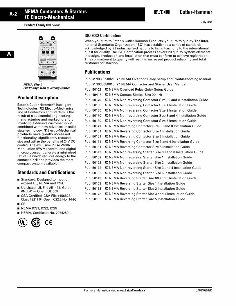
NEMA, Size 0Full Voltage Non-reversing Starter
ISO 9002 Certification
When you turn to Eaton’s Cutler-Hammer Products, you turn to quality. The Inter-national Standards Organization (ISO) has established a series of standards acknowledged by 91 industrialized nations to bring harmony to the international quest for quality. The ISO Certification process covers 20 quality system elements in design, production and installation that must conform to achieve registration. This commitment to quality will result in increased product reliability and total customer satisfaction.
Publications
Pub. MN03305002E
IT.
NEMA Overload Relay Setup and Troubleshooting Manual
Pub. MN03305001E
IT.
NEMA Contactor and Starter User Manual
Pub. 50102
IT.
NEMA Overload Relay Quick Setup Guide
Pub. 49416
IT.
NEMA Contact Blocks (Size 00 – 4)
Pub. 50140
IT.
NEMA Non-reversing Contactor Size 00 and 0 Installation Guide
Pub. 50150
IT.
NEMA Non-reversing Contactor Size 1 Installation Guide
Pub. 50160
IT.
NEMA Non-reversing Contactor Size 2 Installation Guide
Pub. 50170
IT.
NEMA Non-reversing Contactor Size 3 and 4 Installation Guide
Pub. 50180
IT.
NEMA Non-reversing Contactor Size 5 Installation Guide
Pub. 50141
IT.
NEMA Reversing Contactor Size 00 and 0 Installation Guide
Pub. 50151
IT.
NEMA Reversing Contactor Size 1 Installation Guide
Pub. 50161
IT.
NEMA Reversing Contactor Size 2 Installation Guide
Pub. 50171
IT.
NEMA Reversing Contactor Size 3 and 4 Installation Guide
Pub. 50181
IT.
NEMA Reversing Contactor Size 5 Installation Guide
Pub. 50142
IT.
NEMA Non-reversing Starter Size 00 and 0 Installation Guide
Pub. 50152
IT.
NEMA Non-reversing Starter Size 1 Installation Guide
Pub. 50162
IT.
NEMA Non-reversing Starter Size 2 Installation Guide
Pub. 50172
IT.
NEMA Non-reversing Starter Size 3 and 4 Installation Guide
Pub. 50182
IT.
NEMA Non-reversing Starter Size 5 Installation Guide
Pub. 50143
IT.
NEMA Reversing Starter Size 00 and 0 Installation Guide
Pub. 50153
IT.
NEMA Reversing Starter Size 1 Installation Guide
Pub. 50163
IT.
NEMA Reversing Starter Size 2 Installation Guide
Pub. 50173
IT.
NEMA Reversing Starter Size 3 and 4 Installation Guide
Pub. 50183
IT.
NEMA Reversing Starter Size 5 Installation Guide
Tab33.book Page 2 Sunday, September 21, 2008 10:27 PM
July 2008
CA08102002K For more information visit:
www.EatonCanada.ca
A-3NEMA Contactors & Starters
A
IT.
Electro-Mechanical
Catalogue Number Selection
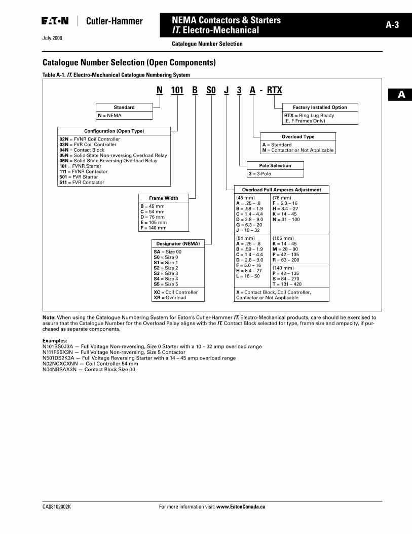
Catalogue Number Selection (Open Components)
Table A-1.
IT.
Electro-Mechanical Catalogue Numbering System
Note:
When using the Catalogue Numbering System for Eaton’s Cutler-Hammer
IT.
Electro-Mechanical products, care should be exercised to assure that the Catalogue Number for the Overload Relay aligns with the
IT.
Contact Block selected for type, frame size and ampacity, if pur-chased as separate components.
Examples:
N101BS0J3A — Full Voltage Non-reversing, Size 0 Starter with a 10 – 32 amp overload rangeN111FS5X3N — Full Voltage Non-reversing, Size 5 ContactorN501DS2K3A — Full Voltage Reversing Starter with a 14 – 45 amp overload rangeN02NCXCXNN — Coil Controller 54 mmN04NBSAX3N — Contact Block Size 00
Designator (NEMA)
SA = Size 00S0 = Size 0S1 = Size 1S2 = Size 2S3 = Size 3S4 = Size 4S5 = Size 5
XC = Coil ControllerXR = Overload
Overload Type
A = StandardN = Contactor or Not Applicable
Standard
N = NEMA
Configuration (Open Type)
02N = FVNR Coil Controller03N = FVR Coil Controller04N = Contact Block05N = Solid-State Non-reversing Overload Relay06N = Solid-State Reversing Overload Relay101 = FVNR Starter111 = FVNR Contactor501 = FVR Starter511 = FVR Contactor
Frame Width
B = 45 mm C = 54 mm D = 76 mm E = 105 mmF = 140 mm
Overload Full Amperes Adjustment
(45 mm)A = .25 – .8B = .59 – 1.9C = 1.4 – 4.4D = 2.8 – 9.0G = 6.3 – 20J = 10 – 32
(76 mm)F = 5.0 – 16H = 8.4 – 27K = 14 – 45N = 31 – 100
(54 mm)A = .25 – .8B = .59 – 1.9C = 1.4 – 4.4D = 2.8 – 9.0F = 5.0 – 16H = 8.4 – 27L = 16 – 50
(105 mm)K = 14 – 45M = 28 – 90P = 42 – 135R = 63 – 200
(140 mm)P = 42 – 135S = 84 – 270T = 131 – 420
X = Contact Block, Coil Controller, Contactor or Not Applicable
Pole Selection
3 = 3-Pole
N 101 B S0 J 3 A - RTX
Factory Installed Option
RTX = Ring Lug Ready(E, F Frames Only)
Tab33.book Page 3 Sunday, September 21, 2008 10:27 PM
July 2008
A-4
For more information visit:
www.EatonCanada.ca
CA08102002K
NEMA Contactors & Starters
A
IT.
Electro-Mechanical
Contactors — Full Voltage, Non-reversing and Reversing
Contents
Description Page
Product Family Overview
Product Description . . . . . . .
A-2
Standards andCertifications . . . . . . . . . . .
A-2
Catalogue NumberSelection . . . . . . . . . . . . . .
A-3
Contactors — Non-reversingand Reversing
Product Description . . . . . . .
A-4
Features . . . . . . . . . . . . . . . .
A-4
Product Selection. . . . . . . . .
A-5
Technical Data and Specifications
. . . . . . . . . . . . .
A-10
Accessories . . . . . . . . . . . . . . . . A-13
Auxiliary Contacts . . . . . . . .
A-15
Renewal Parts
. . . . . . . . . . . . . .
A-17
Dimensions
. . . . . . . . . . . . . . . .
A-18
Product Description
The Cutler-Hammer
®
Intelligent Technologies (
IT.
) Electro-Mechanical Contactor from Eaton’s electrical business consists of an
IT.
Electro-Mechanical Contact Block and
IT.
Electro-Mechanical Coil Controller as a Full Voltage Non-reversing (FVNR) or Full Voltage Reversing (FVR) device. Size 00 to Size 4 Contact Blocks combined with Coil Controllers (factory or field assembled) are stand-alone Contactors. Only the Size 5 Contactors have internal factory assembled coil controllers.
Features
■
Size 00 – 5, 9 – 270A, 2 – 200 hp, 600V
■
24V DC Coil Control — safe, reliable global standard
■
Frame width (mm): 45, 54, 76, 105, 140
■
No laminations, shading coils or magnet noise
■
-40 to 149°F (-40 to 65°C) operating temperature
■
No seal in auxiliary contacts required — control wiring is not needed between the contactor and overload relay
■
Conformal coated printed circuit boards for resistance to harsh environments
■
Unique Pulse Width Modulated coil controller minimizes coil power consumption
■
Microprocessor-based control
■
Easily accessible mounting feet for panel mounting
■
Meets or exceeds global standards for EMC (Electromagnetic compati-bility) immunity and emissions
■
Front and side mounted Auxiliary Contacts: 1NO, 1 NC, 2NO, 2NC, 1NO/1NC and logic level
■
2- or 3-wire control
■
Built-in logic to provide either 2- or 3-wire control, eliminating the need to provide and wire auxiliary con-tacts to seal in and interlock the contactor coils
■
Easy field assembly of control wiring — plug and unplug lockable control connector
■
DIN rail mounting for Sizes 00 – 2
■
Optional mounting plates for Size 00 – 4
■
Common accessories
■
Long-life silver nickel and silver tin oxide contacts provide excellent conductivity and superior resistance to welding and arc erosion
■
Environmentally friendly materials
■
Low wattage coils and minimal heat dissipation
Reversing Contactors
■
Includes Reversing Power Wiring and bus bars
■
Mounting plates for Size 00 – 4
■
Exclusive internal electronic inter-lock for reversing
■
Field installed Reversing Kits
■
Unique coil controller energizes both forward and reverse contactors — one control point for wiring
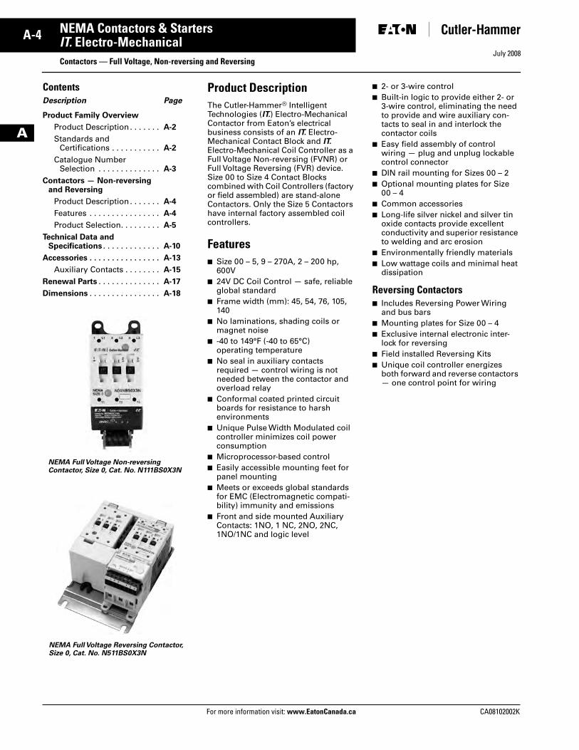
NEMA Full Voltage Reversing Contactor, Size 0, Cat. No. N511BS0X3N
NEMA Full Voltage Non-reversing Contactor, Size 0, Cat. No. N111BS0X3N
Tab33.book Page 4 Sunday, September 21, 2008 10:27 PM
July 2008
CA08102002K For more information visit:
www.EatonCanada.ca
A-5NEMA Contactors & Starters
A
IT.
Electro-Mechanical
Contactors — Full Voltage, Non-reversing and Reversing
Product Selection
Non-reversing Contactors
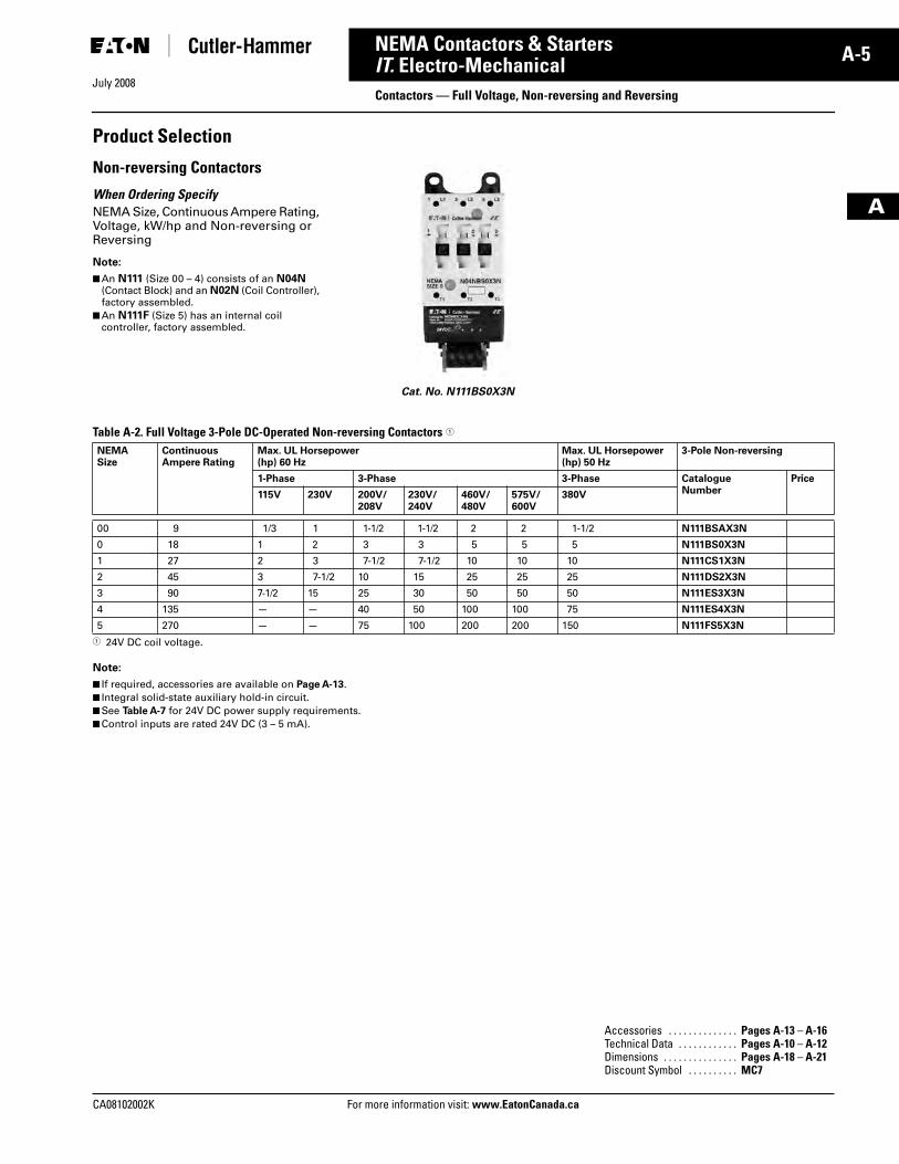
When Ordering Specify
NEMA Size, Continuous Ampere Rating, Voltage, kW/hp and Non-reversing or Reversing
Note:
■
An
N111
(Size 00 – 4) consists of an
N04N
(Contact Block) and an
N02N
(Coil Controller), factory assembled.
■
An
N111F
(Size 5) has an internal coil controller, factory assembled.
Table A-2. Full Voltage 3-Pole DC-Operated Non-reversing Contactors
�
�
24V DC coil voltage.
Note:
■
If required, accessories are available on
Page A-13
.
■
Integral solid-state auxiliary hold-in circuit.
■
See
Table A-7
for 24V DC power supply requirements.
■
Control inputs are rated 24V DC (3 – 5 mA).
Cat. No. N111BS0X3N
NEMASize
Continuous Ampere Rating
Max. UL Horsepower(hp) 60 Hz
Max. UL Horsepower (hp) 50 Hz
3-Pole Non-reversing
1-Phase 3-Phase 3-Phase CatalogueNumber
Price
115V 230V 200V/208V
230V/240V
460V/480V
575V/600V
380V
00 9 1/3 1 1-1/2 1-1/2 2 2 1-1/2
N111BSAX3N
0 18 1 2 3 3 5 5 5
N111BS0X3N
1 27 2 3 7-1/2 7-1/2 10 10 10
N111CS1X3N
2 45 3 7-1/2 10 15 25 25 25
N111DS2X3N
3 90 7-1/2 15 25 30 50 50 50
N111ES3X3N
4 135 — — 40 50 100 100 75
N111ES4X3N
5 270 — — 75 100 200 200 150
N111FS5X3N
Accessories . . . . . . . . . . . . . .
Pages A-13
–
A-16
Technical Data . . . . . . . . . . . .
Pages A-10
–
A-12
Dimensions . . . . . . . . . . . . . . .
Pages A-18 – A-21Discount Symbol . . . . . . . . . . MC7
Tab33.book Page 5 Sunday, September 21, 2008 10:27 PM
July 2008
A-6
For more information visit: www.EatonCanada.ca CA08102002K
NEMA Contactors & Starters
A
IT. Electro-MechanicalContactors — Full Voltage, Non-reversing and Reversing
Reversing Contactors
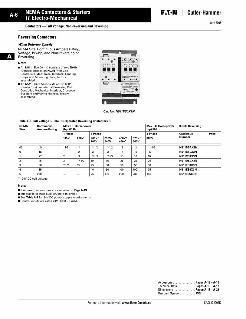
When Ordering SpecifyNEMA Size, Continuous Ampere Rating, Voltage, kW/hp, and Non-reversing or Reversing
Note:
■ An N511 (Size 00 – 4) consists of two N04N (Contact Blocks), an N03N (FVR Coil Controller), Mechanical Interlock, Fanning Strips and Mounting Plate, factory assembled.
■ An N511F (Size 5) consists of two N111F (Contactors), an Internal Reversing Coil Controller, Mechanical Interlock, Crossover Bus Bars and Wiring Harness, factory assembled.
Table A-3. Full Voltage 3-Pole DC-Operated Reversing Contactors �
� 24V DC coil voltage.
Note:
■ If required, accessories are available on Page A-13.■ Integral solid-state auxiliary hold-in circuit.■ See Table A-7 for 24V DC power supply requirements.■ Control inputs are rated 24V DC (3 – 5 mA).
Cat. No. N511BS0X3N
NEMASize
Continuous Ampere Rating
Max. UL Horsepower(hp) 60 Hz
Max. UL Horsepower (hp) 50 Hz
3-Pole Reversing
1-Phase 3-Phase 3-Phase CatalogueNumber
Price
115V 230V 200V/208V
230V/240V
460V/480V
575V/600V
380V
00 9 1/3 1 1-1/2 1-1/2 2 2 1-1/2 N511BSAX3N
0 18 1 2 3 3 5 5 5 N511BS0X3N
1 27 2 3 7-1/2 7-1/2 10 10 10 N511CS1X3N
2 45 3 7-1/2 10 15 25 25 25 N511DS2X3N
3 90 7-1/2 15 25 30 50 50 50 N511ES3X3N
4 135 — — 40 50 100 100 75 N511ES4X3N
5 270 — — 75 100 200 200 150 N511FS5X3N
Accessories . . . . . . . . . . . . . . . Pages A-13 – A-16Technical Data . . . . . . . . . . . . Pages A-10 – A-12Dimensions . . . . . . . . . . . . . . . Pages A-18 – A-21Discount Symbol . . . . . . . . . . . MC7
Tab33.book Page 6 Sunday, September 21, 2008 10:27 PM
July 2008
CA08102002K For more information visit: www.EatonCanada.ca
A-7NEMA Contactors & Starters
A
IT. Electro-Mechanical Starters — Full Voltage, Non-reversing and Reversing
ContentsDescription Page
Product Family Overview
Product Description . . . . . . A-2
Standards andCertifications . . . . . . . . . . A-2
Catalogue NumberSelection. . . . . . . . . . . . . . A-3
Starters — Non-reversingand Reversing
Product Description . . . . . . A-7
Features . . . . . . . . . . . . . . . A-7
Product Selection . . . . . . . . A-8
Technical Data and Specifications . . . . . . . . . . . . A-10
Accessories . . . . . . . . . . . . . . . A-13
Auxiliary Contacts . . . . . . . A-15
Renewal Parts . . . . . . . . . . . . . A-17
Dimensions . . . . . . . . . . . . . . . A-22
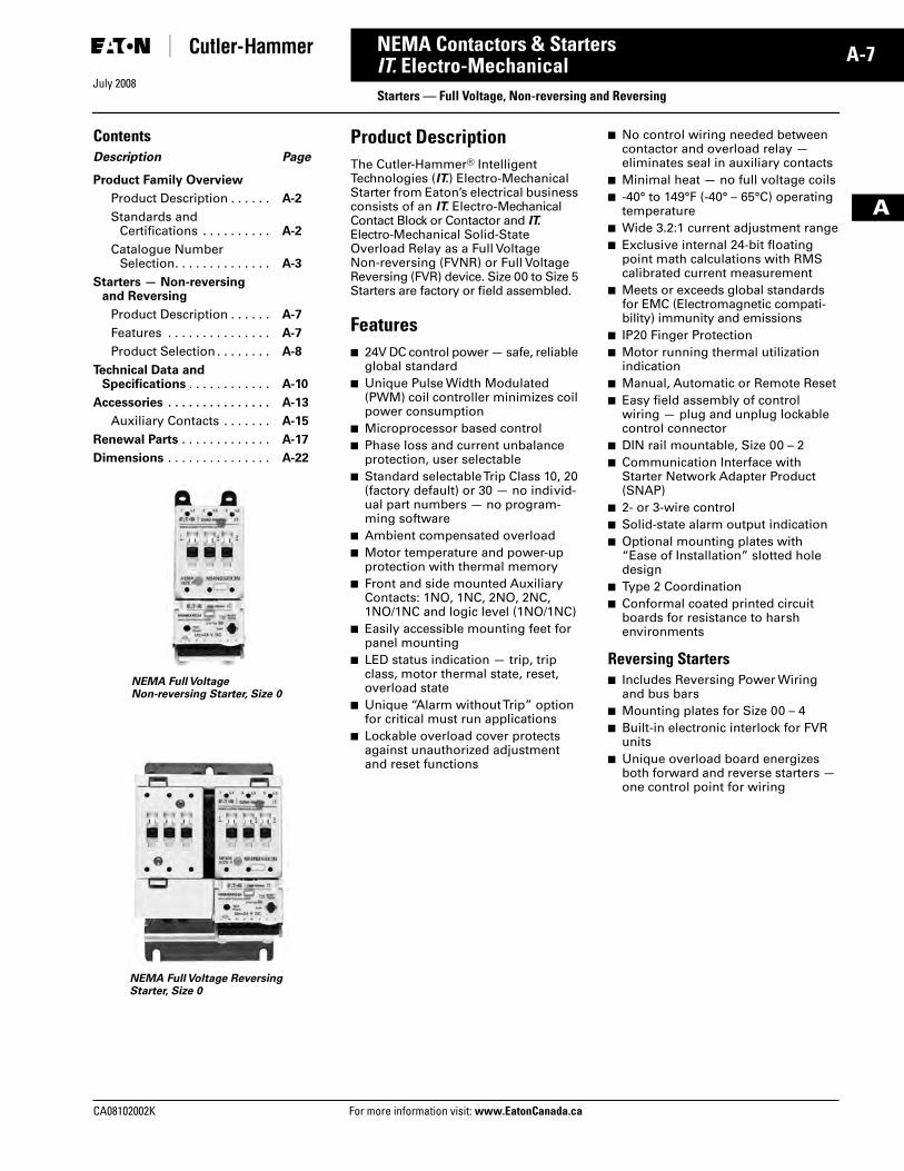
Product DescriptionThe Cutler-Hammer® Intelligent Technologies (IT.) Electro-Mechanical Starter from Eaton’s electrical business consists of an IT. Electro-Mechanical Contact Block or Contactor and IT. Electro-Mechanical Solid-State Overload Relay as a Full Voltage Non-reversing (FVNR) or Full Voltage Reversing (FVR) device. Size 00 to Size 5 Starters are factory or field assembled.
Features■ 24V DC control power — safe, reliable
global standard■ Unique Pulse Width Modulated
(PWM) coil controller minimizes coil power consumption
■ Microprocessor based control■ Phase loss and current unbalance
protection, user selectable■ Standard selectable Trip Class 10, 20
(factory default) or 30 — no individ-ual part numbers — no program-ming software
■ Ambient compensated overload■ Motor temperature and power-up
protection with thermal memory■ Front and side mounted Auxiliary
Contacts: 1NO, 1NC, 2NO, 2NC, 1NO/1NC and logic level (1NO/1NC)
■ Easily accessible mounting feet for panel mounting
■ LED status indication — trip, trip class, motor thermal state, reset, overload state
■ Unique “Alarm without Trip” option for critical must run applications
■ Lockable overload cover protects against unauthorized adjustment and reset functions
■ No control wiring needed between contactor and overload relay — eliminates seal in auxiliary contacts
■ Minimal heat — no full voltage coils■ -40° to 149°F (-40° – 65°C) operating
temperature■ Wide 3.2:1 current adjustment range■ Exclusive internal 24-bit floating
point math calculations with RMS calibrated current measurement
■ Meets or exceeds global standards for EMC (Electromagnetic compati-bility) immunity and emissions
■ IP20 Finger Protection■ Motor running thermal utilization
indication■ Manual, Automatic or Remote Reset■ Easy field assembly of control
wiring — plug and unplug lockable control connector
■ DIN rail mountable, Size 00 – 2■ Communication Interface with
Starter Network Adapter Product (SNAP)
■ 2- or 3-wire control■ Solid-state alarm output indication■ Optional mounting plates with
“Ease of Installation” slotted hole design
■ Type 2 Coordination■ Conformal coated printed circuit
boards for resistance to harsh environments
Reversing Starters■ Includes Reversing Power Wiring
and bus bars■ Mounting plates for Size 00 – 4■ Built-in electronic interlock for FVR
units■ Unique overload board energizes
both forward and reverse starters — one control point for wiring
NEMA Full Voltage Non-reversing Starter, Size 0
NEMA Full Voltage Reversing Starter, Size 0
Tab33.book Page 7 Sunday, September 21, 2008 10:27 PM
July 2008
A-8
For more information visit: www.EatonCanada.ca CA08102002K
NEMA Contactors & Starters
A
IT. Electro-MechanicalStarters — Full Voltage, Non-reversing and Reversing
Product Selection
Non-reversing Starters
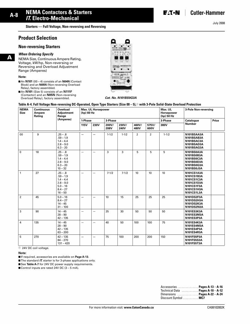
When Ordering SpecifyNEMA Size, Continuous Ampere Rating, Voltage, kW/hp, Non-reversing or Reversing and Overload Adjustment Range (Amperes)
Note:
■ An N101 (00 – 4) consists of an N04N (Contact Block) and an N05N (Non-reversing Overload Relay), factory assembled.
■ An N101 (Size 5) consists of an N111F (Contactor) and an N05N (Non-reversing Overload Relay), factory assembled.
Table A-4. Full Voltage Non-reversing DC-Operated, Open Type Starters (Size 00 – 5),� with 3-Pole Solid-State Overload Protection
� 24V DC coil voltage.
Note:
■ If required, accessories are available on Page A-13.■ The standard IT. starter is for 3-phase applications only.■ See Table A-7 for 24V DC power supply requirements.■ Control inputs are rated 24V DC (3 – 5 mA).
Cat. No. N101BS0G3A
NEMASize
ContinuousAmpereRating
OverloadAdjustmentRange(Amperes)
Max. UL Horsepower(hp) 60 Hz
Max. UL Horsepower(hp) 50 Hz
3-Pole Non-reversing
1-Phase 3-Phase 3-Phase CatalogueNumber
Price
115V 230V 200V/208V
230V/240V
460V/480V
575V/600V
380V
00 9 .25 – .8.59 – 1.91.4 – 4.42.8 – 9.06.3 – 20
— — 1-1/2 1-1/2 2 2 1-1/2 N101BSAA3AN101BSAB3AN101BSAC3AN101BSAD3AN101BSAG3A
0 18 .25 – .8.59 – 1.91.4 – 4.42.8 – 9.06.3 – 2010 – 32
— — 3 3 5 5 5 N101BS0A3AN101BS0B3AN101BS0C3AN101BS0D3AN101BS0G3AN101BS0J3A
1 27 .25 – .8.59 – 1.91.4 – 4.42.8 – 9.05.0 – 168.4 – 2716 – 50
— — 7-1/2 7-1/2 10 10 10 N101CS1A3AN101CS1B3AN101CS1C3AN101CS1D3AN101CS1F3AN101CS1H3AN101CS1L3A
2 45 5.0 – 168.4 – 2714 – 4531 – 100
— — 10 15 25 25 25 N101DS2F3AN101DS2H3AN101DS2K3AN101DS2N3A
3 90 14 – 4528 – 9042 – 135
— — 25 30 50 50 50 N101ES3K3AN101ES3M3AN101ES3P3A
4 135 14 – 4528 – 9042 – 13563 – 200
— — 40 50 100 100 75 N101ES4K3AN101ES4M3AN101ES4P3AN101ES4R3A
5 270 42 – 13584 – 270131 – 420
— — 75 100 200 200 150 N101FS5P3AN101FS5S3AN101FS5T3A
Accessories . . . . . . . . . . . . . . . Pages A-13 – A-16Technical Data . . . . . . . . . . . . Pages A-10 – A-12Dimensions . . . . . . . . . . . . . . . Pages A-22 – A-24Discount Symbol . . . . . . . . . . . MC7
Tab33.book Page 8 Sunday, September 21, 2008 10:27 PM
July 2008
CA08102002K For more information visit: www.EatonCanada.ca
A-9NEMA Contactors & Starters
A
IT. Electro-MechanicalStarters — Full Voltage, Non-reversing and Reversing
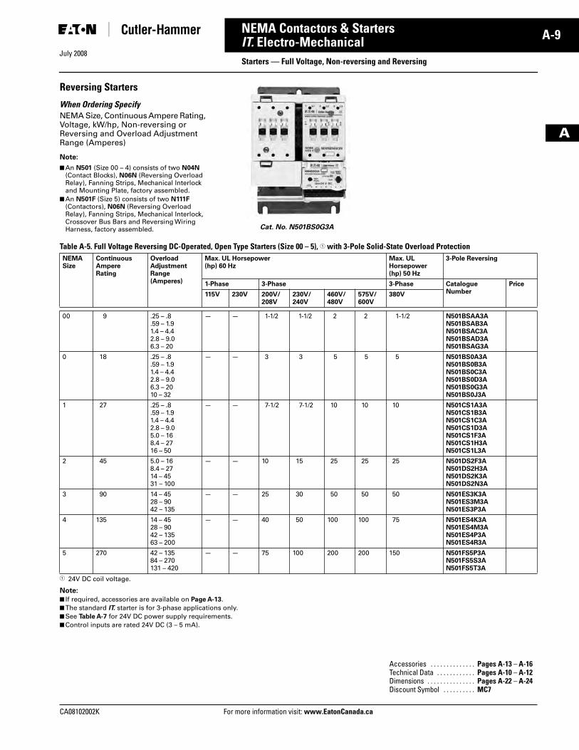
Reversing Starters
When Ordering SpecifyNEMA Size, Continuous Ampere Rating, Voltage, kW/hp, Non-reversing or Reversing and Overload Adjustment Range (Amperes)
Note:
■ An N501 (Size 00 – 4) consists of two N04N (Contact Blocks), N06N (Reversing Overload Relay), Fanning Strips, Mechanical Interlock and Mounting Plate, factory assembled.
■ An N501F (Size 5) consists of two N111F (Contactors), N06N (Reversing Overload Relay), Fanning Strips, Mechanical Interlock, Crossover Bus Bars and Reversing Wiring Harness, factory assembled.
Table A-5. Full Voltage Reversing DC-Operated, Open Type Starters (Size 00 – 5), � with 3-Pole Solid-State Overload Protection
� 24V DC coil voltage.
Note:
■ If required, accessories are available on Page A-13.■ The standard IT. starter is for 3-phase applications only.■ See Table A-7 for 24V DC power supply requirements.■ Control inputs are rated 24V DC (3 – 5 mA).
Cat. No. N501BS0G3A
NEMASize
ContinuousAmpereRating
OverloadAdjustmentRange(Amperes)
Max. UL Horsepower(hp) 60 Hz
Max. UL Horsepower(hp) 50 Hz
3-Pole Reversing
1-Phase 3-Phase 3-Phase CatalogueNumber
Price
115V 230V 200V/208V
230V/240V
460V/480V
575V/600V
380V
00 9 .25 – .8.59 – 1.91.4 – 4.42.8 – 9.06.3 – 20
— — 1-1/2 1-1/2 2 2 1-1/2 N501BSAA3AN501BSAB3AN501BSAC3AN501BSAD3AN501BSAG3A
0 18 .25 – .8.59 – 1.91.4 – 4.42.8 – 9.06.3 – 2010 – 32
— — 3 3 5 5 5 N501BS0A3AN501BS0B3AN501BS0C3AN501BS0D3AN501BS0G3AN501BS0J3A
1 27 .25 – .8.59 – 1.91.4 – 4.42.8 – 9.05.0 – 168.4 – 2716 – 50
— — 7-1/2 7-1/2 10 10 10 N501CS1A3AN501CS1B3AN501CS1C3AN501CS1D3AN501CS1F3AN501CS1H3AN501CS1L3A
2 45 5.0 – 168.4 – 2714 – 4531 – 100
— — 10 15 25 25 25 N501DS2F3AN501DS2H3AN501DS2K3AN501DS2N3A
3 90 14 – 4528 – 9042 – 135
— — 25 30 50 50 50 N501ES3K3AN501ES3M3AN501ES3P3A
4 135 14 – 4528 – 9042 – 13563 – 200
— — 40 50 100 100 75 N501ES4K3AN501ES4M3AN501ES4P3AN501ES4R3A
5 270 42 – 13584 – 270131 – 420
— — 75 100 200 200 150 N501FS5P3AN501FS5S3AN501FS5T3A
Accessories . . . . . . . . . . . . . . Pages A-13 – A-16Technical Data . . . . . . . . . . . . Pages A-10 – A-12Dimensions . . . . . . . . . . . . . . . Pages A-22 – A-24Discount Symbol . . . . . . . . . . MC7
Tab33.book Page 9 Sunday, September 21, 2008 10:27 PM
July 2008
A-10
For more information visit: www.EatonCanada.ca CA08102002K
NEMA Contactors & Starters
A
IT. Electro-MechanicalTechnical Data and Specifications
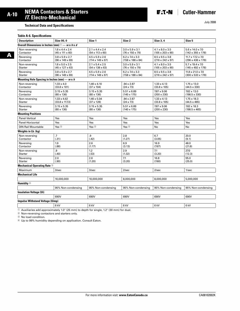
Table A-6. Specifications
� Auxiliaries add approximately 1.0" (25 mm) to depth for single, 1.2" (30 mm) for dual. � Non-reversing contactors and starters only.� No load condition.� Up to 99% humidity depending on application. Consult Eaton.
Description Size 00, 0 Size 1 Size 2 Size 3, 4 Size 5
Overall Dimensions in Inches (mm) � — w x h x dNon-reversing Contactor
1.8 x 4.4 x 2.4(45 x 111 x 60)
2.1 x 4.4 x 2.4(54 x 113 x 60)
3.0 x 5.9 x 3.1(76 x 150 x 79)
4.1 x 8.0 x 3.5(105 x 203 x 90)
5.6 x 14.0 x 7.0(142 x 355 x 178)
Reversing Contactor
3.8 x 5.9 x 2.7(96 x 149 x 69)
4.5 x 5.9 x 2.6(114 x 149 x 67)
6.2 x 7.4 x 3.3(158 x 188 x 84)
8.5 x 9.5 x 3.8(216 x 242 x 97)
11.7 x 17.2 x 7.0(296 x 436 x 178)
Non-reversing Starter
1.8 x 5.0 x 2.5(45 x 127 x 63)
2.1 x 5.4 x 2.5(54 x 138 x 63)
3.0 x 5.9 x 3.1(76 x 150 x 79)
4.1 x 8.0 x 3.5(105 x 203 x 90)
5.7 x 19.4 x 7.0(145 x 492 x 178)
Reversing Starter
3.8 x 5.9 x 2.7(96 x 149 x 69)
4.5 x 5.9 x 2.6(114 x 149 x 67)
6.2 x 7.4 x 3.3(158 x 188 x 84)
8.5 x 9.5 x 3.8(216 x 242 x 97)
11.8 x 21.0 x 7.0(300 x 533 x 178)
Mounting Hole Spacing in Inches (mm) — w x h Non-reversing Contactor
1.33 x 4.0 (33.8 x 101)
1.46 x 4.10(37 x 104)
.94 x 2.87 (24 x 73)
1.33 x 4.13 (33.8 x 10⁵)
1.75 x 13.0(44.5 x 330)
Reversing Contactor
3.15 x 5.35(80 x 136)
3.15 x 5.35 (80 x 136)
5.51 x 6.89 (140 x 175)
7.87 x 9.06 (200 x 230)
7.82 x 13.0(198.5 x 330)
Non-reversing Starter
1.33 x 4.62 (33.8 x 117.3)
1.46 x 5.04 (37 x 128)
.94 x 2.87 (24 x 73)
1.33 x 4.13 (33.8 x 10⁵)
1.75 x 18.3(44.5 x 465)
Reversing Starter
3.15 x 5.35 (80 x 136)
3.15 x 5.35 (80 x 136)
5.51 x 6.89 (140 x 175)
7.87 x 9.06 (200 x 230)
7.82 x 18.3(198.5 x 465)
Mounting PositionsPanel-Vertical Yes Yes Yes Yes Yes
Panel-Horizontal Yes Yes Yes Yes Yes
DIN Rail Mountable Yes � Yes � Yes � No No
Weights in Lb. (kg)Non-reversing Contactor
.7(.31)
.9(.42)
2.8(1.27)
6.7(3.05)
20.0 (9.1)
Reversing Contactor
1.9(.86)
2.6(1.17)
6.9(3.13)
16.9(7.67)
48.0 (21.8)
Non-reversing Starter
.9(.40)
1.2(.53)
2.9(1.32)
7.1(3.20)
27.0 (12.3)
Reversing Starter
2.0(.90)
2.6(1.20)
7.1(3.20)
16.8(7.60)
55.0(25.0)
Mechanical Operating Rate �
Maximum 3/sec 3/sec 2/sec 2/sec 1/sec
Mechanical Life10,000,000 10,000,000 8,000,000 8,000,000 5,000,000
Humidity �
95% Non-condensing 95% Non-condensing 95% Non-condensing 95% Non-condensing 95% Non-condensing
Insulation Voltage (Ui)690V 690V 690V 690V 690V
Impulse Withstand Voltage (Uimp)6 kV 6 kV 6 kV 6 kV 6 kV
Tab33.book Page 10 Sunday, September 21, 2008 10:27 PM
July 2008
CA08102002K For more information visit: www.EatonCanada.ca
A-11NEMA Contactors & Starters
A
IT. Electro-MechanicalTechnical Data and Specifications
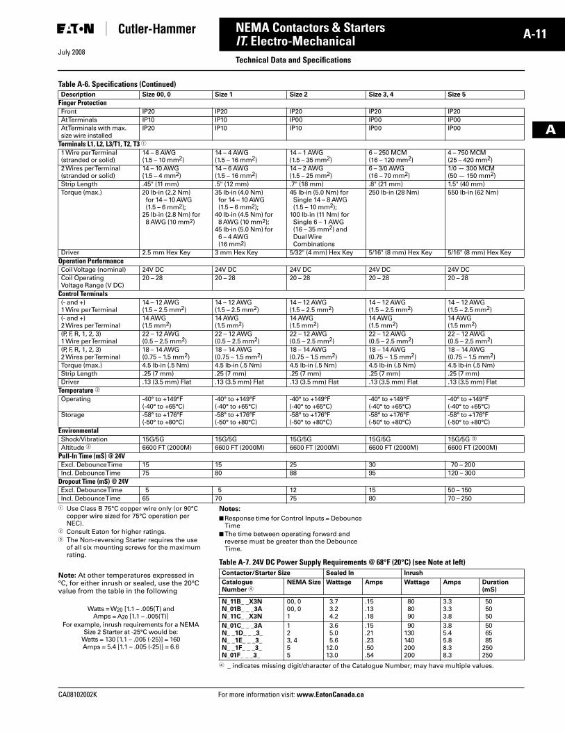
Table A-6. Specifications (Continued)
� Use Class B 75°C copper wire only (or 90°C copper wire sized for 75°C operation per NEC).
� Consult Eaton for higher ratings.� The Non-reversing Starter requires the use
of all six mounting screws for the maximum rating.
Note: At other temperatures expressed in °C, for either inrush or sealed, use the 20°Cvalue from the table in the following
Description Size 00, 0 Size 1 Size 2 Size 3, 4 Size 5
Finger ProtectionFront IP20 IP20 IP20 IP20 IP20At Terminals IP10 IP10 IP00 IP00 IP00At Terminals with max. size wire installed
IP20 IP10 IP10 IP00 IP00
Terminals L1, L2, L3/T1, T2, T3 �1 Wire per Terminal(stranded or solid)
14 – 8 AWG(1.5 – 10 mm2)
14 – 4 AWG(1.5 – 16 mm2)
14 – 1 AWG(1.5 – 35 mm2)
6 – 250 MCM(16 – 120 mm2)
4 – 750 MCM(25 – 420 mm2)
2 Wires per Terminal(stranded or solid)
14 – 10 AWG(1.5 – 4 mm2)
14 – 6 AWG(1.5 – 16 mm2)
14 – 2 AWG(1.5 – 25 mm2)
6 – 3/0 AWG(16 – 70 mm2)
1/0 — 300 MCM(50 — 150 mm2)
Strip Length .45" (11 mm) .5" (12 mm) .7" (18 mm) .8" (21 mm) 1.5" (40 mm)Torque (max.) 20 lb-in (2.2 Nm)
for 14 – 10 AWG(1.5 – 6 mm2);
25 lb-in (2.8 Nm) for8 AWG (10 mm2)
35 lb-in (4.0 Nm)for 14 – 10 AWG(1.5 – 6 mm2);
40 lb-in (4.5 Nm) for 8 AWG (10 mm2);
45 lb-in (5.0 Nm) for 6 – 4 AWG (16 mm2)
45 lb-in (5.0 Nm) for Single 14 – 8 AWG (1.5 – 10 mm2);
100 lb-in (11 Nm) for Single 6 – 1 AWG (16 – 35 mm2) andDual Wire Combinations
250 lb-in (28 Nm) 550 lb-in (62 Nm)
Driver 2.5 mm Hex Key 3 mm Hex Key 5/32" (4 mm) Hex Key 5/16" (8 mm) Hex Key 5/16" (8 mm) Hex KeyOperation PerformanceCoil Voltage (nominal) 24V DC 24V DC 24V DC 24V DC 24V DCCoil Operating Voltage Range (V DC)
20 – 28 20 – 28 20 – 28 20 – 28 20 – 28
Control Terminals(- and +)1 Wire per Terminal
14 – 12 AWG(1.5 – 2.5 mm2)
14 – 12 AWG(1.5 – 2.5 mm2)
14 – 12 AWG(1.5 – 2.5 mm2)
14 – 12 AWG(1.5 – 2.5 mm2)
14 – 12 AWG(1.5 – 2.5 mm2)
(- and +)2 Wires per Terminal
14 AWG(1.5 mm2)
14 AWG(1.5 mm2)
14 AWG(1.5 mm2)
14 AWG(1.5 mm2)
14 AWG(1.5 mm2)
(P, F, R, 1, 2, 3)1 Wire per Terminal
22 – 12 AWG(0.5 – 2.5 mm2)
22 – 12 AWG(0.5 – 2.5 mm2)
22 – 12 AWG(0.5 – 2.5 mm2)
22 – 12 AWG(0.5 – 2.5 mm2)
22 – 12 AWG(0.5 – 2.5 mm2)
(P, F, R, 1, 2, 3)2 Wires per Terminal
18 – 14 AWG(0.75 – 1.5 mm2)
18 – 14 AWG(0.75 – 1.5 mm2)
18 – 14 AWG(0.75 – 1.5 mm2)
18 – 14 AWG(0.75 – 1.5 mm2)
18 – 14 AWG(0.75 – 1.5 mm2)
Torque (max.) 4.5 lb-in (.5 Nm) 4.5 lb-in (.5 Nm) 4.5 lb-in (.5 Nm) 4.5 lb-in (.5 Nm) 4.5 lb-in (.5 Nm)Strip Length .25 (7 mm) .25 (7 mm) .25 (7 mm) .25 (7 mm) .25 (7 mm)Driver .13 (3.5 mm) Flat .13 (3.5 mm) Flat .13 (3.5 mm) Flat .13 (3.5 mm) Flat .13 (3.5 mm) Flat
Temperature �Operating -40° to +149°F
(-40° to +65°C)-40° to +149°F(-40° to +65°C)
-40° to +149°F(-40° to +65°C)
-40° to +149°F(-40° to +65°C)
-40° to +149°F(-40° to +65°C)
Storage -58° to +176°F(-50° to +80°C)
-58° to +176°F(-50° to +80°C)
-58° to +176°F(-50° to +80°C)
-58° to +176°F(-50° to +80°C)
-58° to +176°F(-50° to +80°C)
EnvironmentalShock/Vibration 15G/5G 15G/5G 15G/5G 15G/5G 15G/5G �
Altitude � 6600 FT (2000M) 6600 FT (2000M) 6600 FT (2000M) 6600 FT (2000M) 6600 FT (2000M)Pull-In Time (mS) @ 24VExcl. Debounce Time 15 15 25 30 70 – 200Incl. Debounce Time 75 80 88 95 120 – 300
Dropout Time (mS) @ 24VExcl. Debounce Time 5 5 12 15 50 – 150Incl. Debounce Time 65 70 75 80 70 – 250
Watts = W20 [1.1 – .005(T) and Amps = A20 [1.1 – .005(T)]
For example, inrush requirements for a NEMA Size 2 Starter at -25°C would be:
Watts = 130 [1.1 – .005 (-25)] = 160Amps = 5.4 [1.1 – .005 (-25)] = 6.6
Notes:
■ Response time for Control Inputs = Debounce Time
■ The time between operating forward and reverse must be greater than the Debounce Time.
Table A-7. 24V DC Power Supply Requirements @ 68°F (20°C) (see Note at left)
� _ indicates missing digit/character of the Catalogue Number; may have multiple values.
Contactor/Starter Size Sealed In Inrush
CatalogueNumber �
NEMA Size Wattage Amps Wattage Amps Duration(mS)
N_11B_ _X3NN_01B_ _ _3AN_11C_ _X3N
00, 000, 01
3.73.24.2
.15
.13
.18
808090
3.33.33.8
505050
N_01C_ _ _3AN_ _1D_ _ _3_N_ _1E_ _ _3_N_ _1F_ _ _3_N_01F_ _ _3_
123, 455
3.65.05.6
12.013.0
.15
.21
.23
.50
.54
90130140200200
3.85.45.88.38.3
506585
250250
Tab33.book Page 11 Sunday, September 21, 2008 10:27 PM
July 2008
A-12
For more information visit: www.EatonCanada.ca CA08102002K
NEMA Contactors & Starters
A
IT. Electro-MechanicalTechnical Data and Specifications
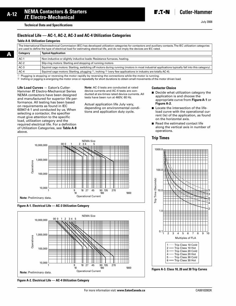
Electrical Life — AC-1, AC-2, AC-3 and AC-4 Utilization CategoriesTable A-8. Utilization Categories
Life Load Curves — Eaton’s Cutler-Hammer IT. Electro-Mechanical Series NEMA contactors have been designed and manufactured for superior life per-formance. All testing has been based on requirements as found in IEC 60947-4-1 and conducted by us. When selecting a contactor, the specifier must give attention to the specific load, utilization category and the required electrical life. For a definition of Utilization Categories, see Table A-8 above.
Note: AC-3 tests are conducted at rated device currents and AC-4 tests are con-ducted at six-times rated device currents. All tests have been run at 460V, 60 Hz.
Actual application life July vary, depending on environmental condi-tions and application duty cycle.
Figure A-1. Electrical Life — AC-3 Utilization Category
Figure A-2. Electrical Life — AC-4 Utilization Category
The International Electrotechnical Commission (IEC) has developed utilization categories for contactors and auxiliary contacts. The IEC utilization categories are used to define the type of electrical load for estimating electrical life, and do not imply the devices are IEC rated.
Category Typical Application
AC-1 Non-inductive or slightly inductive loads: Resistance furnaces, heating.
AC-2 Slip-ring motors: Starting and stopping of running motors
AC-3 Squirrel cage motors: Starting, switching off motors during running (motors in most industrial applications typically fall into this category).
AC-4 Squirrel cage motors: Starting, plugging �, inching � (very few applications in industry are totally AC-4).� Plugging is stopping or reversing the motor rapidly by reversing the connections while the motor is running.� Inching or jogging is energizing the motor once or repeatedly for short durations to obtain small movements of the motor driven load.
1 910 100 1000
18 4527 90 135 270
Operational Current
00 0 1 2 3 4 5NEMA Size
10,000,000
1,000,000
100,000
10,000
Ope
ratio
ns
Note: Preliminary data.
1 910 100 1000
18 4527 90 135 270
Operational Current
00 0 1 2 3 4 5NEMA Size
10,000,000
1,000,000
100,000
10,000
Ope
ratio
ns
Note: Preliminary data.
Contactor Choice ■ Decide what utilization category the
application is and choose the appropriate curve from Figure A-1 or Figure A-2.
■ Locate the intersection of the life-load curve with the operational cur-rent (le) of the application, as found on the horizontal axis.
■ Read the estimated contact life along the vertical axis in number of operations.
Trip Times
Figure A-3. Class 10, 20 and 30 Trip Curves
1000.0
100.0
10.0
1.0
0.11 2 3 4 5 6 7 8 9
2
416
35
10
Trip
Tim
e (S
eco
nd
s)
Trip Class 10 ColdTrip Class 10 HotTrip Class 20 ColdTrip Class 20 HotTrip Class 30 ColdTrip Class 30 Hot
123456
Multiples of FLA
Tab33.book Page 12 Sunday, September 21, 2008 10:27 PM
July 2008
CA08102002K For more information visit: www.EatonCanada.ca
A-13NEMA Contactors & Starters
A
IT. Electro-MechanicalAccessories
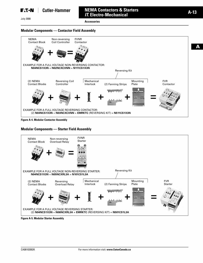
Modular Components — Contactor Field Assembly
Figure A-4. Modular Contactor Assembly
Modular Components — Starter Field Assembly
Figure A-5. Modular Starter Assembly
NEMA Contact Block
Non-reversingCoil Controller
FVNRContactor
EXAMPLE FOR A FULL VOLTAGE REVERSING CONTACTOR:(2) N04NCS1X3N + N03NCXCXNN + EMRKTC (REVERSING KIT) = N511CS1X3N
FVRContactor
Reversing Coil Controller
Mechanical Interlock (2) Fanning Strips
(2) NEMAContact Blocks
Mounting Plate
EXAMPLE FOR A FULL VOLTAGE NON-REVERSING CONTACTOR:N04NCS1X3N + N02NCXCXNN = N111CS1X3N
Reversing Kit
Non-reversing Overload Relay
FVNRStarter
FVRStarter
Reversing Overload Relay
EXAMPLE FOR A FULL VOLTAGE NON-REVERSING STARTER:N04NCS1X3N + N05NCXRL3A = N101CS1L3A
EXAMPLE FOR A FULL VOLTAGE REVERSING STARTER:(2) N04NCS1X3N + N06NCXRL3A + EMRKTC (REVERSING KIT) = N501CS1L3A
NEMA Contact Block
Mechanical Interlock (2) Fanning Strips
(2) NEMAContact Blocks
Mounting Plate
Reversing Kit
Tab33.book Page 13 Sunday, September 21, 2008 10:27 PM
July 2008
A-14
For more information visit: www.EatonCanada.ca CA08102002K
NEMA Contactors & Starters
A
IT. Electro-MechanicalAccessories
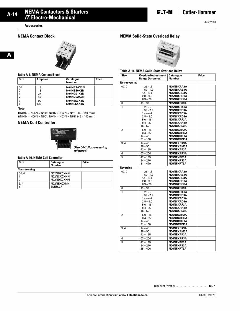
NEMA Contact Block
Table A-9. NEMA Contact Block
Note:
■ N04N + N05N = N101; N04N + N02N = N111 (45 – 140 mm)■ N04N + N06N = N501; N04N + N03N = N511 (45 – 140 mm)
NEMA Coil Controller
Table A-10. NEMA Coil Controller
NEMA Solid-State Overload Relay
Table A-11. NEMA Solid-State Overload Relay
Size Amperes CatalogueNumber
Price
00012
9182745
N04NBSAX3NN04NBS0X3NN04NCS1X3NN04NDS2X3N
34
90135
N04NES3X3NN04NES4X3N
Size CatalogueNumber
Price
Non-reversing00, 012
N02NBXCXNNN02NCXCXNNN02NDXCXNN
3, 45
N02NEXCXNNEMUCCF
Size 00-1 Non-reversing(pictured)
Size Overload Adjustment Range (Amperes)
CatalogueNumber
Price
Non-reversing00, 0 .25 – .8
.59 – 1.91.4 – 4.42.8 – 9.06.3 – 20
N05NBXRA3AN05NBXRB3AN05NBXRC3AN05NBXRD3AN05NBXRG3A
0 10 – 32 N05NBXRJ3A
1 .25 – .8.59 – 1.9
1.4 – 4.42.8 – 9.05.0 – 168.4 – 27
16 – 50
N05NCXRA3AN05NCXRB3AN05NCXRC3AN05NCXRD3AN05NCXRF3AN05NCXRH3AN05NCXRL3A
2 5.0 – 168.4 – 27
14 – 4531 – 100
N05NDXRF3AN05NDXRH3AN05NDXRK3AN05NDXRN3A
3, 4 14 – 4528 – 9042 – 135
N05NEXRK3AN05NEXRM3AN05NEXRP3A
4 63 – 200 N05NEXRR3A
5 42 – 13584 – 270
131 – 420
N05NFXRP3AN05NFXRS3AN05NFXRT3A
Reversing00, 0 .25 – .8
.59 – 1.91.4 – 4.42.8 – 9.06.3 – 20
N06NBXRA3AN06NBXRB3AN06NBXRC3AN06NBXRD3AN06NBXRG3A
0 10 – 32 N06NBXRJ3A
1 .25 – .8.59 – 1.9
1.4 – 4.42.8 – 9.05.0 – 168.4 – 27
16 – 50
N06NCXRA3AN06NCXRB3AN06NCXRC3AN06NCXRD3AN06NCXRF3AN06NCXRH3AN06NCXRL3A
2 5.0 – 168.4 – 27
14 – 4531 – 100
N06NDXRF3AN06NDXRH3AN06NDXRK3AN06NDXRN3A
3, 4 14 – 4528 – 9042 – 135
N06NEXRK3AN06NEXRM3AN06NEXRP3A
4 63 – 200 N06NEXRR3A
5 42 – 13584 – 270
125 – 400
N06NFXRP3AN06NFXRS3AN06NFXRT3A
Discount Symbol . . . . . . . . . . . . . . . . . . . . . . . . MC7
Tab33.book Page 14 Sunday, September 21, 2008 10:27 PM
CA08102002K For more information visit: www.EatonCanada.ca
A-15NEMA Contactors & Starters
July 2008
A
IT. Electro-MechanicalAccessories
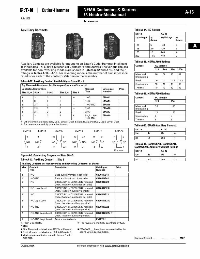
Auxiliary Contacts
Auxiliary Contacts are available for mounting on Eaton’s Cutler-Hammer Intelligent Technologies (IT.) Electro-Mechanical Contactors and Starters. The various choices available for non-reversing models are shown in Tables A-12 and A-13, and their ratings in Tables A-14 – A-16. For reversing models, the number of auxiliaries indi-cated is for each of the contactors/starters in the assembly.
Table A-12. Auxiliary Contact Availability — Sizes 00 – 5
� Other combinations: Single, Dual, Single; Dual, Single, Dual; and Dual, Logic Level, Dual.� For reversers, multiply quantities by two.
Figure A-6. Connecting Diagram — Sizes 00 – 5
Table A-13. Auxiliary Contact — Size 5
� Form C contacts. � For reversers, multiply quantities by two.Notes:
■ Side Mounted — Maximum (10) Total Circuits■ Front Mounted — Maximum (6) Total Circuits �
■ Maximum 4 auxiliaries per side (base + 3 side mounted)
■ EMASA/B _ _ have been superseded by the above Catalogue Numbers.
Top Mounted (Maximum Auxiliaries per Contactor/Starter) �
Contactor/Starter Size ContactType
Catalogue Number
Price
Size 00, 0 Size 1 Size 2 Size 3, 4 Size 5
3 3 3 3 — 1NO EMA13
3 3 3 3 — 1NC EMA14
2 2 � 3 3 — 1NO-1NC EMA15
2 2 � 3 3 — 2NO EMA16
2 2 � 3 3 — 2NC EMA17
2 3 3 3 3 Logic Level1NO-1NC
EMA70
Auxiliary Contacts per Non-reversing and Reversing Contactor or Starter
Max ContactType
Description CatalogueNumber
Price
2 1NO Base auxiliary (max. 1 per side) C320KGS41
2 1NO-1NC Base auxiliary (max. 1 per side) C320KGS42
6 1NO C320KGS41 or C320KGS42 required (max. 3 Add-on auxiliaries per side)
C320KGS20
2 1NO Logic Level C320KGS41 or C320KGS42 required (max. 1 Add-on auxiliary per side)
C320KGS20L
6 1NC C320KGS41 or C320KGS42 required (max. 2 Add-on auxiliaries per side)
C320KGS21
2 1NC Logic Level C320KGS41 or C320KGS42 required (max. 1 Add-on auxiliary per side)
C320KGS21L
2 1NO-1NC C320KGS41 or C320KGS42 required (max. 1 Add-on auxiliary per side)
C320KGS22
2 1NO-1NC Logic Level C320KGS41 or C320KGS42 required (max. 1 Add-on auxiliary per side)
C320KGS22L �
3 1NO-1NC Logic Level Front mounted only EMA70 �
1
NC
2
EMA14
4
NO
1
23 21
NC
22
EMA70
13
NO
14
11
NC
12
13
NO
14
EMA15 EMA16 EMA17
3
EMA13
NO
4
2
NC
1
21
NC
22
NO
24
Common
Table A-14. IEC Ratings
Table A-15. NEMA A600 Ratings
Table A-16. NEMA P300 Ratings
Table A-17. EMA70 Auxiliary Contact
Table A-18. C320KGS20L, C320KGS21L, C320KGS22L, Auxiliary Contact Ratings
DC-13 AC-15
Ue Voltage le Amps.
Ue Voltage le Amps.
24 5 48 8
48 2.5 120 6
125 1.1 240 4
250 .55 440 2
Current AC Voltage
120 240 480 600
Make and Interrupting
60 30 15 12
Break 6 3 1.5 1.2
Continuous 10 10 10 10
Thermal 10 10 10 10
Current DC Voltage
125 250
Make and Interrupting
1.1 .55
Break 1.1 .55
Continuous 5 5
Thermal 5 5
DC-12 AC-12
Ue Ie Ue Ie
30 .1 250 .1
DC-12 AC-12
Ue Ie Ue Ie
80 0.1 250 0.1
Discount Symbol . . . . . . . . . . . . . . . . . . . . . . . MC7
Tab33.book Page 15 Sunday, September 21, 2008 10:27 PM
July 2008
A-16
For more information visit: www.EatonCanada.ca CA08102002K
NEMA Contactors & Starters
A
IT. Electro-MechanicalAccessories
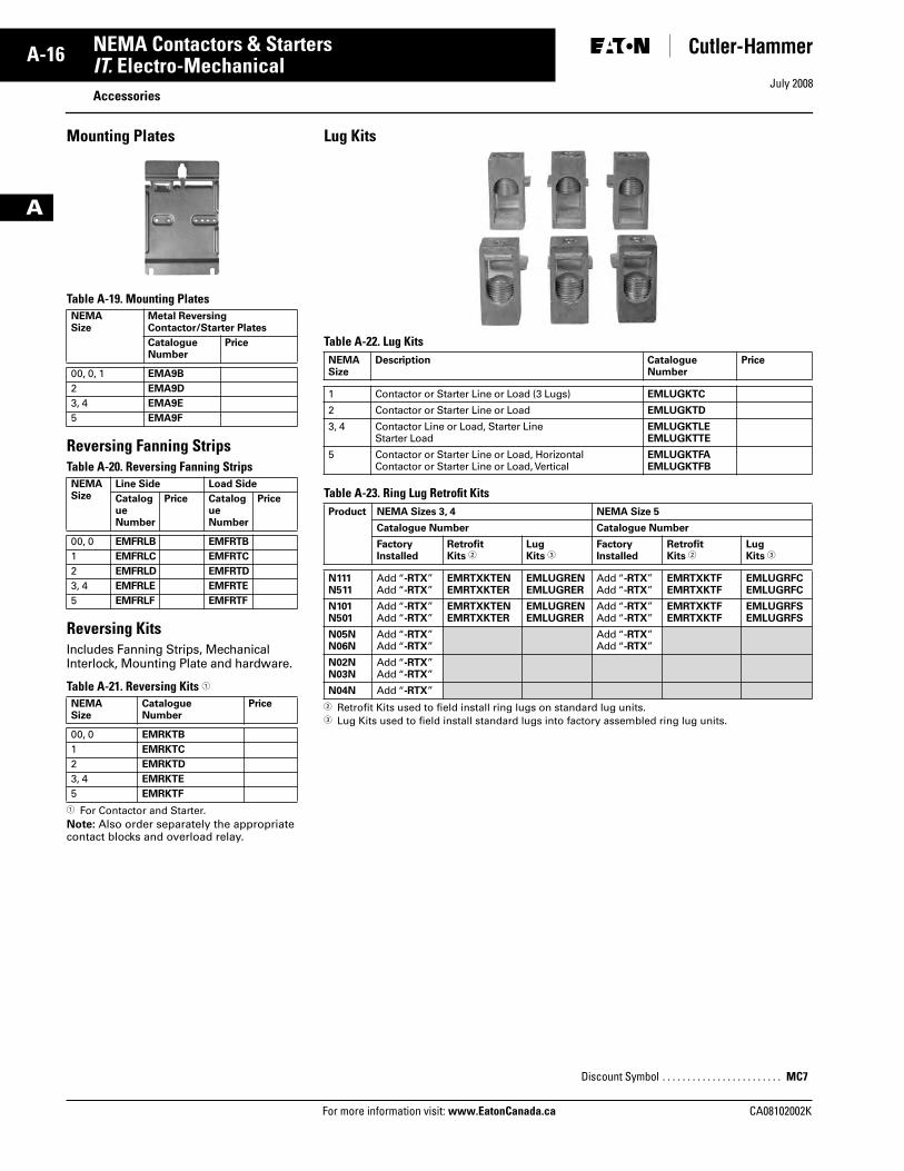
Mounting Plates
Table A-19. Mounting Plates
Reversing Fanning StripsTable A-20. Reversing Fanning Strips
Reversing KitsIncludes Fanning Strips, Mechanical Interlock, Mounting Plate and hardware.
Table A-21. Reversing Kits �
� For Contactor and Starter. Note: Also order separately the appropriate contact blocks and overload relay.
NEMASize
Metal ReversingContactor/Starter Plates
CatalogueNumber
Price
00, 0, 1 EMA9B
2 EMA9D
3, 4 EMA9E
5 EMA9F
NEMASize
Line Side Load Side
CatalogueNumber
Price CatalogueNumber
Price
00, 0 EMFRLB EMFRTB
1 EMFRLC EMFRTC
2 EMFRLD EMFRTD
3, 4 EMFRLE EMFRTE
5 EMFRLF EMFRTF
NEMASize
CatalogueNumber
Price
00, 0 EMRKTB
1 EMRKTC
2 EMRKTD
3, 4 EMRKTE
5 EMRKTF
Lug Kits
Table A-22. Lug Kits
Table A-23. Ring Lug Retrofit Kits
� Retrofit Kits used to field install ring lugs on standard lug units.� Lug Kits used to field install standard lugs into factory assembled ring lug units.
NEMASize
Description CatalogueNumber
Price
1 Contactor or Starter Line or Load (3 Lugs) EMLUGKTC
2 Contactor or Starter Line or Load EMLUGKTD
3, 4 Contactor Line or Load, Starter LineStarter Load
EMLUGKTLEEMLUGKTTE
5 Contactor or Starter Line or Load, HorizontalContactor or Starter Line or Load, Vertical
EMLUGKTFAEMLUGKTFB
Product NEMA Sizes 3, 4 NEMA Size 5
Catalogue Number Catalogue Number
FactoryInstalled
RetrofitKits �
LugKits �
Factory Installed
RetrofitKits �
LugKits �
N111N511
Add “-RTX”Add “-RTX”
EMRTXKTENEMRTXKTER
EMLUGRENEMLUGRER
Add “-RTX”Add “-RTX”
EMRTXKTFEMRTXKTF
EMLUGRFCEMLUGRFC
N101N501
Add “-RTX”Add “-RTX”
EMRTXKTENEMRTXKTER
EMLUGRENEMLUGRER
Add “-RTX”Add “-RTX”
EMRTXKTFEMRTXKTF
EMLUGRFSEMLUGRFS
N05NN06N
Add “-RTX”Add “-RTX”
Add “-RTX”Add “-RTX”
N02NN03N
Add “-RTX”Add “-RTX”
N04N Add “-RTX”
Discount Symbol . . . . . . . . . . . . . . . . . . . . . . . . MC7
Tab33.book Page 16 Sunday, September 21, 2008 10:27 PM
July 2008
CA08102002K For more information visit: www.EatonCanada.ca
A-17NEMA Contactors & Starters
A
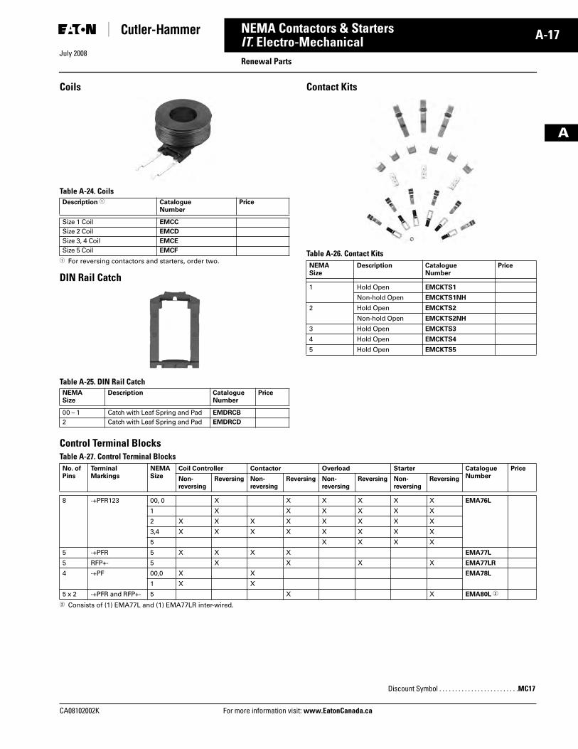
IT. Electro-MechanicalRenewal Parts
Coils
Table A-24. Coils
� For reversing contactors and starters, order two.
DIN Rail Catch
Table A-25. DIN Rail Catch
Contact Kits
Table A-26. Contact Kits
Control Terminal Blocks Table A-27. Control Terminal Blocks
� Consists of (1) EMA77L and (1) EMA77LR inter-wired.
Description � CatalogueNumber
Price
Size 1 Coil EMCC
Size 2 Coil EMCD
Size 3, 4 Coil EMCE
Size 5 Coil EMCF
NEMASize
Description CatalogueNumber
Price
00 – 1 Catch with Leaf Spring and Pad EMDRCB
2 Catch with Leaf Spring and Pad EMDRCD
NEMASize
Description CatalogueNumber
Price
1 Hold Open EMCKTS1
Non-hold Open EMCKTS1NH
2 Hold Open EMCKTS2
Non-hold Open EMCKTS2NH
3 Hold Open EMCKTS3
4 Hold Open EMCKTS4
5 Hold Open EMCKTS5
No. of Pins
Terminal Markings
NEMA Size
Coil Controller Contactor Overload Starter CatalogueNumber
Price
Non-reversing
Reversing Non-reversing
Reversing Non-reversing
Reversing Non-reversing
Reversing
8 -+PFR123 00, 0 X X X X X X EMA76L
1 X X X X X X
2 X X X X X X X X
3,4 X X X X X X X X
5 X X X X
5 -+PFR 5 X X X X EMA77L
5 RFP+- 5 X X X X EMA77LR
4 -+PF 00,0 X X EMA78L
1 X X
5 x 2 -+PFR and RFP+- 5 X X EMA80L �
Discount Symbol . . . . . . . . . . . . . . . . . . . . . . . . .MC17
Tab33.book Page 17 Sunday, September 21, 2008 10:27 PM
July 2008
A-18
For more information visit: www.EatonCanada.ca CA08102002K
NEMA Contactors & Starters
A
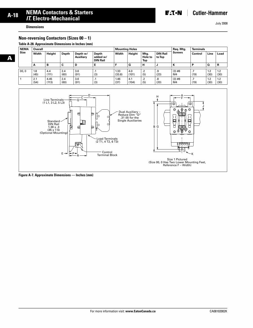
IT. Electro-MechanicalDimensions
Non-reversing Contactors (Sizes 00 – 1)Table A-28. Approximate Dimensions in Inches (mm)
Figure A-7. Approximate Dimensions — Inches (mm)
NEMASize
Overall Mounting Holes Req. Mtg.Screws
Terminals
Width Height Depth Depth w/Auxiliary
Depthadded w/ DIN Rail
Width Height Mtg. Hole to Top
DIN Railto Top
Control Line Load
A B C D E F G H J K P Q R
00, 0 1.8(45)
4.4(111)
2.4(60)
3.6(91)
.1(3)
1.33(33.8)
4.0(101)
.2(5)
.9(23)
(3) #8M4
.7(19)
1.2(30)
1.2(30)
1 2.1(54)
4.45(113)
2.4(60)
3.6(91)
.1(3)
1.46(37)
4.1(104)
.2(5)
.8(20)
(3) #8M4
.7(19)
1.2(30)
1.2(30)
RP Control
Terminal BlockE
Load Terminals(2 T1, 4 T2, 6 T3)
Dual Auxiliary –Reduce Dim “D”
.31 (8) for theSingle Auxiliaries
K
QC FH
G
J
B
AD
Line Terminals(1 L1, 3 L2, 5 L3)
StandardDIN Rail1.38 x .3(35 x 7.5)
(Optional Mounting)
Size 1 Pictured(Size 00, 0 Has Two Lower Mounting Feet,
Reference F – Width)
Tab33.book Page 18 Sunday, September 21, 2008 10:27 PM
July 2008
CA08102002K For more information visit: www.EatonCanada.ca
A-19NEMA Contactors & Starters
A
IT. Electro-MechanicalDimensions
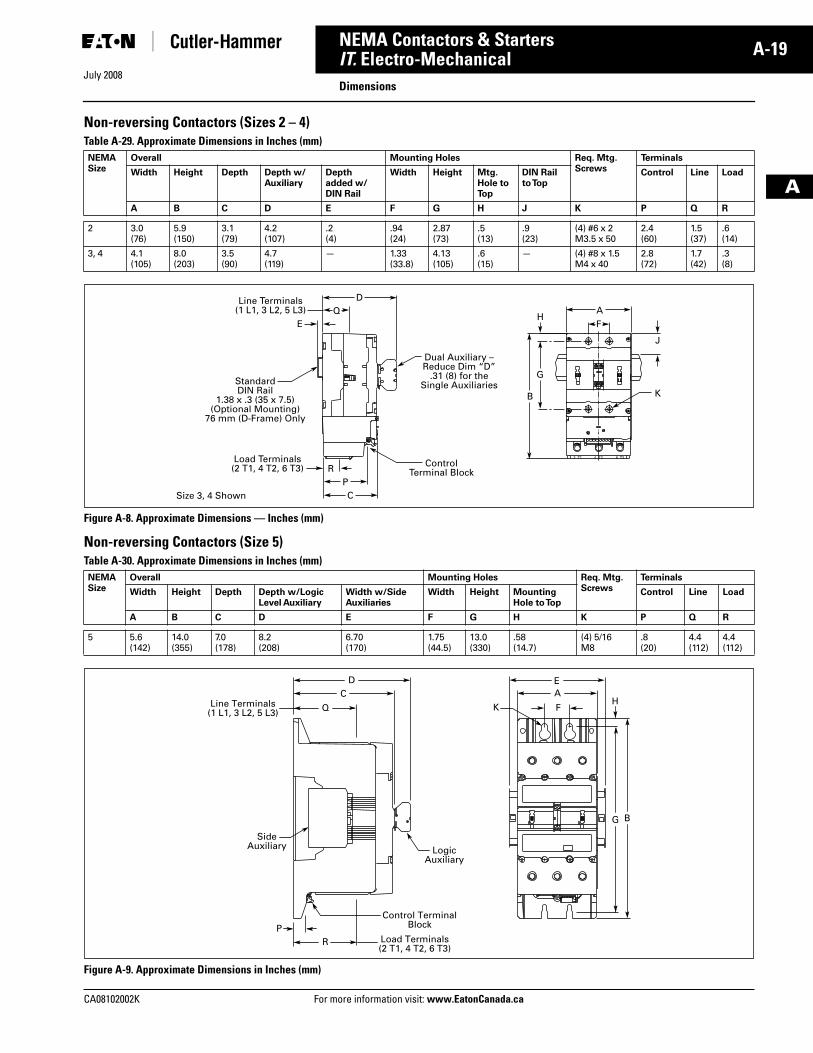
Non-reversing Contactors (Sizes 2 – 4) Table A-29. Approximate Dimensions in Inches (mm)
Figure A-8. Approximate Dimensions — Inches (mm)
Non-reversing Contactors (Size 5)Table A-30. Approximate Dimensions in Inches (mm)
Figure A-9. Approximate Dimensions in Inches (mm)
NEMASize
Overall Mounting Holes Req. Mtg.Screws
Terminals
Width Height Depth Depth w/Auxiliary
Depthadded w/ DIN Rail
Width Height Mtg. Hole to Top
DIN Railto Top
Control Line Load
A B C D E F G H J K P Q R
2 3.0(76)
5.9(150)
3.1(79)
4.2(107)
.2(4)
.94(24)
2.87(73)
.5(13)
.9(23)
(4) #6 x 2M3.5 x 50
2.4(60)
1.5(37)
.6(14)
3, 4 4.1(105)
8.0(203)
3.5(90)
4.7(119)
— 1.33(33.8)
4.13(105)
.6(15)
— (4) #8 x 1.5M4 x 40
2.8(72)
1.7(42)
.3(8)
NEMASize
Overall Mounting Holes Req. Mtg.Screws
Terminals
Width Height Depth Depth w/LogicLevel Auxiliary
Width w/SideAuxiliaries
Width Height MountingHole to Top
Control Line Load
A B C D E F G H K P Q R
5 5.6(142)
14.0(355)
7.0(178)
8.2(208)
6.70(170)
1.75(44.5)
13.0(330)
.58(14.7)
(4) 5/16M8
.8(20)
4.4(112)
4.4(112)
2 T1 T24 T36
K
J
H
G
B
Dual Auxiliary –Reduce Dim “D”
.31 (8) for theSingle Auxiliaries
AF
QE
DLine Terminals(1 L1, 3 L2, 5 L3)
StandardDIN Rail
1.38 x .3 (35 x 7.5)(Optional Mounting)
76 mm (D-Frame) Only
ControlTerminal BlockR
P
Load Terminals(2 T1, 4 T2, 6 T3)
Size 3, 4 Shown C
Load Terminals (2 T1, 4 T2, 6 T3)
PR
Line Terminals (1 L1, 3 L2, 5 L3)
DC
Q
EA
FK
Logic Auxiliary
Side Auxiliary
Control Terminal Block
G B
H
Tab33.book Page 19 Sunday, September 21, 2008 10:27 PM
July 2008
A-20
For more information visit: www.EatonCanada.ca CA08102002K
NEMA Contactors & Starters
A
IT. Electro-MechanicalDimensions
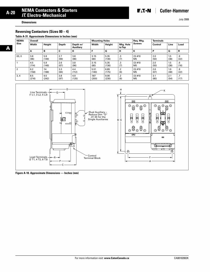
Reversing Contactors (Sizes 00 – 4) Table A-31. Approximate Dimensions in Inches (mm)
Figure A-10. Approximate Dimensions — Inches (mm)
NEMASize
Overall Mounting Holes Req. Mtg.Screws
Terminals
Width Height Depth Depth w/Auxiliary
Width Height Mtg. Hole to Top
Control Line Load
A B C D F G H K P Q R
00, 0 3.8(96)
5.9(149)
2.7(69)
3.8(96)
3.15(80)
5.35(136)
.3(7)
(3) #10M5
2.0(50)
1.5(38)
.9(22)
1 4.5(114)
5.9(149)
2.6(67)
3.8(96)
3.15(80)
5.35(136)
.3(7)
(3) #10M5
2.0(50)
1.5(38)
.6(16)
2 6.2(158)
7.4(188)
3.3(84)
4.4(112)
5.51(140)
6.89(175)
.2(6)
(3) #10M5
2.6(67)
1.9(48)
.9(22)
3, 4 8.5(216)
9.5(242)
3.8(97)
4.9(125)
7.87(200)
9.06(230)
.2(6)
(3) #10M5
3.1(80)
2.1(54)
.7(17)
ControlTerminal Block
Dual Auxiliary –Reduce Dim “D”
.31 (8) for theSingle Auxiliaries
K
P
FR
A
C
H
GB
QD
Line Terminals(1 L1, 3 L2, 5 L3)
Load Terminals(2 T1, 4 T2, 6 T3)
Tab33.book Page 20 Sunday, September 21, 2008 10:27 PM
July 2008
CA08102002K For more information visit: www.EatonCanada.ca
A-21NEMA Contactors & Starters
A
IT. Electro-MechanicalDimensions
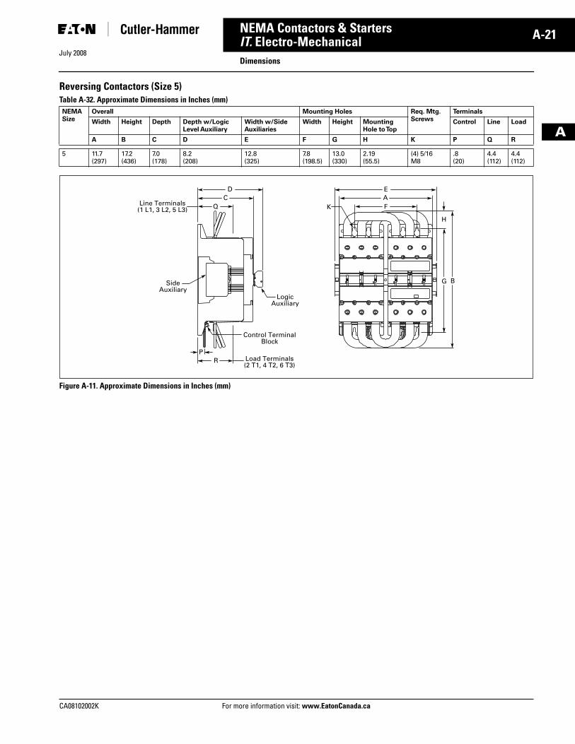
Reversing Contactors (Size 5)Table A-32. Approximate Dimensions in Inches (mm)
Figure A-11. Approximate Dimensions in Inches (mm)
NEMASize
Overall Mounting Holes Req. Mtg.Screws
Terminals
Width Height Depth Depth w/LogicLevel Auxiliary
Width w/SideAuxiliaries
Width Height MountingHole to Top
Control Line Load
A B C D E F G H K P Q R
5 11.7(297)
17.2(436)
7.0(178)
8.2(208)
12.8(325)
7.8(198.5)
13.0(330)
2.19(55.5)
(4) 5/16M8
.8(20)
4.4(112)
4.4(112)
Logic Auxiliary
Side Auxiliary
Control Terminal Block
Load Terminals (2 T1, 4 T2, 6 T3)
PR
Q
DC
F
EA
Line Terminals (1 L1, 3 L2, 5 L3) K
G B
H
Tab33.book Page 21 Sunday, September 21, 2008 10:27 PM
July 2008
A-22
For more information visit: www.EatonCanada.ca CA08102002K
NEMA Contactors & Starters
A
IT. Electro-MechanicalDimensions
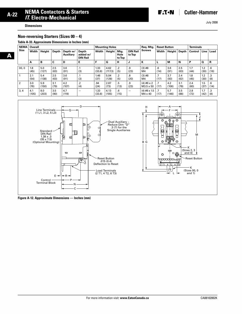
Non-reversing Starters (Sizes 00 – 4) Table A-33. Approximate Dimensions in Inches (mm)
Figure A-12. Approximate Dimensions — Inches (mm)
NEMASize
Overall Mounting Holes Req. Mtg.Screws
Reset Button Terminals
Width Height Depth Depth w/Auxiliary
Depthadded w/ DIN Rail
Width Height Mtg. Hole to Top
DIN Railto Top
Width Height Depth Control Line Load
A B C D E F G H J K L M N P Q R
00, 0 1.8(45)
5.0(127)
2.5(63)
3.6(91)
.1(3)
1.33(33.8)
4.62(117.3)
.2(5)
.9(23)
(3) #8M4
.6(14)
3.6(91)
2.5(63)
1.7(44)
1.2(30)
.6(16)
1 2.1(54)
5.4(138)
2.5(63)
3.6(91)
.1(3)
1.46(37)
5.04(128)
.2(5)
.8(20)
(3) #8M4
.7(17)
3.7(93)
2.4(62)
1.8(45)
1.2(30)
.3(8)
2 3.0(76)
5.9(150)
3.1(79)
4.2(107)
.2(4)
.94(24)
2.87(73)
.5(13)
.9(23)
(4) #6 x 2M3.5 x 50
.7(17)
4.2(106)
3.1(78)
2.4(60)
1.5(37)
.6(14)
3, 4 4.1(105)
8.0(203)
3.5(90)
4.7(119)
— 1.33(33.8)
4.13(105)
.6(15)
— (4) #8 x 1.5M4 x 40
.7(17)
5.7(146)
3.5(88)
2.8(72)
1.7(42)
.3(8)
ControlTerminal Block
P
REL
Reset Button.015 (0.4)
Deflection to Reset
Load Terminals(2 T1, 4 T2, 6 T3)
Dual Auxiliary –Reduce Dim “D”
.3 (7) for theSingle Auxiliaries
Reset Button
K(Sizes 00, 0
and 1)
K(Sizes 2, 3
and 4)
Q
N
C
H
G
J
M
B
FAD
Line Terminals(1 L1, 3 L2, 5 L3)
StandardDIN Rail1.38 x .3(35 x 7.5)
(Optional Mounting)
Tab33.book Page 22 Sunday, September 21, 2008 10:27 PM
July 2008
CA08102002K For more information visit: www.EatonCanada.ca
A-23NEMA Contactors & Starters
A
IT. Electro-MechanicalDimensions
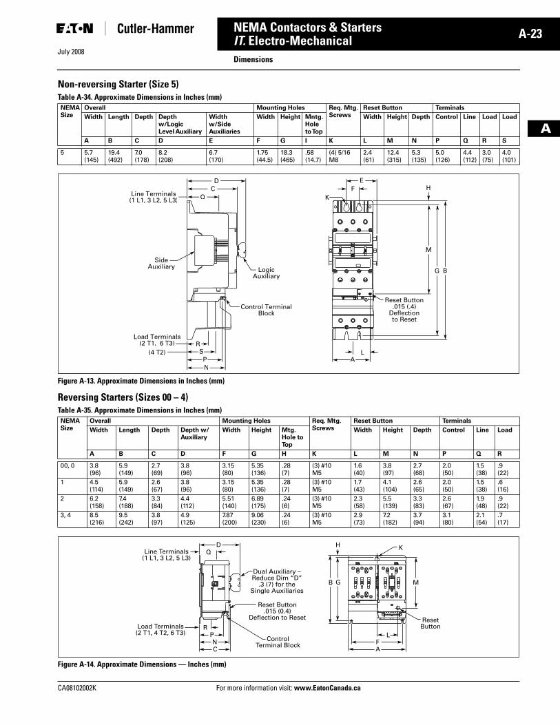
Non-reversing Starter (Size 5)Table A-34. Approximate Dimensions in Inches (mm)
Figure A-13. Approximate Dimensions in Inches (mm)
Reversing Starters (Sizes 00 – 4)Table A-35. Approximate Dimensions in Inches (mm)
Figure A-14. Approximate Dimensions — Inches (mm)
NEMASize
Overall Mounting Holes Req. Mtg.Screws
Reset Button Terminals
Width Length Depth Depth w/LogicLevel Auxiliary
Width w/SideAuxiliaries
Width Height Mntg.Holeto Top
Width Height Depth Control Line Load Load
A B C D E F G I K L M N P Q R S
5 5.7(145)
19.4(492)
7.0(178)
8.2(208)
6.7(170)
1.75(44.5)
18.3(465)
.58(14.7)
(4) 5/16 M8
2.4(61)
12.4(315)
5.3(135)
5.0(126)
4.4(112)
3.0(75)
4.0(101)
NEMASize
Overall Mounting Holes Req. Mtg.Screws
Reset Button Terminals
Width Length Depth Depth w/Auxiliary
Width Height Mtg. Hole to Top
Width Height Depth Control Line Load
A B C D F G H K L M N P Q R
00, 0 3.8(96)
5.9(149)
2.7(69)
3.8(96)
3.15(80)
5.35(136)
.28(7)
(3) #10M5
1.6(40)
3.8(97)
2.7(68)
2.0(50)
1.5(38)
.9(22)
1 4.5(114)
5.9(149)
2.6(67)
3.8(96)
3.15(80)
5.35(136)
.28(7)
(3) #10M5
1.7(43)
4.1(104)
2.6(65)
2.0(50)
1.5(38)
.6(16)
2 6.2(158)
7.4(188)
3.3(84)
4.4(112)
5.51(140)
6.89(175)
.24(6)
(3) #10M5
2.3(58)
5.5(139)
3.3(83)
2.6(67)
1.9(48)
.9(22)
3, 4 8.5(216)
9.5(242)
3.8(97)
4.9(125)
7.87(200)
9.06(230)
.24(6)
(3) #10M5
2.9(73)
7.2(182)
3.7(94)
3.1(80)
2.1(54)
.7(17)
SideAuxiliary Logic
Auxiliary
Control TerminalBlock
SPN
Load Terminals(2 T1, 6 T3)
(4 T2)R
AL
Q
DC
Line Terminals(1 L1, 3 L2, 5 L3)
FE
K
G B
M
H
Reset Button.015 (.4)
Deflectionto Reset
ResetButton
K
PF
RL
NAC
G M
ControlTerminal Block
Reset Button.015 (0.4)
Deflection to Reset
Dual Auxiliary –Reduce Dim “D”
.3 (7) for theSingle Auxiliaries
B
QD H
Line Terminals(1 L1, 3 L2, 5 L3)
Load Terminals(2 T1, 4 T2, 6 T3)
Tab33.book Page 23 Sunday, September 21, 2008 10:27 PM
July 2008
A-24
For more information visit: www.EatonCanada.ca CA08102002K
NEMA Contactors & Starters
A
IT. Electro-MechanicalDimensions
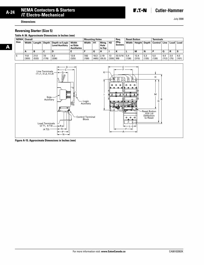
Reversing Starter (Size 5)Table A-36. Approximate Dimensions in Inches (mm)
Figure A-15. Approximate Dimensions in Inches (mm)
NEMASize
Overall Mounting Holes Req.Mtg.Screws
Reset Button Terminals
Width Length Depth Depth w/LogicLevel Auxiliary
Width w/SideAuxiliaries
Width H1 Mntg.Holeto Top
H2 Width Height Depth Control Line Load Load
A B C D E F G H I K L M N P Q R S
5 11.8(300)
21.0(533)
7.0(178)
8.2(208)
12.8(325)
7.82(199)
18.3(465)
2.19(55.5)
13(330)
(5) 5/16M8
5.4(138)
12.4(315)
5.3(135)
5.0(126)
4.4(112)
3.0(75)
4.0(101)
Side Auxiliary
Logic Auxiliary
Control Terminal Block
SPN
Load Terminals (2 T1, 6 T3)
(4 T2)R
FA
L
Q
DC
EF
Line Terminals (1 L1, 3 L2, 5 L3) K
GB
I M
H
Reset Button.015 (.4)
Deflectionto Reset
Tab33.book Page 24 Sunday, September 21, 2008 10:27 PM
July 2008
CA08102002K For more information visit: www.EatonCanada.ca
A-25NEMA Contactors & Starters
A
FreedomProduct Family Overview
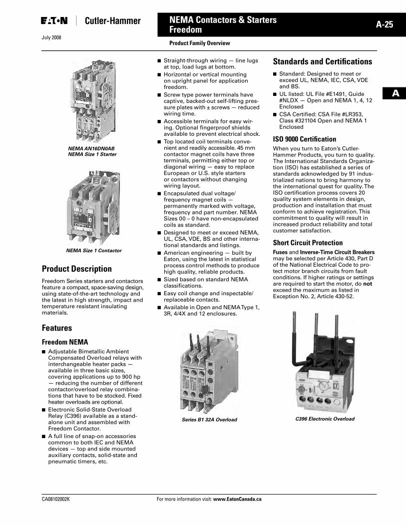
Product DescriptionFreedom Series starters and contactors feature a compact, space-saving design, using state-of-the-art technology and the latest in high strength, impact and temperature resistant insulating materials.
Features
Freedom NEMA■ Adjustable Bimetallic Ambient
Compensated Overload relays with interchangeable heater packs — available in three basic sizes, covering applications up to 900 hp — reducing the number of different contactor/overload relay combina-tions that have to be stocked. Fixed heater overloads are optional.
■ Electronic Solid-State Overload Relay (C396) available as a stand-alone unit and assembled with Freedom Contactor.
■ A full line of snap-on accessories common to both IEC and NEMA devices — top and side mounted auxiliary contacts, solid-state and pneumatic timers, etc.
NEMA AN16DN0ABNEMA Size 1 Starter
NEMA Size 1 Contactor
■ Straight-through wiring — line lugs at top, load lugs at bottom.
■ Horizontal or vertical mounting on upright panel for application freedom.
■ Screw type power terminals have captive, backed-out self-lifting pres-sure plates with ± screws — reduced wiring time.
■ Accessible terminals for easy wir-ing. Optional fingerproof shields available to prevent electrical shock.
■ Top located coil terminals conve-nient and readily accessible. 45 mm contactor magnet coils have three terminals, permitting either top or diagonal wiring — easy to replace European or U.S. style starters or contactors without changing wiring layout.
■ Encapsulated dual voltage/frequency magnet coils — permanently marked with voltage, frequency and part number. NEMA Sizes 00 – 0 have non-encapsulated coils as standard.
■ Designed to meet or exceed NEMA, UL, CSA, VDE, BS and other interna-tional standards and listings.
■ American engineering — built by Eaton, using the latest in statistical process control methods to produce high quality, reliable products.
■ Sized based on standard NEMA classifications.
■ Easy coil change and inspectable/replaceable contacts.
■ Available in Open and NEMA Type 1, 3R, 4/4X and 12 enclosures.
Standards and Certifications■ Standard: Designed to meet or
exceed UL, NEMA, IEC, CSA, VDE and BS.
■ UL listed: UL File #E1491, Guide #NLDX — Open and NEMA 1, 4, 12 Enclosed
■ CSA Certified: CSA File #LR353, Class #321104 Open and NEMA 1 Enclosed
ISO 9000 CertificationWhen you turn to Eaton’s Cutler-Hammer Products, you turn to quality. The International Standards Organiza-tion (ISO) has established a series of standards acknowledged by 91 indus-trialized nations to bring harmony to the international quest for quality. The ISO certification process covers 20 quality system elements in design, production and installation that must conform to achieve registration. This commitment to quality will result in increased product reliability and total customer satisfaction.
Short Circuit ProtectionFuses and Inverse-Time Circuit Breakers may be selected per Article 430, Part D of the National Electrical Code to pro-tect motor branch circuits from fault conditions. If higher ratings or settings are required to start the motor, do not exceed the maximum as listed in Exception No. 2, Article 430-52.
Series B1 32A Overload C396 Electronic Overload
Tab33.book Page 25 Sunday, September 21, 2008 10:27 PM
July 2008
A-26
For more information visit: www.EatonCanada.ca CA08102002K
NEMA Contactors & Starters
A
FreedomCatalogue Number Selection
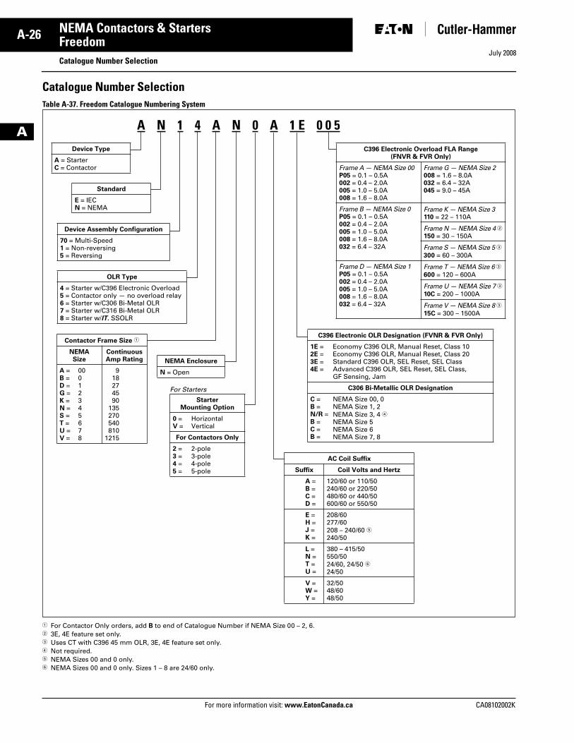
Catalogue Number SelectionTable A-37. Freedom Catalogue Numbering System
� For Contactor Only orders, add B to end of Catalogue Number if NEMA Size 00 – 2, 6.� 3E, 4E feature set only.� Uses CT with C396 45 mm OLR, 3E, 4E feature set only.� Not required.� NEMA Sizes 00 and 0 only.� NEMA Sizes 00 and 0 only. Sizes 1 – 8 are 24/60 only.
Device Type
A = StarterC = Contactor
Contactor Frame Size �
NEMASize
ContinuousAmp Rating
A = B = D = G = K = N = S = T = U = V =
00012345678
918274590
135270540810
1215
A N 1 4 A N 0 A 1 E 0 0 5
AC Coil Suffix
Suffix Coil Volts and Hertz
A =B =C =D =
120/60 or 110/50240/60 or 220/50480/60 or 440/50600/60 or 550/50
E =H =J =K =
208/60277/60208 – 240/60 �240/50
L =N =T =U =
380 – 415/50550/5024/60, 24/50 �24/50
V =W =Y =
32/5048/6048/50
Standard
E = IECN = NEMA
Device Assembly Configuration
70 = Multi-Speed1 = Non-reversing5 = Reversing
OLR Type
4 = Starter w/C396 Electronic Overload5 = Contactor only — no overload relay6 = Starter w/C306 Bi-Metal OLR7 = Starter w/C316 Bi-Metal OLR8 = Starter w/IT. SSOLR
C396 Electronic Overload FLA Range (FNVR & FVR Only)
Frame A — NEMA Size 00P05 = 0.1 – 0.5A002 = 0.4 – 2.0A005 = 1.0 – 5.0A008 = 1.6 – 8.0A
Frame G — NEMA Size 2008 = 1.6 – 8.0A032 = 6.4 – 32A045 = 9.0 – 45A
Frame B — NEMA Size 0P05 = 0.1 – 0.5A002 = 0.4 – 2.0A005 = 1.0 – 5.0A008 = 1.6 – 8.0A032 = 6.4 – 32A
Frame K — NEMA Size 3 110 = 22 – 110A
Frame N — NEMA Size 4 �150 = 30 – 150A
Frame S — NEMA Size 5 �300 = 60 – 300A
Frame D — NEMA Size 1P05 = 0.1 – 0.5A002 = 0.4 – 2.0A005 = 1.0 – 5.0A008 = 1.6 – 8.0A032 = 6.4 – 32A
Frame T — NEMA Size 6 �600 = 120 – 600A
Frame U — NEMA Size 7 �10C = 200 – 1000A
Frame V — NEMA Size 8 �15C = 300 – 1500A
C396 Electronic OLR Designation (FVNR & FVR Only)
1E =2E =3E =4E =
Economy C396 OLR, Manual Reset, Class 10Economy C396 OLR, Manual Reset, Class 20Standard C396 OLR, SEL Reset, SEL ClassAdvanced C396 OLR, SEL Reset, SEL Class, GF Sensing, Jam
C306 Bi-Metallic OLR Designation
C =B =N/R =B =C =B =
NEMA Size 00, 0NEMA Size 1, 2NEMA Size 3, 4 �NEMA Size 5NEMA Size 6NEMA Size 7, 8
NEMA Enclosure
N = Open
For Starters
StarterMounting Option
0 = V =
HorizontalVertical
For Contactors Only
2 = 3 = 4 = 5 =
2-pole3-pole4-pole5-pole
Tab33.book Page 26 Sunday, September 21, 2008 10:27 PM
July 2008
CA08102002K For more information visit: www.EatonCanada.ca
A-27NEMA Contactors & Starters
A
FreedomContactors — Non-reversing and Reversing
ContentsDescription Page
Product Family Overview
Product Description . . . . . . A-25
Features . . . . . . . . . . . . . . . A-25
Standards and Certifications . . . . . . . . . . A-25
Catalogue NumberSelection. . . . . . . . . . . . . . A-26
Contactors — Non-reversing and Reversing
Product Description . . . . . . A-27
Features . . . . . . . . . . . . . . . A-27
Technical Data . . . . . . . . . . A-27
Product Selection — 3-Pole Contactors . . . . . . A-28
Product Selection — 2-, 4- and 5-Pole Contactors . . . . . . . . . . . . A-29
Technical Data . . . . . . . . . . . . . A-36
Accessories . . . . . . . . . . . . . . . A-39
Auxiliary Contacts . . . . . . . A-43
DC Magnet Coils . . . . . . . . A-45
Mounting Plates . . . . . . . . . A-46
Special Modifications . . . . . . . A-47
Renewal Parts . . . . . . . . . . . . . A-48
Dimensions . . . . . . . . . . . . . . . A-51
Product Description
Non-reversing Contactors are most commonly used to switch motor loads in applications where running overcurrent protection is either not required or is provided separately. Contactors consist of a magnetically actuated switch which can be remotely operated by a push-button station or pilot device such as a proximity switch, limit switch, float switch, auxiliary contacts, etc.
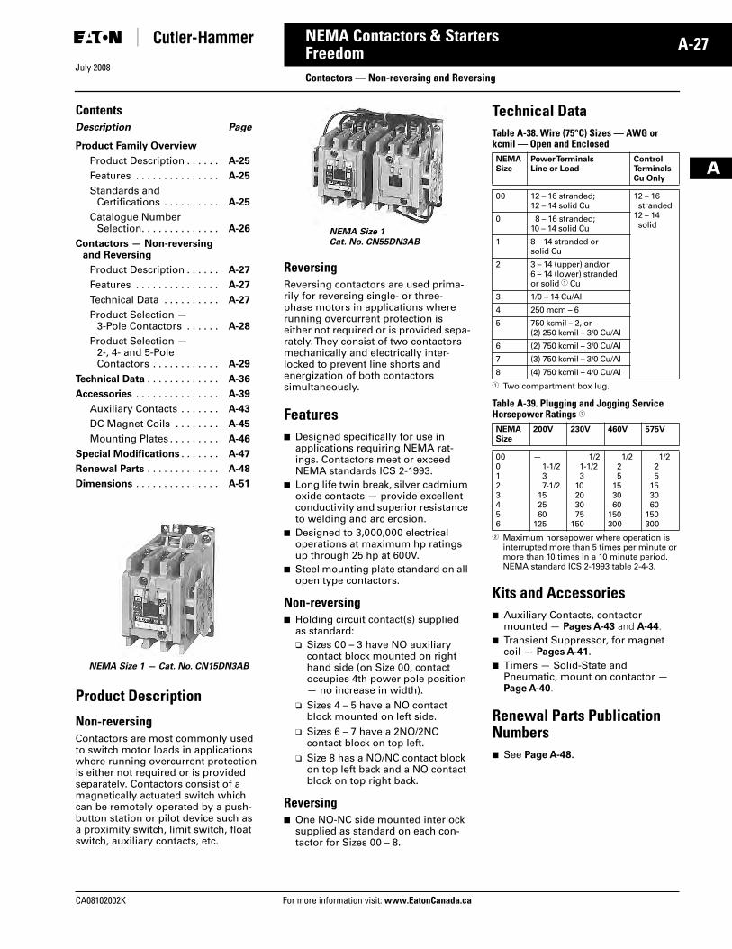
Reversing Reversing contactors are used prima-rily for reversing single- or three-phase motors in applications where running overcurrent protection is either not required or is provided sepa-rately. They consist of two contactors mechanically and electrically inter-locked to prevent line shorts and energization of both contactors simultaneously.
Features■ Designed specifically for use in
applications requiring NEMA rat-ings. Contactors meet or exceed NEMA standards ICS 2-1993.
■ Long life twin break, silver cadmium oxide contacts — provide excellent conductivity and superior resistance to welding and arc erosion.
■ Designed to 3,000,000 electrical operations at maximum hp ratings up through 25 hp at 600V.
■ Steel mounting plate standard on all open type contactors.
Non-reversing■ Holding circuit contact(s) supplied
as standard:❑ Sizes 00 – 3 have NO auxiliary
contact block mounted on right hand side (on Size 00, contact occupies 4th power pole position — no increase in width).
❑ Sizes 4 – 5 have a NO contact block mounted on left side.
❑ Sizes 6 – 7 have a 2NO/2NC contact block on top left.
❑ Size 8 has a NO/NC contact block on top left back and a NO contact block on top right back.
Reversing ■ One NO-NC side mounted interlock
supplied as standard on each con-tactor for Sizes 00 – 8.
Technical DataTable A-38. Wire (75°C) Sizes — AWG or kcmil — Open and Enclosed
� Two compartment box lug.
Table A-39. Plugging and Jogging Service Horsepower Ratings �
� Maximum horsepower where operation is interrupted more than 5 times per minute or more than 10 times in a 10 minute period. NEMA standard ICS 2-1993 table 2-4-3.
Kits and Accessories■ Auxiliary Contacts, contactor
mounted — Pages A-43 and A-44. ■ Transient Suppressor, for magnet
coil — Pages A-41. ■ Timers — Solid-State and
Pneumatic, mount on contactor — Page A-40.
Renewal Parts Publication Numbers■ See Page A-48.
NEMA Size 1 — Cat. No. CN15DN3AB
NEMA Size 1Cat. No. CN55DN3AB
NEMASize
Power TerminalsLine or Load
ControlTerminalsCu Only
00 12 – 16 stranded; 12 – 14 solid Cu
12 – 16stranded
12 – 14solid
0 8 – 16 stranded; 10 – 14 solid Cu
1 8 – 14 stranded or solid Cu
2 3 – 14 (upper) and/or 6 – 14 (lower) stranded or solid � Cu
3 1/0 – 14 Cu/Al
4 250 mcm – 6
5 750 kcmil – 2, or (2) 250 kcmil – 3/0 Cu/Al
6 (2) 750 kcmil – 3/0 Cu/Al
7 (3) 750 kcmil – 3/0 Cu/Al
8 (4) 750 kcmil – 4/0 Cu/Al
NEMASize
200V 230V 460V 575V
000123456
—1-1/237-1/2
152560
125
1/21-1/23
10203075
150
1/225
153060
150300
1/225
153060
150300
Tab33.book Page 27 Sunday, September 21, 2008 10:27 PM
July 2008
A-28
For more information visit: www.EatonCanada.ca CA08102002K
NEMA Contactors & Starters
A
FreedomContactors — Non-reversing and Reversing
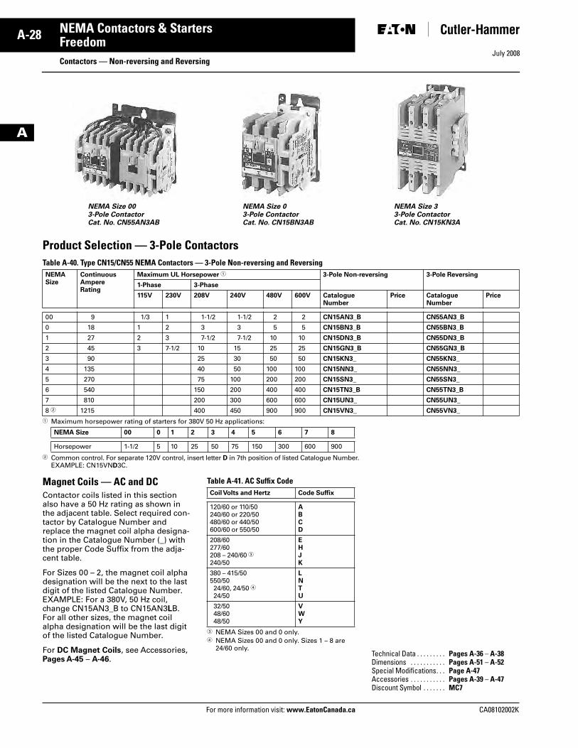
Product Selection — 3-Pole Contactors Table A-40. Type CN15/CN55 NEMA Contactors — 3-Pole Non-reversing and Reversing
� Maximum horsepower rating of starters for 380V 50 Hz applications:
� Common control. For separate 120V control, insert letter D in 7th position of listed Catalogue Number. EXAMPLE: CN15VND3C.
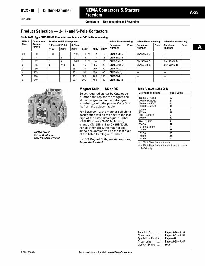
Magnet Coils — AC and DCContactor coils listed in this section also have a 50 Hz rating as shown in the adjacent table. Select required con-tactor by Catalogue Number and replace the magnet coil alpha designa-tion in the Catalogue Number (_) with the proper Code Suffix from the adja-cent table.
For Sizes 00 – 2, the magnet coil alpha designation will be the next to the last digit of the listed Catalogue Number. EXAMPLE: For a 380V, 50 Hz coil, change CN15AN3_B to CN15AN3LB. For all other sizes, the magnet coil alpha designation will be the last digit of the listed Catalogue Number.
For DC Magnet Coils, see Accessories, Pages A-45 – A-46.
Table A-41. AC Suffix Code
� NEMA Sizes 00 and 0 only.� NEMA Sizes 00 and 0 only. Sizes 1 – 8 are
24/60 only.
NEMASize
ContinuousAmpereRating
Maximum UL Horsepower � 3-Pole Non-reversing 3-Pole Reversing
1-Phase 3-Phase
115V 230V 208V 240V 480V 600V CatalogueNumber
Price CatalogueNumber
Price
00 9 1/3 1 1-1/2 1-1/2 2 2 CN15AN3_B CN55AN3_B
0 18 1 2 3 3 5 5 CN15BN3_B CN55BN3_B
1 27 2 3 7-1/2 7-1/2 10 10 CN15DN3_B CN55DN3_B
2 45 3 7-1/2 10 15 25 25 CN15GN3_B CN55GN3_B
3 90 25 30 50 50 CN15KN3_ CN55KN3_
4 135 40 50 100 100 CN15NN3_ CN55NN3_
5 270 75 100 200 200 CN15SN3_ CN55SN3_
6 540 150 200 400 400 CN15TN3_B CN55TN3_B
7 810 200 300 600 600 CN15UN3_ CN55UN3_
8 � 1215 400 450 900 900 CN15VN3_ CN55VN3_
NEMA Size 00 0 1 2 3 4 5 6 7 8
Horsepower 1-1/2 5 10 25 50 75 150 300 600 900
NEMA Size 003-Pole ContactorCat. No. CN55AN3AB
NEMA Size 03-Pole ContactorCat. No. CN15BN3AB
NEMA Size 33-Pole ContactorCat. No. CN15KN3A
Coil Volts and Hertz Code Suffix
120/60 or 110/50240/60 or 220/50480/60 or 440/50600/60 or 550/50
ABCD
208/60277/60208 – 240/60 �240/50
EHJK
380 – 415/50550/5024/60, 24/50 �24/50
LNTU
32/5048/6048/50
VWY
Technical Data . . . . . . . . . Pages A-36 – A-38Dimensions . . . . . . . . . . . Pages A-51 – A-52Special Modifications. . . Page A-47Accessories . . . . . . . . . . . Pages A-39 – A-47Discount Symbol . . . . . . . MC7
Tab33.book Page 28 Sunday, September 21, 2008 10:27 PM
July 2008
CA08102002K For more information visit: www.EatonCanada.ca
A-29NEMA Contactors & Starters
A
FreedomContactors — Non-reversing and Reversing
Product Selection — 2-, 4- and 5-Pole Contactors Table A-42. Type CN15 NEMA Contactors — 2-, 4- and 5-Pole Non-reversing
NEMA Size 25-Pole ContactorCat. No. CN15GN5AB
Magnet Coils — AC or DCSelect required starter by Catalogue Number and replace the magnet coil alpha designation in the Catalogue Number (_) with the proper Code Suf-fix from the adjacent table.
For Sizes 00 – 2, the magnet coil alpha designation will be the next to the last digit of the listed Catalogue Number. EXAMPLE: For a 380V, 50 Hz coil, change CN15BN3_B to CN15BN3LB. For all other sizes, the magnet coil alpha designation will be the last digit of the listed Catalogue Number.
For DC Magnet Coils, see Accessories, Pages A-45 – A-46.
Table A-43. AC Suffix Code
� NEMA Sizes 00 and 0 only.� NEMA Sizes 00 and 0 only. Sizes 1 – 8 are
24/60 only.
NEMASize
ContinuousAmpereRating
Maximum UL Horsepower 2-Pole Non-reversing 4-Pole Non-reversing 5-Pole Non-reversing
1-Phase (2-Pole) 3-Phase CatalogueNumber
Price CatalogueNumber
Price CatalogueNumber
Price
115V 230V 208V 240V 480V 600V
00 9 1/3 1 1-1/2 1-1/2 2 2 CN15AN2_B CN15AN4_B —
0 18 1 2 2 3 5 5 CN15BN2_B — —
1 27 2 3 7-1/2 7-1/2 10 10 CN15DN2_B CN15DN4_B CN15DN5_B
2 45 3 7-1/2 10 15 25 25 CN15GN2_B CN15GN4_B CN15GN5_B
3 90 25 30 50 50 CN15KN2_ — —
4 135 40 50 100 100 CN15NN2_ — —
5 270 75 100 200 200 CN15SN2_ — —
6 540 150 200 400 400 CN15TN2_B — —
Coil Volts and Hertz Code Suffix
120/60 or 110/50240/60 or 220/50480/60 or 440/50600/60 or 550/50
ABCD
208/60277/60208 – 240/60 �240/50
EHJK
380 – 415/50550/5024/60, 24/50 �24/50
LNTU
32/5048/6048/50
VWY
Technical Data. . . . . . . . . . Pages A-36 – A-38Dimensions . . . . . . . . . . . . Pages A-51 – A-52Special Modifications . . . Page A-47Accessories . . . . . . . . . . . . Pages A-39 – A-47Discount Symbol . . . . . . . . MC7
Tab33.book Page 29 Sunday, September 21, 2008 10:27 PM
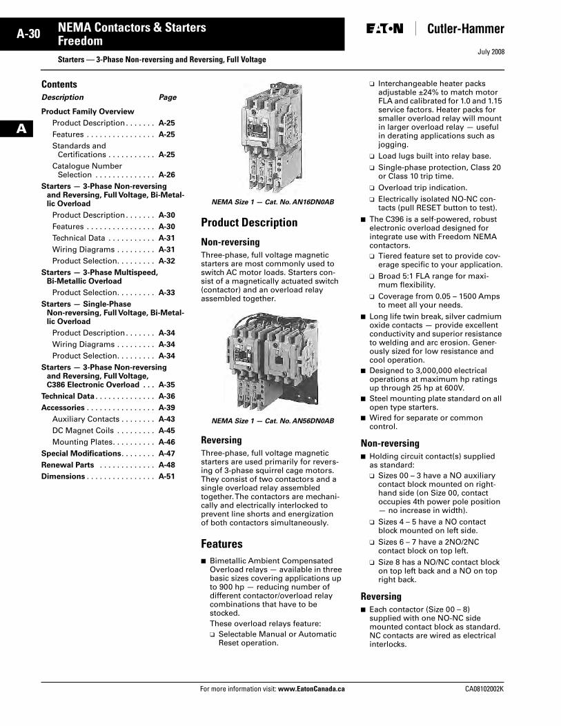
July 2008
A-30
For more information visit: www.EatonCanada.ca CA08102002K
NEMA Contactors & Starters
A
Freedom Starters — 3-Phase Non-reversing and Reversing, Full Voltage
ContentsDescription Page
Product Family Overview
Product Description . . . . . . . A-25
Features . . . . . . . . . . . . . . . . A-25
Standards and Certifications . . . . . . . . . . . A-25
Catalogue NumberSelection . . . . . . . . . . . . . . A-26
Starters — 3-Phase Non-reversing and Reversing, Full Voltage, Bi-Metal-lic Overload
Product Description . . . . . . . A-30
Features . . . . . . . . . . . . . . . . A-30
Technical Data . . . . . . . . . . . A-31
Wiring Diagrams . . . . . . . . . A-31
Product Selection. . . . . . . . . A-32
Starters — 3-Phase Multispeed, Bi-Metallic Overload
Product Selection. . . . . . . . . A-33
Starters — Single-PhaseNon-reversing, Full Voltage, Bi-Metal-lic Overload
Product Description . . . . . . . A-34
Wiring Diagrams . . . . . . . . . A-34
Product Selection. . . . . . . . . A-34
Starters — 3-Phase Non-reversing and Reversing, Full Voltage, C386 Electronic Overload . . . A-35
Technical Data . . . . . . . . . . . . . . A-36
Accessories . . . . . . . . . . . . . . . . A-39
Auxiliary Contacts . . . . . . . . A-43
DC Magnet Coils . . . . . . . . . A-45
Mounting Plates. . . . . . . . . . A-46
Special Modifications. . . . . . . . A-47
Renewal Parts . . . . . . . . . . . . . A-48
Dimensions . . . . . . . . . . . . . . . . A-51
Product Description
Non-reversingThree-phase, full voltage magnetic starters are most commonly used to switch AC motor loads. Starters con-sist of a magnetically actuated switch (contactor) and an overload relay assembled together.
Reversing Three-phase, full voltage magnetic starters are used primarily for revers-ing of 3-phase squirrel cage motors.They consist of two contactors and a single overload relay assembled together. The contactors are mechani-cally and electrically interlocked to prevent line shorts and energization of both contactors simultaneously.
Features■ Bimetallic Ambient Compensated
Overload relays — available in three basic sizes covering applications up to 900 hp — reducing number of different contactor/overload relay combinations that have to be stocked.These overload relays feature:❑ Selectable Manual or Automatic
Reset operation.
❑ Interchangeable heater packs adjustable ±24% to match motor FLA and calibrated for 1.0 and 1.15 service factors. Heater packs for smaller overload relay will mount in larger overload relay — useful in derating applications such as jogging.
❑ Load lugs built into relay base.❑ Single-phase protection, Class 20
or Class 10 trip time.❑ Overload trip indication.❑ Electrically isolated NO-NC con-
tacts (pull RESET button to test).■ The C396 is a self-powered, robust
electronic overload designed for integrate use with Freedom NEMA contactors.❑ Tiered feature set to provide cov-
erage specific to your application.❑ Broad 5:1 FLA range for maxi-
mum flexibility.❑ Coverage from 0.05 – 1500 Amps
to meet all your needs.■ Long life twin break, silver cadmium
oxide contacts — provide excellent conductivity and superior resistance to welding and arc erosion. Gener-ously sized for low resistance and cool operation.
■ Designed to 3,000,000 electrical operations at maximum hp ratings up through 25 hp at 600V.
■ Steel mounting plate standard on all open type starters.
■ Wired for separate or common control.
Non-reversing■ Holding circuit contact(s) supplied
as standard:❑ Sizes 00 – 3 have a NO auxiliary
contact block mounted on right-hand side (on Size 00, contact occupies 4th power pole position — no increase in width).
❑ Sizes 4 – 5 have a NO contact block mounted on left side.
❑ Sizes 6 – 7 have a 2NO/2NC contact block on top left.
❑ Size 8 has a NO/NC contact block on top left back and a NO on top right back.
Reversing■ Each contactor (Size 00 – 8)
supplied with one NO-NC side mounted contact block as standard. NC contacts are wired as electrical interlocks.
NEMA Size 1 — Cat. No. AN16DN0AB
NEMA Size 1 — Cat. No. AN56DN0AB
Tab33.book Page 30 Sunday, September 21, 2008 10:27 PM
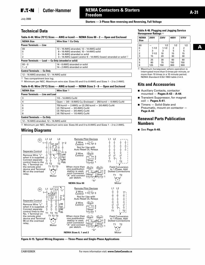
CA08102002K For more information visit: www.EatonCanada.ca
A-31NEMA Contactors & Starters
July 2008
A
FreedomStarters — 3-Phase Non-reversing and Reversing, Full Voltage
Technical DataTable A-44. Wire (75°C) Sizes — AWG or kcmil — NEMA Sizes 00 – 2 — Open and Enclosed
� Two compartment box lug.� Minimum per NEC. Maximum wire size: Sizes 00 and 0 to 8 AWG and Sizes 1 – 2 to 2 AWG.
Table A-45. Wire (75°C) Sizes — AWG or kcmil — NEMA Sizes 3 – 8 — Open and Enclosed
� Minimum per NEC. Maximum wire size: Sizes 00 and 0 to 8 AWG and Sizes 1 – 2 to 2 AWG.
Wiring Diagrams
Figure A-15. Typical Wiring Diagrams — Three-Phase and Single-Phase Applications
NEMA Size Wire Size � Cu Only
Power Terminals — Line00012
12 – 16 AWG stranded, 12 – 14 AWG solid8 – 16 AWG stranded, 10 – 14 AWG solid8 – 14 AWG stranded or solid3 – 14 AWG (upper) and/or 6 – 14 AWG (lower) stranded or solid �
Power Terminals — Load — Cu Only (stranded or solid)00 – 01 – 2
14 – 6 AWG stranded or solid14 – 2 AWG stranded or solid
Control Terminals — Cu Only12 – 16 AWG stranded, 12 – 14 AWG solid
NEMA Size Wire Size �
Power Terminals — Line and Load3 1/0 – 14 AWG Cu/Al
4 Open — 3/0 – 8 AWG Cu; Enclosed — 250 kcmil — 6 AWG Cu/Al
5678
750 kcmil — 2 AWG; or (2) 250 kcmil — 3/0 AWG Cu/Al(2) 750 kcmil — 3/0 AWG Cu/Al(3) 750 kcmil — 3/0 AWG Cu/Al(4) 750 kcmil — 1/0 AWG Cu/Al
Control Terminals — Cu Only12 – 16 AWG stranded, 12 – 14 AWG solid
Not for Use withAuto Reset OL Relays
Separate Control
Remove Wire “c”when it is supplied.Connect separatecontrol lines to theNo. 1 Terminal onthe remote pilotdevice and Terminal96 on the overloadrelay.
“c”
“A”
When more thanone pushbuttonstation is used,omit Connector
“A” and connectper sketch.
Field Conversionto 1-Phase, Add
Dotted Connections
Remote Pilot Devices
NEMA Size 00
2 WireControl
L1 L2 L3
T1 T2 T3T1 T2 T3
1 A1 A2
A2
2
398979695
1 3
3
32
1
2
L1
T1 T2
T1 T2
L2
1
Start
Start Start
Stop
Stop Stop
3 WireControl
Motor
Motor
Not for Use withAuto Reset OL Relays
Separate Control
Remove Wire “c”when it is supplied.Connect separatecontrol lines to theNo. 1 Terminal onthe remote pilotdevice and Terminal96 on the overloadrelay.
“A”
When more thanone pushbuttonstation is used,omit Connector
“A” and connectper sketch.
Field Conversionto 1-Phase, Add
Dotted Connections
Remote Pilot Devices
NEMA Sizes 0, 1 and 2
2 WireControl
T1 T2 T3
“c”L1 L2 L3
T1 T2 T3
1 A1 A22
3
98979695
1 3
3
32
1
2
L1
T1 T2
T1 T2
L2
1
Start
Start Start
Stop
Stop Stop
3 WireControl
Motor
Motor
Table A-46. Plugging and Jogging ServiceHorsepower Ratings �
� Maximum horsepower where operation is interrupted more than 5 times per minute, or more than 10 times in a 10 minute period. NEMA Standard ICS2-1993 table 2-4-3.
Kits and Accessories■ Auxiliary Contacts, contactor
mounted — Pages A-43 – A-44. ■ Transient Suppressor, for magnet
coil — Pages A-41. ■ Timers — Solid-State and
Pneumatic, mount on contactor — Page A-40.
Renewal Parts Publication Numbers■ See Page A-48.
NEMASize
200V 230V 460V 575V
000123
—1-1/237-1/2
15
1/21-1/23
1020
1/225
1530
1/225
1530
456
2560
125
3075
150
60150300
60150300
Tab33.book Page 31 Sunday, September 21, 2008 10:27 PM
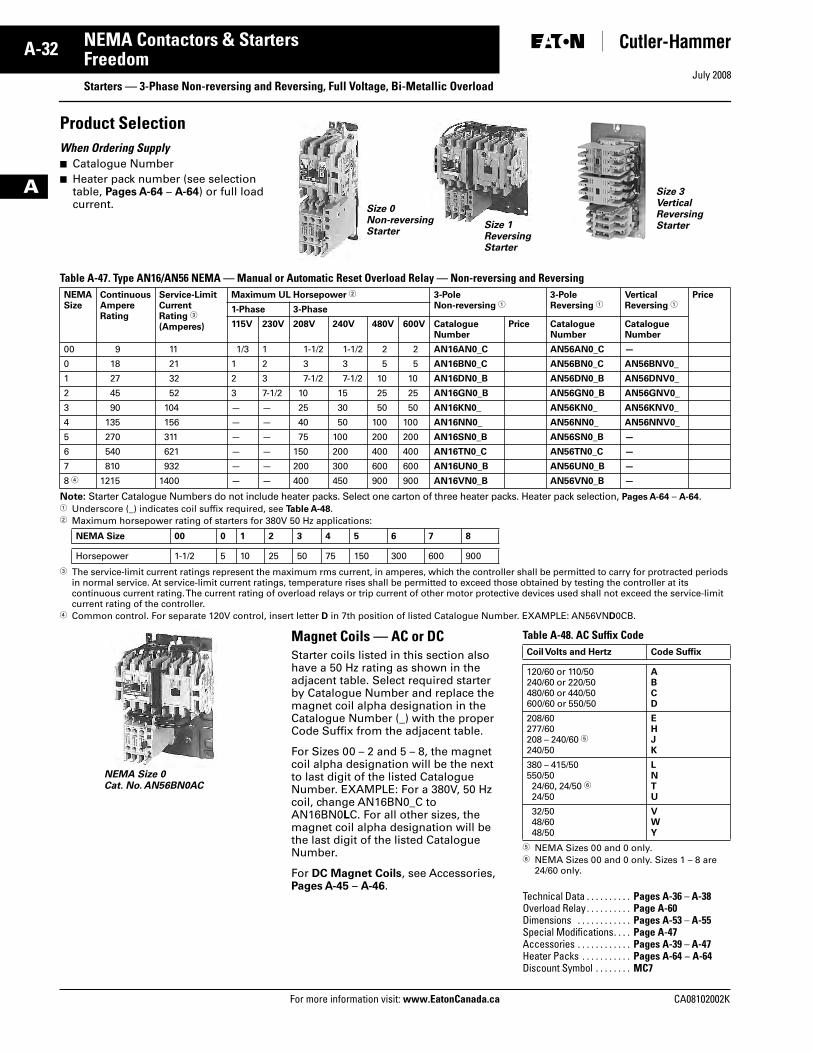
July 2008
A-32
For more information visit: www.EatonCanada.ca CA08102002K
NEMA Contactors & Starters
A
FreedomStarters — 3-Phase Non-reversing and Reversing, Full Voltage, Bi-Metallic Overload
Product Selection When Ordering Supply■ Catalogue Number■ Heater pack number (see selection
table, Pages A-64 – A-64) or full load current.
Table A-47. Type AN16/AN56 NEMA — Manual or Automatic Reset Overload Relay — Non-reversing and Reversing
Note: Starter Catalogue Numbers do not include heater packs. Select one carton of three heater packs. Heater pack selection, Pages A-64 – A-64.� Underscore (_) indicates coil suffix required, see Table A-48.� Maximum horsepower rating of starters for 380V 50 Hz applications:
� The service-limit current ratings represent the maximum rms current, in amperes, which the controller shall be permitted to carry for protracted periods in normal service. At service-limit current ratings, temperature rises shall be permitted to exceed those obtained by testing the controller at its continuous current rating. The current rating of overload relays or trip current of other motor protective devices used shall not exceed the service-limit current rating of the controller.
� Common control. For separate 120V control, insert letter D in 7th position of listed Catalogue Number. EXAMPLE: AN56VND0CB.
Magnet Coils — AC or DCStarter coils listed in this section also have a 50 Hz rating as shown in the adjacent table. Select required starter by Catalogue Number and replace the magnet coil alpha designation in the Catalogue Number (_) with the proper Code Suffix from the adjacent table.
For Sizes 00 – 2 and 5 – 8, the magnet coil alpha designation will be the next to last digit of the listed Catalogue Number. EXAMPLE: For a 380V, 50 Hz coil, change AN16BN0_C to AN16BN0LC. For all other sizes, the magnet coil alpha designation will be the last digit of the listed Catalogue Number.
For DC Magnet Coils, see Accessories, Pages A-45 – A-46.
Table A-48. AC Suffix Code
� NEMA Sizes 00 and 0 only.� NEMA Sizes 00 and 0 only. Sizes 1 – 8 are
24/60 only.
NEMASize
ContinuousAmpereRating
Service-LimitCurrentRating �
(Amperes)
Maximum UL Horsepower � 3-PoleNon-reversing �
3-PoleReversing �
VerticalReversing �
Price
1-Phase 3-Phase
115V 230V 208V 240V 480V 600V CatalogueNumber
Price CatalogueNumber
CatalogueNumber
00 9 11 1/3 1 1-1/2 1-1/2 2 2 AN16AN0_C AN56AN0_C —
0 18 21 1 2 3 3 5 5 AN16BN0_C AN56BN0_C AN56BNV0_
1 27 32 2 3 7-1/2 7-1/2 10 10 AN16DN0_B AN56DN0_B AN56DNV0_
2 45 52 3 7-1/2 10 15 25 25 AN16GN0_B AN56GN0_B AN56GNV0_
3 90 104 — — 25 30 50 50 AN16KN0_ AN56KN0_ AN56KNV0_
4 135 156 — — 40 50 100 100 AN16NN0_ AN56NN0_ AN56NNV0_
5 270 311 — — 75 100 200 200 AN16SN0_B AN56SN0_B —
6 540 621 — — 150 200 400 400 AN16TN0_C AN56TN0_C —
7 810 932 — — 200 300 600 600 AN16UN0_B AN56UN0_B —
8 � 1215 1400 — — 400 450 900 900 AN16VN0_B AN56VN0_B —
NEMA Size 00 0 1 2 3 4 5 6 7 8
Horsepower 1-1/2 5 10 25 50 75 150 300 600 900
Size 0Non-reversing Starter
Size 1Reversing Starter
Size 3 Vertical Reversing Starter
NEMA Size 0 Cat. No. AN56BN0AC
Coil Volts and Hertz Code Suffix
120/60 or 110/50240/60 or 220/50480/60 or 440/50600/60 or 550/50
ABCD
208/60277/60208 – 240/60 �240/50
EHJK
380 – 415/50550/5024/60, 24/50 �24/50
LNTU
32/5048/6048/50
VWY
Technical Data . . . . . . . . . . Pages A-36 – A-38Overload Relay . . . . . . . . . . Page A-60Dimensions . . . . . . . . . . . . Pages A-53 – A-55Special Modifications. . . . Page A-47Accessories . . . . . . . . . . . . Pages A-39 – A-47Heater Packs . . . . . . . . . . . Pages A-64 – A-64Discount Symbol . . . . . . . . MC7
Tab33.book Page 32 Sunday, September 21, 2008 10:27 PM
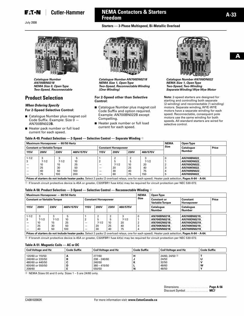
July 2008
CA08102002K For more information visit: www.EatonCanada.ca
A-33NEMA Contactors & Starters
A
FreedomStarters — 3-Phase Multispeed, Bi-Metallic Overload
Product SelectionWhen Ordering SpecifyFor 2-Speed Selective Control:
■ Catalogue Number plus magnet coil Code Suffix. Example: Size 0 — AN700BN022B.
■ Heater pack number or full load current for each speed.
For 2-Speed other than Selective Control:
■ Catalogue Number plus magnet coil Code Suffix and option required. Example: AN700BN022B except Compelling.
■ Heater pack number or full load current for each speed.
Note: 2-speed starters are designed for starting and controlling both separate (2-winding) and reconnectable (1-winding) motors. Separate winding, WYE-WYE motors have a separate winding for each speed. Reconnectable, consequent pole motors use the same winding for both speeds. All standard starters are wired for selective control.
Table A-49. Product Selection — 2-Speed — Selective Control — Separate Winding �
� If branch circuit protective device is 45A or greater, C320FBR1 fuse kit(s) may be required for circuit protection per NEC 530-072.
Table A-50. Product Selection — 2-Speed — Selective Control — Reconnectable Winding �
� If branch circuit protective device is 45A or greater, C320FBR1 fuse kit(s) may be required for circuit protection per NEC 530-072.
Table A-51. Magnetic Coils — AC or DC
� NEMA Sizes 00 and 0 only. Sizes 1 – 5 are 24/60 only.
Catalogue Number AN700DN0218NEMA Size 1, Open TypeTwo-Speed, Reconnectable Winding(One-Winding)
Catalogue Number AN700DN022NEMA Size 1, Open TypeTwo-Speed, Two-WindingSeparate Winding) Wye-Wye Motor
Catalogue Number AN700BN0218NEMA Size 0, Open TypeTwo-Speed, Reconnectable
Maximum Horsepower — 60/50 Hertz NEMASize
Open Type
Constant or Variable Torque Constant Horsepower CatalogueNumber
Price
115V 200V 230V 460V/575V 115V 200V 230V 460/575V
1-1/23————
37-1/2
10254075
37-1/2
153050
100
5102550
100200
12————
257-1/2
203060
25
10254075
37-1/2
204075
150
012345
AN700BN022_AN700DN022_AN700GN022_AN700KN022_AN700NN022_AN700SN022_
Prices of starters do not include heater packs. Select 2 packs (2 overload relays, one for each speed). Heater pack selection, Pages A-64 – A-64.
Maximum Horsepower — 60/50 Hertz NEMASize
Open Type
Constant or Variable Torque Constant Horsepower Constant orVariable Torque
ConstantHorsepower
Price
115V 200V 230V 460V/575V 115V 200V 230V 460/575V CatalogueNumber
CatalogueNumber
1-1/23———
37-1/2
102540
37-1/2
153050
5102550
100
12———
257-1/2
2030
25
102540
37-1/2
204075
01234
AN700BN0218_AN700DN0218_AN700GN0218_AN700KN0218_AN700NN0218_
AN700BN0219_AN700DN0219_AN700GN0219_AN700KN0219_AN700NN0219_
Prices of starters do not include heater packs. Select 2 packs (2 overload relays, one for each speed). Heater pack selection, Pages A-64 – A-64.
Coil Voltage and Hz Code Suffix Coil Voltage and Hz Code Suffix Coil Voltage and Hz Code Suffix
120/60 or 110/50240/60 or 220/50480/60 or 440/50600/60 or 550/50208/60
ABCDE
277/60208 – 240/60240/50380 – 415/50550/50
HJKLN
24/60, 24/50 �24/5032/5048/6048/50
TUVWY
Dimensions. . . . . . . . . . . . . . . . . . . . . . Page A-56Discount Symbol . . . . . . . . . . . . . . . . . MC7
Tab33.book Page 33 Sunday, September 21, 2008 10:27 PM
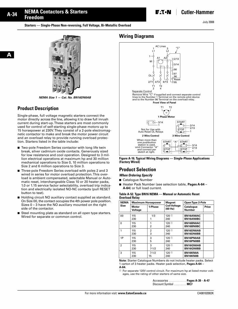
July 2008
A-34
For more information visit: www.EatonCanada.ca CA08102002K
NEMA Contactors & Starters
A
Freedom Starters — Single-Phase Non-reversing, Full Voltage, Bi-Metallic Overload
Product DescriptionSingle-phase, full voltage magnetic starters connect the motor directly across the line, allowing it to draw full inrush current during start-up. These starters are most commonly used for control of self-starting single-phase motors up to 15 horsepower at 230V. They consist of a 2-pole electromag-netic contactor to make and break the motor power circuit and an overload relay to provide running overload protec-tion. Starters listed in the table include:
■ Two-pole Freedom Series contactor with long life twin break, silver cadmium oxide contacts. Generously sized for low resistance and cool operation. Designed to 3 mil-lion electrical operations at maximum hp and 30 million mechanical operations to Size 0, 10 million operations to Size 2 and 6 million operations to Size 3.
■ Three-pole Freedom Series overload with poles 2 and 3 wired in series for motor overload protection. This over-load is ambient compensated, selectable Manual or Auto-matic reset, interchangeable Class 10 or 20 heater packs, 1.0 or 1.15 service factor selectability, overload trip indica-tion and electrically isolated NO-NC contacts (pull RESET button to test).
■ Holding circuit NO auxiliary contact supplied as standard. On Size 00, the contact occupies the 4th power pole position. Sizes 0 – 3 have the NO auxiliary mounted on the right side of the contactor.
■ Steel mounting plate as standard on all open type starters. Wired for separate or common control.
Wiring Diagrams
Figure A-16. Typical Wiring Diagrams — Single-Phase Applications(Factory Wired)
Product SelectionWhen Ordering Specify ■ Catalogue Number■ Heater Pack Number (see selection table, Pages A-64 –
A-64) or full load current.
Table A-52. Type BN16 NEMA — Manual or Automatic Reset Overload Relay
Note: Starter Catalogue Numbers do not include heater packs. Select 1 carton of 3 heater packs. Heater pack selection, Pages A-64 – A-64.� For separate 120V control circuit. For maximum hp at listed motor volt-
ages, use the rating of other starters of same size.
NEMA Size 1 — Cat. No. BN16DN0AB
NEMASize
Maximum Horsepower MagnetCoil Voltage(60 Hz)
Open Type 2-Pole
MotorVoltage
1-Phase CatalogueNumber
Price
00 115230
1/31
120 �240
BN16AN0ACBN16AN0BC
0 115230
12
120 �240
BN16BN0ACBN16BN0BC
1 115230
23
120 �240
BN16DN0ABBN16DN0BB
1P 115230
35
120 �240
BN16PN0ABBN16PN0BB
2 115230
37-1/2
120 �240
BN16GN0ABBN16GN0BB
3 115230
7-1/215
120 �240
BN16KN0ABN16KN0B
Accessories . . . . . . . . . . . . . Pages A-39 – A-47Discount Symbol . . . . . . . . . MC7
Front View of Panel
1 Phase Motor
When more thanone pushbuttonstation is used,
omit Connector “A”and connect persketch at right.
2 Wire Control
Not for Use withAuto Reset OL Relays
3 Wire Control
START
STOP
AC Lines1
L1
1
M
OL
A1 A2 2/13
3/14
98
9796
952/T1 4/T2 6/T3Reset
3L2
T12
T24
T1 T2
“C”
3/14
Separate ControlRemove Wire “C” if supplied and connect separate controllines to the Number 1 Terminal on the remote pilot deviceand to the Number 96 Terminal on the overload relay.
1 3/142/131
START “A”
STOP
START
STOP
3/142/131
Tab33.book Page 34 Sunday, September 21, 2008 10:27 PM
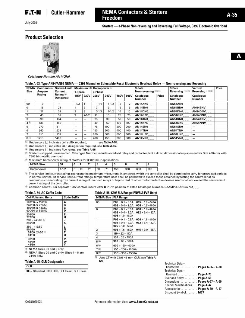
July 2008
CA08102002K For more information visit: www.EatonCanada.ca
A-35NEMA Contactors & Starters
A
FreedomStarters — 3-Phase Non-reversing and Reversing, Full Voltage, C396 Electronic Overload
Product Selection
Table A-53. Type AN14/AN54 NEMA — C396 Manual or Selectable Reset Electronic Overload Relay — Non-reversing and Reversing
� Underscore (_) indicates coil suffix required, see Table A-54.� Underscore (_) indicates OLR designation required, see Table A-55.� Underscore (_) indicates FLA range, see Table A-56.� Starter is shipped unassembled. Catalogue Number includes overload relay and contactor. Not a direct dimensional replacement for Size 4 Starter with
C306 bi-metallic overload.� Maximum horsepower rating of starters for 380V 50 Hz applications:
� The service-limit current ratings represent the maximum rms current, in amperes, which the controller shall be permitted to carry for protracted periods in normal service. At service-limit current ratings, temperature rises shall be permitted to exceed those obtained by testing the controller at its continuous current rating. The current rating of overload relays or trip current of other motor protective devices used shall not exceed the service-limit current rating of the controller.
� Common control. For separate 120V control, insert letter D in 7th position of listed Catalogue Number. EXAMPLE: AN54VND_ _ _.
Table A-54. AC Suffix Code
NEMA Sizes 00 and 0 only.� NEMA Sizes 00 and 0 only. Sizes 1 – 8 are
24/60 only.
Table A-55. OLR Designation
Table A-56. C396 FLA Range (FNVR & FVR Only)
� Uses CT with C396 45 mm OLR, see Table A-125
NEMASize
ContinuousAmpereRating
Service-Limit CurrentRating �
(Amperes)
Maximum UL Horsepower � 3-PoleNon-reversing ���
3-PoleReversing ���
VerticalReversing ���
Price
1-Phase 3-Phase
115V 230V 208V 240V 480V 600V CatalogueNumber
Price CatalogueNumber
CatalogueNumber
00 9 11 1/3 1 1-1/2 1-1/2 2 2 AN14AN0_ _ _ AN54AN0_ _ _ —
0 18 21 1 2 3 3 5 5 AN14BN0_ _ _ AN54BN0_ _ _ AN54BNV_ _ _
1 27 32 2 3 7-1/2 7-1/2 10 10 AN14DN0_ _ _ AN54DN0_ _ _ AN54DNV_ _ _
2 45 52 3 7-1/2 10 15 25 25 AN14GN0_ _ _ AN54GN0_ _ _ AN54GNV_ _ _
3 90 104 — — 25 30 50 50 AN14KN0_ _ _ AN54KN0_ _ _ AN54KNV_ _ _
4 � 135 156 — — 40 50 100 100 AN14NN0_ _ _ AN54NN0_ _ _ AN54NNV_ _ _
5 270 311 — — 75 100 200 200 AN14SN0_ _ _ AN54SN0_ _ _ —
6 540 621 — — 150 200 400 400 AN14TN0_ _ _ AN54TN0_ _ _ —
7 810 932 — — 200 300 600 600 AN14UN0_ _ _ AN54UN0_ _ _ —
8 � 1215 1400 — — 400 450 900 900 AN14VN0_ _ _ AN54VN0_ _ _ —
Catalogue Number AN14GN0_
NEMA Size 00 0 1 2 3 4 5 6 7 8
Horsepower 1-1/2 5 10 25 50 75 150 300 600 900
Coil Volts and Hertz Code Suffix
120/60 or 110/50240/60 or 220/50480/60 or 440/50600/60 or 550/50
ABCD
208/60277/60208 – 240/60 240/50
EHJK
380 – 415/50550/5024/60, 24/50 24/50
LNTU
32/5048/6048/50
VWY
OLR
3E = Standard C396 OLR, SEL Reset, SEL Class
NEMA Size FLA Range
00 P05 = 0.1 – 0.5A002 = 0.4 – 2.0A
005 = 1.0 – 5.0A008 = 1.6 – 8.0A
0 P05 = 0.1 – 0.5A002 = 0.4 – 2.0A005 = 1.0 – 5.0A
008 = 1.6 – 8.0A032 = 6.4 – 32A
1 P05 = 0.1 – 0.5A002 = 0.4 – 2.0A005 = 1.0 – 5.0A
008 = 1.6 – 8.0A032 = 6.4 – 32A
2 008 = 1.6 – 8.0A 045 = 9.0 – 45A3 110 = 22 – 110A4 150 = 30 – 150A
5 � 300 = 60 – 300A
6 � 600 = 120 – 600A7 � 10C = 200 – 1000A8 � 15C = 300 – 1500A
Technical Data – Contactors. . . . . . . . . . . . . Pages A-36 – A-38
Technical Data – Overload . . . . . . . . . . . . . . Page A-70
Overload Relay . . . . . . . . . Page A-66Dimensions . . . . . . . . . . . . Pages A-57 – A-59Special Modifications . . . Page A-47Accessories . . . . . . . . . . . . Pages A-39 – A-47Discount Symbol . . . . . . . . MC7
Tab33.book Page 35 Sunday, September 21, 2008 10:27 PM
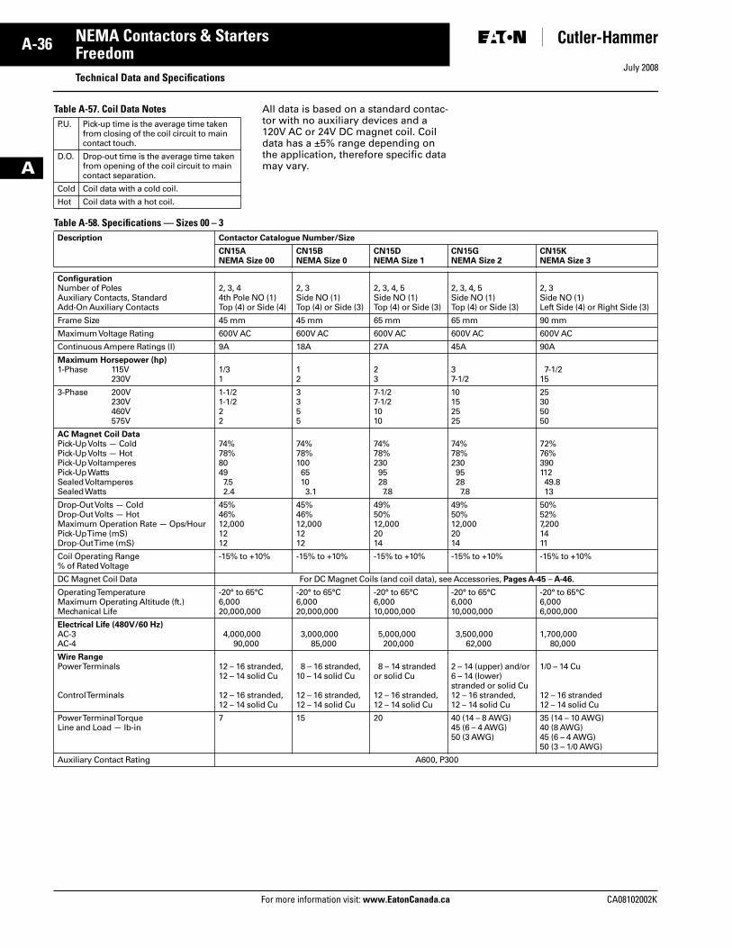
July 2008
A-36
For more information visit: www.EatonCanada.ca CA08102002K
NEMA Contactors & Starters
A
FreedomTechnical Data and Specifications
Table A-57. Coil Data Notes All data is based on a standard contac-tor with no auxiliary devices and a 120V AC or 24V DC magnet coil. Coil data has a ±5% range depending on the application, therefore specific data may vary.
Table A-58. Specifications — Sizes 00 – 3
P.U. Pick-up time is the average time taken from closing of the coil circuit to main contact touch.
D.O. Drop-out time is the average time taken from opening of the coil circuit to main contact separation.
Cold Coil data with a cold coil.
Hot Coil data with a hot coil.
Description Contactor Catalogue Number/Size
CN15ANEMA Size 00
CN15BNEMA Size 0
CN15DNEMA Size 1
CN15GNEMA Size 2
CN15KNEMA Size 3
ConfigurationNumber of PolesAuxiliary Contacts, StandardAdd-On Auxiliary Contacts
2, 3, 44th Pole NO (1)Top (4) or Side (4)
2, 3Side NO (1)Top (4) or Side (3)
2, 3, 4, 5Side NO (1)Top (4) or Side (3)
2, 3, 4, 5Side NO (1)Top (4) or Side (3)
2, 3Side NO (1)Left Side (4) or Right Side (3)
Frame Size 45 mm 45 mm 65 mm 65 mm 90 mm
Maximum Voltage Rating 600V AC 600V AC 600V AC 600V AC 600V AC
Continuous Ampere Ratings (I) 9A 18A 27A 45A 90A
Maximum Horsepower (hp)1-Phase 115V
230V1/31
12
23
37-1/2
7-1/215
3-Phase 200V230V460V575V
1-1/21-1/222
3355
7-1/27-1/21010
10152525
25305050
AC Magnet Coil DataPick-Up Volts — ColdPick-Up Volts — HotPick-Up VoltamperesPick-Up WattsSealed VoltamperesSealed Watts
74%78%80497.52.4
74%78%10065103.1
74%78%23095287.8
74%78%23095287.8
72%76%39011249.813
Drop-Out Volts — ColdDrop-Out Volts — HotMaximum Operation Rate — Ops/HourPick-Up Time (mS)Drop-Out Time (mS)
45%46%12,0001212
45%46%12,0001212
49%50%12,0002014
49%50%12,0002014
50%52%7,2001411
Coil Operating Range % of Rated Voltage
-15% to +10% -15% to +10% -15% to +10% -15% to +10% -15% to +10%
DC Magnet Coil Data For DC Magnet Coils (and coil data), see Accessories, Pages A-45 – A-46.
Operating TemperatureMaximum Operating Altitude (ft.)Mechanical Life
-20° to 65°C6,00020,000,000
-20° to 65°C6,00020,000,000
-20° to 65°C6,00010,000,000
-20° to 65°C6,00010,000,000
-20° to 65°C6,0006,000,000
Electrical Life (480V/60 Hz)AC-3AC-4
4,000,00090,000
3,000,00085,000
5,000,000200,000
3,500,00062,000
1,700,00080,000
Wire RangePower Terminals
Control Terminals
12 – 16 stranded,12 – 14 solid Cu
12 – 16 stranded,12 – 14 solid Cu
8 – 16 stranded,10 – 14 solid Cu
12 – 16 stranded,12 – 14 solid Cu
8 – 14 stranded or solid Cu
12 – 16 stranded,12 – 14 solid Cu
2 – 14 (upper) and/or6 – 14 (lower)stranded or solid Cu12 – 16 stranded,12 – 14 solid Cu
1/0 – 14 Cu
12 – 16 stranded12 – 14 solid Cu
Power Terminal TorqueLine and Load — lb-in
7 15 20 40 (14 – 8 AWG)45 (6 – 4 AWG)50 (3 AWG)
35 (14 – 10 AWG)40 (8 AWG)45 (6 – 4 AWG)50 (3 – 1/0 AWG)
Auxiliary Contact Rating A600, P300
Tab33.book Page 36 Sunday, September 21, 2008 10:27 PM
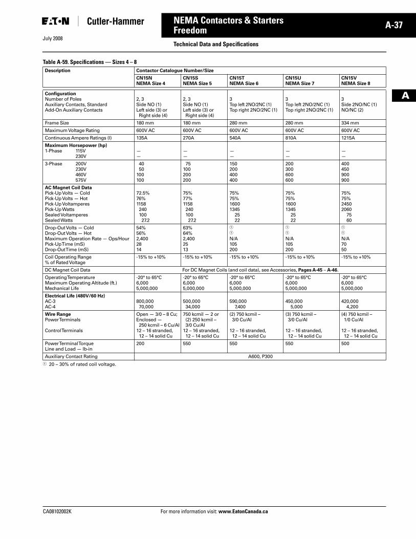
July 2008
CA08102002K For more information visit: www.EatonCanada.ca
A-37NEMA Contactors & Starters
A
FreedomTechnical Data and Specifications
Table A-59. Specifications — Sizes 4 – 8
� 20 – 30% of rated coil voltage.
Description Contactor Catalogue Number/Size
CN15NNEMA Size 4
CN15SNEMA Size 5
CN15TNEMA Size 6
CN15UNEMA Size 7
CN15VNEMA Size 8
ConfigurationNumber of PolesAuxiliary Contacts, StandardAdd-On Auxiliary Contacts
2, 3Side NO (1)Left side (3) or Right side (4)
2, 3Side NO (1)Left side (3) or Right side (4)
3Top left 2NO/2NC (1)Top right 2NO/2NC (1)
3Top left 2NO/2NC (1)Top right 2NO/2NC (1)
3Side 2NO/NC (1)NO/NC (2)
Frame Size 180 mm 180 mm 280 mm 280 mm 334 mm
Maximum Voltage Rating 600V AC 600V AC 600V AC 600V AC 600V AC
Continuous Ampere Ratings (I) 135A 270A 540A 810A 1215A
Maximum Horsepower (hp)1-Phase 115V
230V——
——
——
——
——
3-Phase 200V230V460V575V
4050
100100
75100200200
150200400400
200300600600
400450900900
AC Magnet Coil DataPick-Up Volts — ColdPick-Up Volts — HotPick-Up VoltamperesPick-Up WattsSealed VoltamperesSealed Watts
72.5%76%115824010027.2
75%77%115824010027.2
75%75%16001345
2522
75%75%16001345
2522
75%75%24502060
7560
Drop-Out Volts — ColdDrop-Out Volts — HotMaximum Operation Rate — Ops/HourPick-Up Time (mS)Drop-Out Time (mS)
54%56%2,4002814
63%64%2,4002513
�
�
N/A105200
�
�
N/A105200
�
�
N/A7050
Coil Operating Range % of Rated Voltage
-15% to +10% -15% to +10% -15% to +10% -15% to +10% -15% to +10%
DC Magnet Coil Data For DC Magnet Coils (and coil data), see Accessories, Pages A-45 – A-46.
Operating TemperatureMaximum Operating Altitude (ft.)Mechanical Life
-20° to 65°C6,0005,000,000
-20° to 65°C6,0005,000,000
-20° to 65°C6,0005,000,000
-20° to 65°C6,0005,000,000
-20° to 65°C6,0005,000,000
Electrical Life (480V/60 Hz)AC-3AC-4
800,00070,000
500,00034,000
590,0007,400
450,0005,000
420,0004,200
Wire RangePower Terminals
Control Terminals
Open — 3/0 – 8 Cu;Enclosed — 250 kcmil – 6 Cu/Al
12 – 16 stranded,12 – 14 solid Cu
750 kcmil — 2 or (2) 250 kcmil – 3/0 Cu/Al
12 – 16 stranded,12 – 14 solid Cu
(2) 750 kcmil – 3/0 Cu/Al
12 – 16 stranded,12 – 14 solid Cu
(3) 750 kcmil – 3/0 Cu/Al
12 – 16 stranded,12 – 14 solid Cu
(4) 750 kcmil – 1/0 Cu/Al
12 – 16 stranded,12 – 14 solid Cu
Power Terminal TorqueLine and Load — lb-in
200 550 550 550 500
Auxiliary Contact Rating A600, P300
Tab33.book Page 37 Sunday, September 21, 2008 10:27 PM
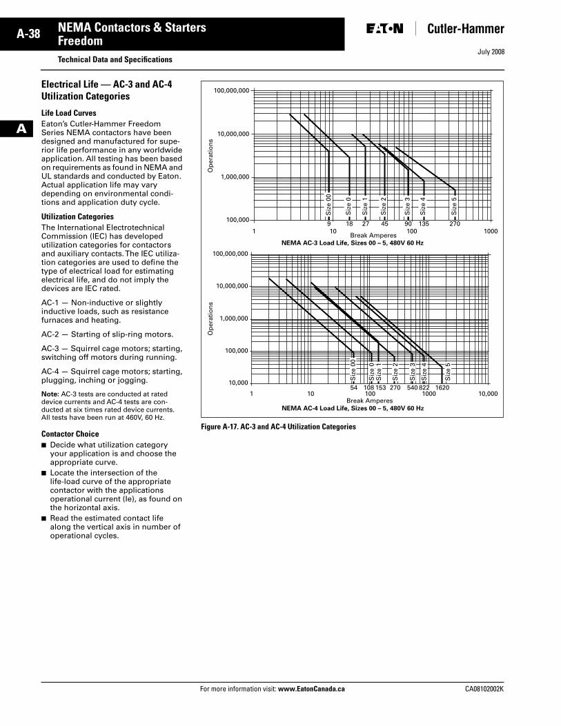
July 2008
A-38
For more information visit: www.EatonCanada.ca CA08102002K
NEMA Contactors & Starters
A
FreedomTechnical Data and Specifications
Electrical Life — AC-3 and AC-4 Utilization Categories
Life Load CurvesEaton’s Cutler-Hammer Freedom Series NEMA contactors have been designed and manufactured for supe-rior life performance in any worldwide application. All testing has been based on requirements as found in NEMA and UL standards and conducted by Eaton. Actual application life may vary depending on environmental condi-tions and application duty cycle.
Utilization CategoriesThe International Electrotechnical Commission (IEC) has developed utilization categories for contactors and auxiliary contacts. The IEC utiliza-tion categories are used to define the type of electrical load for estimating electrical life, and do not imply the devices are IEC rated.
AC-1 — Non-inductive or slightly inductive loads, such as resistance furnaces and heating.
AC-2 — Starting of slip-ring motors.
AC-3 — Squirrel cage motors; starting, switching off motors during running.
AC-4 — Squirrel cage motors; starting, plugging, inching or jogging.
Note: AC-3 tests are conducted at rated device currents and AC-4 tests are con-ducted at six times rated device currents. All tests have been run at 460V, 60 Hz.
Contactor Choice■ Decide what utilization category
your application is and choose the appropriate curve.
■ Locate the intersection of the life-load curve of the appropriate contactor with the applications operational current (Ie), as found on the horizontal axis.
■ Read the estimated contact life along the vertical axis in number of operational cycles.
Figure A-17. AC-3 and AC-4 Utilization Categories
NEMA AC-3 Load Life, Sizes 00 – 5, 480V 60 Hz
100,000,000
10,000,000
1,000,000
100,0009
1 10Break Amperes
100 100018 27 45 90 135 270
Siz
e 00
Siz
e 0
Siz
e 1
Siz
e 2
Siz
e 3
Siz
e 4
Siz
e 5
Op
erat
ion
sO
per
atio
ns
NEMA AC-4 Load Life, Sizes 00 – 5, 480V 60 Hz
100,000,000
Siz
e 00
Siz
e 0
Siz
e 1
Siz
e 2
Siz
e 3
Siz
e 4
Siz
e 5
10,000,000
1,000,000
100,000
10,00010854
1 10Break Amperes
100 1000 10,000153 270 540 822 1620
Tab33.book Page 38 Sunday, September 21, 2008 10:27 PM
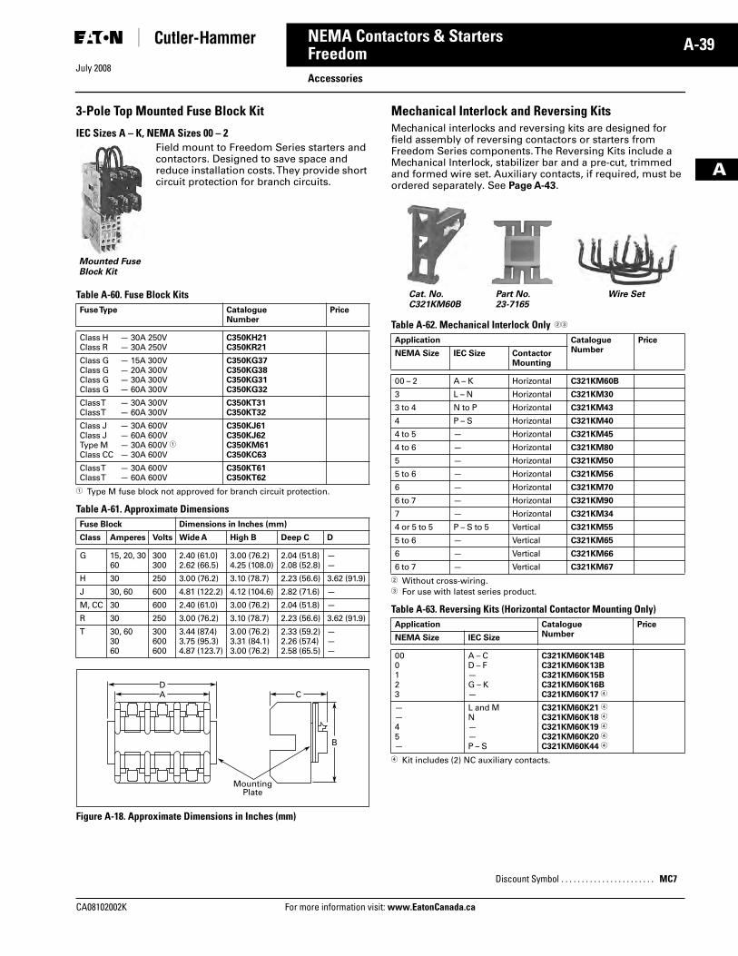
July 2008
CA08102002K For more information visit: www.EatonCanada.ca
A-39NEMA Contactors & Starters
A
FreedomAccessories
3-Pole Top Mounted Fuse Block Kit
IEC Sizes A – K, NEMA Sizes 00 – 2Field mount to Freedom Series starters and contactors. Designed to save space and reduce installation costs. They provide short circuit protection for branch circuits.
Table A-60. Fuse Block Kits
� Type M fuse block not approved for branch circuit protection.
Table A-61. Approximate Dimensions
Figure A-18. Approximate Dimensions in Inches (mm)
Mechanical Interlock and Reversing KitsMechanical interlocks and reversing kits are designed for field assembly of reversing contactors or starters from Freedom Series components. The Reversing Kits include a Mechanical Interlock, stabilizer bar and a pre-cut, trimmed and formed wire set. Auxiliary contacts, if required, must be ordered separately. See Page A-43.
Table A-62. Mechanical Interlock Only ��
� Without cross-wiring.� For use with latest series product.
Table A-63. Reversing Kits (Horizontal Contactor Mounting Only)
� Kit includes (2) NC auxiliary contacts.
Fuse Type CatalogueNumber
Price
Class H — 30A 250VClass R — 30A 250V
C350KH21C350KR21
Class G — 15A 300VClass G — 20A 300VClass G — 30A 300VClass G — 60A 300V
C350KG37C350KG38C350KG31C350KG32
Class T — 30A 300VClass T — 60A 300V
C350KT31C350KT32
Class J — 30A 600VClass J — 60A 600VType M — 30A 600V �Class CC — 30A 600V
C350KJ61C350KJ62C350KM61C350KC63
Class T — 30A 600VClass T — 60A 600V
C350KT61C350KT62
Fuse Block Dimensions in Inches (mm)
Class Amperes Volts Wide A High B Deep C D
G 15, 20, 3060
300300
2.40 (61.0)2.62 (66.5)
3.00 (76.2)4.25 (108.0)
2.04 (51.8)2.08 (52.8)
——
H 30 250 3.00 (76.2) 3.10 (78.7) 2.23 (56.6) 3.62 (91.9)
J 30, 60 600 4.81 (122.2) 4.12 (104.6) 2.82 (71.6) —
M, CC 30 600 2.40 (61.0) 3.00 (76.2) 2.04 (51.8) —
R 30 250 3.00 (76.2) 3.10 (78.7) 2.23 (56.6) 3.62 (91.9)
T 30, 603060
300600600
3.44 (87.4)3.75 (95.3)4.87 (123.7)
3.00 (76.2)3.31 (84.1)3.00 (76.2)
2.33 (59.2)2.26 (57.4)2.58 (65.5)
———
Mounted Fuse Block Kit
A C
MountingPlate
D
B
Application CatalogueNumber
Price
NEMA Size IEC Size ContactorMounting
00 – 2 A – K Horizontal C321KM60B
3 L – N Horizontal C321KM30
3 to 4 N to P Horizontal C321KM43
4 P – S Horizontal C321KM40
4 to 5 — Horizontal C321KM45
4 to 6 — Horizontal C321KM80
5 — Horizontal C321KM50
5 to 6 — Horizontal C321KM56
6 — Horizontal C321KM70
6 to 7 — Horizontal C321KM90
7 — Horizontal C321KM34
4 or 5 to 5 P – S to 5 Vertical C321KM55
5 to 6 — Vertical C321KM65
6 — Vertical C321KM66
6 to 7 — Vertical C321KM67
Application CatalogueNumber
Price
NEMA Size IEC Size
000123
A – CD – F—G – K—
C321KM60K14BC321KM60K13BC321KM60K15BC321KM60K16BC321KM60K17 �
——45—
L and MN——P – S
C321KM60K21 �
C321KM60K18 �
C321KM60K19 �
C321KM60K20 �
C321KM60K44 �
Discount Symbol . . . . . . . . . . . . . . . . . . . . . . . MC7
Cat. No.C321KM60B
Part No.23-7165
Wire Set
Tab33.book Page 39 Sunday, September 21, 2008 10:27 PM
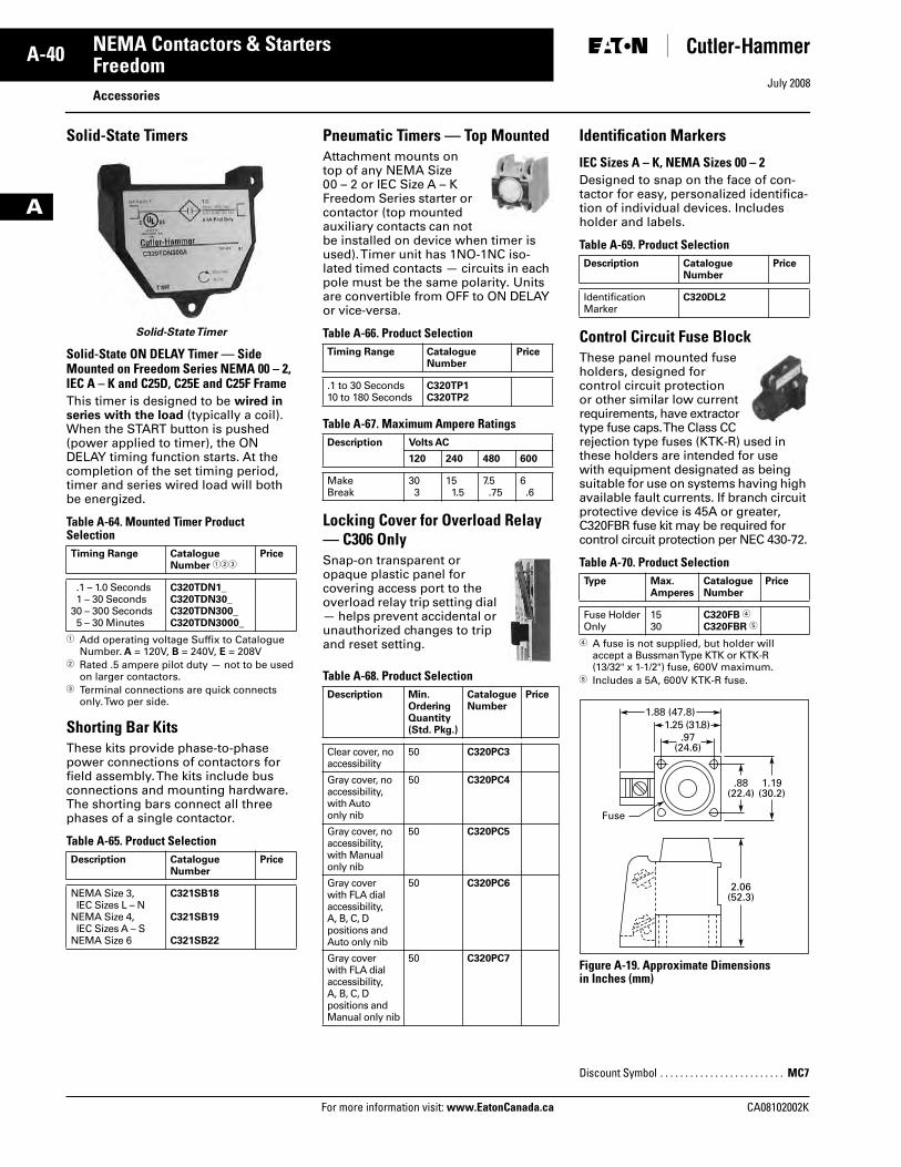
July 2008
A-40
For more information visit: www.EatonCanada.ca CA08102002K
NEMA Contactors & Starters
A
FreedomAccessories
Solid-State Timers
Solid-State Timer
Solid-State ON DELAY Timer — Side Mounted on Freedom Series NEMA 00 – 2, IEC A – K and C25D, C25E and C25F FrameThis timer is designed to be wired in series with the load (typically a coil). When the START button is pushed (power applied to timer), the ON DELAY timing function starts. At the completion of the set timing period, timer and series wired load will both be energized.
Table A-64. Mounted Timer Product Selection
� Add operating voltage Suffix to Catalogue Number. A = 120V, B = 240V, E = 208V
� Rated .5 ampere pilot duty — not to be used on larger contactors.
� Terminal connections are quick connects only. Two per side.
Shorting Bar KitsThese kits provide phase-to-phase power connections of contactors for field assembly. The kits include bus connections and mounting hardware. The shorting bars connect all three phases of a single contactor.
Table A-65. Product Selection
Pneumatic Timers — Top MountedAttachment mounts on top of any NEMA Size 00 – 2 or IEC Size A – K Freedom Series starter or contactor (top mounted auxiliary contacts can not be installed on device when timer is used). Timer unit has 1NO-1NC iso-lated timed contacts — circuits in each pole must be the same polarity. Units are convertible from OFF to ON DELAY or vice-versa.
Table A-66. Product Selection
Table A-67. Maximum Ampere Ratings
Locking Cover for Overload Relay — C306 OnlySnap-on transparent or opaque plastic panel for covering access port to the overload relay trip setting dial — helps prevent accidental or unauthorized changes to trip and reset setting.
Table A-68. Product Selection
Identification Markers
IEC Sizes A – K, NEMA Sizes 00 – 2Designed to snap on the face of con-tactor for easy, personalized identifica-tion of individual devices. Includes holder and labels.
Table A-69. Product Selection
Control Circuit Fuse BlockThese panel mounted fuse holders, designed for control circuit protection or other similar low current requirements, have extractor type fuse caps. The Class CC rejection type fuses (KTK-R) used in these holders are intended for use with equipment designated as being suitable for use on systems having high available fault currents. If branch circuit protective device is 45A or greater, C320FBR fuse kit may be required for control circuit protection per NEC 430-72.
Table A-70. Product Selection
� A fuse is not supplied, but holder will accept a Bussman Type KTK or KTK-R (13/32" x 1-1/2") fuse, 600V maximum.
� Includes a 5A, 600V KTK-R fuse.
Figure A-19. Approximate Dimensionsin Inches (mm)
Timing Range CatalogueNumber ���
Price
.1 – 1.0 Seconds1 – 30 Seconds
30 – 300 Seconds5 – 30 Minutes
C320TDN1_C320TDN30_C320TDN300_C320TDN3000_
Description CatalogueNumber
Price
NEMA Size 3, IEC Sizes L – N
NEMA Size 4, IEC Sizes A – S
NEMA Size 6
C321SB18
C321SB19
C321SB22
Timing Range CatalogueNumber
Price
.1 to 30 Seconds10 to 180 Seconds
C320TP1C320TP2
Description Volts AC
120 240 480 600
MakeBreak
303
151.5
7.5.75
6.6
Description Min.OrderingQuantity(Std. Pkg.)
CatalogueNumber
Price
Clear cover, noaccessibility
50 C320PC3
Gray cover, noaccessibility,with Autoonly nib
50 C320PC4
Gray cover, noaccessibility,with Manualonly nib
50 C320PC5
Gray coverwith FLA dialaccessibility,A, B, C, Dpositions andAuto only nib
50 C320PC6
Gray coverwith FLA dialaccessibility,A, B, C, Dpositions andManual only nib
50 C320PC7
Description CatalogueNumber
Price
Identification Marker
C320DL2
Type Max.Amperes
CatalogueNumber
Price
Fuse HolderOnly
1530
C320FB �
C320FBR �
Discount Symbol . . . . . . . . . . . . . . . . . . . . . . . . . MC7
.97(24.6)
1.25 (31.8)1.88 (47.8)
1.19(30.2)
.88(22.4)
2.06(52.3)
Fuse
Tab33.book Page 40 Sunday, September 21, 2008 10:27 PM
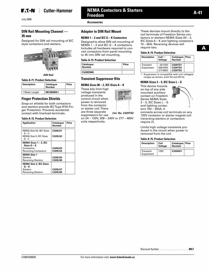
July 2008
CA08102002K For more information visit: www.EatonCanada.ca
A-41NEMA Contactors & Starters
A
FreedomAccessories
DIN Rail Mounting Channel — 35 mmDesigned for DIN rail mounting of IEC style contactors and starters.
DIN Rail
Table A-71. Product Selection
Finger Protection ShieldsSnap-on shields for both contactors and starters provide IEC Type IP20 Fin-ger Protection. Prevents accidental contact with line/load terminals.
Table A-72. Product Selection
Adapter to DIN Rail Mount
NEMA 1 – 2 and IEC G – K ContactorsDesigned to allow DIN rail mounting of NEMA 1 – 2 and IEC G – K contactors. Includes all hardware required to con-vert contactors from panel mounting to 35 mm DIN rail mounting.
Table A-73. Product Selection
Transient Suppressor Kits
NEMA Sizes 00 – 2, IEC Sizes A – KThese kits limit high voltage transients produced in the control circuit when power is removed from the contactor or starter coil. There are three separate suppressors for use on 24 – 120V, 208 – 240V or 277 – 480V coils respectively.
These devices mount directly to the coil terminals of Freedom Series con-tactors or starters NEMA Sizes 00 – 2, IEC Sizes A – K and lighting contactors 10 – 60A. Reversing devices will require two.
Table A-74. Product Selection
� Suppressor is compatible with coil voltages/ranges as shown, both 50 and 60 Hz.
NEMA Sizes 3 – 5, IEC Sizes L – SThis device mounts on top of any side mounted auxiliary contact on Freedom Series NEMA Sizes 3 – 5, IEC Sizes L – S and lighting contac-tors 100 – 300A. It connects across coil terminals on any 120V contactor or starter magnet coil (reversing starters or contactors require 2).
Limits high voltage transients pro-duced in the circuit when power is removed from the coil.
Table A-75. Product Selection
Description CatalogueNumber
Price
1 Meter Length MC382MA1
Application CatalogueNumber
Price
NEMA Size 00, IEC SizesA – C
NEMA Size 0, IEC SizesD – F
C320LS1
C320LS2
NEMA Sizes 1 – 2, IEC Sizes G – K
ContactorsReversing Contactors
C320LS3C320LS4
NEMA Size 1StartersReversing Starters
C320LS5C320LS6
NEMA Size 2, IEC SizesG – K
StartersReversing Starters
C320LS7C320LS8
CatalogueNumber
Price
C320DN65
Cat. No. C320TS2
Description Coil �
VoltageCatalogueNumber
Price
TransientSuppressor
24/120V208/240V277/480V
C320TS1C320TS2C320TS3
Description CoilVoltage
CatalogueNumber
Price
TransientSuppressor
120V C320AS1
Discount Symbol . . . . . . . . . . . . . . . . . . . . . . . . . MC7
Tab33.book Page 41 Sunday, September 21, 2008 10:27 PM
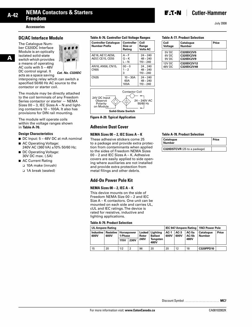
July 2008
A-42
For more information visit: www.EatonCanada.ca CA08102002K
NEMA Contactors & Starters
A
FreedomAccessories
DC/AC Interface ModuleThe Catalogue Num-ber C320DC Interface Module is an optically isolated solid-state switch which provides a means of operating AC coils with 5 – 48V DC control signal. It acts as a space saving interposing relay which can switch a specified 50/60 Hz AC source to the contactor or starter coil.
The module may be directly attached to the coil terminals of any Freedom Series contactor or starter — NEMA Sizes 00 – 3, IEC Sizes A – N and light-ing contactors 10 – 100A. It also has provisions for DIN rail mounting.
The module will operate coils within the voltage ranges shown in Table A-76.
Design Characteristics■ DC Input: 5 – 48V DC at mA nominal■ AC Operating Voltage:
240V AC (360 VA) ±10% 50/60 Hz; ■ DC Operating Voltage:
30V DC max. (.5A)■ AC Current Rating
❑ 10A make (inrush)❑ 1A break (sealed)
Cat. No. C320DC
Table A-76. Controller Coil Voltage Ranges
Figure A-20. Typical Application
Table A-77. Product Selection
Adhesive Dust Cover
NEMA Sizes 00 – 2, IEC Sizes A – KThese adhesive stickers come 25 to a package and provide extra protec-tion from contaminants when applied to the sides of Freedom NEMA Sizes 00 – 2 and IEC Sizes A – K. Adhesive covers are easily applied to side open-ing where auxiliaries are not installed and provide extra protection from metal filings and other debris.
Table A-78. Product Selection
Add-On Power Pole Kit
NEMA Sizes 00 – 2, IEC A – KThis device mounts on the side of Freedom NEMA Size 00 – 2 and IEC Size A – K contactors. One unit can be mounted on each side and carries UL, cUL and IEC ratings. The device is rated for resistive, inductive and lighting applications.
Table A-79. Product Selection
Controller CatalogueNumber Prefix
ControllerSize or Rating
Coil RangeVolts AC
AE16, AE17, AE56, AE57, CE15, CE55
A – FG – KL – N
24 – 24048 – 240
110 – 240
AN16, AN56, CN15, CN55
00 – 01 – 23
24 _ 24048 – 240
110 – 240
CN35 10 – 30A60A
100A
24 – 24048 – 240
110 – 240
24V DC InputObservePolarity
on Module
24 – 240V AC50/60 Hz
Contactor Coil
Solid-State Switch
Coil Voltage
CatalogueNumber
Price
5V DC 6V DC 9V DC
C320DC2V5C320DC2V6C320DC2V9
12V DC48V DC
C320DC2V12C320DC2V48
CatalogueNumber
Price
C320DSTCVR (25 to a package)
UL Ampere Rating IEC 947 Ampere Rating 1NO Power Pole
Inductive600V
Resistive600V
Horsepower 1-Phase
LockedRotor 240V
LightingBallastTungsten480V
AC-1600V
AC-3 600V
AC-5aAC-5b480V
CatalogueNumber
Price
115V 230V
15 20 1/2 2 96 20 20 12 18 C320PPD10
Discount Symbol . . . . . . . . . . . . . . . . . . . . . . . . . MC7
Tab33.book Page 42 Sunday, September 21, 2008 10:27 PM
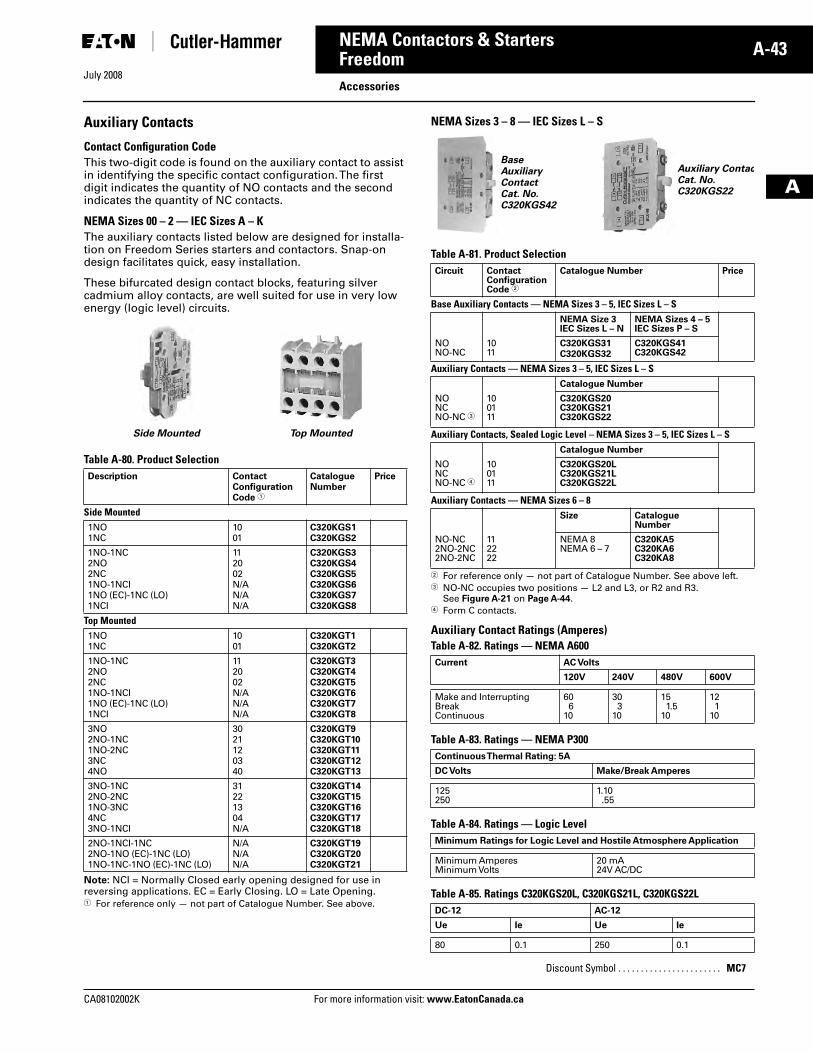
July 2008
CA08102002K For more information visit: www.EatonCanada.ca
A-43NEMA Contactors & Starters
A
FreedomAccessories
Auxiliary Contacts
Contact Configuration CodeThis two-digit code is found on the auxiliary contact to assist in identifying the specific contact configuration. The first digit indicates the quantity of NO contacts and the second indicates the quantity of NC contacts.
NEMA Sizes 00 – 2 — IEC Sizes A – KThe auxiliary contacts listed below are designed for installa-tion on Freedom Series starters and contactors. Snap-on design facilitates quick, easy installation.
These bifurcated design contact blocks, featuring silver cadmium alloy contacts, are well suited for use in very low energy (logic level) circuits.
Table A-80. Product Selection
Note: NCI = Normally Closed early opening designed for use in reversing applications. EC = Early Closing. LO = Late Opening.� For reference only — not part of Catalogue Number. See above.
NEMA Sizes 3 – 8 — IEC Sizes L – S
Table A-81. Product Selection
� For reference only — not part of Catalogue Number. See above left.� NO-NC occupies two positions — L2 and L3, or R2 and R3.
See Figure A-21 on Page A-44.� Form C contacts.
Auxiliary Contact Ratings (Amperes) Table A-82. Ratings — NEMA A600
Table A-83. Ratings — NEMA P300
Table A-84. Ratings — Logic Level
Table A-85. Ratings C320KGS20L, C320KGS21L, C320KGS22L
Description ContactConfiguration Code �
CatalogueNumber
Price
Side Mounted1NO1NC
1001
C320KGS1C320KGS2
1NO-1NC2NO2NC1NO-1NCI1NO (EC)-1NC (LO)1NCI
112002N/AN/AN/A
C320KGS3C320KGS4C320KGS5C320KGS6C320KGS7C320KGS8
Top Mounted1NO1NC
1001
C320KGT1C320KGT2
1NO-1NC2NO2NC1NO-1NCI1NO (EC)-1NC (LO)1NCI
112002N/AN/AN/A
C320KGT3C320KGT4C320KGT5C320KGT6C320KGT7C320KGT8
3NO2NO-1NC1NO-2NC3NC4NO
3021120340
C320KGT9C320KGT10C320KGT11C320KGT12C320KGT13
3NO-1NC2NO-2NC1NO-3NC4NC3NO-1NCI
31221304N/A
C320KGT14C320KGT15C320KGT16C320KGT17C320KGT18
2NO-1NCI-1NC2NO-1NO (EC)-1NC (LO)1NO-1NC-1NO (EC)-1NC (LO)
N/AN/AN/A
C320KGT19C320KGT20C320KGT21
Side Mounted Top Mounted
Circuit ContactConfigurationCode �
Catalogue Number Price
Base Auxiliary Contacts — NEMA Sizes 3 – 5, IEC Sizes L – SNEMA Size 3IEC Sizes L – N
NEMA Sizes 4 – 5IEC Sizes P – S
NONO-NC
1011
C320KGS31C320KGS32
C320KGS41C320KGS42
Auxiliary Contacts — NEMA Sizes 3 – 5, IEC Sizes L – SCatalogue Number
NONCNO-NC �
100111
C320KGS20C320KGS21C320KGS22
Auxiliary Contacts, Sealed Logic Level – NEMA Sizes 3 – 5, IEC Sizes L – SCatalogue Number
NONCNO-NC �
100111
C320KGS20LC320KGS21LC320KGS22L
Auxiliary Contacts — NEMA Sizes 6 – 8Size Catalogue
Number
NO-NC2NO-2NC2NO-2NC
112222
NEMA 8NEMA 6 – 7
C320KA5C320KA6C320KA8
Current AC Volts
120V 240V 480V 600V
Make and InterruptingBreakContinuous
606
10
303
10
151.5
10
121
10
Continuous Thermal Rating: 5A
DC Volts Make/Break Amperes
125250
1.10.55
Minimum Ratings for Logic Level and Hostile Atmosphere Application
Minimum AmperesMinimum Volts
20 mA24V AC/DC
DC-12 AC-12
Ue Ie Ue Ie
80 0.1 250 0.1
Discount Symbol . . . . . . . . . . . . . . . . . . . . . . . MC7
BaseAuxiliary ContactCat. No. C320KGS42
Auxiliary ContacCat. No. C320KGS22
Tab33.book Page 43 Sunday, September 21, 2008 10:27 PM
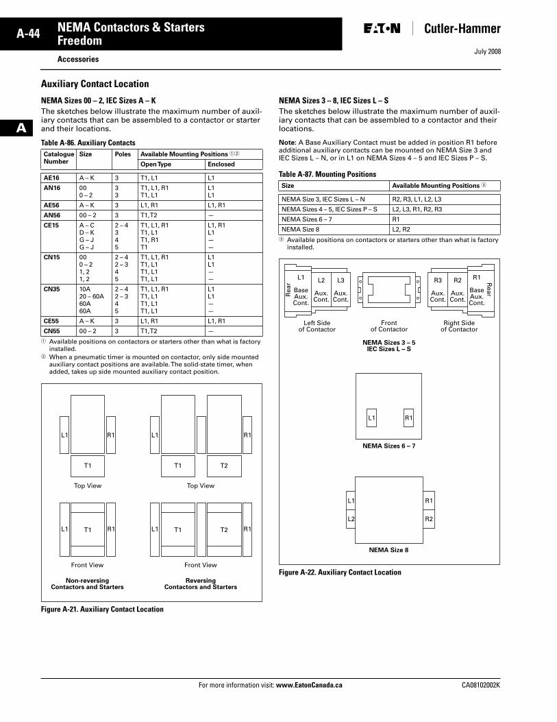
July 2008
A-44
For more information visit: www.EatonCanada.ca CA08102002K
NEMA Contactors & Starters
A
FreedomAccessories
Auxiliary Contact Location
NEMA Sizes 00 – 2, IEC Sizes A – KThe sketches below illustrate the maximum number of auxil-iary contacts that can be assembled to a contactor or starter and their locations.
Table A-86. Auxiliary Contacts
� Available positions on contactors or starters other than what is factory installed.
� When a pneumatic timer is mounted on contactor, only side mounted auxiliary contact positions are available. The solid-state timer, when added, takes up side mounted auxiliary contact position.
Figure A-21. Auxiliary Contact Location
NEMA Sizes 3 – 8, IEC Sizes L – SThe sketches below illustrate the maximum number of auxil-iary contacts that can be assembled to a contactor and their locations.
Note: A Base Auxiliary Contact must be added in position R1 before additional auxiliary contacts can be mounted on NEMA Size 3 and IEC Sizes L – N, or in L1 on NEMA Sizes 4 – 5 and IEC Sizes P – S.
Table A-87. Mounting Positions
� Available positions on contactors or starters other than what is factory installed.
Figure A-22. Auxiliary Contact Location
CatalogueNumber
Size Poles Available Mounting Positions ��
Open Type Enclosed
AE16 A – K 3 T1, L1 L1
AN16 000 – 2
33
T1, L1, R1T1, L1
L1L1
AE56 A – K 3 L1, R1 L1, R1
AN56 00 – 2 3 T1, T2 —
CE15 A – CD – KG – JG – J
2 – 4345
T1, L1, R1T1, L1T1, R1T1
L1, R1L1——
CN15 000 – 21, 21, 2
2 – 42 – 345
T1, L1, R1T1, L1T1, L1T1, L1
L1L1——
CN35 10A20 – 60A60A60A
2 – 42 – 345
T1, L1, R1T1, L1T1, L1T1, L1
L1L1——
CE55 A – K 3 L1, R1 L1, R1
CN55 00 – 2 3 T1, T2 —
L1
T1 T2
R1
L1 T1 T2 R1
L1
T1
Top View
Front View
L1 T1 R1
Front View
ReversingContactors and Starters
Non-reversingContactors and Starters
Top View
R1
Size Available Mounting Positions �
NEMA Size 3, IEC Sizes L – N R2, R3, L1, L2, L3
NEMA Sizes 4 – 5, IEC Sizes P – S L2, L3, R1, R2, R3
NEMA Sizes 6 – 7 R1
NEMA Size 8 L2, R2
NEMA Sizes 6 – 7
NEMA Sizes 3 – 5IEC Sizes L – S
NEMA Size 8
L1 R1
L1
Frontof Contactor
Left Sideof Contactor
L2
Aux.Cont.
L3
Aux.Cont.
R2
Aux.Cont.
R3
Aux.Cont.
L1
BaseAux.Cont.
R1
BaseAux.Cont.
Rea
r Rear
Right Sideof Contactor
R1
L2 R2
Tab33.book Page 44 Sunday, September 21, 2008 10:27 PM
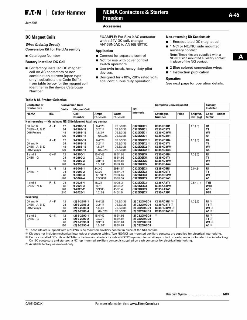
July 2008
CA08102002K For more information visit: www.EatonCanada.ca
A-45NEMA Contactors & Starters
A
FreedomAccessories
DC Magnet Coils
When Ordering SpecifyConversion Kit for Field Assembly
■ Catalogue Number
Factory Installed DC Coil
■ For factory installed DC magnet coil on AC contactors or non-combination starters (open type only), substitute the Code Suffix from table below for the magnet coil identifier in the device Catalogue Number.
EXAMPLE: For Size 0 AC contactor with a 24V DC coil, change AN16BN0AC to AN16BN0T1C.
Application■ Connect for separate control■ Not for use with cover control
switch operators■ Use twin break, heavy-duty pilot
devices.■ Designed for +10%, -20% rated volt-
age, continuous duty operation.
Non-reversing Kit Consists of:■ 1 Encapsulated DC magnet coil■ 1 NCI or NO/NCI side mounted
auxiliary contactNote: These kits are supplied with a NO/NCI side mounted auxiliary contact in place of the NCI contact.
■ 2 Blue colored connection wires■ 1 Instruction publication
OperationSee next page for operation details.
Table A-88. Product Selection
� These kits are supplied with a NO/NCI side mounted auxiliary contact in place of the NCI contact.� Kit does not include mechanical interlock or crossover wiring. Two NO/NCI top mounted auxiliary contacts are supplied for electrical interlocking.� Factory installed DC coils on NEMA contactors and starters include a NO/NC top mounted auxiliary contact on each contactor for electrical interlocking.
On IEC contactors and starters, a NC top mounted auxiliary contact is supplied on each contactor for electrical interlocking.� Available factory assembled only.
Contactor orStarter Size
Conversion Data Complete Conversion Kit FactoryInstalledVolts Magnet Coil NCI
InterlockNEMA IEC CoilNumber
AmpsP.U./Seal
WattsP.U./Seal
CatalogueNumber
Price Ship Wt.Lbs. (kg)
CodeSuffix
Adder
Non-reversing — Kit includes NCI Side Mounted Auxiliary contact00 and 0CN35 – A, B, DD15 Relays
A – F 122448
120
9-2988-119-2988-129-2988-139-2988-14
6.4/.283.2/.141.6/.07.64/.028
76.8/3.3676.8/3.3676.8/3.3676.8/3.36
C320KGD1C320KGD1C320KGD1C320KGD1
C335KD3R1C335KD3T1C335KD3W1C335KD3A1
1.0 (.5) R1T1W1A1
�
00 and 0CN35 – A, B, DD15 Relays
A – F 122448
120
9-2988-119-2988-129-2988-139-2988-14
6.4/.283.2/.141.6/.07.64/.028
76.8/3.3676.8/3.3676.8/3.3676.8/3.36
C320KGD2 �
C320KGD2 �
C320KGD2 �
C320KGD2 �
C335KD3R4C335KD3T4C335KD3W4C335KD3A4
1.0 (.5) R4T4W4A4
1 and 2CN35 – G
G – K 122448
120
9-2990-19-2990-29-2990-39-2990-4
15.4/.427.7/.213.9/.111.5/.041
185/4.98185/4.96185/5.04185/4.87
C320KGD5C320KGD5C320KGD5C320KGD5
C335KD4R4C335KD4T4C335KD4W4C335KD4A4
1.0 (.5) R4T4W4A4
3CN35 – K
L – N 122448
120
9-3002-19-3002-29-3002-39-3002-4
24/.4012/.206.1/.0972.5/.038
293/4.84288/4.75295/4.67298/4.57
C320KGD3C320KGD3C320KGD3C320KGD3
C335KD5R1C335KD5T1C335KD5W1C335KD5A1
2.0 (.9) R1T1W1A1
4 and 5CN35 – N, S
P – S 2448
120240
9-2026-49-2026-39-2026-29-2026-1
18/.229/.113.3/.051.7/.02
400/5.3400/5.2450/5.4440/4.9
C320KGD3C320KGD3C320KGD3C320KGD3
C335KA3T1C335KA3W1C335KA3A1C335KA3B1
2.5 (1.1) T1BW1BA1BB1B
Reversing00 and 0CN35 – A, B, DD15 Relays
A – F 122448
120
(2) 9-2988-1(2) 9-2988-2(2) 9-2988-3(2) 9-2988-4
6.4/.283.2/.141.6/.07.64/.028
76.8/3.3676.8/3.3676.8/3.3676.8/3.36
(2) C320KGD1(2) C320KGD1(2) C320KGD1(2) C320KGD1
C335RD3R1 �
C335RD3T1 �
C335RD3W1 �
C335RD3A1 �
1.0 (.5) R1 �
T1 �
W1 �
A1 �
1 and 2CN35 – G
G – K 122448
120
(2) 9-2990-1(2) 9-2990-2(2) 9-2990-3(2) 9-2990-4
15.4/.427.7/.213.9/.111.5/.041
185/4.98185/4.96185/5.04185/4.87
(2) C320KGD3(2) C320KGD3(2) C320KGD3(2) C320KGD3
� R1 �
T1 �
W1 �
A1 �
Discount Symbol . . . . . . . . . . . . . . . . . . . . . . . . . MC7
Tab33.book Page 45 Sunday, September 21, 2008 10:27 PM
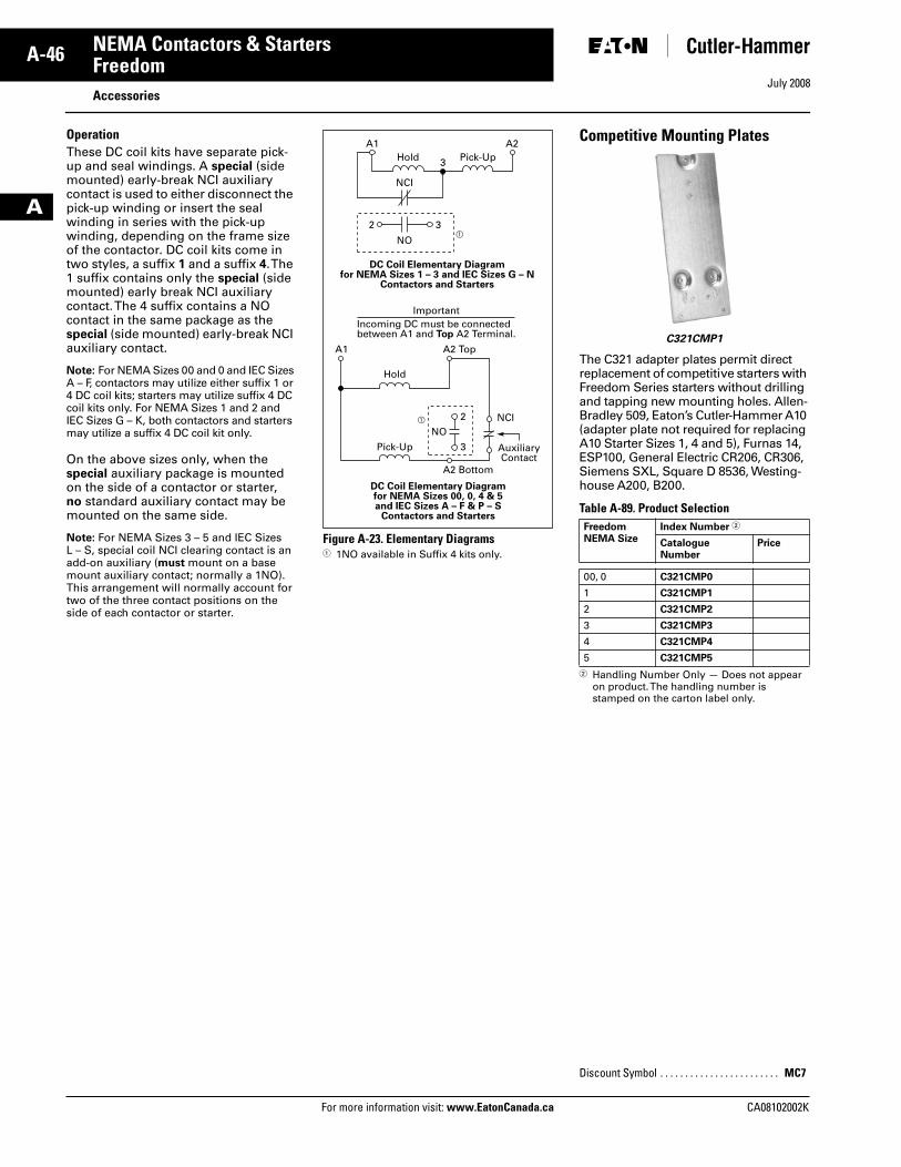
July 2008
A-46
For more information visit: www.EatonCanada.ca CA08102002K
NEMA Contactors & Starters
A
FreedomAccessories
Operation These DC coil kits have separate pick-up and seal windings. A special (side mounted) early-break NCI auxiliary contact is used to either disconnect the pick-up winding or insert the seal winding in series with the pick-up winding, depending on the frame size of the contactor. DC coil kits come in two styles, a suffix 1 and a suffix 4. The 1 suffix contains only the special (side mounted) early break NCI auxiliary contact. The 4 suffix contains a NO contact in the same package as the special (side mounted) early-break NCI auxiliary contact.
Note: For NEMA Sizes 00 and 0 and IEC Sizes A – F, contactors may utilize either suffix 1 or 4 DC coil kits; starters may utilize suffix 4 DC coil kits only. For NEMA Sizes 1 and 2 and IEC Sizes G – K, both contactors and starters may utilize a suffix 4 DC coil kit only.
On the above sizes only, when the special auxiliary package is mounted on the side of a contactor or starter, no standard auxiliary contact may be mounted on the same side.
Note: For NEMA Sizes 3 – 5 and IEC Sizes L – S, special coil NCI clearing contact is an add-on auxiliary (must mount on a base mount auxiliary contact; normally a 1NO). This arrangement will normally account for two of the three contact positions on the side of each contactor or starter.
Figure A-23. Elementary Diagrams� 1NO available in Suffix 4 kits only.
Competitive Mounting Plates
The C321 adapter plates permit direct replacement of competitive starters with Freedom Series starters without drilling and tapping new mounting holes. Allen-Bradley 509, Eaton’s Cutler-Hammer A10 (adapter plate not required for replacing A10 Starter Sizes 1, 4 and 5), Furnas 14, ESP100, General Electric CR206, CR306,Siemens SXL, Square D 8536, Westing-house A200, B200.
Table A-89. Product Selection
� Handling Number Only — Does not appear on product. The handling number is stamped on the carton label only.
AuxiliaryContact
ImportantIncoming DC must be connectedbetween A1 and Top A2 Terminal.
A1 A2
A1 A2 Top
A2 Bottom
3
NCI
NO�
�
3
2
3
NCINO
2
Hold Pick-Up
Hold
Pick-Up
DC Coil Elementary Diagramfor NEMA Sizes 1 – 3 and IEC Sizes G – N
Contactors and Starters
DC Coil Elementary Diagramfor NEMA Sizes 00, 0, 4 & 5and IEC Sizes A – F & P – S
Contactors and StartersFreedomNEMA Size
Index Number �
CatalogueNumber
Price
00, 0 C321CMP0
1 C321CMP1
2 C321CMP2
3 C321CMP3
4 C321CMP4
5 C321CMP5
Discount Symbol . . . . . . . . . . . . . . . . . . . . . . . . MC7
C321CMP1
Tab33.book Page 46 Sunday, September 21, 2008 10:27 PM
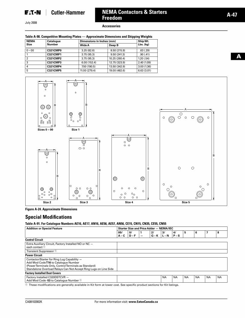
July 2008
CA08102002K For more information visit: www.EatonCanada.ca
A-47NEMA Contactors & Starters
A
FreedomAccessories
Table A-90. Competitive Mounting Plates — Approximate Dimensions and Shipping Weights
Figure A-24. Approximate Dimensions
Special ModificationsTable A-91. For Catalogue Numbers AE16, AE17, AN16, AE56, AE57, AN56, CE15, CN15, CN35, CE55, CN55
� These modifications are generally available in Kit form at lower cost. See specific product sections for Kit listings.
NEMASize
CatalogueNumber
Dimensions in Inches (mm) Ship Wt. Lbs. (kg)Wide A Deep B
0 – 00 C321CMP0 3.25 (82.6) 8.50 (215.9) .63 (.29)1 C321CMP1 3.75 (95.3) 9.50 (241.3) .90 (.41)2 C321CMP2 3.75 (95.3) 10.25 (260.4) 1.20 (.54)3 C321CMP3 6.00 (152.4) 12.75 (323.9) 2.40 (1.09)4 C321CMP4 7.50 (190.5) 13.50 (342.9) 3.00 (1.36)5 C321CMP5 11.00 (279.4) 19.00 (482.6) 6.63 (3.01)
Addition or Special Feature Starter Size and Price Adder — NEMA/IEC
00/A – C
0/D – F
1—
2/G – K
3/L – N
4/P – S
5 6 7 8
Control CircuitExtra Auxiliary Circuit, Factory Installed NO or NC — each contact �
Transient Suppressor �
Power CircuitContactor/Starter for Ring Lug Capability — Add Mod Code T16 to Catalogue Number(Power Terminals Only, Control Terminals as Standard)Standalone Overload Relays Can Not Accept Ring Lugs on Line Side
Factory Installed Dust CoversFactory Installed C320DSTCVR — Add Mod Code -53 to Catalogue Number �
NA NA NA NA NA NA
A
B
A
B
A
Size 2
Size 1Sizes 0 – 00
B
A
A
Size 5
B
Size 4
B
A
Size 3
B
Tab33.book Page 47 Sunday, September 21, 2008 10:27 PM
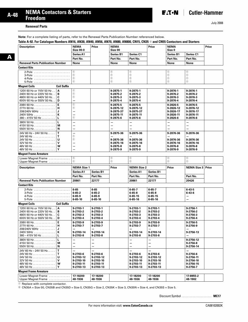
July 2008
A-48
For more information visit: www.EatonCanada.ca CA08102002K
NEMA Contactors & Starters
A
Freedom Renewal Parts
Note: For a complete listing of parts, refer to the Renewal Parts Publication Number referenced below.
Table A-92. For Catalogue Numbers AN16, AN30, AN40, AN56, AN70, AN80, AN800, CN15, CN35 � and CN55 Contactors and Starters
� Replace with complete contactor. � CN35A = Size 00, CN35B and CN35D = Size 0, CN35G = Size 2, CN35K = Size 3, CN35N = Size 4, and CN35S = Size 5.
Description NEMA Size 00-0
Price NEMA Size 00
Price NEMASize 0
Price
Series A1 Series B1 Series C1 Series B1 Series C1
Part No. Part No. Part No. Part No. Part No.
Renewal Parts Publication Number None None None None None
Contact Kits2-Pole . . . . . . . . . . . . . . . . . . . . . . . .3-Pole . . . . . . . . . . . . . . . . . . . . . . . .4-Pole . . . . . . . . . . . . . . . . . . . . . . . .5-Pole . . . . . . . . . . . . . . . . . . . . . . . .
�
�
�
�
�
�
�
�
�
�
�
�
�
�
�
�
�
�
�
�
Magnet Coils Coil Suffix120V 60 Hz or 110V 50 Hz . .240V 60 Hz or 220V 50 Hz. .480V 60 Hz or 440V 50 Hz. .600V 60 Hz or 550V 50 Hz. .
ABCD
�
�
�
—
9-2875-19-2875-29-2875-39-2875-4
9-2875-19-2875-29-2875-39-2875-4
9-2876-19-2876-29-2876-39-2876-4
9-2876-19-2876-29-2876-39-2876-4
208V 60 Hz . . . . . . . . . . . . . .277V 60 Hz . . . . . . . . . . . . . .208/240V 60Hz . . . . . . . . . .240V 50Hz . . . . . . . . . . . . . .380 – 415V 50 Hz . . . . . . . . .
EHJKL
�
�
— —�
9-2875-59-2875-129-2875-379-2875-119-2875-6
9-2875-59-2875-129-2875-379-2875-119-2875-6
9-2826-5 9-2826-12 9-2826-17 9-2826-11 9-2826-6
9-2876-5 9-2876-12 9-2876-17 9-2876-11 9-2876-6
380V 50 Hz . . . . . . . . . . . . . .415V 50 Hz . . . . . . . . . . . . . .550V 50 Hz . . . . . . . . . . . . . .
LMN
— — —
— — —
— — —
— — —
— — —
24V 60 Hz – 24V 50 Hz. . . . .24V 60 Hz . . . . . . . . . . . . . . .24V 50 Hz . . . . . . . . . . . . . . .32V 50 Hz . . . . . . . . . . . . . . .48V 60 Hz . . . . . . . . . . . . . . .48V 50 Hz . . . . . . . . . . . . . . .
TTUVWY
— �
�
———
9-2875-36— 9-2875-369-2875-169-2875-89-2875-9
9-2875-36— 9-2875-369-2875-169-2875-89-2875-9
9-2876-36— 9-2876-369-2876-169-2876-89-2876-9
9-2876-36— 9-2876-369-2876-169-2876-89-2876-9
Magnet Frame Armature Lower Magnet Frame . . . . . . . . . . . . . .Upper Magnet Frame . . . . . . . . . . . . . .
�
�
�
�
�
�
�
�
�
�
Description NEMA Size 1 Price NEMA Size 2 Price NEMA Size 3 Price
Series A1 Series B1 Series A1 Series B1
Part No. Part No. Part No. Part No. Part No.
Renewal Parts Publication Number 20861 22177 20861 22177 20426
Contact Kits2-Pole . . . . . . . . . . . . . . . . . . . . . . . .3-Pole . . . . . . . . . . . . . . . . . . . . . . . .4-Pole . . . . . . . . . . . . . . . . . . . . . . . .5-Pole . . . . . . . . . . . . . . . . . . . . . . . .
6-656-65-26-65-96-65-10
6-656-65-26-65-96-65-10
6-65-76-65-86-65-156-65-16
6-65-76-65-86-65-156-65-16
6-43-56-43-6——
Magnet Coils Coil Suffix120V 60 Hz or 110V 50 Hz . .240V 60 Hz or 220V 50 Hz. .480V 60 Hz or 440V 50 Hz. .600V 60 Hz or 550V 50 Hz. .
ABCD
9-2703-19-2703-29-2703-39-2703-4
9-2703-19-2703-29-2703-39-2703-4
9-2703-19-2703-29-2703-39-2703-4
9-2703-19-2703-29-2703-39-2703-4
9-2756-19-2756-29-2756-39-2756-4
208V 60 Hz . . . . . . . . . . . . . .277V 60 Hz . . . . . . . . . . . . . .208/240V 60Hz . . . . . . . . . .240V 50Hz . . . . . . . . . . . . . .380 – 415V 50 Hz . . . . . . . . .
EHJKL
9-2703-99-2703-7—9-2703-149-2703-8
9-2703-99-2703-7—9-2703-149-2703-8
9-2703-99-2703-7—9-2703-149-2703-8
9-2703-99-2703-7—9-2703-149-2703-8
9-2756-59-2756-9—9-2756-13—
380V 50 Hz . . . . . . . . . . . . . .415V 50 Hz . . . . . . . . . . . . . .550V 50 Hz . . . . . . . . . . . . . .
LMN
— — —
— — —
— — —
— — —
9-2756-129-2756-89-2756-14
24V 60 Hz – 24V 50 Hz. . . . .24V 60 Hz . . . . . . . . . . . . . . .24V 50 Hz . . . . . . . . . . . . . . .32V 50 Hz . . . . . . . . . . . . . . .48V 60 Hz . . . . . . . . . . . . . . .48V 50 Hz . . . . . . . . . . . . . . .
TTUVWY
—9-2703-69-2703-129-2703-109-2703-119-2703-13
—9-2703-69-2703-129-2703-109-2703-119-2703-13
—9-2703-69-2703-129-2703-109-2703-119-2703-13
—9-2703-69-2703-129-2703-109-2703-119-2703-13
— 9-2756-69-2756-119-2756-109-2756-159-2756-7
Magnet Frame Armature Lower Magnet Frame . . . . . . . . . . . . . .Upper Magnet Frame . . . . . . . . . . . . . .
17-1820048-1936
17-1820048-1936
17-1820048-1936
17-1820048-1936
17-8955-248-1902
Discount Symbol . . . . . . . . . . . . . . . . . . . . . . MC17
Tab33.book Page 48 Sunday, September 21, 2008 10:27 PM
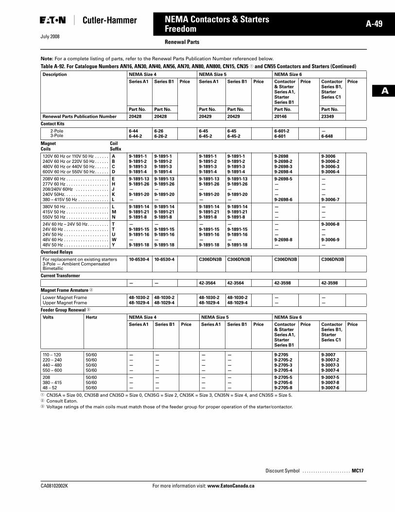
July 2008
CA08102002K For more information visit: www.EatonCanada.ca
A-49NEMA Contactors & Starters
A
FreedomRenewal Parts
Note: For a complete listing of parts, refer to the Renewal Parts Publication Number referenced below.
Table A-92. For Catalogue Numbers AN16, AN30, AN40, AN56, AN70, AN80, AN800, CN15, CN35 � and CN55 Contactors and Starters (Continued)
� CN35A = Size 00, CN35B and CN35D = Size 0, CN35G = Size 2, CN35K = Size 3, CN35N = Size 4, and CN35S = Size 5.� Consult Eaton. � Voltage ratings of the main coils must match those of the feeder group for proper operation of the starter/contactor.
Description NEMA Size 4 NEMA Size 5 NEMA Size 6
Series A1 Series B1 Price Series A1 Series B1 Price Contactor & Starter Series A1, StarterSeries B1
Price Contactor Series B1, StarterSeries C1
Price
Part No. Part No. Part No. Part No. Part No. Part No.
Renewal Parts Publication Number 20428 20428 20429 20429 20146 23349
Contact Kits2-Pole 3-Pole
6-44 6-44-2
6-266-26-2
6-456-45-2
6-456-45-2
6-601-26-601
—6-648
MagnetCoils
CoilSuffix
120V 60 Hz or 110V 50 Hz . . . . . .240V 60 Hz or 220V 50 Hz . . . . . .480V 60 Hz or 440V 50 Hz . . . . . .600V 60 Hz or 550V 50 Hz. . . . . .
ABCD
9-1891-19-1891-29-1891-39-1891-4
9-1891-19-1891-29-1891-39-1891-4
9-1891-19-1891-29-1891-39-1891-4
9-1891-19-1891-29-1891-39-1891-4
9-26989-2698-29-2698-39-2698-4
9-30069-3006-29-3006-39-3006-4
208V 60 Hz . . . . . . . . . . . . . . . . . .277V 60 Hz . . . . . . . . . . . . . . . . . .208/240V 60Hz . . . . . . . . . . . . . .240V 50Hz. . . . . . . . . . . . . . . . . . .380 – 415V 50 Hz . . . . . . . . . . . . .
EHJKL
9-1891-139-1891-26—9-1891-20—
9-1891-139-1891-26—9-1891-20—
9-1891-139-1891-26—9-1891-20—
9-1891-139-1891-26—9-1891-20—
9-2698-5———9-2698-6
————9-3006-7
380V 50 Hz . . . . . . . . . . . . . . . . . .415V 50 Hz . . . . . . . . . . . . . . . . . .550V 50 Hz . . . . . . . . . . . . . . . . . .
LMN
9-1891-149-1891-219-1891-8
9-1891-149-1891-219-1891-8
9-1891-149-1891-219-1891-8
9-1891-149-1891-219-1891-8
———
———
24V 60 Hz – 24V 50 Hz . . . . . . . . .24V 60 Hz . . . . . . . . . . . . . . . . . . .24V 50 Hz . . . . . . . . . . . . . . . . . . .48V 60 Hz . . . . . . . . . . . . . . . . . . .48V 50 Hz . . . . . . . . . . . . . . . . . . .
TTUWY
—9-1891-159-1891-16—9-1891-18
—9-1891-159-1891-16—9-1891-18
—9-1891-159-1891-16—9-1891-18
—9-1891-159-1891-16—9-1891-18
———9-2698-8—
9-3006-8——9-3006-9—
Overload Relays For replacement on existing starters 3-Pole — Ambient Compensated Bimetallic
10-6530-4 10-6530-4 C306DN3B C306DN3B C306DN3B C306DN3B
Current Transformer— — 42-3564 42-3564 42-3598 42-3598
Magnet Frame Armature �
Lower Magnet FrameUpper Magnet Frame
48-1030-248-1029-4
48-1030-248-1029-4
48-1030-248-1029-4
48-1030-248-1029-4
——
——
Feeder Group Renewal �
Volts Hertz NEMA Size 4 NEMA Size 5 NEMA Size 6
Series A1 Series B1 Price Series A1 Series B1 Price Contactor & Starter Series A1, Starter Series B1
Price Contactor Series B1, Starter Series C1
Price
110 – 120220 – 240440 – 480550 – 600
50/6050/6050/6050/60
————
————
————
————
9-27059-2705-29-2705-39-2705-4
9-30079-3007-29-3007-39-3007-4
208380 – 41548 – 52
50/6050/6050/60
———
———
———
———
9-2705-59-2705-69-2705-8
9-3007-59-3007-89-3007-6
Discount Symbol . . . . . . . . . . . . . . . . . . . . . . MC17
Tab33.book Page 49 Sunday, September 21, 2008 10:27 PM
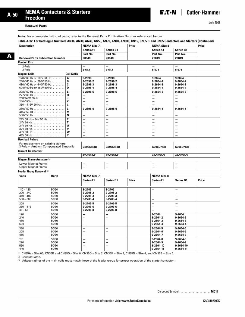
July 2008
A-50
For more information visit: www.EatonCanada.ca CA08102002K
NEMA Contactors & Starters
A
Freedom Renewal Parts
Note: For a complete listing of parts, refer to the Renewal Parts Publication Number referenced below.
Table A-92. For Catalogue Numbers AN16, AN30, AN40, AN56, AN70, AN80, AN800, CN15, CN35 � and CN55 Contactors and Starters (Continued)
� CN35A = Size 00, CN35B and CN35D = Size 0, CN35G = Size 2, CN35K = Size 3, CN35N = Size 4, and CN35S = Size 5.� Consult Eaton. � Voltage ratings of the main coils must match those of the feeder group for proper operation of the starter/contactor.
Description NEMA Size 7 Price NEMA Size 8 Price
Series A1 Series B1 Series A1 Series B1
Part No. Part No. Part No. Part No.
Renewal Parts Publication Number 20848 20848 20849 20849
Contact Kits2-Pole 3-Pole
—6-613
—6-613
—6-571
—6-571
Magnet Coils Coil Suffix120V 60 Hz or 110V 50 Hz . . . . . . . . .240V 60 Hz or 220V 50 Hz. . . . . . . . .480V 60 Hz or 440V 50 Hz. . . . . . . . .600V 60 Hz or 550V 50 Hz. . . . . . . . .
ABCD
9-26989-2698-29-2698-39-2698-4
9-26989-2698-29-2698-39-2698-4
9-26549-2654-29-2654-39-2654-4
9-26549-2654-29-2654-39-2654-4
208V 60 Hz . . . . . . . . . . . . . . . . . . . . .277V 60 Hz . . . . . . . . . . . . . . . . . . . . .208/240V 60Hz . . . . . . . . . . . . . . . . .240V 50Hz . . . . . . . . . . . . . . . . . . . . .380 – 415V 50 Hz . . . . . . . . . . . . . . . .
EHJKL
9-2698-5————
9-2698-5————
9-2654-6————
9-2654-6————
380V 50 Hz . . . . . . . . . . . . . . . . . . . . .415V 50 Hz . . . . . . . . . . . . . . . . . . . . .550V 50 Hz . . . . . . . . . . . . . . . . . . . . .
LMN
9-2698-6——
9-2698-6——
9-2654-5——
9-2654-5——
24V 60 Hz – 24V 50 Hz. . . . . . . . . . . .24V 60 Hz . . . . . . . . . . . . . . . . . . . . . .24V 50 Hz . . . . . . . . . . . . . . . . . . . . . .32V 50 Hz . . . . . . . . . . . . . . . . . . . . . .48V 60 Hz . . . . . . . . . . . . . . . . . . . . . .48V 50 Hz . . . . . . . . . . . . . . . . . . . . . .
TTUVWY
——————
——————
——————
——————
Overload Relays For replacement on existing starters 3-Pole — Ambient Compensated Bimetallic C306DN3B C306DN3B C306DN3B C306DN3B
Current Transformer42-3598-2 42-3598-2 42-3598-3 42-3598-3
Magnet Frame Armature �
Lower Magnet Frame Upper Magnet Frame
——
——
——
——
Feeder Group Renewal �
Volts Hertz NEMA Size 7 NEMA Size 8
Series A1 Series B1 Price Series A1 Series B1 Price
110 – 120220 – 240440 – 480550 – 600
50/6050/6050/6050/60
9-27059-2705-29-2705-39-2705-4
9-27059-2705-29-2705-39-2705-4
————
————
208380 – 41548 – 52
50/6050/6050/60
9-2705-59-2705-69-2705-8
9-2705-59-2705-69-2705-8
———
———
120240480600
50/6050/6050/6050/60
————
————
9-26649-2664-29-2664-39-2664-4
9-26649-2664-29-2664-39-2664-4
380208415
50/6050/6050/60
———
———
9-2664-59-2664-69-2664-7
9-2664-59-2664-69-2664-7
110220550440
50/6050/6050/6050/60
————
————
9-2664-89-2664-99-2664-109-2664-11
9-2664-89-2664-99-2664-109-2664-11
Discount Symbol . . . . . . . . . . . . . . . . . . . . . . . MC17
Tab33.book Page 50 Sunday, September 21, 2008 10:27 PM
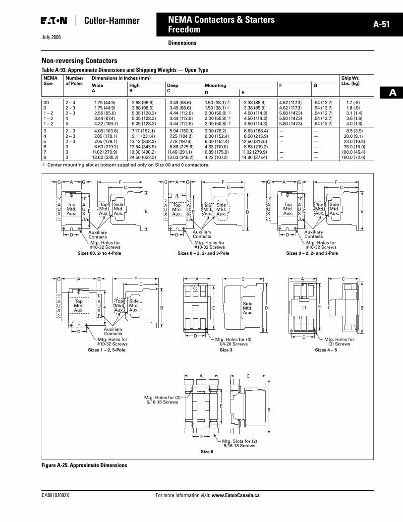
July 2008
CA08102002K For more information visit: www.EatonCanada.ca
A-51NEMA Contactors & Starters
A
FreedomDimensions
Non-reversing ContactorsTable A-93. Approximate Dimensions and Shipping Weights — Open Type
� Center mounting slot at bottom supplied only on Size 00 and 0 contactors.
Figure A-25. Approximate Dimensions
NEMASize
Numberof Poles
Dimensions in Inches (mm) Ship Wt.Lbs. (kg)Wide
AHighB
DeepC
Mounting F G
D E
0001 – 21 – 21 – 2
2 – 42 – 32 – 345
1.75 (44.5)1.75 (44.5)2.56 (65.0)3.44 (87.4)4.32 (109.7)
3.88 (98.6)3.88 (98.6)5.05 (128.3)5.05 (128.3)5.05 (128.3)
3.49 (88.6)3.49 (88.6)4.44 (112.8)4.44 (112.8)4.44 (112.8)
1.50 (38.1) �1.50 (38.1) �2.00 (50.8) �2.00 (50.8) �2.00 (50.8) �
3.38 (85.9)3.38 (85.9)4.50 (114.3)4.50 (114.3)4.50 (114.3)
4.62 (117.3)4.62 (117.3)5.80 (147.3)5.80 (147.3)5.80 (147.3)
.54 (13.7)
.54 (13.7)
.54 (13.7)
.54 (13.7)
.54 (13.7)
1.7 (.8)1.8 (.8)3.1 (1.4)3.6 (1.6)4.0 (1.8)
345678
2 – 32 – 32 – 3333
4.08 (103.6)7.05 (179.1)7.05 (179.1)8.63 (219.2)
11.02 (279.9)13.00 (330.2)
7.17 (182.1)9.11 (231.4)
13.12 (333.2)13.54 (343.9)19.30 (490.2)24.50 (622.3)
5.94 (150.9)7.25 (184.2)7.78 (197.6)8.88 (225.6)
11.46 (291.1)13.63 (346.2)
3.00 (76.2)6.00 (152.4)6.00 (152.4)4.33 (110.0)6.89 (175.0)4.22 (107.2)
6.63 (168.4)8.50 (215.9)
12.50 (317.5)8.63 (219.2)
11.02 (279.9)14.86 (377.4)
——————
——————
8.5 (3.9)20.0 (9.1)23.0 (10.4)35.0 (15.9)
100.0 (45.4)160.0 (72.6)
Mtg. Holes for#10-32 Screws
AUX
AUX
A GG FC
D
TopMtd.Aux.
AuxiliaryContacts
TopMtd.Aux.
SideMtd.Aux.E B
Mtg. Holes for#10-32 Screws
AUX
AUX
A GG FC
D
TopMtd.Aux.
AuxiliaryContacts
TopMtd.Aux.
SideMtd.Aux.E B
Mtg. Holes for#10-32 Screws
AUX
AUX
A GG FC
D
TopMtd.Aux.
AuxiliaryContacts
TopMtd.Aux.
SideMtd.Aux.E B
Sizes 00, 2- to 4-Pole
Mtg. Holes for#10-32 Screws
AUX
AUX
A GG FC
D
TopMtd.Aux.
AuxiliaryContacts
TopMtd.Aux.
SideMtd.Aux.
SideMtd.Aux.
E B
Sizes 1 – 2, 5-Pole
Mtg. Holes for (3)1/4-20 Screws
A C A C
D
BE
Size 3
Mtg. Holes for(3) Screws
D
BE
Sizes 4 – 5
Sizes 0 – 2, 2- and 3-Pole Sizes 0 – 2, 2- and 3-Pole
C
Mtg. Slots for (2)5/16-18 Screws
Mtg. Holes for (2)5/16-18 Screws
D
A
BE
Size 6
Tab33.book Page 51 Sunday, September 21, 2008 10:27 PM
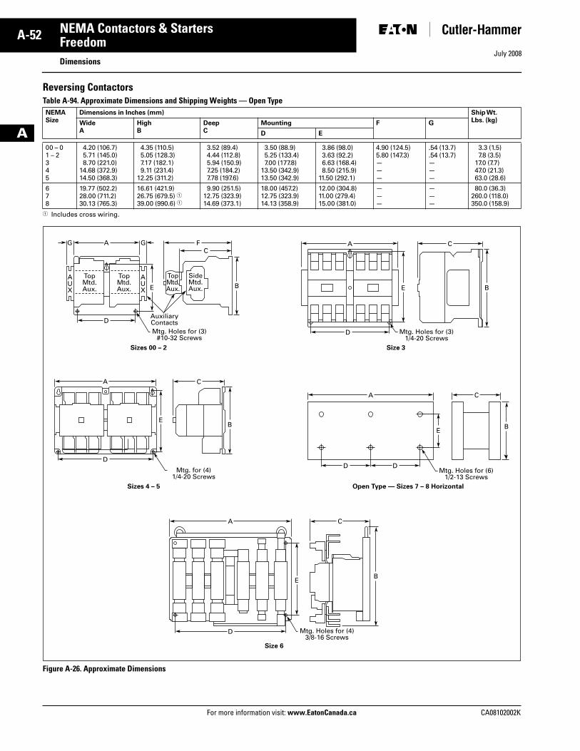
July 2008
A-52
For more information visit: www.EatonCanada.ca CA08102002K
NEMA Contactors & Starters
A
FreedomDimensions
Reversing ContactorsTable A-94. Approximate Dimensions and Shipping Weights — Open Type
� Includes cross wiring.
Figure A-26. Approximate Dimensions
NEMASize
Dimensions in Inches (mm) Ship Wt.Lbs. (kg)Wide
AHighB
DeepC
Mounting F G
D E
00 – 01 – 2345
4.20 (106.7)5.71 (145.0)8.70 (221.0)
14.68 (372.9)14.50 (368.3)
4.35 (110.5)5.05 (128.3)7.17 (182.1)9.11 (231.4)
12.25 (311.2)
3.52 (89.4)4.44 (112.8)5.94 (150.9)7.25 (184.2)7.78 (197.6)
3.50 (88.9)5.25 (133.4)7.00 (177.8)
13.50 (342.9)13.50 (342.9)
3.86 (98.0)3.63 (92.2)6.63 (168.4)8.50 (215.9)
11.50 (292.1)
4.90 (124.5)5.80 (147.3)———
.54 (13.7)
.54 (13.7)———
3.3 (1.5)7.8 (3.5)
17.0 (7.7)47.0 (21.3)63.0 (28.6)
678
19.77 (502.2)28.00 (711.2)30.13 (765.3)
16.61 (421.9)26.75 (679.5) �39.00 (990.6) �
9.90 (251.5)12.75 (323.9)14.69 (373.1)
18.00 (457.2)12.75 (323.9)14.13 (358.9)
12.00 (304.8)11.00 (279.4)15.00 (381.0)
———
———
80.0 (36.3)260.0 (118.0)350.0 (158.9)
Mtg. Holes for (3)#10-32 Screws
AUX
AUX
A GG FC
D
TopMtd.Aux.
TopMtd.Aux.
AuxiliaryContacts
TopMtd.Aux.
SideMtd.Aux.E B
Sizes 00 – 2 Size 3
Mtg. for (4)1/4-20 Screws
A C
D
EB
CA
Sizes 4 – 5
Mtg. Holes for (3)1/4-20 Screws
CA
D
E B
Mtg. Holes for (6)1/2-13 Screws
D D
EB
Open Type — Sizes 7 – 8 Horizontal
Mtg. Holes for (4)3/8-16 Screws
D
A C
EB
Size 6
Tab33.book Page 52 Sunday, September 21, 2008 10:27 PM
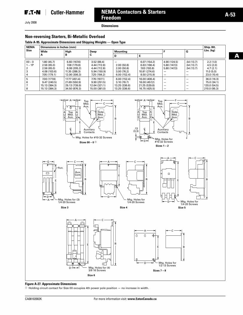
July 2008
CA08102002K For more information visit: www.EatonCanada.ca
A-53NEMA Contactors & Starters
A
FreedomDimensions
Non-reversing Starters, Bi-Metallic OverloadTable A-95. Approximate Dimensions and Shipping Weights — Open Type
Figure A-27. Approximate Dimensions� Holding circuit contact for Size 00 occupies 4th power pole position — no increase in width.
NEMASize
Dimensions in Inches (mm) Ship. Wt.Lbs. (kg)Wide
AHighB
DeepC
Mounting F G
D E
00 – 01 – 1P234
1.80 (45.7)2.56 (65.0)2.56 (65.0)4.08 (103.6)7.05 (179.1)
6.60 (167.6)7.08 (179.8)8.08 (205.2)
11.35 (288.3)12.06 (306.3)
3.52 (89.4)4.44 (112.8)4.44 (112.8)5.94 (150.9)7.25 (184.2)
—2.00 (50.8)2.00 (50.8)3.00 (76.2)6.00 (152.4)
6.07 (154.2)6.63 (168.4)7.63 (193.8)
10.81 (274.6)8.50 (215.9)
4.90 (124.5)5.80 (147.3)5.80 (147.3)——
.54 (13.7)
.54 (13.7)
.54 (13.7)——
2.2 (1.0)4.5 (2.0)4.7 (2.1)
11.0 (5.0)23.0 (10.4)
5678
7.00 (177.8)9.47 (240.5)
15.13 (384.3)15.13 (384.3)
17.77 (451.4)21.69 (550.9)29.13 (739.9)34.50 (876.3)
7.76 (197.1)9.90 (251.5)
12.64 (321.1)15.00 (381.0)
6.00 (152.4)3.10 (78.7)
13.25 (336.6)13.25 (336.6)
16.00 (406.4)18.00 (457.2)21.25 (539.8)16.75 (425.5)
————
————
36.0 (16.3)75.0 (34.1)
120.0 (54.5)210.0 (95.3)
SideMtd.Aux.
D
AUX
Aux.Cont.
Aux.
AUX
A GGC
F
TopMtd.Aux.
AuxiliaryContacts
Mtg. Holes for #10-32 Screws
TopMtd.Aux.
E
C L C L
B
C A CG
E B
Sizes 00 – 0 �Mtg. Holes for#10-32 Screws
Sizes 1 – 2
DA Mtg. Holes for (3)
1/4-20 Screws
Size 3
EB
A C
B
DMtg. Holes for1/4-20 Screws
Size 4
E
D Mtg. Holes for1/4-20 Screws
Size 5
A C
BE
D Mtg. Holes for1/2-13 Screws
Sizes 7 – 8
Size 6
A C
BE
D Mtg. Holes for (4)3/8-16 Screws
SideMtd.Aux.
AUX
AUX
A GG FC
TopMtd.Aux.
AuxiliaryContacts
TopMtd.Aux.
E
.13(3.3)
B
Tab33.book Page 53 Sunday, September 21, 2008 10:27 PM
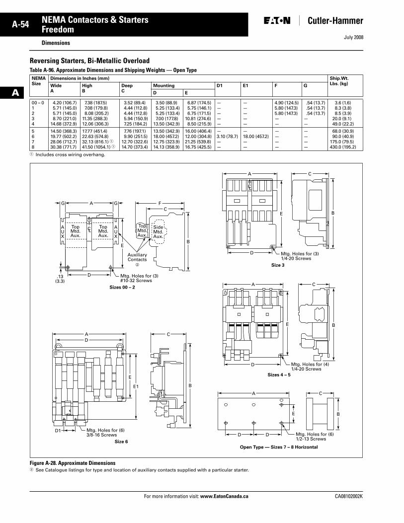
July 2008
A-54
For more information visit: www.EatonCanada.ca CA08102002K
NEMA Contactors & Starters
A
FreedomDimensions
Reversing Starters, Bi-Metallic OverloadTable A-96. Approximate Dimensions and Shipping Weights — Open Type
� Includes cross wiring overhang.
Figure A-28. Approximate Dimensions� See Catalogue listings for type and location of auxiliary contacts supplied with a particular starter.
NEMASize
Dimensions in Inches (mm) Ship.Wt.Lbs. (kg)Wide
AHighB
DeepC
Mounting D1 E1 F G
D E
00 – 01 234
4.20 (106.7)5.71 (145.0)5.71 (145.0)8.70 (221.0)
14.68 (372.9)
7.38 (187.5)7.08 (179.8)8.08 (205.2)
11.35 (288.3)12.06 (306.3)
3.52 (89.4)4.44 (112.8)4.44 (112.8)5.94 (150.9)7.25 (184.2)
3.50 (88.9)5.25 (133.4)5.25 (133.4)7.00 (177.8)
13.50 (342.9)
6.87 (174.5)5.75 (146.1)6.75 (171.5)
10.81 (274.6)8.50 (215.9)
—————
—————
4.90 (124.5)5.80 (147.3)5.80 (147.3)——
.54 (13.7)
.54 (13.7)
.54 (13.7)——
3.6 (1.6)8.3 (3.8)8.5 (3.9)
20.0 (9.1)49.0 (22.2)
5678
14.50 (368.3)19.77 (502.2)28.06 (712.7)30.38 (771.7)
17.77 (451.4)22.63 (574.8)32.13 (816.1) �41.50 (1054.1) �
7.76 (197.1)9.90 (251.5)
12.70 (322.6)14.70 (373.4)
13.50 (342.9)18.00 (457.2)12.75 (323.9)14.13 (358.9)
16.00 (406.4)12.00 (304.8)21.25 (539.8)16.75 (425.5)
—3.10 (78.7)——
—18.00 (457.2)——
————
————
68.0 (30.9)90.0 (40.9)
175.0 (79.5)430.0 (195.2)
SideMtd.Aux.
AUX
AUX
A
D.13(3.3)
GG FC
TopMtd.Aux.
TopMtd.Aux.
AuxiliaryContacts
�
Mtg. Holes for (3)#10-32 Screws
TopMtd.Aux.
EB
Sizes 00 – 2
A
D1
CD
Mtg. Holes for (6)3/8-16 Screws
E
E1 B
Size 6
D Mtg. Holes for (3)1/4-20 Screws
E
CA
B
Size 3
D Mtg. Holes for (4)1/4-20 Screws
E
CA
B
Sizes 4 – 5
DD Mtg. Holes for (6)1/2-13 Screws
E
A C
B
Open Type — Sizes 7 – 8 Horizontal
C L
C L
Tab33.book Page 54 Sunday, September 21, 2008 10:27 PM
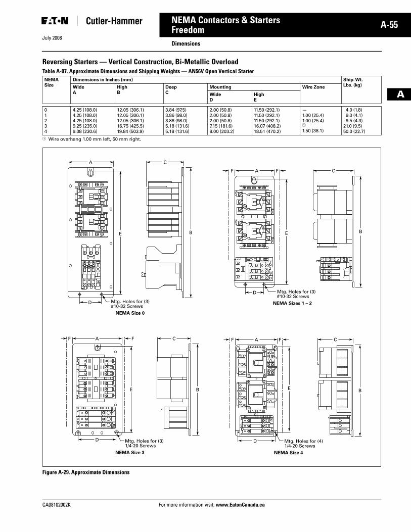
July 2008
CA08102002K For more information visit: www.EatonCanada.ca
A-55NEMA Contactors & Starters
A
FreedomDimensions
Reversing Starters — Vertical Construction, Bi-Metallic OverloadTable A-97. Approximate Dimensions and Shipping Weights — AN56V Open Vertical Starter
� Wire overhang 1.00 mm left, 50 mm right.
Figure A-29. Approximate Dimensions
NEMASize
Dimensions in Inches (mm) Ship. Wt.Lbs. (kg)Wide
AHighB
DeepC
Mounting Wire Zone
WideD
HighE
01234
4.25 (108.0)4.25 (108.0)4.25 (108.0)9.25 (235.0)9.08 (230.6)
12.05 (306.1)12.05 (306.1)12.05 (306.1)16.75 (425.5)19.84 (503.9)
3.84 (97.5)3.86 (98.0)3.86 (98.0)5.18 (131.6)5.18 (131.6)
2.00 (50.8)2.00 (50.8)2.00 (50.8)7.15 (181.6)8.00 (203.2)
11.50 (292.1)11.50 (292.1)11.50 (292.1)16.07 (408.2)18.51 (470.2)
—1.00 (25.4)1.00 (25.4)�
1.50 (38.1)
4.0 (1.8)9.0 (4.1)9.5 (4.3)
21.0 (9.5)50.0 (22.7)
Mtg. Holes for (3)#10-32 Screws
NEMA Size 0
D
E
A
B
C
Mtg. Holes for (3)#10-32 Screws
NEMA Sizes 1 – 2
D
E
A CFF
B
Mtg. Holes for (3)1/4-20 Screws
NEMA Size 3
D
E
A CFF
B
Mtg. Holes for (4)1/4-20 Screws
NEMA Size 4
D
E
A CFF
B
Tab33.book Page 55 Sunday, September 21, 2008 10:27 PM
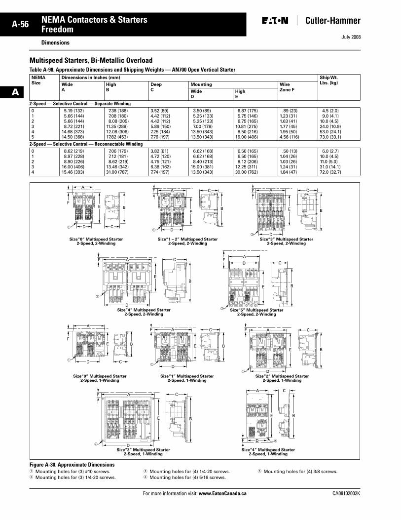
July 2008
A-56
For more information visit: www.EatonCanada.ca CA08102002K
NEMA Contactors & Starters
A
FreedomDimensions
Multispeed Starters, Bi-Metallic OverloadTable A-98. Approximate Dimensions and Shipping Weights — AN700 Open Vertical Starter
Figure A-30. Approximate Dimensions � Mounting holes for (3) #10 screws.� Mounting holes for (3) 1/4-20 screws.
� Mounting holes for (4) 1/4-20 screws.� Mounting holes for (4) 5/16 screws.
� Mounting holes for (4) 3/8 screws.
NEMASize
Dimensions in Inches (mm) Ship Wt.Lbs. (kg)Wide
AHighB
DeepC
Mounting WireZone FWide
DHighE
2-Speed — Selective Control — Separate Winding 012345
5.19 (132)5.66 (144)5.66 (144)8.72 (221)
14.68 (373)14.50 (368)
7.38 (188)7.08 (180)8.08 (205)
11.35 (288)12.06 (306)17.82 (453)
3.52 (89)4.42 (112)4.42 (112)5.89 (150)7.25 (184)7.76 (197)
3.50 (89)5.25 (133)5.25 (133)7.00 (178)
13.50 (343)13.50 (343)
6.87 (175)5.75 (146)6.75 (165)
10.81 (275)8.50 (216)
16.00 (406)
.89 (23)1.23 (31)1.63 (41)1.77 (45)1.95 (50)4.56 (116)
4.5 (2.0)9.0 (4.1)
10.0 (4.5)24.0 (10.9)53.0 (24.1)73.0 (33.1)
2-Speed — Selective Control — Reconnectable Winding01234
8.62 (219)8.97 (228)8.90 (226)
16.00 (406)15.46 (393)
7.06 (179)7.12 (181)8.62 (219)
13.46 (342)31.00 (787)
3.82 (81)4.72 (120)4.75 (121)6.38 (162)7.74 (197)
6.62 (168)6.62 (168)8.40 (213)
15.00 (381)13.50 (343)
6.50 (165)6.50 (165)8.12 (206)
12.25 (311)30.00 (762)
.50 (13)1.04 (26)1.03 (26)1.24 (31)1.84 (47)
6.0 (2.7)10.0 (4.5)11.0 (5.0)31.0 (14.1)72.0 (32.7)
��
�
E B
A
D C
F
EB
A
D
CF
E B
A
D
CF
Size“3” Multispeed Starter2-Speed, 2-Winding
Size“1 – 2” Multispeed Starter2-Speed, 2-Winding
Size“0” Multispeed Starter2-Speed, 2-Winding
EB
A
D
CF
E B
AF
D C
�
Size“4” Multispeed Starter2-Speed, 2-Winding
�Size“5” Multispeed Starter
2-Speed, 2-Winding
E B
A
D
CF
E B
A
D
C
F ��
Size“4” Multispeed Starter2-Speed, 1-Winding
Size“3” Multispeed Starter2-Speed, 1-Winding
E B
A
D C
F
E B
A
D
CF
E B
A
D
CF
�
�
�
Size“2” Multispeed Starter2-Speed, 1-Winding
Size“1” Multispeed Starter2-Speed, 1-Winding
Size“0” Multispeed Starter2-Speed, 1-Winding
Tab33.book Page 56 Sunday, September 21, 2008 10:27 PM
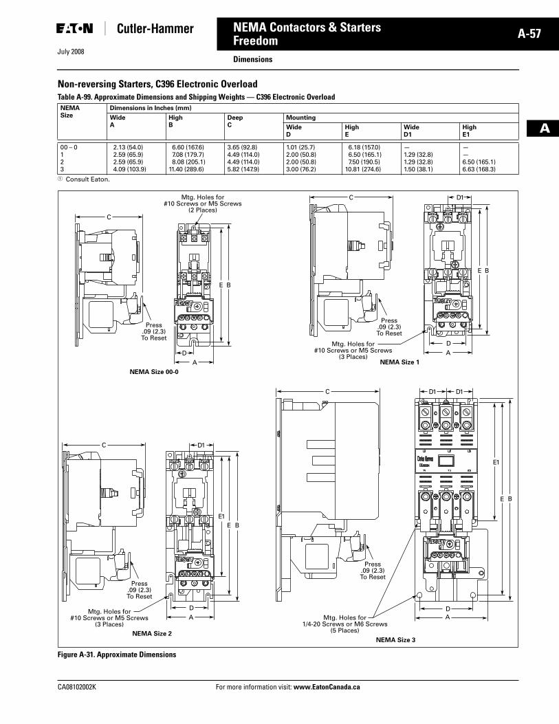
July 2008
CA08102002K For more information visit: www.EatonCanada.ca
A-57NEMA Contactors & Starters
A
FreedomDimensions
Non-reversing Starters, C396 Electronic OverloadTable A-99. Approximate Dimensions and Shipping Weights — C396 Electronic Overload
� Consult Eaton.
Figure A-31. Approximate Dimensions
NEMASize
Dimensions in Inches (mm)
WideA
HighB
DeepC
Mounting
WideD
HighE
WideD1
HighE1
00 – 0123
2.13 (54.0)2.59 (65.9)2.59 (65.9)4.09 (103.9)
6.60 (167.6)7.08 (179.7)8.08 (205.1)
11.40 (289.6)
3.65 (92.8)4.49 (114.0)4.49 (114.0)5.82 (147.9)
1.01 (25.7)2.00 (50.8)2.00 (50.8)3.00 (76.2)
6.18 (157.0)6.50 (165.1)7.50 (190.5)
10.81 (274.6)
—1.29 (32.8)1.29 (32.8)1.50 (38.1)
——6.50 (165.1)6.63 (168.3)
NEMA Size 1
NEMA Size 00-0
D1C
C
D
E B
ADA
E1
E B
E1E B
BE
D1D1C
D1C
NEMA Size 3
DAMtg. Holes for
1/4-20 Screws or M6 Screws(5 Places)
Press.09 (2.3)To Reset
Mtg. Holes for#10 Screws or M5 Screws
(3 Places)
Mtg. Holes for#10 Screws or M5 Screws
(2 Places)
Mtg. Holes for#10 Screws or M5 Screws
(3 Places)
Press.09 (2.3)To Reset
Press.09 (2.3)To Reset
Press.09 (2.3)To Reset
NEMA Size 2
DA
Tab33.book Page 57 Sunday, September 21, 2008 10:27 PM
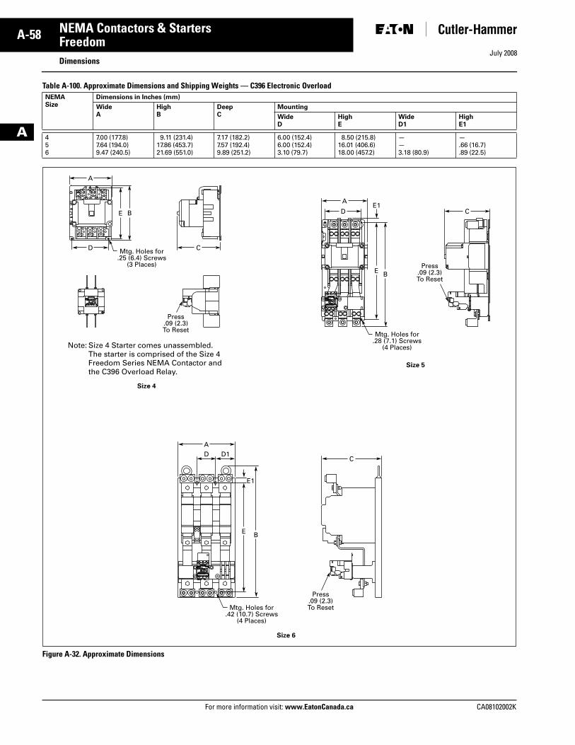
July 2008
A-58
For more information visit: www.EatonCanada.ca CA08102002K
NEMA Contactors & Starters
A
FreedomDimensions
Table A-100. Approximate Dimensions and Shipping Weights — C396 Electronic Overload
Figure A-32. Approximate Dimensions
NEMASize
Dimensions in Inches (mm)
WideA
HighB
DeepC
Mounting
WideD
HighE
WideD1
HighE1
456
7.00 (177.8)7.64 (194.0)9.47 (240.5)
9.11 (231.4)17.86 (453.7)21.69 (551.0)
7.17 (182.2)7.57 (192.4)9.89 (251.2)
6.00 (152.4)6.00 (152.4)3.10 (79.7)
8.50 (215.8)16.01 (406.6)18.00 (457.2)
——3.18 (80.9)
—.66 (16.7).89 (22.5)
E1
BE
E1
BE
BE D C
A
DC
D1A
A
D C
Mtg. Holes for.28 (7.1) Screws
(4 Places)
Press.09 (2.3)To Reset
Mtg. Holes for.42 (10.7) Screws
(4 Places)
Press.09 (2.3)To Reset
Mtg. Holes for.25 (6.4) Screws
(3 Places)
Press.09 (2.3)To Reset
Note: Size 4 Starter comes unassembled. The starter is comprised of the Size 4 Freedom Series NEMA Contactor and the C396 Overload Relay.
Size 4
Size 5
Size 6
Tab33.book Page 58 Sunday, September 21, 2008 10:27 PM
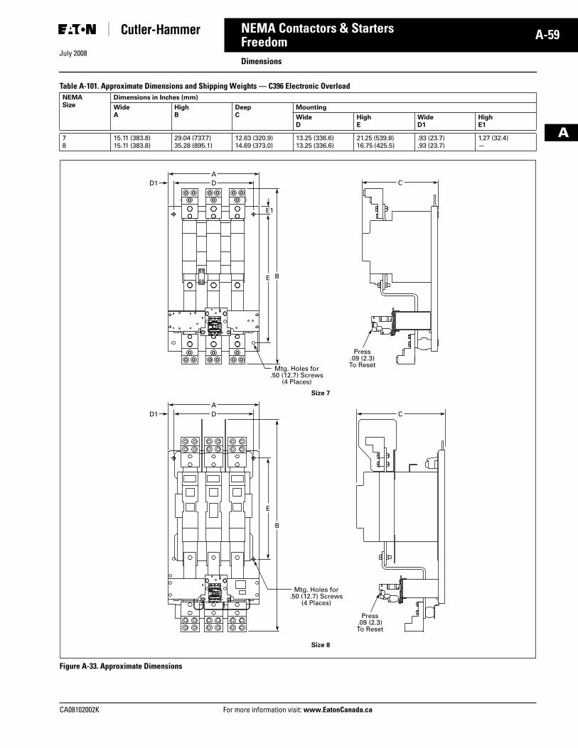
July 2008
CA08102002K For more information visit: www.EatonCanada.ca
A-59NEMA Contactors & Starters
A
FreedomDimensions
Table A-101. Approximate Dimensions and Shipping Weights — C396 Electronic Overload
Figure A-33. Approximate Dimensions
NEMASize
Dimensions in Inches (mm)
WideA
HighB
DeepC
Mounting
WideD
HighE
WideD1
HighE1
78
15.11 (383.8)15.11 (383.8)
29.04 (737.7)35.28 (895.1)
12.63 (320.9)14.69 (373.0)
13.25 (336.6)13.25 (336.6)
21.25 (539.8)16.75 (425.5)
.93 (23.7)
.93 (23.7)1.27 (32.4)—
E1
B
B
E
E
DD1
D1
A
DA
C
C
Mtg. Holes for.50 (12.7) Screws
(4 Places)
Press.09 (2.3)To Reset
Mtg. Holes for.50 (12.7) Screws
(4 Places)
Press.09 (2.3)To Reset
Size 7
Size 8
Tab33.book Page 59 Sunday, September 21, 2008 10:27 PM
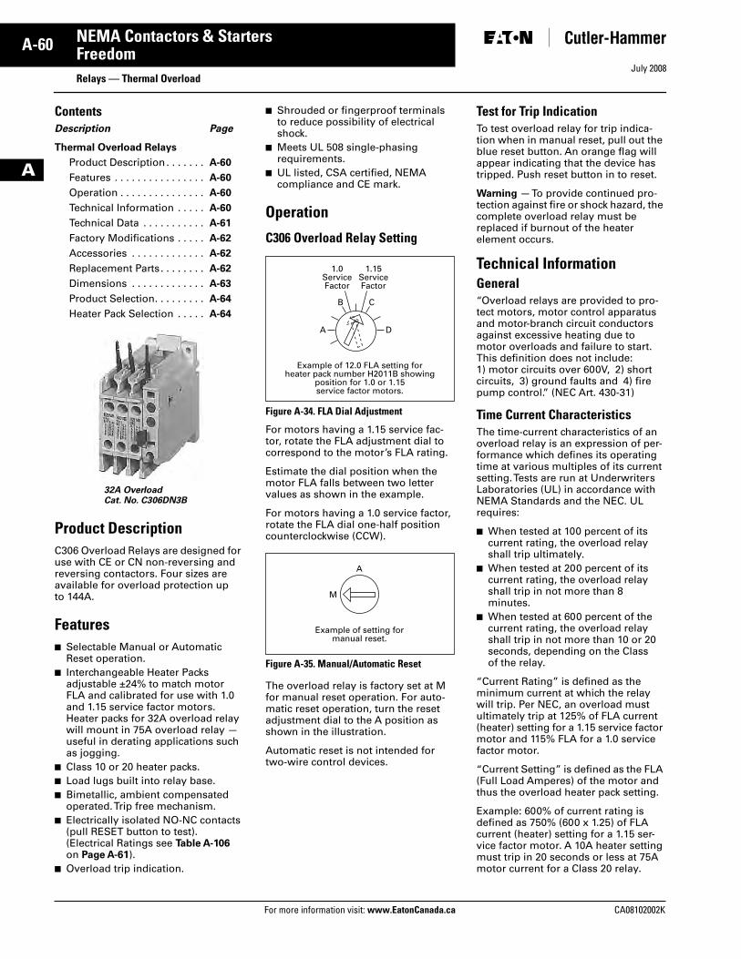
July 2008
A-60
For more information visit: www.EatonCanada.ca CA08102002K
NEMA Contactors & Starters
A
FreedomRelays — Thermal Overload
ContentsDescription Page
Thermal Overload Relays
Product Description . . . . . . . A-60
Features . . . . . . . . . . . . . . . . A-60
Operation . . . . . . . . . . . . . . . A-60
Technical Information . . . . . A-60
Technical Data . . . . . . . . . . . A-61
Factory Modifications . . . . . A-62
Accessories . . . . . . . . . . . . . A-62
Replacement Parts. . . . . . . . A-62
Dimensions . . . . . . . . . . . . . A-63
Product Selection. . . . . . . . . A-64
Heater Pack Selection . . . . . A-64
Product DescriptionC306 Overload Relays are designed for use with CE or CN non-reversing and reversing contactors. Four sizes are available for overload protection up to 144A.
Features■ Selectable Manual or Automatic
Reset operation.■ Interchangeable Heater Packs
adjustable ±24% to match motor FLA and calibrated for use with 1.0 and 1.15 service factor motors. Heater packs for 32A overload relay will mount in 75A overload relay — useful in derating applications such as jogging.
■ Class 10 or 20 heater packs.■ Load lugs built into relay base.■ Bimetallic, ambient compensated
operated. Trip free mechanism.■ Electrically isolated NO-NC contacts
(pull RESET button to test).(Electrical Ratings see Table A-106 on Page A-61).
■ Overload trip indication.
■ Shrouded or fingerproof terminals to reduce possibility of electrical shock.
■ Meets UL 508 single-phasing requirements.
■ UL listed, CSA certified, NEMA compliance and CE mark.
Operation
C306 Overload Relay Setting
Figure A-34. FLA Dial Adjustment
For motors having a 1.15 service fac-tor, rotate the FLA adjustment dial to correspond to the motor’s FLA rating.
Estimate the dial position when the motor FLA falls between two letter values as shown in the example.
For motors having a 1.0 service factor, rotate the FLA dial one-half position counterclockwise (CCW).
Figure A-35. Manual/Automatic Reset
The overload relay is factory set at M for manual reset operation. For auto-matic reset operation, turn the reset adjustment dial to the A position as shown in the illustration.
Automatic reset is not intended for two-wire control devices.
Test for Trip IndicationTo test overload relay for trip indica-tion when in manual reset, pull out the blue reset button. An orange flag will appear indicating that the device has tripped. Push reset button in to reset.
Warning — To provide continued pro-tection against fire or shock hazard, the complete overload relay must be replaced if burnout of the heater element occurs.
Technical InformationGeneral“Overload relays are provided to pro-tect motors, motor control apparatus and motor-branch circuit conductors against excessive heating due to motor overloads and failure to start. This definition does not include:1) motor circuits over 600V, 2) short circuits, 3) ground faults and 4) fire pump control.” (NEC Art. 430-31)
Time Current CharacteristicsThe time-current characteristics of an overload relay is an expression of per-formance which defines its operating time at various multiples of its current setting. Tests are run at Underwriters Laboratories (UL) in accordance with NEMA Standards and the NEC. UL requires:
■ When tested at 100 percent of its current rating, the overload relay shall trip ultimately.
■ When tested at 200 percent of its current rating, the overload relay shall trip in not more than 8 minutes.
■ When tested at 600 percent of the current rating, the overload relay shall trip in not more than 10 or 20 seconds, depending on the Class of the relay.
“Current Rating” is defined as the minimum current at which the relay will trip. Per NEC, an overload must ultimately trip at 125% of FLA current (heater) setting for a 1.15 service factor motor and 115% FLA for a 1.0 service factor motor.
“Current Setting” is defined as the FLA (Full Load Amperes) of the motor and thus the overload heater pack setting.
Example: 600% of current rating is defined as 750% (600 x 1.25) of FLA current (heater) setting for a 1.15 ser-vice factor motor. A 10A heater setting must trip in 20 seconds or less at 75A motor current for a Class 20 relay.
32A OverloadCat. No. C306DN3B
1.0ServiceFactor
1.15ServiceFactor
A
B C
D
Example of 12.0 FLA setting forheater pack number H2011B showing
position for 1.0 or 1.15service factor motors.
A
M
Example of setting formanual reset.
Tab33.book Page 60 Sunday, September 21, 2008 10:27 PM
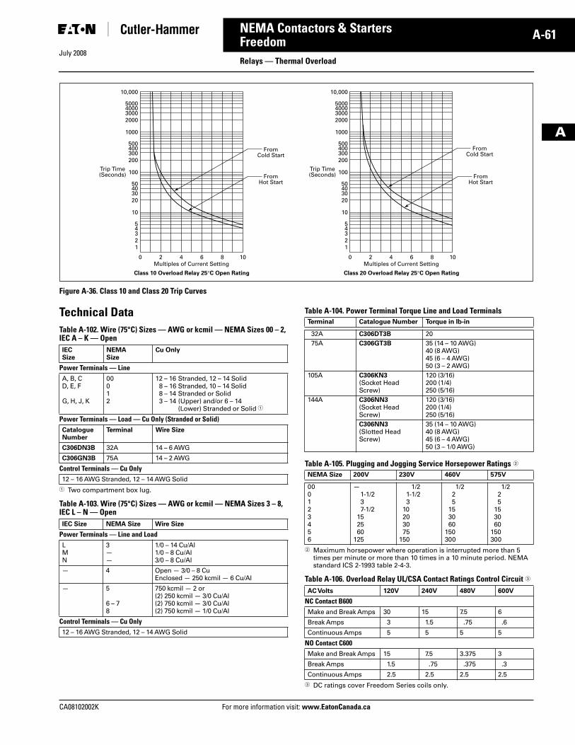
July 2008
CA08102002K For more information visit: www.EatonCanada.ca
A-61NEMA Contactors & Starters
A
FreedomRelays — Thermal Overload
Figure A-36. Class 10 and Class 20 Trip Curves
Technical DataTable A-102. Wire (75°C) Sizes — AWG or kcmil — NEMA Sizes 00 – 2, IEC A – K — Open
� Two compartment box lug.
Table A-103. Wire (75°C) Sizes — AWG or kcmil — NEMA Sizes 3 – 8, IEC L – N — Open
Table A-104. Power Terminal Torque Line and Load Terminals
Table A-105. Plugging and Jogging Service Horsepower Ratings �
� Maximum horsepower where operation is interrupted more than 5 times per minute or more than 10 times in a 10 minute period. NEMA standard ICS 2-1993 table 2-4-3.
Table A-106. Overload Relay UL/CSA Contact Ratings Control Circuit �
� DC ratings cover Freedom Series coils only.
0
12345
10
20304050
100
200300400500
1000
2000300040005000
10,000
2 4 6 8 10
FromHot Start
FromCold Start
Multiples of Current Setting
Trip Time(Seconds)
Class 10 Overload Relay 25°C Open Rating
0
12345
10
20304050
100
200300400500
1000
2000300040005000
10,000
2 4 6 8 10
FromHot Start
FromCold Start
Multiples of Current Setting
Trip Time(Seconds)
Class 20 Overload Relay 25°C Open Rating
IECSize
NEMASize
Cu Only
Power Terminals — LineA, B, CD, E, F
G, H, J, K
00012
12 – 16 Stranded, 12 – 14 Solid8 – 16 Stranded, 10 – 14 Solid8 – 14 Stranded or Solid3 – 14 (Upper) and/or 6 – 14
(Lower) Stranded or Solid �
Power Terminals — Load — Cu Only (Stranded or Solid)CatalogueNumber
Terminal Wire Size
C306DN3B 32A 14 – 6 AWG
C306GN3B 75A 14 – 2 AWG
Control Terminals — Cu Only12 – 16 AWG Stranded, 12 – 14 AWG Solid
IEC Size NEMA Size Wire Size
Power Terminals — Line and LoadLMN
3——
1/0 – 14 Cu/Al1/0 – 8 Cu/Al3/0 – 8 Cu/Al
— 4 Open — 3/0 – 8 CuEnclosed — 250 kcmil — 6 Cu/Al
— 5
6 – 78
750 kcmil — 2 or(2) 250 kcmil — 3/0 Cu/Al(2) 750 kcmil — 3/0 Cu/Al(2) 750 kcmil — 1/0 Cu/Al
Control Terminals — Cu Only12 – 16 AWG Stranded, 12 – 14 AWG Solid
Terminal Catalogue Number Torque in lb-in
32A C306DT3B 2075A C306GT3B 35 (14 – 10 AWG)
40 (8 AWG)45 (6 – 4 AWG)50 (3 – 2 AWG)
105A C306KN3(Socket Head Screw)
120 (3/16)200 (1/4)250 (5/16)
144A C306NN3(Socket Head Screw)
120 (3/16)200 (1/4)250 (5/16)
C306NN3(Slotted Head Screw)
35 (14 – 10 AWG)40 (8 AWG)45 (6 – 4 AWG)50 (3 – 1/0 AWG)
NEMA Size 200V 230V 460V 575V
000123456
—1-1/237-1/2
152560
125
1/21-1/23
10203075
150
1/225
153060
150300
1/225
153060
150300
AC Volts 120V 240V 480V 600V
NC Contact B600Make and Break Amps 30 15 7.5 6
Break Amps 3 1.5 .75 .6
Continuous Amps 5 5 5 5
NO Contact C600Make and Break Amps 15 7.5 3.375 3
Break Amps 1.5 .75 .375 .3
Continuous Amps 2.5 2.5 2.5 2.5
Tab33.book Page 61 Sunday, September 21, 2008 10:27 PM
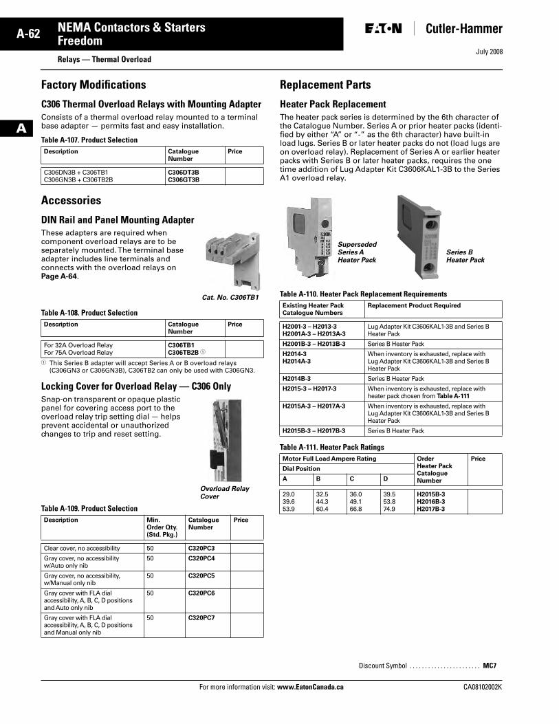
July 2008
A-62
For more information visit: www.EatonCanada.ca CA08102002K
NEMA Contactors & Starters
A
FreedomRelays — Thermal Overload
Factory Modifications
C306 Thermal Overload Relays with Mounting AdapterConsists of a thermal overload relay mounted to a terminal base adapter — permits fast and easy installation.
Table A-107. Product Selection
Accessories
DIN Rail and Panel Mounting AdapterThese adapters are required when component overload relays are to be separately mounted. The terminal base adapter includes line terminals and connects with the overload relays onPage A-64.
Table A-108. Product Selection
� This Series B adapter will accept Series A or B overload relays (C306GN3 or C306GN3B), C306TB2 can only be used with C306GN3.
Locking Cover for Overload Relay — C306 OnlySnap-on transparent or opaque plastic panel for covering access port to the overload relay trip setting dial — helps prevent accidental or unauthorized changes to trip and reset setting.
Table A-109. Product Selection
Replacement Parts
Heater Pack Replacement The heater pack series is determined by the 6th character of the Catalogue Number. Series A or prior heater packs (identi-fied by either “A” or “-” as the 6th character) have built-in load lugs. Series B or later heater packs do not (load lugs are on overload relay). Replacement of Series A or earlier heater packs with Series B or later heater packs, requires the one time addition of Lug Adapter Kit C3606KAL1-3B to the Series A1 overload relay.
Table A-110. Heater Pack Replacement Requirements
Table A-111. Heater Pack Ratings
Description CatalogueNumber
Price
C306DN3B + C306TB1C306GN3B + C306TB2B
C306DT3BC306GT3B
Description CatalogueNumber
Price
For 32A Overload RelayFor 75A Overload Relay
C306TB1C306TB2B �
Description Min.Order Qty.(Std. Pkg.)
CatalogueNumber
Price
Clear cover, no accessibility 50 C320PC3
Gray cover, no accessibility w/Auto only nib
50 C320PC4
Gray cover, no accessibility, w/Manual only nib
50 C320PC5
Gray cover with FLA dial accessibility, A, B, C, D positions and Auto only nib
50 C320PC6
Gray cover with FLA dial accessibility, A, B, C, D positions and Manual only nib
50 C320PC7
Cat. No. C306TB1
Overload Relay Cover
Existing Heater PackCatalogue Numbers
Replacement Product Required
H2001-3 – H2013-3H2001A-3 – H2013A-3
Lug Adapter Kit C3606KAL1-3B and Series B Heater Pack
H2001B-3 – H2013B-3 Series B Heater Pack
H2014-3H2014A-3
When inventory is exhausted, replace with Lug Adapter Kit C3606KAL1-3B and Series B Heater Pack
H2014B-3 Series B Heater Pack
H2015-3 – H2017-3 When inventory is exhausted, replace with heater pack chosen from Table A-111
H2015A-3 – H2017A-3 When inventory is exhausted, replace with Lug Adapter Kit C3606KAL1-3B and Series B Heater Pack
H2015B-3 – H2017B-3 Series B Heater Pack
Motor Full Load Ampere Rating Order Heater PackCatalogue Number
Price
Dial Position
A B C D
29.039.653.9
32.544.360.4
36.049.166.8
39.553.874.9
H2015B-3H2016B-3H2017B-3
Discount Symbol . . . . . . . . . . . . . . . . . . . . . . . MC7
SupersededSeries AHeater Pack
Series BHeater Pack
Tab33.book Page 62 Sunday, September 21, 2008 10:27 PM
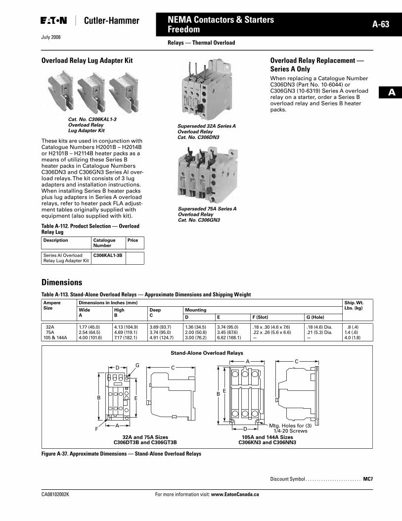
July 2008
CA08102002K For more information visit: www.EatonCanada.ca
A-63NEMA Contactors & Starters
A
FreedomRelays — Thermal Overload
Overload Relay Lug Adapter Kit
These kits are used in conjunction with Catalogue Numbers H2001B – H2014B or H2101B – H2114B heater packs as a means of utilizing these Series B heater packs in Catalogue Numbers C306DN3 and C306GN3 Series Al over-load relays. The kit consists of 3 lug adapters and installation instructions. When installing Series B heater packs plus lug adapters in Series A overload relays, refer to heater pack FLA adjust-ment tables originally supplied with equipment (also supplied with kit).
Table A-112. Product Selection — Overload Relay Lug
Overload Relay Replacement — Series A OnlyWhen replacing a Catalogue Number C306DN3 (Part No. 10-6044) or C306GN3 (10-6319) Series A overload relay on a starter, order a Series B overload relay and Series B heater packs.
DimensionsTable A-113. Stand-Alone Overload Relays — Approximate Dimensions and Shipping Weight
Figure A-37. Approximate Dimensions — Stand-Alone Overload Relays
Description Catalogue Number
Price
Series Al OverloadRelay Lug Adapter Kit
C306KAL1-3B
Cat. No. C306KAL1-3Overload RelayLug Adapter Kit
Superseded 32A Series A Overload RelayCat. No. C306DN3
Superseded 75A Series AOverload RelayCat. No. C306GN3
AmpereSize
Dimensions in Inches (mm) Ship. Wt.Lbs. (kg)Wide
AHighB
DeepC
Mounting
D E F (Slot) G (Hole)
32A75A
105 & 144A
1.77 (45.0)2.54 (64.5)4.00 (101.6)
4.13 (104.9)4.69 (119.1)7.17 (182.1)
3.69 (93.7)3.74 (95.0)4.91 (124.7)
1.36 (34.5)2.00 (50.8)3.00 (76.2)
3.74 (95.0)3.45 (87.6)6.62 (168.1)
.18 x .30 (4.6 x 7.6)
.22 x .26 (5.6 x 6.6)—
.18 (4.6) Dia.
.21 (5.3) Dia.—
.8 (.4)1.4 (.6)4.0 (1.8)
Stand-Alone Overload Relays
DA C
C
EBE
B
ADF
32A and 75A SizesC306DT3B and C306GT3B
105A and 144A Sizes C306KN3 and C306NN3
G
Mtg. Holes for (3)1/4-20 Screws
Discount Symbol . . . . . . . . . . . . . . . . . . . . . . . . . MC7
Tab33.book Page 63 Sunday, September 21, 2008 10:27 PM
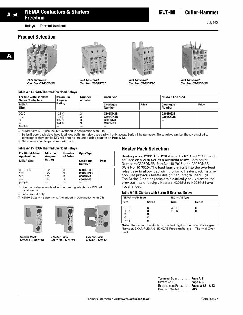
July 2008
A-64
For more information visit: www.EatonCanada.ca CA08102002K
NEMA Contactors & Starters
A
FreedomRelays — Thermal Overload
Product Selection
Table A-114. C306 Thermal Overload Relays
� NEMA Sizes 5 – 8 use the 32A overload in conjunction with CTs. � Series B overload relays have load lugs built into relay base and will only accept Series B heater packs. These relays can be directly attached to
contactor or they can be DIN rail or panel mounted using adapter on Page A-62.� These relays can be panel mounted only.
Table A-115. C306 Thermal Overload Relays
� Overload relay assembled with mounting adapter for DIN rail or panel mount.
� Panel mount only.� NEMA Sizes 5 – 8 use the 32A overload in conjunction with CTs.
Heater Pack SelectionHeater packs H2001B to H2017B and H2101B to H2117B are to be used only with Series B overload relays Catalogue Numbers C306DN3B (Part No. 10-7016) and C306GN3B (Part No. 10-7020). The load lugs are built into the overload relay base to allow load wiring prior to heater pack installa-tion. The previous heater design had integral load lugs. The Series B heater packs are electrically equivalent to the previous heater design. Heaters H2018-3 to H2024-3 have not changed.
Table A-116. Starters with Series B Overload Relays
Note: The series of a starter is the last digit of the listed Catalogue Number. EXAMPLE: AN16DN0AB.FreedomRelays — Thermal Over-load
For Use with Freedom Series Contactors
MaximumAmpereRating
Numberof Poles
Open Type NEMA 1 Enclosed
NEMASize
CatalogueNumber
Price CatalogueNumber
Price
00, 01, 2345 – 8 �
32 �75 �
105 �144 �—
3333—
C306DN3BC306GN3BC306KN3C306NN3—
C306DG3BC306GG3B—
75A OverloadCat. No. C306GN3B
75A OverloadCat. No. C306GT3B
32A OverloadCat. No. C306DT3B
32A OverloadCat. No. C306DN3B
For Stand-Alone Applications
Maximum Ampere Rating
Number of Poles
Open Type
NEMA Size CatalogueNumber
Price
00, 0, 1 �1 �3 �4 �5 – 8 �
3275
105144—
3333—
C306DT3BC306GT3BC306KN3C306NN3—
Heater PackH2001B – H2017B
Heater PackH2101B – H2117B
Heater PackH2018 – H2024
NEMA — AN Type IEC — AE Type
Size Series Size Series
00 – 01 – 2567 – 8
CBBCB
A – FG – K
CB
Technical Data . . . . . . . . . Page A-61Dimensions . . . . . . . . . . . . Page A-63Replacement Parts. . . . . . Pages A-62 – A-63Discount Symbol . . . . . . . . MC7
Tab33.book Page 64 Sunday, September 21, 2008 10:27 PM
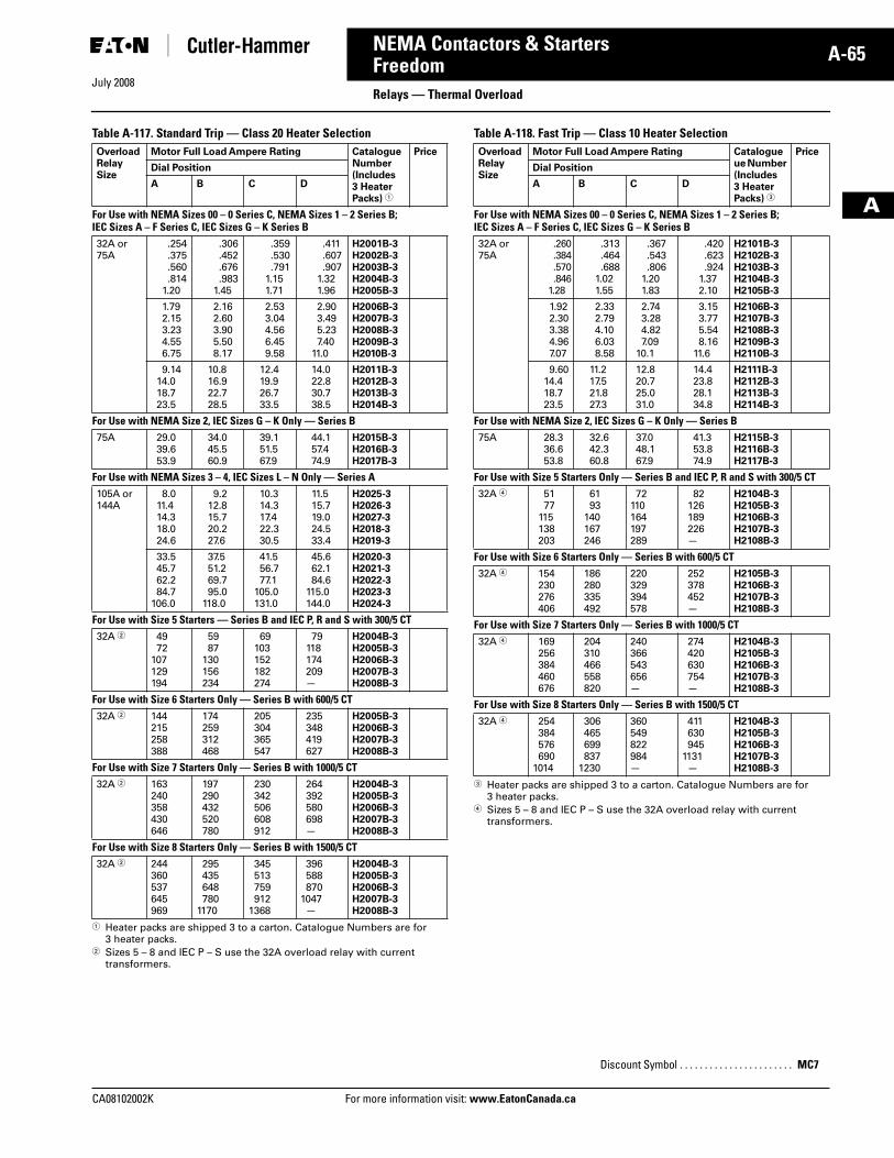
July 2008
CA08102002K For more information visit: www.EatonCanada.ca
A-65NEMA Contactors & Starters
A
FreedomRelays — Thermal Overload
Table A-117. Standard Trip — Class 20 Heater Selection
� Heater packs are shipped 3 to a carton. Catalogue Numbers are for 3 heater packs.
� Sizes 5 – 8 and IEC P – S use the 32A overload relay with current transformers.
Table A-118. Fast Trip — Class 10 Heater Selection
� Heater packs are shipped 3 to a carton. Catalogue Numbers are for 3 heater packs.
� Sizes 5 – 8 and IEC P – S use the 32A overload relay with current transformers.
OverloadRelaySize
Motor Full Load Ampere Rating Catalogue Number (Includes 3 Heater Packs) �
Price
Dial Position
A B C D
For Use with NEMA Sizes 00 – 0 Series C, NEMA Sizes 1 – 2 Series B;IEC Sizes A – F Series C, IEC Sizes G – K Series B32A or75A
.254
.375
.560
.8141.20
.306
.452
.676
.9831.45
.359
.530
.7911.151.71
.411
.607
.9071.321.96
H2001B-3H2002B-3H2003B-3H2004B-3H2005B-3
1.792.153.234.556.75
2.162.603.905.508.17
2.533.044.566.459.58
2.903.495.237.40
11.0
H2006B-3H2007B-3H2008B-3H2009B-3H2010B-3
9.1414.018.723.5
10.816.922.728.5
12.419.926.733.5
14.022.830.738.5
H2011B-3H2012B-3H2013B-3H2014B-3
For Use with NEMA Size 2, IEC Sizes G – K Only — Series B75A 29.0
39.653.9
34.045.560.9
39.151.567.9
44.157.474.9
H2015B-3H2016B-3H2017B-3
For Use with NEMA Sizes 3 – 4, IEC Sizes L – N Only — Series A105A or144A
8.011.414.318.024.6
9.212.815.720.227.6
10.314.317.422.330.5
11.515.719.024.533.4
H2025-3H2026-3H2027-3H2018-3H2019-3
33.545.762.284.7
106.0
37.551.269.795.0
118.0
41.556.777.1
105.0131.0
45.662.184.6
115.0144.0
H2020-3H2021-3H2022-3H2023-3H2024-3
For Use with Size 5 Starters — Series B and IEC P, R and S with 300/5 CT32A � 49
72107129194
5987
130156234
69103152182274
79118174209—
H2004B-3H2005B-3H2006B-3H2007B-3H2008B-3
For Use with Size 6 Starters Only — Series B with 600/5 CT32A � 144
215258388
174259312468
205304365547
235348419627
H2005B-3H2006B-3H2007B-3H2008B-3
For Use with Size 7 Starters Only — Series B with 1000/5 CT32A � 163
240358430646
197290432520780
230342506608912
264392580698—
H2004B-3H2005B-3H2006B-3H2007B-3H2008B-3
For Use with Size 8 Starters Only — Series B with 1500/5 CT32A � 244
360537645969
295435648780
1170
345513759912
1368
396588870
1047—
H2004B-3H2005B-3H2006B-3H2007B-3H2008B-3
OverloadRelaySize
Motor Full Load Ampere Rating Catalogueue Number (Includes 3 Heater Packs) �
Price
Dial Position
A B C D
For Use with NEMA Sizes 00 – 0 Series C, NEMA Sizes 1 – 2 Series B;IEC Sizes A – F Series C, IEC Sizes G – K Series B32A or75A
.260
.384
.570
.8461.28
.313
.464
.6881.021.55
.367
.543
.8061.201.83
.420
.623
.9241.372.10
H2101B-3H2102B-3H2103B-3H2104B-3H2105B-3
1.922.303.384.967.07
2.332.794.106.038.58
2.743.284.827.09
10.1
3.153.775.548.16
11.6
H2106B-3H2107B-3H2108B-3H2109B-3H2110B-3
9.6014.418.723.5
11.217.521.827.3
12.820.725.031.0
14.423.828.134.8
H2111B-3H2112B-3H2113B-3H2114B-3
For Use with NEMA Size 2, IEC Sizes G – K Only — Series B75A 28.3
36.653.8
32.642.360.8
37.048.167.9
41.353.874.9
H2115B-3H2116B-3H2117B-3
For Use with Size 5 Starters Only — Series B and IEC P, R and S with 300/5 CT32A � 51
77115138203
6193
140167246
72110164197289
82126189226—
H2104B-3H2105B-3H2106B-3H2107B-3H2108B-3
For Use with Size 6 Starters Only — Series B with 600/5 CT32A � 154
230276406
186280335492
220329394578
252378452—
H2105B-3H2106B-3H2107B-3H2108B-3
For Use with Size 7 Starters Only — Series B with 1000/5 CT32A � 169
256384460676
204310466558820
240366543656—
274420630754—
H2104B-3H2105B-3H2106B-3H2107B-3H2108B-3
For Use with Size 8 Starters Only — Series B with 1500/5 CT32A � 254
384576690
1014
306465699837
1230
360549822984—
411630945
1131—
H2104B-3H2105B-3H2106B-3H2107B-3H2108B-3
Discount Symbol . . . . . . . . . . . . . . . . . . . . . . . MC7
Tab33.book Page 65 Sunday, September 21, 2008 10:27 PM
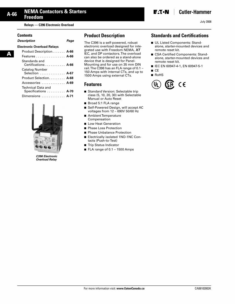
July 2008
A-66
For more information visit: www.EatonCanada.ca CA08102002K
NEMA Contactors & Starters
A
FreedomRelays — C396 Electronic Overload
ContentsDescription Page
Electronic Overload Relays
Product Description . . . . . . . A-66
Features . . . . . . . . . . . . . . . . A-66
Standards and Certifications . . . . . . . . . . . A-66
Catalog Number Selection . . . . . . . . . . . . . . A-67
Product Selection. . . . . . . . . A-68
Accessories . . . . . . . . . . . . . A-69
Technical Data andSpecifications . . . . . . . . . . A-70
Dimensions . . . . . . . . . . . . . A-71
Product DescriptionThe C396 is a self-powered, robust electronic overload designed for inte-grated use with Freedom NEMA, XT IEC, and DP contactors. The overload can also be ordered as a stand-alone device that is designed for Panel-Mounting and for use on 35 mm DIN rail. The C396 has an FLA range of 0.1 – 150 Amps with internal CTs, and up to 1500 Amps using external CTs.
Features■ Standard Version: Selectable trip
class (5, 10, 20, 30) with Selectable Manual or Auto Reset
■ Broad 5:1 FLA range■ Self-Powered Design, will accept AC
voltages from 12 – 690V 50/60 Hz■ Ambient Temperature
Compensation■ Low Heat Generation■ Phase Loss Protection■ Phase Unbalance Protection■ Electrically isolated 1NO-1NC Con-
tacts (Push-to-Test)■ Trip Status Indicator■ FLA range of 0.1 – 1500 Amps
Standards and Certifications■ UL Listed Components: Stand-
alone, starter-mounted devices and remote reset kit.
■ CSA Certified Components: Stand-alone, starter-mounted devices and remote reset kit.
■ IEC EN 60947-4-1, EN 60947-5-1■ CE ■ RoHS
C396 ElectronicOverload Relay
Tab33.book Page 66 Sunday, September 21, 2008 10:27 PM

July 2008
CA08102002K For more information visit: www.EatonCanada.ca
A-67NEMA Contactors & Starters
A
FreedomRelays — C396 Electronic Overload
Catalogue Number SelectionTable A-119. C396 Electronic Overload Catalogue Numbering System
� Choose appropriate adapter based on application FLA range and contactor’s frame size.
Table A-120. Stand-Alone Overload Relay Suffix Code
Table A-121. XT IEC Adapter Suffix Code
Table A-122. Freedom NEMA Adapter Suffix Code
Table A-123. DP Contactor Adapter Suffix Code
Class
SEL = Selectable
Device Type
C396 = C396 Electronic Overload Relay
Frame Size
A = 45 mm B = 65 mm C = 110 mm
Max. Amperes Current Rating
Frame A (45 mm)P05 = 0.1 – 0.5002 = 0.4 – 2.0005 = 1 – 5008 = 1.6 – 8032 = 6.4 – 32045 = 9 – 45
Frame B (65 mm)075 = 15 – 75110 = 22 – 110
Frame C (110 mm)150 = 30 – 150
C 3 9 6 A 2 A P 0 5 S E L A X
Adapter Suffix Code �
See Tables A-120 to A-123.
Feature Set
Reset Type
2 = Standard A = Auto
FLA Range Frame Size Suffix
All N/A AX
Contactor Frame Size
FLA Range(Amps)
Suffix
IEC Frame B 0.1 – 0.50.4 – 2.01 – 51.6 – 86.4 – 32
XB
IEC Frame C 0.1 – 0.50.4 – 2.01 – 51.6 – 86.4 – 32
XC
IEC Frame D 6.4 – 329 – 45
15 – 75
XD
IEC Frame F – G 22 – 110 XF
FLA Range(Amps)
ContactorFrame Size
Suffix
0.1 – 0.5 NEMA Size 00NEMA Size 0NEMA Size 1
FD
0.4 – 2.0 NEMA Size 00NEMA Size 0NEMA Size 1
FD
1 – 5 NEMA Size 00NEMA Size 0NEMA Size 1
F00F0F1
1.6 – 8 NEMA Size 00NEMA Size 0NEMA Size 1NEMA Size 2
F00F0F1F2
6.4 – 32 NEMA Size 0NEMA Size 1
FBFD
9 – 45 NEMA Size 2 FG
22 – 110 NEMA Size 3 FK
FLA Range(Amps)
ContactorFrame Size
Suffix
0.1 – 0.50.4 – 2.01 – 5
15, 25, 30A DC
1.6 – 8 15, 25, 30, 40A DE
6.4 – 32 15, 25, 30, 40, 50A DF
9 – 45 40, 50A DF
15 – 75 60, 75A DG
Tab33.book Page 67 Sunday, September 21, 2008 10:27 PM
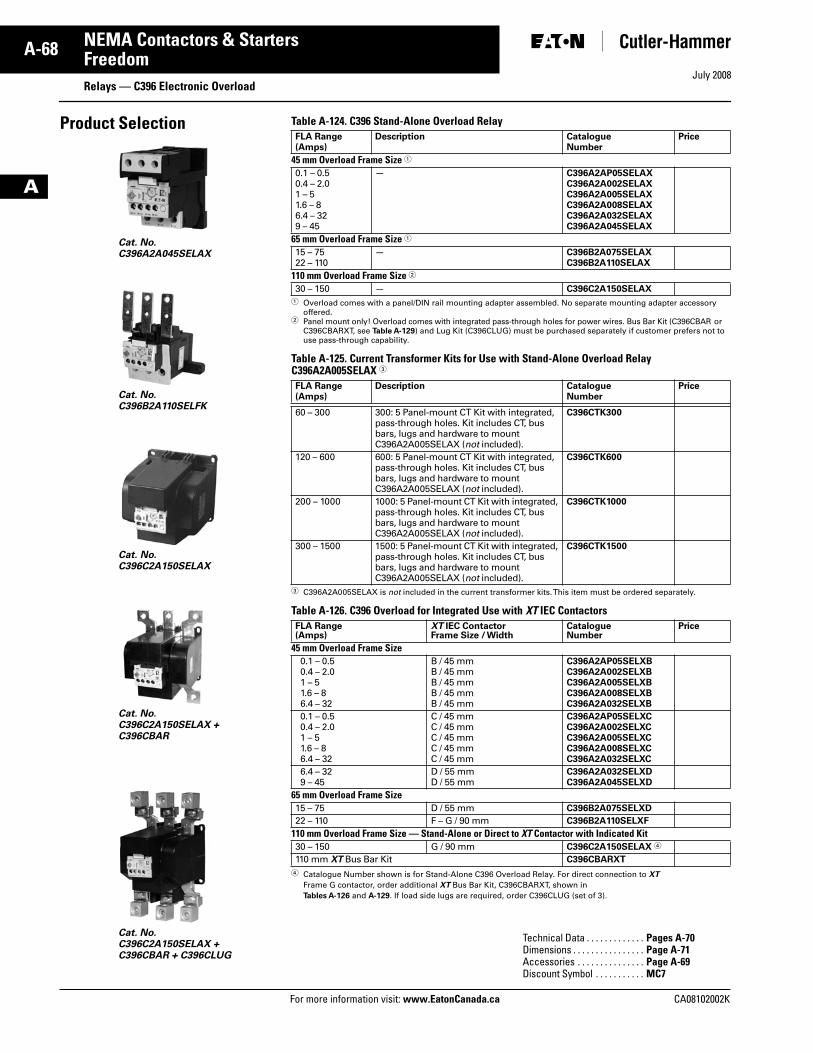
July 2008
A-68
For more information visit: www.EatonCanada.ca CA08102002K
NEMA Contactors & Starters
A
FreedomRelays — C396 Electronic Overload
Product Selection
Cat. No. C396B2A110SELFK
Cat. No. C396C2A150SELAX + C396CBAR
Cat. No.C396C2A150SELAX
Cat. No. C396C2A150SELAX + C396CBAR + C396CLUG
Cat. No. C396A2A045SELAX
Table A-124. C396 Stand-Alone Overload Relay
� Overload comes with a panel/DIN rail mounting adapter assembled. No separate mounting adapter accessory offered.
� Panel mount only! Overload comes with integrated pass-through holes for power wires. Bus Bar Kit (C396CBAR or C396CBARXT, see Table A-129) and Lug Kit (C396CLUG) must be purchased separately if customer prefers not to use pass-through capability.
Table A-125. Current Transformer Kits for Use with Stand-Alone Overload Relay C396A2A005SELAX �
� C396A2A005SELAX is not included in the current transformer kits. This item must be ordered separately.
Table A-126. C396 Overload for Integrated Use with XT IEC Contactors
� Catalogue Number shown is for Stand-Alone C396 Overload Relay. For direct connection to XT
Frame G contactor, order additional XT Bus Bar Kit, C396CBARXT, shown in Tables A-126 and A-129. If load side lugs are required, order C396CLUG (set of 3).
FLA Range(Amps)
Description CatalogueNumber
Price
45 mm Overload Frame Size �
0.1 – 0.50.4 – 2.01 – 51.6 – 86.4 – 329 – 45
— C396A2AP05SELAXC396A2A002SELAXC396A2A005SELAXC396A2A008SELAXC396A2A032SELAXC396A2A045SELAX
65 mm Overload Frame Size �
15 – 7522 – 110
— C396B2A075SELAXC396B2A110SELAX
110 mm Overload Frame Size �
30 – 150 — C396C2A150SELAX
FLA Range(Amps)
Description CatalogueNumber
Price
60 – 300 300: 5 Panel-mount CT Kit with integrated, pass-through holes. Kit includes CT, bus bars, lugs and hardware to mount C396A2A005SELAX (not included).
C396CTK300
120 – 600 600: 5 Panel-mount CT Kit with integrated, pass-through holes. Kit includes CT, bus bars, lugs and hardware to mount C396A2A005SELAX (not included).
C396CTK600
200 – 1000 1000: 5 Panel-mount CT Kit with integrated, pass-through holes. Kit includes CT, bus bars, lugs and hardware to mount C396A2A005SELAX (not included).
C396CTK1000
300 – 1500 1500: 5 Panel-mount CT Kit with integrated, pass-through holes. Kit includes CT, bus bars, lugs and hardware to mount C396A2A005SELAX (not included).
C396CTK1500
FLA Range(Amps)
XT IEC ContactorFrame Size / Width
CatalogueNumber
Price
45 mm Overload Frame Size0.1 – 0.50.4 – 2.01 – 51.6 – 86.4 – 32
B / 45 mmB / 45 mmB / 45 mmB / 45 mmB / 45 mm
C396A2AP05SELXBC396A2A002SELXBC396A2A005SELXBC396A2A008SELXBC396A2A032SELXB
0.1 – 0.50.4 – 2.01 – 51.6 – 86.4 – 32
C / 45 mmC / 45 mmC / 45 mmC / 45 mmC / 45 mm
C396A2AP05SELXCC396A2A002SELXCC396A2A005SELXCC396A2A008SELXCC396A2A032SELXC
6.4 – 329 – 45
D / 55 mmD / 55 mm
C396A2A032SELXDC396A2A045SELXD
65 mm Overload Frame Size15 – 75 D / 55 mm C396B2A075SELXD
22 – 110 F – G / 90 mm C396B2A110SELXF
110 mm Overload Frame Size — Stand-Alone or Direct to XT Contactor with Indicated Kit30 – 150 G / 90 mm C396C2A150SELAX �
110 mm XT Bus Bar Kit C396CBARXT
Technical Data . . . . . . . . . . . . . Pages A-70 Dimensions . . . . . . . . . . . . . . . . Page A-71Accessories . . . . . . . . . . . . . . . Page A-69Discount Symbol . . . . . . . . . . . MC7
Tab33.book Page 68 Sunday, September 21, 2008 10:27 PM
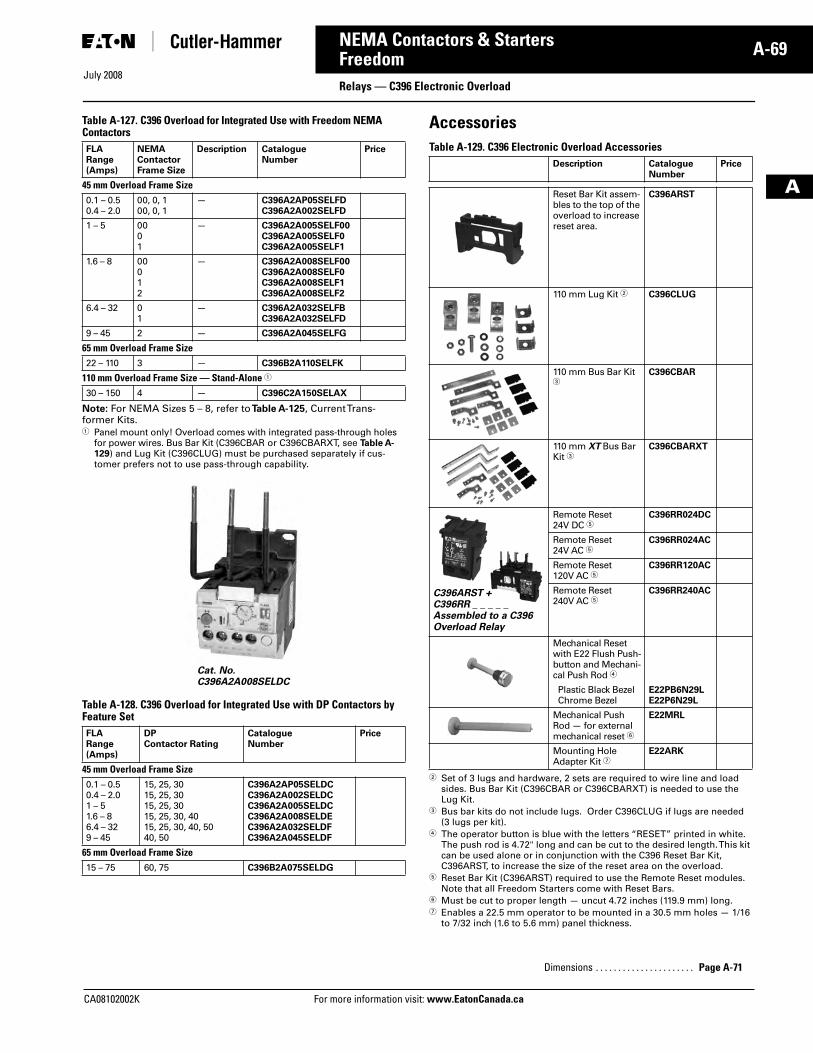
July 2008
CA08102002K For more information visit: www.EatonCanada.ca
A-69NEMA Contactors & Starters
A
FreedomRelays — C396 Electronic Overload
Table A-127. C396 Overload for Integrated Use with Freedom NEMA Contactors
Note: For NEMA Sizes 5 – 8, refer to Table A-125, Current Trans-former Kits.� Panel mount only! Overload comes with integrated pass-through holes
for power wires. Bus Bar Kit (C396CBAR or C396CBARXT, see Table A-129) and Lug Kit (C396CLUG) must be purchased separately if cus-tomer prefers not to use pass-through capability.
Table A-128. C396 Overload for Integrated Use with DP Contactors by Feature Set
AccessoriesTable A-129. C396 Electronic Overload Accessories
� Set of 3 lugs and hardware, 2 sets are required to wire line and load sides. Bus Bar Kit (C396CBAR or C396CBARXT) is needed to use the Lug Kit.
� Bus bar kits do not include lugs. Order C396CLUG if lugs are needed (3 lugs per kit).
� The operator button is blue with the letters “RESET” printed in white. The push rod is 4.72" long and can be cut to the desired length. This kit can be used alone or in conjunction with the C396 Reset Bar Kit, C396ARST, to increase the size of the reset area on the overload.
� Reset Bar Kit (C396ARST) required to use the Remote Reset modules. Note that all Freedom Starters come with Reset Bars.
� Must be cut to proper length — uncut 4.72 inches (119.9 mm) long.� Enables a 22.5 mm operator to be mounted in a 30.5 mm holes — 1/16
to 7/32 inch (1.6 to 5.6 mm) panel thickness.
FLARange(Amps)
NEMA Contactor Frame Size
Description CatalogueNumber
Price
45 mm Overload Frame Size0.1 – 0.50.4 – 2.0
00, 0, 100, 0, 1
— C396A2AP05SELFDC396A2A002SELFD
1 – 5 0001
— C396A2A005SELF00C396A2A005SELF0C396A2A005SELF1
1.6 – 8 00012
— C396A2A008SELF00C396A2A008SELF0C396A2A008SELF1C396A2A008SELF2
6.4 – 32 01
— C396A2A032SELFBC396A2A032SELFD
9 – 45 2 — C396A2A045SELFG
65 mm Overload Frame Size22 – 110 3 — C396B2A110SELFK
110 mm Overload Frame Size — Stand-Alone �
30 – 150 4 — C396C2A150SELAX
FLARange(Amps)
DP Contactor Rating
CatalogueNumber
Price
45 mm Overload Frame Size0.1 – 0.50.4 – 2.01 – 51.6 – 86.4 – 329 – 45
15, 25, 3015, 25, 3015, 25, 3015, 25, 30, 4015, 25, 30, 40, 5040, 50
C396A2AP05SELDCC396A2A002SELDCC396A2A005SELDCC396A2A008SELDEC396A2A032SELDFC396A2A045SELDF
65 mm Overload Frame Size15 – 75 60, 75 C396B2A075SELDG
Cat. No.C396A2A008SELDC
Description CatalogueNumber
Price
Reset Bar Kit assem-bles to the top of the overload to increase reset area.
C396ARST
110 mm Lug Kit � C396CLUG
110 mm Bus Bar Kit �
C396CBAR
110 mm XT Bus Bar Kit �
C396CBARXT
Remote Reset 24V DC �
C396RR024DC
Remote Reset 24V AC �
C396RR024AC
Remote Reset 120V AC �
C396RR120AC
Remote Reset 240V AC �
C396RR240AC
Mechanical Reset with E22 Flush Push-button and Mechani-cal Push Rod �
Plastic Black BezelChrome Bezel
E22PB6N29LE22P6N29L
Mechanical Push Rod — for external mechanical reset �
E22MRL
Mounting Hole Adapter Kit �
E22ARK
Dimensions . . . . . . . . . . . . . . . . . . . . . . Page A-71
C396ARST + C396RR _ _ _ _ _Assembled to a C396 Overload Relay
Tab33.book Page 69 Sunday, September 21, 2008 10:27 PM
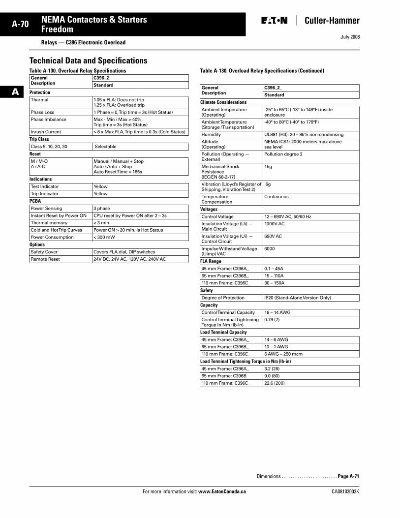
July 2008
A-70
For more information visit: www.EatonCanada.ca CA08102002K
NEMA Contactors & Starters
A
FreedomRelays — C396 Electronic Overload
Technical Data and SpecificationsTable A-130. Overload Relay Specifications Table A-130. Overload Relay Specifications (Continued)GeneralDescription
C396_2_
Standard
ProtectionThermal 1.05 x FLA: Does not trip
1.25 x FLA: Overload trip
Phase Loss 1 Phase = 0, Trip time = 3s (Hot Status)
Phase Imbalance Max - Min / Max > 40%,Trip time = 3s (Hot Status)
Inrush Current > 8 x Max FLA, Trip time is 0.3s (Cold Status)
Trip ClassClass 5, 10, 20, 30 Selectable
ResetM / M-OA / A-O
Manual / Manual + StopAuto / Auto + StopAuto Reset Time = 165s
IndicationsTest Indicator Yellow
Trip Indicator Yellow
PCBAPower Sensing 3 phase
Instant Reset by Power ON CPU reset by Power ON after 2 – 3s
Thermal memory < 3 min.
Cold and Hot Trip Curves Power ON > 20 min. is Hot Status
Power Consumption < 300 mW
OptionsSafety Cover Covers FLA dial, DIP switches
Remote Reset 24V DC, 24V AC, 120V AC, 240V AC
GeneralDescription
C396_2_
Standard
Climate ConsiderationsAmbient Temperature (Operating)
-25° to 65°C (-13° to 149°F) inside enclosure
Ambient Temperature (Storage / Transportation)
-40° to 80°C (-40° to 176°F)
Humidity UL991 (H3): 20 – 95% non-condensing
Altitude (Operating)
NEMA ICS1: 2000 meters max above sea level
Pollution (Operating — External)
Pollution degree 3
Mechanical Shock Resistance (IEC/EN 68-2-17)
15g
Vibration (Lloyd’s Register of Shipping, Vibration Test 2)
6g
Temperature Compensation
Continuous
VoltagesControl Voltage 12 – 690V AC, 50/60 Hz
Insulation Voltage (Ui) — Main Circuit
1000V AC
Insulation Voltage (Ui) — Control Circuit
690V AC
Impulse Withstand Voltage (Uimp) VAC
6000
FLA Range45 mm Frame: C396A_ 0.1 – 45A
65 mm Frame: C396B_ 15 – 110A
110 mm Frame: C396C_ 30 – 150A
SafetyDegree of Protection IP20 (Stand-Alone Version Only)
CapacityControl Terminal Capacity 18 – 14 AWG
Control Terminal Tightening Torque in Nm (lb-in)
0.79 (7)
Load Terminal Capacity45 mm Frame: C396A_ 14 – 6 AWG
65 mm Frame: C396B_ 10 – 1 AWG
110 mm Frame: C396C_ 6 AWG – 250 mcm
Load Terminal Tightening Torque in Nm (lb-in)45 mm Frame: C396A_ 3.2 (28)
65 mm Frame: C396B_ 9.0 (80)
110 mm Frame: C396C_ 22.6 (200)
Dimensions . . . . . . . . . . . . . . . . . . . . . . . . . Page A-71
Tab33.book Page 70 Sunday, September 21, 2008 10:27 PM
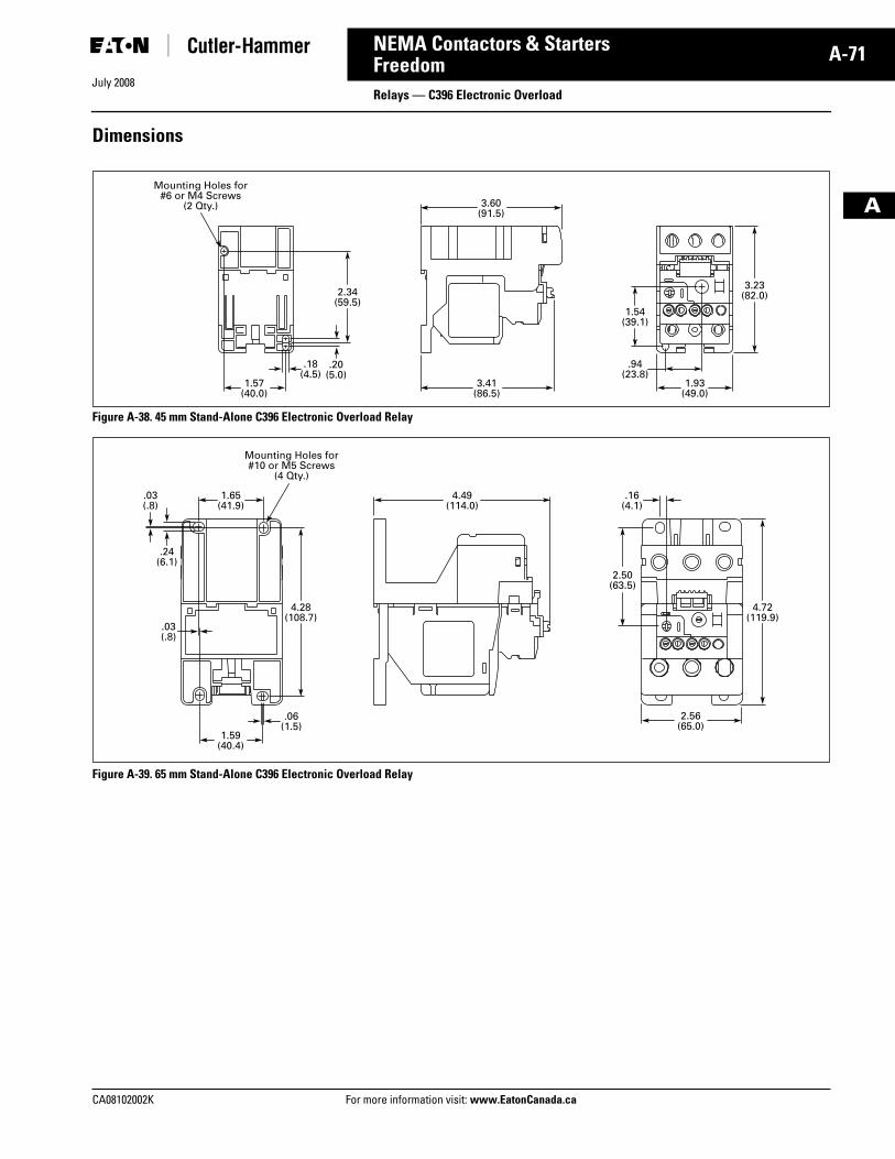
July 2008
CA08102002K For more information visit: www.EatonCanada.ca
A-71NEMA Contactors & Starters
A
FreedomRelays — C396 Electronic Overload
Dimensions
Figure A-38. 45 mm Stand-Alone C396 Electronic Overload Relay
Figure A-39. 65 mm Stand-Alone C396 Electronic Overload Relay
1.57(40.0)
1.93(49.0)
3.41(86.5)
3.60(91.5)
.18(4.5)
.94(23.8)
2.34(59.5)
3.23(82.0)
1.54(39.1)
Mounting Holes for#6 or M4 Screws
(2 Qty.)
.20(5.0)
2.50(63.5)
4.49(114.0)
1.65(41.9)
.16(4.1)
1.59(40.4)
2.56(65.0)
.03(.8)
.06(1.5)
4.28(108.7)
4.72(119.9)
Mounting Holes for#10 or M5 Screws
(4 Qty.)
.03(.8)
.24(6.1)
Tab33.book Page 71 Sunday, September 21, 2008 10:27 PM
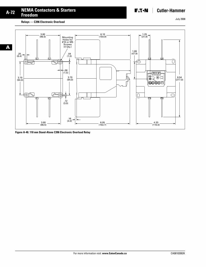
July 2008
A-72
For more information visit: www.EatonCanada.ca CA08102002K
NEMA Contactors & Starters
A
FreedomRelays — C396 Electronic Overload
Figure A-40. 110 mm Stand-Alone C396 Electronic Overload Relay
8.54(217.0)
1.89(47.9)
1.25(31.9)
6.10(154.9)
.16(4.0)
.25(6.4)
.04(1.0)
6.05(153.7)
4.33(110.0)
3.80(96.5)
3.80(96.5)
3.70(94.0)
3.70(94.0)
MountingHoles for#10 or M5
Screws(4 Qty.)
.06(1.5)
.12(3.0)
Tab33.book Page 72 Sunday, September 21, 2008 10:27 PM
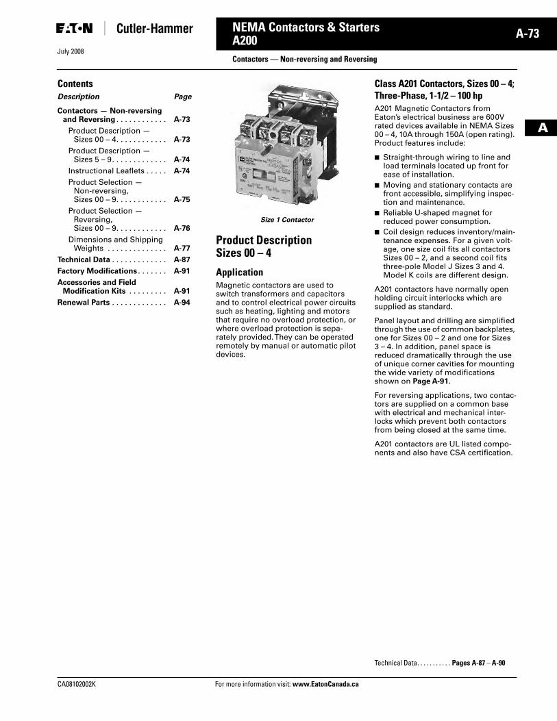
July 2008
CA08102002K For more information visit: www.EatonCanada.ca
A-73NEMA Contactors & Starters
A
A200Contactors — Non-reversing and Reversing
ContentsDescription Page
Contactors — Non-reversingand Reversing . . . . . . . . . . . . A-73
Product Description — Sizes 00 – 4. . . . . . . . . . . . A-73
Product Description — Sizes 5 – 9. . . . . . . . . . . . . A-74
Instructional Leaflets . . . . . A-74
Product Selection — Non-reversing, Sizes 00 – 9. . . . . . . . . . . . A-75
Product Selection — Reversing, Sizes 00 – 9. . . . . . . . . . . . A-76
Dimensions and Shipping Weights . . . . . . . . . . . . . . A-77
Technical Data . . . . . . . . . . . . . A-87
Factory Modifications . . . . . . . A-91
Accessories and Field Modification Kits . . . . . . . . . A-91
Renewal Parts . . . . . . . . . . . . . A-94
Size 1 Contactor
Product Description Sizes 00 – 4
ApplicationMagnetic contactors are used to switch transformers and capacitors and to control electrical power circuits such as heating, lighting and motors that require no overload protection, or where overload protection is sepa-rately provided. They can be operated remotely by manual or automatic pilot devices.
Class A201 Contactors, Sizes 00 – 4; Three-Phase, 1-1/2 – 100 hpA201 Magnetic Contactors from Eaton’s electrical business are 600V rated devices available in NEMA Sizes 00 – 4, 10A through 150A (open rating). Product features include:
■ Straight-through wiring to line and load terminals located up front for ease of installation.
■ Moving and stationary contacts are front accessible, simplifying inspec-tion and maintenance.
■ Reliable U-shaped magnet for reduced power consumption.
■ Coil design reduces inventory/main-tenance expenses. For a given volt-age, one size coil fits all contactors Sizes 00 – 2, and a second coil fits three-pole Model J Sizes 3 and 4. Model K coils are different design.
A201 contactors have normally open holding circuit interlocks which are supplied as standard.
Panel layout and drilling are simplified through the use of common backplates, one for Sizes 00 – 2 and one for Sizes 3 – 4. In addition, panel space is reduced dramatically through the use of unique corner cavities for mounting the wide variety of modifications shown on Page A-91.
For reversing applications, two contac-tors are supplied on a common base with electrical and mechanical inter-locks which prevent both contactors from being closed at the same time.
A201 contactors are UL listed compo-nents and also have CSA certification.
Technical Data. . . . . . . . . . . Pages A-87 – A-90
Tab33.book Page 73 Sunday, September 21, 2008 10:27 PM
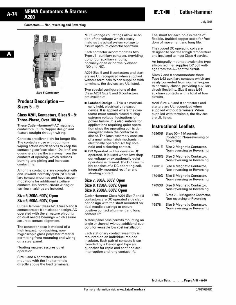
July 2008
A-74
For more information visit: www.EatonCanada.ca CA08102002K
NEMA Contactors & Starters
A
A200Contactors — Non-reversing and Reversing
Size 5 Contactor
Product Description — Sizes 5 – 9
Class A201, Contactors, Sizes 5 – 9; Three-Phase, Over 100 hpThese Cutler-Hammer® AC magnetic contactors utilize clapper design and feature straight-through wiring.
Contacts are silver alloy for longer life. The contacts close with optimum wiping action which serves to keep the contacting surfaces clean. De-ion® arc quenchers draw the arc away from the contacts at opening, which reduces burning and pitting and increases contact life.
All of the contactors are complete with one unwired, normally-open (NO) auxil-iary contact mounted and have accom-modations for additional auxiliary contacts. No control circuit wiring or terminal markings are included.
Size 5, 300A, 600V, OpenSize 6, 600A, 600V, OpenCutler-Hammer Class A201 Size 5 and 6 contactors are front clapper design, AC operated with the armature pivoting on dual needle bearings which assure accurate contact alignment.
The contactor base is molded of a high impact, non-tracking, non-hygroscopic glass polyester material permitting front mounting and wiring on a steel panel.
Floating magnet assures quiet operation.
Size 5 and 6 contactors must be mounted with the line terminals directly above the load terminals.
Multi-voltage coil ratings allow selec-tion of the voltage which closely matches the actual system voltage to assure optimum contactor operation.
Each contactor accommodates two Type J11 auxiliary contacts, providing up to four auxiliary circuits, normally-open or normally-closed (NO and NC).
A201 Size 5 and 6 contactors and start-ers are UL recognized when supplied without terminals. When supplied with terminals, the devices are UL listed.
Two special configurations of the Class A201 Size 5 and 6 contactors are available:
■ Latched Design — This is a mechani-cally held, electrically released device. It is applied where the con-tactor must remain closed during extreme voltage fluctuations or power failure. It is also suitable for applications requiring quiet opera-tion since the operating coil is de-energized when the contactor is closed. The latch assembly consists of a mechanical latch mechanism, electrically operated AC trip sole-noid and a clearing contact.
■ DC Operated — This device is DC operated. It is used where low drop-out voltage or exceptionally quiet operation is desired. The DC assem-bly consists of a DC operating coil, integrally mounted rectifier and shorting contact.
Size 7, 900A, 600V, OpenSize 8, 1350A, 600V, OpenSize 9, 2500A, 600V, OpenCutler-Hammer Class A201 Size 7 and 8 contactors are DC operated side clap-per design with the shaft mounted on dual needle bearings to ensure positive contact alignment and long contact life.
A steel panel base permits mounting on angle or channel without additional sup-port, for versatile low cost installation.
Each stationary contact assembly is mounted on an individual molded insulator. Each pair of contacts is sur-rounded by a De-ion grid type arc quencher for rapid and confined arc interruption and long contact life.
The shunt for each pole is made of flexible, braided copper cable for free-dom of movement and long life.
The rugged DC operating coils are designed to operate at high temperature and insulated to meet Class H service.
An integrally mounted avalanche type silicon rectifier supplies DC coil volt-age from the AC control circuit.
Sizes 7 and 8 accommodate three Type L-63 auxiliary contacts which are easily converted from normally-open to normally-closed, providing auxiliary circuit flexibility. Size 9 uses L-64 auxiliary contacts with a total of four circuits.
A201 Size 7, 8 and 9 contactors and starters are UL recognized when supplied without terminals. When supplied with terminals, the devices are UL listed.
Instructional Leaflets16960B Sizes 00 – 1 Magnetic
Contactor, Non-reversing or Reversing
16961E Size 2 Magnetic Contactor, Non-reversing or Reversing
13238G Size 3 Magnetic Contactor, Non-reversing or Reversing
17001C Size 4 Magnetic Contactor, Non-reversing or Reversing
17049D Size 5 Magnetic Contactor, Non-reversing or Reversing
17053B Size 6 Magnetic Contactor, Non-reversing or Reversing
17048 Sizes 7 – 8 Magnetic Contactor, Non-reversing or Reversing
16978 Size 9 Magnetic Contactor, Non-reversing or Reversing
Technical Data . . . . . . . . . . .Pages A-87 – A-90
Tab33.book Page 74 Sunday, September 21, 2008 10:27 PM
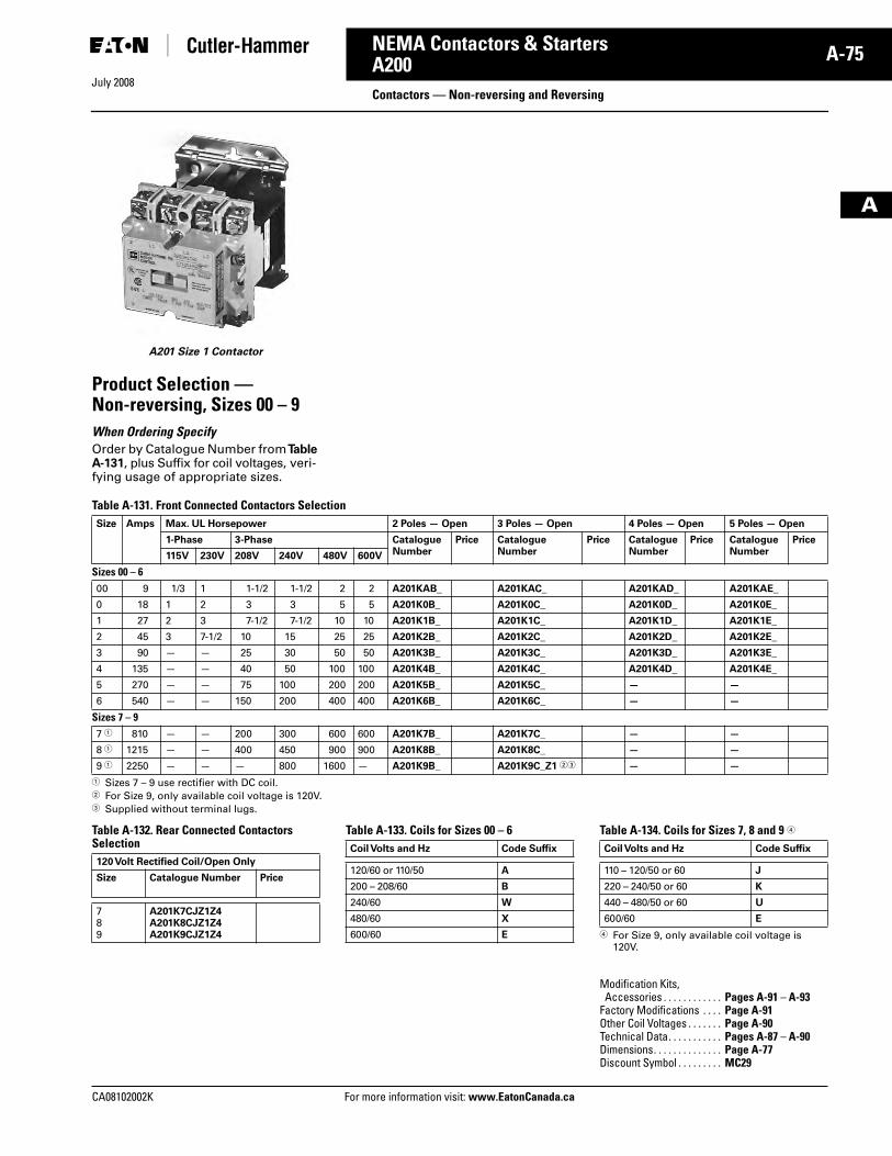
July 2008
CA08102002K For more information visit: www.EatonCanada.ca
A-75NEMA Contactors & Starters
A
A200Contactors — Non-reversing and Reversing
A201 Size 1 Contactor
Product Selection — Non-reversing, Sizes 00 – 9When Ordering Specify Order by Catalogue Number from Table A-131, plus Suffix for coil voltages, veri-fying usage of appropriate sizes.
Table A-131. Front Connected Contactors Selection
� Sizes 7 – 9 use rectifier with DC coil.� For Size 9, only available coil voltage is 120V.� Supplied without terminal lugs.
Table A-132. Rear Connected Contactors Selection
Table A-133. Coils for Sizes 00 – 6 Table A-134. Coils for Sizes 7, 8 and 9 �
� For Size 9, only available coil voltage is 120V.
Size Amps Max. UL Horsepower 2 Poles — Open 3 Poles — Open 4 Poles — Open 5 Poles — Open
1-Phase 3-Phase CatalogueNumber
Price CatalogueNumber
Price CatalogueNumber
Price CatalogueNumber
Price
115V 230V 208V 240V 480V 600V
Sizes 00 – 600 9 1/3 1 1-1/2 1-1/2 2 2 A201KAB_ A201KAC_ A201KAD_ A201KAE_
0 18 1 2 3 3 5 5 A201K0B_ A201K0C_ A201K0D_ A201K0E_
1 27 2 3 7-1/2 7-1/2 10 10 A201K1B_ A201K1C_ A201K1D_ A201K1E_
2 45 3 7-1/2 10 15 25 25 A201K2B_ A201K2C_ A201K2D_ A201K2E_
3 90 — — 25 30 50 50 A201K3B_ A201K3C_ A201K3D_ A201K3E_
4 135 — — 40 50 100 100 A201K4B_ A201K4C_ A201K4D_ A201K4E_
5 270 — — 75 100 200 200 A201K5B_ A201K5C_ — —
6 540 — — 150 200 400 400 A201K6B_ A201K6C_ — —
Sizes 7 – 97 � 810 — — 200 300 600 600 A201K7B_ A201K7C_ — —
8 � 1215 — — 400 450 900 900 A201K8B_ A201K8C_ — —
9 � 2250 — — — 800 1600 — A201K9B_ A201K9C_Z1 �� — —
120 Volt Rectified Coil/Open Only
Size Catalogue Number Price
789
A201K7CJZ1Z4A201K8CJZ1Z4A201K9CJZ1Z4
Coil Volts and Hz Code Suffix
120/60 or 110/50 A
200 – 208/60 B
240/60 W
480/60 X
600/60 E
Coil Volts and Hz Code Suffix
110 – 120/50 or 60 J
220 – 240/50 or 60 K
440 – 480/50 or 60 U
600/60 E
Modification Kits, Accessories . . . . . . . . . . . . Pages A-91 – A-93
Factory Modifications . . . . Page A-91Other Coil Voltages . . . . . . . Page A-90Technical Data. . . . . . . . . . . Pages A-87 – A-90Dimensions. . . . . . . . . . . . . . Page A-77Discount Symbol . . . . . . . . . MC29
Tab33.book Page 75 Sunday, September 21, 2008 10:27 PM
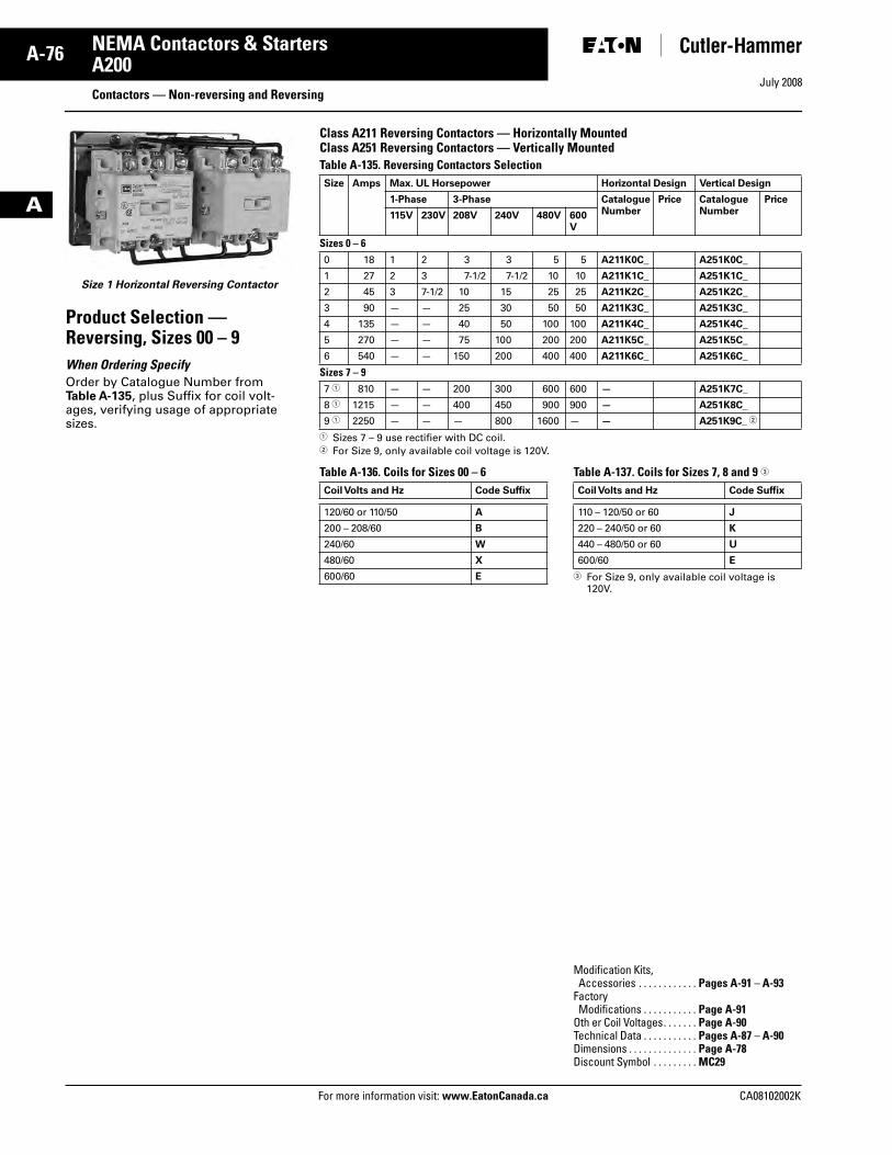
July 2008
A-76
For more information visit: www.EatonCanada.ca CA08102002K
NEMA Contactors & Starters
A
A200Contactors — Non-reversing and Reversing
Size 1 Horizontal Reversing Contactor
Product Selection — Reversing, Sizes 00 – 9When Ordering Specify Order by Catalogue Number from Table A-135, plus Suffix for coil volt-ages, verifying usage of appropriate sizes.
Class A211 Reversing Contactors — Horizontally MountedClass A251 Reversing Contactors — Vertically Mounted Table A-135. Reversing Contactors Selection
� Sizes 7 – 9 use rectifier with DC coil.� For Size 9, only available coil voltage is 120V.
Table A-136. Coils for Sizes 00 – 6 Table A-137. Coils for Sizes 7, 8 and 9 �
� For Size 9, only available coil voltage is 120V.
Size Amps Max. UL Horsepower Horizontal Design Vertical Design
1-Phase 3-Phase CatalogueNumber
Price CatalogueNumber
Price
115V 230V 208V 240V 480V 600V
Sizes 0 – 60 18 1 2 3 3 5 5 A211K0C_ A251K0C_
1 27 2 3 7-1/2 7-1/2 10 10 A211K1C_ A251K1C_
2 45 3 7-1/2 10 15 25 25 A211K2C_ A251K2C_
3 90 — — 25 30 50 50 A211K3C_ A251K3C_
4 135 — — 40 50 100 100 A211K4C_ A251K4C_
5 270 — — 75 100 200 200 A211K5C_ A251K5C_
6 540 — — 150 200 400 400 A211K6C_ A251K6C_
Sizes 7 – 97 � 810 — — 200 300 600 600 — A251K7C_
8 � 1215 — — 400 450 900 900 — A251K8C_
9 � 2250 — — — 800 1600 — — A251K9C_ �
Coil Volts and Hz Code Suffix
120/60 or 110/50 A
200 – 208/60 B
240/60 W
480/60 X
600/60 E
Coil Volts and Hz Code Suffix
110 – 120/50 or 60 J
220 – 240/50 or 60 K
440 – 480/50 or 60 U
600/60 E
Modification Kits, Accessories . . . . . . . . . . . . Pages A-91 – A-93
Factory Modifications . . . . . . . . . . . Page A-91
Oth er Coil Voltages. . . . . . . Page A-90Technical Data . . . . . . . . . . . Pages A-87 – A-90Dimensions . . . . . . . . . . . . . . Page A-78Discount Symbol . . . . . . . . . MC29
Tab33.book Page 76 Sunday, September 21, 2008 10:27 PM
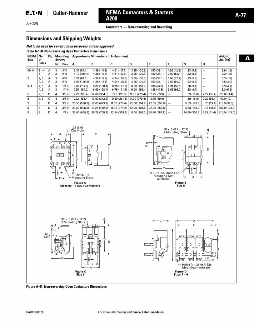
July 2008
CA08102002K For more information visit: www.EatonCanada.ca
A-77NEMA Contactors & Starters
A
A200Contactors — Non-reversing and Reversing
Dimensions and Shipping WeightsNot to be used for construction purposes unless approved. Table A-138. Non-reversing Open Contactors Dimensions
Figure A-41. Non-reversing Open Contactors Dimensions
NEMASize
No.ofPoles
Fig. MountingScrews
Approximate Dimensions in Inches (mm) Weight,Lbs. (kg)
No. Size A B C D E F G H
00, 0, 1 2 – 45
AA
33
#10#10
3.31 (84.1)4.19 (106.4)
4.38 (111.3)4.38 (111.3)
4.61 (117.1)4.61 (117.1)
3.95 (100.3)3.95 (100.3)
1.50 (38.1)1.50 (38.1)
1.66 (42.2)2.09 (53.1)
.23 (5.8)
.23 (5.8)——
2.6 (1.2)3.2 (1.5)
2 2, 34, 5
AA
33
#10#10
3.31 (84.1)5.06 (128.5)
4.38 (111.3)4.38 (111.3)
4.94 (125.5)4.94 (125.5)
3.95 (100.3)3.95 (100.3)
1.50 (38.1)1.50 (38.1)
1.66 (42.2)2.53 (64.3)
.23 (5.8)
.23 (5.8)——
3.3 (1.5)4.5 (2.0)
3, 4 2, 34, 5
AA
33
1/4 in.1/4 in.
4.63 (117.6)7.25 (184.2)
6.63 (168.4)6.63 (168.4)
6.75 (171.5)6.75 (171.5)
6.00 (152.4)6.00 (152.4)
1.88 (47.8)1.88 (47.8)
2.31 (58.7)3.63 (92.2)
.38 (9.7)
.38 (9.7)——
9.3 (4.2)13.0 (5.9)
5 2, 3 B 4 3/8 in. 7.22 (183.4) 12.00 (304.8) 7.75 (196.9) 11.00 (279.4) 2.75 (69.9) — .59 (15.0) 2.22 (56.4) 25.0 (11.4)
6 2, 3 C 4 3/8 in. 7.22 (183.4) 13.50 (342.9) 9.50 (251.3) 11.00 (279.4) 2.75 (69.9) — .59 (15.0) 2.22 (56.4) 42.0 (19.1)
7 3 D 4 3/8 in. 23.50 (596.9) 18.63 (473.2) 11.00 (279.4) 12.00 (304.8) 22.00 (558.8) — 5.63 (143.0) .75 (19.1) 215.0 (97.6)
8 3 D 4 3/8 in. 23.50 (596.9) 19.25 (489.0) 11.00 (279.4) 12.00 (304.8) 22.00 (558.8) — 5.63 (143.0) .75 (19.1) 265.0 (120.3)
9 3 D 4 1/2 in. 33.00 (838.2) 29.75 (755.7) 12.94 (328.7) 8.00 (203.2) 30.75 (781.1) — 14.50 (368.3) 1.63 (41.4) 315.0 (143.0)
A C
E.20 (5.1) 4
Mounting Slots
.22 (5.6)Dia. Hole
E2 G
DB
Figure ASizes 00 – 4 A201 Contactors
F
C
.12(3.0)
.38 x .5 (9.7 x 12.7)2 Mounting Slots
Figure C Size 6
EA
H
BD
G
E2
C
.12(3)
.38 x .5 (9.7 x 12.7)2 Mounting Slots
A
Figure BSize 5
E H
BD
G
E2
.38 (9.7) Dia. Open EndMounting Slot
(2 Places)
C AE H
DB
Figure DSizes 7 – 9
G
4 Holes for .38 (9.7) Dia.Mounting Hardware
Tab33.book Page 77 Sunday, September 21, 2008 10:27 PM
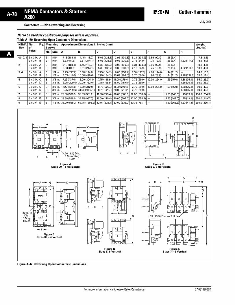
July 2008
A-78
For more information visit: www.EatonCanada.ca CA08102002K
NEMA Contactors & Starters
A
A200Contactors — Non-reversing and Reversing
Not to be used for construction purposes unless approved. Table A-139. Reversing Open Contactors Dimensions
Figure A-42. Reversing Open Contactors Dimensions
NEMASize
No.ofPoles
Fig. MountingScrews
Approximate Dimensions in Inches (mm) Weight,Lbs. (kg)
No. Size A B C D E F G H
00, 0, 1 3 x 3 H.3 x 3 V.
AB
33
#10#10
7.13 (181.1)3.33 (84.6)
4.45 (113.0)9.61 (244.1)
5.05 (128.3)5.05 (128.3)
3.95 (100.3)9.08 (230.6)
5.31 (134.9)2.16 (54.9)
3.56 (90.4).75 (19.1)
.25 (6.4)
.25 (6.4)—4.52 (114.8)
7.8 (3.5)8.9 (4.0)
2 3 x 3 H.3 x 3 V.
AB
33
#10#10
7.13 (181.1)3.33 (84.6)
4.45 (113.0)9.61 (244.1)
5.38 (136.7)5.38 (136.7)
3.95 (100.3)9.08 (230.6)
5.31 (134.9)2.16 (54.9)
3.56 (90.4).75 (19.1)
.25 (6.4)
.25 (6.4)—4.52 (114.8)
9.1 (4.1)10.0 (4.5)
3, 4 3 x 3 H.3 x 3 V.
AB
33
1/4 in.1/4 in.
9.75 (247.7)4.63 (117.6)
6.88 (174.8)16.56 (420.6)
7.25 (184.2)7.25 (184.2)
6.00 (152.4)15.69 (398.5)
7.00 (177.8)2.75 (69.9)
4.88 (124.0).94 (23.9)
.44 (11.2)
.44 (11.2)—7.78 (197.6)
24.0 (10.9)25.0 (11.4)
5 3 x 3 H.3 x 3 V.
CD
88
3/8 in.3/8 in.
17.22 (437.4)8.25 (209.6)
12.00 (304.8)30.00 (762.0)
7.75 (196.9)7.75 (196.9)
11.00 (279.4)18.00 (457.8)
2.75 (69.9)2.75 (69.9)
10.00 (254.0)—
.59 (15.0)—
1.38 (35.1)1.38 (35.1)
55.0 (25.0)55.0 (26.0)
6 3 x 3 H.3 x 3 V.
CD
88
3/8 in.3/8 in.
17.22 (437.4)8.25 (209.6)
13.50 (342.9)41.50 (1054.1)
8.75 (222.3)8.75 (222.3)
11.00 (279.4)28.00 (711.2)
2.75 (69.9)2.75 (69.9)
10.00 (254.0)—
.59 (15.0)—
1.38 (35.1)1.38 (35.1)
90.0 (40.9)90.0 (40.9)
7 3 x 3 V. E 8 3/8 in. 23.50 (596.9) 38.63 (981.2) 11.00 (279.4) 20.00 (508.0) 22.00 (558.8) — 5.63 (143.0) .75 (19.1) 450.0 (204.3)
8 3 x 3 V. E 8 3/8 in. 23.50 (596.9) 39.25 (997.0) 11.00 (279.4) 20.00 (508.0) 22.00 (558.8) — 5.63 (143.0) .75 (19.1) 550.0 (249.7)
9 3 x 3 V. E 8 1/2 in. 33.00 (838.2) 62.75 (1593.9) 12.94 (328.7) 33.00 (838.2) 30.75 (781.1) — 14.50 (368.3) 1.63 (41.4) 650.0 (295.1)
E
Figure ASizes 00 – 4 Horizontal
Figure CSizes 5, 6 Horizontal
CF E H
A
CA
F
A
F
Figure B Sizes 00 – 4 Vertical
Figure DSizes 5, 6 Vertical
Figure ESizes 7 – 9 Vertical
C
C
BD
G
BD
B
DH
G
BD
G
E2
E2.20 (5.1) Dia.
3 MountingSlots
.20 (5.1)Dia.
3 Mtg.Holes
AE H
E2
C
AE H
D
G
B.53 (13.5) Dia. — 3 Holes
Tab33.book Page 78 Sunday, September 21, 2008 10:27 PM
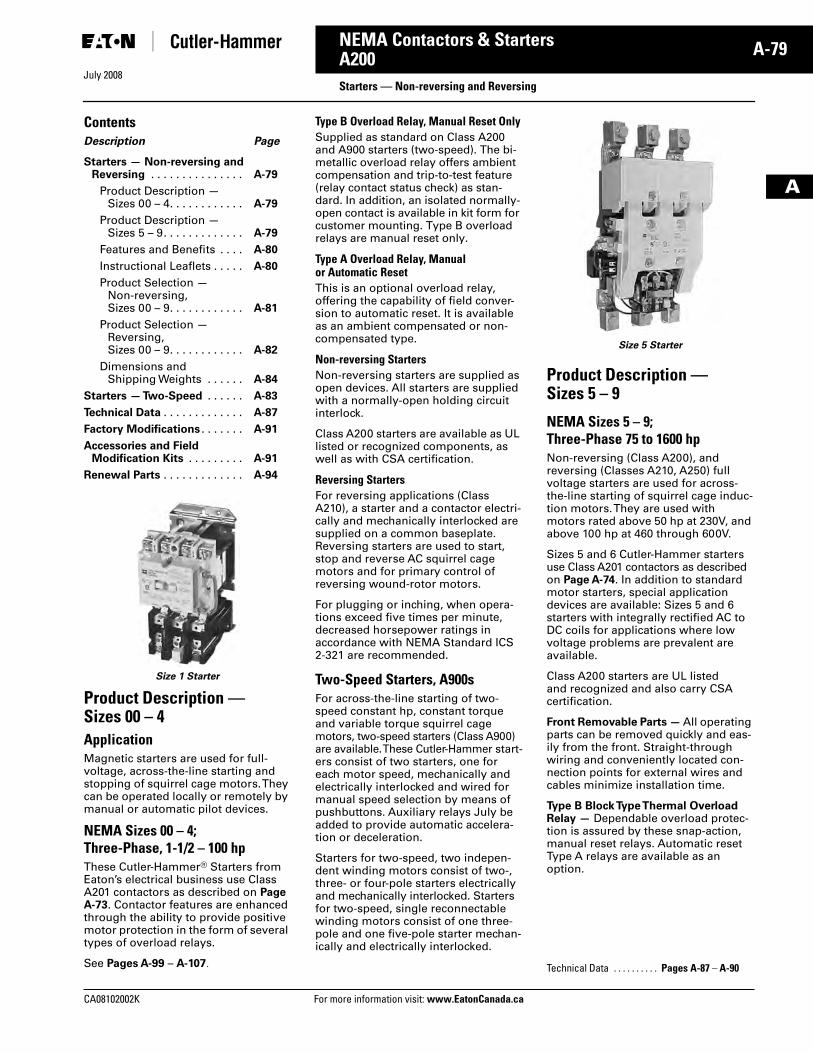
July 2008
CA08102002K For more information visit: www.EatonCanada.ca
A-79NEMA Contactors & Starters
A
A200Starters — Non-reversing and Reversing
ContentsDescription Page
Starters — Non-reversing and Reversing . . . . . . . . . . . . . . . A-79
Product Description — Sizes 00 – 4. . . . . . . . . . . . A-79
Product Description — Sizes 5 – 9. . . . . . . . . . . . . A-79
Features and Benefits . . . . A-80
Instructional Leaflets . . . . . A-80
Product Selection —Non-reversing, Sizes 00 – 9. . . . . . . . . . . . A-81
Product Selection —Reversing,Sizes 00 – 9. . . . . . . . . . . . A-82
Dimensions and Shipping Weights . . . . . . A-84
Starters — Two-Speed . . . . . . A-83
Technical Data . . . . . . . . . . . . . A-87
Factory Modifications . . . . . . . A-91
Accessories and Field Modification Kits . . . . . . . . . A-91
Renewal Parts . . . . . . . . . . . . . A-94
Size 1 Starter
Product Description — Sizes 00 – 4 ApplicationMagnetic starters are used for full-voltage, across-the-line starting and stopping of squirrel cage motors. They can be operated locally or remotely by manual or automatic pilot devices.
NEMA Sizes 00 – 4; Three-Phase, 1-1/2 – 100 hpThese Cutler-Hammer® Starters from Eaton’s electrical business use Class A201 contactors as described on Page A-73. Contactor features are enhanced through the ability to provide positive motor protection in the form of several types of overload relays.
See Pages A-99 – A-107.
Type B Overload Relay, Manual Reset OnlySupplied as standard on Class A200 and A900 starters (two-speed). The bi-metallic overload relay offers ambient compensation and trip-to-test feature (relay contact status check) as stan-dard. In addition, an isolated normally-open contact is available in kit form for customer mounting. Type B overload relays are manual reset only.
Type A Overload Relay, Manual or Automatic ResetThis is an optional overload relay, offering the capability of field conver-sion to automatic reset. It is available as an ambient compensated or non-compensated type.
Non-reversing StartersNon-reversing starters are supplied as open devices. All starters are supplied with a normally-open holding circuit interlock.
Class A200 starters are available as UL listed or recognized components, as well as with CSA certification.
Reversing StartersFor reversing applications (Class A210), a starter and a contactor electri-cally and mechanically interlocked are supplied on a common baseplate. Reversing starters are used to start, stop and reverse AC squirrel cage motors and for primary control of reversing wound-rotor motors.
For plugging or inching, when opera-tions exceed five times per minute, decreased horsepower ratings in accordance with NEMA Standard ICS 2-321 are recommended.
Two-Speed Starters, A900sFor across-the-line starting of two-speed constant hp, constant torque and variable torque squirrel cage motors, two-speed starters (Class A900) are available. These Cutler-Hammer start-ers consist of two starters, one for each motor speed, mechanically and electrically interlocked and wired for manual speed selection by means of pushbuttons. Auxiliary relays July be added to provide automatic accelera-tion or deceleration.
Starters for two-speed, two indepen-dent winding motors consist of two-, three- or four-pole starters electrically and mechanically interlocked. Starters for two-speed, single reconnectable winding motors consist of one three-pole and one five-pole starter mechan-ically and electrically interlocked.
Size 5 Starter
Product Description — Sizes 5 – 9
NEMA Sizes 5 – 9; Three-Phase 75 to 1600 hpNon-reversing (Class A200), and reversing (Classes A210, A250) full voltage starters are used for across-the-line starting of squirrel cage induc-tion motors. They are used with motors rated above 50 hp at 230V, and above 100 hp at 460 through 600V.
Sizes 5 and 6 Cutler-Hammer starters use Class A201 contactors as described on Page A-74. In addition to standard motor starters, special application devices are available: Sizes 5 and 6 starters with integrally rectified AC to DC coils for applications where low voltage problems are prevalent are available.
Class A200 starters are UL listed and recognized and also carry CSA certification.
Front Removable Parts — All operating parts can be removed quickly and eas-ily from the front. Straight-through wiring and conveniently located con-nection points for external wires and cables minimize installation time.
Type B Block Type Thermal Overload Relay — Dependable overload protec-tion is assured by these snap-action, manual reset relays. Automatic reset Type A relays are available as an option.
Technical Data . . . . . . . . . . Pages A-87 – A-90
Tab33.book Page 79 Sunday, September 21, 2008 10:27 PM
July 2008
A-80
For more information visit: www.EatonCanada.ca CA08102002K
NEMA Contactors & Starters
A
A200Starters — Non-reversing and Reversing
Types of StartersClass A200, Sizes 5 and 6 — Non-reversing starters contain an AC magnetically-operated Size 5 or Size 6 line contactor and block Type B three-pole overload relay, along with three current transformers. A control relay whose contacts handle the coil current of the starter is provided with Size 6 starters.
Class A200, Sizes 7, 8 and 9 — Non-reversing starters contain a DC operated line contactor, DC power sup-ply, block Type B three-pole overload relay with three current transformers and a control relay.
Class A960/A970/A980 Multi-Speed Starters: Refer to Page A-83.
Features and Benefits
Sizes 00 – 4■ Straight-Through Wiring, Up-Front,
Out-Front Terminals for ease in installation.
■ Unique Accessory Mounting Cavities reduce panel space requirements.
■ Snap-in Accessories for application flexibility.
■ Vertical and Horizontal Interlocking capability increases application flexibility.
■ Ambient Compensated Overload Relays available as standard, offer-ing superior motor protection in variable motor/controller environments.
■ Isolated Normally Open Relay Contact available in kit mounting form on Type B Overload Relay.
Sizes 5 – 9■ Rectified AC/DC Coils available
to reduce premature drop-out or “kiss” problems due to inherent low voltage conditions.
■ Clapper Design armature assembly pivots on needle bearings resulting in quick, smooth opening and clos-ing of the magnet.
■ Stainless Steel Kick-Out Spring assures quick, positive drop-out time.
■ Front Removable Parts all current carrying parts front removable for easy inspection and maintenance.
Instructional Leaflets16958 Sizes 00 – 1, 3-Pole Motor
Controller
16956 Sizes 00 – 1, 2-Pole, Single-Phase Motor Controller
16959 Size 2, 3-Pole Motor Controller
16957 Size 2, 2-Pole, Single-Phase Motor Controller
15465C Sizes 3 and 4J Motor Controller
17000C Size 4, Model K Motor Controller
17054C Size 5 Motor Controller
17055C Size 6 Motor Controller
Technical Data . . . . . . . . . . . Pages A-87 – A-90
Tab33.book Page 80 Sunday, September 21, 2008 10:27 PM
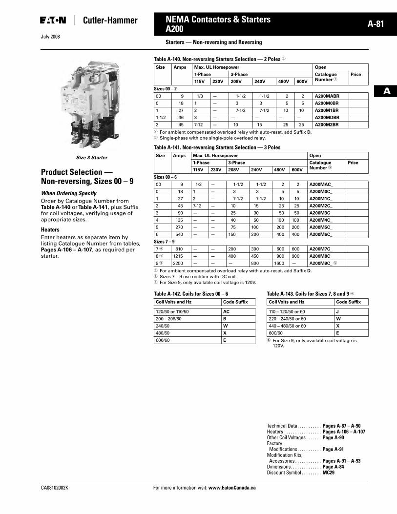
July 2008
CA08102002K For more information visit: www.EatonCanada.ca
A-81NEMA Contactors & Starters
A
A200Starters — Non-reversing and Reversing
Size 3 Starter
Product Selection —Non-reversing, Sizes 00 – 9When Ordering SpecifyOrder by Catalogue Number from Table A-140 or Table A-141, plus Suffix for coil voltages, verifying usage of appropriate sizes.
Heaters Enter heaters as separate item by listing Catalogue Number from tables, Pages A-106 – A-107, as required per starter.
Table A-140. Non-reversing Starters Selection — 2 Poles �
� For ambient compensated overload relay with auto-reset, add Suffix D.� Single-phase with one single-pole overload relay.
Table A-141. Non-reversing Starters Selection — 3 Poles
� For ambient compensated overload relay with auto-reset, add Suffix D.� Sizes 7 – 9 use rectifier with DC coil.� For Size 9, only available coil voltage is 120V.
Table A-142. Coils for Sizes 00 – 6 Table A-143. Coils for Sizes 7, 8 and 9 �
� For Size 9, only available coil voltage is 120V.
Size Amps Max. UL Horsepower Open
1-Phase 3-Phase CatalogueNumber �
Price
115V 230V 208V 240V 480V 600V
Sizes 00 – 200 9 1/3 — 1-1/2 1-1/2 2 2 A200MABR
0 18 1 — 3 3 5 5 A200M0BR
1 27 2 — 7-1/2 7-1/2 10 10 A200M1BR
1-1/2 36 3 — — — — — A200MDBR
2 45 7-12 — 10 15 25 25 A200M2BR
Size Amps Max. UL Horsepower Open
1-Phase 3-Phase CatalogueNumber �
Price
115V 230V 208V 240V 480V 600V
Sizes 00 – 600 9 1/3 — 1-1/2 1-1/2 2 2 A200MAC_
0 18 1 — 3 3 5 5 A200M0C_
1 27 2 — 7-1/2 7-1/2 10 10 A200M1C_
2 45 7-12 — 10 15 25 25 A200M2C_
3 90 — — 25 30 50 50 A200M3C_
4 135 — — 40 50 100 100 A200M4C_
5 270 — — 75 100 200 200 A200M5C_
6 540 — — 150 200 400 400 A200M6C_
Sizes 7 – 97 � 810 — — 200 300 600 600 A200M7C_
8 � 1215 — — 400 450 900 900 A200M8C_
9 � 2250 — — — 800 1600 — A200M9C_ �
Coil Volts and Hz Code Suffix
120/60 or 110/50 AC
200 – 208/60 B
240/60 W
480/60 X
600/60 E
Coil Volts and Hz Code Suffix
110 – 120/50 or 60 J
220 – 240/50 or 60 W
440 – 480/50 or 60 X
600/60 E
Technical Data. . . . . . . . . . . Pages A-87 – A-90Heaters . . . . . . . . . . . . . . . . . Pages A-106 – A-107Other Coil Voltages . . . . . . . Page A-90Factory Modifications. . . . . . . . . . . Page A-91
Modification Kits, Accessories . . . . . . . . . . . . Pages A-91 – A-93
Dimensions. . . . . . . . . . . . . . Page A-84Discount Symbol . . . . . . . . . MC29
Tab33.book Page 81 Sunday, September 21, 2008 10:27 PM
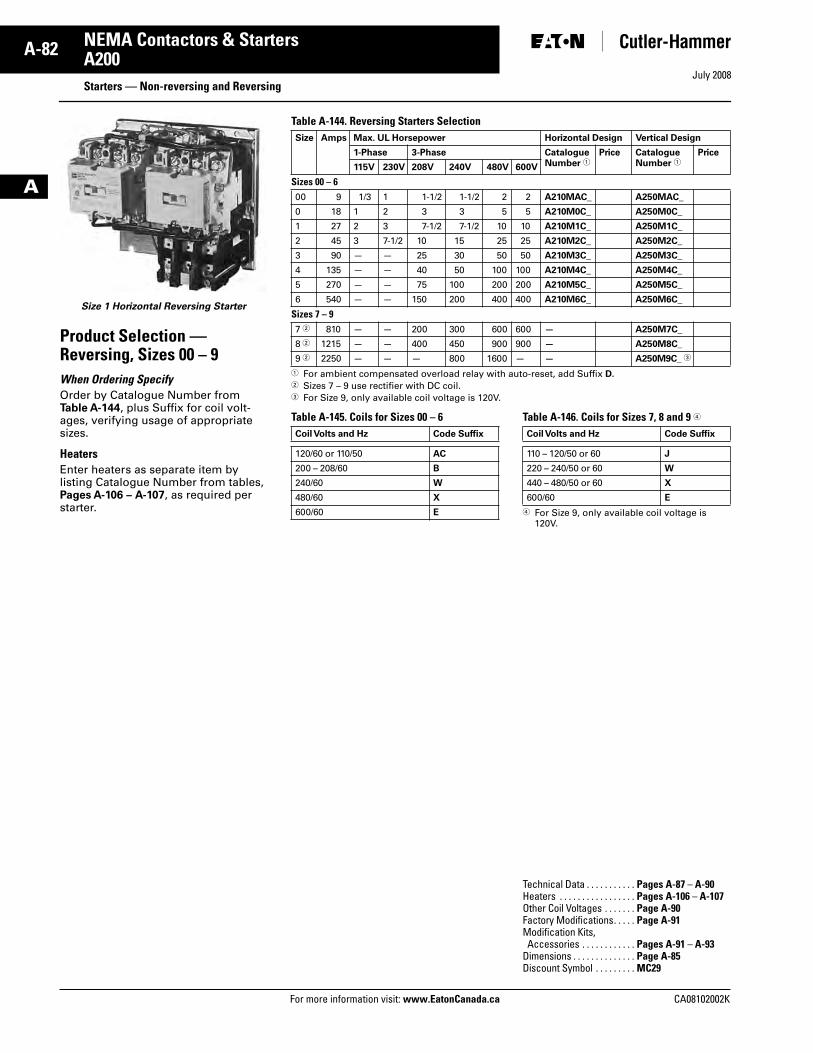
July 2008
A-82
For more information visit: www.EatonCanada.ca CA08102002K
NEMA Contactors & Starters
A
A200Starters — Non-reversing and Reversing
Size 1 Horizontal Reversing Starter
Product Selection —Reversing, Sizes 00 – 9When Ordering SpecifyOrder by Catalogue Number from Table A-144, plus Suffix for coil volt-ages, verifying usage of appropriate sizes.
Heaters Enter heaters as separate item by listing Catalogue Number from tables, Pages A-106 – A-107, as required per starter.
Table A-144. Reversing Starters Selection
� For ambient compensated overload relay with auto-reset, add Suffix D.� Sizes 7 – 9 use rectifier with DC coil.� For Size 9, only available coil voltage is 120V.
Table A-145. Coils for Sizes 00 – 6 Table A-146. Coils for Sizes 7, 8 and 9 �
� For Size 9, only available coil voltage is 120V.
Size Amps Max. UL Horsepower Horizontal Design Vertical Design
1-Phase 3-Phase CatalogueNumber �
Price CatalogueNumber �
Price
115V 230V 208V 240V 480V 600V
Sizes 00 – 600 9 1/3 1 1-1/2 1-1/2 2 2 A210MAC_ A250MAC_
0 18 1 2 3 3 5 5 A210M0C_ A250M0C_
1 27 2 3 7-1/2 7-1/2 10 10 A210M1C_ A250M1C_
2 45 3 7-1/2 10 15 25 25 A210M2C_ A250M2C_
3 90 — — 25 30 50 50 A210M3C_ A250M3C_
4 135 — — 40 50 100 100 A210M4C_ A250M4C_
5 270 — — 75 100 200 200 A210M5C_ A250M5C_
6 540 — — 150 200 400 400 A210M6C_ A250M6C_
Sizes 7 – 97 � 810 — — 200 300 600 600 — A250M7C_
8 � 1215 — — 400 450 900 900 — A250M8C_
9 � 2250 — — — 800 1600 — — A250M9C_ �
Coil Volts and Hz Code Suffix
120/60 or 110/50 AC
200 – 208/60 B
240/60 W
480/60 X
600/60 E
Coil Volts and Hz Code Suffix
110 – 120/50 or 60 J
220 – 240/50 or 60 W
440 – 480/50 or 60 X
600/60 E
Technical Data . . . . . . . . . . . Pages A-87 – A-90Heaters . . . . . . . . . . . . . . . . . Pages A-106 – A-107Other Coil Voltages . . . . . . . Page A-90Factory Modifications. . . . . Page A-91Modification Kits, Accessories . . . . . . . . . . . . Pages A-91 – A-93
Dimensions . . . . . . . . . . . . . . Page A-85Discount Symbol . . . . . . . . . MC29
Tab33.book Page 82 Sunday, September 21, 2008 10:27 PM
CA08102002K For more information visit: www.EatonCanada.ca
A-83NEMA Contactors & Starters
July 2008
A
A200Starters — Two-Speed
Product SelectionFor Separate Two-Winding Motors
HeatersEnter heaters as separate item by listing Catalogue Number from table, Pages A-106 – A-107, as required per starter.
Table A-147. Three-Phase, Non-reversing, Reversing 60 Hz Starters — Heater Selection
� For ambient compensated overload relay with auto-reset, add Suffix D.
For Single-Winding MotorsTable A-148. Product Selection — Sizes 0 – 6
� For ambient compensated overload relay with auto-reset, add Suffix D.
NEMA Amps Constant Horsepower Constant or Variable Torque 3 Poles — Open
208V 240V 480V 600V 208V 240V 480V 600V CatalogueNumber �
Price
Sizes 0 – 60 18 3 3 5 5 2 2 3 3 A960M0C_
1 27 7-1/2 7-1/2 10 10 5 5 7-1/2 7-1/2 A960M1C_
2 45 10 15 25 25 7-1/2 10 20 20 A960M2C_
3 90 25 30 50 50 20 25 40 40 A960M3C_
4 135 40 50 100 100 30 40 75 75 A960M4C_
5 270 75 100 200 200 60 75 150 150 A960M5C_
6 540 150 200 400 400 100 150 300 300 A960M6C_
NEMA Amps 208V 240V 480V 600V 3 Poles — Open
CatalogueNumber �
Price
Constant Horsepower 0 18 3 3 5 5 A970M0C_
1 27 7-1/2 7-1/2 10 10 A970M1C_
2 45 10 15 25 25 A970M2C_
3 90 25 30 50 50 A970M3C_
4 135 40 50 100 100 A970M4C_
5 270 75 100 200 200 A970M5C_
6 540 150 200 400 400 A970M6C_
Constant or Variable Torque0 18 2 2 3 3 A980M0C_
1 27 5 5 7-1/2 7-1/2 A980M1C_
2 45 7-1/2 10 20 20 A980M2C_
3 90 20 25 40 40 A980M3C_
4 135 30 40 75 75 A980M4C_
5 270 60 75 150 150 A980M5C_
6 540 100 150 300 300 A980M6C_
Table A-149. Coils for Sizes 0 – 6
Table A-150. Coils for Sizes 0 – 6
Coil Volts and Hz Coil Suffix
120/60 or 110/50 AC
200 – 208/60 B
240/60 W
480/60 X
600/60 E
Coil Volts and Hz Coil Suffix
120/60 or 110/50 AC
200 – 208/60 B
240/60 W
480/60 X
600/60 E
Technical Data. . . . . . . . . . . Pages A-87 – A-90Heaters . . . . . . . . . . . . . . . . . Pages A-106 – A-107Other Coil Voltages . . . . . . . Page A-90Factory Modifications . . . . Page A-91Modification Kits, Accessories . . . . . . . . . . . . Pages A-91 – A-93
Dimensions. . . . . . . . . . . . . . Page A-86Discount Symbol . . . . . . . . . MC29
Tab33.book Page 83 Sunday, September 21, 2008 10:27 PM
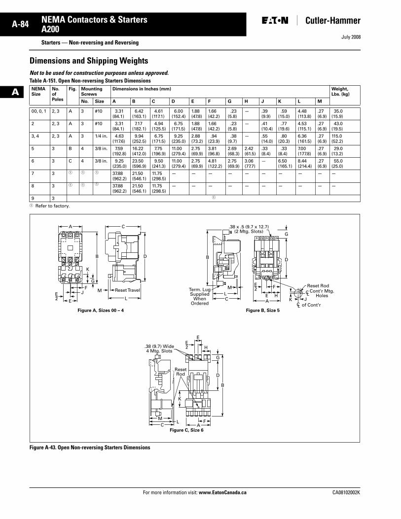
July 2008
A-84
For more information visit: www.EatonCanada.ca CA08102002K
NEMA Contactors & Starters
A
A200Starters — Non-reversing and Reversing
Dimensions and Shipping WeightsNot to be used for construction purposes unless approved. Table A-151. Open Non-reversing Starters Dimensions
� Refer to factory.
Figure A-43. Open Non-reversing Starters Dimensions
NEMASize
No. ofPoles
Fig. MountingScrews
Dimensions in Inches (mm) Weight,Lbs. (kg)
No. Size A B C D E F G H J K L M
00, 0, 1 2, 3 A 3 #10 3.31(84.1)
6.42(163.1)
4.61 (117.1)
6.00(152.4)
1.88(47.8)
1.66 (42.2)
.23(5.8)
— .39(9.9)
.59(15.0)
4.48(113.8)
.27(6.9)
35.0 (15.9)
2 2, 3 A 3 #10 3.31 (84.1)
7.17(182.1)
4.94(125.5)
6.75(171.5)
1.88(47.8)
1.66(42.2)
.23 (5.8)
— .41(10.4)
.77(19.6)
4.53(115.1)
.27(6.9)
43.0 (19.5)
3, 4 2, 3 A 3 1/4 in. 4.63 (117.6)
9.94(252.5)
6.75(171.5)
9.25(235.0)
2.88(73.2)
.94(23.9)
.38 (9.7)
— .55(14.0)
.80(20.3)
6.36(161.5)
.27(6.9)
115.0 (52.2)
5 3 B 4 3/8 in. 7.59 (192.8)
16.22 (412.0)
7.75(196.9)
11.00(279.4)
2.75(69.9)
3.81(96.8)
2.69(68.3)
2.42(61.5)
.33(8.4)
.33(8.4)
7.00(177.8)
.27(6.9)
29.0(13.2)
6 3 C 4 3/8 in. 9.25 (235.0)
23.50(596.9)
9.50(241.3)
11.00(279.4)
2.75(69.9)
4.81(122.2)
2.75(69.9)
3.06(77.7)
— 6.50(165.1)
8.44(214.4)
.27(6.9)
55.0(25.0)
7 3 � � � 37.88 (962.2)
21.50(546.1)
11.75(298.5)
— — — — — — — — — —
8 3 � � � 37.88(962.2)
21.50(546.1)
11.75(298.5)
— — — — — — — — — —
9 3 �
E L C A
C AF
H
E
M
ResetRod
L
LM F
HEK J
Reset Rod
Figure A, Sizes 00 – 4 Figure B, Size 5
Figure C, Size 6
Reset TravelMJF
CA
B B
K
B
DD
D
G
G
K
G
E2
E2
E2
C L
C L
of Cont'r
Cont'r Mtg.Holes
.38 (9.7) Wide4 Mtg. Slots
.38 x .5 (9.7 x 12.7)(2 Mtg. Slots)
Term. LugSupplied
WhenOrdered
Tab33.book Page 84 Sunday, September 21, 2008 10:27 PM
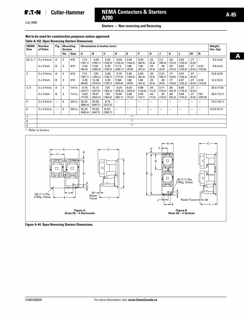
July 2008
CA08102002K For more information visit: www.EatonCanada.ca
A-85NEMA Contactors & Starters
A
A200Starters — Non-reversing and Reversing
Not to be used for construction purposes unless approved. Table A-152. Open Reversing Starters Dimensions
� Refer to factory.
Figure A-44. Open Reversing Starters Dimensions
NEMASize
Numberof Poles
Fig. MountingScrews
Dimensions in Inches (mm) Weight,Lbs. (kg)
No. Size A B C D E F G J K L M N
00, 0, 1 3 x 3 Horiz.
3 x 3 Vert.
A
B
3
3
#10
#10
7.13(181.1)3.33
(84.6)
6.50(165.1)11.63(295.4)
5.05(128.3)5.05
(128.3)
6.00(152.4)11.13(282.7)
5.69(144.5)1.88(47.8)
3.56(90.4)1.66(42.2)
.25(6.4).25(6.4)
2.3(58.4).39
(9.9)
.59(15.0).59(15.0)
4.92(125.0)4.92(125.0)
.27(6.9).27(6.9)
—
4.52(114.8)
9.0 (4.0)
9.8 (4.4)
2 3 x 3 Horiz.
3 x 3 Vert.
A
B
3
3
#10
#10
7.13(181.1)3.33
(84.6)
7.25(184.2)12.38(314.5)
5.38(136.7)5.38
(136.7)
6.75(171.5)11.88(301.8)
5.69(144.5)1.88(47.8)
3.56(90.4)1.66(42.2)
.25(6.4).25(6.4)
2.31(58.7).39
(9.9)
.77(19.6).77(19.6)
4.97(126.2)4.97(126.2)
.27(6.9).27(6.9)
—
4.52(114.8)
10.8 (4.9)
12.2 (5.5)
3, 4 3 x 3 Horiz.
3 x 3 Vert.
A
B
3
3
1/4 in.
1/4 in.
9.75(247.7)4.63
(117.6)
10.13(257.3)19.81(503.2)
7.25(184.2)7.25
(184.2)
9.25(235.0)18.94(481.1)
8.00(203.2)2.88(73.2)
4.88(124.0)2.94(74.7)
.44(11.2).44(11.2)
3.11(79.0).55
(14.0)
.80(20.3).80(20.3)
6.86(174.2)6.86(174.2)
.27(6.9).27(6.9)
—
7.91(200.9)
26.0 (11.8)
28.0 (12.7)
5 3 x 3 Horiz. — 4 3/8 in. 35.25(895.4)
25.50(647.7)
8.75(222.3)
— — — — — — — — — 73.0 (33.1)
6 3 x 3 Horiz. — 4 3/8 in. 35.25(895.4)
25.50(647.7)
10.50(266.7)
— — — — — — — — — 127.0 (57.7)
7 �
8 �
9 �
E
Figure ASizes 00 – 4 Horizontal
Figure BSizes 00 – 4 Vertical
.28 (7.1) Dia.3 Mtg. Holes L
L
J
E
J
MResetTravel M
A C
F
A C
F
B D
N
G
BD
K
G
K
.28 (7.1) Dia.3 Mtg. Holes
Reset Travel
Tab33.book Page 85 Sunday, September 21, 2008 10:27 PM
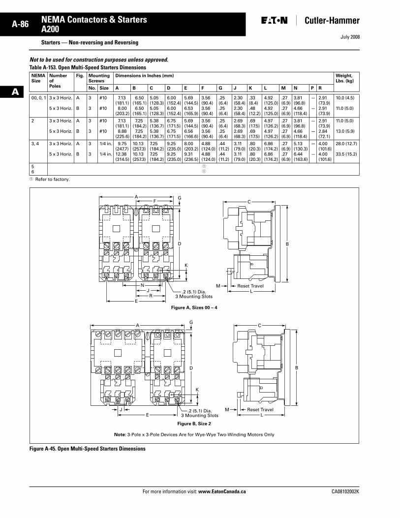
July 2008
A-86
For more information visit: www.EatonCanada.ca CA08102002K
NEMA Contactors & Starters
A
A200Starters — Non-reversing and Reversing
Not to be used for construction purposes unless approved. Table A-153. Open Multi-Speed Starters Dimensions
� Refer to factory.
Figure A-45. Open Multi-Speed Starters Dimensions
NEMASize
NumberofPoles
Fig. MountingScrews
Dimensions in Inches (mm) Weight,Lbs. (kg)
No. Size A B C D E F G J K L M N P R
00, 0, 1 3 x 3 Horiz.
5 x 3 Horiz.
A
B
3
3
#10
#10
7.13(181.1)8.00
(203.2)
6.50(165.1)6.50
(165.1)
5.05(128.3)5.05(128.3)
6.00(152.4)6.00(152.4)
5.69(144.5)6.53(165.9)
3.56(90.4)3.56(90.4)
.25(6.4).25(6.4)
2.30(58.4)2.30(58.4)
.33(8.4).48(12.2)
4.92(125.0)4.92(125.0)
.27(6.9).27(6.9)
3.81(96.8)4.66(118.4)
—
—
2.91(73.9)2.91(73.9)
10.0 (4.5)
11.0 (5.0)
2 3 x 3 Horiz.
5 x 3 Horiz.
A
B
3
3
#10
#10
7.13(181.1)8.88
(225.6)
7.25(184.2)7.25
(184.2)
5.38(136.7)5.38(136.7)
6.75(171.5)6.75(171.5)
5.69(144.5)6.56(166.6)
3.56(90.4)3.56(90.4)
.25(6.4).25(6.4)
2.69(68.3)2.69(68.3)
.69(17.5).69(17.5)
4.97(126.2)4.97(126.2)
.27(6.9).27(6.9)
3.81(96.8)4.66(118.4)
—
—
2.91(73.9)2.84(72.1)
11.0 (5.0)
13.0 (5.9)
3, 4 3 x 3 Horiz.
5 x 3 Horiz.
A
B
3
3
1/4 in.
1/4 in.
9.75(247.7)12.38(314.5)
10.13(257.3)10.13(257.3)
7.25(184.2)7.25(184.2)
9.25(235.0)9.25(235.0)
8.00(203.2)9.31(236.5)
4.88(124.0)4.88(124.0)
.44(11.2).44(11.2)
3.11(79.0)3.11(79.0)
.80(20.3).80(20.3)
6.86(174.2)6.86(174.2)
.27(6.9).27(6.9)
5.13(130.3)6.44(163.6)
—
—
4.00(101.6)4.00(101.6)
28.0 (12.7)
33.5 (15.2)
56
�
�
A
D
G
B
K
F C
J .2 (5.1) Dia.3 Mounting Slots
Figure A, Sizes 00 – 4
RE
NL
Reset TravelM
A
D
G
B
K
C
.2 (5.1) Dia.3 Mounting Slots
Figure B, Size 2
EJ
LReset TravelM
Note: 3-Pole x 3-Pole Devices Are for Wye-Wye Two-Winding Motors Only
Tab33.book Page 86 Sunday, September 21, 2008 10:27 PM
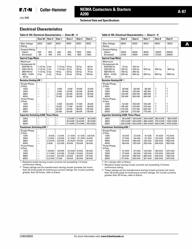
July 2008
CA08102002K For more information visit: www.EatonCanada.ca
A-87NEMA Contactors & Starters
A
A200Technical Data and Specifications
Electrical CharacteristicsTable A-154. Electrical Characteristics — Sizes 00 – 4
� Resistive loads having inrush currents not exceeding 1.5 times continuous rating.
� These ratings are for transformers having inrush currents not more than 20 times peak of continuous current ratings. For inrush currents greater than 20 times, refer to Eaton.
Table A-155. Electrical Characteristics — Sizes 5 – 9
� For ratings refer to Eaton.� Resistive loads having inrush currents not exceeding 1.5 times
continuous rating.� These ratings are for transformers having inrush currents not more
than 20 times peak of continuous current ratings. For inrush currents greater than 20 times, refer to Eaton.
Size 00 Size 0 Size 1 Size 2 Size 3 Size 4
Max. VoltageRating
600V 600V 600V 600V 600V 600V
Ampere Rating(Open)(Enclosed)
10A9A
20A18A
30A27A
50A45A
100A90A
150A135A
Squirrel Cage MotorMaximumHorsepower At:200V/60 Hz230V/ 60 Hz380V/50 Hz460V – 575V/60 Hz
1-1/2 hp1-1/2 hp1-1/2 hp2 hp
3 hp3 hp5 hp5 hp
7-1/2 hp7-1/2 hp
10 hp10 hp
10 hp15 hp25 hp25 hp
25 hp30 hp50 hp50 hp
40 hp50 hp75 hp
100 hp
Resistive Heating kW �
Single-Phase, 2-Pole
120V240V480V600V
Three-Phase, 3-Pole
120V240V480V600V
————
————
————
————
3 kW6 kW
12 kW15 kW
5 kW10 kW20 kW25 kW
5 kW10 kW20 kW25 kW
8.5 kW17 kW34 kW43 kW
10 kW20 kW40 kW50 kW
17 kW34 kW68 kW86 kW
15 kW30 kW60 kW75 kW
26 kW68 kW
105 kW130 kW
Capacitor Switching kVAR, Three-Phase240V480V600V
———
———
———
12 kVAR25 kVAR31 kVAR
27 kVAR53 kVAR67 kVAR
40 kVAR80 kVAR
100 kVAR
Transformer Switching kVA �
Single-Phase, 2-Pole
120V240V480V600V
Three-Phase, 3-Pole
120V240V480V600V
————
————
.6 kVA1.2 kVA2.4 kVA3 kVA
1.8 kVA2.1 kVA4.2 kVA5.2 kVA
1.2 kVA2.4 kVA4.9 kVA6.2 kVA
3.6 kVA4.3 kVA8.5 kVA
11 kVA
2.1 kVA4.1 kVA8.3 kVA
10 kVA
6.3 kVA7.2 kVA
14 kVA18 kVA
4.1 kVA8.1 kVA
16 kVA20 kVA
12 kVA14 kVA28 kVA35 kVA
6.8 kVA14 kVA27 kVA34 kVA
20 kVA23 kVA47 kVA59 kVA
Size 5 Size 6 Size 7 Size 8 Size 9
Max. VoltageRating
600V 600V 600V 600V 600V
Ampere Rating(Open)(Enclosed)
300A270A
600A540A
900A810A
1350A1215A
2500A2250A
Squirrel Cage MotorMaximum Horsepower At:200V/60 Hz230V/60 Hz380V/50 Hz460V – 575V/60 Hz
75 hp100 hp150 hp200 hp
150 hp200 hp300 hp400 hp
—300 hp—600 hp
—450 hp—900 hp
—800 hp
—1600 hp
Resistive Heating kW �
Single-Phase, 2-Pole
120V240V480V600V
Three-Phase, 3-Pole
120V240V480V600V
30 kW60 kW
120 kW150 kW
52 kW105 kW210 kW260 kW
60 kW120 kW240 kW300 kW
105 kW210 kW415 kW515 kW
90 kW180 kW360 kW450 kW
155 kW315 kW625 kW775 kW
�
�
�
�
�
�
�
�
�
�
�
�
�
�
�
�
Capacitor Switching kVAR, Three-Phase240V480V600V
80 kVAR160 kVAR200 kVAR
160 kVAR320 kVAR400 kVAR
240 kVAR480 kVAR600 kVAR
360 kVAR720 kVAR900 kVAR
665 kVAR1325 kVAR1670 kVAR
Transformer Switching kVA �
Single-Phase, 2-Pole
120V240V480V600V
Three-Phase, 3-Pole
120V240V480V600V
14 kVA27 kVA54 kVA68 kVA
41 kVA47 kVA94 kVA
117 kVA
27 kVA54 kVA
108 kVA135 kVA
81 kVA94 kVA
188 kVA234 kVA
41 kVA81 kVA
162 kVA203 kVA
122 kVA140 kVA280 kVA351 kVA
61 kVA122 kVA244 kVA304 kVA
182 kVA210 kVA420 kVA526 kVA
112 kVA225 kVA450 kVA562 kVA
337 kVA342 kVA783 kVA975 kVA
Tab33.book Page 87 Sunday, September 21, 2008 10:27 PM
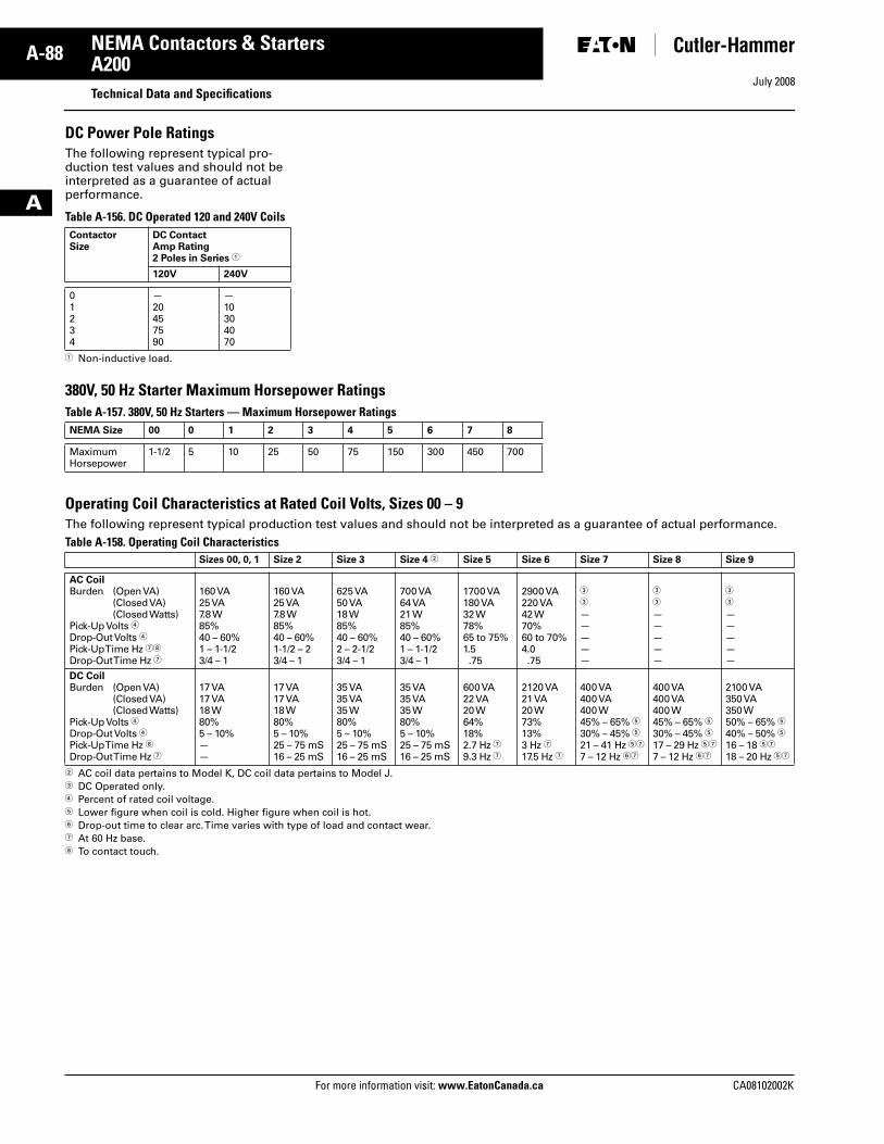
July 2008
A-88
For more information visit: www.EatonCanada.ca CA08102002K
NEMA Contactors & Starters
A
A200Technical Data and Specifications
DC Power Pole RatingsThe following represent typical pro-duction test values and should not be interpreted as a guarantee of actual performance.
Table A-156. DC Operated 120 and 240V Coils
� Non-inductive load.
380V, 50 Hz Starter Maximum Horsepower RatingsTable A-157. 380V, 50 Hz Starters — Maximum Horsepower Ratings
Operating Coil Characteristics at Rated Coil Volts, Sizes 00 – 9The following represent typical production test values and should not be interpreted as a guarantee of actual performance.Table A-158. Operating Coil Characteristics
� AC coil data pertains to Model K, DC coil data pertains to Model J.� DC Operated only. � Percent of rated coil voltage.� Lower figure when coil is cold. Higher figure when coil is hot.� Drop-out time to clear arc. Time varies with type of load and contact wear.� At 60 Hz base. To contact touch.
ContactorSize
DC ContactAmp Rating 2 Poles in Series �
120V 240V
01234
—20457590
—10304070
NEMA Size 00 0 1 2 3 4 5 6 7 8
MaximumHorsepower
1-1/2 5 10 25 50 75 150 300 450 700
Sizes 00, 0, 1 Size 2 Size 3 Size 4 � Size 5 Size 6 Size 7 Size 8 Size 9
AC CoilBurden (Open VA)
(Closed VA)(Closed Watts)
Pick-Up Volts �Drop-Out Volts �Pick-Up Time Hz �
Drop-Out Time Hz �
160 VA25 VA7.8 W85%40 – 60%1 – 1-1/23/4 – 1
160 VA25 VA7.8 W85%40 – 60%1-1/2 – 23/4 – 1
625 VA50 VA18 W85%40 – 60%2 – 2-1/23/4 – 1
700 VA64 VA21 W85%40 – 60%1 – 1-1/23/4 – 1
1700 VA180 VA32 W78%65 to 75%1.5.75
2900 VA220 VA42 W70%60 to 70%4.0.75
�
�
—————
�
�
—————
�
�
—————
DC CoilBurden (Open VA)
(Closed VA)(Closed Watts)
Pick-Up Volts �Drop-Out Volts �Pick-Up Time Hz Drop-Out Time Hz �
17 VA17 VA18 W80%5 – 10%——
17 VA17 VA18 W80%5 – 10%25 – 75 mS16 – 25 mS
35 VA35 VA35 W80%5 – 10%25 – 75 mS16 – 25 mS
35 VA35 VA35 W80%5 – 10%25 – 75 mS16 – 25 mS
600 VA22 VA20 W64%18%2.7 Hz �9.3 Hz �
2120 VA21 VA20 W73%13%3 Hz �17.5 Hz �
400 VA400 VA400 W45% – 65% �30% – 45% �21 – 41 Hz ��
7 – 12 Hz ��
400 VA400 VA400 W45% – 65% �30% – 45% �17 – 29 Hz ��
7 – 12 Hz ��
2100 VA350 VA350 W50% – 65% �40% – 50% �16 – 18 ��
18 – 20 Hz ��
Tab33.book Page 88 Sunday, September 21, 2008 10:27 PM
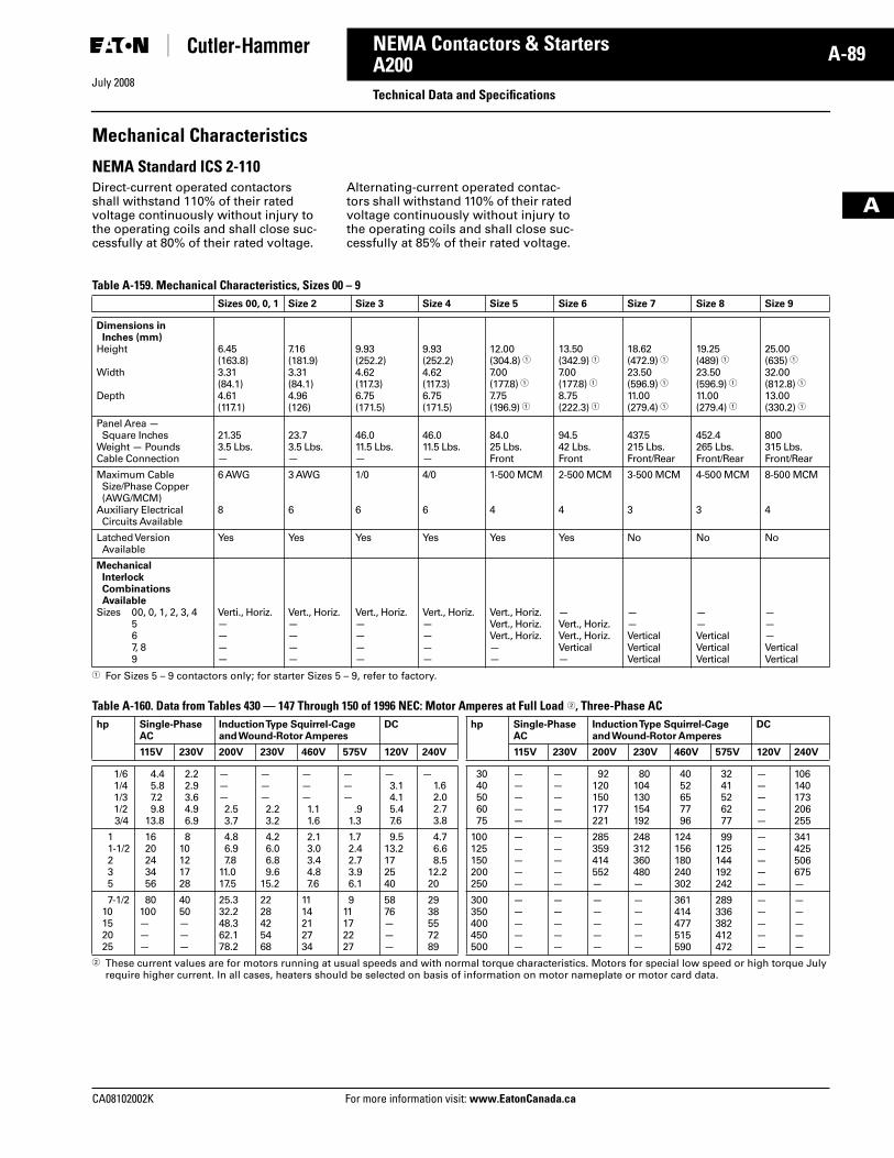
July 2008
CA08102002K For more information visit: www.EatonCanada.ca
A-89NEMA Contactors & Starters
A
A200Technical Data and Specifications
Mechanical Characteristics
NEMA Standard ICS 2-110Direct-current operated contactors shall withstand 110% of their rated voltage continuously without injury to the operating coils and shall close suc-cessfully at 80% of their rated voltage.
Alternating-current operated contac-tors shall withstand 110% of their rated voltage continuously without injury to the operating coils and shall close suc-cessfully at 85% of their rated voltage.
Table A-159. Mechanical Characteristics, Sizes 00 – 9
� For Sizes 5 – 9 contactors only; for starter Sizes 5 – 9, refer to factory.
Table A-160. Data from Tables 430 — 147 Through 150 of 1996 NEC: Motor Amperes at Full Load �, Three-Phase AC
� These current values are for motors running at usual speeds and with normal torque characteristics. Motors for special low speed or high torque July require higher current. In all cases, heaters should be selected on basis of information on motor nameplate or motor card data.
Sizes 00, 0, 1 Size 2 Size 3 Size 4 Size 5 Size 6 Size 7 Size 8 Size 9
Dimensions in Inches (mm)
Height
Width
Depth
6.45(163.8)3.31(84.1)4.61(117.1)
7.16(181.9)3.31(84.1)4.96(126)
9.93(252.2)4.62(117.3)6.75(171.5)
9.93(252.2)4.62(117.3)6.75(171.5)
12.00(304.8) �7.00(177.8) �7.75(196.9) �
13.50(342.9) �7.00(177.8) �8.75(222.3) �
18.62(472.9) �23.50(596.9) �11.00(279.4) �
19.25(489) �23.50(596.9) �11.00(279.4) �
25.00(635) �32.00(812.8) �13.00(330.2) �
Panel Area — Square Inches
Weight — PoundsCable Connection
21.353.5 Lbs.—
23.73.5 Lbs.—
46.011.5 Lbs.—
46.011.5 Lbs.—
84.025 Lbs.Front
94.542 Lbs.Front
437.5215 Lbs.Front/Rear
452.4265 Lbs.Front/Rear
800315 Lbs.Front/Rear
Maximum CableSize/Phase Copper (AWG/MCM)
Auxiliary Electrical Circuits Available
6 AWG
8
3 AWG
6
1/0
6
4/0
6
1-500 MCM
4
2-500 MCM
4
3-500 MCM
3
4-500 MCM
3
8-500 MCM
4
Latched VersionAvailable
Yes Yes Yes Yes Yes Yes No No No
Mechanical Interlock CombinationsAvailable
Sizes 00, 0, 1, 2, 3, 4567, 89
Verti., Horiz.————
Vert., Horiz.————
Vert., Horiz.————
Vert., Horiz.————
Vert., Horiz.Vert., Horiz.Vert., Horiz.——
—Vert., Horiz.Vert., Horiz.Vertical—
——VerticalVerticalVertical
——VerticalVerticalVertical
———VerticalVertical
hp Single-PhaseAC
Induction Type Squirrel-Cageand Wound-Rotor Amperes
DC hp Single-PhaseAC
Induction Type Squirrel-Cageand Wound-Rotor Amperes
DC
115V 230V 200V 230V 460V 575V 120V 240V 115V 230V 200V 230V 460V 575V 120V 240V
1/61/41/31/23/4
4.45.87.29.8
13.8
2.22.93.64.96.9
———2.53.7
———2.23.2
———1.11.6
———
.91.3
—3.14.15.47.6
—1.62.02.73.8
3040506075
—————
—————
92120150177221
80104130154192
4052657796
3241526277
—————
106140173206255
11-1/2235
1620243456
810121728
4.86.97.8
11.017.5
4.26.06.89.6
15.2
2.13.03.44.87.6
1.72.42.73.96.1
9.513.2172540
4.76.68.5
12.220
100125150200250
—————
—————
285359414552—
248312360480—
124156180240302
99125144192242
—————
341425506675—
7-1/210152025
80100———
4050———
25.332.248.362.178.2
2228425468
1114212734
911172227
5876———
2938557289
300350400450500
—————
—————
—————
—————
361414477515590
289336382412472
—————
—————
Tab33.book Page 89 Sunday, September 21, 2008 10:27 PM
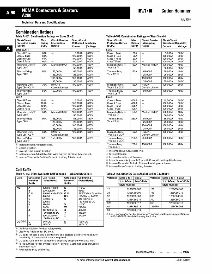
July 2008
A-90
For more information visit: www.EatonCanada.ca CA08102002K
NEMA Contactors & Starters
A
A200Technical Data and Specifications
Combination RatingsTable A-161. Combination Ratings — Sizes 00 – 2
� Instantaneous Adjustable Trip.� Circuit Breaker.� Inverse Time Circuit Breaker.� Instantaneous Adjustable Trip with Current Limiting Attachment.� Inverse Time with Built-In Current Limiting Attachment.
Table A-162. Combination Ratings — Sizes 3 and 4
� Instantaneous Adjustable Trip.� Circuit Breaker. Inverse Time Circuit Breaker.� Instantaneous Adjustable Trip with Current Limiting Attachment.� Inverse Time with Built-In Current Limiting Attachment. Inverse Time Current Limiting Breaker.
Coil SuffixTable A-163. Other Available Coil Voltages — AC and DC Coils
� List Price Addition for dual voltage coils. � List Price Addition for DC coils. DC coils for Size 5 and 6 contactors and starters are intermittent duty
rated only. A mechanical latch is required.� DC coils. Use only on contactors originally supplied with a DC coil.� For Q suffixes “order by description” consult Customer Support Centre,
1-800-268-3578. Availability may be limited.
Table A-164. Other DC Coils Available (For Q Suffix) �
� For Q suffixes “order by description” consult Customer Support Centre, 1-800-268-3578. Availability may be limited.
Short-CircuitProtective Device(SCPD)
Max.RatingSCPD
Circuit BreakerInterrupting Rating
Short-Circuit Withstand Capability
Current Voltage
Sizes 00, 0, 1Class H FuseClass J FuseClass R FuseClass T Fuse
60A60A60A60A
————
5,000A100,000A100,000A100,000A
600V600V600V600V
Magnetic Only �Type CB �
30A Marked HMCP 100,000A 480V50,000A 600V
Thermal/Mag.Type CB �
50A 65,000A 65,000A 480V25,000A 25,000A 600V
100,000A 100,000A 480V35,000A 35,000A 600V
Magnetic OnlyType CB + CL �
30A HMCP + Current Limiter
100,000A 600V
Thermal/Mag.Type CLB �
50A 150,000A 100,000A 480V
Size 2Class H FuseClass J FuseClass R FuseClass T Fuse
100A100A100A100A
————
5,000A100,000A100,000A100,000A
600V600V600V600V
Magnetic Only �Type CB �
50A Marked HMCP 100,000A 480V50,000A 600V
Thermal/Mag.Type CB �
90A 65,000A 65,000A 480V25,000A 25,000A 600V
100,000A 100,000A 480V35,000A 35,000A 600V
Magnetic OnlyType CB + CL �
50A HMCP + Current Limiter
100,000A 600V
Thermal/Mag.Type CLB �
50A 150,000A 100,000A 480V
Short-CircuitProtective Device(SCPD)
Max.RatingSCPD
Circuit BreakerInterrupting Rating
Short-Circuit Withstand Capability
Current Voltage
Size 3 Class H FuseClass J FuseClass R FuseClass T Fuse
60A60A60A60A
————
5,000A100,000A100,000A100,000A
600V600V600V600V
Magnetic Only �Type CB �
100A Marked HMCP 100,000A 480V50,000A 600V
Thermal/Mag.Type CB
150A 65,000A 65,000A 480V25,000A 25,000A 600V
100,000A 100,000A 480V35,000A 35,000A 600V
Magnetic OnlyType CB + CL �
100A HMCP + Current Limiter
100,000A 600V
Thermal/Mag.Type CLB �
150A 50,000A 100,000A 480V
Size 4Class H FuseClass J FuseClass R FuseClass T Fuse
400A400A400A400A
————
10,000A100,000A100,000A100,000A
600V600V600V600V
Magnetic Only �Type CB �
150A Marked HMCP 100,000A 480V50,000A 600V
Thermal/Mag.Type CB
250A 65,000A 65,000A 480V25,000A 25,000A 600V
100,000A 100,000A 480V35,000A 35,000A 600V
Magnetic OnlyType CB + CL �
150A HMCP + Current Limiter
100,000A 600V
Thermal/Mag.Type CB + CL �
250A 200,000A 100,000A 600V
Thermal/Mag.Type CLB
250A 150,000A 100,000A 480V
Coils CatalogueNumberSuffix
Coil Rating (Volts/Hertz)
CatalogueNumberSuffix
Coil Rating (Volts/Hertz)
AC ABC �DEGHIJ
K
120/60, 110/50200-208/60240/60 and 480/60440/50600/60 Hz220/50380/5024/60110-120/50 or 60 Rect. to DC
220-240/50 or 60 Rect. to DC
NPQ �R �U
VWXYZ
110/5048/60AC/DC Volts Specified120/60 and 240/60440-480/50 or60 Rect. to DC
110/60240/60480/60415/50277/60
DC � � LM
24V DC48V DC
ST
125V DC250V DC
Voltages Sizes 0 & 1 Size 2 Voltages Sizes 0 & 1 Size 2
1- to 4-Pole 1- to 3-Pole 1- to 4-Pole 1- to 3-Pole
Style Number Style Number
12 1268C86G07 79 1268C86G0828 1268C86G06 96 1268C86G1532 1268C86G09 200 1268C86G1134 1268C86G16 300 1268C86G1437.5 1268C86G17 315 1268C86G1240 1268C86G13 125/250 1268C86G0350 1268C86G10 —
Discount Symbol . . . . . . . . . . . . . . . . . . . . . . . MC17
Tab33.book Page 90 Sunday, September 21, 2008 10:27 PM
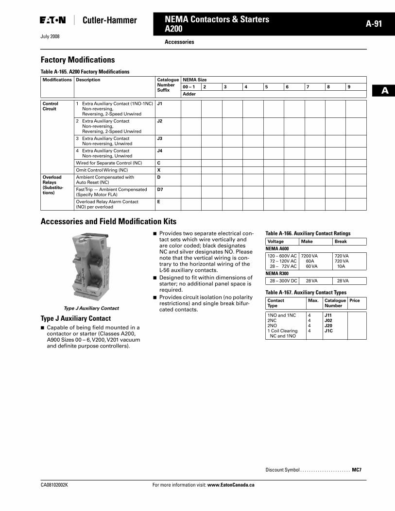
July 2008
CA08102002K For more information visit: www.EatonCanada.ca
A-91NEMA Contactors & Starters
A
A200Accessories
Factory ModificationsTable A-165. A200 Factory Modifications
Accessories and Field Modification Kits
Type J Auxiliary Contact
Type J Auxiliary Contact■ Capable of being field mounted in a
contactor or starter (Classes A200, A900 Sizes 00 – 6, V200, V201 vacuum and definite purpose controllers).
■ Provides two separate electrical con-tact sets which wire vertically and are color coded; black designates NC and silver designates NO. Please note that the vertical wiring is con-trary to the horizontal wiring of the L-56 auxiliary contacts.
■ Designed to fit within dimensions of starter; no additional panel space is required.
■ Provides circuit isolation (no polarity restrictions) and single break bifur-cated contacts.
Table A-166. Auxiliary Contact Ratings
Table A-167. Auxiliary Contact Types
Modifications Description CatalogueNumberSuffix
NEMA Size
00 – 1 2 3 4 5 6 7 8 9
Adder
Control Circuit
1 Extra Auxiliary Contact (1NO-1NC) Non-reversing, Reversing, 2-Speed Unwired
J1
2 Extra Auxiliary Contact Non-reversing, Reversing, 2-Speed Unwired
J2
3 Extra Auxiliary Contact Non-reversing, Unwired
J3
4 Extra Auxiliary Contact Non-reversing, Unwired
J4
Wired for Separate Control (NC) C
Omit Control Wiring (NC) X
Overload Relays (Substitu-tions)
Ambient Compensated with Auto Reset (NC)
D
Fast Trip — Ambient Compensated (Specify Motor FLA)
D7
Overload Relay Alarm Contact (NO) per overload
E
Voltage Make Break
NEMA A600120 – 600V AC72 – 120V AC28 – 72V AC
7200 VA60A60 VA
720 VA720 VA10A
NEMA R30028 – 300V DC 28 VA 28 VA
Contact Type
Max. Catalogue Number
Price
1NO and 1NC2NC2NO1 Coil Clearing NC and 1NO
4444
J11J02J20J1C
Discount Symbol . . . . . . . . . . . . . . . . . . . . . . . MC7
Tab33.book Page 91 Sunday, September 21, 2008 10:27 PM
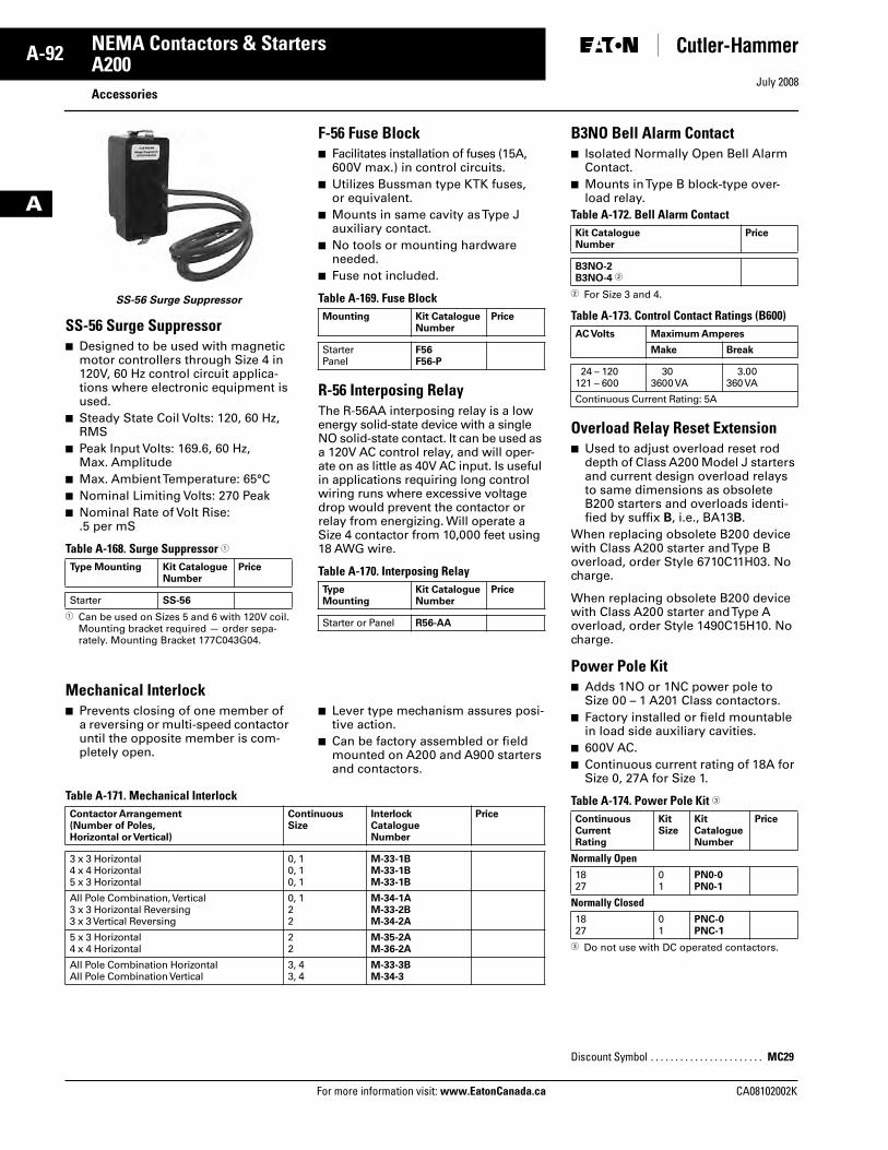
July 2008
A-92
For more information visit: www.EatonCanada.ca CA08102002K
NEMA Contactors & Starters
A
A200 Accessories
SS-56 Surge Suppressor
SS-56 Surge Suppressor■ Designed to be used with magnetic
motor controllers through Size 4 in 120V, 60 Hz control circuit applica-tions where electronic equipment is used.
■ Steady State Coil Volts: 120, 60 Hz, RMS
■ Peak Input Volts: 169.6, 60 Hz, Max. Amplitude
■ Max. Ambient Temperature: 65°C■ Nominal Limiting Volts: 270 Peak■ Nominal Rate of Volt Rise:
.5 per mS
Table A-168. Surge Suppressor �
� Can be used on Sizes 5 and 6 with 120V coil. Mounting bracket required — order sepa-rately. Mounting Bracket 177C043G04.
F-56 Fuse Block■ Facilitates installation of fuses (15A,
600V max.) in control circuits.■ Utilizes Bussman type KTK fuses,
or equivalent.■ Mounts in same cavity as Type J
auxiliary contact.■ No tools or mounting hardware
needed.■ Fuse not included.
Table A-169. Fuse Block
R-56 Interposing RelayThe R-56AA interposing relay is a low energy solid-state device with a single NO solid-state contact. It can be used as a 120V AC control relay, and will oper-ate on as little as 40V AC input. Is useful in applications requiring long control wiring runs where excessive voltage drop would prevent the contactor or relay from energizing. Will operate a Size 4 contactor from 10,000 feet using 18 AWG wire.
Table A-170. Interposing Relay
Mechanical Interlock■ Prevents closing of one member of
a reversing or multi-speed contactor until the opposite member is com-pletely open.
■ Lever type mechanism assures posi-tive action.
■ Can be factory assembled or field mounted on A200 and A900 starters and contactors.
Table A-171. Mechanical Interlock
Type Mounting Kit Catalogue Number
Price
Starter SS-56
Mounting Kit CatalogueNumber
Price
StarterPanel
F56F56-P
Type Mounting
Kit Catalogue Number
Price
Starter or Panel R56-AA
Contactor Arrangement (Number of Poles, Horizontal or Vertical)
ContinuousSize
Interlock CatalogueNumber
Price
3 x 3 Horizontal4 x 4 Horizontal5 x 3 Horizontal
0, 10, 10, 1
M-33-1BM-33-1BM-33-1B
All Pole Combination, Vertical3 x 3 Horizontal Reversing3 x 3 Vertical Reversing
0, 122
M-34-1AM-33-2BM-34-2A
5 x 3 Horizontal4 x 4 Horizontal
22
M-35-2AM-36-2A
All Pole Combination HorizontalAll Pole Combination Vertical
3, 43, 4
M-33-3BM-34-3
B3NO Bell Alarm Contact■ Isolated Normally Open Bell Alarm
Contact.■ Mounts in Type B block-type over-
load relay.Table A-172. Bell Alarm Contact
� For Size 3 and 4.
Table A-173. Control Contact Ratings (B600)
Overload Relay Reset Extension■ Used to adjust overload reset rod
depth of Class A200 Model J starters and current design overload relays to same dimensions as obsolete B200 starters and overloads identi-fied by suffix B, i.e., BA13B.
When replacing obsolete B200 device with Class A200 starter and Type B overload, order Style 6710C11H03. No charge.
When replacing obsolete B200 device with Class A200 starter and Type A overload, order Style 1490C15H10. No charge.
Power Pole Kit■ Adds 1NO or 1NC power pole to
Size 00 – 1 A201 Class contactors.■ Factory installed or field mountable
in load side auxiliary cavities.■ 600V AC.■ Continuous current rating of 18A for
Size 0, 27A for Size 1.
Table A-174. Power Pole Kit �
� Do not use with DC operated contactors.
Kit Catalogue Number
Price
B3NO-2B3NO-4 �
AC Volts Maximum Amperes
Make Break
24 – 120121 – 600
303600 VA
3.00360 VA
Continuous Current Rating: 5A
ContinuousCurrentRating
Kit Size
Kit CatalogueNumber
Price
Normally Open1827
01
PN0-0PN0-1
Normally Closed1827
01
PNC-0PNC-1
Discount Symbol . . . . . . . . . . . . . . . . . . . . . . . MC29
Tab33.book Page 92 Sunday, September 21, 2008 10:27 PM
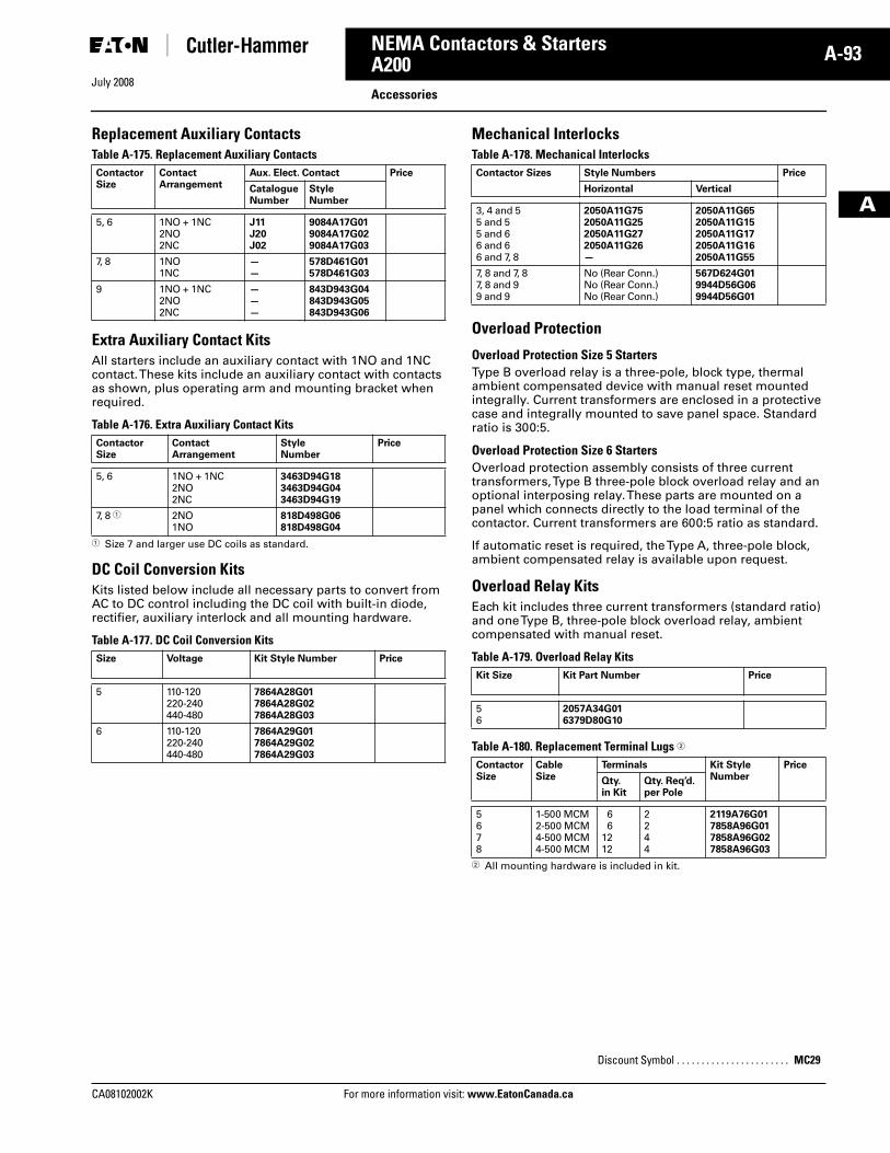
July 2008
CA08102002K For more information visit: www.EatonCanada.ca
A-93NEMA Contactors & Starters
A
A200Accessories
Replacement Auxiliary ContactsTable A-175. Replacement Auxiliary Contacts
Extra Auxiliary Contact KitsAll starters include an auxiliary contact with 1NO and 1NC contact. These kits include an auxiliary contact with contacts as shown, plus operating arm and mounting bracket when required.
Table A-176. Extra Auxiliary Contact Kits
� Size 7 and larger use DC coils as standard.
DC Coil Conversion KitsKits listed below include all necessary parts to convert from AC to DC control including the DC coil with built-in diode, rectifier, auxiliary interlock and all mounting hardware.
Table A-177. DC Coil Conversion Kits
Mechanical InterlocksTable A-178. Mechanical Interlocks
Overload Protection
Overload Protection Size 5 StartersType B overload relay is a three-pole, block type, thermal ambient compensated device with manual reset mounted integrally. Current transformers are enclosed in a protective case and integrally mounted to save panel space. Standard ratio is 300:5.
Overload Protection Size 6 StartersOverload protection assembly consists of three current transformers, Type B three-pole block overload relay and an optional interposing relay. These parts are mounted on a panel which connects directly to the load terminal of the contactor. Current transformers are 600:5 ratio as standard.
If automatic reset is required, the Type A, three-pole block, ambient compensated relay is available upon request.
Overload Relay KitsEach kit includes three current transformers (standard ratio) and one Type B, three-pole block overload relay, ambient compensated with manual reset.
Table A-179. Overload Relay Kits
Table A-180. Replacement Terminal Lugs �
� All mounting hardware is included in kit.
Contactor Size
ContactArrangement
Aux. Elect. Contact Price
CatalogueNumber
Style Number
5, 6 1NO + 1NC2NO2NC
J11J20J02
9084A17G019084A17G029084A17G03
7, 8 1NO1NC
——
578D461G01578D461G03
9 1NO + 1NC2NO2NC
———
843D943G04843D943G05843D943G06
Contactor Size
ContactArrangement
Style Number
Price
5, 6 1NO + 1NC2NO2NC
3463D94G183463D94G043463D94G19
7, 8 � 2NO1NO
818D498G06818D498G04
Size Voltage Kit Style Number Price
5 110-120220-240440-480
7864A28G017864A28G027864A28G03
6 110-120220-240440-480
7864A29G017864A29G027864A29G03
Contactor Sizes Style Numbers Price
Horizontal Vertical
3, 4 and 55 and 55 and 66 and 66 and 7, 8
2050A11G752050A11G252050A11G272050A11G26—
2050A11G652050A11G152050A11G172050A11G162050A11G55
7, 8 and 7, 87, 8 and 99 and 9
No (Rear Conn.)No (Rear Conn.)No (Rear Conn.)
567D624G019944D56G069944D56G01
Kit Size Kit Part Number Price
56
2057A34G016379D80G10
ContactorSize
CableSize
Terminals Kit Style Number
Price
Qty. in Kit
Qty. Req’d.per Pole
5678
1-500 MCM2-500 MCM4-500 MCM4-500 MCM
66
1212
2244
2119A76G017858A96G017858A96G027858A96G03
Discount Symbol . . . . . . . . . . . . . . . . . . . . . . . MC29
Tab33.book Page 93 Sunday, September 21, 2008 10:27 PM
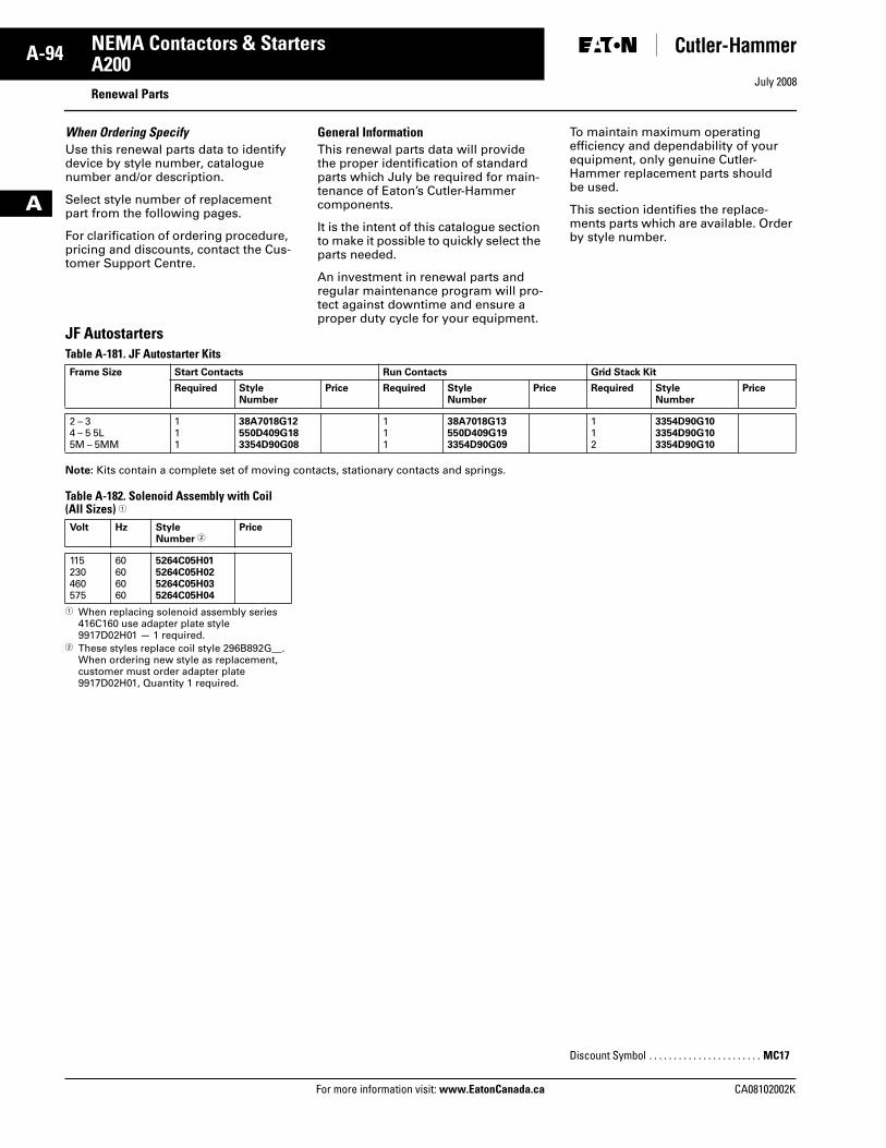
July 2008
A-94
For more information visit: www.EatonCanada.ca CA08102002K
NEMA Contactors & Starters
A
A200Renewal Parts
When Ordering SpecifyUse this renewal parts data to identify device by style number, catalogue number and/or description.
Select style number of replacement part from the following pages.
For clarification of ordering procedure, pricing and discounts, contact the Cus-tomer Support Centre.
General InformationThis renewal parts data will provide the proper identification of standard parts which July be required for main-tenance of Eaton’s Cutler-Hammer components.
It is the intent of this catalogue section to make it possible to quickly select the parts needed.
An investment in renewal parts and regular maintenance program will pro-tect against downtime and ensure a proper duty cycle for your equipment.
To maintain maximum operating efficiency and dependability of your equipment, only genuine Cutler-Hammer replacement parts should be used.
This section identifies the replace-ments parts which are available. Order by style number.
JF AutostartersTable A-181. JF Autostarter Kits
Note: Kits contain a complete set of moving contacts, stationary contacts and springs.
Table A-182. Solenoid Assembly with Coil (All Sizes) �
� When replacing solenoid assembly series 416C160 use adapter plate style 9917D02H01 — 1 required.
� These styles replace coil style 296B892G__. When ordering new style as replacement, customer must order adapter plate 9917D02H01, Quantity 1 required.
Frame Size Start Contacts Run Contacts Grid Stack Kit
Required Style Number
Price Required Style Number
Price Required Style Number
Price
2 – 34 – 5 5L5M – 5MM
111
38A7018G12550D409G183354D90G08
111
38A7018G13550D409G193354D90G09
112
3354D90G103354D90G103354D90G10
Volt Hz Style Number �
Price
115230460575
60606060
5264C05H015264C05H025264C05H035264C05H04
Discount Symbol . . . . . . . . . . . . . . . . . . . . . . . MC17
Tab33.book Page 94 Sunday, September 21, 2008 10:27 PM
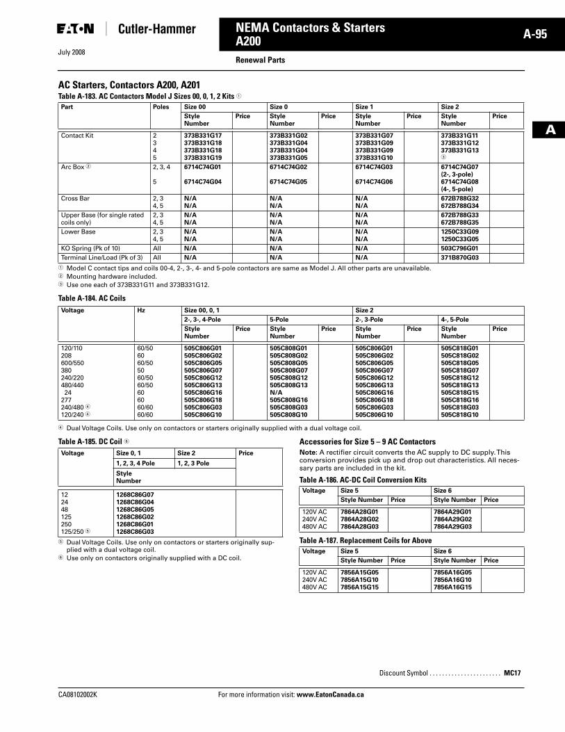
July 2008
CA08102002K For more information visit: www.EatonCanada.ca
A-95NEMA Contactors & Starters
A
A200Renewal Parts
AC Starters, Contactors A200, A201Table A-183. AC Contactors Model J Sizes 00, 0, 1, 2 Kits �
� Model C contact tips and coils 00-4, 2-, 3-, 4- and 5-pole contactors are same as Model J. All other parts are unavailable.� Mounting hardware included.� Use one each of 373B331G11 and 373B331G12.
Table A-184. AC Coils
� Dual Voltage Coils. Use only on contactors or starters originally supplied with a dual voltage coil.
Table A-185. DC Coil �
� Dual Voltage Coils. Use only on contactors or starters originally sup-plied with a dual voltage coil.
� Use only on contactors originally supplied with a DC coil.
Accessories for Size 5 – 9 AC Contactors Note: A rectifier circuit converts the AC supply to DC supply. This conversion provides pick up and drop out characteristics. All neces-sary parts are included in the kit.
Table A-186. AC-DC Coil Conversion Kits
Table A-187. Replacement Coils for Above
Part Poles Size 00 Size 0 Size 1 Size 2
Style Number
Price Style Number
Price Style Number
Price Style Number
Price
Contact Kit 2345
373B331G17373B331G18373B331G18373B331G19
373B331G02373B331G04373B331G04373B331G05
373B331G07373B331G09373B331G09373B331G10
373B331G11373B331G12373B331G13�
Arc Box � 2, 3, 4
5
6714C74G01
6714C74G04
6714C74G02
6714C74G05
6714C74G03
6714C74G06
6714C74G07 (2-, 3-pole)6714C74G08 (4-, 5-pole)
Cross Bar 2, 34, 5
N/AN/A
N/AN/A
N/AN/A
672B788G32672B788G34
Upper Base (for single rated coils only)
2, 34, 5
N/AN/A
N/AN/A
N/AN/A
672B788G33672B788G35
Lower Base 2, 34, 5
N/AN/A
N/AN/A
N/AN/A
1250C33G091250C33G05
KO Spring (Pk of 10) All N/A N/A N/A 503C796G01
Terminal Line/Load (Pk of 3) All N/A N/A N/A 371B870G03
Voltage Hz Size 00, 0, 1 Size 2
2-, 3-, 4-Pole 5-Pole 2-, 3-Pole 4-, 5-Pole
Style Number
Price Style Number
Price Style Number
Price Style Number
Price
120/110208600/550380240/220480/440 24277240/480 �120/240 �
60/506060/505060/5060/50606060/6060/60
505C806G01505C806G02505C806G05505C806G07505C806G12505C806G13505C806G16505C806G18505C806G03505C806G10
505C808G01505C808G02505C808G05505C808G07505C808G12505C808G13N/A505C808G16505C808G03505C808G10
505C806G01505C806G02505C806G05505C806G07505C806G12505C806G13505C806G16505C806G18505C806G03505C806G10
505C818G01505C818G02505C818G05505C818G07505C818G12505C818G13505C818G15505C818G16505C818G03505C818G10
Voltage Size 0, 1 Size 2 Price
1, 2, 3, 4 Pole 1, 2, 3 Pole
Style Number
122448125250125/250 �
1268C86G071268C86G041268C86G051268C86G021268C86G011268C86G03
Voltage Size 5 Size 6
Style Number Price Style Number Price
120V AC240V AC480V AC
7864A28G017864A28G027864A28G03
7864A29G017864A29G027864A29G03
Voltage Size 5 Size 6
Style Number Price Style Number Price
120V AC240V AC480V AC
7856A15G057856A15G107856A15G15
7856A16G057856A16G107856A16G15
Discount Symbol . . . . . . . . . . . . . . . . . . . . . . . MC17
Tab33.book Page 95 Sunday, September 21, 2008 10:27 PM
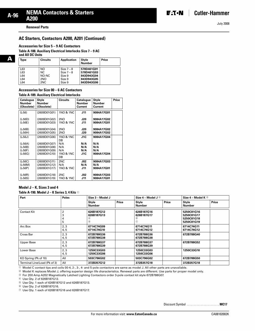
July 2008
A-96
For more information visit: www.EatonCanada.ca CA08102002K
NEMA Contactors & Starters
A
A200Renewal Parts
AC Starters, Contactors A200, A201 (Continued)
Accessories for Size 5 – 9 AC Contactors Table A-188. Auxiliary Electrical Interlocks Size 7 – 9 AC and All DC Units
Accessories for Size 00 – 6 AC ContactorsTable A-189. Auxiliary Electrical Interlocks
Model J – K, Sizes 3 and 4 Table A-190. Model J – K Series 3, 4 Kits �
� Model C contact tips and coils 00-4, 2-, 3-, 4- and 5-pole contactors are same as model J. All other parts are unavailable.� Model K replaces Model J, offering superior design life characteristics. Renewal parts are different. Use parts for proper model only. � For 200 Amp A202 Magnetically Latched Lighting Contactors order 3-pole contact kit style 672B788G07.� Use Qty. 2 of 626B187G12. � Use Qty. 1 each of 626B187G12 and 626B187G13.� Use Qty. 2 of 626B187G16.� Use Qty. 1 each of 626B187G16 and 626B187G17.
Type Circuits Application Style Number
Price
L63L63L64L64L64
NONCNO-NC2NO2NC
Size 7 – 8Size 7 – 8Size 9Size 9Size 9
578D461G01578D461G03843D943G04843D943G05843D943G06
CatalogueNumber(Obsolete)
StyleNumber(Obsolete)
Circuits CatalogueNumberCurrent
StyleNumberCurrent
Price
(L-56)
(L-56D)(L-56E)
(L-56B)(L-56H)
(2609D01G01)
(2609D01G02)(2609D01G03)
(2609D01G04)(2609D01G05)
1NO & 1NC
2NO1NO & 1NC
2NO2NO
J11
J20J11
J20J20
9084A17G01
9084A17G029084A17G01
9084A17G029084A17G02
(L-56J)
(L-56A)(L-56B)(L-56F)(L-56G)
(2609D01G06)
(2609D01G07)(2609D01G08)(2609D01G09)(2609D01G10)
1NO & 1NC DBN/AN/AN/A1NO & 1NC DB
J1C
N/AN/AN/AJ1C
9084A17G04
N/AN/AN/A9084A17G04
(L-56C)(L-56M)(L-56P)
(L-56R)(L-56S)
(2609D01G11)(2609D01G12)(2609D01G17)
(2609D01G18)(2609D01G19)
2NCN/A1NO & 1NC
2NC1NO & 1NC
J02N/AJ11
J02J11
9084A17G03N/A9084A17G01
9084A17G039084A17G01
Part Poles Size 3 – Model J Size 4 – Model J � Size 4 – Model K �
Style Number
Price Style Number
Price Style Number
Price
Contact Kit 2345
626B187G12626B187G13�
�
626B187G16626B187G17�
�
5250C81G165250C81G175250C81G185250C81G19
Arc Box 2, 34, 5
6714C74G096714C74G10
6714C74G116714C74G12
6714C74G116714C74G12
Cross Bar 2, 34, 5
672B788G36672B788G38
672B788G36672B788G38
672B788G40
Upper Base 2, 34, 5
672B788G37672B788G39
672B788G37672B788G39
672B788G52
Lower Base 2, 34, 5
1250C33G031250C33G06
1250C33G031250C33G06
1250C33G10
KO Spring (Pk of 10) All 503C796G02 503C796G02 672B788G50
Terminal Line/Load (Pk of 3) All 372B357G12 372B357G18 372B357G18
Discount Symbol . . . . . . . . . . . . . . . . . . . . . . . MC17
Tab33.book Page 96 Sunday, September 21, 2008 10:27 PM
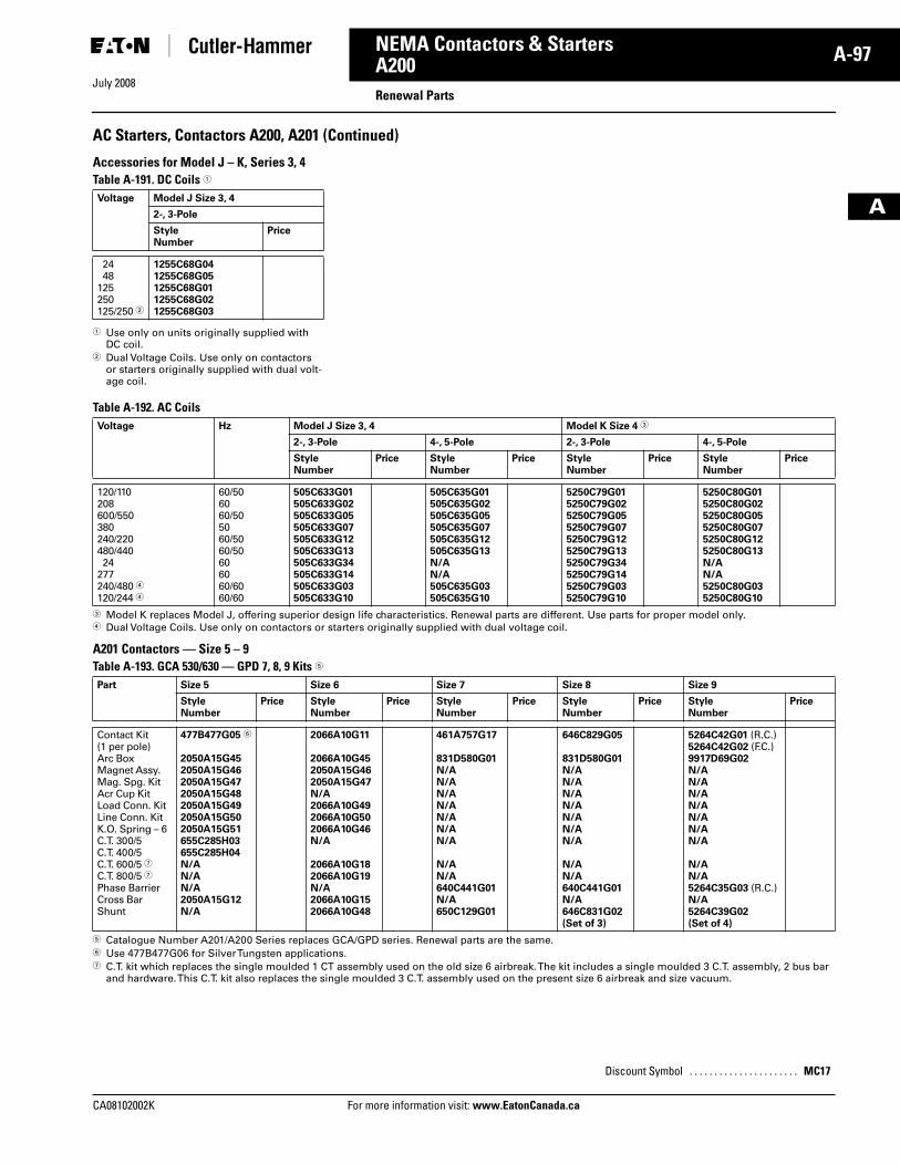
July 2008
CA08102002K For more information visit: www.EatonCanada.ca
A-97NEMA Contactors & Starters
A
A200Renewal Parts
AC Starters, Contactors A200, A201 (Continued)
Accessories for Model J – K, Series 3, 4 Table A-191. DC Coils �
� Use only on units originally supplied with DC coil.
� Dual Voltage Coils. Use only on contactors or starters originally supplied with dual volt-age coil.
Table A-192. AC Coils
� Model K replaces Model J, offering superior design life characteristics. Renewal parts are different. Use parts for proper model only.� Dual Voltage Coils. Use only on contactors or starters originally supplied with dual voltage coil.
A201 Contactors — Size 5 – 9 Table A-193. GCA 530/630 — GPD 7, 8, 9 Kits �
� Catalogue Number A201/A200 Series replaces GCA/GPD series. Renewal parts are the same. � Use 477B477G06 for Silver Tungsten applications.� C.T. kit which replaces the single moulded 1 CT assembly used on the old size 6 airbreak. The kit includes a single moulded 3 C.T. assembly, 2 bus bar
and hardware. This C.T. kit also replaces the single moulded 3 C.T. assembly used on the present size 6 airbreak and size vacuum.
Voltage Model J Size 3, 4
2-, 3-Pole
Style Number
Price
24 48125250125/250 �
1255C68G041255C68G051255C68G011255C68G021255C68G03
Voltage Hz Model J Size 3, 4 Model K Size 4 �
2-, 3-Pole 4-, 5-Pole 2-, 3-Pole 4-, 5-Pole
Style Number
Price Style Number
Price Style Number
Price Style Number
Price
120/110208600/550380240/220480/440 24277240/480 �120/244 �
60/506060/505060/5060/50606060/6060/60
505C633G01505C633G02505C633G05505C633G07505C633G12505C633G13505C633G34505C633G14505C633G03505C633G10
505C635G01505C635G02505C635G05505C635G07505C635G12505C635G13N/AN/A505C635G03505C635G10
5250C79G015250C79G025250C79G055250C79G075250C79G125250C79G135250C79G345250C79G145250C79G035250C79G10
5250C80G015250C80G025250C80G055250C80G075250C80G125250C80G13N/AN/A5250C80G035250C80G10
Part Size 5 Size 6 Size 7 Size 8 Size 9
Style Number
Price Style Number
Price Style Number
Price Style Number
Price Style Number
Price
Contact Kit(1 per pole)Arc BoxMagnet Assy.Mag. Spg. KitAcr Cup KitLoad Conn. KitLine Conn. KitK.O. Spring – 6C.T. 300/5C.T. 400/5C.T. 600/5 �C.T. 800/5 �Phase BarrierCross BarShunt
477B477G05 �
2050A15G452050A15G462050A15G472050A15G482050A15G492050A15G502050A15G51655C285H03655C285H04N/AN/AN/A2050A15G12N/A
2066A10G11
2066A10G452050A15G462050A15G47N/A2066A10G492066A10G502066A10G46N/A
2066A10G182066A10G19N/A2066A10G152066A10G48
461A757G17
831D580G01N/AN/AN/AN/AN/AN/AN/A
N/AN/A640C441G01N/A650C129G01
646C829G05
831D580G01N/AN/AN/AN/AN/AN/AN/A
N/AN/A640C441G01N/A646C831G02(Set of 3)
5264C42G01 (R.C.)5264C42G02 (F.C.)9917D69G02N/AN/AN/AN/AN/AN/AN/A
N/AN/A5264C35G03 (R.C.)N/A5264C39G02 (Set of 4)
Discount Symbol . . . . . . . . . . . . . . . . . . . . . . MC17
Tab33.book Page 97 Sunday, September 21, 2008 10:27 PM
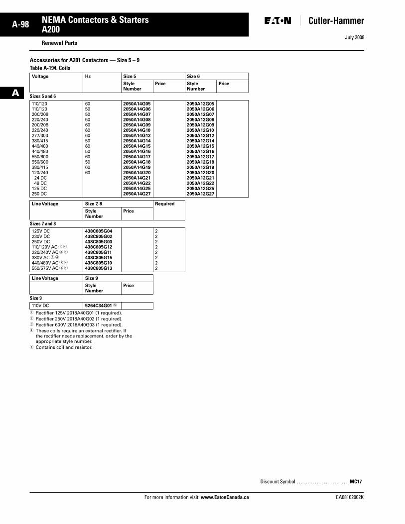
July 2008
A-98
For more information visit: www.EatonCanada.ca CA08102002K
NEMA Contactors & Starters
A
A200Renewal Parts
Accessories for A201 Contactors — Size 5 – 9Table A-194. Coils
� Rectifier 125V 2018A40G01 (1 required).� Rectifier 250V 2018A40G02 (1 required).� Rectifier 600V 2018A40G03 (1 required).� These coils require an external rectifier. If
the rectifier needs replacement, order by the appropriate style number.
� Contains coil and resistor.
Voltage Hz Size 5 Size 6
Style Number
Price Style Number
Price
Sizes 5 and 6110/120110/120200/208220/240200/208220/240277/303380/415440/480440/480550/600550/600380/415120/240 24 DC 48 DC125 DC250 DC
6050505060606050605060506060
2050A14G052050A14G062050A14G072050A14G082050A14G092050A14G102050A14G122050A14G142050A14G152050A14G162050A14G172050A14G182050A14G192050A14G202050A14G212050A14G222050A14G252050A14G27
2050A12G052050A12G062050A12G072050A12G082050A12G092050A12G102050A12G122050A12G142050A12G152050A12G162050A12G172050A12G182050A12G192050A12G202050A12G212050A12G222050A12G252050A12G27
Line Voltage Size 7, 8 Required
Style Number
Price
Sizes 7 and 8125V DC230V DC250V DC110/120V AC � �220/240V AC � �380V AC � �440/480V AC � �550/575V AC � �
438C805G04438C805G02438C805G03438C805G12438C805G11438C805G15438C805G10438C805G13
22222222
Line Voltage Size 9
Style Number
Price
Size 9110V DC 5264C34G01 �
Discount Symbol . . . . . . . . . . . . . . . . . . . . . . . MC17
Tab33.book Page 98 Sunday, September 21, 2008 10:27 PM
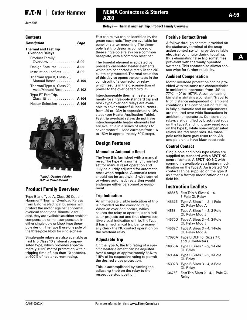
July 2008
CA08102002K For more information visit: www.EatonCanada.ca
A-99NEMA Contactors & Starters
A
A200Relays — Thermal and Fast Trip, Product Family Overview
ContentsDescription Page
Thermal and Fast Trip Overload Relays
Product FamilyOverview . . . . . . . . . . . . . A-99
Design Features . . . . . . . . A-99
Instruction Leaflets . . . . . . A-99
Thermal Type B, Class 20, Manual Reset . . . . . . . . . A-100
Thermal Type A, Class 20, Auto/Manual Reset . . . . . A-102
Type FT Fast Trip, Class 10 . . . . . . . . . . . . . . A-104
Heater Selection . . . . . . . . A-106
Type A Overload Relay3-Pole Panel Mount
Product Family OverviewType B and Type A, Class 20 Cutler-Hammer® Thermal Overload Relays from Eaton’s electrical business will protect the motor against abnormal overload conditions. Bimetallic actu-ated, they are available as either ambient compensated or non-compensated in either single-pole or block type three-pole design. The Type B use one pole of the three-pole block for single-phase.
Single-pole relays are also available as Fast Trip Class 10 ambient compen-sated type, which provides approxi-mately 125% motor protection with a tripping time of less than 10 seconds, at 600% of heater current rating.
Fast trip relays can be identified by the green reset rods. They are available for panel or starter mounting. The three-pole fast trip design is composed of three single-pole relays on a common baseplate, with a common reset bar.
The bimetal element is actuated by precisely calibrated heater elements which are connected directly in the cir-cuit to be protected. Thermal actuation of this device opens the contacts in the coil circuit of a contactor or relay which results in the disconnection of power to the overloaded circuit.
Interchangeable thermal heater ele-ments for single-pole standard trip and block type overload relays are avail-able to cover motor full load currents from .29 to 133A in approximately 10% steps (see Heater Application Table). Fast trip overload relays do not have interchangeable heater elements but are available in a series of ratings to cover motor full load currents from 1.6 to 150A in approximately 50% steps.
Design Features
Manual or Automatic ResetThe Type B is furnished with a manual reset. The Type A is normally furnished set for manual reset operation and July be quickly adjusted for automatic reset when required. Automatic reset should not be used with 2-wire control or where automatic restarting would endanger either personnel or equip-ment.
Trip IndicationAn immediate visible indication of trip is provided on the overload relay. When an overload occurs, which causes the relay to operate, a trip indi-cator projects out and thus shows pos-itive visual indication of trip. The Type B has a mechanical trip bar to manu-ally check the NC contact operation on the overload relay.
Adjustable TripOn the Type A, the trip rating of a spe-cific heater element can be adjusted over a range of approximately 85% to 115% of its respective rating to permit the desired close protection.
This is accomplished by turning the adjusting knob on the relay to the respective stop position.
Positive Contact BreakA follow-through contact, provided on the stationary terminal of the snap action control switch, provides reliable electrical continuity during toggling, thus eliminating false trip sometimes prevalent with thermally operated switches. This contact also allows con-tact wipe for further reliability.
Ambient CompensationMotor overload protection can be pro-vided with the same trip characteristics in ambient temperature from -40° to 77°C (-40° to 167°F). A compensating bimetal maintains a constant “travel to trip” distance independent of ambient conditions. The compensating feature is fully automatic and no adjustments are required over wide fluctuations in ambient temperatures. Compensated relays are identified by black reset rods on the Type A and light gray reset rods on the Type B, while non-compensated relays use red reset rods. AA three-pole units have gray reset rods. AA one-pole units have black reset rods.
Control ContactSingle-pole and block type relays are supplied as standard with a SPST NC control contact. A SPDT NO-NC with common is available as a factory mod-ification on the Type A. An isolated NO contact can be supplied on the Type B as either a factory modification or as a field kit.
Instruction Leaflets14885B Fast Trip A Sizes 0 – 4,
3-Pole OL Relay14567E Type A Sizes 1 – 2, 1-Pole
OL Relay Mod A14568 Type A Sizes 1 – 2, 3-Pole
OL Relay Mod J14570D Type A Sizes 3 – 4, 3-Pole
OL Relay Mod J14569C Type A Sizes 3 – 4, 1-Pole
OL Relay Mod A17093A Type B OLR for Sizes 7, 8
and 9 Contactors16955A Type B Sizes 1 – 2, 1-Pole
OL Relay16954A Type B Sizes 1 – 2, 3-Pole
OL Relay15392B Type B Sizes 3 – 4, 3-Pole
OL Relay13676F Fast Trip Sizes 0 – 4, 1-Pole OL
Relay
Tab33.book Page 99 Sunday, September 21, 2008 10:27 PM
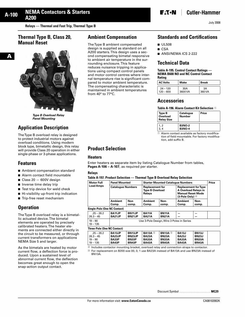
July 2008
A-100
For more information visit: www.EatonCanada.ca CA08102002K
NEMA Contactors & Starters
A
A200Relays — Thermal and Fast Trip, Thermal Type B
Thermal Type B, Class 20, Manual Reset
Type B Overload RelayPanel Mounting
Application DescriptionThe Type B overload relay is designed to protect industrial motors against overload conditions. Using modern block type, bimetallic design, this relay will provide Class 20 operation in either single-phase or 3-phase applications.
Features■ Ambient compensation standard■ Alarm contact field mountable■ Class 20 — 600V design■ Inverse time delay trip■ Test trip device for weld check■ Hi-visibility up-front trip indication■ Trip-free reset mechanism
OperationThe Type B overload relay is a bimetal-lic actuated device. The bimetal elements are operated by precisely calibrated heaters. The heater ele-ments are connected either directly in the circuit to be measured, or through current transformers on applications NEMA Size 5 and larger.
As the bimetals are heated by motor current flow, a deflection force is pro-duced. Upon a sustained level of abnormal current flow, the deflection becomes great enough to open the snap-action output contact.
Ambient CompensationThe Type B ambient compensated design is supplied as standard on all A200 starters. This design uses a sec-ond compensating bimetal responsive to ambient air temperature in the sur-rounding enclosure. This feature reduces nuisance tripping in applica-tions using compact control panels and motor control centres where inter-nal temperature rise is significant com-pared to motor ambient temperature. The compensating characteristic is maintained in ambient temperatures from 40° to 77°C.
Standards and Certifications■ UL508■ CSA■ ANSI/NEMA ICS 2-222
Technical DataTable A-195. Control Contact Ratings — NEMA B600 NO and NC Control Contact Rating
AccessoriesTable A-196. Alarm Contact Kit Selection �
� Alarm contact available as factory modifica-tion of field mountable. For factory modifica-tion, add suffix B.
Product Selection
Heaters Enter heaters as separate item by listing Catalogue Number from tables, Pages A-106 – A-107, as required per starter.
Relays Table A-197. Product Selection — Thermal Type B Overload Relay Selection
� Includes contactor mounting bracket, overload relay and connection straps to contactor.� For replacement on B200 size 00, 0, 1 use BA23A instead of BA13A and use BN23A instead of
BN13A.
AC Volts Make Break
24 – 120120 – 600
30A3600 VA
3A360 VA
Type B OverloadRelay Size
Catalogue Number
Price
1, 23, 4
B3NO-2B3NO-4
Motor FullLoad Amps
Panel Mounted Starter Mounted Catalogue Numbers Price
Catalogue Numbers Replacement forType B OverloadRelays
Replacement for Type A Overload Relays in Manual Reset Mode(3-Pole Only) �
AmbientComp.
Noncomp.
AmbientComp.
Non-comp.
AmbientComp.
Non-comp.
Single-Pole (One NC Contact).25 – 26.2
26.3 – 45BA11JPBA21JP
BN11JPBN21JP
BA11ABA21A
BN11ABN21A
——
——
19 – 9019 – 135
Use 3-Pole Design, Wire 3 Poles in Series
Three-Pole (One NC Contact).25 – 26.2
26.3 – 4519 – 9019 – 135
BA13JPBA23JPBA33PBA43P
BN13JPBN23JPBN33PBN43P
BA13A �
BA23ABA33ABA43A
BN13A �
BN23ABN33ABN43A
BA13JBA23JBA33ABA43A
BN13JBN23JBN33ABN43A
Discount Symbol . . . . . . . . . . . . . . . . . . . . . . . MC29
Tab33.book Page 100 Sunday, September 21, 2008 10:27 PM
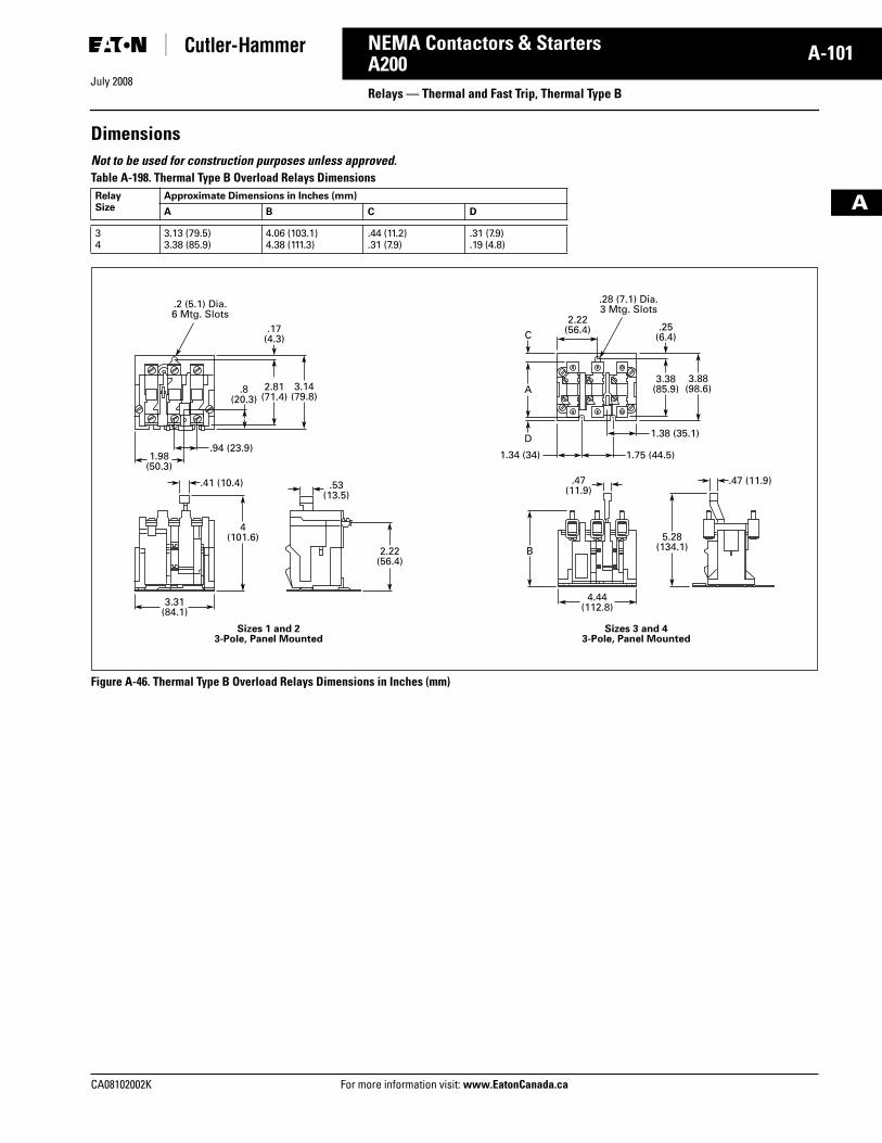
July 2008
CA08102002K For more information visit: www.EatonCanada.ca
A-101NEMA Contactors & Starters
A
A200Relays — Thermal and Fast Trip, Thermal Type B
DimensionsNot to be used for construction purposes unless approved. Table A-198. Thermal Type B Overload Relays Dimensions
Figure A-46. Thermal Type B Overload Relays Dimensions in Inches (mm)
RelaySize
Approximate Dimensions in Inches (mm)
A B C D
34
3.13 (79.5)3.38 (85.9)
4.06 (103.1)4.38 (111.3)
.44 (11.2)
.31 (7.9).31 (7.9).19 (4.8)
C
D
A
.94 (23.9)1.98
(50.3)
.8(20.3)
3.14(79.8)
2.81(71.4)
.17(4.3)
1.38 (35.1)
1.75 (44.5)
.41 (10.4) .47 (11.9).47(11.9).53
(13.5)
4(101.6)
Sizes 1 and 23-Pole, Panel Mounted
Sizes 3 and 43-Pole, Panel Mounted
3.31(84.1)
4.44(112.8)
5.28(134.1)
3.88(98.6)
3.38(85.9)
2.22(56.4)
1.34 (34)
B
.25(6.4)
2.22(56.4)
.2 (5.1) Dia.6 Mtg. Slots
.28 (7.1) Dia.3 Mtg. Slots
Tab33.book Page 101 Sunday, September 21, 2008 10:27 PM
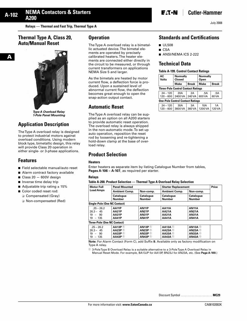
July 2008
A-102
For more information visit: www.EatonCanada.ca CA08102002K
NEMA Contactors & Starters
A
A200Relays — Thermal and Fast Trip, Thermal Type A
Thermal Type A, Class 20, Auto/Manual Reset
Type A Overload Relay1-Pole Panel Mounting
Application DescriptionThe Type A overload relay is designed to protect industrial motors against overload conditions. Using modern block type, bimetallic design, this relay will provide Class 20 operation in either single- or 3-phase applications.
Features■ Field selectable manual/auto reset■ Alarm contract factory available■ Class 20 — 600V design■ Inverse time delay trip■ Adjustable trip rating ± 15%■ Color coded reset rod:
❑ Compensated (Gray)❑ Non-compensated (Red)
OperationThe Type A overload relay is a bimetal-lic actuated device. The bimetal ele-ments are operated by precisely calibrated heaters. The heater ele-ments are connected either directly in the circuit to be measured, or through current transformers on applications NEMA Size 5 and larger.
As the bimetals are heated by motor current flow, a deflection force is pro-duced. Upon a sustained level of abnormal current flow, the deflection becomes great enough to open the snap-action output contact.
Automatic ResetThe Type A overload relay can be sup-plied as an option on all A200 starters to provide automatic reset operation. The overload relay is always shipped in the non-automatic mode. To set up auto operation, reposition the reset rod by loosening and re-tightening a hold-down clamp at the base of over-load relay.
Standards and Certifications■ UL508■ CSA■ ANSI/NEMA ICS 2-222
Technical DataTable A-199. Control Contact Ratings
Product SelectionHeaters Enter heaters as separate item by listing Catalogue Number from tables,Pages A-106 – A-107, as required per starter.
Relays Table A-200. Product Selection — Thermal Type A Overload Relay Selection
Note: For Alarm Contact (Form C), add Suffix B. Available only as factory modification on Type A relay. � 3-Pole Type B Overload Relay is a suitable alternative to a 3-Pole Type A Overload Relay in
Manual Reset Mode. For example, BA13JP for AA13P, BN23J for AN23A, etc. (See Page A-100.)
ACVolts
NormallyClosed
NormallyOpen
Make Break Make Break
Three-Pole Control Contact Ratings24 – 120
120 – 60020A
2400 VA2A
240 VA.5A
600 VA.5A
60 VA
One-Pole Control Contact Ratings24 – 120
120 – 60030A
3600 VA3A
360 VA10A
1200 VA1A
120 VA
Motor Full Load Amps
Panel Mounted Starter Replacement Price
Ambient Comp. Non-comp. Ambient Comp. Non-comp.
CatalogueNumber
CatalogueNumber
CatalogueNumber
CatalogueNumber
Single-Pole (One NC Contact).25 – 26.2
26.3 – 4519 – 9019 – 135
AA11PAA21PAA31PAA41P
AN11PAN21PAN31PAN41P
AA11AAA21AAA31AAA41A
AN11AAN21AAN31AAN41A
Three-Pole (One NC Contact).25 – 26.2
26.3 – 4519 – 9019 – 135
AA13P �
AA23P �
AA33P �
AA43P �
AN13P �
AN23P �
AN33P �
AN43P �
AA13A �
AA23A �
AA33A �
AA43A �
AN13A �
AN23A �
AN33A �
AN43A �
Discount Symbol . . . . . . . . . . . . . . . . . . . . . . . MC29
Tab33.book Page 102 Sunday, September 21, 2008 10:27 PM
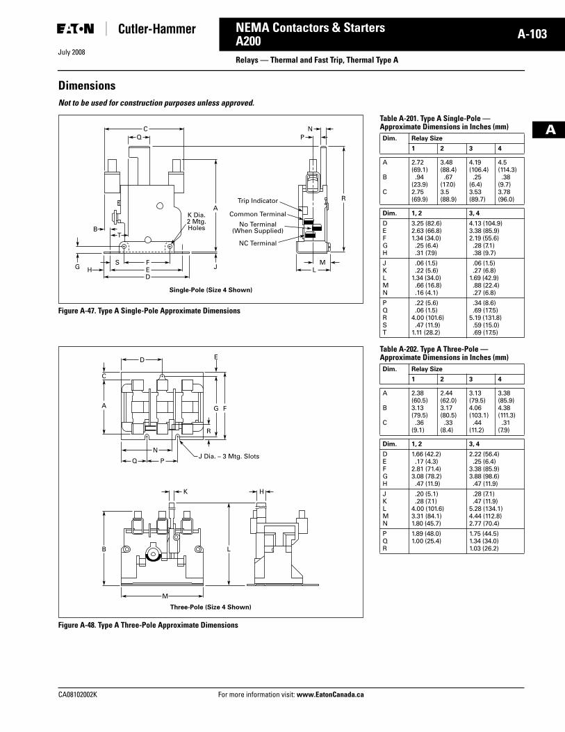
CA08102002K For more information visit: www.EatonCanada.ca
A-103NEMA Contactors & Starters
July 2008
A
A200Relays — Thermal and Fast Trip, Thermal Type A
DimensionsNot to be used for construction purposes unless approved.
Figure A-47. Type A Single-Pole Approximate Dimensions
Figure A-48. Type A Three-Pole Approximate Dimensions
CQ P
N
F
TB
MSE LHD
A
JG
RTrip Indicator
Common Terminal
No Terminal(When Supplied)
NC Terminal
K Dia.2 Mtg.Holes
Single-Pole (Size 4 Shown)
D
N
Q P
K
J Dia. – 3 Mtg. Slots
Three-Pole (Size 4 Shown)
H
M
FGA
C
B L
E
R
Table A-201. Type A Single-Pole —Approximate Dimensions in Inches (mm)
Table A-202. Type A Three-Pole —Approximate Dimensions in Inches (mm)
Dim. Relay Size
1 2 3 4
A
B
C
2.72(69.1).94
(23.9)2.75(69.9)
3.48(88.4).67
(17.0)3.5(88.9)
4.19(106.4).25
(6.4)3.53(89.7)
4.5(114.3).38
(9.7)3.78(96.0)
Dim. 1, 2 3, 4
DEFGH
3.25 (82.6)2.63 (66.8)1.34 (34.0).25 (6.4).31 (7.9)
4.13 (104.9)3.38 (85.9)2.19 (55.6).28 (7.1).38 (9.7)
JKLMN
.06 (1.5)
.22 (5.6)1.34 (34.0).66 (16.8).16 (4.1)
.06 (1.5)
.27 (6.8)1.69 (42.9).88 (22.4).27 (6.8)
PQRST
.22 (5.6)
.06 (1.5)4.00 (101.6).47 (11.9)
1.11 (28.2)
.34 (8.6)
.69 (17.5)5.19 (131.8).59 (15.0).69 (17.5)
Dim. Relay Size
1 2 3 4
A
B
C
2.38(60.5)3.13(79.5).36
(9.1)
2.44(62.0)3.17(80.5).33
(8.4)
3.13(79.5)4.06(103.1).44
(11.2)
3.38(85.9)4.38(111.3).31
(7.9)
Dim. 1, 2 3, 4
DEFGH
1.66 (42.2).17 (4.3)
2.81 (71.4)3.08 (78.2).47 (11.9)
2.22 (56.4).25 (6.4)
3.38 (85.9)3.88 (98.6).47 (11.9)
JKLMN
.20 (5.1)
.28 (7.1)4.00 (101.6)3.31 (84.1)1.80 (45.7)
.28 (7.1)
.47 (11.9)5.28 (134.1)4.44 (112.8)2.77 (70.4)
PQR
1.89 (48.0)1.00 (25.4)
1.75 (44.5)1.34 (34.0)1.03 (26.2)
Tab33.book Page 103 Sunday, September 21, 2008 10:27 PM
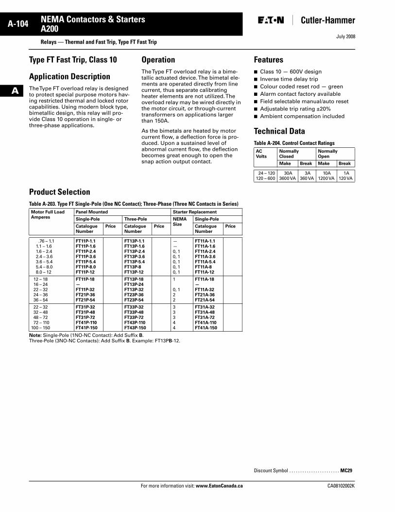
July 2008
A-104
For more information visit: www.EatonCanada.ca CA08102002K
NEMA Contactors & Starters
A
A200Relays — Thermal and Fast Trip, Type FT Fast Trip
Type FT Fast Trip, Class 10
Application DescriptionThe Type FT overload relay is designed to protect special purpose motors hav-ing restricted thermal and locked rotor capabilities. Using modern block type, bimetallic design, this relay will pro-vide Class 10 operation in single- or three-phase applications.
OperationThe Type FT overload relay is a bime-tallic actuated device. The bimetal ele-ments are operated directly from line current, thus separate calibrating heater elements are not utilized. The overload relay may be wired directly in the motor circuit, or through-current transformers on applications larger than 150A.
As the bimetals are heated by motor current flow, a deflection force is pro-duced. Upon a sustained level of abnormal current flow, the deflection becomes great enough to open the snap action output contact.
Product Selection Table A-203. Type FT Single-Pole (One NC Contact); Three-Phase (Three NC Contacts in Series)
Note: Single-Pole (1NO-NC Contact): Add Suffix B. Three-Pole (3NO-NC Contacts): Add Suffix B. Example: FT13PB-12.
Motor Full Load Amperes
Panel Mounted Starter Replacement
Single-Pole Three-Pole NEMA Size
Single-Pole
CatalogueNumber
Price CatalogueNumber
Price CatalogueNumber
Price
.76 – 1.11.1 – 1.61.6 – 2.42.4 – 3.63.6 – 5.45.4 – 8.08.0 – 12
FT11P-1.1FT11P-1.6FT11P-2.4FT11P-3.6FT11P-5.4FT11P-8.0FT11P-12
FT13P-1.1FT13P-1.6FT13P-2.4FT13P-3.6FT13P-5.4FT13P-8FT13P-12
——0, 10, 10, 10, 10, 1
FT11A-1.1FT11A-1.6FT11A-2.4FT11A-3.6FT11A-5.4FT11A-8FT11A-12
12 – 1816 – 2422 – 3224 – 3636 – 54
FT11P-18—FT11P-32FT21P-36FT21P-54
FT13P-18FT13P-24FT13P-32FT23P-36FT23P-54
1
0, 122
FT11A-18—FT11A-32FT21A-36FT21A-54
22 – 3232 – 4848 – 7272 – 110
100 – 150
FT31P-32FT31P-48FT31P-72FT41P-110FT41P-150
FT33P-32FT33P-48FT33P-72FT43P-110FT43P-150
33344
FT31A-32FT31A-48FT31A-72FT41A-110FT41A-150
Features■ Class 10 — 600V design■ Inverse time delay trip■ Colour coded reset rod — green■ Alarm contact factory available■ Field selectable manual/auto reset■ Adjustable trip rating ±20%■ Ambient compensation included
Technical DataTable A-204. Control Contact RatingsACVolts
NormallyClosed
NormallyOpen
Make Break Make Break
24 – 120120 – 600
30A3600 VA
3A360 VA
10A1200 VA
1A120 VA
Discount Symbol . . . . . . . . . . . . . . . . . . . . . . . MC29
Tab33.book Page 104 Sunday, September 21, 2008 10:27 PM
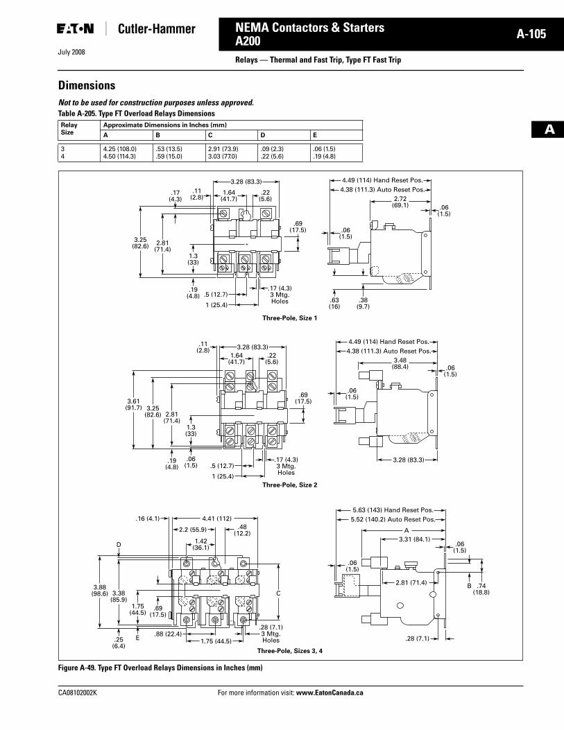
July 2008
CA08102002K For more information visit: www.EatonCanada.ca
A-105NEMA Contactors & Starters
A
A200Relays — Thermal and Fast Trip, Type FT Fast Trip
DimensionsNot to be used for construction purposes unless approved. Table A-205. Type FT Overload Relays Dimensions
Figure A-49. Type FT Overload Relays Dimensions in Inches (mm)
RelaySize
Approximate Dimensions in Inches (mm)
A B C D E
34
4.25 (108.0)4.50 (114.3)
.53 (13.5)
.59 (15.0)2.91 (73.9)3.03 (77.0)
.09 (2.3)
.22 (5.6).06 (1.5).19 (4.8)
4.49 (114) Hand Reset Pos.4.38 (111.3) Auto Reset Pos.
1 (25.4)
.5 (12.7)
2.72(69.1)
1.64(41.7)
2.81(71.4)
3.28 (83.3)
3.25(82.6)
.17 (4.3)3 Mtg.Holes
1.3(33)
.19(4.8)
.19(4.8)
.25(6.4)
.69(17.5)
.63(16)
Three-Pole, Size 1
.38(9.7)
.17(4.3)
.11(2.8)
.22(5.6)
.06 (1.5)
.06 (1.5)
4.49 (114) Hand Reset Pos.4.38 (111.3) Auto Reset Pos.
1 (25.4)
.5 (12.7)
3.48(88.4)
1.64(41.7)
2.81(71.4)
3.28 (83.3)
3.28 (83.3)
3.25(82.6)
3.61(91.7)
.17 (4.3)3 Mtg.Holes
1.3(33)
.06(1.5)
.69(17.5)
Three-Pole, Size 2
.11(2.8)
.22(5.6)
3.38(85.9)
D
3.88(98.6)
1.75(44.5)
C
E
.69(17.5)
.06 (1.5)
.06 (1.5)
5.63 (143) Hand Reset Pos.5.52 (140.2) Auto Reset Pos.
3.31 (84.1)A
.28 (7.1)
Three-Pole, Sizes 3, 4
2.81 (71.4)
.06 (1.5)
.74 (18.8)
B
.06 (1.5)
1.75 (44.5)
4.41 (112)
2.2 (55.9) .48(12.2)
1.42(36.1)
.16 (4.1)
.88 (22.4).28 (7.1)3 Mtg.Holes
Tab33.book Page 105 Sunday, September 21, 2008 10:27 PM
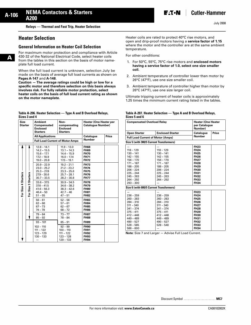
July 2008
A-106
For more information visit: www.EatonCanada.ca CA08102002K
NEMA Contactors & Starters
A
A200Relays — Thermal and Fast Trip, Heater Selection
Heater Selection
General Information on Heater Coil SelectionFor maximum motor protection and compliance with Article 430-32 of the National Electrical Code, select heater coils from the tables in this section on the basis of motor name-plate full load current.
When the full load current is unknown, selection July be made on the basis of average full load currents as shown on Pages A-147 and A-148. Caution — The average ratings could be high or low for a specific motor and therefore selection on this basis always involves risk. For fully reliable motor protection, select heater coils on the basis of full load current rating as shown on the motor nameplate.
Heater coils are rated to protect 40°C rise motors, and open and drip-proof motors having a service factor of 1.15 where the motor and the controller are at the same ambient temperature.
For other conditions:
1. For 50°C, 55°C, 75°C rise motors and enclosed motors having a service factor of 1.0, select one size smaller coil.
2. Ambient temperature of controller lower than motor by 26°C (47°F), use one size smaller coil.
3. Ambient temperature of controller higher than motor by 26°C (47°F), use one size larger coil.
Ultimate tripping current of heater coils is approximately 1.25 times the minimum current rating listed in the tables.
Table A-206. Heater Selection — Type A and B Overload Relays, Sizes 3 and 4
Table A-207. Heater Selection — Type A and B Overload Relays, Sizes 5 and 6
Note: Size 7 and Larger — Advise Full Load Current.
SizeStarter
Ambient CompensatedEnclosed Starters
Non-compensating Enclosed Starters
Heater (One Heater per Catalogue Number)
All Applications CatalogueNumber
Price
Full Load Current of Motor Amps
12.8 – 14.114.2 – 15.515.6 – 17.117.2 – 18.919.0 – 20.8
11.9 – 13.013.1 – 14.314.4 – 15.916.0 – 17.417.5 – 19.1
FH68FH69FH70FH71FH72
20.9 – 22.923.0 – 25.225.3 – 27.827.9 – 30.630.7 – 33.5
19.2 – 21.121.2 – 23.223.3 – 25.625.7 – 28.128.2 – 30.8
FH73FH74FH75FH76FH77
33.6 – 37.537.6 – 41.541.6 – 56.346.4 – 5051 – 55
30.9 – 34.534.6 – 38.238.3 – 42.642.7 – 4647 – 51
FH78FH79FH80FH81FH82
56 – 6162 – 6667 – 7374 – 78
52 – 5657 – 6162 – 6768 – 72
FH83FH84FH85FH86
79 – 8485 – 92
73 – 7778 – 84
FH87FH88
93 – 101 85 – 91 FH89
102 – 110111 – 122123 – 129130 – 133—
92 – 99100 – 110111 – 122123 – 128129 – 133
FH90FH91FH92FH93FH94
Fo
r S
ize 4
Sta
rters
Fo
r S
ize 3
Sta
rters
Compensated Overload Relay Heater (One Heater per Catalogue Number)
Open Starter Enclosed Starter CatalogueNumber
Price
Full Load Current of Motor (Amps)
Size 5 (with 300/5 Current Transformers)—118 – 129130 – 141142 – 155156 – 170171 – 187188 – 205206 – 224225 – 244245 – 263264 – 292293 – 300
—118 – 129130 – 141142 – 155156 – 170171 – 187188 – 205206 – 224225 – 244245 – 263264 – 292—
FH23FH24FH25FH26FH27FH28FH29FH30FH31FH32FH33FH34
Size 6 (with 600/5 Current Transformers)—236 – 259260 – 283284 – 310311 – 340341 – 374375 – 411412 – 448449 – 489490 – 527528 – 585586 – 600
—236 – 259260 – 283284 – 310311 – 340341 – 374375 – 411412 – 448449 – 489490 – 527528 – 540—
FH23FH24FH25FH26FH27FH28FH29FH30FH31FH32FH33FH34
Discount Symbol . . . . . . . . . . . . . . . . . . . . . . . MC7
Tab33.book Page 106 Sunday, September 21, 2008 10:27 PM
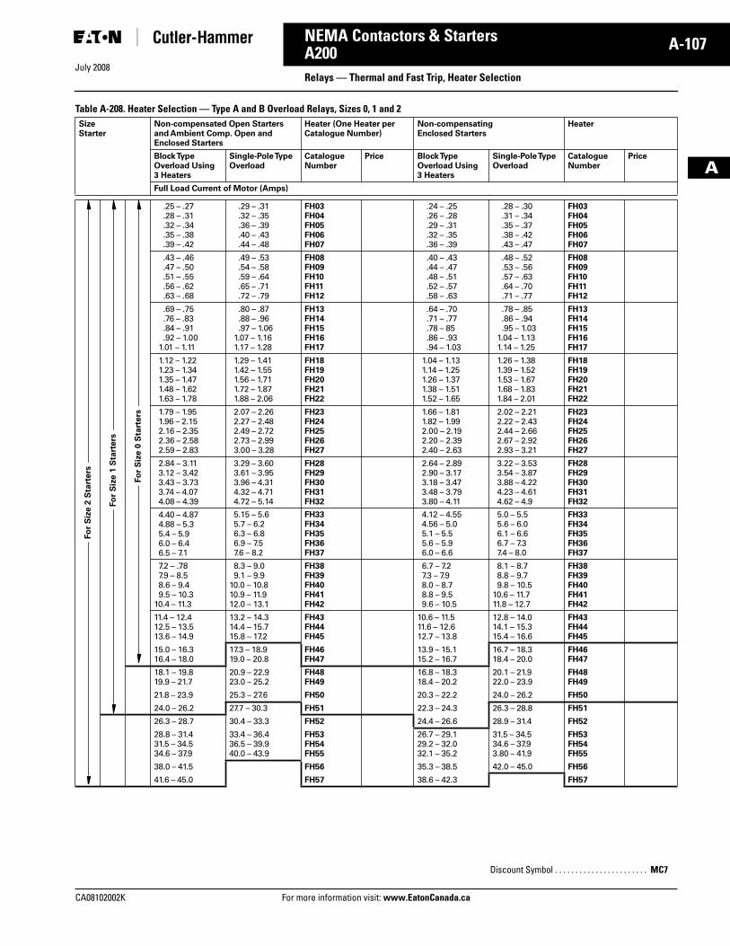
July 2008
CA08102002K For more information visit: www.EatonCanada.ca
A-107NEMA Contactors & Starters
A
A200Relays — Thermal and Fast Trip, Heater Selection
Table A-208. Heater Selection — Type A and B Overload Relays, Sizes 0, 1 and 2 SizeStarter
Non-compensated Open Starters and Ambient Comp. Open and Enclosed Starters
Heater (One Heater per Catalogue Number)
Non-compensating Enclosed Starters
Heater
Block Type Overload Using 3 Heaters
Single-Pole Type Overload
CatalogueNumber
Price Block Type Overload Using 3 Heaters
Single-Pole Type Overload
CatalogueNumber
Price
Full Load Current of Motor (Amps)
.25 – .27
.28 – .31
.32 – .34
.35 – .38
.39 – .42
.29 – .31
.32 – .35
.36 – .39
.40 – .43
.44 – .48
FH03FH04FH05FH06FH07
.24 – .25
.26 – .28
.29 – .31
.32 – .35
.36 – .39
.28 – .30
.31 – .34
.35 – .37
.38 – .42
.43 – .47
FH03FH04FH05FH06FH07
.43 – .46
.47 – .50
.51 – .55
.56 – .62
.63 – .68
.49 – .53
.54 – .58
.59 – .64
.65 – .71
.72 – .79
FH08FH09FH10FH11FH12
.40 – .43
.44 – .47
.48 – .51
.52 – .57
.58 – .63
.48 – .52
.53 – .56
.57 – .63
.64 – .70
.71 – .77
FH08FH09FH10FH11FH12
.69 – .75
.76 – .83
.84 – .91
.92 – 1.001.01 – 1.11
.80 – .87
.88 – .96
.97 – 1.061.07 – 1.161.17 – 1.28
FH13FH14FH15FH16FH17
.64 – .70
.71 – .77
.78 – 85
.86 – .93
.94 – 1.03
.78 – .85
.86 – .94
.95 – 1.031.04 – 1.131.14 – 1.25
FH13FH14FH15FH16FH17
1.12 – 1.221.23 – 1.341.35 – 1.471.48 – 1.621.63 – 1.78
1.29 – 1.411.42 – 1.551.56 – 1.711.72 – 1.871.88 – 2.06
FH18FH19FH20FH21FH22
1.04 – 1.131.14 – 1.251.26 – 1.371.38 – 1.511.52 – 1.65
1.26 – 1.381.39 – 1.521.53 – 1.671.68 – 1.831.84 – 2.01
FH18FH19FH20FH21FH22
1.79 – 1.951.96 – 2.152.16 – 2.352.36 – 2.582.59 – 2.83
2.07 – 2.262.27 – 2.482.49 – 2.722.73 – 2.993.00 – 3.28
FH23FH24FH25FH26FH27
1.66 – 1.811.82 – 1.992.00 – 2.192.20 – 2.392.40 – 2.63
2.02 – 2.212.22 – 2.432.44 – 2.662.67 – 2.922.93 – 3.21
FH23FH24FH25FH26FH27
2.84 – 3.113.12 – 3.423.43 – 3.733.74 – 4.074.08 – 4.39
3.29 – 3.603.61 – 3.953.96 – 4.314.32 – 4.714.72 – 5.14
FH28FH29FH30FH31FH32
2.64 – 2.892.90 – 3.173.18 – 3.473.48 – 3.793.80 – 4.11
3.22 – 3.533.54 – 3.873.88 – 4.224.23 – 4.614.62 – 4.9
FH28FH29FH30FH31FH32
4.40 – 4.874.88 – 5.35.4 – 5.96.0 – 6.46.5 – 7.1
5.15 – 5.65.7 – 6.26.3 – 6.86.9 – 7.57.6 – 8.2
FH33FH34FH35FH36FH37
4.12 – 4.554.56 – 5.05.1 – 5.55.6 – 5.96.0 – 6.6
5.0 – 5.55.6 – 6.06.1 – 6.66.7 – 7.37.4 – 8.0
FH33FH34FH35FH36FH37
7.2 – .787.9 – 8.58.6 – 9.49.5 – 10.3
10.4 – 11.3
8.3 – 9.09.1 – 9.9
10.0 – 10.810.9 – 11.912.0 – 13.1
FH38FH39FH40FH41FH42
6.7 – 7.27.3 – 7.98.0 – 8.78.8 – 9.59.6 – 10.5
8.1 – 8.78.8 – 9.79.8 – 10.5
10.6 – 11.711.8 – 12.7
FH38FH39FH40FH41FH42
11.4 – 12.412.5 – 13.513.6 – 14.9
13.2 – 14.314.4 – 15.715.8 – 17.2
FH43FH44FH45
10.6 – 11.511.6 – 12.612.7 – 13.8
12.8 – 14.014.1 – 15.315.4 – 16.6
FH43FH44FH45
15.0 – 16.316.4 – 18.0
17.3 – 18.919.0 – 20.8
FH46FH47
13.9 – 15.115.2 – 16.7
16.7 – 18.318.4 – 20.0
FH46FH47
18.1 – 19.819.9 – 21.7
20.9 – 22.923.0 – 25.2
FH48FH49
16.8 – 18.318.4 – 20.2
20.1 – 21.922.0 – 23.9
FH48FH49
21.8 – 23.9 25.3 – 27.6 FH50 20.3 – 22.2 24.0 – 26.2 FH50
24.0 – 26.2 27.7 – 30.3 FH51 22.3 – 24.3 26.3 – 28.8 FH51
26.3 – 28.7 30.4 – 33.3 FH52 24.4 – 26.6 28.9 – 31.4 FH52
28.8 – 31.431.5 – 34.534.6 – 37.9
33.4 – 36.436.5 – 39.940.0 – 43.9
FH53FH54FH55
26.7 – 29.129.2 – 32.032.1 – 35.2
31.5 – 34.534.6 – 37.93.80 – 41.9
FH53FH54FH55
38.0 – 41.5 FH56 35.3 – 38.5 42.0 – 45.0 FH56
41.6 – 45.0 FH57 38.6 – 42.3 FH57
Fo
r S
ize 2
Sta
rters
Fo
r S
ize 1
Sta
rters
Fo
r S
ize 0
Sta
rters
Discount Symbol . . . . . . . . . . . . . . . . . . . . . . . MC7
Tab33.book Page 107 Sunday, September 21, 2008 10:27 PM
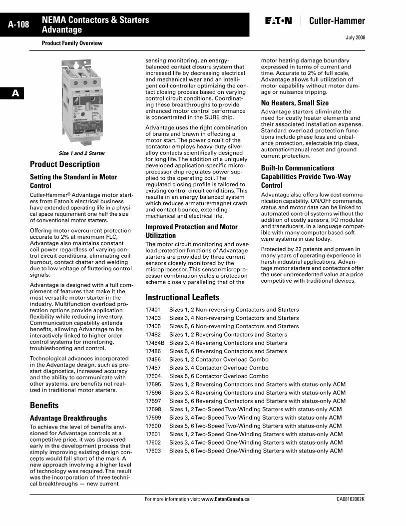
July 2008
A-108
For more information visit: www.EatonCanada.ca CA08102002K
NEMA Contactors & Starters
A
AdvantageProduct Family Overview
Size 1 and 2 Starter
Product DescriptionSetting the Standard in Motor ControlCutler-Hammer® Advantage motor start-ers from Eaton’s electrical business have extended operating life in a physi-cal space requirement one half the size of conventional motor starters.
Offering motor overcurrent protection accurate to 2% at maximum FLC, Advantage also maintains constant coil power regardless of varying con-trol circuit conditions, eliminating coil burnout, contact chatter and welding due to low voltage of fluttering control signals.
Advantage is designed with a full com-plement of features that make it the most versatile motor starter in the industry. Multifunction overload pro-tection options provide application flexibility while reducing inventory. Communication capability extends benefits, allowing Advantage to be interactively linked to higher order control systems for monitoring, troubleshooting and control.
Technological advances incorporated in the Advantage design, such as pre-start diagnostics, increased accuracy and the ability to communicate with other systems, are benefits not real-ized in traditional motor starters.
BenefitsAdvantage BreakthroughsTo achieve the level of benefits envi-sioned for Advantage controls at a competitive price, it was discovered early in the development process that simply improving existing design con-cepts would fall short of the mark. A new approach involving a higher level of technology was required. The result was the incorporation of three techni-cal breakthroughs — new current
sensing monitoring, an energy-balanced contact closure system that increased life by decreasing electrical and mechanical wear and an intelli-gent coil controller optimizing the con-tact closing process based on varying control circuit conditions. Coordinat-ing these breakthroughs to provide enhanced motor control performance is concentrated in the SURE chip.
Advantage uses the right combination of brains and brawn in effecting a motor start. The power circuit of the contactor employs heavy-duty silver alloy contacts scientifically designed for long life. The addition of a uniquely developed application-specific micro-processor chip regulates power sup-plied to the operating coil. The regulated closing profile is tailored to existing control circuit conditions. This results in an energy balanced system which reduces armature/magnet crash and contact bounce, extending mechanical and electrical life.
Improved Protection and Motor UtilizationThe motor circuit monitoring and over-load protection functions of Advantage starters are provided by three current sensors closely monitored by the microprocessor. This sensor/micropro-cessor combination yields a protection scheme closely paralleling that of the
motor heating damage boundary expressed in terms of current and time. Accurate to 2% of full scale, Advantage allows full utilization of motor capability without motor dam-age or nuisance tripping.
No Heaters, Small SizeAdvantage starters eliminate the need for costly heater elements and their associated installation expense. Standard overload protection func-tions include phase loss and unbal-ance protection, selectable trip class, automatic/manual reset and ground current protection.
Built-In Communications Capabilities Provide Two-Way ControlAdvantage also offers low cost commu-nication capability. ON/OFF commands, status and motor data can be linked to automated control systems without the addition of costly sensors, I/O modules and transducers, in a language compat-ible with many computer-based soft-ware systems in use today.
Protected by 22 patents and proven in many years of operating experience in harsh industrial applications, Advan-tage motor starters and contactors offer the user unprecedented value at a price competitive with traditional devices.
Instructional Leaflets17401 Sizes 1, 2 Non-reversing Contactors and Starters17403 Sizes 3, 4 Non-reversing Contactors and Starters17405 Sizes 5, 6 Non-reversing Contactors and Starters17482 Sizes 1, 2 Reversing Contactors and Starters17484B Sizes 3, 4 Reversing Contactors and Starters17486 Sizes 5, 6 Reversing Contactors and Starters17456 Sizes 1, 2 Contactor Overload Combo17457 Sizes 3, 4 Contactor Overload Combo17604 Sizes 5, 6 Contactor Overload Combo17595 Sizes 1, 2 Reversing Contactors and Starters with status-only ACM17596 Sizes 3, 4 Reversing Contactors and Starters with status-only ACM17597 Sizes 5, 6 Reversing Contactors and Starters with status-only ACM17598 Sizes 1, 2 Two-Speed Two-Winding Starters with status-only ACM17599 Sizes 3, 4 Two-Speed Two-Winding Starters with status-only ACM17600 Sizes 5, 6 Two-Speed Two-Winding Starters with status-only ACM17601 Sizes 1, 2 Two-Speed One-Winding Starters with status-only ACM17602 Sizes 3, 4 Two-Speed One-Winding Starters with status-only ACM17603 Sizes 5, 6 Two-Speed One-Winding Starters with status-only ACM
Tab33.book Page 108 Sunday, September 21, 2008 10:27 PM
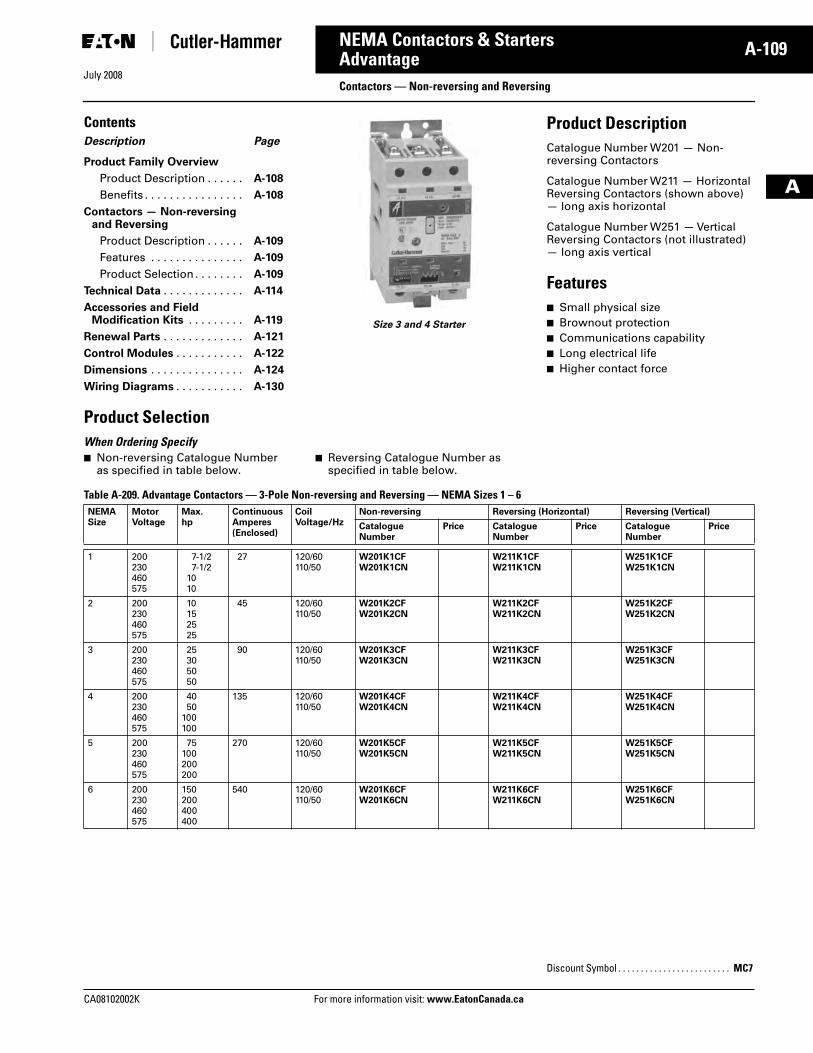
July 2008
CA08102002K For more information visit: www.EatonCanada.ca
A-109NEMA Contactors & Starters
A
AdvantageContactors — Non-reversing and Reversing
ContentsDescription Page
Product Family Overview
Product Description . . . . . . A-108
Benefits . . . . . . . . . . . . . . . . A-108
Contactors — Non-reversing and Reversing
Product Description . . . . . . A-109
Features . . . . . . . . . . . . . . . A-109
Product Selection . . . . . . . . A-109
Technical Data . . . . . . . . . . . . . A-114
Accessories and FieldModification Kits . . . . . . . . . A-119
Renewal Parts . . . . . . . . . . . . . A-121
Control Modules . . . . . . . . . . . A-122
Dimensions . . . . . . . . . . . . . . . A-124
Wiring Diagrams . . . . . . . . . . . A-130
Size 3 and 4 Starter
Product DescriptionCatalogue Number W201 — Non-reversing Contactors
Catalogue Number W211 — Horizontal Reversing Contactors (shown above) — long axis horizontal
Catalogue Number W251 — Vertical Reversing Contactors (not illustrated) — long axis vertical
Features■ Small physical size■ Brownout protection■ Communications capability■ Long electrical life■ Higher contact force
Product Selection When Ordering Specify ■ Non-reversing Catalogue Number
as specified in table below.■ Reversing Catalogue Number as
specified in table below.
Table A-209. Advantage Contactors — 3-Pole Non-reversing and Reversing — NEMA Sizes 1 – 6 NEMASize
MotorVoltage
Max.hp
ContinuousAmperes(Enclosed)
Coil Voltage/Hz
Non-reversing Reversing (Horizontal) Reversing (Vertical)
CatalogueNumber
Price CatalogueNumber
Price CatalogueNumber
Price
1 200230460575
7-1/27-1/2
1010
27 120/60110/50
W201K1CFW201K1CN
W211K1CFW211K1CN
W251K1CFW251K1CN
2 200230460575
10152525
45 120/60110/50
W201K2CFW201K2CN
W211K2CFW211K2CN
W251K2CFW251K2CN
3 200230460575
25305050
90 120/60110/50
W201K3CFW201K3CN
W211K3CFW211K3CN
W251K3CFW251K3CN
4 200230460575
4050
100100
135 120/60110/50
W201K4CFW201K4CN
W211K4CFW211K4CN
W251K4CFW251K4CN
5 200230460575
75100200200
270 120/60110/50
W201K5CFW201K5CN
W211K5CFW211K5CN
W251K5CFW251K5CN
6 200230460575
150200400400
540 120/60110/50
W201K6CFW201K6CN
W211K6CFW211K6CN
W251K6CFW251K6CN
Discount Symbol . . . . . . . . . . . . . . . . . . . . . . . . . MC7
Tab33.book Page 109 Sunday, September 21, 2008 10:27 PM
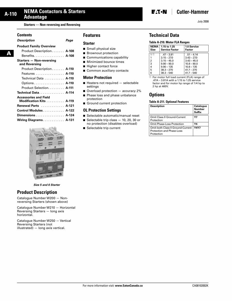
July 2008
A-110
For more information visit: www.EatonCanada.ca CA08102002K
NEMA Contactors & Starters
A
AdvantageStarters — Non-reversing and Reversing
ContentsDescription Page
Product Family Overview
Product Description . . . . . . . A-108
Benefits. . . . . . . . . . . . . . . . . A-108
Starters — Non-reversing and Reversing
Product Description . . . . . . . A-110
Features . . . . . . . . . . . . . . . . A-110
Technical Data . . . . . . . . . . . A-110
Options . . . . . . . . . . . . . . . . . A-110
Product Selection. . . . . . . . . A-111
Technical Data . . . . . . . . . . . . . . A-114
Accessories and FieldModification Kits . . . . . . . . . . A-119
Renewal Parts . . . . . . . . . . . . . A-121
Control Modules . . . . . . . . . . . . A-122
Dimensions . . . . . . . . . . . . . . . . A-124
Wiring Diagrams . . . . . . . . . . . . A-131
Size 5 and 6 Starter
Product DescriptionCatalogue Number W200 — Non-reversing Starters (shown above)
Catalogue Number W210 — Horizontal Reversing Starters — long axis horizontal.
Catalogue Number W250 — Vertical Reversing Starters (not illustrated) — long axis vertical.
Features
Starter■ Small physical size■ Brownout protection■ Communications capability■ Minimized bounce times■ Higher contact force■ Common auxiliary contacts
Motor Protection■ Heaters not required — selectable
settings■ Overload protection — accuracy 2%■ Phase loss and phase unbalance
protection■ Ground current protection
OL Protection Settings■ Selectable automatic/manual reset■ Selectable trip class — 10, 20, 30 or
no protection (disables overload)■ Selectable trip current
Technical DataTable A-210. Motor FLA Ranges
� For motor full load current (FLA) range of .47A – 3.81A with a 1.15 to 1.25 service factor and for motor hp range of 1/4 hp to 2 hp at 460V.
OptionsTable A-211. Optional Features
NEMASize
1.15 to 1.25Service Factor
1.0 Service Factor
1 �123456
.47 – 3.813.15 – 27.03.15 – 45.09.90 – 90.09.90 – 13538.3 – 27038.3 – 540
.51 – 4.143.43 – 27.03.43 – 45.010.8 – 90.010.8 – 13541.7 – 27041.7 – 540
Description CatalogueNumberSuffix
Omit Class II Ground-Current Protection
Y7
Omit Phase-Loss Protection Y4
Omit both Class II Ground-Current Protection and Phase-Loss Protection
Y4Y7
Tab33.book Page 110 Sunday, September 21, 2008 10:27 PM
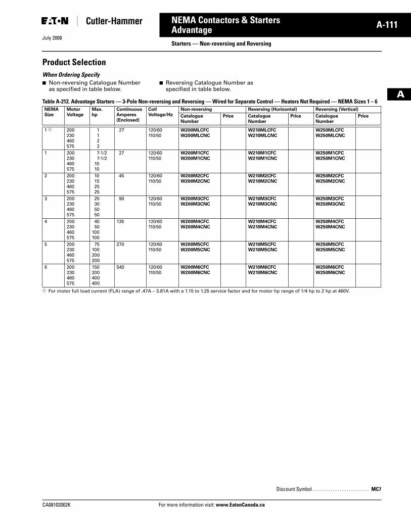
July 2008
CA08102002K For more information visit: www.EatonCanada.ca
A-111NEMA Contactors & Starters
A
AdvantageStarters — Non-reversing and Reversing
Product SelectionWhen Ordering Specify ■ Non-reversing Catalogue Number
as specified in table below.■ Reversing Catalogue Number as
specified in table below.
Table A-212. Advantage Starters — 3-Pole Non-reversing and Reversing — Wired for Separate Control — Heaters Not Required — NEMA Sizes 1 – 6
� For motor full load current (FLA) range of .47A – 3.81A with a 1.15 to 1.25 service factor and for motor hp range of 1/4 hp to 2 hp at 460V.
NEMASize
MotorVoltage
Max.hp
ContinuousAmperes(Enclosed)
Coil Voltage/Hz
Non-reversing Reversing (Horizontal) Reversing (Vertical)
CatalogueNumber
Price CatalogueNumber
Price CatalogueNumber
Price
1 � 200230460575
1122
27 120/60110/50
W200MLCFCW200MLCNC
W210MLCFCW210MLCNC
W250MLCFCW250MLCNC
1 200230460575
7-1/27-1/2
1010
27 120/60110/50
W200M1CFCW200M1CNC
W210M1CFCW210M1CNC
W250M1CFCW250M1CNC
2 200230460575
10152525
45 120/60110/50
W200M2CFCW200M2CNC
W210M2CFCW210M2CNC
W250M2CFCW250M2CNC
3 200230460575
25305050
90 120/60110/50
W200M3CFCW200M3CNC
W210M3CFCW210M3CNC
W250M3CFCW250M3CNC
4 200230460575
4050
100100
135 120/60110/50
W200M4CFCW200M4CNC
W210M4CFCW210M4CNC
W250M4CFCW250M4CNC
5 200230460575
75100200200
270 120/60110/50
W200M5CFCW200M5CNC
W210M5CFCW210M5CNC
W250M5CFCW250M5CNC
6 200230460575
150200400400
540 120/60110/50
W200M6CFCW200M6CNC
W210M6CFCW210M6CNC
W250M6CFCW250M6CNC
Discount Symbol . . . . . . . . . . . . . . . . . . . . . . . . . MC7
Tab33.book Page 111 Sunday, September 21, 2008 10:27 PM
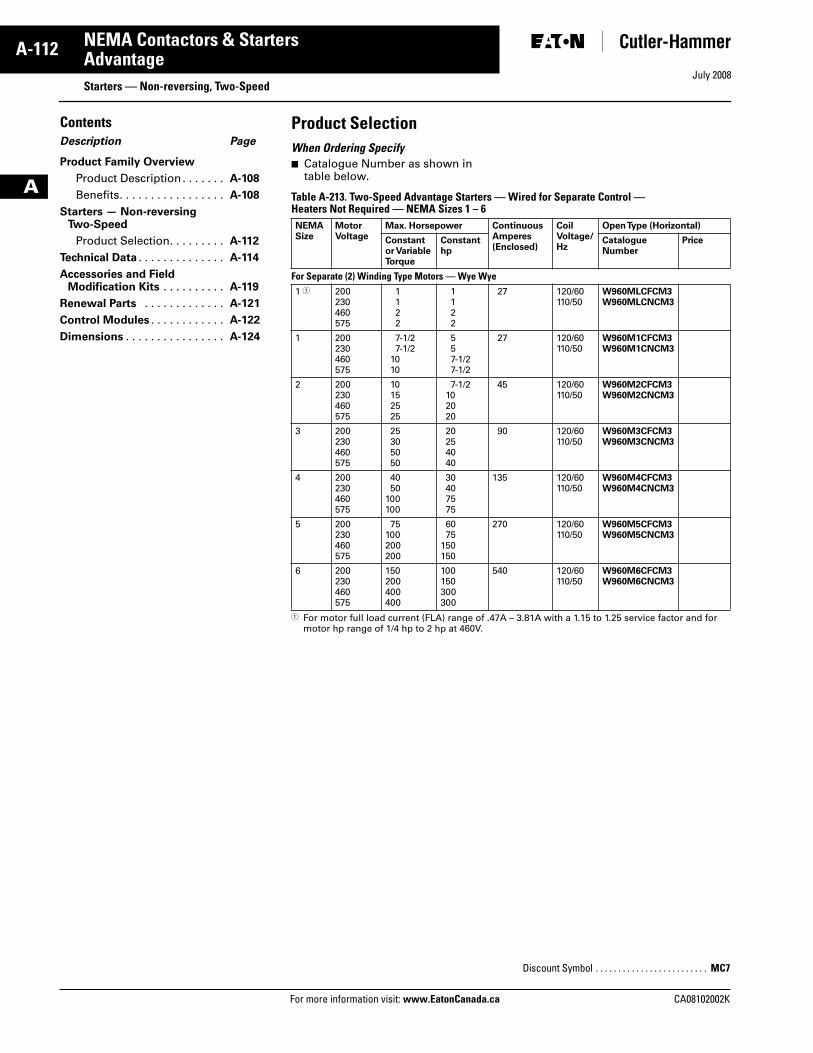
July 2008
A-112
For more information visit: www.EatonCanada.ca CA08102002K
NEMA Contactors & Starters
A
AdvantageStarters — Non-reversing, Two-Speed
ContentsDescription Page
Product Family Overview
Product Description . . . . . . . A-108
Benefits. . . . . . . . . . . . . . . . . A-108
Starters — Non-reversingTwo-Speed
Product Selection. . . . . . . . . A-112
Technical Data . . . . . . . . . . . . . . A-114
Accessories and FieldModification Kits . . . . . . . . . . A-119
Renewal Parts . . . . . . . . . . . . . A-121
Control Modules . . . . . . . . . . . . A-122
Dimensions . . . . . . . . . . . . . . . . A-124
Product SelectionWhen Ordering Specify■ Catalogue Number as shown in
table below.
Table A-213. Two-Speed Advantage Starters — Wired for Separate Control — Heaters Not Required — NEMA Sizes 1 – 6
� For motor full load current (FLA) range of .47A – 3.81A with a 1.15 to 1.25 service factor and for motor hp range of 1/4 hp to 2 hp at 460V.
NEMA Size
MotorVoltage
Max. Horsepower ContinuousAmperes(Enclosed)
CoilVoltage/Hz
Open Type (Horizontal)
Constantor VariableTorque
Constanthp
CatalogueNumber
Price
For Separate (2) Winding Type Motors — Wye Wye1 � 200
230460575
1122
1122
27 120/60110/50
W960MLCFCM3W960MLCNCM3
1 200230460575
7-1/27-1/2
1010
557-1/27-1/2
27 120/60110/50
W960M1CFCM3W960M1CNCM3
2 200230460575
10152525
7-1/2102020
45 120/60110/50
W960M2CFCM3W960M2CNCM3
3 200230460575
25305050
20254040
90 120/60110/50
W960M3CFCM3W960M3CNCM3
4 200230460575
4050
100100
30407575
135 120/60110/50
W960M4CFCM3W960M4CNCM3
5 200230460575
75100200200
6075
150150
270 120/60110/50
W960M5CFCM3W960M5CNCM3
6 200230460575
150200400400
100150300300
540 120/60110/50
W960M6CFCM3W960M6CNCM3
Discount Symbol . . . . . . . . . . . . . . . . . . . . . . . . . MC7
Tab33.book Page 112 Sunday, September 21, 2008 10:27 PM
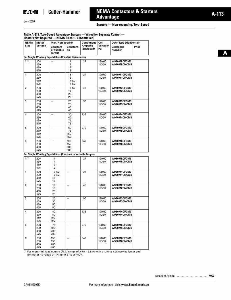
CA08102002K For more information visit: www.EatonCanada.ca
A-113NEMA Contactors & Starters
July 2008
A
AdvantageStarters — Non-reversing, Two-Speed
Table A-213. Two-Speed Advantage Starters — Wired for Separate Control — Heaters Not Required — NEMA Sizes 1– 6 (Continued)
� For motor full load current (FLA) range of .47A – 3.81A with a 1.15 to 1.25 service factor and for motor hp range of 1/4 hp to 2 hp at 460V.
NEMA Size
MotorVoltage
Max. Horsepower ContinuousAmperes(Enclosed)
CoilVoltage/Hz
Open Type (Horizontal)
Constantor VariableTorque
Constanthp
CatalogueNumber
Price
For Single Winding Type Motors Constant Horsepower 1 � 200
230460575
— 1122
27 120/60110/50
W970MLCFCM3W970MLCNCM3
1 200230460575
— 557-1/27-1/2
27 120/60110/50
W970M1CFCM3W970M1CNCM3
2 200230460575
— 7-1/2102020
45 120/60110/50
W970M2CFCM3W970M2CNCM3
3 200230460575
— 20254040
90 120/60110/50
W970M3CFCM3W970M3CNCM3
4 200230460575
— 30407575
135 120/60110/50
W970M4CFCM3W970M4CNCM3
5 200230460575
— 6075
150150
270 120/60110/50
W970M5CFCM3W970M5CNCM3
6 200230460575
— 100150300300
540 120/60110/50
W970M6CFCM3W970M6CNCM3
For Single Winding Type Motors (Constant or Variable Torque)1 � 200
230460575
1122
— 27 120/60110/50
W980MLCFCM3W980MLCNCM3
1 200230460575
7-1/27-1/2
1010
— 27 120/60110/50
W980M1CFCM3W980M1CNCM3
2 200230460575
10152525
— 45 120/60110/50
W980M2CFCM3W980M2CNCM3
3 200230460575
25305050
— 90 120/60110/50
W980M3CFCM3W980M3CNCM3
4 200230460575
4050
100100
— 135 120/60110/50
W980M4CFCM3W980M4CNCM3
5 200230460575
75100200200
— 270 120/60110/50
W980M5CFCM3W980M5CNCM3
6 200230460575
150150400400
— 540 120/60110/50
W980M6CFCM3W980M6CNCM3
Discount Symbol . . . . . . . . . . . . . . . . . . . . . . . . . MC7
Tab33.book Page 113 Sunday, September 21, 2008 10:27 PM
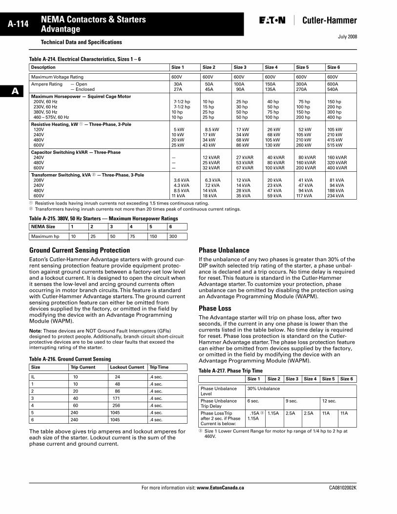
July 2008
A-114
For more information visit: www.EatonCanada.ca CA08102002K
NEMA Contactors & Starters
A
AdvantageTechnical Data and Specifications
Table A-214. Electrical Characteristics, Sizes 1 – 6
� Resistive loads having inrush currents not exceeding 1.5 times continuous rating.� Transformers having inrush currents not more than 20 times peak of continuous current ratings.
Table A-215. 380V, 50 Hz Starters — Maximum Horsepower Ratings
Ground Current Sensing ProtectionEaton’s Cutler-Hammer Advantage starters with ground cur-rent sensing protection feature provide equipment protec-tion against ground currents between a factory-set low level and a lockout current. It is designed to open the circuit when it senses the low-level and arcing ground currents often occurring in motor branch circuits. This feature is standard with Cutler-Hammer Advantage starters. The ground current sensing protection feature can either be omitted from devices supplied by the factory, or omitted in the field by modifying the device with an Advantage Programming Module (WAPM).
Note: These devices are NOT Ground Fault Interrupters (GFIs) designed to protect people. Additionally, branch circuit short-circuit protective devices are to be used to clear faults that exceed the interrupting rating of the starter.
Table A-216. Ground Current Sensing
The table above gives trip amperes and lockout amperes for each size of the starter. Lockout current is the sum of the phase current and ground current.
Phase UnbalanceIf the unbalance of any two phases is greater than 30% of the DIP switch selected trip rating of the starter, a phase unbal-ance is declared and a trip occurs. No time delay is required for reset. This feature is standard in the Cutler-Hammer Advantage starter. To customize your protection, phase unbalance can be omitted by disabling the protection using an Advantage Programming Module (WAPM).
Phase LossThe Advantage starter will trip on phase loss, after two seconds, if the current in any one phase is lower than the currents listed in the table below. No time delay is required for reset. Phase loss protection is standard on the Cutler-Hammer Advantage starter. The phase loss protection feature can either be omitted from devices supplied by the factory, or omitted in the field by modifying the device with an Advantage Programming Module (WAPM).
Table A-217. Phase Trip Time
� Size 1 Lower Current Range for motor hp range of 1/4 hp to 2 hp at 460V.
Description Size 1 Size 2 Size 3 Size 4 Size 5 Size 6
Maximum Voltage Rating 600V 600V 600V 600V 600V 600V
Ampere Rating — Open— Enclosed
30A27A
50A45A
100A90A
150A135A
300A270A
600A540A
Maximum Horsepower — Squirrel Cage Motor200V, 60 Hz230V, 60 Hz380V, 50 Hz460 – 575V, 60 Hz
7-1/2 hp7-1/2 hp
10 hp10 hp
10 hp15 hp25 hp25 hp
25 hp30 hp50 hp50 hp
40 hp50 hp75 hp
100 hp
75 hp100 hp150 hp200 hp
150 hp200 hp300 hp400 hp
Resistive Heating, kW � — Three-Phase, 3-Pole120V240V480V600V
5 kW10 kW20 kW25 kW
8.5 kW17 kW34 kW43 kW
17 kW34 kW68 kW86 kW
26 kW68 kW
105 kW130 kW
52 kW105 kW210 kW260 kW
105 kW210 kW415 kW515 kW
Capacitor Switching kVAR — Three-Phase240V480V600V
———
12 kVAR25 kVAR32 kVAR
27 kVAR53 kVAR67 kVAR
40 kVAR80 kVAR
100 kVAR
80 kVAR160 kVAR200 kVAR
160 kVAR320 kVAR400 kVAR
Transformer Switching, kVA � — Three-Phase, 3-Pole208V240V480V600V
3.6 kVA4.3 kVA8.5 kVA
11 kVA
6.3 kVA7.2 kVA
14 kVA18 kVA
12 kVA14 kVA28 kVA35 kVA
20 kVA23 kVA47 kVA59 kVA
41 kVA47 kVA94 kVA
117 kVA
81 kVA94 kVA
188 kVA234 kVA
NEMA Size 1 2 3 4 5 6
Maximum hp 10 25 50 75 150 300
Size Trip Current Lockout Current Trip Time
IL 10 24 .4 sec.
1 10 48 .4 sec.
2 20 86 .4 sec.
3 40 171 .4 sec.
4 60 256 .4 sec.
5 240 1045 .4 sec.
6 240 1045 .4 sec.
Size 1 Size 2 Size 3 Size 4 Size 5 Size 6
Phase Unbalance Level
30% Unbalance
Phase Unbalance Trip Delay
6 sec. 9 sec. 12 sec.
Phase Loss Trip after 2 sec. if Phase Current is below:
.15A �1.15A
1.15A 2.5A 2.5A 11A 11A
Tab33.book Page 114 Sunday, September 21, 2008 10:27 PM
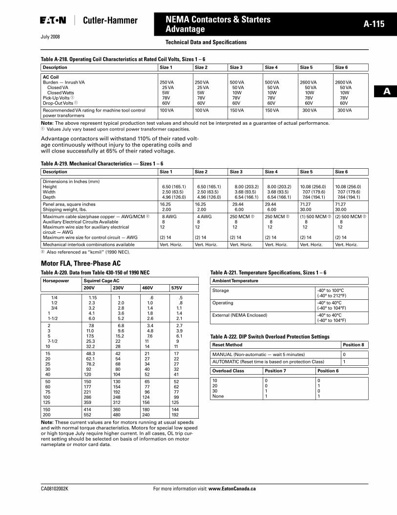
July 2008
CA08102002K For more information visit: www.EatonCanada.ca
A-115NEMA Contactors & Starters
A
AdvantageTechnical Data and Specifications
Table A-218. Operating Coil Characteristics at Rated Coil Volts, Sizes 1 – 6
Note: The above represent typical production test values and should not be interpreted as a guarantee of actual performance.� Values July vary based upon control power transformer capacities.
Advantage contactors will withstand 110% of their rated volt-age continuously without injury to the operating coils and will close successfully at 65% of their rated voltage.
Table A-219. Mechanical Characteristics — Sizes 1 – 6
� Also referenced as “kcmil” (1990 NEC).
Motor FLA, Three-Phase ACTable A-220. Data from Table 430-150 of 1990 NEC
Note: These current values are for motors running at usual speeds and with normal torque characteristics. Motors for special low speed or high torque July require higher current. In all cases, OL trip cur-rent setting should be selected on basis of information on motor nameplate or motor card data.
Table A-221. Temperature Specifications, Sizes 1 – 6
Table A-222. DIP Switch Overload Protection Settings
Description Size 1 Size 2 Size 3 Size 4 Size 5 Size 6
AC CoilBurden — Inrush VA
Closed VAClosed Watts
Pick-Up Volts �Drop-Out Volts �
250 VA25 VA5W78V60V
250 VA25 VA5W78V60V
500 VA50 VA10W78V60V
500 VA50 VA10W78V60V
2600 VA50 VA10W78V60V
2600 VA50 VA10W78V60V
Recommended VA rating for machine tool control power transformers
100 VA 100 VA 150 VA 150 VA 300 VA 300 VA
Description Size 1 Size 2 Size 3 Size 4 Size 5 Size 6
Dimensions in Inches (mm)HeightWidthDepth
6.50 (165.1)2.50 (63.5)4.96 (126.0)
6.50 (165.1)2.50 (63.5)4.96 (126.0)
8.00 (203.2)3.68 (93.5)6.54 (166.1)
8.00 (203.2)3.68 (93.5)6.54 (166.1)
10.08 (256.0)7.07 (179.6)7.64 (194.1)
10.08 (256.0)7.07 (179.6)7.64 (194.1)
Panel area, square inchesShipping weight, lbs.
16.252.00
16.252.00
29.446.00
29.446.00
71.2730.00
71.2730.00
Maximum cable size/phase copper — AWG/MCM �Auxiliary Electrical Circuits AvailableMaximum wire size for auxiliary electrical circuit — AWGMaximum wire size for control circuit — AWG
8 AWG8
12
(2) 14
4 AWG8
12
(2) 14
250 MCM �8
12
(2) 14
250 MCM �8
12
(2) 14
(1) 500 MCM �8
12
(2) 14
(2) 500 MCM �8
12
(2) 14
Mechanical interlock combinations available Vert. Horiz. Vert. Horiz. Vert. Horiz. Vert. Horiz. Vert. Horiz. Vert. Horiz.
Horsepower Squirrel Cage AC
200V 230V 460V 575V
1/41/23/4
11-1/2
1.152.33.24.16.0
12.02.83.65.2
.61.01.41.82.6
.5
.81.11.42.1
2357-1/2
10
7.811.017.525.332.2
6.89.6
15.22228
3.44.87.6
1114
2.73.96.19
11
1520253040
48.362.178.292
120
42546880
104
2127344052
1722273241
506075
100125
150177221286359
130154192248312
657796
124156
52627799
125
150200
414552
360480
180240
144192
Ambient Temperature
Storage -40° to 100°C(-40° to 212°F)
Operating -40° to 40°C(-40° to 104°F)
External (NEMA Enclosed) -40° to 40°C(-40° to 104°F)
Reset Method Position 8
MANUAL (Non-automatic — wait 5 minutes) 0
AUTOMATIC (Reset time is based on protection Class) 1
Overload Class Position 7 Position 6
102030None
0011
0101
Tab33.book Page 115 Sunday, September 21, 2008 10:27 PM
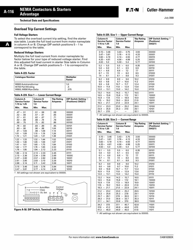
July 2008
A-116
For more information visit: www.EatonCanada.ca CA08102002K
NEMA Contactors & Starters
A
AdvantageTechnical Data and Specifications
Overload Trip Current Settings
Full Voltage StartersTo select the overload current trip setting, find the starter size table. Locate the full load current from motor nameplate in column A or B. Change DIP switch positions 5 – 1 to correspond to the table.
Reduced Voltage StartersMultiply the full load current from motor nameplate by factor below for your type of reduced voltage starter. Find this adjusted full load current in starter Size table in Column A or B. Change DIP switch positions 5 – 1 to correspond to the table.
Table A-223. Factor
Table A-224. Size 1 — Lower Current Range
� All settings not shown are equivalent to 00000.
Figure A-50. DIP Switch, Terminals and Reset
Table A-225. Size 1 — Upper Current Range
� All settings not shown are equivalent to 00000.
Table A-226. Size 2 — Current Range
� All settings not shown are equivalent to 00000.
Catalogue Number MultiplierFactor
W600 AutotransformerW700 Part WindingW800, W890 Wye-Delta
1.0.5.575
Column AService Factor1.15 to 1.25
Column BService Factor1.0
Trip RatingAmperes
DIP Switch Setting �
(Positions) (54321)
Min. Max. Min. Max.
.47 –
.52 –
.57 –
.62 –
.69 –
.51
.56
.61
.68
.75
.51 –
.57 –
.62 –
.68 –
.75 –
.56
.61
.67
.74
.82
.59
.65
.71
.78
.86
0000000001000100001100100
.76 –
.83 –
.91 –1.01 –1.10 –
.82
.901.001.091.21
.83 –
.90 –
.99 –1.10 –1.20 –
.89
.981.091.191.31
.951.041.141.261.38
0010100110001110100001001
1.22 –1.34 –1.47 –1.62 –1.78 –
1.331.461.611.771.95
1.32 –1.45 –1.60 –1.76 –1.94 –
1.441.591.751.932.12
1.521.671.842.022.23
0101001011011000110101110
1.96 –2.15 –2.37 –2.61 –2.86 –
2.142.362.602.853.14
2.13 –2.34 –2.57 –2.83 –3.11 –
2.332.562.823.103.42
2.452.692.963.263.58
0111110000100011001010011
3.15 –3.47 –
3.463.81
3.43 –3.77 –
3.764.14
3.944.34
1010010101
1
1234567
8
0
Auto/ManClassOL Set 3 P E C
ControlVoltage
Reset
Column AService Factor1.15 to 1.25
Column BService Factor1.0
Trip RatingAmperes
DIP Switch Setting �
(Positions) (54321)
Min. Max. Min. Max.
3.15 –3.47 –3.82 –4.20 –4.62 –
3.463.814.194.615.0
3.43 –3.76 –4.14 –4.56 –5.00 –
3.754.134.554.995.4
3.934.334.775.255.77
0000000001000100001100100
5.2 –5.6 –6.1 –6.7 –7.4 –
5.56.06.67.38.1
5.5 –6.1 –6.6 –7.3 –8.1 –
6.06.57.28.08.8
6.356.97.78.59.3
0010100110001110100001001
8.2 –9.0 –9.9 –
10.9 –12.0 –
8.99.80.811.913.1
8.9 –9.7 –
10.7 –11.8 –13.0 –
9.610.611.712.914.2
10.211.212.413.615.0
0101001011011000110101110
13.2 –14.5 –15.9 –17.5 –19.3 –
14.415.817.419.221.1
14.3 –15.8 –17.3 –19.0 –21.0 –
15.717.218.920.922.9
16.518.119.921.924.1
0111110000100011001010011
21.2 –23.4 –25.7 –
23.325.627.0
23.0 –25.3 –—
25.227.0—
26.529.132.1
101001010110110
Column AService Factor1.15 to 1.25
Column BService Factor1.0
Trip RatingAmperes
DIP Switch Setting �
(Positions) (54321)
Min. Max. Min. Max.
3.15 –3.47 –3.82 –4.20 –4.62 –
3.463.814.194.615.0
3.43 –3.76 –4.14 –4.56 –5.00 –
3.754.134.554.995.4
3.934.334.775.255.77
0000000001000100001100100
5.1 –5.6 –6.1 –6.7 –7.4 –
5.56.06.67.38.1
5.5 –6.1 –6.6 –7.3 –8.1 –
6.06.57.28.08.8
6.356.97.78.59.3
0010100110001110100001001
8.2 –9.0 –9.9 –
10.9 –12.0 –
8.99.8
10.811.913.1
8.9 –9.7 –
10.7 –11.8 –13.0 –
9.610.611.712.914.2
10.211.212.413.615.0
0101001011011000110101110
13.2 –14.5 –15.9 –17.5 –19.3 –
14.415.817.419.221.1
14.3 –15.8 –17.3 –19.0 –21.0 –
15.717.218.920.922.9
16.518.119.921.924.1
0111110000100011001010011
21.2 –23.3 –25.7 –28.2 –31.1 –
23.225.628.131.034.1
23.0 –25.3 –27.9 –30.6 –33.8 –
25.227.830.533.737.0
26.529.132.135.338.9
1010010101101101011111000
34.2 –37.6 –41.3 –
37.541.245.0
37.1 –40.8 –44.9 –
40.744.845.0
42.847.051.6
110011101011011
Tab33.book Page 116 Sunday, September 21, 2008 10:27 PM
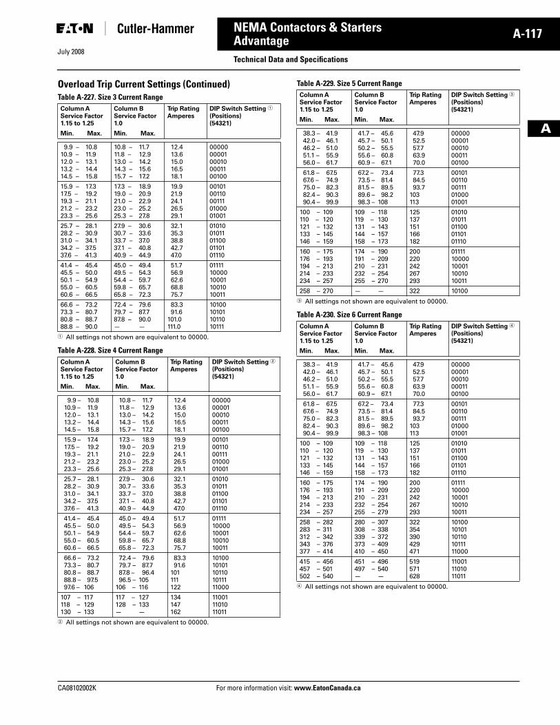
July 2008
CA08102002K For more information visit: www.EatonCanada.ca
A-117NEMA Contactors & Starters
A
AdvantageTechnical Data and Specifications
Overload Trip Current Settings (Continued)Table A-227. Size 3 Current Range
� All settings not shown are equivalent to 00000.
Table A-228. Size 4 Current Range
� All settings not shown are equivalent to 00000.
Table A-229. Size 5 Current Range
� All settings not shown are equivalent to 00000.
Table A-230. Size 6 Current Range
� All settings not shown are equivalent to 00000.
Column AService Factor1.15 to 1.25
Column BService Factor1.0
Trip RatingAmperes
DIP Switch Setting �
(Positions) (54321)
Min. Max. Min. Max.
9.9 –10.9 –12.0 –13.2 –14.5 –
10.811.913.114.415.8
10.8 –11.8 –13.0 –14.3 –15.7 –
11.712.914.215.617.2
12.413.615.016.518.1
0000000001000100001100100
15.9 –17.5 –19.3 –21.2 –23.3 –
17.319.221.123.225.6
17.3 –19.0 –21.0 –23.0 –25.3 –
18.920.922.925.227.8
19.921.924.126.529.1
0010100110001110100001001
25.7 –28.2 –31.0 –34.2 –37.6 –
28.130.934.137.541.3
27.9 –30.7 –33.7 –37.1 –40.9 –
30.633.637.040.844.9
32.135.338.842.747.0
0101001011011000110101110
41.4 –45.5 –50.1 –55.0 –60.6 –
45.450.054.960.566.5
45.0 –49.5 –54.4 –59.8 –65.8 –
49.454.359.765.772.3
51.756.962.668.875.7
0111110000100011001010011
66.6 –73.3 –80.8 –88.8 –
73.280.788.790.0
72.4 –79.7 –87.8 –—
79.687.790.0—
83.391.6
101.0111.0
10100101011011010111
Column AService Factor1.15 to 1.25
Column BService Factor1.0
Trip RatingAmperes
DIP Switch Setting �
(Positions) (54321)
Min. Max. Min. Max.
9.9 –10.9 –12.0 –13.2 –14.5 –
10.811.913.114.415.8
10.8 –11.8 –13.0 –14.3 –15.7 –
11.712.914.215.617.2
12.413.615.016.518.1
0000000001000100001100100
15.9 –17.5 –19.3 –21.2 –23.3 –
17.419.221.123.225.6
17.3 –19.0 –21.0 –23.0 –25.3 –
18.920.922.925.227.8
19.921.924.126.529.1
0010100110001110100001001
25.7 –28.2 –31.0 –34.2 –37.6 –
28.130.934.137.541.3
27.9 –30.7 –33.7 –37.1 –40.9 –
30.633.637.040.844.9
32.135.338.842.747.0
0101001011011000110101110
41.4 –45.5 –50.1 –55.0 –60.6 –
45.450.054.960.566.5
45.0 –49.5 –54.4 –59.8 –65.8 –
49.454.359.765.772.3
51.756.962.668.875.7
0111110000100011001010011
66.6 –73.3 –80.8 –88.8 –97.6 –
73.280.788.797.5
106
72.4 –79.7 –87.8 –96.5 –
106 –
79.687.796.4
105116
83.391.6
101111122
1010010101101101011111000
107 –118 –130 –
117129133
117 –128 –—
127133—
134147162
110011101011011
Column AService Factor1.15 to 1.25
Column BService Factor1.0
Trip RatingAmperes
DIP Switch Setting �
(Positions) (54321)
Min. Max. Min. Max.
38.3 –42.0 –46.2 –51.1 –56.0 –
41.946.151.055.961.7
41.7 –45.7 –50.2 –55.6 –60.9 –
45.650.155.560.867.1
47.952.557.763.970.0
0000000001000100001100100
61.8 –67.6 –75.0 –82.4 –90.4 –
67.574.982.390.399.9
67.2 –73.5 –81.5 –89.6 –98.3 –
73.481.489.598.2
108
77.384.593.7
103113
0010100110001110100001001
100 –110 –121 –133 –146 –
109120132145159
109 –119 –131 –144 –158 –
118130143157173
125137151166182
0101001011011000110101110
160 –176 –194 –214 –234 –
175193213233257
174 –191 –210 –232 –255 –
190209231254270
200220242267293
0111110000100011001010011
258 – 270 — — 322 10100
Column AService Factor1.15 to 1.25
Column BService Factor1.0
Trip RatingAmperes
DIP Switch Setting �
(Positions) (54321)
Min. Max. Min. Max.
38.3 –42.0 –46.2 –51.1 –56.0 –
41.946.151.055.961.7
41.7 –45.7 –50.2 –55.6 –60.9 –
45.650.155.560.867.1
47.952.557.763.970.0
0000000001000100001100100
61.8 –67.6 –75.0 –82.4 –90.4 –
67.574.982.390.399.9
67.2 –73.5 –81.5 –89.6 –98.3 –
73.481.489.598.2
108
77.384.593.7
103113
0010100110001110100001001
100 –110 –121 –133 –146 –
109120132145159
109 –119 –131 –144 –158 –
118130143157173
125137151166182
0101001011011000110101110
160 –176 –194 –214 –234 –
175193213233257
174 –191 –210 –232 –255 –
190209231254279
200220242267293
0111110000100011001010011
258 –283 –312 –343 –377 –
282311342376414
280 –308 –339 –373 –410 –
307338372409450
322354390429471
1010010101101101011111000
415 –457 –502 –
456501540
451 –497 –—
496540—
519571628
110011101011011
Tab33.book Page 117 Sunday, September 21, 2008 10:27 PM
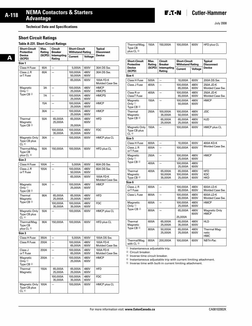
July 2008
A-118
For more information visit: www.EatonCanada.ca CA08102002K
NEMA Contactors & Starters
A
AdvantageTechnical Data and Specifications
Short Circuit RatingsTable A-231. Short-Circuit Ratings
� Instantaneous adjustable trip.� Circuit breaker.� Inverse time circuit breaker.� Instantaneous adjustable trip with current limiting attachment.� Inverse time with built-in current limiting attachment.
Short-CircuitProtectiveDevice(SCPD)
Max.Rating(SCPD)
CircuitBreakerInterruptingRating
Short-CircuitWithstand Rating
TypicalDisconnectDeviceCurrent Voltage
Size 1Class H Fuse 60A — 5,000A 600V 30A DS Sw.
Class J, Ror T Fuse
60A — 100,000A50,000A
480V600V
30A DS Sw.
65,000A 600V 100A FD-KMolded Case Sw.
MagneticOnly �Type CB �
3A — 100,000A25,000A
480V600V
HMCPHMCPS
7A — 100,000A25,000A
480V600V
HMCPS
15A — 100,000A25,000A
480V600V
HMCP
30A — 100,000A25,000A
480V600V
HMCP
ThermalMagneticType CB �
50A 65,000A25,000A
65,000A
25,000A
480V600V
HFD
100,000A35,000A
100,000A35,000A
480V600V
FDC
Magnetic OnlyType CB plusCL �
30A — 100,000A 600V HMCP plus CL
Thermal/Mag.Type CBplus CL �
50A 150,000A 100,000A 600V HFD plus CL
Size 2Class H Fuse 100A — 5,000A 600V 60A DS Sw.
Class J, Ror T Fuse
100A — 100,000A50,000A
480V600V
60A DS Sw.
65,000A 600V 100A FD-KMolded Case Sw.
MagneticOnly �Type CB �
50A — 100,000A25,000A
480V600V
HMCP
ThermalMagneticType CB �
90A 65,000A25,000A
65,000A25,000A
480V600V
HFD
100,000A35,000A
100,000A35,000A
480V600V
FDC
Magnetic OnlyType CB plusCL �
50A — 100,000A 600V HMCP plus CL
Thermal/Mag.Type CBplus CL �
90A 150,000A 100,000A 600V HFD plus CL
Size 3Class H Fuse 350A — 5,000A 600V 100A DS Sw.
Class R Fuse 200A — 100,000A65,000A
480V600V
100A FD-K Molded Case Sw.
Class J or T Fuse
200A — 100,000A65,000A
480V600V
100A FD-KMolded Case Sw.
MagneticOnly �Type CB �
200A — 100,000A25,000A
480V600V
HMCP
ThermalMagnetic
150A 65,000A25,000A
65,000A25,000A
480V600V
HFD
100,000A35,000A
100,000A35,000A
480V600V
FDC
Magnetic OnlyType CB plusCL �
100A — 100,000A 600V HMCP plus CL
Thermal/Mag.Type CBplus CL �
150A 150,000A 100,000A 600V HFD plus CL
Short-CircuitProtectiveDevice(SCPD)
Max.Rating(SCPD)
CircuitBreakerInterruptingRating
Short-CircuitWithstand Rating
TypicalDisconnectDeviceCurrent Voltage
Size 4Class H Fuse 500A — 10,000A 600V 200A DS Sw.
Class J Fuse 400A — 100,000A65,000A
480V600V
250A JD-K Molded Case Sw.
Class R or Class T Fuse
400A — 100,000A65,000A
480V600V
250A JD-K Molded Case Sw.
MagneticOnly �Type CB �
150A — 100,000A50,000A
480V600V
HMCP
ThermalMagneticType CB �
250A 100,000A35,000A
100,000A50,000A
480V600V
JDC
65,000A25,000A
65,000A25,000A
480V600V
HJD
Magnetic Only Type CB plus CL �
150A — 100,000A 600V HMCP plus CL
Size 5Class H Fuse 600A — 10,000A 600V 400A KD-K
Molded Case Sw.Class J, Ror T Fuse
600A — 100,000A 600V
MagneticOnly �Type CB �
250A — 100,000A25,000A
480V600V
HMCP
400A — 100,000A25,000A
480V600V
ThermalMagneticType CB �
400A 65,000A50,000A35,000A
65,000A100,000A25,000A
480V600V600V
HFDKDCHKD
Size 6Class J, Ror T Fuse
600A — 100,000A65,000A
480V600V
600A LD-K Molded Case Sw.
Class L Fuse 800A — 100,000A65,000A
480V600V
600A LD-K Molded Case Sw.
MagneticOnly �Type CB �
600A — 100,000A25,000A
480V600V
HMCP
800A — 65,000A
25,000A
480V600V
Magnetic OnlyHMCP
ThermalMagneticType CB �
600A 65,000A25,000A
65,000A35,000A
480V600V
HLD
800A 50,000A25,000A
65,000A25,000A
480V600V
Thermal Mag-neticHMC
Thermal/Mag.with CL �
800A 200,000A 100,000A 600V NB Tri-Pac
Tab33.book Page 118 Sunday, September 21, 2008 10:27 PM
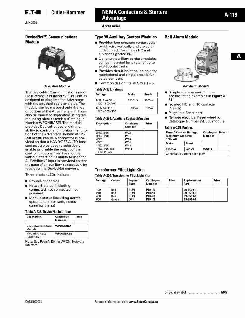
July 2008
CA08102002K For more information visit: www.EatonCanada.ca
A-119NEMA Contactors & Starters
A
AdvantageAccessories
DeviceNet™ Communications Module
DeviceNet Module
The DeviceNet Communications mod-ule (Catalogue Number WPONIDNA) is designed to plug into the Advantage with the attached cable and plug. The module can be snapped onto the top or bottom of the Advantage unit. It can also be mounted separately using the mounting plate assembly (Catalogue Number WPONIBASE). The module provides DeviceNet users with the ability to control and monitor the func-tions of the Advantage system at 125, 250 or 500 kbaud. A connector is pro-vided so that a HAND/OFF/AUTO hard contact July be used to selectively enable or disable the output of the control functions from the module without affecting its ability to monitor. A “Feedback” input is provided so that the state of an auxiliary contact July be read over the DeviceNet network.
Three bicolor LEDs indicate:
■ DeviceNet address■ Network status (including
connected, not connected, not powered)
■ Module status (including normal operation, minor fault, needs commissioning)
Table A-232. DeviceNet Interface
Note: See Page A-134 for WPONI Network Interface.
Description CatalogueNumber
Price
DeviceNet InterfaceModule
WPONIDNA
Mounting Plate Assembly
WPONIBASE
Type W Auxiliary Contact Modules■ Provides four separate contact sets
which wire vertically and are color coded; black designates NC and silver designated NO.
■ Up to two auxiliary contact modules can be mounted for a total of up to eight contact sets.
■ Provides circuit isolation (no polarity restrictions) and single break bifur-cated contacts.
■ Common design fits all Sizes 1 – 6.
Table A-233. Ratings
Table A-234. Auxiliary Contact Modules
Bell Alarm Module
Bell Alarm Module
■ Simple snap-on mounting —see mounting examples in Figure A-51.
■ Isolated NO and NC contacts (1 each)
■ Plugs into Reset port■ Remote electrical Reset wired to
Catalogue Number WBELL module
Table A-235. Ratings
Transformer Pilot Light KitsTable A-236. Transformer Pilot Light Kits
Voltage Make Break
NEMA A600 — 120 – 600V AC
7200 VA 720 VA
NEMA Q300 — 125 – 300V DC
69 VA 69 VA
Description CatalogueNumber
Price
2NO, 2NC3NO, 1NC4NO4NC1NO, 3NC1NO, 1NC and 2 Tie Points
W22W31W40W04W13W11T
Form C Contact RatingsMaximum Amperes — 120V AC
CatalogueNumber
Price
Make Break
2880 VA 480 VA WBELL
Continuous Current Rating: 5A
Voltage Colour LegendPlate
CatalogueNumber
Price ReplacementPart
Price
120240480600
RedRedRedGreen
RUNRUNRUNOFF
PLK1RPLK2RPLK4RPLK1G
99-3590-199-3590-399-3590-699-3590-8
Discount Symbol . . . . . . . . . . . . . . . . . . . . . . . . . MC7
Tab33.book Page 119 Sunday, September 21, 2008 10:27 PM
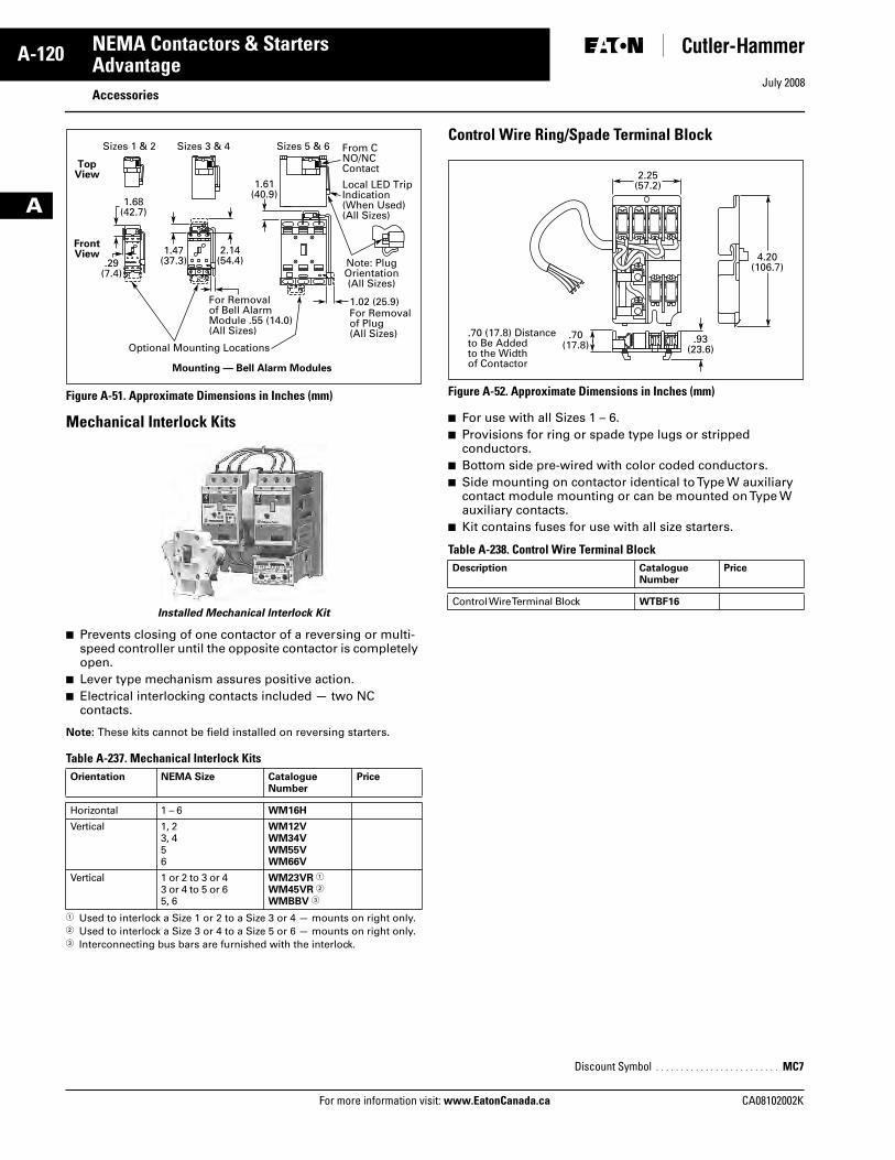
July 2008
A-120
For more information visit: www.EatonCanada.ca CA08102002K
NEMA Contactors & Starters
A
AdvantageAccessories
Figure A-51. Approximate Dimensions in Inches (mm)
Mechanical Interlock Kits
Installed Mechanical Interlock Kit
■ Prevents closing of one contactor of a reversing or multi-speed controller until the opposite contactor is completely open.
■ Lever type mechanism assures positive action.■ Electrical interlocking contacts included — two NC
contacts.
Note: These kits cannot be field installed on reversing starters.
Table A-237. Mechanical Interlock Kits
� Used to interlock a Size 1 or 2 to a Size 3 or 4 — mounts on right only.� Used to interlock a Size 3 or 4 to a Size 5 or 6 — mounts on right only.� Interconnecting bus bars are furnished with the interlock.
Control Wire Ring/Spade Terminal Block
Figure A-52. Approximate Dimensions in Inches (mm)
■ For use with all Sizes 1 – 6.■ Provisions for ring or spade type lugs or stripped
conductors.■ Bottom side pre-wired with color coded conductors.■ Side mounting on contactor identical to Type W auxiliary
contact module mounting or can be mounted on Type W auxiliary contacts.
■ Kit contains fuses for use with all size starters.
Table A-238. Control Wire Terminal Block
Orientation NEMA Size Catalogue Number
Price
Horizontal 1 – 6 WM16H
Vertical 1, 23, 456
WM12VWM34VWM55VWM66V
Vertical 1 or 2 to 3 or 43 or 4 to 5 or 65, 6
WM23VR �
WM45VR �
WMBBV �
Sizes 1 & 2 Sizes 3 & 4 Sizes 5 & 6
1.68(42.7)
1.47(37.3)
2.14(54.4)
1.61(40.9)
.29(7.4)
1.02 (25.9)For Removalof Plug(All Sizes)
For Removalof Bell AlarmModule .55 (14.0)(All Sizes)
Optional Mounting Locations
Local LED TripIndication(When Used)(All Sizes)
From CNO/NCContact
Note: PlugOrientation(All Sizes)
TopView
FrontView
Mounting — Bell Alarm Modules
Description CatalogueNumber
Price
Control Wire Terminal Block WTBF16
Discount Symbol . . . . . . . . . . . . . . . . . . . . . . . . . MC7
2.25(57.2)
.70(17.8) .93
(23.6)
4.20(106.7)
.70 (17.8) Distanceto Be Addedto the Widthof Contactor
Tab33.book Page 120 Sunday, September 21, 2008 10:27 PM
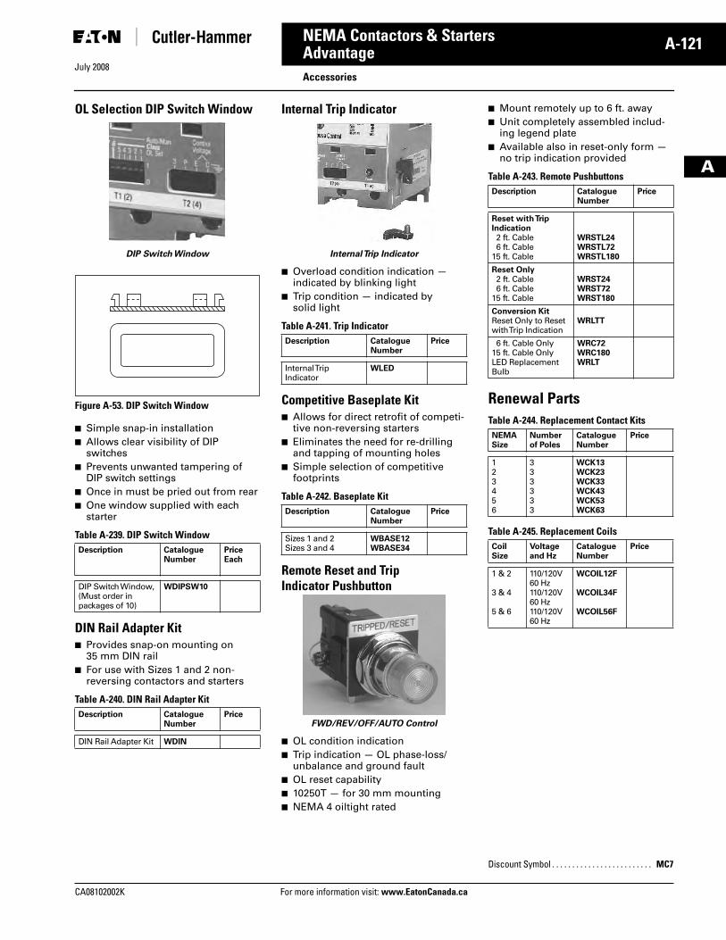
July 2008
CA08102002K For more information visit: www.EatonCanada.ca
A-121NEMA Contactors & Starters
A
AdvantageAccessories
OL Selection DIP Switch Window
DIP Switch Window
Figure A-53. DIP Switch Window
■ Simple snap-in installation■ Allows clear visibility of DIP
switches■ Prevents unwanted tampering of
DIP switch settings■ Once in must be pried out from rear■ One window supplied with each
starter
Table A-239. DIP Switch Window
DIN Rail Adapter Kit■ Provides snap-on mounting on
35 mm DIN rail■ For use with Sizes 1 and 2 non-
reversing contactors and starters
Table A-240. DIN Rail Adapter Kit
Internal Trip Indicator
Internal Trip Indicator
■ Overload condition indication — indicated by blinking light
■ Trip condition — indicated by solid light
Table A-241. Trip Indicator
Competitive Baseplate Kit■ Allows for direct retrofit of competi-
tive non-reversing starters■ Eliminates the need for re-drilling
and tapping of mounting holes■ Simple selection of competitive
footprints
Table A-242. Baseplate Kit
Remote Reset and Trip Indicator Pushbutton
FWD/REV/OFF/AUTO Control
■ OL condition indication■ Trip indication — OL phase-loss/
unbalance and ground fault■ OL reset capability■ 10250T — for 30 mm mounting■ NEMA 4 oiltight rated
■ Mount remotely up to 6 ft. away■ Unit completely assembled includ-
ing legend plate■ Available also in reset-only form —
no trip indication provided
Table A-243. Remote Pushbuttons
Renewal PartsTable A-244. Replacement Contact Kits
Table A-245. Replacement Coils
Description CatalogueNumber
Price Each
DIP Switch Window, (Must order in packages of 10)
WDIPSW10
Description CatalogueNumber
Price
DIN Rail Adapter Kit WDIN
Description CatalogueNumber
Price
Internal TripIndicator
WLED
Description CatalogueNumber
Price
Sizes 1 and 2Sizes 3 and 4
WBASE12WBASE34
Description CatalogueNumber
Price
Reset with Trip Indication2 ft. Cable6 ft. Cable
15 ft. Cable
WRSTL24WRSTL72WRSTL180
Reset Only2 ft. Cable6 ft. Cable
15 ft. Cable
WRST24WRST72WRST180
Conversion KitReset Only to Reset with Trip Indication
WRLTT
6 ft. Cable Only15 ft. Cable OnlyLED Replacement Bulb
WRC72WRC180WRLT
NEMASize
Numberof Poles
CatalogueNumber
Price
123456
333333
WCK13WCK23WCK33WCK43WCK53WCK63
CoilSize
Voltage and Hz
CatalogueNumber
Price
1 & 2
3 & 4
5 & 6
110/120V 60 Hz110/120V 60 Hz110/120V 60 Hz
WCOIL12F
WCOIL34F
WCOIL56F
Discount Symbol . . . . . . . . . . . . . . . . . . . . . . . . . MC7
Tab33.book Page 121 Sunday, September 21, 2008 10:27 PM
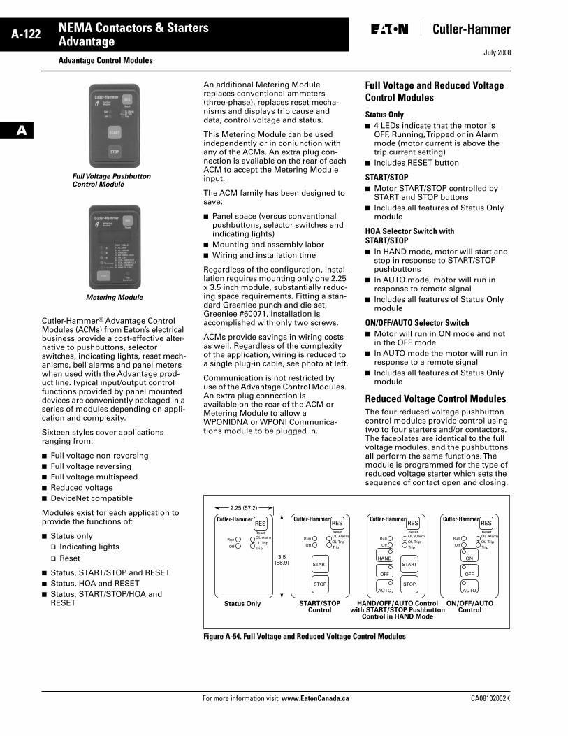
July 2008
A-122
For more information visit: www.EatonCanada.ca CA08102002K
NEMA Contactors & Starters
A
AdvantageAdvantage Control Modules
Cutler-Hammer® Advantage Control Modules (ACMs) from Eaton’s electrical business provide a cost-effective alter-native to pushbuttons, selector switches, indicating lights, reset mech-anisms, bell alarms and panel meters when used with the Advantage prod-uct line. Typical input/output control functions provided by panel mounted devices are conveniently packaged in a series of modules depending on appli-cation and complexity.
Sixteen styles cover applications ranging from:
■ Full voltage non-reversing■ Full voltage reversing■ Full voltage multispeed■ Reduced voltage■ DeviceNet compatible
Modules exist for each application to provide the functions of:
■ Status only❑ Indicating lights❑ Reset
■ Status, START/STOP and RESET■ Status, HOA and RESET■ Status, START/STOP/HOA and
RESET
Full Voltage PushbuttonControl Module
Metering Module
An additional Metering Module replaces conventional ammeters (three-phase), replaces reset mecha-nisms and displays trip cause and data, control voltage and status.
This Metering Module can be used independently or in conjunction with any of the ACMs. An extra plug con-nection is available on the rear of each ACM to accept the Metering Module input.
The ACM family has been designed to save:
■ Panel space (versus conventional pushbuttons, selector switches and indicating lights)
■ Mounting and assembly labor■ Wiring and installation time
Regardless of the configuration, instal-lation requires mounting only one 2.25 x 3.5 inch module, substantially reduc-ing space requirements. Fitting a stan-dard Greenlee punch and die set, Greenlee #60071, installation is accomplished with only two screws.
ACMs provide savings in wiring costs as well. Regardless of the complexity of the application, wiring is reduced to a single plug-in cable, see photo at left.
Communication is not restricted by use of the Advantage Control Modules. An extra plug connection is available on the rear of the ACM or Metering Module to allow a WPONIDNA or WPONI Communica-tions module to be plugged in.
Full Voltage and Reduced Voltage Control Modules
Status Only■ 4 LEDs indicate that the motor is
OFF, Running, Tripped or in Alarm mode (motor current is above the trip current setting)
■ Includes RESET button
START/STOP■ Motor START/STOP controlled by
START and STOP buttons■ Includes all features of Status Only
module
HOA Selector Switch with START/STOP■ In HAND mode, motor will start and
stop in response to START/STOP pushbuttons
■ In AUTO mode, motor will run in response to remote signal
■ Includes all features of Status Only module
ON/OFF/AUTO Selector Switch■ Motor will run in ON mode and not
in the OFF mode■ In AUTO mode the motor will run in
response to a remote signal■ Includes all features of Status Only
module
Reduced Voltage Control ModulesThe four reduced voltage pushbutton control modules provide control using two to four starters and/or contactors. The faceplates are identical to the full voltage modules, and the pushbuttons all perform the same functions. The module is programmed for the type of reduced voltage starter which sets the sequence of contact open and closing.
Figure A-54. Full Voltage and Reduced Voltage Control Modules
OL Alarm
TripOL Trip
OL Alarm
TripOL Trip
OL Alarm
TripOL Trip
RES
Reset
Run
Off
OL Alarm
TripOL Trip
RESReset
RESReset
RESReset
Run
Off
Run
HANDSTART
STOP
START
STOP
OFF
AUTO
ON
OFF
AUTO
Off
Run
Off
Status Only START/STOPControl
HAND/OFF/AUTO Controlwith START/STOP Pushbutton
Control in HAND Mode
ON/OFF/AUTOControl
3.5(88.9)
2.25 (57.2)
Tab33.book Page 122 Sunday, September 21, 2008 10:27 PM
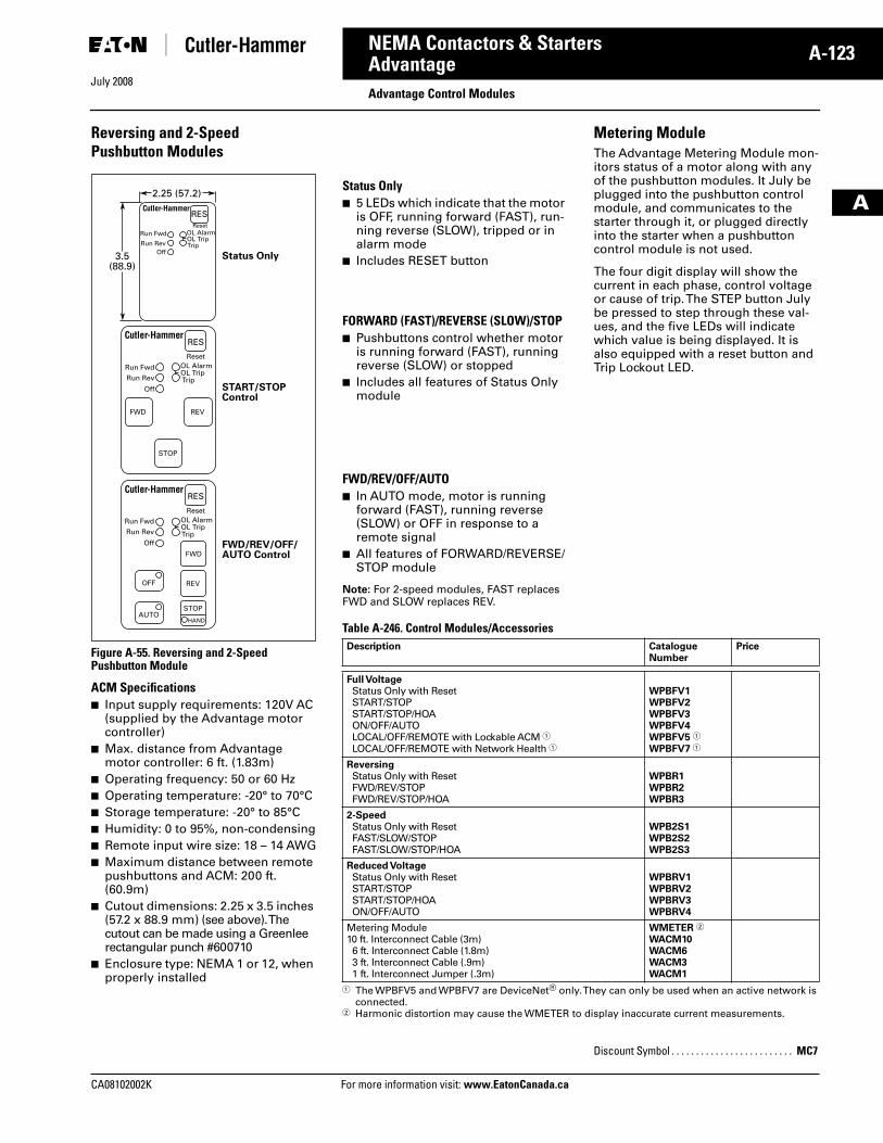
July 2008
CA08102002K For more information visit: www.EatonCanada.ca
A-123NEMA Contactors & Starters
A
AdvantageAdvantage Control Modules
Reversing and 2-Speed Pushbutton Modules
Figure A-55. Reversing and 2-Speed Pushbutton Module
ACM Specifications■ Input supply requirements: 120V AC
(supplied by the Advantage motor controller)
■ Max. distance from Advantage motor controller: 6 ft. (1.83m)
■ Operating frequency: 50 or 60 Hz■ Operating temperature: -20° to 70°C■ Storage temperature: -20° to 85°C■ Humidity: 0 to 95%, non-condensing■ Remote input wire size: 18 – 14 AWG■ Maximum distance between remote
pushbuttons and ACM: 200 ft. (60.9m)
■ Cutout dimensions: 2.25 x 3.5 inches (57.2 x 88.9 mm) (see above). The cutout can be made using a Greenlee rectangular punch #600710
■ Enclosure type: NEMA 1 or 12, when properly installed
RESReset
Run Fwd
Run RevOff
OL Alarm
TripOL Trip
Status Only
RES
Reset
REVFWD
STOP
Run Fwd
Run Rev
Off
OL Alarm
TripOL Trip
START/STOPControl
RES
Reset
REV
AUTO
OFF
STOP
HAND
FWD
Run Fwd
Run Rev
Off
OL Alarm
TripOL Trip
FWD/REV/OFF/AUTO Control
3.5(88.9)
2.25 (57.2)Status Only■ 5 LEDs which indicate that the motor
is OFF, running forward (FAST), run-ning reverse (SLOW), tripped or in alarm mode
■ Includes RESET button
FORWARD (FAST)/REVERSE (SLOW)/STOP■ Pushbuttons control whether motor
is running forward (FAST), running reverse (SLOW) or stopped
■ Includes all features of Status Only module
FWD/REV/OFF/AUTO■ In AUTO mode, motor is running
forward (FAST), running reverse (SLOW) or OFF in response to a remote signal
■ All features of FORWARD/REVERSE/STOP module
Note: For 2-speed modules, FAST replaces FWD and SLOW replaces REV.
Metering ModuleThe Advantage Metering Module mon-itors status of a motor along with any of the pushbutton modules. It July be plugged into the pushbutton control module, and communicates to the starter through it, or plugged directly into the starter when a pushbutton control module is not used.
The four digit display will show the current in each phase, control voltage or cause of trip. The STEP button July be pressed to step through these val-ues, and the five LEDs will indicate which value is being displayed. It is also equipped with a reset button and Trip Lockout LED.
Table A-246. Control Modules/Accessories
� The WPBFV5 and WPBFV7 are DeviceNet® only. They can only be used when an active network is connected.
� Harmonic distortion may cause the WMETER to display inaccurate current measurements.
Description CatalogueNumber
Price
Full VoltageStatus Only with ResetSTART/STOPSTART/STOP/HOAON/OFF/AUTOLOCAL/OFF/REMOTE with Lockable ACM �LOCAL/OFF/REMOTE with Network Health �
WPBFV1WPBFV2WPBFV3WPBFV4WPBFV5 �
WPBFV7 �
ReversingStatus Only with ResetFWD/REV/STOPFWD/REV/STOP/HOA
WPBR1WPBR2WPBR3
2-SpeedStatus Only with ResetFAST/SLOW/STOPFAST/SLOW/STOP/HOA
WPB2S1WPB2S2WPB2S3
Reduced VoltageStatus Only with ResetSTART/STOPSTART/STOP/HOAON/OFF/AUTO
WPBRV1WPBRV2WPBRV3WPBRV4
Metering Module10 ft. Interconnect Cable (3m)6 ft. Interconnect Cable (1.8m)3 ft. Interconnect Cable (.9m)1 ft. Interconnect Jumper (.3m)
WMETER �
WACM10WACM6WACM3WACM1
Discount Symbol . . . . . . . . . . . . . . . . . . . . . . . . . MC7
Tab33.book Page 123 Sunday, September 21, 2008 10:27 PM
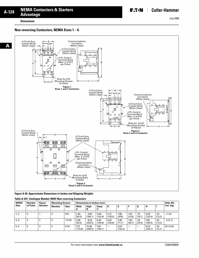
July 2008
A-124
For more information visit: www.EatonCanada.ca CA08102002K
NEMA Contactors & Starters
A
AdvantageDimensions
Non-reversing Contactors, NEMA Sizes 1 – 6
Figure A-56. Approximate Dimensions in Inches and Shipping Weights
Table A-247. Catalogue Number W201 Non-reversing Contactors NEMA Size
Numberof Poles
FigureNumber
Mounting Screws Dimensions in Inches (mm) Ship. Wt. Lbs. (kg)Number Size Wide
AHighB
DeepC
D E F G H I
1, 2 3 1 3 #10 2.50(63.5)
6.50(165.1)
4.84(122.9)
5.12(130.0)
1.88 (47.8)
1.25(31.8)
.75(19.1)
6.00(152.4)
.52(13.2)
2 (.9)
3, 4 3 2 3 1/4-20 3.68(93.5)
8.00(203.2)
6.49(164.8)
6.45(163.8)
2.80(71.1)
1.84(46.7)
.93(23.6)
7.50(190.5)
.52(13.2)
6 (2.7)
5, 6 3 3 4 5/16 7.07(179.6)
10.08(256.0)
7.64(194.1)
— 6.00(152.4)
— — 9.20(233.7)
.50(12.7)
30 (13.6)
AF G
I
H
E
BD
CSlots for #10
Mounting Screws(3 Holes)
CommunicationsConnector
(When Used)
4 Pt. Control Terminal Block(Max. 2 of #14
per Point)
4 Circuit Aux.Contact Block(When Used)
4 Circuit Aux.Contact Block(When Used)
CL
AI
H
E
B
C
Slots for 5/16Mounting Bolts
(4 Slots)
CommunicationConnector
(When Used)
4 Pt. Control Terminal Block(Max. 2 of #14
per Point)
4 Circuit Aux.Contact Block(When Used)
4 Circuit Aux.Contact Block(When Used)
Figure 3Sizes 5 and 6 Contactor
AF G
I
H
E
BD
CSlots for 1/4-20
Mounting Screws(3 Places)
CommunicationsConnector
(When Used)
4 Pt. Control Terminal Block(Max. 2 of #14
per Point)
4 Circuit Aux.Contact Block(When Used)
4 Circuit Aux.Contact Block(When Used)
CL
Figure 2Sizes 3 and 4 Contactor
Figure 1Sizes 1 and 2 Contactor
Tab33.book Page 124 Sunday, September 21, 2008 10:27 PM
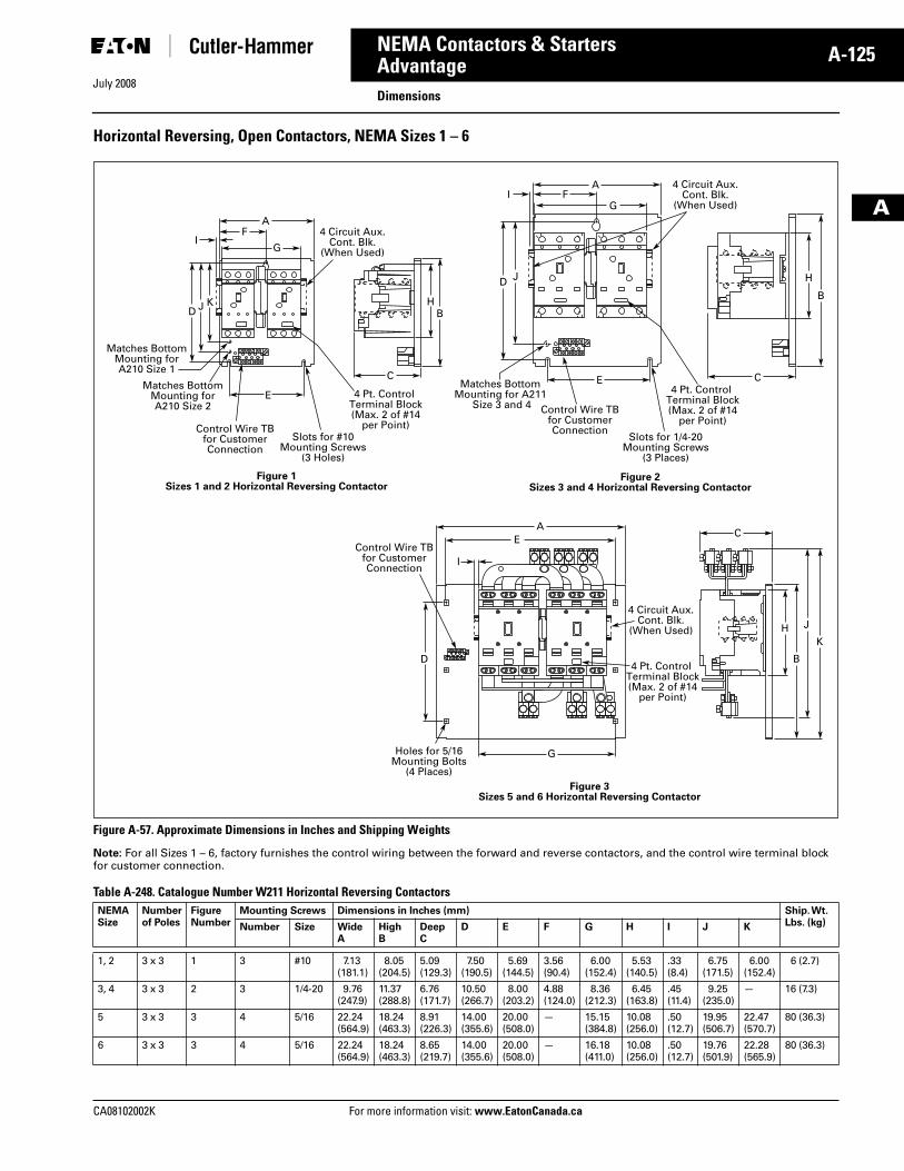
July 2008
CA08102002K For more information visit: www.EatonCanada.ca
A-125NEMA Contactors & Starters
A
AdvantageDimensions
Horizontal Reversing, Open Contactors, NEMA Sizes 1 – 6
Figure A-57. Approximate Dimensions in Inches and Shipping Weights
Note: For all Sizes 1 – 6, factory furnishes the control wiring between the forward and reverse contactors, and the control wire terminal block for customer connection.
Table A-248. Catalogue Number W211 Horizontal Reversing Contactors NEMA Size
Numberof Poles
FigureNumber
Mounting Screws Dimensions in Inches (mm) Ship. Wt. Lbs. (kg)Number Size Wide
AHighB
DeepC
D E F G H I J K
1, 2 3 x 3 1 3 #10 7.13(181.1)
8.05(204.5)
5.09(129.3)
7.50(190.5)
5.69(144.5)
3.56(90.4)
6.00(152.4)
5.53(140.5)
.33(8.4)
6.75(171.5)
6.00(152.4)
6 (2.7)
3, 4 3 x 3 2 3 1/4-20 9.76(247.9)
11.37(288.8)
6.76(171.7)
10.50(266.7)
8.00(203.2)
4.88(124.0)
8.36(212.3)
6.45(163.8)
.45(11.4)
9.25(235.0)
— 16 (7.3)
5 3 x 3 3 4 5/16 22.24(564.9)
18.24(463.3)
8.91(226.3)
14.00(355.6)
20.00(508.0)
— 15.15(384.8)
10.08(256.0)
.50(12.7)
19.95(506.7)
22.47(570.7)
80 (36.3)
6 3 x 3 3 4 5/16 22.24(564.9)
18.24(463.3)
8.65(219.7)
14.00(355.6)
20.00(508.0)
— 16.18(411.0)
10.08(256.0)
.50(12.7)
19.76(501.9)
22.28(565.9)
80 (36.3)
AF
D J K
IG
E
C
BH
4 Circuit Aux.Cont. Blk.
(When Used)
Control Wire TBfor CustomerConnection
Matches BottomMounting forA210 Size 2
Matches BottomMounting forA210 Size 1
Slots for #10Mounting Screws
(3 Holes)
4 Pt. Control Terminal Block(Max. 2 of #14
per Point)
AF
D J
IG
E C
B
H
4 Circuit Aux.Cont. Blk.
(When Used)
Control Wire TBfor CustomerConnection
Matches BottomMounting for A211
Size 3 and 4
Slots for 1/4-20Mounting Screws
(3 Places)
4 Pt. Control Terminal Block(Max. 2 of #14
per Point)
Figure 1Sizes 1 and 2 Horizontal Reversing Contactor
Figure 2Sizes 3 and 4 Horizontal Reversing Contactor
AE
C
I
D
G
B
HK
J4 Circuit Aux.
Cont. Blk.(When Used)
Control Wire TBfor CustomerConnection
Holes for 5/16Mounting Bolts
(4 Places)
4 Pt. Control Terminal Block(Max. 2 of #14
per Point)
Figure 3Sizes 5 and 6 Horizontal Reversing Contactor
Tab33.book Page 125 Sunday, September 21, 2008 10:27 PM
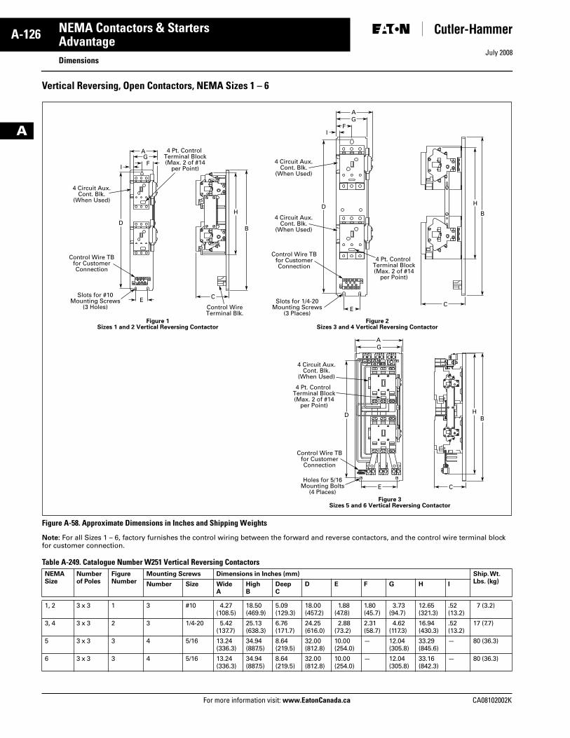
July 2008
A-126
For more information visit: www.EatonCanada.ca CA08102002K
NEMA Contactors & Starters
A
AdvantageDimensions
Vertical Reversing, Open Contactors, NEMA Sizes 1 – 6
Figure A-58. Approximate Dimensions in Inches and Shipping Weights
Note: For all Sizes 1 – 6, factory furnishes the control wiring between the forward and reverse contactors, and the control wire terminal block for customer connection.
Table A-249. Catalogue Number W251 Vertical Reversing Contactors NEMA Size
Numberof Poles
FigureNumber
Mounting Screws Dimensions in Inches (mm) Ship. Wt. Lbs. (kg)Number Size Wide
AHighB
DeepC
D E F G H I
1, 2 3 x 3 1 3 #10 4.27(108.5)
18.50(469.9)
5.09(129.3)
18.00(457.2)
1.88(47.8)
1.80(45.7)
3.73(94.7)
12.65(321.3)
.52(13.2)
7 (3.2)
3, 4 3 x 3 2 3 1/4-20 5.42(137.7)
25.13(638.3)
6.76(171.7)
24.25(616.0)
2.88(73.2)
2.31(58.7)
4.62(117.3)
16.94(430.3)
.52(13.2)
17 (7.7)
5 3 x 3 3 4 5/16 13.24(336.3)
34.94(887.5)
8.64(219.5)
32.00(812.8)
10.00(254.0)
— 12.04(305.8)
33.29(845.6)
— 80 (36.3)
6 3 x 3 3 4 5/16 13.24(336.3)
34.94(887.5)
8.64(219.5)
32.00(812.8)
10.00(254.0)
— 12.04(305.8)
33.16(842.3)
— 80 (36.3)
AGF
I
D
E C
B
H
4 Circuit Aux.Cont. Blk.
(When Used)
Control Wire TBfor CustomerConnection
Slots for #10Mounting Screws
(3 Holes) Control WireTerminal Blk.
4 Pt. Control Terminal Block(Max. 2 of #14
per Point)
AG
FI
D
EC
B
H
4 Circuit Aux.Cont. Blk.
(When Used)
4 Circuit Aux.Cont. Blk.
(When Used)
Control Wire TBfor CustomerConnection
Slots for 1/4-20Mounting Screws
(3 Places)
4 Pt. Control Terminal Block(Max. 2 of #14
per Point)
Figure 2Sizes 3 and 4 Vertical Reversing Contactor
Figure 1Sizes 1 and 2 Vertical Reversing Contactor
AG
D
CE
BH
4 Circuit Aux.Cont. Blk.
(When Used)
Control Wire TBfor CustomerConnection
Holes for 5/16Mounting Bolts
(4 Places)
4 Pt. Control Terminal Block(Max. 2 of #14
per Point)
Figure 3Sizes 5 and 6 Vertical Reversing Contactor
Tab33.book Page 126 Sunday, September 21, 2008 10:27 PM
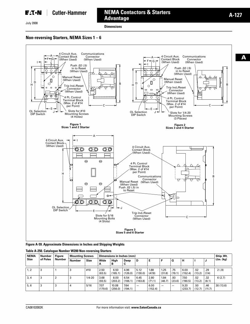
July 2008
CA08102002K For more information visit: www.EatonCanada.ca
A-127NEMA Contactors & Starters
A
AdvantageDimensions
Non-reversing Starters, NEMA Sizes 1 – 6
Figure A-59. Approximate Dimensions in Inches and Shipping Weights
Table A-250. Catalogue Number W200 Non-reversing Starters NEMA Size
Numberof Poles
FigureNumber
Mounting Screws Dimensions in Inches (mm) Ship. Wt. Lbs. (kg)Number Size Wide
AHighB
DeepC
D E F G H I J
1, 2 3 1 3 #10 2.50(63.5)
6.50(165.1)
4.96(126.0)
5.12(130.0)
1.88(47.8)
1.25(31.8)
.75(19.1)
6.00(152.4)
.52(13.2)
.29(7.4)
2 (.9)
3, 4 3 2 3 1/4-20 3.68(93.5)
8.00(203.2)
6.54(166.1)
6.45(163.8)
2.80(71.1)
1.84(46.7)
.93(23.6)
7.50(190.5)
.52(13.2)
.32(8.1)
6 (2.7)
5, 6 3 3 4 5/16 7.07(179.6)
10.08(256.0)
7.64(194.1)
— 6.00(152.4)
— — 9.20(233.7)
.50(12.7)
.46(11.7)
30 (13.6)
AF G
I
H
JE
BD
C
OL SelectionDIP Switch
Slots for #10Mounting Screws
(4 Holes)
Trip Ind./ResetConnector
(When Used)
Manual Reset(When Used)
CommunicationsConnector
(When Used)
4 Pt. Control Terminal Block(Max. 2 of #14
per Point)
4 Circuit Aux.Contact Block(When Used)
Push .02 (.5)in to Reset
(When Used)
CL
A
I
H
EJ
B
C
OL SelectionDIP Switch
Slots for 5/16Mounting Bolts
(4 Slots)
Trip Ind./ResetConnector
(When Used)
Manual Reset(When Used)
Push .02 (.5) into Reset
CommunicationsConnector
(When Used)
4 Pt. Control Terminal Block(Max. 2 of #14
per Point)
4 Circuit Aux.Contact Block(When Used)
4 Circuit Aux.Contact Block(When Used)
AF GI
H
JE
BD
C
OL SelectionDIP Switch
Figure 2Sizes 3 and 4 Starter
Figure 3Sizes 5 and 6 Starter
Figure 1Sizes 1 and 2 Starter
Slots for 1/4-20Mounting Screws
(3 Places)
Trip Ind./ResetConnector
(When Used)
Manual Reset(When Used)
CommunicationsConnector
(When Used)
4 Pt. Control Terminal Block(Max. 2 of #14
per Point)
4 Circuit Aux.Contact Block(When Used)
Push .02 (.5)in to Reset
(When Used)
Tab33.book Page 127 Sunday, September 21, 2008 10:27 PM
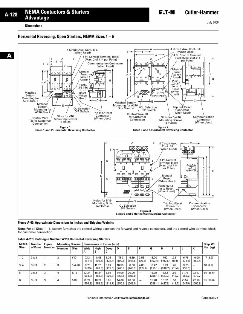
July 2008
A-128
For more information visit: www.EatonCanada.ca CA08102002K
NEMA Contactors & Starters
A
AdvantageDimensions
Horizontal Reversing, Open Starters, NEMA Sizes 1 – 6
Figure A-60. Approximate Dimensions in Inches and Shipping Weights
Note: For all Sizes 1 – 6, factory furnishes the control wiring between the forward and reverse contactors, and the control wire terminal block for customer connection.
Table A-251. Catalogue Number W210 Horizontal Reversing Starters NEMA Size
Numberof Poles
FigureNumber
Mounting Screws Dimensions in Inches (mm) Ship. Wt. Lbs. (kg)Number Size Wide
AHighB
DeepC
D E F G H I J K
1, 2 3 x 3 1 3 #10 7.13(181.1)
8.05(204.5)
5.25(133.4)
7.50(190.5)
5.69(144.5)
3.56(90.4)
6.00(152.4)
7.62(192.5)
.33(8.4)
6.75(171.5)
6.00(152.4)
7 (3.2)
3, 4 3 x 3 2 3 1/4-20 9.76(247.9)
11.37(288.8)
6.81(173.0)
10.50(266.7)
8.00(203.2)
4.88(124.0)
8.47(215.1)
9.79(248.7)
.45(11.4)
9.25(235.0)
— 18 (8.2)
5 3 x 3 3 4 5/16 22.24(564.9)
18.24(463.3)
8.91(226.3)
14.00(355.6)
20.00(508.0)
— 15.28 (388.1)
16.82(427.2)
.50(12.7)
21.76(552.7)
22.47(570.7)
85 (38.6)
6 3 x 3 3 4 516 22.24(564.9)
18.24(463.3)
8.65(219.7)
14.00(355.6)
20.00(508.0)
— 15.28(388.1)
16.82(427.2)
.50(12.7)
21.57(547.9)
22.28(565.9)
85 (38.6)
AF
D J K
IG
E
C
B
H
4 Circuit Aux. Cont. Blk.(When Used)
Control WireTB for Customer
Connection
MatchesBottom
Mounting forA210 Size 2
MatchesBottom
Mounting forA210 Size 1
Slots for #10Mounting Screws
(3 Holes)
4 Pt. Control Terminal Block(Max. 2 of #14 per Point)
AF
D J
IG
E C
B
H
4 Circuit Aux. Cont. Blk.(When Used)
Control Wire TBfor CustomerConnection
Matches BottomMounting for A210
Size 3 and 4
Slots for 1/4-20Mounting Screws
(3 Places)
4 Pt. Control TerminalBlock (Max. 2 of #14
per Point)
Figure 1Sizes 1 and 2 Horizontal Reversing Contactor
Figure 2Sizes 3 and 4 Horizontal Reversing Contactor
OL SelectionDIP Switch
OL SelectionDIP Switch
Trip Ind./ResetConnector
(When Used)
Communication Connector(When Used)
CommunicationConnector
(When Used)
ManualReset(WhenUsed)
Trip Ind./ResetConnector
(When Used)
ManualReset(WhenUsed)
Push.02 (.5)in toReset(WhenUsed)
Push.02 (.5)in toReset(WhenUsed)
A C
I
D
G
B
HK
J
4 Circuit Aux.Cont. Blk.
(When Used)
Holes for 5/16Mounting Bolts
(4 Places) OL Selection DIP Switch
4 Pt. Control Terminal Block(Max. 2 of #14
per Point)
ManualReset
(When Used)
Figure 3Sizes 5 and 6 Horizontal Reversing Contactor
Trip Ind./ResetConnector
(When Used)
Push .02 (.5)in to Reset
(When Used)
CommunicationConnector
(When Used)
Tab33.book Page 128 Sunday, September 21, 2008 10:27 PM
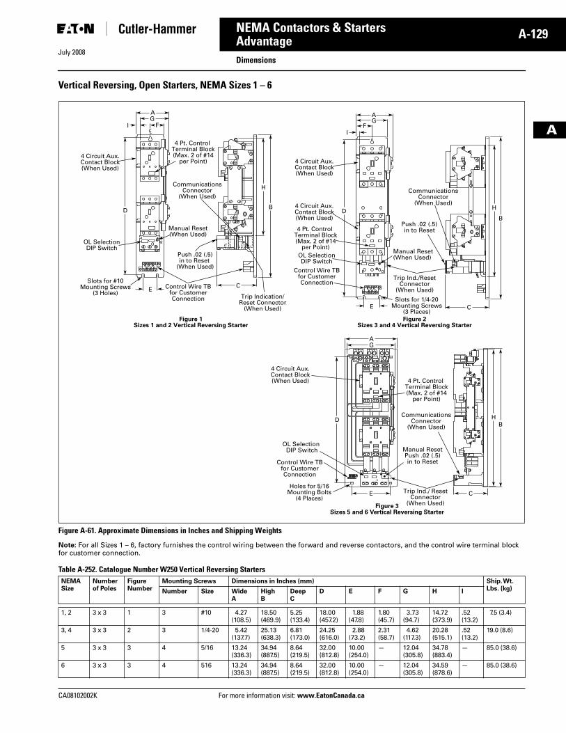
July 2008
CA08102002K For more information visit: www.EatonCanada.ca
A-129NEMA Contactors & Starters
A
AdvantageDimensions
Vertical Reversing, Open Starters, NEMA Sizes 1 – 6
Figure A-61. Approximate Dimensions in Inches and Shipping Weights
Note: For all Sizes 1 – 6, factory furnishes the control wiring between the forward and reverse contactors, and the control wire terminal block for customer connection.
Table A-252. Catalogue Number W250 Vertical Reversing Starters NEMA Size
Numberof Poles
FigureNumber
Mounting Screws Dimensions in Inches (mm) Ship. Wt. Lbs. (kg)Number Size Wide
AHighB
DeepC
D E F G H I
1, 2 3 x 3 1 3 #10 4.27(108.5)
18.50(469.9)
5.25(133.4)
18.00(457.2)
1.88(47.8)
1.80(45.7)
3.73(94.7)
14.72(373.9)
.52(13.2)
7.5 (3.4)
3, 4 3 x 3 2 3 1/4-20 5.42(137.7)
25.13(638.3)
6.81(173.0)
24.25(616.0)
2.88(73.2)
2.31(58.7)
4.62(117.3)
20.28(515.1)
.52(13.2)
19.0 (8.6)
5 3 x 3 3 4 5/16 13.24(336.3)
34.94(887.5)
8.64(219.5)
32.00(812.8)
10.00(254.0)
— 12.04(305.8)
34.78(883.4)
— 85.0 (38.6)
6 3 x 3 3 4 516 13.24(336.3)
34.94(887.5)
8.64(219.5)
32.00(812.8)
10.00(254.0)
— 12.04(305.8)
34.59(878.6)
— 85.0 (38.6)
AG
FI
D
EC
B
H
4 Circuit Aux.Contact Block(When Used)
OL SelectionDIP Switch
Control Wire TBfor CustomerConnection
Push .02 (.5)in to Reset
(When Used)
Slots for #10Mounting Screws
(3 Holes)
4 Pt. Control Terminal Block(Max. 2 of #14
per Point)
Manual Reset(When Used)
CommunicationsConnector
(When Used)
Trip Indication/Reset Connector
(When Used)
CL
AG
FI
D
E C
B
H
4 Circuit Aux.Contact Block(When Used)
4 Circuit Aux.Contact Block(When Used)
Control Wire TBfor CustomerConnection
Slots for 1/4-20Mounting Screws
(3 Places)
4 Pt. Control Terminal Block(Max. 2 of #14
per Point)Manual Reset(When Used)
Trip Ind./ResetConnector
(When Used)
OL SelectionDIP Switch
CommunicationsConnector
(When Used)
Push .02 (.5)in to Reset
Figure 2Sizes 3 and 4 Vertical Reversing Starter
Figure 1Sizes 1 and 2 Vertical Reversing Starter
AG
D
E
BH
4 Circuit Aux.Contact Block(When Used)
Control Wire TBfor CustomerConnection
Holes for 5/16Mounting Bolts
(4 Places)
4 Pt. Control Terminal Block(Max. 2 of #14
per Point)
OL Selection DIP Switch Manual Reset
Push .02 (.5)in to Reset
Trip Ind./ ResetConnector
(When Used)
CommunicationsConnector
(When Used)
C
Figure 3Sizes 5 and 6 Vertical Reversing Starter
Tab33.book Page 129 Sunday, September 21, 2008 10:27 PM
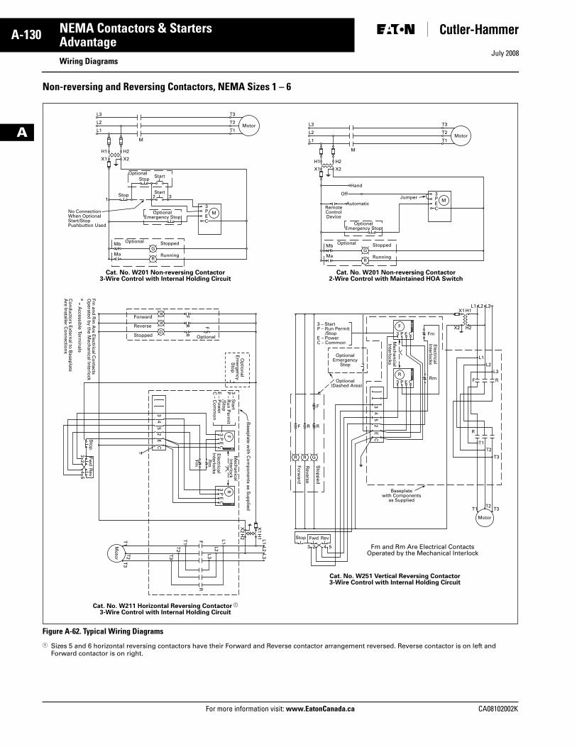
July 2008
A-130
For more information visit: www.EatonCanada.ca CA08102002K
NEMA Contactors & Starters
A
AdvantageWiring Diagrams
Non-reversing and Reversing Contactors, NEMA Sizes 1 – 6
Figure A-62. Typical Wiring Diagrams
� Sizes 5 and 6 horizontal reversing contactors have their Forward and Reverse contactor arrangement reversed. Reverse contactor is on left and Forward contactor is on right.
L3
L2
L1
T3
T2
T1
H1
X1
132
3M
GMa
Mb
R
PEC
StartStop
StartOptional
Stop
OptionalEmergency Stop
H2
M
Motor
X2
Stopped
No ConnectionWhen OptionalStart/StopPushbutton Used
Optional
Running
Cat. No. W201 Non-reversing Contactor3-Wire Control with Internal Holding Circuit
L3
L2
L1
T3
T2
T1
H1
X1
3M
GMa
Mb
R
PEC
Automatic
H2
M
Motor
X2
StoppedOptional
Running
OptionalEmergency Stop
RemoteControlDevice
JumperOff
Hand
Cat. No. W201 Non-reversing Contactor2-Wire Control with Maintained HOA Switch
Cat. No. W211 Horizontal Reversing Contactor �
3-Wire Control with Internal Holding Circuit
Cat. No. W251 Vertical Reversing Contactor3-Wire Control with Internal Holding Circuit
Fm and Rm Are Electrical ContactsOperated by the Mechanical Interlock
T1
T3
T2
Mo
tor
T2
T3
T1
Sto
pFw
dR
ev
32
54
Stop Fwd Rev
3 2 54
F
F
FR
R
RR
G
F
3P
EC
3P
EC
R
R
L1 L1X
1H
1
X2
H2
L2 L2
L3 L3
Mech
anical
Interlo
ck
Basep
late with
Co
mp
on
ents as S
up
plied
Electrical
Interlo
cksR
m
Fm
3 – Start
P – R
un
Perm
it /S
top
E – P
ow
erC
– Co
mm
on
Op
tion
alE
merg
ency
Sto
p
43
CE
52
43
CE
52
Optional
Forward
Reverse
Stopped
Fm an
d R
m A
re Electrical C
on
tactsO
perated
by th
e Mech
anical In
terlock
= Accessib
le Termin
als
Co
nd
ucto
rs Extern
al to B
aseplate
Are In
staller Co
nn
ection
s
Fm
Rm
Mech
ancial
Interlo
cks
Electrical
Interlo
cks
R
3 P E C
F
Sto
pp
ed
Reverse
Forw
ard
3 P E C
R
F
RRF
T1 T3T2
Motor
T2
T3
T1
R
F R
L1
L1X1 H1
X2 H2
L2
L2
L3
L3
3 – StartP – Run Permit /StopE – PowerC – Common
OptionalEmergency
Stop
Optional (Dashed Area)
R G
Baseplatewith Components
as Supplied
Tab33.book Page 130 Sunday, September 21, 2008 10:27 PM
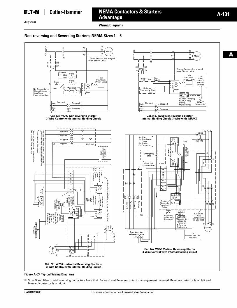
July 2008
CA08102002K For more information visit: www.EatonCanada.ca
A-131NEMA Contactors & Starters
A
AdvantageWiring Diagrams
Non-reversing and Reversing Starters, NEMA Sizes 1 – 6
Figure A-63. Typical Wiring Diagrams
� Sizes 5 and 6 horizontal reversing contactors have their Forward and Reverse contactor arrangement reversed. Reverse contactor is on left and Forward contactor is on right.
L3
L2
L1
T3
T2
T1
H1
X1
132
3M
GMa
Mb
R
Reset
TripInd./Reset
(When Used)
PEC
StartStop
StartOptional
Stop
OptionalEmergency Stop
H2
M
Motor
X2
(Current Sensors Are IntegralInside Starter Units)
Stopped
No ConnectionWhen OptionalStart/StopPushbutton Used
Optional
Running
Start2 3StopStop
Cat. No. W200 Non-reversing Starter3-Wire Control with Internal Holding Circuit
L3
L2
L1
T3
T2
T1
H1
X1
3M
PONIMod.
GMa
Mb
R
Reset
TripInd./Reset
(When Used)To
OtherIMPACCNetworkDevices
ToIMPACC
Network PC
PEC
H2
M
Motor
X2(Current Sensors Are IntegralInside Starter Units)
Caution – UnplugIMPACC PlugDuringMaintenanceStoppedOptional
Running
I1I2
OptionalEmergency Stop
Cat. No. W200 Non-reversing StarterInternal Holding Circuit, 3-Wire with IMPACC
Cat. No. W210 Horizontal Reversing Starter �
3-Wire Control with Internal Holding Circuit
Cat. No. W250 Vertical Reversing Starter3-Wire Control with Internal Holding Circuit
T1
T3
T2
Mo
tor
T2
T3
T1
Sto
p
Reset
Reset
Fwd
Rev
ToIM
PAC
C/IN
CO
MN
etwo
rk
3
1
24
5
Stop Fwd Rev
3 2 4 5
(Op
tion
al)Lig
hted
Also
Availab
le(O
ptio
nal)
May A
lso B
eA
dd
ed to
Forw
ard&
Reverse
Co
ntacto
rs
WP
ON
IM
od
.
F
F
FR
R
RR
GA
F
3P
EC
3P
EC
R
R
L1 L1X
1H
1
X2
H2
L2 L2
L3 L3
Mech
anical
Interlo
ck
Basep
late with
Co
mp
on
ents as S
up
plied
Electrical
Interlo
cksR
m
Fm
Mech
anical
Interlo
ck
Electrical
Interlo
cks
3 – Start
P – R
un
Perm
it /S
top
E – P
ow
erC
– Co
mm
on
Op
tion
alE
merg
ency
Sto
p
9695
98
984
35
CE
2
984
3C
E5
2
EC
OLR
Optional98
Forward
Reverse
Stopped
Tripped
Fm an
d R
m A
re Electrical C
on
tactsO
perated
by th
e Mech
anical In
terlock
= A
ccessible Term
inals
Co
nd
ucto
rs Extern
al to B
aseplate
Are In
staller Co
nn
ection
s
Co
ntacts
Sh
ow
nin
En
ergized
State
Reset
98
1
Reset
ToIMPACC/INCOM
Network
(Optional)Lighted Also
Available(Optional)
May Also BeAdded toForward
& ReverseContactors
WPONIMod.
96 95 98E C
OLRContactsShown inEnergized
State
R
3 PFm
EmergencyStop
Rm
E C
F
3 P E C
R
T1 T3T2
Motor
T2 T3T1
R
F
L1
L1X1 H1
X2 H2
L2
L2
L3
L3
3 – StartP – Run Permit /StopE – PowerC – Common
G A
Baseplatewith
Componentsas Supplied
Tripp
ed
Sto
pp
ed
Forw
ard
F
R
R
Reverse
RF
Optional (Dashed Area)
Tab33.book Page 131 Sunday, September 21, 2008 10:27 PM
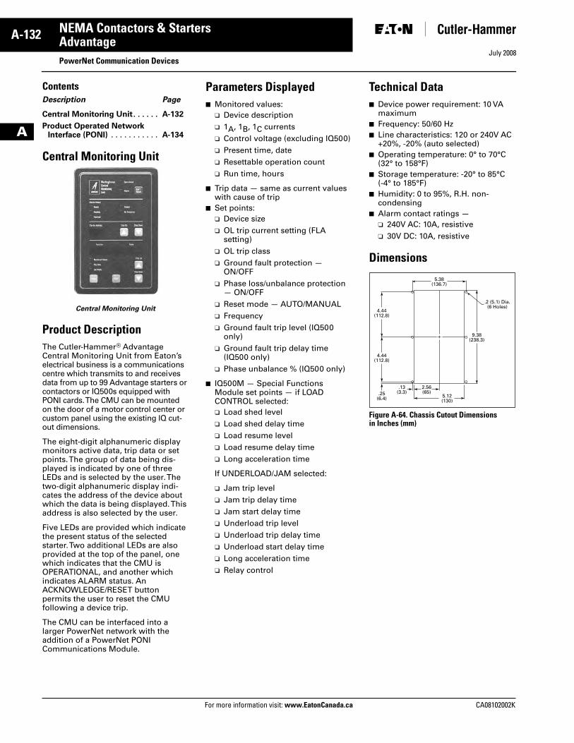
July 2008
A-132
For more information visit: www.EatonCanada.ca CA08102002K
NEMA Contactors & Starters
A
AdvantagePowerNet Communication Devices
ContentsDescription Page
Central Monitoring Unit. . . . . . A-132
Product Operated NetworkInterface (PONI) . . . . . . . . . . . A-134
Central Monitoring Unit
Central Monitoring Unit
Product DescriptionThe Cutler-Hammer® Advantage Central Monitoring Unit from Eaton’s electrical business is a communications centre which transmits to and receives data from up to 99 Advantage starters or contactors or IQ500s equipped with PONI cards. The CMU can be mounted on the door of a motor control center or custom panel using the existing IQ cut-out dimensions.
The eight-digit alphanumeric display monitors active data, trip data or set points. The group of data being dis-played is indicated by one of three LEDs and is selected by the user. The two-digit alphanumeric display indi-cates the address of the device about which the data is being displayed. This address is also selected by the user.
Five LEDs are provided which indicate the present status of the selected starter. Two additional LEDs are also provided at the top of the panel, one which indicates that the CMU is OPERATIONAL, and another which indicates ALARM status. An ACKNOWLEDGE/RESET button permits the user to reset the CMUfollowing a device trip.
The CMU can be interfaced into a larger PowerNet network with the addition of a PowerNet PONI Communications Module.
Parameters Displayed■ Monitored values:
❑ Device description❑ 1A, 1B, 1C currents❑ Control voltage (excluding IQ500)❑ Present time, date❑ Resettable operation count❑ Run time, hours
■ Trip data — same as current values with cause of trip
■ Set points:❑ Device size❑ OL trip current setting (FLA
setting)❑ OL trip class❑ Ground fault protection —
ON/OFF❑ Phase loss/unbalance protection
— ON/OFF❑ Reset mode — AUTO/MANUAL❑ Frequency❑ Ground fault trip level (IQ500
only)❑ Ground fault trip delay time
(IQ500 only)❑ Phase unbalance % (IQ500 only)
■ IQ500M — Special Functions Module set points — if LOAD CONTROL selected:❑ Load shed level❑ Load shed delay time❑ Load resume level❑ Load resume delay time❑ Long acceleration time
If UNDERLOAD/JAM selected:
❑ Jam trip level❑ Jam trip delay time❑ Jam start delay time❑ Underload trip level❑ Underload trip delay time❑ Underload start delay time❑ Long acceleration time❑ Relay control
Technical Data■ Device power requirement: 10 VA
maximum■ Frequency: 50/60 Hz■ Line characteristics: 120 or 240V AC
+20%, -20% (auto selected)■ Operating temperature: 0° to 70°C
(32° to 158°F)■ Storage temperature: -20° to 85°C
(-4° to 185°F)■ Humidity: 0 to 95%, R.H. non-
condensing■ Alarm contact ratings —
❑ 240V AC: 10A, resistive❑ 30V DC: 10A, resistive
Dimensions
Figure A-64. Chassis Cutout Dimensionsin Inches (mm)
9.38(238.3)
4.44(112.8)
4.44(112.8)
.25(6.4)
2.56(65)
.13(3.3)
5.12(130)
5.38(136.7)
.2 (5.1) Dia.(6 Holes)
Tab33.book Page 132 Sunday, September 21, 2008 10:27 PM
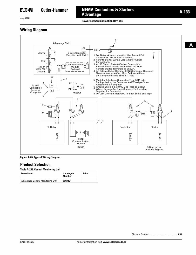
July 2008
CA08102002K For more information visit: www.EatonCanada.ca
A-133NEMA Contactors & Starters
A
AdvantagePowerNet Communication Devices
Wiring Diagram
Figure A-65. Typical Wiring Diagram
Product SelectionTable A-253. Central Monitoring Unit Description Catalogue
NumberPrice
Advantage Central Monitoring Unit WCMU
1. For Network Interconnection Use Twisted Pair Conductors. No. 18 AWG Shielded.2. Refer to Starter Wiring Diagrams for Actual Connections.3. A 150 Ohm (1/2 Watt) Carbon Composition Resistor Unit Must Be Installed on the Most Remote Starter Terminals as Shown.4. An Eaton‘s Cutler-Hammer CONI (Computer Operated Network Interface) Card Must Be Inserted into the Computer Frame. (See IL 17199)
5. Modular Telephone Connector. Type RJ11 is to Be Supplied by the Customer and Wired per View A Required at Computer.6. Ground Shielding at Only One Place as Shown.7. Where Devices Are Daisy Chained, Tie Shielding Together for Continuity.8. On Last Device in Network, Tie Back Shield and Tape.
Advantage CMU
Alarm
Trip
Ground
120 or240V AC
J5
J6
2 Wire Connector(Supplied with CMU)
CommunicationModule
(Optional)
To IBM Compatible
PersonalComputer
1J3
1
1
23
3
4
12
2
34
5
4
6
5
6
6
7
7 7
8
8
9
(Y)
(BL)
View A
OL Relay
PONICommunication
Module
IQ 500 3-Digit IncomAddress Register
Contactor Starter
RES
OFF
0 9 8002
001
Discount Symbol . . . . . . . . . . . . . . . . . . . . . . . . . . C40
Tab33.book Page 133 Sunday, September 21, 2008 10:27 PM
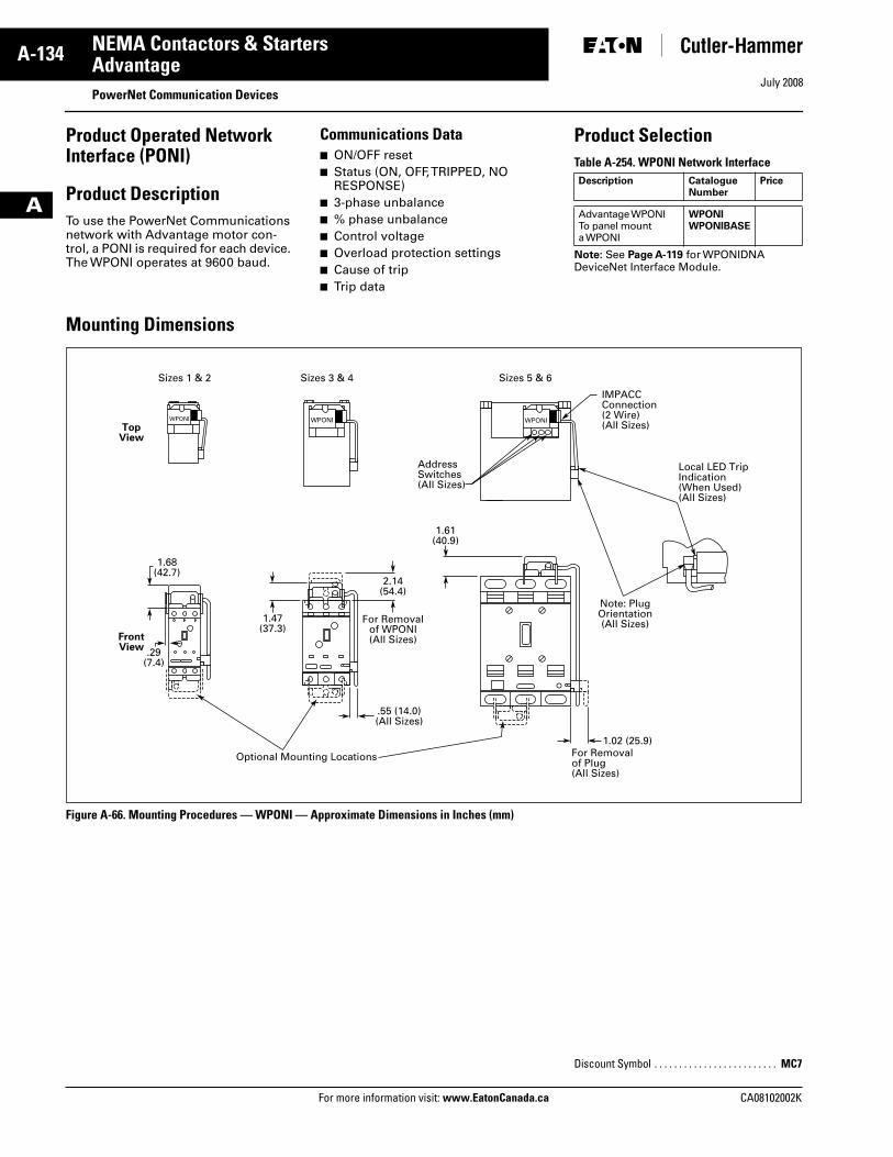
July 2008
A-134
For more information visit: www.EatonCanada.ca CA08102002K
NEMA Contactors & Starters
A
AdvantagePowerNet Communication Devices
Product Operated Network Interface (PONI)
Product DescriptionTo use the PowerNet Communications network with Advantage motor con-trol, a PONI is required for each device. The WPONI operates at 9600 baud.
Communications Data■ ON/OFF reset■ Status (ON, OFF, TRIPPED, NO
RESPONSE)■ 3-phase unbalance■ % phase unbalance■ Control voltage■ Overload protection settings■ Cause of trip■ Trip data
Product SelectionTable A-254. WPONI Network Interface
Note: See Page A-119 for WPONIDNA DeviceNet Interface Module.
Mounting Dimensions
Figure A-66. Mounting Procedures — WPONI — Approximate Dimensions in Inches (mm)
Description Catalogue Number
Price
Advantage WPONITo panel mount a WPONI
WPONIWPONIBASE
Sizes 1 & 2 Sizes 3 & 4 Sizes 5 & 6
1.68(42.7)
1.47(37.3)
2.14(54.4)
1.61(40.9)
.29(7.4)
1.02 (25.9)For Removalof Plug(All Sizes)
For Removalof WPONI(All Sizes)
.55 (14.0)(All Sizes)
Optional Mounting Locations
Local LED TripIndication(When Used)(All Sizes)
IMPACCConnection(2 Wire)(All Sizes)
Note: PlugOrientation(All Sizes)
TopView
FrontView
AddressSwitches(All Sizes)
WPONIWPONIWPONI
Discount Symbol . . . . . . . . . . . . . . . . . . . . . . . . . MC7
Tab33.book Page 134 Sunday, September 21, 2008 10:27 PM
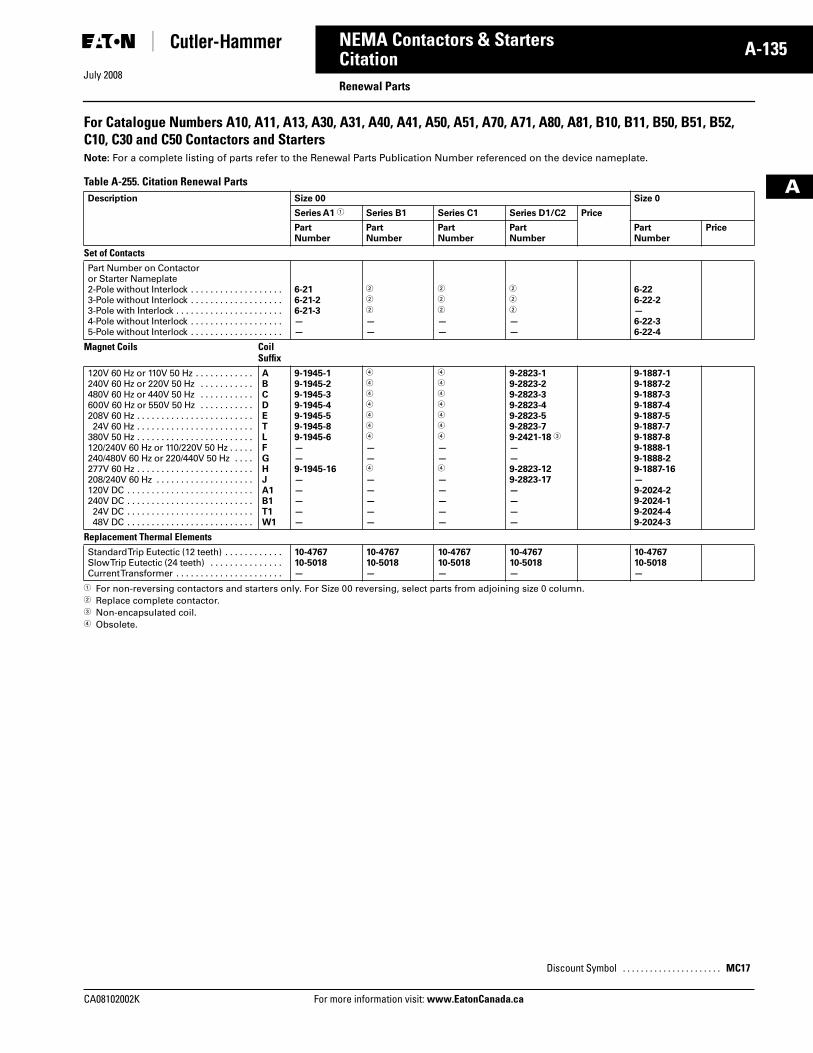
July 2008
CA08102002K For more information visit: www.EatonCanada.ca
A-135NEMA Contactors & Starters
A
Citation Renewal Parts
For Catalogue Numbers A10, A11, A13, A30, A31, A40, A41, A50, A51, A70, A71, A80, A81, B10, B11, B50, B51, B52, C10, C30 and C50 Contactors and StartersNote: For a complete listing of parts refer to the Renewal Parts Publication Number referenced on the device nameplate.
Table A-255. Citation Renewal Parts
� For non-reversing contactors and starters only. For Size 00 reversing, select parts from adjoining size 0 column.� Replace complete contactor. � Non-encapsulated coil.� Obsolete.
Description Size 00 Size 0
Series A1 � Series B1 Series C1 Series D1/C2 Price
Part Number
Part Number
Part Number
Part Number
Part Number
Price
Set of Contacts Part Number on Contactor or Starter Nameplate 2-Pole without Interlock . . . . . . . . . . . . . . . . . . . 3-Pole without Interlock . . . . . . . . . . . . . . . . . . . 3-Pole with Interlock . . . . . . . . . . . . . . . . . . . . . . 4-Pole without Interlock . . . . . . . . . . . . . . . . . . . 5-Pole without Interlock . . . . . . . . . . . . . . . . . . .
6-21 6-21-26-21-3——
�
�
�
——
�
�
�
——
�
�
�
——
6-226-22-2—6-22-36-22-4
Magnet Coils Coil Suffix
120V 60 Hz or 110V 50 Hz . . . . . . . . . . . .240V 60 Hz or 220V 50 Hz . . . . . . . . . . .480V 60 Hz or 440V 50 Hz . . . . . . . . . . .600V 60 Hz or 550V 50 Hz . . . . . . . . . . .208V 60 Hz . . . . . . . . . . . . . . . . . . . . . . . . 24V 60 Hz . . . . . . . . . . . . . . . . . . . . . . . .380V 50 Hz . . . . . . . . . . . . . . . . . . . . . . . .120/240V 60 Hz or 110/220V 50 Hz . . . . .240/480V 60 Hz or 220/440V 50 Hz . . . .277V 60 Hz . . . . . . . . . . . . . . . . . . . . . . . .208/240V 60 Hz . . . . . . . . . . . . . . . . . . . .120V DC . . . . . . . . . . . . . . . . . . . . . . . . . .240V DC . . . . . . . . . . . . . . . . . . . . . . . . . . 24V DC . . . . . . . . . . . . . . . . . . . . . . . . . . 48V DC . . . . . . . . . . . . . . . . . . . . . . . . . .
ABCDETLFGHJA1B1T1W1
9-1945-19-1945-29-1945-39-1945-49-1945-59-1945-89-1945-6——9-1945-16—————
�
�
�
�
�
�
�
——�
—————
�
�
�
�
�
�
�
——�
—————
9-2823-19-2823-29-2823-39-2823-49-2823-59-2823-79-2421-18 �
——9-2823-129-2823-17————
9-1887-19-1887-29-1887-39-1887-49-1887-59-1887-79-1887-89-1888-19-1888-29-1887-16—9-2024-29-2024-19-2024-49-2024-3
Replacement Thermal Elements Standard Trip Eutectic (12 teeth) . . . . . . . . . . . . Slow Trip Eutectic (24 teeth) . . . . . . . . . . . . . . . Current Transformer . . . . . . . . . . . . . . . . . . . . . .
10-476710-5018—
10-476710-5018—
10-476710-5018—
10-476710-5018—
10-476710-5018—
Discount Symbol . . . . . . . . . . . . . . . . . . . . . . MC17
Tab33.book Page 135 Sunday, September 21, 2008 10:27 PM
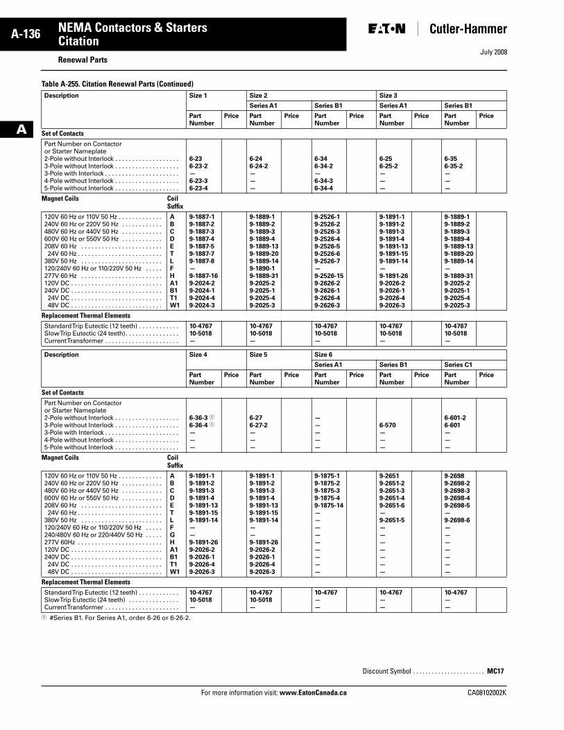
July 2008
A-136
For more information visit: www.EatonCanada.ca CA08102002K
NEMA Contactors & Starters
A
CitationRenewal Parts
Table A-255. Citation Renewal Parts (Continued)
� #Series B1. For Series A1, order 6-26 or 6-26-2.
Description Size 1 Size 2 Size 3
Series A1 Series B1 Series A1 Series B1
Part Number
Price Part Number
Price Part Number
Price Part Number
Price Part Number
Price
Set of Contacts Part Number on Contactor or Starter Nameplate 2-Pole without Interlock . . . . . . . . . . . . . . . . . . . 3-Pole without Interlock . . . . . . . . . . . . . . . . . . . 3-Pole with Interlock . . . . . . . . . . . . . . . . . . . . . . 4-Pole without Interlock . . . . . . . . . . . . . . . . . . . 5-Pole without Interlock . . . . . . . . . . . . . . . . . . .
6-236-23-2—6-23-36-23-4
6-246-24-2———
6-346-34-2—6-34-36-34-4
6-256-25-2———
6-356-35-2———
Magnet Coils Coil Suffix
120V 60 Hz or 110V 50 Hz . . . . . . . . . . . . .240V 60 Hz or 220V 50 Hz . . . . . . . . . . . .480V 60 Hz or 440V 50 Hz . . . . . . . . . . . .600V 60 Hz or 550V 50 Hz . . . . . . . . . . . .208V 60 Hz . . . . . . . . . . . . . . . . . . . . . . . . 24V 60 Hz . . . . . . . . . . . . . . . . . . . . . . . . .380V 50 Hz . . . . . . . . . . . . . . . . . . . . . . . .120/240V 60 Hz or 110/220V 50 Hz . . . . .277V 60 Hz . . . . . . . . . . . . . . . . . . . . . . . .120V DC . . . . . . . . . . . . . . . . . . . . . . . . . . .240V DC . . . . . . . . . . . . . . . . . . . . . . . . . . . 24V DC . . . . . . . . . . . . . . . . . . . . . . . . . . . 48V DC . . . . . . . . . . . . . . . . . . . . . . . . . . .
ABCDETLFHA1B1T1W1
9-1887-19-1887-29-1887-39-1887-49-1887-59-1887-79-1887-8—9-1887-169-2024-29-2024-19-2024-49-2024-3
9-1889-19-1889-29-1889-39-1889-49-1889-139-1889-209-1889-149-1890-19-1889-319-2025-29-2025-19-2025-49-2025-3
9-2526-19-2526-29-2526-39-2526-49-2526-59-2526-69-2526-7—9-2526-159-2626-29-2626-19-2626-49-2626-3
9-1891-19-1891-29-1891-39-1891-49-1891-139-1891-159-1891-14—9-1891-269-2026-29-2026-19-2026-49-2026-3
9-1889-19-1889-29-1889-39-1889-49-1889-139-1889-209-1889-14—9-1889-319-2025-29-2025-19-2025-49-2025-3
Replacement Thermal Elements Standard Trip Eutectic (12 teeth) . . . . . . . . . . . . Slow Trip Eutectic (24 teeth). . . . . . . . . . . . . . . . Current Transformer . . . . . . . . . . . . . . . . . . . . . .
10-476710-5018—
10-476710-5018—
10-476710-5018—
10-476710-5018—
10-476710-5018—
Description Size 4 Size 5 Size 6
Series A1 Series B1 Series C1
Part Number
Price Part Number
Price Part Number
Price Part Number
Price Part Number
Price
Set of Contacts Part Number on Contactor or Starter Nameplate 2-Pole without Interlock . . . . . . . . . . . . . . . . . . . 3-Pole without Interlock . . . . . . . . . . . . . . . . . . . 3-Pole with Interlock . . . . . . . . . . . . . . . . . . . . . . 4-Pole without Interlock . . . . . . . . . . . . . . . . . . . 5-Pole without Interlock . . . . . . . . . . . . . . . . . . .
6-36-3 �
6-36-4 �
———
6-276-27-2———
—————
6-570———
6-601-26-601———
Magnet Coils Coil Suffix
120V 60 Hz or 110V 50 Hz . . . . . . . . . . . . .240V 60 Hz or 220V 50 Hz . . . . . . . . . . . .480V 60 Hz or 440V 50 Hz . . . . . . . . . . . .600V 60 Hz or 550V 50 Hz . . . . . . . . . . . .208V 60 Hz . . . . . . . . . . . . . . . . . . . . . . . . 24V 60 Hz . . . . . . . . . . . . . . . . . . . . . . . . .380V 50 Hz . . . . . . . . . . . . . . . . . . . . . . . .120/240V 60 Hz or 110/220V 50 Hz . . . . .240/480V 60 Hz or 220/440V 50 Hz . . . . .277V 60Hz . . . . . . . . . . . . . . . . . . . . . . . . .120V DC . . . . . . . . . . . . . . . . . . . . . . . . . . .240V DC . . . . . . . . . . . . . . . . . . . . . . . . . . . 24V DC . . . . . . . . . . . . . . . . . . . . . . . . . . . 48V DC . . . . . . . . . . . . . . . . . . . . . . . . . . .
ABCDETLFGHA1B1T1W1
9-1891-19-1891-29-1891-39-1891-49-1891-139-1891-159-1891-14——9-1891-269-2026-29-2026-19-2026-49-2026-3
9-1891-19-1891-29-1891-39-1891-49-1891-139-1891-159-1891-14——9-1891-269-2026-29-2026-19-2026-49-2026-3
9-1875-19-1875-29-1875-39-1875-49-1875-14—————————
9-26519-2651-29-2651-39-2651-49-2651-6—9-2651-5———————
9-26989-2698-29-2698-39-2698-49-2698-5—9-2698-6———————
Replacement Thermal Elements Standard Trip Eutectic (12 teeth) . . . . . . . . . . . . Slow Trip Eutectic (24 teeth) . . . . . . . . . . . . . . . Current Transformer . . . . . . . . . . . . . . . . . . . . . .
10-476710-5018—
10-476710-5018—
10-4767——
10-4767——
10-4767——
Discount Symbol . . . . . . . . . . . . . . . . . . . . . . . MC17
Tab33.book Page 136 Sunday, September 21, 2008 10:27 PM
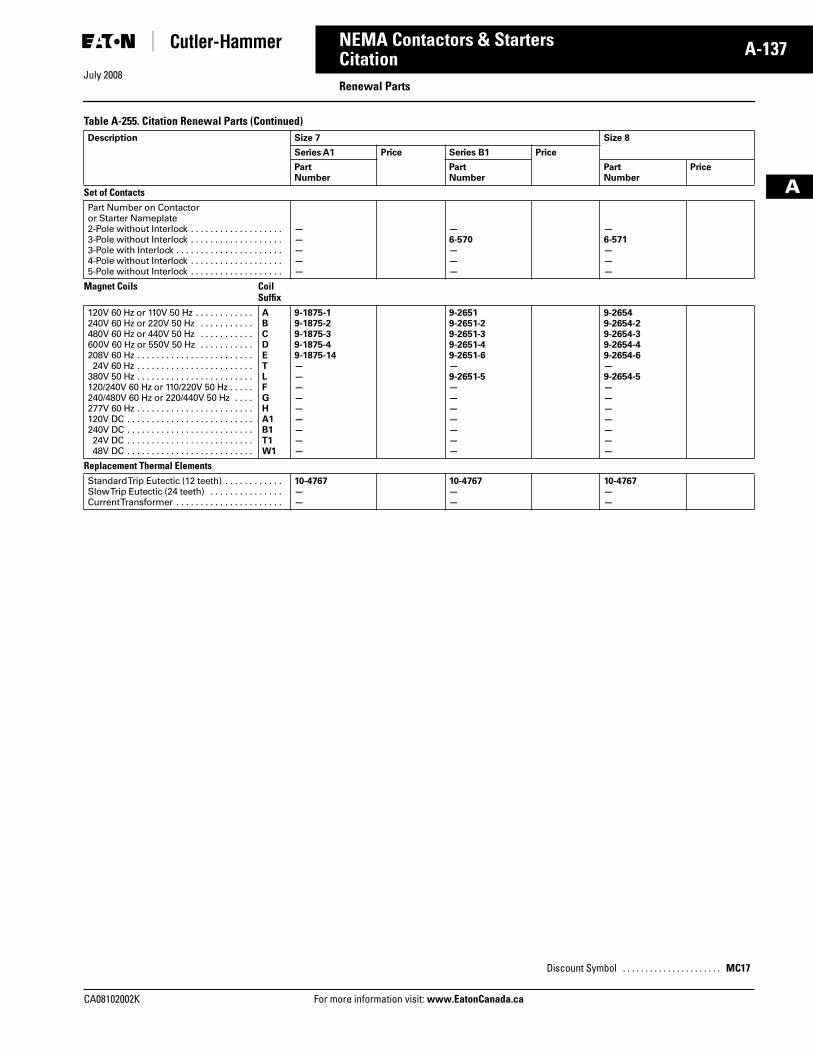
July 2008
CA08102002K For more information visit: www.EatonCanada.ca
A-137NEMA Contactors & Starters
A
CitationRenewal Parts
Table A-255. Citation Renewal Parts (Continued)Description Size 7 Size 8
Series A1 Price Series B1 Price
Part Number
Part Number
Part Number
Price
Set of Contacts Part Number on Contactor or Starter Nameplate 2-Pole without Interlock . . . . . . . . . . . . . . . . . . . 3-Pole without Interlock . . . . . . . . . . . . . . . . . . . 3-Pole with Interlock . . . . . . . . . . . . . . . . . . . . . . 4-Pole without Interlock . . . . . . . . . . . . . . . . . . . 5-Pole without Interlock . . . . . . . . . . . . . . . . . . .
—————
—6-570———
—6-571———
Magnet Coils Coil Suffix
120V 60 Hz or 110V 50 Hz . . . . . . . . . . . .240V 60 Hz or 220V 50 Hz . . . . . . . . . . .480V 60 Hz or 440V 50 Hz . . . . . . . . . . .600V 60 Hz or 550V 50 Hz . . . . . . . . . . .208V 60 Hz . . . . . . . . . . . . . . . . . . . . . . . . 24V 60 Hz . . . . . . . . . . . . . . . . . . . . . . . .380V 50 Hz . . . . . . . . . . . . . . . . . . . . . . . .120/240V 60 Hz or 110/220V 50 Hz . . . . .240/480V 60 Hz or 220/440V 50 Hz . . . .277V 60 Hz . . . . . . . . . . . . . . . . . . . . . . . .120V DC . . . . . . . . . . . . . . . . . . . . . . . . . .240V DC . . . . . . . . . . . . . . . . . . . . . . . . . . 24V DC . . . . . . . . . . . . . . . . . . . . . . . . . . 48V DC . . . . . . . . . . . . . . . . . . . . . . . . . .
ABCDETLFGHA1B1T1W1
9-1875-19-1875-29-1875-39-1875-49-1875-14—————————
9-26519-2651-29-2651-39-2651-49-2651-6—9-2651-5———————
9-26549-2654-29-2654-39-2654-49-2654-6—9-2654-5———————
Replacement Thermal Elements Standard Trip Eutectic (12 teeth) . . . . . . . . . . . . Slow Trip Eutectic (24 teeth) . . . . . . . . . . . . . . . Current Transformer . . . . . . . . . . . . . . . . . . . . . .
10-4767——
10-4767——
10-4767——
Discount Symbol . . . . . . . . . . . . . . . . . . . . . . MC17
Tab33.book Page 137 Sunday, September 21, 2008 10:27 PM
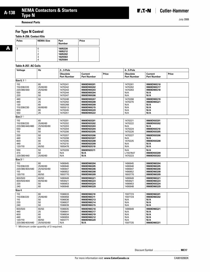
July 2008
A-138
For more information visit: www.EatonCanada.ca CA08102002K
NEMA Contactors & Starters
A
Type NRenewal Parts
For Type N ControlTable A-256. Contact Kits
Table A-257. AC Coils
� Minimum order quantity of 3 required.
Poles NEMA Size Part Number
Price
3 0123 4
16052261605212160520216255631625564
Voltage Hz 2-, 3-Pole 4-, 5-Pole
Obsolete Part Number
CurrentPart Number
Price Obsolete Part Number
CurrentPart Number
Price
Size 0, 1 �
110110/208/220220/380/440550220
6025/60/6025/50/606050
14702411470242147024314702441470247
9969D90G019969D90G029969D90G039969D90G049969D90G06
147026114702621470263N/AN/A
9969D90G169969D90G179969D90G18N/AN/A
440440120115/208/230600550
50256060/60/606025
147024814702501605268160551314702451470251
9969D90G079969D90G089969D90G099969D90G159969D90G209969D90G22
14702681470270N/AN/AN/AN/A
9969D90G199969D90G21N/AN/AN/AN/A
Size 2 �
110110/208/220220/380/440/480550110
6025/60/6025/50/60/606050
14702011470202147020314702041470206
9969D92G019969D92G029969D92G039969D92G049969D92G05
14702211470222N/A14702241470226
9969D93G019969D93G02N/A9969D93G109969D93G05
220440600440120/110
5050602560/50
14702071470208147020514702101605478
9969D92G069969D92G079969D92G089969D92G099969D92G10
1470227N/A1470225N/AN/A
9969D93G06N/A9969D93G08N/AN/A
550415220/380/440
505025/60/60
1470209N/AN/A
9969D92G11N/AN/A
N/AL15576471470223
N/A9969D93G099969D93G03
Size 3 �
110110/208/220220/380/400/440110120/110
6025/60/6025/50/50/605060/50
14906451490646149064714906521600770
9969D96G049969D96G059969D96G069969D96G089969D96G09
14906451490646149064714906521600770
9969D96G049969D96G059969D96G069969D96G089969D96G09
600/500600/500/400220240
60/5060/50/405060
1490649165942114906531490648
9969D96G219969D96G239969D93G249969D96G29
1490649165942114906531490648
9969D96G219969D96G239969D93G249969D96G29
Size 4110110/208/220110220240
6025/60/60505050
15966331490658159663615966371596639
9969D96G109969D96G119969D96G139969D96G149969D96G15
15977231597724N/AN/AN/A
9969D96G019969D96G02N/AN/AN/A
600/500440600440120/110220/380/400/440
60/5025606060/5025/50/50/60
15966351596641159663414906591600771N/A
9969D96G169969D96G179969D96G199969D96G129969D96G20N/A
1490649N/AN/AN/AN/A1597725
9969D96G21N/AN/AN/AN/A9969D96G31
Discount Symbol . . . . . . . . . . . . . . . . . . . . . . . MC17
Tab33.book Page 138 Sunday, September 21, 2008 10:27 PM
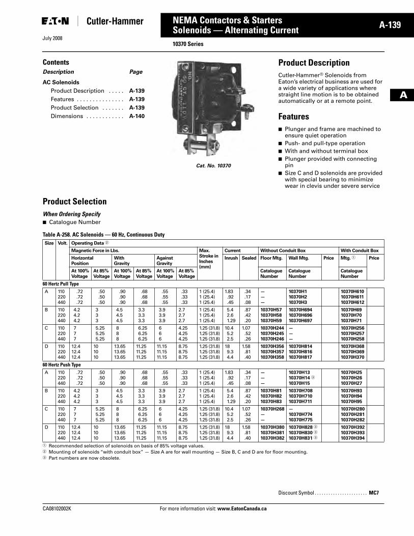
July 2008
CA08102002K For more information visit: www.EatonCanada.ca
A-139NEMA Contactors & Starters
A
Solenoids — Alternating Current10370 Series
ContentsDescription Page
AC Solenoids
Product Description . . . . . A-139
Features . . . . . . . . . . . . . . . A-139
Product Selection . . . . . . . A-139
Dimensions . . . . . . . . . . . . A-140
Cat. No. 10370
Product DescriptionCutler-Hammer® Solenoids from Eaton’s electrical business are used for a wide variety of applications where straight line motion is to be obtained automatically or at a remote point.
Features■ Plunger and frame are machined to
ensure quiet operation■ Push- and pull-type operation■ With and without terminal box■ Plunger provided with connecting
pin■ Size C and D solenoids are provided
with special bearing to minimize wear in clevis under severe service
Product SelectionWhen Ordering Specify■ Catalogue Number
Table A-258. AC Solenoids — 60 Hz, Continuous Duty
� Recommended selection of solenoids on basis of 85% voltage values.� Mounting of solenoids “with conduit box” — Size A are for wall mounting — Size B, C and D are for floor mounting.� Part numbers are now obsolete.
Size Volt. Operating Data �
Magnetic Force in Lbs. Max.Stroke inInches(mm)
Current Without Conduit Box With Conduit Box
HorizontalPosition
With Gravity
AgainstGravity
Inrush Sealed Floor Mtg. Wall Mtg. Price Mtg. � Price
At 100%Voltage
At 85%Voltage
At 100%Voltage
At 85%Voltage
At 100%Voltage
At 85%Voltage
CatalogueNumber
CatalogueNumber
CatalogueNumber
60 Hertz Pull TypeA 110
220440
.72
.72
.72
.50
.50
.50
.90
.90
.90
.68
.68
.68
.55
.55
.55
.33
.33
.33
1 (25.4)1 (25.4)1 (25.4)
1.83.92.45
.34
.17
.08
———
10370H110370H210370H3
10370H61010370H61110370H612
B 110220440
4.24.24.2
333
4.54.54.5
3.33.33.3
3.93.93.9
2.72.72.7
1 (25.4)1 (25.4)1 (25.4)
5.42.61.29
.87
.42
.20
10370H5710370H5810370H59
10370H69410370H69610370H697
10370H6910370H7010370H71
C 110220440
777
5.255.255.25
888
6.256.256.25
666
4.254.254.25
1.25 (31.8)1.25 (31.8)1.25 (31.8)
10.45.22.5
1.07.52.26
10370H24410370H24510370H246
———
10370H25610370H25710370H258
D 110220440
12.412.412.4
101010
13.6513.6513.65
11.2511.2511.25
11.1511.1511.15
8.758.758.75
1.25 (31.8)1.25 (31.8)1.25 (31.8)
189.34.4
1.58.81.40
10370H35610370H35710370H358
10370H81410370H81610370H817
10370H36810370H36910370H370
60 Hertz Push TypeA 110
220440
.72
.72
.72
.50
.50
.50
.90
.90
.90
.68
.68
.68
.55
.55
.55
.33
.33
.33
1 (25.4)1 (25.4)1 (25.4)
1.83.92.45
.34
.17
.08
———
10370H1310370H14 �
10370H15
10370H2510370H2610370H27
B 110220440
4.24.24.2
333
4.54.54.5
3.33.33.3
3.93.93.9
2.72.72.7
1 (25.4)1 (25.4)1 (25.4)
5.42.61.29
.87
.42
.20
10370H8110370H8210370H83
10370H70810370H71010370H711
10370H9310370H9410370H95
C 110220440
777
5.255.255.25
888
6.256.256.25
666
4.254.254.25
1.25 (31.8)1.25 (31.8)1.25 (31.8)
10.45.22.5
1.07.52.26
10370H268——
—10370H77410370H775
10370H28010370H28110370H282
D 110220440
12.412.412.4
101010
13.6513.6513.65
11.2511.2511.25
11.1511.1511.15
8.758.758.75
1.25 (31.8)1.25 (31.8)1.25 (31.8)
189.34.4
1.58.81.40
10370H38010370H38110370H382
10370H828 �
10370H830 �
10370H831 �
10370H39210370H39310370H394
Discount Symbol . . . . . . . . . . . . . . . . . . . . . . . MC7
Tab33.book Page 139 Sunday, September 21, 2008 10:27 PM
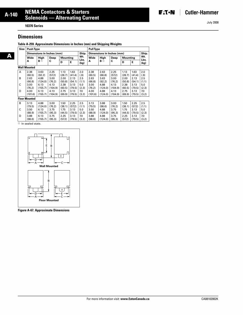
July 2008
A-140
For more information visit: www.EatonCanada.ca CA08102002K
NEMA Contactors & Starters
A
Solenoids — Alternating Current10370 Series
DimensionsTable A-259. Approximate Dimensions in Inches (mm) and Shipping Weights
� In sealed state.
Figure A-67. Approximate Dimensions
Size Push Type Pull Type
Dimensions in Inches (mm) Ship.Wt.Lbs.(kg)
Dimensions in Inches (mm) Ship.Wt.Lbs.(kg)
WideA
HighB �
DeepC
Mounting WideA
HighB �
DeepC
Mounting
D E D E
Wall MountedA
B
C
D
2.38(60.5)2.63(66.8)3.00(76.2)4.00(101.6)
3.63(92.2)4.88(124.0)6.13(155.7)6.13(155.7)
2.25(57.2)3.00(76.2)4.13(104.9)4.13(104.9)
1.13(28.7)2.00(50.8)2.38(60.5)2.75(69.9)
1.63(41.4)2.13(54.1)3.13(79.5)3.13(79.5)
2.0(.9)2.5(1.1)5.0(2.3)7.0(3.2)
2.38(60.5)2.63(66.8)3.00(76.2)4.00(101.6)
2.63(66.8)3.63(92.2)4.88(124.0)4.88(124.0)
2.25(57.2)3.00(76.2)4.13(104.9)4.13(104.9)
1.13(28.7)2.00(50.8)2.38(60.5)2.75(69.9)
1.63(41.4)2.13(54.1)3.13(79.5)3.13(79.5)
2.0(.9)2.5(1.1)5.0(2.3)7.0(3.2)
Floor MountedB
C
D
3.13(79.5)3.50(88.9)3.88(98.6)
4.88(124.0)6.13(155.7)6.13(155.7)
3.00(76.2)3.75(95.3)3.75(95.3)
1.50(38.1)1.75(44.5)2.25(57.2)
2.25(57.2)3.13(79.5)3.13(79.5)
2.5(1.1)5.0(2.3)7.0(3.2)
3.13(79.5)3.50(88.9)3.88(98.6)
3.88(98.6)4.88(124.0)4.88(124.0)
3.00(76.2)3.75(95.3)3.75(95.3)
1.50(38.1)1.75(44.5)2.25(57.2)
2.25(57.2)3.13(79.5)3.13(79.5)
2.5(1.1)5.0(2.3)7.0(3.2)
DA
B
DA
EC
C
E
B
Wall Mounted
Floor Mounted
Tab33.book Page 140 Sunday, September 21, 2008 10:27 PM
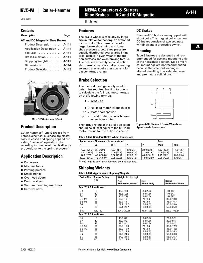
July 2008
CA08102002K For more information visit: www.EatonCanada.ca
A-141NEMA Contactors & Starters
A
Shoe Brakes — AC and DC Magnetic511 Series
ContentsDescription Page
AC and DC Magnetic Shoe Brakes
Product Description . . . . . A-141
Application Description . . . A-141
Features . . . . . . . . . . . . . . . A-141
Brake Selection . . . . . . . . . A-141
Shipping Weights . . . . . . . . A-141
Dimensions . . . . . . . . . . . . A-144
Product Selection . . . . . . . . A-142
Size S-7 Brake and Wheel
Product DescriptionCutler-Hammer® Type S Brakes from Eaton’s electrical business are electri-cally released and spring applied pro-viding “fail-safe” operation. The retarding torque developed is directly proportional to the spring pressure.
Application Description■ Conveyors■ Machine tools■ Printing presses■ Small cranes■ Overhead doors■ Dumb waiters■ Vacuum moulding machines■ Carnival rides
FeaturesThe brake wheel is of relatively large size in relation to the torque developed by the brake. This permits use of a larger brake shoe lining and lower shoe pressures. Low shoe pressure, equally distributed over a large lining area, results in even wear of the fric-tion surfaces and even braking torque. The oversize wheel type construction also permits use of a smaller operating solenoid that requires less current for a given torque rating.
DC BrakesStandard DC brakes are equipped with shunt coils. The magnet coil circuit on DC brakes consists of two separate windings and a protective switch.
MountingType S brakes are designed and rec-ommended for use and mounting only in the horizontal position. Side or verti-cal mountings are not recommended because the solenoid loading is altered, resulting in accelerated wear and premature coil failure.
Brake SelectionThe method most generally used to determine required braking torque is to calculate the full load motor torque by the following formula:
The torque rating of the brake selected should be at least equal to the full load motor torque for the duty considered.
Figure A-68. Standard Brake Wheels — Approximate Dimensions
Table A-260. Standard Brake Wheel Dimensions
� Hub lengths other than standard are not available.
Shipping WeightsTable A-261. Approximate Shipping Weights
T = 5252 x hprpm
T = Full load motor torque in lb-fthp = Motor horsepower
rpm = Speed of shaft on which brake wheel is mounted W
Z
X
A Y
Approximate Dimensions in Inches (mm) Bore
A Z W � X Y Max. Min.
4.00 (101.6)5.50 (139.7)7.00 (177.8)
10.00 (254.0)
2.75 (69.9)3.25 (82.6)4.25 (108.0)4.25 (108.0)
1.63 (41.4)2.00 (50.8)3.00 (76.2)3.25 (82.6)
1.38 (35.1)1.63 (41.4)1.25 (31.8)1.25 (31.8)
2.50 (63.5)3.25 (82.6)4.00 (101.6)4.88 (124.0)
1.38 (35.1)2.00 (50.8)2.25 (57.2)2.88 (73.2)
.50 (12.7)
.75 (19.1)1.00 (25.4)1.38 (35.1)
Brake Size Torque Ratingft-lb
Weight in Lbs. (kg)
Net —Brake with Wheel
Net —Wheel Only
Boxed —Brake with Wheel
Type “S” AC Shoe BrakesS-4S-4S-4S-5-1/2S-5-1/2S-7S-7
3101525355075
15.8 (7.2)15.8 (7.2)15.8 (7.2)33.2 (15.1)33.2 (15.1)52.1 (23.7)52.1 (23.7)
3.4 (1.5)3.4 (1.5)3.4 (1.5)7.5 (3.4)7.5 (3.4)
18.8 (8.5)18.8 (8.5)
17.0 (7.7)17.0 (7.7)17.0 (7.7)36.0 (16.3)36.0 (16.3)55.0 (25.0)55.0 (25.0)
S-10 125, 160 200.0 (90.8) 38.5 (17.3) 225.0 (102.2)
Type “S” DC Shoe BrakesS-4S-4S-4S-5-1/2S-5-1/2S-7S-7S-7S-7
310152535507585
110
18.0 (8.2)18.0 (8.2)18.0 (8.2)35.0 (15.9)35.0 (15.9)54.0 (24.5)54.0 (24.5)54.0 (24.5)54.0 (24.5)
3.4 (1.5)3.4 (1.5)3.4 (1.5)7.5 (3.4)7.5 (3.4)
18.8 (8.5)18.8 (8.5)18.8 (8.5)18.8 (8.5)
20.0 (9.1)20.0 (9.1)20.0 (9.1)38.0 (17.3)38.0 (17.3)58.0 (26.3)58.0 (26.3)58.0 (26.3)58.0 (26.3)
Tab33.book Page 141 Sunday, September 21, 2008 10:27 PM
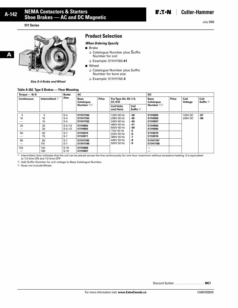
July 2008
A-142
For more information visit: www.EatonCanada.ca CA08102002K
NEMA Contactors & Starters
A
Shoe Brakes — AC and DC Magnetic511 Series
Size S-4 Brake and Wheel
Product SelectionWhen Ordering Specify■ Brake
❑ Catalogue Number plus Suffix Number for coil
❑ Example: 511H1193-41
■ Wheel❑ Catalogue Number plus Suffix
Number for bore size❑ Example: 511H1150-3
Table A-262. Type S Brakes — Floor Mounting
� Intermittent duty indicates that the coil can be placed across the line continuously for one hour maximum without excessive heating. It is equivalent to 1/2 time ON and 1/2 time OFF.
� Add Suffix Number for coil voltage to Base Catalogue Number.� Does not include Wheel.
Torque — lb-ft BrakeSize
AC DC
Continuous Intermittent � BaseCatalogueNumber ��
Price For Type S4, S5-1/2, S7, S10
BaseCatalogueNumber ��
Price CoilVoltage
Coil Suffix �
Coil Voltsand Hertz
CoilSuffix �
310—
31015
S-4S-4S-4
511H1194511H1193511H1192
120V 60 Hz208V 60 Hz240V 60 Hz480V 60 Hz600V 60 Hz110V 50 Hz220V 50 Hz380V 50 Hz440V 50 Hz550V 50 Hz
-39-45-40-41-58-5-6-7-8-9
511H955511H956511H957
120V DC240V DC
-97-98
25—
2535
S-5-1/2S-5-1/2
511H992511H993
511H994511H995
50—
5075
S-7S-7
511H970511H971
511H975511H976
85—
85110
S-7S-7
511H1195511H1196
511H1197511H1198
125—
125160
S-10S-10
511H996511H997
——
Discount Symbol . . . . . . . . . . . . . . . . . . . . . . . MC7
Tab33.book Page 142 Sunday, September 21, 2008 10:27 PM
July 2008
CA08102002K For more information visit: www.EatonCanada.ca
A-143NEMA Contactors & Starters
A
Shoe Brakes — AC and DC Magnetic511 Series
Table A-263. Brake Wheels
� Taper is at rate of 1.25 inches per foot on diameter. In bore size selection, use diameter of tapered shaft. Bore tolerance: +.000 -.005 inches.� Add Suffix Number for bore size to Base catalogue Number.� Bore tolerance: +.000 -.001 inches.
Table A-264. Brake Wheel Suffix Numbers
� Bore size selected must be between minimum and maximum dimensions listed in brake wheel selection table.� Price Additions
Wheel Sizein Inches
Min.Bore inInches (mm)
Max.Bore in Inches (mm)
PilotBore inInches (mm)
WK2 Straight Bore � Tapered Bore �
Base �
Catalogue Number
FinishedBore
PilotBore Only
Base �
Catalogue Number
FinishedBore
PilotBore Only
Price Price Price Price
4.0 .50 (12.7) 1.38 (35.1) .50 (12.7) .06 511H1150 511H1151
5.5 .75 (19.1) 2.00 (50.8) .75 (19.1) .26 511H1160 511H1161
7.0 1.00 (25.4) 2.25 (57.2) .75 (19.1) .77 511H1170 511H1171
10.0 1.38 (35.1) 2.88 (73.2) 1.13 (28.7) 3.10 511H1190 511H1191
Bore Size Suffix Number — Add to Base Catalogue Number
Bore � in Inches (mm) Keyway in Inches Suffix Number Bore � in Inches (mm) Keyway in Inches (mm) Suffix Number
Standard Bore Sizes — No Price Addition Pilot Bore.625 (15.88).750 (19.05).875 (22.23)
None3/16 x 3/323/16 x 3/323/16 x 3/32
-1-2-3-4
1.625 (41.28)1.875 (47.63)2.125 (53.98)2.375 (60.33)
3/38 x 3/16 1/2 x 1/4 1/2 x 1/4 5/8 x 5/16
-9-10-11-12
1.000 (25.40)1.125 (28.58)1.250 (31.75)1.375 (34.93)
1/4 x 1/81/4 x 1/81/4 x 1/8
5/16 x 5/32
-5-6-7-8
2.500 (63.50)2.625 (66.68)2.750 (69.85)2.875 (73.03)
5/8 x 5/16 5/8 x 5/16 5/8 x 5/16 3/4 x 3/8
-63-13-18-14
Non-standard Bore Sizes — Make Necessary Price Addition �
.500 (12.70)
.750 (19.05)
.875 (22.23)1.000 (25.40)
1/8 x 1/161/4 x 1/81/4 x 1/8
5/16 x 5/32
-50-51-52-53
1.687 (42.85)1.750 (44.45)1.937 (49.20)2.000 (50.80)
3/8 x 3/16 3/8 x 3/16 1/2 x 1/4 1/2 x 1/4
-58-59-60-61
1.187 (30.15)1.375 (34.93)1.437 (36.50)1.500 (38.10)
1/4 x 1/83/8 x 3/163/8 x 3/163/8 x 3/16
-54-55-56-57
2.250 (57.15)———
1/2 x 1/4 — ——
-62———
Description Adder
4.0 Inch (101.6 mm)5.5 Inch (139.7 mm)7.0 Inch (177.8 mm)
10.0 Inch (254.0 mm)
Discount Symbol . . . . . . . . . . . . . . . . . . . . . . . MC7
Tab33.book Page 143 Sunday, September 21, 2008 10:27 PM
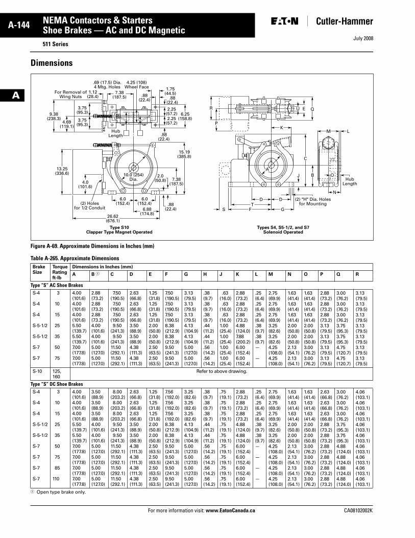
July 2008
A-144
For more information visit: www.EatonCanada.ca CA08102002K
NEMA Contactors & Starters
A
Shoe Brakes — AC and DC Magnetic511 Series
Dimensions
Figure A-69. Approximate Dimensions in Inches (mm)
Table A-265. Approximate Dimensions
� Open type brake only.
BrakeSize
TorqueRatingft-lb
Dimensions in Inches (mm)
A B � C D E F G H J K L M N O P Q R
Type “S” AC Shoe BrakesS-4
S-4
S-4
S-5-1/2
S-5-1/2
S-7
S-7
3
10
15
25
35
50
75
4.00(101.6)4.00(101.6)4.00(101.6)5.50(139.7)5.50(139.7)7.00(177.8)7.00(177.8)
2.88(73.2)2.88(73.2)2.88(73.2)4.00(101.6)4.00(101.6)5.00(127.0)5.00(127.0)
7.50(190.5)7.50
(190.5)7.50
(190.5)9.50
(241.3)9.50
(241.3)11.50(292.1)11.50(292.1)
2.63(66.8)2.63(66.8)2.63(66.8)3.50(88.9)3.50(88.9)4.38(111.3)4.38(111.3)
1.25(31.8)1.25(31.8)1.25(31.8)2.00(50.8)2.00(50.8)2.50(63.5)2.50(63.5)
7.50(190.5)7.50(190.5)7.50(190.5)8.38(212.9)8.38(212.9)9.50(241.3)9.50(241.3)
3.13(79.5)3.13(79.5)3.13(79.5)4.13(104.9)4.13(104.9)5.00(127.0)5.00(127.0)
.38(9.7).38(9.7).38(9.7).44(11.2).44(11.2).56(14.2).56(14.2)
.63(16.0).63
(16.0).63
(16.0)1.00(25.4)1.00(25.4)1.00(25.4)1.00(25.4)
2.88(73.2)2.88(73.2)2.88(73.2)4.88(124.0)7.88(200.2)6.00(152.4)6.00(152.4)
.25(6.4).25(6.4).25(6.4).38(9.7).38(9.7)—
—
2.75(69.9)2.75(69.9)2.75(69.9)3.25(82.6)3.25(82.6)4.25(108.0)4.25(108.0)
1.63(41.4)1.63(41.4)1.63(41.4)2.00(50.8)2.00(50.8)2.13(54.1)2.13(54.1)
1.63(41.4)1.63(41.4)1.63(41.4)2.00(50.8)2.00(50.8)3.00(76.2)3.00(76.2)
2.88(73.2)2.88(73.2)2.88(73.2)3.13(79.5)3.13(79.5)3.13(79.5)3.13(79.5)
3.00(76.2)3.00(76.2)3.00(76.2)3.75(95.3)3.75(95.3)4.75(120.7)4.75(120.7)
3.13(79.5)3.13(79.5)3.13(79.5)3.13(79.5)3.13(79.5)3.13(79.5)3.13(79.5)
S-10 125,160
Refer to above drawing.
Type “S” DC Shoe BrakesS-4
S-4
S-4
S-5-1/2
S-5-1/2
S-7
S-7
S-7
S-7
3
10
15
25
35
50
75
85
110
4.00(101.6)4.00(101.6)4.00(101.6)5.50(139.7)5.50(139.7)7.00(177.8)7.00(177.8)7.00(177.8)7.00(177.8)
3.50(88.9)3.50(88.9)3.50(88.9)4.00(101.6)4.00(101.6)5.00(127.0)5.00(127.0)5.00(127.0)5.00(127.0)
8.00(203.2)8.00
(203.2)8.00
(203.2)9.50
(241.3)9.50
(241.3)11.50(292.1)11.50(292.1)11.50(292.1)11.50(292.1)
2.63(66.8)2.63(66.8)2.63(66.8)3.50(88.9)3.50(88.9)4.38(111.3)4.38(111.3)4.38(111.3)4.38(111.3)
1.25(31.8)1.25(31.8)1.25(31.8)2.00(50.8)2.00(50.8)2.50(63.5)2.50(63.5)2.50(63.5)2.50(63.5)
7.56(192.0)7.56(192.0)7.56(192.0)8.38(212.9)8.38(212.9)9.50(241.3)9.50(241.3)9.50(241.3)9.50(241.3)
3.25(82.6)3.25(82.6)3.25(82.6)4.13(104.9)4.13(104.9)5.00(127.0)5.00(127.0)5.00(127.0)5.00(127.0)
.38(9.7).38(9.7).38(9.7).44(11.2).44(11.2).56(14.2).56(14.2).56(14.2).56(14.2)
.75(19.1).75(19.1).75(19.1).75(19.1).75(19.1).75(19.1).75(19.1).75(19.1).75(19.1)
2.88(73.2)2.88(73.2)2.88(73.2)4.88(124.0)4.88(124.0)6.00(152.4)6.00(152.4)6.00(152.4)6.00(152.4)
.25(6.4).25(6.4).25(6.4).38(9.7).38(9.7)—
—
—
—
2.75(69.9)2.75(69.9)2.75(69.9)3.25(82.6)3.25(82.6)4.25(108.0)4.25(108.0)4.25(108.0)4.25(108.0)
1.63(41.4)1.63(41.4)1.63(41.4)2.00(50.8)2.00(50.8)2.13(54.1)2.13(54.1)2.13(54.1)2.13(54.1)
1.63(41.4)1.63(41.4)1.63(41.4)2.00(50.8)2.00(50.8)3.00(76.2)3.00(76.2)3.00(76.2)3.00(76.2)
2.63(66.8)2.63(66.8)2.63(66.8)2.88(73.2)2.88(73.2)2.88(73.2)2.88(73.2)2.88(73.2)2.88(73.2)
3.00(76.2)3.00(76.2)3.00(76.2)3.75(95.3)3.75(95.3)4.88(124.0)4.88(124.0)4.88(124.0)4.88(124.0)
4.06(103.1)4.06(103.1)4.06(103.1)4.06(103.1)4.06(103.1)4.06(103.1)4.06(103.1)4.06(103.1)4.06(103.1)
26.62(676.1)
(2) Holesfor 1/2 Conduit
13.25(336.6)
4.0(101.6)
3.75(95.3)
3.75(95.3)
4.69(119.1)
HubLength
9.38(238.3)
6.25(158.8)
15.19(385.8)
10.0 (254)Dia. 7.38
(187.5)
2.0(50.8)
.88(22.4)
6.0(152.4)
7.38(187.5)
1.12(28.4)
1.75(44.5)
2.25(57.2)2.25
(57.2)
6.0(152.4)
6.88(174.8)
FT
D D
K
N
M L
(2) "H" Dia. Holesfor Mounting
HubLength
C
B O
QR
P
J
EU
GS
For Removal ofWing Nuts .88
(22.4) .88(22.4)
.88(22.4)
4.25 (108)Wheel Face
.69 (17.5) Dia.4 Mtg. Holes
Types S4, S5-1/2, and S7Solenoid Operated
Type S10Clapper Type Magnet Operated
A
Tab33.book Page 144 Sunday, September 21, 2008 10:27 PM
July 2008
CA08102002K For more information visit: www.EatonCanada.ca
A-145NEMA Contactors & Starters
A
Reference Data
IEC Utilization Categories(See also IEC/EN 60947-1; 2.1.18/IEV 441-17-19)
A combination of specified require-ments relating to the condition in which the switching device or fuse fulfills its purpose and selected to represent a characteristic group of real-life applications. The specified requirements may, for example, relate to the values of making and breaking capacity and other characteristic val-ues, data concerning associated cir-cuits and the applicable conditions of use and operational behavior.
Table A-266. Used in Technical Data & Formulas
Annex A (informative)Table A-267. Examples of Utilization Categories for Low-Voltage Switchgear and Controlgear �
� 60947-1 © IEC: 2004.� By plugging is understood stopping or reversing the motor rapidly by reversing motor primary connections while the motor is running.� By inching (jogging) is understood energizing a motor once or repeatedly for short periods to obtain small movements of the driven mechanism.
Code Descriptions
DF Duty factory
IΔn Response value of earth-fault release
Icm Rated short-circuit making capacity
Icn Rated short-circuit breaking capacity
Ics Rated service short-circuit breaking capacity
Icu Rated ultimate short-circuit breaking capacity
Icw Rated short-time withstand current
Ie Rated operational current
Ik Transformer initial short-circuit AC cur-rent
IL Load monitoring response value
In Rated current
INT Transformer rated current
IPK Rated peak withstand current
Iq Rated conditional short-circuit current
Ir Overcurrent release set value
Irm Response value of non-delayed short-circuit release
Ii Response value of non-delayed short-circuit release
Irmf Response value of fixed, non-delayed short-circuit release
Code Descriptions
Irmv Response value of short-time delayed short-circuit release
Isd Response value of short-time delayed short-circuit release
IT Response value of earth-fault release
Ig Response value of earth-fault release
Ith Conventional free air thermal current
Ithe Conventional thermal current of enclosed devices
Iu Rated uninterrupted current
SNT Transformer rating
tr Time delay of overload release response
tT Time delay of earth-fault release response
tg Time delay of earth-fault release response
tv Time delay of short-circuit release response
Uc Rated actuating voltage
Ue Rated operational voltage
Ui Rated insulation voltage
Uimp Rated impulse withstand voltage
Uk Transformer short-circuit voltage
Us Rated control voltage
Category Typical Applications Relevant IEC Product Standard
Nature of Current — ACAC-1 Non-inductive or slightly inductive loads, resistance furnaces 60947-4-1
AC-2 Slip-ring motors: starting, switching off 60947-4-1
AC-3 Squirrel-cage motors: starting, switching off motors during running 60947-4-1
AC-4 Squirrel-cage motors: starting, plugging �, inching � 60947-4-1
AC-5a Switching of electric discharge lamp controls 60947-4-1
AC-5b Switching of incandescent lamps 60947-4-1
AC-6a Switching of transformers 60947-4-1
AC-6b Switching of capacitor banks 60947-4-1
AC-7a Slightly inductive loads for household appliances and similar applications 61095
AC-7b Motor-loads for household applications 61095
AC-8a Hermetic refrigerant compressor motor control with manual resetting of overload releases 60947-4-1
AC-8b Hermetic refrigerant compressor motor control with automatic resetting of overload releases 60947-4-1
AC-12 Control of resistive loads and solid-state loads with isolation by optocouplers 60947-5-1
AC-12 Control of resistive loads and solid-state loads with optical isolation 60947-5-2
AC-13 Control of solid-state loads with transformer isolation 60947-5-1
AC-14 Control of small electromagnetic loads 60947-5-1
AC-15 Control of AC electromagnetic loads 60947-5-1
AC-20 Connecting and disconnecting under no-load conditions 60947-3
AC-21 Switching of resistive loads, including moderate overloads 60947-3
AC-22 Switching of mixed resistive and inductive loads, including moderate overloads 60947-3
AC-23 Switching of motor loads or other highly inductive loads 60947-3
Tab33.book Page 145 Sunday, September 21, 2008 10:27 PM
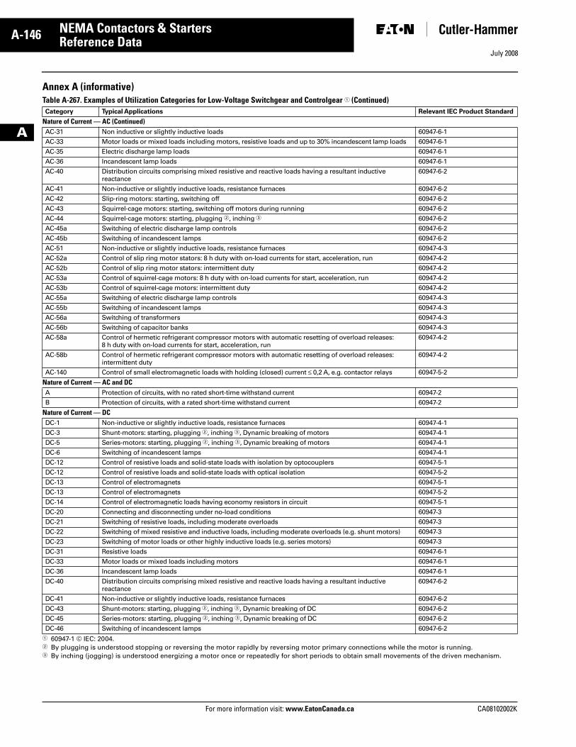
July 2008
A-146
For more information visit: www.EatonCanada.ca CA08102002K
NEMA Contactors & Starters
A
Reference Data
Annex A (informative)Table A-267. Examples of Utilization Categories for Low-Voltage Switchgear and Controlgear � (Continued)
� 60947-1 © IEC: 2004.� By plugging is understood stopping or reversing the motor rapidly by reversing motor primary connections while the motor is running.� By inching (jogging) is understood energizing a motor once or repeatedly for short periods to obtain small movements of the driven mechanism.
Category Typical Applications Relevant IEC Product Standard
Nature of Current — AC (Continued)AC-31 Non inductive or slightly inductive loads 60947-6-1
AC-33 Motor loads or mixed loads including motors, resistive loads and up to 30% incandescent lamp loads 60947-6-1
AC-35 Electric discharge lamp loads 60947-6-1
AC-36 Incandescent lamp loads 60947-6-1
AC-40 Distribution circuits comprising mixed resistive and reactive loads having a resultant inductive reactance
60947-6-2
AC-41 Non-inductive or slightly inductive loads, resistance furnaces 60947-6-2
AC-42 Slip-ring motors: starting, switching off 60947-6-2
AC-43 Squirrel-cage motors: starting, switching off motors during running 60947-6-2
AC-44 Squirrel-cage motors: starting, plugging �, inching � 60947-6-2
AC-45a Switching of electric discharge lamp controls 60947-6-2
AC-45b Switching of incandescent lamps 60947-6-2
AC-51 Non-inductive or slightly inductive loads, resistance furnaces 60947-4-3
AC-52a Control of slip ring motor stators: 8 h duty with on-load currents for start, acceleration, run 60947-4-2
AC-52b Control of slip ring motor stators: intermittent duty 60947-4-2
AC-53a Control of squirrel-cage motors: 8 h duty with on-load currents for start, acceleration, run 60947-4-2
AC-53b Control of squirrel-cage motors: intermittent duty 60947-4-2
AC-55a Switching of electric discharge lamp controls 60947-4-3
AC-55b Switching of incandescent lamps 60947-4-3
AC-56a Switching of transformers 60947-4-3
AC-56b Switching of capacitor banks 60947-4-3
AC-58a Control of hermetic refrigerant compressor motors with automatic resetting of overload releases: 8 h duty with on-load currents for start, acceleration, run
60947-4-2
AC-58b Control of hermetic refrigerant compressor motors with automatic resetting of overload releases: intermittent duty
60947-4-2
AC-140 Control of small electromagnetic loads with holding (closed) current ≤ 0,2 A, e.g. contactor relays 60947-5-2
Nature of Current — AC and DCA Protection of circuits, with no rated short-time withstand current 60947-2
B Protection of circuits, with a rated short-time withstand current 60947-2
Nature of Current — DCDC-1 Non-inductive or slightly inductive loads, resistance furnaces 60947-4-1
DC-3 Shunt-motors: starting, plugging �, inching �, Dynamic breaking of motors 60947-4-1
DC-5 Series-motors: starting, plugging �, inching �, Dynamic breaking of motors 60947-4-1
DC-6 Switching of incandescent lamps 60947-4-1
DC-12 Control of resistive loads and solid-state loads with isolation by optocouplers 60947-5-1
DC-12 Control of resistive loads and solid-state loads with optical isolation 60947-5-2
DC-13 Control of electromagnets 60947-5-1
DC-13 Control of electromagnets 60947-5-2
DC-14 Control of electromagnetic loads having economy resistors in circuit 60947-5-1
DC-20 Connecting and disconnecting under no-load conditions 60947-3
DC-21 Switching of resistive loads, including moderate overloads 60947-3
DC-22 Switching of mixed resistive and inductive loads, including moderate overloads (e.g. shunt motors) 60947-3
DC-23 Switching of motor loads or other highly inductive loads (e.g. series motors) 60947-3
DC-31 Resistive loads 60947-6-1
DC-33 Motor loads or mixed loads including motors 60947-6-1
DC-36 Incandescent lamp loads 60947-6-1
DC-40 Distribution circuits comprising mixed resistive and reactive loads having a resultant inductive reactance
60947-6-2
DC-41 Non-inductive or slightly inductive loads, resistance furnaces 60947-6-2
DC-43 Shunt-motors: starting, plugging �, inching �, Dynamic breaking of DC 60947-6-2
DC-45 Series-motors: starting, plugging �, inching �, Dynamic breaking of DC 60947-6-2
DC-46 Switching of incandescent lamps 60947-6-2
Tab33.book Page 146 Sunday, September 21, 2008 10:27 PM
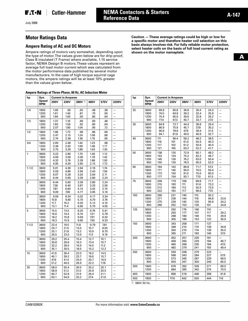
July 2008
CA08102002K For more information visit: www.EatonCanada.ca
A-147NEMA Contactors & Starters
A
Reference Data
Motor Ratings Data
Ampere Rating of AC and DC MotorsAmpere ratings of motors vary somewhat, depending upon the type of motor. The values given below are for drip-proof, Class B insulated (T Frame) where available, 1.15 service factor, NEMA Design B motors. These values represent an average full load motor current which was calculated from the motor performance data published by several motor manufacturers. In the case of high torque squirrel cage motors, the ampere ratings will be at least 10% greater than the values given below.
Caution — These average ratings could be high or low for a specific motor and therefore heater coil selection on this basis always involves risk. For fully reliable motor protection, select heater coils on the basis of full load current rating as shown on the motor nameplate.
Ampere Ratings of Three-Phase, 60 Hz, AC Induction Motor
� 380V 50 Hz.
hp Syn.SpeedRPM
Current in Amperes
200V 230V 380V � 460V 575V 2200V
1/4 18001200900
1.091.611.84
.951.401.60
.55
.81
.93
.48
.70
.80
.38
.56
.64
———
1/3 18001200900
1.371.832.07
1.191.591.80
.69
.921.04
.60
.80
.90
.48
.64
.72
———
1/2 18001200900
1.982.472.74
1.722.152.38
.991.241.38
.861.081.19
.69
.86
.95
———
3/4 18001200900
2.833.363.75
2.462.923.26
1.421.691.88
1.231.461.63
.981.171.30
———
1 360018001200900
3.224.094.324.95
2.803.563.764.30
1.702.062.282.60
1.401.781.882.15
1.121.421.501.72
————
1-1/2 360018001200900
5.015.596.076.44
4.364.865.285.60
2.642.943.203.39
2.182.432.642.80
1.741.942.112.24
————
2 360018001200900
6.447.367.879.09
5.606.406.847.90
3.393.874.144.77
2.803.203.423.95
2.242.562.743.16
————
3 360018001200900
9.5910.811.713.1
8.349.40
10.211.4
5.025.706.206.90
4.174.705.125.70
3.343.764.104.55
————
5 360018001200900
15.516.618.218.3
13.514.415.815.9
8.208.749.599.60
6.767.217.917.92
5.415.786.326.33
————
7-1/2 360018001200900
22.424.725.126.5
19.521.521.823.0
11.813.013.213.9
9.7910.710.911.5
7.818.558.709.19
————
10 360018001200900
29.230.832.235.1
25.426.828.030.5
15.416.316.918.5
12.713.414.015.2
10.110.711.212.2
————
15 360018001200900
41.945.147.651.2
36.439.241.444.5
22.023.725.026.9
18.219.620.722.2
14.515.716.517.8
————
20 360018001200900
58.058.960.763.1
50.451.252.854.9
30.531.031.933.2
25.225.626.427.4
20.120.521.121.9
————
hp Syn.SpeedRPM
Current in Amperes
200V 230V 380V � 460V 575V 2200V
25 360018001200900
69.974.575.477.4
60.864.865.667.3
36.839.239.640.7
30.432.432.833.7
24.325.926.227.0
————
30 360018001200900
84.886.990.694.1
73.775.678.881.8
44.445.747.649.5
36.837.839.440.9
29.430.231.532.7
————
40 360018001200900
111116117121
96.4101102105
58.261.061.263.2
48.250.450.652.2
38.540.340.441.7
————
50 360018001200900
138143145150
120124126130
72.975.276.278.5
60.162.263.065.0
48.249.750.452.0
————
60 360018001200900
164171173177
143140150154
86.890.091.093.1
71.774.575.077.0
57.359.460.061.5
————
75 360018001200900
206210212222
179183184193
108111112117
89.691.692.096.5
71.773.273.577.5
————
100 360018001200900
266271275290
231236239252
140144145153
115118120126
92.294.895.6
101
—23.624.224.8
125 360018001200900
————
292293298305
176177180186
146147149153
116117119122
—29.229.930.9
150 360018001200900
————
343348350365
208210210211
171174174183
137139139146
—34.835.537.0
200 360018001200900
————
452458460482
257265266279
226229230241
181184184193
—46.747.049.4
250 360018001200900
————
559568573600
338343345347
279284287300
223227229240
—57.558.560.5
300 18001200
——
678684
392395
339342
271274
69.070.0
400 1800 — 896 518 448 358 91.8
500 1800 — 1110 642 555 444 116
Tab33.book Page 147 Sunday, September 21, 2008 10:27 PM
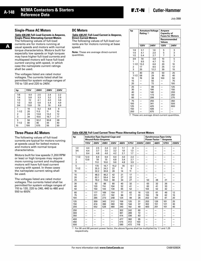
July 2008
A-148
For more information visit: www.EatonCanada.ca CA08102002K
NEMA Contactors & Starters
A
Reference Data
Single-Phase AC MotorsTable 430.248. Full-Load Currents in Amperes, Single-Phase Alternating-Current MotorsThe following values of full-load currents are for motors running at usual speeds and motors with normal torque characteristics. Motors built for especially low speeds or high torques may have higher full-load currents and multispeed motors will have full-load current varying with speed, in which case the nameplate current ratings shall be used.
The voltages listed are rated motor voltages. The currents listed shall be permitted for system voltage ranges of 110 to 120 and 220 to 240V.
Three-Phase AC MotorsThe following values of full-load currents are typical for motors running at speeds usual for belted motors and motors with normal torque characteristics.
Motors built for low speeds (1,200 RPM or less) or high torques may require more running current and multispeed motors will have full-load current varying with speed. In these cases the nameplate current rating shall be used.
The voltages listed are rated motor voltages. The currents listed shall be permitted for system voltage ranges of 110 to 120, 220 to 240, 440 to 480 and 550 to 600V.
hp 115V 200V 208V 230V
1/61/41/31/23/4
4.45.87.29.8
13.8
2.53.34.15.67.9
2.43.24.05.47.6
2.22.93.64.96.9
11-1/223
16202434
9.211.513.819.6
8.81113.218.7
8101217
57-1/2
10
5680
100
32.24657.5
30.84455
284050
DC MotorsTable 430.247. Full-Load Current in Amperes, Direct-Current MotorsThe following values of full-load cur-rents are for motors running at base speed.
Note: These are average direct-current quantities.
� These are average direct-current quantities.
Table 430.250. Full-Load Current Three-Phase Alternating-Current Motors
� For 90 and 80 percent power factor, the above figures shall be multiplied by 1.1 and 1.25 respectively.
hp Armature Voltage Rating �
Ampere Capacity of Fuses for Motors
RecommendedValues
120V 240V 120V 240V
1/41/31/2
3.14.15.4
1.62.02.7
557
333
3/411-1/223
7.69.5
13.21725
3.84.76.68.5
12.2
1015202530
57
101215
57-1/2
101520
405876——
2029385572
5080
100——
25405075
100
2530405060
—————
89106140173206
—————
125150200250275
75100125150200
—————
255341425506675
—————
350500600——
hp Induction Type Squirrel-Cage and Wound-Rotor Amperes
Synchronous Type Unity Power Factor � Amperes
115V 200V 208V 230V 460V 575V 2300V 230V 460V 575V 2300V
1/23/41
4.46.48.4
2.53.74.8
2.43.54.6
2.23.24.2
1.11.62.1
.91.31.7
———
———
———
———
———
1-1/223
12.013.6—
6.97.8
11.0
6.67.5
10.6
6.06.89.6
3.03.44.8
2.42.73.9
———
———
———
———
———
57-1/2
10
———
17.525.332.2
16.724.230.8
15.22228
7.61114
6.19
11
———
———
———
———
———
152025
———
48.362.178.2
46.259.474.8
425468
212734
172227
———
——53
——26
——21
———
304050
———
92120150
88114143
80104130
405265
324152
———
6383
104
324152
263342
———
6075
100
———
177221285
169211273
154192248
7796
124
627799
162026
123155202
6178
101
496281
121520
125150200
———
359414552
343396528
312360480
156180240
125144192
313749
253302400
126151201
101121161
253040
250300350
———
———
———
———
302361414
242289336
607283
———
———
———
———
400450500
———
———
———
———
477515590
382412472
95103118
———
———
———
———
Tab33.book Page 148 Sunday, September 21, 2008 10:27 PM
Related Documents


![Cutler-Hammer NEMA Contactors & Starters Thermal ... January 2001 Vol. 2, Ref. No. 10053] NEMA Contactors & Starters Thermal Overload Relays Freedom Line 33-37 Table 33-74. Standard](https://static.cupdf.com/doc/110x72/5ac0a7ec7f8b9a213f8c3cf8/cutler-hammer-nema-contactors-starters-thermal-january-2001-vol-2-ref-no.jpg)


![33-36 NEMA Contactors & Starters Thermal Overload Relays … · 2017-07-13 · NEMA Contactors & Starters 33 Thermal Overload Relays Freedom Line Vol. 2, Ref. No. [0050] Technical](https://static.cupdf.com/doc/110x72/5e914b6b3f90271d1b711acd/33-36-nema-contactors-starters-thermal-overload-relays-2017-07-13-nema-contactors.jpg)