1 Enhanced friction model for Friction Stir Welding (FSW) analysis: simulation and experimental validation N. Dialami*, M. Chiumenti*, M. Cervera*, A. Segatori † and W. Osikowicz † * International Center for Numerical Methods in Engineering (CIMNE), Universidad Politécnica de Cataluña, Campus Norte UPC, 08034 Barcelona, Spain e-mail: [email protected] (N. Dialami), [email protected] (M. Chiumenti), [email protected] (M. Cervera), † Sapa AB Technology, Kanalgatan 1, 612 81 FINSPÅNG, Sweden Email: [email protected] (A. Segatori), [email protected] (W. Osikowicz) Abstract Friction is one of the main heat generation mechanisms in Friction Stir Welding (FSW). This phenomenon occurs between the pin and the workpiece as the rotating tool moves along the weld line. An accurate friction model is essential for obtaining realistic results in a FSW simulation in particular temperature, forces and torque. In this work, a modified Norton’s friction law is developed. The suggested enhanced friction model aims at providing not only the realistic temperature field but also the forces and torque. This model does not exclusively relate the frictional shear stress to the sliding velocity; conversely it takes into account the effect of non-uniform pressure distribution under the shoulder, as this latter has an important role in the process of heat generation. Longitudinal, transversal and vertical forces and torque are numerically calculated. The effect of the enhanced friction model is reflected in these forces. In particular, it leads to a more realistic estimation of the transversal and longitudinal forces in comparison with the results obtained using former models. The friction model is successfully validated by the experimental measurements provided by the industrial partner (Sapa). The experimental analysis is performed for the material characterization, the calibration of the friction model and, more generally, the assessment of the overall numerical strategy proposed for the FSW simulation. Keywords: FSW, Friction model, Experimental validation 1. Introduction In Friction Stir Welding (FSW), a rotating tool with a given profile moves forward along the weld line. The frictional contact between the FSW tool and the workpiece as well as and the plastic dissipation are responsible for the heat generation and softening of the material. As the tool moves forward, the weld is being formed by material stirring. The frictional heat generation occurs predominantly under the shoulder, due to its greater surface area. The contact condition between the shoulder and the workpiece can be of sliding or sticking types, depending on the value of the tangential shear strength. This strength is a function of the temperature and the strain rate.

Welcome message from author
This document is posted to help you gain knowledge. Please leave a comment to let me know what you think about it! Share it to your friends and learn new things together.
Transcript
1
Enhanced friction model for Friction Stir Welding (FSW) analysis: simulation and experimental validation
N. Dialami*, M. Chiumenti*, M. Cervera*,
A. Segatori† and W. Osikowicz †
* International Center for Numerical Methods in Engineering (CIMNE), Universidad Politécnica de Cataluña, Campus Norte UPC, 08034 Barcelona, Spain
e-mail: [email protected] (N. Dialami), [email protected] (M. Chiumenti), [email protected] (M. Cervera),
† Sapa AB Technology, Kanalgatan 1, 612 81 FINSPÅNG, Sweden
Email: [email protected] (A. Segatori), [email protected] (W. Osikowicz)
Abstract
Friction is one of the main heat generation mechanisms in Friction Stir Welding (FSW). This phenomenon occurs between the pin and the workpiece as the rotating tool moves along the weld line. An accurate friction model is essential for obtaining realistic results in a FSW simulation in particular temperature, forces and torque. In this work, a modified Norton’s friction law is developed. The suggested enhanced friction model aims at providing not only the realistic temperature field but also the forces and torque. This model does not exclusively relate the frictional shear stress to the sliding velocity; conversely it takes into account the effect of non-uniform pressure distribution under the shoulder, as this latter has an important role in the process of heat generation. Longitudinal, transversal and vertical forces and torque are numerically calculated. The effect of the enhanced friction model is reflected in these forces. In particular, it leads to a more realistic estimation of the transversal and longitudinal forces in comparison with the results obtained using former models. The friction model is successfully validated by the experimental measurements provided by the industrial partner (Sapa). The experimental analysis is performed for the material characterization, the calibration of the friction model and, more generally, the assessment of the overall numerical strategy proposed for the FSW simulation. Keywords: FSW, Friction model, Experimental validation
1. Introduction
In Friction Stir Welding (FSW), a rotating tool with a given profile moves forward along the weld line. The frictional contact between the FSW tool and the workpiece as well as and the plastic dissipation are responsible for the heat generation and softening of the material. As the tool moves forward, the weld is being formed by material stirring. The frictional heat generation occurs predominantly under the shoulder, due to its greater surface area. The contact condition between the shoulder and the workpiece can be of sliding or sticking types, depending on the value of the tangential shear strength. This strength is a function of the temperature and the strain rate.
2
At the first glance, the process is simple as it involves only the movement of a tool through a weld line. However, the real FSW mechanism is complex as it is highly nonlinear and coupled. The strong coupling between the temperature field and the material behaviour does not permit to rely on simple tribological tests for representing the friction behaviour in FSW. Either measurements must be carried out while actually executing FSW (which is not trivial) or numerical simulations must be performed. Veljic et al. [1] deal with the heat generation during plunge stage in FSW. They developed a 3D finite element model in the commercial code ABAQUS/Explicit. Coulomb’s friction law is used for expressing the frictional heat generated by the tool. They find that the heat generated by friction is predominant and affects the slip rate of the tool against the workpiece while the material stirring is related to the heat generated by plastic deformation. Colegrove et al. [2] analyse several FSW modelling techniques: 1) limiting the maximum shear stress at the contact surface allowing for the shoulder to slip on the workpiece, 2) calibration of the maximum shear stress used by the contact model with the heat generation from the friction process obtained from experiments. Their model captured many of the real process characteristics, but provided poor predictions of the welding forces and over-prediction of the weld temperature. In [3], the FSW process of AA2024-T3 material using different metal sheet thickness is analysed. They show that about 85% in the heat generation in FSW comes from the frictional process. The stirring effect generated by the welding tool becomes less important in FSW of thick workpieces. In [4], two friction models (Coulomb’s and modified Coulomb’s laws) are compared in a fully coupled thermo-mechanical numerical model. A small difference between these models is observed using low rotating speeds. For high rotating speed, Coulomb’s model fails as the shear stress at the interface is not limited, while the modified Coulomb’s model may be used. In the previous works of the authors the effect of slip and stick conditions on circular and non-circular pin shapes was analysed [6-12]. Up to now, the FSW contact conditions are generally considered to be either fully stick (heat generated by plastic dissipation) or slip (heat generated by friction). However, these assumptions are restrictive. A combination of those is presented in [5] to identify the contact conditions in FSW processes. The thermal and mechanical outcomes obtained with prescribed stick and slip conditions are assessed by means of comparison with experiments. Hamilton et al in [13], develop a thermal model for FSW analysis in which a slip factor based on the energy per unit length of weld is considered. The proposed model predicts correctly the maximum temperature for a wide range of energy levels while under predicts the temperature for low energy levels (in the latter case the heat generated via plastic deformation dominates). In reference [14], experimental and numerical models of the friction stir processing technique are presented. A conventional tool without a pin is used. During the trials, the tool temperature, torque and forces acting on the tool are measured. As an initial simplification to the model, only heat generation due to the friction between tool and the workpiece is considered while the heat generation due to plastic deformation is not taken into account. Zhang et al [15] develop an Eulerian model which is validated experimentally. They conclude that the increase of the slipping velocity is the main source of the heat input according with the increase of the rotating speed. They assume that the frictional stresses at both the shoulder contact surface and the pin surface are constant.
3
Fagan et al [16] focus on the development of a friction stir forming model using a solid mechanics approach through Material Point Method (MPM). Their model includes heat transfer processes due to plastic dissipation as well as frictional heating. In this work a Coulomb’s friction law is assumed. Assidi et al. [17] develop a friction model for FSW simulation calibrated by experimental measurements. The main feature of the numerical approach is to compute the contact and frictional interaction between the plate and the FSW tool. The sensitivity of the welding forces and tool temperatures to friction coefficients is attained using Norton’s friction model. Vertical and horizontal forces and tool temperatures are accurately recorded at steady state. In reference [33], the thermal behavior during the FSW process is simulated using ABAQUS. Coulomb’s friction model is modified to calculate temperature dependent friction coefficient values. They show the strong dependence of the heat generation on the tool rotating and advancing speed. In reference [34], they use a parallel ALE formulation developed in Forge® finite element code to model the defects such as flashes and worm holes. The friction at the tool/workpiece interface is modeled using Norton’s friction law. Calibration of thermo-mechanical material parameters and the friction model is performed by assessing the measured forces, torques and temperatures for two finite element frameworks: Eulerian and ALE. More references on the heat generation sources can be found in [18], where thermo-mechanical conditions during FSW of polymers are detailed. To better understand the complex mechanisms in FSW processes, a fully coupled thermo-mechanical model together with a suitable friction model to properly describe the tribological condition at the tool/workpiece interface is desirable. Hence, the aim of this work is to present an enhanced friction model that accounts for the actual process behaviour including the effect of viscosity and pressure distribution below the tool. The frictional shear stress is related to the sliding velocity through a process-dependent friction parameter. in this work, an enhanced friction model is addressed to provide a more realistic thermo-mechanical response in comparison with the previous proposals. The suggested friction model accounts for the relative velocity as well as effect of non-uniform pressure distribution under the shoulder. The effect of the enhanced friction model results in an improved estimation of forces in FSW. This paper also presents the calibration of the proposed friction model by comparing the results of a 3D analysis with the experimental evidence provided by the industrial partner (Sapa). The outline of the paper is the following. In the next section, the friction model proposed for the simulation of FSW is presented. Section 3 briefly describes the solution strategy to perform the numerical simulation of the FSW process used in this work. Section 4 is devoted to the solution of a 2D benchmark for the assessment of the friction model. Finally, a 3D model is analysed numerically and experimentally validated in Section 5. 2. Friction models
In FSW, the friction law characterizes the friction law at the contact interface between the tool and the workpiece according to their relative sliding movement. Several friction
4
laws defining the interfacial shear stress are available in the literature. For the numerical simulation of FSW process, Coulomb’s and Norton’s laws are the most commonly used.
2.1. Coulomb’s friction law
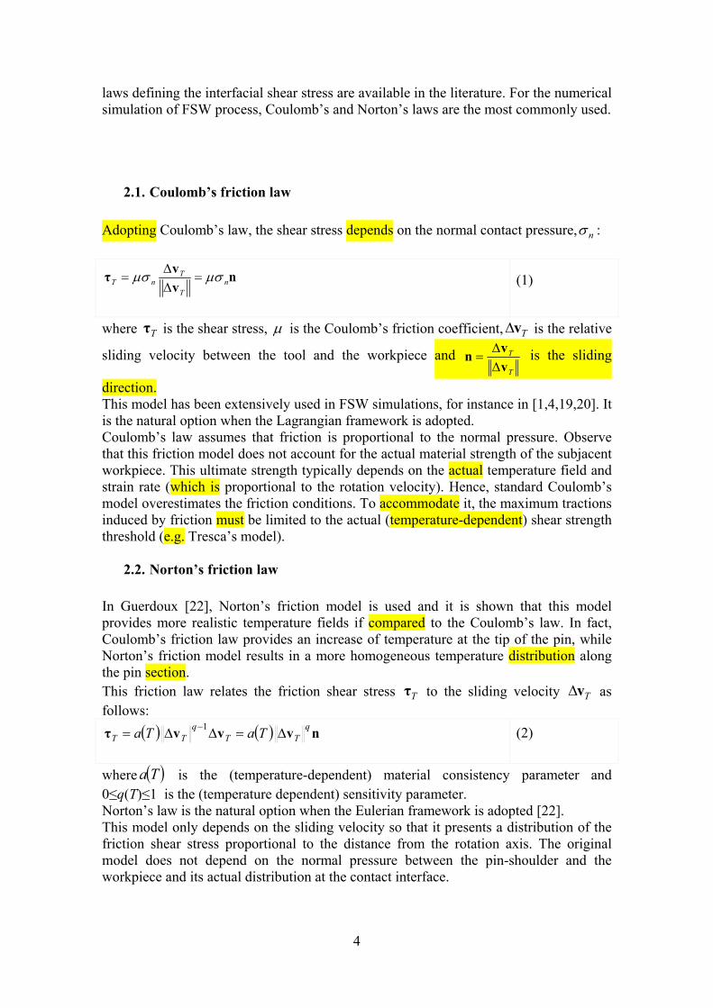
Adopting Coulomb’s law, the shear stress depends on the normal contact pressure, n :
nv
vτ n
T
TnT
(1)
where Tτ is the shear stress, is the Coulomb’s friction coefficient, Tv is the relative
sliding velocity between the tool and the workpiece and T
T
v
vn
is the sliding
direction. This model has been extensively used in FSW simulations, for instance in [1,4,19,20]. It is the natural option when the Lagrangian framework is adopted. Coulomb’s law assumes that friction is proportional to the normal pressure. Observe that this friction model does not account for the actual material strength of the subjacent workpiece. This ultimate strength typically depends on the actual temperature field and strain rate (which is proportional to the rotation velocity). Hence, standard Coulomb’s model overestimates the friction conditions. To accommodate it, the maximum tractions induced by friction must be limited to the actual (temperature-dependent) shear strength threshold (e.g. Tresca’s model).
2.2. Norton’s friction law
In Guerdoux [22], Norton’s friction model is used and it is shown that this model provides more realistic temperature fields if compared to the Coulomb’s law. In fact, Coulomb’s friction law provides an increase of temperature at the tip of the pin, while Norton’s friction model results in a more homogeneous temperature distribution along the pin section. This friction law relates the friction shear stress Tτ to the sliding velocity Tv as follows:
nvvvτq
TTq
TT TaTa
1 (2)
where Ta is the (temperature-dependent) material consistency parameter and 0≤q(T)≤1 is the (temperature dependent) sensitivity parameter. Norton’s law is the natural option when the Eulerian framework is adopted [22]. This model only depends on the sliding velocity so that it presents a distribution of the friction shear stress proportional to the distance from the rotation axis. The original model does not depend on the normal pressure between the pin-shoulder and the workpiece and its actual distribution at the contact interface.
5
2.3. Modified Norton’s friction law
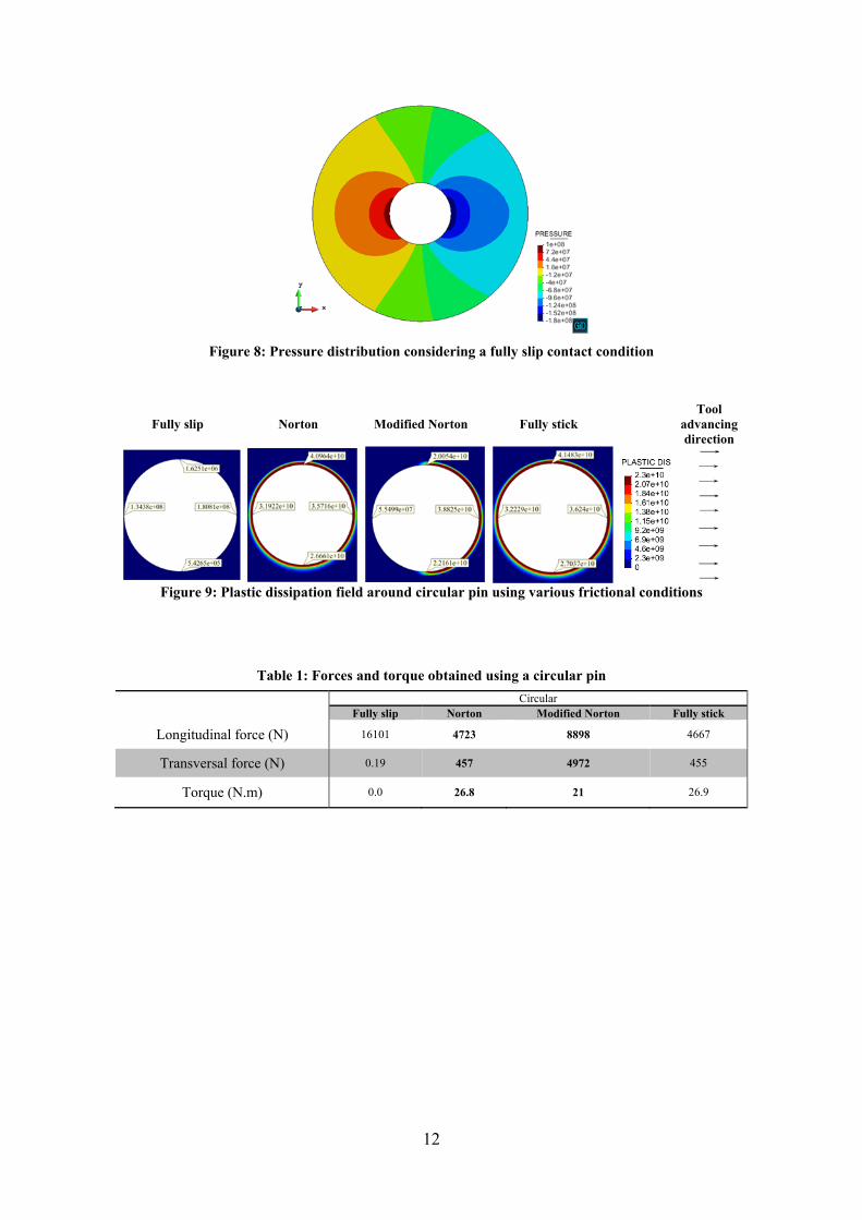
In this work, a modified Norton’s friction model is proposed. The main idea is to take into account the effects of a non-uniform distribution of the pressure field below the pin-shoulder as the Coulomb’s model does. The experimental evidence suggests higher values of friction at the front side of the tool reducing in the rear part [23, 35]. This is consistent with the pressure distribution in FSW where the front of the pin-tool suffers higher compression than the rear side (see figure 8). Hence, the model proposed assumes a modified consistency parameter depending on the actual position of each point at the contact interface with respect to the rotation axis and the advancing velocity. The proposed modified Norton’s friction law reads:
nvτq
TT Txa , (3)
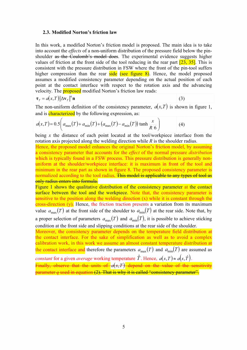
The non-uniform definition of the consistency parameter, Txa , is shown in figure 1, and is characterized by the following expression, as:
6tanh5.0, minmaxminmax R
xTaTaTaTaTxa (4)
being x the distance of each point located at the tool/workpiece interface from the rotation axis projected along the welding direction while R is the shoulder radius. Hence, the proposed model enhances the original Norton’s friction model, by assuming a consistency parameter that accounts for the effect of the normal pressure distribution which is typically found in a FSW process. This pressure distribution is generally non-uniform at the shoulder/workpiece interface: it is maximum in front of the tool and minimum in the rear part as shown in figure 8. The proposed consistency parameter is normalized according to the tool radius. This model is applicable to any types of tool as only radius enters into formula. Figure 1 shows the qualitative distribution of the consistency parameter at the contact surface between the tool and the workpiece. Note that, the consistency parameter is sensitive to the position along the welding direction (x) while it is constant through the cross-direction (y). Hence, the friction traction presents a variation from its maximum value Tamax at the front side of the shoulder to Tamin at the rear side. Note that, by
a proper selection of parameters Tamax and Tamin , it is possible to achieve sticking
condition at the front side and slipping conditions at the rear side of the shoulder. Moreover, the consistency parameter depends on the temperature field distribution at the contact interface. For the sake of simplification as well as to avoid a complex calibration work, in this work we assume an almost constant temperature distribution at the contact interface and therefore the parameters Tamax and Tamin are assumed as
constant for a given average working temperature T̂ . Hence, TxaTxa ˆ,, .
Finally, observe that the units of Txa , depend on the value of the sensitivity parameter q used in equation (2). That is why it is called “consistency parameter”.
6
Figure 1: The distribution of friction parameter a at the tool interface
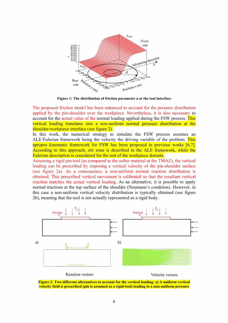
The proposed friction model has been enhanced to account for the pressure distribution applied by the pin-shoulder over the workpiece. Nevertheless, it is also necessary to account for the actual value of the normal loading applied during the FSW process. This vertical loading translates into a non-uniform normal pressure distribution at the shoulder/workpiece interface (see figure 2). In this work, the numerical strategy to simulate the FSW process assumes an ALE/Eulerian framework being the velocity the driving variable of the problem. This apropos kinematic framework for FSW has been proposed in previous works [6,7]. According to this approach, stir zone is described in the ALE framework, while the Eulerian description is considered for the rest of the workpiece domain. Assuming a rigid pin-tool (as compared to the softer material at the TMAZ), the vertical loading can be prescribed by imposing a vertical velocity of the pin-shoulder surface (see figure 2a). As a consequence, a non-uniform normal reaction distribution is obtained. This prescribed vertical movement is calibrated so that the resultant vertical reaction matches the actual vertical loading. As an alternative, it is possible to apply normal tractions at the top surface of the shoulder (Neumann’s condition). However, in this case a non-uniform vertical velocity distribution is typically obtained (see figure 2b), meaning that the tool is not actually represented as a rigid body.
Figure 2: Two different alternatives to account for the vertical loading: a) A uniform vertical velocity field is prescribed (pin is assumed as a rigid-tool) leading to a non-uniform pressure
7
distribution; b) A uniform pressure distribution is applied (Neumann’s condition) and consequently a non-uniform velocity field is obtained.
3. The solution strategy
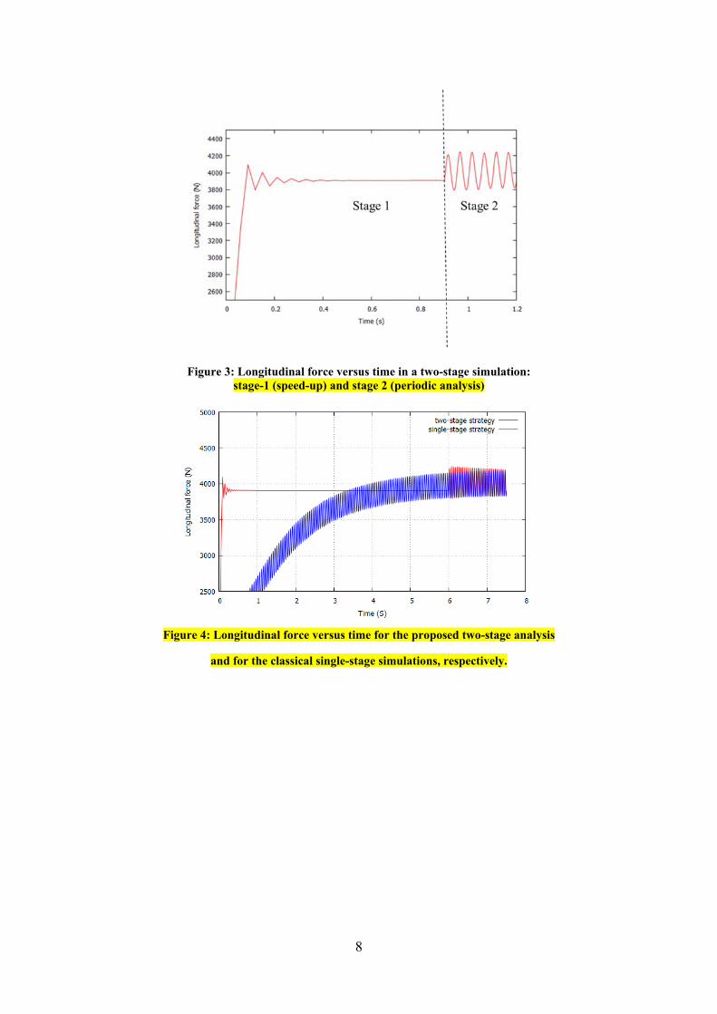
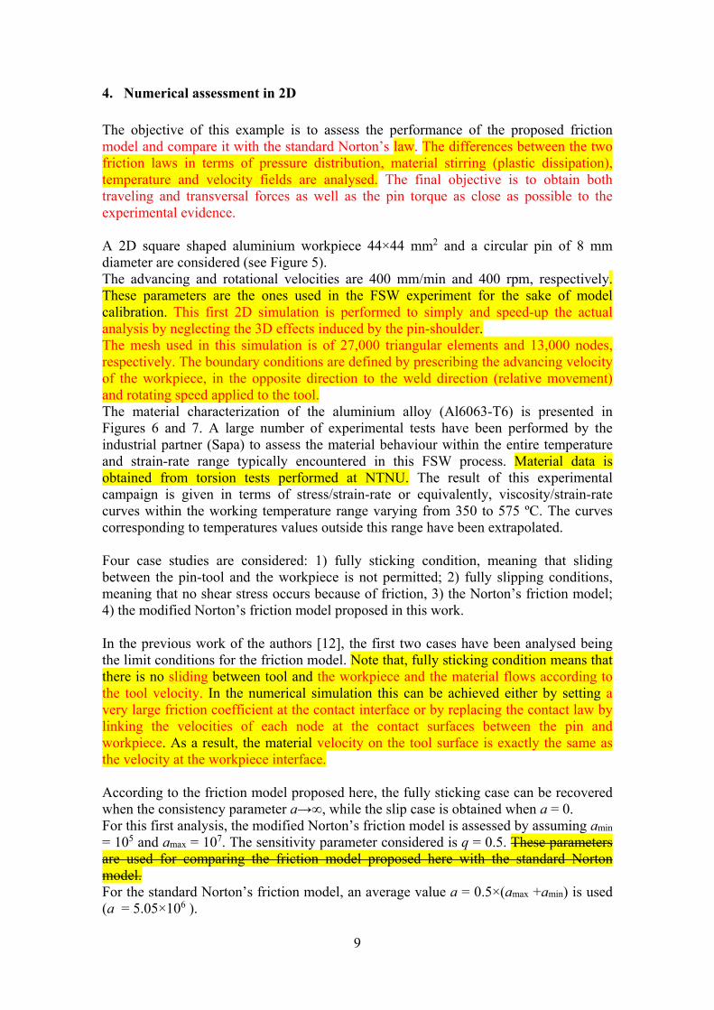
In this work, a two-stage speed-up strategy previously proposed by the authors in [12] is adopted (see figure 3). In both stages the coupled thermo-mechanical problem is solved using a staggered algorithm. In the first phase, the speed-up stage, the coupled thermo-mechanical analysis is intended to quickly reach the thermal steady-state. The pin tool is kept fix so that an Eulerian framework is adopted. The thermal field obtained is very close to the periodic temperature distribution when the pin is rotating. To achieve this objective, the inertia term in the energy balance equation is modified to accelerate the transient stage by decreasing the thermal capacity. In the second phase, the periodic stage, the coupled thermo-mechanical analysis is launched assuming, as initial condition, the temperature and velocity fields obtained in the first stage (see figure 3). In this second stage, an apropos kinematic framework is adopted combing ALE, Eulerian and Lagrangian formulations for the stir zone, the workpiece and the pin-tool, respectively. This kinematic framework has been proposed in our previous work [6,7] and has been used in all the subsequent developments. Further details of this approach are detailed therein. The two-stage strategy allows for a fast and accurate analysis of non-cylindrical pin-shapes leading to a periodic solution according to the rotation of the pin (see figure 3). Moreover, the CPU time can be reduced by almost 50 times compared to the standard single-stage transient model, while resulting in the same steady-state process conditions (see figure 4) while preserving the capabilities of the original model to predict FSW process forces and torque for any pin shape. The balance equations are solved by a stabilized mixed velocity-pressure FE formulation which has proved to have excellent performance for isochoric material flow [38, 39, 40]. The simulations in this work are carried out using the in-house finite element code COMET [31] developed by the authors. The results post-processing is performed by the pre and postprocessor software, GiD, developed at CIMNE [32].
8
Figure 3: Longitudinal force versus time in a two-stage simulation: stage-1 (speed-up) and stage 2 (periodic analysis)
Figure 4: Longitudinal force versus time for the proposed two-stage analysis
and for the classical single-stage simulations, respectively.
9
4. Numerical assessment in 2D
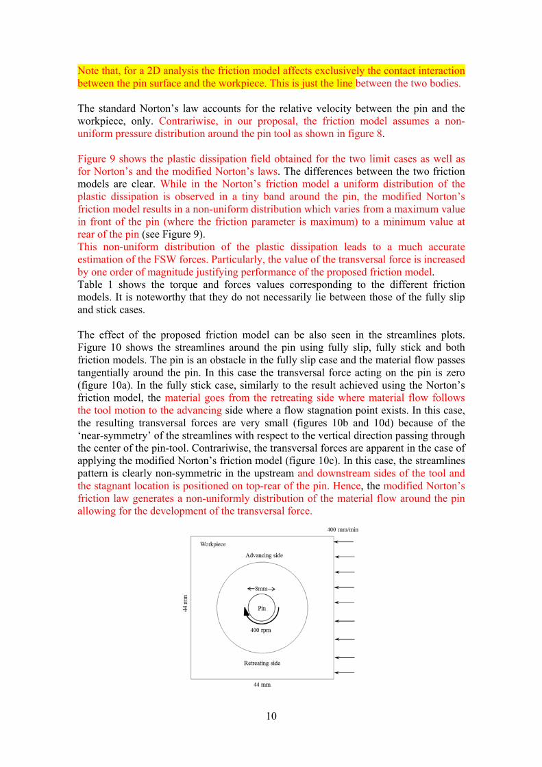
The objective of this example is to assess the performance of the proposed friction model and compare it with the standard Norton’s law. The differences between the two friction laws in terms of pressure distribution, material stirring (plastic dissipation), temperature and velocity fields are analysed. The final objective is to obtain both traveling and transversal forces as well as the pin torque as close as possible to the experimental evidence. A 2D square shaped aluminium workpiece 44×44 mm2 and a circular pin of 8 mm diameter are considered (see Figure 5). The advancing and rotational velocities are 400 mm/min and 400 rpm, respectively. These parameters are the ones used in the FSW experiment for the sake of model calibration. This first 2D simulation is performed to simply and speed-up the actual analysis by neglecting the 3D effects induced by the pin-shoulder. The mesh used in this simulation is of 27,000 triangular elements and 13,000 nodes, respectively. The boundary conditions are defined by prescribing the advancing velocity of the workpiece, in the opposite direction to the weld direction (relative movement) and rotating speed applied to the tool. The material characterization of the aluminium alloy (Al6063-T6) is presented in Figures 6 and 7. A large number of experimental tests have been performed by the industrial partner (Sapa) to assess the material behaviour within the entire temperature and strain-rate range typically encountered in this FSW process. Material data is obtained from torsion tests performed at NTNU. The result of this experimental campaign is given in terms of stress/strain-rate or equivalently, viscosity/strain-rate curves within the working temperature range varying from 350 to 575 ºC. The curves corresponding to temperatures values outside this range have been extrapolated. Four case studies are considered: 1) fully sticking condition, meaning that sliding between the pin-tool and the workpiece is not permitted; 2) fully slipping conditions, meaning that no shear stress occurs because of friction, 3) the Norton’s friction model; 4) the modified Norton’s friction model proposed in this work. In the previous work of the authors [12], the first two cases have been analysed being the limit conditions for the friction model. Note that, fully sticking condition means that there is no sliding between tool and the workpiece and the material flows according to the tool velocity. In the numerical simulation this can be achieved either by setting a very large friction coefficient at the contact interface or by replacing the contact law by linking the velocities of each node at the contact surfaces between the pin and workpiece. As a result, the material velocity on the tool surface is exactly the same as the velocity at the workpiece interface. According to the friction model proposed here, the fully sticking case can be recovered when the consistency parameter a→∞, while the slip case is obtained when a = 0. For this first analysis, the modified Norton’s friction model is assessed by assuming amin = 105 and amax = 107. The sensitivity parameter considered is q = 0.5. These parameters are used for comparing the friction model proposed here with the standard Norton model. For the standard Norton’s friction model, an average value a = 0.5×(amax +amin) is used (a = 5.05×10⁶ ).
10
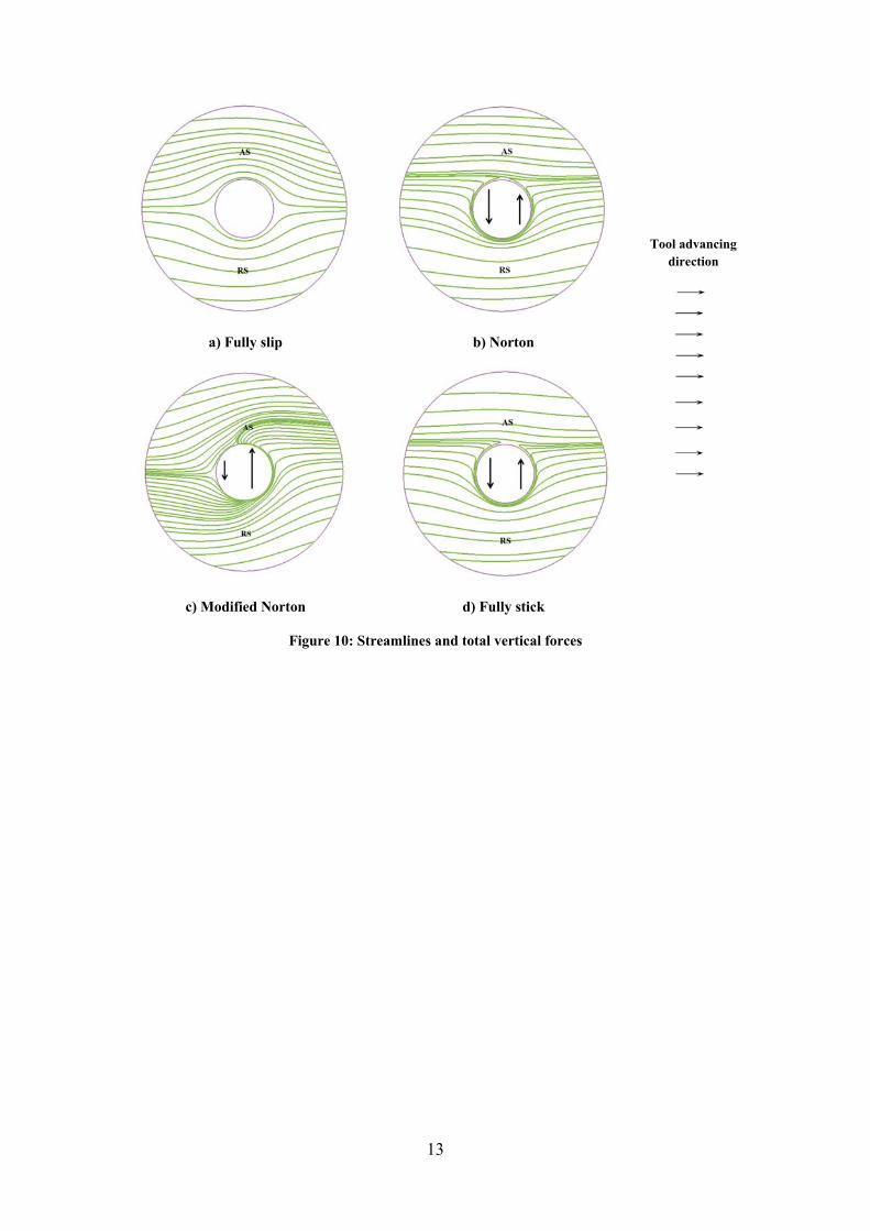
Note that, for a 2D analysis the friction model affects exclusively the contact interaction between the pin surface and the workpiece. This is just the line between the two bodies. The standard Norton’s law accounts for the relative velocity between the pin and the workpiece, only. Contrariwise, in our proposal, the friction model assumes a non-uniform pressure distribution around the pin tool as shown in figure 8. Figure 9 shows the plastic dissipation field obtained for the two limit cases as well as for Norton’s and the modified Norton’s laws. The differences between the two friction models are clear. While in the Norton’s friction model a uniform distribution of the plastic dissipation is observed in a tiny band around the pin, the modified Norton’s friction model results in a non-uniform distribution which varies from a maximum value in front of the pin (where the friction parameter is maximum) to a minimum value at rear of the pin (see Figure 9). This non-uniform distribution of the plastic dissipation leads to a much accurate estimation of the FSW forces. Particularly, the value of the transversal force is increased by one order of magnitude justifying performance of the proposed friction model. Table 1 shows the torque and forces values corresponding to the different friction models. It is noteworthy that they do not necessarily lie between those of the fully slip and stick cases. The effect of the proposed friction model can be also seen in the streamlines plots. Figure 10 shows the streamlines around the pin using fully slip, fully stick and both friction models. The pin is an obstacle in the fully slip case and the material flow passes tangentially around the pin. In this case the transversal force acting on the pin is zero (figure 10a). In the fully stick case, similarly to the result achieved using the Norton’s friction model, the material goes from the retreating side where material flow follows the tool motion to the advancing side where a flow stagnation point exists. In this case, the resulting transversal forces are very small (figures 10b and 10d) because of the ‘near-symmetry’ of the streamlines with respect to the vertical direction passing through the center of the pin-tool. Contrariwise, the transversal forces are apparent in the case of applying the modified Norton’s friction model (figure 10c). In this case, the streamlines pattern is clearly non-symmetric in the upstream and downstream sides of the tool and the stagnant location is positioned on top-rear of the pin. Hence, the modified Norton’s friction law generates a non-uniformly distribution of the material flow around the pin allowing for the development of the transversal force.
11
Figure 5: The 2D problem description
Figure 6: Material characterization
Figure 7: Temperature dependent thermal properties
12
Figure 8: Pressure distribution considering a fully slip contact condition
Fully slip Norton Modified Norton Fully stick Tool
advancing direction
Figure 9: Plastic dissipation field around circular pin using various frictional conditions
Table 1: Forces and torque obtained using a circular pin
Circular
Fully slip Norton Modified Norton Fully stick
Longitudinal force (N) 16101 4723 8898 4667
Transversal force (N) 0.19 457 4972 455
Torque (N.m) 0.0 26.8 21 26.9
13
Tool advancing direction
a) Fully slip b) Norton
c) Modified Norton d) Fully stick
Figure 10: Streamlines and total vertical forces
14
5. Calibration of the 3D numerical model by experimental data
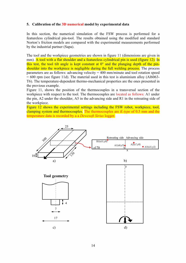
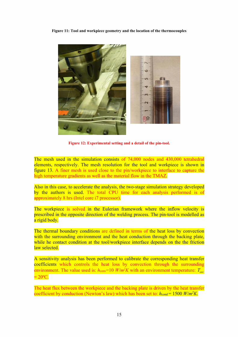
In this section, the numerical simulation of the FSW process is performed for a featureless cylindrical pin-tool. The results obtained using the modified and standard Norton’s friction models are compared with the experimental measurements performed by the industrial partner (Sapa). The tool and the workpiece geometries are shown in figure 11 (dimensions are given in mm). A tool with a flat shoulder and a featureless cylindrical pin is used (figure 12). In this test, the tool tilt angle is kept constant at 0° and the plunging depth of the pin-shoulder into the workpiece is negligible during the full welding process. The process parameters are as follows: advancing velocity = 400 mm/minute and tool rotation speed = 600 rpm (see figure 11d). The material used in this test is aluminium alloy (Al6063-T6). The temperature-dependent thermo-mechanical properties are the ones presented in the previous example. Figure 11, shows the position of the thermocouples in a transversal section of the workpiece with respect to the tool. The thermocouples are located as follows: A1 under the pin, A2 under the shoulder, A5 in the advancing side and R1 in the retreating side of the workpiece. Figure 12 shows the experimental settings including the FSW robot, workpiece, tool, clamping system and thermocouples. The thermocouples are K-type of 0.5 mm and the temperature data is recorded by a a Dewesoft Sirius logger.
15
Figure 11: Tool and workpiece geometry and the location of the thermocouples
Figure 12: Experimental setting and a detail of the pin-tool.
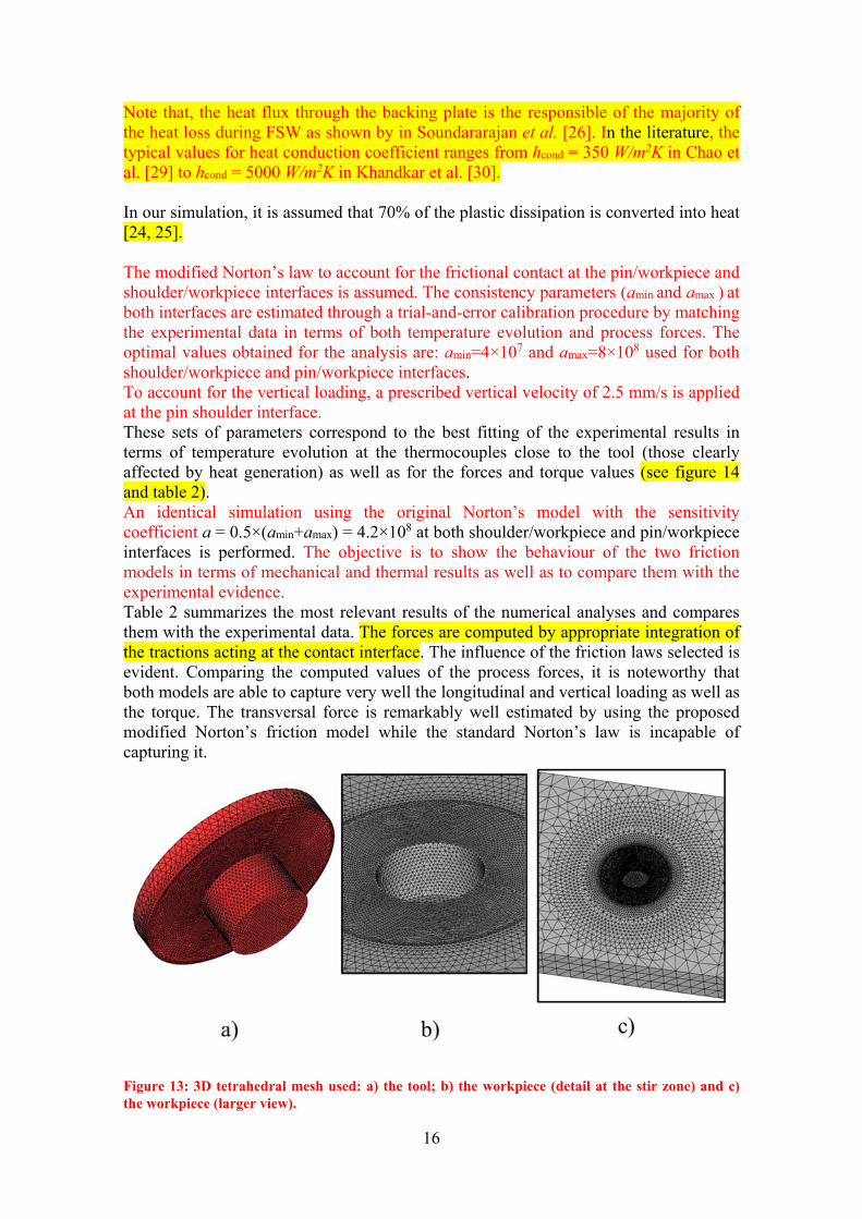
The mesh used in the simulation consists of 74,000 nodes and 430,000 tetrahedral elements, respectively. The mesh resolution for the tool and workpiece is shown in figure 13. A finer mesh is used close to the pin/workpiece to interface to capture the high temperature gradients as well as the material flow in the TMAZ. Also in this case, to accelerate the analysis, the two-stage simulation strategy developed by the authors is used. The total CPU time for each analysis performed is of approximately 8 hrs (Intel core i7 processor). The workpiece is solved in the Eulerian framework where the inflow velocity is prescribed in the opposite direction of the welding process. The pin-tool is modelled as a rigid body. The thermal boundary conditions are defined in terms of the heat loss by convection with the surrounding environment and the heat conduction through the backing plate, while he contact condition at the tool/workpiece interface depends on the the friction law selected. A sensitivity analysis has been performed to calibrate the corresponding heat transfer coefficients which controls the heat loss by convection through the surrounding environment. The value used is: hconv=10 W/m2K with an environment temperature: envT
= 20ºC. The heat flux between the workpiece and the backing plate is driven by the heat transfer coefficient by conduction (Newton’s law) which has been set to: hcond = 1500 W/m2K.
16
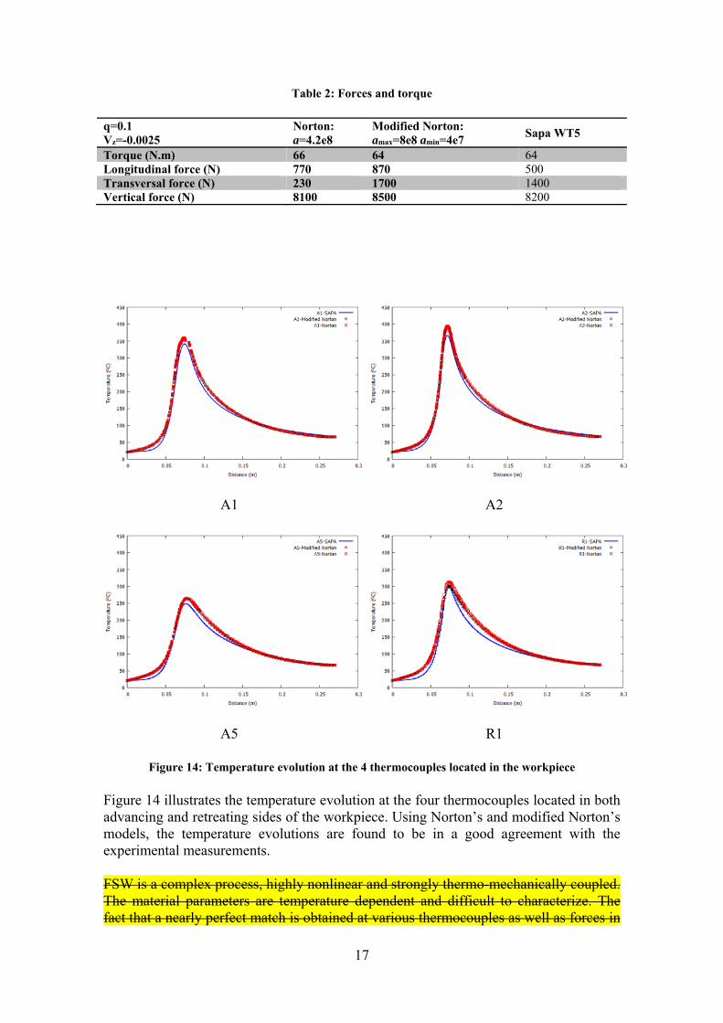
Note that, the heat flux through the backing plate is the responsible of the majority of the heat loss during FSW as shown by in Soundararajan et al. [26]. In the literature, the typical values for heat conduction coefficient ranges from hcond = 350 W/m2K in Chao et al. [29] to hcond = 5000 W/m2K in Khandkar et al. [30]. In our simulation, it is assumed that 70% of the plastic dissipation is converted into heat [24, 25]. The modified Norton’s law to account for the frictional contact at the pin/workpiece and shoulder/workpiece interfaces is assumed. The consistency parameters (amin and amax ) at both interfaces are estimated through a trial-and-error calibration procedure by matching the experimental data in terms of both temperature evolution and process forces. The optimal values obtained for the analysis are: amin=4×10⁷ and amax=8×10⁸ used for both shoulder/workpiece and pin/workpiece interfaces. To account for the vertical loading, a prescribed vertical velocity of 2.5 mm/s is applied at the pin shoulder interface. These sets of parameters correspond to the best fitting of the experimental results in terms of temperature evolution at the thermocouples close to the tool (those clearly affected by heat generation) as well as for the forces and torque values (see figure 14 and table 2). An identical simulation using the original Norton’s model with the sensitivity coefficient a = 0.5×(amin+amax) = 4.2×10⁸ at both shoulder/workpiece and pin/workpiece interfaces is performed. The objective is to show the behaviour of the two friction models in terms of mechanical and thermal results as well as to compare them with the experimental evidence. Table 2 summarizes the most relevant results of the numerical analyses and compares them with the experimental data. The forces are computed by appropriate integration of the tractions acting at the contact interface. The influence of the friction laws selected is evident. Comparing the computed values of the process forces, it is noteworthy that both models are able to capture very well the longitudinal and vertical loading as well as the torque. The transversal force is remarkably well estimated by using the proposed modified Norton’s friction model while the standard Norton’s law is incapable of capturing it.
Figure 13: 3D tetrahedral mesh used: a) the tool; b) the workpiece (detail at the stir zone) and c) the workpiece (larger view).
17
Table 2: Forces and torque
q=0.1 Vz=-0.0025
Norton: a=4.2e8
Modified Norton: amax=8e8 amin=4e7
Sapa WT5
Torque (N.m) 66 64 64 Longitudinal force (N) 770 870 500 Transversal force (N) 230 1700 1400 Vertical force (N) 8100 8500 8200
A1 A2
A5 R1
Figure 14: Temperature evolution at the 4 thermocouples located in the workpiece
Figure 14 illustrates the temperature evolution at the four thermocouples located in both advancing and retreating sides of the workpiece. Using Norton’s and modified Norton’s models, the temperature evolutions are found to be in a good agreement with the experimental measurements. FSW is a complex process, highly nonlinear and strongly thermo-mechanically coupled. The material parameters are temperature dependent and difficult to characterize. The fact that a nearly perfect match is obtained at various thermocouples as well as forces in
18
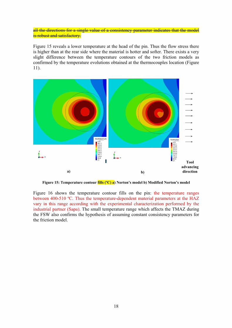
all the directions for a single value of a consistency parameter indicates that the model is robust and satisfactory. Figure 15 reveals a lower temperature at the head of the pin. Thus the flow stress there is higher than at the rear side where the material is hotter and softer. There exists a very slight difference between the temperature contours of the two friction models as confirmed by the temperature evolutions obtained at the thermocouples location (Figure 11).
a) b)
Tool advancing direction
Figure 15: Temperature contour fills (ºC) a) Norton’s model b) Modified Norton’s model
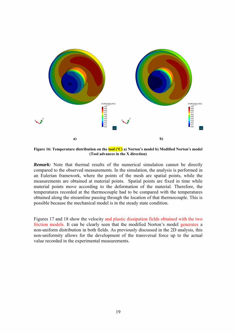
Figure 16 shows the temperature contour fills on the pin: the temperature ranges between 400-510 ºC. Thus the temperature-dependent material parameters at the HAZ vary in this range according with the experimental characterization performed by the industrial partner (Sapa). The small temperature range which affects the TMAZ during the FSW also confirms the hypothesis of assuming constant consistency parameters for the friction model.
19
a) b)
Figure 16: Temperature distribution on the tool (ºC) a) Norton’s model b) Modified Norton’s model (Tool advances in the X direction)
Remark: Note that thermal results of the numerical simulation cannot be directly compared to the observed measurements. In the simulation, the analysis is performed in an Eulerian framework, where the points of the mesh are spatial points, while the measurements are obtained at material points. Spatial points are fixed in time while material points move according to the deformation of the material. Therefore, the temperatures recorded at the thermocouple had to be compared with the temperatures obtained along the streamline passing through the location of that thermocouple. This is possible because the mechanical model is in the steady state condition.
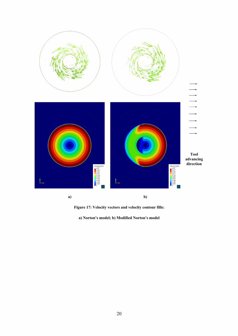
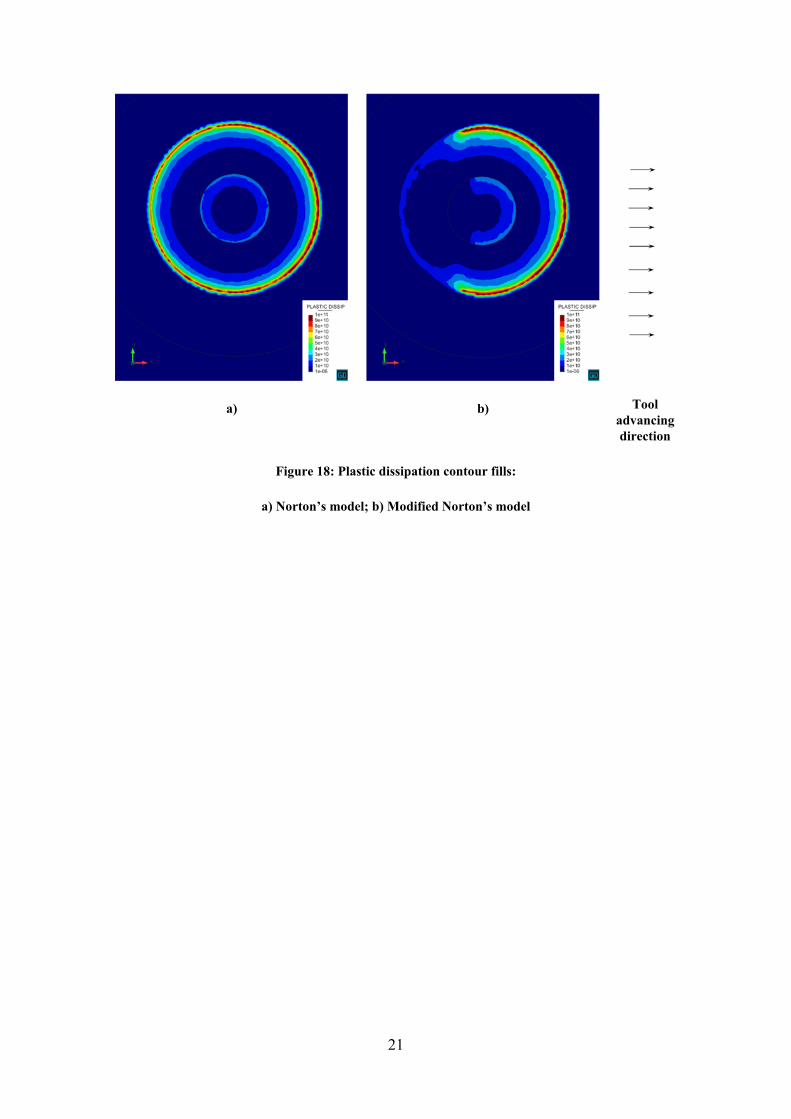
Figures 17 and 18 show the velocity and plastic dissipation fields obtained with the two friction models. It can be clearly seen that the modified Norton’s model generates a non-uniform distribution in both fields. As previously discussed in the 2D analysis, this non-uniformity allows for the development of the transversal force up to the actual value recorded in the experimental measurements.
20
Tool advancing direction
a)
b)
Figure 17: Velocity vectors and velocity contour fills:
a) Norton’s model; b) Modified Norton’s model
21
a)
b)
Tool advancing direction
Figure 18: Plastic dissipation contour fills:
a) Norton’s model; b) Modified Norton’s model
22
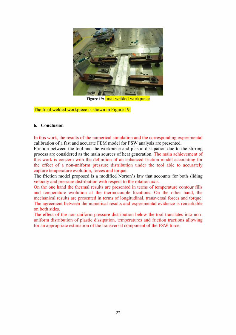
Figure 19: final welded workpiece
The final welded workpiece is shown in Figure 19.
6. Conclusion
In this work, the results of the numerical simulation and the corresponding experimental calibration of a fast and accurate FEM model for FSW analysis are presented. Friction between the tool and the workpiece and plastic dissipation due to the stirring process are considered as the main sources of heat generation. The main achievement of this work is concern with the definition of an enhanced friction model accounting for the effect of a non-uniform pressure distribution under the tool able to accurately capture temperature evolution, forces and torque. The friction model proposed is a modified Norton’s law that accounts for both sliding velocity and pressure distribution with respect to the rotation axis. On the one hand the thermal results are presented in terms of temperature contour fills and temperature evolution at the thermocouple locations. On the other hand, the mechanical results are presented in terms of longitudinal, transversal forces and torque. The agreement between the numerical results and experimental evidence is remarkable on both sides. The effect of the non-uniform pressure distribution below the tool translates into non-uniform distribution of plastic dissipation, temperatures and friction tractions allowing for an appropriate estimation of the transversal component of the FSW force.
23
References
[1] Veljic DM, Rakin MP, Perovic MM. Heat generation during plunge stage in friction stir welding. Thermal Sci 2013;17:489–96.
[2] Colegrove PA. Modelling and development of the Trivex friction stir welding tool. Welding World 2004;48:10–26.
[3] Zhang Z, Chen JT, Zhang ZW, Zhang HW. Coupled thermo-mechanical model based comparison of friction stir welding processes of AA2024-T3 in different thicknesses. J Mater Sci 2011;46:5815–21.
[4] Zhang Z, Zhang HW. Effect of contact model on numerical simulation of friction stir welding. Acta Metall Sinica 2008;44:85–90.
[5] Wang H, Colegrove PA, Dos Santos JF. Numerical investigation of the tool contact condition during friction stir welding of aerospace aluminium alloy. Comput Mater Sci 2013;71:101–8.
[6] Chiumenti, M., Cervera, M., Agelet de Saracibar, C. and Dialami, N. (2012) Numerical modeling of friction stir welding processes. Computer Methods in Applied Mechanics and Engineering, 254:353-369.
[7] Dialami, N., Chiumenti, M., Cervera, M. and Agelet de Saracibar, C. (2013) An apropos kinematic framework for the numerical modeling of friction stir welding. Computers and Structures 117:48-57.
[8] Dialami N., Chiumenti M., Cervera M., Agelet de Saracibar C. and Ponthot J.-P. (2013) Material Flow Visualization in Friction Stir Welding via Particle Tracing, International Journal of Metal Forming, 1-15, DOI:10.1007/s12289-013-1157-4.
[9] Dialami N., Chiumenti M., Cervera M., Agelet de Saracibar C. and Ponthot J.-P. (2014) Numerical simulation and visualization of material flow in friction stir welding via particle tracing, Numerical Simulations of Coupled Problems in Engineering,157-169, Springer International Publishing.
[10] Dialami, N., Cervera, M., Chiumenti, M. and Agelet de Saracibar, C. (2016) Local-global strategy for the prediction of residual stresses in FSW processes, International Journal of Advanced Manufacturing Technology, 1-13. DOI: 10.1007/s00170-016-9016-3
[11] Dialami, N., Chiumenti, M., Cervera, M. and Agelet de Saracibar, C. (2017) Challenges in thermo-mechanical analysis of Friction Stir Welding processes, Archives of Computational Methods in Engineering, 24:189-225, http://dx.doi.org/10.1007/s11831-015-9163-y.
[12] Dialami, N., Chiumenti, M., Cervera, M. and Agelet de Saracibar, C. (2017) A fast and accurate two-stage strategy to evaluate the effect of the pin tool profile on metal flow, torque and forces during friction stir welding, International Journal of Mechanical Sciences 122:215-227.
24
[13] Hamilton C., Dymek S., Sommers A. (2008) A thermal model of friction stir welding in aluminum alloys, International Journal of Machine Tools & Manufacture 48: 1120–1130
[14] Węglowski M. and Hamilton C. (2013) An experimental investigation and modelling of friction stir processing, Engineering transactions 61(1): 65–80.
[15] Zhang Z. and Zhang H. W. (2014) Solid mechanics-based Eulerian model of friction stir welding, Int J Adv Manuf Technol 72:1647–1653
[16] Fagan T., Lemiale V., Nairn J., Ahuja Y., Ibrahim R., Estrin Y. (2016) Detailed thermal and material flow analyses of Friction Stir Forming using a three-dimensional particle based model, Journal of Materials Processing Technology 231: 422-430.
[17] Assidi, M., Fourment, L., Guerdoux, S. and Nelson, T. (2010) Friction model for friction stir welding process simulation: calibrations from welding experiments, Int. J. Mach. Tools Manuf. 50 (2), 143–155.
[18] Simões F. and Rodrigues D.M. (2014) Material flow and thermo-mechanical conditions during Friction Stir Welding of polymers: Literature review, experimental results and empirical analysis, Materials and Design 59:344–351
[19] Chao, Y.J., X. Qi, and W. Tang, Heat transfer in friction stir welding: Experimental and numerical studies (2003) Journal of manufacturing science and engineering, 125 (1): 138-145.
[20] Schmidt, H. and J. Hattel, A local model for the thermomechanical conditions in friction stir welding (2005) Modelling and Simulation in Materials Science and Engineering 13(1): p. 77-93.
[22] Guerdoux, S., Numerical simulation of the friction stir welding process, Ph. D. thesis, Mines-Paris, 2007.
[23] Colligan K (1999) Material flow behavior during friction welding of aluminum. Weld J 75 (7):229–237
[24] Ravichandran G., Rosakis A. J., Hodowany J. and Rosakis Ph. (2002) On the Conversion of Plastic Work into Heat During High Strain Rate Deformation AIP Conference Proceedings 620, 557
[25] Nandan R., DebRoy T. and Bhadeshia H. K. D. H. (2008) Recent Advances in Friction Stir Welding – Process, Weldment Structure and Properties, Progress in Materials Science 53: 980-1023
[26] Soundararajan, V., Zekovic, S. and Kovacevic, R. (2005), Thermo-mechanical model with adaptive boundary conditions for friction stir welding of Al 6061, International Journal of Machine Tools & Manufacture, 45: 1577-87.
[27] Schmidt, H.B. and Hattel, J.H. (2008), Thermal modelling of friction stir welding, Scripta Materialia, 58:332-7.
25
[28] Khandkar, M.Z.H., Khan, J.A. and Reynolds, A.P. (2003), “Input torque based thermal model of friction stir welding of Al-6061, 6th International Trends in Welding Research Conference Proceedings, Pine Mountain, GA, USA, 15-19 April 2002.
[29] Chao, Y.J., Qi, X. and Tang, W. (2003), Heat transfer in friction stir welding – experimental and numerical studies, Journal of Manufacturing Science and Engineering 125:138-45.
[30] Khandkar, M.Z.H., Khan, J.A., Reynolds, A.P. and Sutton, M.A. (2006), Predicting residual stresses in friction stir welded metals, Journal of Materials Processing Technology, 174:195-203.
[31] Cervera M., Agelet de Saracibar C., Chiumenti M. (2002) COMET: Coupled Mechanical and Thermal Analysis, Data Input Manual, Version 5. 0, Technical Report IT-308, http://www.cimne.upc.es
[32] GiD: The personal pre and post preprocessor, 2002. <http://www.gidhome.com>.
[33] Meyghani, B., Awang, M., Emamian, S. and Khalid, N. M. (2017). Developing a Finite Element Model for Thermal Analysis of Friction Stir Welding by Calculating Temperature Dependent Friction Coefficient. In 2nd International Conference on Mechanical, Manufacturing and Process Plant Engineering, 107-126, Springer, Singapore.
[34] Fourment L., Gastebois S.and Dubourg L. (2016) Calibration of 3D ALE Finite Element Model from Experiments on Friction Stir Welding of Lap Joints, AIP Conference Proceedings 1769, 100006 (2016); doi: http://dx.doi.org/10.1063/1.4963500
[35] Đurđanović M. B., Mijajlović M. M., Milčić D. S., Stamenković D. S. (2009) Heat generation during friction stir welding process. Tribology in Industry 31: 8−14.
[36] Jain R., Kumari K., Kesharwani R. K., Kumar S., Pal S. K., Singh S. B. , Panda S. K. , Samantaray A. K. (2015) Friction Stir Welding: Scope and Recent Development, Modern Manufacturing Engineering,179-229, Part of the Materials Forming, Machining and Tribology book series (MFMT)
[37] Elbanhawy A, Chevallier E, Domin K (2013) Numerical investigation of friction stir welding of high temperature materials. NAFEMS world congress, Salzburg
[38] Agelet de Saracibar C., Chiumenti M., Cervera M., Dialami N. and Seret A. (2014) Computational modeling and sub-grid scale stabilization of incompressibility and convection in the numerical simulation of friction stir welding processes, Archives of Computational Methods in Engineering, 21: 3-37.
[39] Cervera M., Chiumenti M., Codina R. (2010) Mixed stabilized finite element methods in nonlinear solid mechanics. Part II: Strain localization, Computer Methods and Applied Mechanics in Engineering, 199 (37-40): 2571-2589.

26
[40] Cervera M., Chiumenti M., Codina R. (2010) Mixed stabilized finite element methods in nonlinear solid mechanics. Part I: Formulation, Computer Methods and Applied Mechanics in Engineering, 199 (37-40): 2559-2570.
Related Documents