PTCC Protection Features

Welcome message from author
This document is posted to help you gain knowledge. Please leave a comment to let me know what you think about it! Share it to your friends and learn new things together.
Transcript

PTCC Protection Features

Overview
The purpose of this presentation is to explain the operation of the various protection features used with the PTCC.
The following topics will be covered:
Sequence Control Live Load Blocking Dead Lockout High Current Lockout Inrush Restraint Cold Load Pickup Single Shot Work Tag

Objectives
At the end of this training session, you should be able to:
Understand how protection and reclosing operations can be modified by the use of the various protection features that are available on the PTCC.

Sequence Control
Where more than one recloser is installed on a feeder, the upstream device must always be coordinated with the downstream device for faults seen by both.
They can become uncoordinated if the fault is still present when the downstream device trips and recloses.
In this case the downstream device will begin timing to trip according to its Trip 2 settings and if the upstream device has also detected the fault it will calculate the time to trip according to its Trip 1 settings.
For a given fault, the upstream device’s Trip 1 time might be shorter than the downstream device’s Trip 2 time.
This could cause an unnecessary loss of supply to the load connected between the two devices.
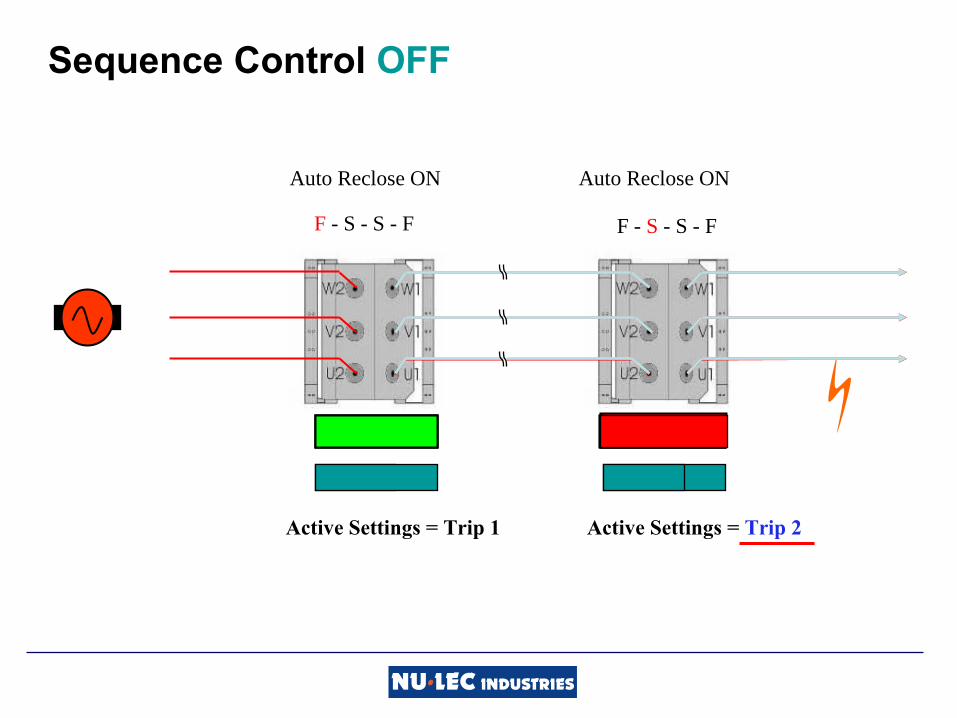
Sequence Control OFF
PickupPickupPickup
Active Settings = Trip 1 Active Settings = Trip 1Active Settings = Trip 2
Auto ReclosePickup
Auto Reclose ON Auto Reclose ON
F - S - S - F F - S - S - FF - S - S - F
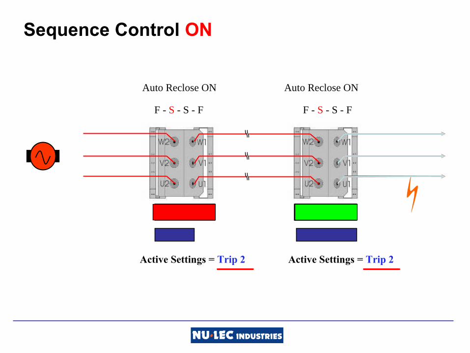
Sequence Control ON
PickupPickupPickup
Active Settings = Trip 1 Active Settings = Trip 1Active Settings = Trip 2
Auto ReclosePickup
Active Settings = Trip 2
Auto Reclose ON Auto Reclose ON
F - S - S - F F - S - S - FF - S - S - FF - S - S - F

Sequence Control Setting on the Control Panel

PTCC Control Panel Navigation
System Status
Event Log
Measurement
Protection

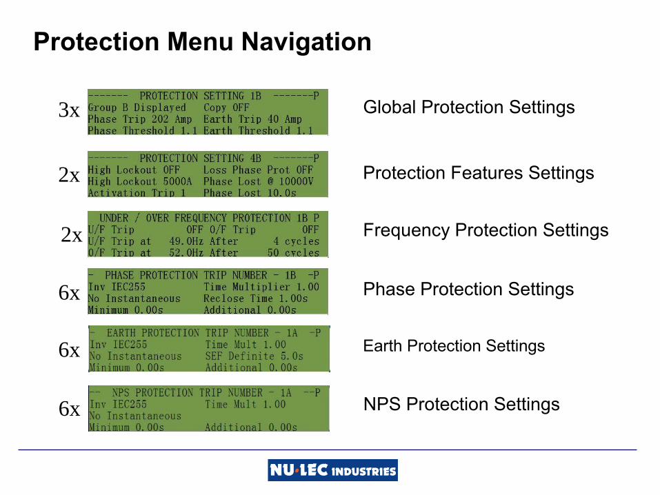
Protection Menu Navigation
6x Earth Protection Settings
6x NPS Protection Settings
3x Global Protection Settings
2x Protection Features Settings
2x Frequency Protection Settings
6x Phase Protection Settings

Sequence Control setting in WSOS

Live Load Blocking

Live Load Blocking
With Live Load Blocking ON, all close requests will be disregarded if any load side terminal is live.
Load 1Source 2
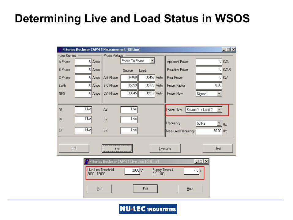
Determining Live and Load Status in WSOS

Live If and Power Flow settings on the Panel

System Status Menu Navigation
1x Trip Flags
2x Operator and System Settings
8x Switchgear Status and Settings
3x Options
1x Quick Key Selection
1x WSOS Port P8 Communications
1x IOEX Status
13x Communications Setup
Dead Lockout

Dead Lockout
When Dead Lockout is ON, the recloser will not automatically reclose unless one or more of the source side or load side terminals are live.
If all the terminals are dead following a protection trip, the controller will go to lockout.
Dead Lockout
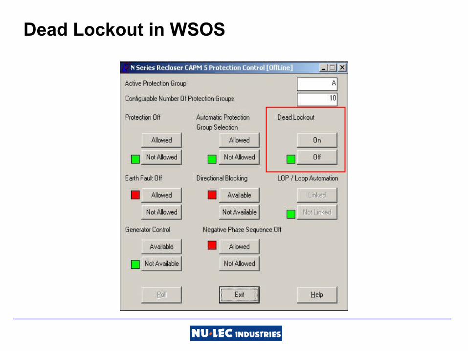
Dead Lockout in WSOS

Dead Lockout On/Off on the Operator Panel
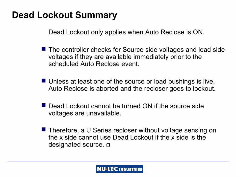
Dead Lockout Summary
Dead Lockout only applies when Auto Reclose is ON.
The controller checks for Source side voltages and load side voltages if they are available immediately prior to the scheduled Auto Reclose event.
Unless at least one of the source or load bushings is live, Auto Reclose is aborted and the recloser goes to lockout.
Dead Lockout cannot be turned ON if the source side voltages are unavailable.
Therefore, a U Series recloser without voltage sensing on the x side cannot use Dead Lockout if the x side is the designated source.
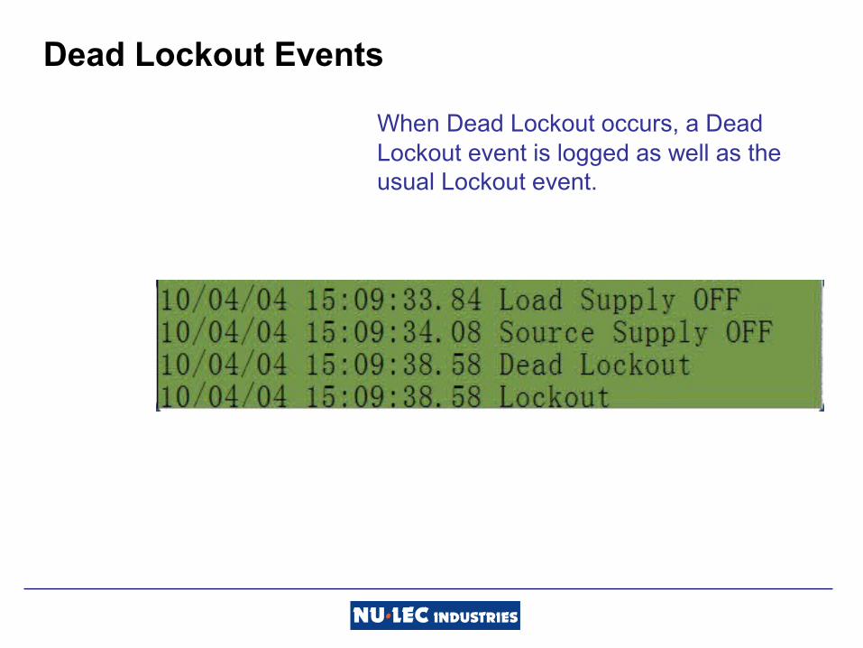
Dead Lockout Events
When Dead Lockout occurs, a Dead Lockout event is logged as well as the usual Lockout event.

High Current Lockout

High Current Lockout
This feature can be used to prevent the recloser from closing onto a large or persistent fault.

High Current Lockout Settings
High Current Lockout operates according to two settings:
Lockout Current
Active Trip No.

High Current Lockout Operation
Auto Reclose ON
High Current Lockout ON
• Lockout current = 500A
• Active Trip = Trip 1
300 A550 A
High Current Lockout

High Current Lockout Summary
Normal Protection Trip occurs with High Current Lockout and Auto Reclose ON.
The controller checks if: The max current measurement for
the most recent protection trip, exceeds the HCL current setting.
The trip number of the most recent protection trip is equal to or greater than the HCL active trip number.
If both of the above conditions are true, the recloser records that the high current setting was exceeded and goes to lockout.
Protection Menu Navigation
6x Earth Protection Settings
6x NPS Protection Settings
3x Global Protection Settings
2x Protection Features Settings
2x Frequency Protection Settings
6x Phase Protection Settings

High Current Lockout setting on the Panel

High Current Lockout setting in WSOS

High Current Lockout and Single Shot
High Current Lockout can occur when Single Shot Mode is active or when closing onto a fault by an operator.
In both of these situations the controller would have gone to lockout anyway without High Current Lockout being triggered.
The difference is that, if High Current Lockout was triggered, an event will be recorded in the Event Log as extra information for fault analysis.

Inrush Restraint
Inrush Restraint works by raising the phase and earth Threshold Currents for a short period of time to allow the inrush current to subside.
Inrush Restraint is armed for operation whenever the load current goes to zero.
When the load at a later time becomes non-zero the Inrush Restraint is activated and the Inrush Multiplier is used in place of the Threshold Current Multiplier for the set time.
Inrush Restraint
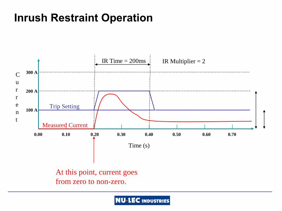
Inrush Restraint Operation
Time (s)
0.00
Current
100 A
200 A
300 A
0.10 0.20 0.30 0.40 0.50 0.60 0.70
Trip Setting
Measured Current
At this point, current goes from zero to non-zero.
IR Time = 200ms IR Multiplier = 2
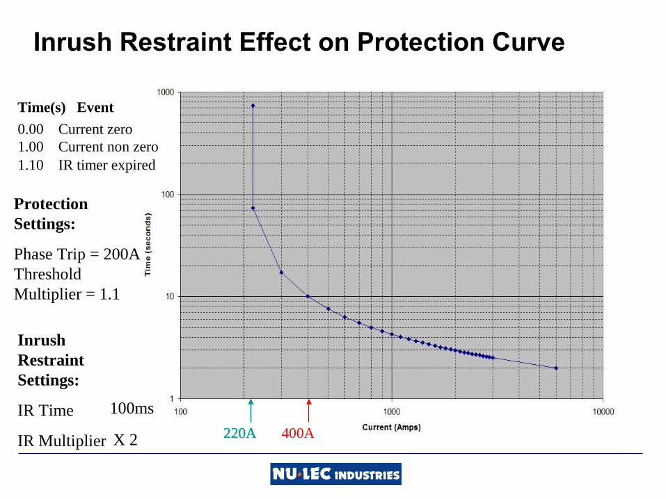
Inrush Restraint Effect on Protection Curve
220A 400A 220A
0.00 Current zero
Time(s) Event
1.00 Current non zero1.10 IR timer expired
Inrush Restraint Settings:
IR Time
IR Multiplier
Protection Settings:
Phase Trip = 200A Threshold Multiplier = 1.1
100ms
X 2

Inrush Restraint – Points to Remember
Inrush Restraint affects phase and earth protection, but does not apply to Definite Time or SEF.
If normal currents are expected to drop below 2.5A, then Inrush cannot be used. In this case Inrush Restraint should be turned off.

Inrush Restraint Settings in WSOS

Protection Menu Navigation
6x Earth Protection Settings
6x NPS Protection Settings
3x Global Protection Settings
2x Protection Features Settings
2x Frequency Protection Settings
6x Phase Protection Settings

Inrush Restraint Settings on Operator Panel

Cold Load Pickup

Cold Load Pickup
When a typical load has been without supply for a period of time (hours) it loses its diversity.
When power is restored the load is higher than usual because all the heater, refrigeration or air conditioner thermostats have turned on.
The longer the period without supply the greater the loss of diversity and the higher the load current will be when supply is restored.

Cold Load Pickup vs Inrush Restraint
Time Inrush Restraint normally operates over 100 – 200ms. Cold Load operates over a number of hours.
Multiple Inrush Restraint applies a set multiple for a set time. Cold Load applies a multiple which changes over time.

1 + Operational Cold Load Time x (User Set Cold Load Multiplier –1)User Set Cold Load Time
Operational Cold Load Multiplier =
Operational Cold Load Time
Time (min)
Current
100 A
200 A
300 A
30 60 90 120 150 180 210
Trip Setting 100A
Load Current 50A

Operational Cold Load Status
Time (min)
Current
100 A
200 A
300 A
60 120 180 240 300 360 420
1 2 3
390
4

Load Off
Cold Load Pickup Effect on Protection Curve
220A 240A 260A 280A 300A 320A 340A 360A 380A 400A 220A
Protection Settings:
Phase Trip = 200A Threshold Multiplier = 1.1
Load OnElapsed Time
10 min20 min30 min40 min50 min60 min70 min80 min90 min
Cold Load Pickup Settings:
CLP Time
CLP Multiplier
90 min
x 2

Cold Load Settings in WSOS

Cold Load Pickup – Points to Remember
The user-set Cold Load Time and Cold Load Multiplier are set on the Protection Settings 5 screen.
On power up, the load is assumed to be diverse, i.e. the Operational Cold Load Time is zeroed and ‘Cold Load IDLE’ will be displayed.
Cold Load affects phase and earth protection thresholds including instantaneous but not SEF.
High Current Lockout and Definite Time settings are not affected.
Cold Load Pickup cannot be used if normal currents are expected to drop below 2.5A, and should be turned off.
When Cold Load protection is turned on the multiplier used for Inrush will always be the higher of the Inrush Multiplier and the Cold Load Multiplier.

Single Shot Mode

Single Shot Mode
Single Shot Mode is used to provide an appropriate protection curve when non-reclosing operation is required, for example, when closing onto a fault.
Single Shot Operation
In Single Shot Mode the controller goes directly to lockout after one trip and will not Auto-Reclose.
Single Shot Mode is activated when:
Auto-Reclose is turned off and Work Tag is not applied. The circuit breaker is closed by operator command
irrespective of the state of Auto-Reclose.
Single Shot is de-activated when:
Auto-Reclose is turned back on. Work Tag is not active, and the Single Shot Timer expires
without a protection pickup ocurring.

Single Shot Timer
This timer starts when the switchgear closes and runs for the preset number of seconds.
This may be disabled by setting the Single Shot reset time to zero.
When set to zero, auto-reclosing will always be enabled while Auto Reclose is ON.
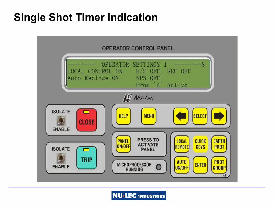
Single Shot Timer Indication

Single Shot Timer initiated by Operator Close
Operator Close
SS Timer
CB Status
t
Single Shot Timer Expires
OPEN CLOSED
Single Shot Timer Setting
Single Shot Mode
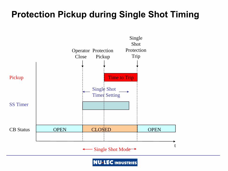
Protection Pickup during Single Shot Timing
CB Status
Pickup
t
SS Timer
Operator Close
OPEN OPEN
Protection Pickup
Single Shot
Protection Trip
CLOSED
Time to Trip
Single Shot Timer Setting
Single Shot Mode

Protection Reset during Single Shot Timing
CB Status
Pickup
t
SS Timer
Operator Close
OPEN
Protection Pickup
CLOSED
Single Shot Timer Setting
Protection Reset
Single Shot Mode
Single Shot Timer Expires

Single Shot Settings in WSOS

Protection Menu Navigation
6x Earth Protection Settings
6x NPS Protection Settings
3x Global Protection Settings
2x Protection Features Settings
2x Frequency Protection Settings
6x Phase Protection Settings

Single Shot Protection Settings
Phase
Earth
NPS

Work Tag

Work Tag
Applying the Work Tag ensures that closing cannot take place at all, either by a local operator, a remote operator or automatically.

Protection Operation with Work Tag Applied
The switchgear cannot close while the Work Tag is applied but Work Tag can be applied when the switchgear is closed.
If a protection trip occurs while the Work Tag is applied, the switchgear will always go to lockout even if Auto Reclose is ON.
The protection pickup and time to trip will be determined by the Work Tag protection settings and Work Tag Trip will be recorded in the Event Log.

Selecting Work Tag ON in WSOS

Applying the Work Tag on the Operator Panel

Work Tag Settings in WSOS

Work Tag Protection Settings
Phase
Earth
NPS
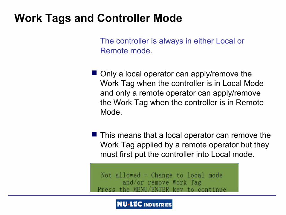
Work Tags and Controller Mode
The controller is always in either Local or Remote mode.
Only a local operator can apply/remove the Work Tag when the controller is in Local Mode and only a remote operator can apply/remove the Work Tag when the controller is in Remote Mode.
This means that a local operator can remove the Work Tag applied by a remote operator but they must first put the controller into Local mode.
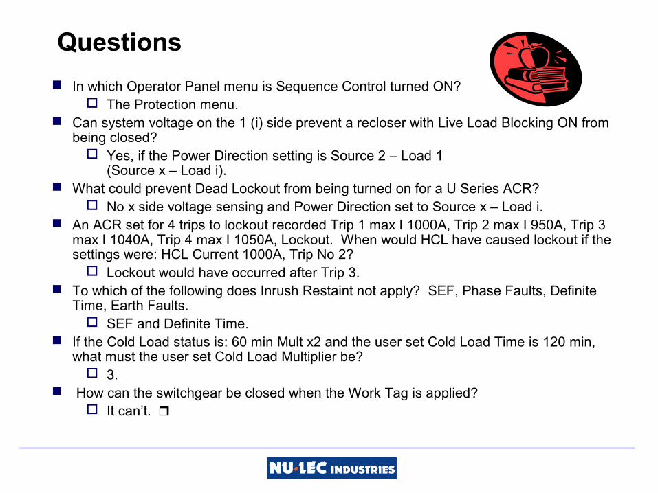
Questions
In which Operator Panel menu is Sequence Control turned ON? The Protection menu.
Can system voltage on the 1 (i) side prevent a recloser with Live Load Blocking ON from being closed?
Yes, if the Power Direction setting is Source 2 – Load 1 (Source x – Load i).
What could prevent Dead Lockout from being turned on for a U Series ACR? No x side voltage sensing and Power Direction set to Source x – Load i.
An ACR set for 4 trips to lockout recorded Trip 1 max I 1000A, Trip 2 max I 950A, Trip 3 max I 1040A, Trip 4 max I 1050A, Lockout. When would HCL have caused lockout if the settings were: HCL Current 1000A, Trip No 2?
Lockout would have occurred after Trip 3. To which of the following does Inrush Restaint not apply? SEF, Phase Faults, Definite
Time, Earth Faults. SEF and Definite Time.
If the Cold Load status is: 60 min Mult x2 and the user set Cold Load Time is 120 min, what must the user set Cold Load Multiplier be?
3. How can the switchgear be closed when the Work Tag is applied?
It can’t.
Related Documents