Copyright 2004 ABB. All rights reserved. External doc. no. Based on 3AFV6000799 en E Project Prep. VMH / Tomi Veikonheimo 07.02.2006 Customer Appr. / Veikonheimo Tomi 09.05.2008 Proj. no. Doc. kind Operating Instruction Doc. des. Ref. des. Title Operating Guidelines Resp. dept VMH Status Approved Doc. no. Lang. Rev. ind. Page 1 ABB Oy, Marine & Turbocharging 3AFV6000799 en H No. of p. 22 ! " # $ % & ’ % ! $( ) $ $ * # # + ) ) , ! " - $ . % % Azipod ® Operating Guidelines

02-A Azipod Operating Guidelines RevH (2)
Jan 02, 2016
Azipod®
Operating Guidelines, To ensure safe and reliable operation with Azipod units, ABB recommends the user to
follow these operational guidelines. These instructions are only for guidance and the sole
responsibility for the safe navigation of the vessel is on its master. Unexpected and
unplanned situations may require different actions.
These instructions are valid for vessels equipped with 2–3 Azipod units and mainly
targeted for cruise vessels.
Bridge equipment can vary between ships. Power limitations can vary between ships.
NOTE! These instructions are not intended for vessels equipped with an Azipod CRP setup.
Welcome message from author
This document is posted to help you gain knowledge. Please leave a comment to let me know what you think about it! Share it to your friends and learn new things together.
Transcript
Copyright 2004 ABB. All rights reserved.
External doc. no. Based on 3AFV6000799 en E Project Prep. VMH / Tomi Veikonheimo 07.02.2006 Customer Appr. / Veikonheimo Tomi 09.05.2008 Proj. no. Doc. kind Operating Instruction Doc.
des. Ref. des.
Title Operating Guidelines Resp. dept VMH Status Approved Doc. no. Lang. Rev. ind. Page 1
ABB Oy, Marine & Turbocharging 3AFV6000799 en H No. of p. 22 ��������� � � � � � � � � � � �� ��� � � � � �� � ��� � � �� � !�" � �# �$���% & �� �' � � �% ��� !�$�( ) ��$���$� * � � # � � # � ��+ � ) � ) , �� � ���!�" - ���$� . ����� � � % % � �� � ���
Azipod®
Operating Guidelines
Doc. kind Operating Instruction Project Customer Title Operating Guidelines Proj. no. Doc. no. Lang. Rev. ind. Page 2
ABB Oy, Marine & Turbocharging 3AFV6000799 en H No. of p. 22
�
Table of Contents
1 GENERAL ................................................................................................................. 3
2 NORMAL OPERATION............................................................................................. 3 2.1 LEVERS AND HANDLING DEVICES........................................................... 3 2.2 GENERAL OPERATIONAL INSTRUCTIONS .............................................. 3 2.3 PREPARATIONS FOR STEERING.............................................................. 6 2.4 LOW-SPEED MANOEUVRING.................................................................... 6
2.4.1 EFFECTIVE THRUST AT DIFFERENT AZIMUTH ANGLES .......... 6 2.4.2 OPERATION WITH TWO AZIPOD UNITS ..................................... 7 2.4.3 OPERATION WITH ONE AZIPOD.................................................. 8 2.4.4 DP OPERATION ............................................................................ 8 2.4.5 MINIMUM RPM .............................................................................. 9 2.4.6 NEGATIVE RPM ............................................................................ 9
2.5 RUNNING ASTERN................................................................................... 10 2.5.1 RUNNING ASTERN WITH POSITIVE RPM ................................. 10 2.5.2 RUNNING ASTERN WITH NEGATIVE RPM................................ 10
2.6 BRAKING................................................................................................... 10 2.7 OPERATION IN HEAVY WEATHER.......................................................... 11 2.8 INCREASE/DECREASE PROGRAM ......................................................... 11
3 ABNORMAL SITUATIONS ..................................................................................... 12 3.1 EMERGENCY STEERING......................................................................... 12
3.1.1 VESSEL HEELING DUE TO MANOEUVRES............................... 12 3.2 CRASH STOP............................................................................................ 12
3.2.1 PROCEDURE DURING CRASH STOP WITH POD WAY ............ 13 3.3 TWO-POD OPERATION, ONE UNIT IS POWERED.................................. 15 3.4 TWO-POD OPERATION, ONE UNIT STEERING ...................................... 15
4 STEERING GEAR CHARACTERISTICS................................................................. 16 4.1 NORMAL OPERATION.............................................................................. 16 4.2 OPERATION IN FAILURE SITUATIONS ................................................... 16 4.3 SWITCHING BETWEEN STEERING GEAR PUMPS................................. 17
APPENDIX 1................................................................................................................... 19
Doc. kind Operating Instruction Project Customer Title Operating Guidelines Proj. no. Doc. no. Lang. Rev. ind. Page 3
ABB Oy, Marine & Turbocharging 3AFV6000799 en H No. of p. 22
�
1 GENERAL
To ensure safe and reliable operation with Azipod units, ABB recommends the user to follow these operational guidelines. These instructions are only for guidance and the sole responsibility for the safe navigation of the vessel is on its master. Unexpected and unplanned situations may require different actions.
These instructions are valid for vessels equipped with 2–3 Azipod units and mainly targeted for cruise vessels.
Bridge equipment can vary between ships. Power limitations can vary between ships.
NOTE! These instructions are not intended for vessels equipped with an Azipod CRP setup.
2 NORMAL OPERATION
This section presents normal day-to-day operation of the vessel.
2.1 LEVERS AND HANDLING DEVICES
The control systems on the bridge may vary from ship to ship. A typical installation includes azimuth levers on the bridge center-console and on both bridge wing-consoles. With these levers it is possible to control the azimuth angle of the pod units in both combined and single-pod mode depending on the installation. Additionally the steering can be controlled by autopilot, in which case the steering commands are directly fed from the autopilot to the steering gear.
The operational placement of the levers and their functionality in different operational modes may vary from vessel to vessel. Please see the control system’s operational manual for the correct functioning of the system.
2.2 GENERAL OPERATIONAL INSTRUCTIONS
Generally, it is recommended to operate and control the pods as gently as possible, because with azimuth propulsion devices it is possible to accelerate the vessel quickly to any direction and this usually leads to necessary use of high power (thrust) levels to stop motion. High power levels at low ship speeds usually lead to harmful heavy vibration that can reduce the lifetime of mechanical components and increase fuel consumption. Especially large azimuth angles combined with high speed through water generate situations that cause heavy vibrations. However, these vibrations might not be felt very clearly on the bridge.

Doc. kind Operating Instruction Project Customer Title Operating Guidelines Proj. no. Doc. no. Lang. Rev. ind. Page 4
ABB Oy, Marine & Turbocharging 3AFV6000799 en H No. of p. 22
�
The general recommendations for various manoeuvres are given in Table 1 and Table 2.
The following general recommendations are for the daily operation of the vessel. These recommendations aim for the safest and most optimal way to operate the vessel with Azipod units. These instructions are based on information gathered from operators and from model-scale testing with different ships and configurations.
• We recommend the power increase/decrease program to be utilized as often as possible (this is a preprogrammed feature that can be activated or deactivated from the bridge).
• In braking/slowing down conditions, reverse power1 shall be avoided (applicable on vessels where the increase/decrease program has not been utilized).
• In open sea condition, pod angles shall be limited to ±10˚. This is a ship-dependent recommendation for course-keeping and maximum angles of the autopilot.
• The recommended way to perform a crash stop is POD WAY (turning pods outwards; the method is described in section 3.2.1).
• Since the propeller is designed for positive RPM, it will always be more effective with positive than with negative RPM. However, in some cases (e.g. in harbor manoeuvres) it might be more time-efficient to reverse instead of turning the pod.
• The unit turns the shortest way from its current position. Therefore, when turning the unit quickly in one move, avoid applying large angles (~180), because this can lead to a situation where the unit turns the opposite way from what was intended.
• Avoid propeller wash over another pod.
1 With reverse power it is referred to the situation where the oncoming water flow rotates the propeller, hence creating a generator of the Azipod unit, which then feeds power into the vessel’s network.

Doc. kind Operating Instruction Project Customer Title Operating Guidelines Proj. no. Doc. no. Lang. Rev. ind. Page 5
ABB Oy, Marine & Turbocharging 3AFV6000799 en H No. of p. 22
�
Table 1. General instructions for various manoeuvres (green allowed, yellow occasionally allowed, red may cause dangerous situations due to fatiguing and excessive wear on components or by sudden movements endangering the general ship stability)
Speed values stated in following table are recommended vessel maximum speeds when starting the operationVessel speed Daily Occasionally EmergencyBoth Azipod turning inwards 10 knots 16 knots Allowed at Any ship speed
Both Azipod turning outwards 10 knots 16 knots Allowed at Any ship speed
Ship slowing (start speed) by rotating both Azipods 35 to 90 degrees outwards (windmilling propellers or with low power)
10 knots 16 knots Allowed at Any ship speed
Maximum ship speed during the use of FAST Steering gear Mode
< 8 knots 8 - 10 knots Allowed at <12 knots
Maximum allowed ship speed During the ordinary use of NFU2 (Non Follow Up) steering tillers
NOT Recommended NOT Recommended Allowed at Any ship speed
2
Table 2. Alternative view: Various manoeuvring operations depending on vessel speed (green allowed, yellow occasionally allowed, red may cause dangerous situations due to fatiguing and excessive wear on components or by sudden movements endangering the general ship stability)
Vessel speed (knots) 2 4 6 8 10 12 14 16 18 20 22 24 26Both Azipod turning inwards
Both Azipod turning outwards
Ship slowing (start speed) by rotating both Azipods 35 to 90 degrees outwards (windmilling propellers or with low power)Maximum ship speed during the use of FAST Steering gear ModeMaximum allowed ship speed During the ordinary use of NFU (Non Follow Up) steering tillers
2 NFU steering is the most elementary form of blind-loop steering for independent pods. The steering angle is not defined, only the Port/Starboard direction, so the actual steering angle must be controlled visually. Also, due to the blind control loop, the set steering angle drifts mechanically and must be compensated manually.
Doc. kind Operating Instruction Project Customer Title Operating Guidelines Proj. no. Doc. no. Lang. Rev. ind. Page 6
ABB Oy, Marine & Turbocharging 3AFV6000799 en H No. of p. 22
�
2.3 PREPARATIONS FOR STEERING
During system start-up, check the operating conditions of the steering system from all control stations by turning each Azipod unit ±35 degrees. There are three reasons for this check:
1. To confirm the operability of all control stations
2. To be sure of the operation of the steering gear
3. To move the slewing bearing rollers to a new position and to maintain a uniform load on the rollers of the slewing bearing
2.4 LOW-SPEED MANOEUVRING
2.4.1 Effective thrust at different azimuth angles
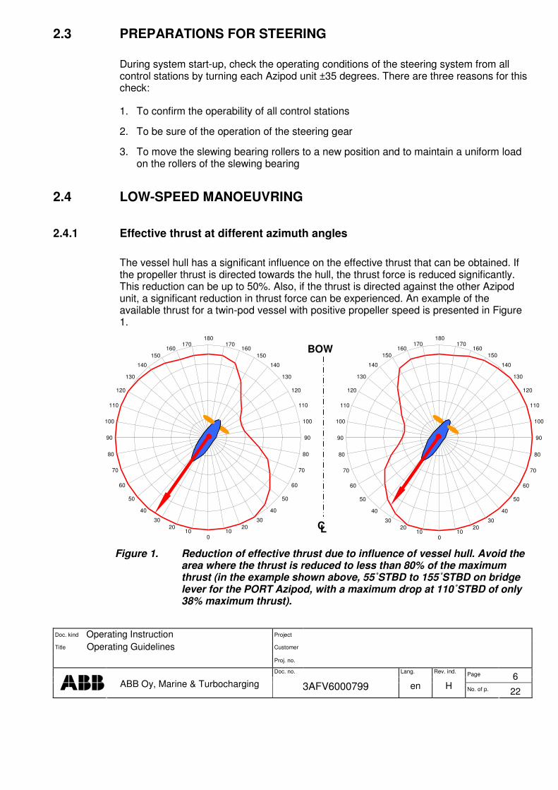
The vessel hull has a significant influence on the effective thrust that can be obtained. If the propeller thrust is directed towards the hull, the thrust force is reduced significantly. This reduction can be up to 50%. Also, if the thrust is directed against the other Azipod unit, a significant reduction in thrust force can be experienced. An example of the available thrust for a twin-pod vessel with positive propeller speed is presented in Figure 1.
Figure 1. Reduction of effective thrust due to influence of vessel hull. Avoid the area where the thrust is reduced to less than 80% of the maximum thrust (in the example shown above, 55˚STBD to 155˚STBD on bridge lever for the PORT Azipod, with a maximum drop at 110˚STBD of only 38% maximum thrust).
180 170
160 150
140 130
120 110
100
90
80 70
60 50
40 30
20 10
0 10 20 30
40 50
60 70
80
90
100 110
120 130
140 150
160 170 180 170
160 150
140 130
120 110
100
90
80 70
60 50
40 30
20 10
0 10 20 30
40 50
60 70
80
90
100
110 120
130 140
150 160 170 BOW
C L
Doc. kind Operating Instruction Project Customer Title Operating Guidelines Proj. no. Doc. no. Lang. Rev. ind. Page 7
ABB Oy, Marine & Turbocharging 3AFV6000799 en H No. of p. 22
�
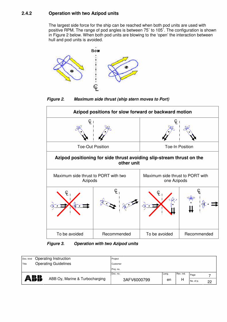
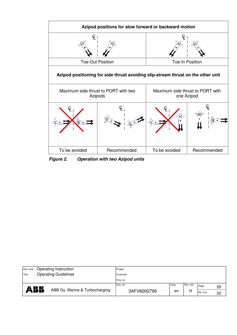
2.4.2 Operation with two Azipod units
The largest side force for the ship can be reached when both pod units are used with positive RPM. The range of pod angles is between 75˚ to 105˚. The configuration is shown in Figure 2 below. When both pod units are blowing to the ‘open’ the interaction between hull and pod units is avoided.
Figure 2. Maximum side thrust (ship stern moves to Port)
Azipod positions for slow forward or backward motion
Toe-Out Position Toe-In Position
Azipod positioning for side thrust avoiding slip-stream thrust on the other unit
Maximum side thrust to PORT with two Azipods
Maximum side thrust to PORT with one Azipods
To be avoided Recommended To be avoided Recommended
Figure 3. Operation with two Azipod units
C L C L
C L C L
C L C L
Doc. kind Operating Instruction Project Customer Title Operating Guidelines Proj. no. Doc. no. Lang. Rev. ind. Page 8
ABB Oy, Marine & Turbocharging 3AFV6000799 en H No. of p. 22
�
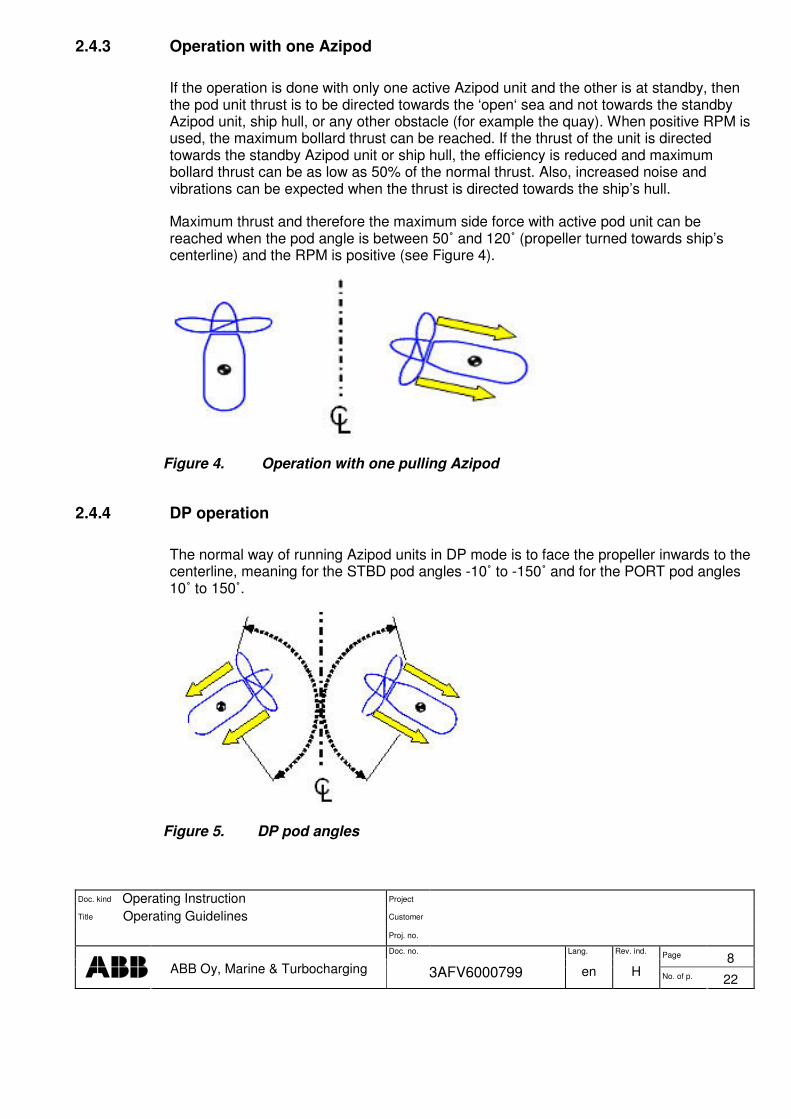
2.4.3 Operation with one Azipod
If the operation is done with only one active Azipod unit and the other is at standby, then the pod unit thrust is to be directed towards the ‘open‘ sea and not towards the standby Azipod unit, ship hull, or any other obstacle (for example the quay). When positive RPM is used, the maximum bollard thrust can be reached. If the thrust of the unit is directed towards the standby Azipod unit or ship hull, the efficiency is reduced and maximum bollard thrust can be as low as 50% of the normal thrust. Also, increased noise and vibrations can be expected when the thrust is directed towards the ship’s hull.
Maximum thrust and therefore the maximum side force with active pod unit can be reached when the pod angle is between 50˚ and 120˚ (propeller turned towards ship’s centerline) and the RPM is positive (see Figure 4).
Figure 4. Operation with one pulling Azipod
2.4.4 DP operation
The normal way of running Azipod units in DP mode is to face the propeller inwards to the centerline, meaning for the STBD pod angles -10˚ to -150˚ and for the PORT pod angles 10˚ to 150˚.
Figure 5. DP pod angles
Doc. kind Operating Instruction Project Customer Title Operating Guidelines Proj. no. Doc. no. Lang. Rev. ind. Page 9
ABB Oy, Marine & Turbocharging 3AFV6000799 en H No. of p. 22
�
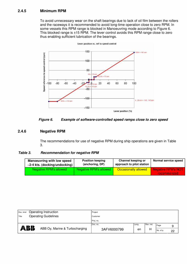
2.4.5 Minimum RPM
To avoid unnecessary wear on the shaft bearings due to lack of oil film between the rollers and the raceways it is recommended to avoid long-time operation close to zero RPM. In some vessels this RPM range is blocked in Manoeuvring mode according to Figure 6. This blocked range is ±15 RPM. The lever control avoids this RPM range close to zero thus enabling sufficient lubrication of the bearings.
Figure 6. Example of software-controlled speed ramps close to zero speed
2.4.6 Negative RPM
The recommendations for use of negative RPM during ship operations are given in Table 3.
Table 3. Recommendation for negative RPM
Manoeuvring with low speed ~2-4 kts. (docking/undocking)
Position keeping (anchoring, DP)
Channel keeping or approach to pilot station
Normal service speed
Negative RPM's allowed Negative RPM's allowed Occasionally allowed Negative RPM's NOT recommended
Doc. kind Operating Instruction Project Customer Title Operating Guidelines Proj. no. Doc. no. Lang. Rev. ind. Page 10
ABB Oy, Marine & Turbocharging 3AFV6000799 en H No. of p. 22
�
2.5 RUNNING ASTERN
2.5.1 Running astern with positive RPM
In this mode, the pod units are first turned 180˚ with azimuth levers (propellers pointing astern). Do this only with azimuth levers and in Manoeuvring mode. The Azipod power is limited for this mode, normally to approx. between 50 and 60% of maximum propulsion power. As the propellers are working in ‘normal’ conditions (positive RPM) in this mode, it is the most efficient way to go astern.
2.5.2 Running astern with negative RPM
In this mode, the Azipod units are kept at zero angles (propellers facing towards the bow). The RPM is set to astern from levers and the thrust created will move the vessel astern.
The propellers are designed for positive RPM. They can, however, be driven in reverse with negative RPM, but they will not work as efficiently as with positive RPMs. Additionally there may be noise and vibrations caused by cavitating propellers.
This manoeuvre can be performed both in Cruise and Manoeuvring mode:
Cruise mode:
Electric motor torque astern is normally limited to 70–80% of maximum torque ahead. This means that the propeller performance is limited in torque instead of power (actual used power is dependent on the propeller characteristics). The Azipod units can be steered normally from the wheel (Azipod units turn parallel).
Manoeuvring mode:
The system limits the Azipod power to 50–60%. The Azipod units can be individually steered from azimuth levers.
2.6 BRAKING
The pod units themselves are generating a large amount of static braking force. Therefore, the most efficient way to reduce the ship speed (here we do not mean crash stop) is by placing the pod units at 35˚ to 90˚ toe-out position (propellers outwards) and at the same time letting the propellers windmill at zero power. This can even be done from full speed without damaging the pod units, but to minimize unnecessary vibrations, consider the recommendations in Table 1 and Table 2. The recommended pod angles are approx. 35˚ to 45˚ outwards. This manoeuvre can be performed only in Manoeuvring mode, because individual azimuth levers are needed to turn the pod units in opposite directions. So when the ship is entering restricted coastal areas with high speed, Cruise mode is switched to Manoeuvring mode, before the braking manoeuvre described above

Doc. kind Operating Instruction Project Customer Title Operating Guidelines Proj. no. Doc. no. Lang. Rev. ind. Page 11
ABB Oy, Marine & Turbocharging 3AFV6000799 en H No. of p. 22
�
can be executed. However, it is recommended to let the speed decrease to about 12–14 knots before changing to Manoeuvring mode.
NOTE! In ships with installed fixipod, the unit’s propeller is set to windmill.
2.7 OPERATION IN HEAVY WEATHER
In heavy weather conditions, it is essential to ensure the safety of the vessel and the people onboard. In these conditions, it may be necessary to use steering techniques that may cause increased levels of vibration and to allow the vessel to yaw more, for example manual steering and larger angles from the azimuth levers. Reduction of speed is to be considered to avoid the most difficult situations. Reduction of speed also increases the redundancy of the power network, allowing it to better cope with power fluctuations from electrical responses.
In head seas at high speed, the vessel may start to vibrate heavily due to bow slamming. Heavy vibration can be avoided by reducing speed or by changing the course of the vessel, or both. Heavy vibration is extremely harmful to all equipment and can shorten the lifetime of all parts affected by it.
During harbor operation or manoeuvring in slow speeds, stern slamming may be encountered. This happens when the waves are coming from astern and they lift up the stern of the vessel, which then slams down. The slamming can induce high impact and vibration forces on the stern of the vessel and are to be avoided.
It is advised that the vessel crew learn the capabilities of the steering equipment in good conditions before going into difficult weather conditions.
We recommend regular emergency exercises to be held locally at the Azipod. These exercises should also include the communication between the bridge and the Azipod room.
NOTE! Load level may be observed by following such operational items as steering gear pressure and vibration levels of bearing systems.
Maintain the equipment according to the maintenance manual to ensure that all the equipment is fully functional in case heavy weather conditions are encountered.
2.8 INCREASE/DECREASE PROGRAM
The power increase/decrease program allows the operator to use the ship’s propulsion in a smoother way. Predefined variables such as power and RPM must be fulfilled before the system can be activated. These variables may vary between ships. The system optimizes the way it works by controlling the propeller power and the operation of the power plant.
Doc. kind Operating Instruction Project Customer Title Operating Guidelines Proj. no. Doc. no. Lang. Rev. ind. Page 12
ABB Oy, Marine & Turbocharging 3AFV6000799 en H No. of p. 22
�
Increase and decrease ramps are much gentler compared to the normal operation of the azimuth lever. There is a clear decrease in the load and vibration levels of the Azipod system when the program is used compared to normal operation. Decrease of the ship speed is done so that any reverse power in the propulsion system is avoided.
The program can be interrupted from manual azimuth levers, if necessary.
3 ABNORMAL SITUATIONS
3.1 EMERGENCY STEERING
In case of an emergency at high speed in Cruise mode with steering wheel operation, it is possible to turn both units to 35 degrees’ pod angle (max. steering angle with steering wheel). The pod units (and propellers) are designed to withstand all forces and moments resulting from this kind of manoeuvre. This kind of operation is allowed only in emergency situations such as extreme course alteration to avoid a collision.
NOTE! In normal operation, the helm angle is limited to ±35˚ on the steering wheel.
NOTE! The vessel will heel heavily (approx. 10…20˚ depending on the ship).
3.1.1 Vessel heeling due to manoeuvres
When using larger steering angles with pods, the vessel can be turned with an extremely small turning radius. The vessel may, however, heel up to 15–20˚. The heeling can cause damage to the equipment/cargo and injuries to people, or both, if it has not been expected. Thus it is recommended to collect data on the maximum heeling angle at different speeds as a function of the pod turning angle. This way it is possible to build up a graph from which the person responsible of operation may check the expected heeling angle before commencing steering actions.
3.2 CRASH STOP
Traditionally, a crash stop has been performed by turning the levers from ahead to reverse. Since the pod units (propellers) can be turned around, there is a possibility to perform a crash stop with a new POD WAY. This is the recommended way to perform a crash stop on vessels with separate levers for PORT and STBD Azipod units, i.e. vessels equipped with a single azimuth lever perform the crash stop in the traditional way.
It is possible to turn the pod units 180˚ without reversing the direction of rotation of the propeller keeping the power ‘’positive’’ the whole time. It is recommended that the pods be turned outwards. However, it is not forbidden to turn the pods inwards. The POD WAY

Doc. kind Operating Instruction Project Customer Title Operating Guidelines Proj. no. Doc. no. Lang. Rev. ind. Page 13
ABB Oy, Marine & Turbocharging 3AFV6000799 en H No. of p. 22
�
crash stop will be more lenient on the power plant, due to decrease in both fluctuation of propulsion power and reverse power generated by the propulsion system. This way the loads on the pod units are reduced and the time and distance of the crash stop is shorter.
Figure 7. Turning of the pods during crash stop
During a crash stop the ship’s course can be controlled with pods (independent levers for every pod unit). If the ship’s course is to be kept unchanged during the crash stop, the pods are to be turned simultaneously in opposite directions.
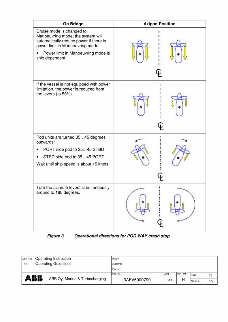
3.2.1 PROCEDURE DURING CRASH STOP WITH POD WAY
NOTE! The POD WAY crash stop can only be performed on vessels with separate levers for PORT and STBD Azipod units.
NOTE! The POD WAY is done by turning the pod units (propellers) simultaneously in opposite directions 180 degrees around their turning axes (See Table 4).

Doc. kind Operating Instruction Project Customer Title Operating Guidelines Proj. no. Doc. no. Lang. Rev. ind. Page 14
ABB Oy, Marine & Turbocharging 3AFV6000799 en H No. of p. 22
�
Table 4. Operational directions for POD WAY crash stop.
On Bridge Azipod Position
Cruise mode is changed to Manoeuvring mode; the system will automatically reduce power if there is power limit in Manoeuvring mode.
• Power limit in Manoeuvring mode is ship dependent.
If the vessel is not equipped with power limitation, the power is reduced from the levers (to 50%).
Pod units are turned 35…45 degrees outwards:
• PORT side pod to 35…45 STBD
• STBD side pod to 35…45 PORT
Wait until ship speed is about 15 knots.
Turn the azimuth levers simultaneously around to 180 degrees.
NOTE! If the ship has 3 pod units, then the center pod unit propeller is set to windmill.

Doc. kind Operating Instruction Project Customer Title Operating Guidelines Proj. no. Doc. no. Lang. Rev. ind. Page 15
ABB Oy, Marine & Turbocharging 3AFV6000799 en H No. of p. 22
�
NOTE! If the center pod is manoeuvrable, it is not turned during crash stop.
3.3 TWO-POD OPERATION, ONE UNIT IS POWERED
Operation with a less than normal number of pods (one or more units not in use)
The maximum power for the remaining units can be reached by opening the supply circuit breakers for unused units, thus reserving the required power to be available in the network. This enables the functional pod to use full power while the one in standby lets its propeller windmill in the water flow. The vessel can be steered normally with the steering wheel and both pods will follow the wheel, since the steering gear is operating normally in both units. The steering capability of the pod unit without thrust is reduced. Autopilot settings are set for normal operation. Therefore, they may not work properly in this situation.
3.4 TWO-POD OPERATION, ONE UNIT STEERING
If one of the Azipod units is to be dedicated purely for propulsion, exclusive technical means can be taken to actively center the hydraulic steering gear zero-degree position for the particular Azipod unit. The need for such action could be due to e.g. maintenance or a control-system update and should only be adopted by a mutual decision between deck and engine staff (Should such a mutual decision be made, the required technical advice can be provided by ABB Marine.)
This will affect the autopilot settings and operation, since it is normally adjusted for twin-pod operation. Therefore adjustments to the system may be necessary. Autopilot maker should make the adjustments.
Both Manoeuvring and Cruise mode can be selected. Full propulsion power can be used and the steering can be done normally from the bridge.
The following remarks should be taken into account:
1. The steering capability of the vessel is decreased due to only one steering pod.
2. Larger steering angles are needed in order to have the same steering effect as with two pods.
3. When the pod unit is steered with large angles at high speed:
• Oblique flow condition reduces propeller thrust, thus operation is less economical
• Cavitation may occur on the propeller and noise onboard
4. The loads on the pod unit are larger than in normal two-pod unit operation, thus ABB recommends the following operational limitations in this case:
Doc. kind Operating Instruction Project Customer Title Operating Guidelines Proj. no. Doc. no. Lang. Rev. ind. Page 16
ABB Oy, Marine & Turbocharging 3AFV6000799 en H No. of p. 22
�
• Reduce ship speed to approx. 75% of maximum speed OR
• Limit steering angles to ±15˚
4 STEERING GEAR CHARACTERISTICS
4.1 NORMAL OPERATION
Depending on the ship, there are generally three different turning rates available (2.5 deg/s, 5 deg/s and 7.5 deg/s). In Cruise mode, it is possible to use one or two hydraulic pumps. With two pumps, the steering rate is double compared to only one pump. In both cases, full torque capacity of the system will be reached.
The Fast mode (ship-dependent) can be selected only in Manoeuvring mode. Both pumps must be running before the selection. In Fast mode, the turning rate will be 2 to 3 times higher than with one pump. At the same time the maximum torque will decrease 33–50%.
All hydraulic motors are in use in every mode.
Under normal operation conditions it is recommended to apply only one steering gear pump on each pod unit.
4.2 OPERATION IN FAILURE SITUATIONS
In case of a failure in the hydraulic system it can be split into two separated halves with a separation valve (SV). After the separation one hydraulic pump can drive half of the hydraulic motors. The turning rate is 100% higher than when using all motors, but the maximum torque decreases to 50%. In this case there is no limitation in the power, but since the maximum torque is approx. 50%, steering angles should not exceed ±15˚. ABB recommends reducing the ship speed to ensure safe operation of the vessel.
Consequently, the ship speed has to be kept below a level that does not risk the opening of safety relief valves (which would lead to loss of steering).
If both halves of the hydraulic system are damaged at the same time, there is no steering torque left. The pod turns around, because the service brake cannot keep the pod stationary (Azipod delivered since the beginning of 2007 are equipped with an automatic locking system that prevents the pod from turning in case of lost hydraulic pressure). The propulsion power drops to zero in the damaged pod unit (the breakers trip).

Doc. kind Operating Instruction Project Customer Title Operating Guidelines Proj. no. Doc. no. Lang. Rev. ind. Page 17
ABB Oy, Marine & Turbocharging 3AFV6000799 en H No. of p. 22
�
4.3 SWITCHING BETWEEN STEERING GEAR PUMPS
In all conditions, one of the steering pumps must be active. Switching from the active steering pump to the other pump is done in the following way:
1. Start the other pump without stopping the active pump
2. Both pumps running
3. Stop the first pump
NOTE! The steering gear pumps should never be stopped simultaneously, before receiving permission. Otherwise the propulsion drive will shut down after a timeout of a few seconds leading to a loss of steering and power.
Copyright 2004 ABB. All rights reserved.
External doc. no. Based on 3AFV6000799 en E Project Prep. VMH / Tomi Veikonheimo 07.02.2006 Customer Appr. / Veikonheimo Tomi 09.05.2008 Proj. no. Doc. kind Operating Instruction Doc.
des. Ref. des.
Title Operating Guidelines Resp. dept VMH Status Approved Doc. no. Lang. Rev. ind. Page 18
ABB Oy, Marine & Turbocharging 3AFV6000799 en H No. of p. 22 ��������� � � � � � � � � � � �� ��� � � � � �� � ��� � � �� � !�" � �# �$���% & �� �' � � �% ��� !�$�( ) ��$���$� * � � # � � # � ��+ � ) � ) , �� � ���!�" - ���$� . ����� � � % % � �� � ���
REVISION
Rev. ind. Page (P)
Chapt. (C)
Description Date Dept./Init.
A This document replaces document 5600957E On cover sheet
B General document update 8.1.2006 TOVE / VMH
C Chapter 4.6 added 13.3.2006/ TOVE / VMH
D General document updated with comments from operators 24.4.2006 TOVE / VMH
E General document updated 5.3.2006
ANKO/VMH
F General document update with input from operators 5.10.2007
TOVE/VMH
G Minor text corrections 12.10.2007
TOVE/VMH
H Changed doc. name to Operating Guidelines
Edited styles to conform to ECM template
30.4.2008
VAD/JTO

Copyright 2004 ABB. All rights reserved.
External doc. no. Based on 3AFV6000799 en E Project Prep. VMH / Tomi Veikonheimo 07.02.2006 Customer Appr. / Veikonheimo Tomi 09.05.2008 Proj. no. Doc. kind Operating Instruction Doc.
des. Ref. des.
Title Operating Guidelines Resp. dept VMH Status Approved Doc. no. Lang. Rev. ind. Page 19
ABB Oy, Marine & Turbocharging 3AFV6000799 en H No. of p. 22 ��������� � � � � � � � � � � �� ��� � � � � �� � ��� � � �� � !�" � �# �$���% & �� �' � � �% ��� !�$�( ) ��$���$� * � � # � � # � ��+ � ) � ) , �� � ���!�" - ���$� . ����� � � % % � �� � ���
APPENDIX 1
Figure 1. Azipod positions at helm angle 35˚ PORT, 100% thrust on PORT Azipod and 90% on STBD Azipod
180 170
160 150
140 130
120 110
100
90
80
70 60
50 40
30 20
10 0 10 20
30 40
50 60
70
80
90
100
110 120
130 140
150 160 170 180
170 160
150 140
130 120
110 100
90
80
70 60
50 40
30 20
10 0 10 20
30 40
50 60
70
80
90
100 110
120 130
140 150
160 170 BOW
C L
Doc. kind Operating Instruction Project Customer Title Operating Guidelines Proj. no. Doc. no. Lang. Rev. ind. Page 20
ABB Oy, Marine & Turbocharging 3AFV6000799 en H No. of p. 22
�
Azipod positions for slow forward or backward motion
Toe-Out Position Toe-In Position
Azipod positioning for side thrust avoiding slip-stream thrust on the other unit
Maximum side thrust to PORT with two Azipods
Maximum side thrust to PORT with one Azipod
To be avoided Recommended To be avoided Recommended
Figure 2. Operation with two Azipod units
C L C L
C L C L
C L C L
Doc. kind Operating Instruction Project Customer Title Operating Guidelines Proj. no. Doc. no. Lang. Rev. ind. Page 21
ABB Oy, Marine & Turbocharging 3AFV6000799 en H No. of p. 22
�
On Bridge Azipod Position
Cruise mode is changed to Manoeuvring mode; the system will automatically reduce power if there is power limit in Manoeuvring mode.
• Power limit in Manoeuvring mode is ship dependent.
If the vessel is not equipped with power limitation, the power is reduced from the levers (to 50%).
Pod units are turned 35…45 degrees outwards:
• PORT side pod to 35…45 STBD
• STBD side pod to 35…45 PORT
Wait until ship speed is about 15 knots.
Turn the azimuth levers simultaneously around to 180 degrees.
Figure 3. Operational directions for POD WAY crash stop

Doc. kind Operating Instruction Project Customer Title Operating Guidelines Proj. no. Doc. no. Lang. Rev. ind. Page 22
ABB Oy, Marine & Turbocharging 3AFV6000799 en H No. of p. 22
�
Table 1. General instructions for various manoeuvres (green allowed, yellow occasionally allowed, red may cause dangerous situations due to fatiguing and excessive wear on components or by sudden movements endangering the general ship stability)
Speed values stated in following table are recommended vessel maximum speeds when starting the operationVessel speed Daily Occasionally EmergencyBoth Azipod turning inwards 10 knots 16 knots Allowed at Any ship speed
Both Azipod turning outwards 10 knots 16 knots Allowed at Any ship speed
Ship slowing (start speed) by rotating both Azipods 35 to 90 degrees outwards (windmilling propellers or with low power)
10 knots 16 knots Allowed at Any ship speed
Maximum ship speed during the use of FAST Steering gear Mode
< 8 knots 8 - 10 knots Allowed at <12 knots
Maximum allowed ship speed During the ordinary use of NFU2 (Non Follow Up) steering tillers
NOT Recommended NOT Recommended Allowed at Any ship speed
Vessel speed (knots) 2 4 6 8 10 12 14 16 18 20 22 24 26Both Azipod turning inwards
Both Azipod turning outwards
Ship slowing (start speed) by rotating both Azipods 35 to 90 degrees outwards (windmilling propellers or with low power)Maximum ship speed during the use of FAST Steering gear ModeMaximum allowed ship speed During the ordinary use of NFU (Non Follow Up) steering tillers
Manoeuvring with low speed ~2-4 kts. (docking/undocking)
Position keeping (anchoring, DP)
Channel keeping or approach to pilot station
Normal service speed
Negative RPM's allowed Negative RPM's allowed Occasionally allowed Negative RPM's NOT recommended
Related Documents