International Journal of Emerging Trends in Engineering Research (IJETER), Vol. 3 No.6, Pages : 453 - 460 (2015) Special Issue of NCTET 2K15 - Held on June 13, 2015 in SV College of Engineering, Tirupati http://warse.org/IJETER/static/pdf/Issue/NCTET2015sp81.pdf 453 ISSN 2347 - 3983 Abstract— The main object of the paper is to implement a distribution system having negligible losses, high quality of supply and reliability. As, average transmission and distribution losses in India have been officially indicated as 23% of the electricity generated because of the fact that in Indian distribution system, energy is transformed into many intermediate stages before it reaches the consumer. Currently, power supplies are distributed at low voltage leading to the inefficiencies in the system. The main reason for high losses is considered to be the use of low voltage for the distribution of power leading to the high current and thus, more resulting in losses. The work reported in this paper involves the analysis of present condition of electric supply, laying do wn the general outlines of the most economical distribution system in order to distribute the power safely without affecting the performance of the system and shifting of existing low voltage distribution network to high voltage distribution and then, comparing both the systems in terms of losses. In overall economic point of view, annual savings and payback period is also determined. Index Terms— Distribution transformer (DTR), high voltage distribution system (HVDS), low voltage distribution system (LVDS), power losses. (key words) I. INTRODUCTION TO DISTRIBUTION SYSTEM In general, electric power is generated at the power stations which are located at the places quite away from the consumers, it is then delivered to the consumers through a large network of transmission and distribution. Earlier, DC generators were connected to the loads at same voltage for electricity distribution because there was no way of changing DC voltage levels. Generally, DC generating plants used to be within 2.4Km of the farthest customers to avoid large and expensive conductors, low voltages were used requiring less insulation and transmission network employed copper which in turn, increased the losses. The present day electrical power system is AC. This distribution system begins as the primary circuit leaves the sub-station and ends as the secondary service which enters the consumer’s meter. Here, the power transformers are installed at power stations raises the generation voltage (11KV or 6.6KV) to higher level (say 220KV or 132KV) for electric power transmission. Electric power at 220KV is transmitted by three-phase, three-wire overhead system to the outskirts of the city and this power is then received by the primary sub-station which reduces the voltage level further to 66KV. This voltage is further stepped down to 11KV at secondary sub-station located at some strategic points in the city. Transformers near the consumer localities step down the voltage level to lower level (400V, 3-phase 4-wire) to supply the loads thereby, distribution of power to long distances became more economical and the distribution losses, size of conductors got reduced. The voltage between any two phases is 415V and between any phase and neutral is 230V. This single-phase 230V is distributed to the residential and commercial load and three-phase, 415V motor load is connected across the three- phase lines directly. Neutral conductor is necessary as it makes the cable better and allows higher latitude to balance the consumers on different phases. Most of the consumers are connected to the transformer, only large customers are fed directly from the distribution voltages. Distribution in rural areas can be single phase for small customers and motor loads. Most of the distribution sub-stations are pole mounted type but in rural areas, these transformer serve only one customer. Conductors require for the distribution may be carried on overhead pole lines or can be buried underground in densely populated areas. II. EXISTING LOW VOLTAGE DISTRIBUTION SYSTEM (LVDS) The following figure is the connection diagram of low voltage distribution system, which has 33/11 KV substation with substation meters, 11 KV feeders, distribution transformers, 415 V distributors and load connections. The existing distribution system in India employs large three-phase 11KV main distribution feeders with three-phase spur lines and three-phase distribution transformers transforming 11KV into 415V. Distribution system with low voltage employs four core cables and long low tension lines and multiple loads fed from a bulk power transformer resulting in the increase in system losses affecting voltage profile and Minimization of Distribution Losses by Implementing High Voltage Distribution System in Real Time Applications N.THIRUPATAIAH asst, professor N.SAIKRISHNAPRASAD Dept. Electrical &Electronics Engineering Dept. Electrical &Electronics Engineering Name of organization – SVCE Tirupati Name of organization - SVCE Tirupati [email protected] [email protected]

Welcome message from author
This document is posted to help you gain knowledge. Please leave a comment to let me know what you think about it! Share it to your friends and learn new things together.
Transcript

International Journal of Emerging Trends in Engineering Research (IJETER), Vol. 3 No.6, Pages : 453 - 460 (2015)
Special Issue of NCTET 2K15 - Held on June 13, 2015 in SV College of Engineering, Tirupati http://warse.org/IJETER/static/pdf/Issue/NCTET2015sp81.pdf
453
ISSN 2347 - 3983
Abstract— The main object of the paper is to implement a distribution system having negligible losses, high quality of supply and reliability. As, average transmission and distribution losses in India have been officially indicated as 23% of the electricity generated because of the fact that in Indian distribution system, energy is transformed into many intermediate stages before it reaches the consumer. Currently, power supplies are distributed at low voltage leading to the inefficiencies in the system. The main reason for high losses is considered to be the use of low voltage for the distribution of power leading to the high current and thus, more resulting in losses. The work reported in this paper involves the analysis of present condition of electric supply, laying do wn the general outlines of the most economical distribution system in order to distribute the power safely without affecting the performance of the system and shifting of existing low voltage distribution network to high voltage distribution and then, comparing both the systems in terms of losses. In overall economic point of view, annual savings and payback period is also determined.
Index Terms— Distribution transformer (DTR), high voltage distribution system (HVDS), low voltage distribution system (LVDS), power losses. (key words)
I. INTRODUCTION TO DISTRIBUTION SYSTEM
In general, electric power is generated at the power stations which are located at the places quite away from the consumers, it is then delivered to the consumers througha large network of transmission and distribution. Earlier, DC generators were connected to the loads at same voltage for electricity distribution because there was no way of changing DC voltage levels. Generally, DC generating plants used to be within 2.4Km of the farthest customers to avoid large and expensive conductors, low voltages were used requiring less insulation and transmission network employed copper which in turn, increased the losses.
The present day electrical power system is AC. This distribution system begins as the primary circuit leaves the sub-station and ends as the secondary service which
enters the consumer’s meter. Here, the power transformers are installed at power stations raises the generation voltage (11KV or 6.6KV) to higher level (say 220KV or 132KV) for electric power transmission. Electric power at 220KV is transmitted by three-phase, three-wire overhead system to the outskirts of the city and this power is then received by the primary sub-station which reduces the voltage level further to 66KV. This voltage is further stepped down to 11KV at secondary sub-station located at some strategic points in the city. Transformers near the consumer localities step down the voltage level to lower level (400V, 3-phase 4-wire) to supply the loads thereby, distribution of power to long distances became more economical and the distribution losses, size of conductors got reduced. The voltage between any two phases is 415V and between any phase and neutral is 230V. This single-phase 230V is distributed to the residential and commercial load and three-phase, 415V motor load is connected across the three-phase lines directly. Neutral conductor is necessary as it makes the cable better and allows higher latitude to balance the consumers on different phases. Most of the consumers are connected to the transformer, only large customers are fed directly from the distribution voltages. Distribution in rural areas can be single phase for small customers and motor loads. Most of the distribution sub-stations are pole mounted type but in rural areas, these transformer serve only one customer. Conductors require for the distribution may be carried on overhead pole lines or can be buried underground in densely populated areas.
II. EXISTING LOW VOLTAGE DISTRIBUTION
SYSTEM (LVDS) The following figure is the connection diagram of
low voltage distribution system, which has 33/11 KV substation with substation meters, 11 KV feeders, distribution transformers, 415 V distributors and load connections. The existing distribution system in India employs large three-phase 11KV main distribution feeders with three-phase spur lines and three-phase distribution transformers transforming 11KV into 415V. Distribution system with low voltage employs four core cables and long low tension lines and multiple loads fed from a bulk power transformer resulting in the increase in system losses affecting voltage profile and
Minimization of Distribution Losses by Implementing High Voltage Distribution System in Real Time Applications
N.THIRUPATAIAH asst, professor N.SAIKRISHNAPRASAD
Dept. Electrical &Electronics Engineering Dept. Electrical &Electronics Engineering Name of organization – SVCE Tirupati Name of organization - SVCE Tirupati

International Journal of Emerging Trends in Engineering Research (IJETER), Vol. 3 No.6, Pages : 453 - 460 (2015)
Special Issue of NCTET 2K15 - Held on June 13, 2015 in SV College of Engineering, Tirupati http://warse.org/IJETER/static/pdf/Issue/NCTET2015sp81.pdf
454
ISSN 2347 - 3983
performance of distribution system. Low voltage distribution is done either by three-phase four-wire, three- phase five-wire, single phase three-wire and single phase two-wire low tension lines. This distribution system involves nearly 2:1 ratio of low& high voltage line lengths.
Fig1: Connection diagram of Present Existed LVDS
Generally, in the process of supplying electricity to the
consumers, energy losses occur due to technical and commercial losses. The technical losses are mainly caused by the energy dissipated in the conductors and equipment used for transformation, transmission and distribution of power. The commercial losses are caused by pilferage, errors in the meter reading or defective meters and in the estimation of unmetered energy supply. These losses depend on the load density, energy pattern used and configuration of transmission and distribution system. 2.1 Reasons for High Technical and Commercial Loss Improper load management resulting in overloading of
conductor and transformers. Also, the pumping load in rural areas and industrial loads in urban areas results in low power factor which in turn, increases the losses.
Inadequate investment in transmission and distribution system in India resulting in the overloading of the distribution system.
Undesired location of distribution transformers increases the overall length of distribution network causing low voltage at the consumers point.
Employment of poor workmanship and use of inferior quality equipment in agricultural pumping in rural areas and in industrial loads in urban areas are some factors greatly affecting the process of distribution network.
Old equipment’s are not maintained, repaired and upgraded properly. Even, capacitors for power factor correction are not installed.
Loss of power is done by deteriorated wires and services. Improper testing and calibration of meters, changing
sequence of terminal wiring and current transformer ratio reduces the recording. In rural areas, loads are widely dispersed and lowtension lines run for long distances to feed a small load. Two or three low tension spans are to be laid to fetch a load of one pump set of 5HP.20 to 30 pump sets are connected on each distribution transformer of 63KVA or 100KVA and for domestic services, about 100 consumers can be connected to the same. Low voltage distribution network results in large faults leading to the frequent interruptions in supply and distribution transformer failures due to low tension fault currents. This distribution system is unsuitable to serve certain areas like desert and forests, where the load density is very low. Low tension faults per annum per 100-circuit Km of lines supplying agricultural pumps are recorded as 15000 and minimum voltage at the customers meter is recorded as 370V. Monitoring of low voltage feeders is very difficult and 75% of low voltage feeders have voltage drop above 5% which is a cause of high current losses beyond loading limits.
2.2 Drawbacks of LVDS
Higher losses, poor tail end voltages, morefluctuations in voltage and frequent cuts fuseblowouts and motor burns out almost twice in eachcropping period of 100 days.
Due to frequent faults, more failures in distribution transformer and its maintenance and repair requires high expenditure. Due to delay in replacement of failed distribution transformers, there is a great loss in standing crops.
Unauthorized hooking or tapping the bare conductors of low tension feeder or tampered service lines and monitoring of low voltage feeders is really very difficult.
In case of any failure in three-phase large capacity distribution transformer, entire unit is to be replaced which consumes more time.
After analyzing the pros and cons of low voltage distribution system, it is clear that there is a great need to reduce the losses in the existing distribution network. Some measures can be taken to minimize the technical as well as commercial losses to some extent and that are: Identification of weakest areas in the distribution system
and strengthening them so as to draw the maximum

International Journal of Emerging Trends in Engineering Research (IJETER), Vol. 3 No.6, Pages : 453 - 460 (2015)
Special Issue of NCTET 2K15 - Held on June 13, 2015 in SV College of Engineering, Tirupati http://warse.org/IJETER/static/pdf/Issue/NCTET2015sp81.pdf
455
ISSN 2347 - 3983
benefits of the limited resources. Segregating the industrial loads from domestic load to
ensure uninterrupted power supplies. Agricultural feeders should be segregated to provide single phase lighting supply to villages.
Shunt capacitors and distribution transformer having lower capacity should be installed to compensate for voltage drop. Employing automatic voltage booster, laying down additional link lines and adoption of high voltage distribution system.
The increase in the load density increases the current density in same proportion which in turn, increases the need of more transforming centers, so a proper strategy is required to be carried out in order to overcome the drawbacks of low voltage distribution system.
The loads in agricultural sector are mainly the pump sets which are used to lift irrigation and they generally, have low power factor and their load density is also low. In existing LVDS, lengthy 11kV LT lines are laid employing three-phase DTR’s of capacity 63 or 100 KVA feeding around 100 consumers and they run for about 1500 hours in an year resulting in poor tail end voltages, high losses, frequent faults, cuts, motor burn outs, DTR failures causing loss of standing crops. To overcome all these problems, implementation of high voltage distribution system is considered as the best move to enhance the performance of distribution system.
III. ADOPTION OF HIGH VOLTAGE DISTRIBUTION SYSTEM (HVDS)
Fig2: Connection diagram of proposed HVDS
The losses in Indian power system are around 20% and are inherent during the processing and delivery of power in existing distribution network. Switching over to three phase HVDS maintains better voltage profiles to agricultural pump sets and reliability of supply to the consumers in agricultural sector . In HVDS, power is distributed mainly
through high voltage lines. This system employs the combination of 11KV three-phase and single phase configuration small capacity distribution transformers (16KVA, 25KVA) extending supply to 8 to 10 consumers with least low tension lines, preferably insulated overhead cable system thereby, reducing losses, overloading and distribution transformer failure and improving the efficiency of the system. This system selects 16/25KVA copper wound transformers with no-load loss (less than 85W) in order to provide mechanical stability to winding.
3.1 Conversion of LVDS into HVDS
HVDS is constructed by converting the existing low tension lines to single-phase, two-wire high tension lines and replacing low tension three-phase cross arm by 11KV cross arm. This 11KV V-shape cross arm should beprovided with three insulators on which the wires are re-laid. Three number of low tension pin insulators and shackles with three number of 11KV pin insulators and strain insulators respectively. Replacing bare conductors by Aerial Bunched Cable (ABC) in theft prone area. New insulators and hardware supports are erected wherever clearances are required. Extended hardware supports that are clamped on to the poles are provided on single pole structure. Connecting existing pump sets from 16/25KVA transformer with ABC and the transformer is then installed on either single or double-pole structure. Low tension line is cleaned and refitted using the same poles and conductors. Each pole is earthed to provide safety to the human being and animals. This conversion does not involve the acquisition of any additional land and there will not be any depletion of cultivable or forest land as the conversion is being done on the existing poles. Therefore, there is no requirement of any R.O.W (Right of Way) for the erection of lines.
HVDS can be single phase and one neutral (continuous neutral from sub-station), two-phase two- wire (rigidly earthed natural system) or three-phase small rating transformers with three-phase high voltage system. With single phase to neutral system, a continuous earth wire is required to be drawn from 33KV/11KV sub-station and earth wire is to be earthed at all the poles. The neutral of the distribution transformer is also earthed on high and low voltage sides. On the secondary side of the transformer, voltage is 230V. The single phase transformer used can be oil filled or dry type (Resin encapsulated). 3.2 Benefits with HVDS The registered customers feel ownership not allowing
others to meddle with low tension network. Thus, the chances of running illegal motors and unauthorized hooking of loads will be prevented due to short and insulated low tension lines minimizing pilferage and improving quality of supply.
Due to reduction in KVA capacity, voltage drop on low
International Journal of Emerging Trends in Engineering Research (IJETER), Vol. 3 No.6, Pages : 453 - 460 (2015)
Special Issue of NCTET 2K15 - Held on June 13, 2015 in SV College of Engineering, Tirupati http://warse.org/IJETER/static/pdf/Issue/NCTET2015sp81.pdf
456
ISSN 2347 - 3983
voltage lines is negligible thereby, improving voltage profile. Therefore, the motors will pump more water and hence, their life of running tube well will increase due to less overheating.
The excellent voltage will reduce the motor burnouts and installation of automatic voltage regulators on high voltage line will minimize the voltage fluctuations.
The single phase motors have built in capacitors and their power factor is more than 0.95 causing low energy losses.
In the event of any fault, only limited no. of customers will be affected increasing the reliability of the system.
Failure of distribution transformer will be eliminated
due to the short length low tension lines and use of aerial bunched cables.
In case of failure of one limb, single phase loads on that phase can be distributed on other two and the failed unit can be replaced quickly and it will be easy to erect and transport too.
Smaller size conductors can be employed and accidents due to touching of snapped conductors reduced as the breaker trips at substation.
Capacities of three phase units can be selected to avoid the laying of low tension lines because these units are available in ratings from 16 KVA to 25 KVA. Also, single phase loads will not contribute to the high unbalances so they can be connected on individual transformers dividing them. Rural electrification systems employ high voltage so that
the distribution lines cover longer distances. In irrigation, single phase HVDS provides availability of good quality of single phase motors improving pump set efficiency and providing high yield of water. On each distribution transformer, only two or three pump sets are connected. In rural areas of low densities, single transformers can be employed for single phase as well as three-phase. The cost of employing three numbers of single phase transformers is more but it can be overcome in approximate three years. By implementing HVDS, a continuous watch can be kept on the reduction in input units and the amount of energy saved in terms of money thus, the billing and collection efficiency increases and the problem of frequent failure of power due to failure of distribution transformer will be reduced considerably.
3.3 HVDS Implemented in Various Areas
HVDS has been implemented in North America where high voltage line is extended to the load point and supply is tapped off from three-phase high voltage mains in the reach of the agricultural pump to serve 5-7HP load provided through distribution transformer of 10KVA.Also, the work of power system up gradation and voltage
improvement has been completed in Bhopal and Gwalior in 2011. Under this, 50 and 17 Km long low tension lines were converted into high tension lines by installing1500 and 800 new transformers respectively. Work of HVDS was also undertaken in Morena and Ambah at a cost of Rs.18 crore under which 1400 transformers were installed to convert low tension lines into high tension lines. These all measures were adopted only to improve the viability of the distribution system.
IV. CASE STUDY The proposed work includes the conversion of existing
LVDS into HVDS in order to minimize the distribution losses and pilferage thereby, improving the voltage profile and quality of supply to the consumers in agricultural sector. For this purpose, two stage methodology is used. In first stage, the power losses in the line and transformer losses for both LT and HVDS system are determined. In the second stage, determination of annual savings and payback period is carried out.
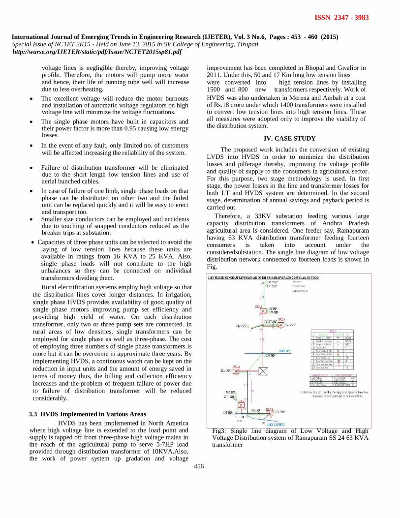
Therefore, a 33KV substation feeding various large capacity distribution transformers of Andhra Pradesh agricultural area is considered. One feeder say, Ramapuram having 63 KVA distribution transformer feeding fourteen consumers is taken into account under the consideredsubstation. The single line diagram of low voltage distribution network connected to fourteen loads is shown in Fig.
Fig3: Single line diagram of Low Voltage and High Voltage Distribution system of Ramapuram SS 24 63 KVA transformer

International Journal of Emerging Trends in Engineering Research (IJETER), Vol. 3 No.6, Pages : 453 - 460 (2015)
Special Issue of NCTET 2K15 - Held on June 13, 2015 in SV College of Engineering, Tirupati http://warse.org/IJETER/static/pdf/Issue/NCTET2015sp81.pdf
457
ISSN 2347 - 3983
In the figure, black lines indicates the low voltage distribution lines, black rectangular box indicates the high rating mother transformer, the red lines indicates high voltage distribution lines, rectangular boxes indicates low rating transformers, the blue lines indicates 11 KV primary feeder and the black cross marks indicates the poles position. 4.2 Calculations of Ramapuram SS 24 63 KVA
Here, voltage on low tension (LT) and high tension (HT) side is 415V and 11KV respectively. The conductor used is Panther (50 mm^2) and the resistance for this particular conductor is 0.556 ohm/Km and power factor is assumed to be 0.8. Power losses in LT arrangement for each consumer are evaluated by equating the corresponding line length and current values (from table1) keeping the fixed value of resistance in equation: ((I^2)×r×L).The parameters available for this particular feeder includes account numbers of all fourteen consumers, sanctioned load in HP, no. of LT poles line length. Other components including load in KW and current are computed from the sanctioned load shown in Table 1.
LT losses including power loss, transformer loss and theft losses of this considered feeder are calculated. Consumer
Sanction Load
No.of Length Current
Power
Load LT of LT Loss
number (HP) (KW) Pole Lines (A) (W)
207 7.5 5.595 6 0.24 9.969 39.78
83 7.5 5.595 6 0.24 9.969 39.78
80 5 3.73 4 0.16 6.63 11.73
173 5 3.73 4 0.16 6.63 11.73
310 7.5 5.595 3 0.12 9.92 19.69
415 5 3.73 5 0.2 6.6139 14.593
488 7.5 5.595 4 0.16 9.9209 26.262
259 5 3.73 1 0.04 6.5496 2.862
104 5 3.73 2 0.08 6.549 5.723
86 5 3.73 4 0.16 6.5977 11.617
93 7.5 5.595 6 0.24 9.9209 39.401
248 6 4.476 6 0.24 7.9563 25.341
257 7.5 5.595 7 0.28 9.9699 46.424
76 7.5 5.595 7 0.28 9.9699 46.424
Total 66.02 341.36
Table 1.Feeder Parameters
4.2.1 LT Power Loss Total Power Loss = 341.36 watts Total LT power loss per annum is evaluated by
summing up the individual power loss of all the consumers and multiplying this value by 2555 hours i.e. total time period of the power supply in agricultural sector is 7 of 24 hours in 365 days per annum.
Power Loss per Annum = [(power loss ) * (No. of hours per day)* (No. of days per Annum)] /1000
Total Power Loss per Annum = (341.3×7×365)/1000 = 872.02 Units.
4.2.2 LT Transformer Losses
On LT side, a large capacity transformer of 63 KVA is used to supply the power to fourteen consumers. Thus, the losses in transformer also contribute to the total losses in LT arrangement. Transformer losses include No Load (Iron) losses and Full Load (Copper) losses. For 63 KVA rating, the fixed value of no load and full load losses are 150 and 1250 W respectively.
No Load Losses per Annum = 383.25 Units, Full Load Losses per Annum = 3193.75 Units.
Total Transformer Losses per Annum = (383.25+3193.75) = 3577 Units.
4.2.3 LT Theft Losses Theft and pilferage account for a substantialpart of LT losses. Pilferage includes unauthorized extensions of loads by consumers and damaging or creating disturbances to the measuring equipment installed at their premises. Theft losses contribute to the 12% of total load and are calculated as below: Total Theft Losses = 12% of Total Load (KW) 0.12× (66.02) = 7.9224 KW Total Theft Losses per
Annum = (7.9224×7×365) = 20241.732 Units
4.2.4 Total LT Losses
Net Losses for LT Distribution = (872.02+3577+20241.732) = 24690.75 Units
After calculating LT losses, LT arrangement is
shifted to HT one by replacing large capacitydistribution transformer of 63 KVA by the transformers having smaller capacity (16, 25 KVA) for supplying power to these consumers keeping same number of poles. This will reduce the power losses to great extent and theft will be minimized. Power and transformer losses in HT arrangement for the same power are calculated. Pilferage in HT arrangement is negligible. Thus, total theft losses per annum in HT arrangement are considered to be NIL.
4.2.5 Voltage Waveforms at Load terminals of LVDS
The voltage at near loads from the mother transformer is maximum where as far load terminal voltage is less compared to near load terminal voltages. The voltage waveforms at one near load (259/5HP) and a far load

International Journal of Emerging Trends in Engineering Research (IJETER), Vol. 3 No.6, Pages : 453 - 460 (2015)
Special Issue of NCTET 2K15 - Held on June 13, 2015 in SV College of Engineering, Tirupati http://warse.org/IJETER/static/pdf/Issue/NCTET2015sp81.pdf
458
ISSN 2347 - 3983
(83/7.5HP) is shown figures. These voltage waveforms are taken from MAT LAB simulation.
411
V
Fig4: Voltage waveform at 259/5HP consumer
405 V
Fig5: Voltage waveform at 83/7.5HP consumer Voltage at 259/5HP consumer is 411 V (near load) and 405 V at 83/7.5HP consumer (far load). 4.2.6 HT Power Losses
Primary voltage and secondary voltage in HT arrangement are 11 KV and 415 V respectively.
Total Power Loss per Annum at 11 KV = (LT Power Losses) {(Secondary voltage/Primary voltage) ^2}
Total Power Loss per Annum = 872.02((415/11000) ^2) = 1.241 Units.
4.2.7 HT Transformer Loss This HT arrangement requires 5 distribution
transformers, four are 25 KVA capacity and one is 16 KVA transformers to feed 14 no. of consumers having load up to 7.5 HP and their no load and full load losses (values taken from table 2) are computed according to the no.of consumers connected to that particular transformer.
No. of Required No Load Full
Load Capacity of Load
Consumers Losses
(HP) Transformer Losses
Availing Load (W)
(KVA) (W)
7.5,5 2,2 25 83 695
7.5,5 2,1 25 83 650
5 2 25 83 600
7.5,6 2,1 25 83 660
7.5,5 1,1 16 63 520
Total 14 395 3125
Table 2. HT Disribution Parameters
Total No Load Losses per Annum = 1009 Units, Total Full Load Losses per Annum = 7984 Units.
Total Transformer Losses per Annum = (1009+7984) = 8993 Units.
4.2.8 Total HT Losses Net Losses in HVDS = (1.24+8993) = 8994.24
Units. Net Reduction in Losses = (Total LT losses-Total
HT losses) = (24690.75 – 8994.24) = 15696.51 Units.
4.2.9 Voltage Waveforms at Load terminals of HVDS The voltage at near load and far load is improved to 414 V and 412 V respectively. These voltage waveforms are shown below figures.
414 V
Fig6: Voltage waveform at 259/5HP consumer
412 V
Fig7: Voltage waveform at 83/7.5HP consumer 4.2.10 Annual Savings
Power Purchase Price by commercial consumer = Rs.7.35
Annual Savings = 7.35(Reduction in Losses) = 7.35(15696) = Rs.1,15,369.34
Capacity of
Transformer Total Cost
Transformer Quantity
(KVA) Cost (Rs.) (Rs.)
16 1 55,000 55,000
25 4 83,000 3,32,000
Total 3,87,000
Table 3. Transformer Costing Parameters

International Journal of Emerging Trends in Engineering Research (IJETER), Vol. 3 No.6, Pages : 453 - 460 (2015)
Special Issue of NCTET 2K15 - Held on June 13, 2015 in SV College of Engineering, Tirupati http://warse.org/IJETER/static/pdf/Issue/NCTET2015sp81.pdf
459
ISSN 2347 - 3983
Miscellaneous Cost includes cost of labor, cost of extra material required for transformer and some cost of dismantling the existing mains which is considered to be Rs.1,20,000 approximately.
4.2.11 Capital Outlay
Capital Outlay = (Total Transformer Cost + Miscellaneous Cost) = Rs. (3,87,000 + 1,20,000) = Rs.5,07,000
4.2.12 Payback Period
Payback period is the length of time required by the cumulative net cash inflows to cover -up the fixed capital investments. Payback Period = (Capital Outlay / Annual Savings) = (5,07,000/1,15,369.34) = 4.4 Years.
Therefore, it is clear from the above
calculations that the use of DTR of small rating for 2 to 3 consumers reduces the power and transformer losses and pilferage hence, results in the increase in annual energy saving. The ultimate objective of adopting this HVDS project is to provide qualitative power to agricultural pump sets in all seasons as per the schedule by taking all possible steps to protect the crops. Thus, it has been proved that the investment on conversion of LVDS to HVDS can be easily recovered by the way of loss reduction within a period of 4 to 5 years. Some opinions have been drawn from the consumers after implementing HVDS in these agricultural areas:- They observed that the motors are drawing less current
and running smoothly without any hissing noise after the conversion from conventional system to HVDS.
Consumers noticed that the voltage profile at the pump
end has improved from 398V to 414V which has improved the pump efficiency.
They also observed that the transformer failures and motor burn outs are also reduced. Hence, life span of motor has increased.
Since the consumers do not allow others to pilfer from their DTR’s. Thus, the theft and interruptions are eliminated ensuring quality of supply and increased productivity.
V. CONCLUSION It is shown that the substantial amount of generated
power is being wasted as losses. Therefore, loss minimization in power system has assumed greater significance. HVDS scheme has led to the formulation of new strategy of energy conservation and minimization of transmission and distribution losses by reducing the power theft. The adoption of HVDS has been indicated as the necessary factor in efficient energy distribution and developing the proper utilization of electricity and efficient distribution of energy in agricultural sector thereby, tackles the problems faced by the farmers. Effective implementation of HVDS scheme has reduced the failure of transformers, burning of agricultural pump sets and curtailment of demand through retrofitting of energy-efficient pumps. This in turn, reduced the wastage of energy and optimization of power intake, thereby promoting the environmental concerns and because of reduced consumption, the farmer gets benefited by the reduction in his monthly expenditure on electricity. It is concluded that the use of distribution transformer of small rating for two or three consumers has reduced the outages, transformer and power losses due to low current and pilferage to a great extent. Also, the accountability of the farmer has increased resulting in moral ownership of the transformer dedicated to single pump. However, initial expenditure on dismantling the existing system is high but it can be compensated in short span of time thus, increasing the annual energy saving. The restructuring of existing LVDS as HVDS in agricultural field presents one of the best technically feasible and financially viable method for providing reliable and quality supply to consumers. Adoption of this innovative measure has been stated to have improved the commercial and technical performance in the particular state. The implementation of this HVDS project opens the avenues for the work in many other related areas. The same work can be extended to commercial, large residential and unbalanced distribution system.
REFERENCES
[1] Energy Audit Report prepared by Southern Power Distribution Company of Andhra Pradesh Limited for the period of October 14, 2009 to February 12, 2011.
[2].J.R.Beard and T.G.N.Haldane, Design of city distribution systems and the problem of standardization,IEEE Journal, 65, 1927, 97-112.
[3].B.R Gupta, Power system analysis and design (New Delhi, S.Chand&Company Limited).
[4].A E W Ford, J R Mathews, B Gregory and G Williams, Review of design, installation and performance of polymeric insulated high voltage cables and accessories in London’s distribution system,IEEE Conference Publication, 383. 1983,119-129.
[5].Robert H.Fletcher and Kai Strunz, Optimal distribution system horizon planning,IEEE Journal of Power system, 22(2), 2007, 791-799.
[6].Vuinovich, A. Sannino, M.G. Ippolito, and G. Morana, Considering

International Journal of Emerging Trends in Engineering Research (IJETER), Vol. 3 No.6, Pages : 453 - 460 (2015)
Special Issue of NCTET 2K15 - Held on June 13, 2015 in SV College of Engineering, Tirupati http://warse.org/IJETER/static/pdf/Issue/NCTET2015sp81.pdf
460
ISSN 2347 - 3983
power quality in expansion planning of distribution systems. [7].Eduardo P. Wiechmann, Esteban J. Pino and Jorge A. Carranza, High
reliability and improved power quality in low voltage distribution system for nonlinear critical loads, IEEE Journal, 1998, 848-853.
[8].Shah Jahirul Islam and Mohd. RuddinAbd.Ghani, Economical
optimization of conductor selection inplanning radial distribution networks,1999, 858-863.
[9].Anoop Singh, A policy for improving efficiency of agriculture pump sets in India(IIT Kanpur, Climate strategies, 2009).
[10].Zhuding Wang, Haijun Liu, David C. Yu, Xiaohui Wang and Hongquan Song, A practical approach to conductor size selection in planning radial distribution system, IEEETtransactions on Power Delivery, 15(1), 2000, 350-354.
[11].E Carpaneto, G Chicco, A Mosso, A Poggi and P Ribaldone, Tools for optimal operation and planning of urban distribution system,IEEE Conference Publication, 482, 2001, 5.22.
[12].M.V Deshpande, Elements of Electrical Power Transmission and Distribution Design (Pune,VidyarthiGrihaPrakashan,1974).
[13].Punjab State Electricity Board (PSEB) Patiala, Environmental and social review on high voltage distribution project for agriculture consumers in the state of Punjab.
Related Documents