A Novel Method for Loss Minimization in Distribution Networks M. A. Kashem, V. Ganapathy, G. B. Jasmon, M. I. Buhari Multimedia University Selangor, Malaysia Tel: (603) 83 125434, Fax: (603) 831 8 3029, Email: [email protected] Abstract: Network reconfiguration for loss minimization is the determination of switching-options that minimizes the power losses for a particular set of loads on a distribution system. In this paper, a novel method is proposed by formulating an algorithm to reconfigure distribution networks for loss minimization. An efficient technique is used to determine the switching combinations, select the status of the switches, and find the best combination of switches for minimum loss. In the first stage of the proposed algorithm, a limited number of switching combinations is generated and the best switching combination is determined. In the second stage, an extensive search is employed to find out any other switching combination that may give rise to minimum loss compared to the loss obtained in the first stage. The proposed method has been tested on a 33-bus system, and the test results indicate that it is able to determine the appropriate switching-options for optimal (or near optimal) configuration with less computation. The results have been compared with those of established methods reported earlier and a comparative study is presented. With the proposed method, for any input load conditions of the system, the optimum switching configuration can automatically be identified within a reasonable computer time and hence the method can be effectively employed for continuous reconfiguration for loss reduction. The method can be effectively used to plan and design power systems before actually implementing the distribution networks for locating the tie- switches and providing the minimum number of sectionalking switches in the branches to reduce installation and switching costs. Keywords: Loss minimization, Network reconfiguration, Distribution automation, and Switching combinations. I. Introduction Distribution systems are normally configured radially for effective coordination of their protective systems. Most distribution networks use sectionalizing-switches that are normally closed, and tie-switches that are normally opened. From time to time, modifying the radial structure of the feeders by changing the odoff status of the sectionalizing and tie switches to transfer Ioads fiom one feeder to another may significantly improve the operating conditions of the overall system. Feeders in a distribution system normally have a mixture of industrial, commercial, residential and lighting loads. The peak load on the substation transformers and feeders occur at different times of the day, and therefore, the distribution system becomes heavily loaded at certain times of the day and lightly loaded at other times. Paper accepted for presentation at the International Conference on Electric Utility Deregulation and Restructuring and Power Technologies 2000, City University, London, 4-7 April 2000. 0-7803-5902-X/00/%10.00 02000 IEEE. Reduction in power losses is obtained by transferring loads fiom the heavily loaded feeders to lightly loaded feeders by reconfiguring the network so that the radial structure of the distribution feeders can be modified fiom time to time. This is done in order to reschedule the loads more efficiently for minimizing the losses in the system. Reconfiguration also allows smoothening out the peak demands improves the voltage profile in the feeders and increases the network reliability. A number of researches have been done on the reconfiguration of the network by closing/opening the tie and sectionalizing switches respectively to minimize losses in a distribution system. A branch exchange type heuristic algorithm has been suggested by Civanlar et. al. [I], where, a simple formula has been developed for determination of change in power loss due to a branch exchange. A different method has been proposed by Baran and Wu [2] to identify the branches to be exchanged using heuristic approach to minimize the search for selecting the switching options. Merlin and Back [3] have used the branch and bound type optimization technique to find the minimum loss configuration. Following the method of reference [3], Shknohammdi and Hong[4] have developed a heuristic algorithm. In their method, the solution is obtained by frst closing all the switches, which are then opened one after another so as to establish the optimum flow pattern in the network. Goswami and Basu 151 also have proposed a heuristic algorithm for feeder reconfiguration by solving the KVL and KCL equations for the network with line impedances replaced by their corresponding resistances only. Broadwater et. al. [6] have applied the Civanlar's method [l] and Huddleston's quadratic loss function and multiple switching pair operation method 171 to solve the minimum loss reconfiguration problem. Peponis et. al. [SI have used the switch-exchange and sequential switch opening methods for reconfiguration of the network for loss reduction. The methods proposed by Rubin Taleski et. al. [9] and Kashem et. al. [lo] are also based on branch- exchange technique for reconfiguration to minimize distribution losses. In all the above methods, the environments under which the calculations are made do not correspond to the actual operating conditions of the system under consideration. They depend on some heuristics and approximations, as the simultaneous switching of the feeder reconfiguration is not considered due to combinatorial explosive nature of the switching options to be encountered. Methods [ll, 121 have been suggested to implement on-line control strategies for power system planing and operations based on continuous network reconfiguration for loss minimization. 251

Welcome message from author
This document is posted to help you gain knowledge. Please leave a comment to let me know what you think about it! Share it to your friends and learn new things together.
Transcript
A Novel Method for Loss Minimization in Distribution Networks
M. A. Kashem, V. Ganapathy, G. B. Jasmon, M. I. Buhari Multimedia University
Selangor, Malaysia Tel: (603) 83 125434, Fax: (603) 831 8 3029, Email: [email protected]
Abstract: Network reconfiguration for loss minimization is the determination of switching-options that minimizes the power losses for a particular set of loads on a distribution system. In this paper, a novel method is proposed by formulating an algorithm to reconfigure distribution networks for loss minimization. An efficient technique is used to determine the switching combinations, select the status of the switches, and find the best combination of switches for minimum loss. In the first stage of the proposed algorithm, a limited number of switching combinations is generated and the best switching combination is determined. In the second stage, an extensive search is employed to find out any other switching combination that may give rise to minimum loss compared to the loss obtained in the first stage. The proposed method has been tested on a 33-bus system, and the test results indicate that it is able to determine the appropriate switching-options for optimal (or near optimal) configuration with less computation. The results have been compared with those of established methods reported earlier and a comparative study is presented. With the proposed method, for any input load conditions of the system, the optimum switching configuration can automatically be identified within a reasonable computer time and hence the method can be effectively employed for continuous reconfiguration for loss reduction. The method can be effectively used to plan and design power systems before actually implementing the distribution networks for locating the tie- switches and providing the minimum number of sectionalking switches in the branches to reduce installation and switching costs. Keywords: Loss minimization, Network reconfiguration, Distribution automation, and Switching combinations.
I. Introduction Distribution systems are normally configured radially for
effective coordination of their protective systems. Most distribution networks use sectionalizing-switches that are normally closed, and tie-switches that are normally opened. From time to time, modifying the radial structure of the feeders by changing the odoff status of the sectionalizing and tie switches to transfer Ioads fiom one feeder to another may significantly improve the operating conditions of the overall system. Feeders in a distribution system normally have a mixture of industrial, commercial, residential and lighting loads. The peak load on the substation transformers and feeders occur at different times of the day, and therefore, the distribution system becomes heavily loaded at certain times of the day and lightly loaded at other times.
Paper accepted for presentation at the International Conference on Electric Utility Deregulation and Restructuring and Power Technologies 2000, City University, London, 4-7 April 2000.
0-7803-5902-X/00/%10.00 02000 IEEE.
Reduction in power losses is obtained by transferring loads fiom the heavily loaded feeders to lightly loaded feeders by reconfiguring the network so that the radial structure of the distribution feeders can be modified fiom time to time. This is done in order to reschedule the loads more efficiently for minimizing the losses in the system. Reconfiguration also allows smoothening out the peak demands improves the voltage profile in the feeders and increases the network reliability. A number of researches have been done on the reconfiguration of the network by closing/opening the tie and sectionalizing switches respectively to minimize losses in a distribution system.
A branch exchange type heuristic algorithm has been suggested by Civanlar et. al. [I], where, a simple formula has been developed for determination of change in power loss due to a branch exchange. A different method has been proposed by Baran and Wu [2] to identify the branches to be exchanged using heuristic approach to minimize the search for selecting the switching options. Merlin and Back [3] have used the branch and bound type optimization technique to find the minimum loss configuration. Following the method of reference [3], Shknohammdi and Hong[4] have developed a heuristic algorithm. In their method, the solution is obtained by frst closing all the switches, which are then opened one after another so as to establish the optimum flow pattern in the network. Goswami and Basu 151 also have proposed a heuristic algorithm for feeder reconfiguration by solving the KVL and KCL equations for the network with line impedances replaced by their corresponding resistances only. Broadwater et. al. [6] have applied the Civanlar's method [l] and Huddleston's quadratic loss function and multiple switching pair operation method 171 to solve the minimum loss reconfiguration problem. Peponis et. al. [SI have used the switch-exchange and sequential switch opening methods for reconfiguration of the network for loss reduction. The methods proposed by Rubin Taleski et. al. [9] and Kashem et. al. [lo] are also based on branch- exchange technique for reconfiguration to minimize distribution losses.
In all the above methods, the environments under which the calculations are made do not correspond to the actual operating conditions of the system under consideration. They depend on some heuristics and approximations, as the simultaneous switching of the feeder reconfiguration is not considered due to combinatorial explosive nature of the switching options to be encountered. Methods [ll, 121 have been suggested to implement on-line control strategies for power system planing and operations based on continuous network reconfiguration for loss minimization.
251
In this paper, an efficient method has been proposed to identify the optimum switching configuration for loss minimization and a comparative study with other established methods made. At the beginning of the proposed method, all the possible switching options obtained fiom the combination of the tie-switch and its two neighbors are selected and the infeasible combinations in the selection are omitted. The minimum loss configuration in the selected combinations is identified. Finally, an extensive search is carried out by changing the switching status one at a time, by either moving to the left or to the right of the open branch in the configuration obtained, and the configuration with maximum loss reduction is determined.
n. Switching Algorithm for Loss Reduction
In a radial distribution system to achieve a maximum reduction in power loss, the aim is to identify the appropriate switching options. In most of the techniques, the losses are calculated by using load-flow studies for each configuration, and the minimum loss configuration is found. In the proposed method, the distribution system is considered with all its laterals simultaneously, instead of determining the switching-options on loop by loop basis. Usually, this type of technique involves very complicated mathematical techniques and large computational time due to the combinatorial nature of the problem. However, the solutions obtained by these methods achieve global optimum of loss minimization problem [9]. The proposed method develops a switching algorithm, which minimizes the computational time by performing the effective search to the requisite switching combinations.
1I.A Determination of Switching Status
In general, any tie orland sectionalizing switches can be closed orland opened to perform various network reconfigurations without creating any closed loop or leaving out any branch unconnected. Any reconfiguration which forms a closed loop, or leaving one or more branches unconnected is classified as infeasible switching combination for network configuration [ 131. To avoid any infeasible switching combinations, the connectivity fiom the source to all the nodes of the system are checked. If a valid path exists, then the configuration is a feasible one, otherwise it is infeasible. It is important to note that every tie switch or sectionalizing switch selected for closing or opening for reconfiguration is considered together with its two immediate neighboring switches. If a tie switch is closed, then a closed loop will be formed. To avoid a closed loop and restore the radial structure, one of the neighboring sectionalizing switches must be opened. The three possible switching combinations form a switch- group. If a sectionalizing switch is opened during reconfiguration, this open branch and its adjoining branches again form a switch-group. In this way, all branches can form switch groups of their own, recursively. If there are n tie switches in a system, there will be n
switch-groups forming 3" different switching combinations. Each switch position in a switching combination is found out by using the formula,
(1) sci = [ SPij , ............. SP,, , SPi, 3 The switch positions of the j* switch in i* combination, SPij can be obtained as,
SPij = [(i - 1) I 3""] mod 3
where, i is the combination number (one of 3" ), j is the switch number ( one of n) and SCi are the positions of the various switches in the i th switching combinations.
The switching positions SCi obtained above will be a 3- digit number containing the combination of 0, 1 and 2, where 0, 1 and 2 status represent the combination with tie- switch open (zero-connect), the right neighbor open (left- connect) the left neighbor open (right-connect) respectively. For zero-connect, the configuration will remain unchanged, but for left-connect or right-connect, the configuration will change according to the left or right- connect logic. Left and right-connect logic are developed using the power flow in the adjoining branches of the tie- branch in the system. When a system is reconfigured by closing the tie-branch and opening either of the adjoining branches, the power-flow in the open-branch which was flowing before reconfiguration, shifts to the newly connected tie-branch. If the left-connect is performed, then the power-flow of the right branch of the tie-branch will be shifted to the tie-branch. Similarly, when the right-connect is performed, the power-flow of the left branch of the tie- branch will be shifted to the tie-branch.
A distribution system after reconfiguration, may become infeasible because there can be some loads which will be isolated from the source of power. In loss minimization technique, there will be certain infeasible combinations arising out of restructuring among the 3" different switching combinations possible. When a branch is left unconnected due to the opening of the sectionalizing switches or a closed loop is created due to the closing of the tie-switches, infeasible combinations result. These infeasible combinations must be identified and eliminated fiom the total combinations. The infeasible combinations are determined by checking the connectivity of each branch in the network. Connectivity of a node or branch means the existence of physical connections of a node or branch from the source. For each combination among all the nodes, select each node one after another, check its connectivity and make its connectivity active if it has the feasible connectivity. This procedure is repeated for all the nodes in the network.
1I.B Finding the Total Losses of a Network by Using Simplified Distflow
Power flow equations for a radial distribution network using real power, reactive power, voltages at the sending and receiving ends of a branch proposed by Baran and Wu r2 I are,
(2)
252
The above equations are called Distflow equations, where, Pi, Qi, V i are the real power, reactive power, and voltage at the sending end and Pi+l, Qi+l, and Vi+l are the receiving end quantities respectively. The quadratic terms in the equations represent the losses on the branches and hence they are much smaller than the power terms Pi and Ql. Hence, by dropping the second order terms the set of new branch equations can be written as,
Pi+l= Pi - PLi+l (4a)
Q. r+l = Q - Q I Li+l (4b)
vi+12 = v? - 2 ( riPi + XiQ) (4c) The solution for the simplified Distflow equations for a radial network can be obtained as [2],
PI+, = c P L k k = i + 2
n
e;+, = C Q L k k = i + 2
The power loss on a branch is calculated as, ri (Pi2 + Qf)
Loss, = Viz
The total system loss is the sum of all the branch losses given by,
Unlike the other load-flow techniques that take a lot of iterations and computational time, in the simplified DistfJow, power-flows are calculated in one cycle of iteration. Therefore, it is suitable for on-line implementation as it reduces computational time.
1I.C Finding the Optimal Configuration for Loss Minimization
The network reconfiguration for loss minimization is performed by opening and/or closing the sectionalizing- and tie-switches in such a way that the radiality of the network is retained and at the same time power losses are minimized. In the proposed method, a systematic approach is employed to perform automatically all types of operations needed for (i) finding the total combinations of the system, (ii) obtaining the feasible combinations, (iii) determining the switching status of the individual switches, (iv) estimating the losses for all the switching combinations, (v) identifying the minimum loss configuration which might be a local or global minimum from among the feasible switching combinations, and (vi) finally making a search to find the global optimm for loss minimization by moving to the left or right of each of the
open lines or tie lines, depending upon whether the right adjoining or the left adjoining branch of a tie-switch is open.
Once the input parameters of the base configuration or any other configuration of a radial system under consideration, are fed to the algorithm, the algorithm automatically reassigns the branches and loads, for any other switching configuration. Ln the input data, apart from specifying the branches, branch impedances, and the loads, we have to specify the tie-branches, the left and right neighboring branches to each of the tie branch and the node numbers on both sides of the tie branches indicating the extent of search to be carried out onto the right and left sides of the tie branches. The switching combinations are formed and the status of each switch in a switch-group is realized. The infeasible combinations are omitted from the total combinations. These switching configurations are formed according to the switching status found from the various switching combinations. The power flows are calculated for each branch of the switching configuration under consideration, and the total power loss is estimated. Likewise, the power loss in each of the remaining configurations is calculated. The configuration that gives the minimum power loss is identified. To further narrow down the search towards the global minimum, a simplified extension of the above procedure is carried out by considering the connectivity of the combination found above. In a reconfigured system obtained from the base configuration, the open sectionalizing or tie switches are considered as the tie switches for the next operation for network reconfiguration. The switch-groups obtained from the combination found above are examined individually, and the switching status of each switch-group is found. If the connectivity of the switch-group remains in the zero switch group (zero-connect) itself, then the switch group is unaltered. If the connectivity of a switch group is towards left (left-connect), the connection is made to move towards right by opening the next neighbor of the right branch of the current tie switch and closing the current tie switch forming a new group. If the connectivity of the switch group is towards right (right-connect), the connection is made to move towards left by opening the next neighbor of the left branch of the current tie-switch and closing the current tie-switch forming a new switch-group. For the newly formed combination, the power loss is calculated and compared with the power loss in the combination estimated earlier. If it is less, then the current combination is considered as the best combination and the search is further carried out in the same direction; otherwise, the combination found earlier is considered as the best combination. The above procedure is applied to other switch-groups in succession and the best combination is found.
111. Test System
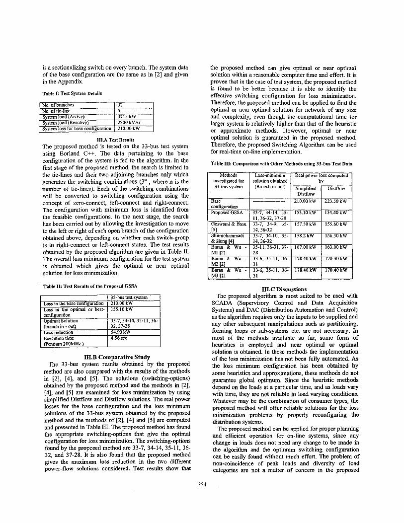
To demonstrate the utility of the proposed switching algorithm, a 33-bus test system is considered and the system details are given in Table I. It is assumed that there
253
No. of branches No. of tie-line
. Svstem load (Active) . System load (Reactive) I 2300kVAr System loss for base configuration I 210.00 kW
32 5 3715 kW
1II.A Test Results The proposed method is tested on the 33-bus test system using Borland C++. The data pertaining to the base configuration of the system is fed to the algorithm. In the first stage of the proposed method, the search is limited to the tie-lines and their two adjoining branches only which generates the switching combinations (3” , where n is the number of tie-lines). Each of the switching combinations will be converted to switching configuration using the concept of zero-connect, left-connect and right-connect. The configuration with minimum loss is identified from the feasible configurations. In the next stage, the search has been carried out by allowing the investigation to move to the left or right of each open branch of the configuration obtained above, depending on whether each switch-group is in right-connect or left-connect status. The test results obtained by the proposed algorithm are given in Table 11. The overall loss minimum configuration for the test system is obtained which gives the optimal or near optimal solution for loss minimization.
Methods investigated for 33-bus system
Base configuration Proposed GSSA
Goswami & Basu
Shirmohammadi & Hong [4]
. 151
- MI [21
- M 2 121
M3 P I
BW & WU -
B~UWI & WU - B w ~ & WU -
Simplified Distflow
210.00 kW
155.10 kW
157.50 kW
158.2 kW
167.00 kW
178.40 kW
178.40 kW
configuration Ootimal Solution I 33-7,34-14,35-11,36-
Distflow
223.50 kW
154.40 kW
155.60 kW
156.30 kW
163.00 kW
170.40 kW
170.40 kW
. Loss in the base configuration
. Loss in the optimal or best-
(Pentium 200MHz ) I 1II.B Comparative Study
The 33-bus system results obtained by the proposed method are also compared with the results of the methods in [2], [4], and [5]. The solutions (switching-options) obtained by the proposed method and the methods in [2], [4], and [5] are examined for loss minimization by using simplified Distf3ow and Distflow solutions. The real power losses for the base configuration and the loss minimum solutions of the 33-bus system obtained by the proposed method and the methods of [2], [4] and [5] are computed and presented in Table 111. The proposed method has found the appropriate switching-options that give the optimal configuration for loss minimization. The switching-options found by the proposed method are 33-7, 34-14, 35-11, 36- 32, and 37-28. It is also found that the proposed method gives the maximum loss reduction in the two different power-flow solutions considered. Test results show that
33-bus test system 210.00 kW 155.10 kW
the proposed method can give optimal or near optimal solution within a reasonable computer time and effort. It is proven that in the case of test system, the proposed method is found to be better because it is able to identify the effective switching configuration for loss minimization. Therefore, the proposed method can be applied to find the optimal or near optimal solution for network of any size and complexity, even though the computational time for larger system is relatively higher than that of the heuristic or approximate methods. However, optimal or near optimal solution is guaranteed in the proposed method. Therefore, the proposed Switching Algorithm can be used for real-time on-line implementation.
Table 111: Comparison with Other Methods using 33-bus Test Data
(branch in - out) 32,37-28 Loss reduction 54.90 kW
’ Execution time 4.56 sec
Loss-minimum solution obtained (Branch in-out)
33-7, 34-14, 35- I 1,36-32,37-28 33-7, 34-9, 35- 14,36-32 33-7, 34-10, 35- 14,36-32 35-11,36-31, 37- 28 33-6. 35-11. 36- 31 33-6, 35-11, 36-
1II.C Discussions The proposed algorithm is most suited to be used with
SCADA (Supervisory Control and Data Acquisition Systems) and DAC (Distribution Automation and Control) as the algorithm requires only the inputs to be supplied and any other subsequent manipulations such as partitioning, forming loops or sub-systems etc. are not necessary. In most of the methods available so far, some form of heuristics is employed and near optimal or optimal solution is obtained. In these methods the implementation of the loss minimization has not been fully automated. As the loss minimum configuration has been obtained by some heuristics and approximations, these methods do not guarantee global optimum. Since the heuristic methods depend on the loads at a particular time, and as loads vary with time, they are not reliable in load varying conditions. Whatever may be the combination of consumer types, the proposed method will offer reliable solutions for the loss minimization problems by properly reconfiguring the distribution systems.
The proposed method can be applied for proper planning and efficient operation for on-line systems, since any change in loads does not need any change to be made in the algorithm and the optimum switching configuration can be easily found without much effort. The problem of non-coincidence of peak loads and diversity of load categories are not a matter of concern in the proposed
254
system. Since simultaneous evaluation of power losses in all the branches are done for a set of switching combinations, the method is more reliable and gives better results. Also, the method gives a lot of flexibility to limit or extend the search simply by specifying the branch numbers to which the search is to be done on both ends of each tie-switch in the system. The proposed method can be reliably employed for loss minimization as it has been found to be most effective and gives the best optimal solutions compared to the methods available for loss minimization by reconfiguring the radial distribution network.
IV. Conclusion A switching algorithm is formulated for network
reconfiguration based loss reduction, and a new solution method is proposed in this paper. To reduce the combinatorial explosive switching problems into a realizable one, an efficient technique has been introduced for reconfiguration of distribution networks. In the first stage, the tie-branches and its two adjoining branches are considered to generate switching combinations and the best combination among them is identified. In the second stage, the search has been extended to find whether there is any other switching option that may give minimum loss. To improve the accuracy and to rule out the possibility of leaving out any other better switching combination, the search is done by considering switching options beyond the two neighboring branches of each of the tie-switches. This is done by specifying the branch numbers to which the search is extended along with each of the tie-switch specifications in the input. The method has been compared with five other methods and a comparative study is presented. From the test results and comparative study it can be concluded that the proposed method can effectively identify the appropriate switches for loss minimization with minimum computational effort. The technique can be effectively installed in real time on-line systems under widely varying load conditions, and this is suitable for power system planning and operations. The proposed method is suitable for continuous reconfiguration for loss reduction. And it can also be used for planning and design of power systems to reduce installation and switching costs.
References:
1. S . Civanlar, J.J. Grainger, H. Yin and S . S . H. Lee, 'Distribution Feeder Reconfiguration for Loss Reduction', IEEE Trans. on Power Delivery, Vo1.3, No.3, pp.1217-1223, July 1988. M. E. Baran and F. F. Wu, 'Network Reconfiguration in Distribution Systems for Loss Reduction and Load Balancing', IEEE Trans. on Power Delivery, Vo1.4, No.2, pp.1401-1407, April 1989. A. Merlin, H. Back, 'Search for a Minimal-Loss Operating Spanning Tree Configuration for an Urban Power Distribution System', Proc. Of the 5* Power System Conference (F'SCC), pp.1-18, Cambridge, 1975. D. Shirmohammadi and H. W. Hong, 'Reconfiguration of Electric Distribution Networks for Resistive Line Losses Reduction', IEEE Trans. on Power Delivery, vo1.4, No.2, pp.1492-1498, April 1989. S . K. Goswami and S . K. Basy 'A New Algorithm for the Reconfiguration of Distribution Feeders for Loss Minimization',
2.
3.
4.
5.
6.
7.
8.
9.
10.
11.
12.
13.
IEEE Trans. on Power Delivery, Vo1.7, No.3, pp.1484-1491, July 1992. R. P. Broadwater, A. H. Khan, H. E. Shaalan and R. E. Lee, Time Varying Load Analysis to Reduce Distribution Losses through Reconfiguration', IEEE Trans. on Power Delivery, Vo1.8, No.1,
C. T. Huddleston, R. P. Broadwater and A. Chandrasekaran, 'Reconfiguration Algorithm for Minimizing Losses in Radial Electric Distribution Systems', Electric Power System Research,
G. P. Peponis, M. P. Papadopoulos and N. D. Hatziargyriou, 'Distribution Network Reconfiguration to Minimize Resistive Line Losses', lEEE Trans. on Power Delivery, Vol.10, No.3, pp.1338- 1342, July 1995. R. Taleski and D. Rajicic, 'Distribution Network Reconfiguration for Energy Loss Reduction', IEEE Trans. on Power Systems, Vo1.12,No.l, pp.398406, February 1997. M. A. Kashem, M. Moghavvemi, A. Mohamed and G. B. Jasmon, 'Loss Reduction in Distribution Networks using New Network Reconfiguration Algorithm', Electric Machines and Power Systems, Vo1.26, No.8, pp.815-829, October 1998. B. C. G. Shin, 'Development of the Loss Minimization Function for Real time Power System Operations: A New Tool', IEEE Trans. on Power Systems, vo1.9, No.4, pp.2028-2034, November 1994.
V. Borozan and N. Rajakovic, 'Minimum Loss Distribution Network Configuration: Analyses and Management', Proc. of IEE Conference, pp.6.18.1-6.18.5, 2-5 June 1997. M. A. Kashem, 'V. Ganapathy, G. B. Jasmon, 'Network Reconfiguration for Enhancement of Voltage Stability in Distribution Networks', to appear in IEE Proceedings - Generation, Transmission and Distribution.
pp.294-300, January 1993.
Vol. 18, NO. 1, pp.57-67, 1990.
Biographies
M. A. Kashem was bom in Bangladesh in 1968. He received his B.Sc. in Electrical & Electronic Engineering from Bangladesh University of Engineering & Technology (BUET) in 1993. He has completed his Masters in Engineering Science from the University of Malaya, Malaysia at 1997. He worked in a power system consultancy firm for one year. Currently he is working as a Lecturer in the Faculty of Engineering, Multimedia University, Malaysia and pursuing his Doctoral study in the same University. His research interests are distribution system automation, power system planning, neural networks and computer networking and he has published more than seventeen papers in these areas. V. Ganapathy was bom on In May 1941 in Salem, India He received his Bachelor of Engineering and Masters or Engineering degrees in the years 1964 and 1971 respectively from the University of Madras, India He got his Ph.D. fiom the Indian Institute of Technology, Madras, India in the year 1982. He has the experience of two years in industries and more than thirty-four years in teaching profession. His research interests are in neural networks, digital signal processing, power systems, microprocessors, computer graphics and robotics. He has published more than fifty papers in the above areas. He is currently with the Faculty of Information Technology, Multimedia University, Malaysia. Ghauth Jasmon was bom in Malaysia in 1956. He graduated with BSc(Eng) and PhD degrees in 1979 and 1982 respectively from the University of London, UK. His research areas are in power systems security, stability, load management and voltage stability, and has published more than sixty papers in these areas. He is currently the Chief Executive and President of Multimedia University, Malaysia He is a Senior Member of the IEEE, Fellow of the IEE(UK) and Fellow of the Institute of Engineers, Australia" M.I. Seyed Mohamed Buhari was bom on 24th April 1974. He did his Bachelors Degree in Computer .Engineering at Mepco Schlenk Engineering College, India and his Masters Degree in Computer Science and Engineering from the PSG College of Technology, India. Currently he is pursuing his Doctoral Programme at the Multimedia University, Malaysia. Till date, he has presented nine technical papers in Intemational conferences. His areas of interest are Computer Networks, Operating Systems and Parallel Processing.
255
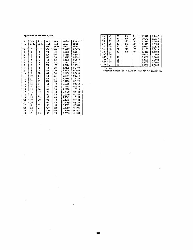
Appendix: 33-bus Test System 25 20 70 600 70 100 40
- Br. no.
1 2 3 4 5 6 7 8 9 10 11 12 13 14 15 16 17 18 19 20 21 22 23 24 25
-
0.2842 0.1447 1.0590 0.9337 0.8042 0.7006 0.5075 0.2585 0.9744 0.9630 0.3105 0.3619 0.3410 0.5302 2.0000 2.0000 2.0000 2.0000 2.0000 2.0000 0.5000 0.5000 0.5000 0.5000
- Sen. node
0 1 2 3 4 5 6 7 8 9 10 11 12 13 14 15 16 1 18 19 20 2 22 23 5
- Rec. node
1 2 3 4 5 6 7 8 9 10 11 12 13 14 15 16 17 18 19 20 21 22 23 24 25
- Real load kw 100 90 120 60 60
200 200 60 60 45 60 60 120 60 60 60 90 90 90 90 90 90 420 420 60
-
-
- Reac. load kVAr 60 40 80 30 20 100 100 20 20 30 35 35 80 10 20 20 40 40 40 40 40 50
200 200 25
-
- Resis- tance ohms 0.0922 0.4930 0.3660 0.3811 0.8190 0.1872 1.7114 1.0300 1.0440 0.1966 0.3744 1.4680 0.5416 0.5910 0.7463 1.2890 0.7320 0.1640 1.5042 0.4095 0.7089 0.4512 0.8980 0.8960 0.2030 -
- Reac- tance ohms 0.0470 0.251 1 0.1 864 0.1941 0.7070 0.6188 1.2351 0.7400 0.7400 0.0650 0.1238 1.1550 0.7129 0.5260 0.5450 1.7210 0.5740 0.1565 1.3554 0.4784 0.9373 0.3083 0.7091 0.701 1 0.1034 -
- 26 27 28 29 30 31 32 33* 34* 35* 36* 37* * Tit Subs
- :t
28 120 28 29 200 29 30 150 30 210
32 60 20
14 11 21 17 32 24 28
lines ation Voltage (kv) = 12
256
Related Documents