The Boiler Control 256 is designed to control a single stage heat source in order to provide outdoor reset. The control has a Liquid Crystal Display (LCD) to view system status and operating information. • Test sequence to ensure proper boiler operation • Setback input for energy savings • CSA C US certified (approved to applicable UL standards) Additional functions include: • Quick Setup for easy installation and programming of control • User comfort adjustment to increase or decrease building space temperature • Advanced settings to fine-tune building requirements - Installation & Operation Manual Boiler Control 256 D 256 07/11 1 of 20 © 2011 D 256 - 07/11 Input Outdoor Sensor Included Input Universal Sensor Included Input 24 V (ac) Power Supply Output Boiler Input tekmar Timer Optional BOIL F OCC Input Boiler Demand Signal Press & Release: all 3 buttons, to adjust menu Press & Hold: Item, to view settings , to test. Boiler Control 256 One Stage Boiler Item Date Code Power: 24 V ±10% 50/60 Hz 3 VA Class 2 Relay: 240 V (ac) 5 A 1/6 hp Meets Class B: Canadian ICES FCC Part 15 H1190D Terminal Unit Boiler Demand Inst / Adv 1 Boil 2 Out 3 Com 4 UnO Sw 5 Boiler 6 7 T 8 Power R+ 9 C- Do not apply power tektra 909-01 Designed & Assembled in Canada Signal wiring must be rated at least 300V Note: Boiler demand must have an electrical closure between terminals 7 and 9 before the boiler is able to fire.

Welcome message from author
This document is posted to help you gain knowledge. Please leave a comment to let me know what you think about it! Share it to your friends and learn new things together.
Transcript
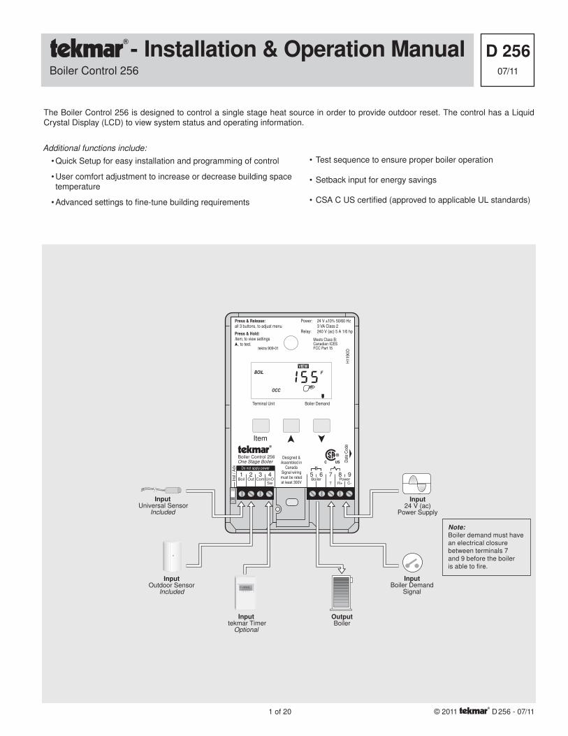
The Boiler Control 256 is designed to control a single stage heat source in order to provide outdoor reset. The control has a Liquid Crystal Display (LCD) to view system status and operating information.
• Test sequence to ensure proper boiler operation
• Setback input for energy savings
• CSA C US certifi ed (approved to applicable UL standards)
Additional functions include:
• Quick Setup for easy installation and programming of control
• User comfort adjustment to increase or decrease building space temperature
• Advanced settings to fi ne-tune building requirements
- Installation & Operation ManualBoiler Control 256
D 25607/11
1 of 20 © 2011 D 256 - 07/11
InputOutdoor Sensor
Included
InputUniversal Sensor
Included
Input24 V (ac)
Power Supply
OutputBoiler
Input tekmar Timer
Optional
BOIL F
OCC
InputBoiler Demand
SignalPRGM
S
T I M E
AMPMUNOCC
OVR
SM W T FT
12
Press & Release:all 3 buttons, to adjust menu
Press & Hold:Item, to view settings , to test.
Boiler Control 256One Stage Boiler
Item
Date
Cod
e
Power: 24 V ±10% 50/60 Hz 3 VA Class 2Relay: 240 V (ac) 5 A 1/6 hp
Meets Class B:Canadian ICESFCC Part 15
H11
90
D
Terminal Unit Boiler Demand
Inst
/ Ad
v
1Boil
2Out
3Com
4UnOSw
5Boiler
6 7
T
8Power
R+
9
C-
Do not apply power
tektra 909-01
Designed & Assembled in
Canada Signal wiring must be rated at least 300V
Note: Boiler demand must have an electrical closure between terminals 7 and 9 before the boiler is able to fire.
This brochure is organized into four main sections. They are: 1) Sequence of Operation, 2) Installation, 3) Control Settings, and 4) Troubleshooting. The Sequence of Operation section has three sub-sections. We recommend reading Section A: General Operation of the Sequence of Operation, as this contains important information on the overall operation of the control. Then read the sub-sec-tions that apply to your installation. For quick installation and setup of the control, refer to the Installation section, DIP Switch Setting section, followed by the Quick Setup section.
The Control Settings section (starting at DIP Switch Setting) of this brochure, describes the various items that are adjusted and displayed by the control. The control functions of each adjustable item are described in the Sequence of Operation.
Reference Material: Essay E 003 “Characterized Heating Curve and Reset Ratio”
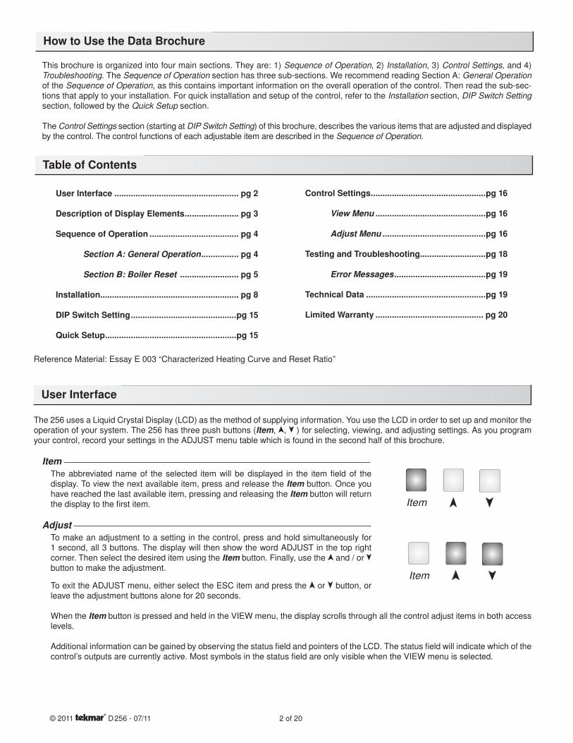
The 256 uses a Liquid Crystal Display (LCD) as the method of supplying information. You use the LCD in order to set up and monitor the operation of your system. The 256 has three push buttons (Item, , ) for selecting, viewing, and adjusting settings. As you program your control, record your settings in the ADJUST menu table which is found in the second half of this brochure.
Item The abbreviated name of the selected item will be displayed in the item fi eld of the display. To view the next available item, press and release the Item button. Once you have reached the last available item, pressing and releasing the Item button will return the display to the fi rst item.
Adjust To make an adjustment to a setting in the control, press and hold simultaneously for 1 second, all 3 buttons. The display will then show the word ADJUST in the top right corner. Then select the desired item using the Item button. Finally, use the and / or button to make the adjustment.
To exit the ADJUST menu, either select the ESC item and press the or button, or leave the adjustment buttons alone for 20 seconds.
When the Item button is pressed and held in the VIEW menu, the display scrolls through all the control adjust items in both access levels.
Additional information can be gained by observing the status fi eld and pointers of the LCD. The status fi eld will indicate which of the control’s outputs are currently active. Most symbols in the status fi eld are only visible when the VIEW menu is selected.
Control Settings .................................................pg 16 View Menu ...............................................pg 16 Adjust Menu ............................................pg 16
Testing and Troubleshooting............................pg 18 Error Messages .......................................pg 19
Technical Data ...................................................pg 19
Limited Warranty .............................................. pg 20
User Interface ..................................................... pg 2
Description of Display Elements ....................... pg 3
Sequence of Operation ...................................... pg 4 Section A: General Operation ................ pg 4 Section B: Boiler Reset ......................... pg 5
Installation........................................................... pg 8
DIP Switch Setting .............................................pg 15
Quick Setup ........................................................pg 15
© 2011 D 256 - 07/11 2 of 20
Item
Item
How to Use the Data Brochure
Table of Contents
User Interface
3 of 20 © 2011 D 256 - 07/11
Item
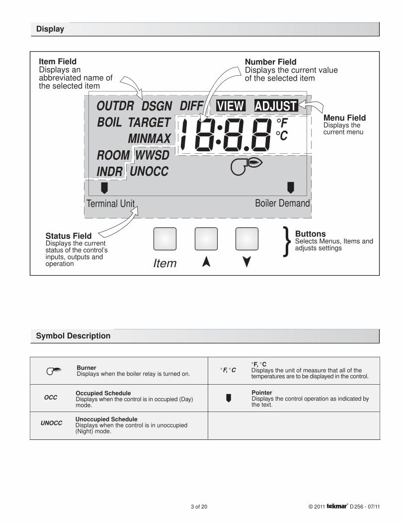
Number FieldDisplays the current valueof the selected item
{ButtonsSelects Menus, Items andadjusts settings
Menu FieldDisplays thecurrent menu
Status FieldDisplays the currentstatus of the control’sinputs, outputs andoperation
Item FieldDisplays anabbreviated name ofthe selected item
Terminal Unit
TARGET
INDR
DSGN DIFFBOILOUTDR
ROOM WWSD
°F°CMAXMIN
OCCUN
VIEW ADJUST
Boiler Demand
BurnerDisplays when the boiler relay is turned on.
°F, °C°F, °CDisplays the unit of measure that all of thetemperatures are to be displayed in the control.
OCCOccupied ScheduleDisplays when the control is in occupied (Day)mode.
UNOCC Unoccupied ScheduleDisplays when the control is in unoccupied(Night) mode.
PointerDisplays the control operation as indicated bythe text.
Display
Symbol Description
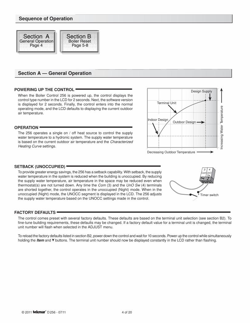
POWERING UP THE CONTROL When the Boiler Control 256 is powered up, the control displays the control type number in the LCD for 2 seconds. Next, the software version is displayed for 2 seconds. Finally, the control enters into the normal operating mode, and the LCD defaults to displaying the current outdoor air temperature.
OPERATION The 256 operates a single on / off heat source to control the supply water temperature to a hydronic system. The supply water temperature is based on the current outdoor air temperature and the Characterized Heating Curve settings.
SETBACK (UNOCCUPIED) To provide greater energy savings, the 256 has a setback capability. With setback, the supply water temperature in the system is reduced when the building is unoccupied. By reducing the supply water temperature, air temperature in the space may be reduced even when thermostat(s) are not turned down. Any time the Com (3) and the UnO Sw (4) terminals are shorted together, the control operates in the unoccupied (Night) mode. When in the unoccupied (Night) mode, the UNOCC segment is displayed in the LCD. The 256 adjusts the supply water temperature based on the UNOCC settings made in the control.
FACTORY DEFAULTS
The control comes preset with several factory defaults. These defaults are based on the terminal unit selection (see section B2). To fi ne-tune building requirements, these defaults may be changed. If a factory default value for a terminal unit is changed, the terminal unit number will fl ash when selected in the ADJUST menu.
To reload the factory defaults listed in section B2, power down the control and wait for 10 seconds. Power up the control while simultaneously holding the Item and buttons. The terminal unit number should now be displayed constantly in the LCD rather than fl ashing.
Section AGeneral Operation
Page 4
Section BBoiler Reset
Page 5-8
© 2011 D 256 - 07/11 4 of 20
Outdoor Design
Incre
asin
g W
ate
r Te
mpera
ture
Design Supply
Decreasing Outdoor Temperature
Terminal Unit
Indoor Design
3 4
Timer switch
Com UnOSw
Sequence of Operation
Section A — General Operation
Section B1General
Section B2Installer
Section B3Advanced
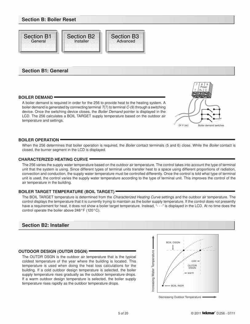
BOILER DEMAND A boiler demand is required in order for the 256 to provide heat to the heating system. A boiler demand is generated by connecting terminal T(7) to terminal C-(9) through a switching device. Once the switching device closes, the Boiler Demand pointer is displayed in the LCD. The 256 calculates a BOIL TARGET supply temperature based on the outdoor air temperature and settings.
BOILER OPERATION When the 256 determines that boiler operation is required, the Boiler contact terminals (5 and 6) close. While the Boiler contact is closed, the burner segment in the LCD is displayed.
CHARACTERIZED HEATING CURVE The 256 varies the supply water temperature based on the outdoor air temperature. The control takes into account the type of terminal unit that the system is using. Since different types of terminal units transfer heat to a space using different proportions of radiation, convection and conduction, the supply water temperature must be controlled differently. Once the control is told what type of terminal unit is used, the control varies the supply water temperature according to the type of terminal unit. This improves the control of the air temperature in the building.
BOILER TARGET TEMPERATURE (BOIL TARGET) The BOIL TARGET temperature is determined from the Characterized Heating Curve settings and the outdoor air temperature. The control displays the temperature that it is currently trying to maintain as the boiler supply temperature. If the control does not presently have a requirement for heat, it does not show a boiler target temperature. Instead, “- - -” is displayed in the LCD. At no time does the control operate the boiler above 248°F (120°C).
OUTDOOR DESIGN (OUTDR DSGN) The OUTDR DSGN is the outdoor air temperature that is the typical coldest temperature of the year where the building is located. This temperature is used when doing the heat loss calculations for the building. If a cold outdoor design temperature is selected, the boiler supply temperature rises gradually as the outdoor temperature drops. If a warm outdoor design temperature is selected, the boiler supply temperature rises rapidly as the outdoor temperature drops.
Section B: Boiler Reset
Section B1: General
Section B2: Installer
5 of 20 © 2011 D 256 - 07/11
C-T
Power
R+
7 8 9
Boiler demand switches24 V (ac)
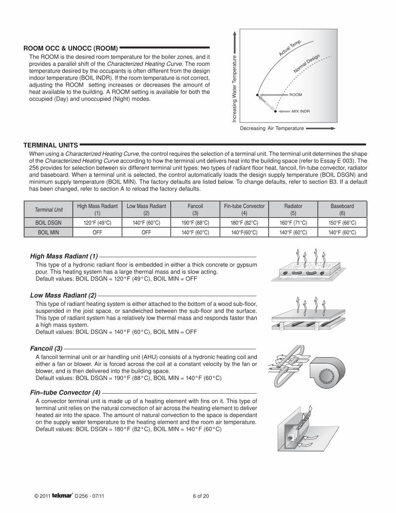
ROOM OCC & UNOCC (ROOM) The ROOM is the desired room temperature for the boiler zones, and it provides a parallel shift of the Characterized Heating Curve. The room temperature desired by the occupants is often different from the design indoor temperature (BOIL INDR). If the room temperature is not correct, adjusting the ROOM setting increases or decreases the amount of heat available to the building. A ROOM setting is available for both the occupied (Day) and unoccupied (Night) modes.
TERMINAL UNITS When using a Characterized Heating Curve, the control requires the selection of a terminal unit. The terminal unit determines the shape of the Characterized Heating Curve according to how the terminal unit delivers heat into the building space (refer to Essay E 003). The 256 provides for selection between six different terminal unit types: two types of radiant fl oor heat, fancoil, fi n-tube convector, radiator and baseboard. When a terminal unit is selected, the control automatically loads the design supply temperature (BOIL DSGN) and minimum supply temperature (BOIL MIN). The factory defaults are listed below. To change defaults, refer to section B3. If a default has been changed, refer to section A to reload the factory defaults.
High Mass Radiant (1) This type of a hydronic radiant fl oor is embedded in either a thick concrete or gypsum pour. This heating system has a large thermal mass and is slow acting.Default values: BOIL DSGN = 120°F (49°C), BOIL MIN = OFF
Low Mass Radiant (2) This type of radiant heating system is either attached to the bottom of a wood sub-fl oor, suspended in the joist space, or sandwiched between the sub-fl oor and the surface. This type of radiant system has a relatively low thermal mass and responds faster than a high mass system.Default values: BOIL DSGN = 140°F (60°C), BOIL MIN = OFF
Fancoil (3) A fancoil terminal unit or air handling unit (AHU) consists of a hydronic heating coil and either a fan or blower. Air is forced across the coil at a constant velocity by the fan or blower, and is then delivered into the building space.Default values: BOIL DSGN = 190°F (88°C), BOIL MIN = 140°F (60°C)
Fin–tube Convector (4) A convector terminal unit is made up of a heating element with fi ns on it. This type of terminal unit relies on the natural convection of air across the heating element to deliver heated air into the space. The amount of natural convection to the space is dependant on the supply water temperature to the heating element and the room air temperature.Default values: BOIL DSGN = 180°F (82°C), BOIL MIN = 140°F (60°C)
Terminal UnitHigh Mass Radiant
(1)Low Mass Radiant
(2)Fancoil
(3)Fin-tube Convector
(4)Radiator
(5)Baseboard
(6)
BOIL DSGN 120°F (49°C) 140°F (60°C) 190°F (88°C) 180°F (82°C) 160°F (71°C) 150°F (66°C)
BOIL MIN OFF OFF 140°F (60°C) 140°F(60°C) 140°F (60°C) 140°F (60°C)
© 2011 D 256 - 07/11 6 of 20
Radiator (5) A radiator terminal unit has a large heated surface that is exposed to the room. A radiator provides heat to the room through radiant heat transfer and natural convection.Default values: BOIL DSGN = 160°F (71°C), BOIL MIN = 140°F (60°C)
Baseboard (6) A baseboard terminal unit is similar to a radiator, but has a low profi le and is installed at the base of the wall. The proportion of heat transferred by radiation from a baseboard is greater than that from a fi n-tube convector.Default values: BOIL DSGN = 150°F (66°C), BOIL MIN = 140°F (60°C)
Section B3: Advanced
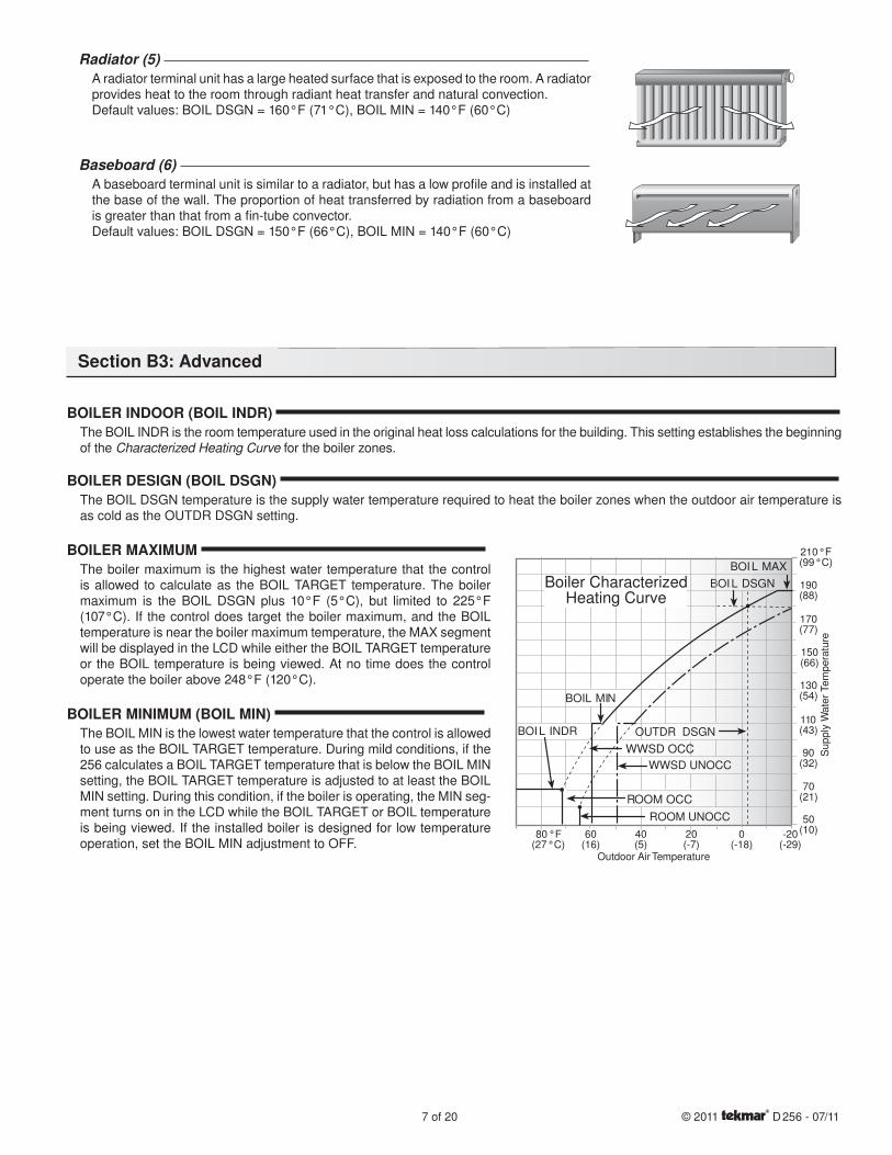
BOILER INDOOR (BOIL INDR) The BOIL INDR is the room temperature used in the original heat loss calculations for the building. This setting establishes the beginning of the Characterized Heating Curve for the boiler zones.
BOILER DESIGN (BOIL DSGN) The BOIL DSGN temperature is the supply water temperature required to heat the boiler zones when the outdoor air temperature is as cold as the OUTDR DSGN setting.
BOILER MAXIMUM The boiler maximum is the highest water temperature that the control is allowed to calculate as the BOIL TARGET temperature. The boiler maximum is the BOIL DSGN plus 10°F (5°C), but limited to 225°F (107°C). If the control does target the boiler maximum, and the BOIL temperature is near the boiler maximum temperature, the MAX segment will be displayed in the LCD while either the BOIL TARGET temperature or the BOIL temperature is being viewed. At no time does the control operate the boiler above 248°F (120°C).
BOILER MINIMUM (BOIL MIN) The BOIL MIN is the lowest water temperature that the control is allowed to use as the BOIL TARGET temperature. During mild conditions, if the 256 calculates a BOIL TARGET temperature that is below the BOIL MIN setting, the BOIL TARGET temperature is adjusted to at least the BOIL MIN setting. During this condition, if the boiler is operating, the MIN seg-ment turns on in the LCD while the BOIL TARGET or BOIL temperature is being viewed. If the installed boiler is designed for low temperature operation, set the BOIL MIN adjustment to OFF.
7 of 20 © 2011 D 256 - 07/11
70(21)
90(32)
110(43)
130(54)
150(66)
170(77)
190(88)
Outdoor Air Temperature
Su
pp
ly W
ate
r Te
mp
era
ture
210°F(99°C)
-20(-29)
0(-18)
20(-7)
40(5)
60(16)
80°F(27°C)
BOIL DSGN
BOIL MAX
BOIL MIN
WWSD UNOCC
BOIL INDR OUTDR DSGN
Boiler CharacterizedHeating Curve
50(10)
ROOM UNOCC
WWSD OCC
ROOM OCC
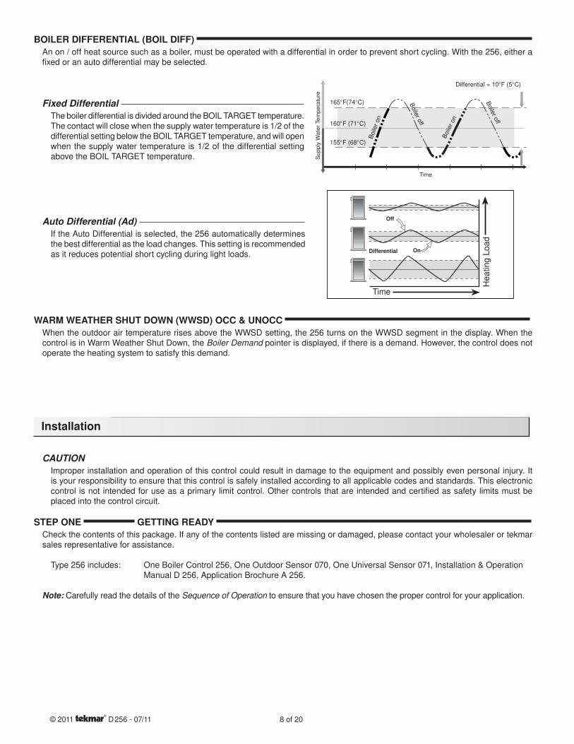
BOILER DIFFERENTIAL (BOIL DIFF) An on / off heat source such as a boiler, must be operated with a differential in order to prevent short cycling. With the 256, either a fi xed or an auto differential may be selected.
Fixed Differential The boiler differential is divided around the BOIL TARGET temperature. The contact will close when the supply water temperature is 1/2 of the differential setting below the BOIL TARGET temperature, and will open when the supply water temperature is 1/2 of the differential setting above the BOIL TARGET temperature.
Auto Differential (Ad) If the Auto Differential is selected, the 256 automatically determines the best differential as the load changes. This setting is recommended as it reduces potential short cycling during light loads.
WARM WEATHER SHUT DOWN (WWSD) OCC & UNOCC When the outdoor air temperature rises above the WWSD setting, the 256 turns on the WWSD segment in the display. When the control is in Warm Weather Shut Down, the Boiler Demand pointer is displayed, if there is a demand. However, the control does not operate the heating system to satisfy this demand.
CAUTION Improper installation and operation of this control could result in damage to the equipment and possibly even personal injury. It is your responsibility to ensure that this control is safely installed according to all applicable codes and standards. This electronic control is not intended for use as a primary limit control. Other controls that are intended and certifi ed as safety limits must be placed into the control circuit.
STEP ONE GETTING READY Check the contents of this package. If any of the contents listed are missing or damaged, please contact your wholesaler or tekmar sales representative for assistance.
Type 256 includes: One Boiler Control 256, One Outdoor Sensor 070, One Universal Sensor 071, Installation & Operation Manual D 256, Application Brochure A 256.
Note: Carefully read the details of the Sequence of Operation to ensure that you have chosen the proper control for your application.
Installation
© 2011 D 256 - 07/11 8 of 20
Supply
Wate
r Tem
pera
ture
Time
Differential = 10°F (5°C)
165°F(74°C) Boile
roff
Boile
ron
155°F (68°C)
160°F (71°C)
Boile
roff
Boile
ron
Off
On
Time
Heating L
oad
Differential
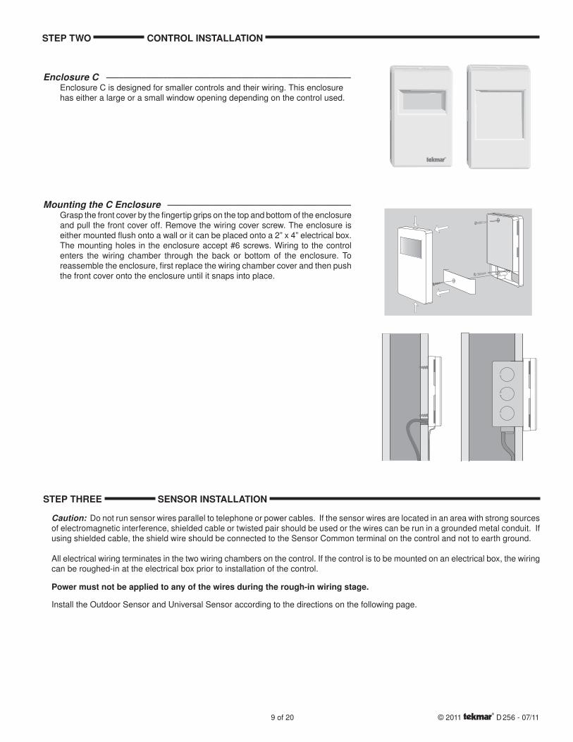
Enclosure C --------------------------------------------------------Enclosure C is designed for smaller controls and their wiring. This enclosure has either a large or a small window opening depending on the control used.
Mounting the C Enclosure ------------------------------------------Grasp the front cover by the fi ngertip grips on the top and bottom of the enclosure and pull the front cover off. Remove the wiring cover screw. The enclosure is either mounted fl ush onto a wall or it can be placed onto a 2” x 4” electrical box. The mounting holes in the enclosure accept #6 screws. Wiring to the control enters the wiring chamber through the back or bottom of the enclosure. To reassemble the enclosure, fi rst replace the wiring chamber cover and then push the front cover onto the enclosure until it snaps into place.
STEP TWO CONTROL INSTALLATION
STEP THREE SENSOR INSTALLATION
Caution: Do not run sensor wires parallel to telephone or power cables. If the sensor wires are located in an area with strong sources of electromagnetic interference, shielded cable or twisted pair should be used or the wires can be run in a grounded metal conduit. If using shielded cable, the shield wire should be connected to the Sensor Common terminal on the control and not to earth ground.
All electrical wiring terminates in the two wiring chambers on the control. If the control is to be mounted on an electrical box, the wiring can be roughed-in at the electrical box prior to installation of the control.
Power must not be applied to any of the wires during the rough-in wiring stage.
Install the Outdoor Sensor and Universal Sensor according to the directions on the following page.
9 of 20 © 2011 D 256 - 07/11
Note: The temperature sensor (thermistor) is built into the enclosure.
Remove the screw and pull the front cover off the sensor enclosure.
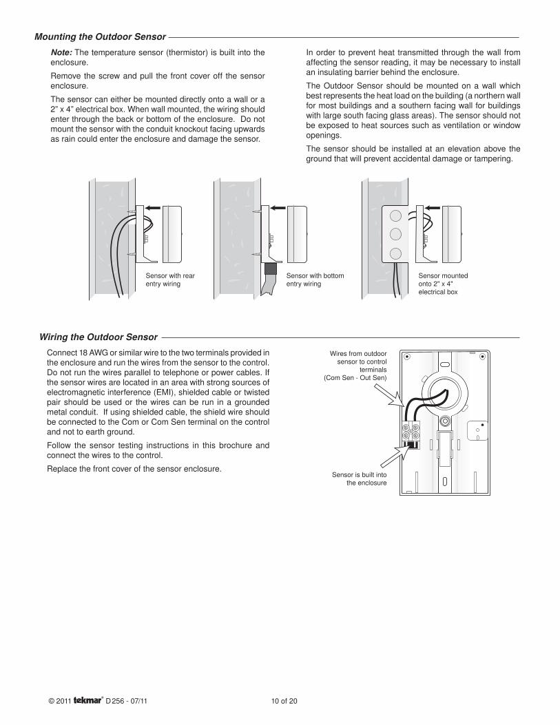
The sensor can either be mounted directly onto a wall or a 2” x 4” electrical box. When wall mounted, the wiring should enter through the back or bottom of the enclosure. Do not mount the sensor with the conduit knockout facing upwards as rain could enter the enclosure and damage the sensor.
In order to prevent heat transmitted through the wall from affecting the sensor reading, it may be necessary to install an insulating barrier behind the enclosure.
The Outdoor Sensor should be mounted on a wall which best represents the heat load on the building (a northern wall for most buildings and a southern facing wall for buildings with large south facing glass areas). The sensor should not be exposed to heat sources such as ventilation or window openings.
The sensor should be installed at an elevation above the ground that will prevent accidental damage or tampering.
Mounting the Outdoor Sensor
Sensor with bottomentry wiring
Sensor with rearentry wiring
Sensor mountedonto 2" x 4"electrical box
Connect 18 AWG or similar wire to the two terminals provided in the enclosure and run the wires from the sensor to the control. Do not run the wires parallel to telephone or power cables. If the sensor wires are located in an area with strong sources of electromagnetic interference (EMI), shielded cable or twisted pair should be used or the wires can be run in a grounded metal conduit. If using shielded cable, the shield wire should be connected to the Com or Com Sen terminal on the control and not to earth ground.
Follow the sensor testing instructions in this brochure and connect the wires to the control.
Replace the front cover of the sensor enclosure.
Wiring the Outdoor Sensor
Wires from outdoorsensor to control
terminals(Com Sen - Out Sen)
Sensor is built intothe enclosure
© 2011 D 256 - 07/11 10 of 20
Mounting the Universal Sensor
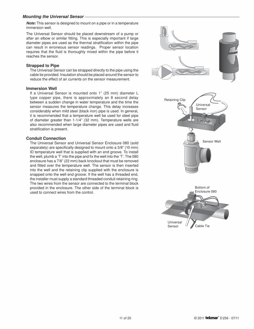
Note: This sensor is designed to mount on a pipe or in a temperature immersion well.
The Universal Sensor should be placed downstream of a pump or after an elbow or similar fi tting. This is especially important if large diameter pipes are used as the thermal stratifi cation within the pipe can result in erroneous sensor readings. Proper sensor location requires that the fl uid is thoroughly mixed within the pipe before it reaches the sensor.
Strapped to PipeThe Universal Sensor can be strapped directly to the pipe using the cable tie provided. Insulation should be placed around the sensor to reduce the effect of air currents on the sensor measurement.
Immersion WellIf a Universal Sensor is mounted onto 1” (25 mm) diameter L type copper pipe, there is approximately an 8 second delay between a sudden change in water temperature and the time the sensor measures the temperature change. This delay increases considerably when mild steel (black iron) pipe is used. In general, it is recommended that a temperature well be used for steel pipe of diameter greater than 1-1/4” (32 mm). Temperature wells are also recommended when large diameter pipes are used and fl uid stratifi cation is present.
Conduit ConnectionThe Universal Sensor and Universal Sensor Enclosure 080 (sold separately) are specifi cally designed to mount onto a 3/8” (10 mm) ID temperature well that is supplied with an end groove. To install the well, plumb a ‘T’ into the pipe and fi x the well into the ‘T’. The 080 enclosure has a 7/8” (22 mm) back knockout that must be removed and fi tted over the temperature well. The sensor is then inserted into the well and the retaining clip supplied with the enclosure is snapped onto the well end groove. If the well has a threaded end, the installer must supply a standard threaded conduit retaining ring. The two wires from the sensor are connected to the terminal block provided in the enclosure. The other side of the terminal block is used to connect wires from the control.
Bottom of Enclosure 080
UniversalSensor Cable Tie
Sensor Well
Retaining Clip
UniversalSensor
11 of 20 © 2011 D 256 - 07/11
STEP FOUR TESTING THE WIRING No wires should be connected to the control during the testing.
The following tests are to be performed using standard testing practices and procedures, and should only be carried out by properly trained and experienced persons.
A good quality electrical test meter, capable of reading from at least 0 - 300 V (ac) and at least 0 - 2,000,000 Ohms, is essential to properly test the wiring and sensors.
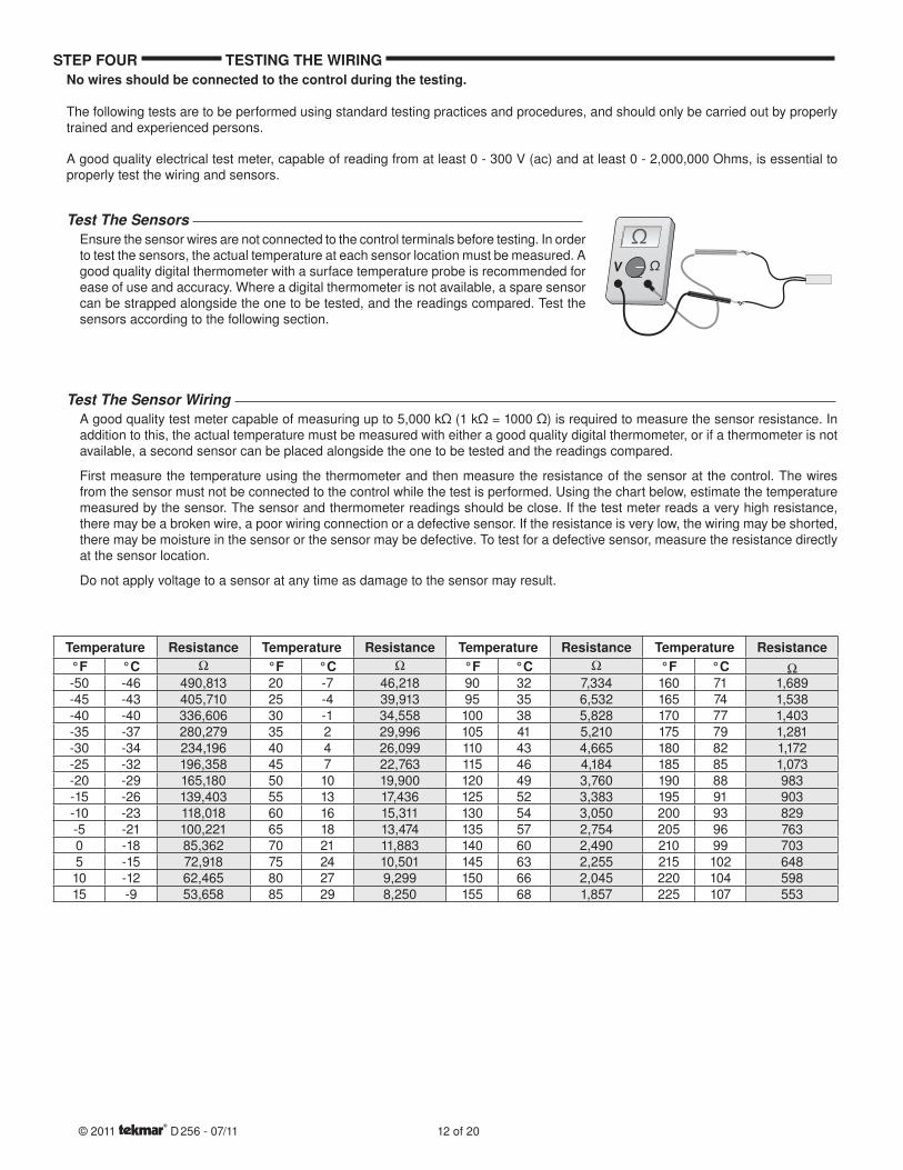
Test The Sensors Ensure the sensor wires are not connected to the control terminals before testing. In order to test the sensors, the actual temperature at each sensor location must be measured. A good quality digital thermometer with a surface temperature probe is recommended for ease of use and accuracy. Where a digital thermometer is not available, a spare sensor can be strapped alongside the one to be tested, and the readings compared. Test the sensors according to the following section.
Temperature Resistance Temperature Resistance Temperature Resistance Temperature Resistance°F °C °F °C °F °C °F °C-50 -46 490,813 20 -7 46,218 90 32 7,334 160 71 1,689-45 -43 405,710 25 -4 39,913 95 35 6,532 165 74 1,538-40 -40 336,606 30 -1 34,558 100 38 5,828 170 77 1,403-35 -37 280,279 35 2 29,996 105 41 5,210 175 79 1,281-30 -34 234,196 40 4 26,099 110 43 4,665 180 82 1,172-25 -32 196,358 45 7 22,763 115 46 4,184 185 85 1,073-20 -29 165,180 50 10 19,900 120 49 3,760 190 88 983-15 -26 139,403 55 13 17,436 125 52 3,383 195 91 903-10 -23 118,018 60 16 15,311 130 54 3,050 200 93 829-5 -21 100,221 65 18 13,474 135 57 2,754 205 96 7630 -18 85,362 70 21 11,883 140 60 2,490 210 99 7035 -15 72,918 75 24 10,501 145 63 2,255 215 102 64810 -12 62,465 80 27 9,299 150 66 2,045 220 104 59815 -9 53,658 85 29 8,250 155 68 1,857 225 107 553
A good quality test meter capable of measuring up to 5,000 kΩ (1 kΩ = 1000 Ω) is required to measure the sensor resistance. In addition to this, the actual temperature must be measured with either a good quality digital thermometer, or if a thermometer is not available, a second sensor can be placed alongside the one to be tested and the readings compared.
First measure the temperature using the thermometer and then measure the resistance of the sensor at the control. The wires from the sensor must not be connected to the control while the test is performed. Using the chart below, estimate the temperature measured by the sensor. The sensor and thermometer readings should be close. If the test meter reads a very high resistance, there may be a broken wire, a poor wiring connection or a defective sensor. If the resistance is very low, the wiring may be shorted, there may be moisture in the sensor or the sensor may be defective. To test for a defective sensor, measure the resistance directly at the sensor location.
Do not apply voltage to a sensor at any time as damage to the sensor may result.
Test The Sensor Wiring
Ω
ΩV
Ω
© 2011 D 256 - 07/11 12 of 20
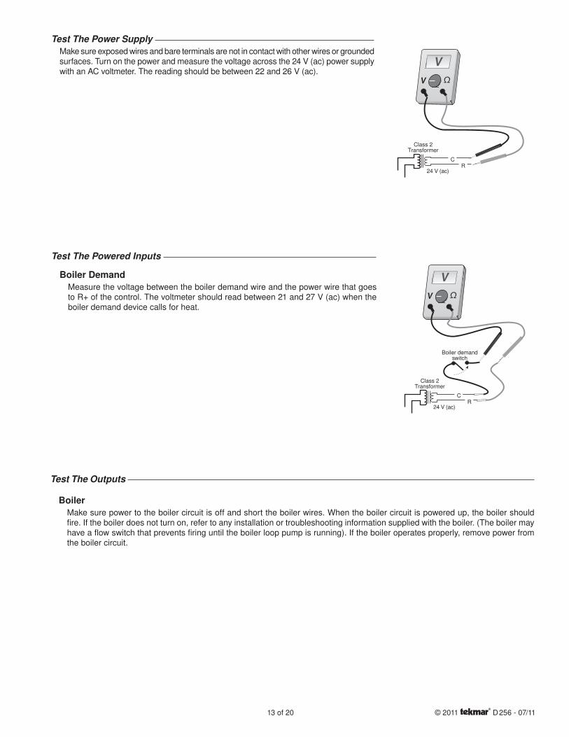
Test The Power Supply Make sure exposed wires and bare terminals are not in contact with other wires or grounded surfaces. Turn on the power and measure the voltage across the 24 V (ac) power supply with an AC voltmeter. The reading should be between 22 and 26 V (ac).
Test The Powered Inputs
Boiler DemandMeasure the voltage between the boiler demand wire and the power wire that goes to R+ of the control. The voltmeter should read between 21 and 27 V (ac) when the boiler demand device calls for heat.
Test The Outputs
BoilerMake sure power to the boiler circuit is off and short the boiler wires. When the boiler circuit is powered up, the boiler should fi re. If the boiler does not turn on, refer to any installation or troubleshooting information supplied with the boiler. (The boiler may have a fl ow switch that prevents fi ring until the boiler loop pump is running). If the boiler operates properly, remove power from the boiler circuit.
13 of 20 © 2011 D 256 - 07/11
24 V (ac)
Class 2Transformer
CR
Ω
VV
24 V (ac)
Class 2Transformer
CR
Ω
VV
Boiler demandswitch
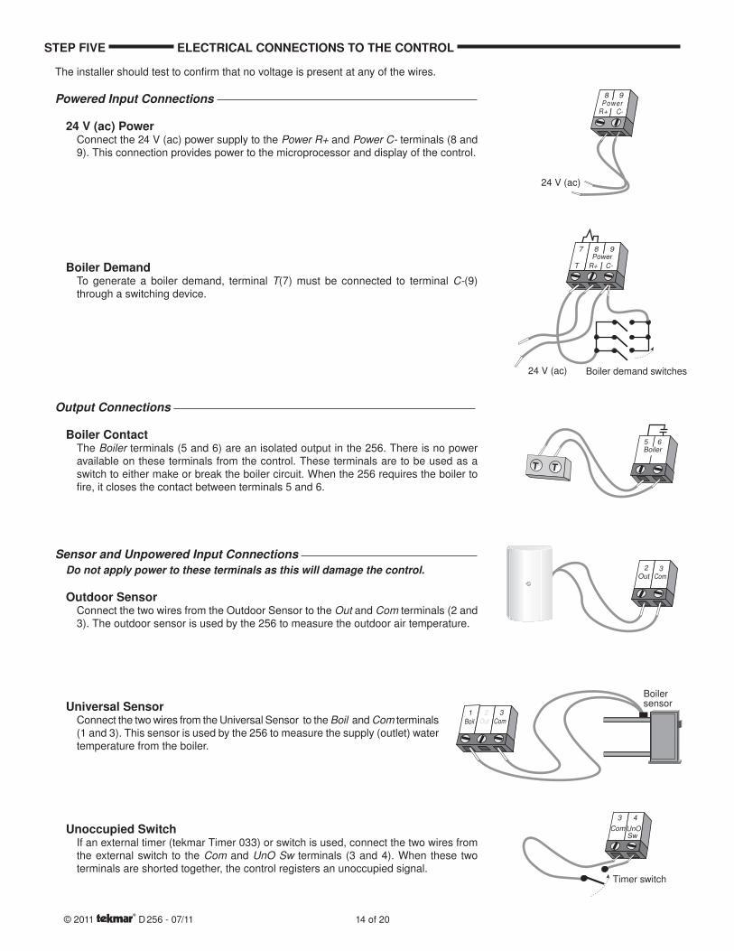
The installer should test to confi rm that no voltage is present at any of the wires.
Powered Input Connections
24 V (ac) PowerConnect the 24 V (ac) power supply to the Power R+ and Power C- terminals (8 and 9). This connection provides power to the microprocessor and display of the control.
Boiler DemandTo generate a boiler demand, terminal T(7) must be connected to terminal C-(9) through a switching device.
Output Connections
Boiler ContactThe Boiler terminals (5 and 6) are an isolated output in the 256. There is no power available on these terminals from the control. These terminals are to be used as a switch to either make or break the boiler circuit. When the 256 requires the boiler to fi re, it closes the contact between terminals 5 and 6.
Sensor and Unpowered Input Connections Do not apply power to these terminals as this will damage the control.
Outdoor SensorConnect the two wires from the Outdoor Sensor to the Out and Com terminals (2 and 3). The outdoor sensor is used by the 256 to measure the outdoor air temperature.
Universal SensorConnect the two wires from the Universal Sensor to the Boil and Com terminals (1 and 3). This sensor is used by the 256 to measure the supply (outlet) water temperature from the boiler.
Unoccupied SwitchIf an external timer (tekmar Timer 033) or switch is used, connect the two wires from the external switch to the Com and UnO Sw terminals (3 and 4). When these two terminals are shorted together, the control registers an unoccupied signal.
STEP FIVE ELECTRICAL CONNECTIONS TO THE CONTROL
© 2011 D 256 - 07/11 14 of 20
8 9
R+ C-Power
24 V (ac)
C-T
Power
R+
7 8 9
Boiler demand switches24 V (ac)
Boiler5 6
T TT T
2 3ComOut
1Boil Out
2 3Com
Boilersensor
Timer switch
3 4
Com UnOSw
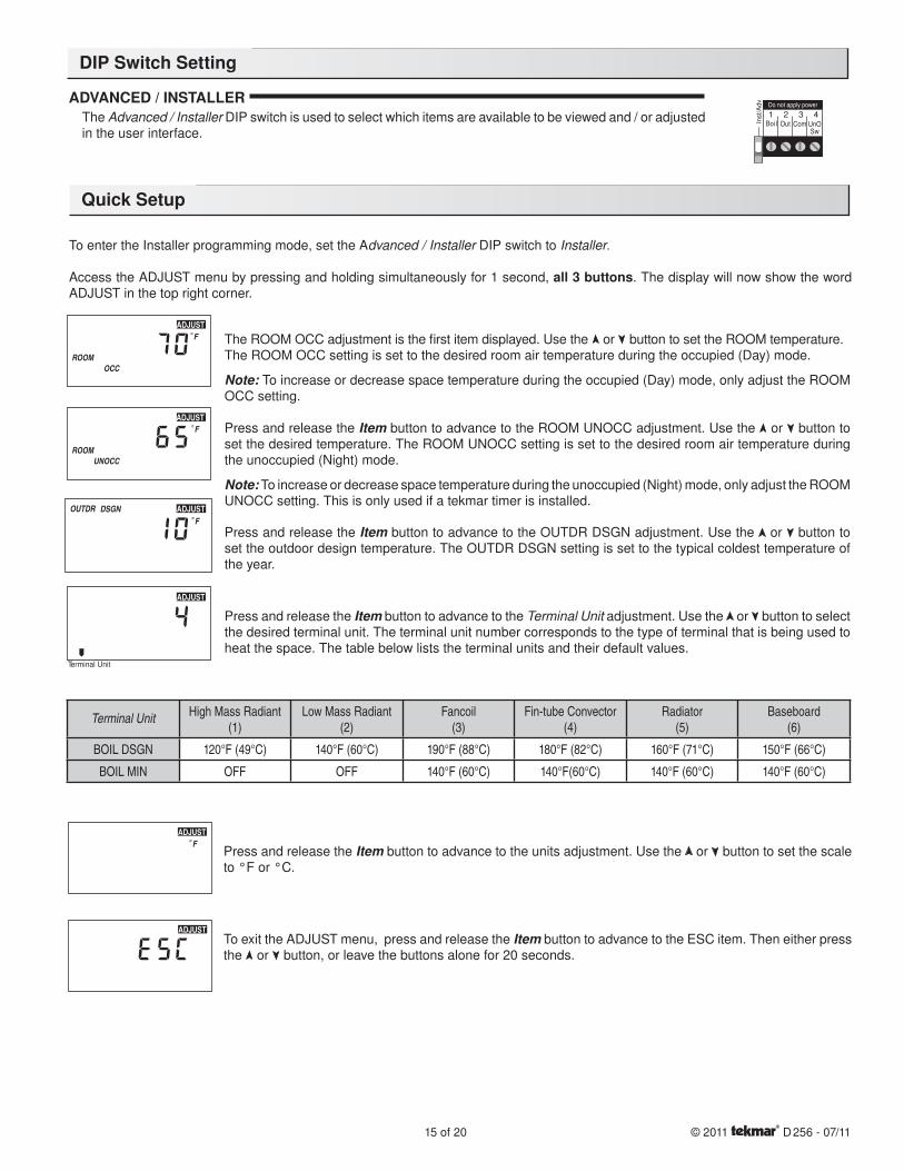
Press and release the Item button to advance to the units adjustment. Use the or button to set the scale to °F or °C.
To exit the ADJUST menu, press and release the Item button to advance to the ESC item. Then either press the or button, or leave the buttons alone for 20 seconds.
ADVANCED / INSTALLER The Advanced / Installer DIP switch is used to select which items are available to be viewed and / or adjusted in the user interface.
To enter the Installer programming mode, set the Advanced / Installer DIP switch to Installer.
Access the ADJUST menu by pressing and holding simultaneously for 1 second, all 3 buttons. The display will now show the word ADJUST in the top right corner.
The ROOM OCC adjustment is the fi rst item displayed. Use the or button to set the ROOM temperature.The ROOM OCC setting is set to the desired room air temperature during the occupied (Day) mode.
Note: To increase or decrease space temperature during the occupied (Day) mode, only adjust the ROOM OCC setting.
Press and release the Item button to advance to the ROOM UNOCC adjustment. Use the or button to set the desired temperature. The ROOM UNOCC setting is set to the desired room air temperature during the unoccupied (Night) mode.
Note: To increase or decrease space temperature during the unoccupied (Night) mode, only adjust the ROOM UNOCC setting. This is only used if a tekmar timer is installed.
Press and release the Item button to advance to the OUTDR DSGN adjustment. Use the or button to set the outdoor design temperature. The OUTDR DSGN setting is set to the typical coldest temperature of the year.
Press and release the Item button to advance to the Terminal Unit adjustment. Use the or button to select the desired terminal unit. The terminal unit number corresponds to the type of terminal that is being used to heat the space. The table below lists the terminal units and their default values.
DIP Switch Setting
Quick Setup
15 of 20 © 2011 D 256 - 07/11
ADJUST
ADJUSTF°
Terminal Unit
ADJUST
ADJUSTDSGNOUTDRF°
ROOMOCCUN
ADJUSTF°
ROOMOCC
ADJUSTF°
Inst/A
dv Do not apply power
Boi l Out Com UnOSw
1 2 3 4
Terminal UnitHigh Mass Radiant
(1)Low Mass Radiant
(2)Fancoil
(3)Fin-tube Convector
(4)Radiator
(5)Baseboard
(6)
BOIL DSGN 120°F (49°C) 140°F (60°C) 190°F (88°C) 180°F (82°C) 160°F (71°C) 150°F (66°C)
BOIL MIN OFF OFF 140°F (60°C) 140°F(60°C) 140°F (60°C) 140°F (60°C)
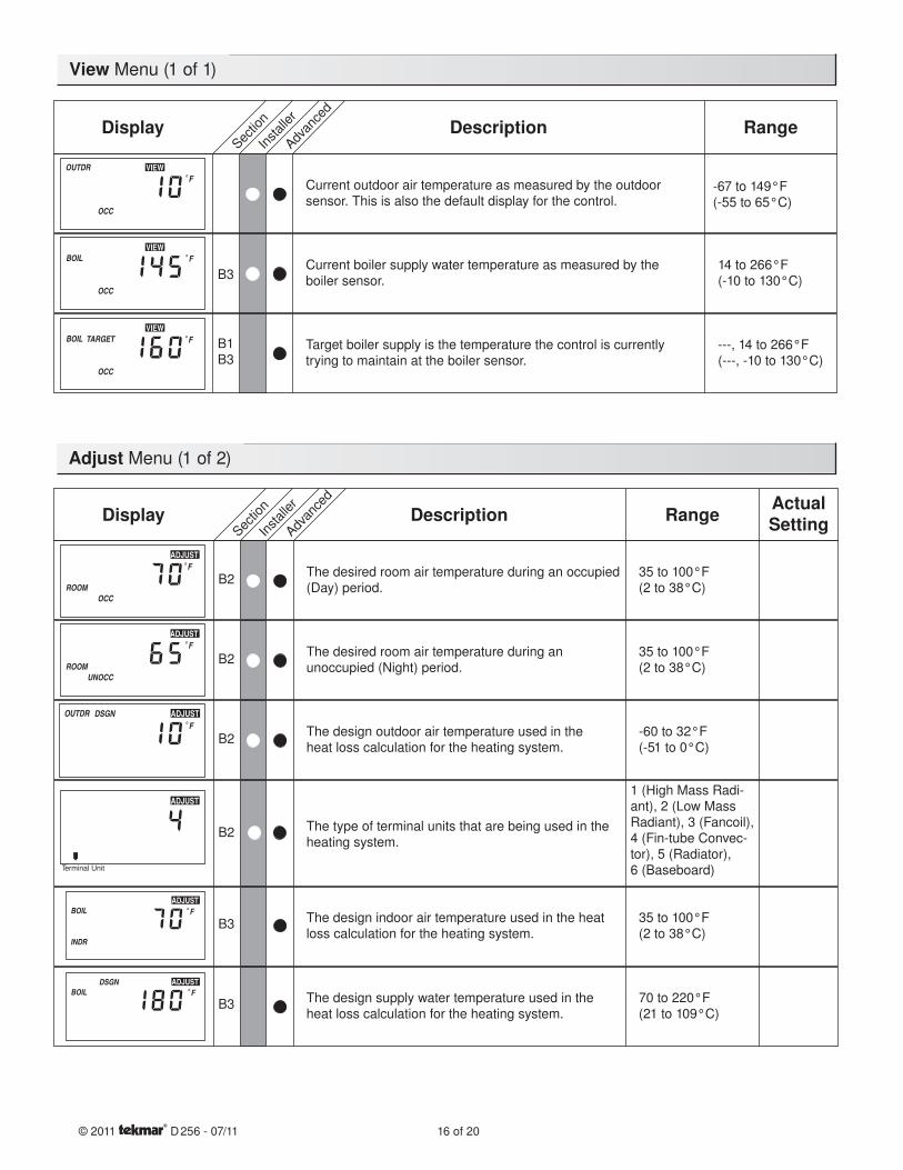
Current outdoor air temperature as measured by the outdoorsensor. This is also the default display for the control.
Sectio
n
Advan
ced
Installer
Display Description Range
Current boiler supply water temperature as measured by the boiler sensor.
14 to 266°F(-10 to 130°C)B3
Target boiler supply is the temperature the control is currently trying to maintain at the boiler sensor.
---, 14 to 266°F(---, -10 to 130°C)
B1B3
-67 to 149°F(-55 to 65°C)
The desired room air temperature during an occupied (Day) period.
35 to 100°F(2 to 38°C)
B2
The desired room air temperature during an unoccupied (Night) period.
35 to 100°F(2 to 38°C)
B2
The design outdoor air temperature used in the heat loss calculation for the heating system.
-60 to 32°F(-51 to 0°C)
B2
The type of terminal units that are being used in the heating system.
B2
Sectio
n
Advan
ced
Installer
Display Description RangeActualSetting
The design indoor air temperature used in the heat loss calculation for the heating system.
35 to 100°F(2 to 38°C)
B3
The design supply water temperature used in the heat loss calculation for the heating system.
70 to 220°F(21 to 109°C)
B3
1 (High Mass Radi-ant), 2 (Low Mass Radiant), 3 (Fancoil), 4 (Fin-tube Convec-tor), 5 (Radiator),6 (Baseboard)
View Menu (1 of 1)
Adjust Menu (1 of 2)
© 2011 D 256 - 07/11 16 of 20
VIEWOUTDR
OCC
F°
VIEWBOIL
OCC
F°
VIEWTARGETBOIL
OCC
F°
ROOMOCC
ADJUSTF°
ROOMOCCUN
ADJUSTF°
ADJUSTDSGNOUTDRF°
Terminal Unit
ADJUST
ADJUST
INDR
BOIL F°
ADJUSTDSGNBOIL F°
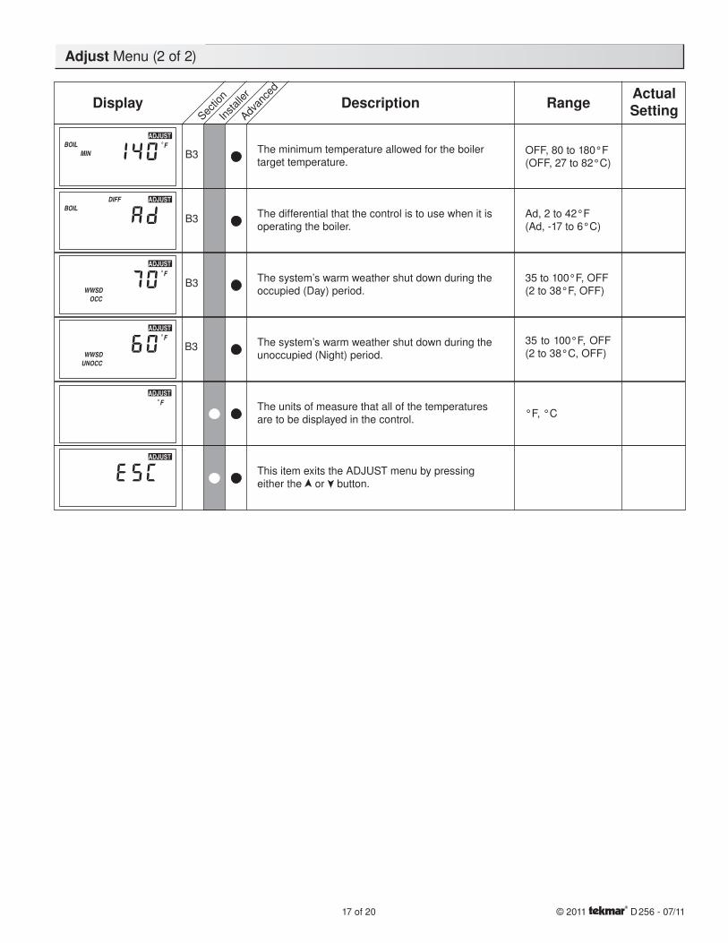
The minimum temperature allowed for the boiler target temperature.
OFF, 80 to 180°F(OFF, 27 to 82°C)
B3
The differential that the control is to use when it is operating the boiler.
Ad, 2 to 42°F(Ad, -17 to 6°C)
B3
The system’s warm weather shut down during the occupied (Day) period.
35 to 100°F, OFF(2 to 38°F, OFF)
B3
The system’s warm weather shut down during the unoccupied (Night) period.
35 to 100°F, OFF(2 to 38°C, OFF)
The units of measure that all of the temperatures are to be displayed in the control.
°F, °C
This item exits the ADJUST menu by pressing either the or button.
Sectio
n
Advan
ced
Installer
Display Description RangeActualSetting
B3
Adjust Menu (2 of 2)
17 of 20 © 2011 D 256 - 07/11
ADJUSTBOIL
MINF°
ADJUSTDIFFBOIL
ADJUST
WWSDOCC
F°
ADJUST
WWSDOCCUN
F°
ADJUSTF°
ADJUST
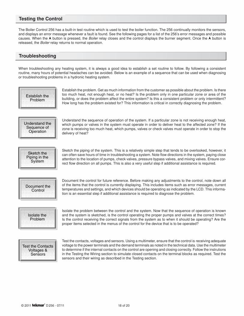
The Boiler Control 256 has a built-in test routine which is used to test the boiler function. The 256 continually monitors the sensors, and displays an error message whenever a fault is found. See the following pages for a list of the 256’s error messages and possible causes. When the button is pressed, the Boiler relay closes and the control displays the burner segment. Once the button is released, the Boiler relay returns to normal operation.
When troubleshooting any heating system, it is always a good idea to establish a set routine to follow. By following a consistent routine, many hours of potential headaches can be avoided. Below is an example of a sequence that can be used when diagnosing or troubleshooting problems in a hydronic heating system.
Establish the problem. Get as much information from the customer as possible about the problem. Is there too much heat, not enough heat, or no heat? Is the problem only in one particular zone or area of the building, or does the problem affect the entire system? Is this a consistent problem or only intermittent? How long has the problem existed for? This information is critical in correctly diagnosing the problem.
Understand the sequence of operation of the system. If a particular zone is not receiving enough heat, which pumps or valves in the system must operate in order to deliver heat to the affected zone? If the zone is receiving too much heat, which pumps, valves or check valves must operate in order to stop the delivery of heat?
Sketch the piping of the system. This is a relatively simple step that tends to be overlooked, however, it can often save hours of time in troubleshooting a system. Note fl ow directions in the system, paying close attention to the location of pumps, check valves, pressure bypass valves, and mixing valves. Ensure cor-rect fl ow direction on all pumps. This is also a very useful step if additional assistance is required.
Document the control for future reference. Before making any adjustments to the control, note down all of the items that the control is currently displaying. This includes items such as error messages, current temperatures and settings, and which devices should be operating as indicated by the LCD. This informa-tion is an essential step if additional assistance is required to diagnose the problem.
Isolate the problem between the control and the system. Now that the sequence of operation is known and the system is sketched, is the control operating the proper pumps and valves at the correct times? Is the control receiving the correct signals from the system as to when it should be operating? Are the proper items selected in the menus of the control for the device that is to be operated?
Test the contacts, voltages and sensors. Using a multimeter, ensure that the control is receiving adequate voltage to the power terminals and the demand terminals as noted in the technical data. Use the multimeter to determine if the internal contacts on the control are opening and closing correctly. Follow the instrutions in the Testing the Wiring section to simulate closed contacts on the terminal blocks as required. Test the sensors and their wiring as described in the Testing section.
Testing the Control
Troubleshooting
© 2011 D 256 - 07/11 18 of 20
Establish theProblem
Understand theSequence of
Operation
Sketch thePiping in the
System
Document theControl
Isolate theProblem
Test the ContactsVoltages &
Sensors
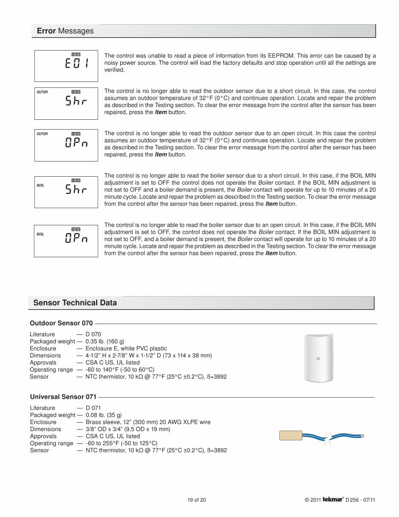
The control was unable to read a piece of information from its EEPROM. This error can be caused by a noisy power source. The control will load the factory defaults and stop operation until all the settings are verifi ed.
The control is no longer able to read the outdoor sensor due to a short circuit. In this case, the control assumes an outdoor temperature of 32°F (0°C) and continues operation. Locate and repair the problem as described in the Testing section. To clear the error message from the control after the sensor has been repaired, press the Item button.
The control is no longer able to read the outdoor sensor due to an open circuit. In this case the control assumes an outdoor temperature of 32°F (0°C) and continues operation. Locate and repair the problem as described in the Testing section. To clear the error message from the control after the sensor has been repaired, press the Item button.
The control is no longer able to read the boiler sensor due to a short circuit. In this case, if the BOIL MIN adjustment is set to OFF the control does not operate the Boiler contact. If the BOIL MIN adjustment is not set to OFF and a boiler demand is present, the Boiler contact will operate for up to 10 minutes of a 20 minute cycle. Locate and repair the problem as described in the Testing section. To clear the error message from the control after the sensor has been repaired, press the Item button.
The control is no longer able to read the boiler sensor due to an open circuit. In this case, if the BOIL MIN adjustment is set to OFF, the control does not operate the Boiler contact. If the BOIL MIN adjustment is not set to OFF, and a boiler demand is present, the Boiler contact will operate for up to 10 minutes of a 20 minute cycle. Locate and repair the problem as described in the Testing section. To clear the error message from the control after the sensor has been repaired, press the Item button.
Sensor Technical Data
Error Messages
Outdoor Sensor 070
Literature — D 070Packaged weight — 0.35 lb. (160 g)Enclosure — Enclosure E, white PVC plasticDimensions — 4-1/2” H x 2-7/8” W x 1-1/2” D (73 x 114 x 38 mm)Approvals — CSA C US, UL listedOperating range — -60 to 140°F (-50 to 60°C)Sensor — NTC thermistor, 10 kΩ @ 77°F (25°C ±0.2°C), ß=3892
Universal Sensor 071
Literature — D 071Packaged weight — 0.08 lb. (35 g)Enclosure — Brass sleeve, 12” (300 mm) 20 AWG XLPE wireDimensions — 3/8” OD x 3/4” (9.5 OD x 19 mm) Approvals — CSA C US, UL listed Operating range — -60 to 255°F (-50 to 125°C)Sensor — NTC thermistor, 10 kΩ @ 77°F (25°C ±0.2°C), ß=3892
19 of 20 © 2011 D 256 - 07/11
BOILVIEW
BOILVIEW
OUTDR VIEW
OUTDR VIEW
VIEW
Limited Warranty The liability of tekmar under this warranty is limited. The Purchaser, by taking receipt of any tekmar product (“Product”), acknowl-edges the terms of the Limited Warranty in effect at the time of such Prod-uct sale and acknowledges that it has read and understands same.
The tekmar Limited Warranty to the Purchaser on the Products sold hereun-der is a manufacturer’s pass-through warranty which the Purchaser is autho-rized to pass through to its customers. Under the Limited Warranty, each tekmar Product is warranted against defects in workmanship and materials if the Product is installed and used in compliance with tekmar’s instructions, ordinary wear and tear excepted. The pass-through warranty period is for a period of twenty-four (24) months from the production date if the Product is not installed during that period, or twelve (12) months from the documented date of installation if installed within twenty-four (24) months from the produc-tion date.
The liability of tekmar under the Limited Warranty shall be limited to, at tekmar’s sole discretion: the cost of parts and labor provided by tekmar to repair defects in materials and / or workmanship of the defective product; or to the exchange of the defective product for a warranty replacement product; or to the granting of credit limited to the original cost of the defective product, and such repair, exchange or credit shall be the sole remedy available from tekmar, and, without limiting the foregoing in any way, tekmar is not responsible, in contract, tort or strict product liability, for any other losses, costs, expenses, inconveniences, or damages, whether direct, indirect, special, secondary, incidental or consequen-tial, arising from ownership or use of the product, or from defects in workman-ship or materials, including any liability for fundamental breach of contract.
The pass-through Limited Warranty applies only to those defective Products returned to tekmar during the warranty period. This Limited Warranty does not cover the cost of the parts or labor to remove or transport the defective Product, or to reinstall the repaired or replacement Product, all such costs and expenses being subject to Purchaser’s agreement and warranty with its customers.
Any representations or warranties about the Products made by Purchaser to its customers which are different from or in excess of the tekmar Limited Warranty
are the Purchaser’s sole responsibility and obligation. Purchaser shall indemnify and hold tekmar harmless from and against any and all claims, liabilities and damages of any kind or nature which arise out of or are related to any such representations or warranties by Purchaser to its customers.
The pass-through Limited Warranty does not apply if the returned Product has been damaged by negligence by persons other than tekmar, accident, fire, Act of God, abuse or misuse; or has been damaged by modifications, alterations or attachments made subsequent to purchase which have not been authorized by tekmar; or if the Product was not installed in compliance with tekmar’s instruc-tions and / or the local codes and ordinances; or if due to defective installation of the Product; or if the Product was not used in compliance with tekmar’s instruc-tions.
THIS WARRANTY IS IN LIEU OF ALL OTHER WARRANTIES, EXPRESS OR IMPLIED, WHICH THE GOVERNING LAW ALLOWS PARTIES TO CONTRAC-TUALLY EXCLUDE, INCLUDING, WITHOUT LIMITATION, IMPLIED WARRAN-TIES OF MERCHANTABILITY AND FITNESS FOR A PARTICULAR PURPOSE, DURABILITY OR DESCRIPTION OF THE PRODUCT, ITS NON-INFRINGE-MENT OF ANY RELEVANT PATENTS OR TRADEMARKS, AND ITS COMPLI-ANCE WITH OR NON-VIOLATION OF ANY APPLICABLE ENVIRONMENTAL, HEALTH OR SAFETY LEGISLATION; THE TERM OF ANY OTHER WARRANTY NOT HEREBY CONTRACTUALLY EXCLUDED IS LIMITED SUCH THAT IT SHALL NOT EXTEND BEYOND TWENTY-FOUR (24) MONTHS FROM THE PRODUCTION DATE, TO THE EXTENT THAT SUCH LIMITATION IS ALLOWED BY THE GOVERNING LAW.
Product Warranty Return Procedure All Products that are believed to have defects in workmanship or materials must be returned, together with a written description of the defect, to the tekmar Representative assigned to the territory in which such Product is located. If tekmar receives an inquiry from someone other than a tekmar Representative, including an inquiry from Purchaser (if not a tekmar Representative) or Purchaser’s customers, regarding a potential war-ranty claim, tekmar’s sole obligation shall be to provide the address and other contact information regarding the appropriate Representative.
The installer must ensure that this control and its wiring are isolated and/or shielded from strong sources of electromagnetic noise. Conversely,
this Class B digital apparatus complies with Part 15 of the FCC Rules and meets all requirements of the Canadian Interference-Causing Equip-
ment Regulations. However, if this control does cause harmful interference to radio or television reception, which is determined by turning the
control off and on, the user is encouraged to try to correct the interference by reorienting or relocating the receiving antenna, relocating the
receiver with respect to this control, and/or connecting the control to a different circuit from that to which the receiver is connected.
Cet appareil numérique de la classe B respecte toutes les exigences du Règlement sur le matériel brouilleur du Canada.
Caution The nonmetallic enclosure does not provide grounding between conduit connections. Use grounding type bushings and jumper wires.
Attention Un boîtier nonmétallique n’assure pas la continuité électrique des conduits. Utiliser des manchons ou des fi ls de accord spécialement conçus pour la mise á la terre.
Technical Data
Limited Warranty and Product Return Procedure
tekmar Control Systems Ltd., Canadatekmar Control Systems, Inc., U.S.A.Head Office: 5100 Silver Star RoadVernon, B.C. Canada V1B 3K4(250) 545-7749 Fax. (250) 545-0650Web Site: www.tekmarcontrols.com
Product design, software and literature are Copyright © 2011 by:tekmar Control Systems Ltd. and tekmar Control Systems, Inc. 20 of 20 All specifications are subject to change without notice.
Printed in Canada. D 256 - 07/11.
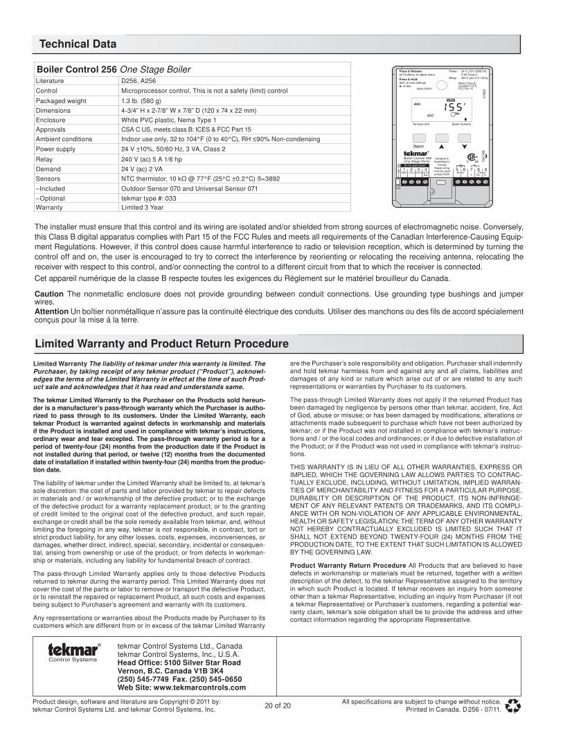
Boiler Control 256 One Stage BoilerLiterature D256, A256
Control Microprocessor control. This is not a safety (limit) control
Packaged weight 1.3 lb. (580 g)
Dimensions 4-3/4” H x 2-7/8” W x 7/8” D (120 x 74 x 22 mm)
Enclosure White PVC plastic, Nema Type 1
Approvals CSA C US, meets class B: ICES & FCC Part 15
Ambient conditions Indoor use only, 32 to 104°F (0 to 40°C), RH ≤90% Non-condensing
Power supply 24 V ±10%, 50/60 Hz, 3 VA, Class 2
Relay 240 V (ac) 5 A 1/6 hp
Demand 24 V (ac) 2 VA
Sensors NTC thermistor, 10 kΩ @ 77°F (25°C ±0.2°C) ß=3892
–Included Outdoor Sensor 070 and Universal Sensor 071
–Optional tekmar type #: 033
Warranty Limited 3 Year
BOIL F
OCC
Press & Release:all 3 buttons, to adjust menu
Press & Hold:Item, to view settings , to test.
Boiler Control 256One Stage Boiler
Item
Date
Code
Power: 24 V ±10% 50/60 Hz 3 VA Class 2Relay: 240 V (ac) 5 A 1/6 hp
Meets Class B:Canadian ICESFCC Part 15
H11
90D
Terminal Unit Boiler Demand
Inst /
Adv
1Boil
2Out
3Com
4UnOSw
5Boiler
6 7
T
8Power
R+
9
C-
Do not apply power
tektra 909-01
Designed & Assembled in
Canada Signal wiring must be rated at least 300V
Related Documents