भारतीय विमानपतन ाधिकरण AIRPORTS AUTHORITY OF INDIA CNS MANUAL STATION ‘FARRUKHABAD’ Prepared by: A.H. KHAN Officer-in-Charge Aeronautical Communication Station Airports Authority of India 1/89D Civil Lines , Fatehgarh, Farrukhabad (U.P.) India Telephone : 91-05692-236437 Mob. 09415116059

Welcome message from author
This document is posted to help you gain knowledge. Please leave a comment to let me know what you think about it! Share it to your friends and learn new things together.
Transcript
भारतीय विमानपत्तन प्राधिकरण
AIRPORTS AUTHORITY OF INDIA
CNS MANUAL STATION ‘FARRUKHABAD’
Prepared by:
A.H. KHAN
Officer-in-Charge
Aeronautical Communication Station
Airports Authority of India
1/89D Civil Lines , Fatehgarh, Farrukhabad (U.P.) India
Telephone : 91-05692-236437 Mob. 09415116059

AIRPORTS AUTHORITY OF INDIA CNS MANUAL
September, 2010 AERONAUTICAL COMMUNICATION STATION FARRUKHABAD
1
PREFACE
1) This Station CNS Manual for the contemporary CNS facilities is designed to provide aviation community
with basic maintenance information about processes, procedures and instructions that are essential for the
provision of safe and efficient CNS services within the airspaces under the jurisdiction of AAI,
Farrukhabad.
2) The Manual prepared and maintained by the Officer-in-charge, Aeronautical Communication Station,
Farrukhabad on behalf of the Airports Authority of India for the use and guidance of CNS executives and
staff of AAI posted at Farrukhabad in particular.
3) This Manual contains the fundamental information and has been developed as a part of comprehensive
documentation of the running maintenance and operational procedures, processes and facilities supporting
conformance to organizational requirements and compliance with the provisions of relevant ICAO
documents and Civil Aviation Requirements.
4) The various contents, inputs and formats have also been taken from Communication, Navigation and
Surveillance (CNS) department of the Airports Authority of India, Rajiv Gandhi Bhawan, Safdarjung
Airport, New Delhi. (Refer CNS Manual, Vol. 1)
5) Restrictions of the facilities, if any, will be updated and published in AIP India.
6) It may be noted that the instructions/procedures given in this manual are particular for a specific
equipment/model rather than general for other similar equipment. As such, this Manual should be read in
conjunction with the contemporary commissioned facility at the station (CVOR & HP-DME in this case)
and the manpower.
7) It is to be recognized that in the changing aviation safety environment, the need to amend the Manual may
be necessitated by a number of causes, such as:
(a) Replacement of the CNS facility.
(b) Upgrading/Revision of existing in-use software versions.
(c) Change in the station’s operational environment.
(d) Changes/amendments to ICAO Annexes/Documents.
(e) Changes/introduction of DGCA/CARs.
(f) Introduction of new technology.
8) Best efforts have been maintained to keep this Manual updated. Beneficial comments (recommendations,
additions, deletions) and/or any pertinent data which may be of useful in improving this document should
be addressed to Officer-in-charge, Aeronautical Communication Station, Farrukhabad.

AIRPORTS AUTHORITY OF INDIA CNS MANUAL
September, 2010 AERONAUTICAL COMMUNICATION STATION FARRUKHABAD
2
CONTENTS
Contents Page
Chapter 1. Document Identification and Control 05—07
1.1 Introduction. 5
1.2 Titles of Document. 5
1.3 Scope of the Document. 5
1.4 Limitation of the Document. 5
1.5 Requirement of the Document. 5
1.6 Purpose of the Document. 5
1.7 Responsibility of the Document. 6
1.8 Authority/Responsibility for Changes. 6
1.9 Review of the Document. 6
1.10 Incorporating Changes. 6
1.11 Effective Date Checking. 6
1.12 Controlling the Manual. 6
1.13 Master Copy. 6
1.14 Currency of the Manual. 6
1.15 Enquires. 7
Chapter 2. General 08—11
2.1 Brief History. 8
2.2 AAI Office. 9
2.3 Role of Station in en-route Navigation. 10
2.4 Organization Structure. 10
2.5 Accountability. 10
2.6 Human Resource. 10
Chapter 3. Facilities 12—15
3.1 VOR. 12
3.3.1 Technical Data. 12
3.3.2 Equipment’s Battery back-up Data. 12
3.3.3 Standarad Tolerances and Station Data. 13
3.2 DME. 13
3.3.1 Technical Data. 13
3.3.2 Equipment’s Battery back-up Data. 14
3.3.3 Standard Tolerances and Station Data. 14
3.3 Supporting facilities. 15
3.3.1 U.P.S. 15
3.3.2 Test Equipments. 15
3.3.3 Generator Sets. 15
3.3.4 Air Conditioners. 15
3.3.5 Operational Jeep. 15
Chapter 4. Station Operation & Maintenance 16—21
4.1 General. 16
4.2 Maintenance Philosophy. 16
4.3 Maintenance Schedule. 16
AIRPORTS AUTHORITY OF INDIA CNS MANUAL
September, 2010 AERONAUTICAL COMMUNICATION STATION FARRUKHABAD
3
4.3.1 Preventive Maintenance Inspection Practices (Daily). 16
4.3.2 Periodical Maintenance. 17
4.4 Performance Check. 17
4.5 Flow Chart for Periodical Maintenance. 18
4.6 Troubleshooting. 19
4.7 Tools and Test Equipments. 19
4.8 Maintenance Records. 19
4.9 Flow Chart for Troubleshooting. 20
4.10 Preservation of Records. 21
4.11 Reference Library. 21
Chapter 5. Crisis Planning and Coordination 22—23
5.1 General. 22
5.2 Availability of Serviceable Card/Module/Unit. 22
5.2.1 Special Maintenance Units (SMUs). 22
5.3 Effect of the Failure. 22
5.4 Facility Malfunction. 23
5.4.1 NOTAM. 23
Chapter 6. Monitoring and Safety 24—25
6.1 General. 24
6.1.1 Executive Monitoring. 24
6.1.2 Status Monitoring. 24
6.1.3 Ground Calibration. 24
6.1.4 Air Calibration. 24
6.1.5 Pilot’s monitoring. 24
6.2 Safety 24
AIRPORTS AUTHORITY OF INDIA CNS MANUAL
September, 2010 AERONAUTICAL COMMUNICATION STATION FARRUKHABAD
4
LIST OF ANNEXURES
i) List of Test Equipments A-1
ii) Tips for Maintenance A-2
iii) Personnel Safety A-3 to A-6
iv) Daily Maintenance Schedule (for CVOR) A-7
v) Daily Maintenance Schedule (for DME) A- 8
vi) Weekly Maintenance Schedule (for CVOR) A-9 to A-10
vii) Weekly Maintenance Schedule (for DME) A-11
viii) Monthly Maintenance Schedule (for CVOR) A-12
ix) Monthly Maintenance Schedule (for DME) A-11
x) Quarterly/Six Monthly/Annual Maintenance Schedules
(For CVOR) A-13
xi) Quarterly Maintenance Schedules (for DME) A-14
xii) Monthly Ground Calibration Reports (for CVOR) A-15
xiii) Monthly Performance Indicator Report (Combined for
CVOR & DME) A-16
xiv) Monthly Status Repots (Combined for CVOR & DME) A-16
xv) Daily Status Report (Combined for CVOR & DME) A-17
xvi) Weekly Status Report (Combined for CVOR & DME) A-17
xvii) Wiring Lay-out of Equipment Room A-18
AIRPORTS AUTHORITY OF INDIA CNS MANUAL
September, 2010 AERONAUTICAL COMMUNICATION STATION FARRUKHABAD
5
CHAPTER 1
DOCUMENT IDENTIFICATION AND CONTROL
1.1 Introduction
This handbook provides the recommended minimum guidance, to be used in conjunction with information
available in instruction books, advisory circulars and manufacturer’s manual for the maintenance of CNS
facilities at the station. This guidance shall not relieve proficient executives from executing
procedures/emergency actions warranted by situations. Additional information is available with CNS Manual
(Vol I) Airports Authority of India, Rajiv Gandhi Bhawan, Safdarjung Airport, New Delhi.
1.2 Title of the Document:
This document is identified as Station CNS Manual in particular context of the Aeronautical Communication
Station, Airports Authority of India, Farrukhabad.
1.3 Scope of the Document:
This Manual provides system maintenance information and establishes a maintenance programme for
navigational aids available with the station. The information provided covers the fo llowing systems,
subsystems or components:
CVOR
HP-DME
Associated Facilities.
1.4 Limitation of the Document:
Regardless of the actual maintenance routines decided upon, the fac tors like manpower s trength etc.
p lays an essential role to any controlled maintenance program at every station respectively. However, it
should be the endeavor of the available maintenance team to implement the true sprit of the minimal
procedures and guidelines described in this manual.
1.5 Requirement of the Document:
The document has been required and prepared in accordance with the guidelines provided in the CHQ CNS
Manual, Chapter 8 of Volume I.
1.6 Purpose of the document:
1.6.1 The main purpose of this document is to provide the minimum maintenance procedures required for
safe and efficient en-route movement of over flying aircraft during flight operations overhead Farrukhabad. It
is published to guide the operational team responsible for the operation and maintenance of CNS facilities at
the station.
1.6.2 The officer in-charge of station will ensure that the provision of CNS services under his jurisdiction
are provided in compliance with the processes, procedures and instructions contained in this manual.
AIRPORTS AUTHORITY OF INDIA CNS MANUAL
September, 2010 AERONAUTICAL COMMUNICATION STATION FARRUKHABAD
6
1.7 Responsibility for documentation and publication:
1.7.1 This Station CNS Manual has been prepared by Officer-in-Charge, Aeronautical Communication
Station, Airports Authority of India, Farrukhabad reviewed, endorsed and approved by the Regional
Headquarter, Northern Region and Corporate Headquarter, AAI, New Delhi. The Officer-in-Charge,
Aerona utical Communication Station, Airports Authority of India, Farrukhabad is responsible to publish
and maintain this manual.
1.7.2 The Officer-in-Charge, Aeronautical Communication Station, Airports Authority of India, Farrukhabad
will ensure that the provisions of CNS services as detailed in this manual are in conformance with the
regulatory provisions contained in the Annexes to ICAO Documents and relevant to the provision of
CARs as applicable.
1.8 Authority/responsibility for Changes
1.8.1 The RHQ/CHQ is responsible for incorporating amendments to the station CNS manual, if required with
due endorsement and approval from the competent authority.
1.8.2 OIC, AAI, Farrukhabad is responsible for ensuring that the manual is kept up to date. This includes
inserting new chapters or chapter amendments in a timely manner amendment advice.
1.9 Review of the Document:
The General Manager (N&S), CHQ will conduct audit/review of this manual to ensure accuracy and updating
of partial or all of its contents and reference data as deemed fit. The results of such audit and action taken
thereupon will be documented and presented onwards for approval.
1.10 Incorporating Changes:
The OIC on behalf of the RHQ will ensure that the changes being incorporated are duly approved by the
competent authority and the relevant pages in the manual are revised. Amendments are posted on AAI’s web-
site. Amendment/advice is issued in time to all concern in respect of new chapter(s) and the same is inserted
in the Manual. Master Copy of the Manual is updated.
1.11 Effective Date:
Effective date of an instruction is indicated at the foot of the page. New edition will be indicated by date at the
foot of the page.
1.12 Controlling the Manual:
Directorate of Information Technology, RHQ will display electronically this manual and amendments
thereafter at web-site www.airportsindia.org.in and www.aai.aero.
1.13 Master Copy:
An electronic and a hard master copy of the authenticated current version of the manual shall be held and
maintained by the OIC, AAI, Farrukhabad.
1.14 Checking Currency of the Manual:
The Current Copy of the manual will be published on AAI’s official web-site www.airportsindia.org.in and
www.aai.aero.
AIRPORTS AUTHORITY OF INDIA CNS MANUAL
September, 2010 AERONAUTICAL COMMUNICATION STATION FARRUKHABAD
7
1.15 Enquiries:
Enquiries/Clarifications/Suggestions, if any, should be addressed to:
Officer-in-charge,
Aeronautical Communication Station,
Airports Authority of India,
1/89D Civil Lines, Fatehgarh, Farrukhabad (U.P.) India
Telephone: 91-05692-236437 Mob. 09415116059
Mail – [email protected]
AIRPORTS AUTHORITY OF INDIA CNS MANUAL
September, 2010 AERONAUTICAL COMMUNICATION STATION FARRUKHABAD
8
CHAPTER 2
GENERAL
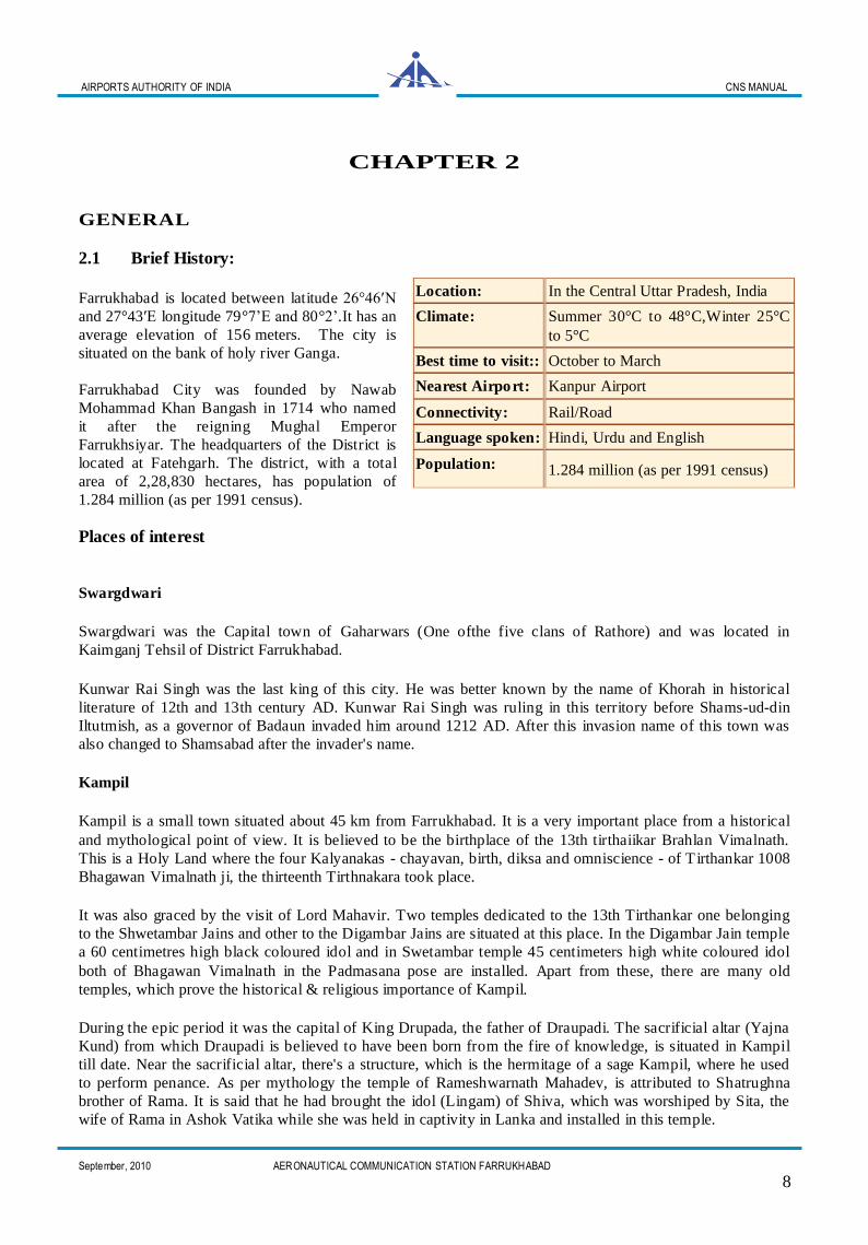
2.1 Brief History:
Farrukhabad is located between latitude 26°46′N
and 27°43′E longitude 79°7’E and 80°2’.It has an
average elevation of 156 meters. The city is
situated on the bank of holy river Ganga.
Farrukhabad City was founded by Nawab
Mohammad Khan Bangash in 1714 who named
it after the reigning Mughal Emperor
Farrukhsiyar. The headquarters of the District is
located at Fatehgarh. The district, with a total
area of 2,28,830 hectares, has population of
1.284 million (as per 1991 census).
Places of interest
Swargdwari
Swargdwari was the Capital town of Gaharwars (One ofthe five clans of Rathore) and was located in
Kaimganj Tehsil of District Farrukhabad.
Kunwar Rai Singh was the last king of this city. He was better known by the name of Khorah in historical
literature of 12th and 13th century AD. Kunwar Rai Singh was ruling in this territory before Shams-ud-din
Iltutmish, as a governor of Badaun invaded him around 1212 AD. After this invasion name of this town was
also changed to Shamsabad after the invader's name.
Kampil
Kampil is a small town situated about 45 km from Farrukhabad. It is a very important place from a historical
and mythological point of view. It is believed to be the birthplace of the 13th tirthaiikar Brahlan Vimalnath.
This is a Holy Land where the four Kalyanakas - chayavan, birth, diksa and omniscience - of Tirthankar 1008
Bhagawan Vimalnath ji, the thirteenth Tirthnakara took place.
It was also graced by the visit of Lord Mahavir. Two temples dedicated to the 13th Tirthankar one belonging
to the Shwetambar Jains and other to the Digambar Jains are situated at this place. In the Digambar Jain temple
a 60 centimetres high black coloured idol and in Swetambar temple 45 centimeters high white coloured idol
both of Bhagawan Vimalnath in the Padmasana pose are installed. Apart from these, there are many old
temples, which prove the historical & religious importance of Kampil.
During the epic period it was the capital of King Drupada, the father of Draupadi. The sacrificial altar (Yajna
Kund) from which Draupadi is believed to have been born from the fire of knowledge, is situated in Kampil
till date. Near the sacrificial altar, there's a structure, which is the hermitage of a sage Kampil, where he used
to perform penance. As per mythology the temple of Rameshwarnath Mahadev, is attributed to Shatrughna
brother of Rama. It is said that he had brought the idol (Lingam) of Shiva, which was worshiped by Sita, the
wife of Rama in Ashok Vatika while she was held in captivity in Lanka and installed in this temple.
Location: In the Central Uttar Pradesh, India
Climate: Summer 30°C to 48°C,Winter 25°C
to 5°C
Best time to visit:: October to March
Nearest Airport: Kanpur Airport
Connectivity: Rail/Road
Language spoken: Hindi, Urdu and English
Population: 1.284 million (as per 1991 census)
AIRPORTS AUTHORITY OF INDIA CNS MANUAL
September, 2010 AERONAUTICAL COMMUNICATION STATION FARRUKHABAD
9
Sankisa
Sankisa is located about 47 km from Farrukhabad. It is believed to be the place where Buddha, along with
Brahma and Devraj Indra descended after giving sermons to his mother in heaven. At the spot of descent
stands a temple with a statue of Buddha. The place is also known for a temple dedicated to Bisari Devi and an
excavated Ashokan elephant pillar. There is also colossal Shiva Linga here. A large fair is held at Sankisa in
the month of Shraavana (July-August) every year.
Neebkarori
A small village near ancient Shankisha is famous for a sage named Lakshman Das. Baba Lakshman Das was
spiritual saint in 20th century. He is better known as Baba Neeb Karori (alt spelling, Neem Karoli, AKA
Maharaj-ji, Baba-Ji). He established many temples of Hanumanji in various parts of India. Temples
established by him at Hanuman Garhi and Kainchi near Nainital, Lucknow, Shimla.
Ghatiya Ghat
This is built on the side of the Ganges and approximately 4 km from the main city. This is a beautiful place
full of small temples and small dwellings. There are also popular shops here. Ghatiya Ghat (Bank of the river)
is the bank of Ganga River.
Ramashram Satsang, Maha Samadhi of Lalaji Maharaj
The holy Samadhi mandir of His Holiness Lalaji Maharaj, is situated on Kanpur Road at Navdia. Shri
Ramachandra ji Maharaj, affectionately called "Lalaji" by the devotees. Lalaji Saheb had founded the
Ramashram Satsang headquartered at Fatehgarh. This satsang is based on the learnings of Nakshbandia wing
of Sufism. Lalaji got his spiritual initiation and completion from Huzoor Mau lana Fazl Ahmed Khan
(Rahantulla Alaih). Now this satsang is having its branches through out the globe. Every year on the vacation
of Easter, bhandara is organised at Maha Samadhi.Presently Shri Dinesh Saxena, the grandson of Lalaji saheb
is looking after the Samadhi mandir. One of disciples of Lalaji Maharaj was Shri Shyam Bihari Lalji 'Babuji'.
His Samadhi Mandir is also in front of Maha Samadhi. The dearest spritual sons of reverend "Babu Ji" - Shri
Rana ji Saheb, Thakur Shri Kaptan Singh Ji, Shri Jagat Narayan "Baba Ji" served continuosly the humanity
under the Highness of their Gurudev Param Pujya "Babu Ji".Pujya Babujee sahab has spread the Satsang as
per the directives of Lalajee sahab.Many spritual sons of Pujya Babu jee, contributed their best in this holy
cause.Later Satsang was headed by Param Sant Mahatma Shri Ram Singh Ranaji Sahab from the Ramashram
Shyamnagar Distt. Kannauj, situated at east bank of Kali River on Kanpur Road.The another vertical of
Satsang is being headed by Shri Jagat Nayaran jee Sahab "Baba Ji" is the divine personality devoted &
dedicated to the Mission of "Lala Ji, Chachcha JI Maharaj and Babu Ji".
2.2 AAI Ofiices:
The AAI has two sites at Farrukhabad:
i) ACS Office at Farrukhabad.
ii) Operational Site at
Jalalabad(Shahjahanpur District).
2.2.1 The ACS office is about 10 Kms. away from the Railway Station in a rented building at Fatehgarh near
district court.
2.2.2 The Operational site Jalalabad is about 50 Km away from the ACS office located at village Rauli-Bauli
near Jalalabad town in Shahjahanpur District.
(Total area of the Operational site is 3.197 Hectare)

AIRPORTS AUTHORITY OF INDIA CNS MANUAL
September, 2010 AERONAUTICAL COMMUNICATION STATION FARRUKHABAD
10
2.2.3 There is also an operational air-strip at Mohmmadabad solely under the control of U.P. Government and
presently used for VVIP aircrafts.
2.3 Role of Station in en-route Navigation:
The station provides a range of ground-based devices to assist en-route navigation. VOR is the main aid to
navigation, providing a radio signal that enables a pilot to take his bearing from a particular station; and co-
installed with it is usually a DME, by interrogating which he can compute his distance from that point. This
combination of VOR/DME is the ICAO standard short-range navigation and position fixing system. ATC
instructions are required by the pilots to fly a particular course or patterns and these are normally linked to
individual VOR 'radials' or positions. Outside controlled airspace the pilot can navigate independently with
reference to VOR/DME, which can also provide a reliable means of defining a predetermined approach to its
destination.
2.4 Organisational Structure:
2.4.1 At present the station is posted with three executives (including Officer-in-charge) and one
assistant. The three executives comprises of one each from Senior Manager, Manager and
Junior Executive level.
2.4.2 The Senior Manager posted at this station is proficient on both ASI VOR and ASI DME .
2.5 Accountability:
2.5.1 The officer-in-charge, Aeronautical Communication Station, Airports Authority of India is responsible
for ensuring the safe, efficient and secure provision of the station facilities and also accountable for all
ongoing operational/administrative deliberations at the station.
2.5.2 The activities required to execute these responsibilities include:
Establishment and Management of an independent Aeronautical Station.
Implementation of ICAO Norms.
Promulgating the CA Requirements.
Modification of the Facility.
Various joint and cooperative activities with different agencies.
2.6 Human Resource:
2.6. 1 A Na vigation facility mainte na nce pers onnel should be specialists in the field. An important element
in a preventive maintenance programme is trained experienced personnel. The authority responsible
for the maintenance should have a thorough knowledge of the equipment, should have experience
with extra-ordinary skill and should be able to make careful inspections for necessary repairs and
modifications, if required. It is desirable for the other staff to have professional training. For
maintenance purpose, well-qualified executives can be trained on-the-job if suitable supervision and
instructions are provided. Considerable exposure to the equipment and its operation is desirable.
These individuals should be present or on-call during the operating hours of the station to correct any
deficiencies that may develop.
AIRPORTS AUTHORITY OF INDIA CNS MANUAL
September, 2010 AERONAUTICAL COMMUNICATION STATION FARRUKHABAD
11
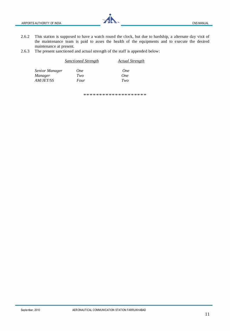
2.6.2 This station is supposed to have a watch round the clock, but due to hardship, a alternate day visit of
the maintenance team is paid to asses the health of the equipments and to execute the desired
maintenance at present.
2.6.3 The present sanctioned and actual strength of the staff is appended below:
Sanctioned Strength Actual Strength
Senior Manager One One
Manager Two One
AM/JET/SS Four Two
********************
AIRPORTS AUTHORITY OF INDIA CNS MANUAL
September, 2010 AERONAUTICAL COMMUNICATION STATION FARRUKHABAD
12
CHAPTER 3
FACILITIES
3.1 VOR:
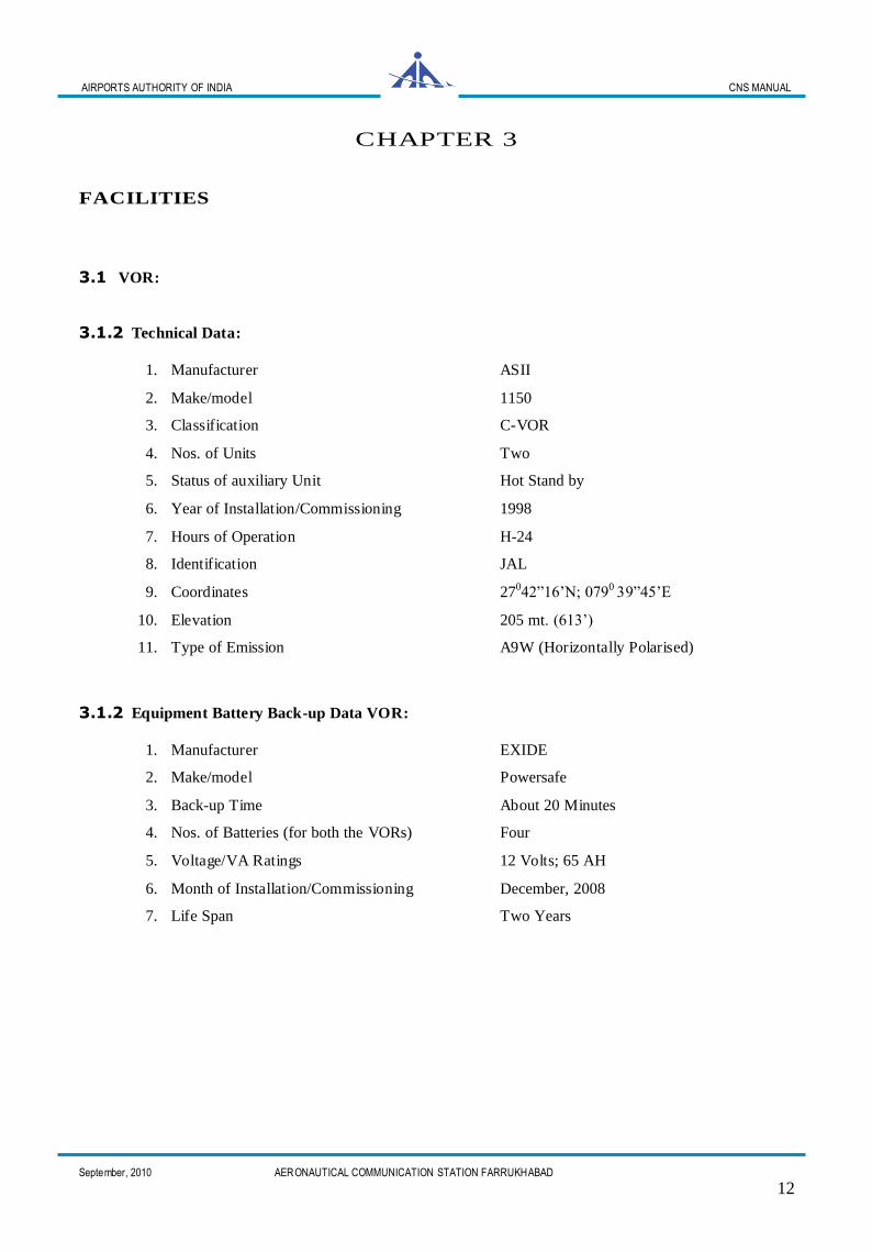
3.1.2 Technical Data:
1. Manufacturer ASII
2. Make/model 1150
3. Classification C-VOR
4. Nos. of Units Two
5. Status of auxiliary Unit Hot Stand by
6. Year of Installation/Commissioning 1998
7. Hours of Operation H-24
8. Identification JAL
9. Coordinates 27042”16’N; 0790 39”45’E
10. Elevation 205 mt. (613’)
11. Type of Emission A9W (Horizontally Polarised)
3.1.2 Equipment Battery Back-up Data VOR:
1. Manufacturer EXIDE
2. Make/model Powersafe
3. Back-up Time About 20 Minutes
4. Nos. of Batteries (for both the VORs) Four
5. Voltage/VA Ratings 12 Volts; 65 AH
6. Month of Installation/Commissioning December, 2008
7. Life Span Two Years
AIRPORTS AUTHORITY OF INDIA CNS MANUAL
September, 2010 AERONAUTICAL COMMUNICATION STATION FARRUKHABAD
13
ST
AT
ION
CN
S M
AN
UA
L, FA
RR
UK
HA
BA
D
AE
RO
NA
UT
ICA
L C
OM
MU
NIC
AT
ION
ST
AT
ION
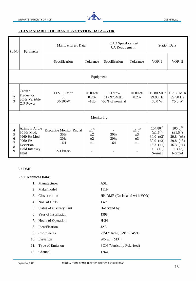
3.1.3 STANDARD, TOLERANCE & STATION DATA—VOR
3.2 DME
3.2.1 Technical Data:
1. Manufacturer ASII
2 . Make/model 1119
3. Classification HP-DME (Co-located with VOR)
4. Nos. of Units Two
5 . Status of auxiliary Unit Hot Stand by
6 . Year of Installation 1998
7. Hours of Operation H-24
8. Identification JAL
9. Coordinates 27042”16’N; 0790 39”45’E
10. Elevation 205 mt. (613’)
11. Type of Emission PON (Vertically Polarized)
12. Channel 126X
Sl. No
Parameter
Manufacturers Data ICAO Specification/
CA Requirement Station Data
Specification Tolerance Specification Tolerance VOR-I VOR-II
Equipment
1
2
3
Carrier
Frequency
30Hz Variable
O/P Power
112-118 Mhz
30
50-100W
±0.002%
0.2%
–1dB
111.975-
117.975MHz
>50% of nominal
±0.002%
0.2%
115.80 MHz
29.90 Hz
80.0 W
117.80 MHz
29.90 Hz
75.0 W
Monitoring
4
5
6
7
8
9
Azimuth Angle
30 Hz Mod.
9960 Hz Mod.
9960 Hz
Deviation
Field Intensity
Ident
Executive Monitor Radial
30%
30%
16:1
2-3 letters
±1O
±2
±2
±1
-
-
30%
30%
16:1
-
±1.5O
±3
±3
±1
-
104.80 O
(±1.5O)
30.0 (±3)
30.0 (±3)
16.3 (±1)
0.0 (±3)
Normal
105.0 O
(±1.5O)
29.8 (±3)
29.8 (±3)
16.3 (±1)
0.0 (±3)
Normal
AIRPORTS AUTHORITY OF INDIA CNS MANUAL
September, 2010 AERONAUTICAL COMMUNICATION STATION FARRUKHABAD
14
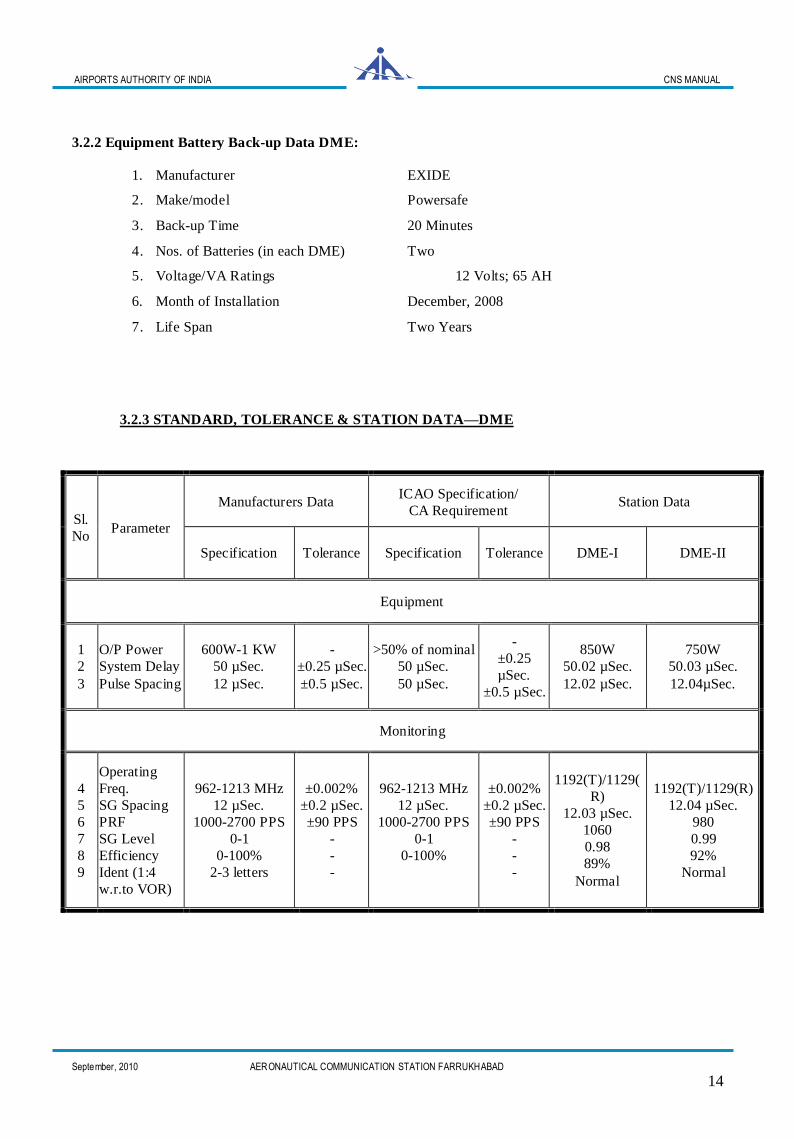
3.2.2 Equipment Battery Back-up Data DME:
1. Manufacturer EXIDE
2 . Make/model Powersafe
3 . Back-up Time 20 Minutes
4 . Nos. of Batteries (in each DME) Two
5 . Voltage/VA Ratings 12 Volts; 65 AH
6. Month of Installation December, 2008
7 . Life Span Two Years
3.2.3 STANDARD, TOLERANCE & STATION DATA—DME
Sl.
No Parameter
Manufacturers Data ICAO Specification/
CA Requirement Station Data
Specification Tolerance Specification Tolerance DME-I DME-II
Equipment
1
2
3
O/P Power
System Delay
Pulse Spacing
600W-1 KW
50 µSec.
12 µSec.
-
±0.25 µSec.
±0.5 µSec.
>50% of nominal
50 µSec.
50 µSec.
-
±0.25
µSec.
±0.5 µSec.
850W
50.02 µSec.
12.02 µSec.
750W
50.03 µSec.
12.04µSec.
Monitoring
4
5
6
7
8
9
Operating
Freq.
SG Spacing
PRF
SG Level
Efficiency
Ident (1:4
w.r.to VOR)
962-1213 MHz
12 µSec.
1000-2700 PPS
0-1
0-100%
2-3 letters
±0.002%
±0.2 µSec.
±90 PPS
-
-
-
962-1213 MHz
12 µSec.
1000-2700 PPS
0-1
0-100%
±0.002%
±0.2 µSec.
±90 PPS
-
-
-
1192(T)/1129(
R)
12.03 µSec.
1060
0.98
89%
Normal
1192(T)/1129(R)
12.04 µSec.
980
0.99
92%
Normal
AIRPORTS AUTHORITY OF INDIA CNS MANUAL
September, 2010 AERONAUTICAL COMMUNICATION STATION FARRUKHABAD
15
ST
AT
ION
CN
S M
AN
UA
L, FA
RR
UK
HA
BA
D
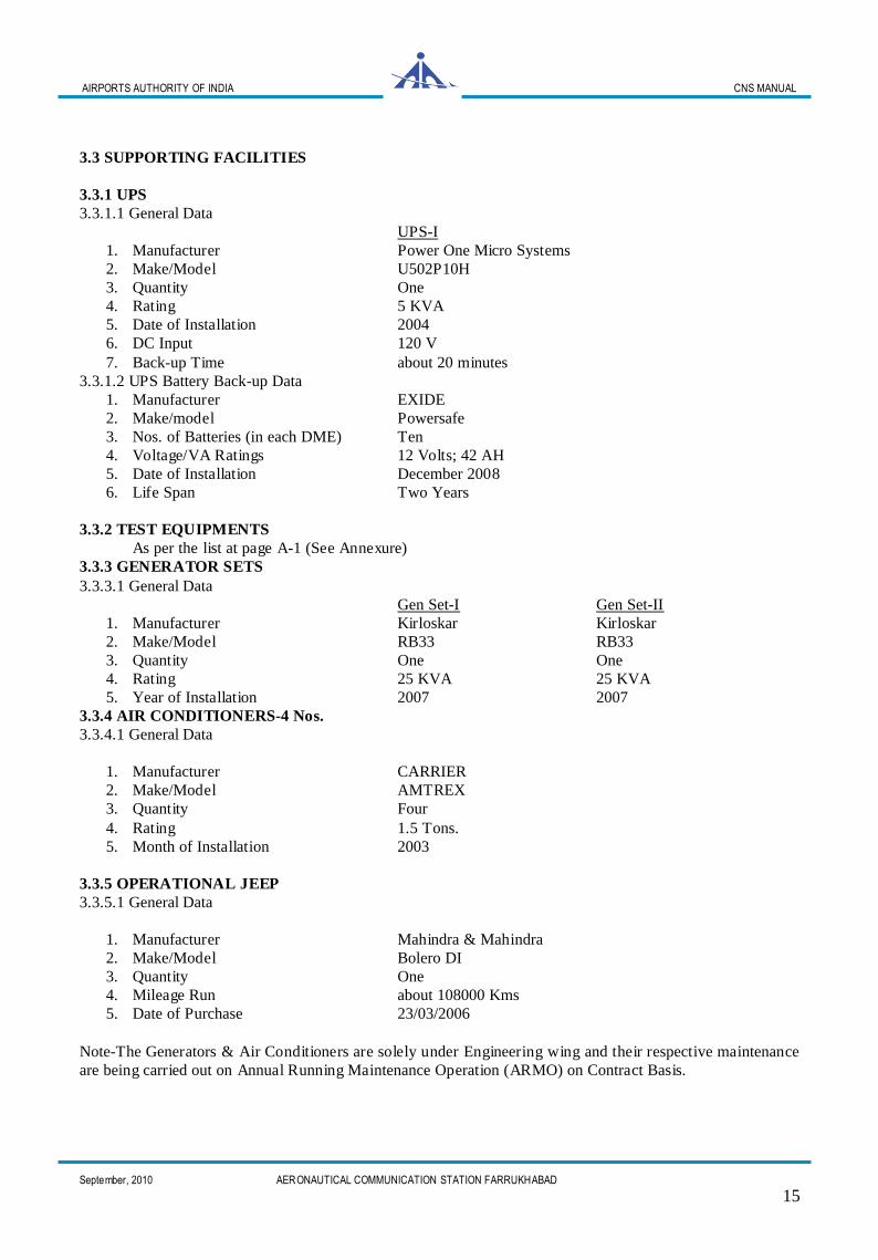
3.3 SUPPORTING FACILITIES
3.3.1 UPS
3.3.1.1 General Data
UPS-I
1. Manufacturer Power One Micro Systems
2. Make/Model U502P10H
3. Quantity One
4. Rating 5 KVA
5. Date of Installation 2004
6. DC Input 120 V
7. Back-up Time about 20 minutes
3.3.1.2 UPS Battery Back-up Data
1. Manufacturer EXIDE
2. Make/model Powersafe
3. Nos. of Batteries (in each DME) Ten
4. Voltage/VA Ratings 12 Volts; 42 AH
5. Date of Installation December 2008
6. Life Span Two Years
3.3.2 TEST EQUIPMENTS
As per the list at page A-1 (See Annexure)
3.3.3 GENERATOR SETS
3.3.3.1 General Data
Gen Set-I Gen Set-II
1. Manufacturer Kirloskar Kirloskar
2. Make/Model RB33 RB33
3. Quantity One One
4. Rating 25 KVA 25 KVA
5. Year of Installation 2007 2007
3.3.4 AIR CONDITIONERS-4 Nos.
3.3.4.1 General Data
1. Manufacturer CARRIER
2. Make/Model AMTREX
3. Quantity Four
4. Rating 1.5 Tons.
5. Month of Installation 2003
3.3.5 OPERATIONAL JEEP
3.3.5.1 General Data
1. Manufacturer Mahindra & Mahindra
2. Make/Model Bolero DI
3. Quantity One
4. Mileage Run about 108000 Kms
5. Date of Purchase 23/03/2006
Note-The Generators & Air Conditioners are solely under Engineering wing and their respective maintenance
are being carried out on Annual Running Maintenance Operation (ARMO) on Contract Basis.
AE
RO
NA
UT
ICA
L CO
MM
UN
ICA
TIO
N S
TA
TIO
N
AIRPORTS AUTHORITY OF INDIA CNS MANUAL
September, 2010 AERONAUTICAL COMMUNICATION STATION FARRUKHABAD
16
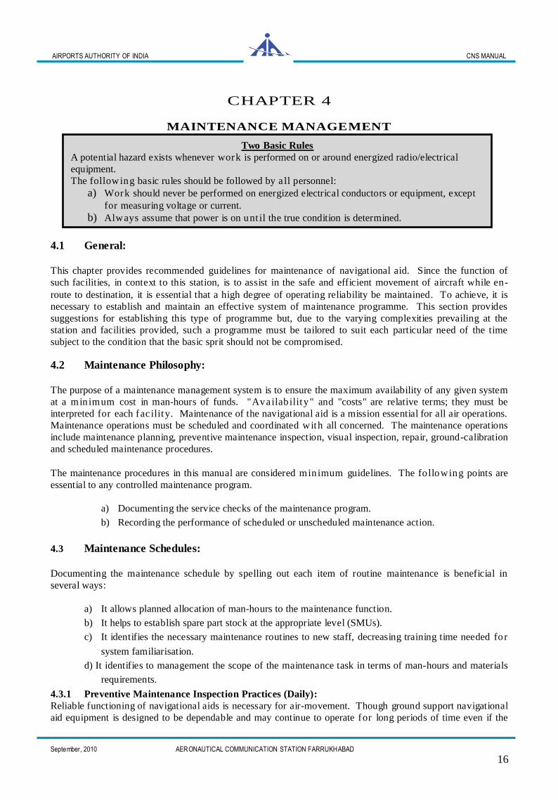
CHAPTER 4
MAINTENANCE MANAGEMENT
4.1 General:
This chapter provides recommended guidelines for maintenance of navigational aid. Since the function of
such facilities, in context to this station, is to assist in the safe and efficient movement of aircraft while en-
route to destination, it is essential that a high degree of operating reliability be maintained. To achieve, it is
necessary to establish and maintain an effective system of maintenance programme. This section provides
suggestions for establishing this type of programme but, due to the varying complexities prevailing at the
station and facilities provided, such a programme must be tailored to suit each particular need of the time
subject to the condition that the basic sprit should not be compromised.
4.2 Maintenance Philosophy:
The purpose of a maintenance management system is to ensure the maximum availability of any given system
at a minimum cost in man-hours of funds. "Availab ility" and "costs" are relative terms; they must be
interpreted for each fac ility. Maintenance of the navigational aid is a mission essential for all air operations.
Maintenance operations must be scheduled and coordinated with all concerned. The maintenance operations
include maintenance planning, preventive maintenance inspection, visual inspection, repair, ground-calibration
and scheduled maintenance procedures.
The maintenance procedures in this manual are considered minimum guidelines. The fo llowing points are
essential to any controlled maintenance program.
a) Documenting the service checks of the maintenance program.
b) Recording the performance of scheduled or unscheduled maintenance action.
4.3 Maintenance Schedules:
Documenting the maintenance schedule by spelling out each item of routine maintenance is beneficial in
several ways:
a) It allows planned allocation of man-hours to the maintenance function.
b) It helps to establish spare part stock at the appropriate level (SMUs).
c) It identifies the necessary maintenance routines to new staff, decreasing training time needed for
system familiarisation.
d) It identifies to management the scope of the maintenance task in terms of man-hours and materials
requirements.
4.3.1 Preventive Maintenance Inspection Practices (Daily):
Reliable functioning of navigational aids is necessary for air-movement. Though ground support navigational
aid equipment is designed to be dependable and may continue to operate for long periods of time even if the
Two Basic Rules
A potential hazard exists whenever work is performed on or around energized radio/electrical
equipment.
The following basic rules should be followed by a ll personnel:
a) Work should never be performed on energized electrical conductors or equipment, except
for measuring voltage or current. b) Always assume that power is on unt il the true condition is determined.

AIRPORTS AUTHORITY OF INDIA CNS MANUAL
September, 2010 AERONAUTICAL COMMUNICATION STATION FARRUKHABAD
17
maintenance is neglected, yet it is essential that a preventive maintenance programme be established to ensure
reliable service and proper equipment operation.
An important factor of preventive maintenance programme is an effective Preventive Maintenance Inspection
(Daily) schedule. This daily schedule is the foundation for the successful maintenance of the equipment. If
the daily schedule is performed properly, it will ensure top system performance and will minimize
unscheduled interruptions and breakdowns. A review of the inspection records, checks, tests and repairs
provides a constant awareness of the equipment condition and gives maintenance personnel advanced warning
of impending trouble.
This includes the following checks on daily basis:
i) Building Condition—cracks, leakage etc.
ii) Antennae System and Associated Structure—corrosion, welding, foundation etc.
iii) Room Temperature/Air-conditioning.
iv) Cleaning of equipment/Equpt. Room/condition of PVC flooring.
v) Wiring Condition—abrasions, breaks, and loose connections etc.
vi) Connectors/Electrical Jumpers—looseness, moisture, rusting etc.
vii) Mechanical Systems—lubrication etc.
viii) Rodent/Lizard/Insect Prevention.
ix) Visit to other establishments (Generator Room etc. for similar observations).
x) Lightening Arrester.
xi) Earthing System.
xii) Obstruction Light.
4.3.2 Periodical Maintenance:
Scheduled inspections and tests are those accomplished on specific types of equipment on a periodic basis.
The schedule may be based either on calendar or on hour ly use increments. These schedules are based on
recommendations from the regulatory authority or from the manufacturers and users of the equipment. These
schedules are considered to be the typical requirements to keep the equipment in good condition. In our case
it is a multi-phased programme, viz, daily, weekly, monthly, quarterly, half yearly & annualy. This is
subjected to:
a) Monitoring of operational parameters
b) Perfect functioning of monitoring device (within standard tolerance) and warning/alarm etc.
c) Equipme nt’s be ha vior under the alarm condition (cha nge over, shut down, restart generations etc.)
d) Alignment/Calibration/Tuning of equipment and accessories according to procedure.
4.4 Performance Checks:
4.4.1 The efficiency of any facility depends upon checks and counter checks. The Performance Check is
also a counter check type of maintenance in which the parameter measured has to be tallied /compared with
station’s previous records in a routine or required manner. It includes the following check:
i) Various Voltage/Current levels (available at TPs & jacks)
ii) Wave Shapes
iii) Monitoring Levels
iv) Station Assigned Frequency
v) Power Levels of various signal/Output Power
vi) Level of internal signal generators.
vii) Modulation Percentage
viii) VSWRs
ix) Lightening Arrester
x) Earthing System
4.4.2 All these checks should also be carried out for associated units/test equipments to assure the safe
operation of facility.
AIRPORTS AUTHORITY OF INDIA CNS MANUAL
September, 2010 AERONAUTICAL COMMUNICATION STATION FARRUKHABAD
18
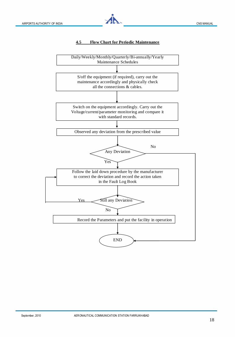
4.5 Flow Chart for Periodic Maintenance
Daily/Weekly/Monthly/Quarterly/Bi-annually/Yearly
Maintenance Schedules
S/off the equipment (if required), carry out the
maintenance accordingly and physically check
all the connections & cables.
Switch on the equipment accordingly. Carry out the
Voltage/current/parameter monitoring and compare it
with standard records.
Observed any deviation from the prescribed value
No
Any Deviation
Yes
Follow the laid down procedure by the manufacturer
to correct the deviation and record the action taken
in the Fault Log Book
Yes Still any Deviation
No
Record the Parameters and put the facility in operation
END
AIRPORTS AUTHORITY OF INDIA CNS MANUAL
September, 2010 AERONAUTICAL COMMUNICATION STATION FARRUKHABAD
19
4.6 Troubleshooting:
Before attending the any equipment/unit, it may be ensured that power supply to the equipment/unit is of
specified rating. In case of AC supply, the voltage and frequency is of rated value whereas in case of DC
supply voltage and ripple filtering is very important.
The common approach of troubleshooting is:
i. Smell out any burnt/overheating component.
ii. Check-up for male/female connector along with its pins and ensure its proper insertion.
iii. Similar exercise may be carried out for all edge connectors and ribbon connectors.
iv. Check the earthing of the equipment. Improper/floating/dry earth sometimes plays havoc despite
of perfect status of the equipment.
To avoid any further damage, It is advisable to isolate the onwards stages or to reduce the power handling
level if and only if the situation permits.
These were the only general methodology for fault finding. It is recommended that a procedural approach
referring to manufacturer’s manual should be adopted for the purpose. A record to this effect should also be
made in the Fault Log Book.
4.7 Tools & Test Equipments:
An important element in a maintenance programme is the tools and test equipment required to perform the
task. This includes the proper tools, test equipment, adequate working space, adequate storage space, spare
modules and applicable technical manuals. Carrying out the maintenance with the perfect and calibrated test
equipments curbs the equipment failure, false signals, and deterioration of the system.
4.8 Maintenance Records:
Maintenance records are an important part of an effective maintenance management system. They provide a
service history of each piece of equipment’s sub-units, ensure regular maintenance without duplication of
effort, and give a data base for statistical analysis of system performances. Without records, knowledge
gained from regular inspections will not be retained, and preventive maintenance will be d if f icu lt. An
effective records system should a llow for the recording and retrieval of information with a minimum of
effort. The records system should compile data that will document the effectiveness of the maintenance
program. By checking the records, a proficient executive will be able to determine whether a particular
maintenance task is being done too frequently or not often enough.
Since corrective and preventive maintenance procedures for the equipment are adequately addressed in CHQ
CNS Manual, this manual contains the compact, recompiled and comprehensive user friendly parameter
recording formats for the maintenance schedules as well as the status reports to be sent to respective RHQ as
per the instructions. These are given in Annexure pages as detailed below:
Sl No.Format for Record Page (for VOR) Page (for DME)
i) Daily Maintenance Schedule A-7 A-8
ii) Weekly Maintenance Schedule A-9 to A-10 A-11
iii) Monthly Maintenance Schedule A-12 A-11
iv) Quarterly/Six Monthly/Annual Maintenance Schedules A-13 A-14
v) Monthly Ground Calibration Reports for VOR A-15 ----
vi) Performance Indicator Report & Monthly Status
Repots (Combined) A-16 A-16
vii) Daily Status Report/Weekly Status Report (Combined) A-17 A-17

AIRPORTS AUTHORITY OF INDIA CNS MANUAL
September, 2010 AERONAUTICAL COMMUNICATION STATION FARRUKHABAD
20
4.9 Flow Chart for Troubleshooting
Spare Part/Module
Available
Yes NO
Follow the laid down procedure to change the module/ component as per the specified ratings and carry out Yes the desired adjustment as per procedure if required
Record the Parameters and Check the faulty Locally No
put the facility in operation Module repairable
Yes
Demand the spares Purchase the spares Send The faulty
END CHQ/CRSD fulfilling the from module to SMU
codal formalities
Follow-up action to get Follow-up action to get
the spares required The repaired/spare module
(if required)
Received Spare/
Repaired Module
∑
Complaint Received/Fault Monitored
Check all Panel Indications/Meter Reading/Parameter of the
Equipment and analyse the fault
Locate the Faulty Unit/Module/Component with the help
of Procedural Methodology & Test Equipments
Determine the spares required to rectify the fault
AIRPORTS AUTHORITY OF INDIA CNS MANUAL
September, 2010 AERONAUTICAL COMMUNICATION STATION FARRUKHABAD
21
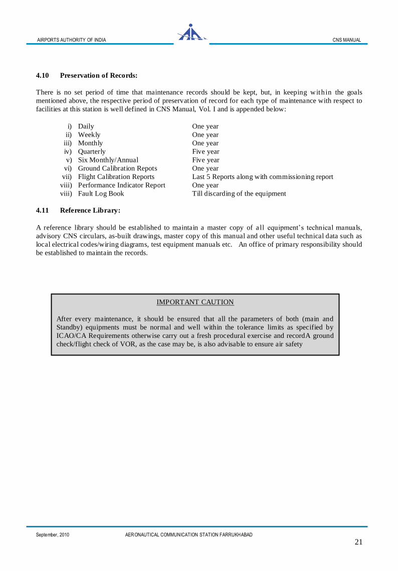
4.10 Preservation of Records:
There is no set period of time that maintenance records should be kept, but, in keeping with in the goals
mentioned above, the respective period of preservation of record for each type of maintenance with respect to
facilities at this station is well defined in CNS Manual, Vol. I and is appended below:
i) Daily One year
ii) Weekly One year
iii) Monthly One year
iv) Quarterly Five year
v) Six Monthly/Annual Five year
vi) Ground Calibration Repots One year
vii) Flight Calibration Reports Last 5 Reports along with commissioning report
viii) Performance Indicator Report One year
viii) Fault Log Book Till discarding of the equipment
4.11 Reference Library:
A reference library should be established to maintain a master copy of a ll equipment’s technical manuals,
advisory CNS circulars, as-built drawings, master copy of this manual and other useful technical data such as
local electrical codes/wiring diagrams, test equipment manuals etc. An office of primary responsibility should
be established to maintain the records.
IMPORTANT CAUTION
After every maintenance, it should be ensured that all the parameters of both (main and
Standby) equipments must be normal and well within the tolerance limits as specified by
ICAO/CA Requirements otherwise carry out a fresh procedural exercise and recordA ground
check/flight check of VOR, as the case may be, is also advisable to ensure air safety
AIRPORTS AUTHORITY OF INDIA CNS MANUAL
September, 2010 AERONAUTICAL COMMUNICATION STATION FARRUKHABAD
22
CHAPTER 5
CRISIS PLANING AND COORDINATION
5.1 General
The air-space with few operations may suffer with a litt le inconvenience to pilot as well as to ground
controller in managing the show without Navigational Aid but the management of a crowded air-space without
the provision of such aid is quite risky for the both. That too if failure occurs at a critical time, it may lead
lives and property be jeopardised. The concept of Hot Stand-by has solved the problem up to certain extent,
still unpredictable failure of the facility sometimes inevitable due to natural reasons. Hence navigational aid
restoration should receive high priority in the interest of air-safety.
5.2 Availability of serviceable card/module/unit:
This section contains guidelines on how to manage serviceable modules to be replaced, co-ordination with
appropriate levels for quick restoration of station facility.
5.2.1 Special Maintenance Units (SMUs):
Under the modernisation plan, the AAI has adopted a cetralised maintenance workshop
concept (CMC/SMUs) at different airports for different facilities. The Special Maintenance Unit (SMU), New
Delhi is identified as the cetralised maintenance unit for the facilities commissioned at this station.
In the event of unexpected failure of facility and in order to minimising the facilities out of operation time,
following guidelines have to be adopted:
a) Isolate, pack and dispatch the faulty module/card along with telephonic coordination to SMU, New
Delhi. Intimate via e-mail to CMC with a fault briefing report as per Performa CMC-01. (Ref.
Caution ‘f’ in packing ESD sensitive device, Annexure page A-2)
b) SMU, in turn, acknowledges station by raising a Site Anomaly Report (SAR) as per Performa CMC-
02.
c) After servicing and hot check or replacement, the card is again dispatched back to station as per
Performa CMC-03.
d) Upon receipt of the module/card at the station,
i) if the performance is satisfactory—Normalise the station and intimate all concerned as well as
SMU to close SAR as per Performa CMC-04.
ii) if the performance is faulty—Again dispatch the faulty module/card along with telephonic
coordination to SMU, New Delhi according to defined procedure bearing the same SAR
number.
5.3 Effect of the Failure:
The effect of the failure of a particular spare part depends on how important the part is to the equipment it is
installed in, and/or how vita l the equipment is to operation. For example, the failure of an indicator lamp in
a unit would not lead to any system downtime whereas any breakdown in a circuit board/module would
cause the failure of the entire facility. The recurrence failure of a particular card/module/unit should be given
due consideration to sort out the problem permanently.

AIRPORTS AUTHORITY OF INDIA CNS MANUAL
September, 2010 AERONAUTICAL COMMUNICATION STATION FARRUKHABAD
23
5.4 Facility Malfunction:
In the event of failure of a facility irrespective short-termed or prolonged, It is mandatory for the service
provider to coordinate with appropriate authority who can inform all such time-critical aeronautical
information to every concerned which could affect a pilot's decision to make a flight. Even after restoration of
the facility similar liasoning is mandatory.
5.4.1 NOTAM (Notice to Airmen):
It is a notice distributed by means of telecommunication containing information concerning the establishment,
condition or change in the status any aeronautical facility, service, procedure or hazard, the timely knowledge
of which is essential to all concerned parties involved in flight operations. The person in charge of the watch
shall report any known or reported malfunctions of a NAVAID to technical operations or appropriate
personnel and coordinate issuance of a NOTAM.
In the case of this station and under such circumstances, all time based coordination has to be carried out with
WSO (Tech.), Palam, New Delhi. (Phone: 011-25653492) with the following details:
Specify an acceptable recovery time for the shutdown facility.
The procedure to be repeated if the acceptable recovery time of a service is exceeded or
Specify time about the restoration of the shutdown facility, if already restored.

AIRPORTS AUTHORITY OF INDIA CNS MANUAL
September, 2010 AERONAUTICAL COMMUNICATION STATION FARRUKHABAD
24
CHAPTER 6
MONITORING AND SAFETY
6.1 General:
To establish the technical efficiency, maintain safety and adequate levels of reliable service of these facilities,
a continuous monitoring is being carried out. The systems do have automatic monitoring that shut down the
equipment if it puts out an unsafe signal. Unmonitored, as used in this order, means that the personnel
responsible for monitoring the facility have lost aural and visual monitoring capabilities and cannot observe
the status of the facility or not physically present at the site. It does not refer to the automatic monitoring
feature. Monitoring is accomplished in following ways:
6.1.1 Executive Monitoring:
It is an electronic means in which the system checks its critical parameters itself and in the event of an out of
tolerance condition, either changes to an auxiliary back-up equipment or shuts the system down if there is no
redundancy or if the redundant circuit is also failed. This monitoring is continuous.
6.1.2 Status Monitoring:
This is an automatic notification, either to the maintenance centre or to an operational position, that the system
has taken an executive action and the navigation system is changed over or off-the-air. Many NAVAIDs are
not continuously status–monitored.
6.1.3 Ground Calibration:
The monitoring of the composite signal at pre-defined bearings on ground leads to an estimated consequence
of correct formation of signal pattern in the air. This ground Calibration is usually carried out once in a month
or as per the requirement.
6.1.4 Air Calibration:
NAVAIDs are flight inspected by specially equipped aircraft on a regular basis to ensure that standards are
met and certifies the facility is air-worthy. In case of CVOR/DME, It may be noted that it has to be carried out
at an interval of every 240 ± 30 days.
6.1.5 Pilot Monitoring:
When a pilot tune and identify NAVAIDs prior to use and afterwards gets the satisfied performance of the
facility as per the standards, this is called Pilot Monitoring.
6.2 Safety:
It is the responsibility of every AAI employee involved with the CNS activities to understand and help achieve
the following safety goals:
• Provide a safe and healthful working environment for all other colleague employees.
• Incorporate safety aspects into maintenance operations planning.
• Reduce operating costs and increase mission capability by protecting human and material assets.
• Eliminate hazardous conditions.
Similarly, the aviation safety program is composed of three elements. They are standardization, compliance,
and hazards identification.
AIRPORTS AUTHORITY OF INDIA CNS MANUAL
September, 2010 AERONAUTICAL COMMUNICATION STATION FARRUKHABAD
25
• Standardization is an ongoing responsibility of all personnel associated with aviation activities.
• Compliance with safety policies, procedures, and practices as spelled out in this manual and associated
document is the responsibility of every maintenance team.
• The Hazard Identification System is both an informal and a formal reporting system. Aviation
personnel are expected and encouraged to inform their subordinates of a hazard.
The end result of these combined efforts of all above is a navigation system that is safe, reliable and air-
worthy and meets the established standards.
AIRPORTS AUTHORITY OF INDIA CNS MANUAL
September, 2010 AERONAUTICAL COMMUNICATION STATION FARRUKHABAD
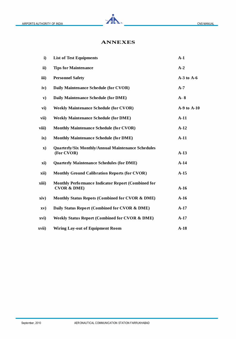
ANNEXES
i) List of Test Equipments A-1
ii) Tips for Maintenance A-2
iii) Personnel Safety A-3 to A-6
iv) Daily Maintenance Schedule (for CVOR) A-7
v) Daily Maintenance Schedule (for DME) A- 8
vi) Weekly Maintenance Schedule (for CVOR) A-9 to A-10
vii) Weekly Maintenance Schedule (for DME) A-11
viii) Monthly Maintenance Schedule (for CVOR) A-12
ix) Monthly Maintenance Schedule (for DME) A-11
x) Quarterly/Six Monthly/Annual Maintenance Schedules
(For CVOR) A-13
xi) Quarterly Maintenance Schedules (for DME) A-14
xii) Monthly Ground Calibration Reports (for CVOR) A-15
xiii) Monthly Performance Indicator Report (Combined for
CVOR & DME) A-16
xiv) Monthly Status Repots (Combined for CVOR & DME) A-16
xv) Daily Status Report (Combined for CVOR & DME) A-17
xvi) Weekly Status Report (Combined for CVOR & DME) A-17
xvii) Wiring Lay-out of Equipment Room A-18
AIRPORTS AUTHORITY OF INDIA CNS MANUAL
September, 2010 AERONAUTICAL COMMUNICATION STATION FARRUKHABAD
A-1
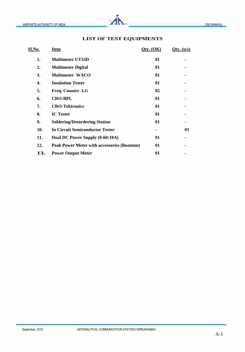
LIST OF TEST EQUIPMENTS
Sl.No. Item Qty. (OK) Qty. (u/s)
1. Multimeter UT33D 01 -
2. Multimeter Digital 01 -
3. Multimeter WACO 01 -
4. Insulation Tester 01 -
5. Freq. Counter LG 02 -
6. CRO-BPL 01 -
7. CRO-Tektronics 01 -
8. IC Tester 01 -
9. Soldering/Desordering Station 01 -
10. In Circuit Semiconductor Tester - 01
11. Dual DC Power Supply (0-60:10A) 01 -
12. Peak Power Meter with accessories (Boonton) 01 -
13. Power Output Meter 01 -
AIRPORTS AUTHORITY OF INDIA CNS MANUAL
September, 2010 AERONAUTICAL COMMUNICATION STATION FARRUKHABAD
A-2
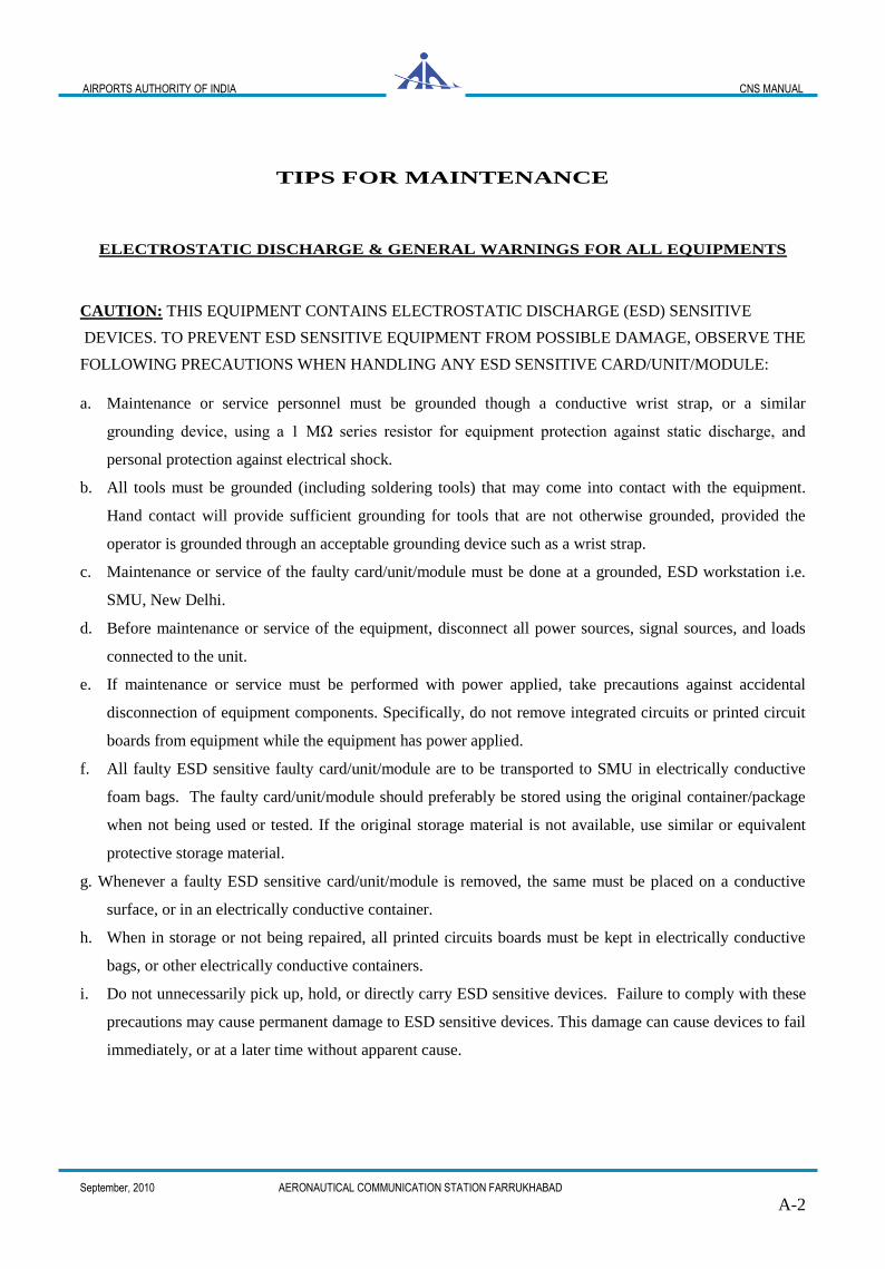
TIPS FOR MAINTENANCE
ELECTROSTATIC DISCHARGE & GENERAL WARNINGS FOR ALL EQUIPMENTS
CAUTION: THIS EQUIPMENT CONTAINS ELECTROSTATIC DISCHARGE (ESD) SENSITIVE
DEVICES. TO PREVENT ESD SENSITIVE EQUIPMENT FROM POSSIBLE DAMAGE, OBSERVE THE
FOLLOWING PRECAUTIONS WHEN HANDLING ANY ESD SENSITIVE CARD/UNIT/MODULE:
a. Maintenance or service personnel must be grounded though a conductive wrist strap, or a similar
grounding device, using a 1 MΩ series resistor for equipment protection against static discharge, and
personal protection against electrical shock.
b. All tools must be grounded (including soldering tools) that may come into contact with the equipment.
Hand contact will provide sufficient grounding for tools that are not otherwise grounded, provided the
operator is grounded through an acceptable grounding device such as a wrist strap.
c. Maintenance or service of the faulty card/unit/module must be done at a grounded, ESD workstation i.e.
SMU, New Delhi.
d. Before maintenance or service of the equipment, disconnect all power sources, signal sources, and loads
connected to the unit.
e. If maintenance or service must be performed with power applied, take precautions against accidental
disconnection of equipment components. Specifically, do not remove integrated circuits or printed circuit
boards from equipment while the equipment has power applied.
f. All faulty ESD sensitive faulty card/unit/module are to be transported to SMU in electrically conductive
foam bags. The faulty card/unit/module should preferably be stored using the original container/package
when not being used or tested. If the original storage material is not available, use similar or equivalent
protective storage material.
g. Whenever a faulty ESD sensitive card/unit/module is removed, the same must be placed on a conductive
surface, or in an electrically conductive container.
h. When in storage or not being repaired, all printed circuits boards must be kept in electrically conductive
bags, or other electrically conductive containers.
i. Do not unnecessarily pick up, hold, or directly carry ESD sensitive devices. Failure to comply with these
precautions may cause permanent damage to ESD sensitive devices. This damage can cause devices to fail
immediately, or at a later time without apparent cause.
AIRPORTS AUTHORITY OF INDIA CNS MANUAL
September, 2010 AERONAUTICAL COMMUNICATION STATION FARRUKHABAD
A-3
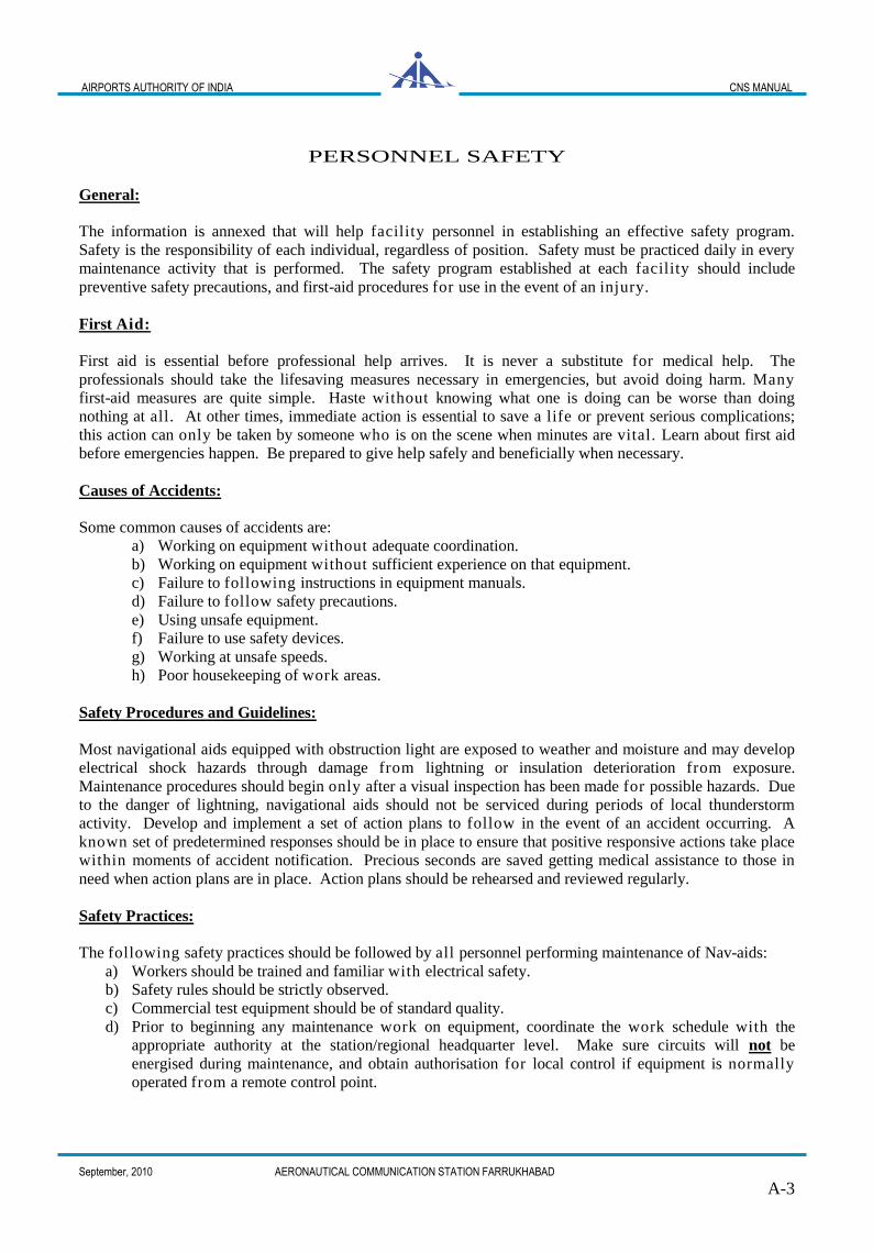
PERSONNEL SAFETY
General:
The information is annexed that will help facility personnel in establishing an effective safety program.
Safety is the responsibility of each individual, regardless of position. Safety must be practiced daily in every
maintenance activity that is performed. The safety program established at each facility should include
preventive safety precautions, and first-aid procedures for use in the event of an injury.
First Aid:
First aid is essential before professional help arrives. It is never a substitute for medical help. The
professionals should take the lifesaving measures necessary in emergencies, but avoid doing harm. Many
first-aid measures are quite simple. Haste without knowing what one is doing can be worse than doing
nothing at all. At other times, immediate action is essential to save a life or prevent serious complications;
this action can only be taken by someone who is on the scene when minutes are vital. Learn about first aid
before emergencies happen. Be prepared to give help safely and beneficially when necessary.
Causes of Accidents:
Some common causes of accidents are:
a) Working on equipment without adequate coordination.
b) Working on equipment without sufficient experience on that equipment.
c) Failure to following instructions in equipment manuals.
d) Failure to follow safety precautions.
e) Using unsafe equipment.
f) Failure to use safety devices.
g) Working at unsafe speeds.
h) Poor housekeeping of work areas.
Safety Procedures and Guidelines:
Most navigational aids equipped with obstruction light are exposed to weather and moisture and may develop
electrical shock hazards through damage from lightning or insulation deterioration from exposure.
Maintenance procedures should begin only after a visual inspection has been made for possible hazards. Due
to the danger of lightning, navigational aids should not be serviced during periods of local thunderstorm
activity. Develop and implement a set of action plans to follow in the event of an accident occurring. A
known set of predetermined responses should be in place to ensure that positive responsive actions take place
within moments of accident notification. Precious seconds are saved getting medical assistance to those in
need when action plans are in place. Action plans should be rehearsed and reviewed regularly.
Safety Practices:
The following safety practices should be followed by all personnel performing maintenance of Nav-aids:
a) Workers should be trained and familiar with electrical safety.
b) Safety rules should be strictly observed.
c) Commercial test equipment should be of standard quality.
d) Prior to beginning any maintenance work on equipment, coordinate the work schedule with the
appropriate authority at the station/regional headquarter level. Make sure circuits will not be
energised during maintenance, and obtain authorisation for local control if equipment is normally
operated from a remote control point.
AIRPORTS AUTHORITY OF INDIA CNS MANUAL
September, 2010 AERONAUTICAL COMMUNICATION STATION FARRUKHABAD
A-4
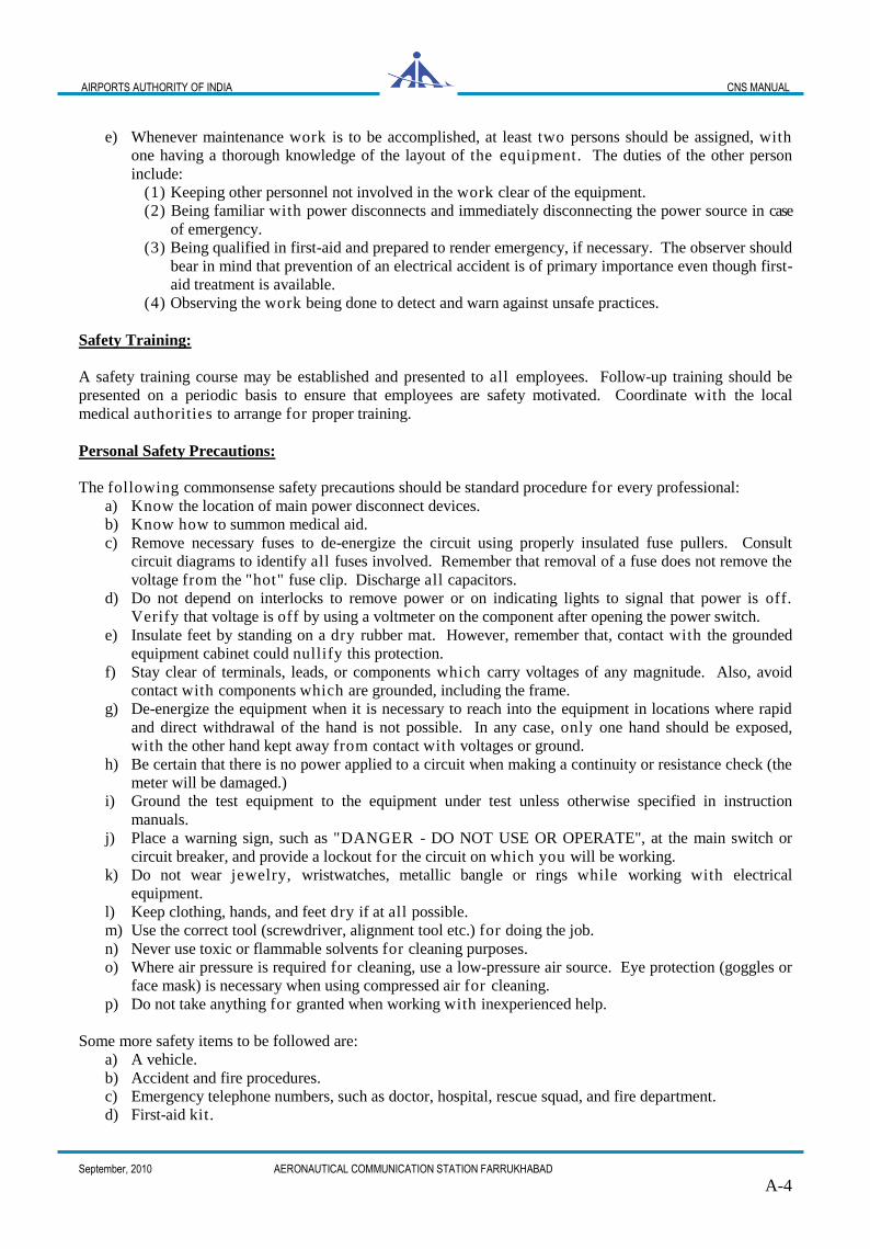
e) Whenever maintenance work is to be accomplished, at least two persons should be assigned, with
one having a thorough knowledge of the layout of the equipment. The duties of the other person
include:
(1) Keeping other personnel not involved in the work clear of the equipment.
(2) Being familiar with power disconnects and immediately disconnecting the power source in case
of emergency.
(3) Being qualified in first-aid and prepared to render emergency, if necessary. The observer should
bear in mind that prevention of an electrical accident is of primary importance even though first-
aid treatment is available.
(4) Observing the work being done to detect and warn against unsafe practices.
Safety Training:
A safety training course may be established and presented to all employees. Follow-up training should be
presented on a periodic basis to ensure that employees are safety motivated. Coordinate with the local
medical authorities to arrange for proper training.
Personal Safety Precautions:
The following commonsense safety precautions should be standard procedure for every professional:
a) Know the location of main power disconnect devices.
b) Know how to summon medical aid.
c) Remove necessary fuses to de-energize the circuit using properly insulated fuse pullers. Consult
circuit diagrams to identify all fuses involved. Remember that removal of a fuse does not remove the
voltage from the "hot" fuse clip. Discharge all capacitors.
d) Do not depend on interlocks to remove power or on indicating lights to signal that power is off.
Verify that voltage is off by using a voltmeter on the component after opening the power switch.
e) Insulate feet by standing on a dry rubber mat. However, remember that, contact with the grounded
equipment cabinet could nullify this protection.
f) Stay clear of terminals, leads, or components which carry voltages of any magnitude. Also, avoid
contact with components which are grounded, including the frame.
g) De-energize the equipment when it is necessary to reach into the equipment in locations where rapid
and direct withdrawal of the hand is not possible. In any case, only one hand should be exposed,
with the other hand kept away from contact with voltages or ground.
h) Be certain that there is no power applied to a circuit when making a continuity or resistance check (the
meter will be damaged.)
i) Ground the test equipment to the equipment under test unless otherwise specified in instruction
manuals.
j) Place a warning sign, such as "DANGER - DO NOT USE OR OPERATE", at the main switch or
circuit breaker, and provide a lockout for the circuit on which you will be working.
k) Do not wear jewelry, wristwatches, metallic bangle or rings while working with electrical
equipment.
l) Keep clothing, hands, and feet dry if at all possible.
m) Use the correct tool (screwdriver, alignment tool etc.) for doing the job.
n) Never use toxic or flammable solvents for cleaning purposes.
o) Where air pressure is required for cleaning, use a low-pressure air source. Eye protection (goggles or
face mask) is necessary when using compressed air for cleaning.
p) Do not take anything for granted when working with inexperienced help.
Some more safety items to be followed are:
a) A vehicle.
b) Accident and fire procedures.
c) Emergency telephone numbers, such as doctor, hospital, rescue squad, and fire department.
d) First-aid kit.
AIRPORTS AUTHORITY OF INDIA CNS MANUAL
September, 2010 AERONAUTICAL COMMUNICATION STATION FARRUKHABAD
A-5
e) Rubber gloves.
f) Insulated fuse puller.
g) Nonmetallic flashlight.
h) Grounding stick.
i) Safety posters and bulletins.
j) Fire extinguisher.
Electric Shock:
An electric shock is the passing of an electric current through a person. The amount of damage depends on the
level of voltage and the amount of current to which the person is subjected.
a) Voltages between 200 and 1000 volts at commercial power line frequencies are particularly harmful
since under these conditions heart muscle spasm and paralysis of the respiratory center occur in
combination. However, the possibility of lower voltages to be proved fatal can not be eliminated. The
body response to current is as follows:
05-to-15 mA stimulates the muscles;
15-to-19 mA can paralyse the muscles and nerves through which it flows;
25 mA and above may produce permanent damage to nerve tissues and blood vessels; and,
70 mA and above may be fatal.
b) The injurious effects suffered during electric shock depend upon the path of the current through the
body. The current path will take the most direct route through the body from the two points of
contact. For this reason, any current path which involves the heart or the brain is particularly
dangerous. Therefore, keeping one hand clear of the equipment will eliminate the possibility of a
current path from arm-to-arm.
Soldering Safety:
a) Soldering can be a safe process if the hazards are recognized and normal safety precautions are
observed. The hazards include heat, fire, shock, fumes, and chemicals.
(1) Heat. Since soldering is a process which requires heat, the danger of burns is always
present. Burns can be received from the primary source of heat (the soldering iron
or soldering gun), from explosions caused by open flames, and from handling
soldered metals before they have cooled sufficiently.
(2) Fire. Closely associated with the danger of heat is the danger of fire. Fires can result
from the careless handling of heated devices or their use near of flammable
fumes or liquids.
(3) Fumes. Volatile fumes are an invisible hazard that may damage both personnel and
property.During the soldering operation, the danger may be decreased by providing
adequate ventilation. Combustible gases, such as acetylene or fumes from
gasoline or alcohol, present an explosion hazard. Fumes are dangerous to breathe;
fumes fromheated fluxes and degreasing liquids can cause lung and skin irritations.
(4) Shock. Since electrical soldering equipment is commonly used, the possibility of an electrical
shock is present. Electrical defects in soldering equipment and associated supply
circuits may expose the technician to dangerous voltages. This hazard can be
minimized by the use of equipment in good condition.
(5) Chemicals. Chemicals which may present a health hazard are used extensively in soldering fluxes
and degreasing solutions. Non-corrosive fluxes present little problem, but the alkalis
and acids used in corrosive fluxes may cause skin irritations and burns. Danger to
the eyes also exists since many of the chemicals are in liquid solutions, and
splashing or spattering may occur. The hazard presented by chemicals is slight if
proper safety precautions are observed.
b) Many precautions are common to all types of soldering and should be observed to prevent injury or
damage to property.
(1) Do not solder electrical equipment unless it is disconnected from the power supply. Death can
result from contact with the high-voltage source being worked on.
AIRPORTS AUTHORITY OF INDIA CNS MANUAL
September, 2010 AERONAUTICAL COMMUNICATION STATION FARRUKHABAD
A-6
(2) Ground all equipment to lessen the danger of electrical shock.
(3) Ground electrical soldering irons and guns when feasible. Grounding will minimize the danger of
electrical shock resulting from defective equipment. It will also reduce the danger of the
soldering equipment producing a spark in explosive areas. Grounding will also protect
semiconductor devices by neutralizing any differences in potential between the soldering
equipment and the semiconductors in transistor equipment.
(4) Do not flip excess solder from the tip of a hot soldering iron. Bits of hot solder can cause
serious skin and eye burns; they may also ignite combustible materials.
(5) Do not handle hot metals; allow the pieces to cool before handling.
(6) Select the proper working area for soldering. Choose a well-ventilated location away from all fire
hazards.
(7) Mechanically secure large work pieces while they are being soldered. Severe injuries or burns may
be received because of a falling work piece.
(8) Wear the proper clothing and protective devices while soldering.
(9) Maintain a clean working area to prevent fires. Remove combustible materials from the floor and
from the surrounding area.
(10) Keep fire-fighting devices and first-aid supplies near the soldering area. All equipment should be
checked at regular intervals.
Lightning/Thunderstorm:
The following rules for personnel safety should be observed during Lightning/Thunderstorm
(1) Remain indoors unless absolutely unavoidable. Stay within a dry area of the building, preferably away
from all metal objects.
(2) If there is a choice of shelter, select a suitable shelter such as large metal or metal-frame buildings,
buildings which are protected against lightning, or vehicles.
AIRPORTS AUTHORITY OF INDIA CNS MANUAL
September, 2010 AERONAUTICAL COMMUNICATION STATION FARRUKHABAD A- 7
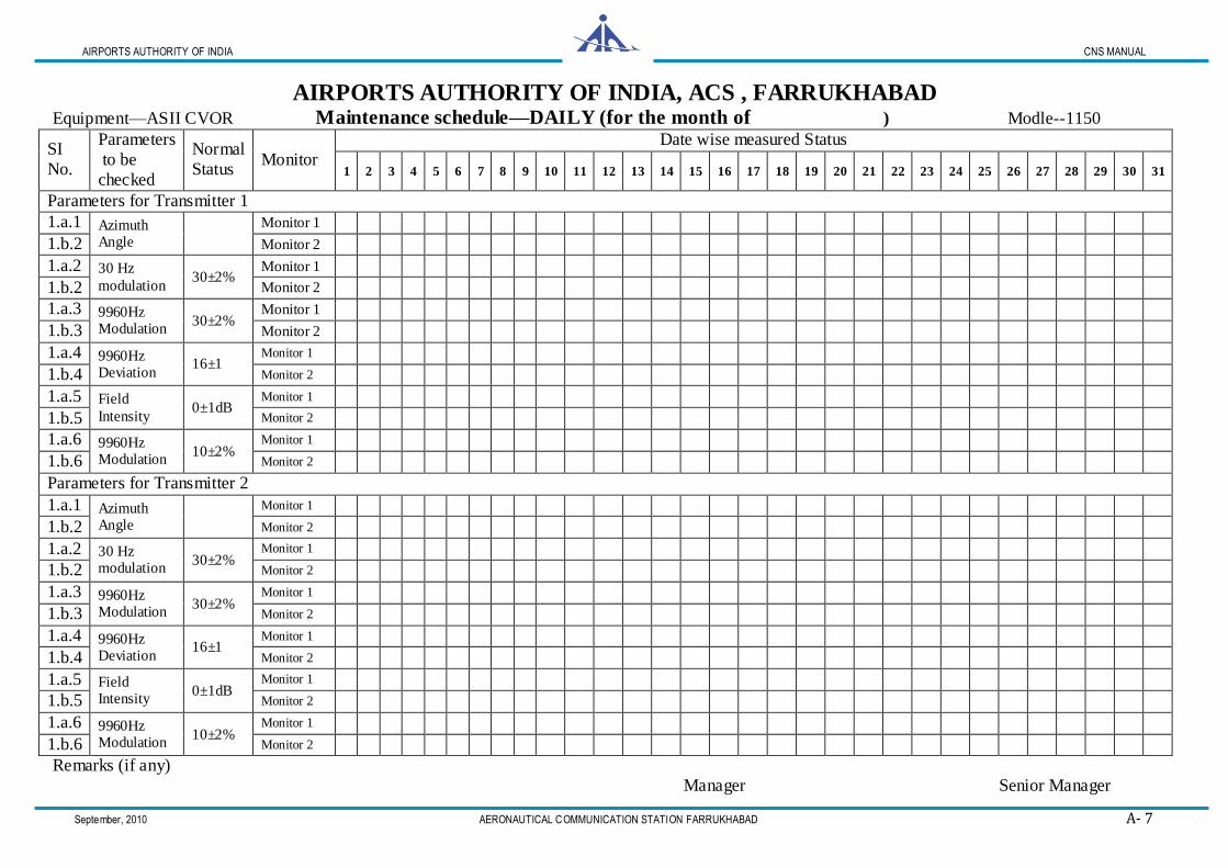
AIRPORTS AUTHORITY OF INDIA, ACS , FARRUKHABAD Equipment—ASII CVOR Maintenance schedule—DAILY (for the month of ) Modle--1150
SI
No.
Parameters
to be
checked
Normal
Status Monitor
Date wise measured Status
1 2 3 4 5 6 7 8 9 10 11 12 13 14 15 16 17 18 19 20 21 22 23 24 25 26 27 28 29 30 31
Parameters for Transmitter 1
1.a.1 Azimuth Angle
Monitor 1
1.b.2 Monitor 2
1.a.2 30 Hz
modulation 30±2%
Monitor 1
1.b.2 Monitor 2
1.a.3 9960Hz Modulation
30±2% Monitor 1
1.b.3 Monitor 2
1.a.4 9960Hz Deviation
16±1 Monitor 1
1.b.4 Monitor 2
1.a.5 Field
Intensity 0±1dB
Monitor 1
1.b.5 Monitor 2
1.a.6 9960Hz Modulation
10±2% Monitor 1
1.b.6 Monitor 2
Parameters for Transmitter 2
1.a.1 Azimuth Angle
Monitor 1
1.b.2 Monitor 2
1.a.2 30 Hz modulation
30±2% Monitor 1
1.b.2 Monitor 2
1.a.3 9960Hz Modulation
30±2% Monitor 1
1.b.3 Monitor 2
1.a.4 9960Hz Deviation
16±1 Monitor 1
1.b.4 Monitor 2
1.a.5 Field Intensity
0±1dB Monitor 1
1.b.5 Monitor 2
1.a.6 9960Hz Modulation
10±2% Monitor 1
1.b.6 Monitor 2
Remarks (if any)
Manager Senior Manager
AIRPORTS AUTHORITY OF INDIA CNS MANUAL
September, 2010 AERONAUTICAL COMMUNICATION STATION FARRUKHABAD A- 8
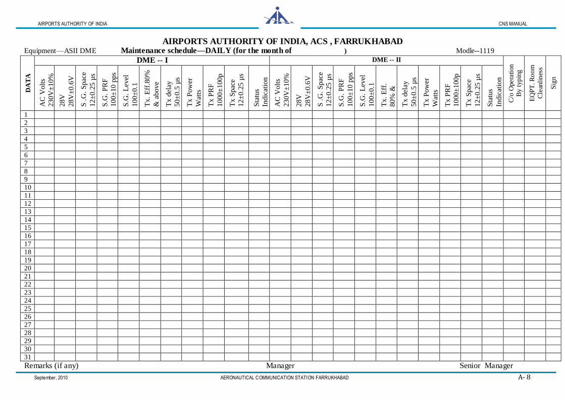
AIRPORTS AUTHORITY OF INDIA, ACS , FARRUKHABAD Equipment—ASII DME Maintenance schedule—DAILY (for the month of ) Modle--1119
DA
TA
DME -- I DME -- II
C/o
Opera
tion
B
y t
yp
ing
AN
T.C
AP
E
QP
T. R
oo
m
Cle
anli
nes
s
Sig
n
AC
Volt
s
230V
±10%
28V
28V
±0.6
V
S .
G.
Spac
e
12
±0.2
5 µ
s
S.G
. P
RF
100±
10 p
ps
S.G
. L
evel
10
0±
0.1
Tx.
Eff
.80%
& a
bo
ve
Tx d
elay
50±
0.5
µs
Tx P
ow
er
Wat
ts
Tx P
RF
1000±
100
p
ps
pps
Tx S
pac
e
12±
0.2
5 µ
s
Sta
tus
Ind
icat
ion
AC
Volt
s
230V
±10%
28V
28V
±0.6
V
S .
G.
Spac
e
12
±0.2
5 µ
s
S.G
. P
RF
100±
10 p
ps
S.G
. L
evel
10
0±
0.1
Tx.
Eff
.
80%
&
abo
ve
T
x d
elay
50±
0.5
µs
Tx P
ow
er
Wat
ts
Tx P
RF
1000±
100
p
ps
pps
Tx S
pac
e
12±
0.2
5 µ
s
Sta
tus
Ind
icat
ion
1
2
3
4
5
6
7
8
9
10
11
12
13
14
15
16
17
18
19
20
21
22
23
24
25
26
27
28
29
30
31
Remarks (if any) Manager Senior Manager

AIRPORTS AUTHORITY OF INDIA CNS MANUAL
September, 2010 AERONAUTICAL COMMUNICATION STATION FARRUKHABAD A-9
A-9
AIRPORTS AUTHORITY OF INDIA, ACS, FARRUKHABAD Maintenance schedule—WEEKLY (for the month of )
Equipment—ASII CVOR Modle—1150

AIRPORTS AUTHORITY OF INDIA CNS MANUAL
September, 2010 AERONAUTICAL COMMUNICATION STATION FARRUKHABAD A-10
A-10

AIRPORTS AUTHORITY OF INDIA CNS MANUAL
September, 2010 AERONAUTICAL COMMUNICATION STATION FARRUKHABAD A-11
A-11
AIRPORTS AUTHORITY OF INDIA CNS MANUAL
September, 2010 AERONAUTICAL COMMUNICATION STATION FARRUKHABAD A-12
A-12
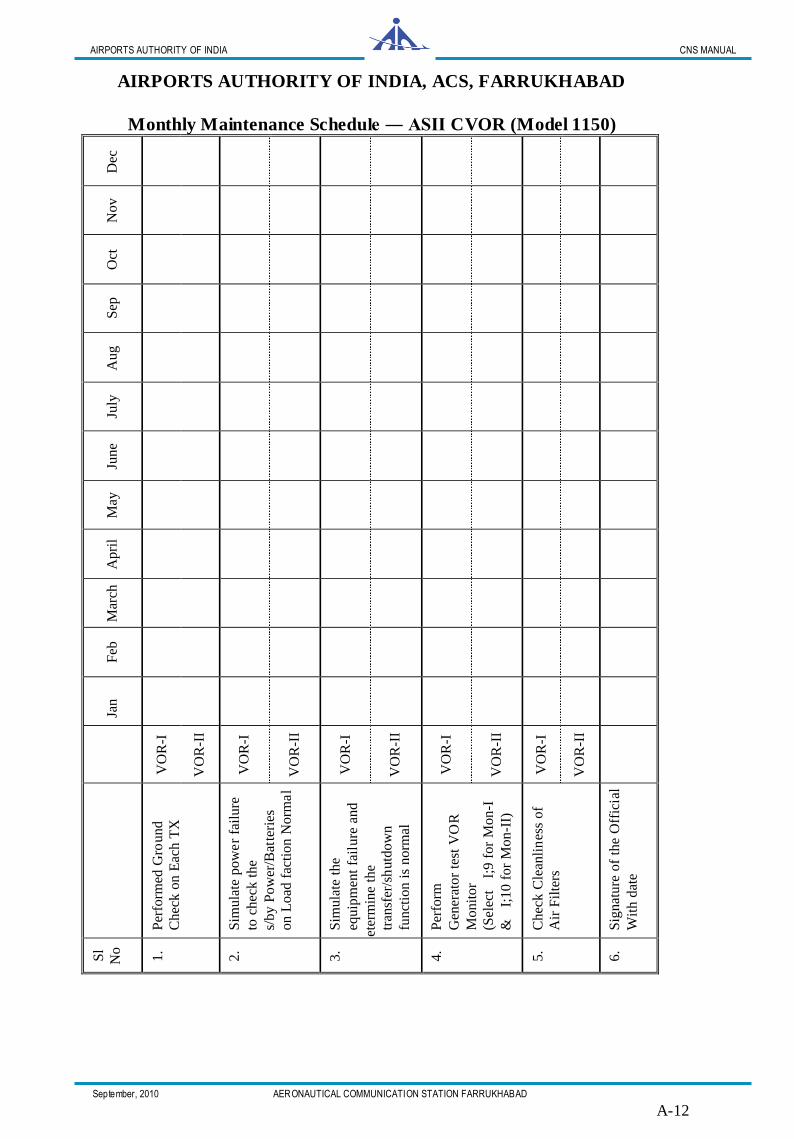
AIRPORTS AUTHORITY OF INDIA, ACS, FARRUKHABAD
Monthly Maintenance Schedule ― ASII CVOR (Model 1150) D
ec
No
v
Oct
Sep
Au
g
July
June
May
Ap
ril
Mar
ch
Feb
Jan
VO
R-I
VO
R-I
I
VO
R-I
VO
R-I
I
VO
R-I
VO
R-I
I
VO
R-I
VO
R-I
I
VO
R-I
VO
R-I
I
Per
form
ed G
round
C
hec
k o
n E
ach T
X
Sim
ula
te p
ow
er
fail
ure
to
chec
k t
he
s/by P
ow
er/B
atte
ries
on L
oad
fac
tion N
orm
al
Sim
ula
te t
he
equ
ipm
ent
fail
ure
an
d
det
erm
ine
the
tran
sfer
/sh
utd
ow
n
fun
ctio
n i
s n
orm
al
Per
form
G
ener
ato
r te
st V
OR
Monit
or
(Sel
ect
I;
9 f
or
Mo
n-I
&
I
;10 f
or
Mon
-II)
Chec
k C
lean
lin
ess
of
Air
Fil
ters
Sig
nat
ure
of
the
Off
icia
l W
ith d
ate
Sl
No
1.
2.
3.
4.
5.
6.
AIRPORTS AUTHORITY OF INDIA CNS MANUAL
September, 2010 AERONAUTICAL COMMUNICATION STATION FARRUKHABAD A-13
A-13
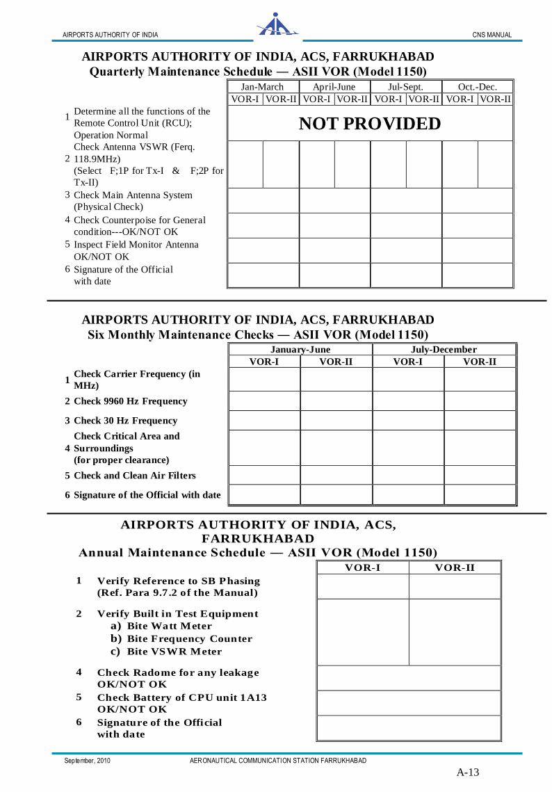
AIRPORTS AUTHORITY OF INDIA, ACS, FARRUKHABAD
Quarterly Maintenance Schedule ― ASII VOR (Model 1150)
Jan-March April-June Jul-Sept. Oct.-Dec.
VOR-I VOR-II VOR-I VOR-II VOR-I VOR-II VOR-I VOR-II
1
Determine all the functions of the
Remote Control Unit (RCU);
Operation Normal NOT PROVIDED
2
Check Antenna VSWR (Ferq.
118.9MHz) (Select F;1P for Tx-I & F;2P for
Tx-II)
3
Check Main Antenna System (Physical Check)
4
Check Counterpoise for General
condition---OK/NOT OK
5
Inspect Field Monitor Antenna OK/NOT OK
6
Signature of the Official with date
AIRPORTS AUTHORITY OF INDIA, ACS, FARRUKHABAD
Six Monthly Maintenance Checks ― ASII VOR (Model 1150)
January-June July-December
VOR-I VOR-II VOR-I VOR-II
1 Check Carrier Frequency (in
MHz)
2 Check 9960 Hz Frequency
3 Check 30 Hz Frequency
4 Check Critical Area and
Surroundings (for proper clearance)
5 Check and Clean Air Filters
6 Signature of the Official with date
AIRPORTS AUTHORITY OF INDIA, ACS,
FARRUKHABAD
Annual Maintenance Schedule ― ASII VOR (Model 1150)
VOR-I VOR-II
1
Verify Reference to SB Phasing (Ref. Para 9.7.2 of the Manual)
2
Verify Built in Test Equipment a) Bite Watt Meter
b) Bite Frequency Counter
c) Bite VSWR Meter
4
Check Radome for any leakage OK/NOT OK
5
Check Battery of CPU unit 1A13 OK/NOT OK
6
Signature of the Official with date
AIRPORTS AUTHORITY OF INDIA CNS MANUAL
September, 2010 AERONAUTICAL COMMUNICATION STATION FARRUKHABAD A-14
A-14
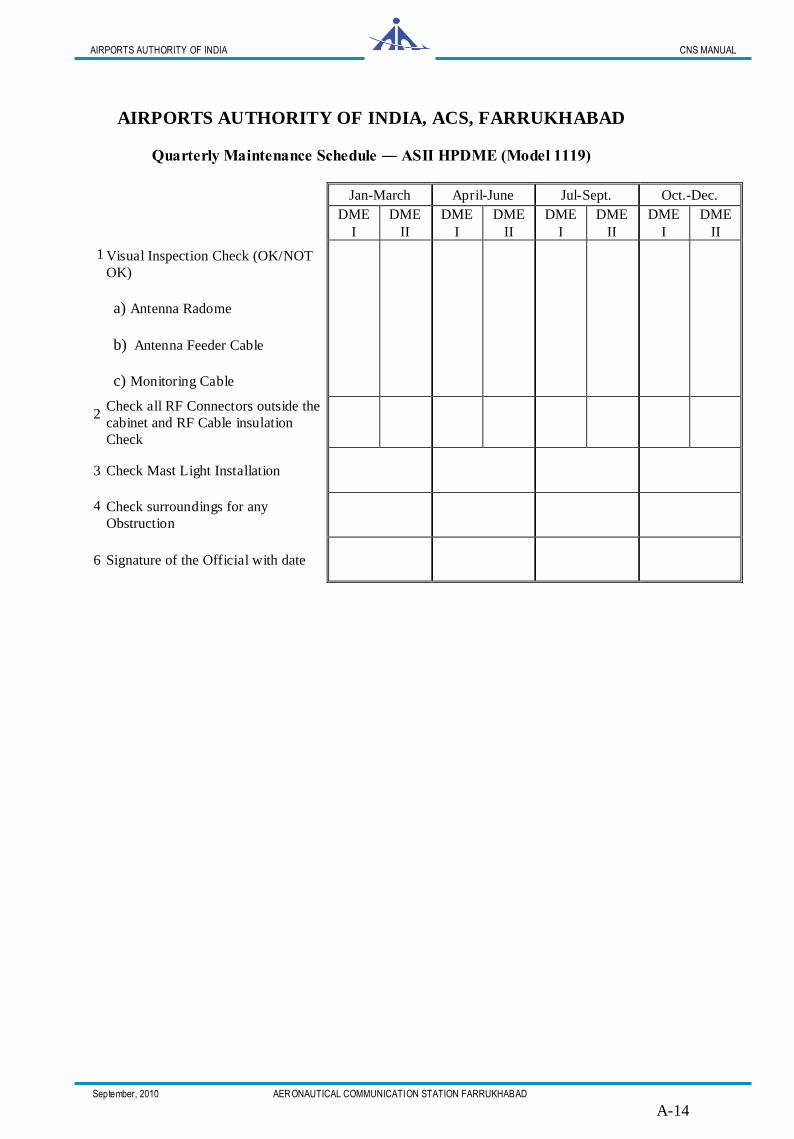
AIRPORTS AUTHORITY OF INDIA, ACS, FARRUKHABAD
Quarterly Maintenance Schedule ― ASII HPDME (Model 1119)
Jan-March April-June Jul-Sept. Oct.-Dec.
DME I
DME II
DME I
DME II
DME I
DME II
DME I
DME II
1
Visual Inspection Check (OK/NOT
OK)
a) Antenna Radome
b) Antenna Feeder Cable
c) Monitoring Cable
2
Check all RF Connectors outside the
cabinet and RF Cable insulation
Check
3 Check Mast Light Installation
4
Check surroundings for any
Obstruction
6 Signature of the Official with date

AIRPORTS AUTHORITY OF INDIA CNS MANUAL
September, 2010 AERONAUTICAL COMMUNICATION STATION FARRUKHABAD A-15
A-15
GROUND CHECK READING OF CVOR as on May 2010

AIRPORTS AUTHORITY OF INDIA CNS MANUAL
September, 2010 AERONAUTICAL COMMUNICATION STATION FARRUKHABAD A-16
A-16
The facility performance indicators of CNS Facilities
(As per Section 3.3.1 of the Corporate Safety Management Manual (C-SMS) on Safety
Performance Measurement)
Name of the Station : ACS, FARRUKHABAD
Period (Month/Year) :
Facilities Available : C-VOR & HP-DME
S.No Facility No of failures Total duration of failures
hours-minutes % U/S
Brief reasons
For U/S
CVOR ASII-1150 Call Sign - JAL Year of Commissioning 1998
1 CVOR
HPDME ASII-1119 Call Sign - JAL Year of Commissioning 1998
2 HPDME
STATUS REPORT OF CVOR & DME IN RESPECT OF ACS, FARRUKHABAD
FOR THE PERIOD FROM ………TO ………
Dated OIC, ACS ,AAI FARRUKHABAD
1. Equipment Type i) VOR—ASII 1150 ii) DME—ASII 1119 HP
2. Hours of Service
in the Period
FACILITY CVOR (H––24) DME (H––24)
Channel Tx A Tx B Xponder A Xponder B
Normal Hours
Actual Hours
3.
Total Un-
serviceability
Period*
FACILITY Date From To Duration Reason Action Taken
CVOR
DME
4. Details of
Recurring Fault
Sl.No. Facility Nature of Fault Details of component Failed Frequency of occurrence
5. Performance
Parameter
CVOR
Channel Error Spread (in Degrees)
%age Mod. AM
%age Mod. Sub carrier
ID (JAL)
Carrier Power(W)
LSB Power(W)
USB Power
(W)
Ferq. (MHz)
1
2
DME
Xponder Station
Delay (µS)
Pulse
Spacing(µS)
Pulse
Width(µS)
Rx
Sensitivity
% Reply
Efficiency
Peak Power
(Watts)
ID
(JAL)
Reply
Frequency
1
2
6. Status of
Supportive System
Sl. No.
Status Subject CVOR DME
Remarks OK U/S OK U/S
1 Monitors
2 ATC Status Indicator --------Not Available ----
3 Air conditioner
4 Power Supply
5 Battery Backup
6 Spare Modules/PCB -------Not Available -----
7 Test Equipments
8 VOR Critical Area
9 Remote Operation -------Not Available -----
10 Remote Lines -------Not Available -----
7. Field Reading
Graph Enclosed
8. Sign. of Official
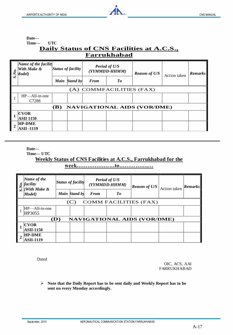
AIRPORTS AUTHORITY OF INDIA CNS MANUAL
September, 2010 AERONAUTICAL COMMUNICATION STATION FARRUKHABAD A-17
A-17
Date—
Time— UTC
Daily Status of CNS Facilities at A.C.S.,
Farrukhabad
Date—
Time— UTC
Weekly Status of CNS Facilities at A.C.S., Farrukhabad for the
week…………………to…………….…
S.N
o.
Name of the facility (With Make &
Model)
Status of facility Period of U/S
(YYMMDD-HHMM) Reason of U/S Action taken
Remarks
Main Stand by From To
(C) COMM FACILITIES (FAX)
1 HP—All-in-one HP3055
(D) NAVIGATIONAL AIDS (VOR/DME)
1 CVOR ASII-1150
2 HP-DME ASII-1119
Dated OIC, ACS, AAI
FARRUKHABAD
Note that the Daily Report has to be sent daily and Weekly Report has to be
sent on every Monday accordingly.
S.N
o.
Name of the facility (With Make &
Model) Status of facility
Period of U/S (YYMMDD-HHMM)
Reason of U/S Action taken
Remarks
Main Stand by From To
(A) COMMFACILITIES (FAX)
1 HP—All-in-one
C7288
(B) NAVIGATIONAL AIDS (VOR/DME)
1 CVOR ASII 1150
2 HP-DME ASII -1119

AIRPORTS AUTHORITY OF INDIA CNS MANUAL
September, 2010 AERONAUTICAL COMMUNICATION STATION FARRUKHABAD A-18
A-18
WIRING LAY OUT OF EQUIPMENT
ROOM
SURGE ARRESTER
5 KVA UPS
1 BO2ARD3
Circuit
Breaker
Circuit
Breaker
Mains 1 2 6 8
MCB DISTRIBUTION
Circuit
Breaker
VOR DME- II EXTENSION DME- I
BOARD
INPUT
OUTPUT
Change/Over switch to bypass UPS; if required
WALL OPENING
MAINS FROM SERVO STABILISER IN
GENERATOR ROOM
Related Documents