© Dirk Zimmer, February 2006, Slide 1 Master Thesis: A Modelica Library for Multibond Graphs and its Application in 3D-Mechanics Author: Dirk Zimmer Adviser: Prof. François E. Cellier Responsible: Prof. Walter Gander

Welcome message from author
This document is posted to help you gain knowledge. Please leave a comment to let me know what you think about it! Share it to your friends and learn new things together.
Transcript
© Dirk Zimmer, February 2006, Slide 1
Master Thesis:
A Modelica Library for Multibond Graphs
and its Application in 3D-Mechanics
Author:
Dirk Zimmer
Adviser:
Prof. François E. Cellier
Responsible:
Prof. Walter Gander

© Dirk Zimmer, February 2006, Slide 2
Overview
• Motivation• Introduction to bond graphs• Presentation of multibond graphs• 3D-mechanical models• Conclusions

© Dirk Zimmer, February 2006, Slide 3
Motivation
• First objective:Implementation of a general modeling tool for multidimensional physical processes: multibond graphs.
• Second objective:The modeling of mechanical systems in terms of multibond graphs.

© Dirk Zimmer, February 2006, Slide 4
Introduction to bond graphs 1
• Elements of a physical system have a certain behavior with respect to power and energy.– A battery is a source of energy.– A thermal capacitance stores energy.– A mechanical damper dissipates energy.– Power is distributed along a junction.
• This offers a general modeling approach for physical systems: bond graphs.

© Dirk Zimmer, February 2006, Slide 5
Introduction to bond graphs 2
• Bond graphs are a modeling tool for continuous physical systems.
• The edges of the graph are the bonds themselves.
• A bond carries an effort and a flow variable. The product of them is power.
e
f

© Dirk Zimmer, February 2006, Slide 6
Introduction to bond graphs 3
• The choice of effort and flow determines the modeling domain:
• The vertex elements are denoted by a mnemonic code corresponding to their behavior with respect to energy and power:
Sources Se Sf
Dissipative R G
Storage C I
Junctions 0 1
domain effort flow
electric u i
mechanic f v
thermal T dS/dt

© Dirk Zimmer, February 2006, Slide 7
Bond graphs: Example

© Dirk Zimmer, February 2006, Slide 8
Bond graphs: Example
S eU 0
0
I L
1
RR 1
0
CC
RR 2
i1
i1 i1
iL uL uCiC
u0
i0
u1
u2
i2
v2v1

© Dirk Zimmer, February 2006, Slide 9
Bond graphs: Example
S eU 0
0
I L
1
RR 1
0
CC
RR 2
i1
i1 i1
iL uL uCiC
u0
i0
u1
u2
i2
v2v1

© Dirk Zimmer, February 2006, Slide 10
Advantages of bond graphs
• Bond graphs offer a general modeling approach to a wide range of physical systems. They find the right balance between specificity and generality.
• The concept of energy and power creates a semantic level for each bond graph.
• Relations can more naturally be expressed in 2D-drawings than in 1D-code.

© Dirk Zimmer, February 2006, Slide 11
The Modelica/Dymola BondLib
• Bond graphs can be composed on screen by drag and drop.
• The resulting model can directly be simulated.
• The library features domain specific solutions, e.g., a library for electric systems.

© Dirk Zimmer, February 2006, Slide 12
Bondgraphs for mechanics 1
• Unfortunately, the BondLib doesn’t feature mechanical applications.
• Various other approaches to this subject are insufficient and/or outdated.

© Dirk Zimmer, February 2006, Slide 13
Bondgraphs for mechanics 2
Problems of mechanical bond graphs:
• Mechanical processes are multidimensional Usage of MultiBond Graphs.
• Holonomic constraints are non-physical Need for extra modeling via signals.
• Mechanical bond graphs become very large Wrapping of the bondgraphic models.

© Dirk Zimmer, February 2006, Slide 14
Multibonds are a vectorial extension of bond graphs.
A multibond covers an arbitrary number of single bonds of the same domain.
All vertex elements are extended accordingly.
MultiBond Graphs
} f3v
t
fy
vy
fx
vx Composition of a multibond for planar mechanics

© Dirk Zimmer, February 2006, Slide 15
The MultiBondLib
• A Modelica/Dymola Library for modeling Multibond graphs has been developed.
• It is an adaptation of the BondLib.
• Further possible applications of multibond graphs are: – multidimensional heat distribution
– chemical reaction dynamics
– general relativity.

© Dirk Zimmer, February 2006, Slide 16
Multibond graphs: Example
Multibond graph of a planar pendulum

© Dirk Zimmer, February 2006, Slide 17
Multibond graphs: Sensors
• Sensor elements serve for different purposes. They can be used to...
– ...measure bondgraphic variables.
– ...convert bondgraphic variables to non-bondgraphic signals.
– ...establish algebraic relationships between bondgraphic elements.
Application of a bondgraphic sensor element

© Dirk Zimmer, February 2006, Slide 18
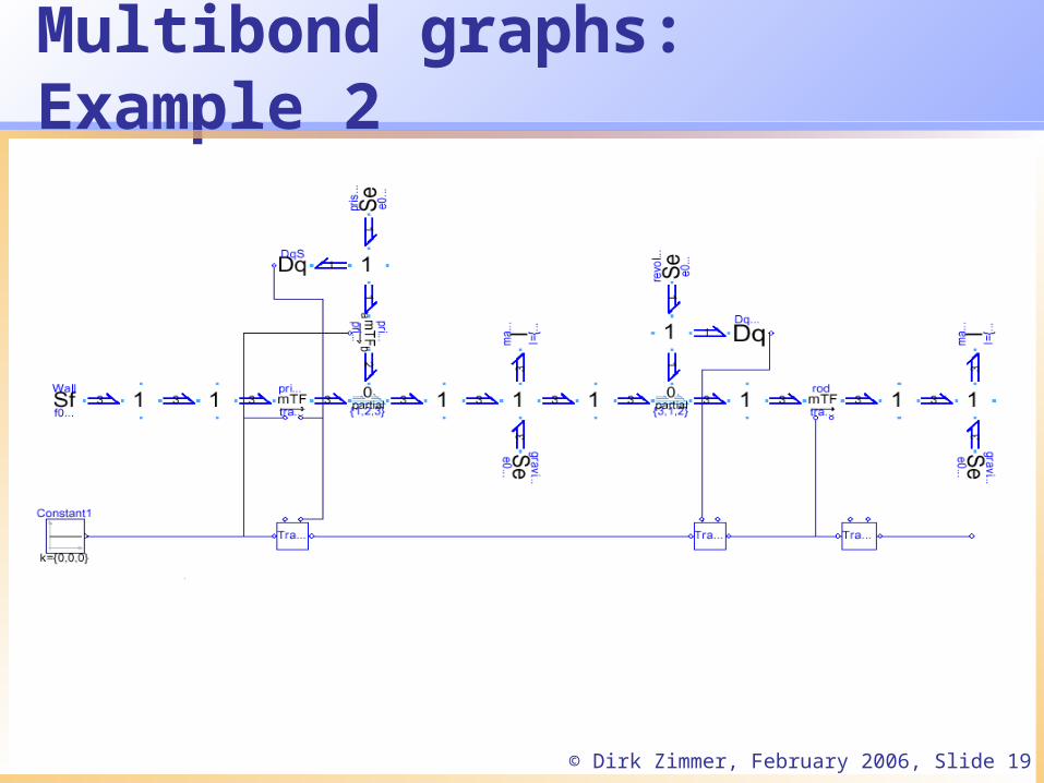
Multibond graphs: Example 2
Model of a free crane crab:
yprismatic joint
revolutejoint
mass 1
mass 2
rod
x
© Dirk Zimmer, February 2006, Slide 19
Multibond graphs: Example 2

© Dirk Zimmer, February 2006, Slide 20
Multibond graphs: Example 2

© Dirk Zimmer, February 2006, Slide 21
Multibond graphs: Example 2

© Dirk Zimmer, February 2006, Slide 22
Wrapping
Wrapping combines the best of two worlds:
• An easy-to-use model is provided at the top level.
• A look inside the model reveals a familiar bondgraphic model.

© Dirk Zimmer, February 2006, Slide 23
3D Mechanics
• A Modelica library for the object-oriented modeling of 3D-mechanical systems has been developed.Partial reimplementation of the MultiBody library.
• All models consist of wrapped bondgraphic models.
• 3D-specific problems had to be solved.– Handling of different coordinate systems.– Description of the orientation.

© Dirk Zimmer, February 2006, Slide 24
3D Mechanics: Components
• Basic elements:
• Joints:

© Dirk Zimmer, February 2006, Slide 25
3D Mechanics: Components
• Force elements:
• Ideal rolling objects:

© Dirk Zimmer, February 2006, Slide 26
3D Mechanics: Example 1
Model of an uncontrolled bicycle

© Dirk Zimmer, February 2006, Slide 27
3D Mechanics: Example 1
Translation:• FrontRevolute.phi• RearWheel.phi[1]• RearWheel.phi[2]• RearWheel.phi[3]• RearWheel.phi_d[1]• RearWheel.phi_d[2]• RearWheel.phi_d[3]• RearWheel.xA• RearWheel.xB• Steering.phi
Systems of 3 and 17 linear equations1 non-linear equation
Simulation20 sec, 2500 output points 213 integration steps. 0.7s CPU-Time
Animation Window:

© Dirk Zimmer, February 2006, Slide 28
3D Mechanics: Example 1
Translation:• FrontRevolute.phi• RearWheel.phi[1]• RearWheel.phi[2]• RearWheel.phi[3]• RearWheel.phi_d[1]• RearWheel.phi_d[2]• RearWheel.phi_d[3]• RearWheel.xA• RearWheel.xB• Steering.phi
Systems of 3 and 17 linear equations1 non-linear equation
Simulation20 sec, 2500 output points 213 integration steps. 0.7s CPU-Time
Animation Window:

© Dirk Zimmer, February 2006, Slide 29
3D Mechanics: Example 1
Translation:• FrontRevolute.phi• RearWheel.phi[1]• RearWheel.phi[2]• RearWheel.phi[3]• RearWheel.phi_d[1]• RearWheel.phi_d[2]• RearWheel.phi_d[3]• RearWheel.xA• RearWheel.xB• Steering.phi
Systems of 3 and 17 linear equations1 non-linear equation
Simulation20seconds, 2500 output points 213 integration steps. 0.7s CPU-Time
0 10 20
-0.2
-0.1
0.0
0.1
0.2
0.3
[rad
]
RearWheel.phi[2]
Plot Window: Lean Angle

© Dirk Zimmer, February 2006, Slide 30
3D Mechanics: Kinematic Loops
• Redundant statements appear in kinematic loops and lead to a singularity of the model.
• Automatic removal of the redundant statements.
• Systems of non-linear equations have to be solved.

© Dirk Zimmer, February 2006, Slide 31
Efficiency of the simulation
• Same efficiency as the MultiBody library. The efficiency is not impaired by the bondgraphic methodology
• The state selection is of major importance for the efficiency. Relative positions and motions of the joints do usually form a good set of state variables.
• The automatic state selection is mostly meaningful and can be improved manually if necessary.
• Kinematic loops could be closed more efficiently by special cut joints, that contain analytic solutions.

© Dirk Zimmer, February 2006, Slide 32
Additional work
• Modeling of mutual gravitational attraction
• Alternative approach to the multibondgraphic modeling of 3D-Systems
• Modeling of mutual collisions
• Modeling of hard impacts…

© Dirk Zimmer, February 2006, Slide 33
Additional work: Impacts
• Extension of the continuous models to hybrid models that allow a discrete change of motion.
• The impulse equations were derived out of the continuous bondgraphic models.
• Several impact models (elasticity, friction, shape).
• Impacts can act on kinematic loops.
• Solution is fine for small scale models.

© Dirk Zimmer, February 2006, Slide 34
Conclusions
• A general solution for multibondgraphic modeling is provided.
• Object-oriented modeling of 2D- and 3D-mechanical systems is supported.
• Hybrid mechanical systems can be simulated.
• The modeling is convenient and the simulation is done efficiently.

© Dirk Zimmer, February 2006, Slide 35
Outlook on future tasks
• Modeling of structural changes:– Modeling of friction and the transition to adhesion.– Modeling of constrained joints.
• Improvement of the hybrid models.
• Bondgraphic modeling of deformable objects.

© Dirk Zimmer, February 2006, Slide 36
The End
Related Documents