© 2006 Cisco Systems, Inc. All rights reserved. Cisco Confidential Steelers Mechanical Design Review 1 PLC MODULE INSTALLATION INSTRUCTIONS IN CGR1240

© 2006 Cisco Systems, Inc. All rights reserved.Cisco Confidential Steelers Mechanical Design Review 1 PLC MODULE INSTALLATION INSTRUCTIONS IN CGR1240.
Dec 16, 2015
Welcome message from author
This document is posted to help you gain knowledge. Please leave a comment to let me know what you think about it! Share it to your friends and learn new things together.
Transcript
© 2006 Cisco Systems, Inc. All rights reserved. Cisco ConfidentialSteelers Mechanical Design Review 1
PLC MODULEINSTALLATION INSTRUCTIONS
IN CGR1240
© 2006 Cisco Systems, Inc. All rights reserved. Cisco ConfidentialSteelers Mechanical Design Review 2
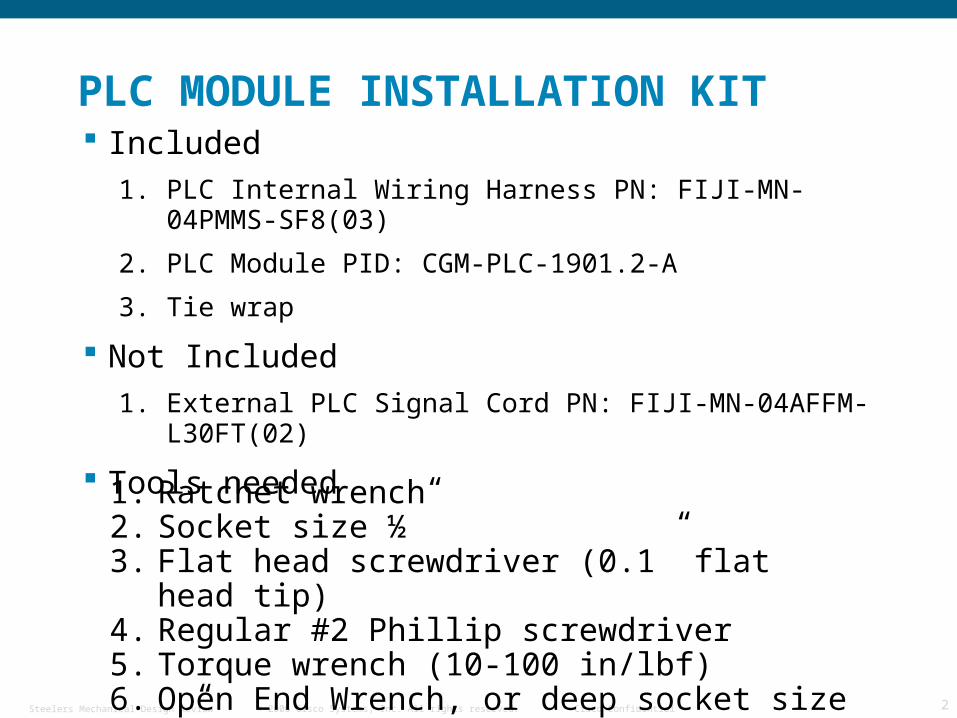
PLC MODULE INSTALLATION KIT Included
1. PLC Internal Wiring Harness PN: FIJI-MN-04PMMS-SF8(03)
2. PLC Module PID: CGM-PLC-1901.2-A
3. Tie wrap
Not Included
1. External PLC Signal Cord PN: FIJI-MN-04AFFM-L30FT(02)
Tools needed
1. Ratchet wrench2. Socket size ½”3. Flat head screwdriver (0.1” flat head tip)4. Regular #2 Phillip screwdriver5. Torque wrench (10-100 in/lbf)6. Open End Wrench, or deep socket size 1”
© 2006 Cisco Systems, Inc. All rights reserved. Cisco ConfidentialSteelers Mechanical Design Review 3
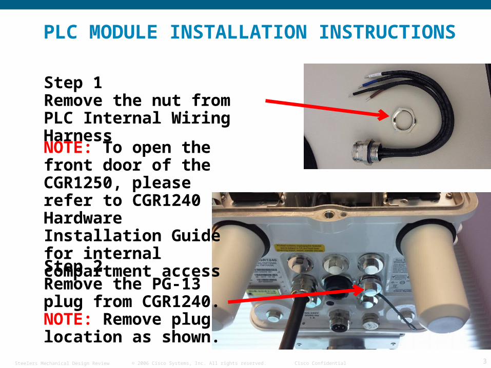
Step 1Remove the nut from PLC Internal Wiring Harness
Step 2Remove the PG-13 plug from CGR1240. NOTE: Remove plug location as shown.
PLC MODULE INSTALLATION INSTRUCTIONS
NOTE: To open the front door of the CGR1250, please refer to CGR1240 Hardware Installation Guide for internal compartment access
© 2006 Cisco Systems, Inc. All rights reserved. Cisco ConfidentialSteelers Mechanical Design Review 4
PLC MODULE INSTALLATION INSTRUCTIONS
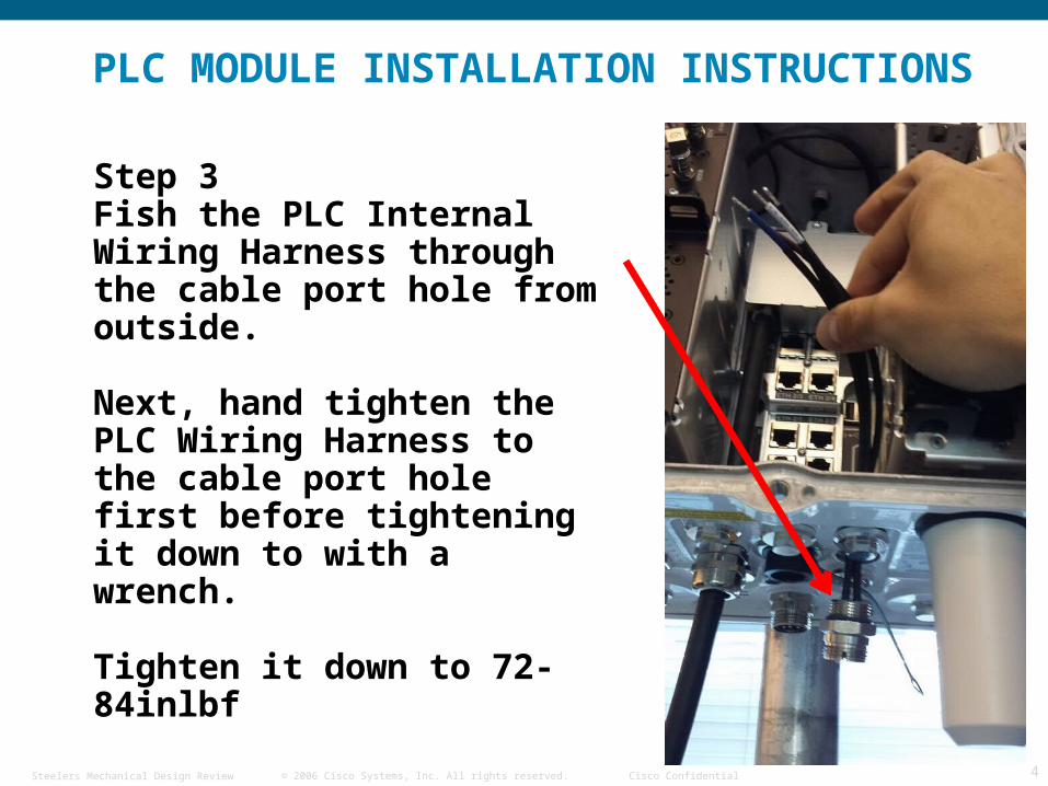
Step 3Fish the PLC Internal Wiring Harness through the cable port hole from outside.
Next, hand tighten the PLC Wiring Harness to the cable port hole first before tightening it down to with a wrench.
Tighten it down to 72-84inlbf
© 2006 Cisco Systems, Inc. All rights reserved. Cisco ConfidentialSteelers Mechanical Design Review 5
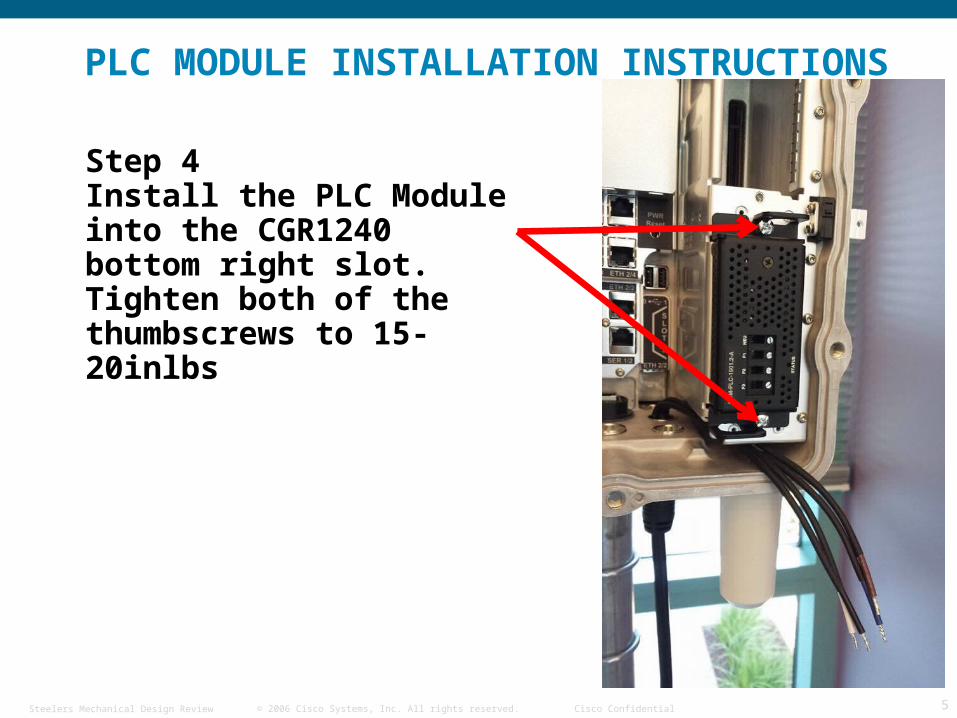
Step 4Install the PLC Module into the CGR1240 bottom right slot. Tighten both of the thumbscrews to 15-20inlbs
PLC MODULE INSTALLATION INSTRUCTIONS
© 2006 Cisco Systems, Inc. All rights reserved. Cisco ConfidentialSteelers Mechanical Design Review 6
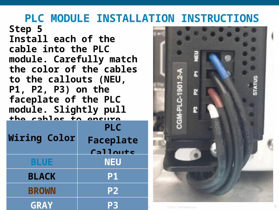
Step 5Install each of the cable into the PLC module. Carefully match the color of the cables to the callouts (NEU, P1, P2, P3) on the faceplate of the PLC module. Slightly pull the cables to ensure secure connection to the PLC module
Wiring Color PLC Faceplate Callouts
BLUE NEU
BLACK P1
BROWN P2
GRAY P3
PLC MODULE INSTALLATION INSTRUCTIONS
© 2006 Cisco Systems, Inc. All rights reserved. Cisco ConfidentialSteelers Mechanical Design Review 7
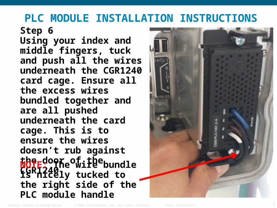
Step 6Using your index and middle fingers, tuck and push all the wires underneath the CGR1240 card cage. Ensure all the excess wires bundled together and are all pushed underneath the card cage. This is to ensure the wires doesn’t rub against the door of the CGR1240.
NOTE: The wire bundle is nicely tucked to the right side of the PLC module handle
PLC MODULE INSTALLATION INSTRUCTIONS
© 2006 Cisco Systems, Inc. All rights reserved. Cisco ConfidentialSteelers Mechanical Design Review 8
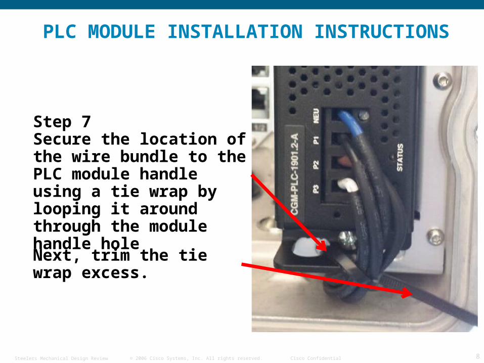
Step 7Secure the location of the wire bundle to the PLC module handle using a tie wrap by looping it around through the module handle hole
Next, trim the tie wrap excess.
PLC MODULE INSTALLATION INSTRUCTIONS
© 2006 Cisco Systems, Inc. All rights reserved. Cisco ConfidentialSteelers Mechanical Design Review 9
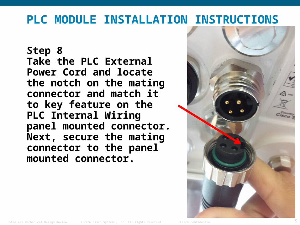
Step 8Take the PLC External Power Cord and locate the notch on the mating connector and match it to key feature on the PLC Internal Wiring panel mounted connector. Next, secure the mating connector to the panel mounted connector.
PLC MODULE INSTALLATION INSTRUCTIONS
© 2006 Cisco Systems, Inc. All rights reserved. Cisco ConfidentialSteelers Mechanical Design Review 10
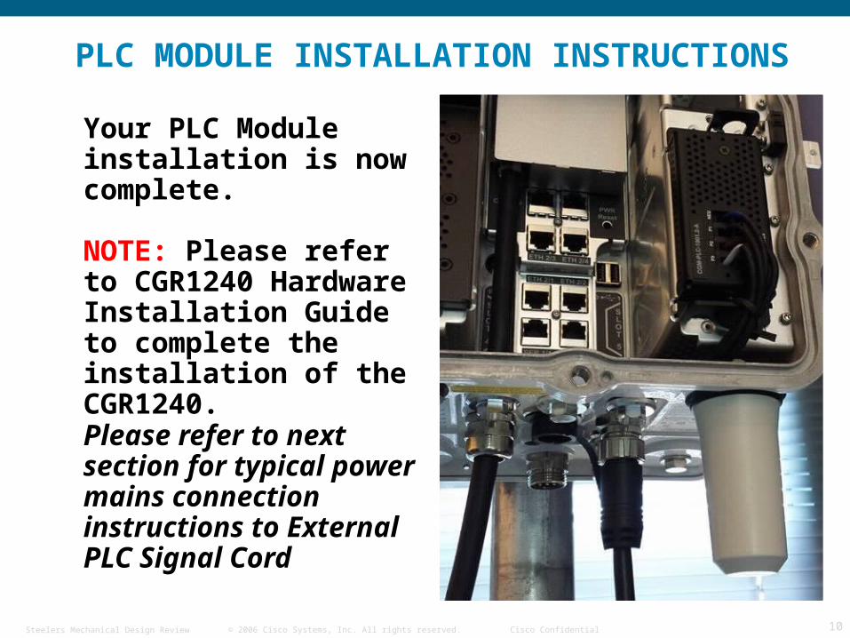
Your PLC Module installation is now complete.
NOTE: Please refer to CGR1240 Hardware Installation Guide to complete the installation of the CGR1240.
Please refer to next section for typical power mains connection instructions to External PLC Signal Cord
PLC MODULE INSTALLATION INSTRUCTIONS
© 2006 Cisco Systems, Inc. All rights reserved. Cisco ConfidentialSteelers Mechanical Design Review 11
WIRING INSTRUCTIONS FOR CONNECTING
EXTERNAL PLC SIGNAL CORD TO THE
CUSTOMER’S AC POWER DISTRIBUTION
LINES
© 2006 Cisco Systems, Inc. All rights reserved. Cisco ConfidentialSteelers Mechanical Design Review 12
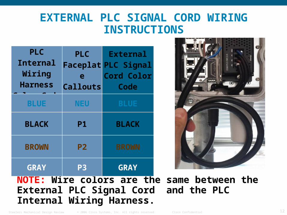
EXTERNAL PLC SIGNAL CORD WIRING INSTRUCTIONS
NOTE: Wire colors are the same between the External PLC Signal Cord and the PLC Internal Wiring Harness.
PLC Internal Wiring
Harness Color Code
PLC Faceplate Callouts
External PLC Signal Cord Color Code
BLUE NEU BLUE
BLACK P1 BLACK
BROWN P2 BROWN
GRAY P3 GRAY
© 2006 Cisco Systems, Inc. All rights reserved. Cisco ConfidentialSteelers Mechanical Design Review 13
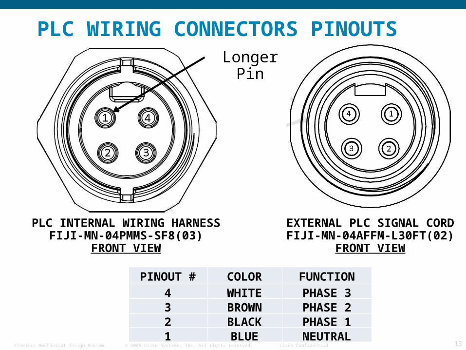
PLC WIRING CONNECTORS PINOUTS
EXTERNAL PLC SIGNAL CORDFIJI-MN-04AFFM-L30FT(02)
FRONT VIEW
PLC INTERNAL WIRING HARNESSFIJI-MN-04PMMS-SF8(03)
FRONT VIEW
PINOUT # COLOR FUNCTION4 WHITE PHASE 33 BROWN PHASE 22 BLACK PHASE 11 BLUE NEUTRAL
Longer Pin
© 2006 Cisco Systems, Inc. All rights reserved. Cisco ConfidentialSteelers Mechanical Design Review 14
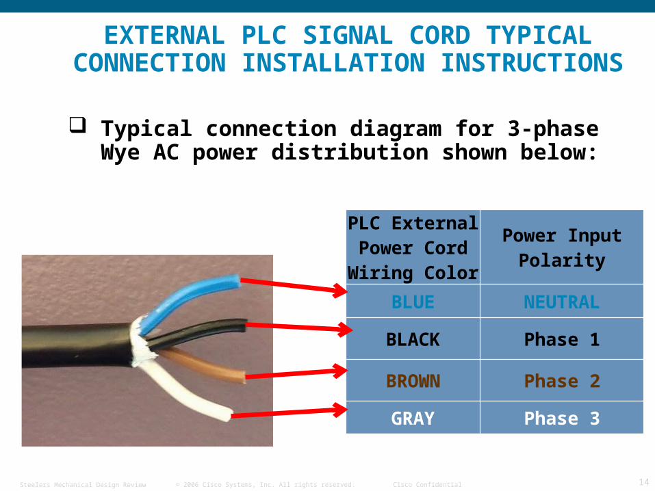
EXTERNAL PLC SIGNAL CORD TYPICAL CONNECTION INSTALLATION INSTRUCTIONS
PLC External Power Cord Wiring Color
Power Input Polarity
BLUE NEUTRAL
BLACK Phase 1
BROWN Phase 2
GRAY Phase 3
Typical connection diagram for 3-phase Wye AC power distribution shown below:
© 2006 Cisco Systems, Inc. All rights reserved. Cisco ConfidentialSteelers Mechanical Design Review 15
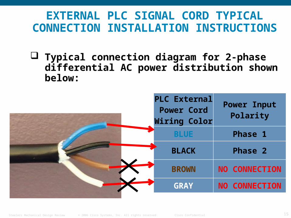
PLC External Power Cord Wiring Color
Power Input Polarity
BLUE Phase 1
BLACK Phase 2
BROWN NO CONNECTION
GRAY NO CONNECTION
EXTERNAL PLC SIGNAL CORD TYPICAL CONNECTION INSTALLATION INSTRUCTIONS
Typical connection diagram for 2-phase differential AC power distribution shown below:
Related Documents