7/30/2019 Zone of Excessive Ground Surface Distortion Due to Dip Slip Fault Rupture http://slidepdf.com/reader/full/zone-of-excessive-ground-surface-distortion-due-to-dip-slip-fault-rupture 1/12 4 th International Conference on Earthquake Geotechnical Engineering June 25-28, 2007 Paper No. 1583 ZONE OF EXCESSIVE GROUND SURFACE DISTORTION DUE TO DIP-SLIP FAULT RUPTURE Achilleas PAPADIMITRIOU 1 , Dimitrios LOUKIDIS 2 George BOUCKOVALAS 3 , Dimitrios KARAMITROS 4 ABSTRACT This paper studies the zone of excessive ground surface distortion created by a dip-slip active fault rupture propagating from the bedrock through a soil layer during an earthquake. The simulation of the fault rupture propagation through the soil layer is performed via quasi-static numerical analyses using the finite difference code FLAC . The analysis focuses on the geometry of the developing shear band and the distribution of surface displacements. The paper presents results from 28 parametric analyses that quantify the effects of soil type, fault type and fault dip angle in the bedrock. The results of the analyses are presented in the form of charts and equations for the rough prediction of the location and the width of the zone of significant surface distortion, and the estimation of the fault displacement required for the rupture to reach the ground surface. An example of the fault propagation prediction in an actual case is presented for the well documented rupture of the Nikomidino fault (Volvi basin in Northern Greece, 20-6-1978). In practice, these results can be used for the definition of zones where construction is disallowed (set-back limits) and of zones where damage-preventing countermeasures should be considered in the design of light-weight structures and lifelines (e.g. pipelines). Keywords: fault rupture, microzonation, setback limits, lifelines, earthquake INTRODUCTION The design of structures in the vicinity of active faults is one of the most difficult problems of earthquake engineering. An indication of the complexity of the problem is that seismic codes generally require the execution of a specialized study for any structure, even though there is no specific methodology in the literature for performing such a study. Moreover, many seismic codes, including the Greek code ΕΑΚ (2002), refer to a zone where construction is disallowed, but do not specifically define its width and location. Additional difficulties arise when the active fault is buried under a soil layer of significant thickness (e.g. a few tens of meters). In such a case, even if the location (trace) and the characteristic of the fault in the geologic bedrock (type, dip angle β and expected displacement d ) are well defined, there are three (3) practical questions that need to be answered: a) Will the fault rupture reach the ground surface and at which location? b) At which zone will the ground surface distortion be prohibitive for conventional construction? c) Will the seismic motion be amplified in the vicinity of the fault and by which amount? In this paper, the emphasis is set on answering the first two questions, since the third cannot be confidently answered without employing large scale seismological monitoring and interpretation. In 1 Lecturer, Dept. of Civil Engineering, University of Thessaly, Greece, Email: [email protected] 2 Post-Doctoral Researcher, Dept. of Civil & Environmental Engineering, Purdue University, USA 3 Professor, School of Civil Engineering, National Technical University of Athens, Greece 4 PhD Candidate, School of Civil Engineering, National Technical University of Athens, Greece

Welcome message from author
This document is posted to help you gain knowledge. Please leave a comment to let me know what you think about it! Share it to your friends and learn new things together.
Transcript

7/30/2019 Zone of Excessive Ground Surface Distortion Due to Dip Slip Fault Rupture
http://slidepdf.com/reader/full/zone-of-excessive-ground-surface-distortion-due-to-dip-slip-fault-rupture 1/12
4th
International Conference onEarthquake Geotechnical Engineering
June 25-28, 2007Paper No. 1583
ZONE OF EXCESSIVE GROUND SURFACE DISTORTION
DUE TO DIP-SLIP FAULT RUPTURE
Achilleas PAPADIMITRIOU1
, Dimitrios LOUKIDIS2
George BOUCKOVALAS3
, Dimitrios KARAMITROS4
ABSTRACT
This paper studies the zone of excessive ground surface distortion created by a dip-slip active fault
rupture propagating from the bedrock through a soil layer during an earthquake. The simulation of the
fault rupture propagation through the soil layer is performed via quasi-static numerical analyses using
the finite difference code FLAC . The analysis focuses on the geometry of the developing shear band
and the distribution of surface displacements. The paper presents results from 28 parametric analyses
that quantify the effects of soil type, fault type and fault dip angle in the bedrock. The results of the
analyses are presented in the form of charts and equations for the rough prediction of the location and
the width of the zone of significant surface distortion, and the estimation of the fault displacement
required for the rupture to reach the ground surface. An example of the fault propagation prediction in
an actual case is presented for the well documented rupture of the Nikomidino fault (Volvi basin in
Northern Greece, 20-6-1978). In practice, these results can be used for the definition of zones where
construction is disallowed (set-back limits) and of zones where damage-preventing countermeasures
should be considered in the design of light-weight structures and lifelines (e.g. pipelines).
Keywords: fault rupture, microzonation, setback limits, lifelines, earthquake
INTRODUCTION
The design of structures in the vicinity of active faults is one of the most difficult problems of
earthquake engineering. An indication of the complexity of the problem is that seismic codes generally
require the execution of a specialized study for any structure, even though there is no specific
methodology in the literature for performing such a study. Moreover, many seismic codes, including
the Greek code ΕΑΚ (2002), refer to a zone where construction is disallowed, but do not specifically
define its width and location.
Additional difficulties arise when the active fault is buried under a soil layer of significant thickness
(e.g. a few tens of meters). In such a case, even if the location (trace) and the characteristic of the faultin the geologic bedrock (type, dip angle β and expected displacement d ) are well defined, there are
three (3) practical questions that need to be answered:
a) Will the fault rupture reach the ground surface and at which location?
b) At which zone will the ground surface distortion be prohibitive for conventional construction?
c) Will the seismic motion be amplified in the vicinity of the fault and by which amount?
In this paper, the emphasis is set on answering the first two questions, since the third cannot be
confidently answered without employing large scale seismological monitoring and interpretation. In
1Lecturer, Dept. of Civil Engineering, University of Thessaly, Greece, Email: [email protected]
2Post-Doctoral Researcher, Dept. of Civil & Environmental Engineering, Purdue University, USA
3 Professor, School of Civil Engineering, National Technical University of Athens, Greece4 PhD Candidate, School of Civil Engineering, National Technical University of Athens, Greece

7/30/2019 Zone of Excessive Ground Surface Distortion Due to Dip Slip Fault Rupture
http://slidepdf.com/reader/full/zone-of-excessive-ground-surface-distortion-due-to-dip-slip-fault-rupture 2/12
this endeavor, researchers have employed various approaches: a) case studies (e.g. Lade et al 1984,
Bray et al 1994a, Mercier et al 1983, Kelson et al 2001), b) experimental studies (e.g. small scale
experiments by Cole and Lade 1984, centrifuge experiments by Roth et al 1981) and c) numerical
studies (e.g. Roth et al 1982, Bray et al 1994). Attempting to generalize results from all different types
of studies showed that there is a need for a systematic and combinatory analysis. This paper aims to
contribute to this effort via numerical analyses that are in accordance with the findings from the
literature.
NUMERICAL METHODOLOGY
The numerical simulations of the active fault rupture propagation through a soil layer are hereby
performed using the finite difference code FLAC (Itasca Inc 1998). The emphasis is put on dip-slip
(normal and reverse) faults and not on strike-slip faults whose rupture propagates almost vertically and
is practically not affected by soil conditions (e.g. Bray et al 1994a).
Figure 1 presents the typical mesh and boundary conditions used in the foregoing analyses. For
reasons of simplicity, the ground surface and the soil-bedrock interface are assumed horizontal, i.e. thesoil layer is assumed horizontal and of uniform height H . The mesh discretization on top of the fault
trace in the bedrock (central region of the mesh) is denser and consists of square elements (or “zones”
in FLAC terminology) so as not to influence the mechanism of fault rupture propagation. Moreover,
the ratio of the total mesh width to the mesh height is at least 4:1 in all analyses, so as to minimize the
effects of the lateral mesh boundaries on the strain accumulation pattern in the central region of the
mesh.
Figure 1. Typical mesh and boundary conditions of the numerical analyses
Displacement increments are prescribed at the segment of the soil-bedrock interface corresponding to
the moving block. The lateral mesh boundaries have also prescribed horizontal displacement (non-zero
for the moving block), but are allowed to move freely in the vertical direction. The prescribed
displacements at the mesh boundaries depend on the simulated fault dip angle and are applied at a very
low rate so as to minimize inertial effects. Hence, all the analyses performed in the context of this
study are practically quasi-static. Given that the fault rupture propagation is governed by the soil
behavior, not only at yield, but mainly in post-yield conditions, the non cohesive soil response was
simulated with the use of a Mohr-Coulomb constitutive model that allows for strain softening. For
cohesive soils, for which the rupture is propagated under undrained conditions, the same constitutive
model was used, but the shear strength was defined on the basis of the undrained shear strength S u.
-40 -30 -20 -10 0 10 20 30 40
0
10
20
(m)
(m)
270x90 elements
fixed in both directions
- fixed in horizontal direction
- free in vertical direction
- applied displacement in
horizontal direction
- free in vertical direction
applied displacement in
both directions x
y
z

7/30/2019 Zone of Excessive Ground Surface Distortion Due to Dip Slip Fault Rupture
http://slidepdf.com/reader/full/zone-of-excessive-ground-surface-distortion-due-to-dip-slip-fault-rupture 3/12
VALIDATION OF NUMERICAL METHODOLOGY
The validation of the numerical methodology was performed via qualitative and quantitative
comparison with results from the literature. For example, Figure 2 compares qualitatively the
numerical results of Loukidis (1999) and Loukidis and Bouckovalas (2001) in terms of the shear strain
rate contours for the case of a dense sand layer overlying a reverse fault with a dip angle β = 135ο
(or -
45o) to respective field observations. These results show that the propagating rupture bends towards
the stationary block (foot wall). This is a general trend for reverse faults in the literature (e.g. Bray et
al 1994). On the other hand, the rupture of normal faults generally bends towards the moving block
(hanging wall).
25.05.0-5.0 0.0 15.010.0
(m)
20.0 30.0
Βραχώδες υπόβαθρο
Επίπεδο ρήγµατος
45°
strain rate
Max. shear
2.0
3.0
4.0
5.0
0.01.0
-610
15.0
12.5
10.0
5.0
0.0
2.5
7.5
(m)
17.5
20.0
sand,ψ=20o
42°
34°
(Bray et al., 1994)
Στιφρό εδαφικό υλικό
Βραχώδες υπόβαθρο
sand,ψ=20o12.5
42°
45°
oo
2.5
0.0
10.0
5.0
7.5
(m)
20.0
15.0
17.5
Figure 2. Depiction of failure surface from fault rupture propagation of a reverse dip-slip fault
with β =135ο
through dense sand: a) numerical results in terms of maximum shear strain rate
contours (Loukidis 1999), b) related field evidence (Bray et al 1994)
For a quantitative evaluation of the methodology, the case of the 1978 Nikomidinon normal fault
rupture was chosen. This is one of four normal faults in the Volvi basin and its rupture is associated
with the great Thessaloniki (Northern Greece) earthquake (June 20th
1978). More specifically, during
that earthquake the fault rupture in the bedrock propagated to the ground surface and its failure surface
was studied in detail by Mercier et al (1983), as shown in Figure 3b. Based on detailed geological,
geophysical and geotechnical data for the area (given its proximity to the Euroseistest Project test site,
e.g. Raptakis et al 2000), a series of numerical analyses was performed (Antoniou 2000, Bouckovalas
et al 2001) taking into account the local site conditions. Various indices can be used for the depiction
of the failure surface within the soil layer. The clearest illustration of the failure surface width and
curvature is achieved with the use of the shear strain rate contours, as shown by the comparison of the
numerical results in Figure 3b to the field observations in Figure 3a.
(b)
(a)
bedrock
bedrock
Dense Sand

7/30/2019 Zone of Excessive Ground Surface Distortion Due to Dip Slip Fault Rupture
http://slidepdf.com/reader/full/zone-of-excessive-ground-surface-distortion-due-to-dip-slip-fault-rupture 4/12
(a)
(b)
-5.0
-10.0 -25.0 -40.0
5.0
15.0
25.0
35.0
45.0
-5.0 (m)
-5.0
-10.0 -25.0 -40.0
5.0
15.0
25.0
35.0
45.0
-5.0 (m)
15.0 30.0 45.00.0-5.0
-10.0
0.0
10.0
20.0
30.0
40.0
50.0
(m)15.0 30.0 45.00.0-5.0
-10.0
0.0
10.0
20.0
30.0
40.0
50.0
(m)
Figure 3. Depiction of failure surface of the 1978 Nikomidino normal fault rupture:
a) field evidence (Mercier et al 1983), b) numerical simulation results (Antoniou 2000)
PARAMETRIC ANALYSES
Twenty eight (28) parametric analyses were performed for the study of the fault rupture propagation
and the ground surface distortion, as a function of the dip angle β of the fault in bedrock, the fault
displacement d and the type of the soil layer. Specifically, the analyses focused on seven (7) values of
the dip angle of the fault in bedrock β = 45ο, 60
ο, 75
ο, 90
ο, 105
ο, 120
οand 135
οand four (4) soil types:
Loose Sand (LS), Dense Sand (DS), Normally-consolidated Clay (NC) and Overconsolidated Clay
(OC). Note that in terms of terminology, a fault is considered normal for dip angles β = 45ο, 60
οand
75ο, and reverse for β = 105
ο, 120
οand 135
ο, while a case of β = 90
οis the borderline case of a vertical
dip-slip fault. The soil layer thickness H in the aforementioned parametric runs was 20m. A limited
number of analyses with H ranging from 5m to 80m were also carried out in order to assess the
influence of the layer thickness.
Regarding the material properties of the Mohr-Coulomb constitutive model (Table 1):
• The Young’s modulus Ε for the cohesive soils is assumed a linear function of the effective
overburden stress (but also of the overconsolidation ratio OCR for the ΟC clays), while for non-
cohesive soils it is assumed a function of z 1/2

7/30/2019 Zone of Excessive Ground Surface Distortion Due to Dip Slip Fault Rupture
http://slidepdf.com/reader/full/zone-of-excessive-ground-surface-distortion-due-to-dip-slip-fault-rupture 5/12
Table 1. Material properties of the Mohr-Coulomb model used in the numerical simulations
Constant LS DS NC OC
ρ (t/m3) 1.6 1.8 1.8 2.0
E (kPa) z 7910 z 11375 z 876
8.05.1
18.01076 ⎥⎦
⎤⎢⎣
⎡⎟ ⎠
⎞⎜⎝
⎛ +
z
H z
ν 0.333 0.333 0.460 0.495
c (kPa) 0 0 2z
8.05.1
18.02 ⎥⎦
⎤⎢⎣
⎡⎟ ⎠
⎞⎜⎝
⎛ +
z
H z
t c (kPa) - - -
8.05.1
18.0 ⎥⎦
⎤⎢⎣
⎡⎟ ⎠
⎞⎜⎝
⎛ +
z
H z
φmax (o) 30 45 0 0
φres (o) - 30 - -
ψ max (o) 0 15 0 0
ψ res (o) - 0 - -
γ res (o
) - 10 - -
• For the non-cohesive soils, the peak friction angle was set to φmax = 30ο
and 45ο
for loose (LS) and
dense sand (DS) respectively, while the peak dilatancy angle was set to ψ max = 0o
and 10ο,
respectively. The strain softening of the dense sand led to residual values of φres=30o
and ψ res=0o
that are attained at a shear strain level of 10%.
• For the cohesive soils, the undrained shear strength for NC clay is given by S u( NC ) = 0.25σ΄ vo
with zero tensile strength t c, whereas for the OC clay the S u profile is given by S u(OC) =
S u(NC)OCR 0.8
, with a tensile strength t c equal to S u/2.
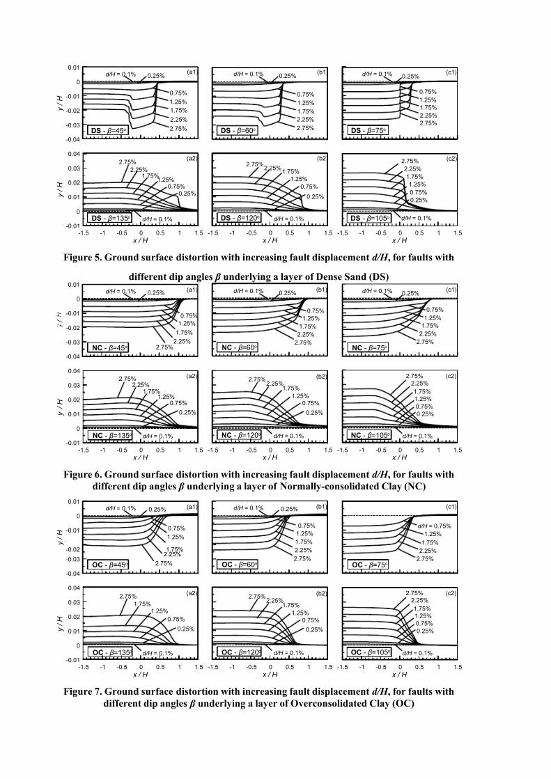
Figures 4, 5, 6 and 7 present the evolution of the ground surface distortion with increasing bedrock
fault displacement d/H , for fault dip angles β = 45ο, 60
ο, 75
ο, 105
ο, 120
οand 135
οand for all four (4)
soil types LS, DS, NC and OC, respectively. The distorted ground surface is presented in terms of the
displaced nodal coordinates ( x and y), normalized in terms of the thickness Η of the soil layer. Note
that before the initiation of the fault rupture, the horizontal ground surface is at elevation y = 0 and that
the fault trace in the bedrock is located at x = 0.
-0.04
-0.03
-0.02
-0.01
0
0.01
y / H
d/H = 0.1% 0.25%
0.75%
1.25%
1.75%
2.25%
2.75%
d/H = 0.1% 0.25%
0.75%
1.25%
1.75%
2.25%
2.75%LS - β=45ο LS - β=60ο
d/H = 0.1% 0.25%
0.75%
1.25%
1.75%
2.25%
2.75%LS - β=75ο
-1.5 -1 -0.5 0 0.5 1 1.5
x / H
-0.01
0
0.01
0.02
0.03
0.04
y / H
d/H = 0.1%
0.25%
0.75%
1.25%
1.75%
2.25%
2.75%
LS - β=135ο
-1.5 -1 -0.5 0 0.5 1 1.5
x / H
d/H = 0.1%
0.25%
0.75%
1.25%
1.75%2.25%
2.75%
LS - β=120ο
-1.5 -1 -0.5 0 0.5 1 1.5
x / H
d/H = 0.1%
0.25%0.75%
1.25%1.75%
2.25%
2.75%
LS - β=105ο
(a1)
(a2)
(b1)
(b2)
(c1)
(c2)
Figure 4. Ground surface distortion with increasing fault displacement d/H , for faults with
different dip angles β underlying a layer of Loose Sand (LS)
7/30/2019 Zone of Excessive Ground Surface Distortion Due to Dip Slip Fault Rupture
http://slidepdf.com/reader/full/zone-of-excessive-ground-surface-distortion-due-to-dip-slip-fault-rupture 6/12
-0.04
-0.03
-0.02
-0.01
0
0.01
y / H
d/H = 0.1% 0.25%
0.75%
1.25%
1.75%
2.25%
2.75%
d/H = 0.1% 0.25%
0.75%
1.25%
1.75%
2.25%
2.75%DS - β=45ο DS - β=60ο
d/H = 0.1% 0.25%
0.75%
1.25%
1.75%
2.25%
2.75%
DS - β=75ο
-1.5 -1 -0.5 0 0.5 1 1.5
x / H
-0.01
0
0.01
0.02
0.03
0.04
y / H
d/H = 0.1%
0.25%
0.75%
1.25%
1.75%
2.25%
2.75%
DS - β=135ο
-1.5 -1 -0.5 0 0.5 1 1.5
x / H
d/H = 0.1%
0.25%
0.75%
1.25%
1.75%2.25%
2.75%
DS - β=120ο
-1.5 -1 -0.5 0 0.5 1 1.5
x / H
d/H = 0.1%
0.25%0.75%
1.25%1.75%
2.25%
2.75%
DS - β=105ο
(a1)
(a2)
(b1) (c1)
(c2)(b2)
Figure 5. Ground surface distortion with increasing fault displacement d/H , for faults with
different dip angles β underlying a layer of Dense Sand (DS)
-0.04
-0.03
-0.02
-0.01
0
0.01
/
d/H = 0.1% 0.25%
0.75%
1.25%
1.75%
2.25%2.75%
d/H = 0.1% 0.25%
0.75%
1.25%
1.75%
2.25%
2.75%NC - β=45ο NC - β=60ο
d/H = 0.1% 0.25%
0.75%
1.25%
1.75%
2.25%
2.75%NC - β=75ο
-1.5 -1 -0.5 0 0.5 1 1.5
x / H
-0.01
0
0.01
0.02
0.03
0.04
y / H
d/H = 0.1%
0.25%
0.75%
1.25%
1.75%
2.25%
2.75%
NC - β=135ο
-1.5 -1 -0.5 0 0.5 1 1.5
x / H
d/H = 0.1%
0.25%
0.75%
1.25%
1.75%2.25%
2.75%
NC - β=120ο
-1.5 -1 -0.5 0 0.5 1 1.5
x / H
d/H = 0.1%
0.25%
0.75%1.25%
1.75%2.25%
2.75%
NC - β=105ο
(a1)
(a2)
(b1)
(b2)
(c1)
(c2)
Figure 6. Ground surface distortion with increasing fault displacement d/H , for faults with
different dip angles β underlying a layer of Normally-consolidated Clay (NC)
-0.04
-0.03
-0.02
-0.01
0
0.01
y / H
d/H = 0.1% 0.25%
0.75%
1.25%
1.75%2.25%
2.75%
d/H = 0.1% 0.25%
0.75%
1.25%
1.75%
2.25%
2.75%OC - β=45ο OC - β=60ο
d/H = 0.75%
1.25%
1.75%
2.25%
2.75%OC - β=75ο
-1.5 -1 -0.5 0 0.5 1 1.5
x / H
-0.01
0
0.01
0.02
0.03
0.04
y / H
d/H = 0.1%
0.25%
0.75%
1.25%
1.75%
2.25%
2.75%
OC - β=135ο
-1.5 -1 -0.5 0 0.5 1 1.5
x / H
d/H = 0.1%
0.25%
0.75%
1.25%
1.75%2.25%
2.75%
OC - β=120ο
-1.5 -1 -0.5 0 0.5 1 1.5
x / H
d/H = 0.1%
0.25%
0.75%
1.25%1.75%
2.75%
OC - β=105ο
(a1)
(a2)
(b1)
(b2)
(c1)
(c2)
Figure 7. Ground surface distortion with increasing fault displacement d/H , for faults with
different dip angles β underlying a layer of Overconsolidated Clay (OC)

7/30/2019 Zone of Excessive Ground Surface Distortion Due to Dip Slip Fault Rupture
http://slidepdf.com/reader/full/zone-of-excessive-ground-surface-distortion-due-to-dip-slip-fault-rupture 7/12
The exact form of the distorted ground surface is of relatively small practical importance, for
preliminary design purposes at least. More important is the knowledge of the value of specific
parameters, like (see Figure 8):
a) the value of the bedrock fault displacement d o /H for the rupture to reach the ground surface,
b) the width L of the zone with significant ground surface distortion, and
c) the location C of the foregoing zone with significant ground surface distortion,
which are the subjects of the next paragraphs.
Figure 8. Schematic illustration of the problem of fault rupture propagation through soil
layer and parameters of engineering interest
Fault displacement for the rupture to reach the ground surface
Numerical results show that an increase of the bedrock fault displacement d/H generally leads to an
increase of the maximum inclination of the ground surface. This increase is characterized by a slow
initial rate up until a limiting value of bedrock fault displacement d o /H beyond which the maximum
ground surface inclination increases intensely, a fact depicting that the rupture has reached the ground
surface. This value of the limiting fault displacement is presented in Figure 9, as a function of the fault
dip angle β and for all four (4) soil types considered here.
It is deduced that for normal faults, the rupture reaches the ground surface for much smaller bedrock
fault displacements (d o /H = 0.2 ÷ 0.4%) as compared to reverse faults (d o /H = 0.3 ÷ 2.4%). One possible explanation for this difference is that reverse faulting occurs in a compressional stress regime
oppositely to normal faulting that occurs in a tensile stress regime. This difference is reminiscent of
the difference between passive and active failure conditions of retaining walls, which require similarly
different strain levels in order to occur.
L
H
C
Ltot
SECONDARY
failure surface
PRIMARY
failure surface
fault plane
straight projection of
bedrock fault planeFault trace in the
bedrock
bedrock
soil deposit
β
H
d
moving block
stationary block
(hanging wall)
(foot wall)

7/30/2019 Zone of Excessive Ground Surface Distortion Due to Dip Slip Fault Rupture
http://slidepdf.com/reader/full/zone-of-excessive-ground-surface-distortion-due-to-dip-slip-fault-rupture 8/12
45 60 75 90 105 120 135
fault dip angle β (o)
0.0
0.4
0.8
1.2
1.6
2.0
2.4
d o
/ H
( % )
LS
DS
NC
OC
reversenormal
45 60 75 90 105 120 135
fault dip angle β (o)
0.0
0.4
0.8
1.2
1.6
2.0
2.4
d o
/ H
( % )
LS
DS
NC
OC
reversenormal
Figure 9. Minimum fault displacement d o /H for the rupture to reach the ground surface
Width of zone with significant ground surface distortion
This study considers as zone of significant ground distortion the region where the ground surface
inclination is larger than 1/500 or 0.2%. This limit was chosen since it is the traditional serviceability
limit of angular distortion for shallow foundations with spread footings. Interestingly, the width L of
this zone tends to remain practically constant for bedrock fault displacements d/H > 1%. Hence, the
width L normalized with respect to soil thickness Η for all analyses is presented in Figure 10, as a
function of the bedrock fault dip angle β and for the four (4) soil types considered here. Moreover, for
the cases where a graben is formed, Figure 10 presents the total width Ltot /H of significant ground
surface distortion which includes the width of the graben and the width of the distortion zone
associated with the secondary rupture.
45 60 75 90 105 120 135
fault dip angle β (ο)
0
0.4
0.8
1.2
1.6
2
L
H
LS
DS
NC
OC
normal reverse
Ltot
/ H
Figure 10. Normalized width L/H of zone with significant ground surface distortion
It is interesting to note that the present numerical results suggest that the higher the d o /H is, the higher
the L/H is expected to be (Figures 9 and 10), especially for non-cohesive soils (LS and DS). Given
that, during the initial stages of bedrock fault movement, the zone of ground distortion increases with
d/H , this trend implies that the width of the zone of significant ground distortion L/H is affected by theamount of deformation accumulated prior to the emergence of the fault rupture to the ground surface.
7/30/2019 Zone of Excessive Ground Surface Distortion Due to Dip Slip Fault Rupture
http://slidepdf.com/reader/full/zone-of-excessive-ground-surface-distortion-due-to-dip-slip-fault-rupture 9/12
Hence, the fact that the width L/H for normal faults is generally smaller than that of reverse faults may
be attributed to the relatively larger values of d o /H in reverse fault cases (see Figure 9) and the
aforementioned interrelation between d o /H and L/H . Nevertheless, the difference in the values of L/H
is not as large as the difference in the values of d o /H , and this because the L/H practically ceases to
develop at d/H >1%, in all cases, as mentioned above.
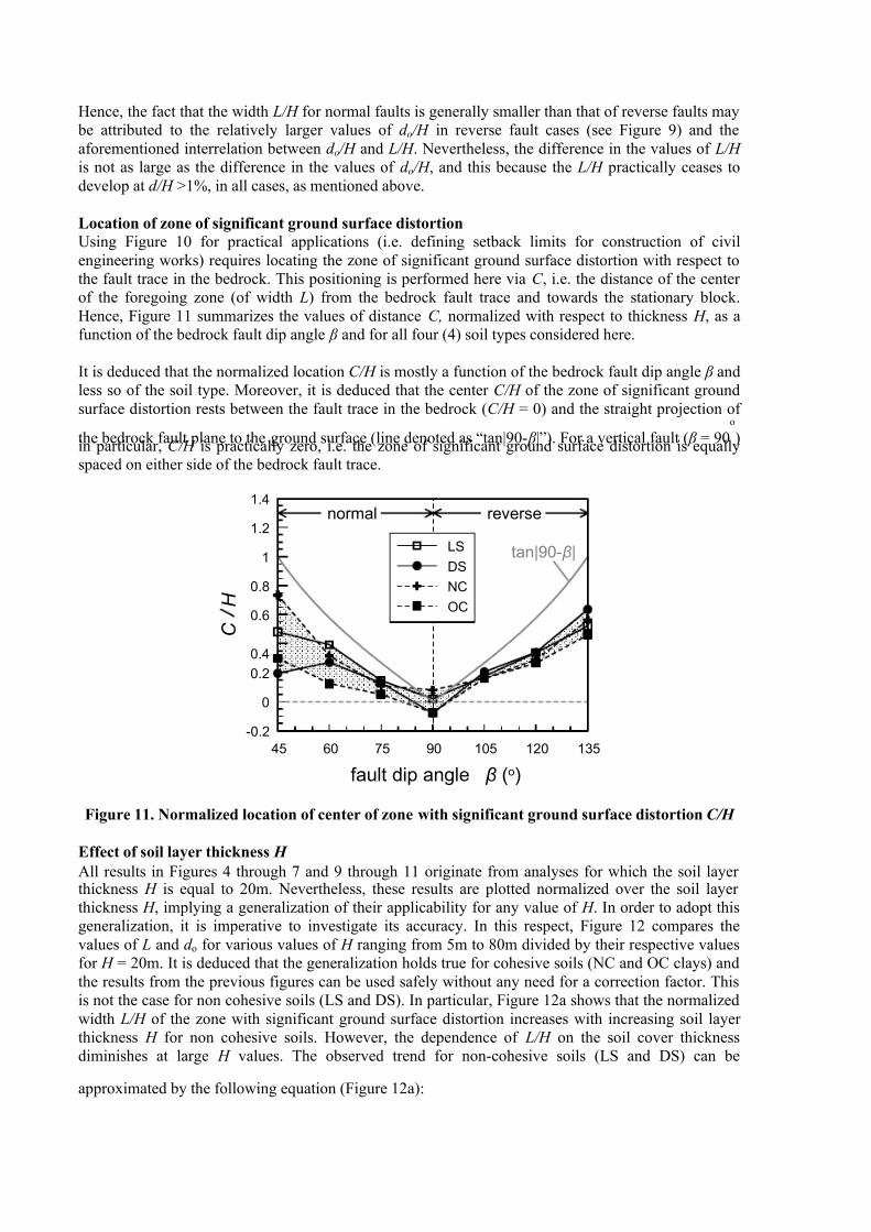
Location of zone of significant ground surface distortion
Using Figure 10 for practical applications (i.e. defining setback limits for construction of civil
engineering works) requires locating the zone of significant ground surface distortion with respect to
the fault trace in the bedrock. This positioning is performed here via C , i.e. the distance of the center
of the foregoing zone (of width L) from the bedrock fault trace and towards the stationary block.
Hence, Figure 11 summarizes the values of distance C, normalized with respect to thickness Η , as a
function of the bedrock fault dip angle β and for all four (4) soil types considered here.
It is deduced that the normalized location C/H is mostly a function of the bedrock fault dip angle β and
less so of the soil type. Moreover, it is deduced that the center C/H of the zone of significant ground
surface distortion rests between the fault trace in the bedrock (C/H = 0) and the straight projection of
the bedrock fault plane to the ground surface (line denoted as “tan|90- β |”). For a vertical fault ( β = 90ο
)in particular, C/H is practically zero, i.e. the zone of significant ground surface distortion is equally
spaced on either side of the bedrock fault trace.
45 60 75 90 105 120 135
fault dip angle β (ο)
-0.2
0
0.2
0.4
0.6
0.8
1
1.2
1.4
C
H
LS
DS
NC
OC
normal reverse
tan|90- β|
Figure 11. Normalized location of center of zone with significant ground surface distortion C/H
Effect of soil layer thickness H
All results in Figures 4 through 7 and 9 through 11 originate from analyses for which the soil layer thickness H is equal to 20m. Nevertheless, these results are plotted normalized over the soil layer
thickness H , implying a generalization of their applicability for any value of H . In order to adopt this
generalization, it is imperative to investigate its accuracy. In this respect, Figure 12 compares the
values of L and d o for various values of H ranging from 5m to 80m divided by their respective values
for H = 20m. It is deduced that the generalization holds true for cohesive soils (NC and OC clays) and
the results from the previous figures can be used safely without any need for a correction factor. This
is not the case for non cohesive soils (LS and DS). In particular, Figure 12a shows that the normalized
width L/H of the zone with significant ground surface distortion increases with increasing soil layer
thickness H for non cohesive soils. However, the dependence of L/H on the soil cover thickness
diminishes at large H values. The observed trend for non-cohesive soils (LS and DS) can be
approximated by the following equation (Figure 12a):

7/30/2019 Zone of Excessive Ground Surface Distortion Due to Dip Slip Fault Rupture
http://slidepdf.com/reader/full/zone-of-excessive-ground-surface-distortion-due-to-dip-slip-fault-rupture 10/12
( )
12.0
20m 20
(m)
/
/⎟ ⎠
⎞⎜⎝
⎛ =
H
H L
H L(1)
As shown in Figure 12b, the effect of the sand layer thickness H on the d o /H for LS and DS is
relatively stronger, and can be quantified with the aid of the following equation (Figure 12b):
( )
4.0
20m20
(m)
/
/⎟ ⎠
⎞⎜⎝
⎛ =
H
H d
H d
o
o (2)
The above equations can be seen as correction factors to the respective data presented in previous
subsections from the analyses with H = 20m. Based on Equations (1) and (2) when the bedrock fault
displacement d o /H increases so does the width L/H of non cohesive soils, but to a smaller degree. This
interrelation of d o /H and L/H for non-cohesive soils is reminiscent of what is observed in Figures 9
and 10 for normal and reverse faults. Focusing on the interpretation of the effect of H on the value of
d o /H , the following may be noted:
− The peak shear strength of both cohesive and non-cohesive soils are assumed linear functions of the vertical effective stress σ΄ vo and thus of the depth z .
− The Young’s modulus E of non-cohesive soils is assumed a non-linear function of the depth z (i.e.
z 1/2
). Therefore, self-similarity with respect to the elastic modulus profile does not hold for LA and
DS, since E/H cannot be a function purely of the normalized depth z/H, oppositely to what happens
in the case of NC and OC, based on the assumed soil properties shown in Table 1.
As a result, the yield strain (that is equal to the ratio of the shear strength divided by the elasticity
modulus of the Mohr-Coulomb soil model) turns out to be independent of the depth z for cohesive
soils and an increasing function of depth (i.e. z 1/2
). Therefore, shallow non-cohesive deposits have a
smaller yield strain as opposed to deep deposits, and as such they require relatively smaller values of
d o /H for the rupture to reach the ground surface (see Figure 12b). On the contrary, for cohesive
deposits (NC and OC) the yield strain is independent of the soil depth and thus the d o /H is provenindependent of H (see Figure 12b). Given the interrelation of d o /H and L/H , the relative increase (or
decrease) of d o /H leads to a smaller increase (or decrease) in the respective values of L/H .
For completeness it is noted that the effect of layer thickness H on the value of C/H is unimportant. An
exception to this rule are the cases where a secondary rupture forms a graben, i.e. cases only possible
when normal faults with low dip angles underlie non-cohesive soil.
0 20 40 60 80 100
H (m)
0.0
0.2
0.4
0.6
0.8
1.0
1.2
1.4
1.6
1.8
2.0
( L / H ) / ( L / H ) H
= 2 0 m
DS - β=45o
DS - β=60o
LS - β=60o
LS - β=120o
NC - β=60o
NC - β=105o
OC - β=45o
OC - β=135o
Equation (1)
0 20 40 60 80 100
H (m)
0.00
0.25
0.50
0.75
1.00
1.25
1.50
1.75
2.00
( o
/ H ) / (
o / H ) H
= 2 0 m
DS - β=45o
DS - β=60o
LS - β=60o
LS - β=120o
NC - β=60o
NC - β=105o
OC - β=45o
OC - β=135o
Equation (2)
Figure 12. Effect of soil layer thickness H on a) the width L/H of the zone with significant ground
surface distortion and b) the bedrock fault displacement d o /H required for the rupture to reachthe ground surface
7/30/2019 Zone of Excessive Ground Surface Distortion Due to Dip Slip Fault Rupture
http://slidepdf.com/reader/full/zone-of-excessive-ground-surface-distortion-due-to-dip-slip-fault-rupture 11/12
CONCLUSIONS
The basic conclusions from this study are the following:
• The fault rupture propagation from the bedrock to the ground surface through a soil layer of
thickness Η may deviate significantly from the straight projection of the bedrock fault plane.
• For non-cohesive soils, the rupture propagation to the ground surface creates a scarp, whereas for
cohesive soils the ground distorts more smoothly, with possible tension cracks in the case of OC
clay. In particular, for non-cohesive soils and small normal fault dip angles β in the bedrock, a
graben is formed in the ground.
• The bedrock fault displacement d o required for the rupture to reach the ground surface and the
location C and width L of the zone with significant ground surface distortion (i.e. where surface
inclinations exceed 1/500 or 0.2%) are found to be a function of the soil thickness H and the dip
angle β of the fault in the bedrock. The soil type has a relatively small effect on the values of C .
• In general, the width L of the zone with significant ground surface distortion ranges from 0.8 H to
1.6 Η , while the location C of the center of the foregoing zone is between the trace of the fault in
the bedrock and its straight projection to the ground surface.
• The bedrock fault displacement required for the rupture to reach the ground surface is larger inthe case of reverse faults (d o /H = 0.3 – 2.4%) than in the case of normal faults (d o /H = 0.2 –
0.4%).
The values of d o, C and L can be estimated via charts and equations that are based on the results of this
study. Use of these in practice presupposes the knowledge of the location, the dip angle and the
expected displacement of the active fault in the bedrock, all objects of a seismo-tectonic study. In such
a case, these charts can be used in seismic microzonation studies for the preliminary definition of
zones of disallowed construction (set-back limits), as well as of zones where damage-preventing
countermeasures should be considered in the design of light-weight structures and lifelines (e.g.
pipelines). In all cases, these charts should be used parametrically for various possible locations of the
fault in the bedrock, in cooperation with seismologists. On the other hand, these results cannot be used
in the case of heavy structures, since the fault-soil-structure interaction may alter the location of the
fault rupture at the ground surface.
Despite the qualitative and quantitative verification of the employed methodology, the fact that the
proposed charts and equations stem from numerical analyses presents a need for further verification,
with insitu and/or laboratory (preferably centrifuge) measurements. This process is currently under
way. In all cases, it must be underlined that the studied problem is extremely complicated and poly-
parametric and hence it is premature to consider general design criteria in the form of code provisions.
ACKNOWLEDGEMENTS
This research was partly funded from the project entitled “EPEAEK2 – Pythagoras” that is co-funded by the European Union and the Ministry of National Education and Religious Affairs of Greece.
REFERENCES
Antoniou Κ , “Numerical simulation of the Nikomidino fault rupture”, Diploma Thesis, Geotechnical
Department, N.T.U.A., 2000 (in Greek)
Bray JD, Seed RB, Cluff LS and Seed HB, “Earthquake Fault Rupture Propagation through Soil”,
Journal of Geotechnical Engineering, ASCE, 120 (3), 543-561, 1994a
Bray JD, Seed RB and Seed HB, “Analysis of Earthquake Fault Propagation through Cohesive Soil”,
Journal of Geotechnical Engineering, ASCE, 120 (3), 562-580, 1994b

7/30/2019 Zone of Excessive Ground Surface Distortion Due to Dip Slip Fault Rupture
http://slidepdf.com/reader/full/zone-of-excessive-ground-surface-distortion-due-to-dip-slip-fault-rupture 12/12
Bouckovalas GD, Loukidis D and Antoniou K, “Active fault rupture propagation in alluvial deposits”,
Proceedings, 9th International Conference of the Hellenic Geologic Society, Athens, September,
2001 (in Greek)
Cole DA Jr and Lade PV, “Influence zones in Alluvium over Dip-Slip Faults”, Journal of
Geotechnical Engineering, ASCE, 110 (5), 599-615, 1984
Itasca Consulting Group, Inc, Minneapolis, “FLAC – Fast Lagrangian Analysis of Continua Version
3.4, User’s Guide” 1998
Kelson KI, Kang K-H, Page WD, Lee C-T and Cluff LS, “Representative styles of deformation along
the Chelungpu Fault from the 1999 Chi-Chi (Taiwan) Earthquake: Geomorphic Characteristics and
Responses of Man-made structures”, Bulleting of the Seismological Society of America, 91 (5),
930-952, 2001
Lade PV, Cole DA Jr, and Cummings D. “Multiple Failure Surfaces Over Dip-Slip Faults”, Journal of
Geotechnical Engineering ASCE, 110 (5), 616-627, 1984
Loukidis D, “Active fault rupture propagation through soil layer”, Diploma Thesis, N.T.U.A. 1999 (in
Greek)
Loukidis D and Bouckovalas GD, “Numerical simulation of active fault rupture propagation through
dry soil”, Proceedings, 4th
International Conference on Recent Advances in Geotechnical
Earthquake Engineering and Soil Dynamics Symposium in honor of Professor W. D. Liam Finn,San Diego, CA, March 26-31, Paper 3.04, 2001
Mercier J-L, Carey-Gailhardis E, Mouyaris N, Simeakis K, Rondoyanis T and Anghelidis C,
“Structural analysis of recent and active faults and regional state of stress in the epicentral area of
the 1978 Thessaloniki earthquakes (Northern Greece)”, Tectonics, 2, 577-600, 1983
Raptakis D, Chavez-Garcia FJ, Makra K and Pitilakis K, “Site effects at Euroseistest-I: Determination
of the valley structure and confrontation of observations with 1D analysis”, Soil Dynamics and
Earthquake Engineering, 19(1), 1-22, 2000
Roth WH, Scott RF and Austin I, “Centrifuge modeling of fault propagation through alluvial soils”,
Geophysical Research Letters, 8 (6), 561-564, 1981
Roth, WH, Kalsi G, Papastamatiou D and Cundall PA, “Numerical Modeling of Fault Propagation in
Soil”, Proceedings of the 4th International Conference on Numerical Methods in Geomechanics,
Edmonton, Canada, 487-494, 1982
Related Documents