User Manual ZKAccess3.5 Security System Version: 3.5.3 Build0001 and above version Supports Pull SDK V2.2.0.205 and above version Supports Standalone SDK V6.2.5.31 and above version About this manual All design and specification declared are subject to change without notice in advance.

Welcome message from author
This document is posted to help you gain knowledge. Please leave a comment to let me know what you think about it! Share it to your friends and learn new things together.
Transcript

User Manual ZKAccess3.5 Security System
Version: 3.5.3 Build0001 and above version
Supports Pull SDK V2.2.0.205 and above version
Supports Standalone SDK V6.2.5.31 and above version
About this manual All design and specification declared are subject to change without notice in advance.


I
Table of Contents
Table of Contents ................................................................................................................................ I
Definitions .......................................................................................................................................... i
1. System Instruction .......................................................................................................................... 1
1.1 Functions Instruction ................................................................................................................ 1 1.2 Basic Operation Flow ................................................................................................................ 2 1.3 Select Language ....................................................................................................................... 2
2. System Management ...................................................................................................................... 3
3. Navigation ...................................................................................................................................... 5
4. Personnel System Management ...................................................................................................... 6
4.1 Department Management ........................................................................................................ 6 4.2 Personnel Management ............................................................................................................ 8
4.2.1 Add Personnel ................................................................................................................. 8 4.2.2 Personnel Adjustment ..................................................................................................... 11 4.2.3 Batch Add Employees ...................................................................................................... 12 4.2.4 Issue Card ....................................................................................................................... 13
5. Device Management ...................................................................................................................... 16
5.1 Area Settings ........................................................................................................................... 16 5.2 Device Management ............................................................................................................... 17
5.2.1 Add Device ..................................................................................................................... 17 5.2.2 Edit and Delete Device .................................................................................................... 23 5.2.3 Search Device ................................................................................................................. 25 5.2.4 Get Event Entries ............................................................................................................. 26 5.2.5 Sync All Data to Device .................................................................................................... 26 5.2.6 Get Personnel Data From Device ...................................................................................... 27 5.2.7 Get Information of Personnel ........................................................................................... 27 5.2.8 More Information ............................................................................................................ 28
6. Security System Management ........................................................................................................ 35
6.1 Time Zones ............................................................................................................................. 36 6.2 Holidays ................................................................................................................................. 39 6.3 Door Settings .......................................................................................................................... 42
6.3.1 Device Name .................................................................................................................. 43 6.3.2 Door Number ................................................................................................................. 43 6.3.3 Door Name ..................................................................................................................... 43 6.3.4 Door Active Time Zone/Default time zone......................................................................... 44 6.3.5 Door Passage Mode Time Zone ........................................................................................ 44 6.3.6 Verify Mode .................................................................................................................... 45 6.3.7 Door Sensor Type ............................................................................................................ 46 6.3.8 Door Status Delay ........................................................................................................... 46 6.3.9 Close and Reverse-lock .................................................................................................... 46 6.3.10 Time Attendance ........................................................................................................... 46 6.3.11 Lock Drive Duration ....................................................................................................... 46 6.3.12 Punch Interval ............................................................................................................... 47 6.3.13 Error Times to Alarm ...................................................................................................... 47 6.3.14 Sensor Dlay Alarm ......................................................................................................... 47 6.3.15 Enable SRB .................................................................................................................... 47 6.3.16 Duress Password & Emergency Password ........................................................................ 48 6.3.17 Apply these Settings to Current Access Control Panel ....................................................... 48

II
6.3.18 Apply these Settings to all Access Control Panel .............................................................. 48 6.4 Access Levels ........................................................................................................................... 48 6.5 Wiegand Format ...................................................................................................................... 50
6.5.1 How to Configure the Wiegand Format ............................................................................. 50 6.5.2 Wiegand Input ................................................................................................................ 56 6.5.3 Wiegand Output ............................................................................................................. 57 6.5.4 Pre-Defined Wiegand Format ........................................................................................... 57
6.6 Interlock Settings .................................................................................................................... 60 6.7 Anti-Passback Settings ............................................................................................................. 61 6.8 Linkage Settings ...................................................................................................................... 64 6.9 First-Card Normal .................................................................................................................... 67 6.10 Multi-Card Opening ............................................................................................................... 68 6.11 Real-time Monitoring ............................................................................................................. 71 6.12 E-Map ................................................................................................................................... 72 6.13 Reader Setting ...................................................................................................................... 73 6.14 Auxiliary Setting .................................................................................................................... 74
7. Access Control Reports ................................................................................................................... 76
7.1 Events Today ........................................................................................................................... 76 7.2 Exception Events ..................................................................................................................... 76 7.3 custom report ......................................................................................................................... 77
7.3.1 Add custom report .......................................................................................................... 77 7.3.2 Viewing Reports .............................................................................................................. 78
8. Time & Attendance ......................................................................................................................... 79
8.1 System ................................................................................................................................... 79 8.2 Setup ..................................................................................................................................... 80
8.2.1 Company Management ................................................................................................... 80 8.2.2 Pay Code ........................................................................................................................ 83 8.2.3 Time Period .................................................................................................................... 84 8.2.4 Shift ............................................................................................................................... 87 8.2.5 Calendar (Schedule shifts for employees) .......................................................................... 90
8.3 Attendance Record Processing ................................................................................................. 90 8.3.1 Punches ......................................................................................................................... 90 8.3.2 Exceptions Assign ........................................................................................................... 92
8.4 Report Processing ................................................................................................................... 93 8.4.1 Attendance Calculation ................................................................................................... 93 8.4.2 Attendance Report .......................................................................................................... 95
9. System Settings.............................................................................................................................. 97
9.1 User & Role Management ......................................................................................................... 97 9.2 Database Management ........................................................................................................... 99
9.2.1 Set Database .................................................................................................................. 99 9.2.2 Backup Database ............................................................................................................ 99 9.2.3 Restore Database ........................................................................................................... 100 9.2.4 Database Backup Path Configuration .............................................................................. 100
9.3 Initialize Database .................................................................................................................. 100 9.4 System Parameter Setting ....................................................................................................... 102
10. Appendixes ................................................................................................................................. 103
Appendix 1 Common Operation ................................................................................................... 103 Appendix 2 Real-Time Event Description ....................................................................................... 109
Normal Events ....................................................................................................................... 109 Abnormal Events ................................................................................................................... 111
Appendix 3 <END-USER LICENSE AGREEMENT> ............................................................................. 112

III
Appendix 4 FAQs ......................................................................................................................... 115 Appendix 5 Wiegand ................................................................................................................... 116


i
Definitions Super User: The user who has all operation levels of the system, who can assign new users
(such as company management personnel, registrar, and access control administrator) in
the system and configure the roles of corresponding users.
Role: During daily use, the super user needs to assign new users having different levels. To
avoid setting individual levels for each user, roles having certain levels can be set in Role
Management, and then be assigned to specified users.
Access Control Time Zone: It can be used for door timing. The reader can be made usable
during valid time periods for certain doors and unusable during other time periods. Time
zone can also be used to set Normal Open time periods for doors, or set access control
levels so that specified users can only access specified doors during specified time periods
(including access levels and First-Card Normal Open settings).
Door Status Delay: The duration for delayed detection of door sensor after the door is
opened. Detection is performed only after the door is opened and the delay duration
expired. When the door is not in the "Normally Open" period, and the door is opened, the
device will start timing. It will trigger alarm when the delay duration expired, and stop
alarm when you close the door. The door status delay should be longer than the lock drive
duration.
Close and Reverse-lock: Set whether or not to lock after door closing.
Lock Drive Duration: Used to control the delay for unlocking after press fingerprint or card
punching.
First-Card Normal Open: During a specified interval, after the first verification by the
person having First-Card Normal Open level, the door will be Normal Open, and will
automatically restore closing after the valid interval expires.
Multi-Card Opening: This function needs to be enabled in some special access occasions,
where the door will open only after the consecutive verification of multiple people. Any
person verifying outside of the defined combination (even if the person belongs to other
combinations) will interrupt the procedure, requiring a 10 seconds wait to restart

ii
verification.
Interlock: Can be set for any two or more locks belonging to one access control panel, so
that when one door is opened, the others will be closed, allowing only one door to be
open at a time.
Anti-pass Back: Currently anti-passback settings support in and out anti-passback. In some
special occasions, it is required that the one who verify and enter from a door must exit and
verify from the same door, with the entry and exit records strictly consistent. For example,
anti-passback between door 1 and door 2: If someone enters from door 1 and then must exit
from door 2; If someone enters from door 2 and then must exit from door 1.
Linkage Setting: When an event is triggered at an input point of the access control system,
a linkage action will occur at the specified output point to control such events as
verification, opening, alarming and exception of the system and list them in the
corresponding monitored report for view by the user.

¡Error! Utilice la pestaña Inicio para aplicar 标题 1 al texto que desea que aparezca aquí.
1
1. System Instruction
1.1 Functions Instruction Security Management has increasing concerns for modern enterprises. This management
system helps customers to integrate operation of safety procedures on one platform,
making access control management easier and more practical so as to improve efficiency.
System Features
1. Powerful data processing capacity, allowing the management of the access control data
for 30,000 people. And supports connect 100 devices for standard configuration.
2. Visible and reasonable work flows come from abundant experience in access control
management.
3. Automatic user name list management.
4. Multilevel management role-based level management secures user data confidentiality.
Configuration Requirements:
CPU: Master frequency of 2.0G or above.
Memory: 1G or above.
Hardware: Available space of 10G or above. We recommend using NTFS hard disk partition
as the system installation directory (NTFS hard disk partition has the better performance
and higher security).
Operating System:
Supported Operating Systems:
Windows XP/Windows 2003/Windows Vista/Windows7/8/8.1
Supported Databases:
MS SQL Server2005/Microsoft Access
System Modules:
The system includes five major functional modules.

2
Personnel System: Primarily two parts: first, Department Management settings, used to set the
Company's organizational chart; Second, Personnel Management settings, used to input
personnel information, assign departments, maintain and manage personnel.
Device System: Set communication parameters for device connection, including system
settings and machine settings. After successful communication, the information of
connected devices can be viewed and operations such as remote monitoring, uploading
and downloading can be performed in the system.
Note:
Digital Vein function displayed on the "Device" and "Personnel" interface in system.
Access Control System: C/S Frame-based management system, enabling normal access
control functions, management of networked access control panel via computer, and
unified personnel access management. The access control system sets door opening time
and levels for registered users, so that some users are permitted to unlock some doors
through verification during certain intervals.
System Settings: Primarily used to assign system users and configure the roles of
corresponding modules, database management such as backup, initialization and recovery,
and set system parameters and manage system operation logs.
1.2 Basic Operation Flow The following are the basic steps to use the system, the user just needs to follow the steps
below and skip the items which are not displayed on their interface.
Step 1: Add Device.
Step 2: Add Personnel.
Step 3: Add Access Control, includes Time Zones, Holidays, Door Setting, Access Levels.
Step 4: View Real-time Monitoring and Reports.
1.3 Select Language Enter into the [System] menu, click [Select Language], it will popup Chinese and English,
Choose the language what you need, and then restart the system to make it take effect.

3
2. System Management 1. Log in to the System
(1) Double click the [ZKAccess3.5 Security System] shortcut on the desktop, the following
homepage pops up.
(2) For system security, it is required to verify identity before accessing the system. We will
provide a super user (having all operation levels) for the beginner of this system. Enter user
name and password, and click [OK], to enter the system.
(3) Check the [remember me] option, save the user name and password, for direct login
next time. click [log in] after inputted.
Note:
The user name of the super user is [admin], and the password is [admin]. After the first login
to the system, for system security, please use the [Modify password] function to modify the
password.
The super user can assign company personnel as system users to (such as company
management personnel, registrar, and access control administrator) and configure the roles of
corresponding modules. For details, see 8.1 User & Role Management.
2. Quit the system:
Click the button on the upper right corner of the interface, directly to quit the system.
3. Modify Password:

4
The super user and the new user created by the super user (the default password for the
new user is "admin") can use the [Modify password] function to modify the login password
for system security. Click [Modify password], it pops up the Edit Page. Enter the old
password and the new password, confirm the new password and click [Confirm] to
complete the modification.

5
3. Navigation After the user logs in to the system, it will show the [Navigation] main interface, Or click
[System]>[ navigation] interface. Follow up, you can also click on the upper
left corner of the icon to switch to the interface. Click the navigation icon will switch to the
corresponding processing interface.

6
4. Personnel System Management Before using the system's access control management functions, first access the personnel
system
for configuration.
Step 1, Department Management settings, used to set the company's organizational chart.
Step 2, Personnel Management settings, used to input personnel, assign departments, and
maintain and manage personnel.
Step 3, set the Access Control Levels.
4.1 Department Management Before managing company personnel, it is required to describe and manage the company
departmental organization chart. Upon first use of the system, by default it has a primary
department named [Company Name] and numbered [1]. This department can be modified
but cannot be deleted.
Main functions of Department Management include Add Department and Department
Maintenance.
1. Add Department:
(1)Click [Personnel] > [Department] > [Add] to show the Add Department interface.
Another way through the import, the other systems or information in the Department of
information into the system, the specific operation, please refer to the 9.1 common
operation.

7
The fields are as follows:
Department name: Any character, up to a combination of 50 characters.
Department number: If required, it shall not be identical to another department. The
length shall not exceed 50 digits. Click [Verify] to see if repeated or not.
Parent department: Select from the pull-down menu and click [OK].
(2)After editing, click [OK] to complete adding, or click [Cancel] to cancel it.
2. Department Maintenance:
(1)The [Upper Department] is an important parameter to determine the Company's
organizational chart. On the right of the interface, the Company's organizational chart will
be shown in the form of a department tree.
(2) Upon a change to the department or organizational structure, the user can use the [Edit]
function to modify such items as Department Name, Department Number or Upper
Department. Click Department Name directly or click the [Edit] button behind the
department to access the edit interface for modification.
(3) To delete a department, click the check box before the department, and click [Cancel
Department], or directly click the [Delete] button behind the department.
(4) click [import] or [export] to import a file from the computer to the interface or export

8
the information to the computer.
(5) click [operation Logs] to see the recent operation of the department.
Note:
A department cannot be deleted freely. If so, the personnel under the department will be
pending, and some historical data will not be able to be queried. If deletion is required,
please first transfer the departmental personnel to another department.
4.2 Personnel Management When starting to use this management program, the user shall register personnel in the
system, or import personnel information from other software or document into this system.
For details, see Appendix 1 Common Operation
4.2.1 Add Personnel
1.Click [Personnel] > [Personnel] > [Add] to show personnel profile edit interface.
The fields are as follows:
Personnel No.: By default, the length cannot exceed 9 digits. A number with a length of less
than 9 digits will be preceded with 0 automatically to complete 9 digits. Numbers cannot
be duplicated. Click [Verify] to see if it is duplicated or not.
Department: Select from the pull-down menu and click [OK]. If the department was not

9
set previously, you can only select the default [Company Name] department.
Card Number: Assign a card number to the person for access control use. This can be done
manually or by using card issuer. For details, please refer to 4.2.2 Personnel Information
Maintenance.
Password: Set personnel password. An access control panel only supports 8-digit
passwords. If a password exceeds the specified length, the system will truncate it
automatically. If you need to modify the password, please clear the old password in the box
and input the new one.
Employment Date: By default it is the current date.
Terminal Management Privilege: Employee or admin.
Personal Photo: The best size is 230×230 pixels, for saving space.
Fingerprint Register: There are two ways that through fingerprint register or machine to
achieve function of fingerprint registration. The fingerprint reader is required to connect to
the computer and install the driver before the registration; The machine registration is
required to add the device to the software (Achieve the fingerprint registeration only
through offline device when editing personnel data).
In addition, can enter the name, cell phone, date of birth, mail and other basic information
(non Chinese can enter the last name)
Details: Can enter staff more information, such as, address, education, nationality,
nationality, identity card number.

10
Alternative Access Levels: Select access levels, start and end dates of access validity time
and multi-card opening personnel groups (Presetting is required. For details, see 6.10
Multi-Card Opening).
set the effective time is mainly for temporary access system, that is, only in the effective
time to open the door, no check is the default always valid.
2.After the staff information editing, click on the [save and Continue] to continue to add
other personnel, or click [OK] to save and exit, the list will show the new staff, click [Cancel]
to give up the operation.
11
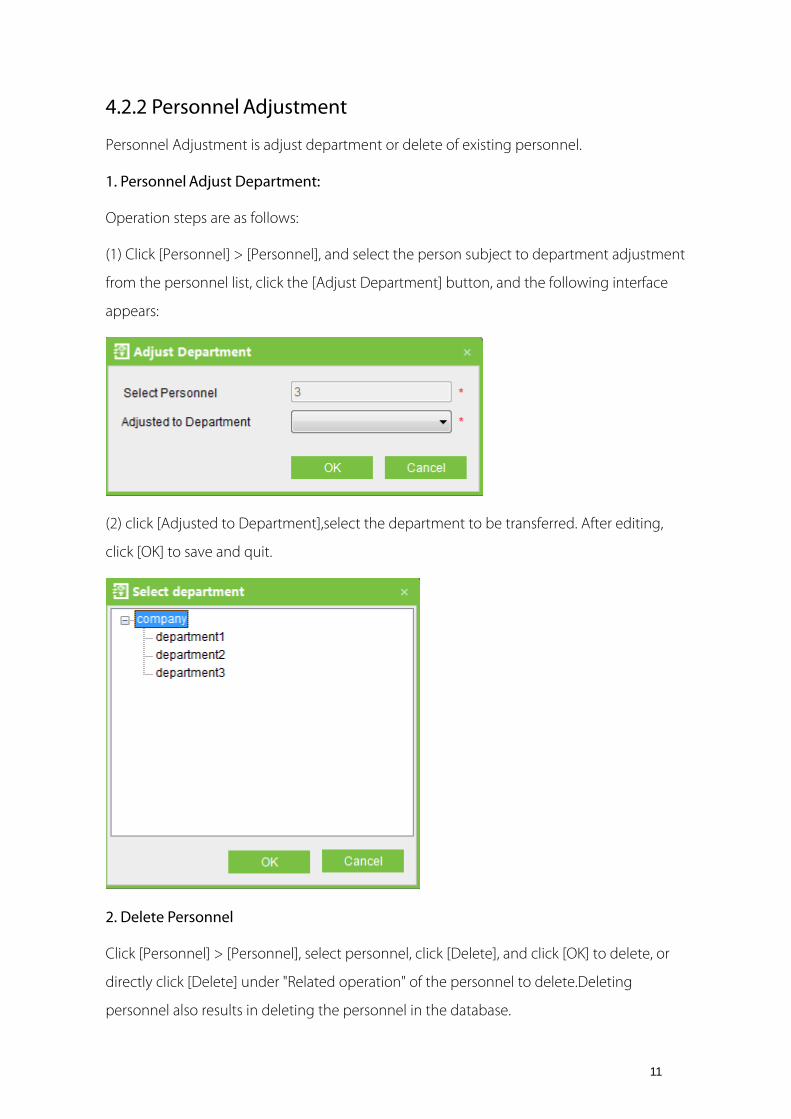
4.2.2 Personnel Adjustment
Personnel Adjustment is adjust department or delete of existing personnel.
1. Personnel Adjust Department:
Operation steps are as follows:
(1) Click [Personnel] > [Personnel], and select the person subject to department adjustment
from the personnel list, click the [Adjust Department] button, and the following interface
appears:
(2) click [Adjusted to Department],select the department to be transferred. After editing,
click [OK] to save and quit.
2. Delete Personnel
Click [Personnel] > [Personnel], select personnel, click [Delete], and click [OK] to delete, or
directly click [Delete] under "Related operation" of the personnel to delete.Deleting
personnel also results in deleting the personnel in the database.
12
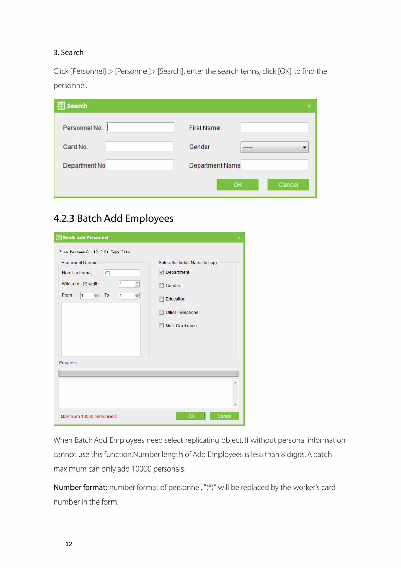
3. Search
Click [Personnel] > [Personnel]> [Search], enter the search terms, click [OK] to find the
personnel.
4.2.3 Batch Add Employees
When Batch Add Employees need select replicating object. If without personal information
cannot use this function.Number length of Add Employees is less than 8 digits. A batch
maximum can only add 10000 personals.
Number format: number format of personnel, "(*)" will be replaced by the worker’s card
number in the form.

13
Wildcard (*) width: That is mean, how many figure the Number pattern has. After the
Wildcard (*) width has been defined, by use the From box, To box to create range. Click
[OK], add employees, and click [Cancel], return the interface.
In addition, you can click on [import], [export] and the computer for file transfer, click
[Operation Logs] to see the operation of the staff.
4.2.4 Issue Card
The operations include Personnel Card Issue, Batch Issue Card, and etc.
For such functions, you can directly click the personnel number in the personnel list to
enter the edit interface for modification, or right-click the [Edit] button to enter the edit
interface for modification. After modification, click [OK] to save and quit.
Personnel Card Issue:
Assign card numbers to personnel, including batch card issue and individual card issue.
(1) How to use the card issuer
The card issuer is connected to the PC through a USB port. When the cursor is on the Card
Number Input box, punch the card on the card issuer, then the card number will display in
the input box.
(2) Batch Card Issue
Click [Personnel] > [Issue Card] > [Batch Issue Card] to show the Batch Issue Card edit
interface.

14
Personnel list, show these all personnel without cards within this number series.
Select the way of "Access Control Issue Card" or "Card Reade".
In using of the card reader, when you swipe the card near to the card reader, the System
will get the card number and issue it to the user in the left list.
Using of the access control panel, you need to select the position of swiping card, such as a
card reader connected with an access control panel. Input the Start Personnel number and
End personnel number, click Personnel list, got the personnel list, and then click [Start to
read], the system will read the card number automatically, and issue it to the user in the left
list one by one. After that, click [Stop to read].
Click [OK] to complete card issue and return. Personnel and corresponding card numbers
will be shown in the list.
(3) Individual Card Issue:
Click [Personnel] > [Card Issue] > [Add] to show Individual Card Issue interface.
Select personnel, enter card number (or use card issuer for card issue), select card issue
date, and click [OK].

15
Note:
The system supports card issue through card issuer and by manually inputting card
numbers.

16
5. Device Management The access control panel to be connected to this system provides access control system
functions. To use these functions, the user must first install devices and connect them to
the network. Second, set corresponding parameters in the system so as to manage these
devices via the system, upload user access control data, download configuration
information, output reports and achieve digital management of the enterprise.
5.1 Area Settings Area is a spatial concept, enabling the user to manage devices in a specific area.
In the access system, after area setting, devices (doors) can be filtered by area upon
real-time monitoring.
The system, by default, has set an area named [Headquarters] and numbered [1]. Area
setting includes Add Area and Delete area.
1. Add area:
Click [Device] > [Area Settings] > [Add] to activate the Add Area edit interface:
The fields are as follows:
Area Name: Any character, up to a combination of 50 characters.
Area Code: Repetition not allowed.
Parent Area: Decides the regional organization structure of the company.

17
After setting, click [OK].
2. Delete area:
Select area, click [Delete], or directly right click [Delete], press [OK].
5.2 Device Management Set the communication parameters of connected devices. Only when communication
parameters, including system settings and device settings, are correct, normal
communication with devices will be possible. When communication is successful, you can
view the information of connected devices, and perform remote monitoring, uploading
and downloading data.
5.2.1 Add Device
Add Device: Click [Device] > [Device] > [Add], also you can click [Search] to search devices
which in the network, and directly add from the searching result.
There are two ways to add Access Control Panel.
1. Add Device:
(1) In the Device Type Selection interface, select Add Access Control Panel. The
communication modes are TCP/ IP or RS485. The following interface will be shown:

18
TCP/ IP
IP Address: Please enter the IP Address of the access control panel.
IP Port No.: In Ethernet mode, the default is 4370.
RS485
Serial Port Number: COM1~COM254.
19
485 Address: The machine number. When serial port numbers are the same, there will be
no repeated 485 addresses.
Baud Rate: Same as the baud rate of the device (9600/19200/38400/ 57600/115200). The
default is 38400.
Note:
The same Serial port Number cannot allow to exits many of baud rates. If RS485 address
respectively for 1 and 2 of the two devices, with 38400 and 115200 baud rate respectively
add in system, and use the same Serial port COM1, it will could not add.
Device Name: Any character, up to a combination of 50 characters.
Communication Password: Any character, up to a combination of 8 characters (No blank).
You need to input this field only when you add a new device with the communication
password. It cannot be modified when you edit the device information except in [Modify
communication password] operation. Please refer to 6.3 Door Settings.
Note:
You do not need to input this field if the device has no communication password, such as
when it is a new factory device or just after the initialization.
Access Control Panel Type: One-Door Access Control Panel, Two-door Access Control Panel,
Four-Door Access Control Panel, Standalone Access Control, Standalone SDK Machine.
Note:
Standalone SDK Machine is the device which supports Standalone SDK communication
protocol, has nothing to do with whether networking. One-Door Access Control Panel,
Two-door Access Control Panel, Four-Door Access Control Pane and Standalone Access
Control are support pull communication protocol, they are pull device.
For example, when adding a device which supports Standalone SDK communication
protocol, choose Standalone Access Control in Access Control Panel Type, after the device
is connected, the Access Control Panel Type will be displayed as Standalone SDK Machine
by automatically.
Switch to Two-door Two-way: When four-door panel is selected, this box will appear. By
default, it is not ticked. This parameter is used to switch the four-door one-way access
control panel to two-door two-way access control panel (For changes of extended device

20
parameters before and after switching, see relevant files of access control panel).
Note:
After the four door one-way access control panel is switched to two- door two-way access
control panel, to switch back, you need delete the device from the system and add it again.
When adding, do not tick the check box before this parameter.
Auto Synchronizes Device Time: By default it is ticked, namely, it will synchronize device
time with server time each time connecting to the device. If it is not ticked, the user can
manually synchronize device time.
Area: Specify areas of devices. After Area Setting, devices (doors) can be filtered by area
upon Real-Time Monitoring.
Clear Data in the Device when Adding: If this option is being ticked, after adding device
adding, the system will clear all data in the device, except the event logs. If you add the
device just for demonstration or testing of the system, there is no need to tick it.
(2) After editing, click [OK], and the system will try connecting the current device:
If connection is successful, it will read the corresponding extended parameters of the
device. At this time, if the access control panel type selected by the user does not meet the
corresponding parameters of the actual device, the system will remind the user. If the user
clicks [OK] to save, it will save the actual access control panel type of the device.
Extended Device Parameters: includes serial number, device type, firmware version number,
auxiliary input quantity, auxiliary output quantity, door quantity, device fingerprint version,
and reader quantity.
If device connection fails, while the user still needs to add the device to the system,
corresponding device parameters and extended parameters, such as the serial number, will
not be written into the system and settings such as anti-passback and linkage will not be
impossible. These settings can be created only when the device is reconnected successfully
and corresponding parameters are acquired.
Note:
When you add a new device to the system, the system will clear all user information, time
zones, holidays, and access control levels settings (including access control group, anti-pass
back, interlock settings, linkage settings, etc.) from the device, except the events record in

21
the device. Unless the information in the device is unusable, we recommend that you not
to delete the device in used, to avoid the loss of information.
Access Control Panel Settings:
TCP/ IP Communication Requirements:
To support and enable TCP/ IP communication, directly connect the device to the PC or
connect to the Internet, get the device IP address and other device information of the
device.
RS485 Communication Requirements:
To support and enable RS485 communication, connect to PC through RS485, get the serial
port number, RS485 machine number (address), baud rate and other device information of
the device.
The devices with yellow background are Standalone SDK Device, for example F8 as below.
2. Add Device By Searching Access Control Panels:
Search the access control panels in the Ethernet.
(1) Click [Device] > [Search Panels], to show the Search interface, supports Ethernet and
RS485 search.

22
Note:
If choose the way of RS485, maybe need select corresponding serial port number, baud
rate, fill in RS485 address.
(2) Click [Start Search], and it will prompt [searching……].
(3) After searching, the list and total number of access control panels will be displayed.

23
Note:
Here we use UDP broadcast mode to search the access controller, this mode cannot
exceed the HUB scale. The IP address can exceed the net segment, but must belong to the
same subnet, and needs to configure the gateway and IP address in the same network
segment.
(4) Click [Add to device list] behind the device, and a dialog box will open. Enter
self-defined device name, and click [OK] to complete device adding.
(5) The default IP address of the access control panel may conflict with the IP of a device on
the Internet. You can modify its IP address: Click [Modify IP Address] behind the device and a
dialog box will open. Enter the new IP address and other parameters (Note: Must configure
the gateway and IP address in the same network segment).
5.2.2 Edit and Delete Device
For communication between the system and the device, data uploading, configuration
downloading, device and system parameters shall be set. The user can see access control
panels within his levels in the current system, and can edit the devices here. The user can to
add or delete devices in Device if needed.
Edit: Select device, tick in the box in front, then click above [Edit] menu or right click [Edit]
to alter.
Delete: Select device, click [Delete], and click [OK].
There are three tabs in the Standalone SDK Device editing interface, [Basic parameters],

24
[Verification and Protocol] and [Other Settings].
Verification and Protocol
ID card: Support reading ID card only.
Mifare card use as ID card: Read the number of Mifare card, but not the memory block.
Protocol enabling status: What protocol is enabled on the specified device. This protocol
must be enabled when the device to use a protocol to communicate with other device.
Matching threshold: The threshold level for recognition of a biometric identification. The
lower the threshold, the higher False Access Rate.
comparison based on the ratio of 1:1 only:Mean it is should enter the number before
comparison . This way can speed up the recognition speed.
The Mifare card must be registered:the device that support Mifare card,Indicates whether the
physical card number of the Mifare card is verified。
Other Settings

25
After the device is connected successfully, user can view the device information and set the
parameters through system.
Choose the device, click【delect】,then click【OK】,can delect the device on the list.
5.2.3 Search Device
Search: Click [Device] > [Device] > [Search], will pop the following interface, enter the search terms to get the information.

26
5.2.4 Get Event Entries
Get event records from the device into the system.
Three options are provided for this operation, Get New Records, Get All Records, and Clear
record after downloaded.
Get New Entries: The system only gets the new event entries since the last time event
entries were collected and records them into the database. Repeated Entries will not be
rewritten.
Get All Entries: The system will get all of the event entries again. Repeated Entries will not
be rewritten.
Clear record after downloaded: After records are downloaded, the device will
automatically delete all the records.
When the network is interrupted or communication is interrupted for any reasons, and the
event records in the device have not been uploaded into the system in real-time, the
operation can be used to manually acquire event records in the device. In addition, the
system also can set timing to get.
Note:
The access controller can restore up to 100 thousands of event entries. When the entries
exceed this number, the device will automatically delete the oldest restored entries (the
default delete number is 10 thousands).
5.2.5 Sync All Data to Device
The system will synchronize the data to the device, including door information, access

27
control levels (personnel information, access control time zones), anti-pass back settings,
interlock settings, linkage settings, first-card normal open settings, multi-card normal open
settings and so on. Select device, click [Synchronize All Data] and click [OK] to complete
synchronization.
Note:
The operation of Synchronize All Data is mainly to delete all data in the device first (except
event record). Download all settings again, please keep the net connection stable and
avoid power down situations, etc. If the device is working normally, please use this function
with caution. Execute it in rare user situations to avoid impact on normal use of the device.
5.2.6 Get Personnel Data From Device
Take origin information of the device saves in the system.
5.2.7 Get Information of Personnel
Renew the current number of personnel quantity, fingerprint quantity, vein number and
face quantity in the device. The final value will be displayed on the device list.

28
5.2.8 More Information
Includes that Modify IP Address, Close Auxiliary Output, Disable, Enable, Modify
Communication Password, Synchronize Time, Upgrade Firmware, Get Logs From SD Card,
Import Data From USB disk and etc.
(1) Disable/Enable
Select device, click [Disable/Enable] from [More Information] menu to stop/start using the
device. When the device's communication with the system is interrupted or the device fails,
the device may automatically appear in disabled status. At this time, after adjusting Internet
or device, click [Enable Device] to reconnect the device and restore device communication.
Note:
If the current device is in enabled status and the connection is not successful, if the user
performs the enable operation, the system will immediately reconnect the device.
(2) Upgrade Firmware
To upgrade firmware in the device, tick the device for which you want to upgrade the
firmware, click [Upgrade firmware], enter edit interface, click [Browse] to select the firmware
upgrade file (named emfw.cfg) provided by Access, and click [OK] to start upgrading.
(3) Synchronize Time
Synchronize device time with current server time.

29
(4) Modify IP Address
Select device and click [Modify IP address] to show the Modification interface. It will obtain
real-time network gateway and mask from the device. If it is fails because the network is
unavailable, then the IP address cannot be modified. Enter new IP address, gateway, and
subnet mask. Click [OK] to save settings and quit. This function the same as [Modify IP
Address Function] in 5.2.1 New Add Device. The difference is when searching control
panels, the devices have not been added into the system, while the current [Modify Device
IP Address] is regarding added devices.
(5) Close Auxiliary Output
Close the auxiliary device connected to the device auxiliary output interface.
(6) Modify Communication Password
Enter the old communication password before modification. After verification, input the
same new password twice, and click [OK] to modify the communication password.

30
Note:
The communication password cannot contain space.
It is recommended that a combination of numbers and letters be used. The
communication password setting can improve the device security. It is recommended to
set communication password for each device.
(7) Change The Fingerprint Identification Threshold
The user can change the fingerprint identification threshold in the device. The scale is
35-70 and 55 by default. In device adding, the system will get the threshold from the
device. If the operation succeeds, user can view the threshold in all of the devices. Batch
operation is permitted, the user can change multiple devices concurrently.
(8) Modify Baudrate: Select device and click [Modify Baudrate] to show the Modification
interface. This option is used to set the baud rate for the communication between the
device and the PC. It includes five options: 9600, 19200, 38400, 57600, and 115200.
(9) Operation Logs
Record this system history operating records, with list form to record all of the operation. At
interface of Personnel, Department, Issue Card has [Operation Logs] menu, click it can
show the relevant record information.

31
(10) Sync Latest Modification Data To Device
The operational process of the new settings information synchronizes to the device.
Such as New Add Personnel, Access Control Setting etc, It is adopt increment
synchronization.
Note:
The operation of Synchronize All Data is mainly to delete all data in the device first (except
event record). Download all settings again, please keep the net connection stable and
avoid power down situations, etc. If the device is working normally, please use this function
with caution. Execute it in rare user situations to avoid impact on normal use of the device.
(11) Export
Click [Device] > [Device] > [More] > [Export], can export the relevant contents of device
with EXCEL or PDF or Txt. format, save on your computer.
(12) Get Logs From SD Card
The system will get the event logs from the SD card in the controller, and then through
system analyzing, will save backed-up records of the SD card to the system.
The log files name of Standalone SDK Machine, Access Control Panel and Standalone SDK
Machine are *.dat, because of data formats are different, the system analyzes the process of
log files are different, details are as follows:
If a file name ends with "_attlog.dat", the system determines that the file is an event record
file of Standalone SDK Machine, and takes characters in front of the underline as the S/N of
the device. If the device with such a machine S/N exists in the database, the system
imports event records; otherwise, no processing is performed.
If a file name does not end with "_attlog.dat", the system determines that the file is an
event record file of the Pull device (Access Control Panel or Standalone Access Control).
Then, the system analyzes the file according to the Pull format, and obtains the S/N of the
device from the file. If the device with such an S/N exists in the database, the system
imports event records; otherwise, no processing is performed.
An event record exported from a Pull device (Access Control Panel or Standalone Access

32
Control) is named BKtransaction.dat by default. An event record exported from Standalone
SDK Machine is named Machine S/N_attlog.dat by default.
When the network is interrupted or communication is interrupted for any reasons, and the
event records in the device have not been uploaded into the system in real-time, the
operation can be used to manually acquire event records in the device. In addition, also
can set timing obtain logs.
Note:
The access controller can restore up to 100 thousands of event logs. When the logs exceed
this number, the device will automatically delete the oldest restored entries (the default
delete number is 10 thousands).
(13) RS485 Master-slave configuration
Click [Device] > [More] > [RS485 Master-slave configure], including three options as follows:
1. RS485 Address: Set the device number. It is equivalent to the Ethernet IP address when
RS485 communicating. It is the only address for establishing serial port communication.
Address values in the range of 1 ~ 255.
2. RS485 Master: Tick this, the master act as controller for setting device, connecting the
reader.
3. RS485 Slave: Tick this, the slave act as reader for setting device, connecting the controller
or access control equipment.
Choose the configuration what you need, click the [OK] button, and then the system will
bring the selected configuration upload to the device, the RS485 master-slave

33
configuration is completed.
Note:
(1) If select one from the RS485 master option or the RS485 master option, the device and
system cannot for RS485 and serial port communication.
(2) If you do not choose any one from the two options, the device and system can for
RS485 and serial port communication.
(3) RS485 master option and RS485 slave option are mutually exclusive options, it means
that RS485 slave will be automatically un-checked state when you choose RS485
master.
(14) Import data from USB disk
Download the user information, fingerprint information, face data, finger vein from device
to USB disk, then upload the data to the database of system.
34
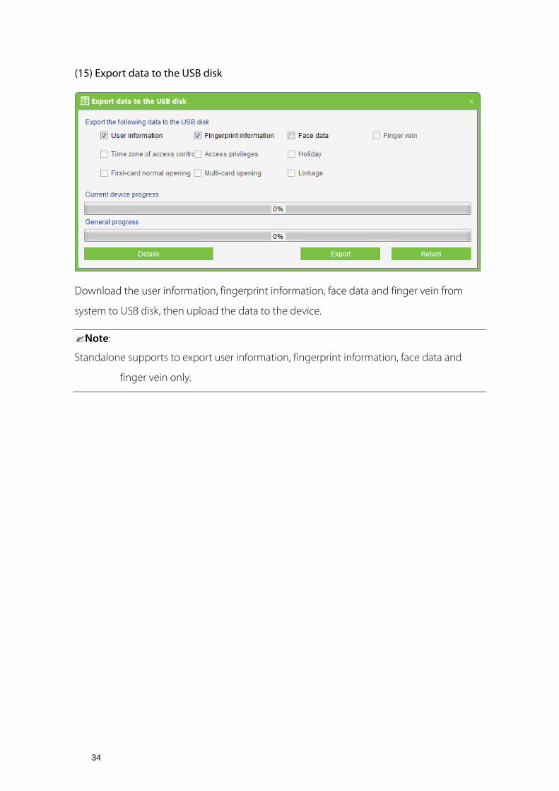
(15) Export data to the USB disk
Download the user information, fingerprint information, face data and finger vein from
system to USB disk, then upload the data to the device.
Note:
Standalone supports to export user information, fingerprint information, face data and
finger vein only.

35
6. Security System Management 1. Work principle of the access control system
The System is a C/S-based management system, providing normal access control functions,
management of networked access control panel via computer, and unified personnel access
management.
The access control system can set the opening levels of registered users, namely, allowing some
personnel to open some doors by verification during a time period.
Otherwise, the system supports the use of data from the access control panel for attendance
purpose, to save the device resource.
It facilitates the management and support of multiple databases, including Access, SQL Server.
Designed based on multi-business convergence, it supports service extension, such as
attendance and supports multiple languages.
2. Access control system parameters
255 time zones.
Unlimited access levels.
Three holiday types and 96 holidays total.
Anti-passback function.
Wiegand format.
Interlock function.
Linkage function.
First-Card Normal Open function.
Multi-Card Opening function.
Remote door opening and closing.
Real-time monitoring.

36
3. Operation functions of access control system
Access Control System Management primarily includes Access Control Time Zones, Access
Control Holiday, Door Settings, Access Levels, Personnel Access Levels, Real-Time Monitoring,
and Reports, etc.
Note:
This chapter the parameters definition can refer to Definitions.
6.1 Time Zones Access Control Time Zone can be used for door timing. The reader can be made usable during
valid time periods of certain doors and unusable during other time periods. Time Zone can also
be used to set Normal Open time periods for doors, or set access control levels so that specified
users can only access specified doors during specified time periods (including access levels and
First-Card Normal Open settings).
The system controls access according to Access Control Time Zones. The system can define up
to 255 time zones. For each time zone, you can define, during a week, you can define up to
three intervals for each day and three holiday types for each time zone. Each interval is the valid
interval in 24 hours of each day. The format of each interval for a time zone: HH: MM-HH: MM,
this is accurate to minutes in the 24-hour system.
Initially, by default the system has access control time zone named [Accessible 24 hours]. This
time period can be modified but cannot be deleted. The user can add Access Control Time
Zones that can be modified.
1. Add Access Control Time Zone:
(1) Enter into the system, click [Access Control] > [Time zones] > [Add] to access the time
zone setting interface.

37
The parameters are as follows:
Time Zone Name: Any character, up to a combination of 50 characters.
Remarks: Detailed description of the current time zone, including an explanation of the
current time zone and primary applications, facilitating the user or other users with same
level to view time zone information. The field is up to 70 characters.
Standalone device parameters
Time zone ID 1: ID of the first time zone (from left to right) in a day from Monday to
Sunday.
Time zone ID 2: ID of the second time zone (from left to right) in a day from Monday to
Sunday.
Time zone ID 3: ID of the third time zone (from left to right) in a day from Monday to
Sunday.
Holiday Time zone ID: ID of the first time zone (from left to right) among time zones of
holiday type 1.

38
Note:
You can define a total of 50 IDs from 1 to 50. Each ID can be allocated to only one time
zone. "1" is the ID of the time zone "24 hours pass" by default, as shown in the following
figure:
Holiday Type: Three holiday types can be defined. The time zones of each type can be
different. When adding holidays, you must specify the holiday type.
In the access control system, the priority of holidays is higher than that of common
weekdays.
For example, the Children's Day in 2014 is Sunday (June 1st). When adding holidays, you
can set the Children's Day as holiday type 1. When June 1st, 2014 arrives, the equipment
manages access control time zones according to the preset holiday type 1, instead of the
preset time zones on Sunday.
Note:
If the holiday type of a time zone is not set, the access is denied in 24 hours by default.
Start Time: Start time of a time zone.
End Time: End time of a time zone.
Setting method: The setting of the time zone is null by default, that is, Norma Close. If a
time zone is Normal Open, press and hold the left mouse button and drag the mouse to
select the entire time frame. The start time 00:00 and the end time 23:59 will be displayed
in the lower part of the page.
You can set a maximum of three time zones in a day. You can drag the mouse on the time
frame to set each time zone. The start time and the end time of each time zone will be
displayed in the lower part of the page. After the time zones are set, click [OK] to save the
settings. The time zone names will be displayed in the list.
Note:
A maximum of three time zones can be set in a day.
2. Maintenance of Access Control Time Zone:

39
Edit: In the time zone list, pitch on relevant time zone, and then right-click to select [Modify
time] to access the time zone modification interface, and modify the time zone setting.
After modification, click [OK], and the modified time zone will be saved and shown in the
time zone list, or click [Cancel] to cancel the operation.
Delete: In the time zone list, pitch on relevant time zone, and then right-click to select
[Delete time], click [OK] to delete the time zone, or click [Cancel] to cancel the operation. A
time zone in use cannot be deleted.
Tick the check boxes before one or more time zones in the time zone list. Click the [Delete]
button over the list, and click [OK] to delete the selected time zones, or click [Cancel] to
cancel the operation.
6.2 Holidays The Access Control Time of a holiday may differ from that of a weekday. For easy operation,
the system provides holiday settings to set access control time for holidays.
Access Control Holiday Management includes Add, Modify and Delete Access Control
Holiday.
1. Add Access Control Holiday:
Three holiday types are supported, each including up to 32 holidays. To conduct special
access level configuration on special dates, the user can select special holidays for setting.
The operation steps are as follows
(1) Click [Access Control System] > [Holidays] > [Add] to access Add Access Control Holiday
edit interface:

40
The fields are as follows:
Holiday Name: Any character, up to a combination of 50 characters.
Holiday Type: Holiday Type 1/2/3, namely, A current holiday record belongs to these three
holiday types and each holiday type includes up to 32 holidays.
Start / End Date: Must meet the date format as "2012-1-1". The Start Date cannot be later
than the End Date otherwise the system will prompt an error. The year of the start date
Start Date cannot be earlier than the current year, and the holiday cannot span years.
Recurring: Yes or No. The default is "No". Annual cycle means that a holiday does not require
modification in different years. For example, the Near Year's Day is on January 1 each year,
and can be set as "Yes". For another example, the Mother's Day is on the second Sunday of
each May, so its date is not fixed and should be set as No.
For example, the date of the holiday "Near Year's Day" is set as January 1, 2012, and the
holiday type is 1, then on January 1, Access Time Control will not follow the time of "Friday"
in the week, but the Access Control Time of Holiday Type 1 such as 6.1 Time Zones.
Standalone device parameters
Holiday Number: Number of a holiday on the device. The holiday number ranges from 1 to
24. This parameter is not supported by a device with the black/white screen.

41
Holiday Time Zone: Time zone used in a holiday. The time zone ID ranges from 1 to 50.
Only the allocated time zone IDs can be used for holiday time zones.
For example, time zone IDs 1, 3, and 4 have been allocated. When adding a holiday, you can
select time zone ID 1, 3, or 4 for the holiday.
(2) After editing, click the [OK] button to save, and it will appear in the holiday list.
2. Modification of Access Control Holiday:
To modify the original Access Control Holiday, click [Edit] behind the Access Control
Holiday to access the edit interface. After modification, click [OK] to save and quit.
3. Deletion of Access Control Holiday:
In the access control holiday list, click the [Delete] button under "Related Operation". Click
[OK] to delete the holiday, or click [Cancel] to cancel the operation. An Access Control
Holiday in use cannot be deleted.
Tick the check boxes before one or more holidays in the holiday list. Click the [Delete]
button over the list, and click [OK] to delete the selected holiday, or click [Cancel] to cancel
the operation.
42
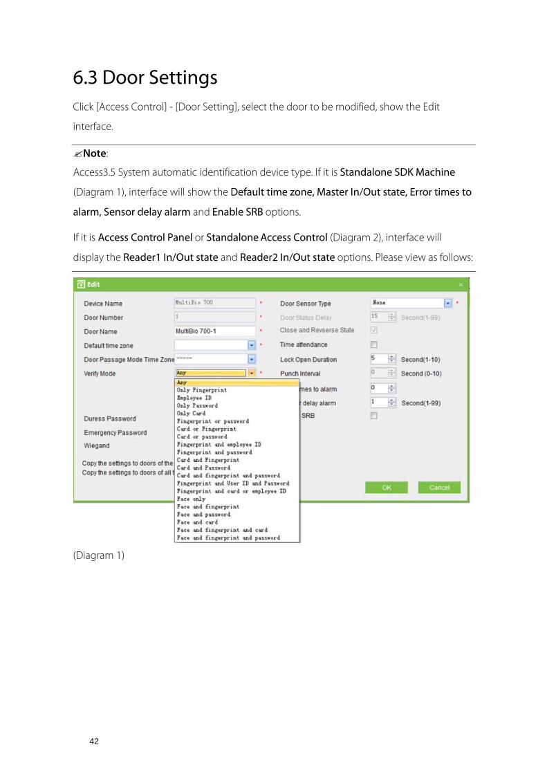
6.3 Door Settings Click [Access Control] - [Door Setting], select the door to be modified, show the Edit
interface.
Note:
Access3.5 System automatic identification device type. If it is Standalone SDK Machine
(Diagram 1), interface will show the Default time zone, Master In/Out state, Error times to
alarm, Sensor delay alarm and Enable SRB options.
If it is Access Control Panel or Standalone Access Control (Diagram 2), interface will
display the Reader1 In/Out state and Reader2 In/Out state options. Please view as follows:
(Diagram 1)

43
(Diagram 2)
6.3.1 Device Name
Device Name is not editable (must be edited in 5.2.1 New Add Device).
6.3.2 Door Number
The system automatically names the numbers of doors according to how many doors of the
device have (for example, the four doors of a four-door control panel are numbered 1, 2, 3 and
4). The number will be consistent with the door number on the device.
Note:
By default, the number following the underline in the door name is consistent to the door
number, but 1/2/3/4 in anti-passback and interlock refers to door serial number rather than
the number following the door name. They are not necessarily related. The system allows
the user to modify the door name, so they cannot be confused.
6.3.3 Door Name
The default Door Name is "device name-door number". Fox example, Device name is
192.168.16.37 and Door number is 1, so the Door Name is 192.168.16.37-1 by default.
The field allows the user to modify as required. Up to 50 characters can be entered.

44
6.3.4 Door Active Time Zone/Default time zone
When the device is Standalone SDK Machine, the parameter is Default time zone, when
the device is Controller or Standalone Access Control, the parameter is Door Active Time
Zone.
By default both are 24 hours pass. Initialized and added access control time zones will be
shown for the user to select. Upon door editing, door valid time zone is needs to be input.
Only after setting the door valid time zone, the door can be opened and closed normally.
6.3.5 Door Passage Mode Time Zone
We recommend to set the door Normal Open time period within the door valid time zone,
only in this situation, the door normal open time zone is valid.
Note:
Consecutive punching of a card having access level of the door for 5 times can release the
Normal Open status for one day (including First-Card Normal Open), and close the door
immediately.
When the system is connected with Access Control Panel or Standalone Access Control,
Time Zone Name is shown in the drop-down list of Door Passage Mode Time Zone, as the
following picture:

45
When the system is connected with Standalone SDK Machine, Time Zone ID is shown in
the drop-down list of Door Passage Mode Time Zone, as the following picture:
6.3.6 Verify Mode
Click [Door Setting], and then double click [Door Name], entry [edit] interface, so select
[Verify Mode].
Controller or Standalone Access Control: Only Fingerprint, Only Password, Only Card, Card
or Fingerprint, Card or Password, Card plus Fingerprint and Card plus Password.
Standalone SDK Machine: Fingerprint or Card or Password, Only Fingerprint and etc.

46
When Password mode is selected, make sure the door uses a reader with keyboard (the
fingerprint verification modes are only available for version 5.0.8 and above version).
Note:
The system supports Vein device, if connect it, [Verify Mode] will show "Only Vein", "Vein and Password", "Vein and Card", " Vein plus Card and Pass " in the system.
6.3.7 Door Sensor Type
NO (door sensor not detected), Normal Open, Normal Close. The default is NO. When
editing doors, the user can select the door sensor type to be Normal Open or Normal Close.
If Normal Open or Normal Close is selected, it is required to select door status delay and
whether close and reverse-lock is required. By default, once door sensor type is set as
Normal Open or Normal Close, the default door status delay will be 15s, and by default it
will enable close and reverse-lock.
6.3.8 Door Status Delay
Set the door sensor delay. An alarm will be generated if the door is left open for a period of
time, and this period is called door sensor delay.
6.3.9 Close and Reverse-lock
Set locking or not after door closing. Tick it for lock after door closing.
6.3.10 Time Attendance
If this option is selected, The AC Log of the door will be used for attendance.
Note:
Please select a door in [Door Setting] before using Time Attendance, or the report will be
none.
6.3.11 Lock Drive Duration
Definition: The time duration of electronic lock works from open to close when user's
verification succeeds (In case the door is closed).
To set this duration, proceed as follows: Select Lock, and press OK. Then enter a desired
number through the numeric pad, and press ESC to exit and save the setting.

47
"S (second)" is chosen as the unit of lock driver duration, and you can set it 1s ~ 10s (some
devices can set 254s at most).
If set the duration to "0", means Lock driver duration is closed. Normally, we do not suggest
set it is "0".
6.3.12 Punch Interval
The unit is seconds (range: 0~10 seconds), and the default is 2 seconds.
6.3.13 Error Times to Alarm
When user error input password, place fingerprints or punch card N times, the device will
alarm.
For example, when N=3, a user error input password 3times, the device will alarm.
Note:
The parameter is only for Standalone SDK Machine.
Value range: 0<=N<=9, when N=0, it means that the device do not alarm all the time.
6.3.14 Sensor Dlay Alarm
When door status delay more than N seconds, the device will alarm.
For example, when N=10, it means that when door status delay more than 10 seconds, the
device will alarm.
Note:
The parameter is only for Standalone SDK Machine.
Value range: 1<=N<=99, when N=0, it means that the device do not alarm all the time.
6.3.15 Enable SRB
When Enable SRB is selected, the lock is controlled in SRB, to keep the door closed when
device is dismantled.
Note:
The parameter is only for Standalone SDK Machine, and only the SRB is installed, the SRB
will be take effect.

48
6.3.16 Duress Password & Emergency Password
Upon duress, use Duress Password (used with legally card) to open the door. When
opening the door with Duress Password, it will alarm. Upon emergency, the user can use
Emergency Password (named Super Password) to open the door. Emergency Password
allows normal door opening. Emergency password is effective in any time zone and any
type of verify mode, usually used for the administrator.
Duress Password setting: The value range is 1 to 6 integers.
Emergency Password: The password can only be set to 8 integers.
6.3.17 Apply these Settings to Current Access Control Panel
Click to apply to all doors of the current access control panel.
6.3.18 Apply these Settings to all Access Control Panel
Click to apply to all doors of all access control panels within the current user's level.
After parameter editing, click [OK] to save and quit.
Other parameters specifications refer to Definitions in this user manual.
6.4 Access Levels Access levels means in a specific time period, which door or door combination can be
opened through verification.
Add access levels:
1. Click [Access Control] > [Access levels] > [Add] to enter Add access levels edit interface:

49
2. Set parameters: access level name (no repetition), access control time zones, door
combination,
selected personnel.
3. click and move the personnel to the selected list of people. Also can click
on all mobile.
4. Click [OK] to complete setting and quit, and added access levels will appear in the list.
Notes:
(1) Select the doors in the access levels as multi-choice, so you can select different doors in
different control panels.
(2) When adding personnel, if selected personnel exist in the current access level, the
system cannot add again.
(3) Two levels with the same time zone and door combination are not allowed in the system.
(4) The devices with yellow background are doors of Standalone SDK Machine.

50
(5) If there is a door of Standalone SDK Machine in the Selected Doors, then the Time Zone
that undefined Time zone ID cannot be selected in the drop-down list of Access Control
Time Zone, otherwise, otherwise you won't save. For example the above picture, COM4-1-1 is
a Standalone SDK Machine, Pass Time Zone 3 is undefined Time zone ID, when click [OK], it
will pop up above prompt dialog box.
Personnel Access Levels: Select personnel, click [Delete from access level] to delete the
personnel from the access level.
6.5 Wiegand Format Wiegand format configuration includes four aspects: How to configure the Wiegand format,
Wiegand Input, Wiegand Output, Pre-Define WG Format.
6.5.1 How to Configure the Wiegand Format
Wiegand format associated with the door, you can assign each door's Wiegand input and
output formats.
Click [Access Control] > [Door Setting], select the door to be modified, show the Edit interface
as follows:
Click [WG Setting], it will display Wiegand Input or Wiegand Input & Output interface.
Editing different doors, the Wiegand setting interface will be different.

51
(1) When editing controller, only with Wiegand Input interface as follows:
(2) When editing Standalone Access Control, With Wiegand Input & Output is
Wiegand26 as default and the interface is as below:
(3) When editing Standalone SDK Machine, With Wiegand Input & Output interface as
below:

52
Instruction to Wiegand input & Wiegand output configuration
Wiegand Output Format: The system has four built-in formats Wiegand 26 (with a device ID),
Wiegand 34 (with a device ID), Wiegand 26 (without device ID) and Wiegand 34 (without
device ID).
Failure ID: Refers to the value output by the system upon verification failure. The output format
is subject to the setting of Wiegand Format and the default value range from 0 to 65535.
Site Code: The Site Code is used for customized Wiegand format, the system acquires the Site
Code of the device automaticly when adding a device. The Site Code is similar to the device ID,
but the Site Code is customizable and can be duplicated among different devices. The default
value range from 0 to 255.
Total Number of Bits: Refers to the Input Format and set the Total number of bits. For
example, if the Input Format is Wiegand 26, then the Total number of bits is 26, if the Input
Format is Wiegand 34, then the Total number of bits is 34. The default value is 26.
Pulse Width: Assigns the width of the Wiegand pulse in microseconds. The value range from 1
to 1000, and the default value is 100.
Pulse Interval: Assigns the interval of the Wiegand pulse in microseconds. The value range
from 1 to 10000, and the default value is 1000.
Input Content: Choose the input contents, You can select the Employee ID or Card ID.

53
Output Content: Choose the output contents, You can select the Employee ID or Card ID.
Note:
If a Standalone Access Control is as a reader to be connected with a controller, then the output
content of Standalone Access Control must the same as input content of controller.
Input Format: Assigns Wiegand inputs format.
Standalone SDK Machine includes Black & White Screen device and Color Screen device,
but the Wiegand Input Format of them are different.
The Wiegand Input Format of Black & White Screen device
The Wiegand input format of Black & White Screen device includes: OEM Code (It does
not need to define for wiegand 26 but Wiegand 37 or Wiegand 34), Facility Code (machine
number or refers to site code), ID Number (user serial number), its first letter respectively
indicate (capital letter and small letter are different) in the form, ofiOFI, the small letter express
odd (Odd), the capital letter refers to even (Even), Oo refers to OEM code, Ff refers to Facility
code, Ii refers to ID number, Prefers to the parity bit.
Following is demonstration with a standard Wiegand 26 Input Format: PFFFFFFFFIIIIiiiiiiiiiiiiP,
Facility code is 1, ID Number is 1 input:

54
Even Facility Code ID Number
Odd
P F F F F F F F F I I I I i i i i i i i i i i i i P1 0 0 0 0 0 0 0 1 0 0 0 0 0 0 0 0 0 0 0 0 0 0 0 1 0
Note:
The letters from second to thirteen are capital letter, and they are Even Parity Bit; The letters
from fourteen to twenty five are small letter, and they are Odd Parity Bit; The first letter is Even
Parity Bit and the last letter is Odd Parity Bit.
The Wiegand Input Format of Color Screen device
The customized format consists of two character strings: the data bits and parity bits. These two
character strings need to be defined separately. Data bits define the number of binary bits
output by Wiegand as well as the meaning of each bit.
The data bits output by Wiegand can be a Card Number (C), Site Code (s), Facility Code (f ),
Manufacturer Code (m) and Parity Bits (p).
Parity Bits define the parity mode of each bit in data bits and ensure the correctness of data
bits during transfer through the parity. The parity bits can be set to Odd Parity (o), Even Parity
(e) and Both Odd Parity and Even Parity (b).
There exists a one-to-one correspondence relationship between the data bits and parity bits.

55
Characters used to define parity bits and their meanings:
o: Indicates the odd parity, that is, there is an odd number of 1’s in the bit sequence (including
one parity bit). For example, for 1000110(0), the parity bit is 0 and there are already three 1’s.
After 0 is suffixed to 1000110, there is still an odd number of 1’s.
e: Indicates the even parity, that is, there is an even number of 1’s in the bit sequence (including
one parity bit). For example, for 1000110(1), the parity bit is 1 and there are already three 1’s.
After 1 is suffixed to 1000110, there is an even number of 1’s.
b: Indicates both odd parity and even parity .
For example, the Wiegand26 can be customized as follows:
Definition of data bits: pssssssssccccccccccccccccp
Definition of parity bits: eeeeeeeeeeeeeooooooooooooo
Note:
Wiegand26 consists of 26 bits. The first bit is the even parity bit of bits 2 to 13; the 26th bit is the
odd parity bit of bits 14 to 25; the second to the ninth bits are the site code; the 10th to the
25th bits are the card number.
For example: Definitions of several universal Wiegand formats.
Wiegand34
Data bits: pccccccccccccccccccccccccccccccccp
Parity bits: eeeeeeeeeeeeeeeeeooooooooooooooooo
Note:
Wiegand34 consists of 34 bits. The first bit is the even parity bit of bits 2 to 17; the 34th bit is the
odd parity bit of bits 18 to 33; the second to the ninth bits are the site code; the 10th to the
25th bits are the card number.
Wiegand37a
Data bits: pmmmmsssssssssssscccccccccccccccccccp

56
Parity bits: oeobeobeobeobeobeobeobeobeobeobeobeoe
Note:
Wiegand37a consists of 37 bits. The first bit is the odd parity bit of bits 3, 4, 6, 7, 9, 10, 12, 13, 15,
16, 18, 19, 21, 22, 24, 25, 27, 28, 30, 31, 33, 34 and 36; the 37th bit is the odd parity bit of bits 2, 4,
5, 7, 8, 10, 11, 13, 14, 16, 17, 19, 20, 22, 23, 25, 26, 28, 29, 31, 32, 34 and 35; bits 4, 7, 10, 13, 16, 19,
22, 25, 28, 31 and 34 participate in both odd and even parity parity . Bits 2 to 5 are manufacturer
code; bits 6 to 17 are the site code; bits 18 to 36 are the card number.
Wiegand37
Data bits: pmmmffffffffffssssssccccccccccccccccp
Parity bits: eeeeeeeeeeeeeeeeeeooooooooooooooooooo
Note:
Wiegand37 consists of 37 bits. The first bit is the even parity bit of bits 2 to 18; the 34th bit is the
odd parity bit of bits 19 to 36; the second to the fourth bits are the manufacturer code; the 5th
to the 14th bits are facilitate code; the 15th to the 20th bits are the site code; the 21st to the
36th bits are the card number.
Wiegand50
Data bits: pssssssssssssssssccccccccccccccccccccccccccccccccp
Parity bits: eeeeeeeeeeeeeeeeeeeeeeeeeooooooooooooooooooooooooo
Note:
Wiegand50 consists of 50 bits. The first bit is the even parity bit of bits 2 to 25; the 50th bit is the
odd parity bit of bits 26 to 49; the second to the 16th bits are the site code; the 17th to the 49th
bits are the card number.
6.5.2 Wiegand Input
Including automatic matching, the default format and User-Defined format, you can be free
configuring any one from the three options. Automatic matching is default format.

57
6.5.3 Wiegand Output
Including the default format and user-define format.
Note:
(1) Wiegand output format configuration, the system will automatic decision the device
whether support Wiegand output or not according to the device type. the system does
not display Wiegand output interface if there is no Wiegand output.
(2) At present, our company's controller does not support Wiegand output format.
6.5.4 Pre-Defined Wiegand Format
Click [Access Control] > [Wiegand Format], then the following interface is as following:
New add interface as following:

58
Total Bits Total Number of Bits of the data. For example, there are 26 bits of
Wiegand26 and the Total Bits is 26; there are 34 bits of Wiegand34
and the Total Bits is 34.
Odd Parity
Start Bit
Indicates the start number of Odd
Parity.
Lengt
h
Bits of Odd Parity.
Even Parity
Start Bit
Indicates the start number of Even
Parity.
Lengt
h
Bits of Even Parity.
Card
Number
Start Bit
Indicates the start number of Card
Number.
Lengt
h
Bits of Card Number
Facility
Code Start
Bit
Indicates the start number of Facility
Code.
Lengt
h
Bits of Facility Code.

59
Take adding Wiegand26 and Wiegand34 as examples in the following three interfaces:

60
Note:
(1) The number of bits start from left, and the first number is 1.
(2) The length of Odd Parity + The length of Even Parity Total Bits
(3) The length of Card Number + The length of Facility Code Total Bits
(4) It is Both Odd Parity and Even Parity if Odd Parity Bit or Even Parity Bit is not assigned;
it is Even Parity if the Odd Parity Bits and Even Parity Bits are assigned.
(5) It is Site Code if Card Number Bit or Facility Code Bit is not assigned; it is Facility Code if
the Card Number Bits and Facility Code Bits are assigned; the Facility Code Bits and
Card Number Bits should not duplicated.
After you choose it, make sure that Wiegand Input or Output format is selected for the door,
click [OK] button. And then the configuration of the Wiegand Format is uploaded to the device,
completing the Wiegand Input and Output configuration.
6.6 Interlock Settings Interlock can be set for any two or more lock belong to one access control panel, so that
when one door is opened, the others will be closed. And you can open one door only
when others are closed.
Before interlock setting, please make sure the access controller is connected with door
sensor according to the Installation Guide, and the door sensor has been set as NC or NO
state.
Add interlock settings:
1. Click [Access Control] > [Interlock] > [Add] to enter the interlock setting edit interface.

61
2. Select device to show interlock settings. Since one device can only correspond to one
interlock setting record, when adding, interlocked devices cannot be seen in the
dropdown list of the device. When deleting established interlock information, the
corresponding device will return to the dropdown list. The setting page will vary with the
number of doors controlled by the selected device:
A one-door control panel has no interlock settings.
A two-door control panel: 1-2 two-door interlock settings.
A four-door control panel: 1-2 two-door interlock, 3-4 two-door interlock, 1-2-3 three-door
interlock, 1-2-3-4 four-door interlock.
3. Select interlock settings, tick an item (multiple interlocks can be selected as long as doors
are not repeated), click [OK] to complete setting, and then the added interlock settings will
be shown in the list.
For example, select 1-2-3-4 four-door interlock, if you want open door 3, doors 1, 2 and 4 needs to be closed.
Note:
When editing, the device cannot be modified, but the interlock setting can be modified. If
interlock setting is not required for the device any more, the interlock setting record can be
deleted. When deleting a device record, its interlock setting record, if exist, will be deleted.
6.7 Anti-Passback Settings Currently anti-passback settings support in and out anti-passback. In some special
occasions, it is required that the one who verify and enter from a door must exit and verify

62
from the same door, with the entry and exit records strictly consistent. For example, one
who follow another to enter the door without card punching will be denied when trying to
exit by card punching, and one who follow another to exit without card punching will be
denied when trying to enter by card punching. When a person enters by card punching,
and gives the card to another to try entering, the other person will be denied. The user can
use this function just by enable it in the settings. This function is normally used in prisons,
the army, national defense, scientific research, bank vaults, etc.
Add anti-passback settings:
1. Click [Access Control System] > [Anti-passback settings] > [Add] to show anti-passback
setting edit interface.
2. Select device (N-door control panel), because one device can only correspond to one
anti-passback setting record, so when adding, devices with anti-passback settings cannot
be seen in the dropdown list. When deleting established anti-passback information, the
corresponding device will appear in the dropdown list. The settings vary with the number
of doors controlled by the device:
Anti-passback can be set between readers and between doors. The card holder enter from
door A, he must exit from door B, this function is used for channel or ticket management.
Anti-passback settings of a one-door control panel: Anti-passback between readers of door
1.
Controller anti-passback
Anti-passback settings of a two-door control panel:
Anti-passback settings of a four-door control panel:

63
Note:
The reader mentioned above includes Wiegand reader that connected with access control
panel and inBIO reader. The single door and two door control panel with Wiegand reader
include out reader and in reader. There is only in reader for four door control panel. The
reader number of 1, 2 (that is RS485 address or device number, the same below) is for door
1, the reader number of 3, 4 is for door 2, etc. No need to consider if it is Wiegand reader or
inBIO reader in setting of anti-passback between doors or between readers, just make sure
the in or out state (means it is the in reader or out reader) and set according to the actual
need. For the reader number, odd number is for in reader, and even number is for out
reader.
Standalone SDK Machine anti-passback

64
3. Select anti-passback settings (it needs to choose Master In/Out State when the device is
Standalone SDK Machine) and tick one item (anti-passback without repetition of doors or
readers can be subject to multi-choice). Click [OK] to complete setting, and the added
anti-passback settings can be shown in the list.
Note:
When editing, you cannot modify the device, but can modify anti-passback settings. If
anti-passback setting is not required for the device any more, the anti-passback setting
record can be deleted. When deleting a device record, its anti-passback setting record, if
exist, will be deleted.
6.8 Linkage Settings Linkage setting means when an event is triggered at an input point of the access control
system, a linkage action will occur at the specified output point to control such events as
verification, opening, alarm and exception of the system and list them in the
corresponding monitored report for view by the user.
Add linkage setting:
1. Click [Access Control System] > [Linkage setting] > [Add] to show the linkage setting
interface.

65
2. Input linkage setting name (input linkage setting name before selecting device). After
selecting device, corresponding linkage setting will appear (The system will first determine
whether or not the device is successfully connected and has read extended device
parameters such as auxiliary input quantity, auxiliary output quantity, door quantity and
reader quantity. If the system has no available extended device parameters, it will remind
the user of failing to set anti-passback. Otherwise, it will, shows linkage setting options
according to the currently selected device, such as the door quantity, auxiliary input and
output quantity):
The fields are as follows:
Trigger Condition: Please refer to 6.11 Real-time Monitoring or the Real Time Events
Description. Except Linkage Event Triggered, Cancel Alarm, Open Auxiliary Output, Close
Auxiliary Output, and Device Start, all events could be trigger condition.
Input Point Address: Any, Door 1, Door 2, Door 3, Door 4, Auxiliary Input 1, Auxiliary Input 2,
Auxiliary Input 3, Auxiliary Input 4, Auxiliary Input 9, Auxiliary Input 10, Auxiliary Input 11,
Auxiliary Input 12 (the specific input point please refer to specific device parameters).
Output Point Address: Lock 1, Lock 2, Lock 3, Lock 4, Auxiliary Output 1, Auxiliary Output 2,
Auxiliary Output 3, Auxiliary Output 4, Auxiliary Output 6, Auxiliary Output 8, Auxiliary

66
Output 9, Auxiliary Output 10 (the specific output point please refer to specific device
parameters).
Action Type: Close, Open, Normal Open. By default it is closed. To open, delay time shall be
set, or Normal Close can be selected.
Delay: Ranges from 1s ~ 254s (This item is valid when the action type is Open)
3. After editing, click [OK] to save and quit, and the added linkage setting will be shown in
the linkage setting list.
For example: If select "Normal Punching Card Open" as the trigger condition, and the input
point is Door 1, the output point is Lock 1, the action type is Open, the delay is 60s, then
when "Normal Punching Card Open"" occurs at Door 1, the linkage action of "Open" will
occur at Lock 1, and door will be open for 60s.
Note:
When editing, you cannot modify the device, but can modify linkage setting name and
configuration. When deleting a device, its linkage setting record, if exist, will be deleted.
If system has set that the input point is a specific door or auxiliary input point under a
trigger condition of a device, it will not allow the user to add (or edit) a linkage setting
record where the device and trigger condition are the same but the input point is "Any".
On the contrary, if the device and trigger condition are the same, and the system has
linkage setting record where the trigger point is "Any", the system will not permit the user
to add (or edit) a linkage setting record where the input point is a specific door or auxiliary
input.
In addition, the system does not allow the same linkage setting at input point and output
point in specific trigger condition.
The same device permits consecutive logical (as mentioned above) linkage settings.

67
6.9 First-Card Normal First-Card Normal Open: During a specified interval, after the first verification by the
person having First-Card Normal Open level, the door will be Normal Open, and will
automatically restore closing after the valid interval expired.
The user can set First-Card Normal Open for a specific door. The settings include door, door
opening time zone and personnel with First-Card Normal Open level. A door can have
First-Card Normal Open settings for multiple time zones. The interface of each door will
show the number of existing First-Card Normal Open settings. For First-Card Normal Open
setting, when adding or editing each record, it is not required to modify the “current door",
but to select time zone. When record adding is successful, add personnel that can open
the door for a First-Card Normal Open setting record. On the right of the interface, you can
browse door opening personnel in a First-Card Normal Open setting and delete current
personnel, so that some personnel will not have First-Card Normal Open level any more.
The operation steps are as follows:
1. Click [Access Control System] > [First-Card Normal] to show First-Card Normal Open
setting interface.
2. Click [Setting] > [Add Door], selects the time zone of First-Card Normal Open, and click
[OK] to save the settings.

68
3. Select a door, click [Add personnel] to set personnel having First-Card Normal Open level.
Click [OK] to save and quit editing.
Note:
For a door currently in Normal Open time period, consecutive verification of a person
having access level for the door for 5 times (the person verification interval should be
within 5 second.) can release the current Normal Open status and close the door. The sixth
person verification will be a normal verification. This function is only effective at the valid
door valid time zone. Normal Open intervals set for other doors within the day and
First-Card Normal Open settings will not take effect anymore.
6.10 Multi-Card Opening 1. Multi-Card Opening Personnel Groups:
It is personnel grouping used to set Multi-Card Opening groups.
(1) Click [Access Control System] > [Multi-Card Opening] > [Multi-Card Opening Personnel
Groups] > [Add] to show the following edit interface:
Group name: Any combination of up to 50 characters that cannot be identical to an
existing group name.
Standalone Device Parameters

69
Group Number: The ID of Personnel Group in device.
Verify Type: Verify Type of Standalone SDK Machine, including Fingerprint or Card and so
on.
Group Time Zone: The time zone of group, the Time Zone with undefined Time Zone ID
cannot be shown in the drop-down list.
After editing, click [OK], return and the added Multi-Card Opening Personnel Groups will
appear in the list.
(2) Select a group, and click [Add a Team Personnel] to add personnel to the group:
(3) After selecting and adding personnel, click [OK] to save and return.
Note:
A person can only belong to one group, and cannot be grouped repeatedly.
2. Multi-Card Opening:
Set levels for personnel in [Multi-Card Opening Personnel Group Setting].
This function needs to be enabled in some special access occasions, where the door will
open only after the consecutive verification of multiple people. Any person verifying
outside of this combination (even if the person belongs to other combination) will
interrupt the procedure, and you need to wait 10 seconds wait to restart verification. It will
not open by verification by only one of the combination.
Multi-Card Opening combination is a combination of the personnel in one or more
Multi-Card Opening Personnel Groups. When setting the number of people in each group,

70
you can configure one group (such as combined door opening by two people in one
group) or multiple groups (such as combined door opening by four people, including 2
people in group 1 and 2 people in group 2), and at least one group shall be entered a
number of door opening people not being 0, and conversely the total number of door
opening people shall not be greater than 5. In addition, if the number of people entered by
the user is greater than the number of people in the current group, the Multi-Card
Opening function will be unable to be realized normally.
Multi-Card Opening settings:
(1) Click [Access Control] > [Multi-Card Opening] > [Add] to show the Multi-Card Opening
setting interface.
Combination Number: The ID of combination in device.
Note:
When adding Standalone SDK Machine, a combination of five groups at most, that can add
nine combinations at most.
(2) For Multi-Card Opening, the number of people for combined door opening is up to 5.
That in the brackets is the current actual number of people in the group. Select the number
of people for combined door opening in a group, and click [OK] to complete editing.

71
6.11 Real-time Monitoring Monitor the statuses and real-time events of doors under the access control panels in the
system in real-time, including normal events and exceptional events (including alarm
events).
Monitoring all:
The system will, by default, show the monitoring of all doors under the control panels
within the current user's access level. The user can monitor one (or more) door(s) by [Area],
[Control panel] or [Door].
Remote Opening/Closing: Including the operations of single door and all current doors. In
single door operation, move the cursor to the door icon, click [Remote opening/closing] in
the open menu. In all current doors operation, click [Close all current doors] in the main
interface to fulfill the operation.
When you remote close the door, self-define the open time interval is enabled, 15 seconds
by default. You can select [Enable Intraday Normal Open Time Zone], and the normal open
time zone intraday will take effect. You can also set the door state to normal open directly,
and no time zone intraday can effect the door state any more (namely normally open for 24
hours).
If you want to close the door, please select [Disable Intraday Normal Open Time Zone] first,
to avoid other normal open time zones take effect and open the door. And then select
[Remote Closing] to fulfill the operation.
Note:
If the operations of remote opening/closing always return failure, please check the current
list of devices. If there are too many offline devices, you need to check the network to
ensure the operation proceed normally.
Cancel all alarms: Once alarming doors appear on the interface, the system will alarm. Click
to cancel the alarms of the control panels for alarming doors. If Cancel Alarms is successful,
the system will automatically stop alarming.
Note:
If a control panel have multiple door alarms at the same time, you need only execute one

72
cancel operation at one of these door to cancel all the alarm in this control panel.
When putting the cursor on a door, it will show relevant parameters and operations: device,
door number, door name, remote opening, and remote closing. Icons in different colors
represent statuses as follows:
Icon
Status Door
alarming
Door
closed
when
online
Door
opened
when
online
Door
sensor
unset
Device
banned
Door
Offline
Door
opening
timeout
Extdoor
offline
Personnel photo display:
If there is a person concerned in the real-time monitoring, and the corresponding photo is
set before, then the photo will be displayed in real-time monitor.
Event monitoring:
The system automatically acquires monitored device event records, including normal
access control events and exceptional access control events (including alarm events). Alarm
events appear in red. Exceptional events excluding alarm events appear in orange. Normal
events appear in green.
On the current event monitoring interface, the recent records are on the top, enabling the
user to see without dragging the scrollbar. Meanwhile, the interface will show up to some
100 records.
6.12 E-Map Before using the e-map, user needs to add the map to the system first. After success adding,
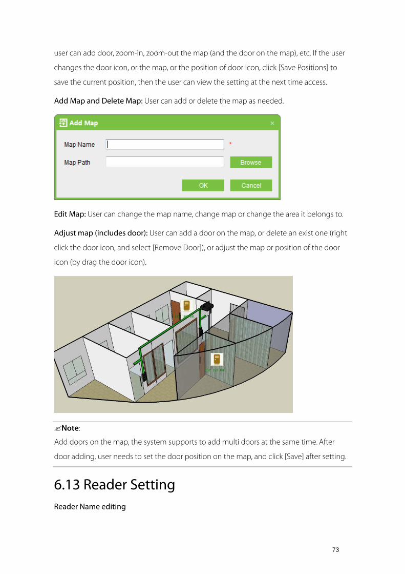
73
user can add door, zoom-in, zoom-out the map (and the door on the map), etc. If the user
changes the door icon, or the map, or the position of door icon, click [Save Positions] to
save the current position, then the user can view the setting at the next time access.
Add Map and Delete Map: User can add or delete the map as needed.
Edit Map: User can change the map name, change map or change the area it belongs to.
Adjust map (includes door): User can add a door on the map, or delete an exist one (right
click the door icon, and select [Remove Door]), or adjust the map or position of the door
icon (by drag the door icon).
Note:
Add doors on the map, the system supports to add multi doors at the same time. After
door adding, user needs to set the door position on the map, and click [Save] after setting.
6.13 Reader Setting Reader Name editing

74
Click [Access Control] > [Reader Setting], choose a reader, click [Edit], then input the reader
name.
Note:
The parameter is not for Standalone SDK Machine, because there is no In/Out state in it.
There are two readers in a door of Controller and Standalone Access Control, representing
in and out state. In Reports and Real-Time Monitoring, the reader names will be displayed
in In/Out Status.
Reader Name Logs
Choose a reader, click , then you can check logs of the reader.
6.14 Auxiliary Setting Auxiliary In/Out name editing
Click [Access Control] > [Auxiliary Setting], choose an auxiliary, click [Edit], then input the
Auxiliary In/Out name.

75
Choose an auxiliary, click , then you can check logs of the auxiliary In/Out name.

76
7. Access Control Reports Includes [Events Today], [Events the latest three days], [Events This week], [Events Last week],
[Exception Events] reports. You can select Export all and Export after query. The user can
generate statistics of relevant device data from access control reports, including card
verification information, door operation information, and normal card punching
information, etc.
About the Normal event and abnormal event please refer to 6.11 Real-time Monitoring for
details.
Note:
Only event records generated when the user uses emergency password to open doors will
include [Only password] verification mode.
7.1 Events Today Click [Reports] > [Events Today], it will displayed following interface, then will show intraday
access control events records.
7.2 Exception Events Click [Reports] > [Exception Events], it will show the access control exception events
records.

77
You can also through put in View the specified conditions access control abnormal events,
such as search "Device Name" to display the relevant exception records as below:
Clear access control exception event records: Clear the list of all access control exception
events.
Real-time door status monitoring: Except to display the electro-map, the system can view
the real-time event monitoring (same data source with door status monitoring, include
alarm sound, etc.).
Door operation: Move the mouse icon to the door position, the system will automatically
filter the operation according to the door status and display them on the popup menu.
User can remote open or close the door, cancel alarm, and etc.
7.3 custom report This function can be combined to view and export.
7.3.1 Add custom report
Click [Reports] > [custom report] > [Add]

78
Check the device information on the left, and move it to right box through key, click【OK】.( mean move left, and mean move all)
7.3.2 Viewing Reports
Click [Reports] > [custom report] > [Viewing Reports]
Set up the search terms, click on the [Viewing Reports] to view the report, click [Export] can
export the report.

79
8. Time & Attendance Please select a door or more in [Access Control] > [Door Setting] before using Time Attendance, or the report will be none.
8.1 System
Click > , the following page is displayed.
Overtime Setting: Set overtime levels 1, 2, and 3 to different lengths of work time and set
whether the weekend overtime is included into the weekday work time if the weekday
work time falls short of the normal work time.
You can set three types of overtime.
The three types of overtime are calculated as follows:
Assume that the values of Time1 to Time6 are specified as follows:
Time1 Time3Time2

80
If an employee's actual daily working hours are greater than time 1 but less than time 2, the
overtime at OT Level 1 is the daily working hours minus time 1. If the actual daily working
hours are greater than time 2, the overtime at OT Level 1 is time 2 minus time 1, and the
overtime at OT Level 2 is the daily working hours minus time 2. The overtime between time
2 and time 3 can be calculated in the same way.
The following example is used to explain how overtime is calculated using the values
specified in the preceding figure.
If an employee works 9 hours a day, he/she has 1-hour overtime (9 minus 8) at OT Level 1. If
the employee works 12 hours one day, he/she has a total of 4-hour overtime, 3-hour
overtime (11 minus 8) at OT Level 1 and 1-hour overtime (12-11) at OT Level 2. If the
employee works 15 hours one day, he/she has a total of 7-hour overtime, 3-hour overtime
(11 minus 8) at OT Level 1, 3-hour overtime (14-11) at OT Level 2, and 1-hour overtime
(15-14) at OT Level 3.
Saturday Counts towards: specifies how the work time on Saturday is calculated. The work
time on Saturday can be included into the normal work time or one of the three types of
overtime, whichever you select.
Sunday Counts towards: specifies how the work time on Sunday is calculated. The work
time on Sunday can be included into the normal work time or one of the three types of
overtime, whichever you select.
Minimum time between two punches: This is the minimum time period (in the unit of
minutes). If two checks are recorded within this time range, only the time of the first check
is recorded in attendance check.
Date And Time Format: Set date and time formats for the system You can select nine types
of date formats in the drop-down box as shown in the following figure. You can select two
types of time formats, as shown in the above figure.
8.2 Setup 8.2.1 Company Management
You need to describe the organizational structure of your company before you manage
staff. You can set the company profile in the Companies menu.

81
Click to access company management.
Step 1: Set general parameters.
Company Code: Is generated by the system automatically.
Company Name: Set the name of your company.
Logo: Select a picture as the logo of your company.
Specify company address information, including parameters such as Address, City, Country,
Fax, Email, State, Postal, Phone, and Website.
Step 2: Set holidays.
The holiday setting facilitates attendance calculation.
Click . The following page is displayed.

82
1. Click to set holidays, as shown in the following figure.
Click , add a holiday, and enter the name of the holiday. After you set all holidays
required, close the Holiday Type Edit window and select a holiday type from the Holiday
Type drop-down list.
2. Set the holiday period.
If you need to select only one date, click a date in the date table and schedule shifts for the
date. If you need to select multiple dates, hold down the Ctrl key and click the dates
required or drag the mouse to select the dates required.

83
3. Set Count Work Time. When employees are present at work during the specified holiday,
select this option and select the mode of salary calculation.
After you set the preceding parameters, click . The added holiday will be
displayed in the left list.
8.2.2 Pay Code
You can define the type of salary payment.
Click . The following page is displayed.
Set all parameters that need to be included in the attendance check summary, such as
Total Work Hours, Regular Hours, overtime1, Late Come, Early Out, absence, and exception.
Each of the parameters has the following settings:
Code: a number automatically assigned by the system to the pay code.
Description: specific description of the pay code.
You can add pay codes and edit or delete user-defined pay codes.

84
8.2.3 Time Period
You can set all time period that may be used in the Time period menu and assign time
period to departments or employees in the Schedule menu. The on-duty time, off-duty
time, and rest time of an employee are determined by the setting of the time period
assigned to the employee.
Click . The following page is displayed.
General
Time Period Name: The name of the time period.
Time Period Start: The time of day employees in this time period are scheduled to begin
work.
Time Period End: The time of day employees in the time period are scheduled to stop
working.
Note:
You can schedule day and night shifts.
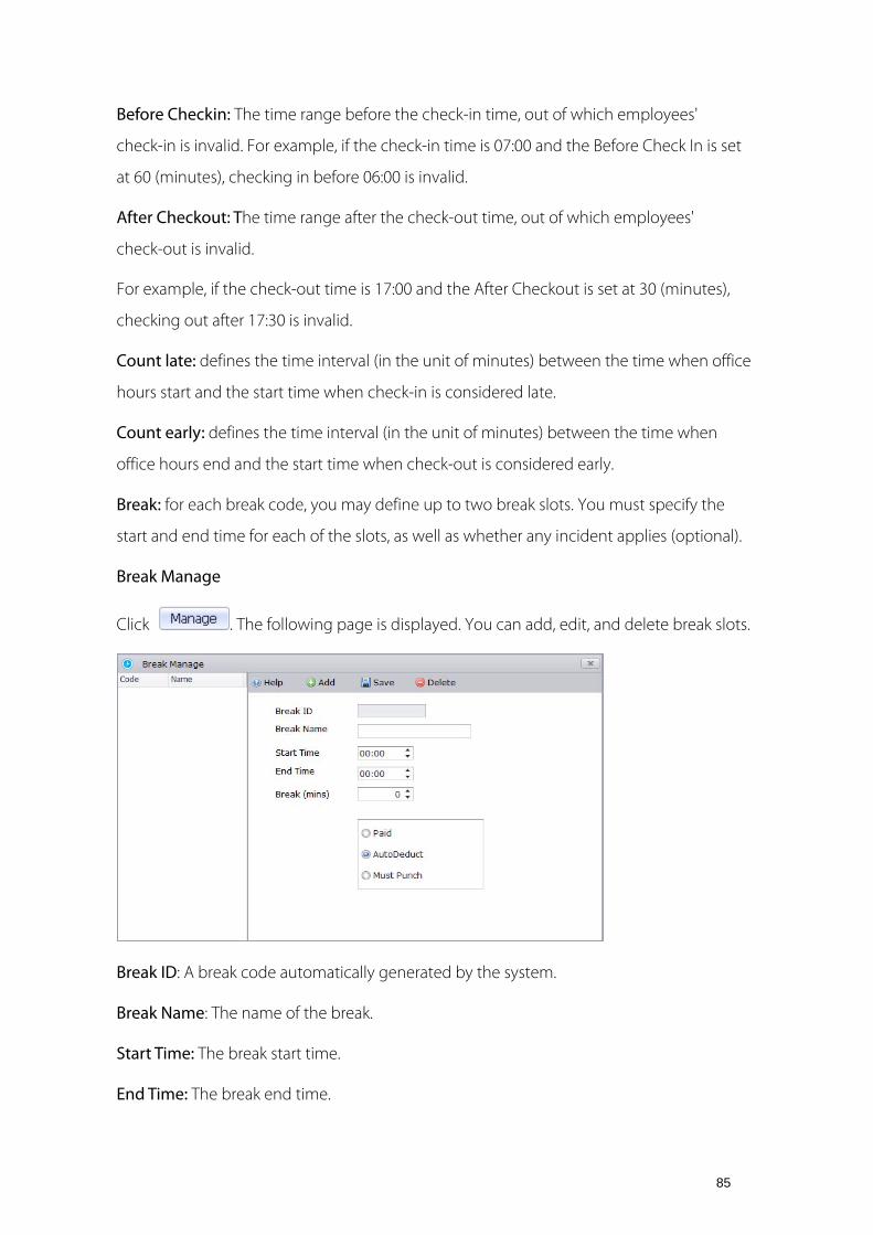
85
Before Checkin: The time range before the check-in time, out of which employees'
check-in is invalid. For example, if the check-in time is 07:00 and the Before Check In is set
at 60 (minutes), checking in before 06:00 is invalid.
After Checkout: The time range after the check-out time, out of which employees'
check-out is invalid.
For example, if the check-out time is 17:00 and the After Checkout is set at 30 (minutes),
checking out after 17:30 is invalid.
Count late: defines the time interval (in the unit of minutes) between the time when office
hours start and the start time when check-in is considered late.
Count early: defines the time interval (in the unit of minutes) between the time when
office hours end and the start time when check-out is considered early.
Break: for each break code, you may define up to two break slots. You must specify the
start and end time for each of the slots, as well as whether any incident applies (optional).
Break Manage
Click . The following page is displayed. You can add, edit, and delete break slots.
Break ID: A break code automatically generated by the system.
Break Name: The name of the break.
Start Time: The break start time.
End Time: The break end time.

86
Break (mins): After you enter time in From and To, the system automatically counts the
break time period.
Paid: The break time belongs to work time regardless of whether you are at work or not
during break.
AutoDeduct: Once the shift type Flexi is selected, it is necessary to set "Minimum Auto
Deduct Time" when you choose AutoDeduct option. If your actual work time is greater
than or equals to the Minimum AutoDeduct Time (your actual work time is the time during
you first check in and last check out ), and your actual break time is less than scheduled
break time, the insufficient break time would still be deducted from your actual work time.
Must Punch: You must punch when the break starts and ends.
Rounding Setting
Rounding
Round Value In/Out: The minimum round-off unit of working hours. As shown in the
previous figure, if the Round To = 10, take 10 minutes as the minimum unit when counting
the working hours.

87
Round Down In/Out: Round up values greater than the Round Down value. Round down
values smaller than or equal to the Round Down value. In and Out correspond to check-in
and check-out respectively.
Round Up In/Out corresponds to Round Down In/out respectively.
Note:
Round Down In/Out + Round Up In/out = Round To. The system allows you to change only
the value of Round Down In/Out and Round To.
Assume that the time period set in the preceding figure are assigned to employees.
If an employee checks in at 08:02 and checks out at 17:55 in this time period mode, the
system rounds down the check-in time as 08:00 and rounds up the check-out time as
18:00. This means the employee is allowed to check in 2 minutes later or check out 5
minutes earlier than the required time.
Round Rule
The number of minutes before the Time period Start Time or after the Time period End
Time in which employees transactions will be treated as if they occurred exactly at the Start
or End times.
Tick Round Rule, click and add a rounding rule, and input corresponding data.
Set an attendance time range on this interface. Start Time Round time End Time is
required. As for any attendance time during this time range, the system records it as the
time in Round Time. Click Add to continue adding Round Time.
For example, enter 07:05 in Round Time, 07:00 in Start Time, and 07:10 in End Time. After
the setting is completed, the system records any attendance time in the range of 07:00 to
07:10 as 07:05.
Note:
Avoid setting Round Time as Time period Start or Time period End. The time range of Start
Time to End Time must be Start Time to End Time < Time period Start or Time period Start
< Start Time to End Time < Time period End or Start Time to End Time > Time period End.
8.2.4 Shift
To schedule shifts, perform the following steps.

88
Step 1: Set the attributes of shift scheduling, including shifts and dates of the shifts and the
use of cyclic shift scheduling.
Step 2: Assign the configured shifts to departments or a single employee.
Specific operations:
Click . The following page is displayed.
Click the date(s) for shift scheduling in the date table and set corresponding parameters on
the right of the date table. Click . Shifts on the selected date(s) are
scheduled. If you need to schedule the same Time Period on multiple dates, hold down the
Ctrl key and click the dates required or drag the mouse to select the dates required.
Shift Name: name of a shift schedule
Pay code: whether to define the type of salary payment.
Time period: Time Period to be scheduled
Cycle Shift: whether cyclic shift scheduling is required. If an employee's work time repeats
in a cycle, you can click to set the time of the cycle.

89
Start Date: Set the start date of the cycle.
Cycle Type and Cycles: Set the type of the cycle, which can be set to daily or weekly.
Assign shifts to departments or employees.
Click . The following page is displayed.
Select the departments or a single employee to which shifts will be assigned and click
[Save].
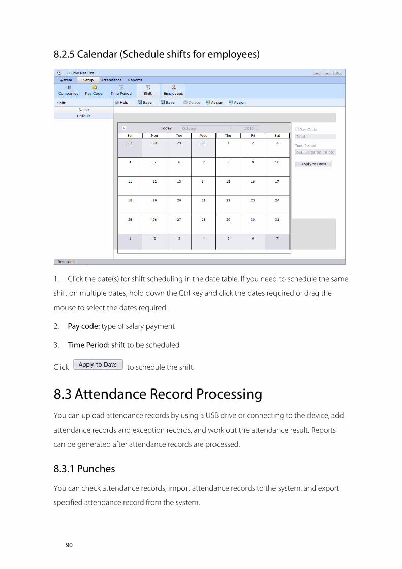
90
8.2.5 Calendar (Schedule shifts for employees)
1. Click the date(s) for shift scheduling in the date table. If you need to schedule the same
shift on multiple dates, hold down the Ctrl key and click the dates required or drag the
mouse to select the dates required.
2. Pay code: type of salary payment
3. Time Period: shift to be scheduled
Click to schedule the shift.
8.3 Attendance Record Processing You can upload attendance records by using a USB drive or connecting to the device, add
attendance records and exception records, and work out the attendance result. Reports
can be generated after attendance records are processed.
8.3.1 Punches
You can check attendance records, import attendance records to the system, and export
specified attendance record from the system.

91
Click . The following page is displayed.
Step 1: Select an employee in the left list, whose attendance records you need to export.
Step 2: Specify the start date and end date of the attendance records to be exported from
the Start Time and End Time drop-down lists.
Step 3: Click . All attendance records of the selected employee maintained
during the specified period will be displayed in the list below.
Step 4: Click [Export].
If you need to import attendance records, click [Import]. You can only import attendance
records from the local computer.

92
You can import attendance records in the MS Excel, Text File, and CSV File formats. Select a
format and the file to be imported. Click [Next] and wait until the file is imported
successfully.
8.3.2 Exceptions Assign
You can set exceptions (such as sick leave and vacation) during normal workdays for
employees.
Click . The following page is displayed.

93
Step 1: Select an employee in the left list, for whom you need to set an exception.
Step 2: Select a date in the calendar, to which the exception will be assigned.
Step 3: Specify Pay Code, Start time, and End time above the calendar and click
.
8.4 Report Processing You can generate, print, and export different types of reports (including employee
information, attendance records, and salaries) in the Reports Menu. You can also generate a
report for the specified employee and work out the attendance result of the employee
during the specified period.
8.4.1 Attendance Calculation
You can work out the attendance result after you have downloaded, modified, and
supplemented attendance records.
Click . The following page is displayed.

94
Step 1: Select an employee in the left list, for whom you need to work out the attendance
result.
Step 2: Select the date when you will perform attendance calculation from the Date
drop-down list.
Step 3: Click if you need to supplement the attendance records of some
employees.

95
1) Select an employee in the left list, for whom you need to add attendance records, and
click [Add].
2) Specify the date and time of adding attendance records, work code and work state of
the employee, and reason for adding attendance records. Click [Save].
Step 4: Click after you have set the preceding information. The result of
attendance calculation will be displayed in the list below.
8.4.2 Attendance Report
Click , the following page is displayed.
Report template: There are 11 types of report templates, which are Transactions Report,
Daily Totals Report, Time Card Report, Total Time Card Report, Early Out Report, Late Come
Report, Absence Report, Employee Shift Report, Exception Report, Hours Summary Report,
and Time Card List Report.
Title: Set the title of the report. The default title is the title of the report template.
From/To Date: Select the start date and end date of the report.
Filter: Select the range of employees to be displayed in the report.

96
After you set the preceding information, click [Save]. You can click to check the
report.
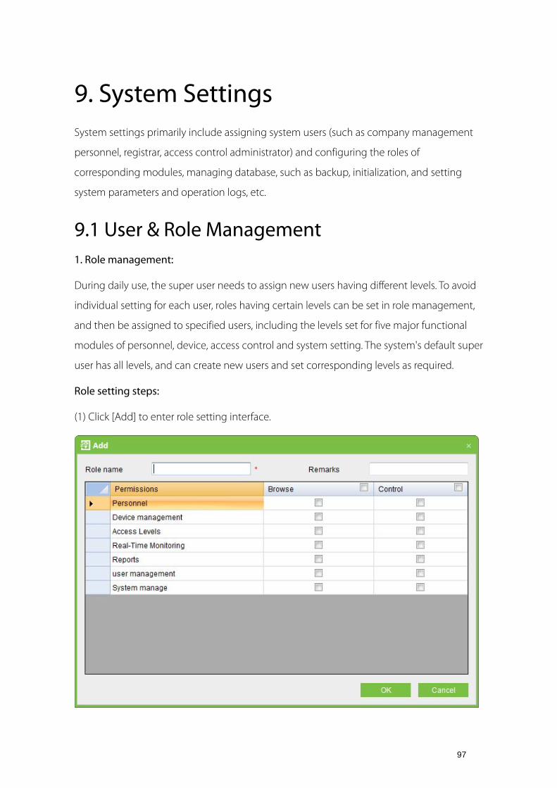
97
9. System Settings System settings primarily include assigning system users (such as company management
personnel, registrar, access control administrator) and configuring the roles of
corresponding modules, managing database, such as backup, initialization, and setting
system parameters and operation logs, etc.
9.1 User & Role Management 1. Role management:
During daily use, the super user needs to assign new users having different levels. To avoid
individual setting for each user, roles having certain levels can be set in role management,
and then be assigned to specified users, including the levels set for five major functional
modules of personnel, device, access control and system setting. The system's default super
user has all levels, and can create new users and set corresponding levels as required.
Role setting steps:
(1) Click [Add] to enter role setting interface.

98
(2) Set role name, select your desired role setting item, and tick levels to be configured for
users of different levels.
(3) After setting, click [OK] to save and return to the list, and added role settings will be
shown in the list.
2. User management:
Add new users to the system, and assign user roles (levels).
Add user:
1. Click [Add], enter new user information, where items with [*] are mandatory. The
parameters are as follows:
Username: Not more than 50 characters, only using letters, numbers or characters.
Password: The length must be more than 4 digits and less than 18 digits. The default
password is 111111.
Staff Status: Indicates if this user can access the administrator site.
Role: Non-super user needs to select a role. By selecting a preset role configuration, this
user will have the levels configured for the role.
2. After editing, click [OK] to complete user adding, and the user will be shown in the list.
To modify existing user, click [Edit] behind the user name, and enter edit interface. After
modification, click [OK] to save and return.
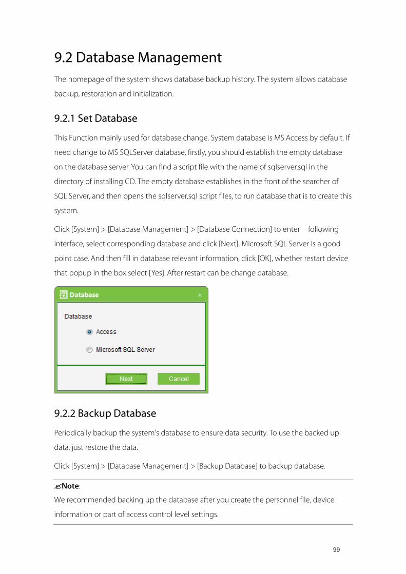
99
9.2 Database Management The homepage of the system shows database backup history. The system allows database
backup, restoration and initialization.
9.2.1 Set Database
This Function mainly used for database change. System database is MS Access by default. If
need change to MS SQLServer database, firstly, you should establish the empty database
on the database server. You can find a script file with the name of sqlserver.sql in the
directory of installing CD. The empty database establishes in the front of the searcher of
SQL Server, and then opens the sqlserver.sql script files, to run database that is to create this
system.
Click [System] > [Database Management] > [Database Connection] to enter following
interface, select corresponding database and click [Next], Microsoft SQL Server is a good
point case. And then fill in database relevant information, click [OK], whether restart device
that popup in the box select [Yes]. After restart can be change database.
9.2.2 Backup Database
Periodically backup the system's database to ensure data security. To use the backed up
data, just restore the data.
Click [System] > [Database Management] > [Backup Database] to backup database.
Note:
We recommended backing up the database after you create the personnel file, device
information or part of access control level settings.

100
9.2.3 Restore Database
Click [System] > [Database Management] > [Restore Databases], [Open] to select a
successfully backed up database from the backup database list. In the pop-up Windows,
click [Yes], system can be restart, it begin database restoration in process.
Note:
Don't close any command window prompt during the database restore process.
9.2.4 Database Backup Path Configuration
Click [System] > [Database Management] > [Database Backup Path Set], the edit interface
appears:
Click [Browse] to select the backup path, click [Save] to save the selection and quit.
Note:
(1) In system installation process, it will prompt to set the database backup path. If you haven't
set the backup path, the operation of backup database can't be executed (The server for
other computer to access, need to set the backup path in the server firstly).
(2) Proposal that the database backup path and the present system installed path not be
under the same disk. Don't set the path to the root of a disk or desktop.
9.3 Initialize Database Initialize database is to restore data to system initialization status. Initialized data in the
database will be deleted. Please operate with care.
Click [System] > [System Initialization], enter into edit interface, select one or several
data-sheets to initialize, and click [OK] to complete initialization and return.

101
For example:
Select to initialize access level: After selection, it will initialize access control time periods,
access control holidays and access levels. All contents on these three pages will restore
initial status.
Select to initialize Person: After selection, it will initialize data of Department, Personnel,
Issue Card, and only reserve system default settings.
Select to initialize Device: After selection, it will initialize all device information in the
system (including access control). If the device is an access control panel, corresponding
device parameters and door information will be deleted.
Select to initialize Access Control: After selection, it will initialize Interlock, Anti-passback,
Linkage settings, First-Card Normal Open and Multi-Card Opening (including Multi-Card
Opening Personnel Group Setting), Access Control Time Zones, Holidays and Access levels.
All data will be restoring initial state.
Select to initialize System: After selection, it will initialize Role, User etc., and only reserve
system default settings.
Select to initialize Report: After selection, it will initialize all events records.
Note:
If the device is still in normal use, please initialize database cautiously, especially when
involving access level-related departments and personnel, access levels, door settings,

102
areas, devices, users and roles. It is recommended that if there are still devices in use after
database initialization, the user shall [Synchronize all data] for the setting to avoid
unexpected errors.
9.4 System Parameter Setting Click [System] > [System Parameter Setting], it will show the interface as below. The user
can free fixed time for new entries. Besides, you can set time of reconnect and set the font.

103
10. Appendixes
Appendix 1 Common Operation 1. Select date
Click [Access Control] > [Holidays] > [Add] to enter edit interface:
Defaults to the current date, if needs to change it, refer to the following steps.
Select the year. Click ( if the span is longer, click it double or three times),
then click or button to select the year you need.
Select the month. Click or button to select the month you need
Click the desired date.
Also you can directly to edit Year, Month and Date in editing box.
2. Import (taking importing personnel table as an example):
If there is an electronic personnel file, which may be the information of the personnel or
access control, attendance or human resources system of another brand, you can import it

104
into this system through the [Import] function.
(1) Click [Import] to show the import edit interface:
Description of items:
Import file: Click [Browse] to select the file to be imported.
File format: Select the format of the file to be imported.
Choosing corresponding import field, means select all, means single selection,
means cancel the mouse options, and means deselect all.
Note:
When importing personnel table, if there is no personnel number or personnel number is
"0", the import operation can't execute. If you need import the personnel gender, please
use "M" represent male and "F" represent female, then execute import operation.
3. Export data (taking exporting Device as an example):
(1) Click [Device] > [Device], and tick up a device, then right click [export] to show the
interface:
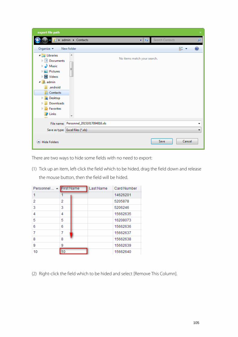
105
There are two ways to hide some fields with no need to export:
(1) Tick up an item, left-click the field which to be hided, drag the field down and release
the mouse button, then the field will be hided.
(2) Right-click the field which to be hided and select [Remove This Column].

106
Note:
If need to show the hidden field, can put the mouse on the list head, right-click select
[Column Chooser] in popup menu, it will display "customization field box" at interface lower
right corner, and drag reductive field to the list head.
(3) Selects the format of exported file: If PDF format is selected there will be no file code

107
option (namely, there is no difference between Simplified and Traditional Chinese). Click
[Export] to directly show the exported file.
If TXT or EXCEL format is selected, then file codes include Simplified and Traditional Chinese,
but Traditional Chinese code can be completely exported only in the operating system in
Traditional Chinese. The system prompts Open or Save.
Note:
When importing department table, exported table is the list currently shown.
4.The use of data list (taking Personnel as an example)
right-click the list top,and choose[Hide Group By Box]
The column will (Group) drag to [Drag a coumn header here to group by that column], as
shown below:

108
Then as shown below
Also can put mouse to icon at list head, the icon will turn into , and then click ,
select [Custom], according to the conditions for search operation as following:
Fill in the corresponding inquires can search relevant conditions. Also can put mouse to list
head, right-click and popup the menu as below, and then process Sort Ascending, Sort
Descending, Group By This Column function etc,.

109
Appendix 2 Real-Time Event Description Normal Events
Normal Punch Open: In [Card Only] verification mode, the person has open door
permission punch the card and trigger this normal event of open the door.
Press Fingerprint Open: In [Fingerprint Only] or [Card plus Fingerprint] verification mode,
the person has the open permission, press the fingerprint at the valid time period, and the
door is opened, and triggers the normal event.
Exit button Open: User press the exit button to open the door within the door valid time
zone, and trigger this normal event.
Punch during Normal Open Time Zone: At the normally open period (set to normally
open period of a single door or the door open period after the first card normally open), or
through the remote normal open operation, the person has open door permission punch
the effective card at the opened door to trigger this normal events.
First Card Normal Open (Punch Card): In [Card Only] verification mode, the person has first
card normally open permission, punch card at the setting first card normally open period
but the door is not opened, and trigger the normal event.
Normal Open Time Zone Over: After the setting normal open time zone, the door will
close automatically. The normal open time zone include the normal open time zone in

110
door setting and the selected normal open time zone in first card setting.
Remote Normal Opening: Set the door state to normal open in the remote opening
operation, and trigger this normal event.
Disable Intraday Normal Open Time Zone: In door normal open state, punch the effective
card for five times near to the card reader (must be the same user), or select [Disable
Intraday Normal Open Time Zone] in remote closing operation, and trigger this normal
event.
Enable Intraday Normal Open Time Zone: If the intraday door normal open time zone is
disabled, punch the effective card for five times near to the card reader (must be the same
user), or select [Enable Intraday Normal Open Time Zone] in remote opening operation,
and trigger this normal event.
Multi-Card Open: In [Card Only] verification mode, multi-card combination can be used to
open the door. After the last card plus fingerprint verified, the system trigger this normal
event.
Emergency Password Open: The password (also known as the super password) set for the
current door can be used for door open. It will trigger this normal event after the
emergency password verified.
Open during Normal Open Time Zone: If the current door is set a normally open period,
the door will open automatically after the setting start time, and trigger this normal event.
Linkage Event Triggered: After the system linkage configuration take effect, trigger this
normal event.
Cancel Alarm: When the user cancel the alarm of the corresponding door, and the
operation is success, trigger this normal event.
Remote Opening: When the user opens a door from remote and the operation is
successful, it will trigger this normal event.
Remote Closing: When the user closes a door from remote and the operation is successful,
it will trigger this normal event.
Open Auxiliary Output: In linkage action setting, if the user selects Auxiliary Output for
Output Point Address, select Open for Action Type, it will trigger this normal event when

111
the linkage setting is take effect.
Close Auxiliary Output: In linkage action setting, if the user selects Auxiliary Output for
Output Point Address, select Open for Action Type, it will trigger this normal event when
the linkage setting is take effect. And if the user closes the opened auxiliary output through
the [Close Auxiliary Output] operation in [Door Setting], trigger this normal event too.
Door Opened Correctly: When the door sensor detects that the door has been properly
opened, triggering this normal event.
Door Closed Correctly: When the door sensor detects that the door has been properly
closed, triggering this normal event.
Auxiliary Input Disconnected: When the auxiliary input point disconnected, trigger this
normal event.
Auxiliary Input Shorted: When the auxiliary input point short circuit, trigger this normal
event.
Device Start: When the device start triggers this normal event, and this event cannot
display on the real-time monitor, but you can check it in the event report.
Abnormal Events
Too Short Punch Interval: When the interval between two card punching is less than the
set time interval, trigger this abnormal event.
Door Inactive Time Zone (Punch Card): In [Card Only] verification mode, the user has the
door open permission, punch card but not at the door effective period of time, and trigger
this abnormal event.
Door Inactive Time Zone (Exit Button): The user has the door open permission, punch
card but not at the access effective period of time, and trigger this abnormal event.
Illegal Time Zone: The user with the permission of opening the current door, punches the
card during the invalid time zone, and triggers this abnormal event.
Access Denied: The registered card without the access permission of the current door,
punch to open the door, trigger this abnormal event.
Anti-Passback: When the anti-pass back setting of the system takes effect, triggers this

112
abnormal event.
Interlock: When the interlocking rules of the system take effect, trigger this abnormal
event.
Multi-Card Authentication (Punching Card): Use multi-card combination to open the door,
the card verification before the last one (whether verified or not), trigger this normal event.
Multi-Card Authentication (Punching Card): Use multi-card combination to open the door,
the card verification before the last one (whether verified or not), trigger this normal event.
Unregistered Card: Refers to the current card is not registered in the system, trigger this
abnormal event.
Opening Timeout: The door sensor detect that it is expired the delay time after opened, if
not close the door, trigger this abnormal event.
Card Expired: The person with the door access permission, punch card to open the door
after the effective time of the access control, cannot be verified and will trigger this
abnormal event.
Password Error: Use card plus password, duress password or emergency password to open
the door, trigger this event if the password is wrong.
Failed to Close during Normal Open Time Zone: The current door is in normal open state,
but the user cannot close the door through [Remote Closing] operation, and trigger this
abnormal event.
Appendix 3 <END-USER LICENSE AGREEMENT> Important - read carefully:
This End-User License Agreement ("EULA") is a legal agreement between you (either an
individual or a single entity) and the mentioned author of this Software for the software
product identified above, which includes computer software and may include associated
media, printed materials, and "online" or electronic documentation ("SOFTWARE
PRODUCT"). By installing, copying, or otherwise using the SOFTWARE PRODUCT, you agree
to be bound by the terms of this EULA. If you do not agree to the terms of this EULA, do
not install or use the SOFTWARE PRODUCT.

113
SOFTWARE PRODUCT LICENSE
The SOFTWARE PRODUCT is protected by copyright laws and international copyright
treaties, as well as other intellectual property laws and treaties. The SOFTWARE PRODUCT is
licensed, not sold.
1. GRANT OF LICENSE. This EULA grants you the following rights: Installation and Use. You
may install and use an unlimited number of copies of the SOFTWARE PRODUCT.
Reproduction and Distribution. You may reproduce and distribute an unlimited number of
copies of the SOFTWARE PRODUCT; Provided that each copy shall be a true and complete
copy, including all copyright and trademark notices, and shall be accompanied by a copy
of this EULA. Copies of the SOFTWARE PRODUCT may be distributed as a standalone
product or included with your own product.
2. DESCRIPTION OF OTHER RIGHTS AND LIMITATIONS.
Limitations on Reverse Engineering, Recompilation, and Disassembly. You may not reverse
engineer, decompile, or disassemble the SOFTWARE PRODUCT, except and only to the
extent that such activity is expressly permitted by applicable law notwithstanding this
limitation.
Separation of Components.
The SOFTWARE PRODUCT is licensed as a single product. Its component parts may not be
separated for use on more than one computer.
Software Transfer.
You may permanently transfer all of your rights under this EULA, provided the recipient
agrees to the terms of this EULA.
Termination.
Without prejudice to any other rights, the Author of this Software may terminate this EULA
if you fail to comply with the terms and conditions of this EULA. In such event, you must
destroy all copies of the SOFTWARE PRODUCT and all of its component parts.
Distribution.
The SOFTWARE PRODUCT may not be sold or be included in a product or package which
intends to receive benefits through the inclusion of the SOFTWARE PRODUCT. The

114
SOFTWARE PRODUCT may be included in any free or non-profit packages or products.
3. COPYRIGHT.
All title and copyrights in and to the SOFTWARE PRODUCT(including but not limited to any
images, photographs, animations, video, audio, music, text, and "applets" incorporated into
the SOFTWARE PRODUCT), the accompanying printed materials, and any copies of the
SOFTWARE PRODUCT are owned by the Author of this Software. The SOFTWARE PRODUCT
is protected by copyright laws and international treaty provisions. Therefore, you must treat
the SOFTWARE PRODUCT like any other copyrighted material except that you may install
the SOFTWARE PRODUCT on a single computer provided you keep the original solely for
backup or archival purposes.
LIMITED WARRANTY
NO WARRANTIES.
The Author of this Software expressly disclaims any warranty for the SOFTWARE PRODUCT.
The SOFTWARE PRODUCT and any related documentation is provided "as is" without
warranty of any kind, either express or implied, including, without limitation, the implied
warranties or merchantability, fitness for a particular purpose, or no infringement. The
entire risk arising out of use or performance of the SOFTWARE PRODUCT remains with you.
NO LIABILITY FOR DAMAGES.
In no event shall the author of this Software be liable for any damages whatsoever
(including, without limitation, damages for loss of business profits, business interruption,
loss of business information, or any other pecuniary loss) arising out of the use of or
inability to use this product, even if the Author of this Software has been advised of the
possibility of such damages.
If YOU ACCEPT the terms of this Agreement:
I acknowledge and understand that by ACCEPTING the terms of this Agreement.
IF YOU DO NOT ACCEPT the terms of this Agreement.
I acknowledge and understand that by refusing to accept these terms, I have rejected this
license agreement and therefore have no legal right to install, use, or copy this Product or
the Licensed Software that it incorporates.

115
Appendix 4 FAQs Q: How to use a card issuer?
A: Connect the card issuer to PC through USB port, and then select individual personnel
card issue or batch card issue. Move the cursor to the card number input box, and punch
the card on the card issuer, then the card number will be automatically shown in the input
box.
Q: What is the use of role setting?
A: Role setting has the following uses:
1. To set unified level for the same type of users newly added, just directly select this role
when adding users.
2. When setting system reminder, and determine which roles can be viewed.
Q: How to operate if I want to set accounts for all personnel of the Company's Financial
Department?
A: First, create a new role in system setting and configure the functions to be used for this
role. Then add a user, set user information, and select the user's role, thus adding a new
account. For other accounts, do the same.
Q: What is the use of blacklist?
A: A blacklisted personnel cannot achieve departure restoration, namely, this person cannot
be employed by the Company any longer. To modify, just modify departure information on
the departure interface.
Q: How to adjust the department of a person?
A: There are the following ways to adjust personnel department:
1. In personnel list, click personnel number or click "Edit" menu to show personnel details,
and modify personnel department in the department item.
2. In personnel list, check the personnel requiring department adjustment, click "Adjust
department", and a dialog box will open, then modify the department.
3. On personnel transfer interface, click Add to open the edit interface, select personnel,
and check department in the transfer field, and complete other information, thus

116
completing transfer.
Q: How to set access levels for visitors?
A: Setting access levels is as follows:
1. In the system, add these personnel, and enter relevant information.
2. Select access levels suitable for them. If there are no suitable levels, it is required to enter
the access control system to add relevant settings.
3. Set valid time, namely, the start and end dates when they need to use access levels.
Q: What are the ways to cancel personnel access control settings?
A: There are the following ways to cancel personnel access control settings:
1. Close access control only: In the personnel list, click personnel number or click "Edit"
menu to show personnel details, and delete access levels and Personnel Group of
Multi-Card Verification in access control settings.
2. Delete personnel: In the personnel list, tick the personnel and click "Delete" to delete this
person from the system. Corresponding access control information will be deleted.
3. In "Personnel access levels settings", delete access levels of personnel, and in "Personnel
Group of Multi-Card Verification", delete Multi-Card Opening levels.
Appendix 5 Wiegand Defined Wiegand format:
Denotes the built-in defined format in the system, do not need user specifies total length
and the each site information. It has 9 formats in the defined format drop-down column.
For details, please operate the Access3.5 software system.
[Wiegand Protocol]
Wiegand26 is an access control standard protocol established by the Access Control
Standard Subcommittee affiliated to the Security Industry Association (SIA). It is a
non-contact IC card reader interface and output protocol.
Wiegand26 defines the interface between the card reader and controller used in the access
control, security and other related industrial fields. Wiegand26 helps standardize the work

117
of the card reader designers and controller manufacturers. The device is also designed in
compliance with Wiegand26.
Digital Signals
Figure 1 is a sequence diagram in which the card reader sends digital signals in bit format
to the access controller. In this sequence diagram, Wiegand follows the SIA's access control
standard protocol for the 26-bit Wiegand card reader (one pulse time ranges between 20us
and 100us, and the pulse jump time ranges between 200us and 20ms). Data1 and Data0
are high level (larger than Voh) signals till the card reader prepares to send a data stream.
The asynchronous low-level pulse (smaller than Vol) generated by the card reader is sent to
the access control panel (The saw-tooth wave as shown in Figure 1) through Data1 or
Data0. Data1 and Data0 pulses will neither overlap nor be generated synchronously. Table 1
lists the maximum and minimum pulse widths (a consecutive pulse) and pulse jump time
(time between pulses) allowed by the F series fingerprint access control terminal.
Table 1 Pulse Time
Symbol Definition Typical Value of Reader
Tpw Pulse Width 100 μs
Tpi Pulse Interval 1 ms
Figure 1 Sequence Diagram
26-Bit Wiegand Format
The composition of the open de facto 26 Bit Weigand industry standard contains 8 bits for
the facility code and 16 bits for the ID number field. Mathematically, these 8 facility codes
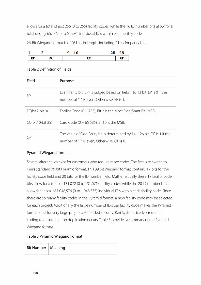
118
allows for a total of just 256 (0 to 255) facility codes, while the 16 ID number bits allow for a
total of only 65,536 (0 to 65,536) individual ID's within each facility code.
26-Bit Wiegand format is of 26 bits in length, including 2 bits for parity bits.
Table 2 Definition of Fields
Field Purpose
EP Even Parity bit (EP) is judged based on field 1 to 13 bit. EP is 0 if the
number of "1" is even; Otherwise, EP is 1.
FC(bit2-bit 9) Facility Code (0 ~ 255); Bit 2 is the Most Significant Bit (MSB).
CC(bit10-bit 25) Card Code (0 ~ 65 535). Bit10 is the MSB.
OP The value of Odd Parity bit is determined by 14 ~ 26 bit. OP is 1 if the
number of "1" is even; Otherwise, OP is 0.
Pyramid Wiegand format
Several alternatives exist for customers who require more codes. The first is to switch to
Keri's standard 39 bit Pyramid format. This 39 bit Wiegand format contains 17 bits for the
facility code field and 20 bits for the ID number field. Mathematically these 17 facility code
bits allow for a total of 131,072 (0 to 131,071) facility codes, while the 20 ID number bits
allow for a total of 1,048,576 (0 to 1,048,575) individual ID's within each facility code. Since
there are so many facility codes in the Pyramid format, a new facility code may be selected
for each project. Additionally the large number of ID's per facility code makes the Pyramid
format ideal for very large projects. For added security, Keri Systems tracks credential
coding to ensure that no duplication occurs. Table 3 provides a summary of the Pyramid
Wiegand format.
Table 3 Pyramid Wiegand Format
Bit Number Meaning

119
Bit 1 Even parity over bits 2 to 9
Bits 2 to 18 Facility code (0 to 131,071); Bit 2 is MSB
Bits 19 to 38 ID Number (0 to 1,048,575); Bit 19 is MSB
Bit 39 Odd parity over bits 20 to 38
Custom Wiegand Formats
The second alternative is to create a custom Wiegand format. Typically, up to 64 bits are
available for creating a custom Wiegand format. With certain limitations, formats with greater
than 64 bits may be created. If a customer currently has a custom Wiegand format from
Wiegand or from other proximity manufacturers, Keri can normally match that format.
Although the customer is primarily responsible for custom format card coding, as an added
benefit Keri Systems tracks card coding for additional security. Table 4 provides an example of
one possible custom Wiegand format.
Table 4 Example of a Custom Wiegand Format
Bit Number Purpose
Bit 1 Even parity over bits 2 to 22
Bits 2 to 9 OEM code (0 to 255); Bit 2 is MSB
Bits 10 to 21 Facility code (0 to 4,096); Bit 10 is MSB
Bits 22 to 43 ID Number (0 to 524,287); Bit 22 is MSB
Bit 44 Even parity over bits 23 to 43
Related Documents


