Zimmer ® NexGen ® Rotating Hinge Knee Primary/ Revision Surgical Technique Designed for use in revision and difficult primary surgeries

Welcome message from author
This document is posted to help you gain knowledge. Please leave a comment to let me know what you think about it! Share it to your friends and learn new things together.
Transcript
Zimmer®
NexGen® Rotating Hinge Knee Primary/
Revision Surgical Technique
Designed for use in revision and difficult primary surgeries

MU
LTI-
RE
FER
EN
CE
4-in
-11
MU
LTI-
RE
FER
EN
CE
4-in
-1
2
MU
LTI-
RE
FER
EN
CE
4-in
-1
3
MU
LTI-
RE
FER
EN
CE
4-in
-1
4
MU
LTI-
RE
FER
EN
CE
4-in
-1
5
1
INTRODUCTIONThe NexGen Rotating Hinge Knee Compo-nents are designed for use in revision and diffi cult primary surgeries. Although most Ro-tating Hinge Knee surgeries involve revision arthroplasty, this document provides options for both primary and revision techniques.
Critical to achieving a successful revision surgery is the development of effi cient and accurate instrumentation combined with ef-fective surgical techniques. The main body of this document explains the use of the NexGen Revision Instruments for a Rotating Hinge re-vision procedure. This technique is followed by appendices that provide additional information about issues relating to revision knee arthroplasty, and describe some of the many surgical technique and instrumentation options available for both primary and revision Rotating Hinge Knee arthroplasty.
The Chart on the preceding page is designed to assist in selecting a surgical approach that is based upon:
• The surgical situation (primary or revision),
• The type of instrumentation selected (Femoral Stem Base, Milling/5-in-1, or crossover from other NexGen techniques),
• The selection of either a Straight or Offset stem extension for use with the femoral component.
This device is indicated for use with bone cement.
These surgical techniques were developed in conjunction with:
James D. Bruckner, M.D. Associate Professor University of Washington Medical Center Seattle, WA
Ernest U. Conrad III, M.D., F.A.C.S. Professor & Director of Orthopaedic Services University of Washington Medical Center Seattle, WA
Doug Letson, M.D. Assistant Professor of Oncology H. Lee Moffi tt Cancer Center & Research Institute Tampa, FL
Hans Wolfram Neumann, Professor, M.D. Director of Orthopaedics Otto-von-Guericke University Magdeburg, Germany
Martin Sparmann, Professor, M.D. Director of Immanuael Hospital Teaching Hospital of Free University Berlin, Germany
Luke M. Vaughan, M.D. Head Section of Tuner Surgery Scripps Clinic Clinical Associate Professor of Orthopaedics UCSD School of Medicine La Jolla, CA
Peter S. Walker, Ph.D. Director of Biomedical Engineering Cooper Union Research Foundation New York, NY
Russell Windsor, M.D. Attending Orthopaedic Surgeon Hospital for Special Surgery
2
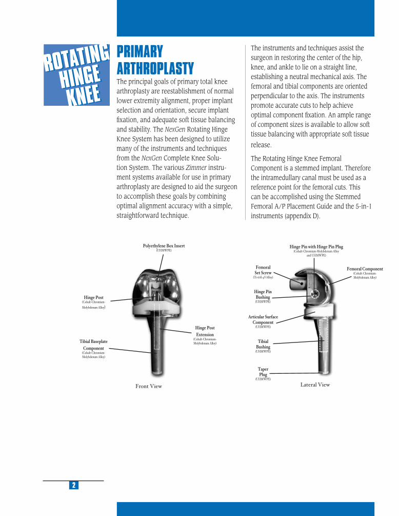
PRIMARY ARTHROPLASTY The principal goals of primary total knee arthroplasty are reestablishment of normal lower extremity alignment, proper implant selection and orientation, secure implant fi xation, and adequate soft tissue balancing and stability. The NexGen Rotating Hinge Knee System has been designed to utilize many of the instruments and techniques from the NexGen Complete Knee Solu-tion System. The various Zimmer instru-ment systems available for use in primary arthroplasty are designed to aid the surgeon to accomplish these goals by combining optimal alignment accuracy with a simple, straightforward technique.
The instruments and techniques assist the surgeon in restoring the center of the hip, knee, and ankle to lie on a straight line, establishing a neutral mechanical axis. The femoral and tibial components are oriented perpendicular to the axis. The instruments promote accurate cuts to help achieve optimal component fi xation. An ample range of component sizes is available to allow soft tissue balancing with appropriate soft tissue
release.
The Rotating Hinge Knee Femoral Component is a stemmed implant. Therefore the intramedullary canal must be used as a reference point for the femoral cuts. This can be accomplished using the Stemmed Femoral A/P Placement Guide and the 5-in-1 instruments (appendix D).
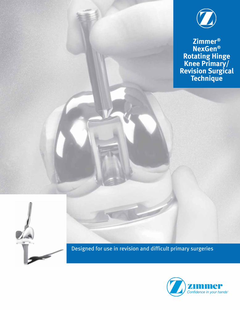
Front View Lateral View
Polyethylene Box Insert(UHMWPE)
Hinge Post(Cobalt-Chromium-
Molybdenum Alloy)
Tibial BaseplateComponent
(Cobalt-Chromium-Molybdenum Alloy)
Hinge PostExtension
(Cobalt-Chromium-Molybdenum Alloy)
FemoralSet Screw
(Ti-6Al-4VAlloy)
Hinge PinBushing(UHMWPE)
Articular SurfaceComponent
(UHMWPE)
TibialBushing(UHMWPE)
TaperPlug
(UHMWPE)
Hinge Pin with Hinge Pin Plug(Cobalt-Chromium-Molybdenum Alloy
and UHMWPE)
Femoral Component(Cobalt-Chromium-Molybdenum Alloy)
MU
LTI-
RE
FER
EN
CE
4-in
-11
MU
LTI-
RE
FER
EN
CE
4-in
-1
2
MU
LTI-
RE
FER
EN
CE
4-in
-1
3
MU
LTI-
RE
FER
EN
CE
4-in
-1
4
MU
LTI-
RE
FER
EN
CE
4-in
-1
5
REVISION ARTHROPLASTY Revision total knee arthroplasty, in particular, can be a very challenging task for any orthopaedic surgeon. Failure of a primary arthroplasty may have many causes, including wear, aseptic loosening, infection, osteolysis, ligamentous instability, and patellofemoral complications. One of the most important requirements in revision knee surgery is to identify the exact failure mode of the preceding arthroplasty. If this is not clearly understood, the revision may be less likely to succeed. A common reason for failure in a revision total knee arthroplasty is to repeat errors that occurred at the previous TKA.
In approaching revision procedures, the surgeon must consider the planning of the incision over a previously operated site, the condition of the soft tissue, the functionality of the extensor mechanism, the extraction of the primary prosthesis, and the preserva-tion of bone stock. The primary goals of a revision procedure include the restoration of anatomical alignment and functional stability, the fi xation of the revision implants, and the accurate reestablishment of the joint line.
When using the NexGen Revision Instru-ments, the specifi c objectives of a revision procedure are:
1. Establish Tibial PlatformThe fi rst goal is to establish a prosthetic platform on solid existing tibial bone stock. This will provide a reference plane for evaluating the fl exion and extension gaps.
2. Stabilize Knee in FlexionNext, the femoral component size that will stabilize the knee in fl exion is chosen and, if needed, augmentation to fi t the femoral condylar bone stock is determined.
3. Stabilize Knee in ExtensionAn acceptable position for the joint line is estimated. This will aid in the deter-mination of the proper articulating surface thickness, distal femoral position, and femo-ral size that will stabilize the knee in extension.
4. Determine Patellofemoral FunctionOnce the gaps have been balanced, the proper position of the joint line needs to be considered. If the joint line has been signifi cantly raised or lowered, patellofemoral problems can be encountered. It may be advisable to consider changing femoral component size and distal/posterior augment selections to optimize patellofemoral function.
3

IMPLANT DESIGN RATIONALEThe Rotating Hinge Knee is intended for use in patients who, in the surgeon’s judgement, require additional prosthetic stabilization due to signifi cant bone loss and/or ligament defi ciencies. The prosthesis is constrained in both the medial/lateral and anterior/poste-rior directions, but allows fl exion/extension and rotation between the femoral and tibial components.
The implant design differs from the traditional hinged prosthesis in that the majority of the weight-bearing function is borne by the con-dyles rather than passing directly through the hinge. This provides a more natural articula-tion that reduces the weight-bearing loads on the hinge mechanism. The femoral component condyles maintain contact across the tibial articular surface throughout the full range of motion. The highly dished articular surface allows the load to be transferred over a large area of contact.
The tibial base plate has a double-capture articu-lar surface locking mechanism to help prevent anteroposterior lift-off and spin out of the articu-lar surface. The rotating platform feature of the component allows 25 degrees of movement in internal and external rotation (50 degrees total). The rotation of the articular surface is limited by a stop on the tibial base plate.
The femoral and tibial components are not locked together, but are held in place by the hinge post extension that extends from the femoral component through the polyethylene articular surface and into a polyethylene bushing in the tibial base plate stem. The hinge post extension on sizes B-F extend into the tibial base plate by 40mm regardless of the articular surface thickness. Thus subluxation potential of the hinge post extension is minimized by having a length that exceeds the
REVISION INSTRUMENT DESIGN RATIONALEThe NexGen Revision Instruments comprise an intramedullary referencing system. All femoral and tibial cuts are based from ream-ers or stem extension provisionals located within the medullary canal. In this way, the instruments reference one of the remaining reliable landmarks of the diseased or badly deformed knee; the medullary canal. The instruments also allow the surgeon to confi rm alignment using extramedullary checks throughout the procedure.
The Femoral Provisional/Cutting Guides serve double duty: as guides to perform the augmentation cuts, as well as provisionals to facilitate trial reductions before and after bone resection.
USING THE MICRO-MILLING/ 5-IN-1 INSTRUMENTATION SYSTEMThe 5-in-1 Instrumentation System can be used to implant a Rotating Hinge Knee Femoral Component in either a primary or revision surgery. If a Rotating Hinge Knee Prosthesis is being implanted in a primary case, and the surgeon prefers to use the 5-in-1 saw blade option, begin with Appendix D to prepare the femur fi rst. If the surgeon prefers to prepare the tibia fi rst, complete Steps 1 and 2 of the Rotating Hinge Knee technique, then proceed to Appendix D. If a Rotating Hinge Knee Prosthesis is being implanted in a revision case, begin with Steps 1-4 of the Rotating Hinge Knee technique, then proceed to Appendix E.
4
MU
LTI-
RE
FER
EN
CE
4-in
-11
MU
LTI-
RE
FER
EN
CE
4-in
-1
2
MU
LTI-
RE
FER
EN
CE
4-in
-1
3
MU
LTI-
RE
FER
EN
CE
4-in
-1
4
MU
LTI-
RE
FER
EN
CE
4-in
-1
5
PREOPERATIVE PLANNINGAs with all primary and revision arthro-plasty, preoperative planning is essential. Estimate the size of the femoral component by templating from a true lateral x-ray of the contralateral knee. Be sure that the Stem Extension Template is centered within the femoral medullary canal. Intraoperative restoration of the appropriate A/P depth of the femur will yield the most appropriate fl exion gap which can then be used to help determine the extension gap. Estimate the need for posterior femoral augmentation by overlaying the appropriate size femoral template on the lateral x-ray of the failed total knee replacement. Templating the proximal/distal position of the femoral component on an A/P x-ray fi lm is often diffi cult. Use the inferior pole of the patella to help determine the appropriate position of the joint line.
Templating the tibial component can yield similar information. Determine the level of bone resection and the possible need for augmentation by centering the tibial stem extension within the tibial canal on the A/P x-ray fi lm. Template the tibia from the lateral x-ray to assure that excessive tibial slope does not signifi cantly change the tibial resection level.
The Zimmer Revision Knee Arthroplasty Surgical Guidelines booklet is recommended for a more complete discussion on revision total knee arthroplasty technique. (This booklet can be ordered through Zimmer, reference catalog number 97-5224-003-00).
5
amount of laxity that would normally occur in knees where the collateral ligaments have been removed.
The system includes a tapered 10mm full block tibial augment that can be applied to the distal side of the tibial plate. This augment assists in restoring the normal joint line and, in effect, increases the thickness of the polyethylene tibial articular surface by 10mm while minimizing the need for multiple articular surfaces. The thickness options available for the articular surfaces are from 12 to 26mm. When the 10mm full block augment is used the articular surface thicknesses extend from 22 to 36mm.
Due to the conforming articular surface geometry of this system, the polyethylene tibial articular surface and the femoral components are size specifi c, e.g. size C femur must be used with size C articular surface. However, a variety of tibial base plate component sizes may be used with each femoral/articular surface size combination. A reference chart is available which lists the possible size combinations.
The femoral component hinge mechanism consists of a hinge post, hinge pin bushing, a polyethylene box insert, and a hinge pin. The hinge post accepts a hinge post exten-sion which inserts into the tibial base plate to connect the two components. The hinge post extension is held in place by a Morse-type taper, and, further secured with integral lock-ing threads.
NexGen femoral augments for posterior, distal, or posterior/distal placement are available for patients with inadequate femoral bone stock (anterior femoral augments from the NexGen System are not compatible or may not be used with the Rotating Hinge Knee). Modular tibial augments in third-, and half-, wedge confi gurations, as well as 5, 10, 15, and 20mm half blocks are also available. The full wedge tibial augments from the NexGen System are not compatible or may not be used with the Rotating Hinge Knee.

PRIMARY PROSTHESIS EXTRACTIONRemove the failed tibial and femoral components, preserving as much of the remaining bone as possible. Remove all cement and debride all bone surfaces down to good quality bone. Perform a synovectomy when indicated to remove cement or wear debris.
Inspect the patellar component for wear and loosening. If either is present, remove the patellar prosthesis. If the patellar component is not worn and is well fi xed, decide whether the design is compatible with the NexGen Rotating Hinge Knee Femoral Component. If the design is compatible, it may be more appropriate to leave the previous patellar component and avoid damage to the patellar bone. For optimal performance a NexGen component is recommended.
6

STEP ONE DETERMINE TIBIAL PROSTHETIC PLATFORM
STEP TWO FINISH THE TIBIA
STEP THREE PREPARE THE FEMORAL CANAL
STEP FOUR EVALUATE FEMORAL SIZE
STEP FIVE ESTABLISH FEMORAL ROTATION
STEP SIX ESTABLISH FLEXION GAP AND STABILITY
STEP SEVEN ESTABLISH EXTENSION GAP AND STABILITY
STEP EIGHT MAKE FEMORAL AUGMENT CUTS
STEP NINE PREPARE FOR THE ROTATING HINGE KNEE BOX
STEP TEN PREPARE THE PATELLA
STEP ELEVEN PERFORM TRIAL REDUCTION
STEP TWELVE COMPONENT ASSEMBLY/IMPLANTATION/
LOCKING MECHANISM
APPENDIX A CROSSOVER TECHNIQUE
APPENDIX B RESECTING THE DISTAL FEMUR
APPENDIX C BALANCING FLEXION/EXTENSION GAPS
APPENDIX D USING THE 5-IN-1 INSTRUMENTATION
SYSTEM FOR A ROTATING HINGE KNEE
PRIMARY PROCEDURE
APPENDIX E USING THE 5-IN-1 INSTRUMENTATION
SYSTEM FOR A ROTATING HINGE KNEE
REVISION PROCEDURE
APPENDIX F USING THE 5-IN-1 INSTRUMENTATION
SYSTEM FOR A ROTATING HINGE KNEE
WITH OFFSET STEM
APPENDIX G SERVICING THE HINGE MECHANISM
DETERM
INE TIB
IAL
PROSTH
ETIC PLATFORM
1
MU
LTI-
RE
FER
EN
CE
4-in
-11
MU
LTI-
RE
FER
EN
CE
4-in
-1
2
MU
LTI-
RE
FER
EN
CE
4-in
-1
3
MU
LTI-
RE
FER
EN
CE
4-in
-1
4
MU
LTI-
RE
FER
EN
CE
4-in
-1
5
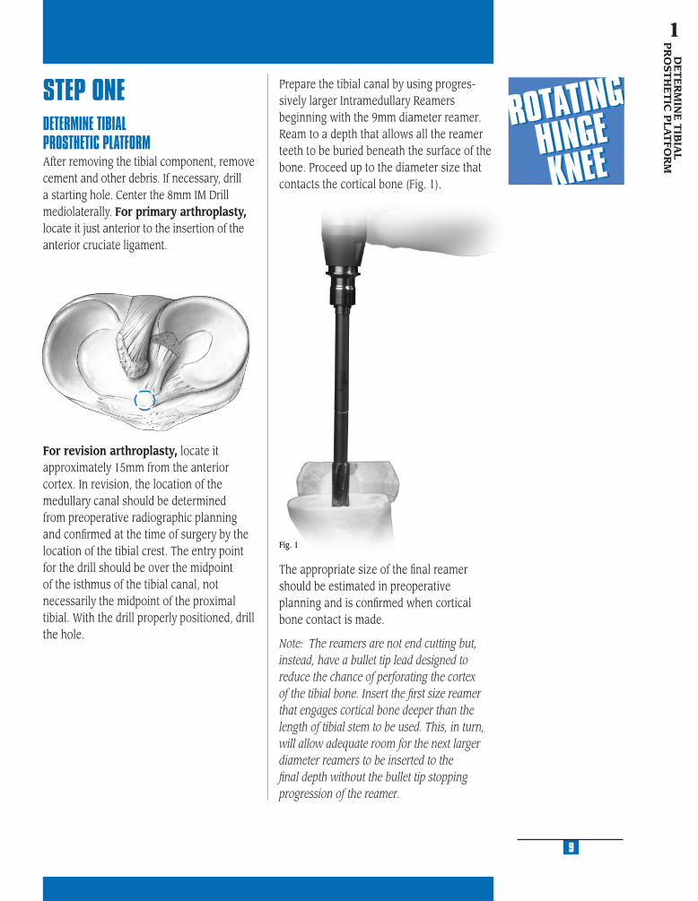
STEP ONEDETERMINE TIBIAL PROSTHETIC PLATFORMAfter removing the tibial component, remove cement and other debris. If necessary, drill a starting hole. Center the 8mm IM Drill mediolaterally. For primary arthroplasty, locate it just anterior to the insertion of the anterior cruciate ligament.
Prepare the tibial canal by using progres-sively larger Intramedullary Reamers beginning with the 9mm diameter reamer. Ream to a depth that allows all the reamer teeth to be buried beneath the surface of the bone. Proceed up to the diameter size that contacts the cortical bone (Fig. 1).
Fig. 1
The appropriate size of the fi nal reamer should be estimated in preoperative planning and is confi rmed when cortical bone contact is made.
Note: The reamers are not end cutting but, instead, have a bullet tip lead designed to reduce the chance of perforating the cortex of the tibial bone. Insert the fi rst size reamer that engages cortical bone deeper than the length of tibial stem to be used. This, in turn, will allow adequate room for the next larger diameter reamers to be inserted to the fi nal depth without the bullet tip stopping progression of the reamer.
For revision arthroplasty, locate it approximately 15mm from the anterior cortex. In revision, the location of the medullary canal should be determined from preoperative radiographic planning and confi rmed at the time of surgery by the location of the tibial crest. The entry point for the drill should be over the midpoint of the isthmus of the tibial canal, not necessarily the midpoint of the proximal tibial. With the drill properly positioned, drill the hole.
9
DE
TE
RM
INE
TIB
IAL
PR
OST
HE
TIC
PLA
TFO
RM
1

Attach the appropriate 0 degree Tibial Boom to the reamer shaft (Fig. 3) or the Stem Extension Provisional assembly. Be sure to direct the boom anteriorly over the medial half of the tibial tubercle.
Fig. 3
Be sure that the reamer remains in line with the tibial shaft based on external tibial landmarks. Retained cement and/or sclerotic bone in this area will tend to defl ect passage of the reamer. If this hap-pens, remove the cement or sclerotic bone. Leave the fi nal Intramedullary Reamer in place, or remove the reamer and attach the Straight Stem Extension Provisional that corresponds to the last reamer size used to the Stem Provisional Adapter (Fig. 2). Insert the Stem Extension Provisional and adapter into the reamed canal.
Fig. 2
The standard cutting slot on any of the augmented tibial cutting guides can be used for a fl at cut. Slide the selected tibial cutting guide onto the Tibial Boom until it contacts the anterior tibia. Then tighten the thumb screw (Fig. 4).
Fig. 4
10
MU
LTI-
RE
FER
EN
CE
4-in
-11
MU
LTI-
RE
FER
EN
CE
4-in
-1
2
MU
LTI-
RE
FER
EN
CE
4-in
-1
3
MU
LTI-
RE
FER
EN
CE
4-in
-1
4
MU
LTI-
RE
FER
EN
CE
4-in
-1
5
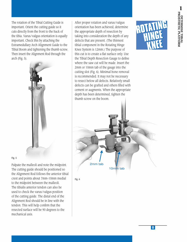
The rotation of the Tibial Cutting Guide is important. Orient the cutting guide so it cuts directly from the front to the back of the tibia. Varus/valgus orientation is equally important. Check this by attaching the Extramedullary Arch Alignment Guide to the Tibial Boom and tightening the thumb screw. Then insert the Alignment Rod through the arch (Fig. 5).
Palpate the malleoli and note the midpoint. The cutting guide should be positioned so the Alignment Rod follows the anterior tibial crest and points about 7mm-10mm medial to the midpoint between the malleoli. The tibialis anterior tendon can also be used to check the varus/valgus position of the cutting guide. The distal end of the Alignment Rod should be in line with the tendon. This will help confi rm that the resected surface will be 90 degrees to the mechanical axis.
Fig. 5
After proper rotation and varus/valgus orientation has been achieved, determine the appropriate depth of resection by taking into consideration the depth of any defects that are present. (The thinnest tibial component in the Rotating Hinge Knee System is 12mm.) The purpose of this cut is to create a fl at surface only. Use the Tibial Depth Resection Gauge to defi ne where the saw cut will be made. Insert the 2mm or 10mm tab of the gauge into the cutting slot (Fig. 6). Minimal bone removal is recommended. It may not be necessary to resect below all defects. Relatively small defects can be grafted and others fi lled with cement or augments. When the appropriate depth has been determined, tighten the thumb screw on the boom.
11
DE
TE
RM
INE
TIB
IAL
PR
OST
HE
TIC
PLA
TFO
RM
1
Fig. 6
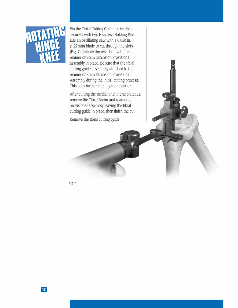
Pin the Tibial Cutting Guide to the tibia securely with two Headless Holding Pins. Use an oscillating saw with a 0.050 in. (1.27mm) blade to cut through the slots (Fig. 7). Initiate the resection with the reamer or Stem Extension Provisional assembly in place. Be sure that the tibial cutting guide is securely attached to the reamer or Stem Extension Provisional Assembly during the initial cutting process. This adds further stability to the cutter.
After cutting the medial and lateral plateaus, remove the Tibial Boom and reamer or provisional assembly leaving the tibial cutting guide in place, then fi nish the cut.
Remove the tibial cutting guide.
12
Fig. 7

FIN
ISH
TH
E T
IBIA
2
STEP ONE DETERMINE TIBIAL PROSTHETIC PLATFORM
STEP TWO FINISH THE TIBIA
STEP THREE PREPARE THE FEMORAL CANAL
STEP FOUR EVALUATE FEMORAL SIZE
STEP FIVE ESTABLISH FEMORAL ROTATION
STEP SIX ESTABLISH FLEXION GAP AND STABILITY
STEP SEVEN ESTABLISH EXTENSION GAP AND STABILITY
STEP EIGHT MAKE FEMORAL AUGMENT CUTS
STEP NINE PREPARE FOR THE ROTATING HINGE KNEE BOX
STEP TEN PREPARE THE PATELLA
STEP ELEVEN PERFORM TRIAL REDUCTION
STEP TWELVE COMPONENT ASSEMBLY/IMPLANTATION/
LOCKING MECHANISM
APPENDIX A CROSSOVER TECHNIQUE
APPENDIX B RESECTING THE DISTAL FEMUR
APPENDIX C BALANCING FLEXION/EXTENSION GAPS
APPENDIX D USING THE 5-IN-1 INSTRUMENTATION
SYSTEM FOR A ROTATING HINGE KNEE
PRIMARY PROCEDURE
APPENDIX E USING THE 5-IN-1 INSTRUMENTATION
SYSTEM FOR A ROTATING HINGE KNEE
REVISION PROCEDURE
APPENDIX F USING THE 5-IN-1 INSTRUMENTATION
SYSTEM FOR A ROTATING HINGE KNEE
WITH OFFSET STEM
APPENDIX G SERVICING THE HINGE MECHANISM

MU
LTI-
RE
FER
EN
CE
4-in
-11
MU
LTI-
RE
FER
EN
CE
4-in
-1
2
MU
LTI-
RE
FER
EN
CE
4-in
-1
3
MU
LTI-
RE
FER
EN
CE
4-in
-1
4
MU
LTI-
RE
FER
EN
CE
4-in
-1
5
STEP TWOFINISH THE TIBIASelect the Rotating Hinge Knee Tibial Sizing Plate that provides the desired tibial coverage by placing various size plates onto the resected tibial surface. Attach the Tibial Provisional/Drill Guide Holding Clamp to the selected sizing plate (Fig. 8). Then use the Alignment Rod to aid in confi rming varus/valgus alignment.
Note: The size designation on the Rotating Hinge Knee Tibial Sizing Plate should be compared to the size designations on the anterior fl ange of the selected Femoral Provi-sional to ensure that the components, in combination with the articular surface, will be kinematically matched (see sizing chart). If there is no match between the femoral pro-visional and the sizing plate, adjust the size of the Femoral Provisional or the sizing plate used to yield a match.
Reinsert the last Intramedullary Reamer or the Stem Extension Provisional assembly. Place the sizing plate over the reamer shaft or stem provisional assembly and onto the prepared bone. Slide the Straight Bushing over the reamer shaft or Stem Provisional Adapter until it seats into the circular step of the sizing plate (Fig. 9). This will properly position the sizing plate relative to the tibial stem location. If the bushing will not seat in the sizing plate, check to be sure that the reamer or provisional assembly is fully inserted into the canal.
Pin the plate with two Small-Head Holding Pins. Remove the bushing, and the reamer or stem provisional assembly, leaving the sizing plate in place.
Note: The sizing plate must be removed prior to the reamer or stem provisional assembly if their diameter exceeds 19mm. Mark the position of the sizing plate using the pin holes or mark with methylene blue prior to removal.
If the position is satisfactory, and tibial augmentation is necessary, proceed to the “Tibial Augmentation” procedure on page 16. If the position is satisfactory, and tibial augmentation is not necessary, proceed to “Drilling the Stem Base” on page 17.
Fig. 8
15Fig. 9
FINIS
H T
HE
TIB
IA
2
NexGen Rotating Hinge Knee Size Chart
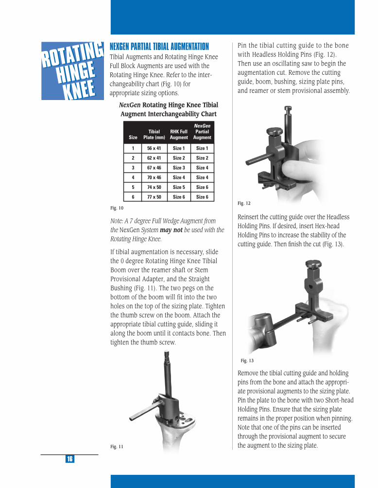
Fig. 13
Fig. 12
NEXGEN PARTIAL TIBIAL AUGMENTATIONTibial Augments and Rotating Hinge Knee Full Block Augments are used with the Rotating Hinge Knee. Refer to the inter-changeability chart (Fig. 10) for appropriate sizing options.
16
Fig. 10
Note: A 7 degree Full Wedge Augment from the NexGen System may not be used with the Rotating Hinge Knee.
If tibial augmentation is necessary, slide the 0 degree Rotating Hinge Knee Tibial Boom over the reamer shaft or Stem Provisional Adapter, and the Straight Bushing (Fig. 11). The two pegs on the bottom of the boom will fit into the two holes on the top of the sizing plate. Tighten the thumb screw on the boom. Attach the appropriate tibial cutting guide, sliding it along the boom until it contacts bone. Then tighten the thumb screw.
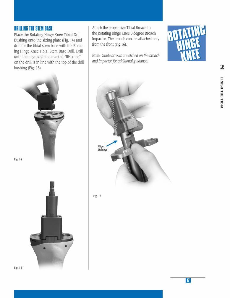
Pin the tibial cutting guide to the bone with Headless Holding Pins (Fig. 12). Then use an oscillating saw to begin the augmentation cut. Remove the cutting guide, boom, bushing, sizing plate pins, and reamer or stem provisional assembly.
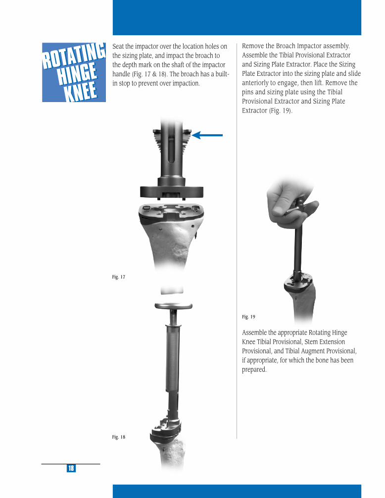
Reinsert the cutting guide over the Headless Holding Pins. If desired, insert Hex-head Holding Pins to increase the stability of the cutting guide. Then fi nish the cut (Fig. 13).
Remove the tibial cutting guide and holding pins from the bone and attach the appropri-ate provisional augments to the sizing plate. Pin the plate to the bone with two Short-head Holding Pins. Ensure that the sizing plate remains in the proper position when pinning. Note that one of the pins can be inserted through the provisional augment to secure the augment to the sizing plate.Fig. 11
NexGen Rotating Hinge Knee Tibial Augment Interchangeability Chart
MU
LTI-
RE
FER
EN
CE
4-in
-11
MU
LTI-
RE
FER
EN
CE
4-in
-1
2
MU
LTI-
RE
FER
EN
CE
4-in
-1
3
MU
LTI-
RE
FER
EN
CE
4-in
-1
4
MU
LTI-
RE
FER
EN
CE
4-in
-1
5
17
Fig. 15
DRILLING THE STEM BASEPlace the Rotating Hinge Knee Tibial Drill Bushing onto the sizing plate (Fig. 14) and drill for the tibial stem base with the Rotat-ing Hinge Knee Tibial Stem Base Drill. Drill until the engraved line marked “RH knee” on the drill is in line with the top of the drill bushing (Fig. 15).
Fig. 14
Attach the proper size Tibial Broach to the Rotating Hinge Knee 0 degree Broach Impactor. The broach can be attached only from the front (Fig.16).
Note: Guide arrows are etched on the broach and impactor for additional guidance.
Fig. 16
FINIS
H T
HE
TIB
IA
2
AlignEtchings
Assemble the appropriate Rotating Hinge Knee Tibial Provisional, Stem Extension Provisional, and Tibial Augment Provisional, if appropriate, for which the bone has been prepared.
Fig. 18
18
Remove the Broach Impactor assembly. Assemble the Tibial Provisional Extractor and Sizing Plate Extractor. Place the Sizing Plate Extractor into the sizing plate and slide anteriorly to engage, then lift. Remove the pins and sizing plate using the Tibial Provisional Extractor and Sizing Plate Extractor (Fig. 19).
Fig. 19
Fig. 17
Seat the impactor over the location holes on the sizing plate, and impact the broach to the depth mark on the shaft of the impactor handle (Fig. 17 & 18). The broach has a built-in stop to prevent over impaction.

MU
LTI-
RE
FER
EN
CE
4-in
-11
MU
LTI-
RE
FER
EN
CE
4-in
-1
2
MU
LTI-
RE
FER
EN
CE
4-in
-1
3
MU
LTI-
RE
FER
EN
CE
4-in
-1
4
MU
LTI-
RE
FER
EN
CE
4-in
-1
5
Insert the fi nal trial prosthesis assembly into the tibia. Be sure that the provisional plate is properly positioned rotationally. Component malrotation on the cut surface of the bone can cause a misfi t. Impact the Stemmed Tibial Provisional with the Tibial Provisional Impactor (Fig. 20). Check to see that the trial prosthesis fi ts the cut surfaces with appropriate apposition to bone. If any undesired gaps are present, remove the trial component and adjust the bone cuts until a good intimate fi t is obtained.
A Straight Stem Extension is typically used with an Rotating Hinge Knee Tibial Component. An Offset Stem can be used only if the diameter of the Intramedullary canal is suffi cient to provide space for the offset of the Offset Stem.
19
Fig. 20
FINIS
H T
HE
TIB
IA
2
A Straight Stem Extension is typically used with an Rotating Hinge Knee Tibial Component. An Offset Stem can be used only if the diameter of the Intramedullary canal is suffi cient to provide space for the offset of the Offset Stem.
20
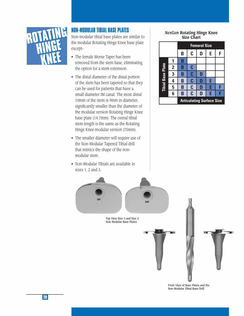
NON-MODULAR TIBIAL BASE PLATESNon-modular tibial base plates are similar to the modular Rotating Hinge Knee base plate except–
• The female Morse Taper has been removed from the stem base, eliminating the option for a stem extension.
• The distal diameter of the distal portion of the stem has been tapered so that they can be used for patients that have a small diameter IM canal. The most distal 10mm of the stem is 9mm in diameter, signifi cantly smaller than the diameter of the modular version Rotating Hinge Knee base plate (14.7mm). The overal tibial stem length is the same as the Rotating Hinge Knee modular version (75mm).
• The smaller diameter will require use of the Non-Modular Tapered Tibial drill that mimics the shape of the non- modular stem.
• Non-Modular Tibials are available in sizes 1, 2 and 3.
Top View Size 3 and Size 2 Non-Modular Base Plates
Front View of Base Plates and the Non-Modular Tibial Base Drill
NexGen Rotating Hinge Knee Size Chart

PR
EPA
RE
TH
E
FE
MO
RA
L C
AN
AL
3
STEP ONE DETERMINE TIBIAL PROSTHETIC PLATFORM
STEP TWO FINISH THE TIBIA
STEP THREE PREPARE THE FEMORAL CANAL
STEP FOUR EVALUATE FEMORAL SIZE
STEP FIVE ESTABLISH FEMORAL ROTATION
STEP SIX ESTABLISH FLEXION GAP AND STABILITY
STEP SEVEN ESTABLISH EXTENSION GAP AND STABILITY
STEP EIGHT MAKE FEMORAL AUGMENT CUTS
STEP NINE PREPARE FOR THE ROTATING HINGE KNEE BOX
STEP TEN PREPARE THE PATELLA
STEP ELEVEN PERFORM TRIAL REDUCTION
STEP TWELVE COMPONENT ASSEMBLY/IMPLANTATION/
LOCKING MECHANISM
APPENDIX A CROSSOVER TECHNIQUE
APPENDIX B RESECTING THE DISTAL FEMUR
APPENDIX C BALANCING FLEXION/EXTENSION GAPS
APPENDIX D USING THE 5-IN-1 INSTRUMENTATION
SYSTEM FOR A ROTATING HINGE KNEE
PRIMARY PROCEDURE
APPENDIX E USING THE 5-IN-1 INSTRUMENTATION
SYSTEM FOR A ROTATING HINGE KNEE
REVISION PROCEDURE
APPENDIX F USING THE 5-IN-1 INSTRUMENTATION
SYSTEM FOR A ROTATING HINGE KNEE
WITH OFFSET STEM
APPENDIX G SERVICING THE HINGE MECHANISM

MU
LTI-
RE
FER
EN
CE
4-in
-11
MU
LTI-
RE
FER
EN
CE
4-in
-1
2
MU
LTI-
RE
FER
EN
CE
4-in
-1
3
MU
LTI-
RE
FER
EN
CE
4-in
-1
4
MU
LTI-
RE
FER
EN
CE
4-in
-1
5
Fig. 21
23
Fig. 22
PR
EPA
RE
TH
E
FEM
OR
AL C
AN
AL
3
Fig. 23
3°
STEP THREE SIZE THE FEMURThe following step may be omitted if this is a revision procedure. Proceed to the section entitled, “Prepare the Femoral Canal.”
In a primary procedure, drill the hole in the center of the patella sulcus of the distal femur (Fig. 21), making sure that the hole is parallel to the shaft of the femur in both the anteroposterior and lateral projections. The hole should be approximately 1cm anterior to the origin of the posterior cruciate ligament. The drill is a step drill and should be used to enlarge the entrance hole on the femur to 12mm in diameter. This will reduce intramedullary pressure from placement of subsequent intramedullary guides.
Insert the IM Femoral A/P Sizing Guide into the hole until it contacts the distal femur. Compress the guide until the anterior boom contacts the anterior cortex of the femur, and both feet rest on the cartilage of the posterior condyles. Placing the guide in fl exion or extension can produce inaccurate readings. Check to ensure that the boom is not seated on a high spot or an unusually low spot.
Read the femoral size directly from the guide. If the indicator is between two sizes, choose the smaller size. This size indicates the proper size of the Stemmed Femoral A/P Placement Guide, the Femoral Milling
Template or 5-in-1 Femoral Cutting Guide, the Femoral Finishing Guide (milling or 5-in-1), and the femoral component. The sizing can be confi rmed at the alignment stage.
The IM Femoral A/P Sizing Guide can also be used to aid in setting 3˚ of external rotation of the femoral component in relation to the nondeformed posterior condyle (Fig. 22). Select and drill through the appropriate holes in the guide being sure that the proper “Right” or “Left” indication is used. Drill one hole on each side medial and lateral. This will place two reference holes on the femur at 3˚ of external rotation. These holes will be used in conjuction with the Revision IM Guide to set rotation.
PREPARE THE FEMORAL CANAL
Beginning with the 9mm Intramedullary Reamer, progressively ream the femoral canal (Fig. 23).
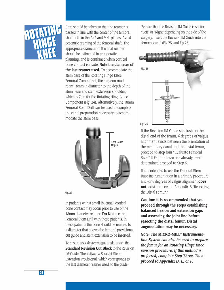
Fig. 24
7cm Ream Depth
In patients with a small IM canal, cortical bone contact may occur prior to use of the 18mm diameter reamer. Do Not use the Femoral Stem Drill with these patients. In these patients the bone should be reamed to a diameter that allows the femoral provisional cut guide and stem extension to be inserted.
To ensure a six-degree valgus angle, attach the Standard Revision Cut Block to the Revision IM Guide. Then attach a Straight Stem Extension Provisional, which corresponds to the last diameter reamer used, to the guide.
Care should be taken so that the reamer is passed in line with the center of the femoral shaft both in the A/P and M/L planes. Avoid eccentric reaming of the femoral shaft. The appropriate diameter of the fi nal reamer should be estimated in preoperative planning, and is confi rmed when cortical bone contact is made. Note the diameter of the last reamer used. To accommodate the stem base of the Rotating Hinge Knee Femoral Component, the surgeon must ream 18mm in diameter to the depth of the stem base and stem extension shoulder, which is 7cm for the Rotating Hinge Knee Component (Fig. 24). Alternatively, the 18mm Femoral Stem Drill can be used to complete the canal preparation necessary to accom-modate the stem base.
24
Fig. 25
If the Revision IM Guide sits fl ush on the distal end of the femur, 6 degrees of valgus alignment exists between the orientation of the medullary canal and the distal femur, proceed to step four “Evaluate Femoral Size.” If Femoral size has already been determined proceed to Step 5.
If it is intended to use the Femoral Stem Base Instrumentation in a primary procedure and/or 6 degrees of valgus alignment does not exist, proceed to Appendix B “Resecting the Distal Femur.”
Caution: it is recommended that you proceed through the steps establishing balanced fl exion and extension gaps and assessing the joint line before resecting the distal femur. Distal augmentation may be necessary.
Note: The MICRO-MILL® Instrumenta-tion System can also be used to prepare the femur for an Rotating Hinge Knee revision procedure. If this method is preferred, complete Step Three. Then proceed to Appendix D, E, or F.
Fig. 26
Be sure that the Revision IM Guide is set for “Left” or “Right” depending on the side of the surgery. Insert the Revision IM Guide into the femoral canal (Fig 25, and Fig 26).

EVA
LU
AT
E
FE
MO
RA
L S
IZE
4
STEP ONE DETERMINE TIBIAL PROSTHETIC PLATFORM
STEP TWO FINISH THE TIBIA
STEP THREE PREPARE THE FEMORAL CANAL
STEP FOUR EVALUATE FEMORAL SIZE
STEP FIVE ESTABLISH FEMORAL ROTATION
STEP SIX ESTABLISH FLEXION GAP AND STABILITY
STEP SEVEN ESTABLISH EXTENSION GAP AND STABILITY
STEP EIGHT MAKE FEMORAL AUGMENT CUTS
STEP NINE PREPARE FOR THE ROTATING HINGE KNEE BOX
STEP TEN PREPARE THE PATELLA
STEP ELEVEN PERFORM TRIAL REDUCTION
STEP TWELVE COMPONENT ASSEMBLY/IMPLANTATION/
LOCKING MECHANISM
APPENDIX A CROSSOVER TECHNIQUE
APPENDIX B RESECTING THE DISTAL FEMUR
APPENDIX C BALANCING FLEXION/EXTENSION GAPS
APPENDIX D USING THE 5-IN-1 INSTRUMENTATION
SYSTEM FOR A ROTATING HINGE KNEE
PRIMARY PROCEDURE
APPENDIX E USING THE 5-IN-1 INSTRUMENTATION
SYSTEM FOR A ROTATING HINGE KNEE
REVISION PROCEDURE
APPENDIX F USING THE 5-IN-1 INSTRUMENTATION
SYSTEM FOR A ROTATING HINGE KNEE
WITH OFFSET STEM
APPENDIX G SERVICING THE HINGE MECHANISM

MU
LTI-
RE
FER
EN
CE
4-in
-11
MU
LTI-
RE
FER
EN
CE
4-in
-1
2
MU
LTI-
RE
FER
EN
CE
4-in
-1
3
MU
LTI-
RE
FER
EN
CE
4-in
-1
4
MU
LTI-
RE
FER
EN
CE
4-in
-1
5
27
STEP FOUREVALUATE FEMORAL SIZEThere are several ways to estimate the appropriate femoral size. The following technique should be used in conjunction with templating as discussed in the Preoperative Planning section, to determine an approximate femoral size. The final size will ultimately be selected during Step Six— Establish Flexion Gap and Stability.
Femoral Sizing TemplatesReinsert the fi nal Intramedullary Reamer, or attach the Stem Extension Provisional that corresponds to the last reamer size used to the Stem Provisional Adapter. Insert the stem provisional assembly or reamer into the femoral canal. Center the etched line of the various sizes of Femoral Sizing Templates on the shaft of the reamer or adapter until the appropriate size is found (Fig. 27).
The femoral component must be chosen to stabilize the arthroplasty with the knee in fl exion, without regard to the available distal femoral bone. Selecting the femoral component to fi t the existing bone may un-dersize the femoral component and can create a large fl exion gap which may be unequal to the extension gap or, if balanced, may lead to undesirable proximal displace-ment of the joint line.
Note: After estimating the femoral size, one can assemble that size of Rotating Hinge Knee Femoral Provisional/Cutting Guide with the Stem Extension Provisional that corresponds with the diameter and depth of reaming of the last reamer used. Seat the femoral assembly on the existing bone. If the components will not seat, use a rongeur to carefully remove any anterior or posterior bone that is preventing insertion. Take care not to overresect at this point.
If using the 5-in-1 Femoral Instrumentation System for a Rotating Hinge Knee procedure, proceed to Appendix D, E or F.
EVA
LUA
TE
FEM
OR
AL
SIZ
E
4
Fig. 27

ESTA
BLISH
FE
MO
RA
L RO
TAT
ION
5
STEP ONE DETERMINE TIBIAL PROSTHETIC PLATFORM
STEP TWO FINISH THE TIBIA
STEP THREE PREPARE THE FEMORAL CANAL
STEP FOUR EVALUATE FEMORAL SIZE
STEP FIVE ESTABLISH FEMORAL ROTATION
STEP SIX ESTABLISH FLEXION GAP AND STABILITY
STEP SEVEN ESTABLISH EXTENSION GAP AND STABILITY
STEP EIGHT MAKE FEMORAL AUGMENT CUTS
STEP NINE PREPARE FOR THE ROTATING HINGE KNEE BOX
STEP TEN PREPARE THE PATELLA
STEP ELEVEN PERFORM TRIAL REDUCTION
STEP TWELVE COMPONENT ASSEMBLY/IMPLANTATION/
LOCKING MECHANISM
APPENDIX A CROSSOVER TECHNIQUE
APPENDIX B RESECTING THE DISTAL FEMUR
APPENDIX C BALANCING FLEXION/EXTENSION GAPS
APPENDIX D USING THE 5-IN-1 INSTRUMENTATION
SYSTEM FOR A ROTATING HINGE KNEE
PRIMARY PROCEDURE
APPENDIX E USING THE 5-IN-1 INSTRUMENTATION
SYSTEM FOR A ROTATING HINGE KNEE
REVISION PROCEDURE
APPENDIX F USING THE 5-IN-1 INSTRUMENTATION
SYSTEM FOR A ROTATING HINGE KNEE
WITH OFFSET STEM
APPENDIX G SERVICING THE HINGE MECHANISM
MU
LTI-
RE
FER
EN
CE
4-in
-11
MU
LTI-
RE
FER
EN
CE
4-in
-1
2
MU
LTI-
RE
FER
EN
CE
4-in
-1
3
MU
LTI-
RE
FER
EN
CE
4-in
-1
4
MU
LTI-
RE
FER
EN
CE
4-in
-1
5
Flexion Gap
31
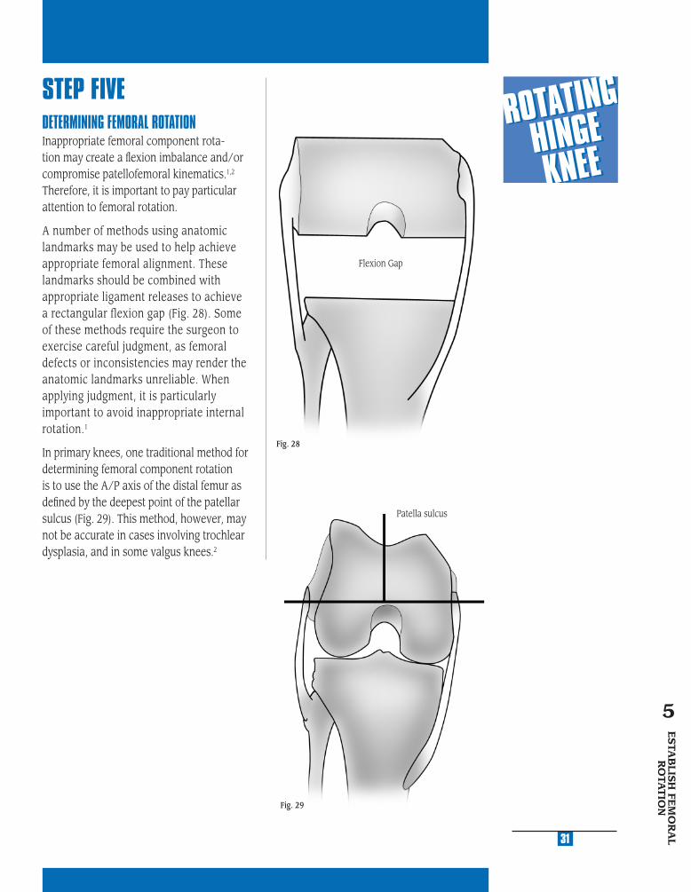
STEP FIVEDETERMINING FEMORAL ROTATIONInappropriate femoral component rota-tion may create a fl exion imbalance and/or compromise patellofemoral kinematics.1,2 Therefore, it is important to pay particular attention to femoral rotation.
A number of methods using anatomic landmarks may be used to help achieve appropriate femoral alignment. These landmarks should be combined with appropriate ligament releases to achieve a rectangular flexion gap (Fig. 28). Some of these methods require the surgeon to exercise careful judgment, as femoral defects or inconsistencies may render the anatomic landmarks unreliable. When applying judgment, it is particularly important to avoid inappropriate internal rotation.1
In primary knees, one traditional method for determining femoral component rotation is to use the A/P axis of the distal femur as defi ned by the deepest point of the patellar sulcus (Fig. 29). This method, however, may not be accurate in cases involving trochlear dysplasia, and in some valgus knees.2
Fig. 28
ESTA
BLIS
H FE
MO
RA
L R
OTA
TIO
N
5
Patella sulcus
Fig. 29

6
Another method for determining femoral component rotation is to reference from the posterior femoral condyles (Fig. 30); however, erosion of the condyles may distort the reference angle calculated from this method and may result in internal rota-tion of the femoral component.2 The tibial shaft axis may offer assistance as a refer-ence for determining femoral rotation (Fig. 31); however, it is usually inadequate and misleading used by itself.2
The recommended method for establishing femoral component rotation is to use the epicondyles, the attachment points for the collateral ligaments (Fig. 32).2 Identifying the epicondylar axis may require additional soft tissue dissection to visualize the epicondyles. The center of the medial epicondyle is located in the sulcus between the proximal and distal origins of the deep MCL. The lateral epicondyle is the most prominent lateral point on the distal femur. The posterior femoral condyles should parallel the transepicondylar axis.
1 Berger, RA; Crossett, LS; Jacobs, JJ; Rubash, HE. Malrotation causing patellofemoral complications after total knee arthroplasty. Clinical Orthopaedics and Related Research. Department of Orthopeadic Surgery, Rush Medical College, Chicago, IL; 1998:144-153.
2 Insall, JN; Surgery of the Knee. 3rd ed. New York, NY: Churchill Livingston; 2001; 1556.
Fig. 31
32
Fig. 30
Fig. 32

MU
LTI-
RE
FER
EN
CE
4-in
-11
MU
LTI-
RE
FER
EN
CE
4-in
-1
2
MU
LTI-
RE
FER
EN
CE
4-in
-1
3
MU
LTI-
RE
FER
EN
CE
4-in
-1
4
MU
LTI-
RE
FER
EN
CE
4-in
-1
5
33
ESTABLISH FEMORAL ROTATION AND POSITION USING THE FEMORAL STEM BASE INSTRUMENTSEstablish Femoral RotationAttach the Femoral Base Guide Flange to the Femoral Stem Base/Cutting Block that corresponds to the femoral component size chosen (In a primary knee procedure, the fl ange cannot be used since the anterior femoral condyles have not been resected). Be sure that the proper “Right” or “Left” indication is facing toward you on the cutting block. Tighten the thumb screw to secure the fl ange to the cutting block. Slide the block and fl ange over the reamer or Stem Provisional Adapter. The cutting block should be fl ush against the distal femur and the fl ange should rest on the anterior femoral cortex (Fig. 33).
Fig. 34
Slide the 9mm-10mm Femoral Guide Bushing over the reamer shaft or Stem Provisional Adapter until it seats into the circular step of the Femoral Stem Base/Cutting Block (Fig. 34).
A collar inside the cutting block serves as a stop to indicate when the bushing is fully seated. The straight bushings are keyed so they can only fi t into the guide one way.
Fig. 33
ESTA
BLIS
H FE
MO
RA
L R
OTA
TIO
N
5
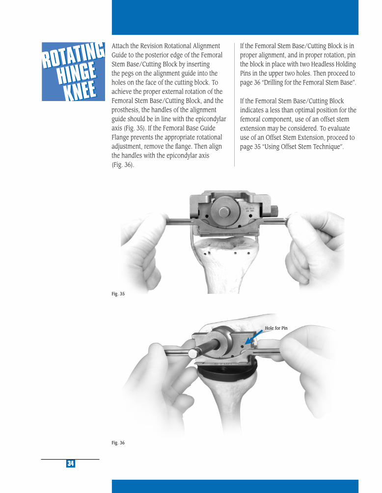
Fig. 36
34
Attach the Revision Rotational Alignment Guide to the posterior edge of the Femoral Stem Base/Cutting Block by inserting the pegs on the alignment guide into the holes on the face of the cutting block. To achieve the proper external rotation of the Femoral Stem Base/Cutting Block, and the prosthesis, the handles of the alignment guide should be in line with the epicondylar axis (Fig. 35). If the Femoral Base Guide Flange prevents the appropriate rotational adjustment, remove the fl ange. Then align the handles with the epicondylar axis (Fig. 36).
Fig. 35
Hole for Pin
If the Femoral Stem Base/Cutting Block is in proper alignment, and in proper rotation, pin the block in place with two Headless Holding Pins in the upper two holes. Then proceed to page 36 “Drilling for the Femoral Stem Base”.
If the Femoral Stem Base/Cutting Block indicates a less than optimal position for the femoral component, use of an offset stem extension may be considered. To evaluate use of an Offset Stem Extension, proceed to page 35 “Using Offset Stem Technique”.

MU
LTI-
RE
FER
EN
CE
4-in
-11
MU
LTI-
RE
FER
EN
CE
4-in
-1
2
MU
LTI-
RE
FER
EN
CE
4-in
-1
3
MU
LTI-
RE
FER
EN
CE
4-in
-1
4
MU
LTI-
RE
FER
EN
CE
4-in
-1
5
Fig. 37
35
Determine Component Placement Using Offset Stem TechniqueIt is important to optimize the A/P and M/L position of the Femoral Stem Base/Cutting Block on the distal femur. If it appears that the prosthesis will not be properly positioned on the distal femur, an offset stem is recom-mended. (For more information about the offset stem, see Appendix F on page 99.) To prepare for the offset stem, use the Femoral Offset Bushing in place of the 9mm-10mm Femoral Guide Bushing. Insert the Femoral Offset Bushing with the numbers facing out. This bushing does not have a step that locks it into a keyed rotational ori-entation on the Femoral Stem Base/Cutting Block. Rotate the bushing within the block until an optimal position is determined.
When the position of the Femoral Stem Base/Cutting Block has been established, confi rm appropriate external rotation and pin the block in place with two Headless Holding Pins in the upper two holes. Remove the 9mm-10mm Femoral Guide Bushing or Femoral Offset Bushing. Remove the Intramedullary Reamer or the Stem Extension Provisional assembly with the Femoral Extractor.
The Femoral Offset Bushing allows the guide and, therefore, the prosthesis, to be shifted 4.5mm from the center of the canal in any direction. If the Femoral Base Guide Flange prevents appropriate placement, remove the fl ange. The necessity for anterior bone resection will result, but be careful not to notch the anterior cortex.
Note: The orientation of the Femoral Offset Bushing by observing the numbers and marks on the bushing relative to the etched line on the posterior face of the Femoral Stem Base/Cutting Block (Fig. 37). This reference will be needed later in the procedure. See arrow Fig. 43 on page 37.
ESTA
BLIS
H FE
MO
RA
L R
OTA
TIO
N
5

Fig. 38
Drilling for the Femoral Stem BaseInsert the 16mm-18mm Femoral Guide Bush-ing into the cutting block.
Attach the Femoral Stem Drill to a drill/reamer and drill through the bushing. Drill to the third engraved line for an Rotating Hinge Knee Femoral Component. The depth is indicated on the drill bit (Fig. 38).
Note: In patients with a small IM Canal, do not use the Femoral Stem Drill. Ream to a diameter that allows the Femoral Provisional Cut Guide and stem extension to be inserted.
Note: If it is known that the distal femoral Augments will be used, the augments should be applied to the posterior surface of the Femoral Stem Base/Cutting Block prior to use of the 18mm Femoral Stem Drill.
Remove the Femoral Base Guide Flange by loosening the thumb screw if it has not already been removed.
Anterior and posterior clean-up cuts may be necessary due to optimal femoral guide rotation and placement from previous steps. For the posterior cut, the Posterior Saw Guide Attachment can be assembled to the hole on the posterior edge of the cutting block. The instrument is marked to indicate the side that must face the bone. Assemble the Posterior Saw Guide Attachment so that it is fl ush with the anterior face of the Femoral Stem Base/Cutting Block. Be sure the thumb screw is fully tightened. Use an oscillating saw to cut the anterior and posterior condyles (Fig. 39, 40, 41, 42).
36
Fig. 40
Fig. 41
Remove the Femoral Stem Base/Cutting Block leaving the headless pins in place.
Fig. 39
Fig. 42
MU
LTI-
RE
FER
EN
CE
4-in
-11
MU
LTI-
RE
FER
EN
CE
4-in
-1
2
MU
LTI-
RE
FER
EN
CE
4-in
-1
3
MU
LTI-
RE
FER
EN
CE
4-in
-1
4
MU
LTI-
RE
FER
EN
CE
4-in
-1
5
When using a straight stem, insert the appropriate size Straight Stem Extension Provisional into the appropriate size Femoral Provisional/Cutting Guide.
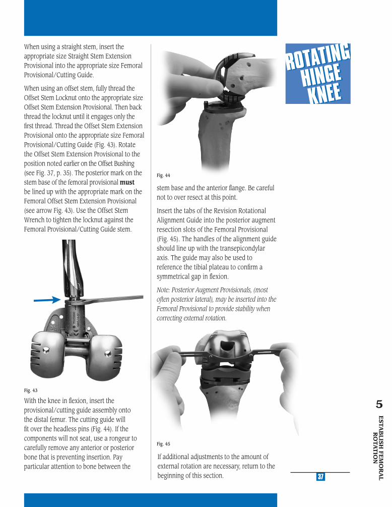
When using an offset stem, fully thread the Offset Stem Locknut onto the appropriate size Offset Stem Extension Provisional. Then back thread the locknut until it engages only the fi rst thread. Thread the Offset Stem Extension Provisional onto the appropriate size Femoral Provisional/Cutting Guide (Fig. 43). Rotate the Offset Stem Extension Provisional to the position noted earlier on the Offset Bushing (see Fig. 37, p. 35). The posterior mark on the stem base of the femoral provisional must be lined up with the appropriate mark on the Femoral Offset Stem Extension Provisional (see arrow Fig. 43). Use the Offset Stem Wrench to tighten the locknut against the Femoral Provisional/Cutting Guide stem.
With the knee in fl exion, insert the provisional/cutting guide assembly onto the distal femur. The cutting guide will fi t over the headless pins (Fig. 44). If the components will not seat, use a rongeur to carefully remove any anterior or posterior bone that is preventing insertion. Pay particular attention to bone between the
Fig. 44
37
Fig. 43
Fig. 45
If additional adjustments to the amount of external rotation are necessary, return to the beginning of this section.
stem base and the anterior fl ange. Be careful not to over resect at this point.
Insert the tabs of the Revision Rotational Alignment Guide into the posterior augment resection slots of the Femoral Provisional (Fig. 45). The handles of the alignment guide should line up with the transepicondylar axis. The guide may also be used to reference the tibial plateau to confi rm a symmetrical gap in fl exion.
Note: Posterior Augment Provisionals, (most often posterior lateral), may be inserted into the Femoral Provisional to provide stability when correcting external rotation.
ESTA
BLIS
H FE
MO
RA
L R
OTA
TIO
N
5

ESTA
BLISH
FLEX
ION
G
AP
AN
D STA
BILIT
Y6
STEP ONE DETERMINE TIBIAL PROSTHETIC PLATFORM
STEP TWO FINISH THE TIBIA
STEP THREE PREPARE THE FEMORAL CANAL
STEP FOUR EVALUATE FEMORAL SIZE
STEP FIVE ESTABLISH FEMORAL ROTATION
STEP SIX ESTABLISH FLEXION GAP AND STABILITY
STEP SEVEN ESTABLISH EXTENSION GAP AND STABILITY
STEP EIGHT MAKE FEMORAL AUGMENT CUTS
STEP NINE PREPARE FOR THE ROTATING HINGE KNEE BOX
STEP TEN PREPARE THE PATELLA
STEP ELEVEN PERFORM TRIAL REDUCTION
STEP TWELVE COMPONENT ASSEMBLY/IMPLANTATION/
LOCKING MECHANISM
APPENDIX A CROSSOVER TECHNIQUE
APPENDIX B RESECTING THE DISTAL FEMUR
APPENDIX C BALANCING FLEXION/EXTENSION GAPS
APPENDIX D USING THE 5-IN-1 INSTRUMENTATION
SYSTEM FOR A ROTATING HINGE KNEE
PRIMARY PROCEDURE
APPENDIX E USING THE 5-IN-1 INSTRUMENTATION
SYSTEM FOR A ROTATING HINGE KNEE
REVISION PROCEDURE
APPENDIX F USING THE 5-IN-1 INSTRUMENTATION
SYSTEM FOR A ROTATING HINGE KNEE
WITH OFFSET STEM
APPENDIX G SERVICING THE HINGE MECHANISM
MU
LTI-
RE
FER
EN
CE
4-in
-11
MU
LTI-
RE
FER
EN
CE
4-in
-1
2
MU
LTI-
RE
FER
EN
CE
4-in
-1
3
MU
LTI-
RE
FER
EN
CE
4-in
-1
4
MU
LTI-
RE
FER
EN
CE
4-in
-1
5
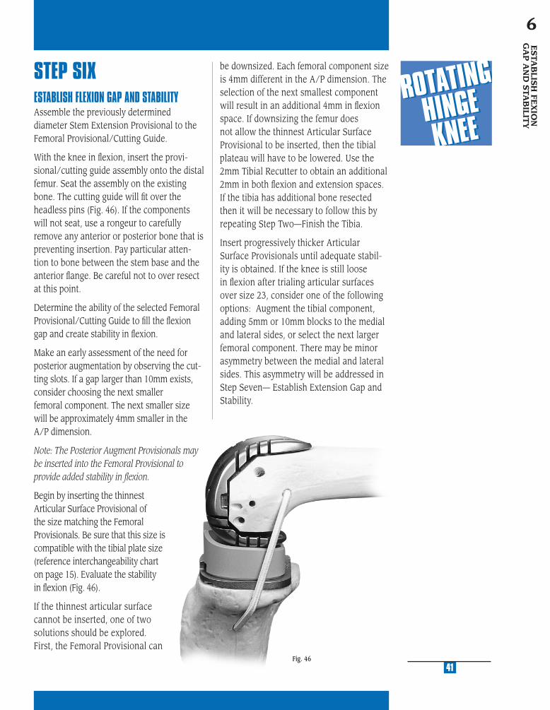
STEP SIXESTABLISH FLEXION GAP AND STABILITYAssemble the previously determined diameter Stem Extension Provisional to the Femoral Provisional/Cutting Guide.
With the knee in fl exion, insert the provi-sional/cutting guide assembly onto the distal femur. Seat the assembly on the existing bone. The cutting guide will fi t over the headless pins (Fig. 46). If the components will not seat, use a rongeur to carefully remove any anterior or posterior bone that is preventing insertion. Pay particular atten-tion to bone between the stem base and the anterior fl ange. Be careful not to over resect at this point.
Determine the ability of the selected Femoral Provisional/Cutting Guide to fi ll the fl exion gap and create stability in fl exion.
Make an early assessment of the need for posterior augmentation by observing the cut-ting slots. If a gap larger than 10mm exists, consider choosing the next smaller femoral component. The next smaller size will be approximately 4mm smaller in the A/P dimension.
Note: The Posterior Augment Provisionals may be inserted into the Femoral Provisional to provide added stability in fl exion.
Begin by inserting the thinnest Articular Surface Provisional of the size matching the Femoral Provisionals. Be sure that this size is compatible with the tibial plate size (reference interchangeability chart on page 15). Evaluate the stability in fl exion (Fig. 46).
If the thinnest articular surface cannot be inserted, one of two solutions should be explored. First, the Femoral Provisional can
41
ESTA
BLIS
H FE
XIO
N
GA
P A
ND
STA
BILIT
Y6
be downsized. Each femoral component size is 4mm different in the A/P dimension. The selection of the next smallest component will result in an additional 4mm in fl exion space. If downsizing the femur does not allow the thinnest Articular Surface Provisional to be inserted, then the tibial plateau will have to be lowered. Use the 2mm Tibial Recutter to obtain an additional 2mm in both fl exion and extension spaces. If the tibia has additional bone resected then it will be necessary to follow this by repeating Step Two—Finish the Tibia.
Insert progressively thicker Articular Surface Provisionals until adequate stabil-ity is obtained. If the knee is still loose in fl exion after trialing articular surfaces over size 23, consider one of the following options: Augment the tibial component, adding 5mm or 10mm blocks to the medial and lateral sides, or select the next larger femoral component. There may be minor asymmetry between the medial and lateral sides. This asymmetry will be addressed in Step Seven— Establish Extension Gap and Stability.
Fig. 46

ESTAB
LISH EXTEN
SION
G
AP A
ND
STAB
ILITY
7
STEP ONE DETERMINE TIBIAL PROSTHETIC PLATFORM
STEP TWO FINISH THE TIBIA
STEP THREE PREPARE THE FEMORAL CANAL
STEP FOUR EVALUATE FEMORAL SIZE
STEP FIVE ESTABLISH FEMORAL ROTATION
STEP SIX ESTABLISH FLEXION GAP AND STABILITY
STEP SEVEN ESTABLISH EXTENSION GAP AND STABILITY
STEP EIGHT MAKE FEMORAL AUGMENT CUTS
STEP NINE PREPARE FOR THE ROTATING HINGE KNEE BOX
STEP TEN PREPARE THE PATELLA
STEP ELEVEN PERFORM TRIAL REDUCTION
STEP TWELVE COMPONENT ASSEMBLY/IMPLANTATION/
LOCKING MECHANISM
APPENDIX A CROSSOVER TECHNIQUE
APPENDIX B RESECTING THE DISTAL FEMUR
APPENDIX C BALANCING FLEXION/EXTENSION GAPS
APPENDIX D USING THE 5-IN-1 INSTRUMENTATION
SYSTEM FOR A ROTATING HINGE KNEE
PRIMARY PROCEDURE
APPENDIX E USING THE 5-IN-1 INSTRUMENTATION
SYSTEM FOR A ROTATING HINGE KNEE
REVISION PROCEDURE
APPENDIX F USING THE 5-IN-1 INSTRUMENTATION
SYSTEM FOR A ROTATING HINGE KNEE
WITH OFFSET STEM
APPENDIX G SERVICING THE HINGE MECHANISM

MU
LTI-
RE
FER
EN
CE
4-in
-11
MU
LTI-
RE
FER
EN
CE
4-in
-1
2
MU
LTI-
RE
FER
EN
CE
4-in
-1
3
MU
LTI-
RE
FER
EN
CE
4-in
-1
4
MU
LTI-
RE
FER
EN
CE
4-in
-1
5
45
STEP SEVENESTABLISH EXTENSION GAP AND STABILITYAfter achieving appropriate stability in fl exion, leave the fi nal Articular Surface Provisional in place and bring the knee to full extension. Assess the overall limb alignment. Bring the Femoral Provisional/Cutting Guide distally to meet the tibial Articular Surface Provisional and create stability in extension.
Note: The Distal and Posterior Augment Provisionals may be used as spacers to create added stability in fl exion and extension (Fig. 47).
Fig. 47
Avoid hyperextension. If hyperextension exists, move the femoral trial more dis-tally. Evaluate the resultant space between the femoral component and distal femur. If the gap exceeds the maximum augment available, 20mm, then evaluate the next smaller femoral component size. This will allow the use of a thicker articular sur-face and will necessitate a return to Step Six—Establish Flexion Gap and Stability, to reassess the flexion gap.
If full extension is not possible, either move the femoral trial more proximally or use a thinner tibial Articular Surface Provisional. Another option is to perform a posterior capsule release.
Note: If a thinner tibial articular surface is used, it may be necessary to use the next larger femoral size and return to Step Six—Establish Flexion Gap and Stability.
Balance Soft TissuesWhile the knee is in extension, perform necessary ligament releases to achieve symmetric and adequate tension. In rare cases, ligament advances may be appropriate. Ligament release should be performed in a manner which is conceptually similar to that in primary arthroplasty. Selectively release the ligaments on the concave or contracted side of the knee until symmetric ligament balance or tension is observed on the medial and lateral sides of the knee with the limb in neutral mechanical alignment. In revision surgery, however, the specifi c ligamentous structures which may be identifi ed in the primary total knee are likely to be scarred fi brous tissue sleeves that are more diffi cult to identify and/or release. In general, they are more amenable to treatment as medial or lateral sleeves of undifferentiated ligamentous tissue.
If the knee is well balanced in extension but has signifi cant imbalance in fl exion, there may be a rotational problem with the femoral component. Internal or excessive external rotation of this component may cause substantial lateral or medial lax-ity in fl exion. If so, evaluate the rotational alignment of the femoral component by returning to Step Five—Establish Femoral Rotation.
ESTA
BLIS
H E
XT
EN
SIO
N
GA
P A
ND
STA
BILIT
Y
7
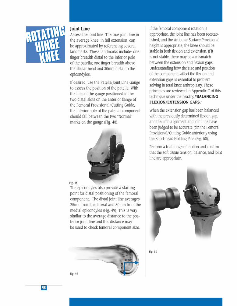
Fig. 49
Fig. 50
46
If the femoral component rotation is appropriate, the joint line has been reestab-lished, and the Articular Surface Provisional height is appropriate, the knee should be stable in both fl exion and extension. If it is not stable, there may be a mismatch between the extension and fl exion gaps. Understanding how the size and position of the components affect the fl exion and extension gaps is essential to problem solving in total knee arthroplasty. These principles are reviewed in Appendix C of this technique under the heading “BALANCING FLEXION/EXTENSION GAPS.”
When the extension gap has been balanced with the previously determined fl exion gap, and the limb alignment and joint line have been judged to be accurate, pin the Femoral Provisional/Cutting Guide anteriorly using the Short-head Holding Pins (Fig. 50).
Perform a trial range of motion and confi rm that the soft tissue tension, balance, and joint line are appropriate.
Fig. 48
30mm30mm
Joint LineAssess the joint line. The true joint line in the average knee, in full extension, can be approximated by referencing several landmarks. These landmarks include: one fi nger breadth distal to the inferior pole of the patella; one fi nger breadth above the fi bular head and 30mm distal to the epicondyles.
If desired, use the Patella Joint Line Gauge to assess the position of the patella. With the tabs of the gauge positioned in the two distal slots on the anterior fl ange of the Femoral Provisional/Cutting Guide, the inferior pole of the patellar component should fall between the two “Normal” marks on the gauge (Fig. 48).
The epicondyles also provide a starting point for distal positioning of the femoral component. The distal joint line averages 25mm from the lateral and 30mm from the medial epicondyles (Fig. 49). This is very similar to the average distance to the pos-terior joint line and this distance may be used to check femoral component size.
MA
KE
FE
MO
RA
L
AU
GM
EN
T C
UT
S
8
STEP ONE DETERMINE TIBIAL PROSTHETIC PLATFORM
STEP TWO FINISH THE TIBIA
STEP THREE PREPARE THE FEMORAL CANAL
STEP FOUR EVALUATE FEMORAL SIZE
STEP FIVE ESTABLISH FEMORAL ROTATION
STEP SIX ESTABLISH FLEXION GAP AND STABILITY
STEP SEVEN ESTABLISH EXTENSION GAP AND STABILITY
STEP EIGHT MAKE FEMORAL AUGMENT CUTS
STEP NINE PREPARE FOR THE ROTATING HINGE KNEE BOX
STEP TEN PREPARE THE PATELLA
STEP ELEVEN PERFORM TRIAL REDUCTION
STEP TWELVE COMPONENT ASSEMBLY/IMPLANTATION/
LOCKING MECHANISM
APPENDIX A CROSSOVER TECHNIQUE
APPENDIX B RESECTING THE DISTAL FEMUR
APPENDIX C BALANCING FLEXION/EXTENSION GAPS
APPENDIX D USING THE 5-IN-1 INSTRUMENTATION
SYSTEM FOR A ROTATING HINGE KNEE
PRIMARY PROCEDURE
APPENDIX E USING THE 5-IN-1 INSTRUMENTATION
SYSTEM FOR A ROTATING HINGE KNEE
REVISION PROCEDURE
APPENDIX F USING THE 5-IN-1 INSTRUMENTATION
SYSTEM FOR A ROTATING HINGE KNEE
WITH OFFSET STEM
APPENDIX G SERVICING THE HINGE MECHANISM
MU
LTI-
RE
FER
EN
CE
4-in
-11
MU
LTI-
RE
FER
EN
CE
4-in
-1
2
MU
LTI-
RE
FER
EN
CE
4-in
-1
3
MU
LTI-
RE
FER
EN
CE
4-in
-1
4
MU
LTI-
RE
FER
EN
CE
4-in
-1
5
49
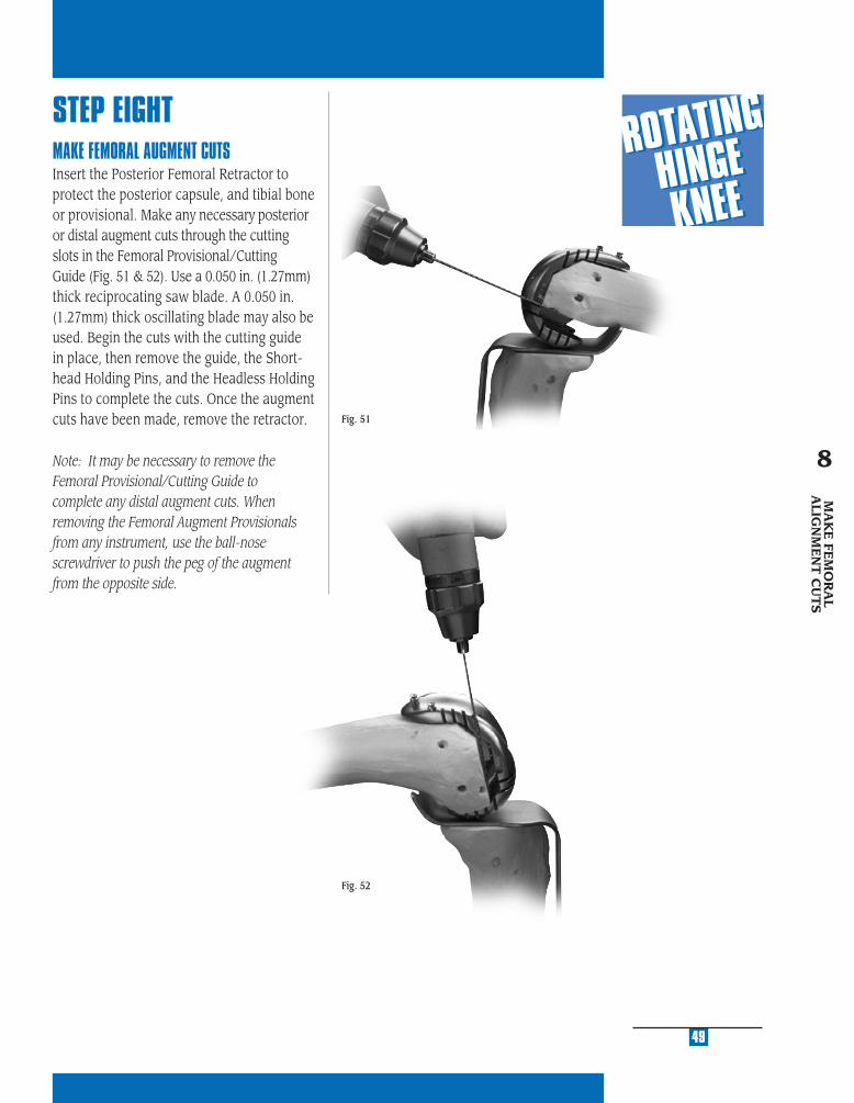
STEP EIGHTMAKE FEMORAL AUGMENT CUTSInsert the Posterior Femoral Retractor to protect the posterior capsule, and tibial bone or provisional. Make any necessary posterior or distal augment cuts through the cutting slots in the Femoral Provisional/Cutting Guide (Fig. 51 & 52). Use a 0.050 in. (1.27mm) thick reciprocating saw blade. A 0.050 in. (1.27mm) thick oscillating blade may also be used. Begin the cuts with the cutting guide in place, then remove the guide, the Short-head Holding Pins, and the Headless Holding Pins to complete the cuts. Once the augment cuts have been made, remove the retractor.
Note: It may be necessary to remove the Femoral Provisional/Cutting Guide to complete any distal augment cuts. When removing the Femoral Augment Provisionals from any instrument, use the ball-nose screwdriver to push the peg of the augment from the opposite side.
Fig. 51
Fig. 52
MA
KE
FEM
OR
AL
ALIG
NM
EN
T C
UT
S
8

PR
EPA
RE
FO
R T
HE
R
OTA
TIN
G H
ING
E K
NE
E B
OX
9
STEP ONE DETERMINE TIBIAL PROSTHETIC PLATFORM
STEP TWO FINISH THE TIBIA
STEP THREE PREPARE THE FEMORAL CANAL
STEP FOUR EVALUATE FEMORAL SIZE
STEP FIVE ESTABLISH FEMORAL ROTATION
STEP SIX ESTABLISH FLEXION GAP AND STABILITY
STEP SEVEN ESTABLISH EXTENSION GAP AND STABILITY
STEP EIGHT MAKE FEMORAL AUGMENT CUTS
STEP NINE PREPARE FOR THE ROTATING HINGE KNEE BOX
STEP TEN PREPARE THE PATELLA
STEP ELEVEN PERFORM TRIAL REDUCTION
STEP TWELVE COMPONENT ASSEMBLY/IMPLANTATION/
LOCKING MECHANISM
APPENDIX A CROSSOVER TECHNIQUE
APPENDIX B RESECTING THE DISTAL FEMUR
APPENDIX C BALANCING FLEXION/EXTENSION GAPS
APPENDIX D USING THE 5-IN-1 INSTRUMENTATION
SYSTEM FOR A ROTATING HINGE KNEE
PRIMARY PROCEDURE
APPENDIX E USING THE 5-IN-1 INSTRUMENTATION
SYSTEM FOR A ROTATING HINGE KNEE
REVISION PROCEDURE
APPENDIX F USING THE 5-IN-1 INSTRUMENTATION
SYSTEM FOR A ROTATING HINGE KNEE
WITH OFFSET STEM
APPENDIX G SERVICING THE HINGE MECHANISM

MU
LTI-
RE
FER
EN
CE
4-in
-11
MU
LTI-
RE
FER
EN
CE
4-in
-1
2
MU
LTI-
RE
FER
EN
CE
4-in
-1
3
MU
LTI-
RE
FER
EN
CE
4-in
-1
4
MU
LTI-
RE
FER
EN
CE
4-in
-1
5
STEP NINEPREPARE FOR THE ROTATING HINGE KNEE BOXRemove the Short-Head Holding Pins from the anterior fl ange of the Rotating Hinge Knee Femoral Provisional/Cutting Guide. Leave the two headless pins distally or reinsert the pins if they were previously removed. These pins will serve to provide rotational alignment for the Rotating Hinge Knee Notch/Chamfer Guide.
Note: One headless pin will also provide suffi cient rotational alignment.
Remove the Femoral Provisional/Cutting Guide and Stem Extension Provisional (Fig. 53). Remove the Stem Extension
Provisional from the Femoral Provisional/Cutting Guide and insert it into the Stem Extension Bushing (Fig. 54). When using an offset stem, fully thread the Offset Stem Locknut onto the appropriate size offset Stem Extension Provisional. Then back thread the locknut until it engages only the fi rst thread. Thread the offset provisional onto the Stem Extension Bushing and rotate the Offset Stem Extension Provisional so that the appropriate number, noted earlier on the Offset Bushing (See Fig. 37, p. 35 and Fig. 43, p. 37), is lined up with the mark on the bushing.
53
Fig. 54
Use the Offset Stem Wrench to tighten the locknut against the Stem Extension Bushing (Fig. 55). Attach any necessary Distal Femoral Augment Provisionals to the Rotating Hinge Knee Notch/Chamfer Guide (Fig. 56). These provisionals should correspond to the augment cuts that were made in Step Eight (Fig. 52, p. 49).
Fig. 53
Fig. 56
Fig. 55
Stem Extension Bushing
PR
EPA
RE
FOR
T
HE
RO
TAT
ING
H
ING
E K
NE
E B
OX
9
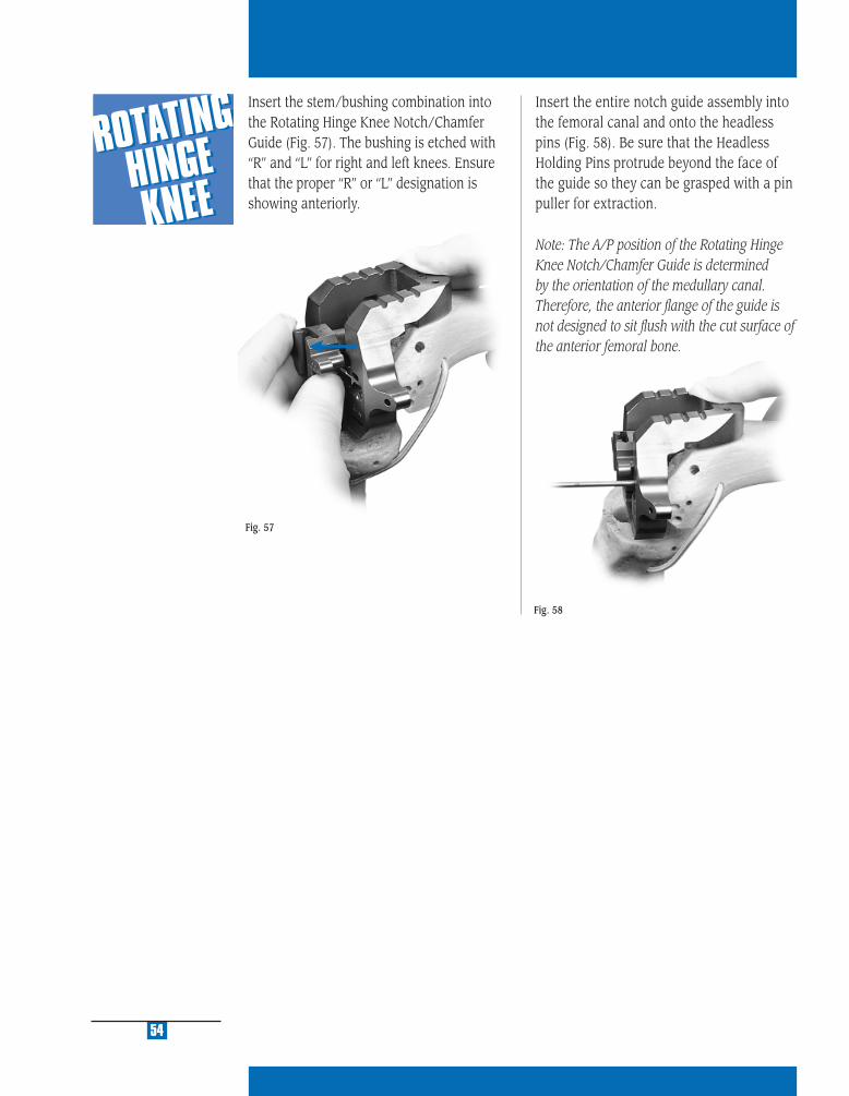
Fig. 57
Fig. 58
Insert the entire notch guide assembly into the femoral canal and onto the headless pins (Fig. 58). Be sure that the Headless Holding Pins protrude beyond the face of the guide so they can be grasped with a pin puller for extraction.
Note: The A/P position of the Rotating Hinge Knee Notch/Chamfer Guide is determined by the orientation of the medullary canal. Therefore, the anterior fl ange of the guide is not designed to sit fl ush with the cut surface of the anterior femoral bone.
54
Insert the stem/bushing combination into the Rotating Hinge Knee Notch/Chamfer Guide (Fig. 57). The bushing is etched with “R” and “L” for right and left knees. Ensure that the proper “R” or “L” designation is showing anteriorly.
MU
LTI-
RE
FER
EN
CE
4-in
-11
MU
LTI-
RE
FER
EN
CE
4-in
-1
2
MU
LTI-
RE
FER
EN
CE
4-in
-1
3
MU
LTI-
RE
FER
EN
CE
4-in
-1
4
MU
LTI-
RE
FER
EN
CE
4-in
-1
5
Fig. 59
Fig. 60
55
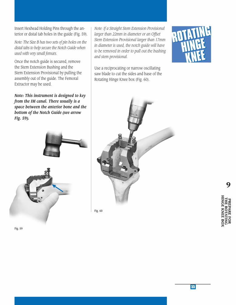
Insert Hexhead Holding Pins through the an-terior or distal tab holes in the guide (Fig. 59).
Note: The Size B has two sets of pin holes on the distal tabs to help secure the Notch Guide when used with very small femurs.
Once the notch guide is secured, remove the Stem Extension Bushing and the Stem Extension Provisional by pulling the assembly out of the guide. The Femoral Extractor may be used.
Note: This instrument is designed to key from the IM canal. There usually is a space between the anterior bone and the bottom of the Notch Guide (see arrow Fig. 59).
Note: If a Straight Stem Extension Provisional larger than 22mm in diameter or an Offset Stem Extension Provisional larger than 17mm in diameter is used, the notch guide will have to be removed in order to pull out the bushing and stem provisional.
Use a reciprocating or narrow oscillating saw blade to cut the sides and base of the Rotating Hinge Knee box (Fig. 60).
PR
EPA
RE
FOR
T
HE
RO
TAT
ING
HIN
GE
KN
EE
BO
X
9
56
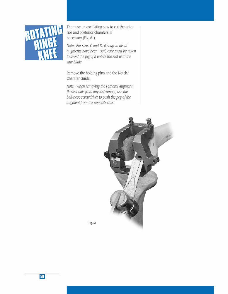
Then use an oscillating saw to cut the ante-rior and posterior chamfers, if necessary (Fig. 61).
Note: For sizes C and D, if snap-in distal augments have been used, care must be taken to avoid the peg if it enters the slot with the saw blade.
Remove the holding pins and the Notch/ Chamfer Guide.
Note: When removing the Femoral Augment Provisionals from any instrument, use the ball-nose screwdriver to push the peg of the augment from the opposite side.
Fig. 61

PR
EPA
RE
T
HE
PA
TE
LLA
10
STEP ONE DETERMINE TIBIAL PROSTHETIC PLATFORM
STEP TWO FINISH THE TIBIA
STEP THREE PREPARE THE FEMORAL CANAL
STEP FOUR EVALUATE FEMORAL SIZE
STEP FIVE ESTABLISH FEMORAL ROTATION
STEP SIX ESTABLISH FLEXION GAP AND STABILITY
STEP SEVEN ESTABLISH EXTENSION GAP AND STABILITY
STEP EIGHT MAKE FEMORAL AUGMENT CUTS
STEP NINE PREPARE FOR THE ROTATING HINGE KNEE BOX
STEP TEN PREPARE THE PATELLA
STEP ELEVEN PERFORM TRIAL REDUCTION
STEP TWELVE COMPONENT ASSEMBLY/IMPLANTATION/
LOCKING MECHANISM
APPENDIX A CROSSOVER TECHNIQUE
APPENDIX B RESECTING THE DISTAL FEMUR
APPENDIX C BALANCING FLEXION/EXTENSION GAPS
APPENDIX D USING THE 5-IN-1 INSTRUMENTATION
SYSTEM FOR A ROTATING HINGE KNEE
PRIMARY PROCEDURE
APPENDIX E USING THE 5-IN-1 INSTRUMENTATION
SYSTEM FOR A ROTATING HINGE KNEE
REVISION PROCEDURE
APPENDIX F USING THE 5-IN-1 INSTRUMENTATION
SYSTEM FOR A ROTATING HINGE KNEE
WITH OFFSET STEM
APPENDIX G SERVICING THE HINGE MECHANISM

MU
LTI-
RE
FER
EN
CE
4-in
-11
MU
LTI-
RE
FER
EN
CE
4-in
-1
2
MU
LTI-
RE
FER
EN
CE
4-in
-1
3
MU
LTI-
RE
FER
EN
CE
4-in
-1
4
MU
LTI-
RE
FER
EN
CE
4-in
-1
5
To compensate for gross bone deficiency, the NexGen Augmentation Patella* is available. The Augmentation Patella provides the additional option of suturing the patella base to the bone remnant or extensor mechanism to provide adjunctive fixation (Fig. 64). Refer to the NexGen Aug-mentation Patella Surgical Technique (97-5988-102-00) for additional information.
* Indicated for use with bone cement in the U.S.A.
STEP TENPREPARE THE PATELLAThe Rotating Hinge Knee is designed to be used with NexGen patellar components. Sizes 32/41 may be used with either the onlay or inset technique. Smaller diameter patella components must not be used unless using the inset technique. The Rotating Hinge Knee femoral component has a wider intercondylar width. Insetting of the patella is required on smaller patella sizes to provide adequate patellar support.
It is not always necessary to revise the pa-tellar component. A well-fi xed component from the NexGen system may be left. If the component is loose or found to be incompatible, determine if there is enough bone remaining to implant a new patellar component. Suffi cient bone must remain to ensure that the pegs from the new prosthesis do not protrude through the anterior surface (Fig. 62).
If the decision is made to replace the primary patellar component, prepare the patella peg holes for a NexGen Patellar Component by centering the appropriate Patellar Drill Guide over the patella. It may be necessary to rotate the guide to avoid the peg holes from the previous patellar component. Holding the guide fi rmly in place, drill the three peg holes using the Patellar/Femoral Drill Bit.
59
The NexGen Patellar Component requires a minimum of 11mm of remaining bone to allow for the implant pegs. If inadequate bone remains, trim the surface and either leave the inadequate bone or consider use of a patella that has been designed to ad-dress inadequate bone stock (Fig. 63).
PR
EPA
RE
TH
E
PAT
ELLA
10
Fig. 62
Fig. 64
Fig. 63

PE
RFO
RM
TR
IAL
RE
DU
CT
ION
11
STEP ONE DETERMINE TIBIAL PROSTHETIC PLATFORM
STEP TWO FINISH THE TIBIA
STEP THREE PREPARE THE FEMORAL CANAL
STEP FOUR EVALUATE FEMORAL SIZE
STEP FIVE ESTABLISH FEMORAL ROTATION
STEP SIX ESTABLISH FLEXION GAP AND STABILITY
STEP SEVEN ESTABLISH EXTENSION GAP AND STABILITY
STEP EIGHT MAKE FEMORAL AUGMENT CUTS
STEP NINE PREPARE FOR THE ROTATING HINGE KNEE BOX
STEP TEN PREPARE THE PATELLA
STEP ELEVEN PERFORM TRIAL REDUCTION
STEP TWELVE COMPONENT ASSEMBLY/IMPLANTATION/
LOCKING MECHANISM
APPENDIX A CROSSOVER TECHNIQUE
APPENDIX B RESECTING THE DISTAL FEMUR
APPENDIX C BALANCING FLEXION/EXTENSION GAPS
APPENDIX D USING THE 5-IN-1 INSTRUMENTATION
SYSTEM FOR A ROTATING HINGE KNEE
PRIMARY PROCEDURE
APPENDIX E USING THE 5-IN-1 INSTRUMENTATION
SYSTEM FOR A ROTATING HINGE KNEE
REVISION PROCEDURE
APPENDIX F USING THE 5-IN-1 INSTRUMENTATION
SYSTEM FOR A ROTATING HINGE KNEE
WITH OFFSET STEM
APPENDIX G SERVICING THE HINGE MECHANISM
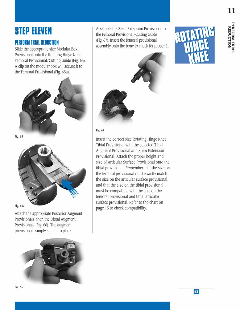
MU
LTI-
RE
FER
EN
CE
4-in
-11
MU
LTI-
RE
FER
EN
CE
4-in
-1
2
MU
LTI-
RE
FER
EN
CE
4-in
-1
3
MU
LTI-
RE
FER
EN
CE
4-in
-1
4
MU
LTI-
RE
FER
EN
CE
4-in
-1
5
Assemble the Stem Extension Provisional to the Femoral Provisional/Cutting Guide (Fig. 67). Insert the femoral provisional assembly onto the bone to check for proper fi t.
Insert the correct size Rotating Hinge Knee Tibial Provisional with the selected Tibial Augment Provisional and Stem Extension Provisional. Attach the proper height and size of Articular Surface Provisional onto the tibial provisional. Remember that the size on the femoral provisional must exactly match the size on the articular surface provisional, and that the size on the tibial provisional must be compatible with the size on the femoral provisional and tibial articular surface provisional. Refer to the chart on page 15 to check compatibility.
Attach the appropriate Posterior Augment Provisionals, then the Distal Augment Provisionals (Fig. 66). The augment provisionals simply snap into place.
STEP ELEVENPERFORM TRIAL REDUCTIONSlide the appropriate size Modular Box Provisional onto the Rotating Hinge Knee Femoral Provisional/Cutting Guide (Fig. 65). A clip on the modular box will secure it to the Femoral Provisional (Fig. 65a).
Fig. 65
Fig. 66
63
Fig. 67
PE
RFO
RM
TR
IAL
RE
DU
CT
ION
11
Fig. 65a
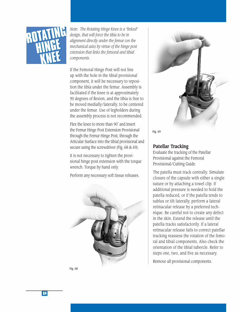
64
Fig. 68
Fig. 69
Note: The Rotating Hinge Knee is a “linked” design, that will force the tibia to be in alignment directly under the femur (on the mechanical axis) by virtue of the hinge post extension that links the femoral and tibial components.
If the Femoral Hinge Post will not line up with the hole in the tibial provisional component, it will be necessary to reposi-tion the tibia under the femur. Assembly is facilitated if the knee is at approximately 90 degrees of fl exion, and the tibia is free to be moved medially/laterally, to be centered under the femur. Use of legholders during the assembly process is not recommended.
Flex the knee to more than 90˚ and insert the Femur Hinge Post Extension Provisional through the Femur Hinge Post, through the Articular Surface into the tibial provisional and secure using the screwdriver (Fig. 68 & 69).
It is not necessary to tighten the provi-sional hinge post extension with the torque wrench. Torque by hand only.
Perform any necessary soft tissue releases.
Patellar TrackingEvaluate the tracking of the Patellar Provisional against the Femoral Provisional/Cutting Guide.
The patella must track centrally. Simulate closure of the capsule with either a single suture or by attaching a towel clip. If additional pressure is needed to hold the patella reduced, or if the patella tends to sublux or tilt laterally, perform a lateral retinacular release by a preferred tech-nique. Be careful not to create any defect in the skin. Extend the release until the patella tracks satisfactorily. If a lateral retinacular release fails to correct patellar tracking reassess the rotation of the femo-ral and tibial components. Also check the orientation of the tibial tubercle. Refer to steps one, two, and five as necessary.
Remove all provisional components.

CO
MP
ON
EN
T A
SSE
MB
LY/
IMP
LA
NTA
TIO
N/ L
OC
KIN
G M
EC
HA
NIS
M
12
STEP ONE DETERMINE TIBIAL PROSTHETIC PLATFORM
STEP TWO FINISH THE TIBIA
STEP THREE PREPARE THE FEMORAL CANAL
STEP FOUR EVALUATE FEMORAL SIZE
STEP FIVE ESTABLISH FEMORAL ROTATION
STEP SIX ESTABLISH FLEXION GAP AND STABILITY
STEP SEVEN ESTABLISH EXTENSION GAP AND STABILITY
STEP EIGHT MAKE FEMORAL AUGMENT CUTS
STEP NINE PREPARE FOR THE ROTATING HINGE KNEE BOX
STEP TEN PREPARE THE PATELLA
STEP ELEVEN PERFORM TRIAL REDUCTION
STEP TWELVE COMPONENT ASSEMBLY/IMPLANTATION/
LOCKING MECHANISM
APPENDIX A CROSSOVER TECHNIQUE
APPENDIX B RESECTING THE DISTAL FEMUR
APPENDIX C BALANCING FLEXION/EXTENSION GAPS
APPENDIX D USING THE 5-IN-1 INSTRUMENTATION
SYSTEM FOR A ROTATING HINGE KNEE
PRIMARY PROCEDURE
APPENDIX E USING THE 5-IN-1 INSTRUMENTATION
SYSTEM FOR A ROTATING HINGE KNEE
REVISION PROCEDURE
APPENDIX F USING THE 5-IN-1 INSTRUMENTATION
SYSTEM FOR A ROTATING HINGE KNEE
WITH OFFSET STEM
APPENDIX G SERVICING THE HINGE MECHANISM

MU
LTI-
RE
FER
EN
CE
4-in
-11
MU
LTI-
RE
FER
EN
CE
4-in
-1
2
MU
LTI-
RE
FER
EN
CE
4-in
-1
3
MU
LTI-
RE
FER
EN
CE
4-in
-1
4
MU
LTI-
RE
FER
EN
CE
4-in
-1
5
67
STEP TWELVECOMPONENT IMPLANTATIONAfter the implants have been chosen, refer to the size interchangeability chart, on page 15, to make one last check to ensure that the femoral, tibial, and articular surface components match.
FEMORAL COMPONENT PREPARATION
Stem ExtensionThe locking mechanism between the femo-ral implant and the stem extension implant is a combination of a Morse-type taper and two set screws. Remove the stem extension locking screw from the stem extension and discard. The stem extension screw is not used with the stemmed femoral component.
Check to ensure that the set screws have not migrated into the femoral stem base taper prior to inserting the stem extension. Insert the stem extension into the base of the femoral component. When using the offset stem extension, use the stem loca-tion referenced earlier and line up that stem location number with the etched line on the posterior stem base housing (see arrow Fig. 70). The stem extension should be “snug” in the femoral component base. If toggle exists, back out one or both of the set screws one half turn. When a “snug” fi t is achieved, wrap the femoral component in a cloth and place it on a surgical cart. While protecting the stem extension, strike it solidly one time with a two-pound mallet.
Note: Hitting the stem more than once may loosen the taper connection.
After seating the Morse-type taper, tighten the two set screws located in the base of the femoral component. Use the Femoral Set Screw Hex Driver and apply moderate torque to tighten each of the two set screws (Fig. 70).
Note: The Femoral Set Screw Hex Driver is designed to limit the amount of torque which can be applied to the set screws. Torque by hand only. It is not necessary to break the Femoral Set Screw Hex Driver.
It is recommended that a stem extension always be used with the Rotating Hinge Knee Femoral Component. If, in the sur-geon’s opinion, a stem is not needed, then the set screws should be removed before implanting the femoral component.
Fig. 70
CO
MP
ON
EN
T A
SSE
MB
LY/
IMPLA
NTA
TION
/LO
CK
ING
ME
CH
AN
ISM
12
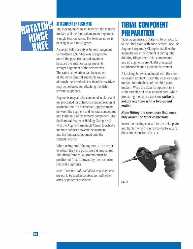
ATTACHMENT OF AUGMENTSThe locking mechanism between the femoral implant and the femoral augment implant is a single fi xation screw. The fi xation screw is packaged with the augment.
A special ball-nose style Femoral Augment Screwdriver (5987-89) was designed to attach the posterior lateral augment because the anterior fl ange prevents straight alignment of the screwdriver. The same screwdriver can be used on all the other femoral augments as well, although the standard Hex-Head Screwdriver may be preferred for attaching the distal femoral augments.
Augments may also be cemented in place and are precoated for enhanced cement fi xation. If augments are to be cemented, apply cement between the augment and femoral component, and to the rails of the femoral component. Use the Femoral Augment Holding Clamp Head with the Augment Assembly Clamp to achieve intimate contact between the augment and the femoral component until the cement is cured.
When using multiple augments, the order in which they are positioned is important. The distal femoral augments must be positioned first, followed by the posterior femoral augments.
Note: Posterior-only and distal-only augments are not to be used in combination with other distal or posterior augments.
TIBIAL COMPONENT PREPARATIONTibial augments are designed to be secured to the tibial plate with bone cement. Use the Augment Assembly Clamp to stabilize the augment while the cement is curing. The Rotating Hinge Knee tibial components and all augments are PMMA precoated to enhance fi xation to the bone cement.
A Locking Screw is included with the stem extension implant. Insert the stem extension implant into the base of the tibial plate implant. Wrap the tibial component in a cloth and place it on a surgical cart. While protecting the stem extension, strike it solidly one time with a two-pound mallet.
Note: Hitting the stem more than once may loosen the taper connection.
Insert the locking screw into the tibial plate and tighten with the screwdriver to secure the stem extension (Fig. 71).
68
Fig. 71
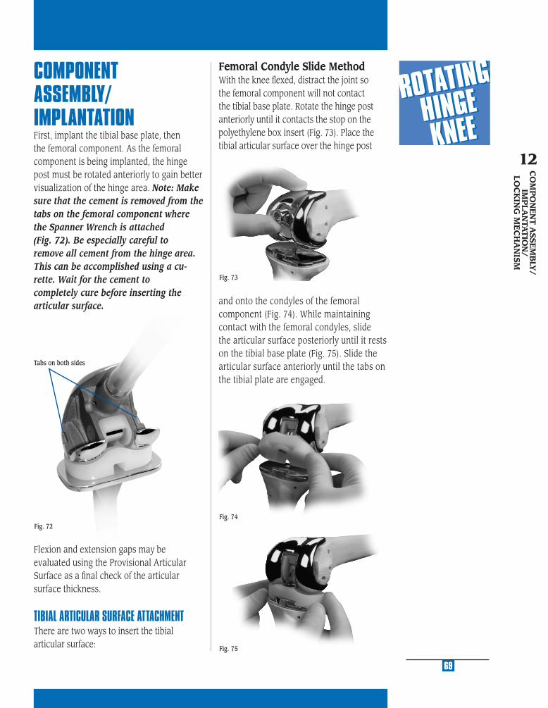
MU
LTI-
RE
FER
EN
CE
4-in
-11
MU
LTI-
RE
FER
EN
CE
4-in
-1
2
MU
LTI-
RE
FER
EN
CE
4-in
-1
3
MU
LTI-
RE
FER
EN
CE
4-in
-1
4
MU
LTI-
RE
FER
EN
CE
4-in
-1
5
Fig. 73
69
COMPONENT ASSEMBLY/IMPLANTATIONFirst, implant the tibial base plate, then the femoral component. As the femoral component is being implanted, the hinge post must be rotated anteriorly to gain better visualization of the hinge area. Note: Make sure that the cement is removed from the tabs on the femoral component where the Spanner Wrench is attached (Fig. 72). Be especially careful to remove all cement from the hinge area. This can be accomplished using a cu-rette. Wait for the cement to completely cure before inserting the articular surface.
Flexion and extension gaps may be evaluated using the Provisional Articular Surface as a fi nal check of the articular surface thickness.
TIBIAL ARTICULAR SURFACE ATTACHMENTThere are two ways to insert the tibial articular surface:
and onto the condyles of the femoral component (Fig. 74). While maintaining contact with the femoral condyles, slide the articular surface posteriorly until it rests on the tibial base plate (Fig. 75). Slide the articular surface anteriorly until the tabs on the tibial plate are engaged.
Fig. 74
Fig. 75
CO
MP
ON
EN
T A
SSEM
BLY
/IM
PLA
NTA
TIO
N/
LOC
KIN
G M
EC
HA
NIS
M
12
Femoral Condyle Slide MethodWith the knee fl exed, distract the joint so the femoral component will not contact the tibial base plate. Rotate the hinge post anteriorly until it contacts the stop on the polyethylene box insert (Fig. 73). Place the tibial articular surface over the hinge post
Fig. 72
Tabs on both sides

70
Fig. 77
Fig. 78
Fig. 76
Distraction MethodWith the knee fl exed, distract the joint so the femoral component will not contact the tibial base plate. Rotate the hinge post anteriorly until it contacts the stop on the polyethylene box insert (Fig. 76). Place the tibial articular surface onto the tibial base plate and slide it forward until it engages the tab (Fig. 77). While distracting the joint, rotate the hinge post posteriorly until it drops into the hole in the middle of the articular surface (Fig. 78).
THE LOCKING MECHANISM OF THE ROTATING HINGE KNEETightening of the taper on the Hinge Post Extension is critical to achieving security of the locking mechanism of the implant. Use of the Spanner Wrench to counteract the opposing forces of the Rotating Hinge Knee Torque Wrench ensures minimal forces are transmitted to the fi xation surfaces, and reduces the potential of binding. Tightening to the level indicated on the Torque Wrench is the most important step in the surgi-cal technique because it “locks” the Hinge Post Extension into position. The Hinge Post Extension is designed with a 4 degree Morse-type taper below the threads (Fig. 79). This 4 degree taper mates with a taper in the hinge post to provide the “lock” between the components. If the hinge post assembly in not properly tightened, postoperative disassembly could potentially occur.
Fig. 79
The hinge post extension threadsinto the hinge post and drives the4 degree Morse-type taper to lock.
4˚

MU
LTI-
RE
FER
EN
CE
4-in
-11
MU
LTI-
RE
FER
EN
CE
4-in
-1
2
MU
LTI-
RE
FER
EN
CE
4-in
-1
3
MU
LTI-
RE
FER
EN
CE
4-in
-1
4
MU
LTI-
RE
FER
EN
CE
4-in
-1
5
71
CO
MP
ON
EN
T A
SSEM
BLY
/IM
PLA
NTA
TIO
N/
LOC
KIN
G M
EC
HA
NIS
M
12
Freedom of the hinge post extension to rotate within the hinge may be compromised (re-duced) by binding between the threads of the hinge post and hinge post extension. This binding is created when the tibial is not aligned directly under the femoral component (Fig 80).
This malalignment creates friction between the threads of the hinge post and hinge post extension as the extension is inserted and turned. The friction in the hinge post extension can lead to a reduction in the tightening torque being applied to threads just above the 4 degree Morse Taper. As bending forces (binding) increase, the rotational torque that is applied to the hinge post extension decreases. This could directly affect locking of the 4 degree locking taper. In cases where this malalignment is signifi cant, it is possible for bending forces to increase to the point where even though the torque wrench reads to the proper level, only a fraction of tightening force is being exerted to the screw threads and Morse Taper. In this case, the 4 degree Morse Taper may not be fully locked. As earlier discussed, adequate taper locking is critical to maintaining assembly.
It is possible to address this concern at the time of implant assembly by following these recommendations.
If diffi culty is encountered in assembling or disassembling the provisional hinge post
components, it is necessary to reposition the lower leg (tibia) under the femur until the hinge post extension pin slips easily into place. The same is true for the implant assembly. The hinge post extension should easily slide through the hole in the top of the hinge post and into the tibial base plate (Fig. 81).
Direction of forcefrom the ankle
Direction of forcefrom the femur
Creates a “Binding” between the threads of the hinge post and hinge post extensions
The Hinge Post Extension will require the tibia to be located directly under the femur. If they are not, it will be diffi cult to insert the hinge post extension. To solve – reposition the lower leg under the femur.
Fig. 80
Fig. 81
The surgeon should be able to easily turn (thread) the hinge post extension until it is fl ush with the top of the hinge using only two fi ngers on the hex head screwdriver. If signifi cant resistace to turning is encountered, the tibial/femoral alignment must be altered to remove the binding force.
Proper alignment must be maintained during the entire assembly process. It is critical to continue to maintain this orientation during the time that the spanner wrench is assembled, and the torque wrench is tightened. Remember, if resistance to turning is encountered, a malalignment is creating a bending force (binding) and reducing the locking torque on the 4 degree Morse Taper.
To confi rm that the femur and tibia are in alignment during the tightening process, use the Knurled Driver to fi nger tighten and loosen the hinge post extension a half turn immediately prior to use of the Torque Wrench. The proper upper/ lower leg alignment position must then be maintained throughout the tightening process.

torque until the needle on the wrench reaches the appropriate mark on the torque wrench (Fig. 84 & 85). While torque is being applied, counter rotation is applied using the Spanner Wrench.
Note: Do not over- or under-torque. Under-tightening of the hinge post extension may allow it to loosen over time. Overtightening is not necessary.
HINGE POST EXTENSION INSERTIONMake sure that the hinge post and hinge post extension tapers are clean and dry prior to assembly of the components. The appropriate length hinge post extension is packaged with each articular surface. Align the hinge post with the hole in the top of the tibial base plate, and insert the hinge post extension in the hinge post through the articular surface and into the hole on the tibial base plate (Fig. 82). Thread the hinge post extension into the hinge post, by hand, using the driver (Fig. 83).
Leave the driver in the hinge post extension. Attach the Spanner Wrench to the two tabs on the outside of the medial and lateral femoral component. Thumb tighten the knurled wheel to snug the wrench to the distal femoral condyles. Attach the Rotating Hinge Knee Defl ection Beam Torque Wrench to the driver, and apply 130 in.-lbs. (15n-m) of
72
Fig. 83
Fig. 82
Fig. 85
Fig. 84

CR
OSSO
VE
R
TE
CH
NIQ
UE
A
STEP ONE DETERMINE TIBIAL PROSTHETIC PLATFORM
STEP TWO FINISH THE TIBIA
STEP THREE PREPARE THE FEMORAL CANAL
STEP FOUR EVALUATE FEMORAL SIZE
STEP FIVE ESTABLISH FEMORAL ROTATION
STEP SIX ESTABLISH FLEXION GAP AND STABILITY
STEP SEVEN ESTABLISH EXTENSION GAP AND STABILITY
STEP EIGHT MAKE FEMORAL AUGMENT CUTS
STEP NINE PREPARE FOR THE ROTATING HINGE KNEE BOX
STEP TEN PREPARE THE PATELLA
STEP ELEVEN PERFORM TRIAL REDUCTION
STEP TWELVE COMPONENT ASSEMBLY/IMPLANTATION/
LOCKING MECHANISM
APPENDIX A CROSSOVER TECHNIQUE
APPENDIX B RESECTING THE DISTAL FEMUR
APPENDIX C BALANCING FLEXION/EXTENSION GAPS
APPENDIX D USING THE 5-IN-1 INSTRUMENTATION
SYSTEM FOR A ROTATING HINGE KNEE
PRIMARY PROCEDURE
APPENDIX E USING THE 5-IN-1 INSTRUMENTATION
SYSTEM FOR A ROTATING HINGE KNEE
REVISION PROCEDURE
APPENDIX F USING THE 5-IN-1 INSTRUMENTATION
SYSTEM FOR A ROTATING HINGE KNEE
WITH OFFSET STEM
APPENDIX G SERVICING THE HINGE MECHANISM
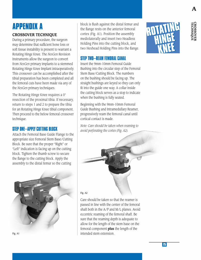
MU
LTI-
RE
FER
EN
CE
4-in
-11
MU
LTI-
RE
FER
EN
CE
4-in
-1
2
MU
LTI-
RE
FER
EN
CE
4-in
-1
3
MU
LTI-
RE
FER
EN
CE
4-in
-1
4
MU
LTI-
RE
FER
EN
CE
4-in
-1
5
Fig. A2
APPENDIX ACROSSOVER TECHNIQUEDuring a primary procedure, the surgeon may determine that suffi cient bone loss or soft tissue instability is present to warrant a Rotating Hinge Knee. The NexGen Revision Instruments allow the surgeon to convert from NexGen primary implants to a stemmed Rotating Hinge Knee Implant intraoperatively. This crossover can be accomplished after the tibial preparation has been completed and all the femoral cuts have been made via any of the NexGen primary techniques.
The Rotating Hinge Knee requires a 0° resection of the proximal tibia. If necessary, return to steps 1 and 2 to prepare the tibia for an Rotating Hinge Knee tibial component. Then proceed to the below femoral crossover technique.
STEP ONE–APPLY CUTTING BLOCKAttach the Femoral Base Guide Flange to the appropriate size Femoral Stem Base/Cutting Block. Be sure that the proper “Right” or “Left” indication is facing up on the cutting block. Tighten the thumb screw to secure the fl ange to the cutting block. Apply the assembly to the distal femur so the cutting
Fig. A1
block is fl ush against the distal femur and the fl ange rests on the anterior femoral cortex (Fig. A1). Position the assembly mediolaterally and insert two Headless Holding Pins into the cutting block, and two Hexhead Holding Pins into the fl ange.
STEP TWO–REAM FEMORAL CANALInsert the 9mm-10mm Femoral Guide Bushing into the circular step of the Femoral Stem Base/Cutting Block. The numbers on the bushing should be facing up. The straight bushings are keyed so they can only fi t into the guide one way. A collar inside the cutting block serves as a stop to indicate when the bushing is fully seated.
Beginning with the 9mm-10mm Femoral Guide Bushing and Intramedullary Reamer, progressively ream the femoral canal until cortical contact is made.
Note: Care should be taken when reaming to avoid perforating the cortex (Fig. A2).
75
CR
OSSO
VE
R
TE
CH
NIQ
UE
A
Care should be taken so that the reamer is passed in line with the center of the femoral shaft both in the A/P and M/L planes. Avoid eccentric reaming of the femoral shaft. Be sure that the reaming depth is adequate to allow for the length of the stem base on the femoral component plus the length of the intended stem extension.
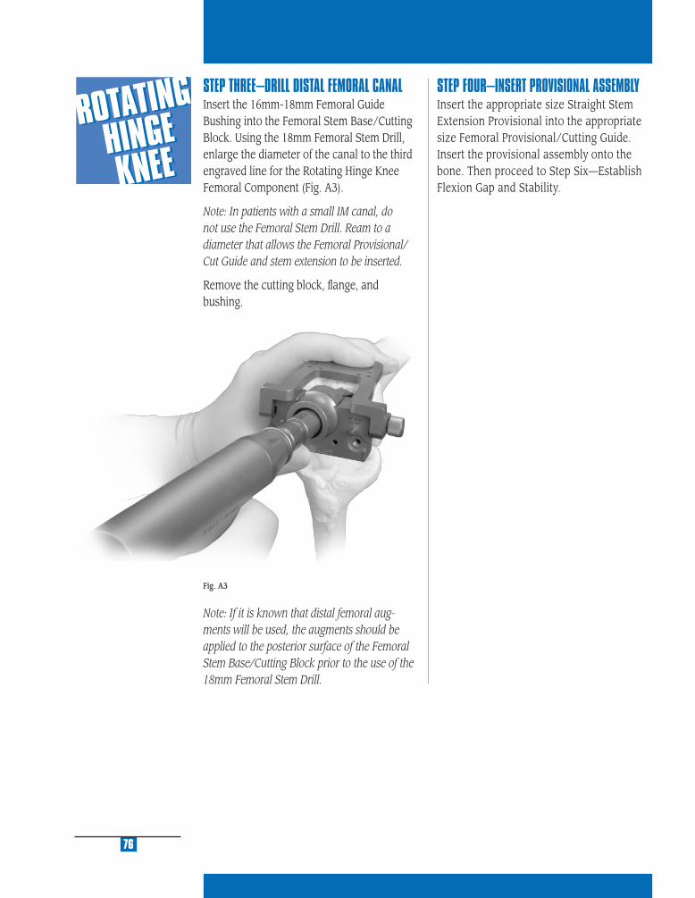
STEP THREE–DRILL DISTAL FEMORAL CANALInsert the 16mm-18mm Femoral Guide Bushing into the Femoral Stem Base/Cutting Block. Using the 18mm Femoral Stem Drill, enlarge the diameter of the canal to the third engraved line for the Rotating Hinge Knee Femoral Component (Fig. A3).
Note: In patients with a small IM canal, do not use the Femoral Stem Drill. Ream to a diameter that allows the Femoral Provisional/ Cut Guide and stem extension to be inserted.
Remove the cutting block, fl ange, and bushing.
Note: If it is known that distal femoral aug-ments will be used, the augments should be applied to the posterior surface of the Femoral Stem Base/Cutting Block prior to the use of the 18mm Femoral Stem Drill.
Fig. A3
76
STEP FOUR–INSERT PROVISIONAL ASSEMBLYInsert the appropriate size Straight Stem Extension Provisional into the appropriate size Femoral Provisional/Cutting Guide.Insert the provisional assembly onto the bone. Then proceed to Step Six—Establish Flexion Gap and Stability.

RE
SE
CT
ING
TH
E
DIS
TA
L F
EM
UR
B
STEP ONE DETERMINE TIBIAL PROSTHETIC PLATFORM
STEP TWO FINISH THE TIBIA
STEP THREE PREPARE THE FEMORAL CANAL
STEP FOUR EVALUATE FEMORAL SIZE
STEP FIVE ESTABLISH FEMORAL ROTATION
STEP SIX ESTABLISH FLEXION GAP AND STABILITY
STEP SEVEN ESTABLISH EXTENSION GAP AND STABILITY
STEP EIGHT MAKE FEMORAL AUGMENT CUTS
STEP NINE PREPARE FOR THE ROTATING HINGE KNEE BOX
STEP TEN PREPARE THE PATELLA
STEP ELEVEN PERFORM TRIAL REDUCTION
STEP TWELVE COMPONENT ASSEMBLY/IMPLANTATION/
LOCKING MECHANISM
APPENDIX A CROSSOVER TECHNIQUE
APPENDIX B RESECTING THE DISTAL FEMUR
APPENDIX C BALANCING FLEXION/EXTENSION GAPS
APPENDIX D USING THE 5-IN-1 INSTRUMENTATION
SYSTEM FOR A ROTATING HINGE KNEE
PRIMARY PROCEDURE
APPENDIX E USING THE 5-IN-1 INSTRUMENTATION
SYSTEM FOR A ROTATING HINGE KNEE
REVISION PROCEDURE
APPENDIX F USING THE 5-IN-1 INSTRUMENTATION
SYSTEM FOR A ROTATING HINGE KNEE
WITH OFFSET STEM
APPENDIX G SERVICING THE HINGE MECHANISM
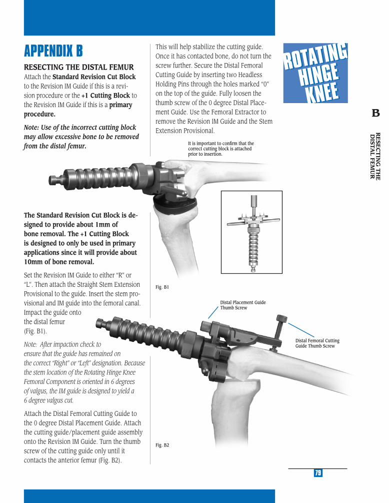
MU
LTI-
RE
FER
EN
CE
4-in
-11
MU
LTI-
RE
FER
EN
CE
4-in
-1
2
MU
LTI-
RE
FER
EN
CE
4-in
-1
3
MU
LTI-
RE
FER
EN
CE
4-in
-1
4
MU
LTI-
RE
FER
EN
CE
4-in
-1
5
APPENDIX BRESECTING THE DISTAL FEMURAttach the Standard Revision Cut Block to the Revision IM Guide if this is a revi-sion procedure or the +1 Cutting Block to the Revision IM Guide if this is a primary procedure.
Note: Use of the incorrect cutting block may allow excessive bone to be removed from the distal femur.
The Standard Revision Cut Block is de-signed to provide about 1mm of bone removal. The +1 Cutting Block is designed to only be used in primary applications since it will provide about 10mm of bone removal.
Set the Revision IM Guide to either “R” or “L”. Then attach the Straight Stem Extension Provisional to the guide. Insert the stem pro-visional and IM guide into the femoral canal. Impact the guide onto the distal femur (Fig. B1).
Note: After impaction check to ensure that the guide has remained on the correct “Right” or “Left” designation. Because the stem location of the Rotating Hinge Knee Femoral Component is oriented in 6 degrees of valgus, the IM guide is designed to yield a 6 degree valgus cut.
Attach the Distal Femoral Cutting Guide to the 0 degree Distal Placement Guide. Attach the cutting guide/placement guide assembly onto the Revision IM Guide. Turn the thumb screw of the cutting guide only until it contacts the anterior femur (Fig. B2).
Fig. B1
Fig. B2
79
It is important to confi rm that the correct cutting block is attached prior to insertion.
Distal Placement Guide Thumb Screw
Distal Femoral Cutting Guide Thumb Screw
This will help stabilize the cutting guide. Once it has contacted bone, do not turn the screw further. Secure the Distal Femoral Cutting Guide by inserting two Headless Holding Pins through the holes marked “0” on the top of the guide. Fully loosen the thumb screw of the 0 degree Distal Place-ment Guide. Use the Femoral Extractor to remove the Revision IM Guide and the Stem Extension Provisional. R
ESE
CT
ING
TH
E
DIS
TAL FE
MU
R
B
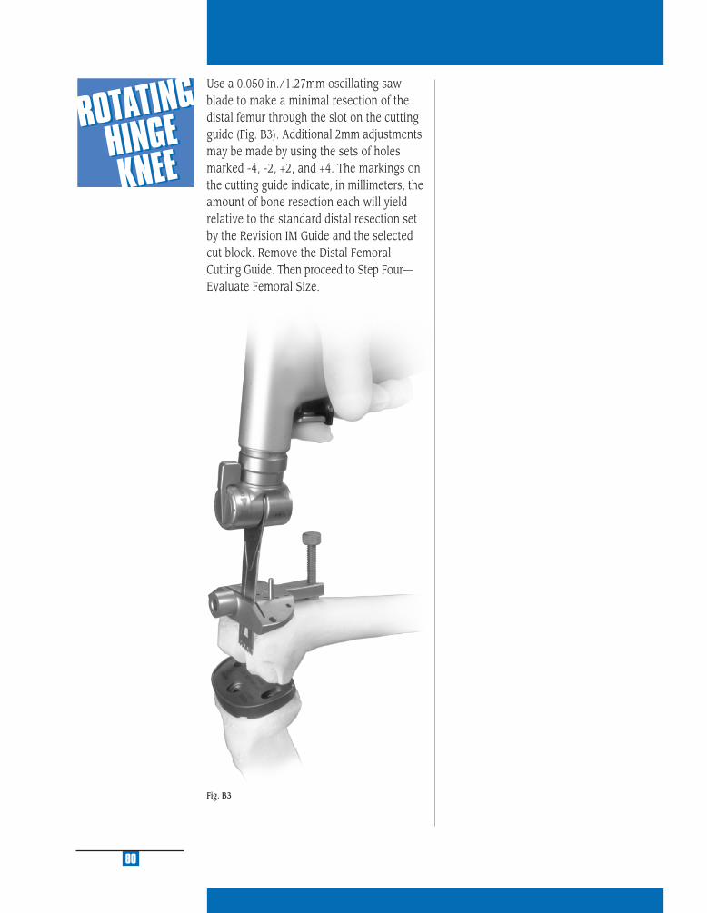
Fig. B3
80
Use a 0.050 in./1.27mm oscillating saw blade to make a minimal resection of the distal femur through the slot on the cutting guide (Fig. B3). Additional 2mm adjustments may be made by using the sets of holes marked -4, -2, +2, and +4. The markings on the cutting guide indicate, in millimeters, the amount of bone resection each will yield relative to the standard distal resection set by the Revision IM Guide and the selected cut block. Remove the Distal Femoral Cutting Guide. Then proceed to Step Four—Evaluate Femoral Size.

BALA
NCIN
G FLEXIO
N/
EXTENSIO
N G
APS
C
STEP ONE DETERMINE TIBIAL PROSTHETIC PLATFORM
STEP TWO FINISH THE TIBIA
STEP THREE PREPARE THE FEMORAL CANAL
STEP FOUR EVALUATE FEMORAL SIZE
STEP FIVE ESTABLISH FEMORAL ROTATION
STEP SIX ESTABLISH FLEXION GAP AND STABILITY
STEP SEVEN ESTABLISH EXTENSION GAP AND STABILITY
STEP EIGHT MAKE FEMORAL AUGMENT CUTS
STEP NINE PREPARE FOR THE ROTATING HINGE KNEE BOX
STEP TEN PREPARE THE PATELLA
STEP ELEVEN PERFORM TRIAL REDUCTION
STEP TWELVE COMPONENT ASSEMBLY/IMPLANTATION/
LOCKING MECHANISM
APPENDIX A CROSSOVER TECHNIQUE
APPENDIX B RESECTING THE DISTAL FEMUR
APPENDIX C BALANCING FLEXION/EXTENSION GAPS
APPENDIX D USING THE 5-IN-1 INSTRUMENTATION
SYSTEM FOR A ROTATING HINGE KNEE
PRIMARY PROCEDURE
APPENDIX E USING THE 5-IN-1 INSTRUMENTATION
SYSTEM FOR A ROTATING HINGE KNEE
REVISION PROCEDURE
APPENDIX F USING THE 5-IN-1 INSTRUMENTATION
SYSTEM FOR A ROTATING HINGE KNEE
WITH OFFSET STEM
APPENDIX G SERVICING THE HINGE MECHANISM
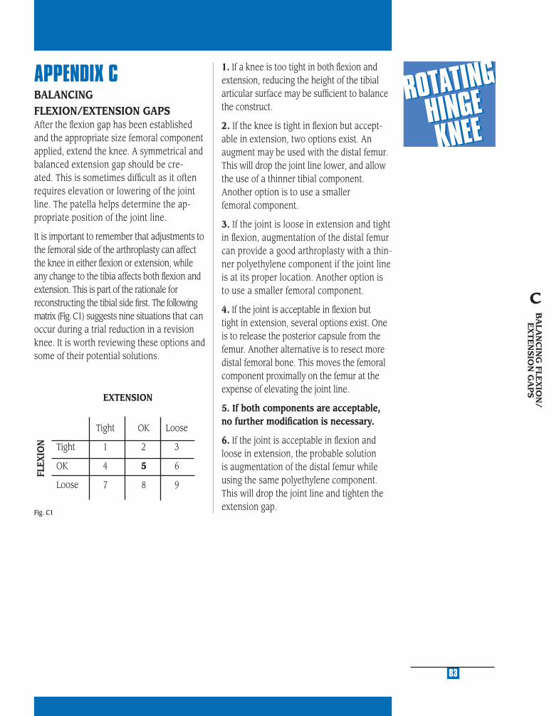
MU
LTI-
RE
FER
EN
CE
4-in
-11
MU
LTI-
RE
FER
EN
CE
4-in
-1
2
MU
LTI-
RE
FER
EN
CE
4-in
-1
3
MU
LTI-
RE
FER
EN
CE
4-in
-1
4
MU
LTI-
RE
FER
EN
CE
4-in
-1
5
82
APPENDIX CBALANCING FLEXION/EXTENSION GAPSAfter the fl exion gap has been established and the appropriate size femoral component applied, extend the knee. A symmetrical and balanced extension gap should be cre-ated. This is sometimes diffi cult as it often requires elevation or lowering of the joint line. The patella helps determine the ap-propriate position of the joint line.
It is important to remember that adjustments to the femoral side of the arthroplasty can affect the knee in either fl exion or extension, while any change to the tibia affects both fl exion and extension. This is part of the rationale for reconstructing the tibial side fi rst. The following matrix (Fig. C1) suggests nine situations that can occur during a trial reduction in a revision knee. It is worth reviewing these options and some of their potential solutions.
1. If a knee is too tight in both fl exion and extension, reducing the height of the tibial articular surface may be suffi cient to balance the construct.
2. If the knee is tight in fl exion but accept-able in extension, two options exist. An augment may be used with the distal femur. This will drop the joint line lower, and allow the use of a thinner tibial component. Another option is to use a smaller femoral component.
3. If the joint is loose in extension and tight in fl exion, augmentation of the distal femur can provide a good arthroplasty with a thin-ner polyethylene component if the joint line is at its proper location. Another option is to use a smaller femoral component.
4. If the joint is acceptable in fl exion but tight in extension, several options exist. One is to release the posterior capsule from the femur. Another alternative is to resect more distal femoral bone. This moves the femoral component proximally on the femur at the expense of elevating the joint line.
5. If both components are acceptable, no further modifi cation is necessary.
6. If the joint is acceptable in fl exion and loose in extension, the probable solution is augmentation of the distal femur while using the same polyethylene component. This will drop the joint line and tighten the extension gap.
Fig. C1
Tight OK Loose
Tight 1 2 3
OK 4 5 6
Loose 7 8 9
EXTENSION
FLEX
ION
83
BA
LAN
CIN
G FLE
XIO
N/
EX
TE
NSIO
N G
AP
S
C
7. If the joint is loose in fl exion and acceptable in extension, a larger femoral component, moved slightly proximal on the femur, may suffi ce. If the original component size was cor-rect, a thicker tibial articular surface and a more proximal femoral position may be necessary.
8. If the joint is loose in fl exion and acceptable in extension, one may choose to accept this situation if it is only of a mild degree, particularly in a highly constrained component. Increasing the femoral size may equalize the gaps. Alternatively, moving the femoral component proximally and applying a thicker tibial articular surface may equalize the gaps.
9. If the joint is symmetrically loose in both fl exion and extension, a thicker tibial articular surface is recommended.
84
Note: After applying one of these solutions, per-form another trial reduction. This will identify any new problem or a variation of the initial problem that now may exist.
Note: Review of the Zimmer Revision Knee Arthroplasty Surgical Guidelines booklet is strongly recommended for a more complete discussion on revision total knee arthroplasty technique. This booklet can be ordered through Zimmer. Please reference catalog number 97-5224-003-00.

STEP ONE DETERMINE TIBIAL PROSTHETIC PLATFORM
STEP TWO FINISH THE TIBIA
STEP THREE PREPARE THE FEMORAL CANAL
STEP FOUR EVALUATE FEMORAL SIZE
STEP FIVE ESTABLISH FEMORAL ROTATION
STEP SIX ESTABLISH FLEXION GAP AND STABILITY
STEP SEVEN ESTABLISH EXTENSION GAP AND STABILITY
STEP EIGHT MAKE FEMORAL AUGMENT CUTS
STEP NINE PREPARE FOR THE ROTATING HINGE KNEE BOX
STEP TEN PREPARE THE PATELLA
STEP ELEVEN PERFORM TRIAL REDUCTION
STEP TWELVE COMPONENT ASSEMBLY/IMPLANTATION/
LOCKING MECHANISM
APPENDIX A CROSSOVER TECHNIQUE
APPENDIX B RESECTING THE DISTAL FEMUR
APPENDIX C BALANCING FLEXION/EXTENSION GAPS
APPENDIX D USING THE 5-IN-1 INSTRUMENTATION
SYSTEM FOR A ROTATING HINGE KNEE
PRIMARY PROCEDURE
APPENDIX E USING THE 5-IN-1 INSTRUMENTATION
SYSTEM FOR A ROTATING HINGE KNEE
REVISION PROCEDURE
APPENDIX F USING THE 5-IN-1 INSTRUMENTATION
SYSTEM FOR A ROTATING HINGE KNEE
WITH OFFSET STEM
APPENDIX G SERVICING THE HINGE MECHANISM
USIN
G 5-IN
-1 INST.
FOR
RO
TATING
HIN
GE
KN
EE PR
IMA
RY
D
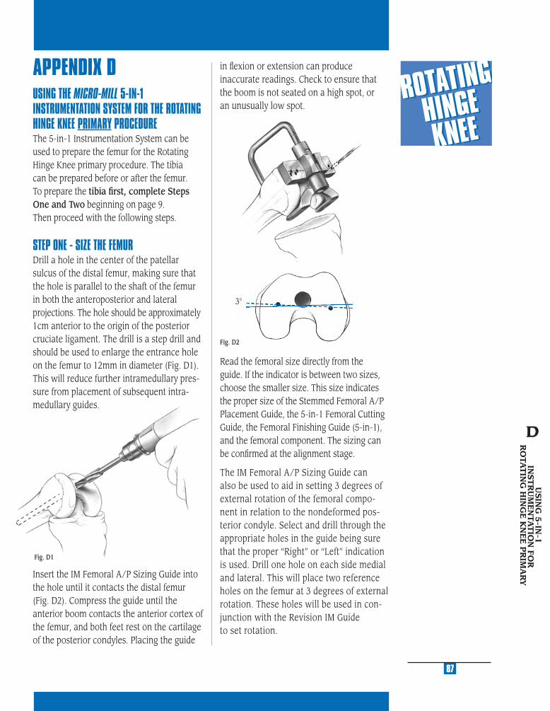
MU
LTI-
RE
FER
EN
CE
4-in
-11
MU
LTI-
RE
FER
EN
CE
4-in
-1
2
MU
LTI-
RE
FER
EN
CE
4-in
-1
3
MU
LTI-
RE
FER
EN
CE
4-in
-1
4
MU
LTI-
RE
FER
EN
CE
4-in
-1
5
APPENDIX DUSING THE MICRO-MILL 5-IN-1 INSTRUMENTATION SYSTEM FOR THE ROTATING HINGE KNEE PRIMARY PROCEDURE The 5-in-1 Instrumentation System can be used to prepare the femur for the Rotating Hinge Knee primary procedure. The tibia can be prepared before or after the femur. To prepare the tibia fi rst, complete Steps One and Two beginning on page 9. Then proceed with the following steps.
STEP ONE - SIZE THE FEMURDrill a hole in the center of the patellar sulcus of the distal femur, making sure that the hole is parallel to the shaft of the femur in both the anteroposterior and lateral projections. The hole should be approximately 1cm anterior to the origin of the posterior cruciate ligament. The drill is a step drill and should be used to enlarge the entrance hole on the femur to 12mm in diameter (Fig. D1). This will reduce further intramedullary pres-sure from placement of subsequent intra-medullary guides.
Insert the IM Femoral A/P Sizing Guide into the hole until it contacts the distal femur (Fig. D2). Compress the guide until the anterior boom contacts the anterior cortex of the femur, and both feet rest on the cartilage of the posterior condyles. Placing the guide
Read the femoral size directly from the guide. If the indicator is between two sizes, choose the smaller size. This size indicates the proper size of the Stemmed Femoral A/P Placement Guide, the 5-in-1 Femoral Cutting Guide, the Femoral Finishing Guide (5-in-1), and the femoral component. The sizing can be confi rmed at the alignment stage.
The IM Femoral A/P Sizing Guide can also be used to aid in setting 3 degrees of external rotation of the femoral compo-nent in relation to the nondeformed pos-terior condyle. Select and drill through the appropriate holes in the guide being sure that the proper “Right” or “Left” indication is used. Drill one hole on each side medial and lateral. This will place two reference holes on the femur at 3 degrees of external rotation. These holes will be used in con-junction with the Revision IM Guide to set rotation.
Fig. D1
87
USIN
G 5
-IN-1
IN
ST
RU
ME
NTA
TIO
N FO
R
RO
TAT
ING
HIN
GE
KN
EE
PR
IMA
RY
D
3°
in fl exion or extension can produce inaccurate readings. Check to ensure that the boom is not seated on a high spot, or an unusually low spot.
Fig. D2

STEP TWO - PREPARE THE FEMORAL CANAL Beginning with the 9mm Intramedullary Reamer, progressively ream the femoral canal. Care should be taken so that the reamer is passed in line with the center of the femoral shaft both in the A/P and M/L planes. Avoid eccentric reaming of the femoral shaft. The appropriate diameter of the fi nal reamer should be estimated in preoperative plan-ning, and is confi rmed when cortical bone contact is made. Note the diameter and depth of the last reamer used. To accom-modate the stem base of the Rotating Hinge Femoral Component, the surgeon must ream 18mm in diameter to the depth of the stem base and stem extension shoulder, which is 7cm for the Rotating Hinge Knee Component.Alternatively, the 18mm Femoral Stem Drill can be used to complete the canal preparation necessary to accommodate the stem base (Figure D3).
Note: The +1 Cutting Block will allow removal of 10mm of bone from the distal femur. It is only used in a primary Rotat-ing Hinge Knee procedure.
Then attach the Straight Stem Extension Provisional, which corresponds to the last diameter reamer used, to the Revision IM Guide. Be sure that the Revision IM Guide is set for “Left” or “Right” depending on the side of the surgery.
Insert the Revision IM Guide into the femoral canal (see Figure D4).
Using the transepicondylar axis as a reference, align the handles of the guide to set the desired rotation. Or, if holes were drilled to establish 3 degrees of external rotation in the previous step, align the slots in the guide with the holes. If needed, 1/8 in. pins can be used to aid alignment with the pin going through the alignment slot on the IM guide and into the alignment holes. Once the proper rotation is achieved, impact the Revision IM Guide until it seats on the most prominent condyle.
After impaction, ensure that the guide has remained on the correct “right” or “left” designation.
88
Fig. D4
7cm Ream Depth
Fig. D3
In patients with a small IM canal, cortical bone contact may occur prior to use of the 18mm diameter reamer. Do not use the Femoral Stem Drill with these patients. In these patients the bone should be reamed to a diameter that allows the femoral provi-sional cut guide and stem extension to be inserted.
Attach the +1 Cut Block to the Revision IM Guide. If a large fl exion contracture ex-ists or, for other reasons, 2mm of additional distal femoral bone needs to be resected, remove the +1 Cut Block.

MU
LTI-
RE
FER
EN
CE
4-in
-11
MU
LTI-
RE
FER
EN
CE
4-in
-1
2
MU
LTI-
RE
FER
EN
CE
4-in
-1
3
MU
LTI-
RE
FER
EN
CE
4-in
-1
4
MU
LTI-
RE
FER
EN
CE
4-in
-1
5
STEP THREE - SET A/P POSITION OF THE FEMUR While the Revision IM Guide is being inserted by the surgeon, the scrub nurse should attach the two Standard Femoral Mounting Bases (Micro sizes require separate bases) to the correct size Stemmed Femoral A/P Placement Guide as determined in the sizing step. Tighten the thumb screws. The bases are right/left specifi c with “R” and “L” indications and can only be assembled in the correct orientation (Fig. D5).
Note: The 1/8 in. pins must be removed from the external rotation slots for the Stemmed Femoral A/P Placement Guide to seat properly.
The two slots on the posterior aspect of the Stemmed Femoral A/P Placement Guide correspond to the posterior femoral resection of the two femoral sizes covered by the guide. This resection level can be checked by placing the Resection Guide through the slots (Fig. D6). More external rotation results in removal of more bone on the medial posterior condyle.
Fig. D5
Insert the Stemmed Femoral A/P Placement Guide with bases attached into the Revision IM Guide until it contacts the stop on the top of the IM guide. The A/P position for this guide is established by the Straight Stem Extension Provisional in the reamed canal. It may be necessary to adjust the anterior and posterior femoral condyle cuts to accommodate the resulting femoral component position.
If neither of the posterior resection levels are satisfactory, the sizing steps should be reevaluated.
Fig. D6
USIN
G 5
-IN-1
IN
ST
RU
ME
NTA
TIO
N FO
R
RO
TAT
ING
HIN
GE
KN
EE
PR
IMA
RY
89
D
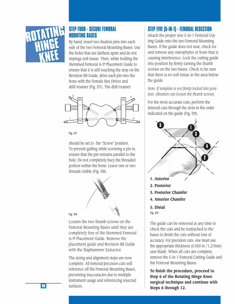
1
2
3
5
4
STEP FOUR - SECURE FEMORAL MOUNTING BASES By hand, insert two fi xation pins into each side of the two Femoral Mounting Bases. Use the holes that are farthest apart and do not impinge soft tissue. Then, while holding the Stemmed Femoral A/P Placement Guide to ensure that it is still touching the stop on the Revision IM Guide, drive each pin into the bone with the Female Hex Driver and drill/reamer (Fig. D7). The drill/reamer
should be set to the “Screw” position. To prevent galling while screwing a pin in, ensure that the pin remains parallel to the hole. Do not completely bury the threaded portion within the bone. Leave one or two threads visible (Fig. D8).
STEP FIVE (5-IN-1) - FEMORAL RESECTIONAttach the proper size 5-in-1 Femoral Cut-ting Guide onto the two Femoral Mounting Bases. If the guide does not seat, check for and remove any osteophytes or bone that is causing interference. Lock the cutting guide into position by fi rmly turning the thumb screws on the two bases. Check to be sure that there is no soft tissue in the area below the guide.
Note: If template is not fi rmly locked into posi-tion, vibration can loosen the thumb screws.
For the most accurate cuts, perform the femoral cuts through the slots in the order indicated on the guide (Fig. D9).
1. Anterior
2. Posterior
3. Posterior Chamfer
4. Anterior Chamfer
5. Distal
The guide can be removed at any time to check the cuts and be reattached to the bases to fi nish the cuts without loss of accuracy. For precision cuts, one must use the appropriate thickness (0.050 in./1.27mm) saw blade. When all cuts are complete, remove the 5-in-1 Femoral Cutting Guide and the Femoral Mounting Bases.
To fi nish the procedure, proceed to Step 6 of the Rotating Hinge Knee surgical technique and continue with Steps 6 through 12.
Fig. D8
Loosen the two thumb screws on the Femoral Mounting Bases until they are completely free of the Stemmed Femoral A/P Placement Guide. Remove the placement guide and Revision IM Guide with the Slaphammer Extractor.
The sizing and alignment steps are now complete. All femoral precision cuts will reference off the Femoral Mounting Bases, preventing inaccuracies due to multiple instrument usage and referencing resected surfaces.90
Fig. D7
Fig. D9

STEP ONE DETERMINE TIBIAL PROSTHETIC PLATFORM
STEP TWO FINISH THE TIBIA
STEP THREE PREPARE THE FEMORAL CANAL
STEP FOUR EVALUATE FEMORAL SIZE
STEP FIVE ESTABLISH FEMORAL ROTATION
STEP SIX ESTABLISH FLEXION GAP AND STABILITY
STEP SEVEN ESTABLISH EXTENSION GAP AND STABILITY
STEP EIGHT MAKE FEMORAL AUGMENT CUTS
STEP NINE PREPARE FOR THE ROTATING HINGE KNEE BOX
STEP TEN PREPARE THE PATELLA
STEP ELEVEN PERFORM TRIAL REDUCTION
STEP TWELVE COMPONENT ASSEMBLY/IMPLANTATION/
LOCKING MECHANISM
APPENDIX A CROSSOVER TECHNIQUE
APPENDIX B RESECTING THE DISTAL FEMUR
APPENDIX C BALANCING FLEXION/EXTENSION GAPS
APPENDIX D USING THE 5-IN-1 INSTRUMENTATION
SYSTEM FOR A ROTATING HINGE KNEE
PRIMARY PROCEDURE
APPENDIX E USING THE 5-IN-1 INSTRUMENTATION
SYSTEM FOR A ROTATING HINGE KNEE
REVISION PROCEDURE
APPENDIX F USING THE 5-IN-1 INSTRUMENTATION
SYSTEM FOR A ROTATING HINGE KNEE
WITH OFFSET STEM
APPENDIX G SERVICING THE HINGE MECHANISM
USIN
G 5-IN
-1 INST.
FOR RO
TATING
HIN
GE
KN
EE REVISION
E
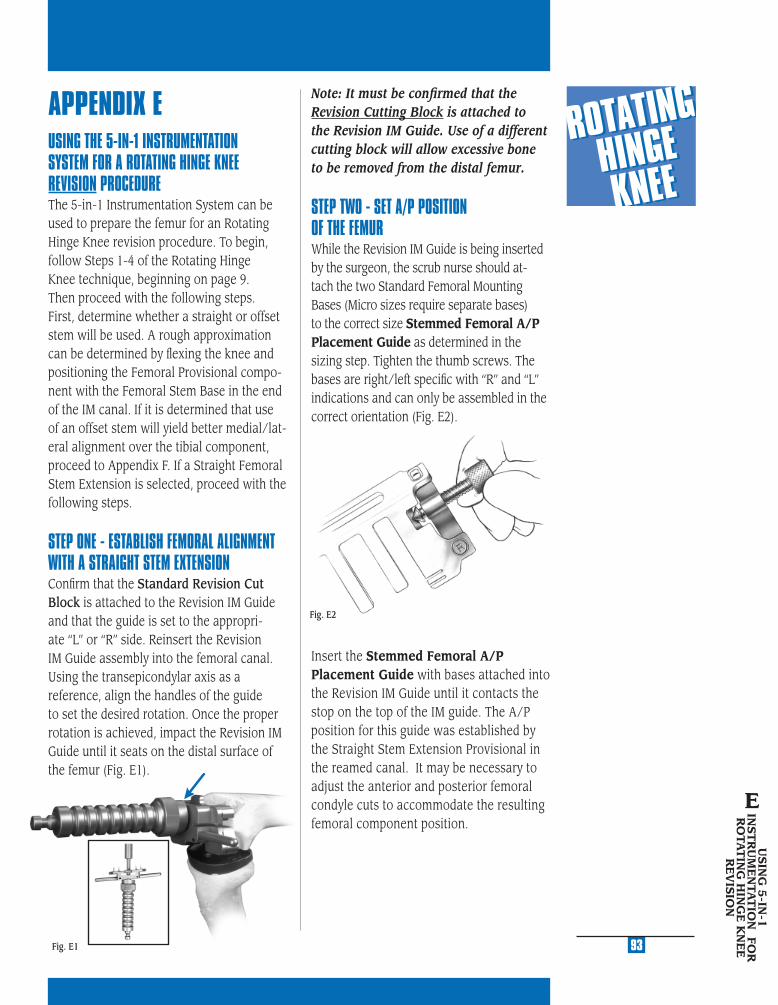
MU
LTI-
RE
FER
EN
CE
4-in
-11
MU
LTI-
RE
FER
EN
CE
4-in
-1
2
MU
LTI-
RE
FER
EN
CE
4-in
-1
3
MU
LTI-
RE
FER
EN
CE
4-in
-1
4
MU
LTI-
RE
FER
EN
CE
4-in
-1
5
APPENDIX EUSING THE 5-IN-1 INSTRUMENTATION SYSTEM FOR A ROTATING HINGE KNEE REVISION PROCEDUREThe 5-in-1 Instrumentation System can be used to prepare the femur for an Rotating Hinge Knee revision procedure. To begin, follow Steps 1-4 of the Rotating Hinge Knee technique, beginning on page 9. Then proceed with the following steps. First, determine whether a straight or offset stem will be used. A rough approximation can be determined by fl exing the knee and positioning the Femoral Provisional compo-nent with the Femoral Stem Base in the end of the IM canal. If it is determined that use of an offset stem will yield better medial/lat-eral alignment over the tibial component, proceed to Appendix F. If a Straight Femoral Stem Extension is selected, proceed with the following steps.
STEP ONE - ESTABLISH FEMORAL ALIGNMENT WITH A STRAIGHT STEM EXTENSIONConfi rm that the Standard Revision Cut Block is attached to the Revision IM Guide and that the guide is set to the appropri-ate “L” or “R” side. Reinsert the Revision IM Guide assembly into the femoral canal. Using the transepicondylar axis as a reference, align the handles of the guide to set the desired rotation. Once the proper rotation is achieved, impact the Revision IM Guide until it seats on the distal surface of the femur (Fig. E1).
Fig. E1
Note: It must be confi rmed that the Revision Cutting Block is attached to the Revision IM Guide. Use of a different cutting block will allow excessive bone to be removed from the distal femur.
STEP TWO - SET A/P POSITION OF THE FEMUR While the Revision IM Guide is being inserted by the surgeon, the scrub nurse should at-tach the two Standard Femoral Mounting Bases (Micro sizes require separate bases) to the correct size Stemmed Femoral A/P Placement Guide as determined in the sizing step. Tighten the thumb screws. The bases are right/left specifi c with “R” and “L” indications and can only be assembled in the correct orientation (Fig. E2).
Insert the Stemmed Femoral A/P Placement Guide with bases attached into the Revision IM Guide until it contacts the stop on the top of the IM guide. The A/P position for this guide was established by the Straight Stem Extension Provisional in the reamed canal. It may be necessary to adjust the anterior and posterior femoral condyle cuts to accommodate the resulting femoral component position.
Fig. E2
USIN
G 5
-IN-1
IN
ST
RU
ME
NTA
TIO
N FO
R
RO
TAT
ING
HIN
GE
KN
EE
R
EV
ISIO
N
E
93
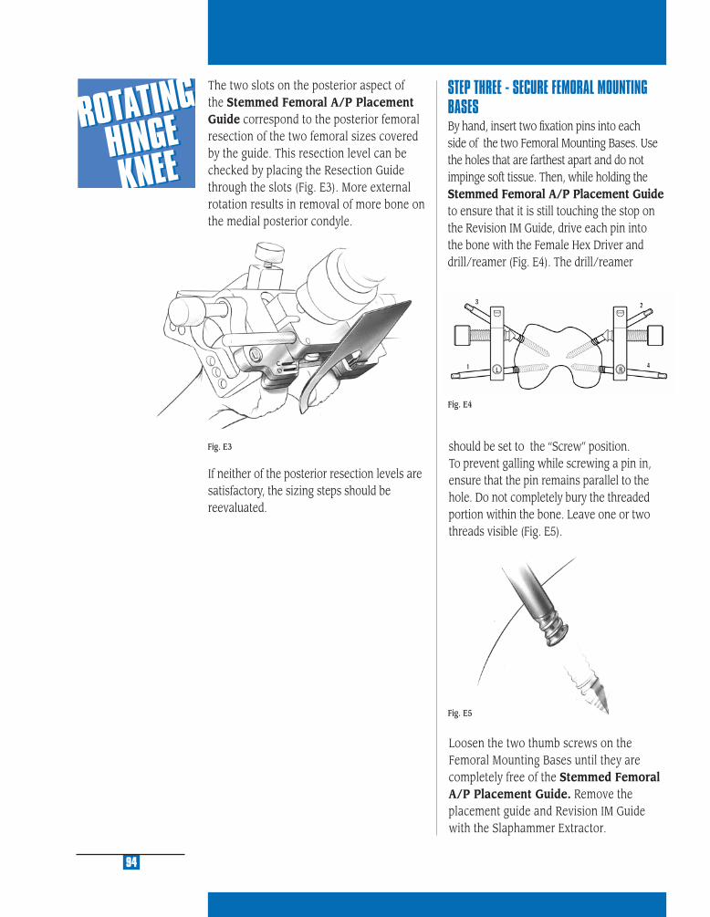
should be set to the “Screw” position. To prevent galling while screwing a pin in, ensure that the pin remains parallel to the hole. Do not completely bury the threaded portion within the bone. Leave one or two threads visible (Fig. E5).
Loosen the two thumb screws on the Femoral Mounting Bases until they are completely free of the Stemmed Femoral A/P Placement Guide. Remove the placement guide and Revision IM Guide with the Slaphammer Extractor.
94
The two slots on the posterior aspect of the Stemmed Femoral A/P Placement Guide correspond to the posterior femoral resection of the two femoral sizes covered by the guide. This resection level can be checked by placing the Resection Guide through the slots (Fig. E3). More external rotation results in removal of more bone on the medial posterior condyle.
STEP THREE - SECURE FEMORAL MOUNTING BASES By hand, insert two fi xation pins into each side of the two Femoral Mounting Bases. Use the holes that are farthest apart and do not impinge soft tissue. Then, while holding the Stemmed Femoral A/P Placement Guide to ensure that it is still touching the stop on the Revision IM Guide, drive each pin into the bone with the Female Hex Driver and drill/reamer (Fig. E4). The drill/reamer
If neither of the posterior resection levels are satisfactory, the sizing steps should be reevaluated.
Fig. E5
Fig. E4
Fig. E3

MU
LTI-
RE
FER
EN
CE
4-in
-11
MU
LTI-
RE
FER
EN
CE
4-in
-1
2
MU
LTI-
RE
FER
EN
CE
4-in
-1
3
MU
LTI-
RE
FER
EN
CE
4-in
-1
4
MU
LTI-
RE
FER
EN
CE
4-in
-1
5
95
STEP FOUR (5-IN-1) - FEMORAL RESECTIONAttach the proper size 5-in-1 Femoral Cutting Guide onto the two Femoral Mounting Bases. If the guide does not seat, check for and remove any interfering osteophytes or bone. Lock the cutting guide into position by fi rmly turning the thumb screws on the two bases. Check to be sure that there is no soft tissue in the area below the guide.
Note: If template is not fi rmly locked into posi-tion, vibration can loosen the thumb screws.
For the most accurate cuts, perform the femoral cuts through the slots in the order indicated on the guide (Fig. E6).
1. Anterior
2. Posterior
3. Posterior Chamfer
4. Anterior Chamfer
5. Distal
The guide can be removed at any time to check the cuts and be reattached to the bases to fi nish the cuts without loss of ac-curacy. For precision cuts, one must use the appropriate thickness (0.050 in./1.27mm) saw blade. When all cuts are complete, re-move the 5-in-1 Femoral Cutting Guide and the Femoral Mounting Bases.
To fi nish the procedure, proceed to Step 6 of the Rotating Hinge Knee surgical technique and continue with Steps 6 through 12.
USIN
G 5
-IN-1
IN
ST
RU
ME
NTA
TIO
N FO
R
RO
TAT
ING
HIN
GE
KN
EE
R
EV
ISIO
N
E
1
2
3
5
4
Fig. E6

STEP ONE DETERMINE TIBIAL PROSTHETIC PLATFORM
STEP TWO FINISH THE TIBIA
STEP THREE PREPARE THE FEMORAL CANAL
STEP FOUR EVALUATE FEMORAL SIZE
STEP FIVE ESTABLISH FEMORAL ROTATION
STEP SIX ESTABLISH FLEXION GAP AND STABILITY
STEP SEVEN ESTABLISH EXTENSION GAP AND STABILITY
STEP EIGHT MAKE FEMORAL AUGMENT CUTS
STEP NINE PREPARE FOR THE ROTATING HINGE KNEE BOX
STEP TEN PREPARE THE PATELLA
STEP ELEVEN PERFORM TRIAL REDUCTION
STEP TWELVE COMPONENT ASSEMBLY/IMPLANTATION/
LOCKING MECHANISM
APPENDIX A CROSSOVER TECHNIQUE
APPENDIX B RESECTING THE DISTAL FEMUR
APPENDIX C BALANCING FLEXION/EXTENSION GAPS
APPENDIX D USING THE 5-IN-1 INSTRUMENTATION
SYSTEM FOR A ROTATING HINGE KNEE
PRIMARY PROCEDURE
APPENDIX E USING THE 5-IN-1 INSTRUMENTATION
SYSTEM FOR A ROTATING HINGE KNEE
REVISION PROCEDURE
APPENDIX F USING THE 5-IN-1 INSTRUMENTATION
SYSTEM FOR A ROTATING HINGE KNEE
WITH OFFSET STEM
APPENDIX G SERVICING THE HINGE MECHANISM
USIN
G 5-IN
-1 INST. FO
R
RO
TATING
HIN
GE K
NEE
REV
ISION
W/O
FFSET STEMF

MU
LTI-
RE
FER
EN
CE
4-in
-11
MU
LTI-
RE
FER
EN
CE
4-in
-1
2
MU
LTI-
RE
FER
EN
CE
4-in
-1
3
MU
LTI-
RE
FER
EN
CE
4-in
-1
4
MU
LTI-
RE
FER
EN
CE
4-in
-1
5
APPENDIX FOFFSET STEMThe offset allows the stem to be positioned 4.5mm away from the center of the canal in any direction, a full 360 degrees. This may be better understood by thinking of the stem as a crank. As the crank is turned, the handle changes position relative to the shaft. Because the handle can be turned a full 360 degrees, its position can be infi nitely changed relative to the shaft.
Use of the offset stem also provides the ability to adjust the femoral component 4.5mm in any direction off the center of the distal femoral canal. For example, the femoral component can be positioned 4.5mm anteriorly or posteriorly, 4.5mm medially or laterally, or any combination of anterior/posterior and medial/lateral orientation that is 4.5mm from the center of the canal (Fig. F1). As shown, for a right femur, this could place the component 3mm medial and 3mm anterior to the center of the canal.
Fig. F1
USING THE 5-IN-1 INSTRUMENTATION SYSTEM FOR A ROTATING HINGE KNEE REVISION PROCEDUREThe 5-in-1 Instrumentation System can be used to prepare the femur for an Rotating Hinge Knee revision procedure. To begin, follow Steps 1-4 of the Rotating Hinge Knee technique, beginning on page 9. Then resect the distal femur as detailed in Appendix B. At that point an evaluation can be made to determine femoral component position on the end of the femur.
STEP ONE - ESTABLISH FEMORAL ALIGNMENT WITH AN OFFSET STEM EXTENSIONDetermine Femoral Component Placement with the Offset StemBase InstrumentsIf it appears that the Stemmed Femoral Component with a Straight Stem Extension will not be properly positioned on the distal femur, an Offset Stem Extension is recommended. To prepare for the offset stem, attach the proper diameter Straight Stem Extension provisional to the Stem Pro-visional Adaptor and insert it into the end of the femur. Then, select the appropriate size Femoral Stem Base Cutting Block selected in Step 4 and assemble the Femoral Offset Bushing. This bushing does not have a step that locks it into a keyed rotational orien-tation on the Femoral Stem Base/Cutting Block. Rotate the bushing within the block until an optimal position is determined.
The Femoral Offset Bushing allows the guide and, therefore, the prosthesis, to be shifted 4.5mm from the center of the canal in any direction. If the Femoral Base Guide Flange prevents appropriate movement, remove the fl ange. The necessity for anterior bone resection will result, but be careful not to notch the anterior cortex.
USIN
G 5
-IN-1
INST.
FOR
RO
TAT
ING
HIN
GE
K
NE
E R
EV
ISIO
NW
/OFFS
ET
ST
EM
F
99
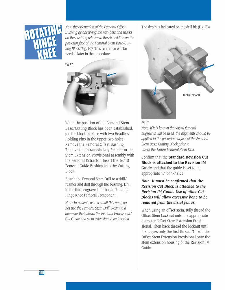
16/18 Femoral
100
Note the orientation of the Femoral Offset Bushing by observing the numbers and marks on the bushing relative to the etched line on the posterior face of the Femoral Stem Base/Cut-ting Block (Fig. F2). This reference will be needed later in the procedure.
When the position of the Femoral Stem Base/Cutting Block has been established, pin the block in place with two Headless Holding Pins in the upper two holes. Remove the Femoral Offset Bushing. Remove the Intramedullary Reamer or the Stem Extension Provisional assembly with the Femoral Extractor. Insert the 16/18 Femoral Guide Bushing into the Cutting Block.
Attach the Femoral Stem Drill to a drill/reamer and drill through the bushing. Drill to the third engraved line for an Rotating Hinge Knee Femoral Component.
Note: In patients with a small IM canal, do not use the Femoral Stem Drill. Ream to a diameter that allows the Femoral Provisional/ Cut Guide and stem extension to be inserted.
Fig. F2
The depth is indicated on the drill bit (Fig. F3)
Fig. F3
Note: If it is known that distal femoral augments will be used, the augments should be applied to the posterior surface of the Femoral Stem Base/Cutting Block prior to use of the 18mm Femoral Stem Drill.
Confirm that the Standard Revision Cut Block is attached to the Revision IM Guide and that the guide is set to the appropriate “L” or “R” side.
Note: It must be confirmed that the Revision Cut Block is attached to the Revision IM Guide. Use of other Cut Blocks will allow excessive bone to be removed from the distal femur.
When using an offset stem, fully thread the Offset Stem Locknut onto the appropriate diameter Offset Stem Extension Provi-sional. Then back thread the locknut until it engages only the first thread. Thread the Offset Stem Extension Provisional onto the stem extension housing of the Revision IM Guide.
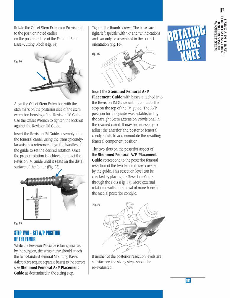
MU
LTI-
RE
FER
EN
CE
4-in
-11
MU
LTI-
RE
FER
EN
CE
4-in
-1
2
MU
LTI-
RE
FER
EN
CE
4-in
-1
3
MU
LTI-
RE
FER
EN
CE
4-in
-1
4
MU
LTI-
RE
FER
EN
CE
4-in
-1
5
Fig. F4
Rotate the Offset Stem Extension Provisional to the position noted earlier on the posterior face of the Femoral Stem Base/Cutting Block (Fig. F4).
Fig. F6
Tighten the thumb screws. The bases are right/left specifi c with “R” and “L” indications and can only be assembled in the correct orientation (Fig. F6).
101
USIN
G 5
-IN-1
INST.
FOR
RO
TAT
ING
HIN
GE
K
NE
E R
EV
ISIO
NW
/OFFS
ET
ST
EM
F
Align the Offset Stem Extension with the etch mark on the posterior side of the stem extension housing of the Revision IM Guide. Use the Offset Wrench to tighten the locknut against the Revision IM Guide.
Insert the Revision IM Guide assembly into the femoral canal. Using the transepicondy-lar axis as a reference, align the handles of the guide to set the desired rotation. Once the proper rotation is achieved, impact the Revision IM Guide until it seats on the distal surface of the femur (Fig. F5).
STEP TWO - SET A/P POSITION OF THE FEMUR While the Revision IM Guide is being inserted by the surgeon, the scrub nurse should attach the two Standard Femoral Mounting Bases (Micro sizes require separate bases) to the correct size Stemmed Femoral A/P Placement Guide as determined in the sizing step.
Fig. F5
Insert the Stemmed Femoral A/P Placement Guide with bases attached into the Revision IM Guide until it contacts the stop on the top of the IM guide. The A/P position for this guide was established by the Straight Stem Extension Provisional in the reamed canal. It may be necessary to adjust the anterior and posterior femoral condyle cuts to accommodate the resulting femoral component position.
The two slots on the posterior aspect of the Stemmed Femoral A/P Placement Guide correspond to the posterior femoral resection of the two femoral sizes covered by the guide. This resection level can be checked by placing the Resection Guide through the slots (Fig. F7). More external rotation results in removal of more bone on the medial posterior condyle.
If neither of the posterior resection levels are satisfactory, the sizing steps should be re-evaluated.
Fig. F7

STEP THREE - SECURE FEMORAL MOUNTING BASES By hand, insert two fi xation pins into each side of the two Femoral Mounting Bases. Use the holes that are farthest apart and do not impinge soft tissue. Then, while holding the Stemmed Femoral A/P Placement Guide to ensure that it is still touching the stop on the Revision IM Guide, drive each pin into the bone with the Female Hex Driver and drill/reamer (Fig. F8). The drill/reamer
should be set to the “Screw” position. To prevent galling while screwing a pin in, ensure that the pin remains parallel to the hole. Do not completely bury the threaded portion within the bone. Leave one or two threads visible (Fig. F9).
Fig. F9
Fig. F8
Loosen the two thumb screws on the Femo-ral Mounting Bases until they are com-pletely free of the Stemmed Femoral A/P Placement Guide. Remove the placement guide and Revision IM Guide with the Slaphammer Extractor.
102
3°
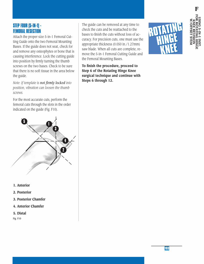
MU
LTI-
RE
FER
EN
CE
4-in
-11
MU
LTI-
RE
FER
EN
CE
4-in
-1
2
MU
LTI-
RE
FER
EN
CE
4-in
-1
3
MU
LTI-
RE
FER
EN
CE
4-in
-1
4
MU
LTI-
RE
FER
EN
CE
4-in
-1
5
STEP FOUR (5-IN-1) - FEMORAL RESECTIONAttach the proper size 5-in-1 Femoral Cut-ting Guide onto the two Femoral Mounting Bases. If the guide does not seat, check for and remove any osteophytes or bone that is causing interference. Lock the cutting guide into position by fi rmly turning the thumb screws on the two bases. Check to be sure that there is no soft tissue in the area below the guide.
Note: If template is not firmly locked into position, vibration can loosen the thumb screws.
For the most accurate cuts, perform the femoral cuts through the slots in the order indicated on the guide (Fig. F10).
1. Anterior
2. Posterior
3. Posterior Chamfer
4. Anterior Chamfer
5. Distal
The guide can be removed at any time to check the cuts and be reattached to the bases to fi nish the cuts without loss of ac-curacy. For precision cuts, one must use the appropriate thickness (0.050 in./1.27mm) saw blade. When all cuts are complete, re-move the 5-in-1 Femoral Cutting Guide and the Femoral Mounting Bases.
To fi nish the procedure, proceed to Step 6 of the Rotating Hinge Knee surgical technique and continue with Steps 6 through 12.
103
USIN
G 5
-IN-1
INST.
FOR
RO
TAT
ING
HIN
GE
K
NE
E R
EV
ISIO
NW
/OFFS
ET
ST
EM
F
Fig. F10
1
2
3
5
4

SE
RV
ICIN
G T
HE
H
ING
E M
EC
HA
NIS
M
G
STEP ONE DETERMINE TIBIAL PROSTHETIC PLATFORM
STEP TWO FINISH THE TIBIA
STEP THREE PREPARE THE FEMORAL CANAL
STEP FOUR EVALUATE FEMORAL SIZE
STEP FIVE ESTABLISH FEMORAL ROTATION
STEP SIX ESTABLISH FLEXION GAP AND STABILITY
STEP SEVEN ESTABLISH EXTENSION GAP AND STABILITY
STEP EIGHT MAKE FEMORAL AUGMENT CUTS
STEP NINE PREPARE FOR THE ROTATING HINGE KNEE BOX
STEP TEN PREPARE THE PATELLA
STEP ELEVEN PERFORM TRIAL REDUCTION
STEP TWELVE COMPONENT ASSEMBLY/IMPLANTATION/
LOCKING MECHANISM
APPENDIX A CROSSOVER TECHNIQUE
APPENDIX B RESECTING THE DISTAL FEMUR
APPENDIX C BALANCING FLEXION/EXTENSION GAPS
APPENDIX D USING THE 5-IN-1 INSTRUMENTATION
SYSTEM FOR A ROTATING HINGE KNEE
PRIMARY PROCEDURE
APPENDIX E USING THE 5-IN-1 INSTRUMENTATION
SYSTEM FOR A ROTATING HINGE KNEE
REVISION PROCEDURE
APPENDIX F USING THE 5-IN-1 INSTRUMENTATION
SYSTEM FOR A ROTATING HINGE KNEE
WITH OFFSET STEM
APPENDIX G SERVICING THE HINGE MECHANISM
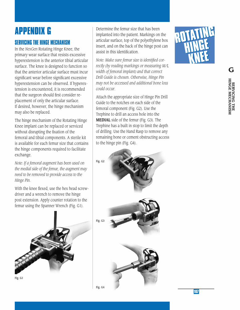
MU
LTI-
RE
FER
EN
CE
4-in
-11
MU
LTI-
RE
FER
EN
CE
4-in
-1
2
MU
LTI-
RE
FER
EN
CE
4-in
-1
3
MU
LTI-
RE
FER
EN
CE
4-in
-1
4
MU
LTI-
RE
FER
EN
CE
4-in
-1
5
APPENDIX GSERVICING THE HINGE MECHANISMIn the NexGen Rotating Hinge Knee, the primary wear surface that resists excessive hyperextension is the anterior tibial articular surface. The knee is designed to function so that the anterior articular surface must incur signifi cant wear before signifi cant excessive hyperextension can be observed. If hyperex-tension is encountered, it is recommended that the surgeon should fi rst consider re-placement of only the articular surface. If desired, however, the hinge mechanism may also be replaced.
The hinge mechanism of the Rotating Hinge Knee implant can be replaced or serviced without disrupting the fi xation of the femoral and tibial components. A sterile kit is available for each femur size that contains the hinge components required to facilitate exchange.
Note: If a femoral augment has been used on the medial side of the femur, the augment may need to be removed to provide access to the Hinge Pin.
With the knee fl exed, use the hex head screw-driver and a wrench to remove the hinge post extension. Apply counter rotation to the femur using the Spanner Wrench (Fig. G1).
107
Fig. G1
Fig. G2
Fig. G3
Fig. G4
Determine the femur size that has been implanted into the patient. Markings on the articular surface, top of the polyethylene box insert, and on the back of the hinge post can assist in this identifi cation.
Note: Make sure femur size is identifi ed cor-rectly (by reading markings or measuring M/L width of femoral implant) and that correct Drill Guide is chosen. Otherwise, Hinge Pin may not be accessed and additional bone loss could occur.
Attach the appropriate size of Hinge Pin Drill Guide to the notches on each side of the femoral component (Fig. G2). Use the Trephine to drill an access hole into the MEDIAL side of the femur (Fig. G3). The Trephine has a built in stop to limit the depth of drilling. Use the Hand Rasp to remove any remaining bone or cement obstructing access to the hinge pin (Fig. G4).
SE
RV
ICIN
G T
HE
H
ING
E M
EC
HA
NIS
M
G

Removing the tibial bushing from the tibial plate stem with the Tibial Bushing Removing Tool (Fig. G8). Be careful to avoid scratching the Tibial Plate surface.
Insert the new tibial bushing from the ser-vice kit into the Tibial Plate Stem and press into place (Fig. G9).
Fig. G5
Remove the Drill Guide. Use the Hinge Pin Plug Removal Tool to remove the polyethylene plug from the hex in the Hinge Pin by pressing the tip into the center of the Hinge Pin plug and turning (Fig. G5).
Remove the Hinge Pin using the Hexhead Screwdriver and a Wrench. Once the Hinge Pin has been removed, the remaining in-ternal hinge components (hinge post and polyethylene box insert) are also removed (Fig. G6 & G7).
Fig. G7
Fig. G9
Fig. G8
108
Fig. G6
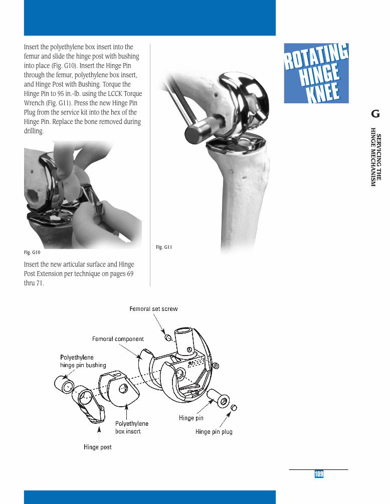
MU
LTI-
RE
FER
EN
CE
4-in
-11
MU
LTI-
RE
FER
EN
CE
4-in
-1
2
MU
LTI-
RE
FER
EN
CE
4-in
-1
3
MU
LTI-
RE
FER
EN
CE
4-in
-1
4
MU
LTI-
RE
FER
EN
CE
4-in
-1
5
109
Fig. G11
Insert the polyethylene box insert into the femur and slide the hinge post with bushing into place (Fig. G10). Insert the Hinge Pin through the femur, polyethylene box insert, and Hinge Post with Bushing. Torque the Hinge Pin to 95 in.-lb. using the LCCK Torque Wrench (Fig. G11). Press the new Hinge Pin Plug from the service kit into the hex of the Hinge Pin. Replace the bone removed during drilling.
Insert the new articular surface and Hinge Post Extension per technique on pages 69 thru 71.
Fig. G10
SE
RV
ICIN
G T
HE
H
ING
E M
EC
HA
NIS
M
G

Contact your Zimmer representative or visit us at www.zimmer.com
97-5
880-
002-
00 R
ev 3
5M
M P
rint
ed in
USA
©20
02, 2
004,
200
5 Z
imm
er, I
nc.
Please refer to package insert for complete product information, including contraindications, warnings, precautions, and adverse effects.
Related Documents