Copyright © 2007-2013 ZigBee Alliance, Inc. All rights reserved. ZigBee Home Automation Public Application Profile Document 05-3520-29 Z IGB EE H OME A UTOMATION P UBLIC A PPLICATION P ROFILE Home Automation Public Application Profile ZigBee Profile: 0x0104 Revision 29 Version 1.2 June 6, 2013 ZigBee Document 05-3520-29 June 6, 2013 12:05 pm Sponsored by: ZigBee Alliance Accepted by This document has been accepted for release by the ZigBee Alliance Board of Directors. Abstract This document defines the home automation profile. Keywords ZigBee, Profile, Home Automation, Application Framework. 1 2 3 4 5 6 7 8 9 10 11 12 13 14 15 16 17 18 19 20 21 22 23 24 25 26 27 28 29 30 31 32 33 34 35 36 37 38 39 40 41 42 43 44 45

Welcome message from author
This document is posted to help you gain knowledge. Please leave a comment to let me know what you think about it! Share it to your friends and learn new things together.
Transcript
ZigBee Home Automation Public Application Profile
Document 05-3520-29
ZIGBEE HOME AUTOMATION PUBLIC APPLICATION PROFILE
Home AutomationPublic Application Profile
ZigBee Profile: 0x0104
Revision 29Version 1.2
June 6, 2013
ZigBee Document 05-3520-29
June 6, 2013 12:05 pm
Sponsored by: ZigBee Alliance
Accepted by This document has been accepted for release by the ZigBee Alliance Board of Directors.
Abstract This document defines the home automation profile.
Keywords ZigBee, Profile, Home Automation, Application Framework.
Copyright © 2007-2013 ZigBee Alliance, Inc. All rights reserved.
123456789101112131415161718192021222324252627282930313233343536373839404142434445
This page intentionally blank
Copyright © 2007-2013 ZigBee Alliance, Inc. All rights reserved.
464748495051525354555657585960616263646566676869707172737475767778798081828384858687888990
3ZigBee Home Automation Public
Application Profile Document 05-3520-29
NOTICE OF USE AND DISCLOSURE
Copyright © ZigBee Alliance, Inc. (2007-20013). All rights reserved. The information within this document is the property of the ZigBee Alliance and its use and disclosure are restricted.
Elements of ZigBee Alliance specifications may be subject to third party intellectual property rights, including without limitation, patent, copyright or trademark rights (such a third party may or may not be a member of ZigBee). ZigBee is not responsible and shall not be held responsible in any manner for identifying or failing to identify any or all such third party intellectual property rights.
This document and the information contained herein are provided on an “AS IS” basis and ZigBee DISCLAIMS ALL WARRANTIES EXPRESS OR IMPLIED, INCLUDING BUT NOT LIMITED TO (A) ANY WARRANTY THAT THE USE OF THE INFORMATION HEREIN WILL NOT INFRINGE ANY RIGHTS OF THIRD PARTIES (INCLUDING WITHOUT LIMITATION ANY INTELLECTUAL PROPERTY RIGHTS INCLUDING PATENT, COPYRIGHT OR TRADEMARK RIGHTS) OR (B) ANY IMPLIED WARRANTIES OF MERCHANTABILITY, FITNESS FOR A PARTICULAR PURPOSE, TITLE OR NON-INFRINGEMENT. IN NO EVENT WILL ZIGBEE BE LIABLE FOR ANY LOSS OF PROFITS, LOSS OF BUSINESS, LOSS OF USE OF DATA, INTERRUPTION OF BUSINESS, OR FOR ANY OTHER DIRECT, INDIRECT, SPECIAL OR EXEMPLARY, INCIDENTIAL, PUNITIVE OR CONSEQUENTIAL DAMAGES OF ANY KIND, IN CONTRACT OR IN TORT, IN CONNECTION WITH THIS DOCUMENT OR THE INFORMATION CONTAINED HEREIN, EVEN IF ADVISED OF THE POSSIBILITY OF SUCH LOSS OR DAMAGE. All Company, brand and product names may be trademarks that are the sole property of their respective owners.
The above notice and this paragraph must be included on all copies of this document that are made.
ZigBee Alliance, Inc.2400 Camino Ramon, Suite 375San Ramon, CA 94583, USA
Copyright © 2007-2013 ZigBee Alliance, Inc. All rights reserved.
919293949596979899100101102103104105106107108109110111112113114115116117118119120121122123124125126127128129130131132133134135
Notice of Use and Disclosure4
This page intentionally blank
Copyright © 2007-2013 ZigBee Alliance, Inc. All rights reserved.
136137138139140141142143144145146147148149150151152153154155156157158159160161162163164165166167168169170171172173174175176177178179180

5ZigBee Home Automation Public
Application Profile Document 05-3520-29
PARTICIPANTS
Contact Information
When the document was released, the Home Automation Profile Task Group leadership was composed of the following members:
Ezra Hale: Chair of the Home Automation Profile Task Group
Drew Gislason: Vice Chair of the Home Automation Profile Task Group
Claudio Borean: Technical Editor of Home Automation Profile Task Group
Andreas Westermann: Secretary of Home Automation Profile Task Group
Contributions were made to this document by the following members:
The ZigBee Alliance thanks Energy@home for its contribution to these technical specifications through technical documents, organization of test events, and active participation of its members.
Energy@home is a no-profit association registered under the Italian law with the mission of promoting technologies and services for energy efficiency at home http://www.energy-home.it.
Shane AlmeidaCasey AndersonWalter BarnumClaudio BoreanChris BrandsonPeter BurnettMark CaterinoDavid ClarkKent CrouseJoe DoubekDave Dundon-HarrisTim GillmanDrew GislasonEzra Hale
William KeithChristian KusterZin KyawGary LeeJared LemkeJens Klostergaard LyngsøGabriele MerlonghiCL NagarajEetay NatanIvan O'NeillIsaac PinhasAndrea RicciJonas RiskaPhil Rudland
Anna RugoPaolo ScuroDavid SmithMatt SmithZachary SmithDon SturekMauro TaiariolStefano ToppanOwen TroyKenny YorkMads WestergreenUrban WicklanderCam Williams
Copyright © 2007-2013 ZigBee Alliance, Inc. All rights reserved.
181182183184185186187188189190191192193194195196197198199200201202203204205206207208209210211212213214215216217218219220221222223224225

Participants6
This page intentionally blank
Copyright © 2007-2013 ZigBee Alliance, Inc. All rights reserved.
226227228229230231232233234235236237238239240241242243244245246247248249250251252253254255256257258259260261262263264265266267268269270

7
Copyright © 2007-2013 ZigBee Alliance, Inc. All rights reserved.
ZigBee Home Automation Public Application Profile
Document 05-3520-29
271272273274275276277278279280281282283284285286287288289290291292293294295296297298299300301302303304305306307308309310311312313314315
TABLE OF CONTENTS
Notice of Use and Disclosure . . . . . . . . . . . . . . . . . . . . . . . . . . . . . 3
Participants. . . . . . . . . . . . . . . . . . . . . . . . . . . . . . . . . . . . . . . . . . . . 5
List of Tables . . . . . . . . . . . . . . . . . . . . . . . . . . . . . . . . . . . . . . . . . . 15
List of Figures . . . . . . . . . . . . . . . . . . . . . . . . . . . . . . . . . . . . . . . . . 23
Document History . . . . . . . . . . . . . . . . . . . . . . . . . . . . . . . . . . . . . . 29
Chapter 1 Introduction 311.1 Scope. . . . . . . . . . . . . . . . . . . . . . . . . . . . . . . . . . . . . . . . . . . . . . 311.2 Purpose . . . . . . . . . . . . . . . . . . . . . . . . . . . . . . . . . . . . . . . . . . . . 311.3 Provisional Features . . . . . . . . . . . . . . . . . . . . . . . . . . . . . . . . . . 31
Chapter 2 References 332.1 ZigBee Alliance Documents . . . . . . . . . . . . . . . . . . . . . . . . . . . . 332.2 European Standards Documents . . . . . . . . . . . . . . . . . . . . . . . . . 34
Chapter 3 Definitions 353.1 Conformance Levels . . . . . . . . . . . . . . . . . . . . . . . . . . . . . . . . . . 353.2 ZigBee Definitions . . . . . . . . . . . . . . . . . . . . . . . . . . . . . . . . . . . 35
Chapter 4 Acronyms and Abbreviations 37
Chapter 5 Profile Description 395.1 A ZigBee Home Automation Network. . . . . . . . . . . . . . . . . . . . 395.2 ZigBee Stack Profile . . . . . . . . . . . . . . . . . . . . . . . . . . . . . . . . . . 40
5.2.1 ZigBee Routing Table Size Recommendations . . . . . . . . . 415.2.2 ZigBee HA Coordinator Recommendations . . . . . . . . . . . 425.2.3 No Network Level Multicasts . . . . . . . . . . . . . . . . . . . . . . 42
5.3 Startup Attribute (SAS) . . . . . . . . . . . . . . . . . . . . . . . . . . . . . . . 425.3.1 Start Up Parameters . . . . . . . . . . . . . . . . . . . . . . . . . . . . . . 435.3.2 Join Parameters . . . . . . . . . . . . . . . . . . . . . . . . . . . . . . . . . 435.3.3 Security Parameters . . . . . . . . . . . . . . . . . . . . . . . . . . . . . . 445.3.4 End Device Parameters . . . . . . . . . . . . . . . . . . . . . . . . . . . 455.3.5 Link Status Parameters . . . . . . . . . . . . . . . . . . . . . . . . . . . 455.3.6 Concentrator Parameters . . . . . . . . . . . . . . . . . . . . . . . . . . 455.3.7 APS Transport Parameters. . . . . . . . . . . . . . . . . . . . . . . . . 46
5.4 ZDO Config for HA Devices . . . . . . . . . . . . . . . . . . . . . . . . . . . 465.5 Device Discovery . . . . . . . . . . . . . . . . . . . . . . . . . . . . . . . . . . . . 46

Copyright © 2007-2013 ZigBee Alliance, Inc. All rights reserved.
Chapter 18
316317318319320321322323324325326327328329330331332333334335336337338339340341342343344345346347348349350351352353354355356357358359360
5.6 Other HA Requirements and Best Practices . . . . . . . . . . . . . . . . 465.7 Device Descriptions . . . . . . . . . . . . . . . . . . . . . . . . . . . . . . . . . . 475.8 ZigBee Cluster Library (ZCL) . . . . . . . . . . . . . . . . . . . . . . . . . . 505.9 Cluster List . . . . . . . . . . . . . . . . . . . . . . . . . . . . . . . . . . . . . . . . . 50
Chapter 6 Constants, Error Codes andGeneral Alarms 53
Chapter 7 Device Specifications 577.1 Common Clusters . . . . . . . . . . . . . . . . . . . . . . . . . . . . . . . . . . . . 57
7.1.1 Optional Support for Clusters with Reporting Capability . 587.1.2 Groups and Scene Cluster Clarification. . . . . . . . . . . . . . . 587.1.3 Level Control Cluster Clarification . . . . . . . . . . . . . . . . . . 587.1.4 Client Cluster Mandatory Commands Clarification . . . . . 637.1.5 Attribute Reporting Clarification. . . . . . . . . . . . . . . . . . . . 637.1.6 Manufacturer-Specific Clusters . . . . . . . . . . . . . . . . . . . . . 647.1.7 Cluster Usage Restrictions. . . . . . . . . . . . . . . . . . . . . . . . . 64
7.2 Certifiable HA Devices and Features . . . . . . . . . . . . . . . . . . . . . 647.3 Feature and Function Description. . . . . . . . . . . . . . . . . . . . . . . . 647.4 Generic Devices . . . . . . . . . . . . . . . . . . . . . . . . . . . . . . . . . . . . . 66
7.4.1 On/Off Switch . . . . . . . . . . . . . . . . . . . . . . . . . . . . . . . . . . 667.4.2 Level Control Switch . . . . . . . . . . . . . . . . . . . . . . . . . . . . . 677.4.3 On/Off Output . . . . . . . . . . . . . . . . . . . . . . . . . . . . . . . . . . 697.4.4 Level Controllable Output . . . . . . . . . . . . . . . . . . . . . . . . . 707.4.5 Scene Selector . . . . . . . . . . . . . . . . . . . . . . . . . . . . . . . . . . 717.4.6 Configuration Tool . . . . . . . . . . . . . . . . . . . . . . . . . . . . . . 727.4.7 Remote Control . . . . . . . . . . . . . . . . . . . . . . . . . . . . . . . . . 747.4.8 Combined Interface . . . . . . . . . . . . . . . . . . . . . . . . . . . . . . 767.4.9 Range Extender . . . . . . . . . . . . . . . . . . . . . . . . . . . . . . . . . 787.4.10 Mains Power Outlet . . . . . . . . . . . . . . . . . . . . . . . . . . . . . 797.4.11 Door Lock . . . . . . . . . . . . . . . . . . . . . . . . . . . . . . . . . . . . 807.4.12 Door Lock Controller. . . . . . . . . . . . . . . . . . . . . . . . . . . . 817.4.13 Simple Sensor . . . . . . . . . . . . . . . . . . . . . . . . . . . . . . . . . 837.4.14 Consumption Awareness Device . . . . . . . . . . . . . . . . . . . 847.4.15 Home Gateway/Energy Management System . . . . . . . . . 857.4.16 Smart Plug . . . . . . . . . . . . . . . . . . . . . . . . . . . . . . . . . . . . 867.4.17 White Goods . . . . . . . . . . . . . . . . . . . . . . . . . . . . . . . . . . 887.4.18 Meter Interface. . . . . . . . . . . . . . . . . . . . . . . . . . . . . . . . . 89
7.5 Lighting Devices. . . . . . . . . . . . . . . . . . . . . . . . . . . . . . . . . . . . . 917.5.1 On/Off Light . . . . . . . . . . . . . . . . . . . . . . . . . . . . . . . . . . . 91

9
Copyright © 2007-2013 ZigBee Alliance, Inc. All rights reserved.
ZigBee Home Automation Public Application Profile
Document 05-3520-29
361362363364365366367368369370371372373374375376377378379380381382383384385386387388389390391392393394395396397398399400401402403404405
7.5.2 Dimmable Light . . . . . . . . . . . . . . . . . . . . . . . . . . . . . . . . . 927.5.3 Color Dimmable Light. . . . . . . . . . . . . . . . . . . . . . . . . . . . 947.5.4 On/Off Light Switch . . . . . . . . . . . . . . . . . . . . . . . . . . . . . 957.5.5 Dimmer Switch . . . . . . . . . . . . . . . . . . . . . . . . . . . . . . . . . 977.5.6 Color Dimmer Switch . . . . . . . . . . . . . . . . . . . . . . . . . . . . 987.5.7 Light Sensor . . . . . . . . . . . . . . . . . . . . . . . . . . . . . . . . . . . . 997.5.8 Occupancy Sensor . . . . . . . . . . . . . . . . . . . . . . . . . . . . . . . 100
7.6 Closure Devices . . . . . . . . . . . . . . . . . . . . . . . . . . . . . . . . . . . . . 1027.6.1 Shade . . . . . . . . . . . . . . . . . . . . . . . . . . . . . . . . . . . . . . . . . 1027.6.2 Shade Controller . . . . . . . . . . . . . . . . . . . . . . . . . . . . . . . . 1037.6.3 Window Covering Device . . . . . . . . . . . . . . . . . . . . . . . . . 1057.6.4 Window Covering Controller . . . . . . . . . . . . . . . . . . . . . . 106
7.7 HVAC Devices . . . . . . . . . . . . . . . . . . . . . . . . . . . . . . . . . . . . . . 1077.7.1 Heating/Cooling Unit. . . . . . . . . . . . . . . . . . . . . . . . . . . . . 1077.7.2 Thermostat . . . . . . . . . . . . . . . . . . . . . . . . . . . . . . . . . . . . . 1097.7.3 Temperature Sensor . . . . . . . . . . . . . . . . . . . . . . . . . . . . . . 1117.7.4 Pump . . . . . . . . . . . . . . . . . . . . . . . . . . . . . . . . . . . . . . . . . 1127.7.5 Pump Controller. . . . . . . . . . . . . . . . . . . . . . . . . . . . . . . . . 1147.7.6 Pressure Sensor . . . . . . . . . . . . . . . . . . . . . . . . . . . . . . . . . 1167.7.7 Flow Sensor . . . . . . . . . . . . . . . . . . . . . . . . . . . . . . . . . . . . 117
7.8 Intruder Alarm System Devices . . . . . . . . . . . . . . . . . . . . . . . . . 1197.8.1 IAS Control and Indicating Equipment (CIE) . . . . . . . . . . 1197.8.2 IAS Ancillary Control Equipment (ACE) . . . . . . . . . . . . . 1207.8.3 IAS Zone . . . . . . . . . . . . . . . . . . . . . . . . . . . . . . . . . . . . . . 1217.8.4 IAS Warning Device (WD) . . . . . . . . . . . . . . . . . . . . . . . . 122
Chapter 8 Home Automation Commissioning 1258.1 Network Steering . . . . . . . . . . . . . . . . . . . . . . . . . . . . . . . . . . . . 125
8.1.1 Form. . . . . . . . . . . . . . . . . . . . . . . . . . . . . . . . . . . . . . . . . . 1258.1.2 Join. . . . . . . . . . . . . . . . . . . . . . . . . . . . . . . . . . . . . . . . . . . 125
8.2 Commissioning . . . . . . . . . . . . . . . . . . . . . . . . . . . . . . . . . . . . . . 1268.2.1 Support for Commissioning Modes . . . . . . . . . . . . . . . . . . 126
8.3 EZ-Mode Commissioning. . . . . . . . . . . . . . . . . . . . . . . . . . . . . . 1268.3.1 References . . . . . . . . . . . . . . . . . . . . . . . . . . . . . . . . . . . . . 1268.3.2 Terms . . . . . . . . . . . . . . . . . . . . . . . . . . . . . . . . . . . . . . . . . 1268.3.3 EZ-Mode Invocation . . . . . . . . . . . . . . . . . . . . . . . . . . . . . 1278.3.4 EZ-Mode Network Steering. . . . . . . . . . . . . . . . . . . . . . . . 1278.3.5 EZ-Mode Finding and Binding . . . . . . . . . . . . . . . . . . . . . 1288.3.6 EZ-Mode Network Steering. . . . . . . . . . . . . . . . . . . . . . . . 128
Copyright © 2007-2013 ZigBee Alliance, Inc. All rights reserved.
Chapter 110
406407408409410411412413414415416417418419420421422423424425426427428429430431432433434435436437438439440441442443444445446447448449450
8.3.7 EZ-Mode Initiator: Finding and Binding. . . . . . . . . . . . . . 1298.3.8 EZ-Mode Target: Finding and Binding . . . . . . . . . . . . . . . 1308.3.9 EZ-Mode Default Constants . . . . . . . . . . . . . . . . . . . . . . . 1318.3.10 EZ-Mode Device Types. . . . . . . . . . . . . . . . . . . . . . . . . . 1318.3.11 Identify Cluster Attribute. . . . . . . . . . . . . . . . . . . . . . . . . 1338.3.12 Identify Cluster Commands . . . . . . . . . . . . . . . . . . . . . . . 134
8.4 Centralized Commissioning . . . . . . . . . . . . . . . . . . . . . . . . . . . . 1368.4.1 Central Commissioning Overview. . . . . . . . . . . . . . . . . . . 1368.4.2 Minimum Requirements for All Devices. . . . . . . . . . . . . . 1378.4.3 Node Discovery . . . . . . . . . . . . . . . . . . . . . . . . . . . . . . . . . 138
8.5 Group Messaging vs. Unicast Messaging. . . . . . . . . . . . . . . . . . 1388.6 Bindings Required for Commissioning . . . . . . . . . . . . . . . . . . . 1398.7 Network Sharing . . . . . . . . . . . . . . . . . . . . . . . . . . . . . . . . . . . . . 139
Chapter 9 Home Automation SpecificCluster Descriptions 1419.1 Electrical Measurement Cluster . . . . . . . . . . . . . . . . . . . . . . . . . 141
9.1.1 Overview . . . . . . . . . . . . . . . . . . . . . . . . . . . . . . . . . . . . . . 1419.1.2 Server . . . . . . . . . . . . . . . . . . . . . . . . . . . . . . . . . . . . . . . . . 142
9.2 Diagnostics Cluster . . . . . . . . . . . . . . . . . . . . . . . . . . . . . . . . . . . 1729.2.1 Overview . . . . . . . . . . . . . . . . . . . . . . . . . . . . . . . . . . . . . . 1729.2.2 Server . . . . . . . . . . . . . . . . . . . . . . . . . . . . . . . . . . . . . . . . . 1729.2.3 Client . . . . . . . . . . . . . . . . . . . . . . . . . . . . . . . . . . . . . . . . . 178
9.3 Window Covering Cluster . . . . . . . . . . . . . . . . . . . . . . . . . . . . . 1789.3.1 Overview . . . . . . . . . . . . . . . . . . . . . . . . . . . . . . . . . . . . . . 1789.3.2 Server . . . . . . . . . . . . . . . . . . . . . . . . . . . . . . . . . . . . . . . . . 1799.3.3 Client . . . . . . . . . . . . . . . . . . . . . . . . . . . . . . . . . . . . . . . . . 190
9.4 Poll Control Cluster . . . . . . . . . . . . . . . . . . . . . . . . . . . . . . . . . . 1909.4.1 Overview . . . . . . . . . . . . . . . . . . . . . . . . . . . . . . . . . . . . . . 1909.4.2 Terminology. . . . . . . . . . . . . . . . . . . . . . . . . . . . . . . . . . . . 1919.4.3 Commissioning Process for the Poll Control Cluster . . . . 1919.4.4 Server . . . . . . . . . . . . . . . . . . . . . . . . . . . . . . . . . . . . . . . . . 1929.4.5 Client . . . . . . . . . . . . . . . . . . . . . . . . . . . . . . . . . . . . . . . . . 1959.4.6 Poll Control Cluster Sequence Diagram . . . . . . . . . . . . . . 198
9.5 Power Profile Cluster . . . . . . . . . . . . . . . . . . . . . . . . . . . . . . . . . 2009.5.1 Overview . . . . . . . . . . . . . . . . . . . . . . . . . . . . . . . . . . . . . . 2019.5.2 References . . . . . . . . . . . . . . . . . . . . . . . . . . . . . . . . . . . . . 2019.5.3 General Description . . . . . . . . . . . . . . . . . . . . . . . . . . . . . . 2029.5.4 Server Attributes . . . . . . . . . . . . . . . . . . . . . . . . . . . . . . . . 202

11
Copyright © 2007-2013 ZigBee Alliance, Inc. All rights reserved.
ZigBee Home Automation Public Application Profile
Document 05-3520-29
451452453454455456457458459460461462463464465466467468469470471472473474475476477478479480481482483484485486487488489490491492493494495
9.5.5 Server Commands Received . . . . . . . . . . . . . . . . . . . . . . . 2049.5.6 Server Commands Generated . . . . . . . . . . . . . . . . . . . . . . 2149.5.7 Client Attributes. . . . . . . . . . . . . . . . . . . . . . . . . . . . . . . . . 2269.5.8 Client Commands Received. . . . . . . . . . . . . . . . . . . . . . . . 2279.5.9 Client Commands Generated . . . . . . . . . . . . . . . . . . . . . . . 2279.5.10 Example of Device Interactions Using the
Power Profile (Informative Section). . . . . . . . . . . . . . . . . . . 2279.6 EN50523 Appliance Control Cluster . . . . . . . . . . . . . . . . . . . . . 230
9.6.1 Overview . . . . . . . . . . . . . . . . . . . . . . . . . . . . . . . . . . . . . . 2309.6.2 References . . . . . . . . . . . . . . . . . . . . . . . . . . . . . . . . . . . . . 2309.6.3 General Description . . . . . . . . . . . . . . . . . . . . . . . . . . . . . . 2319.6.4 Server Attributes . . . . . . . . . . . . . . . . . . . . . . . . . . . . . . . . 2319.6.5 Server Commands Received . . . . . . . . . . . . . . . . . . . . . . . 2339.6.6 Server Commands Generated . . . . . . . . . . . . . . . . . . . . . . 2379.6.7 Client . . . . . . . . . . . . . . . . . . . . . . . . . . . . . . . . . . . . . . . . . 241
9.7 EN50523 Appliance Identification Cluster. . . . . . . . . . . . . . . . . 2419.7.1 Overview . . . . . . . . . . . . . . . . . . . . . . . . . . . . . . . . . . . . . . 2419.7.2 Server . . . . . . . . . . . . . . . . . . . . . . . . . . . . . . . . . . . . . . . . . 2419.7.3 Client . . . . . . . . . . . . . . . . . . . . . . . . . . . . . . . . . . . . . . . . . 246
9.8 Meter Identification Cluster . . . . . . . . . . . . . . . . . . . . . . . . . . . . 2469.8.1 Overview . . . . . . . . . . . . . . . . . . . . . . . . . . . . . . . . . . . . . . 2469.8.2 References . . . . . . . . . . . . . . . . . . . . . . . . . . . . . . . . . . . . . 2479.8.3 Server . . . . . . . . . . . . . . . . . . . . . . . . . . . . . . . . . . . . . . . . . 2489.8.4 Client . . . . . . . . . . . . . . . . . . . . . . . . . . . . . . . . . . . . . . . . . 251
9.9 EN50523 Appliance Events and Alerts Cluster . . . . . . . . . . . . . 2529.9.1 Overview . . . . . . . . . . . . . . . . . . . . . . . . . . . . . . . . . . . . . . 2529.9.2 Server . . . . . . . . . . . . . . . . . . . . . . . . . . . . . . . . . . . . . . . . . 2539.9.3 Client . . . . . . . . . . . . . . . . . . . . . . . . . . . . . . . . . . . . . . . . . 257
9.10 Appliance Statistics Cluster . . . . . . . . . . . . . . . . . . . . . . . . . . . 2589.10.1 Overview . . . . . . . . . . . . . . . . . . . . . . . . . . . . . . . . . . . . . 2589.10.2 Server . . . . . . . . . . . . . . . . . . . . . . . . . . . . . . . . . . . . . . . . 2589.10.3 Client . . . . . . . . . . . . . . . . . . . . . . . . . . . . . . . . . . . . . . . . 2629.10.4 Appliance Statistics Cluster Sequence Diagram . . . . . . . 263
Chapter 10 Home Automation, ZCLCluster Extensions 26510.1 Door Lock Cluster Extensions . . . . . . . . . . . . . . . . . . . . . . . . . 265
10.1.1 Door Lock Cluster . . . . . . . . . . . . . . . . . . . . . . . . . . . . . . 26510.1.2 Server . . . . . . . . . . . . . . . . . . . . . . . . . . . . . . . . . . . . . . . . 265

Copyright © 2007-2013 ZigBee Alliance, Inc. All rights reserved.
Chapter 112
496497498499500501502503504505506507508509510511512513514515516517518519520521522523524525526527528529530531532533534535536537538539540
10.1.3 Client . . . . . . . . . . . . . . . . . . . . . . . . . . . . . . . . . . . . . . . . 31310.2 Thermostat Cluster Extensions . . . . . . . . . . . . . . . . . . . . . . . . . 313
10.2.1 Introduction . . . . . . . . . . . . . . . . . . . . . . . . . . . . . . . . . . . 31310.2.2 References . . . . . . . . . . . . . . . . . . . . . . . . . . . . . . . . . . . . 31310.2.3 General Description . . . . . . . . . . . . . . . . . . . . . . . . . . . . . 314
10.3 Thermostat User Interface Configuration Cluster Extensions . 33310.3.1 Introduction . . . . . . . . . . . . . . . . . . . . . . . . . . . . . . . . . . . 33310.3.2 References . . . . . . . . . . . . . . . . . . . . . . . . . . . . . . . . . . . . 33310.3.3 General Description . . . . . . . . . . . . . . . . . . . . . . . . . . . . . 33310.3.4 Sample Conversion Code. . . . . . . . . . . . . . . . . . . . . . . . . 334
10.4 Level Control Cluster Extensions . . . . . . . . . . . . . . . . . . . . . . . 33610.4.1 Introduction . . . . . . . . . . . . . . . . . . . . . . . . . . . . . . . . . . . 33610.4.2 References . . . . . . . . . . . . . . . . . . . . . . . . . . . . . . . . . . . . 33610.4.3 General Description . . . . . . . . . . . . . . . . . . . . . . . . . . . . . 337
10.5 On/Off Switch Configuration Cluster Extensions . . . . . . . . . . 33810.5.1 Introduction . . . . . . . . . . . . . . . . . . . . . . . . . . . . . . . . . . . 33810.5.2 References . . . . . . . . . . . . . . . . . . . . . . . . . . . . . . . . . . . . 33910.5.3 General Description . . . . . . . . . . . . . . . . . . . . . . . . . . . . . 33910.5.4 SwitchType Attribute. . . . . . . . . . . . . . . . . . . . . . . . . . . . 339
10.6 Over the Air Bootload Cluster Extensions . . . . . . . . . . . . . . . . 34010.6.1 Overview . . . . . . . . . . . . . . . . . . . . . . . . . . . . . . . . . . . . . 34010.6.2 OTA Bootloading Timing Considerations. . . . . . . . . . . . 340
10.7 IAS Zone Cluster Extensions . . . . . . . . . . . . . . . . . . . . . . . . . . 34110.7.1 Introduction . . . . . . . . . . . . . . . . . . . . . . . . . . . . . . . . . . . 34110.7.2 References . . . . . . . . . . . . . . . . . . . . . . . . . . . . . . . . . . . . 34110.7.3 General Description . . . . . . . . . . . . . . . . . . . . . . . . . . . . . 34110.7.4 Server . . . . . . . . . . . . . . . . . . . . . . . . . . . . . . . . . . . . . . . . 342
10.8 IAS ACE Cluster Extensions . . . . . . . . . . . . . . . . . . . . . . . . . . 34410.8.1 Introduction . . . . . . . . . . . . . . . . . . . . . . . . . . . . . . . . . . . 34410.8.2 References . . . . . . . . . . . . . . . . . . . . . . . . . . . . . . . . . . . . 34410.8.3 General Description . . . . . . . . . . . . . . . . . . . . . . . . . . . . . 34410.8.4 Server . . . . . . . . . . . . . . . . . . . . . . . . . . . . . . . . . . . . . . . . 344
10.9 IAS WD Cluster Extensions . . . . . . . . . . . . . . . . . . . . . . . . . . . 34810.9.1 Introduction . . . . . . . . . . . . . . . . . . . . . . . . . . . . . . . . . . . 34810.9.2 References . . . . . . . . . . . . . . . . . . . . . . . . . . . . . . . . . . . . 34810.9.3 General Description . . . . . . . . . . . . . . . . . . . . . . . . . . . . . 34810.9.4 Server . . . . . . . . . . . . . . . . . . . . . . . . . . . . . . . . . . . . . . . . 348
10.10 Power Configuration Cluster Extensions . . . . . . . . . . . . . . . . 350

13
Copyright © 2007-2013 ZigBee Alliance, Inc. All rights reserved.
ZigBee Home Automation Public Application Profile
Document 05-3520-29
541542543544545546547548549550551552553554555556557558559560561562563564565566567568569570571572573574575576577578579580581582583584585
10.10.1 Power Configuration Cluster Attribute Set . . . . . . . . . . 35010.10.2 BatteryInformationAttribute Set . . . . . . . . . . . . . . . . . . 35110.10.3 Battery Settings Attribute Set . . . . . . . . . . . . . . . . . . . . 35210.10.4 Battery Information 2 Attribute Set . . . . . . . . . . . . . . . . 35710.10.5 Battery Settings 2 Attribute Set . . . . . . . . . . . . . . . . . . . 35810.10.6 Battery Information 3 Attribute Set . . . . . . . . . . . . . . . . 35810.10.7 Battery Settings 3 Attribute Set . . . . . . . . . . . . . . . . . . . 358
Chapter 11 Home Automation CCBs 35911.1 CCB #1169 . . . . . . . . . . . . . . . . . . . . . . . . . . . . . . . . . . . . . . . . 35911.2 CCB #1097 . . . . . . . . . . . . . . . . . . . . . . . . . . . . . . . . . . . . . . . . 35911.3 CCB #1092 . . . . . . . . . . . . . . . . . . . . . . . . . . . . . . . . . . . . . . . . 36111.4 CCB #1093 . . . . . . . . . . . . . . . . . . . . . . . . . . . . . . . . . . . . . . . . 36111.5 CCB #1094 . . . . . . . . . . . . . . . . . . . . . . . . . . . . . . . . . . . . . . . . 36211.6 CCB #1085 . . . . . . . . . . . . . . . . . . . . . . . . . . . . . . . . . . . . . . . . 36311.7 CCB #1770 . . . . . . . . . . . . . . . . . . . . . . . . . . . . . . . . . . . . . . . . 36311.8 CCB #1771 . . . . . . . . . . . . . . . . . . . . . . . . . . . . . . . . . . . . . . . . 36311.9 CCB #1772 . . . . . . . . . . . . . . . . . . . . . . . . . . . . . . . . . . . . . . . . 36311.10 CCB #1773 . . . . . . . . . . . . . . . . . . . . . . . . . . . . . . . . . . . . . . . 36411.11 CCB #1774 . . . . . . . . . . . . . . . . . . . . . . . . . . . . . . . . . . . . . . . 36411.12 CCB #1777 . . . . . . . . . . . . . . . . . . . . . . . . . . . . . . . . . . . . . . . 36411.13 CCB #1779 . . . . . . . . . . . . . . . . . . . . . . . . . . . . . . . . . . . . . . . 36511.14 CCB #1780 . . . . . . . . . . . . . . . . . . . . . . . . . . . . . . . . . . . . . . . 36511.15 CCB #1782 . . . . . . . . . . . . . . . . . . . . . . . . . . . . . . . . . . . . . . . 36511.16 CCB #1783 . . . . . . . . . . . . . . . . . . . . . . . . . . . . . . . . . . . . . . . 36511.17 CCB #1790 . . . . . . . . . . . . . . . . . . . . . . . . . . . . . . . . . . . . . . . 365
Chapter 12 Discover Commands 36712.1 New Discover Commands . . . . . . . . . . . . . . . . . . . . . . . . . . . . 367
12.1.1 Discover Commands Received Command . . . . . . . . . . . 36712.1.2 Discover Commands Received Response . . . . . . . . . . . . 36912.1.3 Discover Commands Generated Command. . . . . . . . . . . 37012.1.4 Discover Commands Generated Response . . . . . . . . . . . 37112.1.5 Discover Attributes Extended Command . . . . . . . . . . . . 37112.1.6 Discover Attributes Extended Response Command . . . . 372
Chapter 13 Green Power in Home Automation 37513.1 Introduction. . . . . . . . . . . . . . . . . . . . . . . . . . . . . . . . . . . . . . . . 375
13.1.1 Scope . . . . . . . . . . . . . . . . . . . . . . . . . . . . . . . . . . . . . . . . 375

Copyright © 2007-2013 ZigBee Alliance, Inc. All rights reserved.
Chapter 114
586587588589590591592593594595596597598599600601602603604605606607608609610611612613614615616617618619620621622623624625626627628629630
13.1.2 . . . . . . . . . . . . . . . . . . . . . . . . . . . . . . . . . . . . . . . . . . . . . Purpose of the Document . . . . . . . . . . . . . . . . . . . . . . . . . . . 375
13.2 References. . . . . . . . . . . . . . . . . . . . . . . . . . . . . . . . . . . . . . . . . 37513.2.1 Normative References . . . . . . . . . . . . . . . . . . . . . . . . . . . 37513.2.2 Informative References . . . . . . . . . . . . . . . . . . . . . . . . . . 376
13.3 Definitions . . . . . . . . . . . . . . . . . . . . . . . . . . . . . . . . . . . . . . . . 37613.3.1 Conformance Levels . . . . . . . . . . . . . . . . . . . . . . . . . . . . 37613.3.2 Conventions . . . . . . . . . . . . . . . . . . . . . . . . . . . . . . . . . . . 37713.3.3 ZigBee Definitions. . . . . . . . . . . . . . . . . . . . . . . . . . . . . . 37713.3.4 Definitions Specific to this Feature . . . . . . . . . . . . . . . . . 378
13.4 Acronyms and Abbreviations . . . . . . . . . . . . . . . . . . . . . . . . . . 38113.5 GP Best Practices for Home Automation . . . . . . . . . . . . . . . . . 382
13.5.1 Profile-specific Settings for HA Devices. . . . . . . . . . . . . 38213.5.2 HA-specific GP operation . . . . . . . . . . . . . . . . . . . . . . . . 383
13.6 HA-specific Commissioning. . . . . . . . . . . . . . . . . . . . . . . . . . . 38513.6.1 Device Indications . . . . . . . . . . . . . . . . . . . . . . . . . . . . . . 385
13.7 HA – GP Commissioning Message Sequence Charts . . . . . . . 38613.7.1 HA – HA Commissioning . . . . . . . . . . . . . . . . . . . . . . . . 38713.7.2 HA – GP Commissioning . . . . . . . . . . . . . . . . . . . . . . . . 387
15
Copyright © 2007-2013 ZigBee Alliance, Inc. All rights reserved.
ZigBee Home Automation Public Application Profile
Document 05-3520-29
631632633634635636637638639640641642643644645646647648649650651652653654655656657658659660661662663664665666667668669670671672673674675
LIST OF TABLES
Table 1.1 Document Revision Change History . . . . . . . . . . . . . . . . . 29Table 5.1 Devices Specified in the HA Profile . . . . . . . . . . . . . . . . . 48Table 5.2 Clusters Used in the HA Profile . . . . . . . . . . . . . . . . . . . . . 50Table 6.1 Constants Specific to the HA Profile . . . . . . . . . . . . . . . . . 53Table 7.1 Clusters Common to All Devices . . . . . . . . . . . . . . . . . . . . 57Table 7.2 Move Commands without On/Off . . . . . . . . . . . . . . . . . . . 59Table 7.3 Move Commands with On/Off . . . . . . . . . . . . . . . . . . . . . 61Table 7.4 Example Features and Functions Configuration for
an HA Device . . . . . . . . . . . . . . . . . . . . . . . . . . . . . . . . . . . . . . . . 65Table 7.5 Clusters Supported by the On/Off Switch Device . . . . . . . 66Table 7.6 Example Features and Functions Supported by the
On/Off Switch Device . . . . . . . . . . . . . . . . . . . . . . . . . . . . . . . . . 67Table 7.7 Clusters Supported by the Level Control Switch Device . 68Table 7.8 Example Features and Functions Supported by the
Level Control Switch Device . . . . . . . . . . . . . . . . . . . . . . . . . . . . 68Table 7.9 Clusters Supported by the On/Off Output Device . . . . . . . 69Table 7.10 Example Features and Functions Supported by the On/
Off Output Device . . . . . . . . . . . . . . . . . . . . . . . . . . . . . . . . . . . . 69Table 7.11 Clusters Supported by the Level Controllable
Output Device . . . . . . . . . . . . . . . . . . . . . . . . . . . . . . . . . . . . . . . 70Table 7.12 Example Features and Functions Supported by
the Level Controllable Output Device . . . . . . . . . . . . . . . . . . . . . 71Table 7.13 Clusters Supported by the Scene Selector Device . . . . . . 72Table 7.14 Example Features and Functions Supported by the
Scene Selector Device . . . . . . . . . . . . . . . . . . . . . . . . . . . . . . . . . 72Table 7.15 Clusters Supported by the Configuration Tool Device . . 73Table 7.16 Example Features and Functions Supported by the
Configuration Tool Device . . . . . . . . . . . . . . . . . . . . . . . . . . . . . 74Table 7.17 Clusters Supported by the Remote Control Device . . . . . 75Table 7.18 Example Features and Functions Supported by the
Remote Control Device . . . . . . . . . . . . . . . . . . . . . . . . . . . . . . . . 75Table 7.19 Clusters Supported by the Combined Interface Device . . 76Table 7.20 Example Features and Functions Supported by the
Combined Interface Device . . . . . . . . . . . . . . . . . . . . . . . . . . . . . 77

Copyright © 2007-2013 ZigBee Alliance, Inc. All rights reserved.
Chapter 116
676677678679680681682683684685686687688689690691692693694695696697698699700701702703704705706707708709710711712713714715716717718719720
Table 7.21 Example Features and Functions Supported by the Range Extender Device . . . . . . . . . . . . . . . . . . . . . . . . . . . . . . . . 78
Table 7.22 Clusters Supported by the Mains Power Outlet Device . . 79Table 7.23 Example Features and Functions Supported by the
Mains Power Outlet Device . . . . . . . . . . . . . . . . . . . . . . . . . . . . . 80Table 7.24 Clusters Supported by the Door Lock Device . . . . . . . . . 80Table 7.25 Example Features and Functions Supported by the
Door Lock Device . . . . . . . . . . . . . . . . . . . . . . . . . . . . . . . . . . . . 81Table 7.26 Clusters Supported by the Door Lock Controller . . . . . . 82Table 7.27 Example Features and Functions Supported by the
Door Lock Controller . . . . . . . . . . . . . . . . . . . . . . . . . . . . . . . . . . 82Table 7.28 Clusters Supported by the Simple Sensor . . . . . . . . . . . . 83Table 7.29 Example Features and Functions Supported by the
Simple Sensor Device . . . . . . . . . . . . . . . . . . . . . . . . . . . . . . . . . 83Table 7.30 Clusters Supported by the Consumption
Awareness Device . . . . . . . . . . . . . . . . . . . . . . . . . . . . . . . . . . . . 84Table 7.31 Example Features and Functions Supported by the
Consumption Awareness Device . . . . . . . . . . . . . . . . . . . . . . . . . 84Table 7.32 Clusters Supported by the Home Gateway/
EnergyManagementSystem . . . . . . . . . . . . . . . . . . . . . . . . . . . . . 85Table 7.33 Example Features and Functions Supported by the
Home Gateway/Energy Management System . . . . . . . . . . . . . . . 86Table 7.34 Clusters Supported by the Smart Plug . . . . . . . . . . . . . . . 87Table 7.35 Example Features and Functions Supported by the
Smart Plugs . . . . . . . . . . . . . . . . . . . . . . . . . . . . . . . . . . . . . . . . . 87Table 7.36 Clusters Supported by the White Goods . . . . . . . . . . . . . 88Table 7.37 Example Features and Functions Supported by
the White Goods . . . . . . . . . . . . . . . . . . . . . . . . . . . . . . . . . . . . . 89Table 7.38 Clusters Supported by the Meter Interface . . . . . . . . . . . 90Table 7.39 Example Features and Functions Supported by
the White Goods . . . . . . . . . . . . . . . . . . . . . . . . . . . . . . . . . . . . . 90Table 7.40 Clusters Supported by the On/Off Light Device . . . . . . . 91Table 7.41 Example Features and Functions Supported by
the On/Off Light Device . . . . . . . . . . . . . . . . . . . . . . . . . . . . . . . 92Table 7.42 Clusters Supported by the Dimmable Light Device . . . . 92Table 7.43 Example Features and Functions Supported by the
Dimmable Light Device . . . . . . . . . . . . . . . . . . . . . . . . . . . . . . . . 93

17
Copyright © 2007-2013 ZigBee Alliance, Inc. All rights reserved.
ZigBee Home Automation Public Application Profile
Document 05-3520-29
721722723724725726727728729730731732733734735736737738739740741742743744745746747748749750751752753754755756757758759760761762763764765
Table 7.44 Clusters Supported by the Color Dimmable Light Device . . . . . . . . . . . . . . . . . . . . . . . . . . . . . . . . . . . . . . . . 94
Table 7.45 Example Features and Functions Supported by the Color Dimmable Light Device . . . . . . . . . . . . . . . . . . . . . . . . . . 95
Table 7.46 Clusters Supported by the On/Off Light Switch . . . . . . . 96Table 7.47 Example Features and Functions Supported by
the On/Off Light Switch . . . . . . . . . . . . . . . . . . . . . . . . . . . . . . . 96Table 7.48 Clusters Supported by the Dimmer Switch Device . . . . . 97Table 7.49 Example Features and Functions Supported by the
Dimmer Switch Device . . . . . . . . . . . . . . . . . . . . . . . . . . . . . . . . 97Table 7.50 Clusters Supported by the Color Dimmer
Switch Device . . . . . . . . . . . . . . . . . . . . . . . . . . . . . . . . . . . . . . . 98Table 7.51 Example Features and Functions Supported by the
Color Dimmer Switch Device . . . . . . . . . . . . . . . . . . . . . . . . . . . 99Table 7.52 Clusters Supported by the Light Sensor Device . . . . . . . 100Table 7.53 Example Features and Functions Supported by the
Light Sensor Device . . . . . . . . . . . . . . . . . . . . . . . . . . . . . . . . . . . 100Table 7.54 Clusters Supported by the Occupancy Sensor Device . . . 101Table 7.55 Example Features and Functions Supported by the
Occupancy Sensor Device . . . . . . . . . . . . . . . . . . . . . . . . . . . . . . 101Table 7.56 Clusters Supported by the Shade Device . . . . . . . . . . . . . 102Table 7.57 Example Features and Functions Supported by the
Shade Device . . . . . . . . . . . . . . . . . . . . . . . . . . . . . . . . . . . . . . . . 103Table 7.58 Clusters Supported by the Shade Controller Device . . . . 104Table 7.59 Example Features and Functions Supported by the
Shade Controller Device . . . . . . . . . . . . . . . . . . . . . . . . . . . . . . . 104Table 7.60 Clusters Supported by the Window Covering Device . . . 105Table 7.61 Example Features and Functions Supported by the
Window Covering Device . . . . . . . . . . . . . . . . . . . . . . . . . . . . . . 105Table 7.62 Clusters Supported by the Window Covering
Controller Device . . . . . . . . . . . . . . . . . . . . . . . . . . . . . . . . . . . . . 106Table 7.63 Example Features and Functions Supported by the
Window Covering Controller Device . . . . . . . . . . . . . . . . . . . . . 107Table 7.64 Clusters Supported by the Heating/Cooling
Unit Device . . . . . . . . . . . . . . . . . . . . . . . . . . . . . . . . . . . . . . . . . 107Table 7.65 Example Features and Functions Supported by the
Heating/Cooling Unit Device . . . . . . . . . . . . . . . . . . . . . . . . . . . 108Table 7.66 Clusters Supported by the Thermostat Device . . . . . . . . . 109

Copyright © 2007-2013 ZigBee Alliance, Inc. All rights reserved.
Chapter 118
766767768769770771772773774775776777778779780781782783784785786787788789790791792793794795796797798799800801802803804805806807808809810
Table 7.67 Example Features and Functions Supported by the Thermostat Device . . . . . . . . . . . . . . . . . . . . . . . . . . . . . . . . . . . . 110
Table 7.68 Clusters Supported by the Temperature Sensor Device . . 111Table 7.69 Example Features and Functions Supported by the
Temperature Sensor Device . . . . . . . . . . . . . . . . . . . . . . . . . . . . . 111Table 7.70 Clusters Supported by the Pump Device . . . . . . . . . . . . . 112Table 7.71 Pump Actions on Receipt for On/Off Commands . . . . . . 113Table 7.72 Relationship Between Level and Setpoint . . . . . . . . . . . . 113Table 7.73 Example Features and Functions Supported by the
Pump Device . . . . . . . . . . . . . . . . . . . . . . . . . . . . . . . . . . . . . . . . 114Table 7.74 Clusters Supported by the Pump Controller Device . . . . 115Table 7.75 Example Features and Functions Supported by the
Pump Controller Device . . . . . . . . . . . . . . . . . . . . . . . . . . . . . . . 116Table 7.76 Clusters Supported by the Pressure Sensor Device . . . . . 116Table 7.77 Example Features and Functions Supported by the
Pressure Sensor Device . . . . . . . . . . . . . . . . . . . . . . . . . . . . . . . . 117Table 7.78 Clusters Supported by the Flow Sensor Device . . . . . . . . 118Table 7.79 Example Features and Functions Supported by the
Flow Sensor Device . . . . . . . . . . . . . . . . . . . . . . . . . . . . . . . . . . . 118Table 7.80 Clusters Supported by the IAS CIE Device . . . . . . . . . . . 119Table 7.81 Example Features and Functions Supported by the
IAS CIE Device . . . . . . . . . . . . . . . . . . . . . . . . . . . . . . . . . . . . . . 119Table 7.82 Clusters Supported by the IAS ACE Device . . . . . . . . . . 120Table 7.83 Example Features and Functions Supported by the
IAS ACE Device . . . . . . . . . . . . . . . . . . . . . . . . . . . . . . . . . . . . . 121Table 7.84 Clusters Supported by the IAS Zone Device . . . . . . . . . . 121Table 7.85 Example Features and Functions Supported by the IAS
Zone Device . . . . . . . . . . . . . . . . . . . . . . . . . . . . . . . . . . . . . . . . . 122Table 7.86 Clusters Supported by the IAS WD Device . . . . . . . . . . . 123Table 7.87 Example Features and Functions Supported by
the IAS WD . . . . . . . . . . . . . . . . . . . . . . . . . . . . . . . . . . . . . . . . . 123Table 8.1 EZ-Mode Default Constants . . . . . . . . . . . . . . . . . . . . . . . 131Table 8.2 Minimum Requirements for EZ-Mode Compatibility . . . . 132Table 8.1 Attributes of the Identify Server Cluster . . . . . . . . . . . . . . 133Table 8.2 Values of the CommissionState Attribute . . . . . . . . . . . . . 134Table 8.3 Received Command IDs for the Identify Cluster . . . . . . . . 135Table 8.3 . . . . . . . . . . . . . . . . . . . . . . . . . . . . . . . . . . . . . . . . . . . . . . 135Table 9.1 Attributes of the Electrical Measurement Cluster . . . . . . . 142

19
Copyright © 2007-2013 ZigBee Alliance, Inc. All rights reserved.
ZigBee Home Automation Public Application Profile
Document 05-3520-29
811812813814815816817818819820821822823824825826827828829830831832833834835836837838839840841842843844845846847848849850851852853854855
Table 9.2 Electrical Measurement Cluster Basic Information . . . . . . 142Table 9.3 MeasurementType Attribute . . . . . . . . . . . . . . . . . . . . . . . 143Table 9.4 DC Measurement Attributes . . . . . . . . . . . . . . . . . . . . . . . 143Table 9.5 DC Formatting Attributes . . . . . . . . . . . . . . . . . . . . . . . . . 145Table 9.6 AC (Non-phase Specific) Measurement Attributes . . . . . . 147Table 9.7 AC (Non-phase Specific) Formatting Attributes . . . . . . . . 149Table 9.8 AC (Single Phase or Phase A) Measurement Attributes . . 151Table 9.9 AC Formatting Attributes . . . . . . . . . . . . . . . . . . . . . . . . . 155Table 9.10 DC Manufacturer Threshold Alarms Attributes . . . . . . . 156Table 9.11 DC Manufacturer Threshold Alarms Attributes . . . . . . . 157Table 9.12 AC Phase B Measurements Attributes . . . . . . . . . . . . . . . 160Table 9.13 AC Phase C Measurements Attributes . . . . . . . . . . . . . . . 164Table 9.14 Generated Command ID’s for the
Electrical Measurement Server . . . . . . . . . . . . . . . . . . . . . . . . . . 168Table 9.15 List of Status Valid Values . . . . . . . . . . . . . . . . . . . . . . . 169Table 9.16 Generated Command ID’s for the
Electrical Measurement Client . . . . . . . . . . . . . . . . . . . . . . . . . . . 170Table 9.17 Server Attribute Sets of the Diagnostics Cluster . . . . . . . 172Table 9.18 Hardware Information Attribute Set . . . . . . . . . . . . . . . . 173Table 9.19 Stack / Network Information Attribute Set . . . . . . . . . . . 173Table 9.20 Window Covering Attribute Set . . . . . . . . . . . . . . . . . . . 179Table 9.21 Window Covering Information Attribute Set . . . . . . . . . 179Table 9.22 WindowCoveringType . . . . . . . . . . . . . . . . . . . . . . . . . . . 180Table 9.23 Bit Meanings for the Config/Status Attribute . . . . . . . . . 181Table 9.24 Window Covering Settings Attribute Set . . . . . . . . . . . . . 183Table 9.25 Bit Meanings for the Mode Attribute . . . . . . . . . . . . . . . . 185Table 9.26 Commands Received by the Window Covering
Server Cluster . . . . . . . . . . . . . . . . . . . . . . . . . . . . . . . . . . . . . . . 185Table 9.27 Server Attributes . . . . . . . . . . . . . . . . . . . . . . . . . . . . . . . 192Table 9.28 Commands Generated by the Poll Control Server . . . . . . 195Table 9.29 Commands Generated by the Poll Control Client . . . . . . 196Table 9.30 Attributes of this Cluster . . . . . . . . . . . . . . . . . . . . . . . . . 202Table 9.31 EnergyRemote Attribute . . . . . . . . . . . . . . . . . . . . . . . . . . 203Table 9.32 ScheduleMode Attribute . . . . . . . . . . . . . . . . . . . . . . . . . . 204Table 9.33 Cluster-specific Commands Received by the Server . . . . 204Table 9.34 Cluster-specific Commands Sent by the Server . . . . . . . . 214Table 9.35 PowerProfileState Enumeration Field . . . . . . . . . . . . . . . 219Table 9.36 Options Field . . . . . . . . . . . . . . . . . . . . . . . . . . . . . . . . . . 226

Copyright © 2007-2013 ZigBee Alliance, Inc. All rights reserved.
Chapter 120
856857858859860861862863864865866867868869870871872873874875876877878879880881882883884885886887888889890891892893894895896897898899900
Table 9.37 Appliance Control Attribute Set . . . . . . . . . . . . . . . . . . . 231Table 9.38 Attributes of the Appliance Functions Attribute Set . . . . 232Table 9.39 Time Encoding . . . . . . . . . . . . . . . . . . . . . . . . . . . . . . . . . 232Table 9.40 Cluster-specific Commands Received by the Server . . . . 233Table 9.41 Command Identification Values . . . . . . . . . . . . . . . . . . . 234Table 9.42 Cluster-specific Commands Sent by the Server . . . . . . . . 237Table 9.43 Appliance Status Values . . . . . . . . . . . . . . . . . . . . . . . . . 238Table 9.44 Remote Enable Flags Values . . . . . . . . . . . . . . . . . . . . . . 240Table 9.45 Appliance Identification Attribute Sets . . . . . . . . . . . . . . 242Table 9.46 Attributes of the Appliance Identification Attribute Set . 242Table 9.47 Basic Appliance Identification Content Specification . . . 242Table 9.48 Product Type IDs . . . . . . . . . . . . . . . . . . . . . . . . . . . . . . . 243Table 9.49 Attributes of the Extended Appliance Identification
Attribute Set . . . . . . . . . . . . . . . . . . . . . . . . . . . . . . . . . . . . . . . . . 243Table 9.50 CECED Specification Version . . . . . . . . . . . . . . . . . . . . . 246Table 9.51 Meter Identification Attribute Sets . . . . . . . . . . . . . . . . . 248Table 9.52 Attributes of the Meter Identification Attribute Set . . . . . 248Table 9.53 Meter Type IDs . . . . . . . . . . . . . . . . . . . . . . . . . . . . . . . . 249Table 9.54 Data Quality IDs . . . . . . . . . . . . . . . . . . . . . . . . . . . . . . . 250Table 9.55 Received Commands IDs for the Events and
Alerts Cluster . . . . . . . . . . . . . . . . . . . . . . . . . . . . . . . . . . . . . . . . 253Table 9.56 Generated Commands IDs for the Appliance Events
and Alerts Cluster . . . . . . . . . . . . . . . . . . . . . . . . . . . . . . . . . . . . 254Table 9.57 Alert Count Organization . . . . . . . . . . . . . . . . . . . . . . . . . 255Table 9.58 Alerts Structure Organization . . . . . . . . . . . . . . . . . . . . . 255Table 9.59 Event Identification . . . . . . . . . . . . . . . . . . . . . . . . . . . . . 257Table 9.60 Server Attributes . . . . . . . . . . . . . . . . . . . . . . . . . . . . . . . 258Table 9.61 Commands Generated by the Appliance
Statistics Server . . . . . . . . . . . . . . . . . . . . . . . . . . . . . . . . . . . . . . 259Table 9.62 Commands Generated by the Appliance
Statistics Client . . . . . . . . . . . . . . . . . . . . . . . . . . . . . . . . . . . . . . 262Table 10.1 Attribute Sets Description . . . . . . . . . . . . . . . . . . . . . . . . 269Table 10.2 Current Information Attribute Set . . . . . . . . . . . . . . . . . . 269Table 10.3 User, PIN, Schedule, Log Information Attribute Set . . . . 271Table 10.4 Operational Settings Attribute Set . . . . . . . . . . . . . . . . . . 273Table 10.5 Operating Modes . . . . . . . . . . . . . . . . . . . . . . . . . . . . . . . 274Table 10.6 DefaultConfigurationRegister Attribute . . . . . . . . . . . . . 276Table 10.7 Security Settings Attribute Set . . . . . . . . . . . . . . . . . . . . . 277

21
Copyright © 2007-2013 ZigBee Alliance, Inc. All rights reserved.
ZigBee Home Automation Public Application Profile
Document 05-3520-29
901902903904905906907908909910911912913914915916917918919920921922923924925926927928929930931932933934935936937938939940941942943944945
Table 10.8 Alarm and Event Masks Attribute Set . . . . . . . . . . . . . . . 279Table 10.9 Alarm Code Table . . . . . . . . . . . . . . . . . . . . . . . . . . . . . . 280Table 10.10 Commands Received by the Server Cluster . . . . . . . . . . 281Table 10.11 User Status Value . . . . . . . . . . . . . . . . . . . . . . . . . . . . . . 284Table 10.12 User Type Value . . . . . . . . . . . . . . . . . . . . . . . . . . . . . . 284Table 10.13 Commands Generated by the Server Cluster . . . . . . . . . 292Table 10.14 Operation Event Source Value . . . . . . . . . . . . . . . . . . . . 304Table 10.15 Operation Event Code Value . . . . . . . . . . . . . . . . . . . . . 305Table 10.16 Keypad Operation Event Value . . . . . . . . . . . . . . . . . . . 306Table 10.17 RF Operation Event Value . . . . . . . . . . . . . . . . . . . . . . . 307Table 10.18 Manual Operation Event Value . . . . . . . . . . . . . . . . . . . 307Table 10.19 RFID Operation Event Value . . . . . . . . . . . . . . . . . . . . . 308Table 10.20 Operation Event Source Value . . . . . . . . . . . . . . . . . . . . 309Table 10.21 Programming Event Codes . . . . . . . . . . . . . . . . . . . . . . 309Table 10.22 Keypad Programming Event Value . . . . . . . . . . . . . . . . 310Table 10.23 RF Programming Event Value . . . . . . . . . . . . . . . . . . . . 311Table 10.24 RFID Programming Event Value . . . . . . . . . . . . . . . . . . 312Table 10.25 Thermostat Information Attribute Set . . . . . . . . . . . . . . 315Table 10.26 . . . . . . . . . . . . . . . . . . . . . . . . . . . . . . . . . . . . . . . . . . . . .
HVAC System Type Configuration Values . . . . . . . . . . . . . . . . . 315Table 10.27 Thermostat Setting Attribute Set . . . . . . . . . . . . . . . . . . 316Table 10.28 ThermostatRunningMode Attribute Values . . . . . . . . . . 316Table 10.29 SystemMode Attribute Values . . . . . . . . . . . . . . . . . . . . 317Table 10.30 Thermostat Schedule & HVAC Relay Attribute Set . . . 317Table 10.31 StartOfWeek Enumeration Values . . . . . . . . . . . . . . . . . 318Table 10.32 TemperatureSetpointHold Attribute Values . . . . . . . . . 319Table 10.33 ThermostatProgrammingOperationMode Values . . . . . 320Table 10.34 HVAC Relay State Values . . . . . . . . . . . . . . . . . . . . . . . 320Table 10.35 Thermostat Setting Attribute Set . . . . . . . . . . . . . . . . . . 321Table 10.36 SetpointChangeSource Values . . . . . . . . . . . . . . . . . . . . 321Table 10.37 SetpointChangeAmount Values . . . . . . . . . . . . . . . . . . . 322Table 10.38 Attributes of the AC Information Attribute Set . . . . . . . 322Table 10.39 ACType Enumeration . . . . . . . . . . . . . . . . . . . . . . . . . . . 323Table 10.40 ACRefrigerantType Enumeration . . . . . . . . . . . . . . . . . . 323Table 10.41 ACCompressorType Enumeration . . . . . . . . . . . . . . . . . 323Table 10.42 ACErrorCode Values . . . . . . . . . . . . . . . . . . . . . . . . . . . 324Table 10.43 ACLouverPosition Values . . . . . . . . . . . . . . . . . . . . . . . 324Table 10.44 AC Refrigerant Type Enumeration . . . . . . . . . . . . . . . . 325

Copyright © 2007-2013 ZigBee Alliance, Inc. All rights reserved.
Chapter 122
946947948949950951952953954955956957958959960961962963964965966967968969970971972973974975976977978979980981982983984985986987988989990
Table 10.45 Server Commands RX Command ID . . . . . . . . . . . . . . . 325Table 10.46 Day Of Week for Sequence Values . . . . . . . . . . . . . . . . 326Table 10.47 Mode for Sequence Values . . . . . . . . . . . . . . . . . . . . . . 327Table 10.48 Server Commands Sent Command ID . . . . . . . . . . . . . . 331Table 10.49 Thermostat User Interface Configuration
Cluster Attributes . . . . . . . . . . . . . . . . . . . . . . . . . . . . . . . . . . . . . 334Table 10.50 ScheduleProgrammingVisibility Attribute Values . . . . . 334Table 10.51 Level Control Server Attributes . . . . . . . . . . . . . . . . . . . 337Table 10.52 Values for the SwitchType Attribute . . . . . . . . . . . . . . . 339Table 10.53 Values of the ZoneStatus Attribute . . . . . . . . . . . . . . . . 342Table 10.54 Zone Settings Attribute Set . . . . . . . . . . . . . . . . . . . . . . 342Table 10.55 Commands Added . . . . . . . . . . . . . . . . . . . . . . . . . . . . . 345Table 10.56 Arm Notification Values . . . . . . . . . . . . . . . . . . . . . . . . 346Table 10.57 PanelStatus Field Values . . . . . . . . . . . . . . . . . . . . . . . . 347Table 10.58 Siren Level Field Values . . . . . . . . . . . . . . . . . . . . . . . . 349Table 10.59 Strobe Level Field Values . . . . . . . . . . . . . . . . . . . . . . . 350Table 10.60 Power Configuration Cluster Attribute Set . . . . . . . . . . 350Table 10.61 Battery Information Attributes . . . . . . . . . . . . . . . . . . . . 351Table 10.62 Battery Settings Attributes . . . . . . . . . . . . . . . . . . . . . . . 352Table 10.63 Values of the BatteryAlarmMask Attribute . . . . . . . . . . 353Table 10.64 Alarm Code Field Enumerations for Battery Alarms . . 354Table 10.65 BatteryAlarmState Enumerations . . . . . . . . . . . . . . . . . . 356Table 11.1 ZCL Default Response Clarification . . . . . . . . . . . . . . . . 360Table 12.1 ZCL Command Frames . . . . . . . . . . . . . . . . . . . . . . . . . . 367Table 13.1 HA-specific Green Power Cluster Attribute Values . . . . 382Table 13.2 HA-specific Green Power Cluster Parameter Values . . . 383
23
Copyright © 2007-2013 ZigBee Alliance, Inc. All rights reserved.
ZigBee Home Automation Public Application Profile
Document 05-3520-29
991992993994995996997998999100010011002100310041005100610071008100910101011101210131014101510161017101810191020102110221023102410251026102710281029103010311032103310341035
LIST OF FIGURES
Figure 5.1 Home Network Enabled by ZigBee HA . . . . . . . . . . . . . . 40Figure 8.1 EZ-Mode Network Steering Flowchart . . . . . . . . . . . . . . 129Figure 8.2 EZ-Mode Initiator Finding and Binding Flowchart . . . . . 130Figure 8.3 EZ-Mode Target Finding and Binding Flowchart . . . . . . 131Figure 8.4 Format of the EZ-Mode Invoke Command Payload . . . . 135Figure 8.5 Format of the Action field . . . . . . . . . . . . . . . . . . . . . . . . 135Figure 8.6 Format of Update Commission State Command Payload 136Figure 8.7 Values of the Action field . . . . . . . . . . . . . . . . . . . . . . . . . 136Figure 8.8 Principle of Central Commissioning with a
Commissioning Director. . . . . . . . . . . . . . . . . . . . . . . . . . . . . . . . 137Figure 9.1 The DC Overload Alarm Mask . . . . . . . . . . . . . . . . . . . . 156Figure 9.2 The AC Alarm Mask Attribute . . . . . . . . . . . . . . . . . . . . . 158Figure 9.3 Format of the Get Profile Info Response Command . . . . 168Figure 9.4 ProfileIntervalPeriod . . . . . . . . . . . . . . . . . . . . . . . . . . . . 168Figure 9.5 Format of the Get Measurement Profile
Response Command . . . . . . . . . . . . . . . . . . . . . . . . . . . . . . . . . . 169Figure 9.6 Format of the Get Measurement Profile Command . . . . . 171Figure 9.7 Format of the Go To Lift Value Command . . . . . . . . . . . 187Figure 9.8 Format of the Go To Lift Percentage Command . . . . . . . 187Figure 9.9 Format of the Go To Tilt Value Command . . . . . . . . . . . 188Figure 9.10 Format of the Go To Lift Percentage Command . . . . . . 188Figure 9.11 Format of the Check-in Response Payload . . . . . . . . . . 196Figure 9.12 Format of the Set Long Poll Interval
Command Payload . . . . . . . . . . . . . . . . . . . . . . . . . . . . . . . . . . . . 197Figure 9.13 Format of the Set Short Poll Interval
Command Payload . . . . . . . . . . . . . . . . . . . . . . . . . . . . . . . . . . . . 198Figure 9.14 Poll Control Cluster Sequence Diagram . . . . . . . . . . . . . 199Figure 9.15 Typical Usage of the Power Profile Cluster . . . . . . . . . . 201Figure 9.16 Format of the Power Profile Request
Command Payload . . . . . . . . . . . . . . . . . . . . . . . . . . . . . . . . . . . . 205Figure 9.17 Format of the Get Power Profile Price
Response Command . . . . . . . . . . . . . . . . . . . . . . . . . . . . . . . . . . 206Figure 9.18 Format of the Get Overall Schedule Price
Response Command . . . . . . . . . . . . . . . . . . . . . . . . . . . . . . . . . . 208

Copyright © 2007-2013 ZigBee Alliance, Inc. All rights reserved.
Chapter 224
103610371038103910401041104210431044104510461047104810491050105110521053105410551056105710581059106010611062106310641065106610671068106910701071107210731074107510761077107810791080
Figure 9.19 Format of the Energy Phases Schedule Notification Command Payload . . . . . . . . . . . . . . . . . . . . . . . . . . 209
Figure 9.20 Format of the Power Profile Notification Command Payload . . . . . . . . . . . . . . . . . . . . . . . . . . . . . . . . . . . . 215
Figure 9.21 Format of the Power Profile State Response Command Frame . . . . . . . . . . . . . . . . . . . . . . . . . . . . . . . . . . . . . 218
Figure 9.22 Format of the Power Profile Record Field . . . . . . . . . . . 218Figure 9.23 Power Profile States . . . . . . . . . . . . . . . . . . . . . . . . . . . . 220Figure 9.24 Power Profile State Diagram . . . . . . . . . . . . . . . . . . . . . 221Figure 9.25 Format of the Energy Phases Schedule State
Response in Case of No Scheduled Phases . . . . . . . . . . . . . . . . . 223Figure 9.26 Format of the Power Profile Schedule Constraints
Notification Command Frame . . . . . . . . . . . . . . . . . . . . . . . . . . . 224Figure 9.27 Format of the Get Power Profile Price Extended
Command Payload . . . . . . . . . . . . . . . . . . . . . . . . . . . . . . . . . . . . 226Figure 9.28 Visualization of Price Associated to a Power Profile . . . 227Figure 9.29 Energy Remote Disabled: Example of Sequence
Diagram with User Interaction . . . . . . . . . . . . . . . . . . . . . . . . . . 228Figure 9.30 EnergyRemote Enabled: Example of Sequence
Diagram with User Interaction . . . . . . . . . . . . . . . . . . . . . . . . . . 229Figure 9.31 Typical Usage of this Cluster . . . . . . . . . . . . . . . . . . . . . 230Figure 9.32 Format of the Execution of a Command Payload . . . . . 234Figure 9.33 Format of the Write Functions Command Frame . . . . . . 235Figure 9.34 Format of the Write Functions Record Field . . . . . . . . . 235Figure 9.35 Format of the Overload Warning Payload . . . . . . . . . . . 237Figure 9.36 Format of the Event ID Enumerator . . . . . . . . . . . . . . . . 237Figure 9.37 Format of the Signal State Response
Command Payload . . . . . . . . . . . . . . . . . . . . . . . . . . . . . . . . . . . . 238Figure 9.38 Typical Usage of This Cluster . . . . . . . . . . . . . . . . . . . . 247Figure 9.39 Typical Usage of this Cluster . . . . . . . . . . . . . . . . . . . . . 252Figure 9.40 Format of the Get Alerts Response
Command Payload . . . . . . . . . . . . . . . . . . . . . . . . . . . . . . . . . . . . 254Figure 9.41 Format of the Alerts Notification Command Payload . . 256Figure 9.42 Format of the Event Notification Command Payload . . 256Figure 9.43 Format of the Log Notification Payload . . . . . . . . . . . . . 259Figure 9.44 Format of the Log Queue Response Payload . . . . . . . . . 260Figure 9.45 Format of the Log Request Payload . . . . . . . . . . . . . . . . 262Figure 9.46 Appliance Statistics Cluster Sequence Diagram . . . . . . 264
25
Copyright © 2007-2013 ZigBee Alliance, Inc. All rights reserved.
ZigBee Home Automation Public Application Profile
Document 05-3520-29
108110821083108410851086108710881089109010911092109310941095109610971098109911001101110211031104110511061107110811091110111111121113111411151116111711181119112011211122112311241125
Figure 10.1 Format of the Alarm Cluster . . . . . . . . . . . . . . . . . . . . . . 266Figure 10.2 Format of the Lock Door Command . . . . . . . . . . . . . . . 282Figure 10.3 Format of the Unlock Door Command . . . . . . . . . . . . . . 283Figure 10.4 Format of the Toggle Command . . . . . . . . . . . . . . . . . . 283Figure 10.5 Format of the Unlock with Timeout Command . . . . . . . 283Figure 10.6 Format of the Set PIN Code Command . . . . . . . . . . . . . 285Figure 10.7 Format of the Get PIN Code Command . . . . . . . . . . . . . 285Figure 10.8 Format of the Clear PIN Code Command . . . . . . . . . . . 286Figure 10.9 Format of the Set User Status Command . . . . . . . . . . . . 286Figure 10.10 Format of the Get User Status Command . . . . . . . . . . . 286Figure 10.11 Format of the Set Week Day Schedule Command . . . . 287Figure 10.12 Format of the Get Week Day Schedule Command . . . 288Figure 10.13 Format of the Clear Week Day Schedule Command . . 288Figure 10.14 Format of the Set Year Day Schedule Command . . . . 288Figure 10.15 Format of the Get Year Day Schedule Command . . . . 289Figure 10.16 Format of the Clear Year Day Schedule Command . . . 289Figure 10.17 Format of the Set Holiday Schedule Command . . . . . . 289Figure 10.18 Format of the Get Holiday Schedule Command . . . . . 290Figure 10.19 Format of the Clear Holiday Schedule Command . . . . 290Figure 10.20 Format of the Set User Type Command . . . . . . . . . . . . 290Figure 10.21 Format of the Get User Type Command . . . . . . . . . . . 290Figure 10.22 Format of the Set RFID Code Command . . . . . . . . . . . 291Figure 10.23 Format of the Get RFID Code Command . . . . . . . . . . 291Figure 10.24 Format of the Clear RFID Code Command . . . . . . . . . 292Figure 10.25 Format of the Get Log Record Response Command . . 294Figure 10.26 Format of the Set PIN Code Response Command . . . . 295Figure 10.27 Format of the Get PIN Code Response Command . . . . 295Figure 10.28 Format of the Clear PIN Code Response Command . . 296Figure 10.29 Format of the Clear All PIN Codes
Response Command . . . . . . . . . . . . . . . . . . . . . . . . . . . . . . . . . . 296Figure 10.30 Format of the Set User Status Response Command . . . 297Figure 10.31 Format of the Get User Status Response Command . . 297Figure 10.32 Format of the Set Week Day Schedule
Response Command . . . . . . . . . . . . . . . . . . . . . . . . . . . . . . . . . . 297Figure 10.33 Format of the Get Week Day Schedule
Response Command . . . . . . . . . . . . . . . . . . . . . . . . . . . . . . . . . . 297Figure 10.34 Format of the Clear Week Day Schedule ID Response
Command . . . . . . . . . . . . . . . . . . . . . . . . . . . . . . . . . . . . . . . . . . . 299
Copyright © 2007-2013 ZigBee Alliance, Inc. All rights reserved.
Chapter 226
112611271128112911301131113211331134113511361137113811391140114111421143114411451146114711481149115011511152115311541155115611571158115911601161116211631164116511661167116811691170
Figure 10.35 Format of the Set Year Day Schedule Response Command . . . . . . . . . . . . . . . . . . . . . . . . . . . . . . . . . . 299
Figure 10.36 Format of the Get Year Day Schedule Response Command . . . . . . . . . . . . . . . . . . . . . . . . . . . . . . . . . . 299
Figure 10.37 Format of the Clear Year Day Schedule Response Command . . . . . . . . . . . . . . . . . . . . . . . . . . . . . . . . . . 300
Figure 10.38 Format of the Set Holiday Schedule Response Command . . . . . . . . . . . . . . . . . . . . . . . . . . . . . . . . . . 300
Figure 10.39 Format of the Get Holiday Schedule Response Command . . . . . . . . . . . . . . . . . . . . . . . . . . . . . . . . . . 301
Figure 10.40 Format of the Clear Holiday Schedule Response Command . . . . . . . . . . . . . . . . . . . . . . . . . . . . . . . . . . 302
Figure 10.41 Format of the Set User Type Response Command . . . 302Figure 10.42 Format of the Get User Type Response Command . . . 302Figure 10.43 Format of the Set RFID Code Response Command . . . 303Figure 10.44 Format of the Get RFID Code Response Command . . 303Figure 10.45 Format of the Clear RIFD Code Response
Command . . . . . . . . . . . . . . . . . . . . . . . . . . . . . . . . . . . . . . . . . . . 303Figure 10.46 Format of the Clear All RIFD Codes
Response Command . . . . . . . . . . . . . . . . . . . . . . . . . . . . . . . . . . 304Figure 10.47 Format of the Operation Event Notification
Command . . . . . . . . . . . . . . . . . . . . . . . . . . . . . . . . . . . . . . . . . . . 304Figure 10.48 Format of the Programming Event Notification
Command . . . . . . . . . . . . . . . . . . . . . . . . . . . . . . . . . . . . . . . . . . . 308Figure 10.49 Set Weekly Schedule Command Payload
Format (1 of 2) . . . . . . . . . . . . . . . . . . . . . . . . . . . . . . . . . . . . . . . 325Figure 10.50 Set Weekly Schedule Command Payload
Format (2 of 2) . . . . . . . . . . . . . . . . . . . . . . . . . . . . . . . . . . . . . . . 326Figure 10.51 Set Heat Weekly Schedule Command Payload
Format (1 of 2) . . . . . . . . . . . . . . . . . . . . . . . . . . . . . . . . . . . . . . . 327Figure 10.52 Set Heat Weekly Schedule Command Payload
Format (2 of 2) . . . . . . . . . . . . . . . . . . . . . . . . . . . . . . . . . . . . . . . 328Figure 10.53 Set Cool Weekly Schedule Command Payload
Format (1 of 2) . . . . . . . . . . . . . . . . . . . . . . . . . . . . . . . . . . . . . . . 328Figure 10.54 Set Cool Weekly Schedule Command Payload
Format (2 of 2) . . . . . . . . . . . . . . . . . . . . . . . . . . . . . . . . . . . . . . . 328Figure 10.55 Set Heat & Cool Weekly Schedule Command Payload
Format (1 of 2 . . . . . . . . . . . . . . . . . . . . . . . . . . . . . . . . . . . . . . . 328

27
Copyright © 2007-2013 ZigBee Alliance, Inc. All rights reserved.
ZigBee Home Automation Public Application Profile
Document 05-3520-29
117111721173117411751176117711781179118011811182118311841185118611871188118911901191119211931194119511961197119811991200120112021203120412051206120712081209121012111212121312141215
Figure 10.56 Set Heat & Cool Weekly Schedule Command Payload Format (2 of 2 . . . . . . . . . . . . . . . . . . . . . . . . . . . . . . . . 329
Figure 10.57 Format of the Get Weekly Schedule Command Payload . . . . . . . . . . . . . . . . . . . . . . . . . . . . . . . . . . . . 330
Figure 10.58 Format of the Relay Status Log Payload . . . . . . . . . . . 332Figure 10.59 Format of the Zone Status Change Notification
Command Payload . . . . . . . . . . . . . . . . . . . . . . . . . . . . . . . . . . . . 343Figure 10.60 Format of the Arm Command Payload . . . . . . . . . . . . 345Figure 10.61 Format of the Zone Status Changed
Command Payload . . . . . . . . . . . . . . . . . . . . . . . . . . . . . . . . . . . . 346Figure 10.62 Format of the Panel Status Changed
Command Payload . . . . . . . . . . . . . . . . . . . . . . . . . . . . . . . . . . . . 347Figure 10.63 Format of the Start Warning Command Payload . . . . . 349Figure 12.1 Format of the Discover Server Commands
Command Frame . . . . . . . . . . . . . . . . . . . . . . . . . . . . . . . . . . . . . 368Figure 12.2 Format of the Discover Commands Received
Response Frame . . . . . . . . . . . . . . . . . . . . . . . . . . . . . . . . . . . . . . 369Figure 12.3 Format of the Discover Attributes Extended
Command Frame . . . . . . . . . . . . . . . . . . . . . . . . . . . . . . . . . . . . . 371Figure 12.4 Format of the Discover Attributes Extended
Response Command Frame . . . . . . . . . . . . . . . . . . . . . . . . . . . . . 373Figure 12.5 Format of the Extended Attribute Information Fields . . 373Figure 12.6 Format of the Attribute Access Control Field . . . . . . . . 374Figure 13.1 HA - HA Commissioning with a GP-enabled
HA Device . . . . . . . . . . . . . . . . . . . . . . . . . . . . . . . . . . . . . . . . . . 387Figure 13.2 HA - GP Bidirectional In Range Commissioning . . . . . 388Figure 13.3 HA - GP Bidirectional Out of Range Commissioning . . 389Figure 13.4 HA - GP Unidirectional Out of Range
Commissioning . . . . . . . . . . . . . . . . . . . . . . . . . . . . . . . . . . . . . . 390

Chapter 228
This page intentionally blank
Copyright © 2007-2013 ZigBee Alliance, Inc. All rights reserved.
121612171218121912201221122212231224122512261227122812291230123112321233123412351236123712381239124012411242124312441245124612471248124912501251125212531254125512561257125812591260

29ZigBee Home Automation Public
Application Profile Document 05-3520-29
DOCUMENT HISTORY
Table 1.1 shows the change history for this specification.
Table 1.1 Document Revision Change History
Revision Version Description
0 0.1 Original version.
1 0.1 Store scene command added to general cluster.
2 0.1 Group Identifier and Vendor Identifier fields added into the general frame format to harmonize with CBA. ThermostatControl cluster and Thermostat device description added. Many editorial fixes.
3 0.3 Added clusters for ThermostatUnit, TempSensor, BinaryInput, BinaryOutput, PumpControl. Many editorial changes.
4 0.4 Moved all the cluster specifications to library files. Streamlined the rest of the document accordingly.
5, 6 0.4 Added space heating / cooling devices.
7 0.4 Added remote control and range extender. Many minor editorial changes.
8 0.4 Added mains power outlet.
9 0.4 Added constants, generic device, generic switchable device, generic level controllable device, configuration device and scene selection device. Streamlined cluster descriptions. Many editorial improvements.
10, 11, 12 0.5 Made changes to resolve comments from LB9.
13 0.5 Final changes to resolve comments from LB9. Specifically, text was added for polling rates, reporting, commissioning and modifications due to changes in the ZCL.
14 0.5 A couple more final adjustments.
15 0.6 Changes made due to initial comment resolution for LB13.
Copyright © 2007-2013 ZigBee Alliance, Inc. All rights reserved.
126112621263126412651266126712681269127012711272127312741275127612771278127912801281128212831284128512861287128812891290129112921293129412951296129712981299130013011302130313041305

Copyright © 2007-2013 ZigBee Alliance, Inc. All rights reserved.
Document History30
130613071308130913101311131213131314131513161317131813191320132113221323132413251326132713281329133013311332133313341335133613371338133913401341134213431344134513461347134813491350
16 0.6 Final changes due to comment resolution. Profile is ready for testing.
17 0.7 Added text to specify mandatory start up settings and commissioning behaviors.
18 0.7 Added text to specify mandatory and optional features and functions per device type.
19-24 0.7-0.9 Added text reflecting changes from Paris 2007 meeting to ensure inter operability between HA profile devices.
25 1.0 Editorial changes for release.
26 1.0 Added CCB resolutions
27 1.1 Added changes for 1.1 revision of 053520
28 1.1.1 Added changes from 1.1.1 revision doc 115340r03ZB_HA_PTG-Profile_1_1_1_revision_for_053520r28.doc
29 1.2 Added changes from 1.2 revision doc115474rXXZB_HA_PTG-Profile_1_2_revision_for_053520r29.doc
Table 1.1 Document Revision Change History (Continued)
Revision Version Description
31ZigBee Home Automation Public
Application Profile Document 05-3520-29
C H A P T E R
1CHAPTER 1INTRODUCTION
1.1 Scope
This profile defines device descriptions and standard practices for applications commonly found in a residential or light commercial environment. Installation scenarios range from a single room to an entire home. The key applications included in this profile are lighting, HVAC, window shades, security, door locks, electricity measurement and smart appliances.
1.2 Purpose
This profile provides standard interfaces and device definitions to allow interoperability among ZigBee Home Automation devices produced by various manufacturers.
1.3 Provisional Features
Some of the features in this version of this specification are provisional and non- certifiable. The text regarding these features may change before reaching certifiable status. The features consist of the following items:
• On/OFF Switch Configuration Cluster
• Poll Control - Multiple devices
• Door Lock cluster - Door State
• Door Lock cluster - Holiday Schedule
• Thermostat cluster - Schedule
• Thermostat cluster - Separate Temperature Sensor and HVAC Unit
Copyright © 2007-2013 ZigBee Alliance, Inc. All rights reserved.
135113521353135413551356135713581359136013611362136313641365136613671368136913701371137213731374137513761377137813791380138113821383138413851386138713881389139013911392139313941395
Copyright © 2007-2013 ZigBee Alliance, Inc. All rights reserved.
Chapter 1Introduction32
139613971398139914001401140214031404140514061407140814091410141114121413141414151416141714181419142014211422142314241425142614271428142914301431143214331434143514361437143814391440
• Thermostat User interface configuration cluster
• Electrical measurement cluster - Get Profile Info, Get Measurement Profile commands
33ZigBee Home Automation Public
Application Profile Document 05-3520-29
C H A P T E R
2CHAPTER 2REFERENCES
The following standards and specifications contain provisions, which through reference in this document constitute provisions of this specification. All the standards and specifications listed are normative references. At the time of publication, the editions indicated were valid. All standards and specifications are subject to revision, and parties to agreements based on this specification are encouraged to investigate the possibility of applying the most recent editions of the standards and specifications indicated below.
2.1 ZigBee Alliance Documents
[B1] ZigBee document 08006r03, ZigBee PICS and Stack Profiles.
[B2] ZigBee document 075123r03, ZigBee Cluster Library Specification.
[B3] ZigBee document 075356r15ZB, ZigBee Smart Energy Profile Specification.
[B4] ZigBee document 115734r11, Electrical Measurement Cluster Specification.
[B5] ZigBee document 120177r05, EZ-Mode Commissioning Specification.
[B6] ZigBee Application Framework Working Group, ZigBee document 075123, “ZigBee Cluster Library Specification”, October 19, 2007.
[B7] ZigBee Standards Organization, “ZigBee Home Automation Public Application Profile-Version 1.1”, February 8, 2010.
[B8] ZigBee Technical Steering Committee (TSC), ZigBee Document 053474r17, “The ZigBee Specification”.
[B9] ZigBee Standards Organization, ZigBee document 075356r14, “ZigBee Smart Energy Profile Specification”, May 29, 2008.
Copyright © 2007-2013 ZigBee Alliance, Inc. All rights reserved.
144114421443144414451446144714481449145014511452145314541455145614571458145914601461146214631464146514661467146814691470147114721473147414751476147714781479148014811482148314841485
Copyright © 2007-2013 ZigBee Alliance, Inc. All rights reserved.
Chapter 2References34
148614871488148914901491149214931494149514961497149814991500150115021503150415051506150715081509151015111512151315141515151615171518151915201521152215231524152515261527152815291530
[B10] ZigBee Standards Organization, ZigBee document 075356r15“ZigBee Smart Energy Profile specification”, Rev. 15 December 1, 2008.
[B11] 075366r00ZB_AFG-ZigBee_Cluster_Library_Public_download_version.pdf – this document describes the ZigBee Cluster Library framework and it is essential that it be understood in order to use this cluster definition document.
[B12] 105684r00ZB_MWG-Energy@Home_Use_cases.pdf – This document describes the use cases requiring the use of this cluster.
[B13] [email protected] – This document describes the marketing requirements for this new feature of HA.
[B14] 106085r00ZB_HA_PTG-Energy@Home_and_HA.ppt – This document describes the functional requirement of this cluster.
[B15] 106086r00ZB_HA_PTG-E@H_specification_ver0.7.pdf – This document describes the baseline for the definition of this cluster.
[B16] 106123r00ZB_MWG-Energy@Home_MRD.doc – This document describes the marketing requirements for this new feature of HA.
[B17] 12-0208-03 ZigBee Home Automation Profile: Protocol Implementation Conformance (PICS) Proforma.
2.2 European Standards Documents
[B18] EN 50131 European Standards Series for Intruder Alarm Systems
[B19] Energy@Home project, “Energy@Home Use Cases”, Rev. 1.2, April 23, 2010.
[B20] BSI British Standards, document BS EN 50523-1:2009, “Household appliances interworking - Part 1: Functional specification”, July 2009.
[B21] BSI British Standards, document BS EN 50523-2:2009, “Household appliances interworking - Part 2: Data structures”, July 2009.
[B22] Indesit Co, “UseCases: Smart Appliances Requirements and Data Structures”, Rev. 1.0, March 22, 2010.
[B23] Indesit Co, Telecom Italia, “Energy@Home, ZigBee and EN50523”, Rev. 1.0, March 22, 2010.
[B24] ISO 4217 – This document describes currency designators and country codes.

35ZigBee Home Automation Public
Application Profile Document 05-3520-29
C H A P T E R
3CHAPTER 3DEFINITIONS
3.1 Conformance Levels
Expected: A key word used to describe the behavior of the hardware or software in the design models assumed by this Draft. Other hardware and software design models may also be implemented.
May: A key word indicating a course of action permissible within the limits of the standard (“may” equals “is permitted”).
Shall: A key word indicating mandatory requirements to be strictly followed in order to conform to the standard; deviations from shall are prohibited (“shall” equals “is required to”).
Should: A key word indicating that, among several possibilities, one is recommended as particularly suitable, without mentioning or excluding others; that a certain course of action is preferred but not necessarily required; or, that (in the negative form) a certain course of action is deprecated but not prohibited (“should” equals “is recommended that”).
3.2 ZigBee Definitions
Attribute: A data entity which represents a physical quantity or state. This data is communicated to other devices using commands.
Cluster: A container for one or more attributes and/or messages in a command structure.
Cluster Identifier: A reference to the unique enumeration of clusters within a specific application profile. The cluster identifier is a 16-bit number unique within the scope of the application profile and identifies a specific cluster. Cluster identifiers are designated as inputs or outputs in the simple descriptor for use in creating a binding table.
Copyright © 2007-2013 ZigBee Alliance, Inc. All rights reserved.
153115321533153415351536153715381539154015411542154315441545154615471548154915501551155215531554155515561557155815591560156115621563156415651566156715681569157015711572157315741575

Copyright © 2007-2013 ZigBee Alliance, Inc. All rights reserved.
Chapter 3Definitions36
157615771578157915801581158215831584158515861587158815891590159115921593159415951596159715981599160016011602160316041605160616071608160916101611161216131614161516161617161816191620
Device: A description of a specific device within a profile. For example, the light sensor device description is a member of the ZigBee Home Automation public application profile. The device description also has a unique identifier that is exchanged as part of the discovery process.
Node: Same as a unit.
Product: A product is a unit that is intended to be marketed. It implements a public application profile.
Service Discovery: The ability of a device to locate services of interest.
Unit: A unit consists of one or more physical objects (for example: switch, controller, etc.) and their corresponding application profile(s) that share a single 802.15.4 radio. Each unit has a unique 64-bit IEEE address.
ZigBee Coordinator: An IEEE 802.15.4-2003 PAN coordinator.
ZigBee End Device: An IEEE 802.15.4-2003 RFD or FFD participating in a ZigBee network, which is neither the ZigBee coordinator nor a ZigBee router.
ZigBee Router: An IEEE 802.15.4-2003 FFD participating in a ZigBee network, which is not the ZigBee coordinator but may act as an IEEE 802.15.4-2003 coordinator within its personal operating space, that is capable of routing messages between devices and supporting associations.

37ZigBee Home Automation Public
Application Profile Document 05-3520-29
C H A P T E R
4CHAPTER 4ACRONYMS AND ABBREVIATIONS
ACE Ancillary Control Equipment
APS Application Support Sub-layer
CIE Control and Indicating Equipment
HA Home Automation
IAS Intruder Alarm Systems
WD Warning Device
ZCL ZigBee Cluster Library
HAN Home Area Network
PAN Personal Area Network
HA ZigBee Home Automation
Copyright © 2007-2013 ZigBee Alliance, Inc. All rights reserved.
162116221623162416251626162716281629163016311632163316341635163616371638163916401641164216431644164516461647164816491650165116521653165416551656165716581659166016611662166316641665
Chapter 4Acronyms and Abbreviations38
This page intentionally blank
Copyright © 2007-2013 ZigBee Alliance, Inc. All rights reserved.
166616671668166916701671167216731674167516761677167816791680168116821683168416851686168716881689169016911692169316941695169616971698169917001701170217031704170517061707170817091710

39ZigBee Home Automation Public
Application Profile Document 05-3520-29
C H A P T E R
5CHAPTER 5PROFILE DESCRIPTION
5.1 A ZigBee Home Automation Network
Home Automation (HA) networks are easily installed by either homeowners or home automation professionals. Installation concepts are simple and uniform across multiple OEM vendors.
ZigBee Home Automation is primarily focused on sporadic real time control of devices, that is, the network is normally quiet, but when a user presses a button on a device, he expects to see the result of that button press across the network quickly.
HA Networks could include nodes which are based on the ZigBee Feature Set and ZigBee PRO Feature Set.
Consumers are expected to buy a home automation system based on a single manufacturer's certified ZigBee Home Automation product suite and then expand the system with certified ZigBee Home Automation products from other vendors. It can occur that not all products in a home automation system are ZigBee Home Automation devices. In this case ZigBee Home Automation certified bridge devices are recommended that can bridge with the non-ZigBee home automation network. For instance, you can connect your ZigBee Home Automation certified devices to a computer equipped with a ZigBee Home Automation certified dongle.
Any ZigBee devices connecting to a ZigBee Home Automation network must be ZigBee certified.
All HA certified devices interoperate with any other HA certified devices. HA may interoperate with other ZigBee public application profile devices (ZigBee Health Care, ZigBee Smart Energy, etc.) if a device is in the HA network that is certified for both or multiple ZigBee public application profiles.
ZigBee Home Automation makes possible networks such as the following:
Copyright © 2007-2013 ZigBee Alliance, Inc. All rights reserved.
171117121713171417151716171717181719172017211722172317241725172617271728172917301731173217331734173517361737173817391740174117421743174417451746174717481749175017511752175317541755
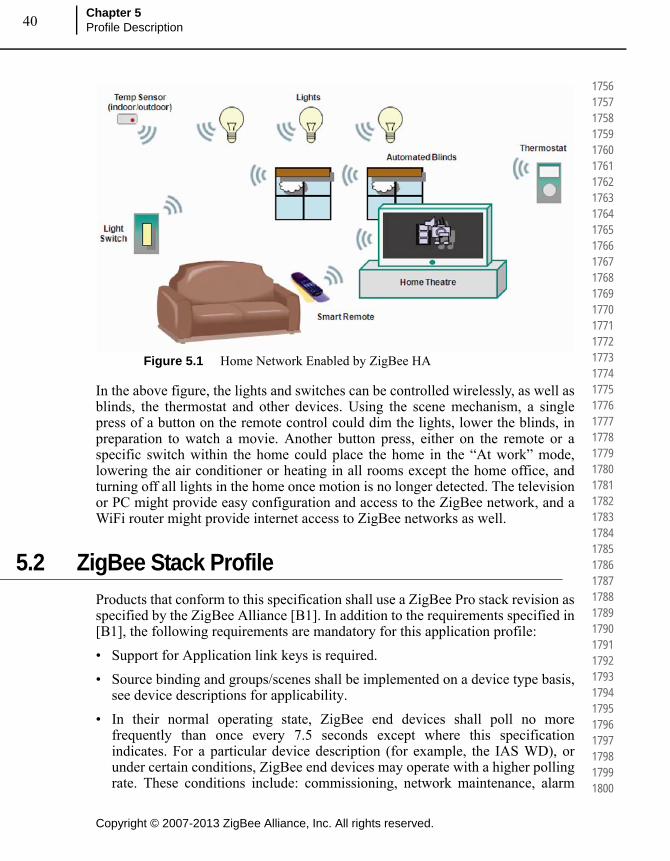
Copyright © 2007-2013 ZigBee Alliance, Inc. All rights reserved.
Chapter 5Profile Description40
175617571758175917601761176217631764176517661767176817691770177117721773177417751776177717781779178017811782178317841785178617871788178917901791179217931794179517961797179817991800
Figure 5.1 Home Network Enabled by ZigBee HA
In the above figure, the lights and switches can be controlled wirelessly, as well as blinds, the thermostat and other devices. Using the scene mechanism, a single press of a button on the remote control could dim the lights, lower the blinds, in preparation to watch a movie. Another button press, either on the remote or a specific switch within the home could place the home in the “At work” mode, lowering the air conditioner or heating in all rooms except the home office, and turning off all lights in the home once motion is no longer detected. The television or PC might provide easy configuration and access to the ZigBee network, and a WiFi router might provide internet access to ZigBee networks as well.
5.2 ZigBee Stack Profile
Products that conform to this specification shall use a ZigBee Pro stack revision as specified by the ZigBee Alliance [B1]. In addition to the requirements specified in [B1], the following requirements are mandatory for this application profile:
• Support for Application link keys is required.
• Source binding and groups/scenes shall be implemented on a device type basis, see device descriptions for applicability.
• In their normal operating state, ZigBee end devices shall poll no more frequently than once every 7.5 seconds except where this specification indicates. For a particular device description (for example, the IAS WD), or under certain conditions, ZigBee end devices may operate with a higher polling rate. These conditions include: commissioning, network maintenance, alarm
41
Copyright © 2007-2013 ZigBee Alliance, Inc. All rights reserved.
ZigBee Home Automation Public Application Profile
Document 05-3520-29
180118021803180418051806180718081809181018111812181318141815181618171818181918201821182218231824182518261827182818291830183118321833183418351836183718381839184018411842184318441845
states, and short periods after transmitting a message to allow for acknowledgements and or responses to be received quickly. They shall return to the standard rate indicated previously during normal operation. It is recommended that ZigBee end devices poll much less frequently than once per 7.5 seconds, especially when the device normally only communicates due to user interaction (for example, the On/Off Light Switch).
• When they first join a network, ZigBee end devices should operate with a higher polling rate for approximately 1 minute in order to allow time for the coordinator to commission the device properly.
• Devices shall support the mandatory stack profile interoperability as described in section 7.2 and 7.3 of the document [B1], ZigBee PICS and Stack Profiles.
• Message fragmentation is not mandatory in HA. It is therefore recommended that a device not ask for a larger response than what can fit in a non-fragmented packet, especially during read or write of multiple attributes.
• If fragmentation is enabled, the device shall first query the Node descriptor of the device it will communicate with to determine the maximum incoming transfer size unless manufacturer-specific packets are sent. The sending device must use a message size during fragmentation that is smaller than this value. If Fragmentation is supported by the device is it recommend to have apsInterFrameDelay set to 50 and apsMaxWindowSize set to 1 in order to ensure maximum interoperability.
• The application should accept commands that may be arbitrarily longer than expected in terms of their application payload. This is necessary for forward compatibility so that command payloads may be extended in the future. This means that a node may throw out an application command for being too short but it should not throw one out for being too long. It should simply parse the command arguments that it understands and ignore the rest.
• Due to the fact that fragmentation is not provided for ZDO messages, a device should implement no more than 25 clusters per endpoint. This is so that devices may retrieve all of the clusters implemented on an endpoint in a single ZDO request. If a device implements more than 25 clusters per endpoint, that device shall also support the ZDO Extended Simple Descriptor Request command.
5.2.1 ZigBee Routing Table Size Recommendations
If a HA device is intended to be primarily deployed in a network that does not support many-to-one routing, its routing table size should be increased as much as possible to account for the typically dense topology of a ZigBee HA deployment. Alternatively, it is recommended that devices that will primarily be installed into many-to-one deployments also increase their own routing tables if possible, in case the devices are deployed in networks that use ad hoc On-Demand Distance

Copyright © 2007-2013 ZigBee Alliance, Inc. All rights reserved.
Chapter 5Profile Description42
184618471848184918501851185218531854185518561857185818591860186118621863186418651866186718681869187018711872187318741875187618771878187918801881188218831884188518861887188818891890
Vector (AODV) routing for the majority of their messaging, though this may be of secondary concern.
5.2.2 ZigBee HA Coordinator Recommendations
The coordinator should indicate to the installer when a new device joins the network. This could be via PC client, LCD screen, or other simple LED indication.
It is highly recommended that all network coordinators support the Time Cluster Server and update the three time attributes (UTCTime, TimeStatus&LocalTime) accordingly.
UTCTime&LocalTime attributes should be updated regularly to reflect the accurate time.
The TimeStatus attribute should have either the Master or Synchronized bitmap enabled to indicate the status of the Time Server.
If the coordinator supports the Door Lock Cluster Client and/or Thermostat Cluster Client and would like to utilize the scheduling features on the server devices, the coordinator shall follow this recommendation closely.
5.2.3 No Network Level Multicasts1
Devices in an HA network SHALL NOT use Network Level multicast, instead they SHALL use APS level multicast for all multicast functions. Furthermore all devices in the HA network SHALL set the stack primitive Network use Multicast, nwkUseMulticast=FALSE
5.3 Startup Attribute (SAS)
In order to ensure interoperability, all ZigBee HA devices should implement compatible Startup Attribute Sets (SAS). This does not mean that set must be modifiable through a commissioning cluster, but that the device must internally implement these stack settings to ensure compatibility and consistent user experience. The start up set parameters described by the Commissioning cluster provide a good basis to specify a HA startup set.
1. CCB 1773
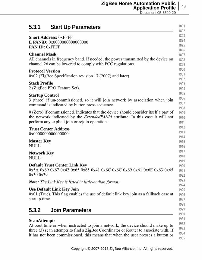
43
Copyright © 2007-2013 ZigBee Alliance, Inc. All rights reserved.
ZigBee Home Automation Public Application Profile
Document 05-3520-29
189118921893189418951896189718981899190019011902190319041905190619071908190919101911191219131914191519161917191819191920192119221923192419251926192719281929193019311932193319341935
5.3.1 Start Up Parameters
Short Address: 0xFFFFE PANiD: 0x0000000000000000PAN ID: 0xFFFF
Channel MaskAll channels in frequency band. If needed, the power transmitted by the device on channel 26 can be lowered to comply with FCC regulations.
Protocol Version0x02 (ZigBee Specification revision 17 (2007) and later).
Stack Profile2 (ZigBee PRO Feature Set).
Startup Control3 (three) if un-commissioned, so it will join network by association when join command is indicated by button press sequence.
0 (Zero) if commissioned. Indicates that the device should consider itself a part of the network indicated by the ExtendedPANId attribute. In this case it will not perform any explicit join or rejoin operation.
Trust Center Address0x0000000000000000
Master KeyNULL
Network KeyNULL.
Default Trust Center Link Key0x5A 0x69 0x67 0x42 0x65 0x65 0x41 0x6C 0x6C 0x69 0x61 0x6E 0x63 0x65 0x30 0x39
Note: The Link Key is listed in little-endian format.
Use Default Link Key Join0x01 (True). This flag enables the use of default link key join as a fallback case at startup time.
5.3.2 Join Parameters
ScanAttemptsAt boot time or when instructed to join a network, the device should make up to three (3) scan attempts to find a ZigBee Coordinator or Router to associate with. If it has not been commissioned, this means that when the user presses a button or
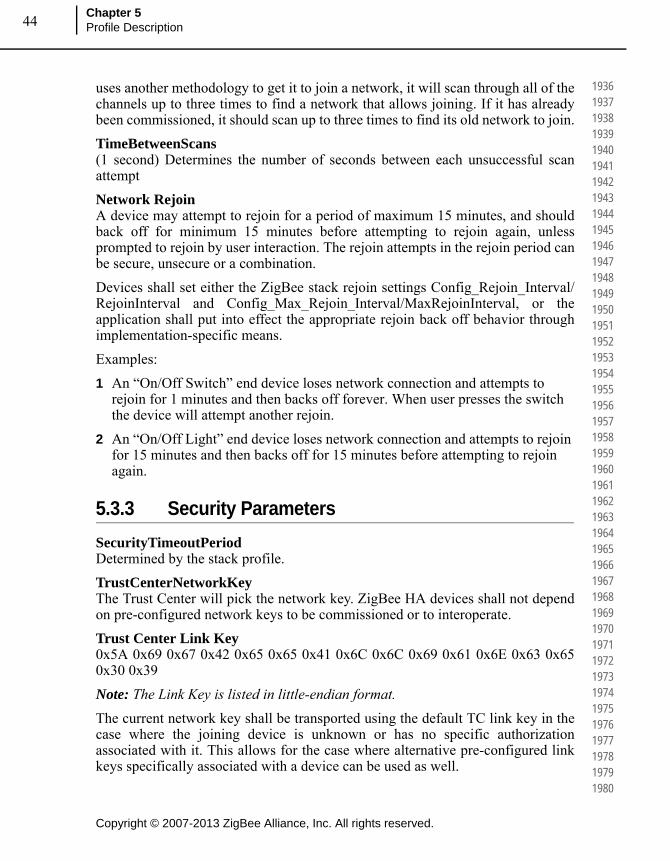
Copyright © 2007-2013 ZigBee Alliance, Inc. All rights reserved.
Chapter 5Profile Description44
193619371938193919401941194219431944194519461947194819491950195119521953195419551956195719581959196019611962196319641965196619671968196919701971197219731974197519761977197819791980
uses another methodology to get it to join a network, it will scan through all of the channels up to three times to find a network that allows joining. If it has already been commissioned, it should scan up to three times to find its old network to join.
TimeBetweenScans(1 second) Determines the number of seconds between each unsuccessful scan attempt
Network RejoinA device may attempt to rejoin for a period of maximum 15 minutes, and should back off for minimum 15 minutes before attempting to rejoin again, unless prompted to rejoin by user interaction. The rejoin attempts in the rejoin period can be secure, unsecure or a combination.
Devices shall set either the ZigBee stack rejoin settings Config_Rejoin_Interval/RejoinInterval and Config_Max_Rejoin_Interval/MaxRejoinInterval, or the application shall put into effect the appropriate rejoin back off behavior through implementation-specific means.
Examples:
1 An “On/Off Switch” end device loses network connection and attempts to rejoin for 1 minutes and then backs off forever. When user presses the switch the device will attempt another rejoin.
2 An “On/Off Light” end device loses network connection and attempts to rejoin for 15 minutes and then backs off for 15 minutes before attempting to rejoin again.
5.3.3 Security Parameters
SecurityTimeoutPeriodDetermined by the stack profile.
TrustCenterNetworkKeyThe Trust Center will pick the network key. ZigBee HA devices shall not depend on pre-configured network keys to be commissioned or to interoperate.
Trust Center Link Key0x5A 0x69 0x67 0x42 0x65 0x65 0x41 0x6C 0x6C 0x69 0x61 0x6E 0x63 0x65 0x30 0x39
Note: The Link Key is listed in little-endian format.
The current network key shall be transported using the default TC link key in the case where the joining device is unknown or has no specific authorization associated with it. This allows for the case where alternative pre-configured link keys specifically associated with a device can be used as well.
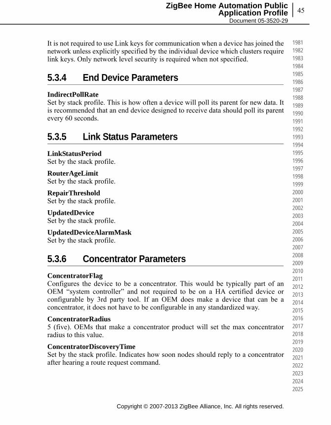
45
Copyright © 2007-2013 ZigBee Alliance, Inc. All rights reserved.
ZigBee Home Automation Public Application Profile
Document 05-3520-29
198119821983198419851986198719881989199019911992199319941995199619971998199920002001200220032004200520062007200820092010201120122013201420152016201720182019202020212022202320242025
It is not required to use Link keys for communication when a device has joined the network unless explicitly specified by the individual device which clusters require link keys. Only network level security is required when not specified.
5.3.4 End Device Parameters
IndirectPollRateSet by stack profile. This is how often a device will poll its parent for new data. It is recommended that an end device designed to receive data should poll its parent every 60 seconds.
5.3.5 Link Status Parameters
LinkStatusPeriodSet by the stack profile.
RouterAgeLimitSet by the stack profile.
RepairThresholdSet by the stack profile.
UpdatedDeviceSet by the stack profile.
UpdatedDeviceAlarmMaskSet by the stack profile.
5.3.6 Concentrator Parameters
ConcentratorFlagConfigures the device to be a concentrator. This would be typically part of an OEM “system controller” and not required to be on a HA certified device or configurable by 3rd party tool. If an OEM does make a device that can be a concentrator, it does not have to be configurable in any standardized way.
ConcentratorRadius5 (five). OEMs that make a concentrator product will set the max concentrator radius to this value.
ConcentratorDiscoveryTimeSet by the stack profile. Indicates how soon nodes should reply to a concentrator after hearing a route request command.

Copyright © 2007-2013 ZigBee Alliance, Inc. All rights reserved.
Chapter 5Profile Description46
202620272028202920302031203220332034203520362037203820392040204120422043204420452046204720482049205020512052205320542055205620572058205920602061206220632064206520662067206820692070
5.3.7 APS Transport Parameters
MaxFrameRetriesSet by stack profile. This determines the maximum number of retries allowed after a transmission failure.
AckWaitDurationSet by stack profile. This is the maximum number of seconds to wait for acknowledgement of an APS frame.
5.4 ZDO Config for HA Devices
ZDO messages relating to binding are either mandatory or optional based on a device-by-device basis. Also, reportable attributes require one or more bindings. See the device description sections for details on each device and which ZDO messages that each must support.
5.5 Device Discovery
When a central device wishes to discover all of the devices on a PAN, the recommended method is to use Network Management Mgmt_Lqi_req/Mgmt_Lqi_rsp commands. This allows a central device (i.e. a diagnostic tool) to query the neighbor table information from every device in the network.Information included in this query provides the device type, IEEE address, network address, LQI,and other useful information for each neighboring device in a network.
Typically when a device is retrieving this information, there will be a fair amount of overlap within the provided responses. For instance, in a dense network, multiple devices may respond with the same neighbors in their neighbor table responses. It is also likely multiple Mgmt_Lqi_req/Mgmt_Lqi_rsp transactions will be required to retrieve an entire neighbor table per device due to the size of each table list entry. To optimize network traffic, it is recommend that each discovered device will be compared to any previously discovered devices and duplicate device discovery messages will not be sent.
5.6 Other HA Requirements and Best Practices
Preferred Channels (11, 14, 15, 19, 20, 24, 25)When forming a new network, or scanning to join a network, HA devices should do channel scans using the above channel mask before scanning the rest of the channels in order to avoid the most commonly used WiFi channels. This is to

47
Copyright © 2007-2013 ZigBee Alliance, Inc. All rights reserved.
ZigBee Home Automation Public Application Profile
Document 05-3520-29
207120722073207420752076207720782079208020812082208320842085208620872088208920902091209220932094209520962097209820992100210121022103210421052106210721082109211021112112211321142115
improve the user experience during installation (quicker joining) and possibly improve bandwidth (on average).
Broadcast PolicyBroadcasts are to be discouraged for HA devices, except for during discovery, when controlling groups, or invoking scenes.
Devices are limited to a maximum broadcast frequency of 9 broadcasts in 9 seconds but strongly encouraged to exercise broadcasts much less frequently. As an example, a latency sensitive application that normally has very low frequency of transmission may transmit two or three broadcasts consecutively within one second.
Frequency AgilityFrequency Agility would only make sense for an OEM system controller, or higher functioning device (system remote etc.).
• Devices must support frequency agility must also contain hooks so that they can be commanded to “go to channel X”.
Key UpdatesIt is recommended that upon join the Trust Center updates the joining device with a new network or device-specific Trust Center link key.
Return to Factory DefaultsIn support of a return to factory default capability, HA devices shall implement the ZDO Management Leave server service. When invoked with a unicast address and the DeviceAddress set to NULL=0x00000000, the device shall implement a NWK Leave. When invoked with a broadcast address and the DeviceAddress set to NULL=0x00000000, the device shall wait the broadcast timeout period to allow the message to propagate through network, then the device shall implement a NWK Leave. Prior to execution of the NWK Leave in either case, processing in the device shall ensure all operating parameters are reset to allow a reset to factory defaults.
Wildcard Profile IdWhen accessing cluster functionality across endpoints with different profile ids, devices should use the wildcard profile id. The wildcard profile id is 0xffff. Applications SHALL also allow messages addressed to the wildcard profile id through to access cluster functionality as they would if they included the HA profile id.
5.7 Device Descriptions
Device descriptions specified in this profile are summarized in Table 5.1. The devices are organized according the end application areas they address. A product that conforms to this specification shall implement at least one of these device
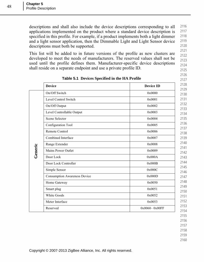
Copyright © 2007-2013 ZigBee Alliance, Inc. All rights reserved.
Chapter 5Profile Description48
211621172118211921202121212221232124212521262127212821292130213121322133213421352136213721382139214021412142214321442145214621472148214921502151215221532154215521562157215821592160
descriptions and shall also include the device descriptions corresponding to all applications implemented on the product where a standard device description is specified in this profile. For example, if a product implements both a light dimmer and a light sensor application, then the Dimmable Light and Light Sensor device descriptions must both be supported.
This list will be added to in future versions of the profile as new clusters are developed to meet the needs of manufacturers. The reserved values shall not be used until the profile defines them. Manufacturer-specific device descriptions shall reside on a separate endpoint and use a private profile ID.
Table 5.1 Devices Specified in the HA Profile
Device Device ID
Gen
eric
On/Off Switch 0x0000
Level Control Switch 0x0001
On/Off Output 0x0002
Level Controllable Output 0x0003
Scene Selector 0x0004
Configuration Tool 0x0005
Remote Control 0x0006
Combined Interface 0x0007
Range Extender 0x0008
Mains Power Outlet 0x0009
Door Lock 0x000A
Door Lock Controller 0x000B
Simple Sensor 0x000C
Consumption Awareness Device 0x000D
Home Gateway 0x0050
Smart plug 0x0051
White Goods 0x0052
Meter Interface 0x0053
Reserved 0x0060– 0x00FF

49
Copyright © 2007-2013 ZigBee Alliance, Inc. All rights reserved.
ZigBee Home Automation Public Application Profile
Document 05-3520-29
216121622163216421652166216721682169217021712172217321742175217621772178217921802181218221832184218521862187218821892190219121922193219421952196219721982199220022012202220322042205
Lig
hti
ng
On/Off Light 0x0100
Dimmable Light 0x0101
Color Dimmable Light 0x0102
On/Off Light Switch 0x0103
Dimmer Switch 0x0104
Color Dimmer Switch 0x0105
Light Sensor 0x0106
Occupancy Sensor 0x0107
Reserved 0x0108 – 0x1FF
Clo
sure
s
Shade 0x0200
Shade Controller 0x0201
Window Covering Device 0x0202
Window Covering Controller 0x0203
Reserved 0x0204 – 0x2FF
HV
AC
Heating/Cooling Unit 0x0300
Thermostat 0x0301
Temperature Sensor 0x0302
Pump 0x0303
Pump Controller 0x0304
Pressure Sensor 0x0305
Flow Sensor 0x0306
Mini Split AC 0x0307
Reserved 0x0308 - 0x3FF
Intr
ud
er A
larm
Sys
tem
s
IAS Control and Indicating Equipment 0x0400
IAS Ancillary Control Equipment 0x0401
IAS Zone 0x0402
IAS Warning Device 0x0403
Reserved 0x0404-0xFFFF
Table 5.1 Devices Specified in the HA Profile (Continued)
Device Device ID

Copyright © 2007-2013 ZigBee Alliance, Inc. All rights reserved.
Chapter 5Profile Description50
220622072208220922102211221222132214221522162217221822192220222122222223222422252226222722282229223022312232223322342235223622372238223922402241224222432244224522462247224822492250
5.8 ZigBee Cluster Library (ZCL)
This profile utilizes the clusters specified in the ZigBee Cluster Library. The implementation details for each cluster are given in the ZCL specifications. Further specification and clarification are given in this profile where necessary.
5.9 Cluster List
The clusters used in this profile are listed in Table 5.2. The clusters are listed according the functional domain they belong to in the ZCL. The corresponding cluster identifiers can be found in the ZigBee Cluster Library specification [B2].
The functionality made available by all supported clusters shall be that given in their ZCL specifications except where a device description in this profile includes further specification, clarification or restriction as needed for that particular device.
Most clusters include optional attributes. The application designer must be aware that optional attributes may not be implemented on a particular device. It is the responsibility of a device’s application to discover and deal with unsupported attributes on other devices.
It is expected that clusters will continue to be developed in the ZCL that will be useful in this profile. In many cases, new clusters will be organized into new device descriptions that are separate from those currently defined. There may also be situations where it makes sense to add clusters as optional or possibly even mandatory elements of existing device descriptions. Creating new device descriptions is the preferred method of adding new clusters to this specification, because new functionality can be mandated in a new device description without causing compatibility issues with previously-defined devices.
Manufacturer-specific clusters may be added to any device description in this profile as long as they follow the specifications given in the ZigBee Cluster Library [B2].
Table 5.2 Clusters Used in the HA Profile
Functional Domain Cluster Name Cluster ID Certifiable
General Basic 0x0000
General Power Configuration 0x0001
General Device Temperature Configuration 0x0002
General Identify 0x0003
General Groups 0x0004

51
Copyright © 2007-2013 ZigBee Alliance, Inc. All rights reserved.
ZigBee Home Automation Public Application Profile
Document 05-3520-29
225122522253225422552256225722582259226022612262226322642265226622672268226922702271227222732274227522762277227822792280228122822283228422852286228722882289229022912292229322942295
General Scenes 0x0005
General On/Off 0x0006
General On/Off Switch Configuration 0x0007
General Level Control 0x0008
General Alarms 0x0009
General Time 0x000A
General Binary Input (Basic) 0x000F
General Partition 0x0016
General Power Profile 0x001a
General EN50523Appliance Control 0x001b
General Poll Control 0x0020
Closures Shade Configuration 0x0100
Closures Door Lock 0x0101
Closures Window Covering 0x0102
HVAC Pump Configuration and Control 0x0200
HVAC Thermostat 0x0201
HVAC Fan Control 0x0202
HVAC Thermostat User Interface Configuration 0x0204
Lighting Color Control 0x0300
Measurement & Sensing Illuminance Measurement 0x0400
Measurement & Sensing Illuminance Level Sensing 0x0401
Measurement & Sensing Temperature Measurement 0x0402
Measurement & Sensing Pressure Measurement 0x0403
Measurement & Sensing Flow Measurement 0x0404
Measurement & Sensing Relative Humidity Measurement 0x0405
Measurement & Sensing Occupancy Sensing 0x0406
Security and Safety IAS Zone 0x0500
Security and Safety IAS ACE 0x0501
Security and Safety IAS WD 0x0502
Smart Energy Metering 0x0702
Home Automation EN50523 Appliance Identification 0x0b00
Table 5.2 Clusters Used in the HA Profile (Continued)
Functional Domain Cluster Name Cluster ID Certifiable
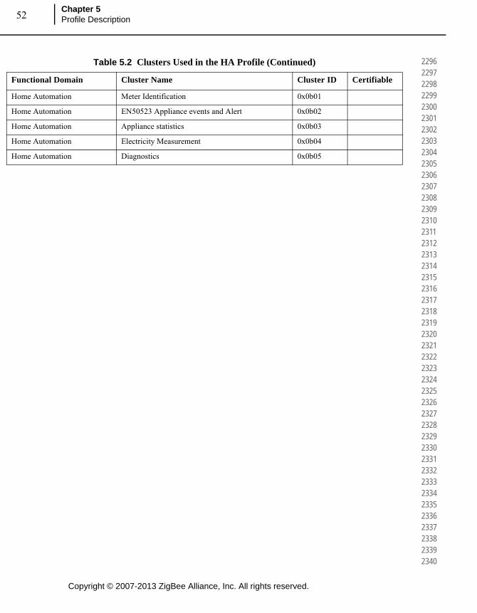
Copyright © 2007-2013 ZigBee Alliance, Inc. All rights reserved.
Chapter 5Profile Description52
229622972298229923002301230223032304230523062307230823092310231123122313231423152316231723182319232023212322232323242325232623272328232923302331233223332334233523362337233823392340
Home Automation Meter Identification 0x0b01
Home Automation EN50523 Appliance events and Alert 0x0b02
Home Automation Appliance statistics 0x0b03
Home Automation Electricity Measurement 0x0b04
Home Automation Diagnostics 0x0b05
Table 5.2 Clusters Used in the HA Profile (Continued)
Functional Domain Cluster Name Cluster ID Certifiable
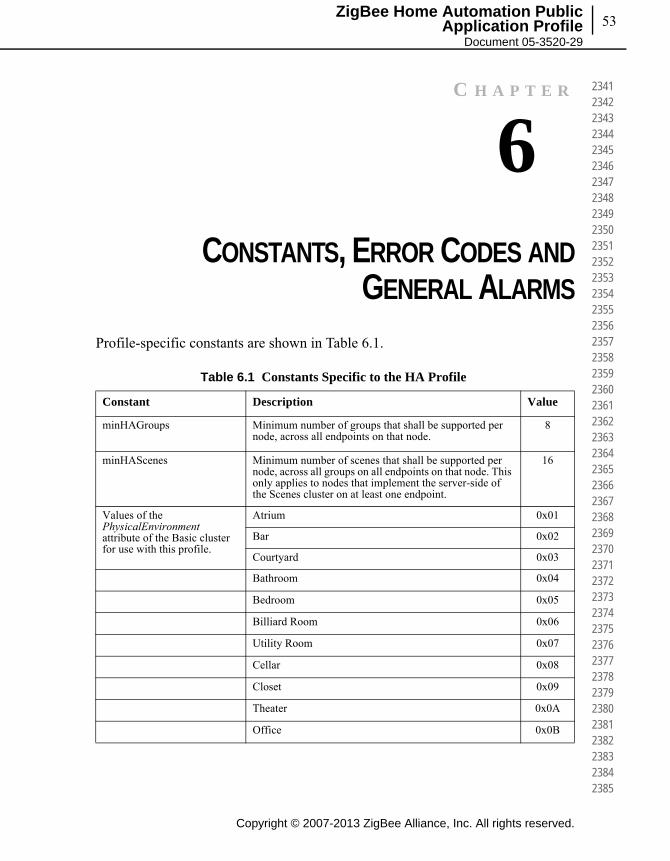
53
Copyright © 2007-2013 ZigBee Alliance, Inc. All rights reserved.
ZigBee Home Automation Public Application Profile
Document 05-3520-29
234123422343234423452346234723482349235023512352235323542355235623572358235923602361236223632364236523662367236823692370237123722373237423752376237723782379238023812382238323842385
C H A P T E R
6CHAPTER 6CONSTANTS, ERROR CODES AND
GENERAL ALARMS
Profile-specific constants are shown in Table 6.1.
Table 6.1 Constants Specific to the HA Profile
Constant Description Value
minHAGroups Minimum number of groups that shall be supported per node, across all endpoints on that node.
8
minHAScenes Minimum number of scenes that shall be supported per node, across all groups on all endpoints on that node. This only applies to nodes that implement the server-side of the Scenes cluster on at least one endpoint.
16
Values of the PhysicalEnvironment attribute of the Basic cluster for use with this profile.
Atrium 0x01
Bar 0x02
Courtyard 0x03
Bathroom 0x04
Bedroom 0x05
Billiard Room 0x06
Utility Room 0x07
Cellar 0x08
Closet 0x09
Theater 0x0A
Office 0x0B

Copyright © 2007-2013 ZigBee Alliance, Inc. All rights reserved.
Chapter 6Constants, Error Codes and General Alarms54
238623872388238923902391239223932394239523962397239823992400240124022403240424052406240724082409241024112412241324142415241624172418241924202421242224232424242524262427242824292430
Values of the PhysicalEnvironment attribute of the Basic cluster for use with this profile.
Deck 0x0C
Den 0x0D
Dining Room 0x0E
Electrical Room 0x0F
Elevator 0x10
Entry 0x11
Family Room 0x12
Main Floor 0x13
Upstairs 0x14
Downstairs 0x15
Basement/Lower Level 0x16
Gallery 0x17
Game Room 0x18
Garage 0x19
Gym 0x1A
Hallway 0x1B
House 0x1C
Kitchen 0x1D
Laundry Room 0x1E
Library 0x1F
Master Bedroom 0x20
Mud Room (small room for coats and boots) 0x21
Nursery 0x22
Pantry 0x23
Office 0x24
Outside 0x25
Pool 0x26
Porch 0x27
Sewing Room 0x28
Sitting Room 0x29
Stairway 0x2A
Table 6.1 Constants Specific to the HA Profile (Continued)
Constant Description Value
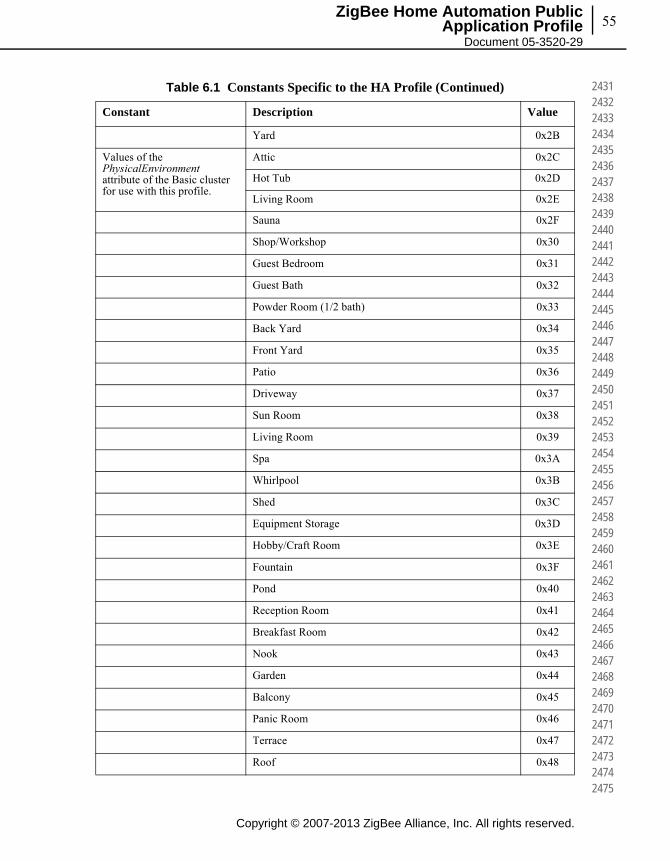
55
Copyright © 2007-2013 ZigBee Alliance, Inc. All rights reserved.
ZigBee Home Automation Public Application Profile
Document 05-3520-29
243124322433243424352436243724382439244024412442244324442445244624472448244924502451245224532454245524562457245824592460246124622463246424652466246724682469247024712472247324742475
Yard 0x2B
Values of the PhysicalEnvironment attribute of the Basic cluster for use with this profile.
Attic 0x2C
Hot Tub 0x2D
Living Room 0x2E
Sauna 0x2F
Shop/Workshop 0x30
Guest Bedroom 0x31
Guest Bath 0x32
Powder Room (1/2 bath) 0x33
Back Yard 0x34
Front Yard 0x35
Patio 0x36
Driveway 0x37
Sun Room 0x38
Living Room 0x39
Spa 0x3A
Whirlpool 0x3B
Shed 0x3C
Equipment Storage 0x3D
Hobby/Craft Room 0x3E
Fountain 0x3F
Pond 0x40
Reception Room 0x41
Breakfast Room 0x42
Nook 0x43
Garden 0x44
Balcony 0x45
Panic Room 0x46
Terrace 0x47
Roof 0x48
Table 6.1 Constants Specific to the HA Profile (Continued)
Constant Description Value

Chapter 6Constants, Error Codes and General Alarms56
This page intentionally blank
Copyright © 2007-2013 ZigBee Alliance, Inc. All rights reserved.
247624772478247924802481248224832484248524862487248824892490249124922493249424952496249724982499250025012502250325042505250625072508250925102511251225132514251525162517251825192520
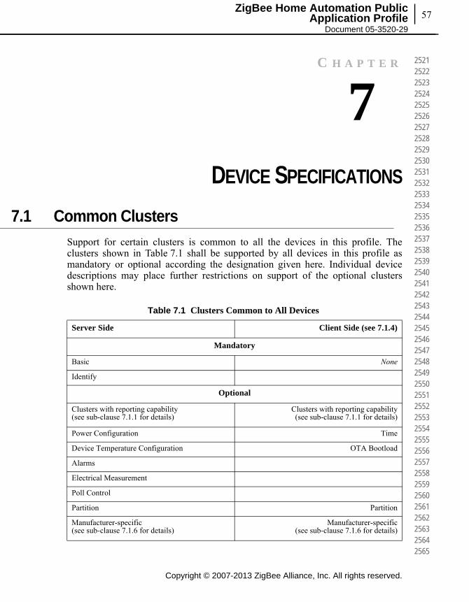
57ZigBee Home Automation Public
Application Profile Document 05-3520-29
C H A P T E R
7CHAPTER 7DEVICE SPECIFICATIONS
7.1 Common Clusters
Support for certain clusters is common to all the devices in this profile. The clusters shown in Table 7.1 shall be supported by all devices in this profile as mandatory or optional according the designation given here. Individual device descriptions may place further restrictions on support of the optional clusters shown here.
Table 7.1 Clusters Common to All Devices
Server Side Client Side (see 7.1.4)
Mandatory
Basic None
Identify
Optional
Clusters with reporting capability (see sub-clause 7.1.1 for details)
Clusters with reporting capability (see sub-clause 7.1.1 for details)
Power Configuration Time
Device Temperature Configuration OTA Bootload
Alarms
Electrical Measurement
Poll Control
Partition Partition
Manufacturer-specific (see sub-clause 7.1.6 for details)
Manufacturer-specific (see sub-clause 7.1.6 for details)
Copyright © 2007-2013 ZigBee Alliance, Inc. All rights reserved.
252125222523252425252526252725282529253025312532253325342535253625372538253925402541254225432544254525462547254825492550255125522553255425552556255725582559256025612562256325642565
Copyright © 2007-2013 ZigBee Alliance, Inc. All rights reserved.
Chapter 7Device Specifications58
256625672568256925702571257225732574257525762577257825792580258125822583258425852586258725882589259025912592259325942595259625972598259926002601260226032604260526062607260826092610
7.1.1 Optional Support for Clusters with Reporting Capability
Some clusters support the ability to report changes to the value of particular attributes. These reports are typically received by the client side of the cluster. All devices in this profile may support any cluster that receives attribute reports.
7.1.2 Groups and Scene Cluster Clarification
7.1.2.1 Groups Clarification
As Groupcasts are made on a broadcast to all devices for which macRxOnWhenIdle = TRUE, Sleeping end devices will not be able to benefit from the features of the Groups and Scenes server Cluster. For example, a door lock which would typically be a sleeping end device would not be able to receive the datagrams required to commission a scene or change for example, to a night scene. It is therefore not Mandatory but only optional to support the Groups and Scenes Server cluster if the device is a Sleeping end device (even when listed as Mandatory).
7.1.2.2 Scenes Clarification
Certain devices have several extension field sets. An example is the Dimmable Light that has an On/Off cluster and a level control cluster. It is required that a scene commissioned shall contain all extension field sets. For example, an Add Scene command sent to a Dimmable light shall contain an On/Off and CurrentLevel. A View Scene response would also contain all extension field sets.
7.1.3 Level Control Cluster Clarification
Table 7.2 shows how the level control cluster shall be implemented. This table shows how a light responds to the same command given a set of attribute settings. For instance if the physical light is off it responds differently than if the physical light is on. However regardless of the light’s on/off state, the internal light level can change as shown in Table 7.2.
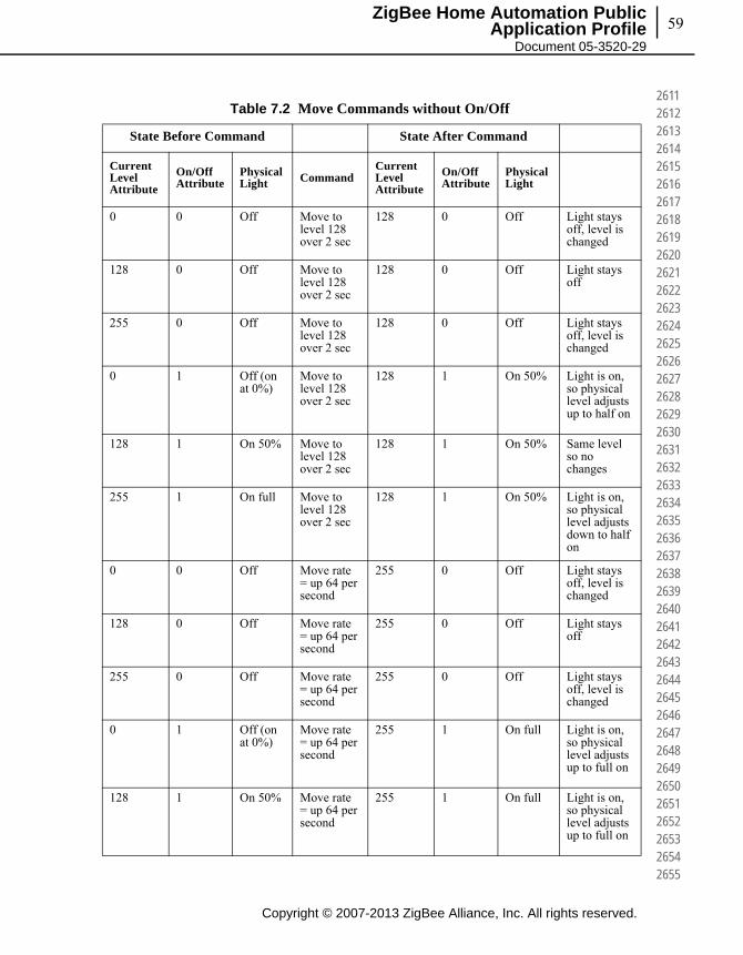
59
Copyright © 2007-2013 ZigBee Alliance, Inc. All rights reserved.
ZigBee Home Automation Public Application Profile
Document 05-3520-29
261126122613261426152616261726182619262026212622262326242625262626272628262926302631263226332634263526362637263826392640264126422643264426452646264726482649265026512652265326542655
Table 7.2 Move Commands without On/Off
State Before Command State After Command
Current Level Attribute
On/Off Attribute
Physical Light Command
Current Level Attribute
On/Off Attribute
Physical Light
0 0 Off Move to level 128 over 2 sec
128 0 Off Light stays off, level is changed
128 0 Off Move to level 128 over 2 sec
128 0 Off Light stays off
255 0 Off Move to level 128 over 2 sec
128 0 Off Light stays off, level is changed
0 1 Off (on at 0%)
Move to level 128 over 2 sec
128 1 On 50% Light is on, so physical level adjusts up to half on
128 1 On 50% Move to level 128 over 2 sec
128 1 On 50% Same level so no changes
255 1 On full Move to level 128 over 2 sec
128 1 On 50% Light is on, so physical level adjusts down to half on
0 0 Off Move rate = up 64 per second
255 0 Off Light stays off, level is changed
128 0 Off Move rate = up 64 per second
255 0 Off Light stays off
255 0 Off Move rate = up 64 per second
255 0 Off Light stays off, level is changed
0 1 Off (on at 0%)
Move rate = up 64 per second
255 1 On full Light is on, so physical level adjusts up to full on
128 1 On 50% Move rate = up 64 per second
255 1 On full Light is on, so physical level adjusts up to full on

Copyright © 2007-2013 ZigBee Alliance, Inc. All rights reserved.
Chapter 7Device Specifications60
265626572658265926602661266226632664266526662667266826692670267126722673267426752676267726782679268026812682268326842685268626872688268926902691269226932694269526962697269826992700
255 1 On full Move rate = up 64 per second
255 1 On full Light is on already at full, so no changes
0 0 Off Move rate = down 64 per second
0 0 Off Light stays off
128 0 Off Move rate = down 64 per second
0 0 Off Light stays off, level is changed
255 0 Off Move rate = down 64 per second
0 0 Off Light stays off, level is changed
0 1 Off (on at 0%)
Move rate = down 64 per second
0 1 Off (on at 0%)
Level is already at 0 -- no changes to level or physical light
128 1 On 50% Move rate = down 64 per second
0 1 Off (on at 0%)
Level moves down to zero, leaving the physical light off (0% on) and on/off attribute at 1
255 1 On full Move rate = down 64 per second
0 1 Off (on at 0%)
Level moves down to zero, leaving the physical light off (0% on) and on/off attribute at 1
Table 7.2 Move Commands without On/Off (Continued)
State Before Command State After Command
Current Level Attribute
On/Off Attribute
Physical Light Command
Current Level Attribute
On/Off Attribute
Physical Light
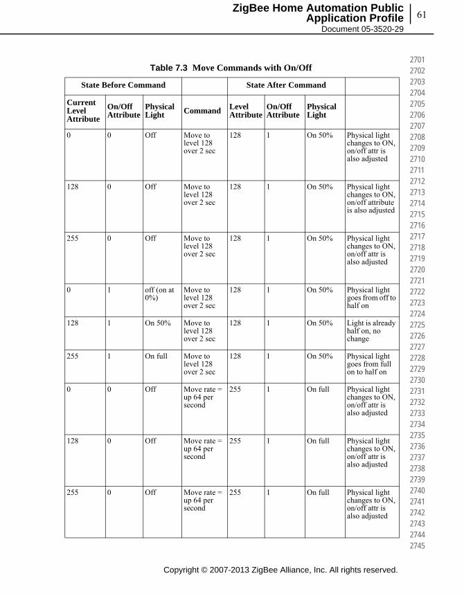
61
Copyright © 2007-2013 ZigBee Alliance, Inc. All rights reserved.
ZigBee Home Automation Public Application Profile
Document 05-3520-29
270127022703270427052706270727082709271027112712271327142715271627172718271927202721272227232724272527262727272827292730273127322733273427352736273727382739274027412742274327442745
Table 7.3 Move Commands with On/Off
State Before Command State After Command
Current Level Attribute
On/Off Attribute
Physical Light Command Level
AttributeOn/Off Attribute
Physical Light
0 0 Off Move to level 128 over 2 sec
128 1 On 50% Physical light changes to ON, on/off attr is also adjusted
128 0 Off Move to level 128 over 2 sec
128 1 On 50% Physical light changes to ON, on/off attribute is also adjusted
255 0 Off Move to level 128 over 2 sec
128 1 On 50% Physical light changes to ON, on/off attr is also adjusted
0 1 off (on at 0%)
Move to level 128 over 2 sec
128 1 On 50% Physical light goes from off to half on
128 1 On 50% Move to level 128 over 2 sec
128 1 On 50% Light is already half on, no change
255 1 On full Move to level 128 over 2 sec
128 1 On 50% Physical light goes from full on to half on
0 0 Off Move rate = up 64 per second
255 1 On full Physical light changes to ON, on/off attr is also adjusted
128 0 Off Move rate = up 64 per second
255 1 On full Physical light changes to ON, on/off attr is also adjusted
255 0 Off Move rate = up 64 per second
255 1 On full Physical light changes to ON, on/off attr is also adjusted

Copyright © 2007-2013 ZigBee Alliance, Inc. All rights reserved.
Chapter 7Device Specifications62
274627472748274927502751275227532754275527562757275827592760276127622763276427652766276727682769277027712772277327742775277627772778277927802781278227832784278527862787278827892790
0 1 Off (on at 0%)
Move rate = up 64 per second
255 1 On full Physical level adjusts from off to full on
128 1 On 50% Move rate = up 64 per second
255 1 On full Physical level adjusts from half on to full on
255 1 On full Move rate = up 64 per second
255 1 On full Light is already on at full level, no changes
0 0 Off Move rate = down 64 per second
0 0 Off Light stays off, level is also at 0
128 0 Off Move rate = down 64 per second
0 0 Off Light stays off, level is also at 0
255 0 Off Move rate = down 64 per second
0 0 Off Light stays off, level is also at 0
0 1 Off (on at 0%)
Move rate = down 64 per second
0 0 Off Physical light is already off, on/off attr is also adjusted
128 1 On 50% Move rate = down 64 per second
0 0 Off Light physically turns off, on/off attr is also adjusted
255 1 On full Move rate = down 64 per second
0 0 Off Light physically turns off, on/off attr is also adjusted
Table 7.3 Move Commands with On/Off (Continued)
State Before Command State After Command
Current Level Attribute
On/Off Attribute
Physical Light Command Level
AttributeOn/Off Attribute
Physical Light
63
Copyright © 2007-2013 ZigBee Alliance, Inc. All rights reserved.
ZigBee Home Automation Public Application Profile
Document 05-3520-29
279127922793279427952796279727982799280028012802280328042805280628072808280928102811281228132814281528162817281828192820282128222823282428252826282728282829283028312832283328342835
7.1.4 Client Cluster Mandatory Commands Clarification
The client generates the cluster-specific commands detailed in the “Commands Received” section of the server cluster as required by the application. This means that even though all commands are listed as mandatory it is only required to implement the client side required for the application.
For example, an On/Off switch might only implement the Toggle command and not the On and Off commands.
7.1.5 Attribute Reporting Clarification
This section clarifies how the Attribute reporting should be configured. All reportable attributes shall have a default configuration that is readable with the Read Reporting Configuration command.
The ZCL provides a mechanism for clusters to report changes to the value of various attributes. It also provides commands to configure the reporting parameters. The attributes that a particular cluster is capable of reporting are listed in the ZCL specification for each cluster. Devices shall support the reporting configuration mechanisms for all reportable attributes. The minimum reporting interval specified in [B2] shall be set to a value greater than or equal to 0x0001. The maximum reporting interval should be set to 0x0000 by default, and if it is set to a non-zero value it shall be set to a value greater than or equal to 0x003C and greater than the value of the minimum reporting interval. These settings will restrict the attributes from being reported more often than once every second if the attribute is changing quickly and at least once every minute if the attribute does not change for a long time. It is recommended that the minimum reporting interval be set to a higher value whenever the application can tolerate it. It is recommended that the maximum reporting interval be set to a much greater value to avoid unnecessary traffic.
Sections 2.2.1 and 2.4.11 in the ZigBee Cluster Library specification [B2] specify that a binding shall be created prior to setting up a report and that the reports are sent through the bindings created.
The specification is intended to mandate that, if one or more bindings are set up from the device, any attribute reports for a specific cluster are always sent over all bindings setup for that cluster.
Reporting uses bindings to determine the destination of a report. Reportable attributes shall have a default configuration. The device may also create its own source binding to address a report to a destination.

Copyright © 2007-2013 ZigBee Alliance, Inc. All rights reserved.
Chapter 7Device Specifications64
283628372838283928402841284228432844284528462847284828492850285128522853285428552856285728582859286028612862286328642865286628672868286928702871287228732874287528762877287828792880
This specification also mandates that all reporting configuration tables and binding tables should be stored in non-volatile memory on the device so that in the event that the device loses power or resets for some other reason, reporting configuration information will not be lost.
In the event that a device is reset-to-factory-defaults, all bindings and reporting configurations will be reset to their default values (see clause 8.4).
7.1.6 Manufacturer-Specific Clusters
The ZCL provides a range of cluster IDs that are reserved for manufacturer-specific clusters. Manufacturer-specific clusters that conform to the requirements given in the ZCL may be added to any device description specified in this profile.
7.1.7 Cluster Usage Restrictions
It is possible to add any cluster defined in the ZigBee Cluster Specification as an optional cluster for any device in this profile and the Smart Energy Application Profile specification Annex D.
Any additional clusters added shall be declared on the device PICS and shall be tested in accordance with the base network and security configurations in this document and the messaging and behavior from that specific cluster test plan.
7.2 Certifiable HA Devices and Features
Not all features or devices listed in this document have been tested and certified. Therefore not all features in this document are certifiable. Only the features and devices listed in the Home Automation Test specification can be certified. The non-certifiable features cannot be certified until the appropriate test cases have been created, golden units from multiple manufacturers have completed testing with them, and the Home Automation Profile task group has approved them for certification.
Refer to Table 5.2 to determine which cluster is certifiable.
7.3 Feature and Function Description
Each device must support a certain set of features and functions. Table 7.4 specifies the mandatory and optional features and functions of each device. This chapter contains a description of what must be supported if the feature or function is supported by the device. The mandatory or optional configuration for each device is described in the following sections.
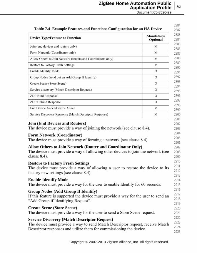
65
Copyright © 2007-2013 ZigBee Alliance, Inc. All rights reserved.
ZigBee Home Automation Public Application Profile
Document 05-3520-29
288128822883288428852886288728882889289028912892289328942895289628972898289929002901290229032904290529062907290829092910291129122913291429152916291729182919292029212922292329242925
Join (End Devices and Routers)The device must provide a way of joining the network (see clause 8.4).
Form Network (Coordinator)The device must provide a way of forming a network (see clause 8.4).
Allow Others to Join Network (Router and Coordinator Only)The device must provide a way of allowing other devices to join the network (see clause 8.4).
Restore to Factory Fresh SettingsThe device must provide a way of allowing a user to restore the device to its factory new settings (see clause 8.4).
Enable Identify ModeThe device must provide a way for the user to enable Identify for 60 seconds.
Group Nodes (Add Group If Identify)If this feature is supported the device must provide a way for the user to send an “Add Group if Identifying Request”.
Create Scene (Store Scene)The device must provide a way for the user to send a Store Scene request.
Service Discovery (Match Descriptor Request)The device must provide a way to send Match Descriptor request, receive Match Descriptor responses and utilize them for commissioning the device.
Table 7.4 Example Features and Functions Configuration for an HA Device
Device Type/Feature or Function Mandatory/Optional
Join (end devices and routers only) M
Form Network (Coordinator only) M
Allow Others to Join Network (routers and Coordinators only) M
Restore to Factory Fresh Settings M
Enable Identify Mode O
Group Nodes (send out an Add Group If Identify) O
Create Scene (Store Scene) O
Service discovery (Match Descriptor Request) O
ZDP Bind Response O
ZDP Unbind Response O
End Device Annce/Device Annce M
Service Discovery Response (Match Descriptor Response) M
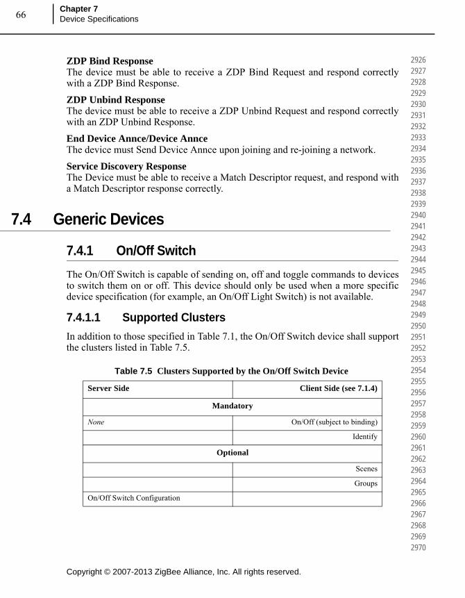
Copyright © 2007-2013 ZigBee Alliance, Inc. All rights reserved.
Chapter 7Device Specifications66
292629272928292929302931293229332934293529362937293829392940294129422943294429452946294729482949295029512952295329542955295629572958295929602961296229632964296529662967296829692970
ZDP Bind ResponseThe device must be able to receive a ZDP Bind Request and respond correctly with a ZDP Bind Response.
ZDP Unbind ResponseThe device must be able to receive a ZDP Unbind Request and respond correctly with an ZDP Unbind Response.
End Device Annce/Device AnnceThe device must Send Device Annce upon joining and re-joining a network.
Service Discovery ResponseThe Device must be able to receive a Match Descriptor request, and respond with a Match Descriptor response correctly.
7.4 Generic Devices
7.4.1 On/Off Switch
The On/Off Switch is capable of sending on, off and toggle commands to devices to switch them on or off. This device should only be used when a more specific device specification (for example, an On/Off Light Switch) is not available.
7.4.1.1 Supported Clusters
In addition to those specified in Table 7.1, the On/Off Switch device shall support the clusters listed in Table 7.5.
Table 7.5 Clusters Supported by the On/Off Switch Device
Server Side Client Side (see 7.1.4)
Mandatory
None On/Off (subject to binding)
Identify
Optional
Scenes
Groups
On/Off Switch Configuration
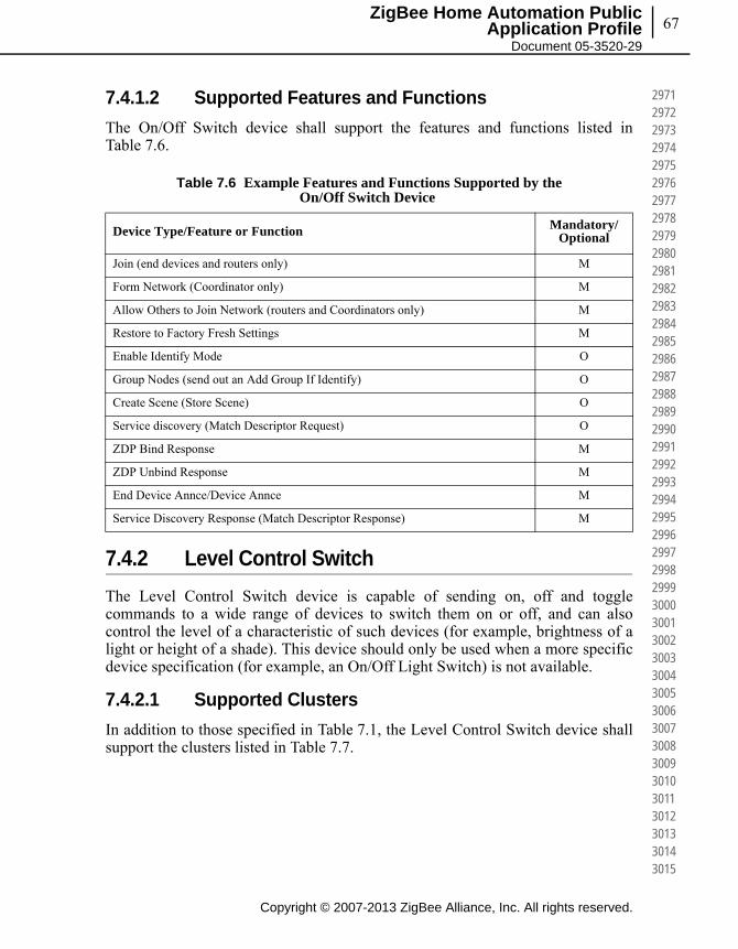
67
Copyright © 2007-2013 ZigBee Alliance, Inc. All rights reserved.
ZigBee Home Automation Public Application Profile
Document 05-3520-29
297129722973297429752976297729782979298029812982298329842985298629872988298929902991299229932994299529962997299829993000300130023003300430053006300730083009301030113012301330143015
7.4.1.2 Supported Features and Functions
The On/Off Switch device shall support the features and functions listed in Table 7.6.
7.4.2 Level Control Switch
The Level Control Switch device is capable of sending on, off and toggle commands to a wide range of devices to switch them on or off, and can also control the level of a characteristic of such devices (for example, brightness of a light or height of a shade). This device should only be used when a more specific device specification (for example, an On/Off Light Switch) is not available.
7.4.2.1 Supported Clusters
In addition to those specified in Table 7.1, the Level Control Switch device shall support the clusters listed in Table 7.7.
Table 7.6 Example Features and Functions Supported by the On/Off Switch Device
Device Type/Feature or Function Mandatory/Optional
Join (end devices and routers only) M
Form Network (Coordinator only) M
Allow Others to Join Network (routers and Coordinators only) M
Restore to Factory Fresh Settings M
Enable Identify Mode O
Group Nodes (send out an Add Group If Identify) O
Create Scene (Store Scene) O
Service discovery (Match Descriptor Request) O
ZDP Bind Response M
ZDP Unbind Response M
End Device Annce/Device Annce M
Service Discovery Response (Match Descriptor Response) M

Copyright © 2007-2013 ZigBee Alliance, Inc. All rights reserved.
Chapter 7Device Specifications68
301630173018301930203021302230233024302530263027302830293030303130323033303430353036303730383039304030413042304330443045304630473048304930503051305230533054305530563057305830593060
7.4.2.2 Supported Features and Functions
The Level Control Switch device shall support the features and functions listed in Table 7.8.
Table 7.7 Clusters Supported by the Level Control Switch Device
Server Side Client Side (see 7.1.4)
Mandatory
None
Identify
On/Off (subject to binding)
Level Control (subject to binding)
Optional
On/Off Switch Configuration Scenes
Groups
Table 7.8 Example Features and Functions Supported by the Level Control Switch Device
Device Type/Feature or Function Mandatory/Optional
Join (end devices and routers only) M
Form Network (Coordinator only) M
Allow Others to Join Network (routers and Coordinators only) M
Restore to Factory Fresh Settings M
Enable Identify Mode O
Group Nodes (send out an Add Group If Identify) O
Create Scene (Store Scene) O
Service discovery (Match Descriptor Request) O
ZDP Bind Response M
ZDP Unbind Response M
End Device Annce/Device Annce M
Service Discovery Response (Match Descriptor Response) M
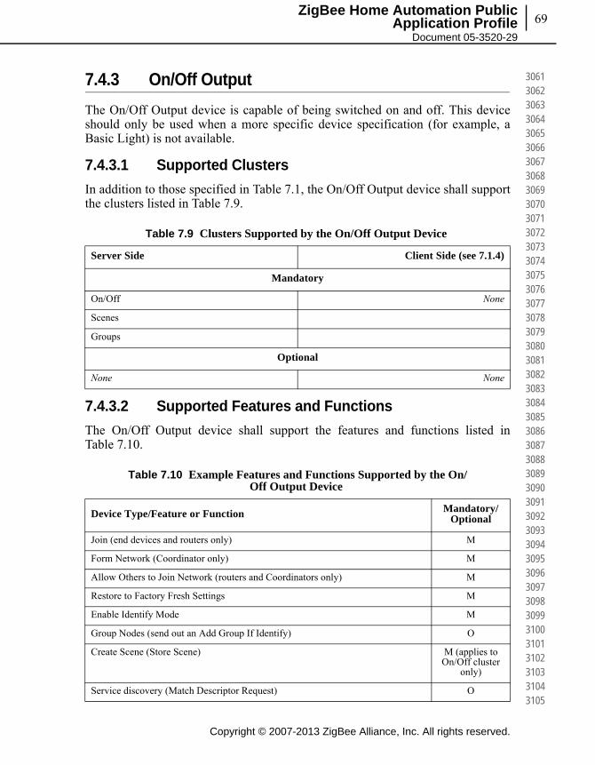
69
Copyright © 2007-2013 ZigBee Alliance, Inc. All rights reserved.
ZigBee Home Automation Public Application Profile
Document 05-3520-29
306130623063306430653066306730683069307030713072307330743075307630773078307930803081308230833084308530863087308830893090309130923093309430953096309730983099310031013102310331043105
7.4.3 On/Off Output
The On/Off Output device is capable of being switched on and off. This device should only be used when a more specific device specification (for example, a Basic Light) is not available.
7.4.3.1 Supported Clusters
In addition to those specified in Table 7.1, the On/Off Output device shall support the clusters listed in Table 7.9.
7.4.3.2 Supported Features and Functions
The On/Off Output device shall support the features and functions listed in Table 7.10.
Table 7.9 Clusters Supported by the On/Off Output Device
Server Side Client Side (see 7.1.4)
Mandatory
On/Off None
Scenes
Groups
Optional
None None
Table 7.10 Example Features and Functions Supported by the On/Off Output Device
Device Type/Feature or Function Mandatory/Optional
Join (end devices and routers only) M
Form Network (Coordinator only) M
Allow Others to Join Network (routers and Coordinators only) M
Restore to Factory Fresh Settings M
Enable Identify Mode M
Group Nodes (send out an Add Group If Identify) O
Create Scene (Store Scene) M (applies to On/Off cluster
only)
Service discovery (Match Descriptor Request) O

Copyright © 2007-2013 ZigBee Alliance, Inc. All rights reserved.
Chapter 7Device Specifications70
310631073108310931103111311231133114311531163117311831193120312131223123312431253126312731283129313031313132313331343135313631373138313931403141314231433144314531463147314831493150
7.4.4 Level Controllable Output
The Level Controllable Output device can be switched on and off, and its output level adjusted. This device should only be used when a more specific device specification (for example, a Dimmer Switch) is not available.
7.4.4.1 Supported Clusters
In addition to those specified in Table 7.1, the Level Controllable Output device shall support the clusters listed in Table 7.11.
7.4.4.2 Supported Features and Functions
The Level Controllable Output device shall support the features and functions listed in Table 7.12.
ZDP Bind Response M
ZDP Unbind Response M
End Device Annce/Device Annce M
Service Discovery Response (Match Descriptor Response) M
EZ-Mode Commissioning M
Table 7.11 Clusters Supported by the Level Controllable Output Device
Server Side Client Side (see 7.1.4)
Mandatory
On/Off None
Level Control
Scenes
Groups
Optional
None None
Table 7.10 Example Features and Functions Supported by the On/Off Output Device (Continued)
Device Type/Feature or Function Mandatory/Optional

71
Copyright © 2007-2013 ZigBee Alliance, Inc. All rights reserved.
ZigBee Home Automation Public Application Profile
Document 05-3520-29
315131523153315431553156315731583159316031613162316331643165316631673168316931703171317231733174317531763177317831793180318131823183318431853186318731883189319031913192319331943195
7.4.5 Scene Selector
The Scene Selector device is capable of setting up and selecting scenes on other devices (including groups of devices).
7.4.5.1 Supported Clusters
In addition to those specified in Table 7.1, the Scene Selector device shall support the clusters listed in Table 7.13.
Table 7.12 Example Features and Functions Supported by the Level Controllable Output Device
Device Type/Feature or Function Mandatory/Optional
Join (end devices and routers only) M
Form Network (Coordinator only) M
Allow Others to Join Network (routers and Coordinators only) M
Restore to Factory Fresh Settings M
Enable Identify Mode M
Group Nodes (send out an Add Group If Identify) O
Create Scene (Store Scene) M (applies to On/Off and
Level Control cluster only)
Service discovery (Match Descriptor Request) O
ZDP Bind Response M
ZDP Unbind Response M
End Device Annce/Device Annce M
Service Discovery Response (Match Descriptor Response) M
EZ-Mode Commissioning M

Copyright © 2007-2013 ZigBee Alliance, Inc. All rights reserved.
Chapter 7Device Specifications72
319631973198319932003201320232033204320532063207320832093210321132123213321432153216321732183219322032213222322332243225322632273228322932303231323232333234323532363237323832393240
7.4.5.2 Supported Features and Functions
The Scene Selector device shall support the features and functions listed in Table 7.14.
7.4.6 Configuration Tool
The Configuration Tool device is capable of configuring other devices. This device is intended for configuring newly installed devices and may be used for performance optimization thereafter.
Table 7.13 Clusters Supported by the Scene Selector Device
Server Side Client Side (see 7.1.4)
Mandatory
None Scenes
Groups
Optional
None Identify
Table 7.14 Example Features and Functions Supported by the Scene Selector Device
Device Type/Feature or Function Mandatory/Optional
Join (end devices and routers only) M
Form Network (Coordinator only) M
Allow Others to Join Network (routers and Coordinators only) M
Restore to Factory Fresh Settings M
Enable Identify Mode O
Group Nodes (send out an Add Group If Identify) M
Create Scene (Store Scene) M
Service discovery (Match Descriptor Request) O
ZDP Bind Response O
ZDP Unbind Response O
End Device Annce/Device Annce M
Service Discovery Response (Match Descriptor Response) M
EZ-Mode Commissioning M
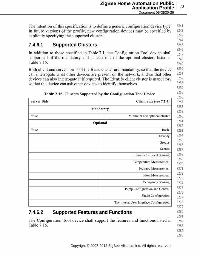
73
Copyright © 2007-2013 ZigBee Alliance, Inc. All rights reserved.
ZigBee Home Automation Public Application Profile
Document 05-3520-29
324132423243324432453246324732483249325032513252325332543255325632573258325932603261326232633264326532663267326832693270327132723273327432753276327732783279328032813282328332843285
The intention of this specification is to define a generic configuration device type. In future versions of the profile, new configuration devices may be specified by explicitly specifying the supported clusters.
7.4.6.1 Supported Clusters
In addition to those specified in Table 7.1, the Configuration Tool device shall support all of the mandatory and at least one of the optional clusters listed in Table 7.15.
Both client and server forms of the Basic cluster are mandatory, so that the device can interrogate what other devices are present on the network, and so that other devices can also interrogate it if required. The Identify client cluster is mandatory so that the device can ask other devices to identify themselves.
7.4.6.2 Supported Features and Functions
The Configuration Tool device shall support the features and functions listed in Table 7.16.
Table 7.15 Clusters Supported by the Configuration Tool Device
Server Side Client Side (see 7.1.4)
Mandatory
None Minimum one optional cluster
Optional
None Basic
Identify
Groups
Scenes
Illluminance Level Sensing
Temperature Measurement
Pressure Measurement
Flow Measurement
Occupancy Sensing
Pump Configuration and Control
Shade Configuration
Thermostat User Interface Configuration
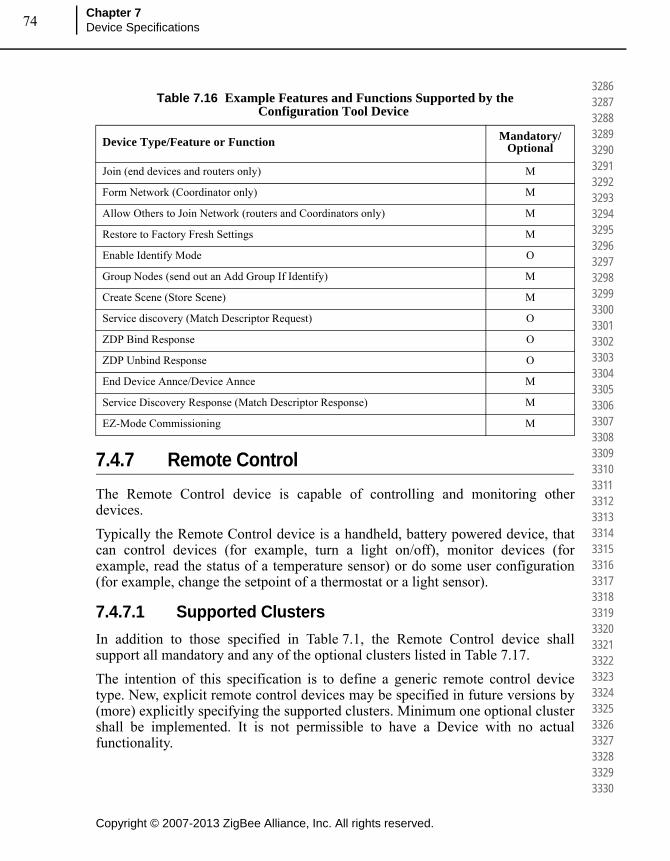
Copyright © 2007-2013 ZigBee Alliance, Inc. All rights reserved.
Chapter 7Device Specifications74
328632873288328932903291329232933294329532963297329832993300330133023303330433053306330733083309331033113312331333143315331633173318331933203321332233233324332533263327332833293330
7.4.7 Remote Control
The Remote Control device is capable of controlling and monitoring other devices.
Typically the Remote Control device is a handheld, battery powered device, that can control devices (for example, turn a light on/off), monitor devices (for example, read the status of a temperature sensor) or do some user configuration (for example, change the setpoint of a thermostat or a light sensor).
7.4.7.1 Supported Clusters
In addition to those specified in Table 7.1, the Remote Control device shall support all mandatory and any of the optional clusters listed in Table 7.17.
The intention of this specification is to define a generic remote control device type. New, explicit remote control devices may be specified in future versions by (more) explicitly specifying the supported clusters. Minimum one optional cluster shall be implemented. It is not permissible to have a Device with no actual functionality.
Table 7.16 Example Features and Functions Supported by the Configuration Tool Device
Device Type/Feature or Function Mandatory/Optional
Join (end devices and routers only) M
Form Network (Coordinator only) M
Allow Others to Join Network (routers and Coordinators only) M
Restore to Factory Fresh Settings M
Enable Identify Mode O
Group Nodes (send out an Add Group If Identify) M
Create Scene (Store Scene) M
Service discovery (Match Descriptor Request) O
ZDP Bind Response O
ZDP Unbind Response O
End Device Annce/Device Annce M
Service Discovery Response (Match Descriptor Response) M
EZ-Mode Commissioning M

75
Copyright © 2007-2013 ZigBee Alliance, Inc. All rights reserved.
ZigBee Home Automation Public Application Profile
Document 05-3520-29
333133323333333433353336333733383339334033413342334333443345334633473348334933503351335233533354335533563357335833593360336133623363336433653366336733683369337033713372337333743375
7.4.7.2 Supported Features and Functions
The Remote Control device shall support the features and functions listed in Table 7.18.
Table 7.17 Clusters Supported by the Remote Control Device
Server Side Client Side (see 7.1.4)
Mandatory
None Minimum one optional cluster
Optional
Basic
Identify
None On/Off
Level Control
Groups
Scenes
Color Control
Pump Configuration and Control
Shade Configuration
On/Off Switch Configuration
Temperature Measurement
Illuminance Level Sensing
Illuminance Measurements
Window Covering
Door Lock
Thermostat
Table 7.18 Example Features and Functions Supported by the Remote Control Device
Device Type/Feature or Function Mandatory/Optional
Join (end devices and routers only) M
Form Network (Coordinator only) M
Allow Others to Join Network (routers and Coordinators only) M

Copyright © 2007-2013 ZigBee Alliance, Inc. All rights reserved.
Chapter 7Device Specifications76
337633773378337933803381338233833384338533863387338833893390339133923393339433953396339733983399340034013402340334043405340634073408340934103411341234133414341534163417341834193420
7.4.7.3 Notes on Operation
To ensure interoperability, a remote controller shall allow the presence of other control devices in the network. In particular, this device should take measures to avoid “fighting” for control.
7.4.8 Combined Interface
The Combined Interface device is capable of controlling and monitoring other devices. It is typically a mains-powered device like a personal computer.
7.4.8.1 Supported Clusters
In addition to those specified in Table 7.1, the Combined Interface device shall support all mandatory and any of the optional clusters listed in Table 7.19.
Restore to Factory Fresh Settings M
Enable Identify Mode O
Group Nodes (send out an Add Group If Identify) O
Create Scene (Store Scene) O
Service discovery (Match Descriptor Request) O
ZDP Bind Response O
ZDP Unbind Response O
End Device Annce/Device Annce M
Service Discovery Response (Match Descriptor Response) M
EZ-Mode Commissioning M
Table 7.19 Clusters Supported by the Combined Interface Device
Server Side Client Side (see 7.1.4)
Mandatory
None Minimum one optional Cluster
Optional
None Basic
Identify
Table 7.18 Example Features and Functions Supported by the Remote Control Device (Continued)
Device Type/Feature or Function Mandatory/Optional
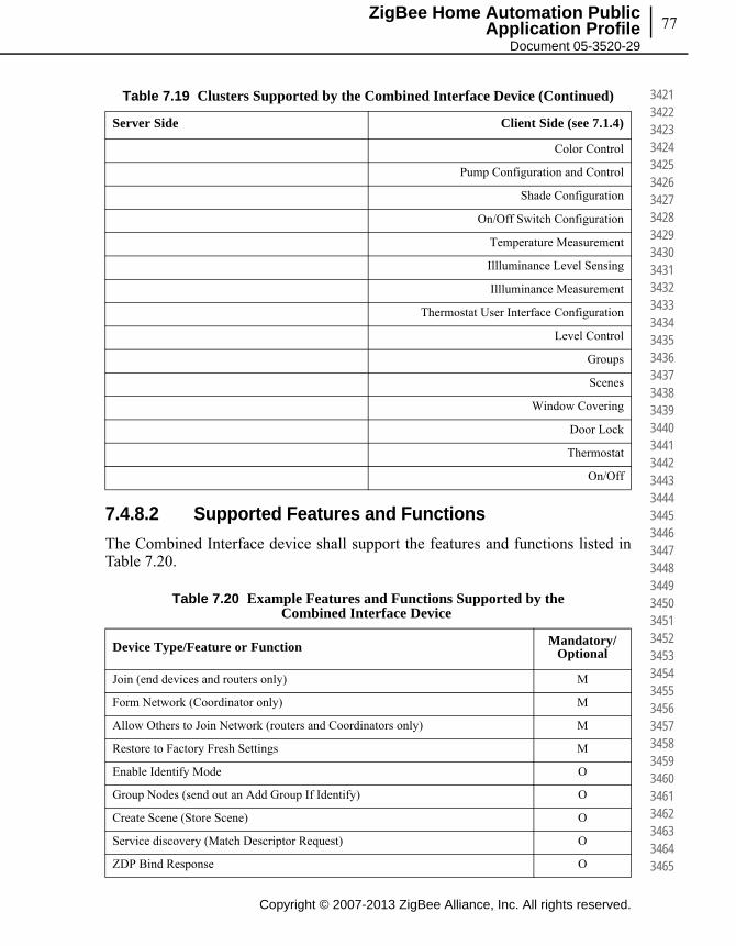
77
Copyright © 2007-2013 ZigBee Alliance, Inc. All rights reserved.
ZigBee Home Automation Public Application Profile
Document 05-3520-29
342134223423342434253426342734283429343034313432343334343435343634373438343934403441344234433444344534463447344834493450345134523453345434553456345734583459346034613462346334643465
7.4.8.2 Supported Features and Functions
The Combined Interface device shall support the features and functions listed in Table 7.20.
Color Control
Pump Configuration and Control
Shade Configuration
On/Off Switch Configuration
Temperature Measurement
Illluminance Level Sensing
Illluminance Measurement
Thermostat User Interface Configuration
Level Control
Groups
Scenes
Window Covering
Door Lock
Thermostat
On/Off
Table 7.20 Example Features and Functions Supported by the Combined Interface Device
Device Type/Feature or Function Mandatory/Optional
Join (end devices and routers only) M
Form Network (Coordinator only) M
Allow Others to Join Network (routers and Coordinators only) M
Restore to Factory Fresh Settings M
Enable Identify Mode O
Group Nodes (send out an Add Group If Identify) O
Create Scene (Store Scene) O
Service discovery (Match Descriptor Request) O
ZDP Bind Response O
Table 7.19 Clusters Supported by the Combined Interface Device (Continued)
Server Side Client Side (see 7.1.4)

Copyright © 2007-2013 ZigBee Alliance, Inc. All rights reserved.
Chapter 7Device Specifications78
346634673468346934703471347234733474347534763477347834793480348134823483348434853486348734883489349034913492349334943495349634973498349935003501350235033504350535063507350835093510
7.4.8.3 Notes on Operation
To ensure interoperability, a Combined Interface device shall allow the presence of other control devices in the network. In particular, this device should take measures to avoid “fighting” for control.
7.4.9 Range Extender
The Range Extender is a simple device that acts as a router for other devices. The Range Extender device shall not be a ZigBee end device. A product that implements the Range Extender devices shall not implement any other devices defined in this profile. This device shall only be used if the product is not intended to have any other application, or if a private application is implemented that has not been addressed by this profile.
7.4.9.1 Supported Clusters
The Range Extender device shall only support the mandatory common clusters listed in Table 7.1.
7.4.9.2 Supported Features and Functions
The Range Extender device shall support the features and functions listed in Table 7.21.
ZDP Unbind Response O
End Device Annce/Device Annce M
Service Discovery Response (Match Descriptor Response) M
EZ-Mode Commissioning M
Table 7.21 Example Features and Functions Supported by the Range Extender Device
Device Type/Feature or Function Mandatory/Optional
Join (end devices and routers only) M
Form Network (Coordinator only) M
Allow Others to Join Network (routers and Coordinators only) M
Restore to Factory Fresh Settings M
Table 7.20 Example Features and Functions Supported by the Combined Interface Device (Continued)
Device Type/Feature or Function Mandatory/Optional
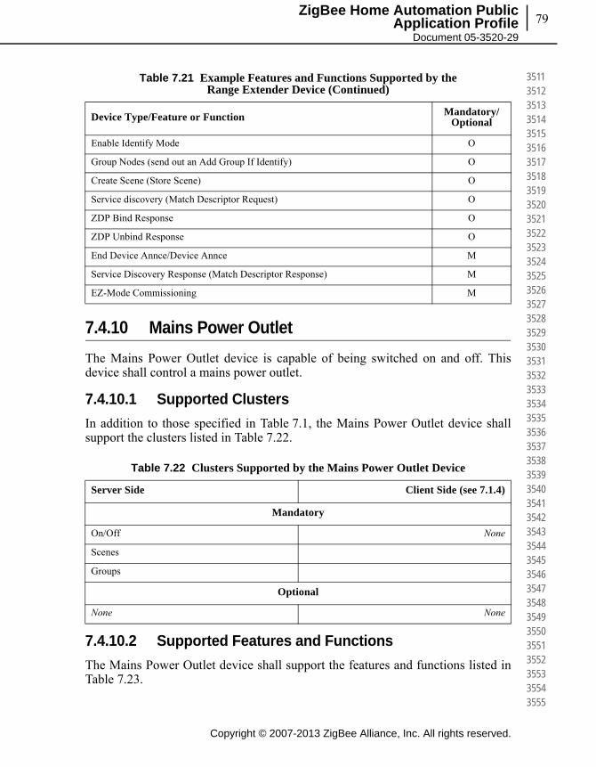
79
Copyright © 2007-2013 ZigBee Alliance, Inc. All rights reserved.
ZigBee Home Automation Public Application Profile
Document 05-3520-29
351135123513351435153516351735183519352035213522352335243525352635273528352935303531353235333534353535363537353835393540354135423543354435453546354735483549355035513552355335543555
7.4.10 Mains Power Outlet
The Mains Power Outlet device is capable of being switched on and off. This device shall control a mains power outlet.
7.4.10.1 Supported Clusters
In addition to those specified in Table 7.1, the Mains Power Outlet device shall support the clusters listed in Table 7.22.
7.4.10.2 Supported Features and Functions
The Mains Power Outlet device shall support the features and functions listed in Table 7.23.
Enable Identify Mode O
Group Nodes (send out an Add Group If Identify) O
Create Scene (Store Scene) O
Service discovery (Match Descriptor Request) O
ZDP Bind Response O
ZDP Unbind Response O
End Device Annce/Device Annce M
Service Discovery Response (Match Descriptor Response) M
EZ-Mode Commissioning M
Table 7.22 Clusters Supported by the Mains Power Outlet Device
Server Side Client Side (see 7.1.4)
Mandatory
On/Off None
Scenes
Groups
Optional
None None
Table 7.21 Example Features and Functions Supported by the Range Extender Device (Continued)
Device Type/Feature or Function Mandatory/Optional

Copyright © 2007-2013 ZigBee Alliance, Inc. All rights reserved.
Chapter 7Device Specifications80
355635573558355935603561356235633564356535663567356835693570357135723573357435753576357735783579358035813582358335843585358635873588358935903591359235933594359535963597359835993600
7.4.11 Door Lock
The Door Lock is capable of receiving Door Lock cluster commands
7.4.11.1 Supported Clusters
In addition to those specified in Table 7.1, the Door Lock device shall support the clusters listed in Table 7.24.
Note: for sleeping end devices, see sub-clause 7.1.2, “Groups and Scene Cluster Clarification”.
Table 7.23 Example Features and Functions Supported by the Mains Power Outlet Device
Device Type/Feature or Function Mandatory/Optional
Join (end devices and routers only) M
Form Network (Coordinator only) M
Allow Others to Join Network (routers and Coordinators only) M
Restore to Factory Fresh Settings M
Enable Identify Mode M
Group Nodes (send out an Add Group If Identify) O
Create Scene (Store Scene) M
Service discovery (Match Descriptor Request) O
ZDP Bind Response M
ZDP Unbind Response M
End Device Annce/Device Annce M
Service Discovery Response (Match Descriptor Response) M
EZ-Mode Commissioning M
Table 7.24 Clusters Supported by the Door Lock Device
Server Side Client Side (see 7.1.4)
Mandatory
Door Lock None
Scenes
Groups
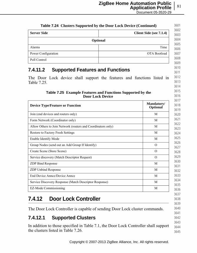
81
Copyright © 2007-2013 ZigBee Alliance, Inc. All rights reserved.
ZigBee Home Automation Public Application Profile
Document 05-3520-29
360136023603360436053606360736083609361036113612361336143615361636173618361936203621362236233624362536263627362836293630363136323633363436353636363736383639364036413642364336443645
7.4.11.2 Supported Features and Functions
The Door Lock device shall support the features and functions listed in Table 7.25.
7.4.12 Door Lock Controller
The Door Lock Controller is capable of sending Door Lock cluster commands.
7.4.12.1 Supported Clusters
In addition to those specified in Table 7.1, the Door Lock Controller shall support the clusters listed in Table 7.26.
Optional
Alarms Time
Power Configuration OTA Bootload
Poll Control
Table 7.25 Example Features and Functions Supported by the Door Lock Device
Device Type/Feature or Function Mandatory/Optional
Join (end devices and routers only) M
Form Network (Coordinator only) M
Allow Others to Join Network (routers and Coordinators only) M
Restore to Factory Fresh Settings M
Enable Identify Mode M
Group Nodes (send out an Add Group If Identify) O
Create Scene (Store Scene) O
Service discovery (Match Descriptor Request) O
ZDP Bind Response M
ZDP Unbind Response M
End Device Annce/Device Annce M
Service Discovery Response (Match Descriptor Response) M
EZ-Mode Commissioning M
Table 7.24 Clusters Supported by the Door Lock Device (Continued)
Server Side Client Side (see 7.1.4)
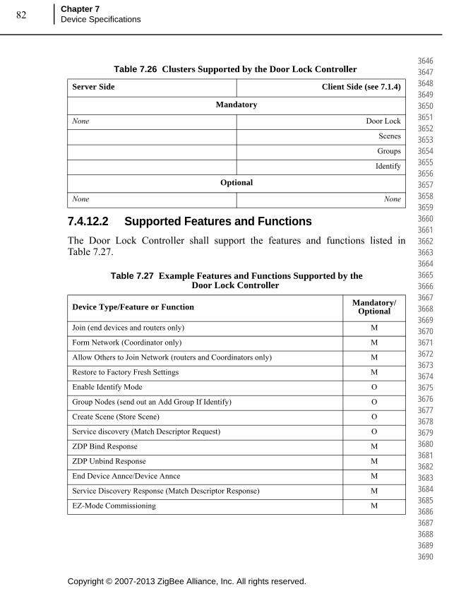
Copyright © 2007-2013 ZigBee Alliance, Inc. All rights reserved.
Chapter 7Device Specifications82
364636473648364936503651365236533654365536563657365836593660366136623663366436653666366736683669367036713672367336743675367636773678367936803681368236833684368536863687368836893690
7.4.12.2 Supported Features and Functions
The Door Lock Controller shall support the features and functions listed in Table 7.27.
Table 7.26 Clusters Supported by the Door Lock Controller
Server Side Client Side (see 7.1.4)
Mandatory
None Door Lock
Scenes
Groups
Identify
Optional
None None
Table 7.27 Example Features and Functions Supported by the Door Lock Controller
Device Type/Feature or Function Mandatory/Optional
Join (end devices and routers only) M
Form Network (Coordinator only) M
Allow Others to Join Network (routers and Coordinators only) M
Restore to Factory Fresh Settings M
Enable Identify Mode O
Group Nodes (send out an Add Group If Identify) O
Create Scene (Store Scene) O
Service discovery (Match Descriptor Request) O
ZDP Bind Response M
ZDP Unbind Response M
End Device Annce/Device Annce M
Service Discovery Response (Match Descriptor Response) M
EZ-Mode Commissioning M
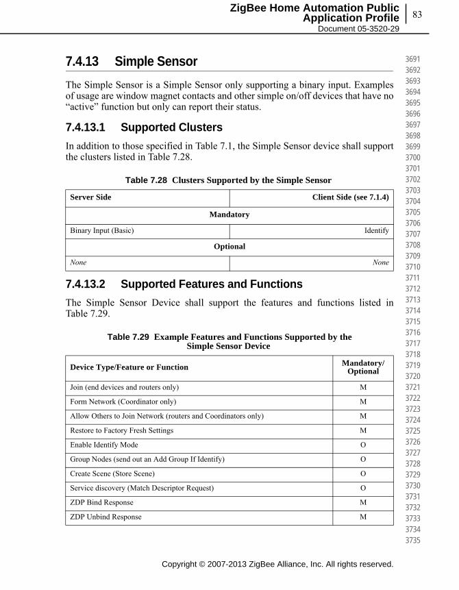
83
Copyright © 2007-2013 ZigBee Alliance, Inc. All rights reserved.
ZigBee Home Automation Public Application Profile
Document 05-3520-29
369136923693369436953696369736983699370037013702370337043705370637073708370937103711371237133714371537163717371837193720372137223723372437253726372737283729373037313732373337343735
7.4.13 Simple Sensor
The Simple Sensor is a Simple Sensor only supporting a binary input. Examples of usage are window magnet contacts and other simple on/off devices that have no “active” function but only can report their status.
7.4.13.1 Supported Clusters
In addition to those specified in Table 7.1, the Simple Sensor device shall support the clusters listed in Table 7.28.
7.4.13.2 Supported Features and Functions
The Simple Sensor Device shall support the features and functions listed in Table 7.29.
Table 7.28 Clusters Supported by the Simple Sensor
Server Side Client Side (see 7.1.4)
Mandatory
Binary Input (Basic) Identify
Optional
None None
Table 7.29 Example Features and Functions Supported by the Simple Sensor Device
Device Type/Feature or Function Mandatory/Optional
Join (end devices and routers only) M
Form Network (Coordinator only) M
Allow Others to Join Network (routers and Coordinators only) M
Restore to Factory Fresh Settings M
Enable Identify Mode O
Group Nodes (send out an Add Group If Identify) O
Create Scene (Store Scene) O
Service discovery (Match Descriptor Request) O
ZDP Bind Response M
ZDP Unbind Response M
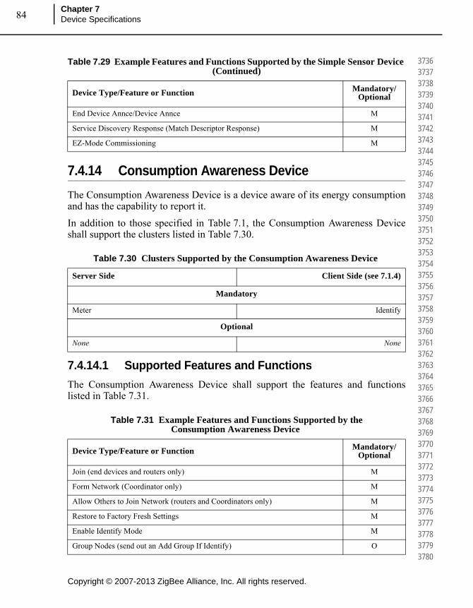
Copyright © 2007-2013 ZigBee Alliance, Inc. All rights reserved.
Chapter 7Device Specifications84
373637373738373937403741374237433744374537463747374837493750375137523753375437553756375737583759376037613762376337643765376637673768376937703771377237733774377537763777377837793780
7.4.14 Consumption Awareness Device
The Consumption Awareness Device is a device aware of its energy consumption and has the capability to report it.
In addition to those specified in Table 7.1, the Consumption Awareness Device shall support the clusters listed in Table 7.30.
7.4.14.1 Supported Features and Functions
The Consumption Awareness Device shall support the features and functions listed in Table 7.31.
End Device Annce/Device Annce M
Service Discovery Response (Match Descriptor Response) M
EZ-Mode Commissioning M
Table 7.30 Clusters Supported by the Consumption Awareness Device
Server Side Client Side (see 7.1.4)
Mandatory
Meter Identify
Optional
None None
Table 7.31 Example Features and Functions Supported by the Consumption Awareness Device
Device Type/Feature or Function Mandatory/Optional
Join (end devices and routers only) M
Form Network (Coordinator only) M
Allow Others to Join Network (routers and Coordinators only) M
Restore to Factory Fresh Settings M
Enable Identify Mode M
Group Nodes (send out an Add Group If Identify) O
Table 7.29 Example Features and Functions Supported by the Simple Sensor Device (Continued)
Device Type/Feature or Function Mandatory/Optional
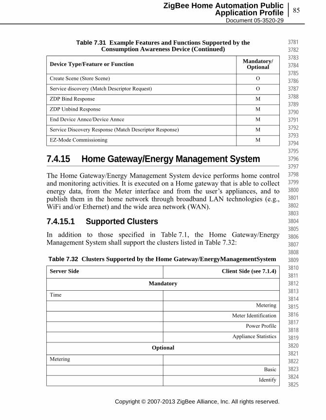
85
Copyright © 2007-2013 ZigBee Alliance, Inc. All rights reserved.
ZigBee Home Automation Public Application Profile
Document 05-3520-29
378137823783378437853786378737883789379037913792379337943795379637973798379938003801380238033804380538063807380838093810381138123813381438153816381738183819382038213822382338243825
7.4.15 Home Gateway/Energy Management System
The Home Gateway/Energy Management System device performs home control and monitoring activities. It is executed on a Home gateway that is able to collect energy data, from the Meter interface and from the user’s appliances, and to publish them in the home network through broadband LAN technologies (e.g., WiFi and/or Ethernet) and the wide area network (WAN).
7.4.15.1 Supported Clusters
In addition to those specified in Table 7.1, the Home Gateway/Energy Management System shall support the clusters listed in Table 7.32:
Create Scene (Store Scene) O
Service discovery (Match Descriptor Request) O
ZDP Bind Response M
ZDP Unbind Response M
End Device Annce/Device Annce M
Service Discovery Response (Match Descriptor Response) M
EZ-Mode Commissioning M
Table 7.32 Clusters Supported by the Home Gateway/EnergyManagementSystem
Server Side Client Side (see 7.1.4)
Mandatory
Time
Metering
Meter Identification
Power Profile
Appliance Statistics
Optional
Metering
Basic
Identify
Table 7.31 Example Features and Functions Supported by the Consumption Awareness Device (Continued)
Device Type/Feature or Function Mandatory/Optional
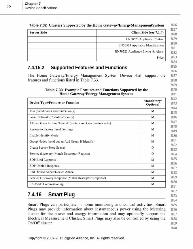
Copyright © 2007-2013 ZigBee Alliance, Inc. All rights reserved.
Chapter 7Device Specifications86
382638273828382938303831383238333834383538363837383838393840384138423843384438453846384738483849385038513852385338543855385638573858385938603861386238633864386538663867386838693870
7.4.15.2 Supported Features and Functions
The Home Gateway/Energy Management System Device shall support the features and functions listed in Table 7.33.
7.4.16 Smart Plug
Smart Plugs can participate in home monitoring and control activities. Smart Plugs may provide information about instantaneous power using the Metering cluster for the power and energy information and may optionally support the Electrical Measurement Cluster. Smart Plugs may also be controlled by using the On/Off cluster.
EN50523 Appliance Control
EN50523 Appliance Identification
EN50523 Appliance Events & Alerts
Price
Table 7.33 Example Features and Functions Supported by the Home Gateway/Energy Management System
Device Type/Feature or Function Mandatory/Optional
Join (end devices and routers only) M
Form Network (Coordinator only) M
Allow Others to Join Network (routers and Coordinators only) M
Restore to Factory Fresh Settings M
Enable Identify Mode M
Group Nodes (send out an Add Group If Identify) M
Create Scene (Store Scene) O
Service discovery (Match Descriptor Request) O
ZDP Bind Response M
ZDP Unbind Response M
End Device Annce/Device Annce M
Service Discovery Response (Match Descriptor Response) M
EZ-Mode Commissioning M
Table 7.32 Clusters Supported by the Home Gateway/EnergyManagementSystem
Server Side Client Side (see 7.1.4)
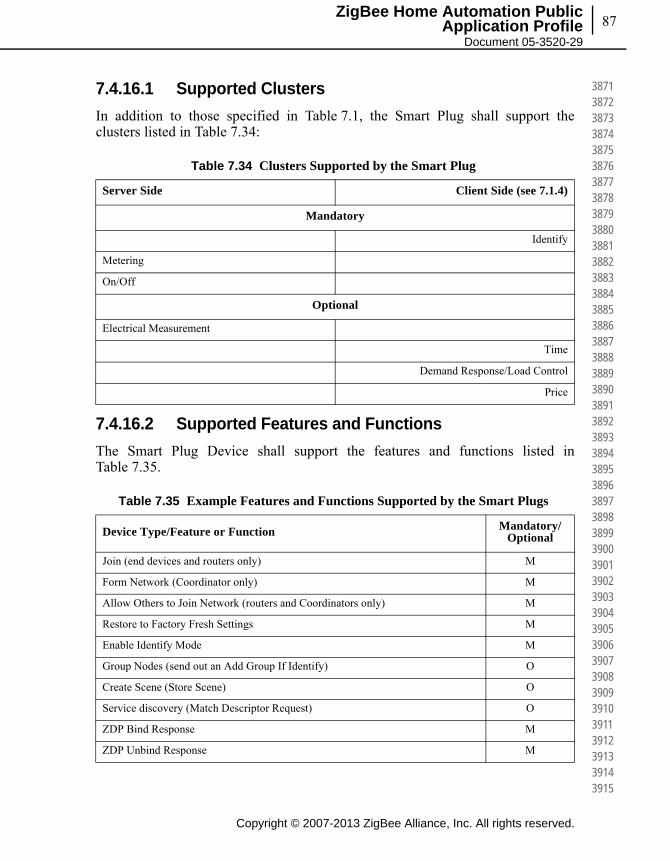
87
Copyright © 2007-2013 ZigBee Alliance, Inc. All rights reserved.
ZigBee Home Automation Public Application Profile
Document 05-3520-29
387138723873387438753876387738783879388038813882388338843885388638873888388938903891389238933894389538963897389838993900390139023903390439053906390739083909391039113912391339143915
7.4.16.1 Supported Clusters
In addition to those specified in Table 7.1, the Smart Plug shall support the clusters listed in Table 7.34:
7.4.16.2 Supported Features and Functions
The Smart Plug Device shall support the features and functions listed in Table 7.35.
Table 7.34 Clusters Supported by the Smart Plug
Server Side Client Side (see 7.1.4)
Mandatory
Identify
Metering
On/Off
Optional
Electrical Measurement
Time
Demand Response/Load Control
Price
Table 7.35 Example Features and Functions Supported by the Smart Plugs
Device Type/Feature or Function Mandatory/Optional
Join (end devices and routers only) M
Form Network (Coordinator only) M
Allow Others to Join Network (routers and Coordinators only) M
Restore to Factory Fresh Settings M
Enable Identify Mode M
Group Nodes (send out an Add Group If Identify) O
Create Scene (Store Scene) O
Service discovery (Match Descriptor Request) O
ZDP Bind Response M
ZDP Unbind Response M
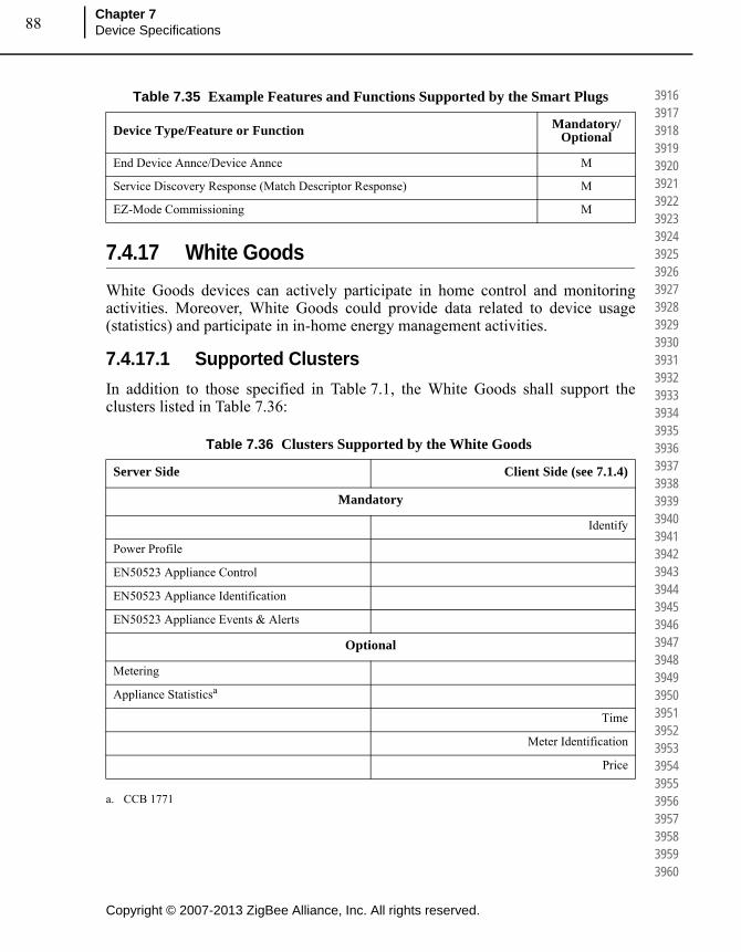
Copyright © 2007-2013 ZigBee Alliance, Inc. All rights reserved.
Chapter 7Device Specifications88
391639173918391939203921392239233924392539263927392839293930393139323933393439353936393739383939394039413942394339443945394639473948394939503951395239533954395539563957395839593960
7.4.17 White Goods
White Goods devices can actively participate in home control and monitoring activities. Moreover, White Goods could provide data related to device usage (statistics) and participate in in-home energy management activities.
7.4.17.1 Supported Clusters
In addition to those specified in Table 7.1, the White Goods shall support the clusters listed in Table 7.36:
End Device Annce/Device Annce M
Service Discovery Response (Match Descriptor Response) M
EZ-Mode Commissioning M
Table 7.36 Clusters Supported by the White Goods
Server Side Client Side (see 7.1.4)
Mandatory
Identify
Power Profile
EN50523 Appliance Control
EN50523 Appliance Identification
EN50523 Appliance Events & Alerts
Optional
Metering
Appliance Statisticsa
a. CCB 1771
Time
Meter Identification
Price
Table 7.35 Example Features and Functions Supported by the Smart Plugs
Device Type/Feature or Function Mandatory/Optional

89
Copyright © 2007-2013 ZigBee Alliance, Inc. All rights reserved.
ZigBee Home Automation Public Application Profile
Document 05-3520-29
396139623963396439653966396739683969397039713972397339743975397639773978397939803981398239833984398539863987398839893990399139923993399439953996399739983999400040014002400340044005
7.4.17.2 Supported Features and Functions
The White Goods Device shall support the features and functions listed in Table 7.37.
7.4.18 Meter Interface
The Meter Interface device represents an interface to a metering device (e.g.,electricity, gas, water, heat, etc.) that is able to send meter information to the home automation network. Depending on what is being measured, the device may be capable of immediate (requested via polling) readings or of autonomous periodic readings (sent via push mechanism). A Metering Interface device may also be capable of communicating certain status indicators (e.g., battery low, tamper detected).In the event that the Meter Interface cannot provide price information, the use of Price Cluster as defined in the Smart Energy specification could be limited to the provision of time-of-use (TOU) intervals by using the Get Scheduled Prices without specifying the actual price. In the case of the Publish Price Command Payload the Price field will be always 0xff..ff, and the Price Tier field shall specify the current tier name.
Table 7.37 Example Features and Functions Supported by the White Goods
Device Type/Feature or Function Mandatory/Optional
Join (end devices and routers only) M
Form Network (Coordinator only) M
Allow Others to Join Network (routers and Coordinators only) M
Restore to Factory Fresh Settings M
Enable Identify Mode M
Group Nodes (send out an Add Group If Identify) O
Create Scene (Store Scene) O
Service discovery (Match Descriptor Request) O
ZDP Bind Response M
ZDP Unbind Response M
End Device Annce/Device Annce M
Service Discovery Response (Match Descriptor Response) M
EZ-Mode Commissioning M

Copyright © 2007-2013 ZigBee Alliance, Inc. All rights reserved.
Chapter 7Device Specifications90
400640074008400940104011401240134014401540164017401840194020402140224023402440254026402740284029403040314032403340344035403640374038403940404041404240434044404540464047404840494050
7.4.18.1 Supported Clusters
In addition to those specified in Table 7.1, the Meter Interface shall support the clusters listed in Table 7.38:
7.4.18.2 Supported Features and Functions
The Meter Interface shall support the features and functions listed in Table 7.39.
Table 7.38 Clusters Supported by the Meter Interface
Server Side Client Side (see 7.1.4)
Mandatory
Identify
Metering
Meter Identification
Optional
Price Price
Time
PrePayment
Message
Table 7.39 Example Features and Functions Supported by the White Goods
Device Type/Feature or Function Mandatory/Optional
Join (end devices and routers only) M
Form Network (Coordinator only) M
Allow Others to Join Network (routers and Coordinators only) M
Restore to Factory Fresh Settings M
Enable Identify Mode M
Group Nodes (send out an Add Group If Identify) O
Create Scene (Store Scene) O
Service discovery (Match Descriptor Request) O
ZDP Bind Response M
ZDP Unbind Response M
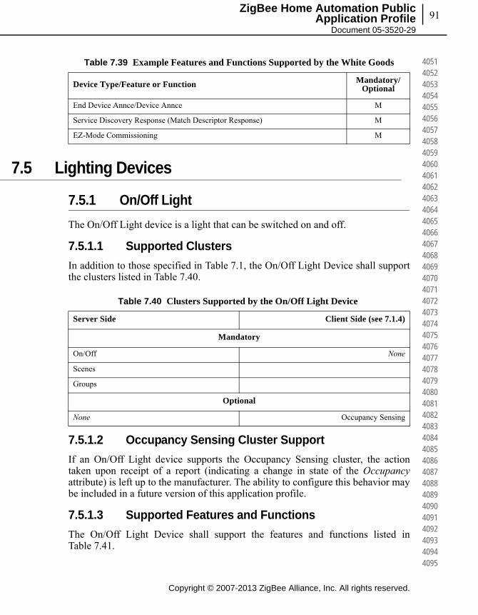
91
Copyright © 2007-2013 ZigBee Alliance, Inc. All rights reserved.
ZigBee Home Automation Public Application Profile
Document 05-3520-29
405140524053405440554056405740584059406040614062406340644065406640674068406940704071407240734074407540764077407840794080408140824083408440854086408740884089409040914092409340944095
7.5 Lighting Devices
7.5.1 On/Off Light
The On/Off Light device is a light that can be switched on and off.
7.5.1.1 Supported Clusters
In addition to those specified in Table 7.1, the On/Off Light Device shall support the clusters listed in Table 7.40.
7.5.1.2 Occupancy Sensing Cluster Support
If an On/Off Light device supports the Occupancy Sensing cluster, the action taken upon receipt of a report (indicating a change in state of the Occupancyattribute) is left up to the manufacturer. The ability to configure this behavior may be included in a future version of this application profile.
7.5.1.3 Supported Features and Functions
The On/Off Light Device shall support the features and functions listed in Table 7.41.
End Device Annce/Device Annce M
Service Discovery Response (Match Descriptor Response) M
EZ-Mode Commissioning M
Table 7.39 Example Features and Functions Supported by the White Goods
Device Type/Feature or Function Mandatory/Optional
Table 7.40 Clusters Supported by the On/Off Light Device
Server Side Client Side (see 7.1.4)
Mandatory
On/Off None
Scenes
Groups
Optional
None Occupancy Sensing

Copyright © 2007-2013 ZigBee Alliance, Inc. All rights reserved.
Chapter 7Device Specifications92
409640974098409941004101410241034104410541064107410841094110411141124113411441154116411741184119412041214122412341244125412641274128412941304131413241334134413541364137413841394140
7.5.2 Dimmable Light
The Dimmable Light device is a light that can be switched on and off, and whose luminance level may be controlled.
7.5.2.1 Supported Clusters
In addition to those specified in Table 7.1, the Dimmable Light device shall support the clusters listed in Table 7.42.
Table 7.41 Example Features and Functions Supported by the On/Off Light Device
Device Type/Feature or Function Mandatory/Optional
Join (end devices and routers only) M
Form Network (Coordinator only) M
Allow Others to Join Network (routers and Coordinators only) M
Restore to Factory Fresh Settings M
Enable Identify Mode M
Group Nodes (send out an Add Group If Identify) O
Create Scene (Store Scene) M
Service discovery (Match Descriptor Request) O
ZDP Bind Response M
ZDP Unbind Response M
End Device Annce/Device Annce M
Service Discovery Response (Match Descriptor Response) M
EZ-Mode Commissioning M
Table 7.42 Clusters Supported by the Dimmable Light Device
Server Side Client Side (see 7.1.4)
Mandatory
On/Off None
Level Control
Scenes
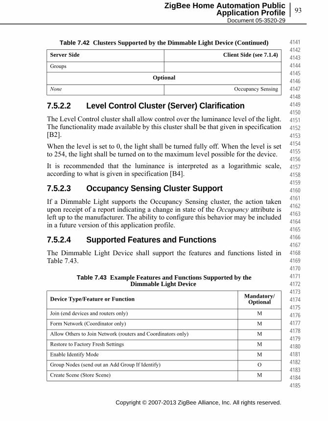
93
Copyright © 2007-2013 ZigBee Alliance, Inc. All rights reserved.
ZigBee Home Automation Public Application Profile
Document 05-3520-29
414141424143414441454146414741484149415041514152415341544155415641574158415941604161416241634164416541664167416841694170417141724173417441754176417741784179418041814182418341844185
7.5.2.2 Level Control Cluster (Server) Clarification
The Level Control cluster shall allow control over the luminance level of the light. The functionality made available by this cluster shall be that given in specification [B2].
When the level is set to 0, the light shall be turned fully off. When the level is set to 254, the light shall be turned on to the maximum level possible for the device.
It is recommended that the luminance is interpreted as a logarithmic scale, according to what is given in specification [B4].
7.5.2.3 Occupancy Sensing Cluster Support
If a Dimmable Light supports the Occupancy Sensing cluster, the action taken upon receipt of a report indicating a change in state of the Occupancy attribute is left up to the manufacturer. The ability to configure this behavior may be included in a future version of this application profile.
7.5.2.4 Supported Features and Functions
The Dimmable Light Device shall support the features and functions listed in Table 7.43.
Groups
Optional
None Occupancy Sensing
Table 7.43 Example Features and Functions Supported by the Dimmable Light Device
Device Type/Feature or Function Mandatory/Optional
Join (end devices and routers only) M
Form Network (Coordinator only) M
Allow Others to Join Network (routers and Coordinators only) M
Restore to Factory Fresh Settings M
Enable Identify Mode M
Group Nodes (send out an Add Group If Identify) O
Create Scene (Store Scene) M
Table 7.42 Clusters Supported by the Dimmable Light Device (Continued)
Server Side Client Side (see 7.1.4)

Copyright © 2007-2013 ZigBee Alliance, Inc. All rights reserved.
Chapter 7Device Specifications94
418641874188418941904191419241934194419541964197419841994200420142024203420442054206420742084209421042114212421342144215421642174218421942204221422242234224422542264227422842294230
7.5.3 Color Dimmable Light
The Color Dimmable Light device can be switched on and off, and its luminance, hue, and saturation levels may be controlled.
7.5.3.1 Supported Clusters
In addition to those specified in Table 7.1, the Color Dimmable Light device shall support the clusters listed in Table 7.44.
7.5.3.2 Occupancy Sensing Cluster Support
If a Color Dimmable Light Device supports the Occupancy Sensing cluster, the action taken upon receipt of a report indicating a change in state of the Occupancyattribute is left up to the manufacturer. The ability to configure this behavior may be included in a future version of this application profile.
Service discovery (Match Descriptor Request) O
ZDP Bind Response M
ZDP Unbind Response M
End Device Annce/Device Annce M
Service Discovery Response (Match Descriptor Response) M
EZ-Mode Commissioning M
Table 7.44 Clusters Supported by the Color Dimmable Light Device
Server Side Client Side (see 7.1.4)
Mandatory
On/Off None
Level Control
Color Control
Scenes
Groups
Optional
None Occupancy Sensing
Table 7.43 Example Features and Functions Supported by the Dimmable Light Device (Continued)
Device Type/Feature or Function Mandatory/Optional
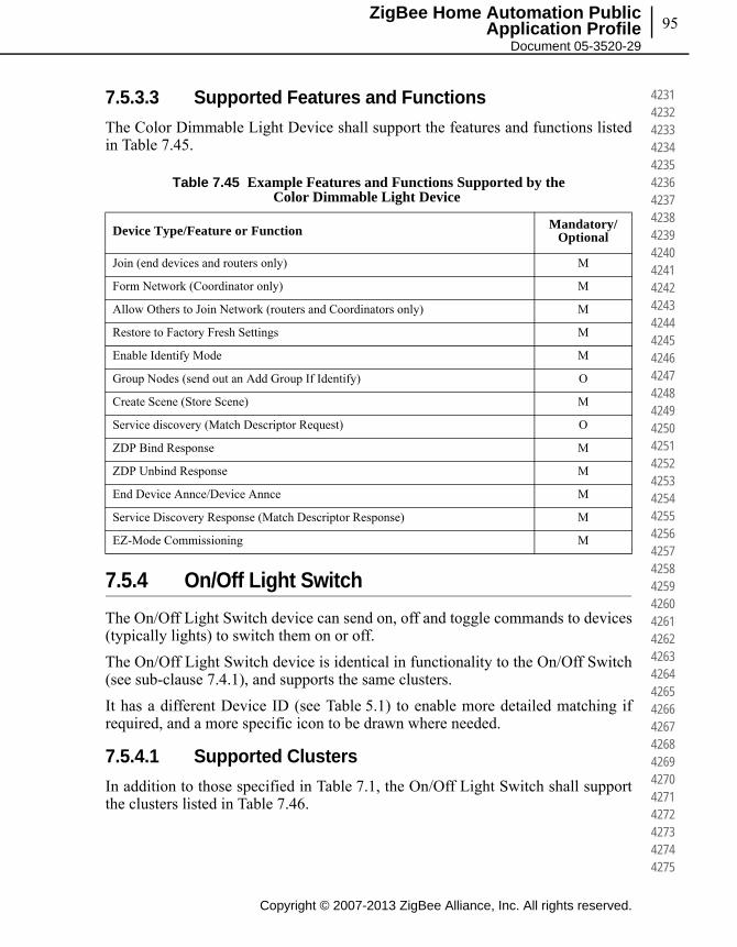
95
Copyright © 2007-2013 ZigBee Alliance, Inc. All rights reserved.
ZigBee Home Automation Public Application Profile
Document 05-3520-29
423142324233423442354236423742384239424042414242424342444245424642474248424942504251425242534254425542564257425842594260426142624263426442654266426742684269427042714272427342744275
7.5.3.3 Supported Features and Functions
The Color Dimmable Light Device shall support the features and functions listed in Table 7.45.
7.5.4 On/Off Light Switch
The On/Off Light Switch device can send on, off and toggle commands to devices (typically lights) to switch them on or off.
The On/Off Light Switch device is identical in functionality to the On/Off Switch (see sub-clause 7.4.1), and supports the same clusters.
It has a different Device ID (see Table 5.1) to enable more detailed matching if required, and a more specific icon to be drawn where needed.
7.5.4.1 Supported Clusters
In addition to those specified in Table 7.1, the On/Off Light Switch shall support the clusters listed in Table 7.46.
Table 7.45 Example Features and Functions Supported by the Color Dimmable Light Device
Device Type/Feature or Function Mandatory/Optional
Join (end devices and routers only) M
Form Network (Coordinator only) M
Allow Others to Join Network (routers and Coordinators only) M
Restore to Factory Fresh Settings M
Enable Identify Mode M
Group Nodes (send out an Add Group If Identify) O
Create Scene (Store Scene) M
Service discovery (Match Descriptor Request) O
ZDP Bind Response M
ZDP Unbind Response M
End Device Annce/Device Annce M
Service Discovery Response (Match Descriptor Response) M
EZ-Mode Commissioning M
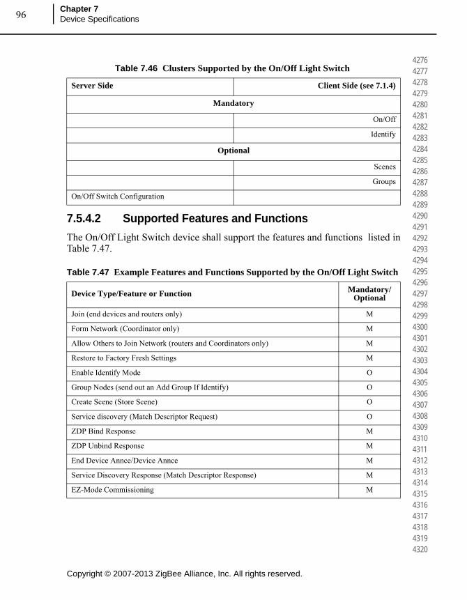
Copyright © 2007-2013 ZigBee Alliance, Inc. All rights reserved.
Chapter 7Device Specifications96
427642774278427942804281428242834284428542864287428842894290429142924293429442954296429742984299430043014302430343044305430643074308430943104311431243134314431543164317431843194320
7.5.4.2 Supported Features and Functions
The On/Off Light Switch device shall support the features and functions listed in Table 7.47.
Table 7.46 Clusters Supported by the On/Off Light Switch
Server Side Client Side (see 7.1.4)
Mandatory
On/Off
Identify
Optional
Scenes
Groups
On/Off Switch Configuration
Table 7.47 Example Features and Functions Supported by the On/Off Light Switch
Device Type/Feature or Function Mandatory/Optional
Join (end devices and routers only) M
Form Network (Coordinator only) M
Allow Others to Join Network (routers and Coordinators only) M
Restore to Factory Fresh Settings M
Enable Identify Mode O
Group Nodes (send out an Add Group If Identify) O
Create Scene (Store Scene) O
Service discovery (Match Descriptor Request) O
ZDP Bind Response M
ZDP Unbind Response M
End Device Annce/Device Annce M
Service Discovery Response (Match Descriptor Response) M
EZ-Mode Commissioning M
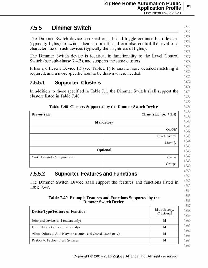
97
Copyright © 2007-2013 ZigBee Alliance, Inc. All rights reserved.
ZigBee Home Automation Public Application Profile
Document 05-3520-29
432143224323432443254326432743284329433043314332433343344335433643374338433943404341434243434344434543464347434843494350435143524353435443554356435743584359436043614362436343644365
7.5.5 Dimmer Switch
The Dimmer Switch device can send on, off and toggle commands to devices (typically lights) to switch them on or off, and can also control the level of a characteristic of such devices (typically the brightness of lights).
The Dimmer Switch device is identical in functionality to the Level Control Switch (see sub-clause 7.4.2), and supports the same clusters.
It has a different Device ID (see Table 5.1) to enable more detailed matching if required, and a more specific icon to be drawn where needed.
7.5.5.1 Supported Clusters
In addition to those specified in Table 7.1, the Dimmer Switch shall support the clusters listed in Table 7.48.
7.5.5.2 Supported Features and Functions
The Dimmer Switch Device shall support the features and functions listed in Table 7.49.
Table 7.48 Clusters Supported by the Dimmer Switch Device
Server Side Client Side (see 7.1.4)
Mandatory
On/Off
Level Control
Identify
Optional
On/Off Switch Configuration Scenes
Groups
Table 7.49 Example Features and Functions Supported by the Dimmer Switch Device
Device Type/Feature or Function Mandatory/Optional
Join (end devices and routers only) M
Form Network (Coordinator only) M
Allow Others to Join Network (routers and Coordinators only) M
Restore to Factory Fresh Settings M

Copyright © 2007-2013 ZigBee Alliance, Inc. All rights reserved.
Chapter 7Device Specifications98
436643674368436943704371437243734374437543764377437843794380438143824383438443854386438743884389439043914392439343944395439643974398439944004401440244034404440544064407440844094410
7.5.6 Color Dimmer Switch
The Color Dimmer Switch device can turn a light on and off, and control the luminance, hue and saturation levels of a multi-color light.
7.5.6.1 Supported Clusters
In addition to those specified in Table 7.1, the Color Dimmer Switch shall support the clusters listed in Table 7.50.
Enable Identify Mode O
Group Nodes (send out an Add Group If Identify) O
Create Scene (Store Scene) O
Service discovery (Match Descriptor Request) O
ZDP Bind Response M
ZDP Unbind Response M
End Device Annce/Device Annce M
Service Discovery Response (Match Descriptor Response) M
EZ-Mode Commissioning M
Table 7.50 Clusters Supported by the Color Dimmer Switch Device
Server Side Client Side (see 7.1.4)
Mandatory
On/Off
Level Control
Color Control
Identify
Optional
On/Off Switch Configuration Scenes
Groups
Table 7.49 Example Features and Functions Supported by the Dimmer Switch Device (Continued)
Device Type/Feature or Function Mandatory/Optional
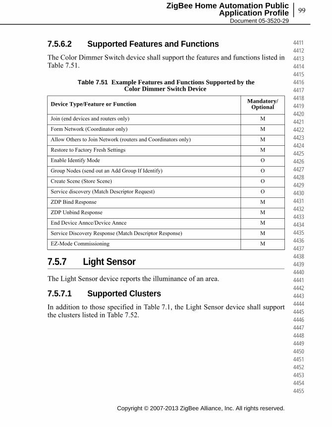
99
Copyright © 2007-2013 ZigBee Alliance, Inc. All rights reserved.
ZigBee Home Automation Public Application Profile
Document 05-3520-29
441144124413441444154416441744184419442044214422442344244425442644274428442944304431443244334434443544364437443844394440444144424443444444454446444744484449445044514452445344544455
7.5.6.2 Supported Features and Functions
The Color Dimmer Switch device shall support the features and functions listed in Table 7.51.
7.5.7 Light Sensor
The Light Sensor device reports the illuminance of an area.
7.5.7.1 Supported Clusters
In addition to those specified in Table 7.1, the Light Sensor device shall support the clusters listed in Table 7.52.
Table 7.51 Example Features and Functions Supported by the Color Dimmer Switch Device
Device Type/Feature or Function Mandatory/Optional
Join (end devices and routers only) M
Form Network (Coordinator only) M
Allow Others to Join Network (routers and Coordinators only) M
Restore to Factory Fresh Settings M
Enable Identify Mode O
Group Nodes (send out an Add Group If Identify) O
Create Scene (Store Scene) O
Service discovery (Match Descriptor Request) O
ZDP Bind Response M
ZDP Unbind Response M
End Device Annce/Device Annce M
Service Discovery Response (Match Descriptor Response) M
EZ-Mode Commissioning M

Copyright © 2007-2013 ZigBee Alliance, Inc. All rights reserved.
Chapter 7Device Specifications100
445644574458445944604461446244634464446544664467446844694470447144724473447444754476447744784479448044814482448344844485448644874488448944904491449244934494449544964497449844994500
7.5.7.2 Supported Features and Functions
The Light Sensor device shall support the features and functions listed in Table 7.53.
7.5.8 Occupancy Sensor
The Occupancy Sensor device reports the occupancy state of an area.
Table 7.52 Clusters Supported by the Light Sensor Device
Server Side Client Side (see 7.1.4)
Mandatory
Illuminance Measurement Identify
Optional
None Groups
Table 7.53 Example Features and Functions Supported by the Light Sensor Device
Device Type/Feature or Function Mandatory/Optional
Join (end devices and routers only) M
Form Network (Coordinator only) M
Allow Others to Join Network (routers and Coordinators only) M
Restore to Factory Fresh Settings M
Enable Identify Mode O
Group Nodes (send out an Add Group If Identify) O
Create Scene (Store Scene) O
Service discovery (Match Descriptor Request) O
ZDP Bind Response M
ZDP Unbind Response M
End Device Annce/Device Annce M
Service Discovery Response (Match Descriptor Response) M
EZ-Mode Commissioning M

101
Copyright © 2007-2013 ZigBee Alliance, Inc. All rights reserved.
ZigBee Home Automation Public Application Profile
Document 05-3520-29
450145024503450445054506450745084509451045114512451345144515451645174518451945204521452245234524452545264527452845294530453145324533453445354536453745384539454045414542454345444545
7.5.8.1 Supported Clusters
In addition to those specified in Table 7.1, the Occupancy Sensor device shall support the clusters listed in Table 7.54.
7.5.8.2 Supported Features and Functions
The Occupancy Sensor device shall support the features and functions listed in Table 7.55.
Table 7.54 Clusters Supported by the Occupancy Sensor Device
Server Side Client Side (see 7.1.4)
Mandatory
Occupancy Sensing Identify
Optional
None Groups
Table 7.55 Example Features and Functions Supported by the Occupancy Sensor Device
Device Type/Feature or Function Mandatory/Optional
Join (end devices and routers only) M
Form Network (Coordinator only) M
Allow Others to Join Network (routers and Coordinators only) M
Restore to Factory Fresh Settings M
Enable Identify Mode O
Group Nodes (send out an Add Group If Identify) O
Create Scene (Store Scene) O
Service discovery (Match Descriptor Request) O
ZDP Bind Response M
ZDP Unbind Response M
End Device Annce/Device Annce M
Service Discovery Response (Match Descriptor Response) M
EZ-Mode Commissioning M
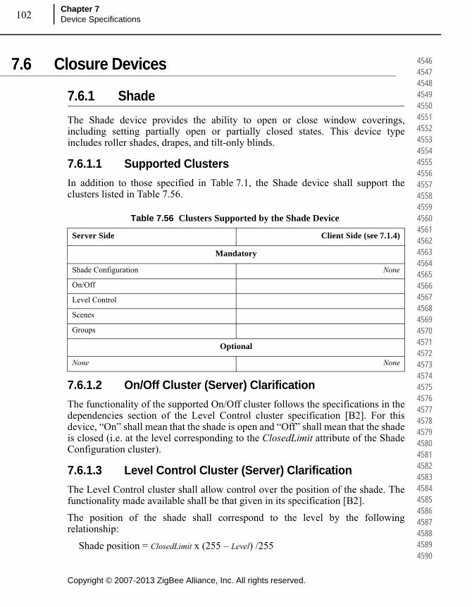
Copyright © 2007-2013 ZigBee Alliance, Inc. All rights reserved.
Chapter 7Device Specifications102
454645474548454945504551455245534554455545564557455845594560456145624563456445654566456745684569457045714572457345744575457645774578457945804581458245834584458545864587458845894590
7.6 Closure Devices
7.6.1 Shade
The Shade device provides the ability to open or close window coverings, including setting partially open or partially closed states. This device type includes roller shades, drapes, and tilt-only blinds.
7.6.1.1 Supported Clusters
In addition to those specified in Table 7.1, the Shade device shall support the clusters listed in Table 7.56.
7.6.1.2 On/Off Cluster (Server) Clarification
The functionality of the supported On/Off cluster follows the specifications in the dependencies section of the Level Control cluster specification [B2]. For this device, “On” shall mean that the shade is open and “Off” shall mean that the shade is closed (i.e. at the level corresponding to the ClosedLimit attribute of the Shade Configuration cluster).
7.6.1.3 Level Control Cluster (Server) Clarification
The Level Control cluster shall allow control over the position of the shade. The functionality made available shall be that given in its specification [B2].
The position of the shade shall correspond to the level by the following relationship:
Shade position = ClosedLimit x (255 – Level) /255
Table 7.56 Clusters Supported by the Shade Device
Server Side Client Side (see 7.1.4)
Mandatory
Shade Configuration None
On/Off
Level Control
Scenes
Groups
Optional
None None

103
Copyright © 2007-2013 ZigBee Alliance, Inc. All rights reserved.
ZigBee Home Automation Public Application Profile
Document 05-3520-29
459145924593459445954596459745984599460046014602460346044605460646074608460946104611461246134614461546164617461846194620462146224623462446254626462746284629463046314632463346344635
When Level is 0 the shade is at the ClosedLimit and is closed. When Level is 255 the shade is at position 0 and is fully open.
7.6.1.4 Supported Features and Functions
The Shade device shall support the features and functions listed in Table 7.57.
7.6.2 Shade Controller
The Shade Controller device can control the level of a shade, and put it into configuration mode so that the user may adjust its limits.
7.6.2.1 Supported Clusters
In addition to those specified in Table 7.1, the Shade Controller device shall support the clusters listed in Table 7.58.
Table 7.57 Example Features and Functions Supported by the Shade Device
Device Type/Feature or Function Mandatory/Optional
Join (end devices and routers only) M
Form Network (Coordinator only) M
Allow Others to Join Network (routers and Coordinators only) M
Restore to Factory Fresh Settings M
Enable Identify Mode M
Group Nodes (send out an Add Group If Identify) O
Create Scene (Store Scene) M
Service discovery (Match Descriptor Request) O
ZDP Bind Response M
ZDP Unbind Response M
End Device Annce/Device Annce M
Service Discovery Response (Match Descriptor Response) M
EZ-Mode Commissioning M

Copyright © 2007-2013 ZigBee Alliance, Inc. All rights reserved.
Chapter 7Device Specifications104
463646374638463946404641464246434644464546464647464846494650465146524653465446554656465746584659466046614662466346644665466646674668466946704671467246734674467546764677467846794680
7.6.2.2 Supported Features and Functions
The Shade Controller device shall support the features and functions listed in Table 7.59.
Table 7.58 Clusters Supported by the Shade Controller Device
Server Side Client Side (see 7.1.4)
Mandatory
None On/Off
Level Control
Identify
Optional
None Shade Configuration
Scenes
Groups
Table 7.59 Example Features and Functions Supported by the Shade Controller Device
Device Type/Feature or Function Mandatory/Optional
Join (end devices and routers only) M
Form Network (Coordinator only) M
Allow Others to Join Network (routers and Coordinators only) M
Restore to Factory Fresh Settings M
Enable Identify Mode O
Group Nodes (send out an Add Group If Identify) O
Create Scene (Store Scene) O
Service discovery (Match Descriptor Request) O
ZDP Bind Response M
ZDP Unbind Response M
End Device Annce/Device Annce M
Service Discovery Response (Match Descriptor Response) M
EZ-Mode Commissioning M
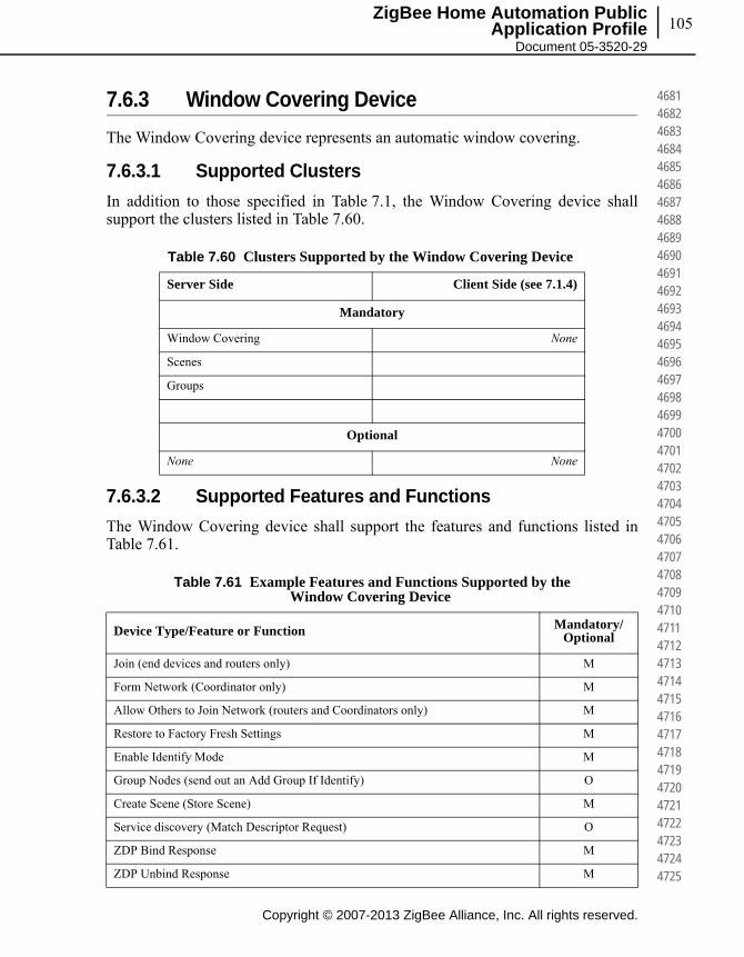
105
Copyright © 2007-2013 ZigBee Alliance, Inc. All rights reserved.
ZigBee Home Automation Public Application Profile
Document 05-3520-29
468146824683468446854686468746884689469046914692469346944695469646974698469947004701470247034704470547064707470847094710471147124713471447154716471747184719472047214722472347244725
7.6.3 Window Covering Device
The Window Covering device represents an automatic window covering.
7.6.3.1 Supported Clusters
In addition to those specified in Table 7.1, the Window Covering device shall support the clusters listed in Table 7.60.
7.6.3.2 Supported Features and Functions
The Window Covering device shall support the features and functions listed in Table 7.61.
Table 7.60 Clusters Supported by the Window Covering Device
Server Side Client Side (see 7.1.4)
Mandatory
Window Covering None
Scenes
Groups
Optional
None None
Table 7.61 Example Features and Functions Supported by the Window Covering Device
Device Type/Feature or Function Mandatory/Optional
Join (end devices and routers only) M
Form Network (Coordinator only) M
Allow Others to Join Network (routers and Coordinators only) M
Restore to Factory Fresh Settings M
Enable Identify Mode M
Group Nodes (send out an Add Group If Identify) O
Create Scene (Store Scene) M
Service discovery (Match Descriptor Request) O
ZDP Bind Response M
ZDP Unbind Response M

Copyright © 2007-2013 ZigBee Alliance, Inc. All rights reserved.
Chapter 7Device Specifications106
472647274728472947304731473247334734473547364737473847394740474147424743474447454746474747484749475047514752475347544755475647574758475947604761476247634764476547664767476847694770
7.6.4 Window Covering Controller
The Window Covering controller is a device that controls an automatic window covering.
7.6.4.1 Supported Clusters
In addition to those specified in Table 7.1, the Window Covering Controller device shall support the clusters listed in Table 7.62.
7.6.4.2 Supported Features and Functions
The Window Covering Controller device shall support the features and functions listed in Table 7.63.
End Device Annce/Device Annce M
Service Discovery Response (Match Descriptor Response) M
EZ-Mode Commissioning M
Table 7.62 Clusters Supported by the Window Covering Controller Device
Server Side Client Side (see 7.1.4)
Mandatory
None Window Covering
Identify
Optional
None Scenes
Groups
Identify
Table 7.61 Example Features and Functions Supported by the Window Covering Device (Continued)
Device Type/Feature or Function Mandatory/Optional

107
Copyright © 2007-2013 ZigBee Alliance, Inc. All rights reserved.
ZigBee Home Automation Public Application Profile
Document 05-3520-29
477147724773477447754776477747784779478047814782478347844785478647874788478947904791479247934794479547964797479847994800480148024803480448054806480748084809481048114812481348144815
7.7 HVAC Devices
7.7.1 Heating/Cooling Unit
The Heating/Cooling Unit device can heat or cool a space in a house. It is not mandatory to provide both functionalities (for example, the device may just heat but not cool). It may be an indoor air handler.
7.7.1.1 Supported Clusters
In addition to those specified in Table 7.1, the Heating/Cooling Unit device shall support the clusters listed in Table 7.64.
Table 7.63 Example Features and Functions Supported by the Window Covering Controller Device
Device Type/Feature or Function Mandatory/Optional
Join (end devices and routers only) M
Form Network (Coordinator only) M
Allow Others to Join Network (routers and Coordinators only) M
Restore to Factory Fresh Settings M
Enable Identify Mode O
Group Nodes (send out an Add Group If Identify) O
Create Scene (Store Scene) O
Service discovery (Match Descriptor Request) O
ZDP Bind Response M
ZDP Unbind Response M
End Device Annce/Device Annce M
Service Discovery Response (Match Descriptor Response) M
EZ-Mode Commissioning M
Table 7.64 Clusters Supported by the Heating/Cooling Unit Device
Server Side Client Side (see 7.1.4)
Mandatory
On/Off
Thermostat
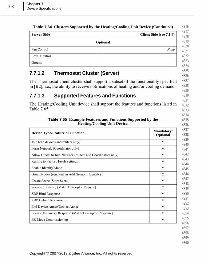
Copyright © 2007-2013 ZigBee Alliance, Inc. All rights reserved.
Chapter 7Device Specifications108
481648174818481948204821482248234824482548264827482848294830483148324833483448354836483748384839484048414842484348444845484648474848484948504851485248534854485548564857485848594860
7.7.1.2 Thermostat Cluster (Server)
The Thermostat client cluster shall support a subset of the functionality specified in [B2], i.e., the ability to receive notifications of heating and/or cooling demand.
7.7.1.3 Supported Features and Functions
The Heating/Cooling Unit device shall support the features and functions listed in Table 7.65.
Optional
Fan Control None
Level Control
Groups
Table 7.65 Example Features and Functions Supported by the Heating/Cooling Unit Device
Device Type/Feature or Function Mandatory/Optional
Join (end devices and routers only) M
Form Network (Coordinator only) M
Allow Others to Join Network (routers and Coordinators only) M
Restore to Factory Fresh Settings M
Enable Identify Mode M
Group Nodes (send out an Add Group If Identify) O
Create Scene (Store Scene) M
Service discovery (Match Descriptor Request) O
ZDP Bind Response M
ZDP Unbind Response M
End Device Annce/Device Annce M
Service Discovery Response (Match Descriptor Response) M
EZ-Mode Commissioning M
Table 7.64 Clusters Supported by the Heating/Cooling Unit Device (Continued)
Server Side Client Side (see 7.1.4)

109
Copyright © 2007-2013 ZigBee Alliance, Inc. All rights reserved.
ZigBee Home Automation Public Application Profile
Document 05-3520-29
486148624863486448654866486748684869487048714872487348744875487648774878487948804881488248834884488548864887488848894890489148924893489448954896489748984899490049014902490349044905
7.7.2 Thermostat
The Thermostat device can have either built-in or separate sensors for temperature, humidity or occupancy. It allows the desired temperature to be set either remotely or locally. The thermostat may send heating and/or cooling requirement notifications to a heating/cooling unit (for example, an indoor air handler) or may include a mechanism to control a heating or cooling unit directly.
7.7.2.1 Supported Clusters
In addition to those specified in Table 7.1, the Thermostat device shall support the clusters listed in Table 7.66.
7.7.2.2 Temperature Measurement Cluster (Client)
The functionality made available by the Temperature Measurement client cluster shall be that given in its specification [B2]. It is used to receive temperature measurements when either the local or outdoor temperature for the thermostat cluster is designated to be sensed remotely.
Table 7.66 Clusters Supported by the Thermostat Device
Server Side Client Side (see 7.1.4)
Mandatory
Thermostat None
Optional
Scenes
Groups
Thermostat User Interface Configuration
Fan Control Fan Control
Temperature Measurement Temperature Measurement
Occupancy Sensing Occupancy Sensing
Relative Humidity Measurement Relative Humidity Measurement
Alarms Time
Power Configuration OTA Bootload
Poll Control

Copyright © 2007-2013 ZigBee Alliance, Inc. All rights reserved.
Chapter 7Device Specifications110
490649074908490949104911491249134914491549164917491849194920492149224923492449254926492749284929493049314932493349344935493649374938493949404941494249434944494549464947494849494950
7.7.2.3 Occupancy Sensing Cluster (Client)
The functionality made available by the Occupancy Sensing client cluster shall be that given in its specification [B2]. It is used to receive occupancy notifications when occupancy for the thermostat cluster is designated to be sensed remotely.
7.7.2.4 Relative Humidity Measurement Cluster (Client)
The functionality made available by the Relative Humidity Measurement client cluster shall be that given in its specification [B2]. It is used to receive humidity measurements when humidity for the Thermostat cluster is designated to be sensed remotely.
7.7.2.5 Scene Table Extensions
The following extension fields shall be added to the Scene table for the Thermostat cluster:
OccupiedCoolingSetpoint
OccupiedHeatingSetpoint
SystemMode
7.7.2.6 Supported Features and Functions
The Thermostat device shall support the features and functions listed in Table 7.67.
Table 7.67 Example Features and Functions Supported by the Thermostat Device
Device Type/Feature or Function Mandatory/Optional
Join (end devices and routers only) M
Form Network (Coordinator only) M
Allow Others to Join Network (routers and Coordinators only) M
Restore to Factory Fresh Settings M
Enable Identify Mode M
Group Nodes (send out an Add Group If Identify) O
Create Scene (Store Scene) O
Service discovery (Match Descriptor Request) O
ZDP Bind Response M
ZDP Unbind Response M
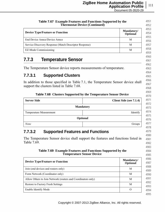
111
Copyright © 2007-2013 ZigBee Alliance, Inc. All rights reserved.
ZigBee Home Automation Public Application Profile
Document 05-3520-29
495149524953495449554956495749584959496049614962496349644965496649674968496949704971497249734974497549764977497849794980498149824983498449854986498749884989499049914992499349944995
7.7.3 Temperature Sensor
The Temperature Sensor device reports measurements of temperature.
7.7.3.1 Supported Clusters
In addition to those specified in Table 7.1, the Temperature Sensor device shall support the clusters listed in Table 7.68.
7.7.3.2 Supported Features and Functions
The Temperature Sensor device shall support the features and functions listed in Table 7.69.
End Device Annce/Device Annce M
Service Discovery Response (Match Descriptor Response) M
EZ-Mode Commissioning M
Table 7.68 Clusters Supported by the Temperature Sensor Device
Server Side Client Side (see 7.1.4)
Mandatory
Temperature Measurement Identify
Optional
None Groups
Table 7.69 Example Features and Functions Supported by the Temperature Sensor Device
Device Type/Feature or Function Mandatory/Optional
Join (end devices and routers only) M
Form Network (Coordinator only) M
Allow Others to Join Network (routers and Coordinators only) M
Restore to Factory Fresh Settings M
Enable Identify Mode O
Table 7.67 Example Features and Functions Supported by the Thermostat Device (Continued)
Device Type/Feature or Function Mandatory/Optional
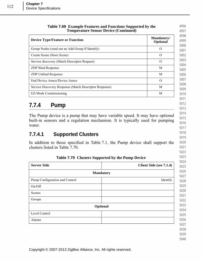
Copyright © 2007-2013 ZigBee Alliance, Inc. All rights reserved.
Chapter 7Device Specifications112
499649974998499950005001500250035004500550065007500850095010501150125013501450155016501750185019502050215022502350245025502650275028502950305031503250335034503550365037503850395040
7.7.4 Pump
The Pump device is a pump that may have variable speed. It may have optional built-in sensors and a regulation mechanism. It is typically used for pumping water.
7.7.4.1 Supported Clusters
In addition to those specified in Table 7.1, the Pump device shall support the clusters listed in Table 7.70.
Group Nodes (send out an Add Group If Identify) O
Create Scene (Store Scene) O
Service discovery (Match Descriptor Request) O
ZDP Bind Response M
ZDP Unbind Response M
End Device Annce/Device Annce O
Service Discovery Response (Match Descriptor Response) M
EZ-Mode Commissioning M
Table 7.70 Clusters Supported by the Pump Device
Server Side Client Side (see 7.1.4)
Mandatory
Pump Configuration and Control Identify
On/Off
Scenes
Groups
Optional
Level Control
Alarms
Table 7.69 Example Features and Functions Supported by the Temperature Sensor Device (Continued)
Device Type/Feature or Function Mandatory/Optional

113
Copyright © 2007-2013 ZigBee Alliance, Inc. All rights reserved.
ZigBee Home Automation Public Application Profile
Document 05-3520-29
504150425043504450455046504750485049505050515052505350545055505650575058505950605061506250635064506550665067506850695070507150725073507450755076507750785079508050815082508350845085
7.7.4.2 On/Off Cluster (Server) Clarifications
The actions carried out by the pump on receipt of commands are shown in Table 7.71.
7.7.4.3 Level Control Cluster (Server) Clarifications
The Level Control cluster shall allow controlling the pump setpoints as specified in [B2], however the transition time is always ignored.
The Setpoint of the pump is a percentage related to the Level according to Table 7.72.
7.7.4.4 Pressure Measurement Notification (Server)
This cluster allows serving of internal pressure measurement if available. This is independent of the Pressure Measurement client cluster, which connects to an external networked pressure sensor.
Pressure Measurement Pressure Measurement
Temperature Measurement Temperature Measurement
Flow Measurement Flow Measurement
Table 7.71 Pump Actions on Receipt for On/Off Commands
Command Action on Receipt
Off If the pump is powered on, store the current level then immediately power it off.
On If the pump is powered off, power it on and move immediately to the level stored by a previous Off command. If no such level has been stored, move immediately to the maximum level allowed for the pump.
Toggle If the pump is powered on, proceed as for the Off command. If the device is powered off, proceed as for the On command.
Table 7.72 Relationship Between Level and Setpoint
Level Setpoint Meaning
0 N/A Pump is stopped
1 - 200 Level / 2 (0.5 - 100.0%) Pump setpoint in percent
201 - 255 100.0% Pump setpoint is 100.0%
Table 7.70 Clusters Supported by the Pump Device (Continued)
Server Side Client Side (see 7.1.4)
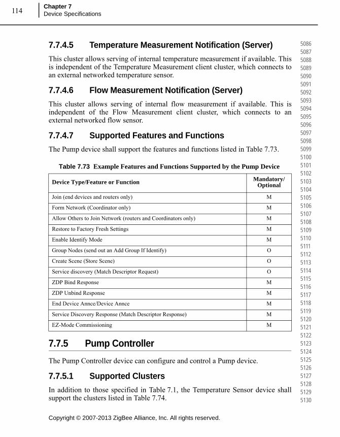
Copyright © 2007-2013 ZigBee Alliance, Inc. All rights reserved.
Chapter 7Device Specifications114
508650875088508950905091509250935094509550965097509850995100510151025103510451055106510751085109511051115112511351145115511651175118511951205121512251235124512551265127512851295130
7.7.4.5 Temperature Measurement Notification (Server)
This cluster allows serving of internal temperature measurement if available. This is independent of the Temperature Measurement client cluster, which connects to an external networked temperature sensor.
7.7.4.6 Flow Measurement Notification (Server)
This cluster allows serving of internal flow measurement if available. This is independent of the Flow Measurement client cluster, which connects to an external networked flow sensor.
7.7.4.7 Supported Features and Functions
The Pump device shall support the features and functions listed in Table 7.73.
7.7.5 Pump Controller
The Pump Controller device can configure and control a Pump device.
7.7.5.1 Supported Clusters
In addition to those specified in Table 7.1, the Temperature Sensor device shall support the clusters listed in Table 7.74.
Table 7.73 Example Features and Functions Supported by the Pump Device
Device Type/Feature or Function Mandatory/Optional
Join (end devices and routers only) M
Form Network (Coordinator only) M
Allow Others to Join Network (routers and Coordinators only) M
Restore to Factory Fresh Settings M
Enable Identify Mode M
Group Nodes (send out an Add Group If Identify) O
Create Scene (Store Scene) O
Service discovery (Match Descriptor Request) O
ZDP Bind Response M
ZDP Unbind Response M
End Device Annce/Device Annce M
Service Discovery Response (Match Descriptor Response) M
EZ-Mode Commissioning M
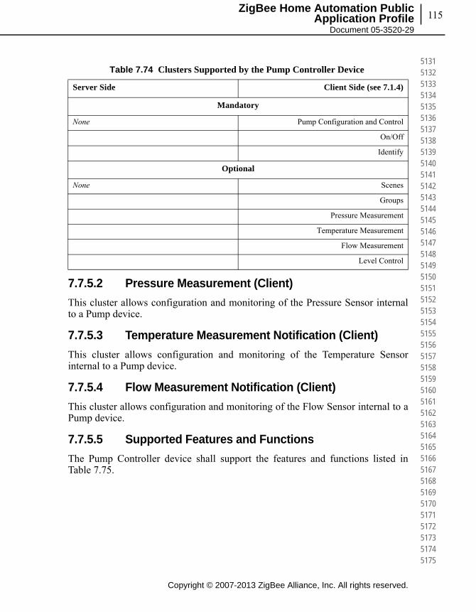
115
Copyright © 2007-2013 ZigBee Alliance, Inc. All rights reserved.
ZigBee Home Automation Public Application Profile
Document 05-3520-29
513151325133513451355136513751385139514051415142514351445145514651475148514951505151515251535154515551565157515851595160516151625163516451655166516751685169517051715172517351745175
7.7.5.2 Pressure Measurement (Client)
This cluster allows configuration and monitoring of the Pressure Sensor internal to a Pump device.
7.7.5.3 Temperature Measurement Notification (Client)
This cluster allows configuration and monitoring of the Temperature Sensor internal to a Pump device.
7.7.5.4 Flow Measurement Notification (Client)
This cluster allows configuration and monitoring of the Flow Sensor internal to a Pump device.
7.7.5.5 Supported Features and Functions
The Pump Controller device shall support the features and functions listed in Table 7.75.
Table 7.74 Clusters Supported by the Pump Controller Device
Server Side Client Side (see 7.1.4)
Mandatory
None Pump Configuration and Control
On/Off
Identify
Optional
None Scenes
Groups
Pressure Measurement
Temperature Measurement
Flow Measurement
Level Control
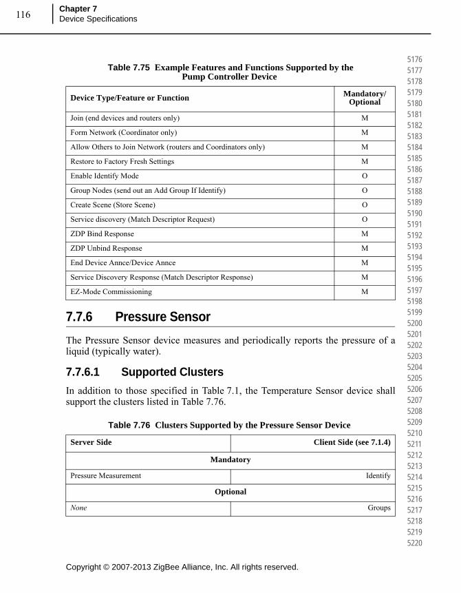
Copyright © 2007-2013 ZigBee Alliance, Inc. All rights reserved.
Chapter 7Device Specifications116
517651775178517951805181518251835184518551865187518851895190519151925193519451955196519751985199520052015202520352045205520652075208520952105211521252135214521552165217521852195220
7.7.6 Pressure Sensor
The Pressure Sensor device measures and periodically reports the pressure of a liquid (typically water).
7.7.6.1 Supported Clusters
In addition to those specified in Table 7.1, the Temperature Sensor device shall support the clusters listed in Table 7.76.
Table 7.75 Example Features and Functions Supported by the Pump Controller Device
Device Type/Feature or Function Mandatory/Optional
Join (end devices and routers only) M
Form Network (Coordinator only) M
Allow Others to Join Network (routers and Coordinators only) M
Restore to Factory Fresh Settings M
Enable Identify Mode O
Group Nodes (send out an Add Group If Identify) O
Create Scene (Store Scene) O
Service discovery (Match Descriptor Request) O
ZDP Bind Response M
ZDP Unbind Response M
End Device Annce/Device Annce M
Service Discovery Response (Match Descriptor Response) M
EZ-Mode Commissioning M
Table 7.76 Clusters Supported by the Pressure Sensor Device
Server Side Client Side (see 7.1.4)
Mandatory
Pressure Measurement Identify
Optional
None Groups

117
Copyright © 2007-2013 ZigBee Alliance, Inc. All rights reserved.
ZigBee Home Automation Public Application Profile
Document 05-3520-29
522152225223522452255226522752285229523052315232523352345235523652375238523952405241524252435244524552465247524852495250525152525253525452555256525752585259526052615262526352645265
7.7.6.2 Supported Features and Functions
The Pressure Sensor device shall support the features and functions listed in Table 7.77.
7.7.7 Flow Sensor
The Flow Sensor device measures and periodically reports the flow rate of a liquid (typically water).
7.7.7.1 Supported Clusters
In addition to those specified in Table 7.1, the Flow Sensor device shall support the clusters listed in Table 7.78.
Table 7.77 Example Features and Functions Supported by the Pressure Sensor Device
Device Type/Feature or Function Mandatory/Optional
Join (end devices and routers only) M
Form Network (Coordinator only) M
Allow Others to Join Network (routers and Coordinators only) M
Restore to Factory Fresh Settings M
Enable Identify Mode O
Group Nodes (send out an Add Group If Identify) O
Create Scene (Store Scene) O
Service discovery (Match Descriptor Request) O
ZDP Bind Response M
ZDP Unbind Response M
End Device Annce/Device Annce M
Service Discovery Response (Match Descriptor Response) M
EZ-Mode Commissioning M

Copyright © 2007-2013 ZigBee Alliance, Inc. All rights reserved.
Chapter 7Device Specifications118
526652675268526952705271527252735274527552765277527852795280528152825283528452855286528752885289529052915292529352945295529652975298529953005301530253035304530553065307530853095310
7.7.7.2 Supported Features and Functions
The Flow Sensor device shall support the features and functions listed in Table 7.79.
Table 7.78 Clusters Supported by the Flow Sensor Device
Server Side Client Side (see 7.1.4)
Mandatory
Flow Measurement Identify
Optional
None Groups
Table 7.79 Example Features and Functions Supported by the Flow Sensor Device
Device Type/Feature or Function Mandatory/Optional
Join (end devices and routers only) M
Form Network (Coordinator only) M
Allow Others to Join Network (routers and Coordinators only) M
Restore to Factory Fresh Settings M
Enable Identify Mode O
Group Nodes (send out an Add Group If Identify) O
Create Scene (Store Scene) O
Service discovery (Match Descriptor Request) O
ZDP Bind Response M
ZDP Unbind Response M
End Device Annce/Device Annce M
Service Discovery Response (Match Descriptor Response) M
EZ-Mode Commissioning M
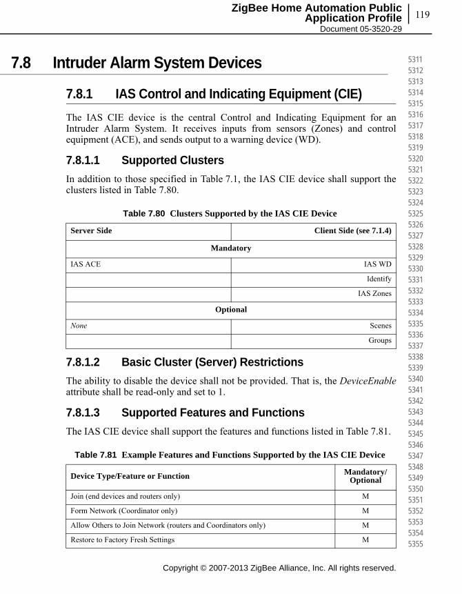
119
Copyright © 2007-2013 ZigBee Alliance, Inc. All rights reserved.
ZigBee Home Automation Public Application Profile
Document 05-3520-29
531153125313531453155316531753185319532053215322532353245325532653275328532953305331533253335334533553365337533853395340534153425343534453455346534753485349535053515352535353545355
7.8 Intruder Alarm System Devices
7.8.1 IAS Control and Indicating Equipment (CIE)
The IAS CIE device is the central Control and Indicating Equipment for an Intruder Alarm System. It receives inputs from sensors (Zones) and control equipment (ACE), and sends output to a warning device (WD).
7.8.1.1 Supported Clusters
In addition to those specified in Table 7.1, the IAS CIE device shall support the clusters listed in Table 7.80.
7.8.1.2 Basic Cluster (Server) Restrictions
The ability to disable the device shall not be provided. That is, the DeviceEnableattribute shall be read-only and set to 1.
7.8.1.3 Supported Features and Functions
The IAS CIE device shall support the features and functions listed in Table 7.81.
Table 7.80 Clusters Supported by the IAS CIE Device
Server Side Client Side (see 7.1.4)
Mandatory
IAS ACE IAS WD
Identify
IAS Zones
Optional
None Scenes
Groups
Table 7.81 Example Features and Functions Supported by the IAS CIE Device
Device Type/Feature or Function Mandatory/Optional
Join (end devices and routers only) M
Form Network (Coordinator only) M
Allow Others to Join Network (routers and Coordinators only) M
Restore to Factory Fresh Settings M

Copyright © 2007-2013 ZigBee Alliance, Inc. All rights reserved.
Chapter 7Device Specifications120
535653575358535953605361536253635364536553665367536853695370537153725373537453755376537753785379538053815382538353845385538653875388538953905391539253935394539553965397539853995400
7.8.2 IAS Ancillary Control Equipment (ACE)
The IAS ACE device is a remote control for an Intruder Alarm System. A ZigBee enabled ACE device can access an IAS CIE device and manipulate the IAS system, on behalf of a level-2 user (see [B4]). The device can also act as a Zone sensor.
7.8.2.1 Supported Clusters
In addition to those specified in Table 7.76, the IAS ACE device shall support the clusters listed in Table 7.82.
7.8.2.2 Supported Features and Functions
The IAS ACE device shall support the features and functions listed in Table 7.82.
Enable Identify Mode O
Group Nodes (send out an Add Group If Identify) O
Create Scene (Store Scene) O
Service discovery (Match Descriptor Request) O
ZDP Bind Response O
ZDP Unbind Response O
End Device Annce/Device Annce M
Service Discovery Response (Match Descriptor Response) M
EZ-Mode Commissioning M
Table 7.82 Clusters Supported by the IAS ACE Device
Server Side Client Side (see 7.1.4)
Mandatory
IAS Zones IAS ACE
Identify
Optional
None None
Table 7.81 Example Features and Functions Supported by the IAS CIE Device
Device Type/Feature or Function Mandatory/Optional
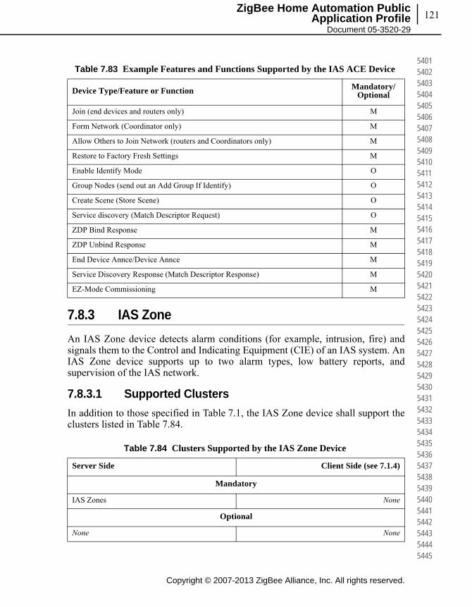
121
Copyright © 2007-2013 ZigBee Alliance, Inc. All rights reserved.
ZigBee Home Automation Public Application Profile
Document 05-3520-29
540154025403540454055406540754085409541054115412541354145415541654175418541954205421542254235424542554265427542854295430543154325433543454355436543754385439544054415442544354445445
7.8.3 IAS Zone
An IAS Zone device detects alarm conditions (for example, intrusion, fire) and signals them to the Control and Indicating Equipment (CIE) of an IAS system. An IAS Zone device supports up to two alarm types, low battery reports, and supervision of the IAS network.
7.8.3.1 Supported Clusters
In addition to those specified in Table 7.1, the IAS Zone device shall support the clusters listed in Table 7.84.
Table 7.83 Example Features and Functions Supported by the IAS ACE Device
Device Type/Feature or Function Mandatory/Optional
Join (end devices and routers only) M
Form Network (Coordinator only) M
Allow Others to Join Network (routers and Coordinators only) M
Restore to Factory Fresh Settings M
Enable Identify Mode O
Group Nodes (send out an Add Group If Identify) O
Create Scene (Store Scene) O
Service discovery (Match Descriptor Request) O
ZDP Bind Response M
ZDP Unbind Response M
End Device Annce/Device Annce M
Service Discovery Response (Match Descriptor Response) M
EZ-Mode Commissioning M
Table 7.84 Clusters Supported by the IAS Zone Device
Server Side Client Side (see 7.1.4)
Mandatory
IAS Zones None
Optional
None None
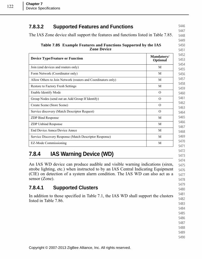
Copyright © 2007-2013 ZigBee Alliance, Inc. All rights reserved.
Chapter 7Device Specifications122
544654475448544954505451545254535454545554565457545854595460546154625463546454655466546754685469547054715472547354745475547654775478547954805481548254835484548554865487548854895490
7.8.3.2 Supported Features and Functions
The IAS Zone device shall support the features and functions listed in Table 7.85.
7.8.4 IAS Warning Device (WD)
An IAS WD device can produce audible and visible warning indications (siren, strobe lighting, etc.) when instructed to by an IAS Central Indicating Equipment (CIE) on detection of a system alarm condition. The IAS WD can also act as a sensor (Zone).
7.8.4.1 Supported Clusters
In addition to those specified in Table 7.1, the IAS WD shall support the clusters listed in Table 7.86.
Table 7.85 Example Features and Functions Supported by the IAS Zone Device
Device Type/Feature or Function Mandatory/Optional
Join (end devices and routers only) M
Form Network (Coordinator only) M
Allow Others to Join Network (routers and Coordinators only) M
Restore to Factory Fresh Settings M
Enable Identify Mode O
Group Nodes (send out an Add Group If Identify) O
Create Scene (Store Scene) O
Service discovery (Match Descriptor Request) O
ZDP Bind Response M
ZDP Unbind Response M
End Device Annce/Device Annce M
Service Discovery Response (Match Descriptor Response) M
EZ-Mode Commissioning M
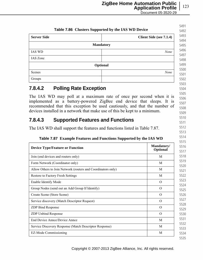
123
Copyright © 2007-2013 ZigBee Alliance, Inc. All rights reserved.
ZigBee Home Automation Public Application Profile
Document 05-3520-29
549154925493549454955496549754985499550055015502550355045505550655075508550955105511551255135514551555165517551855195520552155225523552455255526552755285529553055315532553355345535
7.8.4.2 Polling Rate Exception
The IAS WD may poll at a maximum rate of once per second when it is implemented as a battery-powered ZigBee end device that sleeps. It is recommended that this exception be used cautiously, and that the number of devices installed in a network that make use of this be kept to a minimum.
7.8.4.3 Supported Features and Functions
The IAS WD shall support the features and functions listed in Table 7.87.
Table 7.86 Clusters Supported by the IAS WD Device
Server Side Client Side (see 7.1.4)
Mandatory
IAS WD None
IAS Zone
Optional
Scenes None
Groups
Table 7.87 Example Features and Functions Supported by the IAS WD
Device Type/Feature or Function Mandatory/Optional
Join (end devices and routers only) M
Form Network (Coordinator only) M
Allow Others to Join Network (routers and Coordinators only) M
Restore to Factory Fresh Settings M
Enable Identify Mode O
Group Nodes (send out an Add Group If Identify) O
Create Scene (Store Scene) O
Service discovery (Match Descriptor Request) O
ZDP Bind Response O
ZDP Unbind Response O
End Device Annce/Device Annce M
Service Discovery Response (Match Descriptor Response) M
EZ-Mode Commissioning M

Chapter 7Device Specifications124
This page intentionally blank
Copyright © 2007-2013 ZigBee Alliance, Inc. All rights reserved.
553655375538553955405541554255435544554555465547554855495550555155525553555455555556555755585559556055615562556355645565556655675568556955705571557255735574557555765577557855795580

125ZigBee Home Automation Public
Application Profile Document 05-3520-29
C H A P T E R
8CHAPTER 8HOME AUTOMATION COMMISSIONING
8.1 Network Steering
8.1.1 Form
HA devices must form their own network or join an existing network.
It is intended that an HA network use simple methods to form a network and to commission devices into it. The primary means of commissioning a network will use EZ-mode methods (button presses or similar user actions) to get nodes to join a network.
This specification has no mandates to the start-up sequence of devices or the network. Here are some recommended practices for user feedback on a device:
• A device should be able to indicate to the user that it has decided to become the coordinator of a network.
• A device should be able to indicate to the user, that it has successfully joined a network.
• A device should be able to indicate to the user, that it is in the process of searching for or joining a network.
These indications can be implemented in a number of ways including blinking indicator lights, colored indicator lights, arrays of indicator lights, text displays, graphic displays, audible indicators such as buzzers and speakers, etc. Blinking a green indicator light is the recommended method.
8.1.2 Join
For devices joining an established network, the device may change between router and end device behavior. This decision must be made, however, prior joining a
Copyright © 2007-2013 ZigBee Alliance, Inc. All rights reserved.
558155825583558455855586558755885589559055915592559355945595559655975598559956005601560256035604560556065607560856095610561156125613561456155616561756185619562056215622562356245625

Copyright © 2007-2013 ZigBee Alliance, Inc. All rights reserved.
Chapter 8Home Automation Commissioning126
562656275628562956305631563256335634563556365637563856395640564156425643564456455646564756485649565056515652565356545655565656575658565956605661566256635664566556665667566856695670
network. The mode of operation is not allowed to change while the device is actively joined, but the behavior can subsequently change if the device first leaves, changes behavior, and then joins the network again using the different mode of operation.
8.2 Commissioning
All of the devices described in this document will require some form of commissioning, even if the user or installer doesn’t see it. This is because, for example, an actuating device needs to be bound to some sort of target in order to do useful work, and even if the required initializations are done at the factory before the device is sold, the required operations are virtually the same as is the outcome.
8.2.1 Support for Commissioning Modes
There are two main commissioning modes supported in HA:
1 EZ-Mode commissioning (push button commissioning)
2 Centralized commissioning (aka tool / gateway / S-mode)
All HA devices can be controlled by a Commissioning Director specified in Centralized commissioning.
EZ-Mode and Centralized commissioning are complementary and fully compatible.
8.3 EZ-Mode Commissioning
8.3.1 References
[B25] ZigBee Document 07-5123 ZigBee Cluster Library Specification
8.3.2 Terms
Term Description
Commission Verb: to put a device in an operational state
Bind or Binding Verb: create a binding or the act of creating a binding
Binding Noun: a ZigBee source binding table entry in a device which determines where data is sent from a cluster on and endpoint

127
Copyright © 2007-2013 ZigBee Alliance, Inc. All rights reserved.
ZigBee Home Automation Public Application Profile
Document 05-3520-29
567156725673567456755676567756785679568056815682568356845685568656875688568956905691569256935694569556965697569856995700570157025703570457055706570757085709571057115712571357145715
8.3.3 EZ-Mode Invocation
1 EZ-Mode operations shall be invoked by some interactive means on a device.
2 A Factory Reset operation, that clears bindings and groups, shall be invoked by some interactive means on a device.
NOTE: EZ-Mode invocation may be overloaded to include both Network Steering and Finding and Binding.
8.3.4 EZ-Mode Network Steering
1 When EZ-Mode Network Steering is invoked on a node that is not joined to a network, it shall attempt to join an existing network. If no networks are found, it may form a network.
2 If a ZigBee Router or Coordinator joins or forms a network, it shall set its own PermitJoin value to at least EZModeTime.
3 If the node is a ZigBee Router and joins a network, it shall broadcast a PermitJoin time of at least EZModeTime.
4 When EZ-Mode Network Steering is invoked on a ZigBee Router or Coordinator, and the node is already joined to a network, the node shall broadcast a minimum PermitJoin time of EZModeTime and shall set its own PermitJoin time to this value.
Invoke EZ-Mode Method A method, requiring human interaction, to initiate or end EZ-Mode commissioning
Node A physical unit with a single MAC address and ZigBee stack
EZ-Mode Network Steering or Network Steering
Joining the proper network as identified by the user, or forming a network when desired by the user
EZ-Mode Finding and Binding
Discovering and creating source bindings between clusters that direct data flow for operational transactions
User A person performing network steering and/or commissioning
Operational State Participating in operational transactions
Operational Transaction Transactions that are used to perform device functions, such attribute reporting or actuation commands (e.g., On, Off, Toggle, etc.) and are not one-time transactions or commissioning transactions.
Initiator An endpoint that has at least 1 cluster that is an initiator of operational transactions
Target An endpoint that has at least 1 cluster that is a target of operational transactions
Term Description
Copyright © 2007-2013 ZigBee Alliance, Inc. All rights reserved.
Chapter 8Home Automation Commissioning128
571657175718571957205721572257235724572557265727572857295730573157325733573457355736573757385739574057415742574357445745574657475748574957505751575257535754575557565757575857595760
8.3.5 EZ-Mode Finding and Binding
1 When EZ-Mode Finding and Binding is invoked on a Target endpoint, it shall set its Identify cluster attribute IdentifyTime to a minimum of EZModeTime. Optionally PermitJoin may also be broadcast with the same time value to synchronize IdentifyTime in the network.
2 When EZ-Mode Finding and Binding is invoked on a Target endpoint, it may synchronize all other identifying endpoints in the network to at least EZModeTime.
3 When EZ-Mode Finding and Binding is invoked on an Initiator endpoint, it shall broadcast to all nodes (including sleepy ZEDs) the Identify Query command one or more times.
4 If an Initiator endpoint performing EZ-Mode Finding and Binding receives an Identify Query re-sponse from an endpoint, then it should attempt to discover clusters on the responding end-point that match clusters on the Initiator endpoint (such as sending a Simple Descriptor request). If a cluster matches on the responding endpoint, this responding endpoint is the Target. For each matching cluster on the Target, the Initiator shall create or use an existing source binding. The binding source shall be the Initiator’s matching cluster. The binding’s destination shall address (unicast or group) the Target’s matching cluster.
5 Once the Initiator is done binding, it may set the IdentifyTime of its Targets to zero.
6 An attribute that supports reporting shall have a default report configuration.
8.3.6 EZ-Mode Network Steering
The flowchart in Figure 8.1 is included to clarify the process. If there is a conflict between the flowchart and the normative text, the text takes precedence.

129
Copyright © 2007-2013 ZigBee Alliance, Inc. All rights reserved.
ZigBee Home Automation Public Application Profile
Document 05-3520-29
576157625763576457655766576757685769577057715772577357745775577657775778577957805781578257835784578557865787578857895790579157925793579457955796579757985799580058015802580358045805
Figure 8.1 EZ-Mode Network Steering Flowchart
8.3.7 EZ-Mode Initiator: Finding and Binding
The flowchart in Figure 8.2 is included to clarify the process. If there is a conflict between the flowchart and the normative text, the text takes precedence.
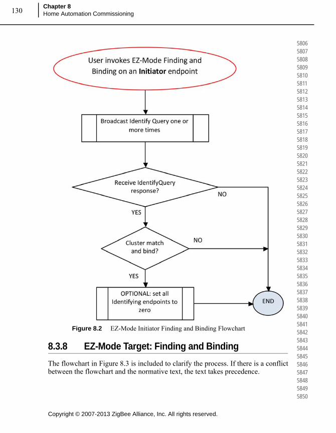
Copyright © 2007-2013 ZigBee Alliance, Inc. All rights reserved.
Chapter 8Home Automation Commissioning130
580658075808580958105811581258135814581558165817581858195820582158225823582458255826582758285829583058315832583358345835583658375838583958405841584258435844584558465847584858495850
Figure 8.2 EZ-Mode Initiator Finding and Binding Flowchart
8.3.8 EZ-Mode Target: Finding and Binding
The flowchart in Figure 8.3 is included to clarify the process. If there is a conflict between the flowchart and the normative text, the text takes precedence.
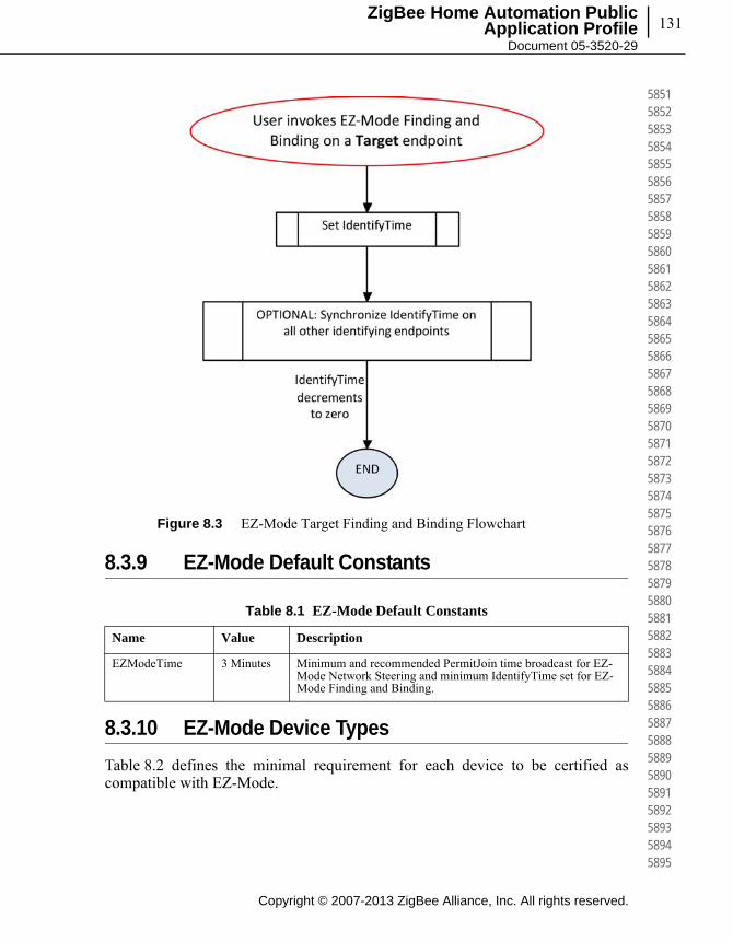
131
Copyright © 2007-2013 ZigBee Alliance, Inc. All rights reserved.
ZigBee Home Automation Public Application Profile
Document 05-3520-29
585158525853585458555856585758585859586058615862586358645865586658675868586958705871587258735874587558765877587858795880588158825883588458855886588758885889589058915892589358945895
Figure 8.3 EZ-Mode Target Finding and Binding Flowchart
8.3.9 EZ-Mode Default Constants
8.3.10 EZ-Mode Device Types
Table 8.2 defines the minimal requirement for each device to be certified as compatible with EZ-Mode.
Table 8.1 EZ-Mode Default Constants
Name Value Description
EZModeTime 3 Minutes Minimum and recommended PermitJoin time broadcast for EZ-Mode Network Steering and minimum IdentifyTime set for EZ-Mode Finding and Binding.

Copyright © 2007-2013 ZigBee Alliance, Inc. All rights reserved.
Chapter 8Home Automation Commissioning132
589658975898589959005901590259035904590559065907590859095910591159125913591459155916591759185919592059215922592359245925592659275928592959305931593259335934593559365937593859395940
Table 8.2 Minimum Requirements for EZ-Mode Compatibility
Device Network Part Initiator Target
0x0000 (On/Off Switch) M M
0x0001 (Level Control Switch) M M
0x0002 (On/Off Output) M M
0x0003 (Level Controllable Output) M M
0x0004 (Scene Selector) M
0x0005 (Configuration Tool) M
0x0006 (Remote Control) M
0x0007 (Combined Interface) M
0x0008 (Range Extender) M
0x0009 (Mains Power Outlet) M M
0x000A (Door Lock) M
0x000B (Door Lock Controller) M
0x000C (Simple Sensor) M M
0x000D (Consumption Awareness Device) M M
0x0050 (Home Gateway) M
0x0051 (Smart Plug) M M
0x0052 (White Goods) M M
0x0053 (Meter Interface) M M
0x0100 (On/Off Light) M M
0x0101 (Dimmable Light) M M
0x0102 (Color Dimmable Light) M M
0x0103 (On/Off Light Switch) M M
0x0104 (Dimmer Switch) M M
0x0105 (Color Dimmer Switch) M M
0x0106 (Light Sensor) M M
0x0107 (Occupancy Sensor) M M
0x0200 (Shade) M M
0x0201 (Shade Controller) M M
0x0202 (Window Covering Device) M M
0x0203 (Window Covering Controller) M M
0x0300 (Heating/Cooling Unit) M M

133
Copyright © 2007-2013 ZigBee Alliance, Inc. All rights reserved.
ZigBee Home Automation Public Application Profile
Document 05-3520-29
594159425943594459455946594759485949595059515952595359545955595659575958595959605961596259635964596559665967596859695970597159725973597459755976597759785979598059815982598359845985
8.3.11 Identify Cluster Attribute
Add a CommissionState attribute and explanation text:
8.3.11.1 CommissionState Attribute
The CommissionState attribute is in this form:
0x0301 (Thermostat) M M
0x0302 (Temperature Sensor) M M
0x0303 (Pump) M M M
0x0304 (Pump Controller) M M M
0x0305 (Pressure Sensor) M M
0x0306 (Flow Sensor) M M
0x0307 (Mini Split AC) M
0x0400 (IAS Control and Indicating Equipment)
M
0x0401 (IAS Ancillary Control Equipment) M
0x0402 (IAS Zone) M
0x0403 (IAS Warning Device) M
Table 8.1 Attributes of the Identify Server Cluster
Identifier Name Type Range Access Default M/O
0x0001 CommissionState
8-bit bitmap - Read 0x00 O
Table 8.2 Minimum Requirements for EZ-Mode Compatibility (Continued)
Device Network Part Initiator Target

Copyright © 2007-2013 ZigBee Alliance, Inc. All rights reserved.
Chapter 8Home Automation Commissioning134
598659875988598959905991599259935994599559965997599859996000600160026003600460056006600760086009601060116012601360146015601660176018601960206021602260236024602560266027602860296030
This attribute shall be a persistent attribute across power cycles. The device may update these states at any time.
Devices may choose to leave a network and reset to factory fresh settings at some point in time if they consider themselves un-commissioned, or if commissioning was interrupted by power loss. If power loss is not the cause, it is recommended that devices choosing to implement this feature do so upon expiry of their PermitJoin or Identify time.
The commissioned or un-commissioned decision is application specific, but may consider data such as the CommisisonState attribute, binding table entries, group memberships and/or reception of operational commands.
Devices implementing this feature are recommended to support the CommisisonState attribute and Update Commission State command (see below) to allow remote devices to understand and influence this decision.
It is recommended as a best practice that upon commissioning themselves to a Target, EZMode initiators send an Update Commission State command, with Action field equal to "Set" and the CommissionStateMask field having an Operational State bit set, in order to notify the Target that it has been commissioned.
8.3.12 Identify Cluster Commands
Add a EZ-Mode Invoke command in 3.5.3.3 with explanation text in new clause 3.5.2.3.3:
Table 8.2 Values of the CommissionState Attribute
Bit Field Name Bit(s) Description
Network State 0 1=Device is on the proper network. Must be set to 1 if Operational State is set to 1
0=device is not on a network, a temporary network, or it is unknown if the device is on the proper network
Operational State 1 1=Device is commissioned for operation. The Network State shall be set to 1.
0=Device is not commissioned for operation.
Reserved 2-7 Reserved bits
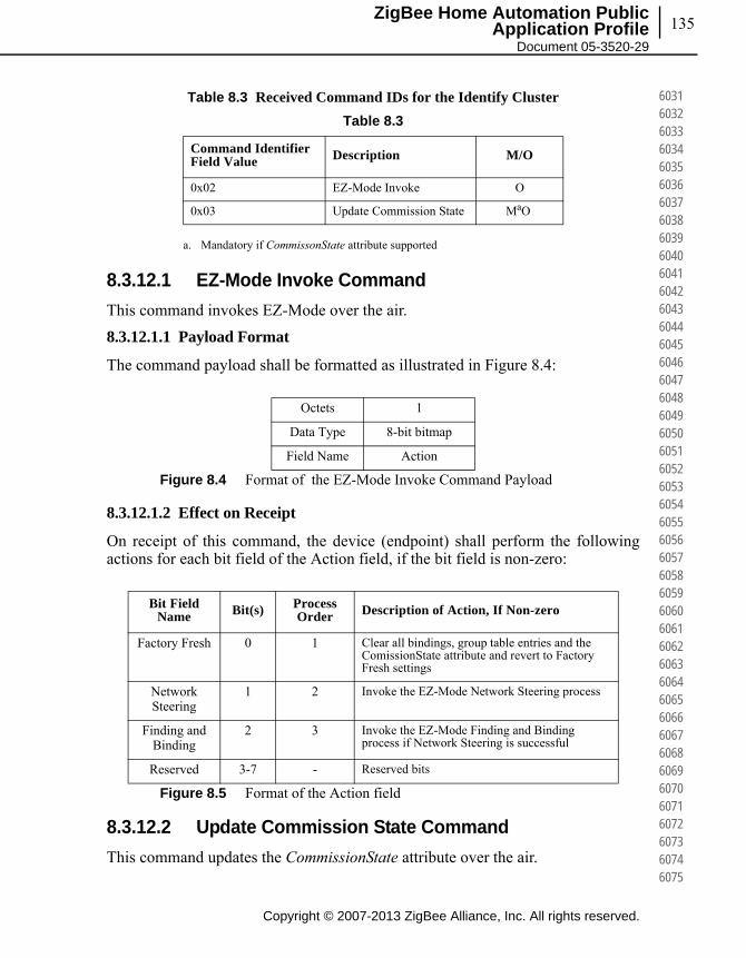
135
Copyright © 2007-2013 ZigBee Alliance, Inc. All rights reserved.
ZigBee Home Automation Public Application Profile
Document 05-3520-29
603160326033603460356036603760386039604060416042604360446045604660476048604960506051605260536054605560566057605860596060606160626063606460656066606760686069607060716072607360746075
Table 8.3 Received Command IDs for the Identify Cluster
8.3.12.1 EZ-Mode Invoke Command
This command invokes EZ-Mode over the air.
8.3.12.1.1 Payload Format
The command payload shall be formatted as illustrated in Figure 8.4:
Figure 8.4 Format of the EZ-Mode Invoke Command Payload
8.3.12.1.2 Effect on Receipt
On receipt of this command, the device (endpoint) shall perform the following actions for each bit field of the Action field, if the bit field is non-zero:
Figure 8.5 Format of the Action field
8.3.12.2 Update Commission State Command
This command updates the CommissionState attribute over the air.
Table 8.3
Command Identifier Field Value Description M/O
0x02 EZ-Mode Invoke O
0x03 Update Commission State MaO
a. Mandatory if CommissonState attribute supported
Octets 1
Data Type 8-bit bitmap
Field Name Action
Bit Field Name Bit(s) Process
Order Description of Action, If Non-zero
Factory Fresh 0 1 Clear all bindings, group table entries and the ComissionState attribute and revert to Factory Fresh settings
Network Steering
1 2 Invoke the EZ-Mode Network Steering process
Finding and Binding
2 3 Invoke the EZ-Mode Finding and Binding process if Network Steering is successful
Reserved 3-7 - Reserved bits
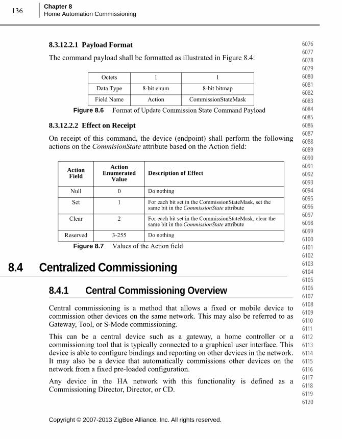
Copyright © 2007-2013 ZigBee Alliance, Inc. All rights reserved.
Chapter 8Home Automation Commissioning136
607660776078607960806081608260836084608560866087608860896090609160926093609460956096609760986099610061016102610361046105610661076108610961106111611261136114611561166117611861196120
8.3.12.2.1 Payload Format
The command payload shall be formatted as illustrated in Figure 8.4:
Figure 8.6 Format of Update Commission State Command Payload
8.3.12.2.2 Effect on Receipt
On receipt of this command, the device (endpoint) shall perform the following actions on the CommisionState attribute based on the Action field:
Figure 8.7 Values of the Action field
8.4 Centralized Commissioning
8.4.1 Central Commissioning Overview
Central commissioning is a method that allows a fixed or mobile device to commission other devices on the same network. This may also be referred to as Gateway, Tool, or S-Mode commissioning.
This can be a central device such as a gateway, a home controller or a commissioning tool that is typically connected to a graphical user interface. This device is able to configure bindings and reporting on other devices in the network. It may also be a device that automatically commissions other devices on the network from a fixed pre-loaded configuration.
Any device in the HA network with this functionality is defined as a Commissioning Director, Director, or CD.
Octets 1 1
Data Type 8-bit enum 8-bit bitmap
Field Name Action CommissionStateMask
Action Field
Action Enumerated
ValueDescription of Effect
Null 0 Do nothing
Set 1 For each bit set in the CommissionStateMask, set the same bit in the CommissionState attribute
Clear 2 For each bit set in the CommissionStateMask, clear the same bit in the CommissionState attribute
Reserved 3-255 Do nothing

137
Copyright © 2007-2013 ZigBee Alliance, Inc. All rights reserved.
ZigBee Home Automation Public Application Profile
Document 05-3520-29
612161226123612461256126612761286129613061316132613361346135613661376138613961406141614261436144614561466147614861496150615161526153615461556156615761586159616061616162616361646165
Figure 8.8 Principle of Central Commissioning with a Commissioning Director.
8.4.2 Minimum Requirements for All Devices
• A device shall process and respond to the ZDO discovery services: Active_EP_req, Simple_Desc_req, Match_Desc_req, IEEE_addr_req, NWK_addr_req.
• Routers and coordinators shall process and respond to the ZDO node manager service Mgmt_Bind_req and Mgmt_Lqi_req.
• A device shall process and respond to the ZDO binding table services Bind_req, Unbind_req, and.
• A device shall implement a binding table whose number of available entries is greater than or equal to the number of supported clusters that may initiate normal operational transactions2.
• A device that supports a reportable attribute shall have a default report configuration.
2. Operational transactions are not one time transactions or commissioning transac-tions. Operational transactions are those that are used to perform the device function, such attribute reporting or actuation commands (e.g. On, Off, Toggle, etc.).
Copyright © 2007-2013 ZigBee Alliance, Inc. All rights reserved.
Chapter 8Home Automation Commissioning138
616661676168616961706171617261736174617561766177617861796180618161826183618461856186618761886189619061916192619361946195619661976198619962006201620262036204620562066207620862096210
• A device that supports a reportable attribute shall process and respond to ZCL commands to read and configure at least one report for that attribute.
• A device that supports a Group Table shall support a the Groups cluster on any endpoint that has a cluster that may be a target of an operational transaction.
8.4.3 Node Discovery
In order to commission devices, the Director needs to discover the nodes in the network. There are two ways nodes can be detected:
8.4.3.1 New Devices Joining
New devices that join the network are announced by a broadcast ZDO command Device_annce. A Director may then use ZDO discovery services (see sub-clause 8.4.2) to understand the nodes in the network, then binding table services (see sub-clause 8.4.2), to manage binding tables, and possibly Groups cluster commands to manage group tables.
8.4.3.2 Devices in Existing Network
When a Director joins an existing network, it needs to discover nodes already in the network.
It is recommended the Director to use the Mgmt_Lqi_req to discover nodes in the network. The benefit of using Mgmt_Lqi_req (instead of IEEE_addr_req or NWK_addr_req) are:
• Device type ZC, ZR, ZED information
• Rx_On_when_Idle information
• Information about parent-child relationships
The algorithms used for managing the incoming Mgmt_Lqi_rsp is not specified.
After this, the Director can perform any commission action as proposed in sub-clause 8.4.1.
8.5 Group Messaging vs. Unicast Messaging
It is important to consider that groups make use of broadcast transmissions. Group messaging should only be used when a device needs to communicate with a group of greater than 5. For groups of less than 5, standard binding and unicast messages should be employed unless simultaneous action is required by the command e.g., lighting. Also, there is no acknowledgement service for group messages, because

139
Copyright © 2007-2013 ZigBee Alliance, Inc. All rights reserved.
ZigBee Home Automation Public Application Profile
Document 05-3520-29
621162126213621462156216621762186219622062216222622362246225622662276228622962306231623262336234623562366237623862396240624162426243624462456246624762486249625062516252625362546255
they are broadcast. Unicast messaging shall be used if a device requires APS acknowledgments.
The commissioning procedures described in EZ-mode and Centralized commissioning can also be used to create one-to-one bindings for unicast messaging. When these procedures are utilized, the decision to create a group or not can be made by the application based on a local device policy. If a device is being bound to only 2 or 3 other devices, a unicast binding entry can be created for each target, and three unicasts will be sent instead of a group broadcast. When the destination is a large number of devices, a group binding entry should be created. This makes group vs. unicast messaging transparent to the user.
8.6 Bindings Required for Commissioning
A minimum number of binding table entries are required per device in order for the device to be able to be commissioned. Each device shall contain a minimum of one binding per endpoint times the number of clusters on that endpoint that support bindings. Thus if a device contains 5 endpoints each with two clusters which expect to be bound, that device must contain a minimum of 10 binding table entries. This rule ensures that properly formatted devices may be commissioned through the use of bindings in a network.
8.7 Network Sharing
8.7.0.1 HA Device Joining SE Network
An HA device that wishes to join an SE 1.x network must have the option to join with an installation code, as described in the SE 1.x specification. Such HA devices may have a user interface to select between using the HA default link key or the SE installation code. A simple HA device without the appropriate user interface may choose to try both the HA default link key and SE installation code when joining a network.
An HA device that joins an SE 1.x network is not required to initiate certificate-based key establishment. It will only have the authorization for messages with network layer encryption, but not APS layer encryption.
Depending on the security policy of the SE 1.x network, the trust center may remove devices that do not initiate key establishment from the network. So an SE 1.x trust center that wishes to accept an HA device must set its security policy to allow a device without key establishment support to remain on the network.
Chapter 8Home Automation Commissioning140
This page intentionally blank
Copyright © 2007-2013 ZigBee Alliance, Inc. All rights reserved.
625662576258625962606261626262636264626562666267626862696270627162726273627462756276627762786279628062816282628362846285628662876288628962906291629262936294629562966297629862996300
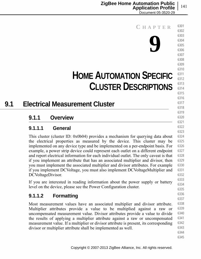
141ZigBee Home Automation Public
Application Profile Document 05-3520-29
C H A P T E R
9CHAPTER 9HOME AUTOMATION SPECIFIC
CLUSTER DESCRIPTIONS
9.1 Electrical Measurement Cluster
9.1.1 Overview
9.1.1.1 General
This cluster (cluster ID: 0x0b04) provides a mechanism for querying data about the electrical properties as measured by the device. This cluster may be implemented on any device type and be implemented on a per-endpoint basis. For example, a power strip device could represent each outlet on a different endpoint and report electrical information for each individual outlet. The only caveat is that if you implement an attribute that has an associated multiplier and divisor, then you must implement the associated multiplier and divisor attributes. For example if you implement DCVoltage, you must also implement DCVoltageMultiplier and DCVoltageDivisor.
If you are interested in reading information about the power supply or battery level on the device, please see the Power Configuration cluster.
9.1.1.2 Formatting
Most measurement values have an associated multiplier and divisor attribute. Multiplier attributes provide a value to be multiplied against a raw or uncompensated measurement value. Divisor attributes provide a value to divide the results of applying a multiplier attribute against a raw or uncompensated measurement value. If a multiplier or divisor attribute is present, its corresponding divisor or multiplier attribute shall be implemented as well.
Copyright © 2007-2013 ZigBee Alliance, Inc. All rights reserved.
630163026303630463056306630763086309631063116312631363146315631663176318631963206321632263236324632563266327632863296330633163326333633463356336633763386339634063416342634363446345
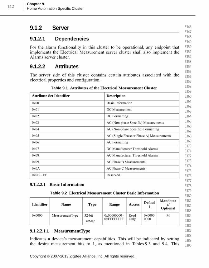
Copyright © 2007-2013 ZigBee Alliance, Inc. All rights reserved.
Chapter 9Home Automation Specific Cluster 142
634663476348634963506351635263536354635563566357635863596360636163626363636463656366636763686369637063716372637363746375637663776378637963806381638263836384638563866387638863896390
9.1.2 Server
9.1.2.1 Dependencies
For the alarm functionality in this cluster to be operational, any endpoint that implements the Electrical Measurement server cluster shall also implement the Alarms server cluster.
9.1.2.2 Attributes
The server side of this cluster contains certain attributes associated with the electrical properties and configuration.
9.1.2.2.1 Basic Information
9.1.2.2.1.1 MeasurementType
Indicates a device’s measurement capabilities. This will be indicated by setting the desire measurement bits to 1, as mentioned in Tables 9.3 and 9.4. This
Table 9.1 Attributes of the Electrical Measurement Cluster
Attribute Set Identifier Description
0x00 Basic Information
0x01 DC Measurement
0x02 DC Formatting
0x03 AC (Non-phase Specific) Measurements
0x04 AC (Non-phase Specific) Formatting
0x05 AC (Single Phase or Phase A) Measurements
0x06 AC Formatting
0x07 DC Manufacturer Threshold Alarms
0x08 AC Manufacturer Threshold Alarms
0x09 AC Phase B Measurements
0x0A AC Phase C Measurements
0x0B – FF Reserved.
Table 9.2 Electrical Measurement Cluster Basic Information
Identifier Name Type Range Access Default
Mandatory/
Optional
0x0000 MeasurementType 32-bit
BitMap
0x00000000 – 0xFFFFFFFF
Read Only
0x00000000
M

143
Copyright © 2007-2013 ZigBee Alliance, Inc. All rights reserved.
ZigBee Home Automation Public Application Profile
Document 05-3520-29
639163926393639463956396639763986399640064016402640364046405640664076408640964106411641264136414641564166417641864196420642164226423642464256426642764286429643064316432643364346435
attribute will be used client devices to determine what all attribute is supported by the meter. Unused bits should be set to zero.
9.1.2.2.2 DC Measurement
Table 9.3 MeasurementType Attribute
Bit Flag Name / Description
0 Active measurement (AC)
1 Reactive measurement (AC)
2 Apparent measurement (AC)
3 Phase A measurement
4 Phase B measurement
5 Phase C measurement
6 DC measurement
7 Harmonics measurement
8 Power quality measurement
9 – 31 Reserved
Table 9.4 DC Measurement Attributes
Identifier Name Type Range Access DefaultMandator
y/ Optional
0x0100 DCVoltage Signed 16-bit integer
-32767 - 32767
Read only 0x8000 O
0x0101 DCVoltageMin
Signed 16-bit integer
-32767 - 32767
Read only 0x8000 O
0x0102 DCVoltageMax
Signed 16-bit integer
-32767 - 32767
Read only 0x8000 O
0x0103 DCCurrent Signed 16-bit integer
-32767 – 32767
Read only 0x8000 O
0x0104 DCCurrentMin
Signed 16-bit integer
-32767 – 32767
Read only 0x8000 O
0x0105 DCCurrentMax
Signed 16-bit integer
-32767 – 32767
Read only 0x8000 O

Copyright © 2007-2013 ZigBee Alliance, Inc. All rights reserved.
Chapter 9Home Automation Specific Cluster 144
643664376438643964406441644264436444644564466447644864496450645164526453645464556456645764586459646064616462646364646465646664676468646964706471647264736474647564766477647864796480
9.1.2.2.2.1 DCVoltage
The DCVoltage attribute represents the most recent DC voltage reading in Volts (V). If the voltage cannot be measured, a value of 0x8000 is returned.
9.1.2.2.2.2 DCVoltageMin
The DCVoltageMin attribute represents the lowest DC voltage value measured in Volts (V). After resetting, this attribute will return a value of 0x8000 until a measurement is made.
9.1.2.2.2.3 DCVoltageMax
The DCVoltageMax attribute represents the highest DC voltage value measured in Volts (V). After resetting, this attribute will return a value of 0x8000 until a measurement is made.
9.1.2.2.2.4 DCCurrent
The DCCurrent attribute represents the most recent DC current reading in Amps (A). If the current cannot be measured, a value of 0x8000 is returned.
9.1.2.2.2.5 DCCurrentMin
The DCCurrentMin attribute represents the lowest DC current value measured in Amps (A). After resetting, this attribute will return a value of 0x8000 until a measurement is made.
0x0106 DCPower Signed 16-bit integer
-32767 – 32767
Read only 0x8000 O
0x0107 DCPowerMin
Signed 16-bit integer
-32767 – 32767
Read only 0x8000 O
0x0108 DCPowerMax
Signed 16-bit integer
-32767 – 32767
Read only 0x8000 O
0x0109 – 0x01FF
Reserved
Table 9.4 DC Measurement Attributes (Continued)
Identifier Name Type Range Access DefaultMandator
y/ Optional
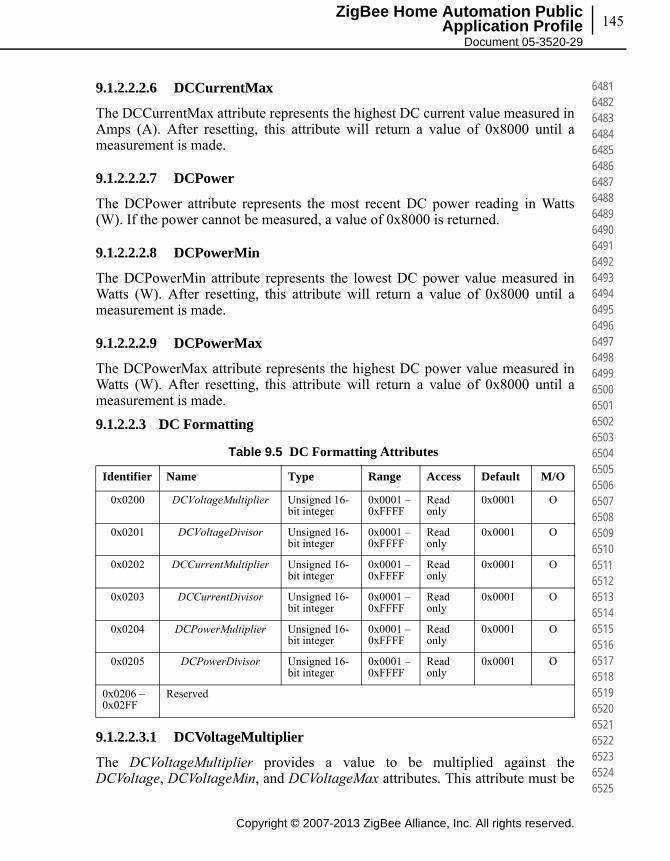
145
Copyright © 2007-2013 ZigBee Alliance, Inc. All rights reserved.
ZigBee Home Automation Public Application Profile
Document 05-3520-29
648164826483648464856486648764886489649064916492649364946495649664976498649965006501650265036504650565066507650865096510651165126513651465156516651765186519652065216522652365246525
9.1.2.2.2.6 DCCurrentMax
The DCCurrentMax attribute represents the highest DC current value measured in Amps (A). After resetting, this attribute will return a value of 0x8000 until a measurement is made.
9.1.2.2.2.7 DCPower
The DCPower attribute represents the most recent DC power reading in Watts (W). If the power cannot be measured, a value of 0x8000 is returned.
9.1.2.2.2.8 DCPowerMin
The DCPowerMin attribute represents the lowest DC power value measured in Watts (W). After resetting, this attribute will return a value of 0x8000 until a measurement is made.
9.1.2.2.2.9 DCPowerMax
The DCPowerMax attribute represents the highest DC power value measured in Watts (W). After resetting, this attribute will return a value of 0x8000 until a measurement is made.
9.1.2.2.3 DC Formatting
9.1.2.2.3.1 DCVoltageMultiplier
The DCVoltageMultiplier provides a value to be multiplied against the DCVoltage, DCVoltageMin, and DCVoltageMax attributes. This attribute must be
Table 9.5 DC Formatting Attributes
Identifier Name Type Range Access Default M/O
0x0200 DCVoltageMultiplier Unsigned 16-bit integer
0x0001 – 0xFFFF
Read only
0x0001 O
0x0201 DCVoltageDivisor Unsigned 16-bit integer
0x0001 – 0xFFFF
Read only
0x0001 O
0x0202 DCCurrentMultiplier Unsigned 16-bit integer
0x0001 – 0xFFFF
Read only
0x0001 O
0x0203 DCCurrentDivisor Unsigned 16-bit integer
0x0001 – 0xFFFF
Read only
0x0001 O
0x0204 DCPowerMultiplier Unsigned 16-bit integer
0x0001 – 0xFFFF
Read only
0x0001 O
0x0205 DCPowerDivisor Unsigned 16-bit integer
0x0001 – 0xFFFF
Read only
0x0001 O
0x0206 – 0x02FF
Reserved

Copyright © 2007-2013 ZigBee Alliance, Inc. All rights reserved.
Chapter 9Home Automation Specific Cluster 146
652665276528652965306531653265336534653565366537653865396540654165426543654465456546654765486549655065516552655365546555655665576558655965606561656265636564656565666567656865696570
used in conjunction with the DCVoltageDivisor attribute. 0x0000 is an invalid value for this attribute.
9.1.2.2.3.2 DCVoltageDivisor
The DCVoltageDivisor provides a value to be divided against the DCVoltage, DCVoltageMin, and DCVoltageMax attributes. This attribute must be used in conjunction with the DCVoltageMultiplier attribute. 0x0000 is an invalid value for this attribute.
9.1.2.2.3.3 DCCurrentMultiplier
The DCCurrentMultiplier provides a value to be multiplied against the DCCurrent, DCCurrentMin, and DCCurrentMax attributes. This attribute must be used in conjunction with the DCCurrentDivisor attribute. 0x0000 is an invalid value for this attribute.
9.1.2.2.3.4 DCCurrentDivisor
The DCCurrentDivisor provides a value to be divided against the DCCurrent, DCCurrentMin, and DCCurrentMax attributes. This attribute must be used in conjunction with the DCCurrentMultiplier attribute. 0x0000 is an invalid value for this attribute.
9.1.2.2.3.5 DCPowerMultiplier
The DCPowerMultiplier provides a value to be multiplied against the DCPower, DCPowerMin, and DCPowerMax attributes. This attribute must be used in conjunction with the DCPowerDivisor attribute. 0x0000 is an invalid value for this attribute.
9.1.2.2.3.6 DCPowerDivisor
The DCPowerDivisor provides a value to be divided against the DCPower, DCPowerMin, and DCPowerMax attributes. This attribute must be used in conjunction with the DCPowerMultiplier attribute. 0x0000 is an invalid value for this attribute.
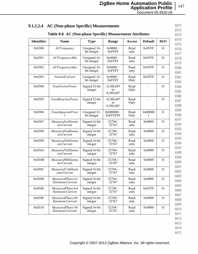
147
Copyright © 2007-2013 ZigBee Alliance, Inc. All rights reserved.
ZigBee Home Automation Public Application Profile
Document 05-3520-29
657165726573657465756576657765786579658065816582658365846585658665876588658965906591659265936594659565966597659865996600660166026603660466056606660766086609661066116612661366146615
9.1.2.2.4 AC (Non-phase Specific) Measurements
Table 9.6 AC (Non-phase Specific) Measurement Attributes
Identifier Name Type Range Access Default M/O
0x0300 ACFrequency Unsigned 16-bit integer
0x0000 – 0xFFFF
Read only
0xFFFF O
0x0301 ACFrequencyMin Unsigned 16-bit integer
0x0000 – 0xFFFF
Read only
0xFFFF O
0x0302 ACFrequencyMax Unsigned 16-bit integer
0x0000 – 0xFFFF
Read only
0xFFFF O
0x0303 NeutralCurrent Unsigned 16-bit integer
0x0000 – 0xFFFF
Read Only
0xFFFF O
0x0304 TotalActivePower Signed 32-bit integer
-8,388,607to
8,388,607
Read Only
- O
0x0305 TotalReactivePower Signed 32-bit integer
-8,388,607to
8,388,607
Read Only
- O
0x0306 TotalApparentPower
Unsigned 32-bit integer
0x000000 – 0xFFFFFF
Read Only
0x000001
O
0x0307 Measured1stHarmonicCurrent
Signed 16-bit integer
-32768 – 32767
Read only
0x8000 O
0x0308 Measured3rdHarmonicCurrent
Signed 16-bit integer
-32768 – 32767
Read only
0x8000 O
0x0309 Measured5thHarmonicCurrent
Signed 16-bit integer
-32768 – 32767
Read only
0x8000 O
0x030A Measured7thHarmonicCurrent
Signed 16-bit integer
-32768 – 32767
Read only
0x8000 O
0x030B Measured9thHarmonicCurrent
Signed 16-bit integer
-32768 – 32767
Read only
0x8000 O
0x030C Measured11thHarmonicCurrent
Signed 16-bit integer
-32768 – 32767
Read only
0x8000 O
0x030D MeasuredPhase1stHarmonicCurrent
Signed 16-bit integer
-32768 – 32767
Read only
0x8000 O
0x030E MeasuredPhase3rdHarmonicCurrent
Signed 16-bit integer
-32768 – 32767
Read only
0xFFFF O
0x030F MeasuredPhase5thHarmonicCurrent
Signed 16-bit integer
-32768 – 32767
Read only
0x8000 O
0x0310 MeasuredPhase7thHarmonicCurrent
Signed 16-bit integer
-32768 – 32767
Read only
0x8000 O

Copyright © 2007-2013 ZigBee Alliance, Inc. All rights reserved.
Chapter 9Home Automation Specific Cluster 148
661666176618661966206621662266236624662566266627662866296630663166326633663466356636663766386639664066416642664366446645664666476648664966506651665266536654665566566657665866596660
9.1.2.2.4.1 ACFrequency
The ACFrequency attribute represents the most recent AC Frequency reading in Hertz (Hz). If the frequency cannot be measured, a value of 0xFFFF is returned.
9.1.2.2.4.2 ACFrequencyMin
The ACFrequencyMin attribute represents the lowest AC Frequency value measured in Hertz (Hz). After resetting, this attribute will return a value of 0xFFFF until a measurement is made.
9.1.2.2.4.3 ACFrequencyMax
The ACFrequencyMax attribute represents the highest AC Frequency value measured in Hertz (Hz). After resetting, this attribute will return a value of 0xFFFF until a measurement is made.
9.1.2.2.4.4 Neutral Current
The NeutralCurrent attribute represents the AC neutral (Line-Out) current value at the moment in time the attribute is read, in Amps (A). If the instantaneous current cannot be measured, a value of 0xFFFF is returned.
9.1.2.2.4.5 Total Active Power
Active power represents the current demand of active power delivered or received at the premises, in kW. Positive values indicate power delivered to the premises where negative values indicate power received from the premises. In case if device is capable of measuring multi elements or phases then this will be net active power value.
9.1.2.2.4.6 Total Reactive Power
Reactive power represents the current demand of reactive power delivered or received at the premises, in kVAr. Positive values indicate power delivered to the premises where negative values indicate power received from the premises. In
0x0311 MeasuredPhase9thHarmonicCurrent
Signed 16-bit integer
-32768 – 32767
Read only
0x8000 O
0x0312 MeasuredPhase11thHarmonicCurrent
Signed 16-bit integer
-32768 – 32767
Read only
0x8000 O
0x0313 – 0x03FF
Reserved
Table 9.6 AC (Non-phase Specific) Measurement Attributes (Continued)
Identifier Name Type Range Access Default M/O

149
Copyright © 2007-2013 ZigBee Alliance, Inc. All rights reserved.
ZigBee Home Automation Public Application Profile
Document 05-3520-29
666166626663666466656666666766686669667066716672667366746675667666776678667966806681668266836684668566866687668866896690669166926693669466956696669766986699670067016702670367046705
case if device is capable of measuring multi elements or phases then this will be net reactive power value.
9.1.2.2.4.7 Total Apparent Power
Represents the current demand of apparent power, in kVA. In case if device is capable of measuring multi elements or phases then this will be net apparent power value.
9.1.2.2.4.8 Measured Nth Harmonic Current Attributes
The Measured1stHarmonicCurrent through MeasuredNthHarmonicCurrent attributes represent the most recent Nth harmonic current reading in an AC frequency. The unit for this measurement is 10 ^ NthHarmonicCurrentMultiplieramperes. If NthHarmonicCurrentMultiplier is not implemented the unit is in amperes. If the Nth harmonic current cannot be measured a value of 0x8000 is returned. A positive value indicates the measured Nth harmonic current is positive, and a negative value indicates that the measured Nth harmonic current is negative.
9.1.2.2.4.9 Measured Phase Nth Harmonic Current Attributes
The MeasuredPhase1stHarmonicCurrent through MeasuredPhaseNthHarmonicCurrent attributes represent the most recent phase of the Nth harmonic current reading in an AC frequency. The unit for this measurement is 10 ^ PhaseNthHarmonicCurrentMultiplier degree. If PhaseNthHarmonicCurrentMultiplier is not implemented the unit is in degree. If the phase of the Nth harmonic current cannot be measured a value of 0x8000 is returned. A positive value indicates the measured phase of the Nth harmonic current is prehurry, and a negative value indicates that the measured phase of the Nth harmonic current is lagging.
9.1.2.2.5 AC (Non-phase Specific) Formatting
Table 9.7 AC (Non-phase Specific) Formatting Attributes
Identifier Name Type Range Access Default M/O
0x0400 ACFrequencyMultiplier Unsigned 16-bit integer
0x0001 – 0xFFFF
Read only
0x0001 O
0x0401 ACFrequencyDivisor Unsigned 16-bit integer
0x0001 – 0xFFFF
Read only
0x0001 O
0x0402 PowerMultiplier Unsigned 32-bit integer
0x000000 –
0xFFFFFF
Read Only
0x000001
O
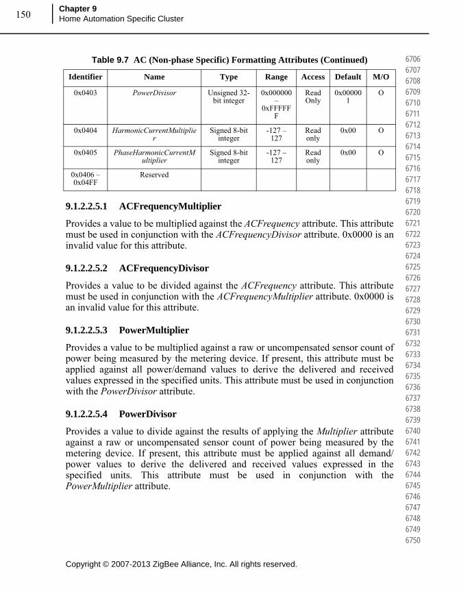
Copyright © 2007-2013 ZigBee Alliance, Inc. All rights reserved.
Chapter 9Home Automation Specific Cluster 150
670667076708670967106711671267136714671567166717671867196720672167226723672467256726672767286729673067316732673367346735673667376738673967406741674267436744674567466747674867496750
9.1.2.2.5.1 ACFrequencyMultiplier
Provides a value to be multiplied against the ACFrequency attribute. This attribute must be used in conjunction with the ACFrequencyDivisor attribute. 0x0000 is an invalid value for this attribute.
9.1.2.2.5.2 ACFrequencyDivisor
Provides a value to be divided against the ACFrequency attribute. This attribute must be used in conjunction with the ACFrequencyMultiplier attribute. 0x0000 is an invalid value for this attribute.
9.1.2.2.5.3 PowerMultiplier
Provides a value to be multiplied against a raw or uncompensated sensor count of power being measured by the metering device. If present, this attribute must be applied against all power/demand values to derive the delivered and received values expressed in the specified units. This attribute must be used in conjunction with the PowerDivisor attribute.
9.1.2.2.5.4 PowerDivisor
Provides a value to divide against the results of applying the Multiplier attribute against a raw or uncompensated sensor count of power being measured by the metering device. If present, this attribute must be applied against all demand/power values to derive the delivered and received values expressed in the specified units. This attribute must be used in conjunction with the PowerMultiplier attribute.
0x0403 PowerDivisor Unsigned 32-bit integer
0x000000 –
0xFFFFFF
Read Only
0x000001
O
0x0404 HarmonicCurrentMultiplier
Signed 8-bit integer
-127 – 127
Read only
0x00 O
0x0405 PhaseHarmonicCurrentMultiplier
Signed 8-bit integer
-127 – 127
Read only
0x00 O
0x0406 – 0x04FF
Reserved
Table 9.7 AC (Non-phase Specific) Formatting Attributes (Continued)
Identifier Name Type Range Access Default M/O

151
Copyright © 2007-2013 ZigBee Alliance, Inc. All rights reserved.
ZigBee Home Automation Public Application Profile
Document 05-3520-29
675167526753675467556756675767586759676067616762676367646765676667676768676967706771677267736774677567766777677867796780678167826783678467856786678767886789679067916792679367946795
9.1.2.2.5.5 HarmonicCurrentMultiplier
Represents the unit value for the MeasuredNthHarmonicCurrent attribute in the format MeasuredNthHarmonicCurrent * 10 ^ HarmonicCurrentMultiplieramperes.
9.1.2.2.5.6 PhaseHarmonicCurrentMultiplier
Represents the unit value for the MeasuredPhaseNthHarmonicCurrent attribute in the format MeasuredPhaseNthHarmonicCurrent * 10 ^ PhaseHarmonicCurrentMultiplier degrees.
9.1.2.2.6 AC (Single Phase or Phase A) Measurements
Table 9.8 AC (Single Phase or Phase A) Measurement Attributes
Identifier Name Type Range Access Default M/O
0x0500 Reserved Signed 16-bit integer
-32768 – 32767
Read only
0xFFFF O
0x0501 LineCurrent Unsigned 16-bit integer
0x0000 – -0xFFFF
Read only
0xFFFF O
0x0502 ActiveCurrent Signed 16-bit integer
-32768 – 32767
Read Only
0xFFFF O
0x0503 ReactiveCurrent Signed 16-bit integer
-32768 – 32767
Read Only
0xFFFF O
0x0504 Reserved Signed 16-bit integer
-32768 – 32767
Read only
0xFFFF O
0x0505 RMSVoltage Unsigned 16-bit integer
0x0000 – - 0xFFFF
Read only
0xFFFF O
0x0506 RMSVoltageMin Unsigned 16-bit integer
0x0000 – 0xFFFF
Read only
0x8000 O
0x0507 RMSVoltageMax Unsigned 16-bit integer
0x0000 – 0xFFFF
Read only
0x8000 O
0x0508 RMSCurrent Unsigned 16-bit integer
0x0000 – 0xFFFF
Read only
0xFFFF O
0x0509 RMSCurrentMin Unsigned 16-bit integer
0x0000 – 0xFFFF
Read only
0xFFFF O
0x050A RMSCurrentMax Unsigned 16-bit integer
0x0000 – 0xFFFF
Read only
0xFFFF O
0x050B ActivePower Signed 16-bit integer
-32768 – 32767
Read only
0xFFFF O
0x050C ActivePowerMin Signed 16-bit integer
-32768 – 32767
Read only
0xFFFF O
0x050D ActivePowerMax Signed 16-bit integer
-32768 – 32767
Read only
0xFFFF O

Copyright © 2007-2013 ZigBee Alliance, Inc. All rights reserved.
Chapter 9Home Automation Specific Cluster 152
679667976798679968006801680268036804680568066807680868096810681168126813681468156816681768186819682068216822682368246825682668276828682968306831683268336834683568366837683868396840
9.1.2.2.6.1 LineCurrent
Represents the single phase or Phase A, AC line current (Square root of active and reactive current) value at the moment in time the attribute is read, in Amps (A). If the instantaneous current cannot be measured, a value of 0x8000 is returned.
9.1.2.2.6.2 ActiveCurrent
Represents the single phase or Phase A, AC active/resistive current value at the moment in time the attribute is read, in Amps (A). Positive values indicate power delivered to the premises where negative values indicate power received from the premises.
9.1.2.2.6.3 ReactiveCurrent
Represents the single phase or Phase A, AC reactive current value at the moment in time the attribute is read, in Amps (A). Positive values indicate power delivered to the premises where negative values indicate power received from the premises.
0x050E ReactivePower Signed 16-bit integer
-32768 – 32767
Read Only
0xFFFF O
0x050F ApparentPower Unsigned 16-bit integer
0x0000 – 0xFFFF
Read Only
0xFFFF O
0x0510 PowerFactor Signed 8-bit integer
-100 to +100
Read Only
0x00 O
0x0511 AverageRMSVoltageMeasurementPeriod
Unsigned 16-bit integer
0x0000 – 0xFFFF
Read/Write
0x0000 O
0x0512 AverageRMSOverVoltageCounter
Unsigned 16-bit integer
0x0000 – 0xFFFF
Read/Write
0x0000 O
0x0513 AverageRMSUnderVoltageCounter
Unsigned 16-bit integer
0x0000 – 0xFFFF
Read/Write
0x0000 O
0x0514 RMSExtremeOverVoltagePeriod
Unsigned 16-bit integer
0x0000 – 0xFFFF
Read/Write
0x0000 O
0x0515 RMSExtremeUnderVoltagePeriod
Unsigned 16-bit integer
0x0000 – 0xFFFF
Read/Write
0x0000 O
0x0516 RMSVoltageSagPeriod
Unsigned 16-bit integer
0x0000 – 0xFFFF
Read/Write
0x0000 O
0x0517 RMSVoltageSwellPeriod
Unsigned 16-bit integer
0x0000 – 0xFFFF
Read/Write
0x0000 O
0x0518 – 0x05FF
Reserved
Table 9.8 AC (Single Phase or Phase A) Measurement Attributes (Continued)
Identifier Name Type Range Access Default M/O
153
Copyright © 2007-2013 ZigBee Alliance, Inc. All rights reserved.
ZigBee Home Automation Public Application Profile
Document 05-3520-29
684168426843684468456846684768486849685068516852685368546855685668576858685968606861686268636864686568666867686868696870687168726873687468756876687768786879688068816882688368846885
9.1.2.2.6.4 RMSVoltage
Represents the most recent RMS voltage reading in Volts (V). If the RMS voltage cannot be measured, a value of 0xFFFF is returned.
9.1.2.2.6.5 RMSVoltageMin
Represents the lowest RMS voltage value measured in Volts (V). After resetting, this attribute will return a value of 0xFFFF until a measurement is made.
9.1.2.2.6.6 RMSVoltageMax
Represents the highest RMS voltage value measured in Volts (V). After resetting, this attribute will return a value of 0xFFFF until a measurement is made.
9.1.2.2.6.7 RMSCurrent
Represents the most recent RMS current reading in Amps (A). If the power cannot be measured, a value of 0xFFFF is returned.
9.1.2.2.6.8 RMSCurrentMin
Represents the lowest RMS current value measured in Amps (A). After resetting, this attribute will return a value of 0x8000 until a measurement is made.
9.1.2.2.6.9 RMSCurrentMax
Represents the highest RMS current value measured in Amps (A). After resetting, this attribute will return a value of 0x8000 until a measurement is made.
9.1.2.2.6.10 ActivePower
Represents the single phase or Phase A, current demand of active power delivered or received at the premises, in Watts (W). Positive values indicate power delivered to the premises where negative values indicate power received from the premises.
9.1.2.2.6.11 ActivePowerMin
Represents the lowest AC power value measured in Watts (W). After resetting, this attribute will return a value of 0x8000 until a measurement is made.
9.1.2.2.6.12 ActivePowerMax
Represents the highest AC power value measured in Watts (W). After resetting, this attribute will return a value of 0x8000 until a measurement is made.
Copyright © 2007-2013 ZigBee Alliance, Inc. All rights reserved.
Chapter 9Home Automation Specific Cluster 154
688668876888688968906891689268936894689568966897689868996900690169026903690469056906690769086909691069116912691369146915691669176918691969206921692269236924692569266927692869296930
9.1.2.2.6.13 ReactivePower
Represents the single phase or Phase A, current demand of reactive power delivered or received at the premises, in VAr. Positive values indicate power delivered to the premises where negative values indicate power received from the premises.
9.1.2.2.6.14 ApparentPower
Represents the single phase or Phase A, current demand of apparent (Square root of active and reactive power) power, in VA.
9.1.2.2.6.15 PowerFactor
Contains the single phase or PhaseA, Power Factor ratio in 1/100ths.
9.1.2.2.6.16 AverageRMSVoltageMeasurementPeriod
The Period in seconds that the RMS voltage is averaged over
9.1.2.2.6.17 AverageRMSOverVoltageCounter
The number of times the average RMS voltage, has been above the AverageRMS OverVoltage threshold since last reset. This counter may be reset by writing zero to the attribute.
9.1.2.2.6.18 AverageRMSUnderVoltageCounter
The number of times the average RMS voltage, has been below the AverageRMS underVoltage threshold since last reset. This counter may be reset by writing zero to the attribute.
9.1.2.2.6.19 RMSExtremeOverVoltagePeriod
The duration in seconds used to measure an extreme over voltage condition.
9.1.2.2.6.20 RMSExtremeUnderVoltagePeriod
The duration in seconds used to measure an extreme under voltage condition.
9.1.2.2.6.21 RMSVoltageSagPeriod
The duration in seconds used to measure a voltage sag condition.
9.1.2.2.6.22 RMSVoltageSwellPeriod
The duration in seconds used to measure a voltage swell condition.
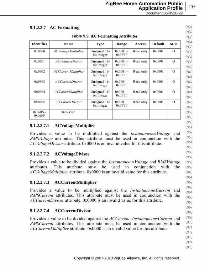
155
Copyright © 2007-2013 ZigBee Alliance, Inc. All rights reserved.
ZigBee Home Automation Public Application Profile
Document 05-3520-29
693169326933693469356936693769386939694069416942694369446945694669476948694969506951695269536954695569566957695869596960696169626963696469656966696769686969697069716972697369746975
9.1.2.2.7 AC Formatting
9.1.2.2.7.1 ACVoltageMultiplier
Provides a value to be multiplied against the InstantaneousVoltage and RMSVoltage attributes. This attribute must be used in conjunction with the ACVoltageDivisor attribute. 0x0000 is an invalid value for this attribute.
9.1.2.2.7.2 ACVoltageDivisor
Provides a value to be divided against the InstantaneousVoltage and RMSVoltageattributes. This attribute must be used in conjunction with the ACVoltageMultiplier attribute. 0x0000 is an invalid value for this attribute.
9.1.2.2.7.3 ACCurrentMultiplier
Provides a value to be multiplied against the InstantaneousCurrent and RMSCurrent attributes. This attribute must be used in conjunction with the ACCurrentDivisor attribute. 0x0000 is an invalid value for this attribute.
9.1.2.2.7.4 ACCurrentDivisor
Provides a value to be divided against the ACCurrent, InstantaneousCurrent and RMSCurrent attributes. This attribute must be used in conjunction with the ACCurrentMultiplier attribute. 0x0000 is an invalid value for this attribute.
Table 9.9 AC Formatting Attributes
Identifier Name Type Range Access Default M/O
0x0600 ACVoltageMultiplier Unsigned 16-bit integer
0x0001 – 0xFFFF
Read only 0x0001 O
0x0601 ACVoltageDivisor Unsigned 16-bit integer
0x0001 – 0xFFFF
Read only 0x0001 O
0x0602 ACCurrentMultiplier Unsigned 16-bit integer
0x0001 – 0xFFFF
Read only 0x0001 O
0x0603 ACCurrentDivisor Unsigned 16-bit integer
0x0001 – 0xFFFF
Read only 0x0001 O
0x0604 ACPowerMultiplier Unsigned 16-bit integer
0x0001 – 0xFFFF
Read only 0x0001 O
0x0605 ACPowerDivisor Unsigned 16-bit integer
0x0001 – 0xFFFF
Read only 0x0001 O
0x0606 – 0x06FF
Reserved
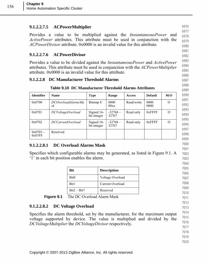
Copyright © 2007-2013 ZigBee Alliance, Inc. All rights reserved.
Chapter 9Home Automation Specific Cluster 156
697669776978697969806981698269836984698569866987698869896990699169926993699469956996699769986999700070017002700370047005700670077008700970107011701270137014701570167017701870197020
9.1.2.2.7.5 ACPowerMultiplier
Provides a value to be multiplied against the InstantaneousPower and ActivePower attributes. This attribute must be used in conjunction with the ACPowerDivisor attribute. 0x0000 is an invalid value for this attribute.
9.1.2.2.7.6 ACPowerDivisor
Provides a value to be divided against the InstantaneousPower and ActivePowerattributes. This attribute must be used in conjunction with the ACPowerMultiplierattribute. 0x0000 is an invalid value for this attribute.
9.1.2.2.8 DC Manufacturer Threshold Alarms
9.1.2.2.8.1 DC Overload Alarms Mask
Specifies which configurable alarms may be generated, as listed in Figure 9.1. A ‘1’ in each bit position enables the alarm.
Figure 9.1 The DC Overload Alarm Mask
9.1.2.2.8.2 DC Voltage Overload
Specifies the alarm threshold, set by the manufacturer, for the maximum output voltage supported by device. The value is multiplied and divided by the DCVoltageMultiplier the DCVoltageDivisor respectively.
Table 9.10 DC Manufacturer Threshold Alarms Attributes
Identifier Name Type Range Access Default M/O
0x0700 DCOverloadAlarmsMask
Bitmap 8 0000 00xx
Read/write 0000 0000
O
0x0701 DCVoltageOverload Signed 16-bit integer
-32768 – 32767
Read only 0xFFFF O
0x0702 DCCurrentOverload Signed 16-bit integer
-32768 – 32767
Read only 0xFFFF O
0x0703 – 0x07FF
Reserved
Bit Description
Bit0 Voltage Overload
Bit1 Current Overload
Bit2 – Bit7 Reserved
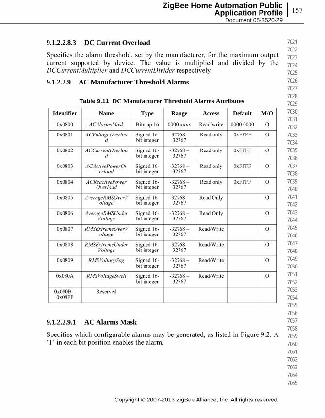
157
Copyright © 2007-2013 ZigBee Alliance, Inc. All rights reserved.
ZigBee Home Automation Public Application Profile
Document 05-3520-29
702170227023702470257026702770287029703070317032703370347035703670377038703970407041704270437044704570467047704870497050705170527053705470557056705770587059706070617062706370647065
9.1.2.2.8.3 DC Current Overload
Specifies the alarm threshold, set by the manufacturer, for the maximum output current supported by device. The value is multiplied and divided by the DCCurrentMultiplier and DCCurrentDivider respectively.
9.1.2.2.9 AC Manufacturer Threshold Alarms
9.1.2.2.9.1 AC Alarms Mask
Specifies which configurable alarms may be generated, as listed in Figure 9.2. A ‘1’ in each bit position enables the alarm.
Table 9.11 DC Manufacturer Threshold Alarms Attributes
Identifier Name Type Range Access Default M/O
0x0800 ACAlarmsMask Bitmap 16 0000 xxxx Read/write 0000 0000 O
0x0801 ACVoltageOverload
Signed 16-bit integer
-32768 – 32767
Read only 0xFFFF O
0x0802 ACCurrentOverload
Signed 16-bit integer
-32768 – 32767
Read only 0xFFFF O
0x0803 ACActivePowerOverload
Signed 16-bit integer
-32768 – 32767
Read only 0xFFFF O
0x0804 ACReactivePowerOverload
Signed 16-bit integer
-32768 – 32767
Read only 0xFFFF O
0x0805 AverageRMSOverVoltage
Signed 16-bit integer
-32768 – 32767
Read Only O
0x0806 AverageRMSUnderVoltage
Signed 16-bit integer
-32768 – 32767
Read Only O
0x0807 RMSExtremeOverVoltage
Signed 16-bit integer
-32768 – 32767
Read/Write O
0x0808 RMSExtremeUnderVoltage
Signed 16-bit integer
-32768 – 32767
Read/Write O
0x0809 RMSVoltageSag Signed 16-bit integer
-32768 – 32767
Read/Write O
0x080A RMSVoltageSwell Signed 16-bit integer
-32768 – 32767
Read/Write O
0x080B – 0x08FF
Reserved
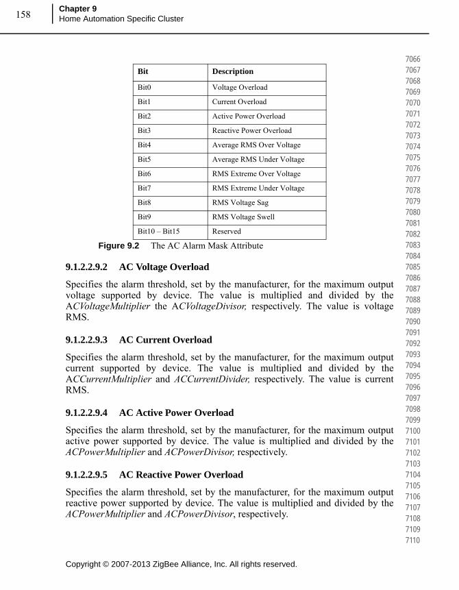
Copyright © 2007-2013 ZigBee Alliance, Inc. All rights reserved.
Chapter 9Home Automation Specific Cluster 158
706670677068706970707071707270737074707570767077707870797080708170827083708470857086708770887089709070917092709370947095709670977098709971007101710271037104710571067107710871097110
Figure 9.2 The AC Alarm Mask Attribute
9.1.2.2.9.2 AC Voltage Overload
Specifies the alarm threshold, set by the manufacturer, for the maximum output voltage supported by device. The value is multiplied and divided by the ACVoltageMultiplier the ACVoltageDivisor, respectively. The value is voltage RMS.
9.1.2.2.9.3 AC Current Overload
Specifies the alarm threshold, set by the manufacturer, for the maximum output current supported by device. The value is multiplied and divided by the ACCurrentMultiplier and ACCurrentDivider, respectively. The value is current RMS.
9.1.2.2.9.4 AC Active Power Overload
Specifies the alarm threshold, set by the manufacturer, for the maximum output active power supported by device. The value is multiplied and divided by the ACPowerMultiplier and ACPowerDivisor, respectively.
9.1.2.2.9.5 AC Reactive Power Overload
Specifies the alarm threshold, set by the manufacturer, for the maximum output reactive power supported by device. The value is multiplied and divided by the ACPowerMultiplier and ACPowerDivisor, respectively.
Bit Description
Bit0 Voltage Overload
Bit1 Current Overload
Bit2 Active Power Overload
Bit3 Reactive Power Overload
Bit4 Average RMS Over Voltage
Bit5 Average RMS Under Voltage
Bit6 RMS Extreme Over Voltage
Bit7 RMS Extreme Under Voltage
Bit8 RMS Voltage Sag
Bit9 RMS Voltage Swell
Bit10 – Bit15 Reserved
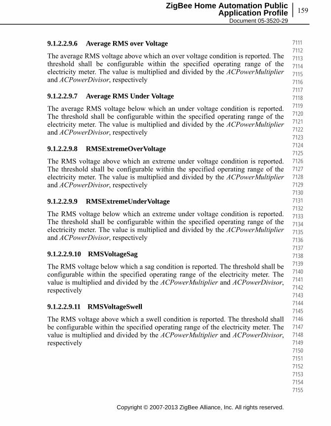
159
Copyright © 2007-2013 ZigBee Alliance, Inc. All rights reserved.
ZigBee Home Automation Public Application Profile
Document 05-3520-29
711171127113711471157116711771187119712071217122712371247125712671277128712971307131713271337134713571367137713871397140714171427143714471457146714771487149715071517152715371547155
9.1.2.2.9.6 Average RMS over Voltage
The average RMS voltage above which an over voltage condition is reported. The threshold shall be configurable within the specified operating range of the electricity meter. The value is multiplied and divided by the ACPowerMultiplierand ACPowerDivisor, respectively
9.1.2.2.9.7 Average RMS Under Voltage
The average RMS voltage below which an under voltage condition is reported. The threshold shall be configurable within the specified operating range of the electricity meter. The value is multiplied and divided by the ACPowerMultiplierand ACPowerDivisor, respectively
9.1.2.2.9.8 RMSExtremeOverVoltage
The RMS voltage above which an extreme under voltage condition is reported. The threshold shall be configurable within the specified operating range of the electricity meter. The value is multiplied and divided by the ACPowerMultiplierand ACPowerDivisor, respectively
9.1.2.2.9.9 RMSExtremeUnderVoltage
The RMS voltage below which an extreme under voltage condition is reported. The threshold shall be configurable within the specified operating range of the electricity meter. The value is multiplied and divided by the ACPowerMultiplierand ACPowerDivisor, respectively
9.1.2.2.9.10 RMSVoltageSag
The RMS voltage below which a sag condition is reported. The threshold shall be configurable within the specified operating range of the electricity meter. The value is multiplied and divided by the ACPowerMultiplier and ACPowerDivisor, respectively
9.1.2.2.9.11 RMSVoltageSwell
The RMS voltage above which a swell condition is reported. The threshold shall be configurable within the specified operating range of the electricity meter. The value is multiplied and divided by the ACPowerMultiplier and ACPowerDivisor, respectively
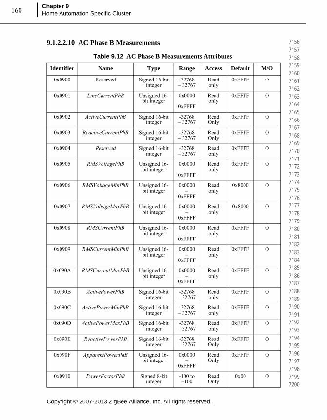
Copyright © 2007-2013 ZigBee Alliance, Inc. All rights reserved.
Chapter 9Home Automation Specific Cluster 160
715671577158715971607161716271637164716571667167716871697170717171727173717471757176717771787179718071817182718371847185718671877188718971907191719271937194719571967197719871997200
9.1.2.2.10 AC Phase B Measurements
Table 9.12 AC Phase B Measurements Attributes
Identifier Name Type Range Access Default M/O
0x0900 Reserved Signed 16-bit integer
-32768 – 32767
Read only
0xFFFF O
0x0901 LineCurrentPhB Unsigned 16-bit integer
0x0000 –
0xFFFF
Read only
0xFFFF O
0x0902 ActiveCurrentPhB Signed 16-bit integer
-32768 – 32767
Read Only
0xFFFF O
0x0903 ReactiveCurrentPhB Signed 16-bit integer
-32768 – 32767
Read Only
0xFFFF O
0x0904 Reserved Signed 16-bit integer
-32768 – 32767
Read only
0xFFFF O
0x0905 RMSVoltagePhB Unsigned 16-bit integer
0x0000 –
0xFFFF
Read only
0xFFFF O
0x0906 RMSVoltageMinPhB Unsigned 16-bit integer
0x0000 –
0xFFFF
Read only
0x8000 O
0x0907 RMSVoltageMaxPhB Unsigned 16-bit integer
0x0000 –
0xFFFF
Read only
0x8000 O
0x0908 RMSCurrentPhB Unsigned 16-bit integer
0x0000 –
0xFFFF
Read only
0xFFFF O
0x0909 RMSCurrentMinPhB Unsigned 16-bit integer
0x0000 –
0xFFFF
Read only
0xFFFF O
0x090A RMSCurrentMaxPhB Unsigned 16-bit integer
0x0000 –
0xFFFF
Read only
0xFFFF O
0x090B ActivePowerPhB Signed 16-bit integer
-32768 – 32767
Read only
0xFFFF O
0x090C ActivePowerMinPhB Signed 16-bit integer
-32768 – 32767
Read only
0xFFFF O
0x090D ActivePowerMaxPhB Signed 16-bit integer
-32768 – 32767
Read only
0xFFFF O
0x090E ReactivePowerPhB Signed 16-bit integer
-32768 – 32767
Read Only
0xFFFF O
0x090F ApparentPowerPhB Unsigned 16-bit integer
0x0000 –
0xFFFF
Read Only
0xFFFF O
0x0910 PowerFactorPhB Signed 8-bit integer
-100 to +100
Read Only
0x00 O

161
Copyright © 2007-2013 ZigBee Alliance, Inc. All rights reserved.
ZigBee Home Automation Public Application Profile
Document 05-3520-29
720172027203720472057206720772087209721072117212721372147215721672177218721972207221722272237224722572267227722872297230723172327233723472357236723772387239724072417242724372447245
9.1.2.2.10.1 LineCurrentPhB
Represents the Phase B, AC line current (Square root sum of active and reactive currents) value at the moment in time the attribute is read, in Amps (A). If the instantaneous current cannot be measured, a value of 0x8000 is returned.
9.1.2.2.10.2 ActiveCurrentPhB
Represents the Phase B, AC active/resistive current value at the moment in time the attribute is read, in Amps (A). Positive values indicate power delivered to the premises where negative values indicate power received from the premises.
9.1.2.2.10.3 ReactiveCurrentPhB
Represents the Phase B, AC reactive current value at the moment in time the attribute is read, in Amps (A). Positive values indicate power delivered to the premises where negative values indicate power received from the premises.
0x0911 AverageRMSVoltageMeasurementPeriodP
hB
Unsigned 16-bit integer
0x0000 –
0xFFFF
Read/Write
0x0000 O
0x0912 AverageRMSOverVoltageCounterPhB
Unsigned 16-bit integer
0x0000 –
0xFFFF
Read/Write
0x0000 O
0x0913 AverageRMSUnderVoltageCounterPhB
Unsigned 16-bit integer
0x0000 –
0xFFFF
Read/Write
0x0000 O
0x0914 RMSExtremeOverVoltagePeriodPhB
Unsigned 16-bit integer
0x0000 –
0xFFFF
Read/Write
0x0000 O
0x0915 RMSExtremeUnderVoltagePeriodPhB
Unsigned 16-bit integer
0x0000 –
0xFFFF
Read/Write
0x0000 O
0x0916 RMSVoltageSagPeriodPhB
Unsigned 16-bit integer
0x0000 –
0xFFFF
Read/Write
0x0000 O
0x0917 RMSVoltageSwellPeriodPhB
Unsigned 16-bit integer
0x0000 –
0xFFFF
Read/Write
0x0000 O
0x0918 – 0x09FF
Reserved
Table 9.12 AC Phase B Measurements Attributes (Continued)
Identifier Name Type Range Access Default M/O

Copyright © 2007-2013 ZigBee Alliance, Inc. All rights reserved.
Chapter 9Home Automation Specific Cluster 162
724672477248724972507251725272537254725572567257725872597260726172627263726472657266726772687269727072717272727372747275727672777278727972807281728272837284728572867287728872897290
9.1.2.2.10.4 RMSVoltagePhB
Represents the most recent RMS voltage reading in Volts (V). If the RMS voltage cannot be measured, a value of 0xFFFF is returned.
9.1.2.2.10.5 RMSVoltageMinPhB
Represents the lowest RMS voltage value measured in Volts (V). After resetting, this attribute will return a value of 0xFFFF until a measurement is made.
9.1.2.2.10.6 RMSVoltageMaxPhB
Represents the highest RMS voltage value measured in Volts (V). After resetting, this attribute will return a value of 0xFFFF until a measurement is made.
9.1.2.2.10.7 RMSCurrentPhB
Represents the most recent RMS current reading in Amps (A). If the power cannot be measured, a value of 0xFFFF is returned.
9.1.2.2.10.8 RMSCurrentMinPhB
Represents the lowest RMS current value measured in Amps (A). After resetting, this attribute will return a value of 0x8000 until a measurement is made.
9.1.2.2.10.9 RMSCurrentMaxPhB
Represents the highest RMS current value measured in Amps (A). After resetting, this attribute will return a value of 0x8000 until a measurement is made.
9.1.2.2.10.10 ActivePowerPhB
Represents the Phase B, current demand of active power delivered or received at the premises, in Watts (W). Positive values indicate power delivered to the premises where negative values indicate power received from the premises.
9.1.2.2.10.11 ActivePowerMinPhB
Represents the lowest AC power value measured in Watts (W). After resetting, this attribute will return a value of 0x8000 until a measurement is made.
9.1.2.2.10.12 ActivePowerMaxPhB
Represents the highest AC power value measured in Watts (W). After resetting, this attribute will return a value of 0x8000 until a measurement is made.
163
Copyright © 2007-2013 ZigBee Alliance, Inc. All rights reserved.
ZigBee Home Automation Public Application Profile
Document 05-3520-29
729172927293729472957296729772987299730073017302730373047305730673077308730973107311731273137314731573167317731873197320732173227323732473257326732773287329733073317332733373347335
9.1.2.2.10.13 ReactivePowerPhB
Represents the Phase B, current demand of reactive power delivered or received at the premises, in VAr. Positive values indicate power delivered to the premises where negative values indicate power received from the premises.
9.1.2.2.10.14 ApparentPowerPhB
Represents the Phase B, current demand of apparent (Square root of active and reactive power) power, in VA.
9.1.2.2.10.15 PowerFactorPhB
Contains the PhaseB, Power Factor ratio in 1/100ths.
9.1.2.2.10.16 AverageRMSVoltageMeasurementPeriodPhB
The Period in seconds that the RMS voltage is averaged over
9.1.2.2.10.17 AverageRMSOverVoltageCounterPhB
The number of times the average RMS voltage, has been above the AverageRMS OverVoltage threshold since last reset. This counter may be reset by writing zero to the attribute.
9.1.2.2.10.18 AverageRMSUnderVoltageCounterPhB
The number of times the average RMS voltage, has been below the AverageRMS underVoltage threshold since last reset. This counter may be reset by writing zero to the attribute.
9.1.2.2.10.19 RMSExtremeOverVoltagePeriodPhB
The duration in seconds used to measure an extreme over voltage condition.
9.1.2.2.10.20 RMSExtremeUnderVoltagePeriodPhB
The duration in seconds used to measure an extreme under voltage condition.
9.1.2.2.10.21 RMSVoltageSagPeriodPhB
The duration in seconds used to measure a voltage sag condition.
9.1.2.2.10.22 RMSVoltageSwellPeriodPhB
The duration in seconds used to measure a voltage swell condition.

Copyright © 2007-2013 ZigBee Alliance, Inc. All rights reserved.
Chapter 9Home Automation Specific Cluster 164
733673377338733973407341734273437344734573467347734873497350735173527353735473557356735773587359736073617362736373647365736673677368736973707371737273737374737573767377737873797380
9.1.2.2.11 AC Phase C Measurements
Table 9.13 AC Phase C Measurements Attributes
Identifier Name Type Range Access Default
Mandatory/
Optional
0x0A00 Reserved Signed 16-bit integer
-32768 – 32767
Read only
0xFFFF O
0x0A01 LineCurrentPhC Unsigned 16-bit integer
0x0000 – 0xFFFF
Read only
0xFFFF O
0x0A02 ActiveCurrentPhC Signed 16-bit integer
-32768 – 32767
Read Only
0xFFFF O
0x0A03 ReactiveCurrentPhC Signed 16-bit integer
-32768 – 32767
Read Only
0xFFFF O
0x0A04 Reserved Signed 16-bit integer
-32768 – 32767
Read only
0xFFFF O
0x0A05 RMSVoltagePhC Unsigned 16-bit integer
0x0000 – 0xFFFF
Read only
0xFFFF O
0x0A06 RMSVoltageMinPhC Unsigned 16-bit integer
0x0000 – 0xFFFF
Read only
0x8000 O
0x0A07 RMSVoltageMaxPhC
Unsigned 16-bit integer
0x0000 – 0xFFFF
Read only
0x8000 O
0x0A08 RMSCurrentPhC Unsigned 16-bit integer
0x0000 – 0xFFFF
Read only
0xFFFF O
0x0A09 RMSCurrentMinPhC Unsigned 16-bit integer
0x0000 – 0xFFFF
Read only
0xFFFF O
0x0A0A RMSCurrentMaxPhC Unsigned 16-bit integer
0x0000 – 0xFFFF
Read only
0xFFFF O
0x0A0B ActivePowerPhC Signed 16-bit integer
-32768 – 32767
Read only
0xFFFF O
0x0A0C ActivePowerMinPhC Signed 16-bit integer
-32768 – 32767
Read only
0xFFFF O
0x0A0D ActivePowerMaxPhC Signed 16-bit integer
-32768 – 32767
Read only
0xFFFF O
0x0A0E ReactivePowerPhC Signed 16-bit integer
-32768 – 32767
Read Only
0xFFFF O
0x0A0F ApparentPowerPhC Unsigned 16-bit integer
0x0000 – 0xFFFF
Read Only
0xFFFF O
0x0A10 PowerFactorPhC Signed 8-bit integer
-100 to +100
Read Only
0x00 O
0x0A11 AverageRMSVoltageMeasurementPeriodP
hC
Unsigned 16-bit integer
0x0000 – 0xFFFF
Read/Write
0x0000 O

165
Copyright © 2007-2013 ZigBee Alliance, Inc. All rights reserved.
ZigBee Home Automation Public Application Profile
Document 05-3520-29
738173827383738473857386738773887389739073917392739373947395739673977398739974007401740274037404740574067407740874097410741174127413741474157416741774187419742074217422742374247425
9.1.2.2.11.1 LineCurrentPhC
Represents the Phase C, AC line current (Square root of active and reactive current) value at the moment in time the attribute is read, in Amps (A). If the instantaneous current cannot be measured, a value of 0x8000 is returned.
9.1.2.2.11.2 ActiveCurrentPhC
Represents the Phase C, AC active/resistive current value at the moment in time the attribute is read, in Amps (A). Positive values indicate power delivered to the premises where negative values indicate power received from the premises.
9.1.2.2.11.3 ReactiveCurrentPhC
Represents the Phase C, AC reactive current value at the moment in time the attribute is read, in Amps (A). Positive values indicate power delivered to the premises where negative values indicate power received from the premises.
9.1.2.2.11.4 RMSVoltagePhC
Represents the most recent RMS voltage reading in Volts (V). If the RMS voltage cannot be measured, a value of 0xFFFF is returned.
0x0A12 AverageRMSOverVoltageCounterPhC
Unsigned 16-bit integer
0x0000 – 0xFFFF
Read/Write
0x0000 O
0x0A13 AverageRMSUnderVoltageCounterPhC
Unsigned 16-bit integer
0x0000 – 0xFFFF
Read/Write
0x0000 O
0x0A14 RMSExtremeOverVoltagePeriodPhC
Unsigned 16-bit integer
0x0000 – 0xFFFF
Read/Write
0x0000 O
0x0A15 RMSExtremeUnderVoltagePeriodPhC
Unsigned 16-bit integer
0x0000 – 0xFFFF
Read/Write
0x0000 O
0x0A16 RMSVoltageSagPeriodPhC
Unsigned 16-bit integer
0x0000 – 0xFFFF
Read/Write
0x0000 O
0x0A17 RMSVoltageSwellPeriodPhC
Unsigned 16-bit integer
0x0000 – 0xFFFF
Read/Write
0x0000 O
0x0A18 – 0x0AFF
Reserved
Table 9.13 AC Phase C Measurements Attributes (Continued)
Identifier Name Type Range Access Default
Mandatory/
Optional

Copyright © 2007-2013 ZigBee Alliance, Inc. All rights reserved.
Chapter 9Home Automation Specific Cluster 166
742674277428742974307431743274337434743574367437743874397440744174427443744474457446744774487449745074517452745374547455745674577458745974607461746274637464746574667467746874697470
9.1.2.2.11.5 RMSVoltageMinPhC
Represents the lowest RMS voltage value measured in Volts (V). After resetting, this attribute will return a value of 0xFFFF until a measurement is made.
9.1.2.2.11.6 RMSVoltageMaxPhC
Represents the highest RMS voltage value measured in Volts (V). After resetting, this attribute will return a value of 0xFFFF until a measurement is made.
9.1.2.2.11.7 RMSCurrentPhC
Represents the most recent RMS current reading in Amps (A). If the power cannot be measured, a value of 0xFFFF is returned.
9.1.2.2.11.8 RMSCurrentMinPhC
Represents the lowest RMS current value measured in Amps (A). After resetting, this attribute will return a value of 0x8000 until a measurement is made.
9.1.2.2.11.9 RMSCurrentMaxPhC
Represents the highest RMS current value measured in Amps (A). After resetting, this attribute will return a value of 0x8000 until a measurement is made.
9.1.2.2.11.10 ActivePowerPhC
Represents the Phase C, current demand of active power delivered or received at the premises, in Watts (W). Positive values indicate power delivered to the premises where negative values indicate power received from the premises.
9.1.2.2.11.11 ActivePowerMinPhC
Represents the lowest AC power value measured in Watts (W). After resetting, this attribute will return a value of 0x8000 until a measurement is made.
9.1.2.2.11.12 ActivePowerMaxPhC
Represents the highest AC power value measured in Watts (W). After resetting, this attribute will return a value of 0x8000 until a measurement is made.
9.1.2.2.11.13 ReactivePowerPhC
Represents the Phase C, current demand of reactive power delivered or received at the premises, in VAr. Positive values indicate power delivered to the premises where negative values indicate power received from the premises.

167
Copyright © 2007-2013 ZigBee Alliance, Inc. All rights reserved.
ZigBee Home Automation Public Application Profile
Document 05-3520-29
747174727473747474757476747774787479748074817482748374847485748674877488748974907491749274937494749574967497749874997500750175027503750475057506750775087509751075117512751375147515
9.1.2.2.11.14 ApparentPowerPhC
Represents the Phase C, current demand of apparent (Square root of active and reactive power) power, in VA.
9.1.2.2.11.15 PowerFactorPhC
Contains the Phase C, Power Factor ratio in 1/100ths.
9.1.2.2.11.16 AverageRMSVoltageMeasurementPeriodPhC
The Period in seconds that the RMS voltage is averaged over
9.1.2.2.11.17 AverageRMSOverVoltageCounterPhC
The number of times the average RMS voltage, has been above the AverageRMS OverVoltage threshold since last reset. This counter may be reset by writing zero to the attribute.
9.1.2.2.11.18 AverageRMSUnderVoltageCounterPhC
The number of times the average RMS voltage, has been below the AverageRMS underVoltage threshold since last reset. This counter may be reset by writing zero to the attribute.
9.1.2.2.11.19 RMSExtremeOverVoltagePeriodPhC
The duration in seconds used to measure an extreme over voltage condition.
9.1.2.2.11.20 RMSExtremeUnderVoltagePeriodPhC
The duration in seconds used to measure an extreme under voltage condition.
9.1.2.2.11.21 RMSVoltageSagPeriodPhC
The duration in seconds used to measure a voltage sag condition.
9.1.2.2.11.22 RMSVoltageSwellPeriodPhC
The duration in seconds used to measure a voltage swell condition.
9.1.2.3 Server Commands
9.1.2.3.1 Commands Generated
The command IDs generated by the electrical measurement server cluster are listed in Table 9.14.

Copyright © 2007-2013 ZigBee Alliance, Inc. All rights reserved.
Chapter 9Home Automation Specific Cluster 168
751675177518751975207521752275237524752575267527752875297530753175327533753475357536753775387539754075417542754375447545754675477548754975507551755275537554755575567557755875597560
9.1.2.3.1.1 Get Profile Info Response Command
The Get Profile Info Response Command shall be formatted as illustrated below
Figure 9.3 Format of the Get Profile Info Response Command
9.1.2.3.1.1.1 Payload Details
Profile Count: Total number of supported profile.
Profile Interval Period: Represents the interval or time frame used to capture parameter for profiling purposes. ProfileIntervalPeriod is an enumerated field representing the following timeframes listed below.
Figure 9.4 ProfileIntervalPeriod
Table 9.14 Generated Command ID’s for the Electrical Measurement Server
Command Identifier Field Value Description Mandatory/
Optional
0x00 Get Profile Info Response Command O
0x01 Get Measurement Profile Response Command O
0x02 – 0xFF Reserved for future
Octets 1 1 1 Variable
Data Type
Unsigned 8-bit integer
8-bit enumeration Unsigned 8-bit integer
Array of attribute IDs (two byte unsigned values)
Field Name
Profile Count Profile Interval Period
MaxNumberOfIntervals
ListOfAttributes
Enumerated Value Time Frame
0 Daily
1 60 minutes
2 30 minutes
3 15 minutes
4 10 minutes
5 7.5 minutes
6 5 minutes
7 2.5 minutes
8 to 255 Reserved for future

169
Copyright © 2007-2013 ZigBee Alliance, Inc. All rights reserved.
ZigBee Home Automation Public Application Profile
Document 05-3520-29
756175627563756475657566756775687569757075717572757375747575757675777578757975807581758275837584758575867587758875897590759175927593759475957596759775987599760076017602760376047605
MaxNumberOfIntervals: Represents the maximum number of intervals the device is capable of returning in one Get Measurement Profile Response command. It is required MaxNumberofIntervals fit within the default Fragmentation ASDU size of 128 bytes, or an optionally agreed upon larger Fragmentation ASDU size supported by both devices as per the application profile supported by the devices.
ListOfAttributes: Represents the list of attributes being profiled.
9.1.2.3.1.2 When Generated
This command is generated when the Client command GetProfileInfo is received.
9.1.2.3.1.3 Get Measurement Profile Response Command
The Get Measurement Profile Response Command shall be formatted as illustrated below
Figure 9.5 Format of the Get Measurement Profile Response Command
9.1.2.3.1.3.1 Payload Details
StartTime: 32-bit value (in UTC) representing the end time of the most chronologically recent interval being requested. Example: Data collected from 2:00 PM to 3:00 PM would be specified as a 3:00 PM interval (end time).
Status:Table status enumeration lists the valid values returned in the Status field.
Octets 4 1 1 1 1 Variable
Data Type
UTC Time
8-bit enumeration
8-bit enumeration Unsigned 8-bit integer
Unsigned 16-bit integer
Array of Attribute values
Field Name
StartTime
Status ProfileIntervalPeriod
NumberOfIntervalsDelivered
Attribute Id
Intervals
Table 9.15 List of Status Valid Values
Status Value Description
0x00 Success
0x01 Attribute Profile not supported
0x02 Invalid Start Time
0x03 More intervals requested than can be returned
0x04 No intervals available for the requested time
0x05 to 0xFF Reserved for future use

Copyright © 2007-2013 ZigBee Alliance, Inc. All rights reserved.
Chapter 9Home Automation Specific Cluster 170
760676077608760976107611761276137614761576167617761876197620762176227623762476257626762776287629763076317632763376347635763676377638763976407641764276437644764576467647764876497650
ProfileIntervalPeriod: Represents the interval or time frame used to capture parameter for profiling purposes. Refer to table “ProfileIntervalPeriod”.
NumberofIntervalsDelivered: Represents the number of intervals the device is returning. Please note the number of intervals returned in the Get Measurement Profile Response command can be calculated when the packets are received and can replace the usage of this field. The intent is to provide this information as a convenience.
AttributeID: The attribute that has been profiled by the application.
Intervals: Series of interval data captured using the period specified by the ProfileIntervalPeriod field. The content of the interval data depend of the type of information requested using the AttributeID field in the Get Measurement Profile Command. Data is organized in a reverse chronological order, the oldest intervals are transmitted first and the newest interval is transmitted last. Invalid intervals should be marked as 0xFFFF. For scaling and data type use the respective attribute set as defined above in attribute sets.
9.1.2.3.1.3.2 When Generated
This command is generated when the Client command GetMeasurementProfile is received.
9.1.2.4 Client Commands
9.1.2.4.1 Commands Generated
The command ID’s generated by the electrical measurement client cluster are listed in Table 9.16.
9.1.2.4.1.1 Get Profile Info Command
This command has no payload.
9.1.2.4.1.1.1 Effect on Receipt
On receipt of this command, the device shall send a Get Profile Info Response Command. A ZCL default response with status
Table 9.16 Generated Command ID’s for the Electrical Measurement Client
Command Identifier Field Value Description Mandatory/
Optional
0x00 Get Profile Info Command O
0x01 Get Measurement Profile Command O
0x02 – 0xFF Reserved for future

171
Copyright © 2007-2013 ZigBee Alliance, Inc. All rights reserved.
ZigBee Home Automation Public Application Profile
Document 05-3520-29
765176527653765476557656765776587659766076617662766376647665766676677668766976707671767276737674767576767677767876797680768176827683768476857686768776887689769076917692769376947695
UNSUP_CLUSTER_COMMAND shall be returned if command is not supported on the device.
9.1.2.4.1.2 Get Measurement Profile Command
The Get Measurement Profile Command shall be formatted as illustrated in Figure 9.6.
Figure 9.6 Format of the Get Measurement Profile Command
9.1.2.4.1.2.1 Payload Details
Attribute ID: The electricity measurement attribute being profiled.
StartTime: 32-bit value (in UTCTime) used to select an Intervals block from all the Intervals blocks available. The Intervals block returned is the most recent block with its StartTime equal or greater to the one provided.
NumberOfIntervals: Represents the number of intervals being requested. This value can’t exceed the size stipulated in the MaxNumberOfIntervals field of Get Profile Info Response Command. If more intervals are requested than can be delivered, the GetMeasurementProfileResponse will return the number of intervals equal to MaxNumberOfIntervals. If fewer intervals available for the time period then only those available are returned.
9.1.2.4.1.2.2 Effect on Receipt
On receipt of this command, the device shall send a Get Measurement Profile Response Command. A ZCL default response with status UNSUP_CLUSTER_COMMAND shall be returned if command is not supported on the device.
Octets 2 1 1
Data Type Unsigned 2-bit integer
UTC Time Unsigned 8-bit integer
Field Name Attribute ID Start Time NumberOfIntervals
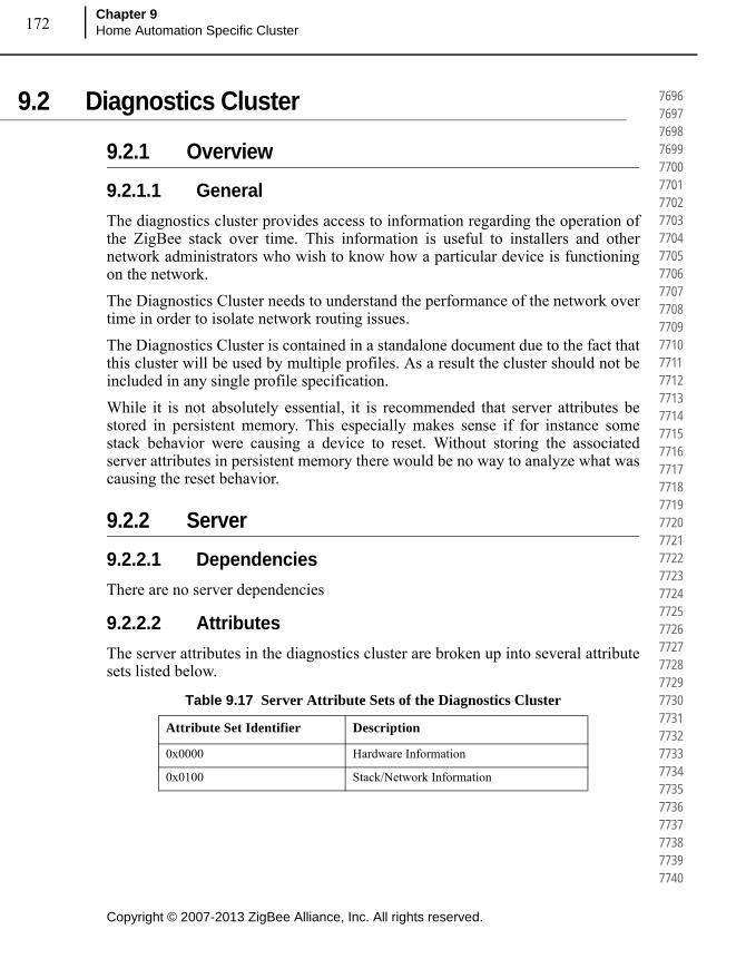
Copyright © 2007-2013 ZigBee Alliance, Inc. All rights reserved.
Chapter 9Home Automation Specific Cluster 172
769676977698769977007701770277037704770577067707770877097710771177127713771477157716771777187719772077217722772377247725772677277728772977307731773277337734773577367737773877397740
9.2 Diagnostics Cluster
9.2.1 Overview
9.2.1.1 General
The diagnostics cluster provides access to information regarding the operation of the ZigBee stack over time. This information is useful to installers and other network administrators who wish to know how a particular device is functioning on the network.
The Diagnostics Cluster needs to understand the performance of the network over time in order to isolate network routing issues.
The Diagnostics Cluster is contained in a standalone document due to the fact that this cluster will be used by multiple profiles. As a result the cluster should not be included in any single profile specification.
While it is not absolutely essential, it is recommended that server attributes be stored in persistent memory. This especially makes sense if for instance some stack behavior were causing a device to reset. Without storing the associated server attributes in persistent memory there would be no way to analyze what was causing the reset behavior.
9.2.2 Server
9.2.2.1 Dependencies
There are no server dependencies
9.2.2.2 Attributes
The server attributes in the diagnostics cluster are broken up into several attribute sets listed below.
Table 9.17 Server Attribute Sets of the Diagnostics Cluster
Attribute Set Identifier Description
0x0000 Hardware Information
0x0100 Stack/Network Information
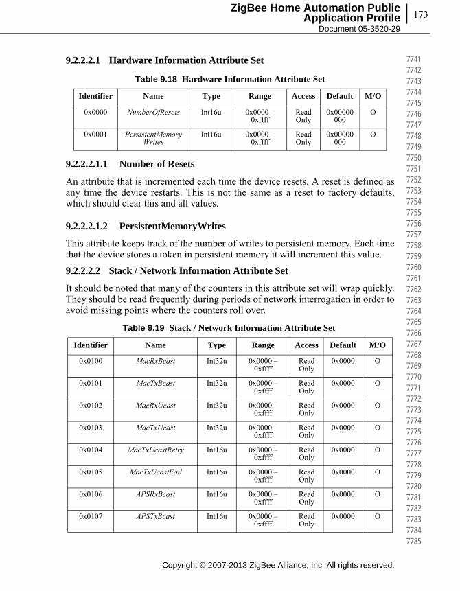
173
Copyright © 2007-2013 ZigBee Alliance, Inc. All rights reserved.
ZigBee Home Automation Public Application Profile
Document 05-3520-29
774177427743774477457746774777487749775077517752775377547755775677577758775977607761776277637764776577667767776877697770777177727773777477757776777777787779778077817782778377847785
9.2.2.2.1 Hardware Information Attribute Set
9.2.2.2.1.1 Number of Resets
An attribute that is incremented each time the device resets. A reset is defined as any time the device restarts. This is not the same as a reset to factory defaults, which should clear this and all values.
9.2.2.2.1.2 PersistentMemoryWrites
This attribute keeps track of the number of writes to persistent memory. Each time that the device stores a token in persistent memory it will increment this value.
9.2.2.2.2 Stack / Network Information Attribute Set
It should be noted that many of the counters in this attribute set will wrap quickly. They should be read frequently during periods of network interrogation in order to avoid missing points where the counters roll over.
Table 9.18 Hardware Information Attribute Set
Identifier Name Type Range Access Default M/O
0x0000 NumberOfResets Int16u 0x0000 – 0xffff
Read Only
0x00000000
O
0x0001 PersistentMemoryWrites
Int16u 0x0000 – 0xffff
Read Only
0x00000000
O
Table 9.19 Stack / Network Information Attribute Set
Identifier Name Type Range Access Default M/O
0x0100 MacRxBcast Int32u 0x0000 – 0xffff
Read Only
0x0000 O
0x0101 MacTxBcast Int32u 0x0000 – 0xffff
Read Only
0x0000 O
0x0102 MacRxUcast Int32u 0x0000 – 0xffff
Read Only
0x0000 O
0x0103 MacTxUcast Int32u 0x0000 – 0xffff
Read Only
0x0000 O
0x0104 MacTxUcastRetry Int16u 0x0000 – 0xffff
Read Only
0x0000 O
0x0105 MacTxUcastFail Int16u 0x0000 – 0xffff
Read Only
0x0000 O
0x0106 APSRxBcast Int16u 0x0000 – 0xffff
Read Only
0x0000 O
0x0107 APSTxBcast Int16u 0x0000 – 0xffff
Read Only
0x0000 O

Copyright © 2007-2013 ZigBee Alliance, Inc. All rights reserved.
Chapter 9Home Automation Specific Cluster 174
778677877788778977907791779277937794779577967797779877997800780178027803780478057806780778087809781078117812781378147815781678177818781978207821782278237824782578267827782878297830
0x0108 APSRxUcast Int16u 0x0000 – 0xffff
Read Only
0x0000 O
0x0109 APSTxUcastSuccess Int16u 0x0000 – 0xffff
Read Only
0x0000 O
0x010A APSTxUcastRetry Int16u 0x0000 – 0xffff
Read Only
0x0000 O
0x010B APSTxUcastFail Int16u 0x0000 – 0xffff
Read Only
0x0000 O
0x010C RouteDiscInitiated Int16u 0x0000 – 0xffff
Read Only
0x0000 O
0x010D NeighborAdded Int16u 0x0000 – 0xffff
Read Only
0x0000 O
0x010E NeighborRemoved Int16u 0x0000 – 0xffff
Read Only
0x0000 O
0x010F NeighborStale Int16u 0x0000 – 0xffff
Read Only
0x0000 O
0x0110 JoinIndication Int16u 0x0000 – 0xffff
Read Only
0x0000 O
0x0111 ChildMoved Int16u 0x0000 – 0xffff
Read Only
0x0000 O
0x0112 NWKFCFailure Int16u 0x0000 – 0xffff
Read Only
0x0000 O
0x0113 APSFCFailure Int16u 0x0000 – 0xffff
Read Only
0x0000 O
0x0114 APSUnauthorizedKey Int16u 0x0000 – 0xffff
Read Only
0x0000 O
0x0115 NWKDecryptFailures Int16u 0x0000 – 0xffff
Read Only
0x0000 O
0x0116 APSDecryptFailures Int16u 0x0000 – 0xffff
Read Only
0x0000 O
0x0117 PacketBufferAllocateFailures
Int16u 0x0000 – 0xffff
Read Only
0x0000 O
0x0118 RelayedUcast Int16u 0x0000 – 0xffff
Read Only
0x0000 O
0x0119 PhytoMACqueuelimitreached
Int16u 0x0000 – 0xffff
Read Only
0x0000 O
0x011A PacketValidatedropcount
Int16u 0x0000 – 0xffff
Read Only
0x0000 O
Table 9.19 Stack / Network Information Attribute Set (Continued)
Identifier Name Type Range Access Default M/O
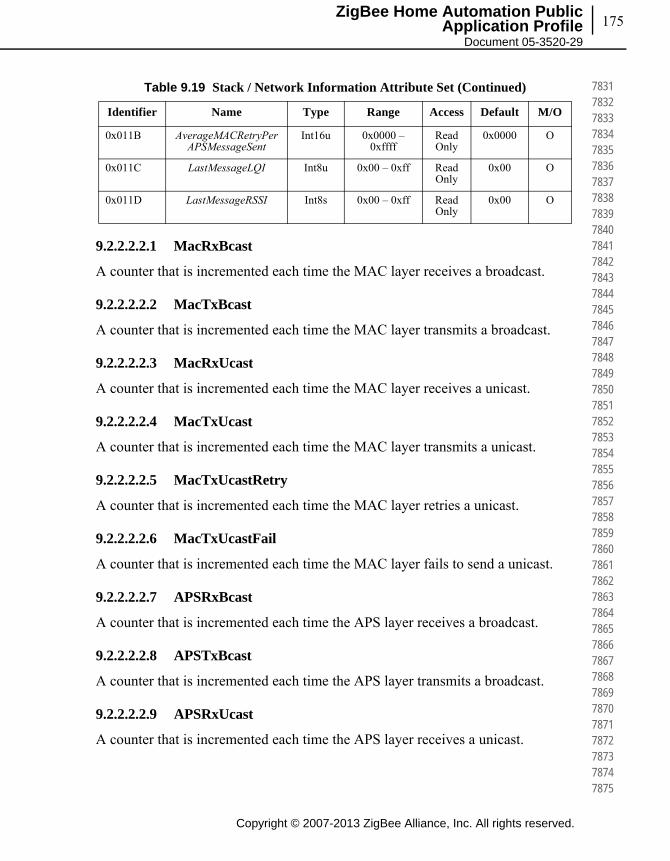
175
Copyright © 2007-2013 ZigBee Alliance, Inc. All rights reserved.
ZigBee Home Automation Public Application Profile
Document 05-3520-29
783178327833783478357836783778387839784078417842784378447845784678477848784978507851785278537854785578567857785878597860786178627863786478657866786778687869787078717872787378747875
9.2.2.2.2.1 MacRxBcast
A counter that is incremented each time the MAC layer receives a broadcast.
9.2.2.2.2.2 MacTxBcast
A counter that is incremented each time the MAC layer transmits a broadcast.
9.2.2.2.2.3 MacRxUcast
A counter that is incremented each time the MAC layer receives a unicast.
9.2.2.2.2.4 MacTxUcast
A counter that is incremented each time the MAC layer transmits a unicast.
9.2.2.2.2.5 MacTxUcastRetry
A counter that is incremented each time the MAC layer retries a unicast.
9.2.2.2.2.6 MacTxUcastFail
A counter that is incremented each time the MAC layer fails to send a unicast.
9.2.2.2.2.7 APSRxBcast
A counter that is incremented each time the APS layer receives a broadcast.
9.2.2.2.2.8 APSTxBcast
A counter that is incremented each time the APS layer transmits a broadcast.
9.2.2.2.2.9 APSRxUcast
A counter that is incremented each time the APS layer receives a unicast.
0x011B AverageMACRetryPerAPSMessageSent
Int16u 0x0000 – 0xffff
Read Only
0x0000 O
0x011C LastMessageLQI Int8u 0x00 – 0xff Read Only
0x00 O
0x011D LastMessageRSSI Int8s 0x00 – 0xff Read Only
0x00 O
Table 9.19 Stack / Network Information Attribute Set (Continued)
Identifier Name Type Range Access Default M/O

Copyright © 2007-2013 ZigBee Alliance, Inc. All rights reserved.
Chapter 9Home Automation Specific Cluster 176
787678777878787978807881788278837884788578867887788878897890789178927893789478957896789778987899790079017902790379047905790679077908790979107911791279137914791579167917791879197920
9.2.2.2.2.10 APSTxUcastSuccess
A counter that is incremented each time the APS layer successfully transmits a unicast.
9.2.2.2.2.11 APSTxUcastRetry
A counter that is incremented each time the APS layer retries the sending of a unicast.
9.2.2.2.2.12 APSTxUcastFail
A counter that is incremented each time the APS layer fails to send a unicast.
9.2.2.2.2.13 RouteDiscInitiated
A counter that is incremented each time the network layer submits a route discovery message to the MAC.
9.2.2.2.2.14 NeighborAdded
A counter that is incremented each time an entry is added to the neighbor table.
9.2.2.2.2.15 NeighborRemoved
A counter that is incremented each time an entry is removed from the neighbor table.
9.2.2.2.2.16 NeighborStale
A counter that is incremented each time a neighbor table entry becomes stale because the neighbor has not been heard from.
9.2.2.2.2.17 JoinIndication
A counter that is incremented each time a node joins or rejoins the network via this node.
9.2.2.2.2.18 ChildMoved
A counter that is incremented each time an entry is removed from the child table.
9.2.2.2.2.19 NWKFCFailure
A counter that is incremented each time a message is dropped at the network layer because the APS frame counter was not higher than the last message seen from that source.
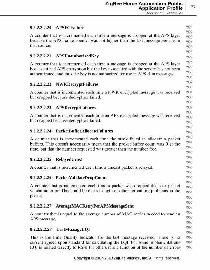
177
Copyright © 2007-2013 ZigBee Alliance, Inc. All rights reserved.
ZigBee Home Automation Public Application Profile
Document 05-3520-29
792179227923792479257926792779287929793079317932793379347935793679377938793979407941794279437944794579467947794879497950795179527953795479557956795779587959796079617962796379647965
9.2.2.2.2.20 APSFCFailure
A counter that is incremented each time a message is dropped at the APS layer because the APS frame counter was not higher than the last message seen from that source.
9.2.2.2.2.21 APSUnauthorizedKey
A counter that is incremented each time a message is dropped at the APS layer because it had APS encryption but the key associated with the sender has not been authenticated, and thus the key is not authorized for use in APS data messages.
9.2.2.2.2.22 NWKDecryptFailures
A counter that is incremented each time a NWK encrypted message was received but dropped because decryption failed.
9.2.2.2.2.23 APSDecryptFailures
A counter that is incremented each time an APS encrypted message was received but dropped because decryption failed.
9.2.2.2.2.24 PacketBufferAllocateFailures
A counter that is incremented each time the stack failed to allocate a packet buffers. This doesn't necessarily mean that the packet buffer count was 0 at the time, but that the number requested was greater than the number free.
9.2.2.2.2.25 RelayedUcast
A counter that is incremented each time a unicast packet is relayed.
9.2.2.2.2.26 PacketValidateDropCount
A counter that is incremented each time a packet was dropped due to a packet validation error. This could be due to length or other formatting problems in the packet.
9.2.2.2.2.27 AverageMACRetryPerAPSMessageSent
A counter that is equal to the average number of MAC retries needed to send an APS message.
9.2.2.2.2.28 LastMessageLQI
This is the Link Quality Indicator for the last message received. There is no current agreed upon standard for calculating the LQI. For some implementations LQI is related directly to RSSI for others it is a function of the number of errors

Copyright © 2007-2013 ZigBee Alliance, Inc. All rights reserved.
Chapter 9Home Automation Specific Cluster 178
796679677968796979707971797279737974797579767977797879797980798179827983798479857986798779887989799079917992799379947995799679977998799980008001800280038004800580068007800880098010
received over a fixed number of bytes in a given message. The one thing that has been agreed is that the Link Quality Indicator is a value between 0 and 255 where 0 indicates the worst possible link and 255 indicates the best possible link. It should be noted that for a device reading the Last Message LQI the returned value shall be the LQI for the read attribute message used to read the attribute itself.
9.2.2.2.2.29 LastMessageRSSI
This is the receive signal strength indication for the last message received. As with Last Message LQI, it should be noted that for a device reading the Last Message RSSI, the returned value shall be the RSSI of the read attribute message used to read the attribute itself.
9.2.2.3 Commands
There are no commands received by the server side of the diagnostics cluster.
9.2.3 Client
9.2.3.1 Dependencies
There are no server dependencies
9.2.3.2 Attributes
There are no attributes on the client side of the diagnostics cluster.
9.2.3.3 Commands
There are no commands received by the client side of the diagnostics cluster.
9.3 Window Covering Cluster
9.3.1 Overview
The window covering cluster provides an interface for controlling and adjusting automatic window coverings such as drapery motors, automatic shades, and blinds.
Note: This Cluster is provisionary and not certifiable. This feature set may change before reaching certifiable status in a future revision of this specification.
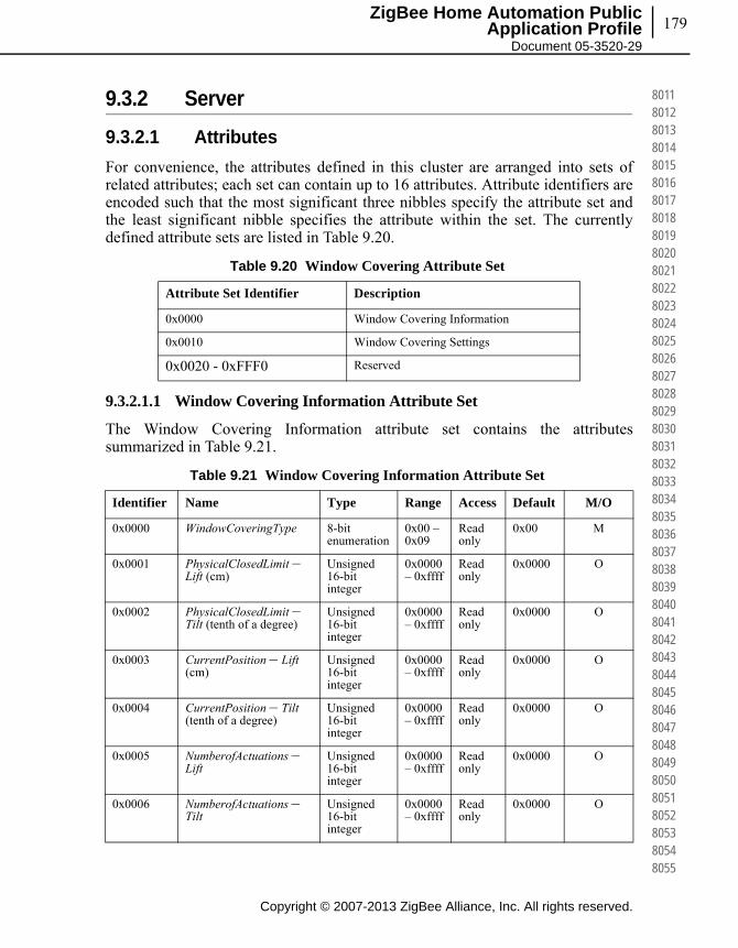
179
Copyright © 2007-2013 ZigBee Alliance, Inc. All rights reserved.
ZigBee Home Automation Public Application Profile
Document 05-3520-29
801180128013801480158016801780188019802080218022802380248025802680278028802980308031803280338034803580368037803880398040804180428043804480458046804780488049805080518052805380548055
9.3.2 Server
9.3.2.1 Attributes
For convenience, the attributes defined in this cluster are arranged into sets of related attributes; each set can contain up to 16 attributes. Attribute identifiers are encoded such that the most significant three nibbles specify the attribute set and the least significant nibble specifies the attribute within the set. The currently defined attribute sets are listed in Table 9.20.
9.3.2.1.1 Window Covering Information Attribute Set
The Window Covering Information attribute set contains the attributes summarized in Table 9.21.
Table 9.20 Window Covering Attribute Set
Attribute Set Identifier Description
0x0000 Window Covering Information
0x0010 Window Covering Settings
0x0020 - 0xFFF0 Reserved
Table 9.21 Window Covering Information Attribute Set
Identifier Name Type Range Access Default M/O
0x0000 WindowCoveringType 8-bit enumeration
0x00 – 0x09
Read only
0x00 M
0x0001 PhysicalClosedLimit –Lift (cm)
Unsigned 16-bit integer
0x0000 – 0xffff
Read only
0x0000 O
0x0002 PhysicalClosedLimit –Tilt (tenth of a degree)
Unsigned 16-bit integer
0x0000 – 0xffff
Read only
0x0000 O
0x0003 CurrentPosition – Lift (cm)
Unsigned 16-bit integer
0x0000 – 0xffff
Read only
0x0000 O
0x0004 CurrentPosition – Tilt (tenth of a degree)
Unsigned 16-bit integer
0x0000 – 0xffff
Read only
0x0000 O
0x0005 NumberofActuations –Lift
Unsigned 16-bit integer
0x0000 – 0xffff
Read only
0x0000 O
0x0006 NumberofActuations –Tilt
Unsigned 16-bit integer
0x0000 – 0xffff
Read only
0x0000 O

Copyright © 2007-2013 ZigBee Alliance, Inc. All rights reserved.
Chapter 9Home Automation Specific Cluster 180
805680578058805980608061806280638064806580668067806880698070807180728073807480758076807780788079808080818082808380848085808680878088808980908091809280938094809580968097809880998100
9.3.2.1.2 WindowCoveringType Attribute
The WindowCoveringType attribute identifies the type of window covering being controlled by this endpoint and shall be set to one of the non-reserved values in Table 9.22.
9.3.2.1.2.1 PhysicalClosedLimit – Lift Attribute
The PhysicalClosedLimit – Lift attribute identifies the maximum possible encoder position possible (in centimeters) to position the height of the window covering – this is ignored if the device is running in Open Loop Control.
0x0007 Config/Status 8-bit-bitmap 0xxx xxxx
Read Only
0000 0011
M
0x0008 CurrentPosition – Lift Percentage
Unsigned 8-bit integer
0-0x64 Read Only
0x00 (O), (M) if device is running in an open loop.a
0x0009 CurrentPosition – Tilt Percentage
Unsigned 8-bit integer
0-0x64 Read Only
0x00 (O), (M) if device is running in an open loop.b
a. CCB 1774
b. CCB 1774
Table 9.22 WindowCoveringType
Value WindowCoveringType
0x00 Rollershade
0x01 Rollershade - 2 Motor
0x02 Rollershade – Exterior
0x03 Rollershade - Exterior - 2 Motor
0x04 Drapery
0x05 Awning
0x06 Shutter
0x07 Tilt Blind - Tilt Only
0x08 Tilt Blind - Lift and Tilt
0x09 Projector Screen
Table 9.21 Window Covering Information Attribute Set (Continued)
Identifier Name Type Range Access Default M/O
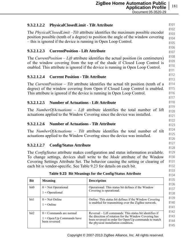
181
Copyright © 2007-2013 ZigBee Alliance, Inc. All rights reserved.
ZigBee Home Automation Public Application Profile
Document 05-3520-29
810181028103810481058106810781088109811081118112811381148115811681178118811981208121812281238124812581268127812881298130813181328133813481358136813781388139814081418142814381448145
9.3.2.1.2.2 PhysicalClosedLimit - Tilt Attribute
The PhysicalClosedLimit –Tilt attribute identifies the maximum possible encoder position possible (tenth of a degree) to position the angle of the window covering – this is ignored if the device is running in Open Loop Control.
9.3.2.1.2.3 CurrentPosition - Lift Attribute
The CurrentPosition – Lift attribute identifies the actual position (in centimeters) of the window covering from the top of the shade if Closed Loop Control is enabled. This attribute is ignored if the device is running in Open Loop Control.
9.3.2.1.2.4 Current Position - Tilt Attribute
The CurrentPosition – Tilt attribute identifies the actual tilt position (tenth of a degree) of the window covering from Open if Closed Loop Control is enabled. This attribute is ignored if the device is running in Open Loop Control.
9.3.2.1.2.5 Number of Actuations - Lift Attribute
The NumberOfActuations – Lift attribute identifies the total number of lift actuations applied to the Window Covering since the device was installed.
9.3.2.1.2.6 Number of Actuations - Tilt Attribute
The NumberOfActuations – Tilt attribute identifies the total number of tilt actuations applied to the Window Covering since the device was installed.
9.3.2.1.2.7 Config/Status Attribute
The ConfigStatus attribute makes configuration and status information available. To change settings, devices shall write to the Mode attribute of the Window Covering Settings Attribute Set. The behavior causing the setting or clearing of each bit is vendor-specific. See Table 9.23 for details on each bit.
Table 9.23 Bit Meanings for the Config/Status Attribute
Bit Meaning Description
bit0 0 = Not Operational
1 = Operational
Operational: This status bit defines if the Window Covering is operational.
bit1 0 = Not Online
1 = Online
Online: This status bit defines if the Window Covering is enabled for transmitting over the ZigBee network.
bit2 0 = Commands are normal
1 = Open/Up Commands have been reversed
Reversal – Lift commands: This status bit identifies if the direction of rotation for the Window Covering has been reversed in order for Open/Up commands to match the physical installation condition.

Copyright © 2007-2013 ZigBee Alliance, Inc. All rights reserved.
Chapter 9Home Automation Specific Cluster 182
814681478148814981508151815281538154815581568157815881598160816181628163816481658166816781688169817081718172817381748175817681778178817981808181818281838184818581868187818881898190
9.3.2.1.3 CurrentPositionLiftPercentage Attribute
The CurrentPositionLiftPercentage attribute identifies the actual position as a percentage between the PhysicalOpenLimitLift attribute and the PhysicalClosedLimitLift attribute of the window covering from the top of the shade if Closed Loop Control is enabled. If the device is running in Open Loop Control or the device only supports Tilt actions, this attribute is not required as an attribute but has a special interpretation when received as part of a scene command (see “Scene Table Extensions” below).
9.3.2.1.4 CurrentPositionTiltPercentage Attribute
The CurrentPositionLiftPercentage attribute identifies the actual position as a percentage between the PhysicalOpenLimitTilt attribute and the PhysicalClosedLimitTilt attribute of the window covering from the top of the shade if Closed Loop Control is enabled. If the device is running in Open Loop Control or the device only support Lift actions, this attribute is not required as an attribute but has a special interpretation when received as part of a scene command (see “Scene Table Extensions” below).
9.3.2.1.5 Window Covering Settings Attribute Set
The Window Covering Settings attribute set contains the attributes summarized in Table 9.24.
bit3 0 = Lift control is Open Loop
1 = Lift control is Closed Loop
Control – Lift: This status bit identifies if the window covering supports Open Loop or Closed Loop Lift Control.
bit4 0 = Tilt control is Open Loop
1 = Tilt control is Closed Loop
Control – Tilt: This status bit identifies if the window covering supports Open Loop or Closed Loop Tilt Control.
bit5 0 = Timer Controlled
1 = Encoder Controlled
This bit is Ignored if running Lift in Open Loop Control.
Encoder – Lift: This status bit identifies if a Closed Loop Controlled Window Covering is employing an encoder for positioning the height of the window covering.
bit6 0 = Timer Controlled
1 = Encoder Controlled
This bit is Ignored if running Tilt in Open Loop Control.
Encoder – Tilt: This status bit identifies if a Closed Loop Controlled Window Covering is employing an encoder for tilting the window covering.
bit7 Reserved Reserved
Table 9.23 Bit Meanings for the Config/Status Attribute (Continued)
Bit Meaning Description

183
Copyright © 2007-2013 ZigBee Alliance, Inc. All rights reserved.
ZigBee Home Automation Public Application Profile
Document 05-3520-29
819181928193819481958196819781988199820082018202820382048205820682078208820982108211821282138214821582168217821882198220822182228223822482258226822782288229823082318232823382348235
9.3.2.1.5.1 InstalledOpenLimit – Lift
The InstalledOpenLimit – Lift attribute identifies the Open Limit for Lifting the Window Covering whether position (in centimeters) is encoded or timed. This attribute is ignored if the device is running in Open Loop Control.
9.3.2.1.5.2 InstalledClosedLimit – Lift
The InstalledClosedLimit – Lift attribute identifies the Closed Limit for Lifting the Window Covering whether position (in centimeters) is encoded or timed. This attribute is ignored if the device is running in Open Loop Control.
Table 9.24 Window Covering Settings Attribute Set
Identifier Name Type Range Access Default M/O
0x0010 InstalledOpenLimit –Lift (cm)
Unsigned 16-bit integer
0x0000 – 0xffff
Read only
0x0000 M
0x0011 InstalledClosedLimit– Lift (cm)
Unsigned 16-bit integer
0x0000 – 0xffff
Read only
0xffff M
0x0012 InstalledOpenLimit –Tilt (tenth of an degree)
Unsigned 16-bit integer
0x0000 – 0xffff
Read only
0x0000 M
0x0013 InstalledClosedLimit– Tilt (tenth of an degree)
Unsigned 16-bit integer
0x0000 – 0xffff
Read only
0xffff M
0x0014 Velocity – Lift (cm/second)
Unsigned 16-bit integer
0x0000 – 0xffff
Read / Write
0x0000 O
0x0015 AccelerationTime –Lift (tenth of a second)
Unsigned 16-bit integer
0x0000 – 0xffff
Read / Write
0x0000 O
0x0016 DecelerationTime –Lift (tenth of a second)
Unsigned 16-bit integer
0x0000 – 0xffff
Read / Write
0x0000 O
0x0017 Mode 8-bit-bitmap xxx0 0000 Read / Write
0001 0100
M
0x0018 Intermediate Setpoints – Lift
Octet string N, 0x0000, 0x0000,… (N comma separated values)
Read / Write
“1,0x0000”
O
0x0019 Intermediate Setpoints – Tilt
Octet string N, 0x0000, 0x0000,… (N comma separated values)
Read / Write
“1,0x0000”
O

Copyright © 2007-2013 ZigBee Alliance, Inc. All rights reserved.
Chapter 9Home Automation Specific Cluster 184
823682378238823982408241824282438244824582468247824882498250825182528253825482558256825782588259826082618262826382648265826682678268826982708271827282738274827582768277827882798280
9.3.2.1.5.3 InstalledOpenLimit – Tilt
The InstalledOpenLimit – Tilt attribute identifies the Open Limit for Tilting the Window Covering whether position (in tenth of a degree) is encoded or timed. This attribute is ignored if the device is running in Open Loop Control.
9.3.2.1.5.4 InstalledClosedLimit – Tilt
The InstalledClosedLimit – Tilt attribute identifies the Closed Limit for Tilting the Window Covering whether position (in tenth of a degree) is encoded or timed. This attribute is ignored if the device is running in Open Loop Control.
9.3.2.1.5.5 Velocity – Lift
The Velocity – Lift attribute identifies the velocity (in centimeters per second) associated with Lifting the Window Covering.
9.3.2.1.5.6 AccelerationTime – Lift
The AccelerationTime – Lift attribute identifies any ramp up times to reaching the velocity setting (in tenth of a second) for positioning the Window Covering.
9.3.2.1.5.7 DecelerationTime – Lift
The DecelerationTime – Lift attribute identifies any ramp down times associated with stopping the positioning (in tenth of a second) of the Window Covering.
9.3.2.1.5.7.1 Mode
The Mode attribute allows configuration of the Window Covering, such as: reversing the motor direction, placing the Window Covering into calibration mode, placing the motor into maintenance mode, disabling the ZigBee network, and disabling status LEDs. See Table 9.25 for details.
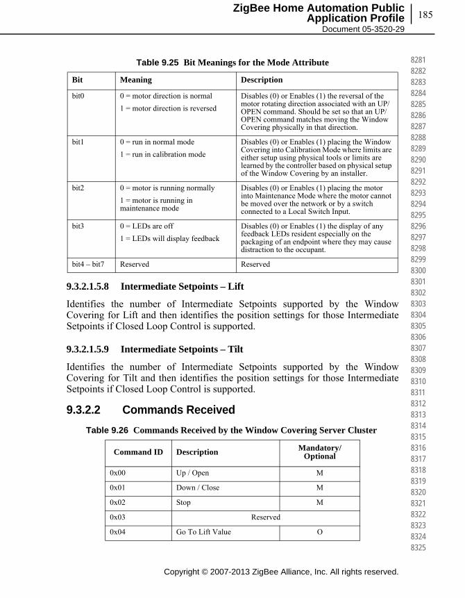
185
Copyright © 2007-2013 ZigBee Alliance, Inc. All rights reserved.
ZigBee Home Automation Public Application Profile
Document 05-3520-29
828182828283828482858286828782888289829082918292829382948295829682978298829983008301830283038304830583068307830883098310831183128313831483158316831783188319832083218322832383248325
9.3.2.1.5.8 Intermediate Setpoints – Lift
Identifies the number of Intermediate Setpoints supported by the Window Covering for Lift and then identifies the position settings for those Intermediate Setpoints if Closed Loop Control is supported.
9.3.2.1.5.9 Intermediate Setpoints – Tilt
Identifies the number of Intermediate Setpoints supported by the Window Covering for Tilt and then identifies the position settings for those Intermediate Setpoints if Closed Loop Control is supported.
9.3.2.2 Commands Received
Table 9.25 Bit Meanings for the Mode Attribute
Bit Meaning Description
bit0 0 = motor direction is normal
1 = motor direction is reversed
Disables (0) or Enables (1) the reversal of the motor rotating direction associated with an UP/OPEN command. Should be set so that an UP/OPEN command matches moving the Window Covering physically in that direction.
bit1 0 = run in normal mode
1 = run in calibration mode
Disables (0) or Enables (1) placing the Window Covering into Calibration Mode where limits are either setup using physical tools or limits are learned by the controller based on physical setup of the Window Covering by an installer.
bit2 0 = motor is running normally
1 = motor is running in maintenance mode
Disables (0) or Enables (1) placing the motor into Maintenance Mode where the motor cannot be moved over the network or by a switch connected to a Local Switch Input.
bit3 0 = LEDs are off
1 = LEDs will display feedback
Disables (0) or Enables (1) the display of any feedback LEDs resident especially on the packaging of an endpoint where they may cause distraction to the occupant.
bit4 – bit7 Reserved Reserved
Table 9.26 Commands Received by the Window Covering Server Cluster
Command ID Description Mandatory/ Optional
0x00 Up / Open M
0x01 Down / Close M
0x02 Stop M
0x03 Reserved
0x04 Go To Lift Value O

Copyright © 2007-2013 ZigBee Alliance, Inc. All rights reserved.
Chapter 9Home Automation Specific Cluster 186
832683278328832983308331833283338334833583368337833883398340834183428343834483458346834783488349835083518352835383548355835683578358835983608361836283638364836583668367836883698370
9.3.2.2.1 Up / Open Command
9.3.2.2.1.1 Payload Format
This command has no payload.
9.3.2.2.1.2 Effect on Receipt
Upon receipt of this command, the Window Covering will adjust the window so the physical lift is at the InstalledOpenLimit – Lift and the tilt is at theInstalledOpenLimit – Tilt. This will happen as fast as possible.
9.3.2.2.2 Down / Close Command
9.3.2.2.2.1 Payload Format
This command has no payload.
9.3.2.2.2.2 Effect on Receipt
Upon receipt of this command, the Window Covering will adjust the window so the physical lift is at the InstalledClosedLimit – Lift and the tilt is at the InstalledClosedLimit – Tilt. This will happen as fast as possible.
9.3.2.2.3 Stop Command
9.3.2.2.3.1 Payload Format
This command has no payload.
9.3.2.2.3.2 Effect on Receipt
Upon receipt of this command, the Window Covering will stop any adjusting to the physical tilt and lift that is currently occurring.
0x05 Go to Lift Percentage O
0x06 Reserved
0x07 Go to Tilt Value O
0x08 Go to Tilt Percentage O
0x09 Reserved
Reserved0x0A
Table 9.26 Commands Received by the Window Covering Server Cluster
Command ID Description Mandatory/ Optional

187
Copyright © 2007-2013 ZigBee Alliance, Inc. All rights reserved.
ZigBee Home Automation Public Application Profile
Document 05-3520-29
837183728373837483758376837783788379838083818382838383848385838683878388838983908391839283938394839583968397839883998400840184028403840484058406840784088409841084118412841384148415
9.3.2.2.4 Go To Lift Value
9.3.2.2.4.1 Payload Format
The Go To Lift Value command payload shall be formatted as illustrated in Figure 9.7.
Figure 9.7 Format of the Go To Lift Value Command
9.3.2.2.4.1.1 Effect on Receipt
Upon receipt of this command, the Window Covering will adjust the window so the physical lift is at the lift value specified in the payload of this command as long as that value is not larger than InstalledOpenLimit – Lift and not smaller than InstalledClosedLimit – Lift. If the lift value is out of bounds a default response containing the status of INVALID_VALUE will be returned.
9.3.2.2.4.2 Go to Lift Percentage
9.3.2.2.4.2.1 Payload Format
The Go To Lift Percentage command payload shall be formatted as illustrated in Figure 9.8.
Figure 9.8 Format of the Go To Lift Percentage Command
9.3.2.2.4.2.2 Effect on Receipt
Upon receipt of this command, the Window Covering will adjust the window so the physical lift is at the lift percentage specified in the payload of this command.The percentage value will be mapped to a 8-bit unsigned integer value between InstalledOpenLimit and InstalledClosedLimit. If the percentage lift value is larger than 100, no physical action will be taken and a default response containing the status of INVALID_VALUE will be returned. If the device only supports open loop lift action then a zero percentage should be treated as a down/close command and a non-zero percentage should be treated as an up/open
Octets 2
Data Type Unsigned 16-bit integer
Field Name Lift Value
Octets 1
Data Type Unsigned 8-bit integer
Field Name Percentage Lift Value
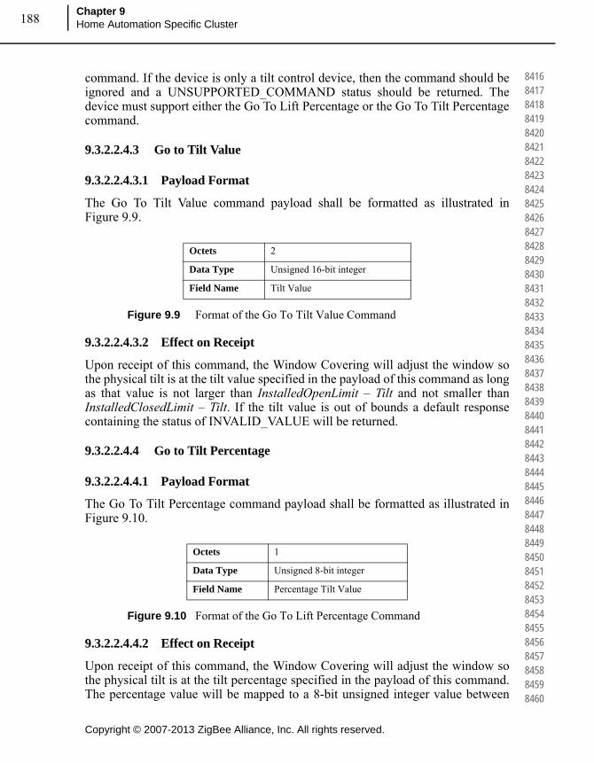
Copyright © 2007-2013 ZigBee Alliance, Inc. All rights reserved.
Chapter 9Home Automation Specific Cluster 188
841684178418841984208421842284238424842584268427842884298430843184328433843484358436843784388439844084418442844384448445844684478448844984508451845284538454845584568457845884598460
command. If the device is only a tilt control device, then the command should be ignored and a UNSUPPORTED_COMMAND status should be returned. The device must support either the Go To Lift Percentage or the Go To Tilt Percentage command.
9.3.2.2.4.3 Go to Tilt Value
9.3.2.2.4.3.1 Payload Format
The Go To Tilt Value command payload shall be formatted as illustrated in Figure 9.9.
Figure 9.9 Format of the Go To Tilt Value Command
9.3.2.2.4.3.2 Effect on Receipt
Upon receipt of this command, the Window Covering will adjust the window so the physical tilt is at the tilt value specified in the payload of this command as long as that value is not larger than InstalledOpenLimit – Tilt and not smaller than InstalledClosedLimit – Tilt. If the tilt value is out of bounds a default response containing the status of INVALID_VALUE will be returned.
9.3.2.2.4.4 Go to Tilt Percentage
9.3.2.2.4.4.1 Payload Format
The Go To Tilt Percentage command payload shall be formatted as illustrated in Figure 9.10.
Figure 9.10 Format of the Go To Lift Percentage Command
9.3.2.2.4.4.2 Effect on Receipt
Upon receipt of this command, the Window Covering will adjust the window so the physical tilt is at the tilt percentage specified in the payload of this command. The percentage value will be mapped to a 8-bit unsigned integer value between
Octets 2
Data Type Unsigned 16-bit integer
Field Name Tilt Value
Octets 1
Data Type Unsigned 8-bit integer
Field Name Percentage Tilt Value

189
Copyright © 2007-2013 ZigBee Alliance, Inc. All rights reserved.
ZigBee Home Automation Public Application Profile
Document 05-3520-29
846184628463846484658466846784688469847084718472847384748475847684778478847984808481848284838484848584868487848884898490849184928493849484958496849784988499850085018502850385048505
InstalledOpenLimit – Tilt and InstalledClosedLimit – Tilt. If the percentage tilt value is larger than 100, no physical action will be taken and a default response containing the status of INVALID_VALUE will be returned. If the device only supports open loop tilt action then a zero percentage should be treated as a down/close command and a non-zero percentage should be treated as an up/open command. If the device is only a lift control device, then the command should be ignored and a UNSUPPORTED_COMMAND status should be returned. The device must support either the Go To Lift Percentage or the Go To Tilt Percentage command.
9.3.2.2.5 Commands Generated
This cluster uses the standard Default Response command defined in the ZCL specification for responding to received commands. Possible status values that can be returned are: SUCCESS, NOT_FOUND, NOT_AUTHORIZED, INSUFFICIENT_SPACE, UNSUP_CLUSTER_COMMAND, INVALID_FIELD, INVALID_VALUE, HARDWARE_FAILURE, FAILURE.
9.3.2.2.6 Scene Table Extensions
If the Window Covering server cluster is implemented, the following extension field is added to the Scene table:
• CurrentPositionLiftPercentageWhen the CurrentPositionLiftPercentage attribute is part of a Scene table, the attribute is treated as a writeable command, that is, setting the lift percentage of the covering device to the value specified in the Scene table extension over the specified transition time. The device may treat the command as a linear transition if appropriate or may accelerate and decelerate as it deems necessary. If the device is only a tilt controlling device this Scene table extension is ignored. If the device is an open loop controlled lift device, then a percentage of 0 is treated as a close command and a non zero percentage is treated as an open command and the device will ignore the transition time and transition as fast as appropriate for that device.
• CurrentPositionTiltPercentageWhen the CurrentPositionTiltPercentage attribute is part of a Scene table, the attribute is treated as a writeable command, that is, setting the tilt percentage of the covering device to the value specified in the Scene table extension over the specified transition time. The device may treat the command as a linear transition if appropriate or may accelerate and decelerate as it deems necessary. If the device is only a lift controlling device this Scene table extension is ignored. If the device is an open loop controlled tilt device, then a percentage of 0 is treated as a close command and a non zero percentage is treated as an open command and the device will ignore the transition time and transition as fast as appropriate for that device.

Copyright © 2007-2013 ZigBee Alliance, Inc. All rights reserved.
Chapter 9Home Automation Specific Cluster 190
850685078508850985108511851285138514851585168517851885198520852185228523852485258526852785288529853085318532853385348535853685378538853985408541854285438544854585468547854885498550
• CurrentPositionLiftSetpointWhen the CurrentPositionLiftSetpoint attribute is part of a Scene table, the attribute is treated as is CurrentPositionLiftPercentage above.
• CurrentPositionTiltSetpointWhen the CurrentPositionTiltSetpoint attribute is part of a Scene table, the attribute is treated as is CurrentPositionTiltPercentage above.
9.3.2.2.7 Attribute Reporting
This cluster shall support attribute reporting using the Report Attributes command and according to the minimum and maximum reporting interval settings described in the ZCL. The following attributes shall be reported:
CurrentPosition – Lift
CurrentPosition – Tilt
9.3.3 Client
9.3.3.1 Attributes
The client has no attributes.
9.3.3.2 Command Received
No cluster-specific commands are received by the client.
9.3.3.3 Commands Generated
The client generates the cluster-specific commands detailed in sub-clause 9.5.2.2.
9.4 Poll Control Cluster
9.4.1 Overview
This cluster provides a mechanism for the management of an end device’s MAC Data Request rate. For the purposes of this cluster, the term “poll” always refers to the sending of a MAC Data Request from the end device to the end device’s parent.
This cluster can be used for instance by a configuration device to make an end device responsive for a certain period of time so that the device can be managed by the controller.
This cluster is composed of a client and server. The end device implements the server side of this cluster. The server side contains several attributes related to the

191
Copyright © 2007-2013 ZigBee Alliance, Inc. All rights reserved.
ZigBee Home Automation Public Application Profile
Document 05-3520-29
855185528553855485558556855785588559856085618562856385648565856685678568856985708571857285738574857585768577857885798580858185828583858485858586858785888589859085918592859385948595
MAC Data Request rate for the device. The client side implements commands used to manage the poll rate for the device.
The end device which implements the server side of this cluster sends a query to the client on a predetermined interval to see if the client would like to manage the poll period of the end device in question. When the client side of the cluster hears from the server it has the opportunity to respond with configuration data to either put the end device in a short poll mode or let the end device continue to function normally.
9.4.2 Terminology
MAC Data Request Rate: The MAC Data Request rate or simply “poll rate” is the frequency with which an end device sends a MAC Data Request to its parent. A parent device is only required to store a single message for its child for 7.68 seconds. Therefore if an end device wants to retrieve messages from its parent, it must send a MAC Data Request every 7.68 seconds.
Generally end devices have two different rates at which they send MAC Data Polls to their parents. A slower rate for when the device is not expecting data (Long Poll Interval) and a faster rate (Short Poll Interval) for when the device is expecting data.
End devices only know that they are expecting data when they have initiated some sort of transaction. This cluster provides a mechanism for forcing this state to make the end device responsive to asynchronous messaging.
Long Poll Interval: The amount of time between MAC Data Requests when the device is in its normal operating state and not expecting any messages.
Short Poll Interval: The amount of time between MAC Data Requests when the device is either expecting data or has been put into “Fast Poll Mode” by the controlling device.
Fast Poll Mode: When the device is polling frequently to retrieve data from its parent we say that the device is in “Fast Poll Mode”. The entire purpose of this cluster is to provide a means of managing when an end device goes into and out of Fast Poll Mode so that it can be made responsive for a controlling device.
9.4.3 Commissioning Process for the Poll Control Cluster
Poll Control Cluster Clients shall configure bindings on the device implementing the Poll Control Cluster Server so that they will receive the regular check-in command on the configured Check-In Interval. This can be done during the configuration period on the end device implementing the Poll Control Cluster
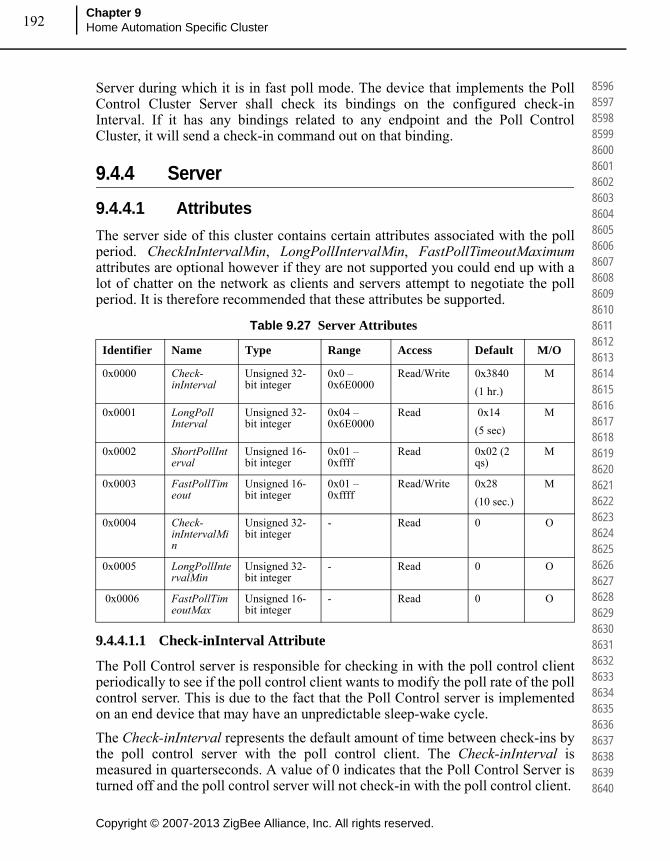
Copyright © 2007-2013 ZigBee Alliance, Inc. All rights reserved.
Chapter 9Home Automation Specific Cluster 192
859685978598859986008601860286038604860586068607860886098610861186128613861486158616861786188619862086218622862386248625862686278628862986308631863286338634863586368637863886398640
Server during which it is in fast poll mode. The device that implements the Poll Control Cluster Server shall check its bindings on the configured check-in Interval. If it has any bindings related to any endpoint and the Poll Control Cluster, it will send a check-in command out on that binding.
9.4.4 Server
9.4.4.1 Attributes
The server side of this cluster contains certain attributes associated with the poll period. CheckInIntervalMin, LongPollIntervalMin, FastPollTimeoutMaximum attributes are optional however if they are not supported you could end up with a lot of chatter on the network as clients and servers attempt to negotiate the poll period. It is therefore recommended that these attributes be supported.
9.4.4.1.1 Check-inInterval Attribute
The Poll Control server is responsible for checking in with the poll control client periodically to see if the poll control client wants to modify the poll rate of the poll control server. This is due to the fact that the Poll Control server is implemented on an end device that may have an unpredictable sleep-wake cycle.
The Check-inInterval represents the default amount of time between check-ins by the poll control server with the poll control client. The Check-inInterval is measured in quarterseconds. A value of 0 indicates that the Poll Control Server is turned off and the poll control server will not check-in with the poll control client.
Table 9.27 Server Attributes
Identifier Name Type Range Access Default M/O
0x0000 Check-inInterval
Unsigned 32-bit integer
0x0 – 0x6E0000
Read/Write 0x3840
(1 hr.)
M
0x0001 LongPoll Interval
Unsigned 32-bit integer
0x04 – 0x6E0000
Read 0x14
(5 sec)
M
0x0002 ShortPollInterval
Unsigned 16-bit integer
0x01 – 0xffff
Read 0x02 (2 qs)
M
0x0003 FastPollTimeout
Unsigned 16-bit integer
0x01 – 0xffff
Read/Write 0x28
(10 sec.)
M
0x0004 Check-inIntervalMin
Unsigned 32-bit integer
- Read 0 O
0x0005 LongPollIntervalMin
Unsigned 32-bit integer
- Read 0 O
0x0006 FastPollTimeoutMax
Unsigned 16-bit integer
- Read 0 O
193
Copyright © 2007-2013 ZigBee Alliance, Inc. All rights reserved.
ZigBee Home Automation Public Application Profile
Document 05-3520-29
864186428643864486458646864786488649865086518652865386548655865686578658865986608661866286638664866586668667866886698670867186728673867486758676867786788679868086818682868386848685
The Poll Control Server checks in with the Poll Control Client by sending a Check-in command to the Client. This value should be longer than the LongPoll Interval attribute. If the Client writes an invalid attribute value (Example: Out of Range as defined in Table 9.27 or a value smaller than the optional Check-inIntervalMin attribute value or a value smaller than the LongPollInterval attribute value), the Server should return Write Attributes Response with a error status not equal to ZCL_SUCCESS(0x00).
The Poll Control Client will hold onto the actions or messages for the Poll Control Server at the application level until the Poll Control Server checks in with the Poll Control Client.
9.4.4.1.2 LongPollInterval Attribute
An end device that implements the Poll Control server may optionally expose a LongPollInterval attribute. The Long Poll Interval represents the maximum amount of time in quarterseconds between MAC Data Requests from the end device to its parent.
The LongPollInterval defines the frequency of polling that an end device does when it is NOT in fast poll mode. The LongPollInterval should be longer than the ShortPollInterval attribute but shorter than the Check-inInterval attribute.
A value of 0xffffffff is reserved to indicate that the device does not have or does not know its long poll interval.
9.4.4.1.3 ShortPollInterval Attribute
An end device that implements the Poll Control server may optionally expose the ShortPollInterval attribute. The ShortPollInterval represents the number of quarterseconds that an end device waits between MAC Data Requests to its parent when it is expecting data (i.e. in fast poll mode).
9.4.4.1.4 FastPollTimeout Attribute
The FastPollTimeout attribute represents the number of quarterseconds that an end device will stay in fast poll mode by default. It is suggested that the FastPollTimeout attribute value be greater than 7.68 seconds.
The Poll Control Cluster Client may override this value by indicating a different value in the Fast Poll Duration argument in the Check-in Response command. If the Client writes a value out of range as defined in Table 9.27 or greater than the optional FastPollTimeoutMax attribute value if supported, the Server returns a Write Attributes Response of status Success (0x00) but the FastPollTimeoutattribute value is automatically updated to an acceptable value. An end device that implements the Poll Control server can be put into a fast poll mode during which it will send MAC Data Requests to its parent at the frequency of its configured ShortPollInterval attribute. During this period of time, fast polling is considered active. When the device goes into fast poll mode, it is required to send MAC Data

Copyright © 2007-2013 ZigBee Alliance, Inc. All rights reserved.
Chapter 9Home Automation Specific Cluster 194
868686878688868986908691869286938694869586968697869886998700870187028703870487058706870787088709871087118712871387148715871687178718871987208721872287238724872587268727872887298730
Requests to its parent at an accelerated rate and is thus more responsive on the network and can receive data asynchronously from the device implementing the Poll Control Cluster Client.
9.4.4.1.5 Check-inIntervalMin
The Poll Control Server may optionally provide its own minimum value for the Check-inInterval to protect against the Check-inInterval being set too low and draining the battery on the end device implementing the Poll Control Server.
9.4.4.1.6 LongPollIntervalMin
The Poll Control Server may optionally provide its own minimum value for the LongPollInterval to protect against another device setting the value to too short a time resulting in an inadvertent power drain on the device.
9.4.4.1.7 FastPollTimeoutMax
The Poll Control Server may optionally provide its own maximum value for the FastPollTimeout to avoid it being set to too high a value resulting in an inadvertent power drain on the device.
9.4.4.2 Attribute Settings and Battery Life Considerations
The Poll Control Cluster is used on end devices that may be battery powered. In order to conserve battery life, it is important that the Poll Control Server maintain certain boundaries for the setting of the Check-inInterval, LongPollInterval and the ShortPollInterval. Therefore, while these attributes are all Read/Write, it is possible that a battery-powered device might maintain its own boundary for the min and max of each of these attributes. The end device implementing the Poll Control Cluster Server may define its own boundaries for these attributes in order to protect itself against a power drain due to improper configuration.
For instance a battery powered device may not allow another device to set its Check-inInterval to too short a value or its FastPollTimeout to too long an interval because it might cause the device to send too frequent check-in messages on the network and stay in fast poll mode for too long a time resulting in a drain on the battery.
The Check-inInterval, LongPollInterval and ShortPollInterval should be set such that:
Check-in Interval >= Long Poll Interval >= Short Poll Interval
The default values chosen for this cluster are:
Check-in Interval = 1 hour = 0x3840 quarterseconds.
Long Poll Interval = 5 seconds = 0x14 quarterseconds.
Short Poll Interval = 2 quarterseconds = 0x02 quarterseconds.

195
Copyright © 2007-2013 ZigBee Alliance, Inc. All rights reserved.
ZigBee Home Automation Public Application Profile
Document 05-3520-29
873187328733873487358736873787388739874087418742874387448745874687478748874987508751875287538754875587568757875887598760876187628763876487658766876787688769877087718772877387748775
Fast Poll Timeout = 10 seconds = 0x28 quarterseconds.
It should be noted that for the Check-in Interval, 0 is a special value and does not apply to this equation.
9.4.4.3 Commands
9.4.4.4 Check-in
The Poll Control Cluster server sends out a Check-in command to the devices to which it is paired based on the server’s Check-inInterval attribute. It does this to find out if any of the Poll Control Cluster Clients with which it is paired are interested in having it enter fast poll mode so that it can be managed. This request is sent out based on either the Check-inInterval, or the next Check-in value in the Fast Poll Stop Request generated by the Poll Control Cluster Client.
The Check-in command expects a Check-in Response command to be sent back from the Poll Control Client. If the Poll Control Server does not receive a Check-in response back from the Poll Control Client up to7.68 seconds it is free to return to polling according to the LongPollInterval.
9.4.4.4.1 Payload Format
There is no payload for this command.
9.4.4.4.2 Effect Upon Receipt
Upon receipt of the Check-in command, the Poll Control Cluster client will respond with a Check-in Response command indicating that the server should or should not begin fast poll mode.
9.4.5 Client
9.4.5.1 Attributes
There are no attributes on the client side of the Poll Control Cluster.
Table 9.28 Commands Generated by the Poll Control Server
Command ID Description Mandatory/Optional
0x00 Check-in M
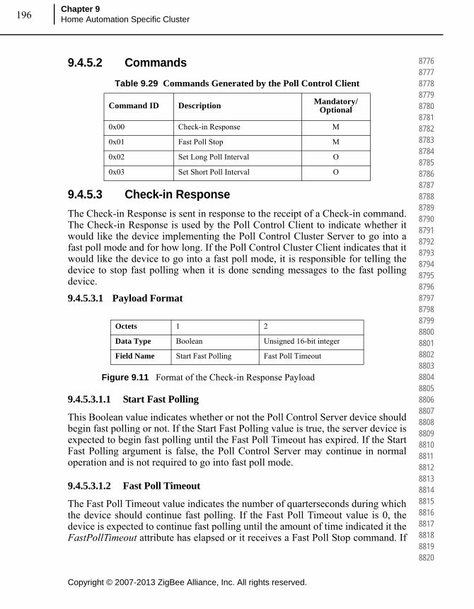
Copyright © 2007-2013 ZigBee Alliance, Inc. All rights reserved.
Chapter 9Home Automation Specific Cluster 196
877687778778877987808781878287838784878587868787878887898790879187928793879487958796879787988799880088018802880388048805880688078808880988108811881288138814881588168817881888198820
9.4.5.2 Commands
9.4.5.3 Check-in Response
The Check-in Response is sent in response to the receipt of a Check-in command. The Check-in Response is used by the Poll Control Client to indicate whether it would like the device implementing the Poll Control Cluster Server to go into a fast poll mode and for how long. If the Poll Control Cluster Client indicates that it would like the device to go into a fast poll mode, it is responsible for telling the device to stop fast polling when it is done sending messages to the fast polling device.
9.4.5.3.1 Payload Format
Figure 9.11 Format of the Check-in Response Payload
9.4.5.3.1.1 Start Fast Polling
This Boolean value indicates whether or not the Poll Control Server device should begin fast polling or not. If the Start Fast Polling value is true, the server device is expected to begin fast polling until the Fast Poll Timeout has expired. If the Start Fast Polling argument is false, the Poll Control Server may continue in normal operation and is not required to go into fast poll mode.
9.4.5.3.1.2 Fast Poll Timeout
The Fast Poll Timeout value indicates the number of quarterseconds during which the device should continue fast polling. If the Fast Poll Timeout value is 0, the device is expected to continue fast polling until the amount of time indicated it the FastPollTimeout attribute has elapsed or it receives a Fast Poll Stop command. If
Table 9.29 Commands Generated by the Poll Control Client
Command ID Description Mandatory/Optional
0x00 Check-in Response M
0x01 Fast Poll Stop M
0x02 Set Long Poll Interval O
0x03 Set Short Poll Interval O
Octets 1 2
Data Type Boolean Unsigned 16-bit integer
Field Name Start Fast Polling Fast Poll Timeout

197
Copyright © 2007-2013 ZigBee Alliance, Inc. All rights reserved.
ZigBee Home Automation Public Application Profile
Document 05-3520-29
882188228823882488258826882788288829883088318832883388348835883688378838883988408841884288438844884588468847884888498850885188528853885488558856885788588859886088618862886388648865
the Start Fast Polling argument is false, the Poll Control Server may ignore the Fast Poll Timeout argument.
The Fast Poll Timeout argument temporarily overrides the FastPollTimeout attribute on the Poll Control Cluster Server for the fast poll mode induced by the Check-in Response command. This value is not expected to overwrite the stored value in the FastPollTimeout attribute.
If the FastPollTimeout parameter in the CheckInResponse command is greater than the FastPollTimeoutMax attribute value, the Server Device shall respond with a default response of error status not equal to ZCL_SUCCESS. It is suggested to use the Error Status of ZCL_INVALID_FIELD (0x85).
9.4.5.4 Fast Poll Stop
The Fast Poll Stop command is used to stop the fast poll mode initiated by the Check-in response. The Fast Poll Stop command has no payload.
9.4.5.5 Set Long Poll Interval
The Set Long Poll Interval command is used to set the read only LongPollIntervalattribute.
When the Poll Control Server receives the Set Long Poll Interval Command, it should check its internal minimal limit and the attributes relationship defined in 9.6.4.2 if the new Long Poll Interval is acceptable. If the new value is acceptable, the new value shall be saved to the LongPollInterval attribute.If the new value is not acceptable, the Poll Control Server shall send a default response of INVALID_VALUE (0x87) and the LongPollInterval attribute value is not updated.
9.4.5.5.1 Payload Format
Figure 9.12 Format of the Set Long Poll Interval Command Payload
9.4.5.6 Set Short Poll Interval
The Set Short Poll Interval command is used to set the read only ShortPollIntervalattribute.
When the Poll Control Server receives the Set Short Poll Interval Command, it should check its internal minimal limit and the attributes relationship defined in 9.6.4.2 if the new Short Poll Interval is acceptable. If the new value is acceptable,
Octets 4
Data Type Unsigned 32-bit integer
Field Name NewLongPollInterval
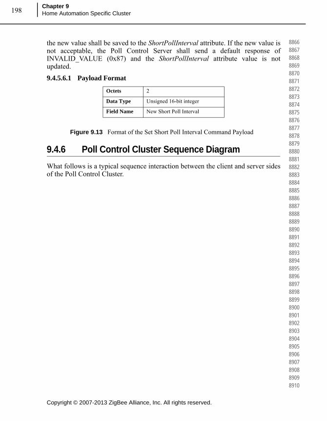
Copyright © 2007-2013 ZigBee Alliance, Inc. All rights reserved.
Chapter 9Home Automation Specific Cluster 198
886688678868886988708871887288738874887588768877887888798880888188828883888488858886888788888889889088918892889388948895889688978898889989008901890289038904890589068907890889098910
the new value shall be saved to the ShortPollInterval attribute. If the new value is not acceptable, the Poll Control Server shall send a default response of INVALID_VALUE (0x87) and the ShortPollInterval attribute value is not updated.
9.4.5.6.1 Payload Format
Figure 9.13 Format of the Set Short Poll Interval Command Payload
9.4.6 Poll Control Cluster Sequence Diagram
What follows is a typical sequence interaction between the client and server sides of the Poll Control Cluster.
Octets 2
Data Type Unsigned 16-bit integer
Field Name New Short Poll Interval
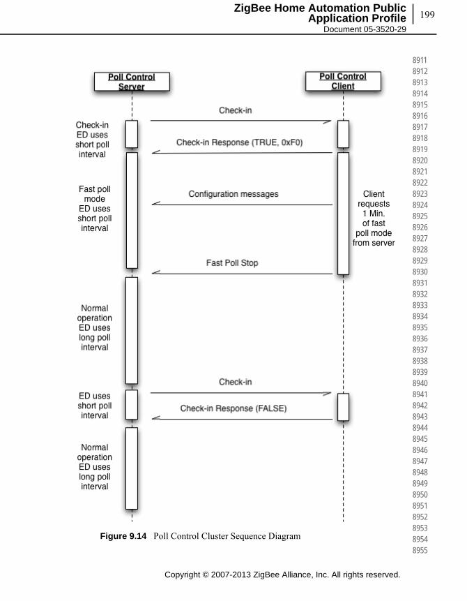
199
Copyright © 2007-2013 ZigBee Alliance, Inc. All rights reserved.
ZigBee Home Automation Public Application Profile
Document 05-3520-29
891189128913891489158916891789188919892089218922892389248925892689278928892989308931893289338934893589368937893889398940894189428943894489458946894789488949895089518952895389548955
Figure 9.14 Poll Control Cluster Sequence Diagram

Copyright © 2007-2013 ZigBee Alliance, Inc. All rights reserved.
Chapter 9Home Automation Specific Cluster 200
895689578958895989608961896289638964896589668967896889698970897189728973897489758976897789788979898089818982898389848985898689878988898989908991899289938994899589968997899889999000
9.4.6.1 Guaranteed Consistent Check In Interval
Provided that the Check-inInterval attribute value stays constant, the interval between two Check In commands is guaranteed. The Check-inInterval should be kept independent regardless of when the Check-In Response or Fast Poll Stop command is received.
9.4.6.2 Multiple Poll Control Client
When the Check-inInterval expires, the Server should send parallel Check-In commands to all paired client devices.
The server should then enter a temporary Fast Poll Mode, with a fixed manufacturer-specific predefined check in timeout duration (t1), to wait for the Check-In Response Messages from all paired device.
Once the server received all the Check-In Response or if the temporary Fast Poll Mode timeout (t1), the server should then gather the information from all Check-In Response messages and determine the longest Fast Poll Timeout (t2) duration.
The Server device shall stay in the Fast Poll Mode for the longest Fast Poll Timeout (t2) duration. The server device may end fast poll mode before the longest fast poll timeout if it is able to determine that every start request from the paired device has been stopped explicitly by the Fast Poll Stop command or implicitly by a timeout.
For example:
Device A implements a poll control server, devices B and C implement poll control clients. Device A sends a check-in command to both B and C. Both B and C respond with check-in response command requesting a fast poll start. Assume B requests fast polling for 5 minutes and C requests fast polling for 10 minutes. If C sends a fast poll stop command after 7 minutes, device A may immediately end fast polling upon receipt of this command since the fast poll period requested by B would have expired after only 5 minutes (before the command from C was received).
When the Check-inInterval attribute is changed (provided that the new value is valid and within acceptable range), the device should reset the internal check-in interval timer and send a check-in command according to the new Check-inInterval value.1
9.5 Power Profile Cluster
This section describes the Power Profile cluster.
1. CCB 1782
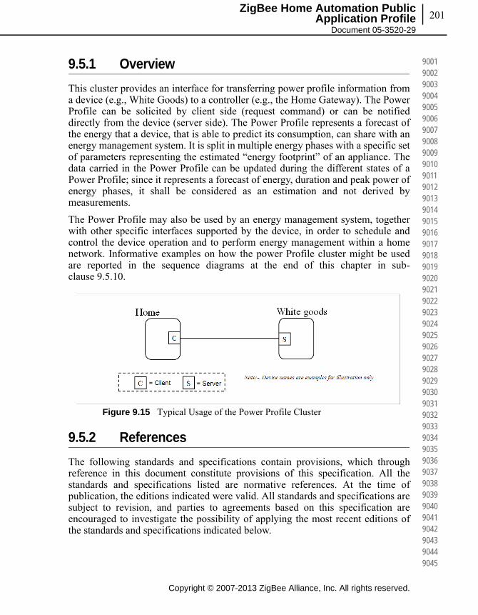
201
Copyright © 2007-2013 ZigBee Alliance, Inc. All rights reserved.
ZigBee Home Automation Public Application Profile
Document 05-3520-29
900190029003900490059006900790089009901090119012901390149015901690179018901990209021902290239024902590269027902890299030903190329033903490359036903790389039904090419042904390449045
9.5.1 Overview
This cluster provides an interface for transferring power profile information from a device (e.g., White Goods) to a controller (e.g., the Home Gateway). The Power Profile can be solicited by client side (request command) or can be notified directly from the device (server side). The Power Profile represents a forecast of the energy that a device, that is able to predict its consumption, can share with an energy management system. It is split in multiple energy phases with a specific set of parameters representing the estimated “energy footprint” of an appliance. The data carried in the Power Profile can be updated during the different states of a Power Profile; since it represents a forecast of energy, duration and peak power of energy phases, it shall be considered as an estimation and not derived by measurements.
The Power Profile may also be used by an energy management system, together with other specific interfaces supported by the device, in order to schedule and control the device operation and to perform energy management within a home network. Informative examples on how the power Profile cluster might be used are reported in the sequence diagrams at the end of this chapter in sub-clause 9.5.10.
Figure 9.15 Typical Usage of the Power Profile Cluster
9.5.2 References
The following standards and specifications contain provisions, which through reference in this document constitute provisions of this specification. All the standards and specifications listed are normative references. At the time of publication, the editions indicated were valid. All standards and specifications are subject to revision, and parties to agreements based on this specification are encouraged to investigate the possibility of applying the most recent editions of the standards and specifications indicated below.
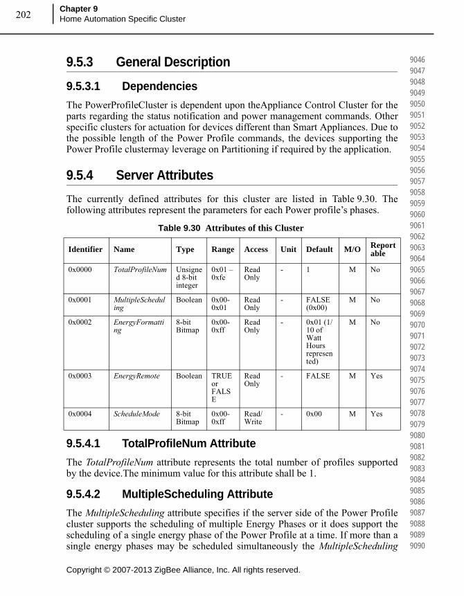
Copyright © 2007-2013 ZigBee Alliance, Inc. All rights reserved.
Chapter 9Home Automation Specific Cluster 202
904690479048904990509051905290539054905590569057905890599060906190629063906490659066906790689069907090719072907390749075907690779078907990809081908290839084908590869087908890899090
9.5.3 General Description
9.5.3.1 Dependencies
The PowerProfileCluster is dependent upon theAppliance Control Cluster for the parts regarding the status notification and power management commands. Other specific clusters for actuation for devices different than Smart Appliances. Due to the possible length of the Power Profile commands, the devices supporting the Power Profile clustermay leverage on Partitioning if required by the application.
9.5.4 Server Attributes
The currently defined attributes for this cluster are listed in Table 9.30. The following attributes represent the parameters for each Power profile’s phases.
9.5.4.1 TotalProfileNum Attribute
The TotalProfileNum attribute represents the total number of profiles supported by the device.The minimum value for this attribute shall be 1.
9.5.4.2 MultipleScheduling Attribute
The MultipleScheduling attribute specifies if the server side of the Power Profile cluster supports the scheduling of multiple Energy Phases or it does support the scheduling of a single energy phase of the Power Profile at a time. If more than a single energy phases may be scheduled simultaneously the MultipleScheduling
Table 9.30 Attributes of this Cluster
Identifier Name Type Range Access Unit Default M/O Reportable
0x0000 TotalProfileNum Unsigned 8-bit integer
0x01 – 0xfe
Read Only
- 1 M No
0x0001 MultipleScheduling
Boolean 0x00-0x01
Read Only
- FALSE (0x00)
M No
0x0002 EnergyFormatting
8-bit Bitmap
0x00-0xff
Read Only
- 0x01 (1/10 of Watt Hours represented)
M No
0x0003 EnergyRemote Boolean TRUE or FALSE
Read Only
- FALSE M Yes
0x0004 ScheduleMode 8-bit Bitmap
0x00-0xff
Read/Write
- 0x00 M Yes
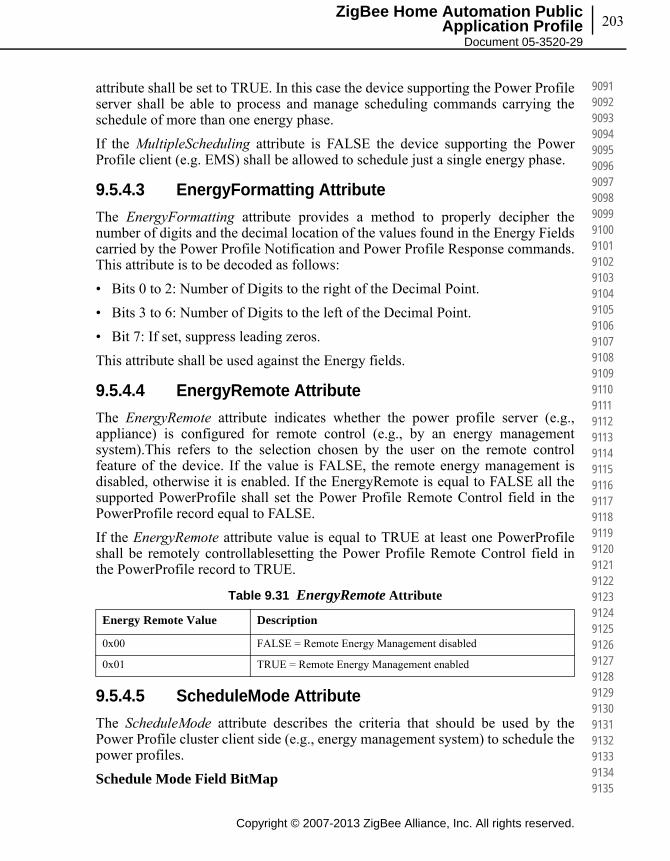
203
Copyright © 2007-2013 ZigBee Alliance, Inc. All rights reserved.
ZigBee Home Automation Public Application Profile
Document 05-3520-29
909190929093909490959096909790989099910091019102910391049105910691079108910991109111911291139114911591169117911891199120912191229123912491259126912791289129913091319132913391349135
attribute shall be set to TRUE. In this case the device supporting the Power Profile server shall be able to process and manage scheduling commands carrying the schedule of more than one energy phase.
If the MultipleScheduling attribute is FALSE the device supporting the Power Profile client (e.g. EMS) shall be allowed to schedule just a single energy phase.
9.5.4.3 EnergyFormatting Attribute
The EnergyFormatting attribute provides a method to properly decipher the number of digits and the decimal location of the values found in the Energy Fields carried by the Power Profile Notification and Power Profile Response commands. This attribute is to be decoded as follows:
• Bits 0 to 2: Number of Digits to the right of the Decimal Point.
• Bits 3 to 6: Number of Digits to the left of the Decimal Point.
• Bit 7: If set, suppress leading zeros.
This attribute shall be used against the Energy fields.
9.5.4.4 EnergyRemote Attribute
The EnergyRemote attribute indicates whether the power profile server (e.g., appliance) is configured for remote control (e.g., by an energy management system).This refers to the selection chosen by the user on the remote control feature of the device. If the value is FALSE, the remote energy management is disabled, otherwise it is enabled. If the EnergyRemote is equal to FALSE all the supported PowerProfile shall set the Power Profile Remote Control field in the PowerProfile record equal to FALSE.
If the EnergyRemote attribute value is equal to TRUE at least one PowerProfile shall be remotely controllablesetting the Power Profile Remote Control field in the PowerProfile record to TRUE.
9.5.4.5 ScheduleMode Attribute
The ScheduleMode attribute describes the criteria that should be used by the Power Profile cluster client side (e.g., energy management system) to schedule the power profiles.
Schedule Mode Field BitMap
Table 9.31 EnergyRemote Attribute
Energy Remote Value Description
0x00 FALSE = Remote Energy Management disabled
0x01 TRUE = Remote Energy Management enabled

Copyright © 2007-2013 ZigBee Alliance, Inc. All rights reserved.
Chapter 9Home Automation Specific Cluster 204
913691379138913991409141914291439144914591469147914891499150915191529153915491559156915791589159916091619162916391649165916691679168916991709171917291739174917591769177917891799180
If the ScheduleMode attribute is set to the value 0x00, the scheduling criteria is demanded to the Power Profile cluster client side, which means that no specific preferences on the schedule mode are requested by the device supporting the server side of the power Profile cluster.
If “Schedule Mode Cheapest” is selected then the energy management system shall try to schedule the Power Profile to minimize the user’s energy bill.
If “Schedule Mode Greenest” is selected then the energy management system shall try to schedule the Power Profile to provide the highest availability of renewable energy sources.
Please note that how the energy management system may obtain “cheapest” or “greenest” information and estimate scheduling times is out of scope of this specification.
If more than a single bit is selected in the ScheduleMode bitmask, the Power Profile client shall try to calculate the schedule following all the selected criteria.
If all the bits are set to zero not specific optimization metrics preferences are requested by the device supporting the Power Profile server.
9.5.5 Server Commands Received
The command IDs for the commands received by the server side of the Power Profile Cluster are listed in Table 9.33.
Table 9.32 ScheduleMode Attribute
Bit Description
bit0 bit0=1 : Schedule Mode Cheapest
bit1 bit1 =1: Schedule Mode Greenest
bit2 to bit7 Reserved
Table 9.33 Cluster-specific Commands Received by the Server
Command Identifier Field Value Description Mandatory
/ Optional
0x00 PowerProfileRequest M
0x01 PowerProfileStateRequest M
0x02 GetPowerProfilePriceResponse M
0x03 GetOverallSchedulePriceResponse M
0x04 EnergyPhasesScheduleNotification M
0x05 EnergyPhasesScheduleResponse M

205
Copyright © 2007-2013 ZigBee Alliance, Inc. All rights reserved.
ZigBee Home Automation Public Application Profile
Document 05-3520-29
918191829183918491859186918791889189919091919192919391949195919691979198919992009201920292039204920592069207920892099210921192129213921492159216921792189219922092219222922392249225
9.5.5.1 Power Profile Request Command
The Power Profile Request Command is generated by a device supporting the client side of the Power Profile cluster in order to request the Power Profile of a server device. It is possible to request all profiles (without knowing how many Power Profiles the server has) or to request a specific PowerProfileID.
In the case of multiple profiles the server should send multiple messages, one for each Power Profile.
Although the profile is in a Power Profile running state (see PowerProfileState), the Power Profile Response transmitted as a reply to a Power Profile Request command shall carry all the energy phases of the estimated Power Profile, including the previous energy phases and the current energy phase which is running. The parameters of the Power Profile (e.g the ExpectedDuration or the Energy fields of all the energy phases) may be updated for the same Power Profile due to a tuning in the forecast.
9.5.5.1.1 Payload Format
The Power Profile Request Command payload shall be formatted as illustrated in Figure 9.16.
Figure 9.16 Format of the Power Profile Request Command Payload
9.5.5.1.1.1 Payload Details
The payload of the Power Profile Request command carries the fields defined in Figure 9.16.
The PowerProfileID field specifies which profile (in the range 1 to TotalProfileNum) is requested. The special value 0x00 of this field does not refer to a particular profile; if 0x00 value is received the device should send details related to all the available profiles.
0x06 PowerProfileScheduleConstraintsRequest M
0x07 EnergyPhasesScheduleStateRequest M
0x08 GetPowerProfilePriceExtendedResponse M
Octets 1
Data Type Unsigned 8-bit integer
Field Name PowerProfileID
Table 9.33 Cluster-specific Commands Received by the Server (Continued)
Command Identifier Field Value Description Mandatory
/ Optional

Copyright © 2007-2013 ZigBee Alliance, Inc. All rights reserved.
Chapter 9Home Automation Specific Cluster 206
922692279228922992309231923292339234923592369237923892399240924192429243924492459246924792489249925092519252925392549255925692579258925992609261926292639264926592669267926892699270
The PowerProfileID field shall not be greater than TotalProfileNum.
9.5.5.1.2 When Generated
This command is generated when the client side of the Power Profile cluster (e.g., a Home gateway device), needs to request the power profile to a device supporting the Power Profile cluster server side (e.g., White Good).
9.5.5.1.3 Effect on Receipt
The device that receives the Power Profile Request command shall reply with a PowerProfileResponse if supported. If the command is not supported the device shall reply with a standard ZCL Default response with status UNSUP_CLUSTER_COMMAND 0x81 (as from ZCL specification).
If the requested profile data are not available, the device shall reply with a standard ZCL response NOT_FOUND 0x8b (according to ZCL specification).
9.5.5.2 Power Profile State Request Command
The Power Profile State Request command is generated in order to retrieve the identifiers of current Power Profiles. This command does not have a payload.
9.5.5.2.1 Effect on Receipt
On receipt of this command, the device shall generate a Power Profile State Response command.
9.5.5.3 Get Power Profile Price Response Command
The Get Power Profile Price Response command allows a device (client) to communicate the cost associated with a defined Power Profile to another device (server) requesting it. If the Price information requested related to the Power Profile is not available yet the response shall be a ZCL default response with "NOT FOUND" Status.
9.5.5.3.1 Payload Format
The Get Power Profile Price Response command payload shall be formatted as illustrated in Figure 9.17.
Figure 9.17 Format of the Get Power Profile Price Response Command
Octets 1 2 4 1
Data Type Unsigned 8-bit integer
Unsigned 16-bit integer
Unsigned 32-bit integer
Unsigned 8-bit integer
Field Name Power Profile ID Currency Price Price trailing Digit

207
Copyright © 2007-2013 ZigBee Alliance, Inc. All rights reserved.
ZigBee Home Automation Public Application Profile
Document 05-3520-29
927192729273927492759276927792789279928092819282928392849285928692879288928992909291929292939294929592969297929892999300930193029303930493059306930793089309931093119312931393149315
9.5.5.3.1.1 Payload Details
PowerProfileID
The PowerProfileID field represents the identifier of the specific profile described by the Power Profile.
This is typically a sequential and contiguous number ranging from 1 to TotalProfileNum.
Currency
The Currency field identifies the local unit of currency used in the price field. This field is thought to be useful for displaying the appropriate symbol for a currency (i.e.: $, €). The value of the currency field should match the values defined by ISO 4217.
Price
The Price field contains the price of the energy of a specific Power Profile measured in base unit of Currency per Unit of Measure (as described in the Metering Cluster, see SE specification) with the decimal point located as indicated by the PriceTrailingDigit field when the energy is delivered to the premise.
Price Trailing Digit
The PriceTrailingDigit field determines where the decimal point is located in the price field. The PriceTrailingDigit indicates the number of digits to the right of the decimal point.
9.5.5.3.2 When Generated
This command is generated when the command Get Power Profile Price is received. Please refer to Get Power Profile Price command description.
9.5.5.3.3 Effect on Receipt
On receipt of this command, the originator (server) is notified of the associated cost of the requested Power Profile, calculated by the Power Profile clientside (see 9.7.10.1 for sequence diagrams and examples).
9.5.5.4 Get Overall Schedule Price Response Command
The Get Overall Schedule Price Response command allows a client to communicate the overall cost associated to all Power Profiles scheduled to a server requesting it. If the Price information requested is not available the response shall be a ZCL default response with “NOT FOUND” Status. The overall cost provided by the Power Profile Client side (e.g. energy management system) is intended as the cost of all the scheduled power profiles. This information may be helpful to assess the overall benefit provided by the scheduler, since a change in the scheduling of a specific device might -in some cases-

Copyright © 2007-2013 ZigBee Alliance, Inc. All rights reserved.
Chapter 9Home Automation Specific Cluster 208
931693179318931993209321932293239324932593269327932893299330933193329333933493359336933793389339934093419342934393449345934693479348934993509351935293539354935593569357935893599360
increase its associated Power Profile cost. In fact in that case the schedule shall provide a global optimization by reducing the overall cost of all the scheduled power profiles, then reducing the energy bill for the user.
9.5.5.4.1 Payload Format
The Get Overall Schedule Price Response command payload shall be formatted as illustrated in Figure 9.18.
Figure 9.18 Format of the Get Overall Schedule Price Response Command
9.5.5.4.2 Payload Details
See Get Power Profile Price Response command payload details.
9.5.5.4.3 When Generated
This command is generated when the command Get Overall Schedule Price Request is received.
9.5.5.4.4 Effect on Receipt
On receipt of this command, the originator is notified of the overall cost of the scheduled Power Profiles, calculated by the Power Profile cluster clientside. This information may be used to assess the overall benefit provided by the scheduler, which might be dependent on the schedule constraints. (see 9.7.10.1 for sequence diagrams and examples).
9.5.5.5 Energy Phases Schedule Notification Command
The Energy Phases Schedule Notification command is generated by a device supporting the client side of the Power Profile cluster in order to schedule the start of a Power Profile and its energy phases (they may be more than one in case of MultipleScheduling attribute equal to TRUE) on a the device supporting the server side of the Power Profile cluster, which did not solicit the schedule (“un-solicited” schedule). That happens when the Power Profile State carries a PowerProfileRemoteControl field equal to TRUE and the Energy Phase has a MaxActivationDelay different than 0x0000 (please note that changes on an already scheduled energy phase or power profile are possible but should be applied just in case of sensible advantages). The mechanisms designed to find the proper schedule are not part of the description of this command.
Octets 2 4 1
Data Type Unsigned 16-bit integer
Unsigned 32-bit integer
Unsigned 8-bit integer
Field Name Currency Price Price trailing Digit

209
Copyright © 2007-2013 ZigBee Alliance, Inc. All rights reserved.
ZigBee Home Automation Public Application Profile
Document 05-3520-29
936193629363936493659366936793689369937093719372937393749375937693779378937993809381938293839384938593869387938893899390939193929393939493959396939793989399940094019402940394049405
Please consider that, in case the MultipleScheduling attribute is FALSE (which means that the server side of the Power Profile cluster shall support the schedule of only a single energy phase at once), the Energy Phases Schedule Notification command should also be used to set a pause between two energy phases (energy pause behavior). In this case the Power Profile State may have any values but the command shall be issued only if the PowerProfileRemoteControl is set to TRUE and the Energy Phase has a MaxActivationDelay different than 0x0000.
9.5.5.5.1 Payload Format
The Energy Phases Schedule Notification command payload shall be formatted as illustrated in Figure 9.19.
Figure 9.19 Format of the Energy Phases Schedule Notification Command Payload
9.5.5.5.1.1 Payload Details
The payload of the Energy Phases Schedule Notification command carries the fields defined in Figure 9.19. Each Energy Phases Schedule Notification message shall include only one Power Profile and the energy phases of that Power Profile that needs to be scheduled. In case this command needs to be sent to a device supporting the server side of the power Profile Cluster with the MultipleScheduling attribute set to false, the payload of Energy Phases Schedule Notification command shall carry just one phase and the Scheduled Time field shall indicate the time scheduled for the whole Power Profile to start (in case the Power Profile is not started yet). If the Power Profile is in ENERGY_PHASE_RUNNING state and the server side of the cluster has the MultipleScheduling attribute set to false, the Energy Phases Schedule Notification command shall carry the scheduled time of the next energy phase.
Power Profile ID
See definition in Power Profile Notification command.
Num of Scheduled Phases
The Num of Scheduled Phases field represents the total number of the energy phases of the Power Profile that need to be scheduled by this command.
Octets 1 1 1 2 … 1 2
Data Type
Unsigned 8-bit integer
Unsigned 8-bit integer
Unsigned 8-bit integer
Unsigned 16-bit integer
… Unsigned 8-bit integer
Unsigned 16-bit integer
Field Name
PowerProfileID
Num of Scheduled Phases
EnergyPhaseIDn
Scheduled Timen
… EnergyPhaseIDn
Scheduled Timen

Copyright © 2007-2013 ZigBee Alliance, Inc. All rights reserved.
Chapter 9Home Automation Specific Cluster 210
940694079408940994109411941294139414941594169417941894199420942194229423942494259426942794289429943094319432943394349435943694379438943994409441944294439444944594469447944894499450
The Energy phases that are not required to be scheduled shall not be counted in Num of Scheduled Phases field. The Num of Scheduled Phases shall be equal to 1 in case the MultipleScheduling attribute set to FALSE (only one energy phase shall be scheduled at a time).The Num of Scheduled Phases may be greater than 1in case the MultipleScheduling attribute set to TRUE (scheduling o multiple energy phases at the same time).
Energy Phase ID
See definition in Power Profile Notification command.
Scheduled Time
The Scheduled Time field represents the relative time scheduled in respect to the end of the previous energy phase. The unit is the minute. The Scheduled Time for the first Energy phase represents the scheduled time (expressed in relative encoding in respect to the current time) for the start of the Power Profile. The Scheduled Time fields for the subsequent Energy phases represent the relative time in minutes in respect to the previous scheduled Energy phase. The Energy phases that are not required to be scheduled will not be included in the commands and not be counted in Num of Scheduled Phases field. Only the Power Profile carrying a Power Profile Remote Control field equal to TRUE (as indicated in Power Profile State Notification command) and the Energy Phases supporting MaxActivationDelay different than 0x0000 shall be schedulable (as indicated in Power Profile Notification command).
9.5.5.5.2 When Generated
This command is generated when the client side of the Power Profile cluster (e.g., a Home gateway device), has calculated a specific schedule for a Power Profile and needs to send the schedule (i.e., “unsolicited” schedule) to a device supporting the Power Profile cluster server side (e.g., White Goods). This command shall be generated only if the recipient devices support schedulable Power Profiles (i.e. only if the Power Profile carries the first Energy Phase with a MaxActivationDelay different than 0x0000).
9.5.5.5.3 Effect on Receipt
The device that receives the Energy Phases Schedule Notification command shall reply with a standard Default response only if requested in the ZCL header of the Energy Phases Schedule Notification command or there is an error (as from ZCL specification).
If the device that receives the Energy Phases Schedule Notification command cannot schedule the energy phases because the activation delay of any of carried phases is equal to zero, it shall reply with a standard Default response with the error code NOT_AUTHORIZED (0x7e).

211
Copyright © 2007-2013 ZigBee Alliance, Inc. All rights reserved.
ZigBee Home Automation Public Application Profile
Document 05-3520-29
945194529453945494559456945794589459946094619462946394649465946694679468946994709471947294739474947594769477947894799480948194829483948494859486948794889489949094919492949394949495
In case the scheduling state of the recipient entity changes after the reception of this command, the recipient will issue an Energy Phases Schedule State Notification.
9.5.5.6 Energy Phases Schedule Response Command
This command is generated by the client side of Power Profile cluster as a reply to the Energy Phases Schedule Request command.
9.5.5.6.1 Payload Format
The Energy Phases Schedule Response command payload shall have the same payload as Energy Phases Schedule Notification command as described in 9.7.5.5 (Energy Phases Schedule Notification command, but “solicited” schedule because it is triggered by the Energy Phases Schedule Request command).
9.5.5.6.1.1 Payload Details
The payload of the Energy Phases Schedule Response command carries the fields defined in 9.7.5.5 (the same as Energy Phases Schedule Notification command).
9.5.5.6.2 When Generated
This command is generated when the server side of the Power Profile cluster (e.g., a White Goods device), has requested, using the Energy Phases Schedule Request, the schedule of a specific power profile to a device supporting the Power Profile cluster client side (e.g., Home gateway) which shall calculate the schedules (“solicited” schedule) and reply with the Energy Phases Schedule Response.
9.5.5.6.3 Effect on Receipt
The device that receives the Energy Phases Schedule Response command shall reply with a standard Default response only if requested in the ZCL header of the Energy Phases Schedule Response command. If the reception of Energy Phases Schedule Response command is not supported the device shall reply with a standard ZCL Default response with status UNSUP_CLUSTER_COMMAND 0x81 (as from ZCL specification).
In case the scheduling state of the recipient entity changes after the reception of this command, the recipient will issue an Energy Phases Schedule State Notification.
9.5.5.7 Power Profile Schedule Constraints Request Command
The Power Profile Schedule Constraints Request command is generated by client side of the Power Profile cluster in order to request the constraints of the Power Profile of a server, in order to set the proper boundaries for the scheduling when calculating the schedules.
Copyright © 2007-2013 ZigBee Alliance, Inc. All rights reserved.
Chapter 9Home Automation Specific Cluster 212
949694979498949995009501950295039504950595069507950895099510951195129513951495159516951795189519952095219522952395249525952695279528952995309531953295339534953595369537953895399540
9.5.5.7.1 Payload Format
The Power Profile Schedule Constraints Requestcommand payload is the same as the one used for Power Profile Request command (see 9.7.5.1).
9.5.5.7.1.1 Payload Details
The payload of the Power Profile Schedule Constraints Request command carries the fields defined in Power Profile Request Command.
The Power Profile ID field specifies which profile (among TotalProfileNum total profiles number) the constraints are referring to.
9.5.5.7.2 When Generated
This command is generated when the client side of the Power Profile cluster (e.g., a Home gateway device), needs to request the constraints of the power profile to a device supporting the Power Profile cluster server side (e.g., Whitegood).
9.5.5.7.3 Effect on Receipt
The device that receives the Power Profile Schedule Constraints Request command shall reply with a Power Profile Schedule Constraints Response if supported. If the command is not supported, the device shall reply with a standard ZCL Default response with status UNSUP_CLUSTER_COMMAND 0x81 (as from ZCL specification).
If the requested profile data are not available, the device shall reply with a standard ZCL response NOT_FOUND 0x8b (according to ZCL specification).
9.5.5.8 Energy Phases Schedule State Request Command
The Energy Phases Schedule State Request command is generated by a device supporting the client side of the Power Profile cluster to check the states of the scheduling of a power profile, which is supported in the device implementing the server side of Power Profile cluster. This command can be used to re-align the schedules between server and client (e.g., after a client reset).
9.5.5.8.1 Payload Format
The Energy Phases Schedule State Request command payload is the same as the one used for Power Profile Request command (see 9.7.5.1).
9.5.5.8.1.1 Payload Details
The payload of the Energy Phases Schedule State Request command carries the fields defined in 9.7.5.1.
The Power Profile ID field specifies which profile (among TotalProfileNum total profiles number) the constraints are referring to.

213
Copyright © 2007-2013 ZigBee Alliance, Inc. All rights reserved.
ZigBee Home Automation Public Application Profile
Document 05-3520-29
954195429543954495459546954795489549955095519552955395549555955695579558955995609561956295639564956595669567956895699570957195729573957495759576957795789579958095819582958395849585
9.5.5.8.2 When Generated
This command is generated when the client side of the Power Profile cluster (e.g., a Home gateway device), needs to check the schedules of the Power Profile to a device supporting the Power Profile cluster server side (e.g., White Good).
9.5.5.8.3 Effect on Receipt
The server that receives the Energy Phases Schedule StateRequest command shall reply to the client with a Energy Phases Schedule State Response, if supported. If the command is not supported, the servers hall reply with a standard ZCL Default response with status UNSUP_CLUSTER_COMMAND 0x81 (as from ZCL specification).
If the requested profile data are not available (e.g., invalid Power Profile ID), the servers hall reply with a standard ZCL response NOT_FOUND 0x8b (according to ZCL specification).
If the server does not have any schedules set, it shall reply with a Energy Phases Schedule State Response carrying NumofScheduledPhases equal to zero (see Format of the Energy Phases Schedule State Response in case of no scheduled phases).
9.5.5.9 Get Power Profile Price Extended Response Command
The Get Power Profile Price Extended Response command allows a device (client) to communicate the cost associated to all Power Profiles scheduled to another device (server) requesting it according to the specific options contained in the Get Power Profile Price Extended Response. If the Price information requested is not available the response shall be a ZCL default response with "NOT FOUND" Status.
9.5.5.9.1 Payload Format
The Get Power Profile Price Extended Response command payload shall be formatted as the Get Power Profile Price Response command.
9.5.5.9.1.1 Payload Details
See Get Power Profile Price Response command payload details.
9.5.5.9.2 When Generated
This command is generated when the command Get Power Profile Price Extended Response is received.

Copyright © 2007-2013 ZigBee Alliance, Inc. All rights reserved.
Chapter 9Home Automation Specific Cluster 214
958695879588958995909591959295939594959595969597959895999600960196029603960496059606960796089609961096119612961396149615961696179618961996209621962296239624962596269627962896299630
9.5.5.9.3 Effect on Receipt
On receipt of this command, the originator is notified of cost of the scheduled Power Profiles, calculated by the Power Profile cluster server side according to the specific option transmitted in the Get Power Profile Price Extended Response command (e.g., cost at specific PowerProfileStartTime). See 9.7.10.1 for sequence diagrams and examples.
9.5.6 Server Commands Generated
c lists commands are generated by the server.
9.5.6.1 Power Profile Notification Command
The Power Profile Notification command is generated by a device supporting the server side of the Power Profile cluster in order to send the information of the specific parameters (such as Peak power and others) belonging to each phase.
9.5.6.1.1 Payload Format
The Power Profile Notification command payload shall be formatted as illustrated in Figure 9.20.
Table 9.34 Cluster-specific Commands Sent by the Server
Command Identifier Field Value Description Mandatory/
Optional
0x00 PowerProfileNotification M
0x01 PowerProfileResponse M
0x02 PowerProfileStateResponse M
0x03 GetPowerProfilePrice O
0x04 PowerProfilesStateNotification M
0x05 GetOverallSchedulePrice O
0x06 EnergyPhasesScheduleRequest M
0x07 EnergyPhasesScheduleStateResponse M
0x08 EnergyPhasesScheduleStateNotification M
0x09 PowerProfileScheduleConstraintsNotification M
0x0A PowerProfileScheduleConstraintsResponse M
0x0B GetPowerProfilePriceExtended O

215
Copyright © 2007-2013 ZigBee Alliance, Inc. All rights reserved.
ZigBee Home Automation Public Application Profile
Document 05-3520-29
963196329633963496359636963796389639964096419642964396449645964696479648964996509651965296539654965596569657965896599660966196629663966496659666966796689669967096719672967396749675
Figure 9.20 Format of the Power Profile Notification Command Payload
9.5.6.1.1.1 Payload Details
The payload of the Power Profile Notification command carries the fields defined in Figure 9.20. Each Power Profile Notification message shall include only one Power Profile.
If multiple phases are transferred within a single Power Profile Notification command (i.e. Number of Transferred Phases greater than 1), the parameters of the other phases (PhaseID, ExpectedDuration, etc) should be carried in the payload. Each phase has a fixed number of parameters and the total length is 10 octets, so that the total length of the payload could be calculated with the following formula:
Total Payload Length = 1 + 1 + 1 + (Num of Transferred Phases * 10)
TotalProfileNum
See sub-clause 9.7.4.1 reporting the TotalProfileNum attribute description.
PowerProfileID
The PowerProfileID field represents the identifier of the specific profile described by the Power Profile.
Octets 1 1 1 1 1 2 2 2 2
Data Type
Unsigned 8-bit integer
Unsigned 8-bit integer
Unsigned 8-bit integer
Unsigned 8-bit integer
Unsigned 8-bit integer
Unsigned 16-bit integer
Unsigned 16-bit integer
Unsigned 16-bit integer
Unsigned 16-bit integer
Field Name
TotalProfileNum
PowerProfileID
Num of Transferred Phases
EnergyPhaseID1
MacroPhaseID1
ExpectedDuration1
PeakPower1
Energy1
MaxActivationDelay1
Octets … 1 1 2 2 2 2
Data Type
… Unsigned 8-bit integer
Unsigned 8-bit integer
Unsigned 16-bit integer
Unsigned 16-bit integer
Unsigned 16-bit integer
Unsigned 16-bit integer
Field Name
… EnergyPhaseIDn
MacroPhaseIDn
ExpectedDurationn
PeakPowern
Energyn MaxActivationDelayn
Copyright © 2007-2013 ZigBee Alliance, Inc. All rights reserved.
Chapter 9Home Automation Specific Cluster 216
967696779678967996809681968296839684968596869687968896899690969196929693969496959696969796989699970097019702970397049705970697079708970997109711971297139714971597169717971897199720
This field contains a sequential and contiguous number ranging from 1 to TotalProfileNum.
Num of Transferred Phases
This field represents the number of the energy phases of the Power Profile.
MacroPhaseID
The MacroPhaseID field represents the identifier of the specific phase (operational-displayed) described by the Power Profile.
This reference could be used in conjunction with a table of ASCII strings, describing the label of the functional phase. This table is not described in the contest of the Power Profile because it may be not functionally linked with energy management.
EnergyPhaseID
The EnergyPhaseID field indicates the identifier of the specific energy phase described by the Power Profile.
This is a sequential and contiguous number ranging from 1 to the maximum number of phases belonging to the Power Profile.
The value 0xFF shall be used to specify invalid energy phase (e.g., for a Power Profile in IDLE state).
ExpectedDuration
The ExpectedDuration field represents the estimated duration of the specific phase. Each unit is a minute.
PeakPower
The PeakPower field represents the estimated power for the specific phase. Each unit is a Watt.
Energy
The Energy field represents the estimated energy consumption for the accounted phase. Each unit is Watt per hours, according to the formatting specified in the EnergyFormatting attribute 9.7.4.3. The Energy value fulfills the following equation:
Energy ≤ PeakPower(Watt) * ExpectedDuration(sec).
MaxActivationDelay
The MaxActivationDelay field indicates the maximum interruption time between the end of the previous phase and the beginning of the specific phase. Each unit is a minute.

217
Copyright © 2007-2013 ZigBee Alliance, Inc. All rights reserved.
ZigBee Home Automation Public Application Profile
Document 05-3520-29
972197229723972497259726972797289729973097319732973397349735973697379738973997409741974297439744974597469747974897499750975197529753975497559756975797589759976097619762976397649765
The special value 0x0000 means that it is not possible to insert a pause between the two consecutive phases.
The MaxActivationDelay field of the first energy phase of a Power Profile shall be set to the value 0xFFFF.
9.5.6.1.2 When Generated
This command is generated when the server side of the Power Profile cluster (e.g., a White Good device), need to send the representation of its power profile to a controller device supporting the Power Profile cluster client side (e.g., Home Gateway).
9.5.6.1.3 Effect on Receipt
The device that receives the Power Profile Notification command shall reply with a standard Default response if requested in the ZCL header of the Power Profile Notification command.
9.5.6.2 Power Profile Response Command
This command is generated by the server side of Power Profile cluster as a reply to the Power Profile Request command. If the reception of Power Profile Request command is not supported the device shall reply with a standard ZCL Default response with status UNSUP_CLUSTER_COMMAND 0x81 (as from ZCL specification).
If the profile data requested are not available, the device shall reply with a standard ZCL response INVALID_VALUE 0x87 (as ZCL specification).
9.5.6.2.1 Payload Format
The Power Profile Response Command payload shall be formatted as illustrated in Figure 9.20 (same as Power Profile Notification command).
9.5.6.2.1.1 Payload Details
The payload of the Power Profile Response command carries the fields defined in Figure 9.20 (the same as Power Profile Notification command).
9.5.6.2.2 When Generated
This command is generated by the server side of Power Profile cluster (e.g., White Good) as a reply to the Power Profile Request command sent by the client side (e.g., a Home gateway device).
9.5.6.2.3 Effect on Receipt
The device that receives the Power Profile Response command shall reply with a standard Default response if requested in the ZCL header of the Power Profile Response command.

Copyright © 2007-2013 ZigBee Alliance, Inc. All rights reserved.
Chapter 9Home Automation Specific Cluster 218
976697679768976997709771977297739774977597769777977897799780978197829783978497859786978797889789979097919792979397949795979697979798979998009801980298039804980598069807980898099810
The device that receives the Power Profile Response command shall reply with a standard ZCL Default response with status UNSUP_CLUSTER_COMMAND 0x81 (as from ZCL specification) if the reception of this command is not supported.
If the profile data requested are not available, the device shall reply with a standard ZCL response INVALID_VALUE 0x87 (as ZCL specification).
9.5.6.3 Power Profile State Response Command
The Power Profile State Response command allows a device (server) to communicate its current Power Profile(s) to another device (client) that previously requested them.
9.5.6.3.1 Payload Format
The Power Profile State Response command payload shall be formatted as illustrated in Figure 9.21.
Figure 9.21 Format of the Power Profile State Response Command Frame
Each Power Profile record shall be formatted as illustrated inFigure 9.22.
Figure 9.22 Format of the Power Profile Record Field
9.5.6.3.1.1 Payload Details
Power Profile Count
The number of Power Profile Records that follow in the message.
Power Profile Record
The Power Profile record support the following fields:
• Power Profile ID: the identifier of the Power Profile as requested;
Octets 1 4 4 ... 4
Field Name
Power Profile Count
Power Profile record 1
Power Profile record 2
... Power Profile record n
Octets 1 1 1 1
Data Type Unsigned 8-bit integer
Unsigned 8-bit integer
Boolean 8-bit enumeration
Field Name Power Profile ID
Energy Phase ID PowerProfileRemoteControl
PowerProfileState
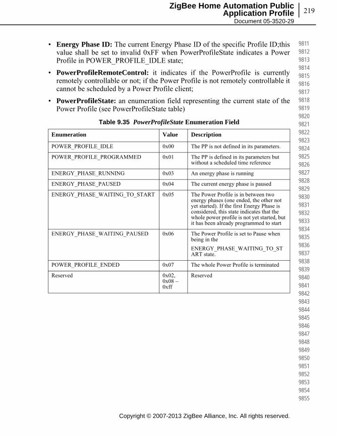
219
Copyright © 2007-2013 ZigBee Alliance, Inc. All rights reserved.
ZigBee Home Automation Public Application Profile
Document 05-3520-29
981198129813981498159816981798189819982098219822982398249825982698279828982998309831983298339834983598369837983898399840984198429843984498459846984798489849985098519852985398549855
• Energy Phase ID: The current Energy Phase ID of the specific Profile ID;this value shall be set to invalid 0xFF when PowerProfileState indicates a Power Profile in POWER_PROFILE_IDLE state;
• PowerProfileRemoteControl: it indicates if the PowerProfile is currently remotely controllable or not; if the Power Profile is not remotely controllable it cannot be scheduled by a Power Profile client;
• PowerProfileState: an enumeration field representing the current state of the Power Profile (see PowerProfileState table)
Table 9.35 PowerProfileState Enumeration Field
Enumeration Value Description
POWER_PROFILE_IDLE 0x00 The PP is not defined in its parameters.
POWER_PROFILE_PROGRAMMED 0x01 The PP is defined in its parameters but without a scheduled time reference
ENERGY_PHASE_RUNNING 0x03 An energy phase is running
ENERGY_PHASE_PAUSED 0x04 The current energy phase is paused
ENERGY_PHASE_WAITING_TO_START 0x05 The Power Profile is in between two energy phases (one ended, the other not yet started). If the first Energy Phase is considered, this state indicates that the whole power profile is not yet started, but it has been already programmed to start
ENERGY_PHASE_WAITING_PAUSED 0x06 The Power Profile is set to Pause when being in the
ENERGY_PHASE_WAITING_TO_START state.
POWER_PROFILE_ENDED 0x07 The whole Power Profile is terminated
Reserved 0x02, 0x08 – 0xff
Reserved

Copyright © 2007-2013 ZigBee Alliance, Inc. All rights reserved.
Chapter 9Home Automation Specific Cluster 220
985698579858985998609861986298639864986598669867986898699870987198729873987498759876987798789879988098819882988398849885988698879888988998909891989298939894989598969897989898999900
Figure 9.23 Power Profile States

221
Copyright © 2007-2013 ZigBee Alliance, Inc. All rights reserved.
ZigBee Home Automation Public Application Profile
Document 05-3520-29
990199029903990499059906990799089909991099119912991399149915991699179918991999209921992299239924992599269927992899299930993199329933993499359936993799389939994099419942994399449945
Figure 9.24 Power Profile State Diagram
9.5.6.3.2 When Generated
This command is generated when the command Power Profile State Request is received. Please refer to sub-clause 9.7.5.2.

Copyright © 2007-2013 ZigBee Alliance, Inc. All rights reserved.
Chapter 9Home Automation Specific Cluster 222
994699479948994999509951995299539954995599569957995899599960996199629963996499659966996799689969997099719972997399749975997699779978997999809981998299839984998599869987998899899990
9.5.6.3.3 Effect on Receipt
On receipt of this command, the originator is notified of the results of its Read Current Power Profiles attempt (i.e. receives the Power Profiles currently running in the server device).
9.5.6.4 Get Power Profile Price Command
The Get Power Profile Price command is generated by the server (e.g., White Goods) in order to retrieve the cost associated to a specific Power Profile. This command has the same payload as the Power Profile Request command (see 9.7.5.1).
9.5.6.4.1 Effects on Receipt
On receipt of this command, the recipient device shall generate a Get Power Profile Price Response command (see 9.7.5.3).
9.5.6.5 PowerProfileStateNotification Command
The Power Profile State Notification command is generated by the server (e.g. White Goods) in order to update the state of the power profile and the current energy phase. It has the same payload as the Power Profile State Response command but it is an unsolicited command.
9.5.6.5.1 Effects on Receipt
On receipt of this command, the recipient device will update its information related to the PowerProfile of the device (e.g., it will update the forecasts of the durations of the Power Profile’s energy phases with the actual data).
9.5.6.6 Get Overall Schedule Price Command
The Get Overall Schedule Price command is generated by the server (e.g., White Goods) in order to retrieve the overall cost associated to all the Power Profiles scheduled by the scheduler (the device supporting the Power Profile cluster client side) for the next 24 hours. This command has no payload.
9.5.6.6.1 Effects on Receipt
On receipt of this command, the recipient device shall generate a Get Overall Schedule Price Response command (9.7.5.4). See 9.7.10.1 for sequence diagrams and examples.
9.5.6.7 Energy Phases Schedule Request Command
The Energy Phases Schedule Request Command is generated by the server (e.g., White Goods) in order to retrieve from the scheduler (e.g., Home Gateway) the
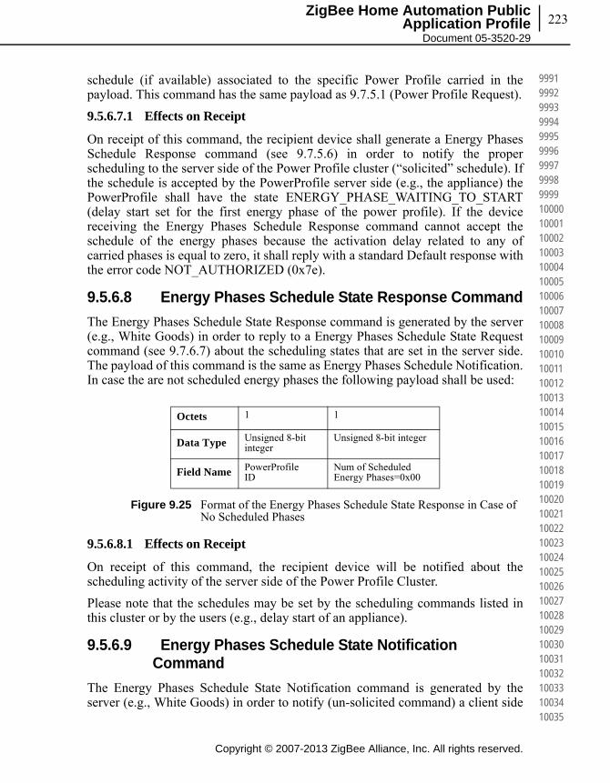
223
Copyright © 2007-2013 ZigBee Alliance, Inc. All rights reserved.
ZigBee Home Automation Public Application Profile
Document 05-3520-29
999199929993999499959996999799989999100001000110002100031000410005100061000710008100091001010011100121001310014100151001610017100181001910020100211002210023100241002510026100271002810029100301003110032100331003410035
schedule (if available) associated to the specific Power Profile carried in the payload. This command has the same payload as 9.7.5.1 (Power Profile Request).
9.5.6.7.1 Effects on Receipt
On receipt of this command, the recipient device shall generate a Energy Phases Schedule Response command (see 9.7.5.6) in order to notify the proper scheduling to the server side of the Power Profile cluster (“solicited” schedule). If the schedule is accepted by the PowerProfile server side (e.g., the appliance) the PowerProfile shall have the state ENERGY_PHASE_WAITING_TO_START (delay start set for the first energy phase of the power profile). If the device receiving the Energy Phases Schedule Response command cannot accept the schedule of the energy phases because the activation delay related to any of carried phases is equal to zero, it shall reply with a standard Default response with the error code NOT_AUTHORIZED (0x7e).
9.5.6.8 Energy Phases Schedule State Response Command
The Energy Phases Schedule State Response command is generated by the server (e.g., White Goods) in order to reply to a Energy Phases Schedule State Request command (see 9.7.6.7) about the scheduling states that are set in the server side. The payload of this command is the same as Energy Phases Schedule Notification. In case the are not scheduled energy phases the following payload shall be used:
Figure 9.25 Format of the Energy Phases Schedule State Response in Case of No Scheduled Phases
9.5.6.8.1 Effects on Receipt
On receipt of this command, the recipient device will be notified about the scheduling activity of the server side of the Power Profile Cluster.
Please note that the schedules may be set by the scheduling commands listed in this cluster or by the users (e.g., delay start of an appliance).
9.5.6.9 Energy Phases Schedule State Notification Command
The Energy Phases Schedule State Notification command is generated by the server (e.g., White Goods) in order to notify (un-solicited command) a client side
Octets 1 1
Data Type Unsigned 8-bit integer
Unsigned 8-bit integer
Field Name PowerProfileID
Num of Scheduled Energy Phases=0x00
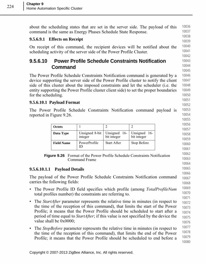
Copyright © 2007-2013 ZigBee Alliance, Inc. All rights reserved.
Chapter 9Home Automation Specific Cluster 224
100361003710038100391004010041100421004310044100451004610047100481004910050100511005210053100541005510056100571005810059100601006110062100631006410065100661006710068100691007010071100721007310074100751007610077100781007910080
about the scheduling states that are set in the server side. The payload of this command is the same as Energy Phases Schedule State Response.
9.5.6.9.1 Effects on Receipt
On receipt of this command, the recipient devices will be notified about the scheduling activity of the server side of the Power Profile Cluster.
9.5.6.10 Power Profile Schedule Constraints Notification Command
The Power Profile Schedule Constraints Notification command is generated by a device supporting the server side of the Power Profile cluster to notify the client side of this cluster about the imposed constraints and let the scheduler (i.e. the entity supporting the Power Profile cluster client side) to set the proper boundaries for the scheduling.
9.5.6.10.1 Payload Format
The Power Profile Schedule Constraints Notification command payload is reported in Figure 9.26.
Figure 9.26 Format of the Power Profile Schedule Constraints Notification Command Frame
9.5.6.10.1.1 Payload Details
The payload of the Power Profile Schedule Constraints Notification command carries the following fields:
• The Power Profile ID field specifies which profile (among TotalProfileNumtotal profiles number) the constraints are referring to.
• The StartAfter parameter represents the relative time in minutes (in respect to the time of the reception of this command), that limits the start of the Power Profile; it means that the Power Profile should be scheduled to start after a period of time equal to StartAfter; if this value is not specified by the device the value shall be 0x0000;
• The StopBefore parameter represents the relative time in minutes (in respect to the time of the reception of this command), that limits the end of the Power Profile; it means that the Power Profile should be scheduled to end before a
Octets 1 2 2
Data Type Unsigned 8-bit integer
Unsigned 16-bit integer
Unsigned 16-bit integer
Field Name PowerProfileID
Start After Stop Before
225
Copyright © 2007-2013 ZigBee Alliance, Inc. All rights reserved.
ZigBee Home Automation Public Application Profile
Document 05-3520-29
100811008210083100841008510086100871008810089100901009110092100931009410095100961009710098100991010010101101021010310104101051010610107101081010910110101111011210113101141011510116101171011810119101201012110122101231012410125
period of time equal to StopBefore; if this value is not specified by the device the value shall be 0xFFFF.
9.5.6.10.2 When Generated
This command is generated when the server side of the Power Profile cluster (e.g., a White Goods device), needs to notify a change in the constraints of the Power Profile (e.g., the user selected boundaries for the specific behavior of the device).
9.5.6.10.3 Effect on Receipt
The device that receives the Power Profile Schedule Constraints Notification command shall use the information carried in the payload of this command to refine the proper schedule of the specific Power Profile indicated in the Power Profile ID field in order to meet the constraints.
9.5.6.11 Power Profile Schedule Constraints Response Command
The Power Profile Schedule Constraints Response command is generated by a device supporting the server side of the Power Profile cluster to reply to a client side of this cluster which sent a Power Profile Schedule Constraints Request. The payload carries the selected constraints to let the scheduler (i.e. the entity supporting the Power Profile client cluster) to set the proper boundaries for completing or refining the scheduling.
9.5.6.11.1 Payload Format
Same as Power Profile Schedule Constraints Notification command (see 9.7.6.10)
9.5.6.11.1.1 When Generated
This command is generated as a reply to the Power Profile Schedule Constraints Request.
9.5.6.11.2 Effect on Receipt
The device that receives the Power Profile Schedule ConstraintsReponse command shall use the information carried in the payload of this command to refine the proper schedule of the specific Power Profile indicated in the Power ProfileID field.
9.5.6.12 Get Power Profile Price Extended Command
The Get Power Profile Price Extended command is generated by the server (e.g., White Goods) in order to retrieve the cost associated to a specific Power Profile considering specific conditions described in the option field (e.g., a specific time).

Copyright © 2007-2013 ZigBee Alliance, Inc. All rights reserved.
Chapter 9Home Automation Specific Cluster 226
101261012710128101291013010131101321013310134101351013610137101381013910140101411014210143101441014510146101471014810149101501015110152101531015410155101561015710158101591016010161101621016310164101651016610167101681016910170
9.5.6.12.1 Payload Format
The Get Power Profile Price Extended Command payload shall be formatted as illustrated in Figure 9.27.
Figure 9.27 Format of the Get Power Profile Price Extended Command Payload
Options
The Options field represents the type of request of extended price is requested to the client side of the power profile cluster (e.g., to a energy management system).
PowerProfileStartTime
The PowerProfileStartTime field represents the relative time (expressed in relative encoding in respect to the current time) when the overall Power Profile can potentially start. The unit is the minute.
9.5.6.12.2 Effects on Receipt
On receipt of this command, the recipient device shall generate a Get Power Profile Price Extended Response command (see 9.7.10.1 for sequence diagrams and examples).
9.5.7 Client Attributes
The client has no attributes.
Octets 1 1 0/2
Data Type Unsigned 8-bit bitmap Unsigned 8-bit integer Unsigned 16-bit integer
Field Name Options PowerProfileID PowerProfileStartTime
Table 9.36 Options Field
Bit Description
0 Bit0=1 : PowerProfileStartTime Field Present
1 Bit1=0 : provide an estimation of the price considering the power profile with contiguous energy phases
Bit1=1 : provide an estimation of the price considering the power profile as scheduled (i.e. taking in account delays between Energy phases set by the EMS)
2 to 7 Reserved

227
Copyright © 2007-2013 ZigBee Alliance, Inc. All rights reserved.
ZigBee Home Automation Public Application Profile
Document 05-3520-29
101711017210173101741017510176101771017810179101801018110182101831018410185101861018710188101891019010191101921019310194101951019610197101981019910200102011020210203102041020510206102071020810209102101021110212102131021410215
9.5.8 Client Commands Received
Description is in server side commands generated (sent) description.
9.5.9 Client Commands Generated
Description is in server side commands received description.
9.5.10 Example of Device Interactions Using the Power Profile (Informative Section)
9.5.10.1 Price Information Retrieved by the White Goods
The price of a specific appliance program is estimated by the Home gateway/EMS, calculated using the Power Profile forecast provided by the appliance and the PowerProfileStartTime contained in the GetPowerProfilePriceExtendedwhich indicates when the appliance program will start. How the Home Gateway/EMS retrieves from the utility the information related to tariff schemes and price changes over time is out of scope of this specification.
The appliance may then show to the user on the display the price associated to a specific cycle set (e.g. a washing machine program “Cotton 90 °C” will cost you “1.15€”).
Figure 9.28 Visualization of Price Associated to a Power Profile

Copyright © 2007-2013 ZigBee Alliance, Inc. All rights reserved.
Chapter 9Home Automation Specific Cluster 228
102161021710218102191022010221102221022310224102251022610227102281022910230102311023210233102341023510236102371023810239102401024110242102431024410245102461024710248102491025010251102521025310254102551025610257102581025910260
9.5.10.2 Interaction with Power Profile Cluster when Appliance is not Remotely Controllable
Figure 9.29 Energy Remote Disabled: Example of Sequence Diagram with User Interaction

229
Copyright © 2007-2013 ZigBee Alliance, Inc. All rights reserved.
ZigBee Home Automation Public Application Profile
Document 05-3520-29
102611026210263102641026510266102671026810269102701027110272102731027410275102761027710278102791028010281102821028310284102851028610287102881028910290102911029210293102941029510296102971029810299103001030110302103031030410305
9.5.10.3 Interaction with Power Profile Cluster when Appliance is Remotely Controllable (Scheduling of Appliance)
Figure 9.30 EnergyRemote Enabled: Example of Sequence Diagram with User Interaction
Smart Appliance Home Gateway
PP: PowerProfileNotification
PP: PowerProfileScheduleConstraintsNotification
PP: PowerProfileStateNotification(PP_PROGRAMMED, PP_REMOTE = False)
PP: EnergyPhasesScheduleResponse
PP: EnergyPhasesScheduleStateNotification
PP: PowerProfileStateNotification(EP_RUNNING, PP_REMOTE = Any)
PP: PowerProfileStateNotification(EP_WAITING_TO_START, PP_REMOTE = True)
Appliance isin PROGRAMMEDstate
Appliance goes
in PROGRAMMED WAITING TO STARTstate
Appliance isin RUNNING state
PP: EnergyPhasesScheduleRequest
PP: PowerProfileStateNotification(PP_ENDED, PP_REMOTE = False)
Appliance is
in END PROGRAMMED state
PP: EnergyPhasesScheduleNotification(eventually if PP_REMOTE = True)
* GetPowerProfilePriceExtended can be generated any time by SA if a PP is active
PP setting
Remote scheduling info
Scheduling request
PP: EnergyPhasesScheduleStateNotificationScheduling implementation
PP: EnergyPhasesScheduleStateNotification
Possible re-scheduling
PP: PowerProfileStateNotification(PP_IDLE, PP_REMOTE = False)
Appliance isin IDLE state(some appliance could not have)

Copyright © 2007-2013 ZigBee Alliance, Inc. All rights reserved.
Chapter 9Home Automation Specific Cluster 230
103061030710308103091031010311103121031310314103151031610317103181031910320103211032210323103241032510326103271032810329103301033110332103331033410335103361033710338103391034010341103421034310344103451034610347103481034910350
9.6 EN50523 Appliance Control Cluster
This section describes the EN50523 Appliance Control cluster.
9.6.1 Overview
This cluster provides an interface to remotely control and to program household appliances. Example of control is Start, Stop and Pause commands.
The status “read” and “set” is compliant to the EN50523 “Signal State” and “Execute Command” functional blocks. Appliances parameters (e.g., Duration and Remaining Time) have been added, since they were missing from the original specs.
Figure 9.31 Typical Usage of this Cluster
Note: Where a physical ZigBee node supports multiple endpoints it will often be the case that many of these settings will apply to the whole node, that is they are the same for every endpoint on the device. In such cases they can be implemented once for the node, and mapped to each endpoint.
9.6.2 References
The following standards and specifications contain provisions, which through reference in this document constitute provisions of this specification. All the standards and specifications listed are normative references. At the time of publication, the editions indicated were valid. All standards and specifications are subject to revision, and parties to agreements based on this specification are encouraged to investigate the possibility of applying the most recent editions of the standards and specifications indicated below.

231
Copyright © 2007-2013 ZigBee Alliance, Inc. All rights reserved.
ZigBee Home Automation Public Application Profile
Document 05-3520-29
103511035210353103541035510356103571035810359103601036110362103631036410365103661036710368103691037010371103721037310374103751037610377103781037910380103811038210383103841038510386103871038810389103901039110392103931039410395
9.6.2.1 ZigBee Alliance Documents
075366r00ZB_AFG-ZigBee_Cluster_Library_Public_download_version.pdf – this document describes the ZigBee Cluster Library framework and it is essential that it be understood in order to use this cluster definition document.
105684r00ZB_MWG-Energy@Home_Use_cases.pdf – This document describes the use cases requiring the use of this cluster
[email protected] – This document describes the marketing requirements for this new feature of HA
106085r00ZB_HA_PTG-Energy@Home_and_HA.ppt – This document describe the functional requirement of this cluster
106086r00ZB_HA_PTG-E@H_specification_ver0.7.pdf – This document describes the baseline for the definition of this cluster
106123r00ZB_MWG-Energy@Home_MRD.doc – This document describes the marketing requirements for this new feature of HA
BSI British Standards, document BS EN 50523-1:2009, “Household appliances interworking - Part 1: Functional specification”, July 2009.
BSI British Standards, document BS EN 50523-2:2009, “Household appliances interworking - Part 2: Data structures”, July 2009
9.6.3 General Description
9.6.3.1 Dependencies
None
9.6.4 Server Attributes
For convenience, the attributes defined in this specification are arranged into sets of related attributes; each set can contain up to 256 attributes. Attribute identifiers are encoded such that the most significant byte specifies the attribute set and the least significant byte specifies the attribute within the set. The currently defined attribute sets are listed in Table 9.37.
Table 9.37 Appliance Control Attribute Set
Attribute Set Identifier Description
0x00 Appliance Functions
0x01-0xff Reserved
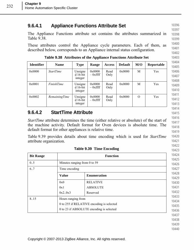
Copyright © 2007-2013 ZigBee Alliance, Inc. All rights reserved.
Chapter 9Home Automation Specific Cluster 232
103961039710398103991040010401104021040310404104051040610407104081040910410104111041210413104141041510416104171041810419104201042110422104231042410425104261042710428104291043010431104321043310434104351043610437104381043910440
9.6.4.1 Appliance Functions Attribute Set
The Appliance Functions attribute set contains the attributes summarized in Table 9.38.
These attributes control the Appliance cycle parameters. Each of them, as described below, corresponds to an Appliance internal status configuration.
9.6.4.2 StartTime Attribute
StartTime attribute determines the time (either relative or absolute) of the start of the machine activity. Default format for Oven devices is absolute time. The default format for other appliances is relative time.
Table 9.39 provides details about time encoding which is used for StartTimeattribute organization.
Table 9.38 Attributes of the Appliance Functions Attribute Set
Identifier Name Type Range Access Default M/O Reportable
0x0000 StartTime Unsigned 16-bit integer
0x0000 – 0xffff
Read Only
0x0000 M Yes
0x0001 FinishTime Unsigned 16-bit integer
0x0000 – 0xffff
Read Only
0x0000 M Yes
0x0002 RemainingTime Unsigned 16-bit integer
0x0000 – 0xffff
Read Only
0x0000 O Yes
Table 9.39 Time Encoding
Bit Range Function
0..5 Minutes ranging from 0 to 59
6..7 Time encoding
Value Enumeration
0x0
0x1
0x2..0x3
RELATIVE
ABSOLUTE
Reserved
8..15 Hours ranging from
0 to 255 if RELATIVE encoding is selected
0 to 23 if ABSOLUTE encoding is selected

233
Copyright © 2007-2013 ZigBee Alliance, Inc. All rights reserved.
ZigBee Home Automation Public Application Profile
Document 05-3520-29
104411044210443104441044510446104471044810449104501045110452104531045410455104561045710458104591046010461104621046310464104651046610467104681046910470104711047210473104741047510476104771047810479104801048110482104831048410485
9.6.4.3 FinishTime Attribute
FinishTime attribute determines the time (either relative or absolute) of the expected end of the machine activity. Default format for Oven is absolute time. The default format for other appliances is relative time.
FinishTime attribute exploits time encoding reported in Table 9.39.
9.6.4.4 RemainingTime Attribute
RemainingTime attribute determines the time, in relative format, of the remaining time of the machine cycle. It represents the time remaining to complete the machine cycle and it is updated only during the RUNNING state of the Appliance. During the other states of the Appliance RemainingTime attribute is indicated as the not valid value “0”.
RemainingTime attribute exploits time encoding reported in Table 9.39.
9.6.5 Server Commands Received
The command IDs for the Appliance Control cluster are listed in Table 9.40.
9.6.5.1 Execution of a Command
This basic message is used to remotely control and to program household appliances. Examples of control are START, STOP and PAUSE.
9.6.5.1.1 Payload Format
The Execution of a Command payload shall be formatted as illustrated in Figure 9.32.
Table 9.40 Cluster-specific Commands Received by the Server
Command Identifier Field Value Description Mandatory
/ Optional
0x00 Execution of a Command Oa
a. CCB 1770
0x01 Signal State M
0x02 Write Functions O
0x03 Overload Pause Resume O
0x04 Overload Pause O
0x05 Overload Warning O
0x06-0xff Reserved -

Copyright © 2007-2013 ZigBee Alliance, Inc. All rights reserved.
Chapter 9Home Automation Specific Cluster 234
104861048710488104891049010491104921049310494104951049610497104981049910500105011050210503105041050510506105071050810509105101051110512105131051410515105161051710518105191052010521105221052310524105251052610527105281052910530
Figure 9.32 Format of the Execution of a Command Payload
9.6.5.1.1.1 Payload Details
The Command Identification field: the command identification is an 8-bits in length field identifying the command to be executed. The enumeration used for this field shall match Table 9.41.
9.6.5.1.2 Effects on Receipt
On receipt of this command, the appliance shall execute the command given in the Command Identification field. The device application shall be informed of the imposed command (and potential personalized tasks could start, e.g., by means of a message to appliance Main Board controller).
After the command execution, the appliance shall generate a Signal State Notification with the new appliance state.
Octets 1
Data Type 8-bit enumerationerator
Field Name Command Identification
Table 9.41 Command Identification Values
Enumeration Value Description
Reserved 0x00 Reserved
Reserved 0x00 Reserved
START 0x01 Start appliance cycle
STOP 0x02 Stop appliance cycle
PAUSE 0x03 Pause appliance cycle
START SUPERFREEZING 0x04 Start superfreezing cycle
STOP SUPERFREEZING 0x05 Stop superfreezing cycle
START SUPERCOOLING 0x06 Start supercooling cycle
STOP SUPERCOOLING 0x07 Stop supercooling cycle
DISABLE GAS 0x08 Disable gas
ENABLE GAS 0x09 Enable gas
Standardized (TBD) 0x0A..0x3f Standardized (TBD)
Non standardized 0x40..0x7f Non standardized
Proprietary 0x80..0xff Proprietary

235
Copyright © 2007-2013 ZigBee Alliance, Inc. All rights reserved.
ZigBee Home Automation Public Application Profile
Document 05-3520-29
105311053210533105341053510536105371053810539105401054110542105431054410545105461054710548105491055010551105521055310554105551055610557105581055910560105611056210563105641056510566105671056810569105701057110572105731057410575
9.6.5.2 Signal State Command
This basic message is used to retrieve Household Appliances status. This command does not have a payload.
9.6.5.2.1 Effects on Receipt
On receipt of this command, the device shall generate a Signal State Response command.
9.6.5.3 Write Functions Command
This basic message is used to set appliance functions, i.e. information regarding the execution of an appliance cycle. Condition parameters such as start time or finish time information could be provided through this command.
9.6.5.3.1 Payload Format
The Write Functions command frame shall be formatted as illustrated in Figure 9.33.
Figure 9.33 Format of the Write Functions Command Frame
Write Functions record shall be formatted as illustrated in Figure 9.34.
Figure 9.34 Format of the Write Functions Record Field
9.6.5.3.2 Payload Details
The Function identifier field: the Function Identifier is 16-bits in length and shall contain the identifier of the function that is to be written.
The Function data type field: the function data type field shall contain the data type of the attribute that is to be written.
The Function data field: the function data field is variable in length and shall contain the actual value of the function that is to be written.
Octets Variable
Field Name Write Functions record
Octets 2 1 Variable
Data Type Unsigned 16-bit integer 8-bit enumerationerator Variable octets
Field Name Function identifier (i.e. attribute identifier)
Function data type Function data
Copyright © 2007-2013 ZigBee Alliance, Inc. All rights reserved.
Chapter 9Home Automation Specific Cluster 236
105761057710578105791058010581105821058310584105851058610587105881058910590105911059210593105941059510596105971059810599106001060110602106031060410605106061060710608106091061010611106121061310614106151061610617106181061910620
9.6.5.3.3 Effects on Receipt
On receipt of this command, the appliance shall set the function given in the Function identifier field. The Function identifier is actually changed only when the appliance internal functions have been changed.
If attribute reporting is configured on some function attributes, an attribute reporting command is generated when the internal appliance functions is actually modified. In case attribute reporting is not used, the correct execution of the Write Function command should be verified by using Read Attribute command on the written attribute.
9.6.5.4 Overload Pause Resume Command
This command shall be used to resume the normal behaviour of a household appliance being in pause mode after receiving a Overload Pause command.
9.6.5.4.1 Payload Format
The Overload Pause Resume Command shall have no payload.
9.6.5.4.2 Effects on Receipt
On receipt of this command, the appliance shall resume its operations.
9.6.5.5 Overload Pause Command
This command shall be used to pause the household appliance as a consequence of an imminent overload event.
9.6.5.6 Payload Format
The Overload Pause Command shall have no payload.
9.6.5.7 Effects on Receipt
On receipt of this command, the appliance shall pause its operations. In order to resume the normal operation an Overload Pause Resume command should be issued by the device supporting the client side of the Appliance control cluster.
9.6.5.8 Overload Warning Command
This basic message is used to send warnings the household appliance as a consequence of a possible overload event, or the notification of the end of the warning state.
9.6.5.8.1 Payload Format
The Overload Warning Command payload shall be formatted as illustrated in Figure 9.35.

237
Copyright © 2007-2013 ZigBee Alliance, Inc. All rights reserved.
ZigBee Home Automation Public Application Profile
Document 05-3520-29
106211062210623106241062510626106271062810629106301063110632106331063410635106361063710638106391064010641106421064310644106451064610647106481064910650106511065210653106541065510656106571065810659106601066110662106631066410665
Figure 9.35 Format of the Overload Warning Payload
9.6.5.8.1.1 Payload Details
The Warning Event field represents the identifier of the events that needs to be communicated to the devices to alert about possible overload.
Figure 9.36 Format of the Event ID Enumerator
9.6.5.8.2 Effects on Receipt
On receipt of this command, the appliance shall show the possible warning state on a display (e.g., showing an icon with possible overload condition when activating the appliance in case of Warnings 1-2) or resume the normal state in case of events showing the return on normal state (e.g., Warning 3-4).
9.6.6 Server Commands Generated
Table 9.42 lists commands are generated by the server.
Octets 2
Data Type 8-bit enumerationerator
Field Name Warning Event
Event ID Description
0x00 Warning 1: overall power above “available power” level
0x01 Warning 2: overall power above “power threshold” level
0x02 Warning 3: overall power back below the “available power” level
0x03 Warning 4: overall power back below the “power threshold” level
0x04 Warning 5: overall power will be potentially above “available power” level if the appliance starts
Table 9.42 Cluster-specific Commands Sent by the Server
Command Identifier Field Value Description Mandatory
/ Optional
0x00 Signal State Response M
0x01 Signal State Notification M
0x02-0xff Reserved -
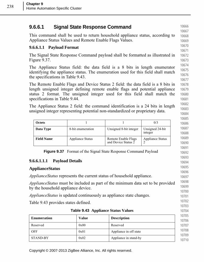
Copyright © 2007-2013 ZigBee Alliance, Inc. All rights reserved.
Chapter 9Home Automation Specific Cluster 238
106661066710668106691067010671106721067310674106751067610677106781067910680106811068210683106841068510686106871068810689106901069110692106931069410695106961069710698106991070010701107021070310704107051070610707107081070910710
9.6.6.1 Signal State Response Command
This command shall be used to return household appliance status, according to Appliance Status Values and Remote Enable Flags Values.
9.6.6.1.1 Payload Format
The Signal State Response Command payload shall be formatted as illustrated in Figure 9.37.
The Appliance Status field: the data field is a 8 bits in length enumerator identifying the appliance status. The enumeration used for this field shall match the specifications in Table 9.43.
The Remote Enable Flags and Device Status 2 field: the data field is a 8 bits in length unsigned integer defining remote enable flags and potential appliance status 2 format. The unsigned integer used for this field shall match the specifications in Table 9.44.
The Appliance Status 2 field: the command identification is a 24 bits in length unsigned integer representing potential non-standardized or proprietary data.
Figure 9.37 Format of the Signal State Response Command Payload
9.6.6.1.1.1 Payload Details
ApplianceStatus
ApplianceStatus represents the current status of household appliance.
ApplianceStatus must be included as part of the minimum data set to be provided by the household appliance device.
ApplianceStatus is updated continuously as appliance state changes.
Table 9.43 provides states defined.
Octets 1 1 0/3
Data Type 8-bit enumeration Unsigned 8-bit integer Unsigned 24-bit integer
Field Name Appliance Status Remote Enable Flags and Device Status 2
Appliance Status 2
Table 9.43 Appliance Status Values
Enumeration Value Description
Reserved 0x00 Reserved
OFF 0x01 Appliance in off state
STAND-BY 0x02 Appliance in stand-by

239
Copyright © 2007-2013 ZigBee Alliance, Inc. All rights reserved.
ZigBee Home Automation Public Application Profile
Document 05-3520-29
107111071210713107141071510716107171071810719107201072110722107231072410725107261072710728107291073010731107321073310734107351073610737107381073910740107411074210743107441074510746107471074810749107501075110752107531075410755
RemoteEnableFlags Field
RemoteEnableFlags represents the current status of household appliance correlated with remote control.
RemoteEnableFlags is mandatory and must be included as part of the minimum data set to be provided by the household appliance device.
RemoteEnableFlags is updated continuously when appliance state remote-controllability changes.
Table 9.44 provides details about flags organization.
PROGRAMMED 0x03 Appliance already programmed
PROGRAMMED WAITING TO START
0x04 Appliance already programmed and ready to start
RUNNING 0x05 Appliance is running
PAUSE 0x06 Appliance is in pause
END PROGRAMMED 0x07 Appliance end programmed tasks
FAILURE 0x08 Appliance is in a failure state
PROGRAMME INTERRUPTED
0x09 The appliance programmed tasks have been interrupted
IDLE 0x0a Appliance in idle state
RINSE HOLD 0x0b Appliance rinse hold
SERVICE 0x0c Appliance in service state
SUPERFREEZING 0x0d Appliance in superfreezing state
SUPERCOOLING 0x0e Appliance in supercooling state
SUPERHEATING 0x0f Appliance in superheating state
Reserved 0x10..0x3f Reserved
Non standardized 0x40..0x7f Non standardized
Proprietarya 0x80..0xff Proprietary
a. Reserved, Non Standardised and Proprietary from CECED naming conventions.
Table 9.43 Appliance Status Values
Enumeration Value Description
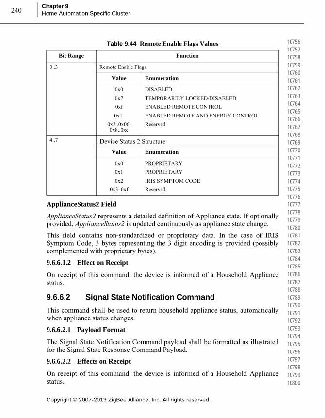
Copyright © 2007-2013 ZigBee Alliance, Inc. All rights reserved.
Chapter 9Home Automation Specific Cluster 240
107561075710758107591076010761107621076310764107651076610767107681076910770107711077210773107741077510776107771077810779107801078110782107831078410785107861078710788107891079010791107921079310794107951079610797107981079910800
ApplianceStatus2 Field
ApplianceStatus2 represents a detailed definition of Appliance state. If optionally provided, ApplianceStatus2 is updated continuously as appliance state change.
This field contains non-standardized or proprietary data. In the case of IRIS Symptom Code, 3 bytes representing the 3 digit encoding is provided (possibly complemented with proprietary bytes).
9.6.6.1.2 Effect on Receipt
On receipt of this command, the device is informed of a Household Appliance status.
9.6.6.2 Signal State Notification Command
This command shall be used to return household appliance status, automatically when appliance status changes.
9.6.6.2.1 Payload Format
The Signal State Notification Command payload shall be formatted as illustrated for the Signal State Response Command Payload.
9.6.6.2.2 Effects on Receipt
On receipt of this command, the device is informed of a Household Appliance status.
Table 9.44 Remote Enable Flags Values
Bit Range Function
0..3 Remote Enable Flags
Value Enumeration
0x0
0x7
0xf
0x1.
0x2..0x06, 0x8..0xe
DISABLED
TEMPORARILY LOCKED/DISABLED
ENABLED REMOTE CONTROL
ENABLED REMOTE AND ENERGY CONTROL
Reserved
4..7 Device Status 2 Structure
Value Enumeration
0x0
0x1
0x2
0x3..0xf
PROPRIETARY
PROPRIETARY
IRIS SYMPTOM CODE
Reserved
241
Copyright © 2007-2013 ZigBee Alliance, Inc. All rights reserved.
ZigBee Home Automation Public Application Profile
Document 05-3520-29
108011080210803108041080510806108071080810809108101081110812108131081410815108161081710818108191082010821108221082310824108251082610827108281082910830108311083210833108341083510836108371083810839108401084110842108431084410845
9.6.7 Client
9.6.7.1 Dependencies
None
9.6.7.2 Attributes
The client has no attributes.
9.6.7.3 Commands Received
Description is in server side commands generated (sent).
9.6.7.4 Commands Generated
Description is in server side commands received.
9.7 EN50523 Appliance Identification Cluster
9.7.1 Overview
Attributes and commands for determining basic information about a device and setting user device information.
The Appliance Identification Cluster is a transposition of EN50523 “Identify Product” functional block.
Note: Where a physical ZigBee node supports multiple endpoints it will often be the case that many of these settings will apply to the whole node, that is they are the same for every endpoint on the device. In such cases they can be implemented once for the node, and mapped to each endpoint.
9.7.2 Server
9.7.2.1 Attributes
For convenience, the attributes defined in this specification are arranged into sets of related attributes; each set can contain up to 16 attributes. Attribute identifiers are encoded such that the most significant three nibbles specify the attribute set and the least significant nibble specifies the attribute within the set. The currently defined attribute sets are listed in Table 9.45.

Copyright © 2007-2013 ZigBee Alliance, Inc. All rights reserved.
Chapter 9Home Automation Specific Cluster 242
108461084710848108491085010851108521085310854108551085610857108581085910860108611086210863108641086510866108671086810869108701087110872108731087410875108761087710878108791088010881108821088310884108851088610887108881088910890
9.7.2.2 Basic Appliance Identification Attribute Set
The Basic Appliance Identification attribute set contains the attributes summarized in Table 9.46.
9.7.2.3 BasicIdentification Attribute
BasicIdentification is 56-bit bitmap (7 octets) and contains the basic appliance identification.
BasicIdentification is mandatory and must be included as part of the minimum data set to be provided by the household appliance device.
Table 9.47 provides attribute content specification.
Company ID and Brand ID fields content could be se according to [B7], Table 5.
Table 9.48 provides Product Type IDs field content, again according to [B7] (see Table 6).
Table 9.45 Appliance Identification Attribute Sets
Attribute Set Identifier Description
0x000 Basic Appliance Identification
0x001 Extended Appliance Identification
0x002-0xfff Reserved
Table 9.46 Attributes of the Appliance Identification Attribute Set
Identifier Name Type Range Access Default M/O Reportable
0x0000 BasicIdentification
Unsigned 56-bit integer
(Length: 7 octets)
Read only
- M No
Table 9.47 Basic Appliance Identification Content Specification
Attribute Name Field Bits
BasicIdentification Company ID 0x00-0x0f
Brand ID 0x10-0x1f
Product Type ID 0x20-0x2f
Spec. Ver. 0x37-0x30

243
Copyright © 2007-2013 ZigBee Alliance, Inc. All rights reserved.
ZigBee Home Automation Public Application Profile
Document 05-3520-29
108911089210893108941089510896108971089810899109001090110902109031090410905109061090710908109091091010911109121091310914109151091610917109181091910920109211092210923109241092510926109271092810929109301093110932109331093410935
9.7.2.4 Extended Appliance Identification Attribute Set
The Extended Appliance Identification attribute set contains the attributes summarized in Table 9.49.
Table 9.48 Product Type IDs
Device (Appliance) Product Type ID
White Goods 0x0000
Dishwasher 0x5601
Tumble Dryer 0x5602
Washer Dryer 0x5603
Washing Machine 0x5604
Hobs 0x5E03
Induction Hobs 0x5E09
Oven 0x5E01
Electrical Oven 0x5E06
Refrigerator Freezer 0x6601
Table 9.49 Attributes of the Extended Appliance Identification Attribute Set
Identifier Name Type Range Access Default M/O Reportable
0x0010 CompanyName
Character String
0 to 16 Octets
Read only
- O No
0x0011 CompanyId Unsigned 16-bit integer
0x0000 – 0xffff
Read only
- O No
0x0012 BrandName Character String
0 to 16 Octets
Read only
- O No
0x0013 BrandId Unsigned 16-bit integer
0x0000 – 0xffff
Read only
O No
0x0014 Model Octet String
0 to 16 Octets
Read only
O No
0x0015 PartNumber Octet String
0 to 16 Octets
Read only
O No
0x0016 ProductRevision
Octet String
0 to 6 Octets
Read only
O No
0x0017 SoftwareRevision
Octet String
0 to 6 Octets
Read only
O No
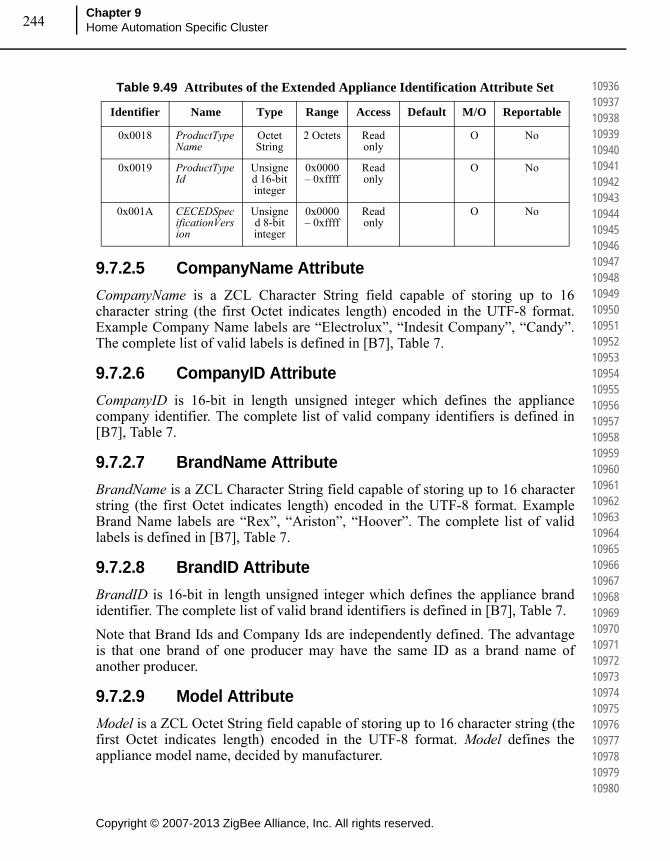
Copyright © 2007-2013 ZigBee Alliance, Inc. All rights reserved.
Chapter 9Home Automation Specific Cluster 244
109361093710938109391094010941109421094310944109451094610947109481094910950109511095210953109541095510956109571095810959109601096110962109631096410965109661096710968109691097010971109721097310974109751097610977109781097910980
9.7.2.5 CompanyName Attribute
CompanyName is a ZCL Character String field capable of storing up to 16 character string (the first Octet indicates length) encoded in the UTF-8 format. Example Company Name labels are “Electrolux”, “Indesit Company”, “Candy”. The complete list of valid labels is defined in [B7], Table 7.
9.7.2.6 CompanyID Attribute
CompanyID is 16-bit in length unsigned integer which defines the appliance company identifier. The complete list of valid company identifiers is defined in [B7], Table 7.
9.7.2.7 BrandName Attribute
BrandName is a ZCL Character String field capable of storing up to 16 character string (the first Octet indicates length) encoded in the UTF-8 format. Example Brand Name labels are “Rex”, “Ariston”, “Hoover”. The complete list of valid labels is defined in [B7], Table 7.
9.7.2.8 BrandID Attribute
BrandID is 16-bit in length unsigned integer which defines the appliance brand identifier. The complete list of valid brand identifiers is defined in [B7], Table 7.
Note that Brand Ids and Company Ids are independently defined. The advantage is that one brand of one producer may have the same ID as a brand name of another producer.
9.7.2.9 Model Attribute
Model is a ZCL Octet String field capable of storing up to 16 character string (the first Octet indicates length) encoded in the UTF-8 format. Model defines the appliance model name, decided by manufacturer.
0x0018 ProductTypeName
Octet String
2 Octets Read only
O No
0x0019 ProductTypeId
Unsigned 16-bit integer
0x0000 – 0xffff
Read only
O No
0x001A CECEDSpecificationVersion
Unsigned 8-bit integer
0x0000 – 0xffff
Read only
O No
Table 9.49 Attributes of the Extended Appliance Identification Attribute Set
Identifier Name Type Range Access Default M/O Reportable

245
Copyright © 2007-2013 ZigBee Alliance, Inc. All rights reserved.
ZigBee Home Automation Public Application Profile
Document 05-3520-29
109811098210983109841098510986109871098810989109901099110992109931099410995109961099710998109991100011001110021100311004110051100611007110081100911010110111101211013110141101511016110171101811019110201102111022110231102411025
9.7.2.10 PartNumber Attribute
PartNumber is a ZCL Octet String field capable of storing up to 16 character string (the first Octet indicates length) encoded in the UTF-8 format. PartNumber defines the appliance part number, decided by manufacturer.
9.7.2.11 ProductRevision Attribute
ProductRevision is a ZCL Octet String field capable of storing up to 6 character string (the first Octet indicates length) encoded in the UTF-8 format. ProductRevision defines the appliance revision code, decided by manufacturer.
9.7.2.12 SoftwareRevision Attribute
SoftwareRevision is a ZCL Octet String field capable of storing up to 6 character string (the first Octet indicates length) encoded in the UTF-8 format. SoftwareRevision defines the appliance software revision code, decided by manufacturer.
9.7.2.13 ProductTypeName Attribute
ProductTypeName is a 2 Octet in length String field which defines the appliance type label. Example ProductTypeName labels are “WM”, “RE”, “GO”, respectively for Washing Machine, Refrigerator and Gas Oven. The complete list of valid labels is defined in [B7], Table 8.
9.7.2.14 ProductTypeID Attribute
ProductTypeID is a 16-bit in length unsigned integer which defines the appliance type identifier. The structure and complete list of valid ProductTypeIds is defined in [B7], Table 7.
9.7.2.15 CECEDSpecificationVersion Attribute
CECEDSpecificationVersion is a 8-bit in length unsigned integer which defines the CECED reference documentation. Compliance and certification of appliance communication capabilities can be defined according to Table 9.50 (see [B7], Table 10).

Copyright © 2007-2013 ZigBee Alliance, Inc. All rights reserved.
Chapter 9Home Automation Specific Cluster 246
110261102711028110291103011031110321103311034110351103611037110381103911040110411104211043110441104511046110471104811049110501105111052110531105411055110561105711058110591106011061110621106311064110651106611067110681106911070
9.7.2.16 Commands Received
No cluster-specific commands are received by the server.
9.7.2.17 Commands Generated
No cluster-specific commands are generated by the server.
9.7.3 Client
9.7.3.1 Attributes
The Client cluster has no attributes.
9.7.3.2 Commands Received
No cluster-specific commands are received by the client.
9.7.3.3 Commands Generated
No cluster-specific commands are generated by the client.
9.8 Meter Identification Cluster
9.8.1 Overview
This cluster provides Attributes and commands for determining advanced information about utility metering device.
Note: Where a physical ZigBee node supports multiple endpoints it will often be the case that many of these settings will apply to the whole node, that is they are the same for every endpoint on the device. In such cases they can be implemented once for the node, and mapped to each endpoint.
Table 9.50 CECED Specification Version
Specification Version Value
Compliant with v1.0, not certified 0x10
Compliant with v1.0, certified 0x1A
Compliant with vX.0, not certified 0xX0
Compliant with vX.0, certified 0xXA
Other values Reserved

247
Copyright © 2007-2013 ZigBee Alliance, Inc. All rights reserved.
ZigBee Home Automation Public Application Profile
Document 05-3520-29
110711107211073110741107511076110771107811079110801108111082110831108411085110861108711088110891109011091110921109311094110951109611097110981109911100111011110211103111041110511106111071110811109111101111111112111131111411115
Figure 9.38 Typical Usage of This Cluster
9.8.2 References
The following standards and specifications contain provisions, which through reference in this document constitute provisions of this specification. All the standards and specifications listed are normative references. At the time of publication, the editions indicated were valid. All standards and specifications are subject to revision, and parties to agreements based on this specification are encouraged to investigate the possibility of applying the most recent editions of the standards and specifications indicated below.
075366r00ZB_AFG-ZigBee_Cluster_Library_Public_download_version.pdf – this document describes the ZigBee Cluster Library framework and it is essential that it be understood in order to use this cluster definition document.
105684r00ZB_MWG-Energy@Home_Use_cases.pdf – This document describes the use cases requiring the use of this cluster
[email protected] – This document describes the marketing requirements for this new feature of HA
106085r00ZB_HA_PTG-Energy@Home_and_HA.ppt – This document describe the functional requirement of this cluster
106086r00ZB_HA_PTG-E@H_specification_ver0.7.pdf – This document describes the baseline for the definition of this cluster
106123r00ZB_MWG-Energy@Home_MRD.doc – This document describes the marketing requirements for this new feature of HA
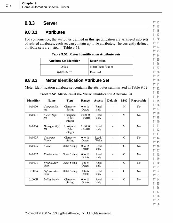
Copyright © 2007-2013 ZigBee Alliance, Inc. All rights reserved.
Chapter 9Home Automation Specific Cluster 248
111161111711118111191112011121111221112311124111251112611127111281112911130111311113211133111341113511136111371113811139111401114111142111431114411145111461114711148111491115011151111521115311154111551115611157111581115911160
9.8.3 Server
9.8.3.1 Attributes
For convenience, the attributes defined in this specification are arranged into sets of related attributes; each set can contain up to 16 attributes. The currently defined attribute sets are listed in Table 9.51.
9.8.3.2 Meter Identification Attribute Set
Meter Identification attribute set contains the attributes summarized in Table 9.52.
Table 9.51 Meter Identification Attribute Sets
Attribute Set Identifier Description
0x000 Meter Identification
0x001-0xfff Reserved
Table 9.52 Attributes of the Meter Identification Attribute Set
Identifier Name Type Range Access Default M/O Reportable
0x0000 CompanyName
Character String
0 to 16 Octets
Read only
- M No
0x0001 Meter Type ID
Unsigned 16-bit integer
0x0000 – 0xffff
Read only
- M No
0x0004 Data Quality ID
Unsigned 16-bit integer
0x0000 – 0xffff
Read only
- M No
0x0005 Customer Name
Character String
0 to 16 Octets
Read / Write
- O No
0x0006 Model Octet String 0 to 16 Octets
Read only
- O No
0x0007 PartNumber Octet String 0 to 16 Octets
Read only
- O No
0x0008 ProductRevision
Octet String 0 to 6 Octets
Read only
- O No
0x000A SoftwareRevision
Octet String 0 to 6 Octets
Read only
- O No
0x000B Utility Name Character String
0 to 16 Octets
Read only
- O No
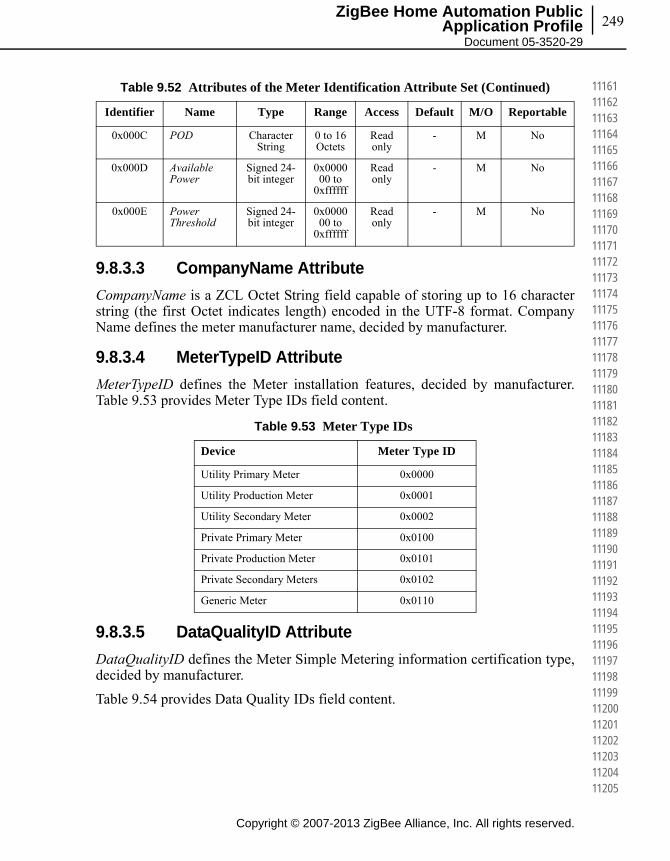
249
Copyright © 2007-2013 ZigBee Alliance, Inc. All rights reserved.
ZigBee Home Automation Public Application Profile
Document 05-3520-29
111611116211163111641116511166111671116811169111701117111172111731117411175111761117711178111791118011181111821118311184111851118611187111881118911190111911119211193111941119511196111971119811199112001120111202112031120411205
9.8.3.3 CompanyName Attribute
CompanyName is a ZCL Octet String field capable of storing up to 16 character string (the first Octet indicates length) encoded in the UTF-8 format. Company Name defines the meter manufacturer name, decided by manufacturer.
9.8.3.4 MeterTypeID Attribute
MeterTypeID defines the Meter installation features, decided by manufacturer. Table 9.53 provides Meter Type IDs field content.
9.8.3.5 DataQualityID Attribute
DataQualityID defines the Meter Simple Metering information certification type, decided by manufacturer.
Table 9.54 provides Data Quality IDs field content.
0x000C POD Character String
0 to 16 Octets
Read only
- M No
0x000D Available Power
Signed 24-bit integer
0x000000 to
0xffffff
Read only
- M No
0x000E Power Threshold
Signed 24-bit integer
0x000000 to
0xffffff
Read only
- M No
Table 9.53 Meter Type IDs
Device Meter Type ID
Utility Primary Meter 0x0000
Utility Production Meter 0x0001
Utility Secondary Meter 0x0002
Private Primary Meter 0x0100
Private Production Meter 0x0101
Private Secondary Meters 0x0102
Generic Meter 0x0110
Table 9.52 Attributes of the Meter Identification Attribute Set (Continued)
Identifier Name Type Range Access Default M/O Reportable
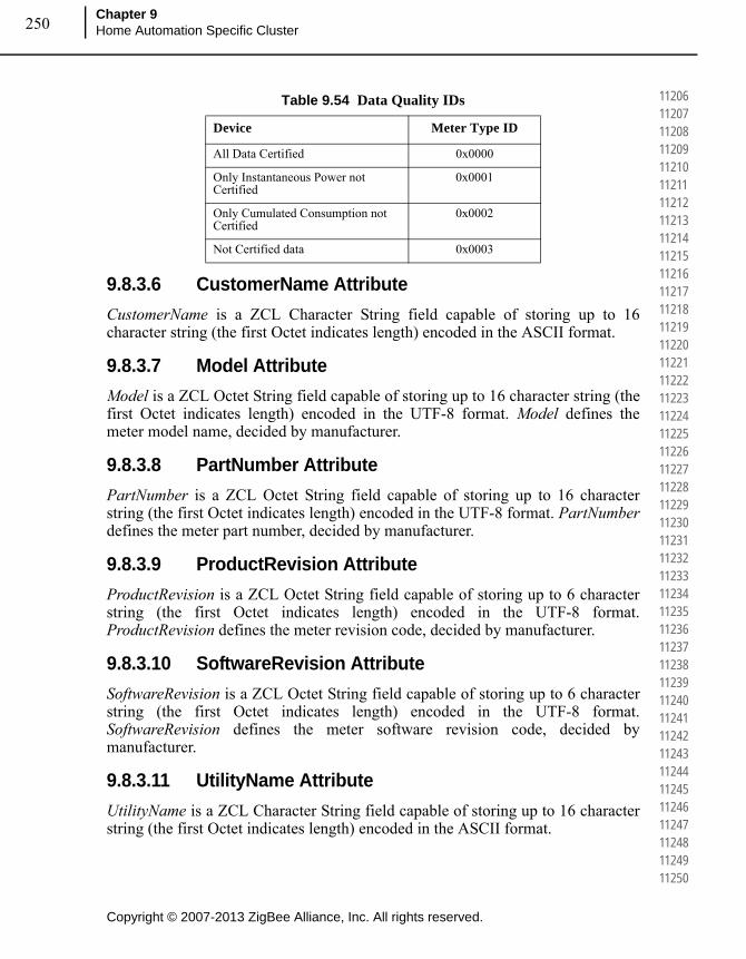
Copyright © 2007-2013 ZigBee Alliance, Inc. All rights reserved.
Chapter 9Home Automation Specific Cluster 250
112061120711208112091121011211112121121311214112151121611217112181121911220112211122211223112241122511226112271122811229112301123111232112331123411235112361123711238112391124011241112421124311244112451124611247112481124911250
9.8.3.6 CustomerName Attribute
CustomerName is a ZCL Character String field capable of storing up to 16 character string (the first Octet indicates length) encoded in the ASCII format.
9.8.3.7 Model Attribute
Model is a ZCL Octet String field capable of storing up to 16 character string (the first Octet indicates length) encoded in the UTF-8 format. Model defines the meter model name, decided by manufacturer.
9.8.3.8 PartNumber Attribute
PartNumber is a ZCL Octet String field capable of storing up to 16 character string (the first Octet indicates length) encoded in the UTF-8 format. PartNumber defines the meter part number, decided by manufacturer.
9.8.3.9 ProductRevision Attribute
ProductRevision is a ZCL Octet String field capable of storing up to 6 character string (the first Octet indicates length) encoded in the UTF-8 format. ProductRevision defines the meter revision code, decided by manufacturer.
9.8.3.10 SoftwareRevision Attribute
SoftwareRevision is a ZCL Octet String field capable of storing up to 6 character string (the first Octet indicates length) encoded in the UTF-8 format. SoftwareRevision defines the meter software revision code, decided by manufacturer.
9.8.3.11 UtilityName Attribute
UtilityName is a ZCL Character String field capable of storing up to 16 character string (the first Octet indicates length) encoded in the ASCII format.
Table 9.54 Data Quality IDs
Device Meter Type ID
All Data Certified 0x0000
Only Instantaneous Power not Certified
0x0001
Only Cumulated Consumption not Certified
0x0002
Not Certified data 0x0003

251
Copyright © 2007-2013 ZigBee Alliance, Inc. All rights reserved.
ZigBee Home Automation Public Application Profile
Document 05-3520-29
112511125211253112541125511256112571125811259112601126111262112631126411265112661126711268112691127011271112721127311274112751127611277112781127911280112811128211283112841128511286112871128811289112901129111292112931129411295
9.8.3.12 POD Attribute
POD (Point of Delivery) is a ZCL Character String field capable of storing up to 16 character string (the first Octet indicates length) encoded in the ASCII format. POD is the unique identification ID of the premise connection point. It is also a contractual information known by the clients and indicated in the bill.
9.8.3.13 AvailablePower
AvailablePower represents the InstantaneousDemand that can be distributed to the customer (e.g., 3.3KW power) without any risk of overload. The Available Power shall use the same formatting conventions as the one used in the simple metering cluster formatting attribute set for the InstantaneousDemand attribute, i.e. the UnitOfMeasure and DemandFormatting.
9.8.3.14 PowerThreshold
PowerThreshold represents a threshold of InstantaneousDemand distributed to the customer (e.g., 4.191KW) that will lead to an imminent risk of overload. The PowerThreshold shall use the same formatting conventions as the one used in the AvailablePower attributes and therefore in the simple metering cluster formatting attribute set for the InstantaneousDemand attribute, i.e. the UnitOfMeasure and DemandFormatting.
9.8.3.15 Commands Received
No cluster-specific commands are received by the server.
9.8.3.16 Commands Generated
No cluster-specific commands are generated by the server.
9.8.4 Client
9.8.4.1 Attributes
The Client has no attributes.
9.8.4.2 Commands Received
No cluster-specific commands are received by the client.
9.8.4.3 Commands Generated
No cluster-specific commands are generated by the client.
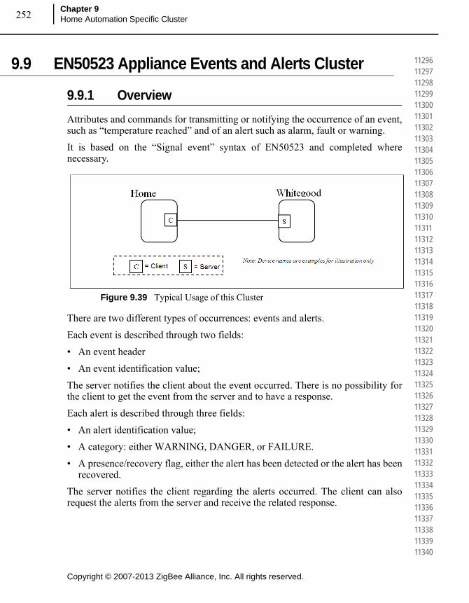
Copyright © 2007-2013 ZigBee Alliance, Inc. All rights reserved.
Chapter 9Home Automation Specific Cluster 252
112961129711298112991130011301113021130311304113051130611307113081130911310113111131211313113141131511316113171131811319113201132111322113231132411325113261132711328113291133011331113321133311334113351133611337113381133911340
9.9 EN50523 Appliance Events and Alerts Cluster
9.9.1 Overview
Attributes and commands for transmitting or notifying the occurrence of an event, such as “temperature reached” and of an alert such as alarm, fault or warning.
It is based on the “Signal event” syntax of EN50523 and completed where necessary.
Figure 9.39 Typical Usage of this Cluster
There are two different types of occurrences: events and alerts.
Each event is described through two fields:
• An event header
• An event identification value;
The server notifies the client about the event occurred. There is no possibility for the client to get the event from the server and to have a response.
Each alert is described through three fields:
• An alert identification value;
• A category: either WARNING, DANGER, or FAILURE.
• A presence/recovery flag, either the alert has been detected or the alert has been recovered.
The server notifies the client regarding the alerts occurred. The client can also request the alerts from the server and receive the related response.
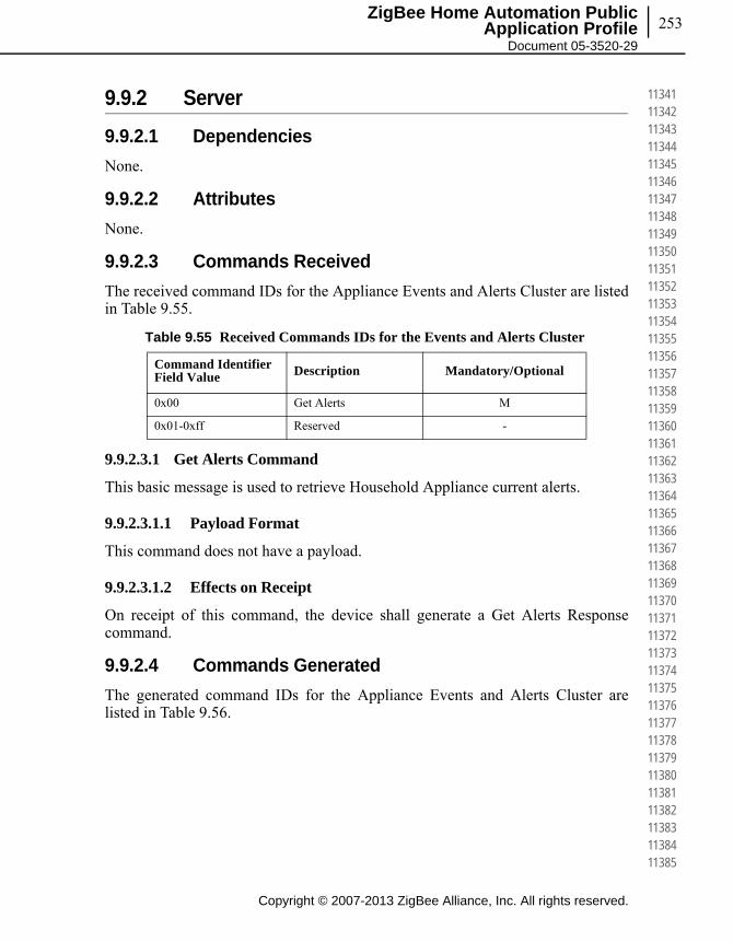
253
Copyright © 2007-2013 ZigBee Alliance, Inc. All rights reserved.
ZigBee Home Automation Public Application Profile
Document 05-3520-29
113411134211343113441134511346113471134811349113501135111352113531135411355113561135711358113591136011361113621136311364113651136611367113681136911370113711137211373113741137511376113771137811379113801138111382113831138411385
9.9.2 Server
9.9.2.1 Dependencies
None.
9.9.2.2 Attributes
None.
9.9.2.3 Commands Received
The received command IDs for the Appliance Events and Alerts Cluster are listed in Table 9.55.
9.9.2.3.1 Get Alerts Command
This basic message is used to retrieve Household Appliance current alerts.
9.9.2.3.1.1 Payload Format
This command does not have a payload.
9.9.2.3.1.2 Effects on Receipt
On receipt of this command, the device shall generate a Get Alerts Response command.
9.9.2.4 Commands Generated
The generated command IDs for the Appliance Events and Alerts Cluster are listed in Table 9.56.
Table 9.55 Received Commands IDs for the Events and Alerts Cluster
Command Identifier Field Value Description Mandatory/Optional
0x00 Get Alerts M
0x01-0xff Reserved -

Copyright © 2007-2013 ZigBee Alliance, Inc. All rights reserved.
Chapter 9Home Automation Specific Cluster 254
113861138711388113891139011391113921139311394113951139611397113981139911400114011140211403114041140511406114071140811409114101141111412114131141411415114161141711418114191142011421114221142311424114251142611427114281142911430
9.9.2.4.1 Get Alerts Response Command
This message is used to return household appliance current alerts.
9.9.2.4.1.1 Payload Format
The payload shall be formatted as illustrated in Figure 9.40.
Figure 9.40 Format of the Get Alerts Response Command Payload
9.9.2.4.1.1.1 Payload Details
The Alerts Count field: the data field is a 8 bits in length unsigned integer, containing the following alerts structures count and alert structure type.
Table 9.57 provides details about Alerts Count and Structure field organization.
Table 9.56 Generated Commands IDs for the Appliance Eventsand Alerts Cluster
Command Identifier Field Value Description Mandatory/Optional
0x00 Get Alerts Response M
0x01 Alerts Notification M
0x02 Event Notification M
0x03 – 0xff Reserved -
Octets 1 3 ... 3
Data Type Unsigned 8-bit integer
Unsigned 24-bit integer
... Unsigned 24-bit integer
Field Name Alerts Counta
a. Even if the ApplianceAlertList array number of element field is 16-bit in length, the actual content is limited to 0x000n, where, in actual implementations, n is lower than 255 (except for the invalid condition, 0xffff). Then, the notification of the Alert count is mapped to a single byte (following appliance interworking specifications).
Alert structure 1 ... Alert structure n

255
Copyright © 2007-2013 ZigBee Alliance, Inc. All rights reserved.
ZigBee Home Automation Public Application Profile
Document 05-3520-29
114311143211433114341143511436114371143811439114401144111442114431144411445114461144711448114491145011451114521145311454114551145611457114581145911460114611146211463114641146511466114671146811469114701147111472114731147411475
Each Alerts Structure field shall be formatted as illustrated in Table 9.58.
The Alert ID field can have the following values:
• Value 0 is reserved.
• Values ranging from 1 to 63 are standardised.
• Values ranging from 64 to 127 are non-standardised.
• Values ranging from 128 to 255 are proprietary.
Table 9.57 Alert Count Organization
Bit range Function
0..3 Number of Alerts n.
4..7 Type of alert.
Value Enumeration
0x0
0x1..0xf
UNSTRUCTURED
Reserved
Table 9.58 Alerts Structure Organization
Bit range Function
0..7 Alert id
8..11 Category
Value Enumeration
0x0
0x1
0x2
0x3
0x4 – 0xf
Reserved
WARNING
DANGER
FAILURE
Reserved
12..13 Presence recovery
Value Enumeration
0x0
0x1
0x2 – 0x3
RECOVERY
PRESENCE
Reserved
14..15 Reserved (set to 0x0)
16..23 Non-standardised or proprietary
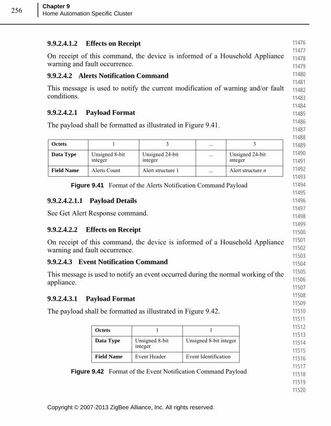
Copyright © 2007-2013 ZigBee Alliance, Inc. All rights reserved.
Chapter 9Home Automation Specific Cluster 256
114761147711478114791148011481114821148311484114851148611487114881148911490114911149211493114941149511496114971149811499115001150111502115031150411505115061150711508115091151011511115121151311514115151151611517115181151911520
9.9.2.4.1.2 Effects on Receipt
On receipt of this command, the device is informed of a Household Appliance warning and fault occurrence.
9.9.2.4.2 Alerts Notification Command
This message is used to notify the current modification of warning and/or fault conditions.
9.9.2.4.2.1 Payload Format
The payload shall be formatted as illustrated in Figure 9.41.
Figure 9.41 Format of the Alerts Notification Command Payload
9.9.2.4.2.1.1 Payload Details
See Get Alert Response command.
9.9.2.4.2.2 Effects on Receipt
On receipt of this command, the device is informed of a Household Appliance warning and fault occurrence.
9.9.2.4.3 Event Notification Command
This message is used to notify an event occurred during the normal working of the appliance.
9.9.2.4.3.1 Payload Format
The payload shall be formatted as illustrated in Figure 9.42.
Figure 9.42 Format of the Event Notification Command Payload
Octets 1 3 ... 3
Data Type Unsigned 8-bit integer
Unsigned 24-bit integer
... Unsigned 24-bit integer
Field Name Alerts Count Alert structure 1 ... Alert structure n
Octets 1 1
Data Type Unsigned 8-bit integer
Unsigned 8-bit integer
Field Name Event Header Event Identification
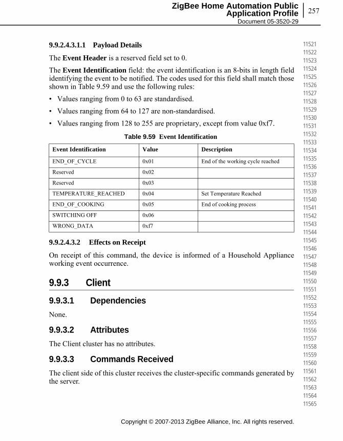
257
Copyright © 2007-2013 ZigBee Alliance, Inc. All rights reserved.
ZigBee Home Automation Public Application Profile
Document 05-3520-29
115211152211523115241152511526115271152811529115301153111532115331153411535115361153711538115391154011541115421154311544115451154611547115481154911550115511155211553115541155511556115571155811559115601156111562115631156411565
9.9.2.4.3.1.1 Payload Details
The Event Header is a reserved field set to 0.
The Event Identification field: the event identification is an 8-bits in length field identifying the event to be notified. The codes used for this field shall match those shown in Table 9.59 and use the following rules:
• Values ranging from 0 to 63 are standardised.
• Values ranging from 64 to 127 are non-standardised.
• Values ranging from 128 to 255 are proprietary, except from value 0xf7.
9.9.2.4.3.2 Effects on Receipt
On receipt of this command, the device is informed of a Household Appliance working event occurrence.
9.9.3 Client
9.9.3.1 Dependencies
None.
9.9.3.2 Attributes
The Client cluster has no attributes.
9.9.3.3 Commands Received
The client side of this cluster receives the cluster-specific commands generated by the server.
Table 9.59 Event Identification
Event Identification Value Description
END_OF_CYCLE 0x01 End of the working cycle reached
Reserved 0x02
Reserved 0x03
TEMPERATURE_REACHED 0x04 Set Temperature Reached
END_OF_COOKING 0x05 End of cooking process
SWITCHING OFF 0x06
WRONG_DATA 0xf7

Copyright © 2007-2013 ZigBee Alliance, Inc. All rights reserved.
Chapter 9Home Automation Specific Cluster 258
115661156711568115691157011571115721157311574115751157611577115781157911580115811158211583115841158511586115871158811589115901159111592115931159411595115961159711598115991160011601116021160311604116051160611607116081160911610
9.9.3.4 Commands Generated
The client side of this cluster generates the cluster-specific commands received by the server as required by the application.
9.10 Appliance Statistics Cluster
9.10.1 Overview
This cluster provides a mechanism for the transmitting appliance statistics to a collection unit (gateway). The statistics can be in format of data logs. In case of statistic information that will not fit the single ZigBee payload, the Partition cluster should be used.
9.10.2 Server
9.10.2.1 Attributes
The server side of this cluster contains the following attributes the statistics and log information.
9.10.2.1.1 LogMaxSize Attribute
The LogMaxSize attribute describes the maximum size of a log payload that can be transferred using the Log Notification and Log Response commands. In case the LogMaxSize attribute is greater than 70 bytes (0x46) the Appliance Statistics commands should be transferred using the partition cluster. This is the case of a “bulk log” transferred from a server side (e.g., White Goods) to a client side (e.g., home gateway) of the Appliance Statistics Cluster.
9.10.2.1.2 LogQueueMaxSize Attribute
The LogQueueMaxSize attribute describes the maximum number of logs that are available in the server side of the Appliance Statistics cluster. The logs may be retrieved by the client using the Log Request command.
Table 9.60 Server Attributes
Identifier Description Type Read/Write M/O Reportable Default
0x0000 LogMaxSize Unsigned 32-bit integer
Read M No 0x0000003C
0x0001 LogQueueMax Size
Unsigned 8-bit integer
Read M No 0x01
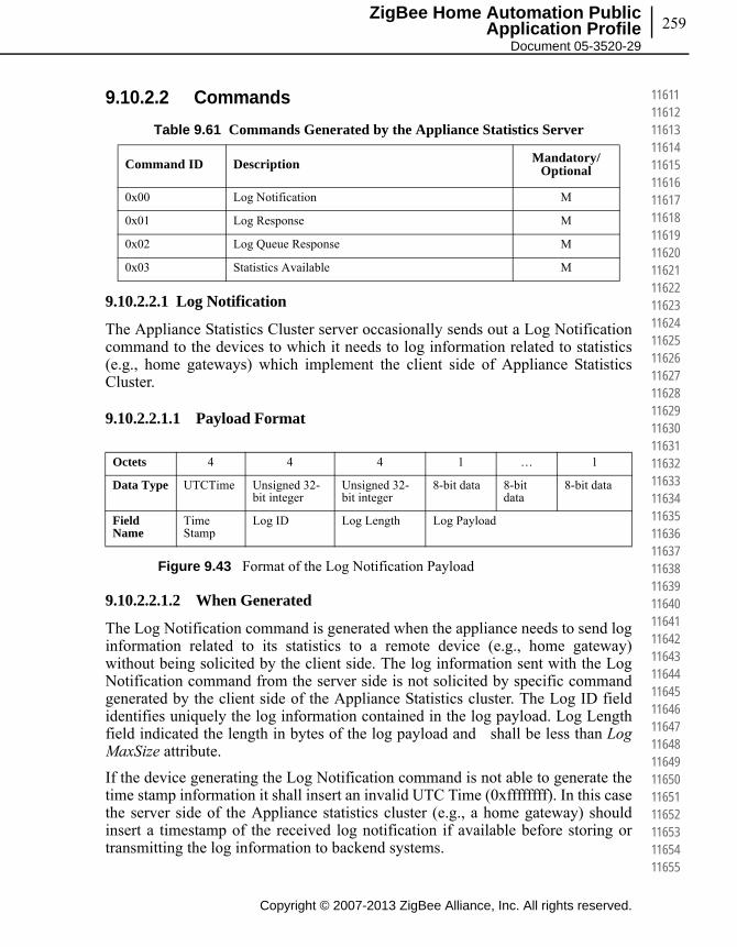
259
Copyright © 2007-2013 ZigBee Alliance, Inc. All rights reserved.
ZigBee Home Automation Public Application Profile
Document 05-3520-29
116111161211613116141161511616116171161811619116201162111622116231162411625116261162711628116291163011631116321163311634116351163611637116381163911640116411164211643116441164511646116471164811649116501165111652116531165411655
9.10.2.2 Commands
9.10.2.2.1 Log Notification
The Appliance Statistics Cluster server occasionally sends out a Log Notification command to the devices to which it needs to log information related to statistics (e.g., home gateways) which implement the client side of Appliance Statistics Cluster.
9.10.2.2.1.1 Payload Format
Figure 9.43 Format of the Log Notification Payload
9.10.2.2.1.2 When Generated
The Log Notification command is generated when the appliance needs to send log information related to its statistics to a remote device (e.g., home gateway) without being solicited by the client side. The log information sent with the Log Notification command from the server side is not solicited by specific command generated by the client side of the Appliance Statistics cluster. The Log ID field identifies uniquely the log information contained in the log payload. Log Length field indicated the length in bytes of the log payload and shall be less than Log MaxSize attribute.
If the device generating the Log Notification command is not able to generate the time stamp information it shall insert an invalid UTC Time (0xffffffff). In this case the server side of the Appliance statistics cluster (e.g., a home gateway) should insert a timestamp of the received log notification if available before storing or transmitting the log information to backend systems.
Table 9.61 Commands Generated by the Appliance Statistics Server
Command ID Description Mandatory/Optional
0x00 Log Notification M
0x01 Log Response M
0x02 Log Queue Response M
0x03 Statistics Available M
Octets 4 4 4 1 … 1
Data Type UTCTime Unsigned 32-bit integer
Unsigned 32-bit integer
8-bit data 8-bit data
8-bit data
Field Name
Time Stamp
Log ID Log Length Log Payload
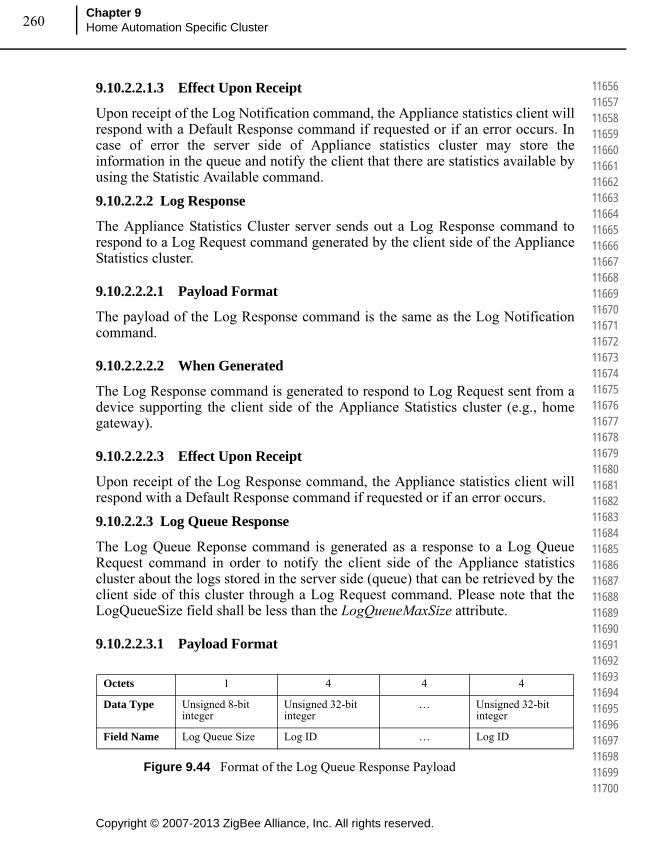
Copyright © 2007-2013 ZigBee Alliance, Inc. All rights reserved.
Chapter 9Home Automation Specific Cluster 260
116561165711658116591166011661116621166311664116651166611667116681166911670116711167211673116741167511676116771167811679116801168111682116831168411685116861168711688116891169011691116921169311694116951169611697116981169911700
9.10.2.2.1.3 Effect Upon Receipt
Upon receipt of the Log Notification command, the Appliance statistics client will respond with a Default Response command if requested or if an error occurs. In case of error the server side of Appliance statistics cluster may store the information in the queue and notify the client that there are statistics available by using the Statistic Available command.
9.10.2.2.2 Log Response
The Appliance Statistics Cluster server sends out a Log Response command to respond to a Log Request command generated by the client side of the Appliance Statistics cluster.
9.10.2.2.2.1 Payload Format
The payload of the Log Response command is the same as the Log Notification command.
9.10.2.2.2.2 When Generated
The Log Response command is generated to respond to Log Request sent from a device supporting the client side of the Appliance Statistics cluster (e.g., home gateway).
9.10.2.2.2.3 Effect Upon Receipt
Upon receipt of the Log Response command, the Appliance statistics client will respond with a Default Response command if requested or if an error occurs.
9.10.2.2.3 Log Queue Response
The Log Queue Reponse command is generated as a response to a Log Queue Request command in order to notify the client side of the Appliance statistics cluster about the logs stored in the server side (queue) that can be retrieved by the client side of this cluster through a Log Request command. Please note that the LogQueueSize field shall be less than the LogQueueMaxSize attribute.
9.10.2.2.3.1 Payload Format
Figure 9.44 Format of the Log Queue Response Payload
Octets 1 4 4 4
Data Type Unsigned 8-bit integer
Unsigned 32-bit integer
… Unsigned 32-bit integer
Field Name Log Queue Size Log ID … Log ID
261
Copyright © 2007-2013 ZigBee Alliance, Inc. All rights reserved.
ZigBee Home Automation Public Application Profile
Document 05-3520-29
117011170211703117041170511706117071170811709117101171111712117131171411715117161171711718117191172011721117221172311724117251172611727117281172911730117311173211733117341173511736117371173811739117401174111742117431174411745
9.10.2.2.3.2 When Generated
The Log Queue Response command is generated to respond to Log Queue Request sent from a device supporting the client side of the Appliance Statistics cluster (e.g., home gateway) to discover the logs that can be currently read through Log Request command. Please note that if Log Queue Size is equal to zero (not logs in the queue), the packet shall not carry Log IDs.
9.10.2.2.3.3 Effect Upon Receipt
Upon receipt of the Log Queue Response command, the Appliance statistics client will respond with a Default Response command if requested or if an error occurs. The client side of the appliance statistics willing to get the logs in the queue shall then use only the Log IDs that have been indicated in the Log Queue Response.
9.10.2.2.4 Statistics Available
The Appliance Statistics Cluster server sends out a Statistic Available command to notify the client side of the Appliance Statistics cluster that there are statistics that can be retrieved by using the Log Request command.
9.10.2.2.4.1 Payload Format
The Statistic Available command is the same as the Log Queue Response command. The Log IDs that can be retrieved by the client are indicated in the payload.
9.10.2.2.4.2 When Generated
The Statistic Available command is generated to notify a device supporting the client side of the Appliance Statistics cluster (e.g., home gateway) to get the statistics information from the log queue as soon as available to perform this operation.
9.10.2.2.4.3 Effect Upon Receipt
Upon receipt of the Statistic Available command, the client side of the Appliance Statistics cluster is notified on the availability of statistics in the server side that can be retrieved by using Log Request commands.
The Appliance statistics client will respond with a Default Response command if requested or if an error occurs.
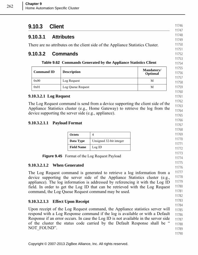
Copyright © 2007-2013 ZigBee Alliance, Inc. All rights reserved.
Chapter 9Home Automation Specific Cluster 262
117461174711748117491175011751117521175311754117551175611757117581175911760117611176211763117641176511766117671176811769117701177111772117731177411775117761177711778117791178011781117821178311784117851178611787117881178911790
9.10.3 Client
9.10.3.1 Attributes
There are no attributes on the client side of the Appliance Statistics Cluster.
9.10.3.2 Commands
9.10.3.2.1 Log Request
The Log Request command is send from a device supporting the client side of the Appliance Statistics cluster (e.g., Home Gateway) to retrieve the log from the device supporting the server side (e.g., appliance).
9.10.3.2.1.1 Payload Format
Figure 9.45 Format of the Log Request Payload
9.10.3.2.1.2 When Generated
The Log Request command is generated to retrieve a log information from a device supporting the server side of the Appliance Statistics cluster (e.g., appliance). The log information is addressed by referencing it with the Log ID field. In order to get the Log ID that can be retrieved with the Log Request command, the Log Queue Request command may be used.
9.10.3.2.1.3 Effect Upon Receipt
Upon receipt of the Log Request command, the Appliance statistics server will respond with a Log Response command if the log is available or with a Default Response if an error occurs. In case the Log ID is not available in the server side of the cluster the status code carried by the Default Response shall be “ NOT_FOUND”.
Table 9.62 Commands Generated by the Appliance Statistics Client
Command ID Description Mandatory/Optional
0x00 Log Request M
0x01 Log Queue Request M
Octets 4
Data Type Unsigned 32-bit integer
Field Name Log ID
263
Copyright © 2007-2013 ZigBee Alliance, Inc. All rights reserved.
ZigBee Home Automation Public Application Profile
Document 05-3520-29
117911179211793117941179511796117971179811799118001180111802118031180411805118061180711808118091181011811118121181311814118151181611817118181181911820118211182211823118241182511826118271182811829118301183111832118331183411835
9.10.3.2.2 Log Queue Request
The Log Queue Request command is send from a device supporting the client side of the Appliance Statistics cluster (e.g. Home Gateway) to retrieve the information about the logs inserted in the queue, from the device supporting the server side (e.g. appliance).
9.10.3.2.2.1 Payload Format
The Log Queue Request command has no payload.
9.10.4 Appliance Statistics Cluster Sequence Diagram
Figure 9.46 shows a typical sequence interaction between the client and server sides of the Appliance Statistics Cluster.
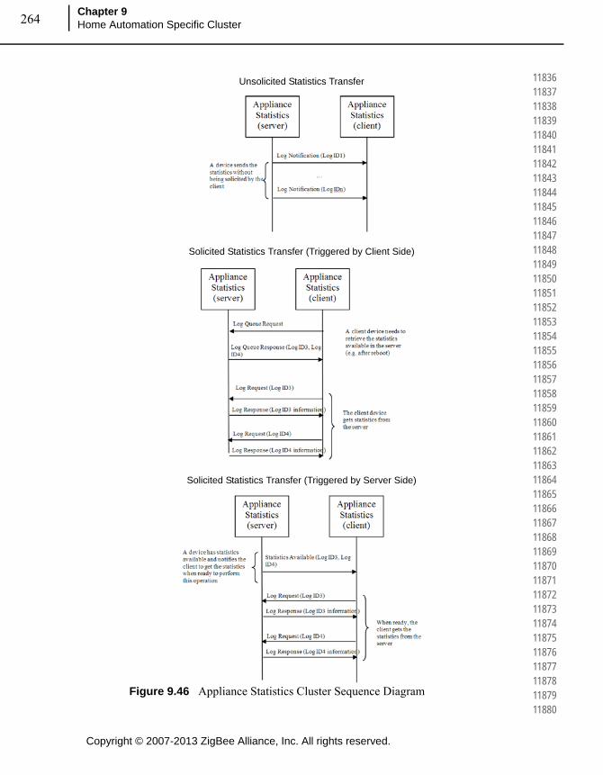
Copyright © 2007-2013 ZigBee Alliance, Inc. All rights reserved.
Chapter 9Home Automation Specific Cluster 264
118361183711838118391184011841118421184311844118451184611847118481184911850118511185211853118541185511856118571185811859118601186111862118631186411865118661186711868118691187011871118721187311874118751187611877118781187911880
Figure 9.46 Appliance Statistics Cluster Sequence Diagram
Unsolicited Statistics Transfer
Solicited Statistics Transfer (Triggered by Client Side)
Solicited Statistics Transfer (Triggered by Server Side)

265ZigBee Home Automation Public
Application Profile Document 05-3520-29
C H A P T E R
10CHAPTER 10HOME AUTOMATION, ZCL
CLUSTER EXTENSIONS
10.1 Door Lock Cluster Extensions
This section describes the recommended practices for Home Automation Door Lock Cluster extensions.
10.1.1 Door Lock Cluster
The door lock cluster provides an interface into a generic way to secure a door. The physical object that provides the locking functionality is abstracted from the cluster. The cluster has a small list of mandatory attributes and functions and a list of optional features.
10.1.2 Server
Generally the door lock itself implements the server side of this cluster. The attributes and commands listed in this cluster were developed to be implemented by a door lock which has the ability to keep track of multiple users and schedules.
10.1.2.1 Alarms, Reports and Events
A door lock implementing all of the optional features provided in this cluster has the ability to push data to a controller in three different forms, Alarms, Reports and Events. Alarms are used to report critical states on the door lock. Reports are used to inform a subscribed device of changes of state in specific attributes on the lock. Events are used to inform a bound device about changes in state related to the operation and programming of the door lock. Event commands are sent to a
Copyright © 2007-2013 ZigBee Alliance, Inc. All rights reserved.
118811188211883118841188511886118871188811889118901189111892118931189411895118961189711898118991190011901119021190311904119051190611907119081190911910119111191211913119141191511916119171191811919119201192111922119231192411925

Copyright © 2007-2013 ZigBee Alliance, Inc. All rights reserved.
Chapter 10Home Automation, ZCL Cluster Extensions266
119261192711928119291193011931119321193311934119351193611937119381193911940119411194211943119441194511946119471194811949119501195111952119531195411955119561195711958119591196011961119621196311964119651196611967119681196911970
binding. Examples of events are locking and unlocking the lock and adding or deleting a user on the lock.
10.1.2.1.1 Alarms
The door lock cluster provides several alarms which can be sent when there is a critical state on the door lock. The alarms available for the door lock cluster are listed in the section below outlining the alarm mask attribute. The Alarm cluster is used to generate the actual alarms.
Alarm example: If the first bit of the attribute Alarm Mask is set, any device that is bound to the alarm cluster will be informed each time the deadbolt becomes jammed. If for some reason the door lock became jammed, the door lock would send an alarm command from the alarms cluster with the payload:
Figure 10.1 Format of the Alarm Cluster
10.1.2.1.2 Reports
The reporting mechanism within the ZCL can be used to subscribe to changes in a specific attribute within the door lock.
Report example: If a coordinator wants to know each time a programming change is made on the door lock, it can use the reporting mechanism to be informed of changes to the Operating Mode attribute. Each time the Operating Mode changes to programming mode, the coordinator will be informed and can then sync its knowledge of user data to make sure that it has an up to date record of user the users supported on the door lock.
10.1.2.1.3 Events
The event mechanism described within this document is unique to the Door Lock Cluster and was designed specifically for this cluster and no other. It is in part modeled on similar mechanisms in other clusters such as the load control events in the Demand Response and Load Control cluster in Smart Energy (DRLC).
The event mechanism in the door lock centers on the transmission of two commands autonomously generated by the server and sent to a bound device. The assumption is that the binding mechanism will be used to commission the server to send these commands.
There are two types of events on the door lock, operational and programmatic. Operational events relate to the general operation of the door lock, when it locks
Octets 1 2
Data Type 8-bit enumeration Cluster ID
Field Name Alarm Code Cluster Identifier
Field Value 0x00 0x0101
267
Copyright © 2007-2013 ZigBee Alliance, Inc. All rights reserved.
ZigBee Home Automation Public Application Profile
Document 05-3520-29
119711197211973119741197511976119771197811979119801198111982119831198411985119861198711988119891199011991119921199311994119951199611997119981199912000120011200212003120041200512006120071200812009120101201112012120131201412015
and unlocks for instance. The programmatic events relate to the programming of the door lock, for example when users are added or modified via the keypad.
Events are transmitted using two server commands, the Operation Event Notification Command and Programming Event Notification Command.
A primary key uniquely identifies each event. The key consists of the event’s type (operation, programming etc…), source (keypad, RF, manual, etc…) and event code. The event mask bit that matches its type, source and event code controls the generation of each event. A complete list of events is included in the description of their commands along with the specific attribute and bit that control their generation.
10.1.2.2 Door Lock Security
The following functionality has not been validated at a Specification Validation Event and is therefore considered provisional.
Door locks have the ability to require the use of APS encryption for sending and receiving of all cluster messages. The Security Level attribute is used to specify the type of encryption required by the door lock.
The APS key MUST be unique to the door lock device in order to provide the enhanced security needed. Therefore, if APS security setting is selected, the device SHALL use a randomly generated install code to generate the unique APS link key to join to the network and use this unique APS link key to encryption all Door Lock Cluster, Group Cluster, Scene Cluster messages.
The hashing method used to convert install code into APS link key is AES-MMO.
It SHOULD be noted that in order for the device with unique APS link key to join successfully to the network, the Trust Centre (e.g., network coordinator) will need to have a method for the user/installer to input the unique install code for the device.
It should be note that the ZigBee security setting will only take effect when the device is not part of a network. If the user modifies the ZigBee Security Level setting while the device is part of a network, the setting will not be applied until the device leaves the network and commissions to a network again.
10.1.2.3 ZigBee Time
There are various references to the ZigBee LocalTime within this cluster specification.
ZigBee LocalTime (32-bit unsigned integer) represents the number of seconds since January 1 2000, in the local zone with time saving adjusted.
Copyright © 2007-2013 ZigBee Alliance, Inc. All rights reserved.
Chapter 10Home Automation, ZCL Cluster Extensions268
120161201712018120191202012021120221202312024120251202612027120281202912030120311203212033120341203512036120371203812039120401204112042120431204412045120461204712048120491205012051120521205312054120551205612057120581205912060
10.1.2.4 PIN/RFID Code Format
The PIN/RFID codes defined in this specification are all in ZCL OCTET STRING format. The first octet in the string specifies the number of octets contained in the remaining of the data field not including itself.
All value in the PIN/RFID code SHALL be ASCII encoded regardless if the PIN/RFID codes are number or characters. For example, code of “1, 2, 3, 4” SHALL be represented as 0x31, 0x32, 0x33, 0x34.
10.1.2.5 Process for Creating a New User with Schedule
The following is the process that the client device SHALL follow for creating a new user with weekday schedule or yearday schedule. The following process should be implemented as an atomic set and should not be broken up.
1 Set Pin Code
2 Set Weekday Schedule or Set Yearday Schedule
3 Set User Type to the desired schedule user type.
10.1.2.6 Process for Clearing All Schedules for a User
The following is the process that the client device SHALL follow for clearing all weekday schedule or all yearday schedule for a user. The following process should be implemented as an atomic set and should not be broken up.
1 Clear All Weekday Schedule or Clear All Yearday Schedule
2 Set User Type to the Unrestricted User Type
Note: If the User Type is not reset to Unrestricted User, the associated user Code (ex: PIN/RFID) will not have access.
10.1.2.7 Clarification of Changing the User Type
When the user type is changed from a scheduled user to some other user type, the door lock server MAY remove the user's schedule.
10.1.2.8 Clarification for Changing the User Code
When changing the user code, the server SHALL not require that the user code be removed first. 2
2. CCB 1772
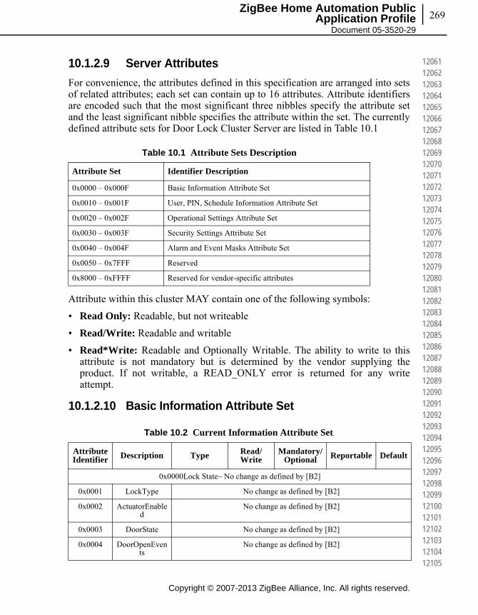
269
Copyright © 2007-2013 ZigBee Alliance, Inc. All rights reserved.
ZigBee Home Automation Public Application Profile
Document 05-3520-29
120611206212063120641206512066120671206812069120701207112072120731207412075120761207712078120791208012081120821208312084120851208612087120881208912090120911209212093120941209512096120971209812099121001210112102121031210412105
10.1.2.9 Server Attributes
For convenience, the attributes defined in this specification are arranged into sets of related attributes; each set can contain up to 16 attributes. Attribute identifiers are encoded such that the most significant three nibbles specify the attribute set and the least significant nibble specifies the attribute within the set. The currently defined attribute sets for Door Lock Cluster Server are listed in Table 10.1
Attribute within this cluster MAY contain one of the following symbols:
• Read Only: Readable, but not writeable
• Read/Write: Readable and writable
• Read*Write: Readable and Optionally Writable. The ability to write to this attribute is not mandatory but is determined by the vendor supplying the product. If not writable, a READ_ONLY error is returned for any write attempt.
10.1.2.10 Basic Information Attribute Set
Table 10.1 Attribute Sets Description
Attribute Set Identifier Description
0x0000 – 0x000F Basic Information Attribute Set
0x0010 – 0x001F User, PIN, Schedule Information Attribute Set
0x0020 – 0x002F Operational Settings Attribute Set
0x0030 – 0x003F Security Settings Attribute Set
0x0040 – 0x004F Alarm and Event Masks Attribute Set
0x0050 – 0x7FFF Reserved
0x8000 – 0xFFFF Reserved for vendor-specific attributes
Table 10.2 Current Information Attribute Set
Attribute Identifier Description Type Read/
WriteMandatory/
Optional Reportable Default
0x0000Lock State– No change as defined by [B2]
0x0001 LockType No change as defined by [B2]
0x0002 ActuatorEnabled
No change as defined by [B2]
0x0003 DoorState No change as defined by [B2]
0x0004 DoorOpenEvents
No change as defined by [B2]
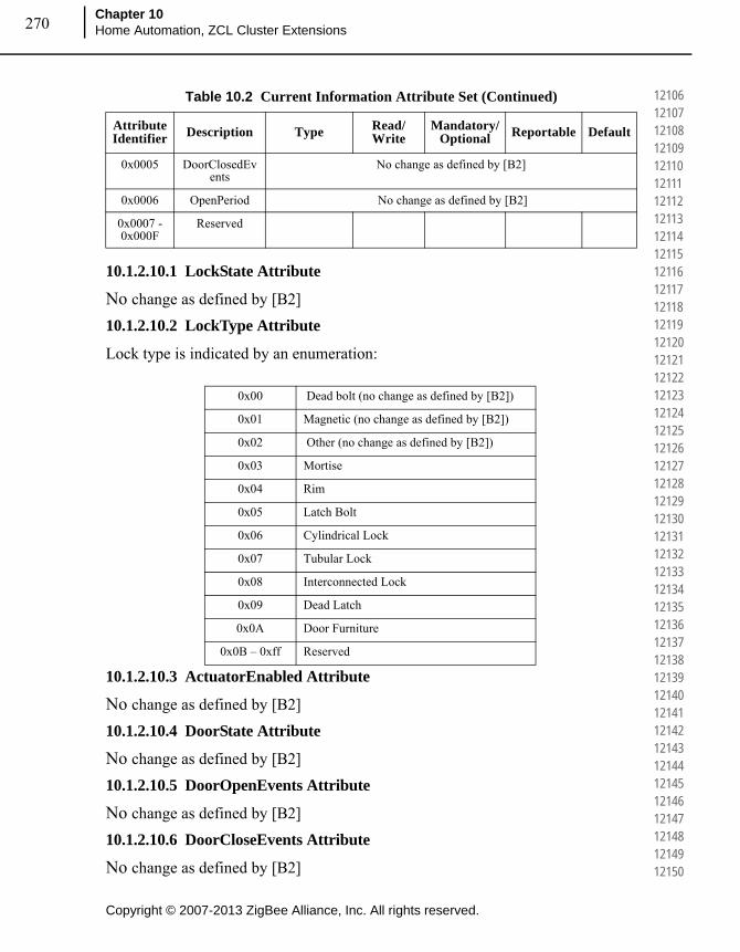
Copyright © 2007-2013 ZigBee Alliance, Inc. All rights reserved.
Chapter 10Home Automation, ZCL Cluster Extensions270
121061210712108121091211012111121121211312114121151211612117121181211912120121211212212123121241212512126121271212812129121301213112132121331213412135121361213712138121391214012141121421214312144121451214612147121481214912150
10.1.2.10.1 LockState Attribute
No change as defined by [B2]
10.1.2.10.2 LockType Attribute
Lock type is indicated by an enumeration:
10.1.2.10.3 ActuatorEnabled Attribute
No change as defined by [B2]
10.1.2.10.4 DoorState Attribute
No change as defined by [B2]
10.1.2.10.5 DoorOpenEvents Attribute
No change as defined by [B2]
10.1.2.10.6 DoorCloseEvents Attribute
No change as defined by [B2]
0x0005 DoorClosedEvents
No change as defined by [B2]
0x0006 OpenPeriod No change as defined by [B2]
0x0007 - 0x000F
Reserved
0x00 Dead bolt (no change as defined by [B2])
0x01 Magnetic (no change as defined by [B2])
0x02 Other (no change as defined by [B2])
0x03 Mortise
0x04 Rim
0x05 Latch Bolt
0x06 Cylindrical Lock
0x07 Tubular Lock
0x08 Interconnected Lock
0x09 Dead Latch
0x0A Door Furniture
0x0B – 0xff Reserved
Table 10.2 Current Information Attribute Set (Continued)
Attribute Identifier Description Type Read/
WriteMandatory/
Optional Reportable Default

271
Copyright © 2007-2013 ZigBee Alliance, Inc. All rights reserved.
ZigBee Home Automation Public Application Profile
Document 05-3520-29
121511215212153121541215512156121571215812159121601216112162121631216412165121661216712168121691217012171121721217312174121751217612177121781217912180121811218212183121841218512186121871218812189121901219112192121931219412195
10.1.2.10.7 OpenPeriod Attribute
No change as defined by [B2]
10.1.2.11 User, PIN, Schedule, Log Information Attribute Set
Table 10.3 User, PIN, Schedule, Log Information Attribute Set
AttributeIdentifier Description Type Read/
WriteMandatory/
Optional Reportable Default
0x0010 Number of Log Records
Supported
Unsigned 16-bit integer
Read Only O No 0
0x0011 Number of Total Users Supported
Unsigned 16-bit integer
Read Only O No 0
0x0012 Number of PIN Users
Supported
Unsigned 16-bit integer
Read Only O No 0
0x0013 Number of RFID Users Supported
Unsigned 16-bit integer
Read Only O No 0
0x0014 Number of Week Day Schedules
Supported Per User
Unsigned 8-bit integer
Read Only O No 0
0x0015 Number of Year Day Schedules
Supported Per User
Unsigned 8-bit integer
Read Only O No 0
0x0016 Number of Holiday
Schedules Supported
Unsigned 8-bit integer
Read Only O No 0
0x0017 Max PIN Code Length
Unsigned 8-bit integer
Read Only O No 0x08
0x0018 Min PIN Code Length
Unsigned 8-bit integer
Read Only O No 0x04
0x0019 Max RFID Code Length
Unsigned 8-bit integer
Read Only O No 0x14
0x001A Min RFID Code Length
Unsigned 8-bit integer
Read Only O No 0x08
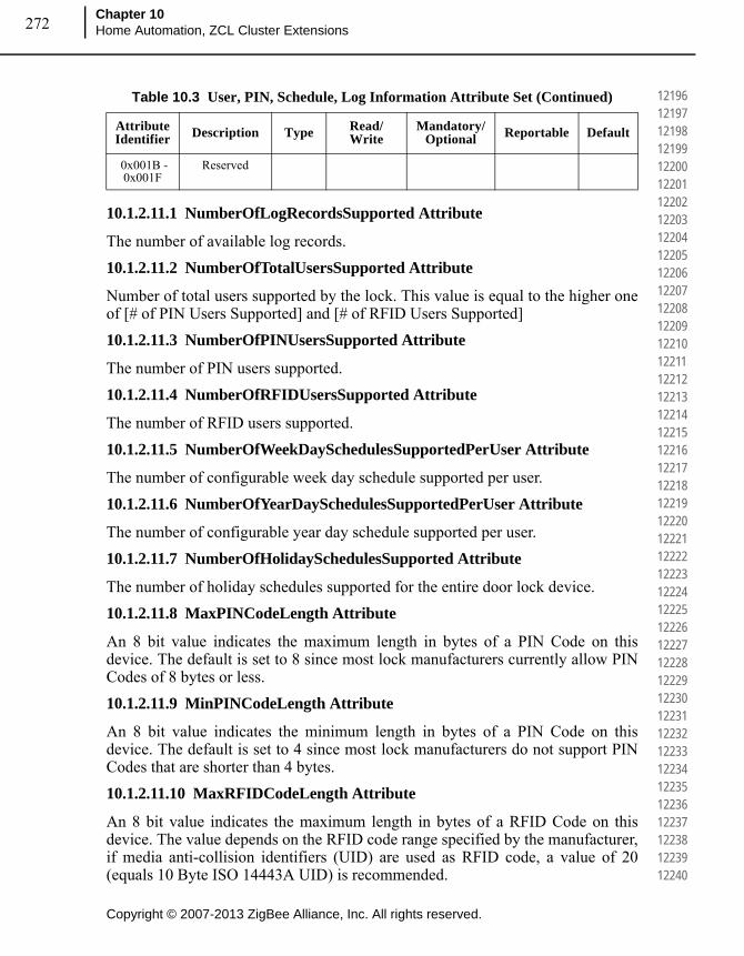
Copyright © 2007-2013 ZigBee Alliance, Inc. All rights reserved.
Chapter 10Home Automation, ZCL Cluster Extensions272
121961219712198121991220012201122021220312204122051220612207122081220912210122111221212213122141221512216122171221812219122201222112222122231222412225122261222712228122291223012231122321223312234122351223612237122381223912240
10.1.2.11.1 NumberOfLogRecordsSupported Attribute
The number of available log records.
10.1.2.11.2 NumberOfTotalUsersSupported Attribute
Number of total users supported by the lock. This value is equal to the higher one of [# of PIN Users Supported] and [# of RFID Users Supported]
10.1.2.11.3 NumberOfPINUsersSupported Attribute
The number of PIN users supported.
10.1.2.11.4 NumberOfRFIDUsersSupported Attribute
The number of RFID users supported.
10.1.2.11.5 NumberOfWeekDaySchedulesSupportedPerUser Attribute
The number of configurable week day schedule supported per user.
10.1.2.11.6 NumberOfYearDaySchedulesSupportedPerUser Attribute
The number of configurable year day schedule supported per user.
10.1.2.11.7 NumberOfHolidaySchedulesSupported Attribute
The number of holiday schedules supported for the entire door lock device.
10.1.2.11.8 MaxPINCodeLength Attribute
An 8 bit value indicates the maximum length in bytes of a PIN Code on this device. The default is set to 8 since most lock manufacturers currently allow PIN Codes of 8 bytes or less.
10.1.2.11.9 MinPINCodeLength Attribute
An 8 bit value indicates the minimum length in bytes of a PIN Code on this device. The default is set to 4 since most lock manufacturers do not support PIN Codes that are shorter than 4 bytes.
10.1.2.11.10 MaxRFIDCodeLength Attribute
An 8 bit value indicates the maximum length in bytes of a RFID Code on this device. The value depends on the RFID code range specified by the manufacturer, if media anti-collision identifiers (UID) are used as RFID code, a value of 20 (equals 10 Byte ISO 14443A UID) is recommended.
0x001B - 0x001F
Reserved
Table 10.3 User, PIN, Schedule, Log Information Attribute Set (Continued)
AttributeIdentifier Description Type Read/
WriteMandatory/
Optional Reportable Default

273
Copyright © 2007-2013 ZigBee Alliance, Inc. All rights reserved.
ZigBee Home Automation Public Application Profile
Document 05-3520-29
122411224212243122441224512246122471224812249122501225112252122531225412255122561225712258122591226012261122621226312264122651226612267122681226912270122711227212273122741227512276122771227812279122801228112282122831228412285
10.1.2.11.11 MinRFIDCodeLength Attribute
An 8 bit value indicates the minimum length in bytes of a RFID Code on this device. The value depends on the RFID code range specified by the manufacturer, if media anti-collision identifiers (UID) are used as RFID code, a value of 8 (equals 4 Byte ISO 14443A UID) is recommended.
10.1.2.12 Operational Settings Attribute Set
The attributes within this attribute set affect the physical behaviour on the server device. Some of the setting might not be applicable to the specific device. When the client sends the write attribute request with values that are not applicable to the server device, the server shall send back a Write Attribute Response with error status not equal to ZCL_SUCCESS(0x00). It is suggested that it should respond with a error status of ZCL_INVALID_VALUE (0x87).
Table 10.4 Operational Settings Attribute Set
AttributeIdentifier Description Type Read/
WriteMandatory/
Optional Reportable Default
0x0020 Enable Logging Boolean Read * Write
O Yes 0
0x0021 Language String(3bytes)
Read * Write
O Yes 0
0x0022 LED Settings Unsigned 8-bit integer
Read * Write
O Yes 0
0x0023 Auto Relock Time
Unsigned 32-bit integer
Read * Write
O Yes 0
0x0024 Sound Volume Unsigned 8-bit integer
Read * Write
O Yes 0
0x0025 Operating Mode
8-bit enumeration
Read * Write
O Yes 0
0x0026 Supported Operating
Modes
Bitmap16 Read Only O No 0x0001
0x0027 Default Configuration
Register
Bitmap16 Read Only O Yes 0x00
0x0028 Enable Local Programming
Boolean Read * Write
O Yes 0x01
0x0029 Enable One Touch Locking
Boolean Read / Write O Yes 0
0x002A Enable Inside Status LED
Boolean Read / Write O Yes 0
0x002B Enable Privacy Mode Button
Boolean Read / Write O Yes 0

Copyright © 2007-2013 ZigBee Alliance, Inc. All rights reserved.
Chapter 10Home Automation, ZCL Cluster Extensions274
122861228712288122891229012291122921229312294122951229612297122981229912300123011230212303123041230512306123071230812309123101231112312123131231412315123161231712318123191232012321123221232312324123251232612327123281232912330
10.1.2.12.1 EnableLogging Attribute
Enable/disable event logging. When event logging is enabled, all event messages are stored on the lock for retrieval. Logging events can be but not limited to Tamper Alarm, Lock, Unlock, Autolock, User Code Added, User Code Deleted, Schedule Added, and Schedule Deleted. For a full detail of all the possible alarms and events, please refer to the full list in the Alarm and Event Masks Attribute Set.
10.1.2.12.2 Language Attribute
Modifies the language for the on-screen or audible user interface using three bytes from ISO-639-1. It consists of one byte of length and two bytes for the language code. For example if the language is set to English, the value would be "02 65 6E" for the language code "en".
10.1.2.12.3 OperatingMode Attribute
Table 10.5 shows the current operating mode and which interfaces are enabled during each of the operating mode:
Normal Mode: The lock operates normally. All interfaces are enabled.
Vacation Mode: Only RF interaction is enabled. The keypad cannot be operated.
Privacy Mode: All external interaction with the door lock is disabled. This is intended so that users presumably inside the property will have control over the entrance. Privacy mode assumes that the lock can only be operated from inside by operating the thumb turn or some other means of ending privacy mode.
0x002C - 0x002F
Reserved
Table 10.5 Operating Modes
Enum Operating ModeInterface (E = Enabled; D = Disabled)
Keypad RF RFID
0x00 Normal E E E
0x01 Vacation D E E
0x02 Privacy D D D
0x03 No RF Lock/Unlock E D E
0x04 Passage N/A N/A N/A
Table 10.4 Operational Settings Attribute Set (Continued)
AttributeIdentifier Description Type Read/
WriteMandatory/
Optional Reportable Default

275
Copyright © 2007-2013 ZigBee Alliance, Inc. All rights reserved.
ZigBee Home Automation Public Application Profile
Document 05-3520-29
123311233212333123341233512336123371233812339123401234112342123431234412345123461234712348123491235012351123521235312354123551235612357123581235912360123611236212363123641236512366123671236812369123701237112372123731237412375
No RF Lock or Unlock: This mode only disables RF interaction with the lock. It specifically applies to the Lock, Unlock, Toggle & Unlock with Timeout Commands.
Passage Mode: The lock is open or can be open or closed at will without the use of a Keypad or other means of user validation.
Note: For modes that disable the RF interface, the door lock shall respond to Lock, Unlock, Toggle, and Unlock with Timeout commands with a ZCL response of ZCL_GENERAL_FAILURE (0x01) and not take the action requested by those commands. The door lock SHALL NOT disable the radio or otherwise unbind or leave the network. It shall still respond to all other commands and requests.
10.1.2.12.4 SupportedOperatingModes Attribute
This bitmap contains all operating bits of the Operating Mode Attribute supported by the lock. The value of the enumeration in “Operating Mode” defines the related bit to be set. All bits supported by a lock SHALL be set to zero.
10.1.2.12.5 LEDSettings Attribute
The settings for the LED support three different modes:
10.1.2.12.6 AutoRelockTime Attribute
The number of seconds to wait after unlocking a lock before it automatically locks again. 0=disabled. .If set, unlock operations from any source will be timed. For one time unlock with timeout use the specific command.
10.1.2.12.7 SoundVolume Attribute
The sound volume on a door lock has three possible settings: silent, low and high volumes.
Bitmap Number Description
0 Normal Mode Supported
1 Vacation Mode Supported
2 Privacy Mode Supported
3 No RF Lock or Unlock Mode Supported
4 Passage Mode Supported
0x00 Never use LED for signalization
0x01 Use LED signalization except for access allowed events
0x02 Use LED signalization for all events

Copyright © 2007-2013 ZigBee Alliance, Inc. All rights reserved.
Chapter 10Home Automation, ZCL Cluster Extensions276
123761237712378123791238012381123821238312384123851238612387123881238912390123911239212393123941239512396123971239812399124001240112402124031240412405124061240712408124091241012411124121241312414124151241612417124181241912420
10.1.2.12.8 DefaultConfigurationRegister Attribute
This attribute represents the default configuration as they are physically set on the device (example: hardware dip switch setting, etc…) and represents the default setting for some of the attributes within this Operational Setting Attribute Set (for example: LED, Auto Lock, Sound Volume, and Operating Mode attributes).
This is a read-only attribute and is intended to allow clients to determine what changes may need to be made without having to query all the included attributes. It may be beneficial for the clients to know what the device’s original settings were in the event that the device needs to be restored to factory default settings.
If the Client device would like to query and modify the door lock server’s operating settings, it SHOULD send read and write attribute request to the specific attributes.
For example, the Buzzer bitmap within this attribute is off. It represents the hardware dip switch Buzzer setting (original default setting) is off and the Sound Volume attribute default value is in Silent Mode. However, it is possible that the current Sound Volume is in High Volume. Therefore, if the client wants to query/modify the current Sound Volume setting on the server, the client SHOULD read/write to the Sound Volume attribute.
0x00 Silent Mode
0x01 Low Volume
0x02 High Volume
Table 10.6 DefaultConfigurationRegister Attribute
Bitmap Number Description
0 0 - Enable Local Programming Attribute default value is 0 (disabled)
1 - Enable Local Programming Attribute default value is 1 (enabled)
1 0 –Keypad Interface default access is disabled
1 - Keypad Interface default access is enabled
2 0 - RF Interface default access is disabled
1 - RF Interface default access is enabled
3 Reserved
4 Reserved
5 0 – Sound Volume attribute default value is 0 (Slight Mode)
1 – Sound Volume attribute default value is equal to something other than 0x00
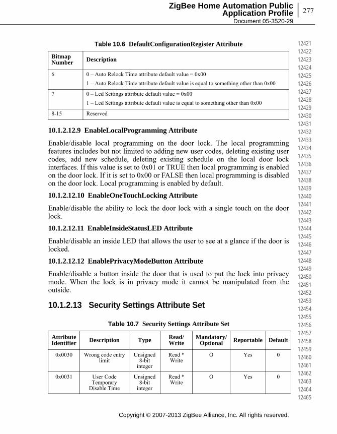
277
Copyright © 2007-2013 ZigBee Alliance, Inc. All rights reserved.
ZigBee Home Automation Public Application Profile
Document 05-3520-29
124211242212423124241242512426124271242812429124301243112432124331243412435124361243712438124391244012441124421244312444124451244612447124481244912450124511245212453124541245512456124571245812459124601246112462124631246412465
10.1.2.12.9 EnableLocalProgramming Attribute
Enable/disable local programming on the door lock. The local programming features includes but not limited to adding new user codes, deleting existing user codes, add new schedule, deleting existing schedule on the local door lock interfaces. If this value is set to 0x01 or TRUE then local programming is enabled on the door lock. If it is set to 0x00 or FALSE then local programming is disabled on the door lock. Local programming is enabled by default.
10.1.2.12.10 EnableOneTouchLocking Attribute
Enable/disable the ability to lock the door lock with a single touch on the door lock.
10.1.2.12.11 EnableInsideStatusLED Attribute
Enable/disable an inside LED that allows the user to see at a glance if the door is locked.
10.1.2.12.12 EnablePrivacyModeButton Attribute
Enable/disable a button inside the door that is used to put the lock into privacy mode. When the lock is in privacy mode it cannot be manipulated from the outside.
10.1.2.13 Security Settings Attribute Set
6 0 – Auto Relock Time attribute default value = 0x00
1 – Auto Relock Time attribute default value is equal to something other than 0x00
7 0 – Led Settings attribute default value = 0x00
1 – Led Settings attribute default value is equal to something other than 0x00
8-15 Reserved
Table 10.7 Security Settings Attribute Set
AttributeIdentifier Description Type Read/
WriteMandatory/
Optional Reportable Default
0x0030 Wrong code entry limit
Unsigned 8-bit
integer
Read * Write
O Yes 0
0x0031 User Code Temporary
Disable Time
Unsigned 8-bit
integer
Read * Write
O Yes 0
Table 10.6 DefaultConfigurationRegister Attribute
Bitmap Number Description
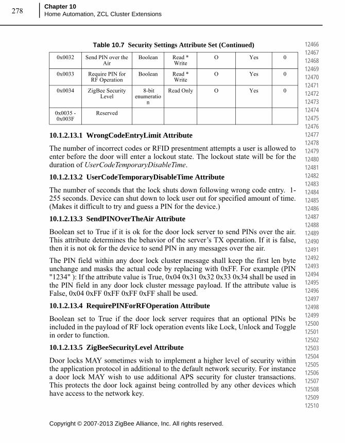
Copyright © 2007-2013 ZigBee Alliance, Inc. All rights reserved.
Chapter 10Home Automation, ZCL Cluster Extensions278
124661246712468124691247012471124721247312474124751247612477124781247912480124811248212483124841248512486124871248812489124901249112492124931249412495124961249712498124991250012501125021250312504125051250612507125081250912510
10.1.2.13.1 WrongCodeEntryLimit Attribute
The number of incorrect codes or RFID presentment attempts a user is allowed to enter before the door will enter a lockout state. The lockout state will be for the duration of UserCodeTemporaryDisableTime.
10.1.2.13.2 UserCodeTemporaryDisableTime Attribute
The number of seconds that the lock shuts down following wrong code entry. 1-255 seconds. Device can shut down to lock user out for specified amount of time. (Makes it difficult to try and guess a PIN for the device.)
10.1.2.13.3 SendPINOverTheAir Attribute
Boolean set to True if it is ok for the door lock server to send PINs over the air. This attribute determines the behavior of the server’s TX operation. If it is false, then it is not ok for the device to send PIN in any messages over the air.
The PIN field within any door lock cluster message shall keep the first len byte unchange and masks the actual code by replacing with 0xFF. For example (PIN "1234" ): If the attribute value is True, 0x04 0x31 0x32 0x33 0x34 shall be used in the PIN field in any door lock cluster message payload. If the attribute value is False, 0x04 0xFF 0xFF 0xFF 0xFF shall be used.
10.1.2.13.4 RequirePINForRFOperation Attribute
Boolean set to True if the door lock server requires that an optional PINs be included in the payload of RF lock operation events like Lock, Unlock and Toggle in order to function.
10.1.2.13.5 ZigBeeSecurityLevel Attribute
Door locks MAY sometimes wish to implement a higher level of security within the application protocol in additional to the default network security. For instance a door lock MAY wish to use additional APS security for cluster transactions. This protects the door lock against being controlled by any other devices which have access to the network key.
0x0032 Send PIN over the Air
Boolean Read * Write
O Yes 0
0x0033 Require PIN for RF Operation
Boolean Read * Write
O Yes 0
0x0034 ZigBee Security Level
8-bit enumeratio
n
Read Only O Yes 0
0x0035 - 0x003F
Reserved
Table 10.7 Security Settings Attribute Set (Continued)

279
Copyright © 2007-2013 ZigBee Alliance, Inc. All rights reserved.
ZigBee Home Automation Public Application Profile
Document 05-3520-29
125111251212513125141251512516125171251812519125201252112522125231252412525125261252712528125291253012531125321253312534125351253612537125381253912540125411254212543125441254512546125471254812549125501255112552125531255412555
The Security Level attribute allows the door lock manufacturer to indicate what level of security the door lock requires.
There are two levels of security possible within this cluster:
• 0 = Network Security (default)
• 1 = APS Security
This attribute is read only over the ZigBee network to protect security method defined by each manufacturer.
However, manufacturer can provide method to modify the security setting locally on the device. The security setting modification will not take effect when the device is in a network.
10.1.2.14 Alarm and Event Masks Attribute Set
Table 10.8 Alarm and Event Masks Attribute Set
AttributeIdentifier Description Type Read/
WriteMandatory/
Optional Reportable Default
0x0040 Alarm Mask Bitmap16 Read/Write
O Yes 0xFFFF
0x0041 Keypad Operation
Event Mask
Bitmap16 Read/Write
O Yes 0xFFFF
0x0042 RF Operation Event Mask
Bitmap16 Read/Write
O Yes 0xFFFF
0x0043 Manual Operation
Event Mask
Bitmap16 Read/Write
O Yes 0xFFFF
0x0044 RFID Operation Event Mask
Bitmap16 Read/Write
O Yes 0xFFFF
0x0045 Keypad Programming Event Mask
Bitmap16 Read/Write
O Yes 0xFFFF
0x0046 RF Programming Event Mask
Bitmap16 Read/Write
O Yes 0xFFFF
0x0047 RFID Programming Event Mask
Bitmap16 Read/Write
O Yes 0xFFFF
0x0048 - 0x004F
Reserved

Copyright © 2007-2013 ZigBee Alliance, Inc. All rights reserved.
Chapter 10Home Automation, ZCL Cluster Extensions280
125561255712558125591256012561125621256312564125651256612567125681256912570125711257212573125741257512576125771257812579125801258112582125831258412585125861258712588125891259012591125921259312594125951259612597125981259912600
10.1.2.14.1 AlarmMask Attribute
The alarm mask is used to turn on/off alarms for particular functions. Alarms for an alarm group are enabled if the associated alarm mask bit is set. Each bit represents a group of alarms. Entire alarm groups can be turned on or off by setting or clearing the associated bit in the alarm mask.
10.1.2.14.2 KeypadOperationEventMask Attribute
Event mask used to turn on and off the transmission of keypad operation events. This mask DOES NOT apply to the storing of events in the report table.
For detail event mask value, please refer to Table 10.16.
10.1.2.14.3 RFOperationEventMask Attribute
Event mask used to turn on and off the transmission of RF operation events. This mask DOES NOT apply to the storing of events in the report table.
For detail event mask value, please refer to Table 10.17.
10.1.2.14.4 ManualOperationEventMask Attribute
Event mask used to turn on and off manual operation events. This mask DOES NOT apply to the storing of events in the report table.
For detail event mask value, please refer to Table 10.18.
10.1.2.14.5 RFIDOperationEventMask Attribute
Event mask used to turn on and off RFID operation events. This mask DOES NOT apply to the storing of events in the report table.
For detail event mask value, please refer to Table 10.19.
Table 10.9 Alarm Code Table
Alarm Code Bitmap Number Alarm Condition
0x00 0 Deadbolt Jammed
0x01 1 Lock Reset to Factory Defaults
0x02 2 Reserved
0x03 3 RF Module Power Cycled
0x04 4 Tamper Alarm – wrong code entry limit
0x05 5 Tamper Alarm - front escutcheon removed from main
0x06 6 Forced Door Open under Door Locked Condition
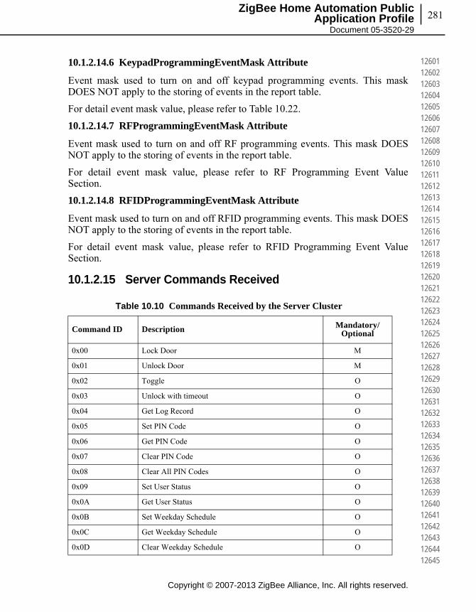
281
Copyright © 2007-2013 ZigBee Alliance, Inc. All rights reserved.
ZigBee Home Automation Public Application Profile
Document 05-3520-29
126011260212603126041260512606126071260812609126101261112612126131261412615126161261712618126191262012621126221262312624126251262612627126281262912630126311263212633126341263512636126371263812639126401264112642126431264412645
10.1.2.14.6 KeypadProgrammingEventMask Attribute
Event mask used to turn on and off keypad programming events. This mask DOES NOT apply to the storing of events in the report table.
For detail event mask value, please refer to Table 10.22.
10.1.2.14.7 RFProgrammingEventMask Attribute
Event mask used to turn on and off RF programming events. This mask DOES NOT apply to the storing of events in the report table.
For detail event mask value, please refer to RF Programming Event Value Section.
10.1.2.14.8 RFIDProgrammingEventMask Attribute
Event mask used to turn on and off RFID programming events. This mask DOES NOT apply to the storing of events in the report table.
For detail event mask value, please refer to RFID Programming Event Value Section.
10.1.2.15 Server Commands Received
Table 10.10 Commands Received by the Server Cluster
Command ID Description Mandatory/Optional
0x00 Lock Door M
0x01 Unlock Door M
0x02 Toggle O
0x03 Unlock with timeout O
0x04 Get Log Record O
0x05 Set PIN Code O
0x06 Get PIN Code O
0x07 Clear PIN Code O
0x08 Clear All PIN Codes O
0x09 Set User Status O
0x0A Get User Status O
0x0B Set Weekday Schedule O
0x0C Get Weekday Schedule O
0x0D Clear Weekday Schedule O

Copyright © 2007-2013 ZigBee Alliance, Inc. All rights reserved.
Chapter 10Home Automation, ZCL Cluster Extensions282
126461264712648126491265012651126521265312654126551265612657126581265912660126611266212663126641266512666126671266812669126701267112672126731267412675126761267712678126791268012681126821268312684126851268612687126881268912690
10.1.2.15.1 Lock Door Command
This command causes the lock device to lock the door. As of HA 1.2, this command includes an optional code for the lock. The door lock MAY require a PIN depending on the value of the [Require PIN for RF Operation attribute].
Figure 10.2 Format of the Lock Door Command
10.1.2.15.2 Unlock Door Command
This command causes the lock device to unlock the door. As of HA 1.2, this command includes an optional code for the lock. The door lock MAY require a code depending on the value of the [Require PIN for RF Operation attribute].
Note: If the attribute AutoRelockTime is supported the lock will close when the auto relock time has expired.
0x0E Set Year Day Schedule O
0x0F Get Year Day Schedule O
0x10 Clear Year Day Schedule O
0x11 Set Holiday Schedule O
0x12 Get Holiday Schedule O
0x13 Clear Holiday Schedule O
0x14 Set User type O
0x15 Get User type O
0x16 Set RFID Code O
0x17 Get RFID Code O
0x18 Clear RFID Code O
0x19 Clear All RFID Codes O
0x1A - 0xFF Reserved
Octets Variable
Data Type ZigBee Octet String
Field Name PIN/RFID Code
Table 10.10 Commands Received by the Server Cluster (Continued)
Command ID Description Mandatory/Optional
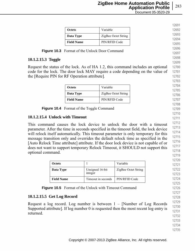
283
Copyright © 2007-2013 ZigBee Alliance, Inc. All rights reserved.
ZigBee Home Automation Public Application Profile
Document 05-3520-29
126911269212693126941269512696126971269812699127001270112702127031270412705127061270712708127091271012711127121271312714127151271612717127181271912720127211272212723127241272512726127271272812729127301273112732127331273412735
Figure 10.3 Format of the Unlock Door Command
10.1.2.15.3 Toggle
Request the status of the lock. As of HA 1.2, this command includes an optional code for the lock. The door lock MAY require a code depending on the value of the [Require PIN for RF Operation attribute].
Figure 10.4 Format of the Toggle Command
10.1.2.15.4 Unlock with Timeout
This command causes the lock device to unlock the door with a timeout parameter. After the time in seconds specified in the timeout field, the lock device will relock itself automatically. This timeout parameter is only temporary for this message transition only and overrides the default relock time as specified in the [Auto Relock Time attribute] attribute. If the door lock device is not capable of or does not want to support temporary Relock Timeout, it SHOULD not support this optional command.
Figure 10.5 Format of the Unlock with Timeout Command
10.1.2.15.5 Get Log Record
Request a log record. Log number is between 1 – [Number of Log Records Supported attribute]. If log number 0 is requested then the most recent log entry is returned.
Octets Variable
Data Type ZigBee Octet String
Field Name PIN/RFID Code
Octets Variable
Data Type ZigBee Octet String
Field Name PIN/RFID Code
Octets 1 Variable
Data Type Unsigned 16-bit integer
ZigBee Octet String
Field Name Timeout in seconds PIN/RFID Code
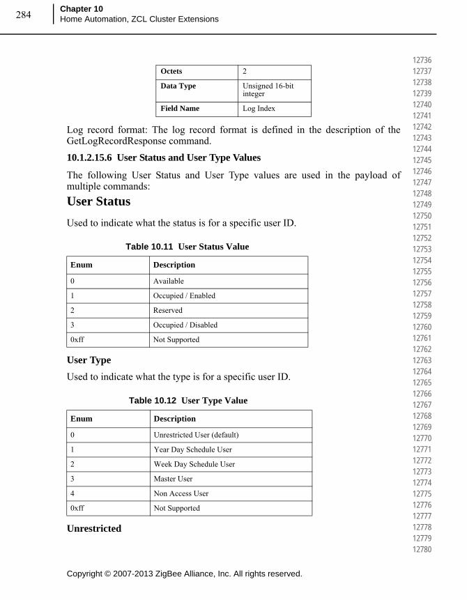
Copyright © 2007-2013 ZigBee Alliance, Inc. All rights reserved.
Chapter 10Home Automation, ZCL Cluster Extensions284
127361273712738127391274012741127421274312744127451274612747127481274912750127511275212753127541275512756127571275812759127601276112762127631276412765127661276712768127691277012771127721277312774127751277612777127781277912780
Log record format: The log record format is defined in the description of the GetLogRecordResponse command.
10.1.2.15.6 User Status and User Type Values
The following User Status and User Type values are used in the payload of multiple commands:
User Status
Used to indicate what the status is for a specific user ID.
User Type
Used to indicate what the type is for a specific user ID.
Unrestricted
Octets 2
Data Type Unsigned 16-bit integer
Field Name Log Index
Table 10.11 User Status Value
Enum Description
0 Available
1 Occupied / Enabled
2 Reserved
3 Occupied / Disabled
0xff Not Supported
Table 10.12 User Type Value
Enum Description
0 Unrestricted User (default)
1 Year Day Schedule User
2 Week Day Schedule User
3 Master User
4 Non Access User
0xff Not Supported
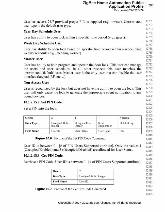
285
Copyright © 2007-2013 ZigBee Alliance, Inc. All rights reserved.
ZigBee Home Automation Public Application Profile
Document 05-3520-29
127811278212783127841278512786127871278812789127901279112792127931279412795127961279712798127991280012801128021280312804128051280612807128081280912810128111281212813128141281512816128171281812819128201282112822128231282412825
User has access 24/7 provided proper PIN is supplied (e.g., owner). Unrestricted user type is the default user type.
Year Day Schedule User
User has ability to open lock within a specific time period (e.g., guest).
Week Day Schedule User
User has ability to open lock based on specific time period within a reoccurring weekly schedule (e.g., cleaning worker).
Master User
User has ability to both program and operate the door lock. This user can manage the users and user schedules. In all other respects this user matches the unrestricted (default) user. Master user is the only user that can disable the user interface (keypad, RF, etc…).
Non Access User
User is recognized by the lock but does not have the ability to open the lock. This user will only cause the lock to generate the appropriate event notification to any bound devices.
10.1.2.15.7 Set PIN Code
Set a PIN into the lock.
Figure 10.6 Format of the Set PIN Code Command
User ID is between 0 - [# of PIN Users Supported attribute]. Only the values 1 (Occupied/Enabled) and 3 (Occupied/Disabled) are allowed for User Status.
10.1.2.15.8 Get PIN Code
Retrieve a PIN Code. User ID is between 0 - [# of PIN Users Supported attribute].
Figure 10.7 Format of the Get PIN Code Command
Octets 2 1 1 Variable
Data Type Unsigned 16-bit integer
Unsigned 8-bit integer
8-bit enumeration
Octet String
Field Name User ID User Status User Type PIN
Octets 2
Data Type Unsigned 16-bit integer
Field Name User ID

Copyright © 2007-2013 ZigBee Alliance, Inc. All rights reserved.
Chapter 10Home Automation, ZCL Cluster Extensions286
128261282712828128291283012831128321283312834128351283612837128381283912840128411284212843128441284512846128471284812849128501285112852128531285412855128561285712858128591286012861128621286312864128651286612867128681286912870
10.1.2.15.9 Clear PIN Code
Delete a PIN. User ID is between 0 - [# of PIN Users Supported attribute].
Figure 10.8 Format of the Clear PIN Code Command
Note: If you delete a PIN Code and this user didn't have a RFID Code, the user status is set to "0 Available", the user type is set to the default value and all schedules are also set to the default values.
10.1.2.15.10 Clear All PIN Code
Clear out all PINs on the lock.
Note: On the server, the clear all PIN codes command should have the same effect as the Clear PIN Code command with respect to the setting of user status, user type and schedules.
10.1.2.15.11 Set User Status
Set the status of a user ID. User Status value of 0x00 is not allowed. In order to clear a user id, the Clear ID Command SHALL be used. For user status value please refer to User Status Value.
Figure 10.9 Format of the Set User Status Command
10.1.2.15.12 Get User Status
Get the status of a user.
Figure 10.10 Format of the Get User Status Command
Octets 2
Data Type Unsigned 16-bit integer
Field Name User ID
Octets 2 1
Data Type Unsigned 16-bit integer Unsigned 8-bit integer
Field Name User ID User Status
Octets 2
Data Type Unsigned 16-bit integer
Field Name User ID

287
Copyright © 2007-2013 ZigBee Alliance, Inc. All rights reserved.
ZigBee Home Automation Public Application Profile
Document 05-3520-29
128711287212873128741287512876128771287812879128801288112882128831288412885128861288712888128891289012891128921289312894128951289612897128981289912900129011290212903129041290512906129071290812909129101291112912129131291412915
10.1.2.15.13 Set Week Day Schedule
Set a weekly repeating schedule for a specified user.
Figure 10.11 Format of the Set Week Day Schedule Command
Schedule ID: number is between 0 – [# of Week Day Schedules Per User attribute].
User ID: is between 0 – [# of Total Users Supported attribute].
Days Mask: bitmask of the effective days in the order XSFTWTMS.
Days mask is listed as bitmask for flexibility to set same schedule across multiple days. For the door lock that does not support setting schedule across multiple days within one command, it SHOULD respond with ZCL INVALID_FIELD (0x85) status when received the set schedule command days bitmask field has multiple days selected.
Start Hour: in decimal format represented by 0x00 – 0x17 (00 to 23 hours).
Start Minute: in decimal format represented by 0x00 – 0x3B (00 to 59 mins).
End Hour: in decimal format represented by 0x00 – 0x17 (00 to 23 hours). End Hour SHALL be equal or greater than Start Hour.
End Minute: in decimal format represented by 0x00 – 0x3B (00 to 59 mins).
If End Hour is equal with Start Hour, End Minute SHALL be greater than Start Minute.
When the Server Device receives the command, the Server Device MAY change the user type to the specific schedule user type. Please refer to Section 10.1.2.5, Process for Creating a New User with Schedule at the beginning of this cluster.3
Octets 1 2 1 1 1 1 1
Data Type Unsigned 8-bit integer
Unsigned 16-bit integer
8-bit Bitmap
Unsigned 8-bit integer
Unsigned 8-bit integer
Unsigned 8-bit integer
Unsigned 8-bit integer
Field Name
Schedule ID #
User ID Days Mask
Start Hour
Start Minute
End Hour End Minute
7 6 5 4 3 2 1 0
Reserved Sat Fri Thur Wed Tue Mon Sun
3. CCB 1772
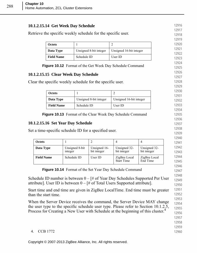
Copyright © 2007-2013 ZigBee Alliance, Inc. All rights reserved.
Chapter 10Home Automation, ZCL Cluster Extensions288
129161291712918129191292012921129221292312924129251292612927129281292912930129311293212933129341293512936129371293812939129401294112942129431294412945129461294712948129491295012951129521295312954129551295612957129581295912960
10.1.2.15.14 Get Week Day Schedule
Retrieve the specific weekly schedule for the specific user.
Figure 10.12 Format of the Get Week Day Schedule Command
10.1.2.15.15 Clear Week Day Schedule
Clear the specific weekly schedule for the specific user.
Figure 10.13 Format of the Clear Week Day Schedule Command
10.1.2.15.16 Set Year Day Schedule
Set a time-specific schedule ID for a specified user.
Figure 10.14 Format of the Set Year Day Schedule Command
Schedule ID number is between 0 – [# of Year Day Schedules Supported Per User attribute]. User ID is between 0 – [# of Total Users Supported attribute].
Start time and end time are given in ZigBee LocalTime. End time must be greater than the start time.
When the Server Device receives the command, the Server Device MAY change the user type to the specific schedule user type. Please refer to Section 10.1.2.5, Process for Creating a New User with Schedule at the beginning of this cluster.4
Octets 1 2
Data Type Unsigned 8-bit integer Unsigned 16-bit integer
Field Name Schedule ID User ID
Octets 1 2
Data Type Unsigned 8-bit integer Unsigned 16-bit integer
Field Name Schedule ID User ID
Octets 1 2 4 4
Data Type Unsigned 8-bit integer
Unsigned 16-bit integer
Unsigned 32-bit integer
Unsigned 32-bit integer
Field Name Schedule ID User ID ZigBee Local Start Time
ZigBee Local End Time
4. CCB 1772
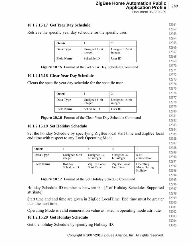
289
Copyright © 2007-2013 ZigBee Alliance, Inc. All rights reserved.
ZigBee Home Automation Public Application Profile
Document 05-3520-29
129611296212963129641296512966129671296812969129701297112972129731297412975129761297712978129791298012981129821298312984129851298612987129881298912990129911299212993129941299512996129971299812999130001300113002130031300413005
10.1.2.15.17 Get Year Day Schedule
Retrieve the specific year day schedule for the specific user.
Figure 10.15 Format of the Get Year Day Schedule Command
10.1.2.15.18 Clear Year Day Schedule
Clears the specific year day schedule for the specific user.
Figure 10.16 Format of the Clear Year Day Schedule Command
10.1.2.15.19 Set Holiday Schedule
Set the holiday Schedule by specifying ZigBee local start time and ZigBee local end time with respect to any Lock Operating Mode.
Figure 10.17 Format of the Set Holiday Schedule Command
Holiday Schedule ID number is between 0 – [# of Holiday Schedules Supported attribute].
Start time and end time are given in ZigBee LocalTime. End time must be greater than the start time.
Operating Mode is valid enumeration value as listed in operating mode attribute.
10.1.2.15.20 Get Holiday Schedule
Get the holiday Schedule by specifying Holiday ID.
Octets 1 2
Data Type Unsigned 8-bit integer
Unsigned 16-bit integer
Field Name Schedule ID User ID
Octets 1 2
Data Type Unsigned 8-bit integer
Unsigned 16-bit integer
Field Name Schedule ID User ID
Octets 1 4 4 1
Data Type Unsigned 8-bit integer
Unsigned 32-bit integer
Unsigned 32-bit integer
8-bit enumeration
Field Name Holiday Schedule ID
ZigBee Local Start Time
ZigBee Local End Time
Operating Mode During Holiday

Copyright © 2007-2013 ZigBee Alliance, Inc. All rights reserved.
Chapter 10Home Automation, ZCL Cluster Extensions290
130061300713008130091301013011130121301313014130151301613017130181301913020130211302213023130241302513026130271302813029130301303113032130331303413035130361303713038130391304013041130421304313044130451304613047130481304913050
Figure 10.18 Format of the Get Holiday Schedule Command
10.1.2.15.21 Clear Holiday Schedule
Clear the holiday Schedule by specifying Holiday ID.
Figure 10.19 Format of the Clear Holiday Schedule Command
10.1.2.15.22 Set User Type
Set the type byte for a specified user.
For user type value please refer to User Type Value.
Figure 10.20 Format of the Set User Type Command
10.1.2.15.23 Get User Type
Retrieve the type byte for a specific user.
Figure 10.21 Format of the Get User Type Command
10.1.2.15.24 Set RFID Code
Set an ID for RFID access into the lock.
Octets 1
Data Type Unsigned 8-bit integer
Field Name Holiday Schedule ID
Octets 1
Data Type Unsigned 8-bit integer
Field Name Holiday Schedule ID
Octets 2 1
Data Type Unsigned 16-bit integer 8-bit enumeration
Field Name User ID User Type
Octets 2
Data Type Unsigned 16-bit integer
Field Name User ID

291
Copyright © 2007-2013 ZigBee Alliance, Inc. All rights reserved.
ZigBee Home Automation Public Application Profile
Document 05-3520-29
130511305213053130541305513056130571305813059130601306113062130631306413065130661306713068130691307013071130721307313074130751307613077130781307913080130811308213083130841308513086130871308813089130901309113092130931309413095
Figure 10.22 Format of the Set RFID Code Command
User ID is between 0 - [# of RFID Users Supported attribute]. Only the values 1 (Occupied/Enabled) and 3 (Occupied/Disabled) are allowed for User Status.
User Status: Used to indicate what the status is for a specific user ID. The values are according to “Set PIN” while not all are supported.
User Type
The values are the same as used for “Set PIN Code”.
10.1.2.15.25 Get RFID Code
Retrieve an ID. User ID is between 0 - [# of RFID Users Supported attribute].
Figure 10.23 Format of the Get RFID Code Command
10.1.2.15.26 Clear RFID Code
Delete an ID. User ID is between 0 - [# of RFID Users Supported attribute]. If you delete a RFID code and this user didn't have a PIN code, the user status has to be set to "0 Available", the user type has to be set to the default value, and all schedules which are supported have to be set to the default values.
Octets 2 1 1 Variable
Data Type Unsigned 16-bit integer
Unsigned 8-bit integer
8-bit enumeration
Octet string
Field Name User ID User Status User Type RFID Code
User Status Byte Value
Occupied / Enabled (Access Given) 1
Reserved 2
Occupied / Disabled 3
Not Supported 0xff
Octets 2
Data Type Unsigned 16-bit integer
Field Name User ID

Copyright © 2007-2013 ZigBee Alliance, Inc. All rights reserved.
Chapter 10Home Automation, ZCL Cluster Extensions292
130961309713098130991310013101131021310313104131051310613107131081310913110131111311213113131141311513116131171311813119131201312113122131231312413125131261312713128131291313013131131321313313134131351313613137131381313913140
Figure 10.24 Format of the Clear RFID Code Command
10.1.2.15.27 Clear All RFID Codes
Clear out all RFIDs on the lock. If you delete all RFID codes and this user didn't have a PIN code, the user status has to be set to "0 Available", the user type has to be set to the default value, and all schedules which are supported have to be set to the default values.
10.1.2.16 Server Commands Generated
Octets 2
Data Type Unsigned 16-bit integer
Field Name User ID
Table 10.13 Commands Generated by the Server Cluster
Command ID Description Mandatory/Optional
0x00 Lock Door Response M
0x01 Unlock Door Response M
0x02 Toggle Response O
0x03 Unlock with Timeout Response O
0x04 Get Log Record Response O
0x05 Set PIN Code Response O
0x06 Get PIN Code Response O
0x07 Clear PIN Code Response O
0x08 Clear All PIN Codes Response O
0x09 Set User Status Response O
0x0A Get User Status Response O
0x0B Set Week Day Schedule Response O
0x0C Get Week Day Schedule Response O
0x0D Clear Week Day Schedule Response O
0x0E Set Year Day Schedule Response O
0x0F Get Year Day Schedule Response O
0x10 Clear Year Day Schedule Response O
0x11 Set Holiday Schedule Response O

293
Copyright © 2007-2013 ZigBee Alliance, Inc. All rights reserved.
ZigBee Home Automation Public Application Profile
Document 05-3520-29
131411314213143131441314513146131471314813149131501315113152131531315413155131561315713158131591316013161131621316313164131651316613167131681316913170131711317213173131741317513176131771317813179131801318113182131831318413185
10.1.2.16.1 Lock Response
This command is sent in response to a Lock command with one status byte payload. The Status field SHALL be set to SUCCESS or FAILURE (see Table 2.16 in [B2]).
The status byte only indicates if the message has received successfully. To determine the lock and/or door status, the client SHOULD query to [Lock State attribute] and [Door State attribute].
10.1.2.16.2 Unlock Door Response
This command is sent in response to a unlock command with one status byte payload. The Status field SHALL be set to SUCCESS or FAILURE (see Table 2.16 in [B2]).
The status byte only indicates if the message has received successfully. To determine the lock and/or door status, the client SHOULD query to [Lock State attribute] and [Door State attribute].
10.1.2.16.3 Toggle Response
This command is sent in response to a Toggle command with one status byte payload. The Status field SHALL be set to SUCCESS or FAILURE (see Table 2.16 in [B2]).
The status byte only indicates if the message has received successfully. To determine the lock and/or door status, the client SHOULD query to [Lock State attribute] and [Door State attribute].
0x12 Get Holiday Schedule Response O
0x13 Clear Holiday Schedule Response O
0x14 Set User Type Response O
0x15 Get User Type Response O
0x16 Set RFID Code Response O
0x17 Get RFID Code Response O
0x18 Clear RFID Code Response O
0x19 Clear All RFID Codes Response O
0x1A – 0x1F Reserved
0x20 Operation Event Notification O
0x21 Programming Event Notification O
Table 10.13 Commands Generated by the Server Cluster (Continued)
Command ID Description Mandatory/Optional
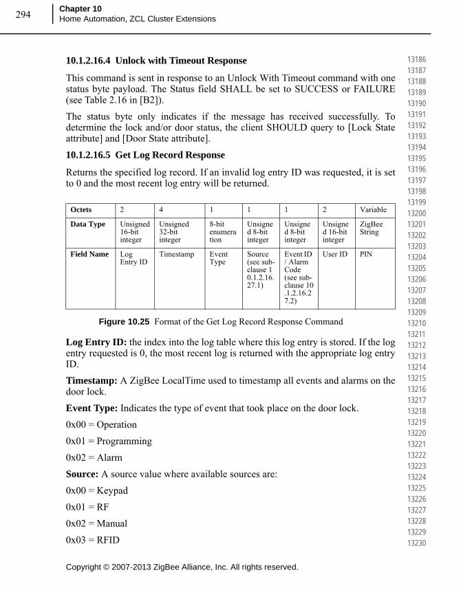
Copyright © 2007-2013 ZigBee Alliance, Inc. All rights reserved.
Chapter 10Home Automation, ZCL Cluster Extensions294
131861318713188131891319013191131921319313194131951319613197131981319913200132011320213203132041320513206132071320813209132101321113212132131321413215132161321713218132191322013221132221322313224132251322613227132281322913230
10.1.2.16.4 Unlock with Timeout Response
This command is sent in response to an Unlock With Timeout command with one status byte payload. The Status field SHALL be set to SUCCESS or FAILURE (see Table 2.16 in [B2]).
The status byte only indicates if the message has received successfully. To determine the lock and/or door status, the client SHOULD query to [Lock State attribute] and [Door State attribute].
10.1.2.16.5 Get Log Record Response
Returns the specified log record. If an invalid log entry ID was requested, it is set to 0 and the most recent log entry will be returned.
Figure 10.25 Format of the Get Log Record Response Command
Log Entry ID: the index into the log table where this log entry is stored. If the log entry requested is 0, the most recent log is returned with the appropriate log entry ID.
Timestamp: A ZigBee LocalTime used to timestamp all events and alarms on the door lock.
Event Type: Indicates the type of event that took place on the door lock.
0x00 = Operation
0x01 = Programming
0x02 = Alarm
Source: A source value where available sources are:
0x00 = Keypad
0x01 = RF
0x02 = Manual
0x03 = RFID
Octets 2 4 1 1 1 2 Variable
Data Type Unsigned 16-bit integer
Unsigned 32-bit integer
8-bit enumeration
Unsigned 8-bit integer
Unsigned 8-bit integer
Unsigned 16-bit integer
ZigBee String
Field Name Log Entry ID
Timestamp Event Type
Source (see sub-clause 10.1.2.16.27.1)
Event ID / Alarm Code (see sub-clause 10.1.2.16.27.2)
User ID PIN
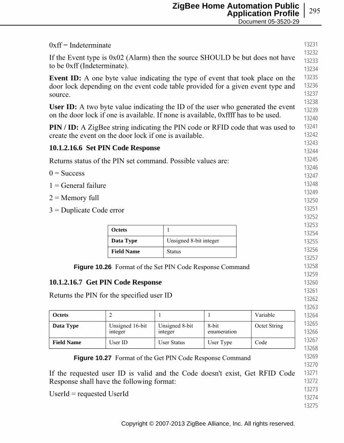
295
Copyright © 2007-2013 ZigBee Alliance, Inc. All rights reserved.
ZigBee Home Automation Public Application Profile
Document 05-3520-29
132311323213233132341323513236132371323813239132401324113242132431324413245132461324713248132491325013251132521325313254132551325613257132581325913260132611326213263132641326513266132671326813269132701327113272132731327413275
0xff = Indeterminate
If the Event type is 0x02 (Alarm) then the source SHOULD be but does not have to be 0xff (Indeterminate).
Event ID: A one byte value indicating the type of event that took place on the door lock depending on the event code table provided for a given event type and source.
User ID: A two byte value indicating the ID of the user who generated the event on the door lock if one is available. If none is available, 0xffff has to be used.
PIN / ID: A ZigBee string indicating the PIN code or RFID code that was used to create the event on the door lock if one is available.
10.1.2.16.6 Set PIN Code Response
Returns status of the PIN set command. Possible values are:
0 = Success
1 = General failure
2 = Memory full
3 = Duplicate Code error
Figure 10.26 Format of the Set PIN Code Response Command
10.1.2.16.7 Get PIN Code Response
Returns the PIN for the specified user ID
Figure 10.27 Format of the Get PIN Code Response Command
If the requested user ID is valid and the Code doesn't exist, Get RFID Code Response shall have the following format:
UserId = requested UserId
Octets 1
Data Type Unsigned 8-bit integer
Field Name Status
Octets 2 1 1 Variable
Data Type Unsigned 16-bit integer
Unsigned 8-bit integer
8-bit enumeration
Octet String
Field Name User ID User Status User Type Code
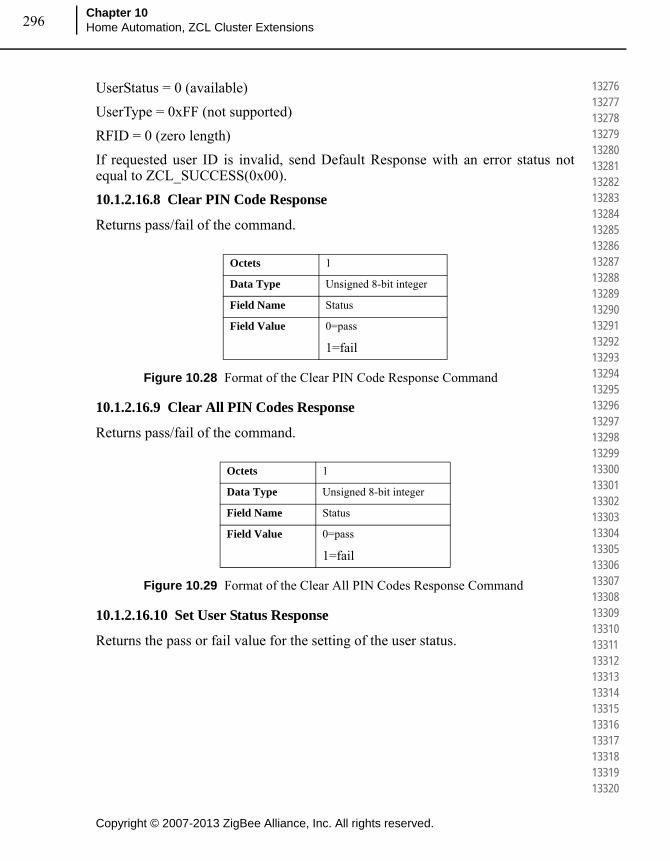
Copyright © 2007-2013 ZigBee Alliance, Inc. All rights reserved.
Chapter 10Home Automation, ZCL Cluster Extensions296
132761327713278132791328013281132821328313284132851328613287132881328913290132911329213293132941329513296132971329813299133001330113302133031330413305133061330713308133091331013311133121331313314133151331613317133181331913320
UserStatus = 0 (available)
UserType = 0xFF (not supported)
RFID = 0 (zero length)
If requested user ID is invalid, send Default Response with an error status not equal to ZCL_SUCCESS(0x00).
10.1.2.16.8 Clear PIN Code Response
Returns pass/fail of the command.
Figure 10.28 Format of the Clear PIN Code Response Command
10.1.2.16.9 Clear All PIN Codes Response
Returns pass/fail of the command.
Figure 10.29 Format of the Clear All PIN Codes Response Command
10.1.2.16.10 Set User Status Response
Returns the pass or fail value for the setting of the user status.
Octets 1
Data Type Unsigned 8-bit integer
Field Name Status
Field Value 0=pass
1=fail
Octets 1
Data Type Unsigned 8-bit integer
Field Name Status
Field Value 0=pass
1=fail
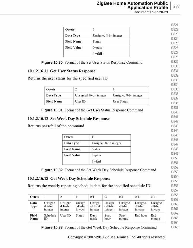
297
Copyright © 2007-2013 ZigBee Alliance, Inc. All rights reserved.
ZigBee Home Automation Public Application Profile
Document 05-3520-29
133211332213323133241332513326133271332813329133301333113332133331333413335133361333713338133391334013341133421334313344133451334613347133481334913350133511335213353133541335513356133571335813359133601336113362133631336413365
Figure 10.30 Format of the Set User Status Response Command
10.1.2.16.11 Get User Status Response
Returns the user status for the specified user ID.
Figure 10.31 Format of the Get User Status Response Command
10.1.2.16.12 Set Week Day Schedule Response
Returns pass/fail of the command
Figure 10.32 Format of the Set Week Day Schedule Response Command
10.1.2.16.13 Get Week Day Schedule Response
Returns the weekly repeating schedule data for the specified schedule ID.
Figure 10.33 Format of the Get Week Day Schedule Response Command
Octets 1
Data Type Unsigned 8-bit integer
Field Name Status
Field Value 0=pass
1=fail
Octets 2 1
Data Type Unsigned 16-bit integer Unsigned 8-bit integer
Field Name User ID User Status
Octets 1
Data Type Unsigned 8-bit integer
Field Name Status
Field Value 0=pass
1=fail
Octets 1 2 1 0/1 0/1 0/1 0/1 0/1
Data Type
Unsigned 8-bit integer
Unsigned 16-bit integer
Unsigned 8-bit integer
Unsigned 8-bit integer
Unsigned 8-bit integer
Unsigned 8-bit integer
Unsigned 8-bit integer
Unsigned 8-bit integer
Field Name
Schedule ID
User ID Status Days mask
Start hour
Start minute
End hour End minute
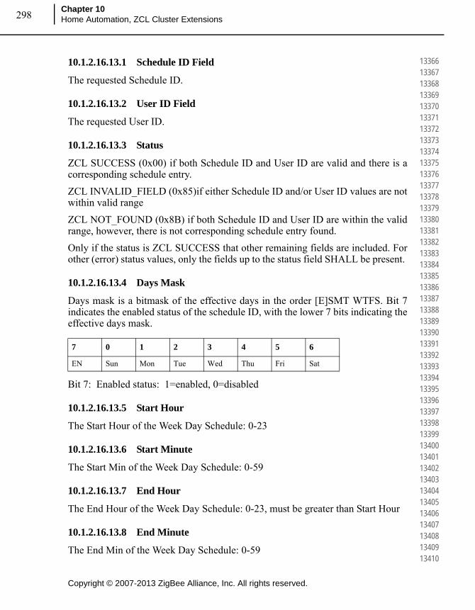
Copyright © 2007-2013 ZigBee Alliance, Inc. All rights reserved.
Chapter 10Home Automation, ZCL Cluster Extensions298
133661336713368133691337013371133721337313374133751337613377133781337913380133811338213383133841338513386133871338813389133901339113392133931339413395133961339713398133991340013401134021340313404134051340613407134081340913410
10.1.2.16.13.1 Schedule ID Field
The requested Schedule ID.
10.1.2.16.13.2 User ID Field
The requested User ID.
10.1.2.16.13.3 Status
ZCL SUCCESS (0x00) if both Schedule ID and User ID are valid and there is a corresponding schedule entry.
ZCL INVALID_FIELD (0x85)if either Schedule ID and/or User ID values are not within valid range
ZCL NOT_FOUND (0x8B) if both Schedule ID and User ID are within the valid range, however, there is not corresponding schedule entry found.
Only if the status is ZCL SUCCESS that other remaining fields are included. For other (error) status values, only the fields up to the status field SHALL be present.
10.1.2.16.13.4 Days Mask
Days mask is a bitmask of the effective days in the order [E]SMT WTFS. Bit 7 indicates the enabled status of the schedule ID, with the lower 7 bits indicating the effective days mask.
Bit 7: Enabled status: 1=enabled, 0=disabled
10.1.2.16.13.5 Start Hour
The Start Hour of the Week Day Schedule: 0-23
10.1.2.16.13.6 Start Minute
The Start Min of the Week Day Schedule: 0-59
10.1.2.16.13.7 End Hour
The End Hour of the Week Day Schedule: 0-23, must be greater than Start Hour
10.1.2.16.13.8 End Minute
The End Min of the Week Day Schedule: 0-59
7 0 1 2 3 4 5 6
EN Sun Mon Tue Wed Thu Fri Sat
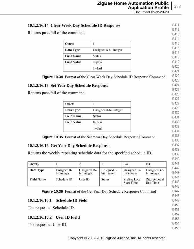
299
Copyright © 2007-2013 ZigBee Alliance, Inc. All rights reserved.
ZigBee Home Automation Public Application Profile
Document 05-3520-29
134111341213413134141341513416134171341813419134201342113422134231342413425134261342713428134291343013431134321343313434134351343613437134381343913440134411344213443134441344513446134471344813449134501345113452134531345413455
10.1.2.16.14 Clear Week Day Schedule ID Response
Returns pass/fail of the command
Figure 10.34 Format of the Clear Week Day Schedule ID Response Command
10.1.2.16.15 Set Year Day Schedule Response
Returns pass/fail of the command
Figure 10.35 Format of the Set Year Day Schedule Response Command
10.1.2.16.16 Get Year Day Schedule Response
Returns the weekly repeating schedule data for the specified schedule ID.
Figure 10.36 Format of the Get Year Day Schedule Response Command
10.1.2.16.16.1 Schedule ID Field
The requested Schedule ID.
10.1.2.16.16.2 User ID Field
The requested User ID.
Octets 1
Data Type Unsigned 8-bit integer
Field Name Status
Field Value 0=pass
1=fail
Octets 1
Data Type Unsigned 8-bit integer
Field Name Status
Field Value 0=pass
1=fail
Octets 1 2 1 0/4 0/4
Data Type Unsigned 8-bit integer
Unsigned 16-bit integer
Unsigned 8-bit integer
Unsigned 32-bit integer
Unsigned 32-bit integer
Field Name Schedule ID User ID Status ZigBee Local Start Time
ZigBee Local End Time
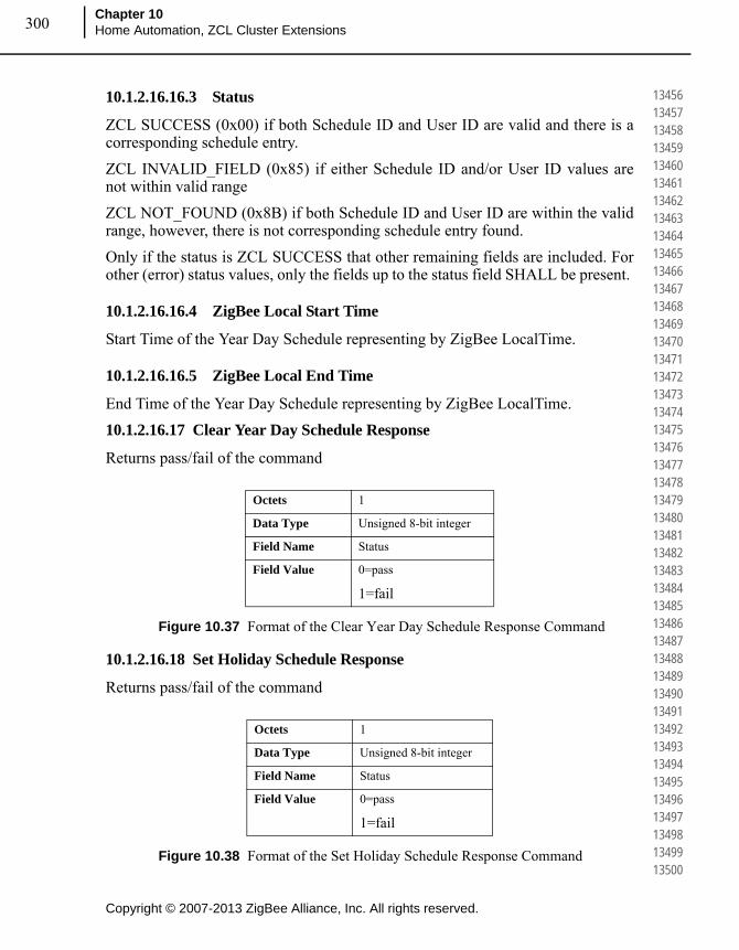
Copyright © 2007-2013 ZigBee Alliance, Inc. All rights reserved.
Chapter 10Home Automation, ZCL Cluster Extensions300
134561345713458134591346013461134621346313464134651346613467134681346913470134711347213473134741347513476134771347813479134801348113482134831348413485134861348713488134891349013491134921349313494134951349613497134981349913500
10.1.2.16.16.3 Status
ZCL SUCCESS (0x00) if both Schedule ID and User ID are valid and there is a corresponding schedule entry.
ZCL INVALID_FIELD (0x85) if either Schedule ID and/or User ID values are not within valid range
ZCL NOT_FOUND (0x8B) if both Schedule ID and User ID are within the valid range, however, there is not corresponding schedule entry found.
Only if the status is ZCL SUCCESS that other remaining fields are included. For other (error) status values, only the fields up to the status field SHALL be present.
10.1.2.16.16.4 ZigBee Local Start Time
Start Time of the Year Day Schedule representing by ZigBee LocalTime.
10.1.2.16.16.5 ZigBee Local End Time
End Time of the Year Day Schedule representing by ZigBee LocalTime.
10.1.2.16.17 Clear Year Day Schedule Response
Returns pass/fail of the command
Figure 10.37 Format of the Clear Year Day Schedule Response Command
10.1.2.16.18 Set Holiday Schedule Response
Returns pass/fail of the command
Figure 10.38 Format of the Set Holiday Schedule Response Command
Octets 1
Data Type Unsigned 8-bit integer
Field Name Status
Field Value 0=pass
1=fail
Octets 1
Data Type Unsigned 8-bit integer
Field Name Status
Field Value 0=pass
1=fail

301
Copyright © 2007-2013 ZigBee Alliance, Inc. All rights reserved.
ZigBee Home Automation Public Application Profile
Document 05-3520-29
135011350213503135041350513506135071350813509135101351113512135131351413515135161351713518135191352013521135221352313524135251352613527135281352913530135311353213533135341353513536135371353813539135401354113542135431354413545
10.1.2.16.19 Get Holiday Schedule Response
Returns the Holiday Schedule Entry for the specified Holiday ID.
Figure 10.39 Format of the Get Holiday Schedule Response Command
10.1.2.16.19.1 Holiday Schedule ID
The requested Holiday Schedule ID
10.1.2.16.19.2 Status
ZCL SUCCESS (0x00) if both Schedule ID and User ID are valid and there is a corresponding schedule entry.
ZCL INVALID_FIELD (0x85) if either Schedule ID and/or User ID values are not within valid range
ZCL NOT_FOUND (0x8B) if both Schedule ID and User ID are within the valid range, however, there is not corresponding schedule entry found.
Only if the status is ZCL SUCCESS that other remaining fields are included. For other (error) status values, only the fields up to the status field SHALL be present.
10.1.2.16.19.3 ZigBee Local Start Time
Start Time of the Year Day Schedule representing by ZigBee LocalTime.
10.1.2.16.19.4 ZigBee Local End Time
End Time of the Year Day Schedule representing by ZigBee LocalTime.
10.1.2.16.19.5 Operating Mode
Operating Mode is valid enumeration value as listed in operating mode attribute
10.1.2.16.20 Clear Holiday Schedule Response
Returns pass/fail of the command
Octets 1 1 0/4 0/4 0/1
Data Type Unsigned 8-bit integer
Unsigned 8-bit integer
Unsigned 32-bit integer
Unsigned 32-bit integer
8-bit enumeration
Field Name Holiday Schedule ID
Status ZigBee Local Start Time
ZigBee Local End Time
Operating Mode During Holiday

Copyright © 2007-2013 ZigBee Alliance, Inc. All rights reserved.
Chapter 10Home Automation, ZCL Cluster Extensions302
135461354713548135491355013551135521355313554135551355613557135581355913560135611356213563135641356513566135671356813569135701357113572135731357413575135761357713578135791358013581135821358313584135851358613587135881358913590
Figure 10.40 Format of the Clear Holiday Schedule Response Command
10.1.2.16.21 Set User Type Response
Returns the pass or fail value for the setting of the user type.
Figure 10.41 Format of the Set User Type Response Command
10.1.2.16.22 Get User Type Response
Returns the user type for the specified user ID.
Figure 10.42 Format of the Get User Type Response Command
10.1.2.16.23 Set RFID Code Response
Returns status of the Set RFID Code command. Possible values are:
0 = Success
1 = General failure
2 = Memory full
3 = Duplicate ID error
Octets 1
Data Type Unsigned 8-bit integer
Field Name Status
Field Value 0=pass
1=fail
Octets 1
Data Type Unsigned 8-bit integer
Field Name Status
Field Value 0=pass
1=fail
Octets 2 1
Data Type Unsigned 16-bit integer 8-bit enumeration
Field Name User ID User Type

303
Copyright © 2007-2013 ZigBee Alliance, Inc. All rights reserved.
ZigBee Home Automation Public Application Profile
Document 05-3520-29
135911359213593135941359513596135971359813599136001360113602136031360413605136061360713608136091361013611136121361313614136151361613617136181361913620136211362213623136241362513626136271362813629136301363113632136331363413635
Figure 10.43 Format of the Set RFID Code Response Command
10.1.2.16.24 Get RFID Code Response
Returns the RFID code for the specified user ID:
Figure 10.44 Format of the Get RFID Code Response Command
If the requested user ID is valid and the Code doesn't exist, Get RFID Code Response shall have the following format:
UserId = requested UserId
UserStatus = 0 (available)
UserType = 0xFF (not supported)
RFID = 0 (zero length)
If requested user ID is invalid, send Default Response with an error status not equal to ZCL_SUCCESS(0x00).
10.1.2.16.25 Clear RFID Code Response
Returns pass/fail of the command.
Figure 10.45 Format of the Clear RIFD Code Response Command
Octets 1
Data Type Unsigned 8-bit integer
Field Name Status
Octets 2 1 1 Variable
Data Type Unsigned 16-bit integer
Unsigned 8-bit integer
8-bit enumeration
Octet String
Field Name User ID User Status User Type RFID Code
Octets 1
Data Type Unsigned 8-bit integer
Field Name Status
Field Value 0=pass
1=fail
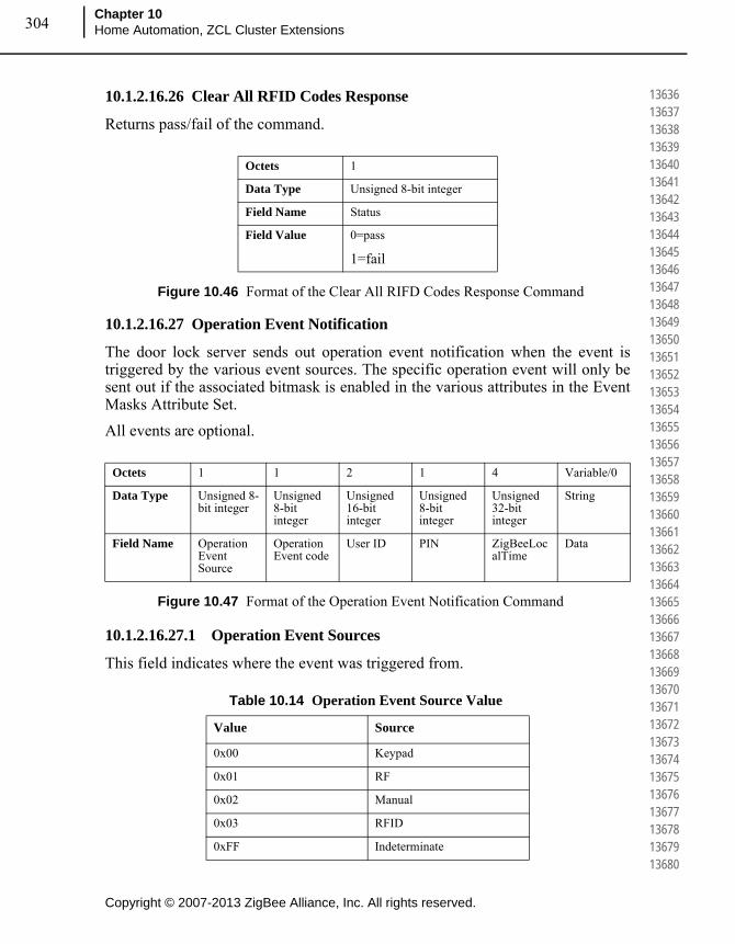
Copyright © 2007-2013 ZigBee Alliance, Inc. All rights reserved.
Chapter 10Home Automation, ZCL Cluster Extensions304
136361363713638136391364013641136421364313644136451364613647136481364913650136511365213653136541365513656136571365813659136601366113662136631366413665136661366713668136691367013671136721367313674136751367613677136781367913680
10.1.2.16.26 Clear All RFID Codes Response
Returns pass/fail of the command.
Figure 10.46 Format of the Clear All RIFD Codes Response Command
10.1.2.16.27 Operation Event Notification
The door lock server sends out operation event notification when the event is triggered by the various event sources. The specific operation event will only be sent out if the associated bitmask is enabled in the various attributes in the Event Masks Attribute Set.
All events are optional.
Figure 10.47 Format of the Operation Event Notification Command
10.1.2.16.27.1 Operation Event Sources
This field indicates where the event was triggered from.
Octets 1
Data Type Unsigned 8-bit integer
Field Name Status
Field Value 0=pass
1=fail
Octets 1 1 2 1 4 Variable/0
Data Type Unsigned 8-bit integer
Unsigned 8-bit integer
Unsigned 16-bit integer
Unsigned 8-bit integer
Unsigned 32-bit integer
String
Field Name Operation Event Source
Operation Event code
User ID PIN ZigBeeLocalTime
Data
Table 10.14 Operation Event Source Value
Value Source
0x00 Keypad
0x01 RF
0x02 Manual
0x03 RFID
0xFF Indeterminate
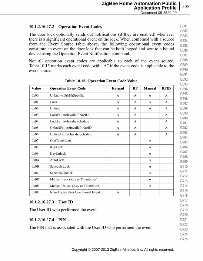
305
Copyright © 2007-2013 ZigBee Alliance, Inc. All rights reserved.
ZigBee Home Automation Public Application Profile
Document 05-3520-29
136811368213683136841368513686136871368813689136901369113692136931369413695136961369713698136991370013701137021370313704137051370613707137081370913710137111371213713137141371513716137171371813719137201372113722137231372413725
10.1.2.16.27.2 Operation Event Codes
The door lock optionally sends out notifications (if they are enabled) whenever there is a significant operational event on the lock. When combined with a source from the Event Source table above, the following operational event codes constitute an event on the door lock that can be both logged and sent to a bound device using the Operation Event Notification command.
Not all operation event codes are applicable to each of the event source. Table 10.15 marks each event code with “A” if the event code is applicable to the event source.
10.1.2.16.27.3 User ID
The User ID who performed the event.
10.1.2.16.27.4 PIN
The PIN that is associated with the User ID who performed the event.
Table 10.15 Operation Event Code Value
Value Operation Event Code Keypad RF Manual RFID
0x00 UnknownOrMfgSpecific A A A A
0x01 Lock A A A A
0x02 Unlock A A A A
0x03 LockFailureInvalidPINorID A A A
0x04 LockFailureInvalidSchedule A A A
0x05 UnlockFailureInvalidPINorID A A A
0x06 UnlockFailureInvalidSchedule A A A
0x07 OneTouchLock A
0x08 KeyLock A
0x09 KeyUnlock A
0x0A AutoLock A
0x0B ScheduleLock A
0x0C ScheduleUnlock A
0x0D Manual Lock (Key or Thumbturn) A
0x0E Manual Unlock (Key or Thumbturn) A
0x0F Non-Access User Operational Event A
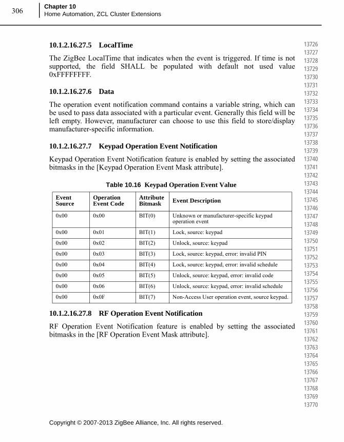
Copyright © 2007-2013 ZigBee Alliance, Inc. All rights reserved.
Chapter 10Home Automation, ZCL Cluster Extensions306
137261372713728137291373013731137321373313734137351373613737137381373913740137411374213743137441374513746137471374813749137501375113752137531375413755137561375713758137591376013761137621376313764137651376613767137681376913770
10.1.2.16.27.5 LocalTime
The ZigBee LocalTime that indicates when the event is triggered. If time is not supported, the field SHALL be populated with default not used value 0xFFFFFFFF.
10.1.2.16.27.6 Data
The operation event notification command contains a variable string, which can be used to pass data associated with a particular event. Generally this field will be left empty. However, manufacturer can choose to use this field to store/display manufacturer-specific information.
10.1.2.16.27.7 Keypad Operation Event Notification
Keypad Operation Event Notification feature is enabled by setting the associated bitmasks in the [Keypad Operation Event Mask attribute].
10.1.2.16.27.8 RF Operation Event Notification
RF Operation Event Notification feature is enabled by setting the associated bitmasks in the [RF Operation Event Mask attribute].
Table 10.16 Keypad Operation Event Value
Event Source
Operation Event Code
Attribute Bitmask Event Description
0x00 0x00 BIT(0) Unknown or manufacturer-specific keypad operation event
0x00 0x01 BIT(1) Lock, source: keypad
0x00 0x02 BIT(2) Unlock, source: keypad
0x00 0x03 BIT(3) Lock, source: keypad, error: invalid PIN
0x00 0x04 BIT(4) Lock, source: keypad, error: invalid schedule
0x00 0x05 BIT(5) Unlock, source: keypad, error: invalid code
0x00 0x06 BIT(6) Unlock, source: keypad, error: invalid schedule
0x00 0x0F BIT(7) Non-Access User operation event, source keypad.
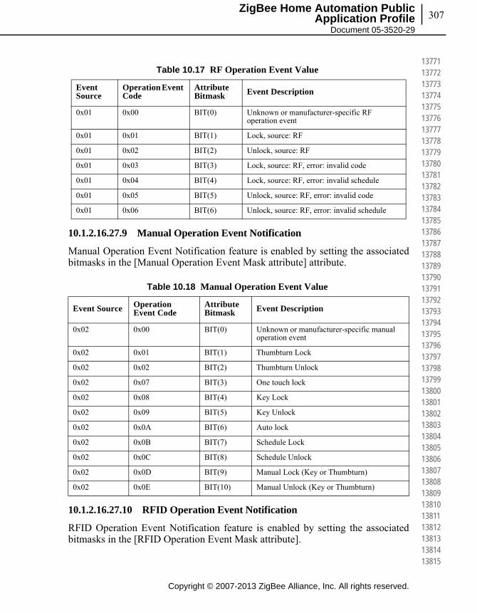
307
Copyright © 2007-2013 ZigBee Alliance, Inc. All rights reserved.
ZigBee Home Automation Public Application Profile
Document 05-3520-29
137711377213773137741377513776137771377813779137801378113782137831378413785137861378713788137891379013791137921379313794137951379613797137981379913800138011380213803138041380513806138071380813809138101381113812138131381413815
10.1.2.16.27.9 Manual Operation Event Notification
Manual Operation Event Notification feature is enabled by setting the associated bitmasks in the [Manual Operation Event Mask attribute] attribute.
10.1.2.16.27.10 RFID Operation Event Notification
RFID Operation Event Notification feature is enabled by setting the associated bitmasks in the [RFID Operation Event Mask attribute].
Table 10.17 RF Operation Event Value
Event Source
Operation Event Code
Attribute Bitmask Event Description
0x01 0x00 BIT(0) Unknown or manufacturer-specific RF operation event
0x01 0x01 BIT(1) Lock, source: RF
0x01 0x02 BIT(2) Unlock, source: RF
0x01 0x03 BIT(3) Lock, source: RF, error: invalid code
0x01 0x04 BIT(4) Lock, source: RF, error: invalid schedule
0x01 0x05 BIT(5) Unlock, source: RF, error: invalid code
0x01 0x06 BIT(6) Unlock, source: RF, error: invalid schedule
Table 10.18 Manual Operation Event Value
Event Source Operation Event Code
Attribute Bitmask Event Description
0x02 0x00 BIT(0) Unknown or manufacturer-specific manual operation event
0x02 0x01 BIT(1) Thumbturn Lock
0x02 0x02 BIT(2) Thumbturn Unlock
0x02 0x07 BIT(3) One touch lock
0x02 0x08 BIT(4) Key Lock
0x02 0x09 BIT(5) Key Unlock
0x02 0x0A BIT(6) Auto lock
0x02 0x0B BIT(7) Schedule Lock
0x02 0x0C BIT(8) Schedule Unlock
0x02 0x0D BIT(9) Manual Lock (Key or Thumbturn)
0x02 0x0E BIT(10) Manual Unlock (Key or Thumbturn)

Copyright © 2007-2013 ZigBee Alliance, Inc. All rights reserved.
Chapter 10Home Automation, ZCL Cluster Extensions308
138161381713818138191382013821138221382313824138251382613827138281382913830138311383213833138341383513836138371383813839138401384113842138431384413845138461384713848138491385013851138521385313854138551385613857138581385913860
10.1.2.16.28 Programming Event Notification
The door lock server sends out a programming event notification whenever a programming event takes place on the door lock.
As with operational events, all programming events can be turned on and off by flipping bits in the associated event mask.
The programming event notification command includes an optional string of data that can be used by the manufacturer to pass some manufacturer-specific information if that is required.
Figure 10.48 Format of the Programming Event Notification Command
10.1.2.16.28.1 Operation Event Sources
This field indicates where the event was trigger from.
Table 10.19 RFID Operation Event Value
Event Source Operation Event Code
Attribute Bitmask Event Description
0x03 0x00 BIT(0) Unknown or manufacturer-specific keypad operation event
0x03 0x01 BIT(1) Lock, source: RFID
0x03 0x02 BIT(2) Unlock, source: RFID
0x03 0x03 BIT(3) Lock, source: RFID, error: invalid RFID ID
0x03 0x04 BIT(4) Lock, source: RFID, error: invalid schedule
0x03 0x05 BIT(5) Unlock, source: RFID, error: invalid RFID ID
0x03 0x06 BIT(6) Unlock, source: RFID, error: invalid schedule
Octets 1 1 2 1 1 1 4 Variable/0
Data Type
Unsigned 8-bit integer
Unsigned 8-bit integer
Unsigned 16-bit integer
Unsigned 8-bit integer
8-bit enumeration
Unsigned 8-bit integer
Unsigned 32-bit integer
String
Field Name
Program Event Source
Program Event Code
User ID PIN User Type
User Status
ZigBee LocalTime
Data
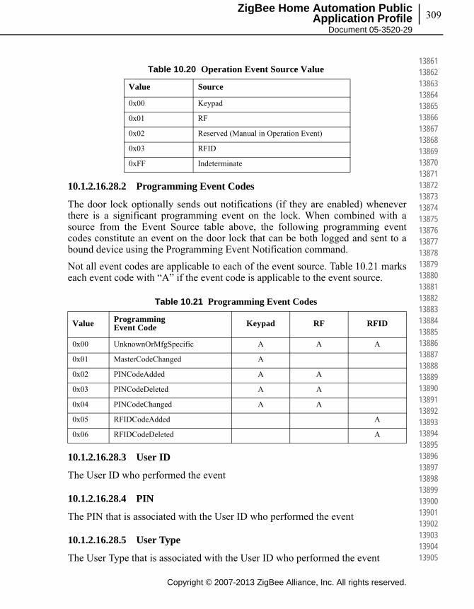
309
Copyright © 2007-2013 ZigBee Alliance, Inc. All rights reserved.
ZigBee Home Automation Public Application Profile
Document 05-3520-29
138611386213863138641386513866138671386813869138701387113872138731387413875138761387713878138791388013881138821388313884138851388613887138881388913890138911389213893138941389513896138971389813899139001390113902139031390413905
10.1.2.16.28.2 Programming Event Codes
The door lock optionally sends out notifications (if they are enabled) whenever there is a significant programming event on the lock. When combined with a source from the Event Source table above, the following programming event codes constitute an event on the door lock that can be both logged and sent to a bound device using the Programming Event Notification command.
Not all event codes are applicable to each of the event source. Table 10.21 marks each event code with “A” if the event code is applicable to the event source.
10.1.2.16.28.3 User ID
The User ID who performed the event
10.1.2.16.28.4 PIN
The PIN that is associated with the User ID who performed the event
10.1.2.16.28.5 User Type
The User Type that is associated with the User ID who performed the event
Table 10.20 Operation Event Source Value
Value Source
0x00 Keypad
0x01 RF
0x02 Reserved (Manual in Operation Event)
0x03 RFID
0xFF Indeterminate
Table 10.21 Programming Event Codes
Value Programming Event Code Keypad RF RFID
0x00 UnknownOrMfgSpecific A A A
0x01 MasterCodeChanged A
0x02 PINCodeAdded A A
0x03 PINCodeDeleted A A
0x04 PINCodeChanged A A
0x05 RFIDCodeAdded A
0x06 RFIDCodeDeleted A
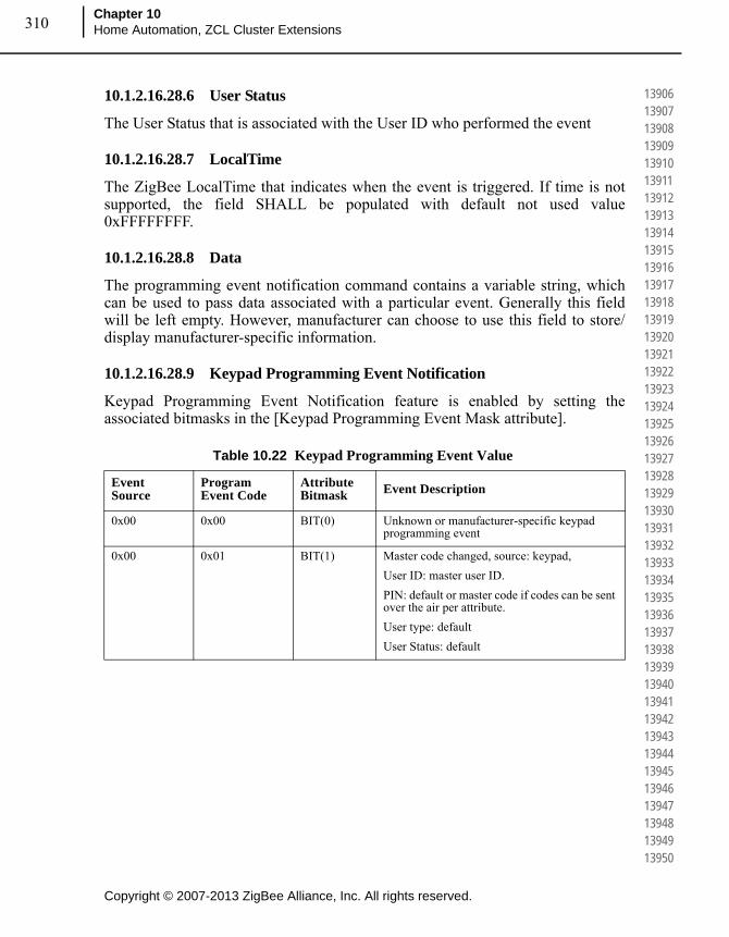
Copyright © 2007-2013 ZigBee Alliance, Inc. All rights reserved.
Chapter 10Home Automation, ZCL Cluster Extensions310
139061390713908139091391013911139121391313914139151391613917139181391913920139211392213923139241392513926139271392813929139301393113932139331393413935139361393713938139391394013941139421394313944139451394613947139481394913950
10.1.2.16.28.6 User Status
The User Status that is associated with the User ID who performed the event
10.1.2.16.28.7 LocalTime
The ZigBee LocalTime that indicates when the event is triggered. If time is not supported, the field SHALL be populated with default not used value 0xFFFFFFFF.
10.1.2.16.28.8 Data
The programming event notification command contains a variable string, which can be used to pass data associated with a particular event. Generally this field will be left empty. However, manufacturer can choose to use this field to store/display manufacturer-specific information.
10.1.2.16.28.9 Keypad Programming Event Notification
Keypad Programming Event Notification feature is enabled by setting the associated bitmasks in the [Keypad Programming Event Mask attribute].
Table 10.22 Keypad Programming Event Value
Event Source
Program Event Code
Attribute Bitmask Event Description
0x00 0x00 BIT(0) Unknown or manufacturer-specific keypad programming event
0x00 0x01 BIT(1) Master code changed, source: keypad,
User ID: master user ID.
PIN: default or master code if codes can be sent over the air per attribute.
User type: default
User Status: default

311
Copyright © 2007-2013 ZigBee Alliance, Inc. All rights reserved.
ZigBee Home Automation Public Application Profile
Document 05-3520-29
139511395213953139541395513956139571395813959139601396113962139631396413965139661396713968139691397013971139721397313974139751397613977139781397913980139811398213983139841398513986139871398813989139901399113992139931399413995
10.1.2.16.28.10 RF Programming Event Notification
RF Programming Event Notification feature is enabled by setting the associated bitmasks in the [RF Programming Event Mask attribute].
0x00 0x02 BIT(2) PIN added, source: keypad
User ID: user ID that was added.
PIN: code that was added (if codes can be sent over the air per attribute.)
User type: default or type added.
User Status: default or status added.
0x00 0x03 BIT(3) PIN deleted, source: keypad
User ID: user ID that was deleted.
PIN: code that was deleted (if codes can be sent over the air per attribute.)
User type: default or type deleted.
User Status: default or status deleted.
0x00 0x04 BIT(4) PIN changed
Source: keypad
User ID: user ID that was changed
PIN: code that was changed (if codes can be sent over the air per attribute.)
User type: default or type changed.
User Status: default or status changed.
Table 10.23 RF Programming Event Value
Event Source
Program Event Code
Attribute Bitmask Event Description
0x01 0x00 BIT(0) Unknown or manufacturer-specific RF programming event.
0x01 0x02 BIT(2) PIN added, source RF
Same as keypad source above
0x01 0x03 BIT(3) PIN deleted, source RF
Same as keypad source above.
0x01 0x04 BIT(4) PIN changed
Source RF
Same as keypad source above
Table 10.22 Keypad Programming Event Value (Continued)
Event Source
Program Event Code
Attribute Bitmask Event Description

Copyright © 2007-2013 ZigBee Alliance, Inc. All rights reserved.
Chapter 10Home Automation, ZCL Cluster Extensions312
139961399713998139991400014001140021400314004140051400614007140081400914010140111401214013140141401514016140171401814019140201402114022140231402414025140261402714028140291403014031140321403314034140351403614037140381403914040
10.1.2.16.28.11 RFID Programming Event Notification
RFID Programming Event Notification feature is enabled by setting the associated bitmasks in the [RFID Programming Event Mask attribute].
10.1.2.17 Scene Table Extension
If the Scene server cluster is implemented, the following extension field is added to the Scene table:
• Lock StateWhen the Lock State attribute is part of a Scene table, the attribute is treated as a writeable command, that is, setting the Lock State to lock will command the lock to lock, and setting the Lock State to unlocked will command the lock to unlock. Setting the Lock State attribute to “not fully locked” is not supported. The transition time field in the Scene table will be treated as a delay before setting the Lock State attribute, that is it is possible to activate a scene with the lock actuation some seconds later.
Locks that do not have an actuation mechanism SHOULD not support the Scene table extension.
Table 10.24 RFID Programming Event Value
Event Source
Program Event Code
Attribute Bitmask Event Description
0x03 0x00 BIT(0) Unknown or manufacturer-specific keypad programming event
0x03 0x05 BIT(5) ID Added, Source: RFID
User ID: user ID that was added.
ID: ID that was added (if codes can be sent over the air per attribute.)
User Type: default or type added.
User Status: default or status added.
0x03 0x06 BIT(6) ID Deleted, Source: RFID
User ID: user ID that was deleted.
ID: ID that was deleted (if codes can be sent over the air per attribute.)
User Type: default or type deleted.
User Status: default or status deleted.

313
Copyright © 2007-2013 ZigBee Alliance, Inc. All rights reserved.
ZigBee Home Automation Public Application Profile
Document 05-3520-29
140411404214043140441404514046140471404814049140501405114052140531405414055140561405714058140591406014061140621406314064140651406614067140681406914070140711407214073140741407514076140771407814079140801408114082140831408414085
10.1.3 Client
10.1.3.1 Dependencies
None
10.1.3.2 Attributes
The client has no attributes.
10.1.3.3 Commands Received
The client receives the cluster-specific commands generated by the server as shown in Table 10.13.
10.1.3.4 Commands Generated
The client generates the cluster-specific commands that will be received by the server as shown in Table 10.10.
10.2 Thermostat Cluster Extensions
This section describes the recommended practices for Home Automation Thermostat Cluster extensions.
10.2.1 Introduction
10.2.1.1 Scope and Purpose
This document describes the proposed addition to the Home Automation specification and the ZigBee Cluster Library for the thermostat cluster. Many programmable thermostats have scheduling capabilities that would be beneficial to control in a standard way. The proposal set out in this document would provide a standard framework for setting and retrieving the schedule for a thermostat. This extension also provided new standard commands and attributes to retrieve HVAC relay status for a thermostat.
10.2.2 References
The following standards and specifications contain provisions, which through reference in this document constitute provisions of this specification. All the standards and specifications listed are normative references. At the time of publication, the editions indicated were valid. All standards and specifications are subject to revision, and parties to agreements based on this specification are
Copyright © 2007-2013 ZigBee Alliance, Inc. All rights reserved.
Chapter 10Home Automation, ZCL Cluster Extensions314
140861408714088140891409014091140921409314094140951409614097140981409914100141011410214103141041410514106141071410814109141101411114112141131411414115141161411714118141191412014121141221412314124141251412614127141281412914130
encouraged to investigate the possibility of applying the most recent editions of the standards and specifications indicated below.
10.2.2.1 ZigBee Alliance Documents
1 ZigBee Document 075366r03, The ZigBee Cluster Library – this document describes the ZigBee Cluster Library framework and it is essential that it be understood in order to use this cluster definition document.
2 ZigBee Document 115593, HA-ThermostatCluster-Temperature-Conversion-Sample-Code – this document provides sample code on how to convert the temperature from Fahrenheit to Celsius and vice versa
10.2.3 General Description
This document mirrors the existing Thermostat Cluster in the ZigBee Cluster Library Specification. The following heading numbers are used to reference the actual sections in the Cluster Library Specification document.
10.2.3.1 Thermostat Temperature Conversion
Many Thermostats store internally or have the capability to display the temperature in degree Fahrenheit format. The ZCL Thermostat Cluster standardizes temperature representation in degree Celsius format when transferred over the air. Sample code has been provided in the ZigBee document 115593, HA-ThermostatCluster-Temperature-Conversion-Sample-Code. Manufacturers should use the conversion algorithm provided to convert temperature from Fahrenheit to Celsius and vice versa.
10.2.3.2 Thermostat Schedule Feature Mandatory Requirement
The StartOfWeek Attribute is the indicator to show that the Weekly schedule extension is supported. If the Weekly schedule extension feature is supported, it is mandatory to also support the StartOfWeek Attribute, NumberOfWeeklyTransitions Attribute, NumberOfDailyTransitions Attribute, Set Weekly Schedule Command and Get Weekly Schedule Command.
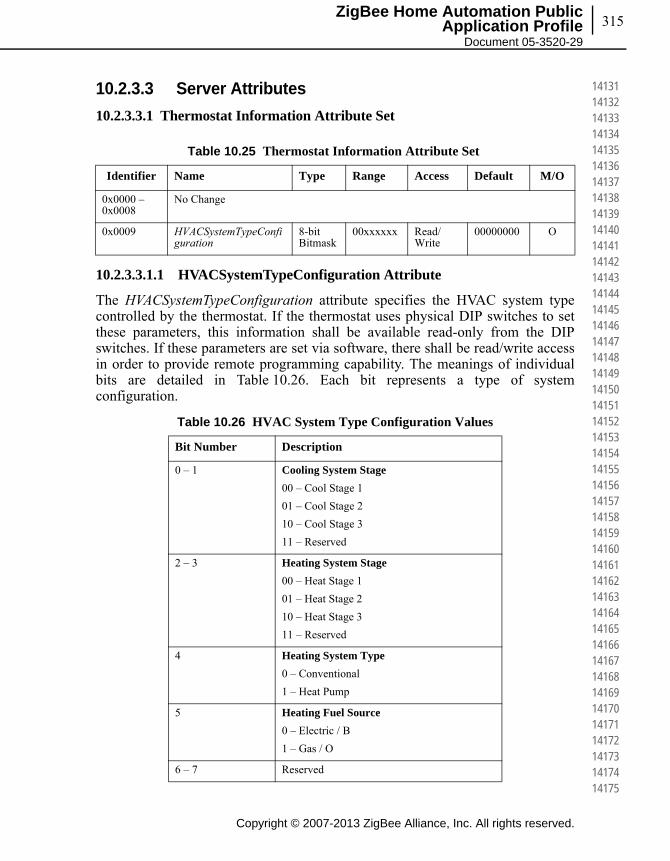
315
Copyright © 2007-2013 ZigBee Alliance, Inc. All rights reserved.
ZigBee Home Automation Public Application Profile
Document 05-3520-29
141311413214133141341413514136141371413814139141401414114142141431414414145141461414714148141491415014151141521415314154141551415614157141581415914160141611416214163141641416514166141671416814169141701417114172141731417414175
10.2.3.3 Server Attributes
10.2.3.3.1 Thermostat Information Attribute Set
10.2.3.3.1.1 HVACSystemTypeConfiguration Attribute
The HVACSystemTypeConfiguration attribute specifies the HVAC system type controlled by the thermostat. If the thermostat uses physical DIP switches to set these parameters, this information shall be available read-only from the DIP switches. If these parameters are set via software, there shall be read/write access in order to provide remote programming capability. The meanings of individual bits are detailed in Table 10.26. Each bit represents a type of system configuration.
Table 10.25 Thermostat Information Attribute Set
Identifier Name Type Range Access Default M/O
0x0000 – 0x0008
No Change
0x0009 HVACSystemTypeConfiguration
8-bit Bitmask
00xxxxxx Read/Write
00000000 O
Table 10.26 HVAC System Type Configuration Values
Bit Number Description
0 – 1 Cooling System Stage
00 – Cool Stage 1
01 – Cool Stage 2
10 – Cool Stage 3
11 – Reserved
2 – 3 Heating System Stage
00 – Heat Stage 1
01 – Heat Stage 2
10 – Heat Stage 3
11 – Reserved
4 Heating System Type
0 – Conventional
1 – Heat Pump
5 Heating Fuel Source
0 – Electric / B
1 – Gas / O
6 – 7 Reserved
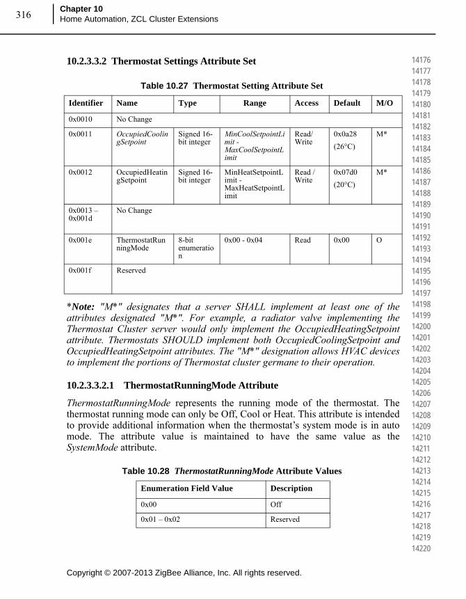
Copyright © 2007-2013 ZigBee Alliance, Inc. All rights reserved.
Chapter 10Home Automation, ZCL Cluster Extensions316
141761417714178141791418014181141821418314184141851418614187141881418914190141911419214193141941419514196141971419814199142001420114202142031420414205142061420714208142091421014211142121421314214142151421614217142181421914220
10.2.3.3.2 Thermostat Settings Attribute Set
*Note: "M*" designates that a server SHALL implement at least one of the attributes designated "M*". For example, a radiator valve implementing the Thermostat Cluster server would only implement the OccupiedHeatingSetpoint attribute. Thermostats SHOULD implement both OccupiedCoolingSetpoint and OccupiedHeatingSetpoint attributes. The "M*" designation allows HVAC devices to implement the portions of Thermostat cluster germane to their operation.
10.2.3.3.2.1 ThermostatRunningMode Attribute
ThermostatRunningMode represents the running mode of the thermostat. The thermostat running mode can only be Off, Cool or Heat. This attribute is intended to provide additional information when the thermostat’s system mode is in auto mode. The attribute value is maintained to have the same value as the SystemMode attribute.
Table 10.27 Thermostat Setting Attribute Set
Identifier Name Type Range Access Default M/O
0x0010 No Change
0x0011 OccupiedCoolingSetpoint
Signed 16-bit integer
MinCoolSetpointLimit -MaxCoolSetpointLimit
Read/Write
0x0a28
(26°C)
M*
0x0012 OccupiedHeatingSetpoint
Signed 16-bit integer
MinHeatSetpointLimit -MaxHeatSetpointLimit
Read / Write
0x07d0
(20°C)
M*
0x0013 – 0x001d
No Change
0x001e ThermostatRunningMode
8-bit enumeration
0x00 - 0x04 Read 0x00 O
0x001f Reserved
Table 10.28 ThermostatRunningMode Attribute Values
Enumeration Field Value Description
0x00 Off
0x01 – 0x02 Reserved

317
Copyright © 2007-2013 ZigBee Alliance, Inc. All rights reserved.
ZigBee Home Automation Public Application Profile
Document 05-3520-29
142211422214223142241422514226142271422814229142301423114232142331423414235142361423714238142391424014241142421424314244142451424614247142481424914250142511425214253142541425514256142571425814259142601426114262142631426414265
10.2.3.3.2.2 System Mode
10.2.3.3.2.2.1 Dry
This mode is required to remove the moisture content from the air inside the room.
10.2.3.3.2.2.2 Sleep
This mode is intended for automatic temperature adjustment and low noise. It is called sleep because it is used when the user goes to sleep. The device is configured to provide maximum comfort without disrupting the user’s sleep.
10.2.3.3.3 Thermostat Schedule & HVAC Relay Attribute Set
0x03 Cool
0x04 Heat
0x05 – 0xFF Reserved
Table 10.29 SystemMode Attribute Values
Enumeration Field Value Description
0x00 – 0x07 No change
0x08 Dry
0x09 Sleep
0x0A – 0xff Reserved
Table 10.30 Thermostat Schedule & HVAC Relay Attribute Set
Identifier Name Type Range Access Default M/O
Schedule Attribute Set 0x0020 – 0x0028
0x0020 StartOfWeek 8-bit enumeration
0x00 –0x06
Read - O
0x0021 NumberOfWeeklyTransitions
8-bit unsigned
0x00 – 0xFF
Read N/A O
0x0022 NumberOfDailyTransitions
8-bit unsigned
0x00 – 0xFF
Read N/A O
0x0023 TemperatureSetpointHold
8-bit enumeration
0x00-0x01
Read/Write
0x00 O
Table 10.28 ThermostatRunningMode Attribute Values (Continued)
Enumeration Field Value Description
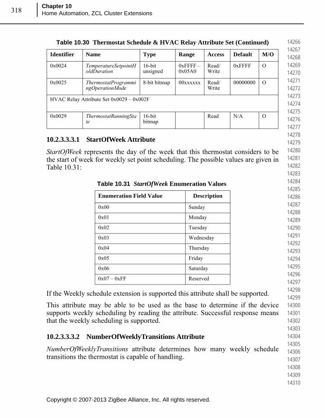
Copyright © 2007-2013 ZigBee Alliance, Inc. All rights reserved.
Chapter 10Home Automation, ZCL Cluster Extensions318
142661426714268142691427014271142721427314274142751427614277142781427914280142811428214283142841428514286142871428814289142901429114292142931429414295142961429714298142991430014301143021430314304143051430614307143081430914310
10.2.3.3.3.1 StartOfWeek Attribute
StartOfWeek represents the day of the week that this thermostat considers to be the start of week for weekly set point scheduling. The possible values are given in Table 10.31:
If the Weekly schedule extension is supported this attribute shall be supported.
This attribute may be able to be used as the base to determine if the device supports weekly scheduling by reading the attribute. Successful response means that the weekly scheduling is supported.
10.2.3.3.3.2 NumberOfWeeklyTransitions Attribute
NumberOfWeeklyTransitions attribute determines how many weekly schedule transitions the thermostat is capable of handling.
0x0024 TemperatureSetpointHoldDuration
16-bit unsigned
0xFFFF – 0x05A0
Read/Write
0xFFFF O
0x0025 ThermostatProgrammingOperationMode
8-bit bitmap 00xxxxxx Read/Write
00000000 O
HVAC Relay Attribute Set 0x0029 – 0x002F
0x0029 ThermostatRunningState
16-bit bitmap
Read N/A O
Table 10.31 StartOfWeek Enumeration Values
Enumeration Field Value Description
0x00 Sunday
0x01 Monday
0x02 Tuesday
0x03 Wednesday
0x04 Thursday
0x05 Friday
0x06 Saturday
0x07 – 0xFF Reserved
Table 10.30 Thermostat Schedule & HVAC Relay Attribute Set (Continued)
Identifier Name Type Range Access Default M/O
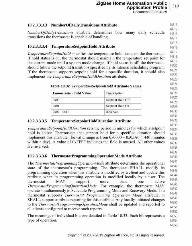
319
Copyright © 2007-2013 ZigBee Alliance, Inc. All rights reserved.
ZigBee Home Automation Public Application Profile
Document 05-3520-29
143111431214313143141431514316143171431814319143201432114322143231432414325143261432714328143291433014331143321433314334143351433614337143381433914340143411434214343143441434514346143471434814349143501435114352143531435414355
10.2.3.3.3.3 NumberOfDailyTransitions Attribute
NumberOfDailyTransitions attribute determines how many daily schedule transitions the thermostat is capable of handling.
10.2.3.3.3.4 TemperatureSetpointHold Attribute
TemperatureSetpointHold specifies the temperature hold status on the thermostat. If hold status is on, the thermostat should maintain the temperature set point for the current mode until a system mode change. If hold status is off, the thermostat should follow the setpoint transitions specified by its internal scheduling program. If the thermostat supports setpoint hold for a specific duration, it should also implement the TemperatureSetpointHoldDuration attribute.
10.2.3.3.3.5 TemperatureSetpointHoldDuration Attribute
TemperatureSetpointHoldDuration sets the period in minutes for which a setpoint hold is active. Thermostats that support hold for a specified duration should implement this attribute.The valid range is from 0x0000 – 0x05A0 (1440 minutes within a day). A value of 0xFFFF indicates the field is unused. All other values are reserved.
10.2.3.3.3.6 ThermostatProgrammingOperationMode Attribute
The ThermostatProgrammingOperationMode attribute determines the operational state of the thermostat’s programming. The thermostat SHALL modify its programming operation when this attribute is modified by a client and update this attribute when its programming operation is modified locally by a user. The thermostat MAY support more than one active ThermostatProgrammingOperationMode. For example, the thermostat MAY operate simultaneously in Schedule Programming Mode and Recovery Mode. If a thermostat supports Thermostat Programming Operation Mode attribute, it SHALL support attribute reporting for this attribute. Any locally-initiated changes to the ThermostatProgrammingOperationMode shall be updated and reported to all clients configured to receive such reports.
The meanings of individual bits are detailed in Table 10.33. Each bit represents a type of operation.
Table 10.32 TemperatureSetpointHold Attribute Values
Enumeration Field Value Description
0x00 Setpoint Hold Off
0x01 Setpoint Hold On
0x02 – 0xFF Reserved
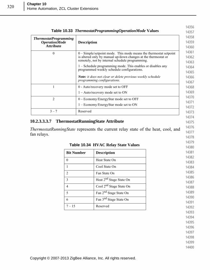
Copyright © 2007-2013 ZigBee Alliance, Inc. All rights reserved.
Chapter 10Home Automation, ZCL Cluster Extensions320
143561435714358143591436014361143621436314364143651436614367143681436914370143711437214373143741437514376143771437814379143801438114382143831438414385143861438714388143891439014391143921439314394143951439614397143981439914400
10.2.3.3.3.7 ThermostatRunningState Attribute
ThermostatRunningState represents the current relay state of the heat, cool, and fan relays.
Table 10.33 ThermostatProgrammingOperationMode Values
ThermostatProgrammingOperationMode
AttributeDescription
0 0 – Simple/setpoint mode. This mode means the thermostat setpoint is altered only by manual up/down changes at the thermostat or remotely, not by internal schedule programming.
1 – Schedule programming mode. This enables or disables any programmed weekly schedule configurations. Note: it does not clear or delete previous weekly schedule programming configurations.
1 0 - Auto/recovery mode set to OFF
1 – Auto/recovery mode set to ON
2 0 – Economy/EnergyStar mode set to OFF
1 – Economy/EnergyStar mode set to ON
3 – 7 Reserved
Table 10.34 HVAC Relay State Values
Bit Number Description
0 Heat State On
1 Cool State On
2 Fan State On
3 Heat 2nd Stage State On
4 Cool 2nd Stage State On
5 Fan 2nd Stage State On
6 Fan 3nd Stage State On
7 – 15 Reserved
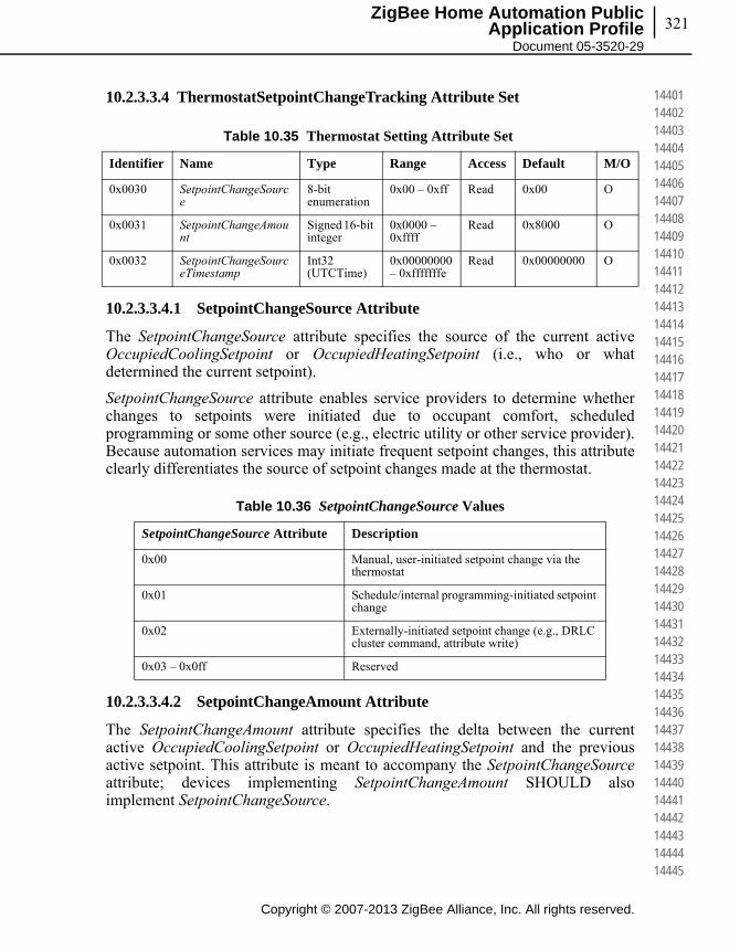
321
Copyright © 2007-2013 ZigBee Alliance, Inc. All rights reserved.
ZigBee Home Automation Public Application Profile
Document 05-3520-29
144011440214403144041440514406144071440814409144101441114412144131441414415144161441714418144191442014421144221442314424144251442614427144281442914430144311443214433144341443514436144371443814439144401444114442144431444414445
10.2.3.3.4 ThermostatSetpointChangeTracking Attribute Set
10.2.3.3.4.1 SetpointChangeSource Attribute
The SetpointChangeSource attribute specifies the source of the current active OccupiedCoolingSetpoint or OccupiedHeatingSetpoint (i.e., who or what determined the current setpoint).
SetpointChangeSource attribute enables service providers to determine whether changes to setpoints were initiated due to occupant comfort, scheduled programming or some other source (e.g., electric utility or other service provider). Because automation services may initiate frequent setpoint changes, this attribute clearly differentiates the source of setpoint changes made at the thermostat.
10.2.3.3.4.2 SetpointChangeAmount Attribute
The SetpointChangeAmount attribute specifies the delta between the current active OccupiedCoolingSetpoint or OccupiedHeatingSetpoint and the previous active setpoint. This attribute is meant to accompany the SetpointChangeSourceattribute; devices implementing SetpointChangeAmount SHOULD also implement SetpointChangeSource.
Table 10.35 Thermostat Setting Attribute Set
Identifier Name Type Range Access Default M/O
0x0030 SetpointChangeSource
8-bit enumeration
0x00 – 0xff Read 0x00 O
0x0031 SetpointChangeAmount
Signed 16-bit integer
0x0000 – 0xffff
Read 0x8000 O
0x0032 SetpointChangeSourceTimestamp
Int32 (UTCTime)
0x00000000 – 0xfffffffe
Read 0x00000000 O
Table 10.36 SetpointChangeSource Values
SetpointChangeSource Attribute Description
0x00 Manual, user-initiated setpoint change via the thermostat
0x01 Schedule/internal programming-initiated setpoint change
0x02 Externally-initiated setpoint change (e.g., DRLC cluster command, attribute write)
0x03 – 0x0ff Reserved

Copyright © 2007-2013 ZigBee Alliance, Inc. All rights reserved.
Chapter 10Home Automation, ZCL Cluster Extensions322
144461444714448144491445014451144521445314454144551445614457144581445914460144611446214463144641446514466144671446814469144701447114472144731447414475144761447714478144791448014481144821448314484144851448614487144881448914490
10.2.3.3.4.3 SetpointChangeSourceTimestamp Attribute
The SetpointChangeSourceTimestamp attribute specifies the time in UTC at which the SetpointChangeSourceAmount attribute change was recorded.
10.2.3.3.5 AC Information Attribute Set
10.2.3.3.5.1 AC Type
Indicates the type of Mini Split ACType of Mini Split AC is defined depending on how Cooling and Heating condition is achieved by Mini Split AC.
Table 10.37 SetpointChangeAmount Values
SetpointChangeAmount Attribute Description
0x0000 – 0xffff The signed difference in 0.01 degrees Celsius between the previous temperature setpoint and the new temperature setpoint.
Table 10.38 Attributes of the AC Information Attribute Set
Identifier Name Type Range Access Default M/O
0x0040 ACType 8-bit enumeration
0x00 – 0x04 Read/Write
0x00 O
0x0041 ACCapacity Unsigned 16-bit integer
0x0000 – 0xffff
Read/Write
0x00 O
0x0042 ACRefrigerantType
8-bit enumeration
0x00-0x03 Read/Write
0x00 O
0x0043 ACCompressor Type
8-bit enumeration
0x00-0x03 Read/Write
0x00 O
0x0044 ACErrorCode 32-bit bitmapa
a. CCB 1790
0x00000000 – 0xffffffff
Read/Write
0x00000000 O
0x0045 ACLouverPosition
8-bit enumeration
0x00 – 0x05 Read/Write
0x00 O
0x0046 ACCoilTemperature
Signed 16-bit integer
0x954d – 0x7fff
Read - O
0x0047 ACCapacityFormat
8-bit enumeration
0x00 – 0xff Read/Write
0x00 O

323
Copyright © 2007-2013 ZigBee Alliance, Inc. All rights reserved.
ZigBee Home Automation Public Application Profile
Document 05-3520-29
144911449214493144941449514496144971449814499145001450114502145031450414505145061450714508145091451014511145121451314514145151451614517145181451914520145211452214523145241452514526145271452814529145301453114532145331453414535
10.2.3.3.5.2 ACCapacity
Indicates capacity of Mini Split AC in terms of the format defined by the ACCapacityFormat attribute
10.2.3.3.5.3 ACRefrigerantType
Indicates type of refrigerant used within the Mini Split AC.
10.2.3.3.5.4 ACCompressor Type
This indicates type of Compressor used within the Mini Split AC.
Table 10.39 ACType Enumeration
Enumeration Field Value Description
0x00 Reserved
0x01 Cooling and Fixed Speed
0x02 Heat Pump and Fixed Speed
0x03 Cooling and Inverter
0x04 Heat Pump and Inverter
Table 10.40 ACRefrigerantType Enumeration
Enumeration Field Value Description
0x00 Reserved
0x01 R22
0x02 R410a
0x03 R407c
Table 10.41 ACCompressorType Enumeration
Enumeration Field Value Description
0x00 Reserved
0x01 T1, Max working ambient 43 C
0x02 T2, Max working ambient 35 C
0x03 T3, Max working ambient 52C

Copyright © 2007-2013 ZigBee Alliance, Inc. All rights reserved.
Chapter 10Home Automation, ZCL Cluster Extensions324
145361453714538145391454014541145421454314544145451454614547145481454914550145511455214553145541455514556145571455814559145601456114562145631456414565145661456714568145691457014571145721457314574145751457614577145781457914580
10.2.3.3.5.5 ACError Code
This indicates the type of errors encountered within the Mini Split AC. Error values are reported with four bytes values. Each bit within the four bytes indicates the unique error.
10.2.3.3.5.6 ACLouverPosition
This attribute indicates the position of Louver on the AC.
Attributes values are listed below.
10.2.3.3.5.7 ACCoilTemperature Attribute
ACCoilTemperature represents the temperature in degrees Celsius, as measured locally or remotely (over the network) as follows:
• ACCoilTemperature = 100 x temperature in degrees Celsius.
• Where -273.15°C <= temperature <= 327.67 ºC, corresponding to a ACCoilTemperature in the range 0x954d to 0x7fff.
• The maximum resolution this format allows is 0.01 ºC.
• ACCoilTemperature of 0x8000 indicates that the temperature measurement is invalid.
Table 10.42 ACErrorCode Values
Bit Value
0 Compressor Failure or Refrigerant Leakage
1 Room Temperature Sensor Failure
2 Outdoor Temperature Sensor Failure
3 Indoor Coil Temperature Sensor Failure
4 Fan Failure
5 – 31 Reserved
Table 10.43 ACLouverPosition Values
Louver Position Byte Value
Fully Closed 0x01
Fully Open 0x02
Quarter Open 0x03
Half Open 0x04
Three Quarters Open 0x05
Reserved 0x06 – 0xFF
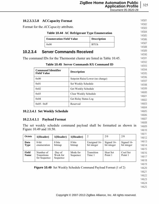
325
Copyright © 2007-2013 ZigBee Alliance, Inc. All rights reserved.
ZigBee Home Automation Public Application Profile
Document 05-3520-29
145811458214583145841458514586145871458814589145901459114592145931459414595145961459714598145991460014601146021460314604146051460614607146081460914610146111461214613146141461514616146171461814619146201462114622146231462414625
10.2.3.3.5.8 ACCapacity Format
Format for the ACCapacity attribute.
10.2.3.4 Server Commands Received
The command IDs for the Thermostat cluster are listed in Table 10.45.
10.2.3.4.1 Set Weekly Schedule
10.2.3.4.1.1 Payload Format
The set weekly schedule command payload shall be formatted as shown in Figure 10.49 and 10.50.
Figure 10.49 Set Weekly Schedule Command Payload Format (1 of 2)
Table 10.44 AC Refrigerant Type Enumeration
Enumeration Field Value Description
0x00 BTUh
Table 10.45 Server Commands RX Command ID
Command Identifier Field Value Description
0x00 Setpoint Raise/Lower (no change)
0x01 Set Weekly Schedule
0x02 Get Weekly Schedule
0x03 Clear Weekly Schedule
0x04 Get Relay Status Log
0x05– 0xff Reserved
Octets 1(Header) 1(Header) 1(Header) 2 2/0 2/0
Data Type
8-bit enumeration
8 bits bitmap
8 bits bitmap
Unsigned 16-bit integer
Signed 16-bit integer
Signed 16-bit integer
Field Name
Number of Transitions for Sequence
Day of Week for Sequence
Mode for Sequence
Transition Time 1
Heat Set Point 1
Cool Set Point 1

Copyright © 2007-2013 ZigBee Alliance, Inc. All rights reserved.
Chapter 10Home Automation, ZCL Cluster Extensions326
146261462714628146291463014631146321463314634146351463614637146381463914640146411464214643146441464514646146471464814649146501465114652146531465414655146561465714658146591466014661146621466314664146651466614667146681466914670
Figure 10.50 Set Weekly Schedule Command Payload Format (2 of 2)
The set weekly schedule command is used to update the thermostat weekly set point schedule from a management system. If the thermostat already has a weekly set point schedule programmed then it should replace each daily set point set as it receives the updates from the management system. For example if the thermostat has 4 set points for every day of the week and is sent a Set Weekly Schedule command with one set point for Saturday then the thermostat should remove all 4 set points for Saturday and replace those with the updated set point but leave all other days unchanged. If the schedule is larger than what fits in one ZigBee frame or contains more than 10 transitions, the schedule shall then be sent using multiple Set Weekly Schedule Commands.
Each Set Weekly Schedule Command has 3 header bytes – Number of Transitions for Sequence, Day of Week for Sequence & Mode for Sequence. The application shall decode the payload according to what has specified in the 3 header bytes.
10.2.3.4.1.2 Number of Transitions for Sequence
The Number of Transitions for Sequence field indicates how many individual transitions to expect for this sequence of commands. If a device supports more than 10 transitions in its schedule they can send this by sending more than 1 “Set Weekly Schedule” command, each containing the separate information that the device needs to set.
10.2.3.4.1.3 Day of Week for Sequence
This field represents the day of the week at which all the transitions within the payload of the command should be associated to. This field is a bitmap and therefore the associated set point could overlap onto multiple days (you could set one transition time for all “week days” or whatever combination of days the implementation requests). Table 10.46 displays the bitmap values:
Octets Variable 2 2/0 2/0
Data Type … Unsigned 16-bit integer Signed 16-bit integer Signed 16-bit integer
Field Name … Transition Time 10 Heat Set Point 10 Cool Set Point 10
Table 10.46 Day Of Week for Sequence Values
Bit Number Description
0 Sunday
1 Monday
2 Tuesday
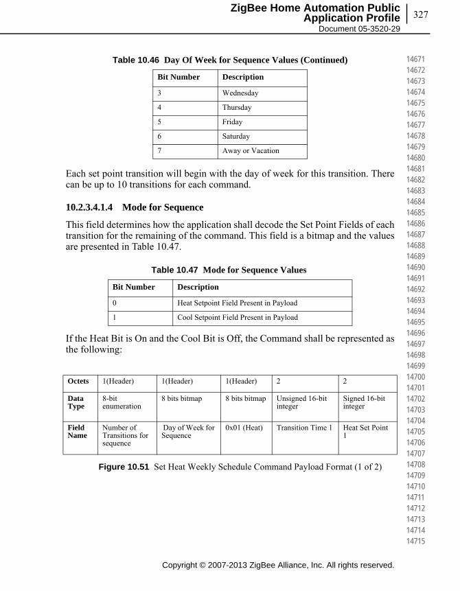
327
Copyright © 2007-2013 ZigBee Alliance, Inc. All rights reserved.
ZigBee Home Automation Public Application Profile
Document 05-3520-29
146711467214673146741467514676146771467814679146801468114682146831468414685146861468714688146891469014691146921469314694146951469614697146981469914700147011470214703147041470514706147071470814709147101471114712147131471414715
Each set point transition will begin with the day of week for this transition. There can be up to 10 transitions for each command.
10.2.3.4.1.4 Mode for Sequence
This field determines how the application shall decode the Set Point Fields of each transition for the remaining of the command. This field is a bitmap and the values are presented in Table 10.47.
If the Heat Bit is On and the Cool Bit is Off, the Command shall be represented as the following:
Figure 10.51 Set Heat Weekly Schedule Command Payload Format (1 of 2)
3 Wednesday
4 Thursday
5 Friday
6 Saturday
7 Away or Vacation
Table 10.47 Mode for Sequence Values
Bit Number Description
0 Heat Setpoint Field Present in Payload
1 Cool Setpoint Field Present in Payload
Octets 1(Header) 1(Header) 1(Header) 2 2
Data Type
8-bit enumeration
8 bits bitmap 8 bits bitmap Unsigned 16-bit integer
Signed 16-bit integer
Field Name
Number of Transitions for sequence
Day of Week for Sequence
0x01 (Heat) Transition Time 1 Heat Set Point 1
Table 10.46 Day Of Week for Sequence Values (Continued)
Bit Number Description

Copyright © 2007-2013 ZigBee Alliance, Inc. All rights reserved.
Chapter 10Home Automation, ZCL Cluster Extensions328
147161471714718147191472014721147221472314724147251472614727147281472914730147311473214733147341473514736147371473814739147401474114742147431474414745147461474714748147491475014751147521475314754147551475614757147581475914760
Figure 10.52 Set Heat Weekly Schedule Command Payload Format (2 of 2)
If the Heat Bit is Off and the Cool Bit is On, the Command shall be represented as the following:
Figure 10.53 Set Cool Weekly Schedule Command Payload Format (1 of 2)
Figure 10.54 Set Cool Weekly Schedule Command Payload Format (2 of 2)
If both the Heat Bit and the Cool Bit are On, the Command shall be represented as the following:
Figure 10.55 Set Heat & Cool Weekly Schedule Command Payload Format (1 of 2
Octets Variable 2 2
Data Type … Unsigned 16-bit integer Signed 16-bit integer
Field Name … Transition Time 10 Heat Set Point 10
Octets 1(Header) 1(Header) 1(Header) 2 2
Data Type
8-bit enumeration
8 bits bitmap 8 bits bitmap Unsigned 16-bit integer
Signed 16-bit integer
Field Name
Number of Transitions for Seq
Day of Week for Sequence
0x02
(Cool)
Transition Time 1
Cool Set Point 1
Octets Variable 2 2
Data Type … Unsigned 16-bit integer Signed 16-bit integer
Field Name … Transition Time 10 Cool Set Point 10
Octets 1(Header) 1(Header) 1(Header) 2 2 2
Data Type
8-bit enumeration
8 bits bitmap
8 bits bitmap
Unsigned 16-bit integer
Signed 16-bit integer
Signed 16-bit integer
Field Name
Number of Transitions for sequence
Day of Week for Sequence
0x03 (Head & Cool)
Transition Time 1
Heat Set Point 1
Cool Set Point 1
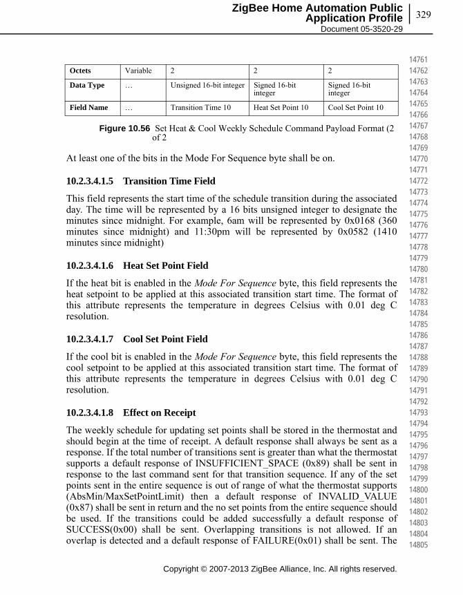
329
Copyright © 2007-2013 ZigBee Alliance, Inc. All rights reserved.
ZigBee Home Automation Public Application Profile
Document 05-3520-29
147611476214763147641476514766147671476814769147701477114772147731477414775147761477714778147791478014781147821478314784147851478614787147881478914790147911479214793147941479514796147971479814799148001480114802148031480414805
Figure 10.56 Set Heat & Cool Weekly Schedule Command Payload Format (2 of 2
At least one of the bits in the Mode For Sequence byte shall be on.
10.2.3.4.1.5 Transition Time Field
This field represents the start time of the schedule transition during the associated day. The time will be represented by a 16 bits unsigned integer to designate the minutes since midnight. For example, 6am will be represented by 0x0168 (360 minutes since midnight) and 11:30pm will be represented by 0x0582 (1410 minutes since midnight)
10.2.3.4.1.6 Heat Set Point Field
If the heat bit is enabled in the Mode For Sequence byte, this field represents the heat setpoint to be applied at this associated transition start time. The format of this attribute represents the temperature in degrees Celsius with 0.01 deg C resolution.
10.2.3.4.1.7 Cool Set Point Field
If the cool bit is enabled in the Mode For Sequence byte, this field represents the cool setpoint to be applied at this associated transition start time. The format of this attribute represents the temperature in degrees Celsius with 0.01 deg C resolution.
10.2.3.4.1.8 Effect on Receipt
The weekly schedule for updating set points shall be stored in the thermostat and should begin at the time of receipt. A default response shall always be sent as a response. If the total number of transitions sent is greater than what the thermostat supports a default response of INSUFFICIENT_SPACE (0x89) shall be sent in response to the last command sent for that transition sequence. If any of the set points sent in the entire sequence is out of range of what the thermostat supports (AbsMin/MaxSetPointLimit) then a default response of INVALID_VALUE (0x87) shall be sent in return and the no set points from the entire sequence should be used. If the transitions could be added successfully a default response of SUCCESS(0x00) shall be sent. Overlapping transitions is not allowed. If an overlap is detected and a default response of FAILURE(0x01) shall be sent. The
Octets Variable 2 2 2
Data Type … Unsigned 16-bit integer Signed 16-bit integer
Signed 16-bit integer
Field Name … Transition Time 10 Heat Set Point 10 Cool Set Point 10
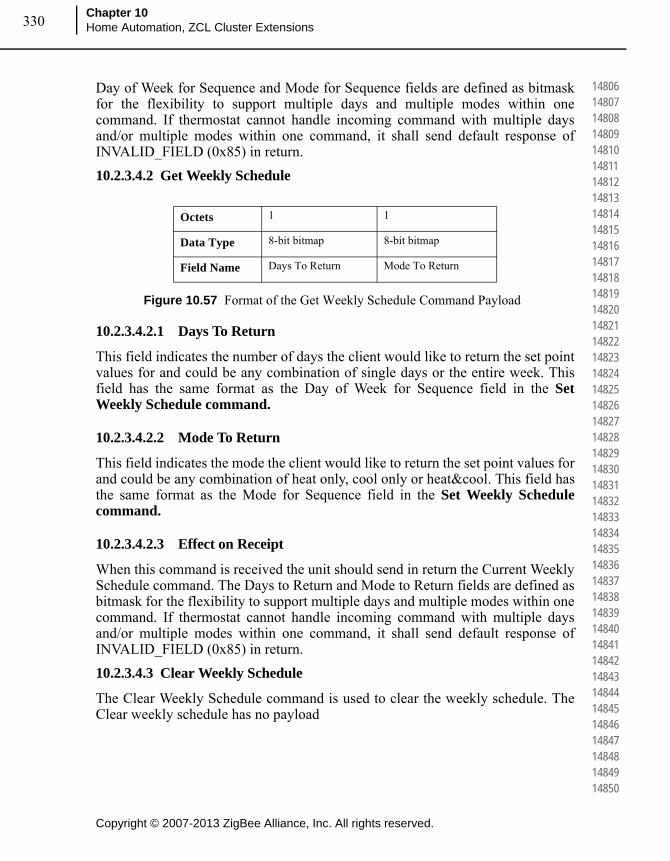
Copyright © 2007-2013 ZigBee Alliance, Inc. All rights reserved.
Chapter 10Home Automation, ZCL Cluster Extensions330
148061480714808148091481014811148121481314814148151481614817148181481914820148211482214823148241482514826148271482814829148301483114832148331483414835148361483714838148391484014841148421484314844148451484614847148481484914850
Day of Week for Sequence and Mode for Sequence fields are defined as bitmask for the flexibility to support multiple days and multiple modes within one command. If thermostat cannot handle incoming command with multiple days and/or multiple modes within one command, it shall send default response of INVALID_FIELD (0x85) in return.
10.2.3.4.2 Get Weekly Schedule
Figure 10.57 Format of the Get Weekly Schedule Command Payload
10.2.3.4.2.1 Days To Return
This field indicates the number of days the client would like to return the set point values for and could be any combination of single days or the entire week. This field has the same format as the Day of Week for Sequence field in the Set Weekly Schedule command.
10.2.3.4.2.2 Mode To Return
This field indicates the mode the client would like to return the set point values for and could be any combination of heat only, cool only or heat&cool. This field has the same format as the Mode for Sequence field in the Set Weekly Schedule command.
10.2.3.4.2.3 Effect on Receipt
When this command is received the unit should send in return the Current Weekly Schedule command. The Days to Return and Mode to Return fields are defined as bitmask for the flexibility to support multiple days and multiple modes within one command. If thermostat cannot handle incoming command with multiple days and/or multiple modes within one command, it shall send default response of INVALID_FIELD (0x85) in return.
10.2.3.4.3 Clear Weekly Schedule
The Clear Weekly Schedule command is used to clear the weekly schedule. The Clear weekly schedule has no payload
Octets 1 1
Data Type 8-bit bitmap 8-bit bitmap
Field Name Days To Return Mode To Return

331
Copyright © 2007-2013 ZigBee Alliance, Inc. All rights reserved.
ZigBee Home Automation Public Application Profile
Document 05-3520-29
148511485214853148541485514856148571485814859148601486114862148631486414865148661486714868148691487014871148721487314874148751487614877148781487914880148811488214883148841488514886148871488814889148901489114892148931489414895
10.2.3.4.3.1 Effect on Receipt
When this command is received, all transitions currently stored shall be cleared and a default response of SUCCESS (0x00) shall be sent in response. There are no error responses to this command.
10.2.3.4.4 Get Relay Status Log
The Get Relay Status Log command is used to query the thermostat internal relay status log. This command has no payload
10.2.3.4.4.1 Effect on Receipt
When this command is received, the unit shall respond with Relay Status Log command if the relay status log feature is supported on the unit.
10.2.3.5 Server Commands Sent
10.2.3.5.1 Get Weekly Schedule Response
This command has the same payload format as the Set Weekly Schedule. Please refer to the payload detail in Section 10.2.3.4.1, Set Weekly Schedule, of this chapter.
10.2.3.5.2 Get Relay Status Log Response
This command is sent from the thermostat cluster server in response to the Get Relay Status Log. After the Relay Status Entry is sent over the air to the requesting client, the specific entry will be cleared from the thermostat internal log.
10.2.3.5.2.1 Payload Format
The relay status log command payload shall be formatted as shown in Figure 10.58.
Table 10.48 Server Commands Sent Command ID
Command Identifier Field Value Description
0x00 Get Weekly Schedule Response
0x01 Get Relay Status Log Response
0x02 – 0xff Reserved
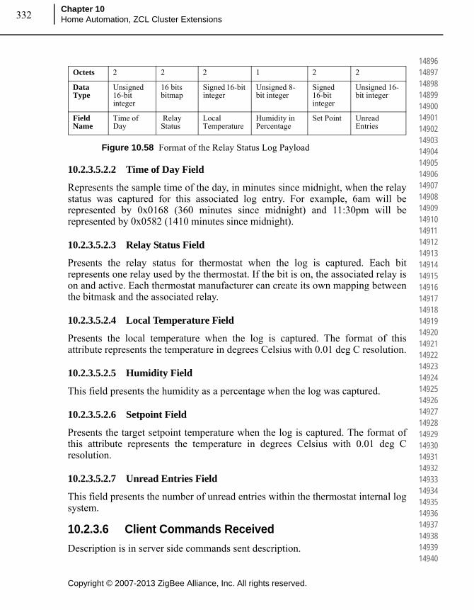
Copyright © 2007-2013 ZigBee Alliance, Inc. All rights reserved.
Chapter 10Home Automation, ZCL Cluster Extensions332
148961489714898148991490014901149021490314904149051490614907149081490914910149111491214913149141491514916149171491814919149201492114922149231492414925149261492714928149291493014931149321493314934149351493614937149381493914940
Figure 10.58 Format of the Relay Status Log Payload
10.2.3.5.2.2 Time of Day Field
Represents the sample time of the day, in minutes since midnight, when the relay status was captured for this associated log entry. For example, 6am will be represented by 0x0168 (360 minutes since midnight) and 11:30pm will be represented by 0x0582 (1410 minutes since midnight).
10.2.3.5.2.3 Relay Status Field
Presents the relay status for thermostat when the log is captured. Each bit represents one relay used by the thermostat. If the bit is on, the associated relay is on and active. Each thermostat manufacturer can create its own mapping between the bitmask and the associated relay.
10.2.3.5.2.4 Local Temperature Field
Presents the local temperature when the log is captured. The format of this attribute represents the temperature in degrees Celsius with 0.01 deg C resolution.
10.2.3.5.2.5 Humidity Field
This field presents the humidity as a percentage when the log was captured.
10.2.3.5.2.6 Setpoint Field
Presents the target setpoint temperature when the log is captured. The format of this attribute represents the temperature in degrees Celsius with 0.01 deg C resolution.
10.2.3.5.2.7 Unread Entries Field
This field presents the number of unread entries within the thermostat internal log system.
10.2.3.6 Client Commands Received
Description is in server side commands sent description.
Octets 2 2 2 1 2 2
Data Type
Unsigned 16-bit integer
16 bits bitmap
Signed 16-bit integer
Unsigned 8-bit integer
Signed 16-bit integer
Unsigned 16-bit integer
Field Name
Time of Day
Relay Status
Local Temperature
Humidity in Percentage
Set Point Unread Entries
333
Copyright © 2007-2013 ZigBee Alliance, Inc. All rights reserved.
ZigBee Home Automation Public Application Profile
Document 05-3520-29
149411494214943149441494514946149471494814949149501495114952149531495414955149561495714958149591496014961149621496314964149651496614967149681496914970149711497214973149741497514976149771497814979149801498114982149831498414985
10.2.3.7 Client Commands Sent
Description is in server side commands received description.
10.3 Thermostat User Interface Configuration Cluster Extensions
This section describes the recommended practices for Thermostat User Interface Configuration Cluster extensions.
10.3.1 Introduction
10.3.1.1 Scope and Purpose
This document provides extensions to the existing thermostat user interface configuration cluster included in the ZigBee Cluster Library specification.
10.3.2 References
The following standards and specifications contain provisions, which through reference in this document constitute provisions of this specification. All the standards and specifications listed are normative references. At the time of publication, the editions indicated were valid. All standards and specifications are subject to revision, and parties to agreements based on this specification are encouraged to investigate the possibility of applying the most recent editions of the standards and specifications indicated below.
10.3.2.1 ZigBee Alliance Documents
1 ZigBee Document 053520r26, The ZigBee Alliance Home Automation Profile
2 ZigBee Document 075366r01, The ZigBee Cluster Library – this document describes the ZigBee Cluster Library framework and it is essential that it be understood in order to use this cluster definition document.
10.3.3 General Description
This document mirrors the existing Thermostat User Interface Configuration Cluster in the ZigBee Cluster Library Specification. The following heading numbers are used to reference the actual sections in the Cluster Library Specification document.
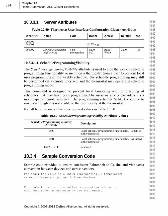
Copyright © 2007-2013 ZigBee Alliance, Inc. All rights reserved.
Chapter 10Home Automation, ZCL Cluster Extensions334
149861498714988149891499014991149921499314994149951499614997149981499915000150011500215003150041500515006150071500815009150101501115012150131501415015150161501715018150191502015021150221502315024150251502615027150281502915030
10.3.3.1 Server Attributes
10.3.3.1.1 ScheduleProgrammingVisibility
The ScheduleProgrammingVisibility attribute is used to hide the weekly schedule programming functionality or menu on a thermostat from a user to prevent local user programming of the weekly schedule. The schedule programming may still be performed via a remote interface, and the thermostat may operate in schedule programming mode.
This command is designed to prevent local tampering with or disabling of schedules that may have been programmed by users or service providers via a more capable remote interface. The programming schedule SHALL continue to run even though it is not visible to the user locally at the thermostat.
It shall be set to one of the non-reserved values in Table 10.50.
10.3.4 Sample Conversion Code
Sample code provided to ensure consistent Fahrenheit to Celsius and vice versa conversion between devices and across vendors.For degF: the value is a int8u representing 2x temperature value in Farenheit (to get 0.5 resolution).
For degC: the value is a int16s representing Celsius in 0.01 resolution as expected by the ZCL format.
Table 10.49 Thermostat User Interface Configuration Cluster Attributes
Identifier Name Type Range Access Default M/O
0x0000 – 0x0001 No Change
0x0002 ScheduleProgrammingVisibility
8-bit enumeration
0x00-0x01
Read / Write
0x00 O
Table 10.50 ScheduleProgrammingVisibility Attribute Values
ScheduleProgrammingVisibility Attribute Description
0x00 Local schedule programming functionality is enabled at the thermostat
0x01 Local schedule programming functionality is disabled at the thermostat
0x02 – 0xFF Reserved

335
Copyright © 2007-2013 ZigBee Alliance, Inc. All rights reserved.
ZigBee Home Automation Public Application Profile
Document 05-3520-29
150311503215033150341503515036150371503815039150401504115042150431504415045150461504715048150491505015051150521505315054150551505615057150581505915060150611506215063150641506515066150671506815069150701507115072150731507415075
/*
* Function : translateZclTemp()
* Description: Converts the temperature setpoints in ZCL
* to the half degF format.
* The half degF format is 8-bit unsigned,
* and represents 2x temperature value in
* Farenheit (to get 0.5 resolution).
* The format used in ZCL is 16-bit signed
* in Celsius and multiplied by 100
* to get 0.01 resolution.
* e.g. 2500(25.00 deg C) ---> 0x9A (77 deg F)
* Input Para : Temperature in ZCL (degC)format
* Output Para: Temperature in half DegF format
*/
int8u translateZclTemp(int16s temperature)
{
int32s x = temperature;
//rearrangement of
// = (x * (9/5) / 100 + 32) * 2;
// the added 250 is for proper rounding.
// a rounding technique that only works
// with positive numbers
return (int8u) ((x*9*2 + 250)/ (5*100) + 64);
}
/*
* Function : translateDegFTemp
* Description: Converts the temperature in DegF
* protocol to the format
* expected by the cluster attribute
* Measured Value in the
* Temperature Measurement
* Information Attribute Set.
* The half deg F format is 8-bit
* unsigned, and represents
* 2x temperature value in

Copyright © 2007-2013 ZigBee Alliance, Inc. All rights reserved.
Chapter 10Home Automation, ZCL Cluster Extensions336
150761507715078150791508015081150821508315084150851508615087150881508915090150911509215093150941509515096150971509815099151001510115102151031510415105151061510715108151091511015111151121511315114151151511615117151181511915120
* Farenheit (to get 0.5 resolution).
* The format expected by cluster
* is 16-bit signed in Celsius and
* multiplied by 100 to get
* 0.01 resolution.
* e.g. 0x9A(77 deg F) ---> 2500 (25.00 deg C)
* Input Para : temperature in DegF format
* Output Para: temperature in ZCL format
*/
int16s translateDegFTemp(int8u temperature)
{
int32s x = temperature;
// rearrangement of
// = 100 * (x/2 - 32) * 5/9
// *1000 (should be 100), +90, then /10,
// is for rounding.
return (int16s) (((x - 64)*5*1000 + 90) / (10*2*9));
}
10.4 Level Control Cluster Extensions
This section describes the recommended practices for Home Automation Level Control Cluster extensions.
10.4.1 Introduction
10.4.1.1 Scope and Purpose
This document provides extensions to the existing level control cluster included in the ZigBee Cluster Library specification.
10.4.2 References
The following standards and specifications contain provisions, which through reference in this document constitute provisions of this specification. All the standards and specifications listed are normative references. At the time of

337
Copyright © 2007-2013 ZigBee Alliance, Inc. All rights reserved.
ZigBee Home Automation Public Application Profile
Document 05-3520-29
151211512215123151241512515126151271512815129151301513115132151331513415135151361513715138151391514015141151421514315144151451514615147151481514915150151511515215153151541515515156151571515815159151601516115162151631516415165
publication, the editions indicated were valid. All standards and specifications are subject to revision, and parties to agreements based on this specification are encouraged to investigate the possibility of applying the most recent editions of the standards and specifications indicated below.
10.4.2.1 ZigBee Alliance Documents
1 ZigBee Document 053520r26, The ZigBee Alliance Home Automation Profile
2 ZigBee Document 075366r01, The ZigBee Cluster Library – this document describes the ZigBee Cluster Library framework and it is essential that it be understood in order to use this cluster definition document.
10.4.3 General Description
This document mirrors the existing Level Control Cluster in the ZigBee Cluster Library Specification. The following heading numbers are used to reference the actual sections in the Cluster Library Specification document.
10.4.3.1 Server Attributes
10.4.3.1.1 OnTransitionTime Attribute
The OnTransitionTime attribute represents the time taken to move the current level from a value of 0 to a value of 255 when an On command is received by an On/Off cluster on the same endpoint. It is specified in 10ths of a second. If this command is not implemented, or contains a value of 0xffff, the On/OffTransitionTime will be used instead.
10.4.3.1.2 OffTransitionTime Attribute
The OffTransitionTime attribute represents the time taken to move the current level from a value of 255 to a value of 0 when an Off command is received by an
Table 10.51 Level Control Server Attributes
Identifier Name Type Range Access Default M/O
0x0010 – 0x0011
No Change
0x0012 OnTransitionTime Unsigned 16-bit integer
0x0000 –
0xfffe
Read/Write - O
0x0013 OffTransitionTime Unsigned 16-bit integer
0x0000 – 0xfffe
Read/Write - O
0x0014 DefaultMoveRate Unsigned 8-bit integer
0x00 – 0xFE
Read/Write - O

Copyright © 2007-2013 ZigBee Alliance, Inc. All rights reserved.
Chapter 10Home Automation, ZCL Cluster Extensions338
151661516715168151691517015171151721517315174151751517615177151781517915180151811518215183151841518515186151871518815189151901519115192151931519415195151961519715198151991520015201152021520315204152051520615207152081520915210
On/Off cluster on the same endpoint. It is specified in 10ths of a second. If this command is not implemented, or contains a value of 0xffff, the On/OffTransitionTime will be used instead.
10.4.3.1.3 DefaultMoveRate Attribute
The DefaultMoveRate attribute determines the movement rate, in units per second, when a Move command is received with a Rate parameter of 0xFF.5
10.4.3.2 Server Commands Received
The On/Off Cluster Extensions adds a modification to the interpretation of the Rate Field in the Move Command (0x01).
10.4.3.2.1 Rate Field
The Rate field specifies the rate of movement in units per second. The actual rate of movement should be as close to this rate as the device is able. If the Rate field is 0xFF, then the value in DefaultMoveRate attribute shall be used. If the Rate field is 0xFF and the DefaultMoveRate attribute is not supported, then the device should move as fast as it is able. If the device is not able to move at a variable rate, this field may be disregarded.6
Also, when using the transition time parameter in Level Control commands, it is defined as the time it takes for the device to move from its current level to the provided level over the transition time. If a device (say a button) is sending a “Move To Level” with a level of 255 and a rate of 100, this will give you (visually) very different results depending on if the CurrentLevel is at 0 or 128. Or, if you want to transition from 0 to 255 over 8 seconds, but have to stop in the middle, you cannot reissue the same command to resume. You have to read the current level and do calculations to adjust this.
10.5 On/Off Switch Configuration Cluster Extensions
This section describes the recommended practices for Home Automation On/Off Switch Configuration Cluster extensions.
10.5.1 Introduction
10.5.1.1 Scope and Purpose
This document provides extensions to the existing level control cluster included in the ZigBee Cluster Library specification.
5. CCB 17776. CCB 1777

339
Copyright © 2007-2013 ZigBee Alliance, Inc. All rights reserved.
ZigBee Home Automation Public Application Profile
Document 05-3520-29
152111521215213152141521515216152171521815219152201522115222152231522415225152261522715228152291523015231152321523315234152351523615237152381523915240152411524215243152441524515246152471524815249152501525115252152531525415255
10.5.2 References
The following standards and specifications contain provisions, which through reference in this document constitute provisions of this specification. All the standards and specifications listed are normative references. At the time of publication, the editions indicated were valid. All standards and specifications are subject to revision, and parties to agreements based on this specification are encouraged to investigate the possibility of applying the most recent editions of the standards and specifications indicated below.
10.5.2.1 ZigBee Alliance Documents
1 ZigBee Document 053520r26, The ZigBee Alliance Home Automation Profile
2 ZigBee Document 075366r01, The ZigBee Cluster Library – this document describes the ZigBee Cluster Library framework and it is essential that it be understood in order to use this cluster definition document.
10.5.3 General Description
This document mirrors the existing On/Off Switch Configuration Cluster in the ZigBee Cluster Library Specification. The following heading numbers are used to reference the actual sections in the Cluster Library Specification document.
10.5.4 SwitchType Attribute
SwitchType attribute value 0x02 indicates a multi-function switch. Multi-function switch does more than just toggle or momentary functionality.
Table 10.52 Values for the SwitchType Attribute
SwitchType Attribute Value
Description Details
0x00 – 0x01 No Change
0x02 Multi-Function A switch that behaves differently depending on user input. Under some conditions it may send a toggle or in some other conditions a move command. The behavior of the switch is application-specific but the nature of the switch is clear, it is a multi-function switch.

Copyright © 2007-2013 ZigBee Alliance, Inc. All rights reserved.
Chapter 10Home Automation, ZCL Cluster Extensions340
152561525715258152591526015261152621526315264152651526615267152681526915270152711527215273152741527515276152771527815279152801528115282152831528415285152861528715288152891529015291152921529315294152951529615297152981529915300
10.6 Over the Air Bootload Cluster Extensions
10.6.1 Overview
The over-the-air (OTA) bootload cluster provides a common mechanism to manage and serve up upgrade images for devices from different manufacturers in the same network. Servers provide firmware images to clients to download, controlling the timing for downloads and when the actual upgrade to a new version of software ism a de. Clients periodically query the server for new images and then can download the image at a rate according to their capabilities or policies.
Details for the over-the-air bootload cluster are maintained in a separate document, reference [095264r19].
Home Automation devices may optionally support the over-the-air bootload cluster client or server.
10.6.2 OTA Bootloading Timing Considerations
The OTA cluster defines the message formatting used to pass device images but does not specify when to use the cluster. The following policies specify how and when to use the OTA cluster such that all devices in an SE network will upgrade at predictable intervals.
OTA clients shall perform service discovery to find the OTA server after registration has completed.
1 OTA clients SHALL perform service discovery to find the OTA server after registration has completed.
2 OTA client device that does not find an OTA server in the network SHALL periodically attempt a new discovery once a day.
3 All devices SHALL query the OTA server at least once a day for information about the next version to upgrade to. Non-sleepy devices in the network may be instructed to begin a new download at any point time via the Image Notify command.
4 All client devices may download data as quickly as their capabilities allow, but at a minimum rate of one block per 10 minutes. This means that at a rate of 1block (50 bytes) per 10 minutes, a 128k file will take 18 days to download.
5 Upon rebooting the device shall determine if it is already joined into the network. If it is joined into a network and has the OTA client cluster it SHALL send a OTA Cluster Query Next Image Command to the server. This command shall be sent at some random point within the first 5 minutes.
341
Copyright © 2007-2013 ZigBee Alliance, Inc. All rights reserved.
ZigBee Home Automation Public Application Profile
Document 05-3520-29
153011530215303153041530515306153071530815309153101531115312153131531415315153161531715318153191532015321153221532315324153251532615327153281532915330153311533215333153341533515336153371533815339153401534115342153431534415345
10.7 IAS Zone Cluster Extensions
10.7.1 Introduction
10.7.1.1 Scope and Purpose
This document describes the proposed addition to the Home Automation specification and the ZigBee Cluster Library for the IAS Zone cluster. The existing attributes and enumerations do not meet Underwriters Laboratory requirements for IASes. This proposal would add attributes and commands to meet these requirements.
Note: These Cluster Extensions are provisionary and not certifiable. This feature set may change before reaching certifiable status in a future revision of this specification.
10.7.2 References
The following standards and specifications contain provisions, which through reference in this document constitute provisions of this specification. All the standards and specifications listed are normative references. At the time of publication, the editions indicated were valid. All standards and specifications are subject to revision, and parties to agreements based on this specification are encouraged to investigate the possibility of applying the most recent editions of the standards and specifications indicated below.
10.7.2.1 ZigBee Alliance Documents
1 ZigBee Document 075366r03, The ZigBee Cluster Library – this document describes the ZigBee Cluster Library framework and it is essential that it be understood in order to use this cluster definition document.
2 ZigBee Document 120409r00, IAS Zone Alarm Cluster Change Proposal
10.7.3 General Description
This document mirrors the existing IAS Zone Cluster in the ZigBee Cluster Library Specification. The following heading numbers are used to reference the actual sections in the Cluster Library Specification document.
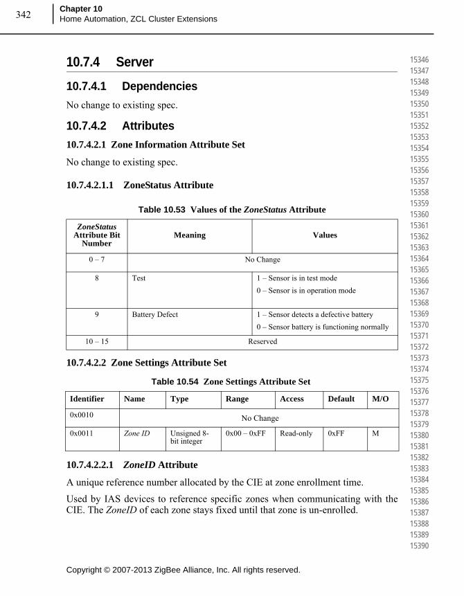
Copyright © 2007-2013 ZigBee Alliance, Inc. All rights reserved.
Chapter 10Home Automation, ZCL Cluster Extensions342
153461534715348153491535015351153521535315354153551535615357153581535915360153611536215363153641536515366153671536815369153701537115372153731537415375153761537715378153791538015381153821538315384153851538615387153881538915390
10.7.4 Server
10.7.4.1 Dependencies
No change to existing spec.
10.7.4.2 Attributes
10.7.4.2.1 Zone Information Attribute Set
No change to existing spec.
10.7.4.2.1.1 ZoneStatus Attribute
10.7.4.2.2 Zone Settings Attribute Set
10.7.4.2.2.1 ZoneID Attribute
A unique reference number allocated by the CIE at zone enrollment time.
Used by IAS devices to reference specific zones when communicating with the CIE. The ZoneID of each zone stays fixed until that zone is un-enrolled.
Table 10.53 Values of the ZoneStatus Attribute
ZoneStatus Attribute Bit
NumberMeaning Values
0 – 7 No Change
8 Test 1 – Sensor is in test mode
0 – Sensor is in operation mode
9 Battery Defect 1 – Sensor detects a defective battery
0 – Sensor battery is functioning normally
10 – 15 Reserved
Table 10.54 Zone Settings Attribute Set
Identifier Name Type Range Access Default M/O
0x0010 No Change
0x0011 Zone ID Unsigned 8-bit integer
0x00 – 0xFF Read-only 0xFF M
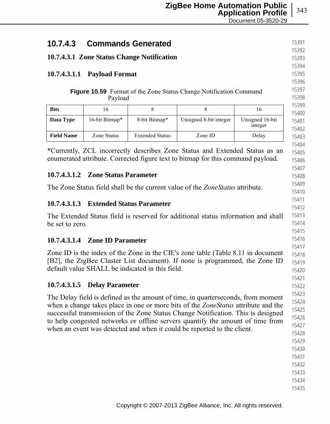
343
Copyright © 2007-2013 ZigBee Alliance, Inc. All rights reserved.
ZigBee Home Automation Public Application Profile
Document 05-3520-29
153911539215393153941539515396153971539815399154001540115402154031540415405154061540715408154091541015411154121541315414154151541615417154181541915420154211542215423154241542515426154271542815429154301543115432154331543415435
10.7.4.3 Commands Generated
10.7.4.3.1 Zone Status Change Notification
10.7.4.3.1.1 Payload Format
*Currently, ZCL incorrectly describes Zone Status and Extended Status as an enumerated attribute. Corrected figure text to bitmap for this command payload.
10.7.4.3.1.2 Zone Status Parameter
The Zone Status field shall be the current value of the ZoneStatus attribute.
10.7.4.3.1.3 Extended Status Parameter
The Extended Status field is reserved for additional status information and shall be set to zero.
10.7.4.3.1.4 Zone ID Parameter
Zone ID is the index of the Zone in the CIE's zone table (Table 8.11 in document [B2], the ZigBee Cluster List document). If none is programmed, the Zone ID default value SHALL be indicated in this field.
10.7.4.3.1.5 Delay Parameter
The Delay field is defined as the amount of time, in quarterseconds, from moment when a change takes place in one or more bits of the ZoneStatus attribute and the successful transmission of the Zone Status Change Notification. This is designed to help congested networks or offline servers quantify the amount of time from when an event was detected and when it could be reported to the client.
Figure 10.59 Format of the Zone Status Change Notification Command Payload
Bits 16 8 8 16
Data Type 16-bit Bitmap* 8-bit Bitmap* Unsigned 8-bit integer Unsigned 16-bit integer
Field Name Zone Status Extended Status Zone ID Delay

Copyright © 2007-2013 ZigBee Alliance, Inc. All rights reserved.
Chapter 10Home Automation, ZCL Cluster Extensions344
154361543715438154391544015441154421544315444154451544615447154481544915450154511545215453154541545515456154571545815459154601546115462154631546415465154661546715468154691547015471154721547315474154751547615477154781547915480
10.8 IAS ACE Cluster Extensions
10.8.1 Introduction
10.8.1.1 Scope and Purpose
This document describes the proposed addition to the Home Automation specification and the ZigBee Cluster Library for the IAS ACE cluster. The existing attributes and enumerations do not meet Underwriters Laboratory requirements for ACEs and lack certain features that service providers require. This proposal would add attributes and commands to meet these requirements.
Note: These Cluster Extensions are provisionary and not certifiable. This feature set may change before reaching certifiable status in a future revision of this specification.
10.8.2 References
The following standards and specifications contain provisions, which through reference in this document constitute provisions of this specification. All the standards and specifications listed are normative references. At the time of publication, the editions indicated were valid. All standards and specifications are subject to revision, and parties to agreements based on this specification are encouraged to investigate the possibility of applying the most recent editions of the standards and specifications indicated below.
10.8.2.1 ZigBee Alliance Documents
1 ZigBee Document 075366r03, The ZigBee Cluster Library – this document describes the ZigBee Cluster Library framework and it is essential that it be understood in order to use this cluster definition document.
10.8.3 General Description
This document mirrors the existing IAS ACE Cluster in the ZigBee Cluster Library Specification. The following heading numbers are used to reference the actual sections in the Cluster Library Specification document.
10.8.4 Server
10.8.4.1 Dependencies
No change to existing spec.
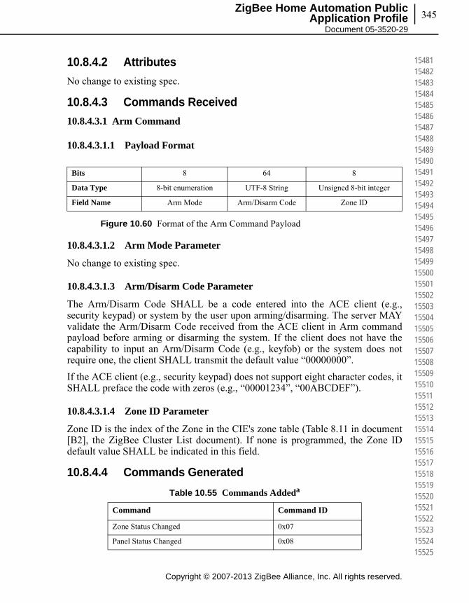
345
Copyright © 2007-2013 ZigBee Alliance, Inc. All rights reserved.
ZigBee Home Automation Public Application Profile
Document 05-3520-29
154811548215483154841548515486154871548815489154901549115492154931549415495154961549715498154991550015501155021550315504155051550615507155081550915510155111551215513155141551515516155171551815519155201552115522155231552415525
10.8.4.2 Attributes
No change to existing spec.
10.8.4.3 Commands Received
10.8.4.3.1 Arm Command
10.8.4.3.1.1 Payload Format
Figure 10.60 Format of the Arm Command Payload
10.8.4.3.1.2 Arm Mode Parameter
No change to existing spec.
10.8.4.3.1.3 Arm/Disarm Code Parameter
The Arm/Disarm Code SHALL be a code entered into the ACE client (e.g., security keypad) or system by the user upon arming/disarming. The server MAY validate the Arm/Disarm Code received from the ACE client in Arm command payload before arming or disarming the system. If the client does not have the capability to input an Arm/Disarm Code (e.g., keyfob) or the system does not require one, the client SHALL transmit the default value “00000000”.
If the ACE client (e.g., security keypad) does not support eight character codes, it SHALL preface the code with zeros (e.g., “00001234”, “00ABCDEF”).
10.8.4.3.1.4 Zone ID Parameter
Zone ID is the index of the Zone in the CIE's zone table (Table 8.11 in document [B2], the ZigBee Cluster List document). If none is programmed, the Zone ID default value SHALL be indicated in this field.
10.8.4.4 Commands Generated
Bits 8 64 8
Data Type 8-bit enumeration UTF-8 String Unsigned 8-bit integer
Field Name Arm Mode Arm/Disarm Code Zone ID
Table 10.55 Commands Addeda
Command Command ID
Zone Status Changed 0x07
Panel Status Changed 0x08

Copyright © 2007-2013 ZigBee Alliance, Inc. All rights reserved.
Chapter 10Home Automation, ZCL Cluster Extensions346
155261552715528155291553015531155321553315534155351553615537155381553915540155411554215543155441554515546155471554815549155501555115552155531555415555155561555715558155591556015561155621556315564155651556615567155681556915570
10.8.4.4.1 Arm Response Command
10.8.4.4.1.1 Payload Format
No change to the existing specification.
10.8.4.4.1.2 Arm Notification Field
The Arm Notification Field shall one of the values shown in Table 10.56.
10.8.4.4.2 Zone Status Changed Command
This command updates ACE clients in the system of changes to zone status recorded by the ACE server (e.g., IAS CIE device).
10.8.4.4.2.1 Payload Format
The Zone Status Changed Command shall be formatted as illustrated in Figure 10.61.
Figure 10.61 Format of the Zone Status Changed Command Payload
10.8.4.4.2.2 Zone ID Parameter
The index of the Zone in the CIE’s zone table (Table 8.11 in document [B2], the ZigBee Cluster List document). If none is programmed, the ZoneID attribute default value SHALL be indicated in this field.
10.8.4.4.2.3 Zone Status Parameter
The current value of the ZoneStatus attribute.
a. CCB 1779
Table 10.56 Arm Notification Values
Arm Mode Attribute Value Meaning
0x00 – 0x03 No change
0x04 Invalid Arm/Disarm Code
0x05-0xfe Reserved
Bits 8 16 128
Data Type Unsigned 8-bit integer 16-bit enumeration UTF-8 String
Field Name Zone ID Zone Status Zone Label
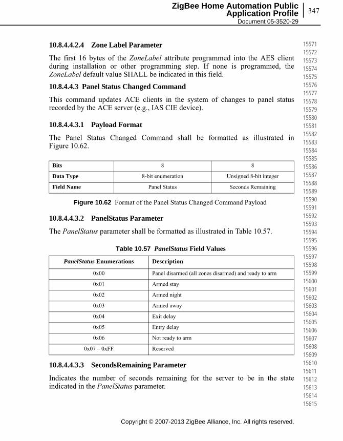
347
Copyright © 2007-2013 ZigBee Alliance, Inc. All rights reserved.
ZigBee Home Automation Public Application Profile
Document 05-3520-29
155711557215573155741557515576155771557815579155801558115582155831558415585155861558715588155891559015591155921559315594155951559615597155981559915600156011560215603156041560515606156071560815609156101561115612156131561415615
10.8.4.4.2.4 Zone Label Parameter
The first 16 bytes of the ZoneLabel attribute programmed into the AES client during installation or other programming step. If none is programmed, the ZoneLabel default value SHALL be indicated in this field.
10.8.4.4.3 Panel Status Changed Command
This command updates ACE clients in the system of changes to panel status recorded by the ACE server (e.g., IAS CIE device).
10.8.4.4.3.1 Payload Format
The Panel Status Changed Command shall be formatted as illustrated in Figure 10.62.
Figure 10.62 Format of the Panel Status Changed Command Payload
10.8.4.4.3.2 PanelStatus Parameter
The PanelStatus parameter shall be formatted as illustrated in Table 10.57.
10.8.4.4.3.3 SecondsRemaining Parameter
Indicates the number of seconds remaining for the server to be in the state indicated in the PanelStatus parameter.
Bits 8 8
Data Type 8-bit enumeration Unsigned 8-bit integer
Field Name Panel Status Seconds Remaining
Table 10.57 PanelStatus Field Values
PanelStatus Enumerations Description
0x00 Panel disarmed (all zones disarmed) and ready to arm
0x01 Armed stay
0x02 Armed night
0x03 Armed away
0x04 Exit delay
0x05 Entry delay
0x06 Not ready to arm
0x07 – 0xFF Reserved
Copyright © 2007-2013 ZigBee Alliance, Inc. All rights reserved.
Chapter 10Home Automation, ZCL Cluster Extensions348
156161561715618156191562015621156221562315624156251562615627156281562915630156311563215633156341563515636156371563815639156401564115642156431564415645156461564715648156491565015651156521565315654156551565615657156581565915660
The SecondsRemaining parameter SHALL be provided if the PanelStatusparameter has a value of 0x04 (Exit delay) or 0x05 (Entry delay).
The default value SHALL be 0x00.
10.9 IAS WD Cluster Extensions
10.9.1 Introduction
10.9.1.1 Scope and Purpose
This document describes the proposed addition to the Home Automation specification and the ZigBee Cluster Library for the IAS WD cluster. The existing attributes and enumerations lack certain features that service providers require. This proposal would add attributes and commands to meet these requirements.
10.9.2 References
The following standards and specifications contain provisions, which through reference in this document constitute provisions of this specification. All the standards and specifications listed are normative references. At the time of publication, the editions indicated were valid. All standards and specifications are subject to revision, and parties to agreements based on this specification are encouraged to investigate the possibility of applying the most recent editions of the standards and specifications indicated below.
10.9.2.1 ZigBee Alliance Documents
1 ZigBee Document 075366r03, The ZigBee Cluster Library – this document describes the ZigBee Cluster Library framework and it is essential that it be understood in order to use this cluster definition document.
10.9.3 General Description
This document mirrors the existing IAS WD Cluster in the ZigBee Cluster Library Specification. The following heading numbers are used to reference the actual sections in the Cluster Library Specification document.
10.9.4 Server
10.9.4.1 Dependencies
No change to existing spec.
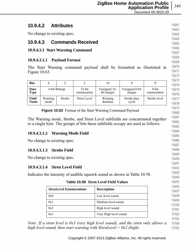
349
Copyright © 2007-2013 ZigBee Alliance, Inc. All rights reserved.
ZigBee Home Automation Public Application Profile
Document 05-3520-29
156611566215663156641566515666156671566815669156701567115672156731567415675156761567715678156791568015681156821568315684156851568615687156881568915690156911569215693156941569515696156971569815699157001570115702157031570415705
10.9.4.2 Attributes
No change to existing spec.
10.9.4.3 Commands Received
10.9.4.3.1 Start Warning Command
10.9.4.3.1.1 Payload Format
The Start Warning command payload shall be formatted as illustrated in Figure 10.63.
Figure 10.63 Format of the Start Warning Command Payload
The Warning mode, Strobe, and Siren Level subfields are concatenated together to a single byte. The groups of bits these subfields occupy are used as follows.
10.9.4.3.1.2 Warning Mode Field
No change to existing spec.
10.9.4.3.1.3 Strobe Field
No change to existing spec.
10.9.4.3.1.4 Siren Level Field
Indicates the intensity of audible squawk sound as shown in Table 10.58.
Note: If a siren level is 0x3 (very high level sound), and the siren only allows a high level sound, then start warning with SirenLevel = 0x2 (high).
Bits 4 2 2 16 8 8
Data Type
6-bit Bitmap 32-bit enumeration
Unsigned 16-bit integer
Unsigned 8-bit integer
8-bit enumeration
Field Name
Warning mode
Strobe Siren Level Warning duration
Strobe duty cycle
Strobe level
Table 10.58 Siren Level Field Values
SirenLevel Enumerations Description
0x0 Low level sound
0x1 Medium level sound
0x2 High level sound
0x3 Very High level sound

Copyright © 2007-2013 ZigBee Alliance, Inc. All rights reserved.
Chapter 10Home Automation, ZCL Cluster Extensions350
157061570715708157091571015711157121571315714157151571615717157181571915720157211572215723157241572515726157271572815729157301573115732157331573415735157361573715738157391574015741157421574315744157451574615747157481574915750
10.9.4.3.1.5 Warning Duration Field
No change to existing spec.
10.9.4.3.1.6 Strobe Duty Cycle Field
Indicates the length of the flash cycle. This provides a means of varying the flash duration for different alarm types (e.g., fire, police, burglar). Valid range is 0-100 in increments of 10. All other values shall be rounded to the nearest valid value. Strobe SHALL calculate duty cycle over a duration of one second. The ON state shall precede the OFF state. For example, if Strobe Duty Cycle Field specifies “40”, then the strobe SHALL flash ON for 4/10ths of a second and then turn OFF for 6/10ths of a second.
The default value for this field SHALL be 0x00.
10.9.4.3.1.7 Strobe Level Field
Indicates the intensity of the strobe as shown in Table 10.59. This attribute is designed to vary the output of the strobe (i.e., brightness) and not its frequency, which is detailed in Section 10.9.4.3.1.6, Strobe Duty Cycle Field.
10.10 Power Configuration Cluster Extensions
10.10.1 Power Configuration Cluster Attribute Set
Table 10.59 Strobe Level Field Values
StrobeLevel Enumerations Description
0x00 Low level strobe
0x01 Medium level strobe
0x02 High level strobe
0x03 Very High level strobe
0x04 – 0xFF Reserved
Table 10.60 Power Configuration Cluster Attribute Set
Attribute Set Identifier Description
0x000 – 0x003 No change
0x004 Battery Source 2 Information
0x005 Battery Source 2 Settings
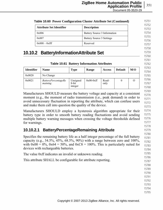
351
Copyright © 2007-2013 ZigBee Alliance, Inc. All rights reserved.
ZigBee Home Automation Public Application Profile
Document 05-3520-29
157511575215753157541575515756157571575815759157601576115762157631576415765157661576715768157691577015771157721577315774157751577615777157781577915780157811578215783157841578515786157871578815789157901579115792157931579415795
10.10.2 BatteryInformationAttribute Set
Manufacturers SHOULD measure the battery voltage and capacity at a consistent moment (e.g., the moment of radio transmission (i.e., peak demand) in order to avoid unnecessary fluctuation in reporting the attribute, which can confuse users and make them call into question the quality of the device.
Manufacturers SHOULD employ a hysteresis algorithm appropriate for their battery type in order to smooth battery reading fluctuations and avoid sending multiple battery warning messages when crossing the voltage thresholds defined for warnings.
10.10.2.1 BatteryPercentageRemaining Attribute
Specifies the remaining battery life as a half integer percentage of the full battery capacity (e.g., 34.5%, 45%, 68.5%, 90%) with a range between zero and 100%, with 0x00 = 0%, 0x64 = 50%, and 0xC8 = 100%. This is particularly suited for devices with rechargeable batteries.
The value 0xff indicates an invalid or unknown reading.
This attribute SHALL be configurable for attribute reporting.
0x006 Battery Source 3 Information
0x007 Battery Source 3 Settings
0x008 – 0xfff Reserved
Table 10.61 Battery Information Attributes
Identifier Name Type Range Access Default M/O
0x0020 No Change
0x0021 BatteryPercentageRemaining
Unsigned 8-bit integer
0x00-0xff Read-only
0 O
Table 10.60 Power Configuration Cluster Attribute Set (Continued)
Attribute Set Identifier Description
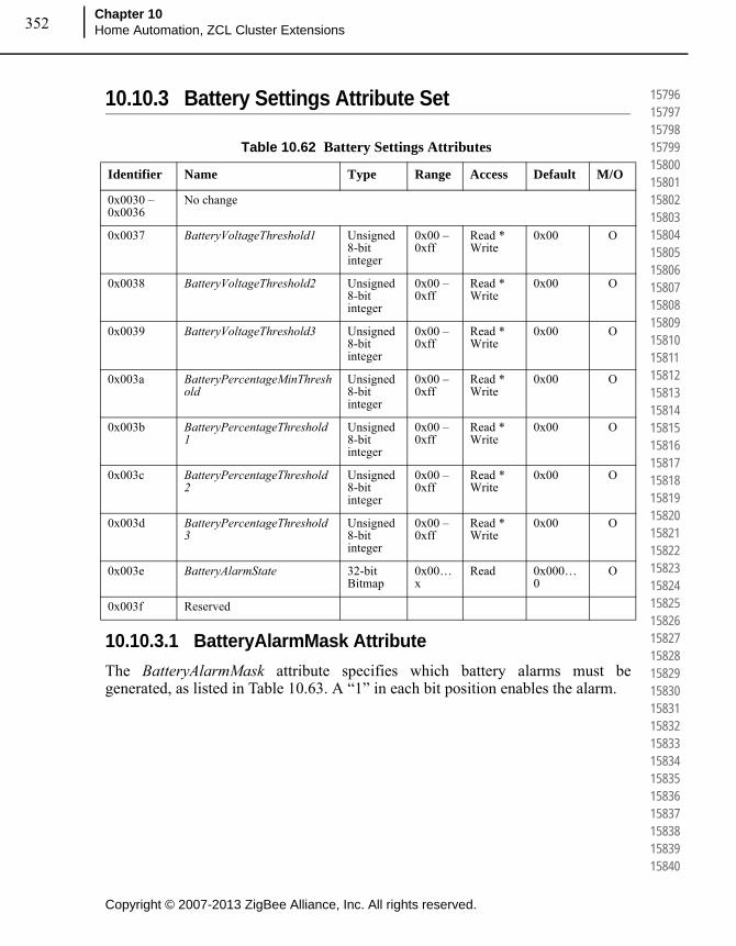
Copyright © 2007-2013 ZigBee Alliance, Inc. All rights reserved.
Chapter 10Home Automation, ZCL Cluster Extensions352
157961579715798157991580015801158021580315804158051580615807158081580915810158111581215813158141581515816158171581815819158201582115822158231582415825158261582715828158291583015831158321583315834158351583615837158381583915840
10.10.3 Battery Settings Attribute Set
10.10.3.1 BatteryAlarmMask Attribute
The BatteryAlarmMask attribute specifies which battery alarms must be generated, as listed in Table 10.63. A “1” in each bit position enables the alarm.
Table 10.62 Battery Settings Attributes
Identifier Name Type Range Access Default M/O
0x0030 – 0x0036
No change
0x0037 BatteryVoltageThreshold1 Unsigned 8-bit integer
0x00 – 0xff
Read * Write
0x00 O
0x0038 BatteryVoltageThreshold2 Unsigned 8-bit integer
0x00 – 0xff
Read * Write
0x00 O
0x0039 BatteryVoltageThreshold3 Unsigned 8-bit integer
0x00 – 0xff
Read * Write
0x00 O
0x003a BatteryPercentageMinThreshold
Unsigned 8-bit integer
0x00 – 0xff
Read * Write
0x00 O
0x003b BatteryPercentageThreshold1
Unsigned 8-bit integer
0x00 – 0xff
Read * Write
0x00 O
0x003c BatteryPercentageThreshold2
Unsigned 8-bit integer
0x00 – 0xff
Read * Write
0x00 O
0x003d BatteryPercentageThreshold3
Unsigned 8-bit integer
0x00 – 0xff
Read * Write
0x00 O
0x003e BatteryAlarmState 32-bit Bitmap
0x00…x
Read 0x000…0
O
0x003f Reserved

353
Copyright © 2007-2013 ZigBee Alliance, Inc. All rights reserved.
ZigBee Home Automation Public Application Profile
Document 05-3520-29
158411584215843158441584515846158471584815849158501585115852158531585415855158561585715858158591586015861158621586315864158651586615867158681586915870158711587215873158741587515876158771587815879158801588115882158831588415885
Manufacturers are responsible for determining the capability to sense and levels at which the alarms are generated. See Section 10.3.2, References for additional recommendations on measuring battery voltage.
10.10.3.2 BatteryVoltageMinThreshold Attribute
Specifies the low battery percentage alarm threshold, measured in percentage (i.e., zero to 100%), for the BatteryPercentageRemaining attribute at which the device can no longer operate or transmit via ist radio (i.e., last gasp).
If the value of BatteryVoltage drops below the threshold specified by BatteryVoltageMinThreshold, an appropriate alarm shall be generated and/or the corresponding bit shall be updated in the BatteryAlarmState attribute.
In order to report to Power Configuration clients, servers that implement BatteryVoltageMinThreshold attribute SHALL implement alarming via the Alarm Cluster, attribute reporting via the BatteryAlarmState attribute, or both.
For servers that implement alarming via the Alarm Cluster, the appropriate alarm is specified in the Alarm Code field (see 3.11.2.3.1) included in the generated alarm SHALL be one of the values in Table 10.64. The host determines which alarm code to populate based on the BatteryAlarmMask attribute and the BatteryVoltageMinThreshold attribute reached. For example, when the BatteryVoltage attribute reaches the value specified by the BatteryVoltageMinThreshold attribute, an alarm with the Alarm Code Field Enumeration “0x10” SHALL be generated.
For servers that implement battery alarm reporting via the BatteryAlarmStateattribute, the bit corresponding to the threshold level reached shall be set to TRUE. See the BatteryAlarmState attribute details for more information.
Table 10.63 Values of the BatteryAlarmMask Attribute
BatteryAlarmMask Attribute Bit Number* Description
0 Battery voltage too low to continue operating the device’s radio (i.e., BatteryVoltageMinThreshold value has been reached)
1 Battery Alarm 1 (i.e., Battery Voltage Threshold 1 or Battery Percentage Threshold 1 value has been reached)
2 Battery Alarm 2 (i.e., Battery Voltage Threshold 2 or Battery Percentage Threshold 2 value has been reached)
3 Battery Alarm 3 (i.e., Battery Voltage Threshold 3 or Battery Percentage Threshold 3 value has been reached)
4 – 7 Reserved
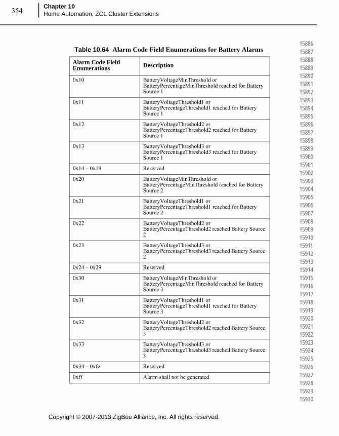
Copyright © 2007-2013 ZigBee Alliance, Inc. All rights reserved.
Chapter 10Home Automation, ZCL Cluster Extensions354
158861588715888158891589015891158921589315894158951589615897158981589915900159011590215903159041590515906159071590815909159101591115912159131591415915159161591715918159191592015921159221592315924159251592615927159281592915930
Table 10.64 Alarm Code Field Enumerations for Battery Alarms
Alarm Code Field Enumerations Description
0x10 BatteryVoltageMinThreshold or BatteryPercentageMinThreshold reached for Battery Source 1
0x11 BatteryVoltageThreshold1 or BatteryPercentageThreshold1 reached for Battery Source 1
0x12 BatteryVoltageThreshold2 or BatteryPercentageThreshold2 reached for Battery Source 1
0x13 BatteryVoltageThreshold3 or BatteryPercentageThreshold3 reached for Battery Source 1
0x14 – 0x19 Reserved
0x20 BatteryVoltageMinThreshold or BatteryPercentageMinThreshold reached for Battery Source 2
0x21 BatteryVoltageThreshold1 or BatteryPercentageThreshold1 reached for Battery Source 2
0x22 BatteryVoltageThreshold2 or BatteryPercentageThreshold2 reached Battery Source 2
0x23 BatteryVoltageThreshold3 or BatteryPercentageThreshold3 reached Battery Source 2
0x24 – 0x29 Reserved
0x30 BatteryVoltageMinThreshold or BatteryPercentageMinThreshold reached for Battery Source 3
0x31 BatteryVoltageThreshold1 or BatteryPercentageThreshold1 reached for Battery Source 3
0x32 BatteryVoltageThreshold2 or BatteryPercentageThreshold2 reached Battery Source 3
0x33 BatteryVoltageThreshold3 or BatteryPercentageThreshold3 reached Battery Source 3
0x34 – 0xfe Reserved
0xff Alarm shall not be generated

355
Copyright © 2007-2013 ZigBee Alliance, Inc. All rights reserved.
ZigBee Home Automation Public Application Profile
Document 05-3520-29
159311593215933159341593515936159371593815939159401594115942159431594415945159461594715948159491595015951159521595315954159551595615957159581595915960159611596215963159641596515966159671596815969159701597115972159731597415975
10.10.3.3 BatteryVoltageThreshold 1-3 Attributes
Specify the low voltage alarm thresholds, measured in units of 100mV, for the BatteryVoltage attribute.
If the value of BatteryVoltage drops below the threshold specified by a BatteryVoltageThreshold, an appropriate alarm SHALL be generated and/or the corresponding bit SHALL be updated in the BatteryAlarmState attribute.
The BatteryVoltageThreshold1-3 attributes SHALL be ordered in ascending order such that the BatteryVoltage level specified to trigger:
• BatteryVoltageThreshold3 is higher than the level specified to trigger BatteryVoltageThreshold2
• BatteryVoltageThreshold2 is higher than the level specified to trigger BatteryVoltageThreshold1
• BatteryVoltageThreshold1 is higher than the level specified to trigger BatteryVoltageMinThreshold
The appropriate alarm is specified in the Alarm Code field (see 3.11.2.3.1) included in the generated alarm SHALL be one of the values in Table 10.64. The host determines which alarm code to populate based on the BatteryAlarmMaskattribute and the BatteryVoltageThreshold1-3 attribute reached.
If this attribute takes the value 0xff then this alarm shall not be generated.
10.10.3.4 BatteryPercentageMinThreshold Attribute
Specifies the low battery percentage alarm threshold, measured in percentage (i.e., zero to 100%), for the BatteryPercentageRemaining attribute (see sub-clause 10.10.2.1).
If the value of BatteryPercentageRemaining drops below the threshold specified by a BatteryPercentageThreshold, an appropriate alarm shall be generated.
The appropriate alarm is specified in the Alarm Code field (see table 3.11.2.3.1 in document [B2], the ZigBee Custer List) included in the generated alarm SHALL be the value in Table 10.64 that corresponds with this threshold being reached for a given battery source. The host determines which alarm code to populate based on the BatteryAlarmMask attribute.
If this attribute takes the value 0xff then this alarm shall not be generated.
10.10.3.5 BatteryPercentageThreshold 1-3 Attributes
Specify the low battery percentage alarm thresholds, measured in percentage (i.e., zero to 100%), for the BatteryPercentageRemaining attribute (see sub-clause 10.10.2.1).
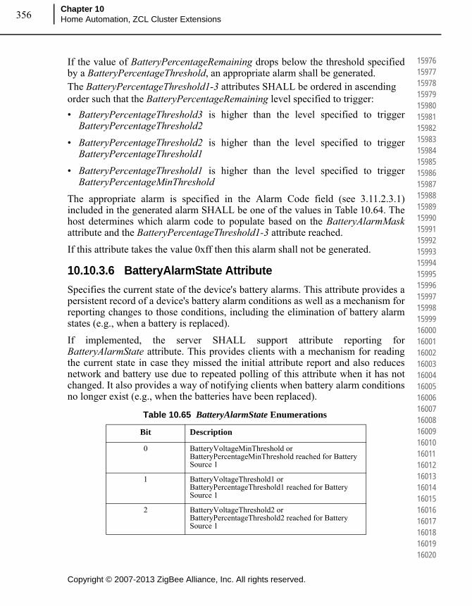
Copyright © 2007-2013 ZigBee Alliance, Inc. All rights reserved.
Chapter 10Home Automation, ZCL Cluster Extensions356
159761597715978159791598015981159821598315984159851598615987159881598915990159911599215993159941599515996159971599815999160001600116002160031600416005160061600716008160091601016011160121601316014160151601616017160181601916020
If the value of BatteryPercentageRemaining drops below the threshold specified by a BatteryPercentageThreshold, an appropriate alarm shall be generated.The BatteryPercentageThreshold1-3 attributes SHALL be ordered in ascending order such that the BatteryPercentageRemaining level specified to trigger:
• BatteryPercentageThreshold3 is higher than the level specified to trigger BatteryPercentageThreshold2
• BatteryPercentageThreshold2 is higher than the level specified to trigger BatteryPercentageThreshold1
• BatteryPercentageThreshold1 is higher than the level specified to trigger BatteryPercentageMinThreshold
The appropriate alarm is specified in the Alarm Code field (see 3.11.2.3.1) included in the generated alarm SHALL be one of the values in Table 10.64. The host determines which alarm code to populate based on the BatteryAlarmMaskattribute and the BatteryPercentageThreshold1-3 attribute reached.
If this attribute takes the value 0xff then this alarm shall not be generated.
10.10.3.6 BatteryAlarmState Attribute
Specifies the current state of the device's battery alarms. This attribute provides a persistent record of a device's battery alarm conditions as well as a mechanism for reporting changes to those conditions, including the elimination of battery alarm states (e.g., when a battery is replaced).
If implemented, the server SHALL support attribute reporting for BatteryAlarmState attribute. This provides clients with a mechanism for reading the current state in case they missed the initial attribute report and also reduces network and battery use due to repeated polling of this attribute when it has not changed. It also provides a way of notifying clients when battery alarm conditions no longer exist (e.g., when the batteries have been replaced).
Table 10.65 BatteryAlarmState Enumerations
Bit Description
0 BatteryVoltageMinThreshold or BatteryPercentageMinThreshold reached for Battery Source 1
1 BatteryVoltageThreshold1 or BatteryPercentageThreshold1 reached for Battery Source 1
2 BatteryVoltageThreshold2 or BatteryPercentageThreshold2 reached for Battery Source 1
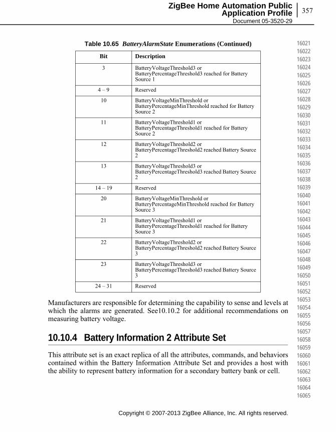
357
Copyright © 2007-2013 ZigBee Alliance, Inc. All rights reserved.
ZigBee Home Automation Public Application Profile
Document 05-3520-29
160211602216023160241602516026160271602816029160301603116032160331603416035160361603716038160391604016041160421604316044160451604616047160481604916050160511605216053160541605516056160571605816059160601606116062160631606416065
Manufacturers are responsible for determining the capability to sense and levels at which the alarms are generated. See10.10.2 for additional recommendations on measuring battery voltage.
10.10.4 Battery Information 2 Attribute Set
This attribute set is an exact replica of all the attributes, commands, and behaviors contained within the Battery Information Attribute Set and provides a host with the ability to represent battery information for a secondary battery bank or cell.
3 BatteryVoltageThreshold3 or BatteryPercentageThreshold3 reached for Battery Source 1
4 – 9 Reserved
10 BatteryVoltageMinThreshold or BatteryPercentageMinThreshold reached for Battery Source 2
11 BatteryVoltageThreshold1 or BatteryPercentageThreshold1 reached for Battery Source 2
12 BatteryVoltageThreshold2 or BatteryPercentageThreshold2 reached Battery Source 2
13 BatteryVoltageThreshold3 or BatteryPercentageThreshold3 reached Battery Source 2
14 – 19 Reserved
20 BatteryVoltageMinThreshold or BatteryPercentageMinThreshold reached for Battery Source 3
21 BatteryVoltageThreshold1 or BatteryPercentageThreshold1 reached for Battery Source 3
22 BatteryVoltageThreshold2 or BatteryPercentageThreshold2 reached Battery Source 3
23 BatteryVoltageThreshold3 or BatteryPercentageThreshold3 reached Battery Source 3
24 – 31 Reserved
Table 10.65 BatteryAlarmState Enumerations (Continued)
Bit Description

Copyright © 2007-2013 ZigBee Alliance, Inc. All rights reserved.
Chapter 10Home Automation, ZCL Cluster Extensions358
160661606716068160691607016071160721607316074160751607616077160781607916080160811608216083160841608516086160871608816089160901609116092160931609416095160961609716098160991610016101161021610316104161051610616107161081610916110
10.10.5 Battery Settings 2 Attribute Set
This attribute set is an exact replica of all the attributes, commands, and behaviors contained within the Battery Settings Attribute Set and provides a host with the ability to represent battery settings for a secondary battery bank or cell.
10.10.6 Battery Information 3 Attribute Set
This attribute set is an exact replica of all the attributes, commands, and behaviors contained within the Battery Information Attribute Set and provides a host with the ability to represent battery information for a tertiary battery bank or cell.
10.10.7 Battery Settings 3 Attribute Set
This attribute set is an exact replica of all the attributes, commands, and behaviors contained within the Battery Settings Attribute Set and provides a host with the ability to represent battery settings for a tertiary battery bank or cell.
359ZigBee Home Automation Public
Application Profile Document 05-3520-29
C H A P T E R
11CHAPTER 11HOME AUTOMATION CCBS
This chapter describes the new Home Automation ZigBee Cluster Library CCBs that shall be applied when developing an HA application.
11.1 CCB #1169
Clarification of the Thermostat cluster.
The following attributes sets the limits to other attributes that are mandatory. If the limits are different than the default value, the attributes shall be included.
• 0x0015 MinHeatSetpoint Limit
• 0x0016 MaxHeatSetpoint Limit
• 0x0017 MinCoolSetpoint Limit
• 0x0018 MaxCoolSetpoint Limit
• 0x0019 MinSetPointDead Band
11.2 CCB #1097
ZCL Default response clarification.
Copyright © 2007-2013 ZigBee Alliance, Inc. All rights reserved.
161111611216113161141611516116161171611816119161201612116122161231612416125161261612716128161291613016131161321613316134161351613616137161381613916140161411614216143161441614516146161471614816149161501615116152161531615416155
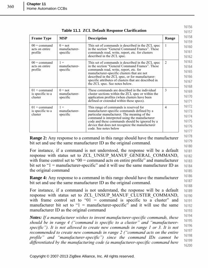
Copyright © 2007-2013 ZigBee Alliance, Inc. All rights reserved.
Chapter 11Home Automation CCBs360
161561615716158161591616016161161621616316164161651616616167161681616916170161711617216173161741617516176161771617816179161801618116182161831618416185161861618716188161891619016191161921619316194161951619616197161981619916200
Range 2: Any response to a command in this range should have the manufacturer bit set and use the same manufacturer ID as the original command.
For instance, if a command is not understood, the response will be a default response with status set to ZCL_UNSUP_MANUF_GENERAL_COMMAND, with frame control set to “00 = command acts on entire profile” and manufacturer bit set to “1 = manufacturer-specific” and it will use the same manufacturer ID as the original command
Range 4: Any response to a command in this range should have the manufacturer bit set and use the same manufacturer ID as the original command.
For instance, if a command is not understand, the response will be a default response with status set to ZCL_UNSUP_MANUF_CLUSTER_COMMAND, with frame control set to “01 = command is specific to a cluster” and manufacturer bit set to “1 = manufacturer-specific” and it will use the same manufacturer ID as the original command
Notes: If a manufacturer wishes to invent manufacturer-specific commands, these should be in range 4 (“command is specific to a cluster” and “manufacturer-specific”). It is not allowed to create new commands in range 1 or 3. It is not recommended to create new commands in range 2 (“command acts on the entire profile” and “manufacturer-specific”) since the command IDs cannot be differentiated by the manufacturing code (a manufacturer-specific command here
Table 11.1 ZCL Default Response Clarification
Frame Type MSP Description Range
00 = command acts on entire profile
0 = not manufacturer-specific
This set of commands is described in the ZCL spec in the section “General Command Frames”. These commands read, write, report, etc. for clusters described in the ZCL spec.
1
00 = command acts on entire profile
1 = manufacturer-specific
This set of commands is described in the ZCL spec in the section “General Command Frames”. These commands read, write, report, etc. for manufacturer-specific clusters that are not described in the ZCL spec, or for manufacturer-specific attributes of clusters that are described in the ZCL spec. See notes below.
2
01 = command is specific to a cluster
0 = not manufacturer-specific
These commands are described in the individual cluster sections within the ZCL spec or within the application profiles (when clusters have been defined or extended within these specs).
3
01 = command is specific to a cluster
1 = manufacturer-specific
This range of commands is reserved for manufacturer-specific commands defined by a particular manufacturer. The meaning of the command is interpreted using the manufacturer code and these commands should be ignored by a device that does not recognize the manufacturer code. See notes below
4
361
Copyright © 2007-2013 ZigBee Alliance, Inc. All rights reserved.
ZigBee Home Automation Public Application Profile
Document 05-3520-29
162011620216203162041620516206162071620816209162101621116212162131621416215162161621716218162191622016221162221622316224162251622616227162281622916230162311623216233162341623516236162371623816239162401624116242162431624416245
means manufacturer-specific attributes). If a new command is created in range 2, it cannot overlap with any existing command IDs and will cause confusion if it overlaps with future command IDs.
11.3 CCB #1092
Correction to the ZCL spec 075123r02 Section: 4.8 (Occupancy Sensing Cluster) changes are in bold
• 4.8.2.2.2.1 PIROccupiedToUnoccupiedDelay Attribute
The PIROccupiedToUnoccupiedDelay attribute is 8-bits in length and specifies the time delay, in seconds, before the PIR sensor changes to its unoccupied state when the sensed area becomes unoccupied. This attribute, along with PIRUnoccupiedToOccupiedTime, may be used to reduce sensor 'chatter' when used in an area where occupation changes frequently.
• 4.8.2.2.2.2 PIRUnoccupiedToOccupiedDelay Attribute
The PIRUnoccupiedToOccupiedDelay attribute is 8-bits in length and specifies the time delay, in seconds, before the PIR sensor changes to its occupied state when the sensed area becomes occupied.
• 4.8.2.2.3.1 UltraSonicOccupiedToUnoccupiedDelay Attribute
The UltraSonicOccupiedToUnoccupiedDelay attribute specifies the time delay, in seconds, before the ultrasonic sensor changes to its unoccupied state when the sensed area becomes unoccupied. This attribute, along with UltraSonicUnoccupiedToOccupiedTime, may be used to reduce sensor ‘chatter’ when used in an area where occupation changes frequently.
• 4.8.2.2.3.2 UltraSonicUnoccupiedToOccupied Delay Attribute
The UltraSonicUnoccupiedToOccupied Delay attribute specifies the time delay, in seconds, before the ultrasonic sensor changes to its occupied state when the sensed area becomes occupied.
11.4 CCB #1093
Additional optional attributes added to the ZCL spec 075123r02 Section: 4.8 (Occupancy Sensing Cluster).
These new attributes, PIRUnoccupiedToOccupiedThreshold and UltraSonicUnoccupiedToOccupiedThreshold can be used in conjunction with either the PIRUnoccupiedToOccupiedDelay or the UltraSonicUnoccupiedToOccupiedDelay attributes to reduce false positives (occupancy wrongly detected). In order to properly discount false positives in
Copyright © 2007-2013 ZigBee Alliance, Inc. All rights reserved.
Chapter 11Home Automation CCBs362
162461624716248162491625016251162521625316254162551625616257162581625916260162611626216263162641626516266162671626816269162701627116272162731627416275162761627716278162791628016281162821628316284162851628616287162881628916290
detection (such as isolated motion triggers not due to a change in occupancy), the sensor device firmware needs to take into account the frequency of occurrence in the detection events, meaning it has to have both a time duration and a number of sensor indications to accurately calculate the rate of occupancy events occurring in the detection region.
Attribute additions:
Name: PIRUnoccupiedToOccupiedThresholdIdentifier: 0x0012Type: Unsigned 8-bit integerRange: 0x00 – 0xFEAccess: Read/WriteDefault: 0x01 (since 0 events over a time period isn’t meaningful)Mandatory/Optional: Optional
Name: UltraSonicUnoccupiedToOccupiedThresholdIdentifier: 0x0022Type: Unsigned 8-bit integerRange: 0x00 – 0xFEAccess: Read/WriteDefault: 0x01 (since 0 events over a time period isn’t meaningful)Mandatory/Optional: Optional
11.5 CCB #1094
Attribute Type changes to the ZCL spec 075123r02 Section: 4.8 (Occupancy Sensing Cluster).
The attributes PIROccupiedToUnoccupiedDelay and UltraSonicOccupiedToUnoccupiedDelay should be type “Unsigned 16-bit integer” instead of “Unsigned 8-bit integer”.
The attributes PIROccupiedToUnoccupiedDelay and UltraSonicOccupiedToUnoccupiedDelay are used to decide how much inactivity constitutes “No Occupancy”. An 8-bit integer quantity in number of seconds is not sufficient for some use cases. This is saying that the maximum amount of time a detection area can be tracked for inactivity is 254 seconds, which is less than 5 minutes. Changing these attributes to 16-bit Unsigned integers, allows a valid range of 0-65535 seconds (over 18 hours) of sensor inactivity before the area is considered Unoccupied.
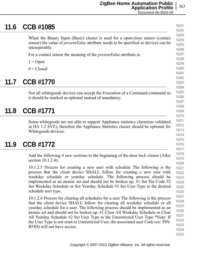
363
Copyright © 2007-2013 ZigBee Alliance, Inc. All rights reserved.
ZigBee Home Automation Public Application Profile
Document 05-3520-29
162911629216293162941629516296162971629816299163001630116302163031630416305163061630716308163091631016311163121631316314163151631616317163181631916320163211632216323163241632516326163271632816329163301633116332163331633416335
11.6 CCB #1085
When the Binary Input (Basic) cluster is used for a open/close sensor (contact sensor) the value of presentValue attribute needs to be specified so devices can be interoperable.
For a contact sensor the meaning of the presentValue attribute is:
1 = Open
0 = Closed
11.7 CCB #1770
Not all whitegoods devices can accept the Execution of a Command command so it should be marked as optional instead of mandatory.
11.8 CCB #1771
Some whitegoods are not able to support Appliance statistics cluster(as validated in HA 1.2 SVE), therefore the Appliance Statistics cluster should be optional for Whitegoods devices.
11.9 CCB #1772
Add the following 4 new sections to the beginning of the door lock cluster (After section 10.1.2.4):
10.1.2.5 Process for creating a new user with schedule The following is the process that the client device SHALL follow for creating a new user with weekday schedule or yearday schedule. The following process should be implemented as an atomic set and should not be broken up. #1 Set Pin Code #2 Set Weekday Schedule or Set Yearday Schedule #3 Set User Type to the desired schedule user type.
10.1.2.6 Process for clearing all schedules for a user The following is the process that the client device SHALL follow for clearing all weekday schedule or all yearday schedule for a user. The following process should be implemented as an atomic set and should not be broken up. #1 Clear All Weekday Schedule or Clear All Yearday Schedule #2 Set User Type to the Unrestricted User Type *Note: If the User Type is not reset to Unrestricted User, the associated user Code (ex: PIN/RFID) will not have access.

Copyright © 2007-2013 ZigBee Alliance, Inc. All rights reserved.
Chapter 11Home Automation CCBs364
163361633716338163391634016341163421634316344163451634616347163481634916350163511635216353163541635516356163571635816359163601636116362163631636416365163661636716368163691637016371163721637316374163751637616377163781637916380
10.1.2.7 Clarification of changing the user type When the user type is changed from a scheduled user to some other user type, the door lock server MAY remove the user's schedule.
10.1.2.8. Clarification for changing the user code When changing the user code, the server SHALL not require that the user code be removed first.
Insert the following text to the end of both (10.1.2.15.16 Set Year Day Schedule) & (10.1.2.15.13 Set Week Day Schedule) command sections. When the Server Device receives the command, the Server Device MAY change the user type to the specific schedule user type. Please refer to Section 10.1.2.5 at the beginning of this cluster.
11.10 CCB #1773
The network level multicast is an optional feature in the ZigBee Pro stack. We should only be using APS layer multicasts instead of network level multicasts so that we guarantee that all devices will hear multicasts intended for them. Add a SHALL statement to the network configuration section in the HA spec. Devices in an HA network SHALL NOT use Network Level multicast, instead they SHALL use APS level multicast for all multicast functions. Furthermore all devices in the HA network SHALL have the stack primitive nwkUseMulticast=FALSE.
11.11 CCB #1774
For the Window Covering Cluster Server (Section 9.3.2) in regards to Table 9.21, Attributes 0x0008 and 0x0009 should be Mandatory if device is a “CLOSED” loop, not a "OPEN" loop.
11.12 CCB #1777
The new HA 1.2 spec re-defines the rate field in the Level Control cluster Move command as a time duration, instead of a rate (unit of movement per second). This breaks compatibility with older HA level control devices, and also ZLL devices. Remedy outline: revert the definition of the rate back to be units of movement per second. Replace older text under the mentioned sections with following text: Section 10.4.3.1.3 DefaultMoveRate Attribute The DefaultMoveRate attribute determines the movement rate, in units per second, when a Move command is received with a Rate parameter of 0xFF Section 10.4.3.2.1 Rate Field The Rate field specifies the rate of movement in units per second. The actual rate of movement should be as close to this rate as the device is able. If the Rate field is 0xFF, then the value in DefaultMoveRate attribute shall be used. If the Rate field

365
Copyright © 2007-2013 ZigBee Alliance, Inc. All rights reserved.
ZigBee Home Automation Public Application Profile
Document 05-3520-29
163811638216383163841638516386163871638816389163901639116392163931639416395163961639716398163991640016401164021640316404164051640616407164081640916410164111641216413164141641516416164171641816419164201642116422164231642416425
is 0xFF and the DefaultMoveRate attribute is not supported, then the device should move as fast as it is able. If the device is not able to move at a variable rate, this field may be disregarded.
11.13 CCB #1779
Both the commands (Arm and Panel Status Changed) are both *generated* by the Server rather than received. Move the entire contents of the Commands Received section to the Commands Generated section.
11.14 CCB #1780
Commands contain parameters rather than attributes. Calling a parameter "PanelStatus Attribute" is confusing. Rename section header and update section text to refer to "Panel Status parameter”.
11.15 CCB #1782
Update the entire section 9.4.6.3 with the following text: "When the checkin interval attribute is changed (provided that the new value is valid and within acceptable range), the device should reset the internal check in interval timer. And send check-in command according to the new check-in interval value."
11.16 CCB #1783
Add to the end of Section 9.4.5.3 Check-In Response "If the FastPollTimeout parameter in the CheckInResponse command is greater than the FastPollTimeoutMax attribute value, the Server Device shall respond with a default response of error status not equal to ZCL_SUCCESS. It is suggested to use the Error Status of ZCL_INVALID_FIELD (0x85).
11.17 CCB# 1790
There is a typo on Line 14246 the ACErrorCode is listed as a Enum32, a type which doesn't exist. From the text explaining the attribute it is clear that the type should be 32 bit bitmap instead.

Chapter 11Home Automation CCBs366
This page intentionally blank
Copyright © 2007-2013 ZigBee Alliance, Inc. All rights reserved.
164261642716428164291643016431164321643316434164351643616437164381643916440164411644216443164441644516446164471644816449164501645116452164531645416455164561645716458164591646016461164621646316464164651646616467164681646916470
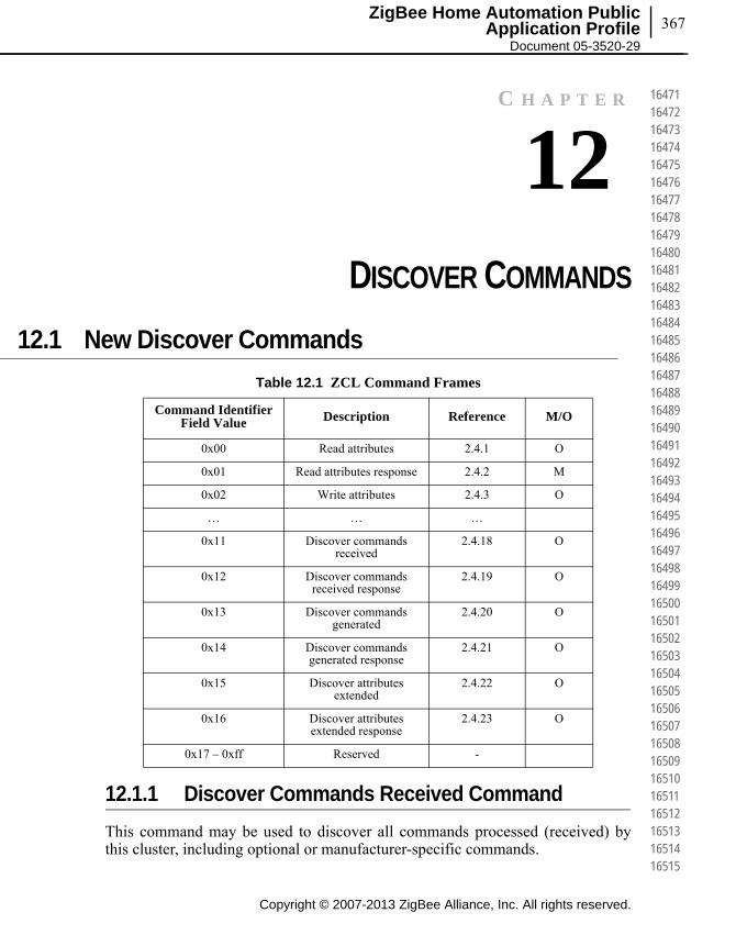
367ZigBee Home Automation Public
Application Profile Document 05-3520-29
C H A P T E R
12CHAPTER 12DISCOVER COMMANDS
12.1 New Discover Commands
12.1.1 Discover Commands Received Command
This command may be used to discover all commands processed (received) by this cluster, including optional or manufacturer-specific commands.
Table 12.1 ZCL Command Frames
Command Identifier Field Value Description Reference M/O
0x00 Read attributes 2.4.1 O
0x01 Read attributes response 2.4.2 M
0x02 Write attributes 2.4.3 O
… … …
0x11 Discover commands received
2.4.18 O
0x12 Discover commands received response
2.4.19 O
0x13 Discover commands generated
2.4.20 O
0x14 Discover commands generated response
2.4.21 O
0x15 Discover attributes extended
2.4.22 O
0x16 Discover attributes extended response
2.4.23 O
0x17 – 0xff Reserved -
Copyright © 2007-2013 ZigBee Alliance, Inc. All rights reserved.
164711647216473164741647516476164771647816479164801648116482164831648416485164861648716488164891649016491164921649316494164951649616497164981649916500165011650216503165041650516506165071650816509165101651116512165131651416515
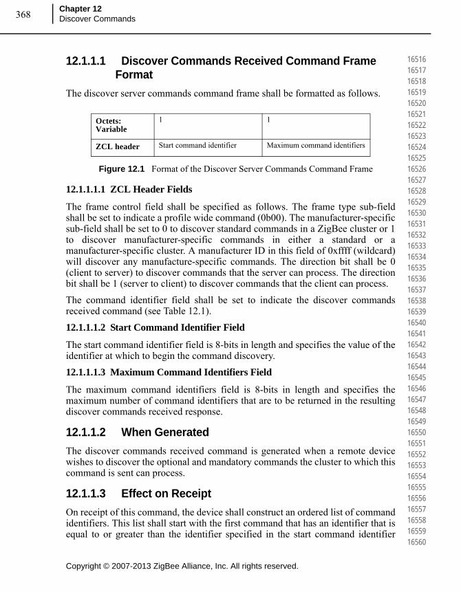
Copyright © 2007-2013 ZigBee Alliance, Inc. All rights reserved.
Chapter 12Discover Commands368
165161651716518165191652016521165221652316524165251652616527165281652916530165311653216533165341653516536165371653816539165401654116542165431654416545165461654716548165491655016551165521655316554165551655616557165581655916560
12.1.1.1 Discover Commands Received Command Frame Format
The discover server commands command frame shall be formatted as follows.
Figure 12.1 Format of the Discover Server Commands Command Frame
12.1.1.1.1 ZCL Header Fields
The frame control field shall be specified as follows. The frame type sub-field shall be set to indicate a profile wide command (0b00). The manufacturer-specific sub-field shall be set to 0 to discover standard commands in a ZigBee cluster or 1 to discover manufacturer-specific commands in either a standard or a manufacturer-specific cluster. A manufacturer ID in this field of 0xffff (wildcard) will discover any manufacture-specific commands. The direction bit shall be 0 (client to server) to discover commands that the server can process. The direction bit shall be 1 (server to client) to discover commands that the client can process.
The command identifier field shall be set to indicate the discover commands received command (see Table 12.1).
12.1.1.1.2 Start Command Identifier Field
The start command identifier field is 8-bits in length and specifies the value of the identifier at which to begin the command discovery.
12.1.1.1.3 Maximum Command Identifiers Field
The maximum command identifiers field is 8-bits in length and specifies the maximum number of command identifiers that are to be returned in the resulting discover commands received response.
12.1.1.2 When Generated
The discover commands received command is generated when a remote device wishes to discover the optional and mandatory commands the cluster to which this command is sent can process.
12.1.1.3 Effect on Receipt
On receipt of this command, the device shall construct an ordered list of command identifiers. This list shall start with the first command that has an identifier that is equal to or greater than the identifier specified in the start command identifier
Octets: Variable
1 1
ZCL header Start command identifier Maximum command identifiers
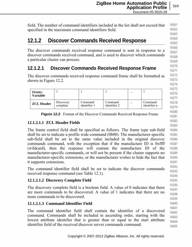
369
Copyright © 2007-2013 ZigBee Alliance, Inc. All rights reserved.
ZigBee Home Automation Public Application Profile
Document 05-3520-29
165611656216563165641656516566165671656816569165701657116572165731657416575165761657716578165791658016581165821658316584165851658616587165881658916590165911659216593165941659516596165971659816599166001660116602166031660416605
field. The number of command identifiers included in the list shall not exceed that specified in the maximum command identifiers field.
12.1.2 Discover Commands Received Response
The discover commands received response command is sent in response to a discover commands received command, and is used to discover which commands a particular cluster can process.
12.1.2.1 Discover Commands Received Response Frame
The discover commands received response command frame shall be formatted as shown in Figure 12.2.
Figure 12.2 Format of the Discover Commands Received Response Frame
12.1.2.1.1 ZCL Header Fields
The frame control field shall be specified as follows. The frame type sub-field shall be set to indicate a profile wide command (0b00). The manufacturer-specific sub-field shall be set to the same value included in the original discover commands command, with the exception that if the manufacture ID is 0xffff (wildcard), then the response will contain the manufacture ID of the manufacturer-specific commands, or will not be present if the cluster supports no manufacturer-specific extensions, or the manufacturer wishes to hide the fact that it supports extensions.
The command identifier field shall be set to indicate the discover commands received response command (see Table 12.1).
12.1.2.1.2 Discovery Complete Field
The discovery complete field is a boolean field. A value of 0 indicates that there are more commands to be discovered. A value of 1 indicates that there are no more commands to be discovered.
12.1.2.1.3 Command Identifier Field
The command identifier field shall contain the identifier of a discovered command. Commands shall be included in ascending order, starting with the lowest attribute identifier that is greater than or equal to the start attribute identifier field of the received discover server commands command.
Octets: Variable
1 1 1 … 1
ZCL Header Discovery complete
Command identifier 1
Command identifier 2
… Command identifier n

Copyright © 2007-2013 ZigBee Alliance, Inc. All rights reserved.
Chapter 12Discover Commands370
166061660716608166091661016611166121661316614166151661616617166181661916620166211662216623166241662516626166271662816629166301663116632166331663416635166361663716638166391664016641166421664316644166451664616647166481664916650
12.1.2.2 When Generated
The discover commands received response is generated in response to a discover commands received command.
12.1.2.3 Effect on Receipt
On receipt of this command, the device is notified of the results of its command discovery request.
Following the receipt of this command, if the discovery complete field indicates that there are more commands to be discovered, the device may choose to send subsequent discover command request commands to obtain the rest of the command identifiers. In this case, the start command identifier specified in the next command discovery request command should be set equal to one plus the last command identifier received in the discover commands received response.
12.1.3 Discover Commands Generated Command
This command may be used to discover all commands which may be generated (sent) by the cluster, including optional or manufacturer-specific commands.
12.1.3.1 Discover Commands Generated Command Frame Format
With the exception of the command ID in the ZCL header, the discover commands generated command frame shall be formatted as described in sub-clause 12.1.1.1 and its subsections.
12.1.3.2 When Generated
The discover commands generated command is generated when a remote device wishes to discover the commands that a cluster may generate on the device to which this command is directed.
12.1.3.3 Effect on Receipt
On receipt of this command, the device shall construct an ordered list of command identifiers. This list shall start with the first command that has an identifier that is equal to or greater than the identifier specified in the start command identifier field. The number of command identifiers included in the list shall not exceed that specified in the maximum command identifiers field.
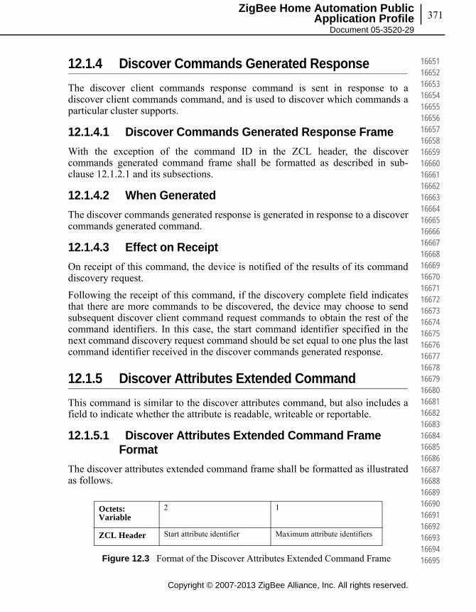
371
Copyright © 2007-2013 ZigBee Alliance, Inc. All rights reserved.
ZigBee Home Automation Public Application Profile
Document 05-3520-29
166511665216653166541665516656166571665816659166601666116662166631666416665166661666716668166691667016671166721667316674166751667616677166781667916680166811668216683166841668516686166871668816689166901669116692166931669416695
12.1.4 Discover Commands Generated Response
The discover client commands response command is sent in response to a discover client commands command, and is used to discover which commands a particular cluster supports.
12.1.4.1 Discover Commands Generated Response Frame
With the exception of the command ID in the ZCL header, the discover commands generated command frame shall be formatted as described in sub-clause 12.1.2.1 and its subsections.
12.1.4.2 When Generated
The discover commands generated response is generated in response to a discover commands generated command.
12.1.4.3 Effect on Receipt
On receipt of this command, the device is notified of the results of its command discovery request.
Following the receipt of this command, if the discovery complete field indicates that there are more commands to be discovered, the device may choose to send subsequent discover client command request commands to obtain the rest of the command identifiers. In this case, the start command identifier specified in the next command discovery request command should be set equal to one plus the last command identifier received in the discover commands generated response.
12.1.5 Discover Attributes Extended Command
This command is similar to the discover attributes command, but also includes a field to indicate whether the attribute is readable, writeable or reportable.
12.1.5.1 Discover Attributes Extended Command Frame Format
The discover attributes extended command frame shall be formatted as illustrated as follows.
Figure 12.3 Format of the Discover Attributes Extended Command Frame
Octets: Variable
2 1
ZCL Header Start attribute identifier Maximum attribute identifiers
Copyright © 2007-2013 ZigBee Alliance, Inc. All rights reserved.
Chapter 12Discover Commands372
166961669716698166991670016701167021670316704167051670616707167081670916710167111671216713167141671516716167171671816719167201672116722167231672416725167261672716728167291673016731167321673316734167351673616737167381673916740
12.1.5.1.1 ZCL Header Fields
The frame control field shall be specified as follows. The frame type sub-field shall be set to indicate a profile wide command (0b00). The manufacturer-specific sub-field shall be set to 0 to discover standard attributes in a ZigBee cluster or 1 to discover manufacturer-specific attributes in either a standard or a manufacturer-specific cluster. A manufacturer ID in this field of 0xffff (wildcard) will discover any manufacture-specific attributes. The direction bit shall be 0 (client to server) to discover attributes that the server hosts. The direction bit shall be 1 (server to client) to discover attributes that the client may host.
The command identifier field shall be set to indicate the discover attributes extended command (see Figure 12.3).
12.1.5.1.2 Start Attribute Identifier Field
The start attribute identifier field is 16-bits in length and specifies the value of the identifier at which to begin the attribute discovery.
12.1.5.1.3 Maximum Attribute Identifiers Field
The maximum attribute identifiers field is 8 bits in length and specifies the maximum number of attribute identifiers that are to be returned in the resulting discover attributes response command.
12.1.5.2 When Generated
The discover attributes extended command is generated when a remote device wishes to discover the identifiers and types of the attributes on a device which are supported within the cluster to which this command is directed, including whether the attribute is readable, writeable or reportable.
12.1.5.3 Effect on Receipt
On receipt of this command, the device shall construct an ordered list of attribute information records, each containing a discovered attribute identifier and its data type, in ascending order of attribute identifiers. This list shall start with the first attribute that has an identifier that is equal to or greater than the identifier specified in the start attribute identifier field. The number of attribute identifiers included in the list shall not exceed that specified in the maximum attribute identifiers field.
12.1.6 Discover Attributes Extended Response Command
This command is sent in response to a discover attribute extended command, and is used to determine if attributes are readable, writable or reportable.
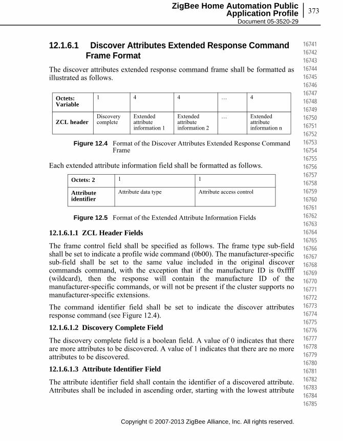
373
Copyright © 2007-2013 ZigBee Alliance, Inc. All rights reserved.
ZigBee Home Automation Public Application Profile
Document 05-3520-29
167411674216743167441674516746167471674816749167501675116752167531675416755167561675716758167591676016761167621676316764167651676616767167681676916770167711677216773167741677516776167771677816779167801678116782167831678416785
12.1.6.1 Discover Attributes Extended Response Command Frame Format
The discover attributes extended response command frame shall be formatted as illustrated as follows.
Figure 12.4 Format of the Discover Attributes Extended Response Command Frame
Each extended attribute information field shall be formatted as follows.
Figure 12.5 Format of the Extended Attribute Information Fields
12.1.6.1.1 ZCL Header Fields
The frame control field shall be specified as follows. The frame type sub-field shall be set to indicate a profile wide command (0b00). The manufacturer-specific sub-field shall be set to the same value included in the original discover commands command, with the exception that if the manufacture ID is 0xffff (wildcard), then the response will contain the manufacture ID of the manufacturer-specific commands, or will not be present if the cluster supports no manufacturer-specific extensions.
The command identifier field shall be set to indicate the discover attributes response command (see Figure 12.4).
12.1.6.1.2 Discovery Complete Field
The discovery complete field is a boolean field. A value of 0 indicates that there are more attributes to be discovered. A value of 1 indicates that there are no more attributes to be discovered.
12.1.6.1.3 Attribute Identifier Field
The attribute identifier field shall contain the identifier of a discovered attribute. Attributes shall be included in ascending order, starting with the lowest attribute
Octets: Variable
1 4 4 … 4
ZCL headerDiscovery complete
Extended attribute information 1
Extended attribute information 2
… Extended attribute information n
Octets: 2 1 1
Attribute identifier
Attribute data type Attribute access control
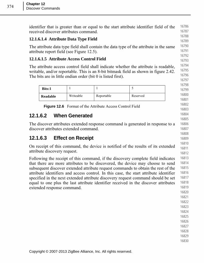
Copyright © 2007-2013 ZigBee Alliance, Inc. All rights reserved.
Chapter 12Discover Commands374
167861678716788167891679016791167921679316794167951679616797167981679916800168011680216803168041680516806168071680816809168101681116812168131681416815168161681716818168191682016821168221682316824168251682616827168281682916830
identifier that is greater than or equal to the start attribute identifier field of the received discover attributes command.
12.1.6.1.4 Attribute Data Type Field
The attribute data type field shall contain the data type of the attribute in the same attribute report field (see Figure 12.5).
12.1.6.1.5 Attribute Access Control Field
The attribute access control field shall indicate whether the attribute is readable, writable, and/or reportable. This is an 8-bit bitmask field as shown in figure 2.42. The bits are in little endian order (bit 0 is listed first).
Figure 12.6 Format of the Attribute Access Control Field
12.1.6.2 When Generated
The discover attributes extended response command is generated in response to a discover attributes extended command.
12.1.6.3 Effect on Receipt
On receipt of this command, the device is notified of the results of its extended attribute discovery request.
Following the receipt of this command, if the discovery complete field indicates that there are more attributes to be discovered, the device may choose to send subsequent discover extended attribute request commands to obtain the rest of the attribute identifiers and access control. In this case, the start attribute identifier specified in the next extended attribute discovery request command should be set equal to one plus the last attribute identifier received in the discover attributes extended response command.
Bits:1 1 1 5
Readable Writeable Reportable Reserved
375ZigBee Home Automation Public
Application Profile Document 05-3520-29
C H A P T E R
13CHAPTER 13GREEN POWER IN HOME AUTOMATION
13.1 Introduction
13.1.1 Scope
This document describes all the best practices aspects related with the Green Power feature usage in HA.
13.1.2 Purpose of the Document
This document describes best practices for Green Power usage in HA networks.
This document is intended as part of HA specification as a referenced document to describe how to configure Green Power feature used in a HA device.
13.2 References
13.2.1 Normative References
13.2.1.1 ZigBee Alliance Documents
[B26] ZigBee document 053474, ZigBee Specification
[B27] ZigBee document 08006, ZigBee-2007 Layer PICS and Stack Profiles
[B28] ZigBee document 075123, ZigBee Cluster Library Specification
[B29] ZigBee document 125474, Home Automation Profile 1.2 Specification
[B30] ZigBee document 094991, Green Power Technical Requirements Document (TRD)
Copyright © 2007-2013 ZigBee Alliance, Inc. All rights reserved.
168311683216833168341683516836168371683816839168401684116842168431684416845168461684716848168491685016851168521685316854168551685616857168581685916860168611686216863168641686516866168671686816869168701687116872168731687416875
Copyright © 2007-2013 ZigBee Alliance, Inc. All rights reserved.
Chapter 13Green Power in Home Automation376
168761687716878168791688016881168821688316884168851688616887168881688916890168911689216893168941689516896168971689816899169001690116902169031690416905169061690716908169091691016911169121691316914169151691616917169181691916920
[B31] ZigBee document 105879, Draft CO2 Level Cluster
[B32] ZigBee document 095499, Green Power 1.0 specification
[B33] ZigBee document 105521, Green Power 1.0 test specification
[B34] ZigBee document 105850, Green Power 1.0 PICS
[B35] ZigBee document 053874, ZigBee Manufacturer Code Database
[B36] ZigBee document 106138, Recommendation for ZigBee PRO Interoperability Across Profiles
[B37] ZigBee document 120177, EZ- Mode Commissioning
13.2.1.2 ISO / IEEE Standards Documents
[B38] Institute of Electrical and Electronics Engineers, Inc., IEEE Std. 802.15.4 2003, IEEE Standard for Information Technology Telecommunications and Information Exchange between Systems – Local and Metropolitan Area Networks – Specific Requirements Part 15.4: Wireless Medium Access Control (MAC) and Physical Layer (PHY) Specifications for Low Rate Wireless Per-sonal Area Networks (WPANs). New York: IEEE Press. 2003
[B39] FIPS Pub 198, The Keyed-Hash Message Authentication Code (HMAC), Federal Information Pro-cessing Standards Publication 198, US Department of Commerce/N.I.S.T., Springfield, Virginia, March 6, 2002. Available from http://csrc.nist.gov/.
13.2.2 Informative References
13.2.2.1 ZigBee Alliance Documents
[B40] ZigBee document 105859, Draft ZigBee Building Automation Profile Specification
[B41] ZigBee document 11196, GP best practices for ZBA
13.3 Definitions
13.3.1 Conformance Levels
Expected: A key word used to describe the behavior of the hardware or software in the design models assumed by this profile. Other hardware and software design models may also be implemented.
377
Copyright © 2007-2013 ZigBee Alliance, Inc. All rights reserved.
ZigBee Home Automation Public Application Profile
Document 05-3520-29
169211692216923169241692516926169271692816929169301693116932169331693416935169361693716938169391694016941169421694316944169451694616947169481694916950169511695216953169541695516956169571695816959169601696116962169631696416965
May: A key word indicating a course of action permissible within the limits of the standard (may equals is permitted).
Shall: A key word indicating mandatory requirements to be strictly followed in order to conform to the standard; deviations from shall are prohibited (shall equals is required to).
Should: A key word indicating that, among several possibilities, one is recommended as particularly suitable, without mentioning or excluding others; that a certain course of action is preferred but not necessarily required; or, that (in the negative form) a certain course of action is deprecated but not prohibited (should equals is rec-ommended that).
13.3.2 Conventions
13.3.2.1 Number Formats
In this specification hexadecimal numbers are prefixed with the designation “0x” and binary numbers are prefixed with the designation “0b”. All other numbers are assumed to be decimal.
13.3.2.2 Transmission Order
The frames in this specification are described as a sequence of fields in a specific order. All frame formats are depicted in the order in which they are transmitted by the PHY, from left to right where the leftmost bit is transmitted first in time. Bits within each field are numbered from 0 (leftmost and least significant) to k-1 (rightmost and most significant), where the length of the field is k bits. Fields that are longer than a single octet are sent to the MAC in the order from the octet containing the lowest numbered bits to the octet containing the highest numbered bits.
13.3.2.3 Reserved Values
Unless otherwise specified, all reserved fields appearing in a frame structure shall be set to zero on transmission and ignored upon reception. Reserved values appearing in multi-value fields shall not be used.
13.3.3 ZigBee Definitions
Attribute: A data entity which represents a physical quantity or state. This data is communicated to other devices using commands.
Cluster: A collection of related attributes and commands, which together define a communications interface between two devices. The devices implement server and client sides of the interface respectively.
Copyright © 2007-2013 ZigBee Alliance, Inc. All rights reserved.
Chapter 13Green Power in Home Automation378
169661696716968169691697016971169721697316974169751697616977169781697916980169811698216983169841698516986169871698816989169901699116992169931699416995169961699716998169991700017001170021700317004170051700617007170081700917010
Cluster Identifier: A 16-bit number unique within the scope of an application profile which identifies a specific cluster.
Device: A device consists of one or more ZigBee device descriptions and their corresponding application profile(s), each on a separate endpoint, that share a single 802.15.4 radio (see [12]). Each device has a unique 64-bit IEEE address.
Device Description: A collection of clusters and associated functionality implemented on a ZigBee endpoint. Device descriptions are defined in the scope of an application profile. Each device description has a unique identifier that is exchanged as part of the discovery process.
Node: Same as a device.
Product: A product is a unit that is intended to be marketed. It may implement a combination of private, published, and standard application profiles.
Trust Center: The device trusted by devices within a ZigBee network to distribute keys for the purpose of network and end-to-end application configuration management (see [1]).
ZigBee Coordinator: An IEEE 802.15.4-2003 PAN coordinator (see [12]).
ZigBee End Device: An IEEE 802.15.4-2003 RFD (Reduced Function Device) or FFD (Full Function Device) (see [12]) participating in a ZigBee network, which is neither the ZigBee coordinator nor a ZigBee router.
ZigBee Router: An IEEE 802.15.4-2003 FFD (Full Function Device) participating in a ZigBee network, which is not the ZigBee coordinator but may act as an IEEE 802.15.4-2003 coordinator within its personal operating space, that is capable of routing messages between devices and supporting associations.
13.3.4 Definitions Specific to this Feature
Application Endpoint: Any endpoint other than the dedicated Green Power Endpoint, hosting application control functionality.
(In)active (Proxy Table) Entry: Proxy Table entry, for which the EntryActive flag is set to TRUE(FALSE), respectively.
(In)valid (Proxy Table) Entry: Proxy Table entry, for which the EntryValid flag is set to TRUE(FALSE), respectively.
Broadcast: Whenever NWK level broadcast transmission is mentioned within this specification without further description for the ZGP-defined commands, or where no further description is provided by the ZigBee specification for the ZigBee-defined commands, the RxOnWhenIdle=TRUE (0xfffd) broadcast address shall be used.

379
Copyright © 2007-2013 ZigBee Alliance, Inc. All rights reserved.
ZigBee Home Automation Public Application Profile
Document 05-3520-29
170111701217013170141701517016170171701817019170201702117022170231702417025170261702717028170291703017031170321703317034170351703617037170381703917040170411704217043170441704517046170471704817049170501705117052170531705417055
Direct Mode: GPS receiving directly the GPFS in GP frame format sent by GPD, if in the radio range of the GPD.
Fully Compliant ZigBee Device: Device implemented according to ZigBee 2007 or ZigBee PRO stack profile, having the role of either ZR or ZED.
Green Power Device Frame (GPDF): Special frame format according to the Green Power specification, which is transmitted by or received by GPD.
Groupcast: One of the communication modes used for tunneling GPD commands between the GPPs and GPSs. In ZigBee terms, it is the APS level multicast, with NWK level broadcast to the RxOnWhenIdle=TRUE (0xfffd) broadcast address.
Pairing: The unidirectional logical link between a Green Power Device and a destination endpoint, which may exist on one or more GP Sinks, which makes the GPS handle the commands received from this particular GPD. Of particular importance is the configuration procedure leading to the establishment of this special relationship.
Portability: Ability to reestablish communication on different location, without interruption or re-commissioning.
Green Power EndPoint (EP GP): A dedicated reserved endpoint, residing on top of the GP stub, hosting the Green Power cluster.
Tunnelled Mode: GPS receiving the GPFS forwarded by a GPP located in the radio range of the GPD. This forwarding uses a normal ZigBee frame format but a specific ZCL command from the Green Power cluster: the GP Notification command (see [7]).
Data GPDF: Any GPDF that carries a GPD Command other than GPD Commissioning (0xE0) or GPD Commissioning Reply (0xF0) or GPD Decommissioning (0xE1).
GPD Data Command: Any GPD Command other than GPD Channel Request (0xE3), GPD Channel Configuration (0xF3), GPD Commissioning (0xE0) or GPD Commissioning Reply (0xF0), GPD Success (0xE2) or GPD Decommissioning (0xE1) (see [7]).
Green Power Device (GPD): A self-powering, energy-harvesting device that implements the Green Power feature.
Green Power Proxy (GPP) or Proxy: A fully compliant ZigBee device, which in addition to a core ZigBee specification also implements the proxy functionality of the Green Power feature. The proxy is able to handle GPDFs and acts as an intermediate node between the GPD and GPSs on the ZigBee network.
Green Power Proxy Minimum (GPPm) or Minimum Proxy: A GPP that only implements the minimum GP feature set, as defined in section A.3.2.9-A.3.2.10 of [7].

Copyright © 2007-2013 ZigBee Alliance, Inc. All rights reserved.
Chapter 13Green Power in Home Automation380
170561705717058170591706017061170621706317064170651706617067170681706917070170711707217073170741707517076170771707817079170801708117082170831708417085170861708717088170891709017091170921709317094170951709617097170981709917100
Green Power Sink (GPS) or Sink: Term used for describing any of GP Target or GP Target+ or GP Combo Minimum or the Target functionality of the GP Combo (see section A.3.2.9-A.3.2.10 of [7]), referring to the capability to receive and process tunneled GPD commands.
Green Power Target (GPT) or Target: A fully compliant ZigBee device, which in addition to a core ZigBee specification also implements the sink functionality of Green Power cluster, allowing for receiving, processing and executing tunneled GPD commands.
Green Power Target+ (GPT+) or Target+: A Target which also implements the GP stub. A Target+ can thus receive, process and execute both tunneled and directly received ZGPD commands.
Green Power Combo (GPC) or Combo: A fully compliant ZigBee device, which in addition to a core ZigBee specification also implements both the proxy and the sink functionality of the Green Power feature. A Combo can thus receive, process and execute both tunneled and directly received GPD commands (in its sink role), as well as forward them to other GP nodes (in its proxy role).
Green Power Combo Minimum (GPCm) or Minimum Combo: A GPC that only implements the minimum GP feature set, as defined in section A.3.2.9-A.3.2.10 of [7].
Common Green Power Stub (cGP): A term used for describing the common functionality of Green Power for sending and receiving data packets.
Dedicated Green Power Stub (dGP): A term used for describing the dedicated Green Power application.
Dedicated LPED Stub (dLPED): A term used for describing the dedicated Low Power End Device Application (defined by the Low Power End Device task group).
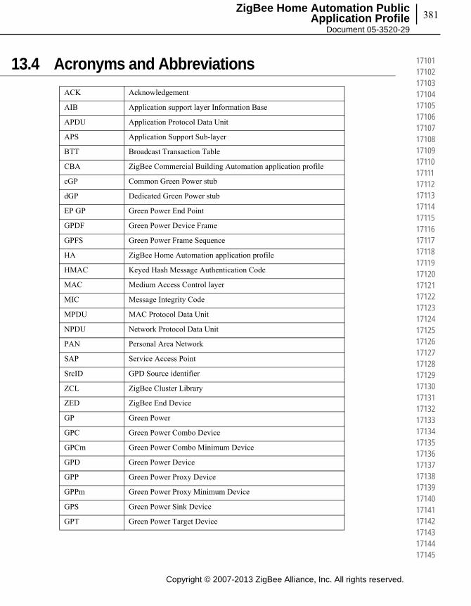
381
Copyright © 2007-2013 ZigBee Alliance, Inc. All rights reserved.
ZigBee Home Automation Public Application Profile
Document 05-3520-29
171011710217103171041710517106171071710817109171101711117112171131711417115171161711717118171191712017121171221712317124171251712617127171281712917130171311713217133171341713517136171371713817139171401714117142171431714417145
13.4 Acronyms and Abbreviations
ACK Acknowledgement
AIB Application support layer Information Base
APDU Application Protocol Data Unit
APS Application Support Sub-layer
BTT Broadcast Transaction Table
CBA ZigBee Commercial Building Automation application profile
cGP Common Green Power stub
dGP Dedicated Green Power stub
EP GP Green Power End Point
GPDF Green Power Device Frame
GPFS Green Power Frame Sequence
HA ZigBee Home Automation application profile
HMAC Keyed Hash Message Authentication Code
MAC Medium Access Control layer
MIC Message Integrity Code
MPDU MAC Protocol Data Unit
NPDU Network Protocol Data Unit
PAN Personal Area Network
SAP Service Access Point
SrcID GPD Source identifier
ZCL ZigBee Cluster Library
ZED ZigBee End Device
GP Green Power
GPC Green Power Combo Device
GPCm Green Power Combo Minimum Device
GPD Green Power Device
GPP Green Power Proxy Device
GPPm Green Power Proxy Minimum Device
GPS Green Power Sink Device
GPT Green Power Target Device

Copyright © 2007-2013 ZigBee Alliance, Inc. All rights reserved.
Chapter 13Green Power in Home Automation382
171461714717148171491715017151171521715317154171551715617157171581715917160171611716217163171641716517166171671716817169171701717117172171731717417175171761717717178171791718017181171821718317184171851718617187171881718917190
13.5 GP Best Practices for Home Automation
13.5.1 Profile-specific Settings for HA Devices
In order for a HA device to support Green Power feature, it shall implement the Green Power cluster as defined in [B32].
Any GP feature, attribute or parameter which doesn’t have HA-specific configuration or value defined in the following sections shall be implemented according to GP spec [B32].
13.5.1.1 GP Functionality Supported per GP Infrastructure Device for HA
HA doesn’t request specific configuration of GP functionality supported per GP infrastructure device.
13.5.1.2 GreenPower Cluster Command Support per GP Infrastructure Device for HA
HA doesn’t request specific support of Green Power cluster command per GP infrastructure device.
13.5.1.3 Profile-specific Default Attribute Values for the Green Power Cluster
Table 13.1 defines the HA profile-specific attribute values for the Green Power cluster.
Please note that HA device shall implement Green Power cluster attributes as defined in GP spec [B32] except for attributes with specific HA value.
GPT+ Green Power Target Plus device
ZR ZigBee Router
ZSE ZigBee Smart Energy
Table 13.1 HA-specific Green Power Cluster Attribute Values
ID Name Access HA M/O HA Default Value
0x0004 GreenPowerEZ-Mode R/W O (default) 3 mins (0x00B4)
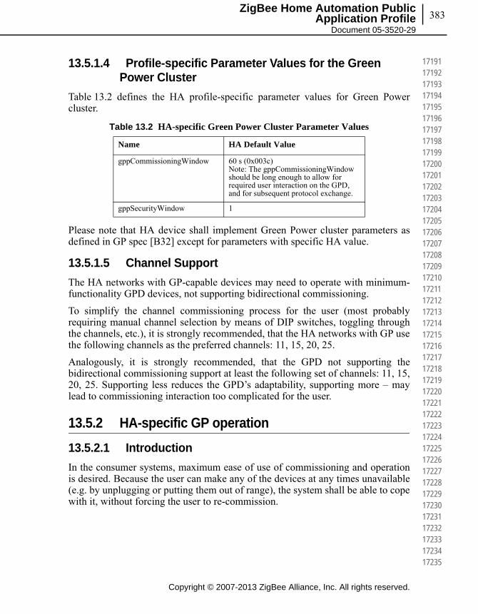
383
Copyright © 2007-2013 ZigBee Alliance, Inc. All rights reserved.
ZigBee Home Automation Public Application Profile
Document 05-3520-29
171911719217193171941719517196171971719817199172001720117202172031720417205172061720717208172091721017211172121721317214172151721617217172181721917220172211722217223172241722517226172271722817229172301723117232172331723417235
13.5.1.4 Profile-specific Parameter Values for the Green Power Cluster
Table 13.2 defines the HA profile-specific parameter values for Green Power cluster.
Please note that HA device shall implement Green Power cluster parameters as defined in GP spec [B32] except for parameters with specific HA value.
13.5.1.5 Channel Support
The HA networks with GP-capable devices may need to operate with minimum-functionality GPD devices, not supporting bidirectional commissioning.
To simplify the channel commissioning process for the user (most probably requiring manual channel selection by means of DIP switches, toggling through the channels, etc.), it is strongly recommended, that the HA networks with GP use the following channels as the preferred channels: 11, 15, 20, 25.
Analogously, it is strongly recommended, that the GPD not supporting the bidirectional commissioning support at least the following set of channels: 11, 15, 20, 25. Supporting less reduces the GPD’s adaptability, supporting more – may lead to commissioning interaction too complicated for the user.
13.5.2 HA-specific GP operation
13.5.2.1 Introduction
In the consumer systems, maximum ease of use of commissioning and operation is desired. Because the user can make any of the devices at any times unavailable (e.g. by unplugging or putting them out of range), the system shall be able to cope with it, without forcing the user to re-commission.
Table 13.2 HA-specific Green Power Cluster Parameter Values
Name HA Default Value
gppCommissioningWindow 60 s (0x003c) Note: The gppCommissioningWindow should be long enough to allow for required user interaction on the GPD, and for subsequent protocol exchange.
gppSecurityWindow 1

Copyright © 2007-2013 ZigBee Alliance, Inc. All rights reserved.
Chapter 13Green Power in Home Automation384
172361723717238172391724017241172421724317244172451724617247172481724917250172511725217253172541725517256172571725817259172601726117262172631726417265172661726717268172691727017271172721727317274172751727617277172781727917280
13.5.2.2 HA-specific GPS Operation
13.5.2.2.1 Behaviour in Commissioning
If a GPS receives a GP Notification or Data GPDF with AutoCommissioning flag set to 0b0 while in commissioning mode, it shall execute the command. If a GPS receives a Data GPDF with Auto-Commissioning flag set to 0b1 when in commissioning mode (whether directly, in GP Commissioning Notification or in GP Notification), it shall not execute the GPD Command.
The intention behind this behavior is to give at time of commissioning a consistent, only commissioning-related feedback to the user.
13.5.2.2.2 Maintenance of Proxy Tables
On receipt of a GP Notification command for which any mismatch in SecurityLevel, SecurityKey or an old GPD security frame counter value is discovered, a GPS shall send a GP Pairing command with the correct sub-field values and/or the required security fields present, carrying the correct values for this GPD.
13.5.2.2.3 GPD Maintenance
In the event of ZigBee operational channel change, the GPS may attempt to update the paired Rx-capable GPDs by sending appropriately protected GPD Channel Configuration command.
In the event of shared key change, the GPS may attempt to update the paired Rx-capable GPDs by sending appropriately protected GPD Commissioning Reply command.
13.5.2.3 HA-specific GPP Operation
13.5.2.3.1 Commissioning Behaviour
On receipt of Data GPDF with Auto-Commissioning sub-field set to 0b0 when in commissioning mode, if the Proxy Table entry for this SrcID already contains sink information, the proxy shall schedule transmission of the GP Notification command to the paired GPSs in the requested communication mode, whereby the commands shall be sent in the following order: GP Tunneling Stop command first, then unicast GP Notifications and groupcast GP Notifications (if any), then broadcast GP Notification (if any).
On receipt of Data GPDF with Auto-Commissioning sub-field set to 0b1 when in commissioning mode, the proxy shall not schedule transmission of GP Notification, even if it has active Proxy Table entry for this SrcID storing some pairing.

385
Copyright © 2007-2013 ZigBee Alliance, Inc. All rights reserved.
ZigBee Home Automation Public Application Profile
Document 05-3520-29
172811728217283172841728517286172871728817289172901729117292172931729417295172961729717298172991730017301173021730317304173051730617307173081730917310173111731217313173141731517316173171731817319173201732117322173231732417325
13.5.2.3.2 Maintenance of Proxy Tables
The GP Pairing Search command shall be sent as broadcast, using proxy aliasing, and gppDiscoveryDelay. If within gppDiscoveryDelay, GP Pairing Search or broadcast GP Notification for the same SrcID and communication modes is receives, the scheduled transmission should be dropped.
13.6 HA-specific Commissioning
It is mandatory for the HA devices that implement GP infrastructure device functionality to support the GP commissioning method as specified in section A.3.9 of the GP specification [B32].
It is left to the implementers of GPS according to this specification, when to update the pairings in the Sink Table (add or remove, dependent on different or the same user interaction, applications internal state, etc.), and when to exit commissioning mode (upon successful/failed pairing, timeout, user interaction, etc.). It is recommended, that the implementers make the GPS behavior understandable to the user (e.g. via a user manual and/or appropriate user feedback). Also, the GPPs in the system shall be instructed to behave accordingly (e.g. using the GP Commissioning Mode command).
13.6.1 Device Indications
With respect to notification of installers and users in order to support the commissioning process, the following practices are recommended.
A GPS should be able to indicate to the user:
• That the device is open for establishing a new pairing (in commissioning mode),
• That a new pairing with a GPD has been created,
• That it has failed to be paired to a GPD. It is recommended that two different types of pairing failures are indicated by different feedback:
▪ the pairing failure is permanent, no point in re-trying (e.g. in case of failure because of application mismatch)
▪ the pairing failure is solvable by re-trying the pairing procedure by retriggering it, at least on the GPD side (e.g. in case of failure because of a timeout).
• If GPD/pairing removal is supported: that GPD/pairing has been removed.
These indications may be implemented in a number of ways including indicator light(s) or an audible indicator.
Copyright © 2007-2013 ZigBee Alliance, Inc. All rights reserved.
Chapter 13Green Power in Home Automation386
173261732717328173291733017331173321733317334173351733617337173381733917340173411734217343173441734517346173471734817349173501735117352173531735417355173561735717358173591736017361173621736317364173651736617367173681736917370
13.7 HA – GP Commissioning Message Sequence Charts
The message sequence charts in this section illustrate how GP proxy-based commissioning method (as defined in section A.3.9 of the GP specification [B32]) can be seamlessly integrated into the HA EZ-mode commissioning (as defined in sec. 8 of HA 1.2 specification [B29] and the dedicated document [B37]), allowing for one any the same user interaction to enable either.
Please note: the GP commissioning procedure encompasses both network joining and pairing, while the HA EZ-mode commissioning covers only pairing of devices already operating (securely) on the same network.
The diagrams below are the recommended solution for enabling both commissioning methods with the same user interaction.
Implementers of GP-enabled HA devices may decide to enable each with a separate user action; this of course requires the user to be able to differentiate the capabilities of the devices to be paired.
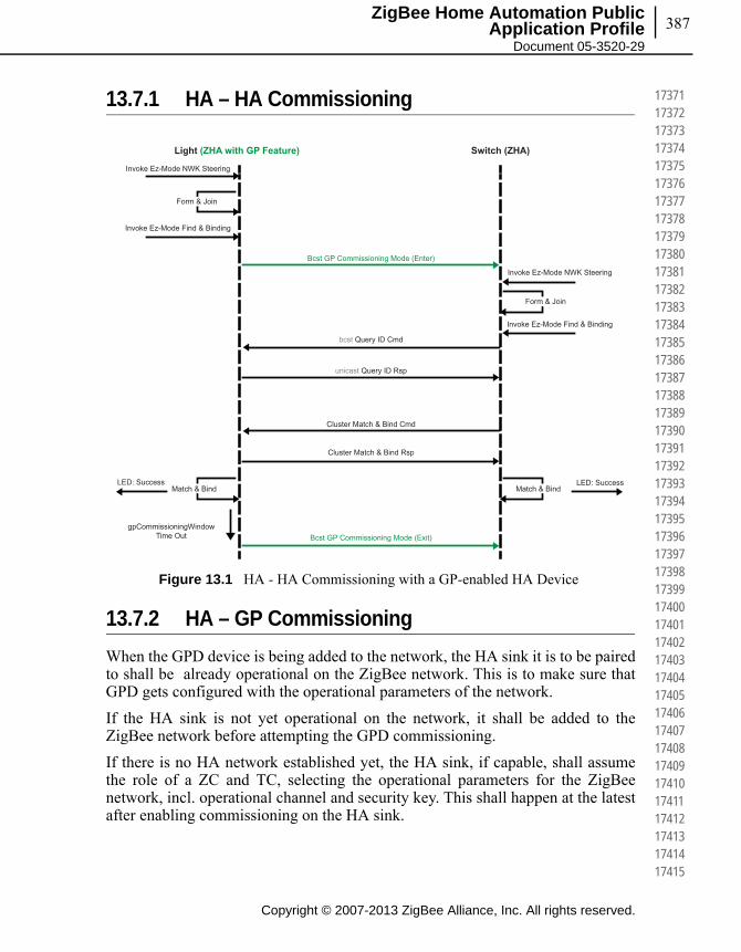
387
Copyright © 2007-2013 ZigBee Alliance, Inc. All rights reserved.
ZigBee Home Automation Public Application Profile
Document 05-3520-29
173711737217373173741737517376173771737817379173801738117382173831738417385173861738717388173891739017391173921739317394173951739617397173981739917400174011740217403174041740517406174071740817409174101741117412174131741417415
13.7.1 HA – HA Commissioning
Figure 13.1 HA - HA Commissioning with a GP-enabled HA Device
13.7.2 HA – GP Commissioning
When the GPD device is being added to the network, the HA sink it is to be paired to shall be already operational on the ZigBee network. This is to make sure that GPD gets configured with the operational parameters of the network.
If the HA sink is not yet operational on the network, it shall be added to the ZigBee network before attempting the GPD commissioning.
If there is no HA network established yet, the HA sink, if capable, shall assume the role of a ZC and TC, selecting the operational parameters for the ZigBee network, incl. operational channel and security key. This shall happen at the latest after enabling commissioning on the HA sink.
Invoke Ez-Mode NWK Steering
Invoke Ez-Mode Find & Binding
bcst Query ID Cmd
unicast Query ID Rsp
Cluster Match & Bind Cmd
Cluster Match & Bind Rsp
Bcst GP Commissioning Mode (Enter)
Bcst GP Commissioning Mode (Exit)gpCommissioningWindow
Time Out
Invoke Ez-Mode NWK Steering
Invoke Ez-Mode Find & Binding
LED: Success LED: Success
Light (ZHA with GP Feature) Switch (ZHA)
Form & Join
Match & Bind Match & Bind
Form & Join
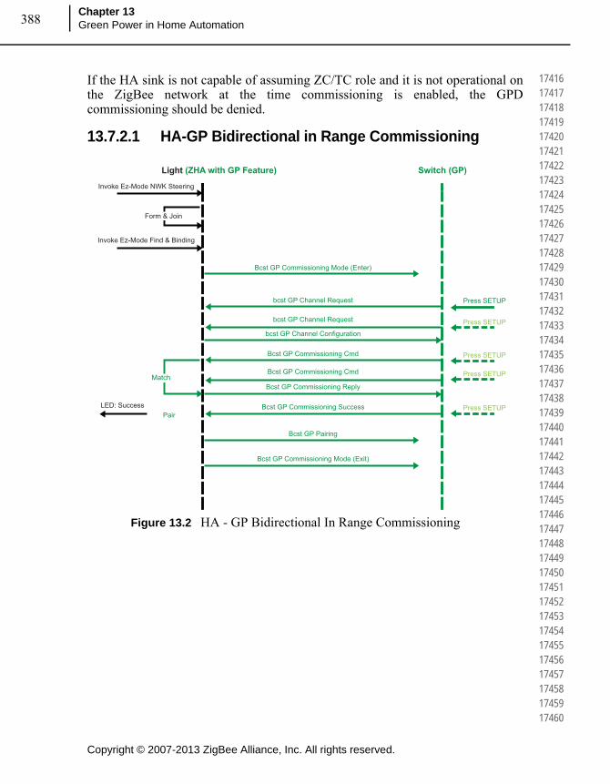
Copyright © 2007-2013 ZigBee Alliance, Inc. All rights reserved.
Chapter 13Green Power in Home Automation388
174161741717418174191742017421174221742317424174251742617427174281742917430174311743217433174341743517436174371743817439174401744117442174431744417445174461744717448174491745017451174521745317454174551745617457174581745917460
If the HA sink is not capable of assuming ZC/TC role and it is not operational on the ZigBee network at the time commissioning is enabled, the GPD commissioning should be denied.
13.7.2.1 HA-GP Bidirectional in Range Commissioning
Figure 13.2 HA - GP Bidirectional In Range Commissioning
Invoke Ez-Mode NWK Steering
Invoke Ez-Mode Find & Binding
Bcst GP Commissioning Mode (Enter)
Bcst GP Commissioning Success
Bcst GP Commissioning Reply
Bcst GP Commissioning Cmd
Bcst GP Commissioning Cmd
bcst GP Channel Request Press SETUP
Press SETUPbcst GP Channel Request
bcst GP Channel Configuration
Bcst GP Commissioning Mode (Exit)
Bcst GP Pairing
LED: Success
Press SETUP
Press SETUP
Press SETUP
Light (ZHA with GP Feature) Switch (GP)
Form & Join
Match
Pair

389
Copyright © 2007-2013 ZigBee Alliance, Inc. All rights reserved.
ZigBee Home Automation Public Application Profile
Document 05-3520-29
174611746217463174641746517466174671746817469174701747117472174731747417475174761747717478174791748017481174821748317484174851748617487174881748917490174911749217493174941749517496174971749817499175001750117502175031750417505
13.7.2.2 HA – GP Bidirectional Out of Range Commissioning
Figure 13.3 HA - GP Bidirectional Out of Range Commissioning
Invoke Ez-Mode NWK Steering
Invoke Ez-Mode Find & Binding
Bcst GP Commissioning Mode (Enter)
Bcst GP Commissioning Success
Bcst GP Commissioning Reply
Bcst GP Commissioning Cmd
Bcst GP Commissioning Cmd
Bcst GP Commissioning Notification
Bcst GP Commissioning Notification
Press SETUP
Press SETUPBcst GP Request
Bcst GP Request
LED: Success
Bcst GP Commissioning Mode (Exit)
Bcst GP Commissioning Notification
Bcst GP Request
Bcst GP Commissioning Notification
Bcst GP Request
Bcst GP Channel Request
Bcst GP Channel RequestBcst GP Channel Configuration
Bcst GP Pairing
Bcst GP Commissioning Notification
Press SETUP
Press SETUP
Press SETUP
Light (ZHA with GP Feature) Switch (GP)GP Proxy
Form & JoinAlready Join
Match
Pair

Copyright © 2007-2013 ZigBee Alliance, Inc. All rights reserved.
Chapter 13Green Power in Home Automation390
175061750717508175091751017511175121751317514175151751617517175181751917520175211752217523175241752517526175271752817529175301753117532175331753417535175361753717538175391754017541175421754317544175451754617547175481754917550
13.7.2.3 HA – GP Unidirectional Out of Range Commissioning
Figure 13.4 HA - GP Unidirectional Out of Range Commissioning
Invoke Ez-Mode NWK Steering
Invoke Ez-Mode Find & Binding
Bcst GP Commissioning Mode (Enter)
Bcst GP Commissioning Cmd, Wrong Channel
Bcst GP Commissioning Notification
Press SETUP
LED: Success
Bcst GP Commissioning Mode (Exit)
Bcst GP Commissioning Cmd, Right Channel
Bcst GP Pairing
Press SETUP
Light (ZHA with GP Feature) Switch (GP)GP Proxy
Form & JoinAlready Join
Match & Pair
Related Documents