1 AN EXPERIMENTAL METHOD FOR STUDYING THE DISCRETE DROPLET IMPACT PHENOMENA IN A FLAMMABLE GAS ENVIRONMENT * He Zhao Department of Energy and Process Engineering Norwegian University of Science and Technology (NTNU) Kolbjørn Hejes vei 1B NO-7491 Trondheim, Norway E-mail: [email protected], [email protected] Amy Brunsvold, Svend T. Munkejord and Mona J. Mølnvik SINTEF Energy Research Sem Sælands vei 11 NO-7465 Trondheim, Norway E-mail: [email protected] ABSTRACT To improve the initial design as well as to gain insight into operational issues of heat exchangers and other process equipment involving complex two-phase flow phenomena, one can choose to conduct full-scale tests. Another possibility, which we consider here, is to gain better and more detailed knowledge of the relevant two-phase flow phenomena, both by numerical and experimental studies. This article presents an experimental method for studying the droplet-pool impact phenomena in a flammable gas environment by using high-speed photography. The design of the test cell enables the integration of different parts which are responsible for phenomena generation, temperature and pressure measurements, and the cell can be operated in the gas-tight condition. In order to discretize the impact phenomena, the high impact frequency is reduced through a special design of an electrical “shutter”. Targeted safety measures are employed in the experiment. Two regimes of n-pentane droplets impacting with a deep pool of the same fluid are identified. Experiments have also been conducted with distilled water and air, for reference. It is found that the flow of n-pentane is more agitated than that of distilled water, and that in a similar diameter range, the transition from coalescence to jetting of n-pentane occurs at a lower velocity level than for water. The main reason for this more agitated flow condition is the low viscosity and surface tension of n- pentane. Key words: Multiphase flow; LNG refrigerants; Droplet impact; Liquid pool; Flammable gas 1. INTRODUCTION 1.1. The Remote Gas Project Natural gas is becoming a global commodity, and it is no longer the case that there are regions where the gas is very cheap and accessible. According to USGS [4], 22% of the world’s undiscovered oil and gas resources may occur in the Arctic. Approximately 84% of these resources are expected to occur in offshore areas, some of which are located far from existing infrastructure. In the Norwegian continental shelf, the reserve replacement ratio is down to 50%, which means that each year, more oil and gas is produced than what is discovered. New gas discoveries often occur in relatively small fields, some of which are not economically feasible to connect to the existing infrastructure. For such fields, the challenge is to develop liquefaction plants offshore, such that the gas can be transported across long distances, in an environmentally sustainable way. Therefore, the strategic research project “Enabling Production of Remote Gas” (2005–2009) has concentrated on knowledge and technology aimed at converting the gas on a floating vessel close to the gas field. The main topics have been: Floating LNG * A version of this article has appeared in the proceedings of the 16th International Conference & Exhibition on Liquefied Natural Gas (LNG 16).

Zhao_fundamental_phenomena_jngse.pdf
Dec 08, 2015
Welcome message from author
This document is posted to help you gain knowledge. Please leave a comment to let me know what you think about it! Share it to your friends and learn new things together.
Transcript
1
AN EXPERIMENTAL METHOD FOR STUDYING THE DISCRETE DROPLET IMPACT PHENOMENA IN A FLAMMABLE GAS
ENVIRONMENT*
He Zhao
Department of Energy and Process Engineering Norwegian University of Science and Technology (NTNU)
Kolbjørn Hejes vei 1B NO-7491 Trondheim, Norway
E-mail: [email protected], [email protected]
Amy Brunsvold, Svend T. Munkejord and Mona J. Mølnvik SINTEF Energy Research
Sem Sælands vei 11 NO-7465 Trondheim, Norway
E-mail: [email protected]
ABSTRACT To improve the initial design as well as to gain insight into operational issues of heat exchangers
and other process equipment involving complex two-phase flow phenomena, one can choose to conduct full-scale tests. Another possibility, which we consider here, is to gain better and more detailed knowledge of the relevant two-phase flow phenomena, both by numerical and experimental studies.
This article presents an experimental method for studying the droplet-pool impact phenomena in a flammable gas environment by using high-speed photography. The design of the test cell enables the integration of different parts which are responsible for phenomena generation, temperature and pressure measurements, and the cell can be operated in the gas-tight condition. In order to discretize the impact phenomena, the high impact frequency is reduced through a special design of an electrical “shutter”. Targeted safety measures are employed in the experiment. Two regimes of n-pentane droplets impacting with a deep pool of the same fluid are identified.
Experiments have also been conducted with distilled water and air, for reference. It is found that the flow of n-pentane is more agitated than that of distilled water, and that in a similar diameter range, the transition from coalescence to jetting of n-pentane occurs at a lower velocity level than for water. The main reason for this more agitated flow condition is the low viscosity and surface tension of n-pentane. Key words: Multiphase flow; LNG refrigerants; Droplet impact; Liquid pool; Flammable gas
1. INTRODUCTION
1.1. The Remote Gas Project
Natural gas is becoming a global commodity, and it is no longer the case that there are regions where the gas is very cheap and accessible. According to USGS [4], 22% of the world’s undiscovered oil and gas resources may occur in the Arctic. Approximately 84% of these resources are expected to occur in offshore areas, some of which are located far from existing infrastructure. In the Norwegian continental shelf, the reserve replacement ratio is down to 50%, which means that each year, more oil and gas is produced than what is discovered. New gas discoveries often occur in relatively small fields, some of which are not economically feasible to connect to the existing infrastructure. For such fields, the challenge is to develop liquefaction plants offshore, such that the gas can be transported across long distances, in an environmentally sustainable way.
Therefore, the strategic research project “Enabling Production of Remote Gas” (2005–2009) has concentrated on knowledge and technology aimed at converting the gas on a floating vessel close to the gas field. The main topics have been:
Floating LNG
* A version of this article has appeared in the proceedings of the 16th International Conference &
Exhibition on Liquefied Natural Gas (LNG 16).

2
Floating chemical gas conversion Whole-system issues
The project structure is illustrated in Figure 1. The present paper is concerned with one challenge related to floating LNG production, namely, to
develop the fundamental knowledge needed to improve the design and operation of heat exchangers and other process equipment in which two-phase flow occur.
Figure 1. The Enabling Production of Remote Gas project.
1.2. Motivation for in-depth studies
Compact and efficient heat exchangers are needed to obtain an energy-efficient liquefied natural gas (LNG) plant with low emissions. The engineering tools in use today are not robust and accurate enough for designing optimized LNG heat exchangers. Improved tools can only come as a result of an improved physical understanding of the complex two-phase flows occurring in the heat exchangers, since these flows determine the heat transfer and pressure drop. This can be achieved by more detailed mathematical modelling, together with sophisticated laboratory observations.
A mathematical modelling method typically used to calculate two-phase flows in great detail, the level-set method, has a very high resolution, but as a consequence can only be used for small physical domains. Therefore, a large amount of work is required to adapt these methods to configurations relevant to heat exchangers, verifying them, and to extract the information needed to build higher-level models that can be employed for engineering purposes.
In this work, we describe the experimental investigation which probes the phenomena of micro-scale liquid droplets impinging vertically on a liquid pool. The experimental setup, designed in order to carry out the experiment under controlled conditions, consists of a droplet generator (with frequency reducer), a high-speed camera with backlighting, and custom data analysis programs. Some typical phenomena observed using this apparatus are coalescence, bouncing and jetting, as illustrated in Figure 2.

3
BOUNCING
COALESCENCE
JETTING
BOUNCING
COALESCENCE
JETTING
Figure 2. Representative images of coalescence, bouncing, and jetting observed from a
droplet impinging on a deep pool.
1.3. Literature review
One of the earliest studies of droplet impact phenomena was undertaken in 1876 when Worthington [20] studied the “finger pattern” and central jet formation as droplets splashed on a plate. Droplet impact phenomena such as droplet-droplet and droplet-pool collisions have gained more and more focus in the recent years due to their wide applications in different fields. For instance, material scientists investigate the phenomena to find and design efficient water-proof materials [12], and process engineers find that the most efficient processes such as spray coating and spray cooling are closely related with the droplet-surface impact processes [2,15]. Other relevant fields are inkjet printing, soil erosion by raindrop impact, spray pesticides [18] and forensic analysis [10].
As mentioned above, one of the major applications that needs the knowledge of droplet impact is the design and estimation of the gas-liquid separation equipment in oil and gas industry [1,11,6]. For instance, a better design for a scrubber should enhance the coalescence between small droplets and into liquid films. Additionally, in a heat exchanger, the most efficient heat transfer occurs where the working fluid and walls are in contact, while the splashing droplets reduce the heat transfer as droplets suspended in the gas phase contribute little to the heat transfer. Hence, it is very important to understand the phenomena to accurately estimate and design the equipment.
Water has been used as the main or one of the main experimental fluids in the literature [17,14,5,19,9], and the ambient gas was in general air, which is non-flammable. The non-flammable gas environment was safe regarding the experimental operation, while in some cases it limited the possibility for investigating the phenomena at the most relevant conditions if a purely saturated-vapour environment was required. Droplet phenomena occurring in LNG heat exchangers are thought to mainly have smaller diameters than 1 mm. However, except the investigation in Ref. [14], others [17,5,19,9] used millimetric droplets (above 1 mm), and this was due to the fact that micron-level droplets (below 1 mm) generated by applying the Plateau-Rayleigh instability were difficult to discretize and thus the phenomena were affected by the neighbouring impacts. A typical case is shown in Figure 3
4
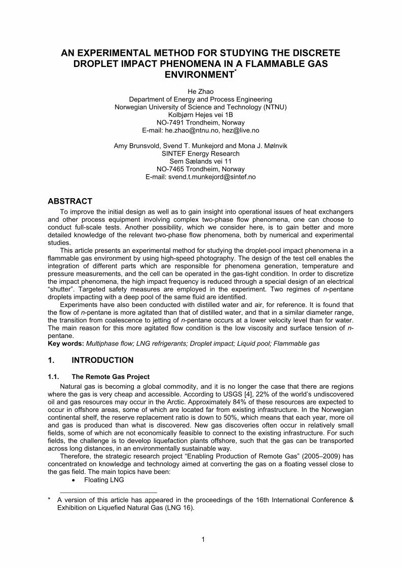
Figure 3. Droplets generated by applying the Plateau-Rayleigh instability.
As shown in this figure, if the single stream of droplets generated by the Plateau-Rayleigh
instability was not disturbed, the distance between two neighbouring droplets was generally 2–3 times the droplet diameter, and this short distance lead to a relatively high impinging frequency. With a distance of 0.85 mm and an impinging velocity of 2.6 m/s, the impinging frequency would be above 3000 Hz, which was much higher than 50–60 Hz under which the neighbouring droplets do not disturb each other during impacts [23,17]. Similar observations of high-frequency impacts without discretization can be found in Refs. [14,21].
The present investigation is aimed at improving the understanding of the droplet impact phenomena inside heat exchangers, and experiments have been carried out using a highly evaporative and flammable fluid, n-pentane, at its saturated state in order to model the physical properties of the mixed refrigerants in the industrial liquefied natural gas (LNG) process. Through a literature review, two challenges were identified in doing such an experiment:
Flammable gas environment: comprehensive safety measures must be employed to prevent explosions.
Discretization of droplets: the impinging frequency must be reduced to a low-enough level that the phenomena are not disturbed by the preceding and following impacts.
In the following, the experimental set-up enabling the use of a flammable test fluid is detailed. Next, experimental observations of jetting and coalescence of n-pentane are shown. Further details can be found in the thesis by Zhao [22].

5
2. EXPERIMENTAL METHODS
Figure 4. Schematic drawing of the experimental setup.
A schematic overview of the experimental setup is shown in Figure 4. It consists of three main parts:
Phenomena-generation: The phenomena were generated inside the gas-tight test cell. A nozzle for generating a stream of mono-dispersed droplets was mounted on the lid of the test cell. The droplet diameter and velocity was changed by adjusting the nitrogen pressure exerted in the liquid reservoir and the orifice diameter (see below and Figure 5), for which different sizes of mounted-pinholes (Thorlabs) were used. An optical cuvette (Hellma, QS101) on a cylindrical stage was placed in the middle of the test cell for generating a deep liquid pool with a free surface. The four surrounding walls of the test cell were mounted with optical glasses made of quartz for observation purposes. On the front side of the test cell, there were four ports, T1,T2, P and V. T1 and T2 were for temperature sensors (PT100). P and V were for pressure transducer (PXT1400) and ventilation, respectively. If a temperature adjustment was needed, a thermostat water bath (Julabo, 12) circulated heated water to the copper coil coupling around the bottom of the test cell. The test cell was placed on two-stacked translation stages (Thorlabs, LNR50M) and a heavy duty lab jack (Thorlabs, L490) for three-dimensional positioning.
Light source: The backlight was a white light LED collimated with optical lenses. Data acquisition: A high-speed camera (Phantom V9) mounted with a long-distance
microscope (Infinity, K2) and a close-focus lens (Infinity, CF3) was used to capture the fast-evolving phenomena. The data was transferred and stored in a computer for analysis. The image resolution was 576 by 288 pixels and the frame rate was 9216 frames per second (fps). The exposure time was from 5 to 10 μs. The temperature and pressure data was logged with a data logger (Hewlett Packard, 34970A) with a frequency of 10 s. The camera was placed on a custom-made aluminium board.
The functions and mechanisms of the main parts are described in the following.

6
2.1. Core parts in the experiment
The most important parts in the phenomena generation are the droplet-generation nozzle, the liquid pool and the test cell.
Droplet-generation nozzle. Figure 5 (a) shows the schematic drawing of the main assembly of the nozzle, and a picture is shown in Figure 5 (b).
(a) Schematic drawing.
(b) Picture.
Figure 5. Main assembly of the nozzle tube.
The nozzle tube was a 6 mm (o.d.) stainless steel tube. One end of the tube was made with external screw thread so that the nozzle cap can be screwed on, and this end contained an O-ring to press the laser pinhole tightly in the nozzle cap. The other end of the tube was connected to the liquid supply reservoir.
The pinholes used in the experiments were 20 μm (P20S), 50 μm (P50S), 100 μm (P100S) and 150 μm (P150S) the mounted-pinholes from Thorlabs. The thickness of the pinholes was 12.5 μm. A 200 μm (04 PIP 017) pinhole was the unmounted standard pinhole from Melles Griot, and the thickness was 13 μm. All the pinhole-plates were precisely cut with the holes centred to fit in the nozzle cap.
The nozzle cap had female screw thread for adapting the nozzle tube. A 1 mm cap hole was located in the centre of the nozzle cap, and this central hole was for preliminary focusing the laser pinholes. The laser pinholes can be positioned and well-centred inside the nozzle cap.

7
Figure 6. Discretization of a mono-dispersed droplet
stream. (Figure from Ref. [16] with modifications). The mechanism for discretizing a mono-dispersed droplet stream is illustrated in Figure 6. The
droplet stream is physically screened by a “shutter”, which is mounted on an electronic motor. The fast-rotating shutter blocks the droplets impinging on the shutter surface and ejects them from the camera focus. Therefore only a fraction of the droplets pass through the shutter and impinge with the pool surface.
Figure 7. Unmounted and mounted shutter.
The electronic shutter is shown in Figure 7. As shown in the figure, the assembled shutter consists
of two parts, an unmounted shutter and an electric motor (Faulhaber, 1935 BRE-009BRE). The shutter was a copper tube with a pair of slits on opposite sides. To enable the generation of a wide range of droplet velocities, several shutters with different slit-widths, and hence “opening times”, were made. The shaft tube was welded on one end of the unmounted shutter, and the shaft of the motor can be inserted in the shaft tube as shown in the figure. The motor was a brushless DC motor with a shaft of 3 mm in diameter. The speed range and nominal power were the two most important parameters for choosing the motor. The speed range should preferably be as wide as possible so that the shutter was able to filter a single stream of droplets with a wide range of impinging velocities. The nominal power was very important when it comes to the safety analysis because the motor was placed in the test cell where flammable fluids were used. The minimum power for generating sparks is 2.5 W, and thus the

8
power of the electronic device in the test cell must be limited below this level to avoid sparks. The motor had a relatively wide operating range of 1600–10000 revolutions per minute (RPM) depending on the voltage. The nominal power was 0.315 W which was safe with a reasonable margin of power.
Liquid pool. Figure 8 shows the cuvette for generating a deep liquid pool. In the experiments, a
cuvette (Hellma, QS101) with the inner dimension (Height: 42.5 mm, Width: 10 mm, length: 20 mm) was used. The deep liquid pool was generated by filling the cuvette fully, and hence the droplets impinged on the free surface of the fluid in the cuvette. Considering a droplet of 1 mm in diameter impinging in the centre of the cuvette, the pool depth was 42.5 times the diameter, and the distances to the surrounding walls were 5 and 10 times the diameter. In the present study, the maximum droplet size was around 0.7mm, and most of the droplet sizes were in the range from 0.1 to 0.6 mm. Therefore, influences from the bottom of the pool and the surrounding walls can be neglected. A needle (Hamilton, Gauge 33) with an outer diameter of 0.21 mm was used as the standard measurement (gauge) for converting the length-measurements from the image-processing unit, pixel, into the standard length unit, millimetre. The cuvette and the needle were put on the cuvette seat, a stainless steel cylinder. The seat was placed in the centre of the test cell, and the bottom of the seat was hollowed to enable the fluids to flow into a drainage which was located below the seat.
Figure 8. Picture of the cuvette for generating a deep
liquid pool.
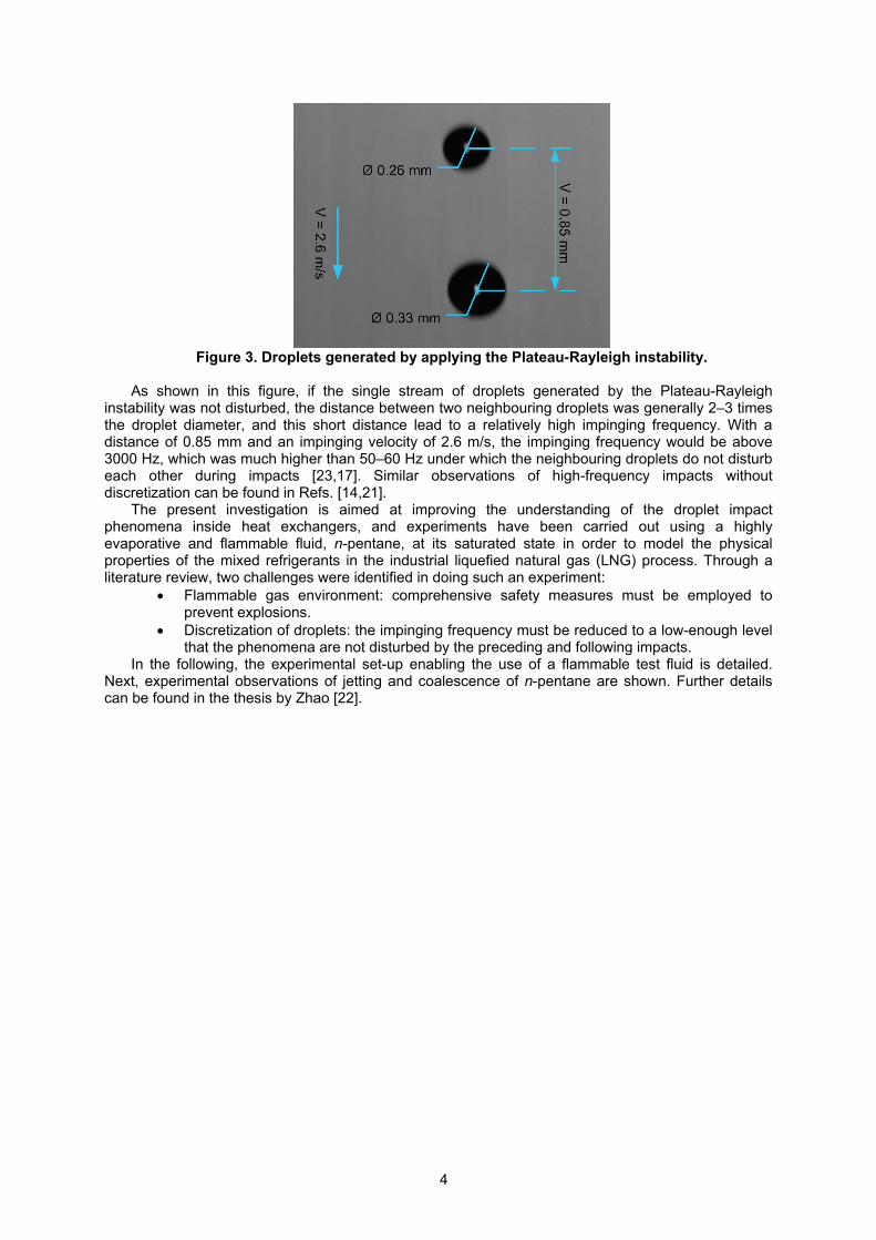
Test cell. Figure 9 (a) and (b) show the schematic drawing and the assembly of the test cell. The
cell consists of three parts: cell lid, cell body and cell bottom. Cell lid: the droplet-generation nozzle was fastened into the nozzle tube holder. The port
of the nitrogen/vent valve was used for nitrogen purging before saturating the test cell with the n-pentane vapour, and for evacuating the cell with a vacuum pump (Leybold S 1.5). The cabling port was used for leading the motor cable to a DC power supply (Agilent, U8001A) with current/voltage lock function.
Cell body: Customized laser windows (Thorlabs) made of BK7 material, which was a type of borosilicate crown glass with low refractive index and low dispersion, were mounted on the cell body by metal flanges. The front windows were 120 mm in diameter and 12.2 mm thick and the side windows were 50.8 mm in diameter with a thickness of 9.5 mm. A rubber gasket made of neoprene with a good chemical resistance to the experimental fluids was used to seal the windows. Four ports can be found on the front of the cell body. Two ports on the left side were used for temperature sensors (PT100). The upper port on the right side was used for pressure transducer (PXT1400). For limiting the power, which could possibly be conducted into the test cell by the temperature and pressure sensors from the computer, power barriers were required. A temperature signal converter (GM
9
International Safety, D1072D) and a pressure signal converter (GM International Safety, D1014D) were used as power barriers for the temperature sensor and the pressure sensor, respectively. The port on the bottom of the right side was used for a gas outlet on which two valves, a manual valve and a safety valve, were mounted. The manual valve was for fast release of the gas in the test cell, and it was useful, for instance, when flushing nitrogen into the test cell. The safety valve was calibrated to be opened when the pressure was over 1.3 bar (abs) which was below the design pressure for the test cell (1.5 bar, abs).
Cell bottom: A drain was used for either circulating or to drain the experimental fluids collected in the test cell.
(a) Schematic drawing (b) Assembly
Figure 9. Schematic drawing and assembly of the test cell.
Safety measures summary. Explosion and fire were the main dangers when carrying out such
an experiment, and in addition, gas toxicity and test-cell overpressure-failure can also lead to serious hazards. One of the potential sources for the explosion, fire, and gas toxicity was the leakage of the test cell, and efficient and inert seals must be used to keep the cell gas-tight. Neoprene gaskets were used for sealing windows, cell lid and bottom, and Teflon plugs were used for sealing the ports for the intrusive instruments such as the motor-cable and the temperature sensors. Both sealing materials were chemically compatible with n-pentane, which is a strong solvent. The vacuum level that could be reached was below 1 mbar (abs). To discover the unlikely event of a gas leak, three hydrocarbon gas-detectors were distributed around the laboratory (two on the wall and one in the ventilation pipe) for alarming and emergency-shutdown, and fixed and flexible ventilations were kept on all the time to remove any gas.
Another possible source for explosion and fire were sparks, which might be generated inside the test cell. As mentioned above, all the intrusive instrument and equipment were evaluated, and the main measure was the power-limitation which was set below the minimum sparking-power, 2.5 W. Besides, the motor was brushless to avoid any friction-sparks in the dangerous zone. Table 1 lists the sources, the dangers and the corresponding safety measures employed in the experiment.
The test cell design pressure was 1.5 bar. In the accidental case of temperature-control failure, the saturation pressure could exceed this value. The design pressure could also be exceeded if the gas bottle were wrongly connected, directly to the test cell. Therefore, a calibrated safety valve with a relief pressure of 1.3 bar was employed.
Table 1. Safety measures in the equipment selection.
Sources Danger Safety measures Leakage Explosion Toxicity seal, HC gas-detectors, vent Safety valve on cell Overpressure Safety valve 1.3 bar Windows on cell Overpressure Thick glass Motor Explosion Brushless, low-power Motor power supply Explosion Power barrier T P sensor Explosion Power barrier Heater Explosion Safe zone

10
2.2. Experimental fluids
N-pentane and its saturated vapour have similar physical properties as the mixed refrigerants in the industrial LNG processes, and thus the focused fluid is n-pentane in its saturation vapour environment. In addition, an experimental run of distilled water was carried out to give an indication of the effect of fluid properties.
In order to show the similarity between n-pentane and the mixed refrigerants, physical properties from both liquid and vapour phases were compared. Two sets of mixed refrigerants, MR1 and MR2, were defined as the basis for comparison. MR1 and MR2 consist of typical mole concentrations of refrigerants which have been commonly used in LNG processes. Table 2 shows information on the specified mixed refrigerants.
Table 2. Specified general mixed refrigerants and corresponding conditions (pressure
assumed 4.5 bar). Refrigerant (mole%) MR1 MR2
Nitrogen (N2) 0 10 Methane (CH4) 5 55 Ethane (C2H6) 90 35
Propane (C3H8) 5 0 Sum 100 100
Figure 10 (a) to (e) compare n-pentane (black curve) and two sets of mixed refrigerants (green
and blue curves) regarding liquid viscosity, surface tension, liquid density, vapour viscosity and vapour density, respectively. In the figure, the temperature ranges differ for water, n-pentane and the refrigerants MR1 and MR2. This is because the experiments with water and n-pentane are carried out at room temperature, while MR1 and MR2 are employed for cryogenic processes.
20 25 30 35 40 450.0
0.1
0.2
0.3
0.4
0.5
0.6
0.7
0.8
0.9
1.0
1.1
-84 -82 -80 -78 -76 -74 -72 -70 -68 -66 -64
0.0
0.1
0.2
0.3
0.4
0.5
0.6
0.7
0.8
0.9
1.0
1.1
-170 -160 -150 -140 -130 -120 -110 -100 -90 -80 -70
0.0
0.1
0.2
0.3
0.4
0.5
0.6
0.7
0.8
0.9
1.0
1.1
20 25 30 35 40 45
0.0
0.1
0.2
0.3
0.4
0.5
0.6
0.7
0.8
0.9
1.0
1.1
n-pentane
Temperature (C)
Liquid viscosity
MR1
MR2
Liqu
id v
isco
sity
(m
Pa.
s)
Water
20 25 30 35 40 450
10
20
30
40
50
60
70
80
-84 -82 -80 -78 -76 -74 -72 -70 -68 -66 -64
0
10
20
30
40
50
60
70
80
-170 -160 -150 -140 -130 -120 -110 -100 -90 -80 -70
0
10
20
30
40
50
60
70
80
20 25 30 35 40 45
0
10
20
30
40
50
60
70
80
Sur
face
tens
ion
(m
N/m
)
Temperature (C)
n-pentane
Surface tension MR1
MR2 Water
(a) Liquid viscosity (b) Surface tension

11
20 25 30 35 40 45
-84 -82 -80 -78 -76 -74 -72 -70 -68 -66 -64
20 25 30 35 40 45
-170 -160 -150 -140 -130 -120 -110 -100 -90 -80 -70
0
100
200
300
400
500
600
700
800
900
1000
1100 n-pentaneLiquid density
MR1
Temperature (C)
Water
Liq
uid
den
sity
(K
g/m
3 )
MR2
20 25 30 35 40 450
2
4
6
8
10
12
14
16
18
20
22
-84 -82 -80 -78 -76 -74 -72 -70 -68 -66 -64
0
2
4
6
8
10
12
14
16
18
20
22
-170 -160 -150 -140 -130 -120 -110 -100 -90 -80 -70
0
2
4
6
8
10
12
14
16
18
20
22
20 25 30 35 40 45
0
2
4
6
8
10
12
14
16
18
20
22
Vap
or
visc
osity
(P
a.s)
n-pentane MR1
Temperature (C)
MR2Vapor viscosity Water
(c) Liquid density (d) Vapour viscosity
20 25 30 35 40 450
1
2
3
4
5
6
7
8
9
10
11
12
13
14
15
-84 -82 -80 -78 -76 -74 -72 -70 -68 -66 -64
0
1
2
3
4
5
6
7
8
9
10
11
12
13
14
15
-170 -160 -150 -140 -130 -120 -110 -100 -90 -80 -70
0
1
2
3
4
5
6
7
8
9
10
11
12
13
14
15
20 25 30 35 40 45
0
1
2
3
4
5
6
7
8
9
10
11
12
13
14
15
Vap
or
dens
ity (
kg/m
3 )
Temperature (C)
n-pentane
Vapor density
MR1
MR2 Water
(e) Vapour density
Figure 10. Comparisons of physical properties between n-pentane and mixed refrigerants. The physical properties of water (red curve) were also plotted in the figures as a reference. The
figures show that, compared to distilled water, n-pentane and its vapour have very comparable physical properties to the mixed refrigerants. The physical properties of the experimental fluids are shown in Table 3.
Table 3. Physical properties of the experimental fluids. 40°C for n-pentane/saturation-
vapour system and 25°C for water/air system. Fluids Density (kg/m3) Viscosity (mPa·s) Surface tension (mN/m)
Distilled watera 996.93 0.890 71.99 n-pentaneb 605.69 0.1969 13.66
a from [13]. b from [7].
Figure 10 shows that the difference in vapour density between n-pentane and the mixed refrigerants was larger than that of the other physical properties. The dominant effects in the transitional region between coalescence and jetting/splashing were considered to be inertia and surface tension [5,14], and thus the gas properties accounted little for the threshold characterization. However, in the transitional region between flow regimes with relatively low impinging velocity, for instance droplet bouncing-coalescence, the effects from gas viscosity and mean free path might become influential [3].
2.3. Experimental uncertainties
The uncertainties that propagate into the diameter and velocity measurements are:

12
Frame rate of the camera: the rate of 9216.59 fps was obtained from averaging over a time interval more than one second and due to the physical limitation the decimal frame does not exist.
Calibration: a calibration using a standard gauge was used to scale the measurements from pixel to standard units. There were two sources related with the calibration, manufactured uncertainty and the measuring uncertainty.
Tilted angle of camera: the uncertainty of the angle would lead to the uncertainty of the displacement, i.e. velocity measurement, of droplets.
Image segmentation: cameras resolve objects by using small grids, namely pixels, and cameras round-off the edge pixels of an object, to either whole pixels or non-pixels, as they are partially shaded. For displacement measurement, the uncertainty was 1 pixel, and for diameter measurement, the uncertainty was estimated by using the simulation method [8].
Threshold judgment for conversion into binary pictures: Raw pictures contain multiple grey levels, and for utilizing the image-processing software, the pictures must be converted into binary pictures (black and white). A grey-level threshold, the grey-levels above which would be counted, must be appointed. The uncertainty of threshold was obtained through the examination of multiple samples.
Oscillation of droplets: the diameter measurement depends on the shape of droplets, and through the examination of multiple samples, the maximum deformation was judged.
The following uncertainty model was employed:
2
122
xx PBU ,
(1)
where Bx and Px were the systematic standard uncertainty and the random uncertainty within 95% confidence level. Besides, for the uncertainties which propagate into the dimensionless numbers, uncertainties in the physical properties of fluids were considered. The maximum uncertainties of both diameter and velocity were found to be less than 3%.
3. EXPERIMENTAL OBSERVATIONS Two main regimes, jetting and coalescence, were observed in the experiments with n-pentane.
Jetting is shown in the sequential images in Figure 11.

13
Figure 11. Sequential images of jetting: Observation of crown-like wave (broken), central
jet. n-pentane droplet: diameter D = 0.22 mm, vertical velocity Vy = 5.2 m/s, velocity V = 5.2 m/s. As shown in this figure, at t = 0.3255 ms a crown-like wave was formed and the rim of the crown
was broken (can be seen both at t = 0.3255 ms and t = 0.4340 ms) into small splashed droplets, which were ejected in the radial direction of the rim. As the crown retracted, a central jet developed and

14
became visible in the frame at t = 2.4957 ms. This central jet continually rose higher and finally sank back into the pool due to gravity. Figure 11 shows the sequential images until t = 4.0148 ms, after which nothing more happens. This impact lasted more than 5 ms without being affected by its neighbouring impacts, and that corresponds to an impact frequency lower than 200 Hz. This is much lower than the “undisturbed” impinging frequency of 5000–6000 Hz which would have occurred if the rotating shutter (Figure 7) had not been employed. Therefore, the rotating shutter is vital for this experiment. In Ref. [23], it was indicated that an impinging frequency below 50–60 Hz was necessary to obtain isolated impacts. Some of the cases considered in the present study had a slightly higher frequency, but still the impacts were found to be sufficiently isolated, as the maximum evolutionary time for a single event in this investigation was approximately 0.01 s, which equalled to a lowest impinging frequency of 100 Hz.
Another regime, coalescence, occurs with lower impact inertial energy, and it is illustrated in Figure 12.
Figure 12. Sequential images of coalescence: Observation of an expansion wave. n-
pentane droplet: diameter D = 0.29 mm, vertical velocity Vy = 2.2 m/s, velocity V = 2.2 m/s. Coalescence is the merging of droplets into the pool. As shown in Figure 12, the impingement of
the coalesced droplet created a less agitated flow compared to the case of jetting. It is noticeable that, compared to Figure 11, Figure 12 contains much less image background noise (small and blurred dots). This was due to the fact that jetting occurred with a higher flow rate (or droplet-generation rate) compared to coalescence, and thus more screened droplets, which were non-focused, appeared in the background. Most of those screened droplets were quite small (diameter below 10 μm) and fell out of the pool, and therefore they had quite little influence on the impact.
4. EXPERIMENTAL RESULTS AND DISCUSSION The impact conditions such as the liquid film thickness, surface condition and impact angles can
affect the impact outcome. For reducing the degree of freedom, a deep liquid pool much thicker than 10 times the droplet diameter and droplet discretization was used to eliminate the effects from the film thickness and surface condition. Vertical impacts were the focus in the experiments. Figure 13 shows the impact angles, and as can be seen from the figure, most of the impact angles (above 90%) are above 85°. Thus, the impact angle can be considered nearly vertical, and the effect from the variation of impact angle can be neglected.

15
Figure 13. Impact angles in the experimental runs of distilled water and n-pentane.
The diameter and velocity of the impinging droplets for the experimental run of distilled water and
n-pentane are shown in Figure 14(a) and (b), respectively.
0 0.1 0.2 0.3 0.4 0.5 0.6 0.70
2
4
6
8
10
12
Diameter (mm)
Impin
gin
g v
elo
city
(m
/s)
CoalescenceJetting
0 0.1 0.2 0.3 0.4 0.5 0.6 0.70
2
4
6
8
10
12
Diameter (mm)
Impin
gin
g v
elo
city
(m
/s)
CoalescenceJetting
(a) Distilled water (b) n-pentane Figure 14. Velocity and diameter of coalescence and jetting for the experimental fluids.
By comparing Figure 14 (a) and (b), several concluding remarks can be drawn: Velocity range: Even though the same experimental setup and procedures were used, the two
experimental runs show different ranges of impinging velocity. The velocity range of distilled water experiment is up to 12 m/s, while the velocity range of n-pentane experiment only reaches about 6 m/s. The reason is that n-pentane has much lower viscosity and surface tension (see Table 3) and this tended to give more unstable flow conditions as the droplet was generated and impinged. These unstable conditions were characterized by higher frequency of droplet generation, more severe droplet oscillation, more thrown-off droplets (background noise) and a more wavy and agitated liquid pool surface than in the experimental run of distilled water. Due to the uncertainties in these unstable flow conditions, generating droplets with higher velocity in the experimental run of n-pentane was hindered.
Threshold between flow regimes: By comparing the coalescence-jetting boundaries, it can be found that in the experimental run of n-pentane, jetting occurred below V = 4 m/s, while jetting occurred at velocities higher than 4 m/s in the experimental run of distilled water. Within a relatively comparable diameter range, lower translational velocities of n-pentane droplets can lead to jetting, and indicates that less inertia is needed for n-pentane to reach more agitated flow conditions such as jetting. This can be attributed to the difference in the physical properties of the fluids, and we suggest that the dominant factor for the low transitional velocity of n-pentane is the low viscosity and surface tension. We can conclude that fluids with low viscosity dissipate less kinetic energy, and the fluids with low surface tension require less kinetic energy to break the surface. Jetting is, in most cases, associated with mass loss from the bulk liquid to the vapour phase and may lead to a loss in heat transfer potential in an LNG process.
16
5. CONCLUSIONS One path towards improving the design and operation of heat exchangers and other process
equipment involving complex two-phase flows is to develop detailed mathematical and numerical models describing the relevant two-phase flow phenomena, while at the same time conducting equally detailed laboratory experiment. The present work constitutes one step on that path.
The phenomena of micro-scale liquid droplets impinging vertically on a liquid pool have been described. Through a number of careful and sophisticated safety measures, the experimental setup and methodology enable investigations of droplet-pool interactions in a flammable gas environment. The test liquid, n-pentane and its saturated vapour, has similar physical properties as the mixed refrigerants used in industrial LNG processes and can be used to simulate two-phase flow processes that occur in LNG heat exchangers.
This work describes a novel technique to discretize droplet impacts with the implementation of an electronic “shutter”. The shutter can reduce the droplet impact frequency from more than 5000 Hz to lower than 200 Hz, which can ensure that single impact events are not affected by the neighbouring droplets. In addition to n-pentane, an experimental run of distilled water was carried out to give an indication of the effect of fluid properties. The impingements were maintained nearly vertical with droplet velocity ranges of 0-12 m/s for distilled water and 0-8 m/s for n-pentane. Two different regimes of sub-millimetric n-pentane droplets impinging on a deep liquid pool of the same fluid were successfully identified: coalescence and jetting. The transitional velocity from coalescence to jetting is above 4 m/s for distilled water and below 4 m/s for n-pentane. A more narrow velocity range and a lower transitional velocity for n-pentane indicate that the impact flows are more agitated for n-pentane, and the dominant factor is the low viscosity and surface tension.
6. ACKNOWLEDGEMENTS This publication forms a part of the Remote Gas project, performed under the strategic Norwegian
research programme Petromaks. The authors acknowledge the partners; Statoil, UOP, Bayerngas Norge, Aker Solutions, DNV, and the Research Council of Norway (168223/S30) for support. Part of the reporting was supported by the Enabling Low-Emission LNG Systems project, and the authors acknowledge the contributions of GDF SUEZ, Statoil and the Petromaks programme of the Research Council of Norway (193062/S60).
He Zhao wishes to express his gratitude to his PhD supervisor, Jostein Pettersen (Adjunct Professor at NTNU and project leader at Statoil).
Thanks are due to Senior Engineer Håvard Rekstad at NTNU for making the test-cell drawings.
7. REFERENCES 1. T. Austrheim, Experimental characterization of high-pressure natural gas scrubbers, PhD
thesis, University of Bergen (2006). 2. S. D. Aziz and S. Chandra, Impact, recoil and splashing of molten metal droplets, International
Journal of Heat and Mass Transfer 43, 2841 (2000). 3. G. A. Bach, D. L. Koch and V. Gopinath, Coalescence and bouncing of small aerosol droplets,
Journal of Fluid Mechanics 4. K. J. Bird, et al. Circum-Arctic resource appraisal: Estimates of undiscovered oil and gas north
of the Arctic Circle. U.S. Geological Survey Fact Sheet 2008-3049 (2008). 5. G. E. Cossali, A. Coghe, and M. Marengo, The impact of a single drop on a wetted solid
surface, Experiments in fluids 22, 463 (1997). 6. C. A. Dorao, M. Fernandino, L. E. Patruno, P.M. Dupuy, H. A. Jakobsen, and H. F. Svendsen,
Macroscopic description of droplet-film interaction for gas-liquid systems, Applied Mathematical Modelling 33, 3309 (2009).
7. A. P. Fröba, L. Pellegrino, and A. Leipertz, Viscosity and surface tension of saturated n-pentane, International Journal of Thermodynamics 25 (5), 1323 (2004).
8. L. García-Tabarés, P. Abramian, J. Calero, F. Toral, A. Ijspeert, and J. C. Peréz, Dimensional metrology of cylinders based on digital image processing: Application to LHC corrector magnets, Proceedings of EPAC pp. 2394–2396 (2002).
9. Q. Y. Huang and H. Zhang, A study of different fluid droplets impacting on a liquid film, Petroleum Science 5, 62 (2008).
10. S. H. James and W. G. Eckert, Interpretation of blood-stain evidence at crime scenes (CRC Press, 1998).

17
11. C. G. Johnsen, Experimental and numerical investigation of droplet phenomena, PhD thesis, Norwegian University of Science and Technology (NTNU), 2007:248 (2007). ISBN 978-82-471-5529-5.
12. M. J. Lander, Nanotube arrays make droplets jump or jiggle, Applied Physics Letters 91 (2007).
13. D. R. Lide, CRC Handbook of Chemistry and Physics (CRC Press/Taylor and Francis, Boca Raton, FL, 2009), 89th ed.
14. C. Mundo, M. Sommerfeld, and C. Tropea, Droplet-wall collisions: Experimental studies of the deformation and breakup process, International Journal of Multiphase Flow 21, 151 (1995).
15. M. Pasandideh-Fard, S. D. Aziz, S. Chandra, and J. Mostaghimi, Cooling effectiveness of a water drop impinging on a hot surface, International Journal of Heat and Fluid Flow 22, 201 (2001).
16. A. Sevault, Experimental investigation of droplets impacting onto a liquid surface, Master’s thesis, ENSMA/SINTEF Energy Research (2008).
17. J. Shin and T. A. McMahon, The turning of a splash, Physics of Fluids 2, 1312 (1990). 18. C. R. Tuck, M. C. B. Ellis, and P. C. H. Miller, Techniques for measurement of droplet size and
velocity distributions in agricultural sprays, Crop Protection 16, 619 (1997). 19. A. B. Wang and C. C. Chen, Splashing impact of a single drop onto very thin liquid films,
Physics of Fluids 12, 2155 (2000). 20. M. Worthington, On the forms assumed by drops of liquids falling vertically on a horizontal
plate, Proceedings of the Royal Society of London 25 (1876). 21. A. L. Yarin and D. A. Weiss, Impact of drops on solid surfaces: Self-similar capillary waves,
and splashing as a new type of kinematic discontinuity, Journal of Fluid Mechanics 283, 141 (1995).
22. H. Zhao, An experimental investigation of liquid droplets impinging vertically on a deep liquid pool, PhD thesis, Norwegian University of Science and Technology (NTNU), 2009:230, (2009). ISBN 978-82-471-1864-1.
23. S. L. Zhbankova and A. V. Kolpakov, Collision of water drops with a plane water surface, Fluid dynamics 25 (3), 470 (1990).