Contingency- Constrained PMU Placement in Power Networks Farrokh Aminifar, Amin Khodaei, Mahmud Fotuhi- Firuzabad, and Mohammad Shahidehpour

Welcome message from author
This document is posted to help you gain knowledge. Please leave a comment to let me know what you think about it! Share it to your friends and learn new things together.
Transcript

Contingency-Constrained PMUPlacement in Power Networks
Farrokh Aminifar, Amin Khodaei, Mahmud Fotuhi-Firuzabad, and Mohammad Shahidehpour

Outline
• Introduction• Problem Formulation• Integer Linear Programming• Experimental Results• Conclusion

Definition • PMU is a device for synchronizing ac voltage and current measurements
with a common time reference.
http://criepi.denken.or.jp/en/system/common/img/unit/unit1_ind_pic2.gif http://www.phasor-rtdms.com/phaserconcepts/images/pmu.jpg

Problem Formulation• The objective of PMU placement problem is to find the minimum # of
PMUs as well as their placement to make the power network topologically observable.
bus 1bus 2
bus 3bus 4
bus 5 bus 8bus 7
bus 9bus 11bus 6
bus 14bus 13bus 12
bus 10

ILP Notation

Traditional ILP Formulation
bus 1bus 2
bus 3bus 4
bus 5bus 8bus 7
bus 9bus 11bus 6
bus 14
bus 13bus 12
bus 10
a12 =1

New Constraints in This Work
• Effect of Zero-Injection Buses• Loss of Measurement Contingency• Line Outage Contingency• Measurement Limitations

Parameter “z” is a binary parameter that is equal to 1 if bus is a zero-injection bus and 0 otherwise
Zero-Injection Buses

Zero-Injection Buses (Cont.)
bus 1bus 2
bus 3bus 4
bus 5bus 8bus 7
bus 9bus 11bus 6
bus 14
bus 13bus 12
bus 10
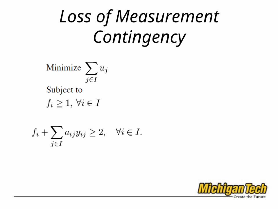
Loss of Measurement Contingency

Loss of Measurement Contingency (Cont.)

Line Outage Contingency

Line Outage Contingency (Cont.)

Measurement Limitations

Experimental Setup
• The standard IEEE 14, IEEE 30, IEEE 39, IEEE 57 and IEEE 118 are investigated.
• CPLEX solver is used to solve the ILP.

Experimental ResultsTest System Base case
systemNo PMU at Zero-Injection
Line Outage Loss of Measurement
Line Outage or Loss of Measurement
IEEE 14-Bus 3 3 7 7 8
IEEE 30-Bus 7 7 13 15 17
IEEE 39-Bus 8 8 15 18 22
IEEE 57-Bus 11 11 19 26 26
IEEE 118-Bus 28 28 53 63 65

Comparing to other works (Cont.)

Conclusions• A fast and practical model based on integer linear programming is
proposed for solving the optimal PMU placement problem. • Different contingency conditions associated with power systems, i.e., line
outages and loss of measurements were considered. • Communication constraints of power networks were considered as
measurement limitations and included in the model.

Thanks
• Questions?
Related Documents


