ZARCO – AN AUTONOMOUS CRAFT FOR UNDERWATER SURVEYS Nuno Cruz, An´ ıbal Matos, S´ ergio Cunha, S´ ergio Silva Faculdade de Engenharia da Universidade do Porto Rua Dr. Roberto Frias 4200-465 Porto Portugal {nacruz,anibal,sergio,srui}@fe.up.pt Keywords: Autonomous Surface Craft, High Resolution Sensing. Abstract The autonomous surface craft (ASC) Zarco is a small size craft developed at Porto University and designed to perform autonomous missions mainly in river dams and estuarine environments, either serving as a moving navigation beacon for underwater vehicles or collecting high resolution interferometric synthetic aperture sonar (In-SAS) data. This paper describes the main systems of Zarco and presents preliminary results concerning the performance of the on-board control system, obtained in test missions. Another paper presented in this conference addresses the In-SAS system. 1 Introduction This paper describes the Autonomous Surface Craft Zarco (figs. 1,7). Zarco is a small size (1.5 m long) catamaran type vessel. In its basic configuration, the vehicle weights a total of 50 kg, and has an additional payload capacity of another 50 kg. The vehicle is electrically powered and can operate at speeds up to 3 knots. It carries an on-board computer responsible for the execution of autonomous or remotely controlled missions, for the real time computation and for the storage of collected payload data. A WiFi link connects Zarco to a shore station, allowing for the remote control of the boat and the supervision of its autonomous operation. The paper starts with a description of the internal structure of Zarco, at the mechanical, electrical and computational levels. Then, a description of the procedure for programming and executing autonomous missions is addressed. Finally, results concerning the performance of Zarco control system are presented. 2 Zarco Subsystems 2.1 Mechanical structure Zarco hardware architecture follows a highly modular approach. The mechanical structure is based on COTS anodized aluminum elements, forming a rigid frame that attaches to the lateral pontoons by a set of snap buttons, resulting in a catamaran arrangement. The pontoons are made of molded polyethylene and each one has a net buoyancy of 50 kg. Propulsion is provided by two electrical thrusters located at the rear of the mechanical structure. These thrusters are based on standard trolling motors, typically available for small boats, and provide a maximum thrust exceeding 250 N. In Zarco, special watertight junction boxes were designed so that the motors can receive power and commands from the computational module, instead of the traditional manual controllers. For transportation, the pontoons are detached from the rigid frame and a special mounting adapter allows the shafts of the motors to change into a horizontal position, aligned with the rest of the frame. All the

Welcome message from author
This document is posted to help you gain knowledge. Please leave a comment to let me know what you think about it! Share it to your friends and learn new things together.
Transcript
ZARCO – AN AUTONOMOUS CRAFT FOR UNDERWATER SURVEYS
Nuno Cruz, Anıbal Matos, Sergio Cunha, Sergio Silva
Faculdade de Engenharia da Universidade do Porto
Rua Dr. Roberto Frias
4200-465 Porto
Portugal
{nacruz,anibal,sergio,srui}@fe.up.pt
Keywords: Autonomous Surface Craft, High Resolution Sensing.
Abstract
The autonomous surface craft (ASC) Zarco is a small size craft developed at Porto University and designedto perform autonomous missions mainly in river dams and estuarine environments, either serving as amoving navigation beacon for underwater vehicles or collecting high resolution interferometric syntheticaperture sonar (In-SAS) data. This paper describes the main systems of Zarco and presents preliminaryresults concerning the performance of the on-board control system, obtained in test missions. Anotherpaper presented in this conference addresses the In-SAS system.
1 Introduction
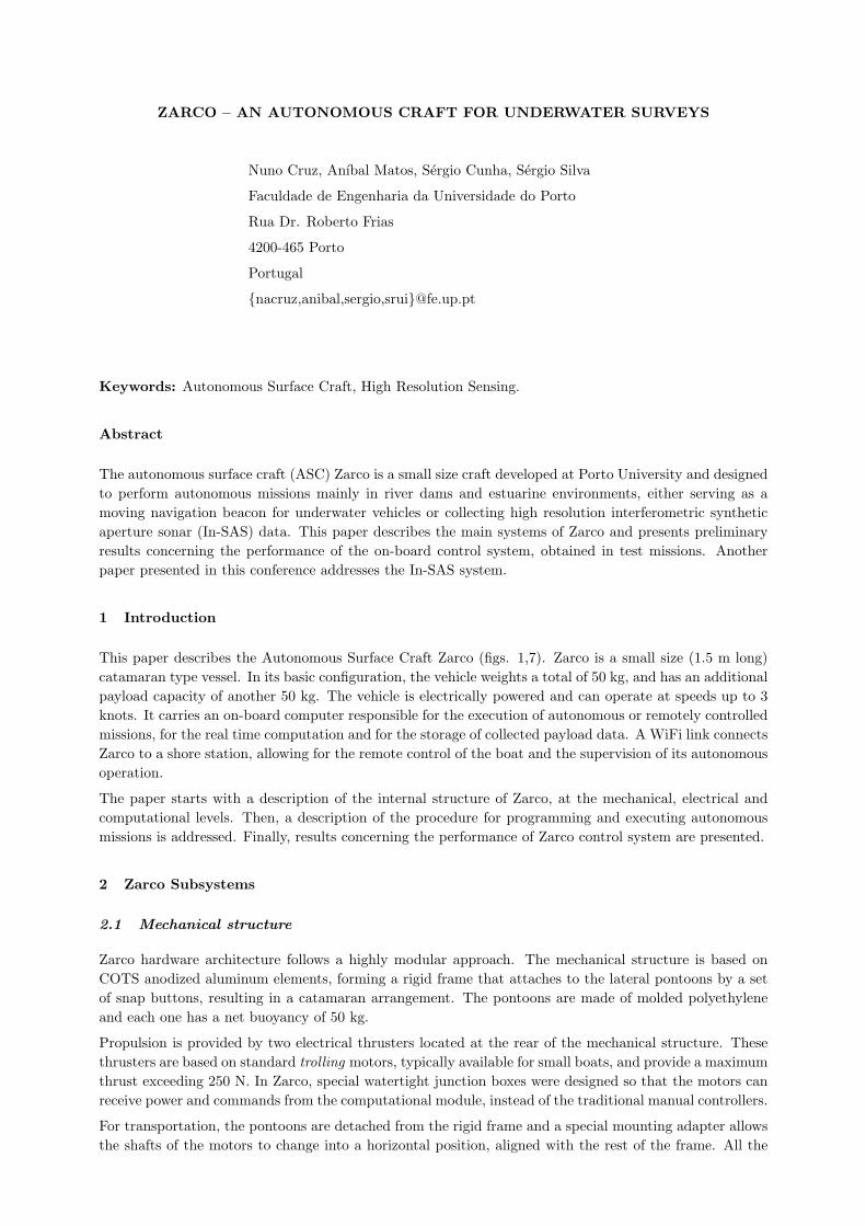
This paper describes the Autonomous Surface Craft Zarco (figs. 1,7). Zarco is a small size (1.5 m long)catamaran type vessel. In its basic configuration, the vehicle weights a total of 50 kg, and has an additionalpayload capacity of another 50 kg. The vehicle is electrically powered and can operate at speeds up to 3knots. It carries an on-board computer responsible for the execution of autonomous or remotely controlledmissions, for the real time computation and for the storage of collected payload data. A WiFi link connectsZarco to a shore station, allowing for the remote control of the boat and the supervision of its autonomousoperation.
The paper starts with a description of the internal structure of Zarco, at the mechanical, electrical andcomputational levels. Then, a description of the procedure for programming and executing autonomousmissions is addressed. Finally, results concerning the performance of Zarco control system are presented.
2 Zarco Subsystems
2.1 Mechanical structure
Zarco hardware architecture follows a highly modular approach. The mechanical structure is based onCOTS anodized aluminum elements, forming a rigid frame that attaches to the lateral pontoons by a setof snap buttons, resulting in a catamaran arrangement. The pontoons are made of molded polyethyleneand each one has a net buoyancy of 50 kg.
Propulsion is provided by two electrical thrusters located at the rear of the mechanical structure. Thesethrusters are based on standard trolling motors, typically available for small boats, and provide a maximumthrust exceeding 250 N. In Zarco, special watertight junction boxes were designed so that the motors canreceive power and commands from the computational module, instead of the traditional manual controllers.
For transportation, the pontoons are detached from the rigid frame and a special mounting adapter allowsthe shafts of the motors to change into a horizontal position, aligned with the rest of the frame. All the
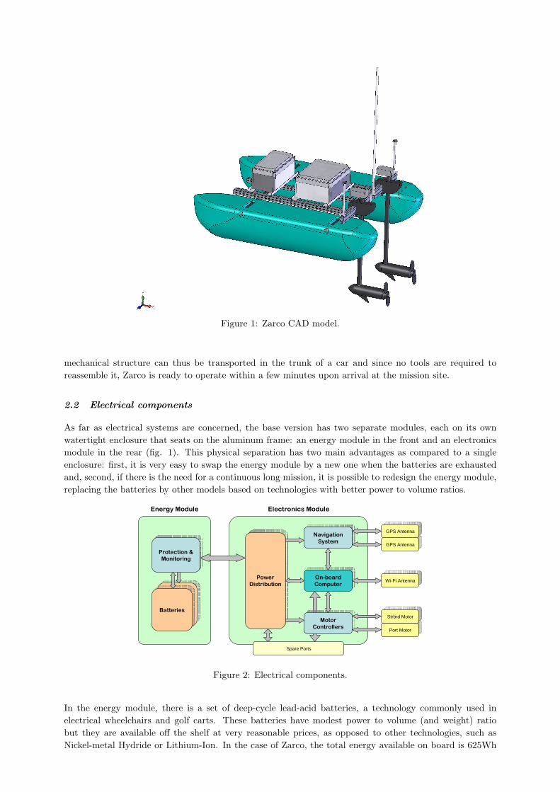
Figure 1: Zarco CAD model.
mechanical structure can thus be transported in the trunk of a car and since no tools are required toreassemble it, Zarco is ready to operate within a few minutes upon arrival at the mission site.
2.2 Electrical components
As far as electrical systems are concerned, the base version has two separate modules, each on its ownwatertight enclosure that seats on the aluminum frame: an energy module in the front and an electronicsmodule in the rear (fig. 1). This physical separation has two main advantages as compared to a singleenclosure: first, it is very easy to swap the energy module by a new one when the batteries are exhaustedand, second, if there is the need for a continuous long mission, it is possible to redesign the energy module,replacing the batteries by other models based on technologies with better power to volume ratios.
����������
��� ����������
���
�����
�����������������
������������
��������
�� �������������
�� �����
�����
����������������
�����������
Wi-Fi AntennaWi-Fi Antenna
Port MotorPort Motor
Strbrd MotorStrbrd Motor
GPS AntennaGPS Antenna
GPS AntennaGPS Antenna
������������������������������
������������������
������������
����������������������
����������
Spare Ports
Figure 2: Electrical components.
In the energy module, there is a set of deep-cycle lead-acid batteries, a technology commonly used inelectrical wheelchairs and golf carts. These batteries have modest power to volume (and weight) ratiobut they are available off the shelf at very reasonable prices, as opposed to other technologies, such asNickel-metal Hydride or Lithium-Ion. In the case of Zarco, the total energy available on board is 625Wh
(at 12V). The ASC autonomy is greatly dependant on the payload installed on board and the velocityprofile required for the mission, but it is usually in the order of 6 to 10 hours of operation. In the casethat longer missions are required, a spare energy module can easily be swapped in the field. Since the timerequired to fully recharge the batteries is 6-8 hours, it is virtually possible to have indefinite missions withtwo sets of energy modules. The batteries may be recharged without opening the enclosure, since any gasaccumulation will be released to the environment via a vent plug. The energy module also holds electronicprotection circuits, with voltage and current monitoring, and the main switch that commands the powerto the on-board electronics.
The electronics module contains the main computer, the navigation sensors and the motor power con-trollers. The enclosure has several spare connectors to provide energy and communications with payloadsensors and allow for future upgrades.
The main computer is based on the PC-104 technology. In the basic configuration, the stack includesa power supply board, the CPU board and a communication board to interface with the other devices(navigation sensors and motor controllers). Additional boards can be installed to interface with specificpayload systems. A solid state disk stores the on-board software and is also used to log data collectedduring vehicle missions, and a long range WiFi link provides communications to shore.
Currently, the navigation system is composed by 2 L1 GPS boards (µBlox RCB-LJ) and a digital compassmodule with tilt sensors (PNI TCM2.0). Although sufficient for the first vehicle tests and some demo op-erations, this sensor package does not provide the accuracy required by some of the envisaged applications.For that, an Inertial Measuring Unit will be integrated in the near future, and the GPS boards will bereplaced by L1+L2 RTK receivers.
2.3 Payload
As far as payload capability is concerned, there is physical space for an extra enclosure in the aluminumframe, with maximum base dimensions of 500 × 300 mm. Naturally, this can be increased by replacingsome of the aluminum elements of the frame by longer ones.
3 Shore station
In an operational scenario, a shore station based in a laptop computer is used to remotely control Zarcoand to monitor its behavior while performing autonomous missions. The shore station is connected tothe vehicle through a Wi-Fi link, guaranteeing a wide band connection. The vehicle is equipped with anomni-directional antenna while the shore station can be connected to an omni-directional or a sectorialantenna, depending on operation area and location of the shore station. In any case, high gain (12 to 24dBi) antennas are always used, which allows communication ranges exceeding 2 km.
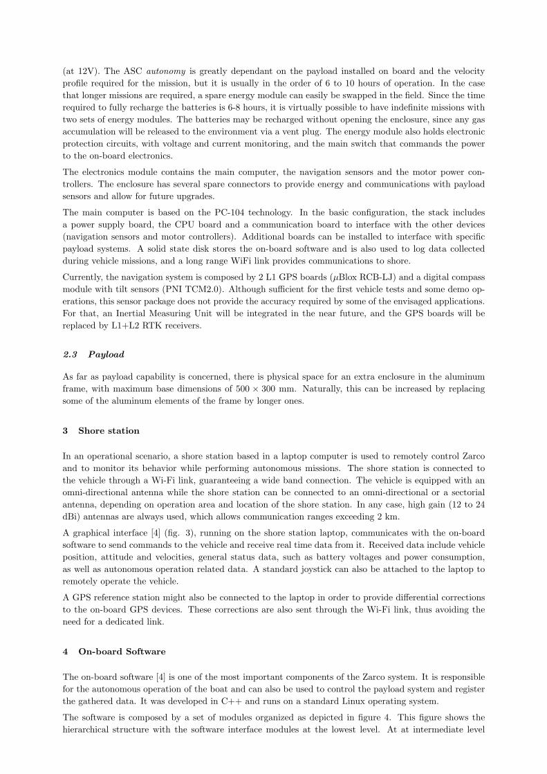
A graphical interface [4] (fig. 3), running on the shore station laptop, communicates with the on-boardsoftware to send commands to the vehicle and receive real time data from it. Received data include vehicleposition, attitude and velocities, general status data, such as battery voltages and power consumption,as well as autonomous operation related data. A standard joystick can also be attached to the laptop toremotely operate the vehicle.
A GPS reference station might also be connected to the laptop in order to provide differential correctionsto the on-board GPS devices. These corrections are also sent through the Wi-Fi link, thus avoiding theneed for a dedicated link.
4 On-board Software
The on-board software [4] is one of the most important components of the Zarco system. It is responsiblefor the autonomous operation of the boat and can also be used to control the payload system and registerthe gathered data. It was developed in C++ and runs on a standard Linux operating system.
The software is composed by a set of modules organized as depicted in figure 4. This figure shows thehierarchical structure with the software interface modules at the lowest level. At at intermediate level

Figure 3: Remote console application.
lie the navigation and control modules, which are responsible for the real time estimation of the vehiclestate and for the real time computation of the vehicle actuation, respectively. At the top level residesthe supervision module. Besides being responsible for the communication with the shore station, eitherexecuting remote commands or sending back relevant data, it monitors the vehicle behavior and deals withunexpected events. A black box data logging system registers all data related to the vehicle motion on aflash disk connected to the CPU board. This system can also be used to register payload data, if necessary.
GPSGPS Compass
CompassIMU
IMUMotors
Motors
NavigationNavigation ControlControl
Supervision
Dat
a lo
ggin
g
Figure 4: On-board software modules.
All the software modules run as independent Linux processes. In this way, not only the system modularityand robustness are increased but also its debugging and recovery from unexpected events is much moresimple. The communication between the modules relies on the exchange of messages, using the UserDatagram Protocol. This allows connectionless data exchanges, with reduced processing overhead, asrequired is this kind of applications.
4.1 Software interface modules
The navigation sensors and motor control boards are controlled by specially developed software interfacemodules. Besides dealing with the specificities of the hardware interfaces of the different physical devices,thus creating an abstraction layer, these modules also provide interfaces to configure and monitor thebehavior of each device.
4.2 Navigation module
As already mentioned, the navigation module is responsible to compute in real time the state of the vehicle(position, attitude and linear and angular velocities). This estimation is performed by an extended Kalmanfilter based algorithm [2], that can be configured to reflect different sets of attached sensors and systems.
Currently, navigation relies only on the data provided by the two µBlox RCB-LJ receivers and the TCM2.0module. The output rates of these sensors are 4 Hz and 16 Hz, respectively.
4.3 Control module
The control module is responsible for the computation in real time of the motor actuation, according tothe mission that the vehicle must perform. For that purpose, the control system implements a series ofcontrol loops associated with each different maneuver. At each control cycle, the control system computesthe vehicle actuation and tests the completion of the current maneuver. If the completion conditions aremet, a new maneuver is started.
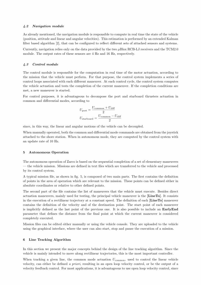
For control purposes, it is advantageous to decompose the port and starboard thrusters actuation incommon and differential modes, according to
Uport =Ucommon + Udiff
2
Ustarboard =Ucommon − Udiff
2
since, in this way, the linear and angular motions of the vehicle can be decoupled.
When manually operated, both the common and differential mode commands are obtained from the joystickattached to the shore station. When in autonomous mode, they are computed by the control system withan update rate of 10 Hz.
5 Autonomous Operation
The autonomous operation of Zarco is based on the sequential completion of a set of elementary maneuvers— the vehicle mission. Missions are defined in text files which are transferred to the vehicle and processedby its control system.
A typical mission file, as shown in fig. 5, is composed of two main parts. The first contains the definitionof points in the area of operation which are relevant to the mission. These points can be defined either inabsolute coordinates or relative to other defined points.
The second part of the file contains the list of maneuvers that the vehicle must execute. Besides directactuation maneuvers, mainly used for testing, the principal vehicle maneuver is the [LineTo]. It consistsin the execution of a rectilinear trajectory at a constant speed. The definition of each [LineTo] maneuvercontains the definition of the velocity and of the destination point. The start point of each maneuveris implicitly defined as the last point of the previous one. It is also possible to include an EarlyEndparameter that defines the distance from the final point at which the current maneuver is consideredcompletely executed.
Mission files can be edited either manually or using the vehicle console. They are uploaded to the vehicleusing the graphical interface, where the user can also start, stop and pause the execution of a mission.
6 Line Tracking Algorithm
In this section we present the major concepts behind the design of the line tracking algorithm. Since thevehicle is mainly intended to move along rectilinear trajectories, this is the most important controller.
When tracking a given line, the common mode actuation Ucommon, used to control the linear vehiclevelocity, can either be defined a priori, resulting in an open loop velocity control, or be the output of avelocity feedback control. For most applications, it is advantageous to use open loop velocity control, since
% Zarco sample mission file
[Definitions]
[Point]
name = middle
lat lon = 41N3.6019 8W27.2990
[Point]
name = upper
base = middle
offset RD = 50 137
[Point]
name = lower
base = middle
offset RD = 50 -43
[Mission]
[LineTo]
name = upper
motors = 50
[LineTo]
name = lower
motors = 25
[LineTo]
name = lower
offset RD = 50 -133
motors = 75
[LineTo]
name = upper
offset RD = 50 -133
motors = 100
[LineTo]
name = upper
motors = 50
Figure 5: Typical mission file.
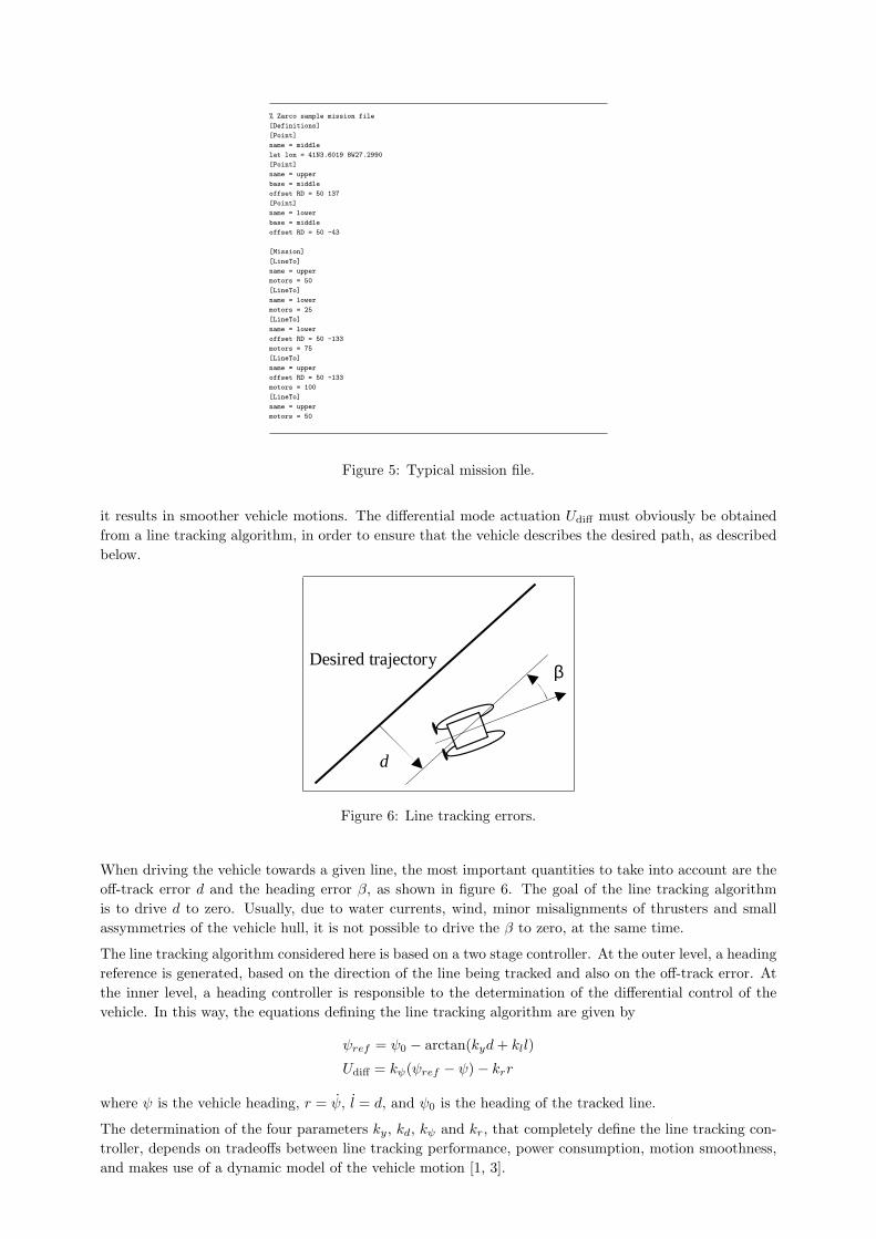
it results in smoother vehicle motions. The differential mode actuation Udiff must obviously be obtainedfrom a line tracking algorithm, in order to ensure that the vehicle describes the desired path, as describedbelow.
Desired trajectory β
d
Figure 6: Line tracking errors.
When driving the vehicle towards a given line, the most important quantities to take into account are theoff-track error d and the heading error β, as shown in figure 6. The goal of the line tracking algorithmis to drive d to zero. Usually, due to water currents, wind, minor misalignments of thrusters and smallassymmetries of the vehicle hull, it is not possible to drive the β to zero, at the same time.
The line tracking algorithm considered here is based on a two stage controller. At the outer level, a headingreference is generated, based on the direction of the line being tracked and also on the off-track error. Atthe inner level, a heading controller is responsible to the determination of the differential control of thevehicle. In this way, the equations defining the line tracking algorithm are given by
ψref = ψ0 − arctan(kyd + kll)
Udiff = kψ(ψref − ψ)− krr
where ψ is the vehicle heading, r = ψ, l = d, and ψ0 is the heading of the tracked line.
The determination of the four parameters ky, kd, kψ and kr, that completely define the line tracking con-troller, depends on tradeoffs between line tracking performance, power consumption, motion smoothness,and makes use of a dynamic model of the vehicle motion [1, 3].
7 Vehicle Performance
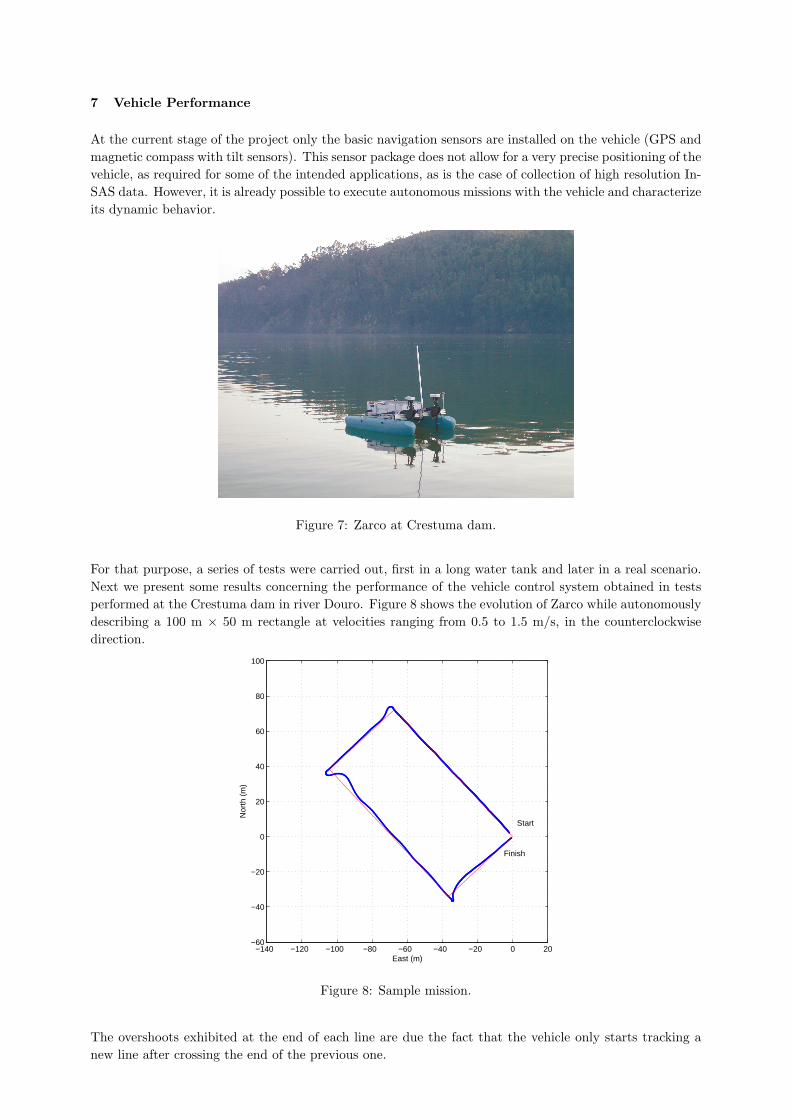
At the current stage of the project only the basic navigation sensors are installed on the vehicle (GPS andmagnetic compass with tilt sensors). This sensor package does not allow for a very precise positioning of thevehicle, as required for some of the intended applications, as is the case of collection of high resolution In-SAS data. However, it is already possible to execute autonomous missions with the vehicle and characterizeits dynamic behavior.
Figure 7: Zarco at Crestuma dam.
For that purpose, a series of tests were carried out, first in a long water tank and later in a real scenario.Next we present some results concerning the performance of the vehicle control system obtained in testsperformed at the Crestuma dam in river Douro. Figure 8 shows the evolution of Zarco while autonomouslydescribing a 100 m × 50 m rectangle at velocities ranging from 0.5 to 1.5 m/s, in the counterclockwisedirection.
−140 −120 −100 −80 −60 −40 −20 0 20−60
−40
−20
0
20
40
60
80
100
East (m)
Nor
th (
m)
Start
Finish
Figure 8: Sample mission.
The overshoots exhibited at the end of each line are due the fact that the vehicle only starts tracking anew line after crossing the end of the previous one.

The performance of the control system can be further assessed considering the off-track error in theexecution of the [LineTo] maneuvers. Figure 9 shows this error for the first 100 m line. Typically, as canbe seen in this figure, the error is almost always below 0.5 m, and its root mean square value is in theorder of 0.2 m.
0 10 20 30 40 50 60 70 80 90 100−0.4
−0.3
−0.2
−0.1
0
0.1
0.2
0.3
0.4
0.5
0.6
distance (m)
offtr
ack
erro
r (m
)
Figure 9: Line tracking performance.
8 Conclusions and Future Work
At the present stage of this project, the Zarco ASC has already been tested and its dynamical behaviorcharacterized. It has been showed that it can perform autonomous missions, tracking desired lines withacceptable accuracy. Its performance is currently constrained by the navigation package installed on-board, but, in the near future, the GPS receivers will be replaced by a pair of L1+L2 RTK receivers, andan inertial measurement unit will be installed on-board. These new sensors will certainly allow for a muchhigher precision of the navigation system.
Acknowledgement
This work was performed in the scope of projects INCORP – Improved Navigation with CooperativeRobotic Platforms – funded by FCT and Programa POSC (POSC / EEA-SRI / 59963 / 2004), and MUV– Navigation and Control of Multiple Underwater Vehicles – funded by FCT and Programa POSI (POSI/ SRI / 47351 / 2002).
References
[1] Fossen, T., 1994. Guidance and Control of Ocean Vehicles. John Wiley & Sons Ltd, London.
[2] Gelb, A., Kasper Jr., J., Nash Jr., R., Price, C., Sutherland Jr., A., 1996. Applied Optimal Estimation.The MIT Press, Cambridge.
[3] Matos, A., 2005. Line Treacking for an Autonomous Surface Vessel. INCORP Project Report, FEUP,Portugal.
[4] Teixeira, J., Rodrigues, P., Pinto, P., 2005. On-board Computer and Remote Console for an Au-tonomous Boat. FEUP, Portugal. (in portuguese)
Related Documents