Vedran ŽANIĆ, Sveučilište u Zagrebu, Fakultet strojarstva i brodogradnje, Ivana Lučića 5, 5, 10000 Zagreb; [email protected] Jerolim ANDRIĆ, Sveučilište u Zagrebu, Fakultet strojarstva i brodogradnje, Ivana Lučića 5 Neven HADŽIĆ, Sveučilište u Zagrebu, Fakultet strojarstva i brodogradnje, Ivana Lučića 5 STRUCTURAL OPTIMIZATION OF LNG CARRIER Summary The purpose of the paper is to present main results of LNG carrier structural optimization. The work has been carried through EU FP6 project IMPROVE. Coarse mesh FE model has been developed in extent of the three cargo holds using MAESTRO software. The strength calculation has been carried out according Bureau Veritas (BV) Rules. The objective of the whole optimization process was to distribute the material more effectively in order to reduce weight/cost and to improve the structural safety. Sensitivity analysis has been performed in order to investigate the influence of a web frame spacing, longitudinal stiffener spacing and material type on the defined design objectives. Structural optimization of LNG structure, for one cargo hold, resulted in mass decrease of about 424 t, or 10.8%, cost of the structure was decreased for about 5%, structural safety was increased and VCG was slightly decreased for about 20 cm compared to prototype structure. Key words: Ship structural optimization, LNG carrier, FEM STRUKTURNA OPTIMIZACIJA BRODA ZA PRIJEVOZ UKAPLJENOG PRIRODNOG PLINA Sažetak Cilj rada je prikazati glavne rezultate strukturne optimizacije broda za prijevoz ukapljenog plina koja je provedena u okviru EU FP6 istraživačkog projekta IMPROVE. Izgrađen je grubi model konačnih elemenata koji obuhvaća tri teretna prostora korištenjem programskog paketa MAESTRO. Proračun čvrstoće proveden je prema Pravilima Bureau Veritas (BV). Cilj cjelokupnog optimizacijskog postupka bio je optimalna redistribucija materijala s ciljem smanjenja težine/cijene i poboljšanja sigurnosti. Provedena je studija senzitivnosti s ciljem istraživanja utjecaja razmaka okvirnih rebara, razmaka uzdužnjaka i tipa materijala na definirane projektne ciljeve. Strukturna optimizacija, na razini jednog skladišta, rezultirala je u smanjenju mase oko 424 t (10.8%), cijena je smanjenja za oko 5%, sigurnost je povećana, dok je VCG je blago smanjen za oko 20cm, u usporedbi s prototipnom konstrukcijom. Ključne riječi: strukturna optimizacija, brod za prijevoz ukapljenog prirodnog plina, MKE

Welcome message from author
This document is posted to help you gain knowledge. Please leave a comment to let me know what you think about it! Share it to your friends and learn new things together.
Transcript

Vedran ŽANIĆ, Sveučilište u Zagrebu, Fakultet strojarstva i brodogradnje, Ivana Lučića 5, 5, 10000 Zagreb; [email protected] Jerolim ANDRIĆ, Sveučilište u Zagrebu, Fakultet strojarstva i brodogradnje, Ivana Lučića 5 Neven HADŽIĆ, Sveučilište u Zagrebu, Fakultet strojarstva i brodogradnje, Ivana Lučića 5
STRUCTURAL OPTIMIZATION OF LNG CARRIER
Summary
The purpose of the paper is to present main results of LNG carrier structural optimization. The work has been carried through EU FP6 project IMPROVE. Coarse mesh FE model has been developed in extent of the three cargo holds using MAESTRO software. The strength calculation has been carried out according Bureau Veritas (BV) Rules. The objective of the whole optimization process was to distribute the material more effectively in order to reduce weight/cost and to improve the structural safety. Sensitivity analysis has been performed in order to investigate the influence of a web frame spacing, longitudinal stiffener spacing and material type on the defined design objectives. Structural optimization of LNG structure, for one cargo hold, resulted in mass decrease of about 424 t, or 10.8%, cost of the structure was decreased for about 5%, structural safety was increased and VCG was slightly decreased for about 20 cm compared to prototype structure.
Key words: Ship structural optimization, LNG carrier, FEM
STRUKTURNA OPTIMIZACIJA BRODA ZA PRIJEVOZ UKAPLJENOG PRIRODNOG PLINA
Sažetak
Cilj rada je prikazati glavne rezultate strukturne optimizacije broda za prijevoz ukapljenog plina koja je provedena u okviru EU FP6 istraživačkog projekta IMPROVE. Izgrađen je grubi model konačnih elemenata koji obuhvaća tri teretna prostora korištenjem programskog paketa MAESTRO. Proračun čvrstoće proveden je prema Pravilima Bureau Veritas (BV). Cilj cjelokupnog optimizacijskog postupka bio je optimalna redistribucija materijala s ciljem smanjenja težine/cijene i poboljšanja sigurnosti. Provedena je studija senzitivnosti s ciljem istraživanja utjecaja razmaka okvirnih rebara, razmaka uzdužnjaka i tipa materijala na definirane projektne ciljeve. Strukturna optimizacija, na razini jednog skladišta, rezultirala je u smanjenju mase oko 424 t (10.8%), cijena je smanjenja za oko 5%, sigurnost je povećana, dok je VCG je blago smanjen za oko 20cm, u usporedbi s prototipnom konstrukcijom.
Ključne riječi: strukturna optimizacija, brod za prijevoz ukapljenog prirodnog plina, MKE

XX Symposium SORTA2012 Structural optimization of LNG carrier
2
1. Introduction The very effective and practical way to transport gas between continents is by ships, in
liquid form. The gas is liquefied by subjecting it to pressure and/or low temperature. Liquid Natural Gas (LNG) carriers are special ships built to transport large volume of LNG at its atmospheric pressure boiling point of -163 °C. The capacity of these ships is now typically between 100 000÷220 000 m3. The LNG ships with membrane type are mostly built in recent years. Membrane tanks are non-self-supporting tanks, which consist of thin layer (membrane) supported through insulation to the adjacent hull structure [1].
The work presented through this paper has been done as a part of EU FP6 project IMPROVE. The objective of University of Zagreb, task 6.2 in WP6, was to develop, analyze and optimize a global 3D FEM model of LNG ship (“free ballast” design) in an integrated multiple criteria decision making environment by using the advanced analysis techniques (FEM, ultimate strength of panel and hull girder) coupled with methods of design synthesis (sequential fractional factorial experiments, genetic algorithm, robustness measure, etc.) at the earliest stage of the design process, which innovatively considers structure, production, operational aspects, performance, and safety criteria on a concurrent basis in order to achieve improved and competitive structural design [2].
2. Global 3D FEM optimization with OCTOPUS/MAESTRO Generally, structural design may be divided into concept, preliminary and detail design.
Concept design is defined as the phase in structural design when geometry and topology are open to modification and structural variants are analyzed in accordance with the needs of the problem multiple stakeholders (head designer, owner, etc). Benefits of optimization procedure in this phase are the biggest.
The design environment of MAESTRO software [3, 4], capable of imbedding multiple quality criteria for structural design, is used to provide the decision support problem (DSP) rationale for multi-criteria (weight, cost and centre of gravity) based optimization [5].
The general mathematical model contains the analysis and the synthesis modules. They have been developed and implemented in the decision support systems MAESTRO and OCTOPUS [6]. They can be decomposed, in principle, into six meta-systems of which two basic ones provide physical and environmental definitions of the problem / process and other four are behavioral systems for modeling response, adequacy, reliability and quality, as described in [7] and are invoked into the design problem definition modules and coupled with different optimization solvers (Σ) into multi-attribute multi-level synthesis procedure [7, 8].
3. Design procedure The general procedure developed for design includes the formulation of design support
problem (DSP), i.e. identification of variables, attributes, constraints, formulation of analytical model (response and feasibility modules), selection of synthesis model and final selection of the solution strategy for the manipulated problem. The analysis of prototype structure P0 enables fair comparisons with other concepts, denoted PJ. The optimal solution PJ, also denoted as OJ, is standardized at the end of the procedure (denoted as DK). The overall description of the design procedure, divided into design phases, is given in Fig. 1.

Structural optimization of LNG carrier XX Symposium SORTA2012
3
Prototype:
LBR 5 (OCTOPUS)
PARAMETER SELECTION
Prototype:
{ }01 4, , , Shipd d d=0P …
{ }1 4, , ,CShipd d d=CP …
COMBINING LOCAL & GLOBAL GROUP DATA (i, j, n(i))
ANALYSIS:- LOADS, (BV), RESPONSE (3D FEM)- ADEQUACY (BV RULES)- QUALITY (aWEIGHT, aCOST, aSAFETY)
SYNTHESIS:- VARIABLES,
- CONSTRAINTS,
- OBJECTIVES, extremize
{ }, 1 4, , ,nij n Shipji iP x x x= …
0gBV ≥
1 4y y…
SYNTHESIS SOLUTION ? (SLP): { } 1, 1 1 4, , ,nij n Shipji iP x x x++ = …
CONVERGED?
i = i 1
,…i 4
Prefered: 1ConceptO
SENSITIVITY ANALYSIS:
NO
YES
n =
1, ..
., nc
ycle
j = 1
, ...,
nS
hipp
aram
eter
s gr
oups
j < nShipparameters group
SELECTION & REDESIGN based on
REOPTIMIZATION (SLP)
j = nShipparameters group
Prefered optimum design: 3PreliminaryO
STANDARDIZATION & FINAL ANALYSIS
DESIGN
CO
NC
EP
T D
ES
IGN
PH
AS
E: I
NIT
IAL
EXP
LOR
ATI
ON
OF
THE
DE
SIG
N S
PA
CE
PR
ELI
MIN
AR
Y D
ES
IGN
PH
AS
E O
PTI
MIZ
ATI
O A
ND
FIN
AL
EV
ALU
ATI
ON
4D
1( 1 3, 1) or
5 ( 5, 2 4)
i i j
j i j
= − =
= = −⎧⎨⎩
P
P
3 4, ,52 5 5P P P
Fig. 1 Design procedure
Slika 1. Projektni postupak
3.1. Design problem identification
The design variables: xTotal ⊆ PJ = { xShip-j, {xSubset -i}}, where n-tuple xTotal includes all design variables in the area under consideration, can be decomposed into subsets of
XX Symposium SORTA2012 Structural optimization of LNG carrier
4
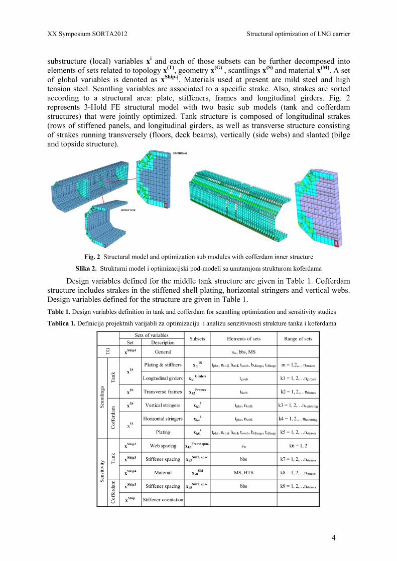
substructure (local) variables xi and each of those subsets can be further decomposed into elements of sets related to topology x(T), geometry x(G) , scantlings x(S) and material x(M). A set of global variables is denoted as xShip-j. Materials used at present are mild steel and high tension steel. Scantling variables are associated to a specific strake. Also, strakes are sorted according to a structural area: plate, stiffeners, frames and longitudinal girders. Fig. 2 represents 3-Hold FE structural model with two basic sub models (tank and cofferdam structures) that were jointly optimized. Tank structure is composed of longitudinal strakes (rows of stiffened panels, and longitudinal girders, as well as transverse structure consisting of strakes running transversely (floors, deck beams), vertically (side webs) and slanted (bilge and topside structure).
Fig. 2 Structural model and optimization sub modules with cofferdam inner structure
Slika 2. Strukturni model i optimizacijski pod-modeli sa unutarnjom strukturom koferdama
Design variables defined for the middle tank structure are given in Table 1. Cofferdam structure includes strakes in the stiffened shell plating, horizontal stringers and vertical webs. Design variables defined for the structure are given in Table 1. Table 1. Design variables definition in tank and cofferdam for scantling optimization and sensitivity studies
Tablica 1. Definicija projektnih varijabli za optimizaciju i analizu senzitivnosti strukture tanka i koferdama
Set Description
xShipJ General sw, bbs, MS
Plating & stiffners xm1S tplat, nstiff, hstiff, tsweb, bsflange, tsflange m = 1,2,... nstrakes
Longitudinal girders xk1Girders tgweb k1 = 1, 2,…ngirders
x2S Transverse frames xk2Frames tfweb k2 = 1, 2,…nframes
x3S Vertical stringers xk33 tplat, nstiff, k3 = 1, 2,…nvertstring
Horizontal stringers xk44 tplat, nstiff, k4 = 1, 2,…nhorstring
Plating xk54 tplat, nstiff, hstiff, tsweb, bsflange, tsflange k5 = 1, 2,…nstrakes
xShip2 Web spacing xk6Frame spac. sw k6 = 1, 2
xShip3 Stiffener spacing xk7Stiff. spac. bbs k7 = 1, 2,…nstrakes
xShip4 Material xk8SM MS, HTS k8 = 1, 2,…nstrakes
xShip3 Stiffener spacing xk9Stiff. spac. bbs k9 = 1, 2,…nstrakes
xShip Stiffener orientation
Range of sets
TG
Sets of variablesSubsets Elements of sets
x1S
x4S
Scan
tling
sSe
nsiti
vity
Tank
Cof
ferd
amTa
nkC
offe
rdam

Structural optimization of LNG carrier XX Symposium SORTA2012
5
The selected design attributes, expressed as function of design variables a (xTotal), were y1 = minimize aWEIGHT, y2 = minimize aCOST and y3 = maximize aSAFETY. Measure of safety is defined via total number of unsatisfied constrains and relative adequacy index (RAI). It is calculated using histogram of the values of various constraints as ratio between the area under the distribution of positive values and total area consisting of area under positive and negative values of constraints. The design constraints and requirements are determined in several ways. Minimum and maximum values were specified by the shipyard. In addition to this, the requirements based on technology and experiences have to be declared in form of various ratios that combine frame, girder and stiffener scantlings. Linear constraints for equivalent HP profiles have to be declared in order to fit the standard HP profiles in the best possible way. Also, in order to satisfy necessary structural strength adequacy parameters had to be equal or greater than zero. MAESTRO nonlinear constraints are given in Table 2. Table 2. MAESTRO structural adequacy constraints with safety factors
Tablica 2. MAESTRO - funkcije ograničenja na temelju podobnosti sa koeficijentima sigurnosti
Item Limit state Description BV Safety factor, γ
1 PCSF Panel Collapse - Stiffener Flexure 1.04 2 PCCB Panel Collapse - Combined Buckling 1.04 3 PCMY Panel Collapse - Membrane Yield 1.224 4 PCSB Panel Collapse - Stiffener Buckling 1.04 5 PYTF Panel Yield - Tension Flange 1.224 6 PYTP Panel Yield - Tension Plate 1.224 7 PYCF Panel Yield - Compression Flange 1.224 8 PYCP Panel Yield - Compression Plate 1.224
9,10 PSPB Panel Serviceability - Plate Bending 1.00 11 PFLB Panel Failure - Local Buckling 0.90 12 GCT Girder Collapse Tripping 1.04 13 GCCF Girder Collapse Compression in Flange 1.04 14 GCCP Girder Collapse Compression in Plate 1.04 15 GYCF Girder Yield Compression in Flange 1.224 16 GYCP Girder Yield Compression in Plate 1.224 17 GYTF Girder Yield Tension in Flange 1.224 18 GYTF Girder Yield in Tension in Plate 1.224
19-21 FCPH Frame Collapse, Plastic Hinge 1.60 22-24 FYCF Frame Yield, Compression in Flange 1.224 25-27 FYTF Frame Yield, Tension in Flange 1.224 28-30 FYCP Frame Yield, Compression in Plate 1.224 31-33 FYTP Frame Yield, Tension in Plate 1.224
3.2. Analysis module
A total number of five loading conditions were defined according to BV requirements [9, 10] along with the appropriate seventeen load cases. Pressure distribution (internal and external, static and dynamic) for all load cases were supplied by ANAST via VERISTAR file [11]. All conclusions were based on these load cases. In addition, representative design sloshing pressure acting on plating and stiffeners of tank inner shell was calculated using BV sloshing module. Figure 3 shows sloshing pressure in kN/m2 calculated for the defined tank geometry. According to defined sloshing pressures, additional set of minimum values was defined in order to satisfy the necessary local strength due to sloshing. This additional set was implemented regarding the inner shell of tank structure (plating and stiffeners).

XX Symposium SORTA2012 Structural optimization of LNG carrier
6
Fig. 3 Sloshing pressure (in kN/m2) acting on plating and stiffeners of tank inner shell
Slika 3. Tlak zapljuskivanja (u kN/m2) definiran za oplatu i uzdužnjake unutarnje strukture tanka
3.3. Synthesis module
Problem can be fully decomposed regarding local variables and attributes but coupling is present in calculation of design criteria. Each of them is dependent on stress fields obtained from FEM analysis and therefore dependent on structural stiffness and load vector. Table 3. Variable schedule in the design procedure ( x = fixed, n = number of cycles)
Tablica 3. Redoslijed varijabli u projektnom postupku ( x = nepromjenjiva varijabla, n =broj ciklusa)
Where: { }ship cycle or variantLocal var. , global var. set i j=JP P To decrease the size of the problem in the first design cycles, the ‘weak’ coupling between longitudinal tank structure and cofferdam is recognized and used to decouple problem on separate optimization of tank and cofferdam structure. Convergence of the process is obtained via unified response analysis of all modules. Accordingly, the design procedure was performed in the following steps:
1. Initial optimization of longitudinal and transverse tank structure (problem P11+21). 2. Optimization of cofferdam structure (problems P31 + 41), decoupled from the tank
optimization sub-problem. (Optimization problem were solved using SLP algorithm inbuilt in MAESTRO software).
3. Joint optimization and analysis of problems P11+21+31 + 41. 4. Sensitivity analysis of the optimal solution using problems P52, P53 and P54, where i =
5 is optimal solution of scantling optimization. Optimal design O1Concept was generated.
5. Based on sensitivity analysis final optimization of preferred variants from step 5 was performed and optimal solution was generated, O3 Preliminary.

Structural optimization of LNG carrier XX Symposium SORTA2012
7
6. The standardization based redesign is performed including sub optimization with respect to the remaining free variables. Final design with all satisfied constraints is denoted as D4.
4. Structural optimization results History of defined design attributes (structural mass, VCG and safety) for optimization
sub-problems P11, P21, P31 and P41 (Table 3) is given in Fig. 4 with respect to optimization cycle. To get better in view into the contribution of particular structure to total mass, results are given separately for middle tank and cofferdam structure.
Fig.4 History of structural mass and number of unsatisfied constraints (TNUC) for middle tank and cofferdam
Slika 4 Promjena mase i ukupnog broja nezadovoljenih ograničenja (TNUC) za strukturu tanka i koferdama
Optimization of middle tank structure has shown strong coupling between longitudinal and transverse structural elements. Design cycle 1 at Fig. 4 shows initial structural mass of longitudinal (orange color) and transverse (green color) elements. During first three cycles

XX Symposium SORTA2012 Structural optimization of LNG carrier
8
mass of transverse elements is constant, while mass of longitudinal elements is decreasing. At 4th cycle mass of transverse structure was decreased due to new scantlings and was kept constant during the rest of design cycles, but due to that the mass of longitudinal structure is increasing. It can be concluded that no improvement can be achieved by modifying transverse structure.
As given in the design sequence flowchart (Fig. 1), sensitivity studies are done when optimization procedure converged to the optimal solution. Three sensitivity studies related to tank structure were done regarding:
• breadth between stiffeners, • material selection, • web frame spacing.
Sensitivity analysis regarding number of stiffeners has shown that additional savings regarding structural mass can be achieved by providing additional stiffener. Cost of a similar structure is higher (greater length of welding) and can be evaluated if the cost parameters are given. Also, sensitivity analysis regarding material type has shown that additional savings regarding structural mass can be achieved by providing higher tension steel for stiffener material. Cost of such structure is higher (cost of material), but no significant gain has been identified in structural weight to justify that solution. Finally, sensitivity analysis regarding web frame spacing has shown that by reducing the web frame spacing additional savings can be achieved with respect to structural mass and also with respect to cost of welding. Following that reasoning, a structure with maximum possible web frame spacing is chosen for the next step of optimization procedure.
Due to new web frame and stiffener spacing new sloshing minimum were calculated. Remodeled LNG ship structure was optimized using MAESTRO software. Mathematical model of optimization problem was formulated according to described design procedure, using the defined set of the design variables, constraints and attributes. When defined, problem was solved using sequential linear programming method (SLP).
History of design attributes (structural mass, cost, VCG and safety) is given in Fig. 5 with respect to optimization cycle. To get better view into the contribution of particular structure to total mass, results are given separately for middle tank and cofferdam structure. Three optimization cycles were performed, as shown in the Fig.5. Additional design cycle (4th) is added and it represents standardization of achieved optimum scantlings.

Structural optimization of LNG carrier XX Symposium SORTA2012
9
Fig. 5 History of structural mass and number of unsatisfied constraints (TNUC) for middle tank and cofferdam
Slika 5. Promjena mase i ukupnog broja nezadovoljenih ograničenja (TNUC) za strukturu tanka i koferdama
Summary of preliminary optimization results are given in Table 4. After the optimization procedure, the standardization of optimal structure achieved in preliminary design phase was performed in order to obtain technologically feasible design of LNG structure. All obtained scantlings were rounded off to some reasonable values. Table 4. Summary of preliminary optimization results
Tablica 4. Sažetak rezultata preliminarne optimizacije
Design solutionStructural mass, (t)
(middle tank)Mass
savings, %Safety
(TNUC) VCG, (mm)
Initial, P0 3931 / 110 16155
Optimal, O3Preliminary 3251 17.3 3 15931
Standardized, D4 3507 10.8 0 15951 When standardized, structural model of LNG ship was further analyzed using
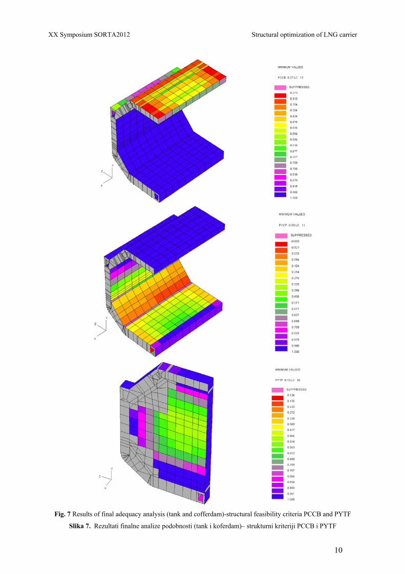
MAESTRO in order to inspect the properties of the new proposed solution. Results of stress and adequacy analysis for the final solution as an example are shown in Figs. 6 and 7.
Fig. 6 Results of final analysis – σx and σy component stresses
Slika 6. Rezultati finalne analize– σx i σy komponentna naprezanja
XX Symposium SORTA2012 Structural optimization of LNG carrier
10
Fig. 7 Results of final adequacy analysis (tank and cofferdam)-structural feasibility criteria PCCB and PYTF
Slika 7. Rezultati finalne analize podobnosti (tank i koferdam)– strukturni kriteriji PCCB i PYTF
Structural optimization of LNG carrier XX Symposium SORTA2012
11
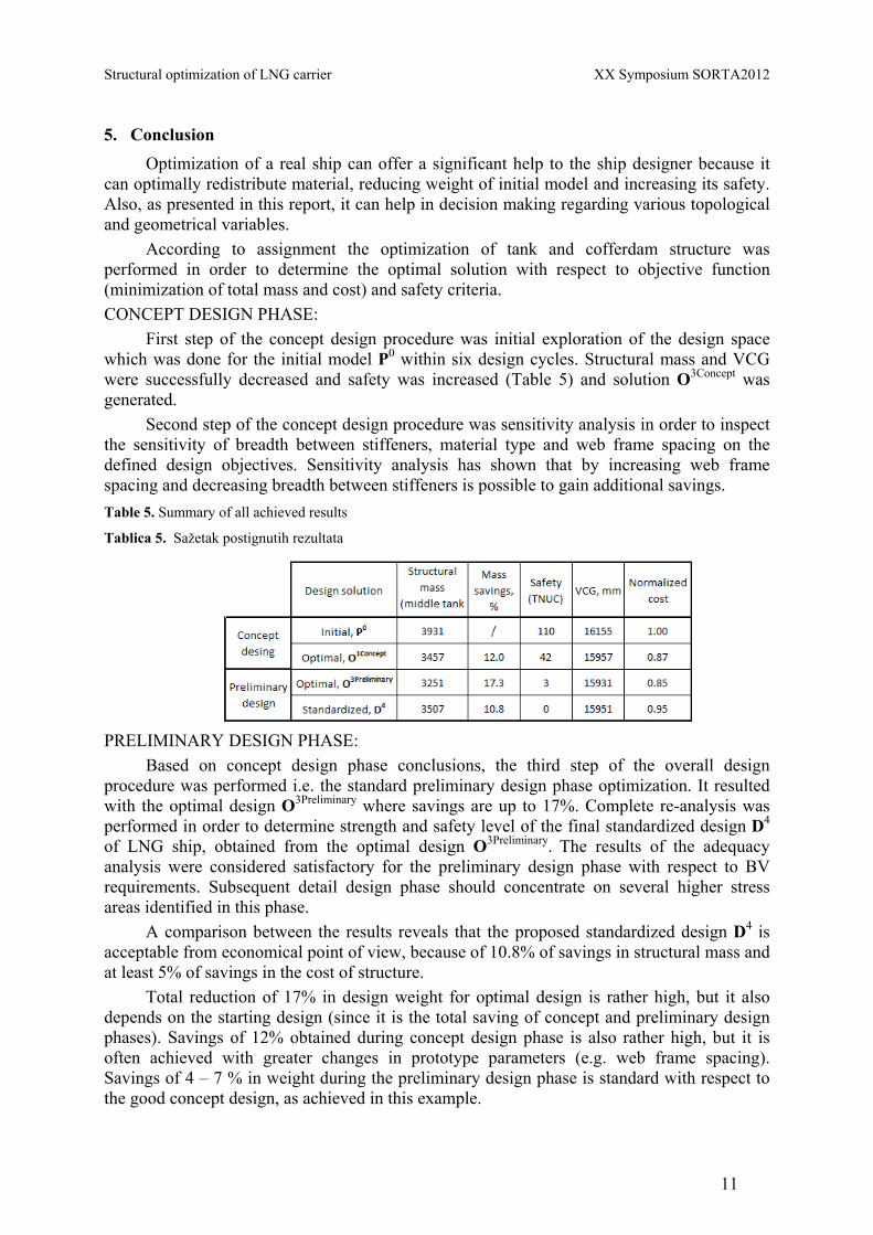
5. Conclusion Optimization of a real ship can offer a significant help to the ship designer because it
can optimally redistribute material, reducing weight of initial model and increasing its safety. Also, as presented in this report, it can help in decision making regarding various topological and geometrical variables.
According to assignment the optimization of tank and cofferdam structure was performed in order to determine the optimal solution with respect to objective function (minimization of total mass and cost) and safety criteria. CONCEPT DESIGN PHASE:
First step of the concept design procedure was initial exploration of the design space which was done for the initial model P0 within six design cycles. Structural mass and VCG were successfully decreased and safety was increased (Table 5) and solution O3Concept was generated.
Second step of the concept design procedure was sensitivity analysis in order to inspect the sensitivity of breadth between stiffeners, material type and web frame spacing on the defined design objectives. Sensitivity analysis has shown that by increasing web frame spacing and decreasing breadth between stiffeners is possible to gain additional savings. Table 5. Summary of all achieved results
Tablica 5. Sažetak postignutih rezultata
PRELIMINARY DESIGN PHASE:
Based on concept design phase conclusions, the third step of the overall design procedure was performed i.e. the standard preliminary design phase optimization. It resulted with the optimal design O3Preliminary where savings are up to 17%. Complete re-analysis was performed in order to determine strength and safety level of the final standardized design D4 of LNG ship, obtained from the optimal design O3Preliminary. The results of the adequacy analysis were considered satisfactory for the preliminary design phase with respect to BV requirements. Subsequent detail design phase should concentrate on several higher stress areas identified in this phase.
A comparison between the results reveals that the proposed standardized design D4 is acceptable from economical point of view, because of 10.8% of savings in structural mass and at least 5% of savings in the cost of structure.
Total reduction of 17% in design weight for optimal design is rather high, but it also depends on the starting design (since it is the total saving of concept and preliminary design phases). Savings of 12% obtained during concept design phase is also rather high, but it is often achieved with greater changes in prototype parameters (e.g. web frame spacing). Savings of 4 – 7 % in weight during the preliminary design phase is standard with respect to the good concept design, as achieved in this example.

XX Symposium SORTA2012 Structural optimization of LNG carrier
12
Optimal point of the preliminary design phase is a good starting point for standardization, usually compared to the initial Yard design. As demonstrated in the example, standardization has brought savings down to 10.8%, but Yard designers can do it better. Knowledge of the optimal (non-standardized) design scantlings (and savings in weight) is offering the designer an excellent opportunity to perform the refined standardization procedure regarding material quantities and production considerations of particular Yard.
A comparison between the results reveals that proposed design (standardized scantlings) is offering simultaneously savings in structural mass and cost, increase in safety (due to logical material distribution) and therefore maturity and the potential of the applied approach to design.
ACKNOWLEDGEMENTS Thanks are due to the long-term support of Croatian Ministry of Science, Education and
Sport: projects 120-1201829-1671. The European Commission under the FP6 Sustainable Surface Transport Program, namely the STREP project IMPROVE, Contract No. FP6-031382 mostly supported the study present in the paper. Thanks are due to all members of the IMPROVE project, the OCTOPUS team (www.fsb.hr/octopus) and to design team of STX–Europe shipyard in St. Nazaire and Bureau Veritas, Paris for fruitful cooperation.
REFERENCES [1] EMI, H., FUJITANI, T., ABE, A.: "Liquefied Gas Carriers”, in: Ship Design and Construction, Vol.II, Ch.32, SNAME, 2004. [2] Rigo, P., Ehlers, S., Žanić, V., Andrić, J., "Design of Innovative Ship Concepts Using an Integrated Decision Support System for Ship Production and Operation", Brodogradnja/Shipbuilding, 2010, Vol.61, No.4, p. 367-381, Zagreb, 2010.
[3] Hughes O.F., "Ship Structural Design", John Wiley & Sons, SNAME, New Jersey, 1988. [4] MAESTRO Version 8.7.6, Program documentation, Proteus engineering, Stevensville, MD, USA, 2007. [5] Hughes, O.F., Mistree, F., Zanic, V.: "A Practical Method for the Rational Design of Ship Structures", Journal of Ship Research, Vol. 24, (1980) No. 2, p.101-113 [6] OCTOPUS Theoretical and User Manuals, FMENA, University of Zagreb, 2009. [7] J-Y Pradillon, V. Žanić et al.: Proceedings of the 15th International Ship and Offshore Structures Congress, Vol. 1, Technical Committee IV.2-Design Methods, (Decision Support Methods - Chapter 6); Mansour, A.E; Ertekin, R.C. (ed.), Elsevier Science, Amsterdam, p. 486-493, 2003. [8] Žanić, V., Andrić, J., Prebeg. P, Kitarović, K., Pirić, K.: "Multi-objective optimization of ship structural topology and scantlings", International Marine Design Conference, Proceedings of IMDC 2009, Vol. 2, p.789-803. Trondheim, Norway, 2009. [9] A. Amrane, V. Žanić et al: "LNG carrier - Structural design aspects(ibid.) ", pp.98-104, Proceedings of IMPROVE final Workshop on Design of Improved and Competitive Ships, V. Žanić, J. Andrić (eds.), available on IMPROVE website (http://www. improve-project.eu/), FMENA, University of Zagreb, 2009. [10] Bureau Veritas, Guidelines for structural analysis of membrane LNG carriers, February 2005. [11] Bureau Veritas, Rules for Steel Ships, Part B-Hull and Stability, April 2007.
Related Documents