Z10PA-U8 Series User Guide

Welcome message from author
This document is posted to help you gain knowledge. Please leave a comment to let me know what you think about it! Share it to your friends and learn new things together.
Transcript

Z10PA-U8 SeriesUser Guide

ii
E9738 First Edition November 2014
Copyright © 2014 ASUSTeK COMPUTER INC. All Rights Reserved.No part of this manual, including the products and software described in it, may be reproduced, transmitted, transcribed, stored in a retrieval system, or translated into any language in any form or by any means, except documentation kept by the purchaser for backup purposes, without the express written permission of ASUSTeK COMPUTER INC. (“ASUS”).Product warranty or service will not be extended if: (1) the product is repaired, modified or altered, unless such repair, modification of alteration is authorized in writing by ASUS; or (2) the serial number of the product is defaced or missing.ASUS PROVIDES THIS MANUAL “AS IS” WITHOUT WARRANTY OF ANY KIND, EITHER EXPRESS OR IMPLIED, INCLUDING BUT NOT LIMITED TO THE IMPLIED WARRANTIES OR CONDITIONS OF MERCHANTABILITY OR FITNESS FOR A PARTICULAR PURPOSE. IN NO EVENT SHALL ASUS, ITS DIRECTORS, OFFICERS, EMPLOYEES OR AGENTS BE LIABLE FOR ANY INDIRECT, SPECIAL, INCIDENTAL, OR CONSEQUENTIAL DAMAGES (INCLUDING DAMAGES FOR LOSS OF PROFITS, LOSS OF BUSINESS, LOSS OF USE OR DATA, INTERRUPTION OF BUSINESS AND THE LIKE), EVEN IF ASUS HAS BEEN ADVISED OF THE POSSIBILITY OF SUCH DAMAGES ARISING FROM ANY DEFECT OR ERROR IN THIS MANUAL OR PRODUCT.SPECIFICATIONS AND INFORMATION CONTAINED IN THIS MANUAL ARE FURNISHED FOR INFORMATIONAL USE ONLY, AND ARE SUBJECT TO CHANGE AT ANY TIME WITHOUT NOTICE, AND SHOULD NOT BE CONSTRUED AS A COMMITMENT BY ASUS. ASUS ASSUMES NO RESPONSIBILITY OR LIABILITY FOR ANY ERRORS OR INACCURACIES THAT MAY APPEAR IN THIS MANUAL, INCLUDING THE PRODUCTS AND SOFTWARE DESCRIBED IN IT.Products and corporate names appearing in this manual may or may not be registered trademarks or copyrights of their respective companies, and are used only for identification or explanation and to the owners’ benefit, without intent to infringe.

iiiZ10PA-U8 Series
Contents
Notices ..................................................................................................................... viii
Federal Communications Commission Statement ........................................ viii
Canadian Department of Communications Statement .................................. viii
REACH ..................................................................................................... viii
Safety information ...................................................................................................... ix
Electrical safety ...............................................................................................ix
Operation safety ..............................................................................................ix
Australia statement notice ............................................................................... x
How this guide is organized ............................................................................xi
Where to find more information .......................................................................xi
Z10PA-U8 Series specifications summary............................................................. xiii
Chapter 1: Product Introduction
1.1 Welcome! ....................................................................................................1-2
1.2 Package contents ......................................................................................1-2
1.3 Serial number label ....................................................................................1-3
1.4 Special features..........................................................................................1-3
1.4.1 Product highlights........................................................................ 1-3
1.4.2 Innovative ASUS features ........................................................... 1-4
Chapter 2: Hardware Information
2.1 Before you proceed ...................................................................................2-2
2.2 Motherboard overview ...............................................................................2-3
2.2.1 Placement direction..................................................................... 2-3
2.2.2 Screw holes.................................................................................2-3
2.2.3 Motherboard layout ..................................................................... 2-4
2.2.4 Layout contents ...........................................................................2-6
2.3 Central Processing Unit (CPU) .................................................................2-8
2.3.1 Installing the CPU ....................................................................... 2-8
2.4 System memory .......................................................................................2-13
2.4.1 Overview ...................................................................................2-13
2.4.2 Memory Configurations ............................................................. 2-13
2.4.3 Installing a DIMM on a single clip DIMM socket........................ 2-14

iv
Contents
2.5 Expansion slots ........................................................................................2-15
2.5.1 Installing an expansion card...................................................... 2-15
2.5.2 Configuring an expansion card ................................................. 2-15
2.5.3 Interrupt assignments................................................................ 2-16
2.5.4 PCI Express x16 slot (x16 link) ................................................. 2-16
2.5.5 PCI Express x8 slot (x8 link) ..................................................... 2-16
2.5.6 PCI Express x8 slot (x4 link) ..................................................... 2-16
2.5.7 PCI slot .....................................................................................2-16
2.5.8 Installing ASMB8 series management board ............................ 2-18
2.6 Onboard LEDs ..........................................................................................2-19
2.7 Jumpers ....................................................................................................2-24
2.8 Connectors ...............................................................................................2-28
2.8.1 Rear panel connectors .............................................................. 2-28
2.8.2 Internal connectors.................................................................... 2-29
Chapter 3: Powering Up
3.1 Starting up for the first time ......................................................................3-2
3.2 Powering off the computer ........................................................................3-3
3.2.1 Using the OS shut down function ................................................ 3-3
3.2.2 Using the dual function power switch .......................................... 3-3
Chapter 4: BIOS setup
4.1 Managing and updating your BIOS ..........................................................4-2
4.1.1 ASUS CrashFree BIOS 3 utility................................................... 4-2
4.1.2 ASUS EZ Flash Utility ................................................................. 4-3
4.1.3 BUPDATER utility ....................................................................... 4-4
4.2 BIOS setup program ..................................................................................4-6
4.2.1 BIOS menu screen ...................................................................... 4-7
4.2.2 Menu bar .....................................................................................4-7
4.2.3 Menu items..................................................................................4-8
4.2.4 Submenu items ...........................................................................4-8
4.2.5 Navigation keys ........................................................................... 4-8
4.2.6 General help................................................................................4-8
4.2.7 Configuration fields ..................................................................... 4-8
4.2.8 Pop-up window............................................................................4-8
4.2.9 Scroll bar .....................................................................................4-8
4.3 Main menu ..................................................................................................4-9
4.3.1 System Date [Day xx/xx/xxxx] ..................................................... 4-9
4.3.2 System Time [xx:xx:xx] ............................................................... 4-9
vZ10PA-U8 Series
Contents
4.4 Advanced menu .......................................................................................4-10
4.4.1 ACPI Settings ............................................................................4-11
4.4.2 Smart Settings...........................................................................4-11
4.4.3 NCT6779D Super IO Configuration .......................................... 4-12
4.4.4 Onboard LAN I210 Configuration ............................................. 4-13
4.4.5 Serial Port Console Redirection ................................................ 4-14
4.4.6 APM ..........................................................................................4-17
4.4.7 Advanced Power Management Configuration........................... 4-18
4.4.8 PCI Subsystem Settings ........................................................... 4-19
4.4.9 Network Stack Configuration..................................................... 4-20
4.4.10 CSM Configuration .................................................................... 4-21
4.4.11 Trusted Computing.................................................................... 4-22
4.4.12 USB Configuration .................................................................... 4-23
4.4.13 iSCSI Configuration................................................................... 4-24
4.5 IntelRCSetup menu ..................................................................................4-25
4.5.1 Processor Configuration............................................................ 4-26
4.5.2 Advanced Power Management Configuration........................... 4-28
4.5.3 Common RefCode Configuration .............................................. 4-29
4.5.4 Memory Configuration ............................................................... 4-30
4.5.5 IIO Configuration .......................................................................4-33
4.5.6 PCH Configuration .................................................................... 4-34
4.5.7 Miscellaneous Configuration ..................................................... 4-37
4.5.8 Server ME Configuration ........................................................... 4-38
4.5.9 Runtime Error Logging ............................................................. 4-38
4.6 Server Mgmt menu ...................................................................................4-39
4.7 Event Logs menu .....................................................................................4-44
4.7.1 Change Smbios Event Log Settings ......................................... 4-44
4.7.2 View Smbios Event Log ............................................................ 4-45
4.8 Monitor menu ...........................................................................................4-46
4.9 Security menu ..........................................................................................4-47
4.10 Boot menu ................................................................................................4-50
4.11 Tool menu .................................................................................................4-51
4.12 Exit menu ..................................................................................................4-52
vi
Contents
Chapter 5: RAID Configuration
5.1 Setting up RAID ..........................................................................................5-2
5.1.1 RAID definitions .......................................................................... 5-2
5.1.2 Installing hard disk drives ............................................................ 5-3
5.1.3 Setting the RAID item in BIOS .................................................... 5-3
5.1.4 RAID configuration utilities .......................................................... 5-3
5.2 LSI Software RAID Configuration Utility ..................................................5-4
5.2.1 Creating a RAID set .................................................................... 5-5
5.2.2 Adding or viewing a RAID configuration.................................... 5-11
5.2.3 Initializing the virtual drives ....................................................... 5-12
5.2.4 Rebuilding failed drives ............................................................. 5-16
5.2.5 Checking the drives for data consistency.................................. 5-18
5.2.6 Deleting a RAID configuration ................................................... 5-21
5.2.7 Selecting the boot drive from a RAID set .................................. 5-22
5.2.8 Enabling WriteCache ................................................................ 5-23
5.3 Intel® Rapid Storage Technology enterprise
SATA/SSATA Option ROM Utility ...........................................................5-24
5.3.1 Creating a RAID set .................................................................. 5-25
5.3.2 Deleting a RAID set................................................................... 5-27
5.3.3 Resetting disks to Non-RAID .................................................... 5-28
5.3.4 Exiting the Intel® Rapid Storage Technology enterprise
SATA/SSATA Option ROM utility .............................................. 5-29
5.3.5 Rebuilding the RAID.................................................................. 5-29
5.3.6 Setting the Boot array in the BIOS Setup Utility ........................ 5-31
5.4 Intel® Rapid Storage Technology enterprise (Windows) ......................5-32
5.4.1 Creating a RAID set .................................................................. 5-33
5.4.2 Changing a Volume Type.......................................................... 5-35
5.4.3 Deleting a volume ..................................................................... 5-36
5.4.4 Preferences ...............................................................................5-37

viiZ10PA-U8 Series
Contents
Chapter 6: Driver installation
6.1 RAID driver installation .............................................................................6-2
6.1.1 Creating a RAID driver disk......................................................... 6-2
6.1.2 Installing the RAID controller driver............................................. 6-3
6.2 Management applications and utilities ............................................................... installation ..............................................................................................................6-13
6.3 Running the Support DVD ......................................................................6-13
6.4 Intel® chipset device software installation ............................................6-17
6.5 Installing the Intel® I210 Gigabit Adapters driver ..................................6-19
6.6 VGA driver installation ............................................................................6-22
6.7 Intel® Rapid Storage Technology enterprise 4.0 installation ...............6-24
Appendix A: Reference Information
A.1 Z10PA-U8 Series block diagram .............................................................. A-2
ASUS contact information .......................................................................................... 1
viii
Notices
Federal Communications Commission StatementThis device complies with Part 15 of the FCC Rules. Operation is subject to the following two conditions:
• This device may not cause harmful interference, and
• This device must accept any interference received including interference that may cause undesired operation.
This equipment has been tested and found to comply with the limits for a Class B digital device, pursuant to Part 15 of the FCC Rules. These limits are designed to provide reasonable protection against harmful interference in a residential installation. This equipment generates, uses and can radiate radio frequency energy and, if not installed and used in accordance with manufacturer’s instructions, may cause harmful interference to radio communications. However, there is no guarantee that interference will not occur in a particular installation. If this equipment does cause harmful interference to radio or television reception, which can be determined by turning the equipment off and on, the user is encouraged to try to correct the interference by one or more of the following measures:
• Reorient or relocate the receiving antenna.
• Increase the separation between the equipment and receiver.
• Connect the equipment to an outlet on a circuit different from that to which the receiver is connected.
• Consult the dealer or an experienced radio/TV technician for help.
Canadian Department of Communications StatementThis digital apparatus does not exceed the Class B limits for radio noise emissions from digital apparatus set out in the Radio Interference Regulations of the Canadian Department of Communications.
This class B digital apparatus complies with Canadian ICES-003.
The use of shielded cables for connection of the monitor to the graphics card is required to assure compliance with FCC regulations. Changes or modifications to this unit not expressly approved by the party responsible for compliance could void the user’s authority to operate this equipment.
REACHComplying with the REACH (Registration, Evaluation, Authorization, and Restriction of Chemicals) regulatory framework, we publish the chemical substances in our products at ASUS REACH website at http://csr.asus.com/english/REACH.htm.

ixZ10PA-U8 Series
Safety information
Electrical safety• To prevent electrical shock hazard, disconnect the power cable from the electrical
outlet before relocating the system.
• When adding or removing devices to or from the system, ensure that the power cables for the devices are unplugged before the signal cables are connected. If possible, disconnect all power cables from the existing system before you add a device.
• Before connecting or removing signal cables from the motherboard, ensure that all power cables are unplugged.
• Seek professional assistance before using an adapter or extension cord. These devices could interrupt the grounding circuit.
• Make sure that your power supply is set to the correct voltage in your area. If you are not sure about the voltage of the electrical outlet you are using, contact your local power company.
• If the power supply is broken, do not try to fix it by yourself. Contact a qualified service technician or your retailer.
Operation safety• Before installing the motherboard and adding devices on it, carefully read all the manuals
that came with the package.
• Before using the product, make sure all cables are correctly connected and the power cables are not damaged. If you detect any damage, contact your dealer immediately.
• To avoid short circuits, keep paper clips, screws, and staples away from connectors, slots, sockets and circuitry.
• Avoid dust, humidity, and temperature extremes. Do not place the product in any area where it may become wet.
• Place the product on a stable surface.
• If you encounter technical problems with the product, contact a qualified service technician or your retailer.
DO NOT throw the motherboard in municipal waste. This product has been designed to enable proper reuse of parts and recycling. This symbol of the crossed out wheeled bin indicates that the product (electrical and electronic equipment) should not be placed in municipal waste. Check local regulations for disposal of electronic products.
DO NOT throw the mercury-containing button cell battery in municipal waste. This symbol of the crossed out wheeled bin indicates that the battery should not be placed in municipal waste.

x
Australia statement noticeFrom 1 January 2012 updated warranties apply to all ASUS products, consistent with the Australian Consumer Law. For the latest product warranty details please visit http://support.asus.com. Our goods come with guarantees that cannot be excluded under the Australian Consumer Law. You are entitled to a replacement or refund for a major failure and compensation for any other reasonably foreseeable loss or damage. You are also entitled to have the goods repaired or replaced if the goods fail to be of acceptable quality and the failure does not amount to a major failure.
If you require assistance please call ASUS Customer Service 1300 2787 88 or visit us at http://support.asus.com

xiZ10PA-U8 Series
About this guide
This user guide contains the information you need when installing and configuring the motherboard.
How this guide is organizedThis user guide contains the following parts:
• Chapter1:Productintroduction
This chapter describes the features of the motherboard and the new technologies it supports.
• Chapter2:Hardwareinformation
This chapter lists the hardware setup procedures that you have to perform when installing system components. It includes description of the switches, jumpers, and connectors on the motherboard.
• Chapter3:Poweringup
This chapter describes the power up sequence and ways of shutting down the system.
• Chapter4:BIOSsetup
This chapter tells how to change system settings through the BIOS Setup menus. Detailed descriptions of the BIOS parameters are also provided.
• Chapter5:RAIDconfiguration
This chapter provides instructions for setting up, creating, and configuring RAID sets using the available utilities.
• Chapter6:Driverinstallation
This chapter provides instructions for installing the necessary drivers for different system components.
• Appendix:Referenceinformation
This appendix includes additional information that you may refer to when configuring the motherboard.
Where to find more informationRefer to the following sources for additional information and for product and software updates.
1. ASUS websites
The ASUS website provides updated information on ASUS hardware and software products. Refer to the ASUS contact information.
2. Optional documentation
Your product package may include optional documentation, such as warranty flyers, that may have been added by your dealer. These documents are not part of the standard package.
xii
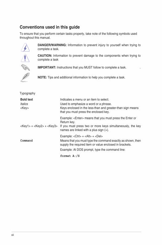
Conventions used in this guideTo ensure that you perform certain tasks properly, take note of the following symbols used throughout this manual.
DANGER/WARNING: Information to prevent injury to yourself when trying to complete a task.
CAUTION: Information to prevent damage to the components when trying to complete a task
IMPORTANT: Instructions that you MUST follow to complete a task. .
NOTE: Tips and additional information to help you complete a task.
Typography
Bold text Indicates a menu or an item to select.Italics Used to emphasize a word or a phrase.<Key> Keys enclosed in the less-than and greater-than sign means
that you must press the enclosed key.
Example: <Enter> means that you must press the Enter or Return key.
<Key1> + <Key2> + <Key3> If you must press two or more keys simultaneously, the key names are linked with a plus sign (+).
Example: <Ctrl> + <Alt> + <Del>Command Means that you must type the command exactly as shown, then
supply the required item or value enclosed in brackets.
Example: At DOS prompt, type the command line:
format A:/S
xiiiZ10PA-U8 Series
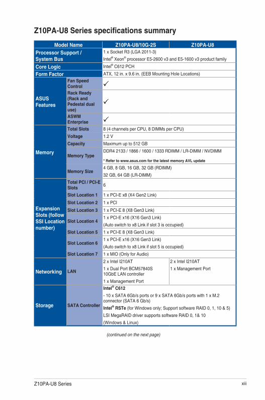
Z10PA-U8 Series specifications summary
(continued on the next page)
Model Name Z10PA-U8/10G-2S Z10PA-U8
Processor Support / System Bus
1 x Socket R3 (LGA 2011-3)
Intel® Xeon® processor E5-2600 v3 and E5-1600 v3 product family
Core Logic Intel® C612 PCH
Form Factor ATX, 12 in. x 9.6 in. (EEB Mounting Hole Locations)
ASUS Features
Fan Speed ControlRack Ready (Rack and Pedestal dual use)ASWM Enterprise
Memory
Total Slots 8 (4 channels per CPU, 8 DIMMs per CPU)
Voltage 1.2 V
Capacity Maximum up to 512 GB
Memory TypeDDR4 2133 / 1866 / 1600 / 1333 RDIMM / LR-DIMM / NVDIMM
* Refer to www.asus.com for the latest memory AVL update
Memory Size4 GB, 8 GB, 16 GB, 32 GB (RDIMM)
32 GB, 64 GB (LR-DIMM)
Expansion Slots (follow SSI Location number)
Total PCI / PCI-E Slots
6
Slot Location 1 1 x PCI-E x8 (X4 Gen2 Link)
Slot Location 2 1 x PCI
Slot Location 3 1 x PCI-E 8 (X8 Gen3 Link)
Slot Location 41 x PCI-E x16 (X16 Gen3 Link)
(Auto switch to x8 Link if slot 3 is occupied)
Slot Location 5 1 x PCI-E 8 (X8 Gen3 Link)
Slot Location 61 x PCI-E x16 (X16 Gen3 Link)
(Auto switch to x8 Link if slot 5 is occupied)
Slot Location 7 1 x MIO (Only for Audio)
Networking LAN
2 x Intel I210AT
1 x Dual Port BCM57840S 10GbE LAN controller
1 x Management Port
2 x Intel I210AT
1 x Management Port
Storage SATA Controller
Intel® C612
- 10 x SATA 6Gb/s ports or 9 x SATA 6Gb/s ports with 1 x M.2 connector (SATA 6 Gb/s)
Intel® RSTe (for Windows only; Support software RAID 0, 1, 10 & 5)
LSI MegaRAID driver supports software RAID 0, 1& 10
(Windows & Linux)

xiv
* Specifications are subject to change without notice.
Z10PA-U8 Series specifications summary
Model Name Z10PA-U8/10G-2S Z10PA-U8
Storage SAS Controller
Optional kits:
ASUS PIKE II 3008 8-port SAS 12G RAID card
ASUS PIKE II 3108 8-port SAS 12G HW RAID cardGraphic VGA Aspeed AST2400 32 MB
Onboard I/O Connectors
TPM Header 1PSU Connector 24-pin SSI power connector + 8-pin SSI 12VManagement connector
Onboard socket for optional management card
USB Connectors
1 x USB 3.0 pin header (up to 2 devices)
1 x USB 2.0 pin header (up to 2 devices)
1 x USB 2.0 connector (Type A USB socket)Fan Header 6 x 4-pinSMBus 1Chassis Intruder 1Front LAN LED 2Serial Port Header 1M.2 Connector 1 (NGFF Type 2242, Capacity 16 ~ 128 GB)
Rear I/O Connectors
VGA Port 1
External USB Port2 x USB 3.0
2 x USB 2.0
SFP+ 2 x SFP+ —
RJ-452 x GbE LAN
1 x Management LAN
PS/2 KB/Mouse 1
Management Solution
Software ASWM EnterpriseOut of Band Remote Management
Optional ASMB8-iKVM for KVM-over-Internet
MonitoringCPU Temperature
FAN RPM
EnvironmentOperation temperature: 10°C ~ 35°C
Non operation temperature: -40°C ~ 70°C
Non operation humidity: 20% ~ 90% (Non condensing)

1Product introduction
This chapter describes the motherboard features and the new technologies it supports.
Chapter 1: Product Introduction

1-2 Chapter 1: Product introduction
1.1 Welcome!Congratulations and thank you for buying an ASUS® Z10PA-U8 Series motherboard!
The motherboard delivers a host of new features and latest technologies, making it another standout in the long line of ASUS quality motherboards!
Before you start installing the motherboard and hardware devices on it, check the items in your package with the list below.
1.2 Package contentsCheck your motherboard package for the following items.
If any of the above items is damaged or missing, contact your retailer.
Standard Gift Box Pack Standard Bulk PackI/O Shield 1 1
SATA 6G cable 10 -
Application CDSupport DVD 1 1 piece per cartonASWM Enterprise SDVD 1 1 piece per carton
Packaging Quantity 1 piece per carton 10 pieces per carton
Optional items Description
PIKE II 3008 LSI 8-port SAS 12G RAID cardPIKE II 3108 LSI 8-port SAS 12G HW RAID cardASMB8-iKVM Remote management solution provides KVM over IP solutionPEM-FDR Mellanox ConnectX-3 FDR cardPEB-10G/57840-2S Dual port 10G SFP+ Ethernet AdapterPEB-10G/57811-1S Single port 10G SFP+ Ethernet Adapter
Z10PA-U8 Series 1-3
1.4 Special features
1.4.1 Product highlights
Latest Processor Technology
The motherboard supports Intel Xeon® processor E5-1600 V3 and E5-2600 V3 product family which provides compelling IPC increases for legacy performance improvements, floating point improvement, easire multi-core programming, and with next-generation processor power management.
Intel® AVX 2.0
Intel® AVX 2.0 extends 256-bit vector support for integer vector operations, doubles fixed point arithmetic throughput, adds support for new vector gather, permutes/blend, vector shifts resulting in fixed and floating-point algorithm improvements. Also, Intel's new microarchitecture doubles the cache bandwidth at L1/L2 to support higher FLOPS and contributes to greater performance in signal and image processing applications.
Next Generation of processor power management
Intel ® Xeon processor E5-2600 v3 product family enhances the processor power management with the features of Energy Efficient Turbo, Uncore Frequency Scaling, and Per-Core P-state. Also, the Integrated Voltage Regulator enables generational performance and power improvements that the standard VR solutions cannot provide.
DDR4 memory supportThe motherboard supports DDR4 memory that features faster clock frequencies and higher data transfer rates of 1333 MT/s to 2133 MT/s (million transfers per second). DDR4 offers a lower voltage standard of 1.2V that reduces memory power demand and provides improved performance.
1.3 Serial number labelBefore requesting support from the ASUS Technical Support team, you must take note of the motherboard's serial number containing 12 characters xxS2xxxxxxxx shown in the figure below. With the correct serial number of the product, ASUS Technical Support team members can then offer a quicker and satisfying solution to your problems.
xxS2xxxxxxxx
Z10PA-U8 Series Made in
China 合格

1-4 Chapter 1: Product introduction
M.2 Support
This motherboard features the M.2 slot, which shares bandwidth with the SATA 6Gb/s port and is dedicated to the operating system.
PCI Express 3.0
PCI Express 3.0 (PCIe 3.0) is the PCI Express bus standard that providse twice the performance and speed of PCIe 2.0. It provides an optimal graphics performance, unprecedented data speed, and seamless transition with its complete backward compatibility to PCIe 2.0 devices.
Intel® I210AT LAN Solution
The motherboard comes with two Gigabit LAN controllers and ports which provide a total solution for your networking needs. The onboard Intel® I210AT Gigabit LAN controllers use the PCI Express interface and could achieve network throughput close to Gigabit bandwidth.
Intel® C612 Series Chipset
The Intel® C612 series chipset supports with enterprise class features which is targeted for Cloud and Storage applications. It is optimized and validated to work with the latest Xeon®
processor E5-2600 v3 product family, compared with the last generation, it also reduces the TDP, supports USB 3.0 with up to 10 SATA III ports thus bringing more features and benefits to the target users.
Serial ATA III technology
The motherboard supports the Serial ATA III technology through the Serial ATA interface and Intel® C612 chipset, delivering up to 6 Gb/s data transfer rates. It also provides enhanced scalability, faster data retrieval, and double the bandwidth of current bus systems.
Temperature, fan, and voltage monitoring
The CPU temperature is monitored to prevent overheating and damage. The system fan rotations per minute (RPM) is monitored for timely failure detection. The chip monitors the voltage levels to ensure a stable supply of current for critical components.
1.4.2 Innovative ASUS features
ASUS Fan Speed control technology
The ASUS Fan Speed control technology smartly adjusts the fan speeds according to the system loading to ensure a quiet, cool, and efficient operation.
2Hardware Information
This chapter lists the hardware setup procedures that you have to perform when installing system components. It includes description of the jumpers and connectors on the motherboard.
Chapter 2: Hardware Information

2-2 Chapter 2: Hardware information
2.1 Before you proceedTake note of the following precautions before you install any motherboard component or change any motherboard settings.
• Unplugthepowercordfromthewallsocketbeforetouchinganycomponent.
• Useagroundedwriststraportouchasafelygroundedobjectorametalobject,suchasthepowersupplycase,beforehandlingcomponentstoavoiddamagingthemdueto static electricity.
• HoldcomponentsbytheedgestoavoidtouchingtheICsonthem.
• Wheneveryouuninstallanycomponent,placeitonagroundedantistaticpadorinthebag that came with the component.
• Beforeyouinstallorremoveanycomponent,ensurethatthepowersupplyisswitchedoff or the power cord is detached from the power supply. Failure to do so may cause severedamagetothemotherboard,peripherals,and/orcomponents.
2-3Z10PA-U8 Series
2.2 Motherboard overviewBeforeyouinstallthemotherboard,studytheconfigurationofyourchassistoensurethatthemotherboardfitsintoit.
Tooptimizethefeaturesofyourmotherboard,wehighlyrecommendthatyouinstallitinanATX 2.2 compliant chassis.
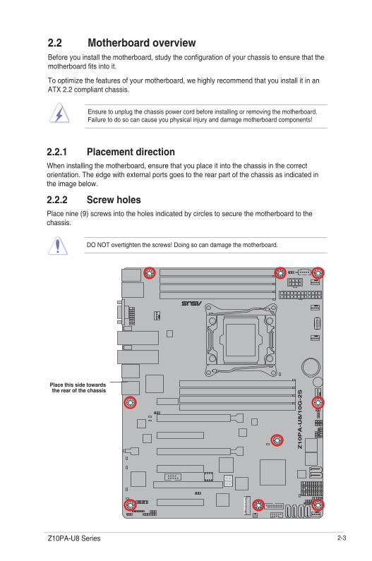
2.2.1 Placement directionWheninstallingthemotherboard,ensurethatyouplaceitintothechassisinthecorrectorientation. The edge with external ports goes to the rear part of the chassis as indicated in the image below.
2.2.2 Screw holesPlace nine (9) screws into the holes indicated by circles to secure the motherboard to the chassis.
DO NOT overtighten the screws! Doing so can damage the motherboard.
Ensure to unplug the chassis power cord before installing or removing the motherboard. Failure to do so can cause you physical injury and damage motherboard components!
Place this side towards the rear of the chassis

2-4 Chapter 2: Hardware information
2.2.3 Motherboard layout
Z10PA-U8/10G-2S

2-5Z10PA-U8 Series
Z10PA-U8

2-6 Chapter 2: Hardware information
2.2.4 Layout contents
Jumpers Page
1. ClearRTCRAM(CLRTC1) 2-24
2. VGAcontrollersetting(3-pinVGA_SW1) 2-25
3. LANcontrollersetting(3-pinLAN_SW1,LAN_SW2) 2-25
4. MEfirmwareforcerecoverysetting(3-pinME_RCVR1) 2-26
5. DDR4thermaleventsetting(3-pinDIMMTRIP1) 2-26
6. RAIDconfigurationutilityselection(3-pinRAID_SEL1) 2-27
7. PMBus1.2PSUselectjumper(3-pinSMART_PSU1) 2-27
Onboard LEDs Page
1. StandbyPowerLED(SBPWR1) 2-19
2. BaseboardManagementControllerLED(BMCLED1) 2-19
3. CPUWarningLED(ERR_CPU1) 2-20
4. CATTLED(CATTERR1) 2-20
5. Q-CodeLEDs(LED1) 2-21
Slots/Sockets Page
1. CPUsocket 2-8
2. DDR4sockets 2-13
3. PCIExpressx16/PCIExpressx8 2-16

2-7Z10PA-U8 Series
Internal connectors Page
1. SerialATA6.0Gb/sconnectors(7-pinSATA1-6,SSATA6G_1-4) 2-29
2. M.2(NGFF)connector(NGFF1) 2-30
3. PowerSupplySMBusconnector(5-pinPSUSMB1) 2-30
4. USB2.0connector(10-1pinUSB56,A-TypeUSB9) 2-31
5. USB3.0connector(20-1pinUSB3_34) 2-31
6. CPU,front,andrearfanconnectors(4-pinCPU_FAN1,FRNT_FAN1,FRNT_FAN2,FRNT_FAN3,FRNT_FAN4,REAR_FAN1) 2-32
7. Serialportconnector(10-1pinCOM1) 2-32
8. TrustedPlatformModuleconnector(20-1pinTPM1) 2-33
9. EATXpowerconnectors(24-pinEATXPWR1,8-pinEATX12V1) 2-34
10. Systempanelconnector(20-1pinPANEL1) 2-35
11. Auxiliarypanelconnector(20-2pinAUX_PANEL1) 2-36
12. HarddiskactivityLEDconnector(4-pinHDLED1) 2-37
13. ChassisIntrusion(2-pinINTRUSION) 2-37

2-8 Chapter 2: Hardware information
2.3.1 Installing the CPUToinstallaCPU:
1. LocatetheCPUsocketonthemotherboard.
2.3 Central Processing Unit (CPU)ThemotherboardcomeswithasurfacemountLGA2011-3SocketdesignedfortheIntel® Xeon E5-2600 v3 processor family.
• Uponpurchaseofthemotherboard,ensurethatthePnPcapisonthesocketandthesocketcontactsarenotbent.ContactyourretailerimmediatelyifthePnPcapismissing,orifyouseeanydamagetothePnPcap/socketcontacts/motherboardcomponents.ASUSwillshoulderthecostofrepaironlyifthedamageisshipment/transit-related.
• Keepthecapafterinstallingthemotherboard.ASUSwillprocessReturnMerchandiseAuthorization(RMA)requestsonlyifthemotherboardcomeswiththecapontheLGA2011-3 socket.
• TheproductwarrantydoesnotcoverdamagetothesocketcontactsresultingfromincorrectCPUinstallation/removal,ormisplacement/loss/incorrectremovalofthePnPcap.
BeforeinstallingtheCPU,ensurethatthesocketboxisfacingtowardyouandthetrianglemark is on the top-right position.
Triangle mark
2-9Z10PA-U8 Series
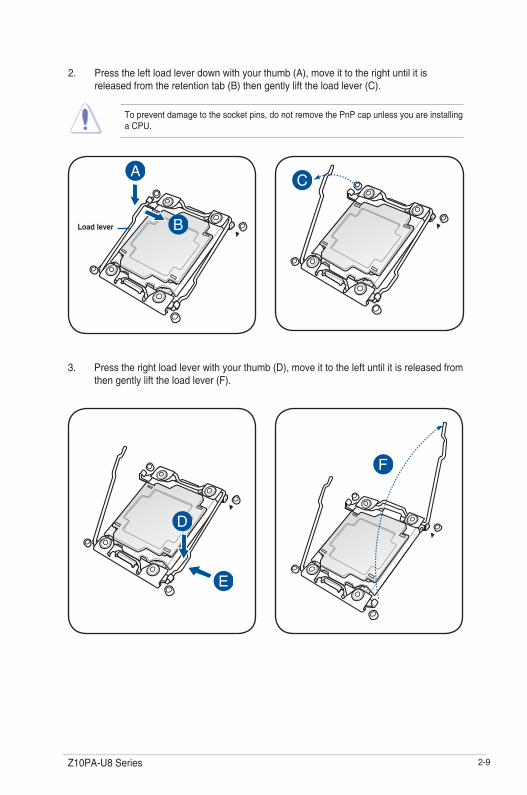
2. Presstheleftloadleverdownwithyourthumb(A),moveittotherightuntilitisreleasedfromtheretentiontab(B)thengentlylifttheloadlever(C).
Topreventdamagetothesocketpins,donotremovethePnPcapunlessyouareinstallingaCPU.
3. Presstherightloadleverwithyourthumb(D),move it to the left until it is released from then gently lift the load lever (F).
Load lever
2-10 Chapter 2: Hardware information
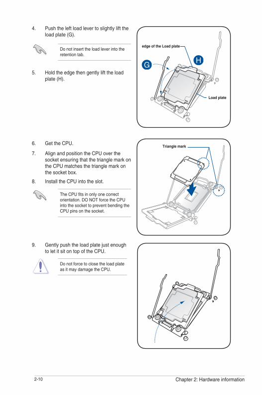
9. Gently push the load plate just enough toletitsitontopoftheCPU.
Do not force to close the load plate asitmaydamagetheCPU.
4. Push the left load lever to slightly lift the load plate (G).
Do not insert the load lever into the retention tab.
TheCPUfitsinonlyonecorrectorientation.DONOTforcetheCPUinto the socket to prevent bending the CPUpinsonthesocket.
6. GettheCPU.
7. AlignandpositiontheCPUoverthesocket ensuring that the triangle mark on theCPUmatchesthetrianglemarkonthe socket box.
Triangle mark
5. Holdtheedgethengentlylifttheloadplate(H).
8. InstalltheCPUintotheslot.
Load plate
edge of the Load plate
2-11Z10PA-U8 Series
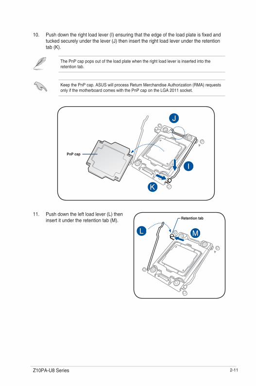
10. Pushdowntherightloadlever(I)ensuringthattheedgeoftheloadplateisfixedandtucked securely under the lever (J) then insert the right load lever under the retention tab(K).
The PnP cap pops out of the load plate when the right load lever is inserted into the retention tab.
KeepthePnPcap.ASUSwillprocessReturnMerchandiseAuthorization(RMA)requestsonlyifthemotherboardcomeswiththePnPcapontheLGA2011socket.
11. Pushdowntheleftloadlever(L)theninsertitundertheretentiontab(M). Retention tab
PnP cap

2-12 Chapter 2: Hardware information
13. ConnecttheCPUfancabletotheconnectoronthemotherboardlabeledCPU_FAN1/CPU_FAN2.
DONOTforgettoconnecttheCPUfanconnector!Hardwaremonitoringerrorscanoccurifyou fail to plug this connector.
TheThermalInterfaceMaterialistoxicandinedible.DONOTeatit.Ifitgetsintoyoureyesortouchesyourskin,washitoffimmediately,andseekprofessionalmedicalhelp.
• Ensure that the Thermal Interface Materialisspreadinaneventhinlayer.
• Some heatsinks come with pre-applied Thermal Interface Material.Ifso,skipthisstep.
12. ApplysomeThermalInterfaceMaterialtotheexposedareaoftheCPUthattheheatsink will be in contact with.

2-13Z10PA-U8 Series
2.4 System memory
2.4.1 OverviewThemotherboardcomeswitheight(8)DoubleDataRate4(DDR4)DualInlineMemoryModules(DIMM)sockets.
ThefigureillustratesthelocationoftheDDR4DIMMsockets:
2.4.2 Memory ConfigurationsYoumayinstall4GB,8GB,16GB,and32GBRDIMMsor32GBand64GBLR-DIMMsintotheDIMMsocketsusingthememoryconfigurationsinthissection.
• RefertoASUSServerAVLfortheupdatedlistofcompatibleDIMMs.
• WheninstallingDIMMs,alwaysstartfromslotA1.
• AlwaysinstallDIMMswiththesameCASlatency.Foroptimumcompatibility,itisrecommended that you obtain memory modules from the same vendor.
Youcanrefertothefollowingrecommendedmemorypopulation:
Recommended Memory configuration DIMM
A1 A2 B1 B2 C1 C2 D1 D2
1 DIMM P
2 DIMMs P P
4 DIMMs P P P P
8 DIMMs P P P P P P P P

2-14 Chapter 2: Hardware information
2.4.3 Installing a DIMM on a single clip DIMM socket
3. HoldtheDIMMatbothendstheninserttheDIMMintothesocket.ApplyforcetobothendsoftheDIMMsimultaneouslyuntil the retaining clip clicks into place andtheDIMMisseatedsecurelyinplace.
Locked Retaining Clip
1. Press the retaining clip outward to unlocktheDIMMsocket.
2. AlignaDIMMonthesocketsuchthatthenotchontheDIMMmatchestheDIMMslotkeyonthesocket.
Unlocked retaining clip
DIMM notch
DIMM slot key
1. Press the retaining clip outward to unlocktheDIMM.
2. RemovetheDIMMfromthesocket.
Removing a DIMM from a single clip DIMM socket
• ToinstalltwoormoreDIMMs,refertotheuserguidebundledwiththemotherboardpackage.
• Refertotheuserguideforqualifiedvendorlistsofthememorymodules.
SupporttheDIMMlightlywithyourfingerswhenpressingtheretainingclips.TheDIMMmightgetdamagedwhenitflipsoutwithextraforce.
AlwaysinserttheDIMMintothesocketVERTICALLYtopreventDIMMnotchdamage.
ADIMMiskeyedwithanotchsothatitfitsinonlyonedirection.DONOTforceaDIMMintoasocketinthewrongdirectiontoavoiddamagingtheDIMM.

2-15Z10PA-U8 Series
2.5 Expansion slotsInthefuture,youmayneedtoinstallexpansioncards.Thefollowingsubsectionsdescribetheslots and the expansion cards that they support.
2.5.1 Installing an expansion cardToinstallanexpansioncard:
1. Beforeinstallingtheexpansioncard,readthedocumentationthatcamewithitandmake the necessary hardware settings for the card.
2. Removethesystemunitcover(ifyourmotherboardisalreadyinstalledinachassis).
3. Removethebracketoppositetheslotthatyouintendtouse.Keepthescrewforlateruse.
4. Alignthecardconnectorwiththeslotandpressfirmlyuntilthecardiscompletelyseated on the slot.
5. Secure the card to the chassis with the screw you removed earlier.
6. Replacethesystemcover.
2.5.2 Configuring an expansion cardAfterinstallingtheexpansioncard,configureitbyadjustingthesoftwaresettings.
1. TurnonthesystemandchangethenecessaryBIOSsettings,ifany.SeeChapter 4 for informationonBIOSsetup.
2. AssignanIRQtothecard.
RefertothetableStandard Interrupt assignments in section Interrupt assignments for more information.
3. Install the software drivers for the expansion card.
Ensure to unplug the power cord before adding or removing expansion cards. Failure to do so may cause you physical injury and damage motherboard components.
WhenusingPCIcardsonsharedslots,ensurethatthedriverssupport“ShareIRQ”orthatthecardsdonotneedIRQassignments.Otherwise,conflictsmayarisebetweenthetwoPCIgroups,makingthesystemunstableandthecardinoperable.

2-16 Chapter 2: Hardware information
*TheseIRQsareusuallyavailableforISAorPCIdevices.
IRQ Priority Standard function
0 1 System Timer
1 2 KeyboardController
2 - Programmable Interrupt
3* 11 CommunicationsPort(COM2)
4* 12 CommunicationsPort(COM1)
5* 13 --
6 14 FloppyDiskController
7* 15 --
8 3 SystemCMOS/RealTimeClock
9* 4 ACPIModewhenused
10* 5 IRQHolderforPCISteering
11* 6 IRQHolderforPCISteering
12* 7 PS/2CompatibleMousePort
13 8 Numeric Data Processor
14* 9 PrimaryIDEChannel
15* 10 SecondaryIDEChannel
2.5.3 Interrupt assignments
Standard Interrupt assignments
2.5.4 PCI Express x16 slot (x16 link)TheonboardPCIE4andPCIE6slotsprovidesonex16Gen3linktoCPU1andautoswitchestox8linkifPCIE3/PCIE5isoccupied.ThisslotsupportsVGAcardsandvariousserverclasshigh performance add-on cards.
2.5.5 PCI Express x8 slot (x8 link)TheonboardPCIE3andPCIE5slotsprovideonex8Gen3linktoCPU1.TheseslotssupportVGA cards and various server class high performance add-on cards.
2.5.6 PCI Express x8 slot (x4 link)TheonboardPCIE1slotprovidesonex4Gen2linktoIntelC612PCHchipset.Thisslotsupport various server class high performance add-on cards.
2.5.7 PCI slot ThePCIslotsupportscardsthatcomplywithPCI2.3specifications.
TheonboardPCIE7supportsMIOonly.

2-17Z10PA-U8 Series
No. (Slot location) Short description
1 PCIE1 PCI-Ex8(x4Gen2 link)
2 PCI2 PCI3 PCIE3 PCI-Ex8(x8Gen3Link)
4 PCIE4 PCI-Ex16(x16Gen3Link) (Autoswitchtox8Linkifslot3isoccupied)
5 PCIE5 PCI-Ex8(x8Gen3Link)
6 PCIE6 PCI-Ex16(x16Gen3Link) (Autoswitchtox8Linkifslot5isoccupied)
7 MIO1 MIO(OnlyforAudio)

2-18 Chapter 2: Hardware information
2.5.8 Installing ASMB8 series management boardFollowthestepsbelowtoinstallanoptionalASMB8seriesmanagementboardonyourmotherboard.
3. InserttheLANcableplugtotheLANport1(dedicatedLAN)orLANport(sharedLAN)for server management.
1. LocatetheBaseboardManagementCardheaderonthemotherboard.
2. OrientandpresstheManagementCardin place.
2-19Z10PA-U8 Series
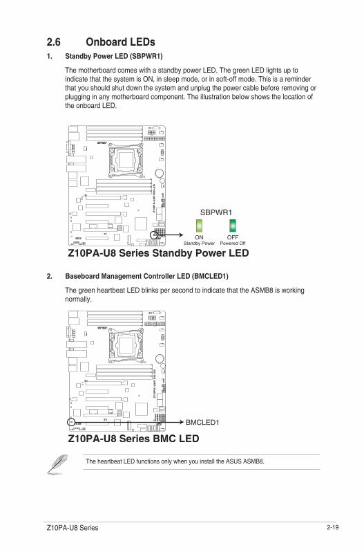
2. Baseboard Management Controller LED (BMCLED1)
ThegreenheartbeatLEDblinkspersecondtoindicatethattheASMB8isworkingnormally.
TheheartbeatLEDfunctionsonlywhenyouinstalltheASUSASMB8.
2.6 Onboard LEDs1. Standby Power LED (SBPWR1)
ThemotherboardcomeswithastandbypowerLED.ThegreenLEDlightsuptoindicatethatthesystemisON,insleepmode,orinsoft-offmode.Thisisareminderthat you should shut down the system and unplug the power cable before removing or plugging in any motherboard component. The illustration below shows the location of theonboardLED.

2-20 Chapter 2: Hardware information
3. CPU Warning LED (ERR_CPU1)
TheCPUwarningLEDslightuptoindicatefailureontheCPU.
4. CATT LED (CATTERR1)
TheCATTLEDindicatesthatthesystemhasexperiencedafatalorcatastrophicerrorand cannot continue to operate.

2-21Z10PA-U8 Series
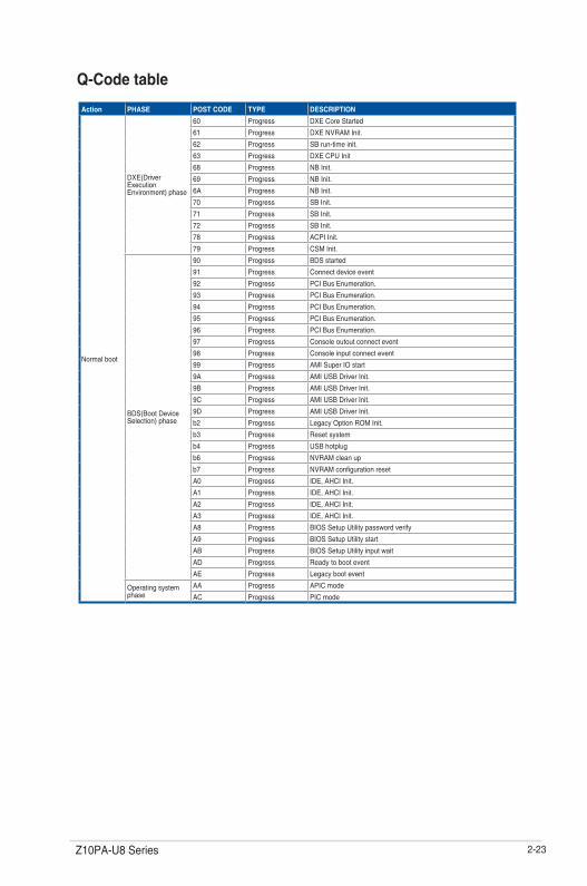
5. Q-Code LEDs (LED1)
TheQ-CodeLEDprovidesa2-digitdisplaythatshowsthestatusofyoursystem.RefertotheQ-Codetableofthisuserguideformoreinformationaboutthe2-digitcodes.
2-22 Chapter 2: Hardware information
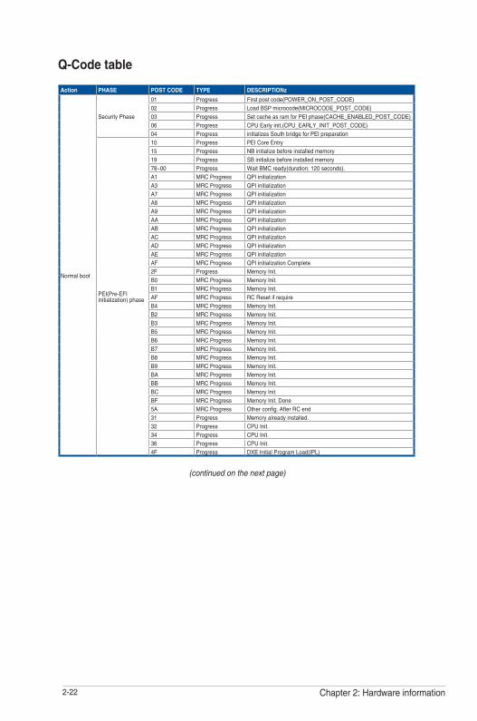
Q-Code table
Action PHASE POST CODE TYPE DESCRIPTIONz
Normal boot
Security Phase
01 Progress Firstpostcode(POWER_ON_POST_CODE)02 Progress LoadBSPmicrocode(MICROCODE_POST_CODE)03 Progress SetcacheasramforPEIphase(CACHE_ENABLED_POST_CODE)06 Progress CPUEarlyinit.(CPU_EARLY_INIT_POST_CODE)04 Progress initializes South bridge for PEI preparation
PEI(Pre-EFI initialization) phase
10 Progress PEICoreEntry15 Progress NBinitializebeforeinstalledmemory19 Progress SBinitializebeforeinstalledmemory78~00 Progress WaitBMCready(duration:120seconds).A1 MRCProgress QPI initializationA3 MRCProgress QPI initializationA7 MRCProgress QPI initializationA8 MRCProgress QPI initializationA9 MRCProgress QPI initializationAA MRCProgress QPI initializationAB MRCProgress QPI initializationAC MRCProgress QPI initializationAD MRCProgress QPI initializationAE MRCProgress QPI initializationAF MRCProgress QPIinitializationComplete2F Progress MemoryInit.B0 MRCProgress MemoryInit.B1 MRCProgress MemoryInit.AF MRCProgress RCResetifrequireB4 MRCProgress MemoryInit.B2 MRCProgress MemoryInit.B3 MRCProgress MemoryInit.B5 MRCProgress MemoryInit.B6 MRCProgress MemoryInit.B7 MRCProgress MemoryInit.B8 MRCProgress MemoryInit.B9 MRCProgress MemoryInit.BA MRCProgress MemoryInit.BB MRCProgress MemoryInit.BC MRCProgress MemoryInit.BF MRCProgress MemoryInit.Done5A MRCProgress Otherconfig.AfterRCend31 Progress Memoryalreadyinstalled.32 Progress CPUInit.34 Progress CPUInit.36 Progress CPUInit.4F Progress DXEInitialProgramLoad(IPL)
(continued on the next page)
2-23Z10PA-U8 Series
Action PHASE POST CODE TYPE DESCRIPTION
Normal boot
DXE(Driver Execution Environment) phase
60 Progress DXECoreStarted
61 Progress DXENVRAMInit.
62 Progress SBrun-timeinit.
63 Progress DXECPUInit
68 Progress NBInit.
69 Progress NBInit.
6A Progress NBInit.
70 Progress SBInit.
71 Progress SBInit.
72 Progress SBInit.
78 Progress ACPIInit.
79 Progress CSMInit.
BDS(BootDeviceSelection) phase
90 Progress BDSstarted
91 Progress Connectdeviceevent
92 Progress PCIBusEnumeration.
93 Progress PCIBusEnumeration.
94 Progress PCIBusEnumeration.
95 Progress PCIBusEnumeration.
96 Progress PCIBusEnumeration.
97 Progress Consoleoutoutconnectevent
98 Progress Consoleinputconnectevent
99 Progress AMISuperIOstart
9A Progress AMIUSBDriverInit.
9B Progress AMIUSBDriverInit.
9C Progress AMIUSBDriverInit.
9D Progress AMIUSBDriverInit.
b2 Progress LegacyOptionROMInit.
b3 Progress Resetsystem
b4 Progress USBhotplug
b6 Progress NVRAMcleanup
b7 Progress NVRAMconfigurationreset
A0 Progress IDE,AHCIInit.
A1 Progress IDE,AHCIInit.
A2 Progress IDE,AHCIInit.
A3 Progress IDE,AHCIInit.
A8 Progress BIOSSetupUtilitypasswordverify
A9 Progress BIOSSetupUtilitystart
AB Progress BIOSSetupUtilityinputwait
AD Progress Readytobootevent
AE Progress Legacybootevent
Operating system phase
AA Progress APICmode
AC Progress PICmode
Q-Code table
2-24 Chapter 2: Hardware information
2.7 Jumpers
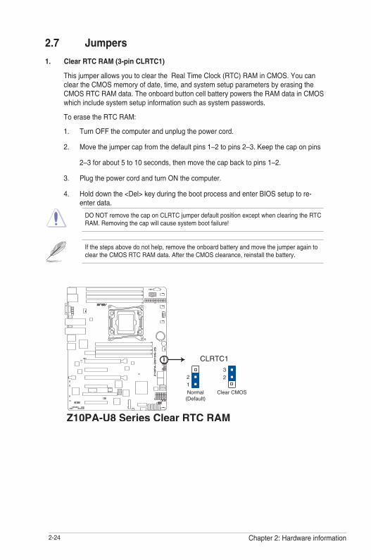
1. Clear RTC RAM (3-pin CLRTC1)
ThisjumperallowsyoutocleartheRealTimeClock(RTC)RAMinCMOS.YoucancleartheCMOSmemoryofdate,time,andsystemsetupparametersbyerasingtheCMOSRTCRAMdata.TheonboardbuttoncellbatterypowerstheRAMdatainCMOSwhich include system setup information such as system passwords.
ToerasetheRTCRAM:
1. Turn OFF the computer and unplug the power cord.
2. Movethejumpercapfromthedefaultpins1–2topins2–3.Keepthecaponpins
2–3forabout5to10seconds,thenmovethecapbacktopins1–2.
3. Plug the power cord and turn ON the computer.
4. Holddownthe<Del>keyduringthebootprocessandenterBIOSsetuptore-enter data.
DONOTremovethecaponCLRTCjumperdefaultpositionexceptwhenclearingtheRTCRAM.Removingthecapwillcausesystembootfailure!
Ifthestepsabovedonothelp,removetheonboardbatteryandmovethejumperagaintocleartheCMOSRTCRAMdata.AftertheCMOSclearance,reinstallthebattery.
2-25Z10PA-U8 Series
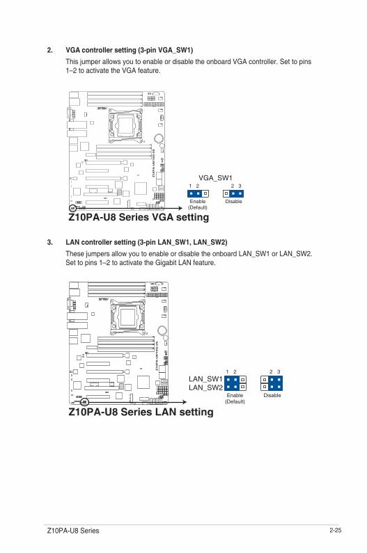
2. VGA controller setting (3-pin VGA_SW1)
This jumper allows you to enable or disable the onboard VGA controller. Set to pins 1–2toactivatetheVGAfeature.
3. LAN controller setting (3-pin LAN_SW1, LAN_SW2)
ThesejumpersallowyoutoenableordisabletheonboardLAN_SW1orLAN_SW2.Set to pins 1–2toactivatetheGigabitLANfeature.

2-26 Chapter 2: Hardware information
4. ME firmware force recovery setting (3-pin ME_RCVR1)
This jumper allows you to force Intel®ManagementEngine(ME)bootfromrecoverymodewhenMEbecomescorrupted.
5. DDR4 thermal event setting (3-pin DIMMTRIP1)
ThisjumperallowsyoutoenableordisableDDR4DIMMthermalsensingeventpin.
2-27Z10PA-U8 Series
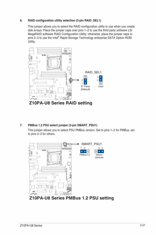
6. RAID configuration utility selection (3-pin RAID_SEL1)
ThisjumperallowsyoutoselecttheRAIDconfigurationutilitytousewhenyoucreatediskarrays.Placethejumpercapsoverpins1–2tousethethirdpartysoftwareLSIMegaRAIDsoftwareRAIDConfigurationUtility;otherwise,placethejumpercapstopins2–3tousetheIntel®RapidStorageTechnologyenterpriseSATAOptionROMUtility.
7. PMBus 1.2 PSU select jumper (3-pin SMART_PSU1)
ThisjumperallowsyoutoselectPSUPMBusversion.Settopins1–2forPMBus,setto pins 2–3 for others.

2-28 Chapter 2: Hardware information
2.8 Connectors
2.8.1 Rear panel connectors
1. PS/2keyboard/mouseport(purple/green):ThisportisforaPS/2keyboardormouse.
2. RJ-45portforiKVM:ThisRJ-45portfunctionswhenyouenabletheASMB8controller.
3. VideoGraphicsAdapter(VGA)port:ThisportisforaVGAmonitororotherVGA-compatible devices.
4. SFP+ports:Theseportisforconnectingtheenhancedsmallform-factorpluggable(SFP+) module that supports data rates up to 10 Gbps.
5. RJ-45portsforLAN:TheseportsallowsGigabitconnectiontoaLANthroughanetworkhub.RefertotheLANportLEDindicationstableformoreinformation.
6. Power-onButton:Pressthisbuttontoturnonthesystem.
7. USB2.0ports1and2:Thesetwo4-pinUniversalSerialBus(USB)portsareavailableforconnectingUSB2.0devices.
8. USB3.0ports1and2:Thesetwo4-pinUniversalSerialBus(USB)portsareavailableforconnectingUSB3.0devices.
9. SFP+LEDs:TheseLEDsindicatesthelinkstatusandthelinkspeedoftheSFP+ports.RefertothetablebelowfortheSFP+LEDindications.
Dedicated Management LAN port LED indications SPEED LED
ACT/LINK LED
Activity/Link LED Speed LED
Status Description Status Description
OFF No link OFF 10Mbpsconnection
ORANGE Linked ORANGE 100Mbpsconnection
BLINKING Data activity GREEN 1 Gbps connection
Management LAN port LED indications
SFP+_LED indications
SFP+ LED
Speed LED
Activity LEDActivity LED Speed LED
Status Description Status Description
OFF No activity OFF -
BLINKING Data activity AMBER 1 Gbps connection
GREEN 10 Gbps connection
2-29Z10PA-U8 Series
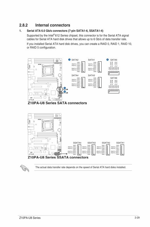
The actual data transfer rate depends on the speed of Serial ATA hard disks installed.
2.8.2 Internal connectors1. Serial ATA 6.0 Gb/s connectors (7-pin SATA1-6, SSATA1-4)
Supported by the Intel® 612Serieschipset,thisconnectorisfortheSerialATAsignalcablesforSerialATAharddiskdrivesthatallowsupto6Gb/sofdatatransferrate.
IfyouinstalledSerialATAharddiskdrives,youcancreateaRAID0,RAID1,RAID10,orRAID5configuration.

2-30 Chapter 2: Hardware information
2. M.2 (NGFF) connector (NGFF1)
ThisconnectorallowsyoutoinstallanM.2device.
3. Power Supply SMBus connector (5-pin PSUSMB1)
ThisconnectorallowsyoutoconnectSMBus(SystemManagementBus)tothePSU(powersupplyunit)toreadPSUinformation.DevicescommunicatewithanSMBushostand/orotherSMBusdevicesusingtheSMBusinterface.
ThisconnectorfunctionsonlywhenyouinstalltheASUSASMB8.
PowersupplyisrequiredtomeetPMBusspecificationandcustomizedBMCFWmaybeneeded.PleasecontactASUSifyourneedfurthersupport.
This connector supports type 2242 devices on the SATA interface.
TheM.2(NGFF)deviceispurchasedseparately

2-31Z10PA-U8 Series
4. USB 2.0 connector (10-1 pin USB56, A-Type USB9)
TheseconnectorsareforUSB2.0ports.ConnecttheUSBmodulecablestoconnectorsUSB56.TheseUSBconnectorscomplywithUSB2.0specificationthatsupportsupto480Mb/sconnectionspeed.
5. USB 3.0 connector (20-1 pin USB3_34)
ThisconnectorallowsyoutoconnectaUSB3.0moduleforadditionalUSB3.0frontorrearpanelports.WithaninstalledUSB3.0module,youcanenjoyallthebenefitsofUSB3.0includingfasterdatatransferspeedsofupto5Gbps,fasterchargingtimeforUSB-chargeabledevices,optimizedpowerefficiency,andbackwardcompatibilitywithUSB2.0.

2-32 Chapter 2: Hardware information
6. CPU, front, and rear fan connectors (4-pin CPU_FAN1, FRNT_FAN1, FRNT_FAN2, FRNT_FAN3, FRNT_FAN4, REAR_FAN1)
Thefanconnectorssupportcoolingfans.Connectthefancablestothefanconnectorsonthemotherboard,ensuringthattheblackwireofeachcablematchesthegroundpinof the connector.
• DONOTforgettoconnectthefancablestothefanconnectors.Insufficientairflowinside the system may damage the motherboard components.
• Thesearenotjumpers!DONOTplacejumpercapsonthefanconnectors!
• AllfansfeaturetheASUSSmartFantechnology.
7. Serial port connector (10-1 pin COM1)
ThisconnectorisfortheserialCOMport.Connecttheserialportmodulecabletooneoftheseconnectors,theninstallthemoduletoaslotopeningatthebackofthesystemchassis.

2-33Z10PA-U8 Series
8. Trusted Platform Module connector (20-1 pin TPM1)
ThisconnectorsupportsaTrustedPlatformModule(TPM)system,whichcansecurelystorekeys,digitalcertificates,passwords,anddata.ATPMsystemalsohelpsenhancenetworksecurity,protectsdigitalidentities,andensuresplatformintegrity.
2-34 Chapter 2: Hardware information
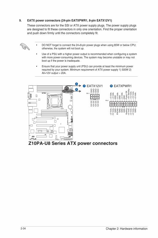
9. EATX power connectors (24-pin EATXPWR1, 8-pin EATX12V1)
These connectors are for the SSI or ATX power supply plugs. The power supply plugs aredesignedtofittheseconnectorsinonlyoneorientation.Findtheproperorientationandpushdownfirmlyuntiltheconnectorscompletelyfit.
• DONOTforgettoconnectthe24+8-pinpowerplugswhenusing85WorbelowCPU;otherwise,thesystemwillnotbootup.
• UseofaPSUwithahigherpoweroutputisrecommendedwhenconfiguringasystemwith more power-consuming devices. The system may become unstable or may not bootupifthepowerisinadequate.
• Ensurethatyourpowersupplyunit(PSU)canprovideatleasttheminimumpowerrequiredbyyoursystem.MinimumrequirementofATXpowersupply1)500W2)All+12Voutput>20A.
2-35Z10PA-U8 Series
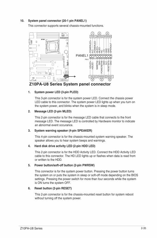
10. System panel connector (20-1 pin PANEL1)
This connector supports several chassis-mounted functions.
1. System power LED (3-pin PLED)
This3-pinconnectorisforthesystempowerLED.ConnectthechassispowerLEDcabletothisconnector.ThesystempowerLEDlightsupwhenyouturnonthesystempower,andblinkswhenthesystemisinsleepmode.
2. Message LED (2-pin MLED)
This2-pinconnectorisforthemessageLEDcablethatconnectstothefrontmessageLED.ThemessageLEDiscontrolledbyHardwaremonitortoindicatean abnormal event occurance.
3. System warning speaker (4-pin SPEAKER)
This 4-pin connector is for the chassis-mounted system warning speaker. The speaker allows you to hear system beeps and warnings.
4. Hard disk drive activity LED (2-pin HDD LED)
This2-pinconnectorisfortheHDDActivityLED.ConnecttheHDDActivityLEDcabletothisconnector.TheHDLEDlightsuporflasheswhendataisreadfromorwrittentotheHDD.
5. Power button/soft-off button (2-pin PWRSW)
This connector is for the system power button. Pressing the power button turns thesystemonorputsthesysteminsleeporsoft-offmodedependingontheBIOSsettings. Pressing the power switch for more than four seconds while the system is ON turns the system OFF.
6. Reset button (2-pin RESET)
This 2-pin connector is for the chassis-mounted reset button for system reboot without turning off the system power.
2-36 Chapter 2: Hardware information
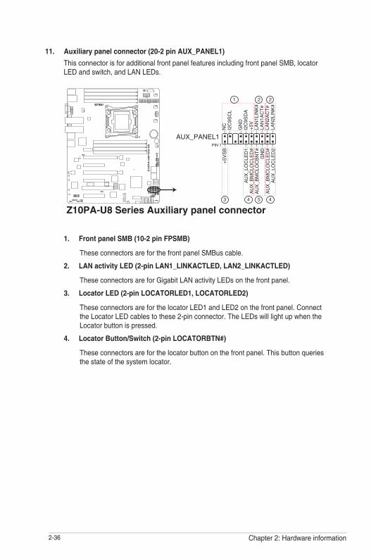
11. Auxiliary panel connector (20-2 pin AUX_PANEL1)
ThisconnectorisforadditionalfrontpanelfeaturesincludingfrontpanelSMB,locatorLEDandswitch,andLANLEDs.
1. Front panel SMB (10-2 pin FPSMB)
TheseconnectorsareforthefrontpanelSMBuscable.
2. LAN activity LED (2-pin LAN1_LINKACTLED, LAN2_LINKACTLED)
TheseconnectorsareforGigabitLANactivityLEDsonthefrontpanel.
3. Locator LED (2-pin LOCATORLED1, LOCATORLED2)
TheseconnectorsareforthelocatorLED1andLED2onthefrontpanel.ConnecttheLocatorLEDcablestothese2-pinconnector.TheLEDswilllightupwhentheLocatorbuttonispressed.
4. Locator Button/Switch (2-pin LOCATORBTN#)
Theseconnectorsareforthelocatorbuttononthefrontpanel.Thisbuttonqueriesthe state of the system locator.

2-37Z10PA-U8 Series
12. Hard disk activity LED connector (4-pin HDLED1)
ThisLEDconnectorisforthestorageadd-oncardcableconnectedtotheSATAorSAS add-on card. The read or write activities of any device connected to the SATA or SASadd-oncardcausesthefrontpanelLEDtolightup.
13. Chassis Intrusion (2-pin INTRUSION)
These leads are for the intrusion detection feature for chassis with intrusion sensor or microswitch.Whenyouremoveanychassiscomponent,thesensortriggersandsendsa high level signal to these leads to record a chassis intrusion event. The default setting isshortCHASSIS#andGNDpinbyjumpercaptodisablethefunction.

2-38 Chapter 2: Hardware information

3Powering Up
This chapter describes the power up sequence, and ways of shutting down the system.
Chapter 3: Powering Up
3-2 Chapter 3: Powering up
3.1 Starting up for the first time1. After making all the connections, replace the system case cover.
2. Be sure that all switches are off.
3. Connect the power cord to the power connector at the back of the system chassis.
4. Connect the power cord to a power outlet that is equipped with a surge protector.
5. Turn on the devices in the following order:
a. Monitor
b. External storage devices (starting with the last device on the chain)
c. System power
6. After applying power, the system power LED on the system front panel case lights up. For systems with ATX power supplies, the system LED lights up when you press the ATX power button. If your monitor complies with “green” standards or if it has a “power standby” feature, the monitor LED may light up or switch between orange and green after the system LED turns on.
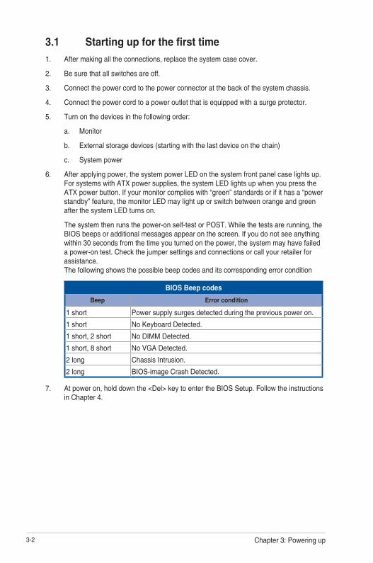
The system then runs the power-on self-test or POST. While the tests are running, the BIOS beeps or additional messages appear on the screen. If you do not see anything within 30 seconds from the time you turned on the power, the system may have failed a power-on test. Check the jumper settings and connections or call your retailer for assistance. The following shows the possible beep codes and its corresponding error condition
BIOS Beep codes
Beep Error condition
1 short Power supply surges detected during the previous power on.
1 short No Keyboard Detected.
1 short, 2 short No DIMM Detected.
1 short, 8 short No VGA Detected.
2 long Chassis Intrusion.
2 long BIOS-image Crash Detected.
7. At power on, hold down the <Del> key to enter the BIOS Setup. Follow the instructions in Chapter 4.

3-3Z10PA-U8 Series
3.2 Powering off the computer
3.2.1 Using the OS shut down functionUsing Windows® Server 2008 R2:
1. Click the Start button, move the cursor to the triangle on the right of Log off, then click Shut Down.
2. From the Shutdown Event Tracker, select the option that best describes why you want to shut down the computer.
3. Ensure that the Planned check box is checked.
4. If necessary, key in comments.
5. Click OK.
Using Windows® Server 2012:
1. Press <Ctrl>+<Alt>+<Del>.
2. Click on the Power icon on the lower right side of the screen.
3. Select Shut down.
4. In the Shutdown Event Tracker, select the Other (Planned) option in the selection lists. Otherwise, select the option that best describes why you want to shut down the computer.
5. Click Continue.
3.2.2 Using the dual function power switchWhile the system is ON, press the power switch for less than four seconds to put the system to sleep mode or to soft-off mode, depending on the BIOS setting.
Pressing the power switch for more than four seconds lets the system enter the soft-off mode regardless of the BIOS setting.

3-4 Chapter 3: Powering up

4BIOS setup
This chapter tells how to change the system settings through the BIOS Setup menus. Detailed descriptions of the BIOS parameters are also provided.
Chapter 4: BIOS setup

4-2 Chapter 4: BIOS setup
4.1 Managing and updating your BIOSThe following utilities allow you to manage and update the motherboard Basic Input/Output System (BIOS) setup:
1. ASUS CrashFree BIOS 3
TorecovertheBIOSusingabootableUSBflashdiskdrivewhentheBIOSfilefailsorgets corrupted.
2. ASUS EzFlash
UpdatestheBIOSusingaUSBflashdisk.
3. BUPDATER
UpdatestheBIOSinDOSmodeusingabootableUSBflashdiskdrive.
Refer to the corresponding sections for details on these utilities.
Recovering the BIOS from a USB flash drive
TorecovertheBIOSfromaUSBflashdrive:
1. InserttheUSBflashdrivewiththeoriginalorupdatedBIOSfiletooneUSBportonthesystem.
2. The utility will automatically recover the BIOS. It resets the system when the BIOS recoveryfinished.
DO NOT shut down or reset the system while recovering the BIOS! Doing so would cause system boot failure!
The recovered BIOS may not be the latest BIOS version for this motherboard. Visit the ASUSwebsiteatwww.asus.comtodownloadthelatestBIOSfile.
SaveacopyoftheoriginalmotherboardBIOSfiletoabootableUSBflashdiskdriveincase you need to restore the BIOS in the future. Copy the original motherboard BIOS using the BUPDATER utility.
4.1.1 ASUS CrashFree BIOS 3 utilityTheASUSCrashFreeBIOS3isanautorecoverytoolthatallowsyoutorestoretheBIOSfilewhen it fails or gets corrupted during the updating process. You can update a corrupted BIOS fileusingaUSBflashdrivethatcontainstheupdatedBIOSfile.
PrepareaUSBflashdrivecontainingtheupdatedmotherboardBIOSbeforeusingthisutility.

4-3Z10PA-U8 Series
3. Press <Tab> to switch to the Drivefield.
4. PresstheUp/DownarrowkeystofindtheUSBflashdiskthatcontainsthelatestBIOS,then press <Enter>.
5. Press <Tab> to switch to the Folder Infofield.
6. PresstheUp/DownarrowkeystofindtheBIOSfile,andthenpress<Enter>toperformthe BIOS update process. Reboot the system when the update process is done.
4.1.2 ASUS EZ Flash UtilityThe ASUS EZ Flash Utility feature allows you to update the BIOS without having to use a DOS-based utility.
Beforeyoustartusingthisutility,downloadthelatestBIOSfromtheASUSwebsiteatwww.asus.com.
To update the BIOS using EZ Flash Utility:
1. InserttheUSBflashdiskthatcontainsthelatestBIOSfileintotheUSBport.
2. Enter the BIOS setup program. Go to the Tool menu then select ASUS EZ Flash Utility. Press <Enter>.
ASUS Tek. EzFlash Utility
[Up/Down/Left/Right]:Switch [Enter]:Choose [q]:Exit
FS0 System Volume Information <DIR>
Windows <DIR>Z10PA-U8 BIOS <DIR>
Current PlatformPlatform : Z10PA-U8Version : 0001Build Date :05/13/2014
New PlatformPlatform : Z10PA-U8Version : 0002Build Date :08/28/2014

4-4 Chapter 4: BIOS setup
4.1.3 BUPDATER utility
The succeeding BIOS screens are for reference only. The actual BIOS screen displays may not be the same as shown.
TheBUPDATERutilityallowsyoutoupdatetheBIOSfileintheDOSenvironmentusingabootableUSBflashdiskdrivewiththeupdatedBIOSfile.
Updating the BIOS fileToupdatetheBIOSfileusingtheBUPDATERutility:
1. VisittheASUSwebsiteatwww.asus.comanddownloadthelatestBIOSfileforthemotherboard.SavetheBIOSfiletoabootableUSBflashdiskdrive.
2. Copy the BUPDATER utility (BUPDATER.exe) from the ASUS support website at support.asus.comtothebootableUSBflashdiskdriveyoucreatedearlier.
3. BootthesysteminDOSmode,thenattheprompt,type:
BUPDATER /i[filename].CAP
where[filename]isthelatestortheoriginalBIOSfileonthebootableUSBflashdiskdrive,thenpress<Enter>.
A:\>BUPDATER /i[file name].CAP
• ThisfunctioncansupportdevicessuchasaUSBflashdiskwithFAT32/16formatandsingle partition only.
• DONOTshutdownorresetthesystemwhileupdatingtheBIOStopreventsystemboot failure!
Ensure to load the BIOS default settings to ensure system compatibility and stability. Press <F5> and select Yes to load the BIOS default settings.
4-5Z10PA-U8 Series
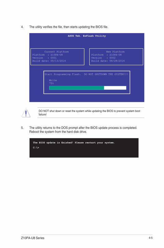
4. Theutilityverifiesthefile,thenstartsupdatingtheBIOSfile.
DO NOT shut down or reset the system while updating the BIOS to prevent system boot failure!
5. The utility returns to the DOS prompt after the BIOS update process is completed. Rebootthesystemfromtheharddiskdrive.
The BIOS update is finished! Please restart your system.
C:\>
Current PlatformPlatform : Z10PA-U8 Version : 0001Build date: 05/13/2014
New PlatformPlatform : Z10PA-U8Version : 0002Build date: 08/28/2014
ASUS Tek. EzFlash Utility
Start Programming Flash. DO NOT SHUTDOWN THE SYSTEM!!!
Write 75%

4-6 Chapter 4: BIOS setup
4.2 BIOS setup programThismotherboardsupportsaprogrammablefirmwarechipthatyoucanupdateusingtheprovided utility described in section 5.1 Managing and updating your BIOS.
UsetheBIOSSetupprogramwhenyouareinstallingamotherboard,reconfiguringyoursystem,orpromptedto“RunSetup.”Thissectionexplainshowtoconfigureyoursystemusing this utility.
EvenifyouarenotpromptedtousetheSetupprogram,youcanchangetheconfigurationofyourcomputerinthefuture.Forexample,youcanenablethesecuritypasswordfeatureorchangethepowermanagementsettings.Thisrequiresyoutoreconfigureyoursystemusingthe BIOS Setup program so that the computer can recognize these changes and record them intheCMOSRAMofthefirmwarechip.
ThefirmwarechiponthemotherboardstorestheSetuputility.Whenyoustartupthecomputer,thesystemprovidesyouwiththeopportunitytorunthisprogram.Press<Del>duringthePower-OnSelf-Test(POST)toentertheSetuputility;otherwise,POSTcontinueswith its test routines.
IfyouwishtoenterSetupafterPOST,restartthesystembypressing<Ctrl+Alt+Delete>,orbypressing the reset button on the system chassis. You can also restart by turning the system offandthenbackon.Dothislastoptiononlyifthefirsttwofailed.
TheSetupprogramisdesignedtomakeitaseasytouseaspossible.Beingamenu-drivenprogram,itletsyouscrollthroughthevarioussub-menusandmakeyourselectionsfromtheavailableoptionsusingthenavigationkeys.
• ThedefaultBIOSsettingsforthismotherboardapplyformostconditionstoensureoptimum performance. If the system becomes unstable after changing any BIOS settings,loadthedefaultsettingstoensuresystemcompatibilityandstability.Press<F5> and select Yes to load the BIOS default settings.
• TheBIOSsetupscreensshowninthissectionareforreferencepurposesonly,andmay not exactly match what you see on your screen.
• VisittheASUSwebsite(www.asus.com)todownloadthelatestBIOSfileforthismotherboard.

4-7Z10PA-U8 Series
4.2.2 Menu barThe menu bar on top of the screen has the following main items:
Main Forchangingthebasicsystemconfiguration
Advanced For changing the advanced system settings
IntelRCSetup For changing the Intel RC settings
Server Mgmt For changing the Server Mgmt settings
Event Logs For changing the event log settings
Monitor Fordisplayingthesystemtemperature,powerstatus,andchangingthe fan settings
Security For changing the security settings
Boot Forchangingthesystembootconfiguration
Tool Forconfiguringoptionsforspecialfunctions
Exit For selecting the exit options
Toselectanitemonthemenubar,presstherightorleftarrowkeyonthekeyboarduntilthedesired item is highlighted.
4.2.1 BIOS menu screen
Navigation keys
General helpMenu bar Configuration fieldsMenu items

4-8 Chapter 4: BIOS setup
4.2.3 Menu itemsThehighlighteditemonthemenubardisplaysthespecificitemsforthatmenu.Forexample,selecting Main shows the Main menu items.
Theotheritems(EventLogs,Advanced,Monitor,Boot,Tool,andExit)onthemenubarhavetheir respective menu items.
4.2.4 Submenu itemsA solid triangle before each item on any menu screen means that the item has a submenu. To displaythesubmenu,selecttheitemthenpress<Enter>.
4.2.5 Navigation keysAtthebottomrightcornerofamenuscreenarethenavigationkeysfortheBIOSsetupprogram.Usethenavigationkeystoselectitemsinthemenuandchangethesettings.
4.2.6 General helpAt the top right corner of the menu screen is a brief description of the selected item.
4.2.7 Configuration fieldsThesefieldsshowthevaluesforthemenuitems.Ifanitemisuser-configurable,youcanchangethevalueofthefieldoppositetheitem.Youcannotselectanitemthatisnotuser-configurable.
Aconfigurablefieldisenclosedinbrackets,andishighlightedwhenselected.Tochangethevalueofafield,selectitandpress<Enter>todisplayalistofoptions.
4.2.8 Pop-up windowSelectamenuitemandpress<Enter>todisplayapop-upwindowwiththeconfigurationoptions for that item.
4.2.9 Scroll barAscrollbarappearsontherightsideofamenuscreenwhenthereareitemsthatdonotfitonthescreen.PresstheUp/Downarrowkeysor<PageUp>/<PageDown>keystodisplaytheother items on the screen.

4-9Z10PA-U8 Series
4.3 Main menuWhenyouentertheBIOSSetupprogram,theMainmenuscreenappears.TheMainmenuprovidesyouanoverviewofthebasicsysteminformation,andallowsyoutosetthesystemdate,time,language,andsecuritysettings.
4.3.1 System Date [Day xx/xx/xxxx]Allows you to set the system date.
4.3.2 System Time [xx:xx:xx]Allows you to set the system time.
4-10 Chapter 4: BIOS setup
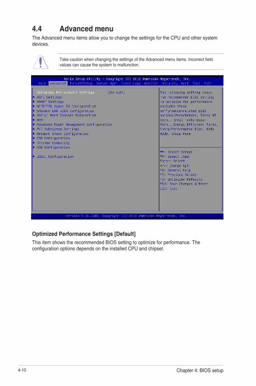
4.4 Advanced menuThe Advanced menu items allow you to change the settings for the CPU and other system devices.
TakecautionwhenchangingthesettingsoftheAdvancedmenuitems.Incorrectfieldvalues can cause the system to malfunction.
Optimized Performance Settings [Default]
This item shows the recommended BIOS setting to optimize for performance. The configurationoptionsdependsontheinstalledCPUandchipset.

4-11Z10PA-U8 Series
4.4.1 ACPI Settings
Enable ACPI Auto Configuration [Disabled]AllowsyoutoenableordisabletheBIOSACPIAutoConfiguration.
Configurationoptions:[Disabled][Enabled]
Enable Hibernation [Enabled]Allows you to enable or disable the ability of the system to hibernate (OS/Sleep State).
Configurationoptions:[Disabled][Enabled]
This option may be not effective with some OS.
ACPI Sleep State [S3 (Suspend to RAM)]Select the highest ACPI sleep state the system will enter when the SUSPEND is pressed.Configurationoptions:[SuspendDisabled][S3(SuspendtoRAM)]
4.4.2 Smart Settings
SMART Self Test [Disabled]Allows you to run SMART Self Test on all HDDs during POST.
Configurationoptions:[Disabled][Enabled]

4-12 Chapter 4: BIOS setup
4.4.3 NCT6779D Super IO Configuration
Serial Port 1 Configuration
Allows you to set the parameters of Serial Port 1/ Serial Port 2.
Serial Port [Enabled]
Allows you to enable or disable Serial Port.
Configurationoptions:[Disabled][Enabled]
Change Settings [Auto]
Allows you to choose the setting for Super IO device.
Configurationoptions:[Auto][IO=3F8h;IRQ=4;][IO=3F8h;IRQ=3,4,5,6,7,9,10,11,12;] [IO=2F8h;IRQ=3,4,5,6,7,9,10,11,12;][IO=3E8h;IRQ=3,4,5,6,7,9,10,11,12;] [IO=2E8h;IRQ=3,4,5,6,7,9,10,11,12;]
4-13Z10PA-U8 Series
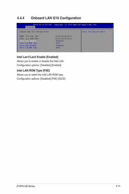
Intel Lan1/Lan2 Enable [Enabled]Allows you to enable or disable the Intel LAN.
Configurationoptions:[Disabled][Enabled]
Intel LAN ROM Type [PXE]Allows you to select the Intel LAN ROM type.
Configurationoptions:[Disabled][PXE][iSCSI]
4.4.4 Onboard LAN I210 Configuration
4-14 Chapter 4: BIOS setup
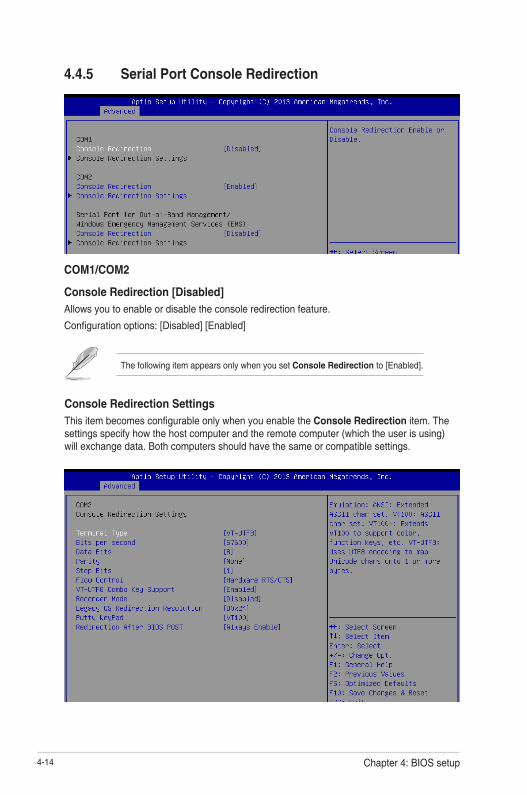
4.4.5 Serial Port Console Redirection
Console Redirection SettingsThisitembecomesconfigurableonlywhenyouenabletheConsole Redirection item. The settings specify how the host computer and the remote computer (which the user is using) will exchange data. Both computers should have the same or compatible settings.
The following item appears only when you set Console Redirection to[Enabled].
COM1/COM2
Console Redirection [Disabled]Allows you to enable or disable the console redirection feature.
Configurationoptions:[Disabled][Enabled]
4-15Z10PA-U8 Series
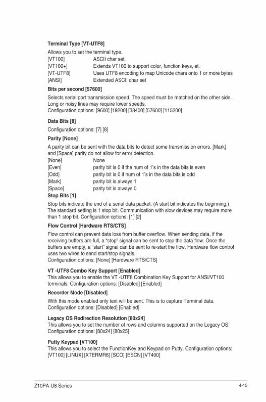
Terminal Type [VT-UTF8]
Allows you to set the terminal type.[VT100] ASCIIcharset.[VT100+] ExtendsVT100tosupportcolor,functionkeys,et.[VT-UTF8] UsesUTF8encodingtomapUnicodecharsonto1ormorebytes[ANSI] ExtendedASCIIcharset
Bits per second [57600]
Selects serial port transmission speed. The speed must be matched on the other side. Long or noisy lines may require lower speeds. Configurationoptions:[9600][19200][38400][57600][115200]
Data Bits [8]
Configurationoptions:[7][8]
Parity [None]
Aparitybitcanbesentwiththedatabitstodetectsometransmissionerrors.[Mark]and[Space]paritydonotallowforerrordetection.[None] None[Even] paritybitis0ifthenumof1’sinthedatabitsiseven[Odd] paritybitis0ifnumof1’sinthedatabitsisodd[Mark] paritybitisalways1[Space] paritybitisalways0Stop Bits [1]
Stopbitsindicatetheendofaserialdatapacket.(Astartbitindicatesthebeginning.)The standard setting is 1 stop bit. Communication with slow devices may require more than1stopbit.Configurationoptions:[1][2]
Flow Control [Hardware RTS/CTS]
Flowcontrolcanpreventdatalossfrombufferoverflow.Whensendingdata,ifthereceivingbuffersarefull,a“stop”signalcanbesenttostopthedataflow.Oncethebuffersareempty,a“start”signalcanbesenttore-starttheflow.Hardwareflowcontroluses two wires to send start/stop signals. Configurationoptions:[None][HardwareRTS/CTS]
VT -UTF8 Combo Key Support [Enabled]This allows you to enable the VT -UTF8 Combination Key Support for ANSI/VT100 terminals.Configurationoptions:[Disabled][Enabled]
Recorder Mode [Disabled]
Withthismodeenabledonlytextwillbesent.ThisistocaptureTerminaldata. Configurationoptions:[Disabled][Enabled]
Legacy OS Redirection Resolution [80x24]This allows you to set the number of rows and columns supported on the Legacy OS. Configurationoptions:[80x24][80x25]
Putty Keypad [VT100]ThisallowsyoutoselecttheFunctionKeyandKeypadonPutty.Configurationoptions:[VT100][LINUX][XTERMR6][SCO][ESCN][VT400]
4-16 Chapter 4: BIOS setup
Serial Port for Out-of-Band Management/
Windows Emergency Management Services (EMS)
Console Redirection [Disabled]Allows you to enable or disable the console redirection feature. Configurationoptions:[Disabled][Enabled]
Redirection After BIOS POST [Bootloader]
This setting allows you to specify if Bootloader is selected than Legacy console redirection.Configurationoptions:[AlwaysEnable][Bootloader]
Console Redirection Settings
Out-of-Band Mgmt Port [COM1]
MicrosoftWindowsEmergencyManagementServices(EMS)allowforremotemanagementofaWindowsServerOSthroughaserialport. Configurationoptions:[COM1][COM2(Disabled)]
Terminal Type [VT-UTF8]
MicrosoftWindowsEmergencyManagementServices(EMS)allowforremotemanagementofaWindowsServerOSthroughaserialport. Configurationoptions:[VT100][VT100+][VT-UTF8][ANSI]
Bits per second [115200]
MicrosoftWindowsEmergencyManagementServices(EMS)allowforremotemanagementofaWindowsServerOSthroughaserialport. Configurationoptions:[9600][19200][57600][115200]
Flow Control [None]
MicrosoftWindowsEmergencyManagementServices(EMS)allowforremotemanagementofaWindowsServerOSthroughaserialport. Configurationoptions:[None][HardwareRTS/CTS][SoftwareXon/Xoff]
The following item appears only when you set Console Redirection to[Enabled].

4-17Z10PA-U8 Series
4.4.6 APMAllowsyoutoconfiguretheAdvancePowerManagement(APM)settings.
Restore AC Power Loss [Last State]Whensetto[PowerOff],thesystemgoesintooffstateafteranACpowerloss.Whensetto[PowerOn],thesystemwillrebootafteranACpowerloss.Whensetto[LastState],thesystemgoesintoeitherofforonstate,whateverthesystemstatewasbeforetheACpowerloss. Configurationoptions:[PowerOff][PowerOn][LastState]
Power On By PCIE [Disabled]
[Disabled] DisablesthePCIEdevicestogenerateawakeevent.
[Enabled] EnablesthePCIEdevicestogenerateawakeevent.
Power On By Ring [Disabled]
[Disabled] DisablesthePCIEdevicestogenerateawakeevent.
[Enabled] EnablesthePCIEdevicestogenerateawakeevent.
Power On By RTC [Disabled]
[Disabled] DisablesRTCtogenerateawakeevent.
[Enabled] Whensetto[Enabled],theitemsRTC Alarm Date (Days) and Hour/ Minute/Secondwillbecomeuser-configurablewithsetvalues.

4-18 Chapter 4: BIOS setup
4.4.7 Advanced Power Management ConfigurationAllowsyoutoconfiguretheadvancedpowermanagementfeaturesofthesystem.
Power Boost [Normal]Allows you to increase extra power input to processor(s) and computing performance depending on applications.
Configurationoptions:[Normal][High][Extreme]
Makesureyourthermalsolutionandpowersupplyareabletohandlethiscircumstances.

4-19Z10PA-U8 Series
4.4.8 PCI Subsystem SettingsAllowsyoutoconfigurePCI,PCI-X,andPCIExpressSettings.
Load RT32 Image [Enabled]Allows you to enable or disable RT32 Image Loading.
Configurationoptions:[Disabled][Enabled]
Above 4G Decoding [Disabled]Allows you to enable or disable 64-bit capable devices to be decoded in above 4G address space.Itonlyworksifthesystemsupports64-bitPCIdecoding.Configurationoptions:[Disabled][Enabled]
SR-IOV Support [Disabled]This option enables or disables SIngle Root IO Virtualization Support if the system has SR-IOV capable PCIe devices.Configurationoptions:[Disabled][Enabled]
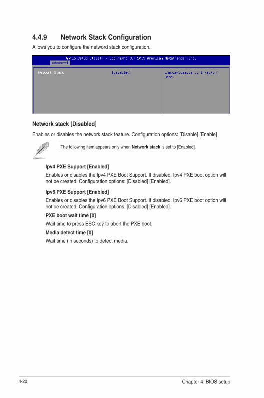
4-20 Chapter 4: BIOS setup
Network stack [Disabled]
Enablesordisablesthenetworkstackfeature.Configurationoptions:[Disable][Enable]
4.4.9 Network Stack ConfigurationAllowsyoutoconfigurethenetwordstackconfiguration.
The following item appears only when Network stack is set to[Enabled].
Ipv4 PXE Support [Enabled]
EnablesordisablestheIpv4PXEBootSupport.Ifdisabled,Ipv4PXEbootoptionwillnotbecreated.Configurationoptions:[Disabled][Enabled].
Ipv6 PXE Support [Enabled]
EnablesordisablestheIpv6PXEBootSupport.Ifdisabled,Ipv6PXEbootoptionwillnotbecreated.Configurationoptions:[Disabled][Enabled].
PXE boot wait time [0]
WaittimetopressESCkeytoabortthePXEboot.
Media detect time [0]
Waittime(inseconds)todetectmedia.
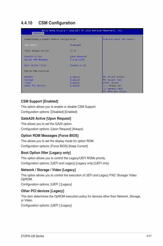
4-21Z10PA-U8 Series
4.4.10 CSM Configuration
CSM Support [Enabled]
This option allows you to enable or disable CSM Support.
Configurationoptions:[Disabled][Enabled]
GateA20 Active [Upon Request]
This allows you to set the GA20 option.
Configurationoptions:[UponRequest][Always]
Option ROM Messages [Force BIOS]
This allows you to set the display mode for option ROM.
Configurationoptions:[ForceBIOS][KeepCurrent]
Boot Option filter [Legacy only]
This option allows you to control the Legacy/UEFI ROMs priority.
Configurationoptions:[UEFIandLegacy][Legacyonly][UEFIonly]
Network / Storage / Video [Legacy]
ThisoptionallowsyoutocontroltheexecutionofUEFIandLegacyPXE/Storage/VideoOpROM.
Configurationoptions:[UEFI][Legacy]
Other PCI devices [Legacy]
ThisitemdeterminestheOpROMexecutionpolicyfordevicesotherthanNetwork,Storage,or Video.
Configurationoptions:[UEFI][Legacy]

4-22 Chapter 4: BIOS setup
4.4.11 Trusted Computing
Configuration
Security Device Support [Disabled]
Allows you to enable or disable the BIOS support for security device.
Configurationoptions:[Disabled][Enabled]
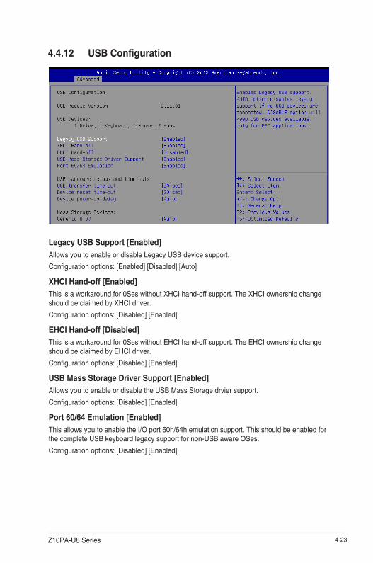
4-23Z10PA-U8 Series
4.4.12 USB Configuration
Legacy USB Support [Enabled]
Allows you to enable or disable Legacy USB device support.
Configurationoptions:[Enabled][Disabled][Auto]
XHCI Hand-off [Enabled]
Thisisaworkaroundfor0SeswithoutXHCIhand-offsupport.TheXHCIownershipchangeshouldbeclaimedbyXHCIdriver.
Configurationoptions:[Disabled][Enabled]
EHCI Hand-off [Disabled]
Thisisaworkaroundfor0SeswithoutEHCIhand-offsupport.TheEHCIownershipchangeshould be claimed by EHCI driver.
Configurationoptions:[Disabled][Enabled]
USB Mass Storage Driver Support [Enabled]
Allows you to enable or disable the USB Mass Storage drvier support.
Configurationoptions:[Disabled][Enabled]
Port 60/64 Emulation [Enabled]
This allows you to enable the I/O port 60h/64h emulation support. This should be enabled for thecompleteUSBkeyboardlegacysupportfornon-USBawareOSes.
Configurationoptions:[Disabled][Enabled]
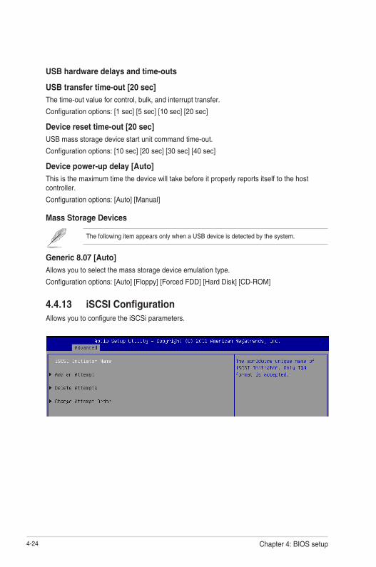
4-24 Chapter 4: BIOS setup
USB hardware delays and time-outs
USB transfer time-out [20 sec]
Thetime-outvalueforcontrol,bulk,andinterrupttransfer.
Configurationoptions:[1sec][5sec][10sec][20sec]
Device reset time-out [20 sec]
USB mass storage device start unit command time-out.
Configurationoptions:[10sec][20sec][30sec][40sec]
Device power-up delay [Auto]
Thisisthemaximumtimethedevicewilltakebeforeitproperlyreportsitselftothehostcontroller.
Configurationoptions:[Auto][Manual]
Mass Storage Devices
The following item appears only when a USB device is detected by the system.
Generic 8.07 [Auto]
Allows you to select the mass storage device emulation type.
Configurationoptions:[Auto][Floppy][ForcedFDD][HardDisk][CD-ROM]
4.4.13 iSCSI ConfigurationAllowsyoutoconfiguretheiSCSiparameters.

4-25Z10PA-U8 Series
4.5 IntelRCSetup menuThe IntelRCSetup menu items allow you to change the processor and chipset settings.

4-26 Chapter 4: BIOS setup
4.5.1 Processor Configuration
Per Socket Configuration
Allows you to set the number of cores to enable. 0 means all cores. Total of 14 cores available.
Hyper Threading [Enabled]Allows you to enable or disable the Intel® Hyper-ThreadingTechnologyfunction.Whendisabled,onlyonethreadperactivatedcoreisenabled. Configurationoptions:[Disabled][Enabled]
Execute Disable Bit [Enabled]XDcanpreventcertainclassesofmaliciousbufferoverflowattackswhencombinedwithasupportingOS(WindowsServer2003SP1,WindowsXPSP2,SuSELinux9.2,RedhatEnterprise 3 Update 3). Configurationoptions:[Disabled][Enabled]
Enable Intel TXT Support [Disabled]ForcestheXDfeaturelogtoalwaysreturn0whendisabled.
Configurationoptions:[Disabled][Enabled]
VMX [Enabled]
EnablestheVanderpoolTechnology.Takeseffectafterreboot.
Configurationoptions:[Disabled][Enabled]

4-27Z10PA-U8 Series
Enable SMX [Disabled]
Enables the Safer Mode Extensions
Configurationoptions:[Disabled][Enabled]
Hardware Prefetcher [Enabled]
This Item allows you to turn on/off the mid level cache(L2) streamer prefetcher.
Configurationoptions:[Disabled][Enabled]
Adjacent Cache Prefetch [Enabled]
This Item allows you to turn on/off prefetching of adjacent cache lines. Configurationoptions:[Disabled][Enabled]
DCU Streamer Prefetcher [Enabled]
This Item allows you to enable or disable prefetcher of next L1 data line. Configurationoptions:[Disabled][Enabled]
DCU IP Prefetcher [Enabled]
This Item allows you to enable or disable prefetch of next L1 line based upon sequential load history.
Configurationoptions:[Disabled][Enabled]
DCU Mode [32K 8Way Without ECC]
Configurationoptions:[32K8WayWithoutECC][16K4WayWithECC]
Direct Cache Access (DCA) [Auto]
This Item allows you to enable or disable Direct Cache Access.
Configurationoptions:[Auto][Disabled][Enabled]
DCA Prefetch Delay [32]
This Item allows you to set the time for the DCA Prefetch delay Help.
Configurationoptions:[Disabled][8][16][24][32][40][48][56][64][72][80][88][96][104][112]
X2APIC [Disabled]
This Item allows you to enable or disable the extended APIC support.
Configurationoptions:[Disabled][Enabled]
AES-NI [Enabled]
This Item allows you to enable or disable the AES-NI support.
Configurationoptions:[Disabled][Enabled]
Down Stream PECI [Disabled]
This Item allows you to enable the PCIe Down Stream PECI writer.
Configurationoptions:[Disabled][Enabled]

4-28 Chapter 4: BIOS setup
4.5.2 Advanced Power Management Configuration
Power Technology [Energy Efficient]This item allows you to enable power management features. Configurationoptions:[Disabled][EnergyEfficient][Custom]
Config TDP [Disabled]Thisitemallowsyoutoenable/disabletheConfigTDP.
Configurationoptions:[Disabled][Enabled]
CPU Advanced PM Turning
This item allows you to set additional CPU Power Management settings.
Energy Perf BIAS
Energy Performance Tuning [Disabled]
Allows your system to select from BIOS or operating system to choose enable energy performance bias tuning.Configurationoptions:[Disabled][Enabled]
Energy Performance Bias setting [Balanced Performance]
Allows you to set the Energy Performance Bias which overrides the OS setting.Configurationoptions:[Performance][BalancedPerformance][BalancedPower][Power]

4-29Z10PA-U8 Series
4.5.3 Common RefCode Configuration
Numa [Enabled]This item enables or disables the Non uniform Memory Access (NUMA).
Configurationoptions:[Disabled][Enabled]
Power/Performance Switch [Enabled]
Allows you to switch between Power or performance.Configurationoptions:[Disabled][Enabled]
Workload Configuration [Balanced]
Optimizationfortheworkloadcharacterization.Configurationoptions:[Balanced][I/Osensitive]
Averaging Time Window [23]
This is used to control the effective window of the average for CO and PO time.
PO TotalTimeThreshold Low [35]
TheHWswitchingmechanismdisablestheperformancesetting(0)whenthetotalPOtime is less than this threshold.
PO TotalTimeThreshold High [58]
TheHWswitchingmechanismenablestheperformancesetting(0)whenthetotalPOtime is greater than this threshold.
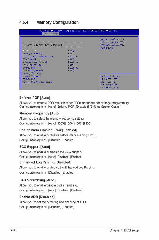
4-30 Chapter 4: BIOS setup
4.5.4 Memory Configuration
Enforce POR [Auto]Allows you to enforce POR restrictions for DDR4 frequency adn voltage programming. Configurationoptions:[Auto][EnforcePOR][Disabled][EnforceStretchGoals]
Memory Frequency [Auto]Allows you to select the memory frequency setting.
Configurationoptions:[Auto][1333][1600][1866][2133]
Halt on mem Training Error [Enabled]Allows you to enable or disable halt on mem Training Error.
Configurationoptions:[Disabled][Enabled]
ECC Support [Auto]Allows you to enable or disable the ECC support.
Configurationoptions:[Auto][Disabled][Enabled]
Enhanced Log Parsing [Disabled]
Allows you to enable or disable the Enhanced Log Parsing.
Configurationoptions:[Disabled][Enabled]
Data Scrambling [Auto]Allows you to enable/disable data scrambling.
Configurationoptions:[Auto][Disabled][Enabled]
Enable ADR [Disabled]Allows you to set the detecting and enabling of ADR.
Configurationoptions:[Disabled][Enabled]

4-31Z10PA-U8 Series
C/A Parity Enable [Auto]Allows you to enable or disable the DDR4's command address parity.
Configurationoptions:[Auto][Disabled][Enabled]
Memory Topology
Displays memory topology with DIMM population information.
Memory Thermal
Allowsyoutoconfigurethermalsettings.
Set Throttling Mode [Disabled]
Configurationoptions:[Disabled][OLTT][CLTT]
OLLT Peak BW [xxx]
AllowsyoutosetthepeakallowedbandwidthforOLTT.Thisisinpercentageandvalidoffset values is from 25-100.
DIMM Tem Stat [xx]
Allows you to select DIMMTEMPSTAT as temp_mid or tem_hi.
Memory Power Savings Mode [Auto]
AllowsyoutoconfiguretheCKEandotherrelatedMemoryPowerSavingsfeatures.Configurationoptions:[Auto][Disabled][APDOn][UserDefined][Reserve]
Memory Power Savings Advanced Options
CK in SR [Auto]Configurationoptions:[Auto][Driven][Tri-State][PulledLow][PulledHigh]
MDLL Off [Auto]
Allows you to shutdown MDLL during SR when enabled.Configurationoptions:[Auto][Disabled][Enabled]
MEMHOT Throttling Mode [Input-only]
Allows you to shutdown MDLL during SR when enabled.Configurationoptions:[Disabled][Input-only][Output-only]
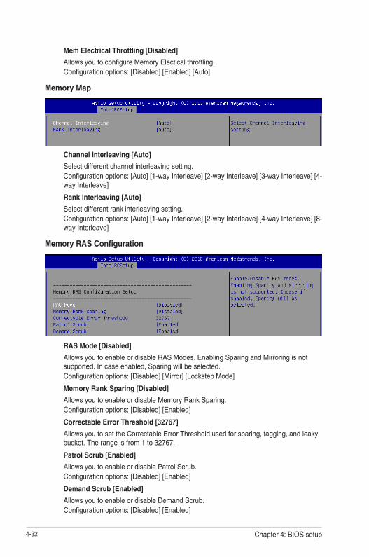
4-32 Chapter 4: BIOS setup
Mem Electrical Throttling [Disabled]
AllowsyoutoconfigureMemoryElecticalthrottling.Configurationoptions:[Disabled][Enabled][Auto]
Memory Map
Channel Interleaving [Auto]
Select different channel interleaving setting.Configurationoptions:[Auto][1-wayInterleave][2-wayInterleave][3-wayInterleave][4-wayInterleave]
Rank Interleaving [Auto]
Selectdifferentrankinterleavingsetting.Configurationoptions:[Auto][1-wayInterleave][2-wayInterleave][4-wayInterleave][8-wayInterleave]
Memory RAS Configuration
RAS Mode [Disabled]
Allows you to enable or disable RAS Modes. Enabling Sparing and Mirroring is not supported.Incaseenabled,Sparingwillbeselected.Configurationoptions:[Disabled][Mirror][LockstepMode]
Memory Rank Sparing [Disabled]
AllowsyoutoenableordisableMemoryRankSparing.Configurationoptions:[Disabled][Enabled]
Correctable Error Threshold [32767]
AllowsyoutosettheCorrectableErrorThresholdusedforsparing,tagging,andleakybucket.Therangeisfrom1to32767.
Patrol Scrub [Enabled]
Allows you to enable or disable Patrol Scrub.Configurationoptions:[Disabled][Enabled]
Demand Scrub [Enabled]
Allows you to enable or disable Demand Scrub.Configurationoptions:[Disabled][Enabled]

4-33Z10PA-U8 Series
EV DFX Features [Disabled]
SetthisoptiontoallowDFXLockBitstoremainclear.
Configurationoptions:[Disabled][Enabled]
PCIE Slot Option ROM Configuration
4.5.5 IIO Configuration
PCIE1/ PCIE2/ PCIE3/ PCIE4/ PCIE6 Option ROM [Disabled]
Allows you to enable or disable the PCIE1/ PCIE2/ PCIE3/ PCIE4/ PCIE6 Option ROM. Configurationoptions:[Disabled][Enabled]
Intel VT for Directed I/O (VT-d)
Intel VT for Directed I/O (VT-d) [Enabled]
Allows you to enable or disable the Intel Virtualization Technology for Directed I/O.Configurationoptions:[Disabled][Enabled]
PCI Express Global Options
TX EQ WA [Enabled]
UsespecialtableforTX_EQandvendorspecificcards. Configurationoptions:[Disabled][Enabled]
PCI-E ASPM Support (Global) [L1 Only]
This option enables or disables the ASPM support for all downstream devices. Configurationoptions:[Disabled][L1Only]

4-34 Chapter 4: BIOS setup
4.5.6 PCH Configuration
PCH Devices
DeepSx Power Policies [Disabled]
AllowsyoutoconfiguretheDeepSxModeconfiguration.Configurationoptions:[Disabled][EnabledinS5][EnabledinS4andS5]
PCI Express Configuration
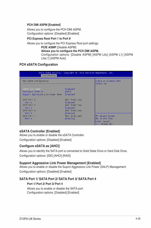
4-35Z10PA-U8 Series
PCH DMI ASPM [Enabled]
AllowsyoutoconfigurethePCHDMIASPM.Configurationoptions:[Disabled][Enabled]
PCI Express Root Port 1 to Port 8
AllowsyoutoconfigurethePCIExpressRootportsettings.PCIE ASMP [DisableASPM]Allows you to configure the PCH DMI ASPM.Configurationoptions: [DisableASPM] [ASPML0s] [ASPML1] [ASPML0sL1][ASPMAuto]
PCH sSATA Configuration
sSATA Controller [Enabled]Allows you to enable or disable the sSATA Controller.
Configurationoptions:[Disabled][Enabled]
Configure sSATA as [AHCI]
AllowsyoutoidentifytheSATAportisconnectedtoSolidStateDriveorHardDiskDrive.
Configurationoptions:[IDE][AHCI][RAID]
Support Aggressive Link Power Management [Enabled]AllowsyoutoenableordisabletheSuportAggressiveLinkPower(SALP)Management.
Configurationoptions:[Disabled][Enabled]
SATA Port 1/ SATA Port 2/ SATA Port 3/ SATA Port 4Port 1/ Port 2/ Port 3/ Port 4
Allows you to enable or disable the SATA port Configurationoptions:[Disabled][Enabled]

4-36 Chapter 4: BIOS setup
PCH SATA Configuration
SATA Controller [Enabled]Allows you to enable or disable the SATA Controller.
Configurationoptions:[Disabled][Enabled]
Configure SATA as [AHCI]
AllowsyoutoidentifytheSATAportisconnectedtoSolidStateDriveorHardDiskDrive.
Configurationoptions:[IDE][AHCI][RAID]
Support Aggressive Link Power Management [Enabled]AllowsyoutoenableordisabletheSuportAggressiveLinkPower(SALP)Management.
Configurationoptions:[Disabled][Enabled]
SATA Port 1~6Port 1/ Port 2/ Port 3/ Port 4/ Port 5/ Port 6 [Enabled]
Allows you to enable or disable the SATA port Configurationoptions:[Disabled][Enabled]
USB Configuration
xHCI Mode [Auto]Allows you to enable or disable the mode of operation of xHCI controller.
Configurationoptions:[Auto][Disabled][Enabled]
USB Ports Per-Port Disable Control [Disabled]
Allows you to control each of the USB ports 1 to 8 disabling.
Configurationoptions:[Disabled][Enabled]
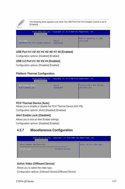
4-37Z10PA-U8 Series
The following items appears only when the USB Ports Per-Port Disable Control is set to [Enabled].
USB Port #1/ #2/ #3/ #4/ #5/ #6/ #7/ #8 [Enabled]
Configurationoptions:[Disabled][Enabled]
USB 3.0 Port #1/ #2/ #3/ #4 [Enabled]
Configurationoptions:[Disabled][Enabled]
Platform Thermal Configuration
PCH Thermal Device [Auto]Allows you to enable or disable the PCH Thermal Device (D31:F6).
Configurationoptions:[Auto][Disabled][Enabled]
Alert Enable Lock [Disabled]
AllowsyoutolockallAlertEnablesettings.
Configurationoptions:[Disabled][Enabled]
4.5.7 Miscellaneous Configuration
Active Video [Offboard Device]
Allows you to select the video type.
Configurationoptions:[OnboardDevice][OffboardDevice]

4-38 Chapter 4: BIOS setup
4.5.8 Server ME ConfigurationDisplays the Server ME Technology parameters on your system.
4.5.9 Runtime Error Logging
Runtime Error Logging
S/W Error Injection Support [Disabled]Whenenabled,S/WErrorInjectionissupportedbyunlockingMSR0x790.
Configurationoptions:[Disabled][Enabled]
Whea Settings
WHEA Support [Disabled]
ThisitemallowsyoutoenableordisabletheWHEAsupport.Configurationoptions:[Disabled][Enabled]
Memory Error Enabling
Memory corrected Error enabling [Disabled]
This item allows you to enable or disable memory corrected Errors.Configurationoptions:[Disabled][Enabled]

4-39Z10PA-U8 Series
4.6 Server Mgmt menuThe Server Management menu displays the server management status and allows you to change the settings.
OS Watchdog Timer [Disabled]This item allows you to start a BIOS timer which can only be shut off by Intel Management Software after the OS loads.
Configurationoptions:[Disabled][Enabled]
ThefollowingitemsisconfigurableonlywhentheOSWatchdogTimerissetto[Enabled].
OS Wtd Timer Timeout [10 minutes]
AllowsyoutoconfigurethelengthfotheOSBootWatchdogTimer.
Configurationoptions:[5minutes][10minutes][15minutes][20minutes]
OS Wtd Timer Policy [Reset]
ThisitemallowsyoutoconfigurethehowthesystemshouldrespondiftheOSBootWatchTimer expires.
Configurationoptions:[DoNothing][Reset][PowerDown]
Serial Mux [Disabled]ThisitemallowsyoutoenableordisableSerialMuxconfiguration.
Configurationoptions:[Disabled][Enabled]
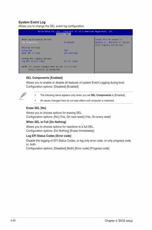
4-40 Chapter 4: BIOS setup
System Event Log AllowsyoutochangetheSELeventlogconfiguration.
SEL Components [Enabled]
Allows you to enable or disable all features of system Event Logging during boot.Configurationoptions:[Disabled][Enabled]
• ThefollowingitemsappearsonlywhenyousetSEL Componentsto[Enabled].
• Allvalueschangedheredonottakeeffectuntilcomputerisrestarted.
Erase SEL [No]
Allows you to choose options for erasing SEL.Configurationoptions:[No][Yes,Onnextreset][Yes,Oneveryreset]
When SEL is Full [Do Nothing]
Allows you to choose options for reactions to a full SEL.Configurationoptions:[DoNothing][EraseImmediately]
Log EFI Status Codes [Error code]
DisabletheloggingofEFIStatusCodes,orlogonlyerrorcode,oronlyprogresscodeor,both.Configurationoptions:[Disabled][Both][Errorcode][Progresscode]

4-41Z10PA-U8 Series
BMC network configuration
Thesub-itemsinthisconfigurationallowyoutoconfiguretheBMCnetworkparameters.
Config Address source DM_LAN1/Shared LAN [Unspecified]
ThisitemallowsyoutoconfigureLANchannelparametersstaticallyordynamically(byBIOSorBMC).UnspecifiedoptionwillnotmodifyanyBMCnetworkparametersduringBIOS phase.Configurationoptions:[Unspecified][Static][DynamicBmcDhcp]
View System Event Log
This item allows you to view the system event log records.
IPv6 BMC Network Configuration
ThisitemallowsyoutoconfiguretheparametersettingsofIPv6BMCnetwork.

4-42 Chapter 4: BIOS setup
IPv6 Display Full Field [Enable]
Displays the full or brief IPv6 Field.Configurationoptions:[Disable][Enable]
IPv6 Display Full Formula [Enable]
Displays the full or brief IPv6 Formula.Configurationoptions:[Disable][Enable]
IPv6 Display Letter Case [Upper Case]
Displays the uppercase or lowercase letters of the alphabet.Configurationoptions:[LowerCase][UpperCase]
IPv6 BMC LAN IP Address source [Previous State]
SelecttoconfigureLANchannelparametersstaticallyordynamically(byBIOSorBMC). Configurationoptions:[PreviousState][Static][Dynamic-ObtainedbyBMCrunningDHCP]
The following items appear only when you set IP BMC Lan IP Address Sourceto[Static].
IPv6 BMC LAN IP AddressAllows you to input IPv6 BMC Lan IP address.
IPv6 BMC LAN IP Prefix LengthAllows you to input IPv6 BMC Lan IP Prefix Length.
IPv6 BMC LAN Default Gateway
Allows you to input IPv6 BMC Lan Default Gateway.
IPv6 BMC LAN DNS SettingsAllows you to enter IPv6 BMC LAN DNS Settings.
IPv6 BMC LAN Link IP AddressAllowsyoutoenterIPv6BMCLANLinkIPaddress.
IPv6 BMC LAN Link IP Prefix LengthAllows you to input IPv6 BMC LanLinkIPPrefixLength.
IPv6 BMC Lan Option [Enable]
This item allows you to enavle IPv6 BMC LAN channel function. Disabling this option will not modifyanyBMCnetworkduringBIOSphase.

4-43Z10PA-U8 Series
The following item appears only when you set IP BMC Lan Optionto[Enable].
IPv6 BMC LAN IP Address Source [Previous State]
SelecttoconfigureLANchannelparametersstaticallyordynamically(byBIOSorBMC). Configurationoptions:[PreviousState][Static][Dynamic-ObtainedbyBMCrunningDHCP]
The following items appear only when you set IP BMC Lan IP Address Sourceto[Static].
IPv6 BMC LAN IP AddressAllows you to input IPv6 BMC Lan IP address.
IPv6 BMC LAN IP Prefix LengthAllows you to input IPv6 BMC Lan IP Prefix Length.
IPv6 BMC LAN Default Gateway
Allows you to input IPv6 BMC Lan Default Gateway.
IPv6 BMC LAN DNS SettingsAllows you to enter IPv6 BMC LAN DNS Settings.
IPv6 BMC LAN Link IP AddressAllowsyoutoenterIPv6BMCLANLinkIPaddress.
IPv6 BMC LAN Link IP Prefix LengthAllows you to input IPv6 BMC LanLinkIPPrefixLength.

4-44 Chapter 4: BIOS setup
4.7 Event Logs menuThe Event Logs menu items allow you to change the event log settings and view the system event logs.
4.7.1 Change Smbios Event Log SettingsPress<Enter>tochangetheSmbiosEventLogconfiguration.
Enabling/Disabling Options
Smbios Event Log [Enabled]
Change this to enable or disable all features of Smbios Event Logging during boot.Configurationoptions:[Disabled][Enabled]
Erasing Settings
Erase Event Log [No]
Choose options for erasing Smbios Event Log. Erasing is done prior to any logging activation duringreset.Configurationoptions:[No][Yes,Nextreset][Yes,Everyreset]
When Log is Full [Do Nothing]
AllowsyoutochooseoptionsforreactionstoafullSmbiosEventLog.Configurationoptions:[DoNothing][EraseImmediately]
Allvalueschangedheredonottakeeffectuntilcomputerisrestarted.
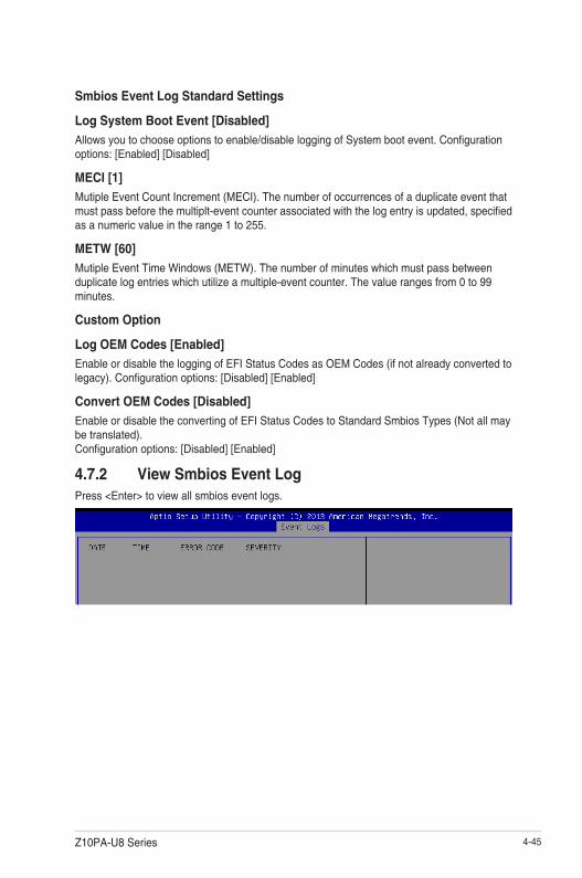
4-45Z10PA-U8 Series
Smbios Event Log Standard Settings
Log System Boot Event [Disabled]
Allowsyoutochooseoptionstoenable/disableloggingofSystembootevent.Configurationoptions:[Enabled][Disabled]
MECI [1]
Mutiple Event Count Increment (MECI). The number of occurrences of a duplicate event that mustpassbeforethemultiplt-eventcounterassociatedwiththelogentryisupdated,specifiedas a numeric value in the range 1 to 255.
METW [60]
MutipleEventTimeWindows(METW).Thenumberofminuteswhichmustpassbetweenduplicate log entries which utilize a multiple-event counter. The value ranges from 0 to 99 minutes.
Custom Option
Log OEM Codes [Enabled]
Enable or disable the logging of EFI Status Codes as OEM Codes (if not already converted to legacy).Configurationoptions:[Disabled][Enabled]
Convert OEM Codes [Disabled]
Enable or disable the converting of EFI Status Codes to Standard Smbios Types (Not all may be translated). Configurationoptions:[Disabled][Enabled]
4.7.2 View Smbios Event LogPress <Enter> to view all smbios event logs.

4-46 Chapter 4: BIOS setup
4.8 Monitor menuTheMonitormenudisplaysthesystemtemperature/powerstatus,andallowsyoutochangethe fan settings.
Scroll down to view the other items
CPU1 Temperature [xxx°C/xxx°F]The onboard hardware monitor automatically detects and displays the CPU temperatures.
CPU FAN1 Speed; FRNT FAN1–4 Speed; REAR FAN1 Speed [xxxx RPM] or [N/A]TheonboardhardwaremonitorautomaticallydetectsanddisplaysthespeedofCPUfans,frontfans,andrearfaninrotationsperminute(RPM).Ifthefanisnotconnectedtothemotherboard,thefieldshowsN/A.
+VCCIO Voltage, VCORE1 Voltage, +VDDQ_AB Voltage, +VDDQ_CD Voltage, +5VSB Voltage, +5V Voltage, +12V Voltage, +3.3V Voltage, VBAT Voltage, +3.3VSB VoltageThe onboard hardware monitor automatically detects the voltage output through the onboard voltage regulators.
CPU FAN1&2 and FRNT FAN1 mode [Generic Speed]
AllowsyoutoconfiguretheASUSSmartFanfeaturethatsmartlyadjuststhefanspeedsformoreefficientsystemoperation.
Configurationoptions:[GenericSpeed][HighSpeedSpeed][FullSpeedSpeed][Manual]
Duty % [50]
ThisitemappearsonlywhenCPUFAN1&2andFRNTFAN1modeissetto[Manual].Thisitemallowsyoutoconfigurethefandutysettingfrom10%to100%.
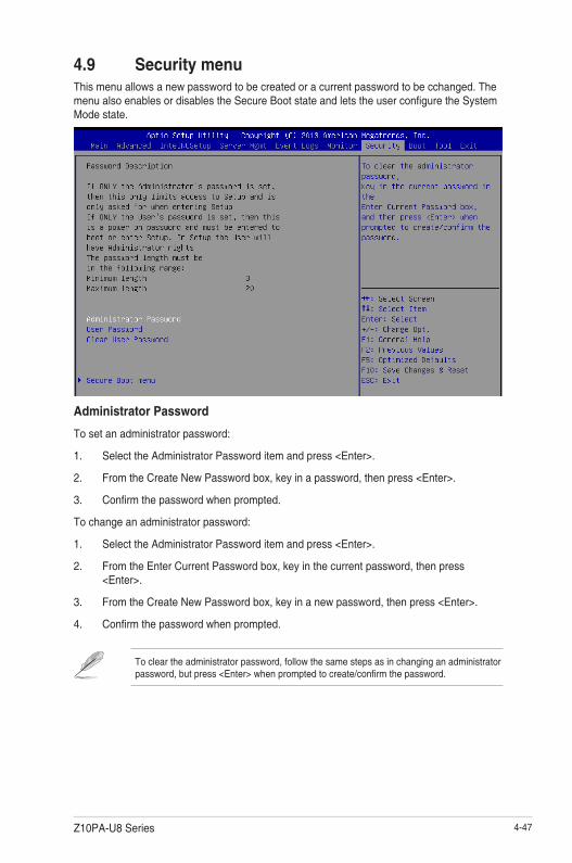
4-47Z10PA-U8 Series
4.9 Security menuThis menu allows a new password to be created or a current password to be cchanged. The menualsoenablesordisablestheSecureBootstateandletstheuserconfiguretheSystemMode state.
Administrator Password
To set an administrator password:
1. Select the Administrator Password item and press <Enter>.
2. FromtheCreateNewPasswordbox,keyinapassword,thenpress<Enter>.
3. Confirmthepasswordwhenprompted.
To change an administrator password:
1. Select the Administrator Password item and press <Enter>.
2. FromtheEnterCurrentPasswordbox,keyinthecurrentpassword,thenpress<Enter>.
3. FromtheCreateNewPasswordbox,keyinanewpassword,thenpress<Enter>.
4. Confirmthepasswordwhenprompted.
Tocleartheadministratorpassword,followthesamestepsasinchanginganadministratorpassword,butpress<Enter>whenpromptedtocreate/confirmthepassword.

4-48 Chapter 4: BIOS setup
User Password
To set a user password:
1. Select the User Password item and press <Enter>.
2. FromtheCreateNewPasswordbox,keyinapassword,thenpress<Enter>.
3. Confirmthepasswordwhenprompted.
To change a user password:
1. Select the User Password item and press <Enter>.
2. FromtheEnterCurrentPasswordbox,keyinthecurrentpassword,thenpress<Enter>.
3. FromtheCreateNewPasswordbox,keyinanewpassword,thenpress<Enter>.
4. Confirmthepasswordwhenprompted.
To clear a user password:
1. Select the Clear User Password item and press <Enter>.
2. Select YesfromtheWarningmessagewindowthenpress<Enter>.
Secure Boot MenuThis item allows you to customize the Secure Boot settings.
Secure Boot [Disabled]
Secure Boot can be enabled if the system is running in User mode with enrolled platform Key (EPK) or if the CSM function is disabled.Configurationoptions:[Disabled][Enabled]
Secure Boot Mode [Custom]
Allows you to set the Secure Boot selector.Configurationoptions:[Custom][Standard]
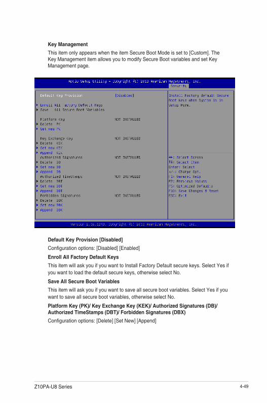
4-49Z10PA-U8 Series
Key Management
ThisitemonlyappearswhentheitemSecureBootModeissetto[Custom].TheKey Management item allows you to modify Secure Boot variables and set Key Management page.
Default Key Provision [Disabled]
Configurationoptions:[Disabled][Enabled]
Enroll All Factory Default Keys
ThisitemwillaskyouifyouwanttoInstallFactoryDefaultsecurekeys.SelectYesifyouwanttoloadthedefaultsecurekeys,otherwiseselectNo.
Save All Secure Boot Variables
Thisitemwillaskyouifyouwanttosaveallsecurebootvariables.SelectYesifyouwanttosaveallsecurebootvariables,otherwiseselectNo.
Platform Key (PK)/ Key Exchange Key (KEK)/ Authorized Signatures (DB)/Authorized TimeStamps (DBT)/ Forbidden Signatures (DBX)
Configurationoptions:[Delete][SetNew][Append]Configuration options: [Set New] [Delete] [Append]

4-50 Chapter 4: BIOS setup
Setup Prompt Timeout [xx]Usethe<+>and<->keystoadjustthenumberofsecondstowaitforsetupactivationkey.
Bootup NumLock State [On]Allowsyoutoselectthepower-onstatefortheNumLock. Configurationoptions:[Off][On]
Boot Logo Display [Disabled]Allows you to enable or disable the full screen logo display feature. Configurationoptions:[Auto][FullScreen][Disabled]
POST Report [5 sec]
Allows you to set the desired POST Report waiting time from 1 to 10 seconds. Configurationoptions:[1sec]~[10sec][UntilPressESC]
Chassis Intrusion Message [Warning]Allows you to set an action when chassis intrusion has occured. Configurationoptions:[Warning][Halt]
Boot Option PrioritiesThese items specify the boot device priority sequence from the available devices. The number of device items that appears on the screen depends on the number of devices installed in the system.
4.10 Boot menuThe Boot menu items allow you to change the system boot options.

4-51Z10PA-U8 Series
• Toselectthebootdeviceduringsystemstartup,press<F8>whenASUSLogoappears.
• ToaccessWindowsOSinSafeMode,pleasepress<F8>afterPOST.
Network Device BBS Priorities / Hard Drive BBS Priorities
These items appear only when you connect SATA ODD or hard drive to the SATA ports and allow you to set the booting order of the SATA devices.
4.11 Tool menuTheToolmenuitemsallowyoutoconfigureoptionsforspecialfunctions.Selectanitemthenpress <Enter> to display the submenu.
ASUS EZ Flash
Allows you to run ASUS EZ Flash BIOS ROM Utility when you press <Enter>. Refer to the ASUS EZ Flash Utility section for details.
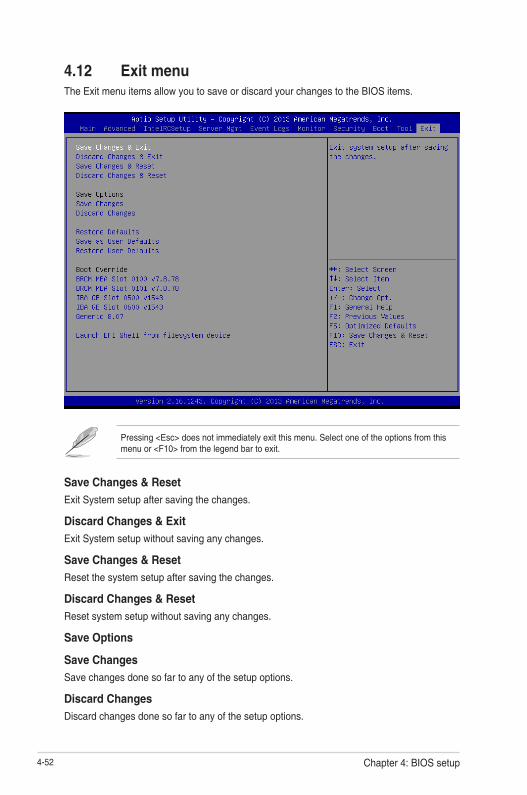
4-52 Chapter 4: BIOS setup
Pressing <Esc> does not immediately exit this menu. Select one of the options from this menu or <F10> from the legend bar to exit.
4.12 Exit menuThe Exit menu items allow you to save or discard your changes to the BIOS items.
Save Changes & Reset
Exit System setup after saving the changes.
Discard Changes & Exit
Exit System setup without saving any changes.
Save Changes & Reset
Reset the system setup after saving the changes.
Discard Changes & Reset
Reset system setup without saving any changes.
Save Options
Save Changes
Save changes done so far to any of the setup options.
Discard Changes
Discard changes done so far to any of the setup options.

4-53Z10PA-U8 Series
Restore Defaults
Restore/load default values for all the setup options.
Save as User Defaults
Save the changes done so far as User Defaults.
Restore User Defaults
Restore the User Defaults to all the setup options.
Boot Override
These items displays the available devices. The device items that appears on the screen
dependsonthenumberofdevicesinstalledinthesystem.Clickanitemtostartbootingfrom
the selected device.
Launch EFI Shell from filesystem device
AttemptstolaunchEFIShellapplication(shellx64.efi)fromoneoftheavailablefilesystem
devices.

4-54 Chapter 4: BIOS setup

5RAID Configuration
This chapter provides instructions for setting up, creating, and configuring RAID sets using the available utilities.
Chapter 5: RAID Configuration

5-2 Chapter 5: RAID configuration
5.1 Setting up RAIDThe motherboard supports the following SATA RAID solutions:
• LSI MegaRAID software RAID Configuration Utility with RAID 0, RAID 1, and RAID 10 support (for both Linux and Windows OS).
• Intel® Rapid Storage Technology enterprise Option ROM Utility with RAID 0, RAID 1, RAID 10, and RAID 5 support (for Windows OS only).
5.1.1 RAID definitionsRAID 0 (Data striping) optimizes two identical hard disk drives to read and write data in parallel, interleaved stacks. Two hard disks perform the same work as a single drive but at a sustained data transfer rate, double that of a single disk alone, thus improving data access and storage. Use of two new identical hard disk drives is required for this setup.
RAID 1 (Data mirroring) copies and maintains an identical image of data from one drive to a second drive. If one drive fails, the disk array management software directs all applications to the surviving drive as it contains a complete copy of the data in the other drive. This RAID configuration provides data protection and increases fault tolerance to the entire system. Use two new drives or use an existing drive and a new drive for this setup. The new drive must be of the same size or larger than the existing drive.
RAID 10 is data striping and data mirroring combined without parity (redundancy data) having to be calculated and written. With the RAID 10 configuration you get all the benefits of both RAID 0 and RAID 1 configurations. Use four new hard disk drives or use an existing drive and three new drives for this setup.
RAID 5 stripes both data and parity information across three or more hard disk drives. Among the advantages of RAID 5 configuration include better HDD performance, fault tolerance, and higher storage capacity. The RAID 5 configuration is best suited for transaction processing, relational database applications, enterprise resource planning, and other business systems. Use a minimum of three identical hard disk drives for this setup.
• If you want to boot the system from a hard disk drive included in a created RAID set, copy first the RAID driver from the support DVD to a floppy disk before you install an operating system to the selected hard disk drive.
• Please refer to chapter 2 for how to select the RAID configuration utility. Move the jumper to choose between LSI MegaRAID and Intel® Rapid RAID.

5-3Z10PA-U8 Series
5.1.3 Setting the RAID item in BIOSYou must set the RAID item in the BIOS Setup before you can create a RAID set from SATA hard disk drives attached to the SATA connectors supported by Intel® C612 chipset.
To do this:
1. Enter the BIOS Setup during POST.
2. Go to the Advanced Menu > PCH SATA Configuration, then press <Enter>.
3. Set SATA Mode to [RAID Mode]
4. Press <F10> to save your changes and exit the BIOS Setup.
Refer to Chapter 4 for details on entering and navigating through the BIOS Setup.
5.1.4 RAID configuration utilitiesDepending on the RAID connectors that you use, you can create a RAID set using the utilities embedded in each RAID controller. For example, use the LSI MegaRAID Software Configuration Utility or the Intel® Rapid Storage Technology if you installed Serial ATA hard disk drives on the Serial ATA connectors supported by the Intel® C612 chipset.
Refer to the succeeding section for details on how to use the RAID configuration utility.
5.1.2 Installing hard disk drivesThe motherboard supports Serial ATA for RAID set configuration. For optimal performance, install identical drives of the same model and capacity when creating a disk array.
To install the SATA hard disks for RAID configuration:
1. Install the SATA hard disks into the drive bays following the instructions in the system user guide.
2. Connect a SATA signal cable to the signal connector at the back of each drive and to the SATA connector on the motherboard.
3. Connect a SATA power cable to the power connector on each drive.
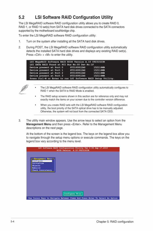
5-4 Chapter 5: RAID configuration
3. The utility main window appears. Use the arrow keys to select an option from the Management Menu and then press <Enter>. Refer to the Management Menu descriptions on the next page.
At the bottom of the screen is the legend box. The keys on the legend box allow you to navigate through the setup menu options or execute commands. The keys on the legend box vary according to the menu level.
5.2 LSI Software RAID Configuration UtilityThe LSI MegaRAID software RAID configuration utility allows you to create RAID 0, RAID 1, or RAID 10 set(s) from SATA hard disk drives connected to the SATA connectors supported by the motherboard southbridge chip.
To enter the LSI MegaRAID software RAID configuration utility:
1. Turn on the system after installing all the SATA hard disk drives.
2. During POST, the LSI MegaRAID software RAID configuration utility automatically detects the installed SATA hard disk drives and displays any existing RAID set(s). Press <Ctrl> + <M> to enter the utility.
• The LSI MegaRAID software RAID configuration utility automatically configures to RAID 1 when the SATA to RAID Mode is enabled.
• The RAID setup screens shown in this section are for reference only and may not exactly match the items on your screen due to the controller version difference.
• When you create RAID sets with the LSI MegaRAID software RAID configuration utility, the boot priority of the SATA optical drive has to be manually adjusted. Otherwise, the system will not boot from the connected SATA ODD.
LSI MegaRAID Software RAID BIOS Version A.10 09231523RLSI SATA RAID Found at PCI Bus No:00 Dev No:1FDevice present at Port 0 ST3160812AS 152114MBDevice present at Port 1 ST3160812AS 152114MBDevice present at Port 2 ST3160812AS 152114MBDevice present at Port 3 ST3160812AS 152114MBPress Ctrl-M or Enter to run LSI Software RAID Setup Utility.
Use Cursor Keys to Navigate Between Items And Press Enter To Select An Option
LSI Software RAID Configuration Utility Ver C.05 Sep 17,2010BIOS Version A.10.09231523R
Configure VD(s)
ConfigureInitializeObjectsRebuildCheck Consistency
Management Menu

5-5Z10PA-U8 Series
5.2.1 Creating a RAID setThe LSI Software RAID Configuration Utility allows you to create a RAID 0, RAID 1, or RAID 10 set using two types of configurations: Easy and New.
In Easy Configuration, the virtual drive parameters are set automatically.
In New Configuration, you manually set the virtual drive parameters.
Using Easy Configuration
To create a RAID set using the Easy Configuration option:
1. From the Management Menu, select Configure > Easy Configuration, and then press <Enter>.
Menu Description
Configure Allows you to create RAID 0, RAID 1 or RAID 10 set using the Easy Configuration or the New Configuration command. This menu also allows you to view, add, or clear RAID configurations or select the boot drive
Initialize Allows you to initialize the virtual drives of a created RAID set
Objects Allows you to initialize virtual drives or change the virtual drive parameters
Rebuild Allows you to rebuild failed drives
Check Consistency Allows you to check the data consistency of the virtual drives of a created RAID set
Use Cursor Keys to Navigate Between Items And Press Enter To Select An Option
LSI Software RAID Configuration Utility Ver C.05 Sep 17,2010BIOS Version A.10.09231523R
Defines Physical Arrays. An Array Will Automatically Become A VD
ConfigureInitializeObjectsRebuildCheck Consistency
Management MenuEasy ConfigurationNew ConfigurationView/Add ConfigurationClear ConfigurationSelect Boot Drive
Configuration Menu
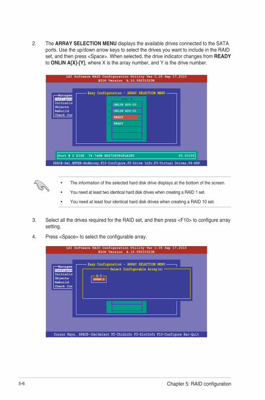
5-6 Chapter 5: RAID configuration
3. Select all the drives required for the RAID set, and then press <F10> to configure array setting.
4. Press <Space> to select the configurable array.
2. The ARRAY SELECTION MENU displays the available drives connected to the SATA ports. Use the up/down arrow keys to select the drives you want to include in the RAID set, and then press <Space>. When selected, the drive indicator changes from READY to ONLIN A[X]-[Y], where X is the array number, and Y is the drive number.
• The information of the selected hard disk drive displays at the bottom of the screen.
• You need at least two identical hard disk drives when creating a RAID 1 set.
• You need at least four identical hard disk drives when creating a RAID 10 set.
SPACE-Sel,ENTER-EndArray,F10-Configure,F2-Drive Info,F3-Virtual Drives,F4-HSP
LSI Software RAID Configuration Utility Ver C.05 Sep 17,2010BIOS Version A.10.09231523R
Port # 2 DISK 74.74GB HDS728080PLA380 05.01C05
ConfigureInitializeObjectsRebuildCheck Consistency
Management MenuEasy Configuration - ARRAY SELECTION MENU
ONLIN A00-00
ONLIN A00-01
READY
READY
0
1
2
3
PORT #
Cursor Keys, SPACE-(De)Select F2-Chidinfo F3-SlotInfo F10-Configure Esc-Quit
LSI Software RAID Configuration Utility Ver C.05 Sep 17,2010BIOS Version A.10.09231523R
ConfigureInitializeObjectsRebuildCheck Consistency
Management MenuEasy Configuration - ARRAY SELECTION MENU
ONLIN A00-00
ONLIN A00-01
READY
READY
0
1
2
3
PORT #Select Configurable Array(s)
A-0SPAN-1

5-7Z10PA-U8 Series
5. Press <F10> again, the virtual drive information appears including a Virtual Drive menu that allows you to change the virtual drive parameters.
6. Select RAID from the Virtual Drive sub-menu, and then press <Enter>.
7. Select the RAID level from the menu, and then press <Enter>.
Use Cursor Keys To Navigate Between Items And Press Enter To Select An Option
LSI Software RAID Configuration Utility Ver C.05 Sep 17,2010BIOS Version A.10.09231523R
Choose RAID Level For This VD
ConfigureInitializeObjectsRebuildCheck Consistency
Management MenuEasy Configuration - ARRAY SELECTION MENU
ONLIN A00-00
ONLIN A00-01
READY
READY
0
1
2
3
PORT #
Virtual Drive(s) ConfiguredLD RAID Size #Stripes StripSz Status
0 1 148.580GB 2 64KB ONLINE
RAID = 1Units= MBSize = 152146MBDWC = OFFRA = OnAcceptSPAN = NO
Virtual Drive 0
Use Cursor Keys To Navigate Between Items And Press Enter To Select An Option
LSI Software RAID Configuration Utility Ver C.05 Sep 17,2010BIOS Version A.10.09231523R
Choose RAID Level For This VD
ConfigureInitializeObjectsRebuildCheck Consistency
Management MenuEasy Configuration - ARRAY SELECTION MENU
ONLIN A00-00
ONLIN A00-01
READY
READY
0
1
2
3
PORT #
Virtual Drive(s) ConfiguredLD RAID Size #Stripes StripSz Status
0 1 148.580GB 2 64KB ONLINE
RAID 0RAID 1
RAID LevelRAID = 1Units= MBSize = 152146MBDWC = OFFRA = OnAcceptSPAN = NO
Virtual Drive 0

5-8 Chapter 5: RAID configuration
8. Select Units from the Virtual Drive sub-menu, and then press <Enter>.
9. Select the units for virtual drive size from the menu, and then press <Enter>.
10. When creating a RAID 1 or a RAID 10 set, select DWC from the Virtual Drive menu, and then press <Enter>.
When creating a RAID 0 set, proceed to step 12.
11. Select On to enable the Disk Write Cache setting, and then press <Enter>.
Enabling DWC can improve the performance, but with the risk of data loss.
Use Cursor Keys To Navigate Between Items And Press Enter To Select An Option
LSI Software RAID Configuration Utility Ver C.05 Sep 17,2010BIOS Version A.10.09231523R
Select Units For VD Size
ConfigureInitializeObjectsRebuildCheck Consistency
Management MenuEasy Configuration - ARRAY SELECTION MENU
ONLIN A00-00
ONLIN A00-01
READY
READY
0
1
2
3
PORT #
Virtual Drive(s) ConfiguredLD RAID Size #Stripes StripSz Status
0 1 148.580GB 2 64KB ONLINE
MBGBTB
Select Units For VD Size
RAID = 1Units= MBSize = 152146MBDWC = OFFRA = OnAcceptSPAN = NO
Virtual Drive 0
Use Cursor Keys To Navigate Between Items And Press Enter To Select An Option
LSI Software RAID Configuration Utility Ver C.05 Sep 17,2010BIOS Version A.10.09231523R
Disk Write Cache Setting of VD
ConfigureInitializeObjectsRebuildCheck Consistency
Management MenuEasy Configuration - ARRAY SELECTION MENU
ONLIN A00-00
ONLIN A00-01
READY
READY
0
1
2
3
PORT #
Virtual Drive(s) ConfiguredLD RAID Size #Stripes StripSz Status
0 1 148.580GB 2 64KB ONLINE
OffOn
Change DWC
RAID = 1Units= MBSize = 152146MBDWC = OFFRA = OnAcceptSPAN = NO
Virtual Drive 0

5-9Z10PA-U8 Series
12. When finished setting the selected virtual drive configuration, select Accept from the menu, and then press <Enter>.
13. Follow step 2 to 12 to configure additional virtual drives.
14. Press <Esc> to finish RAID configuration. When prompted to save configuration, select Yes from the menu, and then press <Enter>.
Cursor Keys, SPACE-(De) Select F2-ChIdInfo F3-SlotInfo F10-Configure Esc-Quit
LSI Software RAID Configuration Utility Ver C.05 Sep 17,2010BIOS Version A.10.09231523R
Accept This VD Configuration And Go To Next VD
ConfigureInitializeObjectsRebuildCheck Consistency
Management MenuEasy Configuration - ARRAY SELECTION MENU
ONLIN A00-00
ONLIN A00-01
READY
READY
0
1
2
3
PORT #
Virtual Drive(s) ConfiguredLD RAID Size #Stripes StripSz Status
0 1 148.580GB 2 64KB ONLINE
RAID = 1Units= MBSize = 152146MBDWC = OFFRA = OnAcceptSPAN = NO
Virtual Drive 0
Use Cursor Keys To Navigate Between Items And Press Enter To Select An Option
LSI Software RAID Configuration Utility Ver C.05 Sep 17,2010BIOS Version A.10.09231523R
Select Yes Or No
ConfigureInitializeObjectsRebuildCheck Consistency
Management Menu YesNo
Save Configuration?Easy ConfigurationNew ConfigurationView/Add ConfigurationClear ConfigurationSelect Boot Drive
Configuration Menu
Virtual Drive(s) ConfiguredLD RAID Size #Stripes StripSz Status
0 1 148.580GB 2 64KB ONLINE

5-10 Chapter 5: RAID configuration
Using New Configuration
When a RAID set already exists, using the New Configuration command erases the existing RAID configuration data. If you do not want to delete the existing RAID set, use the View/Add Configuration command to view or create another RAID configuration.
To create a RAID set using the New Configuration option
1. From the Management Menu, select Configure > New Configuration, and then press <Enter>.
2. Follow step 2 to 9 of the previous section: Using Easy Configuration.
3. Select Size from the Virtual Drive menu, and then press <Enter>.
4. Key-in the desired virtual drive size, and then press <Enter>.
5. Follow step 10 to 14 of the previous section: Using Easy Configuration to create the RAID set.
Use Cursor Keys To Navigate Between Items And Press Enter To Select An Option
LSI Software RAID Configuration Utility Ver C.05 Sep 17,2010BIOS Version A.10.09231523R
Clear Existing Configuration And Start A New Configuration
ConfigureInitializeObjectsRebuildCheck Consistency
Management MenuEasy ConfigurationNew ConfigurationView/Add ConfigurationClear ConfigurationSelect Boot Drive
Configuration Menu
Use Cursor Keys To Navigate Between Items And Press Enter To Select An Option
LSI Software RAID Configuration Utility Ver C.05 Sep 17,2010BIOS Version A.10.09231523R
Enter VD Size:
ConfigureInitializeObjectsRebuildCheck Consistency
Management MenuEasy Configuration - ARRAY SELECTION MENU
ONLIN A00-00
ONLIN A00-01
READY
READY
0
1
2
3
PORT #
Virtual Drive(s) ConfiguredLD RAID Size #Stripes StripSz Status
0 1 148.580GB 2 64KB ONLINE
RAID = 1Units= MBSize = 152146MBDWC = OFFRA = OnAcceptSPAN = NO
Virtual Drive 0Enter VD Size: 152146_

5-11Z10PA-U8 Series
5.2.2 Adding or viewing a RAID configurationYou can add a new RAID configuration or view an existing configuration using the View/Add Configuration command.
Adding a new RAID configurationTo add a new RAID configuration:
1. From the Management Menu, select Configure > View/Add Configuration, and then press <Enter>.
2. The ARRAY SELECTION MENU displays the available drives connected to the SATA ports. Select the drive(s) you want to include in the RAID set, then press <Space>. When selected, the drive indicator changes from READY to ONLIN A[X]-[Y], where X is the array number, and Y is the drive number.
The information of the selected hard disk drive displays at the bottom of the screen.
3. Follow step 3 to 12 of section 6.2.1 Creating a RAID set: Using Easy Configuration to add a new RAID set.
Use Cursor Keys To Navigate Between Items And Press Enter To Select An Option
LSI Software RAID Configuration Utility Ver C.05 Sep 17,2010BIOS Version A.10.09231523R
View/Add to The Existing Configuration
ConfigureInitializeObjectsRebuildCheck Consistency
Management MenuEasy ConfigurationNew ConfigurationView/Add ConfigurationClear ConfigurationSelect Boot Drive
Configuration Menu
SPACE-Sel,ENTER-EndArray,F10-Configure,F2-Drive Info,F3-Virtual Drives,F4-HSP
LSI Software RAID Configuration Utility Ver C.05 Sep 17,2010BIOS Version A.10.09231523R
Port # 2 DISK 77247MB HDS72808PLA380 PF20A60A
ConfigureInitializeObjectsRebuildCheck Consistency
Management MenuView/Add Configuration - ARRAY SELECTION MENU
ONLIN A00-00
ONLIN A00-01
READY
READY
0
1
2
3
PORT #

5-12 Chapter 5: RAID configuration
5.2.3 Initializing the virtual drives
After creating the RAID set(s), you must initialize the virtual drives. You may initialize the virtual drives of a RAID set(s) using the Initialize or Objects command on the Management Menu.
Using the Initialize command
To initialize the virtual drive using the Initialize command
1. From the Management Menu, select Initialize, and then press <Enter>.
2. The screen displays the available RAID set(s) and prompts you to select the virtual drive to initialize. Use the arrow keys to select the virtual drive from the Virtual Drive selection, and then press <Space>.
Use Cursor Keys to Navigate Between Items And Press Enter To Select An Option
LSI Software RAID Configuration Utility Ver C.05 Sep 17,2010BIOS Version A.10.09231523R
Initialize VD(s)
ConfigureInitializeObjectsRebuildCheck Consistency
Management Menu
SPACE-(De)Select, F10-Initialize
LSI Software RAID Configuration Utility Ver C.05 Sep 17,2010BIOS Version A.10.09231523R
Select VD
ConfigureInitializeObjectsRebuildCheck Consistency
Management MenuEasy Configuration - ARRAY SELECTION MENU
Virtual Drive(s) ConfiguredLD RAID Size #Stripes StripSz Status
0 1 148.580GB 2 64KB ONLINE
Virtual Drive 0Virtual Drives

5-13Z10PA-U8 Series
3. Press <F10> to start initialization. When prompted, select Yes from the Initialize? dialog box, and then press <Enter>.
Initializing a virtual drive erases all data on the drive.
4. A progress bar appears on screen. If desired, press <Esc> to abort initialization. When initialization is completed, press <Esc>.
SPACE-(De)Select, F10-Initialize
LSI Software RAID Configuration Utility Ver C.05 Sep 17,2010BIOS Version A.10.09231523R
Init Will Destroy Data On Selected VD(s)
ConfigureInitializeObjectsRebuildCheck Consistency
Management MenuEasy Configuration - ARRAY SELECTION MENU
Virtual Drive(s) ConfiguredLD RAID Size #Stripes StripSz Status
0 1 148.580GB 2 64KB ONLINE
Virtual Drive 0Virtual Drives
YesNo
Initialize?
SPACE-(De)Select, F10-Initialize
LSI Software RAID Configuration Utility Ver C.05 Sep 17,2010BIOS Version A.10.09231523R
ConfigureInitializeObjectsRebuildCheck Consistency
Management Menu
Virtual Drive(s) ConfiguredLD RAID Size #Stripes StripSz Status
0 1 148.580GB 2 64KB ONLINE
Virtual Drive 0Virtual Drives
Init of VD Is In ProcessVD 0 Initialization Complete. Press Esc..
100% Completed

5-14 Chapter 5: RAID configuration
Using the Objects commandTo initialize the virtual drives using the Objects command
1. From the Management Menu, select Objects > Virtual Drive, and then press <Enter>.
2. Select the virtual drive to initialize from the Virtual Drives sub-menu, and then press <Enter>.
Use Cursor Keys To Navigate Between Items And Press Enter To Select An Option
LSI Software RAID Configuration Utility Ver C.05 Sep 17,2010BIOS Version A.10.09231523R
Change VD Parameters
ConfigureInitializeObjectsRebuildCheck Consistency
Management MenuAdapterVirtual DrivePhysical Drive
Objects
Press ENTER To Select A VD, <Del> To Delete A VD
LSI Software RAID Configuration Utility Ver C.05 Sep 17,2010BIOS Version A.10.09231523R
Select VD
ConfigureInitializeObjectsRebuildCheck Consistency
Management MenuAdapterVirtual DrivePhysical Drive
Objects Virtual Drive 0Virtual Drive(1)
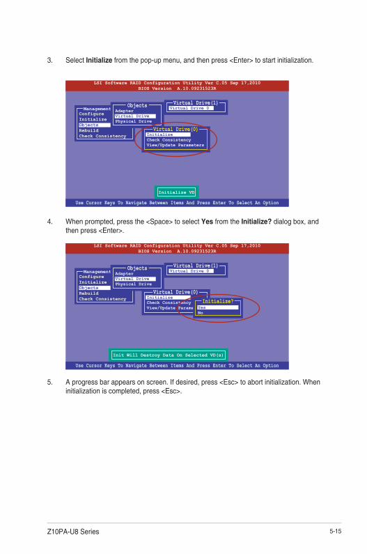
5-15Z10PA-U8 Series
3. Select Initialize from the pop-up menu, and then press <Enter> to start initialization.
4. When prompted, press the <Space> to select Yes from the Initialize? dialog box, and then press <Enter>.
5. A progress bar appears on screen. If desired, press <Esc> to abort initialization. When initialization is completed, press <Esc>.
Use Cursor Keys To Navigate Between Items And Press Enter To Select An Option
LSI Software RAID Configuration Utility Ver C.05 Sep 17,2010BIOS Version A.10.09231523R
Initialize VD
ConfigureInitializeObjectsRebuildCheck Consistency
Management MenuAdapterVirtual DrivePhysical Drive
Objects Virtual Drive 0Virtual Drive(1)
InitializeCheck ConsistencyView/Update Parameters
Virtual Drive(0)
Use Cursor Keys To Navigate Between Items And Press Enter To Select An Option
LSI Software RAID Configuration Utility Ver C.05 Sep 17,2010BIOS Version A.10.09231523R
ConfigureInitializeObjectsRebuildCheck Consistency
Management MenuAdapterVirtual DrivePhysical Drive
Objects Virtual Drive 0Virtual Drive(1)
InitializeCheck ConsistencyView/Update Parameters
Virtual Drive(0)
YesNo
Initialize?
Init Will Destroy Data On Selected VD(s)

5-16 Chapter 5: RAID configuration
5.2.4 Rebuilding failed drives
You can manually rebuild failed hard disk drives using the Rebuild command in the Management Menu.
To rebuild a failed hard disk drive
1. From the Management Menu, select Rebuild, and then press <Enter>.
2. The PHYSICAL DRIVES SELECTION MENU displays the available drives connected to the SATA ports. Select the drive you want to rebuild, and then press <Space>.
Use Cursor Keys to Navigate Between Items And Press Enter To Select An Option
LSI Software RAID Configuration Utility Ver C.05 Sep 17,2010BIOS Version A.10.09231523R
Rebuild VD(s)
ConfigureInitializeObjectsRebuildCheck Consistency
Management Menu
SPACE-(De)Select,F10-Start Rebuild,F2-Drive Information,F3-View Virtual Drives
LSI Software RAID Configuration Utility Ver C.05 Sep 17,2010BIOS Version A.10.09231523R
Port # 1 DISK 77247MB HDS72808PLA380 PF20A60A
ConfigureInitializeObjectsRebuildCheck Consistency
Management MenuREBUILD - PHYSICAL DRIVES SELECTION MENU
ONLIN A00-00
FAIL A00-01
0
1
PORT #

5-17Z10PA-U8 Series
3. After selecting the drive to rebuild, press <F10>. When prompted, press <Y> to rebuild the drive.
4. When rebuild is complete, press any key to continue.
SPACE-(De)Select,F10-Start Rebuild,F2-Drive Information,F3-View Virtual Drives
LSI Software RAID Configuration Utility Ver C.05 Sep 17,2010BIOS Version A.10.09231523R
Port # 1 DISK 77247MB HDS72808PLA380 PF20A60A
ConfigureInitializeObjectsRebuildCheck Consistency
Management MenuREBUILD - PHYSICAL DRIVES SELECTION MENU
ONLIN A00-00
FAIL A00-01
0
1
PORT #
Rebuilding of Drive Will Take A Few Minutes. Start Rebuilding Drive (Y/N)?

5-18 Chapter 5: RAID configuration
5.2.5 Checking the drives for data consistency
You can check and verify the accuracy of data redundancy in the selected virtual drive. The utility can automatically detect and/or detect and correct any differences in data redundancy depending on the selected option in the Objects > Adapter menu.
The Check Consistency command is available only for virtual drives included in a RAID 1 or RAID 10 set.
Using the Check Consistency CommandTo check data consistency using the Check Consistency command
1. From the Management Menu, select Check Consistency, and then press <Enter>.
2. The screen displays the available RAID set(s) and prompts you to select the virtual drive to check. Press <Space> to select the virtual drive from the Virtual Drive sub-menu, and then press <F10>.
Use Cursor Keys to Navigate Between Items And Press Enter To Select An Option
LSI Software RAID Configuration Utility Ver C.05 Sep 17,2010BIOS Version A.10.09231523R
CC of VD(s)
ConfigureInitializeObjectsRebuildCheck Consistency
Management Menu
SPACE-(De)Select, F10-Initialize
LSI Software RAID Configuration Utility Ver C.05 Sep 17,2010BIOS Version A.10.09231523R
Select VD
ConfigureInitializeObjectsRebuildCheck Consistency
Management MenuEasy Configuration - ARRAY SELECTION MENU
Virtual Drive(s) ConfiguredLD RAID Size #Stripes StripSz Status
0 1 148.580GB 2 64KB ONLINE
Virtual Drive 0Virtual Drives
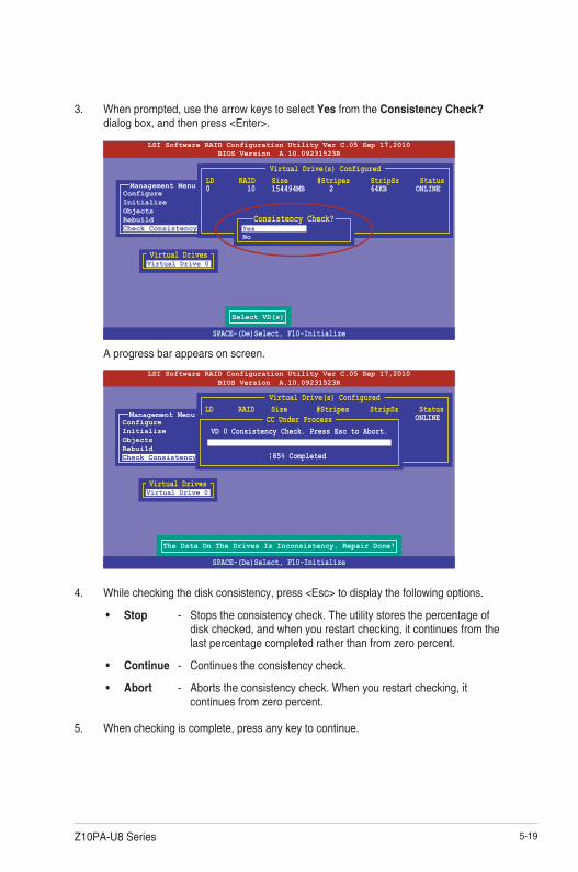
5-19Z10PA-U8 Series
3. When prompted, use the arrow keys to select Yes from the Consistency Check? dialog box, and then press <Enter>.
A progress bar appears on screen.
4. While checking the disk consistency, press <Esc> to display the following options.
• Stop - Stops the consistency check. The utility stores the percentage of disk checked, and when you restart checking, it continues from the last percentage completed rather than from zero percent.
• Continue - Continues the consistency check.
• Abort - Aborts the consistency check. When you restart checking, it continues from zero percent.
5. When checking is complete, press any key to continue.
SPACE-(De)Select, F10-Initialize
LSI Software RAID Configuration Utility Ver C.05 Sep 17,2010BIOS Version A.10.09231523R
Select VD(s)
ConfigureInitializeObjectsRebuildCheck Consistency
Management MenuEasy Configuration - ARRAY SELECTION MENU
Virtual Drive(s) ConfiguredLD RAID Size #Stripes StripSz Status0 10 154494MB 2 64KB ONLINE
Virtual Drive 0Virtual Drives
YesNo
Consistency Check?
SPACE-(De)Select, F10-Initialize
LSI Software RAID Configuration Utility Ver C.05 Sep 17,2010BIOS Version A.10.09231523R
The Data On The Drives Is Inconsistency. Repair Done!
ConfigureInitializeObjectsRebuildCheck Consistency
Management MenuEasy Configuration - ARRAY SELECTION MENU
Virtual Drive(s) ConfiguredLD RAID Size #Stripes StripSz Status0 10 154494MB 2 64KB ONLINE
Virtual Drive 0Virtual Drives
CC Under ProcessVD 0 Consistency Check. Press Esc to Abort.
85% Completed

5-20 Chapter 5: RAID configuration
Using the Objects commandTo check data consistency using the Objects command
1. From the Management Menu, select Objects, and then select Virtual Drive from the sub-menu.
2. Use the arrow keys to select the virtual drive you want to check, and then press <Enter>.
3. Select Check Consistency from the pop-up menu, and then press <Enter>.
4. When prompted, use the arrow keys to select Yes from the dialog box to check the drive.
5. When checking is complete, press any key to continue.
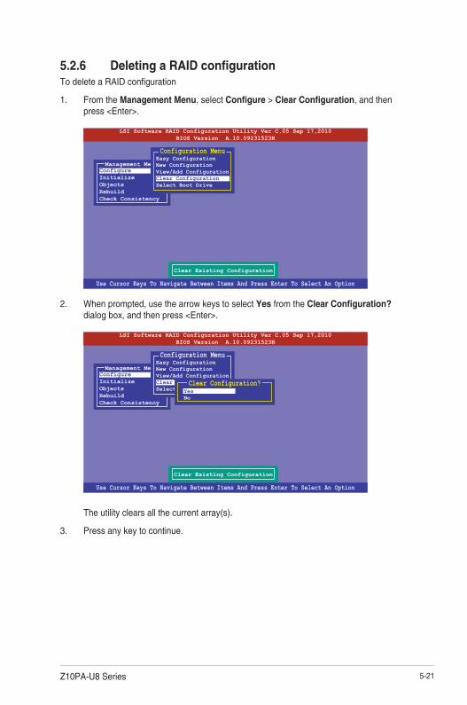
5-21Z10PA-U8 Series
5.2.6 Deleting a RAID configurationTo delete a RAID configuration
1. From the Management Menu, select Configure > Clear Configuration, and then press <Enter>.
2. When prompted, use the arrow keys to select Yes from the Clear Configuration? dialog box, and then press <Enter>.
The utility clears all the current array(s).
3. Press any key to continue.
Use Cursor Keys To Navigate Between Items And Press Enter To Select An Option
LSI Software RAID Configuration Utility Ver C.05 Sep 17,2010BIOS Version A.10.09231523R
Clear Existing Configuration
ConfigureInitializeObjectsRebuildCheck Consistency
Management MenuEasy ConfigurationNew ConfigurationView/Add ConfigurationClear ConfigurationSelect Boot Drive
Configuration Menu
YesNo
Clear Configuration?

5-22 Chapter 5: RAID configuration
5.2.7 Selecting the boot drive from a RAID setYou must have created a new RAID configuration before you can select the boot drive from a RAID set. See section 6.2.1 Creating a RAID set: Using New Configuration for details.
To select the boot drive from a RAID set
1. From the Management Menu, select Configure > Select Boot Drive, and then press <Enter>.
2. When prompted, use the arrow keys to select the bootable virtual drive from the list, then press <Enter>.
3. The virtual drive is selected as boot drive. Press any key to continue.
Use Cursor Keys To Navigate Between Items And Press Enter To Select An Option
LSI Software RAID Configuration Utility Ver C.05 Sep 17,2010BIOS Version A.10.09231523R
Select A Boot VD
ConfigureInitializeObjectsRebuildCheck Consistency
Management MenuEasy ConfigurationNew ConfigurationView/Add ConfigurationClear ConfigurationSelect Boot Drive
Configuration Menu
Use Cursor Keys To Navigate Between Items And Press Enter To Select An Option
LSI Software RAID Configuration Utility Ver C.05 Sep 17,2010BIOS Version A.10.09231523R
Select A Boot VD
ConfigureInitializeObjectsRebuildCheck Consistency
Management MenuEasy ConfigurationNew ConfigurationView/Add ConfigurationClear ConfigurationSelect Boot Drive
Configuration MenuBoot Drive 0
Bootable VDs(1): Current Boot VD(0)

5-23Z10PA-U8 Series
5.2.8 Enabling WriteCacheYou may manually enable the RAID controller’s WriteCache option after creating a RAID set to improve the data transmission performance.
When you enable WriteCache, you may lose data when a power interruption occurs while transmitting or exchanging data among the drives.
The WriteCache function is recommended for RAID 1 and RAID 10 sets.
To enable WriteCache
1. From the Management Menu, select Objects > Adapter, select an existing adapter, and then press <Enter> to display the adapter properties.
2. Select Disk WC, and then press <Enter> to turn on the option.
5. When finished, press any key to continue.
3. From the Management Menu, select Objects > Virtual Drive, select an existing adapter and press <Enter>. Select View/Update Parameters and press <Enter> to display the adapter properties.
4. Select Disk WC, and then press <Enter> to turn on the option.
Use Cursor Keys To Navigate Between Items And Press Enter To Select An Option
LSI Software RAID Configuration Utility Ver C.05 Sep 17,2010BIOS Version A.10.09231523R
Disk Write Cache - Off(Write Through or On(Write Back)
ConfigureInitializeObjectsRebuildCheck Consistency
Management MenuAdapterVirtual DrivePhysical Drive
ObjectsRebuild Rate = 30Chk Const Rate = 30FGI Rate = 30BGI Rate = 30Disk WC = OffRead Ahead = OnBios State = EnableCont On Error = YesFast Init = EnableAuto Rebuild = OnAuto Resume = EnableDisk Coercion = 1GBFactory Default
Adapter 0
Use Cursor Keys To Navigate Between Items And Press Enter To Select An Option
LSI Software RAID Configuration Utility Ver C.05 Sep 17,2010BIOS Version A.10.09231523R
Disk Write Cache Setting of VD
ConfigureInitializeObjectsRebuildCheck Consistency
Management MenuAdapterVirtual DrivePhysical Drive
ObjectsRAID = 0Size = 148.580GBStripe Size = 64KB#Stripes = 2State = OPTIMALSpans = 1Disk WC = OnRead Ahead = On
Virtual Drive

5-24 Chapter 5: RAID configuration
5.3 Intel® Rapid Storage Technology enterprise SATA/SSATA Option ROM Utility
The Intel® Rapid Storage Technology enterprise SATA/SSATA Option ROM utility allows you to create RAID 0, RAID 1, RAID 10 (RAID 1+0), and RAID 5 set from Serial ATA hard disk drives that are connected to the Serial ATA connectors.
The navigation keys at the bottom of the screen allow you to move through the menus and select the menu options.
The RAID BIOS setup screens shown in this section are for reference only and may not exactly match the items on your screen.
To launch the Intel® Rapid Storage Technology enterprise SATA/SSATA Option ROM utility:
1. Turn on the system.
2. During POST, press <Ctrl>+<I> to display the utility main menu.
Before you proceed, ensure that you have installed the Serial ATA hard disk drives, have set the correct jumper settings of the motherboard, and have set the correct SATA mode in the BIOS setup. You can refer to the Installing hard disk drives, Setting Jumpers, and Setting the RAID mode sections in BIOS for more information.
[ESC]-Exit [ENTER]-Select Menu[ ]-Select
Intel(R) Rapid Storage Technology enterprise - SATA Option ROM - 3.6.0.1023Copyright(C) 2003-12 Intel Corporation. All Rights Reserved.
[ MAIN MENU ]
[ DISK/VOLUME INFORMATION]
RAID Volumes:None defined.
Physical Disks: ID Drive Model Serial # Size Type/Status(Vol ID)0 ST3300656SS HWAS0000991753TR 279.3GB Non-RAID Disk1 ST3300656SS 37VN00009846RAJ1 279.3GB Non-RAID Disk2 ST3300656SS 397600009846UEDY 279.3GB Non-RAID Disk3 ST3300656SS GWC50000991756G6 279.3GB Non-RAID Disk
3. Reset Disks to Non-RAID4. Exit
1. Create RAID Volume2. Delete RAID Volume

5-25Z10PA-U8 Series
5.3.1 Creating a RAID setTo create a RAID set:
1. From the utility main menu, select 1. Create RAID Volume and press <Enter>.
2. Key in a name for the RAID set and press <Enter>.
3. Press the up/down arrow keys to select a RAID Level that you wish to create then press <Enter>.
4. From the Disks item field, press <Enter> to select the hard disk drives that you want to include in the RAID set.
5. Use the up/down arrow keys to move the selection bar then press <Space> to select a disk. A small triangle before the Port number marks the selected drive. Press <Enter> when you are done.
[ESC]-Previous Menu [ENTER]-Select[ ]Change
Intel(R) Rapid Storage Technology enterprise - SATA Option ROM - 3.6.0.1023Copyright(C) 2003-12 Intel Corporation. All Rights Reserved.
[ CREATE VOLUME MENU ]
[ HELP ]
Name:RAID Level:
Disks:Strip Size:Capacity:
Syne:Create Volume
Enter a unique volume name that has no special characters and is16 characters or less.
Volume0RAID0(Strips)Select Disks128KB0.0 GBN/A
[TAB]-Next
[ SELECT DISKS ]
Port Drive Model Serial # Size Status0 ST3300656SS HWAS0000991753TR 279.3GB Non-RAID Disk1 ST3300656SS 37VN00009846RAJ1 279.3GB Non-RAID Disk2 ST3300656SS 397600009846UEDY 279.3GB Non-RAID Disk3 ST3300656SS GWC50000991756G6 279.3GB Non-RAID Disk
Select 1 Master and 1 Recovery disk to create volume.
[ ]-Prev/Next [TAB]-(M)aster [SPACE]-(R)ecovery [ENTER]-Done

5-26 Chapter 5: RAID configuration
6. Use the up/down arrow keys to select the stripe size for the RAID array (for RAID 0, 10 and 5 only) then press <Enter>. The available stripe size values range from 4 KB to 128 KB. The following are typical values: RAID 0: 128KB RAID 10: 64KB RAID 5: 64KB
We recommend a lower stripe size for server systems, and a higher stripe size for multimedia computer systems used mainly for audio and video editing.
7. In the Capacity field item, key in the RAID volume capacity that you want to use and press <Enter>. The default value field indicates the maximum allowed capacity.
8. Press <Enter> to start creating the RAID volume.
9. From the following warning message, press <Y> to create the RAID volume and return to the main menu, or press <N> to go back to the CREATE VOLUME menu.
WARNING: ALL DATA ON SELECTED DISKS WILL BE LOST.
Are you sure you want to create this volume? (Y/N):

5-27Z10PA-U8 Series
5.3.2 Deleting a RAID set
Take caution when deleting a RAID set. You will lose all data on the hard disk drives when you delete a RAID set.
To delete a RAID set:
1. From the utility main menu, select 2. Delete RAID Volume and press <Enter>.
2. From the Delete Volume Menu, press the up/down arrow keys to select the RAID set you want to delete then press <Del>.
3. Press <Y> to confirm deletion of the selected RAID set and return to the utility main menu, or press <N> to return to the DELETE VOLUME menu.
[ESC]-Previous Menu[ ]-Select
Intel(R) Rapid Storage Technology enterprise - SATA Option ROM - 3.6.0.1023Copyright(C) 2003-12 Intel Corporation. All Rights Reserved.
[ DELETE VOLUME MENU ]
[ HELP ]
Deleting a volume will reset the disks to non-RAID
WARNING: ALL DISK DATA WILL BE DELETED.(This does not apply to Recovery volumes)
[DEL]-Delete Volume
Name Level Drives Capacity Status BootableVolume0 RAID0(Stripe) 2 298.0GB Normal Yes
ALL DATA IN THE VOLUME WILL BE LOST!(This does not apply to Recovery volumes)
Are you sure you want to delete volume “Volume0”? (Y/N):
[ DELETE VOLUME VERIFICATION ]

5-28 Chapter 5: RAID configuration
5.3.3 Resetting disks to Non-RAID
Take caution before you reset a RAID volume hard disk drive to non-RAID. Resetting a RAID volume hard disk drive deletes all internal RAID structure on the drive.
To reset a RAID set:
1. From the utility main menu, select 3. Reset Disks to Non-RAID and press <Enter>.
2. Press the up/down arrow keys to select the drive(s) or disks of the RAID set you want to reset, then press <Space>. A small triangle before the Port number marks the selected drive. Press <Enter> when you are done.
3. Press <Y> in the confirmation window to reset the drive(s) or press <N> to return to the utility main menu.
Port Drive Model Serial # Size Status0 ST3300656SS HWAS0000991753TR 279.3GB Member Disk1 ST3300656SS 37VN00009846RAJ1 279.3GB Member Disk
Select the disks that should be reset.
Resetting RAID disk will remove its RAID structuresand revert it to a non-RAID disk.
[ ]-Previous/Next [SPACE]-Selects [ENTER]-Selection Complete
[ RESET RAID DATA ]
WARNING: Resetting a disk causes all data on the disk to be lost.(This does not apply to Recovery volumes)

5-29Z10PA-U8 Series
Select a destination disk with the same size as the original hard disk.
5.3.5 Rebuilding the RAID
This option is only for the RAID 1 set.
Rebuilding the RAID with other non-RAID diskIf any of the SATA hard disk drives included in the RAID 1 array failed, the system displays the status of the RAID volume as “Degraded” during POST. You can rebuild the RAID array with other installed non-RAID disks.
To rebuild the RAID with other non-RAID disk:
1. During POST, press <Ctrl>+<I> at the prompt to enter the Intel Rapid Storage Technology option ROM utility.
2. If there is a non-RAID SATA Hard Disk available, the utility will prompt you to rebuild the RAID. Press the up/down arrow keys to select the destination disk then Press <Enter> to start the rebuilding process, or press <ESC> to exit.
5.3.4 Exiting the Intel® Rapid Storage Technology enterprise SATA/SSATA Option ROM utility
To exit the utility:
1. From the utility main menu, select 4. Exit then press <Enter>.
2. Press <Y> to exit or press <N> to return to the utility main menu.
Select the port of destination disk for rebuilding (ESC to exit):Port Drive Model Serial # SizeX XXXXXXXXXXX XXXXXXXX XXX.GB
“Degraded” volume and disk available for rebuilding detected. Selectigna disk initiates a rebuild. Rebuild completes in the operating system.
[ ]-Previous/Next [ENTER]-Select [ESC]-Exit
[ DEGRADED VOLUME DETECTED ]
Are you sure you want to exit? (Y/N):
[ CONFIRM EXIT ]

5-30 Chapter 5: RAID configuration
3. The utility immediately starts rebuilding after the disk is selected. When done, the status of the degraded RAID volume is changed to “Rebuild”.
4. Press <Esc> to exit Intel Rapid Storage Technology and reboot the system.
5. Select Start > Programs > Intel Rapid Storage > Intel Rapid Storage Console or click the Intel Rapid Storage Technology tray icon to load the Intel Rapid Storage Manager utility.
6. From the View menu, select Advanced Mode to display the details of the Intel Rapid Storage Console.
7. From the Volumes view option, select RAID volume to view the rebuilding status. When finished, the status is changed to “Normal”.
Rebuilding the RAID with a new hard diskIf any of the SATA hard disk drives included in the RAID array failed, the system displays the status of the RAID volume as “Degraded” during POST. You may replace the disk drive and rebuild the RAID array.
To rebuild the RAID with a new hard disk:
1. Remove the failed SATA hard disk and install a new SATA hard disk of the same specification into the same SATA Port.
Select a destination disk with the same size as the original hard disk.
2. Reboot the system then follow the steps in section Rebuilding the RAID with other non-RAID disk.
[ESC]-Exit [ENTER]-Select Menu[ ]-Select
Intel(R) Rapid Storage Technology enterprise - SATA Option ROM - 3.6.0.1023Copyright(C) 2003-12 Intel Corporation. All Rights Reserved.
[ MAIN MENU ]
[ DISK/VOLUME INFORMATION]
RAID Volumes: *=Data is EncryptedID Name Level1 Strip Size Status Bootable1 Volume0 RAID1(Mirror) N/A 149.0GB Rebuild Yes
Physical Devices: Port Drive Model Serial # Size Type/Status(Vol ID)1 ST3160812AS 9LS0F4HL 149.0GB Member Disk(0)2 ST3160812AS 3LS0JYL8 149.0GB Member Disk(0)
Volumes with “Rebuild” status will be rebuilt within the operating system.
3. Reset Disks to Non-RAID4. Exit
1. Create RAID Volume2. Delete RAID Volume

5-31Z10PA-U8 Series
5.3.6 Setting the Boot array in the BIOS Setup Utility
You can set the boot priority sequence in the BIOS for your RAID arrays when creating multi-RAID using the Intel® Rapid Storage Technology enterprise SATA Option ROM utililty.
To set the boot array in the BIOS:
Set at least one of the arrays bootable to boot from the hard disk.
1. Reboot the system and press <Del> to enter the BIOS setup utility during POST.
2. Go to the Boot menu and select the boot option priority.
3. Use up/down arrow keys to select the boot priority and press <Enter>. See the Boot menu section of Chapter 4 for more details.
4. From the Exit menu, select Save Changes & Exit, then press <Enter>.
5. When the confirmation window appears, select Yes, then press <Enter>.

5-32 Chapter 5: RAID configuration
5.4 Intel® Rapid Storage Technology enterprise (Windows)
The Intel® Rapid Storage Technology enterprise allows you to create RAID 0, RAID 1, RAID 10 (RAID 1+0), and RAID 5 set(s) from Serial ATA hard disk drives that are connected to the Serial ATA connectors supported by the Southbridge.
You can click Rescan to re-scan any attached hard disks.
1. Turn on the system and go to the windows desktop.
2. Click the Intel® Rapid Storage Technology enterprise icon to display the main menu.
Your storage system is configured for data protection, increased performance and optimal data storage capacity. You can create additional volumes to further optimize your storage system.
To enter the Intel® Rapid Storage Technology enterprise utility under Windows operating system:
You need to manually install the Intel® Rapid Storage Technology enterprise utility on a Windows® operating system. Please refer to the installation instructions in Chapter 6.

5-33Z10PA-U8 Series
5.4.1 Creating a RAID setTo create a RAID set:
1. From the utility main menu, select Create Volume and select volume type.
2. Click Next.
3. Enter a name for the RAID set, then select the array disks.
4. Select Volume Size tab, you can drag the bar to decide the volume size.
5. Click Next.
• If you do not want to keep the data on one of the selected disks, select NO when prompted.
• If you want to Enable volume write-back cache or Initialize volume, click Advanced.
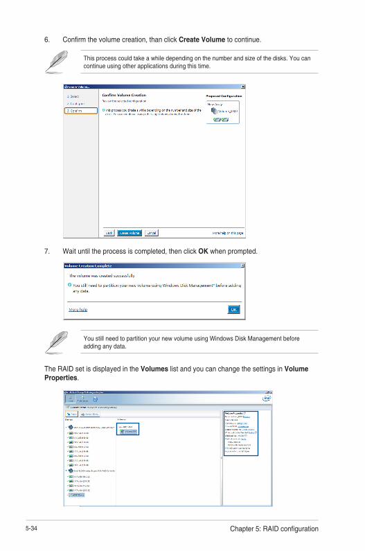
5-34 Chapter 5: RAID configuration
6. Confirm the volume creation, than click Create Volume to continue.
This process could take a while depending on the number and size of the disks. You can continue using other applications during this time.
7. Wait until the process is completed, then click OK when prompted.
You still need to partition your new volume using Windows Disk Management before adding any data.
The RAID set is displayed in the Volumes list and you can change the settings in Volume Properties.
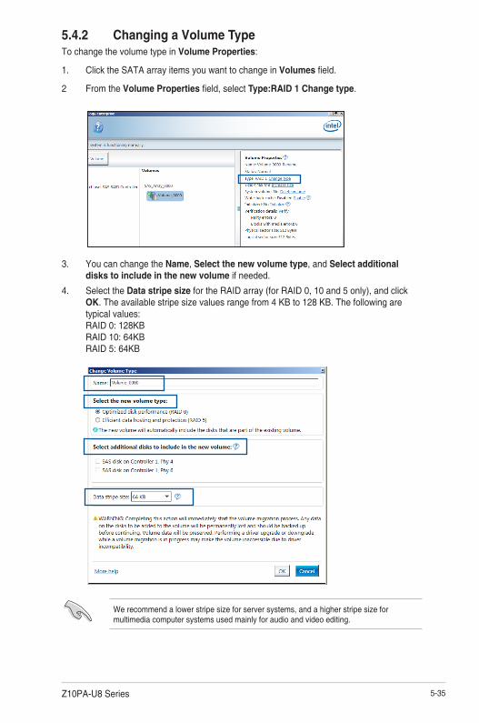
5-35Z10PA-U8 Series
5.4.2 Changing a Volume TypeTo change the volume type in Volume Properties:
1. Click the SATA array items you want to change in Volumes field.
2 From the Volume Properties field, select Type:RAID 1 Change type.
We recommend a lower stripe size for server systems, and a higher stripe size for multimedia computer systems used mainly for audio and video editing.
3. You can change the Name, Select the new volume type, and Select additional disks to include in the new volume if needed.
4. Select the Data stripe size for the RAID array (for RAID 0, 10 and 5 only), and click OK. The available stripe size values range from 4 KB to 128 KB. The following are typical values: RAID 0: 128KB RAID 10: 64KB RAID 5: 64KB

5-36 Chapter 5: RAID configuration
5.4.3 Deleting a volume
Be cautious when deleting a volume. You will lose all data on the hard disk drives.Before you proceed, ensure that you back up all your important data from your hard drives.
To delete a volume:
1. From the utility main menu, select the volume (exp. Volume_0000) in Volumes field you want to delete.
3. Click Yes to delete the volume and return to the utility main menu, or click No to return to the main menu.
2. Select Delete volume in Volume Properties field. The following screen appears.
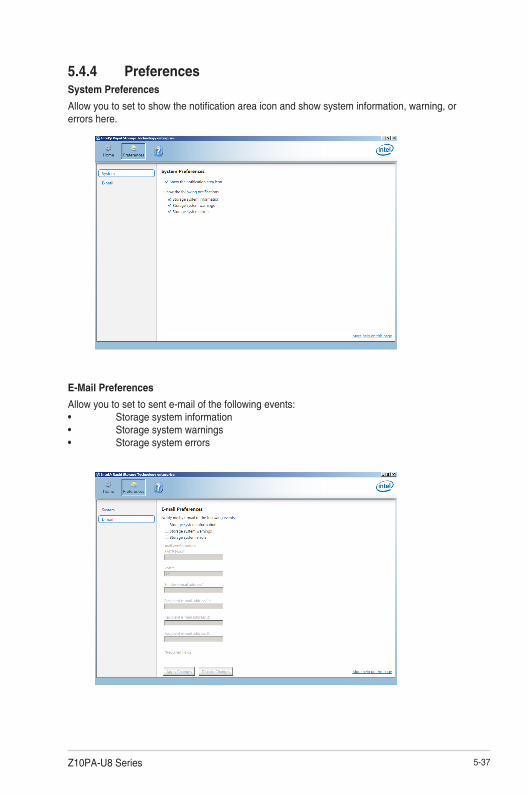
5-37Z10PA-U8 Series
5.4.4 PreferencesSystem Preferences
Allow you to set to show the notification area icon and show system information, warning, or errors here.
E-Mail Preferences
Allow you to set to sent e-mail of the following events:• Storage system information• Storage system warnings• Storage system errors

5-38 Chapter 5: RAID configuration

6Driver installation
This chapter provides the instructions for installing the necessary drivers for different system components in both Linux® and Windows® Operating Systems.
Chapter 6: Driver installation

6-2 Chapter 6: Driver installation
6.1 RAID driver installationAfter creating the RAID sets for your server system, you are now ready to install an operating system to the independent hard disk drive or bootable array. This part provides the instructions on how to install the RAID controller drivers during OS installation.
6.1.1 Creating a RAID driver disk
The system does not include a floppy drive. You have to use a USB floppy drive when creating a SATA RAID driver disk.
If you have created RAID sets with the LSI Software RAID configuration utility, the boot priority of the SATA optical disk drive has to be manually adjusted. Otherwise, the system will not boot from the connected SATA ODD.
To create a RAID driver disk in Windows® environment
1. Start Windows®.
2. Place the motherboard support DVD into the optical drive.
3. Go to the Make disk menu, and then select the type of RAID driver disk you want to create.
4. Insert a floppy disk into the USB floppy disk drive.
5. Follow succeeding screen instructions to complete the process.
Write-protect the floppy disk to avoid computer virus infection.
To create a RAID driver disk in Red Hat® Enterprise Linux server environment
1. Insert a blank formatted high-density floppy disk to the USB floppy disk drive.
2. Type dd if=XXX.img of=/dev/fd0 to decompress the file into the floppy disk from the following path in the support DVD:
For LSI MegaRAID Driver
\Drivers\C610 LSI RAID\Driver\makedisk\Linux
3. Eject the floppy disk.

Z10PA-U8 Series 6-3
6.1.2 Installing the RAID controller driver
During Windows® Server 2008 R2 OS installationTo install the RAID controller driver when installing Windows® Server 2008 R2 OS
1. Boot the computer using the Windows® Server 2008 R2 OS installation disc. Follow the screen instructions to start installing Windows Server 2008 R2.
2. When prompted to choose a type of installation, click Custom (advanced).
3. Click Load Driver.

6-4 Chapter 6: Driver installation
4. A message appears, reminding you to insert the installation media containing the driver of the RAID controller driver. If you have only one optical drive installed in your system, eject the Windows OS installation disc and replace with the motherboard Support DVD into the optical drive. Click Browse to continue.
5. Locate the driver in the corresponding folder of the Support DVD then click OK to continue.
6. Select the RAID controller driver you need from the list and click Next.
7. When the system finishes loading the RAID driver, replace the motherboard Support DVD with the Windows Server installation disc. Select the drive to install Windows and click Next.
8. Setup then proceeds with the OS installation. Follow screen instructions to continue.
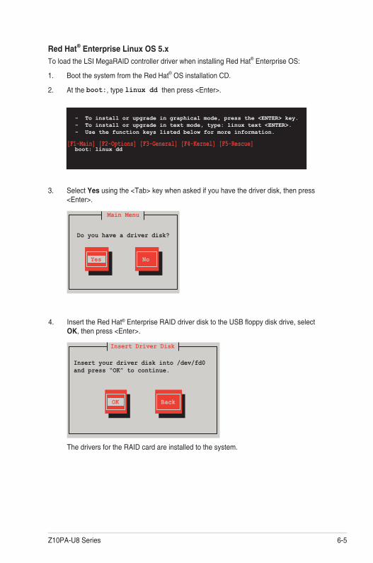
Z10PA-U8 Series 6-5
3. Select Yes using the <Tab> key when asked if you have the driver disk, then press <Enter>.
Main Menu
Do you have a driver disk?
Yes No
4. Insert the Red Hat® Enterprise RAID driver disk to the USB floppy disk drive, select OK, then press <Enter>.
The drivers for the RAID card are installed to the system.
Insert Driver Disk
OK Back
Insert your driver disk into /dev/fd0 and press “OK” to continue.
- To install or upgrade in graphical mode, press the <ENTER> key.- To install or upgrade in text mode, type: linux text <ENTER>.- Use the function keys listed below for more information.
[F1-Main] [F2-Options] [F3-General] [F4-Kernel] [F5-Rescue]boot: linux dd
Red Hat® Enterprise Linux OS 5.x
To load the LSI MegaRAID controller driver when installing Red Hat® Enterprise OS:
1. Boot the system from the Red Hat® OS installation CD.
2. At the boot:, type linux dd then press <Enter>.

6-6 Chapter 6: Driver installation
5. When asked if you will load additional RAID controller drivers, select No, then press <Enter>.
More Driver Disks?
Yes No
6. Follow the onscreen instructions to finish the OS installation.
7. When the installation is completed, DO NOT click Reboot. Press <Ctrl> + <Alt> + <F2> to switch to the command-line interface from graphic user interface.
8. Type the following commands when using a Legacy floppy.
mkdir /mnt/driver mount /dev/fd0 /mnt/driver cd /mnt/driver sh replace_ahci.sh reboot
Do you wish to load any more driver disks?
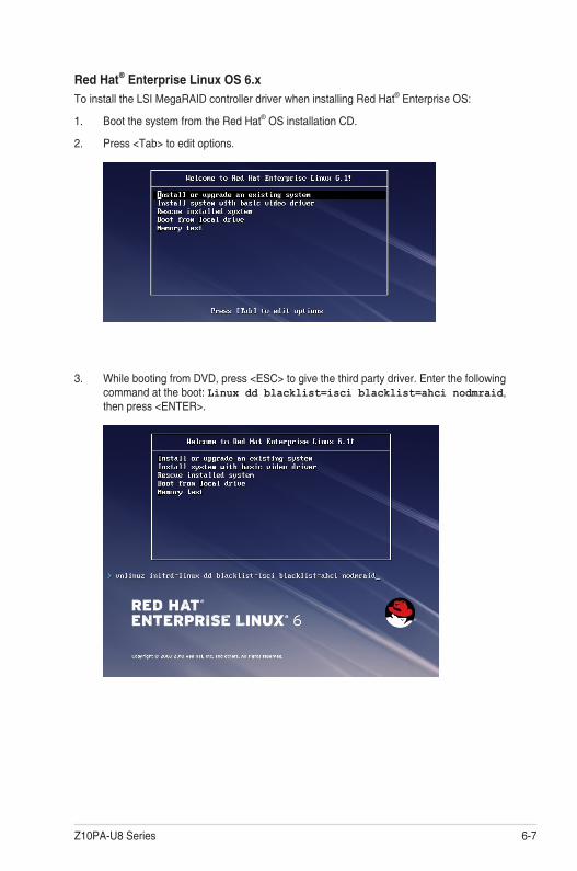
Z10PA-U8 Series 6-7
3. While booting from DVD, press <ESC> to give the third party driver. Enter the following command at the boot: Linux dd blacklist=isci blacklist=ahci nodmraid, then press <ENTER>.
Red Hat® Enterprise Linux OS 6.x
To install the LSI MegaRAID controller driver when installing Red Hat® Enterprise OS:
1. Boot the system from the Red Hat® OS installation CD.
2. Press <Tab> to edit options.

6-8 Chapter 6: Driver installation
4. Select Yes using the <Tab> key when asked if you have the driver disk, then press <Enter>.
5 . You have multiple devices which could serve as source for a driver disk. Choose one you like to use and select OK, then press <Enter>.
OK Cancel
Main Menu
Yes No
Driver Disk Source
You have multiple devices which could serve as source for a driver disk. Which would you like to use?
sdcsddsdbsr0
Do you have a driver disk?
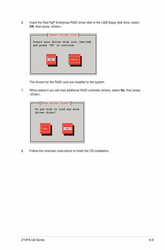
Z10PA-U8 Series 6-9
6. Insert the Red Hat® Enterprise RAID driver disk to the USB floppy disk drive, select OK, then press <Enter>.
The drivers for the RAID card are installed to the system.
7. When asked if you will load additional RAID controller drivers, select No, then press <Enter>.
More Driver Disks?
Yes No
Insert Driver Disk
OK Back
8. Follow the onscreen instructions to finish the OS installation.
Insert your driver disk into /dev/sdb and press “OK” to continue.
Do you wish to load any more driver disks?

6-10 Chapter 6: Driver installation
Preparing the Linux DriverEnsure that there is another computer with a Linux-based OS to create the RAID driver. When creating the RAID driver, you may refer to the examples below which uses a 64bit SUSE Linux system to create a 64bit RAID driver for SUSE11 sp1.
1. Copy the image file into the Linux system.
Example: megasr-15.00.0120.2012-1-sles11-ga-x86_64.img
2. Create a folder.
Example: image
3. Mount the image file into the image folder using this command format:
mount -oloop [image file name] image
Example: mount -oloop megasr-15-15.00.0120.2012-1-sles11-ga-x86__64.img image
4. Copy the contents of the image directory, labeled as 01, into a FAT32 USB drive.
5. Rename the 01 folder to CD Image.
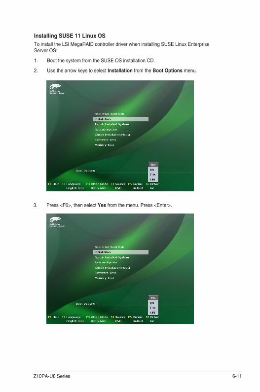
Z10PA-U8 Series 6-11
3. Press <F6>, then select Yes from the menu. Press <Enter>.
Installing SUSE 11 Linux OSTo install the LSI MegaRAID controller driver when installing SUSE Linux Enterprise Server OS:
1. Boot the system from the SUSE OS installation CD.
2. Use the arrow keys to select Installation from the Boot Options menu.

6-12 Chapter 6: Driver installation
6. Select Back and follow the onscreen instructions to finish the installation.
4. Use the USB drive to provide the third-party driver during the OS installation. Type the command brokenmodules=ahci in Boot Options field, and press <Enter>.
5. When below screen appears, select the USB floppy disk drive (sda) as the driver update medium. Select OK, then press <Enter>.
Please choose the Driver Update medium.
sda: USB Floppyother device
OK Back

Z10PA-U8 Series 6-13
6.2 Management applications and utilities installation
When you place the support DVD into the optical drive, the DVD automatically displays the main screen if Autorun is enabled in your computer. By default, the Drivers tab is displayed.
If Autorun is NOT enabled in your computer, browse the contents of the support DVD to locate the file ASSETUP.EXE from the BIN folder. Double-click the ASSETUP.EXE to run the support DVD.
6.3 Running the Support DVD
1. The contents of the support DVD are subject to change at any time without notice. Visit the ASUS website (www.asus.com) for the latest updates on software and utilities.
2. The support DVD is supported on Windows® Server 2008 R2 and Windows® Server 2012.
The support DVD that is bundled with your motherboard contains drivers, management applications, and utilities that you can install to maximize the features of your motherboard.
The main screen of the Support DVD contains the following tabs:
1. Drivers
2. Utilities
3. MakeDisk
4. Manual
5. Contact
The main screen of the Support DVD looks exactly the same on the Windows® Server 2008 R2 and on the Windows® Server 2012 Operating System (OS).
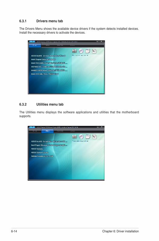
6-14 Chapter 6: Driver installation
The Drivers Menu shows the available device drivers if the system detects installed devices. Install the necessary drivers to activate the devices.
6.3.2 Utilities menu tab
The Utilities menu displays the software applications and utilities that the motherboard supports.
6.3.1 Drivers menu tab
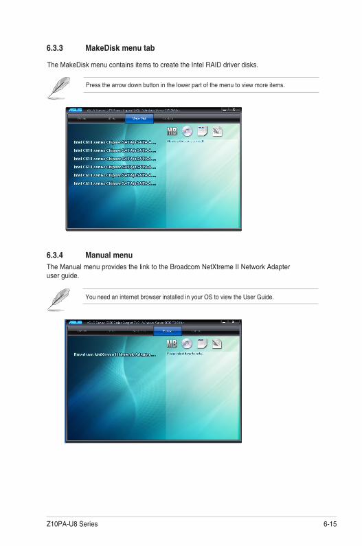
Z10PA-U8 Series 6-15
The MakeDisk menu contains items to create the Intel RAID driver disks.
6.3.3 MakeDisk menu tab
Press the arrow down button in the lower part of the menu to view more items.
6.3.4 Manual menuThe Manual menu provides the link to the Broadcom NetXtreme II Network Adapter user guide.
You need an internet browser installed in your OS to view the User Guide.

6-16 Chapter 6: Driver installation
6.3.5 Contact information menuThe Contact menu displays the ASUS contact information, e-mail addresses, and useful links if you need more information or technical support for your motherboard.

Z10PA-U8 Series 6-17
6.4 Intel® chipset device software installationThis section provides the instructions on how to install the Intel® chipset device software on the system.
You need to manually install the Intel® chipset device software on a Windows operating system.
To install the Intel® chipset device software:
1. Restart the computer, and then log on with Administrator privileges.
2. Insert the motherboard/system support DVD to the optical drive. The support DVD automatically displays the Drivers menu if Autorun is enabled in your computer.
If Autorun is NOT enabled in your computer, browse the contents of the support DVD to locate the file ASSETUP.EXE from the BIN folder. Double-click the ASSETUP.EXE to run the support DVD.
3. Click the item Intel Chipset Device Software from the menu.
4. The Intel(R) Chipset Device Software window appears. Click Next to start installation.

6-18 Chapter 6: Driver installation
5. Select Yes to accept the terms of the License Agreement and continue the process.
6. Read the Readme File Information and press Next to continue the installation.
7. Toggle Yes, I want to restart the computer npw and click Finish to complete the setup process.
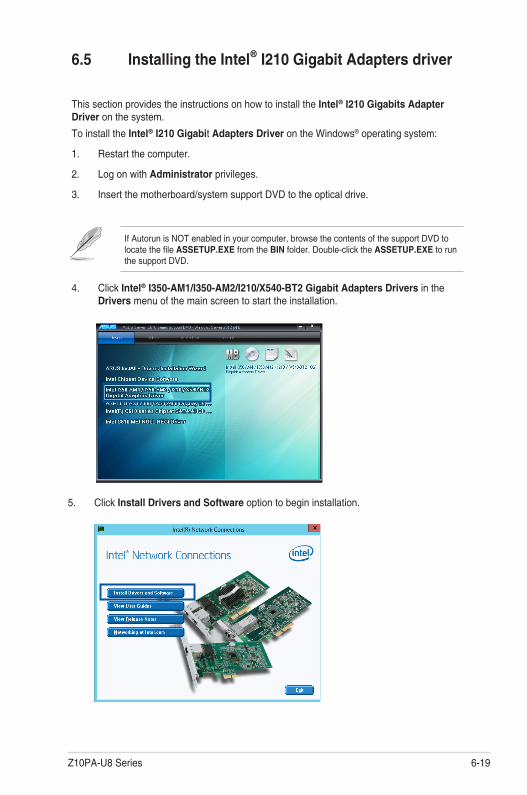
Z10PA-U8 Series 6-19
5. Click Install Drivers and Software option to begin installation.
6.5 Installing the Intel® I210 Gigabit Adapters driver
This section provides the instructions on how to install the Intel® I210 Gigabits Adapter Driver on the system.
To install the Intel® I210 Gigabit Adapters Driver on the Windows® operating system:
1. Restart the computer.
2. Log on with Administrator privileges.
3. Insert the motherboard/system support DVD to the optical drive.
If Autorun is NOT enabled in your computer, browse the contents of the support DVD to locate the file ASSETUP.EXE from the BIN folder. Double-click the ASSETUP.EXE to run the support DVD.
4. Click Intel® I350-AM1/I350-AM2/I210/X540-BT2 Gigabit Adapters Drivers in the Drivers menu of the main screen to start the installation.

6-20 Chapter 6: Driver installation
6. Click Next when the Intel(R) Network Connections–InstallShield Wizard window appears.
7. Tick I accept the terms in the license agreement and click Next to continue.
8. From the Setup Options window, click Next to start the installation.
By default, Intel(R) PROSet for Windows Device Manager and Windows PowerShell Module are ticked.

Z10PA-U8 Series 6-21
9. Click Install to start the installation.
10. When the installation is done, press Finish to complete the installation.
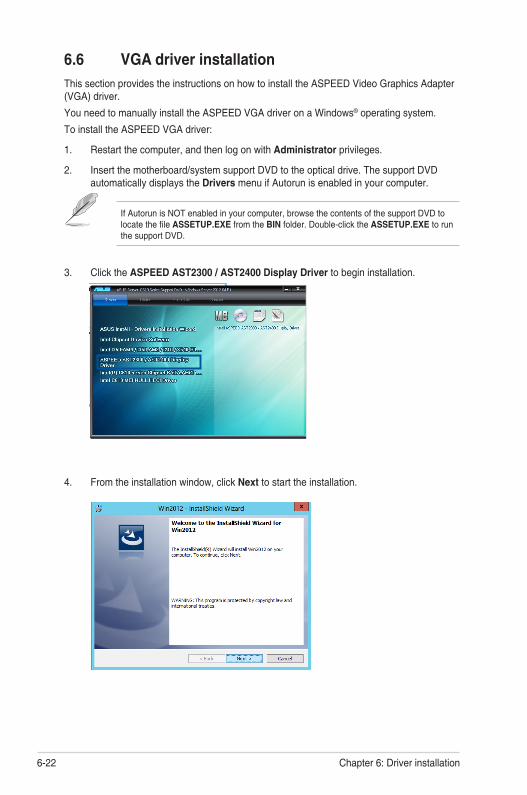
6-22 Chapter 6: Driver installation
6.6 VGA driver installationThis section provides the instructions on how to install the ASPEED Video Graphics Adapter (VGA) driver.
You need to manually install the ASPEED VGA driver on a Windows® operating system.
To install the ASPEED VGA driver:
1. Restart the computer, and then log on with Administrator privileges.
2. Insert the motherboard/system support DVD to the optical drive. The support DVD automatically displays the Drivers menu if Autorun is enabled in your computer.
If Autorun is NOT enabled in your computer, browse the contents of the support DVD to locate the file ASSETUP.EXE from the BIN folder. Double-click the ASSETUP.EXE to run the support DVD.
3. Click the ASPEED AST2300 / AST2400 Display Driver to begin installation.
4. From the installation window, click Next to start the installation.

Z10PA-U8 Series 6-23
6. Click Finish to complete the installation.
5. Click Install to proceed with the installation.
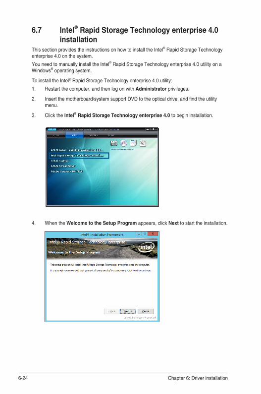
6-24 Chapter 6: Driver installation
6.7 Intel® Rapid Storage Technology enterprise 4.0 installationThis section provides the instructions on how to install the Intel® Rapid Storage Technology enterprise 4.0 on the system.
You need to manually install the Intel® Rapid Storage Technology enterprise 4.0 utility on a Windows® operating system.
To install the Intel® Rapid Storage Technology enterprise 4.0 utility:
1. Restart the computer, and then log on with Administrator privileges.
2. Insert the motherboard/system support DVD to the optical drive, and find the utility menu.
3. Click the Intel® Rapid Storage Technology enterprise 4.0 to begin installation.
4. When the Welcome to the Setup Program appears, click Next to start the installation.
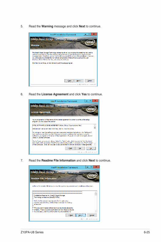
Z10PA-U8 Series 6-25
5. Read the Warning message and click Next to continue.
6. Read the License Agreement and click Yes to continue.
7. Read the Readme File Information and click Next to continue.
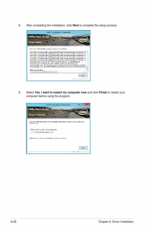
6-26 Chapter 6: Driver installation
9. Select Yes, I want to restart my computer now and click Finish to restart your computer before using the program.
8. After completing the installation, click Next to complete the setup process.

AReference Information
This appendix includes additional information that you may refer to when configuring the motherboard.
Appendix A: Reference Information

A-2 Appendix A: Reference information
A.1 Z10PA-U8 Series block diagram
Z10PA-U8/10G-2S
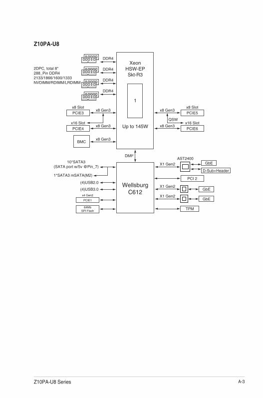
Z10PA-U8 Series A-3
Z10PA-U8

A-4 Appendix A: Reference information

ASUS contact information
ASUSTeK COMPUTER INC.Address 15 Li-Te Road, Peitou, Taipei, Taiwan 11259Telephone +886-2-2894-3447Fax +886-2-2890-7798E-mail [email protected] site http://www.asus.com
Technical SupportTelephone +86-21-38429911Fax +86-21-58668722 ext: 9101Online Support http://support.asus.com/techserv/techserv.aspx
ASUSTeK COMPUTER INC. (Taiwan)Address 15 Li-Te Road, Peitou, Taipei, Taiwan 11259Telephone +886-2-2894-3447Fax +886-2-2890-7798E-mail [email protected] site http://www.asus.com.tw
Technical SupportTelephone +886-2-2894-3447 (0800-093-456)Online Support http://support.asus.com/techserv/techserv.aspx
ASUSTeK COMPUTER INC. (China)Address No.508, Chundong Road, Xinzhuang Industrial Zone, Minhang District, Shanghai, China.Telephone +86-21-5442-1616Fax +86-21-5442-0099Web site http://www.asus.com.cn
Technical SupportTelephone 400-620-6655
Online Support http://support.asus.com/techserv/techserv.aspx

ASUS contact information
ASUS COMPUTER INTERNATIONAL (America)Address 800 Corporate Way, Fremont, CA 94539, USAFax +1-510-608-4555Web site http://usa.asus.com
Technical SupportSupport fax +1-812-284-0883General support +1-812-282-2787Online support http://support.asus.com/techserv/techserv.aspx
ASUS COMPUTER GmbH (Germany and Austria)Address Harkort Str. 21-23, D-40880 Ratingen, GermanyFax +49-2102-959911Web site http://www.asus.deOnline contact http://www.asus.de/sales
Technical Support Telephone +49-1805-010923 Support Fax +49-2102-959911 Online support http://support.asus.com/techserv/techserv.aspx
ASUS Czech Service s.r.o. (Europe) Address Na Rovince 887, 720 00 Ostrava – Hrabová, Czech Republic Telephone +420-596766888 Web site http://www.asus.cz
Technical Support Telephone +420-596-766-891 Fax +420-596-766-329 E-mail [email protected] Online Support http://support.asus.com/techserv/techserv.aspx
ASUS contact information
ASUS Holland BV (The Netherlands) Address Marconistraat 2, 7825GD EMMEN, The Netherlands Web site http://www.asus.com
Technical Support Telephone +31-(0)591-5-70292 Fax +31-(0)591-666853 E-mail [email protected] Online Support http://support.asus.com/techserv/techserv.aspx
ASUS Polska Sp. z o.o. (Poland) Address Ul. Postępu 6, 02-676 Warszawa, Poland Web site http://pl.asus.com
Technical Support Telephone +48-225718033 Online Support http://support.asus.com/techserv/techserv.aspx
ASK-Service (Russia and CIS) Address г.Москва, ул. Орджоникидзе, д.10, Россия Telephone (495) 640-32-75 Web site http://ru.asus.com
Technical Support Telephone 008-800-100-ASUS (008-800-100-2787) Online Support http://vip.asus.com/eservice/techserv.aspx?SLanguage=ru
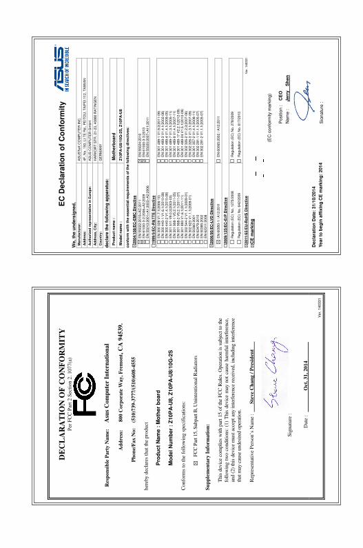
EC
De
cla
rati
on
of
Co
nfo
rmit
y
We
, th
e u
nd
ers
ign
ed
, M
an
ufa
ctu
rer:
A
SU
ST
eK
CO
MP
UT
ER
IN
C.
Ad
dre
ss
: 4
F,
No
. 1
50
, L
I-T
E R
d.,
PE
ITO
U,
TA
IPE
I 1
12
, T
AIW
AN
A
uth
ori
ze
d r
ep
res
en
tati
ve
in
Eu
rop
e:
AS
US
CO
MP
UT
ER
Gm
bH
Ad
dre
ss
, C
ity:
HA
RK
OR
T S
TR
. 2
1-2
3, 4
08
80 R
AT
ING
EN
Co
un
try:
GE
RM
AN
Y
de
cla
re t
he
fo
llo
win
g a
pp
ara
tus:
Pro
du
ct
nam
e :
M
oth
erb
oa
rd
Mo
del n
am
e :
Z
10P
A-U
8/1
0G
-2S
, Z
10
PA
-U8
co
nfo
rm w
ith
th
e e
ssen
tial re
qu
irem
en
ts o
f th
e f
ollo
win
g d
irecti
ves:
2004
/10
8/E
C-E
MC
Dir
ecti
ve
E
N 5
502
2:2
01
0+
AC
:20
11
E
N 6
100
0-3
-2:2
00
6+
A2
:20
09
E
N 5
501
3:2
00
1+
A1
:200
3+
A2:2
00
6
E
N 5
502
4:2
01
0
E
N 6
100
0-3
-3:2
01
3
E
N 5
502
0:2
00
7+
A1
1:2
01
1
1999
/5/E
C-R
&T
TE
Dir
ecti
ve
E
N 3
00
32
8 V
1.7
.1(2
00
6-1
0)
E
N 3
00
44
0-1
V1
.6.1
(20
10
-08
) E
N 3
00
44
0-2
V1
.4.1
(20
10
-08
) E
N 3
01
51
1 V
9.0
.2(2
00
3-0
3)
E
N 3
01
90
8-1
V5
.2.1
(20
11
-05
) E
N 3
01
90
8-2
V5
.2.1
(20
11
-07
) E
N 3
01
89
3 V
1.6
.1(2
01
1-1
1)
E
N 3
02
54
4-2
V1
.1.1
(20
09
-01
) E
N 3
02
62
3 V
1.1
.1(2
00
9-0
1)
E
N 5
036
0:2
00
1
E
N 6
247
9:2
01
0
E
N 5
038
5:2
00
2
E
N 6
231
1:2
00
8
E
N 3
01
48
9-1
V1
.9.2
(20
11
-09
) E
N 3
01
48
9-3
V1
.4.1
(20
02
-08
) E
N 3
01
48
9-4
V1
.4.1
(20
09
-05
) E
N 3
01
48
9-7
V1
.3.1
(20
05
-11
) E
N 3
01
48
9-9
V1
.4.1
(20
07
-11
) E
N 3
01
48
9-1
7 V
2.2
.1(2
01
2-0
9)
E
N 3
01
48
9-2
4 V
1.5
.1(2
01
0-0
9)
E
N 3
02
32
6-2
V1
.2.2
(20
07
-06
) E
N 3
02
32
6-3
V1
.3.1
(20
07
-09
) E
N 3
01
35
7-2
V1
.4.1
(20
08
-11
) E
N 3
02
29
1-1
V1
.1.1
(20
05
-07
) E
N 3
02
29
1-2
V1
.1.1
(20
05
-07
)
2006
/95/E
C-L
VD
Dir
ecti
ve
EN
60
95
0-1
/ A
12:2
011
E
N 6
006
5:2
00
2 / A
12
:20
11
2009
/12
5/E
C-E
rP D
irecti
ve
R
eg
ula
tio
n (
EC
) N
o. 1
275
/200
8
R
eg
ula
tio
n (
EC
) N
o. 6
42/2
009
R
eg
ula
tio
n (
EC
) N
o. 2
78/2
009
R
eg
ula
tio
n (
EC
) N
o. 6
17/2
013
2011/6
5/E
U-R
oH
S D
ire
cti
ve
V
er.
140331
CE
ma
rkin
g
De
cla
rati
on
Da
te:
31/1
0/2
01
4
Ye
ar
to b
eg
in a
ffix
ing
CE
ma
rkin
g:
201
4
Po
sitio
n : C
EO
Na
me
:
Je
rry S
he
n
Sig
na
ture
: __
__
___
__
_
(EC
co
nfo
rmity m
ark
ing)
D
EC
LA
RA
TIO
N O
F C
ON
FO
RM
IT
Y
Per F
CC P
art 2
Sec
tion 2
. 107
7(a)
R
esp
on
sib
le P
arty N
am
e:
Asu
s C
om
pu
ter In
tern
atio
na
l
A
dd
ress:
800 C
orp
orate W
ay, F
rem
on
t, C
A 9
45
39
.
Ph
on
e/F
ax N
o:
(510)739-3777/(510)608-4555
here
by de
clare
s tha
t the
prod
uct
P
rod
uc
t N
am
e :
Mo
the
r b
oa
rd
M
od
el
Nu
mb
er
: Z
10
PA
-U8
, Z
10
PA
-U8
/10
G-2
S
Co
nfor
ms t
o the
follo
wing
spec
ifica
tions
:
FC
C Pa
rt 15
, Sub
part
B, U
nint
entio
nal R
adiat
ors
Su
pp
lem
en
ta
ry
In
fo
rm
atio
n:
This
devic
e com
plies
with
part
15 of
the F
CC R
ules.
Opera
tion i
s sub
ject t
o the
fo
llowi
ng tw
o co
nditi
ons:
(1) T
his d
evice
may
not
caus
e harm
ful i
nterfe
rence
, an
d (2)
this
devic
e mus
t acc
ept a
ny in
terfer
ence
rece
ived,
includ
ing in
terfer
ence
tha
t may
caus
e und
esire
d ope
ration
.
Re
pres
entat
ive P
erso
n’s N
ame :
Steve C
han
g / P
resid
en
t
Sign
ature
:
Date
: O
ct. 3
1, 2
01
4
V
er.
140331
Related Documents