The Z1000 variable speed drive is designed for building automation applications such as fans, pumps, and cooling towers through 500 HP. The Z1000 features an easy-to-read LCD keypad that provides Hand- Off-Auto interface and a real time clock. These features make the Z1000 perfect for most building automation applications that require reliable motor control. Z1000 HVAC Drive 3 HP to 500 HP Fan and Pump Applications Specifications Overload Capacity • 110% for 60 seconds, Output Frequency • 0.01 to 240 Hz Control Methods • V/Hz Control • Open Loop Vector Control for Permanent Magnet motors Motor Types • Squirrel Cage Induction • Interior Permanent Magnet (IPM) Enclosures • NEMA Type 1 / IP20 : 3 - 100 HP 208V and 3 - 250 HP 480V • Open Type / IP00 : 125 - 150 HP 208V and 300 - 500 HP 480V Ambient Operating Temperature • -10°C to 40°C (14°F to 104°F) Global Certification • UL, CSA, CE, RoHS Standard I/O • Seven Multi-Function Programmable Digital Inputs (24Vdc) • Two Multi-Function Programmable Analog Inputs (0-10VDC or 4-20mA) • One Fault Relay Output (Form C - 2 Amps at 250Vac max) • Three Multi-Function Programmable Relay Output (Form A - 2 Amps @ 250Vac max) • Two Multi-Function Programmable Analog Outputs (0-10Vdc or 4-20mA) • One 24 Vdc, 150 mA Transducer or Transmitter Power Supply for customer use Network Communications • Built-in BACnet, RS485/422 - Programmable up to 76.8 kbps • Optional: LonWorks, Metasys, APOGEE FLN, EtherNet/IP Yaskawa America, Inc. | Tel: 1-800-YASKAWA (927-5292) | www.yaskawa.com Drives & Motion Division Harmonic Mitigation* Built-in 5% line impedance for input harmonic reduction. Noise Filter* On board EMI/RFI filter complies with IEC 61800-3 restricted distribution for first environment. Serial Communications Embedded BACnet communications (BTL Certified), along with Modbus/ Memobus. Ratings Plenum Rated (UL 1995). Seismic Rated (IBC 2006 - Certification 12/2011). Made with RoHS compliant materials. Internal Real-Time Clock Time and date stamping for events, along with timer controls for starting stopping and speed changes without the need for external controls. PI Feature Maintains a set point for closed loop control of fans and pumps for pressure, flow or temperature regulation and eliminates the need for a closed loop output signal from a BAS. Independent PI to control an external device in the system. LCD Operator 5-Line 16 character alpha-numeric, easy to read and understand display, with Hand-Off-Auto functions. Carrier Frequency 5 kHz carrier frequency with dynamic noise control for quiet motor operation. Application Macros Choose from pre-configured set up macros to match the application for quick and easy set up. Sealed Heatsink Allows for drive to be mounted in a NEMA 12 enclosure with heatsink external. * Available only as options, 300-500HP ratings.

Welcome message from author
This document is posted to help you gain knowledge. Please leave a comment to let me know what you think about it! Share it to your friends and learn new things together.
Transcript
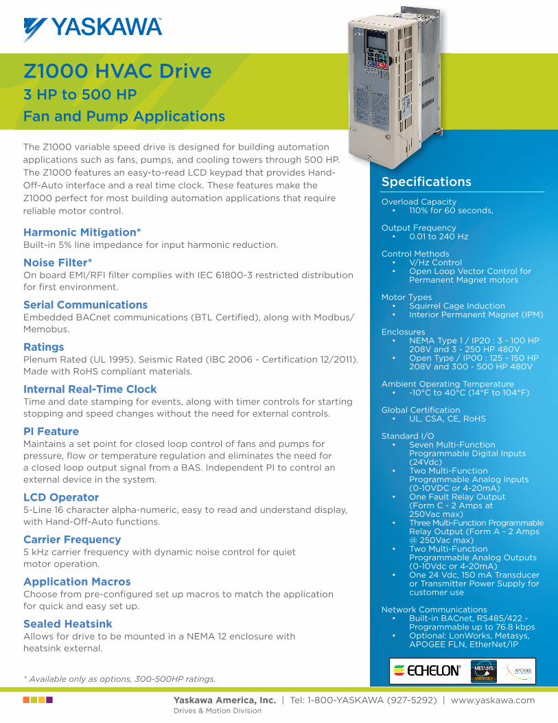
The Z1000 variable speed drive is designed for building automation applications such as fans, pumps, and cooling towers through 500 HP. The Z1000 features an easy-to-read LCD keypad that provides Hand-Off-Auto interface and a real time clock. These features make the Z1000 perfect for most building automation applications that require reliable motor control.
Z1000 HVAC Drive3 HP to 500 HPFan and Pump Applications
Specifi cationsOverload Capacity
• 110% for 60 seconds,
Output Frequency• 0.01 to 240 Hz
Control Methods• V/Hz Control• Open Loop Vector Control for
Permanent Magnet motors
Motor Types• Squirrel Cage Induction• Interior Permanent Magnet (IPM)
Enclosures• NEMA Type 1 / IP20 : 3 - 100 HP
208V and 3 - 250 HP 480V• Open Type / IP00 : 125 - 150 HP
208V and 300 - 500 HP 480V
Ambient Operating Temperature• -10°C to 40°C (14°F to 104°F)
Global Certifi cation• UL, CSA, CE, RoHS
Standard I/O• Seven Multi-Function
Programmable Digital Inputs (24Vdc)
• Two Multi-Function Programmable Analog Inputs (0-10VDC or 4-20mA)
• One Fault Relay Output (Form C - 2 Amps at 250Vac max)
• Three Multi-Function Programmable Relay Output (Form A - 2 Amps @ 250Vac max)
• Two Multi-Function Programmable Analog Outputs (0-10Vdc or 4-20mA)
• One 24 Vdc, 150 mA Transducer or Transmitter Power Supply for customer use
Network Communications• Built-in BACnet, RS485/422 -
Programmable up to 76.8 kbps• Optional: LonWorks, Metasys,
APOGEE FLN, EtherNet/IP
Yaskawa America, Inc. | Tel: 1-800-YASKAWA (927-5292) | www.yaskawa.comDrives & Motion Division
Harmonic Mitigation*Built-in 5% line impedance for input harmonic reduction.
Noise Filter*On board EMI/RFI fi lter complies with IEC 61800-3 restricted distribution for fi rst environment.
Serial CommunicationsEmbedded BACnet communications (BTL Certifi ed), along with Modbus/Memobus.
RatingsPlenum Rated (UL 1995). Seismic Rated (IBC 2006 - Certifi cation 12/2011). Made with RoHS compliant materials.
Internal Real-Time ClockTime and date stamping for events, along with timer controls for starting stopping and speed changes without the need for external controls.
PI FeatureMaintains a set point for closed loop control of fans and pumps for pressure, fl ow or temperature regulation and eliminates the need for a closed loop output signal from a BAS. Independent PI to control an external device in the system.
LCD Operator5-Line 16 character alpha-numeric, easy to read and understand display, with Hand-Off-Auto functions.
Carrier Frequency5 kHz carrier frequency with dynamic noise control for quiet motor operation.
Application MacrosChoose from pre-confi gured set up macros to match the application for quick and easy set up.
Sealed HeatsinkAllows for drive to be mounted in a NEMA 12 enclosure with heatsink external.
* Available only as options, 300-500HP ratings.
Document Number: FL.Z1000.01 • 10-15-2011 • © 2011
Yaskawa America, Inc. | Tel: 1-800-YASKAWA (927-5292) | www.yaskawa.comDrives & Motion Division
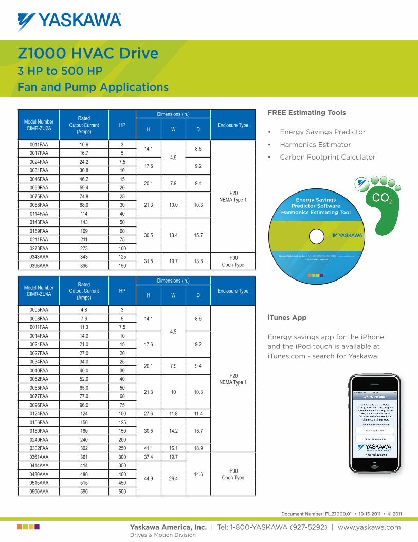
Model Number CIMR-ZU2A
Rated Output Current
(Amps)HP
Dimensions (in.)
Enclosure TypeH W D
0011FAA 10.6 314.1
4.98.6
IP20NEMA Type 1
0017FAA 16.7 50024FAA 24.2 7.5
17.6 9.20031FAA 30.8 100046FAA 46.2 15
20.1 7.9 9.40059FAA 59.4 200075FAA 74.8 25
21.3 10.0 10.30088FAA 88.0 300114FAA 114 400143FAA 143 50
30.5 13.4 15.70169FAA 169 600211FAA 211 750273FAA 273 1000343AAA 343 125
31.5 19.7 13.8 IP00Open-Type0396AAA 396 150
Model Number CIMR-ZU4A
Rated Output Current
(Amps)HP
Dimensions (in.)
Enclosure TypeH W D
0005FAA 4.8 314.1
4.9
8.6
IP20NEMA Type 1
0008FAA 7.6 50011FAA 11.0 7.50014FAA 14.0 10
17.6 9.20021FAA 21.0 150027FAA 27.0 200034FAA 34.0 25
20.1 7.9 9.40040FAA 40.0 300052FAA 52.0 40
21.3 10 10.30065FAA 65.0 500077FAA 77.0 600096FAA 96.0 750124FAA 124 100 27.6 11.8 11.40156FAA 156 125
30.5 14.2 15.70180FAA 180 1500240FAA 240 2000302FAA 302 250 41.1 16.1 18.90361AAA 361 300 37.4 19.7
14.6 IP00Open-Type
0414AAA 414 350
44.9 26.40480AAA 480 4000515AAA 515 4500590AAA 590 500
Z1000 HVAC Drive3 HP to 500 HPFan and Pump Applications
Energy SavingsPredictor Software
Harmonics Estimating Tool
Yaskawa Electric America, Inc. | Tel: 1-800-YASKAWA (927-5292) | www.yaskawa.com
© 2011 All Rights Reserved
iTunes App
Energy savings app for the iPhone and the iPod touch is available at iTunes.com - search for Yaskawa.
FREE Estimating Tools
• Energy Savings Predictor
• Harmonics Estimator
• Carbon Footprint Calculator
Z1000 Drive Z1000 Bypass Z1000 Configured E7 Drive E7S Slim Configured Package E7C Drive Configured E7N Narrow Bypass Package E7L Drive Bypass E7B Drive Bypass E7E Drive Engineered
Model Number Designation for Z1000 Drive
View Models and Ratings
Find Local Contact
Sales Rep Distributor Service Center
Enter Request
Application and Product Help Literature Quote Technical Support
Home | Site Map | Contact Us | Search Copyright © 2012 Yaskawa America, Inc. All Rights Reserved. Conditions of Use | Privacy Policy Drives & Motion Division
Global Sites Home Site Map Contact Us SearchAdvanced Search
Partner Info Login
Home > Commercial HVAC Drives > Model Number Designation
Login
Products Support Downloads Sales Training Industries/Applications About Us
Page 1 of 1Z1000 Model Number Designation
9/19/2012http://www.yaskawa.com/site/products.nsf/ProductDetailPages/Commercial%20HVAC%2...
lisah
Text Box
Z1000 Subs 10/25/2011 1
Date Customer Job Name P.O. / S.O. 8/21/2012 PROFESSIONAL
MECHANICAL SHORES
Variable Frequency Drive (VFD) Z1000 Mechanical Specification Submittal
(For NEMA 1 Rated Drives) GENERAL
The Z1000 is a high performance PWM (pulse-width-modulated) AC drive. Three-phase input line power is converted to a sine-coded, variable frequency output, which provides optimum speed control of any conventional squirrel cage induction motor and permanent magnet motor. The use of IGBTs (Insulated Gate Bipolar Transistors), with a carrier frequency range of 1 kHz to 12.5 kHz, permits quiet motor operation.
This drive has one control logic board for all horsepower ratings. Printed circuit boards employ surface mount technology, providing both high reliability, and small physical size of the printed circuit assemblies. The dual 32 bit microprocessors deliver the computing power necessary for complete three phase motor control in building automation systems.
Operating Principle: Input three phase AC line voltage is first rectified to a fixed DC voltage. Using pulse width modulation (PWM) inverter technology, the DC voltage is processed, to produce an output waveform in a series of variable-width pulses. Unique firmware algorithms optimize motor magnetization through control of voltage, current and frequency applied to generate a nearly sinusoidal output waveform.
STANDARDS UL 508C (Power Conversion)
CSA 22.2 No. 14-95 (Industrial Control Equipment)
UL 1995 (Plenum)
CE mark 2006/95/EC LVD
CE mark 2004/108/EC
IEC 61800-5-1 (LVD)
EN 61800-3
IEC 529
IEEE C62.41
BTL Listed
UL, cUL listed; CE marked
ENVIRONMENTAL & SERVICE CONDITIONS Ambient service temperature:
NEMA 1 (IP20): -10C to 40C (14F to 104F)
Ambient storage temperature: -20C to 70C (-4F to 158F)
Humidity: 0 % to 95 %, non-condensing
Altitude: to 1000 meters (3300 feet), higher by derating
Service factor: 1.0
Vibration: 9.81m/s2 (1 G) maximum at 10 to 20 Hz, 2.0 m/s2
(0.2 G) at 20 Hz to 55 Hz.
Plenum mounting capable (IP20)
RoHS Compliant
QUALITY ASSURANCE In circuit testing of all printed circuit boards is conducted, to ensure proper manufacturing.
Final printed circuit board assemblies are functionally tested, via computerized test equipment.
All fully assembled controls are computer tested with induction motor loads to assure unit specifications are met.
The average MTBF (Mean Time Between Failure) is 28 years
CONSTRUCTION Input Section - VFD power input stage converts three phase AC line power into a fixed DC voltage, via a solid state full wave diode rectifier, with MOV (Metal Oxide Varistor) surge protection. An internal 5% DC bus reactor reduces harmonics for cleaner power.
Intermediate Section - DC bus maintains a fixed DC voltage, with filtering and short circuit protection, as a DC supply to the VFD output section. It is interfaced with the VFD diagnostic logic circuit, to continuously monitor and protect the power components.
Output Section - Insulated Gate Bipolar Transistors (IGBTs) convert DC bus voltage to a variable frequency and voltage, utilizing a PWM sine-coded output to the motor. IGBT output allows motor noise, at 60 Hz, to measure less than 2 dB (@ 1 meter) above that resulting from across the line operation.
Power and control electronics housings:
NEMA 1 (IP20) wall-mounted enclosure:
208 V, 3 thru 100 HP; 480 V, 3 thru 250 HP
lisah
Text Box
Z1000 Subs 10/25/2011 2
CONSTRUCTION (continued) Microprocessor based control circuit
Non-Volatile memory (NV RAM); all programming memory is saved when the VFD is disconnected from power.
Current transformers detect the output current for motor control and protective functions
Digital operator keypad and display, with copy function, provides local control and readout capability:
Hand/Off/Auto commands
Speed Reference command
Reset command
Easy to remove heat sink cooling fan with programmable on/off control
USB Type B port for quick and easy PC Connection
PRODUCT FEATURES Displacement power factor of .98 throughout the motor speed range
Input phase insensitive; sequencing of the three phase input is unnecessary
Internal EMI/RFI filter complies with IEC 61800-3 restricted distribution for first environment
Built-In real time clock for time and date stamping events along with timer functions for starting, stopping and speed changes without the need for external controls
Volt meter, ammeter, kilowatt meter elapsed run time meter and heat sink temperature monitoring functions
Two internal (PI) Controls
1. Drive internal PI closed loop control with selectable engineering units
2. Independent PI control for use with external device
Differential PI feedback feature
Sleep function in both closed loop and open loop control
Feedback signal low pass filter
Feedback signal loss detection and selectable response strategy
Feedback signal inverse and square root capability
24 Vdc, 150ma transmitter power supply
Input and output terminal status indication
Diagnostic fault indication
VFD efficiency: 96% at half-speed; 98% at full-speed
“S-curve” soft start / soft stop capability
Run/Fault output contacts
Serial communication loss detection and selectable response strategy
“Up/Down” floating point control capability
Controlled speed range of 40:1
Critical frequency rejection capability: 3 selectable, adjustable bandwidths
100% starting torque capability, available from 3 Hz to 60 Hz
Remote speed reference (speed command) signal:
0 to 10 VDC (20 k)
4 to 20 mA DC (250 )
Adjustable carrier frequency, from 1 kHz to 12.5 kHz
Dynamic noise control for quiet motor operation
Programmable security code
7 programmable multi-function input terminals (24Vdc) providing 60+ programmable features, including:
Customer Safeties
BAS / Damper Interlock
Emergency Override
Preset Speed
PI control enable / disable
3 programmable multi-function output relays (Form A rated 2 amps @ 250Vac & 30Vdc), providing 50+ functions, including:
Damper control
Hand / Auto Status
Contactor Control for External Bypass
Overtorque/undertorque detection
Serial communication status
No load detection (broken belt alert)
One fixed “Fault” form C output relay (Rated 2 amps @ 250Vac & 30Vdc)
7 preset speeds
Built-in BACnet protocol along with Modbus/Memobus. Protocol are accessible via RS-422/485 communication, which is standard
Stationary motor auto-tuning
“Kinetic Energy Braking” (KEB) function stops the motor in up to half the time it would take without this function.
LCD keypad: Hand/Off/Auto functions with a built-in copy feature,
Motor preheat function
Flash upgradeable firmware
Customizable monitor display
Heat sink over temperature speed fold-back feature
“Bumpless” transfer between Hand and Auto modes
Emergency override can be used as “smoke purge” function
Fan failure detection and selectable drive action
Z1000 Subs 10/25/2011 3
OPERATION Output frequency and speed display can be programmed for other speed-related and control indications, including: RPM, CFM, GPM, PSI, in WC, % of maximum RPM or custom
Power loss ride-thru (2 seconds capable)
Time delay on start, peak avoidance
VFD accepts either a direct acting or a reverse acting speed command signal
Bi-directional “Speed Search” capability, in order to start into a rotating load. Two types: current detection and residual voltage detection
DC injection braking, to prevent fan “wind milling”
Remote Run/Stop command input
Two programmable 0 to 10 VDC or 4-20ma analog outputs, proportional to drive monitor functions including: output frequency, output current, output power, PI feedback, output voltage and more…..
5-Line 16 Character LCD display provides readout functions that include: output frequency, output voltage, output current, output power, DC bus voltage, interface terminal status, PI feedback and fault status.
Programmable HVAC specific application macros
Over 100 programmable functions, resettable to factory HVAC presets
User parameter initialization, re-establish project specific parameters
Ramp-to-stop or coast-to-stop selection
Auto restart capability: 0 to 10 attempts with adjustable delay time between attempts
One custom selectable Volts/Hertz pattern and multiple preset Volts/Hertz patterns
Auto speed reference input signal, adjustable for bias and gain
While the VFD is running, operational changes in control and display functions are possible, including:
Acceleration time (0 to 6000 seconds)
Deceleration time (0 to 6000 seconds)
Frequency reference command
Hand/Off/Auto commands
Monitor display
Removable digital operator
Automatic energy saving, reduced voltage operation
PROTECTION Output current overload rating of 110 % of drive’s continuous current rating for 60 seconds
Output short circuit protection
Current limited stall prevention (overload trip prevention) during acceleration, deceleration, and run conditions
Optically isolated operator controls
Fault display and last 10 faults storage
“Hunting” prevention logic
Electronic ground fault protection
Electronic thermal motor overload protection (UL approved)
DC bus charge indication
Heat sink over temperature protection
Cooling fan operating hours recorded
Input/Output phase loss protection
Reverse prohibit selectability
Short circuit withstand rating of 100K amps RMS
OPTIONS
LonWorks Interface
EtherNet/IP
Siemens Apogee FLN
Metasys N2
Related Documents


