COMPARATIVE TESTING, EVALUATION, AND CHARACTERIZATION OF SELECTED ADVANCED FLIGHT-PROVEN SPACE MATERIALS Z. Iskanderova (1) , J. Kleiman (1) , V. Issoupov (1) , M. van Eesbeek (2) , T. Rohr (2) , and T. Minton (3) (1) Integrity Testing Laboratory Inc., 80 Esna Park Dr., Units #7-9, Markham, ON, Canada, L3R 2R7 (2) ESA/ESTEC, Keplerlaan 1, PO Box 299, NL-2200 A.G. Noordwijk, The Netherlands (3) Department of Chemistry and Biochemistry, Montana State University, Bozeman, MT, USA ABSTRACT This paper is based on an extensive research program conducted by ITL on advanced thermal control space materials from major space countries that is a continuation of an international long-term research program started in the 90 th at ITL. As part of the program, ground-based simulated low-Earth orbit (LEO) testing and comparative durability and performance evaluation of a number of advanced Russian space materials and their functional US and European counterparts was performed. The major objective of this study was a comparative evaluation of the impact of simulated LEO space environment on the selected materials collected from various sources of Russian, European (France) and US origins. The Russian materials available for this study have included thin polymer films, metalized space polymer films, and thermal control paints, sophisticated Russian space textiles and multi-layer systems of special designs. Testing and characterization of major functional properties was performed at ITL before and after the simulated LEO space environment tests. All materials in this study have been fast atomic oxygen (FAO) beam tested in three different ground-based FAO and FAO/VUV facilities that included the Variable Energy Multifunctional Environmental Simulator (VEMES™) facility developed by ITL Inc., the hyperthermal atomic oxygen (AO) source at Montana State University (MSU) and the Atomic Oxygen Beam Facility (AOBF) at the NASA Marshall Space Flight Center (MSFC) that allowed to extend the range of testing parameters. 1. INTRODUCTION In the last decade, space materials scientists worldwide expressed a concern about the problems of space durability of various external space materials and coatings interacting with the space environment. The influence on the space environment has become one of the major concerns due to the significantly extended longevity of space missions, international collaboration on various space projects, first of all, the International Space Station development and operation, as well as space exploration. The selection of the best, most durable materials is associated with the main subjects of space exploration, such as space mission’s safety, spacecraft structures reliability and multi-million spending or savings. An international long-term research program started in the 90 th at ITL [1,2] on comparative testing, durability evaluation, characterization and surface modification of advanced flight-proven space materials was extended in this program to include other materials from Russia, Europe and USA in order to identify the best candidates for future space missions. These aspects of space materials’ research become a special high-priority subject at the time of international collaboration and joint international agreements, for instance, such as the recent Agreement of 14 major space countries regarding their collaborative plans and efforts in the new era of global space exploration [3,4]. The major objective of this study was a comparative evaluation of the impact of simulated LEO space environment on a variety of Russian advanced space materials and their US and European functional counterparts being used in space flights and the comparison of the results from three different LEO simulation facilities and to other LEO simulation facilities, where possible. 2. EXPERIMENTAL 2.1 Materials The Russian materials that have been made available for this study by ITL included thin polymer films, metalized space polymer films, and thermal control coatings (TTC), sophisticated space textiles and multi- layer systems of special designs. Western functional counterparts of the Russian materials included thin polymer films produced by Sheldahl, as well as advanced conductive and non-conductive last generation thermal control paints by Lord Corp. (USA) and MAP (France) supplied to ITL by ESA/ESTEC. All space materials of this study are presented in Table 1. 2.2 Testing and characterization The space environmental simulation testing and additional studies have included:

Welcome message from author
This document is posted to help you gain knowledge. Please leave a comment to let me know what you think about it! Share it to your friends and learn new things together.
Transcript

COMPARATIVE TESTING, EVALUATION, AND CHARACTERIZATION OF SELECTED ADVANCED FLIGHT-PROVEN SPACE MATERIALS
Z. Iskanderova(1), J. Kleiman(1), V. Issoupov(1), M. van Eesbeek(2), T. Rohr(2), and T. Minton(3)
(1)Integrity Testing Laboratory Inc., 80 Esna Park Dr., Units #7-9, Markham, ON, Canada, L3R 2R7
(2)ESA/ESTEC, Keplerlaan 1, PO Box 299, NL-2200 A.G. Noordwijk, The Netherlands (3)Department of Chemistry and Biochemistry, Montana State University, Bozeman, MT, USA
ABSTRACT This paper is based on an extensive research program conducted by ITL on advanced thermal control space materials from major space countries that is a continuation of an international long-term research program started in the 90th at ITL. As part of the program, ground-based simulated low-Earth orbit (LEO) testing and comparative durability and performance evaluation of a number of advanced Russian space materials and their functional US and European counterparts was performed. The major objective of this study was a comparative evaluation of the impact of simulated LEO space environment on the selected materials collected from various sources of Russian, European (France) and US origins. The Russian materials available for this study have included thin polymer films, metalized space polymer films, and thermal control paints, sophisticated Russian space textiles and multi-layer systems of special designs. Testing and characterization of major functional properties was performed at ITL before and after the simulated LEO space environment tests. All materials in this study have been fast atomic oxygen (FAO) beam tested in three different ground-based FAO and FAO/VUV facilities that included the Variable Energy Multifunctional Environmental Simulator (VEMES™) facility developed by ITL Inc., the hyperthermal atomic oxygen (AO) source at Montana State University (MSU) and the Atomic Oxygen Beam Facility (AOBF) at the NASA Marshall Space Flight Center (MSFC) that allowed to extend the range of testing parameters. 1. INTRODUCTION In the last decade, space materials scientists worldwide expressed a concern about the problems of space durability of various external space materials and coatings interacting with the space environment. The influence on the space environment has become one of the major concerns due to the significantly extended longevity of space missions, international collaboration on various space projects, first of all, the International Space Station development and operation, as well as space exploration. The selection of the best, most durable materials is associated with the main subjects of
space exploration, such as space mission’s safety, spacecraft structures reliability and multi-million spending or savings. An international long-term research program started in the 90th at ITL [1,2] on comparative testing, durability evaluation, characterization and surface modification of advanced flight-proven space materials was extended in this program to include other materials from Russia, Europe and USA in order to identify the best candidates for future space missions. These aspects of space materials’ research become a special high-priority subject at the time of international collaboration and joint international agreements, for instance, such as the recent Agreement of 14 major space countries regarding their collaborative plans and efforts in the new era of global space exploration [3,4]. The major objective of this study was a comparative evaluation of the impact of simulated LEO space environment on a variety of Russian advanced space materials and their US and European functional counterparts being used in space flights and the comparison of the results from three different LEO simulation facilities and to other LEO simulation facilities, where possible. 2. EXPERIMENTAL 2.1 Materials The Russian materials that have been made available for this study by ITL included thin polymer films, metalized space polymer films, and thermal control coatings (TTC), sophisticated space textiles and multi-layer systems of special designs. Western functional counterparts of the Russian materials included thin polymer films produced by Sheldahl, as well as advanced conductive and non-conductive last generation thermal control paints by Lord Corp. (USA) and MAP (France) supplied to ITL by ESA/ESTEC. All space materials of this study are presented in Table 1. 2.2 Testing and characterization The space environmental simulation testing and additional studies have included:
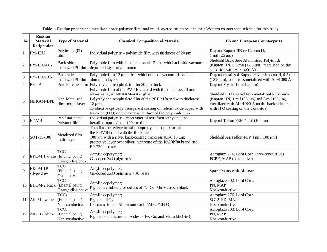
Table 1. Russian pristine and metalized space polymer films and multi-layered structures and their Western counterparts selected for this study
№ Russian Material
Designation Type of Material Chemical Composition of Material US and European Counterparts
1 PM-1EU Polyimide (PI) film Individual polymer – polyimide film with thickness of 20 μm Dupont Kapton HN or Kapton H,
1 mil (25 μm)
2 PM-1EU-OA Back-side metalized PI film
Polyimide film with the thickness of 12 μm, with back-side vacuum deposited layer of aluminum
Sheldahl Back Side Aluminized Polyimide (Kapton HN, 0.5 mil (12.5 μm), metalized on the back side with Al ~1000 Å)
3 PM-1EU-DA Both-side metalized PI film
Polyimide film 12 μm thick, with both side vacuum-deposited aluminum layers
Dupont metalized Kapton HN or Kapton H, 0.5 mil (12.5 μm), both sides metalized with Al ~1000 Å
4 PET-A Pure Polymer film Polyethylene-terephtalate film 20 μm thick Dupont Mylar, 1 mil (25 μm)
5 NIIKAM-DPL Non-Metalized films multi-layer
Polyimide film of the PM-1EU brand with the thickness 20 μm; adhesive layer: NIIKAM-AK-1 glue; Polyethylene-terephtalate film of the PET-M brand with thickness 12 μm; conductive optically transparent coating of indium oxide doped with tin oxide (ITO) on the external surface of the polyimide film
Sheldahl ITO Coated back-metalized Polyimide (Kapton HN, 1 mil (25 μm) and 3 mil (75 μm), metalized with Al ~1000 Å on the back side, and with ITO coating on the front side)
6 F-4MB Per-fluorinated Polymer film
Individual polymer – copolymer of tetrafluoroethylene and hexafluoropropylene, 100 μm thick. Dupont Teflon FEP, 4 mil (100 μm)
7 SOT-1S-100 Metalized film multi-layer
Tetrafluoroethylene-hexafluoropropylene copolymer of the F-4MB brand with the thickness 100 μm with a silver back-coating thickness 0.1-0.15 μm; protective layer over silver: nichrome of the Kh20N80 brand and EP-730 lacquer
Sheldahl Ag/Teflon-FEP 4 mil (100 μm)
8 EKOM-1 white TCC (Enamel paint) Charge-dissipative
Acrylic copolymer; Ga-doped ZnO pigments
Aeroglaze 276, Lord Corp. (non-conductive) PCBE, MAP (conductive)
9 EKOM-1P silver-grey
TCC (Enamel paint) Conductive
Acrylic copolymer; Ga-doped ZnO pigments + Al paste Space Paints with Al paste
10 EKOM-2 black TCCs (Enamel paint) Charge-dissipative
Acrylic copolymer; Pigment: a mixture of oxides of Fe, Cu, Mn + carbon black
Aeroglaze 302, Lord Corp. PN, MAP Non-conductive
11 AK-512 white TCCs (Enamel paint) Non-conductive
Acrylic copolymer; Pigment TiO2. Inorganic filler - Aluminum earth (Al2O3*3H2O)
Aeroglaze 276, Lord Corp. SG121FD, MAP Non-conductive
12 AK-512 black TCCs (Enamel paint) Non-conductive
Acrylic copolymer; Pigments: a mixture of oxides of Fe, Cu, and Mn, added SiO2
Aeroglaze 302, Lord Corp. PN, MAP Non-conductive

№ Russian Material
Designation Type of Material Chemical Composition of Material US and European Counterparts
13 KO-5191 white TCCs (Silicone paint) Non-conductive
Polymethylsiloxane binder; Pigment ZnO
Aeroglaze 276, Lord Corp. SG121FD, MAP Non-conductive
14 40-1-28 white TCCs (Silicone paint) Non-conductive
Organosilicone resin KO-116 (polymethylsiloxane); Pigment ZrO2
Aeroglaze 276, Lord Corp. SG121FD, MAP Non-conductive
15 TRSO-TsM white
TCCs (Silicate paint) Non-conductive
Water solution of potassium silicate; Pigment ZrO2
White Silicate PSB, MAP Non-conductive
16 RAM-1 Fabric
Polyimide film of the PM-1EU-OA brand with the thickness 12 μm with back-side vacuum deposited layer of aluminum; reinforcing layer: T-06 light-weight fabric of arimide fibers; binding agent between the film and fabric: polyamido-imide resin of the PI-LK-4TP brand; conductive optically transparent coating of indium oxide doped with tin oxide (ITO) on the external surface of the polyimide film
Sheldahl ITO Coated, Back Side Aluminized Polyimide (Kapton HN, 1 mil (25 μm) and 3 mil (75 μm), Al ~1000 Å)
17 RAM-2 Fabric
Polyimide film of the PM-1EU-OA brand with the thickness 12 μm with back-sided vacuum deposited layer of aluminum; reinforcing layer: polyether fabric; binding agent between the layer and fabric: thermally resistant copolymer; conductive optically transparent coating of indium oxide doped with tin oxide (ITO) on the external surface of the polyimide film
Sheldahl ITO Coated, Back Side Aluminized Polyimide (Kapton HN, 1 mil (25 μm) and 3 mil (75 μm), Al ~1000 Å)
18 Arimide fabric 5359-87 Fabric Based on arimide (polyimide) threads Polyimide Kapton HN or Kapton H
19 Arimide frame fabric 56420 Fabric
Arimide threads; skeleton cell with the dimensions 10×10 mm made of copper silvered wire wound onto an arimide thread
Polyimide Kapton HN or Kapton H
20 Arimide frame fabric SCh 5365-89
Fabric Black arimide threads; skeleton cell with the dimensions 10×10 mm made of copper silvered wire wound onto a black arimide thread
Dupont Kapton CB – Carbon filled Kapton HN, or Kapton Black
21 TSON-SOT M bts Fabric
Alumina borosilicate glass fibers STMK; skeleton cell with the dimensions 10×10 mm made of copper silvered wire wound onto a Capron thread
Alumina borosilicate glass fibers-based space fabrics

• Atomic oxygen exposure of all materials at
Multipurpose LEO Environmental Simulator, VEMES™, designed and developed at ITL [5], up to FAO fluencies of ~2×10²⁰ atoms/cm2 at room temperature;
• Selected samples of pristine and surface modified Aeroglaze and EKOM-1, EKOM-1P, and EKOM-2 thermal control coatings were tested at NASA Marshall Space Flight Center (MSFC) Atomic Oxygen Beam Facility (AOBF) described in [6,7];
• Additional selective testing of the most advanced sophisticated space materials in reputable, well characterised Laser-Detonation Hyper-Thermal Beam Source [8], up to a fluence of ~(2.5-2.6)×1020 atoms/cm2;
• Extensive erosion resistance studies and comparative mechanical, compositional and functional durability evaluation among various groups of selected materials, using data from the above AO sources;
• Comparative surface analysis by SEM/EDS for identification of surface composition, morphology, and surface chemistry changes;
• Critical comparative evaluation of space durability for Russian space materials and their Western functional counterparts.
Full testing and characterization of functional and surface properties was performed at ITL before and after the simulated LEO space environment tests. That work included identification of material type, optical and SEM microscopy analysis. Surface composition and the functional properties, in particular, thermal optical properties, i.e. solar absorptance αs and thermal emittance ε, as well as surface resistivity, have been collected from materials’ manufacturers and re-measured at ITL before and after the ground-based accelerated testing, though, this data is not discussed in the present paper. 3. RESULTS AND DISCUSSION 3.1 Testing in the VEMES™ LEO Simulator Facility Samples of Russian thermal control paints and their Western functional counterparts have been exposed to ~5 eV atomic oxygen beam with AO flux of ~(2-7)×1014 atoms/cm2/s. All samples were fixed to a metal sample holder plate 20 cm in diameter (Fig. 1). The sample holder in the VEMES™ chamber was positioned at ~30 cm from the AO source. All material specimens selected for this testing were conditioned in vacuum for ~24 hours prior to AO exposure.
Fig. 1. Russian thermal control paints and Western functional counterpart sample layout for AO testing.
A set of the Russian and Western thermal control space paints (Fig. 1) containing Russian EKOM-1, EKOM-1P, EKOM-2 and TRSO-TsM and European MAP space paints PN, PCBE and SG121FD; USA Aeroglaze A276 and Z302 space paints – have been exposed in two stages to a total FAO fluence of ~1.86×10²⁰ atoms/cm2 (Table 2) typical for a standard ground-based test of materials qualified for application in LEO. As can be seen from table 2, all Russian and USA organic paints experience, more or less, some mass loss due to erosion of organic polymeric binders, such as polyurethanes (USA) or acrylic copolymers (Russia). In case of TRSO-TsM silicate paint, the strong mass loss is related to desorption of significant amounts of water from the materials of this class. Contrary to this, surface stabilization and protection of MAP organosilicone paints was achieved under FAO exposure (see Table 2). A mass gain was observed for PN, PCBE and SG121FD samples (from 1 µg/cm2 for PN black paint up to ~54.8 µg/cm2 for white PCBE, and ~85 µg/cm2 in case of white paint SG121FD) contrary to the mass loss for polyurethane (USA) or acrylic (Russian) organic binders that is an indication of surface conversion to a stable, self-protective, most probably silica-like surface structures. The FAO exposure conducted at VEMES™ facility has confirmed the erosion resistance results for the PCBE and SG121FD white MAP organosilicone paints [9]. In particular, the considerable mass gain of these silicone-based materials that was obtained during exposures at the CASOAR – European fast AO simulation chamber has been confirmed in this study. This behavior that has not been explained in [10] can be explained by efficient surface conversion under fast atomic oxygen beams, leading to carbon reduction due to C-O and other volatile formation and release in vacuum, and significant oxygen uptake, with subsequent formation of protective silica-like inorganic surface compounds.

Table 2. Summary of FAO erosion mass change data for the Russian and their Western counterpart thermal control paints (Irradiation with a total AO fluence ~1.86×10²⁰ atoms/cm2)
Sample Mass before (g) Mass after (g) Mass change (mg)
Erosion results (μg/cm2)
EKOM-1 1.91870 1.91707 -1.63 -235.2 EKOM-1P 3.46747 3.46614 -1.33 -191.9 EKOM-2 1.71691 1.71406 -2.85 -411.3 TRSO-TsM *) 3.06798 3.05872 -9.26 -1336.2 PN (Sample #1) 0.71763 0.71764 0.01 1.4 PN (Sample #6) 0.72675 0.72674 -0.01 -1.4 PCBE 1.49589 1.49627 0.38 54.8 SG121FD 1.53108 1.53167 0.59 85.1 A276 0.19004 0.18835 -1.69 -243.9 Z302 0.17919 0.17830 -0.89 -128.4
*) This high mass loss can be explained by desorption of bound water from this silicate paint, as indicated below. The Russian and Western space polymer films, textiles, and multi-layers have been divided into two groups according to their expected erosion resistance that was based on surface composition (see Fig. 2).
Fig. 2. Layout of materials with expected low erosion (Set I) for VEMES™ exposure
Set I of expected low erosion materials has been exposed to a total FAO fluence of 6.8×10¹⁹ atoms/cm2 in a two-stage exposure experiment that helped to get some inside of the kinetics of the on-going processes. Kapton HN, 1 mil (25 μm) and Russian polyimide PM-1EU, 20 µm were included as reference materials. During the first exposure with fluence ~2.7×10¹⁹ atoms/cm2, a distinguishable mass gain of ~10-55 μg/cm2 has occurred on all of the ITO coated materials, i.e. the NIIKAM-DPL, the ITO-coated Kapton HN, 1 and 3 mil (25 and 75 μm) and the RAM-1 and RAM-2 space textiles. At the same exposure, a significant mass loss, higher that for Kapton HN, occurred for per-fluorinated Teflon FER and Russian SOT-1S-100 that is based on the Russian Teflon film. As can be seen from Table 3, at
the end of the second exposure not mass gain, but some mass loss occurred at the majority of ITO-coated materials. The ITO-coated Kapton HN, 1 mil was the only exception, with some recorded mass gain. At the same time, the erosion resistance of ITO-coated NIIKAM-DPL had drastically decreased when the fluence was raised, most probably, due to extensive cracking and etching in the cracked areas. The second set of samples (Set II) for exposure at the VEMES™ facility was represented by high erosion yield materials and has been exposed to a FAO fluence of ~7.5×10¹⁹ atoms/cm2. The erosion results obtained for this set of materials are presented in Table 4. Note that the erosion mass loss obtained for Teflon FEP and F-4MB per-fluorinated polymers during FAO exposure at the VEMES™ facility (see Tables 3 and 4) has been significantly higher when compared to that for Kapton HN witness samples and to Russian polyimide films PM-1EU. The above discrepancy is discussed in Section 3.4 and could be indicative of strong vacuum ultraviolet (VUV) or ionic oxygen components generated by the VEMES™ FAO source, since the per-fluorinated polymers are particularly sensitive to these factors [11,12]. Since the SOT-1S-100 multi-layer has a tetrafluoroethylene-hexafluoropropylene copolymer of the F-4MB brand on the front side surface (see Table 1), the erosion data obtained for SOT-1S-100 at the VEMES™ facility may be influenced by the same effects and is, therefore, questionable as well. To avoid any questionable conclusions, both these materials, together with some Russian advanced textiles, have been FAO-tested at the highly reliable, well-characterized 5 eV Laser-Detonation Hyper-Thermal Beam Source at MSU (see Section 3.3).

Table 3. Summary of mass changes for Russian and Western materials with expected low erosion, Set I, due to
irradiation with a total FAO fluence ~6.8×10¹⁹ atoms/cm2
Sample Mass before (g)
Mass after (g)
Mass change (mg)
Erosion results (μg/cm2)
RAM-1 0.05020 0.05019 -0.01 -1.57 RAM-2 0.06692 0.06691 -0.01 -1.57 NIIKAM-DPL 0.02872 0.02808 -0.64 -100.45 SOT-1S-100 0.13464 0.13378 -0.86 -134.97 ITO × 1.0 mil (25 μm) Kapton 0.02316 0.02321 0.05 7.85
ITO × 3.0 mil (75 μm) Kapton 0.07005 0.06998 -0.07 -10.99
PM-1EU-DA 0.01157 0.01156 -0.01 -1.57 Teflon FEP 300c 0.10229 0.09870 -3.59 -563.44 PM-1EU 0.09378 0.09319 -0.59 -92.60 *) Kapton HN 1 mil (25 μm) 0.02131 0.02086 -0.45 -70.63 *)
*) Kapton HN, 1mil, and Russian polyimide PM-1EU, 20 µm included as reference materials
Table 4. FAO erosion mass loss data for the Russian space materials with expected high erosion, Set II (Irradiation with AO fluence ~7.5×10¹⁹ atoms/cm2)
Sample Mass before (g) Mass after (g) Mass change
(mg) Erosion results
(μg/cm2) Fabric TSON-SOT M 0.04602 0.04475 -1.27 -233.64 Aramide fabric 56420 0.06006 0.05771 -2.35 -373.51 Aramide fabric 5359-87 0.05414 0.05216 -1.98 -314.71 Aramide 5365-89 0.05929 0.05793 -1.36 -216.16 PA 66 (nylon) 0.03855 0.03478 -3.77 -599.21 PET Mylar 2 mil (50 μm) 0.04485 0.04289 -1.96 -311.53
PET (Rus.) 3 for 1 *) 0.05977 0.05485 -4.92 -782.00 Capron 50613 0.03342 0.03044 -2.98 -473.65 F-4MB 0.10000 0.09583 -4.17 -662.79
*) 3 layers of this material have been stacked as one sample for the FAO exposure 3.2 Testing in the NASA AOBF facility The Russian EKOM-1, EKOM-1P and EKOM-2 thermal control coatings and their US counterparts (see Table 1) were exposed at MSFC Atomic Oxygen Beam Facility to 5 eV neutral FAO fluence in the range (5-10.1)×1020 atoms/cm2. During the atomic oxygen exposure, VUV radiation was produced in the AOBF, primarily at 130 nm, corresponding to ~800-900 equivalent sun hours (ESH). Figs. 3 and 4 show a round sample holder loaded with the Russian thermal control paints and a Kapton sample for monitoring FAO fluence. The cover plate has been removed. The unexposed areas are not easy to discern, which agrees with the slight changes in optical properties. Table 5 summarizes the AO fluence and mass changes for all tested samples. Among the EKOM
paints, not only the traditional black and white, but also the silver-grey EKOM-1P paint is also present. ITL has an experience of dealing with a special grey paint manufactured and used by MDA [13] for space application as a mixture of the Aeroglaze paints A276 and Z306. Samples of this paint have been used as counterparts for EKOM-1P.

Fig. 3. FAO test sample holder with cover plate removed. Clockwise from Top: Kapton for FAO fluence monitoring, EKOM-1 white paint, EKOM-1P silver-grey
paint, and EKOM-2 black paint
Fig. 4. FAO test sample holder with another batch of samples. Clockwise from Top: AK512 black paint,
Kapton for AO fluence monitoring, EKOM-1P silver-grey paint, and EKOM-2 black paint
Table 5. Summary of mass loss data of the Russian and their Western counterpart space thermal control paints
Mass (g) Sample
AO Fluence × 1020
atoms/cm2 Before AO After AO Mass change
(mg)
Erosion results
(μg/cm2) EKOM-1 7.22 3.38245 3.38119 -1.26 -178.3 EKOM-1P 9.96 3.49427 3.49335 -0.92 -130.2 EKOM-2 7.61 3.32738 3.32525 -2.13 -301.5 A276:Z306 5.53 42.08252 42.07120 -11.32 -786.1 Z302 5.25 7.45808 7.44878 -9.30 -492.8 AK512 b 1.9 1.69888 1.69655 -2.33 -329.8 TRSO-TsM *) 1.9 2.99754 2.98753 -10.01 -1416.8
*) The very high mass loss can be explained by desorption of bound water from this silicate paint
Note that the highest FAO fluence achieved in this testing was relevant to long-duration space missions, i.e. it was approximately 1/5 - 1/7 of the fluence received by materials in ram direction during the 4 years of in-space MISSE-1experiment at ISS in 2001-2004, at the maximum of solar activity [14] and could be compared with ~1 year in space in MISSE-3 experiment in the 2004-2005 period [15]. The visual appearances of grey paint sample from Aeroglaze paints mixture (A276:Z306) and the Aeroglaze Z302 paint after FAO exposure showed the original dark color of the samples in the areas where a holding clamp was applied. The unexposed area under the clamp is particularly noticeable for the grey sample. The appearance of exposed pigments and highly developed surface morphology, visible for the pristine EKOM-1 paint after the FAO testing at AOBF of MSFC, were clear signs of surface erosion (Fig. 5).
Fig. 5. SEM micrographs of Russian EKOM-1 paint after FAO+VUV exposure. Magnification 500x. The
insert shows in greater details the surface morphology. Magnification 2000x
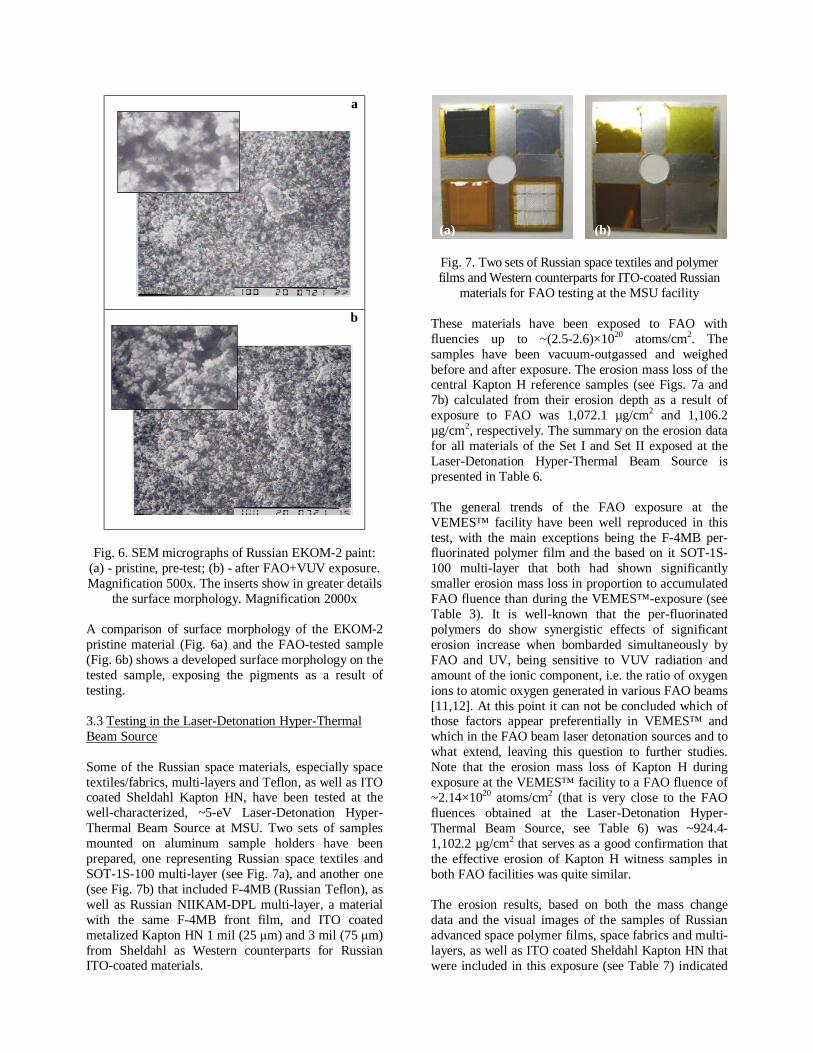
a
b
Fig. 6. SEM micrographs of Russian EKOM-2 paint:
(a) - pristine, pre-test; (b) - after FAO+VUV exposure. Magnification 500x. The inserts show in greater details
the surface morphology. Magnification 2000x A comparison of surface morphology of the EKOM-2 pristine material (Fig. 6a) and the FAO-tested sample (Fig. 6b) shows a developed surface morphology on the tested sample, exposing the pigments as a result of testing. 3.3 Testing in the Laser-Detonation Hyper-Thermal Beam Source Some of the Russian space materials, especially space textiles/fabrics, multi-layers and Teflon, as well as ITO coated Sheldahl Kapton HN, have been tested at the well-characterized, ~5-eV Laser-Detonation Hyper-Thermal Beam Source at MSU. Two sets of samples mounted on aluminum sample holders have been prepared, one representing Russian space textiles and SOT-1S-100 multi-layer (see Fig. 7a), and another one (see Fig. 7b) that included F-4MB (Russian Teflon), as well as Russian NIIKAM-DPL multi-layer, a material with the same F-4MB front film, and ITO coated metalized Kapton HN 1 mil (25 μm) and 3 mil (75 μm) from Sheldahl as Western counterparts for Russian ITO-coated materials.
Fig. 7. Two sets of Russian space textiles and polymer films and Western counterparts for ITO-coated Russian
materials for FAO testing at the MSU facility These materials have been exposed to FAO with fluencies up to ~(2.5-2.6)×1020 atoms/cm2. The samples have been vacuum-outgassed and weighed before and after exposure. The erosion mass loss of the central Kapton H reference samples (see Figs. 7a and 7b) calculated from their erosion depth as a result of exposure to FAO was 1,072.1 µg/cm2 and 1,106.2 µg/cm2, respectively. The summary on the erosion data for all materials of the Set I and Set II exposed at the Laser-Detonation Hyper-Thermal Beam Source is presented in Table 6. The general trends of the FAO exposure at the VEMES™ facility have been well reproduced in this test, with the main exceptions being the F-4MB per-fluorinated polymer film and the based on it SOT-1S-100 multi-layer that both had shown significantly smaller erosion mass loss in proportion to accumulated FAO fluence than during the VEMES™-exposure (see Table 3). It is well-known that the per-fluorinated polymers do show synergistic effects of significant erosion increase when bombarded simultaneously by FAO and UV, being sensitive to VUV radiation and amount of the ionic component, i.e. the ratio of oxygen ions to atomic oxygen generated in various FAO beams [11,12]. At this point it can not be concluded which of those factors appear preferentially in VEMES™ and which in the FAO beam laser detonation sources and to what extend, leaving this question to further studies. Note that the erosion mass loss of Kapton H during exposure at the VEMES™ facility to a FAO fluence of ~2.14×10²⁰ atoms/cm2 (that is very close to the FAO fluences obtained at the Laser-Detonation Hyper-Thermal Beam Source, see Table 6) was ~924.4-1,102.2 µg/cm2 that serves as a good confirmation that the effective erosion of Kapton H witness samples in both FAO facilities was quite similar. The erosion results, based on both the mass change data and the visual images of the samples of Russian advanced space polymer films, space fabrics and multi-layers, as well as ITO coated Sheldahl Kapton HN that were included in this exposure (see Table 7) indicated
(a) (b)

that the surfaces of the tested materials were eroded to a different extend, showing for some of them a matte appearance and a developed surface morphology; with the changes being less obvious for the ITO coated materials Kapton HN 1 mil (25 μm) + ITO and Kapton HN 3 mil (75 μm) + ITO and strong erosion for the
Russian polyimide (Arimide) fibers-based Fabric 5359-87. Surprisingly high erosion was observed for NIIKAM-DPL that may be explained considering the very high ITO non-uniformity that was found for this sample (i.e. presence of only a very thin, brittle and easily eroded ITO layer or its total absence).
Table 6. Mass loss and erosion data of the selected Russian and selected Western counterparts space materials
Sample AO Fluence
× 1020 atoms/cm2
Mass before (g)
Mass after (g)
Mass change
(mg)
Erosion results
(μg/cm2) Fabric 5359-87 0.05987 0.05299 -6.88 -1066.67 Fabric 5365-89 0.05966 0.05432 -5.34 -827.91 SOT-1S-100 0.14555 0.14325 -2.30 -356.59 Fabric TSON-SOT M
2.52
0.06308 0.06081 -2.27 -351.94 NIIKAM-DPL 0.02960 0.02216 -7.44 -1153.49 F-4MB 0.10591 0.10458 -1.33 -206.20 ITO × Kapton HN 3.0 mil 0.07026 0.06987 -0.39 -60.47 ITO × Kapton HN 1.0 mil
2.60
0.02317 0.02308 -0.09 -13.95 According to the mass loss and SEM surface analysis of materials exposed at the MSU source, the only materials that were stable or low-eroded under FAO was Sheldahl
ITO coated Kapton HN 1 mil (25 μm) and 3 mil (75 μm), see Fig. 8(a-d).
Fig. 8. Planar SEM analysis: (a) - Kapton HN 1 mil (25 μm) + ITO, pristine sample; (b) - Kapton HN 1 mil (25 μm) + ITO, FAO-exposed; (c) - Kapton HN 3 mil (75 μm) + ITO, pristine sample; (d) - Kapton HN 3 mil (75 μm) + ITO,
FAO-exposed. Magnification 1500x According to the mass loss measurements and SEM analysis of the samples FAO-exposed at the MSU Source, the following Russian and Western space materials could be attributed to the class of significantly or highly-eroded materials under FAO:
• NIIKAM-DPL;
• F-4MB Polymer Film; • SOT-1S-100 Multi-Layer System; • Arimide Fabric 5359-87; • Arimide Fibers 5365-89; • Fabric TSON-SOT M.
(a) (b)
(c) (d)

Fig. 9. Planar SEM analysis: (a) - NIIKAM-DPL multilayer structure, pristine sample; (b) - NIIKAM-DPL multilayer structure, FAO-exposed; (c) - F-4MB polymer film, pristine sample; (d) - F-4MB polymer film, pristine sample, FAO-
exposed. Magnification 1500x The SEM surface analysis results for the pristine and FAO-exposed samples of those materials are shown in Fig. 9(a-d). 3.4 Evaluation of Russian and Western space materials FAO-tested at different FAO beam facilities In general, the main trends observed in erosion behavior of the investigated Russian space materials and their Western functional counterparts during FAO exposure at different FAO beam facilities (see Sections 3.1-3.3) have been well reproduced. However, according to both mass change data and SEM surface analysis results, in a few cases significant discrepancies in erosion behavior have been observed. The first case is the non-metalized ITO coated multi-layer NIIKAM-DPL that showed strong differences in the erosion patterns after exposure at different FAO beam facilities. An explanation to the observed discrepancy has been found after conducting a series of surface resistivity measurements. It was found that ITO coating on the surface of pristine NIIKAM-DLP material is highly non-uniform, leading to a very significant dispersion of measured surface resistivity data. As a consequence, among the two FAO-exposed samples, one sample did have a layer of ITO coating on the surface, and another one almost did not. The F-4MB fluorinated polymer and based on it SOT-1S-100 multi-layer tested at the VEMES™ facility has shown significantly higher erosion mass loss in proportion to accumulated FAO fluence than during testing at the Laser-Detonation Hyper-Thermal Beam Source. This behavior can be an indication of strong VUV radiation and ionic component generated at the
VEMES™ FAO source, since the per-fluorinated polymers are particularly sensitive to these factors [11, 12]. Therefore, it can be concluded that pure fast AO beams have not been always produced at the VEMES™ facility, especially, regarding that particular exposure that included the F-4MB material. Most probably, this could happen due to inadequate optimization of the operational parameters of the FAO source. 4. CONCLUSIONS As a continuation of an international program initiated by ITL on comparative evaluation of space materials, a number of Russian, European and US thermal control materials were tested in three different LEO space simulator sources and the results were evaluated. The ITL-developed VEMES™ atomic oxygen simulator was used for comparative erosion resistance testing of a large number of Russian and Western materials. In addition, selected materials of special interest were tested in medium- and high-fluence FAO beam exposures and at combined FAO/UV conditions, using two other FAO beam facilities. Based on compiled and analyzed together FAO testing results, supported by post-testing surface analysis data, all materials in this study have been assigned to one of two major groups/classes, depending on their LEO space durability, i.e. a) stable or low-erosion with very low or no mass loss and low visible erosion on the surface; and b) significant, high-erosion, with a significant or very significant mass loss confirmed, together with sufficient or strong morphology change due to erosion of the surface.
(a) (b)
(c) (d)

It was demonstrated and confirmed in this study through a large number of experiments that under oxygen plasma, FAO and FAO+VUV exposure, surface erosion occurs on many types of polymer films and organic paints, regardless of the supply source and origin of manufacturing. These changes do affect, to a different extent, their optical and electrical properties that are very important in many space applications. For all the tested silicate paints, regardless of their origin, the significant mass loss under FAO exposure was attributed to the loss of water of the silicate, or “liquid glass”, water-borne binders. On the other hand, all metalized (front-side and both-sides) space polymer materials from Russian and Western sources demonstrated good stable behavior under the standard testing conditions and durations that is indicative of the fact that the metallization processes of thin space polymer films are well developed in Russian and Western facilities. It has been shown that all Russian EKOM paints maintain their surface resistivity and charge dissipative properties in imitated LEO exposure, even up to high FAO fluencies. These features favor them for both extended GEO and LEO uses, with some possible surface modifications performed for the LEO long-term missions that extend even further the useful life. While the results for the majority of the materials demonstrated the same trends in different facilities, the quantitative results for some of them were found to be sensitive to the additional space environment factors produced in each of the testing facility. In general, it is known that the Indium Tin Oxide thin film coatings are brittle and prone to damage. The effects associated with such behavior of ITO thin coatings expressed themselves in this study. It was learned that in order to extend the useful life of ITO-coated materials, they should be handled very carefully and that the quality of the substrate surface significantly influences their durability. As an additional outcome of the study, further efforts can be advised to perform surface modification of the Russian EKOM thermal control paints to make them fully erosion resistant in LEO space environment, for instance, using the surface modification technologies developed at ITL. A specially designed long-term LEO space flight experiment can be recommended for the MAP silicone paints to prove that they may either cause insignificant or not at all silicone contamination of the sensitive space optical surfaces. This data, if confirmed positively, opens the door for possible exciting opportunity of using MAP silicone paints in long-term LEO space missions.
5. ACKNOWLEDGMENTS The authors wish to acknowledge the help from Ms. A. Tang at ITL for the SEM/EDS analysis and Ms. M. Finkenor from NASA Marshall Space Flight Centre for useful discussions and help with some of the samples in this study. A large part of this work was done under the ESTEC Contract No.21383/08/NL/PA. 6. REFERENCES 1. J.I. Kleiman, Y. Gudimenko, Z. Iskanderova, R.C.
Tennyson and W.D. Morison, “Modification of Thermal Control Paints by PhotosilTM Technology”, Proc. of the ICPMSE-4, 4th International Space Conference, Toronto, Canada, 23-24 April, 1998, eds. J.I. Kleiman and R.C. Tennyson, Kluwer Academic Publishers, Space Technology Proceedings, v.4, pp.243-252, 2001.
2. J.I. Kleiman, “Surface Modification of Polymers, Paints and Composite Materials Used in the Low Earth Orbit Space Environment”, in Materials for Space Applications, edited by M. Chipara, D. L. Edwards, R. S. Benson, Sh. Phillips (Mater. Res. Soc. Symp. Proc. 851, Warrendale, PA, 2005), paper NN8.6.
3. “The Global Exploration Strategy: The Framework for Coordination”. April 2007.
4. “The global exploration strategy”, See http://www.esa.int/SPECIALS/Space_Exploration_Strategy/SEMDAM0YUFF_0.html
5. J. Kleiman, S. Horodetsky, V. Sergeyev, V. Issoupov, and R. Ng, “Critical review of the design of space environment simulators: Lessons learnt”, Proc. of the 10th Int. Symp. on Materials in a Space Environment / 8th Int. Conf. on Protection of Materials and Structure from the LEO Space Environment, Collioure, France, June 19-23, 2006.
6. Finckenor, M. M., Edwards, D. L., Vaughn, J. A., Schneider, T. A., Hovater, M. A., and Hoppe, D. T., “Test and Analysis Capabilities of the Space Environment Effects Team at Marshall Space Flight Center”, NASA TP-2002-212076, 5-6, Nov. 2002.
7. J.I. Kleiman, Y. Gudimenko, R. Ng, Z.A. Iskanderova, A. Grigorievsky, L. Kisileva, D. Edwards and M. Finkenor, “Surface Modification of Conductive and Nonconductive Paints for Space Durability Enhancement”, J. of Spacecraft and Rockets, v. 43, No.2, 2006, pp.443-450.
8. T. K. Minton, and D. J. Garton, “Dynamics of Atomic-Oxygen-Induced Polymer Degradation in Low Earth Orbit”, In: “Chemical Dynamics in Extreme Environments”, Advanced Series In Physical Chemistry - Vol. 11, Ed. by R.A. Dressler, World Scientific, 2001.

9. Space and High Technology Paints and Coatings. MAP Corp., Booklet.
10. S. Remaury, J.C. Guillaumon, and P. Nabarra, “Behaviour of Thermal Control Coatings under Atomic Oxygen and Ultraviolet Radiation”, Proc. of the 6th Int. Conf. on Protection of Materials and Structures from the Space Environment, Toronto, Canada, May 1-3, 2002, Kluwer Academic, Norwell, MA, 2003, p. 193.
11. Z. A. Iskanderova, J. Kleiman, “Oxygen-Based Plasma, Ion Beam and Atomic Oxygen Interaction with Polymers: Physical and Chemical Processes of Erosion and Etching”, Rept., Univ. of Toronto Inst. for Aerospace Studies, Toronto, ON, Canada, 1993.
12. R.H. Krech, et al., “AO Experiments at PSI”, BMDO/JPL EOIM-3 Workshop, Arcadia, CA, June 22-23, 1993.
13. Y. Gudimenko, R. Ng, J. Kleiman, Z. Iskanderova, D. Milligan, P.C. Hughes, and R.C. Tennyson, “Photosil™ Application for External Space Materials and Components”, Proc. of the 6th Int. Conf. on Protection of Materials and Structures from the Space Environment, Toronto, Canada, May 1-3, 2002, Kluwer Academic, Norwell, MA, 2003, pp. 419-434.
14. See MISSE website http://misse1.larc.nasa.gov/ 15. Z. Iskanderova, J. I. Kleiman, and R. C. Tennyson,
“Pristine and Surface-Modified Polymers in LEO: MISSE Results versus Predictive Models and Ground-Based Testing”, Proc. of the 9th Int. Conf. on Protection of Materials and Structures in a Space Environment, Toronto, Canada, May 20-23, 2008.
Related Documents