5EB-28199-E2 YZF-R6 OWNER’S MANUAL

Welcome message from author
This document is posted to help you gain knowledge. Please leave a comment to let me know what you think about it! Share it to your friends and learn new things together.
Transcript
5EB-28199-E2
YZF-R6
OWNER’S MANUAL
00001 INTRODUCTION
maha’s vast experience in andcture of high-quality products,bility.
o as to enjoy all your YZF-R6’sstruct you in how to operate, to safeguard yourself and oth-
elp to keep your motorcycle inestions, do not hesitate to con-
nt rides. So, remember to put
E_5eb_Intro0.fm Page 1 Thursday, November 18, 1999 4:00 PM
EAU
Welcome to the Yamaha world of motorcycling!
As the owner of a YZF-R6, you are benefiting from Yanewest technology for the design and the manufawhich have earned Yamaha a reputation for dependa
Please take the time to read this manual thoroughly, sadvantages. The owner’s manual does not only ininspect and maintain your motorcycle, but also in howers from trouble and injury.
In addition, the many tips given in this manual will hthe best possible condition. If you have any further qutact your Yamaha dealer.
The Yamaha team wishes you many safe and pleasasafety first!

EAU00005PORTANT MANUAL INFORMATION
ticularly important information is distinguished in this manual by the following notations:
T! YOUR SAFETY IS IN-
E_5eb_Info0.fm Page 1 Thursday, November 18, 1999 4:01 PM
IM
Par
re injury or death to theing the motorcycle.
to avoid damage to the
learer.
torcycle and should remain
d quality. Therefore, whilelable at the time of printing, this manual. If there is anydealer.
C
N
The Safety Alert Symbol meanVOLVED!
WARNING Failure to follow WARNING imotorcycle operator, a bystand
AUTION: A CAUTION indicates specialmotorcycle.
OTE: A NOTE provides key informati
NOTE:@
● This manual should be considwith it even if the motorcycle
● Yamaha continually seeks adthis manual contains the mosthere may be minor discrepanquestion concerning this man
@
s ATTENTION! BECOME ALER
nstructions could result in seveer or a person inspecting or repair
precautions that must be taken
on to make procedures easier or c
ered a permanent part of this mois subsequently sold.vancements in product design ant current product information avaicies between your motorcycle andual, please consult your Yamaha

IMPORTANT MANUAL INFORMATIONEW000002
INGAD THIS MANUAL CAREFULLY AND COMPLETELY BEFORE OPERATINGRCYCLE.
E_5eb_Info0.fm Page 2 Thursday, November 18, 1999 4:01 PM
WARN@
PLEASE RETHIS MOTO@

IMPORTANT MANUAL INFORMATION
© 1991st
All rightunauthopermissi
i
E_5eb_Info0.fm Page 3 Thursday, November 18, 1999 4:01 PM
EAU00008
YZF-R6OWNER’S MANUAL
9 by Yamaha Motor Co., Ltd. Edition, November 1999s reserved. Any reprinting orrized use without the writtenon of Yamaha Motor Co., Ltd.s expressly prohibited.
Printed in Japan.

TABLE OF CONTENTS
RIGHT OF WAY 1
2
CONTROL FUNCTIONS 3
HECKS 4
PORTANT RIDING POINTS 5
NANCE AND MINOR REPAIR 6
E AND STORAGE 7
8
MATION 9
EAU00009
E_5eb_Toc0
1 GIVE SAFETY THE
2 DESCRIPTION
3 INSTRUMENT AND
4 PRE-OPERATION C
5 OPERATION AND IM
6 PERIODIC MAINTE
7 MOTORCYCLE CAR
8 SPECIFICATIONS
9 CONSUMER INFOR
.fm Page 1 Thursday, November 18, 1999 4:01 PM
INDEX

E_5eb_Toc0.fm Page 2 Thursday, November 18, 1999 4:01 PM

1
GIVE SAFETY THE RIGHT OF WAY
GIVE SAFETY THE RIGHT OF WAY................................................. 1-1
E_5eb_LabelTOC.fm Page 1 Thursday, November 18, 1999 4:01 PM
1
EAU00021
nsurpassed feeling of power andt accept; even the best motorcycle
E_5eb_Label.fm Page 1 Thursday, November 18, 1999 4:02 PM
motorcycle’s value and operatinge for the rider: good performanceedication, drugs and alcohol is, ofrs - must always be at their mentallcohol, there is a tendency to take
eat belts are for car drivers and made of leather or tear-resistantves and a properly fitting helmet.relessness. Though full-coverage and protection, motorcyclists willrisk of going too fast and are apt tohe good motorcyclist rides safely, caused by others.
1-1
1-GIVE SAFETY THE RIGHT OF WAY
Motorcycles are fascinating vehicles, which can give you an ufreedom. However, they also impose certain limits, which you musdoes not ignore the laws of physics.
Regular care and maintenance are essential for preserving yourcondition. Moreover, what is true for the motorcycle is also trudepends on being in good shape. Riding under the influence of mcourse, out of the question. Motorcycle riders - more than car driveand physical best. Under the influence of even small amounts of adangerous risks.
Protective clothing is as essential for the motorcycle rider as spassengers. Always wear a complete motorcycle suit (whethersynthetic materials with protectors), sturdy boots, motorcycle gloOptimum protective wear, however, should not encourage cahelmets and suits, in particular, create an illusion of total safetyalways be vulnerable. Riders who lack critical self-control run the take chances. This is even more dangerous in wet weather. Tpredictably and defensively - avoiding all dangers, including those
Enjoy your ride!
2
DESCRIPTION
Left view ............................................................................................. 2-1Right view........................................................................................... 2-2Controls/Instruments .......................................................................... 2-3
E_5eb_DescriptionTOC.fm Page 1 Thursday, November 18, 1999 4:02 PM

2
EAU00026
E_5eb_Description.fm Page 1 Thursday, November 18, 1999 4:02 PM
2-DE
Lef
r spring preload (page 3-20)
r rebound damping (page 3-20)(page 3-11)
k (page 6-13)(page 6-11)
1.
2.
3.4.5.
2-1
SCRIPTION
t view
Front fork compression damping force adjusting screw (page 3-19)Front fork rebound damping force adjusting screw (page 3-18)Front fork spring preload adjusting bolt (page 3-18)Air filter (page 6-17)Rear shock absorber compression damping force adjusting screw (page 3-20)
6. Rear shock absorbeadjusting ring
7. Rear shock absorbeforce adjusting knob
8. Shift pedal9. Coolant reservoir tan
10. Engine oil filter
DESCRIPTION
2
R
11121314151617
E_5eb_Description.fm Page 2 Thursday, November 18, 1999 4:02 PM
2-2
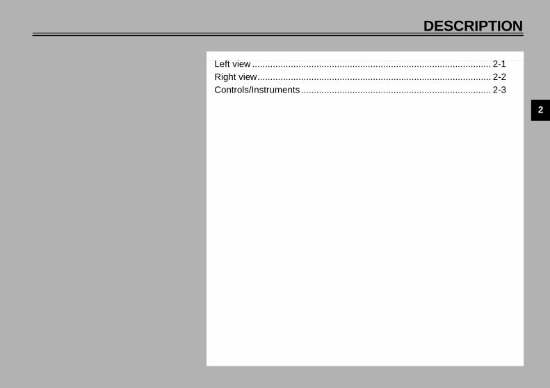
ight view
. Luggage strap holders (page 3-23)
. Tool kit (page 6-1)
. Fuses (page 6-34)
. Rear brake fluid reservoir
. Radiator cap (page 6-14)
. Front brake fluid reservoir
. Rear brake pedal (page 3-12)
DE
2
Co
1.2.3.4.5.
(page 3-8)ches (page 3-10)
(page 6-21)(page 3-11)
E_5eb_Description.fm Page 3 Thursday, November 18, 1999 4:02 PM
SCRIPTION
2-3
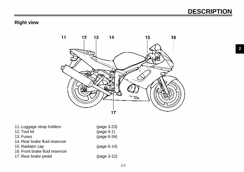
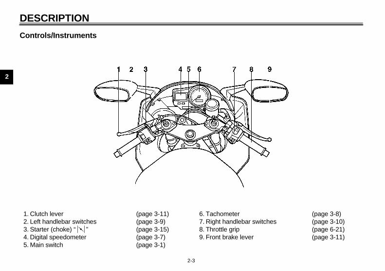
ntrols/Instruments
Clutch lever (page 3-11)Left handlebar switches (page 3-9)Starter (choke) “ ” (page 3-15)Digital speedometer (page 3-7)Main switch (page 3-1)
6. Tachometer7. Right handlebar swit8. Throttle grip9. Front brake lever
3
INSTRUMENT AND CONTROL FUNCTIONS
Main switch/Steering lock .....................................3-1Indicator lights ......................................................3-2Oil level / coolant temperature indicator light
circuit check ........................................................3-5Fuel indicator light circuit check............................3-6Digital speedometer..............................................3-7Tachometer ...........................................................3-8Diagnosis device...................................................3-9Handlebar switches ..............................................3-9Clutch lever .........................................................3-11Shift pedal...........................................................3-11Front brake lever .................................................3-11Rear brake pedal ................................................3-12Antitheft alarm (optional) ....................................3-12
Fuel tank cap ..................................................... 3-13Fuel .................................................................... 3-13Fuel tank breather hose ..................................... 3-14Starter (choke) “ ” .......................................... 3-15Seats.................................................................. 3-15Helmet holder..................................................... 3-17Storage compartment ........................................ 3-17Front fork adjustment ......................................... 3-17Rear shock absorber adjustment ....................... 3-19Recommended combinations of the front fork
and the rear shock absorber settings............... 3-22Luggage strap holders ....................................... 3-23Sidestand ........................................................... 3-23Sidestand/clutch switch operation check............ 3-24
E_5eb_FunctionsTOC.fm Page 1 Thursday, November 18, 1999 4:03 PM
3
EAU00027
E_5eb_Functions.fm Page 1 Thursday, November 18, 1999 4:03 PM
3-IN
EW000016
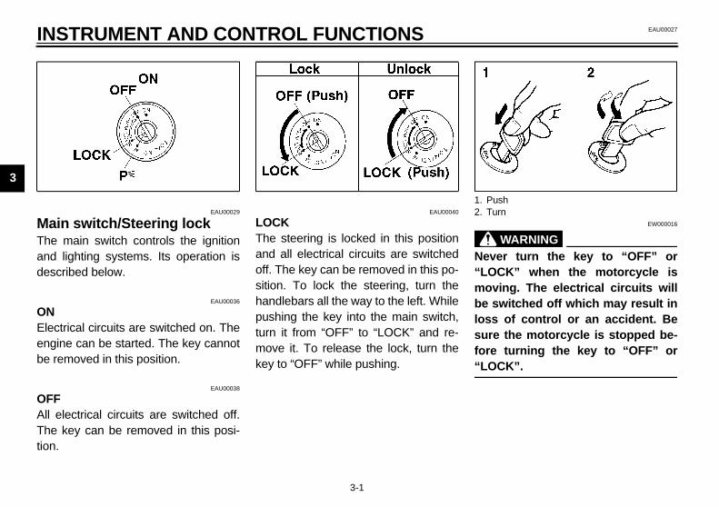
WARNINGer turn the key to “OFF” orCK” when the motorcycle isving. The electrical circuits willswitched off which may result in of control or an accident. Be
e the motorcycle is stopped be- turning the key to “OFF” orCK”.
ushurn
MaTheanddes
ONEleengbe r
OFAll Thetion
3-1
STRUMENT AND CONTROL FUNCTIONS
EAU00029
in switch/Steering lock main switch controls the ignition lighting systems. Its operation iscribed below.
EAU00036
ctrical circuits are switched on. Theine can be started. The key cannotemoved in this position.
EAU00038
Felectrical circuits are switched off. key can be removed in this posi-.
EAU00040
LOCKThe steering is locked in this positionand all electrical circuits are switchedoff. The key can be removed in this po-sition. To lock the steering, turn thehandlebars all the way to the left. Whilepushing the key into the main switch,turn it from “OFF” to “LOCK” and re-move it. To release the lock, turn thekey to “OFF” while pushing.
@
Nev“LOmobe losssurfore“LO@
1. P2. T
NTROL FUNCTIONS
3
ThancoThtioTothDeddi
EAU00057
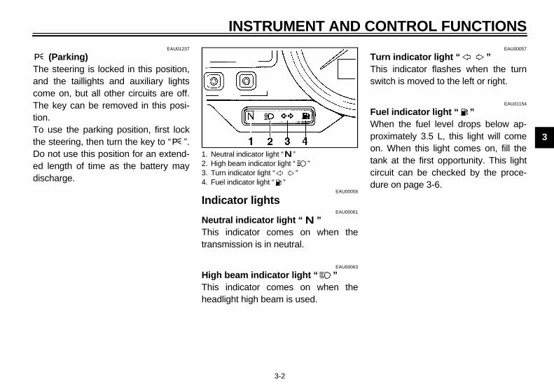
rn indicator light “ ”is indicator flashes when the turnitch is moved to the left or right.
EAU01154
el indicator light “ ”hen the fuel level drops below ap-oximately 3.5 L, this light will come. When this light comes on, fill the
nk at the first opportunity. This lightcuit can be checked by the proce-re on page 3-6.
E_5eb_Functions.fm Page 2 Thursday, November 18, 1999 4:03 PM
INSTRUMENT AND CO
3-2
EAU01237
(Parking)e steering is locked in this position,d the taillights and auxiliary lightsme on, but all other circuits are off.e key can be removed in this posi-n. use the parking position, first lock
e steering, then turn the key to “ ”.o not use this position for an extend- length of time as the battery may
scharge.EAU00056
Indicator lightsEAU00061
Neutral indicator light “ ”This indicator comes on when thetransmission is in neutral.
EAU00063
High beam indicator light “ ”This indicator comes on when theheadlight high beam is used.
TuThsw
FuWprontacirdu
1. Neutral indicator light “ ”2. High beam indicator light “ ”3. Turn indicator light “ ”4. Fuel indicator light “ ”
IN
3
Oiltor Thi
●
1. O2. O
i3. C
E_5eb_Functions.fm Page 3 Thursday, November 18, 1999 4:03 PM
STRUMENT AND CONTROL FUNCTIONS
3-3
EAU01564
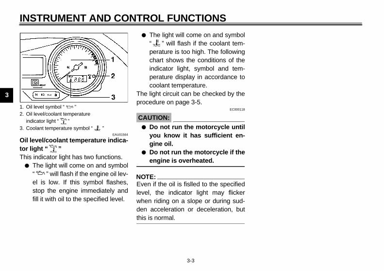
level/coolant temperature indica-light “ ”s indicator light has two functions.
The light will come on and symbol“ ” will flash if the engine oil lev-el is low. If this symbol flashes,stop the engine immediately andfill it with oil to the specified level.
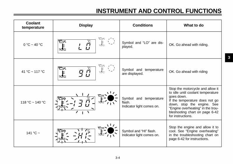
● The light will come on and symbol“ ” will flash if the coolant tem-perature is too high. The followingchart shows the conditions of theindicator light, symbol and tem-perature display in accordance tocoolant temperature.
The light circuit can be checked by theprocedure on page 3-5.
EC000118
CAUTION:@
● Do not run the motorcycle untilyou know it has sufficient en-gine oil.
● Do not run the motorcycle if theengine is overheated.
@
NOTE:@
Even if the oil is fislled to the specifiedlevel, the indicator light may flickerwhen riding on a slope or during sud-den acceleration or deceleration, butthis is normal. @
il level symbol “ ”il level/coolant temperature
ndicator light “ ”oolant temperature symbol “ ”
NTROL FUNCTIONS
3
CB
What to do
is- OK. Go ahead with riding.
re OK. Go ahead with riding
re
Stop the motorcycle and allow itto idle until coolant temperaturegoes down.If the temperature does not godown, stop the engine. See“Engine overheating” in the trou-bleshooting chart on page 6-42for instructions.
Stop the engine and allow it tocool. See “Engine overheating”in the troubleshooting chart onpage 6-42 for instructions.
E_5eb_Functions.fm Page 4 Thursday, November 18, 1999 4:03 PM
INSTRUMENT AND CO
3-4
-77E
Coolant temperature Display Conditions
0 °C ~ 40 °C Symbol and “LO” are dplayed.
41 °C ~ 117 °C Symbol and temperatuare displayed.
118 °C ~ 140 °C Symbol and temperatuflash.Indicator light comes on.
141 °C ~ Symbol and “HI” flash. Indicator light comes on.
˚C
˚C
˚C
˚C
IN
3
EAU02987
eckCB-75
oes not come on.
Hdeel
aha dealer inspect l circuit.
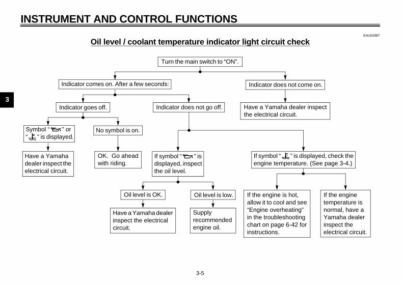
l “ ” is displayed, check the emperature. (See page 3-4.)
S“
e is hot, ool and see erheating” leshooting ge 6-42 for
s.
If the engine temperature is normal, have a Yamaha dealer inspect the electrical circuit.
E_5eb_Functions.fm Page 5 Thursday, November 18, 1999 4:03 PM
STRUMENT AND CONTROL FUNCTIONS
3-5
Oil level / coolant temperature indicator light circuit chE
Indicator comes on. After a few seconds: Indicator d
ave a Yamaha aler inspect the
ectrical circuit.
Turn the main switch to “ON”.
Have a Yamthe electrica
If symboengine t
Indicator goes off.
No symbol is on.ymbol “ ” or ” is displayed.
OK. Go ahead with riding.
Indicator does not go off.
If symbol “ ” is displayed, inspect the oil level.
Oil level is OK. Oil level is low.
Have a Yamaha dealer inspect the electrical circuit.
Supply recommended engine oil.
If the enginallow it to c“Engine ovin the troubchart on painstruction
NTROL FUNCTIONS
3
EAU01295
CB
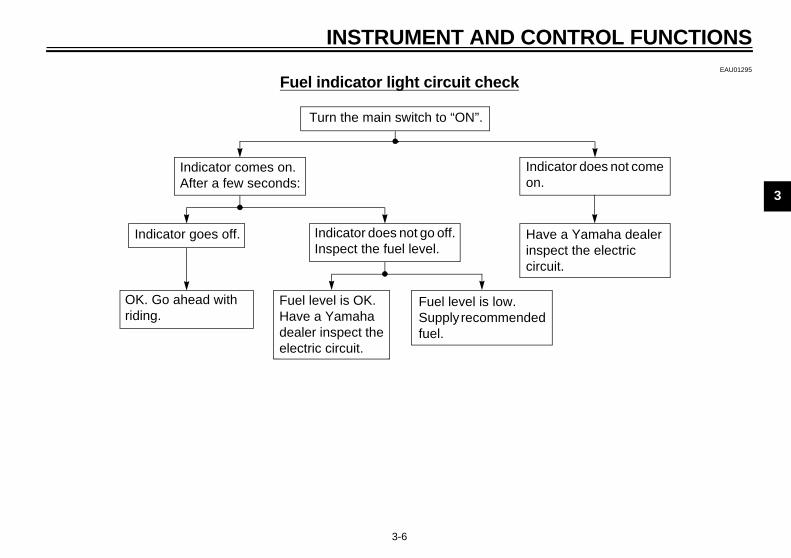
icator does not come .
ve a Yamaha dealer pect the electric cuit.
E_5eb_Functions.fm Page 6 Thursday, November 18, 1999 4:03 PM
INSTRUMENT AND CO
3-6
Fuel indicator light circuit check-69E
Turn the main switch to “ON”.
Indon
Hainscir
Indicator goes off. Indicator does not go off. Inspect the fuel level.
Indicator comes on.After a few seconds:
OK. Go ahead with riding.
Fuel level is OK.Have a Yamaha dealer inspect the electric circuit.
Fuel level is low.Supply recommendedfuel.

IN
3
DigThi
●
●
●
●
NO@
ForTo from“SEond@
etting a meterreset a trip odometer to 0.0, select itpushing the “SELECT” button andh the “RESET” button for at least second. To reset the fuel reserve
meter, select it by pushing theLECT” button and push theSET” button for at least one sec-. The display will return to “TRIP 1”.
ou do not reset the fuel reserve tripter manually, it will automatically re- and return to “TRIP 1” after refuel- and the motorcycle has traveledh 5 km and for approximately 3 min-s.
TE:r the fuel reserve trip meter is reset,
display always returns to theIP 1” mode. If “TRIP 2” was beingd before the fuel reserve trip meter
eset, be sure to push the “SELECT”ton to change back to the “TRIP 2”de.
1. S2. C3. “4. “
E_5eb_Functions.fm Page 7 Thursday, November 18, 1999 4:03 PM
STRUMENT AND CONTROL FUNCTIONS
3-7
EAU01601
ital speedometers speedometer is equipped with:
an odometertwo trip odometersa fuel reserve trip metera clock
TE: UK and USA models only:change the speedometer display kilometers to miles, press the
LECT” button for at least two sec-s.
Odometer and trip meter modesUse the trip meters to estimate how faryou can ride on a tank of fuel.Use the fuel reserve trip meter to seethe distance traveled from when thefuel level dropped to the reserve level.
Selecting a modePush the “SELECT” button to changebetween the odometer mode “ODO”and the trip odometer modes “TRIP 1”and “TRIP 2” in the following order:“ODO” → “TRIP 1” → “TRIP 2” →“ODO”
If the fuel level indicator light comes on(see page 3-2), the odometer displaywill automatically change to the fuel re-serve trip meter mode “TRIP F” andstart counting the distance traveledfrom that point. Push the “SELECT”button to change between the fuelodometer, trip odometer and odometermodes in the following order:“TRIP F” → “TRIP 1” → “TRIP 2” →“ODO” → “TRIP F”
ResTo by pusonetrip“SE“REondIf ymesetingbotute
NO@
Aftethe“TRuseis rbutmo@
peedometerlock, odometer
SELECT” buttonRESET” button
NTROL FUNCTIONS
3
CTom“RToodbu
To1
2
3
4
5
EAU00101
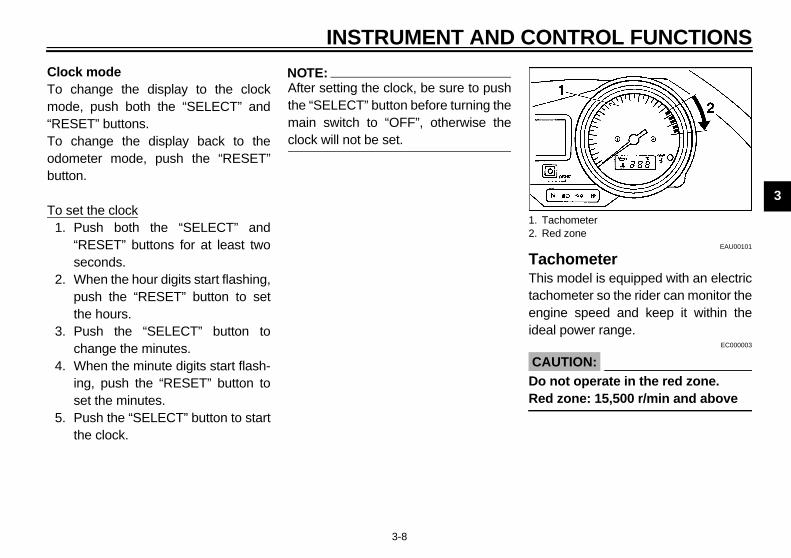
chometeris model is equipped with an electric
chometer so the rider can monitor thegine speed and keep it within theal power range.
EC000003
AUTION: not operate in the red zone.d zone: 15,500 r/min and above
TachometerRed zone
E_5eb_Functions.fm Page 8 Thursday, November 18, 1999 4:03 PM
INSTRUMENT AND CO
3-8
lock mode change the display to the clock
ode, push both the “SELECT” andESET” buttons. change the display back to theometer mode, push the “RESET”tton.
set the clock. Push both the “SELECT” and
“RESET” buttons for at least twoseconds.
. When the hour digits start flashing,push the “RESET” button to setthe hours.
. Push the “SELECT” button tochange the minutes.
. When the minute digits start flash-ing, push the “RESET” button toset the minutes.
. Push the “SELECT” button to startthe clock.
NOTE:@
After setting the clock, be sure to pushthe “SELECT” button before turning themain switch to “OFF”, otherwise theclock will not be set. @
TaThtaenide
C@
DoRe@
1.2.
IN
3
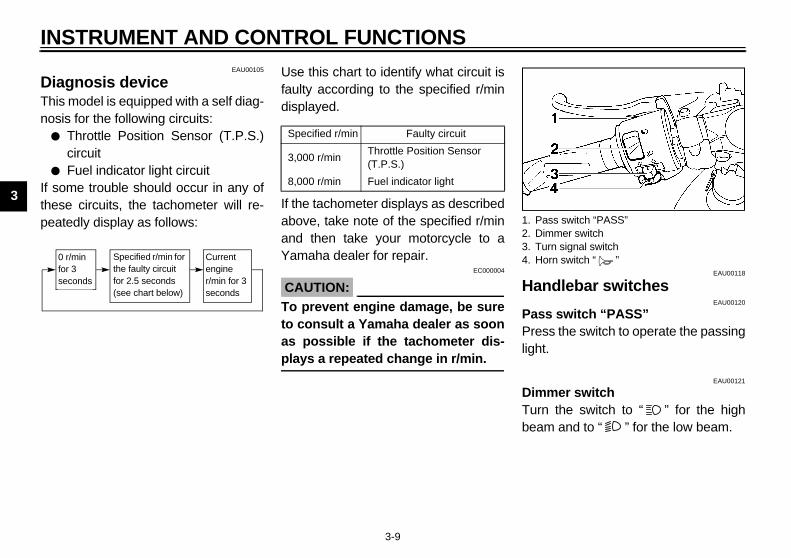
DiaThinos
●
●
If sthepeaCB-53
EAU00118
ndlebar switchesEAU00120
s switch “PASS”ss the switch to operate the passingt.
EAU00121
mer switchn the switch to “ ” for the highm and to “ ” for the low beam.
ass switch “PASS”immer switchurn signal switchorn switch “ ”
E_5eb_Functions.fm Page 9 Thursday, November 18, 1999 4:03 PM
STRUMENT AND CONTROL FUNCTIONS
3-9
EAU00105
gnosis devices model is equipped with a self diag-is for the following circuits:Throttle Position Sensor (T.P.S.)circuitFuel indicator light circuit
ome trouble should occur in any ofse circuits, the tachometer will re-tedly display as follows:
E
Use this chart to identify what circuit isfaulty according to the specified r/mindisplayed.CB-60E
If the tachometer displays as describedabove, take note of the specified r/minand then take your motorcycle to aYamaha dealer for repair.
EC000004
CAUTION:@
To prevent engine damage, be sureto consult a Yamaha dealer as soonas possible if the tachometer dis-plays a repeated change in r/min. @
Ha
PasPreligh
DimTurbea
0 r/min for 3 seconds
Specified r/min for the faulty circuit for 2.5 seconds (see chart below)
Current engine r/min for 3 seconds
Specified r/min Faulty circuit
3,000 r/minThrottle Position Sensor (T.P.S.)
8,000 r/min Fuel indicator light
1. P2. D3. T4. H

NTROL FUNCTIONS
3
TuToswtuswceputo
HPr
EAU01238
ht switchrning the light switch to “ ”,
rns on the auxiliary lights, meterhts and taillights. Turning the lightitch to “ ” turns the headlight ono.
EAU00143
art switch “ ”e starter motor cranks the engineen pushing the start switch.
EC000005
AUTION:e starting instructions prior torting the engine.
E_5eb_Functions.fm Page 10 Thursday, November 18, 1999 4:03 PM
INSTRUMENT AND CO
3-10
EAU00127
rn signal switch signal a right-hand turn, push theitch to “ ”. To signal a left-hand
rn, push the switch to “ ”. Once theitch is released it will return to thenter position. To cancel the signal,sh the switch in after it has returned
the center position.
EAU00129
orn switch “ ”ess the switch to sound the horn. EAU00138
Engine stop switchThe engine stop switch is a safety de-vice for use in an emergency such aswhen the motorcycle overturns or iftrouble occurs in the throttle system.Turn the switch to “ ” to start the en-gine. In case of emergency, turn theswitch to “ ” to stop the engine.
LigTutuligswals
StThwh
C@
Sesta@
1. Engine stop switch2. Lights switch3. Start switch “ ”

IN
3
CluThehanoff levhanreleThereleatiocedcirc
EAU00161
nt brake lever front brake lever is located on thet handlebar and is equipped with ake lever adjusting dial. To activate front brake, pull the lever toward handlebar.
E_5eb_Functions.fm Page 11 Thursday, November 18, 1999 4:03 PM
STRUMENT AND CONTROL FUNCTIONS
3-11
EAU00152
tch lever clutch lever is located on the leftdlebar, and the ignition circuit cut-system is incorporated in the clutcher holder. Pull the clutch lever to thedlebar to disengage the clutch, andase the lever to engage the clutch. lever should be pulled rapidly andased slowly for smooth clutch oper-n. (Refer to the engine starting pro-ures for a description of the ignitionuit cut-off system.)
EAU00157
Shift pedalThis motorcycle is equipped with a con-stant-mesh 6-speed transmission.The shift pedal is located on the leftside of the engine and is used in com-bination with the clutch when shifting.
FroTherighbrathethe
1. Shift pedal

NTROL FUNCTIONS
3
Totupuseis
EAU00109
ntitheft alarm (optional) antitheft alarm can be equipped to
is motorcycle. Consult your Yamahaaler to obtain and install the alarm.
1.2.a.
E_5eb_Functions.fm Page 12 Thursday, November 18, 1999 4:03 PM
INSTRUMENT AND CO
3-12
adjust the front brake lever position,rn the brake lever adjusting dial whilelling the lever forward. Make sure thetting on the brake lever adjusting dial
aligned with the arrow mark.
EAU00162
Rear brake pedalThe rear brake pedal is on the rightside of the motorcycle. Press down onthe brake pedal to apply the rear brake.
AAnthde
Lever position adjusting dialArrow markLever distance
1. Rear brake pedal

IN
3
FuTo Opturnbe ope
To Pukeycoution
EAU01183
elke sure there is sufficient fuel in thek. Fill the fuel tank to the bottom of filler tube as shown in the illustra-.
EW000130
WARNINGnot overfill the fuel tank. Avoidling fuel on the hot engine. Do fill the fuel tank above the bot- of the filler tube or it may over- when the fuel heats up later andands.
1. L2. O
iller tubeuel level
E_5eb_Functions.fm Page 13 Thursday, November 18, 1999 4:03 PM
STRUMENT AND CONTROL FUNCTIONS
3-13
EAU02935
el tank capopenen the lock cover. Insert the key and it 1/4 turn clockwise. The lock willreleased and the cap can bened.
closesh the tank cap into position with the inserted. To remove the key, turn itnterclockwise to the original posi-. Then, close the lock cover.
NOTE:@
This tank cap cannot be closed unlessthe key is in the lock. The key cannotbe removed if the cap is not lockedproperly. @
EW000023
WARNING@
Be sure the cap is properly installedand locked in place before riding themotorcycle. @
FuMatanthetion
@
Do spilnottomflowexp@
ock coverpen
1. F2. F
NTROL FUNCTIONS
3
C@
AlatFues@
N@
If feta@
E_5eb_Functions.fm Page 14 Thursday, November 18, 1999 4:03 PM
INSTRUMENT AND CO
3-14
EAU00185
AUTION:ways wipe off spilled fuel immedi-ely with a dry and clean soft cloth.el may deteriorate painted surfac- or plastic parts.
EAU00191
OTE:knocking or pinging occurs, use a dif-rent brand of gasoline or higher oc-ne grade.
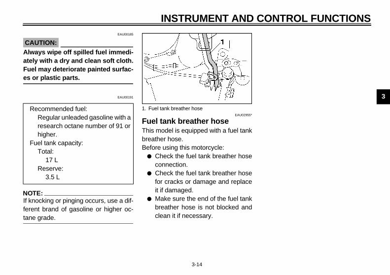
EAU02955*
Fuel tank breather hoseThis model is equipped with a fuel tankbreather hose.Before using this motorcycle:
● Check the fuel tank breather hoseconnection.
● Check the fuel tank breather hosefor cracks or damage and replaceit if damaged.
● Make sure the end of the fuel tankbreather hose is not blocked andclean it if necessary.
Recommended fuel:Regular unleaded gasoline with a research octane number of 91 or higher.
Fuel tank capacity:Total:
17 LReserve:
3.5 L
1. Fuel tank breather hose
IN
3
StaStaair-cuiMostaMosta
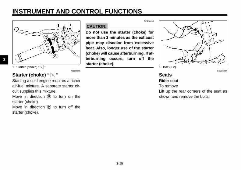
EAU01890
atser seatremove up the rear corners of the seat aswn and remove the bolts.
1. S olt (× 2)
E_5eb_Functions.fm Page 15 Thursday, November 18, 1999 4:03 PM
STRUMENT AND CONTROL FUNCTIONS
3-15
EAU02973
rter (choke) “ ”rting a cold engine requires a richerfuel mixture. A separate starter cir-t supplies this mixture.ve in direction a to turn on therter (choke).ve in direction b to turn off therter (choke).
ECA00038
CAUTION:@
Do not use the starter (choke) formore than 3 minutes as the exhaustpipe may discolor from excessiveheat. Also, longer use of the starter(choke) will cause afterburning. If af-terburning occurs, turn off thestarter (choke). @
SeRidTo Liftsho
tarter (choke) “ ” 1. B

NTROL FUNCTIONS
3
ToInsebo
installsert the projection on the rear of theat into the seat holder and pushwn on the front of the seat.
TE:ake sure that the seats are securelyed.
1.2.
ProjectionSeat holder
E_5eb_Functions.fm Page 16 Thursday, November 18, 1999 4:03 PM
INSTRUMENT AND CO
3-16
installsert the projection on the front of theat into the seat holder and install thelts.
Passenger seatTo removeInsert the key into the seat lock andturn it counterclockwise. While holdingthe key in that position, lift up the frontof the seat and pull it forward.
ToInsedo
NO@
Mfitt@
ProjectionSeat holder
1. Passenger seat lock2. Open
1.2.

IN
3
HeRetheins
@
Nemejecpos@
EAU01862*
nt fork adjustments front fork is equipped with springload and damping force adjusters.
EW000037
WARNINGh fork leg must be set to thee pressure. Uneven setting can
se poor handling and loss of sta-y. 1. H
E_5eb_Functions.fm Page 17 Thursday, November 18, 1999 4:03 PM
STRUMENT AND CONTROL FUNCTIONS
3-17
EAU00265
lmet holdermove the passenger seat and hook helmet into the helmet holder. Thentall the passenger seat.
EW000030
WARNINGver ride with a helmet in the hel-t holder. The helmet may hit ob-ts, causing loss of control andsibly an accident.
EAU01242
Storage compartmentThe storage compartment is locatedunder the passenger seat. (Refer topage 3-15 for details on how to openthe seat.)
EW000033
WARNING@
Do not exceed maximum load. Maxi-mum load: 3 kg@
FroThipre
@
Eacsamcaubilit@
elmet holder 1. Storage compartment
NTROL FUNCTIONS
3
AdTucrtoprfro
C@
Thththfo@
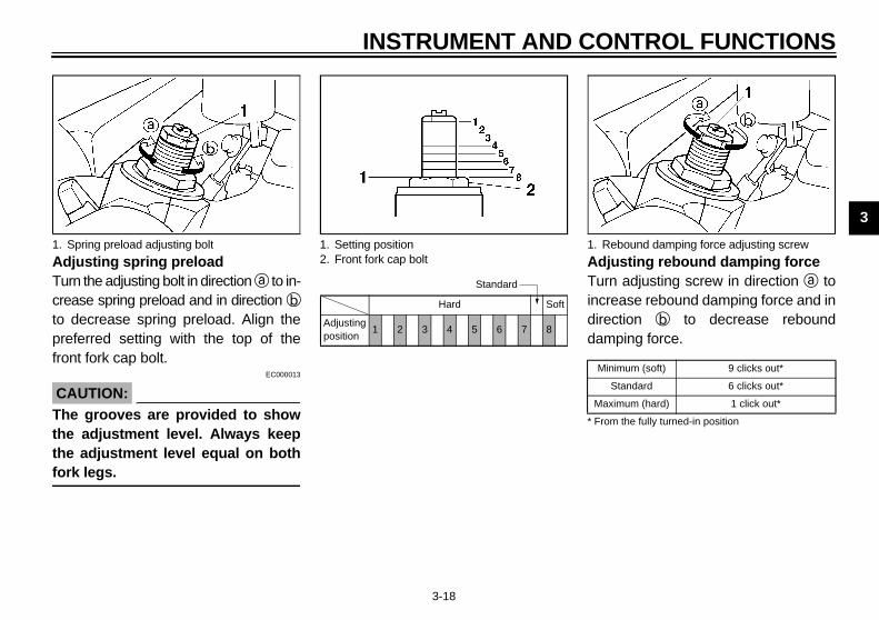
justing rebound damping forcern adjusting screw in direction a torease rebound damping force and inection b to decrease reboundmping force.
3E
1. Rebound damping force adjusting screw
inimum (soft) 9 clicks out*
Standard 6 clicks out*
aximum (hard) 1 click out*
rom the fully turned-in position
E_5eb_Functions.fm Page 18 Thursday, November 18, 1999 4:03 PM
INSTRUMENT AND CO
3-18
justing spring preloadrn the adjusting bolt in direction a to in-
ease spring preload and in direction b decrease spring preload. Align theeferred setting with the top of thent fork cap bolt.
EC000013
AUTION:e grooves are provided to show
e adjustment level. Always keepe adjustment level equal on bothrk legs.
AdTuincdirdaCI-3
Spring preload adjusting bolt 1. Setting position2. Front fork cap bolt
CI-18E
Hard Soft
Adjusting position
1 2 3 4 5 6 7 8
Standard
1.
M
M
* F
IN
3
AdforcTurto forccomCI-33
CA@
Nebeyset@
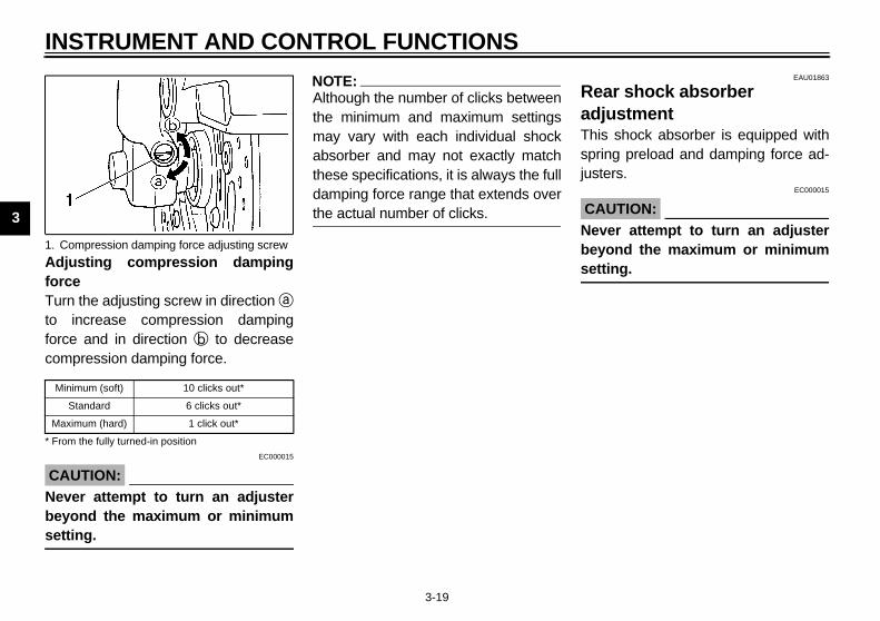
EAU01863
ar shock absorber justments shock absorber is equipped withing preload and damping force ad-ers.
EC000015
UTION:er attempt to turn an adjusterond the maximum or minimumting.
1. C
M
Ma
* Fro
E_5eb_Functions.fm Page 19 Thursday, November 18, 1999 4:03 PM
STRUMENT AND CONTROL FUNCTIONS
3-19
justing compression dampingen the adjusting screw in direction aincrease compression dampinge and in direction b to decreasepression damping force.
E
EC000015
UTION:ver attempt to turn an adjusterond the maximum or minimum
ting.
NOTE:@
Although the number of clicks betweenthe minimum and maximum settingsmay vary with each individual shockabsorber and may not exactly matchthese specifications, it is always the fulldamping force range that extends overthe actual number of clicks. @
ReadThisprjust
CA@
Nevbeyset
ompression damping force adjusting screw
inimum (soft) 10 clicks out*
Standard 6 clicks out*
ximum (hard) 1 click out*
m the fully turned-in position

NTROL FUNCTIONS
3
AdTucrtoMthsisoCI-
justing compression dampingrcern the adjusting screw in direction a
increase compression dampingrce and in direction b to decreasempression damping force.4E
1.2.3.
Ap
Compression damping force adjusting screw
inimum (soft) 13 clicks out*
Standard 7 clicks out*
aximum (hard) 1 click out*
rom the fully turned-in position
E_5eb_Functions.fm Page 20 Thursday, November 18, 1999 4:03 PM
INSTRUMENT AND CO
3-20
justing spring preloadrn the adjusting ring in direction a to in-
ease spring preload and in direction b decrease spring preload.ake sure that the appropriate notch ine adjusting ring is aligned with the po-tion indicator on the rear shock ab-rber.
18E
Adjusting rebound damping forceTurn the adjusting knob in direction ato increase rebound damping force andin direction b to decrease rebounddamping force.CI-34E
AdfoTutofocoCI-3
Spring preload adjusting ringSpecial wrenchPosition indicator
HardStan-dard
Soft
djusting osition
9 8 7 6 5 4 3 2 1
1. Rebound damping force adjusting knob
Minimum (soft) 25 clicks out*
Standard 9 clicks out*
Maximum (hard) 1 click out*
* From the fully turned-in position
1.
M
M
* F

IN
3
NO@
Alththemaabsthedamthe@
E_5eb_Functions.fm Page 21 Thursday, November 18, 1999 4:03 PM
STRUMENT AND CONTROL FUNCTIONS
3-21
TE:ough the number of clicks between
minimum and maximum settingsy vary with each individual shockorber and may not exactly matchse specifications, it is always the full
ping force range that extends over actual number of clicks.
EAU00315
WARNING@
This shock absorber contains high-ly pressurized nitrogen gas. Readand understand the following infor-mation before handling the shockabsorber. The manufacturer cannotbe held responsible for propertydamage or personal injury that mayresult from improper handling.
● Do not tamper with or attempt toopen the cylinder assembly.
● Do not subject the shock ab-sorber to an open flame or otherhigh heat source. This maycause the unit to explode due toexcessive gas pressure.
● Do not deform or damage thecylinder in any way. Cylinderdamage will result in poordamping performance.
● Take your shock absorber to aYamaha dealer for any service.
@
NTROL FUNCTIONS
3
EAU01580
R er settingsUCI-
EC000016
C@
N@
L r shock absorber adjustment
Compression damping force
Rebound damping force
4 ~ 13 3 ~ 25
1 ~ 8 1 ~ 7
E_5eb_Functions.fm Page 22 Thursday, November 18, 1999 4:03 PM
INSTRUMENT AND CO
3-22
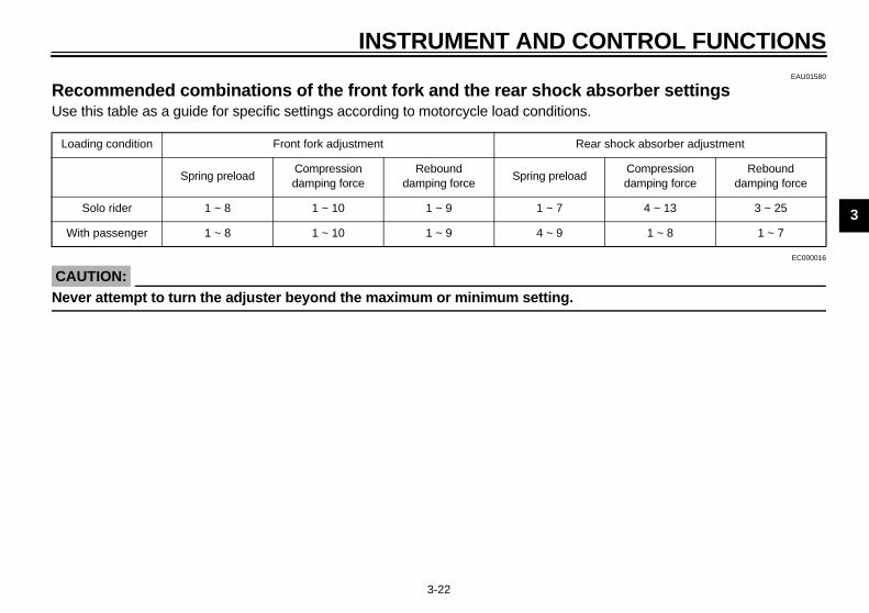
ecommended combinations of the front fork and the rear shock absorbse this table as a guide for specific settings according to motorcycle load conditions.31E
AUTION:ever attempt to turn the adjuster beyond the maximum or minimum setting.
oading condition Front fork adjustment Rea
Spring preload Compression damping force
Rebound damping force
Spring preload
Solo rider 1 ~ 8 1 ~ 10 1 ~ 9 1 ~ 7
With passenger 1 ~ 8 1 ~ 10 1 ~ 9 4 ~ 9
IN
3
LuThebel
EW000044
WARNINGs motorcycle must not be operat-with the sidestand in the downition. If the stand is not properlyacted, it could contact theund and distract the operator, re-ing in a possible loss of control.aha has designed into this
torcycle a lockout system to as- the operator in fulfilling the re-nsibility of retracting thestand. Please check carefully
operating instructions listed be- and if there is any indication of alfunction, return the motorcycle Yamaha dealer immediately for
air.
1. L
E_5eb_Functions.fm Page 23 Thursday, November 18, 1999 4:03 PM
STRUMENT AND CONTROL FUNCTIONS
3-23
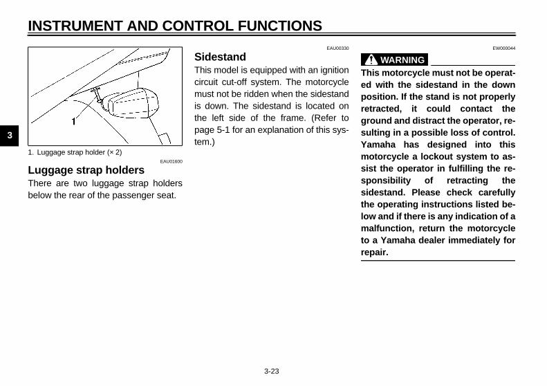
EAU01600
ggage strap holdersre are two luggage strap holders
ow the rear of the passenger seat.
EAU00330
SidestandThis model is equipped with an ignitioncircuit cut-off system. The motorcyclemust not be ridden when the sidestandis down. The sidestand is located onthe left side of the frame. (Refer topage 5-1 for an explanation of this sys-tem.)
@
Thied posretrgrosultYammosistsposidethelowmato arep@
uggage strap holder (× 2)
NTROL FUNCTIONS
3
SopCswfoCD
TA“
TS
PP
E
S
C
E_5eb_Functions.fm Page 24 Thursday, November 18, 1999 4:03 PM
INSTRUMENT AND CO
3-24
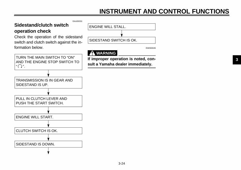
EAU00331
idestand/clutch switch eration check
heck the operation of the sidestanditch and clutch switch against the in-
rmation below.-11E
EW000045
WARNING@
If improper operation is noted, con-sult a Yamaha dealer immediately. @
URN THE MAIN SWITCH TO “ON” ND THE ENGINE STOP SWITCH TO
”.
RANSMISSION IS IN GEAR AND IDESTAND IS UP.
ULL IN CLUTCH LEVER AND USH THE START SWITCH.
NGINE WILL START.
IDESTAND IS DOWN.
LUTCH SWITCH IS OK.
ENGINE WILL STALL.
SIDESTAND SWITCH IS OK.

E_5eb_Functions.fm Page 25 Thursday, November 18, 1999 4:03 PM

4
PRE-OPERATION CHECKS
Pre-operation check list...................................................................... 4-1
E_5eb_PreopTOC.fm Page 1 Thursday, November 18, 1999 4:04 PM

4
EAU01114
al functions can start to deterioratelements). Any damage, fluid leak ort, in addition to a thorough visual in-
E_5eb_Preop.fm Page 1 Thursday, November 18, 1999 4:05 PM
4-PR
Owquicloss
EAU00340
PAGE
6-25 ~ 6-28
6-25 ~ 6-28
6-25
6-21, 6-30
6-10 ~ 6-13
6-13 ~ 6-16
6-28 ~ 6-29
6-21 ~ 6-246-37 ~ 6-40
6-30
6-30
6-31
spe
Fro
Re
Clu
Th
En
Co
Dri
Wh
Co
Bra
Brapiv
4-1
E-OPERATION CHECKS
ners are personally responsible for their vehicle’s condition. Your motorcycle’s vitkly and unexpectedly, even if it remains unused (for instance, if it is exposed to the e of tire pressure could have serious consequences. Therefore, it is very important thaction, you check the following points before each ride.
PRE-OPERATION CHECK LISTITEM CHECKS
nt brake • Check operation, free play, fluid level and fluid leakage.• Fill with DOT 4 brake fluid if necessary.ar brake
tch • Check operation condition and free play.• Adjust if necessary.
rottle grip and housing • Check for smooth operation.• Lubricate if necessary.
gine oil • Check oil level.• Fill with oil if necessary.
olant reservoir tank • Check coolant level.• Fill with coolant if necessary.
ve chain • Check chain slack and condition.• Adjust if necessary.
eels and tires • Check tire pressure, wear and damage.
ntrol cable • Check for smooth operation. • Lubricate if necessary.
ke pedal shaft • Check for smooth operation. • Lubricate if necessary.
ke and clutch lever ots
• Check for smooth operation. • Lubricate if necessary.

PERATION CHECKS
4NPr spection can be thoroughly accom-pl e involved.
If nd repaired before operatingth
S 6-31
C ed. —
F 3-13 ~ 3-14
Ls 6-35 ~ 6-36
PAGE
E_5eb_Preop.fm Page 2 Thursday, November 18, 1999 4:05 PM
PRE-O
4-2
OTE:e-operation checks should be made each time the motorcycle is used. Such an inished in a very short time; and the added safety it assures is more than worth the tim
WARNINGany item in the PRE-OPERATION CHECK is not working properly, have it inspected ae motorcycle.
idestand pivot • Check for smooth operation. • Lubricate if necessary.
hassis fasteners • Make sure that all nuts, bolts and screws are properly tighten• Tighten if necessary.
uel tank • Check fuel level.• Fill with fuel if necessary.
ights, signals and witches • Check for proper operation.
ITEM CHECKS

E_5eb_Preop.fm Page 3 Thursday, November 18, 1999 4:05 PM

5
OPERATION AND IMPORTANT RIDING POINTS
Starting the engine............................................................................. 5-1Starting a warm engine ...................................................................... 5-3Shifting ............................................................................................... 5-4Tips for reducing fuel consumption .................................................... 5-4Engine break-in .................................................................................. 5-5Parking ............................................................................................... 5-5
E_5eb_OperationTOC.fm Page 1 Thursday, November 18, 1999 4:05 PM

5
EAU00372
E_5eb_Operation.fm Page 1 Thursday, November 18, 1999 4:05 PM
5-OP
@
●
●
●
@
5-1
ERATION AND IMPORTANT RIDING POINTSEAU00373
WARNINGBefore riding this motorcycle,become thoroughly familiarwith all operating controls andtheir functions. Consult aYamaha dealer regarding anycontrol or function that you donot thoroughly understand.Never start your engine or let itrun for any length of time in aclosed area. The exhaust fumesare poisonous and can causeloss of consciousness anddeath within a short time. Al-ways operate your motorcyclein an area with adequate ventila-tion.Before starting out, always besure the sidestand is up. Failureto retract the sidestand com-pletely can result in a seriousaccident when you try to turn acorner.
EAU01382*
Starting the engine
NOTE:@
This motorcycle is equipped with an ig-nition circuit cut-off system. The enginecan be started only under one of thefollowing conditions:
● The transmission is in neutral.● The sidestand is up, the transmis-
sion is in gear and the clutch is dis-engaged.
The motorcycle must not be riddenwhen the sidestand is down. @
EW000054
WARNING@
Before going through the followingsteps, check the function of thesidestand switch and clutch switch.(Refer to page 3-24.) @

ANT RIDING POINTS
5
CF
IN GEAR AND
H LEVER AND PUSH START E WILL START.
BE RIDDEN.
E_5eb_Operation.fm Page 2 Thursday, November 18, 1999 4:05 PM
OPERATION AND IMPORT
5-2
-28E
TURN THE MAIN SWITCH TO “ON” AND THE ENGINE STOP SWITCH TO “ ”.
IF TRANSMISSION IS IN NEUTRAL AND SIDESTAND IS DOWN,
PUSH THE START SWITCH.ENGINE WILL START.
RETRACT THE SIDESTAND AND PUT TRANSMISSION IN GEAR.
IF TRANSMISSION ISSIDESTAND IS UP,
PULL IN THE CLUTCTHE SWITCH. ENGIN
MOTORCYCLE CAN BE RIDDEN. MOTORCYCLE CAN
O
5
1.
CA@
ThedicshoanddoespocheCO@
2.
NO@
WhneutheYa@
3.
4.
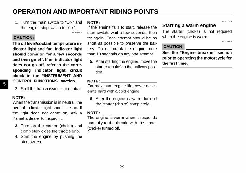
EAU01258
rting a warm engine starter (choke) is not requiredn the engine is warm.
EC000046
UTION: the “Engine break-in” sectionr to operating the motorcycle for first time.
E_5eb_Operation.fm Page 3 Thursday, November 18, 1999 4:05 PM
PERATION AND IMPORTANT RIDING POINTS
5-3
Turn the main switch to “ON” andthe engine stop switch to “ ”.
ECA00005
UTION: oil level/coolant temperature in-
ator light and fuel indicator lightuld come on for a few seconds then go off. If an indicator lights not go off, refer to the corre-nding indicator light circuitck in the “INSTRUMENT ANDNTROL FUNCTIONS” section.
Shift the transmission into neutral.
TE:en the transmission is in neutral, thetral indicator light should be on. If
light does not come on, ask amaha dealer to inspect it.
Turn on the starter (choke) andcompletely close the throttle grip.Start the engine by pushing thestart switch.
NOTE:@
If the engine fails to start, release thestart switch, wait a few seconds, thentry again. Each attempt should be asshort as possible to preserve the bat-tery. Do not crank the engine morethan 10 seconds on any one attempt. @
5. After starting the engine, move thestarter (choke) to the halfway posi-tion.
NOTE:@
For maximum engine life, never accel-erate hard with a cold engine! @
6. After the engine is warm, turn offthe starter (choke) completely.
NOTE:@
The engine is warm when it respondsnormally to the throttle with the starter(choke) turned off. @
StaThewhe
CA@
Seepriothe@

ANT RIDING POINTS
5SThama clpeTopeensl
EAU00424
ps for reducing fuel nsumptionur motorcycle’s fuel consumptionpends to a large extent on youring style. The following tips can helpduce fuel consumption:● Warm up the engine before riding.● Turn off the starter (choke) as
soon as possible.● Shift up swiftly and avoid high en-
gine speeds during acceleration.● Do not double-clutch or rev the en-
gine while shifting down and avoidhigh engine speeds with no loadon the engine.
● Turn off the engine instead of let-ting it idle for an extended lengthof time, i.e. in traffic jams, at trafficlights or railroad crossings.
1.N.
E_5eb_Operation.fm Page 4 Thursday, November 18, 1999 4:05 PM
OPERATION AND IMPORT
5-4
EAU00423
hiftinge transmission lets you control theount of power you have available at
given speed for starting, accelerating,imbing hills, etc. The use of the shiftdal is shown in the illustration. shift into neutral, depress the shiftdal repeatedly until it reaches thed of its travel, then raise the pedal
ightly.
EC000048
CAUTION:@
● Do not coast for long periodswith the engine off, and do nottow the motorcycle a long dis-tance. Even with gears in neu-tral, the transmission is onlyproperly lubricated when theengine is running. Inadequatelubrication may damage thetransmission.
● Always use the clutch whenchanging gears. The engine,transmission, and driveline arenot designed to withstand theshock of forced shifting and canbe damaged by shifting withoutusing the clutch.
@
TicoYoderidre
Shift pedalNeutral

O
5
EnThein tperthisreatheput1,6gincorthisatiosulmu
EAU00460
rkingen parking the motorcycle, stop theine and remove the ignition key.
EW000058
WARNING exhaust system is hot. Park the
torcycle in a place where pedes-ns or children are not likely toch the motorcycle. Do not park motorcycle on a slope or softund; the motorcycle may over-.
E_5eb_Operation.fm Page 5 Thursday, November 18, 1999 4:05 PM
PERATION AND IMPORTANT RIDING POINTS
5-5
EAU01128
gine break-inre is never a more important periodhe life of your motorcycle than theiod between zero and 1,600 km. For reason we ask that you carefullyd the following material. Because engine is brand new, you must not an excessive load on it for the first00 km. The various parts in the en-e wear and polish themselves to therect operating clearances. During period, prolonged full throttle oper-n, or any condition which might re-
t in excessive heating of the engine,st be avoided.
EAU01329
0 ~ 1,000 kmAvoid operation above 5,000 r/min.
1,000 ~ 1,600 kmAvoid cruising speeds in excess of6,000 r/min.
EC000052
CAUTION:@
After 1,000 km of operation, be sureto replace the engine oil and oil fil-ter. @
1,600 km and beyondProceed with normal riding.
EC000053
CAUTION:@
● Never let engine speeds enterthe red zone.
● If any engine trouble should oc-cur during the break-in period,consult a Yamaha dealer imme-diately.
@
PaWheng
@
Themotriatouthegroturn@

6
PERIODIC MAINTENANCE AND MINOR REPAIR
Tool kit...................................................................6-1Periodic maintenance and lubrication...................6-3Cowling and panel removal and installation..........6-6Cowlings A and B .................................................6-6Panel C .................................................................6-8Spark plug inspection ...........................................6-9Engine oil ............................................................6-10Cooling system ...................................................6-13Changing the coolant..........................................6-14Air filter ...............................................................6-17Air intake duct .....................................................6-19Carburetor adjustment ........................................6-20Idle speed adjustment ........................................6-20Throttle cable free play inspection ......................6-21Valve clearance adjustment ................................6-21Tires....................................................................6-21Wheels................................................................6-24Clutch lever free play adjustment........................6-25Brake light switch adjustment .............................6-25Checking the front and rear brake pads..............6-26Inspecting the brake fluid level............................6-27Brake fluid replacement ......................................6-28Drive chain slack check ......................................6-28
Drive chain slack adjustment ............................. 6-29Drive chain lubrication........................................ 6-29Cable inspection and lubrication ........................ 6-30Throttle cable and grip lubrication...................... 6-30Brake pedal lubrication....................................... 6-30Brake and clutch lever lubrication ...................... 6-31Sidestand lubrication.......................................... 6-31Rear suspension lubrication............................... 6-31Front fork inspection........................................... 6-32Steering inspection ............................................ 6-32Wheel bearings .................................................. 6-33Battery................................................................ 6-33Fuse replacement .............................................. 6-34Headlight bulb replacement ............................... 6-35Tail/brake light bulb replacement........................ 6-36Turn signal light bulb replacement...................... 6-36Supporting the motorcycle ................................. 6-37Front wheel removal........................................... 6-37Front wheel installation ...................................... 6-38Rear wheel removal ........................................... 6-39Rear wheel installation....................................... 6-40Troubleshooting.................................................. 6-40Troubleshooting chart......................................... 6-41
E_5eb_PeriodicTOC.fm Page 1 Thursday, November 18, 1999 4:06 PM

6
EAU00462
E_5eb_Periodic.fm Page 1 Thursday, November 18, 1999 4:06 PM
6-PE
Perbric
EAU01129
ol kit tool kit is located inside the storagepartment. (See page 3-17 for com-
tment opening procedures.) Thels provided in the owner’s tool kit aressist you in the performance of pe-ic maintenance. However, someer tools such as a torque wrench are necessary to perform the mainte-ce correctly. service information included in this
nual is intended to provide you, theer, with the necessary information
completing some of your own pre-tive maintenance and minor re-rs.
ool kit
the posmoandbe geninteCOTERTIOUATHATIMTERROof mandlow
@
If ycycdon@
6-1
RIODIC MAINTENANCE AND MINOR REPAIREAU00464
iodic inspection, adjustment and lu-ation will keep your motorcycle insafest and most efficient conditionsible. Safety is an obligation of thetorcycle owner. The maintenance lubrication schedule chart shouldconsidered strictly as a guide toeral maintenance and lubricationrvals. YOU MUST TAKE INTONSIDERATION THAT WEATHER,RAIN, GEOGRAPHICAL LOCA-
NS, AND A VARIETY OF INDIVID-L USES ALL TEND TO DEMAND
T EACH OWNER ALTER THISE SCHEDULE TO SHORTER IN-VALS TO MATCH THE ENVI-
NMENT. The most important pointsotorcycle inspection, adjustment,
lubrication are explained in the fol-ing pages.
EW000060
WARNINGou are not familiar with motor-le service, this work should bee by a Yamaha dealer.
EAU01296
CAUTION:@
Do not test this motorcycle on a dy-namometer for an extended periodof time as discoloration to the fiberconstructed muffler may occur fromthe heat. @
ToThecompartooto ariodothalsonanThemaownfor venpai
1. T

AND MINOR REPAIR
6
N@
If quyose@
@
Maploemusfo@
E_5eb_Periodic.fm Page 2 Thursday, November 18, 1999 4:06 PM
PERIODIC MAINTENANCE
6-2
OTE:you do not have necessary tools re-ired during a service operation, takeur motorcycle to a Yamaha dealer forrvice.
EW000062
WARNINGodifications to this motorcycle notproved by Yamaha may cause
ss of performance, excessiveissions, and render it unsafe for
e. Consult a Yamaha dealer be-re attempting any changes.
PE
6
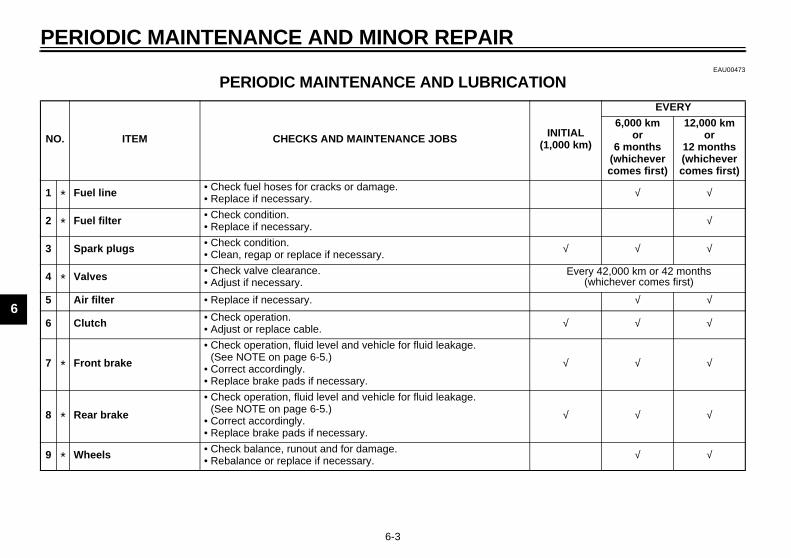
EAU00473
ONCP-01
NO INITIAL(1,000 km)
EVERY
6,000 km or
6 months(whichevercomes first)
12,000 km or
12 months(whichevercomes first)
1 √ √
2 √
3 √ √ √
4 Every 42,000 km or 42 months (whichever comes first)
5 √ √
6 √ √ √
7 √ √ √
8 √ √ √
9 √ √
E_5eb_Periodic.fm Page 3 Thursday, November 18, 1999 4:06 PM
RIODIC MAINTENANCE AND MINOR REPAIR
6-3
PERIODIC MAINTENANCE AND LUBRICATIE
. ITEM CHECKS AND MAINTENANCE JOBS
* Fuel line • Check fuel hoses for cracks or damage. • Replace if necessary.
* Fuel filter • Check condition. • Replace if necessary.
Spark plugs • Check condition. • Clean, regap or replace if necessary.
* Valves • Check valve clearance. • Adjust if necessary.
Air filter • Replace if necessary.
Clutch • Check operation. • Adjust or replace cable.
* Front brake
• Check operation, fluid level and vehicle for fluid leakage. (See NOTE on page 6-5.)
• Correct accordingly.• Replace brake pads if necessary.
* Rear brake
• Check operation, fluid level and vehicle for fluid leakage. (See NOTE on page 6-5.)
• Correct accordingly.• Replace brake pads if necessary.
* Wheels • Check balance, runout and for damage. • Rebalance or replace if necessary.
AND MINOR REPAIR
6
10 √ √
11 √ √
12 √ √
13 Every 1,000 km and after washing themotorcycle or riding in the rain
14 √ √
15 √ √
16 √ √
17 √ √ √
18 √ √
19 √ √
N INITIAL(1,000 km)
EVERY
6,000 km or
6 months(whichevercomes first)
12,000 km or
12 months(whichevercomes first)
E_5eb_Periodic.fm Page 4 Thursday, November 18, 1999 4:06 PM
PERIODIC MAINTENANCE
6-4
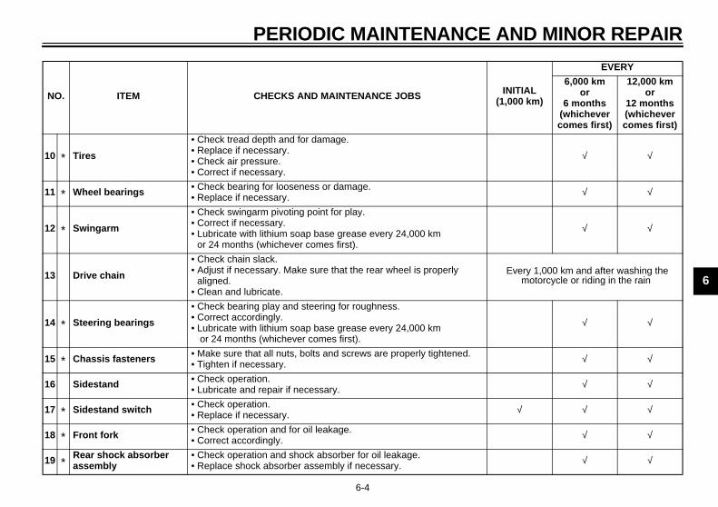
* Tires
• Check tread depth and for damage.• Replace if necessary.• Check air pressure.• Correct if necessary.
* Wheel bearings • Check bearing for looseness or damage. • Replace if necessary.
* Swingarm
• Check swingarm pivoting point for play.• Correct if necessary. • Lubricate with lithium soap base grease every 24,000 km
or 24 months (whichever comes first).
Drive chain
• Check chain slack. • Adjust if necessary. Make sure that the rear wheel is properly
aligned.• Clean and lubricate.
* Steering bearings
• Check bearing play and steering for roughness.• Correct accordingly. • Lubricate with lithium soap base grease every 24,000 km
or 24 months (whichever comes first).
* Chassis fasteners • Make sure that all nuts, bolts and screws are properly tightened.• Tighten if necessary.
Sidestand • Check operation.• Lubricate and repair if necessary.
* Sidestand switch • Check operation. • Replace if necessary.
* Front fork • Check operation and for oil leakage. • Correct accordingly.
*Rear shock absorber assembly
• Check operation and shock absorber for oil leakage. • Replace shock absorber assembly if necessary.
O. ITEM CHECKS AND MAINTENANCE JOBS

PE
6
* SiEAU02970*
NO@
● as.●
fluid. Check the brake fluid level
ery two years.
@
20 √ √
21 √ √
22 √ √
23 √
24 √ √
NO IAL0 km)
EVERY
6,000 km or
6 months(whichevercomes first)
12,000 km or
12 months(whichevercomes first)
E_5eb_Periodic.fm Page 5 Thursday, November 18, 1999 4:06 PM
RIODIC MAINTENANCE AND MINOR REPAIR
6-5
nce these items require special tools, data and technical skills, they should be serviced by a Yamaha dealer.
TE:The air filter needs more frequent service if you are riding in unusually wet or dusty areHydraulic brake system• When disassembling the master cylinder or caliper cylinder, always replace the brake
regularly and fill as required.• Replace the oil seals on the inner parts of the master cylinder and caliper cylinder ev• Replace the brake hoses every four years or if cracked or damaged.
*Rear suspension relay arm and connecting arm pivoting points
• Check operation. • Correct if necessary.
* Carburetors • Check engine idling speed, synchronization and starter operation. • Adjust if necessary. √
Engine oil• Check oil level and vehicle for oil leakage. • Correct if necessary.• Change. (Warm engine before draining.)
√
Engine oil filter cartridge • Replace. √
* Cooling system
• Check coolant level and vehicle for coolant leakage.• Correct if necessary.• Change coolant every 24,000 km or 24 months (whichever comes
first).
. ITEM CHECKS AND MAINTENANCE JOBS INIT(1,00

AND MINOR REPAIR
6
CanThneofcha or
1.
2.
Screw (× 6)
E_5eb_Periodic.fm Page 6 Thursday, November 18, 1999 4:06 PM
PERIODIC MAINTENANCE
6-6
EAU01139
owling and panel removal d installatione cowlings and panels illustrateded to be removed to perform some
the maintenance described in thisapter. Refer to this section each timecowling or panel has to be removed reinstalled.
EAU01602
Cowlings A and BTo remove
1. Remove the screws.
Cowling A (right side) Cowling B (left side)Panel C
1. Screw (× 5) 1.
PE
6
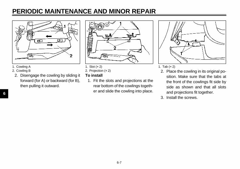
2.Place the cowling in its original po-sition. Make sure that the tabs atthe front of the cowlings fit side byside as shown and that all slotsand projections fit together.Install the screws.
1. C2. C
ab (× 2)
E_5eb_Periodic.fm Page 7 Thursday, November 18, 1999 4:06 PM
RIODIC MAINTENANCE AND MINOR REPAIR
6-7
Disengage the cowling by sliding itforward (for A) or backward (for B),then pulling it outward.
To install1. Fit the slots and projections at the
rear bottom of the cowlings togeth-er and slide the cowling into place.
2.
3.
owling Aowling B
1. Slot (× 2)2. Projection (× 2)
1. T
AND MINOR REPAIR
6
PToR
1.
E_5eb_Periodic.fm Page 8 Thursday, November 18, 1999 4:06 PM
PERIODIC MAINTENANCE
6-8
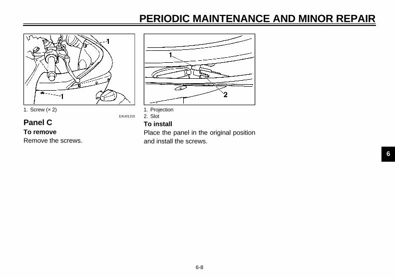
EAU01315
anel C remove
emove the screws.
To installPlace the panel in the original positionand install the screws.
Screw (× 2) 1. Projection2. Slot

PE
6
SpThecomperdeacanginNosamcolcenpoimoly. diffthin
en installing a spark plug, the gas- surface should always be cleaned a new gasket used. Any grimeuld be wiped off from the threads the spark plug tightened to thecified torque.
TE: torque wrench is not available whenalling a spark plug, a good estimatehe correct torque is 1/4 to 1/2 turnt finger tight. The spark plug shouldtightened to the specified torque asn as possible.
a. S
ightening torque:Spark plug:
12.5 Nm (1.25 m·kg)
E_5eb_Periodic.fm Page 9 Thursday, November 18, 1999 4:06 PM
RIODIC MAINTENANCE AND MINOR REPAIR
6-9
EAU01639
ark plug inspection spark plug is an important engineponent and should be inspected
iodically, preferably by a Yamahaler. The condition of the spark plug indicate the condition of the en-
e.rmally, all spark plugs from the
e engine should have the sameor on the white insulator around theter electrode. The ideal color at thisnt is a medium-to-light tan color for atorcycle that is being ridden normal-If one spark plug shows a distinctlyerent color, there could be some-g wrong with the engine.
Do not attempt to diagnose such prob-lems yourself. Instead, take the motor-cycle to a Yamaha dealer. The sparkplugs should be periodically removedand inspected because heat and de-posits will cause any spark plug toslowly break down and erode. If elec-trode erosion becomes excessive, or ifcarbon and other deposits are exces-sive, the spark plug should be replacedwith the specified plug.
Before installing any spark plug, mea-sure the electrode gap with a wirethickness gauge and adjust it to specifi-cation.
Whketandshoandspe
NO@
If ainstof tpasbe soo@
park plug gap
Specified spark plug:CR10EK (NGK)
Spark plug gap:0.6 ~ 0.7 mm
T
AND MINOR REPAIR
6
C@
DmtioThtoththcawinw@
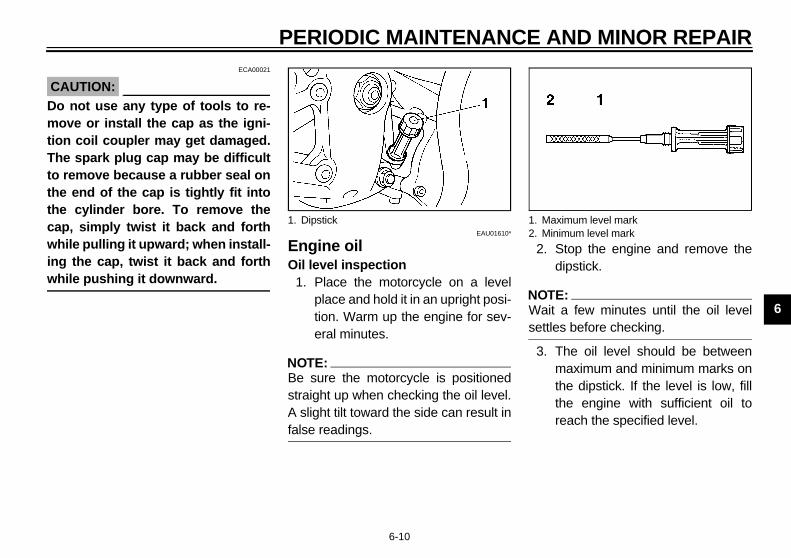
. Stop the engine and remove thedipstick.
TE:ait a few minutes until the oil levelttles before checking.
. The oil level should be betweenmaximum and minimum marks onthe dipstick. If the level is low, fillthe engine with sufficient oil toreach the specified level.
Maximum level markMinimum level mark
E_5eb_Periodic.fm Page 10 Thursday, November 18, 1999 4:06 PM
PERIODIC MAINTENANCE
6-10
ECA00021
AUTION:o not use any type of tools to re-ove or install the cap as the igni-n coil coupler may get damaged.e spark plug cap may be difficult
remove because a rubber seal one end of the cap is tightly fit intoe cylinder bore. To remove thep, simply twist it back and forth
hile pulling it upward; when install-g the cap, twist it back and forthhile pushing it downward.
EAU01610*
Engine oilOil level inspection
1. Place the motorcycle on a levelplace and hold it in an upright posi-tion. Warm up the engine for sev-eral minutes.
NOTE:@
Be sure the motorcycle is positionedstraight up when checking the oil level.A slight tilt toward the side can result infalse readings. @
2
NO@
Wse@
3
1. Dipstick 1.2.
PE
6
Enpla
1.
2.
3.
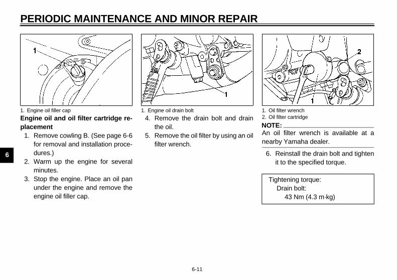
TE:oil filter wrench is available at arby Yamaha dealer.
Reinstall the drain bolt and tightenit to the specified torque.
1. E il filter wrenchil filter cartridge
ightening torque:Drain bolt:
43 Nm (4.3 m·kg)
E_5eb_Periodic.fm Page 11 Thursday, November 18, 1999 4:06 PM
RIODIC MAINTENANCE AND MINOR REPAIR
6-11
gine oil and oil filter cartridge re-cement
Remove cowling B. (See page 6-6for removal and installation proce-dures.)Warm up the engine for severalminutes.Stop the engine. Place an oil panunder the engine and remove theengine oil filler cap.
4. Remove the drain bolt and drainthe oil.
5. Remove the oil filter by using an oilfilter wrench.
NO@
An nea@
6.
ngine oil filler cap 1. Engine oil drain bolt 1. O2. O
T
AND MINOR REPAIR
6
7
N@
Mly@
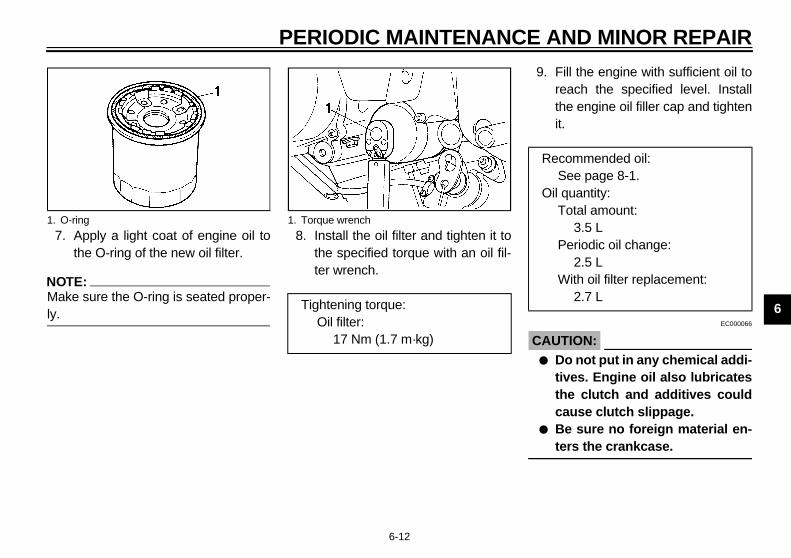
. Fill the engine with sufficient oil toreach the specified level. Installthe engine oil filler cap and tightenit.
EC000066
AUTION:● Do not put in any chemical addi-
tives. Engine oil also lubricatesthe clutch and additives couldcause clutch slippage.
● Be sure no foreign material en-ters the crankcase.
1.
Recommended oil:See page 8-1.
Oil quantity:Total amount:
3.5 LPeriodic oil change:
2.5 LWith oil filter replacement:
2.7 L
E_5eb_Periodic.fm Page 12 Thursday, November 18, 1999 4:06 PM
PERIODIC MAINTENANCE
6-12
. Apply a light coat of engine oil tothe O-ring of the new oil filter.
OTE:ake sure the O-ring is seated proper-.
8. Install the oil filter and tighten it tothe specified torque with an oil fil-ter wrench.
9
C@
@
O-ring 1. Torque wrench
Tightening torque:Oil filter:
17 Nm (1.7 m·kg)

PE
6
10.
11.
CA@
If tmagindea@
12.
If the level is low, remove the res-ervoir tank cover by removing thebolts.
Add coolant or distilled water toraise it to the specified level.Install the reservoir tank cover andbolts.
olt (× 2)
eservoir tank capacity:0.44 L
E_5eb_Periodic.fm Page 13 Thursday, November 18, 1999 4:06 PM
RIODIC MAINTENANCE AND MINOR REPAIR
6-13
Start the engine and warm it up forseveral minutes. While warmingup, check for oil leakage. If oilleakage is found, stop the engineimmediately and check for thecause.After the engine is started, the oillevel indicator light should go off ifthe oil is at the specified level.
EC000067
UTION:he indicator light flickers or re-ins on, immediately stop the en-e and consult with a Yamahaler.
Install the cowling.
EAU01611
Cooling system1. Check the coolant level in the res-
ervoir tank when the engine is coldas the coolant level will vary withengine temperature. The coolantlevel should be between the maxi-mum and minimum marks.
2.
3.
4.
1. Maximum level mark2. Minimum level mark
1. B
R
AND MINOR REPAIR
6
C@
Htow@
N@
If ercoThlycoth@
5
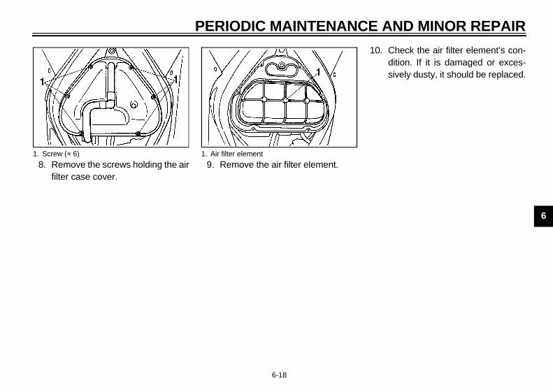
. Remove the water pump drain boltand drain the coolant from the wa-ter pump housing.
. Disconnect the radiator hose byloosening the clamp and drain thecoolant completely.
. Thoroughly flush the cooling sys-tem with clean tap water.
Water pump drain boltClamp bolt
E_5eb_Periodic.fm Page 14 Thursday, November 18, 1999 4:06 PM
PERIODIC MAINTENANCE
6-14
EC000080
AUTION:ard water or salt water is harmful the engine. You may use distilledater if you can’t get soft water.
OTE:water is added, have a Yamaha deal- check the antifreeze content of theolant as soon as possible.e radiator fan operation is complete-
automatic. It is switched on or off ac-rding to the coolant temperature ine radiator.
. If your motorcycle overheats, seepage 6-42 for details.
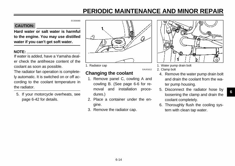
EAU01612
Changing the coolant1. Remove panel C, cowling A and
cowling B. (See page 6-6 for re-moval and installation proce-dures.)
2. Place a container under the en-gine.
3. Remove the radiator cap.
4
5
6
1. Radiator cap 1.2.

PE
6
7.
8.
Remove the reservoir tank by re-moving the bolts.Remove the reservoir tank capand turn the tank upside down toempty it.Install the reservoir tank.Fill the reservoir tank with coolantup to the maximum level, then in-stall the cap and cover.Pour the recommended coolantinto the radiator until it is full.
T
olt (× 2)
E_5eb_Periodic.fm Page 15 Thursday, November 18, 1999 4:06 PM
RIODIC MAINTENANCE AND MINOR REPAIR
6-15
Connect the radiator hose andtighten the clamp.Retighten the drain bolt to thespecified torque. If the gasket isdamaged, replace it.
9. Remove the reservoir tank coverby removing the bolts.
10.
11.
12.13.
14.
ightening torque:Drain bolt:
12 Nm (1.2 m·kg)1. Bolt (× 2) 1. B

AND MINOR REPAIR
6
C@
Htow@
1516
E_5eb_Periodic.fm Page 16 Thursday, November 18, 1999 4:06 PM
PERIODIC MAINTENANCE
6-16
EC000080
AUTION:ard water or salt water is harmful the engine. You may use distilledater if you can’t get soft water.
. Install the radiator cap.
. Run the engine several minutes torecheck the coolant level in the ra-diator. If it is low, fill with morecoolant until it reaches the top ofthe radiator.
17. Check for coolant leakage.
NOTE:@
If you find any leaks, ask a Yamahadealer to inspect. @
18. Install the panel and the cowling.
Recommended anti-freeze:High quality ethylene glycol anti-freeze containing corrosion inhibitors for aluminum engines.
Antifreeze and water mix ratio:1:1
Total amount:2.15 L
Reservoir tank capacity:0.44 L

PE
6
AirThebe shoyouare
1.
2.
3.
Tilt the front of the fuel tank backaway from the air filter case. Besure to support it as shown.
1. B
E_5eb_Periodic.fm Page 17 Thursday, November 18, 1999 4:06 PM
RIODIC MAINTENANCE AND MINOR REPAIR
6-17
EAU01821*
filter air filter element’s condition should
checked at the specified intervals. Ituld be checked more frequently if are riding in unusually wet or dustyas.
Remove the rider seat. (See page3-15 for seat removal and installa-tion procedures.)Remove the bolts holding the fueltank.Lift the fuel tank upward.
4. Set the fuel cock to “OFF”.5. Disconnect the fuel sender lead
coupler.6. Disconnect the hoses.
NOTE:@
Before removing the hoses, mark themto ensure that they will be reinstalled intheir correct positions. @
7.olt (× 2) 1. Fuel cock
2. Hose (× 2)3. Fuel sender lead coupler
AND MINOR REPAIR
6
8
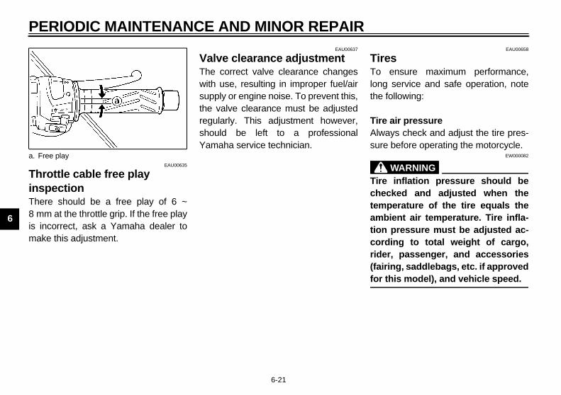
. Check the air filter element’s con-dition. If it is damaged or exces-sively dusty, it should be replaced.
1.
E_5eb_Periodic.fm Page 18 Thursday, November 18, 1999 4:06 PM
PERIODIC MAINTENANCE
6-18
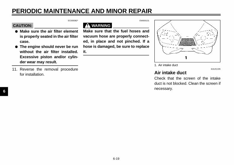
. Remove the screws holding the airfilter case cover.
9. Remove the air filter element.
10
Screw (× 6) 1. Air filter element
PE
6
CA@
●
●
@
11. EAU01335
intake ductck that the screen of the intaket is not blocked. Clean the screen ifessary.
ir intake duct
E_5eb_Periodic.fm Page 19 Thursday, November 18, 1999 4:06 PM
RIODIC MAINTENANCE AND MINOR REPAIR
6-19
EC000082*
UTION:Make sure the air filter elementis properly seated in the air filtercase.The engine should never be runwithout the air filter installed.Excessive piston and/or cylin-der wear may result.
Reverse the removal procedurefor installation.
EW000131
WARNING@
Make sure that the fuel hoses andvacuum hose are properly connect-ed, in place and not pinched. If ahose is damaged, be sure to replaceit. @
AirCheducnec
1. A

AND MINOR REPAIR
6
CThthcashhaexspas
C@
ThYathfo@
TE:the specified idle speed cannot betained by performing the above ad-tment, consult a Yamaha dealer.
Standard idle speed:1,250 ~ 1,350 r/min
E_5eb_Periodic.fm Page 20 Thursday, November 18, 1999 4:06 PM
PERIODIC MAINTENANCE
6-20
EAU00630
arburetor adjustmente carburetors are important parts of
e engine and require very sophisti-ted adjustment. Most adjustmentsould be left to a Yamaha dealer whos the professional knowledge andperience to do so. However, the idleeed may be adjusted by the owner part of routine maintenance.
EC000095
AUTION:e carburetors were set at themaha factory after many tests. If
ey are changed, poor engine per-rmance and damage may result.
EAU00632
Idle speed adjustment1. Start the engine and warm it up for
a few minutes at approximately1,000 to 2,000 r/min. Occasionallyrev the engine to 4,000 to5,000 r/min. The engine is warmwhen it quickly responds to thethrottle.
2. Set the idle to the specified enginespeed by adjusting the throttlestop screw. Turn the screw in di-rection a to increase enginespeed and in direction b to de-crease engine speed.
NO@
If objus@
1. Throttle stop screw
PE
6
ThinsThe8 mis ma
EAU00658
esensure maximum performance,
g service and safe operation, note following:
air pressureays check and adjust the tire pres-e before operating the motorcycle.
EW000082
WARNING inflation pressure should becked and adjusted when theperature of the tire equals thebient air temperature. Tire infla- pressure must be adjusted ac-ding to total weight of cargo,r, passenger, and accessories
ring, saddlebags, etc. if approvedthis model), and vehicle speed.
a. F
E_5eb_Periodic.fm Page 21 Thursday, November 18, 1999 4:06 PM
RIODIC MAINTENANCE AND MINOR REPAIR
6-21
EAU00635
rottle cable free play pectionre should be a free play of 6 ~m at the throttle grip. If the free play
incorrect, ask a Yamaha dealer toke this adjustment.
EAU00637
Valve clearance adjustmentThe correct valve clearance changeswith use, resulting in improper fuel/airsupply or engine noise. To prevent this,the valve clearance must be adjustedregularly. This adjustment however,should be left to a professionalYamaha service technician.
TirTo lonthe
TireAlwsur
@
Tirechetemamtioncorride(faifor @
ree play
AND MINOR REPAIR
6
CE
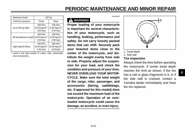
re inspectionways check the tires before operatinge motorcycle. If center tread depthaches the limit as shown, if the tires a nail or glass fragments in it, or if
e side wall is cracked, contact amaha dealer immediately and have
e tire replaced.
M
C
U
9
H
* La
Tread depthSide wall
E_5eb_Periodic.fm Page 22 Thursday, November 18, 1999 4:06 PM
PERIODIC MAINTENANCE
6-22
-33E EW000083
WARNING@
Proper loading of your motorcycleis important for several characteris-tics of your motorcycle, such ashandling, braking, performance andsafety. Do not carry loosely packeditems that can shift. Securely packyour heaviest items close to thecenter of the motorcycle, and dis-tribute the weight evenly from sideto side. Properly adjust the suspen-sion for your load, and check thecondition and pressure of your tires.NEVER OVERLOAD YOUR MOTOR-CYCLE. Make sure the total weightof the cargo, rider, passenger, andaccessories (fairing, saddlebags,etc. if approved for this model) doesnot exceed the maximum load of themotorcycle. Operation of an over-loaded motorcycle could cause tiredamage, an accident, or even injury. @
TiAlthrehathYath
aximum load* 187 kg
old tire pressure Front Rear
p to 90 kg load*250 kPa
(2.50 kg/cm2,2.50 bar)
250 kPa(2.50 kg/cm2,
2.50 bar)
0 kg Maximum load*250 kPa
(2.50 kg/cm2,2.50 bar)
290 kPa(2.90 kg/cm2,
2.90 bar)
igh speed riding250 kPa
(2.50 kg/cm2,2.50 bar)
250 kPa(2.50 kg/cm2,
2.50 bar)
oad is the total weight of cargo, rider, passengernd accessories.
1.2.
PE
6
@
Opcesstatrolplaimmed be cia@
CE-26
NO@
Thetionformreg@
TireThiles
E
E
M(fr
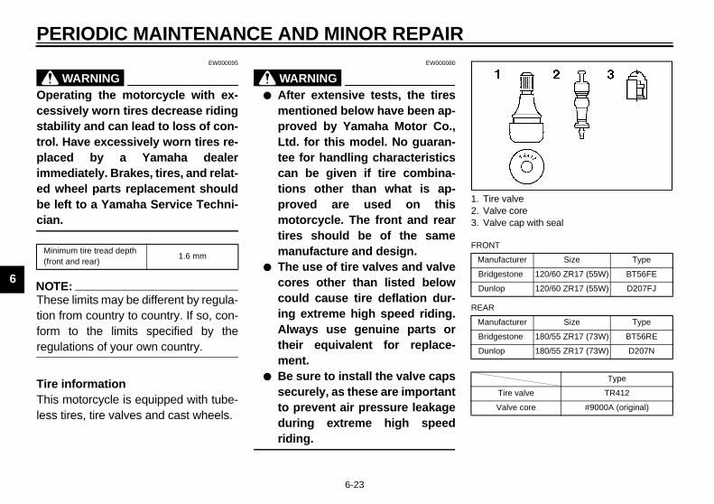
ire valvealve corealve cap with seal
NT
nufacturer Size Type
idgestone 120/60 ZR17 (55W) BT56FE
nlop 120/60 ZR17 (55W) D207FJ
R
nufacturer Size Type
idgestone 180/55 ZR17 (73W) BT56RE
nlop 180/55 ZR17 (73W) D207N
Type
Tire valve TR412
Valve core #9000A (original)
E_5eb_Periodic.fm Page 23 Thursday, November 18, 1999 4:06 PM
RIODIC MAINTENANCE AND MINOR REPAIR
6-23
EW000095
WARNINGerating the motorcycle with ex-sively worn tires decrease ridingbility and can lead to loss of con-. Have excessively worn tires re-ced by a Yamaha dealer
ediately. Brakes, tires, and relat-wheel parts replacement shouldleft to a Yamaha Service Techni-n.
E
TE:se limits may be different by regula- from country to country. If so, con- to the limits specified by the
ulations of your own country.
informations motorcycle is equipped with tube-s tires, tire valves and cast wheels.
EW000080
WARNING@
● After extensive tests, the tiresmentioned below have been ap-proved by Yamaha Motor Co.,Ltd. for this model. No guaran-tee for handling characteristicscan be given if tire combina-tions other than what is ap-proved are used on thismotorcycle. The front and reartires should be of the samemanufacture and design.
● The use of tire valves and valvecores other than listed belowcould cause tire deflation dur-ing extreme high speed riding.Always use genuine parts ortheir equivalent for replace-ment.
● Be sure to install the valve capssecurely, as these are importantto prevent air pressure leakageduring extreme high speedriding.
@
CE-10
CE-12
inimum tire tread depth ont and rear)
1.6 mm
1. T2. V3. V
FRO
Ma
Br
Du
REA
Ma
Br
Du
AND MINOR REPAIR
6
@
Thhiloorus
@
E_5eb_Periodic.fm Page 24 Thursday, November 18, 1999 4:06 PM
PERIODIC MAINTENANCE
6-24
EAU00684
WARNINGis motorcycle is fitted with super
gh-speed running tires. The fol-wing points must be observed inder for you to make fully effectivee of these tires.
● Never fail to use the specifiedtires in tire replacement. Othertires may have a danger ofbursting at super high-speeds.
● New tires have a relatively lowgrip on the road surface untilthey have been slightly worn.Therefore, approximately100 km should be traveled atnormal speed before any high-speed riding is done.
● Before any high-speed runs, thetires should be warmed-up suf-ficiently.
● Always inflate to the correct tirepressure according to the oper-ating conditions.
EAU00687
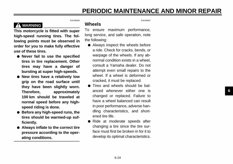
WheelsTo ensure maximum performance,long service, and safe operation, notethe following:
● Always inspect the wheels beforea ride. Check for cracks, bends, orwarpage of the wheels. If any ab-normal condition exists in a wheel,consult a Yamaha dealer. Do notattempt even small repairs to thewheel. If a wheel is deformed orcracked, it must be replaced.
● Tires and wheels should be bal-anced whenever either one ischanged or replaced. Failure tohave a wheel balanced can resultin poor performance, adverse han-dling characteristics, and short-ened tire life.
● Ride at moderate speeds afterchanging a tire since the tire sur-face must first be broken in for it todevelop its optimal characteristics.

PE
6
CluadThejus
1.
2.
EAU00713
ke light switch adjustment rear brake light switch is activated
the brake pedal and is properly ad-ed when the brake light comes on before braking takes effect. To ad- the rear brake light switch, hold thetch body so it does not rotate whileing the adjusting nut.n the adjusting nut in direction a toke the brake light come on earlier.n the adjusting nut in direction b toke the brake light come on later.
1. A2. F
rake light switchdjusting nut
E_5eb_Periodic.fm Page 25 Thursday, November 18, 1999 4:06 PM
RIODIC MAINTENANCE AND MINOR REPAIR
6-25
EAU01356
tch lever free play justment clutch lever free play should be ad-
ted to 10 ~ 15 mm.Turn the adjusting bolt at theclutch lever in direction a to in-crease free play or in direction bto decrease free play. If the speci-fied free play cannot be obtained,proceed with the following steps.Turn the adjusting bolt at theclutch lever in direction a to loos-en the cable.
3. Remove cowling A. (See page 6-6for removal and installation proce-dures.)
4. Loosen the locknut at the crank-case side.
5. Turn the adjusting nut at thecrankcase in direction a to in-crease free play or in direction bto decrease free play. Then tight-en the locknut.
6. Install the cowling.
BraTheby justjustjustswiturnTurmaTurma
djusting boltree play
1. Locknut2. Adjusting nut
1. B2. A
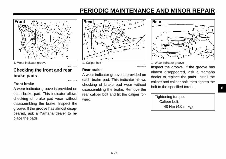
AND MINOR REPAIR
6
Cbr
FrA eachdigrpepl
spect the groove. If the groove hasost disappeared, ask a Yamaha
aler to replace the pads. Install theliper and caliper bolt, then tighten thelt to the specified torque.
1. Wear indicator groove
Tightening torque:Caliper bolt:
40 Nm (4.0 m·kg)
E_5eb_Periodic.fm Page 26 Thursday, November 18, 1999 4:06 PM
PERIODIC MAINTENANCE
6-26
EAU00721
hecking the front and rear ake pads
EAU00725
ont brakewear indicator groove is provided onch brake pad. This indicator allowsecking of brake pad wear without
sassembling the brake. Inspect theoove. If the groove has almost disap-ared, ask a Yamaha dealer to re-
ace the pads.
EAU01641
Rear brakeA wear indicator groove is provided oneach brake pad. This indicator allowschecking of brake pad wear withoutdisassembling the brake. Remove therear caliper bolt and tilt the caliper for-ward.
Inalmdecabo
Wear indicator groove 1. Caliper bolt 1.

PE
6
InslevInsthebraBeis aishOb
●
Brake fluid may deteriorate paint-ed surfaces or plastic parts. Al-ways clean up spilled fluidimmediately.Have a Yamaha dealer check thecause if the brake fluid level goesdown.
1. M
E_5eb_Periodic.fm Page 27 Thursday, November 18, 1999 4:06 PM
RIODIC MAINTENANCE AND MINOR REPAIR
6-27
EAU00731
pecting the brake fluid elufficient brake fluid may let air enter brake system, possibly causing thekes to become ineffective.fore riding, check that the brake fluidbove the minimum level and replen- when necessary.serve these precautions:
When checking the fluid level,make sure the top of the mastercylinder is level by turning the han-dlebars.
● Use only the designated qualitybrake fluid. Otherwise, the rubberseals may deteriorate, causingleakage and poor brake perfor-mance.
● Refill with the same type of brakefluid. Mixing fluids may result in aharmful chemical reaction andlead to poor brake performance.
● Be careful that water does not en-ter the master cylinder when refill-ing. Water will significantly lowerthe boiling point of the fluid andmay result in vapor lock.
●
●
inimum level mark 1. Minimum level mark
Recommended brake fluid: DOT 4
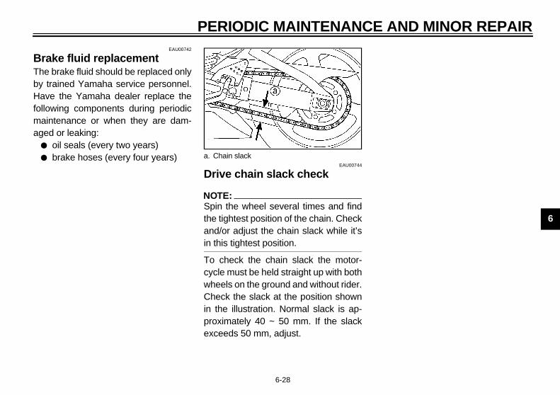
AND MINOR REPAIR
6
BThbyHfomag
E_5eb_Periodic.fm Page 28 Thursday, November 18, 1999 4:06 PM
PERIODIC MAINTENANCE
6-28
EAU00742
rake fluid replacemente brake fluid should be replaced only trained Yamaha service personnel.
ave the Yamaha dealer replace thellowing components during periodicaintenance or when they are dam-ed or leaking:
● oil seals (every two years)● brake hoses (every four years)
EAU00744
Drive chain slack check
NOTE:@
Spin the wheel several times and findthe tightest position of the chain. Checkand/or adjust the chain slack while it’sin this tightest position. @
To check the chain slack the motor-cycle must be held straight up with bothwheels on the ground and without rider.Check the slack at the position shownin the illustration. Normal slack is ap-proximately 40 ~ 50 mm. If the slackexceeds 50 mm, adjust.
a. Chain slack

PE
6
Dr1.2.
EAU03006
ve chain lubrication chain consists of many parts whichk with each other. If the chain is notintained properly, it will wear outckly. Therefore, the chain must beviced regularly. This service is es-ially necessary when riding in dustyas. This motorcycle is equipped a sealed type chain. Steam clean-
, high-pressure washers, and sol-ts can damage the drive chain, sonot use these for cleaning it. Usey kerosene to clean the drive chain.e it dry, and thoroughly lubricate it SAE 30 ~ 50W motor oil. Do not any other lubricants on the drivein. They may contain solvents thatld damage the sealed chain.
EC000097
UTION:sure to oil the chain after wash- the motorcycle or riding in the.
1. A2. A3. L4. A
E_5eb_Periodic.fm Page 29 Thursday, November 18, 1999 4:06 PM
RIODIC MAINTENANCE AND MINOR REPAIR
6-29
EAU01251
ive chain slack adjustmentLoosen the axle nut.Loosen the locknuts on each side.To tighten the chain, turn the chainadjusting bolts in direction a. Toloosen the chain, turn the adjust-ing bolts in direction b and pushthe wheel forward. Turn each ad-justing bolt exactly the sameamount to maintain correct axlealignment. There are marks oneach side of the swingarm. Usethese marks to align the rearwheel.
EC000096
CAUTION:@
Too little chain slack will overloadthe engine and other vital parts.Keep the slack within the specifiedlimits. @
3. After adjusting, tighten the lock-nuts. Then tighten the axle nut tothe specified torque.
DriThewormaquiserpecarewithingvendo onlWipwithusechacou
CA@
Be ingrain@
xle nutdjusting boltocknutlignment marks
Tightening torque:Axle nut:
150 Nm (15.0 m·kg)
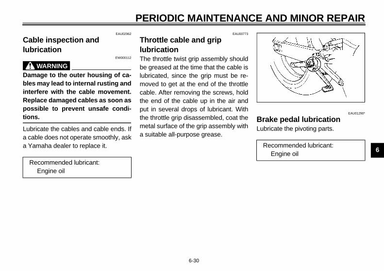
AND MINOR REPAIR
6
Clu
@
DblinRpotio@
Lua a
EAU01290*
rake pedal lubricationbricate the pivoting parts.
Recommended lubricant:Engine oil
E_5eb_Periodic.fm Page 30 Thursday, November 18, 1999 4:06 PM
PERIODIC MAINTENANCE
6-30
EAU02962
able inspection and brication
EW000112
WARNINGamage to the outer housing of ca-es may lead to internal rusting andterfere with the cable movement.eplace damaged cables as soon asssible to prevent unsafe condi-ns.
bricate the cables and cable ends. Ifcable does not operate smoothly, askYamaha dealer to replace it.
EAU00773
Throttle cable and grip lubricationThe throttle twist grip assembly shouldbe greased at the time that the cable islubricated, since the grip must be re-moved to get at the end of the throttlecable. After removing the screws, holdthe end of the cable up in the air andput in several drops of lubricant. Withthe throttle grip disassembled, coat themetal surface of the grip assembly witha suitable all-purpose grease.
BLu
Recommended lubricant:Engine oil
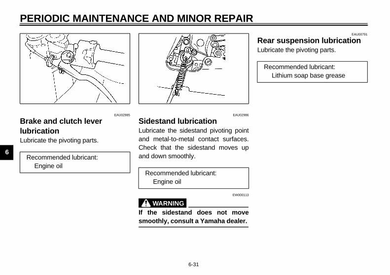
PE
6
BrlubLub
EAU00791
ar suspension lubricationricate the pivoting parts.
R
ecommended lubricant:Lithium soap base grease
E_5eb_Periodic.fm Page 31 Thursday, November 18, 1999 4:06 PM
RIODIC MAINTENANCE AND MINOR REPAIR
6-31
EAU02985
ake and clutch lever ricationricate the pivoting parts.
EAU02986
Sidestand lubricationLubricate the sidestand pivoting pointand metal-to-metal contact surfaces.Check that the sidestand moves upand down smoothly.
EW000113
WARNING@
If the sidestand does not movesmoothly, consult a Yamaha dealer. @
ReLub
ecommended lubricant:Engine oil
Recommended lubricant:Engine oil
R

AND MINOR REPAIR
6
FVi
@
Seth@
Cinfro EAU00794
teering inspectionriodically inspect the condition of theering. Worn out or loose steeringarings may be dangerous. Place and under the engine to raise thent wheel off the ground. Hold theer end of the front forks and try to
ove them forward and backward. Ify free play can be felt, ask a Yamahaaler to inspect and adjust the steer-. Inspection is easier if the fronteel is removed.
EW000115
WARNINGcurely support the motorcycle so
ere is no danger of it falling over.
E_5eb_Periodic.fm Page 32 Thursday, November 18, 1999 4:06 PM
PERIODIC MAINTENANCE
6-32
EAU02939
ront fork inspectionsual check
EW000115
WARNINGcurely support the motorcycle so
ere is no danger of it falling over.
heck for scratches or damage on thener tube and excessive oil leakagem the front fork. Operation check
1. Place the motorcycle on a levelplace.
2. Hold the motorcycle in an uprightposition and apply the front brake.
3. Push down hard on the handle-bars several times and check if thefork rebounds smoothly.
EC000098
CAUTION:@
If any damage or unsmooth move-ment is found with the front fork,consult a Yamaha dealer. @
SPestebestafrolowmandeingwh
@
Seth@

PE
6
WhIf thhubsmspe
EW000116
WARNINGtery electrolyte is poisonous andgerous, causing severe burns,
. It contains sulfuric acid. Avoidtact with skin, eyes or clothing.TIDOTE:
EXTERNAL: Flush with water.INTERNAL: Drink large quanti-ties of water or milk. Follow withmilk of magnesia, beaten egg,or vegetable oil. Call a physi-cian immediately.EYES: Flush with water for15 minutes and get promptmedical attention.
teries produce explosive gases.p sparks, flame, cigarettes etc.,y. Ventilate when charging org in an enclosed space. Alwaysld your eyes when working near
teries. EP OUT OF REACH OF CHIL-EN.
E_5eb_Periodic.fm Page 33 Thursday, November 18, 1999 4:06 PM
RIODIC MAINTENANCE AND MINOR REPAIR
6-33
EAU01144
eel bearingsere is play in the front or rear wheel or if the wheel does not turn
oothly, have a Yamaha dealer in-ct the wheel bearings.
EAU01291
BatteryThis motorcycle is equipped with asealed-type battery. Therefore it is notnecessary to check the electrolyte or fillthe battery with distilled water.
● If the battery seems to have dis-charged, consult a Yamaha deal-er.
● If the motorcycle is equipped withoptional electrical accessories, thebattery tends to discharge morequickly, so be sure to recharge itperiodically.
@
BatdanetcconAN
●
●
●
BatKeeawausinshiebatKEDR@

AND MINOR REPAIR
6
BaThitamWmbaco
C@
@
EC000103
AUTION: not use fuses of higher amper-e rating than those recommend-. Substitution of a fuse ofproper rating can cause extensivectrical system damage and pos-ly a fire.
Main fuseSpare fuse
E_5eb_Periodic.fm Page 34 Thursday, November 18, 1999 4:06 PM
PERIODIC MAINTENANCE
6-34
ttery storageis motorcycle is equipped with a dig-l speedometer and the odometeremory tends to drain the battery.hen the motorcycle is not used for aonth or longer, be sure to remove thettery, fully charge it and store it in aol, dry place.
EC000102
AUTION:● Completely recharge the bat-
tery before storing. Storing adischarged battery can causepermanent battery damage.
● Use a battery charger designedfor a sealed-type (MF) battery.Using a conventional batterycharger will cause battery dam-age. If you do not have a sealed-type battery charger, contactyour Yamaha dealer.
● Always make sure the connec-tions are correct when reinstall-ing the battery.
EAU01754
Fuse replacementThe fuse boxes are located under therider seat. If any fuse is blown, turn offthe main switch and the switch of thecircuit in question. Install a new fuse ofspecified amperage. Turn on theswitches and see if the electrical deviceoperates. If the fuse immediately blowsagain, consult a Yamaha dealer.
C@
Doagedimelesib@
1. Ignition fuse2. Headlight fuse3. Signaling system fuse4. Spare fuse (× 3)5. Radiator fan fuse6. Odometer fuse
1.2.

PE
6
Unhook the bulb holder and re-move the defective bulb.
EW000119
WARNINGp flammable products and yourds away from a bulb while it is
as it is hot. Do not touch a bulbil it cools down.
Put a new bulb into position andsecure it in place with the bulbholder.
S
ulb holder
E_5eb_Periodic.fm Page 35 Thursday, November 18, 1999 4:06 PM
RIODIC MAINTENANCE AND MINOR REPAIR
6-35
EAU01822*
Headlight bulb replacementThis motorcycle is equipped with aquartz bulb headlight.If the headlight bulb burns out, replacethe bulb as follows:
1. Remove panel C. (See page 6-8for panel removal and installationprocedures.)
2. Remove the headlight connectorand the bulb holder cover.
3.
@
Keehanon,unt@
4.
pecified fuses:Main fuse: 30 AHeadlight fuse: 20 ASignaling system fuse: 20 ARadiator fan fuse: 7.5 AIgnition fuse: 15 AOdometer fuse: 7.5 A
1. Connector2. Bulb holder cover
1. B

AND MINOR REPAIR
6
C@
To
@
5
If nem
EAU01095
rn signal light bulb placement. Remove the screw and the lens.. Remove the defective bulb by
pushing it inward and turning itcounterclockwise.
. Install a new bulb by pushing it in-ward and turning it clockwise.
. Install the lens and tighten thescrew.
Screw
E_5eb_Periodic.fm Page 36 Thursday, November 18, 1999 4:06 PM
PERIODIC MAINTENANCE
6-36
EC000104
AUTION: prevent damage to the following:
● Headlight bulbAvoid touching the glass part ofthe bulb. Keep it free from oil;otherwise, the transparency ofthe glass, life of the bulb, and il-luminous flux will be adverselyaffected. If oil gets on the bulb,thoroughly clean it with a clothmoistened with alcohol or lac-quer thinner.
● Headlight lens• Do not affix any type of tinted
film or stickers to the head-light lens.
• Do not use headlight bulbs ofwattage higher than speci-fied.
. Install the bulb holder cover andreconnect the headlight connec-tor.
the headlight beam adjustment iscessary, ask a Yamaha dealer toake that adjustment.
EAU01823
Tail/brake light bulb replacement
1. Remove the passenger seat. (Seepage 3-15 for seat removal and in-stallation procedures.)
2. To remove the socket, turn it coun-terclockwise.
3. To remove the defective bulb, turnit counterclockwise.
4. Push a new bulb into the socketand turn it clockwise.
5. Install the socket and turn it clock-wise.
6. Install the passenger seat.
Ture
12
3
4
1. Bulb socket 1.

PE
6
SuSinterswhwhnanstacycbefstroder
FroTo eitha mfronmomowh
EAU01617
nt wheel removalEW000122
WARNINGIt is advisable to have a Yamahadealer service the wheel.Securely support the motor-cycle so there is no danger of itfalling over.
Loosen the pinch bolt and caliperbolts.Loosen the wheel axle by using a19-mm hexagon wrench.
heel axleinch bolt
E_5eb_Periodic.fm Page 37 Thursday, November 18, 1999 4:06 PM
RIODIC MAINTENANCE AND MINOR REPAIR
6-37
EAU01579
pporting the motorcyclece the Yamaha YZF-R6 has no cen-tand, follow these precautions
en removing the front and reareel or performing other mainte-ce requiring the motorcycle to
nd upright. Check that the motor-le is in a stable and level positionore starting any maintenance. Ang wooden box can be placed un- the engine for added stability.
nt wheel servicestabilize the rear of the motorcycle,er use a motorcycle stand or placeotorcycle jack under the frame int of the rear wheel to prevent it from
ving from side to side. Then use atorcycle stand to elevate the fronteel off of the ground.
Rear wheel serviceUse a motorcycle stand or motorcyclejack to elevate the motorcycle so therear wheel is off the ground. Alterna-tively, two jacks can be placed underthe frame or swingarm.
Fro
@
●
●
@
1.
2.
1. W2. P
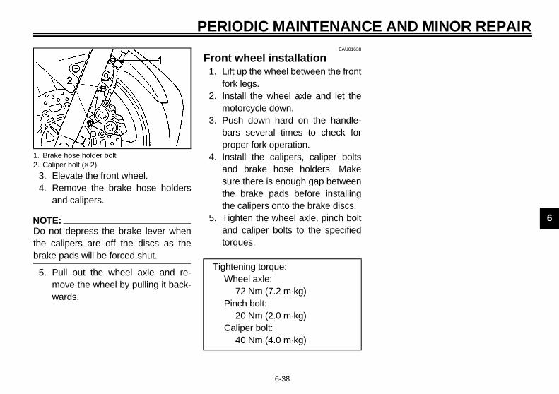
AND MINOR REPAIR
6
34
N@
Dthbr@
5
1.2.
E_5eb_Periodic.fm Page 38 Thursday, November 18, 1999 4:06 PM
PERIODIC MAINTENANCE
6-38
. Elevate the front wheel.
. Remove the brake hose holdersand calipers.
OTE:o not depress the brake lever whene calipers are off the discs as theake pads will be forced shut.
. Pull out the wheel axle and re-move the wheel by pulling it back-wards.
EAU01638
Front wheel installation1. Lift up the wheel between the front
fork legs.2. Install the wheel axle and let the
motorcycle down.3. Push down hard on the handle-
bars several times to check forproper fork operation.
4. Install the calipers, caliper boltsand brake hose holders. Makesure there is enough gap betweenthe brake pads before installingthe calipers onto the brake discs.
5. Tighten the wheel axle, pinch boltand caliper bolts to the specifiedtorques.
Brake hose holder boltCaliper bolt (× 2)
Tightening torque:Wheel axle:
72 Nm (7.2 m·kg)Pinch bolt:
20 Nm (2.0 m·kg)Caliper bolt:
40 Nm (4.0 m·kg)

PE
6
Re
@
●
●
@
1.
2.
TE:Do not depress the brake pedalwhen the caliper is off the disc asthe brake pads will be forced shut.You do not have to disassemblethe chain in order to remove or in-stall the rear wheel.
1. A2. A3. L
E_5eb_Periodic.fm Page 39 Thursday, November 18, 1999 4:06 PM
RIODIC MAINTENANCE AND MINOR REPAIR
6-39
EAU01247
ar wheel removalEW000122
WARNINGIt is advisable to have a Yamahadealer service the wheel.Securely support the motor-cycle so there is no danger of itfalling over.
Loosen the axle nut and caliperbolts.Elevate the rear wheel.
3. Remove the axle nut, caliper boltsand caliper.
4. Loosen the locknuts on each sideof the swingarm.
5. Turn the chain adjusting bolts fullyinward.
6. Push the wheel forward and re-move the drive chain.
7. Pull out the wheel axle and re-move the wheel assembly by pull-ing backwards.
NO@
●
●
@
xle nutdjusting boltocknut
1. Caliper bolt (× 2)

AND MINOR REPAIR
6
R1
2
3
4
5
E_5eb_Periodic.fm Page 40 Thursday, November 18, 1999 4:06 PM
PERIODIC MAINTENANCE
6-40
EAU01246
ear wheel installation. Install the wheel assembly and in-
sert the axle.. Install and adjust the drive chain.
(See page 6-28 for details aboutadjusting the drive chain slack.)
. Install the axle nut and let themotorcycle down.
. Install the caliper and caliper bolts.Make sure there is enough gapbetween the brake pads before in-stalling the caliper onto the brakedisc.
. Tighten the axle nut and caliperbolts to the specified torques.
EAU01008
TroubleshootingAlthough Yamaha motorcycles receivea rigid inspection before shipment fromthe factory, trouble may occur duringoperation.Any problem in the fuel, compression,or ignition systems can cause poorstarting and loss of power. The trouble-shooting chart describes a quick, easyprocedure for making checks.If your motorcycle requires any repair,bring it to a Yamaha dealer. The skilledtechnicians at a Yamaha dealershiphave the tools, experience, and know-how to properly service your motor-cycle. Use only genuine Yamaha partson your motorcycle. Imitation parts maylook like Yamaha parts, but they are of-ten inferior. Consequently, they have ashorter service life and can lead to ex-pensive repair bills.
Tightening torque:Axle nut:
150 Nm (15.0 m·kg)Caliper bolt:
40 Nm (4.0 m·kg)

PERIODIC
6
Troubleshootin
WARNING@
Never check the fu@
Check if thein the fuel ta
1. Fuel
to compression check.
2. Com
Engine doesn’t start, ask a Yamaha dealer to inspect.
Engine doesn’t start, go to battery check.
Open throttle half-way and startthe engine.
E_5eb_Periodic.fm Page 41 Thursday, November 18, 1999 4:06 PM
Use the electric st
Remove spark pluand check electro
3. Ignition
Use the electric s
4. Battery
MAINTENANCE AND MINOR REPAIR
6-41
EAU02990
g chartEW000125
el system while smoking or in the vicinity of an open flame.
re is fuel nk.
Enough fuel.
No fuel.
Go to compression check.
Supply fuel. Engine doesn’t start, go
arter.
pressionThere is compression.
No compression.
Go to ignition check.
Ask a Yamaha dealer to inspect.
gsdes.
Wet.
Dry.
Wipe clean with dry cloth and correct spark gap or replace spark plugs.
Ask a Yamaha dealer to inspect.
tarter.
Engine turns over quickly.
Engine turns over slowly.
Battery good.
Check connections orrecharge.
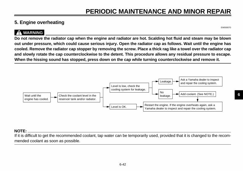
AND MINOR REPAIR
6
5.EW000070
@
D id and steam may be blownou s. Wait until the engine hasco a towel over the radiator capan esidual pressure to escape.W kwise and remove it. @
N@
If vided that it is changed to the recom-m@
ge.
age.Ask a Yamaha dealer to inspect and repair the cooling system.
Add coolant. (See NOTE.)
e. If the engine overheats again, ask a o inspect and repair the cooling system.
E_5eb_Periodic.fm Page 42 Thursday, November 18, 1999 4:06 PM
PERIODIC MAINTENANCE
6-42
Engine overheating
WARNINGo not remove the radiator cap when the engine and radiator are hot. Scalding hot flut under pressure, which could cause serious injury. Open the radiator cap as followoled. Remove the radiator cap stopper by removing the screw. Place a thick rag like d slowly rotate the cap counterclockwise to the detent. This procedure allows any rhen the hissing sound has stopped, press down on the cap while turning countercloc
OTE:it is difficult to get the recommended coolant, tap water can be temporarily used, proended coolant as soon as possible.
Wait until the engine has cooled.
Check the coolant level in the reservoir tank and/or radiator.
Level is OK.
Level is low, check the cooling system for leakage.
No leaka
Leak
Restart the enginYamaha dealer t

E_5eb_Periodic.fm Page 43 Thursday, November 18, 1999 4:06 PM

7
MOTORCYCLE CARE AND STORAGE
Care ................................................................................................... 7-1Storage............................................................................................... 7-4
E_5eb_CleaningTOC.fm Page 1 Thursday, November 18, 1999 4:07 PM
7
EAU01637
aningr normal useove dirt with warm water, a neutral
E_5eb_Cleaning.fm Page 1 Thursday, November 18, 1999 4:08 PM
7-MO
CaThea m
ergent and a soft clean sponge,n rinse with plenty of clean water. a tooth or bottle brush for hard-to-
ch parts. Tougher dirt and insects come off more easily if the area isered with a wet cloth for a few min-s before cleaning. There is a specialnge included in the plastic bag con-ing the owners manual. Use thisnge to clean the muffler and to re-ve any discoloration from the muf-.
ablenenresimaylookquekeetendmathatcareoming
7-1
TORCYCLE CARE AND STORAGE
re exposure of its technology makesotorcycle charming but also vulner-. Although high-quality compo-ts are used, they are not all rust-stant. While a rusty exhaust pipe remain unnoticed on a car, it does unattractive on a motorcycle. Fre-nt and proper care, however, willp your motorcycle looking good, ex- its life and maintain its perfor-
nce. Moreover, the warranty states the vehicle must be properly taken of. For all these reasons, it is rec-
mended that you observe the follow-cleaning and storing precautions.
Before cleaning1. Cover up the muffler outlet with a
plastic bag.2. Make sure that all caps and covers
as well as all electrical couplersand connectors, including thespark plug caps, are tightly in-stalled.
3. Remove extremely stubborn dirt,like oil burnt onto the crankcase,with a degreasing agent and abrush, but never apply such prod-ucts onto seals, gaskets, sprock-ets, the drive chain and wheelaxles. Always rinse the dirt anddegreaser off with water.
CleAfteRemdettheUsereawillcovutespotainspomofler
ARE AND STORAGE
7
C@
● For motorcycles equipped witha windshield: Do not use strongcleaners or hard sponges asthey will cause dulling orscratching. Some cleaningcompounds for plastic mayleave scratches on the wind-shield. Test the product on asmall hidden part of the wind-shield to make sure they do notleave any marks. If the wind-shield is scratched, use a quali-ty plastic polishing compoundafter washing.
ter riding in the rain, near the sea or salt-sprayed roadsnce sea salt or salt sprayed on theads in the winter are extremely corro-e in combination with water, carryt the following steps after each ridethe rain, near the sea or on salt-rayed roads. (Salt sprayed in thenter may remain on the roads wello spring.)
E_5eb_Cleaning.fm Page 2 Thursday, November 18, 1999 4:08 PM
MOTORCYCLE C
7-2
ECA00010
AUTION:● Avoid using strong acidic wheel
cleaners, especially on spokedwheels. If you do use suchproducts for hard-to-removedirt, do not leave it on any long-er than instructed, then thor-oughly rinse it off with water,immediately dry the area andapply a corrosion protectionspray.
● Improper cleaning can damagewindshields, cowlings, panelsand other plastic parts. Useonly a soft, clean cloth orsponge with mild detergent andwater to clean plastic.
● Do not use any harsh chemicalproducts on plastic parts. Besure to avoid using cloths orsponges which have been incontact with strong or abrasivecleaning products, solvent orthinner, fuel (gasoline), rust re-movers or inhibitors, brake flu-id, antifreeze or electrolyte.
● Do not use high-pressure wash-ers or steam-jet cleaners sincethey cause water seepage anddeterioration in the following ar-eas: seals (of wheel bearings,swingarm bearings, forks andbrakes), electric components(couplers, connectors, instru-ments, switches and lights),breather hoses and vents.
@
AfonSirosivouin spwiint

M
7
1.
CA@
Docresal@
2.
EWA00001
WARNINGke sure that there is no oil or waxthe brakes and tires. If neces-y, clean the brake discs and lin-s with a regular brake discner or acetone, and wash the
s with warm water and mild soap.n, carefully test the motorcycle
its braking performance and cor-ing behavior.
E_5eb_Cleaning.fm Page 3 Thursday, November 18, 1999 4:08 PM
OTORCYCLE CARE AND STORAGE
7-3
Clean your motorcycle with coldwater and soap after the enginehas cooled down.
ECA00012
UTION: not use warm water since it in-ases the corrosive action of thet.
Be sure to apply a corrosion pro-tection spray on all (even chrome-and nickel-plated) metal surfacesto prevent corrosion.
After cleaning1. Dry the motorcycle with a chamois
or an absorbing cloth.2. Immediately dry the drive chain
and lubricate it to prevent it fromrusting.
3. Use a chrome polish to shinechrome, aluminum and stainless-steel parts, including the exhaustsystem. (Even the thermally in-duced discoloring of stainless-steel exhaust systems can be re-moved through polishing.)
4. To prevent corrosion, it is recom-mended to apply a corrosion pro-tection spray on all (even chrome-and nickel-plated) metal surfaces.
5. Use spray oil as a universal clean-er to remove any remaining dirt.
6. Touch up minor paint damagecaused by stones, etc.
7. Wax all painted surfaces.8. Let the motorcycle dry completely
before storing it or covering it.
@
Maon saringcleatireThefor ner@
ARE AND STORAGE
7
C@
@
N@
Cw@
ng-termfore storing your motorcycle for sev-
al months:. Follow all the instructions in the
“Care” section of this chapter.. Drain the carburetor float cham-
bers by loosening the drain bolts;this will prevent fuel deposits frombuilding up. Pour the drained fuelinto the fuel tank.
. Only for motorcycles equippedwith a fuel cock which has an“OFF” position: Turn the fuel cockto “OFF”.
. Fill up the fuel tank and add fuelstabilizer (if available) to preventthe fuel tank from rusting and thefuel from deteriorating.
. Perform the following steps to pro-tect the cylinders, piston rings, etc.from corrosion.
E_5eb_Cleaning.fm Page 4 Thursday, November 18, 1999 4:08 PM
MOTORCYCLE C
7-4
ECA00013
AUTION:● Apply spray oil and wax spar-
ingly and wipe off any excess.● Never apply oil or wax on rub-
ber and plastic parts, but treatthem with a suitable care prod-uct.
● Avoid using abrasive polishingcompounds as they wear awaythe paint.
OTE:onsult a Yamaha dealer for advice onhat products to use.
StorageShort-termAlways store your motorcycle in a cool,dry place and, if necessary, protect itagainst dust with a porous cover.
ECA00014
CAUTION:@
● Storing the motorcycle in apoorly ventilated room or cover-ing it with a tarp while it is stillwet will allow water and humidi-ty to seep in and cause rust.
● To prevent corrosion, avoiddamp cellars, stables (becauseof the presence of ammonia)and areas where strong chemi-cals are stored.
@
LoBeer
1
2
3
4
5

M
7
a
b
c
d
e
@
Whsurtrodfrom@
Remove the battery and fullycharge it. Store it in a cool, dryplace and recharge it once amonth. Do not store the battery inan excessively cold or warm place(less than 0°C or more than 30°C).For more information, see “Batterystorage” in the chapter “PERIOD-IC MAINTENANCE AND MINORREPAIRS”.
TE:ke any necessary repairs beforering the motorcycle.
E_5eb_Cleaning.fm Page 5 Thursday, November 18, 1999 4:08 PM
OTORCYCLE CARE AND STORAGE
7-5
. Remove the spark plug caps andspark plugs.
. Pour a teaspoonful of engine oilinto each spark plug bore.
. Install the spark plug caps onto thespark plugs and place the sparkplugs on the cylinder head so thatthe electrodes are grounded. (Thiswill limit sparking during the nextstep.)
. Turn the engine over several timeswith the starter. (This will coat thecylinder walls with oil.)
. Remove the spark plug caps fromthe spark plugs, install the sparkplugs and then the spark plugcaps.
EWA00003
WARNINGen turning the engine over, bee to ground the spark plug elec-es to prevent damage or injury sparking.
6. Lubricate all control cables andthe pivoting points of all levers andpedals as well as of the sidestand/centerstand.
7. Check and, if necessary, correctthe tire air pressure, then raise themotorcycle so that both of itswheels are off the ground. Alterna-tively, turn the wheels a little everymonth in order to prevent the tiresfrom becoming degraded in onespot.
8. Cover up the muffler outlet with aplastic bag to prevent moisturefrom entering.
9.
NO@
Masto@

8
SPECIFICATIONS
Specifications ..................................................................................... 8-1HOW TO USE THE CONVERSION TABLE ....................................... 8-5
E_5eb_SpecTOC.fm Page 1 Thursday, November 18, 1999 4:08 PM
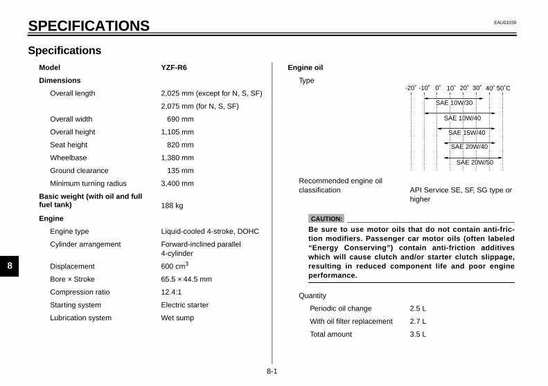
8
EAU01038
E_5eb_Spec.fm Page 1 Thursday, November 18, 1999 4:08 PM
8-SP
Sp01E
M
oil API Service SE, SF, SG type or higher
2.5 L
ment 2.7 L
3.5 L
-20˚ -10˚ 0˚ 10˚ 20˚ 30˚ 40˚ 50˚C
SAE 10W/30
SAE 15W/40
SAE 20W/40
SAE 20W/50
SAE 10W/40
tor oils that do not contain anti-fric-senger car motor oils (often labeledg”) contain anti-friction additives
lutch and/or starter clutch slippage,d component life and poor engine
D
Bf
E
8-1
ECIFICATIONS
ecificationsodel YZF-R6
imensions
Overall length 2,025 mm (except for N, S, SF)
2,075 mm (for N, S, SF)
Overall width 690 mm
Overall height 1,105 mm
Seat height 820 mm
Wheelbase 1,380 mm
Ground clearance 135 mm
Minimum turning radius 3,400 mm
asic weight (with oil and full uel tank) 188 kg
ngine
Engine type Liquid-cooled 4-stroke, DOHC
Cylinder arrangement Forward-inclined parallel 4-cylinder
Displacement 600 cm3
Bore × Stroke 65.5 × 44.5 mm
Compression ratio 12.4:1
Starting system Electric starter
Lubrication system Wet sump
Engine oil
Type
Recommended engine classification
Quantity
Periodic oil change
With oil filter replace
Total amount
CAUTION:
Be sure to use motion modifiers. Pas“Energy Conservinwhich will cause cresulting in reduceperformance.
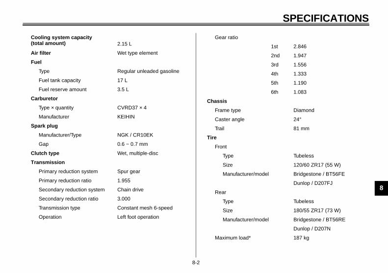
SPECIFICATIONS
8
1st 2.846
2nd 1.947
3rd 1.556
4th 1.333
5th 1.190
6th 1.083
Diamond
24°
81 mm
Tubeless
120/60 ZR17 (55 W)
el Bridgestone / BT56FE
Dunlop / D207FJ
Tubeless
180/55 ZR17 (73 W)
el Bridgestone / BT56RE
Dunlop / D207N
187 kg
E_5eb_Spec.fm Page 2 Thursday, November 18, 1999 4:08 PM
8-2
Cooling system capacity (total amount) 2.15 L
Air filter Wet type element
Fuel
Type Regular unleaded gasoline
Fuel tank capacity 17 L
Fuel reserve amount 3.5 L
Carburetor
Type × quantity CVRD37 × 4
Manufacturer KEIHIN
Spark plug
Manufacturer/Type NGK / CR10EK
Gap 0.6 ~ 0.7 mm
Clutch type Wet, multiple-disc
Transmission
Primary reduction system Spur gear
Primary reduction ratio 1.955
Secondary reduction system Chain drive
Secondary reduction ratio 3.000
Transmission type Constant mesh 6-speed
Operation Left foot operation
Gear ratio
Chassis
Frame type
Caster angle
Trail
Tire
Front
Type
Size
Manufacturer/mod
Rear
Type
Size
Manufacturer/mod
Maximum load*
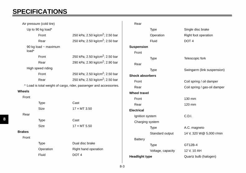
SP
8
Single disc brake
Right foot operation
DOT 4
Telescopic fork
Swingarm (link suspension)
Coil spring / oil damper
Coil spring / gas-oil damper
130 mm
120 mm
C.D.I.
A.C. magneto
tput 14 V, 320 W@ 5,000 r/min
GT12B-4
acity 12 V, 10 AH
Quartz bulb (halogen)
E_5eb_Spec.fm Page 3 Thursday, November 18, 1999 4:08 PM
ECIFICATIONS
8-3
Air pressure (cold tire)
Up to 90 kg load*
Front 250 kPa; 2.50 kg/cm2; 2.50 bar
Rear 250 kPa; 2.50 kg/cm2; 2.50 bar
90 kg load ~ maximum load*
Front 250 kPa; 2.50 kg/cm2; 2.50 bar
Rear 290 kPa; 2.90 kg/cm2; 2.90 bar
High speed riding
Front 250 kPa; 2.50 kg/cm2; 2.50 bar
Rear 250 kPa; 2.50 kg/cm2; 2.50 bar
* Load is total weight of cargo, rider, passenger and accessories.
Wheels
Front
Type Cast
Size 17 × MT 3.50
Rear
Type Cast
Size 17 × MT 5.50
Brakes
Front
Type Dual disc brake
Operation Right hand operation
Fluid DOT 4
Rear
Type
Operation
Fluid
Suspension
Front
Type
Rear
Type
Shock absorbers
Front
Rear
Wheel travel
Front
Rear
Electrical
Ignition system
Charging system
Type
Standard ou
Battery
Type
Voltage, cap
Headlight type
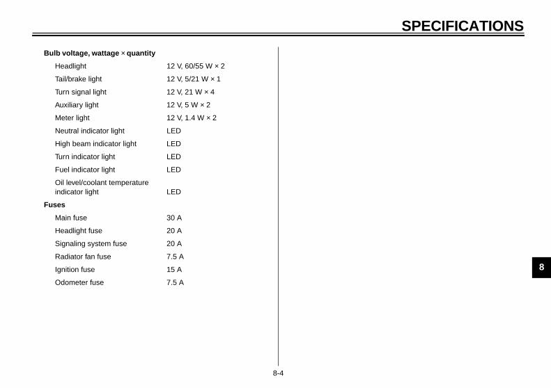
SPECIFICATIONS
8
E_5eb_Spec.fm Page 4 Thursday, November 18, 1999 4:08 PM
8-4
Bulb voltage, wattage × quantity
Headlight 12 V, 60/55 W × 2
Tail/brake light 12 V, 5/21 W × 1
Turn signal light 12 V, 21 W × 4
Auxiliary light 12 V, 5 W × 2
Meter light 12 V, 1.4 W × 2
Neutral indicator light LED
High beam indicator light LED
Turn indicator light LED
Fuel indicator light LED
Oil level/coolant temperature indicator light LED
Fuses
Main fuse 30 A
Headlight fuse 20 A
Signaling system fuse 20 A
Radiator fan fuse 7.5 A
Ignition fuse 15 A
Odometer fuse 7.5 A

SP
8
HOCS-0
AllMEUsunEx
M
ERSION TABLERIC TO IMPERIAL
nit Multiplier Imperial unit
7.23386.7940.07230.8679
ft·lbin·lbft·lbin·lb
2.2050.03527
lboz
0.6214 mph
0.62143.2811.0940.39370.03937
miftydinin
0.035270.061020.87990.2199
oz (IMP liq.)cu·inqt (IMP liq.)gal (IMP liq.)
(°C)
55.99714.22349/5 + 32
lb/inpsi (lb/in2)Fahrenheit (°F)
E_5eb_Spec.fm Page 5 Thursday, November 18, 1999 4:08 PM
ECIFICATIONS
8-5
EAU01064
W TO USE THE CONVERSION TABLE2E
specification data in this manual are listed in SI andTRIC UNITS. e this table to convert METRIC unit data to IMPERIALit data..
ETRIC MULTIPLIER IMPERIAL
**mm × 0.03937 = **in
2 mm × 0.03937 = 0.08 in
CONVMET
Metric u
Torque
m·kgm·kgcm·kgcm·kg
Weight kgg
Speed km/hr
Distance
kmmmcmmm
Volume /Capacity
cc (cm3)cc (cm3)lt (liter)lt (liter)
Misc.kg/mmkg/cm2
Centigrade
9
CONSUMER INFORMATION
Identification number records............................................................. 9-1Key identification number ................................................................... 9-1Vehicle identification number.............................................................. 9-1Model label......................................................................................... 9-2
E_5eb_ConsumerTOC.fm Page 1 Thursday, November 18, 1999 4:08 PM

9
EAU01039
E_5eb_Consumer.fm Page 1 Thursday, November 18, 1999 4:09 PM
9-CO
IdeRec
EAU01043
hicle identification number vehicle identification number is
mped into the steering head pipe.ord this number in the space pro-d.
TE: vehicle identification number isd to identify your motorcycle andy be used to register your motor-le with the licensing authority inr state.
ehicle identification number
vehel lavidespafor len.
1.CA-02
2.
CA-02
3.CA-01
9-1
NSUMER INFORMATIONEAU02944
ntification number recordsord the key identification number,icle identification number and mod-bel information in the spaces pro-d for assistance when orderingre parts from a Yamaha dealer orreference in case the vehicle is sto-
KEY IDENTIFICATION NUMBER:E
VEHICLE IDENTIFICATION NUMBER:
E
MODEL LABEL INFORMATION:E
EAU01041
Key identification numberThe key identification number isstamped on the key tag. Record thisnumber in the space provided and useit for reference when obtaining a newkey.
VeThestaRecvide
NO@
Theusemacycyou@
1. Key identification number 1. V
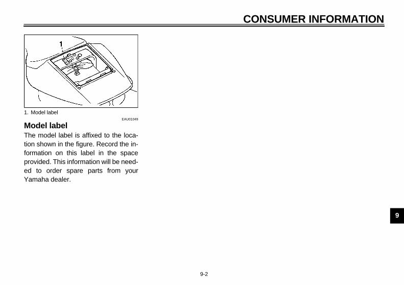
MER INFORMATION
9
MThtiofopredYa
1.
E_5eb_Consumer.fm Page 2 Thursday, November 18, 1999 4:09 PM
CONSU
9-2
EAU01049
odel labele model label is affixed to the loca-n shown in the figure. Record the in-rmation on this label in the spaceovided. This information will be need- to order spare parts from yourmaha dealer.
Model label
D
f intit
ttakakakak
brbreaeattnowsw
git
iviviv
dentification number records ...................9-1dle speed adjustment ............................6-20ndicator lights..........................................3-2
Fuel indicator light...............................3-2High beam indicator light ....................3-2Neutral indicator light ..........................3-2Oil level/coolant temperature
indicator light....................................3-3Turn indicator light ..............................3-2
nspecting the brake fluid level ...............6-27
ey identification number .........................9-1
eft view...................................................2-1ight switch ............................................3-10uggage strap holders ...........................3-23
ain switch/Steering lock.........................3-1odel label ..............................................9-2
eutral indicator light ...............................3-2
il level/coolant temperature indicator light........................................................3-3il level / coolant temperature indicator light circuit check ...................................3-5
anel C....................................................6-8arking.....................................................5-5
E_5ebIX.fm Page 1 Thursday, November 18, 1999 4:09 PM
10-IN
AAirAirAn
BBaBrBrBrBr
CCaCaCaChCh
pCluCluCoCoCo
inCo
DDiaDigDimDrDrDr
nging the coolant .............................6-14cking the front and rear brake ds ....................................................6-26ch lever............................................3-11ch lever free play adjustment ...........6-25trols/Instruments................................2-3ling system ......................................6-13ling and panel removal and tallation .............................................6-6lings A and B ....................................6-6
nosis device......................................3-9al speedometer .................................3-7mer switch .........................................3-9e chain lubrication............................6-29e chain slack adjustment..................6-29e chain slack check..........................6-28
Fuel tank cap......................................... 3-13Fuse replacement.................................. 6-34
GGive safety the right of way ..................... 1-1
HHandlebar switches ................................. 3-9
Dimmer switch ................................... 3-9Engine stop switch ........................... 3-10Horn switch ...................................... 3-10Light switch ...................................... 3-10Pass switch........................................ 3-9Start switch ...................................... 3-10Turn signal switch ............................ 3-10
Headlight bulb replacement ................... 6-35Helmet holder ........................................ 3-17High beam indicator light ......................... 3-2Horn switch ........................................... 3-10
LLL
MMM
NN
OO
O
PPP
EX
ilter ..................................................6-17take duct ........................................6-19heft alarm (optional) ........................3-12
ery ...................................................6-33e and clutch lever lubrication...........6-31e fluid replacement .........................6-28e light switch adjustment.................6-25e pedal lubrication...........................6-30
le inspection and lubrication ............6-30uretor adjustment ...........................6-20.........................................................7-1
EEngine break-in ....................................... 5-5Engine oil .............................................. 6-10Engine stop switch................................. 3-10
FFront brake lever ................................... 3-11Front fork adjustment............................. 3-17Front fork inspection .............................. 6-32Front wheel installation .......................... 6-38Front wheel removal .............................. 6-37Fuel ....................................................... 3-13Fuel indicator light ................................... 3-2Fuel indicator light circuit check ............... 3-6Fuel tank breather hose......................... 3-14
IIII
I
KK
L
INDEX
PaPePre
RReReReReReRe
fra
Rig
SSeShShSidSid
cSidSpSpStaStaStaStaSteStoStoSu
E_5ebIX.fm Page 2 Thursday, November 18, 1999 4:09 PM
ats..................................................... 3-15ifting .................................................... 5-4ift pedal ............................................. 3-11estand .............................................. 3-23estand/clutch switch operation
heck .................................................. 3-24estand lubrication ............................. 6-31ark plug inspection .............................. 6-9ecifications .......................................... 8-1rter (choke) “ ”.............................. 3-15rting a warm engine............................ 5-3rting the engine .................................. 5-1rt switch............................................ 3-10ering inspection ................................ 6-32rage.................................................... 7-4rage compartment ............................ 3-17pporting the motorcycle ..................... 6-37
Valve clearance adjustment .................. 6-21Vehicle identification number................... 9-1
WWheel bearings ..................................... 6-33Wheels.................................................. 6-24
ss switch ............................................. 3-9riodic maintenance and lubrication ...... 6-3-operation check list ........................... 4-1
ar brake pedal ................................... 3-12ar shock absorber adjustment ........... 3-19ar suspension lubrication................... 6-31ar wheel installation........................... 6-40ar wheel removal............................... 6-39commended combinations of the ont fork and the rear shock bsorber settings................................. 3-22ht view................................................ 2-2
TTachometer............................................. 3-8Tail/brake light bulb replacement........... 6-36Throttle cable and grip lubrication.......... 6-30Throttle cable free play inspection ......... 6-21Tips for reducing fuel consumption.......... 5-4Tires...................................................... 6-21Tool kit .................................................... 6-1Troubleshooting .................................... 6-40Troubleshooting chart ........................... 6-41Turn indicator light................................... 3-2Turn signal light bulb replacement......... 6-36Turn signal switch ................................. 3-10
V

PRINTED IN JAPAN99 · 11 - 1.9 × 1 CR
(E)
PRINTED ON RECYCLED PAPER
YAMAHA MOTOR CO., LTD.
Related Documents