0 By Y.R.SUBRAMANYAM, M.Tech, F.I.E, CHIEF TECHNICAL OFFICER (QC), APTIDCO, VIJAYAWADA.

Welcome message from author
This document is posted to help you gain knowledge. Please leave a comment to let me know what you think about it! Share it to your friends and learn new things together.
Transcript
0
By
Y.R.SUBRAMANYAM, M.Tech, F.I.E,
CHIEF TECHNICAL OFFICER (QC),
APTIDCO, VIJAYAWADA.

1

2
CONTENTS
Chapters Page No
1. Introduction to Quality Assurance manual 3
2. Quality Control & Quality Assurance Concepts 5
3. Quality Assurance Plan for Materials & Works 16
4. Documentations 26
5. Quality Control Test procedures 82
6. Formats for Recording QC Test Results 113
7. Important G.Os on E.P.C contacts & Relevant instructions on QC & QA 141
3
CHAPTER 1
Introduction to Quality Assurance Manual for PMAY – AHP (Urban Housing) Projects
"Pradhan Mantri Awas Yojana- Housing for All (Urban)" is a flagship programme of
Government of India as well as Government of Andhra Pradesh (GoAP) and is aimed at
addressing the housing requirement of the urban poor including slum dwellers.
For the year 2015-16 1,20,106 AHP houses were sanctioned under PMAY urban.
For the year 2017-18 2,43,162 AHP houses were sanctioned under PMAY urban.
Another 4lakhs AHP houses are going to be sanctioned within the next 3 months and will
be grounded before March 2018.
Financial assistance for the PMAY- AHP houses are as follows
• Central Share – Rs 1.50 Lakhs/ unit
• State share – Rs 1.50 Lakhs/unit (in addition External Infrastructure and Land
Cost will be borne by the State Govt. of AP.)
The remaining balance cost will be arranged through Bank loans and will be borne by beneficiary.
The Highlights of PMAY- NTR Urban housing are as follows
Mostly G+3 pattern units with vitrified flooring, bathroom with ceramic flooring, ceramic
dadooing in kitchen and booth room, wall putty & Emulsion paints.
The Andhra Pradesh is first State in the entire world to adopt Monolithic Technology for
housing meant for urban poor.
Govt. of AP is first state in India to implement entire EWS housing through Shear wall
Technology.
The Completion period of all Housing Projects is fixed as 15 Months so as to deliver the
houses to the needy urban poor without any delay
This Quality Assurance Manual (QAM) has been prepared with the objective of putting in place a
comprehensive, consistent and common system through Testing and Inspections for quality
assurance to address specific need of the project to be taken up for implementation of Pradhan
Mantri Awas Yojana (PMAY) – AHP(Urban) Housing projects with the focus on the activities
primarily on supervision and quality control of construction works of the project after award of
contract.
The QA manual shall be used for day-to-day reference of the Engineers in the field and the
Contractors engaged in the construction works of PMAY Housing, Social Amenities &
basic Civic Infrastructure. This manual will also help the implementing agencies to set the
procedures to be adopted by the contractor for Quality Control. The manual contains checklists
and quality control tests & their frequency related to various civil works primarily with Housing
construction proposed under PMAY.

4
The quality control requirements prescribed in this Manual will be mandatory for all PMAY
works.
This QA Manual focuses on the implementation activities of the project following contract award
and primarily on supervision and quality control of construction works.
Its aim is to ensure that the works are executed as per specifications. Quality Assurance and test
results shall be interpreted as applicable for different contracts in accordance with contractual
provisions.
The Manual covers the overall quality assurance system and the field level quality control
procedures for different types house construction works, based on IS codes. This Quality Assurance
manual has been prepared referring following sources:
a. Relevant IS Codes
b. CPWD Specifications
c. National Building Code.
d. MoRTH Specifications

5
CHAPTER 2
Quality Control & Quality Assurance Concepts
Quality definition as per ISO : 8402 of 1994
The totality of features and characteristics of a product or services that bear on its ability
to satisfy stated or implied needs.
In the contractual environments needs/ requirements are specified.
As such quality is generally understood to mean compliance with specified
requirements, i.e., fulfillment of material specification, process specification,
equipment specification and end specifications.
QC Definition : The operational techniques or activities (eg. Inspection or test) that are
used to verify fulfillment of quality requirements for services and or products.
QC normally refers to those tests necessary to control a product and to determine
the quality of the product being produced.
Quality control is a means to control the quality i.e., to verify the compliance of
materials, equipment, process and final product to pre-determined requirements.
Quality control in Building construction typically involves ensuring compliance
with specified standards for the materials, workmanship and finished building in
order to ensure the performance of the building according to the design.
The specified standards are contained in the Agreements, IS codes etc. For the
purpose of ensuring compliance of specified standards, random samples and
statistical methods are commonly used as the basis for accepting or rejecting the
batches of materials and the work completed.
Defects or failures in constructed facilities can result in very large costs. Even with
minor defects, re-construction may be required and facility operations impaired.
Increased costs and delays are the result. In the worst case, failures may cause
personal injuries or fatalities
During the past, quality was often considered as conformance to specifications and
was based on detection at the end of production stage, thus, ensuring conformance
to specified requirements entirely through inspection and testing of product at the
end. This is the quality control phase.
In order to maintain or enhance the quality of the offerings, manufacturers use two
techniques, quality control and quality assurance. These two practices make sure

6
that the end product or the service meets the quality requirements and standards
defined for the product or the service
If one looks around in the corporate sector, it is revealed that mere conformity to
specifications is no longer considered as a measure of quality and the major
corporate organizations have switched to a quality assurance (QA) phase.
QUALITY ASSURANCE
• All those planned and systematic actions necessary to provide adequate confidence
that a product or service / facility will satisfy given requirements for quality and
also to perform satisfactorily in service.
• QA addresses the overall problem of obtaining the quality of a service, product, or
facility in the most efficient, economical, and satisfactory manner possible.
• QA involves continued evaluation of the activities of planning, design, development
of plans and specifications, advertising and awarding of contracts, construction, and
maintenance, and the interactions of these activities
QA Vs QC
• Many people get confused between quality control (QC) and quality assurance
(QA).
• The process of making sure that the stakeholders are adhered to the defined
standards and procedures is called quality control. In quality control, a verification
process takes place. Certain activities and products are verified against a defined set
of standards
• The QA stresses on planned and systematic working with a view to eliminate non-
conformities. Statistical process control techniques are employed to assure that the
product meets specified requirements, rather than achieving through detection and
rejection of detectives at the end of production.
Quality Assurance (QA) Quality Control (QC)
Making sure the quality of a product is
what it should be
Making the quality of product what it
should be
Implementing agency responsibility A producer / contractor responsibility
Includes QC
Doing the right things
A part of QA
Doing things right
Motivates good QC practices Motivated by QA and acceptance
producers

7
Quality Control (QC) Vs QUALITY ASSURANCE (QA)
Definition of Quality control with reference to QA: Those QA actions and
considerations necessary to assess and adjust production and construction processes so as
to control the level of quality being produced in the end product.
QA refers to those tests necessary to make a decision on acceptance of a project and hence
to ensure that the product being evaluated is indeed what the client specified. These QA
tests are normally performed by the implementing agency.
QUALITY ASSURANCE
• In quality assurance, a constant effort is made to enhance the quality practices in the
organization. Therefore, continuous improvements are expected in quality functions
in the company. For this, there is a dedicated quality assurance team commissioned.
Sometimes, in larger organizations, a 'Process' team is also allocated for enhancing
the processes and procedures in addition to the quality assurance team. Quality
assurance team of the organization has many responsibilities. First and foremost
responsibility is to define a process for achieving and improving quality. Some
organizations come up with their own process and others adopt a standard processes
such as ISO.
Quality Assurance covers much larger area in comparison to Quality control
functions.
• Right design.
• Right materials of Construction.
• Right way of Construction.
• Right way of maintenance
The quality of materials and work shall meet the requirements specified in the agreement &
relevant IS codes. The decision with regard to the relevance and applicability of the Clause shall
rest with the Inchare Engineer. The quality of materials and work that are not relevant to the
building specifications further shall meet the requirements of other relevant standards that are
required to be followed. The manufacturer‘s testing and certification shall be essential for the
manufactured materials.

8
QUALITY MANAGEMENT MECHANISM
A three tire quality management mechanism has been practiced for ensuring the
quality in PMAY- AHP housing projects.
In House QMM: In-house quality control by the contractor with the approval of
Engineer.
First tier QMM: The executive agency has the primary function of quality control
through enforcement of technical standards and quality control requirements
through regular testing, close supervision and inspection.
Second tier QMM: The quality control wing plays an important roll to ensure that
the quality management system at the site is functioning satisfactorily and suggest
possible improvements where required and thus conducts quality audit.
In house QMM by the contractor • First and foremost responsibility is to define a process for achieving and improving
quality.
• In order to complete the Buildings so as to meet the specified requirements,
contractors have to produce a quality control plan. These quality control plans have
to include all certified material deliveries, component manufacturing steps, material
acceptance tests and site acceptance tests
• This quality system is described (by the contractor) in a specific ―Project Quality
Plan‖, which should include subjects such as project organization, procedures to be
applied during investigation, design & drawings preparation, procurement,
fabrication, construction and commissioning and a summary of quality control
plans.
• Contractors are responsible for the execution and completion of the work(s)
inaccordance with the contractual provisions, specified standards & specifications
and with in the contractual time and contract price for the work(s).
• For the E.P.C (turnkey) contracts, contractors are also responsible for preparing
design, drawings, quantity surveying, cost estimation etc. and obtaining their
approval.
• All test samples should be preserved, with proper identification numbers, test log
reference, test date, and other applicable information. These samples must be stored
at contractor‘s office/laboratory by the contractor.

9
• The Contractor Shall Establish field laboratory of 40 Sq meter area in the project
site and establish all testing equipments to conduct the required tests on materials,
workman ship and finished items of work.
• The Contractor Shall Submit Quality Management Plan (QMP) duly indicating the
test procedures, frequency of testing and formats for recording test results, and get
approval for QMP before proceeding with execution of the project.
• The contractor shall submit the detailed designs, all drawing and get approval from
the competent authority and based on the above the contractor shall submit the
detailed estimate with BOQ (Bill of Quantities) which will be basis for making
payments.
• Quality Control Tests on Materials before incorporation in the Works:
• All materials before incorporation in the work shall be tested by the Contractor for
the tests indicated ―under ‗Tests to be carried out prior to Construction‘.
• The tests shall be carried out from each source identified by the Contractor.
• The test samples shall be representative of the material available from the source.
• Any change/variation in the quality of material with depth of strata shall be
reported.
• Important tests like sieve analysis for particle size and gradation, flakiness index,
Elongation Index, deleterious materials, aggregate crushing value, silt content,
Aggregate Impact Value and any other tests specified by the Engineer shall
invariable carried out in the presence of a representative of the Engineer.
• The test results shall form the basis for approval of the source and the material for
incorporation in the work.
• For manufactured items, however, such as concrete pipes, doors & windows, water
supply and sanitary items, flooring tiles, dadooing tiles etc, a test certificate
obtained by the Manufacturer from an approved Test House shall be accepted
Quality Control Tests during Construction
• During execution of the work, quality control for workmanship and ensuring
conformance to specifications shall be exercised on the basis of the tests indicated
under ‗Field Quality Control Tests during Construction‘.
• The tests shall be carried out by the Contractor independently or in the presence of
Employer‘s representative.

10
• The Contractor shall be fully responsible for all the tests carried out for the work.
• The First tier of quality management at project site has the primary function of
quality control through enforcement of technical standards and quality control
requirements through, regular testing, close supervision and inspection. The quality
management functions of Implementation team shall include the following:
• Preparation of realistic detailed project report(DPR) with adequate attention to
investigations and pre-construction activities which are essential for proper design
and estimation of the project following relevant specifications.
• Preparation of bid documents and effective selection process for procurement of
works, based on proven capacity and ability of the contractors.
• Supervising Site Quality Control arrangements including materials and
workmanship, primarily through testing as per provisions of this manual.
• Ensuring that: Contractors have brought the necessary machinery and equipment to
site.
• (ii) Field laboratory has been established.
• (iii) Key engineering personnel have been deployed by the Contractor.
• (iv) The work programme has been approved.
• Taking timely action to ensure replacement of defective material and rectification of
defective workmanship.
• The Field engineers shall record the results in their own handwriting.
• The Senior Engineers during their site visits shall have a few tests carried out in
their presence and sign in the Quality Control Register.
• Submission of monthly tests reports.
• Verification of Non Conformance Reports(NCR)when ever non-conformance
occurs and the action taken by the Contractor on the NCR.
• Payment to the Contractor shall be regulated as per the Quality Control tests.

11
First tier QC Testing
• The following frequency of visits to projects sites by the below mentioned
implementation officials to extract good quality is much essential, while the work is
in progress:
– ATO–Daily
– Dy. Technical Officer–Twice a week
– Technical Officer–Once a week
– Photographs at each stage of work with reinforcement must be taken and
field officers must maintain a photo showing all components of work.
• Stage Passing:
• The responsibility at different levels of the executing agencies have been prescribed
and made mandatory through the introduction of stage passing
• Supervisory officers at the level of ATO/ and Dy. TO shall exercise quality control
checks and certify the work of various stages on the basis of tests and their
frequencies indicated under ‗Quality Control Checks‘.
• The officer certifying the work at various stages as prescribed shall be responsible
for the quality and quantity of the work certified by him.
• The prescribed tests, frequencies and the procedure for stage passing by
Supervisory Officers shall be mandatory and shall form part of the Contract.
• Non-conformance reports
• When the test results do not confirm to the prescribed limits, NCR will be issued to
the Contractors.
• The contractors should rectify the defects and intimate to the engineer in charge and
again test should be conducted to ascertain that work has been rectified to meet the
standards.
• Remedying the defects and deficiencies shall be carried out in the following
manner:
• (1) Replacing the non-conforming material by materials conforming to the
standards by changing the material source, material processing, construction
equipment or technique before incorporation of the material in work.

12
• (2) In case a non-conforming material has been incorporated in the work, by
removing the work to the extent of non-conformities and replacing it by a work
meeting the requirements of the quality.
• (3) In case a work or any of its component exceeds the limits of tolerances specified
in the quality standards, by rectifying the work and bringing it within the limits of
tolerance
Second tier QC Testing • Quality Monitoring:
• The Quality Control Officers shall check the proper functioning of the Executive
agencies by verifying the quality of completed works executed by the executive
agencies and to see whether the executive agencies are effectively exercising
quality control checks and reaching the intended objective.
• The AIMS of the Quality Control
• QC aim is to identify defects both in materials and finished product.
• The goal of QC is to identify defects after a product is developed and before it is
released
• The actives or techniques used to achieve and maintain the product quality, process
and service comes under QC.
• Quality control Team has to continuously inspect the work in progress to ensure
that it is in line with the project scope and with an effective quality control
programme which includes specified standards and service requirements. This QC
team shall be responsible for overall quality of works to be implemented through
contractor.
• The Concerned QC team member(s) shall record their observations, in the QC
registers. Daily work record / Site order book as prescribed in this Quality
Assurance manual shall also be maintained at project site
• The QC Team should also be ensured that Quality control lab has been established
by the contractor and qualified personal as per provisions of contract have been
deployed. It is also be ensured that records and registers of quality control have
been maintained properly and observations are being recorded.
• They will also verify that the Non-Conformance Reports are issued in time and
action is being taken by Contractor promptly. They will prepare Inspection Reports
which shall be sent to the Implementation team for taking remedial action.
13
Quality Audit • All the test results registers maintained by the field officers and contractors will be
compared with reference to the number of tests specified in the codes. Further,
obtained strength will be compared with required strength specified in the Codes /
Agreement
The observed deficiencies in both quality and quantity will be quantified and compared
with acceptable limits. The deficiencies beyond tolerable limits will be brought to the
notice of the Chief Engineer concerned, for taking further necessary action.
INTIMATION TO QUALITY CONTROL WING
Agreement Authority shall forward copy of contract documents to the concerned Technical
Officer and Chief Technical officers of QC wing within 10 days of executing agreement. The
Dy. Technical Officer in charge of the work shall intimate the date of carrying out of concrete
works or any item of work which requires sampling during the course of construction, well in
advance to the Technical Officer, QC wing. The Technical Officer in charge of the work shall
ensure that the date of commencement of each item of work is intimated in a timely manner to
the concerned Technical Officer & Chief technical officer of the QC wing for arranging second-
tier QC testing.
MANUFACTURER’S CERTIFICATE
The Contractor shall produce Manufacturer‘s certificate wherever required as per the guidelines
in this Manual. The Contractor shall record the following statement in the Manufacturer‘s
certificate before submission to the Dy.Technical Officer. ―This Manufacturer‘s Certificate for
the supply of ……………. (Name of material with item number in Schedule) has been obtained
by me from the manufacturer/dealer M/s ………………………………………. (Enter name and
address of dealer/manufacturer) on …………………., for the actual Material supplied at Site‖.
He shall sign below the statement with date and name seal. The Contractor shall be responsible
for the genuineness of the certificate submitted by him.
PROCEDURE FOR TAKING SAMPLES AT SITE
Samples for all tests in the first-tier QC testing shall be taken in the presence of an officer not
below the rank of the Engineer-Incharge in charge. Photographs in which departmental officers
and Contractor‘s representative are present may be taken during sampling of items and kept as a
record. There shall be a separate module for Quality Control in the online for recording the
photographs and test results. The photographs shall be uploaded on the very next day of
sampling. After sampling, the Engineer-Incharge in charge shall make entries regarding the
samples taken in the QC register at the earliest. The entries in the QC register shall be duly
checked and attested by the Dy.Technical Officer.

14
Samples taken shall be kept in sealed bags and these bags shall be opened only at the time of
testing. The samples which require curing shall be kept for curing at the site itself. The
responsibility for sealing the bags shall vest with the Dy.Technical Officer/Engineer-Incharge.
The responsibility for keeping the sealed samples under safe custody and curing shall vest with
the Contractor. The Engineer-Incharge shall ensure that the curing of the sample is done
properly.
Samples for second-tier testing shall be taken from site by an officer not below the rank of an
Assistant Technical Officer of the QC wing. If samples taken are kept at the site for curing, the
same procedure detailed for first-tier testing shall be followed. An acknowledgement for receipt
of the sample shall be obtained by the QC wing from the Contractor or his representative, to
ensure that he will keep the sample under safe custody. Photographs of sampling shall be taken
by the officer entrusted to take the sample. The photograph shall be uploaded in the online by
the Technical Officer of the concerned QC laboratory on the very next day.
RECTIFICATION OF DEFECTIVE WORK
The Contractor is bound to carry out the rectification works at his own cost, if results obtained
during quality control tests either in the first-tier or second-tier do not comply with the
requirements. He shall also carry out rectification works, if any pointed out during technical
audit done after completion of work.
The Dy.Chief Technical Officer/ Technical Officer shall initiate action, if required based on the
test results obtained from first-tier and second-tier testing and the technical audit. On receipt of
the test reports, the Dy.Chief Technical Officer shall compare the results obtained in the tests
with the values specified. If the result of any test falls outside the requirement, he shall issue
notice to the Contractor forthwith, pointing out the nature and extent of defects and directing to
rectify the defects by suitable methods. The Dy.Chief Technical Officer shall inspect site after
rectification is completed and issue approval in writing if he is satisfied with the rectification
work carried out.
If a Contractor does not comply with the direction to carry out rectification work, his contract
shall be terminated at his risk and cost and penal action as per registration rules shall be initiated
against him.

15
CHECKLISTS
There shall be a quality verification of the work at the time of submission of each bill by the
Contractor. For this, checklists are to be filled up by the Engineer-Incharge concerned during
the execution. It shall be verified and attested by the Dy.Technical Officer and reviewed by the
Technical Officer before submission to the Dy.Chief Technical Officer along with the bill for
payment. The entire monitoring process shall be done through online. Specimen checklists for
quality assurance are given in Appendices of this Manual.

16
CHAPTER 3
Quality Assurance plans for materials & Civil Works of PMAY-AHP (Urban)
Housing Projects.
Quality Assurance Plan for basic construction materials
This chapter provides an overview of control requirements for materials and equipment
components, including site testing, manufacturers‘ certification and third party inspection.
Control and approval of construction materials and equipment components to be incorporated in
the works shall be based on the following:
1. Test reports for materials tested at site, such as cement, sand, water, aggregates,
bitumen etc.
2. Manufacturer‘s certificates and IS mark for manufactured items.
3. Third party inspection for various items as per contract documents.
Q.A P for Basic Materials
The first step towards ensuring good quality construction is to get good quality basic materials
required to be used in the construction activities. These materials may be raw materials like
Aggregates, Sand, Earth or Water, processed materials like Cement, Bitumen, and Geo textile.
Sealant etc. or processed and assembled materials like Bearings and Expansion Joints. This shall
also require prior approval of the source or supplier for the individual material or product.
In order to ensure that material used in construction is of high quality and meets the codal
requirements of BIS, IRC or MORTH as applicable, a series of tests have to be carried out at
regular frequencies. The testing has to be done first at the level of the supplier I manufacturer or the
contractor. This forms the first level check. The testing may be done jointly with the client or the client may
do the testing independently in the site laboratory. This forms the second level check. The material is also
got tested from reputed independent laboratories. This forms the third level check.
Materials Tested at Project Site:
The materials to be tested at project site include cement, water, aggregates for concrete, bricks and
stones, soil for embankments, and aggregates and bituminous materials for road works. For
aggregates and soil, the contractor shall obtain the approval of the borrow source or quarry before
extracting material. The list of materials to be tested on site is given below. Test procedures are
presented in under the referenced procedures described. Test report formats are included in
Annexure A-Z. The reports are to be maintained in a bound register, where in 3 copies of report
will be prepared, two copies are to be submitted with monthly report and third copy to be
retained by contractor.

17
TESTS TO BE CONDUCTED ON THE CEMENT
a) Cement:- The following tests should be conducted on the cement duly obtaining one
bag from the each consignment received at site.
1) Normal consistency
2) Initial setting time/Final setting time
3) Fineness
4) Soundness
5) Compressive strength - 3/7/28 days
Test certificates shall be produced to the field engineers and shall obtain approval before use on
the work.
TESTS TO BE CONDUCTED ON THE STEEL
b) Steel:- HYSD Fe 415/Fe500 conforming to IS: 1786 should be used. The following
tests are to be conducted on all diameters for each consignment.
• 1) Tensile Stress
• 2) Modulus of Elasticity
• 3) Weight Kg/Mt.
• 4) Percentage Elongation.
5) Rebend Test
TESTS TO BE CONDUCTED ON THE COURSE AGGREGATE
c) Coarse Aggregate:-The following tests to be conducted on the Coarse aggregate.
1) Grading Test
2) Aggregate impact Value or los angles abrasion value
3) Deleterious material
4) Flakiness Index
5) Elongation Index
6) Soundness
7) Alkalinity and acidity as per IS-3025
8) Solids
18
Materials and Equipment certified by Manufacturer
Apart from tests conducted on field, acceptance of certain manufactured materials and equipment
components, as stipulated in the contract, shall be based on test certificate(s) from the manufacturer
conforming to BIS and on visual inspection. These items shall bear the ISI mark. Implementing
agency shall review the manufacturers‘ certificates for conformance to contract requirements before
these items are delivered to the site, installed or otherwise incorporation in the works. Materials
and equipment subject to manufacturer‘s certification are as under:
1. Cement
2. Steel/Reinforcing Steel
3. Paint, Primers and Protective Coatings
4. Water Proofing Compound
5. Metal Works such as windows, barbed wire, MS ladder, footrest, rolling
shutters etc,.
Materials and Equipment Inspected By Third Party
Materials and equipment are to be inspected by a third party as stipulated in the contract
documents. Third party inspection would normally take place at the factory during or upon
completion of manufacture. Before delivery on site, Third Party Inspection (TPI) certificates shall
be reviewed for conformance to requirements. Inspection criteria should be stipulated in the
contract document.
Quality Assurance of General Civil and Structural Works
The subject covers materials to be used for building works, the testing of works and the inspection
of workmanship for general civil and structural works. The key elements to be inspected in these
works are concreting, stone masonry, brick masonry and finishes. The requirements for testing and
control of materials for these works are outlined in the previous paras.
Q.A.P for Site Activities
While executing important activities like Piling, Casting of Reinforced Cement concrete elements,
construction of Embankment, Road works like WBM, road surfacing activities etc. it has to be
ensured that the completed work satisfied the required of Q-4 level of Quality Assurance as
per the RC: SP-47. In addition to the checks and tests on the quality of the materials to be
used as enumerated in the previous chapter, it shall be necessary to carry out certain tests during
the construction process itself at the various stages of construction. These tests for various
activities comprise its QAP.
19
The results of these tests shall be reported as per the proformas given in the subsequent paras
and the various checks required to be made at different stages have also, been given in the
previous paras. A standardized procedure for carrying out the activities has to be viewed as a
whole in order to ensure the complete QAP of any particular activity.
Testing of Works
The works to be tested on site include excavation, cement concreting and stone & brick masonry.
All the materials proposed to be used in these works shall be tested by the contractor and get these
approved well in advance of execution of these works.
Tests for general civil and structural works are listed in below. Test procedures are presented in
the below paras, under the referenced test numbers. Required materials tests are also indicated
materials testing procedures are presented in previous section. Test report formats are included in
Annexure A-Z. The contractor shall conduct tests as stipulated.
Tests to be Conducted on the Concrete
1) Slump test as per IS-1199
2) Cube Strength (Compressive Strength)
Concrete cubes of 150 mm X 150 mm X 150 mm should be cast and tested at different levels of
structure for 7 days and 28 days for compressive strength and the frequency of sampling should
be as follows.
• One test for 1-5 cum of concrete
• Two tests for 6-15 cum of concrete
• Three tests for 16-30 cum of concrete
• Four tests for 31-50 cum of concrete
• + one set for every 50 cum of additional concrete work.
Note: One sample will have 3 specimens
Tests to be Conducted on the Self Compaction Concrete
1) Flow ability – Slump Flow Test
2) Passing ability – L Box Test
3) Viscosity - T500 Slump, Flow Test or V-Funnel Test
4) Segregation - Segregation Resistance (Sieve) Test
5) Compressive Strength - Cube Strength
Concrete cubes of 150mm X 150mm X 150mm should be cast and tested at different
levels of structure for 7 days and 28 days for compressive strength and the frequency of sampling
should be as prescribed in the previous slide.

20
Other Tests
• The standard procedure is adopted for the assessment of quality of foundations, walls,
slabs, doors & windows, flooring items, Electrification, water supply & Sanitary fittings,
etc....
• Further, The permeability test will be conducted on roof slab, toilet slabs and water tanks
to assess the leakages
Foundations:-
• Before starting the work the safe bearing capacity of soil must be tested in the
approved/authorized laboratory for adopting suitable designs.
P.C.C: Plain Cement Concrete:
• Plain cement concrete (PCC) is used to provide rigid impervious bed to RCC in
foundation. PCC can be used over compacted ground Plain cement concrete can also
called only "cement concrete (CC)" or "binding concrete"
• Check the dimensions of form work of PCC before mixing concrete.
• Check polythene sheet is laid over PCC bed.
• Check the concrete slump (maximum slump should be 75mm)
• Check the thickness level of PCC before casting by putting steel pegs in concreting area or
putting level pillar of fresh concrete at suitable distance.
• Check the finish level of PCC by thread fixing with nails in form work.
• Inspect if the concrete is placing gently
Reinforced Cement Concrete Footings
• Reinforced Cement Concrete Footings: RCC Footings are structural elements that
transmit column or wall loads to the underlying soil below the structure. Footings are
designed to transmit these loads to the soil without exceeding its safe bearing capacity, to
prevent excessive settlement of the structure to a tolerable limit, to minimize differential
settlement, and to prevent sliding and overturning. Footings are laid above the PCC to
support the structure according to the dimensions given in the plan with Reinforcement
• Marking of Footings
• Laying of footings
• Checking of Footings
• Marking of footing: According to the grid lines marked on the site the PCC is laid, that
grids are transferred to the PCC and by that reference the marking of the footing is done
• Laying of Footing: Laying of footing is done on PCC, it required all the shuttering works
and the reinforcement works

21
Checking of Footings:
1. Reinforcement check
2. Shuttering checks
Reinforcement Checks:
1. Steel Placing: The steel has to be placed in a proper way as per the drawings
2. Spacing: After placing the steel the spacing should be checked properly with the reference
of the markings and whether they are as per the drawings or not
3. Number of Bars: Check whether the given number of bars is placed or not
4. Diameter of Bars: This is the important factor that will consider mainly while laying of the
reinforcement. The diameter of the bars has to be placed in the same direction as given in the
drawings.
5. Chair height calculations: Mainly chairs are provided to avoid the contact of the top mat to
the bottom mat. The height of the chairs is dependent on the depth of footing
6. Alignments: In this reinforcement checks the alignments are checked by considering the
covers on the all sides of the footing
3 Shuttering Checks:
1. Profile (level): Whether the top of the footing is level or not has to be checked in these
checks.
2. Alignments: The footings are to be laid in the same alignments; if not there may be chances
of changing the position of the footing
3. Plumb: The vertical of the footing is checked by using the plump
4. Dimensions: The dimension of footing has to be laid same in the site as per the drawings
given. For that, the dimensions of the footings can be accurately checked.
5. Diagonal: After marking the footing dimensions on the PCC it has to be checked
diagonally.
6. Supports: After providing the shuttering works it has to support by some supports, so that
can avoid the leakage of the concrete when it is poured. For providing this supports the
excavations has to be done 1 feet extra excluding the dimension of the footing not in the
depth.
7. Gaps: The gaps between the shuttering works has to be avoided, so when the concrete is
poured the leakage can be arrested
8. Covers: After laying of the reinforcement the covers has to be checked. If it is not, there
may be chances of increasing the cover at one side and decreasing at other side.
22
RCC PLINTHBEAM, SHEARWALL AND SLAB
• Plinth BEAMS: A beam is a structural member which spans horizontally between
supports and carries loads which act at right angles to the length of the beam. Furthermore,
the width and depth of the beam are "small" compared with the span. Typically, the width
and depth are less than span/10 the cover at other side.
• Shear walls: Shear walls are vertical elements of the horizontal force resisting system
shear wall in structural engineering is a structural element that transmits, through
compression, the weight of the structure above to other structural elements below.
• SLAB: A concrete slab is a common structural element of modern buildings. Horizontal
slabs of steel reinforced concrete, typically between 100 and 500 millimeters thick, are
most often used to construct floors and ceilings, while thinner slabs are also used for
exterior paving.
• Checks conducted for the beams walls and slabs
• Reinforcement Checks
• Shuttering Checks
Reinforcement Checks
1 Steel Placing: The steel has to be placed in a proper way as per the drawings
2 Spacing: After placing the steel the spacing should be checked properly with the reference
of the markings and whether there are as per the drawings or not.
3 Number of Bars Check whether the given numbers of bars are placed or not.
4 Diameter of Bars: This is the important factor that will consider mainly while lying of the
reinforcement. The diameter of the bars has to be placed in the same direction as given in
the drawings
Lapping:
• Steel reinforcement usually comes in 6m (200 ft) and 12m (40ft) lengths. In such cases
where the steel reinforcement is required to exceed these lengths, or other cut lengths then
a splice is required. This lap length as we would discuss varies depending on the bars sizes
as there are various bar sizes and where the bars are lapped and/or which structural
member or element the lapping occurs.
Shuttering Checks
• Alignments: The footings are to be laid in the same alignments; if not there may be
chances of changing the position of the footing
• Plumb: The vertical of the item is checked by using the plumb
23
• Dimensions: The dimension of items has to be laid same in the site as per the drawings
given. For that, the dimensions of the items can be accurately checked
• Diagonal: After marking the footing dimensions on the PCC it has to be checked
diagonally.
• Supports: After providing the shuttering works it has to supported by some supports, so
that can avoid the leakage of the concrete when it is poured. For providing this supports
the excavations has to be done 1 feet extra excluding the dimension of the footing not in
the depth
• Gaps: The gaps between the shuttering works has to be avoided, so when the concrete is
poured the leakage can be arrestees
• Covers: After laying of the reinforcement the covers has to be checked. If it is not, there may
be chances of increasing the cover at one side and decreasing the cover at other side.
Control of electromechanical works
The subject gives an overview of the quality control requirements for electromechanical works,
such as water treatment and supply systems, sewage treatment plants, compost plants, pumping
systems, and power supply and distribution systems. The requirements for testing and control of
input materials and components, including manufacturers‘ certification and third party inspections,
are outlined in the previous chapter.
Materials and components to be incorporated into electromechanical works shall be inspected as
soon as they are delivered, to ensure that they meet the specifications and design requirements, are
in agreement with shipping documentation, and are accompanied by manufacturer‘s certifications
or third party inspection certificates, as applicable. Accepted materials and equipment shall be
properly stored by the contractor until needed. If manufacturer‘s installation instructions conflict
with design or contract requirements, these shall be notified immediately. Installation shall proceed
only after the materials and components are approved.
A series of inspections and tests during installation and completion of electromechanical works
shall be performed by the contractor or the equipment manufacturer and witnessed by Engineer-
in-charge, as follows:
• Preparatory Inspections: Prior to installation, the civil and structural works where
electromechanical equipment is to be installed shall be inspected to ensure conformance
with designs and equipment installation requirements.
• Installation Inspections and Tests: A system of inspections and tests, as specified in the
contract or recommended by the equipment manufacturer, shall be employed throughout
movement to position and installation of equipment and systems. Inspections shall be
performed at critical points during installation. Surveillance shall be provided throughout

24
the progress of work to ensure that installation is performed in accordance with the
contract requirements, approved drawings, acceptable workmanship standards and
configuration control requirements. All field modifications and retrofit work shall be
performed under the surveillance of the installation inspector.
• Installation Verification Inspections: Prior to all mechanical and electrical testing,
verification inspections shall be performed to ensure that equipment has been satisfactorily
installed.
• System Tests: These tests shall be conducted as appropriate to demonstrate that the installed
systems are free from damage due to shipment and installation, and that equipment performs
in accordance with specifications.
• Integrated Tests: After completion of system tests, integrated tests shall be performed
to demonstrate that the system performs satisfactorily when connected to its interfacing
systems or sub-systems. These tests will be followed up by commissioning tests.
• Commissioning Tests: These consist of a series of tests performed under service
operating procedures to demonstrate compatibility of the physical plant with operating
procedures.
• Final Inspections: Final inspections shall be performed to ensure that the completed work is
in accordance with the contract and that all previously identified discrepancies have been
resolved satisfactorily.
External Electrification:
All supply and installation work shall be carried out as per specification and in accordance with the
construction drawings and shall conform to requirements called for in the Indian Electricity Rules
1956 with its latest amendment, Indian Electricity Acts and all relevant codes and practices issued
by the Bureau of Indian Standard as amended up-to-date. The work shall also comply with the
provisions of the general or local set of legislatures and regulations of any local or other statutory
authority which may be applicable.
Contractor shall obtain approval of the layout at site from the Engineer-in-Charge before
commencement of the work. Contractor shall furnish samples of materials at site for approval
including arranging necessary tests on samples, as directed by the Engineer-in-Charge in an
approved Laboratory.

25
Contractor shall employ a full time experienced supervisor having electrical supervisor‘s certificate
of competency endorsed by the Licensing Board, Directorate of Electricity of concerned State to
supervise the work.
Contractor shall keep the appropriate Electrical Inspector & supply authority be informed from
time to time as per the execution programme of the work shall be the responsibility of the contractor
and he shall be responsible to ensuring that all work passes their approval.
26
CHAPTER 4
Documentation on Quality Assurance Proper check lists and test preformed play a vital role in not only ensuring the quality control
but also for proper documentation of the project. At the end of the project, will he only the
documents which will help in knowing the quality assurance system adopted in that project. In
order to maintain the uniformity in the documentation of the total project, some checklists have
been given in this manual along with the testing proformas. Check lists are framed for the
selection of the best material and workman ship etc. and also for ensuring the specifications to
be followed in the execution of the work. While the test proformas are to be used while
conducting any test at site.
Proper check lists and tests preformed play a vital role in not only ensuring the quality control
but also for proper documentation of the project.
The supplier should also have the capacity to supply the required volumes of material while
maintaining consistence in quality. Certain checks shall have to be carried out in order to select
and approve one more suppliers or manufacturers for the material to be used in the
construction.
The quality control however does not end with the approval of the source. The material procured
from the approved sources needs to be checked frequently for its quality carrying out certain tests.
These tests and their testing frequency have been mentioned in the previous chapter. The formats for
reporting the results of the tests are given below. While framing the test profomas for the
material testing, the emphasis has been given in the BIS codes which are applicable for the
acceptance of the material in the work before the selection as well as during the execution of
the work
All the tests and field checks are to be carried out as per the applicable quality control requirements.
The tests are carried out by the contractor who will designate (Engineer) a laboratory-in-charge
authorized to sign test reports for him. The witnessing officer will sign the reports and put his name
and designation. The flow of test report documentation shall generally be as follows: i) Test reports shall be submitted by the contractor to the Engineer – in-charge.
ii) Engineer – in -charge representative shall issue a Conformance/Non-Conformance
Report (CNC Report) to the contractor after review of test results using Format QF-1. The
CNC reports will have a running serial number for each contract package. iii) The CNC report shall be entered in the Test Report Log by the contractor at the site,
using Format of QF-2. The details of input materials will be recorded in the Material
27
Register, using QF-3. The contractor shall maintain all test records properly. iv) Other approvals given to the contractor will be recorded in the daily logs of the
contractor which should form part of the contractor‘s monthly report. A recommended
format for Daily Work Record/Site Order Book is illustrated in Format QF-4.
v) Hindrance during execution if any shall be recorded in Hindrance register as per QF-5.
Similar procedures shall be followed for the transmittal and review of test reports for tests performed
at outside laboratories, for manufacturers‘ certificates, and for third party inspection reports.
Tracking of Instructions
During the process of construction, different agencies are expected to conduct site visits and instruct
the contractor to ensure quality and timely construction within the costs to the extent possible. The
multiplicity of agencies is a special feature of the project sanctioned under PMAY. Hence there
may be some ambiguity in the instruction flow if these are not transmitted and recorded properly.
All the instructions to the contractor shall flow through the Engineer in charge of the Implementing
Agency. The instructions are of the following types:
1. All instructions related to the contract administration including approval of the
contract variation orders, time extensions, notices related to rate of progress etc. to be
issued by implementing agency.
2. The instructions regarding quality, testing, monitoring and work scheduling can be issued
by the CMA, State quality monitors and representatives of implementing agencies also. In
case of conflict of instructions of the in these matters, the instructions of the Implementing
Agency would prevail.
3. Instructions issued during site visits or inspections of the various agencies, which are
normally recorded in the contractor‘s Site Order Book, shown in QF-4.
4. Instructions issued during review meetings in the form of minutes, letters, etc.
All instructions noted above are to be recorded by the contractor in the instruction log. Instructions
also include notices of rejection of work inspected because it was found to be non-conforming to
requirements and which has to be redone or rectified.
Site Order Book
The Contractor shall be responsible to maintain a Site Order Book, in triplicate, at the site of the
works at all times, and this shall be open for inspection by authorized representatives of Central,
State and Implementing agencies.
28
The Site Order Book has two primary purposes – to record the day-to-day instructions to the
Contractor and the Contractor‘s compliance with these instructions, and to record the inspection
and acceptance of work completion stages along with issuing approvals to the Contractor to proceed
with the next stage of construction.
As noted above, the status of the Contractor‘s compliance with instructions issued is to be
summarized in the Instruction Log and reviewed monthly by the implementing agency and
during the periodic inspections by supervising agencies. In cases where the Contractor has failed
to comply with the instructions, the reasons therefore shall be determined and necessary remedial
actions taken. The implementing agency will maintain a file of site orders issued to contractor
for record and compliance.
Non Conforming Products and Procedures
In broad terms, for the Quality Assurance of the finished works it is necessary for the materials and
workmanship to comply with the Contract requirements. Non-complying works shall be rejected.The
statement above is true in general terms but special difficulties arise in the case of concrete, where the
non-compliance may only be known after 28 day cube test results. In these cases removal, re-execution
or rectification of the work is usually difficult. Therefore separate procedures are laid cut below for non-
complying concretes. A similar situation may also arise when test results of some materials arrive after
the same has already been incorporated in the project. This happens when certain materials like
Admixture which require long term tests, such as development of compressive and flexural strength
over 1 year and length changeover 1year, to be performed and the construction cannot wait for them.
Other such example is long term corrosion resistance test on coatings. Many a times test results may get
delayed accidentally and the material may have been incorporated in the project. All such situations
need to be dealt with in a careful manner. This chapter describes procedures for the same.
Non-Compliance other than Strength or Finish for Concrete Works
In the event that any requirement other than strength and standard of finish is not met then the following
procedure shall be followed:-
The Contractor shall be notified without delay verbally and in writing by the following means.
Return of the Request for Inspection form signed "not approved" with the reasons for rejection stated.
Issue of a Site Instruction or Site works order or letter stating the facts and confirming that the works
are not approved.
Approval to carry out concreting of a similar nature shall be withheld. The Contractor shall be asked
for his proposals to rectify the non-compliance which may involve resubmission of materials, new trial
mixes, and revised method statement.

29
The acceptance or rejection of any unapproved concrete work shall be referred to the Engineer. When
satisfied with the measures taken to ensure future compliance the Engineer shall confirm approval to
continue concrete for - permanent works.
Non-Compliance with Strength requirements
The Specifications for concrete recognizes the statistical possibility of cube failures and thus limits of
mean, standard deviations, and minimum values of strength are specified. A single isolated
unsatisfactory cube result is not usually cause for rejection. The rejection criteria are as set out in the
Contract agreement.
In order to provide assurance against strength failures the procedures described in Chapter 4 shall be
observed.
In the event of cube failures outside the provision of the Contract then the non-compliance procedures
described in the specifications shall be followed.
In addition the following procedures shall be followed:-
a) Approval of concrete of similar works shall be withheld.
b) All aspects of concreting shall be reviewed.
c) The cause of failure shall be identified and measures taken to remedy the problem.
d) The repair/ rectification procedures for commonly arising defects should be covered by tender
specifications, from which the contractor shall be asked to state his exact proposals for
rectification. It shall be ensured that the faulty work is made good following approved method
and retested and/or inspected.
The fact of non-compliance & rectification means as proposed should be conveyed to the Engineer and
for review & opinion about
a) Acceptability of Contractor's proposal.
b) Further non-destructive testing, if any.
c) Acceptability in case strength is achieved at a later age (e.g. 90days).
d) Acceptability at the level of strength achieved for the stress levels in concerned members.
e) Rejection of concrete.
Non-Compliance with Finish Requirements
In order to prevent occurrence of unacceptable standard of finish the procedures for formwork and trial
panels described in shall be followed. This will involve preparation of scaled Mock up trials if provided
for in the contract or ordered by the Engineer in case of specific doubts,
Where the required finish is not attained then the non- compliance procedure described in the Specifications
shall be followed.

30
In addition the following procedures shall be followed
Approval of similar formwork shall be withheld.
All aspects of formwork shall be reviewed.
The cause of poor finish shall be identified.
Works other than concrete the procedure for acceptance of finish works for earthworks, formwork,
reinforcement, coatings on reinforcement, materials for concrete, pre stressing and bridge finishing
works are straightforward and shall be as follows:-
1. Regular special testing, logging of results and inspections shall determine compliance or
non-compliance.
2. Any non-compliance shall without delay be notified to the Contractor.
This shall be done both verbally and in writing by the following means:-
• Return of the Request for Inspection form signed "not approved" with the reasons for
rejection stated.
• Issue of a Site Inspection or Site Work Order or letter stating the facts and confining that the
works are not acceptable for inclusion in the pertinent works.
3. The Contractor shall be asked to state his exact proposals for rectification and it shall be ensured
that the faulty work is made good and retested or inspected as decided by the Engineer.
It is mandatory that all instances of works outside the Specifications are recorded in writing to the
Contractor. This ensures that:-
The Contractor is compulsory informed. A record of non-compliance is built up to give a general guide to
the Contractor's performance.
The Quality Assurance Manager shall summaries the following information for each category of work:-
The total number of inspections and tests.
The number first time approvals i.e. the number of times the material or workman ship is
approved on the inspection.
The number of second; third; fourth etc. inspections or tests of i. e same work required before
final approval.
The first time approvals, second, third, etc. over suitable time intervals.
From the above in action, the Engineer shall review the Contractor's superintendence and take action
where necessary to improve matters. From increases or decreases in the number of first time the
improvement or deterioration in Contractor's performance can be monitored. Record of
repair/rectification, retesting, inspection & acceptance shall be kept as part of "as built‖ documentation.
Record of all references to designers for opinion/rectification and approvals given by them. Record of
compliance to the modifications in procedures, testing etc., if any, shall be properly maintained.

31
ADMIXTURES
In case the material test show non compliance prior to its use the complete material lot shall be
removed from the site at once and the procedure stated above shall be followed. But, in case results
arrive after the particular Admixture has been used in the concrete then the contractor shall be required
to give his methodology of rectification, strengthening and get it approved by the Engineer before
execution. Such a rectified structure shall be subject to appropriate non destructive test in, if felt
necessary by the Engineer. If no satisfactory method is found then the structural members incorporating
the non compliance material shall be dismantled at no cost to the owner/client in the case of proprietary
materials such as Admixture, Bearings, Expansion joints etc the respective manufacturer shall invariably
be consulted for analysis of the problems and possible rectification measures.

32
The following forms & Certificates are to be submitted for taking up QC inspection.
Annexure-I
Work memo for QC inspection 1.0 PARTICULARS OF PROJECT:
1.1(a) Name of the Project
1.1(b) Name of the CITY /ULB
1.2(a) Description of work (Please mention the Foundation
& Basement details, Dimensions of the Walls, Slabs
etc,.)
1.2(b) Agreement No.
1.2(c) Name of Agency/Contractor
1.3(a) Scheduled date of commencement
1.3(b) Actual date of commencement
1.4(a) Scheduled date of completion
1.4(b) Expected/ Actual date of completion
1.5(a) Stage of work as on date of inspections (Please
enclose as many Photographs as possible)
1.5(b) Percentage progress at the time of inspection vis a-vis
expected as per contract and reasons for delay, if any
1.5(c) Details of mile stones as per contract vis-à-vis their
achievement
1.5(d) Name of the officers in execution Wing
1. ATO
2. DTO
3. TO
4. Dy.CTO
AEE/AE DEE EE

33
Annexure-II
Lab Tests Conducted by Other Agency Name of the Work:
Sl.No. Material No.of Tests
done
Whether Results are
within limits
(YES/NO)
1 Water: Asper Clause 5.4 of ISI 456-2000
2 Design Mix M30:
3
Cement: 43 Grade (IS:8112-1989)/6
Grade (IS:12269-1989)
4 Steel: Fe 415/Fe 500 (IS:1786-1985)
5 Sand: (IS 383)
6 Coarse Aggregate
a) 20m Metal (IS 383)
b)12.5mm Metal
c) Single Size :
d)Graded Size:
7 40mm Metal (single Size): (IS 383)
8 CC Cubes for VRCC/SCC Members (7 &
28Days)
9 Tiles (IS:13712:2006)
1) For Flooring
a)Vitrified tiles :
b)Ceramic tiles:
Vitrified /Ceramic tiles for Dadooing:
10 Door Frames:
11 Window frames & Shutters:
12 Flush door Shutters as per IS 2202
AEE/AE DEE EE
34
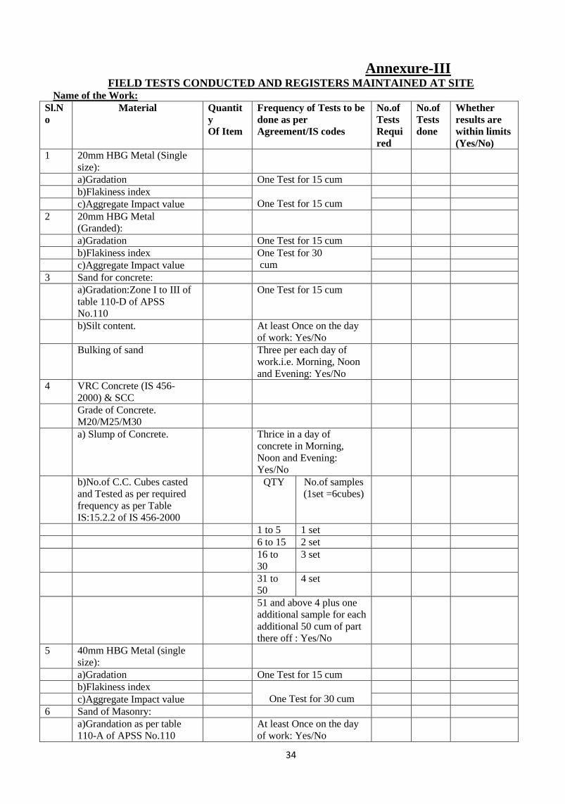
Annexure-III
FIELD TESTS CONDUCTED AND REGISTERS MAINTAINED AT SITE Name of the Work:
Sl.N
o
Material Quantit
y
Of Item
Frequency of Tests to be
done as per
Agreement/IS codes
No.of
Tests
Requi
red
No.of
Tests
done
Whether
results are
within limits
(Yes/No)
1 20mm HBG Metal (Single
size):
a)Gradation One Test for 15 cum
b)Flakiness index
One Test for 15 cum
c)Aggregate Impact value
2 20mm HBG Metal
(Granded):
a)Gradation One Test for 15 cum
b)Flakiness index One Test for 30
cum
c)Aggregate Impact value
3 Sand for concrete:
a)Gradation:Zone I to III of
table 110-D of APSS
No.110
One Test for 15 cum
b)Silt content. At least Once on the day
of work: Yes/No
Bulking of sand Three per each day of
work.i.e. Morning, Noon
and Evening: Yes/No
4 VRC Concrete (IS 456-
2000) & SCC
Grade of Concrete.
M20/M25/M30
a) Slump of Concrete. Thrice in a day of
concrete in Morning,
Noon and Evening:
Yes/No
b)No.of C.C. Cubes casted
and Tested as per required
frequency as per Table
IS:15.2.2 of IS 456-2000
QTY No.of samples
(1set =6cubes)
1 to 5 1 set
6 to 15 2 set
16 to
30
3 set
31 to
50
4 set
51 and above 4 plus one
additional sample for each
additional 50 cum of part
there off : Yes/No
5 40mm HBG Metal (single
size):
a)Gradation One Test for 15 cum
b)Flakiness index
One Test for 30 cum
c)Aggregate Impact value
6 Sand of Masonry:
a)Grandation as per table
110-A of APSS No.110
At least Once on the day
of work: Yes/No

35
7 Sand for Finishing‘s:
a)Gradation as per table 110-
B&110-c of APSS No.110 At least Once on the day
of work: Yes/No
AEE/AE DEE EE
36
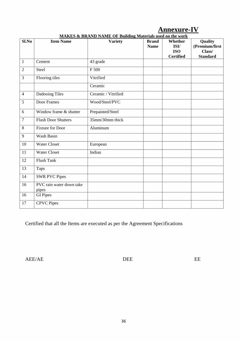
Annexure-IV MAKES & BRAND NAME OF Building Materials used on the work
Sl.No Item Name Variety Brand
Name
Whether
ISI/
ISO
Certified
Quality
(Premium/first
Class/
Standard
1 Cement 43 grade
2 Steel F 500
3 Flooring tiles Vitrified
Ceramic
4 Dadooing Tiles Ceramic / Vitrified
5 Door Frames Wood/Steel/PVC
6 Window frame & shutter Prepainted/Steel
7 Flush Door Shutters 35mm/30mm thick
8 Fixture for Door Aluminum
9 Wash Basin
10 Water Closet European
11 Water Closet Indian
12 Flush Tank
13 Taps
14 SWR PVC Pipes
16 PVC rain water down take
pipes
16 GI Pipes
17 CPVC Pipes
Certified that all the Items are executed as per the Agreement Specifications
AEE/AE DEE EE

37
Annexure-V
Check List – 4 Makes/Brands of Materials: Electrical
Name of the Work: Sl.No. Item Name Brand
Name
Whether ISI (Yes/No)
1 PVC Conduit Pipes
2 Switches/Switch board
3 6 amps 2/3 pin sockets
4 16 Amps 5 in 1 sockets
5 Tube light fittings
6 LED Lights
7 Ceiling Fans
8 Exhaust fans
9 Air Conditiners
10 Distribution Boards
11 MCB‘S
12 PVC flexible copper cables
13 Aluminium UG Cables
14 Pumps & Motors
Certified that all the items are executed as per the Agreement specifications.
AEE/AE DEE EE
38
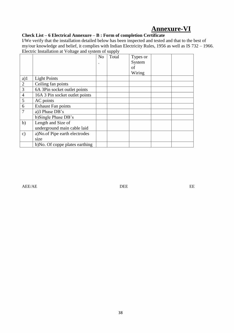
Annexure-VI Check List – 6 Electrical Annexure – B : Form of completion Certificate
I/We verify that the installation detailed below has been inspected and tested and that to the best of
my/our knowledge and belief, it complies with Indian Electricity Rules, 1956 as well as IS 732 – 1966.
Electric Installation at Voltage and system of supply
No
.
Total Types or
System
of
Wiring
a)1 Light Points
2 Ceiling fan points
3 6A 3Pin socket outlet points
4 16A 3 Pin socket outlet points
5 AC points
6 Exhaust Fan points
7 a)3 Phase DB‘s
b)Single Phase DB‘s
b) Length and Size of
underground main cable laid
c) a)No.of Pipe earth electrodes
size
b)No. Of coppe plates earthing
AEE/AE DEE EE

39
Annexure-VII
Certificates Name of the work:
1. Foundation and Basement filling Certificate
It is certified that filling in the above work is done with useful excavated earth (exuding rock)/Carted
earth/Gavel/Sand in trenches, sides of foundations and basement in layers not exceeding 150 mm thick,
consolidating each deposited layer duly watering and ramming as per Agreement and APSS No.309 &
310.
2. No Cracks Certificate
This is to certify that no cracks were seen in the walls and slab for the above work.
3. No Dampness Certificate
It is certified that ponding test is conducted as per agreement and there is no dampness /leakages
observed either on walls or cellings for the above work.
4. Wood Certificate
It is certified that wood used for doors / windows / ventilators / cub boards etc, for the above work is well
seasoned and as per agreement specification.
5. Certificate on Maintenance of Registers
It is certified that site Order Book, Daily Event Register, Field tests Registers and Lab test reports for the
above work are maintained as per agreement conditions
6. Expansion Joint Certificate
It is certified that the expansion joints provided in the work to line and level as shown in approved
drawing and ponding test is conducted in and around expansion joint portions and no dampness and no
leakages are observed and treatment to expansion joint portions are executed as per agreement
specifications/ approved drawings.
7. Expansion Joint Certificate
It is certified that the above work is competed satisfactory in all respect as per agreement specifications,
approved drawings and circular instructions issued from time to time.
AEE / AE DEE EE

40
Format QF-1 : Conformance/ Non-Conformance Report
Ref: Date:
To
[Contractor]
Package No. : ;Contract No.:
Title of Work :
Based on the review of the submitted test reports, as mentioned in the table below, our comments
and instructions are mentioned herein for your suitable action.
Test Report
No.
Date Test Labo-
ratory
Material Comments
(Conforms/ Does not conform. See
instructions below)
Instructions (Actions to be taken by Contractor):
Engineer – in - Charge

41
Format QF-2 : Test Report Log
Contract Package No. : ; Title of Work:
Contract No. : ; Contractor:
Date of
Sample
Lab
Name
Material
/ Process
Test
Report
No.
Date
of
TR
CNC
Report
No.
Date C /
NC
Action
to be
Taken by
Contractor
Inspecting
Authority
Sign
Note: C – Conformance; NC - Non-Conformance
Engineer – in - Charge
42
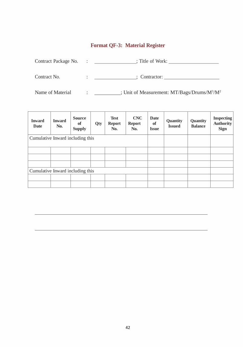
Format QF-3: Material Register
Contract Package No. : ; Title of Work:
Contract No. : ; Contractor:
Name of Material : ; Unit of Measurement: MT/Bags/Drums/M3/M2
Inward
Date
Inward
No.
Source
of
Supply
Qty
Test
Report
No.
CNC
Report
No.
Date
of
Issue
Quantity
Issued
Quantity
Balance
Inspecting
Authority
Sign
Cumulative Inward including this
Cumulative Inward including this

43
Format QF-4: Daily Work Record/Site Order Book
Name of Work …………………………………………………………………………………
Date of commencement / period for completion ………………………………………
Sl. No Remarks of Inspecting Officer or
Contractor
Action taken and by Whom Remarks
(3 copies per set – one copy each to be sent to Engineer in charge, Implementing Agency records
by the Contractor; one copy to be retained at site)

44
Format QF-5: Inspection Register
Name of Work …………………………………………………………………………………
S.No
Date
and
Time
Officers name
and Designa-
tion
Items
Inspected
and specif-
ic defects
noticed &
action to be
taken
Signature
Defects taken to Site Order
Book / Letter written
Final
Action
/ result.
Site
Order
Book
page
No. /
letter
no.
Date Sign. of
Engineer – in
- charge

45
Format QF-6: Instruction Log
Contract Package No. :
Title of Work :
Contract No. :
Contractor :
Date of In-
struction
Instruction Mode of Transmittal Compliance
Action by
Contractor
Inspecting
Authority
Sign Charge
Order
Site Instruc-
tion
Letter Minutes
46
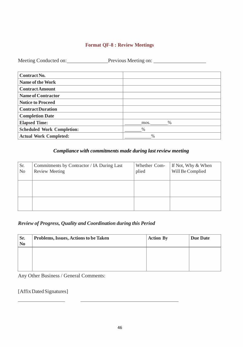
Format QF-8 : Review Meetings
Meeting Conducted on: Previous Meeting on:
Contract No.
Name of the Work
Contract Amount
Name of Contractor
Notice to Proceed
Contract Duration
Completion Date
Elapsed Time: mos. %
Scheduled Work Completion: %
Actual Work Completed: %
Compliance with commitments made during last review meeting
Sr.
No
Commitments by Contractor / IA During Last
Review Meeting
Whether Com-
plied
If Not, Why & When
Will Be Complied
Review of Progress, Quality and Coordination during this Period
Sr.
No
Problems, Issues, Actions to be Taken Action By Due Date
Any Other Business / General Comments:
[Affix Dated Signatures]

47
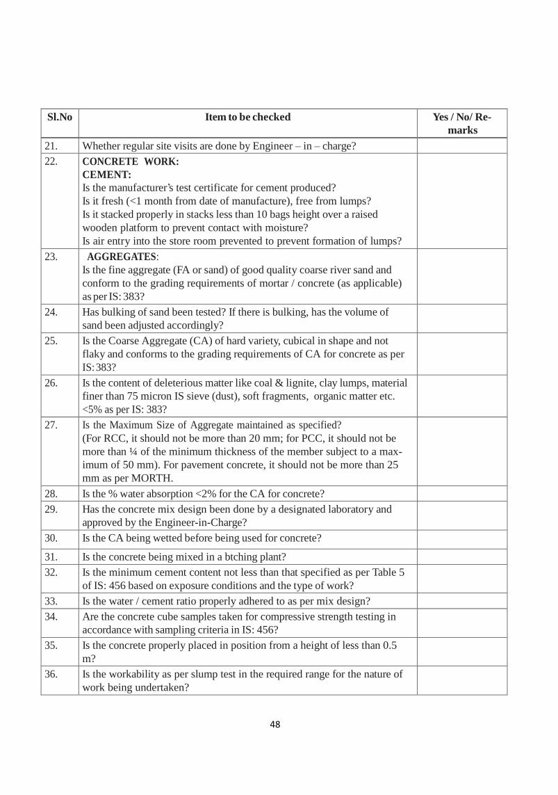
Format GC – 1: General Check list for Works
Sl.No Item to be checked Yes / No/ Re-
marks
1. Is the Community Information (Display) Board installed at the entry to
site is it useful in knowing the details of works?
2. Is the People‘s Estimate (pamphlet) also distributed to the community?
3. Is there a Community Monitoring Committee in the site
4. Is it able to monitor the Progress and Quality of work effectively?
5. AVAILABILITY OF DOCUMENTS:
Are copies of following available at site
i) Contract documents incl. contract drawings,
ii) Construction (working) drawings,
iii) Estimates and designs ?
iv) Are the Site Order Book and Quality Control Test Registers properly
maintained and available at contractor‘s site office?
6. Is there a Work Plan of the contractor?
7. Are the TBMs set up & verified by Engineer – in - charge?
8. Are the underground works commenced / done first i.e., sewerage, water
supply, drains, street lighting, roads in that sequence?
9. Are the construction of sewerage & drainage commenced from down-
stream end?
10. Are the Drain top levels below the road edge levels and also below the
Courtyard Levels of houses in general?
11. Are there any encroachments to be removed?
12. Is there any delay in progress of work with reference to work plan?
13. Is there any deviation in work or field conditions with reference to design?
Does any technical / financial problem need to be addressed?
14. Is the construction as per construction drawings?
15. Is the Contactor conducting quality control tests?
Is the Quality control test register being maintained properly and endorsed
by the Engineer – in -charge?
16. Is proper barricading provided where necessary to ensure safety of
residents?
17. Are drains and sewers properly connected to their disposal points?
18. Is there free flow of drainage?
19. What is the feedback of community on:
i) quality of work &
ii) functional aspects of works?
20. Specific remarks on performance of consultant (where mobilized).
Is there a Resident Engineer stationed for the site for supervision?
48
Sl.No Item to be checked Yes / No/ Re-
marks
21. Whether regular site visits are done by Engineer – in – charge?
22. CONCRETE WORK:
CEMENT:
Is the manufacturer‘s test certificate for cement produced?
Is it fresh (<1 month from date of manufacture), free from lumps?
Is it stacked properly in stacks less than 10 bags height over a raised
wooden platform to prevent contact with moisture?
Is air entry into the store room prevented to prevent formation of lumps?
23. AGGREGATES:
Is the fine aggregate (FA or sand) of good quality coarse river sand and
conform to the grading requirements of mortar / concrete (as applicable)
as per IS: 383?
24. Has bulking of sand been tested? If there is bulking, has the volume of
sand been adjusted accordingly?
25. Is the Coarse Aggregate (CA) of hard variety, cubical in shape and not
flaky and conforms to the grading requirements of CA for concrete as per
IS: 383?
26. Is the content of deleterious matter like coal & lignite, clay lumps, material
finer than 75 micron IS sieve (dust), soft fragments, organic matter etc.
<5% as per IS: 383?
27. Is the Maximum Size of Aggregate maintained as specified?
(For RCC, it should not be more than 20 mm; for PCC, it should not be
more than ¼ of the minimum thickness of the member subject to a max-
imum of 50 mm). For pavement concrete, it should not be more than 25
mm as per MORTH.
28. Is the % water absorption <2% for the CA for concrete?
29. Has the concrete mix design been done by a designated laboratory and
approved by the Engineer-in-Charge?
30. Is the CA being wetted before being used for concrete?
31. Is the concrete being mixed in a btching plant?
32. Is the minimum cement content not less than that specified as per Table 5
of IS: 456 based on exposure conditions and the type of work?
33. Is the water / cement ratio properly adhered to as per mix design?
34. Are the concrete cube samples taken for compressive strength testing in
accordance with sampling criteria in IS: 456?
35. Is the concrete properly placed in position from a height of less than 0.5
m?
36. Is the workability as per slump test in the required range for the nature of
work being undertaken?
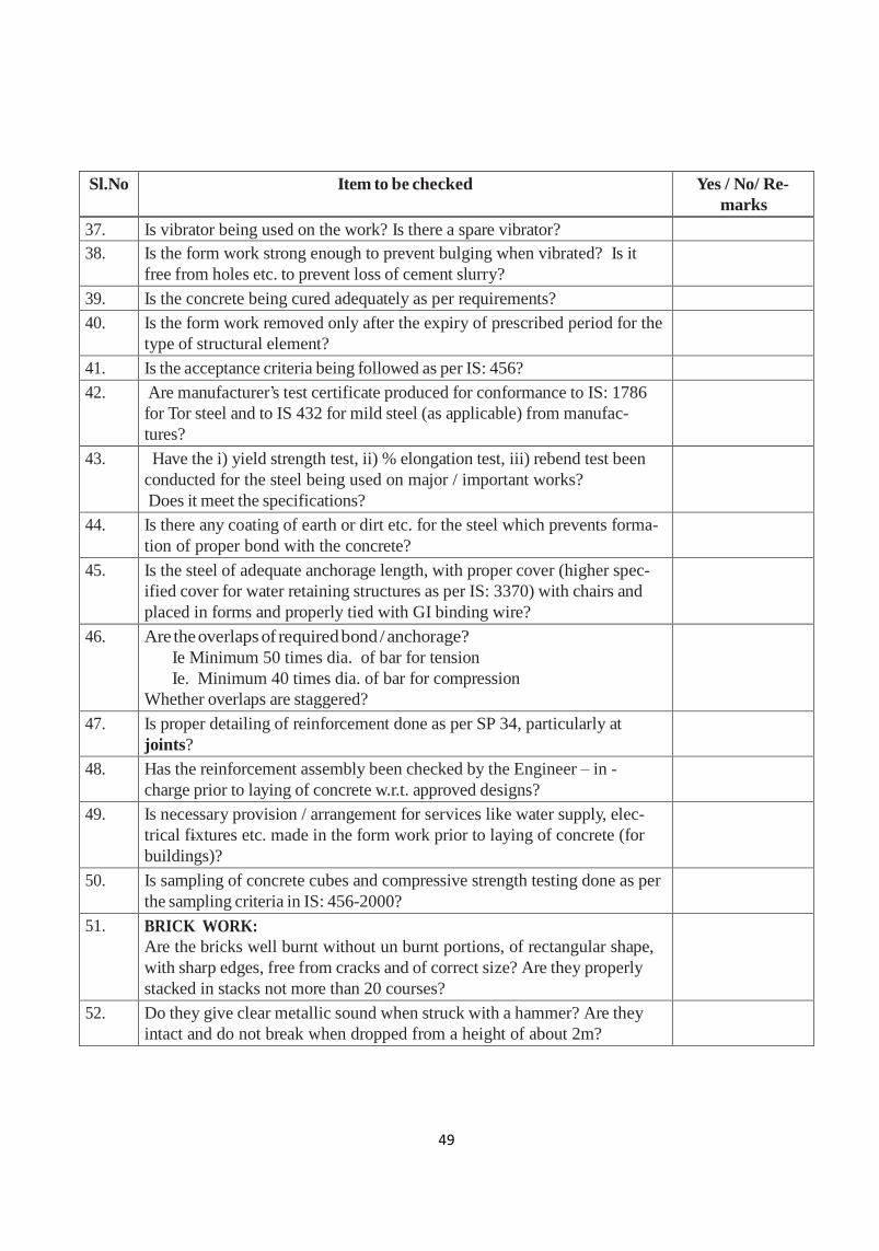
49
Sl.No Item to be checked Yes / No/ Re-
marks
37. Is vibrator being used on the work? Is there a spare vibrator?
38. Is the form work strong enough to prevent bulging when vibrated? Is it
free from holes etc. to prevent loss of cement slurry?
39. Is the concrete being cured adequately as per requirements?
40. Is the form work removed only after the expiry of prescribed period for the
type of structural element?
41. Is the acceptance criteria being followed as per IS: 456?
42. Are manufacturer‘s test certificate produced for conformance to IS: 1786
for Tor steel and to IS 432 for mild steel (as applicable) from manufac-
tures?
43. Have the i) yield strength test, ii) % elongation test, iii) rebend test been
conducted for the steel being used on major / important works?
Does it meet the specifications?
44. Is there any coating of earth or dirt etc. for the steel which prevents forma-
tion of proper bond with the concrete?
45. Is the steel of adequate anchorage length, with proper cover (higher spec-
ified cover for water retaining structures as per IS: 3370) with chairs and
placed in forms and properly tied with GI binding wire?
46. Are the overlaps of required bond / anchorage?
Ie Minimum 50 times dia. of bar for tension
Ie. Minimum 40 times dia. of bar for compression
Whether overlaps are staggered?
47. Is proper detailing of reinforcement done as per SP 34, particularly at
joints?
48. Has the reinforcement assembly been checked by the Engineer – in -
charge prior to laying of concrete w.r.t. approved designs?
49. Is necessary provision / arrangement for services like water supply, elec-
trical fixtures etc. made in the form work prior to laying of concrete (for
buildings)?
50. Is sampling of concrete cubes and compressive strength testing done as per
the sampling criteria in IS: 456-2000?
51. BRICK WORK:
Are the bricks well burnt without un burnt portions, of rectangular shape,
with sharp edges, free from cracks and of correct size? Are they properly
stacked in stacks not more than 20 courses?
52. Do they give clear metallic sound when struck with a hammer? Are they
intact and do not break when dropped from a height of about 2m?

50
Sl.No Item to be checked Yes / No/ Re-
marks
53 Are the bricks soaked in water for 2 hours before being used?
54. Have the bricks been tested for compressive strength? Do they satisfy 50
kg/cm2 for 1st class bricks (for sewer man holes) and 35 kg/cm2 for 2nd class
bricks for other works?
55. Is the % water absorption after 24 hours not more than 20%?
56. Does the sand fall in the grading as prescribed? Is the mortar used as per
specified mix proportions?
57. Is the frog (manufacturer‘s mark) kept on the top of the brick while laying
the brickwork?
58. Are the joints in each layer broken to prevent stress concentration?
59. Is the thickness of mortar joint as per specification?
(Not more than 12 mm for 2nd class brickwork and 10 mm for 1st class
brickwork)
60. Are the joints raked when mortar is green for at least 7.5 mm before
plastering?
61. Is the brickwork cured for at least 14 days after construction?
62. Any constraints to speedy progress of work?
63. Any constraints to maintaining quality of work?
64. Any other remarks of the Inspecting Officer
Signature of Inspecting officer

51
Format– IC – 1: Checklists for Building Works
Sr.
No.
Items
Remarks by
Implementation
agency / Authorised
representative
Compliance by
Contractor
1) EXCAVATION & PCC
A. Pre Excavation
1 Construction Drawings
indicating levels available at Site
2 Proper safety precautions taken
for site and public
3 Precautions taken for dewatering
and protecting site from flooding
4 Dumping ground established
5 Setting out and levels as per
drawings
6 Intermediate levels checked
B. Post Excavation
1 Characteristics of excavated strata
noted and deviations informed
2 Appropriate shoring and
shuttering done
3 Final excavation levels, surface
inspected and approved
4 Anti-Termite Treatment has been
done post excavation
2) PLAIN CEMENT CONCRETE WORKS
A . Pre-concreting
1 All levels and dimensions
checked for correctness
2 Shuttering is as per plan and has
no gaps in between

52
Sr.
No.
Items
Remarks by
Implementation
agency / Authorised
representative
Compliance by
Contractor
3 All materials are of specified
brand and grade
B. During Concreting
1 Mixing of concrete has been done
as specified
2 Slump and other tests carried out
as specified
3 Honeycombing removed
4
Required number of Samples
have been taken for carrying out
slump tests, cube tests etc
C. Post Concreting
1 Concreting has been done as per
specified line and level
2 Curing has been done as specified
3 Compaction has been done
properly
4 Remedial measures taken for
removal of defects
3) ANTI TERMITE TREATMENT (ATT)
1 Chemicals for ATT are as per
specifications
2 Chemicals in use are within the
expiry date.
3 Sufficient quantities of chemicals
are available at site for ATT.
4
Safety precautions have been
taken for carrying out ATT and
storage of Chemicals.
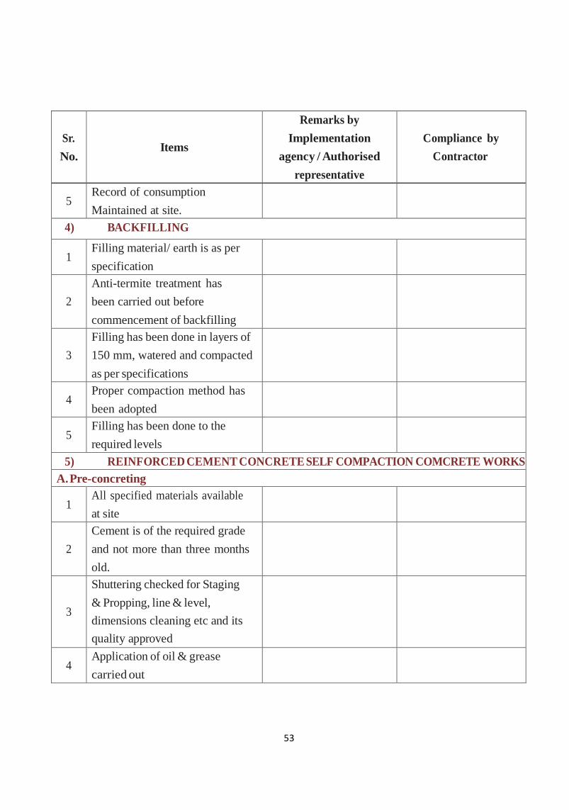
53
Sr.
No.
Items
Remarks by
Implementation
agency / Authorised
representative
Compliance by
Contractor
5 Record of consumption
Maintained at site.
4) BACKFILLING
1 Filling material/ earth is as per
specification
2
Anti-termite treatment has
been carried out before
commencement of backfilling
3
Filling has been done in layers of
150 mm, watered and compacted
as per specifications
4 Proper compaction method has
been adopted
5 Filling has been done to the
required levels
5) REINFORCED CEMENT CONCRETE SELF COMPACTION COMCRETE WORKS
A. Pre-concreting
1 All specified materials available
at site
2
Cement is of the required grade
and not more than three months
old.
3
Shuttering checked for Staging
& Propping, line & level,
dimensions cleaning etc and its
quality approved
4 Application of oil & grease
carried out
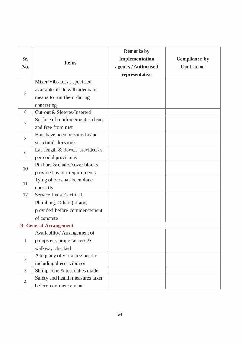
54
Sr.
No.
Items
Remarks by
Implementation
agency / Authorised
representative
Compliance by
Contractor
5
Mixer/Vibrator as specified
available at site with adequate
means to run them during
concreting
6 Cut-out & Sleeves/Inserted
7 Surface of reinforcement is clean
and free from rust
8 Bars have been provided as per
structural drawings
9 Lap length & dowels provided as
per codal provisions
10 Pin bars & chairs/cover blocks
provided as per requirements
11 Tying of bars has been done
correctly
12 Service lines(Electrical,
Plumbing, Others) if any,
provided before commencement
of concrete
B. General Arrangement
1
Availability/ Arrangement of
pumps etc, proper access &
walkway checked
2 Adequacy of vibrators/ needle
including diesel vibrator
3 Slump cone & test cubes made
4 Safety and health measures taken
before commencement
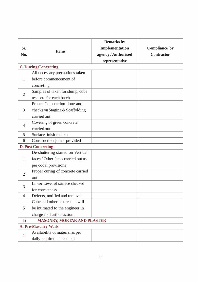
55
Sr.
No.
Items
Remarks by
Implementation
agency / Authorised
representative
Compliance by
Contractor
C. During Concreting
1
All necessary precautions taken
before commencement of
concreting
2 Samples of taken for slump, cube
tests etc for each batch
3
Proper Compaction done and
checks on Staging & Scaffolding
carried out
4 Covering of green concrete
carried out
5 Surface finish checked
6 Construction joints provided
D. Post Concreting
1
De-shuttering started on Vertical
faces / Other faces carried out as
per codal provisions
2 Proper curing of concrete carried
out
3 Line& Level of surface checked
for correctness
4 Defects, notified and removed
5
Cube and other test results will
be intimated to the engineer in
charge for further action
6) MASONRY, MORTAR AND PLASTER
A. Pre-Masonry Work
1 Availability of material as per
daily requirement checked
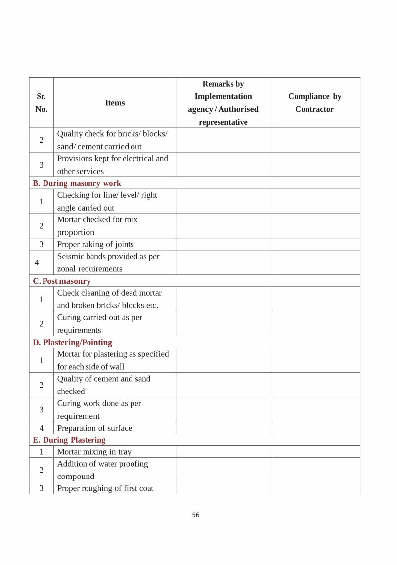
56
Sr.
No.
Items
Remarks by
Implementation
agency / Authorised
representative
Compliance by
Contractor
2 Quality check for bricks/ blocks/
sand/ cement carried out
3 Provisions kept for electrical and
other services
B. During masonry work
1 Checking for line/ level/ right
angle carried out
2 Mortar checked for mix
proportion
3 Proper raking of joints
4 Seismic bands provided as per
zonal requirements
C. Post masonry
1 Check cleaning of dead mortar
and broken bricks/ blocks etc.
2 Curing carried out as per
requirements
D. Plastering/Pointing
1 Mortar for plastering as specified
for each side of wall
2 Quality of cement and sand
checked
3 Curing work done as per
requirement
4 Preparation of surface
E. During Plastering
1 Mortar mixing in tray
2 Addition of water proofing
compound
3 Proper roughing of first coat

57
Sr.
No.
Items
Remarks by
Implementation
agency / Authorised
representative
Compliance by
Contractor
4 Check for collection of mortar
spills
5 Cleaning of dead mortar
6 Check of waviness
7 Check for grooves/ drip moulds
8 Application of cement slurry on
concrete surface
F. After Plastering
1 Curing
2 Check for hollowness
3 Check for cracks
4 Check for diagonal
5 Lime wash after 3 days (within5
days in case of neeru application)
6 Safety and health measures
7) WATER PROOFING
1 Surface for waterproofing has
been prepared and cleaned
2
Safety measures/ precautions
taken before commencement of
works
3 Specified type of water proofing
used
4 Specified material used for
waterproofing
5 The material used was as per
specification
6
Work has been carried out as per
specifications by the department/
specialized agency
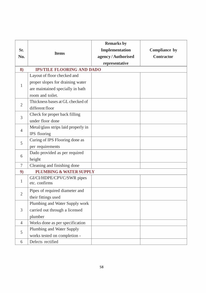
58
Sr.
No.
Items
Remarks by
Implementation
agency / Authorised
representative
Compliance by
Contractor
8) IPS/TILE FLOORING AND DADO
1
Layout of floor checked and
proper slopes for draining water
are maintained specially in bath
room and toilet.
2 Thickness bases at GL checked of
different floor
3 Check for proper back filling
under floor done
4 Metal/glass strips laid properly in
IPS flooring
5 Curing of IPS Flooring done as
per requirements
6 Dado provided as per required
height
7 Cleaning and finishing done
9) PLUMBING & WATER SUPPLY
1 GI/CI/HDPE/CPVC/SWR pipes
etc. confirms
to relevant IS codes
2 Pipes of required diameter and
their fittings used
3
Plumbing and Water Supply work
carried out through a licensed
plumber
4 Works done as per specification
5 Plumbing and Water Supply
works tested on completion -
6 Defects rectified
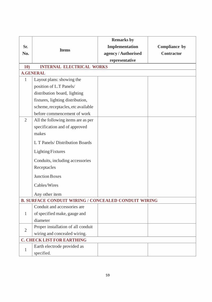
59
Sr.
No.
Items
Remarks by
Implementation
agency / Authorised
representative
Compliance by
Contractor
10) INTERNAL ELECTRICAL WORKS
A.GENERAL
1 Layout plans: showing the
position of L.T Panels/
distribution board, lighting
fixtures, lighting distribution,
scheme, receptacles, etc available
before commencement of work
2 All the following items are as per
specification and of approved
makes
L T Panels/ Distribution Boards
Lighting Fixtures
Conduits, including accessories
Receptacles
Junction Boxes
Cables/Wires
Any other item
B. SURFACE CONDUIT WIRING / CONCEALED CONDUIT WIRING
1
Conduit and accessories are
of specified make, gauge and
diameter
2 Proper installation of all conduit
wiring and concealed wiring.
C. CHECK LIST FOR EARTHING
1 Earth electrode provided as
specified.
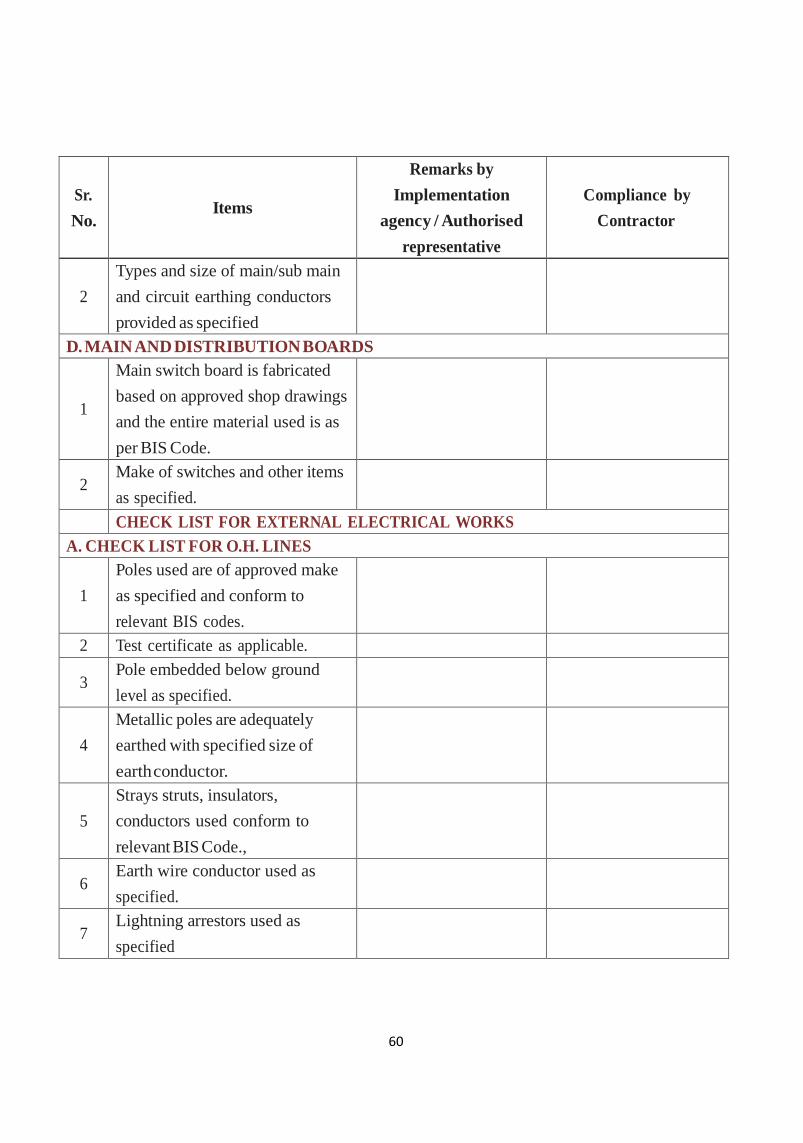
60
Sr.
No.
Items
Remarks by
Implementation
agency / Authorised
representative
Compliance by
Contractor
2
Types and size of main/sub main
and circuit earthing conductors
provided as specified
D. MAIN AND DISTRIBUTION BOARDS
1
Main switch board is fabricated
based on approved shop drawings
and the entire material used is as
per BIS Code.
2 Make of switches and other items
as specified.
CHECK LIST FOR EXTERNAL ELECTRICAL WORKS
A. CHECK LIST FOR O.H. LINES
1
Poles used are of approved make
as specified and conform to
relevant BIS codes.
2 Test certificate as applicable.
3 Pole embedded below ground
level as specified.
4
Metallic poles are adequately
earthed with specified size of
earth conductor.
5
Strays struts, insulators,
conductors used conform to
relevant BIS Code.,
6 Earth wire conductor used as
specified.
7 Lightning arrestors used as
specified

61
Sr.
No.
Items
Remarks by
Implementation
agency / Authorised
representative
Compliance by
Contractor
8
Spacing of poles, spans and
clearance between, conductors
and, surroundings kept as
specified.
9 Insulators used for specified
grade.
B. CABLE LAYING
1 Trenches of specified dimensions
excavated and prepared
2
Required quantity of sand
cushioning provided; cable laid;
another layer of sand and brick
protective covering provided.
Refilling done earth ramming
and dressing done.
3
Cables entry point in building or
crossing roads path protected by
providing Hume pipes or PVC
pipe
4 Cable tested before and after
laying and before emerging
C. CHECK LIST FOR EARTHING
1 Earth electrode provided as
specified
2
Types and size of main/ sub main
and circuit earthing conductors
provided as specified.
11) DRAINAGE WORKS
1 Excavation for drains carried out
as per the approved lay-out
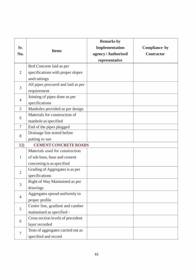
62
Sr.
No.
Items
Remarks by
Implementation
agency / Authorised
representative
Compliance by
Contractor
2
Bed Concrete laid as per
specifications with proper slopes
and cuttings
3 All pipes procured and laid as per
requirement
4 Jointing of pipes done as per
specifications
5 Manholes provided as per design
6 Materials for construction of
manhole as specified
7 End of the pipes plugged
8 Drainage line tested before
putting to use
12) CEMENT CONCRETE ROADS
1
Materials used for construction
of sub base, base and cement
concreting is as specified
2 Grading of Aggregates is as per
specifications
3 Right of Way Maintained as per
drawings
4 Aggregates spread uniformly to
proper profile
5 Centre line, gradient and camber
maintained as specified -
6 Cross section levels of precedent
layer recorded
7 Tests of aggregates carried out as
specified and record
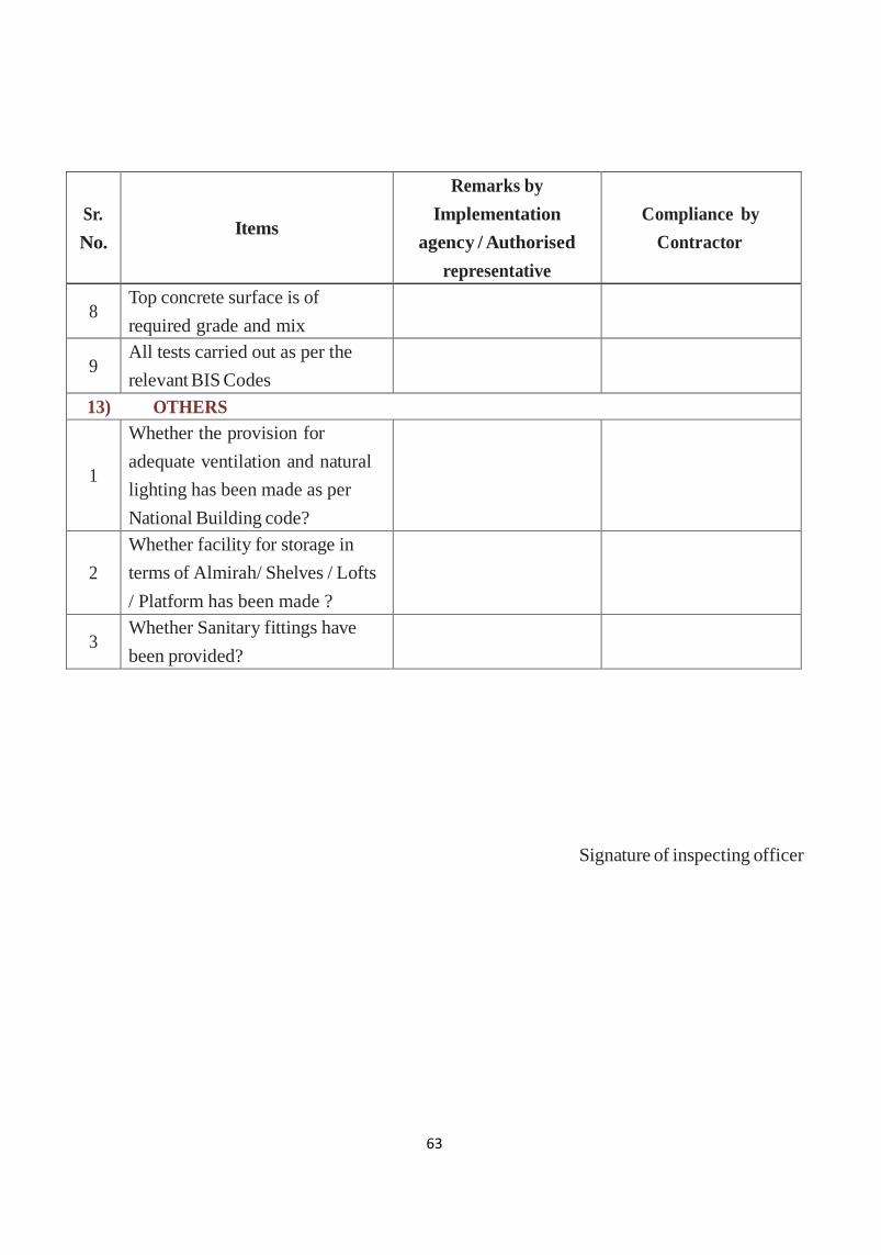
63
Sr.
No.
Items
Remarks by
Implementation
agency / Authorised
representative
Compliance by
Contractor
8 Top concrete surface is of
required grade and mix
9 All tests carried out as per the
relevant BIS Codes
13) OTHERS
1
Whether the provision for
adequate ventilation and natural
lighting has been made as per
National Building code?
2
Whether facility for storage in
terms of Almirah/ Shelves / Lofts
/ Platform has been made ?
3 Whether Sanitary fittings have
been provided?
Signature of inspecting officer

64
Format– IC – 3 : Inspection checklists for Drains
Sl.No. Item to be checked Remarks by Imple-
mentation agency /
Authorised represen-
tative
Compliance
by Contrac-
tor
1. Is the construction as per approved construction
drawings?
2. Are the Drain Top Levels below the Road Edge Levels
and Courtyard Levels for onsite drains?
3. Is Proper alignment and gradient maintained for the
drains?
4. Are the dimensions correct?
5. Is proper granular bedding provided under the bed
concrete after removing loose, slushy soil? Is the bed
concrete of Good quality?
6. Is the construction done to the required gradient?
7. Are the CA, FA and water of good quality & free
from deleterious material?
8. Are the concrete cube samples taken by Engineer – in
-charge and tested? If so, do they satisfy compressive
strength requirements?
9. Is Vibrator being used?
10. Is Curing done properly for the specified period?
11. Is the internal drainage properly connected to the
outfall drain?
12. Are the Road side drain walls raised to just below
road level?
Are the dimensions of these walls adequate?
13. Is the finishing of the drain good?
14. Are the culverts adequate to discharge the drainage?
If not, do they need widening?
15. Are the water pipe lines across the drain or beside
the drain being shifted /realigned/encased to prevent
pollution of water?
16. Is there any need to rehabilitate existing damaged
drain section if any, which inhibits the efficiency of
functioning of the drain?
Signature of inspecting officer
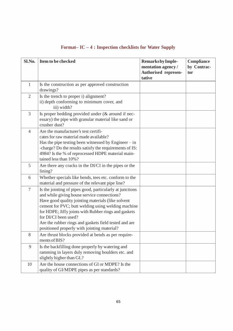
65
Format– IC – 4 : Inspection checklists for Water Supply
Sl.No. Item to be checked Remarks by Imple-
mentation agency /
Authorised represen-
tative
Compliance
by Contrac-
tor
1 Is the construction as per approved construction
drawings?
2 Is the trench to proper i) alignment?
ii) depth conforming to minimum cover, and
iii) width?
3 Is proper bedding provided under (& around if nec-
essary) the pipe with granular material like sand or
crusher dust?
4 Are the manufacturer‘s test certifi-
cates for raw material made available?
Has the pipe testing been witnessed by Engineer – in
-charge? Do the results satisfy the requirements of IS:
4984? Is the % of reprocessed HDPE material main-
tained less than 10%?
5 Are there any cracks in the DI/CI in the pipes or the
lining?
6 Whether specials like bends, tees etc. conform to the
material and pressure of the relevant pipe line?
7 Is the jointing of pipes good, particularly at junctions
and while giving house service connections?
Have good quality jointing materials (like solvent
cement for PVC; butt welding using welding machine
for HDPE; Jiffy joints with Rubber rings and gaskets
for DI/CI been used?
Are the rubber rings and gaskets field tested and are
positioned properly with jointing material?
8 Are thrust blocks provided at bends as per require-
ments of BIS?
9 Is the backfilling done properly by watering and
ramming in layers duly removing boulders etc. and
slightly higher than GL?
10 Are the house connections of GI or MDPE? Is the
quality of GI/MDPE pipes as per standards?

66
Sl.No. Item to be checked Remarks by Imple-
mentation agency /
Authorised represen-
tative
Compliance
by Contrac-
tor
11 Are the
i) valves, ii) valve chambers, covers and iii) specials
of good quality? iv) are they properly and safely
located to prevent their breaking due to traffic? v) do
they conform to the relevant pipe line requirements?
12 Whether air valves conform to the pipe line require-
ments?
13 Whether non-return valves conform to the pipe line
requirements?
14 Whether pressure release valves conform to the pipe
line requirements?
15 Are horizontal stretches in the pipe line avoided to
prevent air accumulation?
16 Have proper Arrangements for Interconnection with
Source of supply done? Are concrete / RCC thrust
blocks provided at bends as applicable?
17 Has the Hydraulic test on pipeline/s been conducted?
Is it witnessed by the Engineer – in -charge & com-
munity?
18 Is the test pressure adequate and as per specifica-
tions?
19 Is there any leaks/cracks/damages observed in the
pipes or joints?
20 Have all Households taken House Service Connec-
tions?
21 Are the pressures adequate? Have all pit taps, if any,
been removed after laying new distribution lines/
replacing old lines?
22 Are there any un served Households?
23 Is there any pollution or scope for pollution of drink-
ing water? If so, are necessary precautions taken or
planned?
24 Is water actually reaching the consumer‘s house with
adequate pressure?

67
Sl.No. Item to be checked Remarks by Imple-
mentation agency /
Authorised represen-
tative
Compliance
by Contrac-
tor
25 PUMP SETS:
i) Are the pumps procured as per specifications of
duty and head? Has testing of pump set been con-
ducted in the presence of Engineer – in -charge?
ii) Have the pump sets passed the tests and satisfy the
duty and head requirements?
iii) Have all accessories like panel board, switch gear
of the pump sets been supplied and are they suitable
and satisfy the quality requirements?
iv) Is the starter provided appropriate to the KW of
the pump set?
iv) Has Trial run been conducted and is it successful?
v) Have single phasing preventor, over load relay &
capacitors been provided?
26 Are the cable sizes provided as per design and oper-
ating conditions?
27 Is positive suction condition ensured for centrifugal
pump sets?
28 Has an eccentric taper been provided on the suction
side?
29 Have the required sluice valves and non-return valve
on delivery side been provided?
Is the piping devoid of unnecessary bends etc. to
reduce friction losses?
30 Have proper earthing, lightning arrestors and safety
controls been provided?
31 Have dismantling joints been provided for the valves
at the pump house?
32 Has the electrical connection been given to the pump
sets?
33 Has the correct Contracted Maximum Demand
(CMD) been agreed with the State Electricity Board ?
34 For a tube well, has the capacity (KW) of the sub-
mersible pump set been fixed based on the depth and
yield of water after conducting yield test?
35 SUMP / OHSR / GLSR
Is the safe bearing capacity (SBC) of soil for founda-
tion of Sump / OHSR been tested?

68
Sl.No. Item to be checked Remarks by Imple-
mentation agency /
Authorised represen-
tative
Compliance
by Contrac-
tor
36 Does the design of foundation for the Sump / OHSR
need any revision based on the SBC?
37 Have necessary strengthening of foundation done
for poor soils like BC soil and / or high water table, if
met?
38 Has the reinforcement assembly at each stage been
checked by the Engineer – in - charge?
39 Is the form work for floor slab/ roof slab / dome ade-
quate and safe?
40 Is the steel being used comply with the relevant
specifications? Are the manufacturer‘s test certificates
available on site?
41 Has the steel been tested for tensile strength, % elon-
gation and rebend test? If so, do the results satisfy the
requirements of the code?
42 Has the minimum cover in accordance with IS: 3370
provided for RCC water retaining structures?
43 Is the detailing at joints properly done as per SP: 34?
44 Have puddle pipes been provided in the floor slab of
OHSR?
45 Has the SUMP / OHSR /GLSR been tested for water
tightness in accordance with IS: 3370?
46 Is there any leakage through the Sump / OHSR /
GLSR?
47 Is the scour of OHSR/GLSR connected to natural
drain?
48 Have the inlet and outlet been inter connected (bye
pass)?
49 Has the overflow pipe been connected to the outlet
pipe?
50 Have proper lightning arrestor, water level indicators,
ventilators, ladders, staircase, railing been provided?
51 Has the ground below the ELSR been raised to pre-
vent stagnation of water?
Signature of inspecting officer
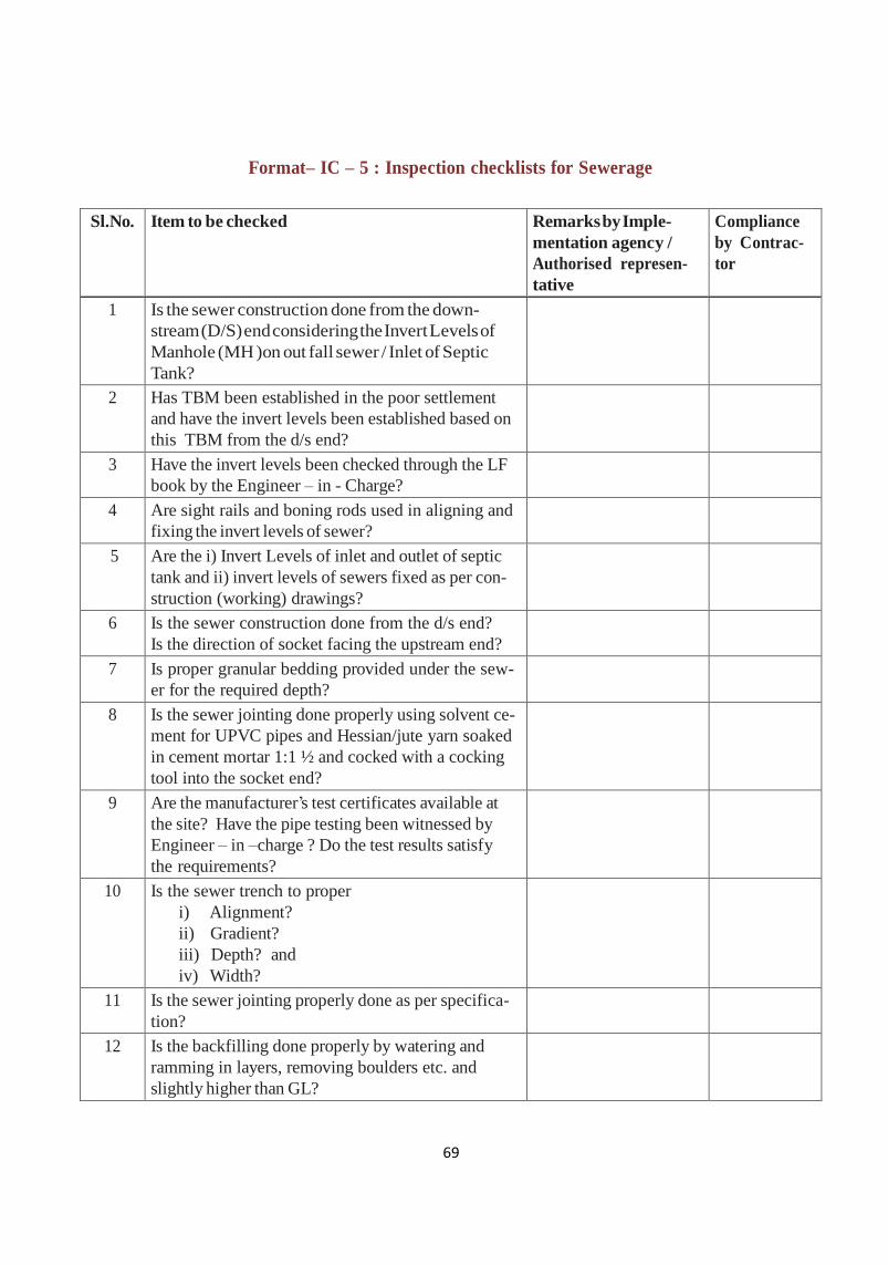
69
Format– IC – 5 : Inspection checklists for Sewerage
Sl.No. Item to be checked Remarks by Imple-
mentation agency /
Authorised represen-
tative
Compliance
by Contrac-
tor
1 Is the sewer construction done from the down-
stream (D/S) end considering the Invert Levels of
Manhole (MH )on out fall sewer / Inlet of Septic
Tank?
2 Has TBM been established in the poor settlement
and have the invert levels been established based on
this TBM from the d/s end?
3 Have the invert levels been checked through the LF
book by the Engineer – in - Charge?
4 Are sight rails and boning rods used in aligning and
fixing the invert levels of sewer?
5 Are the i) Invert Levels of inlet and outlet of septic
tank and ii) invert levels of sewers fixed as per con-
struction (working) drawings?
6 Is the sewer construction done from the d/s end?
Is the direction of socket facing the upstream end?
7 Is proper granular bedding provided under the sew-
er for the required depth?
8 Is the sewer jointing done properly using solvent ce-
ment for UPVC pipes and Hessian/jute yarn soaked
in cement mortar 1:1 ½ and cocked with a cocking
tool into the socket end?
9 Are the manufacturer‘s test certificates available at
the site? Have the pipe testing been witnessed by
Engineer – in –charge ? Do the test results satisfy
the requirements?
10 Is the sewer trench to proper
i) Alignment?
ii) Gradient?
iii) Depth? and
iv) Width?
11 Is the sewer jointing properly done as per specifica-
tion?
12 Is the backfilling done properly by watering and
ramming in layers, removing boulders etc. and
slightly higher than GL?
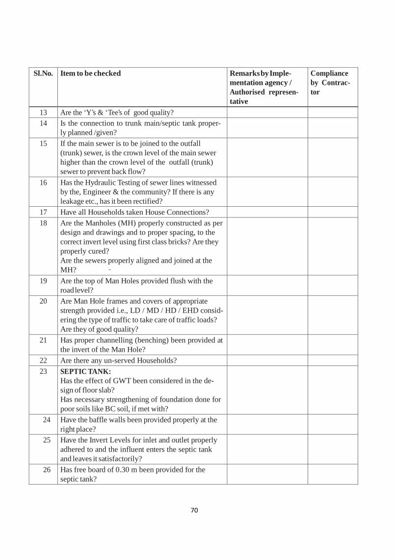
70
Sl.No. Item to be checked Remarks by Imple-
mentation agency /
Authorised represen-
tative
Compliance
by Contrac-
tor
13 Are the ‗Y‘s & ‗Tee‘s of good quality?
14 Is the connection to trunk main/septic tank proper-
ly planned /given?
15 If the main sewer is to be joined to the outfall
(trunk) sewer, is the crown level of the main sewer
higher than the crown level of the outfall (trunk)
sewer to prevent back flow?
16 Has the Hydraulic Testing of sewer lines witnessed
by the, Engineer & the community? If there is any
leakage etc., has it been rectified?
17 Have all Households taken House Connections?
18 Are the Manholes (MH) properly constructed as per
design and drawings and to proper spacing, to the
correct invert level using first class bricks? Are they
properly cured?
Are the sewers properly aligned and joined at the
MH?
19 Are the top of Man Holes provided flush with the
road level?
20 Are Man Hole frames and covers of appropriate
strength provided i.e., LD / MD / HD / EHD consid-
ering the type of traffic to take care of traffic loads?
Are they of good quality?
21 Has proper channelling (benching) been provided at
the invert of the Man Hole?
22 Are there any un-served Households?
23 SEPTIC TANK:
Has the effect of GWT been considered in the de-
sign of floor slab?
Has necessary strengthening of foundation done for
poor soils like BC soil, if met with?
24 Have the baffle walls been provided properly at the
right place?
25 Have the Invert Levels for inlet and outlet properly
adhered to and the influent enters the septic tank
and leaves it satisfactorily?
26 Has free board of 0.30 m been provided for the
septic tank?
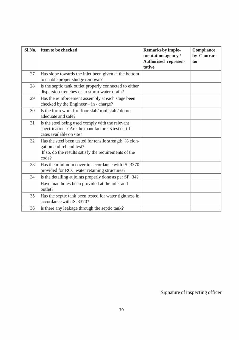
70
Sl.No. Item to be checked Remarks by Imple-
mentation agency /
Authorised represen-
tative
Compliance
by Contrac-
tor
27 Has slope towards the inlet been given at the bottom
to enable proper sludge removal?
28 Is the septic tank outlet properly connected to either
dispersion trenches or to storm water drain?
29 Has the reinforcement assembly at each stage been
checked by the Engineer – in - charge?
30 Is the form work for floor slab/ roof slab / dome
adequate and safe?
31 Is the steel being used comply with the relevant
specifications? Are the manufacturer‘s test certifi-
cates available on site?
32 Has the steel been tested for tensile strength, % elon-
gation and rebend test?
If so, do the results satisfy the requirements of the
code?
33 Has the minimum cover in accordance with IS: 3370
provided for RCC water retaining structures?
34 Is the detailing at joints properly done as per SP: 34?
Have man holes been provided at the inlet and
outlet?
35 Has the septic tank been tested for water tightness in
accordance with IS: 3370?
36 Is there any leakage through the septic tank?
Signature of inspecting officer

71
Format– IC – 6 Community Monitoring Committee - Checklist
Sl.
No
Item to be checked Yes / No /
Remark
Remarks by
Implementation
agency /
Authorized
representative
Compliance
by
Contractor
if any
1. Is the Community Information (Display) Board
installed near the entry to the site is it useful in
knowing the details of works?
2. Is the People‘s Estimate (pamphlet) distributed
to the community?
3. Does the Contractor / Engineer enable proper
Community Monitoring of the works? How can
it be made more effective?
4. Are the underground works commenced / done
first i.e., sewerage, water supply, drains, street
lighting, roads in that sequence?
5. Are the construction of sewerage & drainage
commenced from downstream end?
6. Does it seem the waste water will enter
their houses when the drains and roads are
completed?
7. Is adequate Gradient maintained for drains and
sewers to enable free flow of waste water?
8.
Are the water pipelines and sewers constructed
to proper i) alignment, ii) depth and iii) is the
jointing good?
9.
Has the Testing of i) water pipe line and ii)
sewers been witnessed by the Engineer – in –
charge and community?
10.
Is drinking water reaching the houses with
adequate pressure?
11. Are there any encroachments to be removed?
12. Is there any delay in progress of work? What are
the constraints?
13. Community‘s perception of the general quality
of work? Satisfactory or not?
15. Are the materials / equipment of the contractor
safe?
17. What is the Frequency of visits of Engineer – in
– charge

72
18. Have ALL Households taken i) water
connections and ii) sewer connections?
19. Any other remarks of the Community
Monitoring committee
Signature of Community Monitoring
Committee Members
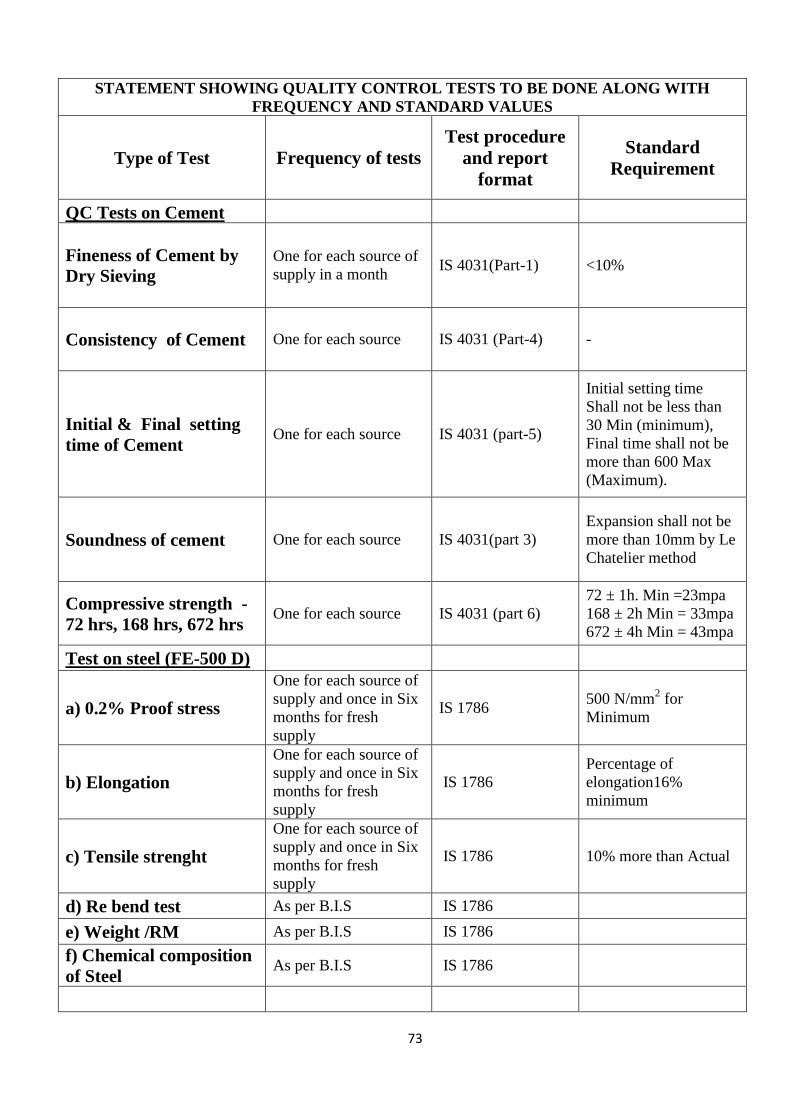
73
STATEMENT SHOWING QUALITY CONTROL TESTS TO BE DONE ALONG WITH
FREQUENCY AND STANDARD VALUES
Type of Test Frequency of tests
Test procedure
and report
format
Standard
Requirement
QC Tests on Cement
Fineness of Cement by
Dry Sieving
One for each source of
supply in a month IS 4031(Part-1) <10%
Consistency of Cement One for each source IS 4031 (Part-4) -
Initial & Final setting
time of Cement One for each source IS 4031 (part-5)
Initial setting time
Shall not be less than
30 Min (minimum),
Final time shall not be
more than 600 Max
(Maximum).
Soundness of cement One for each source IS 4031(part 3)
Expansion shall not be
more than 10mm by Le
Chatelier method
Compressive strength -
72 hrs, 168 hrs, 672 hrs One for each source IS 4031 (part 6)
72 ± 1h. Min =23mpa
168 ± 2h Min = 33mpa
672 ± 4h Min = 43mpa
Test on steel (FE-500 D)
a) 0.2% Proof stress
One for each source of
supply and once in Six
months for fresh
supply
IS 1786 500 N/mm
2 for
Minimum
b) Elongation
One for each source of
supply and once in Six
months for fresh
supply
IS 1786
Percentage of
elongation16%
minimum
c) Tensile strenght
One for each source of
supply and once in Six
months for fresh
supply
IS 1786 10% more than Actual
d) Re bend test As per B.I.S IS 1786
e) Weight /RM As per B.I.S IS 1786
f) Chemical composition
of Steel As per B.I.S IS 1786
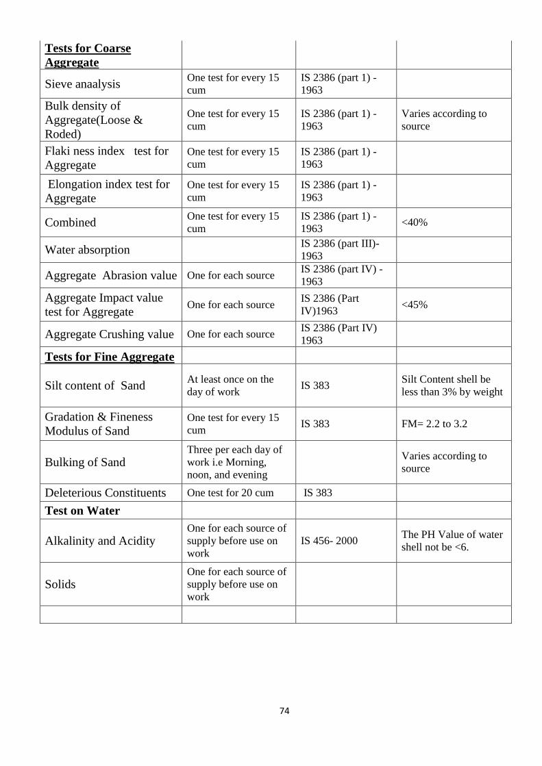
74
Tests for Coarse
Aggregate
Sieve anaalysis One test for every 15
cum
IS 2386 (part 1) -
1963
Bulk density of
Aggregate(Loose &
Roded)
One test for every 15
cum
IS 2386 (part 1) -
1963
Varies according to
source
Flaki ness index test for
Aggregate One test for every 15
cum
IS 2386 (part 1) -
1963
Elongation index test for
Aggregate One test for every 15
cum
IS 2386 (part 1) -
1963
Combined One test for every 15
cum
IS 2386 (part 1) -
1963 <40%
Water absorption IS 2386 (part III)-
1963
Aggregate Abrasion value One for each source IS 2386 (part IV) -
1963
Aggregate Impact value
test for Aggregate One for each source
IS 2386 (Part
IV)1963 <45%
Aggregate Crushing value One for each source IS 2386 (Part IV)
1963
Tests for Fine Aggregate
Silt content of Sand At least once on the
day of work IS 383
Silt Content shell be
less than 3% by weight
Gradation & Fineness
Modulus of Sand One test for every 15
cum IS 383 FM= 2.2 to 3.2
Bulking of Sand Three per each day of
work i.e Morning,
noon, and evening
Varies according to
source
Deleterious Constituents One test for 20 cum IS 383
Test on Water
Alkalinity and Acidity One for each source of
supply before use on
work
IS 456- 2000 The PH Value of water
shell not be <6.
Solids One for each source of
supply before use on
work
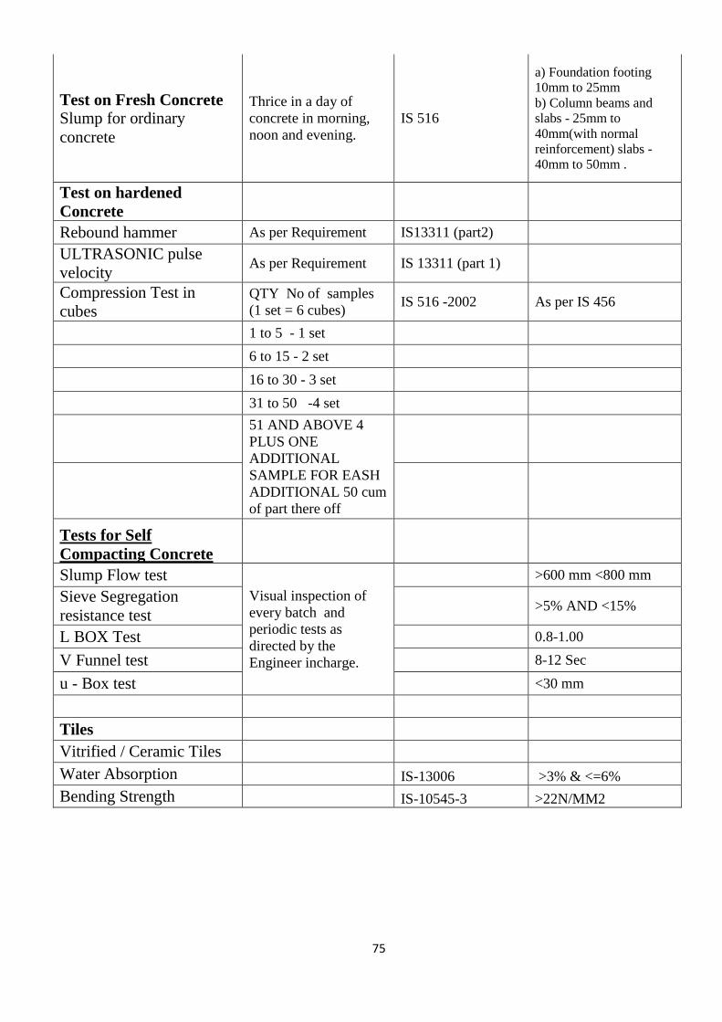
75
Test on Fresh Concrete Slump for ordinary
concrete
Thrice in a day of
concrete in morning,
noon and evening.
IS 516
a) Foundation footing
10mm to 25mm
b) Column beams and
slabs - 25mm to
40mm(with normal
reinforcement) slabs -
40mm to 50mm .
Test on hardened
Concrete
Rebound hammer As per Requirement IS13311 (part2)
ULTRASONIC pulse
velocity As per Requirement IS 13311 (part 1)
Compression Test in
cubes QTY No of samples
(1 set = 6 cubes) IS 516 -2002 As per IS 456
1 to 5 - 1 set
6 to 15 - 2 set
16 to 30 - 3 set
31 to 50 -4 set
51 AND ABOVE 4
PLUS ONE
ADDITIONAL
SAMPLE FOR EASH
ADDITIONAL 50 cum
of part there off
Tests for Self
Compacting Concrete
Slump Flow test
Visual inspection of
every batch and
periodic tests as
directed by the
Engineer incharge.
>600 mm <800 mm
Sieve Segregation
resistance test >5% AND <15%
L BOX Test 0.8-1.00
V Funnel test 8-12 Sec
u - Box test <30 mm
Tiles
Vitrified / Ceramic Tiles
Water Absorption
IS-13006 >3% & <=6%
Bending Strength IS-10545-3 >22N/MM2
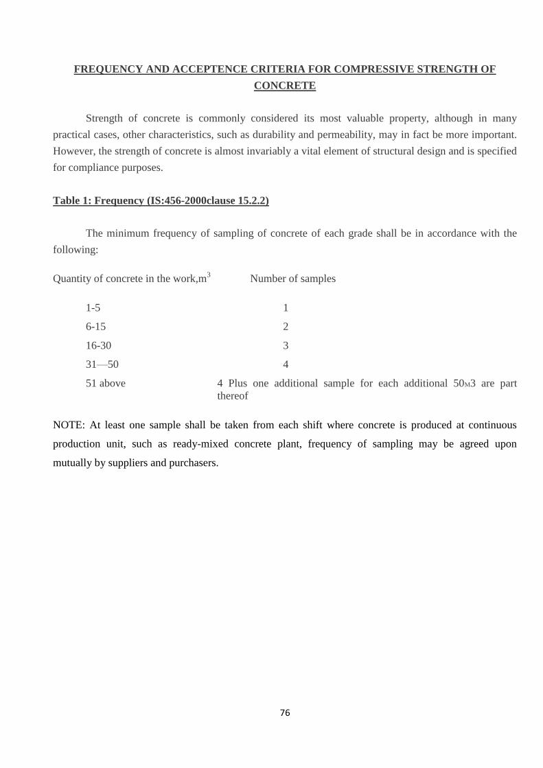
76
FREQUENCY AND ACCEPTENCE CRITERIA FOR COMPRESSIVE STRENGTH OF
CONCRETE
Strength of concrete is commonly considered its most valuable property, although in many
practical cases, other characteristics, such as durability and permeability, may in fact be more important.
However, the strength of concrete is almost invariably a vital element of structural design and is specified
for compliance purposes.
Table 1: Frequency (IS:456-2000clause 15.2.2)
The minimum frequency of sampling of concrete of each grade shall be in accordance with the
following:
Quantity of concrete in the work,m3
Number of samples
1-5 1
6-15 2
16-30 3
31—50 4
51 above 4 Plus one additional sample for each additional 50M3 are part
thereof
NOTE: At least one sample shall be taken from each shift where concrete is produced at continuous
production unit, such as ready-mixed concrete plant, frequency of sampling may be agreed upon
mutually by suppliers and purchasers.
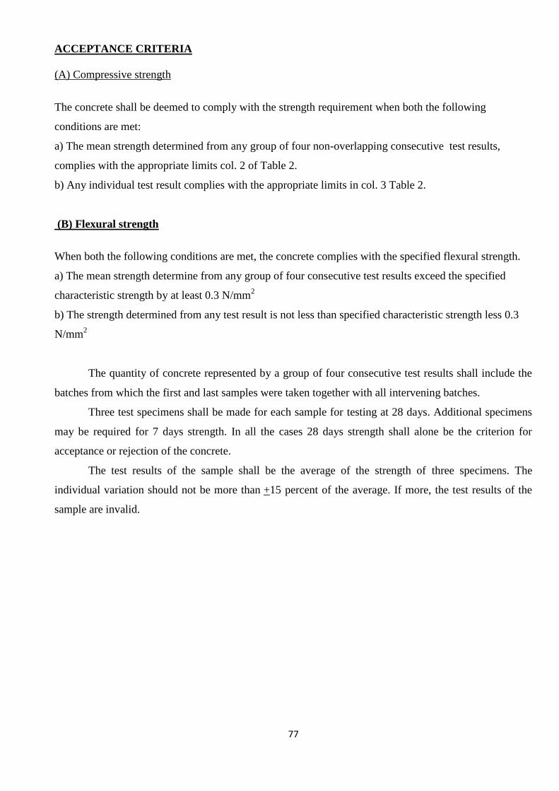
77
ACCEPTANCE CRITERIA
(A) Compressive strength
The concrete shall be deemed to comply with the strength requirement when both the following
conditions are met:
a) The mean strength determined from any group of four non-overlapping consecutive test results,
complies with the appropriate limits col. 2 of Table 2.
b) Any individual test result complies with the appropriate limits in col. 3 Table 2.
(B) Flexural strength
When both the following conditions are met, the concrete complies with the specified flexural strength.
a) The mean strength determine from any group of four consecutive test results exceed the specified
characteristic strength by at least 0.3 N/mm2
b) The strength determined from any test result is not less than specified characteristic strength less 0.3
N/mm2
The quantity of concrete represented by a group of four consecutive test results shall include the
batches from which the first and last samples were taken together with all intervening batches.
Three test specimens shall be made for each sample for testing at 28 days. Additional specimens
may be required for 7 days strength. In all the cases 28 days strength shall alone be the criterion for
acceptance or rejection of the concrete.
The test results of the sample shall be the average of the strength of three specimens. The
individual variation should not be more than +15 percent of the average. If more, the test results of the
sample are invalid.
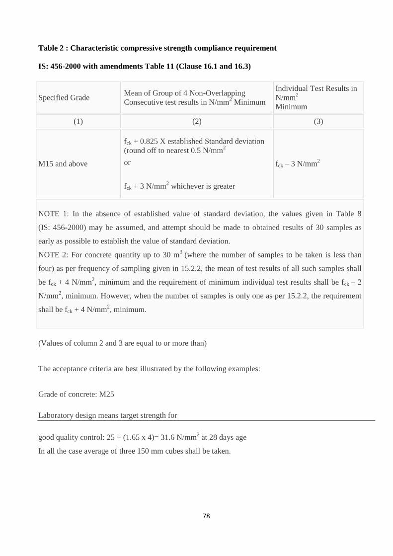
78
Table 2 : Characteristic compressive strength compliance requirement
IS: 456-2000 with amendments Table 11 (Clause 16.1 and 16.3)
(Values of column 2 and 3 are equal to or more than)
The acceptance criteria are best illustrated by the following examples:
Grade of concrete: M25
Laboratory design means target strength for
good quality control: 25 + (1.65 x 4)= 31.6 N/mm2 at 28 days age
In all the case average of three 150 mm cubes shall be taken.
Specified Grade Mean of Group of 4 Non-Overlapping
Consecutive test results in N/mm2 Minimum
Individual Test Results in
N/mm2
Minimum
(1) (2) (3)
M15 and above
fck + 0.825 X established Standard deviation
(round off to nearest 0.5 N/mm2
or
fck + 3 N/mm2 whichever is greater
fck – 3 N/mm2
NOTE 1: In the absence of established value of standard deviation, the values given in Table 8
(IS: 456-2000) may be assumed, and attempt should be made to obtained results of 30 samples as
early as possible to establish the value of standard deviation.
NOTE 2: For concrete quantity up to 30 m3 (where the number of samples to be taken is less than
four) as per frequency of sampling given in 15.2.2, the mean of test results of all such samples shall
be fck + 4 N/mm2, minimum and the requirement of minimum individual test results shall be fck – 2
N/mm2, minimum. However, when the number of samples is only one as per 15.2.2, the requirement
shall be fck + 4 N/mm2, minimum.
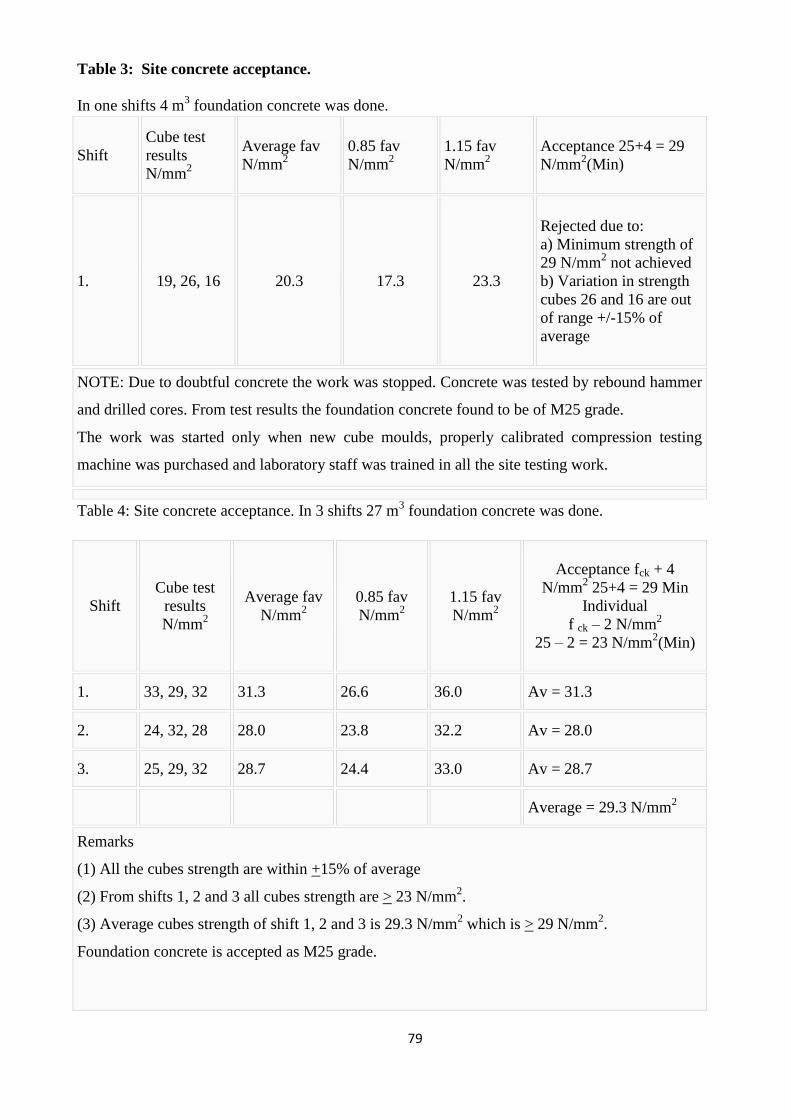
79
Table 3: Site concrete acceptance.
In one shifts 4 m3 foundation concrete was done.
Shift
Cube test
results
N/mm2
Average fav
N/mm2
0.85 fav
N/mm2
1.15 fav
N/mm2
Acceptance 25+4 = 29
N/mm2(Min)
1. 19, 26, 16 20.3 17.3 23.3
Rejected due to:
a) Minimum strength of
29 N/mm2 not achieved
b) Variation in strength
cubes 26 and 16 are out
of range +/-15% of
average
NOTE: Due to doubtful concrete the work was stopped. Concrete was tested by rebound hammer
and drilled cores. From test results the foundation concrete found to be of M25 grade.
The work was started only when new cube moulds, properly calibrated compression testing
machine was purchased and laboratory staff was trained in all the site testing work.
Table 4: Site concrete acceptance. In 3 shifts 27 m3 foundation concrete was done.
Shift
Cube test
results
N/mm2
Average fav
N/mm2
0.85 fav
N/mm2
1.15 fav
N/mm2
Acceptance fck + 4
N/mm2 25+4 = 29 Min
Individual
f ck – 2 N/mm2
25 – 2 = 23 N/mm2(Min)
1. 33, 29, 32 31.3 26.6 36.0 Av = 31.3
2. 24, 32, 28 28.0 23.8 32.2 Av = 28.0
3. 25, 29, 32 28.7 24.4 33.0 Av = 28.7
Average = 29.3 N/mm
2
Remarks
(1) All the cubes strength are within +15% of average
(2) From shifts 1, 2 and 3 all cubes strength are > 23 N/mm2.
(3) Average cubes strength of shift 1, 2 and 3 is 29.3 N/mm2 which is > 29 N/mm
2.
Foundation concrete is accepted as M25 grade.
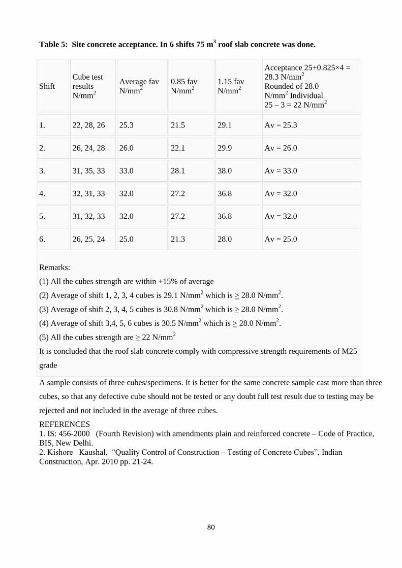
80
Table 5: Site concrete acceptance. In 6 shifts 75 m3 roof slab concrete was done.
Shift
Cube test
results
N/mm2
Average fav
N/mm2
0.85 fav
N/mm2
1.15 fav
N/mm2
Acceptance 25+0.825×4 =
28.3 N/mm2
Rounded of 28.0
N/mm2 Individual
25 – 3 = 22 N/mm2
1. 22, 28, 26 25.3 21.5 29.1 Av = 25.3
2. 26, 24, 28 26.0 22.1 29.9 Av = 26.0
3. 31, 35, 33 33.0 28.1 38.0 Av = 33.0
4. 32, 31, 33 32.0 27.2 36.8 Av = 32.0
5. 31, 32, 33 32.0 27.2 36.8 Av = 32.0
6. 26, 25, 24 25.0 21.3 28.0 Av = 25.0
Remarks:
(1) All the cubes strength are within +15% of average
(2) Average of shift 1, 2, 3, 4 cubes is 29.1 N/mm2 which is > 28.0 N/mm
2.
(3) Average of shift 2, 3, 4, 5 cubes is 30.8 N/mm2 which is > 28.0 N/mm
2.
(4) Average of shift 3,4, 5, 6 cubes is 30.5 N/mm2 which is > 28.0 N/mm
2.
(5) All the cubes strength are > 22 N/mm2
It is concluded that the roof slab concrete comply with compressive strength requirements of M25
grade
A sample consists of three cubes/specimens. It is better for the same concrete sample cast more than three
cubes, so that any defective cube should not be tested or any doubt full test result due to testing may be
rejected and not included in the average of three cubes.
REFERENCES
1. IS: 456-2000 (Fourth Revision) with amendments plain and reinforced concrete – Code of Practice,
BIS, New Delhi.
2. Kishore Kaushal, ―Quality Control of Construction – Testing of Concrete Cubes‖, Indian
Construction, Apr. 2010 pp. 21-24.
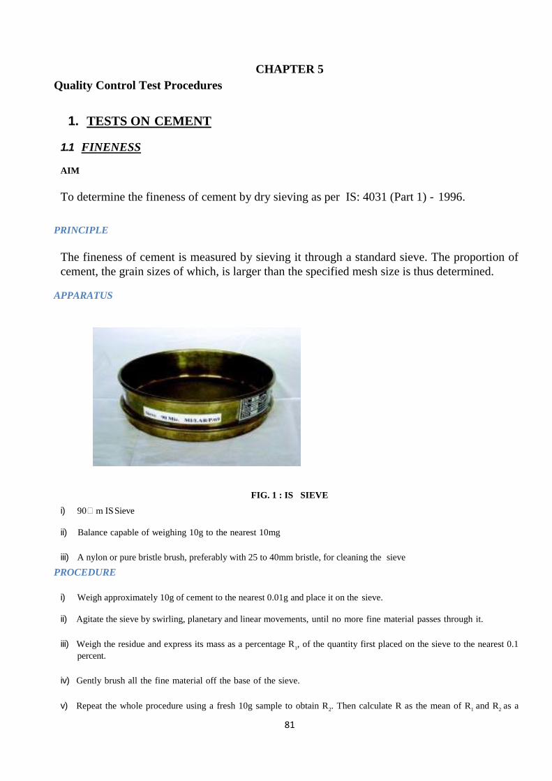
81
CHAPTER 5
Quality Control Test Procedures
1. TESTS ON CEMENT
1.1 FINENESS AIM
To determine the fineness of cement by dry sieving as per IS: 4031 (Part 1) - 1996.
PRINCIPLE
The fineness of cement is measured by sieving it through a standard sieve. The proportion of
cement, the grain sizes of which, is larger than the specified mesh size is thus determined.
APPARATUS
FIG. 1 : IS SIEVE
i) 90m IS Sieve
ii) Balance capable of weighing 10g to the nearest 10mg
iii) A nylon or pure bristle brush, preferably with 25 to 40mm bristle, for cleaning the sieve
PROCEDURE
i) Weigh approximately 10g of cement to the nearest 0.01g and place it on the sieve.
ii) Agitate the sieve by swirling, planetary and linear movements, until no more fine material passes through it.
iii) Weigh the residue and express its mass as a percentage R
1, of the quantity first placed on the sieve to the nearest 0.1
percent.
iv) Gently brush all the fine material off the base of the sieve.
v) Repeat the whole procedure using a fresh 10g sample to obtain R
2. Then calculate R as the mean of R
1 and R
2 as a
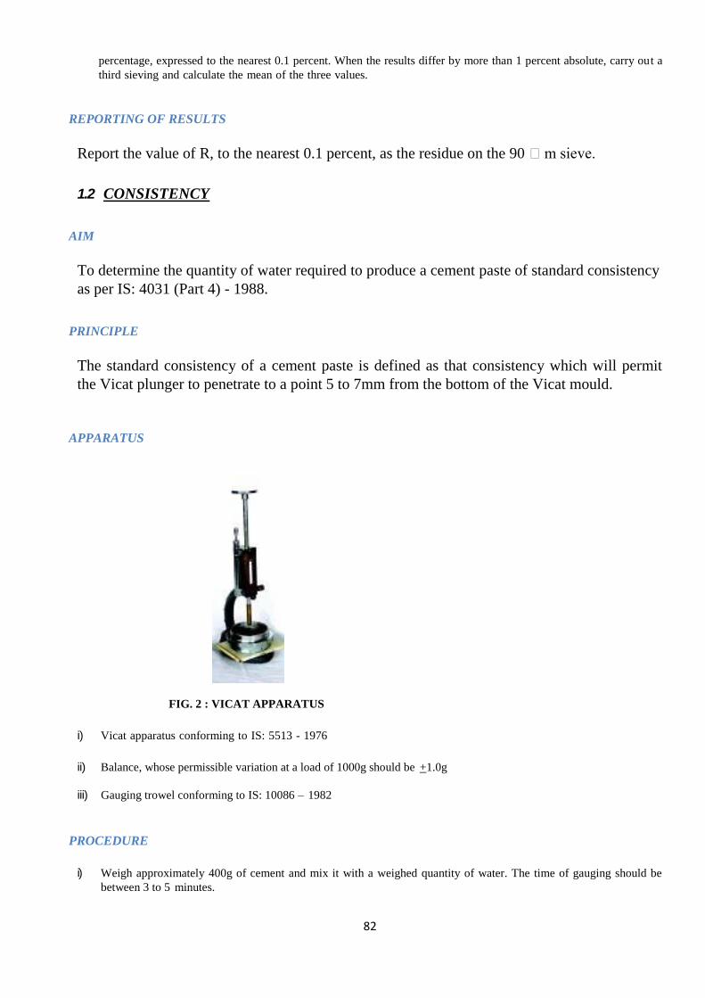
82
percentage, expressed to the nearest 0.1 percent. When the results differ by more than 1 percent absolute, carry out a
third sieving and calculate the mean of the three values.
REPORTING OF RESULTS
Report the value of R, to the nearest 0.1 percent, as the residue on the 90 m sieve.
1.2 CONSISTENCY
AIM
To determine the quantity of water required to produce a cement paste of standard consistency
as per IS: 4031 (Part 4) - 1988.
PRINCIPLE
The standard consistency of a cement paste is defined as that consistency which will permit
the Vicat plunger to penetrate to a point 5 to 7mm from the bottom of the Vicat mould.
APPARATUS
FIG. 2 : VICAT APPARATUS
i) Vicat apparatus conforming to IS: 5513 - 1976
ii) Balance, whose permissible variation at a load of 1000g should be +1.0g
iii) Gauging trowel conforming to IS: 10086 – 1982
PROCEDURE
i) Weigh approximately 400g of cement and mix it with a weighed quantity of water. The time of gauging should be
between 3 to 5 minutes.
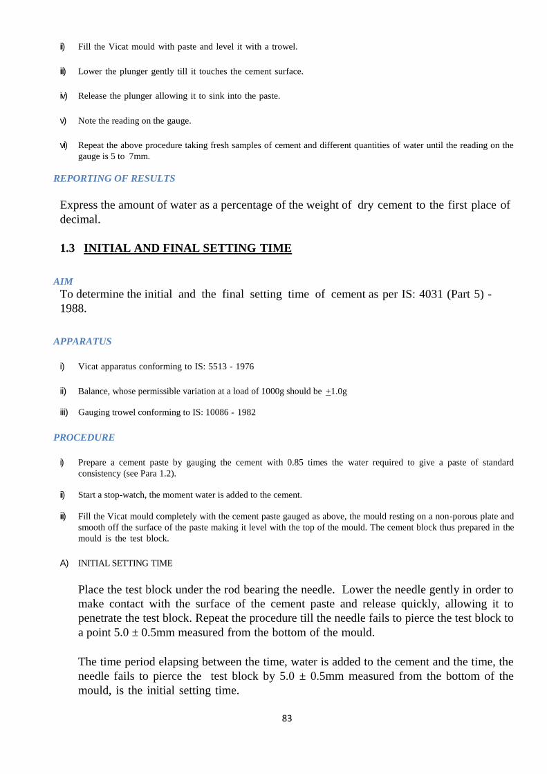
83
ii) Fill the Vicat mould with paste and level it with a trowel.
iii) Lower the plunger gently till it touches the cement surface.
iv) Release the plunger allowing it to sink into the paste.
v) Note the reading on the gauge.
vi) Repeat the above procedure taking fresh samples of cement and different quantities of water until the reading on the
gauge is 5 to 7mm.
REPORTING OF RESULTS
Express the amount of water as a percentage of the weight of dry cement to the first place of
decimal.
1.3 INITIAL AND FINAL SETTING TIME
AIM
To determine the initial and the final setting time of cement as per IS: 4031 (Part 5) -
1988.
APPARATUS
i) Vicat apparatus conforming to IS: 5513 - 1976
ii) Balance, whose permissible variation at a load of 1000g should be +1.0g
iii) Gauging trowel conforming to IS: 10086 - 1982
PROCEDURE
i) Prepare a cement paste by gauging the cement with 0.85 times the water required to give a paste of standard
consistency (see Para 1.2).
ii) Start a stop-watch, the moment water is added to the cement.
iii) Fill the Vicat mould completely with the cement paste gauged as above, the mould resting on a non-porous plate and
smooth off the surface of the paste making it level with the top of the mould. The cement block thus prepared in the
mould is the test block.
A) INITIAL SETTING TIME
Place the test block under the rod bearing the needle. Lower the needle gently in order to
make contact with the surface of the cement paste and release quickly, allowing it to
penetrate the test block. Repeat the procedure till the needle fails to pierce the test block to
a point 5.0 ± 0.5mm measured from the bottom of the mould.
The time period elapsing between the time, water is added to the cement and the time, the
needle fails to pierce the test block by 5.0 ± 0.5mm measured from the bottom of the
mould, is the initial setting time.

84
B) FINAL SETTING TIME
Replace the above needle by the one with an annular attachment.
The cement should be considered as finally set when, upon applying the needle gently to
the surface of the test block, the needle makes an impression therein, while the attachment
fails to do so. The period elapsing between the time, water is added to the cement and the
time, the needle makes an impression on the surface of the test block, while the attachment
fails to do so, is the final setting time.
REPORTING OF RESULTS
The results of the initial and the final setting time should be reported to the nearest five minutes.
1.4 SOUNDNESS
AIM
To determine the soundness of cement by Le-Chatelier method as per IS: 4031 (Part 3) –
1988.
APPARATUS
FIG. 3 : LE-CHATELIER'S TEST APPARATUS
i) The apparatus for conducting the Le-Chatelier test should conform to IS: 5514 - 1969
ii) Balance, whose pemissible variation at a load of 1000g should be +1.0g
iii) Water bath
PROCEDURE
i) Place the mould on a glass sheet and fill it with the cement paste formed by gauging cement with 0.78 times the water
required to give a paste of standard consistency (see Para 1.2).
ii) Cover the mould with another piece of glass sheet, place a small weight on this covering glass sheet and immediately
submerge the whole assembly in water at a temperature of 27 ± 2oC and keep it there for 24hrs.
iii) Measure the distance separating the indicator points to the nearest 0.5mm (say d l).
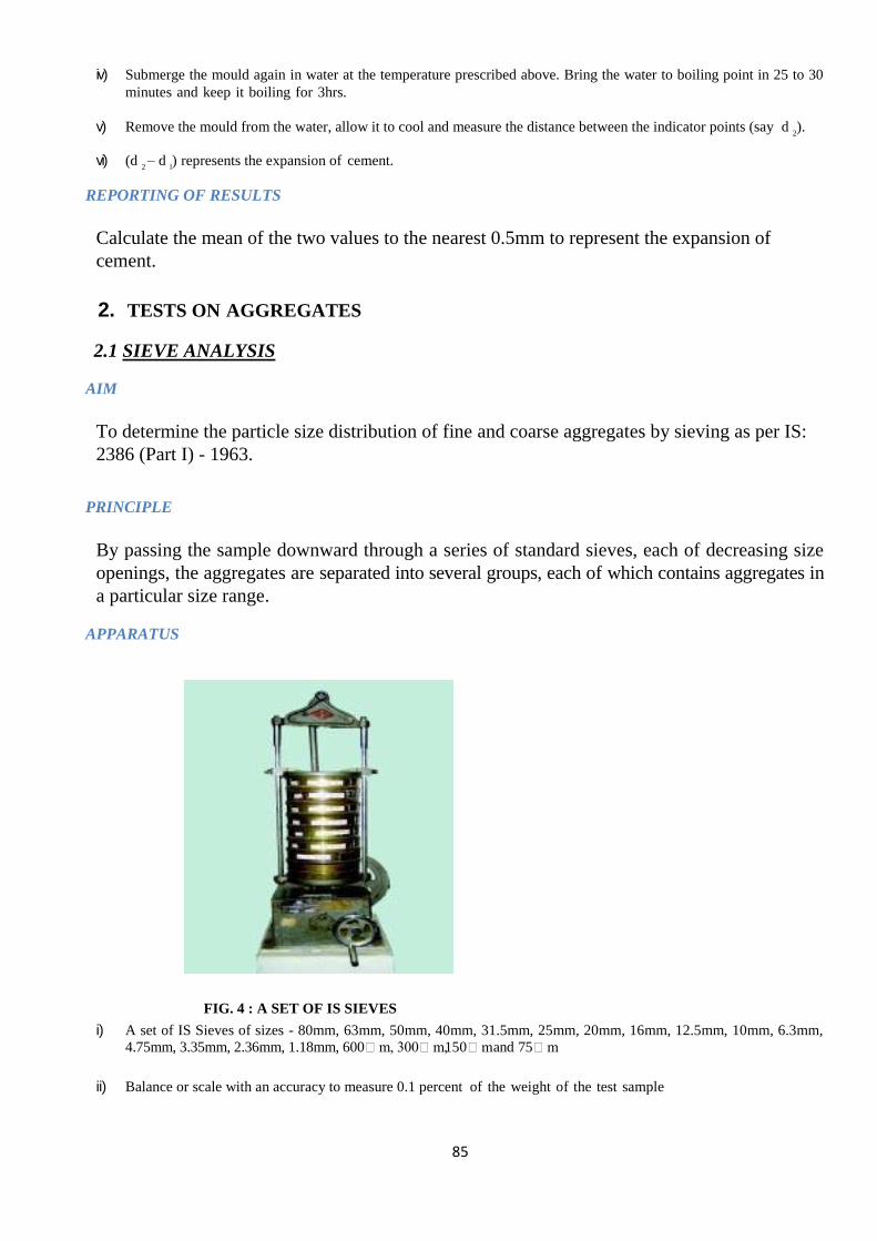
85
iv) Submerge the mould again in water at the temperature prescribed above. Bring the water to boiling point in 25 to 30
minutes and keep it boiling for 3hrs.
v) Remove the mould from the water, allow it to cool and measure the distance between the indicator points (say d 2).
vi) (d 2 – d
l) represents the expansion of cement.
REPORTING OF RESULTS
Calculate the mean of the two values to the nearest 0.5mm to represent the expansion of
cement.
2. TESTS ON AGGREGATES
2.1 SIEVE ANALYSIS
AIM
To determine the particle size distribution of fine and coarse aggregates by sieving as per IS:
2386 (Part I) - 1963.
PRINCIPLE
By passing the sample downward through a series of standard sieves, each of decreasing size
openings, the aggregates are separated into several groups, each of which contains aggregates in
a particular size range.
APPARATUS
FIG. 4 : A SET OF IS SIEVES
i) A set of IS Sieves of sizes - 80mm, 63mm, 50mm, 40mm, 31.5mm, 25mm, 20mm, 16mm, 12.5mm, 10mm, 6.3mm,
4.75mm, 3.35mm, 2.36mm, 1.18mm, 600m, 300m, 150m and 75m
ii) Balance or scale with an accuracy to measure 0.1 percent of the weight of the test sample
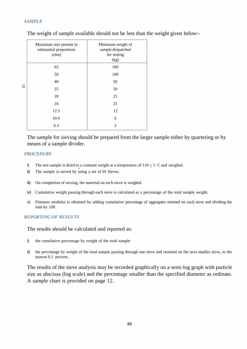
86
o
SAMPLE
The weight of sample available should not be less than the weight given below:-
Maximum size present in
substantial proportions
(mm)
Minimum weight of
sample despatched
for testing
(kg)
63 100
50 100
40 50
25 50
20 25
16 25
12.5 12
10.0 6
6.3 3
The sample for sieving should be prepared from the larger sample either by quartering or by
means of a sample divider.
PROCEDURE
i) The test sample is dried to a constant weight at a temperature of 110 + 5 C and weighed.
ii) The sample is sieved by using a set of IS Sieves.
iii) On completion of sieving, the material on each sieve is weighed.
iv) Cumulative weight passing through each sieve is calculated as a percentage of the total sample weight.
v) Fineness modulus is obtained by adding cumulative percentage of aggregates retained on each sieve and dividing the
sum by 100.
REPORTING OF RESULTS
The results should be calculated and reported as:
i) the cumulative percentage by weight of the total sample
ii) the percentage by weight of the total sample passing through one sieve and retained on the next smaller sieve, to the
nearest 0.1 percent.
The results of the sieve analysis may be recorded graphically on a semi-log graph with particle
size as abscissa (log scale) and the percentage smaller than the specified diameter as ordinate.
A sample chart is provided on page 12.
12

87
PER
CEN
TAG
E P
ASS
ING
o
100
80
60
40
20
0
75 212 425 850 1.70 3.35 6.3 12.5 20 40 63 150 300 600 1.18 2.36 4.75 10 16 25 50 80
APERTURE SIZE IN MICRONS APERTURE SIZE IN MILLIMETRES SIEVE SIZES
Note - The vertical scale of this chart is an arithmetic scale and the horizontal scale is logarithmic.
CHART FOR RECORDING SIEVE ANALYSIS RESULTS
2.2 WATER ABSORPTION AIM
To determine the water absorption of coarse aggregates as per IS: 2386 (Part III) - 1963.
APPARATUS
i) Wire basket - perforated, electroplated or plastic coated with wire hangers for suspending it from the balance
ii) Water-tight container for suspending the basket
iii) Dry soft absorbent cloth - 75cm x 45cm (2 nos.)
iv) Shallow tray of minimum 650 sq.cm area
v) Air-tight container of a capacity similar to the basket
vi) Oven
SAMPLE
A sample not less than 2000g should be used.
PROCEDURE
i) The sample should be thoroughly washed to remove finer particles and dust, drained and then placed in the
wire basket and immersed in distilled water at a temperature between 22 and 32 C.
ii) After immersion, the entrapped air should be removed by lifting the basket and allowing it to drop 25 times in
25 seconds. The basket and sample should remain immersed for a period of 24 + ½ hrs. afterwards.

88
o
———–
iii) The basket and aggregates should then be removed from the water, allowed to drain for a few minutes, after
which the aggregates should be gently emptied from the basket on to one of the dry clothes and
gently surface-dried with the cloth, transferring it to a second dry cloth when the first would remove
no further moisture. The aggregates should be spread on the second cloth and exposed to the
atmosphere away from direct sunlight till it appears to be completely surface-dry. The aggregates
should be weighed (Weight 'A').
iv) The aggregates should then be placed in an oven at a temperature of 100 to 110 C for 24hrs. It should then be
removed from the oven, cooled and weighed (Weight 'B').
REPORTING OF RESULTS
Water absorption =
A - B x 100%
B
Two such tests should be done and the individual and mean results should be reported.
A sample proforma for the record of the test results is given in Annexure-I.
2.3 AGGREGATE ABRASION VALUE
AIM
To determine the abrasion value of coarse aggregates as per IS: 2386 (Part IV) - 1963.
APPARATUS
Los Angles abrasion testing machine
IS Sieve of size - 1.7mm
FIG. 5: LOS ANGLES MACHINE
i) Abrasive charge-12nos. cast iron or steel spheres approximately 48mm dia. and each weighing between 390
and 445g ensuring that the total weight of charge is 5000 +25g
ii) Oven

89
o
o
———–
PREPARATION OF SAMPLE
The test sample should consist of clean aggregates which has been dried in an oven at
105 to 110 C to a substantially constant weight and should conform to one of the
gradings shown in the table below:
PROCEDURE
The test sample and the abrasive charge should be placed in the Los Angles abrasion
testing machine and the machine rotated at a speed of 20 to 33 revolutions/minute for
1000 revolutions. At the completion of the test, the material should be discharged and
sieved through 1.70mm IS Sieve.
Grading of test samples
Sieve size
(Square hole)
Weight in g of test sample for grade
A B C D E F G
Passing
through
(mm)
Retained
on
(mm)
80 63 - - - - 2500* - -
63 50 - - - - 2500* - -
50 40 - - - - 5000* 5000* -
40 25 1250 - - - - 5000* 5000*
25 20 1250 - - - - - 5000*
20 12.5 1250 2500 - - - - -
12.5 10 1250 2500 - - - - -
10 6.3 - - 2500 - - - -
6.3 4.75 - - 2500 - - - -
4.75 2.36 - - - 5000 - - -
* Tolerance of +2 percent permitted.
REPORTING OF RESULTS
i) The material coarser than 1.70mm IS Sieve should be washed, dried in an oven at a temperature of 100 to 110
C to a constant weight and weighed (Weight 'B').
ii) The proportion of loss between weight 'A' and weight 'B' of the test sample should be expressed as a
percentage of the original weight of the test sample. This value should be reported as,
Aggregate abrasion value =
A - B x 100%
A
A sample proforma for the record of the test results is given in Annexure-II.

90
o
2.4 AGGREGATE IMPACT VALUE
AIM
To determine the aggregate impact value of coarse aggregates as per IS: 2386 (Part IV) -
1963.
APPARATUS
FIG. 6 : AGGREGATE IMPACT TEST MACHINE
i) Impact testing machine conforming to IS: 2386 (Part IV)
- 1963
ii) IS Sieves of sizes - 12.5mm, 10mm and 2.36mm
iii) A cylindrical metal measure of 75mm dia. and 50mm depth
iv) A tamping rod of 10mm circular cross section and 230mm length, rounded at one end
v) Oven
PREPARATION OF SAMPLE
i) The test sample should conform to the following grading:
- Passing through 12.5mm IS Sieve 100%
- Retention on 10mm IS Sieve 100%
ii) The sample should be oven-dried for 4hrs. at a temperature of 100 to 110 C and cooled.
iii) The measure should be about one-third full with the prepared aggregates and tamped with 25 strokes of the
tamping rod. A further similar quantity of aggregates should be added and a further tamping of 25 strokes
given. The measure should finally be filled to overflow, tamped 25 times and the surplus aggregates struck off,
using a tamping rod as a straight edge. The net weight of the aggregates in the measure should be determined
to the nearest gram (Weight 'A').
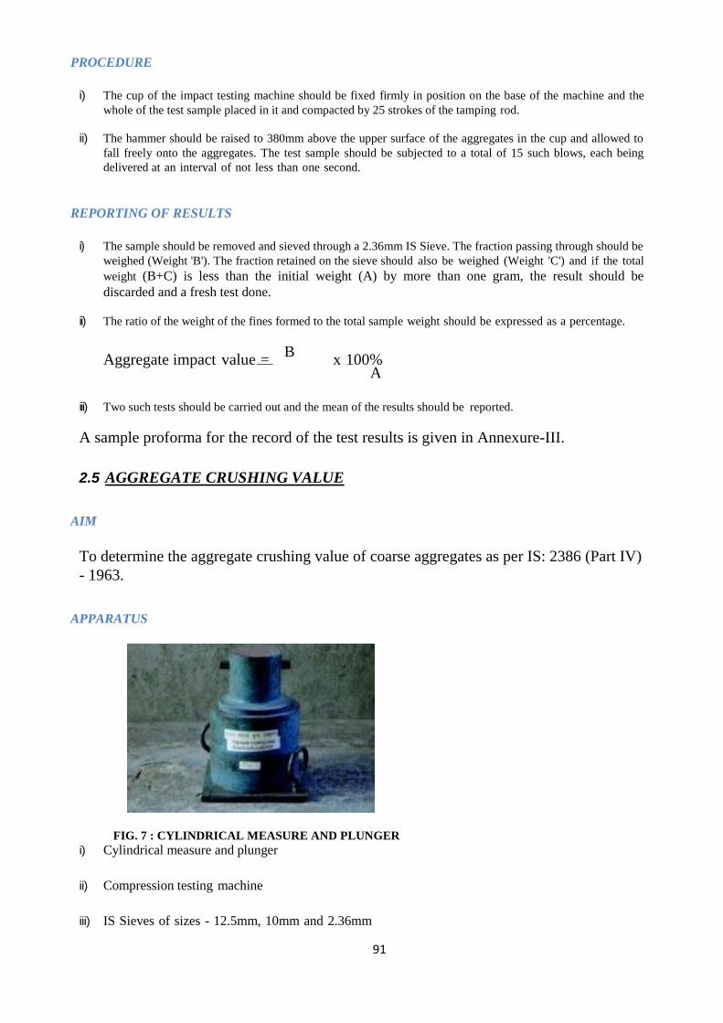
91
——–
PROCEDURE
i) The cup of the impact testing machine should be fixed firmly in position on the base of the machine and the
whole of the test sample placed in it and compacted by 25 strokes of the tamping rod.
ii) The hammer should be raised to 380mm above the upper surface of the aggregates in the cup and allowed to
fall freely onto the aggregates. The test sample should be subjected to a total of 15 such blows, each being
delivered at an interval of not less than one second.
REPORTING OF RESULTS
i) The sample should be removed and sieved through a 2.36mm IS Sieve. The fraction passing through should be
weighed (Weight 'B'). The fraction retained on the sieve should also be weighed (Weight 'C') and if the total
weight (B+C) is less than the initial weight (A) by more than one gram, the result should be
discarded and a fresh test done.
ii) The ratio of the weight of the fines formed to the total sample weight should be expressed as a percentage.
Aggregate impact value =
B x 100%
A
iii) Two such tests should be carried out and the mean of the results should be reported.
A sample proforma for the record of the test results is given in Annexure-III.
2.5 AGGREGATE CRUSHING VALUE
AIM
To determine the aggregate crushing value of coarse aggregates as per IS: 2386 (Part IV)
- 1963.
APPARATUS
FIG. 7 : CYLINDRICAL MEASURE AND PLUNGER
i) Cylindrical measure and plunger
ii) Compression testing machine
iii) IS Sieves of sizes - 12.5mm, 10mm and 2.36mm

92
o
——
PROCEDURE
i) The aggregates passing through 12.5mm and retained on 10mm IS Sieve are oven-dried at a
temperature of 100 to 110 C for 3 to 4hrs.
ii) The cylinder of the apparatus is filled in 3 layers, each layer tamped with 25 strokes of a tamping
rod.
iii) The weight of aggregates is measured (Weight 'A').
iv) The surface of the aggregates is then leveled and the plunger inserted. The apparatus is then placed
in the compression testing machine and loaded at a uniform rate so as to achieve 40t load in 10
minutes. After this, the load is released.
v) The sample is then sieved through a 2.36mm IS Sieve and the fraction passing through the sieve is
weighed (Weight 'B').
vi) Two tests should be conducted.
REPORTING OF RESULTS
Aggregate crushing value = B
x 100%
A The result should be recorded to the first decimal place and the mean of the two results
reported.
3. TESTS ON FRESH CONCRETE
3.1 WORKABILITY
3.1.1 SLUMP AIM
To determine the workability of fresh concrete by slump test as per IS: 1199 - 1959.
APPARATUS
93
FIG. 8 : SLUMP CONE
i) Slump cone
ii) Tamping rod
PROCEDURE
i) The internal surface of the mould is thoroughly cleaned and applied with a light coat of oil.
ii) The mould is placed on a smooth, horizontal, rigid and non- absorbent surface.
iii) The mould is then filled in four layers with freshly mixed concrete, each approximately to one-
fourth of the height of the mould.
iv) Each layer is tamped 25 times by the rounded end of the tamping rod (strokes are distributed evenly
over the cross- section).
v) After the top layer is rodded, the concrete is struck off the level with a trowel.
vi) The mould is removed from the concrete immediately by raising it slowly in the vertical direction.
vii) The difference in level between the height of the mould and that of the highest point of the subsided
concrete is measured.
viii) This difference in height in mm is the slump of the concrete.
REPORTING OF RESULTS
The slump measured should be recorded in mm of subsidence of the specimen during the test.
Any slump specimen, which collapses or shears off laterally gives incorrect result and if this
occurs, the test should be repeated with another sample. If, in the repeat test also, the specimen
shears, the slump should be measured and the fact that the specimen sheared, should be
recorded.
4. TESTS ON HARDENED CONCRETE
4.1 NON-DESTRUCTIVE TESTS
4.1.1 REBOUND HAMMER AIM
To assess the likely compressive strength of concrete by using rebound hammer as per
IS: 13311 (Part 2) - 1992.
PRINCIPLE
The rebound of an elastic mass depends on the hardness of the surface against which its mass
strikes. When the plunger of the rebound hammer is pressed against the surface of the concrete,
the spring-controlled mass rebounds and the extent of such a rebound depends upon the surface
hardness of the concrete. The surface hardness and therefore the rebound is taken to be related to

94
the compressive strength of the concrete. The rebound value is read from a graduated scale and
is designated as the rebound number or rebound index. The compressive strength can be read
directly from the graph provided on the body of the hammer.
APPARATUS
FIG. 11 : REBOUND HAMMER
PROCEDURE
i) Before commencement of a test, the rebound hammer should be tested against the test anvil, to get
reliable results, for which the manufacturer of the rebound hammer indicates the range of readings
on the anvil suitable for different types of rebound hammer.
ii) Apply light pressure on the plunger - it will release it from the locked position and allow it to extend
to the ready position for the test.
iii) Press the plunger against the surface of the concrete, keeping the instrument perpendicular to the test
surface. Apply a gradual increase in pressure until the hammer impacts. (Do not touch the button
while depressing the plunger. Press the button after impact, in case it is not convenient to note the
rebound reading in that position.)
iv) Take the average of about 15 readings.
INTERPRETATION OF RESULTS
The rebound reading on the indicator scale has been calibrated by the manufacturer of the
rebound hammer for horizontal impact, that is, on a vertical surface, to indicate the compressive
strength. When used in any other position, appropriate correction as given by the manufacturer
is to be taken into account.
4.1.2 ULTRASONIC PULSE VELOCITY AIM
To assess the quality of concrete by ultrasonic pulse velocity method as per IS: 13311 (Part 1) -
1992.
PRINCIPLE
The method consists of measuring the time of travel of an ultrasonic pulse passing through the
concrete being tested. Comparatively higher velocity is obtained when concrete quality is good in
terms of density, uniformity, homogeneity etc.

95
APPARATUS
FIG. 12 : ULTRASONIC PULSE VELOCITY METER
i) Ultrasonic pulse velocity meter
PROCEDURE
i) Preparing for use: Before switching on the 'V' meter, the transducers should be connected to the
sockets marked "TRAN" and " REC".
The 'V' meter may be operated with either:
a) the internal battery,
b) an external battery or
c) the A.C line.
ii) Set reference: A reference bar is provided to check the instrument zero. The pulse time for the bar is
engraved on it. Apply a smear of grease to the transducer faces before placing it on the opposite ends
of the bar. Adjust the 'SET REF' control until the reference bar transit time is obtained on the
instrument read-out.
iii) Range selection: For maximum accuracy, it is recommended that the 0.1 microsecond range be
selected for path length upto 400mm.
iv) Pulse velocity: Having determined the most suitable test points on the material to be tested, make
careful measurement of the path length ‗L‘. Apply couplant to the surfaces of the transducers and
press it hard onto the surface of the material. Do not move the transducers while a reading is being
taken, as this can generate noise signals and errors in measurements. Continue holding the
transducers onto the surface of the material until a consistent reading appears on the display, which
is the time in microsecond for the ultrasonic pulse to travel the distance 'L'.
The mean value of the display readings should be taken when the units digit hunts between two
values.
Pulse velocity = Path length
v) Separation of transducer leads: It is advisable to prevent the two transducer leads from coming into
close contact with each other when the transit time measurements are being taken. If this is not done,
the receiver lead might pick-up unwanted signals from the transmitter lead and this would result in
an incorrect display of the transit time.
Travel time
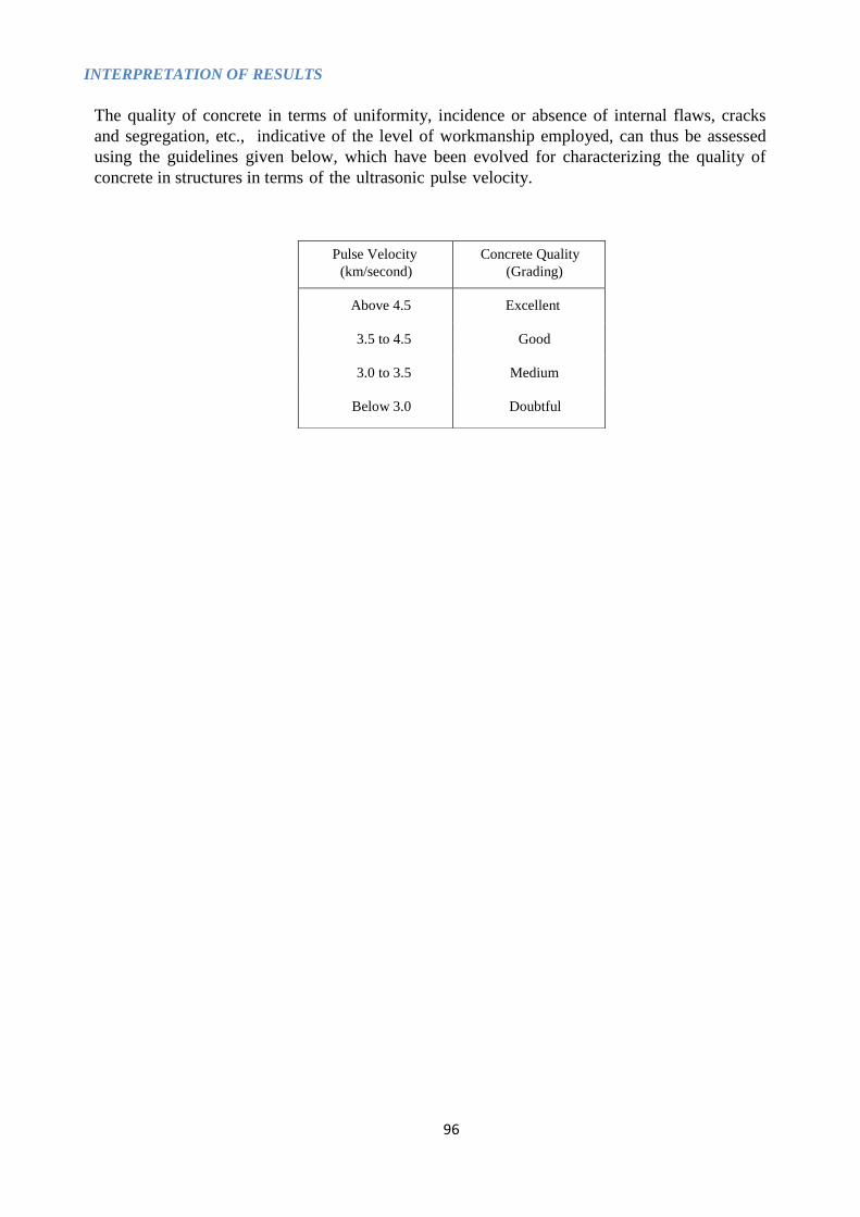
96
INTERPRETATION OF RESULTS
The quality of concrete in terms of uniformity, incidence or absence of internal flaws, cracks
and segregation, etc., indicative of the level of workmanship employed, can thus be assessed
using the guidelines given below, which have been evolved for characterizing the quality of
concrete in structures in terms of the ultrasonic pulse velocity.
Pulse Velocity
(km/second)
Concrete Quality
(Grading)
Above 4.5 Excellent
3.5 to 4.5 Good
3.0 to 3.5 Medium
Below 3.0 Doubtful

98
4.2 COMPRESSION TEST
AIM
To determine the compressive strength of concrete specimens as per IS: 516 - 1959.
APPARATUS
FIG. 13 : COMPRESSION TESTING MACHINE
i) Compression testing machine conforming to IS: 516 - 1959
AGE AT TEST
Tests should be done at recognized ages of the test specimens, usually being 7 and 28
days. The ages should be calculated from the time of the addition of water to the drying
of ingredients.
NUMBER OF SPECIMENS
At least three specimens, preferably from different batches, should be taken for testing at
each selected age.
PROCEDURE
i) The specimens, prepared according to IS: 516 - 1959 and stored in water, should be tested
immediately on removal from the water and while still in wet condition. Specimens when received
dry should be kept in water for 24hrs. before they are taken for testing. The dimensions of
the specimens, to the nearest 0.2mm and their weight should be noted before testing.
ii) The bearing surfaces of the compression testing machine should be wiped clean and any loose sand
or other material removed from the surfaces of the specimen, which would be in contact with the
compression platens.
iii) In the case a of cubical specimen, the specimen should be placed in the machine in such a manner
that the load could be applied to the opposite sides of the cubes, not to the top and the bottom. The
axis of the specimen should be carefully aligned with the centre of thrust of the spherically seated
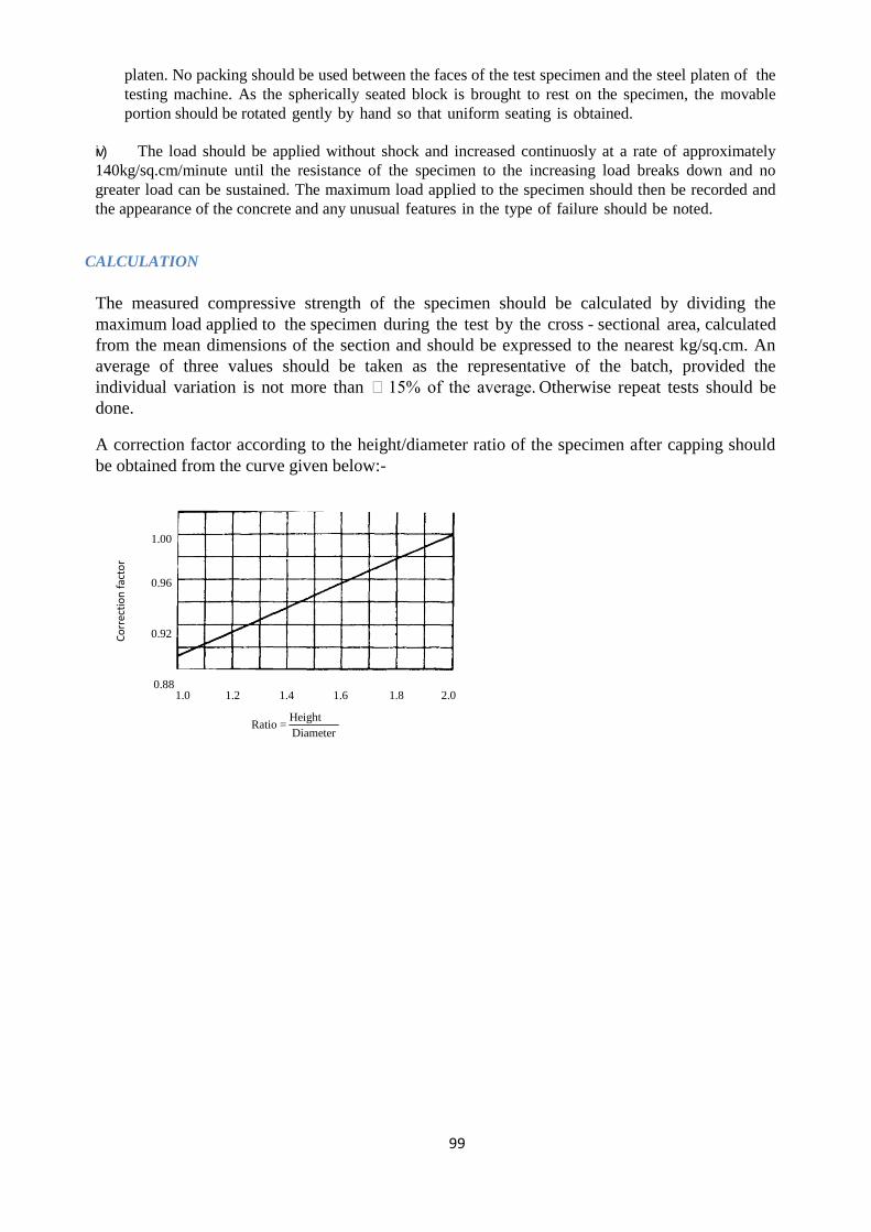
99
platen. No packing should be used between the faces of the test specimen and the steel platen of the
testing machine. As the spherically seated block is brought to rest on the specimen, the movable
portion should be rotated gently by hand so that uniform seating is obtained.
iv) The load should be applied without shock and increased continuosly at a rate of approximately
140kg/sq.cm/minute until the resistance of the specimen to the increasing load breaks down and no
greater load can be sustained. The maximum load applied to the specimen should then be recorded and
the appearance of the concrete and any unusual features in the type of failure should be noted.
CALCULATION
The measured compressive strength of the specimen should be calculated by dividing the
maximum load applied to the specimen during the test by the cross - sectional area, calculated
from the mean dimensions of the section and should be expressed to the nearest kg/sq.cm. An
average of three values should be taken as the representative of the batch, provided the
individual variation is not more than 15% of the average. Otherwise repeat tests should be
done.
A correction factor according to the height/diameter ratio of the specimen after capping should
be obtained from the curve given below:-
1.00
0.96
0.92
0.88
1.0 1.2 1.4 1.6 1.8 2.0
Ratio = Height
Diameter
Co
rrec
tio
n f
acto
r

100
Correction factor for height-diameter ratio of a core
The product of this correction factor and the measured compressive strength is
known as the corrected compressive strength, this being the equivalent strength of a
cylinder having a height/diameter ratio of two. The equivalent cube strength of the
concrete should be determined by multiplying the corrected cylinder strength by
1.25.
REPORTING OF RESULTS
The following information should be included in the report on each test
specimen:
i) identification mark
ii) date of test
iii) age of specimen
iv) curing conditions, including date of manufacture of specimen
v) weight of specimen
vi) dimensions of specimen
vii) cross-sectional area
viii) maximum load
ix) compressive strength
x) appearance fractured faces of concrete of and type of fracture, if unusual
xi) date of test
xii) age of specimen
xiii) curing conditions, including date of manufacture of specimen
xiv) weight of specimen
xv) dimensions of specimen
xvi) cross-sectional area
xvii) maximum load
xviii) compressive strength
xix) appearance fractured faces of concrete of and type of fracture, if unusual
101
Self-compacting concrete (SCC)
Definition
Self-compacting concrete (SCC) is an innovative concrete that does not require vibration
for placing and compaction. It is able to flow under its own weight, completely filling
formwork and achieving full compaction, even in the presence of congested
reinforcement. The hardened concrete is dense, homogeneous and has the same
engineering properties and durability as traditional vibrated concrete.
• It's very flowable concrete with high workability that has ability to flow under it's
own weight with no need of vibration and no segregation and without the separation
of the constituent materials until it sets
Passing ability
Ability of fresh concrete to flow through tight openings such as spaces between steel
reinforcing bars.
Segregation resistance
The ability of concrete to remain homogeneous in composition while in its fresh state.
Slump flow
The mean diameter of the spread of fresh concrete using conventional slump cone.
Slump-flow Test and T500mm Test
This test specifies the procedure for determining the slump-flow and t500 time for self-
compacting concrete. The test is not suitable when the maximum size of the aggregate
exceeds 40 mm.
Principle
The slump-flow test is an indication of the flow ability of self-compacting concrete in the
absence of obstructions. It is based on the slump test described in IS 1199 (Part 2). The flow
ability is evaluated by measuring the maximum spreading diameter (d max) and the time it
reaches the spreading diameter of 500 mm (t500). The d max of spreading is a measure of
the self-compacting concrete flow range when subjected to load from its own weight. It is an
indication of the yield stress of the self compacting concrete. The t500 time is a measure of
the speed of flow and an indication of the relative viscosity of the self-compacting concrete.
The result is an indication of the filling ability of self-compacting concrete. The fresh
concrete is poured into a cone as used for the IS 1199 (Part 2) slump test. When the cone is
withdrawn upwards the time from commencing upward movement of the cone to when the
concrete has flowed to a diameter of 500 mm is measured; this is the t500 time. The largest
diameter of the flow spread of the concrete and the diameter of the spread at right angles to
it are then measured and the mean is the slump-flow.
Apparatus
The apparatus shall be in accordance with IS 1199 (Part 2) except as detailed below.
Base plate, made from a flat steel plate, with a plan area of at least 900 mm × 900 mm on
which concrete can be placed.
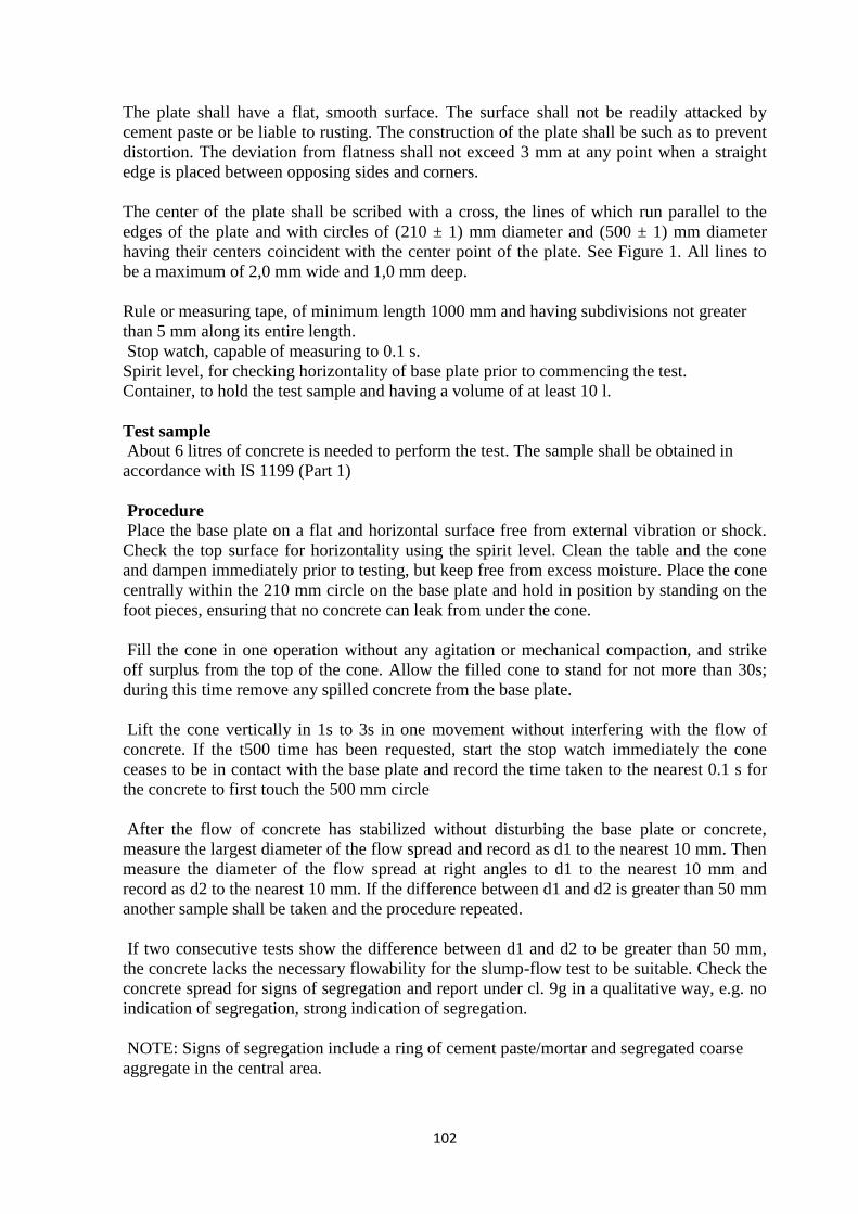
102
The plate shall have a flat, smooth surface. The surface shall not be readily attacked by
cement paste or be liable to rusting. The construction of the plate shall be such as to prevent
distortion. The deviation from flatness shall not exceed 3 mm at any point when a straight
edge is placed between opposing sides and corners.
The center of the plate shall be scribed with a cross, the lines of which run parallel to the
edges of the plate and with circles of (210 ± 1) mm diameter and (500 ± 1) mm diameter
having their centers coincident with the center point of the plate. See Figure 1. All lines to
be a maximum of 2,0 mm wide and 1,0 mm deep.
Rule or measuring tape, of minimum length 1000 mm and having subdivisions not greater
than 5 mm along its entire length.
Stop watch, capable of measuring to 0.1 s.
Spirit level, for checking horizontality of base plate prior to commencing the test.
Container, to hold the test sample and having a volume of at least 10 l.
Test sample
About 6 litres of concrete is needed to perform the test. The sample shall be obtained in
accordance with IS 1199 (Part 1)
Procedure
Place the base plate on a flat and horizontal surface free from external vibration or shock.
Check the top surface for horizontality using the spirit level. Clean the table and the cone
and dampen immediately prior to testing, but keep free from excess moisture. Place the cone
centrally within the 210 mm circle on the base plate and hold in position by standing on the
foot pieces, ensuring that no concrete can leak from under the cone.
Fill the cone in one operation without any agitation or mechanical compaction, and strike
off surplus from the top of the cone. Allow the filled cone to stand for not more than 30s;
during this time remove any spilled concrete from the base plate.
Lift the cone vertically in 1s to 3s in one movement without interfering with the flow of
concrete. If the t500 time has been requested, start the stop watch immediately the cone
ceases to be in contact with the base plate and record the time taken to the nearest 0.1 s for
the concrete to first touch the 500 mm circle
After the flow of concrete has stabilized without disturbing the base plate or concrete,
measure the largest diameter of the flow spread and record as d1 to the nearest 10 mm. Then
measure the diameter of the flow spread at right angles to d1 to the nearest 10 mm and
record as d2 to the nearest 10 mm. If the difference between d1 and d2 is greater than 50 mm
another sample shall be taken and the procedure repeated.
If two consecutive tests show the difference between d1 and d2 to be greater than 50 mm,
the concrete lacks the necessary flowability for the slump-flow test to be suitable. Check the
concrete spread for signs of segregation and report under cl. 9g in a qualitative way, e.g. no
indication of segregation, strong indication of segregation.
NOTE: Signs of segregation include a ring of cement paste/mortar and segregated coarse
aggregate in the central area.
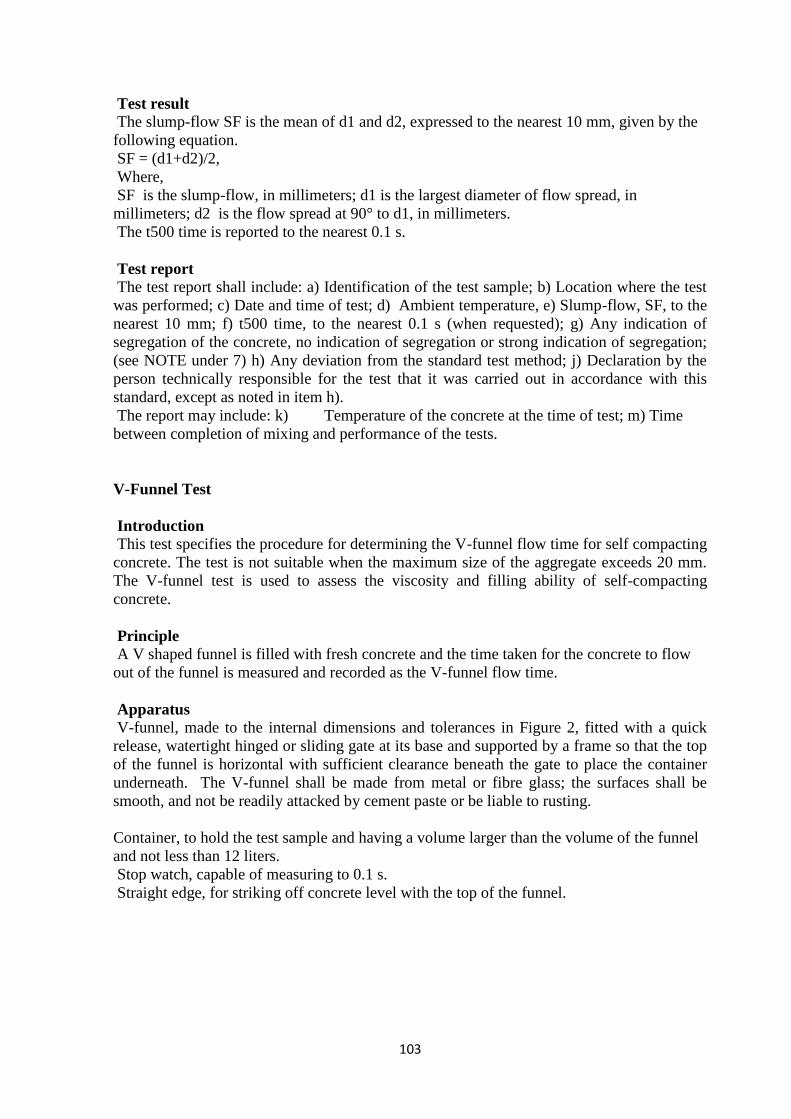
103
Test result
The slump-flow SF is the mean of d1 and d2, expressed to the nearest 10 mm, given by the
following equation.
SF = (d1+d2)/2,
Where,
SF is the slump-flow, in millimeters; d1 is the largest diameter of flow spread, in
millimeters; d2 is the flow spread at 90° to d1, in millimeters.
The t500 time is reported to the nearest 0.1 s.
Test report
The test report shall include: a) Identification of the test sample; b) Location where the test
was performed; c) Date and time of test; d) Ambient temperature, e) Slump-flow, SF, to the
nearest 10 mm; f) t500 time, to the nearest 0.1 s (when requested); g) Any indication of
segregation of the concrete, no indication of segregation or strong indication of segregation;
(see NOTE under 7) h) Any deviation from the standard test method; j) Declaration by the
person technically responsible for the test that it was carried out in accordance with this
standard, except as noted in item h).
The report may include: k) Temperature of the concrete at the time of test; m) Time
between completion of mixing and performance of the tests.
V-Funnel Test
Introduction
This test specifies the procedure for determining the V-funnel flow time for self compacting
concrete. The test is not suitable when the maximum size of the aggregate exceeds 20 mm.
The V-funnel test is used to assess the viscosity and filling ability of self-compacting
concrete.
Principle
A V shaped funnel is filled with fresh concrete and the time taken for the concrete to flow
out of the funnel is measured and recorded as the V-funnel flow time.
Apparatus
V-funnel, made to the internal dimensions and tolerances in Figure 2, fitted with a quick
release, watertight hinged or sliding gate at its base and supported by a frame so that the top
of the funnel is horizontal with sufficient clearance beneath the gate to place the container
underneath. The V-funnel shall be made from metal or fibre glass; the surfaces shall be
smooth, and not be readily attacked by cement paste or be liable to rusting.
Container, to hold the test sample and having a volume larger than the volume of the funnel
and not less than 12 liters.
Stop watch, capable of measuring to 0.1 s.
Straight edge, for striking off concrete level with the top of the funnel.

104
Test sample
A sample of at least 12 litres shall be obtained in accordance with IS 1199 (Part 1).
Procedure
Clean the funnel and bottom gate, then dampen all the inside surface including the gate.
Close the gate and pour the sample of concrete into the funnel in one operation, without any
agitation or mechanical compaction, then strike off the top with the straight edge so that the
concrete is level with the top of the funnel. Place the container under the funnel in order to
collect the concrete. After a delay of (10 ± 2) s from filling the funnel, open the gate quickly
and measure the time tv, to 0.1 s, from opening the gate to when it is possible to see
vertically through the funnel into the container below for the first time. The time tv is the V-
funnel flow time. The flow of concrete from the funnel shall be continuous. If a blockage
occurs the test shall be repeated. If a second blockage occurs the concrete lacks the
necessary viscosity. Report if a blockage has occurred.
Test report
The test report shall include:
a) Identification of the test sample;
b) location where the test was performed;
c) date when test performed;
d) Ambient temperature;
e) V-funnel flow time (tv) to the nearest 0.1s;
f) Any deviation from the standard test method; Declaration by the person
technically responsible for the test that it was carried out in accordance with this
standard, except as noted in item.
g) The report may include:
h) Temperature of the concrete at the time of test;
i) Time between completion of mixing and performance of the tests.
L Box Test
Introduction
The L-box test is used to assess the passing ability of self-compacting concrete to flow
through tight openings including spaces between reinforcing bars and other obstructions
without segregation or blocking.
Principle
The L box test is used to assess the passing ability of self-compacting concrete to flow
through tight openings including spaces between reinforcing bars and other obstructions
without segregation or blocking. There are two variations; the two bar test and the three bar
test. The three bar test simulates more congested reinforcement. A measured volume of fresh
concrete is allowed to flow horizontally through the gaps between vertical, smooth
reinforcing bars. The heights of the concrete in the vertical section (H1) and at the end of the
horizontal section (H2), see Figure 3, are measured and the ratio H2/H1 determined. This
ratio is a measure of the passing or blocking behaviour of self-compacting concrete.

105
Apparatus
L box, having the general arrangement and internal dimensions as shown in Fig. 3.
The L box shall be of rigid construction with surfaces that are smooth, flat and not readily
attacked by cement paste or be liable to rusting. The vertical hopper may be removable for
ease of cleaning.
The bar positioning system shall be such that two smooth steel bars of (12 ± 0,2) mm
diameter will provide a gap of (59 ± 1) mm for the two bar test and three smooth steel bars
of (12 ± 0,2) mm diameter will provide a gap of (41 ± 1) mm for the three bar test. The
system shall locate the bars in the L box so that they are vertical and equidistant across the
width of the box.
The surface of any material used in the assemblies shall not be readily attacked by cement
paste or be liable to rusting.
Rule or measuring tape, of minimum length 500 mm and graduated at intervals not
exceeding 1 mm, the zero mark being at the extreme end of the rule or measuring tape.
Containers, to hold the sample and having a total volume not less than 14 l. Spirit level, for
checking horizontality of base of L box base prior to commencing the test.
Straight edge, for striking off concrete level with the top of the L box.
Test sample A sample of at least 12 liters shall be obtained in accordance with IS 1199
Part 1.
Test procedure Support the L box on a level base and check for horizontality using the spirit
level. Clean the L box and dampen immediately prior to testing, but keep free from excess
moisture. Close the gate between the vertical and horizontal sections. Pour the concrete from
the container(s) into the filling hopper of the L box, without any agitation or mechanical
compaction, then strike off the top with the straight edge so that the concrete is level with
the top of the vertical section of the L box and allow to stand for (60 ± 10) s. Check the
concrete for signs of segregation before and after filling of the L box and report under cl.
22d) in a qualitative way, e.g. no indication of segregation, strong indication of segregation.
NOTE: Signs of segregation include a layer of cement paste/mortar and segregated coarse.
Fully open the sliding gate in a smooth continuous action to allow the concrete to flow into
the horizontal section. When movement has ceased, measure the drop in height of the level
of concrete ΔH1 to the nearest 1 mm in the vertical section on the gate side of the box at
three positions equally spaced across the width of the box. The mean depth of the concrete
H1 is the difference between the height of vertical section and the average of the three
readings of ΔH1. Record H1 to the nearest 1 mm. The same procedure is used to calculate
the mean depth of the concrete at the end of the horizontal section of the L box H2 from the
difference with the height of the horizontal section and the average of the three readings of
ΔH2. Record H2 to the nearest 1 mm.
Test result
The passing ability ratio PL, as measured by the L box test, is calculated to the nearest 0.01
from the following equation:
Where, PL is the passing ability ratio measured by the L box test; H1 is the mean depth of
concrete in the vertical section of the box, in millimeters; H2 is the mean depth of concrete
at the end of the horizontal section of the box, in millimeters.

106
Test report the test report shall include:
a) Identification of the test sample;
b) Location where the test was performed;
c) Date and time of test;
d) Ambient temperature,
e) Whether two bar or three bar test was carried out;
f) Passing ability ratio, PL, to the nearest 0.05;
g) Any segregation or bleeding observed during filling of the L box, no indication of
segregation/bleeding or strong indication of segregation/bleeding; (see NOTE under 20)
h) Any deviation from the standard test method;
j) Declaration by the person technically responsible for the test that it was carried out in
accordance with this standard, except as noted in item
The report may include:
k) Temperature of the concrete at the time of test;
m) Time between completion of mixing and performance of the tests
Sieve Segregation Resistance Test
Introduction
This test specifies the procedure for determining the sieve segregation resistance of self-
compacting concrete.
Principle
The sieve segregation resistance test is used to assess the resistance of self compacting
concrete to segregation. After sampling, the fresh concrete is allowed to stand for 15 min
and any separation of bleed water is noted. A known weight of the sample is then poured
into a sieve with 4.75 mm square apertures. After 2 min the weight of material which has
passed through the sieve is recorded. The segregation ratio is then calculated as the
proportion of the sample passing through the sieve.
Apparatus
Perforated plate sieve, having 4.75 mm square apertures, frame diameter 300 mm andheight
40 mm, conforming to IS: 460 (Part 2) complete with a receiver from which thesieve can be
easily removed by lifting vertically.
Weighing machine, having a flat platform which can accommodate the sieve receiver and
having a capacity of at least 10 kg, calibrated in increments of ≤ 20 g. Sample container, a
rigid container made from a non-absorbent material and having a minimum internal diameter
of 200 mm and a capacity of at least 11 l with a 10 l point indicated on the inside of the
container.
Timer, capable of measuring to 1 s.
Thermometer, capable of measuring to 1 °C.
Test sample A sample which fills the sample container to be obtained in accordance with IS
1199 -1
Procedure
Take and record the temperature of the concrete to the nearest 1 °C by using the
thermometer. Place (10 ± 0.5) litres of concrete in the sample container and cover to prevent
evaporation.
Allow to stand in a level position, without disturbance, for (15 ± 0.5) min.
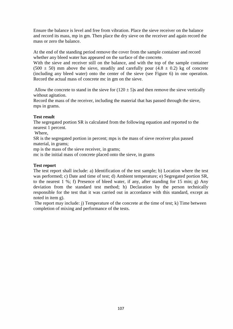
107
Ensure the balance is level and free from vibration. Place the sieve receiver on the balance
and record its mass, mp in gm. Then place the dry sieve on the receiver and again record the
mass or zero the balance.
At the end of the standing period remove the cover from the sample container and record
whether any bleed water has appeared on the surface of the concrete.
With the sieve and receiver still on the balance, and with the top of the sample container
(500 ± 50) mm above the sieve, steadily and carefully pour (4.8 ± 0.2) kg of concrete
(including any bleed water) onto the center of the sieve (see Figure 6) in one operation.
Record the actual mass of concrete mc in gm on the sieve.
Allow the concrete to stand in the sieve for (120 ± 5)s and then remove the sieve vertically
without agitation.
Record the mass of the receiver, including the material that has passed through the sieve,
mps in grams.
Test result
The segregated portion SR is calculated from the following equation and reported to the
nearest 1 percent.
Where,
SR is the segregated portion in percent; mps is the mass of sieve receiver plus passed
material, in grams;
mp is the mass of the sieve receiver, in grams;
mc is the initial mass of concrete placed onto the sieve, in grams
Test report The test report shall include: a) Identification of the test sample; b) Location where the test
was performed; c) Date and time of test; d) Ambient temperature; e) Segregated portion SR,
to the nearest 1 %; f) Presence of bleed water, if any, after standing for 15 min; g) Any
deviation from the standard test method; h) Declaration by the person technically
responsible for the test that it was carried out in accordance with this standard, except as
noted in item g).
The report may include: j) Temperature of the concrete at the time of test; k) Time between
completion of mixing and performance of the tests.
108
METHOD STATEMENT FOR INSTALLATION OF BORED CAST-IN-SITU
PILES.
1. Pile point will be marked on the ground with Total Survey Station.
2. The Rotary boring machine will be moved to pile location and positioned w.r.t pile
center pile ensuring verticality of mast with in-built indicator Panel facility or with
spirit level.
3. After boring of about 5 to 6mtrs. Temporary steel casing or approx. Some depth
will be placed in plumb position and checked with help of Spirit level.
4. Boring shall be carried out using rotary auger/bucket up to the tip of Pile. The
depth of the bore shall be checked with a steel wire and tape.
5. The side of bore hole shall be stabilized even during boring by use of Betonies
slurry through its length. The level of betonies suspension shall be maintained up
to approx. 10M above the bottom level of temporary Casting at the top.
6. The bottom of bore hole shall be cleaned thoroughly using bucket.
7. Full length of steel reinforcement cage with spacer blocks will be lowered into the
borehole.
8. 8‖/10‖ dia tremmie pipe shall be lowered into bore hole keeping the bottom of
termite approximately 300mm above pile bottom level.
9. The bore hole shall again be cleaned by betonies circulation by pumping Fresh
betonies solution of a specific gravity of at least 1,025. The adequacy of pump for
flushing piles more than 20mtr deep will be ensured.
10. After ensuring that the out coming betonies slurry is clean and consistency of the
same is almost equal, (density to be measured & maintained) as that of fresh
betonies slurry, the betonies circulation will be stopped.
11. If bore is left without concreting for more than two hours, it shall be flushed
again.
12. Hopper wills he placed on termite pipe.
13. Ready mix concrete of required grade with 150 to I80mm slump shall be brought
by transit mixers.
14. Concrete shall be poured through tremmie pipe (directly from transit Mixer in the
hopper).
15. Concreting shall generally be poured with minimum interruption. However, under
unavoidable circumstance if the operation has to be suspended temporarily, then
the termite pipe shall be raised and lowered slowly from the time to time to
avoid setting of concrete around it.
16. Sacrificial concrete at top will be cast for at least 1m.

109
17. The termite pipe shall be removed in stage during pouring of concrete ensuring
that the termite bottom is always within the concrete. The operation shall be
continued till the entire length of pile is cast.
18. The boring machine shall be brought back to location and temporary casing shall
be removed using casing adapter.
19. Bore soil betonies mud shall be removed with the help of loader and tippers.
METHOD STATEMENT- LOAD TEST ON PILES
The initial load test to be carried out as per IS-2911 Part-4- 1985.
The Kent ledge structure shall be designed according to the applicable loads.
A pit of l2Mxl2M shall be excavated up to 2m below the ground level.
Further, pit about 3 M x: 3 M shall be excavated around the test pile up to about l below
the test level of 1.40 M height below the bottom level of previous pit.
The pile shall be chipped off in order to remove the weak concrete and finished smooth
at the test level with the same grade of concrete as in the pile.
The supports for the main girders shall be made of RCC and the top level shall be
maintained at a pre-determined level, so that there is a gap of about 50mm between the
jack assembly and the soffit of the main girders at the zero-load position. Sketch is
shown in the drawing.
The jacks shall be placed over M.S. Plates on the pile, so that the center of gravity of
the jacks is over the center of the M.S. Plates and over the center of the pi le.
The Kent ledge structure be placed in position as per design. The girders shall be tack-
welded with reinforcement bars so as to keep them in position during the loading. The
Kent ledge shall be covered with M.S. plates of 4mm thickness.
It is to be ensured throughout the process of loading that the kent ledge load shall be
concentric with the center of the pile. The Kent ledge shall be loaded with sand
bags/precast concrete blocks/sand.
Datum bars shall be provided with its supports at a distance of 5M from the edge of the
piles. The supports shall be embedded in concrete into the ground. The datum bars
shall be made of rigid structure steel material. The datum bars shall be so arranged as
to accommodate dial gauges at three edges of the pile, the edges making apex points of
an equilateral triangle.
Three numbers of magnetic stands shall be placed on the pile at the apex: points as
mentioned above. The magnetic stands shall be placed on M.S. Plates fixed to the pile
surface with some adhesive material. The dial gauges to be used for the test shall be of
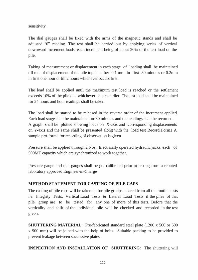
110
sensitivity.
The dial gauges shall be fixed with the arms of the magnetic stands and shall be
adjusted ‗0‖ reading. The test shall be carried out by applying series of vertical
downward increment loads, each increment being of about 20% of the test load on the
pile.
Taking of measurement or displacement in each stage of loading shall be maintained
till rate of displacement of the pile top is either 0.1 mm in first 30 minutes or 0.2mm
in first one hour or till 2 hours whichever occurs first.
The load shall be applied until the maximum test load is reached or the settlement
exceeds 10% of the pile dia, whichever occurs earlier. The test load shall be maintained
for 24 hours and hour readings shall be taken.
The load shall be started to be released in the reverse order of the increment applied.
Each load stage shall be maintained for 30 minutes and the readings shall be recorded.
A graph shall be plotted showing loads on X-axis and corresponding displacements
on Y-axis and the same shall be presented along with the load test Record Form1 A
sample pro-forma for recording of observation is given.
Pressure shall be applied through 2 Nos. Electrically operated hydraulic jacks, each of
500MT capacity which are synchronized to work together.
Pressure gauge and dial gauges shall be got calibrated prior to testing from a reputed
laboratory approved Engineer-in-Charge
METHOD STATEMENT FOR CASTING OF PILE CAPS
The casting of pile caps will be taken up for pile groups cleared from all the routine tests
i.e. Integrity Tests, Vertical Load Tests & Lateral Load Tests if the piles of that
pile group are to be tested for any one of more of this tests. Before that the
verticality and shift of the individual pile will be checked and recorded in the test
given.
SHUTTERING MATERIAL: Pre-fabricated standard steel plate (1200 x 500 or 600
x 900 mm) will be joined with the help of bolts. Suitable packing to be provided to
prevent leakage between successive plates.
INSPECTION AND INSTALLATION OF SHUTTERING: The shuttering will
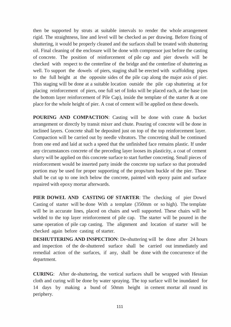
111
then be supported by struts at suitable intervals to render the whole arrangement
rigid. The straightness, line and level will be checked as per drawing. Before fixing of
shuttering, it would be properly cleaned and the surfaces shall be treated with shuttering
oil. Final cleaning of the enclosure will be done with compressor just before the casting
of concrete. The position of reinforcement of pile cap and pier dowels will be
checked with respect to the centerline of the bridge and the centerline of shuttering as
well. To support the dowels of piers, staging shall be erected with scaffolding pipes
to the full height at the opposite sides of the pile cap along the major axis of pier.
This staging will be done at a suitable location outside the pile cap shuttering at for
placing reinforcement of piers, one full set of links will be placed each, at the base (on
the bottom layer reinforcement of Pile Cap), inside the template of the starter & at one
place for the whole height of pier. A coat of cement will be applied on these dowels.
POURING AND COMPACTION: Casting will be done with crane & bucket
arrangement or directly by transit mixer and chute. Pouring of concrete will be done in
inclined layers. Concrete shall be deposited just on top of the top reinforcement layer.
Compaction will be carried out by needle vibrators. The concreting shall be continued
from one end and laid at such a speed that the unfinished face remains plastic. If under
any circumstances concrete of the preceding layer looses its plasticity, a coat of cement
slurry will be applied on this concrete surface to start further concreting. Small pieces of
reinforcement would be inserted party inside the concrete top surface so that protruded
portion may be used for proper supporting of the props/turn buckle of the pier. These
shall be cut up to one inch below the concrete, painted with epoxy paint and surface
repaired with epoxy mortar afterwards.
PIER DOWEL AND CASTING OF STARTER: The checking of pier Dowel
Casting of starter will be done With a template (350mm or so high). The template
will be in accurate lines, placed on chairs and well supported. These chairs will be
welded to the top layer reinforcement of pile cap. The starter will be poured in the
same operation of pile cap casting. The alignment and location of starter will be
checked again before casting of starter.
DESHUTTERING AND INSPECTION: De-shuttering will be done after 24 hours
and inspection of the de-shuttered surface shall be carried out immediately and
remedial action of the surfaces, if any, shall be done with the concurrence of the
department.
CURING: After de-shuttering, the vertical surfaces shall be wrapped with Hessian
cloth and curing will be done by water spraying. The top surface will be inundated for
14 days by making a bund of 50mm height in cement mortar all round its
periphery.
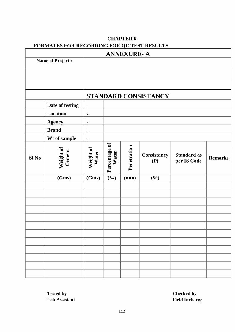
112
CHAPTER 6
FORMATES FOR RECORDING FOR QC TEST RESULTS
ANNEXURE- A Name of Project :
STANDARD CONSISTANCY
Date of testing :-
Location :-
Agency :-
Brand :-
Wt of sample :-
Sl.No
Wei
gh
t o
f
Cem
ent
Wei
gh
t o
f
Wa
ter
Per
cen
tag
e o
f
Wa
ter
Pen
etra
tio
n
Consistancy
(P)
Standard as
per IS Code Remarks
(Gms) (Gms) (%) (mm) (%)
Tested by
Checked by
Lab Assistant
Field Incharge
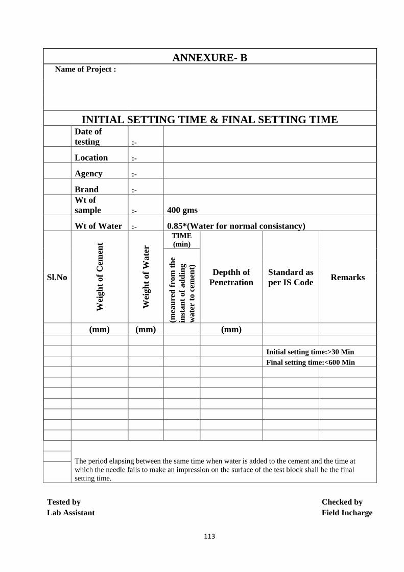
113
ANNEXURE- B Name of Project :
INITIAL SETTING TIME & FINAL SETTING TIME
Date of
testing :-
Location :-
Agency :-
Brand :-
Wt of
sample :- 400 gms
Wt of Water :- 0.85*(Water for normal consistancy)
Sl.No
Wei
gh
t o
f C
emen
t
Wei
gh
t o
f W
ate
r
TIME
(min)
Depthh of
Penetration
Standard as
per IS Code Remarks
(mea
ure
d f
rom
th
e
inst
an
t of
ad
din
g
wate
r to
cem
ent)
(mm) (mm) (mm)
Initial setting time:>30 Min
Final setting time:<600 Min
The period elapsing between the same time when water is added to the cement and the time at
which the needle fails to make an impression on the surface of the test block shall be the final
setting time.
Tested by
Checked by
Lab Assistant
Field Incharge
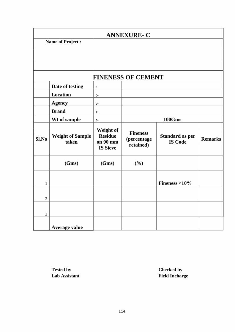
114
ANNEXURE- C Name of Project :
FINENESS OF CEMENT
Date of testing :-
Location :-
Agency :-
Brand :-
Wt of sample :- 100Gms
Sl.No Weight of Sample
taken
Weight of
Residue
on 90 mm
IS Sieve
Fineness
(percentage
retained)
Standard as per
IS Code Remarks
(Gms) (Gms) (%)
1 Fineness <10%
2
3
Average value
Tested by
Checked by
Lab Assistant
Field Incharge

115
ANNEXURE- D Name of Project :
COMPRESSIVE STRENGTH Room Temp Date of Age of
specimen
Crushing
load (T)
Crushing
Strength
kg/cm2
Remarks
Casting Testing
(Cube Size = 7.06 cm, Wt. of Cement = 200 gms, Wt. of Standard Sand = 600 gms)
Comments of Laboratory In-Charge
Signed & Sealed by Laboratory In-Charge
Witnessed by: Name
Designation Signature

116
ANNEXURE-E Name of Project
:
GRADATION OF FINE AGGEREGATE
Date of
testing :-
Location :-
Agency :-
Source
of
material :-
Sl.No
Is S
eive
des
ign
ati
on
Wei
gh
t o
f
Sa
mp
le
reta
ined
% o
f W
eig
ht
reta
ined
Cu
mu
lati
ve
%
of
Wei
gh
t
reta
ined
% o
f w
eig
ht
pass
ing
Gradation limits
Rem
ark
s
Gra
din
g
Zo
ne
I
Gra
din
g
Zo
ne
II
Gra
din
g
Zo
ne
III
Gra
din
g
Zo
ne
IV
(MM) (GMS) (GMS) (%) (%)
1 10 100 100 100 100
2 4.75 90-100 90-100 90-100 95-100
3 2.36 60-95 75-100 85-100 95-100
4 1.18 30-70 55-90 75-100 90-100
5 600 MIC 15-34 35-59 60-79 80-100
6 300 MIC 5-20 8-30 12-40 15-50
7 150 MIC 0-10 0-10 0-10 0-15
Pan
FM=
Tested by
Checked by
Lab Assistant
Field Incharge

117
ANNEXURE-F Name of Project :
BULK DENSITY OF FINE AGGREGATE
Date of testing :-
Location :-
Agency :-
Source of Material :-
Description
Sa
mp
le-1
Sa
mp
le-2
Un
its
Sta
nd
ard
as
per
IS
Co
de
Rem
ark
s
Capacity of Measure Lts
Empty Weight of Measure Kgs
Empty Weight of Measure + Sand
(loose) Kgs
Weight of loose sand Kgs
Bulk Density (loose) Kgs/Lts
Avg value of Bulk Density Kgs/Lts
Empty Weight of Measure + Sand
(Roded) Kgs
Weight of Roded sand Kgs
Bulk Density (Roded) Kgs/Lts
Avg value of Bulk Density Kgs/Lts
Tested by
Checked by
Lab Assistant
Field Incharge

118
ANNEXURE-G Name of Project :
DETERMINATION OF SILT CONTENT
Date of testing :-
Location :-
Agency :-
Source of Material :-
Sl.No Description Sample-
1
Sample-
2 Sample-3
Standard as per
IS Code Remarks
1 Volume of Sample (V1) ml Silt Content <3%
2 Volume of Silt (V2) ml
3 Percentage of silt
(V2/V1)*100
Average
Tested by
Checked by
Lab Assistant
Field Incharge

119
ANNEXURE-H Name of Project :
TEST CERTIFICATE FOR WATER FOR CONSTRUCTION WORK
Package Name: Package No.:
Contractor Name: Contract No.:
Source of Supply:
No. of Samples Tested: Date Sample Collected:
Tested : Tested as per IS-
S. No
Colo
r
pH
Valu
e
Org
an
ic
Soli
ds
(mg
/l)
Ino
rga
nic
Soli
ds
(mg
/l)
Sulp
ha
tes
(as
SO
4)
Chlo
ri
des
(as
Cl)
Suspended
Matter (mg/l)
(mg/l) (mg/l)
Limits >6
<200 <3000 <500
PCC
<2000 <2000
RCC
<1000
Traces of Oil & Grease
Average Hardness as CaCO3
Comments of Laboratory In-Charge
Signed & Sealed by Laboratory In-Charge
Witnessed by:
Name
Designation
Signature
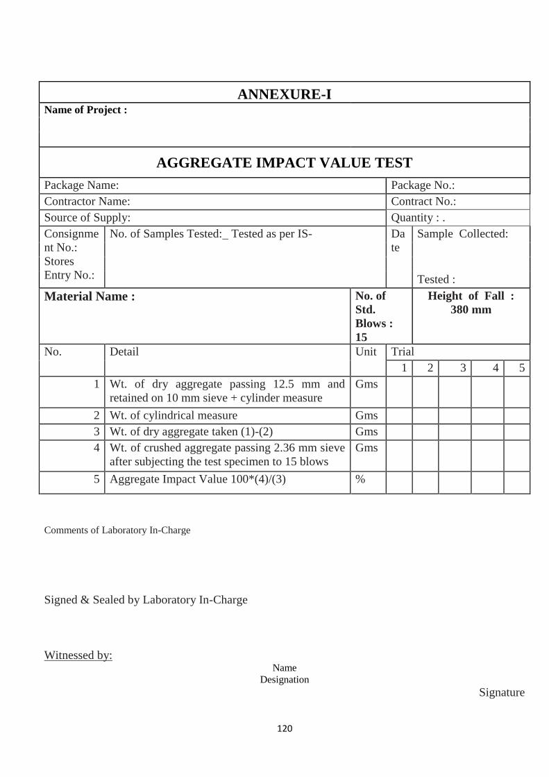
120
ANNEXURE-I Name of Project :
AGGREGATE IMPACT VALUE TEST
Package Name: Package No.:
Contractor Name: Contract No.:
Source of Supply: Quantity : .
Consignme
nt No.:
Stores
Entry No.:
No. of Samples Tested: Tested as per IS- Da
te
Sample Collected:
Tested :
Material Name : No. of
Std.
Blows :
15
Height of Fall :
380 mm
No. Detail Unit Trial
1 2 3 4 5
1 Wt. of dry aggregate passing 12.5 mm and
retained on 10 mm sieve + cylinder measure
Gms
2 Wt. of cylindrical measure Gms
3 Wt. of dry aggregate taken (1)-(2) Gms
4 Wt. of crushed aggregate passing 2.36 mm sieve
after subjecting the test specimen to 15 blows
Gms
5 Aggregate Impact Value 100*(4)/(3) %
Comments of Laboratory In-Charge
Signed & Sealed by Laboratory In-Charge
Witnessed by: Name
Designation
Signature

121
ANNEXURE-J Name of Project :
LOS ANGELES ABRASION TEST Package Name: Package No.:
Contractor Name: Contract No.:
Source of Supply: Quantity : .
Consignment
No.: Stores
Entry No.:
No. of Samples Tested: Tested as per
IS-
Date Sample Collected: Tested :
Material Name : No. Of
Revolutions
500/100
rpm
No. Of Abrasive Changes
No. Detail Unit Trial
1 2 3 4 5
1 Weight of aggregate of
specified gradation
Kg
2 Weight of passing IS 1.7 mm
sieve after specified
revolution
Kg
3 Los Angeles Abrasion Value %
=100 X (2)/(1)
Average Value
Comments of Laboratory In-Charge
Signed & Sealed by Laboratory In-Charge
Witnessed
by: Name Designation Signature
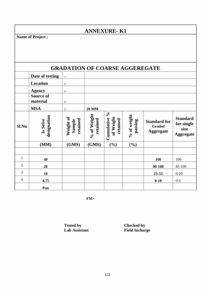
122
ANNEXURE- K1 Name of Project :
GRADATION OF COARSE AGGEREGATE
Date of testing :-
Location :-
Agency :-
Source of
material :-
MSA :- 20 MM
Sl.No
Is S
eiv
e
des
ign
ati
on
Wei
gh
t o
f
Sa
mp
le
reta
ined
% o
f W
eig
ht
reta
ined
Cu
mu
lati
ve
%
of
Wei
gh
t
reta
ined
% o
f w
eig
ht
pass
ing
Standard for Graded
Aggregate
Standard
for single
size
Aggregate
(MM) (GMS) (GMS) (%) (%)
1 40 100 100
2 20 90-100 85-100
3 10 25-55 0-20
4 4.75 0-10 0-5
Pan
FM=
Tested by
Lab Assistant Checked by
Field Incharge

123
ANNEXURE- K2 Name of Project :
GRADATION OF COARSE AGGEREGATE
Date of testing :-
Location :-
Agency :-
Source of
material :-
MSA :- 12.5 MM
Sl.No
Is S
eive
des
ign
ati
on
Wei
gh
t o
f
Sa
mp
le
reta
ined
% o
f W
eig
ht
reta
ined
Cu
mu
lati
ve
%
of
Wei
gh
t
reta
ined
% o
f w
eig
ht
pass
ing
Standard for Graded
Aggregate
Standard
for single
size
Aggregate
(MM) (GMS) (GMS) (%) (%)
1 20 100 --
2 16 -- 100
3 12.5 90-100 85-100
4 10 40-85 0-45
5 4.75 0-10 0-10
Pan
FM=
Tested by
Lab Assistant Checked by
Field Incharge
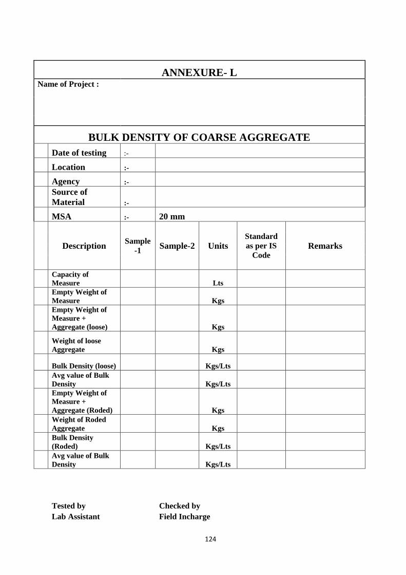
124
ANNEXURE- L Name of Project :
BULK DENSITY OF COARSE AGGREGATE
Date of testing :-
Location :-
Agency :-
Source of
Material :-
MSA :- 20 mm
Description Sample
-1 Sample-2 Units
Standard
as per IS
Code Remarks
Capacity of
Measure Lts
Empty Weight of
Measure Kgs
Empty Weight of
Measure +
Aggregate (loose) Kgs
Weight of loose
Aggregate Kgs
Bulk Density (loose) Kgs/Lts
Avg value of Bulk
Density Kgs/Lts
Empty Weight of
Measure +
Aggregate (Roded) Kgs
Weight of Roded
Aggregate Kgs
Bulk Density
(Roded) Kgs/Lts
Avg value of Bulk
Density Kgs/Lts
Tested by
Checked by
Lab Assistant
Field Incharge

125
ANNEXURE- M Name of Project :
FLAKINESS INDEX & ELONGATION INDEX
(As part IS 2386 Part 1)
Date of
testing :-
Location :-
Agency :-
Source of
materials :-
MSA :- 20mm
Sl.
No
Pa
ss t
hro
ug
h g
ua
ge
Ret
ain
ed o
n g
au
ge
Wei
gh
t
Sp
ecif
ied
th
ick
nes
s
gu
ag
e
Wei
gh
t o
f fr
act
ion
pass
ing t
hro
ug
h
ga
ug
e
Ret
ain
ed o
n
thic
kn
ess
ga
ug
e
Sp
ecif
ied
len
gth
ga
ug
e
Elo
ngate
d
Ag
gre
ga
te w
eig
ht
Sta
nd
ard
as
per
IS
Co
de
Rem
arks
(mm) (mm) (G
ms)
(Gm
s) (Gms)
(G
ms)
25 20 25-20 25-20 FLAKINESS
% =
20 16 20-16 20-16 ELONGATED
% =
16 12.5 16-12.5 16-12.5 COMBINED
% =<40%
12.5 10 12.5-10 12.5-10
10 6.3 10-6.3 10-6.3
Tested by
Checked by
Lab Assistant
Field Incharge

126
ANNEXURE- N Name of Project
:
CUBE STRENGTH OF CONCRETE Date of testing
:- Agency :-
Location :-
Source of
Material :-
Source of Material :-
Sl.N
o
(1)
Grade of
Concrete
(2)
Date of
Casting
(3)
Date of
Testing
(4)
Age of
Specimen
Days (5)
Size of
Specimen
in mm
(6)
Weight of
Specimen
in kgs
(7)
Density
(8)
Area of
Loading
(9)
Maximum
Load
(10)
Compressive
Strength
(11)
Avg
Compressive
Strength
(12)
0.85*Avg Fav
(13)
1.15*Avg Fav
(14)
Acceptance
30+4=34
N/mm2(Min) &
for Individual
Cube
30-2=28 or
30-3=27
(15)
Remarks
(16)
Tested by
Checked by
Lab Assistant
Field Incharge
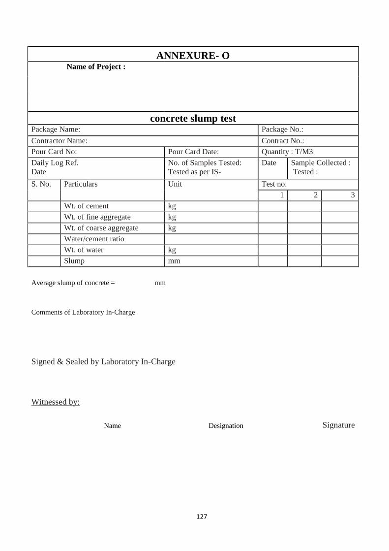
127
ANNEXURE- O Name of Project :
concrete slump test Package Name: Package No.:
Contractor Name: Contract No.:
Pour Card No: Pour Card Date: Quantity : T/M3
Daily Log Ref.
Date
No. of Samples Tested:
Tested as per IS-
Date Sample Collected :
Tested :
S. No. Particulars Unit Test no.
1 2 3
Wt. of cement kg
Wt. of fine aggregate kg
Wt. of coarse aggregate kg
Water/cement ratio
Wt. of water kg
Slump mm
Average slump of concrete = mm
Comments of Laboratory In-Charge
Signed & Sealed by Laboratory In-Charge
Witnessed by:
Name Designation Signature
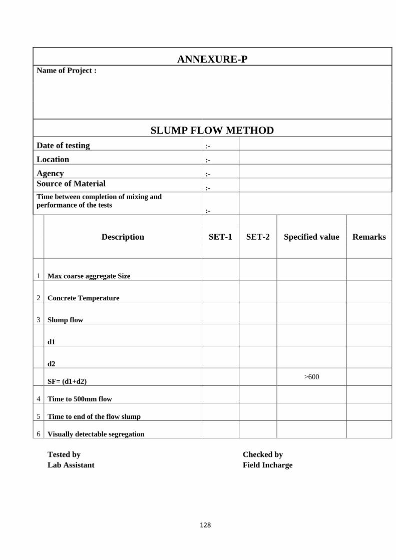
128
ANNEXURE-P Name of Project :
SLUMP FLOW METHOD
Date of testing :-
Location :-
Agency :-
Source of Material :-
Time between completion of mixing and
performance of the tests :-
Description SET-1 SET-2 Specified value Remarks
1 Max coarse aggregate Size
2 Concrete Temperature
3 Slump flow
d1
d2
SF= (d1+d2) >600
4 Time to 500mm flow
5 Time to end of the flow slump
6 Visually detectable segregation
Tested by
Checked by
Lab Assistant
Field Incharge
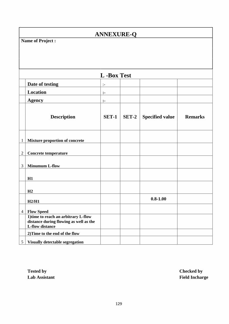
129
ANNEXURE-Q Name of Project :
L -Box Test
Date of testing :-
Location :-
Agency :-
Description SET-1 SET-2 Specified value Remarks
1 Mixture proportion of concrete
2 Concrete temperature
3 Minumum L-flow
H1
H2
H2/H1 0.8-1.00
4 Flow Speed
1)time to reach an arbitrary L-flow
distance during flowing as well as the
L-flow distance
2)Time to the end of the flow
5 Visually detectable segregation
Tested by
Checked by
Lab Assistant
Field Incharge
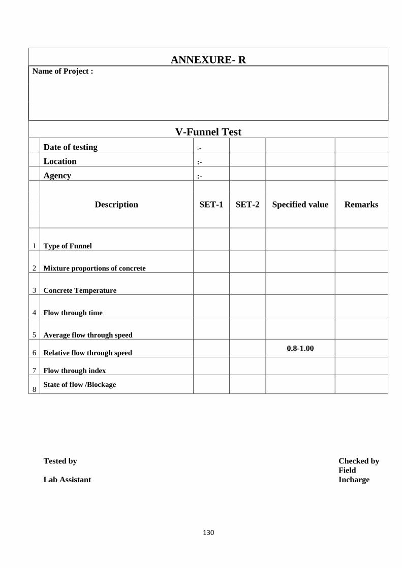
130
ANNEXURE- R Name of Project :
V-Funnel Test
Date of testing :-
Location :-
Agency :-
Description SET-1 SET-2 Specified value Remarks
1 Type of Funnel
2 Mixture proportions of concrete
3 Concrete Temperature
4 Flow through time
5 Average flow through speed
6 Relative flow through speed 0.8-1.00
7 Flow through index
8 State of flow /Blockage
Tested by
Checked by
Lab Assistant
Field
Incharge
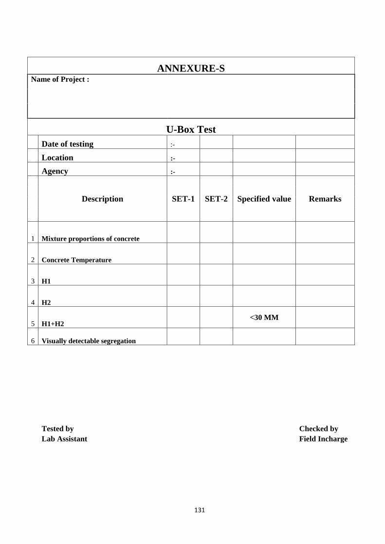
131
ANNEXURE-S Name of Project :
U-Box Test
Date of testing :-
Location :-
Agency :-
Description SET-1 SET-2 Specified value Remarks
1 Mixture proportions of concrete
2 Concrete Temperature
3 H1
4 H2
5 H1+H2 <30 MM
6 Visually detectable segregation
Tested by
Checked by
Lab Assistant
Field Incharge

132
ANNEXURE- T Name of Project :
SIEVE SEGREGATION RESISTANCE TEST
Date of testing :-
Location :-
Agency :-
Time between completion of mixing and performance
of the tests
:-
The temperature of the concrete at the time of tests
:-
Description SET-1 SET-2 Specified
value
Rem
arks
Weight of seive receiver Wp =
weight of Seive receiver + Sieve (make balance zero) =
Presence of bleed water if any,after standing for 15 min =
Actual Weight of concrete pored in sieve mc =
Weight of mass of concrete on receiver after allowing
2min mps =
SR =(mps -mp)*100/mc SR = < 15 %
Average value SR =
Tested by
Checked by
Lab Assistant
Field Incharge
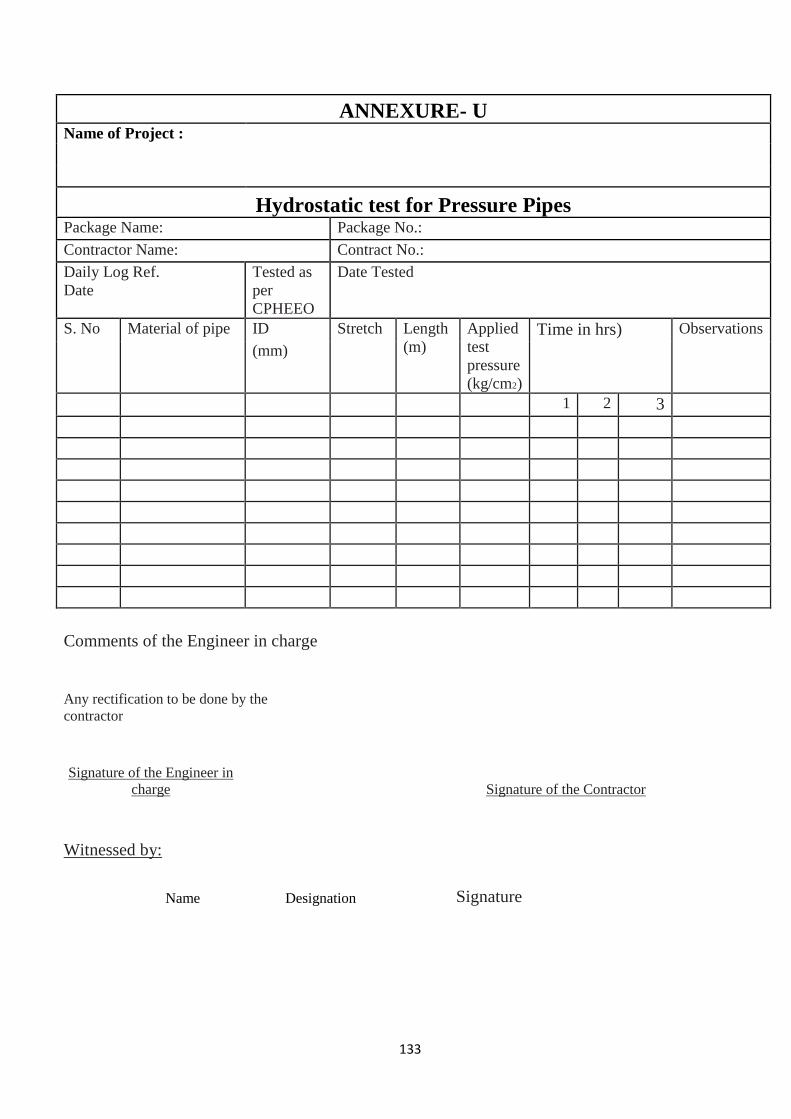
133
ANNEXURE- U Name of Project :
Hydrostatic test for Pressure Pipes Package Name: Package No.:
Contractor Name: Contract No.:
Daily Log Ref.
Date
Tested as
per
CPHEEO
Date Tested
S. No Material of pipe ID Stretch Length
(m)
Applied
test
pressure
(kg/cm2)
Time in hrs) Observations
(mm)
1 2 3
Comments of the Engineer in charge
Any rectification to be done by the
contractor
Signature of the Engineer in
charge
Signature of the Contractor
Witnessed by:
Name Designation Signature
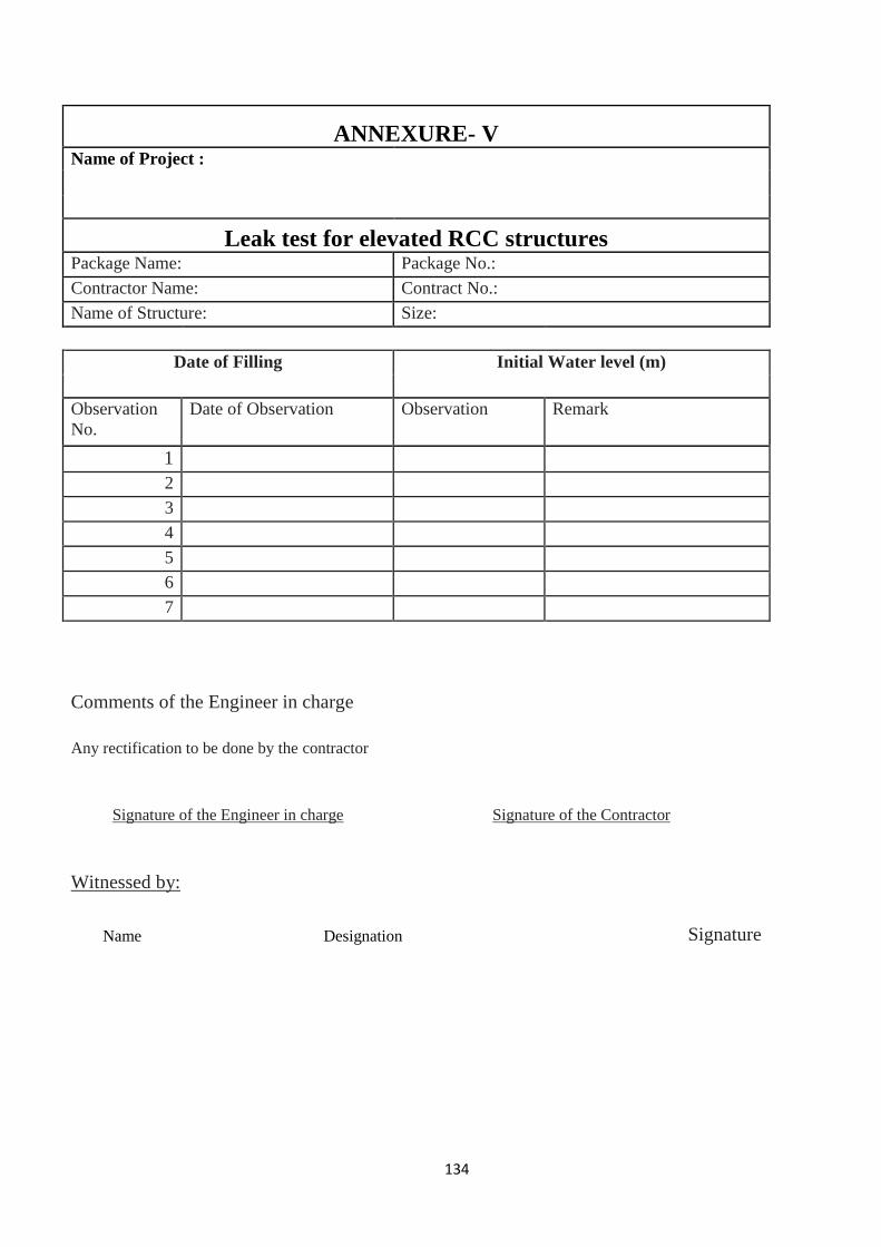
134
ANNEXURE- V Name of Project :
Leak test for elevated RCC structures Package Name: Package No.:
Contractor Name: Contract No.:
Name of Structure: Size:
Date of Filling Initial Water level (m)
Observation
No.
Date of Observation Observation Remark
1
2
3
4
5
6
7
Comments of the Engineer in charge
Any rectification to be done by the contractor
Signature of the Engineer in charge Signature of the Contractor
Witnessed by:
Name Designation Signature
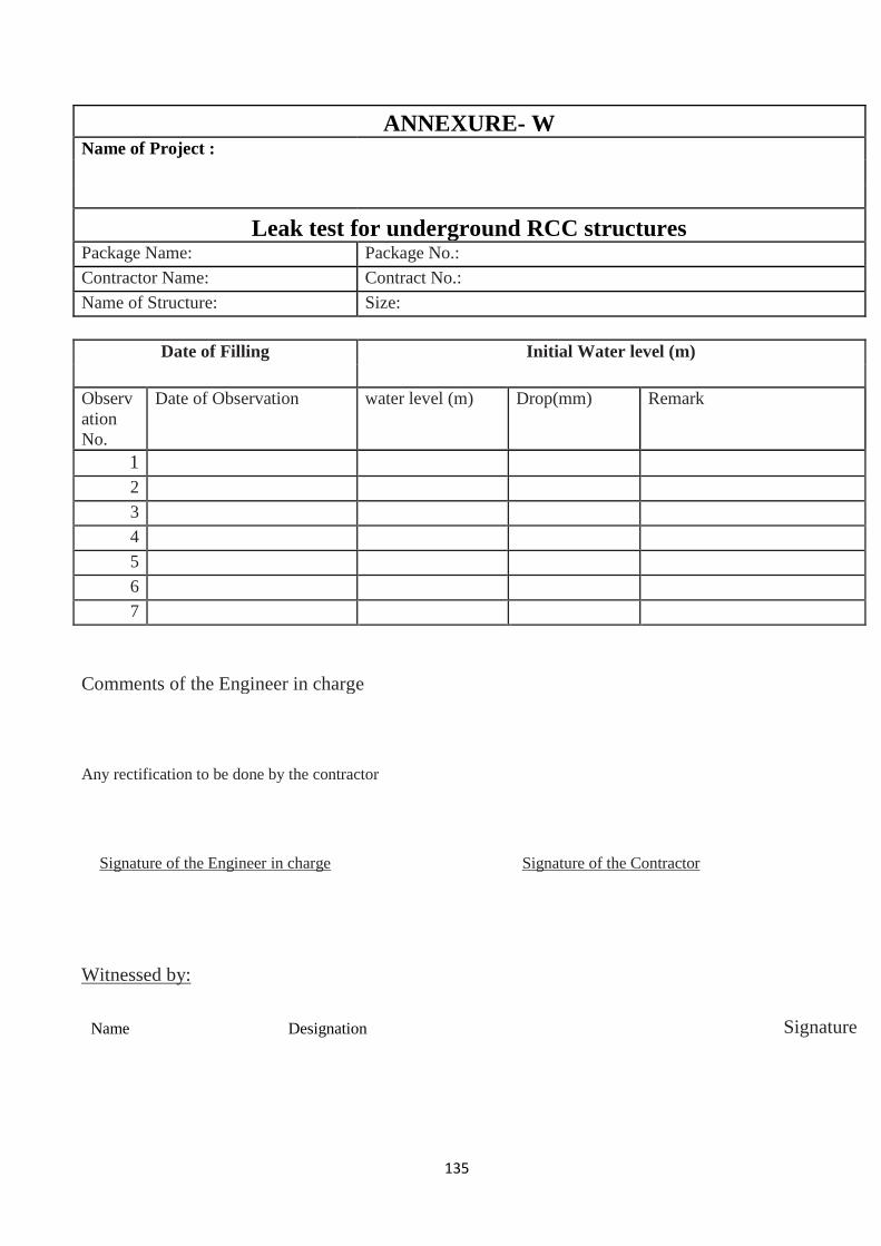
135
ANNEXURE- W Name of Project :
Leak test for underground RCC structures Package Name: Package No.:
Contractor Name: Contract No.:
Name of Structure: Size:
Date of Filling Initial Water level (m)
Observ
ation
No.
Date of Observation water level (m) Drop(mm) Remark
1
2
3
4
5
6
7
Comments of the Engineer in charge
Any rectification to be done by the contractor
Signature of the Engineer in charge Signature of the Contractor
Witnessed by:
Name Designation
Signature

136
ANNEXURE- X Name of Project :
Permit format for concreting
Date of Concreting
This Permit Format must be presented to Employer’s Representative at least
one day advance of proposed concreting. Concreting can be done only if
Permit Format is duly signed by authorized representative of implementing
agency.
Package Name: Package No.:
Contractor Name: Contract No.:
Where the concrete used:
Supervised By: Quantity : T/M3
Daily Log Ref.
Date
Mix Grade:
Time Start
Finish
Date Sample Collected :
Tested :
Materials Status of Testing and
Approval
Quantity
available at site
Cement
CA1
CA2
Fine Aggregate
Water
Equipments Status
Mixer
Weight Batching M/C
Vibrator
Cube moulds
Cone, Alternative Power
Labour
Availability of Skilled
manpower
Availability of Labour

137
ANNEXURE- Y Name of Project
:
Centering & Shuttering
Centering & Shuttering
· IS formwork plan submitted and approved.
· IS formwork checked by Engineer in Charge
Reinforcement
IS reinforcement placed as per approved drawings and design and
checked by Engineer in charge.
Plasticizers
1. Is use of plasticizers approved.
2. Name and make of plasticizer
3. Type of plasticizer
Labor Amenities
Approved for concreting
Signature of authorized representative of implementing agency
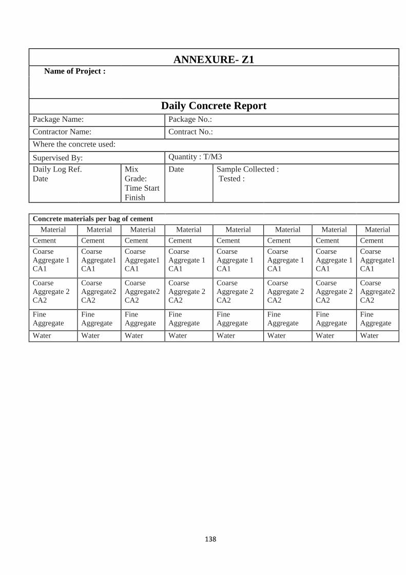
138
ANNEXURE- Z1 Name of Project :
Daily Concrete Report
Package Name: Package No.:
Contractor Name: Contract No.:
Where the concrete used:
Supervised By: Quantity : T/M3
Daily Log Ref.
Date
Mix
Grade:
Time Start
Finish
Date Sample Collected :
Tested :
Concrete materials per bag of cement
Material Material Material Material Material Material Material Material
Cement Cement Cement Cement Cement Cement Cement Cement
Coarse
Aggregate 1
CA1
Coarse
Aggregate1
CA1
Coarse
Aggregate1
CA1
Coarse
Aggregate 1
CA1
Coarse
Aggregate 1
CA1
Coarse
Aggregate 1
CA1
Coarse
Aggregate 1
CA1
Coarse
Aggregate1
CA1
Coarse
Aggregate 2
CA2
Coarse
Aggregate2
CA2
Coarse
Aggregate2
CA2
Coarse
Aggregate 2
CA2
Coarse
Aggregate 2
CA2
Coarse
Aggregate 2
CA2
Coarse
Aggregate 2
CA2
Coarse
Aggregate2
CA2
Fine
Aggregate
Fine
Aggregate
Fine
Aggregate
Fine
Aggregate
Fine
Aggregate
Fine
Aggregate
Fine
Aggregate
Fine
Aggregate
Water Water Water Water Water Water Water Water
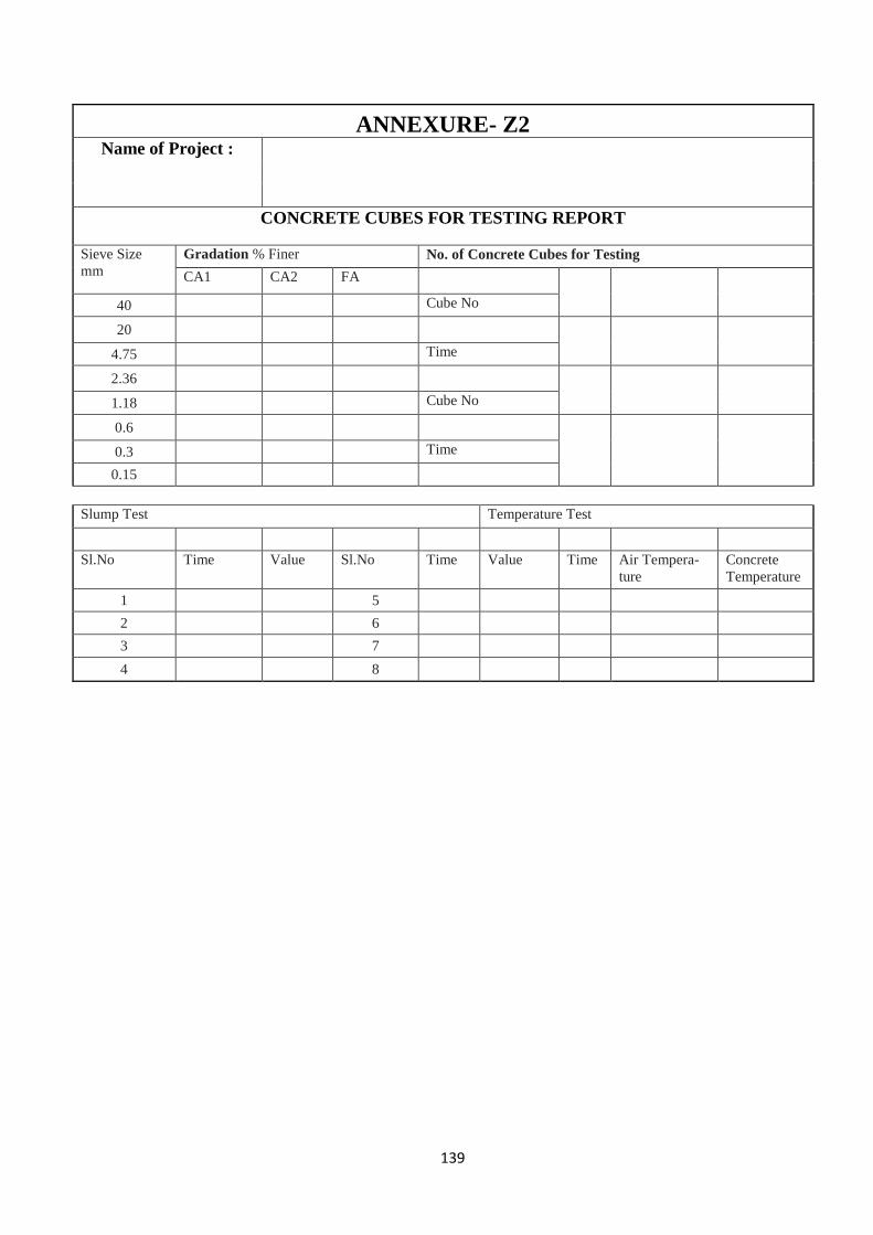
139
ANNEXURE- Z2 Name of Project :
CONCRETE CUBES FOR TESTING REPORT
Sieve Size
mm
Gradation % Finer No. of Concrete Cubes for Testing
CA1 CA2 FA
40 Cube No
20
4.75 Time
2.36
1.18 Cube No
0.6
0.3 Time
0.15
Slump Test Temperature Test
Sl.No Time Value Sl.No Time Value Time Air Tempera-
ture
Concrete
Temperature
1 5
2 6
3 7
4 8

140
CHAPTER 7
E.P.C. Contracts G.Os & QC Instructions.

141
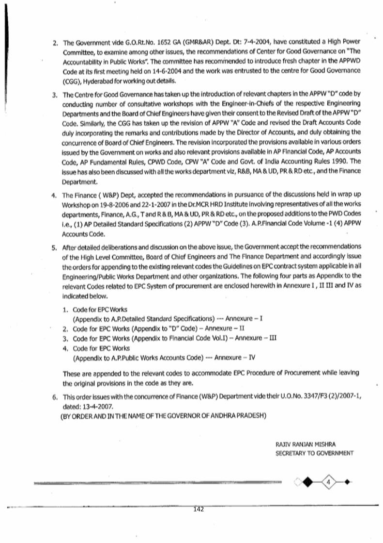
142

143
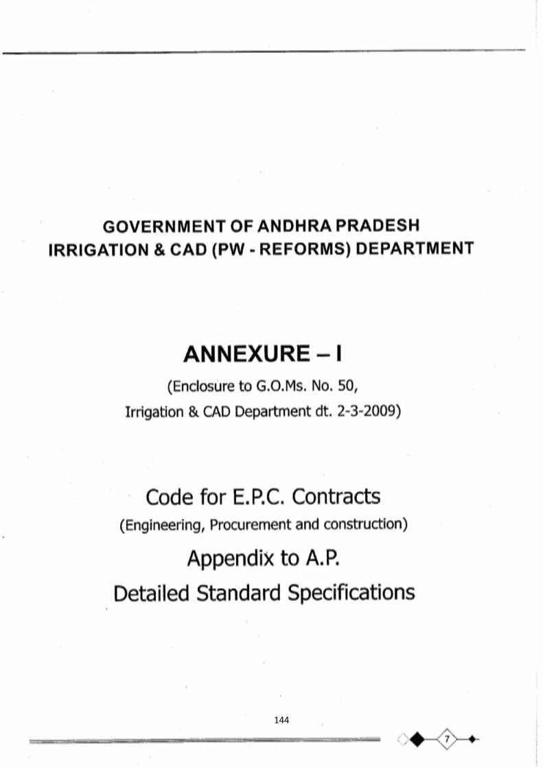
144
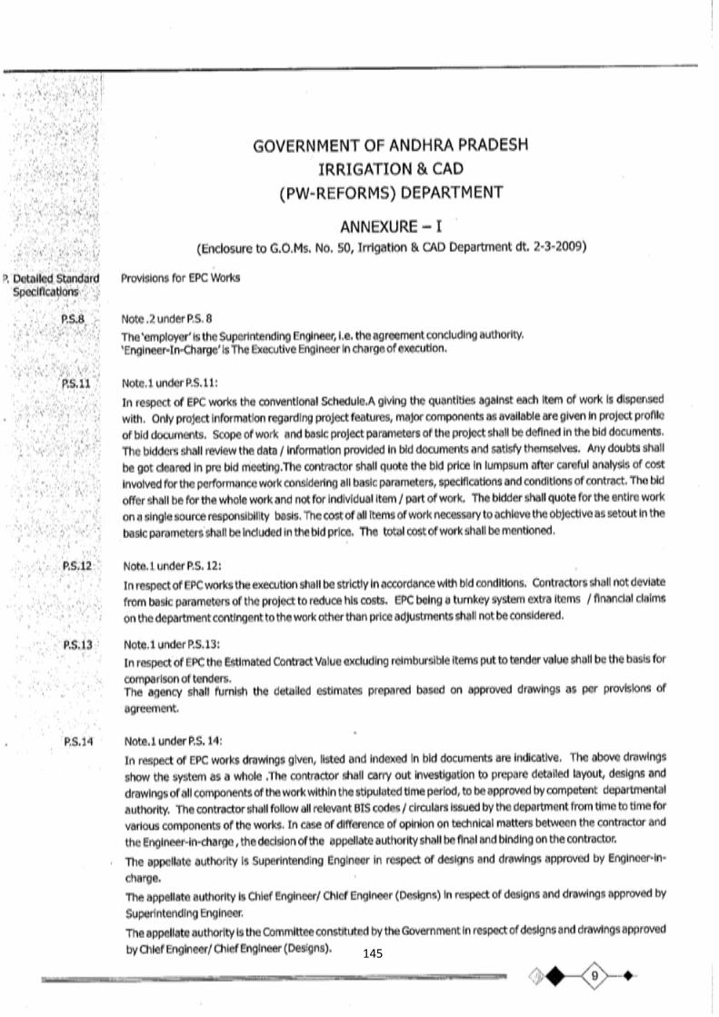
145
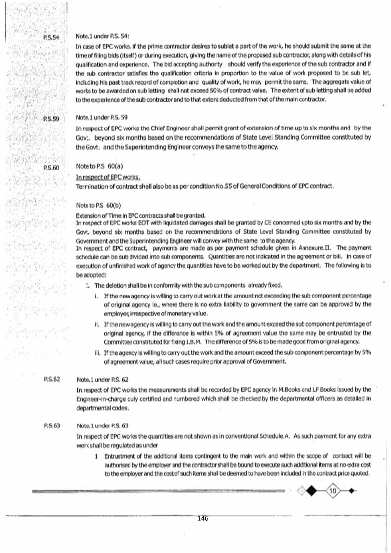
146
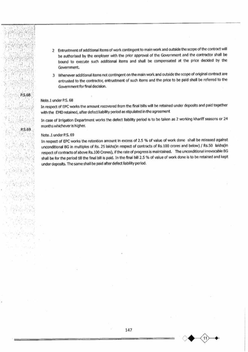
147

148
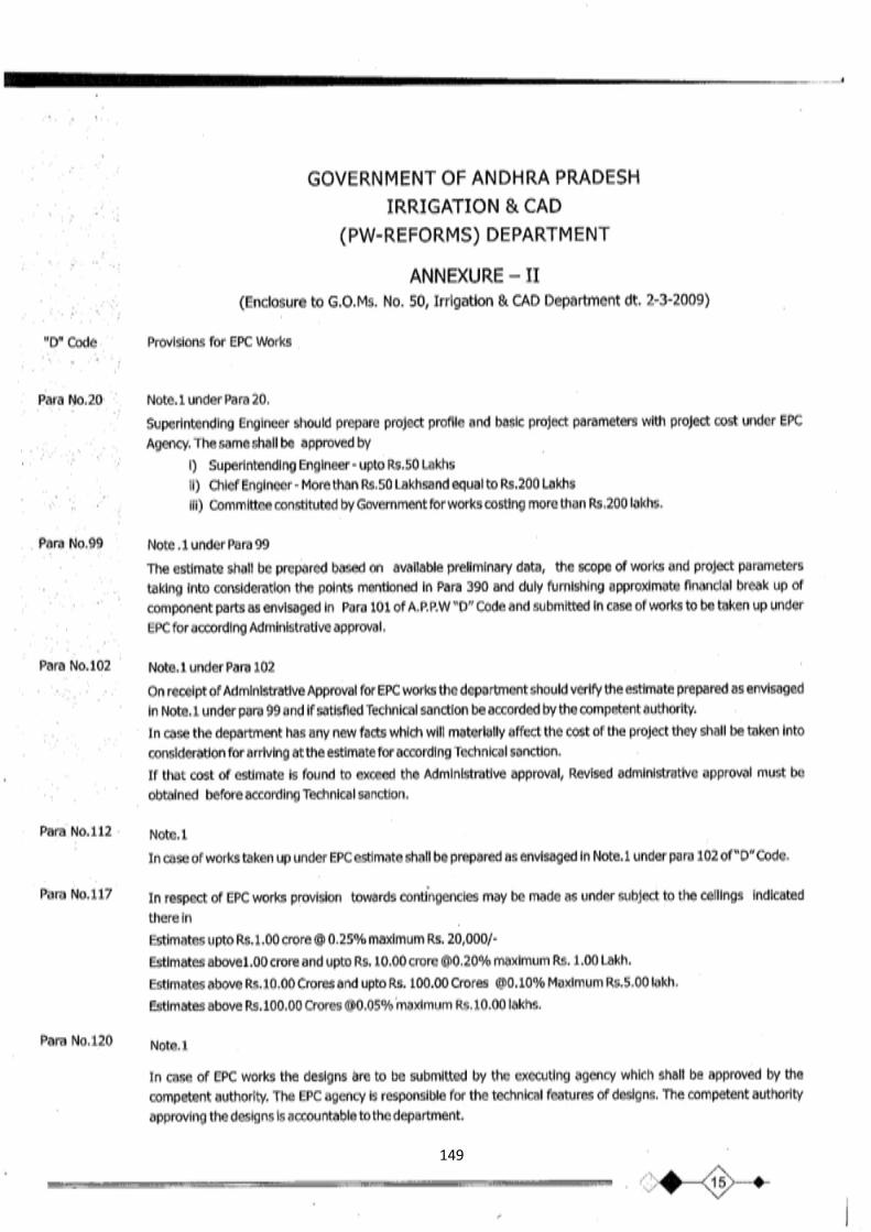
149

150

151
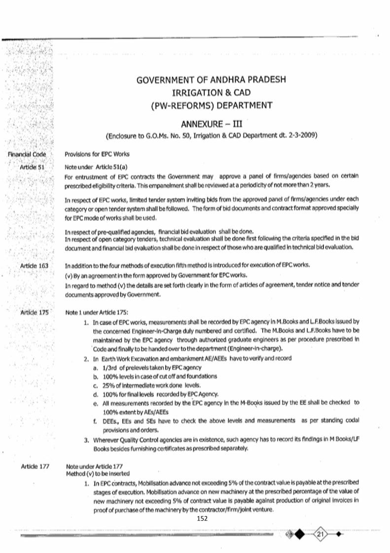
152

153
154

155
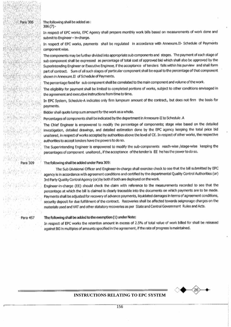
156
INSTRUCTIONS RELATING TO EPC SYSTEM
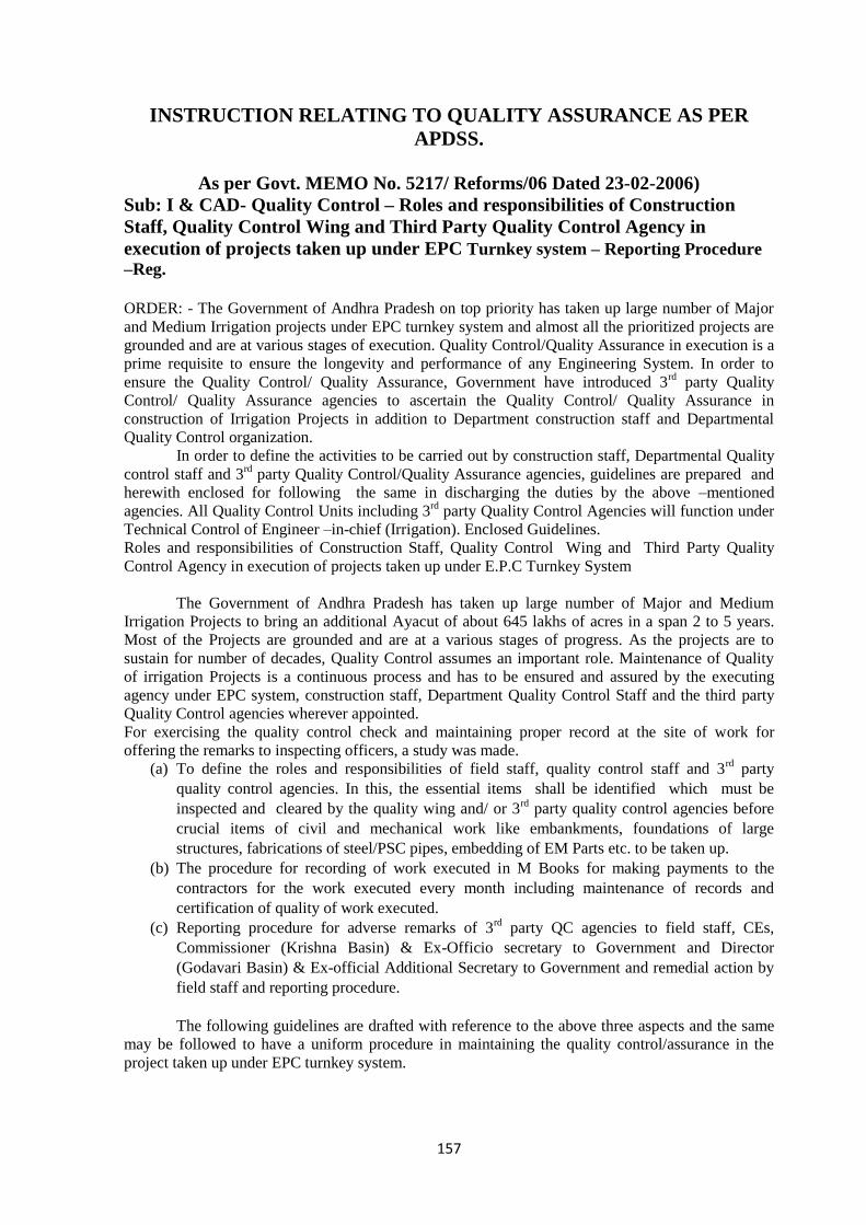
157
INSTRUCTION RELATING TO QUALITY ASSURANCE AS PER
APDSS.
As per Govt. MEMO No. 5217/ Reforms/06 Dated 23-02-2006)
Sub: I & CAD- Quality Control – Roles and responsibilities of Construction
Staff, Quality Control Wing and Third Party Quality Control Agency in
execution of projects taken up under EPC Turnkey system – Reporting Procedure
–Reg.
ORDER: - The Government of Andhra Pradesh on top priority has taken up large number of Major
and Medium Irrigation projects under EPC turnkey system and almost all the prioritized projects are
grounded and are at various stages of execution. Quality Control/Quality Assurance in execution is a
prime requisite to ensure the longevity and performance of any Engineering System. In order to
ensure the Quality Control/ Quality Assurance, Government have introduced 3rd
party Quality
Control/ Quality Assurance agencies to ascertain the Quality Control/ Quality Assurance in
construction of Irrigation Projects in addition to Department construction staff and Departmental
Quality Control organization.
In order to define the activities to be carried out by construction staff, Departmental Quality
control staff and 3rd
party Quality Control/Quality Assurance agencies, guidelines are prepared and
herewith enclosed for following the same in discharging the duties by the above –mentioned
agencies. All Quality Control Units including 3rd
party Quality Control Agencies will function under
Technical Control of Engineer –in-chief (Irrigation). Enclosed Guidelines.
Roles and responsibilities of Construction Staff, Quality Control Wing and Third Party Quality
Control Agency in execution of projects taken up under E.P.C Turnkey System
The Government of Andhra Pradesh has taken up large number of Major and Medium
Irrigation Projects to bring an additional Ayacut of about 645 lakhs of acres in a span 2 to 5 years.
Most of the Projects are grounded and are at a various stages of progress. As the projects are to
sustain for number of decades, Quality Control assumes an important role. Maintenance of Quality
of irrigation Projects is a continuous process and has to be ensured and assured by the executing
agency under EPC system, construction staff, Department Quality Control Staff and the third party
Quality Control agencies wherever appointed.
For exercising the quality control check and maintaining proper record at the site of work for
offering the remarks to inspecting officers, a study was made.
(a) To define the roles and responsibilities of field staff, quality control staff and 3rd
party
quality control agencies. In this, the essential items shall be identified which must be
inspected and cleared by the quality wing and/ or 3rd
party quality control agencies before
crucial items of civil and mechanical work like embankments, foundations of large
structures, fabrications of steel/PSC pipes, embedding of EM Parts etc. to be taken up.
(b) The procedure for recording of work executed in M Books for making payments to the
contractors for the work executed every month including maintenance of records and
certification of quality of work executed.
(c) Reporting procedure for adverse remarks of 3rd
party QC agencies to field staff, CEs,
Commissioner (Krishna Basin) & Ex-Officio secretary to Government and Director
(Godavari Basin) & Ex-official Additional Secretary to Government and remedial action by
field staff and reporting procedure.
The following guidelines are drafted with reference to the above three aspects and the same
may be followed to have a uniform procedure in maintaining the quality control/assurance in the
project taken up under EPC turnkey system.

158
(A) The roles and responsibilities of field staff, Quality Control staff and 3rd
party
Quality control Agencies.
(I) FIELD STAFF
(1) The field staff (construction staff) has to associate with the EPC agency while
conducting the tests. In case of necessity they may conduct tests independently
whenever required. Under E.P.C. system the field staff plays a vital role in
quality assurance of the works.
(2) The field staff shall invariably check and produce all the following records and
O.K. Cards maintained by E.P.C. Agency at the site to the Inspecting Officers.
A) Registers:-
1) Site order.
2) Register of Bench Marks.
3) Material O.K. Register.
4) Register of foundations.
5) Register of placement for concrete, Embankment, Reinforcement
and other test reports.
6) Register of test reports of compressive strength of concrete
specimens.
7) Cement day Book.
B) O.K. Cards for big Structures and Heavy Embankments:
1) O.K. Cards for cast-in-situ concrete lining.
2) O.K. Cards for Earthwork Embankment.
3) O.K. Cards for grouting.
4) O.K. Cards for structural concrete work.
3) The inspecting officers should verify the above records with their observations and sign in the
Registers maintained at site during their inspections.
4) In case of Earthwork excavation embankment, the field staffs have to check and record the pre
levels 25% of the pre levels taken by the E.P.C. Agency. In case of cut-off and foundations the
field‘s staff has to check and record 100% levels.
II) Department quality control Staff
1) The Department Quality control staff shall verify the records maintained at site by E.P.C.
agency and the third party quality control agency. The field quality control staff has to check
25% of the final levels of Earthwork, revetment, lining, concrete, linear dimensions of
important structures; gates etc., and recede independently.
2) Regarding the tests and frequency of tests, the field quality control staffs have to
conduct/associate with construction staff as mentioned in Annexure ‗D‘. In case of
ambiguity, they shall conduct tests in A.P.E.R.L. independently.
3) Where the Third party quality control agency is not appointed, the Department quality
control staff have to issue the quality certificates for releasing payment to the E.P.C. agency
during construction and after completion.
III) Third Party Quality Control Agency
1) The third party quality control agency should posses all the testing facilities as per agreement
and conduct independent testing to assure the quality of work. They should also verify 10% of
the tests being done by the E.P.C agency independently.
2) The third party quality control agency has to submit the reports and records to the Engineer-
in-charge vide appendix XE‘ (enclosed)
159
3) The Third party quality control agency shall give Quality control certificate for each work bill
executed by the EPC agency.
C) Reporting procedure for adverse remarks of 3rd
– party quality control agency and departmental
quality control staff.
1. Reporting procedure shall be followed as per appendix VE.
2. The third party quality control agency shall submit reports in four sets for specific cases of
deficiencies for connective action to the Engineer-in-charge soon after verification. The substandard
material shall be rejected and got them removed from the site. In case of necessity, engineer-in-
charge shall arrange to stop the work till the deficiencies are rectified to the satisfaction of the 3rd
party quality control agency/departmental quality staff.
3. The Engineer-in-charge shall communicate the above remarks of 3rd
party quality control agency
to the EPC agency for compliance of corrective action.
4. The EPC agency shall furnish compliance report to the Engineer-in-Charge, who in turn forward
the same to the third party quality control agency/departmental quality control as the case may be for
verification.
5. Soon after receipt of report on the compliance to the remarks of the third party quality control
agency by the EPC agency, evidence of compliance of corrective action has to be furnished to the
engineer-in-charge to proceed with further work.
6. In addition to the above, the observations made by third party quality control and the Department
quality control staff have to be invariably complied with before the next bill is present for payment
and certificate to that effect has to be recorded in bills presented by the EPC agency duly
countersigned by their field construction staff before making payments.
7. Engineer-in-Charge shall conduct meeting with the EPC agency and 3rd
party quality control
agency once in a fortnight to review the adverse remarks, compliance reports, verification report etc.
Any non compliance of the adverse remarks within reasonable time shall be brought to the specific
notice of superintending Engineer, Chief Engineer (HOD) and the concerned Secretary (Project /
Commissioner (Krishna Basis) / Director, Godavari Basin.
8. On completion of the works, the third party quality control Agency and Department Quality
control staff have to certify that the work has been executed as per design and specification satisfying
intended scope of project as indicated in the agreement before making final payments to the E.P.C.
agency
9. Mechanical Division shall do all Quality Control Checks of Mechanical works under the control
of Engineer-in-Chief (Irrigation).
11. In respect of CM and CD works (structures) the intermediate payments will be in three stages
i.e., at (a) completion of foundation including earth work (b) completion of substructure and (c)
completion of super structure including miscellaneous items. The mode of payment will be 30 %
after completion of foundation. 30 % after completion of sub- structure and balance 40 % after
completion of individual structure.
12. The cost of earth work excavation and structure (on percentage basis with respect to whole work
) mentioned in Schedule ‖A‖
13. Intermediate payment for each structure (in 3 stages) shall be for canals and distributaries (up to
10 cusecs discharges) only. For minor and sub-minor (below 10 cusecs discharges) no separate
intermediate payment to the structures shall be considered. For minor and sub minor payment shall
be released when earth work excavation of canal and all structures (CM& CD works) are completed
in full shape for a length of 5 Kms.
14. For other work like spillway, earth dam, pressure main, gates etc. The agreement clause for
payment shall be followed keeping in view the agreement condition.
15. The Engineer-in-Charge shall recommend for release of payment duly ensuring quality certificate
by the third party quality control agency /Department Quality control staff (in absence of third party
quality control).

160
Quality Control – Roles and responsibilities of Construction staff, Quality control Wing and
3rd
Q.C. Agency in Execution of Project – Further Instructruction / Guideline Issued – Reg
1. The agreement copy, the approved drawings are to be communicated to the 3rd
party agency
so as to enable them to verify the ongoing execution with respects to the conditions
stipulated therein.
2. Further, if any changes /deviations with respect to the already approved ones, are also to be
immediately communicated to the 3rd
party agency without fail.
3. All the registers needed to be maintained by the EPC Agency shall have to be made available
to the inspecting officers and the 3rd
party Quality Control agency. The departmental staff
has to ensure the same.
4. The EPC agencies are also to establish their own full-fledged laboratories in accordance with
the agreement and codal provisions. The department staff shall have to ensure the same and
see that the equipment is got calibrated from time to time by 3rd
party Quality Control
agency and the reports be obtained and recorded.
5. All the above records / registers being maintained shall invariably be authenticated by the
Executive Engineer / Superintending Engineer whenever they inspect the site of work.
6. The Superintending engineer shall inspect the works frequently duly issuing the inspection
notes discussing the progress, quality of the work and lapses / deviations if any.
7. It is to be ensured that whenever Executive Engineer / Superintending Engineer inspect the
site, he shall insist for testing of materials etc. In their presence on critical points if any, and
shall endorse the test proceedings and results of the test conducted.
8. It is being noticed that the EPC agency is conducting the test in his laboratory or in same
private laboratories. It is to be ensured that at least 10 % of tests shall be got done at APERL
/ NITS or in the colleges run by Government or universities or other reputed institutes like
NCCMB. Hyderabad. Tor steel, Hyderabad etc. Having ISO certificate for carrying out the
tests.
9. The Engineer in charges shall furnished the M Book and LF books along with the invoice for
payment of the EPC Agency to the 3rd
party Quality Control agency by 22nd
of every month
for certification and the PAD officer for making arrangement for payments.
10. The Engineer in charges shall ensure that the 3rd
party agency team during its visit to the site
of work daily, gives the observations sheet to the DEE / AEE at the site itself and that the
adverse remarks if any shall have to be attended to immediately and got cleared by them.
11. The superintending Engineer shall conduct fortnightly review meeting with the EPC agency
and 3rd
party Quality Control agency combinedly for reviewing the compliance of the
observations being made.
12. The mix designs of concrete obtained from the laboratories are not being approved by the
Superintending Engineers or Chief Engineers. They may be approved by the Superintending
Engineers / Chief Engineers before adopting in the works.
13. The cement and steel have to be got tested invariably for each stock brought to work site
and test reports are to be made available during inspection also
14. As per agreement OK cards are to be maintained but it is observed that at many places they
are not seen. The Superintending Engineers / Chief Engineers may ensure that ok cards are
mentioned at each work place.
15. It has been observed that EPC Agencies have not submitted proper quality management
plans. They have to also with 3rd
party quality management staff. All Chief Engineers /
Superintending Engineers must insist for QMP and report compliance. The concerned
Superintending Engineer should see that all agencies deploy the quality management staff as
per agreement within next two weeks and obtain their particulars. If they are not deployed as
per agreement, it may be notified to the agencies proposing suitable recovery from work
bills.

161
16. Superintending Engineers shall invariably conduct fortnightly management meeting with
EPC Agency along with 3rd
party QA / QC Agencies and departmental officials and discuss
in detail the quality assurance aspects. The minutes of such meetings shall be sent by SE to
the undersigned without fail.
17. As per agreement, OK cards are to be maintained, but it has been noticed that OK cards
system is not being maintained properly in many packages. Similarly, Guidelines provide for
certain records to be maintained at site. Superintending Engineers must ensure that all OK
cards and other documents / plans to be maintained at site should be invariably made
available at site only. Certain documents and registers may also be kept available at the
laboratory established by the EPC Agencies.
18. For all the lining works in different projects, curing is a critical process and due attention has
to be paid by the executing agencies to ensure proper curing. This is also to ensured for all
other concrete works. All Superintending Engineers should critically review the performance
of EPC agencies on this and ensure quality standards.
19. The cement and steel have to be got tested invariably for each stock brought to the site and
test reports are to be made available during inspection.
20. Quality Management Plan.
i) The Quality Management plan for the contract work has to be obtained from the
contractors indicating the following.
a) The quantum of work to be done quantities of various materials required the
electrical and mechanical equipment to be installed.
b) The number of tests to be conducted for various materials, electrical and
mechanical equipment and also for finished items of work as per IS codes and
other Codes.
c) The details of field laboratories and testing facilities available for conducting the
above tests.
d) M.O.U with external laboratories approved by the Government for conducting
required tests on equipment and materials.
e) The personnel of Contractor in-charge of Quality Management with their names,
duties and authority. The qualifications of the persons in- charge of collecting
samples, testing materials, testing equipment and finished items work, persons
in-charge of quality assurance with power to reject the defective work, the
process of rectification of o be recurrence of defects.
ii) Copies of the quality management plan have to be furnished to the concerned field
officers and also to the third party Quality Control team.
iii) The Quality Management plan of the contractors for the work is to be reviewed with
the contractors Quality control team and modifications or improvements, if any,
have to be got incorporated.
iv) Approved designs with plans have to be reviewed with the contractor‘s
Managements staff and third party Control Team before commencement of work on
all the structure, the quality and safety plans have to be obtained from the
Contractors and approved.
v) The test reports of all the work done quantities, materials, equipment and finished
items of work are to be obtained from the Contractor along with the bill for payment.
The Chief Engineer and Superintending Engineers are requested to specifically note
that no bill payment should be accepted if it is not accompanied by the test reports
vi) The test reports of all the tests conducted by the third party also may be obtained for
every month.
162
vii) Whenever a bill is received from the contractor in full shape for payment a
certificate of verification of Quality and conformity of work to the required
specifications is to be obtained from the third party quality control team
viii) The chief Engineers / Superintending Engineers may submit the list of defects and
rectifications attended by the Contractor with each payment.
ix) In addition to the communication of deficiencies separately by the Quality control
agency, they must be allowed to record the same in the placement Register to draw
immediate attention of the construction staff and to take prompt action to rectify the
same.
x) The reinforcement details must invariably be got checked by the Quality control
agency
xi) The construction staff should insist on establishing the laboratories by the EPC
agency (Wherever they are not established) to enable the quality control agency to
associate with them while conducting tests.
xii) Engineer incharge of the project (superintending engineer in most cases) is
responsible for quality assurance of the project.
The Construction staff must ensure compliance report on the rectification of defects pointed
out by the Quality control agency before proceeding with further work. These reports shall
be available at site for inspection by any authority concerned.
If the contractor is not promptly complying with, the report of the departmental officers, the
Superintending Engineer concerned should take immediate necessary action to withhold the
payments till required rectifications are carried out.
21. Recovery of Mobilization Advance:
Dedication of the advance commences in the next interim payment following that in which total of
such payments to the contractor reached 10% of contract value. The deduction will be made at the
rate of 20% of the amount of all the interim payment together with interest/ The exclusion of
amounts paid till the stage of recovery is reached is not correct. Government reiterates the
clarification issued in Government Memo. No 1938-F8 (1)99-9 F&) (FW) Department, Dated 17-01-
2000.
22. Seigniorage Charge:
Seigniorage Charges shall be recovered from the bills on the quantities used and measured at the
rates mentioned in the agreement and a per the conditions of the agreement. All material including
ordinary earth used on the work will attract seigniorage changes even if they are supplied free of cost
as per agreement conditions.
23. Liquidated Damages:
Liquidated charges shall be recovered as per the conditions of the agreement and Executive Engineer
is responsible for effecting recovery. For fixing revised milestones the competency is vested with
Chief Engineer.
Related Documents


