YOUR LOGO HERE! PROPERTY NAME HERE! EVERYTHING IS CUSTOMISABLE! Fictional Hotel Predictive Wireless Design Report Prepared by *your name here*

Welcome message from author
This document is posted to help you gain knowledge. Please leave a comment to let me know what you think about it! Share it to your friends and learn new things together.
Transcript

YOUR LOGO HERE!
PROPERTY NAME HERE!
EVERYTHING IS CUSTOMISABLE!
Fictional Hotel Predictive Wireless Design Report
Prepared by *your name here*
2
CHANGEABLE COLOURS!
Index
Executive Summary – Page 3
Signal Strength – Page 4-6
Channel Overlap – Page 7-8
Data Rate – Page 9-10
Throughput – Page 11-12
Channel Bandwidth – Page 13-14
Configuration – 15-16
Installation – Best Practices – Page 17
3
EDITABLE CONTENT!
Executive Summary
This Predictive Wireless Design has been considered for a full hotel and has been designed
accordingly.
Using our wireless engineering software, we created a design based on the buildings plans to predict
and design the wireless network.
The AP placement and Channel design has been specifically configured to maximize the effectiveness
of the network under load.
Aps have been placed specifically for their intended purpose and should me mounted as per the
mounting instructions at the end of this report. APS have been set to a height of 2 meters off the
ground.
This report is intended to be a predictive model for the purposes of illustration, and installation. To
validate the findings, it is recommended performing an on-site validation survey after the network
has been completed where some configuration changes may need to be made.
4
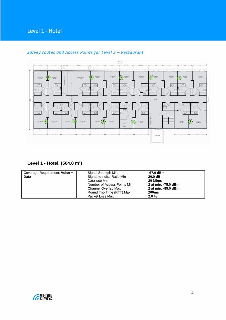
Level 1 - Hotel
Survey routes and Access Points for Level 3 – Restaurant.
Level 1 - Hotel. (504.0 m²)
Coverage Requirement: Voice + Data
Signal Strength Min -67.0 dBm Signal-to-noise Ratio Min 20.0 dB Data rate Min 20 Mbps Number of Access Points Min 2 at min. -75.0 dBm Channel Overlap Max 2 at min. -85.0 dBm Round Trip Time (RTT) Max 200ms Packet Loss Max 2.0 %

5
Signal Strength for Level 1 - Hotel
on 2.4 GHz band
Signal Strength - sometimes called coverage - is the most basic requirement for a wireless network.
As a general guideline, low signal strength means unreliable connections, and low data throughput.
6
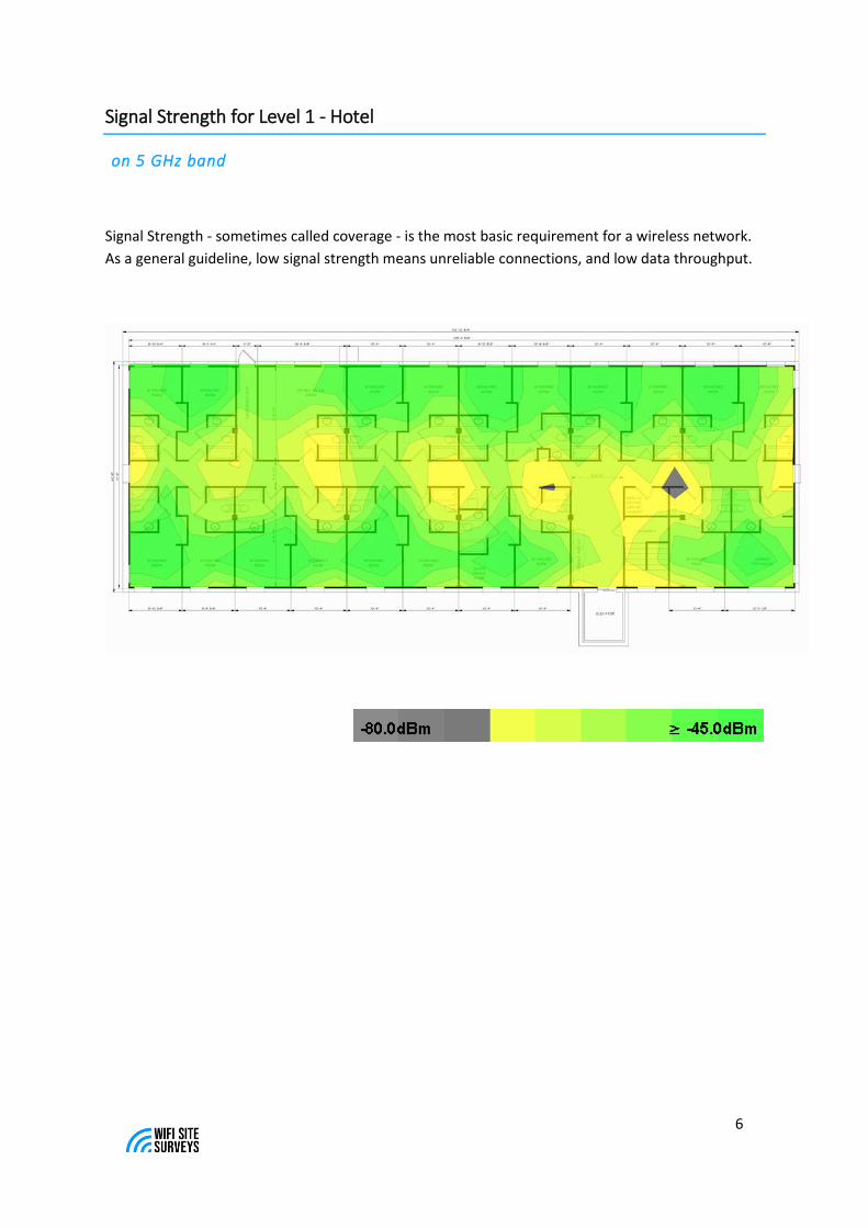
Signal Strength for Level 1 - Hotel
on 5 GHz band
Signal Strength - sometimes called coverage - is the most basic requirement for a wireless network.
As a general guideline, low signal strength means unreliable connections, and low data throughput.

7
Channel overlap for Level 1 - Hotel
on 2.4 GHz band
Channel overlap indicates the number of access points audible at each location in a
single channel.

8
Channel overlap for Level 1 - Hotel
on 5 GHz band
Channel overlap indicates the number of access points audible at each location in a
single channel.
9
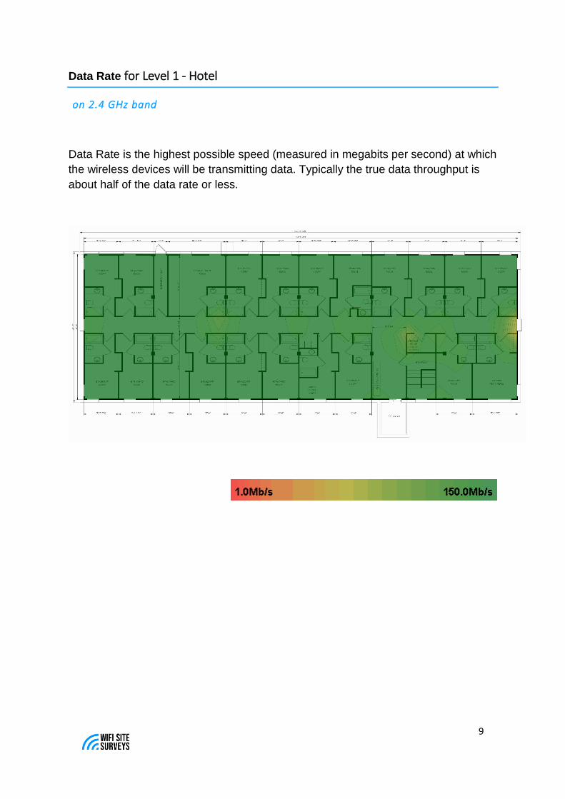
Data Rate for Level 1 - Hotel
on 2.4 GHz band
Data Rate is the highest possible speed (measured in megabits per second) at which
the wireless devices will be transmitting data. Typically the true data throughput is
about half of the data rate or less.

10
Data Rate for Level 1 - Hotel
on 5 GHz band
Data Rate is the highest possible speed (measured in megabits per second) at which
the wireless devices will be transmitting data. Typically the true data throughput is
about half of the data rate or less.
11
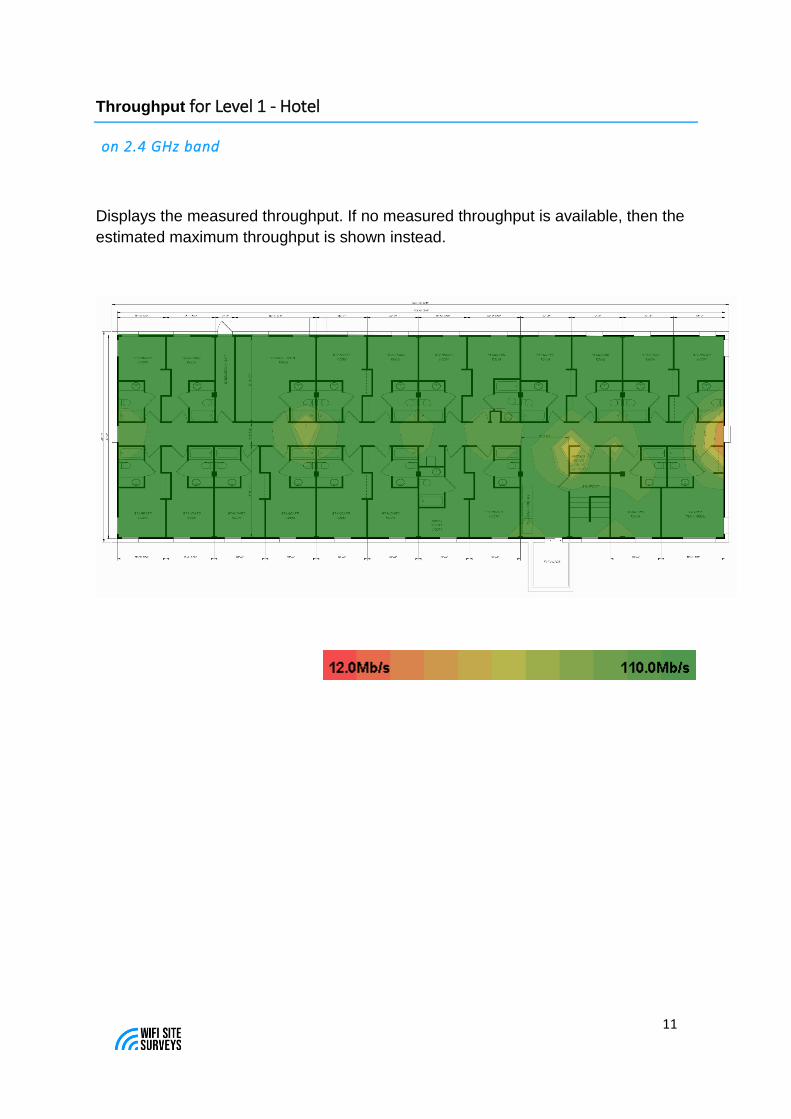
Throughput for Level 1 - Hotel
on 2.4 GHz band
Displays the measured throughput. If no measured throughput is available, then the
estimated maximum throughput is shown instead.

12
Throughput for Level 1 - Hotel
on 5 GHz band
Displays the measured throughput. If no measured throughput is available, then the
estimated maximum throughput is shown instead.

13
Channel Bandwidth for Level 1 - Hotel
on 2.4 GHz band
Shows the maximum channel bandwidth available in each area.

14
Channel Bandwidth for Level 1 - Hotel
on 5 GHz band
Shows the maximum channel bandwidth available in each area.

15
Access Point Placement / Configuration
Level 1 - Hotel
Simulated Access Points on Level 1 - Hotel
AP # Access Point
1 Room 102
802.11n 11 20 mW Ruckus ZoneFlex H510 2.4GHz
802.11ac 165 25 mW Ruckus ZoneFlex H510 5GHz
2 Room 104
802.11n 1 20 mW Ruckus ZoneFlex H510 2.4GHz
802.11ac 40 25 mW Ruckus ZoneFlex H510 5GHz
3 Room 106
802.11n 6 20 mW Ruckus ZoneFlex H510 2.4GHz
802.11ac 56 25 mW Ruckus ZoneFlex H510 5GHz
4 Room 108
802.11n 11 20 mW Ruckus ZoneFlex H510 2.4GHz
802.11ac 48 25 mW Ruckus ZoneFlex H510 5GHz
5 Room 110
802.11n 1 20 mW Ruckus ZoneFlex H510 2.4GHz

16
802.11ac 149 25 mW Ruckus ZoneFlex H510 5GHz
6 Room 112
802.11n 6 20 mW Ruckus ZoneFlex H510 2.4GHz
802.11ac 36 25 mW Ruckus ZoneFlex H510 5GHz
7 Room 115
802.11n 1 20 mW Ruckus ZoneFlex H510 2.4GHz
802.11ac 161 25 mW Ruckus ZoneFlex H510 5GHz
8 Room 117
802.11n 11 20 mW Ruckus ZoneFlex H510 2.4GHz
802.11ac 153 25 mW Ruckus ZoneFlex H510 5GHz
9 Room 119
802.11n 6 20 mW Ruckus ZoneFlex H510 2.4GHz
802.11ac 64 25 mW Ruckus ZoneFlex H510 5GHz
10 Room 121
802.11n 1 20 mW Ruckus ZoneFlex H510 2.4GHz
802.11ac 52 25 mW Ruckus ZoneFlex H510 5GHz

17
Installation
Best practices for placing AP’s
Most AP’s are designed to be mounted on a ceiling, facing downwards.
Unless otherwise specified in the design please follow this method. Don’t
place AP’s above ceiling tiles as this will dramatically affect signal.
(cisco ap shown as a reference)
The AP design is specific within 1 meter. If the installer runs into a pole or
an obstacle, that is fine to move the location of the AP within a meter.
Sprinkler manufacturers spray patterns will vary, but generally make sure
the placement of the AP is over a meter away from a fire sprinkler or any
other type of sensors such as smoke.
Don’t place AP’s on, or behind metal objects. If necessary, construct a
bracket to drop the AP below the lowest metal object. Or place AP on a
piece of wood that is attached to the metal and make sure the AP is
parallel to the ground.
Related Documents