Yokogawa Electric Corporation Digital Power Meter IM253401-01E 3rd Edition

Welcome message from author
This document is posted to help you gain knowledge. Please leave a comment to let me know what you think about it! Share it to your friends and learn new things together.
Transcript

Yokogawa Electric Corporation
Digital Power Meter
IM253401-01E3rd Edition

IM 253401-01E 1
ForewordAThank you for purchasing the YOKOGAWA WT110 or WT130 Digital Power Meter.
This User’s Manual contains useful information regarding the instrument’s functions and
operating procedures, as well as precautions that should be observed during use. To ensure
proper use of the instrument, please read this manual thoroughly before operating it.
Keep the manual in a safe place for quick reference whenever a question arises.
Notes• The peak measurement function and the MATH function described in this manual apply to
WT110/WT130 with ROM version 2.01 or later.
• The contents of this manual are subject to change without prior notice.
• Every effort has been made in the preparation of this manual to ensure the accuracy of its
contents. However, should you have any questions or find any errors, please contact your
dealer or YOKOGAWA sales office.
• Copying or reproduction of all or any part of the contents of this manual without
YOKOGAWA’s permission is strictly prohibited.
RevisionsFirst edition: September 1995
2nd edition: March 1997
3rd edition: March 1998
Disk No. BA123rd Edition:March 1998(YK)All Rights Reserved, Copyright © 1995 Yokogawa Electric Corporation

IM 253401-01E2
Checking the Contents of the Package
Unpack the box and check the contents before operating the instrument. In case the wrong
instrument or accessories have been delivered, or if some accessories are not present, or if they
seem abnormal, contact the dealer from which you purchased them.
WT110/WT130 Main BodyCheck that the model code and suffix code given on the name plate located at the right side of
the main body are according to your order.
WT110 (model code: 253401) WT130 (model code: 253502, 253503)
Made in Japan
SUFFIX
MODEL
NO.
Made in Japan
SUFFIX
MODEL
NO.Made in Japan
SUFFIX
MODEL
NO.
Model and Suffix codesModel code Suffix code Specifications253401 WT110 Single-phase model253502 WT130 Three-phase, three-wire model253503 WT130 Three-phase, four-wire model
Interface -C1 GP-IB interface-C2 RS-232-C interface
Power voltage -0 100-120V/220-240V
Power cord -D [Maximum rated voltage: 125V; Maximum rated current: 7A]-F VDE Standard Power Cord (Part No.: A1009WD)
[Maximum rated voltage: 250V; Maximum rated current: 10A]-J BS Standard Power Cord (Part No.: A1023WD)
[Maximum rated voltage: 250V; Maximum rated current: 5A]-R SAA Standard Power Cord (Part No.: A1024WD)
[Maximum rated voltage: 240V; Maximum rated current: 10A]
OptionsExternal sensor input function /EX1 ... 2.5/5/10V range
/EX2 ... 50/100/200mV range
Harmonic analysis function /HRM .. –
External input/output function /DA4 ... 4 channels D/A output (for 253401)/DA12 . 12 channels D/A output (for 253502/253503)/CMP .. Comparator 4 channels, D/A output 4 channels
Ex: WT130 Three-phase, three-wire model, GP-IB interface, with UL/CSA power cord, withexternal sensor input 50/100/200mV range, with harmonic analysis function, and 12 channelsD/A output →253202-C1-0-D/EX2/HRM/DA12
NO. (instrument number)When contacting the dealer from which you purchased the instrument, please quote the
instrument No.

IM 253401-01E 3
Standard AccessoriesThe following standard accessories are supplied with the instrument. Make sure that all items
are present and undamaged.
Name Part No. Q’ty Remarks1 Power cord see page 2 1 —
2 Power fuse A1346EF 1 only for the three-phase modelTime lag, 0.5A, 250V(located in the fuse holder)Not provided with the single-phase model
3 24-pin connector A1004JD 1 For remote, D/A output(only provided with options /DA4, /DA12 or/CMP)
4 User’s Manual IM253401-01E 1 this manual
5 Rubber feed A9088ZM 1 set
6 Clamp filter (Ferrite core) A1179MN 1 for WT110 only
1. One of the power cords is supplied according to the instrument's suffix code
3. 4.
D F J R
2. 5. 6.
Optional EquipmentThe following optional equipment is available. Upon receiving any optional equipment, make
sure that all the items ordered have been supplied and they are in good condition.
If you have any questions regarding optional equipment, or if you wish to place an order,
contact the dealer from whom you purchased the instrument.
Name Parts No. Minimum Q’ty RemarksDigital printer 740921 1 ESC/P compatible, RS-232-C/Centronics
NoteIt is recommended that the packing box be kept in a safe place. The box can be used for transporting theinstrument.
Checking the Contents of the Package

IM 253401-01E4
Safety Precautions
This instrument is a IEC safety class I instrument (provided with terminal for protective
grounding).
The following general safety precautions must be observed during all phases of operation,
service and repair of this instrument. If this instrument is used in a manner not sepecified in this
manual, the protection provided by this instrument may be impaired.
Also,YOKOGAWA Electric Corporation assumes no liability for the customer’s failure to
comply with these requirements.
The fullowing symbols are used on this instrument.
To avoid injury, death of personnel or damage to the instrument, the operator must refer to an
explanation in the User's Manual or Service Manual.
Danger, risk of electric shock
Alternating current
ON(power)
OFF(power)
In-position of a bistable push control
Out-position of a bistable push control
Ground

IM 253401-01E 5
WARNINGDo not Operate in an Explosive Atmosphere
Do not operate the instrument in the presence of flammable liquids orvapors.
Operation of any electrical instrument in such an environment constitutes a
safety hazard.
Protective GroundingMake sure to connect the protective grounding to prevent an electric shockbefore turning ON the power.
Necessity of Protective GroundingNever cut off the internal or external protective grounding wire ordisconnect the wiring of protective grounding terminal. Doing so poses apotential shock hazard.
Defect of Protective GroundingDo not operate the instrument when protective grounding or fuse might be
defective.
Power Cord and PlugTo prevent an electric shock or fire, be sure to use the power cord supplied
by YOKOGAWA. The main power plug must be plugged in an outlet withprotective grounding terminal. Do no invalidate protection by using anextension cord without protective grounding.
Power SupplyEnsure the source voltage matches the voltage of the power supply before
turning ON the power.
External ConnectionTo ground securely, connect the protective grounding before connecting to
measurement or control unit.
FuseTo prevent a fire, make sure to use fuses with specified standard (current,
voltage, type). Before replacing the fuse, turn OFF the power anddisconnect the power source. Do not use a different fuse or short-circuit thefuse holder.
Do not Remove any CoversThere are some areas with high voltage. Do not remove any cover if the
power supply is connected. The cover should be removed by qualifiedpersonnel only.
Safety Precautions

IM 253401-01E6
How to Use this Manual
This User’s Manual consists of 15 chapters, an Appendix and an Index as described below.
Chapter 1 What this Instrument Can DoExplains the flow of the measurement input signals and gives an outline of thefunctions.
Chapter 2 Nomenclature, Keys and DisplaysGives the name of each part and each key, and describes how to use it. Thischapter also gives the displays in case of overrange/error during measurement.
Chapter 3 Before OperationDescribes points to watch during use and describes how to install the instrument,wire the measuring circuits, connect the power cord and switch the power ON/OFF.
Chapter 4 Setting Measurement ConditionsExplains settings such as measurement mode, filter ON/OFF, measurement range,scaling in case of external PT/CT or external sensor (such as shunt or clamp),averaging and measurement conditions.
Chapter 5 Measuring/Displaying Voltage, Current, and Active Power and FrequencyExplains the procedures for measuring and displaying voltage, current and activepower.
Chapter 6 Computing/Displaying Apparent Power, Reactive Power, Power Factor andPhase Angle.Explains the procedures for measuring and displaying apparent power, reactivepower, power factor and phase angle.
Chapter 7 IntegratingExplains the procedures for integration of active power and current.
Chapter 8 Using the Harmonic Analysis Function (option)Explains the procedures when using the harmonic analysis function.
Chapter 9 Storing/RecallingExplains the procedures when storing or recalling measured data or settingparameters from the internal memory.
Chapter 10 Using External In/OutputExplains the procedures for remote control, D/A output (option), external plotter/printer output and comparator (option).
Chapter 11 GP-IB InterfaceExplains the procedures for controlling the instrument by personal computer and forsending measurement/computed data to a personal computer using the GP-IBinterface.
Chapter 12 RS-232-C InterfaceExplains the procedures for controlling the instrument by personal computer/controller and for sending measurement/computed data to a personal computer/controller using the RS-232-C interface.
Chapter 13 Other Useful FunctionsExplains the procedures such as backing up set-up information and initializingsettings.
Chapter 14 Adjustment, Calibration and Trouble-ShootingExplains the procedures for calibration, adjustment, the way to verify trouble, thecontents of error messages and the way to replace the fuse.
Chapter 15 SpecificationsDescribes the specifications of the instrument.
Appendix Describes communication commands and sample programs.
Index Gives the index in alphabetic order.

IM 253401-01E 7
Conventions Used in this Manual
Symbols UsedThe following symbol marks are used throughout this manual to attract the operator’s attention.
To avoid injury or death of personnel, or damage to the instrument, the
operator must refer to the User's Manual. In the User's Manual, these
symbols appear on the pages to which the operator must refer.
WARNINGDescribes precautions that should be observed to prevent the danger of
serious injury or death to the user.
CAUTION Describes precautions that should be observed to prevent the danger of
minor or moderate injury to the user, or the damage to the property.
Note Provides information that is important for proper operation of the
instrument.
Displayed Characters on the 7-Segment LEDIn order to display all numbers and alphabetic characters on the 7-segment LED, some of them
are displayed in a slightly altered format. For details, refer to section 1.3.
Markings used for Descriptions of Operations
Relevant Keys Indicates the relevant panel keys and indicators to carry out
the operation.
Operating Procedure The procedure is explained by a flow diagram. For the
meaning of each operation, refer to the example below. The
operating procedures are given with the assumption that you
are not familiar with the operation. Thus, it may not be
necessary to carry out all the steps when changing settings.
Explanation Describes settings and restrictions relating to the operation.
An example of an Operating Procedure
1.
SHIFTSETUP
OUTPUT
ENTER3.
(Display C)
(Display C)
2.
ENTER5.
4. End ofsetting
The items in this figure are obtained by the following setting procedures. The blinking part of
the display can be set.
1. After pressing the SHIFT key and the SHIFT indicator is lit, press the SETUP (OUTPUT)
key. The output setting menu will appear on display C.
2. Select rELAY using the up/down keys.
Pressing either key, 4 selectable items will be displayed consecutively.
3. Verify the setting by pressing the ENTER key.
The setting menu corresponding to the item selected at step 2 will appear at display C.
4. Select oFF or on using the up/down keys.
Pressing either key, 6 selectable items will be displayed consecutively.
5. Verify the setting by pressing the ENTER key.

IM 253401-01E8
Contents
Foreword ............................................................................................................................................................................. 1
Checking the Contents of the Package ..................................................................................................... 2
Safety Precautions ...................................................................................................................................................... 4
How to Use this Manual .......................................................................................................................................... 6
Conventions Used in this Manual .................................................................................................................. 7
Chapter 1 What this Instrument Can Do1.1 System Configuration and Block Diagram .................................................................................. 1-1
1.2 Functions ...................................................................................................................................... 1-2
1.3 Digital Numbers/Characters, and Initial Menus .......................................................................... 1-5
Chapter 2 Nomenclature, Keys and Displays2.1 Front Panel, Rear Panel and Top View........................................................................................ 2-1
2.2 Operation Keys and Function/Element Display .......................................................................... 2-2
2.3 Displays in case of Overrange/Error during Measurement ......................................................... 2-4
Chapter 3 Before Operation3.1 Usage Precautions ........................................................................................................................ 3-1
3.2 Installing the Instrument .............................................................................................................. 3-2
3.3 Wiring Precautions ...................................................................................................................... 3-4
3.4 Wiring the Measurement Circuit ................................................................................................. 3-5
3.5 Wiring the Measurement Circuit when Using External PT/CT ................................................... 3-7
3.6 Wiring the Measurement Circuit when Using the External Sensor ............................................. 3-9
3.7 Connecting the Power Supply .................................................................................................... 3-12
3.8 Turning the Power ON/OFF ...................................................................................................... 3-13
3.9 Selecting the Wiring Method (for WT130) .............................................................................. 3-15
3.10 Improving the Measurement Accuracy ...................................................................................... 3-16
Chapter 4 Setting Measurement Conditions4.1 Selecting the Measurement Mode ................................................................................................ 4-1
4.2 Turning the Filter ON/OFF .......................................................................................................... 4-3
4.3 Selecting the Measurement Range in case of Direct Input .......................................................... 4-4
4.4 Setting the Scaling Value when External PT/CT is Used ............................................................ 4-6
4.5 Selecting the Measurement Range and Setting the Scaling Value when External Sensor is
Used (option) ............................................................................................................................... 4-8
4.6 Using the Averaging Function ................................................................................................... 4-10
4.7 Using the Four Arithmetical Operation Function (Applies to WT110/WT130 with ROM
Version 2.01 or later) ................................................................................................................. 4-12
4.8 Computing the Crest Factor (Applies to WT110/WT130 with ROM Version 2.01 or later) .... 4-15
4.9 Computing the Efficiency (Applies to WT130 with ROM Version 2.01 or later) .................... 4-16
Chapter 5 Measuring/Displaying Voltage, Current, Active Power, Frequency,Four Arithmetic Operation Value, Crest Factor and Peak Value
5.1 Measuring/Displaying Voltage, Current and Active Power ........................................................ 5-1
5.2 Measuring/Displaying Frequency ................................................................................................ 5-3
5.3 Measuring/Displaying Four Arithmetic Operation Value, Crest Factor and Peak Value ........... 5-4

IM 253401-01E 9
3
2
1
4
5
6
7
8
9
10
11
12
13
14
15
App
Index
Contents
Chapter 6 Computing/Displaying Apparent Power, Reactive Power, PowerFactor and the Phase Angle6.1 Computing/Displaying Apparent Power, Reactive Power and Power Factor ............................. 6-1
6.2 Computing/Displaying the Phase Angle ...................................................................................... 6-2
Chapter 7 Integration7.1 Integrator Functions ..................................................................................................................... 7-1
7.2 Setting Integration Mode and Integration Timer ......................................................................... 7-4
7.3 Displaying Integrated Values ....................................................................................................... 7-5
7.4 Precautions Regarding Use of Integrator Function ...................................................................... 7-7
Chapter 8 Using the Harmonic Analysis Function (optional)8.1 Harmonic Analysis Function ....................................................................................................... 8-1
8.2 Setting the Element, PLL Source and Harmonic Distortion Method .......................................... 8-3
8.3 Switching the Harmonic Analysis Function ON/OFF ................................................................. 8-5
8.4 Setting the Harmonic Order and Displaying the Results of Harmonic Analysis ......................... 8-6
Chapter 9 Storing/Recalling9.1 Storing/Recalling Measured Data ................................................................................................ 9-1
9.2 Storing/Recalling Set-up Parameters ........................................................................................... 9-4
Chapter 10 Using External In/Output10.1 Remote Control and D/A Output Connector (optional) ............................................................. 10-1
10.2 Remote Control (optional) ......................................................................................................... 10-2
10.3 D/A Output (optional) ................................................................................................................ 10-3
10.4 Comparator Function (optional) ................................................................................................ 10-7
10.5 Setting the Comparator Mode (optional) ................................................................................... 10-9
10.6 Setting the Comparator Limit Values (optional) ..................................................................... 10-10
10.7 Comparator Display (optional) ................................................................................................ 10-14
10.8 Turning the Comparator Function ON/OFF (optional) ........................................................... 10-16
10.9 Outputting to an External Plotter/Printer ................................................................................. 10-17
Chapter 11 GP-IB Interface11.1 Using the GP-IB Interface ......................................................................................................... 11-1
11.2 Responses to Interface Messages ............................................................................................... 11-2
11.3 Status Byte Format (before the IEEE488.2-1987 Standard) ...................................................... 11-3
11.4 Output Format for Measured/Computed Data, Harmonic Analysis Data, Set-up
Parameters and Error Codes ...................................................................................................... 11-4
11.5 Setting the Address/Addressable Mode ..................................................................................... 11-9
11.6 Setting the Output Items .......................................................................................................... 11-10
11.7 Commands (before the IEEE488.2-1987 Standard) ................................................................ 11-12
Chapter 12 RS-232-C Interface12.1 Using the RS-232-C Interface .................................................................................................... 12-1
12.2 Connecting the Interface Cable .................................................................................................. 12-2
12.3 Setting the Mode, Handshaking Method, Data Format and Baud Rate ..................................... 12-4
12.4 Format and Commands of Output Data (brefore the IEEE488.2-1987 Standard) ..................... 12-7
Chapter 13 Other Useful Functions13.1 Back-up of Set-up Parameters ................................................................................................... 13-1
13.2 Initializing Set-up Parameters .................................................................................................... 13-2

IM 253401-01E10
Contents
Chapter 14 Adjustment, Calibration and Trouble-Shooting14.1 Adjustments ............................................................................................................................... 14-1
14.2 Calibration ................................................................................................................................. 14-4
14.3 In Case of Malfunctioning ....................................................................................................... 14-10
14.4 Error Codes and Corrective Actions ........................................................................................ 14-11
14.5 Replacing the Fuse (for WT130) ............................................................................................. 14-13
Chapter 15 Specifications15.1 Input ........................................................................................................................................... 15-1
15.2 Measurement Functions ............................................................................................................. 15-1
15.3 Frequency Measurement ............................................................................................................ 15-1
15.4 Communication .......................................................................................................................... 15-1
15.5 Computing Functions ................................................................................................................. 15-2
15.6 Display Functions ...................................................................................................................... 15-2
15.7 Integrator Functions ................................................................................................................... 15-2
15.8 Internal Memory Function ......................................................................................................... 15-2
15.9 D/A Converter (optional) ........................................................................................................... 15-2
15.10 External Input (optional) ............................................................................................................ 15-3
15.11 Comparator Output (optional) ................................................................................................... 15-3
15.12 External Control and Input Signals
(in combination with the D/A converter and comparator options) ............................................ 15-3
15.13 General Specifications ............................................................................................................... 15-3
15.14 Total Harmonic Analysis Function (optional) ........................................................................... 15-3
15.15 External Dimensions .................................................................................................................. 15-4
Appendix 1 Communication Commands (before the IEEE488.2-1987Standard)App.1.1 Commands ....................................................................................................................... App1-1
App.1.2 Sample Program ............................................................................................................. App1-10
App.1.3 For Users Using Communication Commands of Digital Power Meter 2533E ............. App1-15
Appendix 2 Communication Commands (according to the IEEE488.2-1987Standard)App.2.1 Overview of IEEE 488.2-1987 ........................................................................................ App2-1
App.2.2 Program Format ............................................................................................................... App2-2
2.2.1 Symbols Used in Syntax Descriptions ................................................................ App2-2
2.2.2 Messages ............................................................................................................. App2-2
2.2.3 Commands ........................................................................................................... App2-4
2.2.4 Responses ............................................................................................................ App2-5
2.2.5 Data ..................................................................................................................... App2-5
2.2.6 Synchronization with the Controller ................................................................... App2-7
App.2.3 Commands ....................................................................................................................... App2-8
2.3.1 Command List ..................................................................................................... App2-8
2.3.2 AOUTput Group ............................................................................................... App2-11
2.3.3 COMMunicate Group ....................................................................................... App2-12
2.3.4 CONFigure Group ............................................................................................. App2-14
2.3.5 DISPlay Group .................................................................................................. App2-17
2.3.6 HARMonics Group ........................................................................................... App2-18
2.3.7 INTEGrate Group .............................................................................................. App2-19
2.3.8 MATH Group .................................................................................................... App2-20
2.3.9 MEASure Group ............................................................................................... App2-21
2.3.10 RECall Group .................................................................................................... App2-27
2.3.11 RELay Group .................................................................................................... App2-28
IM 253401-01E 11
3
2
1
4
5
6
7
8
9
10
11
12
13
14
15
App
Index
Contents
2.3.12 SAMPle Group .................................................................................................. App2-30
2.3.13 STATus Group .................................................................................................. App2-31
2.3.14 STORe Group .................................................................................................... App2-32
2.3.15 Common Command Group ............................................................................... App2-33
App.2.4 Status Report .................................................................................................................. App2-35
2.4.1 Overview of the Status Report .......................................................................... App2-35
2.4.2 Status Byte ........................................................................................................ App2-36
2.4.3 Standard Event Register .................................................................................... App2-37
2.4.4 Extended Event Register ................................................................................... App2-38
2.4.5 Output Queue and Error Queue ......................................................................... App2-39
App. 2.5 Sample Program ............................................................................................................. App2-40
App. 2.6 ASCII Character Codes ................................................................................................. App2-42
App. 2.7 Communication-related Error Messages ....................................................................... App2-43
Index

IM 253401-01E 1-1
1
What this Instrum
ent Can D
o
1.1 System Configuration and Block Diagram
System Configuration
Equipmentundertest
Voltage input
Current input
PT
CT
Ext.sensor
Digitalpower meter
WT110(253401)
WT130(253502,253503)
Analog output
GP-IB orRS-232-C
Recorder
PersonalComputer
Ext. printeror plotter
Contact / relay outputInputeitherone
Inputeitherone
Block Diagram
INPUT ELEMENT 1
INPUT ELEMENT 2
INPUT ELEMENT 3
CPU
VOLTAGE INPUT
CURRENT INPUT
LPF
LPF
A/D
A/D
Zero Cross
Detector
Zero Cross
Detector
ISO
ISO
A/Dinterface
Lead/Lag
Detector
EEPROM
SAMPLINGCLOCK
Bus
CPU
FREQUENCY
COUNTER × 2CLOCK
PLLHARMONICS
DMACRAM
COMPARATOR
EEPROM
D/A OUTPUT
RS-232-C
GP-IB
CONTROLLERKEY&DISPLAY
ROMRAM
or
DSP
Model INPUT Section253401 ELEMENT 1 253502253503
ELEMENT 1,3 ELEMENT 1,2,3
(Option)
(Option)(Option)
Arbiter
BusArbiter
This instrument consists of various sections: input (voltage input and current input circuits),
DSP, CPU, display and interface section.
In the voltage input circuit, the input voltage is formalized by a voltage divider and operational
amplifier, then sent to the A/D converter.
In the current input circuit, one shunt resistor is used to form a closed circuit. The voltage
between both ends of the shunt resistor is amplified and formalized by an operational amplifier
and then sent to the A/D converter. This method enables switching of the current range without
opening the current measurement circuit, so the current range can be switched while electricitiy
is supplied to the circuit. This also enables remote control via communications outputs.
The output from the A/D converter in the current input and voltage input circuits is sent to the
DSP (Digital Signal Processor) via a photo-isolator, which is used to provide insulation between
the current input circuit (or voltage circuit) and the DSP. One DSP is provided for each input
element (current/voltage). For example, a total of 3 DSP’s are used for the three-phase, four-
wire model (model 253503). The DSP performs averaging of voltage, current and active power
for each sampled data sent from the A/D converter. After processing of a certain number of sets
of data has been completed, computation of apparent power, reactive power, power factor and
phase angle starts.
Computation results are then sent from the DSP to the CPU, where computation such as range
conversion, sigma computation and scaling is carried out. Control of display and outputs is also
performed by the CPU.

IM 253401-01E1-2
1.2 Functions
Input FunctionsVoltage and Current Input SectionsA voltage or current supplied to each input terminal is normalized then sent to the A/D
converter, where the voltage or current is converted into digital signals. The digital signals are
then sent via photo-isolator to a 16-bits high-speed DSP (Digital Signal Processor) or CPU,
where computation of the measured value is carried out.
Frequency Measuring RangeMeasurement of DC voltage, current and power as well as AC voltage and current in the
frequency range 10Hz to 50kHz.
FilterThis instrument carries out various measurements after synchronizing the frequency of the input
signals. Therefore, correct measurements are necessary. Thus, a filter is being applied to the
frequency measurement circuit to eliminate noise of waveforms, such as inverted and distortion
waveforms.
Wiring MethodThe input units for voltage or current measurement are located on the rear panel of this
instrument. These units are called input elements. The number of input elements depends on the
model, and the possible wiring methods are as follows. The wiring method demonstrates the
circuit configuration to measure voltage, current and power and this circuit configuration varies
by phase and number of electrical wires.
model number of elements wiring method253401 1 single-phase, two-wire (1Φ2W)
253502 2 single-phase, two-wire (1Φ2W); single-phase, three-wire(1Φ3W); three-phase, three-wire (3Φ3W)
253503 3 single-phase, two-wire (1Φ2W); single-phase, three-wire(1Φ3W); three-phase, three-wire (3Φ3W); three-phase, four-wire (3Φ4W); three-voltage, three-current (3V3A)
Display FunctionsThis function enables display of measured/computed values using three red high-intensity 7-
segment LED displays. A total of three values can be displayed at once.
Computing FunctionsApparent Power, Reactive Power, Power Factor and Phase AngleBased on the measurement values of voltage, current and active power, the values of apparent
power, reactive power, power factor and phase angle can be computed.
Scaling FunctionWhen performing voltage or current measurements with an external PT, CT, shunt, external
sensor (clamp) or such connected, you can set a scaling factor to the primary/secondary ratio.
This is called scaling. This function enables display of the measured values of voltage, current,
active power, reactive power, integrated current and integrated power factor in terms of
primary-side values.
Averaging FunctionThis function is used to perform exponential or moving averaging on the measured values
before displaying them in cases where the measured values are not stable.

IM 253401-01E 1-3
1
What this Instrum
ent Can D
o
1.2 Functions
Four Arithmetic Operation Function (Applies to WT110/WT130 with ROMVersion 2.01 or later)Results from six types of arithmetic operations can be displayed. (A+B, A-B, A*B, A/B, A2/B,
A/B2)
Crest Factor Computing Function (Applies to WT110/WT130 with ROMVersion 2.01 or later)Crest factor is determined by peak value/RMS value. Crest factor of the voltage and current are
computed and displayed on models that have the peak measurement function.
Peak Measurement Function (Applies to WT110/WT130 with ROM Version2.01 or later)This function measures the peak value of the voltage and current. Crest factor (peak value/RMS
value) can also be computed and displayed.
Integrator FunctionsThis function enables integration of active power and current. All measurement values (and
computed values) can be displayed, even when integration is in progress, except for the
integrated values (watt hour and ampere hour) and elapsed integration time. Since also
integrated values of negative polarity can be displayed, the consumed watt hour (ampere hour)
value of the positive side and the watt hour value returning to the power supply of the negative
side can be displayed seperately.
Frequency Measurement FunctionThis function enables measurement of the frequency of input voltage and current.
Measuring range is from 10Hz to 50kHz (however, depending on the internal timing of the
instrument, measurement might be carried out in the range from 4Hz to 10Hz also).
Harmonic Analysis Function (option)This function enables computation of voltage, current, active power and so forth of up to the
50th order, the relative harmonic content of harmonic orders and the phase angle of each order
compared to the fundamental (first order). This is for one selected input element. Furthermore,
the total rms value (fundamental + harmonic) of the voltage, current and active power, and the
harmonic distortion factor (THD) can be calculated.
Storage/Recalling of Measured data and Setting ParametersThis function enables the storage of measured data and setting parameters into the internal
memory. Furthermore, after recalling measured data or setting parameters, these data can be
displayed or output by communication interface.
D/A Output Function (option)This function enables output of measured values of voltage, current, active power, apparent
power, reactive power, power factor and phase angle as a DC analog signal with full scale of
±5V. Output items up to 12 output channels (253401: 4 channels) can be selected.
Comparator Function (option)This function compares the measured values of voltage, current, active power, apparent power,
reactive power, power factor and phase angle and such with preset limit values. When the
measured values cross those preset limits, a contact output relay will be activated. Output items
up to 4 channels can be set.

IM 253401-01E1-4
Remote Control Functions (option)External InputThis instrument can be controlled using the following TTL-level, low pulse, logic signals.
EXT HOLD (when options /DA4, /DA12, /CMP are installed)
Holds updating of the displayed values or releases the hold status.
EXT TRIG (when options /DA4, /DA12, /CMP are installed)
Updates the displayed values in hold mode.
EXT START (when options /DA4, /DA12 are installed)
Starts integration.
EXT STOP (when options /DA4, /DA12 are installed)
Stops integration.
EXT RESET (when options /DA4, /DA12 are installed)
Resets the integration results.
External OutputThis instrument can output the following TTL-level, low pulse, logic signals.
EXT BUSY (when options /DA4, /DA12 are installed)
Outputs continuously from integration start through integration stop.
Communication FunctionsEither a GP-IB or RS-232-C interface is provided as standard according to the custormer’s
preference. Measured/computed data of up to 14 channels can be output. It is also possible to
control this instrument from the personal computer.
Output Function to an External Plotter / PrinterMeasured/computed data can be printed on an external plotter or printer using the GP-IB or RS-
232-C interface.
Other Useful FunctionsBackup Function of Set-up ParametersThis instrument backs up the set-up parameters (including computed values) in case power is
cut off accidentally as a result of a power failure or for any other reason.
Initializing Set-up ParametersThis function enables you to reset the set-up parameters to initial (factory) settings.
1.2 Functions

IM 253401-01E 1-5
1
What this Instrum
ent Can D
o
1.3 Digital Numbers/Characters, and Initial Menus
Digital Numbers/CharactersThis instrument is equipped with a 7-segment LED which imposes some restrictions on the
usable characters. The numbers/characters are styled as follows.
0123456789
ABCDEFGHIJ
KLMNOPQRST
Small c
Small h
UVWXYZ+−×÷
Initial MenusEvery function of this instrument can be set using the menus on the display. The initial displays
which appear when the operation keys are pressed, are shown below.
(Display C)
V RANGE2.
(Display C)
A RANGE2.
When equipped with option /EX1(Display C)
When equipped with option /EX2(Display C)
2. 2.
1.
• Voltage Range Setting
1.
• Current Range Setting
(Display C)
SETUP2. (Filter setting)
(Averaging setting)
(Scaling setting)
(Ext. sensor input setting)
(Initiallizing set-up parameters)
1.
• Filter/Scaling/Averaging/Ext. Sensor Input/Initializing Set-up Parameters
(Computation, crest factor settings)

IM 253401-01E1-6
SHIFTRESET
INTEG SET
( Display C )
2. (Setting integration mod)
(Setting integration timer)
(Setting integration preset time)
1.
• Integration Setting
SHIFTSTART
HARMONICS
(Display C)
2.
1.
• Turning the Harmonic Analysis Function ON/OFF
(Setting the element)
(Setting PLL source)
(Setting computation methood of harmonic distortion)
SHIFTSTOP
MEMORY
( Display C )
2. (Storing measurement data)
(Recalling measurement data)
(Storing set-up parameters)
(Recalling set-up parameters)
1.
• Storing/Recalling to/from Internal Memory
SHIFTSETUP
OUTPUT
( Display C )
2. (Setting comm./plotter/printer output)
(Execute plotter/printer output)
(Setting D/A output)
(Comparator setting:relay output setting)
1.
• Setting Output
SHIFTLOCAL
INTERFACE
( Display C )
2. (Setting addressable mode A)
(Setting addressable mode B)
(Setting talk-only mode)
(Print mode setting:setting plotter/printer output)
1.
• Setting Communication Interface (GP-IB)
(Setting communication commands according to IEEE 488.2-1987)
SHIFTLOCAL
INTERFACE
( Display C )
2. (Setting normal mode)
(Setting talk-only mode)
(Print mode setting:setting plotter/printer output)
1.
• Setting Communication Interface (RS-232-C)
(Setting communication commands according to IEEE 488.2-1987)
1.3 Digital Numbers/Characters, and Initial Menus

IM 253401-01E 2-1
2
Nom
enclature, Keys and D
isplays
2.1 Front Panel, Rear Panel and Top View
Front Panel WT110 (253401) WT130 (253502, 253503)
Rear PanelWT110 (253401) WT130 (253502, 253503)
Top ViewWT110 (253401) WT130 (253502, 253503)
handle
ventilation slot
handle
ventilation slotpower switchpage 3-13
7-segment display
operation keyspage 2-3
function/unit/element display
7-segment display
operation keyspage 2-2
function/unit display
page 3-9, 3-10External sensor input terminal
power switchpage 3-13
power connectorpage 3-12
power connectorpage 3-12
power fusepage 14-13page 3-9, 3-10
External sensor input terminal
Voltage input terminalpage 3-5 to 3-8
Voltage input terminalpage 3-5 to 3-8
Current input terminalpage 3-5 to 3-8
Current input terminalpage 3-5 to 3-8
GP-IB or RS-232-C connectorchapter 11, 12
Ext. in/output connectorchapter 10
Ext. in/output connectorchapter 10
GP-IB or RS-232-C connectorchapter 11, 12
ventilation slot ventilation slot
rear panelrear panel
front panel front panel

IM 253401-01E2-2
2.2 Operation Keys and Function/Element Display
WT110 (253401): Operation keys and function display
SCALING
AVG
FILTER
STORE
RECALL
HARMONICS
SAMPLE
V OVER
A OVER
MODERMS
V MEAN
DC
A
B
C
hour
hour
min
min sec
FUNCTION
V VAm
Ak var
M W TIME
V PFm
Ak deg
M W %
FUNCTION
AUTO AUTO
MODE
FUNCTION
V Hzm
Ak h
M W
TRIG
V RANGE A RANGE HOLD
ENTER
INTEGRATOR
START
HARMONICS MEMORY INTEG SET
STOP RESET
REMOTE
INTERFACE OUTPUT
LOCAL SETUPhSHIFT
TRIG
SETUP
Keeps the displayed value, and the HOLD indicator will light up. Pressing once again will result in canceling HOLD
When in the HOLD situation this results in updating the displayed value
SHIFTLOCAL
INTERFACE
SHIFTSETUP
OUTPUT
Starts integration
Stops integration
Integration value and elapsed time of integration are set to zero(0)
Shows the setting menu for integration mode/time, and rated integration time (Ch. 7)
RESETINTEG SET
RESET
STOP
START
ENTER
For decreasing the voltage/current range, and for setting of functions/values
For increasing the voltage/current range, and for setting of functions/values
For verifying the set range/function/value
Moves the cursor of a value from left to right
Moves the decimal point from left to rightSHIFT
SHIFT
HOLD
SHIFTHOLD
SHIFT HARMONICSSTART
SHIFT MEMORYSTOP
SHIFT MODEV RANGE
A RANGE
V RANGE
Shows the voltage range setting menu (page 4-4)
Shows the current range setting menu (page 4-4, 4-8)
Switches between modes (page 4-1)
AUTO indicator
Lights up when range is AUTO
FUNCTION
Sets the displayed function (Ch. 5, 6)
Function/unit display
Indicators for operation conditions
Shows sampling, voltage/current overrange and measurement mode
Shows the setting menu for harmonics ON/OFF, PLL source, and element selection (Ch. 8)
When the REMOTE indicator is lit, the remote function will be canceled. When the REMOTE indicator is not lit, the setting menu for communication/printing will appear
Shows the setting menu for storing/recalling measurement data and set-up information (Ch. 9)
Shows the setting menu for communication/printing (Ch. 11, 12)
Shows the setting menu for communication output items, D/A output, plotter /printer output and comparator output (Ch. 10 to 12)
For settings such as initializing settings, filter, average, scaling, computing and ext. sensor input (Ch. 4)
Indicators for operating functionsWhen a function is set and in operation, this indicator will light up
LOCAL
SHIFT

IM 253401-01E 2-3
2
Nom
enclature, Keys and D
isplays
2.2 Operation Keys and Function/Element Display
WT130 (253502, 253503): Operation keys and function / element display
SCALING AVG FILTER STORE RECALL HARMONICS
SAMPLE
V OVER
A OVER
MODE
RMS
V MEAN
DC
A
B
C
hour
hour
min
min sec
V VAm
Ak var
M W TIME
V PFm
Ak deg
M W %
FUNCTION
AUTO AUTO
MODE
1Φ3W
V Hzm
Ak h
M W
TRIG
V RANGE A RANGE HOLD
ENTER
INTEGRATOR
START
HARMONICS MEMORY INTEG SET
STOP RESET
REMOTE
INTERFACE OUTPUT
LOCAL SETUP
hSHIFT
WIRING3Φ4W
3Φ3W
3V3A
ELEMENT
1 2 3
FUNCTION ELEMENT
1 2 3
FUNCTION ELEMENT
1 2 3
WIRING
FUNCTION
ELEMENT
Function/unit display
Sets the displayed function (Ch. 5, 6)
Sets the connection format matching the connection to the voltage/current input terminals at the rear (page 3-15)
Sets the input element for measurement/integration. The corresponding indicator will light up (Ch. 5, 6)
Indicators for operating functionsWhen a function is set and in operation, this indicator will light up
SHIFT HARMONICSSTART
Shows the setting menu for harmonics ON/OFF, PLL source, and element selection (Ch. 8)
SHIFT MEMORYSTOP
Shows the setting menu for storing/recalling measurement data and set-up information (Ch. 9)
SETUP
SETUP
SHIFT INTERFACE
SHIFT OUTPUT
When the REMOTE indicator is lit, the remote function will be canceled. When the REMOTE indicator is not lit, the setting menu for communication/printing will appear
Shows the setting menu for communication/printing (Ch. 11, 12)
Shows the setting menu for communication output items, D/A output, plotter / printer output and comparator output (Ch. 10 to 12)
For settings such as initializing settings, filter, average, scaling and ext. sensor input (Ch. 4)
LOCAL
LOCAL
Starts integration
Integration value and elapsed time of integration are set to zero(0)
Shows the setting menu for integration mode/time, and rated integration time (Ch.7)
RESETINTEG SET
RESET
STOP
START
SHIFT
ENTER
For decreasing the voltage/current range, and for setting of functions/values
For increasing the voltage/current range, and for setting of functions/values
For verifying the set range/function/value
Moves the cursor of a value from left to right
Moves the decimal point from left to rightSHIFT
SHIFT
Keeps the displayed value, and the HOLD indicator will light up. Pressing once again will result in canceling HOLD
When in the HOLD situation this results in updating the displayed value
HOLD
SHIFT TRIGHOLD
SHIFT MODEV RANGE
A RANGE
V RANGEShows the voltage range setting menu (page 4-4)
Shows the current range setting menu (page 4-4, 4-8)
Switches between modes (page 4-1)AUTO indicatorLights up when range is AUTO
Indicators for operation conditionsShows sampling, voltage/current overrange and measurement mode
Stops integration

IM 253401-01E2-4
2.3 Displays in case of Overrange / Error duringMeasurement
Overrange displayOverrange occurs when the measured voltage or current exceeds 140% of the rated
measurement range. In that case the range will automatically be increased, however up to 140%
of the maximum range. When this level is exceeded, the overrange display wil appear, which
looks as follows.
Computation over displayWhen the computed value becomes too high during the computation process, the following
display will appear.
Peak over displayWhen the sampled data (instantaneous voltage or instantaneous current) exceed approx. 300%
of the measurement range, the “V over” or “A over” indicators at the front panel will light up.
V OVER
A OVER
NoteThe “V over” and “A over” indicators at the front panel will light up in case of overrange or peak-over ofany signal which is input to the elements.
Display in case the measurement value is too smallIn case either the measured voltage or measured current drops below 0.5% of the measurement
range, the display will indicate as follows. This is only in case the measurement mode is RMS
or V MEAN.
Function DisplayV(voltage)A(current) displays zerovar(reactive power)
PF(power factor)
deg(phase angle)
Interruption during measurementIf the measurement range, or function/element is changed and the contents of the display
changes, the display will indicate as follows.

IM 253401-01E 3-1
3
Before O
peration
3.1 Usage Precautions
Safety PrecautionsBefore using the instrument for the first time, make sure you have read the safety precautions on
page 4 and 5.
Do not remove the case from the instrument.
Some areas in the instrument use high voltages, which are extremely dangerous.
When the instrument needs internal inspection or adjustment, contact your nearest
YOKOGAWA representative. Addresses may be found on the back cover of this manual.
If you notice smoke or unusual odors coming from the instrument, immediately turn OFF the
power and unplug the power cord. Also turn OFF the power to all the objects being measured
that are connected to the input terminals. If such an irregularity occurs, contact your nearest
YOKOGAWA representative. Addresses may be found on the back cover of this manual.
Do not place anything on the power cord and keep it away from any heat generating articles.
When unplugging the power cord from the power outlet, always hold the plug and pull it, never
pull the cord itself. If the power cord becomes damaged, contact your nearest YOKOGAWA
representative. Addresses may be found on the back cover of this manual.
General Handling PrecautionsNever place anything on top of the instrument, especially objects containing water. Entry of
water into the instrument may result in breakdowns.
When Moving the InstrumentFirst turn off the power of the objects to be measured and disconnect the connected cables such
as for measurement and communication. Then turn off the power switch and unplug the power
cord from the power outlet. Always carry the instrument by the handles as shown below.
WT110 (253401) WT130 (253502, 253503)
To prevent internal temperature rise, do not block the vent holes in the instrument case.
Keep input terminals away from electrically charged articles as they may damage internal
circuits.
Do not allow volatile chemicals to come into contact with the case or operation panel. Also do
not leave any rubber or vinyl products in contact with them for prolonged periods. The
operation panel is made of thermoplastic resin, so take care not to allow any heated articles such
as a soldering iron to come in contact with it.
For cleaning the case and the operation panel, unplug the power cord first, then gently wipe
with a dry, soft and clean cloth. Do not use chemicals such as benzene or thinner, since these
may cause discoloration or damage.
If the instrument will not be used for a long period, unplug the power cord from the AC outlet.

IM 253401-01E3-2
3.2 Installing the Instrument
Installation ConditionsThe instrument must be installed in a place where the following conditions are met.
Ambient temperature and humidityAmbient temperature: 5 to 40˚C
Ambient humidity: 20 to 80% RH (no condensation)
Horizontal positionThe instrument must be installed horizontally. A non-horizontal or inclining position can
impede proper measurement of the instrument.
Well-ventilated locationVent holes are provided on the top and bottom of the instrument. To prevent rise in internal
temperature, do not block these vent holes.
In case you removed the feet for rack-mounting the instrument, make sure to keep a space of at
least 20mm as not to block the vent holes.
Never install the instrument in any of the following places• In direct sunlight or near heat sources;
• Near noise sources such as high voltage equipment or power lines ;
• Where an excessive amount of soot, steam, dust or corrosive gases is present;
• Where the level of mechanical vibration is high;
• Near magnetic field sources;
• In an unstable place.Note
• To ensure high measurement accuracy, the instrument should only be used under the followingconditions.Ambient temperature: 23 ± 5˚CAmbient humidity: 30 to 75% RH (no condensation)When using the instrument in the temperature ranges of 5 to 18 or 28 to 40˚C, add the temperaturecoefficient to the accuracy as specified in chapter 15 “Specifications”.
• If the ambient humidity of the installation site is 30% or below, use an anti-static mat to preventgeneration of static electricity.
• Internal condensation may occur if the instrument is moved to another place where both ambienttemperature and humidity are higher, or if the room temperature changes rapidly. In such casesacclimatize the instrument to the new environment for at least one hour before starting operation.
Installation PositionDesktopPlace the instrument in a horizontal position or tilted using the stand, as shown below.
• WT110 (253401)When installing using the handle, verify that the handle is in a fixed position. While pulling the
handle approx. 2 to 3mm from the turning axes on both side, slowly turn the handle until it slips
into the fixed position.
1
234
5
67 8
13
Turning axis
Fixed positions of the handle(We recommend the positions 1, 3, 5, or 8. When using no 4, don´t put any weight on the instrument.)
Turn the stands after pulling them approx. 2-3 mm on both sides.
• WT130 (253502, 253503)

IM 253401-01E 3-3
3
Before O
peration
Rack mountTo install the instrument in a rack, use one of the following optional rack mount kits.
• Rack mount kit (option)Kit
751533-E2
751533-J2
751534-E2
751534-J2
Specifications
WT110 EIA standard
WT110 JIS standard
WT110 EIA standard
WT110 JIS standard
Kit
751533-E3
751533-J3
751534-E3
751534-J3
Specifications
WT130 EIA standard
WT130 JIS standard
WT130 EIA standard
WT130 JIS standard
• Mounting procedure1. Remove the handle. For the WT110, turn the handle to position 8 (refer to the picture on the
previous page) and remove the handle by pulling it approx. 10mm from the turning axes on
both sides. For the WT130, remove the handle by first removing the covers of the handle, and
then unfastening the screws.
WT110 (253401) WT130 (253502, 253503)
Turning axis
Turn the handle to position 8 and remove it by pulling it approx. 10 mm from the turning axes on both sides. Cover
Cover
Handle
For more detailed information regarding the rack mount procedure, refer to the instruction
manual accompanied with the rack mount kit.
2. Remove the feet from the instrument.
3. Remove the seals covering the mounting holes from the front side of the instrument.
4. Mount the rack mount brackets.
5. Mount the instrument in the rack.
NoteWhen mounting the instrument in a rack, make sure not to block the vent holes. Refer to page 3-2.
3.2 Installing the Instrument

IM 253401-01E3-4
3.3 Wiring Precautions
WARNING• To prevent hazards, make sure to apply a ground protection before
connecting the object being measured.• Always turn OFF the power to the object being measured before
connecting it to the instrument. Never connect or disconnect themeasurement lead wires from the object while power is being supplied to it,otherwise a serious accident may result.
• When the power switch is ON, never apply a voltage or current exceedingthe level specified in the table below to the voltage input or current inputterminal. When the power switch is OFF, turn off the power of theinstrument under measurement as well.For details regarding the other terminals, such as the external inputterminal, refer to chapter 15 “Specifications”.
Max allowable input Voltage input Current input
Instantaneous max (for 1s)
The peak value is 2000V or the RMS value is 1500V,whichever is less
The peak value is 150Aor the RMS value is 40A, whichever is less
Continuous The peak value is 1500V or the RMS value is 1000V, whichever is less
The peak value is 100A or the RMS value is 30A, whichever is less
• In case you are using an external potential transformer (PT) or currenttransformer (CT), use one which has a sufficient withstand voltage againstthe voltage to be measured (a withstand voltage of 2E + 1000V isrecommended, where E is the measurement voltage.) Also be sure not toallow the secondary side of the CT to go open-circuit while power issupplied, otherwise an extremely dangerous high voltage will be generatedon the secondary side of the CT.
• If the instrument is used in a rack, provide a power switch so that power tothe instrument can be shut off from the front of the rack in an emergency.
• For safety reasons, make sure that the bare end of the measurement leadwire connected to each input terminal does not protrude from the terminal.Also make sure that the measurement lead wires are connected to theterminals securely.
• The voltage ratings across the measuring (voltage and current) input andthe ground for this instrument varies under operating conditions.• When protective covers are used on GP-IB or RS-232-C and external
input/output connectors;Voltage across each measuring input terminal and ground 600Vrms max.
• When protective covers are removed from GP-IB or RS-232-C and fromexternal input/output connectors; or when connectors are used;
Voltage across A, ±(V and A side) input terminals and ground 400Vrms max.Voltage across V terminal and ground 600Vrms max.
CAUTION• The lead wires must have a sufficient margin in both withstand voltage and
current against those to be measured. They must also have insulationresistance appropriate to their ratings. Ex. If measurement is carried out ona current of 20A, use copper wires with a conductor cross-sectional area ofat least 4mm2.
Note• After completing the wiring of the WT130, the WIRING key needs to be used to select the wiring
system before starting measurements. Refer to section 3.9, page 3-15.• When measuring high currents, or currents or voltages that contain high-frequency components, wiring
should be made with special attention paid to possible mutual interference and noise problems.• Keep the lead wires short as possible.• For current circuits indicated by thick lines in the wiring diagrams shown in section 3.3, use thick lead
wires appropriate for the current to be measured.• The lead wire to the voltage input terminal should be connected as close to the load of the object under
measurement as possible.• To minimize stray capacitance to ground, route both lead wires and grounding wires so that they are as
away from the instrument's case as possible.

IM 253401-01E 3-5
3
Before O
peration
3.4 Wiring the Measurement Circuit
WARNING• When applying a current to be measured directly to the input terminals of
the instrument, disconnect the input cable of the external sensor. A voltagemight be generated by the external sensor input terminal when connected.
CAUTION• A load current flows in the thick lines show in the diagrams; therefore, a
wire with sufficient current capacity must be used for these lines.
Wiring diagram for single-phase, two-wire system (253401, 253502, 253503)SOURCE LOAD
A
V
±
±
Input terminal(ELEMENT)
SOURCE LOAD
SOURCE
LOADV
A
±± A
V
LOADV±
V
A±A
SOURCE
A
V
±
±
Input terminal(ELEMENT)
Wiring diagram for single-phase, three-wire system (253502, 253503)SOURCE LOAD
SOURCE
LOAD
V
A
±
±A
V
V
±
VA
±A
N 1
3
1
3
N
A
V
±
±
Input terminal(ELEMENT1)
A
V
±
±
Input terminal(ELEMENT3)
NoteThe wire connected from the source the ± current terminal must be routed as close as possible to theground potential in order to minimize measurement error.

IM 253401-01E3-6
Wiring diagram for three-phase, three-wire system (253502, 253503)SOURCE LOAD
SOURCE
LOAD
A±A
±
A±A
S
1
3
R
T V±
V
VV
3
1
R
ST
A
V
±
±
Input terminal(ELEMENT3)
A
V
±
±
Input terminal(ELEMENT1)
Wiring diagram for three-phase, four-wire system (253503)
A
V
±
±
Input terminal(ELEMENT3)
LOAD
SOURCE
LOAD
A±A
A±A
1
3
R
ST
SOURCE
SR
TN V
±
V1
±V
V3
±V
V2
A±A
2
N
A
V
±
±
Input terminal(ELEMENT1)
A
V
±
±
Input terminal(ELEMENT2)
Wiring diagram for three-voltage, three-current system (253503)LOAD
SOURCE
LOAD
A±A
A±A
1
3
R
ST
SOURCE
SR
T
V±
V1
±V
V3
±V
V
2
A±A
2A
V
±
±
Input terminal(ELEMENT3)
A
V
±
±
Input terminal(ELEMENT1)
A
V
±
±
Input terminal(ELEMENT2)
3.4 Wiring the Measurement Circuit

IM 253401-01E 3-7
3
Before O
peration
3.5 Wiring the Measurement Circuit when UsingExternal PT/CT
WARNING• When using an external CT, do not allow the secondary side of the CT to
go open-circuit while power is supplied, otherwise an extremely highvoltage will be generated on the secondary side of the CT.
CAUTION• A load current flows in the thick lines shown in the diagrams; therefore, a
wire with sufficient current capacity must be used for these lines.
Use of a PT (or CT) enables measurement of voltage or current even if the maximum voltage or
maximum current of the object to be measured exceeds the maximum measuring range.
• If the maximum voltage of the object to be measured exceeds 600V, connect an external
potential transformer (PT), and connect the secondary side of the PT to the voltage input
terminals.
• If the maximum current of the object to be measured exceeds 20A, connect an external
current transformer (CT), and connect the secondary side of the CT to the current input
terminals.
Wiring diagram for single-phase, two-wire system with PT and CT connected(253401, 253502, 253503)
SOURCE LOAD
L CT PTV
v
SOURCE LOAD
L CT PTV
vl
A
V
±
±
Input terminal(ELEMENT)
l
A
V
±
±
Input terminal(ELEMENT)
Wiring diagram for single-phase, three-wire system with PT and CT connected(253502, 253503)
SOURCE
L
l
CT PTV
v
LOAD
L
l
CT PTV
v
N
A
V
±
±
Input terminal(ELEMENT1)
A
V
±
±
Input terminal(ELEMENT3)
Note• Using the scaling function enables direct reading of measured values on the display. Refer to section 4.4
on page 4-6.• It must be noted that measured values are affected by the frequency and phase characteristics of PT and
CT.

IM 253401-01E3-8
Wiring diagram for three-phase, three-wire system with PT and CT connected(253502, 253503)
SOURCE
L
l
CT PTV
v
LOAD
L
l
CT PTV
v
ST
R
A
V
±
±
Input terminal(ELEMENT1)
A
V
±
±
Input terminal(ELEMENT3)
Wiring diagram for three-phase, four-wire system with PT and CT connected(253503)
SOURCE LOAD
ST
R
L
l
CT PTV
v
L
l
CT PTV
v
L
l
CT PTV
v
N
A
V
±
±
Input terminal(ELEMENT1)
A
V
±
±
Input terminal(ELEMENT2)
A
V
±
±
Input terminal(ELEMENT3)
Wiring diagram for three-voltage, three-current system with PT and CTconnected (253503)
SOURCE LOAD
ST
R
L
l
CT PTV
v
L
l
CT PTV
v
L
l
CT PTV
v
A
V
±
±
Input terminal(ELEMENT1)
A
V
±
±
Input terminal(ELEMENT2)
A
V
±
±
Input terminal(ELEMENT3)
3.5 Wiring the Measurement Circuit when Using External PT/CT

IM 253401-01E 3-9
3
Before O
peration
3.6 Wiring the Measurement Circuit when Usingthe External Sensor
WARNING• Use an external sensor that is enclosed in a case which has sufficient
withstand voltage against the voltages to be measured. Use of bare sensormay cause an electric shock if the sensor is touched accidentally.
• Before connecting an external shunt, make sure the power to the shunt isturned OFF. Always make sure to turn OFF the power switch of the source.When the power is supplied a voltage will be present at the shunt, so don't
touch the shunt with your hands.• When using the clamp sensor, make sure to fully understand the
specifications/instruction manual regarding voltages of the measurement
circuit and the clamp sensor, and verify that no hazard exists.• Do not touch the current terminal of the input element and not connect any
measurement lead. When power is applied to the measurement circuit, a
voltage will be generated at the current terminal, which constitutes ahazard.
• The connector to the input terminal for the external sensor should not have
bare wires protruding; make sure to make connections to this terminalaccording to safety measures, since voltages will be present at the barewires, which constitutes a hazard.
CAUTION• A load current flow in the thick lines shown in the diagrams; therefore, a
wire with sufficient current capacity must be used for these lines.
Note• The external sensor must be selected carefully and its frequency and phase characteristics taken into
account.• The external sensor must be wired so that the area between the wires connected to both ends of the
sensor is minimized, in order to reduce the effect of the magnetic field generated by the current to bemeasured. Measurement is affected by field lines entering this area. Minimizing this area also reducesthe effects of external noise.
• Connect the external shunt as in the figures below. To avoid the effects of common-mode voltage, theexternal shunt must be connected using AWG18 wires (cross sectional area of 1mm2).
• Since measurement accuracy decreases as an effect of an increase of wiring resistance and floatingcapacity, keep the wiring between the external sensor and this instrument as short as possible.
LOAD
Ext. shunt
V
±
A±
Ext. sensor input terminal
Current input terminal
Voltage input terminal
• If the measuring object is high frequency and high power and is not grounded, use an isolation sensor(CT, DC-CT, clamp)
LOAD
Clamp sensor
V
±
A±
Ext. sensor input terminal
Current input terminal
Voltage input terminal

IM 253401-01E3-10
In cases where the maximum current of the object under measurement exceeds 20A,
measurement becomes possible by connecting an external sensor. The range for external sensor
input is either 2.5/5/10V or 50/100/200mV. Either range is available as an option.
In the following wiring diagrams, the external shunt is grounded. When using the clamp sensor,
replace the shunt with the clamp sensor.
Note• When using the external sensor or the clamp sensor, take care not to reverse the polarity when applying
the clamp to the measurement circuit.• Using the scaling function enables direct reading of measured values on the display. Refer to section 4.5
on page 4-8.
Wiring diagram for single-phase, two-wire system with external shuntconnected (253401, 253502, 253503)
SOURCE LOAD
Connection side
Ext. shunt
± A
OUT L OUT H
Ext. sensor input terminal (EXT)
A
V
±
±
Input terminal(ELEMENT)
Wiring diagram for single-phase, three-wire system with external shuntconnected (253502, 253503)
SOURCE LOAD
±A
OUT LOUT H
±A
OUT LOUT HN
Ext. sensor input terminal (EXT)
A
V
±
±
Input terminal(ELEMENT3)
Ext. sensor input terminal (EXT)
A
V
±
±
Input terminal(ELEMENT1)
3.6 Wiring the Measurement Circuit when Using the External Sensor

IM 253401-01E 3-11
3
Before O
peration
3.6 Wiring the Measurement Circuit when Using the External Sensor
Wiring diagram for three-phase, three-wire system with external shuntconnected (253502, 253503)
SOURCE LOAD
±A
OUT LOUT H
±A
OUT LOUT H
R
S
T
Ext. sensor input terminal (EXT)
A
V
±
±
Input terminal(ELEMENT1)
Ext. sensor input terminal (EXT)
A
V
±
±
Input terminal(ELEMENT3)
Wiring diagram for three-phase, four-wire system with external shuntconnected (253503)
SOURCE LOAD
±A
OUT LOUT H
±A
OUT LOUT HR
S
T
N
±A
OUT LOUT H
Ext. sensor input terminal (EXT)
A
V
±
±
Input terminal(ELEMENT3)
Ext. sensor input terminal (EXT)
A
V
±
±
Input terminal(ELEMENT1)
Ext. sensor input terminal (EXT)
A
V
±
±
Input terminal(ELEMENT2)
Wiring diagram for three-voltage, three-current system with external shuntconnected (253503)
SOURCE LOAD
±A
OUT LOUT H
±A
OUT LOUT HR
S
T±A
OUT LOUT H
Ext. sensor input terminal (EXT)
A
V
±
±
Input terminal(ELEMENT3)
Ext. sensor input terminal (EXT)
A
V
±
±
Input terminal(ELEMENT1)
Ext. sensor input terminal (EXT)
A
V
±
±
Input terminal(ELEMENT2)

IM 253401-01E3-12
3.7 Connecting the Power Supply
Before Connecting the Power Supply
WARNING• Be sure to connect the protective grounding to prevent an electric shock
before turning on the power.• Be sure to use the power supply cord provided by YOKOGAWA. The mains
power plug can only be plugged into an outlet with a protective grounding
terminal.• Ensure that the source voltage matches the voltage of the power supply
before turning on the power.
• Connect the power cord only after having verified that the power switch isturned OFF.
• Never use an extension cord without protective grounding wire since this
will invalidate the protection feature.
Connecting Procedure1 Make sure that the power switch of the instrument is turned OFF.
2 Connect the accessory power cord to the power connector on the back of the instrument.
3 Insert the power cord to the power outlet which conforms to the following specifications.
Make sure that you use an outlet with a protective grounding terminal only.
Rated supply voltage : 100 to 120VAC / 200 to 240VAC
Permitted supply voltage range : 90 to 132VAC / 180 to 264VAC
Rated supply voltage frequency : 50/60Hz
Permitted supply voltage frequency range : 48 to 63Hz
Power consumption : Model Max. power consumption
253401 21VA (at 120VAC),
30VA (at 240VAC)
253502 30VA (at 120VAC),
45VA (at 240VAC)
253503 35VA (at 120VAC),
50VA (at 240VAC)
3 pin consent
Power cord(accessory)
WT110 WT130

IM 253401-01E 3-13
3
Before O
peration
3.8 Turning the Power ON/OFF
Item to be Checked before Turning ON the Power• Check that the instrument is installed correctly (refer to section 3.2, page 3-2).
• Check that the power cord is connected properly (refer to section 3.7, page 3-12).
Location of the Power SwitchThe power switch is located in the lower left corner of the front panel.
Turning the Power ONTurning the power ON will result in staring the test program, which checks each memory.
When the results of these checks are all satisfactory, opening, messages will appear as described
on the next page, after which the instrument will be ready for measurement.
When the test program results in displaying error codes, proper operation of the instrument
cannot be performed. Immediately turn OFF the power and contact you nearest representative.
Addresses may be found on the back cover of this manual. When contacting your
representative, inform him of the name, suffix and No. code as on the right side panel, and of
the displayed error code(s).
Note• In case of an error code, refer to section 14.4, page 14-11, for a description and corrective action.• A warm-up time of approx.30 minutes is required before all spesifications of the instrument can be met.
Turning the Power OFFWhen turning the power OFF, the previous set-up parameters will be kept. Consequently,
turning the power ON again will result in the appearance of the setting condition of the previous
measurements.
NoteThe instrument uses a lithium battery to back up set-up information. The life of the battery under normaloperating temperature of 23˚C is approx. ten years. When the battery life is exhausted, turning ON thepower switch will result in an error code and the battery needs to be replaced. Never replace the batteryyourself, but inform your nearest representative. Addresses may be found on the back cover of thismanual.

IM 253401-01E3-14
Opening Messages
1
11
12
10
2
3
4
5
6
7
8
9
10
9
Power switchON
All LED`s light up Extinguish
No display
(Model)
Display A
A B C
A B C
A B C
A B C
A B C
A B C
A B C
A B C
A B C
A B C
A B C
A B C
NO
YES
Ready for measurement
All specs/option havebeen displayed?
Display differsdepending on specs
and options.
(For WT110)
(For 253502 )
E-1(E-2)
*1
Display B Display C
No display
(Version) No display
(Only for/EX1, EX2)
(Only for/HRM option)
(For/DA option)
(For/CMP option)
(/GPIB mode)
(/GPIB address)
(RS-232-C mode)
(RS-232-C handshake)
(RS-232-C format)
(RS-232-C baud rate)
*2
*1 Displays the setting valid before the power was turned OFF. Any of Addr.A/Addr.b/tonLY/Print can be displayed.
*2 Displays the setting valid before the power was turned OFF. Any of nor/tonly/Print can be displayed.
3.8 Turning the Power ON/OFF

IM 253401-01E 3-15
3
Before O
peration
3.9 Selecting the Wiring Method (for WT130)
Relevant Keys
SCALING AVG FILTER STORE RECALL HARMONICS
SAMPLE
V OVER
A OVER
MODE
RMS
V MEAN
DC
A
B
C
hour
hour
min
min sec
V VAm
Ak var
M W TIME
V PFm
Ak deg
M W %
FUNCTION
AUTO AUTO
MODE
1Φ3W
V Hzm
Ak h
M W
TRIG
V RANGE A RANGE HOLD
ENTER
INTEGRATOR
START
HARMONICS MEMORY INTEG SET
STOP RESET
REMOTE
INTERFACE OUTPUT
LOCAL SETUP
hSHIFT
WIRING3Φ4W
3Φ3W
3V3A
ELEMENT
1 2 3
FUNCTION ELEMENT
1 2 3
FUNCTION ELEMENT
1 2 3
*Shows the operation panel of the WT130. For the differences between WT110 and WT130, refer to section 2.2, page 2-2, 2-3
Displays relevant keys and indicator
Explanation
Wiring MethodThe wiring method is selectable by pressing the WIRING key. The selectable wiring method
depends on the model.
WT110 (253401)This model has no such function. Only one (1) input element has been installed
(ELEMENT1). Only single-phase, two-wire measurement is possible.
WT130 (253502)Pressing the WIRING key results in changing the wiring method in the following order. Two
(2) elements have been installed (ELEMENT1, ELEMENT3).
1Φ3W 3Φ3W
3Φ4W 3V3A
1Φ3W :Single-phase, three-wire system
3Φ3W :Three-phase, three-wire system
*In case of a measurement circuit of single-phase, two-wire system, and having selected either element 1 or 3, selecting any of the above mentioned wring methods will result in correct measurement/computation. However, the measurement/computation results in case element Σ has been selected lose the physical meaning.
WIT130 (253503)Pressing the WIRING key results in changing the wiring method in the following order.
Three (3) elements have been installed (ELEMENT1, ELEMENT2, ELEMENT3).
1Φ3W 3Φ3W
3Φ4W 3V3A
1Φ3W :Single-phase, three-wire system
3Φ3W :Three-phase, three-wire system
3Φ4W :Three-phase, four-wire system
3V3A :Three-voltage, three-current system
*In case of a measurement circuit of single-phase, two-wire system, and having selected either element 1, 2, or 3, selecting any of the above mentioned wring methods will result in correct measurement/computation. However, the measurement/computation results in case element Σ has been selected lose their physical meaning.
NoteSelect a wiring method which matches the actual wiring, since the computation method varies accordingto the wiring method. Consequently, when the wiring method does not match the actual wiring,measurement errors may occur.

IM 253401-01E3-16
3.10 Improving the Measurement Accuracy
Recommended Wiring MethodThe instrument is designed so that voltage input impedance is high and current input impedance
is low to reduce the effect of power loss on measurement accuracy.
Voltage input impedance : Approx. 2MΩ (all ranges), with a capacitance of appox. 15pF
connected in parallel
Current input impedance : Approx. 6mΩ+0.1µH (all ranges)
From the explanation given below, it can be understood that the effect of power loss on
measurement accuracy can be reduced by wiring according to the load resistance.
SOURCELOAD
This instrument
V
±
A±
iV
i L
SOURCE LOAD
A
V
±
±
Input terminal(ELEMENT)
In the above diagram, the voltage measurement circuit is connected to the load side. The effectsof power loss on measurement accuracy are explained below. For simplification, it is assumedthat a DC power source and resistive load are used. The current measurement circuit measuresthe sum of the current iL that flows to the load (object being measured) and the current iV thatflows to the voltage measurement circuit. This means that the current iV is erroneous since thecurrent to be measured is iL.Since the input impedance of the voltage measurement circuit is high (appox. 2MΩ), and even ifthe input voltage is 600V iV becomes approx. 0.3mA (=600V/2MΩ). If the instrumental error isassumed to be lower than 0.1%, the measured current (iL) will be 300mA or higher (loadresistance is 2kΩ or lower). If the input voltage is 10V, iL is 5mA or higher. The relationshipbetween the input voltage and the measured current in cases where instrumental error is within
0.1% and 0.01% is given below as a reference.
0 1 2 3 4 5
100
200
300
400
500
600
Measured current(A)
0.1% effect 0.01% effect
Effect decreases
Measured voltage(V)
In many cases the recommended wiring method is suitable. For instance, when input voltageand current are 100V and 5A, iV is 0.05mA (=100V/2MΩ), therefore the effect on measurementaccuracy is 0.001% (=0.05mA/5A), which is low.On the other hand, measurement accuracy is significantly affected when the measured current islow (i.e. high load resistance). In this case, make the connections as follows so that the currentmeasurement circuit is located on the load side. The voltage measurement circuit measures thesum of the voltage drop eL at the load and eA at the current measurement circuit, therefore eAis erroneous. However, the effect of this error is small since the input impedance of the currentmeasurement circuit is low. For instance, if the load resistance is 600Ω, the input impedance isapprox. 6mΩ, therefore the error in measurement is approx. 0.001% (=eA/(eL+eA)), which is
low
SOURCE LOADP
V
A
Q
This instrument
±eL
e A
±
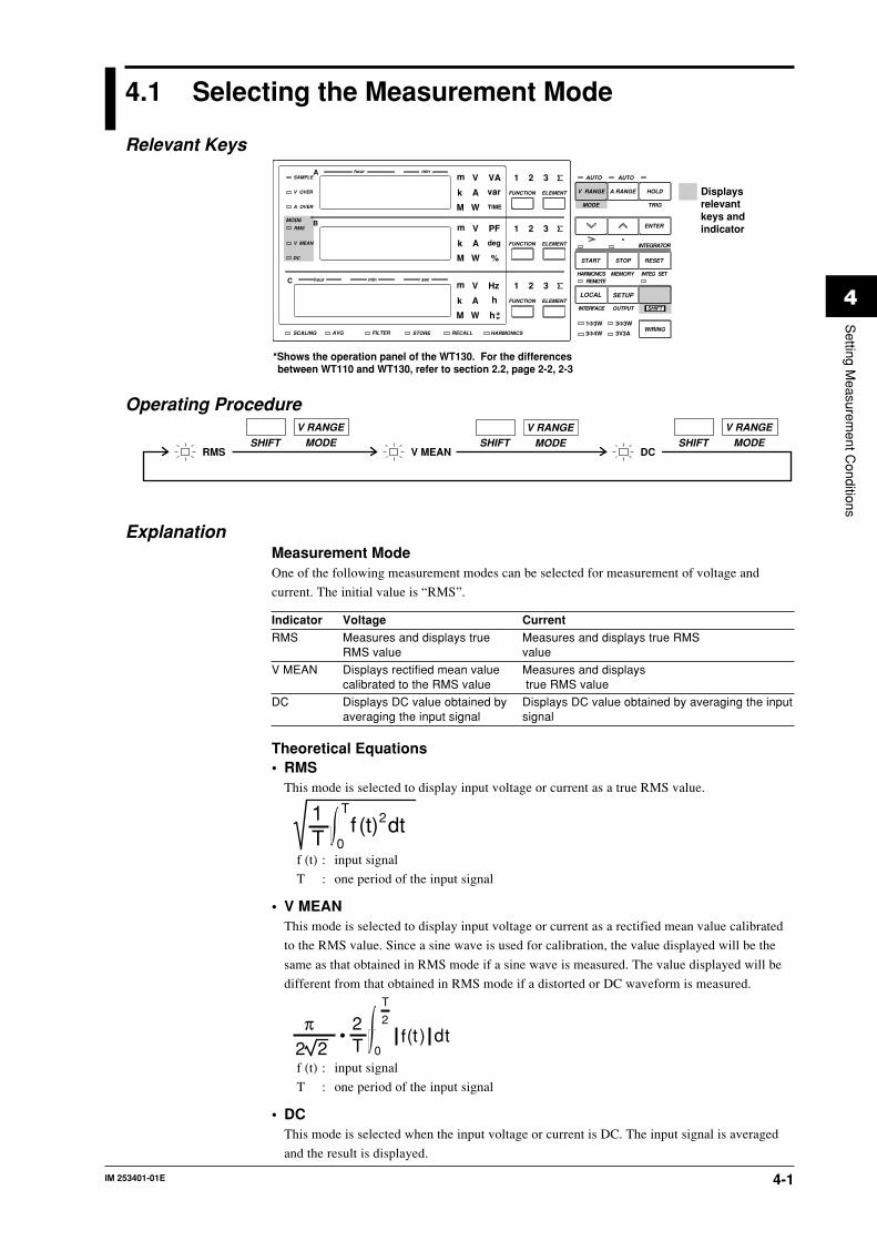
IM 253401-01E 4-1
4
Setting M
easurement C
onditions
4.1 Selecting the Measurement Mode
Relevant Keys
SCALING AVG FILTER STORE RECALL HARMONICS
SAMPLE
V OVER
A OVER
MODE
RMS
V MEAN
DC
A
B
C
hour
hour
min
min sec
V VAm
Ak var
M W TIME
V PFm
Ak deg
M W %
FUNCTION
AUTO AUTO
MODE
1Φ3W
V Hzm
Ak h
M W
TRIG
V RANGE A RANGE HOLD
ENTER
INTEGRATOR
START
HARMONICS MEMORY INTEG SET
STOP RESET
REMOTE
INTERFACE OUTPUT
LOCAL SETUP
hSHIFT
WIRING3Φ4W
3Φ3W
3V3A
ELEMENT
1 2 3
FUNCTION ELEMENT
1 2 3
FUNCTION ELEMENT
1 2 3
*Shows the operation panel of the WT130. For the differences between WT110 and WT130, refer to section 2.2, page 2-2, 2-3
Displays relevant keys and indicator
Operating Procedure
RMS V MEAN DCMODE
V RANGESHIFTMODE
V RANGESHIFT MODE
V RANGESHIFT
ExplanationMeasurement ModeOne of the following measurement modes can be selected for measurement of voltage and
current. The initial value is “RMS”.
Indicator Voltage CurrentRMS Measures and displays true Measures and displays true RMS
RMS value value
V MEAN Displays rectified mean value Measures and displayscalibrated to the RMS value true RMS value
DC Displays DC value obtained by Displays DC value obtained by averaging the inputaveraging the input signal signal
Theoretical Equations• RMS
This mode is selected to display input voltage or current as a true RMS value.
1T 0
Tf (t)2dt
f (t) : input signal
T : one period of the input signal
• V MEANThis mode is selected to display input voltage or current as a rectified mean value calibrated
to the RMS value. Since a sine wave is used for calibration, the value displayed will be the
same as that obtained in RMS mode if a sine wave is measured. The value displayed will be
different from that obtained in RMS mode if a distorted or DC waveform is measured.
π2 2
• 2T 0
T
2
f (t ) dt
f (t) : input signal
T : one period of the input signal
• DCThis mode is selected when the input voltage or current is DC. The input signal is averaged
and the result is displayed.

IM 253401-01E4-2
Typical Waveform Types and Differences in Measured Values betweenMeasurement Modes
Name
Measurementmode
Waveform
RMSvalue
Meanvalue
Mean-value rectification
Linear averaging
Sinewave
Half-waverectification
Full-waverectification
Directcurrent
Triangularwave
SquarewavePulse
Pulse
RMS — V MEAN DC
Ep
2
Ep
2
Ep
2
Ep
Ep
3
Ep
D · Ep
τ
2π · Ep
2
π· Ep
Ep
π
2
π · Ep
Ep
Ep
2
Ep
D · Ep
τ
2π · Ep
Ep
2
Ep
2 2
Ep
2
π
2 2· Ep
π
4 2 · Ep
π
2 2 · Ep
π τ
4π 2 · Ep
πD
2 2 · Ep D · Ep
τ
2π · Ep
2
π · Ep
0
0
Ep
π0 2πEp
π0 2πEp
π0 2πEp
Ep
π0 2πEp
π0 2π Ep
0 2πEp
τ
Ep
π
0
Display
τ2π
When duty D (= ) is applied.
4.1 Selecting the Measurement Mode

IM 253401-01E 4-3
4
Setting M
easurement C
onditions
4.2 Turning the Filter ON/OFF
Relevant Keys
SCALING AVG FILTER STORE RECALL HARMONICS
SAMPLE
V OVER
A OVER
MODE
RMS
V MEAN
DC
A
B
C
hour
hour
min
min sec
V VAm
Ak var
M W TIME
V PFm
Ak deg
M W %
FUNCTION
AUTO AUTO
MODE
1Φ3W
V Hzm
Ak h
M W
TRIG
V RANGE A RANGE HOLD
ENTER
INTEGRATOR
START
HARMONICS MEMORY INTEG SET
STOP RESET
REMOTE
INTERFACE OUTPUT
LOCAL SETUP
hSHIFT
WIRING3Φ4W
3Φ3W
3V3A
ELEMENT
1 2 3
FUNCTION ELEMENT
1 2 3
FUNCTION ELEMENT
1 2 3
*Shows the operation panel of the WT130. For the differences between WT110 and WT130, refer to section 2.2, page 2-2, 2-3
Displays relevant keys and indicator
Operating Procedure
Selecting the filter(Display C)
ENTER
3.SETUP
1.ENTER
(Display C)
4.2.
5.
End
• Perform operations following the thick line in the below menu.• Press the ENTER key to confirm the selection or setting.• When you want to leave the current menu during operation, press the key described
under step 1. The confirmed settings made until that point will be kept.
ExplanationFilter FunctionThe instrument will perform measurements after synchronizing to the cycle of the input signal.
Consequently, the frequency of the input signal can be measured properly. The filter, at a cut-
off frequency of 300Hz, will only be applied to the frequency measurement circuit and will
remove noise from distorted and inverted waves, etc.. This allows the frequency to be measured
correctly which improves the accuracy of each measurement value. The filter will not be applied
to the voltage and current circuit. The initial value is OFF.
NoteThe filter setting cannot be changed while integration is being carried out.

IM 253401-01E4-4
4.3 Selecting the Measurement Range in case ofDirect Input
Relevant Keys
SCALING AVG FILTER STORE RECALL HARMONICS
SAMPLE
V OVER
A OVER
MODE
RMS
V MEAN
DC
A
B
C
hour
hour
min
min sec
V VAm
Ak var
M W TIME
V PFm
Ak deg
M W %
FUNCTION
AUTO AUTO
MODE
1Φ3W
V Hzm
Ak h
M W
TRIG
V RANGE A RANGE HOLD
ENTER
INTEGRATOR
START
HARMONICS MEMORY INTEG SET
STOP RESET
REMOTE
INTERFACE OUTPUT
LOCAL SETUP
hSHIFT
WIRING3Φ4W
3Φ3W
3V3A
ELEMENT
1 2 3
FUNCTION ELEMENT
1 2 3
FUNCTION ELEMENT
1 2 3
*Shows the operation panel of the WT130. For the differences between WT110 and WT130, refer to section 2.2, page 2-2, 2-3
Displays relevant keys and indicator
Operating Procedure
(Display C)1.V RANGE ENTER
3.
2.
ENTER
3.(Display C)1.A RANGE
2.
End
End
• Voltage Range Setting
• Current Range Setting
• Perform operations following the thick line in the below menu.• Press the ENTER key to confirm the selection or setting.• When you want to leave the current menu during operation, press the key described under step 1. The confirmed settings made until that point will be kept.
ExplanationManual Range (fixed) versus Automatic Range (auto)The measurement range can be of one of the following types. The initial setting is Auto range
ON.
• Manual rangeVoltage range : selectable from 600/300/150/60/30/15V
Current range : selectable from 20/10/5/2/1/0.5A
• Auto range: AutoThe measuring range is adjusted automatically according to the input voltage or current as
follows. Overrange is handled the same way as for the manually selected range.

IM 253401-01E 4-5
4
Setting M
easurement C
onditions
Range up:A higher range is selected immediately if the instantaneous input voltage or current exceeds
approx. 300% of the rated value during sampling. If the meaured voltage or current exceeds
110% of the rated value, a higher range will be selected at the end of the current
measurement cycle.
Range down:A lower range is selected if the measured voltage or current drops below 30% of the rated
value. However, even when the measured voltage or current drops below 30% of the rated
value, range down will not be done when this would result in waveforms with a high crest
factor causing peak over.
Verifying the RangeTo verify the current range setting press the V RANGE key or the A RANGE key. The result
will be shown at display C. In order to return to the measurement status, press the same key
again.
Note• When the range is set to auto, you cannot move to the minimum range by pressing the ∧ key. On the
other hand, when the range is set to the minimum, you cannot move to auto range by pressing the ∨ key.• When the range is set to auto, the range may be adjusted frequently if a waveform such as a pulse is
input. In such a case, set the range manually.
Power RangeThe measuring range for active power, apparent power and reactive power is determined as
follows.
Wiring method Power rangesingle-phase, two-wire (1Φ2W) voltage range × current range
single-phase, three-wire (1Φ3W) voltage range × current range × 2three-phase, three-wire (3Φ3W)three-voltage, three-current (3A3V)
three-phase, four-wire (3Φ4W) voltage range × current range × 3
The maximum display is 9999.
When the result of “voltage range × current range” exceeds 1000W, the unit on the display will
change to “kW”; When this result exceeds 1000kW, the unit on the display will change to MW.
NoteWhen the range is set to auto, the measuring range switches according to range up/range downconditions. Therefore, the range may vary even if the measured values remain the same.
4.3 Selecting the Measurement Range in case of Direct Input

IM 253401-01E4-6
4.4 Setting the Scaling Value when External PT/CTis Used
Relevant Keys
SCALING AVG FILTER STORE RECALL HARMONICS
SAMPLE
V OVER
A OVER
MODE
RMS
V MEAN
DC
A
B
C
hour
hour
min
min sec
V VAm
Ak var
M W TIME
V PFm
Ak deg
M W %
FUNCTION
AUTO AUTO
MODE
1Φ3W
V Hzm
Ak h
M W
TRIG
V RANGE A RANGE HOLD
ENTER
INTEGRATOR
START
HARMONICS MEMORY INTEG SET
STOP RESET
REMOTE
INTERFACE OUTPUT
LOCAL SETUP
hSHIFT
WIRING3Φ4W
3Φ3W
3V3A
ELEMENT
1 2 3
FUNCTION ELEMENT
1 2 3
FUNCTION ELEMENT
1 2 3
*Shows the operation panel of the WT130. For the differences between WT110 and WT130, refer to section 2.2, page 2-2, 2-3
Displays relevant keys and indicator
Operating Procedure
1.• Setting the Scaling Value
• Perform operations following the thick line in the below menu.• Press the ENTER key to confirm the selection or setting.• When you want to leave the current menu during operation, press the key described under step 1. The confirmed settings made until that point will be kept.
ENTER
3.
SETUP
6.,16.
4.
(Display C)
ENTER
5.
ENTER
7.ENTER
11.
Selecting theinput element
(Display C)PT ratio selecting
(Display A)CT ratio selecting
(Display B)
ENTER
13Power value(Display C)
ENTER
15.
2.
ENTER
17.
End
8. up down
9. cursor shift
10. decimal point shift
SHIFT
SHIFT •
(Display C)
14. Same as step 8 to 10
12. Same as step 8 to 10
(Display C)
ENTER
3.
SETUP
4.
(Display C)
ENTER
5.
2.
End
1.• Selecting Scaling ON/OFF
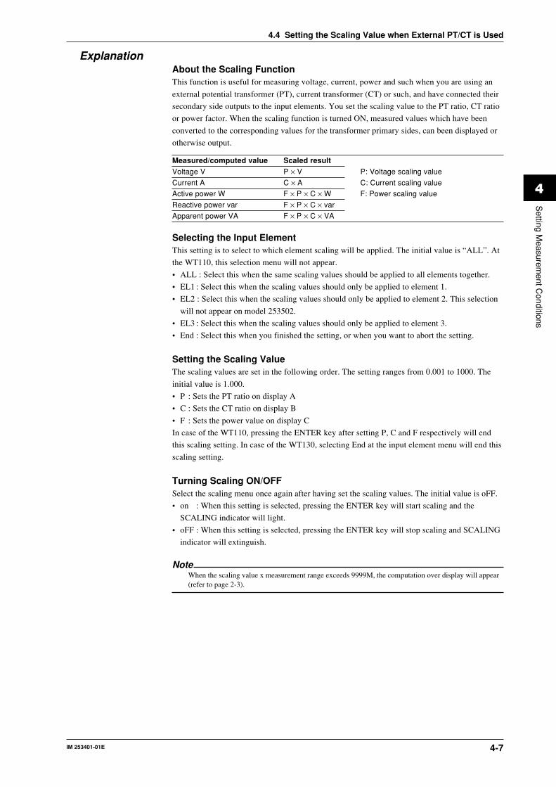
IM 253401-01E 4-7
4
Setting M
easurement C
onditions
ExplanationAbout the Scaling FunctionThis function is useful for measuring voltage, current, power and such when you are using an
external potential transformer (PT), current transformer (CT) or such, and have connected their
secondary side outputs to the input elements. You set the scaling value to the PT ratio, CT ratio
or power factor. When the scaling function is turned ON, measured values which have been
converted to the corresponding values for the transformer primary sides, can been displayed or
otherwise output.
Measured/computed value Scaled resultVoltage V P × V P: Voltage scaling value
Current A C × A C: Current scaling value
Active power W F × P × C × W F: Power scaling value
Reactive power var F × P × C × var
Apparent power VA F × P × C × VA
Selecting the Input ElementThis setting is to select to which element scaling will be applied. The initial value is “ALL”. At
the WT110, this selection menu will not appear.
• ALL : Select this when the same scaling values should be applied to all elements together.
• EL1 : Select this when the scaling values should only be applied to element 1.
• EL2 : Select this when the scaling values should only be applied to element 2. This selection
will not appear on model 253502.
• EL3 : Select this when the scaling values should only be applied to element 3.
• End : Select this when you finished the setting, or when you want to abort the setting.
Setting the Scaling ValueThe scaling values are set in the following order. The setting ranges from 0.001 to 1000. The
initial value is 1.000.
• P : Sets the PT ratio on display A
• C : Sets the CT ratio on display B
• F : Sets the power value on display C
In case of the WT110, pressing the ENTER key after setting P, C and F respectively will end
this scaling setting. In case of the WT130, selecting End at the input element menu will end this
scaling setting.
Turning Scaling ON/OFFSelect the scaling menu once again after having set the scaling values. The initial value is oFF.
• on : When this setting is selected, pressing the ENTER key will start scaling and the
SCALING indicator will light.
• oFF : When this setting is selected, pressing the ENTER key will stop scaling and SCALING
indicator will extinguish.
NoteWhen the scaling value x measurement range exceeds 9999M, the computation over display will appear(refer to page 2-3).
4.4 Setting the Scaling Value when External PT/CT is Used

IM 253401-01E4-8
4.5 Selecting the Measurement Range and Settingthe Scaling Value when External Sensor isUsed (option)
Relevant Keys
SCALING AVG FILTER STORE RECALL HARMONICS
SAMPLE
V OVER
A OVER
MODE
RMS
V MEAN
DC
A
B
C
hour
hour
min
min sec
V VAm
Ak var
M W TIME
V PFm
Ak deg
M W %
FUNCTION
AUTO AUTO
MODE
1Φ3W
V Hzm
Ak h
M W
TRIG
V RANGE A RANGE HOLD
ENTER
INTEGRATOR
START
HARMONICS MEMORY INTEG SET
STOP RESET
REMOTE
INTERFACE OUTPUT
LOCAL SETUP
hSHIFT
WIRING3Φ4W
3Φ3W
3V3A
ELEMENT
1 2 3
FUNCTION ELEMENT
1 2 3
FUNCTION ELEMENT
1 2 3
*Shows the operation panel of the WT130. For the differences between WT110 and WT130, refer to section 2.2, page 2-2, 2-3
Displays relevant keys and indicator
Operating Procedure
SETUP
ENTER3.
Select the external sensor function(Display C)
2.
4.ENTER
5.
ENTER13.
End
ENTER5.
Select the setting function(Display C)
Select all(Display C)
Set element 1(Display A)
ENTER9.
6.7.8.
Set element 2(Display B)
ENTER11.
Set element 3(Display C)
ENTER9.
End6. up down
7. cursor shift
8. decimal point shift
SHIFT
SHIFT •
Same as step 6 to 8 mentioned above.
10. Same as step 6 to 8
12. Same as step 6 to 8
1.
• Setting the Scaling Value of the External Sensor Input
• Perform operations following the thick line in the below menu.• Press the ENTER key to confirm the selection or setting.• When you want to leave the current menu during operation, press the key described under step 1. The confirmed settings made until that point will be kept.
ENTER3.
In case of/EX1 option(Display C)1.
A RANGE
In case of/EX2 option(Display C)
2.
ENTER3.
2.
End End
• Selecting the Measurement Range (Current, with Scaling function ON)
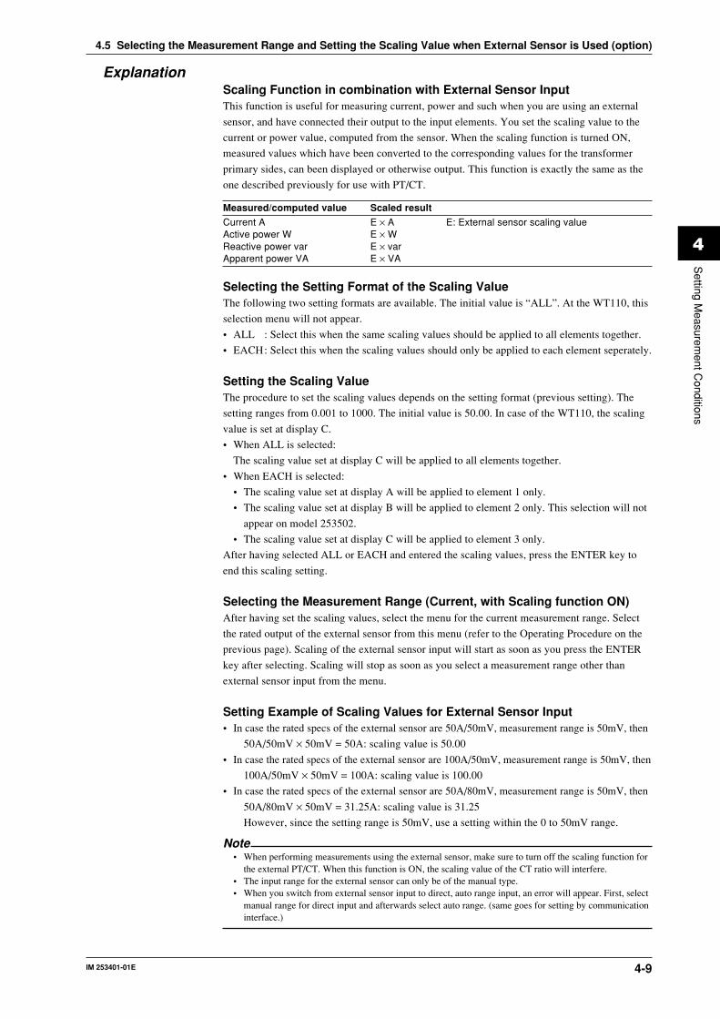
IM 253401-01E 4-9
4
Setting M
easurement C
onditions
ExplanationScaling Function in combination with External Sensor InputThis function is useful for measuring current, power and such when you are using an external
sensor, and have connected their output to the input elements. You set the scaling value to the
current or power value, computed from the sensor. When the scaling function is turned ON,
measured values which have been converted to the corresponding values for the transformer
primary sides, can been displayed or otherwise output. This function is exactly the same as the
one described previously for use with PT/CT.
Measured/computed value Scaled resultCurrent A E × A E: External sensor scaling valueActive power W E × WReactive power var E × varApparent power VA E × VA
Selecting the Setting Format of the Scaling ValueThe following two setting formats are available. The initial value is “ALL”. At the WT110, this
selection menu will not appear.
• ALL : Select this when the same scaling values should be applied to all elements together.
• EACH: Select this when the scaling values should only be applied to each element seperately.
Setting the Scaling ValueThe procedure to set the scaling values depends on the setting format (previous setting). The
setting ranges from 0.001 to 1000. The initial value is 50.00. In case of the WT110, the scaling
value is set at display C.
• When ALL is selected:
The scaling value set at display C will be applied to all elements together.
• When EACH is selected:
• The scaling value set at display A will be applied to element 1 only.
• The scaling value set at display B will be applied to element 2 only. This selection will not
appear on model 253502.
• The scaling value set at display C will be applied to element 3 only.
After having selected ALL or EACH and entered the scaling values, press the ENTER key to
end this scaling setting.
Selecting the Measurement Range (Current, with Scaling function ON)After having set the scaling values, select the menu for the current measurement range. Select
the rated output of the external sensor from this menu (refer to the Operating Procedure on the
previous page). Scaling of the external sensor input will start as soon as you press the ENTER
key after selecting. Scaling will stop as soon as you select a measurement range other than
external sensor input from the menu.
Setting Example of Scaling Values for External Sensor Input• In case the rated specs of the external sensor are 50A/50mV, measurement range is 50mV, then
50A/50mV × 50mV = 50A: scaling value is 50.00
• In case the rated specs of the external sensor are 100A/50mV, measurement range is 50mV, then
100A/50mV × 50mV = 100A: scaling value is 100.00
• In case the rated specs of the external sensor are 50A/80mV, measurement range is 50mV, then
50A/80mV × 50mV = 31.25A: scaling value is 31.25
However, since the setting range is 50mV, use a setting within the 0 to 50mV range.
Note• When performing measurements using the external sensor, make sure to turn off the scaling function for
the external PT/CT. When this function is ON, the scaling value of the CT ratio will interfere.• The input range for the external sensor can only be of the manual type.• When you switch from external sensor input to direct, auto range input, an error will appear. First, select
manual range for direct input and afterwards select auto range. (same goes for setting by communicationinterface.)
4.5 Selecting the Measurement Range and Setting the Scaling Value when External Sensor is Used (option)

IM 253401-01E4-10
4.6 Using the Averaging Function
Relevant Keys
SCALING AVG FILTER STORE RECALL HARMONICS
SAMPLE
V OVER
A OVER
MODE
RMS
V MEAN
DC
A
B
C
hour
hour
min
min sec
V VAm
Ak var
M W TIME
V PFm
Ak deg
M W %
FUNCTION
AUTO AUTO
MODE
1Φ3W
V Hzm
Ak h
M W
TRIG
V RANGE A RANGE HOLD
ENTER
INTEGRATOR
START
HARMONICS MEMORY INTEG SET
STOP RESET
REMOTE
INTERFACE OUTPUT
LOCAL SETUP
hSHIFT
WIRING3Φ4W
3Φ3W
3V3A
ELEMENT
1 2 3
FUNCTION ELEMENT
1 2 3
FUNCTION ELEMENT
1 2 3
*Shows the operation panel of the WT130. For the differences between WT110 and WT130, refer to section 2.2, page 2-2, 2-3
Displays relevant keys and indicator
Operating Procedure
Selecting the averaging function(Display C)
ENTER
3.SETUP
ENTER
7.Selecting the type
(Display B)
2.
6.
4.
(Display C)
ENTER
5.
8.
Selecting the sample number(Display C)
ENTER
9.
End
1.
• Setting Averaging
• Perform operations following the thick line in the below menu.• Press the ENTER key to confirm the selection or setting.• When you want to leave the current menu during operation, press the key described under step 1. The confirmed settings made until that point will be kept.
Selecting the averaging function(Display C)
ENTER
3.SETUP2.
4.
(Display C)
ENTER
5.
End
1.
• Averaging ON/OFF

IM 253401-01E 4-11
4
Setting M
easurement C
onditions
4.6 Using the Averaging Function
ExplanationAbout the Averaging FunctionThis function performs exponential averaging or moving averaging on measurement values.
When the displayed values are unsteady due to big fluctuations in power source or load, or due
to the low frequency of the input signal, this function is useful to stabilize the displayed values
for easier reading.
Selecting the Type of AveragingThe following two selections are available. The initial value is “Lin”.
• Exponential Averaging : EPExponential averaging is expressed by the following equation.
Dn = Dn-1 + (Mn-Dn-1)/K
where
Dn : the value at the “n”th display;
Dn-1 : the exponentially averaged value at the “n-1”th display;
Mn : the measurement value at the “n”th display;
K : attenuation constant
• Moving Averaging: LinMoving averaging is expressed by the following equation.
Dn = (Mn-(m-1) + Mn-(m-2) + ... Mn-2 + Mn-1 + Mn)/m
where
Dn : the value at the “n”th display;
Mn-(m-1) : the measurement value at (m-1) display before the “n”th display;
Mn-(m-2) : the measurement value at (m-2) display before the “n”th display;
:
Mn-2 : the measurement value at two displays before the “n”th display;
Mn-1 : the measurement value at one display before the “n”th display;
Mn : the measurement value at the “n”th display;
m : sample number
Setting the Averaging Sample Number/Attenuation ConstantThe following selections are available. The attenuation constant (for exponential averaging) and
the sample number (for moving averaging) are set and saved seperately. The initial value is “8”.
Setting Averaging ON/OFFSelect the averaging menu once again after having set the averaging values. The initial value is
oFF.
• on : When this setting is selected, pressing the ENTER key will start averaging and the
AVG indicator will light.
• oFF : When this setting is selected, pressing the ENTER key will stop averaging and the
AVG indicator will extinguish.

IM 253401-01E4-12
4.7 Using the Four Arithmetical Operation Function(Applies to WT110/WT130 with ROM Version2.01 or later)
Relevant Keys
SCALING AVG FILTER STORE RECALL HARMONICS
SAMPLE
V OVER
A OVER
MODE
RMS
V MEAN
DC
A
B
C
hour
hour
min
min sec
V VAm
Ak var
M W TIME
V PFm
Ak deg
M W %
FUNCTION
AUTO AUTO
MODE
1Φ3W
V Hzm
Ak h
M W
TRIG
V RANGE A RANGE HOLD
ENTER
INTEGRATOR
START
HARMONICS MEMORY INTEG SET
STOP RESET
REMOTE
INTERFACE OUTPUT
LOCAL SETUP
hSHIFT
WIRING3Φ4W
3Φ3W
3V3A
ELEMENT
1 2 3
FUNCTION ELEMENT
1 2 3
FUNCTION ELEMENT
1 2 3
*Shows the operation panel of the WT130. For the differences between WT110 and WT130, refer to section 2.2, page 2-2, 2-3
Displays relevant keys and indicator
Operating Procedure
ENTER
3.
SETUP
1.
ENTER
4.2.
5.
• Perform operations following the thick line in the below menu.• Press the ENTER key to confirm the selection or setting.• When you want to leave the current menu during operation, press the key described under step 1. The confirmed settings made until that point will be kept.
(for WT130 only)
End
(Display C)
Selecting the four arithmetical operations function
(Display C)
ExplanationFour Arithmetical Operations FunctionDisplays the following computation results on display C. “ ” is displayed at the front when the
computation results are being displayed.
:A+B
:A−B
:A×B
:A÷B
:A÷B
:A ÷B
2
2
A, B indicates display A, B respectively.
Note• The meanings of the displayed symbols are as follows:
:+(Addition)
:−(Subtraction)
:×(Multiplication)
:÷(Division)
:^(Exponent)
• If the display A function is displaying INTEG TIME (elapsed time of integration), the computation resultdisplays “- - - - -” (no data).
• If the value of display B function is less than 0.0001% of the rating, the computation result displays “- -oF - -”.

IM 253401-01E 4-13
4
Setting M
easurement C
onditions
4.7 Using the Four Arithmetical Operation Function (Applies to WT110/WT130 with ROM Version 2.01 or later)
Application Example• Power summation
: Displays the result of display A + display B.
Computation example :Display A Display B Display C Wiring methodW1 W2 or W3 W1+W2 Any
or W1+W3
W1
W2またはW3
Converter
• Power loss: Displays the result of display A – display B.
Computation example 1 :Display A Display B Display C Wiring methodW1 W3 W1–W3 Any
W3W1 Converter
Computation example 2 :Display A Display B Display C Wiring method∑W(=W1+W3) W2 ∑W–W2 3Φ3W
W2W1
W3
Converter
Computation example 3 :Display A Display B Display C Wiring methodW2 ∑W(=W1+W3) W2–∑W 3Φ3W
W2W1
W3
Converter

IM 253401-01E4-14
• Useful when setting a function other than VA (apparent power) fordisplay A and displaying VA on display C.
: Displays the result of display A × display B.
Computation example :Display A Display B Display C Wiring methodV1rms A1rms V1rms×A1rms Any
• Absolute value of the impedance: Displays the result of display A ÷ display B.
Computation example :Display A Display B Display C Wiring method
V1rms A1rms |Z|=V1rms
AnyA1rms
V1
A1
SOURCE LOAD
• Voltage ratio across the wires and phase current ratio for a three-phasewiring.
: Displays the result of display A ÷ display B.Computation example :
Display A Display B Display C Wiring method
V1rms A3rmsV1rms
3Φ3WA3rms
A1rms A3rmsA1rms
A3rms
V1
SOURCE LOAD
V3
A1
A3
• Impedance, resistance and reactance : Displays the result of display A ÷ (display B)2
Computation example :Display A Display B Display C Wiring method
VA1 A1rms |Z|= VA1
Any(A1rms)2
W1 A1rms R= W1
(A1rms)2
Var1 A1rms |X|= Var1
(A1rms)2
V1
A1
SOURCE LOAD
• Resistance : Displays the result of (display A)2 ÷ display B
Computation example :Display A Display B Display C Wiring method
V1rms W1 R=(V1rms)2
Any W1
V1
A1
SOURCE LOAD
4.7 Using the Four Arithmetical Operation Function (Applies to WT110/WT130 with ROM Version 2.01 or later)

IM 253401-01E 4-15
4
Setting M
easurement C
onditions
4.8 Computing the Crest Factor (Applies to WT110/WT130 with ROM Version 2.01 or later)
Relevant Keys
SCALING AVG FILTER STORE RECALL HARMONICS
SAMPLE
V OVER
A OVER
MODE
RMS
V MEAN
DC
A
B
C
hour
hour
min
min sec
V VAm
Ak var
M W TIME
V PFm
Ak deg
M W %
FUNCTION
AUTO AUTO
MODE
1Φ3W
V Hzm
Ak h
M W
TRIG
V RANGE A RANGE HOLD
ENTER
INTEGRATOR
START
HARMONICS MEMORY INTEG SET
STOP RESET
REMOTE
INTERFACE OUTPUT
LOCAL SETUP
hSHIFT
WIRING3Φ4W
3Φ3W
3V3A
ELEMENT
1 2 3
FUNCTION ELEMENT
1 2 3
FUNCTION ELEMENT
1 2 3
*Shows the operation panel of the WT130. For the differences between WT110 and WT130, refer to section 2.2, page 2-2, 2-3
Displays relevant keys and indicator
Operating Procedure
ENTER
3.
SETUP
1.
ENTER4.2. 5.
• Perform operations following the thick line in the below menu.• Press the ENTER key to confirm the selection or setting.• When you want to leave the current menu during operation, press the key described under step 1. The confirmed settings made until that point will be kept.
Selecting the four arithmetical operations function
(Display C) (Display C)(for WT130 only)
End
ExplanationCrest factor computationThe crest factor is determined by peak value/rms value. The crest factors for voltage and
current are computed and displayed. “ ” is displayed at the front when the crest factor is being
displayed.
Computing equation for the crest factor and displayCF V1 : Displays the result of (Peak of V1)/(rms of V1)
CF V2 : Displays the result of (Peak of V2)/(rms of V2) (for 253503 only)
CF V3 : Displays the result of (Peak of V3)/(rms of V3) (for 253502 and 253503)
CF A1 : Displays the result of (Peak of A1)/(rms of A1)
CF A2 : Displays the result of (Peak of A2)/(rms of A2) (for 253503 only)
CF A3 : Displays the result of (Peak of A3)/(rms of A3) (for 253502 and 253503)
Note
• Definition of crest factor : PEAK value
RMS value• If the measurement mode is V MEAN or DC, “- - - - -” is displayed.

IM 253401-01E4-16
4.9 Computing the Efficiency (Applies to WT130with ROM Version 2.01 or later)
Relevant Keys
SCALING AVG FILTER STORE RECALL HARMONICS
SAMPLE
V OVER
A OVER
MODE
RMS
V MEAN
DC
A
B
C
hour
hour
min
min sec
V VAm
Ak var
M W TIME
V PFm
Ak deg
M W %
FUNCTION
AUTO AUTO
MODE
1Φ3W
V Hzm
Ak h
M W
TRIG
V RANGE A RANGE HOLD
ENTER
INTEGRATOR
START
HARMONICS MEMORY INTEG SET
STOP RESET
REMOTE
INTERFACE OUTPUT
LOCAL SETUP
hSHIFT
WIRING3Φ4W
3Φ3W
3V3A
ELEMENT
1 2 3
FUNCTION ELEMENT
1 2 3
FUNCTION ELEMENT
1 2 3
*Shows the operation panel of the WT130. For the differences between WT110 and WT130, refer to section 2.2, page 2-2, 2-3
Displays relevant keys and indicator
Operating Procedure
ENTER
3.
SETUP
1.ENTER
4.2.
5.
• Perform operations following the thick line in the below menu.• Press the ENTER key to confirm the selection or setting.• When you want to leave the current menu during operation, press the key described under step 1. The confirmed settings made until that point will be kept.
Selecting the four arithmetical operations function
(Display C) (Display C)
End
ExplanationSetting the Wiring MethodThe computing equation for efficiency changes according to the wiring method as indicated on
the next page. For the operating procedure, see section 3.9 "Selecting the Wiring Method (for
WT130)."

IM 253401-01E 4-17
4
Setting M
easurement C
onditions
Wiring Method and Computing Equation• When the input and output are both two-wire
Select 1Φ2W, 1Φ3W, or 3Φ3W for the wiring method for the three-phase three-wire system
253502) and 1Φ2W for the wiring method for the three-phase four-wire system (253503).
Converter
Primary side
W1
Secondary side
W3
Output sideComputing equation
Efficiency(µ) = (W3/W1)×100
• When the input is two-wire and the output is three-wireSelect 1Φ2W, 1Φ3W, 3Φ3W, or 3V3A for the wiring method. This only applies to model
253503.
Converter
Primary side
W2
Secondary side
W1
Output side
W3
Computing equation
Efficiency(µ) = (W1+W3)/W2×100
4.9 Computing the Efficiency (Applies to WT130 with ROM Version 2.01 or later)

IM 253401-01E 5-1
5
Measuring / D
isplaying Voltage, C
urrent, Active P
ower, F
requency,
Four A
rithmetic O
peration Value, C
rest Factor and P
eak Value
5.1 Measuring/Displaying Voltage, Current andActive Power
Relevant Keys
SCALING AVG FILTER STORE RECALL HARMONICS
SAMPLE
V OVER
A OVER
MODE
RMS
V MEAN
DC
A
B
C
hour
hour
min
min sec
V VAm
Ak var
M W TIME
V PFm
Ak deg
M W %
FUNCTION
AUTO AUTO
MODE
1Φ3W
V Hzm
Ak h
M W
TRIG
V RANGE A RANGE HOLD
ENTER
INTEGRATOR
START
HARMONICS MEMORY INTEG SET
STOP RESET
REMOTE
INTERFACE OUTPUT
LOCAL SETUP
hSHIFT
WIRING3Φ4W
3Φ3W
3V3A
ELEMENT
1 2 3
FUNCTION ELEMENT
1 2 3
FUNCTION ELEMENT
1 2 3
*Shows the operation panel of the WT130. For the differences between WT110 and WT130, refer to section 2.2, page 2-2, 2-3
Displays relevant keys and indicator
Operating Procedure1 Selecting the Display Function
Select either V (voltage), A (current) or W (power) by pressing the FUNCTION key.
DisplayA
B
C
FUNCTION
V A W VA var TIME
V A W PF deg
FUNCTION FUNCTION FUNCTION FUNCTION
FUNCTION FUNCTION FUNCTION FUNCTION FUNCTION
FUNCTION
Wh± and Ah± will light twice. and are displayed on the top of display C.You can reverse the order by first pressing the SHIFT key followed by the FUNCTION key.*1 Displayed on WT110/WT130 with ROM version 2.01 or later.
A W V Hz A Hz Wh
AhAh±
Wh±
Wh±
Ah±
FUNCTION FUNCTION FUNCTION FUNCTION FUNCTION FUNCTION
FUNCTIONFUNCTIONFUNCTIONFUNCTIONFUNCTION
FUNCTION
FUNCTION
FUNCTION
& V
& A
*1
V
*1
*1
2 Selecting the Input ElementSelect the input element by pressing the ELEMENT key.
WT110(253401)
WT130(253502)
WT130(253503)
No such function
1 2 3 ΣELEMENT ELEMENT ELEMENT ELEMENT
1 3 ΣELEMENT ELEMENT ELEMENT
3 Selecting the Measurement RangeYou can select the voltage measurement range by pressing the V RANGE key, and the
current measurement range by pressing the A RANGE key. For more details, refer to either of
the following.
• 4.3 Selecting the Measurement Range in case of Direct Input, on page 4-4;
• 4.4 Setting the Scaling Value when External PT/CT is Used, on page 4-6;
• 4.5 Selecting the Measurement Range and Setting the Scaling Value when External Sensor
is Used (option), on page 4-8.
4 Selecting the Measurement ModeSelect the measurement mode by pressing the V RANGE (MODE) key after having pressed
the SHIFT key so that the SHIFT indicator is lit. For more details, refer to section 4.1 on page
4-1.

IM 253401-01E5-2
ExplanationContinuous Maximum Allowable Input• Voltage : peak voltage is 1.5kV, or the RMS value is 1.0kV, whichever is less.
• Current : peak current is 100A or the RMS value is 30A, whichever is less. In case of external
sensor input, the peak value is 5 times the measurement range or less.
Maximum Reading of the Display and Units• Maximum reading : for voltage, current and power, each 9999
• Units : V (voltage), A (current), W (power)
• Prefix : m, k, M
Selecting the Display FunctionThe following selections are available.
• V : voltage will be displayed
• A : current will be displayed
• W : power will be displayed
Selecting the Input ElementThe type of input element which can be selected depends on the model number. Make your
selection after having verified your model number.
• 1/2/3 : Displays the measurement values of element 1/2/3
• ∑ : Displays according to the wiring method, and is as follows.
ΣV ΣA ΣW
1Φ3W 2V1+V3
V1+V3
2A1+A3 W1+W3
W1+W3
W1+W2+W3
W1+W3
2
3V1+V2+V3
3V1+V2+V3
V1A1+V3A3
V1A1+V2A2+V3A3
V1A1+V3A3
var1+var3
var1+var3
var1+var2+var3
var1+var3V1A1+V2A2+V3A3
3Φ4W
3V3A
3Φ3W 2A1+A3
23
3
3A1+A2+A3
3A1+A2+A3
( )
3 ( )
ΣVA Σvar
ΣPF Σdeg
1Φ3W
3Φ4W3V3A
3Φ3W ΣWΣVA
cos-1ΣPF
Wiring method
Wiring method
5.1 Measuring/Displaying Voltage, Current and Active Power

IM 253401-01E 5-3
5
Measuring / D
isplaying Voltage, C
urrent, Active P
ower, F
requency,
Four A
rithmetic O
peration Value, C
rest Factor and P
eak Value
5.2 Measuring/Displaying Frequency
Relevant Keys
SCALING AVG FILTER STORE RECALL HARMONICS
SAMPLE
V OVER
A OVER
MODE
RMS
V MEAN
DC
A
B
C
hour
hour
min
min sec
V VAm
Ak var
M W TIME
V PFm
Ak deg
M W %
FUNCTION
AUTO AUTO
MODE
1Φ3W
V Hzm
Ak h
M W
TRIG
V RANGE A RANGE HOLD
ENTER
INTEGRATOR
START
HARMONICS MEMORY INTEG SET
STOP RESET
REMOTE
INTERFACE OUTPUT
LOCAL SETUP
hSHIFT
WIRING3Φ4W
3Φ3W
3V3A
ELEMENT
1 2 3
FUNCTION ELEMENT
1 2 3
FUNCTION ELEMENT
1 2 3
*Shows the operation panel of the WT130. For the differences between WT110 and WT130, refer to section 2.2, page 2-2, 2-3
Displays relevant keys and indicator
Operating Procedure1 Selecting the Display Function
Select either V Hz (voltage frequency) or A Hz (current frequency) by pressing theFUNCTION key of display C.
FUNCTIONSHIFT
FUNCTIONSHIFT
FUNCTIONSHIFT
DisplayC A W V Hz A Hz Wh
AhAh±
Wh±
Wh±
Ah±
FUNCTION FUNCTION FUNCTION FUNCTION FUNCTION FUNCTION
FUNCTIONFUNCTIONFUNCTIONFUNCTIONFUNCTION
FUNCTION
FUNCTION
FUNCTION
&V
&A
*1
V
*1
*1
Wh± and Ah± will light twice. and are displayed on the top of display C.You can reverse the order by first pressing the SHIFT key followed by the FUNCTION key.*1 Displayed on WT110/WT130 with ROM version 2.01 or later.
2 Selecting the Input ElementSelect the input element by pressing the ELEMENT key of display C. The operation is thesame as the one described on page 5-1.
ExplanationMeasurement RangeThe measurement range lies from 10 to 50kHz. Depending on the internal timing, however,measurements can be done in the range from 4 to 10Hz. At 100Hz/1kHz/10kHz/100kHz, themeasurement range is auto range.Maximum Reading of the Display and Units• Maximum reading : 9999• Units : Hz• Prefix : k
Selecting the Display FunctionThe following selections are available.• V Hz: voltage frequency will be displayed• A Hz: current frequency will be displayed
Selecting the Input ElementThe type of input element which can be selected depends on the model number. Make yourselection after having verified your model number.• 1/2/3 : Displays the measurement values of element 1/2/3• ∑ : Displays no measurement values, only dots.
Note• In case the level of the input signal is low (below approx. 7%), or when the frequency is smaller than the
measurement range, the display will show “ErrLo”. When the frequency is larger than the measurementrange, the display will show “ErrHi”.
• This instrument measures the frequency after synchronizing to the cycle of the input signal. Werecommend to turn ON the filter when measuring an inverted waveform or a waveform with high noise.However, depending on the signal’s frequency and level, “ErrLo” might appear on the display. Since thefilter’s cutoff frequency is 300Hz, the signal attenuates and no signal will be detected.
• Even when the filter is set OFF but the frequency exceeds the measurement range, “ErrLo” might appearsince no signal will be detected anymore due to the internal circuit’s attenuation.

IM 253401-01E5-4
5.3 Measuring/Displaying Four ArithmeticOperation Value, Crest Factor and Peak Value
Relevant Keys
SCALING AVG FILTER STORE RECALL HARMONICS
SAMPLE
V OVER
A OVER
MODE
RMS
V MEAN
DC
A
B
C
hour
hour
min
min sec
V VAm
Ak var
M W TIME
V PFm
Ak deg
M W %
FUNCTION
AUTO AUTO
MODE
1Φ3W
V Hzm
Ak h
M W
TRIG
V RANGE A RANGE HOLD
ENTER
INTEGRATOR
START
HARMONICS MEMORY INTEG SET
STOP RESET
REMOTE
INTERFACE OUTPUT
LOCAL SETUP
hSHIFT
WIRING3Φ4W
3Φ3W
3V3A
ELEMENT
1 2 3
FUNCTION ELEMENT
1 2 3
FUNCTION ELEMENT
1 2 3
*Shows the operation panel of the WT130. For the differences between WT110 and WT130, refer to section 2.2, page 2-2, 2-3
Displays relevant keys and indicator
Operating Procedure1 Selecting the display Function
Select either (four arithmetical operations, crest factor), (voltage peak value) or (current
peak value) by pressing the FUNCTION key.Display
C A W V Hz A Hz Wh
AhAh±
Wh±
Wh±
Ah±
FUNCTION FUNCTION FUNCTION FUNCTION FUNCTION FUNCTION
FUNCTIONFUNCTIONFUNCTIONFUNCTIONFUNCTION
FUNCTION
FUNCTION
FUNCTION
&V
&A
*1
V
*1
*1
Wh± and Ah± will light twice. and are displayed on the top of display C.You can reverse the order by first pressing the SHIFT key followed by the FUNCTION key.*1 Displayed on WT110/WT130 with ROM version 2.01 or later.
2.Selecting the Input ElementTo measure or display the peak value, press the ELEMENT key of display C and select the
input element.
The procedure is the same as shown on page 5-1.
ExplanationMeasureing/displaying peak value
is displayed at the front of display C for both voltage and current.
• If the function is set to "V," the peak value of the voltage is measured and displayed.
• If the function is set to "I," the peak value of the current is measured and displayed.
Displaying the result of the four arithmetical operation abd the crestfactorWhen display C is set to , the result of the computing equation specified in Section 4.7 or the
crest factor specified in Section 4.8 is displayed.
However, if the value of display B function is less than 0.0001% of the rating, “- - oF - -” is
displayed for the computation result.

IM 253401-01E 6-1
6
Com
puting / Displaying A
pparent Pow
er, Reactive P
ower , P
ower F
actor and Phase A
ngle
6.1 Computing / Displaying Apparent Power,Reactive Power and Power Factor
Relevant Keys
SCALING AVG FILTER STORE RECALL HARMONICS
SAMPLE
V OVER
A OVER
MODE
RMS
V MEAN
DC
A
B
C
hour
hour
min
min sec
V VAm
Ak var
M W TIME
V PFm
Ak deg
M W %
FUNCTION
AUTO AUTO
MODE
1Φ3W
V Hzm
Ak h
M W
TRIG
V RANGE A RANGE HOLD
ENTER
INTEGRATOR
START
HARMONICS MEMORY INTEG SET
STOP RESET
REMOTE
INTERFACE OUTPUT
LOCAL SETUP
hSHIFT
WIRING3Φ3W
3Φ4W 3V3A
ELEMENT
1 2 3
FUNCTION ELEMENT
1 2 3
FUNCTION ELEMENT
1 2 3
*Shows the operation panel of the WT130. For the differences between WT110 and WT130, refer to section 2.2, page 2-2, 2-3
Displays relevant keys and indicator
Operating Procedure1 Selecting the Display Function
Select either VA (apparant power), var (reactive power) or PF (power factor) by pressing the
FUNCTION key of display A or B.
DisplayA
B
FUNCTION
V A W VA var TIME
V A W PF deg
FUNCTION FUNCTION FUNCTION FUNCTION
FUNCTION FUNCTION FUNCTION FUNCTION FUNCTION
FUNCTION
You can reverse the order by first pressing the SHIFT key followed by the FUNCTION key.
2 Selecting the Input ElementSelect the input element by pressing the ELEMENT key of display A or B. The operation is
the same as the one described on page 5-1.
ExplanationMaximum Reading of the Display and Units• Maximum reading of apparent and reactive power: 9999
• Display range of power factor : –1.000 to 1.000
(when the computed result lies between 1.001 and 2.000, 1.000 will be displayed. When the
result is 2.001 or more, PFErr will be displayed.)
• Units : VA (apparent power), var (reactive power), power factor (no unit)
• Prefix : m, k, M,
Selecting the Display FunctionThe following selections are available.
• VA : apparent power will be displayed
• var : reactive power will be displayed
• PF : power factor will be displayed
Selecting the Input ElementThe type of input element which can be selected depends on the model number. Make your
selection after having verified your model number.
• 1/2/3 : Displays the measurement values of element 1/2/3
• ∑ : Refer to page 5-2.
Note• Changing the measurement mode might result in different computed results, even when the input signal
is the same. For more details on the measurement mode, refer to page 4-1.• When either the voltage or current drops below 0.5% of the measurement range, PFErr will be displayed.

IM 253401-01E6-2
6.2 Computing/Displaying the Phase Angle
Relevant Keys
SCALING AVG FILTER STORE RECALL HARMONICS
SAMPLE
V OVER
A OVER
MODE
RMS
V MEAN
DC
A
B
C
hour
hour
min
min sec
V VAm
Ak var
M W TIME
V PFm
Ak deg
M W %
FUNCTION
AUTO AUTO
MODE
1Φ3W
V Hzm
Ak h
M W
TRIG
V RANGE A RANGE HOLD
ENTER
INTEGRATOR
START
HARMONICS MEMORY INTEG SET
STOP RESET
REMOTE
INTERFACE OUTPUT
LOCAL SETUP
hSHIFT
WIRING3Φ3W
3Φ4W 3V3A
ELEMENT
1 2 3
FUNCTION ELEMENT
1 2 3
FUNCTION ELEMENT
1 2 3
*Shows the operation panel of the WT130. For the differences between WT110 and WT130, refer to section 2.2, page 2-2, 2-3
Displays relevant keys and indicator
Operating Procedure1 Selecting the Display Function
Select deg (phase angle) by pressing the FUNCTION key of display B.Display
B V A W PF degFUNCTION FUNCTION FUNCTION FUNCTION FUNCTION
You can reverse the order by first pressing the SHIFT key followed by the FUNCTION key.
2 Selecting the Input ElementSelect the input element by pressing the ELEMENT key of display B. The operation is the
same as the one described on page 5-1.
ExplanationDisplay Range and UnitsDisplay range : G180.0 to d180.0 (G meaning phase lag, d meaning phase lead)
Unit : deg
Selecting the Display FunctionWhen you select deg, the phase angle will be displayed.
Selecting the Input ElementThe type of input element which can be selected depends on the model number. Make your
selection after having verified your model number.
• 1/2/3 : Displays the measurement values of element 1/2/3
• ∑ : Refer to page 5-2.
Note• Changing the measurement mode might result in different computed results, even when the input signal
is the same. For more details on the measurement mode, refer to page 4-1.• When either the voltage or current drops below 0.5% of the measurement range, dEGErr will be
displayed.• Distinction between phase lag and lead can be made properly, only when both voltage and current are
sine waves, and when the percentage of voltage or current input relating to the measurement range doesnot fluctuate much.
• If the computed result of the power factor exceeds 1, the display will be as follows.- when the power factor ranges between 1.001 to 2.000; the phase angle displays 0.0;- when the power factor is 2.001 or more, the phase angle displays dEGErr.

7-1IM 253401-01E
7
Integration
7.1 Integrator Functions
Active power integration and current integration can be carried out. All measurement values
(and computed values) can be displayed, even when integration is in progress, except for the
integrated values (watt hour or ampere hour) and integration elapsed time. Since integrated
values of negative polarity can be also displayed, the consumed watt hour (ampere hour) value
of the positive side and the watt hour value returning to the power supply of the negative side
(ampere hour: only when the measurement mode is DC), can be displayed seperately.
Integration ModesThe following three modes are available as integration modes.
Manual Integration Mode• Integration starts: after having pressed the START key
• Integration stops:
• after having pressed the STOP key;
• when the integrated value reaches the maximum of 999999MWh/MAh, or when the
integrated value of negative polarity reaches –99999MWh/MAh;
• when the integration elapsed time reaches the maximum of 999 hours and 59 minutes.
• Integration holds: the integration elapsed time and integrated values at the point where
integration stopped will be held until the RESET key is pressed.
Max. integrated value (999999 MWh/MAh)Integrated
value
Integration time
Start Stop Reset Start
Hold
Hold
Reset
Hold
Displayoverflow
Standard Integration Mode• Integration starts: after having pressed the START key
• Integration stops:
• when the preset time for integration is reached;
• when the integrated value reaches the maximum of 999999MWh/MAh, or when the
integrated value of negative polarity reaches –99999MWh/MAh.
• Integration holds: the integration elapsed time and integrated values at the point where
integration stopped will be held until the RESET key is pressed.
Integrated value
Integration time
Start Reset
Hold
Hold
Integration timer preset time

IM 253401-01E7-2
Continous Integration Mode (Repeat Integration)• Integration starts:
• after having pressed the START key;
• when the preset time for integration is reached, the integrated value and integration elapsed
time are reset automatically and restarted immediately.
• Integration stops:
• when the preset time for integration is reached; however, the integrated value and
integration elapsed time are reset automatically and restarted immediately;
• after having pressed the STOP key;
• when the integrated value reaches the maximum of 999999MWh/MAh, or when the
integrated value of negative polarity reaches –99999MWh/MAh;
• Integration holds: the integration elapsed time and integrated values at the point where they
reached the maximum or at the point where the STOP key was pressed will be held until the
RESET key is pressed.
Integrated value
Integration time
Start Reset
Hold
Integration timer preset time
Stop
Hold
Integration timer preset time
Integration timer preset time
Integration MethodsEach display update interval (250ms) the apparent power values or current values are added to
the integrated values, and will be time converted. The integration equations are as follows.
Power integration
T=0
t Wi4×3600
Wi : Active power between display update interval
t : Preset integration time
Current integration
T=0
t Ai4×3600
Ai : Current value between display update interval
t : Preset integration time
7.1 Integrator Functions

7-3IM 253401-01E
7
Integration
Display Resolution during IntegrationThe display resolution for integrated values is 100000 counts. The decimal point shifts
automatically since the integrated value increases in accordance with the elapsed time.
The decimal point shifting timing is determined automatically according to the selected voltage
and current measuring ranges. After the rated value is set for both voltage and current
measuring ranges, the decimal point shifts when the integrated value exceeds 100000 counts.
However, the minimum measurement unit is 1/1000 times the power range which is determined
by the rated voltage and current ranges, and the maximum measurement unit is MWh (or MAh).
The following shows the watt hour values when rated values are input at a 150V/5A range. The
below mentioned "h", "m" and "s" stand for hour, minutes and seconds respectively.
Elapsed time Integrated value0s 0.000mWh2s 416.67mWh :4s 833.33mWh5s 1.0417Wh:47 9.7917Wh48 10.000Wh:7m59s 99.792Wh8m00s 100.00Wh:1h00m00s 750.00Wh2h00m00s 1.5000kWh:13h00m00s 9.7500kWh14h00m00s 10.500kWh
Display Function of Integrator ValuesBy selecting the display function, you can display the polarity of the integrator values.
Display function Measurement mode Display contentsWh RMS,VMEAN,DC both positive and negative watt hour valuesWh±*1 RMS,VMEAN,DC positive watt hour valueWh±*1 RMS,VMEAN,DC negative watt hour value
Ah RMS,VMEAN total ampere hour valuesDC both positive and negative ampere hour values
Ah±*2 RMS,VMEAN total ampere hour values (same as Ah)DC positive ampere hour value
Ah±*2 RMS,VMEAN –0DC negative ampere hour value
*1 When the Wh function is selected, pressing the FUNCTION key once or twice will result in Wh±.Pressing the FUNCTION key once will result in displaying the positive watt hour value, whereaspressing the FUNCTION key twice will result in displaying the negative watt hour value. In case ofthe negative watt hour value, "–" will appear in front of the value.
*2 When the Ah function is selected, pressing the FUNCTION key once or twice will result in Ah±.Pressing the FUNCTION key once will result in displaying the positive ampere hour value, whereaspressing the FUNCTION key twice will result in displaying the negative ampere hour value. In caseof the negative ampere hour value, "–" will appear in front of the value.
Note• When negative integrated values are displayed, the maximum display reading will become –99999MWh/
MAh because of the added minus character.• When the measurement mode is RMS/VMEAN and the current input drops below 0.5% of the rated
range, the ampere hour value will become zero (0).• During integration is in progress (until being reset), operation of other functions are restricted. Refer to
page 7-8 for more details.
7.1 Integrator Functions
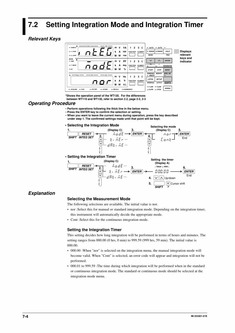
IM 253401-01E7-4
7.2 Setting Integration Mode and Integration Timer
Relevant Keys
SCALING AVG FILTER STORE RECALL HARMONICS
SAMPLE
V OVER
A OVER
MODE
RMS
V MEAN
DC
A
B
C
hour
hour
min
min sec
V VAm
Ak var
M W TIME
V PFm
Ak deg
M W %
FUNCTION
AUTO AUTO
MODE
1φ3W
V Hzm
Ak h
M W
TRIG
V RANGE A RANGE HOLD
ENTER
INTEGRATOR
START
HARMONICS MEMORY INTEG SET
STOP RESET
REMOTE
INTERFACE OUTPUT
LOCAL SETUP
hSHIFT
WIRING3φ4W
3φ3W
3V3A
ELEMENT
1 2 3
FUNCTION ELEMENT
1 2 3
FUNCTION ELEMENT
1 2 3
*Shows the operation panel of the WT130. For the differences between WT110 and WT130, refer to section 2.2, page 2-2, 2-3
Displays relevant keys and indicator
Operating Procedure
SHIFTRESET
INTEG SETENTER
3.(Display C)ENTER
5.Selecting the mode
(Display C)
2. 4.End
1.• Selecting the Integration Mode
• Perform operations following the thick line in the below menu.• Press the ENTER key to confirm the selection or setting.• When you want to leave the current menu during operation, press the key described
under step 1. The confirmed settings made until that point will be kept.
hour min
1.
SHIFTRESET
INTEG SETENTER
3.
(Display C) Setting the timer(Display A)
2.ENTER
6.
4. Up/down
5. Cursor shiftSHIFT
End
• Setting the Integration Timer
ExplanationSelecting the Measurement ModeThe following selections are available. The initial value is nor.
• nor :Select this for manual or standard integration mode. Depending on the integration timer,
this instrument will automatically decide the appropriate mode.
• Cont :Select this for the continuous integration mode.
Setting the Integration TimerThis setting decides how long integration will be performed in terms of hours and minutes. The
setting ranges from 000.00 (0 hrs, 0 min) to 999.59 (999 hrs, 59 min). The initial value is
000.00.
• 000.00 :When "nor" is selected on the integration menu, the manual integration mode will
become valid. When "Cont" is selected, an error code will appear and integration will not be
performed.
• 000.01 to 999.59 :The time during which integration will be performed when in the standard
or continuous integration mode. The standard or continuous mode should be selected at the
integration mode menu.

7-5IM 253401-01E
7
Integration
7.3 Displaying Integrated Values
Relevant Keys
SCALING AVG FILTER STORE RECALL HARMONICS
SAMPLE
V OVER
A OVER
MODE
RMS
V MEAN
DC
A
B
C
hour
hour
min
min sec
V VAm
Ak var
M W TIME
V PFm
Ak deg
M W %
FUNCTION
AUTO AUTO
MODE
1φ3W
V Hzm
Ak h
M W
TRIG
V RANGE A RANGE HOLD
ENTER
INTEGRATOR
START
HARMONICS MEMORY INTEG SET
STOP RESET
REMOTE
INTERFACE OUTPUT
LOCAL SETUP
hSHIFT
WIRING3φ4W
3φ3W
3V3A
ELEMENT
1 2 3
FUNCTION ELEMENT
1 2 3
FUNCTION ELEMENT
1 2 3
*Shows the operation panel of the WT130. For the differences between WT110 and WT130, refer to section 2.2, page 2-2, 2-3
Displays relevant keys and indicator
Operating Procedure1 Selecting the Display Function
Pressing the FUNCTION key on display A will select TIME (integration elapsed time).
Pressing the FUNCTION key on display C will select either Wh/Wh± (power) or Ah/Ah±(current).
DisplayA
C
FUNCTION
V A W VA var TIMEFUNCTION FUNCTION FUNCTION FUNCTION FUNCTION
A W V Hz A Hz Wh
AhAh±
Wh±
Wh±
Ah±
FUNCTION FUNCTION FUNCTION FUNCTION FUNCTION FUNCTION
FUNCTIONFUNCTIONFUNCTIONFUNCTIONFUNCTION
FUNCTION
FUNCTION
FUNCTION
&V
&A
*1
V
*1
*1
Wh± and Ah± will light twice. and are displayed on the top of display C.You can reverse the order by first pressing the SHIFT key followed by the FUNCTION key.*1 Displayed on WT110/WT130 with ROM version 2.01 or later.
2 Selecting the Input ElementSelect the input element by pressing the ELEMENT key on display C. The operation is the
same as the one described on page 5-1.
3 Starting IntegrationPress the START key. The START indicator will light, the integrated value will appear on
display C and the integration elapsed time will appear on display A.
START
4 Holding IntegrationPress the HOLD key. The HOLD indicator will light, and the displayed values will be held.
HOLD
5 Cancelling HOLD, and Updating the IntegrationContinuing from step 4, press the HOLD key once more, or press the SHIFT key followed by
the HOLD (TRIG) key. The HOLD indicator will extinguish and the displayed value will be
updated.
HOLDTRIG
6 Stopping IntegrationPress the STOP key. The START indicator will extinguish and the STOP indicator will light.
The displayed values will be held.
STOP
7 Resetting IntegrationPress the RESET key. The STOP indicator will extinguish and the values on display A and C
will be reset to 000.00.RESET

IM 253401-01E7-6
ExplanationMaximum Reading of the Display and UnitsMaximum reading
• Integrated value :999999 (–99999 in case of minus display)
• Integration elapsed time :999.59
• Units : Wh (power integration : watt hour value), Ah(current integration : ampere hour value)
• Prefix : m, k, M
Selecting the Display FunctionThe following selections are available.
• Wh :displays both the positive and negative watt hour values
• Wh± :displays the positive watt hour value
• Ah :displays the total ampere hour values
• Ah± :displays the total ampere hour values or the positive ampere hour value
For more details, refer to page 7-3.
Selecting the Input Element• 1/2/3 :Displays the measurement values of element 1/2/3
• ∑ :Displays the total integrated values of the elements installed. The method of computation
depends on the wiring method. The computation method changes to Wh or Ah for the active
power W (refer to chapter 15).
When the display function TIME is selected on display A, there is no element function available
on display A. Pressing the ELEMENT key on display A will result in an error code.
Update Hold FunctionAlthough the held values will not be updated, integration continues. When hold is being
cancelled, the integration results (values and time) corresponding to the point of cancellation,
will be displayed.
For details regarding the relation with the START/STOP key, refer to the following page.
Integration ResetResetting will result in returning the integration results to the status before integration started.
Pressing the RESET key is useful after integration has been stopped.
For details regarding the relation with the START/STOP key, refer to the following page.
Display in case of Integration OverWhen the maximum integration value has been reached (999999MWh/MAh or
–99999MWh/MAh), integration will stop and that result will be held on the display.
When the maximum integration time has been reached (up to 999hrs 59min), integration will
stop and that result will be held on the display.
7.3 Displaying Integrated Values

7-7IM 253401-01E
7
Integration
7.4 Precautions Regarding Use of IntegratorFunction
Relation between Integration Hold and the START/STOP keyWhen the HOLD key is pressed, the display and communication output of the integrated results
is being held while integration continues. The relation between this hold function and the
START/STOP key is as follows.
• Even when starting integration while the hold function is on, the display and communication
output will remain unchanged. Only canceling the hold function or activating a trigger
(pressing the SHIFT key followed by the HOLD (TRIG) key) will result in displaying or
outputting the integrated results of the time of cancellation.ONHOLDOFF
Displayed value
Integration preset time
(Dotted line shows integrated value)
START STOP RESET
• Even when stopping integration while the hold function is on, the displayed integrated value
will remain unchanged. However, as soon the hold function is turned off or a trigger is
activated, the integrated results of the time when integration was stopped will be displayed or
output.
Integration preset time
(Dotted line shows integrated value)
TRIGOFF
ONHOLD
ON ON ON
Displayed value
START STOP RESET
Relation between Integration Reset and the START/STOP keyThe relation between integration reset and the start/stop key is as follows.
Integrated value
Integration preset time
Interrupt
Start
Restart
Interrupt Reset
Restart
Auto stop Reset
Preset time for integration
START STOP START STOP RESET START RESET
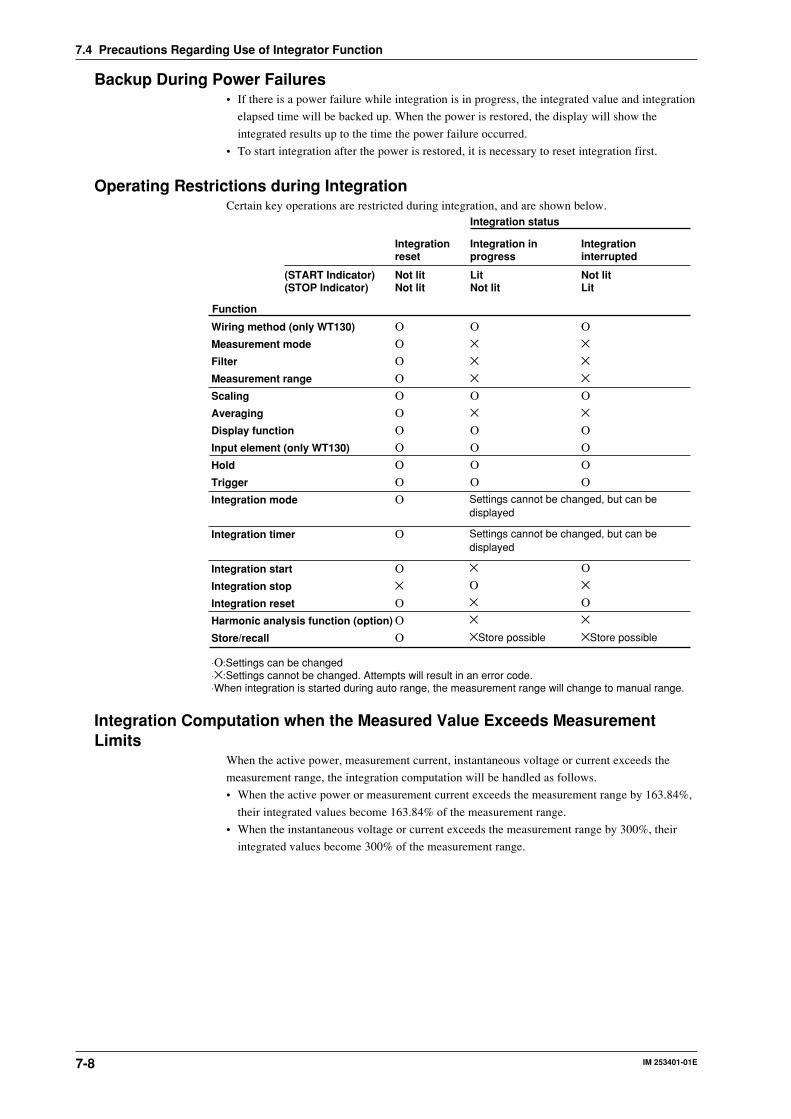
IM 253401-01E7-8
Backup During Power Failures• If there is a power failure while integration is in progress, the integrated value and integration
elapsed time will be backed up. When the power is restored, the display will show the
integrated results up to the time the power failure occurred.
• To start integration after the power is restored, it is necessary to reset integration first.
Operating Restrictions during IntegrationCertain key operations are restricted during integration, and are shown below.
Function
Integration status
Integration in progress
Integration reset
Integration interrupted
LitNot lit
Not litNot lit
Not litLit
ΟΟΟΟΟΟΟΟΟΟΟ
Ο
Ο×ΟΟΟ
Wiring method (only WT130)
Measurement mode
Filter
Measurement range
Scaling
Averaging
Display function
Input element (only WT130)
Hold
Trigger
Integration mode
Integration timer
Integration start
Integration stop
Integration reset
Harmonic analysis function (option)
Store/recall
(START Indicator)(STOP Indicator)
Ο×××Ο×ΟΟΟΟ
Ο×××Ο×ΟΟΟΟ
⋅Ο:Settings can be changed⋅×:Settings cannot be changed. Attempts will result in an error code.⋅When integration is started during auto range, the measurement range will change to manual range.
Ο×Ο××Store possible
×Ο×××Store possible
Settings cannot be changed, but can be displayed
Settings cannot be changed, but can be displayed
Integration Computation when the Measured Value Exceeds MeasurementLimits
When the active power, measurement current, instantaneous voltage or current exceeds the
measurement range, the integration computation will be handled as follows.
• When the active power or measurement current exceeds the measurement range by 163.84%,
their integrated values become 163.84% of the measurement range.
• When the instantaneous voltage or current exceeds the measurement range by 300%, their
integrated values become 300% of the measurement range.
7.4 Precautions Regarding Use of Integrator Function

IM 253401-01E 8-1
8
Using the H
armonic A
nalysis Function (optional)
8.1 Harmonic Analysis Function
This chapter explains the harmonics analysis function which can be applied to normal
measurements of voltage, current and power.
Analyzed/Displayed ItemsAfter having set the harmonic analysis function to ON, the harmonic component of voltage,
current, or active power, will be analyzed and displayed for one of the input elements (not
applicable for the WT110). Depending on the setting of the display function, the display
changes as follows.Display
A
Display function
No display function lit
FUNCTIONV A W V Hz
FUNCTION FUNCTION FUNCTION FUNCTIONA Hz
V A WFUNCTION FUNCTION FUNCTION
No display function litDisplay function V, A, W
FUNCTIONV A W PF
FUNCTION FUNCTION FUNCTION FUNCTION FUNCTIONV% A%
W%Vdeg A% V%AdegFUNCTION FUNCTIONFUNCTIONFUNCTIONFUNCTION
: Displays the harmonic order (1 to 50): Displays all rms values (computed values) of 1up to 50 components of voltage, current or active power
FUNCTION
VAW
PFV %A %V %A %W %
V deg
A deg
: Displays the voltage analysis value of the order shown on display A: Displays the current analysis value of the order shown on display A: Displays the active power analysis value of the order shown on display A: Displays the power factor of the fundamental (1st order): Displays the voltage harmonic distortion, proceeded by "t" on display B: Displays the current harmonic distortion, proceeded by "t" on display B: Displays the relative harmonic content of the voltage of the order shown on display A: Displays the relative harmonic content of the current of the order shown on display A: Displays the relative harmonic content of the active power of the order shown on
display A: · In case the 1st order (fundamental) is shown on display A:
Displays the phase angle between the voltage of the first order and the current of the first order
· In case the order 2 to 50 is shown on display A:Displays the phase angle between the voltage of the first order and each voltage of the 2nd to 50th order
: · In case the 1st order (fundamental) is shown on display A:Displays the phase angle between the voltage of the first order and the current of the first order (same as V deg)
· In case the order 2 to 50 is shown on display A:Displays the phase angle between the current of the first order and each current of the 2nd to 50th order
Display function : Displays all rms values (computed values) of 1 up to 50 components of voltage, current or active power.
: Displays the fundamental frequency of the voltage for PLL synchronization (displays the measurement value for only the selected voltage input)
: Displays the fundamental frequency of the current for PLL synchronization (displays the measurement value for only the selected current input)
V, A, W
V Hz
A Hz
DisplayB
DisplayC
Auto Range OperationThe up/down operation of the measurement range is the same as for normal measurement.
NoteWhen the range changes, the PLL synchronization will be re-established. Therefore, correctmeasurement values might not be obtained which might result in an unstable range. If this is the case, setthe measurement range to a fixed range.
Display Renewal RateHarmonic analysis data will be updated approx. every 3 seconds.

IM 253401-01E8-2
Holding the DisplayWhen you use the display hold function and change the order or display function while the
harmonic analysis function is ON, you can display the harmonic data analyzed at the
corresponding time.
Updating the Displayed DataThe display can be updated in the same way as for normal measurement.
Overrange/Error DisplaysIn case the fundamental frequency of the PLL synchronization signal lies outside the
measurement range. Display B will show “FrqEr”.Note
The measurement range of the fundamental frequency of the harmonic analysis function is different fromthe frequency measurement range of normal measurement. Refer to Ch. 15 for more details.
Display in case of OverrangeThe overrange display (being the same as for normal measurement) will appear when all rms
values of the 1st to 50th order reach the following value:
• 140% of the rated range for the 600V voltage range, or 20A current range
• 200% of the rated range for voltage ranges except 600V, or current ranges except 20A
The relative harmonic content and harmonic distortion are related to voltage and current.
Error DisplayThe power factor or phase angle will show PFErr or dEGEr when either the voltage, range or
power exceeds 200% of the range.
Computation Over DisplayAppears in the same way as for normal measurement.
Dot DisplayThe display will show dots in any of the following cases.
• When there are no more analysis data to be displayed during harmonic analysis;
• Soon after the harmonic analysis function has been turned ON;
• When the PLL synchronization is being re-established;
• Until the initial analysis data are obtained, after having changed the settings;
• When the analysis order which depends on the fundamental frequency, exceeds the upper
limit, after having set the order at display A;
• When the display function is set to relative harmonic content (%) and the order at display A is
set to 1;
• When the PLL source is set to voltage, and an attempt is made to display the current
frequency (AHz); or when the PLL source is set to current, and an attempt is made to display
the voltage frequency (VHz);
• When an element which is not assigned to the measurement object, is selected. However,
since the frequency is not related to the element setting, the fundamental frequency
designated as the PLL source can be displayed.
Averaging FunctionExponential averaging is performed with an attenuation constant of 8.
Output to an External PlotterUsing the GP-IB or RS-232-C interface, harmonic analysis data can be printed as value or graph
on an external plotter.
Effect of AliasingThis instrument is not equipped with an internal aliasing filter. Due to aliasing accidental errors
may occur under the following circumstances.
Fundamental frequency f in Hz
40≤f<70 errors may occur in case of harmonic components of the 256th or higher;
70≤f<130 errors may occur in case of harmonic components of the 128th or higher;
130≤f<250 errors may occur in case of harmonic components of the 64th or higher;
250≤f≤440 errors may occur in case of harmonic components of the 32nd or higher.
8.1 Harmonic Analysis Function

IM 253401-01E 8-3
8
Using the H
armonic A
nalysis Function (optional)
8.2 Setting the Element, PLL Source and HarmonicDistortion Method
Relevant Keys
SCALING AVG FILTER STORE RECALL HARMONICS
SAMPLE
V OVER
A OVER
MODE
RMS
V MEAN
DC
A
B
C
hour
hour
min
min sec
V VAm
Ak var
M W TIME
V PFm
Ak deg
M W %
FUNCTION
AUTO AUTO
MODE
1Φ3W
V Hzm
Ak h
M W
TRIG
V RANGE A RANGE HOLD
ENTER
INTEGRATOR
START
HARMONICS MEMORY INTEG SET
STOP RESET
REMOTE
INTERFACE OUTPUT
LOCAL SETUP
hSHIFT
WIRING3Φ3W
3Φ 4W 3V3A
ELEMENT
1 2 3
FUNCTION ELEMENT
1 2 3
FUNCTION ELEMENT
1 2 3
*Shows the operation panel of the WT130. For the differences between WT110 and WT130, refer to section 2.2, page 2-2, 2-3
Displays relevant keys and indicator
Operating Procedure
SHIFTSTART
HARMONICS
ENTER3.
(Display C)
2.Setting the element
(Display C)
4.ENTER
5.
End
1.
• Setting the Element
• Perform operations following the thick line in the below menu.• Press the ENTER key to confirm the selection or setting.• When you want to leave the current menu during operation, press the key described under step 1. The confirmed settings made until that point will be kept.
SHIFTSTART
HARMONICS
ENTER3.
(Display C)
2.
Setting the PLL source(Display C)
4.ENTER
5.
End
1.
• Setting the PLL source
SHIFTSTART
HARMONICS
ENTER3.
(Display C)
2.
Setting the computation method(Display C)
4.ENTER
5.
End
1.
• Setting the Computation Method of the Harmonic Distortion

IM 253401-01E8-4
ExplanationSetting the ElementOnly one input element should be set for harmonic analysis. The initial value is EL1. At the
WT110 the element setting menu does not appear.
• EL1 : Element 1 will be used for analysis;
• EL2 : Element 2 will be used for analysis; In case of the 253502, this menu will not be shown;
• EL3 : Element 3 will be used for analysis.
Setting the PLL sourceFor harmonic analysis, it is necessary to select the input to be used as the fundamental
frequency (PLL source) for synchronization. (PLL stands for Phase Locked Loop.)
• V1: Sets the voltage of element 1 as the PLL source;
• A1: Sets the current of element 1 as the PLL source;
• V2: Sets the voltage of element 2 as the PLL source;
• A2: Sets the current of element 2 as the PLL source;
• V3: Sets the voltage of element 3 as the PLL source;
• A3: Sets the current of element 3 as the PLL source.
Note• If the fundamental frequency of the PLL source cannot be measured due to fluctuations or distortion, it is
not possible to obtain correct measurement results. In this case, it is suggested that voltage withrelatively small distortion be selected as the PLL source.
• It is recommended to turn ON the filter in cases where the fundamental frequency is 300Hz or less andhigh frequency components are present.
• If the amplitude of the input signal selected as the PLL source is smaller than the rated range value, PLLsynchronization may sometimes fail. In this case, it is suggested that a suitable measurement range beselected so that the input level exceeds 30% of the rated range value.
Setting the Computation Method of Harmonic DistortionThe computation method of harmonic distortion can be selected from the following two. In the
following explanation a maximum of 50 analysis orders is assumed. In case of a maximum less
than 50, computation/display will be performed up to that order.
• iEC : Computes the ratio of the rms value of the 2nd to 50th order component to that of the
fundamental (1st order).
• CSA : Computes the ratio of the rms value of the 2nd to 50th order component to that of the
rms value of the 1st to 50th component.
Computation EquationIn case of iEC
k=2
n
(Ck)2 /C1
In case of CSA
k=2
n
(Ck)2 /k=1
n
(Ck)2
C1 : Fundamental component (1st order)Ck : Fundamental or harmonic componentk : Analysis ordern : Maximum order. The maximum order depends on the fundamental frequency of the input set
as the PLL source. Refer to Ch. 15 for more details.
8.2 Setting the Element, PLL Source and Harmonic Distortion Method
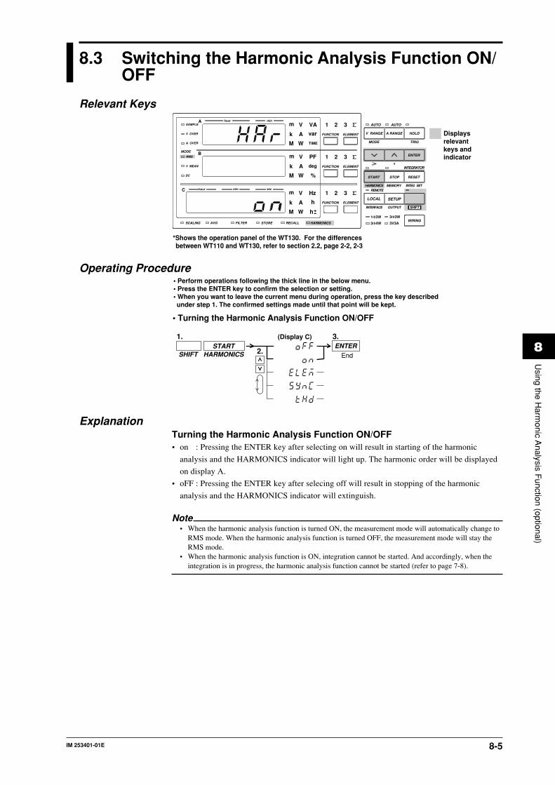
IM 253401-01E 8-5
8
Using the H
armonic A
nalysis Function (optional)
8.3 Switching the Harmonic Analysis Function ON/OFF
Relevant Keys
SCALING AVG FILTER STORE RECALL HARMONICS
SAMPLE
V OVER
A OVER
MODE
RMS
V MEAN
DC
A
B
C
hour
hour
min
min sec
V VAm
Ak var
M W TIME
V PFm
Ak deg
M W %
FUNCTION
AUTO AUTO
MODE
1Φ3W
V Hzm
Ak h
M W
TRIG
V RANGE A RANGE HOLD
ENTER
INTEGRATOR
START
HARMONICS MEMORY INTEG SET
STOP RESET
REMOTE
INTERFACE OUTPUT
LOCAL SETUP
hSHIFT
WIRING3Φ3W
3Φ4W 3V3A
ELEMENT
1 2 3
FUNCTION ELEMENT
1 2 3
FUNCTION ELEMENT
1 2 3
*Shows the operation panel of the WT130. For the differences between WT110 and WT130, refer to section 2.2, page 2-2, 2-3
Displays relevant keys and indicator
Operating Procedure
SHIFTSTART
HARMONICS
(Display C)
2.ENTER
3.
End
1.
• Turning the Harmonic Analysis Function ON/OFF
• Perform operations following the thick line in the below menu.• Press the ENTER key to confirm the selection or setting.• When you want to leave the current menu during operation, press the key described under step 1. The confirmed settings made until that point will be kept.
ExplanationTurning the Harmonic Analysis Function ON/OFF• on : Pressing the ENTER key after selecting on will result in starting of the harmonic
analysis and the HARMONICS indicator will light up. The harmonic order will be displayed
on display A.
• oFF : Pressing the ENTER key after selecing off will result in stopping of the harmonic
analysis and the HARMONICS indicator will extinguish.
Note• When the harmonic analysis function is turned ON, the measurement mode will automatically change to
RMS mode. When the harmonic analysis function is turned OFF, the measurement mode will stay theRMS mode.
• When the harmonic analysis function is ON, integration cannot be started. And accordingly, when theintegration is in progress, the harmonic analysis function cannot be started (refer to page 7-8).

IM 253401-01E8-6
8.4 Setting the Harmonic Order and Displaying theResults of Harmonic Analysis
Relevant Keys
SCALING AVG FILTER STORE RECALL HARMONICS
SAMPLE
V OVER
A OVER
MODE
RMS
V MEAN
DC
A
B
C
hour
hour
min
min sec
V VAm
Ak var
M W TIME
V PFm
Ak deg
M W %
FUNCTION
AUTO AUTO
MODE
1Φ3W
V Hzm
Ak h
M W
TRIG
V RANGE A RANGE HOLD
ENTER
INTEGRATOR
START
HARMONICS MEMORY INTEG SET
STOP RESET
REMOTE
INTERFACE OUTPUT
LOCAL SETUP
hSHIFT
WIRING3Φ3W
3Φ4W 3V3A
ELEMENT
1 2 3
FUNCTION ELEMENT
1 2 3
FUNCTION ELEMENT
1 2 3
*Shows the operation panel of the WT130. For the differences between WT110 and WT130, refer to section 2.2, page 2-2, 2-3
Displays relevant keys and indicator
Operating ProcedureThe following operations assume that the harmonic analysis function is turned ON.
Setting the Harmonics Order1. Light up the display function indicator of display A.
DisplayA Light up display function V A W
FUNCTION FUNCTION FUNCTION FUNCTION
2. Set the harmonics order.
(Display A)
Displaying the Values of Harmonic AnalysisDisplays each analysis value after having set the display function of either display B or C.
FUNCTIONV A W PF
FUNCTION FUNCTION FUNCTION FUNCTION FUNCTIONV% A%
W%Vdeg A% V%AdegFUNCTION FUNCTIONFUNCTIONFUNCTIONFUNCTION
DisplayB
FUNCTIONV A W V Hz
FUNCTION FUNCTION FUNCTION FUNCTIONA Hz
DisplayC
ExplanationSetting the Order of HarmonicsThe maximum order for which analysis results can be displayed varies depending on the
frequency of the fundamental.
Example
• When the fundamental frequency is 50Hz, up to 50 orders can be displayed;
• When the fundamental frequency is 400Hz, up to 30 orders can be displayed.
When an order is set exceeding the maximum order, display B will change to the dot display.
Refer to Ch. 15 for more details on upper limits of analysis orders.

IM 253401-01E 8-7
8
Using the H
armonic A
nalysis Function (optional)
Displaying the Results of Harmonic AnalysisDepending on the setting of display function of display B and C, the analyzed items will appear
on the display as follows. In the following explanation a maximum of 50 analysis orders is
assumed. In case of a maximum less than 50, computation/display will be performed up to that
order.
Display BV : Shows the analysis value of the voltage corresponding to the order shown on display A;
A : Shows the analysis value of the current corresponding to the order shown on display A;
W : Shows the analysis value of the active power corresponding to the order shown on
display A;
PF : Shows the power factor of the fundamental (1st order);
V% : Shows the harmonic distortion of the voltage followed by the character “t”; Two
computation methods are available; Refer to page 8-4 for details. The display range is
0.00 to 99.99 and 100.0 to 999.9%.
A% : Shows the harmonic distortion of the current followed by the character “t”; Two
computation methods are available; Refer to page 8-4 for details. The display range is
0.00 to 99.99 and 100.0 to 999.9%.
V% : Shows the relative harmonic content of the voltage corresponding to the order shown
on display A; The display range is 0.00 to 99.99 and 100.0 to 999.9%.
A% : Shows the relative harmonic content of the current corresponding to the order shown on
display A; The display range is 0.00 to 99.99 and 100.0 to 999.9%.
W% : Shows the relative harmonic content of the active power corresponding to the order
shown on display A; The display range is 0.00 to ±99.99 and ±100.0 to ±999.9%.
V deg : In case the fundamental (1st order) is shown on display A
Shows the phase angle between the 1st order of the current and the 1st order of the
voltage. G (phase lag) or d (phase lead) will also be displayed.
In case the 2nd to 50th order is shown on display A
Shows the phase angle between the 1st order of the voltage and the 2nd to 50th order of
each voltage. A – (minus) will be displayed in front of the order only when the 2nd to
50th order is phase-lagged. The display range is –180.0 to 180.0 deg.
A deg : In case the fundamental (1st order) is shown on display A
Shows the same as in case of V deg.
In case the 2nd to 50th order is shown on display A
Shows the phase angle between the 1st order of the current and the 2nd to 50th order of
each current. A – (minus) will be displayed in front of the order only when the 2nd to
50th order is phase-lagged. The display range is –180.0 to 180.0 deg.
Display CV : Shows each rms (computed) value of the 1st to 50th harmonic component of the
voltage;
A : Shows each rms (computed) value of the 1st to 50th harmonic component of the
current;
W : Shows each rms (computed) value of the 1st to 50th harmonic component of the active
power;
8.4 Setting the Harmonic Order and Displaying the Results of Harmonic Analysis

IM 253401-01E8-8
8.4 Setting the Harmonic Order and Displaying the Results of Harmonic Analysis
Computation Equation
V=k=1
n
(Vk)2
A=k=1
n
(Ak)2
W=k=1
n
Wk
Vk, Ak, Wk :Each component of 1st to 50th order of voltage, current and active power;k :Analysis ordern :Maximum order. The maximum order depends on the fundamental frequency of the
input set as the PLL source. Refer to Ch. 15 for more details.
V Hz : Shows the fundamental frequency of the voltage of the PLL source. This frequency
applies only to the element selected as PLL source. For details regarding the PLL source
setting, refer to page 8-3. The measurement range is the same as in case of normal
measurement.
The range of fundamental frequencies in case of harmonic analysis is 40 to 440Hz.
However, depending on internal timing, there are cases where measurements in the 20 to
700Hz range can be performed.
A Hz : Shows the fundamental frequency of the current of the PLL source. The rest is the same
as in case of V Hz.
Note• In case you select an input element using the ELEMENT key which is not the assigned element for the
harmonic analysis or you selected a display function which is not being analyzed/measured, then the bardisplay appears.
• When the harmonic analysis function is turned ON on the WT130, pressing the ELEMENT key will notresult in moving to ∑.
• When pressing the FUNCTION key on display A, and the display function becomes V, A or W, thendisplay A will show the same analysis items as the V, A or W shown on display C.
• Characteristics such as maximum reading, display range, units, etc. which are not described on theprevious page, are not different from the characteristics of normal measurement.
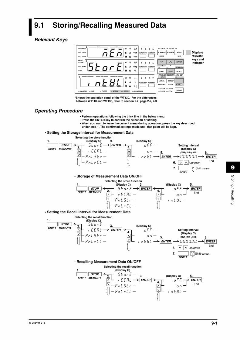
IM 253401-01E 9-1
9
Storing / R
ecalling
9.1 Storing/Recalling Measured Data
Relevant Keys
SCALING AVG FILTER STORE RECALL HARMONICS
SAMPLE
V OVER
A OVER
MODE
RMS
V MEAN
DC
A
B
C
hour
hour
min
min sec
V VAm
Ak var
M W TIME
V PFm
Ak deg
M W %
FUNCTION
AUTO AUTO
MODE
1Φ3W
V Hzm
Ak h
M W
TRIG
V RANGE A RANGE HOLD
ENTER
INTEGRATOR
START
HARMONICS MEMORY INTEG SET
STOP RESET
REMOTE
INTERFACE OUTPUT
LOCAL SETUP
hSHIFT
WIRING3Φ4W
3Φ3W
3V3A
ELEMENT
1 2 3
FUNCTION ELEMENT
1 2 3
FUNCTION ELEMENT
1 2 3
*Shows the operation panel of the WT130. For the differences between WT110 and WT130, refer to section 2.2, page 2-2, 2-3
Displays relevant keys and indicator
Operating Procedure
• Setting the Storage Interval for Measurement Data
1.
SHIFTSTOP
MEMORYENTER
3.Selecting the store function
(Display C)
2.Setting interval
(Display C)hour min sec
ENTER8.
End
(Display C)
4.
ENTER5.
6. Up/down
7. Shift cursorSHIFT
• Perform operations following the thick line in the below menu.• Press the ENTER key to confirm the selection or setting.• When you want to leave the current menu during operation, press the key described
under step 1. The confirmed settings made until that point will be kept.
1.
SHIFTSTOP
MEMORYENTER
3.Selecting the store function
(Display C)
2.
(Display C)
4.ENTER
5.
End
• Storage of Measurement Data ON/OFF
1.
SHIFTSTOP
MEMORYENTER
3.
Selecting the recall function(Display C)
2.Setting Interval
(Display C)hour min sec
ENTER8.
End
(Display C)
4.
ENTER5.
6. Up/down
7. Shift cursorSHIFT
• Setting the Recall Interval for Measurement Data
1.
SHIFTSTOP
MEMORYENTER
3.
Selecting the recall function(Display C)
2. (Display C)
4.ENTER
5.
End
• Recalling Measurement Data ON/OFF

IM 253401-01E9-2
ExplanationStoring Measured Data (Storing into Internal Memory)The number of blocks which can be stored into the internal memory is as follows.
Model In case of normal measurement In case of harmonic analysis253401 600 Blocks 30 Blocks
253402 300 Blocks 30 Blocks
353503 200 Blocks 30 Blocks
Items which can be storedOne block consists of all data which are obtained when the display is updated once. The data
number increases by the number of used input elements and therefore the number of blocks
that can be stored depends on the model as described above.
• when storing normal measured data (harmonic analysis function is turned OFF)
Each measured/integrated data of normal measurement will be stored. However, only either
the voltage frequency or current frequency will be stored *1.
*1 When either the V Hz or A Hz display function is lit, the frequency of that function will
be stored. When neither is lit, the frequency of the latest lit display function will be
stored. Regarding the element, the frequency of the latest set element will be stored.
• when storing harmonic analysis data (harmonic analysis function is turned ON)
Normal measured data will not be stored. All analysis data of the elements which are being
used for analysis, will be stored.
Aborting Storage• when all the above described blocks are full;
• when during the storage process “oFF” is selected at the store ON/OFF setting.
Setting the Storage IntervalSets the time during which storage will be carried out.
• when storing normal measured data (harmonic analysis function is turned OFF)
• Setting range : 00.00.00 (0hrs, 0min, 0sec) to 99.59.59 (99hrs, 59min, 59sec)
• Initial value : 00.00.00
When the setting is 00.00.00, the interval will become 250ms.
• when storing harmonic analysis data (harmonic analysis function is turned ON)
• Setting range : 00.00.00 (0hrs, 0min, 0sec) to 99.59.59 (99hrs, 59min, 59sec)
• Initial value : 00.00.00
When the setting ranges from 00.00.00 to 00.00.03, the interval will become 3s; from
00.00.04 to 00.00.06, the interval will become 6s; from 00.00.07 to 00.00.09, the interval will
become 9s; in other cases, the set interval will be valid.
Storage ON/OFFAfter having set the storage interval, select the store menu once again. The initial value is oFF.
• on : Storing will start by pressing the ENTER key after selecting “on”; the STORE
indicator will light while storage is in progress.
• oFF : Storing will stop by pressing the ENTER key after selecting “oFF”; the STORE
indicator will extinguish.Note
• After storing has been stopped and storing is restarted, the existing data in the memory will beoverwritten. Previous data will therefore be lost.
• Stored data will be kept even after the power has been turned OFF because of the internal lithiumbattery.
• When integrated values are not present, the dot display will be stored as data, whereas 000.00 will bestored as integration preset time.
• When the fundamental frequency is high and up to 50 windows of harmonic analysis data are notpresent, the dot display will be stored as data.
• While storage is in progress, several settings cannot be changed, such as switching the harmonic analysisfunction ON/OFF, changing the related input element, the PLL source, the harmonic distortion factorcomputation method, nor can scaling, averaging and filter settings be changed, nor integration mode,integration time and storage interval.
• If you press the HOLD key while storing data, the measurement operation and the counting operation ofthe store interval are suspended. The storage operation itself is also suspended. However, if integrationis in progress, measurement and integration continues internally.
9.1 Storing/Recalling Measured Data

IM 253401-01E 9-3
9
Storing / R
ecalling
9.1 Storing/Recalling Measured Data
Recalling Measured Data (Retrieving Data from the Internal Memory)After displaying data stored in the internal memory on the panel, you can use all display
functions and carry out integration and display these data. Furthermore, by using the
communication function, data can be output.
Items which can be recalledall data which can be stored.
Aborting Recalling- when all stored data are retrieved;
- when during the recall process “oFF” is selected at the store ON/OFF setting.
Setting the Recalling IntervalSets the time during which recalling will be carried out.
• Setting range : 00.00.00 (0hrs, 0min, 0sec) to 99.59.59 (99hrs, 59min, 59sec)
• Initial value : 00.00.00
When recalling normal measured data, the interval will become 250ms when the setting is
00.00.00.
When recalling harmonic analysis data, the interval will become 1s when the setting is 00.00.00.
Recalling ON/OFFAfter having set the recalling interval, select the recall menu once again. The initial value is
oFF.
• on : Recalling will start by pressing the ENTER key after selecting “on”; the RECALL
indicator will light while recalling is in progress.
• oFF : Recalling will stop by pressing the ENTER key after selecting “oFF”; the RECALL
indicator will extinguish
Note• During recalling, the measurement conditions/range *1 will become as those of the data being recalled.
After recalling finishes, the original measurement conditions will return.*1 measurement range, measurement mode, filter ON/OFF, scaling ON/OFF, scaling values, averaging
ON/OFF, averaging mode, averaging values, integration mode, integration time, harmonic analysisfunction ON/OFF, PLL source, input element, computation method of harmonic distortion factor
• When recalling data to a personal computer by communication interface, data might be cut due to thedata length or used personal computer. In such a case, increase the recalling interval.
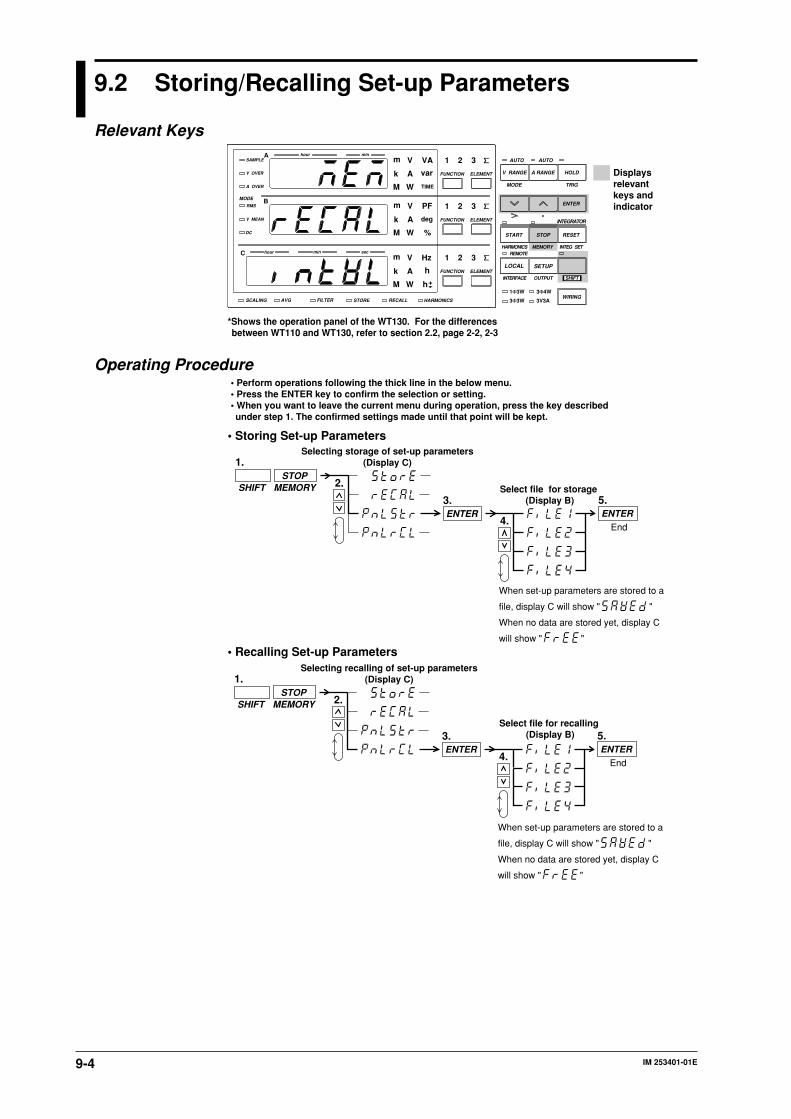
IM 253401-01E9-4
9.2 Storing/Recalling Set-up Parameters
Relevant Keys
SCALING AVG FILTER STORE RECALL HARMONICS
SAMPLE
V OVER
A OVER
MODE
RMS
V MEAN
DC
A
B
C
hour
hour
min
min sec
V VAm
Ak var
M W TIME
V PFm
Ak deg
M W %
FUNCTION
AUTO AUTO
MODE
1Φ3W
V Hzm
Ak h
M W
TRIG
V RANGE A RANGE HOLD
ENTER
INTEGRATOR
START
HARMONICS MEMORY INTEG SET
STOP RESET
REMOTE
INTERFACE OUTPUT
LOCAL SETUP
hSHIFT
WIRING3Φ3W
3Φ4W
3V3A
ELEMENT
1 2 3
FUNCTION ELEMENT
1 2 3
FUNCTION ELEMENT
1 2 3
*Shows the operation panel of the WT130. For the differences between WT110 and WT130, refer to section 2.2, page 2-2, 2-3
Displays relevant keys and indicator
Operating Procedure
1.
SHIFTSTOP
MEMORY
ENTER3.
Selecting storage of set-up parameters(Display C)
2.Select file for storage
(Display B)
4.ENTER
5.
End
• Storing Set-up Parameters
• Perform operations following the thick line in the below menu.• Press the ENTER key to confirm the selection or setting.• When you want to leave the current menu during operation, press the key described under step 1. The confirmed settings made until that point will be kept.
When set-up parameters are stored to a
file, display C will show " "
When no data are stored yet, display C
will show " "
1.
SHIFTSTOP
MEMORY
ENTER3.
Selecting recalling of set-up parameters(Display C)
2.
Select file for recalling (Display B)
4.ENTER
5.
End
• Recalling Set-up Parameters
When set-up parameters are stored to a
file, display C will show " "
When no data are stored yet, display C
will show " "
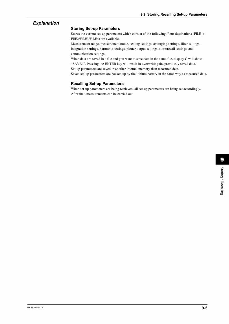
IM 253401-01E 9-5
9
Storing / R
ecalling
9.2 Storing/Recalling Set-up Parameters
ExplanationStoring Set-up ParametersStores the current set-up parameters which consist of the following. Four destinations (FiLE1/
FilE2/FiLE3/FiLE4) are available.
Measurement range, measurement mode, scaling settings, averaging settings, filter settings,
integration settings, harmonic settings, plotter output settings, store/recall settings, and
communication settings.
When data are saved in a file and you want to save data in the same file, display C will show
“SAVEd”. Pressing the ENTER key will result in overwriting the previously saved data.
Set-up parameters are saved in another internal memory than measured data.
Saved set-up parameters are backed up by the lithium battery in the same way as measured data.
Recalling Set-up ParametersWhen set-up parameters are being retrieved, all set-up parameters are being set accordingly.
After that, measurements can be carried out.

IM 253401-01E 10-1
10
Using E
xternal In / Output
10.1 Remote Control and D/A Output Connector(optional)
Using the remote control and the D/A output connector, this instrument can be remotely
controlled and D/A output can be done. The connector’s pin sequence and signal assignment is
as follows.
Connector’s Pin Sequence WT110 : 253401 WT130 : 253502, 253503
1 12
2413
(Rear panel)
Pin Assignment/DA4 specifications (for WT110: 253401 only)remote control, 4 channel D/A output
123456789
101112
131415161718192021222324
DIGITAL COMEXT HOLD EXT START EXT RESET No Connection
DA 3chDA 1chDA COM
DIGITAL COMEXT TRIG EXT STOP INTEG BUSY
DA 4chDA 2chDA COM
Pin No. Signal Pin No. Signal
(Output) (Output)
(Output) (Output)
(Input) (Input) (Input)
(Input) (Input) (Output)
No ConnectionNo ConnectionNo ConnectionNo Connection
No ConnectionNo ConnectionNo ConnectionNo ConnectionNo Connection
/DA12 specifications (for WT130: 253502, 253503)remote control, 12 channel D/A output
123456789
101112
131415161718192021222324
DIGITAL COMEXT HOLD EXT START EXT RESET
DA COM
No ConnectionDA 11ch DA 9ch DA 7ch DA 5ch DA 3ch DA 1ch
DIGITAL COMEXT TRIGEXT STOPINTEG BUSY
DA COM
DA 12ch DA 10ch DA 8ch DA 6ch DA 4ch DA 2ch
Pin No. Signal Pin No. Signal
(Output) (Output) (Output) (Output) (Output) (Output)
(Output) (Output) (Output) (Output) (Output) (Output)
(Input) (Input) (Input)
(Output) (Input) (Input)
No Connection
/CMP specifications (for WT110/130: 253401, 253502, 253503)remote control, 4 channel D/A output, 4 channel comparator output
123456789
101112
131415161718192021222324
Pin No. Signal Pin No. SignalDIGITAL COMEXT HOLD
No ConnectionDA 3ch
DA COM
DA 1ch
RELAY 3ch NCCOMNO
RELAY 1ch NCCOMNO
DIGITAL COMEXT TRIG
DA 4ch
DA COM
DA 2ch
RELAY 4ch NCCOMNO
RELAY 2ch NCCOMNO
(Output)
(Input) (Input)
(Output)(Output)(Output)
No Connection
WARNINGThe connectors used in this function have protective covers. When thecovers are removed or when using connectors, the voltage ratings across
the measuring input and the ground become as follows:Voltage across A, ±(V and A side) input terminals and ground 400 Vrms max.Voltage across V terminal and ground 600 Vrms max.
Put the protective cover on the connector when this function is not used.
1
12
13
24
(Rear panel)
0.01µF
+5V
Remote control:input circuit
TTL levelLH
+5V
Remote control:output circuit
10kW100Ω
100Ω
:0 to 0.8V:2.0 to 5V
TTL levelLH
:0 to 0.4V(8mA):2.4 to 5V(–400µA)
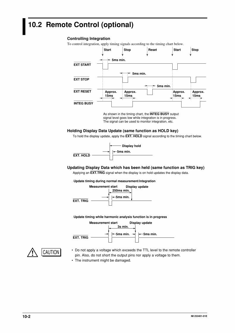
IM 253401-01E10-2
10.2 Remote Control (optional)
Controlling IntegrationTo control integration, apply timing signals according to the timing chart below.
EXT START
EXT STOP
EXT RESET
INTEG BUSY
StopStart Reset StopStart
5ms min.
5ms min.
5ms min.
Approx.15ms
Approx. 15ms
Approx.15ms
Approx. 15ms
As shown in the timing chart, the INTEG BUSY output signal level goes low while integration is in progress.The signal can be used to monitor integration, etc.
Holding Display Data Update (same function as HOLD key)
5ms min.
Display hold
EXT. HOLD
To hold the display update, apply the EXT. HOLD signal according to the timing chart below.
Updating Display Data which has been held (same function as TRIG key)
Measurement start
EXT. TRIG5ms min.
250ms min.Display update
EXT. TRIG 5ms min.
Display update
5ms min.
3s min.Measurement start
⋅Update timing during normal measurement/integration
⋅Update timing while harmonic analysis function is in progress
Applying an EXT.TRIG signal when the display is on hold updates the display data.
CAUTION • Do not apply a voltage which exceeds the TTL level to the remote controllerpin. Also, do not short the output pins nor apply a voltage to them.
• The instrument might be damaged.

IM 253401-01E 10-3
10
Using E
xternal In / Output
10.3 D/A Output (optional)
Relevant Keys
SCALING AVG FILTER STORE RECALL HARMONICS
SAMPLE
V OVER
A OVER
MODE
RMS
V MEAN
DC
A
B
C
hour
hour
min
min sec
V VAm
Ak var
M W TIME
V PFm
Ak deg
M W %
FUNCTION
AUTO AUTO
MODE
1Φ3W
V Hzm
Ak h
M W
TRIG
V RANGE A RANGE HOLD
ENTER
INTEGRATOR
START
HARMONICS MEMORY INTEG SET
STOP RESET
REMOTE
INTERFACE OUTPUT
LOCAL SETUP
hSHIFT
WIRING3Φ4W
3Φ3W
3V3A
ELEMENT
1 2 3
FUNCTION ELEMENT
1 2 3
FUNCTION ELEMENT
1 2 3
*Shows the operation panel of the WT130. For the differences between WT110 and WT130, refer to section 2.2, page 2-2, 2-3
Displays relevant keys and indicator
Operating Procedure
• Setting D/A Output
1.
SHIFTSETUP
OUTPUT
ENTER3.
Selecting D/A output function(Display C)
2.
4.
Selecting output format(Display C)
ENTER5.
End (Selecting default setting)
Selecting output channel
(Display B)
6.,12.
ENTER7.
Selecting output item(Display C)
8.
ENTER
ENTER13.
End
11.
*1
ENTER
*2
8. Sets the A column
9. Moves to the B column
10. Select from 1 to 4 *3SHIFT
(Select desired item)
• Perform operations following the thick line in the below menu.• Press the ENTER key to confirm the selection or setting.• When you want to leave the current menu during operation, press the key described under step 1. The confirmed settings made until that point will be kept.
*1 When you press the key at step 11, the output channel displayed at display B will change to the next channel, i.e. from ch1 to ch2 and so forth.
*2 The number of channels depends on the installed options. In case of option /DA4 or /CMP, there are four channels, in case of option /DA12, there are twelve channels available.
*3 Depends on the model number. Refer to the specifications section for more details.
*4 Displayed on WT110/WT130 with ROM version2.01 or later.
A B
*4
*4
*4

IM 253401-01E10-4
• Setting Preset Integration Time
hour min
1.
SHIFTRESET
INTEG SET
ENTER3.
Selecting preset integration time(Display C)
Preset time setting(Display A)2.
ENTER6.
4. Up/down
5. cursor shiftSHIFT
End
ExplanationD/A OutputVoltage, current, active power, apparent power, reactive power, power factor, phase angle,
harmonic analysis data and integrated data values will be output as a 5V FS analog voltage. The
number of items which can be output (number of output channels) depends on the installed
options.
Default Setting of the Output FormatThe default items which will be output can be selected as follows.
• dFLt-n (normal measurement values are set as default)Select this when you want to output normal measurement values. Which items are output to
which channel is described below.
OptionModel
ch1ch2ch3ch4ch5ch6ch7ch8ch9ch10ch11ch12
/DA4253401
/DA12 /CMP253502 253503 253401 253502 253503
VAWHz
V1-V3ΣVA1-A3ΣAW1-W3ΣW
V1V2V3ΣVA1A2A3ΣAW1W2W3ΣW
VAWHz
These channels cannot be set.
These channels cannot be set.
*1 *1
*1
*2
:When either the function indicator of V Hz or A Hz is lit, the frequency corresponding to the lit function indicator will be output. When neither indicator is lit, the frequency of the last used function indicator will be output. The frequency of the last assigned element will be output.
:The number corresponds to input element 1, 2, or 3.
*2*2V1A1W1Hz *1
V1A1W1Hz *1
*2 *2
Output channel
• dFLt-i (integration measurement values are set as default)Select this when you want to output integration measurement values. Which items are output
to which channel is described below.
OptionModel
ch1ch2ch3ch4ch5ch6ch7ch8ch9ch10ch11ch12
/DA4253401
/DA12 /CMP253502 253503 253401 253502 253503
WWhAhHz
W1-W3ΣWWh1-Wh3ΣWhAh1-Ah3ΣAh
W1W2W3ΣWWh1Wh2Wh3ΣWhAh1Ah2Ah3ΣAh
WWhAhHz
These channels cannot be set.
These channels cannot be set.
*1 *1
*1
*2
:When either the function indicator of V Hz or A Hz is lit, the frequency corresponding to the lit function indicator will be output. When neither indicator is lit, the frequency of the last used function indicator will be output. The frequency of the last assigned element will be output.
:The number corresponds to input element 1, 2, or 3.
*2*2W1Wh1Ah1Hz *1
W1Wh1Ah1Hz *1
*2 *2
Output channel
10.3 D/A Output (optional)

IM 253401-01E 10-5
10
Using E
xternal In / Output
Selecting the Desired Item of the Output FormatThe items to be output are set per each output channel.
• Setting the output channelThe number of channels depends on the installed options and can be selected from the
following.
• /DA4 : 4 channels
• /DA12: 12 channels
• /CMP : 4 channels
• Setting the output function (corresponds to column A in the procedure)The output function can be set to any of the following.
V (voltage), A (current), P (active power), VAr (reactive power), VA (apparent power), PF
(power factor), VFrq (voltage frequency), AFrq (current frequency), Ph (total Watt-hour Wh),
Ah (total Ampere-hour), dEG (phase angle), VP(peak value of voltage)*2, AP(peak value of
current)*2, MATH(computation)*2, Ph+ (positive watt hour value Wh+), Ph– (negative watt
hour value Wh–), Ah+ (positive ampere hour value*1), Ah– (negative ampere hour value*1),
– – – – (D/A output 0V; no further elements can be set)
*1 For details concerning the positive value of the ampere hour, refer to page 7-3.
*2 Available on WT110/WT130 with ROM version 2.01 or later.
• Setting the element (corresponds to colum B in the operatingprocedure)• WT110 (253401) no such element setting available;
• WT130 (253502) element can be selected from 1, 3 or 4
• WT130 (253503) element can be selected from 1, 2, 3 or 4
The element number 4 represents ∑.
Note• D/A output of each display function can be done when the rated range of voltage, current and power is
5.0V FS. This is also true when scaling function is being used.• When the scaling value is different for each element and the element is set to ∑, D/A output can be done
when the rated range is set to 5.0V FS for each element.
Setting the Integration Preset TimeThe D/A output of integrated values will be 5.0V FS when the rated range has been input
consequently during the preset integration time (rated integration time).
Setting range : 000.00 (0 hrs 0 min) to 999.59 (999 hrs 59 min)
The initial value is 1. When 000.00 is set, the D/A output value will be 0V.
10.3 D/A Output (optional)

IM 253401-01E10-6
10.3 D/A Output (optional)
Relation between the output item and the D/A output voltage
D/A output
Displayed value [Hz]4
0.2V0.5V
2.5V
5.0V
10 100 1k 10k 50k
Approx. 7.5V
• Frequency
• Integrated value
D/A output
Time0
In case of rated value input
In case of 140% of rated value input
to:rated integration time
Approx. 7.0V
5.0V
• Other items
Displayed value[%]
D/A output
Approx. 7.5VApprox. 7.0V
5.0V
–5.0VApprox. –7.0VApprox. –7.5V
Displayed value140%100%0%–100%–140%
OutputApprox. 7.0V5.0V0V–5.0VApprox. –7.0V
However, for PF and deg, points in the range from +5 to +7 V and from –5 to –7 V are not output. If there is an error, the output will be about ±7.5 V. If the MATH setting is set to efficiency, the output will be +5 V for 100%. For Vp and Ap, the output will be ±5 V when the value is three times the range rating. In addition, output will not be ±7.5 V when Vp and Ap are over the range.
–140 –100100 140
to

IM 253401-01E 10-7
10
Using E
xternal In / Output
10.4 Comparator Function (optional)
When the instrument is equipped with option /CMP you can compare the measured/computed/
integrated/analysis values with previously set limits and these results can be output by contact
relay.
Contact Relay OutputThis instrument is equipped with four contact relays (4 ch) as follows. If the relay is not
operating, the NC (Normally Closed) contact is closed. If the relay is operating, the NC contact
is opened and the NO (Normally Open) contact is closed.
Relay specifications• Contact rating : rated 24V/0.5A (max. 30V/0.5A)
• Minimum load : 10mV/10µA
• Operating life with load : approx. 500000 times (at contact rating)
• Operating life without load : approx. one hundred million times
• Contact Response time : less than 500ms
NoteSince this relay is subject to wear, it is excluded from the 3-year warranty.
CAUTION Damage to the relays may occur when a voltage or current exceeding thespecified range is applied to the contact output terminal.
Comparator ModeThe following two comparator modes are available.
Single ModeIf the measured/computed/integrated/analysis values exceed the previously set limits, the relay
contact will become NO. This mode is useful when you want to assign each of the four relays
individually. Refer to the figure below.
Exceeding limit⇒ closed status
NC
NO
ch 2COM
24V
When the current value is less than 3A: NO-GO will be determined and the circuit becomes open.When the current value is 3A or more: GO will be determined and the circuit becomes closed.
Below limit⇒ open status
NC
NO
ch 2COM
24V
Current
Time
3A Limit of ch2 is set to 3A
NO-GO determination area
Current
Time
3A Limit of ch2 is set to 3A
GO determination area

IM 253401-01E10-8
10.4 Comparator Function (optional)
Dual ModeThis mode allows you to combine the limit values of two relays (e.g. the upper value (Hi) and
the lower value (Lo)) to determine the contact status. The four relays will be fixed as two pairs
of ch1 & ch2 and ch3 & ch4. Setting the limit values of a pair of relays (e.g. ch1 & ch2) can
only be done at the same display function. The setting method, relay operation, etc. are the same
as in the single mode, and when the measured/computed/integrated/analysis values exceed the
preset limits, the contact status will become NO.
The following shows an example.
Below lower limit⇒ open circuit
NC
NO
ch 1COM
NC
NO
ch 2COM
Exceeding lower limit, below upper⇒ closed circuit NC
NO
ch 1COM
NC
NO
ch 2COM
Exceeding upper limit⇒ open circuit NC
NO
ch 1COM
NC
NO
ch 2COM
24V
24V
24V
When the current value exceeds 1A, but is less then 3A: GO will be ditermined and the circuit becomes closed.When the current value lies below 1A, or exceeds3A:NO-GO will be determined and the circuit becomes open.
Current
Time
Upper limit(Hi)
Lower limit(Lo)
3A
1A Limit of ch2 is set to 1A
Limit of ch1 is set to 3A
Current
Time
Upper limit(Hi)
Lower limit(Lo)
3A
1A Limit of ch2 is set to 1A
Limit of ch1 is set to 3A
Current
Time
Upper limit(Hi)
Lower limit(Lo)
3A
1A Limit of ch2 is set to 1A
Limit of ch1 is set to 3A
GO determination area
NO-GO determination area
NO-GO determination area
Note• In the dual mode, the combinations ch1&ch2, and ch3&ch4 are fixed. The combinations ch1&ch3 and
ch2&ch4 are not possible.• Within a pair you can set either channel as upper or lower limit.
CAUTION Make sure not to greatly vary the input signal when using the comparatorfunction. Depending on the input signal used for determination, theinstrument may display error codes (i.e. overrange) and this will change the
output relays as follows. When using the output relay as a control signal,make sure to match these control signals with other equipments toeliminate erroneuous control.
Displayed error Relay statusoL (over range) The NC contact is closed.
oF (over flow) The NC contact is closed.
dEGEr (phase angle error) The NC contact is closed.
PFErr (power factor error) The NC contact is closed.
ErrLo (frequency error) The NC contact is closed.
ErrHi (frequency error) The NO contact is closed for thiscase only.
FrqErr (frequency error in case of harmonic analysis) The NC contact is closed.
—— (error when no data are present) The NC contact is closed.

IM 253401-01E 10-9
10
Using E
xternal In / Output
10.5 Setting the Comparator Mode (optional)
Relevant Keys
SCALING AVG FILTER STORE RECALL HARMONICS
SAMPLE
V OVER
A OVER
MODE
RMS
V MEAN
DC
A
B
C
hour
hour
min
min sec
V VAm
Ak var
M W TIME
V PFm
Ak deg
M W %
FUNCTION
AUTO AUTO
MODE
1Φ3W
V Hzm
Ak h
M W
TRIG
V RANGE A RANGE HOLD
ENTER
INTEGRATOR
START
HARMONICS MEMORY INTEG SET
STOP RESET
REMOTE
INTERFACE OUTPUT
LOCAL SETUP
hSHIFT
WIRING3Φ4W
3Φ3W
3V3A
ELEMENT
1 2 3
FUNCTION ELEMENT
1 2 3
FUNCTION ELEMENT
1 2 3
*Shows the operation panel of the WT130. For the differences between WT110 and WT130, refer to section 2.2, page 2-2, 2-3
Displays relevant keys and indicator
Operating Procedure
1.
SHIFTSETUP
OUTPUT
ENTER3.
Selecting the comparator function(Display C)
(Display C)
2.
4.
ENTER5.
6.
Selecting the mode(Display C)
ENTER7.
End
• Perform operations following the thick line in the below menu.• Press the ENTER key to confirm the selection or setting.• When you want to leave the current menu during operation, press the key described under step 1. The confirmed settings made until that point will be kept.
ExplanationSetting the Comparator ModeThe following two settings are available. For details, refer to pages 10-7, 10-8. The initial value
is SinGL.
• SinGL : the comparator mode will be set to single mode;
• duAL : the comparator mode will be set to dual mode.
Note• When you change the comparator mode after having set the comparator limit (refer to page 10-10), the
situation will change as follows. Also verify the comparator limits again.• When you change the mode to the dual mode after having set limits in the single mode, the limit of ch2
will take the value of the limit of ch1, and the limit of ch4 will take the value of the limit of ch3. Whenyou return again to the single mode, the previous values of each channel will be restored.
CAUTION Do not change the comparator mode, measurement mode or harmonic
analysis ON/OFF, while the comparator function is in progress (ON).Similar to the Note above, changing the type of limit might result inunexpected statuses of the output relay.
IM 253401-01E10-10
10.6 Setting the Comparator Limit Values (optional)
Relevant Keys
SCALING AVG FILTER STORE RECALL HARMONICS
SAMPLE
V OVER
A OVER
MODE
RMS
V MEAN
DC
A
B
C
hour
hour
min
min sec
V VAm
Ak var
M W TIME
V PFm
Ak deg
M W %
FUNCTION
AUTO AUTO
MODE
1Φ3W
V Hzm
Ak h
M W
TRIG
V RANGE A RANGE HOLD
ENTER
INTEGRATOR
START
HARMONICS MEMORY INTEG SET
STOP RESET
REMOTE
INTERFACE OUTPUT
LOCAL SETUP
hSHIFT
WIRING3Φ4W
3Φ3W
3V3A
ELEMENT
1 2 3
FUNCTION ELEMENT
1 2 3
FUNCTION ELEMENT
1 2 3
*Shows the operation panel of the WT130. For the differences between WT110 and WT130, refer to section 2.2, page 2-2, 2-3
Displays relevant keys and indicator
Operating Procedure
• Setting the Comparator Limit Values in case of Normal Measurement
1.
SHIFTSETUP
OUTPUT
ENTER3.
Selecting the comparator function(Display C)
(Display C)
2.
4.
ENTER5.
Relay setting(Display C)
6.,18.
ENTER7.
Setting type of limit(Display A)
ENTER19.
End
*1
8.
ENTER11.
Setting limit value(Display B)
ENTER15.
Setting exponent(Display C)
ENTER17.
16.12. Up/down
13. Shift cursor
14. Shift decimal point
SHIFT
SHIFT •
8. Sets the A column
9. Moves to the B column
10. Select from 1 to 4
SHIFT*2
• Perform operations following the thick line in the below menu.• Press the ENTER key to confirm the selection or setting.• When you want to leave the current menu during operation, press the key described under step 1. The confirmed settings made until that point will be kept.
ENTER*1 When you press the key at step 17, the output channel displayed at display C will change to the next channel, i.e. from ch1 to ch2 and so forth.
*2 Depends on the model number. Refer to the specifications section for more details.
*3 Displayed on WT110/WT130 with ROM version 2.01 or later.
A B
*3
*3*3

IM 253401-01E 10-11
10
Using E
xternal In / Output
10.6 Setting the Comparator Limit Values (optional)
• Setting the Comparator Limit Values in case of Harmonic Anaiysis
1.
SHIFTSETUP
OUTPUT
ENTER3.
Selecting the comparator function(Display C)
(Display C)
2.
4.
ENTER5.
Relay setting (Display C)
6.,20.
ENTER7.
Setting type of limit(Display A)
ENTER21.
End
*1
8.
ENTER13.
Setting limit value(Display B)
ENTER17.
Setting exponent(Display C)
ENTER19.
18.14. Up/down
15. Shift cursor
16. Shift decimal point
SHIFT
SHIFT •
A B
SHIFT
C
SHIFT
8. Sets the A column
9. Moves to the B column
10. Select from 1 to 3
11. Moves to the C column
12. Select from 01 to 50
*2
*3
ENTER*1 When you press the key at step 19, the output channel displayed at display C will change to the next channel, i.e. from ch1 to ch2 and so forth.
*2 Depends on the model number. Refer to the specifications section for more details.
*3 As the maximum order of harmonic analysis data varies by the fundamental frequency, there might be cases where no analysis data are present up to the 50th order (display show bars). In such a case, even setting the limit values will not result in proper operation.
*4 The first digit is for the polarity. Select "–" in caseof a negative value, and nothing incase of a positivevalue.
*4

IM 253401-01E10-12
ExplanationSetting the Comparator Limit Values in case of Normal MeasurementYou can set the type of the limit and its value for each relay seperately.
• Relay settingSelects the relay (ch1 to ch4) for which the type of limit and its value will be set.
• Setting the type of limit (corresponding to column A in the procedure)The following selections are available. When the comparator mode is dual, ch1&ch2 and
ch3&ch4 are pairs and the same type of limit should be set for the channels of one pair.
V (voltage), A (current), P (active power), VAr (reactive power), VA (apparent power), PF
(power factor), VFrq (voltage frequency), AFrq (current frequency), Ph (total Watt-hour Wh),
Ah (total Ampere-hour), dEG (phase angle), VP(peak value of voltage)*2, AP(peak value of
current)*2, MATH(computation)*2, Ph+ (positive watt hour value Wh+), Ph– (negative watt
hour value Wh–), Ah+ (positive ampere hour value*1), Ah– (negative ampere hour value*1),
– – – – (no data)
*1 For details concerning the positive value of the ampere hour, refer to page 7-3.
*2 Available on WT110/WT130 with ROM version 2.01 or later.
• Setting the element (corresponds to column B in the operatingprocedure)• WT110 (253401) no such element setting available;
• WT130 (253502) element can be selected from 1, 3 or 4
• WT130 (253503) element can be selected from 1, 2, 3 or 4
The element number 4 represents ∑.
• Setting the limit valueNo element setting is available on the WT110.
Setting range: 0.000 to ±9999
Initial setting:
ch1 : V (type) : 1 (element) : 600.0 (value) : E+0 (exponent) [ 600V voltage limit of
element 1 for channel 1]ch2 : A (type) : 1 (element) : 20.00 (value) : E+0 (exponent) [ 20.00A current limit
of element 1 for channel 2]
ch3 : P (type): 1 (element) : 1.200 (value) : E+3 (exponent) [ 1.2kW active powerlimit of element 1 for channel 3]
ch4 : PF (type) : 1 (element) : 1.000 (value) : E+0 (exponent) [ Power factor 1 limit
of element 1 for channel 4]• Setting the exponent
The following selections are available. The initial value is as described above.
E–3 (10–3), E+0 (100), E+3 (103), E+6 (106)
Setting the Comparator Limit Values in case of Harmonic AnalysisYou can set the type of the limit and its value for each relay seperately.
• Relay settingSelects the relay (ch1 to ch4) for which the type of limit and its value will be set.
• Setting the type of limit (corresponding to column A in the procedure)The following selections are available. When the comparator mode is dual, ch1&ch2 and
ch3&ch4 are pairs and the same type of limit should be set for the channels of one pair.
V (voltage), A (current), P (active power), PF (power factor), Vt (harmonic distortion of
voltage), At (harmonic distortion of current), CV (relative harmonic content of each voltage
harmonic order), CA (relative harmonic content of each current harmonic order), CP (relative
harmonic content of each active power harmonic order), Vd (voltage phase angle of each
order), Ad (current phase angle of each order), – – – – (no data)
* For details concerning the meaning of harmonic analysis values, refer to chapter 8.
• Setting the element (corresponds to column B in the operating procedure)• WT110 (253401) no such element setting available;
• WT130 (253502) element can be selected from 1 or 3
• WT130 (253503) element can be selected from 1, 2 or 3
10.6 Setting the Comparator Limit Values (optional)

IM 253401-01E 10-13
10
Using E
xternal In / Output
Setting the harmonic order (corresponds to column C in the procedure)Setting range: 01 to 50
Initial value: refer to the following.
The maximum order of harmonic analysis data varies by the fundamental frequency. Therefore,
there might be cases where no analysis data are present up to the 50th order (and the display
will show bars). In such a case, even if you set an harmonic order, determination will not be
carried out. Therefore, before setting, verify the maximum order (chapter 15) and the
fundamental frequency of the object of measurement.
• Setting the limit valueNo element setting is available on the WT110.
Setting range : 0.000 to ±9999
Initial setting :
ch1 : V (type) : 1 (element) : 600.0 (value) : E+0 (exponent) [ 600V voltage limit ofelement 1 for channel 1]
ch2 : A (type) : 1 (element) : 20.00 (value) : E+0 (exponent) [ 20.00A current limitof element 1 for channel 2]
ch3 : P (type) : 1 (element) : 1.200 (value) : E+3 (exponent) [ 1.2kW active power
limit of element 1 for channel 3]ch4 : PF (type) : 1 (element) : 1.000 (value) : E+0 (exponent) [ Power factor 1 limit
of element 1 for channel 4]
• Setting the exponentThe following selections are available. The initial value is as described above.
E–3 (10–3), E+0 (100), E+3 (103), E+6 (106)
Note• When you use limit values based on harmonic analysis data, make sure to set the harmonic analysis
function to ON (page 8-5) before you set the comparator function ON (page 10-16).• Although the four relays used in case of normal measurement and in case of harmonic analysis are the
same, the contents of the settings will be kept for both seperately. For example, even after setting a limitfor ch1 in case of harmonic analysis after previously having set a limit for ch1 in case of normalmeasurement, will result in keeping both values.
• The determination method does not change as a result of – (minus) limit values. For example, if a limitof –1 is set, the relay will not be activated when the input signal value reaches –2 coming from an evenlower value, but will be activated when the input signal value becomes 0.
• Make sure to set the polarity of the phase angle as well, + for phase lead (and can be ignored), – forphase lag.
10.6 Setting the Comparator Limit Values (optional)

IM 253401-01E10-14
10.7 Comparator Display (optional)
Relevant Keys
SCALING AVG FILTER STORE RECALL HARMONICS
SAMPLE
V OVER
A OVER
MODE
RMS
V MEAN
DC
A
B
C
hour
hour
min
min sec
V VAm
Ak var
M W TIME
V PFm
Ak deg
M W %
FUNCTION
AUTO AUTO
MODE
1Φ3W
V Hzm
Ak h
M W
TRIG
V RANGE A RANGE HOLD
ENTER
INTEGRATOR
START
HARMONICS MEMORY INTEG SET
STOP RESET
REMOTE
INTERFACE OUTPUT
LOCAL SETUP
hSHIFT
WIRING3Φ4W
3Φ3W
3V3A
ELEMENT
1 2 3
FUNCTION ELEMENT
1 2 3
FUNCTION ELEMENT
1 2 3
*Shows the operation panel of the WT130. For the differences between WT110 and WT130, refer to section 2.2, page 2-2, 2-3
Displays relevant keys and indicator
Operating Procedure
1.
SHIFTSETUP
OUTPUT
ENTER3.
Selecting the comparator function(Display C)
Selecting the display function(Display C)
2.
4.
ENTER5.
6.
(Display C)ENTER
7.
End
• Perform operations following the thick line in the below menu.• Press the ENTER key to confirm the selection or setting.• When you want to leave the current menu during operation, press the key described under step 1 . The confirmed settings made until that point will be kept.

IM 253401-01E 10-15
10
Using E
xternal In / Output
ExplanationComparator Display FunctionThis function allows you to verify the set limits together with measurement/computation/
analysis data on the display when using the comparator function. The display is as follows,
depending on whether the comparator function is set to single or dual mode.
• Display in case the comparator function is set to single mode
A
B
C
VA
var
TIME
PFm
k deg
M %
V Hzm
Ak h
M W h
1 2 3
channel (Relay)(Selectable from ch1 to ch4 by )
Unit k, m, M (Applies to each corresponding display)
Unit (Corresponding to the relay on displayA)
Input element (Corresponding to the relay on displayA)
Limit value (Corresponding to the relay on displayA)
Measurement/computation/analysis data (Corresponding to the relay on displayA)
• Display in case the comparator function is set to dual mode
A
B
C
VAm
k var
M TIME
PFm
k deg
M %
V Hzm
Ak h
M W h
1 2 3
Limit ralue (Display the limit value of ch1 or ch3 by )
Unit k, m, M (Applies to each corresponding display)
Unit (Corresponding to the relay on displayA)
Input element (Corresponding to the relay on displayA)
Measurement/computation/analysis data (Corresponding to the relay on displayA and B)
Limit value (Displays the limit value of ch2 or ch4 by )*1
*1
*1 The limit values on display A and B will show the pairs of ch1&ch2 and ch3&ch4 alternately by pressing the keys.
Comparator Display Function ON/OFFThis setting allows you to turn the above described display function ON or OFF.
• oN : The comparator display will appear by pressing the ENTER key after selecting “on”;
• oFF : The normal measurement or harmonic analysis display will appear by pressing the
ENTER key after selecting “oFF”.
Note• Pressing the FUNCTION or ELEMENT key will result in an error. Other keys can be operated.• Determination is done by internal data of the input signal, and not by displayed data. For example, when
the limit is set to 10.00 and the internal data of the input signal coming from a lower value reaches 9.999,the relay will not be activated. Only when the internal data reaches a value of 10.000, the relay will beactivated.
10.7 Comparator Display (optional)

IM 253401-01E10-16
10.8 Turning the Comparator Function ON/OFF(optional)
Relevant Keys
SCALING AVG FILTER STORE RECALL HARMONICS
SAMPLE
V OVER
A OVER
MODE
RMS
V MEAN
DC
A
B
C
hour
hour
min
min sec
V VAm
Ak var
M W TIME
V PFm
Ak deg
M W %
FUNCTION
AUTO AUTO
MODE
1Φ3W
V Hzm
Ak h
M W
TRIG
V RANGE A RANGE HOLD
ENTER
INTEGRATOR
START
HARMONICS MEMORY INTEG SET
STOP RESET
REMOTE
INTERFACE OUTPUT
LOCAL SETUP
hSHIFT
WIRING3Φ4W
3Φ3W
3V3A
ELEMENT
1 2 3
FUNCTION ELEMENT
1 2 3
FUNCTION ELEMENT
1 2 3
*Shows the operation panel of the WT130. For the differences between WT110 and WT130, refer to section 2.2, page 2-2, 2-3
Displays relevant keys and indicator
Operating Procedure
1.
SHIFTSETUP
OUTPUT
ENTER3.
Selecting the comparator function(Display C)
(Display C)
2.
ENTER5.
4. End
• Perform operations following the thick line in the below menu.• Press the ENTER key to confirm the selection or setting.• When you want to leave the current menu during operation, press the key described under step 1. The confirmed settings made until that point will be kept.
ExplanationTurning the Comparator Function ON/OFFAfter having set all the items described on the previous pages, turn the comparator function ON.
• oN : The comparator function will start by pressing the ENTER key after selecting “on”;
• oFF : The comparator function will stop by pressing the ENTER key after selecting “oFF”.
CAUTION • After having turned ON the comparator function, do not change thecomparator mode. Changing the type of limit might result in unexpected
statuses of the output relay.• Make sure not to greatly vary the input signal before turning the comparator
function ON. Depending on the input signal used for determination, the
instrument may display error codes (i.e. overrange) and this will change theoutput relays as described on page 10-8. When using the output relay as acontrol signal, make sure to match these control signals with other
equipments to eliminate erroneuous control.

IM 253401-01E 10-17
10
Using E
xternal In / Output
10.9 Outputting to an External Plotter / Printer
Relevant Keys
SCALING AVG FILTER STORE RECALL HARMONICS
SAMPLE
V OVER
A OVER
MODE
RMS
V MEAN
DC
A
B
C
hour
hour
min
min sec
V VAm
Ak var
M W TIME
V PFm
Ak deg
M W %
FUNCTION
AUTO AUTO
MODE
1Φ3W
V Hzm
Ak h
M W
TRIG
V RANGE A RANGE HOLD
ENTER
INTEGRATOR
START
HARMONICS MEMORY INTEG SET
STOP RESET
REMOTE
INTERFACE OUTPUT
LOCAL SETUP
hSHIFT
WIRING3Φ3W
3Φ4W 3V3A
ELEMENT
1 2 3
FUNCTION ELEMENT
1 2 3
FUNCTION ELEMENT
1 2 3
*Shows the operation panel of the WT130. For the differences between WT110 and WT130, refer to section 2.2, page 2-2, 2-3
Displays relevant keys and indicator
Operating Procedure
1.
SHIFTLOCAL
INTERFACEENTER
3.2.
ENTER5.
4.
Communication settings depend on your communication interface.Refer to Ch.11 or 12 for the menu.This menu only appears in case of version 1.11 and later.For instruments earlier than version 1.11, the setting ends at step 3.PCL is displayed on WT110/WT130 with version 2.21 or later.
Setting the output Mode(Display C)
Communication setting*1
End End
*2Setting plotter or printer
(Display C)
•Setting the Output Mode If the communication interface that you purchased is an RS-232-C, the menu proceeds to the "Selecting handshaking method" menu of page 12-4. Set the relevant parameters such as the handshaking method, format, and baud rate, then press the ENTER key to complete the settings. If the communication interface is a GPIB, the procedure ends at step 5.
*1
*2
*3
*3
• Perform operations following the thick line in the below menu.• Press the ENTER key to confirm the selection or setting.• When you want to leave the current menu during operation, press the key described under step 1. The confirmed settings made until that point will be kept.
SHIFTSETUP
OUTPUTENTER
3.(Display C) (Display C)
2.ENTER
5.4.
Setting the output items(Display C)
ENTER9.
End6.
6. Sets the A column
7. Moves to the B column
8. Select from 1 to 3
A B
SHIFT
1.• Setting the Output Items
SHIFTSETUP
OUTPUTENTER
3.
Activating the output(Display C)
2.
End
1.
• Activating the Output
Selecting data or set-up parameters(Display C)
ENTER5.
End4.
*1 This menu only appears in case of version 1.11 and higher.For instruments lower than version 1.11, the setting ends at step 3.
*1
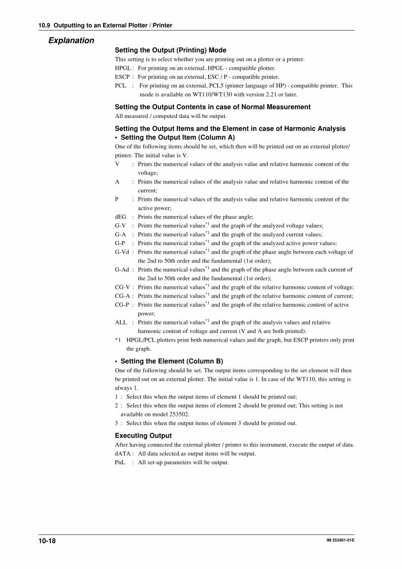
IM 253401-01E10-18
ExplanationSetting the Output (Printing) ModeThis setting is to select whether you are printing out on a plotter or a printer.
HPGL : For printing on an external, HPGL - compatible plotter.
ESCP : For printing on an external, ESC / P - compatible printer.
PCL : For printing on an external, PCL5 (printer language of HP) - compatible printer. This
mode is available on WT110/WT130 with version 2.21 or later.
Setting the Output Contents in case of Normal MeasurementAll measured / computed data will be output.
Setting the Output Items and the Element in case of Harmonic Analysis• Setting the Output Item (Column A)One of the following items should be set, which then will be printed out on an external plotter/
ptinter. The initial value is V.
V : Prints the numerical values of the analysis value and relative harmonic content of the
voltage;
A : Prints the numerical values of the analysis value and relative harmonic content of the
current;
P : Prints the numerical values of the analysis value and relative harmonic content of the
active power;
dEG : Prints the numerical values of the phase angle;
G-V : Prints the numerical values*1 and the graph of the analyzed voltage values;
G-A : Prints the numerical values*1 and the graph of the analyzed current values;
G-P : Prints the numerical values*1 and the graph of the analyzed active power values;
G-Vd : Prints the numerical values*1 and the graph of the phase angle between each voltage of
the 2nd to 50th order and the fundamental (1st order);
G-Ad : Prints the numerical values*1 and the graph of the phase angle between each current of
the 2nd to 50th order and the fundamental (1st order);
CG-V : Prints the numerical values*1 and the graph of the relative harmonic content of voltage;
CG-A : Prints the numerical values*1 and the graph of the relative harmonic content of current;
CG-P : Prints the numerical values*1 and the graph of the relative harmonic content of active
power;
ALL : Prints the numerical values*1 and the graph of the analysis values and relative
harmonic content of voltage and current (V and A are both printed).
*1 HPGL/PCL plotters print both numerical values and the graph, but ESCP printers only print
the graph.
• Setting the Element (Column B)One of the following should be set. The output items corresponding to the set element will then
be printed out on an external plotter. The initial value is 1. In case of the WT110, this setting is
always 1.
1 : Select this when the output items of element 1 should be printed out;
2 : Select this when the output items of element 2 should be printed out; This setting is not
available on model 253502.
3 : Select this when the output items of element 3 should be printed out.
Executing OutputAfter having connected the external plotter / printer to this instrument, execute the output of data.
dATA : All data selected as output items will be output.
PnL : All set-up parameters will be output.
10.9 Outputting to an External Plotter / Printer

IM 253401-01E 10-19
10
Using E
xternal In / Output
Note• When the output items are to be sent by communication interface and they are set to V, A, P or dEG,
these items are then output. When the output item to be sent by communication is set to ALL, not onlythe V and A data are output, but P and dEG data as well. When the output item to be sent bycommunication is set to G-V to CG-P, the output data will not be the graph, but the numerical values.
• The orders are printed up to the maximum analysis order.• When the fundamental frequency lies outside the measurement range of the harmonic analysis (display B
will show FrqEr), an attempt to output will result in an error code.• When you set an element which is not the element of measurement (column B), an attempt to output will
result in an error code.• When no analysis data are present, “––––” will be printed.• There are cases where the active power value becomes negative. The corresponding bargraph will be
printed in thin print.• When no plotter is connected, output time-out will result in an error code.
Example of Output to an External Plotter• Output example in case of output item G-V of harmonic analysis data
(Slight differences may exist due to used plotter, etc.)
100.0
10.00
1.000
100.0m
10.00m1 2010 30 40 50
Model : M/253503/HRMV Range : 60VA Range : 1AFunction : V 1 Sync : PLL V1Freq V1 60.00 HzV1 rms 49.98 VA1 rms 0.002 AW1 = 0.02 WDEG1 = LEAD 50.1 degPF1 = 0.641V1 THD(IEC) = 12.01 %A1 THD(IEC) = 95.58 %
===
####### Harmonic Voltage List #######
Or Volt [ V ] Cont [ % ] Or Volt [ V ] Cont [ % ]
1 49.623 5.50 11.095 1.99 4.017 1.01 2.039 0.62 1.24
11 0.41 0.8213 0.30 0.6015 0.22 0.4517 0.17 0.3519 0.14 0.2821 0.12 0.2323 0.09 0.1925 0.08 0.1627 0.07 0.1429 0.06 0.1131 0.05 0.1033 0.04 0.0835 0.05 0.0937 0.03 0.0739 0.03 0.0641 0.03 0.0643 0.03 0.0545 0.02 0.0547 0.02 0.0549 0.02 0.04
24 0.01 0.026 0.02 0.038 0.01 0.01
10 0.00 0.0112 0.00 0.0114 0.00 0.0016 0.00 0.0118 0.00 0.0120 0.00 0.0022 0.00 0.0124 0.00 0.0126 0.00 0.0128 0.01 0.0130 0.00 0.0132 0.00 0.0134 0.00 0.0136 0.00 0.0138 0.00 0.0040 0.01 0.0142 0.00 0.0144 0.00 0.0146 0.00 0.0148 0.00 0.0150 0.00 0.01
0.03 0.06
#### Harmonic Spectrum (Voltage) ####[V]
OrderAnalysis Value
Relative HarmonicContent
Voltage range
Current range
Function and element
PLL source
Frequency of PLL sourceRms value of 1st to 50thorder of voltage
Rms value of 1st to 50thorder of active power
Rms value of 1st to 50thorder of current
Phase angle between thefundamental current andfundamental voltagePower factor of the fundamental (1st order)
Harmonic distortion of the voltageHarmonic distortion of the current
AVG(EXP 8)Scaling
= OFF= OFF
Averaging
Scaling
AnalysisValue
Order
10.9 Outputting to an External Plotter / Printer

IM 253401-01E10-20
Output example of harmonic analysis data
Refer to the previous page for a description
Model : M/253503/HRMV Range : 15 VA Range : 0.5AFunction : V 1Sync : PLL V1Freq V1 = 60.00 HzV1 rms = 5.76 VA1 rms = 1.4 mAW1 = -0.001 WDEG1 = LEAD 153.8 degPF1 = -0.897V1 THD (IEC) = 15.71%A1 THD (IEC) = - - - oF - - - Avg (EXP 8 ) = OFFScaling = OFF
####### Harmonic Voltage List #######Or Volt [V] Cont [%] Or Volt [V] Cont [%] 1 5.69 2 0.09 1.60 3 0.68 12.02 4 0.04 0.74 5 0.32 5.63 6 0.16 2.77 7 0.06 1.05 8 0.11 2.01 9 0.12 2.15 10 0.09 1.6511 0.17 2.96 12 0.08 1.4713 0.02 0.39 14 0.01 0.2515 0.02 0.43 16 0.01 0.2517 0.04 0.63 18 0.02 0.4119 0.07 1.15 20 0.07 1.3121 0.07 1.15 22 0.02 0.3123 0.11 1.93 24 0.10 1.8425 0.08 1.39 26 0.05 0.8527 0.06 1.04 28 0.06 0.9729 0.08 1.44 30 0.09 1.5931 0.06 1.03 32 0.02 0.3633 0.06 1.08 34 0.06 1.0635 0.00 0.02 36 0.03 0.5737 0.04 0.77 38 0.04 0.7239 0.04 0.74 40 0.07 1.2441 0.01 0.26 42 0.02 0.4043 0.01 0.14 44 0.06 1.0445 0.05 0.94 46 0.02 0.4347 0.07 1.18 48 0.05 0.9449 0.07 1.30 50 0.06 1.09
#### Harmonic Spectrum ( Voltage ) ####
10m 100m 1 10 100
1
3
5
7
9
11
13
15
17
19
21
23
25
27
29
31
33
35
37
39
41
43
45
47
49
Analysis Value
Ord
er
WT110/130 Setup ListsVersion : 1.11Model : 253503-C1/EX1/HRM/CMP
V Range : 15 Vrms ManualA Range : 0.5 Arms ManualExt. Sensor (Elem 1) = 50.00AExt. Sensor (Elem 2) = 50.00AExt. Sensor (Elem 3) = 50.00A
Display A : Time Element 1Display B : PF Element 1Display C : A Hz Element 3
Wiring : 1 Phase 3 WireFilter : OffHold : OnScaling : OffPT Ratio (Elem 1) =1.000CT Ratio (Elem 1) =1.000Scaling Factor (Elem 1) =1.000PT Ratio (Elem 2) =1.000CT Ratio (Elem 2) =1.000Scaling Factor (Elem 2) =1.000PT Ratio (Elem 3) =1.000CT Ratio (Elem 3) =1.000Scaling Factor (Elem 3) =1.000
Averaging : OffAveraging Type : LinerAveraging Coefficient : 8
Integrate Mode : ManualIntegrate Timer : 000:00Rated Time (DA) : 001:00
Store : OffStore Interval : 00:00:00Recall : OffRecall Interval : 00:00:00
Sync. Source : PLL V1Harmonics : OffDisplay A Order : 01Harmonics Element : Element 1Distortion Formula : IEC
Comparator : OffComparator Mode : SingleComparator Display : OffComparator Channel : 1
Communication Command : 0
Voltage rangeCurrent rangeExternal sensorscaling values
Items shownWiring methodFilter ON/OFFHold ON/OFF
Scaling ON/OFF
Voltage(PT)ratio Current(CT)ratio Power value
Averaging ON/OFF Type CoefficientIntegration mode
Integration timerIntegration preset timeStorage ON/OFF IntervalRecall ON/OFF IntervalPLL source Harmonicsfunction ON/OFF Order Element Distortion formulaComparatorfunction ON/OFF Mode Display ON/OFF ChannelComm.command
Output example of set-up parameters
Output example of normal measurement dataElement 1, Element 2, Element 3, Sigma
V 0.88 , 0.00 , 0.09 , 0.48A 2.7m, 0.0m , 0.0m , 1.4m
W -0.000 , 0.000 , 0.000 , -0.00
VA 0.002 , 0.000 , 0.000 , 0.00
Var 0.002 , 0.000 , 0.000 , 0.00
PF -0.156 , PFErr , PFErr , -0.156
DEG 99.0 , dEGErr , dEGErr , 99.0
HzA ------- , ------- , ErrLo ,
Integrator : StartIntegrator Time : 000:05:55
Element 1, Element 2, Element 3, Sigma
Wh+ 0.00m, 0.00m, 0.00m, 0.0000Wh- -0.03m, -0.00m, -0.00m, -0.0000
Wh -0.03m, -0.00m, -0.00m, -0.0000
Ah+ 0.245m, 0.000m, 0.000m, 0.245m
Ah- 0.000m, 0.000m, 0.000m, 0.000m
Ah 0.245m, 0.000m, 0.000m, 0.245m
ElementVoltageCurrentActive powerApparent powerReactive powerPower factorPhase angleFrequencyIntegration statusIntegration elapsed time
Watt-hour
Ampere-hour
10.9 Outputting to an External Plotter / Printer

IM 253401-01E 11-1
11
GP
-IB Interface
11.1 Using the GP-IB Interface
This instrument is equipped with a GP-IB interface in accordance with your preference. Thisinterface permits remote control from a controller such as a personal computer, and output ofvarious data.
Overview of the GP-IB InterfaceThe table below shows functions that are available in each mode.Mode FunctionAddressable mode (mode A and mode B), Listener Functions performed by key operations488.2 mode (except for LOCAL key and power ON/OFF)
measured/computed/analysis data output requestsetting parameters output requesterror code output request
Talker measured/computed/analysis data outputsetting parameters outputerror code outputstatus byte output
Talk-only mode Talker measured/computed/analysis data output
Addressable Mode AData is output when the data output request command “OD” is received. This mode enablestransmission of data at a specified time.Addressable Mode BThis mode does not require a measured data inquiry command. When data is requested by thecontroller (personal computer, etc.), the data is output as the display is updated whenmeasurement is completed. Therefore, if an attempt is made to transmit data at intervals shorterthan the display intervals, the controller is forced to wait until the next display interval.488.2 ModeThis mode allows commands conforming to the IEEE St'd 488.2-1987 protocol to be used.Talk-only ModeThis mode does not require a controller. Data is output at certain intervals. This interval can beset to any length. This mode is useful when the instrument is connected to a listener-only devicesuch as a printer.Print ModeThis mode is useful when harmonic analysis data are output to the external plotter/printer. Fordetails, refer to page 10-17.
GP-IB Interface Specifications• Electrical & mechanical specifications : conforms to IEEE st’d 488-1978• Functional specifications : refer to the table below• Code : ISO (ASCII) code• Address setting : 0 to 30 listener and talker addresses, or talk-only can be selected using the
front panel keys.• Remote mode clear : remote mode can be cleared by pressing the LOCAL key on the front
panel. However, this is not possible when Local Lockout has been set by the controller.
Function Subset name Descriptionsource handshake SH1 full source handshake capabilityacceptor handshake AH1 full acceptor handshake capabilitytalker T5 basic talker capability, serial polling, nontalker on MLA
(My Listen Address), talk-only capabilitylistener L4 Basic listener capability, nonlistener to MTA (My Talk
Address), no listen-only capabilityservice request SR1 full service request capabilityremote local RL1 full remote/local capabilityparallel poll PR0 no parallel polling capabilitydevice clear DC1 full device clear capabilitydevice trigger DT1 full device trigger capabilitycontroller C0 no controller function
WARNINGThe connectors used in this function have protective covers. When thecovers are removed or when using connectors, the voltage ratings acrossthe measuring input and the ground become as follows:
Voltage across A, ±(V and A side) input terminals and ground 400 Vrms max.Voltage across V terminal and ground 600 Vrms max.
Put the protective cover on the connector when this function is not used.

IM 253401-01E11-2
11.2 Responses to Interface Messages
Responses to Interface MessagesIFC (Interface Clear)Unaddresses talker and listener.
REN (Remote Enable)Transfers the instrument from local control to remote control.
GTL (Go To Local)Transfers the instrument from remote control to local control.
SDC (Selective Device Clear), DCL (Device Clear)Cleasrs GP-IB input/output buffer, and resets an error. The set-up information and measurement
state are not affected. DCL is applicable to all devices on the bus, whilst DSC is applicable to
designated devices only.
GET (Group Execute Trigger)Same function as the TRIG key.
LLO (Local Lockout)Invalidates the LOCAL key on the front panel to inhibit transfer from remote control to local
control.
Switching between Remote and Local ModeWhen switched from local to remote modeThe REMOTE indicator will light up, and all panel keys except the LOCAL key cannot be
operated. Set-up parameres entered in the local mode will be retained.
When switched from remote to local modeThe REMOTE indicator will extinguish and all panel keys can be operated. Set-up parameters
entered in the remote mode will be retained.
Valid keys for remote controlPressing the LOCAL key in remote control will switch the instrument to local control.
However, this is not possible in case the Local Lockout has been set by the controller.

IM 253401-01E 11-3
11
GP
-IB Interface
11.3 Status Byte Format (before the IEEE 488.2-1987Standard)
DIO 8 DIO 7 DIO 6 DIO 5 DIO 4 DIO 3 DIO 2 DIO 1
IntegrationBUSY
SRQ ERROR STORE/RECALL
BUSY
OVER SyntaxERROR
IntegrationEND
ComputationEND
Integration Busy (DIO 8)This bit is set to “1” when integration is in progress. This bit cannot be disabled by the IM
command since it is a status bit. Even if this bit is set to “1”, SRQ will not be affected.
SRQ (DIO 7)This bit is set to “1” when computation End (DIO 1), integration End (DIO 2), OVER (DIO 4)
or Syntax error (DIO 3) occurs. When RQS is set to “1”, SRQ is set to True, issuing a service
request to the controller. This bit is reset to “0” when a response is sent to the serial poll. To
prevent the SRQ and status byte being affected by computation End, integration End, Over or
Syntax error, this bit must be disabled by the IM command.
After an “IM15”, SRQ is affected by a computation End, integration End, Over, or Syntax error.
After an “IM1”, SRQ is affected only by a computation End.
In case of “IM4”, SRQ is affected only by a Syntax error.
ERROR (DIO 6)When a Syntax error or Over occurs, this bit is set to “1” and the SRQ is set to True.
Store/Recall Busy (DIO 5)This bit is set to “1” when storing/recalling of data is in progress. This bit cannot be disabled by
the IM command since it is a status bit. Even if this bit is set to “1”, SRQ will not be affected.
Over (DIO 4)This bit is set to “1” and SRQ is set to True when an overrange occurs in the measured data.
However, this is not valid if the bit has been disabled by the IM command. This bit is reset after
a response is made to the serial poll. The nature of Over can by identified by the OE command.
Syntax error (DIO 3)This bit is set to “1” when a command error, parameter error or execution error occurs. The
error No. can be identified by the OE command. This bit is reset after a response is made to the
serial poll. However, this is not valid if the bit has been disabled be the IM command.
Integration End (DIO 2)This bit is set to “1” when integration has been completed. The bit is reset when a response is
made to the serial poll. However, this is not valid if the bit has been disabled by the IM
command.
Computation End (DIO1)This bit is set to “1” when computation has been completed and the display is updated. The bit
is reset when a response is made to the serial poll. However, this is not valid if the bit has been
disabled by the IM command.

IM 253401-01E11-4
11.4 Output Format for Normal Measured/ComputedData, Harmonic Analysis Data, Set-upParameters and Error Codes
Output Format of Normal Measured/Computed DataData FormatMeasured data normally consists of a 6-byte header and 11 bytes of data
Header Data
Header SectionThe header section consists of 6 bytes (h1 to h6).
h1 h2 h3 h4 h5 h6
h1 to h3: data typeV_ _ : voltage A_ _ : Current W_ _ : Active powerVA_ : Apparent power Var : Reactive power PF_ : Power factorHzV : Voltage frequency HzA : Current frequency Wh_ : Watt hourAh_ : Ampere hour DEG : Phase angle Vpk : Peak voltage valueApk : Peak current value EFF : Efficiency CV1 : V1 crest factorCV2 : V2 crest factor CV3 : V3 crest factor CA1 : A1 crest factorCA2 : A2 crest factor CA3 : A3 crest factorA+B : (display A)+(display B) A–B : (display A)–(display B)A*B : (display A)*(display B) A/B : (display A)/(display B)Wh+ : Positive watt hour Wh– : Negative watt-hourAh+ : Positive ampere hour Ah– : Negative ampere hourHMS : Elapsed time of integration MEM : Data number in case of recalling(Efficiency, crest factor, and the results of four arithmetic operations can be output onWT110/WT130 with ROM version 2.01 and later. However, different instruments havedifferent restrictions on the output of these parameters.)
h4: Element
1: Element 1 2: Element 2 3: Element 3 4: ∑h1-h4: data type (only when the computing equation is A/B2 or A2/B on WT110/WT130 withROM version 2.01 or later)
A/B2: (display A)/(display B)2
A2/B: (display A)2/(display B)
h5: Data state
N: normal I: Overrange O: Computation overflow P: Peak overflowE: No data
h6: Indicates data lag/lead in case of DEG data type. In case of other data types, _ (space) willoccur.
G: Lag D: Lead _: Not detectable
Data SectionThe data section consists of 11 bytes.
d1 d2 d3 d4 d5 d6 d7 d8 d9 d10 d11
d1 : polarity; _ (space) or – (minus)d2 to d8 : mantissa, floating-point number of the maximum six digitsd9 to d11 : exponent; E-3→m, E+0, E+3 → k, E+6 → MData state in case of an overrange (“oL” is being displayed)
h1 h2 h3 h4 I _ _ 9 9 9 9 9 9 . E + 3
Data state in case of a computation overflow(“oF”, “PFErr”, “dEGEr”, “ErrLo”, “ErrHi” is being displayed)
h1 h2 h3 h4 O _ _ 8 8 8 8 8 8 . E + 0
Data state in case of no data (when the display is - - - - -)"I" becomes "E" for data during overrange.
Elapsed time of integration
H M S _ _ _ d1 d2 d3 d4 d5 d6 d7 d8 d9
d1 to d3 : Hour d4 : “:”d5 to d6 : Minute d7 : “:”d8 to d9 : Second

IM 253401-01E 11-5
11
GP
-IB Interface
Output Format when Self SelectedUp to 14 normal measured/computed data can be output simultaneously, and the user is allowed
to choose any output information type for those 14 data. Each output block is of the following
format.
ch.1 , ch.2 ch.3 ch.4 Terminator, ,
ch.5 , ch.6 ch.7 ch.8 Terminator, ,
ch.9 , ch.10 ch.11 ch.12 Terminator, ,
ch.13 , ch.14 Terminator
END Terminator
Line 1
Line 2
Line 3
Line 4
Line 5
Line 6
Datanumber Terminator (The data number will only be output in case of recall)
Each output block usually consists of five lines (six in case of recall) including the block end
line “END”. However, if all output types on a line are set to “no output”, this line will be
omitted, reducing the number of output lines by one. For example, if all output items of ch.9 to
ch12 are set to “no output”, line 4 in the above example will be omitted.
Furthermore, if any channel on a line is set to “no output”, all data following this channel on the
line will be shifted forward. For example, if the ch.2 on line 1 is set to “no output”, data of ch.1
will be followed by data of ch.3.
Output Format in case of Normal MeasurementWT110 (253401)
V1 data Terminator
A1 data Terminator
W1 data Terminator
Frequency , Display C Terminator
END Terminator
Line 1
Line 2
Line 3
Line 4
Line 5
Line 6
Datanumber Terminator (The data number will only be output in case of recall)
WT130 (253502)
V1 data , V3 data SV data Terminator,
A1 data , A3 data SA data Terminator,
W1 data , W3 data SW data Terminator,
Frequency , Display C Terminator
END Terminator
Line 1
Line 2
Line 3
Line 4
Line 5
Line 6
Datanumber Terminator (The data number will only be output in case of recall)
Note• When the frequency is set by either of the following methods, only one value is measured, and that value
will be output.- by panel keys : by the FUNCTION key and ELEMENT key of display C (except WT110)- by communication command : by the “DC” or “EC” command.
After setting the measurement object of frequency, even changing the display C to something differentthan VHz or AHz will not result in changing the object of measurement of frequency. When selecting theoutput items yourself and you set a frequency item which is not object of measurement, “999999.E+03”will be output.
11.4 Output Format for Normal Measured/Computed Data, Harmonic Analysis Data, Set-up Parameters and Error Codes

IM 253401-01E11-6
11.4 Output Format for Normal Measured/Computed Data, Harmonic Analysis Data, Set-up Parameters and Error Codes
WT130 (253503)
V1 data , V2 data V3data SV data Terminator, ,
A1 data , A2 data A3 data SA data Terminator, ,
W1 data , W2 data W3 data SW data Terminator, ,
Frequency , Display C Terminator
END Terminator
Line 1
Line 2
Line 3
Line 4
Line 5
Line 6
Datanumber Terminator (The data number will only be output in case of recall)
Default Output Format in case Integration Measurement
WT110 (253401)
W1 data Terminator
Wh1data Terminator
Ah1data Terminator
Frequency ,Elapsedintegration time Terminator
END Terminator
Line 1
Line 2
Line 3
Line 4
Line 5
Line 6
Datanumber Terminator (The data number will only be output in case of recall)
WT130 (253502)
W1 data , W3 data SW data Terminator,
Wh1data , Wh3data SWhdata Terminator,
Ah1data , Ah3data SAhdata Terminator,
END Terminator
Line 1
Line 2
Line 3
Line 4
Line 5
Line 6
Datanumber Terminator (The data number will only be output in case of recall)
Frequency ,Elapsedintegration time Terminator
WT130 (253503)
W1 data , W2 data W3 data SW data Terminator, ,
Wh1data , Wh2data Wh3data SWhdata Terminator, ,
Ah1data , Ah2data Ah3data SAhdata Terminator, ,
END Terminator
Line 1
Line 2
Line 3
Line 4
Line 5
Line 6
Datanumber Terminator (The data number will only be output in case of recall)
Frequency ,Elapsedintegration time Terminator

IM 253401-01E 11-7
11
GP
-IB Interface
Output Format of Harmonic Analysis DataData FormatHarmonic analysis data normally consists of a 8-byte header and 11 bytes of data
Header Data
Header SectionThe header section consists of 8 bytes (h1 to h8).
h1 h2 h3 h4 h5 h6 h8h7
h1 to h3 : data type
V__ : voltage A__ : Current W__ : Active power
DEG : Phase angle between the 1st order voltage and 1st order current
DGV : Phase angle between the 1st order voltage and the 2nd to 50st order voltage
DGA : Phase angle between the 1st order current and the 2nd to 50st order current
PF_ : Fundamental power factor (1st order)
HzV : Fundamental frequency of the voltage of the PLL source
HzA : Fundamental frequency of the current of the PLL source
THD : Harmonic distortion (either IEC or CSA)
CNT : Relative harmonic content
MEM : Data number in case of recalling
h4: Element
1: Element 1 2: Element 2 3: Element 3 4: Not applicable
h5: Data state
N: normal I: Overrange O: Computation overflow P: Peak overflow
E: No data
h6, h7: Order
01 to 50: Order of fundamental or higher harmonic (up to the maximum analysis order).
“__” (space) will be assigned in case of frequency, harmonic distortion, power factor or in
case of all computed values of the 1st to 50th order.
h8: Indicates data lag/lead in case of DEG data type. In case of other data types, __ (space)
will occur.
G: Lag D: Lead _: Not detectable
Data SectionThe data section consists of 11 bytes.
d1 d2 d3 d4 d5 d6 d7 d8 d9 d10 d11
d1 : polarity; __ (space) or – (minus)
d2 to d8 : mantissa, floating-point number of the maximum six digits
In case of harmonic distortion and relative harmonic content :
d9 : %
d10 to d11 : __ (space)
In other cases :
d9 to d11 : exponent; E-3 → m, E+0, E+3 → k, E+6 → M
11.4 Output Format for Normal Measured/Computed Data, Harmonic Analysis Data, Set-up Parameters and Error Codes

IM 253401-01E11-8
Output FormatThe output format depends on the selected output items which can be selected by the “OH”
command.
In case of voltage and currentAll computed values ofthe 1st to 50th order , Terminator
Analysis value forfundamental (1st order) , Terminator
END Terminator
Line 1
Line 2
Line 3
Line 51
Line 52
Analysis value for 50thharmonic
, Terminator
Analysis value for 2ndharmonic , Terminator
Frequency
Relative harmonic content for 2nd harmonic
Relative harmonic contentfor 50th harmonic
harmonic distortion
In case of active powerAll computed values of the 1st to 50th order
, Terminator
Analysis value forfundamental (1st order) , Terminator
END Terminator
Line 1
Line 2
Line 3
Line 51
Line 52
Analysis value for50th harmonic
, Terminator
Analysis value for2nd harmonic
, Terminator
Frequency
Relative harmonic contentfor 2nd harmonic
Relative harmonic contentfor 50th harmonic
Power factor
In case of phase angle
, Terminator
END Terminator
Line 1
Line 2
Line 3
Line 50
Line 51
Phase angle betweenfundamentals of voltage and current
Frequency
Phase angle betweenfundamental and2nd harmonic of current
, TerminatorPhase angle betweenfundamental and 2ndharmonic of voltage
, TerminatorPhase angle betweenfundamental and3rd harmonic of voltage
, TerminatorPhase angle betweenfundamental and50th harmonic of voltage
Phase angle betweenfundamental and3rd harmonic of current
Phase angle betweenfundamental and50th harmonic of current
In case of ALL settingThe data will be output in the sequence voltage → current → active power → phase angle →END <terminator>
- The output format of each item is as described for each item above;
- The END line is not output for each item, but after finishing the entire output operation.
Output Format of Set-up Parameters and Error CodesRefer to the explanations and examples of the “OS” or the “OE” commands described in
Appendix 1.1.
11.4 Output Format for Normal Measured/Computed Data, Harmonic Analysis Data, Set-up Parameters and Error Codes

IM 253401-01E 11-9
11
GP
-IB Interface
11.5 Setting the Address/Addressable Mode
Relevant Keys
SCALING AVG FILTER STORE RECALL HARMONICS
SAMPLE
V OVER
A OVER
MODE
RMS
V MEAN
DC
A
B
C
hour
hour
min
min sec
V VAm
Ak var
M W TIME
V PFm
Ak deg
M W %
FUNCTION
AUTO AUTO
MODE
1Φ3W
V Hzm
Ak h
M W
TRIG
V RANGE A RANGE HOLD
ENTER
INTEGRATOR
START
HARMONICS MEMORY INTEG SET
STOP RESET
REMOTE
INTERFACE OUTPUT
LOCAL SETUP
hSHIFT
WIRING3Φ4W
3Φ3W
3V3A
ELEMENT
1 2 3
FUNCTION ELEMENT
1 2 3
FUNCTION ELEMENT
1 2 3
* Shows the operation panel of the WT130. For the differences between WT110 and WT130, refer to section 2.2, page 2-2, 2-3
Displays relevant keys and indicators
Operating Procedure
1.
SHIFTLOCAL
INTERFACEENTER
3.Setting the mode
( Display C )
2.ENTER
6.Setting the address
( Display C )
Setting the interval( Display C )hour min sec
End
ENTER6.
End
ENTER3.
4.5.
4. up down
5. cursor shift SHIFT
• Perform operations following the thick line in the below menu.• Press the ENTER key to confirm the selection or setting.• When you want to leave the current menu during operation, press the key described under step 1. The confirmed settings made until that point will be kept.
Same as step 4 to 5 mentioned above.
(Select this when setting commands according to IEEE 488.2-1987. Note that this menu only appears in case of version 1.11 and later. Refer to page 3-14 to confirm your version.)
ExplanationMode SettingRefer to page 11-1 for details.
Address SettingA particular address is assigned to each device connected to the GP-IB interface so that each
device can be recognized by every device. Therefore, an address must be assigned to this
instrument when it is connected to a personal computer.
Address setting range: 0 to 30
The initial value is “1”. Initializating the instrument will not result in changing the address
setting.
Talk-only FunctionThis function only allows the instrument to send data to other devices. If talk-only is off, the
instrument can both send and receive data. In talk-only mode, the instrument cannot be
controlled by the controller.
TerminatorWhen this instrument is used as a listenerUse “CR+LF”, “LF” or “EOI” as the receiving terminator.When this instrument is used as a talker
The sending terminator is set using the DL command. The initial setting is “CR+LF+EOI”.
Note• It is not possible for this instrument to receive data if the “CR” terminator is sent from the controller. It is
also not possible to set “CR” as the terminator which is to be sent from this instrument.

IM 253401-01E11-10
11.6 Setting the Output Items
Relevant Keys
SCALING AVG FILTER STORE RECALL HARMONICS
SAMPLE
V OVER
A OVER
MODE
RMS
V MEAN
DC
A
B
C
hour
hour
min
min sec
V VAm
Ak var
M W TIME
V PFm
Ak deg
M W %
FUNCTION
AUTO AUTO
MODE
1Φ3W
V Hzm
Ak h
M W
TRIG
V RANGE A RANGE HOLD
ENTER
INTEGRATOR
START
HARMONICS MEMORY INTEG SET
STOP RESET
REMOTE
INTERFACE OUTPUT
LOCAL SETUP
hSHIFT
WIRING3Φ4W
3Φ3W
3V3A
ELEMENT
1 2 3
FUNCTION ELEMENT
1 2 3
FUNCTION ELEMENT
1 2 3
* Shows the operation panel of the WT130. For the differences between WT110 and WT130, refer to section 2.2, page 2-2, 2-3
Displays relevant keys and indicators
Operating Procedure
SHIFTSETUP
OUTPUTENTER3.
Selecting communication(Display C)
Selecting normal(Display C)
2.ENTER5.
4.
Selecting output format (Display C)
ENTER7.
End6.
Setting output channel(Display C)
8.,14.
ENTER9.
Setting output item(Display C)
10.
ENTER
ENTER15.
End
13.*1
ENTER
10. Sets the A column
11. Moves to the B column
12. Select from 1 to 4
SHIFT
(Selecting desired item)
(Selecting default setting)
*1 When you press the key at step 13, the output
channel displayed at display B will change to the next
channel, i.e. from ch1 to ch2 and so forth.
*2 Displayed on WT110/WT130 with ROM version 2.01 or
later.
1.
• Setting the Output Item in case of Normal Measurement
• Perform operations following the thick line in the below menu.• Press the ENTER key to confirm the selection or setting.• When you want to leave the current menu during operation, press the key described under step 1. The confirmed settings made until that point will be kept.
A B
*2
*2
*2

IM 253401-01E 11-11
11
GP
-IB Interface
11.6 Setting the Output Items
Setting the Output Item in case of Harmonic Analysis1.
SHIFTSETUP
OUTPUTENTER
3.( Display C ) ( Display C )
2.ENTER
5.4.
Setting output item( Display C )
ENTER9.
End6.
6. Sets the A column
7. Moves to the B column
8. Select from 1 to 3
A B
SHIFT
*1
*1 When graph printouts are selected as the output item, only data values will be output by communication
ExplanationSetting the Output Item in case of Normal Measurement• Selecting the Default Setting
Predefined items will be output by the communication function. The following types of default
settings exist and they depend on the model. For more details, refer to page 11-5 and 11-6.
Normal default setting : dFLt-nConsists of V (voltage), A (current), W (active power, the above menu shows P), frequency
and displayed data of display C.
Integration default setting : dFLt-iConsists of W (active power, the above menu shows P), Wh (watt hour), Ah (ampere hour),
frequency, and integration time.
• Selecting yourselfYou can set any item to each of ch1 to ch14 output channels.
Setting the channelSets which channel (ch1 to ch14) will output the item.
Setting the output item (corresponds to column A in the operating procedure)Any of the following items can be selected. The initial value is V.V (voltage), A (current), P (active power), VAr (reactive power), VA (apparent power), PF(power factor), VFrq (voltage frequency), AFrq (current frequency), Ph (total watt hour Wh),Ah (total ampere hour), dEG (phase angle),VP(peak value of voltage)*2, AP(peak value ofcurrent)*2, MATH(computation)*2, t1 (elapsed integration time), Ph+ (positive watt hourWh+), Ph– (negative watt hour Wh–), Ah+ (positive ampere hour*1), Ah– (negative amperehour*1), – – – – (no output)
*1 For details regarding the positive ampere hour, refer to page 7-3.
*2 Available on WT110/WT130 with ROM version 2.01 or later.
• Setting the element (corresponds to column B in the operating procedure)The element setting depends on the model and is as follows. The initial value is “1”.• WT110 (253401) no such element setting available;• WT130 (253502) element can be selected from 1, 3 or 4• WT130 (253503) element can be sleected from 1, 2, 3 or 4
The element number 4 represents ∑.
Setting the Output Item in case of Harmonic AnalysisThe setting is carried out in the same way as described in section 10.9. However, when output
data by communication function, graphs will be printed, but only data values will be output. For
details, refer to page 10-17, 10-18.

IM 253401-01E11-12
11.7 Commands (before the IEEE 488.2-1987 Standard)
For a detailed description of each command, refer to appendix 1.1.
Command DescriptionWiring system WRm (WiRing) sets wiring systemVoltage range RVm (Range Voltage) sets voltage range
AVm(Auto Voltage range) sets voltage auto rangeCurrent range RAm(Range current(A)) sets current range
AAm(Auto current(A) range) sets current auto rangeSAm(Sensor Ampere) sets external sensor
Display range DR(Display Range) sets external sensorMeasurement mode MNm(MeaN) sets external sensorFilter FLm(FiLter) sets filter ON/OFFHold HDm(sampling HolD) holds display and output dataTrigger E or ST or <GET> triggerDisplay DAm(Display A function) selects function to be displayed on display A
DBm(Display B function) selects function to be displayed on display BDCm(Display C function) selects function to be displayed on display CEAm(Element display A) selects element to be displayed on display AEBm(Element display B) selects element to be displayed on display BECm(Element display C) selects element to be displayed on display C
Scaling SCm(SCaling) sets scaling ON/OFFKVm(K*Amplre) sets the scaling valueKAm(K*Wattage)KWm(K*Voltage)
Averaging AGm(AveraGing) sets averaging ON/OFFATm(Averaging Type) selects exponential averaging or moving averagingACm(Averaging Coefficient) sets attenuation constant or averaging number
MATH MTm(MaThematics) Sets computing equation
Integration IS(Integrate Start ) starts integrationIP(Integrate stoP) stops integrationIR(Integrate Reset) resets integrationICm(Integrate Continuous) sets integration modeTMm1,m2(integrate TiMer) sets integration preset time
Data storage SO(Store On) starts storageSRm1,m2,m3(Store inteRval) sets storage interval
Data recalling ROm(Recall On) starts recallingRRm1,m2,m3(recall inteRval) sets recalling interval
Set-up parameters SLm(panel Setting Load) recalling set-up parametersSSm(panel Setting Save) storing set-up parametersRC(Reset Command) initialize set-up parameters
Communication CMm(Communication coMmand) sets command group to be usedcommands OD(Output Data) requests output of measured data
OFm1,m2,m3(Output Function) sets output itemsOFDm(Output Function Default) sets default output itemsOS(Output panal Setting) requests output of setting parametersOE(Output Error code) requests output of error codeHm(Header) sets output data headerDLm(DeLimiter) sets output data delimiterIMm(Interrupt Mask) sets status byte interrupt mask
/HAM (option) HAm(Harmonics Analize) sets harmonic analysis ON/OFFHEm(Harmonics Eiement) sets harmonics elementOR(harmonics ORder) sets harmonics orderOHm1,m2(Output Harmonics function) sets communication or output blockPSm(Pll Source ) sets PLL sourceDFm(Distortion Formula) sets distortion formula
/DA (option) OAm1,m2,m3(Output Analog) sets output items yourselfOADm(Output Analog Default) sets default output itemsRTm1,m2,(integrate Rated Time) sets integration time
/CMP (option) YOm(relaY On) sets comparator function ON/OFFYMm(relaY Mode) sets comparator modeDYm(Display relaY) sets display relay ON/OFF for comparatorYCm(relaY Channel) sets the relay channelOYm1,m2,m3,m4,m5 sets the output relay function for normal measurement
(Output relaY function)OYHm1,m2,m3,m4,m5,m6 sets the output relay function for harmonic analysis
(Output relaY Harmonic function)
Note• If commands relating to options are used on instruments which do not have the options installed, "Error
11" is displayed. Also, there are no responses to inquiries.• "MATH" is available on WT110/WT130 with ROM version 2.01 or later.

IM 253401-01E 12-1
12
RS
-232-C Interface
12.1 Using the RS-232-C Interface
This instrument is equipped with a RS-232-C interface in accordance with your preference. This
interface permits remote control from a controller such as a personal computer, and output of
various data.
Overview of the RS-232-C InterfaceThe table below shows functions that are available in each mode.
Mode FunctionNormal mode Reception Functions performed by key operations (except for LOCAL key
and power ON/OFF)measured/computed/analysis data output requestsetting parameters output requesterror code output request
Transmission measured/computed/analysis data outputsetting parameters outputerror code outputstatus byte output
Talk-only mode Transmission measured/computed/analysis data output
Normal ModeThis mode is equivalent to the the addressable mode A of the GP-IB function, and enablesreception of commands and transmission of data. Measured data is output on reception of the“OD” command.
488.2 ModeThis mode allows receiving of commands conforming to the IEEE St'd 488.2-1987 protocol.
Talk-only ModeThis mode is equivalent to the Talk-only mode of the GP-IB function. Only measured data canbe output and commands cannot be received.There is no equivalent to the addressable mode B of the GP-IB function.
Print ModeThis mode is useful when harmonic analysis data are output to the external plotter/printer. For
details, refer to page 10-17.
RS-232-C Interface SpecificationsElectrical characteristics : conforms to EIA RS-232-C
Connection : point-to-point
Communications : full-duplex
Synchronization : start-stop system
Baud rate : 75, 150, 300, 600, 1200, 2400, 4800, 9600
Start bit : 1 bit
Data length (word length) : 7 or 8 bits
Parity : Even, odd or no parity
Stop bit : 1 or 2 bits
Hardware handshaking : User can select whether CA, CB, CC and CD signals will always beTrue, or be used for control.
Software handshaking : User can select whether to control only transmission or bothtransmission and reception using X-on and X-off signals.
X-on (ASCII 11H)X-off (ASCII 13H)
Receive buffer size : 64 bytes
WARNINGThe connectors used in this function have protective covers. When thecovers are removed or when using connectors, the voltage ratings acrossthe measuring input and the ground become as follows:
Voltage across A, ±(V and A side) input terminals and ground 400 Vrms max.Voltage across V terminal and ground 600 Vrms max.
Put the protective cover on the connector when this function is not used.

IM 253401-01E12-2
12.2 Connecting the Interface Cable
When connecting this instrument to a personal computer, make sure that the handshaking
method, data transmission rate and data format selected for the instrument match those selected
fro the computer. For details, refer to the following pages. Also make sure that the correct
interface cable is used.
Connector and Signal NamesNumbers in the figure represent the Pin Nos.
Pins 8 through 13 are not used
20
1 2 3 4 5 6 7
RS-232-C Connector : DBSP-JB25S or equivalent
Pins 14 through 19 are not used
Pins 21 through 25 are not used
1 AA(GND : Protective Ground) Grounded to the case of this instrument
2 BA(TXD : Transmitted Data) Data transmitted to personal computer
Signal direction: output
3 BB(RXD : Received Data) Data received from personal computerSignal direction: input
4 CA(RTS : Request to Send) Signal used to handshake when receiving data frompersonal computerSignal direction: output
5 CB(CTS : Clear to Send) Signal used to handshake when transmitting data topersonal computerSignal direction: input
6 CC(DSR : Data Set Ready) Signal used to handshake when transmitting data topersonal computerSignal direction: input
7 AB(GND : Signal Ground) Ground for signals
20 CD(DTR : Data Terminal Ready) Signal used to handshake when receiving data frompersonal computerSignal direction: output
NotePins 8 to 19 and 21 to 25 are not used.
Signal DirectionThe figure below shows the direction of the signals used by the RS-232-C interface.
Computer
6
20
4
5
2
3
This instrument
CC(DSR)
CD(DTR) [data terminal ready]
CA(RTS) [request to send]
CB(CTS) [clear to send ready]
BA(TXD) [transmitted data]
BB(RXD) [received data]
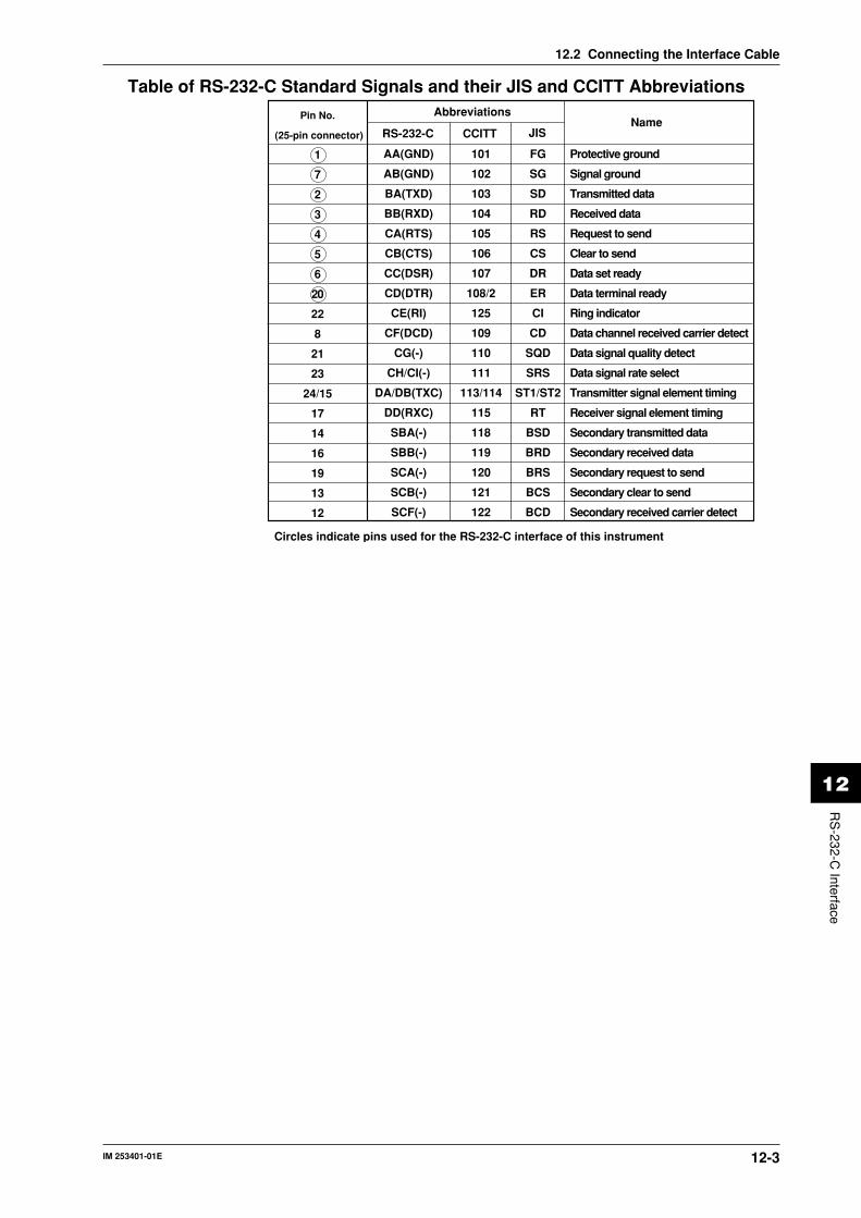
IM 253401-01E 12-3
12
RS
-232-C Interface
12.2 Connecting the Interface Cable
Table of RS-232-C Standard Signals and their JIS and CCITT Abbreviations
Pin No.
(25-pin connector)
1
7
2
3
4
5
6
20
22
8
21
23
24/15
17
14
16
19
13
12
Abbreviations
RS-232-C
AA(GND)
AB(GND)
BA(TXD)
BB(RXD)
CA(RTS)
CB(CTS)
CC(DSR)
CD(DTR)
CE(RI)
CF(DCD)
CG(-)
CH/CI(-)
DA/DB(TXC)
DD(RXC)
SBA(-)
SBB(-)
SCA(-)
SCB(-)
SCF(-)
101
102
103
104
105
106
107
108/2
125
109
110
111
113/114
115
118
119
120
121
122
Protective ground
Signal ground
Transmitted data
Received data
Request to send
Clear to send
Data set ready
Data terminal ready
Ring indicator
Data channel received carrier detect
Data signal quality detect
Data signal rate select
Transmitter signal element timing
Receiver signal element timing
Secondary transmitted data
Secondary received data
Secondary request to send
Secondary clear to send
Secondary received carrier detect
Circles indicate pins used for the RS-232-C interface of this instrument
NameCCITT JIS
FG
SG
SD
RD
RS
CS
DR
ER
CI
CD
SQD
SRS
ST1/ST2
RT
BSD
BRD
BRS
BCS
BCD

IM 253401-01E12-4
12.3 Setting the Mode, Handshaking Method, DataFormat and Baud Rate
Relevant Keys
SCALING AVG FILTER STORE RECALL HARMONICS
SAMPLE
V OVER
A OVER
MODE
RMS
V MEAN
DC
A
B
C
hour
hour
min
min sec
V VAm
Ak var
M W TIME
V PFm
Ak deg
M W %
FUNCTION
AUTO AUTO
MODE
1Φ3W
V Hzm
Ak h
M W
TRIG
V RANGE A RANGE HOLD
ENTER
INTEGRATOR
START
HARMONICS MEMORY INTEG SET
STOP RESET
REMOTE
INTERFACE OUTPUT
LOCAL SETUP
hSHIFT
WIRING3Φ4W
3Φ3W
3V3A
ELEMENT
1 2 3
FUNCTION ELEMENT
1 2 3
FUNCTION ELEMENT
1 2 3
*Shows the operation panel of the WT130. For the differences between WT110 and WT130, refer to section 2.2, page 2-2, 2-3
Displays relevant keys and indicator
Operating Procedure
1.
SHIFTLOCAL
INTERFACEENTER
3.Setting the mode
(Display C)
2.
ENTER9.
hour min sec
ENTER14.
END
ENTER5.
ENTER7.
4. 6.
8.
Selecting handshaking method(Display A)
Selecting data format(Display B)
Setting baud rate(Display C)
SHIFT
• Perform operations following the thick line in the below menu.• Press the ENTER key to confirm the selection or setting.• When you want to leave the current menu during operation, press the key described under step 1. The confirmed settings made until that point will be kept.
Setting interval(Display C)
10.ENTER
11.
END
Setting terminator(Display C)
ENTER11.
*
For mode" " or " "
For mode" "
12. up down
13. cursor shift
* Select this when setting commands according to IEEE 488.2-1987. Note that this menu only appears in case of version 1.11 and later. Refer to page 3-14 to confirm your version.

IM 253401-01E 12-5
12
RS
-232-C Interface
ExplanationMode SettingRefer to page 12-1 for more details.
HandshakingTo use an RS-232-C interface to transfer data between this instrument and a computer, it is
necessary to use certain procedures by mutual agreement to ensure the proper transfer of data.
These procedures are called “handshaking”. Various handshaking systems are available
depending on the computer to be used; the same handshaking system must be used for both
computer and this instrument. This instrument allows you to choose any handshaking method
from the following eight using the panel keys.
Handshaking method combinations (a circle indicates that the function is available)
Data sending control(Control method when sending data to computer)
Data receiving control(Control method when receiving data from computer)
Softwarehandshake
SoftwarehandshakeHardware handshake Hardware handshake
Sending stops when X-off is received, and sending is resumed when X-on is received.
Sending stops when CB (CTS) is False, and sending is resumed when CB is True.
Sending stops when CC (DSR)is False,and sending is resumed when CC is True.
No
handshake
X-off is sent when received data buffer becomes 3/4-full, and X-on is sent when received data buffer becomes 1/4-full.
CD(DTR) is set to False when received data buffer becomes 3/4-full, and is set to True when received data buffer becomes 1/4-full.
CA(RTS) is set to False when received data buffer becomes 3/4-full, and is set to True when received data buffer becomes 1/4-full.
No
handshake
0
1
2
3
4
5
6
7
ΟΟΟ
ΟΟ
ΟΟ
ΟΟ
Ο
Ο
Ο
Ο
Ο
Ο
Ο
Mo
de
sele
ctio
n n
o.
Precautions Regarding Data Receiving ControlWhen handshaking is used to control received data, data may still be sent from the computer
even if the free space in the receive buffer drops below 16 bytes. In this case, after the receive
buffer becomes full, the excess data will be lost, whether handshaking is in use or not. Data
storage to the buffer will start again when there is free space in the buffer.
64 bytes
Used Free, 16 bytes
When handshaking is in use,reception of data will stop when the free space in the buffer drops to 16 bytes since data cannot be passed to the main program fast enough to keep up with the transmission.
Used Free, 48 bytes
After reception of data stops, data continues to be passed to the internal program. Reception of data starts again when the free space in the buffer inceases to 48 bytes.
Used
Whether handshaking is in use or not, if the buffer becomes full, any additional data received is no longer stored and is lost.
12.3 Setting the Mode, Handshaking Method, Data Format and Baud Rate

IM 253401-01E12-6
12.3 Setting the Mode, Handshaking Method, Data Format and Baud Rate
Data FormatThe RS-232-C interface of this instrument performs communications using start-stop
synchronization. In start-stop synchronization, one character is transmitted at a time. Each
character consists of a start bit, data bits, a parity bit, and a stop bit. Refer to the figure below.
Data bit(7 or 8 bits)
1 character
Stop bit
1
1 or 2 bits2
Parity bit Even, odd or noneStart bit
Circuit idle state
Level returns to idlestate (dotted line) orthe start bit the nextdata (solid line)
The table below shows the data format combinations supported.
Preset value
0
1
2
3
Start bit
1
1
1
1
Data length
8
7
7
7
Parity
No
Odd
Even
No
Stop bit
1
1
1
2
Baud RateThe baud rate can be selected from 75, 150, 300, 600, 1200, 2400, 4800 or 9600.
About the TerminatorData can be received with either "CR+LF" or "LF" terminator. For transmission terminator,
you can select from "CR+LF," "LF," and "CR."
IntervalIn case of the talk-only mode, this setting specifies the interval to send data.
Setting range : 00.00.00 (0hr 0min 0sec) to 99.59.59 (99 hrs 59min 59sec)
Initial value : 00.00.00
NoteThe error code 390 may appear depending on the status of this instrument. In such a case, lower the baudrate.

IM 253401-01E 12-7
12
RS
-232-C Interface
12.4 Format and Commands of Output Data (beforethe IEEE488.2-1987 Standard)
Output FormatThe format of output data is the same as for the GP-IB interface. Refer to page 11-4 for more
details.
CommandsThe commands used for the RS-232-C interface are identical to those used for the GP-IB
interface, except for the following commands.
DL/DL?Sets or inquires about output data terminator.
SyntaxDLm <terminator>
“m” indicates terminator
m= 0 : CR + LF
1 : LF
2 : CR
Query DL?<terminator>
Example DL1
NoteIf a value outside the setting range is set, an error code will appear.
The interface message function of the GP-IB interface is assigned to the following commands at
the RS-232-C interface.
<ESC>SEquivalent to GP-IB’s serial poll function. Status byte is output when the S command is
received following reception of the <ESC> code (1BH).
<ESC>REquivalent to GP-IB’s remote/local control function. The instrument is placed in remote status
and panel keys become invalid when the R command is received following reception of the
<ESC> code (1BH). Press the LOCAL key to exit from the remote status.
<ESC>LEquivalent to GP-IB’s remote/local control function. When the instrument is in remote status,
the instrument will be placed in local status when the L command is received following
reception of the <ESC> code (1BH).
<ESC>CEquivalent to GP-IB’s device clear function. The communication devices of this instrument are
initialized when the C command is received following reception of the <ESC> code (1BH).
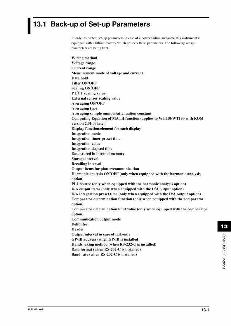
IM 253401-01E 13-1
13
Other U
seful Functions
13.1 Back-up of Set-up Parameters
In order to protect set-up parameters in case of a power failure and such, this instrument is
equipped with a lithium battery which protects these parameters. The following set-up
parameters are being kept.
Wiring methodVoltage rangeCurrent rangeMeasurement mode of voltage and currentData holdFilter ON/OFFScaling ON/OFFPT/CT scaling valueExternal sensor scaling valueAveraging ON/OFFAveraging typeAveraging sample number/attenuation constantComputing Equation of MATH function (applies to WT110/WT130 with ROMversion 2.01 or later)Display function/element for each displayIntegration modeIntegration timer preset timeIntegration valueIntegration elapsed timeData stored in internal memoryStorage intervalRecalling intervalOutput items for plotter/communicationHarmonic analysis ON/OFF (only when equipped with the harmonic analysisoption)PLL source (only when equipped with the harmonic analysis option)D/A output items (only when equipped with the D/A output option)D/A integration preset time (only when equipped with the D/A output option)Comparator determination function (only when equipped with the comparatoroption)Comparator determination limit value (only when equipped with the comparatoroption)Communication output modeDelimiterHeaderOutput interval in case of talk-onlyGP-IB address (when GP-IB is installed)Handshaking method (when RS-232-C is installed)Data format (when RS-232-C is installed)Baud rate (when RS-232-C is installed)

IM 253401-01E13-2
13.2 Initializing Set-up Parameters
Relevant Keys
SCALING AVG FILTER STORE RECALL HARMONICS
SAMPLE
V OVER
A OVER
MODE
RMS
V MEAN
DC
A
B
C
hour
hour
min
min sec
V VAm
Ak var
M W TIME
V PFm
Ak deg
M W %
FUNCTION
AUTO AUTO
MODE
1Φ3W
V Hzm
Ak h
M W
TRIG
V RANGE A RANGE HOLD
ENTER
INTEGRATOR
START
HARMONICS MEMORY INTEG SET
STOP RESET
REMOTE
INTERFACE OUTPUT
LOCAL SETUP
hSHIFT
WIRING3Φ4W
3Φ3W
3V3A
ELEMENT
1 2 3
FUNCTION ELEMENT
1 2 3
FUNCTION ELEMENT
1 2 3
*Shows the operation panel of the WT130. For the differences between WT110 and WT130, refer to section 2.2, page 2-2, 2-3
Displays relevant keys and indicator
Operating Procedure
SETUP
ENTER3.
Selecting initializing(Display C)
2.
End ⇒ Settings will be initialized
1.
• Perform operations following the thick line in the below menu.• Press the ENTER key to confirm the selection or setting.• When you want to leave the current menu during operation, press the key described under step 1. The confirmed settings made until that point will be kept.
ExplanationInitializing Set-up ParametersSet-up parameters will be initialized as soon as the ENTER key is being pressed in theprocedure described above. The initial settings are as follows.
Item Initial settingDisplay A Display function: V, element: 1Display B Display function: A, element: 1Display C Display function: W, element: 1Filter OFFMeasurement range Auto rangeMeasurement mode RMSWiring method (only WT130) 1F3WHold OFFPC/CT scaling value P: 1.000, C: 1.000, F: 1.000
scaling ON/OFF: OFFExternal sensor scaling value 50.00AAveraging Averaging type: exponential, attenuation constant: 8
Averaging ON/OFF: OFFMATH computing equation WT110: Voltage crest factor
WT130: EfficiencyFrequency VHzIntegration Reset condition, integration mode: manual
Integration preset time: 0hr, 0minHarmonic analysis (option) PLL source: V1, harmonic distortion factor computation format: IEC, element: 1
Harmonic analysis function ON/OFF: OFFStorage/recalling Interval: 0hr 0min 0sec, storage/recalling ON/OFF: OFFD/A output (option) Output items: normal measurement items, integration preset time: 1hr, 0minComparator (option) Mode: single, determination function: (V1, A1, P1, PF1)
Limit value: refer to page 10-12, 10-13, display function ON/OFF: OFFData output Communication, item: normal measurement settingGP-IB Addressable mode: A, address: 1, status byte:15,
delimiter: 0RS-232-C Normal mode, handshaking mode: 0, format: 0,
Baud rate: 9600, delimiter: 0, status byte: 15
Note• Be careful since measurement data will be lost when initializing. However, measurement data or set-up
parameters stored in the internal memory will be kept.• "MATH computing equation" applies to WT110/WT130 with ROM version 2.01 or later.

IM 253401-01E 14-1
14
Adjustm
ent, Calibration and T
rouble-Shooting
14.1 Adjustments
When the measurement values are erroneous, adjust this instrument using the following
procedures.
Required EquipmentsAC Voltage/Current Standard (0.02%, 30 to 300V, 1 to 10A/60Hz)
recommended: Yokogawa 9100
or 2558 (if you want to carry out adjustments with an accuracy higher than the one 2558 is
providing, fine adjust the output using the Digital Multi Meter (DMM) 1271)
DMM (0.5%)
recommended: Yokogawa 7552
AdjustingPreparations• Preparing this instrument1 Turn ON the power while pressing the SHIFT key. Release the SHIFT key after all LED’s
have lit up.
2 Press the ENTER key.
“rAnGE” will appear on display C. Press the ∧ or ∨ key and the display will change to “Ein”
(in case of the external input option), “dA” (in case of the D/A option) or “End”. The
“rAnGE” mode is for adjustments of voltages or currents, while the “dA” mode is for
adjustments of the D/A output. This instrument has no need for adjustment of power.
3 Select “rAnGE” and press the ENTER key. Then let the instrument warm up for at least 30
minutes.
• Preparing the AC voltage/current standard and DMM4 Allow a warm-up time of at least one hour for the AC voltage/current standard and, if
necessary, DMM.
Operating KeysThe keys to be used for carrying out adjustments, are as follows.
ENTER : Press this key to confirm every adjustment of each range.
SHIFT : Returns to the previous screen when aborting adjustment. However, since the
adjustments will not be displayed, turn the power OFF and ON again.
RESET : Returns to normal measurement. However, all adjusted data will become
invalid.
A RANGE : Press this key to proceed to the following range without adjusting the current
range. When adjusting the D/A output, press this key to move the new input
value to the right.
V RANGE : Press this key to return to the previous range without adjusting the current
range. When adjusting the D/A output, press this key to move the new input
value to the left.
Adjusting the Voltage Range1 Select “rAnGE” as described in the preparation above, press the ENTER key, and the display
will become as follows.
Display A rAnGE
Display B 30.00V
Display C displays measurement value for five seconds.
2 Connect the voltage output of the AC voltage/current standard to the voltage input terminal of
this instrument. Connect the H terminal of the standard to the V terminal of this instrument,
and connect the L terminal of the standard to the ± terminal of this instrument. In case of the
WT130, bundle all V terminals together and bundle all ± terminals together.
3 Set the output voltage of the standard to 30.00V and output this voltage.

IM 253401-01E14-2
4 Press the ENTER key after the value on display C stabilizes. (Even in a stabilized condition,
drifting within ± 2 digits limit may occur.)
5 Display B will change to “300.0” V.
6 Set the output voltage of the standard to 300.0V.
7 Press the ENTER key after the value on display C stabilizes. (Even in a stabilized condition,
drifting within ± 2 digits limit may occur.)
8 Turn the output of the standard OFF.
This completes the adjustment of the voltage range. The current range will be adjusted next.
If the current range is not to be adjusted, press the SHIFT key here.
Adjusting the Current Range1 After having completed adjusting the 300V voltage range, display B will show “1.000” A.
2 Connect the current output of the AC voltage/current standard to the current input terminal of
this instrument. Connect the H terminal of the standard to the A terminal of this instrument,
and connect the L terminal of the standard to the ± terminal of this instrument. In case of the
WT130, connect the current terminal of each input element horizontally. That is connect the
H terminal of the standard to the A terminal of element 1, the ± terminal to the A terminal of
element 2, the ± to the A terminal of element 3, followed by connecting the ± terminal to the
L terminal of the standard.
3 Set the output of the standard to 1.000A and output this current.
4 Press the ENTER key after the value on display C stabilizes. (Even in a stabilized condition,
drifting within ± 1 digit limit may occur.)
5 Display B will change to “10.00” A.
6 Set the output of the standard to 10.000A.
7 Press the ENTER key after the value on display C stabilizes. (Even in a stabilized condition,
drifting within ± 1 digit limit may occur.)
8 Turn the output of the standard OFF.
9 Press the SHIFT key and display C will change to “rAnGE”. This completes the range
adjustments. When you press the RESET key instead of the SHIFT key, the carried out
adjustments will become invalid.
In case the External Input Option is installed (/EX1 or /EX2)1 Select “Ein” in step 2 of Preparing this instrument (see previous page) and press the ENTER
key.
2 Display B will change to “10.00” V (or “200.0” mV).
3 Connect the voltage output of the AC voltage/current standard to the voltage input terminal of
this instrument. Connect the H terminal of the standard to the EXT terminal of this
instrument, and connect the L terminal of the standard to the ± terminal of this instrument. In
case of the WT130, bundle all EXT terminals together and bundle all ± terminals together.
4 Set the output voltage of the standard to 10.000V (or 200.00mV) and output this voltage.
5 Press the ENTER key after the value on display C stabilizes. (Even in a stabilized condition,
drifting within ± 2 digits limit may occur.)
6 Press the SHIFT key and display C will change to “Ein”. This completes the external input
adjustments. When you press the RESET key instead of the SHIFT key, the carried out
adjustments will become invalid.
NoteThe displayed value of the external input will become 50.000A by the rated range.
14.1 Adjustments

IM 253401-01E 14-3
14
Adjustm
ent, Calibration and T
rouble-Shooting
14.1 Adjustments
Adjusting the D/A Output• Preparations1 Connect the pin No. of the output connector corresponding to the channel to be adjusted to
the H terminal of the DMM, and connect pin No. 12 and 24 of the output connector to the L
terminal.
2 Set the range of the DMM to 20V.
3 After “dA” appears on display C (using the ∧ or ∨ key), press the ENTER key.
• AdjustingAfter having carried out the above described preparations, the displays will show the following.
Display A will be blinking.
display A: ch 1
display B: 5.000
display C: 5.0000
1 Select the channel to be adjusted on display A by pressing the ∧ or ∨ key, and then press the
ENTER key. The head digit of display C will start blinking. From that point a voltage of
approx. +5V will be output from the connector.
2 Press the V RANGE or A RANGE key to move the blinking digit of display C. Then, using
the ∧ or ∨ key, adjust the blinking value to the value displayed at the DMM.
3 After having adjusted all digits of display C, press the ENTER key. “–5.000V” will appear on
display C, and a voltage of approx. –5 V will be output from the connector.
4 Carry out step 2 once again.
5 After having adjusted all digits of display C, press the ENTER key.
6 Change the channel indication on display A from “ch1” to “ch2”. Carry out steps 1 to 5 to
adjust channel 2.
7 Carry out steps 1 to 5 to adjust all channels.
8 Press the SHIFT key and display C will change to “dA”. This completes the D/A output
adjustments. When you press the RESET key instead of the SHIFT key, the carried out
adjustments will become invalid.
After Finishing AdjustmentsAfter having finished all adjustments, turn the power OFF and ON again.
Communication Commands to Carry Out AdjustmentsCommand DescriptionCAL1 Enters the range adjustment modeCAL2 Enters the external input range adjustment modeCAL3 Enters the D/A output adjustment modeCAL0 Finishes adjustment (and returns to normal measurement mode)CR0 Switches to 30V range in range adjustment modeCR1 Switches to 300V range in range adjustment modeCR2 Switches to 1A range in range adjustment modeCR1 Switches to 10A range in range adjustment modeCHm Switches the channel in D/A output adjustment mode m = 1 to 12CDm,n Enters the actual output value in D/A output adjustment mode
m = 1 to 12, n = actual output valueDO0 Outputs +5V in D/A output adjustment modeDO1 Outputs –5V in D/A output adjustment modeOD Requests the output of measurement data, and sets the output format to normal
measurement defaultENT Corresponds to the ENTER key operation, confirming the adjustment value.CAN Corresponds to the RESET key operation, ignoringthe adjustments.END Corresponds to the SHIFT key operation, keeping the adjustments.
Note• In case of D/A adjustment, change the channel using the CHm command, then carry out DO0 or DO1
command, and the request output using the CDm,n command. After the CDm,n command is beingexecuted by +5V or –5V, make sure to confirm by the ENT command.
• After the display has been stabilized in the range adjustment mode or external input range adjustmentmode, execute the ENT command.

IM 253401-01E14-4
14.2 Calibration
Required EquipmentDC Voltage/Current Standard
recommended: Yokogawa 2552, 2550
AC Voltage/Current Standard
recommended: Yokogawa 2558
or 9100 (up to 400Hz)
or Fluke 5200A + 5215A or 5200A + 5220A
Digital Power Meter
recommended: Yokogawa WT2000 or 2531
2ch Synchronizer
recommended: Yokogawa FG120
Calibration of DC Voltage, Current and PowerWiringConnect the DC voltage and DC current standard as follows. In case of the WT130, voltages are
connected parallel, and currents in series.
DC voltagestandard
H
L
DC Amp.H
L
V
±A
± EUT
V
±A
±
V
±A
±
DC voltage standard
EUT
H
L
EXT
± (A)
EXT
± (A)
EXT
± (A)
EUT:Equipment under test
• External sensor input (equipped with option /EX1)
• Direct input

IM 253401-01E 14-5
14
Adjustm
ent, Calibration and T
rouble-Shooting
DC voltage standard
EUT
H
L
EXT
± (A)
EXT
± (A)
EXT
± (A)
• External sensor input (equipped with option /EX2)
CalibrationRegarding the combination of voltage and current ranges, we recommend applying the
following.
• Test the current ranges with the voltage range set to 150V;
• Test the voltage ranges with the current range set to 5A.
Of course testing can be carried out using other combinations as well.
1 Set the voltage or current range of this instrument to the testing range.
2 Set the output voltage of the DC voltage standard to the rated range value of this instrument,
and output the voltage.
3 Set the output current of the DC current standard to the rated range value of this instrument,
and output the current.
4 Fine adjust the output setting value of the voltage standard so that the voltage or current value
displayed on this instrument shows the rated range.
5 Read the output voltage or current setting value of the voltage standard and treat this as the
reference.
6 Verify that the power factor value displayed on this instrument shows the rated value. The
product of the voltage setting value and the current setting value of the voltage standard is the
calibrated power factor value.
NoteBefore carrying out the calibration described above, verify that this instrument performs within its accuracyspecifications.• Set the output of the DC voltage standard to the rated range of this instrument, read this voltage or
current value on the display on this instrument and verify that this value lies within this instrument’saccuracy.
• Set the output of the DC voltage standard to the rated range of this instrument, read the power factorvalue on the display on this instrument and verify that this value lies within this instrument’s accuracy.
14.2 Calibration

IM 253401-01E14-6
14.2 Calibration
Calibration of AC Voltage, Current and PowerWiringConnect the Digital Power meter, Synchronizer and the AC voltage and AC current standard as
follows.
AC voltage standard
H
L
H
L
AC voltage standard
V
±A
± EUT
V
±A
±
V
±A
±
V
±A
±
Digital power meter
Synchronizer
AC voltage standard
EUT
H
L
EXT
± (A)
EXT
± (A)
EXT
± (A)
EUT:Equipment under test
• Direct input
• External sensor input (equipped with option /EX1)Change as follows for wiring currents only.
Synchronizer

IM 253401-01E 14-7
14
Adjustm
ent, Calibration and T
rouble-Shooting
AC voltage standard
EUT
H
L
EXT
± (A)
EXT
± (A)
EXT
± (A)
• External sensor input (equipped with option /EX2)Change as follows for wiring currents only.
Synchronizer
PreparationSet the frequency of the AC voltage standard and of each channel of the synchronizer to 60Hz.
Then, while not exceeding the maximum values of the external synchronization inputs of the
voltage and current standard, rise the output level of the synchronizer until the standards are
synchronized. Make sure that the phase angle between each channel of the synchronizer is 0
degrees.
Calibrating1 Set the voltage or current range of this instrument to the range to be calibrated.
2 Set the output voltage of the AC voltage standard to the rated range of this instrument, and
output the voltage.
3 Set the output current of the AC current standard to the rated range of this instrument, and
output the current.
4 Fine adjust the output values of the standard so that the displayed voltage or current value on
this instrument show the rated range.
5 Read the output voltage or current value, and keep it as a reference.
6 Verify that the displayed power value corresponds to the rated value. The product of the
voltage value and the current value is the reference value of the power.
Note• Before starting the above described calibration, verify that the accuracy of this instrument lies within the
specifications.- Adjust the output of the standard to the rated range value of this instrument, then read the displayed
voltage or current value on this instrument and verify that this value lies within the specifications.- Slightly change the phase angle of ch2 of the synchronizer (current signal) so that the displayed power
value becomes the rated value. Then read the displayed power value on this instrument and verify thatthis value lies within the specifications (power factor = 1).
- Change the phase of ch2 of the synchronizer so that the displayed power value becomes zero. Thenread the displayed power value on this instrument and verify that this value lies within thespecifications (power factor = 0).
• When calibrating the harmonic analysis, match the phase so that the displayed power value becomes thecalibrated value.
• When calibrating using a frequency of more than 60Hz, set the same frequency for the synchronizer andthe standard. In such a case, use a voltage/current standard which surely has a sufficient accuracyregarding the output frequency. This means to use measuring equipment with an accuracy of 3 to 4 timesthe specified higher accuracy of this instrument.
14.2 Calibration

IM 253401-01E14-8
14.2 Calibration
Calibration of D/A OutputPreparation1 Connect the AC voltage standard to the voltage terminal of this instrument. The wiring
method is the same as when adjustments are carried out (see page 14-3). However, calibration
of the WT130 can also be carried out when only element 1 is connected.
2 Set the D/A output of this instrument to V1 for each channel.
Calibrating1 Connect the DMM to ch1 of the output terminal in the same way as when carrying out
adjustments.
2 Set the voltage range of this instrument to a suitable range.
3 Set the output voltage of the voltage standard so that positive rated values are generated.
4 Then read the value of the DMM and verify that this value lies within the specifications.
5 Connect the DMM to ch2 of D/A output and carry out steps 3 and 4. Repeat this for all D/A
channels.
6 Set the output voltage of the voltage standard so that negative rated values are generated.
7 Repeat steps 4 and 5 and verify all channels.
8 Turn the output of the voltage standard OFF.
Verifying the Comparator Output FunctionPreparation1 Connect the voltage standard to the voltage terminal of this instrument.
2 Set the range of this instrument to 15V.
3 Set the comparator output to V1 for each channel.
4 Set the comparator setting value to 10V for each channel.
Calibrating1 Set the output of the voltage standard so that the displayed value on this instrument becomes
9.99V, and output this voltage.
2 Measure the resistance values between all terminals of the comparator output (between NO
and COM or between NC and COM) using the DMM. Verify that the resistance between NO
and COM is at least 50MΩ, and that the resistance between NC and COM is at most 0.1Ω.
3 Set the output of the voltage standard so that the displayed value on this instrument becomes
10.01V, and output this voltage.
4 Measure the resistance values between all terminals of the comparator output (between NO
and COM or between NC and COM) using the DMM. Verify that the resistance between NO
and COM is at most 0.1Ω, and that the resistance between NC and COM is at least 50MΩ.
5 Turn the output of the voltage standard OFF.

IM 253401-01E 14-9
14
Adjustm
ent, Calibration and T
rouble-Shooting
Calibration of the Harmonic Analysis FunctionConnectionUse the same instruments as in case of AC power measurement and connect them in the same
way (refer to page 14-6 and 14-7).
Preparation1 Set the voltage range of this instrument to 15V, and the current range to 1A.
2 Turn the harmonic analysis function ON.
Calibrating Currents1 Set the ch1 of the synchronizer to 60Hz, ch 2 to 900Hz (15 times) and output these
frequencies.
2 Set the frequency of the voltage standard to 60Hz, the output voltage to 15V and output the
voltage.
3 Set the frequency of the current standard to 900Hz, the output current to 1A and output the
current.
4 Set the displayed number on display A of this instrument to 15.
5 Set the display function of display B to A and verify that the displayed value lies within the
specifications. In case of the WT130, verify each element 1, 2, and 3.
6 If required, change the ch2 setting of the synchronizer and the frequency of the current
standard, and verify another number.
7 Turn the output of the voltage and current standard OFF.
Calibrating Voltages1 Set the ch1 of the synchronizer to 900Hz (15 times), ch 2 to 60Hz and output these
frequencies.
2 Set the frequency of the current standard to 60Hz, the output current to 1A and output the
current.
3 Set the frequency of the voltage standard to 900Hz, the output voltage to 15V and output the
voltage.
4 Set the displayed number on display A of this instrument to 15.
5 Set the display function of display B to V and verify that the displayed value lies within the
specifications. In case of the WT130, verify each element 1, 2, and 3.
6 If required, change the ch1 setting of the synchronizer and the frequency of the current
standard, and verify another number.
7 Turn the output of the voltage and current standard OFF.
Verification of FunctionsAuto Range Operation1 Set the voltage or current range of this instrument to Auto range. In case of no voltage or
current input, the voltage range will become 15V, and the current range will become 0.5A
automatically.
2 Press the V RANGE key to verify the 15V range and then press this key once more.
3 Press the A RANGE key to verify the 0.5A range and then press this key once more.
4 Connect the output terminal of the voltage standard (either AC or DC) to the voltage input
terminal of this instrument, and connect the current standard to the current input terminal.
5 Set the output voltage of the voltage standard to 600V and output this voltage.
6 Verify that the display shows “––––” as the measured voltage value for approx. 1.5 seconds
and then changes to 600V.
7 Turn the output of the voltage standard OFF.
8 Set the output current of the current standard to 20A and output this current.
9 Verify that the display shows “––––” as the measured current value for approx. 1.5 seconds
and then changes to 20A.
10 Turn the output of the current standard OFF.
14.2 Calibration

IM 253401-01E14-10
14.3 In Case of Malfunctioning
Check These Items FirstIf the instrument does not operate properly even if the actions given in the table below are
performed, contact your nearest sales representative. Addresses may be found on the back cover
of this manual. When contacting your representative, inform the ROM version No. which is
displayed on display B on power-up.
Items to check
⋅ Is the power cord properly connected to the power connector of this instrument and the AC outlet?
⋅ Is the input power voltage within the allowed range?⋅ Has the fuse blown? (for WT130 only)
⋅ Is there a possibility of noise?⋅ Are measurement leads connected correctly?⋅ Is the filter OFF?⋅ Are the ambient temperature and humidity within the allowed
range?
⋅ Is the REMOTE indicator LED off?
⋅ Does the GP-IB address specified in the program match the address set up in the instrument?
⋅ Does the interface meet the IEEE standard 488-1978 electrical and mechanical requirements?
⋅ Are the instrument and controller using the same communication settings?
Symptom
Displayed data is odd.
Keys do not function properly.
Instrument cannot be controlled via the RS-232-C interface.
Nothing is displayed when the power is turned ON.
Instrument cannot be controlled via GP-IB interface.
Referencepage
3-12,3-13
14-13
3-2,3-4,3-5 to 3-11,3-15,4-1,4-3
11-2
11-1,11-9
12-1 to 12-3

IM 253401-01E 14-11
14
Adjustm
ent, Calibration and T
rouble-Shooting
14.4 Error Codes and Corrective Actions
Error Codes for Operation and MeasurementCorrective Action
Check for error in the command sent.
Correct the value.
Check whether integration is in progress or is interrupted.
It is not possible to set auto range while external sensor range is selected.
Check whether the command or key operation is correct.
Check whether harmonic analysis is in progress or is interrupted.
Store data in the internal memory or select the proper file to be stored.
Reset integration.
Set a correct preset time.
Error Code
11
12
13
14
15
16
17
18
19
30
31
32
33
41
42
43
44
45
46
47
50
51
52
53
Reference pageDescription
Received a command not used by this instrument.
Parameter value specified is outside the allowed range.
Attempted to execute a key operation or received a communications command, while integration was running or was interrupted, that cannot be executed or received in such a state.
Attempted to set auto range while external sensor range is selected.
Attempted to execute a command or key operation that was protected.
Attempted to execute a key operation or received a communications command, while harmonic analysis was being performed or was interrupted, that cannot be executed or received in such a state.
Print output time-out.
No data to be printed or not in the printing mode.
Attempted to execute a key operation or received a communications command, while storing/recalling of data being performed.
Invalid file data.
File is damaged.
No data stored in the internal memory.
No space to store data in the internal memory.
⋅ Attempted to start integration while there is an overflow condition.
⋅ Attempted to start integration after integration time has reached its preset value.
Attempted to start integration while integration is in progress.
Measurement stopped due to overflow during integration or due to a power failure.
Attempted to stop integration even though integration was not in progress.
Attempted to reset integration even though integration was not in progress or integration mode was not selected.
Attempted to start integration while measurement of peak overflow was in progress or during an overrange condition.
Attempted to start integration in continuous integration mode when integration preset time was set to "0".
A/D conversion time-out.
Measurement data overflow occurred."oL" is displayed.
Voltage peak overflow occurred.V OVER indicator lights up.
Current peak overflow occurred.A OVER indicator lights up.
11-12
App. 2
7-8, 11-12
4-5
-
8-5
10-18
10-17
-
-
-
Ch. 9
9-2
7-5
7-8
7-8
7-8
7-6
2-4
7-4
-
2-4
2-4
2-4

IM 253401-01E14-12
14.4 Error Codes and Corrective Actions
Lower the baud rate.
54
55
56
57
58
59
390
Power factor exceeded "2" during measurement of power factor.
"PFErr" was displayed at the end of power factor computation during measurement of phase angle.
Input level was too low or below measurement range during measurement of frequency. "Err-Lo" is displayed.
Measured frequency exceeded the measurement range. "Err-Hi" is displayed.
Computation overflow occurred."oF" is displayed.
Harmonic analysis becomes "FrqEr".
Overrun error.
6-1
6-1, 6-2
5-3
5-3
2-4
8-2
12-6
Error Codes regarding Self Diagnosis
Error Code Description Corrective Action60 Data failure of set-up parameters backup. -
(set-up parameters are set to default)61 EEPROM (element 1) failure. Service is required.62 EEPROM (element 2) failure. Service is required63 EEPROM (element 3) failure. Service is required.64 EEPROM (D/A board) failure. Service is required.65 A/D converter (element 1) failure. Service is required.66 A/D converter (element 2) failure. Service is required.67 A/D converter (element 3) failure. Service is required.68 Data file failure File will be initialized
(measurement data, set-up parameter file failure) automatically.69 Lithium battery voltage drop. Service is required.
71 DSP communications failure. Service is required.75 DSP1 program RAM failure. Service is required.76 DSP2 program RAM failure. Service is required.77 DSP3 program RAM failure. Service is required.79 ROM checksum error. Service is required.80 RAM read/write check error. Service is required.81 DSP1 data RAM error. Service is required.82 DSP2 data RAM error. Service is required.83 DSP3 data RAM error. Service is required.84 DSP1 sample clock failure. Service is required.85 DSP2 sample clock failure. Service is required.86 DSP3 sample clock failure. Service is required.90 Incorrect board combination. Service is required.91 Incorrect board combination. Service is required.

IM 253401-01E 14-13
14
Adjustm
ent, Calibration and T
rouble-Shooting
14.5 Replacing the Fuse (for WT130)
When replacing the fuse of the WT130, carry out the procedure described below.
WARNING• The fuse used must be of the specified rating (current, voltage, type) in
order to prevent a fire hazard.
• Make sure to turn OFF the power switch and to unplug the power cord fromits source before replacing the fuse.
• Never short-circuit the fuse holder.
Fuse RatingsThe fuse used in the WT130 has the following specifications.
100V/200V CommonMaximum rated voltage : 250V
Maximum rate current : 0.5A
Type : Time-lag
Approved standard : UL/VDE
Parts number : A1346EF
Replacing ProcedureReplace the fuse as follows.
1 Turn the power switch OFF.
2 Unplug the power cord from the power connector.
3 Place the tip of a flat-blade screwdriver in to the slot of the fuse holder, and move the
screwdriver in the direction of the arrow to remove the fuse holder.
4 Remove the blown fuse.
5 Insert a new fuse into the holder, then install the holder in place.
NoteThe fuse used in the WT110 can not be replaced by the user, because of the fuse inside the case. If youbelieve the fuse is blown, please contact your nearest YOKOGAWA representative listed on the backcover of this manual. The ratings of the fuses used inside the case are indicated below.
Location Max. rated voltage Max. rated current Type Approved standard Part No.Main board 250 V 1 A Time lag UL/VDE S9564VK

IM 253401-01E 15-1
15
Specifications
Chapter 15 Specifications
15.1 Input
Item
Input circuit type
Rated inputs (range rms)
Input impedance
Instantaneous maximum allowable input for 20 ms, 1 cycle
Instantaneous maximum allowable
input for 1 s
Continuous maximum allowable input
Continuous maximum common mode
voltage (at 50/60 Hz)
Common mode rejection ratio at 600 Vrms between input terminals and case
Input terminals
A/D conversion
Range switching
Automatic range switching
Measurement mode switching
Voltage (V)
Resistive voltage divider
15/30/60/150/300/600V
Input resistance approx.2MΩ, Input capacitance approx.13 pF
The peak is 2.8 kV or the RMS value is 2.0 kV, whichever is less.
The peak is 2.0 kV or the RMS value is 1.5 kV, whichever is less.
The peak is 1.5 kV or the RMS value is 1.0 kV, whichever is less.
Binding posts
600 Vrms (when the protective cover for the output connector is used)CAT II,400 Vrms (when the protective cover for the output connector is removed)CAT II
50/60 Hz, better than -80 dB ( ±0.01% of range maximum)Voltage input terminals : short, Current input terminals : openReference value: 50 kHz max. ±(maximum range rating)/(range rating) × 0.001 × f% of range or less; 0.01% or more; the unit f: kHz
Simultaneous sampling of voltage and current inputs; Resolution: 12 bits; Maximum conversion rate: approx. 22µs (approx. 45 kHz)
Range can be selected manually, automatically or by communication control.
Range up: When the measured value exceeds 110% of the rated range or the peak value exceeds approximately 300% of the rated rangeRange down: When the measured value becomes less than 30% of the rated range and the peak value is less than approximately 300% of thesubordinate range
The following modes can be set manually or by communication control:RMS: True RMS measurement for both voltage and current; V MEAN: Rectified Mean Calibrated to an RMS sine wave measurement for voltage,and true RMS measurement for current; DC: Mean value measurement for voltage and current
Floating input
Current (A)
Shunt input
Direct input: 0.5/1/2/5/10/20 AExternal input (optional): 2.5/5/10 V or 50/100/200 mV
Direct input: approx. 6 mΩ + approx. 0.1 µHExternal input: 2.5/5/10 V - approx. 100 kΩ; 50/100/200 mV - approx. 20 kΩ
The peak is 450 A or the RMS value is 300 A, whichever is less.External input: Peak value is 10 times the range or less.
The peak is 150 A or the RMS value is 40 A, whichever is less.External input: Peak value is 10 times the range or less.
The peak is 100 A or the RMS value is 30 A, whichever is less.External input: Peak value is 5 times the range or less.
Direct input: Large binding posts, External input: Safety terminals
15.2 Measurement Functions
Item
Method
Frequency range
Crest factor
Display accuracy
Accuracy (within 3 months after calibration)
(Conditions)
Temperature: 23 ±5°CHumidity: 30% to 75% R.H.
Supply voltage: Specified Voltage ±5%
Input waveform: Sine wave
Common mode voltage: 0 V DC
Filter: ON at 200 Hz or less
Scaling: OFF
This accuracy are guaranteed by
YOKOGAWA calibration system.
Note: The unit f in accuracy expressions is kHz.
Effect of power factor
Note: The ϕ is the phase angle between the
voltage and current, and the f is frequency.
Effective input range
Accuracy (within 12 months after calibration)
Temperature coefficient
Display update rate
Voltage/current Effective power
cosϕ = 0
45 Hz ≤ f ≤ 66 Hz:add ±0.25% of range
Reference data (up to 50kHz): add ±(0.23 + 0.4 × fkHz)% of range
1 > cosϕ > 0
add the product of tanϕ and the effect on cosϕ = 0.
With the input range at 10% to 110%, the above specified accuracy is valid. With the input range at 110% to 130%, the above specified reading accuracy increased 0.5 times is added to the accuracy.
The above specified reading accuracy increased 0.5 times is added to the accuracy (within 3 months after calibration).
±0.03% of range/°C at 5 to 18°C, 28 to 40°C4 times/s
Digital sampling method, summation averaging method
DC, 10 Hz to 50 kHz
"3" at rated input
* DC: ±0.2% of range is added if the 0.5/1 A range is selected. * DC: ±0.2% of range is added if the 0.5/1 A range is selected.
DC :
10Hz ≤ f < 45Hz :
45Hz ≤ f ≤ 66Hz :
66Hz < f ≤ 1kHz :
1kHz < f ≤ 10kHz :
10kHz < f ≤ 20kHz :
Reference value
20kHz < f ≤ 50kHz :
±(0.2 % of rdg + 0.2% of rng)*
±(0.3% of rdg + 0.2% of rng)
±(0.15% of rdg + 0.1% of rng)
±(0.3% of rdg + 0.2% of rng)
±(0.2% of rdg + 0.3% of rng)
±(0.05 × f)% of rdg
±(0.5% of rdg + 0.5% of rng)
±[0.15 × (f-10)% of rdg]
±(0.5% of rdg + 0.5% of rng)
±[0.15 × (f-10)% of rdg]
DC :
10Hz ≤ f < 45Hz :
45Hz ≤ f ≤ 66Hz :
66Hz < f ≤ 1kHz :
1kHz < f ≤ 10kHz :
10kHz < f ≤ 20kHz :
Reference value
20kHz < f ≤ 50kHz :
±(0.3% of rdg + 0.3% of rng)*
±(0.5% of rdg + 0.3% of rng)
±(0.25% of rdg + 0.1% of rng)
±(0.5% of rdg + 0.3% of rng)
±(0.3% of rdg + 0.5% of rng)
±(0.08 × f)% of rdg
±(0.8% of rdg + 0.8% of rng)
±[0.19 × (f-10)% of rdg]
±(0.8% of rdg + 0.8 % of rng)
±[0.25 × (f-10)% of rdg]
15.3 Frequency Measurement
Input: V1, V2, V3, A1, A2, A3Operating principle: Reciprocal counting methodFrequency ranges: 10 Hz to 50 kHzAccuracy: ±(0.1% of rdg + 1 digit)
Minimum input is more than 30% of rated range.When an input frequency is less than 200Hz, FILTER must be
ON to obtain the specification accuracy.Minimum input frequency is more than 20% of frequency
measurement range.
15.4 Communication
Communication Specifications (GP-IB & RS-232-C)GP-IB:
Electrical specifications: IEEE St’d 488.2-1987Mechanical specifications: IEEE St’d 488.2-1987Interface function: SH1, AH1, T5, L4, SR1, RL1, PP0,
DC1,DT1, C0RS-232-C:
Transmission mode: Start stop synchronizationBaud rate: 75, 150, 300, 600, 1200, 2400, 4800, 9600 bps

IM 253401-01E15-2
15.5 Computing Functions
Effective Power(W)
1-phase2-wire W VA=V×A (VA) –W
Apparent Power(VA)
Power Factor(PF)
Phase Angle(deg)
Reactive Power (var)
2 2W
VA
W
VA=cos ( )–1
1-ph
ase
3-w
ire3-
phas
e 3-
wire
(tw
o po
wer
met
er m
etho
d)
3-ph
ase
3-w
ire(t
hree
pow
er m
eter
met
hod)
3-ph
ase
4-w
ire
Com
puta
tion
W i
i =1, 3
ΣW=W1+W3
W i
i =1, 3
ΣW=W1+W3
W i
i =1,2,3
ΣW=W1+W3
W i
i =1,2,3
ΣW=W1+W2+W3
VA i =V i ×A i
i =1, 3
ΣVA=VA1+VA3
VA i =V i ×A i
i =1, 3
2 2
var i
= (VA i) –W i
i =1, 3
W i
VA i
PF i
=
i =1, 3
–1W i
VA i
ϕ i
=cos ( )
i =1, 3
Σvar=var1+var3
2 2
var i
= (VA i) –W i
i =1, 3
Σvar=var1+var3
2 2
var i
= (VA i) –W i
i =1,2,3
Σvar=var1+var3
2 2
var i
= (VA i) –W i
i =1,2,3
Σvar=var1+var2+var3
ΣW
ΣVA
ΣPF
=
W i
VA i
PF i
=
i =1, 3
ΣW
ΣVA
ΣPF
=
W i
VA i
PF i
=
i =1,2,3
ΣW
ΣVA
ΣPF
=
W i
VA i
PF i
=
i =1,2,3
ΣW
ΣVA
ΣPF
=
–1 ΣW
ΣVA
Σϕ
=cos ( )
–1W i
VA i
ϕ i
=cos ( )
i =1, 3
–1 ΣW
ΣVA
Σϕ
=cos ( )
–1W i
VA i
ϕ i
=cos ( )
i =1,2,3
–1 ΣW
ΣVA
Σϕ
=cos ( )
–1W i
VA i
ϕ i
=cos ( )
i =1,2,3
–1ΣW
ΣVA
Σϕ
=cos ( )
ΣVA
=
(VA1+VA3 )
32
VA i =V i ×A i
i =1,2,3
ΣVA
=
(VA1+VA2+VA3)
33
VA i =V i ×A i
i =1,2,3
ΣVA=VA1+VA2+VA3
ComputatingRange
Depends on the selected V and A ranges
Depends on the selected V and A ranges
Same as apparent power (var ≤ 0) -1 to 0 to 1 -180 to 0 to 180
Display resolution 10000 10000 10000 ±1.000 ±180.0
Computing accuracy (for the value operated from the measured value)
— ±0.005% of VA range
±0.005% of var range
±0.0005Resolution (power factor ±0.0005)
Note 1: The apparent power (VA), reactive power (var), power factor (PF), and phase angle(deg) measurements in this instrument are computed digitally from the voltage,current and effective power. If the input is non-sinusoidal, the measured values maydiffer from those obtained with instruments employing different measurementprinciples.
Note 2: When the current or voltage is less than 0.5% of the range, the VA and var will bedisplayed as 0, and PF/deg will be displayed as an error.
Note 3: The Lead and Lag are displayed for V and A input at 50% or more. The detectedlead/lag accuracy is ±5 degrees over the frequency range of 20 Hz to 2 kHz.
15.6 Display Functions
Display type: 7-segment LEDNumber of displays: 3
DISPLAYABC
* Vpk, Apk, and MATH are supported only for ROM versions 2.01 or later.
V, A, W : 9999Wh, Ah : 999999V, AHz : 9999
V, A, W, VA, var (each element), elapsed integration timeV, A, W, PF, deg (each element), % (contents ratio in %, THD)V, A, W, V ⋅ AHz, ±Wh, ±Ah (each element)Vpk*, Apk*, MATH*
Displayed Value Maximum Reading
Unit: m, k, M, V, A, W, VA, var, Hz, h±, deg, %Display update rate: 4 times/sResponse time: Approximately 0.5 s (time for displayed value to settle within
accuracy specifications of final value after step change from 0% to100% or 100% to 0% of rated range)
Display scaling function Significant digits: Selected automatically according tosignificant digits in the voltage and current rangesReassign ratio: 0.001 to 1000
Averaging function: The following two algorithms can be selected:Exponential averagingMoving averagingResponse can be set; for exponential averaging, the attenuationconstant can be selected and for moving averaging, the number ofaverages (N) can be set to 8, 16, 32, or 64.
Peak over range display The alarm LED will light up when the RMS value is greater than140% of the range or the peak value is greater than 300% of therange.
15.7 Integrator Function
Display resolution: Depending on elapsed time value, the resolution will be changed.Maximum display: –99999 to 999999 MWh (or MAh)Modes: Standard integration mode (timer mode)
Continuous integration mode (repeat mode)Manual integration mode
Timer: When the timer is set, integration will be stopped automatically.Setting range: 000 h:00 min to 999 h:59 min (000 h:00 min will beshown when manual integration mode is selected automatically.)
Count overflow: If the integration count flows above 999999 MWh (or MAh) or below–99999 MWh (or MAh), integration stops and the elapsed time isheld on the display.
Accuracy: ±(display accuracy + 0.2% of rdg) However, only when the inputsignal is continuous.
Timer accuracy: ±0.02%Remote control: Start, stop, and reset can be remotely controlled by external
contact signals.However, the /DA4 or /DA12 options must be installed.
15.8 Internal Memory Function
Measurement dataNumber of data that can be stored:
WT110 (253401): 600 blocksWT130 (253502): 300 blocksWT130 (253503): 200 blocks
Each block has following data:measurement setting mode, measurement ranges, V, A, W,Wh+, Wh-, Ah+, Ah-, elapsed time and frequencyWriting intervals: 250 ms and 1 s to 99 h: 59 min: 59 sReading intervals: 250 ms and 1 s to 99 h: 59 min: 59 s (bothintervals can be set on a second basis)
Panel setup information: Four-pattern information can be written/read.
15.9 D/A Converter (optional)
Output voltage: ±5 VDC FS (approximately ±7.5 V maximum) at rated value orrange Number of output channels: 12 when the /DA12 option isinstalled; 4 when the /DA4 option is installed
Output data selection: Can be selected for each channel.Accuracy: ±(Display accuracy + 0.2% of range)Update rate: Identical to display update intervalTemperature coefficient: ±0.05% of f.s./ °C
• Frequency
D/A output
Displayed value [Hz]4
0.2V0.5V
2.5V
5.0V
10 100 1k 10k 50k
Approx. 7.5V
• Integration
D/A output
Approx. 7.0V
5.0V
0 t0 Integration time
140% input of the rated value
Rated value input
t0: Rated value setting time
• Other items
D/A output
0V–100%–140%
–5.0V
Approx. –7.0VApprox. –7.5V
5.0V
Approx. 7.0VApprox. 7.5V
140%100%
Displayed value 140% 100% 0%–100%–140%
Output Approx. 7.0V
5.0V 0V–5.0V
Approx. –7.0V
However, for PF and deg, points in the range from +5 to +7 V and from –5 to –7 V are not output. If there is an error, the output will be about ±7.5 V.
Displayed value
Chapter 15 Specifications

IM 253401-01E 15-3
15
Specifications
Chapter 15 Specifications
15.10 External Input (optional)
Either /EX1 or /EX2 can be selected as a voltage-output-type current sensor./EX1: 2.5/5/10 V/EX2: 50/100/200 mVSpecifications: Refer to item “Input.”
15.11 Comparator Output (optional)
Output method: Normally open and normally closed relay contact outputs (one pair)Number of output channels and channel setup: 4 (Can be set for each channel.)Contact capacity: 24 V/0.5 AD/A output (4 channels): Refer to item “D/A Output (Optional).”
15.12 External Control and Input Signals(in combination with the D/A converter and comparator options)
External Control and Input/Output signalsEXT-HOLD, EXT-TRIG, EXT-START, EXT-STOP, EXT-RESET,INTEG-BUSY(However, the /DA4 or /DA12 options must be installed. Only EXT-HOLD and EXT-TRIG are available if the /CMP option is installed.)
Input level:-TTL negative pulse
15.13 General Specifications
Warm-up time: Approx. 30 min.Ambient temperature and humidity range: 5 to 40°C, 20% to 80% R.H. (no condensation)Operating altitude 2000m or belowInsulation resistance: Between voltage input terminals and case
Between current input terminals and output terminalsBetween voltage input terminals and current input terminalsBetween voltage input terminals of each elementBetween current input terminals of each elementBetween voltage input terminals and power plugBetween current input terminals and power plugBetween case and power plugAbove: 50 MW or more at 500 V DC
Withstanding voltage: Between voltage input terminals and caseBetween current input terminals and output terminalsBetween voltage input terminals and current input terminalsBetween voltage input terminals of each elementBetween current input terminals of each elementBetween voltage input terminals and power plugBetween current input terminals and power plugAbove: AC 3700 V for 1 minute at 50/60 HzBetween case and power plug: AC 1500 V for 1 minute at 50/60 Hz
Power supply: Any power supply voltage between 100 and 240 V; frequency: 50/60 Hz
Vibration test condition: Sweep test - Frequency: 8 to 150 Hz sweep, all 3 directions for1 minute
Endurance test - Frequency: 16.7 Hz, all 3 directions; amplitude of4 mm for 2 h
Impact condition: Impact test: Acceleration at 490 m/s2, all 3 directionsFree-fall test - Height: 100 mm, 1 time for each 4 sides
Power consumption: WT110:30 VA maximum; WT130: 50 VA maximum (Power supply :240V)WT110:20 VA maximum; WT130: 32 VA maximum (Power supply :100V)
External dimensions: WT110:Approx. W × H × D : 213 × 88 × 350 (mm),8-3/8 × 3-1/2 × 13-3/4 (inch)
WT130:Approx. W × H × D : 213 × 132 × 350 (mm),8-3/8 × 5-3/16 × 13-3/4 (inch)
Weight: WT110:Approx. 3.0 (kg), 6.6 (lbs)WT130:Approx. 5.0 (kg), 11.0 (Lbs)
Accessories: Power cord: UL/CSA, VDE, SAA or BS standard 1 pcSpare fuse (for WT130 only)24-pin connectorUser’s ManualRubber feed
Emission* Complying Standard:EN55011-Group1, Class AThis is a Class A product for industrial environment. In adomestic environment, this product may cause radiointerference in which cause the user may be required to takeadequate measures.
Cable Condition:Measuring Input
WT100To bundle the wires between source and load withFerrite Core (A1179MN).
WT130To bundle the wires between source and load for eachphase and to separate the input signal wires by lessthan 50 mm between each phase and neutral line.
External Senser Input (installed /EX1 or /EX2 option)500 mm max
External Input/Output Signals (installed /DA4, /DA12, /CMP option)To use shielded wires
Immunity* Complying Standard: EN50082-2:1995Susceptibility Under Immunity Condition
Measuring Input : ±5 % of range maxDA Output : ±40 % of range max
Testing ConditionVoltage : range 150 V Input, 100 V/50 HzCurrent : range 1 A Input, 1 A/50 Hz
Safety standard* Complying Standard :EN61010Overvoltage Category IIPollution degree 2
* Applies to products manufactured after Jan. 1997 having the CE Mark. For all otherproducts, please contact your nearest YOKOGAWA representative as listed on the backcover of this manual.
15.14 Total Harmonic Analysis Function (optional)
Method: synchronization to the fundamental frequency by using a phaselocked loop (PLL) circuit
Frequency range: Fundamental frequency between 40 Hz and 440 HzMaximum reading: 9999Items to be analyzed: V1, V2, V3, A1, A2, A3, W1, W2, W3, deg1, deg2, deg3
Each harmonic components, Total Vrms, Total Arms, Totaleffective power, PF of the fundamental, Phase-angle offundamental, For each harmonic phase-angle related to thefundamental, Total harmonic distortion ratio in %, and contentsratio in %.However, a simultaneous analysis can be made for a specifiedinput module.
Sampling speed/method:The sampling speed depends on the fundamental frequency to beinput:
Input frequency
range
Sampling frequency
Window up to the n'th
harmonicOrder
40≤ f<70Hz70≤ f<130Hz130≤ f<250Hz250≤ f<440Hz
f×512Hzf×256Hzf×128Hzf×64Hz
1 period of f2 period of f4 period of f8 period of f
50505030
FFT number of points : 512 points FFTFFT calculation accuracy:32 bitsWindow: Rectangular windowDisplay update interval: Approx. 3 sAccuracy: ±0.2% of range is added to the normal display accuracy.

IM 253401-01E15-4
15.15 External Dimensions
WT110(253401)
250213
179
8819
73 23 356
480460
99 50
24.5
116.
8
99 50
24.5
485
462
116.
8
480
460
88
44.5
21.8
6.8
485
463
88 44.5
21.8
6.8
Unit:mm
Rear
JIS rack mount
20Protruding from rack
20Protruding from rack
EIA rack mount
20Protruding from rack
20Protruding from rack
Unless other wise specified, tolerance is ±3% (However, tolerance is ±0.3mm when below 10mm)
Chapter 15 Specifications

IM 253401-01E 15-5
15
Specifications
WT130(253502, 253503)
149
100
24.5
485462
176.
8
485463
132.
5
89
21.8
6.8
480460
21.8
6.8
89132.
5
480460
24.5
6.8
17
149
100
2131313
220
23 356
Unit:mm
Rear
JIS rack mount20Protruding from rack
20Protruding from rack
EIA rack mount
20Protruding from rack
20Protruding from rack
Unless other wise specified, tolerance is ±3% (However, tolerance is ±0.3mm when below 10mm)
Chapter 15 Specifications
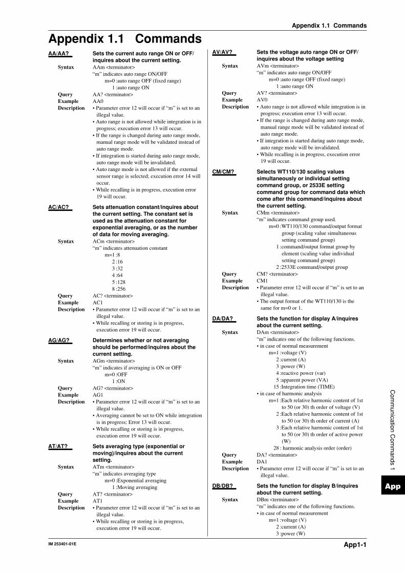
IM 253401-01E App1-1
App
Appendix 1.1 Commands
Com
munication C
omm
ands 1
Appendix 1.1 CommandsAA/AA? Sets the current auto range ON or OFF/
inquires about the current setting.Syntax AAm <terminator>
“m” indicates auto range ON/OFFm=0 :auto range OFF (fixed range)
1 :auto range ONQuery AA? <terminator>Example AA0Description • Parameter error 12 will occur if “m” is set to an
illegal value.• Auto range is not allowed while integration is in
progress; execution error 13 will occur.• If the range is changed during auto range mode,
manual range mode will be validated instead ofauto range mode.
• If integration is started during auto range mode,auto range mode will be invalidated.
• Auto range mode is not allowed if the externalsensor range is selected; execution error 14 willoccur.
• While recalling is in progress, execution error19 will occur.
AC/AC? Sets attenuation constant/inquires aboutthe current setting. The constant set isused as the attenuation constant forexponential averaging, or as the numberof data for moving averaging.
Syntax ACm <terminator>“m” indicates attenuation constant
m=1 :82 :163 :324 :645 :1288 :256
Query AC? <terminator>Example AC1Description • Parameter error 12 will occur if “m” is set to an
illegal value.• While recalling or storing is in progress,
execution error 19 will occur.
AG/AG? Determines whether or not averagingshould be performed/inquires about thecurrent setting.
Syntax AGm <terminator>“m” indicates if averaging is ON or OFF
m=0 :OFF1 :ON
Query AG? <terminator>Example AG1Description • Parameter error 12 will occur if “m” is set to an
illegal value.• Averaging cannot be set to ON while integration
is in progress; Error 13 will occur.• While recalling or storing is in progress,
execution error 19 will occur.
AT/AT? Sets averaging type (exponential ormoving)/inquires about the currentsetting.
Syntax ATm <terminator>“m” indicates averaging type
m=0 :Exponential averaging1 :Moving averaging
Query AT? <terminator>Example AT1Description • Parameter error 12 will occur if “m” is set to an
illegal value.• While recalling or storing is in progress,
execution error 19 will occur.
AV/AV? Sets the voltage auto range ON or OFF/inquires about the voltage setting
Syntax AVm <terminator>“m” indicates auto range ON/OFF
m=0 :auto range OFF (fixed range)1 :auto range ON
Query AV? <terminator>Example AV0Description • Auto range is not allowed while integration is in
progress; execution error 13 will occur.• If the range is changed during auto range mode,
manual range mode will be validated instead ofauto range mode.
• If integration is started during auto range mode,auto range mode will be invalidated.
• While recalling is in progress, execution error19 will occur.
CM/CM? Selects WT110/130 scaling valuessimultaneously or individual settingcommand group, or 2533E settingcommand group for command data whichcome after this command/inquires aboutthe current setting.
Syntax CMm <terminator>“m” indicates command group used.
m=0 :WT110/130 command/output formatgroup (scaling value simultaneoussetting command group)
1 :command/output format group byelement (scaling value individualsetting command group)
2 :2533E command/output groupQuery CM? <terminator>Example CM1Description • Parameter error 12 will occur if “m” is set to an
illegal value.• The output format of the WT110/130 is the
same for m=0 or 1.
DA/DA? Sets the function for display A/inquiresabout the current setting.
Syntax DAm <terminator>“m” indicates one of the following functions.• in case of normal measurement
m=1 :voltage (V)2 :current (A)3 :power (W)4 :reactive power (var)5 :apparent power (VA)
15 :Integration time (TIME)• in case of harmonic analysis
m=1 :Each relative harmonic content of 1stto 50 (or 30) th order of voltage (V)
2 :Each relative harmonic content of 1stto 50 (or 30) th order of current (A)
3 :Each relative harmonic content of 1stto 50 (or 30) th order of active power(W)
28 : harmonic analysis order (order)Query DA? <terminator>Example DA1Description • Parameter error 12 will occur if “m” is set to an
illegal value.
DB/DB? Sets the function for display B/inquiresabout the current setting.
Syntax DBm <terminator>“m” indicates one of the following functions.• in case of normal measurement
m=1 :voltage (V)2 :current (A)3 :power (W)

IM 253401-01EApp1-2
Appendix 1.1 Commands
6 :power factor (PF)11 :phase angle (deg)
• in case of harmonic analysism=1 :Analysis value of each component of
voltage (V)2 :Analysis value of each component of
current (A)3 :Analysis value of each component of
active power (W)6 :power factor (PF)
16 :harmonic distortion factor of voltage(V THD)
17 :harmonic distortion factor of current(A THD)
19 :Relative harmonic content of eachvoltage component (V %)
20 :Relative harmonic content of eachcurrent component (A %)
21 :Relative harmonic content of eachactive power component (W %)
22 :Phase angle between each voltage ofthe 2nd to 50 (or 30) th order and thefundamental (1st order) voltage.
23 :Phase angle between each current ofthe 2nd to 50 (or 30) th order and thefundamental (1st order) current.
Query DB? <terminator>Example DB1Description • Parameter error 12 will occur if “m” is set to an
illegal value.
DC/DC? Sets the function for display C/inquiresabout the current setting
Syntax DCm <terminator>“m” indicates one of the following functions.• in case of normal measurement
m=1 :voltage (V)2 :current (A)3 :power (W)7 :Input voltage frequency (V Hz)8 :Input current frequency (A Hz)9 :watt hour (Wh)
10 :ampere hour (Ah)12 :Peak voltage value (Vpk)*13 :Peak current value (Apk)*14 :Computation result (MATH)*24 :positive watt hour (Wh+)25 :negative watt hour (Wh–)26 :positive ampere hour (Ah+)27 :negative ampere hour (Ah–)* Applies to WT110/WT130 with ROM
version 2.01 or later• in case of harmonic analysis
m=1 :Rms value of the 1st to 50 (or 30) thorder of voltage (V)
2 :Rms value of the 1st to 50 (or 30) thorder of current (A)
3 :Rms value of the 1st to 50 (or 30) thorder of active power (W)
7 :Input voltage frequency (V Hz)8 :Input current frequency (A Hz)
Query DC? <terminator>Example DC1Description • Parameter error 12 will occur if “m” is set to an
illegal value.
DF/DF? Sets the computation method forharmonic distortion (THD)/inquires aboutthe current setting.
Syntax DFm <terminator>“m” indicates the computation method forharmonic distortion (refer to page 8-4)
m=0 :IEC1 :CSA
Query DF? <terminator>Example DF0Description • Parameter error 12 will occur if “m” is set to an
illegal value.• While recalling or storing is in progress,
execution error 19 will occur.
DL/DL? Sets the terminator for communicationoutput data/inquires about the currentsetting.
Syntax DL <terminator>“m” indicates terminator
GP-IB RS-232-Cm=0 :CR+LF+EOI CR+LF
1 :LF LF2 :EOI CR
Query DL? <terminator>Example DL0Description • Parameter error 12 will occur if “m” is set to an
illegal value.
DR/DR? Displays the current range.Syntax DRm <terminator>
“m” indicates the range.m=0 :cancels the range display and returns
to measurement display1 :displays voltage, current and shunt
value of element 1 on display A, Band C respectively.
2 :displays the shunt value of element 1,2 and 3 on display A, B and Crespectively (WT130 only).
Query DR? <terminator>Example DR0Description • Parameter error 12 will occur if “m” is set to an
illegal value.
DY/DY? Sets the display for comparator ON/OFF,or inquires about the current setting.
Syntax DYm <terminator>“m” indicates display for comparator ON/OFF
m=0 :cancels the display for comparator1 :sets the display for comparator ON
Query DY? <terminator>Example DY1Description • Parameter error 12 will occur if “m” is set to an
illegal value.
EA/EA? Sets the element for display A/inquires about the current setting.
Syntax EA m <terminator>“m” indicates element.
m=1 :Element 12 :Element 2 (for model 253503 only)3 :Element 3 (for WT130 only)4 :∑ (for WT130 only)
Query EA? <terminator>Example EA1Description • Parameter error 12 will occur if “m” is set to an
illegal value.
EB/EB? Sets the element for display B/inquiresabout the current setting.
Syntax EB m <terminator>“m” indicates element.
m=1 :Element 12 :Element 2 (for model 253503 only)3 :Element 3 (for WT130 only)4 :∑ (for WT130 only)
Query EB? <terminator>Example EB1Description • Parameter error 12 will occur if “m” is set to an
illegal value.
EC/EC? Sets the element for display C/inquiresabout the current setting.
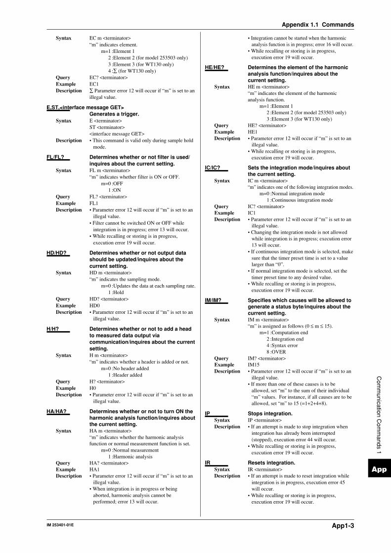
IM 253401-01E App1-3
App
Appendix 1.1 Commands
Com
munication C
omm
ands 1
Syntax EC m <terminator>“m” indicates element.
m=1 :Element 12 :Element 2 (for model 253503 only)3 :Element 3 (for WT130 only)4 :∑ (for WT130 only)
Query EC? <terminator>Example EC1Description ∑ Parameter error 12 will occur if “m” is set to an
illegal value.
E,ST,<interface message GET>Generates a trigger.
Syntax E <terminator>ST <terminator><interface message GET>
Description • This command is valid only during sample holdmode.
FL/FL? Determines whether or not filter is used/inquires about the current setting.
Syntax FL m <terminator>“m” indicates whether filter is ON or OFF.
m=0 :OFF1 :ON
Query FL? <terminator>Example FL1Description • Parameter error 12 will occur if “m” is set to an
illegal value.• Filter cannot be switched ON or OFF while
integration is in progress; error 13 will occur.• While recalling or storing is in progress,
execution error 19 will occur.
HD/HD? Determines whether or not output datashould be updated/inquires about thecurrent setting.
Syntax HD m <terminator>“m” indicates the sampling mode.
m=0 :Updates the data at each sampling rate.1 :Hold
Query HD? <terminator>Example HD0Description • Parameter error 12 will occur if “m” is set to an
illegal value.
H/H? Determines whether or not to add a headto measured data output viacommunication/inquires about the currentsetting.
Syntax H m <terminator>“m” indicates whether a header is added or not.
m=0 :No header added1 :Header added
Query H? <terminator>Example H0Description • Parameter error 12 will occur if “m” is set to an
illegal value.
HA/HA? Determines whether or not to turn ON theharmonic analysis function/inquires aboutthe current setting.
Syntax HA m <terminator>“m” indicates whether the harmonic analysisfunction or normal measurement function is set.
m=0 :Normal measurement1 :Harmonic analysis
Query HA? <terminator>Example HA1Description • Parameter error 12 will occur if “m” is set to an
illegal value.• When integration is in progress or being
aborted, harmonic analysis cannot beperformed; error 13 will occur.
• Integration cannot be started when the harmonicanalysis function is in progress; error 16 will occur.
• While recalling or storing is in progress,execution error 19 will occur.
HE/HE? Determines the element of the harmonicanalysis function/inquires about thecurrent setting.
Syntax HE m <terminator>“m” indicates the element of the harmonicanalysis function.
m=1 :Element 12 :Element 2 (for model 253503 only)3 :Element 3 (for WT130 only)
Query HE? <terminator>Example HE1Description • Parameter error 12 will occur if “m” is set to an
illegal value.• While recalling or storing is in progress,
execution error 19 will occur.
IC/IC? Sets the integration mode/inquires aboutthe current setting.
Syntax IC m <terminator>“m” indicates one of the following integration modes.
m=0 :Normal integration mode1 :Continuous integration mode
Query IC? <terminator>Example IC1Description • Parameter error 12 will occur if “m” is set to an
illegal value.• Changing the integration mode is not allowed
while integration is in progress; execution error13 will occur.
• If continuous integration mode is selected, makesure that the timer preset time is set to a valuelarger than “0”.
• If normal integration mode is selected, set thetimer preset time to any desired value.
• While recalling or storing is in progress,execution error 19 will occur.
IM/IM? Specifies which causes will be allowed togenerate a status byte/inquires about thecurrent setting.
Syntax IM m <terminator>“m” is assigned as follows (0 ≤ m ≤ 15).
m=1 :Computation end2 :Integration end4 :Syntax error8 :OVER
Query IM? <terminator>Example IM15Description • Parameter error 12 will occur if “m” is set to an
illegal value.• If more than one of these causes is to be
allowed, set “m” to the sum of their individual“m” values. For instance, if all causes are to beallowed, set “m” to 15 (=1+2+4+8).
IP Stops integration.Syntax IP <terminator>Description • If an attempt is made to stop integration when
integration has already been interrupted(stopped), execution error 44 will occur.
• While recalling or storing is in progress,execution error 19 will occur.
IR Resets integration.Syntax IR <terminator>Description • If an attempt is made to reset integration while
integration is in progress, execution error 45will occur.
• While recalling or storing is in progress,execution error 19 will occur.

IM 253401-01EApp1-4
Appendix 1.1 Commands
IS Starts integration.Syntax IS <terminator>Description • If an attempt is made to start integration when
integration is already in progress, executionerror 42 will occur.
• If a voltage or current peak overflow, oroverrange takes place when an attempt is madeto start integration, execution error 46 willoccur, and integration will not be started.
• While recalling or storing is in progress,execution error 19 will occur.
KV/KV?, KA/KA?, KW/KW?Sets the scaling constant/inquires aboutthe current setting.KV is used for voltage measurement, KAfor current measurement, and KW forpower measurement.
Syntax When CM0 is set:KVn <terminator>KAn <terminator>KWn <terminator>
When CM1 is set:KVm,n <terminator>KAm,n <terminator>KWm,n <terminator>
“m” indicates element.m=0 : All elements (Setting not allowed
during inquiry)1 :Element 12 :Element 2 (for model 253503 only)3 :Element 3 (for WT130 only)
“n” indicates scaling value.0.001 ≤ n ≤ 1000
Query When CM0 is set:KV? <terminator>KA? <terminator>KW? <terminator>When CM1 is set:KV1? <terminator>KA2? <terminator>KW3? <terminator>
Example When CM0 is set:KV1.000KA1.000KW1.000
When CM1 is set:KV1,1.000KA2,1.000KW3,1.000
Description • Parameter error 12 will occur if “m” is set to anillegal value.
• “n” must be floating-point or integer.• Error 12 will occur when an inquiry is made if
the scaling values set for each element by CM0differ from each other.
• While recalling or storing is in progress,execution error 19 will occur.
MN/MN? Sets the measurement mode for voltageand current/inquires about the currentsetting.
Syntax MN m <terminator>“m1” indicates the measurement mode.
m1=0 : RMS1 : V MEAN (MEAN in case of voltage,
RMS in case of current)2 :DC
Query MN? <terminator>Example MN0Description • Parameter error 12 will occur if “m” is set to an
illegal value.• Changing of the measurement mode is not
allowed while integration is in progress;execution error 13 will occur.
• While recalling or storing is in progress,execution error 19 will occur.
MT/MT? Sets the computing equation of MATHfunction/inquires about the currentsetting.
Syntax MTm<terminator>m indicates the computing equation.
m=0 : Efficiency (available only on theWT130)
1 : Crest factor of the voltage inputwaveform of input element 1
2 : Crest factor of the voltage inputwaveform of input element 2(available only three-phase four-wiremodel of the WT130)
3 : Crest factor of the voltage inputwaveform of input element 3(available only on the WT130)
4 : Crest factor of the current inputwaveform of input element 1
5 : Crest factor of the current inputwaveform of input element 2(available only three-phase four-wiremodel of the WT130)
6 : Crest factor of the current inputwaveform of input element 3(available only on
7 : display A + display B8 : display A – display B9 : display A X display B
10 : display A / display B11 : display A / (display B)2
12 : (display A)2 / display BQuery MT?<terminator>Example MT0Description • This command applies to WT110/WT130 with
ROM version 2.01 or later.
OA/OA? Sets D/A output items/inquires about thecurrent settings.Up to 4 or 12 measured data can beselected and output as analog signal fromthe D/A converter.
Syntax OA m1,m2,m3 <terminator>“m1” indicates D/A output channel, and must beset within the following range.
1 ≤ m1 ≤ 12 or 4“m2” indicates output item no.
m2=0 :No output1 :Voltage (V)2 :Current (A)3 :Power (W)4 :Reactive power (var)5 :Apparent power (VA)6 :Power factor (PF)7 :Input voltage frequency (V Hz)8 :Input current frequency (A Hz)9 :Watt-hour (Wh)
10 :Ampere-hour (Ah)11 :Phase angle (deg)12 : Peak voltage value (Vpk)*13 : Peak current value (Apk)*14 : Computation result (MATH)*24 :Positive watt-hour (Wh+)25 :Negative watt-hour (Wh–)26 :Positive ampere-hour (Ah+)27 :Negative ampere-hour (Ah–)* Applies to WT110/WT130 with ROM
version 2.01 or later“m3” indicates element.
m=1 :Element 12 :Element 2 (for model 253503 only)3 :Element 3 (for WT130 only)4 :∑ (for WT130 only)

IM 253401-01E App1-5
App
Appendix 1.1 Commands
Com
munication C
omm
ands 1
Query OA1? <terminator>Example OA1,3,2Description • Parameter error 12 will occur if any of “m1”,
“m2” and “m3” is set to an illegal value.• If computation result is selected and the MATH
computing equation is set to anything other thanefficiency (MT0),the D/A output is fixed to 0(V).
• "No output" and "computation result" have norelation to the element, but when using themwith the "OA" command, set m3=1.
OAD/OAD? Initializes D/A output items/inquires aboutthe current settings. Two sets of defaultsettings are available: one is for normalmeasurement and the other is forintegration. The same initialization canalso be performed using a key operation.
Syntax OAD m <terminator>“m” indicates default no.
m=2 :Select mode0 :Default for normal measurement1 :Default for integration
Query OAD? <terminator>Example OAD1Description • Parameter error 12 will occur if “m” is set to an
illegal value.• Select mode (OAD2) is validated when the OA
command is executed if “m” has been set to “0”(default for normal measurement) or “1”(default for integration).
OD Requests output of measurement data.Syntax OD <terminator>Description • The OD command should be used only in
addressable mode A. If the OD command isused in addressable mode B, execution error 11will occur. Setting the addressable mode shouldbe done using a key operation.
OE Requests output of error codes viacommunications.
Syntax OE <terminator>Example ERR11 <terminator>
Error codeDescription11 Command error12 Parameter error13 Attempted to change settings which cannot
be changed while integration was inprogress.
14 Attempted to set auto range mode whileexternal sensor range was selected.
15 Attempted to execute a command that wasprotected.
16 Attempted to execute a command that wasprotected while harmonic analysis wasbeing performed.
17 Time-out in print output.18 Not in printing mode, or no data available.19 Attempted to execute commands while
recalling/storing is in progress.30 File data failure31 File is damaged.32 Not stored in internal memory.33 No data to be stored in internal memory.41 Attempted to start integration when
integration had been stopped due to anirregularity.
42 Attempt made to start integration duringintegration.
43 Measurement stopped due to overflowduring integration or due to a power failure.
44 Attempt made to stop integration whileintegration was interrupted.
45 Attempt made to reset integration whileintegration was in progress.
46 Attempt made to start integration whenpeak overflow was detected.
51 Measurement data overflow occurred. “-oL” is displayed.
52 Voltage peak overflow occurred53 Current peak overflow occurred54 Power factor exceeded “2”. “PFErr” is
displayed.55 “degErr” was displayed.56 Frequency input level was too low or below
measurement range. “ErrLo” is displayed.57 Frequency was above the measurement
range. “ErrHi,” is displayed.58 Computation overflow occurred. “—oF—
” is displayed.59 When harmonic analysis is carried out,
“FrqEr” is displayed
OF/OF? Sets communication output informationtypes/inquires about the current settings.Up to 14 measured data can be selectedand output.
Syntax OF m1,m2,m3 <terminator>“m1” indicates communication output channel,and must be set within the following range.
1 ≤ m1 ≤ 14“m2” indicates output type no.
m2=0 :No output1 :Voltage (V)2 :Current (A)3 :Power (W)4 :Reactive power (var)5 :Apparent power (VA)6 :Power factor (PF)7 :Input voltage frequency (V Hz)8 :Input current frequency (A Hz)9 :Watt-hour (Wh)
10 :Ampere-hour (Ah)11 :Phase angle (deg)12 : Peak voltage value (Vpk)*13 : Peak current value (Apk)*14 : Computation result (MATH)*15 :Integration time24 :Positive watt-hour (Wh+)25 :Negative watt-hour (Wh–)26 :Positive ampere-hour (Ah+)27 :Negative ampere-hour (Ah–)* Applies to WT110/WT130 with ROM
version 2.01 or later“m3” indicates element, and must be set withinthe following range.
1 ≤ m3 ≤ 4Query OF1? <terminator>Example OF1,3,2Description • Parameter error 12 will occur if “m1”, “m2” or
“m3” is set to an illegal value.• "No output," "computation range," and
"integration time" have no relation to theelement, but when using them with the "OF"command, set m3=1.
OFD/OFD? Initializes communication outputinformation type/inquires about thecurrent settings. Two sets of defaultsetting are available: one is for normalmeasurement and the other is forintegration.
Syntax OFD m <terminator>“m” indicates default no.
m=2 :Select mode (valid only for the inquirycommand)
0 :Default for normal measurement1 :Default for integration
Query OFD? <terminator>Example OFD1Description • Parameter error 12 will occur if “m” is set to an
illegal value.

IM 253401-01EApp1-6
Appendix 1.1 Commands
• Select mode (OFD2) is validated when the OFcommand is executed if “m” is set to “0”(default for normal measurement) or “1”(default for integration).
• If you select default for normal measurement,the output of channel 13 is the information onthe frequency target function that is currentlymeasured, and the output of channel 14 is theinformation displayed on display C. If youchange either the frequency measurement targetor display information of display C, the outputalso changes.
OH/OH? Sets communication output informationtypes in case of harmonic analysis/inquires about the current settings.
Syntax OH m1,m2 <terminator>“m1” indicates output type no.• in case of print mode
m1=1 :(V) outputs voltage analysis value andrelative harmonic content as anumerical value
2 :(A) outputs current analysis value andrelative harmonic content as anumerical value
3 :(W) outputs active power analysisvalue and relative harmonic content asa numerical value
4 :(deg) outputs the phase angle as anumerical value
5 :(GV) outputs voltage analysis value asnumerical value and graph
6 :(GA) outputs current analysis value asnumerical value and graph
7 :(GW) outputs active power analysisvalue as numerical value and graph
8 :(GVD) outputs the phase anglebetween the 2nd to 50 (or 30) th ordervoltage and the fundamental (1storder) as numerical value and graph
9 :(GAD) outputs the phase anglebetween the 2nd to 50 (or 30) th ordercurrent and the fundamental (1storder) as numerical value and graph
10 :(CGV) outputs the relative harmoniccontent of voltage as numerical valueand graph
11 :(CGA) outputs the relative harmoniccontent of current as numerical valueand graph
12 :(CGW) outputs the relative harmoniccontent of active power as numericalvalue and graph
13 :(ALL) outputs the relative harmoniccontent and analysis value of bothvoltage and current
• in case of any other modem1=1 :(V) outputs voltage analysis value and
relative harmonic content as anumerical value
2 :(A) outputs current analysis value andrelative harmonic content as anumerical value
3 :(W) outputs active power analysisvalue and relative harmonic content asa numerical value
4 :(deg) outputs the phase angle betweenthe first order voltage(current) and the2nd to 50 (or 30) th voltage(current) asa numerical value
5 :(GV) outputs voltage analysis valueand relative harmonic content asnumerical value
6 :(GA) outputs current analysis valueand relative harmonic content asnumerical value
7 :(GW) outputs active power analysisvalue and relative harmonic content asnumerical value
8 :(GVD) outputs the phase anglebetween the first ordervoltage(current) and the 2nd to 50 (or30) th voltage(current) as a numericalvalue
9 :(GAD) outputs the phase anglebetween the first ordervoltage(current) and the 2nd to 50 (or30) th voltage(current) as a numericalvalue
10 :(CGV) outputs the analysis value ofvoltage and relative harmonic contentas numerical value
11 :(CGA) outputs the analysis value ofcurrent and relative harmonic contentas numerical value
12 :(CGW) outputs the analysis value ofactive power and relative harmoniccontent as numerical value
13 :(ALL) outputs the relative harmoniccontent and analysis value of bothvoltage and current
“m2” indicates elementm2=1 :Element 1
2 :Element 2 (for model 253503 only)3 :Element 3 (for WT130 only)
Query OH? <terminator>Example OH13,1Description • Parameter error 12 will occur if “m1” or “m2” is
set to an illegal value.
OR/OR? Designates the harmonic order of theharmonic component shown on display B(V,A,W,V %, A%, W%, V deg, A deg)/inquires about the current settings.
Syntax OR m <terminator>“m” indicates the harmonic order
m= any number between 1 to 50 (or 30)Query OR? <terminator>Example OR50Description • Parameter error 12 will occur if “m” is set to an
illegal value.• Depending on the fundamental frequency of the
PLL source set as the input, the maximumnumber of orders varies.
• When an order exceeding the maximum hasbeen set, display B will show [——].
OS Requests output of setting parameters viacommunications.
Syntax OS <terminator>Example
Line 1 :Model nameMODEL253503 <terminator>
Line 2 :Voltage rangeRV9;AV1 <terminator>
Line 3 :Current rangeWhen CM0 is set:RA9;AA1;SA50.00 <terminator>When CM1 is set:RA9;AA1;SA1,50.00;SA2,50.00;SA3,50.0 <terminator>
Line 4 :Display functionDA1;DB2;DC3 <terminator>
Line 5 :ElementEA1;EB1;EC1 <terminator>
Line 6 :Measurement conditionWR2;FL0;SC0;AG0;HD0;MT0
<terminator>

IM 253401-01E App1-7
App
Appendix 1.1 Commands
Com
munication C
omm
ands 1
Line 7 :Measurement modeMN0 <terminator>
Line 8 :Scaling constantWhen CM0 is set:KV1.000;KA1.000;KW1.000
<terminator>When CM1 is set:KV1,1.000;KA1,1.000;KW1,1.000KV2,1.000;KA2,1.000;KW2,1.000;KV3,1.000;KA3,1.000;KW3,1.000
<terminator>Line 9 :Averaging setting
AT1;AC1 <terminator>Line 10:Integration setting
IC0;TM0,0 <terminator>Line 11:Storing/recalling setting
SO0;SR0,0,0;RO0;RR0,0,0 <terminator>Line 12 :Command group used
CM0 <terminator>Line 13 :Output end
END <terminator>Description • The number of lines varies depending on the
options used.• When the harmonic analysis option is used, the
following line must be installed before the usedcommand group.
PS1;HA0;OR1;HE1;DF0 <terminator>• When the D/A output option is used, the
following line must be inserted before the usedcommand group.
RT0,1 <terminator>• When the comparator option is used, the
following line must be inserted before the usedcommand group.
YO0;YM1;DY0;YC1 <terminator>• When a CM0 is issued, if the shunt current
values or scaling values set for each elementdiffer from each other, the value set for element1 will be output.
OY/OY? Sets the relay output items in case ofnormal measurement/inquires about thecurrent setting. Up to four items can beset.
Syntax OY m1,m2,m3,m4,m5 <terminator>“m1” indicates the output relay channel
1 ≤ m1 ≤ 4“m2” indicates the output item number
m2=0 : no output1 :Voltage (V)2 :Current (A)3 :Power (W)4 :Reactive power (var)5 :Apparent power (VA)6 :Power factor (PF)7 :Input voltage frequency (V Hz)8 :Input current frequency (A Hz)9 :Watt-hour (Wh)
10 :Ampere-hour (Ah)11 :Phase angle (deg)12 : Peak voltage value (Vpk)*13 : Peak current value (Apk)*14 : Computation result (MATH)*24 :Positive watt-hour (Wh+)25 :Negative watt-hour (Wh–)26 :Positive ampere-hour (Ah+)27 :Negative ampere-hour (Ah–)* Applies to WT110/WT130 with ROM
version 2.01 or later“m3” indicates element.
m=1 :Element 12 :Element 2 (for model 253503 only)3 :Element 3 (for WT130 only)4 :∑ (for WT130 only)
“m4” indicates setting value.0.000 ≤ m4 ≤ ±9999
“m5” indicates prefixm5=0 :m(E-3)
1 :(E+0)2 :k(E+3)3 :M(E+6)
Query OY1? <terminator>Example OY1,1,1,600.0,1Description • Parameter error 12 will occur if “m” is set to an
illegal value.• "No output" and "computation result" have no
relation to the element, but when using themwith the "OY" command, set m3=1.
OYH/OYH? Sets the relay output items in case ofharmonic analysis/inquires about thecurrent setting. Up to four items can beset.
Syntax OYH m1,m2,m3,m4,m5,m6 <terminator>“m1” indicates the output relay channel
1 ≤ m1 ≤ 4“m2” indicates the output item number
m2=0 :no output1 :Voltage (V)2 :Current (A)3 :Power (W)6 :Power factor (PF)
16 :harmonic distortion factor of voltage(V THD)
17 :harmonic distortion factor of current(A THD)
19 :Relative harmonic content of eachvoltage component (V %)
20 :Relative harmonic content of eachcurrent component (A %)
21 :Relative harmonic content of eachactive power component (W %)
22 :Phase angle between each voltage ofthe 2nd to 50 (or 30) th order and thefundamental (1st order) voltage (Vdeg)
23 :Phase angle between each current ofthe 2nd to 50 (or 30) th order and thefundamental (1st order) current (Adeg)
“m3” indicates element.m=1 :Element 1
2 :Element 2 (for model 253503 only)3 :Element 3 (for WT130 only)
“m4” indicates order of the harmonic.m4 = any number between 1 and 50 (or 30)
“m5” indicates setting value.0.000 ≤ m5 ≤ ±9999
“m6” indicates prefix.m6=0 : m(E-3)
1 : (E+0)2 : k(E+3)3 : M(E+6)
Query OYH3? <terminator>Example OYH3,3,1,1,1,200,2Description • Parameter error 12 will occur if “m” is set to an
illegal value.• “No output” is not related to any element, order
or setting value, so in case the OYH commandis set, set these all to 1 as a dummy.
• “PF”, “VTHD” and “ATHD” are not related toany order, so in case the OYH command isused, set 1 as a dummy.
PS/PS? Sets the input as the PLL source/inquiresabout the current setting.

IM 253401-01EApp1-8
Appendix 1.1 Commands
Syntax PS m <terminator>“m” indicates the input as the PLL source
m=1 :V12 :A13 :V2 (for model 253503 only)4 :A2 (for model 253503 only)5 :V3 (for WT130 only)6 :A3 (for WT130 only)
Query PS? <terminator>Example PS1Description • Parameter error 12 will occur if any illegal value
is set.• While recalling or storing is in progress,
execution error 19 will occur.
RA/RA? Sets current range/inquires about thecurrent setting.
Syntax RA m <terminator>“m” indicates current range.
m=4 :0.5 A range5 :1 A range6 :2 A range7 :5 A range8 :10 A range9 :20 A range
15 :50 mV range (only when equippedwith option EX2)
16 :100 mV range (only when equippedwith option EX2)
17 :200 mV range (only when equippedwith option EX2)
18 :2.5 V range (only when equipped withoption EX1)
19 :5 V range (only when equipped withoption EX1)
20 :10 V range (only when equipped withoption EX1)
Query RA? <terminator>Example RA9Description • Parameter error 12 will occur if “m” is set to an
illegal value.• Changing of the current range is not allowed
while integration is in progress; execution error13 will occur.
• The 50 mV, 100 mV and 200 mV or 2.5V, 5Vand 10V ranges are for the external sensor.When using any of these ranges, be sure to set avalid sensor value using the SA command.
• While recalling or storing is in progress,execution error 19 will occur.
RC Initializes setting parameters.Syntax RC <terminator>
RO/RO? Sets the recall function ON/OFF orinquires about the current setting.
Syntax RO m <terminator>“m” indicates recall ON or OFF.
m=0 : recall OFF1 : recall ON
Query RO? <terminator>Example RO1Description • Parameter error 12 will occur if “m” is set to an
illegal value.
RR/RR? Sets the recall interval/inquires about thecurrent setting.
Syntax RR m1,m2,m3 <terminator>“m1” indicates the hour
0 ≤ m1 ≤ 99“m2” indicates the minutes
0 ≤ m2 ≤ 59“m3” indicates the seconds
0 ≤ m3 ≤ 59
Query RR? <terminator>Example RR0,0,0Description • Parameter error 12 will occur if an illegal value
is set.• When the recall interval is set to 0hrs, 0min,
0sec, the interval will be 250msec in case ofnormal measurement and 1s in case of harmonicanalysis.
• While recalling or storing is in progress,execution error 19 will occur.
RT/RT? Sets the rated integration time whenintegrated values are to be output as ananalog signal/inquires about the currentsetting.
Syntax RT m1,m2 <terminator>“m1” indicates hour, and must be set within thefollowing range.
0 ≤ m1 ≤ 999“m2” indicates minute, and must be set within thefollowing range.
0 ≤ m2 ≤ 59Query RT? <terminator>Example RT1,0Description • Parameter error 12 will occur if an illegal value
is set.
RV/RV? Sets voltage range/inquires about thecurrent setting.
Syntax RV m <terminator>“m” indicates voltage range.
m=3 :15V range4 :30 V range5 :60 V range6 :100 V range7 :150 V range8 :300 V range9 :600 V range
Query RV? <terminator>Example RV9Description • Parameter error 12 will occur if an illegal value
is set.• Changing of the voltage range is not allowed
while integration is in progress; execution error13 will occur.
• While recalling or storing is in progress,execution error 19 will occur.
SA/SA? Sets the external sensor scaling value/inquires about the current setting.
Syntax When CM0 is set:SA n <terminator>
When CM1 is set:SA m,n <terminator>
“m” indicates element.m=0 :All elements (Setting not allowed
during inquiry)1 :Element 12 :Element 2 (only for model 253503)3 :Element 3 (only for the WT130)
“n” indicates external sensor scaling value.0.001 ≤ n ≤ 1000
Query When CM0 is set:SA? <terminator>
When CM1 is set:SAm? <terminator>
Example When CM0 is set:SA50.00
When CM1 is set:SA1,50.00
Description • Parameter error 12 will occur if “m” is set to anillegal value.
• Error 12 will occur when an inquiry is made ifthe shunt current values set for each element byCM0 differ from each other.

IM 253401-01E App1-9
App
Appendix 1.1 Commands
Com
munication C
omm
ands 1
• While recalling or storing is in progress,execution error 19 will occur.
SC/SC? Determines whether or not to use thescaling function/inquires about thecurrent setting.
Syntax SC m <terminator>“m” indicates whether scaling is ON or OFF.
m=0 : OFF1 : ON
Query SC? <terminator>Example SC1Description • Parameter error 12 will occur if “m” is set to an
illegal value.• While recalling or storing is in progress,
execution error 19 will occur.
SL Recalls set-up parameters from aselected file.
Syntax SL m <terminator>“m” indicates file no., and must be set within thefollowing range.
1 ≤ m ≤ 4Description • Parameter error 12 will occur if “m” is set to an
illegal value.• It is not possible to recall communications-
related information (communication mode,address etc.) using this command.
• While recalling or storing is in progress,execution error 19 will occur.
SO/SO? Sets the store function ON/OFF orinquires about the current setting.
Syntax SO m <terminator>“m” indicates whether storage is ON or OFF.
m=0 : OFF1 : ON
Query SO? <terminator>Example SO1Description • Parameter error 12 will occur if “m” is set to an
illegal value.• While recalling or storing is in progress,
execution error 19 will occur.
SR/SR? Sets the storage interval/inquires aboutthe current setting.
Syntax SR m1,m2,m3 <terminator>“m1” indicates the hour
0 ≤ m1 ≤ 99“m2” indicates the minutes
0 ≤ m2 ≤ 59“m3” indicates the seconds
0 ≤ m3 ≤ 59Query SR? <terminator>Example SR0,0,0Description • Parameter error 12 will occur if an illegal value
is set.• When the storage interval is set to 0hrs, 0min,
0sec, refer to page 9-2.• While recalling or storing is in progress,
execution error 19 will occur.
SS Stores set-up parameters into a selectedfile.
Syntax SS m <terminator>“m” indicates file no., and must be set within thefollowing range.
1 ≤ m ≤ 4Description • Parameter error 12 will occur if “m” is set to an
illegal value.• The following set-up parameters can be stored:
All set-up parameters which can be output bythe OS commandInformation related to communications (GP-IB, RS-232-C etc.)
• While recalling or storing is in progress,execution error 19 will occur.
TM/TM? Sets integration preset time/inquiresabout the current setting.
Syntax TM m1,m2 <terminator>“m1” indicates hour, and must be set within thefollowing range.
0 ≤ m1 ≤ 999“m2” indicates minute, and must be set within thefollowing range.
0 ≤ m2 ≤ 59Query TM? <terminator>Example TM0,0Description • Parameter error 12 will occur if an illegal value
is set.• While recalling or storing is in progress,
execution error 19 will occur.
WR/WR? Sets the wiring system/inquires about thecurrent setting.
Syntax WR m <terminator>m=2 :1Φ3W
3 :3Φ3W4 :3Φ4W (available only for the 253503)5 :3V3A (available only for the 253503)
Query WR? <terminator>Example WR2Description • Parameter error 12 will occur if an illegal value
is set.
YC/YC? Sets the display channel while thecomparator function is ON/inquires aboutthe current setting.
Syntax YC m <terminator>“m” indicates the channel number for display• in case of single mode
m=1 :Displays limit and measurement valueon display 1
2 :Displays limit and measurement valueon display 2
3 :Displays limit and measurement valueon display 3
4 :Displays limit and measurement valueon display 4
• in case of dual modem=1,2 :Displays limit and measurement value
on display 1 and 2 respectivelym=3,4 :Displays limit and measurement value
on display 3 and 4 respectivelyQuery YC? <terminator>Example YC1Description • Parameter error 12 will occur if “m” is set to an
illegal value.
YM/YM? Sets the mode of the comparator function/inquires about the current setting.
Syntax YM m <terminator>“m” indicates the display mode
m=0 :Single mode1 :Dual mode
Query YM? <terminator>Example YM1Description • Parameter error 12 will occur if “m” is set to an
illegal value.
YO/YO? Sets the comparator function ON/OFF orinquires about the current setting.
Syntax YO m <terminator>“m” indicates whether the comparator function isON/OFF
m=0 :OFF1 :ON
Query YO? <terminator>Example YO1Description • Parameter error 12 will occur if “m” is set to an
illegal value.

IM 253401-01EApp1-10
Appendix 1.2 Sample Program
Appendix 1.2 Sample Program
Before Programming
This section describes sample programs for a IBM PC/AT and compatible system with National
Instruments GPIB-PCIIA board installed. Sample programs in this manual are written in Quick
BASIC version 4.0/4.5
Programming FormatThe programming format for this instrument is as follows.
Command + Parameter + Terminator
The used codes are ASCII codes.
Example DA 2 CR LFcommand parameter terminator
CommandsOne to three capital characters are used to designate a command.
ParametersCharacters or numericals are in ASCII code.
Terminator• In case of GP-IB:When this instrument is set to listener mode, either [CR+LF], [LF], or [EOI] can be used as the
terminator.
When this instrument is set to talker mode, the terminator set using the DL command becomes
valid. Refer to page App1-2.
• In case of RS-232-C:Refer to page 12-7 and App1-2.
Sending Several CommandsYou can express several commands on one line. In such a case, enter a “;” (semicolon) between
two commands (command + parameter).
NoteIt makes no difference whether a space, tab or similar is entered between command and parameter.
QueryA command followed by a “?” (question mark) is called a query command. When such a
command is sent, the current data will appear.
Query Current data
DA? ⇒⇒⇒⇒⇒ DA1
Parameter ValuesUp to 5 digits after the decimal point will be recognized.

IM 253401-01E App1-11
App
Appendix 1.2 Sample Program
Com
munication C
omm
ands 1
Sample Program‘*********************************************************************‘* WT110/WT130 *‘* Program to read measurement data 10 times and then display them *‘* Microsoft QuickBASIC 4.0/4.5 Version *‘*********************************************************************REM $INCLUDE: ‘qbdecl4.bas’BORD$ = “GPIB0”: CALL IBFIND(BORD$, BD%)IF BD% < 0 THEN GOTO ERRDISPCALL IBSIC(BD%): GOSUB ERRCHKDEVICE$ = “WT”: CALL IBFIND(DEVICE$, WT%)IF WT% < 0 THEN GOTO ERRDISPCALL IBCLR(WT%): GOSUB ERRCHK‘CMD$ = “HD0” ‘ Hold OFFCALL IBWRT(WT%, CMD$): GOSUB ERRCHKCMD$ = “FL0” ‘ Filter OFFCALL IBWRT(WT%, CMD$): GOSUB ERRCHKCMD$ = “SC0” ‘ Scaling OFFCALL IBWRT(WT%, CMD$): GOSUB ERRCHKCMD$ = “AG0” ‘ Averaging OFFCALL IBWRT(WT%, CMD$): GOSUB ERRCHKCMD$ = “DA1;EA1” ‘ Display A = V1CALL IBWRT(WT%, CMD$): GOSUB ERRCHKCMD$ = “DB2;EB1” ‘ Display B = A1CALL IBWRT(WT%, CMD$): GOSUB ERRCHKCMD$ = “DC3;EC1” ‘ Display C = W1CALL IBWRT(WT%, CMD$): GOSUB ERRCHKCMD$ = “RV7;RA7” ‘ Measurement range = 150V/5ACALL IBWRT(WT%, CMD$): GOSUB ERRCHKCMD$ = “MN0” ‘ Measurement mode = RMSCALL IBWRT(WT%, CMD$): GOSUB ERRCHK‘ Output items for comm. = default setting for normal measurementCMD$ = “OFD0”CALL IBWRT(WT%, CMD$): GOSUB ERRCHK‘ Delimiter for Comm. output = CR+LF+EOICMD$ = “DL0”CALL IBWRT(WT%, CMD$): GOSUB ERRCHKBUF$ = SPACE$(255)FOR I = 1 TO 10 FOR J = 0 TO 5000: NEXT J ‘ Waiting CMD$ = “OD” CALL IBWRT(WT%, CMD$): GOSUB ERRCHK DO CALL IBRD(WT%, BUF$): GOSUB ERRCHK PRINT LEFT$(BUF$, IBCNT% - 2) LOOP WHILE LEFT$(BUF$, 3) <> “END”NEXT IPRGEND:CALL IBLOC(WT%)END‘‘ When IBFIND call failedERRDISP:PRINT “ ===== No such board or device name ===== “GOTO PRGEND‘‘ GP-IB error checkERRCHK:IF IBSTA% >= 0 THEN RETURNPRINT “ ===== Error ===== “GOTO PRGEND

IM 253401-01EApp1-12
Appendix 1.2 Sample Program
‘*********************************************************************‘* WT110/WT130 *‘* Program for adjusting range *‘* Turn ON the power while pressing the SHIFT key. *‘* Microsoft QuickBASIC 4.0/4.5 Version *‘*********************************************************************REM $INCLUDE: ‘qbdecl4.bas’BORD$ = “GPIB0”: CALL IBFIND(BORD$, BD%)IF BD% < 0 THEN GOTO ERRDISPCALL IBSIC(BD%): GOSUB ERRCHKDEVICE$ = “WT”: CALL IBFIND(DEVICE$, WT%)IF WT% < 0 THEN GOTO ERRDISPCALL IBCLR(WT%): GOSUB ERRCHK‘DO CLS PRINT “Main menu for range adjustment” PRINT “” PRINT “1:Range adjustment” PRINT “2:Adjustment of ext. sensor range” PRINT “0:End “ PRINT “Command >> “; : LINE INPUT C$ IF C$ = “1” THEN GOSUB RANGE ELSEIF C$ = “2” THEN GOSUB SHUNT ELSEIF C$ = “0” THEN EXIT DO END IFLOOP‘PRGEND:CALL IBLOC(WT%)END‘RANGE:CMD$ = “CAL1”: CALL IBWRT(WT%, CMD$): GOSUB ERRCHKDO CLS PRINT “Range adjustment” PRINT “” PRINT “1: 30.00 V range” PRINT “2: 300.0 V range” PRINT “3: 1.000 A range” PRINT “4: 10.00 A range” PRINT “S: Adjustment values will be kept” PRINT “C: Adjustment values will not be kept” PRINT “Command >> “; : LINE INPUT C$ IF C$ = “1” THEN CMD$ = “CR0”: CALL IBWRT(WT%, CMD$): GOSUB ERRCHK: GOSUB ODDISP ELSEIF C$ = “2” THEN CMD$ = “CR1”: CALL IBWRT(WT%, CMD$): GOSUB ERRCHK: GOSUBODDISP ELSEIF C$ = “3” THEN CMD$ = “CR2”: CALL IBWRT(WT%, CMD$): GOSUB ERRCHK: GOSUB ODDISP ELSEIF C$ = “4” THEN CMD$ = “CR3”: CALL IBWRT(WT%, CMD$): GOSUB ERRCHK: GOSUB ODDISP ELSEIF C$ = “S” THEN CMD$ = “END”: CALL IBWRT(WT%, CMD$): GOSUB ERRCHK: EXIT DO ELSEIF C$ = “C” THEN CMD$ = “CAN”: CALL IBWRT(WT%, CMD$): GOSUB ERRCHK: EXIT DO END IFLOOPRETURN‘ODDISP:PRINT “1: Adjustment values of this range will be updated”PRINT “0: Return to previous menu”DO CMD$ = “OD”: CALL IBWRT(WT%, CMD$): GOSUB ERRCHK LOCATE 15, 1 BUF$ = SPACE$(255) DO
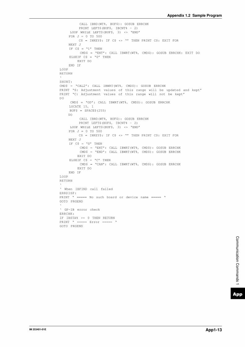
IM 253401-01E App1-13
App
Appendix 1.2 Sample Program
Com
munication C
omm
ands 1
CALL IBRD(WT%, BUF$): GOSUB ERRCHK PRINT LEFT$(BUF$, IBCNT% - 2) LOOP WHILE LEFT$(BUF$, 3) <> “END” FOR J = 0 TO 500 C$ = INKEY$: IF C$ <> “” THEN PRINT C$: EXIT FOR NEXT J IF C$ = “1” THEN CMD$ = “ENT”: CALL IBWRT(WT%, CMD$): GOSUB ERRCHK: EXIT DO ELSEIF C$ = “0” THEN EXIT DO END IFLOOPRETURN‘SHUNT:CMD$ = “CAL2”: CALL IBWRT(WT%, CMD$): GOSUB ERRCHKPRINT “S: Adjustment values of this range will be updated and kept”PRINT “C: Adjustment values of this range will not be kept”DO CMD$ = “OD”: CALL IBWRT(WT%, CMD$): GOSUB ERRCHK LOCATE 15, 1 BUF$ = SPACE$(255) DO CALL IBRD(WT%, BUF$): GOSUB ERRCHK PRINT LEFT$(BUF$, IBCNT% - 2) LOOP WHILE LEFT$(BUF$, 3) <> “END” FOR J = 0 TO 500 C$ = INKEY$: IF C$ <> “” THEN PRINT C$: EXIT FOR NEXT J IF C$ = “S” THEN CMD$ = “ENT”: CALL IBWRT(WT%, CMD$): GOSUB ERRCHK CMD$ = “END”: CALL IBWRT(WT%, CMD$): GOSUB ERRCHK EXIT DO ELSEIF C$ = “C” THEN CMD$ = “CAN”: CALL IBWRT(WT%, CMD$): GOSUB ERRCHK EXIT DO END IFLOOPRETURN‘‘ When IBFIND call failedERRDISP:PRINT “ ===== No such board or device name ===== “GOTO PRGEND‘‘ GP-IB error checkERRCHK:IF IBSTA% >= 0 THEN RETURNPRINT “ ===== Error ===== “GOTO PRGEND

IM 253401-01EApp1-14
Appendix 1.2 Sample Program
‘*********************************************************************‘* WT110/WT130 *‘* Program for D/A output adjusting *‘* Turn ON the power while pressing the SHIFT key. *‘* Microsoft QuickBASIC 4.0/4.5 Version *‘*********************************************************************REM $INCLUDE: ‘qbdecl4.bas’BORD$ = “GPIB0”: CALL IBFIND(BORD$, BD%)IF BD% < 0 THEN GOTO ERRDISPCALL IBSIC(BD%): GOSUB ERRCHKDEVICE$ = “WT”: CALL IBFIND(DEVICE$, WT%)IF WT% < 0 THEN GOTO ERRDISPCALL IBCLR(WT%): GOSUB ERRCHK‘CMD$ = “CAL3”: CALL IBWRT(WT%, CMD$): GOSUB ERRCHKDO CLS PRINT “D/A output adjustment” PRINT “” PRINT “1-12 : Assigning D/A channel” PRINT “S : Adjustment values will be kept” PRINT “C : Adjustment values will not be kept” PRINT “Command >> “; : LINE INPUT CH$ IF CH$ = “S” THEN CMD$ = “END”: CALL IBWRT(WT%, CMD$): GOSUB ERRCHK: EXIT DO ELSEIF CH$ = “C” THEN CMD$ = “CAN”: CALL IBWRT(WT%, CMD$): GOSUB ERRCHK: EXIT DO ELSE CH = VAL(CH$) IF CH >= 1 AND CH <= 12 THEN GOSUB DACH END IF END IFLOOP‘PRGEND:CALL IBLOC(WT%)END‘DACH:CH$ = STR$(CH)CMD$ = “CH” + CH$: CALL IBWRT(WT%, CMD$): GOSUB ERRCHKCMD$ = “DO0”: CALL IBWRT(WT%, CMD$): GOSUB ERRCHKPRINT “”PRINT “+5V has been output to”; CH$; “channel”PRINT “Measure”; CH$; “channel’s voltage”PRINT “Measurement value = “; : LINE INPUT D$CMD$ = “CD” + CH$ + “,” + D$: CALL IBWRT(WT%, CMD$): GOSUB ERRCHKFOR I = 0 TO 2000: NEXT ICMD$ = “ENT”: CALL IBWRT(WT%, CMD$): GOSUB ERRCHKCMD$ = “DO1”: CALL IBWRT(WT%, CMD$): GOSUB ERRCHKPRINT “”PRINT “-5V has been output to”; CH$; “channel”PRINT “Measure”; CH$; “channel’s voltage”
PRINT “Measurement value = “; : LINE INPUT D$CMD$ = “CD” + CH$ + “,” + D$: CALL IBWRT(WT%, CMD$): GOSUB ERRCHKFOR I = 0 TO 2000: NEXT ICMD$ = “ENT”: CALL IBWRT(WT%, CMD$): GOSUB ERRCHKRETURN‘‘ When IBFIND call failedERRDISP:PRINT “ ===== No such board or device name ===== “GOTO PRGEND‘‘ GP-IB error checkERRCHK:IF IBSTA% >= 0 THEN RETURNPRINT “ ===== Error ===== “GOTO PRGEND

IM 253401-01E App1-15
App
Com
munication C
omm
ands 1
Appendix 1.3 For Users Using Communication Commands of Digital Power Meter 2533E
Appendix 1.3 For Users Using CommunicationCommands of Digital Power Meter 2533E
The WT110/130 differ from the 2533E in communication commands and data format. The
WT110/130 has a function which enables the user to use communication programs created for the
2533E. This function is described below.
Communication CommandsUnder usual conditions, the 2533E commands cannot be used. The “CM” command should be set
to CM2 to be able to use the 2533E commands (for details about the CM command, refer to
Appendix 2).
Description is given below in alphabetical order of those commands which differ from the
WT110/130 when the 2533E group is selected.
Note• For addressable mode setting method, refer to section 11-1, page 11-9.• WT110/130 code format is used for error code and status byte. For details, refer to page 11-3 and 14-3. The
WT110/130 code format differs from 2533E code format.• To read harmonic analysis data via RS-232-C interface, select a value other than “0” for handshake mode
since harmonics analysis data consists of a number of output bytes.
OS Requests output of settingparameters. This command cannot beused if 2533E command group is selectedby the “CM” command. However, in thiscase the “OL” command can be usedinstead.
WR/WR? Sets the wiring system/inquiresabout the current setting.
Syntax WRm <terminator>m stands for wiring system.
m=0 : 3Φ3W (for 253502, 253503 only)1 : 3Φ4W (for 253503 only)3 : 1Φ3W (for 253502, 253503 only)4 : 3V3A (for 253503 only)
Query WR? <terminator>Example WR0Description Parameter error 12 will occur if “m” is set to an
illegal value.
DS Sets the delimiter EOI output timing.This command is used with the 2533E, butcannot be used with the WT110/130 evenif the 2533E group is selected by the “CM”command.
MN/MN? Sets the measurement mode/inquiresabout the current setting.
Syntax MNm <terminator>m stands for measurement mode.
m=0 : RMS1 : V MEAN2 : DC
Query MN? <terminator>Example MN0Description Parameter error 12 will occur if “m” is set to an
illegal value.
OL Requests output of settingparameters. Output format differs fromthat of the 2533E
Syntax OL <terminator>Example
MODEL253503<terminator>RV9;AV1<terminator>RV9;AA1;SA50.00<terminator>DA1;DB2;DC3<terminator>EA1;EB1;EC1<terminator>WR3;FL0;SC0;AG0;HD0;MT0<terminator>MN0<terminator>KV1.000;KA1.000;KW1.000<terminator>AT1;AC1<terminator>IC0;TM0,0<terminator>SO0;SR0,0,0;RO0;RR0,0,0<terminator>PS1;HA0;OR1;HE1;DF0<terminator>RT1,0<terminator>YO0;YM1;DY0;YC1<terminator>CM2<terminator>END<terminator>
Description When the external sensor scaling values and P/C/F scaling values set for each element differ fromeach other, the value set for element 1 will beoutput.

IM 253401-01EApp1-16
Appendix 1.3 For Users Using Communication Commands of Digital Power Meter 2533E
Output ItemsTo read measurement data using the 2533E communication program, the WT110/130 addressable
mode B must be set. Output items do no match those displayed on each display as in the WT110/
130, but match those set for ch.1 to ch.3 in output function setting for the WT110/130. Select
output items according to the 2533E communication programs.
Note• WT110/130 output items for ch.4 and subsequent ch. nos. are not output.• For details regarding the setting of output items, refer to page 11-10.
Data Output FormatData consists of a 12-byte header and 12 bytes of data.
The entire data output format is shown below.
ch.1 header , ,ch.1 data ch.2 header ch.2 data ch.3 header ch.3 data
• Header Section
h1 h2 h3 h4 h5 h6 h7 h8 h9 h10 h11 h12
h1 to h2: Output channel
DA: ch1 DB: ch2 DC: ch3
h3 to h4: Data type
1: V (voltage) 8 : HzA (current frequency) 15: HMS (integration elapsed time)
2: A (current) 9 : Wh (watt hour) 24: Wh+ (positive watt hour)
3: W (power) 10: Ah (ampere hour) 25: Wh– (negative watt hour)
4: var (reactive power) 11: DEG (phase angle) 26: Ah+ (positive ampere hour)
5: VA (apparent power) 12: Peak voltage value (Vpk)* 27: Ah– (negative ampere hour)
6 : PF (power factor) 13: Peak current value (Apk)*
7 : HzV (voltage frequency) 14: Computation result (MATH)*
* Applies to WT110/WT130 with ROM version 2.01 or later
NoteIf “15” is set to h3 and h4 while “DB” is set to h1 and h2, “DB4_” is output to h1 through h4. This is done toconform to 2533E format.
h5 to h6: Output channel
EA: ch1 EB: ch2 EC: ch3
h7: Element
1: element 1 2: element 2 3: element 3 4: ∑ _: no element
h8: Data state
N: normal I: overrange/no data O: computation overflow
h9 to h11: Unit
V_ _ : V VA_: VA DEG: DEG HM_: integration elapsed time
A_ _ : A HZ_ : Hz Vpk : Vpk*2
W_ _: W Wh_: Wh Apk : Apk*2
VAR: var Ah_ : Ah Efficiency (EFF) or computation result*1, *2
*1: CV1, CV2, CV3, CA1, CA2, CA3, A+B, A–B, A*B, A/B, A/2(meaning A/B2), A2/
(meaning A2/B)
*2: Applies to WT110/WT130 with ROM version 2.01 or later
h12: fixed to “,”
• Output Section
d1 d2 d3 d4 d5 d6 d7 d8 d9 d10 d11 d12
d1: Polarity : _ (space) or – (minus)
d2 to d9 : Mantissa, floating decimal of max. 7 digits
d10 to d12 : Exponent
E-3 ⇒ m E+0 E+3 ⇒ k E+6 ⇒ M
% – – ⇒ for efficiency(EFF)

IM 253401-01E App2-1
App
Appendix 2.1 Overview of IEEE 488.2-1987
Com
munication C
omm
ands 2
Appendix 2.1 Overview of IEEE 488.2-1987
(11)Size of data block of response dataBlock data are not supported.
(12)List of supported common commandsRefer to Appendix 2.3.15 Common Command Group.
(13)Condition of device when calibration issuccessfully completed*CAL? is not supported.
(14)Maximum length of block data which can beused for definition of trigger macro when *DDTis used*DDT is not supported.
(15)Maximum length of macro label if macrodefinition is used; maximum length of block datawhich can be used for definition of macro;processing when recursion is used in definitionof macroMacro functions are not supported.
(16)Response to *IDN?Refer to Appendix 2.3.15 Common Command Group.
(17)Size of storage area for protected user data ifPUD and *PUD? are used.*PUD and *PUD? are not supported.
(18)Length of resource name if *RDT and *RDT? areused.*RDT and *RDT? are not supported.
(19)Change in status if *RST, *LRN?, *RCL and *SAV areused.*RST
Refer to Appendix 2.3.15 Common Command Group.*LRN?, *RCL, *SAV
These commands are not supported.(20)Execution range of self-test using *TST?
Refer to Appendix 2.3.15 Common Command Group.(21)Structure of extended return status
Refer to Appendix 2.4.(22)To find out whether each command is performed
in parallel or sequentiallyRefer to Appendix 2.2.6 Synchronization with theController, or Appendix 2.3.
(23)Functions performed until a message indicatingcompletion of the command is displayedRefer to the function description of each command inAppendix 2.3, and to the corresponding chapters.
The GP-IB interface provided with this instrument conformsto IEEE 488.2-1987. This standard requires the following 23points be stated in this document. This appendix describesthese points.
(1) Subsets supported by IEEE 488.1 interfacefunctionsRefer to the specifications on page 11-1.
(2) Operation of device when the device is assignedto an address other than one of the addresses 0to 30This instrument does not allow assignment to an addressother than 0 to 30.
(3) Reaction when the user initializes addresssettings.Change of the current address is acknowledged when anew address is set using the INTERFACE key menu. Thenewly set address is valid until another new address is set.
(4) Device set-up at power ON. Commands whichcan be used at power ONBasically, the previous settings (i.e. the settings whichwere valid when power was turned OFF) are valid.All commands are available at power ON.
(5) Message transmission options(a) Input buffer size and operation
The input buffer’s capacity is 1024 bytes.(b) Types of queries which return multiple
response messagesRefer to the examples of each command in Appendix2.3.
(c) Types of queries which generate responsedata during analysis of the syntaxEvery query generates response data when analysis ofthe syntax is performed.
(d) Types of queries which generate responsedata during receptionNo query generates response data when it is receivedby the controller.
(e) Types of commands which have pairs ofparameters.No such commands.
(6) List of function elements which configurecommands used for the device. All those whichare included in elements of composite commandprogram headersRefer to Appendix 2.2 and 2.3.
(7) Buffer size which affects transmission of blockdataBlock data are not supported.
(8) List of program data elements which can beused in equations and nesting limitCannot be used.
(9) Syntax of response data to queriesRefer to the examples of each command in Appendix 2.3.
(10)Communication between devices which do notfollow the rules regarding response dataNo other modes than conforming to IEEE 488.2-1987 aresupported.

IM 253401-01EApp2-2
Appendix 2.2 Program Format
Appendix 2.2 Program Format
2.2.2 Messages
Blocks of message data are transferred between the controllerand this instrument during communications. Messages sentfrom the controller to this instrument are called programmessages, and messages sent back from this instrument to thecontroller are called response messages.If a program message contains a query command, i.e. acommand which requests a response, this instrument returns aresponse message. A single response message is alwaysreturned in reply to a program message.
Program MessagesAs explained above, the data (message) sent from thecontroller to this instrument is called a program message. Theformat of a program message is shown below.
<PMT>
;
Program message unit
<Program message unit>A program message consists of zero or more program messageunits; each unit corresponds to one command. This instrumentexecutes commands one by one according to the order inwhich they are received.Program message units are delimited by a “;”.For a description of the format of the program message unit,refer to the explanation given further below.
Example :CONFIGURE:MODE RMS;FILTER ON<PMT>
Unit Unit<PMT>PMT is a terminator used to terminate each program message.The following three types of terminator are available.NL (New Line) : Same as LF (Line Feed). ASCII code
“0AH” is used.^END : END message defined in IEEE488.1. (EOI
signal)(The data byte sent with an END messagewill be the final item of the programmessage unit.)
NL^END : NL with an END message attached(NL is not included in the programmessage unit.)
2.2.1 Symbols Used in SyntaxDescriptions
Symbols which are used in the syntax descriptions inAppendix 2.3 are shown below. These symbols are referred toas BNF notation (Backus-Naur Form). For detailedinformation, refer to pages App2-6 to App2-7.
Symbol Description Example Example< > Defined value CHANnel<x> <x>=1, 2 CHANNEL2
One of the options in MODE AND|OR MODE AND
is selected.| Exclusive OR MODE AND|OR MODE AND
[ ] Abbreviated :MEASure[:MODE] <NRf>
... may be repeated

IM 253401-01E App2-3
App
Appendix 2.2 Program Format
Com
munication C
omm
ands 2
Program message unit formatThe format of a program message unit is shown below.
,
<Program header> <Program data>Space
<Program header>A program header is used to indicate the command type. Fordetails, refer to page App2-4.
<Program data>If certain conditions are required for the execution of acommand, program data must be added. Program data must beseparated from the header by a space (ASCII code “20H”). Ifmultiple items of program data are included, they must beseparated by a “,” (comma).
Example :CONFIGURE:AVERAGING:TYPE LINEAR, 8<PMT>
Header Data
Response MessagesThe data returned by this instrument to the controller is calleda response message. The format of a response message isshown below.
<RMT>
;
<Response message unit>
<Response message units>A response message consists of one or more response messageunits: each response message unit corresponds to oneresponse.Response message units are delimited by a “;”.For the response message format, refer to the next item.
Example:CONFIGURE:VOLTAGE:RANGE 15.0E+00;AUTO 0<RMT>
Unit Unit
<RMT>RMT is the terminator used for every response message. Onlyone type of response message is available; NL^END.
Response message unit formatThe format of a program message unit is shown below.
,
<Rsps. header> <Response data>Space
<Response header>A response header sometimes precedes the response data.Response data must be separated from the header by a space.For details, refer to page App2-6.
<Response data>Response data is used to define a response. If multiple itemsof response data are used, they must be separated by a “,”(comma).
Example :500.0E-03<RMT> :CONFIGURE:MODE RMS<RMT>
Data Header DataIf a program message contains more than one query, responsesare made in the same order as the queries. Normally, eachquery returns only one response message unit, but there aresome queries which return more than one response messageunit. The first response message unit always responds to thefirst query, but it is not always true that the ‘n‘th unit alwaysresponds to the ‘n‘th query. Therefore, if you want to makesure that a response is made to each query, the programmessage must be divided up into individual messages.
Points to Note concerning Message Transmission• It is always possible to send a program message if the
previous message which was sent did not contain anyqueries.
• If the previous message contained a query, it is not possibleto send another program message until a response messagehas been received. An error will occur if a programmessage is sent before a response message has beenreceived in its entirety. A response message which has notbeen received will be discarded.
• If an attempt is made by the controller to receive a responsemessage, even if there it no response message, an error willoccur. An error will also occur if the controller makes anattempt to receive a response message before transmissionof a program message has been completed.
• If a program message of more than one unit is sent andsome of the units are incomplete, this instrument receivesprogram message units which the instrument thinkscomplete and attempts to execute them. However, theseattempts may not always be successful and a response maynot always be returned, even if the program messagecontains queries.
Dead LockThis instrument has a buffer memory in which both programand response messages of 1024 bytes or more can be stored.(The number of bytes available will vary depending on theoperating state of the instrument.) If both buffer memoriesbecome full at the same time, this instrument becomesinoperative. This state is called dead lock. In this case,operation can be resumed by discarding the response message.No dead lock will occur, if the size of the program messageincluding the PMT is kept below 1024 bytes. Furthermore, nodead lock will occur if the program message does not containa query.

IM 253401-01EApp2-4
Appendix 2.2 Program Format
2.2.3 CommandsThere are two types of command (program header) which canbe sent from the controller to this instrument. They differ inthe format of their program headers.
They are• Common command header• Compound header
Common Command HeaderCommands defined in IEEE 488.2-1987 are called commoncommands. The header format of a common command isshown below. An asterisk (*) must always be attached to thebeginning of a command.
∗ <Mnemonic> ?
An example of a common command*CLS
Compound HeaderCommands designed to be used only with this instrument areclassified and arranged in a hierarchy according to theirfunction. The format of a compound header is illustratedbelow. A colon (:) must be used when specifying a lower-levelheader.
:
<Mnemonic> ?:
An example of a compound headerCONFIGURE:MODE RMS
NoteA mnemonic is a character string made up of alphanumeric
characters.
Consecutive CommandsCommand GroupA command group is a group of commands which have thesame compound header. A command group may contain sub-groups.
ExampleCommands relating to integration
INTEGRATE?
INTEGRATE:MODE
INTEGRATE:TIMer
INTEGRATE:STARt
INTEGRATE:STOP
INTEGRATE:RESet
When Consecutive Commands are in the SameGroupThis instrument stores the hierarchical level of the commandwhich is currently being executed, and performs analysis onthe assumption that the next command to be sent will alsobelong to the same level. Therefore, it is possible to omit theheader if the commands belong to the same group.
Example DISPLAY1:FUNCTION V;ELEMENT 1<PMT>
When Consecutive Commands are in DifferentGroupsA colon (:) must be included before the header of a command,if the command does not belong to the same group as thepreceding command.
Example DISPLAY1:FUNCTION V;:SAMPLE:HOLD ON<PMT>
In Case of Consecutive Common CommandsCommon commands defined in IEEE 488.2-1987 areindependent of hierarchical level. Thus, it is not necessary toadd a colon (:) before a common command.
Example DISPLAY1:FUNCTION V;*CLS;ELEMENT 1<PMT>
When Separating Commands by <PMT>If a terminator is used to separate two commands, eachcommand is a separate message. Therefore, the commonheader must be typed in for each command even whencommands of the same command group are being sent.
ExampleDISPLAY1:FUNCTION V<PMT>DISPLAY1:ELEMENT 1<PMT>
Upper-level QueryAn upper-level query is a compound header to which aquestion mark is appended. Execution of an upper-level queryallows all settings of one group to be output at once. Somequery groups comprising more than three hierarchical levelscan output all their lower level settings.
Example INTEGRATE?<PMT>
:INTEGRATE:MODE NORMAL;TIMER 0,0
In reply to a query, a response can be returned as a programmessage to this instrument.
Header Interpretation RulesThis instrument interprets the header received according to thefollowing rules.• Mnemonics are not case sensitive.
Example “FUNCtion” can also be written as “function” or“Function”.
• The lower-case part of a header can be omitted.Example “FUNCtion” can also be written as “FUNCT” or
“FUNC”.• If the header ends with a question mark, the command is a
query. It is not possible to omit the question mark.Example “FUNCtion?” cannot be abbreviated to anything
shorter than “FUNC?”.• If the “x” at the end of a mnemonic is omitted, it is assumed
to be “1”.Example If “ELEMent<x>” is written as “ELEM”, this
represents “ELEMent1”.• Any part of a command enclosed by [ ] can be omitted.
Example [CONFigure]:SCALing[:STATe] ON can bewritten as “SCAL ON”.
• However, a part enclosed by [ ] cannot be omitted if islocated at the end of an upper-level query.Example “SCALing?” and “SCALing:STATe?” belong to
different upper-level query levels.
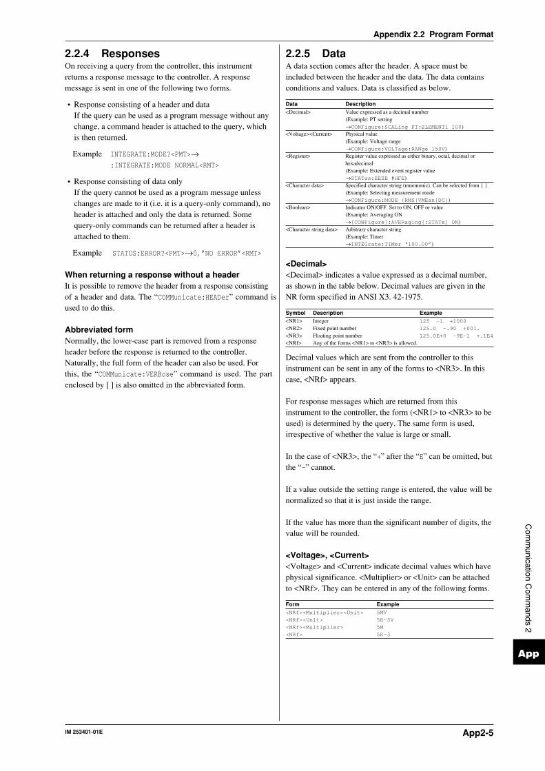
IM 253401-01E App2-5
App
Appendix 2.2 Program Format
Com
munication C
omm
ands 2
2.2.4 ResponsesOn receiving a query from the controller, this instrumentreturns a response message to the controller. A responsemessage is sent in one of the following two forms.
• Response consisting of a header and dataIf the query can be used as a program message without anychange, a command header is attached to the query, whichis then returned.
Example INTEGRATE:MODE?<PMT>→:INTEGRATE:MODE NORMAL<RMT>
• Response consisting of data onlyIf the query cannot be used as a program message unlesschanges are made to it (i.e. it is a query-only command), noheader is attached and only the data is returned. Somequery-only commands can be returned after a header isattached to them.
Example STATUS:ERROR?<PMT>→0,”NO ERROR”<RMT>
When returning a response without a headerIt is possible to remove the header from a response consistingof a header and data. The “COMMunicate:HEADer” command isused to do this.
Abbreviated formNormally, the lower-case part is removed from a responseheader before the response is returned to the controller.Naturally, the full form of the header can also be used. Forthis, the “COMMunicate:VERBose” command is used. The partenclosed by [ ] is also omitted in the abbreviated form.
2.2.5 DataA data section comes after the header. A space must beincluded between the header and the data. The data containsconditions and values. Data is classified as below.
Data Description<Decimal> Value expressed as a decimal number
(Example: PT setting→CONFigure:SCALing PT:ELEMENT1 100)
<Voltage><Current> Physical value(Example: Voltage range→CONFigure:VOLTage:RANge 150V)
<Register> Register value expressed as either binary, octal, decimal orhexadecimal(Example: Extended event register value→STATus:EESE #HFE)
<Character data> Specified character string (mnemonic). Can be selected from (Example: Selecting measurement mode→CONFigure:MODE RMS|VMEan|DC)
<Boolean> Indicates ON/OFF. Set to ON, OFF or value(Example: Averaging ON→[CONFigure]:AVERaging[:STATe] ON)
<Character string data> Arbitrary character string(Example: Timer→INTEGrate:TIMer “100.00”)
<Decimal><Decimal> indicates a value expressed as a decimal number,as shown in the table below. Decimal values are given in theNR form specified in ANSI X3. 42-1975.
Symbol Description Example<NR1> Integer 125 -1 +1000
<NR2> Fixed point number 125.0 -.90 +001.
<NR3> Floating point number 125.0E+0 -9E-1 +.1E4
<NRf> Any of the forms <NR1> to <NR3> is allowed.
Decimal values which are sent from the controller to thisinstrument can be sent in any of the forms to <NR3>. In thiscase, <NRf> appears.
For response messages which are returned from thisinstrument to the controller, the form (<NR1> to <NR3> to beused) is determined by the query. The same form is used,irrespective of whether the value is large or small.
In the case of <NR3>, the “+” after the “E” can be omitted, butthe “–” cannot.
If a value outside the setting range is entered, the value will benormalized so that it is just inside the range.
If the value has more than the significant number of digits, thevalue will be rounded.
<Voltage>, <Current><Voltage> and <Current> indicate decimal values which havephysical significance. <Multiplier> or <Unit> can be attachedto <NRf>. They can be entered in any of the following forms.
Form Example<NRf><Multiplier><Unit> 5MV
<NRf><Unit> 5E-3V
<NRf><Multiplier> 5M
<NRf> 5E-3

IM 253401-01EApp2-6
Appendix 2.2 Program Format
<Multiplier>Multipliers which can be used are shown below.
Symbol Word DescriptionEX Exa 1018
PE Peta 1015
T Tera 1012
G Giga 109
MA Mega 106
K Kilo 103
M Mili 10-3
U Micro 10-6
N Nano 10-9
P Pico 10-12
F Femto 10-15
<Unit>Units which can be used are shown below.
Symbol Word DescriptionV Volt VoltageA Ampere Current
<Multiplier> and <Unit> are not case sensitive.“U” is used to indicate “µ”.“MA” is used for Mega (M) to distinguish it from Mili.However, when using “MA” for current, Mili-ampere will bevalid; therefore use “MAA” to assign Mega-ampere.If both <Multiplier> and <Unit> are omitted, the default unitwill be used.Response messages are always expressed in <NR3> form.Neither <Multiplier> nor <Unit> is used, therefore the defaultunit is used.
<Register><Register> indicates an integer, and can be expressed inhexadecimal, octal or binary as well as as a decimal number.<Register> is used when each bit of a value has a particularmeaning. <Register> is expressed in one of the followingforms.
Form Example<NRf> 1
#H<Hexadecimal value made up of the digits 0 to 9, and A to F> #H0F
#Q<Octal value made up of the digits 0 to 7> #q777
#B<Binary value made up of the digits 0 and 1> #B001100
<Register> is not case sensitive.Response messages are always expressed as <NR1>.
<Character Data><Character data> is a specified string of character data (amnemonic). It is mainly used to indicate options, and ischosen from the character strings given in . Forinterpretation rules, refer to “Header Interpretation Rules” onpage App2-5.
Form ExampleRMS|VMEan|DC RMS
As with a header, the “COMMunicate:VERBose” command canbe used to return a response message in its full form.Alternatively, the abbreviated form can be used.The “COMMunicate:HEADer” command does not affect<character data>.
<Boolean><Boolean> is data which indicates ON or OFF, and isexpressed in one of the following forms.
Form ExampleON|OFF|<NRf> ON OFF 1 0
When <Boolean> is expressed in <NRf> form, OFF isselected if the rounded integer value is “0” and ON is selectedif the rounded integer is “Not 0”.A response message is always “1” if the value is ON and “0” ifit is OFF.
<Character String Data><Character string data> is not a specified character string like<Character data>. It is an arbitrary character string. Acharacter string must be enclosed in single quotation marks (‘)or double quotation marks (“).
Form Example<Character string data> ‘ABC’ “IEEE488.2-1987”
Response messages are always enclosed in double quotationmarks.
If a character string contains a double quotation mark (“), thedouble quotation mark will be replaced by two concatenateddouble quotation marks (““). This rule also applies to a singlequotation mark within a character string.
<Character string data> is an arbitrary character string,therefore this instrument assumes that the remaining programmessage units are part of the character string if no single (‘) ordouble quotation mark (“) is encountered. As a result, no errorwill be detected if a quotation mark is omitted.

IM 253401-01E App2-7
App
Appendix 2.2 Program Format
Com
munication C
omm
ands 2
2.2.6 Synchronization with theController
There are two kinds of command; overlap commands andsequential commands. Execution of an overlap command maystart before execution of the previously sent command iscompleted.
For example, if the next program message is transmitted afterthe measurement range has been changed and an query ismade about the measurement data, it may occur that regardlesswhether the measurement data have been updated,MEASure[:NORMal]:VALue? will be executed. The displaybecomes “——” (no data) and “9.91E+37 (Not a number)”will be output.
[CONFigure:]VOLTage:RANGe 60V;:MEASure[:NORMal:
VALue?<PMT>
In this case, synchronization with the time at which the updateof measurement data is completed must be accomplished, asshown next.
Using STATus:CONDition? queryA “STATus:CONDition?” query is used to make an inquiryabout the contents of the condition register (page App2-37). Itis possible to judge whether updating measurement data is inprogress or not by reading bit 0 of the condition register. Bit 0is “1” if updating is in progress, and “0” if updating isstopped.
Using the extended event registerChanges in the condition register are reflected in the extendedevent register (page App2-38).
Example STATus:FILTer1 FALL;:STATus:EESE 1;EESR?;
*SRE8;[:CONFigure]:VOLTage:RANGe 60V<PMT>
(Service request is awaited.)MEASure[:NORMal]:VALue?<PMT>
“STATus:FILTer1 FALL” indicates that the transit filter is setso that bit 0 is set to “1” when bit 0 (FILTer 1) of thecondition register is changed from “1” to “0”.“STATus:EESE 1” is a command used only to reflect the statusof bit 0 of the extended event register in the status byte.“STATus:EESR?” is used to clear the extended event register.The “*SRE” command is used to generate a service requestcaused solely by the extended event register.“MEASure[:NORMal]:VALue?” will not be executed until aservice request is generated.
Using the COMMunicate:WAIT commandThe “COMMunicate:WAIT” command halts communicationsuntil a specific event is generated.
Example STATus:FILTer1 FALL;:STATus:EESE 1;EESR?;
[:CONFigure]:VOLTage:RANGe 60V<PMT>
(Response to STATus:EESR? is decoded.)COMMunicate:WAIT 1;:MEASure[:NORMal]
:VALue?<PMT>
For a description of “STATus:FILTer 1 FALL” and“STATus:EESR?”, refer to “Using the extended event register”on this page.“COMMunicate:WAIT 1” means that communications is halteduntil bit 0 of the extended event register is set to “1”.“MEASure[:NORMal]:VALue?” will not be executed until bit 0of the extended event register is set to “1”.

IM 253401-01EApp2-8
Appendix 2.3 Commands
Appendix 2.3 Commands
2.3.1Command ListCommand Description Page
AOUTput Group
:AOUTput? Queries all settings related to D/A output. App. 2-11
:AOUTput:CHANnel<x> Sets/queries the D/A output item. App. 2-11
:AOUTput:IRTime Sets/queries the preset integration time for D/A output of integrated values. App. 2-11
:AOUTput:PRESet Sets the default value as D/A output items. App. 2-11
COMMunicateG roup
:COMMunicate? Queries all settings related to communication. App. 2-12
:COMMunicate:HEADer Sets/queries whether a header is to be added. App. 2-12
:COMMunicate:LOCKout Sets/cancels local lockout. App. 2-12
:COMMunicate:REMote Sets remote/local condition. App. 2-12
:COMMunicate:STATus? Queries the status of a specified circuit. App. 2-13
:COMMunicate:VERBose Sets/queries the response to be in full or abbreviated form. App. 2-13
:COMMunicate:WAIT Waits until one of the specified extended event occurs. App. 2-13
:COMMunicate:WAIT? Generates a response when on of the specified extended events occurs. App. 2-13
CONFigure Group
:CONFigure? Queries all settings related to the measurement conditions. App. 2-15
[:CONFigure]:AVERaging? Queries all settings related to the averaging function. App. 2-15
[:CONFigure]:AVERaging[:STATe] Sets/queries averaging ON/OFF. App. 2-15
[:CONFigure]:AVERaging:TYPE Sets/queries averaging type and constant. App. 2-15
[:CONFigure]:CURRent? Queries all settings related to the current range. App. 2-15
[:CONFigure]:CURRent:AUTO Sets/queries the current auto range ON/OFF. App. 2-15
[:CONFigure]:CURRent:ESCaling? Queries all settings related to the external sensor. App. 2-15
[:CONFigure]:CURRent:ESCaling[:ALL] Sets the scaling values for the external sensor for all elements at once. App. 2-15
[:CONFigure]:CURRent:ESCaling:ELEMent<x>
Sets/queries the scaling values for the external sensor for each element. App. 2-15
[:CONFigure]:CURRent:RANGe Sets/queries the current range. App. 2-15
[:CONFigure]:FILTer Sets/queries the filter ON/OFF. App. 2-15
[:CONFigure]:MODE Sets/queries the measurement mode. App. 2-15
[:CONFigure]:SCALing? Queries all settings related to the scaling function. App. 2-16
[:CONFigure]:SCALing:PT|CT|SFACtor? Queries all settings related to scaling value for voltage|current|power. App. 2-16
[:CONFigure]:SCALing:PT|CT|SFACtor[:ALL]
Sets the scaling values for all elements of voltage|current|power. App. 2-16
[:CONFigure]:SCALing:PT|CT|SFACtor:ELEMent<x>
Sets the scaling values for each element of voltage|current|power. App. 2-16
[:CONFigure]:SCALing[:STATe] Sets/queries the scaling function ON/OFF. App. 2-16
[:CONFigure]:VOLTage? Queries all settings related to the voltage range. App. 2-16
[:CONFigure]:VOLTage:AUTO Sets/queries the voltage auto range ON/OFF. App. 2-16
[:CONFigure]:VOLTage:RANGe Sets/queries the voltage range. App. 2-16
[:CONFigure]:WIRing Sets/queries the wiring method. App. 2-16
DISPlay Group
:DISPlay<x>? Queries all the display settings. App. 2-17
:DISPlay<x>:ELEMent Sets/queries the element to be displayed. App. 2-17
:DISPlay<x>:FUNCtion Sets/queries the function to be displayed. App. 2-17
:DISPlay<x>:MODE Sets/queries the contents of the display. App. 2-17
HARMonics Group
:HARMonics? Queries all settings related to harmonic analysis. App. 2-18
:HARMonics:DISPlay? Queries all settings related to the display in case of harmonic analysis. App. 2-18
:HARMonics:DISPlay:ORDer Sets/queries the order of the harmonic component to be shown on display B. App. 2-18
:HARMonics:ELEMent Sets/queries the element for harmonic analysis. App. 2-18
:HARMonics[:STATe] Sets/queries the harmonic analysis mode ON/OFF. App. 2-18
:HARMonics:SYNChronize Sets/queries the input to be used as PLL source. App. 2-18
:HARMonics:THD Sets/queries the computation method for harmonic distortion. App. 2-18

IM 253401-01E App2-9
App
Appendix 2.3 Commands
Com
munication C
omm
ands 2
Command Description Page
INTEGrate Group
:INTEGrate? Queries all settings related to integration. App. 2-19
:INTEGrate:MODE Sets/queries the integration mode. App. 2-19
:INTEGrate:RESet Resets the integration values. App. 2-19
:INTEGrate:STARt Starts integration. App. 2-19
:INTEGrate:STOP Stops integration. App. 2-19
:INTEGrate:TIMer Sets/queries the integration timer. App. 2-19
MATH Group (applies to WT110/WT130 with ROM version 2.01 or later)
:MATH? Queries all settings related to the computing function. App. 2-20
:MATH:ARIThmetic Sets/queries the computing equation of the four arithmetic operations. App. 2-20
:MATH:CFACtor Sets/queries the computing equation of the crest factor. App. 2-20
:MATH:TYPE Sets/queries the computing equation. App. 2-20
MEASure Group
:MEASure? Queries all settings related to measurement/computation data. App. 2-22
:MEASure:HARMonics? Queries all settings related to harmonic analysis data. App. 2-22
:MEASure:HARMonics:ITEM? Queries all settings related to the output items of harmonic analysis data. App. 2-22
:MEASure:HARMonics:ITEM:PRESet Sets the ON/OFF pattern for all communication outputs of the harmonic
analysis function. App. 2-22
:MEASure:HARMonics:ITEM:SYNChronize|<harmonic analysis function>
Sets/queries the communication output item of harmonic analysis ON/OFF. App. 2-22
:MEASure:HARMonics:VALue? Queries harmonic analysis data set by commands other than
“MEASure:HARMonics:ITEM”. App. 2-22
:MEASure:NORMal? Queries all settings related to normal measured/computed data. App. 2-22
:MEASure[:NORMal]:ITEM? Queries all settings related to the output items of normal measured/computed data. App. 2-23
:MEASure[:NORMal]:ITEM:PRESet Sets the ON/OFF pattern for all communication outputs of the normal
measurement function. App. 2-23
:MEASure[:NORMal]:ITEM:TIME|MATH Sets/queries the ON/OFF state of the communication output of
integration time|MATH. App. 2-23
:MEASure[:NORMal]:ITEM:<normal measurement function>?
Queries communication output settings of the normal measurement function. App. 2-23
:MEASure[:NORMal]:ITEM:<normal measurement function>[:ALL]
Sets the communication output items concerning all elements or S ON/
OFF at once. App. 2-23
:MEASure[:NORMal]:ITEM:<normal measurement function>:ELEMent<x>
Sets/queries the communication output items concerning each element
ON/OFF. App. 2-23
:MEASure[:NORMal]:ITEM:<normal measurement function>:SIGMA
Sets/queries the communication output items concerning S ON/OFF. App. 2-23
:MEASure[:NORMal]:VALue? Queries normal measured/computed data set by commands other than
“MEASure[:NORMal]:ITEM” App. 2-23
RECall Group
:RECall? Queries all settings related to recalling data. App. 2-27
:RECall:INTerval Sets/queries the recalling interval. App. 2-27
:RECall:PANel Retrieves the set-up parameters file. App. 2-27
:RECall[:STATe] Sets/queries recalling ON/OFF. App. 2-27

IM 253401-01EApp2-10
Appendix 2.3 Commands
Command Description Page
RELay Group
RELay? Queries all settings related to the comparator function. App. 2-28
:RELay:DISPLay Sets/queries the comparator display OFF, or in case of ON, the channel to be
displayed. App. 2-28
:RELay:HCHannel<x>? Queries all settings related to relay output items in case of harmonic analysis. App. 2-28
:RELay:HCHannel<x>:FUNCtion Sets/queries function of the relay output item in case of harmonic analysis. App. 2-29
:RELay:HCHannel<x>:THReshold Sets/queries the threshold level for the relay output item. App. 2-29
:RELay:MODE Sets/queries the mode of the comparator function. App. 2-29
:RELay:NCHannel<x>? Queries all settings related to the relay output items in case of normal
measurement. App. 2-29
:RELay:NCHannel<x>:FUNCtion Sets/queries the function of the relay output in case of normal measurement. App. 2-29
:RELay:NCHannel<x>:THReshold Sets/queries the threshold level for the relay output item. App. 2-29
:RELay:STATe Sets/queries the comparator function ON/OFF. App. 2-29
SAMPle Group
:SAMPle? Queries all settings related to sampling. App. 2-30
:SAMPle:HOLD Sets/queries to hold the output of data (display, communication). App. 2-30
STATus Group
:STATus? Queries all settings related to the status of communication. App. 2-31
:STATus:CONDition? Queries the contents of the condition filter and clears it at the same time. App. 2-31
:STATus:EESE Sets/queries the extended event register. App. 2-31
:STATus:EESR? Queries the contents of the extended event register and clears it. App. 2-31
:STATus:ERRor? Queries the occurred error code and message. App. 2-31
:STATus:FILTer<x> Sets/queries the transit filter. App. 2-31
:STATus:QMESsage Sets/queries whether or not to apply the corresponding message to the
query “STATus:ERRor?”. App. 2-31
:STATus:SPOLl?(Serial Poll) Executes serial polling. App. 2-31
STORe Group
:STORe? Queries all settings related to storing data. App. 2-32
:STORe:INTerval Sets/queries the interval for storing data. App. 2-32
:STORe:PANel Saves the set-up parameters to a file. App. 2-32
:STORe[:STATe] Sets/queries the store function ON/OFF. App. 2-32
Common Command Group
*CLS Clears the standard event register, extended event register and error queue. App. 2-33
*ESE Sets/queries the value of the standard event enable register. App. 2-33
*ESR? Sets/queries the value of the standard event register and clears it. App. 2-33
*IDN? Queries the instrument model. App. 2-33
*OPC This command is not supported by this instrument. App. 2-33
*OPC? This command is not supported by this instrument, and is always “1”. App. 2-33
*OPT? Queries installed options. App. 2-34
*PSC Sets/queries whether or not to clear some registers at power ON. App. 2-34
*RST Initializes the present settings. App. 2-34
*SRE Sets/queries the value of the service request enable register. App. 2-34
*STB? Queries the value of the status byte register. App. 2-34
*TRG Executes the same operation as the TRIG(SHIFT+HOLD) key. App. 2-34
*TST? Executes a self-test and queries the results. App. 2-34
*WAI This command is not supported by this instrument. App. 2-34

IM 253401-01E App2-11
App
Appendix 2.3 Commands
Com
munication C
omm
ands 2
2.3.2 AOUTput GroupThe commands in the AOUTput group are used to make settings relating to, and inquires about D/A output. This allows you tomake the same settings and inquiries as can be set using the lower menus of [OUTPUT]-”dA” or [INTEG SET]-”dAtimE”.
:AOUTput : PRESet <Space> NORMal
INTEGrate
CHANnel <x> <Space> <Normal measurement> , <NRf>
ELEMent <x>
SIGMa
OFF
?
IRTime <Space> <NRf> , <NRf>
?
?
<Character string>
;
AOUTput:IRTimeFunction Sets the preset integration time for D/A output of
integrated values, or queries the current setting.Syntax AOUTput:IRTime <NRf>,<NRf>|<String>
<NRf>,<NRf>=0,0 to 999,59<String>=HHH:MM HHH hour MM minutes
Example AOUTPUT:IRTIME 1,0AOUTPUT:IRTIME “2:00“AOUTPUT:IRTIME?→:AOUTPUT:IRTIME 2,0
AOUTput:PRESetFunction Initializes the output items for D/A output.Syntax AOUTput:PREset NORMal|INTEGrate
NORMal = default for normal measurementINTEGrate = default for integration
Example AOUTPUT:PRESET NORMALDescription Refer to page 10-4 for a description of default D/A
output items for normal measurement and integration.
AOUTput?Function Queries all the settings relating to D/A output.Syntax AOUTput?Example AOUTPUT?Æ:AOUTPUT:CHANNEL1 V,1;CHANNEL2 V,2;
CHANNEL3 V,3;CHANNEL4 V,SIGMA;CHANNEL5 A,1;CHANNEL6 A,2;CHANNEL7 A,3;CHANNEL8 A,SIGMA;CHANNEL9 W,1;CHANNEL10 W,2;CHANNEL11 W,3;CHANNEL12 W,SIGMA;:AOUTPUT:IRTIME 1,0
AOUTput:CHANnel<x>Function Sets the D/A output item, or queries the current
setting.Syntax AOUTput:CHANnel<x> <normal measurement
function>,(<NRf>|ELEMent<1-3>|SIGMa)|OFF<x>=1 to 12(in case of /DA12) 1 to 4 (in case of /DA4)<normal measurement function>=V|A|W|VA|VAR|PF|DEGRee|VHZ|AHZ|WH|WHP|WHM|AH|AHP|AHM|MATH|VPK|APK
Example AOUTPUT:CHANNEL1 V,1AOUTPUT:CHANNEL1?→:AOUTPUT:CHANNEL1 V,1AOUTPUT:CHANNEL2?→:AOUTPUT:CHANNEL2 OFF
NoteIn the following pages, the alphanumeric character strings used in the descriptions of the <normalmeasurement function> or the <harmonic analysis function> indicates the following data.• <Normal measurement function>
V: voltage, A: current, W: effective power, VA: apparent power, VAR: reactive power, PF: powerfactor, DEGRee: phase angle, VHZ: voltage frequency, AHZ: current frequency, WH: watt hour, WHP:positive watt hour, WHM: negative watt hour, AH: current hour, AHP: positive current hour, AHM:negative current hour, MATH: MATH computation result, VPK: peak voltage, APK: peak currentHowever, MATH, VPK, APK applies to WT110/WT130 with ROM version 2.01 or later.
• <Harmonic analysis function>See page App2-25.
• OtherTIME: integration time, ORDer: harmonic order

IM 253401-01EApp2-12
Appendix 2.3 Commands
2.3.3 COMMunicate GroupThe commands in the COMMunicate group are used to make settings relating to, and inquires about communications. There is nofront panel key for this function.
:COMMunicate : HEADer <Space> OFF
ON
<NRf>
?
VERBose <Space> OFF
ON
<NRf>
?
WAIT <Space> <Register>
?
REMote <Space> OFF
ON
<NRf>
?
LOCKout <Space> OFF
ON
<NRf>
?
STATus ?
?
;
COMMunicate:LOCKoutFunction Sets local lockout ON or OFF.Syntax COMMunicate:LOCKout <Boolean>
COMMunicate:LOCKout?Example COMMUNICATE:LOCKOUT ON
COMMUNICATE:LOCKOUT?→:COMMUNICATE:LOCKOUT 1Description This command is used for the RS-232C interface.
COMMunicate:REMoteFunction Sets remote (ON) or local mode (OFF).Syntax COMMunicate:REMote <Boolean>
COMMunicate:REMote?Example COMMUNICATE:REMOTE ON
COMMUNICATE:REMOTE?→:COMMUNICATE:REMOTE 1Description This command is used for the RS-232C interface.
COMMunicate?Function Queries all the communication settings.Syntax COMMunicate?Example COMMUNICATE?
→:COMMUNICATE:HEADER 1;VERBOSE 1
COMMunicate:HEADerFunction Determines whether a header is to be added (for
example:“CONFIGURE:VOLTAGE:RANGE 150.0E+00”) ornot (for example:150.0E+00) when sending a responseto a query, or queries the current setting.
Syntax COMMunicate:HEADer <Boolean>COMMunicate:HEADer?
Example COMMUNICATE:HEADER ONCOMMUNICATE:HEADER?→:COMMUNICATE:HEADER 1

IM 253401-01E App2-13
App
Appendix 2.3 Commands
Com
munication C
omm
ands 2
COMMunicate:STATus?Function Queries the status of a specified circuit.Syntax COMMunicate:STATus?Example COMMUNICATE:STATUS?→:COMMUNICATE:STATUS 0Description The status condition for each bit is as follows.
bit GP-IB RS-232-C0 permanent Parity error
comm. error1 always 0 framing error2 always 0 break character occurrence3 and up always 0 always 0
When a status occurs which results in changing of thebits, reading it will clear the error.
COMMunicate:VERBoseFunction Determines whether a response to a query is to be
returned in full form (for example:CONFIGURE:VOLTAGE:RANGE 150.0E+00), or in abbreviated form(for example: VOLT:RANG 150.0E+00), or queries thecurrent setting.
Syntax COMMunicate:VERBose <Boolean>COMMunicate:VERBose?
Example COMMUNICATE:VERBOSE ONCOMMUNICATE:VERBOSE?→:COMMUNICATE:VERBOSE 1
COMMunicate:WAITFunction Waits until one of the specified extended event occurs.Syntax COMMunicate:WAIT <Register>
<Register>= 0 to 65535 (For a description of theextended event register, refer to page App2-38.)
Example COMMUNICATE:WAIT 65535Description For a description of synchronization using
“COMMunicate:WAIT”, refer to page App2-8.
COMMunicate:WAIT?Function Generates a response when one of the specified
extended events occurs.Syntax COMMunicate:WAIT? <Register>
<Register>= 0 to 65535 (For a description of theextended event register, refer to page App2-38.)
Example COMMUNICATE:WAIT? 65535→1

IM 253401-01EApp2-14
Appendix 2.3 Commands
2.3.4 CONFigure GroupThe CONFigure group relates to the measurement settings. The same function can be performed using the WIRING key, VRANGE key, A RANGE key, MODE (SHIFT + V RANGE) key and SETUP key (except for “PnLrSt”) on the front panel. Theexternal sensor input range and external sensor scaling values are only vald if equipped with the external sensor option (/EX1 or /EX2).
:CONFigure : WIRing <Space> P1W2
P1W3
P3W3
P3W4
V3A3
?
MODE <Space> RMS
VMEan
DC
?
VOLT age : RANGe <Space>
?
AUTO <Space> OFF
ON
<NRf>
?
?
CURRent : RANGe <Space>
EXTernal ,
?
AUTO <Space> OFF
ON
<NRf>
?
ESCaling : ALL <Space> <NRf>
ELEMent <x> <Space> <NRf>
?
?
?
FILTer <Space> OFF
ON
<NRf>
?
SCALing : STAT e <Space> OFF
ON
<NRf>
?
PT : ALL <Space> <NRf>
ELEMent <x> <Space> <NRf>
?
?
CT
SFACtor
?
AVERaging : STAT e <Space> OFF
ON
<NRf>
?
TYPE <Space> LINear , <NRf>
EXPonent
<Voltage>
<Voltage>
<Current>
?
?
?
;
;
;
;
;
;
;

IM 253401-01E App2-15
App
Appendix 2.3 Commands
Com
munication C
omm
ands 2
CONFigure?Function Queries all the settings related to the measurement
conditions.Syntax CONFigure?Example CONFIGURE?→:CONFIGURE:WIRING P1W3;MODE RMS;
VOLTAGE:RANGE 600.0E+00;AUTO 1;:CONFIGURE:CURRENT:RANGE 20.0E+00;AUTO 1;ESCALING:ELEMENT1 50.00E+00;ELEMENT2 50.00E+00;ELEMENT3 50.00E+00;:CONFIGURE:FILTER 0;SCALING:STATE 0;PT:ELEMENT1 1.000E+00;ELEMENT2 1.000E+00;ELEMENT3 1.000E+00;:CONFIGURE:SCALING:CT:ELEMENT1 1.000E+00;ELEMENT2 1.000E+00;ELEMENT3 1.000E+00;:CONFIGURE:SCALING:SFACTOR:ELEMENT1 1.000E+00;ELEMENT2 1.000E+00;ELEMENT3 1.000E+00;:CONFIGURE:AVERAGING:STATE 0;TYPE LINEAR,8
[CONFigure]:AVERaging?Function Queries all the setting values related to the averaging
function.Syntax [CONFigure]:AVERaging?Example [CONFIGURE]:AVERAGING?→:CONFIGURE:AVERAGING:
STATE 0;TYPE LINEAR,8
[CONFigure]:AVERaging[:STATe]Function Sets averaging ON/OFF, or queries the current status.Syntax [CONFigure]:AVERaging[:STATe] <Boolean>
[CONFigure]:AVERaging:STATe?Example [CONFIGURE]:AVERAGING:STATE OFF
[CONFIGURE]:AVERAGING:STATE?→:CONFIGURE:AVERAGING:STATE 0
[CONFigure]:AVERaging:TYPEFunction Sets the averaging type and constant, queries the
current setting.Syntax [CONFigure]:AVERaging:TYPE LINear|
EXPonent,<NRf>[CONFigure]:AVERaging:TYPE?<NRf>=8, 16, 32, 64 (averaging constant)
Example [CONFIGURE]:AVERAGING:TYPE LINEAR,8[CONFIGURE]:AVERAGING:TYPE?→:CONFIGURE:AVERAGING:TYPE LINEAR,8
[CONFigure]:CURRent?Function Queries all setting values relating to the current range
(external sensor range)Syntax [CONFigure]:CURRent?Example [CONFIGURE]:CURRENT?→:CONFIGURE:CURRENT:
RANGE 20.0E+00;AUTO 1;ESCALING:ELEMENT1 50.00E+00;ELEMENT2 50.00E+00;ELEMENT3 50.00E+00
[CONFigure]:CURRent:AUTOFunction Sets the current auto range ON/OFF, or queries the
current setting.Syntax [CONFigure]:CURRent:AUTO <Boolean>
[CONFigure]:CURRent:AUTO?Example [CONFIGURE]:CURRENT:AUTO ON
[CONFIGURE]:CURRENT:AUTO?→:CONFIGURE:CURRENT:AUTO 1
[CONFigure]:CURRent:ESCaling?Function Queries all scaling values for the external sensor.Syntax [CONFigure]:CURRent:ESCaling?Example [CONFIGURE]:CURRENT:ESCALING?→:CONFIGURE:
CURRENT:ESCALING:ELEMENT1 50.00E+00;ELEMENT2 50.00E+00;ELEMENT3 50.00E+00
[CONFigure]:CURRent:ESCaling[:ALL]Function Sets the scaling values for the external sensor for all
elements at once.Syntax [CONFigure]:CURRent:ESCaling[:ALL] <NRf>
<NRf>= 0.001 to 1000Example [CONFIGURE]:CURRENT:ESCALING:ALL 50.00Description The setting values differ as follows.
Less than 1.000 : Three digits after the floating-pointare valid.1.000 to 1000 : The first five digits are valid.
[CONFigure]:CURRent:ESCaling:ELEMent<x>Function Sets the scaling values for the external sensor for each
element separately, queries the current setting.Syntax [CONFigure]:CURRent:ESCaling:
ELEMent<x> <NRf>[CONFigure]:CURRent:ESCaling:ELEMent<x>?<x>=1 (WT110 single model)
1, 3 (WT130 three-phase, three-wiremodel)
1 to 3(WT130 three-phase, four-wiremodel)
<NRf>=0.001 to 1000Example [CONFIGURE]:CURRENT:ESCALING:ELEMENT1 50.00
[CONFIGURE]:CURRENT:ESCALING:ELEMENT1?→:CONFIGURE:CURRENT:ESCALING:ELEMENT1 50.00E+00
Description Setting values differ as described at [CONFigure]:CURRent:ESCaling[:ALL].
[CONFigure]:CURRent:RANGeFunction Sets the current range (external sensor input range),
queries the current setting.Syntax [CONFigure]:CURRent:RANGe
<current>|(EXTernal,<voltage>)[CONFigure]:CURRent:RANGe?<current>=500mA to 20A (0.5, 1, 2, 5, 10,
20A)<voltage>=50mV to 200mV (50, 100, 200mV, for
/EX2 option)=2.5V to 10V (2.5, 5, 10V, for /EX1 option)
Example Setting of current range/query[CONFIGURE]:CURRENT:RANGE 20A[CONFIGURE]:CURRENT:RANGE?→:CONFIGURE:CURRENT:RANGE 20.0E+00Setting of external sensor input range/query (in case of /EX2 option)[CONFIGURE]:CURRENT:RANGE EXTERNAL,50MV[CONFIGURE]:CURRENT:RANGE?→:CONFIGURE:CURRENT:RANGE EXTERNAL,50.0E-03
[CONFigure]:FILTerFunction Sets the filter ON/OFF, queries the current setting.Syntax [CONFigure]:FILTer <Boolean>
[CONFigure]:FILTer?Example [CONFIGURE]:FILTER OFF
[CONFIGURE]:FILTER?→:CONFIGURE:FILTER 0
[CONFigure]:MODEFunction Sets the measurement mode of current and voltage,
queries the current setting.Syntax [CONFigure]:MODE RMS|VMEan|DC
[CONFigure]:MODE?Example [CONFIGURE]:MODE RMS
[CONFIGURE]:MODE?→:CONFIGURE:MODE RMS

IM 253401-01EApp2-16
Appendix 2.3 Commands
[CONFigure]:SCALing?Function Queries all settings relating to the scaling function.Syntax [CONFigure]:SCALing?Example [CONFIGURE]:SCALING?→:CONFIGURE:
SCALING:STATE 0;PT:ELEMENT1 1.000E+00;ELEMENT2 1.000E+00;ELEMENT3 1.000E+00;:CONFIGURE:SCALING:CT:ELEMENT1 1.000E+00;ELEMENT2 1.000E+00;ELEMENT3 1.000E+00;:CONFIGURE:SCALING:SFACTOR:ELEMENT1 1.000E+00;ELEMENT2 1.000E+00;ELEMENT3 1.000E+00
[CONFigure]:SCALing:PT|CT|SFACtor?Function Queries all scaling values related to
voltage|current|power.Syntax [CONFigure]:SCALing:PT|CT|SFACtor?Example [CONFIGURE]:SCALING:PT?→:CONFIGURE:SCALING:
PT:ELEMENT1 1.000E+00;ELEMENT2 1.000E+00;ELEMENT3 1.000E+00
[CONFigure]:SCALing:PT|CT|SFACtor[:ALL]Function Sets the scaling values for all elements of
voltage|current|power at once.Syntax [CONFigure]:SCALing:PT|CT|SFACtor[:ALL]
<NRf><NRf>=0.001 to 1000
Example [CONFIGURE]:SCALING:PT:ALL 1.000Description The setting values differ as follows.
Less than 1.000 : Three digits after the decimal pointare valid.1.000 to 1000 : The first five digits are valid.
[CONFigure]:SCALing:PT|CT|SFACtor:ELEMent<x>Function Sets the scaling value for voltage|current|power
of each element, queries the current setting.Syntax [CONFigure]:SCALing:PT|CT|SFACtor:
ELEMent<x> <NRf>[CONFigure]:SCALing:PT|CT|SFACtor:ELEMent<x>?<x>= 1 (WT110 single-phase model)
1, 3 (WT130 three-phase, three-wiremodel)
1 to 3(WT130 three-phase, four-wiremodel)
<NRf>=0.001 to 1000Example [CONFIGURE]:SCALING:PT:ELEMENT1 1.000
[CONFIGURE]:SCALING:PT:ELEMENT1?→:CONFIGURE:SCALING:PT:ELEMENT1 1.000E+00
Description Setting values differ as described at[CONFigure]:CURRent:ESCaling[:ALL].
[CONFigure]:SCALing[:STATe]Function Sets scaling ON/OFF, queries the current setting.Syntax [CONFigure]:SCALing[:STATe] <Boolean>
[CONFigure]:SCALing:STATe?Example [CONFIGURE]:SCALING:STATE OFF
[CONFIGURE]:SCALING:STATE?→:CONFIGURE:SCALING:STATE 0
[CONFigure]:VOLTage?Function Queries all settings relating to voltage range.Syntax [CONFigure]:VOLTage?Example [CONFIGURE]:VOLTAGE?→:CONFIGURE:VOLTAGE:
RANGE 600.0E+00;AUTO 1
[CONFigure]:VOLTage:AUTOFunction Sets the voltage auto range ON/OFF, queries the
current setting.Syntax [CONFigure]:VOLTage:AUTO <Boolean>
[CONFigure]:VOLTage:AUTO?Example [CONFigure]:VOLTage:AUTO ON
[CONFIGURE]:VOLTAGE:AUTO?→:CONFIGURE:VOLTAGE:AUTO 1
[CONFigure]:VOLTage:RANGeFunction Sets the voltage range/queries the current setting.Syntax [CONFigure]:VOLTage:RANGe <voltage>
[CONFigure]:VOLTage:RANGe?<voltage>=15V to 600V (15, 30, 60, 150, 300,600V)
Example [CONFIGURE]:VOLTAGE:RANGE 600V[CONFIGURE]:VOLTAGE:RANGE?→:CONFIGURE:VOLTAGE:RANGE 600.0E+00
[CONFigure]:WIRingFunction Sets the wiring method/queries the current setting.Syntax [CONFigure]:WIRing P1W2|P1W3|P3W3|P3W4|V3A3
[CONFigure]:WIRing?Example [CONFIGURE]:WIRING P1W3
[CONFIGURE]:WIRING?→:CONFIGURE:WIRING P1W3Description The selections stand for the following.
P1W2 : Single-phase, two-wires ( only for WT110)P1W3 : Single-phase, three-wires (only for WT130)P3W3 : Three-phase, three-wires (only for WT130)P3W4 : Three-phase, four-wires (only for WT130 3-phase, 4-wire model)V3A3 : Three-voltage, three-current (only for WT1303-phase, 4-wire model)
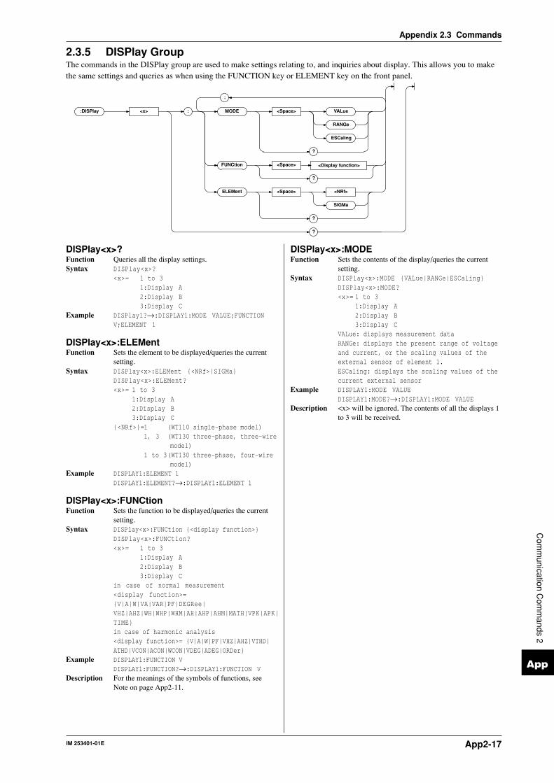
IM 253401-01E App2-17
App
Appendix 2.3 Commands
Com
munication C
omm
ands 2
2.3.5 DISPlay GroupThe commands in the DISPlay group are used to make settings relating to, and inquiries about display. This allows you to makethe same settings and queries as when using the FUNCTION key or ELEMENT key on the front panel.
:DISPlay <x> : MODE <Space> VALue
RANGe
ESCaling
?
FUNCtion <Space>
?
ELEMent <Space> <NRf>
SIGMa
?
?
<Display function>
;
DISPlay<x>:MODEFunction Sets the contents of the display/queries the current
setting.Syntax DISPlay<x>:MODE VALue|RANGe|ESCaling
DISPlay<x>:MODE?<x>= 1 to 3
1:Display A2:Display B3:Display C
VALue: displays measurement dataRANGe: displays the present range of voltageand current, or the scaling values of theexternal sensor of element 1.ESCaling: displays the scaling values of thecurrent external sensor
Example DISPLAY1:MODE VALUEDISPLAY1:MODE?→:DISPLAY1:MODE VALUE
Description <x> will be ignored. The contents of all the displays 1to 3 will be received.
DISPlay<x>?Function Queries all the display settings.Syntax DISPlay<x>?
<x>= 1 to 31:Display A2:Display B3:Display C
Example DISPlay1?→:DISPLAY1:MODE VALUE;FUNCTIONV;ELEMENT 1
DISPlay<x>:ELEMentFunction Sets the element to be displayed/queries the current
setting.Syntax DISPlay<x>:ELEMent <NRf>|SIGMa
DISPlay<x>:ELEMent?<x>= 1 to 3
1:Display A2:Display B3:Display C
<NRf>=1 (WT110 single-phase model)1, 3 (WT130 three-phase, three-wire
model)1 to 3(WT130 three-phase, four-wire
model)Example DISPLAY1:ELEMENT 1
DISPLAY1:ELEMENT?→:DISPLAY1:ELEMENT 1
DISPlay<x>:FUNCtionFunction Sets the function to be displayed/queries the current
setting.Syntax DISPlay<x>:FUNCtion <display function>
DISPlay<x>:FUNCtion?<x>= 1 to 3
1:Display A2:Display B3:Display C
in case of normal measurement<display function>=V|A|W|VA|VAR|PF|DEGRee|VHZ|AHZ|WH|WHP|WHM|AH|AHP|AHM|MATH|VPK|APK|TIMEin case of harmonic analysis<display function>= V|A|W|PF|VHZ|AHZ|VTHD|ATHD|VCON|ACON|WCON|VDEG|ADEG|ORDer
Example DISPLAY1:FUNCTION VDISPLAY1:FUNCTION?→:DISPLAY1:FUNCTION V
Description For the meanings of the symbols of functions, seeNote on page App2-11.

IM 253401-01EApp2-18
Appendix 2.3 Commands
2.3.6 HARMonics GroupThe commands in the HARMonics group relate to the harmonic analysis function. This allow you to make the same settings andinquiries as when using the HARMONICS key on the front panel and the corresponding menus. This group is only useful in caseyour instrument is equipped with the /HRM option.
:HARMonics : STAT e <Space> OFF
ON
<NRf>
?
ELEMent <Space> <NRf>
?
SYNChroniz e <Space> V , <NRf>
ELEMent <x>A
?
THD <Space> IEC
CSA
?
DISPlay : ORDer <Space> <NRf>
?
?
?
;
;
HARMonics[:STATe]Function Sets the harmonic analysis mode ON/OFF, queries the
current setting.Syntax HARMonics[:STATe] <Boolean>
HARMonics[:STATe]?Example HARMONICS:STATE ON
HARMONICS:STATE?→:HARMONICS:STATE 1
HARMonics:SYNChronizeFunction Sets the fundamental frequency for PLL
synchronization (PLL source)/queries the currentsetting.
Syntax HARMonics:SYNChronize(V|A),(<NRf>|ELEMent<1-3>)HARMonics:SYNChronize?
Example HARMONICS:SYNCHRONIZE V,1HARMONICS:SYNCHRONIZE?→:HARMONICS:SYNCHRONIZE V,1
HARMonics:THDFunction Sets the computation method for harmonic distortion
(THD) for harmonic analysis/queries the currentsetting.
Syntax HARMonics:THD IEC|CSAHARMonics:THD?
Example HARMONICS:THD IECHARMONICS:THD?→:HARMONICS:THD IEC
HARMonics?Function Queries all settings relating to harmonic analysis.Syntax HARMonics?Example HARMONICS?→:HARMONICS:STATE 0;ELEMENT 1;
SYNCHRONIZE V,1;THD IEC;DISPLAY:ORDER 1
HARMonics:DISPlay?Function Queries all settings concerning the display in case of
harmonic analysis.Syntax HARMonics:DISPlay?Example HARMONICS:DISPLAY?
HARMONICS:DISPLAY?→:HARMONICS:DISPLAY:ORDER 1
HARMonics:DISPlay:ORDerFunction Sets the order of the harmonic component to be shown
on display B, queries the current setting.Syntax HARMonics:DISPlay:ORDer <NRf>
HARMonics:DISPlay:ORDer?<NRf>=1 to 50
Example HARMONICS:DISPLAY:ORDER 1HARMONICS:DISPLAY:ORDER?→:HARMONICS:DISPLAY:ORDER 1
HARMonics:ELEMentFunction Sets the element for harmonic analysis/queries the
current setting.Syntax HARMonics:ELEMent <NRf>
HARMonics:ELEMent?<NRf>=1 (WT110 single-phase model)
1, 3 (WT130 three-phase, three-wiremodel)
1 to 3(WT130 three-phase, four-wiremodel)
Example HARMONICS:ELEMENT 1HARMONICS:ELEMENT?→:HARMONICS:ELEMENT 1

IM 253401-01E App2-19
App
Appendix 2.3 Commands
Com
munication C
omm
ands 2
2.3.7 INTEGrate GroupThe commands in the INTEGrate group are used to make settings relating to, and inquiries about integration. This allows you tomake the same settings and inquiries as when using the START key, STOP key, RESET key, INTEG SET key and theircorresponding menus.
:INTEGrate : MODE <Space> NORMal
CONTinuous
?
TIMer <Space> <NRf> , <NRf>
?
STARt
STOP
RESet
?
<Character string>
;
INTEGrate?Function Queries all settings relating to integration.Syntax INTEGrate?Example INTEGRATE?→:INTEGRATE:MODE NORMAL;TIMER 0,0
INTEGrate:MODEFunction Sets the integration mode/queries the current setting.Syntax INTEGrate:MODE NORMal|CONTinuous
INTEGrate:MODE?Example INTEGRATE:MODE NORMAL
INTEGRATE:MODE?→:INTEGRATE:MODE NORMAL
INTEGrate:RESetFunction Resets the integrated values.Syntax INTEGrate:RESetExample INTEGRATE:RESET
INTEGrate:STARtFunction Starts integration.Syntax INTEGrate:STARtExample INTEGRATE:START
INTEGrate:STOPFunction Stops integration.Syntax INTEGrate:STOPExample INTEGRATE:STOP
INTEGrate:TIMerFunction Sets the integration timer/queries the current setting.Syntax INTEGrate:TIMer <NRf>,<NRf>|<String>
<NRf>,<NRf>=0,0 to 999,59<String>=HHH:MM HHH hour MM minute
Example INTEGRATE:TIMER 10,0INTEGRATE:TIMER “10:00“INTEGRATE:TIMER?→:INTEGRATE:TIMER 10,0
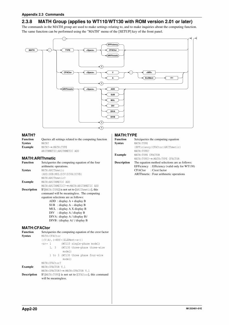
IM 253401-01EApp2-20
Appendix 2.3 Commands
2.3.8 MATH Group (applies to WT110/WT130 with ROM version 2.01 or later)The commands in the MATH group are used to make settings relating to, and to make inquiries about the computing function.The same function can be performed using the "MATH" menu of the [SETUP] key of the front panel.
:MATH : TYPE <Space> CFACtor
ARIThmetic
?
CFACtor <Space> V , <NRf>
ELEMent <x>A
?
ARIThmetic <Space> ADD
SUB
MUL
DIV
?
?
;
DIVA
DIVB
EFFiciency
MATH?Function Queries all settings related to the computing functionSyntax MATH?Example MATH?→:MATH:TYPE
ARITHMETIC;ARITHMETIC ADD
MATH:ARIThmeticFunction Sets/queries the computing equation of the four
arithmetic operations.Syntax MATH:ARIThmetic
ADD|SUB|MUL|DIV|DIVA|DIVBMATH:ARIThmetic?
Example MATH:ARITHMETIC ADDMATH:ARITHMETIC?→:MATH:ARITHMETIC ADD
Description If [MATH:TYPE] is not set to [ARIThmetic], thiscommand will be meaningless. The computingequation selections are as follows:
ADD : display A + display BSUB : display A – display BMUL : display A X display BDIV : display A / display BDIVA : display A / (display B)2
DIVB : (display A)2 / display B
MATH:CFACtorFunction Sets/queries the computing equation of the crest factorSyntax MATH:CFACtor
(V|A),(<NRf>|ELEMent<x>)<x>= 1 (WT110 single-phase model)
1, 3 (WT130 three-phase three-wiremodel)
1 to 3 (WT130 three phase four-wiremodel)
MATH:CFACtor?Example MATH:CFACTOR V,1
MATH:CFACTOR?→:MATH:CFACTOR V,1Description If [MATH:TYPE] is not set to [CFACtor], this command
will be meaningless.
MATH:TYPEFunction Sets/queries the computing equationSyntax MATH:TYPE
EFFiciency|CFACtor|ARIThmeticMATH:TYPE?
Example MATH:TYPE CFACTORMATH:TYPE?→:MATH:TYPE CFACTOR
Description The equation method selections are as follows:EFFiciency : Efficiency (valid only for WT130)CFACtor : Crest factorARIThmetic : Four arithmetic operations

IM 253401-01E App2-21
App
Appendix 2.3 Commands
Com
munication C
omm
ands 2
2.3.9 MEASure GroupThe MEASure group relates to measurement/computation data. There are no front panel keys for these functions. Also, yourinstrument must be equipped with the /HRM (harmonic analysis function) to be able to use the related commands. Setting theoutput items for measurement/computation data is only valid in the communication mode.
:MEASure : NORMal : VALue ?
ITEM : PRESet <Space> NORMal
INTEGrate
CLEar
: ALL <Space> OFF
ON
<NRf>
ELEMent <x> <Space> OFF
ON
<NRf>
?
SIGMa <Space> OFF
ON
<NRf>
?
?
TIME <Space> OFF
ONMATH
<NRf>
?
?
?
HARMonics : VALue ?
ITEM : PRESet <Space> VPATtern
ALL
CLEar
<Space> OFF
ON
<NRf>
?
SYNChroniz e
?
?
?
<Normal meas. function>
<Harmonic analysis function>
;
;
;
;
;
APATtern
WPATtern
DPATtern
;

IM 253401-01EApp2-22
Appendix 2.3 Commands
MEASure?Function Queries all the settings related to measurement/
computation data.Syntax MEASure?Example Example of WT130 three-phase four-wire model
(ROM version 2.01)MEASURE?→:MEASURE:NORMAL:ITEM:V:ELEMENT1 1;ELEMENT2 1;ELEMENT3 1;SIGMA 1;:MEASURE:NORMAL:ITEM:A:ELEMENT1 1;ELEMENT2 1;ELEMENT3 1;SIGMA 1;:MEASURE:NORMAL:ITEM:W:ELEMENT1 1;ELEMENT2 1;ELEMENT3 1;SIGMA 1;:MEASURE:NORMAL:ITEM:VA:ELEMENT1 0;ELEMENT2 0;ELEMENT3 0;SIGMA 0;:MEASURE:NORMAL:ITEM:VAR:ELEMENT1 0;ELEMENT2 0;ELEMENT3 0;SIGMA 0;:MEASURE:NORMAL:ITEM:PF:ELEMENT1 0;ELEMENT2 0;ELEMENT3 0;SIGMA 0;:MEASURE:NORMAL:ITEM:DEGREE:ELEMENT1 0;ELEMENT2 0;ELEMENT3 0;SIGMA 0;:MEASURE:NORMAL:ITEM:VHZ:ELEMENT1 0;ELEMENT2 0;ELEMENT3 0;SIGMA 0;:MEASURE:NORMAL:ITEM:AHZ:ELEMENT1 0;ELEMENT2 0;ELEMENT3 0;SIGMA 0;:MEASURE:NORMAL:ITEM:WH:ELEMENT1 0;ELEMENT2 0;ELEMENT3 0;SIGMA 0;:MEASURE:NORMAL:ITEM:WHP:ELEMENT1 0;ELEMENT2 0;ELEMENT3 0;SIGMA 0;:MEASURE:NORMAL:ITEM:WHM:ELEMENT1 0;ELEMENT2 0;ELEMENT3 0;SIGMA 0;:MEASURE:NORMAL:ITEM:AH:ELEMENT1 0;ELEMENT2 0;ELEMENT3 0;SIGMA 0;:MEASURE:NORMAL:ITEM:AHP:ELEMENT1 0;ELEMENT2 0;ELEMENT3 0;SIGMA 0;:MEASURE:NORMAL:ITEM:AHM:ELEMENT1 0;ELEMENT2 0;ELEMENT3 0;SIGMA 0;:MEASURE:NORMAL:ITEM:VPK:ELEMENT1 0;ELEMENT2 0;ELEMENT3 0;SIGMA 0;:MEASURE:NORMAL:ITEM:APK:ELEMENT1 0;ELEMENT2 0;ELEMENT3 0;SIGMA 0;:MEASURE:NORMAL:ITEM:TIME 0;MATH 0;:MEASURE:HARMONICS:ITEM:SYNCHRONIZE 1;VTHD 1;V 1;VCON 1;ATHD 0;A 0;ACON 0;PF 0;W 0;WCON 0;VDEG 0;ADEG 0
MEASure:HARMonics?Function Queries all settings related to harmonic analysis data.Syntax MEASure:HARMonics?Example MEASURE:HARMONICS?→:MEASURE:HARMONICS:ITEM:
SYNCHRONIZE 1;VTHD 1;V 1;VCON 1;ATHD 0;A 0;ACON 0;PF 0;W 0;WCON 0;VDEG 0;ADEG 0
MEASure:HARMonics:ITEM?Function Queries all settings related to the communication
output items of harmonic analysis data.Syntax MEASure:HARMonics:ITEM?Example MEASURE:HARMONICS:ITEM?→(Same result as for
MEASure:HARMonics?)
MEASure:HARMonics:ITEM:PRESetFunction Sets the ON/OFF pattern for all communication
outputs of the harmonic analysis function.Syntax MEASure:HARMonics:ITEM:PRESet VPATtern|
APATtern|WPATtern|DPATtern|ALL|CLEarExample MEASURE:HARMONICS:ITEM:PRESET VPATTERNDescription The following six patterns can be selected.
VPATtern:SYNChronize/VTHD/V/VCON→ON,others→ OFF
APATtern:SYNChronize/ATHD/A/ACON→ON,others→ OFF
WPATtern:SYNChronize/PF/W/WCON→ON,others→ OFF
DPATtern:SYNChronize/VDEG/ADEG→ON, others→ OFF
ALL :all items→ ONCLEar :all items→ OFF
MEASure:HARMonics:ITEM:SYNChronize|<harmonicanalysis function>Function Sets the communication output item of harmonic
analysis ON/OFF, queries the current setting.Syntax MEASure:HARMonics:ITEM:SYNChronize|
<harmonic analysis function> <Boolean>MEASure:HARMonics:ITEM:SYNChronize|<harmonic analysis function>?<harmonic analysis function>=VTHD|V|VCON|ATHD|A|ACON|PF|W|WCON|VDEG|ADEGSYNChronize=PLL source
Example MEASURE:HARMONICS:ITEM:VTHD ONMEASURE:HARMONICS:ITEM:VTHD?→:MEASURE:HARMONICS:ITEM:VTHD 1
Description The selection SYNChronize is for outputting thefrequency of the PLL source.You can query the PLL source input by the commandHARMonics:SYNChronize?
MEASure:HARMonics:VALue?Function Queries harmonic analysis data set by commands
other than”MEASure:HARMonics:ITEM”.Syntax MEASure:HARMonics:VALue?Example MEASURE:HARMONICS:VALUE?→60.00E+00,
12.01E+00,49.98E+00,49.62E+00,0.03E+00,5.50E+00,.....
Description • The renewal of harmonic analysis data output hereoccurs when bit0 (UPD) of the condition register(refer to page App2-38) changes from high to low.For more details, refer to 2.2.6.
• For the output format of harmonic analysis data,refer to page App2-25.
MEASure:NORMal?Function Queries all settings related to normal measured/
computed data.Syntax MEASure:NORMal?Example Example of WT130 three-phase four-wire model
(ROM version 2.01)MEASURE:NORMAL?→:MEASURE:NORMAL:ITEM:V:ELEMENT1 1;ELEMENT2 1;ELEMENT3 1;SIGMA 1;:MEASURE:NORMAL:ITEM:A:ELEMENT1 1;ELEMENT2 1;ELEMENT3 1;SIGMA 1;:MEASURE:NORMAL:ITEM:W:ELEMENT1 1;ELEMENT2 1;ELEMENT3 1;SIGMA 1;:MEASURE:NORMAL:ITEM:VA:ELEMENT1 0;ELEMENT2 0;ELEMENT3 0;SIGMA 0;:MEASURE:NORMAL:ITEM:VAR:ELEMENT1 0;ELEMENT2 0;ELEMENT3 0;SIGMA 0;:MEASURE:NORMAL:ITEM:PF:ELEMENT1 0;ELEMENT2 0;ELEMENT3 0;SIGMA 0;:MEASURE:NORMAL:ITEM:DEGREE:ELEMENT1 0;ELEMENT2 0;ELEMENT3 0;SIGMA 0;:MEASURE:NORMAL:ITEM:VHZ:ELEMENT1 0;ELEMENT2 0;ELEMENT3 0;SIGMA 0;:MEASURE:NORMAL:ITEM:AHZ:ELEMENT1 0;ELEMENT2 0;ELEMENT3 0;SIGMA 0;:MEASURE:NORMAL:ITEM:WH:ELEMENT1 0;ELEMENT2 0;ELEMENT3 0;SIGMA 0;:MEASURE:NORMAL:ITEM:WHP:ELEMENT1 0;ELEMENT2 0;ELEMENT3 0;SIGMA 0;:MEASURE:NORMAL:ITEM:WHM:ELEMENT1 0;ELEMENT2 0;ELEMENT3 0;SIGMA 0;:MEASURE:NORMAL:ITEM:AH:ELEMENT1 0;ELEMENT2 0;ELEMENT3 0;SIGMA 0;:MEASURE:NORMAL:ITEM:AHP:ELEMENT1 0;ELEMENT2 0;ELEMENT3 0;SIGMA 0;:MEASURE:NORMAL:ITEM:AHM:ELEMENT1 0;ELEMENT2 0;ELEMENT3 0;SIGMA 0;:MEASURE:NORMAL:ITEM:VPK:ELEMENT1 0;ELEMENT2 0;ELEMENT3 0;SIGMA 0;:MEASURE:NORMAL:ITEM:APK:ELEMENT1 0;ELEMENT2 0;ELEMENT3 0;SIGMA 0;:MEASURE:NORMAL:ITEM:TIME 0;MATH 0

IM 253401-01E App2-23
App
Appendix 2.3 Commands
Com
munication C
omm
ands 2
MEASure[:NORMal]:ITEM?Function Queries all settings related to the communication
output items of normal measured/computed data.Syntax MEASure[:NORMal]:ITEM?Example MEASURE:NORMAL:ITEM?→(Results are the same
as for MEASure:NORMal? )
MEASure[:NORMal]:ITEM:PRESetFunction Sets the ON/OFF pattern for all communication
outputs of the normal measurement function.Syntax MEASure[:NORMal]:ITEM:PRESet NORMal|
INTEGrate|CLEarExample MEASURE:NORMAL:ITEM:PRESET NORMALDescription The following three patterns can be selected. The
same setting applies to the current all elements or ∑.NORMal : V/A/W→ON, others→OFFINTEGrate : W/WH/AH/TIME→ON, others→OFFCLEar : all items→OFF
MEASure[:NORMal]:ITEM:TIME|MATHFunction Sets the communication output of integration
elasped time|MATH ON/OFF, queries about thecurrent setting.
Syntax MEASure[:NORMal]:ITEM:TIME|MATH <Boolean>MEASure[:NORMal]:ITEM:TIME|MATH?
Example MEASURE:NORMAL:ITEM:TIME OFFMEASURE:NORMAL:ITEM:TIME?→:MEASURE:NORMAL:ITEM:TIME 0
MEASure[:NORMal]:ITEM:<normalmeasurement function>?Function Queries communication output settings of the normal
measurement function.Syntax MEASure[:NORMal]:ITEM:<normal measurement
function>?<normal measurement function>=V|A|W|VA|VAR|PF|DEGRee|VHZ|AHZ|WH|WHP|WHM|AH|AHP|AHM|VPK|APK
Example MEASURE:NORMAL:ITEM:V?→:MEASURE:NORMAL:ITEM:V:ELEMENT1 1;ELEMENT2 1;ELEMENT3 1;SIGMA 1
Description For the meanings of the symbols of functions, seeNote on page App2-11.
MEASure[:NORMal]:ITEM:<normalmeasurement function>[:ALL]Function Sets the communication output concerning all
elements or ∑ ON/OFF at once.Syntax MEASure[:NORMal]:ITEM:<normal measurement
function>[:ALL] <Boolean>Example MEASURE:NORMAL:ITEM:V:ALL ON
MEASure[:NORMal]:ITEM:<normalmeasurement function>:ELEMent<x>Function Sets the communication output concerning each
element ON/OFF, queries the current setting.Syntax MEASure[:NORMal]:ITEM:<normal measurement
function>:ELEMent<x> <Boolean>MEASure[:NORMal]:ITEM:<normal measurementfunction>:ELEMent<x>?
Example MEASURE:NORMAL:ITEM:V:ELEMENT1 ONMEASURE:NORMAL:ITEM:V:ELEMENT?→:MEASURE:NORMAL:ITEM:V:ELEMENT1 1
MEASure[:NORMal]:ITEM:<normalmeasurement function>:SIGMaFunction Sets the communication output concerning ∑ ON/
OFF, queries the current setting.Syntax MEASure[:NORMal]:ITEM:<normal measurement
function>:SIGMa <Boolean>MEASure[:NORMal]:ITEM:<normal measurementfunction>:SIGMa?
Example MEASURE:NORMAL:ITEM:V:SIGMA ONMEASURE:NORMAL:ITEM:V:SIGMA?→: MEASURE:NORMAL:ITEM:V:SIGMA 1
MEASure[:NORMal]:VALue?Function Queries normal measured/computed data set by
commands other than “MEASure[:NORMal]:ITEM”.Syntax MEASure[:NORMal]:VALue?Example MEASURE:NORMAL:VALUE?→
10.04E+00,10.02E+00, 10.03E+00,49.41E+00,...Description • The renewal of normal measured/computed data
output here occures when bit0 (UPD) of thecondition register (refer to page App2-38) changesfrom high to low. For more details, refer to 2.2.6.
• For the output format of normal measured/computeddata, refer to page App2-24.
• When the harmonic analysis function is ON,harmonic analysis data will be returned.

IM 253401-01EApp2-24
Appendix 2.3 Commands
Output Format/Data Format of Normal Measured/Computed Data and Harmonic Analysis DataThe output format/data format of normal measured/computed data and harmonic analysis data
which is requested by MEASure[:NORMal]:VALue? or MEASure:HARMonics:VALue?, is as
follows.
Data Format of Normal Measured/Computed Data• All data of the <harmonic analysis function> are output in the <NR3> format.
(Example) 99.99E+00
V,A,W,VA,VAR,PF,DEGR,VHZ,AHZ,VPK,APK,MATH→mantissa: max. 4 digits + exponent: 2 digits
WH,WHP,WHM,AH,AHP,AHM →mantissa: max. 6 digits + exponent: 2 digits
(max. 5 digits in case of negative value)
• The sign of the mantissa will only be applied in case of negative values. However, phase lead
and lag (in case of phase angle (DEG)) will be shown as follows.
LEAD → +180.0E+00
LAG → -180.0E+00
in phase → 0.0E+00 (The mantissa will be proceeded by a space)
• In case of overrange or computation over,“9.9E+37“(+∞) will be output.
(i.e. in case the display shows –oL–, –oF–, PFErr, dEGEr, ErrLo, or ErrHi)
• In case no data is present (i.e. the display shows – – – – –), “9.91E+37“ (NAN) will be output.
• The integration elasped time is output as hours, minutes, seconds in the <NR1> format.
(Example) 999,59,59
Output Format of Normal Measured/Computed DataThe communication output is set ON by any of the commands starting with
“MEASure[:NORMal]:ITEM” and the normal measured/computed data or integration elasped time
are output according to the following order of priority. Besides, in case of recalling normal
measurement or integration data, the data number will be output in <NR1> format as well. Data
will be output in the following order corresponding to each element. However, note that for model
253401 only element 1 is valid, and for model 253502 only element 1, 3 and Σ are valid.
(0. Data number in case of recalling)
1. V1 →V2 ‘ →V3 →V∑ 2. A1 →A2 →A3 →A∑ 3. W1 →W2 →W3 →W∑ 4. VA1 →VA2 →VA3 →VA∑ 5. VAR1 →VAR2 →VAR3 →VAR∑ 6. PF1 →PF2 →PF3 →PF∑ 7. DEGR1 →DEGR2 →DEGR3 →DEGR∑ 8. VHZ1 →VHZ2 →VHZ3 →VHZ∑ 9. AHZ1 →AHZ2 →AHZ3 →AHZ∑10. WH1 →WH2 →WH3 →WH∑11. WHP1 →WHP2 →WHP3 →WHP∑12. WHM1 →WHM2 →WHM3 →WHM∑13. AH1 →AH2 →AH3 →AH∑14. AHP1 →AHP2 →AHP3 →AHP∑15. AHM1 →AHM2 →AHM3 →AHM∑16. TIME (integration elasped time)
Each data is divided by a comma”,” and is ended by the terminator <RMT>.
Output Example of Normal Measured/Computed Data• Output example for model 253502 after having sent the following commands.
(Sent) MEASURE:NORMAL:ITEM:PRESET NORMAL
MEASURE:NORMAL:VALUE?
(Received data) 10.04E+00,10.02E+00,10.03E+00,49.41E+00,49.52E+00,
49.47E+00,429.0E+00,429.2E+00,0.858E+03
(Data contents) V1:10.04E+00 V3:10.02E+00 V∑:10.03E+00A1:49.41E+00 A3:49.52E+00 A∑:49.47E+00W1:429.0E+00 W3:429.2E+00 W∑:0.858E+03

IM 253401-01E App2-25
App
Appendix 2.3 Commands
Com
munication C
omm
ands 2
• Output example for model 253503 where measurement data first have been stored during
integration, and while recalling these data, the following commands have been sent.
(Sent) MEASURE:NORMAL:ITEM:PRESET INTEGRATE
MEASURE:NORMAL:VALUE?
(Received data) 10,428.6E+00,428.1E+00,428.8E+00,1.285E+03,71.45E+00,
71.37E+00,71.49E+00,214.31E+00,8.2342E+00,8.2354E+00,
8.2519E+00,24.721E+00,0,10,0
(Data contents)
Recalled data number: 10
W1:10.428E+00 W2:428.1E+00 W3:428.8E+00 W∑:1.285E+03WH1:71.45E+00 WH2:71.37E+00 WH3:71.49E+00 WH∑:214.31E+00AH1:8.2342E+00 AH2:8.2354E+00 AH3:8.2519E+00 AH∑:24.721E+00Integration preset time: 0 (hours), 10 (minutes), 0 (seconds)
Data Format of Harmonic AnalysisAll data will be output in the <NR3> format. (mantissa: max. 4 digits + exponent: 2 digits)
Output Format of Harmonic AnalysisThe communication output is set ON by any of the commands starting with
“MEASure:HARMonics:ITEM” and the harmonic measurement data or frequency of PLL source
(SYNChronize) are output according to the following order of priority. Besides, in case of
recalling normal measurement or integration data, the data number will be output in <NR1>
format as well.
(0.Data number in case of recalling)
1.Frequency of PLL source (SYNChronize)
2.VTHD 3.V 4.VCON 5.ATHD 6.A 7.ACON
8.PF 9.W 10.WCON 11.VDEG 12.ADEG
Harmonic analysis data will be output for all applicable elements. To find out to which element
the data correspond, use the HARMonics:ELEMent? command.
• Frequency of PLL Source (SYNChronize) : 1 data
Outputs the fundamental frequency (VHZ/AHZ) of the voltage/current for which the PLL source
has been set. The input of the PLL source can be found out using HARMonics:SYNChronize?.
• VTHD,ATHD : 1 data
Outputs the harmonic distortion factor of voltage/current. (for either iEC or CSA). The used
computation method can be found out using the HARMonics:THD? command.
• V,A,W : 51(or 31) data
Rms values of the 1st to 50(or 30)th order→fundamental analysis value (1st order)→harmonic
analysis value (2nd order)→ · · · →harmonic analysis value (50(or 30)th order)
• VCON,ACON,WCON : 49(or 29) data
Harmonic relative content (2nd order)→ · →harmonic relative content (50(or 30)th order)
• PF : 1 data
Outputs the power factor of the fundamental (1st order).
• VDEG : 50(or 30) data
Phase angle between the1st order voltage and 1st order current→Phase angle between the 2nd
order voltage and 1st order voltage→ · · · →Phase angle between the 50(or 30)th order voltage
and the 1st order voltage.
• ADEG : 50(or 30) data
Phase angle between the1st order voltage and 1st order current→Phase angle between the 2nd
order current and 1st order current→ · · · →Phase angle between the 50(or 30)th order current
and the 1st order current.
Each data is divided by a comma “,” and ended by the terminator <RMT>.
IM 253401-01EApp2-26
Appendix 2.3 Commands
Output Example of Harmonic Analysis Data• Output example for model 253503, after having sent the following commands. (Refer also to
page 10-19 for output example of external plotter).
(Sent) MEASURE:HARMONICS:ITEM:PRESET VPATTERN
MEASURE:HARMONICS:VALUE?
(Received data) 60.00E+00,12.01E+00,49.98E+00,49.62E+00,0.03E+00,5.50E+00,
0.01E+00,1.99E+00,0.02E+00,1.01E+00,0.01E+00,0.62E+00,
0.00E+00,0.41E+00,0.00E+00,0.30E+00,0.00E+00,0.22E+00,
0.00E+00,0.17E+00,0.00E+00,0.14E+00,0.00E+00,0.12E+00,
0.00E+00,0.09E+00,0.00E+00,0.08E+00,0.00E+00,0.07E+00,
0.01E+00,0.06E+00,0.00E+00,0.05E+00,0.00E+00,0.04E+00,
0.00E+00,0.05E+00,0.00E+00,0.03E+00,0.00E+00,0.03E+00,
0.01E+00,0.03E+00,0.00E+00,0.03E+00,0.00E+00,0.02E+00,
0.00E+00,0.02E+00,0.00E+00,0.02E+00,0.00E+00,0.06E+00,
11.09E+00,0.02E+00,4.01E+00,0.03E+00,2.03E+00,0.01E+00,
1.24E+00,0.01E+00,0.82E+00,0.01E+00,0.60E+00,0.00E+00,
0.45E+00,0.01E+00,0.35E+00,0.01E+00,0.28E+00,0.00E+00,
0.23E+00,0.01E+00,0.19E+00,0.01E+00,0.16E+00,0.01E+00,
0.14E+00,0.01E+00,0.11E+00,0.01E+00,0.10E+00,0.01E+00,
0.08E+00,0.01E+00,0.09E+00,0.01E+00,0.07E+00,0.00E+00,
0.06E+00,0.01E+00,0.06E+00,0.01E+00,0.05E+00,0.01E+00,
0.05E+00,0.01E+00,0.05E+00,0.01E+00,0.04E+00,0.01E+00
(Data contents) Frequency of PLL source :60.00E+00 (Hz)
Harmonic distortion factor of voltage :12.01E+00 (%)
Rms value of 1st to 50th order :49.98E+00 (V)
Fundamental analysis value (1st order) :49.62E+00 (V)
Harmonic analysis value (2nd order) :0.03E+00 (V)
: :
Harmonic analysis value (50th order) :0.00E+00 (V)
Harmonic relative content (2nd order) :0.06E+00 (%)
: :
Harmonic relative content (50th order) :0.01E+00 (%)
The data consist of 102 items in total.

IM 253401-01E App2-27
App
Appendix 2.3 Commands
Com
munication C
omm
ands 2
2.3.10 RECall GroupThe commands in the RECall group are used to make settings relating to, and inquires about recalling data. This allows you tomake the same settings and inquiries as can be set using the lower menus of [MEMORY]-”rECAL” or [MEMORY]-”PnLrC”.
:RECall : STAT e <Space> OFF
ON
<NRf>
?
INTer val <Space> <NRf> , <NRf> , <NRf>
?
PANel <Space> <NRf>
?
<Character string>
;
RECall?Function Queries all the settings relating to recalling data.Syntax RECall?Example RECALL?→:RECALL:STATE 0;INTERVAL 0,0,0
RECall:INTervalFunction Sets the recalling interval/queries the current setting.Syntax RECall:INTerval <NRf>,<NRf>,<NRf>|<String>
RECall:INTerval?<NRf>,<NRf>,<NRf>=0,0,0 to 99,59,59<String>=HH:MM:SS HH hour MM minutes SSseconds
Example RECALL:INTERVAL 0,0,0RECALL:INTERVAL “00:00:00“RECALL:INTERVAL?→:RECALL:INTERVAL 0,0,0
Description Even when the interval has been set to 0,0,0, theinterval becomes 250ms in case of normalmeasurement and 1s in case of harmonic analysis.
RECall:PANelFunction Retrieves the set-up parameters file.Syntax RECall:PANel <NRf>
<NRf>=1 to 4 : file numberExample RECALL:PANEL 1
RECall[:STATe]Function Turns recalling ON/OFF, queries the current setting.Syntax RECall[:STATe] <Boolean>
RECall:STATe?Example RECALL:STATE ON
RECALL:STATE?→:RECALL:STATE 1

IM 253401-01EApp2-28
Appendix 2.3 Commands
2.3.11 RELay GroupThe commands in the RELay group are used to make settings relating to, and inquiries about the comparator function. Thisallows you to make the same settings and inquiries as when using the lower menus of [OUTPUT]-”rELAY”. This group is onlyuseful in case your instrument is equipped with the /CMP option.
:RELay : STAT e <Space> OFF
ON
<NRf>
?
MODE <Space> SINGle
DUAL
?
NCHannel <x> : FUNCtion <Space> , <NRf>
ELEMent <x>
SIGMa
OFF
?
THReshold <Space> <NRf>
?
?
HCHannel <x> : FUNCtion <Space> , <NRf> , <NRf>
ORDer <x>ELEMent <x>
OFF
?
THReshold <Space> <NRf>
?
?
DISPlay <Space> <NRf>
CHANnel <x>
OFF
?
?
<Normal meas. function>
<Harmonic analysisfunction>
;
;
;
RELay:DISPlayFunction Sets the comparator display OFF, or, in case of ON,
the channel to be displayed/queries the current setting.Syntax RELay:DISPlay <NRf>|CHANnel<1-4>|OFF
RELay:DISPlay?<NRf>=1 to 4:channel
Example RELAY:DISPLAY 1RELAY:DISPLAY?→:RELAY:DISPLAY 1
RELay:HCHannel<x>?Function Queries all settings related to relay output items in
case of harmonic analysis.Syntax RELay:HCHannel<x>?
<x>= 1 to 4Example RELAY:HCHANNEL1?→:RELAY:HCHANNEL1:
FUNCTION V,1,1;THRESHOLD 600.0E+00
RELay?Function Queries all settings relating to the comparator
function.Syntax RELay?Example RELAY?→:RELAY:STATE 0;MODE SINGLE;NCHANNEL1:
FUNCTION V,1;THRESHOLD600.0E+00;:RELAY:NCHANNEL2:FUNCTION A,1;THRESHOLD20.00E+00;:RELAY:NCHANNEL3:FUNCTION W,1;THRESHOLD1.200E+03;:RELAY:NCHANNEL4:FUNCTION PF,1;THRESHOLD1.000E+00;:RELAY:HCHANNEL1:FUNCTIONV,1,1;THRESHOLD600.0E+00;:RELAY:HCHANNEL2:FUNCTION A,1,1;THRESHOLD 20.00E+00;:RELAY:HCHANNEL3:FUNCTION W,1,1;THRESHOLD1.200E+03;:RELAY:HCHANNEL4:FUNCTIONPF,1;THRESHOLD 1.000E+00;:RELAY:DISPLAY OFF

IM 253401-01E App2-29
App
Appendix 2.3 Commands
Com
munication C
omm
ands 2
RELay:HCHannel<x>:FUNCtionFunction Sets the function of the relay output item in case of
harmonic analysis/queries the current setting.Syntax RELay:HCHannel<x>:FUNCtion <harmonic
analysis function>,(<NRf>|ELEMent<1-3>),(<NRf>|ORDer<1-50>)|OFF<harmonic analysis function>=VTHD|V|VCON|ATHD|A|ACON|PF|W|WCON|VDEG|ADEG
Example RELAY:HCHANNEL1:FUNCTION V,1,1RELAY:HCHANNEL1?→:RELAY:HCHANNEL1:FUNCTION V,1,1RELAY:HCHANNEL2?→:RELAY:HCHANNEL2:FUNCTION OFFRELAY:HCHANNEL4?→:RELAY:HCHANNEL4:FUNCTION PF,1
Description • The order setting will be ignored in case theharmonic analysis function is set to VTHD, ATHDor PF and might therefore be omitted.
• Even if V,A or W has been selected, the rms value ofthe 1st to 50th order does not become thecorresponding relay output item. Also, even ifVDEG or ADEG has been selected, the phase anglebetween the 1st order voltage and 1st order currentdoes not become the corresponding relay outputitem.
RELay:HCHannel<x>:THResholdFunction Sets the threshold level for the relay output item in
case of harmonic analysis/queries the current setting.Syntax RELay:HCHannel<x>:THReshold <NRf>
<x>= 1 to 4<NRf>= 0.000E+00 to ±9.999E+09
Example RELAY:HCHANNEL1:THRESHOLD 600.0E+00RELAY:HCHANNEL1:THRESHHOLD?→:RELAY:HCHANNEL1:THRESHOLD 600.0E+00
Description The mantissa of the setting value is rounded a follows.Less than 1.000 : Rounded to the third digit left of the
decimal.1.000 to 9999 : Rounded to the fourth significant
digit.
RELay:MODEFunction Sets the mode of the comparator function/queries the
current setting.Syntax RELay:MODE SINGle|DUAL
RELay:MODE?Example RELAY:MODE DUAL
RELAY:MODE?→:RELAY:MODE DUAL
RELay:NCHannel<x>?Function Queries all settings related to the relay output items in
case of normal measurement.Syntax RELay:NCHannel<x>?
<x>=1 to 4Example RELAY:NCHANNEL2?→:RELAY:NCHANNEL2:
FUNCTION A,1;THRESHOLD 20.00E+00
RELay:NCHannel<x>:FUNCtionFunction Sets the function of the relay output item in case of
normal measurement/queries the current setting.Syntax RELay:NCHannel<x>:FUNCtion <normal
measurement function>,(<NRf>|ELEMent<1-3>|SIGMa)|OFF<x>=1 to 4<normal measurement function>=V|A|W|VA|VAR|PF|DEGRee|VHZ|AHZ|WH|WHP|WHM|AH|AHP|AHM|MATH|VPK|APK
Example RELAY:NCHANNEL3:FUNCTION W,1RELAY:NCHANNEL3?→:RELAY:NCHANNEL3:FUNCTION W,1
Description • Except for the case when it is OFF, you will specify<normal measurement function> and <element> forthe relay output function. However, if the <normalmeasurement function> is set to MATH, <element>is ignored. (The response to the query will have the<element> omitted.)
• For the meanings of the symbols of functions, seeNote on page App2-11.
RELay:NCHannel<x>:THResholdFunction Sets the threshold level for the relay output item in
case of normal measurement/queries the currentsetting.
Syntax RELay:NCHannel<x>:THReshold <NRf><x>=1 to 4<NRf>=0.000E+00 to ±9.999E+09
Example RELAY:NCHANNEL3:THRESHOLD 1.200E+03RELAY:NCHANNEL3:THRESHHOLD?→:RELAY:NCHANNEL3:THRESHOLD 1.200E+03
Description The mantissa of the setting value is rounded a follows.Less than 1.000 : Rounded to the third digit left of the
decimal.1.000 to 9999 : Rounded to the fourth significant
digit.
RELay:STATeFunction Sets the comparator function ON/OFF, queries the
current setting.Syntax RELay[:STATe] <Boolean>
RELay:STATe?Example RELAY ON
RELAY:STATE ONRELAY:STATE?→:RELAY:STATE 1

IM 253401-01EApp2-30
Appendix 2.3 Commands
2.3.12 SAMPle GroupThe commands in the SAMPle group are used to make settings relating to, and inquiries about sampling. You can make the samesettings as when using the [HOLD] key on fhe front panel.
:SAMPle : HOLD <Space> OFF
ON
<NRf>
?
?
;
SAMPle?Function Queries all settings related to sampling.Syntax SAMPle?Example SAMPLE?→:SAMPLE:HOLD 0
SAMPle:HOLDFunction Sets to hold the output of data (display,
communication)/queries the current setting.Syntax SAMPle:HOLD <Boolean>
SAMPle:HOLD?Example SAMPLE:HOLD ON
SAMPLE:HOLD?→:SAMPLE:HOLD 1
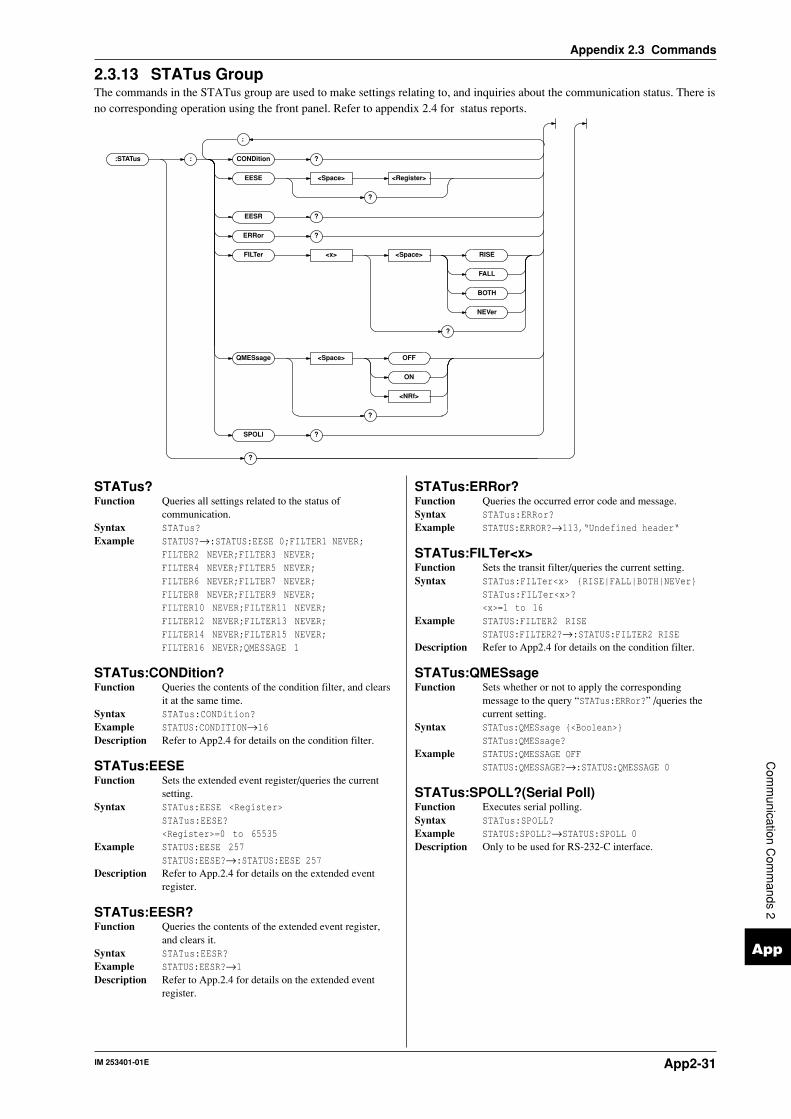
IM 253401-01E App2-31
App
Appendix 2.3 Commands
Com
munication C
omm
ands 2
2.3.13 STATus GroupThe commands in the STATus group are used to make settings relating to, and inquiries about the communication status. There isno corresponding operation using the front panel. Refer to appendix 2.4 for status reports.
:STATus : CONDition ?
EESE <Space> <Register>
?
EESR ?
ERRor ?
FILTer <x> <Space> RISE
FALL
BOTH
NEVer
?
QMESsage <Space> OFF
ON
<NRf>
?
SPOLl ?
?
;
STATus?Function Queries all settings related to the status of
communication.Syntax STATus?Example STATUS?→:STATUS:EESE 0;FILTER1 NEVER;
FILTER2 NEVER;FILTER3 NEVER;FILTER4 NEVER;FILTER5 NEVER;FILTER6 NEVER;FILTER7 NEVER;FILTER8 NEVER;FILTER9 NEVER;FILTER10 NEVER;FILTER11 NEVER;FILTER12 NEVER;FILTER13 NEVER;FILTER14 NEVER;FILTER15 NEVER;FILTER16 NEVER;QMESSAGE 1
STATus:CONDition?Function Queries the contents of the condition filter, and clears
it at the same time.Syntax STATus:CONDition?Example STATUS:CONDITION→16Description Refer to App2.4 for details on the condition filter.
STATus:EESEFunction Sets the extended event register/queries the current
setting.Syntax STATus:EESE <Register>
STATus:EESE?<Register>=0 to 65535
Example STATUS:EESE 257STATUS:EESE?→:STATUS:EESE 257
Description Refer to App.2.4 for details on the extended eventregister.
STATus:EESR?Function Queries the contents of the extended event register,
and clears it.Syntax STATus:EESR?Example STATUS:EESR?→1Description Refer to App.2.4 for details on the extended event
register.
STATus:ERRor?Function Queries the occurred error code and message.Syntax STATus:ERRor?Example STATUS:ERROR?→113,“Undefined header“
STATus:FILTer<x>Function Sets the transit filter/queries the current setting.Syntax STATus:FILTer<x> RISE|FALL|BOTH|NEVer
STATus:FILTer<x>?<x>=1 to 16
Example STATUS:FILTER2 RISESTATUS:FILTER2?→:STATUS:FILTER2 RISE
Description Refer to App2.4 for details on the condition filter.
STATus:QMESsageFunction Sets whether or not to apply the corresponding
message to the query “STATus:ERRor?” /queries thecurrent setting.
Syntax STATus:QMESsage <Boolean>STATus:QMESsage?
Example STATUS:QMESSAGE OFFSTATUS:QMESSAGE?→:STATUS:QMESSAGE 0
STATus:SPOLL?(Serial Poll)Function Executes serial polling.Syntax STATus:SPOLL?Example STATUS:SPOLL?→STATUS:SPOLL 0Description Only to be used for RS-232-C interface.

IM 253401-01EApp2-32
Appendix 2.3 Commands
2.3.14 STORe GroupThe commands in the STORe group are used to make settings relating to and inquiries about storing data. This allows you tomake the same settings as when using the lower menus of [MEMORY]-”StorE” or [MEMORY]-”PnLSt”.
:STORe : STAT e <Space> OFF
ON
<NRf>
?
INTer val <Space> <NRf> , <NRf> , <NRf>
?
PANel <Space> <NRf>
?
<Character string>
;
STORe?Function Queries all settings related to storing data.Syntax STORe?Example STORE?→:STORE:STATE 0;INTERVAL 0,0,0
STORe:INTervalFunction Sets the interval for storage/queries the current setting.Syntax STORe:INTerval <NRf>,<NRf>,<NRf>|<String>
STORe:INTerval?<NRf>,<NRf>,<NRf>=0,0,0 to 99,59,59<String>=HH:MM:SS HH hour MM min SS sec
Example STORE:INTERVAL 0,0,0STORE:INTERVAL “00:00:00“STORE:INTERVAL?→:STORE:INTERVAL 0,0,0
Description • If the storage interval is set to 0,0,0, the storageinterval becomes 250ms in case of normalmeasurement.
• For the storage interval in case of harmonic analysis,refer to page 9-2.
STORe:PANelFunction Saves the set-up parameters to a file.Syntax STORe:PANel <NRf>
<NRf>=1 to 4:file numberExample STORE:PANEL 1
STORe[:STATe]Function Sets store ON/OFF, queries the current setting.Syntax STORe[:STATe] <Boolean>
STORe:STATe?Example STORE:STATE ON
STORE:STATE?→:STORE:STATE 1

IM 253401-01E App2-33
App
Appendix 2.3 Commands
Com
munication C
omm
ands 2
2.3.15 Common Command GroupThe commands in the common command group are independent of the instrument’s functions, and are specified in IEEE 488.2-1987. There is no front panel key that corresponds to this group.
*CLS
*ESE <Space> <NRf>
?
*ESR ?
*IDN ?
*OPT ?
*PSC <Space> <NRf>
?
*RST
*SRE <Space> <NRf>
?
*STB ?
*TRG
*WAI
;
*OPC
*OPC ?
*TST ?
*CLSFunction Clears the standard event register, extended event
register and error queue.Syntax *CLSExample *CLSDescription • The output will also be cleared if a *CLS command is
appended after the program message terminator.• For details on the registers and queues, refer to
appendix 2.4.
*ESEFunction Sets the value for the standard event enable register, or
queries the current setting.Syntax *ESE <NRf>
*ESE?<NRf>=0 to 255
Example *ESE 253*ESE?→253
Description • Each bit is expressed as a decimal number.• For example, if “*ESE 253” is set, the standard
enable register will be set to “11111101”. Thismeans that bit 2 of the standard event register isdisabled so that bit 5 (ESB) of the status byteregister will not be set to “1”, even if a query erroroccurs.
• Default is “*ESE 255” , i.e. all bits are enabled.• The standard event enable register will be cleared
when an inquiry is made using *ESE?.• For details referring the standard event enable
register, refer to page App2-36.
*ESR?Function Queries the value of the standard event register and
clears it at the same time.Syntax *ESR?Example *ESR?→32Description • Each bit is expressed as a decimal number.
• It is possible to ascertain the type of event which hasoccurred, while SRQ is occuring.
• For example, if “*ESR 32” is returned, this meansthat the standard event register is “00100000” , i.e.the SRQ has occurred due to a command syntaxerror.
• If a query is made using *ESR?, the standard eventregister will be cleared.
• For details referring the standard event enableregister, refer to page App2-37.
*IDN?Function Queries the instrument model.Syntax *IDN?Example *IDN?→YOKOGAWA,253503,0,F1.11Description A reply consists of the following information:
<Model>,<Type>,<Serial No.> and <Firmwareversion>
*OPCFunction When *OPC is sent, this command sets bit 0 (the OPC
bit) of the standard event register to “1”. Thiscommand is not supported by this instrument.
Syntax *OPC
*OPC?Function When *OPC? is sent, “1” in (ASCII code) will be
returned. This command is not supported by thisinstrument.
Syntax *OPC?
IM 253401-01EApp2-34
Appendix 2.3 Commands
*OPT?Function Queries installed options.Syntax *OPT?Example *OPT?→EXT1, HARM, DA4, CMPDescription • “NONE” will be attached to the reply if no options
are installed.• “OPT?” must always be the last query in program
message. If there is another query after this, an errorwill occur.
*PSCFunction Selects whether or not to clear the following registers
when turning ON the power, or queries the currentsetting. The registers are the standard event enableregister, the extended event enable register and thetransition filter. However, they cannot be cleared if theparameter is “0”.
Syntax *PSC <NRf>*PSC?<NRf>=0(no clearance), other than0(clearance)
Example *PSC 1*PSC?→1
Description Refer to App 2.4 for more details on the registers.
*RSTFunction Resets (initializes) the present settings.Syntax *RSTExample *RSTDescription • Refer to 13.2 for initial settings.
*SREFunction Sets the value of the service request enable register, or
queries the current setting.Syntax *SRE <NRf>
*SRE?<NRf>=0 to 255
Example *SRE 239*SRE?→239
Description • Each bit is expressed as a decimal number.• For example, if “*SRE 239” is set, the service request
enable register will be set to “11101111”. Thismeans that bit 4 of the service request enable registeris disabled, so that bit 5 (ESB0 of the status byteregister will not be set to “1”, even if the outputqueue is not empty.
• However, bit 6 (MSS) of the status byte register isthe MSS bit, so it will be ignored.
• Default is “*SRE 255”, i.e. all bits are enabled.• The service request enable register will not be
cleared, even if a query is made using *SRE?.• For details of the service request enable register,
refer to page App2-36.
*STB?Function Queries the value of the status byte register.Syntax *STB?Example *STB?→4Description • Each bit is expressed as a decimal number.
• Bit 6 is RQS and not MSS because the register isread without serial polling.
• For example, if “*STB 4” is returned, the status byteregister is set to “00000100”, i.e. the error queue isnot empty (an error has occurred).
• The status byte register will not be cleared, even if aquery is made using *STB?.
• For details of the status byte register, refer to pageApp2-36.
*TRGFunction Executes the same operation as the TRIG
(SHIFT+HOLD) key on the front panel.Syntax *TRGDescription • Executes the same operation as when using the multi
line message GET (Group Execute Trigger).
*TST?Function Executes a self-test and queries the result. All internal
memory boards are tested.Syntax *TST?Example *TST?→0Description • “0” will be returned when the result are satisfactory.
If an abnormality is detected, “1” will be returned.
*WAIFunction Waits for the command following *WAI until execution
of the designated overlap command has beencompleted. This command is not supported by thisinstrument.
Syntax *WAI

IM 253401-01E App2-35
App
Appendix 2.4 Status Report
Com
munication C
omm
ands 2
Appendix 2.4 Status Report
2.4.1 Overview of the Status ReportThe figure below shows the status report which is read by a serial poll. This is an extended version of the one specified in IEEE488.2-1987.
15 14 13 12 11 10 9 8 7 6 5 4 3 2 1 0
15 14 13 12 11 10 9 8 7 6 5 4 3 2 1 0
15 14 13 12 11 10 9 8 7 6 5 4 3 2 1 0
Condition filter
Transit filter
Extended event register
&
15 14 13 12 11 10 9 8 7 6 5 4 3 2 1 0 Extended event enable register
&
&
&
&
&
&
&
&
&
&
&
&
&
&
&
7 6 5 4 3 2 1 0 Standard event register
&
&
&
&
&
&
&
&
7 6 5 4 3 2 1 0 Standard event enable register
OR
OR
7 6 ESB MAV EES EAV 1 0 Status byte
MSS
RQS
Output queue
Error queue
Occurrence of a service request
&
&
&
&
&
&
&
7 6 5 4 3 2 1 0 Service request enable register
OR
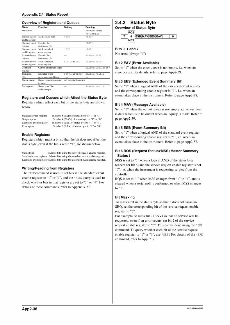
IM 253401-01EApp2-36
Appendix 2.4 Status Report
Overview of Registers and QueuesName Function Writing ReadingStatus byte — Serial poll (RQS),
*STB?(MSS)Service request Masks status byte. *SRE *SRE?
enable registerStandard event Event in the — *ESR?
register instrument (1)Standard event Masks standard *ESE *ESE?
enable register event register.Extended event Event in the — STATus:EESR?
register instrument (2)Extended event Masks extended STATus:EESE STATus:EESE?
enable register event register.Condition Current instrument status — STATus:CONDition?
registerTransition Extended event STATus:FILTer STATus:FILTer
filter occurrence conditions <x> <x>
Output queue Stores response message All executable queuesto a query.
Error queue Stores error Nos. — STATus:ERRor?
and messages.
Registers and Queues which Affect the Status ByteRegisters which affect each bit of the status byte are shownbelow.
Standard event register : Sets bit 5 (ESB) of status byte to “1” or “0”.Output queue : Sets bit 4 (MAV) of status byte to “1” or “0”.Extended event register : Sets bit 3 (EES) of status byte to “1” or “0”.Error queue : Sets bit 2 (EAV) of status byte to “1” or “0”.
Enable RegistersRegisters which mask a bit so that the bit does not affect thestatus byte, even if the bit is set to “1”, are shown below.
Status byte :Masks bits using the service request enable register.Standard event register :Masks bits using the standard event enable register.Extended event register :Masks bits using the extended event enable register.
Writing/Reading from RegistersThe *ESE command is used to set bits in the standard eventenable register to “1” or “0”, and the *ESR? query is used tocheck whether bits in that register are set to “1” or “0”. Fordetails of these commands, refer to Appendix 2.3.
2.4.2 Status ByteOverview of Status Byte
7 6 ESB MAV EES EAV 1 0RQS
MSS
Bits 0, 1 and 7Not used (always “0”)
Bit 2 EAV (Error Available)Set to “1” when the error queue is not empty, i.e. when anerror occurs. For details, refer to page App2-39.
Bit 3 EES (Extended Event Summary Bit)Set to “1” when a logical AND of the extended event registerand the corresponding enable register is “1”, i.e. when anevent takes place in the instrument. Refer to page App2-38.
Bit 4 MAV (Message Available)Set to “1” when the output queue is not empty, i.e. when thereis data which is to be output when an inquiry is made. Refer topage App2-39.
Bit 5 ESB (Event Summary Bit)Set to “1” when a logical AND of the standard event registerand the corresponding enable register is “1”, i.e. when anevent takes place in the instrument. Refer to page App2-37.
Bit 6 RQS (Request Status)/MSS (Master SummaryStatus )
MSS is set to “1” when a logical AND of the status byte(except for bit 6) and the service request enable register is not“0”, i.e. when the instrument is requesting service from thecontroller.RQS is set to “1” when MSS changes from “0” to “1”, and iscleared when a serial poll is performed or when MSS changesto “0”.
Bit MaskingTo mask a bit in the status byte so that it does not cause anSRQ, set the corresponding bit of the service request enableregister to “0”.For example, to mask bit 2 (EAV) so that no service will berequested, even if an error occurs, set bit 2 of the servicerequest enable register to “0”. This can be done using the *SREcommand. To query whether each bit of the service requestenable register is “1” or “0”, use *SRE?. For details of the *SREcommand, refer to App. 2.3.

IM 253401-01E App2-37
App
Appendix 2.4 Status Report
Com
munication C
omm
ands 2
Operation of the Status ByteA service request is issued when bit 6 of the status bytebecomes “1”. Bit 6 becomes “1” when any of the other bitsbecomes “1” (or when the corresponding bit in the servicerequest enable register becomes “1”).For example, if an event takes place and the logical OR ofeach bit of the standard event register and the correspondingbit in the enable register is “1”, bit 5 (ESB) will be set to “1”.In this case, if bit 5 of the service request enable register is“1”, bit 6 (MSS) will be set to “1”, thus requesting servicefrom the controller.It is also possible to check what type of event has occurred byreading the contents of the status byte.
Reading from the Status ByteThe following two methods are provided for reading the statusbyte.
• Inquiry using the *STB? queryMaking an inquiry using the *STB? query sets bit 6 to MSS.This causes the MSS to be read. After completion of theread-out, none of the bits in the status byte will be cleared.
•Serial pollExecution of a serial poll changes bit 6 to RQS. This causesRQS to be read. After completion of the read-out, only RQSis cleared. Using a serial poll, it is not possible to read MSS.
Clearing the Status ByteNo method is provided for forcibly clearing all the bits in thestatus byte. Bits which are cleared are shown below.
•When an inquiry is made using the *STB? queryNo bit is cleared.
•When a serial poll is performedOnly the RQS bit is cleared.
•When the *CLS command is receivedWhen the *CLS command is received, the status byte itself isnot cleared, but the contents of the standard event register(which affects the bits in the status byte) are cleared. As aresult, the corresponding bits in the status byte are cleared,except bit 4 (MAV), since the output queue cannot beemptied by the *CLS command. However, the output queuewill also be cleared if the *CLS command is received justafter a program message terminator.
2.4.3 Standard Event RegisterOverview of the Standard Event Register
URQ6
PON7 5 4 3 2 1 0
CME EXE DDE QYE RQC OPC
Bit 7 PON (Power ON)Bit 7 PON (Power ON) Set to “1” when power is turned ON
Bit 6 URQ (User Request)Not used (always “0”)
Bit 5 CME (Command Error)Set to “1” when the command syntax is incorrect.Examples: Incorrectly spelled command name; “9” used inoctal data.
Bit 4 EXE (Execution Error)Set to “1” when the command syntax is correct but thecommand cannot be executed in the current state.Examples: Parameters are outside the setting range: an
attempt is made to make a hard copy during acquisition.
Bit 3 DDE (Device Dependent Error)Set to “1” when execution of the command is not possible dueto an internal problem in the instrument that is not a commanderror or an execution error.
Bit 2 QYE (Query Error)Set to “1” if the output queue is empty or if the data is missingeven after a query has been sent.Examples: No response data; data is lost due to an overflow
in the output queue.
Bit 1 RQC (Request Control)Not used (always “0”)
Bit 0 OPC (Operation Complete)Set to “1” when the operation designated by the *OPCcommand has been completed.
Bit MaskingTo mask a bit in the standard event register so that it does notcause bit 5 (ESB) of the status byte to change, set thecorresponding bit in the standard event enable register to “0”.For example, to mask bit 2 (QYE) so that ESB will not be setto “1”, even if a query error occurs, set bit 2 of the standardevent enable register to “0”. This can be done using the *ESEcommand. To inquire whether each bit of the standard eventenable register is “1” or “0”, use the *ESE?. For details of the*ESE command, refer to App. 2.3.

IM 253401-01EApp2-38
Appendix 2.4 Status Report
Operation of the Standard Event RegisterThe standard event register is provided for eight differentkinds of event which can occur inside the instrument. Bit 5(ESB) of the status byte is set to “1” when any of the bits inthis register becomes “1” (or when the corresponding bit of thestandard event enable register becomes “1”).
Examples1. A query error occurs.2. Bit 2 (QYE) is set to “1”.3. Bit 5 (ESB) of the status byte is set to “1” if bit 2 of thestandard event enable register is “1”.
It is also possible to check what type of event has occurredinside the instrument by reading the contents of the standardevent register.
Reading from the Standard Event RegisterThe contents of the standard event register can be read by the*ESR command. After completion of the read-out, the registerwill be cleared.
Clearing the Standard Event RegisterThe standard event register is cleared in the following threecases.• When the contents of the standard event register are read
using *ESR?• When the *CLS command is received• When power is turned ON again
2.4.4 Extended Event RegisterReading the extended event register tells you whether changes in the condition register (reflecting internal conditions) haveoccurred. A transition filter can be applied which allows you to decide which events are reported to the extended event register.
OVR1
6POV1
7 5 4 3 2 1 0SRB FOV OVRS ITM ITG UPDPOA1
8OVR2
9POV2
10POA2
11OVR3
12POV3
13POA3
140
15
67 5 4 3 2 1 089101112131415
Condition register:STATus:CONDition?
Transition filter
01415Extended event register
167 5 4 38910111213 2
67 5 4 3 2 18910111213141516
:STATus:FILTer<x>RISE|FALL|BOTH|NEVer
:STATus:EESR?
FILTer<x>→
The meaning of each bit of the condition register is as follows.
Bit 0 UPD (Updating) Set to “1” during updating of measurement data.
Bit 1 ITG (Integrate busy) Set to “1” during integration. (See figure below)
Bit 2 ITM (Integrate timer busy) Set to “1” during the integration timer is being operated. (See figure below)
Bit 3 OVRS (∑ results overflow) Set to “1” when the integration results of ∑ overflow. (Display shows “—oF—” )
Bit 4 FOV (Frequency over) Set to “1” when the frequency lies outside the measurement range (Display shows
“ErrLo” , “ErrHi” or “FrqEr” .
Bit 5 SRB (Store/Recall busy) Set to “1” while storing or recalling is in progress.
Bit 6 OVR1 (Element 1; measured data over) Set to “1” when the measurement/computed data of element 1 overflow, or when an
error occurs. (Display shown “—oF—” , “—oL—” , “PFErr” or “dEGEr” )
Bit 7 POV1 (Element 1; voltage peak over) Set to “1” when the voltage value of element 1 exceeds the peak value.
Bit 8 POA1 (Element 1; current peak over) Set to “1” when the current value of element 1 exceeds the peak value.
Bit 9 OVR2 (Element 2; measured data over) Set to “1” when the measurement/computed data of element 2 overflow, or when an
error occurs. (Display shown “—oF—” , “—oL—” , “PFErr” or “dEGEr” )
Bit 10 POV2 (Element 2; voltage peak over) Set to “1” when the voltage value of element 2 exceeds the peak value.
Bit 11 POA2 (Element 2; current peak over) Set to “1” when the current value of element 2 exceeds the peak value.
Bit 12 OVR3 (Element 3; measured data over) Set to “1” when the measurement/computed data of element 3 overflow, or when an
error occurs. (Display shown “—oF—” , “—oL—” , “PFErr” or “dEGEr” )
Bit 13 POV3 (Element 3; voltage peak over) Set to “1” when the voltage value of element 3 exceeds the peak value.
Bit 14 POA3 (Element 1; current peak over) Set to “1” when the current value of element 3 exceeds the peak value.
The transition filter is applied to each bit of the condition register seperately, and can be selected from the following. Note thatthe numbering of the bits used in the filter setting differs from the actual bit number (1 to 16 vs. 0 to 15).

IM 253401-01E App2-39
App
Appendix 2.4 Status Report
Com
munication C
omm
ands 2
Manual integration mode Standard integration mode Continuous integration mode
Start Start StartStop Stop StopReset ResetReset
ITG
ITM
Integration
Timer preset time
Integration
When the elapsed integration time reaches the preset integration time, data will be reset automatically and the contact status will change.
Integration Integration
ITG
ITM
ITG
ITM
Timer preset time
Timer preset time
Timer preset time
Rise The bit of the extended event register becomes “1” when the bit of the condition register changes from “0” to “1”.
Fall The bit of the extended event register becomes “1” when the bit of the condition register changes from “1” to “0”.
Both The bit of the extended event register becomes “1” when the bit of the condition register changes from “0” to “1”, or from
“1” to “0”.
Never The bit of the extended event register is disabled and always “0”.
2.4.5 Output Queue and Error QueueOverview of the Output QueueThe output queue is provided to store response messages to queries. For example, when the WAVeform:SEND? query is sent torequest output of the acquired waveform, the response data will be stored in the output queue until it is read out.The example below shows that data is stored record by record in the output queue, and is read out oldest item first, newest itemlast. The output queue is emptied in the following cases (in addition to when read-out is performed).• When a new message is received from the controller• When dead lock occurs (page App2-4)• When a device clear command (DCL or SDC) is received• When power is turned ON again
The output queue cannot be emptied using the *CLS command. To see whether the output queue is empty or not, check bit 4(MAV) of the status byte.
D1D2D1 D2
D1
Overview of the Error QueueThe error queue stores the error No. and message when an error occurs. For example, when the built-in battery has run out, anerror occurs and its error No. (901) and message “Backup Failure” will be stored in the error queue.The contents of the error queue can be read using the STATus:ERRor? query. As with the output queue, messages are read oldestfirst, newest last (refer to the previous page).If the error queue becomes full, the final message will be replaced by message 350, “Queue overflow”.
The error queue is emptied in the following cases (in addition to when read-out is performed).• When the *CLS command is received• When power is turned ON again
To see whether the error queue is empty or not, check bit 2 (EAV) of the status byte.

IM 253401-01EApp2-40
Appendix 2.5 Sample Program
Appendix 2.5 Sample Program
This section describes sample programs for a IBM PC/AT and compatible system with National
Instruments AT-GPIB/TNTIEEE-488.2 board. Sample programs in this manual are written in
Quick BASIC version 4.0/4.5.
‘*********************************************************************‘* WT110/WT130 *‘* After having set the measurement conditions/measurement range, *‘* output the following data:voltage(V),current(A),active power(W), *‘* voltage frequency(VHz) of element 1. *‘* Microsoft QuickBASIC 4.0/4.5 Version *‘*********************************************************************REM $INCLUDE: ‘qbdecl4.bas’N = 4DIM D$(N) ‘ Array D$(4) is prepared for receiving dataBORD$ = “GPIB0”: CALL IBFIND(BORD$, BD%)IF BD% < 0 THEN GOTO ERRDISPCALL IBSIC(BD%): GOSUB ERRCHKDEVICE$ = “WT”: CALL IBFIND(DEVICE$, WT%)IF WT% < 0 THEN GOTO ERRDISPCALL IBCLR(WT%): GOSUB ERRCHKV% = 1: CALL IBSRE(BD%, V%)CLS‘ Setting measurement conditions‘ Hold OFF, Measurement mode = RMS, Filter OFF, Scaling OFF, Averaging OFFCMD$ = “SAMPLE:HOLD OFF”: CALL IBWRT(WT%, CMD$): GOSUB ERRCHKCMD$ = “MODE RMS”: CALL IBWRT(WT%, CMD$): GOSUB ERRCHKCMD$ = “FILTER OFF”: CALL IBWRT(WT%, CMD$): GOSUB ERRCHKCMD$ = “SCALING OFF”: CALL IBWRT(WT%, CMD$): GOSUB ERRCHKCMD$ = “AVERAGING OFF”: CALL IBWRT(WT%, CMD$): GOSUB ERRCHK‘ Setting measurement range(150V/5A)CMD$ = “VOLTAGE:RANGE 150V;:CURRENT:RANGE 5A”CALL IBWRT(WT%, CMD$): GOSUB ERRCHK‘ Sets display C to VHz1 in order to measure the voltage frequency of element 1CMD$ = “DISPLAY3:FUNCTION VHZ;ELEMENT 1”CALL IBWRT(WT%, CMD$): GOSUB ERRCHK‘ Sets the communication output items.(V1,A1,W1,VHz1 ON, all others OFF)CMD$ = “MEASURE:ITEM:PRESET CLEAR”: CALL IBWRT(WT%, CMD$): GOSUB ERRCHKCMD$ = “MEASURE:ITEM:V:ELEMENT1 ON”: CALL IBWRT(WT%, CMD$): GOSUB ERRCHKCMD$ = “MEASURE:ITEM:A:ELEMENT1 ON”: CALL IBWRT(WT%, CMD$): GOSUB ERRCHKCMD$ = “MEASURE:ITEM:W:ELEMENT1 ON”: CALL IBWRT(WT%, CMD$): GOSUB ERRCHKCMD$ = “MEASURE:ITEM:VHZ:ELEMENT1 ON”: CALL IBWRT(WT%, CMD$): GOSUB ERRCHK‘ Sets the filter to detect the end of data updatingCMD$ = “STATUS:FILTER1 FALL” ‘ bit0(UPD)CALL IBWRT(WT%, CMD$): GOSUB ERRCHKBUF$ = SPACE$(200)‘ Reads the measurement data and displays them (10 times)FOR I = 1 TO 10 CMD$ = “STATUS:EESR?” ‘ Clears the extended event register CALL IBWRT(WT%, CMD$): GOSUB ERRCHK CALL IBRD(WT%, BUF$): GOSUB ERRCHK ‘ Waiting until data are finished updating CMD$ = “COMMUNICATE:WAIT 1” CALL IBWRT(WT%, CMD$): GOSUB ERRCHK CMD$ = “MEASURE:VALUE?” ‘ Requests output of measurement data CALL IBWRT(WT%, CMD$): GOSUB ERRCHK CALL IBRD(WT%, BUF$): GOSUB ERRCHK ‘ Reads measurement data K = 1 FOR J = 1 TO N IF J < N THEN S = INSTR(K, BUF$, “,”) ELSE S = INSTR(K, BUF$, CHR$(10)) D$(J) = MID$(BUF$, K, S - K) K = S + 1 NEXT J ‘ Shows the measurement data per function PRINT “V1”, D$(1) ‘V1 PRINT “A1”, D$(2) ‘A1 PRINT “W1”, D$(3) ‘W1 PRINT “VHz1”, D$(4) ‘VHz1NEXT IPRGEND:CALL IBLOC(WT%)END ‘ End‘‘ When IBFIND call failedERRDISP:PRINT “ ===== No such board or device name ===== “GOTO PRGEND‘‘ GP-IB error checkERRCHK:IF IBSTA% >= 0 THEN RETURNPRINT “ ===== Error ===== “GOTO PRGEND

IM 253401-01E App2-41
App
Appendix 2.5 Sample Program
Com
munication C
omm
ands 2
‘*********************************************************************‘* WT110/WT130 *‘* Executes harmonic analysis for element 1 and displays the *‘* following: *‘* * Frequency of the PLL source(=voltage of element 1) *‘* * Harmonic distortion factor of the current(ATHD) *‘* * Rms values of the 1st to 50th order current *‘* * Fundamental(1st order) and harmonic analysis values(2nd to *‘* 50th order)currents *‘* Microsoft QuickBASIC 4.0/4.5 Version *‘*********************************************************************REM $INCLUDE: ‘qbdecl4.bas’N = 53DIM D$(N) ‘ Array D$(53) is prepared for receiving dataBORD$ = “GPIB0”: CALL IBFIND(BORD$, BD%)IF BD% < 0 THEN GOTO ERRDISPCALL IBSIC(BD%): GOSUB ERRCHKDEVICE$ = “WT”: CALL IBFIND(DEVICE$, WT%)IF WT% < 0 THEN GOTO ERRDISPCALL IBCLR(WT%): GOSUB ERRCHKV% = 1: CALL IBSRE(BD%, V%)CLS‘ Settings related to harmonic analysis‘ Element=1, PLL source=V1, Computation method of harmonic distortion=IECCMD$ = “HARMONICS:STATE ON;ELEMENT 1;SYNCHRONIZE V,1;THD IEC”CALL IBWRT(WT%, CMD$): GOSUB ERRCHK‘ Sets the communication output items.‘ Sets all functions OFF. Sets only necessary functions ON.CMD$ = “MEASURE:HARMONICS:ITEM:PRESET CLEAR”CALL IBWRT(WT%, CMD$): GOSUB ERRCHKCMD$ = “MEASURE:HARMONICS:ITEM:SYNCHRONIZE ON;ATHD ON;A ON”CALL IBWRT(WT%, CMD$): GOSUB ERRCHK‘ Sets the filter to detect the end of data updatingCMD$ = “STATUS:FILTER1 FALL”CALL IBWRT(WT%, CMD$): GOSUB ERRCHK‘ Reads the analysis data and displays them (10 times)FOR I = 1 TO 10 CMD$ = “STATUS:EESR?” ‘ Clears the extended event register CALL IBWRT(WT%, CMD$): GOSUB ERRCHK BUF$ = SPACE$(255) CALL IBRD(WT%, BUF$): GOSUB ERRCHK ‘ Waiting until data are finished updating CMD$ = “COMMUNICATE:WAIT 1” CALL IBWRT(WT%, CMD$): GOSUB ERRCHK CMD$ = “MEASURE:VALUE?” ‘ Requests output of analysis data CALL IBWRT(WT%, CMD$): GOSUB ERRCHK BUF$ = SPACE$(1000) CALL IBRD(WT%, BUF$): GOSUB ERRCHK ‘ Reads analysis data K = 1 FOR J = 1 TO N ‘ Order of output data
IF J < N THEN S = INSTR(K, BUF$, “,”) ELSE S = INSTR(K, BUF$, CHR$(10))D$(J) = MID$(BUF$, K, S - K)K = S + 1
NEXT J ‘ Displaying analysis data PRINT “V1 FREQ”, D$(1) ‘ Frequency of PLL source PRINT “A1 THD(IEC)”, D$(2) ‘ Harmonic distortion of current PRINT “A1 RMS”, D$(3) ‘ Rms values of the 1st to 50th order FOR J = 1 TO N-3 STEP 2 ‘ Fundamental/higher harmonics analysis values
PRINT “A1 Order” + STR$(J), D$(J + 3), ‘ odd numbered componentPRINT “A1 Order” + STR$(J + 1), D$(J + 4) ‘ even numbered component
NEXT JNEXT IPRGEND:CALL IBLOC(WT%)END ‘ End‘‘ When IBFIND call failedERRDISP:PRINT “ ===== No such board or device name ===== “GOTO PRGEND‘‘ GP-IB error checkERRCHK:IF IBSTA% >= 0 THEN RETURNPRINT “ ===== Error ===== “GOTO PRGEND

IM 253401-01EApp2-42
Appendix 2.6 ASCII Character Codes
Appendix 2.6 ASCII Character Codes
ASCII chracter codes are given below.
0
1
2
3
4
5
6
7
10
11
12
13
14
15
16
17
NUL
SOH
STX
ETX
EOT
ENQ
ACK
BEL
BS
HT
LF
VT
FF
CR
SO
SI
20
21
22
23
24
25
26
27
30
31
32
33
34
35
36
37
40
41
42
43
44
45
46
47
50
51
52
53
54
55
56
57
60
61
62
63
64
65
66
67
70
71
72
73
74
75
76
77
100
101
102
103
104
105
106
107
110
111
112
113
114
115
116
117
120
121
122
123
124
125
126
127
130
131
132
133
134
135
136
137
140
141
142
143
144
145
146
147
150
151
152
153
154
155
156
157
160
161
162
163
164
165
166
167
170
171
172
173
174
175
176
177
0
1
2
3
4
5
6
7
8
9
A
B
C
D
E
F
0
1
2
3
4
5
6
7
8
9
A
B
C
D
E
F
10
11
12
13
14
15
16
17
18
19
1A
1B
1C
1D
1E
1F
20
21
22
23
24
25
26
27
28
29
2A
2B
2C
2D
2E
2F
30
31
32
33
34
35
36
37
38
39
3A
3B
3C
3D
3E
3F
40
41
42
43
44
45
46
47
48
49
4A
4B
4C
4D
4E
4F
50
51
52
53
54
55
56
57
58
59
5A
5B
5C
5D
5E
5F
60
61
62
63
64
65
66
67
68
69
6A
6B
6C
6D
6E
6F
70
71
72
73
74
75
76
77
78
79
7A
7B
7C
7D
7E
7F
0
1
2
3
4
5
6
7
8
9
10
11
12
13
14
15
16
17
18
19
20
21
22
23
24
25
26
27
28
29
30
31
32
33
34
35
36
37
38
39
40
41
42
43
44
45
46
47
48
49
50
51
52
53
54
55
56
57
58
59
60
61
62
63
64
65
66
67
68
69
70
71
72
73
74
75
76
77
78
79
80
81
82
83
84
85
86
87
88
89
90
91
92
93
94
95
96
97
98
99
100
101
102
103
104
105
106
107
108
109
110
111
112
113
114
115
116
117
118
119
120
121
122
123
124
125
126
127
GTL
SDC
PPC
GET
TCT
LLO
DCL
PPU
SPE
SPD
0
1
2
3
4
5
6
7
8
9
10
11
12
13
14
15
16
17
18
19
20
21
22
23
24
25
26
27
28
29
30
UNL
DEL
DC1
DC2
DC3
DC4
NAK
SYN
ETB
CAN
EM
SUB
ESC
FS
GS
RS
US
SP
!
”
#
$
%
&
’
(
)
*
+
,
-
.
/
0
1
2
3
4
5
6
7
8
9
:
;
<
=
>
?
@
A
B
C
D
E
F
G
H
I
J
K
L
M
N
O
P
Q
R
S
T
U
V
W
X
Y
Z
[
\
]
^
_
‘
a
b
c
d
e
f
g
h
i
j
k
l
m
n
o
p
q
r
s
t
u
v
w
x
y
z
|
~
DEL(RUBOUT)
0
1
2
3
4
5
6
7
8
9
10
11
12
13
14
15
16
17
18
19
20
21
22
23
24
25
26
27
28
29
30
UNT
0
1
2
3
4
5
6
7
8
9
10
11
12
13
14
15
16
17
18
19
20
21
22
23
24
25
26
27
28
29
30
Address Command
Universal Command
Listener Address
Talker Address
Secondary Command
25
15 21
PPU
NAKOctal
Hexadecimal
GP-IB code
Decimal
ASCII character codeExample
0 1 2 3 4 5 6 7

IM 253401-01E App2-43
App
Appendix 2.7 Communication-related Error Messages
Com
munication C
omm
ands 2
Appendix 2.7 Communication-related ErrorMessages
Error messages related to communications are given below.
When servicing is required, contact your nearest YOKOGAWA representative, as given on the
back cover of this manual.
Only error messages relating to the communication mode 488.2 are given here. For other error
messages, refer to App 1.1 and 14.4.
Errors in communications commands (100 to 199)Code Message Action Reference Page
102 Syntax error Incorrect syntax App. 2.2, App. 2.3
103 Invalid separator Insert a comma between data items to separate them. App2-3
104 Data type error Refer to pages App2-6, 2-7 and enter data using the correct App2-6, App2-7data format.
105 GET not allowed GET is not supported as a response to an interface message. –
108 Parameter not allowed Check the number of parameters. App2-6, App. 2.3
109 Missing parameter Enter the required number of parameters. App2-6, App. 2.3
111 Header separator error Insert a space between the header and the data to separate them. App2-3
112 Program mnemonic too long Check the mnemonic (character string consisting of letters and App. 2.3numbers).
113 Undefined header Check the header. App. 2.3
114 Header suffix out of range Check the header. App. 2.3
120 Numeric data error Mantissa must be entered before the numeric value in <NRf> format. App2-6
123 Exponent too large Use a smaller exponent in <NR3> format. App2-6, App. 2.3
124 Too many digits Limit the number of digits to 255 or less. App2-6, App. 2.3
128 Numeric data not allowed Enter in a format other than <NRf> format. App2-6, App. 2.3
131 Invalid suffix Check the units for <Voltage> and <Current>. App2-7
134 Suffix too long Check the units for <Voltage> and <Current>. App2-7
138 Suffix not allowed No units are allowed other than <Voltage> and <Current>. App2-7
141 Invalid character data Enter one of the character strings in ...|...|.... App. 2.3
144 Character data too long Check the character strings in ...|...|.... App. 2.3
148 Character data not allowed Enter in a format other than one of those in ...|...|.... App. 2.3
150 String data error <Character string> must be enclosed by double quotation marks App2-7or single quotation marks.
151 Invalid string data <Character string> is too long or contains characters which cannot App. 2.3be used.
158 String data not allowed Enter in a data format other than <Character string>. App. 2.3
161 Invalid block data <Block data> is not allowed. –
168 Block data not allowed <Block data> is not allowed. –
171 Invalid expression Equation is not allowed. App. 2.3
178 Expression data not allowed Equation is not allowed. App. 2.3
181 Invalid outside macro definition Does not conform to the macro definition specified in IEEE488.2. —

IM 253401-01EApp2-44
Appendix 2.7 Communication-related Error Messages
Errors in communications execution (200 to 299)Code Message Action Reference Page
221 Setting conflict Check the relevant setting. App.2.3
222 Data out of range Check the setting range. App.2.3
223 Too much data Check the data byte length. App.2.3
224 Illegal parameter value Check the setting range. App.2.3
241 Hardware missing Check availability of options. —
260 Expression error Equation is not allowed. —
270 Macro error Does not conform to the macro definition specified in IEEE488.2. —
272 Macro execution error Does not conform to the macro definition specified in IEEE488.2. —
273 Illegal macro label Does not conform to the macro definition specified in IEEE488.2. —
275 Macro definition too long Does not conform to the macro definition specified in IEEE488.2. —
276 Macro recursion error Does not conform to the macro function specified in IEEE488.2. —
277 Macro redefinition not allowed Does not conform to the macro definition specified in IEEE488.2. —
278 Macro header not found Does not conform to the macro definition specified in IEEE488.2. —
Error in communication Query(400 to 499)Code Message Action Reference Page
410 Query INTERRUPTED Check transmission/reception order. App2-3
420 Query UNTERMINATED Check transmission/reception order. App2-3
430 Query DEADLOCKED Limit the length of the program message including <PMT> to App2-41024 bytes or less.
440 Query UNTERMINATED after Do not enter any query after *IDN? and *OPT?. —
indefinite response
Errors in Execution (800 to 899)Codes Message Action Reference Page
813 to 819 Invalid operation Refer to 14.4 14-11
830 to 833 Internal memory access error Refer to 14.4 14-11
841 to 847 Integrator execute error Refer to 14.4 14-11
Error in System Operation (912)Code Message Action Reference Page
912 Fatal error in Communication driver Service is required. —
Warnings (350, 390)Code Message Action Reference Page
350 Queue overflow Read out the queue. App2-39
390 Overrun error Adjust the baud rate. —(only for RS-232C)
NoteThe warning code 350 only appears in case of an overflow of the error queue. The error which occurs in caseof clearing the STATus:ERRor? will not appear on the screen.

IM 253401-01E Index-1
Index
Index
Index
Index
Symbols<Boolean> ............................................................................. App2-6<ESC> ......................................................................................... 12-7<PMT> ................................................................................... App2-2<RMT> .................................................................................. App2-3488.2 mode (GP-IB) .................................................................. 11-1488.2 mode (RS-232-C) ............................................................ 12-17-segment LED ................................................................................ 7
AA/D converter ................................................................................ 1-1accessories ........................................................................................ 3active power display ..................................................................... 5-1active power integration .............................................................. 7-1address setting ............................................................................ 11-9addressable mode ....................................................................... 11-1adjustment .................................................................................. 14-1aliasing ........................................................................................... 8-2ampere hour ................................................................................... 7-1apparant power display ................................................................ 6-1ASCII chracter code ........................................................... App2-42attenuation constant ................................................................... 4-11auto range ...................................................................................... 4-4averaging function ..................................................................... 4-11averaging function (harmonic analysis) ..................................... 8-2averaging sample number ......................................................... 4-11
Bback-up of set-up parameters ................................................... 13-1backup (integration) ..................................................................... 7-8baud rate ..................................................................................... 12-6block diagram ................................................................................ 1-1BNF notation (Backus-Naur Form) .................................... App2-2boolean ................................................................................... App2-6
Ccalibration ................................................................................... 14-4clamp filter ....................................................................................... 3command (RS-232-C) ............................................................... 12-7communication command (IEEE488.2-1987) ................... App2-8communication commands (before IEEE488.2-1987) ...... App1-1communication commands (model 2533) ........................ App1-15communication function .............................................................. 1-4comparator display .................................................................. 10-15comparator function ........................................................... 1-3, 10-7comparator function ON ......................................................... 10-16comparator mode ....................................................................... 10-7computation method of harmonic distortion ............................. 8-4computation over display ............................................................. 2-4computation over display (harmonics analysis) ........................ 8-2computing function ....................................................................... 1-2condition register ............................................... App2-36, App2-38connector (RS-232-C) ............................................................... 12-2connector’s pin sequence .......................................................... 10-1contact relay output ................................................................... 10-7
content .............................................................................................. 8continous integration mode ......................................................... 7-2continuous maximum allowable input ....................................... 5-2controlling .................................................................................. 10-2corrective action ...................................................................... 14-11CPU ................................................................................................ 1-1crest factor ................................................................... 1-3, 4-15, 5-4CT ................................................................................................... 4-7current display .............................................................................. 5-1current frequency display ............................................................ 5-3current integration ........................................................................ 7-1current integration method .......................................................... 7-2current transformer ....................................................................... 4-7
DD/A output .................................................................................. 10-4D/A output function ..................................................................... 1-3D/A output voltage .................................................................... 10-6data format (RS-232-C) ............................................................ 12-6DC .................................................................................................. 4-1DCL (device clear) .................................................................... 11-2dead lock ................................................................................ App2-3digital character ............................................................................ 1-5digital numbers ............................................................................. 1-5digital printer ................................................................................... 3display .................................................................................... 2-2, 2-4display function ............................................................................ 1-2display resolution for integrated values ..................................... 7-3displayed character .......................................................................... 7dot display (harmonic analysis) .................................................. 8-2DSP ................................................................................................ 1-1dual mode ................................................................................... 10-8
Eeffect of aliasing ........................................................................... 8-2error code .................................................................................. 14-11error display (harmonics analysis) ............................................. 8-2error message (communication) ........................................ App2-43error queue ......................................................... App2-36, App2-39ESC ............................................................................................. 12-7example of an operating procedure ............................................... 7exponential averaging ............................................................... 4-11extended event enable register .......................................... App2-36extended event register ..................................... App2-36, App2-38external connection ......................................................................... 5external dimensions ................................................................... 15-4external sensor scaling value ....................................................... 4-9
Fferrite core ........................................................................................ 3filter ................................................................................................ 4-3foreword ........................................................................................... 1frequency measurement function ................................................ 1-3front panel ..................................................................................... 2-1function .......................................................................................... 1-2fuse .................................................................................................... 5fuse rating ................................................................................. 14-13

IM 253401-01EIndex-2
Index
GGET (group execute trigger) .................................................... 11-2GP-IB interface .......................................................................... 11-1GP-IB interface specifications ................................................. 11-1GTL (go to local) ....................................................................... 11-2
Hhandshaking ................................................................................ 12-5harmonic analysis function .......................................................... 1-3harmonic component .................................................................... 8-1harmonic distortion ...................................................................... 8-4harmonics analysis function ........................................................ 8-1harmonics order ............................................................................ 8-6header interpretation rule ..................................................... App2-4
IIEEE 488.2-1987 .................................................................. App2-1IFC (interface clear) .................................................................. 11-2initial menu ................................................................................... 1-5initializing set-up parameters ................................................... 13-2input circuit ................................................................................... 1-1input function ................................................................................ 1-2instrument number ........................................................................... 2integrated value display ............................................................... 7-5integration elapsed time ............................................................... 7-1integration hold ............................................................................. 7-7integration method ........................................................................ 7-2integration mode ........................................................................... 7-1integration preset time .............................................................. 10-5integration reset ............................................................................ 7-7integration timer ........................................................................... 7-4integrator function ................................................................ 1-3, 7-1interruption during measurement ................................................ 2-4interval (talk-only mode) .......................................................... 12-6
LLLO (local lockout) ................................................................... 11-2
Mmalfunctioning ......................................................................... 14-10manual integration mode ............................................................. 7-1manual range ................................................................................. 4-4maximum allowable input ........................................................... 5-2measurement mode ....................................................................... 4-1measurement range ....................................................................... 4-4messages ................................................................................ App2-2mnemonic .............................................................................. App2-4model ................................................................................................. 2moving averaging ...................................................................... 4-11
NNC (normally closed) ................................................................ 10-7NO (normally open) .................................................................. 10-7normal mode ............................................................................... 12-1notes .................................................................................................. 1
Ooperating restriction (integration) ............................................... 7-8option ................................................................................................ 2optional equipment .......................................................................... 3output (printing) mode ............................................................ 10-18output format (D/A output) ...................................................... 10-4output format (error code) ........................................................ 11-8output format (harmonic analysis data) ................. 11-7, App2-25output format (model 2533) .............................................. App1-16output format (normal measured/computed data) . 11-4, App2-24output format (set-up parameter) ............................................. 11-8output function .............................................................................. 1-4output queue ....................................................... App2-36, App2-39overlap command .................................................................. App2-7overrange display .......................................................................... 2-4overview of IEEE 488.2-1987 ............................................. App2-1
Ppackage ............................................................................................. 2peak over display .......................................................................... 2-4phase angle display ....................................................................... 6-2phase lag ........................................................................................ 6-2phase lead ...................................................................................... 6-2phase locked loop ......................................................................... 8-4pin assignment ........................................................................... 10-1PLL source .................................................................................... 8-4PMT ........................................................................................ App2-2potential transformer .................................................................... 4-7power cord .................................................................................... 2, 5power display ................................................................................ 5-1power factor .................................................................................. 4-7power factor display ..................................................................... 6-1power integration method ............................................................ 7-2power range ................................................................................... 4-5power supply .................................................................................... 5preset time for integration ........................................................... 7-1print mode (GP-IB) ................................................................... 11-1print mode (RS-232-C) ............................................................. 12-1printing mode ........................................................................... 10-18program format (IEEE488.2-1987) ..................................... App2-2program messages ................................................................. App2-2protective grounding ....................................................................... 5PT ................................................................................................... 4-7

IM 253401-01E Index-3
Index
Index
Index
Rrange ............................................................................................... 4-4rated integration time ................................................................ 10-5reactive power display ................................................................. 6-1rear panel ....................................................................................... 2-1recalling ......................................................................................... 1-3recalling interval ........................................................................... 9-3recalling measured data ............................................................... 9-3recalling set-up parameters .......................................................... 9-5relay output ................................................................................ 10-7relay specifications .................................................................... 10-7relay status .................................................................................. 10-8remote control ............................................................................ 10-2remote control function ................................................................ 1-4REN (remote enable) ................................................................. 11-2repeat integration .......................................................................... 7-2replacing the fuse (only for WT130) ..................................... 14-13response messages ................................................................ App2-3responses to interface messages ............................................... 11-2revisions ............................................................................................ 1RMS ............................................................................................... 4-1RMT ....................................................................................... App2-3RS-232-C interface .................................................................... 12-1RS-232-C interface specifications ........................................... 12-1rubber feed ....................................................................................... 3
Ssafety precaution .............................................................................. 4sample number ........................................................................... 4-11sample program (before IEEE488.2-1987) ...................... App1-10sample program (IEEE488.2-1987) .................................. App2-40scaling function ............................................................................. 4-7scaling function with external sens ............................................ 4-9scaling value .................................................................................. 4-7SDC (selective device clear) .................................................... 11-2sequential command ............................................................. App2-7service request enable register .......................................... App2-36setting the comparator limit values ....................................... 10-12setting the comparator mode .................................................... 10-9signal direction .......................................................................... 12-2signal names (RS-232-C) .......................................................... 12-2single mode ................................................................................ 10-7specifications ............................................................................. 15-1SRQ ............................................................................................. 11-3standard accessories ........................................................................ 3standard event enable register .......................... App2-36, App2-37standard event register ...................................... App2-36, App2-37standard integration mode ........................................................... 7-1starting of the harmonic analysis ................................................ 8-5status byte ............................................................................ App2-36status byte format (before IEEE 488.2-1987) ........................ 11-3status report ......................................................................... App2-35storage ............................................................................................ 1-3storage interval ............................................................................. 9-2storing measurement data ............................................................ 9-2storing set-up parameters ............................................................. 9-5suffix code ........................................................................................ 2switching (remote and local mode) ......................................... 11-2symbol mark ................................................................................. 4, 7system configuration .................................................................... 1-1
Ttalk-only function ...................................................................... 11-9talk-only mode (GP-IB) ............................................................ 11-1talk-only mode (RS-232-C) ...................................................... 12-1terminator ................................................................................... 11-9top view ......................................................................................... 2-1transition filter ................................................... App2-36, App2-38turning the comparator function ON ..................................... 10-16
VV MEAN ........................................................................................ 4-1values of harmonic analysis display ........................................... 8-6verifying the range ....................................................................... 4-5voltage display .............................................................................. 5-1voltage frequency display ............................................................ 5-3
Wwatt hour ........................................................................................ 7-1waveform type .............................................................................. 4-2
Related Documents