YLCS WATER AND REMOTE AIR COOLED SCREW CHILLER YLCS Millennium TM WATER AND REMOTE AIR COOLED SCREW CHILLER R134a REFRIGERANT COOLING CAPACITIES 336 kW to 1090 kW York YLCS Water Cooled Screw Chillers are a compact design suitable for water or water-glycol cooling. Models are available in three versions: standard units (SA), units for applications requiring high condensing temperatures (HA) and units for applications where remote condensers are necessary (AA). Semi-hermetic twin helical screw compressors are provided to ensure high operational efficiencies and reliable performance. They are designed to be located in a plant room and require a cooling tower or dry cooler for heat rejection. CONTENTS Specification Accessories and Options Operating Limitations Refrigeration Flow Diagram Selection Guide Cooling Capacities Fouling Factors Pressure Drop Graphs Physical Data Electrical Data Dimensions Electrical Connections Clearances Weight Distribution AVAILABLE MODELS & NOMINAL COOLING CAPACITIES TABLE 1 FEATURES BENEFITS Manufactured to ISO 9001/EN 29001. High standard of quality control. High efficiency industrial type semi-hermetic twin helical screw compressors. Energy efficient, long life, reliable compressor. Separate power and control compartments with lockable doors and emergency stop device. Operator safety considerations. Power compartment optional door interlocked isolators. Operator safety convenience. Star/Delta compressor starter. Reduced starting current. Microprocessor control with visual display of temperatures, pressures, motor current, operating hours and number of starts. System data logging and temperature reset capability. Fault diagnostics. Energy management. Multiple Independant Refrigerant Circuits System Stand-by Security Full Factory Run Test Verifies quality control and ensures that the unit operates satisfactorily prior to delivery Unit remote alarm contacts. Warning notification. Optional remote water temperature reset. Improves operating efficiency. Building Management System interface. For central data logging and single point system monitoring and control. Page D.1 Doc. No. PC155/11.04/GB SA Models Model 0350 0415 0480 0530 0575 0620 Cooling Capacity (kW) 336 407 474 511 556 600 Model 0660 0725 0840 0955 1050 1110 Cooling Capacity (kW) 654 736 837 964 1008 1090 Cooling capacities at 7 °C leaving chilled liquid temperature and 35 °C leaving condenser water temperature. HA Models Model 0350 0415 0480 0530 0575 0620 Cooling Capacity (kW) 282 339 396 432 467 507 Model 0660 0725 0840 0955 1050 1110 Cooling Capacity (kW) 546 605 692 780 838 871 Cooling capacities at 7 °C leaving chilled liquid temperature and 50 °C leaving condenser water temperature. AA Models Model 0350 0415 0480 0530 0575 0620 Cooling Capacity (kW) 317 384 447 484 525 584 Model 0660 0725 0840 0955 1050 1110 Cooling Capacity (kW) 635 710 810 922 939 1063 Cooling capacities at 7 °C leaving chilled liquid temperature at 45 °C saturated discharge temperature at unit.

Welcome message from author
This document is posted to help you gain knowledge. Please leave a comment to let me know what you think about it! Share it to your friends and learn new things together.
Transcript
YLC
SW
AT
ER
AN
DR
EM
OT
EA
IRC
OO
LE
DS
CR
EW
CH
ILLE
R
YLCS MillenniumTM
WATER ANDREMOTE AIRCOOLED SCREWCHILLERR134a REFRIGERANT
COOLING CAPACITIES336 kW to 1090 kW
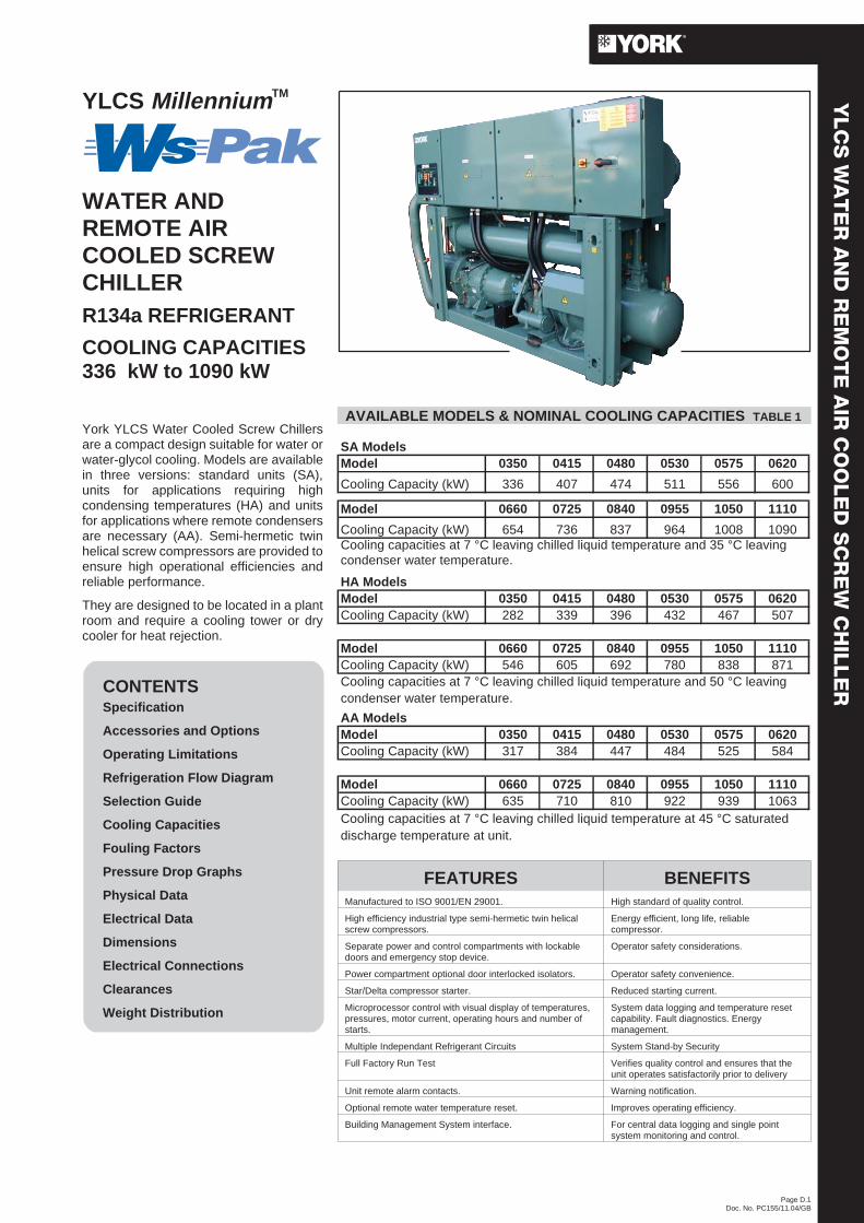
York YLCS Water Cooled Screw Chillersare a compact design suitable for water orwater-glycol cooling. Models are availablein three versions: standard units (SA),units for applications requiring highcondensing temperatures (HA) and unitsfor applications where remote condensersare necessary (AA). Semi-hermetic twinhelical screw compressors are provided toensure high operational efficiencies andreliable performance.
They are designed to be located in a plantroom and require a cooling tower or drycooler for heat rejection.
CONTENTSSpecification
Accessories and Options
Operating Limitations
Refrigeration Flow Diagram
Selection Guide
Cooling Capacities
Fouling Factors
Pressure Drop Graphs
Physical Data
Electrical Data
Dimensions
Electrical Connections
Clearances
Weight Distribution
AVAILABLE MODELS & NOMINAL COOLING CAPACITIES TABLE 1
FEATURES BENEFITSManufactured to ISO 9001/EN 29001. High standard of quality control.
High efficiency industrial type semi-hermetic twin helicalscrew compressors.
Energy efficient, long life, reliablecompressor.
Separate power and control compartments with lockabledoors and emergency stop device.
Operator safety considerations.
Power compartment optional door interlocked isolators. Operator safety convenience.
Star/Delta compressor starter. Reduced starting current.
Microprocessor control with visual display of temperatures,pressures, motor current, operating hours and number ofstarts.
System data logging and temperature resetcapability. Fault diagnostics. Energymanagement.
Multiple Independant Refrigerant Circuits System Stand-by Security
Full Factory Run Test Verifies quality control and ensures that theunit operates satisfactorily prior to delivery
Unit remote alarm contacts. Warning notification.
Optional remote water temperature reset. Improves operating efficiency.
Building Management System interface. For central data logging and single pointsystem monitoring and control.
Page D.1Doc. No. PC155/11.04/GB
SA ModelsModel 0350 0415 0480 0530 0575 0620
Cooling Capacity (kW) 336 407 474 511 556 600
Model 0660 0725 0840 0955 1050 1110
Cooling Capacity (kW) 654 736 837 964 1008 1090Cooling capacities at 7 °C leaving chilled liquid temperature and 35 °C leavingcondenser water temperature.
HA ModelsModel 0350 0415 0480 0530 0575 0620Cooling Capacity (kW) 282 339 396 432 467 507
Model 0660 0725 0840 0955 1050 1110Cooling Capacity (kW) 546 605 692 780 838 871Cooling capacities at 7 °C leaving chilled liquid temperature and 50 °C leavingcondenser water temperature.
AA ModelsModel 0350 0415 0480 0530 0575 0620Cooling Capacity (kW) 317 384 447 484 525 584
Model 0660 0725 0840 0955 1050 1110Cooling Capacity (kW) 635 710 810 922 939 1063Cooling capacities at 7 °C leaving chilled liquid temperature at 45 °C saturateddischarge temperature at unit.
SPECIFICATIONGeneralYLCS models shall be completely assembled with allinterconnecting refrigerant piping and internal wiring, ready forfield installation. SA and HA units shall be pressure tested,evacuated, and fully factory charged with refrigerant and oil ineach of the independent refrigerant circuits. For AA units, theunit shall be pressure tested, evacuated, and filled with 0.35 barg pressure of nitrogen per independant circuit.. After assembly,a simulated functional test shall be performed on the unit
Unit to have final overspray paint after assembly (optional) bycustomer request.
CompressorsEach compressor shall be direct drive, semi-hermetic, rotarytwin screw type and include the following items:
• Two screw rotors, with asymmetric profiles, manufacturedfrom forged steel.
• A cast iron compressor housing precision machined toprovide optimal clearance for the rotors.
• The entire compressor, from suction to discharge shall have adesign working pressure of 31 barg.
• Capacity Control: The compressors shall start at the minimumload position and provide a load control range from 100% to15% of the full load using step control. A microprocessorcontrolled output pressure regulating capacity control valveshall be supplied to command compressor capacityindependent of control valve input pressure and to balancethe compressor capacity with the cooling load.
• An automatic spring return of capacity control valve to theminimum load position to ensure compressor starting atminimum motor load.
• An internal discharge check valve to prevent rotor backspinupon shutdown.
• Remote acoustic tuned muffler.• Discharge and optional suction shut-off service valves.• A reliable suction gas cooled high efficiency, accessible
hermetic motor with redundant overload protection using boththermistor and current overload protection.
• A suction gas screen and serviceable, 17 micron full flow oilfilter within the compressor housing.
• A 300 W compressor body heater.• Integral oil separators with a design working pressure of 31
barg shall be the high efficiency, augmented gasimpingement type to maximise oil extraction without fragilemedia to break down.
Motor StartingTwo types of compressor motor starting are available: star/deltaopen transition starter and optional star/delta closed transitionstarter.
The standard star/delta starter utilises 3 motor contactors and atransition delay relay. The optional closed Star/Delta starterutilises 4 motor contactors, a set of transition resistors and atransition delay relay. The star/delta start allows inrush currentto be limited to approximately 33% LRA with the closedtransition option reducing the transitent star to delta current.
When the microprocessor initiates a start signal to run acompressor, it runs in Star for 4 seconds and then transitions toDelta.
Oil CoolingCompressor oil cooling shall be provided by refrigerant liquid,which will be injected into the rotor suction when the temperaturesetpoint is exceeded.
EvaporatorThe evaporator is a shell and tube design with refrigerant on thetube side and water on the shell side. Tubes are formed in a ‘U’shape and held in a tube bundle, which is free to expandindependent of the shell. An independent circuit shall beprovided for each compressor. The waterside (shell) design
working pressure of the evaporator is 10 bar g. The refrigerantside (tubes) design working pressure is 20 bar g on models 0350to 0660 and 24 bar g on models 0725 to 1110.
The evaporator shall have water pass baffles fabricated fromnon metalic composite materials (0335 to 0955) and corrosionresistant galvanised steel (1050 to 1110), removable head foraccess to internally enhanced, seamless, copper tubes. Watervent and drain connections shall also be included.
The water nozzles are fitted with Victualic couplings (loose item)for field installation by contractor. Optional welded flanges &companion flanges are offered including necessay nuts, boltsand gaskets.
CondenserFor SA and HA units separate circuit condensers shall becleanable shell & tube type with a built in sub-cooler andre-moveable water heads. The design working pressure on thewater side shall be 10 Bar g and 30 bar on the refrigerant sidewhich is protected by pressure relief valve(s). For AA units watercooled condensers shall be factory removed. Remote air-cooledcondenser to be supplied by others.
Refrigerant CircuitsAn independent refrigerant circuit shall be provided percompressor. Liquid line components shall include: manualshut-off valve with charging port, high absorption removablecore filter-drier, solenoid valve, sight glass with moistureindicator, and thermostatic expansion valve. Suction linescomponents shall include a pressure relief valve and a servicevalve (optional) and shall be covered with closed-cell insulation.Discharge line components shall include a manual shut-offvalve, pressure relief valve, temperature sensor andhigh-pressure cut-out sensors.
Power and Control PanelsAll controls and motor starting equipment necessary for unit Allcontrols and motor starting equipment necessary for unitoperation shall be factory wired and function tested.
The panel enclosure shall be designed to IP42 (rain/dust tight)and be manufactured from powder painted galvanised steel.Component mounting panels are of non-painted galvanisedsteel to ensure optimum protective circuit (earthing).
The Power and Control Panel shall be divided into a powersection for each electrical system, a control section and acommon input section. Power entry is from the top of the controlpanel common input section. All sections shall have a separatehinged, latched, and gasket sealed door.
Each power compartment shall contain:
Compressor fuses, compressor and phase sequence failure,phase rotation and star/delta time delay relays to give overloadand short circuit protection.
The control section shall contain:
On/Off switch, microcomputer keypad and display,microprocessor board, I/O expansion board, relay boards andpower supply board.
Models with Standard Single Point Power SupplyConnectionThe common input section contains:
An incoming non-fused disconnect switch for connection of thecustomer provided single power supply. Internal factory wiring totwo fused protected power sections. The control supply isderived internally from the incoming power supply.
The common input section also contains the control circuitswitch disconnect/emergency stop device, a transformer (toprovide the necessary 24V and 12V supplies for the powersupply board, and I/O board), control fuses, residual currentcircuit breaker, and terminals for a remote emergency stopdevice.
Page D.2Doc. No. PC155/11.04/GB
Microprocessor ControlsThe microprocessor shall have the following functions anddisplays:
• A liquid crystal 40 character display with text provided on twolines and light emitting diode backlighting for outdoor viewing.
• A colour coded, 35 button, sealed keypad with sections forDisplay, Entry, Setpoints, Clock, Print, Program and UnitOn/Off switch.
The standard controls shall include: automatic pump down atshutdown, run signal contacts, demand load limit from externalbuilding automation system input, remote reset liquidtemperature reset input, unit alarm contacts, chilled liquid pumpcontrol, automatic reset after power failure, automatic systemoptimisation to match operating conditions, software stored innon-volatile memory (EPROM) to eliminate chiller failure due toAC power failure.
The microprocessor can be directly connected to a YORK ISNBuilding Automation System via the standard on-board RS485communication port. This option also provides open systemcompatibility with other communications networks.
Programmed Setpoints shall be retained in a lithium batterybacked RTC memory for a minimum of 5 years.
DISPLAY – In Metric (°C and barg) or English (°F and psig)units. For each circuit, the following items shall be displayed:
• Entering and leaving chilled liquid temperature.• Day, date and time. Daily start/stop times. Holiday and
Manual Override status.• Compressor operating hours and starts. Automatic or manual
lead/lag. Lead compressor identification.• Run permissive status. No cooling load condition.
Compressor run status.• Anti-recycle timer and anti-coincident start timer status per
compressor.• System suction (and suction superheat), discharge, and oil
pressures and temperatures.• Percent full load compressor motor current. Compressor
capacity control valve input steps.• Cut-out status and set-points for: entering chilled liquid
temperature., low suction pressure, high discharge pressureand temperature, high oil temperature, high and low current,and low leaving liquid temperature.
• Unloading limit setpoints for high discharge pressure andcompressor motor current.
• Liquid pull-down rate sensitivity (0.3°C to 3°C/minute in0.05°C increments).
• Status of load and unload timers, chilled liquid pump.• “Out of range” message.• Up to 6 fault shut down conditions.
ENTRY – Enter set point changes, cancel inputs, advance day,and change AM/PM.
SET POINTS – Chilled liquid temperature, chilled liquid range,remote reset temperature range.
CLOCK – Time, daily or holiday start/stop schedule, manualoverride for servicing.
PRINT – Operating data or system fault shutdown history for lastsix faults, printouts via a separate printer (by others).
PROGRAM – Low leaving liquid temperature cutout, 300 to 600second anti-recycle timer, lag compressor start time delay,average motor current unload point, liquid temperature set-pointreset signal from YORK ISN or building automation system (byothers) via:
• Pulse width modulated (PWM) input for up to 22°C total resetas standard.
• Optional Building Automation System interface input card forup to 11°C reset using a 4 to 20 mA, 0 to 10 Vdc input, ordiscrete reset input.
• [NOTE: The Standard microprocessor can be directlyconnected to a YORK ISN Building Automation System viathe standard on-board RS485 communication port. ThisOption also provides open system compatibility with othercommunications networks (BACNET™ & LONMARK™) viainterface through standard onboard 485 or 232 port and anexternal YorkTalk Translator.]
• Additional functions (password protected) for programmingby a qualified service technician:
• Cut-outs for low suction pressure, high discharge pressure,high oil temperature.
• High discharge pressure unload setpoint.• Compressor motor current percent limit.
Motor ProtectionThe microprocessor motor protection provides high currentprotection to ensure that the motor is not damaged due tovoltage, excess refrigerant or other problems that could causeexcessive motor current.
The microprocessor also provides low motor current protectionwhen it senses a motor current of less than 10% FLA.
A motor protector module provides thermal and current motoroverload protection. The module also protects against phase tophase current imbalance, over current, under current and phaserotation.
Page D.3Doc. No. PC155/11.04/GB
ACCESSORIES AND OPTIONSELECTRICAL OPTIONS
Power Supply ConnectionUnits are available with either single point or multi point powersupply connections:
Single Point - System Fused Disconnect Switches
A non-fused disconnect switch in the common input section ofthe panel for connection of the customer provided single powersupply. Internal factory wiring to two door interlocked fuseddisconnect switches mounted in the power sections. The controlsupply is derived internally from the terminal block.
Single Point - System Circuit BreakersA terminal block in the common input section of the panel forconnection of the customer provided single power supply.Internal factory wiring to two door interlocked circuit breakers,mounted in the power sections. The control supply is derivedinternally from the terminal block.
Multi-Point - System Circuit BreakersTwo door interlocked circuit breakers, mounted in the powersections, for connection of the customer provided powersupplies. A non-fused disconnect switch / emergency stopdevice (QCSD/ESD) in the common input section withtermination for the customer (400 V, 2 Ø, 50 Hz ) control supply.
Building Automation System (BAS) / EMS InterfaceProvides a means to reset the leaving chilled liquid temperatureand from the BAS / EMS (Factory Mounted):
Printed circuit board to accept 4 to 20 mA, 0 to 10 Vdc, or drycontact closure input from the BAS / EMS.
Note: A YORK ISN Building Automation System can provide aPulse Width Modulated (PWM) signal direct to the standardcontrol panel via the standard on-board RS485 port.
Page D.4Doc. No. PC155/11.04/GB
Micro GatewayInterface to enable communication with building control systemsusing BACnet or MODBUS protocols. See separate Yorkdocumentation.
ACCESSORIES
Anti-Vibration MountsOptional 25mm deflection, open spring, anti-vibration mountswith levelling screw. Supplied loose for field installation.
Optional floor mounting kit with 25 mm neoprene pads. Suppliedloose for field installation.
Power Factor Correction:Factory mounted passive (static) correction capacitors tocorrect unit compressor power factors to 0.95 (depending onoperating conditions). Contact Marketing for availability.
Flow SwitchSwitch with 1 inch IPS thread suitable for 10 barg DWP andhaving gold contacts for low voltage/current, to protect unit fromloss of water flow. Supplied loose for field installation.
Additional PED safety devices for HollandContact Marketing for availability.
Pressure Relief Service Valve KitAllows valve to be removed and replaced with no loss ofrefrigerant
Suction Shut-off ValvesA ball valve in the low pressure (suction) pipework perrefrigerant circuit for isolation.
Evaporator KitsVertical nozzle cooler with Welded/Companion Flange kit(except 1050 & 1110). Horizontal nozzle cooler with VictualicCoupling(loose item). Horizontal nozzle cooler withWelded/Companion Flange kit.
Low temperature Evaporators:Low Temp Vertical Nozzle with Victualic coupling(loose Item).All other low temperature vessel option configurations withflanges as above.
Heat Pump Sensor Kit:Capability of controlling condenser water off for heat pumpapplications. Contact Marketing for availability.
Acoustic Sound Enclosure:Full sound enclosure over complete unit, with panel access forcontrol panel and serviceability. Attenuation with two categorylevels 15dBA & 18dBA. Contact Marketing for availability.
Closed Transition Star/DeltaWith the addition of closed transition contactors and resistors,the change over spike during starting can be reduced to nearerthe star inrush level thus reducing the risk of electricalinterference during compressor start. Contact Marketing foravailability.
Mechanical Gauge KitFactory fitted mechanical gauges for display of suction anddischarge pressures, one complete set per system.
Double Thickness InsulationThe cooler is covered with 38 mm (1 ½ inch) flexible, UV-stablecolour co-ordinated closed-cell, foam insulation for added frostprotection.
Dual Pressure Relief ValvesTwo safety valves in parallel of which one is operational toassist in valve replacement during maintenance. ContactMarketing for availability.
High Condensing Temperature Kit(Standard HA configuration)Additional motor cooling required above 40°C leaving waterfrom the condenser.
Condenser extension / Manifold kitsCondenser extension kit simplifies connections to customerpipework. Both options come with either Victualic coupling orwelded Flange/companion flange kit
Language LCD and KeypadStandard display language and keypad is English. French,German, Italian, Spainish and Portugese are available asoptions. For Russian and Hungarian contact Marketing.
Sequence Controller:Monitors mixed leaving chilled water or glycol temperature fromtwo to four units and controls to maintain required mixedtemperature whlist running the minimum number of units.
PrinterHand held printer for obtaining printout of unit operating dataand history data.
Paint OversprayComplete unit finish in Carribean Blue.
Lifting Lug KitOne set of ISO Mk5 cam locs to enable safe and easy unithandling.
Factory Witness Test:To perform a customer functional witness test of coolingcapacity only, test is carried out in factory test area.
Page D.5Doc. No. PC155/11.04/GB
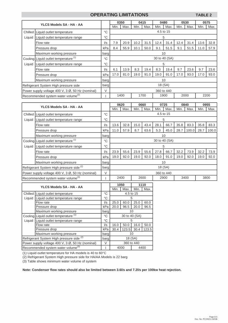
Min. Max. Min. Max. Min. Max. Min. Max. Min. Max.
Chilled Liquid outlet temperature °C
Liquid Liquid outlet temperature range °C
Flow rate l/s 7.9 20.9 10.2 31.5 12.4 31.4 12.4 31.4 13.6 32.8
Pressure drop kPa 8.4 55.9 10.1 50.0 9.1 51.5 9.1 51.5 11.0 57.9
Maximum working pressure barg
Cooling Liquid outlet temperature (1) °C
Liquid Liquid outlet temperature range °C
Flow rate l/s 6.1 13.9 8.3 19.4 8.3 19.4 9.7 23.6 9.7 23.6
Pressure drop kPa 17.0 81.0 19.0 91.0 19.0 91.0 17.0 93.0 17.0 93.0
Maximum working pressure barg
Refrigerant System High pressure side barg
Power supply voltage 400 V, 3 Ø, 50 Hz (nominal) V
Recommended system water volume(2) l
Min. Max. Min. Max. Min. Max. Min. Max. Min. Max.
Chilled Liquid outlet temperature °C
Liquid Liquid outlet temperature range °C
Flow rate l/s 13.6 32.8 15.0 43.4 28.1 66.7 35.8 83.3 35.8 83.3
Pressure drop kPa 11.0 57.9 8.7 63.6 5.3 45.0 28.7 100.0 28.7 100.0
Maximum working pressure barg
Cooling Liquid outlet temperature (1) °C
Liquid Liquid outlet temperature range °C
Flow rate l/s 23.9 55.6 23.9 55.6 27.8 66.7 32.2 73.9 32.2 73.9
Pressure drop kPa 19.0 92.0 19.0 92.0 18.0 91.0 19.0 92.0 19.0 92.0
Maximum working pressure barg
Refrigerant System High pressure side (2) barg
Power supply voltage 400 V, 3 Ø, 50 Hz (nominal) V
Recommended system water volume(3) l
Min. Max. Min. Max.Chilled Liquid outlet temperature °CLiquid Liquid outlet temperature range °C
Flow rate l/s 25.0 60.0 25.0 60.0Pressure drop kPa 20.0 96.5 20.0 96.5Maximum working pressure barg
Cooling Liquid outlet temperature (1) °CLiquid Liquid outlet temperature range °C
Flow rate l/s 16.0 50.0 16.0 50.0Pressure drop kPa 30.4 123.5 30.4 123.5Maximum working pressure barg
Refrigerant System High pressure side (2) bargPower supply voltage 400 V, 3 Ø, 50 Hz (nominal) VRecommended system water volume(3) l
(1) Liquid outlet temperature for HA models is 40 to 60°C(2) Refrigerant System High pressure side for HA/AA Models is 22 barg(3) Table shows minimum water volume of system
Note: Condenser flow rates should also be limited between 3.6l/s and 7.2l/s per 100kw heat rejection.
4000 4400
18 (SA)360 to 440
1030 to 40 (SA)
5
10
4.5 to 155
YLCS Models SA - HA - AA1050 1110
YLCS Models SA - HA - AA
2200
5
1400 1700 1900 2000
18 (SA)
360 to 440
10
30 to 40 (SA)
5
10
0575
4.5 to 15
0350 0415 0480 0530
YLCS Models SA - HA - AA0620 0660 0725 0840 0955
4.5 to 15
5
10
30 to 40 (SA)
5
10
18 (SA)
360 to 4402400 2600 2900 3400 3800
OPERATING LIMITATIONS TABLE 2
Page D.6Doc. No. PC155/11.04/GB
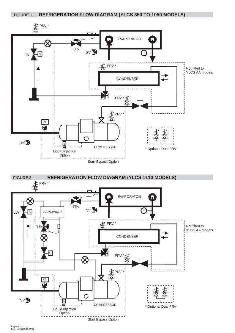
Not fitted toYLCS AA models
COMPRESSOR
TS
PT
s
Liquid InjectionOption
PRV *
LLV
TEVSV
PRV *
PRV *
SV
PRV *
Start Bypass Option
* Optional Dual PRV
CONDENSER
EVAPORATOR
FIGURE 1 REFRIGERATION FLOW DIAGRAM (YLCS 350 TO 1050 MODELS)
CONDENSER
ECONOMISER
Not fitted toYLCS AA models
COMPRESSOR
EVAPORATOR
T
PT
s
Liquid InjectionOption
PRV *
SLLV
S
TEV
TEV
SV
PRV *
PRV *
SV
PRV *
Start Bypass Option
* Optional Dual PRV
FIGURE 2 REFRIGERATION FLOW DIAGRAM (YLCS 1110 MODELS)
Page D.7Doc. No. PC155/11.04/GB
DATA REQUIREDTo select a YORK YLCS chiller the following information isrequired:
1. Design cooling capacity.
2. Chilled water entering and leaving temperatures.
3. Condenser water entering and leaving temperature.
4. Chilled water flow (l/s) if one of the temperatures in (2) isunknown.
5. Condenser water flow (l/s) if one of the temperatures in (3) isunknown.
Determine the capacity or water flow from:
Cooling Capacity (kW) = Range (°C) x chilled water (l/s) x 4.18
Determine the heat rejection or water flow from:
Heat Rejection (kW) = Range (°C) x condenser water (l/s) x 4.18
NOTE: If condenser coolant is glycol solution allow 2 K increasein condensing temperature to estimate the cooling capacity &power inpact on your selection.
CHILLER SELECTION METHOD1. Determine the correct size of chiller by selecting the model
which most closely matches the required capacity at thedesign conditions of leaving water temperature andcondenser leaving water temperature.
2. Apply correction factors for fouling factor to the capacity andpower values from the capacity tables. Ensure the correctedcapacity is still sufficient for requirements.
3. Using the corrected capacity of the selected chiller adjust thedesign temperature range, or flow rate, to balance theformulae shown above.
4. Physical and electrical data can now be determined from thetables.
5. Always re-check that selections fall within the operatinglimitations.
YLCS SAMPLE SELECTION
1. Confirm the system requirements
Cooling Capacity: 400 kWChilled Water Inlet Temperature: 12 °CChilled Water Outlet Temperature: 7 °CCondenser Water Inlet Temperature: 30 °CCondenser Water Outlet Temperature: 35 °CEvaporator and Condenser Fouling Factors: 0
2. Select Model and Read the Performance
From the capacity table, modelYLCS0415SA can be selectedwith the following performance.
Cooling Capacity: 406.9 kWCompressor Input Power: 91.9 kWHeat Rejection 494.1 kW.
3. Determine the Flow Rate
Cooling Capacity (kW) = Range (°C) x chilled water (l/s) x 4.18= 406.9 = 19.46 l/s
5 x 4.18Heat Rejection (kW) = Range (°C) x condenser water (l/s) x 4.18
= 494.1 = 23.64 l/s*5 x 4.18
* Total unit flow rate.For condenser flow rate, divide by 2 = 11.82 l/s.
4. Correct the Data
Fouling Factor
The cooling capacity and the compressor input should becorrected using the factors given below, if applicable.Recalculate flow rates as required.
Flow Rate
When the water Inlet/Outlet temperature difference is not 5°C,correct the flow rate by the following formula:
Corrected Flow Rate = 5 (°C) X Flow RateTemp. Difference(°C)
The corrected Flow Rate must be confirmed to be within theworking range.
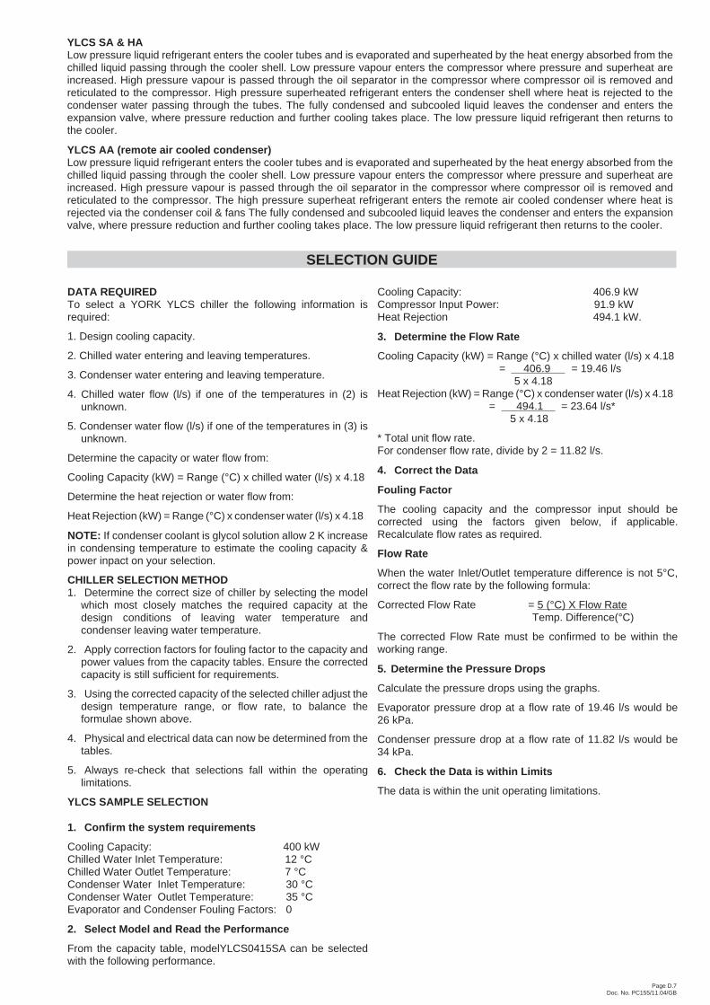
5. Determine the Pressure Drops
Calculate the pressure drops using the graphs.
Evaporator pressure drop at a flow rate of 19.46 l/s would be26 kPa.
Condenser pressure drop at a flow rate of 11.82 l/s would be34 kPa.
6. Check the Data is within Limits
The data is within the unit operating limitations.
SELECTION GUIDE
YLCS SA & HALow pressure liquid refrigerant enters the cooler tubes and is evaporated and superheated by the heat energy absorbed from thechilled liquid passing through the cooler shell. Low pressure vapour enters the compressor where pressure and superheat areincreased. High pressure vapour is passed through the oil separator in the compressor where compressor oil is removed andreticulated to the compressor. High pressure superheated refrigerant enters the condenser shell where heat is rejected to thecondenser water passing through the tubes. The fully condensed and subcooled liquid leaves the condenser and enters theexpansion valve, where pressure reduction and further cooling takes place. The low pressure liquid refrigerant then returns tothe cooler.
YLCS AA (remote air cooled condenser)Low pressure liquid refrigerant enters the cooler tubes and is evaporated and superheated by the heat energy absorbed from thechilled liquid passing through the cooler shell. Low pressure vapour enters the compressor where pressure and superheat areincreased. High pressure vapour is passed through the oil separator in the compressor where compressor oil is removed andreticulated to the compressor. The high pressure superheat refrigerant enters the remote air cooled condenser where heat isrejected via the condenser coil & fans The fully condensed and subcooled liquid leaves the condenser and enters the expansionvalve, where pressure reduction and further cooling takes place. The low pressure liquid refrigerant then returns to the cooler.
Page D.8Doc. No. PC155/11.04/GB
5 10 15 20 25 30 40 50 60 80 1005
10
15
20
25
30
40
50
60
7080
100
Pre
ssur
eD
rop[
kPa]
Flow Rate [l/s]
03500660
0725
0415
05750620
04800530
08400955
10501110
FIGURE 3 COOLER PRESSURE DROP
5 10 15 20 25 30 40 50
15
20
25
30
40
50
60
7080
100
130
Pre
ssur
eD
rop[
kPa]
Flow Rate [l/s]
0350 0725
08400955
10501110
06200660
04150480
05300575
10
FIGURE 4 CONDENSER PRESSURE DROP
COOLER
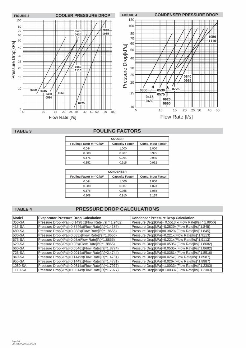
Fouling Factor m² °C/kW Capacity Factor Comp. Input Factor
0.044 1.000 1.000
0.088 0.987 0.995
0.176 0.964 0.985
0.352 0.915 0.962
CONDENSER
Fouling Factor m² °C/kW Capacity Factor Comp. Input Factor
0.044 1.000 1.000
0.088 0.987 1.023
0.176 0.955 1.068
0.308 0.910 1.135
TABLE 3 FOULING FACTORS
Model Evaporator Pressure Drop Calculation Condenser Pressure Drop Calculation350-SA Pressure Drop[kPa]= 0.1498 x(Flow Rate[l/s] ^ 1.9482) Pressure Drop[kPa]= 0.5518 x(Flow Rate[l/s] ^ 1.8956)415-SA Pressure Drop[kPa]=0.3746x(Flow Rate[l/s]^1.4185) Pressure Drop[kPa]=0.3829x(Flow Rate[l/s]^1.845)480-SA Pressure Drop[kPa]=0.083x(Flow Rate[l/s]^1.8656) Pressure Drop[kPa]=0.3829x(Flow Rate[l/s]^1.845)530-SA Pressure Drop[kPa]=0.083x(Flow Rate[l/s]^1.8656) Pressure Drop[kPa]=0.221x(Flow Rate[l/s]^1.9113)575-SA Pressure Drop[kPa]=0.08x(Flow Rate[l/s]^1.8865) Pressure Drop[kPa]=0.221x(Flow Rate[l/s]^1.9113)620-SA Pressure Drop[kPa]=0.08x(Flow Rate[l/s]^1.8865) Pressure Drop[kPa]=0.0505x(Flow Rate[l/s]^1.8682)660-SA Pressure Drop[kPa]=0.0546x(Flow Rate[l/s]^1.8724) Pressure Drop[kPa]=0.0505x(Flow Rate[l/s]^1.8682)725-SA Pressure Drop[kPa]=0.0014x(Flow Rate[l/s]^2.4744) Pressure Drop[kPa]=0.0381x(Flow Rate[l/s]^1.8516)840-SA Pressure Drop[kPa]=0.1449x(Flow Rate[l/s]^1.4781) Pressure Drop[kPa]=0.026x(Flow Rate[l/s]^1.8987)955-SA Pressure Drop[kPa]=0.1449x(Flow Rate[l/s]^1.4781) Pressure Drop[kPa]=0.026x(Flow Rate[l/s]^1.8987)1050-SA Pressure Drop[kPa]=0.0614x(Flow Rate[l/s]^1.7977) Pressure Drop[kPa]=1.0033x(Flow Rate[l/s]^1.2303)1110-SA Pressure Drop[kPa]=0.0614x(Flow Rate[l/s]^1.7977) Pressure Drop[kPa]=1.0033x(Flow Rate[l/s]^1.2303)
TABLE 4 PRESSURE DROP CALCULATIONS
Page D.9Doc. No. PC155/11.04/GB
Coo
lP
ower
HR
Coo
lP
ower
HR
Coo
lP
ower
HR
Coo
lP
ower
HR
Coo
lP
ower
HR
Coo
lP
ower
HR
Coo
lP
ower
HR
kWkW
kWkW
kWkW
kWkW
kWkW
kWkW
kWkW
kWkW
kWkW
kWkW
kW
4.5
326.
869
.939
3.2
311.
377
.338
4.7
295.
486
.037
7.1
279.
494
.836
9.4
257.
510
9.0
361.
123
6.9
121.
035
1.9
216.
313
3.5
343.
1
533
1.7
70.1
398.
331
6.2
77.5
389.
930
0.2
86.3
382.
228
4.3
95.0
374.
526
2.7
109.
036
6.2
240.
012
2.0
355.
922
0.4
134.
034
7.7
634
1.4
70.5
408.
432
6.0
78.0
400.
131
0.0
86.7
392.
429
4.1
95.5
384.
827
3.0
109.
037
6.5
250.
312
2.0
366.
222
8.7
135.
035
6.9
735
1.2
70.9
418.
633
5.8
78.5
410.
331
9.8
87.2
402.
730
3.9
96.0
395.
128
2.2
110.
038
6.7
259.
612
3.0
376.
423
5.9
136.
036
5.1
836
3.6
71.5
431.
534
6.1
78.9
421.
033
0.4
87.7
413.
731
4.7
96.5
406.
329
2.5
111.
039
8.0
268.
812
4.0
386.
624
6.2
136.
037
5.4
937
6.0
72.2
444.
535
6.4
79.2
431.
634
0.9
88.1
424.
632
5.5
97.0
417.
630
2.8
111.
040
8.3
279.
112
4.0
396.
925
5.4
137.
038
5.6
1038
4.9
73.7
454.
936
8.1
79.7
443.
835
1.6
89.0
436.
233
5.1
98.3
428.
531
1.1
111.
041
6.5
286.
312
4.0
404.
126
2.7
137.
039
2.8
1139
3.8
75.1
465.
237
9.7
80.2
456.
036
2.2
90.0
447.
734
4.7
99.7
439.
432
3.4
111.
042
8.9
301.
812
2.0
417.
727
6.0
138.
040
7.1
1240
2.7
76.6
475.
539
1.4
80.8
468.
137
2.9
90.9
459.
235
4.3
101.
045
0.3
334.
811
1.0
440.
231
4.2
121.
042
9.1
286.
313
9.0
418.
4
1341
4.7
77.1
488.
040
3.4
81.2
480.
638
5.0
91.4
471.
936
6.7
101.
746
3.3
344.
011
2.0
450.
432
1.4
121.
043
6.3
294.
613
8.0
425.
7
1442
6.8
77.7
500.
641
5.4
81.6
493.
039
7.2
92.0
484.
637
9.0
102.
347
6.3
358.
411
3.0
465.
833
6.8
122.
045
2.7
310.
013
7.0
440.
2
1543
8.8
78.3
513.
142
7.5
82.1
505.
440
9.4
92.5
497.
339
1.4
103.
048
9.3
369.
811
3.0
477.
134
8.1
123.
046
5.0
321.
413
5.0
449.
6
4.5
389.
982
.146
7.8
374.
790
.646
0.7
354.
710
1.7
451.
333
4.8
112.
844
1.9
309.
412
8.5
431.
528
4.3
143.
042
0.1
260.
115
8.3
410.
4
539
8.6
82.3
476.
838
1.1
90.8
467.
436
1.0
101.
945
7.8
340.
911
3.0
448.
331
5.4
128.
843
7.8
290.
514
5.0
428.
226
5.2
159.
041
6.3
641
6.1
82.7
494.
639
4.0
91.3
480.
837
3.6
102.
447
0.9
353.
311
3.5
461.
132
7.5
129.
345
0.3
301.
814
5.0
439.
527
5.5
160.
542
8.0
743
3.6
83.0
512.
540
6.9
91.9
494.
138
6.3
102.
948
4.0
365.
711
4.0
474.
033
9.1
130.
046
2.6
313.
114
6.0
451.
828
5.3
161.
543
8.7
844
1.9
84.3
521.
942
0.2
92.3
508.
039
9.6
103.
449
7.9
379.
011
4.5
487.
835
3.0
130.
047
6.5
326.
514
5.0
464.
329
6.6
161.
545
0.1
945
0.1
85.5
531.
343
3.6
92.8
521.
841
3.0
103.
951
1.7
392.
411
5.0
501.
736
6.7
129.
348
9.5
340.
914
4.0
477.
730
8.0
162.
546
2.3
1046
3.8
88.4
547.
844
7.4
93.3
536.
042
5.7
105.
052
5.4
404.
111
6.7
514.
937
6.5
130.
350
0.2
349.
214
4.0
486.
031
6.2
163.
047
1.1
1147
7.6
91.3
564.
346
1.1
93.7
550.
143
8.4
106.
053
9.2
415.
811
9.0
528.
839
0.6
131.
051
5.1
365.
714
4.0
502.
533
2.2
164.
048
8.0
1249
1.3
94.1
580.
747
4.8
94.1
564.
345
1.1
107.
155
2.9
427.
512
0.0
541.
540
3.0
131.
852
8.2
379.
014
4.0
515.
834
4.5
165.
050
1.3
1350
5.0
93.2
593.
648
8.9
95.4
579.
546
5.7
108.
056
8.4
442.
612
0.7
557.
241
4.8
132.
354
0.5
387.
314
4.0
524.
135
4.8
164.
051
0.6
1451
8.8
92.3
606.
550
3.0
96.6
594.
848
0.3
109.
058
3.8
457.
712
1.3
572.
943
1.3
133.
055
7.7
405.
814
5.0
543.
637
4.4
162.
552
8.8
1553
2.5
91.4
619.
351
7.1
97.9
610.
049
4.9
109.
959
9.3
472.
812
2.0
588.
744
6.0
133.
857
3.1
419.
214
6.0
557.
938
9.3
160.
554
1.8
4.5
457.
896
.154
9.1
437.
810
6.2
538.
641
3.3
118.
552
5.8
388.
813
0.8
513.
036
1.8
148.
550
2.9
332.
816
5.8
490.
330
3.9
183.
047
7.7
546
5.6
96.3
557.
144
5.0
106.
454
6.0
420.
811
8.7
533.
539
6.6
131.
052
1.0
368.
714
9.0
510.
334
0.9
167.
049
9.6
310.
018
4.0
484.
8
648
1.0
96.8
573.
045
9.4
106.
956
0.9
435.
711
9.2
548.
941
2.0
131.
553
6.9
382.
615
0.0
525.
135
3.3
168.
051
2.9
322.
418
6.0
499.
1
749
6.5
97.3
588.
947
3.8
107.
457
5.8
450.
611
9.7
564.
342
7.5
132.
055
2.9
396.
615
0.5
539.
536
5.7
169.
052
6.2
334.
818
7.0
512.
4
851
4.0
98.0
607.
148
9.8
107.
859
2.2
466.
612
0.2
580.
744
3.4
132.
556
9.3
414.
114
9.5
556.
138
4.2
166.
054
1.9
347.
118
7.0
524.
8
953
1.5
98.8
625.
350
5.7
108.
360
8.6
482.
612
0.7
597.
245
9.4
133.
058
5.7
431.
114
8.0
571.
740
2.7
163.
055
7.6
360.
518
8.0
539.
1
1054
4.9
100.
864
0.7
522.
610
9.1
626.
249
7.7
122.
061
3.6
472.
813
5.0
601.
044
2.4
149.
558
4.4
412.
016
4.0
567.
836
9.8
189.
054
9.3
1155
8.3
102.
965
6.0
539.
410
9.8
643.
751
2.8
123.
463
0.0
486.
213
7.0
616.
345
7.8
151.
060
1.3
429.
516
5.0
586.
338
8.3
190.
056
8.8
1257
1.7
104.
967
1.3
556.
211
0.6
661.
352
7.9
124.
864
6.4
499.
613
9.0
631.
647
1.7
152.
561
6.6
443.
916
6.0
601.
640
2.7
191.
058
4.2
1358
9.5
105.
768
9.9
570.
311
3.0
677.
654
4.0
126.
366
4.0
517.
713
9.7
650.
448
5.6
153.
063
1.0
453.
216
6.0
610.
941
5.1
190.
059
5.6
1460
7.4
106.
570
8.6
584.
411
5.4
694.
056
0.1
127.
968
1.6
535.
914
0.3
669.
350
4.7
153.
565
0.5
473.
816
7.0
632.
543
8.8
188.
061
7.4
1562
5.2
107.
472
7.2
598.
411
7.8
710.
357
6.3
129.
469
9.2
554.
114
1.0
688.
152
2.2
154.
566
9.0
490.
316
8.0
649.
945
7.3
186.
063
4.0
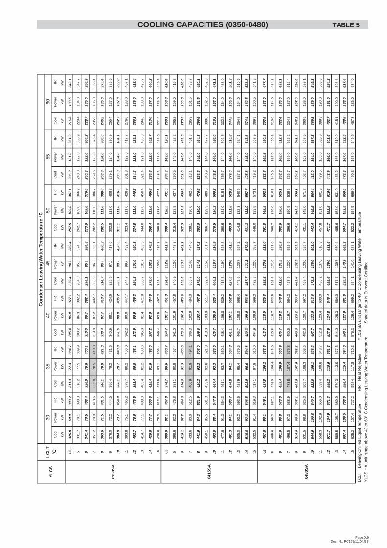
LCLT
=Le
avin
gC
hille
dLi
quid
Tem
pera
ture
HR
=H
eatR
ejec
tion
YLC
SS
Aun
itra
nge
to40
°C
Con
dens
ing
Leav
ing
Wat
erTe
mpe
artu
re
YLC
SH
Aun
itra
n ge
abov
e40
to60
°C
Con
dens
ing
Leav
ing
Wat
erTe
mpe
ratu
reS
hade
dda
tais
Eur
oven
tCer
tifie
d
YL
CS
0350
SA
0480
SA
0415
SA
40L
CLT
°C30
35
Co
nd
ense
rL
eavi
ng
Wat
erTe
mp
erat
ure
°C
4550
5560
COOLING CAPACITIES (0350-0480) TABLE 5
Page D.10Doc. No. PC155/11.04/GB
Coo
lP
ower
HR
Coo
lP
ower
HR
Coo
lP
ower
HR
Coo
lP
ower
HR
Coo
lP
ower
HR
Coo
lP
ower
HR
Coo
lP
ower
HR
kWkW
kWkW
kWkW
kWkW
kWkW
kWkW
kWkW
kWkW
kWkW
kWkW
kW
4.5
493.
110
4.6
592.
547
1.0
115.
758
0.8
447.
712
9.1
570.
342
4.4
142.
555
9.7
394.
716
2.9
549.
536
4.5
182.
153
7.5
334.
220
1.3
525.
4
550
2.6
105.
060
2.4
479.
011
5.9
589.
145
5.8
129.
557
8.8
432.
614
3.0
568.
540
2.2
163.
355
7.3
371.
818
3.5
546.
234
0.9
202.
053
2.8
652
1.7
105.
762
2.1
494.
911
6.4
605.
547
2.0
130.
259
5.7
449.
114
4.0
585.
941
7.2
164.
057
3.0
385.
218
4.0
560.
035
4.3
203.
554
7.6
754
0.8
106.
464
1.8
510.
911
6.9
621.
948
8.2
130.
961
2.6
465.
614
5.0
603.
343
2.1
164.
858
8.6
398.
618
5.0
574.
436
7.7
204.
556
2.0
855
3.6
107.
865
6.1
527.
911
7.8
639.
850
5.5
131.
763
0.5
483.
114
5.5
621.
345
0.6
164.
060
6.4
418.
218
2.0
591.
138
1.1
205.
057
5.9
956
6.5
109.
367
0.3
544.
911
8.8
657.
752
2.7
132.
464
8.5
500.
614
6.0
639.
346
8.9
162.
562
3.3
437.
817
9.0
607.
839
5.0
206.
059
0.7
1058
2.6
110.
868
7.9
562.
411
5.9
672.
553
8.9
132.
166
4.4
515.
314
8.3
656.
348
0.0
163.
863
5.5
448.
118
0.0
619.
140
5.3
207.
060
2.0
1159
8.8
112.
470
5.6
579.
911
3.1
687.
355
5.0
131.
968
0.3
530.
115
0.7
673.
249
8.8
165.
565
6.0
468.
118
1.0
640.
142
4.9
208.
562
3.0
1261
4.9
114.
072
3.2
597.
411
0.2
702.
157
1.1
131.
669
6.2
544.
915
3.0
690.
251
4.2
167.
367
3.1
484.
118
2.0
657.
044
0.3
209.
563
9.4
1363
3.5
115.
074
2.7
614.
911
5.3
724.
458
9.5
134.
571
7.2
564.
115
3.7
710.
152
7.9
167.
568
7.0
495.
418
2.0
668.
345
3.2
208.
065
0.8
1465
2.0
115.
976
2.1
632.
412
0.3
746.
760
7.9
137.
373
8.3
583.
315
4.3
729.
955
0.3
168.
571
0.4
518.
118
3.0
691.
947
7.9
205.
567
3.1
1567
0.5
116.
978
1.5
649.
912
5.4
769.
162
6.2
140.
275
9.4
602.
615
5.0
749.
856
9.1
169.
573
0.1
535.
618
4.0
710.
449
8.0
203.
569
1.3
4.5
537.
111
4.2
645.
750
9.9
126.
462
9.9
484.
914
0.4
618.
345
9.9
154.
560
6.7
427.
717
7.3
596.
139
6.2
198.
458
4.6
364.
621
9.5
573.
1
554
5.9
114.
665
4.7
519.
112
6.5
639.
349
3.9
140.
862
7.6
468.
715
5.0
615.
943
5.7
177.
560
4.3
402.
720
0.0
592.
737
1.8
220.
058
0.8
656
3.4
115.
267
2.9
537.
712
6.9
658.
251
1.9
141.
564
6.3
486.
215
6.0
634.
445
1.7
178.
062
0.8
417.
220
0.0
607.
238
6.3
221.
059
6.2
758
0.9
115.
969
1.0
556.
212
7.3
677.
152
9.9
142.
266
5.0
503.
715
7.0
652.
846
7.6
179.
063
7.7
431.
620
1.0
622.
540
0.7
222.
061
1.6
860
4.1
116.
971
5.1
573.
212
8.3
695.
054
7.7
143.
168
3.7
522.
215
8.0
672.
348
7.2
178.
565
6.8
452.
219
8.0
640.
341
5.1
223.
062
6.9
962
7.3
117.
873
9.2
590.
212
9.2
712.
956
5.5
144.
170
2.4
540.
815
9.0
691.
850
6.8
177.
067
4.9
472.
819
5.0
658.
042
9.5
224.
064
2.3
1064
1.3
120.
375
5.7
610.
112
3.2
727.
158
3.5
142.
371
8.6
556.
916
1.3
710.
251
7.6
178.
068
6.7
484.
119
6.0
670.
344
0.8
225.
065
4.6
1165
5.4
122.
977
2.1
630.
011
7.2
741.
360
1.5
140.
473
4.9
573.
016
3.7
728.
553
9.7
180.
071
0.7
506.
819
7.0
693.
946
1.4
227.
067
7.1
1266
9.5
125.
478
8.6
649.
911
1.2
755.
561
9.5
138.
675
1.2
589.
216
6.0
746.
955
6.7
182.
072
9.6
524.
319
8.0
712.
447
7.9
228.
069
4.5
1368
9.1
126.
480
9.1
670.
511
9.1
783.
664
0.1
143.
077
6.0
609.
816
7.0
768.
457
0.1
182.
074
3.0
537.
719
8.0
725.
849
1.3
226.
070
6.0
1470
8.6
127.
382
9.6
691.
112
7.0
811.
866
0.7
147.
580
0.9
630.
416
8.0
790.
059
5.9
183.
577
0.2
562.
419
9.0
751.
451
7.1
223.
072
8.9
1572
8.2
128.
385
0.0
711.
713
4.9
839.
968
1.3
152.
082
5.7
651.
016
9.0
811.
561
5.9
184.
579
1.2
580.
920
0.0
770.
953
8.7
221.
074
8.6
4.5
576.
812
3.5
694.
155
0.3
136.
668
0.0
524.
815
3.2
670.
349
9.3
169.
866
0.6
462.
019
3.3
645.
542
6.8
215.
863
1.8
391.
723
8.3
618.
0
558
8.1
123.
970
5.8
560.
313
7.0
690.
553
4.6
153.
568
0.4
508.
817
0.0
670.
347
1.0
193.
565
4.8
433.
621
7.5
640.
339
9.6
239.
062
6.7
661
0.8
124.
672
9.2
580.
413
7.8
711.
455
4.1
154.
270
0.6
527.
917
0.5
689.
948
9.0
194.
067
3.3
450.
121
8.0
657.
241
5.6
240.
564
4.1
763
3.5
125.
475
2.6
600.
513
8.7
732.
357
3.7
154.
972
0.8
546.
917
1.0
709.
450
6.8
195.
069
2.0
466.
621
9.0
674.
643
1.6
242.
066
1.5
865
1.0
126.
477
1.0
618.
513
9.2
750.
759
2.5
155.
674
0.3
566.
517
2.0
729.
952
6.3
195.
371
1.8
486.
221
8.0
693.
344
7.5
243.
067
8.4
966
8.5
127.
378
9.4
636.
513
9.7
769.
261
1.3
156.
375
9.8
586.
117
3.0
750.
454
5.9
195.
073
1.2
505.
721
7.0
711.
946
3.5
244.
069
5.3
1068
5.0
129.
880
8.3
656.
813
7.1
787.
163
0.2
156.
477
8.8
603.
617
5.7
770.
555
8.3
195.
874
4.2
519.
121
7.0
725.
347
5.3
245.
070
8.1
1170
1.4
132.
482
7.2
677.
113
4.6
804.
964
9.1
156.
579
7.7
621.
117
8.3
790.
558
3.5
196.
877
0.4
546.
421
6.0
751.
649
8.0
247.
073
2.7
1271
7.9
134.
984
6.1
697.
313
2.1
822.
866
8.0
156.
581
6.7
638.
618
1.0
810.
660
2.6
197.
879
0.4
567.
021
5.0
771.
351
6.0
248.
075
1.6
1373
8.5
135.
986
7.6
717.
213
7.4
847.
868
9.1
159.
784
0.8
660.
918
2.0
833.
861
7.0
198.
380
5.3
580.
921
5.5
785.
653
0.5
246.
076
4.2
1475
9.1
136.
888
9.1
737.
114
2.8
872.
871
0.2
162.
986
4.9
683.
218
3.0
857.
164
4.8
199.
583
4.3
607.
721
6.5
813.
455
8.8
243.
078
9.6
1577
9.7
137.
891
0.6
757.
114
8.2
897.
873
1.3
166.
188
9.1
705.
618
4.0
880.
466
6.7
200.
885
7.4
628.
321
8.0
835.
458
2.0
240.
581
0.4
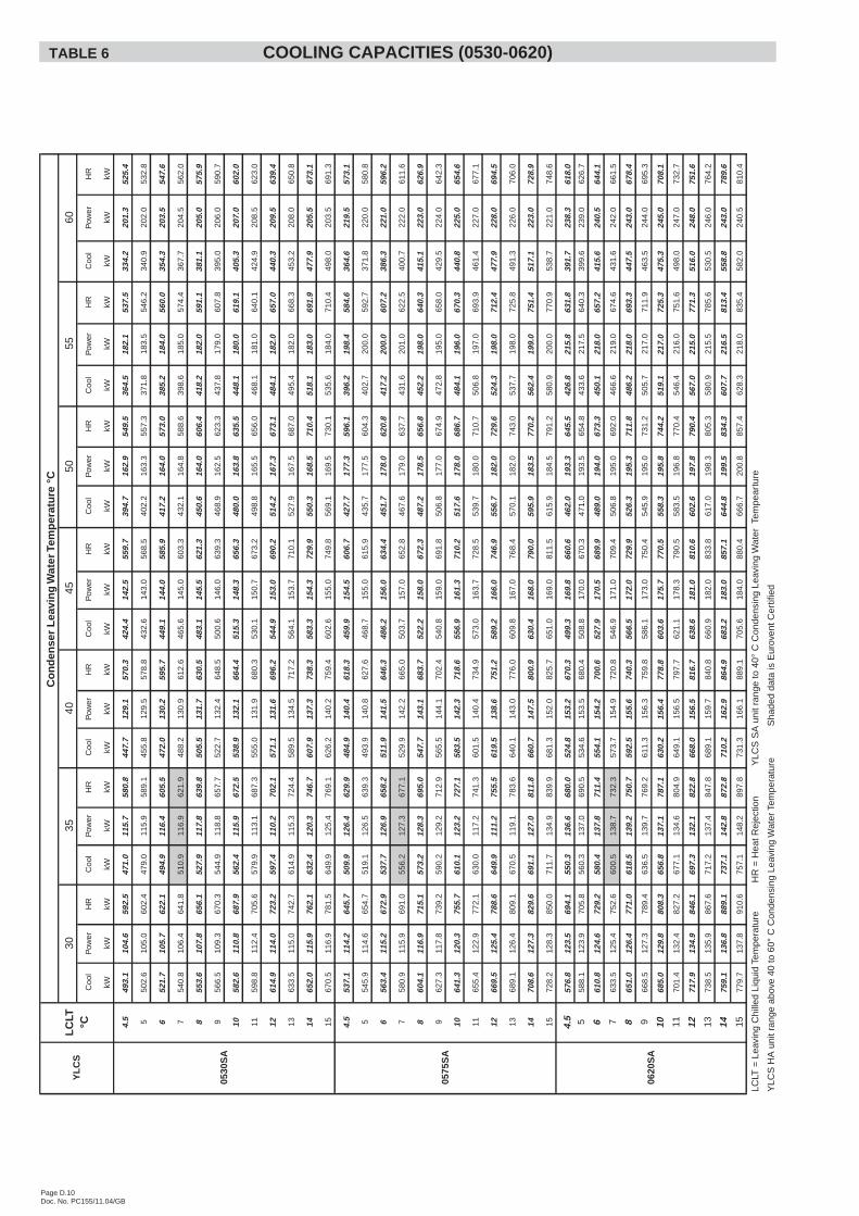
LCLT
=Le
avin
gC
hille
dLi
quid
Tem
pera
ture
HR
=H
eatR
ejec
tion
YLC
SS
Aun
itra
nge
to40
°C
Con
dens
ing
Leav
ing
Wat
erTe
mpe
artu
re
YLC
SH
Aun
itra
n ge
abov
e40
to60
°C
Con
dens
ing
Leav
ing
Wat
erTe
mpe
ratu
reS
hade
dda
tais
Eur
oven
tCer
tifie
d
LC
LT°C
Co
nd
ense
rL
eavi
ng
Wat
erTe
mp
erat
ure
°C
3035
4045
5055
60
0575
SA
0530
SA
YL
CS
0620
SA
TABLE 6 COOLING CAPACITIES (0530-0620)
Page D.11Doc. No. PC155/11.04/GB
Coo
lP
ower
HR
Coo
lP
ower
HR
Coo
lP
ower
HR
Coo
lP
ower
HR
Coo
lP
ower
HR
Coo
lP
ower
HR
Coo
lP
ower
HR
kWkW
kWkW
kWkW
kWkW
kWkW
kWkW
kWkW
kWkW
kWkW
kWkW
kW
4.5
627.
513
4.4
755.
259
8.7
148.
773
9.9
568.
016
6.2
725.
953
7.4
183.
871
2.0
496.
220
9.3
695.
045
7.4
233.
167
8.9
418.
725
7.0
662.
8
563
8.6
134.
976
6.8
609.
814
9.2
751.
557
8.9
166.
673
7.1
548.
018
4.0
722.
850
6.2
209.
570
5.3
464.
523
5.0
687.
842
7.5
258.
067
2.6
666
0.7
135.
978
9.8
631.
915
0.1
774.
560
0.5
167.
375
9.4
569.
118
4.5
744.
452
6.3
210.
072
5.8
483.
123
6.0
707.
344
5.0
260.
069
2.0
768
2.9
136.
881
2.9
654.
115
1.1
797.
562
2.1
168.
078
1.7
590.
218
5.0
765.
954
5.9
211.
074
6.4
501.
623
7.0
726.
846
2.5
262.
071
1.4
870
4.5
137.
383
4.9
674.
115
1.5
818.
164
2.5
168.
880
2.8
610.
818
6.0
787.
556
5.5
212.
076
6.9
520.
223
8.0
746.
348
0.0
263.
072
9.8
972
6.2
137.
885
7.0
694.
215
2.0
838.
666
2.8
169.
582
3.8
631.
418
7.0
809.
058
5.0
213.
078
7.4
538.
723
9.0
765.
749
7.5
264.
074
8.3
1074
3.7
140.
987
7.5
715.
215
3.0
860.
568
2.5
171.
384
5.3
649.
918
9.7
830.
159
8.9
213.
580
1.8
554.
123
8.0
780.
250
9.9
265.
076
1.6
1176
1.2
144.
189
8.0
736.
115
3.9
882.
370
2.3
173.
186
6.7
668.
519
2.3
851.
262
7.3
213.
583
0.1
586.
123
5.0
809.
353
4.6
267.
078
8.2
1277
8.7
147.
391
8.6
757.
115
4.9
904.
272
2.0
174.
988
8.2
687.
019
5.0
872.
364
8.4
213.
585
1.2
609.
823
2.0
830.
255
4.1
268.
080
8.7
1380
1.7
146.
094
0.4
780.
115
5.8
928.
174
5.5
175.
991
2.7
711.
019
6.0
897.
266
3.8
214.
586
7.6
624.
223
3.0
845.
556
9.6
266.
082
2.3
1482
4.7
144.
796
2.2
803.
115
6.8
952.
076
9.1
176.
993
7.1
735.
119
7.0
922.
269
3.7
215.
589
8.4
653.
023
4.0
875.
360
0.5
263.
085
0.3
1584
7.7
143.
598
4.0
826.
115
7.7
975.
979
2.6
177.
996
1.5
759.
119
8.0
947.
271
7.4
217.
092
3.5
675.
723
6.0
899.
962
5.2
260.
087
2.2
4.5
696.
514
6.5
835.
765
9.2
162.
081
3.1
626.
518
0.9
798.
359
3.8
199.
878
3.6
549.
222
8.3
766.
150
7.7
254.
174
9.1
466.
128
0.0
732.
1
570
7.6
146.
984
7.1
674.
716
2.5
829.
064
0.1
181.
281
2.3
605.
620
0.0
795.
656
0.3
228.
577
7.4
515.
025
7.0
759.
247
4.8
281.
074
1.8
672
9.8
147.
586
9.9
705.
616
3.4
860.
866
7.4
182.
084
0.3
629.
320
0.5
819.
858
2.5
229.
080
0.0
535.
625
7.0
779.
849
2.3
283.
076
1.2
775
1.9
148.
289
2.7
736.
516
4.4
892.
669
4.7
182.
786
8.3
653.
020
1.0
844.
060
4.6
229.
582
2.6
556.
225
8.0
801.
351
0.9
285.
078
1.6
877
6.6
149.
291
8.3
760.
116
5.3
917.
271
7.7
183.
789
2.1
675.
220
2.0
867.
162
8.3
228.
584
5.4
582.
025
5.0
824.
253
0.5
286.
080
2.2
980
1.3
150.
194
3.9
783.
816
6.3
941.
874
0.6
184.
691
6.0
697.
320
3.0
890.
265
2.5
227.
086
8.2
607.
725
1.0
846.
255
0.0
287.
082
2.7
1082
2.3
153.
696
8.2
808.
916
7.2
967.
776
4.1
186.
694
1.4
719.
320
6.0
915.
067
1.0
228.
088
7.6
623.
225
1.0
861.
656
4.4
288.
083
8.0
1184
3.2
157.
199
2.4
834.
016
8.2
993.
778
7.6
188.
696
6.8
741.
320
9.0
939.
869
6.8
230.
591
5.8
653.
025
2.0
892.
459
2.3
289.
086
6.8
1286
4.2
160.
610
16.7
859.
016
9.1
1019
.781
1.1
190.
699
2.1
763.
221
2.0
964.
671
9.5
232.
594
0.3
675.
725
3.0
916.
061
3.9
291.
089
0.3
1388
9.2
164.
410
45.4
878.
916
9.7
1040
.283
4.0
191.
410
15.8
789.
021
3.0
991.
374
0.1
233.
596
1.9
691.
125
4.0
932.
463
1.4
289.
090
5.9
1491
4.3
168.
210
74.0
898.
817
0.4
1060
.785
6.8
192.
210
39.4
814.
721
4.0
1018
.076
8.4
234.
599
1.2
723.
125
5.0
965.
366
6.4
286.
093
8.1
1593
9.4
172.
011
02.7
918.
817
1.0
1081
.287
9.6
193.
010
63.0
840.
521
5.0
1044
.779
4.1
236.
010
18.3
747.
825
7.0
991.
969
3.2
283.
096
2.0
4.5
802.
116
9.5
963.
176
6.6
187.
494
4.6
724.
320
8.8
922.
768
2.1
230.
390
0.9
629.
726
3.3
879.
858
1.5
294.
386
1.0
533.
332
5.3
842.
3
581
5.8
170.
097
7.2
780.
718
8.1
959.
473
8.0
209.
693
7.1
695.
323
1.0
914.
764
2.2
263.
889
2.8
589.
729
6.5
871.
454
3.3
326.
085
3.0
684
3.1
171.
010
05.5
809.
118
9.5
989.
176
5.3
211.
096
5.8
721.
523
2.5
942.
466
7.2
264.
891
8.7
612.
929
7.0
895.
056
3.4
327.
587
4.5
787
0.4
172.
010
33.7
837.
419
1.0
1018
.879
2.6
212.
599
4.4
747.
823
4.0
970.
169
2.2
265.
894
4.6
636.
529
8.0
919.
658
3.5
329.
589
6.5
889
2.0
174.
810
58.0
864.
719
1.4
1046
.581
9.1
213.
210
21.7
773.
523
5.0
996.
871
9.7
264.
397
0.8
666.
429
4.0
945.
760
6.7
330.
092
0.2
991
3.6
177.
710
82.4
892.
019
1.9
1074
.384
5.6
214.
010
48.9
799.
323
6.0
1023
.574
7.3
262.
899
6.9
695.
829
0.0
971.
362
9.3
330.
594
3.3
1094
1.8
178.
611
11.4
920.
519
3.2
1104
.087
2.4
216.
310
77.8
824.
323
9.3
1051
.776
6.1
264.
010
16.9
713.
329
0.5
989.
364
5.8
332.
096
1.2
1196
9.9
179.
611
40.5
949.
019
4.4
1133
.789
9.2
218.
611
06.8
849.
424
2.7
1079
.979
7.7
266.
810
51.1
746.
829
1.5
1023
.767
7.7
335.
099
6.0
1299
8.1
180.
511
69.5
977.
519
5.7
1163
.492
6.0
220.
911
35.8
874.
524
6.0
1108
.282
3.5
269.
310
79.3
772.
529
3.0
1050
.970
3.0
337.
510
23.6
1310
26.9
183.
412
01.1
1002
.919
8.2
1191
.295
3.6
222.
111
64.6
904.
324
6.0
1138
.084
7.4
269.
811
03.7
790.
529
4.0
1069
.872
3.1
335.
010
41.3
1410
55.8
186.
212
32.6
1028
.320
0.8
1219
.098
1.2
223.
411
93.5
934.
224
6.0
1167
.987
9.9
270.
511
36.9
827.
129
5.5
1107
.876
3.2
331.
010
77.7
1510
84.6
189.
112
64.2
1053
.720
3.3
1246
.810
08.9
224.
712
22.3
964.
124
6.0
1197
.890
9.2
271.
511
67.2
854.
929
7.5
1137
.579
4.1
327.
511
05.3
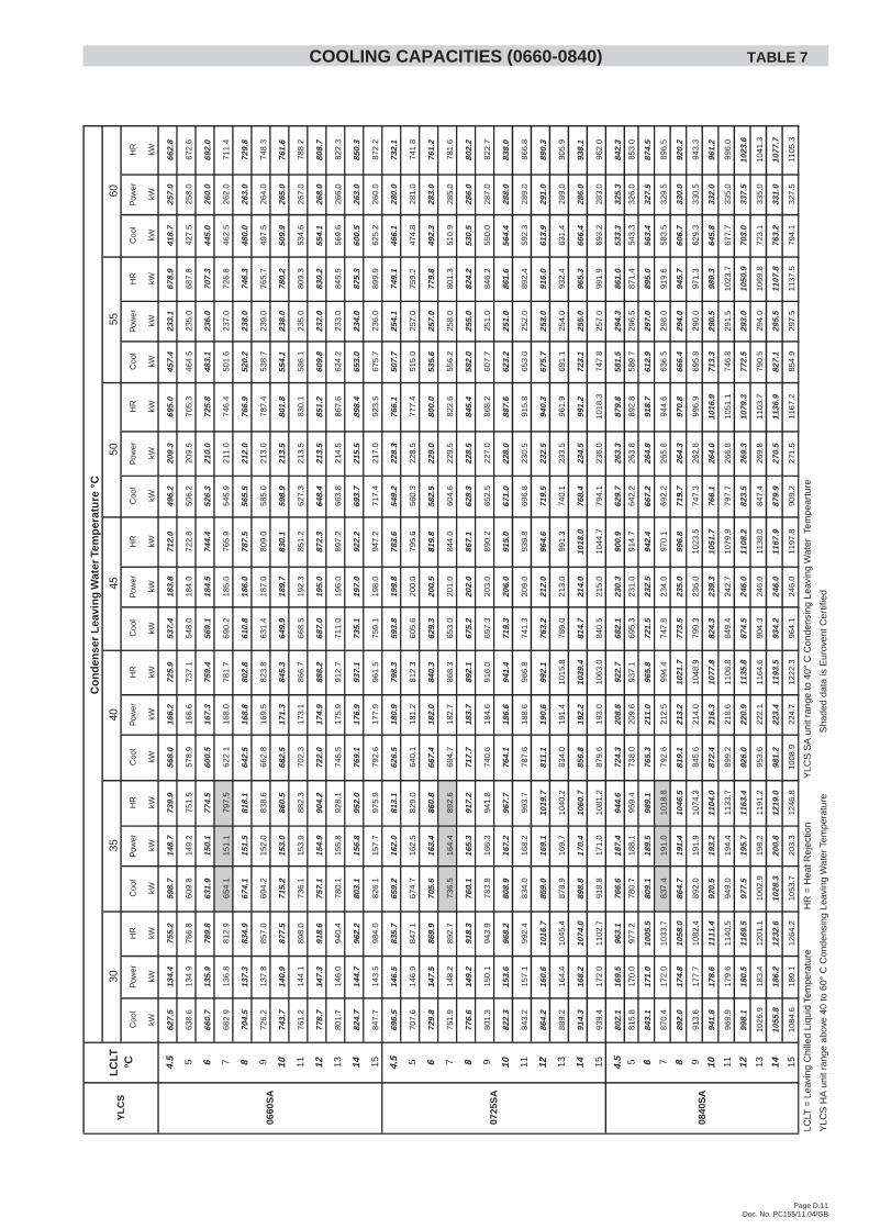
LCLT
=Le
avin
gC
hille
dLi
quid
Tem
pera
ture
HR
=H
eatR
ejec
tion
YLC
SS
Aun
itra
nge
to40
°C
Con
dens
ing
Leav
ing
Wat
erTe
mpe
artu
re
YLC
SH
Aun
itra
n ge
abov
e40
to60
°C
Con
dens
ing
Leav
ing
Wat
erTe
mpe
ratu
reS
hade
dda
tais
Eur
oven
tCer
tifie
d
4045
5055
60
Co
nd
ense
rL
eavi
ng
Wat
erTe
mp
erat
ure
°C
0660
SA
0725
SA
0840
SA
YL
CS
LC
LT°C
3035
COOLING CAPACITIES (0660-0840) TABLE 7
Page D.12Doc. No. PC155/11.04/GB
Coo
lP
ower
HR
Coo
lP
ower
HR
Coo
lP
ower
HR
Coo
lP
ower
HR
Coo
lP
ower
HR
Coo
lP
ower
HR
Coo
lP
ower
HR
kWkW
kWkW
kWkW
kWkW
kWkW
kWkW
kWkW
kWkW
kWkW
kWkW
kW
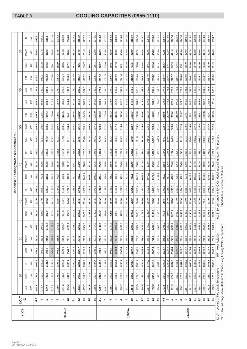
4.5
901.
519
2.6
1084
.585
4.6
213.
010
57.0
811.
923
7.0
1037
.176
9.2
261.
010
17.1
710.
229
8.3
993.
565
5.3
334.
497
3.0
600.
537
0.5
952.
5
591
6.7
193.
211
00.3
876.
521
3.8
1079
.683
0.2
237.
910
56.2
783.
826
2.0
1032
.772
4.1
299.
010
08.1
664.
433
6.0
983.
661
1.8
371.
096
4.3
694
7.1
194.
511
31.8
920.
321
5.2
1124
.786
6.7
239.
610
94.4
813.
226
4.0
1064
.075
1.9
300.
510
37.4
690.
133
7.0
1010
.363
4.5
372.
098
7.9
797
7.5
195.
711
63.4
964.
121
6.6
1169
.990
3.3
241.
311
32.5
842.
526
6.0
1095
.277
9.7
302.
010
66.6
716.
933
8.0
1038
.065
6.1
374.
010
11.4
810
09.4
196.
711
96.2
996.
521
8.0
1203
.693
4.0
242.
511
64.3
871.
426
7.0
1125
.081
1.1
300.
010
96.1
750.
933
3.0
1067
.268
2.9
374.
010
38.2
910
41.3
197.
612
29.1
1029
.021
9.5
1237
.496
4.6
243.
711
96.1
900.
226
8.0
1154
.884
2.0
298.
511
25.6
783.
832
9.0
1096
.470
8.6
374.
010
63.9
1010
68.8
202.
012
60.7
1048
.222
1.0
1258
.298
8.5
246.
412
22.5
928.
727
1.7
1186
.886
1.1
300.
011
46.1
803.
433
0.0
1116
.972
7.2
376.
010
84.4
1110
96.3
206.
512
92.4
1067
.422
2.6
1278
.910
12.3
249.
012
48.8
957.
227
5.3
1218
.889
8.7
303.
011
86.5
840.
533
1.0
1154
.976
3.2
381.
011
25.2
1211
23.7
210.
913
24.1
1086
.722
4.2
1299
.610
36.2
251.
612
75.2
985.
727
9.0
1250
.892
7.5
306.
012
18.2
869.
333
3.0
1185
.779
2.1
384.
011
56.9
1311
55.7
212.
513
57.5
1120
.622
5.2
1334
.510
70.0
251.
613
09.0
1019
.427
8.0
1283
.595
4.8
306.
012
45.5
889.
933
4.0
1207
.281
4.7
381.
011
76.7
1411
87.6
214.
113
91.0
1154
.622
6.1
1369
.411
03.8
251.
613
42.8
1053
.027
7.0
1316
.299
1.4
306.
512
82.6
931.
133
6.0
1250
.386
0.1
376.
012
17.3
1512
19.5
215.
714
24.4
1188
.622
7.1
1404
.311
37.6
251.
513
76.6
1086
.727
6.0
1348
.910
24.3
307.
013
16.0
962.
033
8.0
1283
.189
5.1
372.
012
48.5
4.5
966.
120
7.0
1162
.892
7.0
231.
511
46.9
864.
726
1.0
1112
.682
1.4
284.
510
91.7
747.
332
9.5
1060
.368
5.5
370.
010
37.0
623.
741
0.5
1013
.6
598
3.7
208.
011
81.3
943.
523
2.0
1163
.987
9.6
262.
011
28.5
836.
428
5.0
1107
.176
5.3
327.
010
75.9
701.
936
8.0
1051
.563
8.6
409.
010
27.2
610
18.7
210.
012
18.2
976.
423
3.0
1197
.890
9.5
264.
011
60.3
866.
228
6.0
1137
.980
1.3
322.
011
07.2
734.
936
4.0
1080
.766
8.5
406.
010
54.2
710
53.7
211.
012
54.1
1008
.423
4.0
1230
.793
9.4
265.
011
91.1
896.
128
7.0
1168
.883
8.4
317.
011
39.6
767.
936
0.0
1109
.969
7.3
403.
010
80.2
810
88.7
212.
012
90.1
1042
.423
5.0
1265
.697
7.5
263.
012
27.3
929.
128
8.0
1202
.786
9.3
319.
011
72.4
797.
236
2.5
1141
.672
5.1
406.
011
10.8
911
22.7
213.
013
25.1
1076
.423
6.0
1300
.610
16.6
261.
012
64.6
962.
028
9.0
1236
.690
0.2
321.
012
05.2
826.
636
5.0
1173
.375
2.9
409.
011
41.5
1011
54.6
218.
013
61.7
1100
.023
6.0
1324
.210
39.3
262.
012
88.2
981.
629
2.0
1259
.092
0.8
322.
012
26.7
846.
136
6.0
1193
.877
1.5
410.
011
61.0
1111
85.5
222.
013
96.4
1148
.523
8.0
1374
.610
85.6
264.
013
36.4
1018
.729
8.0
1301
.896
1.0
324.
012
68.8
884.
836
8.0
1234
.480
8.6
412.
012
00.0
1212
18.5
227.
014
34.1
1185
.523
9.0
1412
.611
21.7
265.
013
73.4
1047
.530
2.0
1334
.499
1.9
325.
013
00.6
914.
136
9.5
1265
.283
6.4
414.
012
29.7
1312
57.6
228.
014
74.2
1212
.324
0.0
1440
.311
46.4
266.
013
99.1
1072
.230
3.0
1360
.110
14.6
326.
013
24.3
937.
336
9.0
1287
.986
0.1
412.
012
51.5
1412
96.8
230.
015
15.3
1267
.924
2.0
1497
.811
96.9
268.
014
51.5
1120
.630
6.0
1411
.310
60.9
329.
013
73.5
983.
136
8.5
1333
.290
5.4
408.
012
93.0
1513
38.0
232.
015
58.4
1311
.224
3.0
1542
.012
35.0
269.
014
90.5
1157
.730
8.0
1450
.310
95.9
331.
014
10.4
1018
.736
8.0
1368
.394
1.4
405.
013
26.2
4.5
1033
.621
7.0
1239
.810
12.5
246.
012
46.2
971.
828
5.5
1243
.085
2.3
296.
511
34.0
794.
133
2.0
1109
.572
8.2
377.
310
86.6
662.
342
2.5
1063
.7
510
49.6
216.
012
54.8
1027
.924
5.0
1260
.798
9.8
283.
012
58.7
867.
329
6.0
1148
.580
9.6
331.
011
24.0
742.
637
6.5
1100
.367
5.7
422.
010
76.6
610
81.5
214.
012
84.8
1058
.824
3.0
1289
.710
25.9
278.
012
90.0
897.
129
5.0
1177
.484
0.5
329.
011
53.0
771.
537
5.0
1127
.770
2.5
421.
011
02.4
711
13.4
213.
013
15.8
1089
.724
1.0
1318
.710
63.0
274.
013
23.3
928.
029
5.0
1208
.387
1.4
327.
011
82.0
800.
837
3.5
1155
.773
0.3
420.
011
29.3
811
36.1
216.
013
41.3
1123
.723
9.0
1350
.810
95.9
272.
013
54.3
962.
029
6.0
1243
.290
1.3
331.
012
15.7
829.
737
8.0
1188
.875
8.1
425.
011
61.8
911
57.7
219.
013
65.8
1157
.723
8.0
1383
.811
28.9
270.
013
85.4
997.
029
8.0
1280
.193
1.1
334.
012
48.4
858.
538
1.5
1220
.978
5.9
429.
011
93.4
1011
91.7
220.
014
00.7
1179
.423
9.0
1406
.411
50.5
271.
014
08.0
1017
.630
1.0
1303
.695
4.8
335.
012
73.1
882.
238
1.0
1244
.180
9.6
427.
012
15.2
1112
24.7
222.
014
35.6
1222
.624
1.0
1451
.611
93.8
275.
014
55.0
1058
.830
7.0
1350
.510
02.2
337.
013
22.3
929.
638
0.0
1290
.685
7.0
423.
012
58.8
1212
58.7
224.
014
71.5
1256
.624
3.0
1487
.512
27.8
277.
014
90.9
1089
.731
2.0
1386
.110
38.2
338.
013
59.3
965.
637
9.0
1325
.789
3.0
420.
012
92.0
1312
95.7
225.
015
09.5
1276
.224
6.0
1509
.912
50.4
77.0
1323
.611
14.5
312.
014
10.9
1058
.834
1.0
1382
.898
6.7
381.
013
48.7
914.
642
1.0
1314
.6
1413
31.8
225.
015
45.5
1316
.325
2.0
1555
.712
96.8
277.
015
59.9
1163
.931
3.0
1461
.310
99.0
347.
014
28.7
1028
.538
4.5
1393
.795
7.9
422.
013
58.8
1513
68.9
226.
015
83.6
1347
.225
7.0
1591
.413
31.8
277.
015
94.9
1202
.031
4.0
1500
.311
30.9
352.
014
65.3
1061
.438
8.0
1430
.099
1.9
424.
013
94.7
LCLT
=Le
avin
gC
hille
dLi
quid
Tem
pera
ture
HR
=H
eatR
ejec
tion
YLC
SS
Aun
itra
nge
to40
°C
Con
dens
ing
Leav
ing
Wat
erTe
mpe
artu
re
YLC
SH
Aun
itra
n ge
abov
e40
to60
°C
Con
dens
ing
Leav
ing
Wat
erTe
mpe
ratu
reS
hade
dda
tais
Eur
oven
tCer
tifie
d
Co
nd
ense
rL
eavi
ng
Wat
erTe
mp
erat
ure
°C
3035
4045
5055
60
1050
SA
1110
SA
YL
CS
LC
LT°C
0955
SA
TABLE 8 COOLING CAPACITIES (0955-1110)
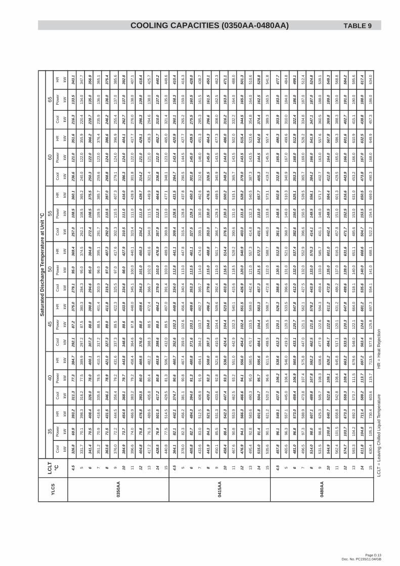
Page D.13Doc. No. PC155/11.04/GB
Coo
lP
ower
HR
Coo
lP
ower
HR
Coo
lP
ower
HR
Coo
lP
ower
HR
Coo
lP
ower
HR
Coo
lP
ower
HR
Coo
lP
ower
HR
kWkW
kWkW
kWkW
kWkW
kWkW
kWkW
kWkW
kWkW
kWkW
kWkW
kW
4.5
326.
869
.939
3.2
311.
377
.338
4.7
292.
187
.237
5.0
279.
195
.036
9.4
257.
010
8.5
360.
123
6.6
121.
035
1.6
216.
313
3.5
343.
1
533
1.7
70.1
398.
331
6.2
77.5
389.
929
7.2
87.5
380.
328
4.3
95.0
374.
526
2.1
108.
536
5.2
240.
012
2.0
355.
922
0.4
134.
034
7.7
634
1.4
70.5
408.
432
6.0
78.0
400.
130
7.2
88.0
390.
829
4.6
95.0
384.
827
2.4
108.
537
5.5
250.
312
2.0
366.
222
8.7
135.
035
6.9
735
1.2
70.9
418.
633
5.8
78.5
410.
331
7.2
88.5
401.
430
3.9
96.0
395.
128
1.7
109.
538
5.7
259.
612
3.0
376.
423
5.9
136.
036
5.1
836
3.6
71.5
431.
534
6.1
78.9
421.
032
7.3
89.0
411.
831
5.2
97.0
407.
329
2.0
110.
539
7.0
268.
812
4.0
386.
624
6.2
136.
037
5.4
937
6.0
72.2
444.
535
6.4
79.2
431.
633
7.3
89.5
422.
332
5.5
97.0
417.
630
2.3
110.
540
7.3
279.
112
4.0
396.
925
5.4
137.
038
5.6
1038
4.9
73.7
454.
936
8.1
79.7
443.
834
8.8
89.6
433.
933
4.8
98.0
427.
931
0.5
111.
041
6.0
286.
312
4.0
404.
126
2.7
137.
039
2.8
1139
6.6
74.0
466.
938
3.2
79.2
458.
436
4.6
87.8
448.
034
5.1
100.
044
0.1
323.
411
1.0
428.
930
1.8
122.
041
7.7
276.
013
8.0
407.
1
1240
4.8
75.8
476.
839
3.5
80.0
469.
537
6.0
88.0
459.
635
4.3
101.
045
0.3
334.
211
1.0
439.
731
4.2
121.
042
9.1
286.
313
9.0
418.
4
1341
7.2
76.3
489.
640
5.8
80.4
482.
238
8.3
88.5
472.
436
6.7
102.
046
3.6
344.
011
1.5
449.
932
1.4
121.
043
6.3
294.
613
8.0
425.
7
1442
8.5
76.9
501.
541
7.2
80.8
493.
939
9.6
89.0
484.
237
9.0
103.
047
6.9
357.
911
2.5
464.
833
6.8
122.
045
2.7
310.
013
7.0
440.
2
1544
0.8
77.5
514.
542
9.5
81.3
506.
741
2.0
89.5
497.
039
1.4
103.
048
9.3
369.
811
3.0
477.
134
8.1
123.
046
5.0
321.
413
5.0
449.
6
4.5
364.
182
.144
2.1
374.
790
.646
0.7
352.
610
2.3
449.
833
4.0
112.
844
1.1
309.
412
8.5
431.
528
4.7
143.
442
0.9
260.
115
8.3
410.
4
537
8.0
82.3
456.
238
1.1
90.8
467.
435
9.0
102.
645
6.4
340.
411
3.0
447.
831
5.4
128.
843
7.8
290.
514
4.5
427.
726
5.2
159.
041
6.3
640
5.8
82.7
484.
339
4.0
91.3
480.
837
1.6
103.
146
9.6
353.
311
3.5
461.
132
7.5
129.
345
0.3
301.
814
5.0
439.
527
5.5
160.
542
8.0
743
3.6
83.0
512.
540
6.9
91.9
494.
138
4.2
103.
748
2.7
365.
711
4.0
474.
033
9.1
130.
046
2.6
312.
614
6.0
451.
328
5.3
161.
543
8.7
844
1.9
84.3
521.
942
0.2
92.3
508.
039
7.3
104.
049
6.2
379.
611
5.0
488.
835
3.0
130.
047
6.5
326.
514
5.0
464.
329
6.6
161.
545
0.1
945
0.1
85.5
531.
343
3.6
92.8
521.
841
0.5
104.
450
9.6
392.
411
5.0
501.
736
6.7
129.
348
9.5
340.
914
3.5
477.
330
8.0
162.
546
2.3
1045
8.4
88.4
542.
344
7.4
93.3
536.
042
4.4
104.
452
3.6
403.
811
6.5
514.
437
6.5
130.
350
0.2
349.
214
4.0
486.
031
6.2
163.
047
1.1
1146
7.6
90.8
553.
946
2.5
93.2
551.
044
2.9
102.
354
0.1
415.
611
8.5
528.
239
0.6
131.
051
5.1
365.
714
3.5
502.
033
2.2
164.
048
8.0
1247
6.9
94.1
566.
346
6.6
94.1
556.
045
4.2
102.
455
1.5
426.
912
0.0
540.
940
3.0
131.
852
8.2
379.
014
3.5
515.
434
4.5
165.
050
1.3
1349
5.4
92.8
583.
649
0.3
95.0
580.
547
0.7
103.
556
9.0
442.
412
1.0
557.
341
4.8
132.
354
0.5
387.
314
3.5
523.
635
4.8
164.
051
0.6
1451
5.0
91.4
601.
850
4.7
95.7
595.
648
4.1
104.
458
3.3
457.
312
1.5
572.
743
1.3
133.
055
7.7
405.
314
4.5
542.
637
4.4
162.
552
8.8
1553
5.6
90.1
621.
252
0.2
96.6
611.
949
8.5
105.
559
8.7
472.
812
2.0
588.
744
6.0
133.
857
3.1
419.
214
5.5
557.
438
9.3
160.
554
1.8
4.5
457.
896
.154
9.1
437.
810
6.2
538.
641
2.3
120.
152
6.3
388.
813
0.5
512.
836
1.8
148.
550
2.9
332.
816
5.8
490.
330
3.9
183.
047
7.7
546
5.6
96.3
557.
144
5.0
106.
454
6.0
419.
212
0.3
533.
539
6.6
131.
052
1.0
368.
714
9.0
510.
334
0.9
167.
049
9.6
310.
018
4.0
484.
8
648
1.0
96.8
573.
045
9.4
106.
956
0.9
433.
112
0.7
547.
841
2.0
132.
053
7.4
382.
615
0.0
525.
135
3.3
168.
051
2.9
322.
418
6.0
499.
1
749
6.5
97.3
588.
947
3.8
107.
457
5.8
447.
012
1.1
562.
142
7.5
132.
055
2.9
396.
615
0.5
539.
536
5.7
169.
052
6.2
334.
818
7.0
512.
4
851
4.0
98.0
607.
148
9.8
107.
859
2.2
462.
512
1.8
578.
244
3.9
133.
057
0.3
414.
114
9.5
556.
138
4.2
166.
054
1.9
347.
118
7.0
524.
8
953
1.5
98.8
625.
350
5.7
108.
360
8.6
477.
912
2.6
594.
345
9.4
133.
058
5.7
431.
114
8.0
571.
740
2.7
163.
055
7.6
360.
518
8.0
539.
1
1054
4.9
100.
864
0.7
522.
610
9.1
626.
249
4.7
122.
661
1.2
472.
813
5.0
601.
044
2.4
149.
558
4.4
412.
016
4.0
567.
836
9.8
189.
054
9.3
1156
2.4
101.
565
8.8
542.
810
8.4
645.
851
7.1
120.
163
1.2
486.
213
7.0
616.
345
7.8
151.
060
1.3
429.
516
5.0
586.
338
8.3
190.
056
8.8
1257
4.7
103.
767
3.3
559.
310
9.4
663.
253
3.5
120.
364
7.8
499.
613
9.0
631.
647
1.7
152.
561
6.6
443.
916
6.0
601.
640
2.7
191.
058
4.2
1359
3.3
104.
269
2.3
573.
711
1.5
679.
654
8.0
122.
166
4.0
518.
114
0.0
651.
148
5.6
153.
063
1.0
453.
216
6.0
610.
941
5.1
190.
059
5.6
1461
1.8
104.
871
1.4
589.
211
3.7
697.
256
3.4
124.
068
1.2
535.
614
0.0
668.
650
4.7
153.
565
0.5
473.
816
7.0
632.
543
8.8
188.
061
7.4
1563
0.4
105.
373
0.4
603.
611
5.7
713.
557
7.8
125.
869
7.3
554.
114
1.0
688.
152
2.2
154.
566
9.0
490.
316
8.0
649.
945
7.3
186.
063
4.0
LCLT
=Le
avin
gC
hille
dLi
quid
Tem
pera
ture
HR
=H
eatR
ejec
tion
45L
CLT
°C35
40
Sat
ura
ted
Dis
char
ge
Tem
per
atu
reat
Un
it°C
5055
6065
YL
CS
0350
AA
0480
AA
0415
AA
COOLING CAPACITIES (0350AA-0480AA) TABLE 9
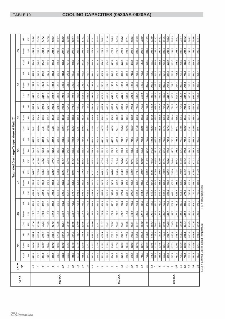
Page D.14Doc. No. PC155/11.04/GB
Coo
lP
ower
HR
Coo
lP
ower
HR
Coo
lP
ower
HR
Coo
lP
ower
HR
Coo
lP
ower
HR
Coo
lP
ower
HR
Coo
lP
ower
HR
kWkW
kWkW
kWkW
kWkW
kWkW
kWkW
kWkW
kWkW
kWkW
kWkW
kW
4.5
493.
110
4.6
592.
547
1.0
115.
758
0.8
444.
313
0.9
568.
742
1.0
144.
855
8.6
393.
116
4.0
548.
936
3.7
182.
653
7.2
334.
220
1.3
525.
4
550
2.6
105.
060
2.4
479.
011
5.9
589.
145
2.2
131.
257
6.8
429.
014
5.3
567.
040
0.4
164.
455
6.6
371.
818
3.5
546.
234
0.9
202.
053
2.8
652
1.7
105.
762
2.1
494.
911
6.4
605.
546
7.9
131.
759
3.0
445.
014
6.3
583.
941
5.1
165.
157
2.0
385.
218
4.0
560.
035
4.3
203.
554
7.6
754
0.8
106.
464
1.8
510.
911
6.9
621.
948
3.6
132.
260
9.2
460.
914
6.8
600.
342
9.8
165.
958
7.3
398.
618
5.0
574.
436
7.7
204.
556
2.0
855
3.6
107.
865
6.1
527.
911
7.8
639.
849
9.8
133.
162
6.2
477.
914
7.5
618.
044
8.1
164.
760
4.6
418.
218
2.0
591.
138
1.1
205.
057
5.9
956
6.5
109.
367
0.3
544.
911
8.8
657.
751
6.0
134.
064
3.3
494.
414
7.7
634.
746
6.1
163.
462
1.3
437.
817
9.0
607.
839
5.0
206.
059
0.7
1058
2.6
110.
868
7.9
562.
411
5.9
672.
553
3.5
132.
265
9.1
510.
714
8.6
651.
847
9.4
164.
363
5.4
448.
118
0.0
619.
140
5.3
207.
060
2.0
1160
2.6
112.
370
9.2
584.
011
2.9
691.
355
7.2
127.
067
7.9
527.
014
9.4
669.
049
7.6
165.
265
4.5
468.
118
1.0
640.
142
4.9
208.
562
3.0
1261
8.0
114.
872
7.1
600.
511
1.0
705.
957
4.7
125.
069
3.5
543.
315
0.3
686.
151
3.7
166.
167
1.5
484.
118
2.0
657.
044
0.3
209.
563
9.4
1363
7.6
114.
974
6.7
619.
011
5.2
728.
559
1.2
128.
671
3.4
562.
015
1.2
705.
752
8.7
166.
668
7.0
495.
418
2.0
668.
345
3.2
208.
065
0.8
1465
6.1
115.
076
5.4
636.
511
9.4
750.
060
8.7
132.
173
4.2
580.
215
1.7
724.
354
9.2
167.
470
8.1
518.
118
3.0
691.
947
7.9
205.
567
3.1
1567
4.7
115.
178
4.0
654.
112
3.7
771.
662
5.2
135.
775
4.1
598.
915
2.7
744.
056
7.3
168.
372
7.2
535.
618
4.0
710.
449
8.0
203.
569
1.3
4.5
537.
111
4.2
645.
750
9.9
126.
462
9.9
481.
514
2.7
617.
145
3.2
159.
160
4.4
424.
417
9.6
594.
939
4.5
199.
558
4.0
364.
621
9.5
573.
1
554
5.9
114.
665
4.7
519.
112
6.5
639.
349
0.3
143.
162
6.2
461.
415
9.6
613.
143
2.1
179.
860
2.9
402.
720
0.0
592.
737
1.8
220.
058
0.8
656
3.4
115.
267
2.9
537.
712
6.9
658.
250
7.8
143.
764
4.3
477.
916
0.6
630.
444
7.5
180.
361
8.8
417.
220
0.0
607.
238
6.3
221.
059
6.2
758
0.9
115.
969
1.0
556.
212
7.3
677.
152
5.3
144.
466
2.5
494.
416
1.5
647.
846
3.0
181.
363
5.2
431.
620
1.0
622.
540
0.7
222.
061
1.6
860
4.1
116.
971
5.1
573.
212
8.3
695.
054
2.6
145.
168
0.4
511.
916
2.0
665.
848
2.0
180.
065
3.0
452.
219
8.0
640.
341
5.1
223.
062
6.9
962
7.3
117.
873
9.2
590.
212
9.2
712.
955
9.8
145.
869
8.3
529.
416
2.5
683.
750
1.1
178.
767
0.9
472.
819
5.0
658.
042
9.5
224.
064
2.3
1064
1.3
120.
375
5.7
610.
112
3.2
727.
157
9.4
142.
771
4.9
548.
616
2.1
702.
751
6.4
179.
168
6.5
484.
119
6.0
670.
344
0.8
225.
065
4.6
1166
0.2
124.
077
8.0
635.
511
8.3
747.
960
5.6
135.
073
3.9
567.
916
1.8
721.
653
7.3
179.
470
7.8
506.
819
7.0
693.
946
1.4
227.
067
7.1
1267
3.6
128.
379
5.5
654.
111
4.0
762.
462
5.2
131.
374
9.9
587.
116
1.5
740.
555
5.7
179.
872
6.4
524.
319
8.0
712.
447
7.9
228.
069
4.5
1369
3.2
127.
881
4.6
674.
712
0.5
789.
164
4.8
136.
477
4.4
606.
016
2.5
760.
357
1.8
180.
274
3.0
537.
719
8.0
725.
849
1.3
226.
070
6.0
1471
1.7
127.
483
2.8
694.
212
7.0
814.
966
4.4
141.
679
8.9
624.
916
3.4
780.
159
3.6
181.
276
5.8
562.
419
9.0
751.
451
7.1
223.
072
8.9
1573
1.3
126.
985
1.9
714.
813
3.6
841.
768
5.0
146.
782
4.3
643.
816
4.4
799.
961
2.3
182.
278
5.4
580.
920
0.0
770.
953
8.7
221.
074
8.6
4.5
576.
812
3.5
694.
155
0.3
136.
668
0.0
515.
815
4.5
662.
548
1.3
172.
464
5.1
453.
319
4.8
638.
442
2.5
216.
562
8.2
391.
723
8.3
618.
0
558
8.1
123.
970
5.8
560.
313
7.0
690.
552
9.4
154.
967
6.6
498.
517
2.9
662.
846
6.1
195.
265
1.5
433.
621
7.5
640.
339
9.6
239.
062
6.7
661
0.8
124.
672
9.2
580.
413
7.8
711.
455
6.7
155.
870
4.8
533.
017
3.9
698.
249
1.6
195.
967
7.7
450.
121
8.0
657.
241
5.6
240.
564
4.1
763
3.5
125.
475
2.6
600.
513
8.7
732.
358
4.0
156.
873
2.9
567.
517
4.8
733.
651
7.1
196.
970
4.1
466.
621
9.0
674.
643
1.6
242.
066
1.5
867
5.7
126.
479
5.7
618.
513
9.2
750.
759
3.5
157.
274
2.9
568.
617
5.3
735.
152
7.4
196.
671
4.2
486.
221
8.0
693.
344
7.5
243.
067
8.4
971
7.9
127.
383
8.8
636.
513
9.7
769.
260
3.1
157.
775
2.9
569.
617
5.8
736.
653
7.7
196.
472
4.2
505.
721
7.0
711.
946
3.5
244.
069
5.3
1071
7.9
129.
884
1.3
656.
813
7.1
787.
162
3.5
156.
177
1.8
590.
217
5.1
756.
655
4.7
196.
174
0.9
519.
121
7.0
725.
347
5.3
245.
070
8.1
1172
6.2
131.
985
1.5
685.
013
4.1
812.
365
1.0
150.
579
3.9
610.
817
4.5
776.
557
8.6
195.
276
4.1
546.
421
6.0
751.
649
8.0
247.
073
2.7
1272
2.0
135.
585
0.8
701.
413
2.6
827.
467
0.5
148.
881
1.9
631.
417
3.9
796.
559
9.2
194.
478
3.9
567.
021
5.0
771.
351
6.0
248.
075
1.6
1375
1.9
135.
588
0.6
736.
513
7.1
866.
770
0.4
152.
484
5.2
651.
317
4.8
817.
461
6.1
195.
280
1.5
580.
921
5.5
785.
653
0.5
246.
076
4.2
1478
2.8
135.
691
1.6
771.
514
1.6
906.
073
0.3
156.
087
8.5
671.
217
5.8
838.
263
9.5
196.
182
5.8
607.
721
6.5
813.
455
8.8
243.
078
9.6
1581
2.7
135.
794
1.6
806.
514
6.1
945.
376
0.1
159.
691
1.8
691.
117
6.7
859.
065
9.7
197.
484
7.2
628.
321
8.0
835.
458
2.0
240.
581
0.4
LCLT
=Le
avin
gC
hille
dLi
quid
Tem
pera
ture
HR
=H
eatR
ejec
tion
0620
AA
0575
AA
0530
AA
YL
CS
LC
LT°C
Sat
ura
ted
Dis
char
ge
Tem
per
atu
reat
Un
it°C
3540
4550
5560
65TABLE 10 COOLING CAPACITIES (0530AA-0620AA)
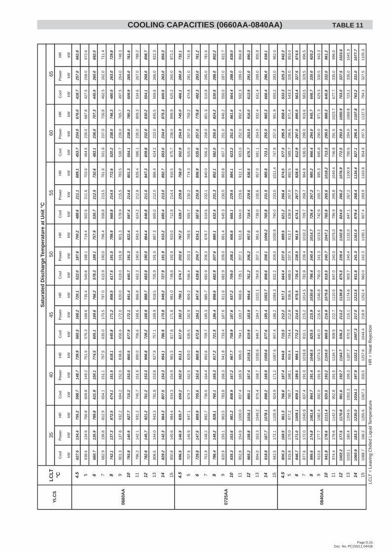
Page D.15Doc. No. PC155/11.04/GB
Coo
lP
ower
HR
Coo
lP
ower
HR
Coo
lP
ower
HR
Coo
lP
ower
HR
Coo
lP
ower
HR
Coo
lP
ower
HR
Coo
lP
ower
HR
kWkW
kWkW
kWkW
kWkW
kWkW
kWkW
kWkW
kWkW
kWkW
kWkW
kW
4.5
627.
513
4.4
755.
259
8.7
148.
773
9.9
560.
316
8.2
720.
152
2.0
187.
670
0.2
488.
621
1.1
689.
145
3.7
234.
067
6.0
418.
725
7.0
662.
8
563
8.6
134.
976
6.8
609.
814
9.2
751.
557
5.3
168.
673
5.4
540.
818
8.1
719.
450
2.6
211.
670
3.6
464.
523
5.0
687.
842
7.5
258.
067
2.6
666
0.7
135.
978
9.8
631.
915
0.1
774.
560
5.1
169.
676
6.2
578.
318
9.1
757.
953
0.7
212.
573
2.6
483.
123
6.0
707.
344
5.0
260.
069
2.0
768
2.9
136.
881
2.9
654.
115
1.1
797.
563
5.0
170.
579
7.0
615.
919
0.0
796.
455
8.8
213.
576
1.6
501.
623
7.0
726.
846
2.5
262.
071
1.4
874
2.1
137.
387
2.5
674.
115
1.5
818.
164
5.8
171.
280
8.5
617.
519
1.0
798.
956
8.8
214.
577
2.6
520.
223
8.0
746.
348
0.0
263.
072
9.8
980
1.3
137.
893
2.2
694.
215
2.0
838.
665
6.6
172.
082
0.0
619.
019
1.9
801.
357
8.9
215.
578
3.5
538.
723
9.0
765.
749
7.5
264.
074
8.3
1079
3.8
140.
992
7.7
715.
215
3.0
860.
567
7.9
172.
184
1.4
640.
719
1.3
822.
459
7.4
214.
680
1.3
554.
123
8.0
780.
250
9.9
265.
076
1.6
1179
6.2
142.
193
1.2
745.
715
1.9
890.
070
6.6
168.
686
6.8
662.
319
0.6
843.
462
4.2
212.
882
6.4
586.
123
5.0
809.
353
4.6
267.
078
8.2
1278
2.8
145.
792
1.2
761.
215
3.3
906.
872
8.2
168.
988
8.7
683.
919
0.0
864.
464
6.8
211.
084
7.3
609.
823
2.0
830.
255
4.1
268.
080
8.7
1380
6.5
144.
094
3.3
781.
815
3.8
927.
975
7.1
169.
991
8.5
705.
919
1.0
887.
366
5.0
212.
086
6.4
624.
223
3.0
845.
556
9.6
266.
082
2.3
1482
9.2
142.
396
4.3
807.
515
4.3
954.
178
6.9
170.
894
9.2
727.
919
1.9
910.
269
0.4
213.
089
2.7
653.
023
4.0
875.
360
0.5
263.
085
0.3
1585
0.8
140.
698
4.4
834.
315
4.9
981.
581
7.8
171.
898
1.0
749.
819
2.9
933.
071
2.8
214.
491
6.5
675.
723
6.0
899.
962
5.2
260.
087
2.2
4.5
696.
514
6.5
835.
765
9.2
162.
081
3.1
617.
018
2.3
790.
157
4.7
202.
676
7.2
539.
722
9.8
758.
050
2.9
254.
974
5.0
466.
128
0.0
732.
1
570
7.6
146.
984
7.1
674.
716
2.5
829.
063
5.5
182.
980
9.2
596.
420
3.3
789.
555
5.7
230.
277
4.3
515.
025
7.0
759.
247
4.8
281.
074
1.8
672
9.8
147.
586
9.9
705.
616
3.4
860.
867
2.6
184.
184
7.4
639.
620
4.7
834.
158
7.6
230.
980
6.9
535.
625
7.0
779.
849
2.3
283.
076
1.2
775
1.9
148.
289
2.7
736.
516
4.4
892.
670
9.7
185.
388
5.7
682.
920
6.2
878.
761
9.5
232.
184
0.0
556.
225
8.0
801.
351
0.9
285.
078
1.6
878
6.4
149.
292
8.1
760.
116
5.3
917.
272
1.5
186.
489
8.6
682.
920
7.6
880.
163
2.4
231.
385
2.1
582.
025
5.0
824.
253
0.5
286.
080
2.2
982
0.9
150.
196
3.5
783.
816
6.3
941.
873
3.4
187.
691
1.6
682.
920
9.0
881.
464
5.3
230.
086
3.8
607.
725
1.0
846.
255
0.0
287.
082
2.7
1083
5.3
153.
698
1.2
808.
916
7.2
967.
775
8.9
187.
693
7.2
709.
020
8.1
906.
666
6.1
229.
588
4.1
623.
225
1.0
861.
656
4.4
288.
083
8.0
1185
2.8
154.
910
00.0
837.
416
5.9
995.
079
4.1
183.
796
8.6
735.
120
7.1
931.
869
4.0
229.
691
2.1
653.
025
2.0
892.
459
2.3
289.
086
6.8
1286
5.2
158.
810
16.1
860.
116
7.4
1019
.181
9.9
183.
999
4.6
761.
220
6.2
957.
071
8.4
229.
693
6.5
675.
725
3.0
916.
061
3.9
291.
089
0.3
1389
4.0
163.
310
49.2
870.
416
8.7
1030
.684
6.7
184.
710
22.1
784.
920
7.1
981.
673
8.0
230.
695
7.0
691.
125
4.0
932.
463
1.4
289.
090
5.9
1491
8.8
167.
710
78.1
898.
216
9.9
1059
.687
7.6
185.
410
53.7
808.
620
8.1
1006
.276
5.8
231.
598
5.8
723.
125
5.0
965.
366
6.4
286.
093
8.1
1594
2.5
172.
111
05.9
924.
917
1.2
1087
.690
7.4
186.
210
84.3
832.
220
9.0
1030
.879
0.0
233.
010
11.4
747.
825
7.0
991.
969
3.2
283.
096
2.0
4.5
800.
316
9.5
961.
376
6.6
187.
494
4.6
715.
521
2.2
917.
166
4.4
237.
088
9.5
621.
226
6.6
874.
557
7.3
295.
985
8.4
533.
332
5.3
842.
3
581
5.8
170.
097
7.2
780.
718
8.1
959.
473
4.4
212.
893
6.6
688.
023
7.5
913.
763
8.9
267.
089
2.5
589.
729
6.5
871.
454
3.3
326.
085
3.0
684
6.7
171.
010
09.1
809.
118
9.5
989.
177
2.2
214.
097
5.5
735.
423
8.5
961.
967
4.1
267.
792
8.5
612.
929
7.0
895.
056
3.4
327.
587
4.5
787
7.6
172.
010
40.9
837.
419
1.0
1018
.881
0.1
215.
210
14.5
782.
823
9.4
1010
.270
9.7
268.
796
4.9
636.
529
8.0
919.
658
3.5
329.
589
6.5
889
5.6
174.
810
61.6
864.
719
1.4
1046
.582
5.5
215.
910
30.6
786.
424
0.4
1014
.772
6.4
267.
298
0.2
666.
429
4.0
945.
760
6.7
330.
092
0.2
991
3.6
177.
710
82.4
892.
019
1.9
1074
.384
1.0
216.
610
46.8
790.
024
1.3
1019
.274
2.9
265.
799
5.3
695.
829
0.0
971.
362
9.3
330.
594
3.3
1094
1.8
178.
611
11.4
920.
519
3.2
1104
.086
9.5
216.
910
75.6
818.
524
0.7
1047
.176
5.9
265.
610
18.2
713.
329
0.5
989.
364
5.8
332.
096
1.2
1197
4.4
176.
611
42.2
952.
819
1.5
1134
.790
8.5
212.
711
10.5
847.
024
0.0
1075
.079
6.9
265.
810
49.4
746.
829
1.5
1023
.767
7.7
335.
099
6.0
1210
02.2
177.
511
70.8
981.
619
2.7
1164
.793
6.3
213.
211
38.8
875.
523
9.4
1102
.982
4.0
266.
210
76.9
772.
529
3.0
1050
.970
3.0
337.
510
23.6
1310
33.1
180.
412
04.5
1002
.219
5.3
1187
.797
0.3
215.
111
74.6
903.
724
0.4
1132
.084
7.1
267.
211
00.9
790.
529
4.0
1069
.872
3.1
335.
010
41.3
1410
60.9
183.
312
35.0
1034
.119
7.9
1222
.110
07.3
217.
012
13.5
931.
824
1.3
1161
.087
9.4
268.
411
34.4
827.
129
5.5
1107
.876
3.2
331.
010
77.7
1510
88.7
186.
212
65.6
1067
.120
0.5
1257
.610
44.4
218.
912
52.4
960.
024
2.3
1190
.190
7.4
269.
911
63.8
854.
929
7.5
1137
.579
4.1
327.
511
05.3
LCLT
=Le
avin
gC
hille
dLi
quid
Tem
pera
ture
HR
=H
eatR
ejec
tion
65
Sat
ura
ted
Dis
char
ge
Tem
per
atu
reat
Un
it°C
0660
AA
0725
AA
0840
AA
YL
CS
LC
LT°C
3540
4550
5560
COOLING CAPACITIES (0660AA-0840AA) TABLE 11
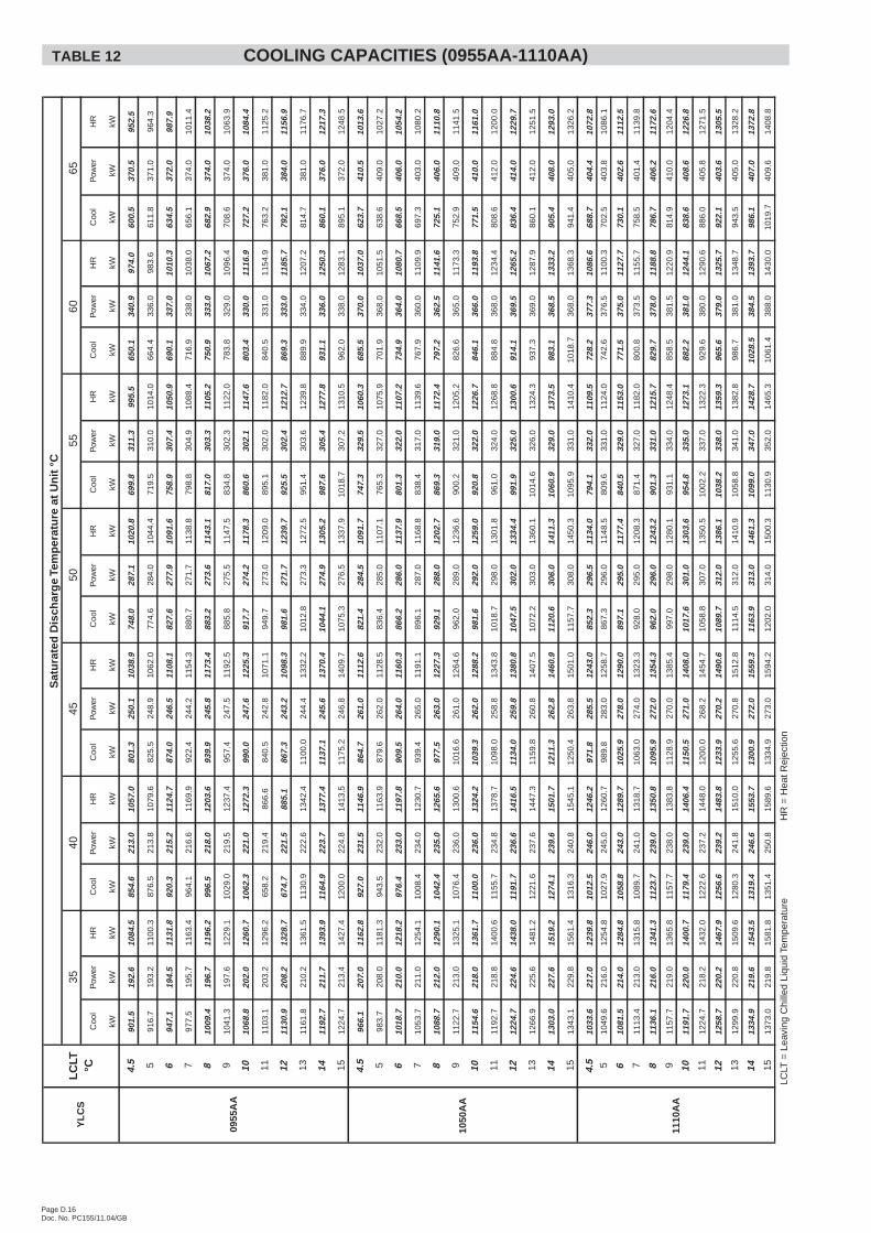
Page D.16Doc. No. PC155/11.04/GB
Coo
lP
ower
HR
Coo
lP
ower
HR
Coo
lP
ower
HR
Coo
lP
ower
HR
Coo
lP
ower
HR
Coo
lP
ower
HR
Coo
lP
ower
HR
kWkW
kWkW
kWkW
kWkW
kWkW
kWkW
kWkW
kWkW
kWkW
kWkW
kW
4.5
901.
519
2.6
1084
.585
4.6
213.
010
57.0
801.
325
0.1
1038
.974
8.0
287.
110
20.8
699.
831
1.3
995.
565
0.1
340.
997
4.0
600.
537
0.5
952.
5
591
6.7
193.
211
00.3
876.
521
3.8
1079
.682
5.5
248.
910
62.0
774.
628
4.0
1044
.471
9.5
310.
010
14.0
664.
433
6.0
983.
661
1.8
371.
096
4.3
694
7.1
194.
511
31.8
920.
321
5.2
1124
.787
4.0
246.
511
08.1
827.
627
7.9
1091
.675
8.9
307.
410
50.9
690.
133
7.0
1010
.363
4.5
372.
098
7.9
797
7.5
195.
711
63.4
964.
121
6.6
1169
.992
2.4
244.
211
54.3
880.
727
1.7
1138
.879
8.8
304.
910
88.4
716.
933
8.0
1038
.065
6.1
374.
010
11.4
810
09.4
196.
711
96.2
996.
521
8.0
1203
.693
9.9
245.
811
73.4
883.
227
3.6
1143
.181
7.0
303.
311
05.2
750.
933
3.0
1067
.268
2.9
374.
010
38.2
910
41.3
197.
612
29.1
1029
.021
9.5
1237
.495
7.4
247.
511
92.5
885.
827
5.5
1147
.583
4.8
302.
311
22.0
783.
832
9.0
1096
.470
8.6
374.
010
63.9
1010
68.8
202.
012
60.7
1062
.322
1.0
1272
.399
0.0
247.
612
25.3
917.
727
4.2
1178
.386
0.6
302.
111
47.6
803.
433
0.0
1116
.972
7.2
376.
010
84.4
1111
03.1
203.
212
96.2
658.
221
9.4
866.
684
0.5
242.
810
71.1
949.
727
3.0
1209
.089
5.1
302.
011
82.0
840.
533
1.0
1154
.976
3.2
381.
011
25.2
1211
30.9
208.
213
28.7
674.
722
1.5
885.
186
7.3
243.
210
98.3
981.
627
1.7
1239
.792
5.5
302.
412
12.7
869.
333
3.0
1185
.779
2.1
384.
011
56.9
1311
61.8
210.
213
61.5
1130
.922
2.6
1342
.411
00.0
244.
413
32.2
1012
.827
3.3
1272
.595
1.4
303.
612
39.8
889.
933
4.0
1207
.281
4.7
381.
011
76.7
1411
92.7
211.
713
93.9
1164
.922
3.7
1377
.411
37.1
245.
613
70.4
1044
.127
4.9
1305
.298
7.6
305.
412
77.8
931.
133
6.0
1250
.386
0.1
376.
012
17.3
1512
24.7
213.
414
27.4
1200
.022
4.8
1413
.511
75.2
246.
814
09.7
1075
.327
6.5
1337
.910
18.7
307.
213
10.5
962.
033
8.0
1283
.189
5.1
372.
012
48.5
4.5
966.
120
7.0
1162
.892
7.0
231.
511
46.9
864.
726
1.0
1112
.682
1.4
284.
510
91.7
747.
332
9.5
1060
.368
5.5
370.
010
37.0
623.
741
0.5
1013
.6
598
3.7
208.
011
81.3
943.
523
2.0
1163
.987
9.6
262.
011
28.5
836.
428
5.0
1107
.176
5.3
327.
010
75.9
701.
936
8.0
1051
.563
8.6
409.
010
27.2
610
18.7
210.
012
18.2
976.
423
3.0
1197
.890
9.5
264.
011
60.3
866.
228
6.0
1137
.980
1.3
322.
011
07.2
734.
936
4.0
1080
.766
8.5
406.
010
54.2
710
53.7
211.
012
54.1
1008
.423
4.0
1230
.793
9.4
265.
011
91.1
896.
128
7.0
1168
.883
8.4
317.
011
39.6
767.
936
0.0
1109
.969
7.3
403.
010
80.2
810
88.7
212.
012
90.1
1042
.423
5.0
1265
.697
7.5
263.
012
27.3
929.
128
8.0
1202
.786
9.3
319.
011
72.4
797.
236
2.5
1141
.672
5.1
406.
011
10.8
911
22.7
213.
013
25.1
1076
.423
6.0
1300
.610
16.6
261.
012
64.6
962.
028
9.0
1236
.690
0.2
321.
012
05.2
826.
636
5.0
1173
.375
2.9
409.
011
41.5
1011
54.6
218.
013
61.7
1100
.023
6.0
1324
.210
39.3
262.
012
88.2
981.
629
2.0
1259
.092
0.8
322.
012
26.7
846.
136
6.0
1193
.877
1.5
410.
011
61.0
1111
92.7
218.
814
00.6
1155
.723
4.8
1378
.710
98.0
258.
813
43.8
1018
.729
8.0
1301
.896
1.0
324.
012
68.8
884.
836
8.0
1234
.480
8.6
412.
012
00.0
1212
24.7
224.
614
38.0
1191
.723
6.6
1416
.511
34.0
259.
813
80.8
1047
.530
2.0
1334
.499
1.9
325.
013
00.6
914.
136
9.5
1265
.283
6.4
414.
012
29.7
1312
66.9
225.
614
81.2
1221
.623
7.6
1447
.311
59.8
260.
814
07.5
1072
.230
3.0
1360
.110
14.6
326.
013
24.3
937.
336
9.0
1287
.986
0.1
412.
012
51.5
1413
03.0
227.
615
19.2
1274
.123
9.6
1501
.712
11.3
262.
814
60.9
1120
.630
6.0
1411
.310
60.9
329.
013
73.5
983.
136
8.5
1333
.290
5.4
408.
012
93.0
1513
43.1
229.
815
61.4
1316
.324
0.8
1545
.112
50.4
263.
815
01.0
1157
.730
8.0
1450
.310
95.9
331.
014
10.4
1018
.736
8.0
1368
.394
1.4
405.
013
26.2
4.5
1033
.621
7.0
1239
.810
12.5
246.
012
46.2
971.
828
5.5
1243
.085
2.3
296.
511
34.0
794.
133
2.0
1109
.572
8.2
377.
310
86.6
688.
740
4.4
1072
.8
510
49.6
216.
012
54.8
1027
.924
5.0
1260
.798
9.8
283.
012
58.7
867.
329
6.0
1148
.580
9.6
331.
011
24.0
742.
637
6.5
1100
.370
2.5
403.
810
86.1
610
81.5
214.
012
84.8
1058
.824
3.0
1289
.710
25.9
278.
012
90.0
897.
129
5.0
1177
.484
0.5
329.
011
53.0
771.
537
5.0
1127
.773
0.1
402.
611
12.5
711
13.4
213.
013
15.8
1089
.724
1.0
1318
.710
63.0
274.
013
23.3
928.
029
5.0
1208
.387
1.4
327.
011
82.0
800.
837
3.5
1155
.775
8.5
401.
411
39.8
811
36.1
216.
013
41.3
1123
.723
9.0
1350
.810
95.9
272.
013
54.3
962.
029
6.0
1243
.290
1.3
331.
012
15.7
829.
737
8.0
1188
.878
6.7
406.
211
72.6
911
57.7
219.
013
65.8
1157
.723
8.0
1383
.811
28.9
270.
013
85.4
997.
029
8.0
1280
.193
1.1
334.
012
48.4
858.
538
1.5
1220
.981
4.9
410.
012
04.4
1011
91.7
220.
014
00.7
1179
.423
9.0
1406
.411
50.5
271.
014
08.0
1017
.630
1.0
1303
.695
4.8
335.
012
73.1
882.
238
1.0
1244
.183
8.6
408.
612
26.8
1112
24.7
218.
214
32.0
1222
.623
7.2
1448
.012
00.0
268.
214
54.7
1058
.830
7.0
1350
.510
02.2
337.
013
22.3
929.
638
0.0
1290
.688
6.0
405.
812
71.5
1212
58.7
220.
214
67.9
1256
.623
9.2
1483
.812
33.9
270.
214
90.6
1089
.731
2.0
1386
.110
38.2
338.
013
59.3
965.
637
9.0
1325
.792
2.1
403.
613
05.5
1312
99.9
220.
815
09.6
1280
.324
1.8
1510
.012
55.6
270.
815
12.8
1114
.531
2.0
1410
.910
58.8
341.
013
82.8
986.
738
1.0
1348
.794
3.5
405.
013
28.2
1413
34.9
219.
615
43.5
1319
.424
6.6
1553
.713
00.9
272.
015
59.3
1163
.931
3.0
1461
.310
99.0
347.
014
28.7
1028
.538
4.5
1393
.798
6.1
407.
013
72.8
1513
73.0
219.
815
81.8
1351
.425
0.8
1589
.613
34.9
273.
015
94.2
1202
.031
4.0
1500
.311
30.9
352.
014
65.3
1061
.438
8.0
1430
.010
19.7
409.
614
08.8
LCLT
=Le
avin
gC
hille
dLi
quid
Tem
pera
ture
HR
=H
eatR
ejec
tion
1050
AA
1110
AA
YL
CS
LC
LT°C
0955
AA
Sat
ura
ted
Dis
char
ge
Tem
per
atu
reat
Un
it°C
3540
4550
5560
65TABLE 12 COOLING CAPACITIES (0955AA-1110AA)
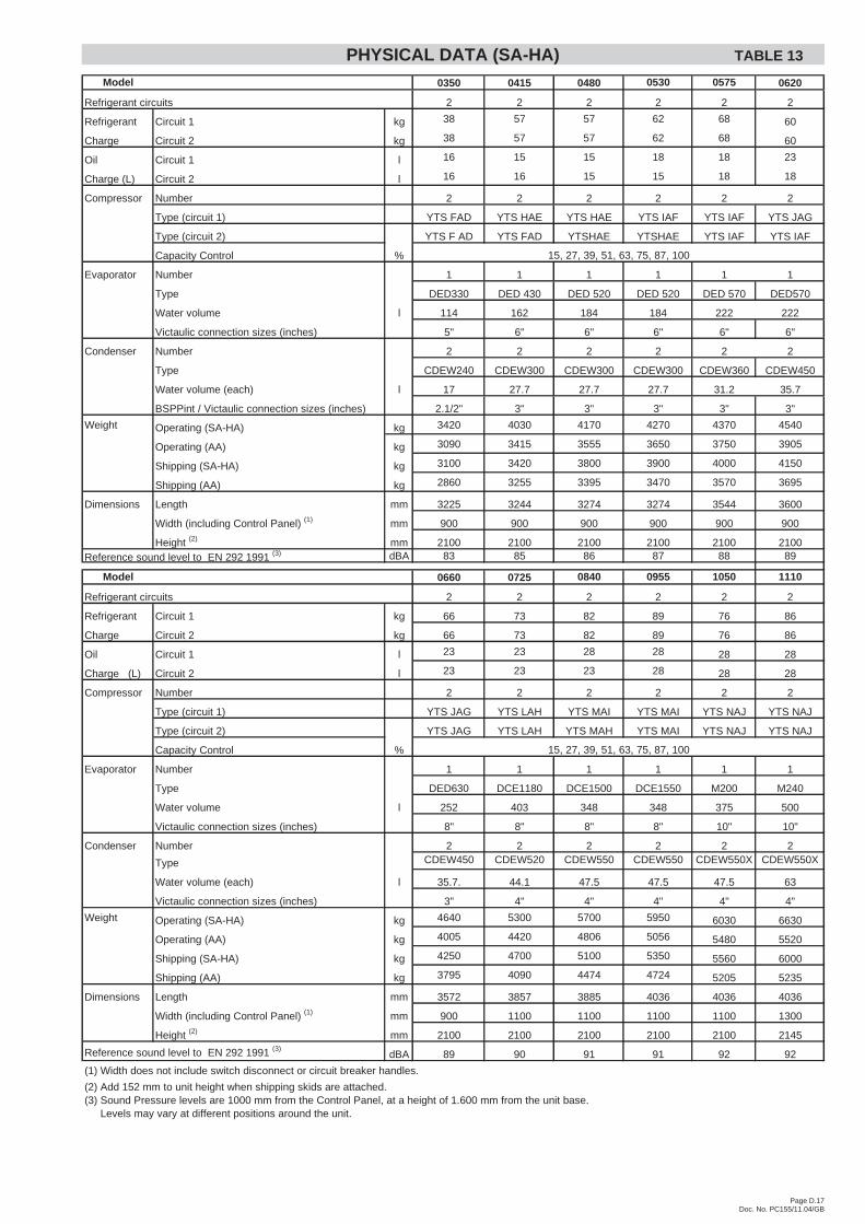
Page D.17Doc. No. PC155/11.04/GB
Model 0350 0415 0480 0530 0575 0620
Refrigerant circuits 2 2 2 2 2 2
Refrigerant Circuit 1 kg 38 57 57 62 68 60
Charge Circuit 2 kg 38 57 57 62 68 60
Oil Circuit 1 l 16 15 15 18 18 23
Charge (L) Circuit 2 l 16 16 15 15 18 18
Compressor Number 2 2 2 2 2 2
Type (circuit 1) YTS FAD YTS HAE YTS HAE YTS IAF YTS IAF YTS JAG
Type (circuit 2) YTS F AD YTS FAD YTSHAE YTSHAE YTS IAF YTS IAF
Capacity Control %
Evaporator Number 1 1 1 1 1 1
Type DED330 DED 430 DED 520 DED 520 DED 570 DED570
Water volume l 114 162 184 184 222 222
Victaulic connection sizes (inches) 5" 6" 6" 6" 6" 6"
Condenser Number 2 2 2 2 2 2
Type CDEW240 CDEW300 CDEW300 CDEW300 CDEW360 CDEW450
Water volume (each) l 17 27.7 27.7 27.7 31.2 35.7
BSPPint / Victaulic connection sizes (inches) 2.1/2" 3" 3" 3" 3" 3"
Weight Operating (SA-HA) kg 3420 4030 4170 4270 4370 4540
Operating (AA) kg 3090 3415 3555 3650 3750 3905
Shipping (SA-HA) kg 3100 3420 3800 3900 4000 4150
Shipping (AA) kg 2860 3255 3395 3470 3570 3695
Dimensions Length mm 3225 3244 3274 3274 3544 3600
Width (including Control Panel) (1) mm 900 900 900 900 900 900
Height (2) mm 2100 2100 2100 2100 2100 2100Reference sound level to EN 292 1991 (3) dBA 83 85 86 87 88 89
Model 0660 0725 0840 0955 1050 1110
Refrigerant circuits 2 2 2 2 2 2
Refrigerant Circuit 1 kg 66 73 82 89 76 86
Charge Circuit 2 kg 66 73 82 89 76 86
Oil Circuit 1 l 23 23 28 28 28 28
Charge (L) Circuit 2 l 23 23 23 28 28 28
Compressor Number 2 2 2 2 2 2
Type (circuit 1) YTS JAG YTS LAH YTS MAI YTS MAI YTS NAJ YTS NAJ
Type (circuit 2) YTS JAG YTS LAH YTS MAH YTS MAI YTS NAJ YTS NAJ
Capacity Control %
Evaporator Number 1 1 1 1 1 1
Type DED630 DCE1180 DCE1500 DCE1550 M200 M240
Water volume l 252 403 348 348 375 500
Victaulic connection sizes (inches) 8" 8" 8" 8" 10" 10"
Condenser Number 2 2 2 2 2 2
Type CDEW450 CDEW520 CDEW550 CDEW550 CDEW550X CDEW550X
Water volume (each) l 35.7. 44.1 47.5 47.5 47.5 63
Victaulic connection sizes (inches) 3" 4" 4" 4" 4" 4"
Weight Operating (SA-HA) kg 4640 5300 5700 5950 6030 6630
Operating (AA) kg 4005 4420 4806 5056 5480 5520
Shipping (SA-HA) kg 4250 4700 5100 5350 5560 6000
Shipping (AA) kg 3795 4090 4474 4724 5205 5235
Dimensions Length mm 3572 3857 3885 4036 4036 4036
Width (including Control Panel) (1) mm 900 1100 1100 1100 1100 1300
Height (2) mm 2100 2100 2100 2100 2100 2145
Reference sound level to EN 292 1991 (3)dBA 89 90 91 91 92 92
(1) Width does not include switch disconnect or circuit breaker handles.
(2) Add 152 mm to unit height when shipping skids are attached.(3) Sound Pressure levels are 1000 mm from the Control Panel, at a height of 1.600 mm from the unit base.(3) Levels may vary at different positions around the unit.
15, 27, 39, 51, 63, 75, 87, 100
15, 27, 39, 51, 63, 75, 87, 100
PHYSICAL DATA (SA-HA) TABLE 13
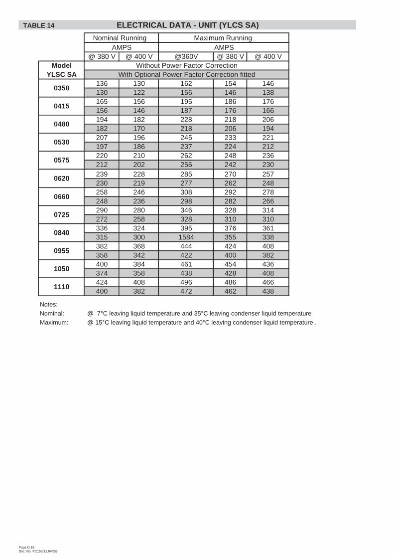
Page D.18Doc. No. PC155/11.04/GB
@ 380 V @ 400 V @360V @ 380 V @ 400 VModel
YLSC SA136 130 162 154 146130 122 156 146 138165 156 195 186 176156 146 187 176 166194 182 228 218 206182 170 218 206 194207 196 245 233 221197 186 237 224 212220 210 262 248 236212 202 256 242 230239 228 285 270 257230 219 277 262 248258 246 308 292 278248 236 298 282 266290 280 346 328 314272 258 328 310 310336 324 395 376 361315 300 1584 355 338382 368 444 424 408358 342 422 400 382400 384 461 454 436374 358 438 428 408424 408 496 486 466400 382 472 462 438
Notes:
Nominal: @ 7°C leaving liquid temperature and 35°C leaving condenser liquid temperature
Maximum: @ 15°C leaving liquid temperature and 40°C leaving condenser liquid temperature .
1050
1110
0530
0480
0575
0620
0660
0725
0840
0955
Maximum Running
With Optional Power Factor Correction fittedWithout Power Factor Correction
0415
AMPSNominal Running
0350
AMPS
TABLE 14 ELECTRICAL DATA - UNIT (YLCS SA)
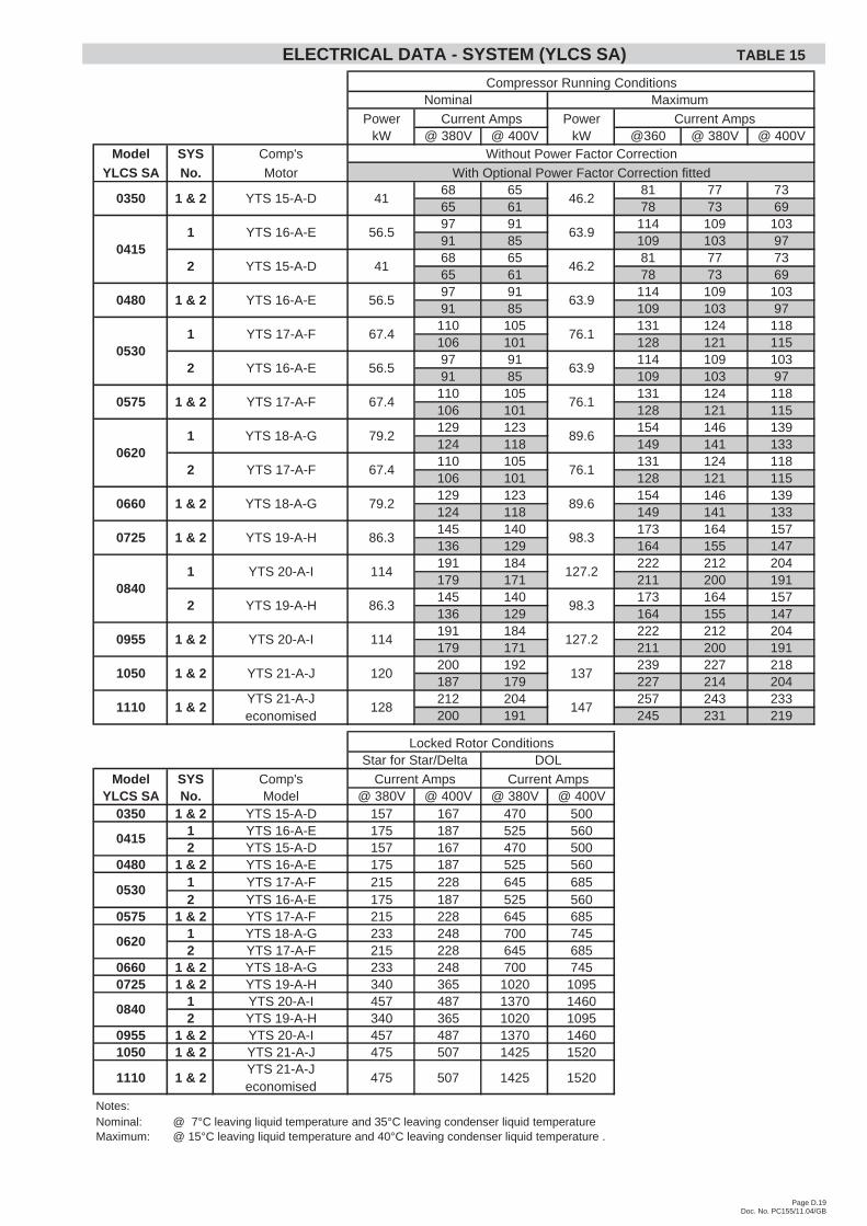
Page D.19Doc. No. PC155/11.04/GB
Power PowerkW @ 380V @ 400V kW @360 @ 380V @ 400V
Model SYS Comp's
YLCS SA No. Motor68 65 81 77 7365 61 78 73 6997 91 114 109 10391 85 109 103 9768 65 81 77 7365 61 78 73 6997 91 114 109 10391 85 109 103 97
110 105 131 124 118106 101 128 121 11597 91 114 109 10391 85 109 103 97
110 105 131 124 118106 101 128 121 115129 123 154 146 139124 118 149 141 133110 105 131 124 118106 101 128 121 115129 123 154 146 139124 118 149 141 133145 140 173 164 157136 129 164 155 147191 184 222 212 204179 171 211 200 191145 140 173 164 157136 129 164 155 147191 184 222 212 204179 171 211 200 191200 192 239 227 218187 179 227 214 204212 204 257 243 233200 191 245 231 219
Model SYS Comp'sYLCS SA No. Model @ 380V @ 400V @ 380V @ 400V
0350 1 & 2 YTS 15-A-D 157 167 470 5001 YTS 16-A-E 175 187 525 5602 YTS 15-A-D 157 167 470 500
0480 1 & 2 YTS 16-A-E 175 187 525 5601 YTS 17-A-F 215 228 645 6852 YTS 16-A-E 175 187 525 560
0575 1 & 2 YTS 17-A-F 215 228 645 6851 YTS 18-A-G 233 248 700 7452 YTS 17-A-F 215 228 645 685
0660 1 & 2 YTS 18-A-G 233 248 700 7450725 1 & 2 YTS 19-A-H 340 365 1020 1095
1 YTS 20-A-I 457 487 1370 14602 YTS 19-A-H 340 365 1020 1095
0955 1 & 2 YTS 20-A-I 457 487 1370 14601050 1 & 2 YTS 21-A-J 475 507 1425 1520
1110 1 & 2YTS 21-A-Jeconomised
475 507 1425 1520
Notes:Nominal: @ 7°C leaving liquid temperature and 35°C leaving condenser liquid temperatureMaximum: @ 15°C leaving liquid temperature and 40°C leaving condenser liquid temperature .
YTS 17-A-F
56.5 63.9
67.4 76.1
67.4 76.1
56.5 63.9
YTS 16-A-E
46.22 41
63.956.5
46.2
MaximumCompressor Running Conditions
Current Amps
Nominal
Current Amps
Without Power Factor Correction
With Optional Power Factor Correction fitted
410350
YTS 15-A-D
YTS 16-A-E
YTS 15-A-D1 & 2
04151
0575 1 & 2
05301 YTS 17-A-F
2 YTS 16-A-E
0480 1 & 2
06201 YTS 18-A-G 79.2 89.6
2 YTS 17-A-F 67.4 76.1
0725 1 & 2 YTS 19-A-H 86.3
127.2
2 YTS 19-A-H 86.3 98.3
89.6
0955 1 & 2 YTS 20-A-I 114
98.3
08401 YTS 20-A-I 114
0660 1 & 2 YTS 18-A-G 79.2
0530
0620
0840
127.2
Current Amps
Locked Rotor ConditionsStar for Star/Delta DOL
0415
Current Amps
137
1110 1 & 2YTS 21-A-Jeconomised
128 147
1050 1 & 2 YTS 21-A-J 120
ELECTRICAL DATA - SYSTEM (YLCS SA) TABLE 15
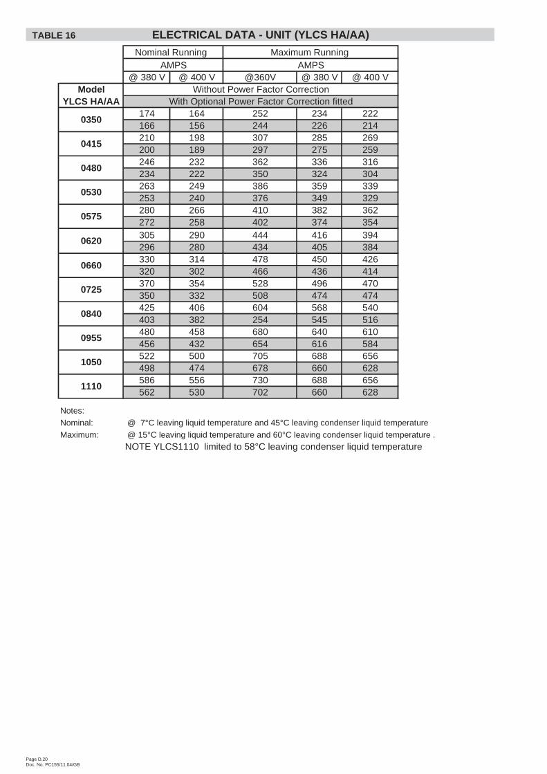
Page D.20Doc. No. PC155/11.04/GB
@ 380 V @ 400 V @360V @ 380 V @ 400 VModel
YLCS HA/AA174 164 252 234 222166 156 244 226 214210 198 307 285 269200 189 297 275 259246 232 362 336 316234 222 350 324 304263 249 386 359 339253 240 376 349 329280 266 410 382 362272 258 402 374 354305 290 444 416 394296 280 434 405 384330 314 478 450 426320 302 466 436 414370 354 528 496 470350 332 508 474 474425 406 604 568 540403 382 254 545 516480 458 680 640 610456 432 654 616 584522 500 705 688 656498 474 678 660 628586 556 730 688 656562 530 702 660 628
Notes:
Nominal: @ 7°C leaving liquid temperature and 45°C leaving condenser liquid temperature
Maximum: @ 15°C leaving liquid temperature and 60°C leaving condenser liquid temperature .
NOTE YLCS1110 limited to 58°C leaving condenser liquid temperature
1050
1110
0530
0480
0575
0620
0660
0725
0840
0955
Maximum Running
With Optional Power Factor Correction fittedWithout Power Factor Correction
0415
AMPSNominal Running
0350
AMPS
TABLE 16 ELECTRICAL DATA - UNIT (YLCS HA/AA)

Page D.21Doc. No. PC155/11.04/GB
Power PowerkW @ 380V @ 400V kW @360 @ 380V @ 400V
Model SYS Comp's
YLCS HA/AA No. Motor87 82 126 117 11183 78 122 113 107
123 116 181 168 158117 111 175 162 15287 82 126 117 11183 78 122 113 107
123 116 181 168 158117 111 175 162 152140 133 205 191 181136 129 201 187 177123 116 181 168 158117 111 175 162 152140 133 205 191 181136 129 201 187 177165 157 239 225 213160 151 233 218 207140 133 205 191 181136 129 201 187 177165 157 239 225 213160 151 233 218 207185 177 264 248 235175 166 254 237 224240 229 340 320 305228 216 327 308 292185 177 264 248 235175 166 254 237 224240 229 340 320 305228 216 327 308 292261 250 365 344 328249 237 351 330 314293 278 365 344 328281 265 351 330 314
Model SYS Comp'sYLCS HA/AA No. Model @ 380V @ 400V @ 380V @ 400V
0350 1 & 2 YTS 15-A-D 157 167 470 5001 YTS 16-A-E 175 187 525 5602 YTS 15-A-D 157 167 470 500
0480 1 & 2 YTS 16-A-E 175 187 525 5601 YTS 17-A-F 215 228 645 6852 YTS 16-A-E 175 187 525 560
0575 1 & 2 YTS 17-A-F 215 228 645 6851 YTS 18-A-G 233 248 700 7452 YTS 17-A-F 215 228 645 685
0660 1 & 2 YTS 18-A-G 233 248 700 7450725 1 & 2 YTS 19-A-H 340 365 1020 1095
1 YTS 20-A-I 457 487 1370 14602 YTS 19-A-H 340 365 1020 1095
0955 1 & 2 YTS 20-A-I 457 487 1370 14601050 1 & 2 YTS 21-A-J 475 507 1425 1520
1110 1 & 2YTS 21-A-Jeconomised
475 507 1425 1520
Notes:
Nominal: @ 7°C leaving liquid temperature and 45°C leaving condenser liquid temperature
Maximum: @ 15°C leaving liquid temperature and 60°C leaving condenser liquid temperature .
NOTE YLCS1110 limited to 58°C leaving condenser liquid temperature
YTS 17-A-F
72.1 96.5
85.5 115
85.5 115
72.1 96.5
YTS 16-A-E
69.82 52.1
96.572.1
69.8
MaximumCompressor Running Conditions
Current Amps
Nominal
Current Amps
Without Power Factor Correction
With Optional Power Factor Correction fitted
52.10350
YTS 15-A-D
YTS 16-A-E
YTS 15-A-D1 & 2
04151
0575 1 & 2
05301 YTS 17-A-F
2 YTS 16-A-E
0480 1 & 2
06201 YTS 18-A-G 101 135
2 YTS 17-A-F 85.5 115
0725 1 & 2 YTS 19-A-H 111
192
2 YTS 19-A-H 111 148
135
0955 1 & 2 YTS 20-A-I 144
148
08401 YTS 20-A-I 144
0660 1 & 2 YTS 18-A-G 101
0530
0620
0840
192
Current Amps
Locked Rotor ConditionsStar for Star/Delta DOL
0415
Current Amps
207
1110 1 & 2YTS 21-A-Jeconomised
168 207
1050 1 & 2 YTS 21-A-J 158
ELECTRICAL DATA - SYSTEM (YLCS HA/AA) TABLE 17
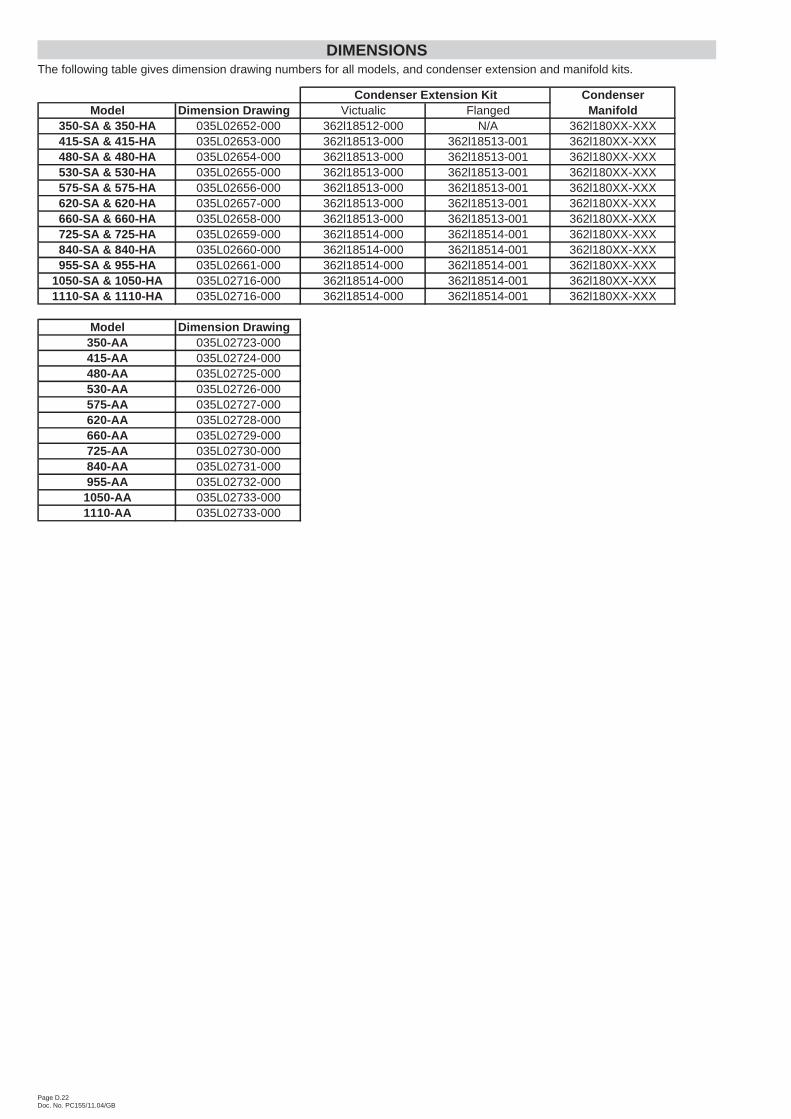
DIMENSIONSThe following table gives dimension drawing numbers for all models, and condenser extension and manifold kits.
Page D.22Doc. No. PC155/11.04/GB
CondenserModel Dimension Drawing Victualic Flanged Manifold
350-SA & 350-HA 035L02652-000 362l18512-000 N/A 362l180XX-XXX415-SA & 415-HA 035L02653-000 362l18513-000 362l18513-001 362l180XX-XXX480-SA & 480-HA 035L02654-000 362l18513-000 362l18513-001 362l180XX-XXX530-SA & 530-HA 035L02655-000 362l18513-000 362l18513-001 362l180XX-XXX575-SA & 575-HA 035L02656-000 362l18513-000 362l18513-001 362l180XX-XXX620-SA & 620-HA 035L02657-000 362l18513-000 362l18513-001 362l180XX-XXX660-SA & 660-HA 035L02658-000 362l18513-000 362l18513-001 362l180XX-XXX725-SA & 725-HA 035L02659-000 362l18514-000 362l18514-001 362l180XX-XXX840-SA & 840-HA 035L02660-000 362l18514-000 362l18514-001 362l180XX-XXX955-SA & 955-HA 035L02661-000 362l18514-000 362l18514-001 362l180XX-XXX
1050-SA & 1050-HA 035L02716-000 362l18514-000 362l18514-001 362l180XX-XXX1110-SA & 1110-HA 035L02716-000 362l18514-000 362l18514-001 362l180XX-XXX
Model Dimension Drawing350-AA 035L02723-000415-AA 035L02724-000480-AA 035L02725-000530-AA 035L02726-000575-AA 035L02727-000620-AA 035L02728-000660-AA 035L02729-000725-AA 035L02730-000840-AA 035L02731-000955-AA 035L02732-000
1050-AA 035L02733-0001110-AA 035L02733-000
Condenser Extension Kit
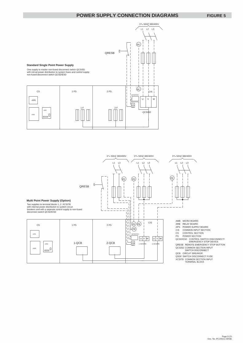
POWER SUPPLY CONNECTION DIAGRAMS FIGURE 5
Page D.23Doc. No. PC155/11.04/GB
U V W
1 PS 2 PS CISCS
3 50HZ 380/400V
3
4
QRESB
PE
PE
CS 1 PS 2 PS
43
PECIS
QRESB
PE
2-F1-F
PE
PE
U V W U V W
1-QCB 2-QCB
L1 L3 L1 L2 L3 L1 L2 L3
L1 L2 L3
-QCSD/ESD
-QCSISD
1-XCSITB 2-XCSITB
-APB
-AMB
-ARB
-APB
-AMB
-ARB
Standard Single Point Power Supply
Multi Point Power Supply (Option)Two supplies to terminal blocks 1, 2 -XCSITBwith internal power distribution to system circuitbreakers and with a seperate control supply to non-fuseddisconnect switch QCSD/ESD
-QCSD/ESD
One supply to master non-fused disconnect switch QCSISDwith intrnal power distribution to system fuses and control supplynon-fused disconnect switch QCSD/ESD
PE
PE
3 50HZ 380/400V 3 50HZ 380/400V 3 50HZ 380/400V
AMB MICRO BOARDARB RELAY BOARDAPS POWER SUPPLY BOARDCIS COMMON INPUT SECTIONCS CONTROL SECTIONPS POWER SECTIONQCSD/ESD CONTROL SWITCH DISCONNECT/
EMERGENCY STOP DEVICEQRESB REMOTE EMERGENCY STOP BUTTONQCSISD COMMON SECTION INPUT
SWITCH DISCONNECTQCB CIRCUIT BREAKERQSDF SWITCH DISCONNECT FUSEXCSITB COMMON SECTION INPUT
TERMINAL BLOCK
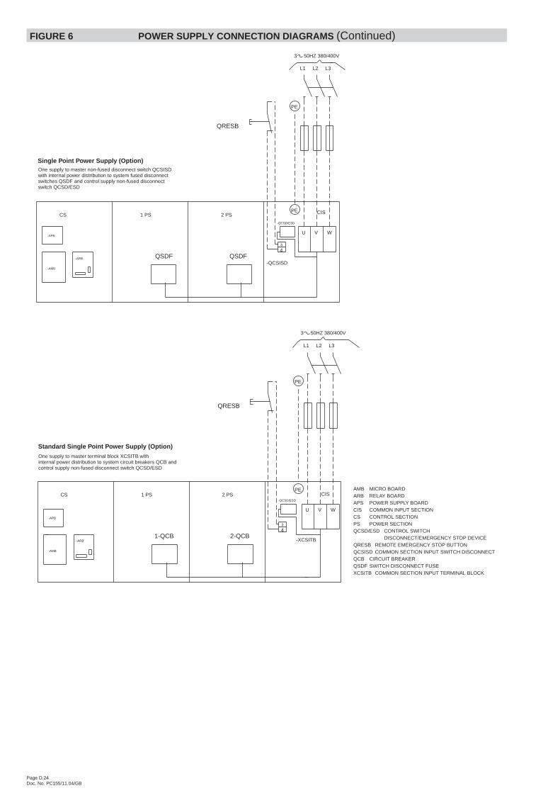
FIGURE 6 POWER SUPPLY CONNECTION DIAGRAMS (Continued)
Page D.24Doc. No. PC155/11.04/GB
CS 1 PS 2 PS
3
4
VU W
CIS
3 50HZ 380/400V
QRESB
QSDF QSDF
PE
PE
CS 1 PS 2 PS
43
U V W
PECIS
QRESB
PE
-XCSITB2-QCB1-QCB
L1 L2 L3
L1 L2 L3
-QCSISD
-APB
-AMB
-ARB
-APB
-AMB
-ARB
Standard Single Point Power Supply (Option)One supply to master terminal block XCSITB withinternal power distribution to system circuit breakers QCB andcontrol supply non-fused disconnect switch QCSD/ESD
-QCSD/ESD
One supply to master non-fused disconnect switch QCSISDwith internal power distribution to system fused disconnectswitches QSDF and control supply non-fused disconnectswitch QCSD/ESD
-QCSD/ESD
Single Point Power Supply (Option)
3 50HZ 380/400V
AMB MICRO BOARDARB RELAY BOARDAPS POWER SUPPLY BOARDCIS COMMON INPUT SECTIONCS CONTROL SECTIONPS POWER SECTIONQCSD/ESD CONTROL SWITCH
DISCONNECT/EMERGENCY STOP DEVICEQRESB REMOTE EMERGENCY STOP BUTTONQCSISD COMMON SECTION INPUT SWITCH DISCONNECTQCB CIRCUIT BREAKERQSDF SWITCH DISCONNECT FUSEXCSITB COMMON SECTION INPUT TERMINAL BLOCK
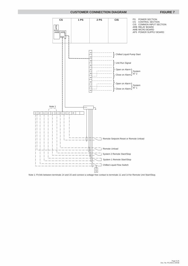
CUSTOMER CONNECTION DIAGRAM FIGURE 7
Page D.25Doc. No. PC155/11.04/GB
CS 1 PS 2 PS CIS
Note 1: Fit link between terminals 14 and 15 and connect a voltage free contact to terminals 11 and 14 for Remote Unit Start/Stop.
13 10 11 14 12 15 16 13 17 20
Note 1
Chilled Liquid Flow Switch
System 1 Remote Start/Stop
System 2 Remote Start/Stop
Remote Setpoint Reset or Remote Unload
Remote Unload
AMB ARB
AP
B
Unit Run Signal
32
31
30
39
37
35
38
Chilled Liquid Pump Start
Close on Alarm
SystemN° 1
Open on Alarm }
}}
}}}
}
36
33
34
Close on Alarm
SystemN° 2
Open on Alarm }
PS POWER SECTIONCS CONTROL SECTIONCIS COMMON INPUT SECTIONARB RELAY BOARDAMB MICRO BOARDAPS POWER SUPPLY BOARD
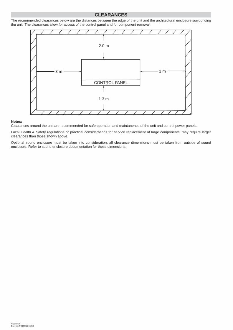
CLEARANCESThe recommended clearances below are the distances between the edge of the unit and the architectural enclosure surroundingthe unit. The clearances allow for access of the control panel and for component removal.
Notes:Clearances around the unit are recommended for safe operation and maintanence of the unit and control power panels.
Local Health & Safety regulations or practical considerations for service replacement of large components, may require largerclearances than those shown above.
Optional sound enclosure must be taken into consideration, all clearance dimensions must be taken from outside of soundenclosure. Refer to sound enclosure documentation for these dimensions.
Page D.26Doc. No. PC155/11.04/GB
2.0 m
1.3 m
3 m 1 m
CONTROL PANEL
Related Documents


![f V..V . >UTA - Islamwaybooks.islamway.net/1/4125/15_GQAlHamad_Dhahd.pdf · AilX^ ^ (3?^ ^ 4»4l jioJU Ajs^ yt y 4l..ylCS^i J ^ (jO_^;>«l]ij JUJb^dl) Ajb^ A-aJlAa ^ a) La 4^](https://static.cupdf.com/doc/110x72/5a709db57f8b9ab1538c1e62/f-vv-uta-islamwaybooksislamwaynet1412515gqalhamaddhahdpdfpdf.jpg)


