EWF0127300 E47 Ver. 3.00 YAMAHA SCARA ROBOT Installation Manual YK-XG Series YK250XG / YK350XG / YK400XG YK500XGL / YK600XGL YK500XG / YK600XG / YK600XGH YK700XG / YK800XG / YK900XG / YK1000XG YK500XGS / YK600XGS YK700XGS / YK800XGS / YK900XGS / YK1000XGS

Welcome message from author
This document is posted to help you gain knowledge. Please leave a comment to let me know what you think about it! Share it to your friends and learn new things together.
Transcript

Ver. 1.09
EWF0127300
E47Ver. 3.00
YAMAHA SCARA ROBOT
Installation ManualYK-XG SeriesYK250XG / YK350XG / YK400XG
YK500XGL / YK600XGLYK500XG / YK600XG / YK600XGH
YK700XG / YK800XG / YK900XG / YK1000XGYK500XGS / YK600XGS
YK700XGS / YK800XGS / YK900XGS / YK1000XGS

CONTENTS YK-XGInstallation Manual
T-1
Safety Instructions
1. Safety Information S-1
2. Signal words used in this manual S-2
3. Warning labels S-3
3.1 Warning labels S-3
3.1.1 Warning label messages S-3
3.1.2 Supplied warning labels S-5
3.2 Warning symbols S-6
4. Major precautions for each stage of use S-7
4.1 Precautions for using robots and controllers S-7
4.2 Design S-8
4.2.1 Precautions for robots S-8
4.2.2 Precautions for robot controllers S-8
4.3 Moving and installation S-9
4.3.1 Precautions for robots S-9
4.3.2 Precautions for robot controllers S-10
4.4 Safety measures S-12
4.4.1 Safety measures S-12
4.4.2 Installing a safety enclosure S-13
4.5 Operation S-14
4.5.1 Trial operation S-14
4.5.2 Automatic operation S-16
4.5.3 Precautions during operation S-16
4.6 Inspection and maintenance S-18
4.6.1 Before inspection and maintenance work S-18
4.6.2 Precautions during service work S-19
4.7 Disposal S-20
5. Emergency action when a person is caught by robot S-21
6. Using the robot safely S-22
6.1 Robot safety functions S-22
6.2 Special training for industrial robot operation S-23
Warranty
CONTENTS YK-XGInstallation Manual
T-2 T-3
Introduction
Before using the robot (Be sure to read the following notes.) i
Introduction v
Chapter 1 Functions
1. Robot manipulator 1-1
1.1 Manipulator movement 1-1
1.2 Part names 1-2
2. Robot controller 1-5
3. Robot initialization number list 1-6
Chapter 2 Installation
1. Robot installation conditions 2-1
1.1 Installation environments 2-1
1.2 Installation base 2-2
2. Installation 2-3
2.1 Unpacking 2-3
2.2 Checking the product 2-5
2.3 Moving the robot 2-9
2.3.1 Moving the YK250XG, YK350XG, YK400XG, YK500XGL, and YK600XGL 2-9
2.3.2 Moving the YK500XG, YK600XG, YK600XGH, YK700XG, YK800XG, YK900XG, and YK1000XG 2-10
2.3.3 Moving the YK500XGS and YK600XGS 2-12
2.3.4 Moving the YK700XGS, YK800XGS, YK900XGS, and YK1000XGS 2-17
2.4 Installing the robot 2-22
3. Protective bonding 2-23
4. Robot cable connection 2-24
5. User wiring and user tubing 2-25
6. Attaching the end effector 2-28
6.1 R-axistolerablemomentofinertiaandaccelerationcoefficient 2-28
6.1.1 Acceleration coefficient vs. moment of inertia (YK250XG) 2-29
6.1.2 Acceleration coefficient vs. moment of inertia (YK350XG) 2-30
6.1.3 Acceleration coefficient vs. moment of inertia (YK400XG) 2-31
6.1.4 Acceleration coefficient vs. moment of inertia (YK500XGL) 2-32
T-2
CONTENTS YK-XGInstallation Manual
T-3
6.1.5 Acceleration coefficient vs. moment of inertia (YK600XGL) 2-33
6.1.6 Acceleration coefficient vs. moment of inertia (YK250XG, YK350XG, YK400XG, YK500XGL, YK600XGL) 2-34
6.1.7 Acceleration coefficient vs. moment of inertia (YK500XG, YK500XGS) 2-34
6.1.8 Acceleration coefficient vs. moment of inertia (YK600XG, YK600XGS) 2-35
6.1.9 Acceleration coefficient vs. moment of inertia (YK600XGH) 2-35
6.1.10 Acceleration coefficient vs. moment of inertia (YK700XG, YK800XG, YK700XGS, YK800XGS) 2-36
6.1.11 Acceleration coefficient vs. moment of inertia (YK900XG, YK1000XG, YK900XGS, YK1000XGS) 2-36
6.2 Equation for moment of inertia calculation 2-37
6.3 Example of moment of inertia calculation 2-40
6.4 Attaching the end effector 2-42
6.5 Gripping force of end effector 2-45
7. Limiting the movement range with X-axis and Y-axis mechanical stoppers 2-46
7.1 YK250XG, YK350XG, YK400XG, YK500XGL, YK600XGL 2-46
7.1.1 Installing the X-axis/Y-axis additional mechanical stoppers 2-47
7.1.2 Robot overrun during impacts with X-axis or Y-axis mechanical stopper 2-49
7.2 YK500XG, YK600XG, YK600XGH, YK700XG, YK800XG, YK900XG, YK1000XG YK500XGS, YK600XGS, YK700XGS, YK800XGS, YK900XGS, YK1000XGS 2-50
7.2.1 Changing the X-axis mechanical stopper position 2-54
7.2.2 Changing the Y-axis mechanical stopper position 2-56
7.2.3 Robot overrun during impacts with X-axis or Y-axis mechanical stopper 2-59
8. Limiting the movement range with Z-axis mechanical stopper 2-60
8.1 YK250XG, YK350XG, YK400XG, YK500XGL, YK600XGL 2-60
8.1.1 Installing the minus direction stopper 2-61
8.1.2 Installing the plus direction stopper 2-63
8.1.3 Overrun amounts during impacts with Z-axis additional mechanical stopper 2-64
8.2 YK500XG, YK600XG, YK600XGH, YK700XG, YK800XG, YK900XG, YK1000XG YK500XGS, YK600XGS, YK700XGS, YK800XGS, YK900XGS, YK1000XGS 2-65
8.2.1 Installing the minus direction stopper 2-67
8.2.2 Installing the plus direction stopper 2-69
8.2.3 Overrun amounts during impacts with Z-axis additional mechanical stopper 2-70
9. Working envelope and mechanical stopper positions for maximum working envelope 2-71
10. Stopping time and stopping distance at emergency stop 2-74
10.1 YK250XG, YK350XG, YK400XG, YK500XGL, YK600XGL 2-74
10.2 YK500XG, YK600XG, YK500XGS, YK600XGS 2-80
10.3 YK600XGH, YK700XG, YK800XG, YK900XG, YK1000XG YK700XGS, YK800XGS, YK900XGS, YK1000XGS 2-85
11. Installing the user wiring and tubing newly 2-94
12. Passing the wiring and tubing in the user wiring/tubing through spline type 2-95
CONTENTS YK-XGInstallation Manual
T-4 T-5
13. Detaching or attaching the covers 2-96
14. Installing the extension shaft (for user wiring/tubing through spline type) 2-101
15.Installingthetoolflange 2-103
Chapter 3 Robot settings
1. Overview 3-1
2. Adjusting the origin 3-2
2.1 Absolute reset method 3-2
2.1.1 Sensor method (X-axis, Y-axis, and R-axis) 3-2
2.1.2 Stroke end method (Z-axis) 3-3
2.2 Machine reference 3-3
2.3 Absolute reset procedures 3-4
2.3.1 Sensor method (X-axis, Y-axis, and R-axis) 3-4
2.3.2 Stroke end method (Z-axis) 3-5
2.4 Changing the origin position and adjusting the machine reference 3-7
2.4.1 Sensor method (YK250XG, YK350XG, YK400XG, YK500XGL, YK600XGL) 3-7
2.4.2 Sensor method (YK500XG, YK600XG, YK600XGH, YK700XG, YK800XG, YK900XG, YK1000XG) (YK500XGS, YK600XGS, YK700XGS, YK800XGS, YK900XGS, YK1000XGS) 3-15
2.5 Adjusting the machine reference value of the stroke end method (Z-axis) 3-26
2.5.1 Stroke end method (YK250XG, YK350XG, YK400XG, YK500XGL, YK600XGL) 3-26
2.5.2 Stroke end method (YK500XG, YK600XG, YK600XGH, YK700XG, YK800XG, YK900XG, YK1000XG) (YK500XGS, YK600XGS, YK700XGS, YK800XGS, YK900XGS, YK1000XGS) 3-28
3. Setting the soft limits 3-31
3.1 Setting the X-axis and Y-axis soft limits 3-31
3.2 Setting the Z-axis soft limits 3-32
3.3 Setting the R-axis soft limit 3-32
3.4 Relation between the X, Y, and R-axis movement angle, the Z-axis movement distance and the number of pulses 3-32
4. Setting the standard coordinates 3-33
4.1 Standard coordinate setting using a standard coordinate setup jig 3-34
4.1.1 YK250XG, YK350XG, YK400XG, YK500XGL, YK600XGL 3-34
4.1.2 YK500XG, YK600XG, YK600XGH, YK700XG, YK800XG, YK900XG, YK1000XG YK500XGS, YK600XGS, YK700XGS, YK800XGS, YK900XGS, YK1000XGS 3-35
5.Affixingthestickersfororiginpositions,movementdirections,andaxisnames 3-38
Chapter 4 Periodic inspecition
1. Overview 4-1
2. List of inspection items 4-2
T-4
CONTENTS YK-XGInstallation Manual
T-5
Chapter 5 Harmonic drive replacement period
1. Overview 5-1
2. Replacement period 5-2
Chapter 6 Increasing the robot operating speed
1. Increasing the robot operating speed 6-1
1.1 Increasing speed by arch motion 6-1
1.2 Increasing the speed with the WEIGHT statement 6-3
1.3 Increasing the speed by the tolerance parameter 6-4
1.4 Increasing the speed by the OUT effective position parameter 6-5
Chapter 7 Specifications
1. Manipulator 7-1
1.1 Basicspecification 7-1
1.1.1 YK250XG, YK350XG, YK400XG, YK500XGL, YK600XGL 7-1
1.1.2 YK500XG, YK600XG, YK600XGH, YK700XG, YK800XG, YK900XG, YK1000XG 7-3
1.1.3 YK500XGS, YK600XGS, YK700XGS, YK800XGS, YK900XGS, YK1000XGS 7-5
1.2 External view and dimensions 7-6
1.2.1 YK250XG 7-6
1.2.2 YK350XG 7-10
1.2.3 YK400XG 7-14
1.2.4 YK500XGL 7-18
1.2.5 YK600XGL 7-22
1.2.6 YK500XG 7-26
1.2.7 YK600XG 7-28
1.2.8 YK600XGH 7-30
1.2.9 YK700XG 7-32
1.2.10 YK800XG 7-34
1.2.11 YK900XG 7-36
1.2.12 YK1000XG 7-38
1.2.13 YK500XGS (Wall-mount model) 7-40
1.2.14 YK500XGS (Wall-mount inverse model) 7-42
1.2.15 YK600XGS (Wall-mount model) 7-44
1.2.16 YK600XGS (Wall-mount inverse model) 7-46
1.2.17 YK700XGS (Wall-mount model) 7-48
1.2.18 YK700XGS (Wall-mount inverse model) 7-50
1.2.19 YK800XGS (Wall-mount model) 7-52
1.2.20 YK800XGS (Wall-mount inverse model) 7-54
1.2.21 YK900XGS (Wall-mount model) 7-56

CONTENTS YK-XGInstallation Manual
T-6
1.2.22 YK900XGS (Wall-mount inverse model) 7-58
1.2.23 YK1000XGS (Wall-mount model) 7-60
1.2.24 YK1000XGS (Wall-mount inverse model) 7-62
1.3 Robot inner wiring diagram 7-64
1.4 Wiring table 7-65
Contents
1. Safety Information S-1
2. Signal words used in this manual S-2
3. Warning labels S-3
3.1 Warning labels S-3
3.1.1 Warning label messages S-3
3.1.2 Supplied warning labels S-5
3.2 Warning symbols S-6
4. Major precautions for each stage of use S-7
4.1 Precautions for using robots and controllers S-7
4.2 Design S-8
4.2.1 Precautions for robots S-8
4.2.2 Precautions for robot controllers S-8
4.3 Moving and installation S-9
4.3.1 Precautions for robots S-9
4.3.2 Precautions for robot controllers S-10
4.4 Safety measures S-12
4.4.1 Safety measures S-12
4.4.2 Installing a safety enclosure S-13
4.5 Operation S-14
4.5.1 Trial operation S-14
4.5.2 Automatic operation S-16
4.5.3 Precautions during operation S-16
4.6 Inspection and maintenance S-18
4.6.1 Before inspection and maintenance work S-18
4.6.2 Precautions during service work S-19
4.7 Disposal S-20
5. Emergency action when a person is caught by robot S-21
6. Using the robot safely S-22
6.1 Robot safety functions S-22
6.2 Special training for industrial robot operation S-23
Safety Instructions

Sa
fety Instruc
tions
S-1
1. Safety InformationIndustrial robots are highly programmable, mechanical devices that provide a large degree of freedom when performing various manipulative tasks. To ensure safe and correct use of YAMAHA industrial robots and controllers, carefully read and comply with the safety instructions and precautions in this "Safety Instructions" guide. Failure to take necessary safety measures or incorrect handling may result in trouble or damage to the robot and controller, and also may cause personal injury (to installation personnel, robot operator or service personnel) including fatal accidents.
Before using this product, read this manual and related manuals and take safety precautions to ensure correct handling. The precautions listed in this manual relate to this product. To ensure safety of the user’s final system that includes YAMAHA robots, please take appropriate safety measures as required by the user’s individual system.
To use YAMAHA robots and controllers safely and correctly, always comply with the safety rules and instructions.
• Forspecificsafetyinformationandstandards,refertotheapplicablelocalregulationsandcomplywith the instructions.
• ThismanualandwarninglabelssuppliedwithorattachedtotherobotarewritteninEnglish.Unlessthe robotoperatorsorservicepersonnelunderstandEnglish,donotpermitthemtohandletherobot.
• CautionsregardingtheofficiallanguageofEUcountries ForequipmentthatwillbeinstalledinEUcountries,thelanguageusedforthemanuals,warninglabels, operationscreencharacters,andCEdeclarationsisEnglishonly. WarninglabelsonlyhavepictogramsorelseincludewarningmessagesinEnglish.Inthelattercase, messages in Japanese or other languages might be added.
It is not possible to list all safety items in detail within the limited space of this manual. So please note that it is essential that the user have a full knowledge of safety and also make correct judgments on safety procedures.
Refer to the manual by any of the following methods when installing, operating or adjusting the robot and controller.
1. Install, operate or adjust the robot and controller while referring to the printed version of the manual (available for an additional fee).
2. Install,operateoradjusttherobotandcontrollerwhileviewingtheCD-ROMversionofthemanual on your computer screen.
3. Install, operate or adjust the robot and controller while referring to a printout of the necessary pagesfromtheCD-ROMversionofthemanual.
Sa
fety Instruc
tions
S-2
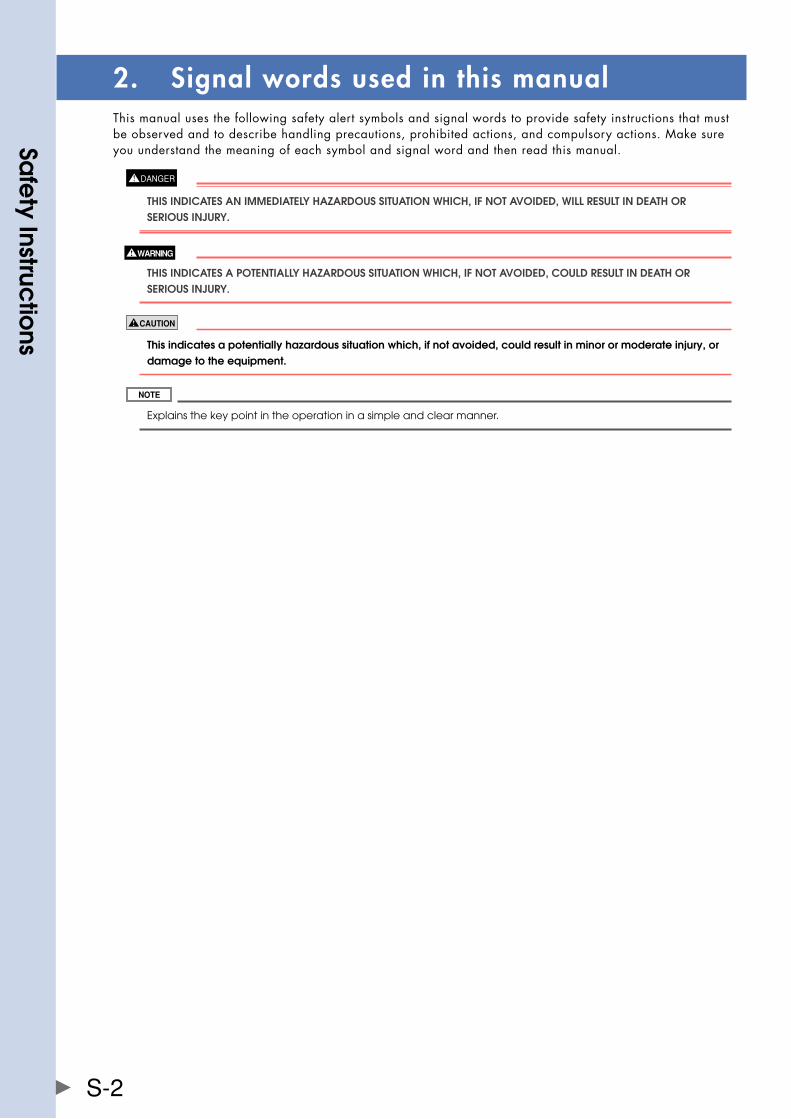
2. Signal words used in this manualThis manual uses the following safety alert symbols and signal words to provide safety instructions that must be observed and to describe handling precautions, prohibited actions, and compulsory actions. Make sure you understand the meaning of each symbol and signal word and then read this manual.
ThIS InDICaTES an IMMEDIaTEly hazaRDOUS SITUaTIOn WhICh, If nOT avOIDED, WIll RESUlT In DEaTh OR SERIOUS InjURy.
ThIS InDICaTES a POTEnTIally hazaRDOUS SITUaTIOn WhICh, If nOT avOIDED, COUlD RESUlT In DEaTh OR SERIOUS InjURy.
This indicates a potentially hazardous situation which, if not avoided, could result in minor or moderate injury, or damage to the equipment.
Explains the key point in the operation in a simple and clear manner.
Sa
fety Instruc
tions
S-3
3. Warning labelsWarning labels shown below are attached to the robot body and controller to alert the operator to potential hazards. To ensure correct use, read the warning labels and comply with the instructions.
3.1 Warning labels
If WaRnIng labElS aRE REMOvED OR DIffICUlT TO SEE, ThEn ThE nECESSaRy PRECaUTIOnS May nOT bE TakEn, RESUlTIng In an aCIDEnT. • Donotremove,alterorstainthewarninglabelsontherobotboDy. • DonotallowwarninglabelstobehiDDenbyDevicesinstalleDontherobotbytheuser. • ProviDeProPerlightingsothatthesymbolsanDinstructionsonthewarninglabelscanbe ClEaRly SEEn fROM OUTSIDE ThE SafETy EnClOSURE.
3.1.1 Warning label messagesWord messages on the danger, warning and caution labels are concise and brief instructions. For more specific instructions, read and follow the "Instructions on this label" described on the right of each label shown below.
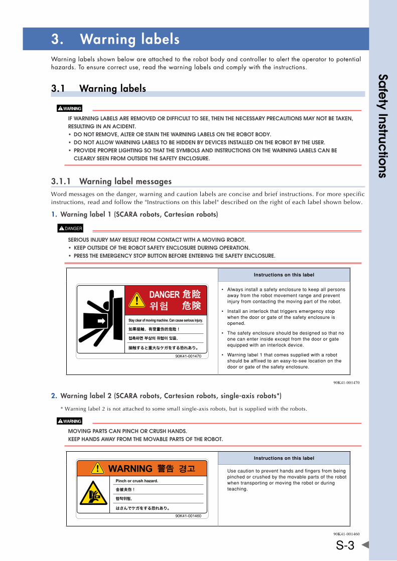
Warning label 1 (SCARA robots, Cartesian robots)1.
SERIOUS InjURy May RESUlT fROM COnTaCT WITh a MOvIng RObOT. • KeePoutsiDeoftherobotsafetyenclosureDuringoPeration. • PresstheemergencystoPbuttonbeforeenteringthesafetyenclosure.
Instructions on this label
• Alwaysinstallasafetyenclosuretokeepallpersonsawayfromtherobotmovementrangeandpreventinjuryfromcontactingthemovingpartoftherobot.
• Installaninterlockthattriggersemergencystopwhenthedoororgateofthesafetyenclosureisopened.
• Thesafetyenclosureshouldbedesignedsothatnoonecanenterinsideexceptfromthedoororgateequippedwithaninterlockdevice.
• Warninglabel1thatcomessuppliedwitharobotshouldbeaffixedtoaneasy-to-seelocationonthedoororgateofthesafetyenclosure.
90K41-001470
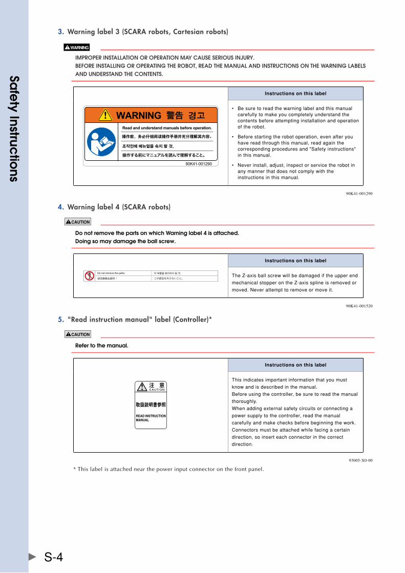
Warning label 2 (SCARA robots, Cartesian robots, single-axis robots*)2.
* Warning label 2 is not attached to some small single-axis robots, but is supplied with the robots.
MOvIng PaRTS Can PInCh OR CRUSh hanDS. kEEP hanDS aWay fROM ThE MOvablE PaRTS Of ThE RObOT.
Instructions on this label
Usecautiontopreventhandsandfingersfrombeingpinchedorcrushedbythemovablepartsoftherobotwhentransportingormovingtherobotorduringteaching.
90K41-001460
Sa
fety Instruc
tions
S-4
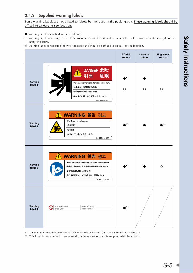
Warning label 3 (SCARA robots, Cartesian robots)3.
IMPROPER InSTallaTIOn OR OPERaTIOn May CaUSE SERIOUS InjURy. bEfORE InSTallIng OR OPERaTIng ThE RObOT, REaD ThE ManUal anD InSTRUCTIOnS On ThE WaRnIng labElS anD UnDERSTanD ThE COnTEnTS.
Instructions on this label
• Besuretoreadthewarninglabelandthismanualcarefullytomakeyoucompletelyunderstandthecontentsbeforeattemptinginstallationandoperationoftherobot.
• Beforestartingtherobotoperation,evenafteryouhavereadthroughthismanual,readagainthecorrespondingproceduresand"Safetyinstructions"inthismanual.
• Neverinstall,adjust,inspectorservicetherobotinanymannerthatdoesnotcomplywiththeinstructionsinthismanual.
90K41-001290
Warning label 4 (SCARA robots)4.
Do not remove the parts on which Warning label 4 is attached. Doing so may damage the ball screw.
Instructions on this label
TheZ-axisballscrewwillbedamagediftheupperend
mechanicalstopperontheZ-axissplineisremovedor
moved.Neverattempttoremoveormoveit.
90K41-001520
"Read instruction manual" label (Controller)*5.
Refer to the manual.
取扱説明書参照
READ INSTRUCTIONMANUAL
Instructions on this label
Thisindicatesimportantinformationthatyoumust
knowandisdescribedinthemanual.
Beforeusingthecontroller,besuretoreadthemanual
thoroughly.
Whenaddingexternalsafetycircuitsorconnectinga
powersupplytothecontroller,readthemanual
carefullyandmakechecksbeforebeginningthework.
Connectorsmustbeattachedwhilefacingacertain
direction,soinserteachconnectorinthecorrect
direction.
93005-X0-00
* This label is attached near the power input connector on the front panel.
Sa
fety Instruc
tions
S-5
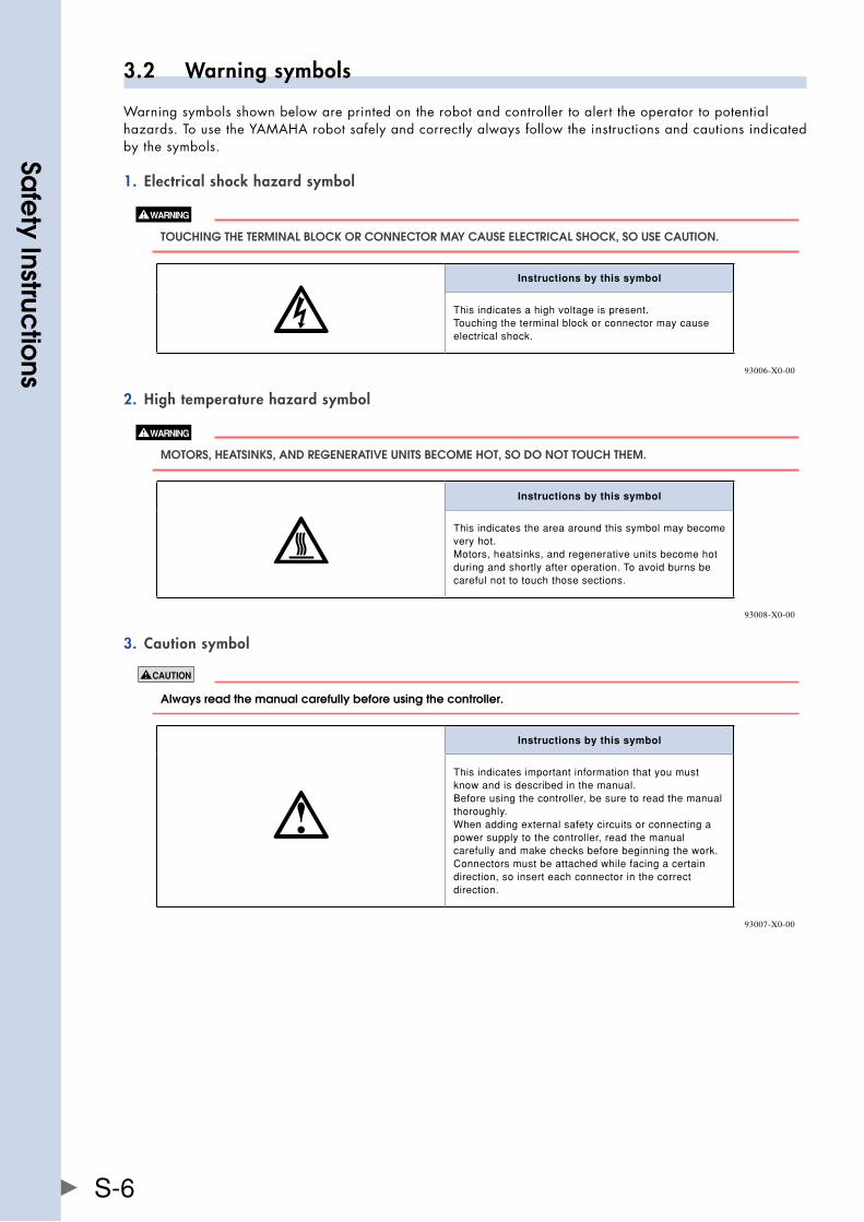
3.1.2 Supplied warning labelsSome warning labels are not affixed to robots but included in the packing box. These warning labels should be affixed to an easy-to-see location.
Warning label is attached to the robot body.
Warning label comes supplied with the robot and should be affixed to an easy-to-see location on the door or gate of the
safety enclosure.
Warning label comes supplied with the robot and should be affixed to an easy-to-see location.
SCARA robots
Cartesian robots
Single-axis robots
Warning label 1
*1
Warning label 2 *1 *2
Warning label 3 *1
Warning label 4 *1
*1: For the label positions, see the SCARA robot user's manual ("1.2 Part names" in Chapter 1).
*2: This label is not attached to some small single-axis robots, but is supplied with the robots.
Sa
fety Instruc
tions
S-6
3.2 Warning symbols
Warning symbols shown below are printed on the robot and controller to alert the operator to potential hazards. To use the YAMAHA robot safely and correctly always follow the instructions and cautions indicated by the symbols.
Electrical shock hazard symbol1.
TOUChIng ThE TERMInal blOCk OR COnnECTOR May CaUSE ElECTRICal ShOCk, SO USE CaUTIOn.
Instructions by this symbol
Thisindicatesahighvoltageispresent.Touchingtheterminalblockorconnectormaycauseelectricalshock.
93006-X0-00
High temperature hazard symbol2.
MOTORS, hEaTSInkS, anD REgEnERaTIvE UnITS bECOME hOT, SO DO nOT TOUCh ThEM.
Instructions by this symbol
Thisindicatestheareaaroundthissymbolmaybecomeveryhot.Motors,heatsinks,andregenerativeunitsbecomehotduringandshortlyafteroperation.Toavoidburnsbecarefulnottotouchthosesections.
93008-X0-00
Caution symbol3.
always read the manual carefully before using the controller.
!
Instructions by this symbol
Thisindicatesimportantinformationthatyoumustknowandisdescribedinthemanual.Beforeusingthecontroller,besuretoreadthemanualthoroughly.Whenaddingexternalsafetycircuitsorconnectingapowersupplytothecontroller,readthemanualcarefullyandmakechecksbeforebeginningthework.Connectorsmustbeattachedwhilefacingacertaindirection,soinserteachconnectorinthecorrectdirection.
93007-X0-00
Sa
fety Instruc
tions
S-7
4. Major precautions for each stage of useThis section describes major precautions that must be observed when using robots and controllers. Be sure to carefully read and comply with all of these precautions even if there is no alert symbol shown.
4.1 Precautions for using robots and controllers
General precautions for using robots and controllers are described below.
Applications where robots cannot be used1.
YAMAHA robots and robot controllers are designed as general-purpose industrial equipment and cannot be used for the
following applications.
yaMaha RObOT COnTROllERS anD RObOTS aRE DESIgnED aS gEnERal-PURPOSE InDUSTRIal EqUIPMEnT anD CannOT bE USED fOR ThE fOllOWIng aPPlICaTIOnS. • inmeDicalequiPmentsystemswhicharecriticaltohumanlife • insystemsthatsignificantlyaffectsocietyanDthegeneralPublic • inequiPmentintenDeDtocarryortransPortPeoPle • inenvironmentswhicharesubjecttovibrationsuchasonboarDshiPsanDvehicles.
Qualification of operators/workers2.
Operators or persons who handle the robot such as for teaching, programming, movement check, inspection, adjustment,
and repair must receive appropriate training and also have the skills needed to perform the job correctly and safely. They
must read the manual carefully to understand its contents before attempting the robot operation or maintenance.
Tasks related to industrial robots (teaching, programming, movement check, inspection, adjustment, repair, etc.) must be
performed by qualified persons who meet requirements established by local regulations and standards for industrial
robots.
• therobotmustbeoPerateDonlybyPersonswhohavereceiveDsafetyanDoPerationtraining. OPERaTIOn by an UnTRaInED PERSOn IS ExTREMEly hazaRDOUS. • aDjustmentanDmaintenancebyremovingacoverrequiresPecializeDtechnicalKnowleDgeanD SkIllS, anD May alSO InvOlvE hazaRDS If aTTEMPTED by an UnSkIllED PERSOn. ThESE TaSkS MUST bE PERfORMED Only by PERSOnS WhO havE EnOUgh abIlITy anD qUalIfICaTIOnS In aCCORDanCE WITh lOCal laWS anD REgUlaTIOnS. fOR DETaIlED InfORMaTIOn, PlEaSE COnTaCT yOUR DISTRIbUTOR WhERE yOU PURChaSED ThE PRODUCT.
Sa
fety Instruc
tions
S-8
4.2 Design
4.2.1 Precautions for robots
Provide safety measures for end effector (gripper, etc.)1.
• enDeffectorsmustbeDesigneDanDmanufactureDsothattheycausenohazarDs(suchasaloose worKPieceorloaD)evenifPower(electricity,airPressure,etc.)isshutofforPowerfluctuations OCCUR. • If ThE ObjECT gRIPPED by ThE EnD EffECTOR MIghT POSSIbly fly Off OR DROP, ThEn PROvIDE aPPROPRIaTE SafETy PROTECTIOn TakIng InTO aCCOUnT ThE ObjECT SIzE, WEIghT, TEMPERaTURE, anD ChEMICal PROPERTIES.
Provide adequate lighting2.
Provide enough lighting to ensure safety during work.
Install an operation status light3.
installasignallight(signaltower)ataneasy-to-seePositionsothattheoPeratorwillbeawareoftherobotstoPstatus(temPorarilystoPPeD,emergencystoP,errorstoP,etc.).
Do not use robots for tasks requiring motor thrust4.
avoidusingthebelt-drivenrobotsfortaskswhichmakeuseofmotorthrust(press-fitting,burrremoval,etc.).These tasks may cause the robot to malfunction.
Clean work tools5.
Work tools such as welding guns and paint nozzles mounted on the robot manipulator tip should preferably be cleaned
automatically when needed.
4.2.2 Precautions for robot controllers
Emergency stop input terminal1.
EaCh RObOT COnTROllER haS an EMERgEnCy STOP InPUT TERMInal TO TRIggER EMERgEnCy STOP. USIng ThIS TERMInal, InSTall a SafETy CIRCUIT SO ThaT ThE SySTEM InClUDIng ThE RObOT COnTROllER WIll WORk SafEly.
Maintain clearance2.
Do not bundle control lines or communication cables together or in close to the main power supply or power lines. Usually separate these by at least 100mm. failure to follow this instruction may cause malfunction due to noise.
Sa
fety Instruc
tions
S-9
4.3 Moving and installation
4.3.1 Precautions for robots
Installation environment ■
Do not use in strong magnetic fields1.
DO nOT USE ThE RObOT nEaR EqUIPMEnT OR In lOCaTIOnS ThaT gEnERaTE STROng MagnETIC fIElDS. ThE RObOT May bREakDOWn OR MalfUnCTIOn If USED In SUCh lOCaTIOnS.
Do not use in locations subject to possible electromagnetic interference, etc.2.
DO nOT USE ThE RObOT In lOCaTIOnS SUbjECT TO ElECTROMagnETIC InTERfEREnCE, ElECTROSTaTIC DISChaRgE OR RaDIO fREqUEnCy InTERfEREnCE. ThE RObOT May MalfUnCTIOn If USED In SUCh lOCaTIOnS CREaTIng hazaRDOUS SITUaTIOnS.
Do not use in locations exposed to flammable gases3.
• yamaharobotsarenotDesigneDtobeexPlosion-Proof. • DonotusetherobotsinlocationsexPoseDtoexPlosiveorinflammablegases,DustParticlesor lIqUID. faIlURE TO fOllOW ThIS InSTRUCTIOn May CaUSE SERIOUS aCCIDEnTS InvOlvIng InjURy OR DEaTh, OR lEaD TO fIRE.
Moving ■
Use caution to prevent pinching or crushing of hands or fingers1.
MOvIng PaRTS Can PInCh OR CRUSh hanDS OR fIngERS. kEEP hanDS aWay fROM ThE MOvablE PaRTS Of ThE RObOT.
As instructed in Warning label 2, use caution to prevent hands or fingers from being pinched or crushed by movable
parts when transporting or moving the robot. For details on warning labels, see "3. Warning labels" in "Safety
instructions."
Take safety measures when moving the robot2.
To ensure safety when moving a SCARA robot with an arm length of 500mm or more, use the eyebolts that come
supplied with the robot.
Refer to the robot manual for details.
Installation ■
Protect electrical wiring and hydraulic/pneumatic hoses1.
Install a cover or similar item to protect the electrical wiring and hydraulic/pneumatic hoses from possible damage.
Wiring ■
Protective measures against electrical shock1.
alWayS gROUnD ThE RObOT TO PREvEnT ElECTRICal ShOCk.
Sa
fety Instruc
tions
S-10
Adjustment ■
Adjustment that requires removing a cover1.
yaMaha RObOT COnTROllERS aRE nOT DESIgnED TO bE ExPlOSIOn-PROOf. DO nOT USE ThEM In lOCaTIOnS ExPOSED TO ExPlOSIvE OR InflaMMablE gaSES, gaSOlInE OR SOlvEnT. faI lURE TO fOllOW ThIS InSTRUCTIOn May CaUSE SERIOUS aCCIDEnTS InvOlvIng InjURy OR DEaTh, OR lEaD TO fIRE. fOR DETaIlED InfORMaTIOn, PlEaSE COnTaCT yOUR DISTRIbUTOR WhERE yOU PURChaSED ThE PRODUCT.
4.3.2 Precautions for robot controllers
Installation environment ■
Installation environment1.
yaMaha RObOTS anD RObOT COnTROllERS aRE nOT DESIgnED TO bE ExPlOSIOn-PROOf. DO nOT USE ThEM In lOCaTIOnS ExPOSED TO ExPlOSIvE OR InflaMMablE gaSES, gaSOlInE OR SOlvEnT. faIlURE TO fOllOW ThIS InSTRUCTIOn May CaUSE SERIOUS aCCIDEnTS InvOlvIng InjURy OR DEaTh, anD lEaD TO fIRE.
• usetherobotcontrollerinlocationsthatsuPPorttheenvironmentalconDitionssPecifieDinthis ManUal. OPERaTIOn OUTSIDE ThE SPECIfIED EnvIROnMEnTal RangE May CaUSE ElECTRICal ShOCk, fIRE, MalfUnCTIOn OR PRODUCT DaMagE OR DETERIORaTIOn. • therobotcontrolleranDProgrammingboxshoulDbeinstalleDatalocationthatisoutsiDethe RObOT MOvEMEnT RangE yET WhERE IT IS EaSy TO OPERaTE anD vIEW RObOT MOvEMEnT. • installtherobotcontrollerinlocationswithenoughsPacetoPerformworK(teaching, InSPECTIOn, ETC.) SafEly. lIMITED SPaCE nOT Only MakES IT DIffICUlT TO PERfORM WORk bUT Can alSO CaUSE InjURy. • installtherobotcontrollerinastable,levellocationanDsecureitfirmly.avoiDinstallingthe COnTROllER UPSIDE DOWn OR In a TIlTED POSITIOn. • ProviDesufficientclearancearounDtherobotcontrollerforgooDventilation.insufficient ClEaRanCE May CaUSE MalfUnCTIOn, bREakDOWn OR fIRE.
Installation ■
To install the robot controller, observe the installation conditions and method described in the manual.
Installation1.
SECUREly TIghTEn ThE SCREWS fOR ThE l-ShaPED bRaCkETS USED TO InSTall ThE RObOT COnTROllER. If nOT SECUREly TIghTEnED, ThE SCREWS May COME lOOSE CaUSIng ThE COnTROllER TO DROP.
Connections2.
• alwaysshutoffallPhasesofthePowersuPPlyexternallybeforestartinginstallationorwiring WORk. faIlURE TO DO ThIS May CaUSE ElECTRICal ShOCk OR PRODUCT DaMagE. • neverDirectlytouchconDuctivesectionsanDelectronicPartsotherthantheconnectors, ROTaRy SWITChES, anD DIP SWITChES On ThE OUTSIDE PanEl Of ThE RObOT COnTROllER. TOUChIng ThEM May CaUSE ElECTRICal ShOCk OR bREakDOWn. • securelyinstalleachcableconnectorintotherecePtaclesorsocKets.Poorconnectionsmay CaUSE ThE COnTROllER OR RObOT TO MalfUnCTIOn.
Sa
fety Instruc
tions
S-11
Wiring ■
Connection to robot controller1.
The controller parameters are preset at the factory before shipping to match the robot model. Check the specified robot
and controller combination, and connect them in the correct combination.
Since the software detects abnormal operation such as motor overloads, the controller parameters must be set correctly
to match the motor type used in the robot connected to the controller.
Wiring safety points2.
alWayS ShUT Off all PhaSES Of ThE POWER SUPPly ExTERnally bEfORE STaRTIng InSTallaTIOn OR WIRIng WORk. faIlURE TO DO ThIS May CaUSE ElECTRICal ShOCk OR PRODUCT DaMagE.
• makesurethatnoforeignmattersuchascuttingchipsorwirescrapsgetintotherobotcontroller.malfunction, breakdownorfiremayresultifthesepenetrateinside. • Donotapplyexcessiveimpactsorloadstotheconnectorswhenmakingcableconnections.thismightbend the connector pins or damage the internal PC board. • whenusingferritecoresfornoiseelimination,besuretofitthemontothepowercableasclosetotherobot controller and/or the robot as possible, to prevent malfunction caused by noise.
Wiring method3.
SECUREly InSTall ThE COnnECTORS InTO ThE RObOT COnTROllER anD, WhEn WIRIng ThE COnnECTORS, MakE ThE CRIMP, PRESS-COnTaCT OR SOlDER COnnECTIOnS CORRECTly USIng ThE TOOl SPECIfIED by ThE COnnECTOR ManUfaCTURER.
When disconnecting the cable from the robot controller, detach by gripping the connector itself and not by tuggingonthecable.loosenthescrewsontheconnector(iffastenedwiththescrews),andthendisconnectthecable. Trying to detach by pulling on the cable itself may damage the connector or cables, and poor cable contact will cause the controller or robot to malfunction.
Precautions for cable routing and installation4.
• alwaysstorethecablesconnectedtotherobotcontrollerinaconduitorclampthemsecurelyinplace.ifthe cablesarenotstoredinaconduitorproperlyclamped,excessiveplayormovementormistakenlypullingon the cable may damage the connector or cables, and poor cable contact will cause the controller or robot to malfunction. • Donotmodifythecablesanddonotplaceanyheavyobjectsonthem.handlethemcarefullytoavoid damage. Damaged cables may cause malfunction or electrical shock. • ifthecablesconnectedtotherobotcontrollermaypossiblybecomedamaged,thenprotectthemwitha cover, etc. • checkthatthecontrollinesandcommunicationcablesareroutedatagapsufficientlyawayfrommainpower supply circuits and power lines, etc. bundling them together with power lines or close to power lines may cause faulty operation due to noise.
Protective measures against electrical shock5.
bE SURE TO gROUnD ThE COnTROllER USIng ThE gROUnD TERMInal On ThE POWER TERMInal blOCk. POOR gROUnDIng May CaUSE ElECTRICal ShOCk.
Sa
fety Instruc
tions
S-12
4.4 Safety measures
4.4.1 Safety measures
Referring to warning labels and manual1.
• beforestartinginstallationoroPerationoftherobot,besuretoreaDthewarninglabelsanDthis ManUal, anD COMPly WITh ThE InSTRUCTIOnS. • neverattemPtanyworKoroPerationunlessDescribeDinthismanual. • neverattemPtanyrePair,PartsrePlacementanDmoDificationunlessDescribeDinthismanual.these TaSkS REqUIRE SPECIalIzED TEChnICal knOWlEDgE anD SkIllS anD May alSO InvOlvE hazaRDS. PlEaSE COnTaCT yOUR DISTRIbUTOR fOR aDvICE.
For details on warning labels, see "3. Warning labels" in "Safety instructions."
Draw up "work instructions" and make the operators/workers understand them2.
DECIDE On "WORk InSTRUCTIOnS" In CaSES WhERE PERSOnnEl MUST WORk WIThIn ThE RObOT MOvEMEnT RangE TO PERfORM STaRTUP OR MaInTEnanCE WORk. MakE SURE ThE WORkERS COMPlETEly UnDERSTanD ThESE "WORk InSTRUCTIOnS".
Decide on "work instructions" for the following items in cases where personnel must work within the robot movement
range to perform teaching, maintenance or inspection tasks. Make sure the workers completely understand these "work
instructions".
1. Robot operating procedures needed for tasks such as startup procedures and handling switches
2. Robot speeds used during tasks such as teaching
3. Methods for workers to signal each other when two or more workers perform tasks
4. Steps that the worker should take when a problem or emergency occurs
5. Steps to take after the robot has come to a stop when the emergency stop device was triggered, including checks for cancelling the problem or error state and safety checks in order to restart the robot.
6. In cases other than above, the following actions should be taken as needed to prevent hazardous situations due to sudden or unexpected robot operation or faulty robot operation as listed below.
•Placeadisplaysignontheoperatorpanel
• Ensurethesafetyofworkersperformingtaskswithintherobotmovementrange
•Clearlyspecifypositionandpostureduringwork Specify a position and posture where worker can constantly check robot movements and immediately move to avoid trouble if an error/problem occurs
•Takenoisepreventionmeasures
•Usemethodsforsignalingoperatorsofrelatedequipment
•Usemethodstodecidethatanerrorhasoccurredandidentifythetypeoferror
Implement the "work instructions" according to the type of robot, installation location, and type of work task.
When drawing up the "work instructions" make an effort to include opinions from the workers involved, equipment
manufacturer technicians, and workplace safety consultants, etc.
Take safety measures3.
• neverentertherobotmovementrangewhiletherobotisoPeratingorthemainPoweristurneD On. faIlURE TO fOllOW ThIS WaRnIng May CaUSE SERIOUS aCCIDEnTS InvOlvIng InjURy OR DEaTh. InSTall a SafETy EnClOSURE OR a gaTE InTERlOCk WITh an aREa SEnSOR TO kEEP all PERSOnS aWay fROM ThE RObOT MOvEMEnT RangE. • whenitisnecessarytooPeratetherobotwhileyouarewithintherobotmovementrangesuchas fOR TEaChIng OR MaInTEnanCE/InSPECTIOn TaSkS, alWayS CaRRy ThE PROgRaMMIng bOx WITh yOU SO ThaT yOU Can IMMEDIaTEly STOP ThE RObOT OPERaTIOn In CaSE Of an abnORMal OR hazaRDOUS COnDITIOn. faIlURE TO fOllOW ThIS InSTRUCTIOn May CaUSE SERIOUS aCCIDEnTS InvOlvIng InjURy OR DEaTh.
Sa
fety Instruc
tions
S-13
• DuringstartuPormaintenancetasKs,DisPlayasign"worKinProgress"ontheProgrammingbox anD OPERaTIOn PanEl In ORDER TO PREvEnT anyOnE OThER Than ThE PERSOn fOR ThaT TaSk fROM MISTakEnly OPERaTIng ThE STaRT OR SElECTOR SWITCh. If nEEDED, TakE OThER MEaSURES SUCh aS lOCkIng ThE COvER On ThE OPERaTIOn PanEl. • alwaysconnecttherobotanDrobotcontrollerinthecorrectcombination.usingtheminan InCORRECT COMbInaTIOn May CaUSE fIRE OR bREakDOWn.
Install system safeguards4.
When configuring an automated system using a robot, hazardous situations are more likely to occur from the automated
system than the robot itself. So the system manufacturer should install the necessary safety measures required for the
individual system. The system manufacturer should provide a proper manual for safe, correct operation and servicing of
the system.
TO ChECk ThE RObOT COnTROllER OPERaTIng STaTUS, REfER TO ThIS ManUal anD TO RElaTED ManUalS. DESIgn anD InSTall ThE SySTEM InClUDIng ThE RObOT COnTROllER SO ThaT IT WIll alWayS WORk SafEly.
Precautions for operation5.
• Donottouchanyelectricalterminal.Directlytouchingtheseterminalsmaycauseelectrical ShOCk, EqUIPMEnT DaMagE, anD MalfUnCTIOn. • DonottouchoroPeratetherobotcontrollerorProgrammingboxwithwethanDs.touchingor OPERaTIng ThEM WITh WET hanDS May RESUlT In ElECTRICal ShOCk OR bREakDOWn.
Do not disassemble and modify6.
nEvER DISaSSEMblE anD MODIfy any PaRT In ThE RObOT, COnTROllER, anD PROgRaMMIng bOx. DO nOT OPEn any COvER. DOIng SO May CaUSE ElECTRICal ShOCk, bREakDOWn, MalfUnCTIOn, InjURy, OR fIRE.
4.4.2 Installing a safety enclosureBe sure to install a safety enclosure to keep anyone from entering within the movement range of the robot. The safety enclosure will prevent the operator and other persons from coming in contact with moving parts of the robot and suffering injury.
SERIOUS InjURy May RESUlT fROM COnTaCT WITh a MOvIng RObOT. •KeePoutsiDeoftherobotsafetyenclosureDuringoPeration. •PresstheemergencystoPbuttonbeforeenteringthesafetyenclosure.
• installaninterlocKthattriggersemergencystoPwhentheDoororgateofthesafetyenclosure IS OPEnED. • thesafetyenclosureshoulDbeDesigneDsothatnoonecanenterinsiDeexcePtfromtheDooror gaTE EqUIPPED WITh an InTERlOCk DEvICE. • warninglabel1(see"3.warninglabels"in"safetyinstructions")thatcomessuPPlieDwitharobot ShOUlD bE affIxED TO an EaSy-TO-SEE lOCaTIOn On ThE DOOR OR gaTE Of ThE SafETy EnClOSURE.
Sa
fety Instruc
tions
S-14
4.5 OperationWhen operating a robot, ignoring safety measures and checks may lead to serious accidents. Always take the following safety measures and checks to ensure safe operation.
ChECk ThE fOllOWIng POInTS bEfORE STaRTIng RObOT OPERaTIOn. •nooneiswithintherobotmovementrange. •theProgrammingunitisinthesPecifieDlocation. •therobotanDPeriPheralequiPmentareingooDconDition.
4.5.1 Trial operationAfter installing, adjusting, inspecting, maintaining or repairing the robot, perform trial operation using the following procedures.
If a safety enclosure has not yet been provided right after installing the robot:1.
then rope off or chain off the movement range around the robot in place of the safety enclosure and observe the
following points.
PlaCE a "RObOT IS MOvIng - kEEP aWay!" SIgn TO kEEP ThE OPERaTOR OR OThER PERSOnnEl fROM EnTERIng WIThIn ThE MOvEMEnT RangE Of ThE RObOT.
• usesturDy,stablePostswhichwillnotfallovereasily. • theroPeorchainshoulDbeeasilyvisibletoeveryonearounDtherobot.
Check the following points before turning on the controller.2.
• Istherobotsecurelyandcorrectlyinstalled?
•Aretheelectricalconnectionstotherobotwiredcorrectly?
•Areitemssuchasairpressurecorrectlysupplied?
• Istherobotcorrectlyconnectedtoperipheralequipment?
•Havesafetymeasures(safetyenclosure,etc.)beentaken?
•Doestheinstallationenvironmentmeetthespecifiedstandards?
After the controller is turned on, check the following points from outside the safety enclosure.3.
•Doestherobotstart,stopandentertheselectedoperationmodeasintended?
•Doeseachaxismoveasintendedwithinthesoftlimits?
•Doestheendeffectormoveasintended?
•Arethecorrectsignalsbeingsenttotheendeffectorandperipheralequipment?
•Doesemergencystopfunction?
•Areteachingandplaybackfunctionsnormal?
•Arethesafetyenclosureandinterlocksfunctioningasintended?
Sa
fety Instruc
tions
S-15
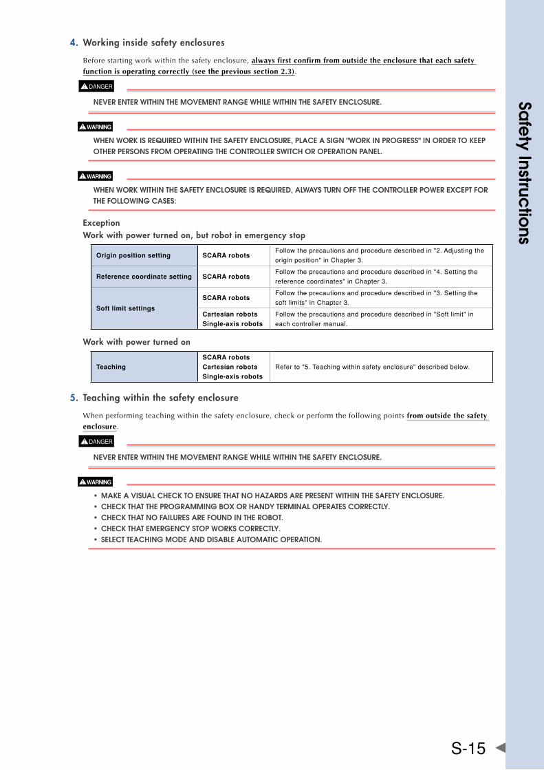
Working inside safety enclosures4.
Before starting work within the safety enclosure, always first confirm from outside the enclosure that each safety
function is operating correctly (see the previous section 2.3).
nEvER EnTER WIThIn ThE MOvEMEnT RangE WhIlE WIThIn ThE SafETy EnClOSURE.
WhEn WORk IS REqUIRED WIThIn ThE SafETy EnClOSURE, PlaCE a SIgn "WORk In PROgRESS" In ORDER TO kEEP OThER PERSOnS fROM OPERaTIng ThE COnTROllER SWITCh OR OPERaTIOn PanEl.
WhEn WORk WIThIn ThE SafETy EnClOSURE IS REqUIRED, alWayS TURn Off ThE COnTROllER POWER ExCEPT fOR ThE fOllOWIng CaSES:
Exception Work with power turned on, but robot in emergency stop
Origin position setting SCARA robotsFollowtheprecautionsandproceduredescribedin"2.Adjustingthe
originposition"inChapter3.
Reference coordinate setting SCARA robotsFollowtheprecautionsandproceduredescribedin"4.Settingthe
referencecoordinates"inChapter3.
Soft limit settings
SCARA robotsFollowtheprecautionsandproceduredescribedin"3.Settingthe
softlimits"inChapter3.
Cartesian robots
Single-axis robots
Followtheprecautionsandproceduredescribedin"Softlimit"in
eachcontrollermanual.
Work with power turned on
Teaching
SCARA robots
Cartesian robots
Single-axis robots
Referto"5.Teachingwithinsafetyenclosure"describedbelow.
Teaching within the safety enclosure5.
When performing teaching within the safety enclosure, check or perform the following points from outside the safety
enclosure.
nEvER EnTER WIThIn ThE MOvEMEnT RangE WhIlE WIThIn ThE SafETy EnClOSURE.
• maKeavisualchecKtoensurethatnohazarDsarePresentwithinthesafetyenclosure. • checKthattheProgrammingboxorhanDyterminaloPeratescorrectly. • checKthatnofailuresarefounDintherobot. • checKthatemergencystoPworKscorrectly. • selectteachingmoDeanDDisableautomaticoPeration.
Sa
fety Instruc
tions
S-16
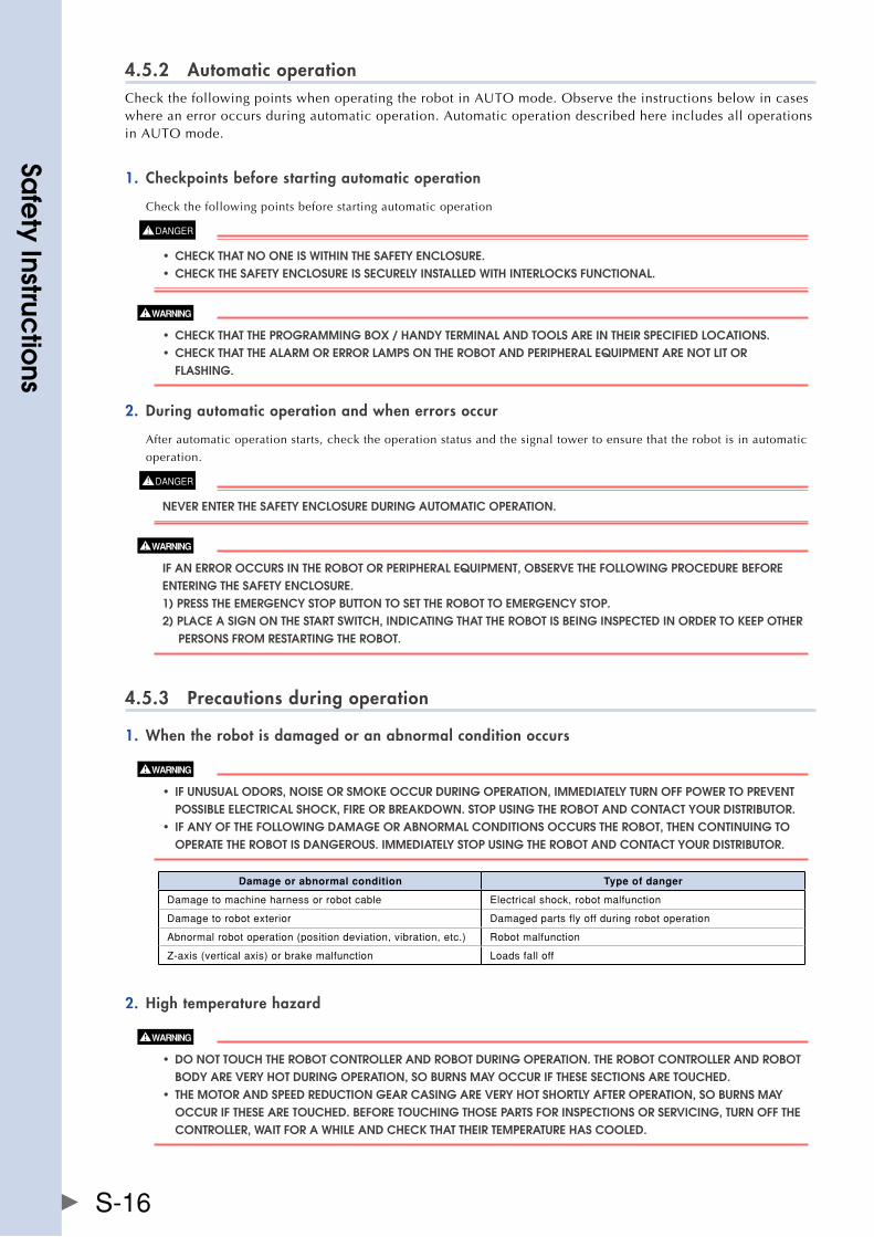
4.5.2 Automatic operationCheckthefollowingpointswhenoperatingtherobotinAUTOmode.Observetheinstructionsbelowincaseswhere an error occurs during automatic operation. Automatic operation described here includes all operations inAUTOmode.
Checkpoints before starting automatic operation1.
Check the following points before starting automatic operation
• checKthatnooneiswithinthesafetyenclosure. • checKthesafetyenclosureissecurelyinstalleDwithinterlocKsfunctional.
• checKthattheProgrammingbox/hanDyterminalanDtoolsareintheirsPecifieDlocations. • checKthatthealarmorerrorlamPsontherobotanDPeriPheralequiPmentarenotlitor flaShIng.
During automatic operation and when errors occur2.
After automatic operation starts, check the operation status and the signal tower to ensure that the robot is in automatic
operation.
nEvER EnTER ThE SafETy EnClOSURE DURIng aUTOMaTIC OPERaTIOn.
If an ERROR OCCURS In ThE RObOT OR PERIPhERal EqUIPMEnT, ObSERvE ThE fOllOWIng PROCEDURE bEfORE EnTERIng ThE SafETy EnClOSURE. 1) PRESS ThE EMERgEnCy STOP bUTTOn TO SET ThE RObOT TO EMERgEnCy STOP. 2) PlaCE a SIgn On ThE STaRT SWITCh, InDICaTIng ThaT ThE RObOT IS bEIng InSPECTED In ORDER TO kEEP OThER PERSOnS fROM RESTaRTIng ThE RObOT.
4.5.3 Precautions during operation
When the robot is damaged or an abnormal condition occurs1.
• ifunusualoDors,noiseorsmoKeoccurDuringoPeration,immeDiatelyturnoffPowertoPrevent POSSIblE ElECTRICal ShOCk, fIRE OR bREakDOWn. STOP USIng ThE RObOT anD COnTaCT yOUR DISTRIbUTOR. • ifanyofthefollowingDamageorabnormalconDitionsoccurstherobot,thencontinuingto OPERaTE ThE RObOT IS DangEROUS. IMMEDIaTEly STOP USIng ThE RObOT anD COnTaCT yOUR DISTRIbUTOR.
Damage or abnormal condition Type of danger
Damagetomachineharnessorrobotcable Electricalshock,robotmalfunction
Damagetorobotexterior Damagedpartsflyoffduringrobotoperation
Abnormalrobotoperation(positiondeviation,vibration,etc.) Robotmalfunction
Z-axis(verticalaxis)orbrakemalfunction Loadsfalloff
High temperature hazard2.
• DonottouchtherobotcontrolleranDrobotDuringoPeration.therobotcontrolleranDrobot bODy aRE vERy hOT DURIng OPERaTIOn, SO bURnS May OCCUR If ThESE SECTIOnS aRE TOUChED. • themotoranDsPeeDreDuctiongearcasingareveryhotshortlyafteroPeration,soburnsmay OCCUR If ThESE aRE TOUChED. bEfORE TOUChIng ThOSE PaRTS fOR InSPECTIOnS OR SERvICIng, TURn Off ThE COnTROllER, WaIT fOR a WhIlE anD ChECk ThaT ThEIR TEMPERaTURE haS COOlED.
Sa
fety Instruc
tions
S-17
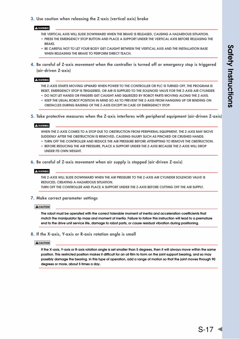
Use caution when releasing the Z-axis (vertical axis) brake3.
ThE vERTICal axIS WIll SlIDE DOWnWaRD WhEn ThE bRakE IS RElEaSED, CaUSIng a hazaRDOUS SITUaTIOn. • PresstheemergencystoPbuttonanDPlaceasuPPortunDertheverticalaxisbeforereleasingthe bRakE. • becarefulnottoletyourboDygetcaughtbetweentheverticalaxisanDtheinstallationbase WhEn RElEaSIng ThE bRakE TO PERfORM DIRECT TEaCh.
Be careful of Z-axis movement when the controller is turned off or emergency stop is triggered 4. (air-driven Z-axis)
ThE z-axIS STaRTS MOvIng UPWaRD WhEn POWER TO ThE COnTROllER OR PlC IS TURnED Off, ThE PROgRaM IS RESET, EMERgEnCy STOP IS TRIggERED, OR aIR IS SUPPlIED TO ThE SOlEnOID valvE fOR ThE z-axIS aIR CylInDER. • DonotlethanDsorfingersgetcaughtanDsqueezeDbyrobotPartsmovingalongthez-axis. • KeePtheusualrobotPositioninminDsoastoPreventthez-axisfromhanginguPorbinDingon ObSTaClES DURIng RaISIng Of ThE z-axIS ExCEPT In CaSE Of EMERgEnCy STOP.
Take protective measures when the Z-axis interferes with peripheral equipment (air-driven Z-axis)5.
WhEn ThE z-axIS COMES TO a STOP DUE TO ObSTRUCTIOn fROM PERIPhERal EqUIPMEnT, ThE z-axIS May MOvE SUDDEnly afTER ThE ObSTRUCTIOn IS REMOvED, CaUSIng InjURy SUCh aS PInChED OR CRUShED hanDS. • turnoffthecontrolleranDreDucetheairPressurebeforeattemPtingtoremovetheobstruction. • beforereDucingtheairPressure,PlaceasuPPortunDerthez-axisbecausethez-axiswillDroP UnDER ITS OWn WEIghT.
Be careful of Z-axis movement when air supply is stopped (air-driven Z-axis)6.
ThE z-axIS WIll SlIDE DOWnWaRD WhEn ThE aIR PRESSURE TO ThE z-axIS aIR CylInDER SOlEnOID valvE IS REDUCED, CREaTIng a hazaRDOUS SITUaTIOn. TURn Off ThE COnTROllER anD PlaCE a SUPPORT UnDER ThE z-axIS bEfORE CUTTIng Off ThE aIR SUPPly.
Make correct parameter settings7.
therobotmustbeoperatedwiththecorrecttolerablemomentofinertiaandaccelerationcoefficientsthatmatch the manipulator tip mass and moment of inertia. failure to follow this instruction will lead to a premature end to the drive unit service life, damage to robot parts, or cause residual vibration during positioning.
If the X-axis, Y-axis or R-axis rotation angle is small8.
ifthex-axis,y-axisorr-axisrotationangleissetsmallerthan5degrees,thenitwillalwaysmovewithinthesameposition.thisrestrictedpositionmakesitdifficultforanoilfilmtoformonthejointsupportbearing,andsomaypossibly damage the bearing. In this type of operation, add a range of motion so that the joint moves through 90 degrees or more, about 5 times a day.
Sa
fety Instruc
tions
S-18
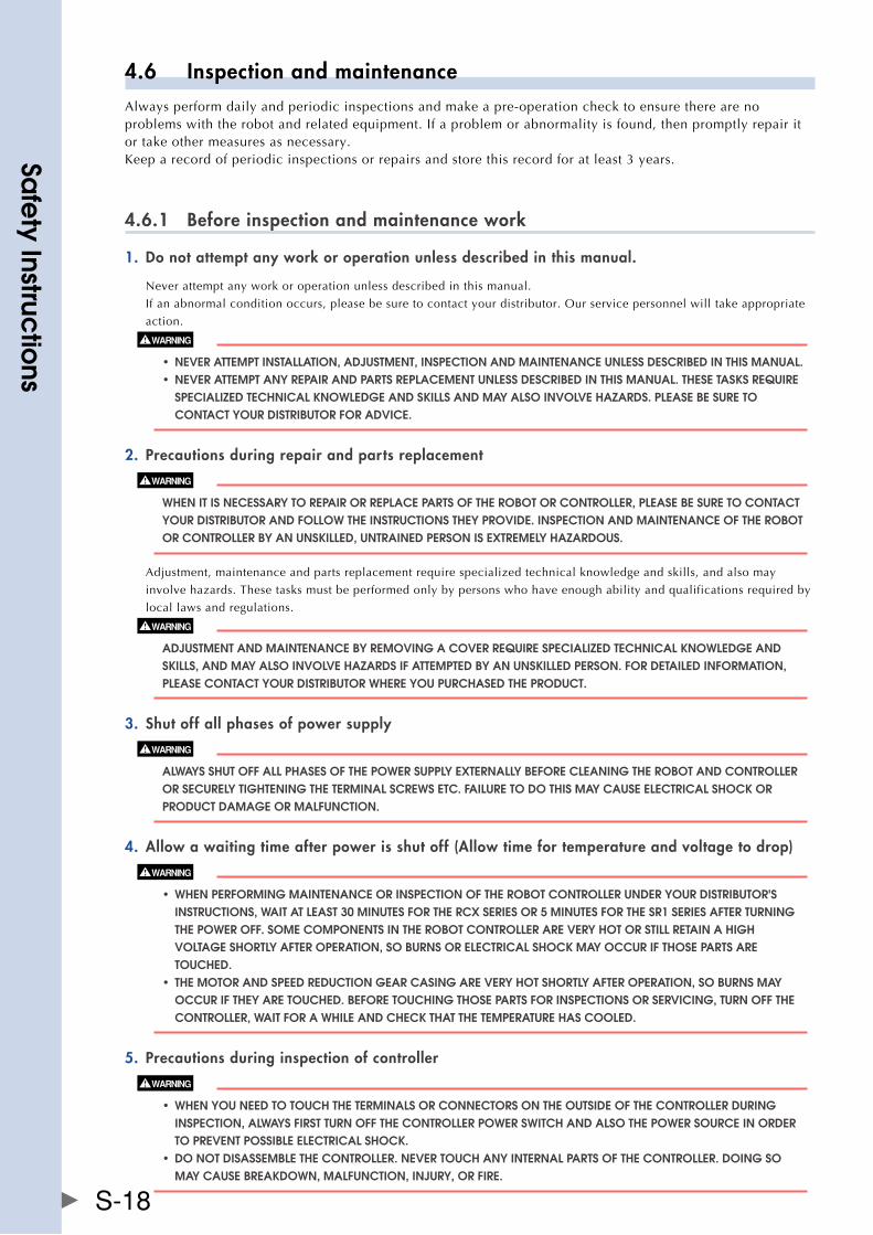
4.6 Inspection and maintenanceAlways perform daily and periodic inspections and make a pre-operation check to ensure there are no problems with the robot and related equipment. If a problem or abnormality is found, then promptly repair it or take other measures as necessary.Keep a record of periodic inspections or repairs and store this record for at least 3 years.
4.6.1 Before inspection and maintenance work
Do not attempt any work or operation unless described in this manual.1.
Never attempt any work or operation unless described in this manual.
If an abnormal condition occurs, please be sure to contact your distributor. Our service personnel will take appropriate
action.
• nEvER aTTEMPT InSTallaTIOn, aDjUSTMEnT, InSPECTIOn anD MaInTEnanCE UnlESS DESCRIbED In ThIS ManUal. • neverattemPtanyrePairanDPartsrePlacementunlessDescribeDinthismanual.thesetasKsrequire SPECIalIzED TEChnICal knOWlEDgE anD SkIllS anD May alSO InvOlvE hazaRDS. PlEaSE bE SURE TO COnTaCT yOUR DISTRIbUTOR fOR aDvICE.
Precautions during repair and parts replacement2.
WhEn IT IS nECESSaRy TO REPaIR OR REPlaCE PaRTS Of ThE RObOT OR COnTROllER, PlEaSE bE SURE TO COnTaCT yOUR DISTRIbUTOR anD fOllOW ThE InSTRUCTIOnS ThEy PROvIDE. InSPECTIOn anD MaInTEnanCE Of ThE RObOT OR COnTROllER by an UnSkIllED, UnTRaInED PERSOn IS ExTREMEly hazaRDOUS.
Adjustment, maintenance and parts replacement require specialized technical knowledge and skills, and also may
involve hazards. These tasks must be performed only by persons who have enough ability and qualifications required by
local laws and regulations.
aDjUSTMEnT anD MaInTEnanCE by REMOvIng a COvER REqUIRE SPECIalIzED TEChnICal knOWlEDgE anD SkIllS, anD May alSO InvOlvE hazaRDS If aTTEMPTED by an UnSkIllED PERSOn. fOR DETaIlED InfORMaTIOn, PlEaSE COnTaCT yOUR DISTRIbUTOR WhERE yOU PURChaSED ThE PRODUCT.
Shut off all phases of power supply3.
alWayS ShUT Off all PhaSES Of ThE POWER SUPPly ExTERnally bEfORE ClEanIng ThE RObOT anD COnTROllER OR SECUREly TIghTEnIng ThE TERMInal SCREWS ETC. faIlURE TO DO ThIS May CaUSE ElECTRICal ShOCk OR PRODUCT DaMagE OR MalfUnCTIOn.
Allow a waiting time after power is shut off (Allow time for temperature and voltage to drop)4.
• whenPerformingmaintenanceorinsPectionoftherobotcontrollerunDeryourDistributor's InSTRUCTIOnS, WaIT aT lEaST 30 MInUTES fOR ThE RCx SERIES OR 5 MInUTES fOR ThE SR1 SERIES afTER TURnIng ThE POWER Off. SOME COMPOnEnTS In ThE RObOT COnTROllER aRE vERy hOT OR STIll RETaIn a hIgh vOlTagE ShORTly afTER OPERaTIOn, SO bURnS OR ElECTRICal ShOCk May OCCUR If ThOSE PaRTS aRE TOUChED. • themotoranDsPeeDreDuctiongearcasingareveryhotshortlyafteroPeration,soburnsmay OCCUR If ThEy aRE TOUChED. bEfORE TOUChIng ThOSE PaRTS fOR InSPECTIOnS OR SERvICIng, TURn Off ThE COnTROllER, WaIT fOR a WhIlE anD ChECk ThaT ThE TEMPERaTURE haS COOlED.
Precautions during inspection of controller5.
• whenyouneeDtotouchtheterminalsorconnectorsontheoutsiDeofthecontrollerDuring InSPECTIOn, alWayS fIRST TURn Off ThE COnTROllER POWER SWITCh anD alSO ThE POWER SOURCE In ORDER TO PREvEnT POSSIblE ElECTRICal ShOCk. • DonotDisassemblethecontroller.nevertouchanyinternalPartsofthecontroller.Doingso May CaUSE bREakDOWn, MalfUnCTIOn, InjURy, OR fIRE.
Sa
fety Instruc
tions
S-19
4.6.2 Precautions during service work
Precautions when removing a motor (Cartesian robots and vertical mount single-axis robots)1.
ThE vERTICal axIS WIll SlIDE DOWn WhEn ThE MOTOR IS REMOvED, CaUSIng a hazaRDOUS SITUaTIOn. • turnoffthecontrolleranDPlaceasuPPortunDertheverticalaxisbeforeremovingthemotor. • becarefulnottoletyourboDygetcaughtbytheDrivingunitoftheverticalaxisorbetweenthe vERTICal axIS anD ThE InSTallaTIOn baSE.
Be careful when removing the Z-axis motor (SCARA robots)2.
ThE z-axIS WIll SlIDE DOWnWaRD WhEn ThE z-axIS MOTOR IS REMOvED, CaUSIng a hazaRDOUS SITUaTIOn. • turnoffthecontrolleranDPlaceasuPPortunDerthez-axisbeforeremovingthez-axismotor. • becarefulnottoletyourboDygetcaughtbytheDrivingunitofthez-axisorbetweenthez-axis DRIvE UnIT anD ThE InSTallaTIOn baSE.
Do not remove the Z-axis upper limit mechanical stopper3.
warninglabel4isattachedtoeachscararobot.(fordetailsonwarninglabels,see"3.warninglabels"in"safetyinstructions.") removingtheupperlimitmechanicalstopperinstalledtothez-axissplineorshiftingitspositionwilldamagethez-axisballscrew.neverattempttoremoveit.
Use caution when handling a robot that contains powerful magnets4.
POWERfUl MagnETS aRE InSTallED InSIDE ThE RObOT. DO nOT DISaSSEMblE ThE RObOT SInCE ThIS May CaUSE InjURy. DEvICES ThaT May MalfUnCTIOn DUE TO MagnETIC fIElDS MUST bE kEPT aWay fROM ThIS RObOT.
Use the following caution items when disassembling or replacing the pneumatic equipment.5.
aIR OR PaRTS May fly OUTWaRD If PnEUMaTIC EqUIPMEnT IS DISaSSEMblED OR PaRTS REPlaCED WhIlE aIR IS STIll SUPPlIED. • DoserviceworKafterturningoffthecontroller,reDucingtheairPressure,anDexhaustingthe RESIDUal aIR fROM ThE PnEUMaTIC EqUIPMEnT. • beforereDucingtheairPressure,PlaceasuPPortstanDunDerthez-axis(2-axisrobotswithair DRIvEn z-axIS) SInCE IT WIll DROP UnDER ITS OWn WEIghT.
Use caution to avoid contact with the controller cooling fan6.
• touchingtherotatingfanmaycauseinjury. • ifremovingthefancover,firstturnoffthecontrolleranDmaKesurethefanhasstoPPeD.
Precautions for robot controllers7.
• backuptherobotcontrollerinternaldataonanexternalstoragedevice.therobotcontrollerinternaldata (programs,pointdata,etc.)maybelostordeletedforunexpectedreasons.alwaysmakeabackupofthis data. • Donotusethinner,benzene,oralcoholtowipeoffthesurfaceoftheprogrammingbox.thesurfacesheetmay be damaged or printed letters or marks erased. Use a soft, dry cloth and gently wipe the surface. • Donotuseahardorpointedobjecttopressthekeysontheprogrammingbox.malfunctionorbreakdown mayresultifthekeysaredamaged.useyourfingerstooperatethekeys. • DonotinsertanysDmemorycardotherthanspecifiedintothesDmemorycardslotintheprogrammingbox. Malfunction or breakdown may result if the wrong memory card is inserted.
Sa
fety Instruc
tions
S-20
4.7 DisposalWhendisposingofrobotsandrelateditems,handlethemcarefullyasindustrialwastes.Usethecorrectdisposal method in compliance with your local regulations, or entrust disposal to a licensed industrial waste disposal company.
Disposal of lithium batteries1.
When disposing of lithium batteries, use the correct disposal method in compliance with your local regulations, or
entrust disposal to a licensed industrial waste disposal company. We do not collect and dispose of the used batteries.
Disposal of packing boxes and materials2.
When disposing of packing boxes and materials, use the correct disposal method in compliance with your local
regulations. We do not collect and dispose of the used packing boxes and materials.
Strong magnet3.
STROng MagnETS aRE InSTallED In ThE RObOT. bE CaREfUl WhEn DISPOSIng Of ThE RObOT.
Sa
fety Instruc
tions
S-21
5. Emergency action when a person is caught by robotIf a person should get caught between the robot and a mechanical part such as the installation base, then release the axis.
Emergency action ■
Release the axis while referring to the following section in the manual for the robot controller.
Controller Refer to:
RCX240 Section8,"Freeingapersoncaughtbytherobot"inChapter1
Make a printout of the relevant page in the manual and post it a conspicuous location near the controller.
Sa
fety Instruc
tions
S-22
6. Using the robot safely6.1 Robot safety functionsSafety functions for YAMAHA robots are described below.
Overload detection1.
This function detects an overload applied to the motor and shuts off the servo power.
If an overload error occurs, take the following measures to avoid such errors:
1. Insert a timer in the program.
2. Reduce the acceleration coefficient.
Overheat detection2.
This function detects an abnormal temperature rise in the driver inside the controller and shuts off the servo power.
If an overheat error occurs, take the following measures to avoid the error:
1. Insert a timer in the program.
2. Reduce the acceleration coefficient.
Soft limits3.
Soft limits can be set on each axis to limit the working envelope in manual operation after return-to-origin and during
automatic operation. The working envelope is the area limited by soft limits.
softlimitsmustbesetwithinthemovementrange(mechanicalstoPPer).ifthesoftlimitissetoutsiDeThE MOvEMEnT RangE, ThEn ThE RObOT axIS May COllIDE WITh ThE MEChanICal STOPPER aT hIgh SPEED, CaUSIng ThE ObjECT gRIPPED by ThE EnD EffECTOR TO fly OUTWaRD OR DROP, anD ThE RObOT TO MalfUnCTIOn.
Mechanical stoppers4.
If the servo power is shut off by emergency stop operation or safety function while the robot is moving, then these
mechanical stoppers prevent the axis from exceeding the movement range. No mechanical stopper is provided on the
rotational axis. The movement range is the area limited by the mechanical stoppers.
•TheXandYaxeshavemechanicalstoppersthatareinstalledatbothendsofthemaximummovementrange.Somerobot models have a standard feature that allows changing the mechanical stopper positions. On some other models, the mechanical stopper positions can also be changed by using option parts.
•TheZ-axishasamechanicalstopperattheupperendandlowerend.Thestopperpositionscanbechangedbyusingoption parts.
•NomechanicalstopperisprovidedontheR-axis.
axIS MOvEMEnT DOES nOT STOP IMMEDIaTEly afTER ThE SERvO POWER SUPPly IS ShUT Off by EMERgEnCy STOP OR OThER SafETy fUnCTIOnS.
Z-axis (vertical axis) brake5.
AnelectromagneticbrakeisinstalledontheZ-axistopreventtheZ-axisfromslidingdownwardwhenservopoweris
OFF.ThisbrakeisworkingwhenthecontrollerisOFFortheZ-axisservopowerisOFFevenwhenthecontrollerisON.
TheZ-axisbrakecanbereleasedbytheprogrammingunit/handyterminalorbyacommandintheprogramwhenthe
controller is ON.
ThE vERTICal axIS WIll SlIDE DOWnWaRD WhEn ThE z-axIS bRakE IS RElEaSED, CREaTIng a hazaRDOUS SITUaTIOn. • PresstheemergencystoPbuttonanDPlaceasuPPortunDertheverticalaxisbeforereleasingthe bRakE. • becarefulnottoletyourboDygetcaughtbetweentheverticalaxisanDinstallationbasewhen RElEaSIng ThE bRakE TO PERfORM DIRECT TEaCh.。
Sa
fety Instruc
tions
S-23
6.2 Special training for industrial robot operationOperators or persons who handle the robot for tasks such as for teaching, programming, movement checks, inspections, adjustments, and repairs must receive appropriate training and also have the skills needed to perform the job correctly and safely. They must also read the manual carefully to understand its contents before attempting the robot operation or maintenance.
Tasks related to industrial robots (teaching, programming, movement check, inspection, adjustment, repair, etc.) must be performed by qualified persons who meet requirements established by local regulations and safety standards for industrial robots.
This manual does not serve as a guarantee of any industrial property rights or any other rights and does not grant a license in any form. Please acknowledge that we bear no liability whatsoever for any problems involving industrial property rights which may arise from the contents of this manual.
2012 YAMAHA MOTOR CO., LTD.
YAMAHA MOTOR CO., LTD. IM Operations
All rights reserved. No part of this publication may be reproduced in any form without the permission of YAMAHA MOTOR CO., LTD.Information furnished by YAMAHA in this manual is believed to be reliable. However, no responsibility is assumed for possible inaccuracies or omissions. If you find any part unclear in this manual, please contact your distributor.
Safety InstructionsJun.2012Ver.1.01ThismanualisbasedonVer.1.01ofJapanesemanual.
Revision record
Manual version Issue date Description
Ver.1.00 May2012 Firstedition
Ver.1.01 Jun.2012 Descriptionof"Emergencyactionwhenapersoniscaughtbyrobot"wasadded,theworksequenceforworkingwithinthesafetyenclosurechanged,typingerrorscorrected,etc.
W
arra
nty
Ver.1.00_201205
WarrantyFor information on the warranty period and terms, please contact our distributor where you purchased the product.
This warranty does not cover any failure caused by: ■
1. Installation, wiring, connection to other control devices, operating methods, inspection or maintenance that does not comply with industry standards or instructions specified in the YAMAHA manual;
2.UsagethatexceededthespecificationsorstandardperformanceshownintheYAMAHAmanual;
3. Product usage other than intended by YAMAHA;
4. Storage, operating conditions and utilities that are outside the range specified in the manual;
5. Damage due to improper shipping or shipping methods;
6. Accident or collision damage;
7. Installation of other than genuine YAMAHA parts and/or accessories;
8. Modification to original parts or modifications not conforming to standard specifications designated by YAMAHA, including customizing performed by YAMAHA in compliance with distributor or customer requests;
9. Pollution, salt damage, condensation;
10. Fires or natural disasters such as earthquakes, tsunamis, lightning strikes, wind and flood damage, etc;
11. Breakdown due to causes other than the above that are not the fault or responsibility of YAMAHA;
The following cases are not covered under the warranty: ■
1. Products whose serial number or production date (month & year) cannot be verified.
2. Changes in software or internal data such as programs or points that were created or changed by the customer.
3. Products whose trouble cannot be reproduced or identified by YAMAHA.
4. Products utilized, for example, in radiological equipment, biological test equipment applications or for other purposes whose warranty repairs are judged as hazardous by YAMAHA.
THEWARRANTYSTATEDHEREINPROVIDEDBYYAMAHAONLYCOVERSDEFECTSINPRODUCTSANDPARTSSOLDBYYAMAHATODISTRIBUTORSUNDERTHISAGREEMENT.ANYANDALLOTHERWARRANTIESORLIABILITIES,EXPRESSORIMPLIED,INCLUDINGBUTNOTLIMITEDTOANYIMPLIEDWARRANTIESOFMERCHANTABILITYORFITNESSFORAPARTICULARPURPOSEAREHEREBYEXPRESSLYDISCLAIMEDBYYAMAHA.MOREOVER,YAMAHASHALLNOTBEHELDRESPONSIBLEFORCONSEQUENTORINDIRECTDAMAGESINANYMANNERRELATINGTOTHEPRODUCT.
Warranty


Contents
beforeusingtherobot(besuretoreadthefollowingnotes.) i
Introduction v
Introduction

Intro
duc
tion
i
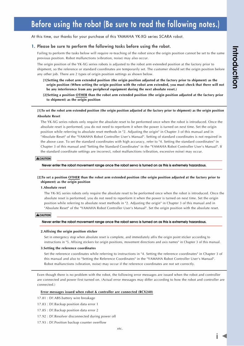
Before using the robot (Be sure to read the following notes.)Atthistime,ourthanksforyourpurchaseofthisYAMAHAYK-XGseriesSCARArobot.
Please be sure to perform the following tasks before using the robot.1. Failing to perform the tasks below will require re-teaching of the robot since the origin position cannot be set to the same
previous position. Robot malfunctions (vibration, noise) may also occur.
TheoriginpositionoftheYK-XGseriesrobotsisadjustedtotherobotarmextendedpositionatthefactorypriorto
shipment, so the reference or standard coordinates are temporarily set. The customer should set the origin position before
any other job. There are 2 types of origin position settings as shown below.
[1]Setting the robot arm extended position (the origin position adjusted at the factory prior to shipment) as the origin position (When setting the origin position with the robot arm extended, you must check that there will not be any interference from any peripheral equipment during the next absolute reset.)
[2]Setting a position OTHER than the robot arm extended position (the origin position adjusted at the factory prior to shipment) as the origin position
[1]To set the robot arm extended position (the origin position adjusted at the factory prior to shipment) as the origin position
Absolute Reset
TheYK-XGseriesrobotsonlyrequiretheabsoluteresettobeperformedoncewhentherobotisintroduced.Oncethe
absolute reset is performed, you do not need to reperform it when the power is turned on next time. Set the origin
position while referring to absolute reset methods in "2. Adjusting the origin" in Chapter 3 of this manual and in
"AbsoluteReset"ofthe"YAMAHARobotControllerUser'sManual".Settingofstandardcoordinatesisnotrequiredin
the above case. To set the standard coordinates with high accuracy, refer to "4. Setting the standard coordinates" in
Chapter3ofthismanualand"SettingtheStandardCoordinates"inthe"YAMAHARobotControllerUser'sManual".If
the standard coordinate settings are incorrect, robot malfunctions (vibration, excessive noise) may occur.
neverentertherobotmovementrangeoncetherobotservoisturnedonasthisisextremelyhazardous.
[2]To set a position OTHER than the robot arm extended position (the origin position adjusted at the factory prior to shipment) as the origin position
1.Absolute reset
TheYK-XGseriesrobotsonlyrequiretheabsoluteresettobeperformedoncewhentherobotisintroduced.Oncethe
absolute reset is performed, you do not need to reperform it when the power is turned on next time. Set the origin
position while referring to absolute reset methods in "2. Adjusting the origin" in Chapter 3 of this manual and in
"AbsoluteReset"ofthe"YAMAHARobotControllerUser'sManual".Settheoriginpositionwiththeabsolutereset.
neverentertherobotmovementrangeoncetherobotservoisturnedonasthisisextremelyhazardous.
2.Affixing the origin position sticker
Set in emergency stop when absolute reset is complete, and immediately affix the origin point sticker according to
instructions in "5. Affixing stickers for origin positions, movement directions and axis names" in Chapter 3 of this manual.
3.Setting the reference coordinates
Set the reference coordinates while referring to instructions in "4. Setting the reference coordinates" in Chapter 3 of
thismanualandalsoto"SettingtheReferenceCoordinates"inthe"YAMAHARobotControllerUser'sManual".
Robot malfunctions (vibration, noise) may occur if the reference coordinates are not set correctly.
Eventhoughthereisnoproblemwiththerobot,thefollowingerrormessagesareissuedwhentherobotandcontroller
are connected and power first turned on. (Actual error messages may differ according to how the robot and controller are
connected.)
Error messages issued when robot & controller are connected (RCX240)
17.81:D?.ABS.batterywirebreakage
17.83:D?.Backuppositiondataerror1
17.85:D?.Backuppositiondataerror2
17.92:D?.Resolverdisconnectedduringpoweroff
17.93:D?.Positionbackupcounteroverflow
etc.
Intro
duc
tion
ii
Repetitive positioning accuracy2.
"Repetitive positioning accuracy" is not guaranteed under the following conditions.
[1] Factors related to absolute accuracy
• Iftheaccuracybetweenthecoordinatepositions(commandpositions)insidetherobotcontrollerandthereal
space positions (moving positions) is required.
[2] Motion pattern factors
• Ifamotionapproachingtotheteachingpointfromadifferentdirectionisincludedduringrepetitiveoperation.
• Ifthepoweristurnedoffortherobotisstoppedbeforecompletingthemotionorthemovingspeedischanged
even when approaching to the teaching point from the same direction.
• Iftherobotismovedtotheteachingpointusingahandsystemdifferentfromthehandsystem(right-handedor
left-handed system) used for the teaching.
[3] Temperature factors
• Iftheambienttemperatureenvironmentchangessignificantly.
• Ifthetemperatureoftherobotmainbodychanges.
[4] Load variation factors
• If load conditions vary during operation (the load varies depending on whether or not the workpiece is present, etc.).
If the X-axis, Y-axis or R-axis rotation angle is small.3.
IftheX-axis,Y-axisorR-axisrotationangleissmallerthan5°sothatitmovesinalmostthesameposition,anoilfilmis
difficult to be formed on the joint support bearing, possibly leading to damage to the bearing. In this type of operation,
addamovementsothatthejointmovesthrough90°ormore,about5timesaday.
Do not remove the Z-axis upper-end mechanical stopper4.
Removingormovingtheupper-endmechanicalstopperattachedtotheZ-axissplinecandamagetheZ-axisballscrew.
Never remove or move it.
If the Z-axis spline vibrates.5.
TheZ-axissplineoftheYK250XG,YK350XG,YK400XG,YK500XGL,andYK600XGLtendstovibrateinaZ-axis
operationspeedrangeof20%to40%.IftheZ-axissplinevibrates,operateitbeyondthisoperationspeedrange.
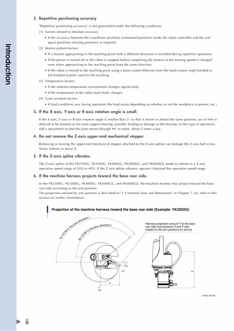
If the machine harness projects toward the base rear side.6.
IntheYK250XG,YK350XG,YK400XG,YK500XGL,andYK600XGL,themachineharnessmayprojecttowardthebase
rear side according to the arm position.
Theprojectionamountbyarmpositionisdescribedin"1.2Externalviewanddimensions"inChapter7.So,refertothis
section for further information.
X
Y
→Y+
↓X+
Projection of the machine harness toward the base rear side (Example: YK250XG)
θx (C
CW
is th
e plus direction.)
θy (C
CW is the plus direction.)
Z
Harness projection amount Y to the base rear side and positions X and Z with respect to the arm positions θx and θy
23001-F6-00
Intro
duc
tion
iii
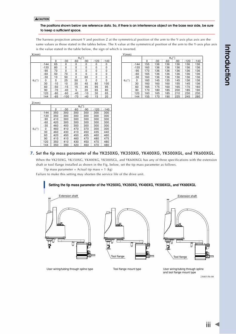
The positions shown below are reference data. So, if there is an interference object on the base rear side, be sure tokeepasufficientspace.
TheharnessprojectionamountYandpositionZatthesymmetricalpositionofthearmtotheY-axisplusaxisarethe
samevaluesasthosestatedinthetablesbelow.TheXvalueatthesymmetricalpositionofthearmtotheY-axisplusaxis
is the value stated in the table below, the sign of which is inverted.
X(mm) Y(mm)θX(°) θX(°)
0 -30 -60 -90 -120 -140 0 -30 -60 -90 -120 -140
θY(°)
-144 65 0 0 0 0 0
θY(°)
-144 155 136 136 136 136 136-120 80 0 0 0 0 0 -120 160 136 136 136 136 136-90 70 0 0 0 0 0 -90 170 136 136 136 136 136-60 50 70 0 0 0 0 -60 165 136 136 136 136 136-30 10 50 0 60 0 0 -30 160 136 136 136 136 1360 0 25 50 0 0 0 0 160 145 135 145 136 136
30 -10 10 20 40 80 100 30 160 160 160 155 145 13660 -50 -15 15 45 95 95 60 165 175 160 165 170 16090 -70 -40 5 20 65 80 90 170 180 185 200 185 190
120 -80 -60 -40 -10 30 65 120 160 165 185 210 230 230144 -65 -100 -70 -40 15 20 144 155 170 190 225 245 280
Z(mm)θX(°)
0 -30 -60 -90 -120 -140
θY(°)
-144 350 300 300 300 300 300-120 350 300 300 300 300 300-90 410 300 300 300 300 300-60 420 300 300 300 300 300-30 460 400 300 300 300 3000 460 410 470 370 300 300
30 460 430 410 450 435 44060 420 450 450 455 460 46090 410 410 460 470 480 475
120 350 410 430 450 470 480144 350 390 420 460 470 480
Set the tip mass parameter of the YK250XG, YK350XG, YK400XG, YK500XGL, and YK600XGL.7. WhentheYK250XG,YK350XG,YK400XG,YK500XGL,andYK600XGLhasanyofthreespecificationswiththeextension
shaft or tool flange installed as shown in the Fig. below, set the tip mass parameter as follows.
Tip mass parameter = Actual tip mass + 1 (kg)
Failure to make this setting may shorten the service life of the drive unit.
Setting the tip mass parameter of the YK250XG, YK350XG, YK400XG, YK500XGL, and YK600XGL
User wiring/tubing through spline type Tool flange mount type User wiring/tubing through spline and tool flange mount type
Extension shaft
Tool flange
Extension shaft
Tool flange
23005-F6-00
Intro
duc
tion
iv
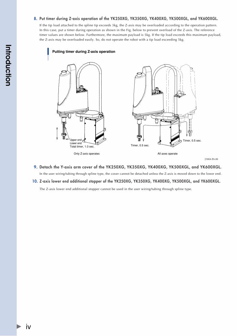
Put timer during Z-axis operation of the YK250XG, YK350XG, YK400XG, YK500XGL, and YK600XGL.8. Ifthetiploadattachedtothesplinetipexceeds3kg,theZ-axismaybeoverloadedaccordingtotheoperationpattern.
Inthiscase,putatimerduringoperationasshownintheFig.belowtopreventoverloadoftheZ-axis.Thereference
timer values are shown below. Furthermore, the maximum payload is 5kg. If the tip load exceeds this maximum payload,
theZ-axismaybeoverloadedeasily.So,donotoperatetherobotwithatiploadexceeding5kg.
Putting timer during Z-axis operation
Only Z-axis operates
Upper endLower endTotal timer, 1.0 sec.
All axes operate
Timer, 0.5 sec.
Timer, 0.5 sec.
23004-F6-00
Detach the Y-axis arm cover of the YK250XG, YK350XG, YK400XG, YK500XGL, and YK600XGL.9. Intheuserwiring/tubingthroughsplinetype,thecovercannotbedetachedunlesstheZ-axisismoveddowntothelowerend.
Z-axis lower end additional stopper of the YK250XG, YK350XG, YK400XG, YK500XGL, and YK600XGL.10.
TheZ-axislowerendadditionalstoppercannotbeusedintheuserwiring/tubingthroughsplinetype.
Intro
duc
tion
v
IntroductionTheYAMAHAYK-XGseriesrobotsareSCARAtypeindustrialrobotsdevelopedbasedonyearsofYAMAHAexperienceandachievementsintheautomationfieldaswellaseffortstostreamlineourin-housemanufacturing systems. TheYK-XGseriesrobotshaveatwo-jointmanipulatorconsistingofanX-axisarmandaY-axisarm,andarefurtherequippedwithaverticalaxis(Z-axis)andarotatingaxis(R-axis)atthetipofthemanipulator.TheYK-XGseriesrobotscanbeusedforawiderangeofassemblyapplicationssuchasinstallationandinsertionofvarious parts, application of sealant, and packing operations.
Thisuser'smanualdescribesthesafetymeasures,handling,adjustmentandmaintenanceofYK-XGseriesrobots for correct, safe and effective use. Be sure to read this manual carefully before installing the robot. Evenafteryouhavereadthismanual,keepitinasafeandconvenientplaceforfuturereference.Thisuser'smanual should be used with the robot and considered an integral part of it. When the robot is moved, transferred or sold, send this manual to the new user along with the robot. Be sure to explain to the new user the need to read through this manual.
This manual describes the following robot models.
Standard modelYK250XG,YK350XG,YK400XG,YK500XGL,YK600XGL,YK500XG,YK600XG,
YK600XGH,YK700XG,YK800XG,YK900XG,YK1000XG
Wall-mount model / Wall-mount inverse model YK500XGS,YK600XGS,YK700XGS,YK800XGS,YK900XGS,YK1000XGS
Fordetailsaboutactualrobotoperationandprogramming,refertothe"YAMAHARobotControllerUser'sManual".
ThE aDjUSTMEnT anD MaInTEnanCE WORk WITh ThE COvER REMOvED nEEDS ThE SPECIal knOWlEDgE anD SkIll. If UnSkIllED WORk PERSOn PERfORMS SUCh WORk, ThIS May InvOlvE RISk. ThESE TaSkS MUST bE PERfORMED Only by PERSOnS WhO havE EnOUgh abIlITy anD qUalIfICaTIOnS In aCCORDanCE WITh lOCal laWS anD REgUlaTIOnS, by REfERRIng TO ThE SEPaRaTE MaInTEnanCE ManUal. fOR DETaIlED InfORMaTIOn, PlEaSE COnTaCT yOUR DISTRIbUTOR WhERE yOU PURChaSED ThE PRODUCT.
NOTES
• Thecontentsofthismanualaresubjecttochangewithoutpriornotice.
• InformationfurnishedbyYAMAHAinthismanualisbelievedtobereliable.
However,ifyoufindanypartunclearorinaccurateinthismanual,pleasecontactyourdistributor.
YAMAHA MOTOR CO., LTD. IM Operations

Chapter 1 Functions
Contents
1. Robot manipulator 1-1
1.1 Manipulator movement 1-1
1.2 Part names 1-2
2. Robot controller 1-5
3. Robot initialization number list 1-6

1-1
1
functio
ns
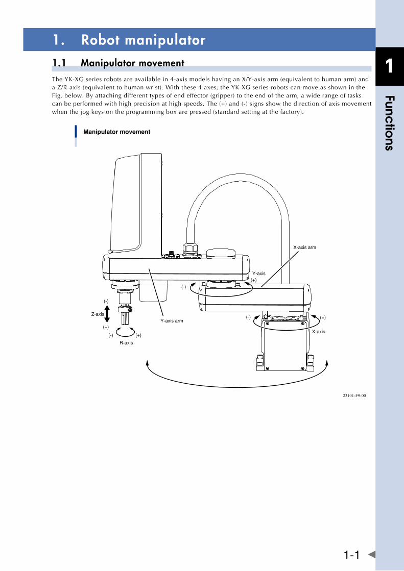
1. Robot manipulator1.1 Manipulator movementTheYK-XGseriesrobotsareavailablein4-axismodelshavinganX/Y-axisarm(equivalenttohumanarm)andaZ/R-axis(equivalenttohumanwrist).Withthese4axes,theYK-XGseriesrobotscanmoveasshownintheFig. below. By attaching different types of end effector (gripper) to the end of the arm, a wide range of tasks can be performed with high precision at high speeds. The (+) and (-) signs show the direction of axis movement when the jog keys on the programming box are pressed (standard setting at the factory).
Manipulator movement
Y-axis(+)
X-axis arm
(-)
(+)
X-axis
(-)Y-axis arm
Z-axis
(-)
(-)
(+)
(+)
R-axis
23101-F9-00
1-2
1
functio
ns
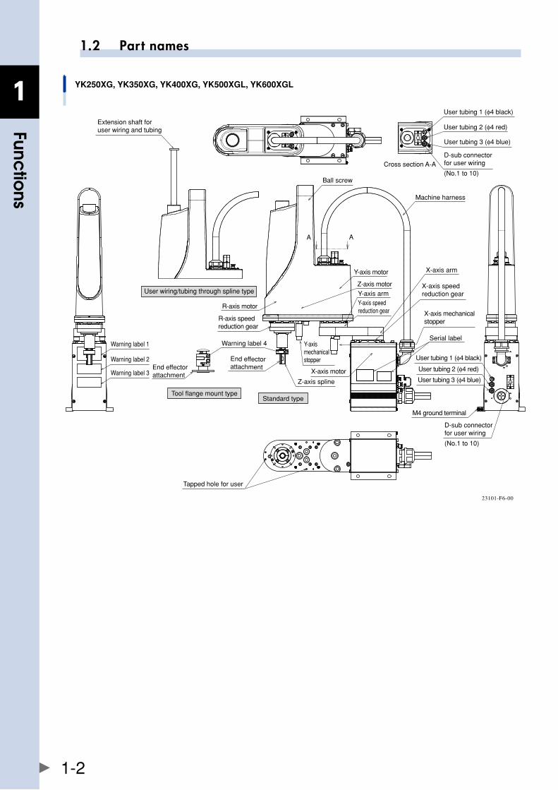
1.2 Part names
YK250XG, YK350XG, YK400XG, YK500XGL, YK600XGL
Machine harness
Ball screw
Extension shaft for user wiring and tubing
R-axis motor
R-axis speed reduction gear
Warning label 4
X-axis motor
Y-axis motor
Y-axis armY-axis speed reduction gear
Z-axis motor
Y-axis mechanical stopper
Z-axis spline
X-axis arm
X-axis speed reduction gear
X-axis mechanical stopper
User tubing 1 (φ4 black)
User tubing 2 (φ4 red)
User tubing 3 (φ4 blue)
M4 ground terminal
End effector attachmentEnd effector
attachment
Tapped hole for user
D-sub connector for user wiring
(No.1 to 10)
Serial label
User tubing 1 (φ4 black)
User tubing 3 (φ4 blue)
D-sub connector for user wiring
(No.1 to 10)
User tubing 2 (φ4 red)
Tool flange mount typeStandard type
Cross section A-A
User wiring/tubing through spline type
A A
Warning label 1
Warning label 2
Warning label 3
23101-F6-00
1-3
1
functio
ns
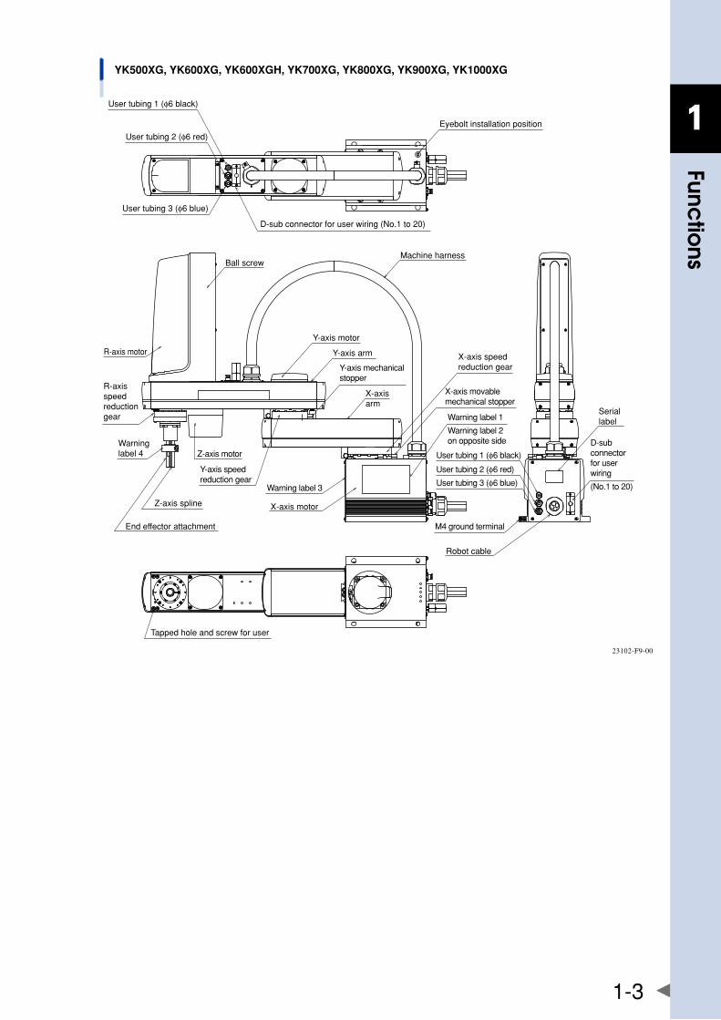
YK500XG, YK600XG, YK600XGH, YK700XG, YK800XG, YK900XG, YK1000XG
User tubing 1 (φ6 black)
User tubing 2 (φ6 red)
User tubing 3 (φ6 blue)
Machine harness
Eyebolt installation position
D-sub connector for user wiring (No.1 to 20)
Ball screw
R-axis motor
R-axis speed reduction gear
End effector attachment
Z-axis spline
Z-axis motor
Y-axis speed reduction gear
Y-axis arm
Y-axis motor
X-axis arm
Y-axis mechanical stopper
Warning label 3
X-axis motor
Tapped hole and screw for user
X-axis speed reduction gear
X-axis movable mechanical stopper
Warning label 1
Warning label 2 on opposite side
User tubing 1 (φ6 black)
User tubing 2 (φ6 red)
User tubing 3 (φ6 blue)
M4 ground terminal
Robot cable
D-sub connector for user wiring
(No.1 to 20)
Serial label
Warninglabel 4
23102-F9-00
1-4
1
functio
ns
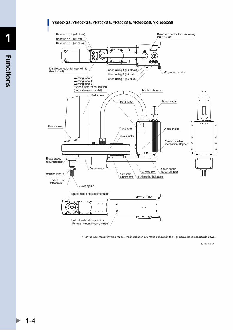
YK500XGS, YK600XGS, YK700XGS, YK800XGS, YK900XGS, YK1000XGS
Warning label 1Warning label 2Warning label 3Eyebolt installation position(For wall-mount model)
D-sub connector for user wiring (No.1 to 20)
User tubing 2 (φ6 red)
User tubing 3 (φ6 blue)
User tubing 1 (φ6 black)
User tubing 1 (φ6 black)
User tubing 2 (φ6 red)
User tubing 3 (φ6 blue)
D-sub connector for user wiring (No.1 to 20)
Eyebolt installation position (For wall-mount inverse model)
* For the wall-mount inverse model, the installation orientation shown in the Fig. above becomes upside down.
Ball screw
Serial label
Machine harness
X-axis motor
Y-axis motor
Y-axis armR-axis motor
R-axis speed reduction gear
Warning label 4
End effector attachment
Z-axis spline
Z-axis motor
Y-axis mechanical stopperY-axis speed reduction gear
X-axis armX-axis speed reduction gear
X-axis movable mechanical stopper
M4 ground terminal
Robot cable
Tapped hole and screw for user
23101-G8-00
1-5
1
functio
ns
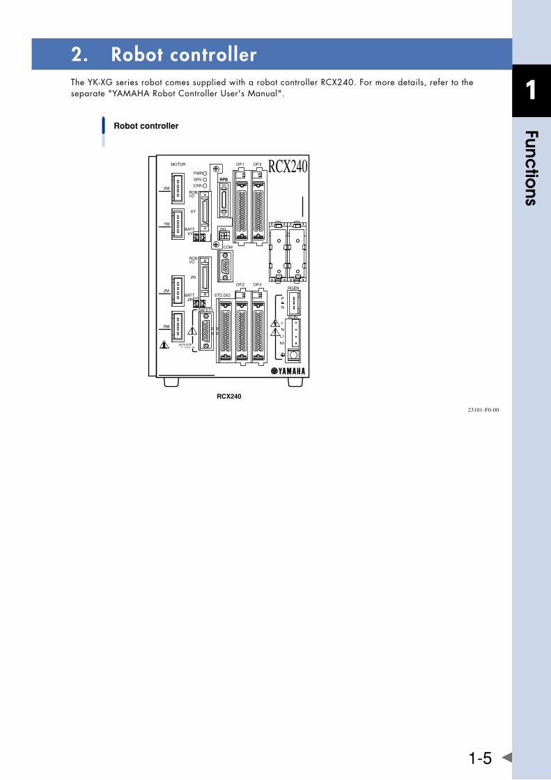
2. Robot controllerTheYK-XGseriesrobotcomessuppliedwitharobotcontrollerRCX240.Formoredetails,refertotheseparate"YAMAHARobotControllerUser'sManual".
RPB
MOTOR
XM
YM
ZM
RM
PWR
SRV
SAFETY
RPB
COM
STD.DIO
ROBI/O
ZR
OP.1 OP.3
OP.2 OP.4RGEN
ACIN
N
P
N1
L1
L
N
SEL
BATTZR
XYBATT
ROB
XY
I/O
13 14EXT.E-STOP
ERR
RCX240
Robot controller
RCX240
23101-F0-00
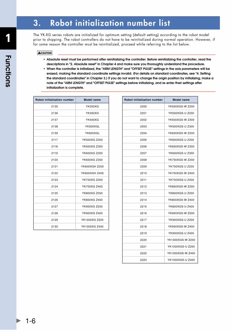
1-6
1
functio
ns
3. Robot initialization number listTheYK-XGseriesrobotsareinitializedforoptimumsetting(defaultsetting)accordingtotherobotmodelprior to shipping. The robot controllers do not have to be reinitialized during normal operation. However, if for some reason the controller must be reinitialized, proceed while referring to the list below.
• absoluteresetmustbeperformedafterreinitializingthecontroller.beforereinitializingthecontroller,readthe descriptions in "2. absolute reset" in Chapter 4 and make sure you thoroughly understand the procedure. • whenthecontrollerisinitialized,the"armlength"and"offsetPulse"settingsintheaxisparameterswillbe erased,makingthestandardcoordinatesettingsinvalid.(fordetailsonstandardcoordinates,see"4.setting the standard coordinates" in Chapter 3.) If you do not want to change the origin position by initializing, make a note of the "aRM lEngTh" and "OffSET PUlSE" settings before initializing, and re-enter their settings after initialization is complete.
Robot initialization number Model name
2135 YK250XG
2136 YK350XG
2137 YK400XG
2138 YK500XGL
2139 YK600XGL
2117 YK500XGZ200
2118 YK500XGZ300
2119 YK600XGZ200
2120 YK600XGZ300
2121 YK600XGHZ200
2122 YK600XGHZ400
2123 YK700XGZ200
2124 YK700XGZ400
2125 YK800XGZ200
2126 YK800XGZ400
2127 YK900XGZ200
2128 YK900XGZ400
2129 YK1000XGZ200
2130 YK1000XGZ400
Robot initialization number Model name
2200 YK500XGS-WZ200
2201 YK500XGS-UZ200
2202 YK500XGS-WZ300
2203 YK500XGS-UZ300
2204 YK600XGS-WZ200
2205 YK600XGS-UZ200
2206 YK600XGS-WZ300
2207 YK600XGS-UZ300
2208 YK700XGS-WZ200
2209 YK700XGS-UZ200
2210 YK700XGS-WZ400
2211 YK700XGS-UZ400
2212 YK800XGS-WZ200
2213 YK800XGS-UZ200
2214 YK800XGS-WZ400
2215 YK800XGS-UZ400
2216 YK900XGS-WZ200
2217 YK900XGS-UZ200
2218 YK900XGS-WZ400
2219 YK900XGS-UZ400
2220 YK1000XGS-WZ200
2221 YK1000XGS-UZ200
2222 YK1000XGS-WZ400
2223 YK1000XGS-UZ400
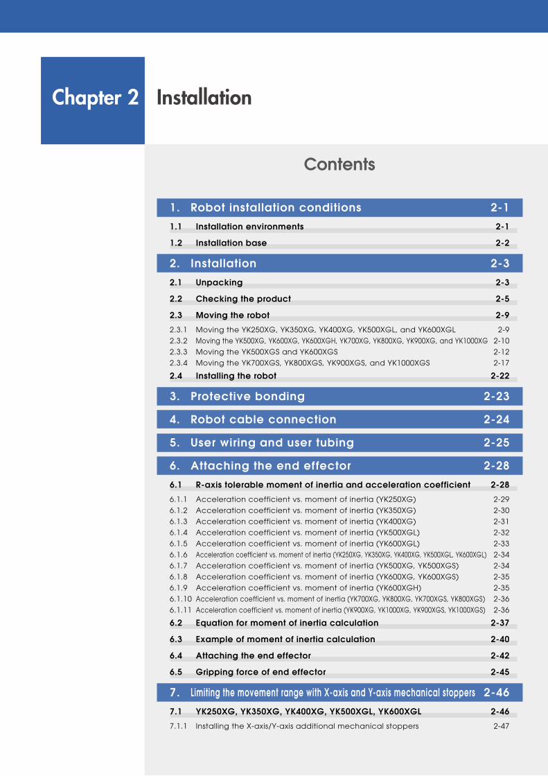
Chapter 2 Installation
Contents
1. Robot installation conditions 2-1
1.1 Installation environments 2-1
1.2 Installation base 2-2
2. Installation 2-3
2.1 Unpacking 2-3
2.2 Checking the product 2-5
2.3 Moving the robot 2-9
2.3.1 Moving the YK250XG, YK350XG, YK400XG, YK500XGL, and YK600XGL 2-9
2.3.2 Moving the YK500XG, YK600XG, YK600XGH, YK700XG, YK800XG, YK900XG, and YK1000XG 2-10
2.3.3 Moving the YK500XGS and YK600XGS 2-12
2.3.4 Moving the YK700XGS, YK800XGS, YK900XGS, and YK1000XGS 2-17
2.4 Installing the robot 2-22
3. Protective bonding 2-23
4. Robot cable connection 2-24
5. User wiring and user tubing 2-25
6. attaching the end ef fector 2-28
6.1 r-axistolerablemomentofinertiaandaccelerationcoefficient 2-28
6.1.1 Acceleration coefficient vs. moment of inertia (YK250XG) 2-29
6.1.2 Acceleration coefficient vs. moment of inertia (YK350XG) 2-30
6.1.3 Acceleration coefficient vs. moment of inertia (YK400XG) 2-31
6.1.4 Acceleration coefficient vs. moment of inertia (YK500XGL) 2-32
6.1.5 Acceleration coefficient vs. moment of inertia (YK600XGL) 2-33
6.1.6 Acceleration coefficient vs. moment of inertia (YK250XG, YK350XG, YK400XG, YK500XGL, YK600XGL) 2-34
6.1.7 Acceleration coefficient vs. moment of inertia (YK500XG, YK500XGS) 2-34
6.1.8 Acceleration coefficient vs. moment of inertia (YK600XG, YK600XGS) 2-35
6.1.9 Acceleration coefficient vs. moment of inertia (YK600XGH) 2-35
6.1.10 Acceleration coefficient vs. moment of inertia (YK700XG, YK800XG, YK700XGS, YK800XGS) 2-36
6.1.11 Acceleration coefficient vs. moment of inertia (YK900XG, YK1000XG, YK900XGS, YK1000XGS) 2-36
6.2 Equation for moment of inertia calculation 2-37
6.3 exampleofmomentofinertiacalculation 2-40
6.4 attaching the end effector 2-42
6.5 gripping force of end effector 2-45
7. limiting the movement range with x-axisandy-axis mechanical stoppers 2-46
7.1 yk250xg, yk350xg, yk400xg, yk500xgl, yk600xgl 2-46
7.1.1 Installing the X-axis/Y-axis additional mechanical stoppers 2-47
7.1.2 Robot overrun during impacts with X-axis or Y-axis mechanical stopper 2-49
7.2 yk500xg, yk600xg, yk600xgh, yk700xg, yk800xg, yk900xg, yk1000xg yk500xgS, yk600xgS, yk700xgS, yk800xgS, yk900xgS, yk1000xgS 2-507.2.1 Changing the X-axis mechanical stopper position 2-54
7.2.2 Changing the Y-axis mechanical stopper position 2-56
7.2.3 Robot overrun during impacts with X-axis or Y-axis mechanical stopper 2-59
8. limiting the movement range withz-axismechanicalstopper 2-60
8.1 yk250xg, yk350xg, yk400xg, yk500xgl, yk600xgl 2-60
8.1.1 Installing the minus direction stopper 2-61
8.1.2 Installing the plus direction stopper 2-63
8.1.3 Overrun amounts during impacts with Z-axis additional mechanical stopper 2-64
8.2 yk500xg, yk600xg, yk600xgh, yk700xg, yk800xg, yk900xg, yk1000xg yk500xgS, yk600xgS, yk700xgS, yk800xgS, yk900xgS, yk1000xgS 2-658.2.1 Installing the minus direction stopper 2-67
8.2.2 Installing the plus direction stopper 2-69
8.2.3 Overrun amounts during impacts with Z-axis additional mechanical stopper 2-70
9. Working envelope and mechanical stopper positionsformaximumworkingenvelope 2-71
10. Stopping time and stopping distance at emergency stop 2-74
10.1 yk250xg, yk350xg, yk400xg, yk500xgl, yk600xgl 2-74
10.2 yk500xg, yk600xg, yk500xgS, yk600xgS 2-80
10.3 yk600xgh, yk700xg, yk800xg, yk900xg, yk1000xg yk700xgS, yk800xgS, yk900xgS, yk1000xgS 2-85
11. Installing the user wiring and tubing newly 2-94
12. Passing the wiring and tubing in the user wiring/tubing through spline type 2-95
13. Detaching or attaching the covers 2-96
14. installingtheextensionshaft(foruserwiring/tubingthroughsplinetype) 2-101
15. Installing the tool flange 2-103
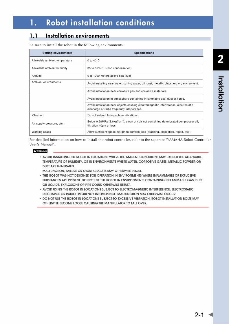
2
Installa
tion
2-1
1. Robot installation conditions1.1 Installation environmentsBe sure to install the robot in the following environments.
Setting environments Specifications
Allowableambienttemperature 0to40°C
Allowableambienthumidity 35to85%RH(noncondensation)
Altitude 0to1000metersabovesealevel
Ambientenvironments Avoidinstallingnearwater,cuttingwater,oil,dust,metallicchipsandorganicsolvent.
Avoidinstallationnearcorrosivegasandcorrosivematerials.
Avoidinstallationinatmospherecontaininginflammablegas,dustorliquid.
Avoidinstallationnearobjectscausingelectromagneticinterference,electrostatic
dischargeorradiofrequencyinterference.
Vibration Donotsubjecttoimpactsorvibrations.
Airsupplypressure,etc.Below0.58MPa(6.0kgf/cm2);cleandryairnotcontainingdeterioratedcompressoroil;
filtration40μmorless
Workingspace Allowsufficientspacemargintoperformjobs(teaching,inspection,repair,etc.)
For detailed information on how to install the robot controller, refer to the separate "YAMAHA Robot Controller User'sManual".
• avoiDinstallingtherobotinlocationswheretheambientconDitionsmayexceeDtheallowable TEMPERaTURE OR hUMIDITy, OR In EnvIROnMEnTS WhERE WaTER, CORROSIvE gaSES, METallIC POWDER OR DUST aRE gEnERaTED. MalfUnCTIOn, faIlURE OR ShORT CIRCUITS May OThERWISE RESUlT. • thisrobotwasnotDesigneDforoPerationinenvironmentswhereinflammableorexPlosive SUbSTanCES aRE PRESEnT. DO nOT USE ThE RObOT In EnvIROnMEnTS COnTaInIng InflaMMablE gaS, DUST OR lIqUIDS. ExPlOSIOnS OR fIRE COUlD OThERWISE RESUlT. • avoiDusingtherobotinlocationssubjecttoelectromagneticinterference,electrostatic DISChaRgE OR RaDIO fREqUEnCy InTERfEREnCE. MalfUnCTIOn May OThERWISE OCCUR. • Donotusetherobotinlocationssubjecttoexcessivevibration.robotinstallationboltsmay OThERWISE bECOME lOOSE CaUSIng ThE ManIPUlaTOR TO fall OvER.
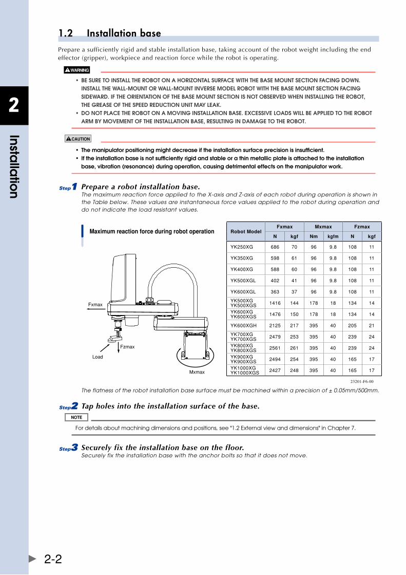
2
Installa
tion
2-2
1.2 Installation basePrepare a sufficiently rigid and stable installation base, taking account of the robot weight including the end effector (gripper), workpiece and reaction force while the robot is operating.
• besuretoinstalltherobotonahorizontalsurfacewiththebasemountsectionfacingDown. InSTall ThE Wall-MOUnT OR Wall-MOUnT InvERSE MODEl RObOT WITh ThE baSE MOUnT SECTIOn faCIng SIDEWaRD. If ThE ORIEnTaTIOn Of ThE baSE MOUnT SECTIOn IS nOT ObSERvED WhEn InSTallIng ThE RObOT, ThE gREaSE Of ThE SPEED REDUCTIOn UnIT May lEak. • DonotPlacetherobotonamovinginstallationbase.excessiveloaDswillbeaPPlieDtotherobot aRM by MOvEMEnT Of ThE InSTallaTIOn baSE, RESUlTIng In DaMagE TO ThE RObOT.
• themanipulatorpositioningmightdecreaseiftheinstallationsurfaceprecisionisinsufficient. • iftheinstallationbaseisnotsufficientlyrigidandstableorathinmetallicplateisattachedtotheinstallation base,vibration(resonance)duringoperation,causingdetrimentaleffectsonthemanipulatorwork.
1 Prepare a robot installation base.The maximum reaction force applied to the X-axis and Z-axis of each robot during operation is shown in the Table below. These values are instantaneous force values applied to the robot during operation and do not indicate the load resistant values.
Maximum reaction force during robot operation
Fxmax
Fzmax
Mxmax
Load
23201-F6-00
The flatness of the robot installation base surface must be machined within a precision of ± 0.05mm/500mm.
2 Tap holes into the installation surface of the base.
For details about machining dimensions and positions, see "1.2 External view and dimensions" in Chapter 7.
3 Securely fix the installation base on the floor.Securely fix the installation base with the anchor bolts so that it does not move.
Robot ModelFxmax Mxmax Fzmax
N kgf Nm kgfm N kgf
YK250XG 686 70 96 9.8 108 11
YK350XG 598 61 96 9.8 108 11
YK400XG 588 60 96 9.8 108 11
YK500XGL 402 41 96 9.8 108 11
YK600XGL 363 37 96 9.8 108 11
YK500XGYK500XGS 1416 144 178 18 134 14
YK600XGYK600XGS 1476 150 178 18 134 14
YK600XGH 2125 217 395 40 205 21
YK700XGYK700XGS 2479 253 395 40 239 24
YK800XGYK800XGS 2561 261 395 40 239 24
YK900XGYK900XGS 2494 254 395 40 165 17
YK1000XGYK1000XGS 2427 248 395 40 165 17
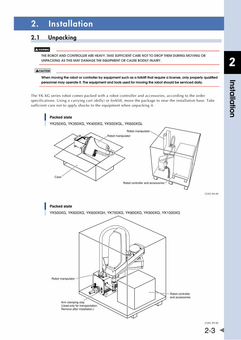
2
Installa
tion
2-3
2. Installation2.1 Unpacking
ThE RObOT anD COnTROllER aRE hEavy. TakE SUffICIEnT CaRE nOT TO DROP ThEM DURIng MOvIng OR UnPaCkIng aS ThIS May DaMagE ThE EqUIPMEnT OR CaUSE bODIly InjURy.
whenmovingtherobotorcontrollerbyequipmentsuchasafolkliftthatrequirealicense,onlyproperlyqualifiedpersonnel may operate it. The equipment and tools used for moving the robot should be serviced daily.
TheYK-XGseriesrobotcomespackedwitharobotcontrollerandaccessories,accordingtotheorderspecifications.Usingacarryingcart(dolly)orforklift,movethepackagetoneartheinstallationbase.Takesufficient care not to apply shocks to the equipment when unpacking it.
Packed state
YK250XG, YK350XG, YK400XG, YK500XGL, YK600XGL
Case
Robot manipulator
Robot manipulator
Robot controller and accessories
23202-F6-00
Packed state
YK500XG, YK600XG, YK600XGH, YK700XG, YK800XG, YK900XG, YK1000XG
Robot manipulator
Robot controllerand accessories
Arm clamping stay(Used only for transportation.Remove after installation.)
23201-F9-00
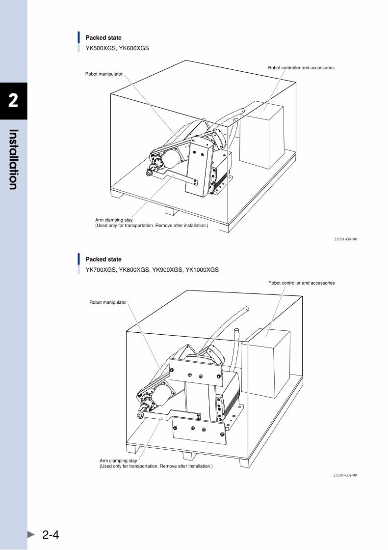
2
Installa
tion
2-4
Packed state
YK500XGS, YK600XGS
Robot manipulatorRobot controller and accessories
Arm clamping stay(Used only for transportation. Remove after installation.)
23201-G8-00
Packed state
YK700XGS, YK800XGS, YK900XGS, YK1000XGS
Robot manipulator
Robot controller and accessories
Arm clamping stay(Used only for transportation. Remove after installation.)
23201-GA-00
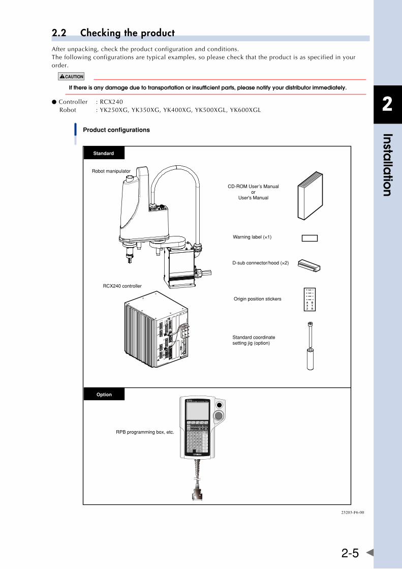
2
Installa
tion
2-5
2.2 Checking the productAfter unpacking, check the product configuration and conditions.The following configurations are typical examples, so please check that the product is as specified in your order.
ifthereisanydamageduetotransportationorinsufficientparts,pleasenotifyyourdistributorimmediately.
● Controller :RCX240Robot :YK250XG,YK350XG,YK400XG,YK500XGL,YK600XGL
RPBMOTOR
XM
YM
ZM
RM
PWR
SRV
SAFETY
RPB
COM
STD.DIO
ROBI/O
ZR
OP.1OP.3
OP.2OP.4
ACINN
P
N1
L1
L
N
SEL
BATT
ZR
XYBATT
ROB
XY
I/O
ERR
RCX240
A BX YZ R
Product configurations
RPB programming box, etc.
Robot manipulator
CD-ROM User’s Manualor
User's Manual
RCX240 controller
Warning label (×1)
Standard coordinatesetting jig (option)
Origin position stickers
D-sub connector/hood (×2)
Standard
Option
23203-F6-00
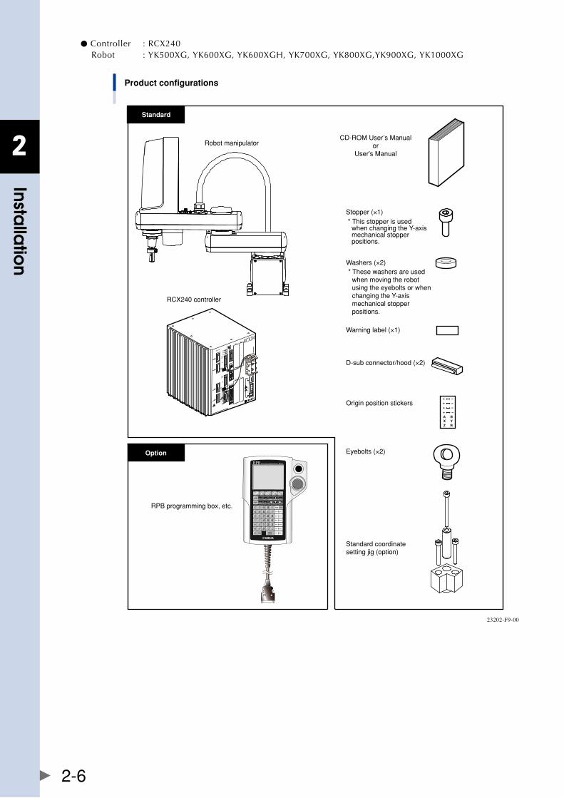
2
Installa
tion
2-6
● Controller :RCX240Robot :YK500XG,YK600XG,YK600XGH,YK700XG,YK800XG,YK900XG,YK1000XG
RPBMOTOR
XM
YM
ZM
RM
PWR
SRV
SAFETY
RPB
COM
STD.DIO
ROBI/O
ZR
OP.1OP.3
OP.2OP.4
ACINN
P
N1
L1
L
N
SEL
BATT
ZR
XYBATT
ROB
XY
I/O
ERR
RCX240
A BX YZ R
Product configurations
RPB programming box, etc.
Robot manipulatorCD-ROM User’s Manual
orUser's Manual
RCX240 controller
Standard coordinatesetting jig (option)
Standard
Option
Warning label (×1)
Eyebolts (×2)
Origin position stickers
D-sub connector/hood (×2)
* These washers are used when moving the robot using the eyebolts or when changing the Y-axis mechanical stopper positions.
Washers (×2)
* This stopper is used when changing the Y-axis mechanical stopper positions.
Stopper (×1)
23202-F9-00
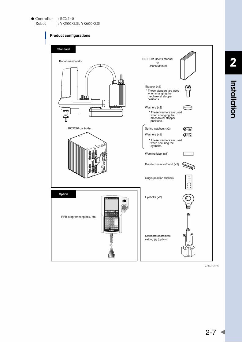
2
Installa
tion
2-7
● Controller :RCX240Robot :YK500XGS,YK600XGS
RPBMOTOR
XM
YM
ZM
RM
PWR
SRV
SAFETY
RPB
COM
STD.DIO
ROBI/O
ZR
OP.1OP.3
OP.2OP.4
ACINN
P
N1
L1
L
N
SEL
BATT
ZR
XYBATT
ROB
XY
I/O
ERR
RCX240
A BX YZ R
Product configurations
RPB programming box, etc.
Robot manipulatorCD-ROM User’s Manual
orUser's Manual
RCX240 controller
Standard coordinatesetting jig (option)
Standard
Option
Warning label (×1)
Eyebolts (×2)
Origin position stickers
D-sub connector/hood (×2)
* These washers are used when changing the mechanical stopper positions.
Washers (×2)
Spring washers (×2)
* These washers are used when securing the eyebolts.
Washers (×2)
* These stoppers are used when changing the mechanical stopper positions.
Stopper (×2)
23202-G8-00
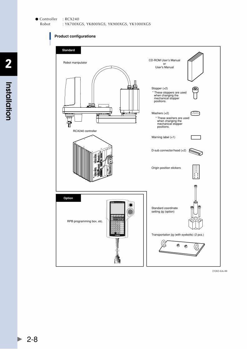
2
Installa
tion
2-8
● Controller :RCX240Robot :YK700XGS,YK800XGS,YK900XGS,YK1000XGS
RPBMOTOR
XM
YM
ZM
RM
PWR
SRV
SAFETY
RPB
COM
STD.DIO
ROBI/O
ZR
OP.1OP.3
OP.2OP.4
ACINN
P
N1
L1
L
N
SEL
BATT
ZR
XYBATT
ROB
XY
I/O
ERR
RCX240
A BX YZ R
Product configurations
RPB programming box, etc.
Robot manipulatorCD-ROM User’s Manual
orUser's Manual
RCX240 controller
Standard coordinatesetting jig (option)
Transportation jig (with eyebolts) (2 pcs.)
Standard
Option
Warning label (×1)
Origin position stickers
D-sub connector/hood (×2)
Washers (×2)
* These washers are used when changing the mechanical stopper positions.
* These stoppers are used when changing the mechanical stopper positions.
Stopper (×2)
23202-GA-00
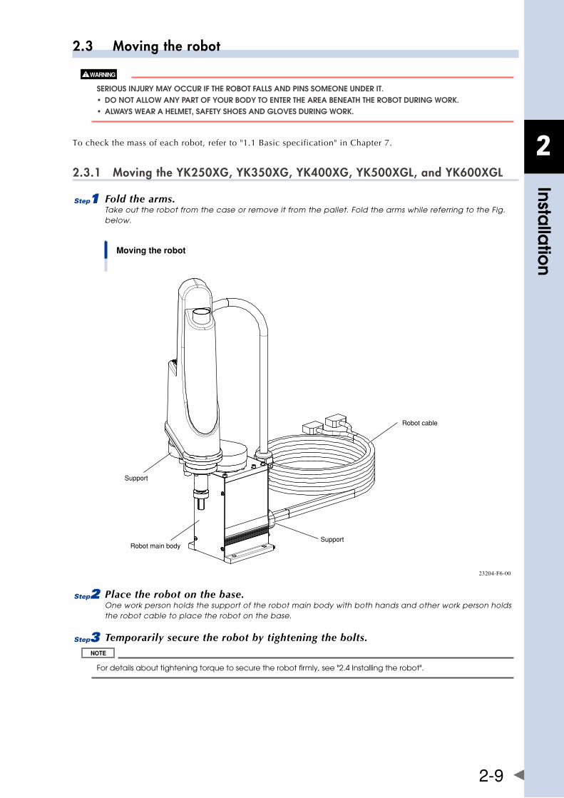
2
Installa
tion
2-9
2.3 Moving the robot
SERIOUS InjURy May OCCUR If ThE RObOT fallS anD PInS SOMEOnE UnDER IT. • DonotallowanyPartofyourboDytoentertheareabeneaththerobotDuringworK. • alwayswearahelmet,safetyshoesanDglovesDuringworK.
To check the mass of each robot, refer to "1.1 Basic specification" in Chapter 7.
2.3.1 Moving the YK250XG, YK350XG, YK400XG, YK500XGL, and YK600XGL
1 Fold the arms.Take out the robot from the case or remove it from the pallet. Fold the arms while referring to the Fig. below.
Moving the robot
Support
Robot cable
SupportRobot main body
23204-F6-00
2 Place the robot on the base.One work person holds the support of the robot main body with both hands and other work person holds the robot cable to place the robot on the base.
3 Temporarily secure the robot by tightening the bolts.
For details about tightening torque to secure the robot firmly, see "2.4 Installing the robot".
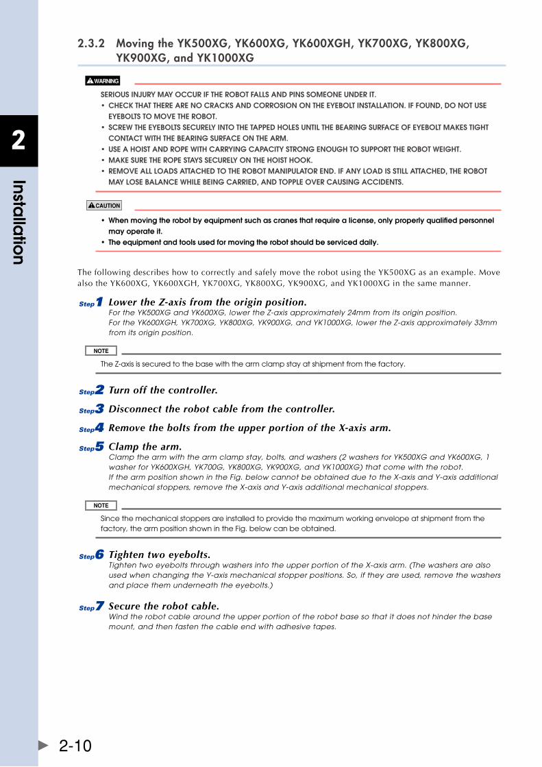
2
Installa
tion
2-10
2.3.2 Moving the YK500XG, YK600XG, YK600XGH, YK700XG, YK800XG, YK900XG, and YK1000XG
SERIOUS InjURy May OCCUR If ThE RObOT fallS anD PInS SOMEOnE UnDER IT. • checKthattherearenocracKsanDcorrosionontheeyeboltinstallation.iffounD,Donotuse EyEbOlTS TO MOvE ThE RObOT. • screwtheeyeboltssecurelyintothetaPPeDholesuntilthebearingsurfaceofeyeboltmaKestight COnTaCT WITh ThE bEaRIng SURfaCE On ThE aRM. • useahoistanDroPewithcarryingcaPacitystrongenoughtosuPPorttherobotweight. • maKesuretheroPestayssecurelyonthehoisthooK. • removeallloaDsattacheDtotherobotmaniPulatorenD.ifanyloaDisstillattacheD,therobot May lOSE balanCE WhIlE bEIng CaRRIED, anD TOPPlE OvER CaUSIng aCCIDEnTS.
• whenmovingtherobotbyequipmentsuchascranesthatrequirealicense,onlyproperlyqualifiedpersonnel may operate it. • theequipmentandtoolsusedformovingtherobotshouldbeserviceddaily.
ThefollowingdescribeshowtocorrectlyandsafelymovetherobotusingtheYK500XGasanexample.MovealsotheYK600XG,YK600XGH,YK700XG,YK800XG,YK900XG,andYK1000XGinthesamemanner.
1 Lower the Z-axis from the origin position.For the YK500XG and YK600XG, lower the Z-axis approximately 24mm from its origin position. For the YK600XGH, YK700XG, YK800XG, YK900XG, and YK1000XG, lower the Z-axis approximately 33mm from its origin position.
The Z-axis is secured to the base with the arm clamp stay at shipment from the factory.
2 Turn off the controller.
3 Disconnect the robot cable from the controller.
4 Remove the bolts from the upper portion of the X-axis arm.
5 Clamp the arm.Clamp the arm with the arm clamp stay, bolts, and washers (2 washers for YK500XG and YK600XG, 1 washer for YK600XGH, YK700G, YK800XG, YK900XG, and YK1000XG) that come with the robot. If the arm position shown in the Fig. below cannot be obtained due to the X-axis and Y-axis additional mechanical stoppers, remove the X-axis and Y-axis additional mechanical stoppers.
Since the mechanical stoppers are installed to provide the maximum working envelope at shipment from the factory, the arm position shown in the Fig. below can be obtained.
6 Tighten two eyebolts.Tighten two eyebolts through washers into the upper portion of the X-axis arm. (The washers are also used when changing the Y-axis mechanical stopper positions. So, if they are used, remove the washers and place them underneath the eyebolts.)
7 Secure the robot cable.Wind the robot cable around the upper portion of the robot base so that it does not hinder the base mount, and then fasten the cable end with adhesive tapes.
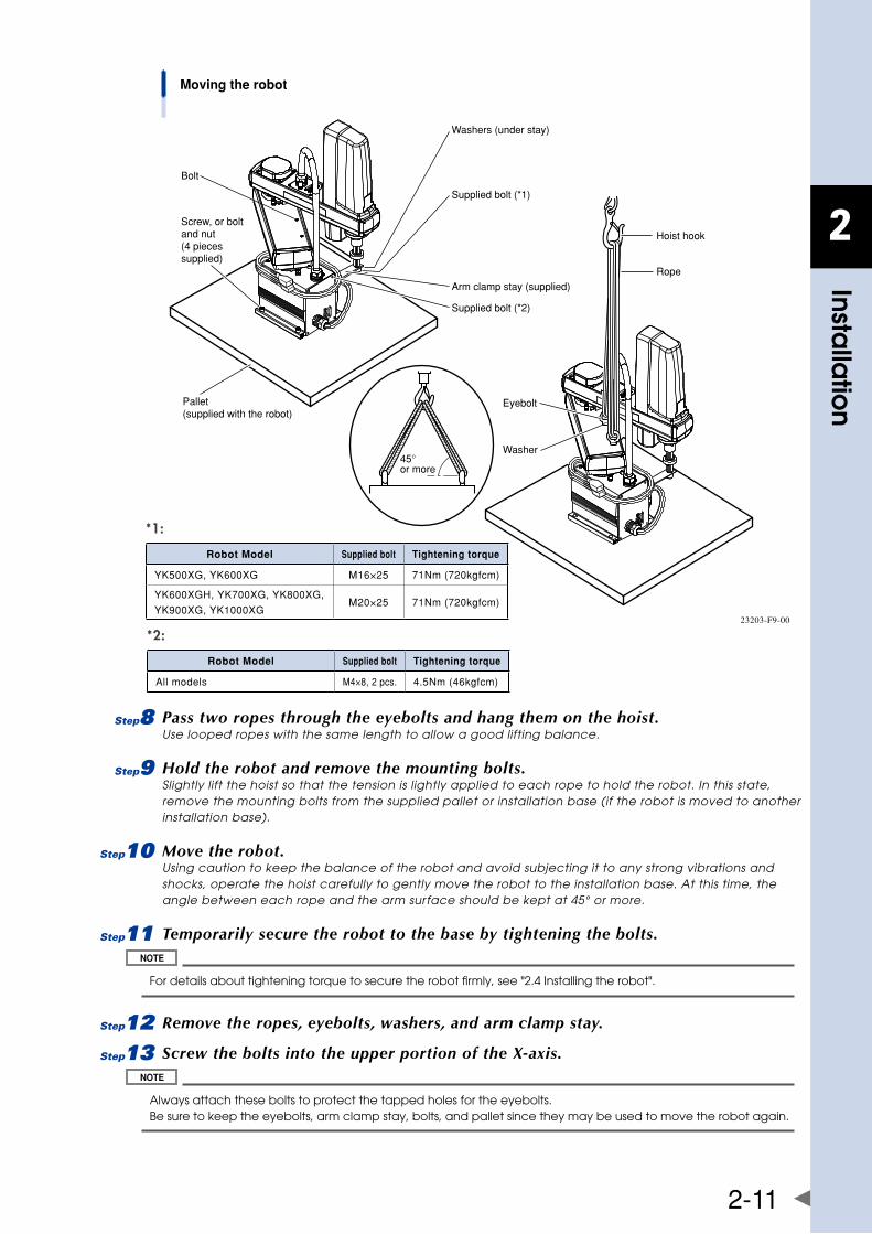
2
Installa
tion
2-11
Pallet(supplied with the robot)
Screw, or boltand nut(4 piecessupplied)
Bolt
Supplied bolt (*1)
Arm clamp stay (supplied)
Supplied bolt (*2)
45°or more
Washers (under stay)
Hoist hook
Rope
Eyebolt
Washer
Moving the robot
23203-F9-00
8 Pass two ropes through the eyebolts and hang them on the hoist.Use looped ropes with the same length to allow a good lifting balance.
9 Hold the robot and remove the mounting bolts.Slightly lift the hoist so that the tension is lightly applied to each rope to hold the robot. In this state, remove the mounting bolts from the supplied pallet or installation base (if the robot is moved to another installation base).
0 Move the robot.Using caution to keep the balance of the robot and avoid subjecting it to any strong vibrations and shocks, operate the hoist carefully to gently move the robot to the installation base. At this time, the angle between each rope and the arm surface should be kept at 45° or more.
q Temporarily secure the robot to the base by tightening the bolts.
For details about tightening torque to secure the robot firmly, see "2.4 Installing the robot".
w Remove the ropes, eyebolts, washers, and arm clamp stay.
e Screw the bolts into the upper portion of the X-axis.
Always attach these bolts to protect the tapped holes for the eyebolts. Be sure to keep the eyebolts, arm clamp stay, bolts, and pallet since they may be used to move the robot again.
*1:
Robot Model Supplied bolt Tightening torque
YK500XG,YK600XG M16×25 71Nm(720kgfcm)
YK600XGH,YK700XG,YK800XG,
YK900XG,YK1000XGM20×25 71Nm(720kgfcm)
*2:
Robot Model Supplied bolt Tightening torque
Allmodels M4×8,2pcs. 4.5Nm(46kgfcm)
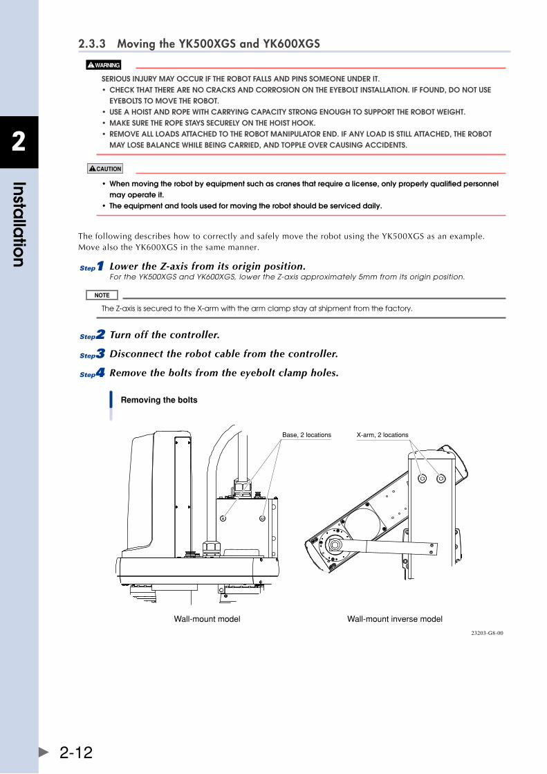
2
Installa
tion
2-12
2.3.3 Moving the YK500XGS and YK600XGS
SERIOUS InjURy May OCCUR If ThE RObOT fallS anD PInS SOMEOnE UnDER IT. • checKthattherearenocracKsanDcorrosionontheeyeboltinstallation.iffounD,Donotuse EyEbOlTS TO MOvE ThE RObOT. • useahoistanDroPewithcarryingcaPacitystrongenoughtosuPPorttherobotweight. • maKesuretheroPestayssecurelyonthehoisthooK. • removeallloaDsattacheDtotherobotmaniPulatorenD.ifanyloaDisstillattacheD,therobot May lOSE balanCE WhIlE bEIng CaRRIED, anD TOPPlE OvER CaUSIng aCCIDEnTS.
• whenmovingtherobotbyequipmentsuchascranesthatrequirealicense,onlyproperlyqualifiedpersonnel may operate it. • theequipmentandtoolsusedformovingtherobotshouldbeserviceddaily.
ThefollowingdescribeshowtocorrectlyandsafelymovetherobotusingtheYK500XGSasanexample.MovealsotheYK600XGSinthesamemanner.
1 Lower the Z-axis from its origin position.For the YK500XGS and YK600XGS, lower the Z-axis approximately 5mm from its origin position.
The Z-axis is secured to the X-arm with the arm clamp stay at shipment from the factory.
2 Turn off the controller.
3 Disconnect the robot cable from the controller.
4 Remove the bolts from the eyebolt clamp holes.
Removing the bolts
Base, 2 locations X-arm, 2 locations
Wall-mount model Wall-mount inverse model
23203-G8-00
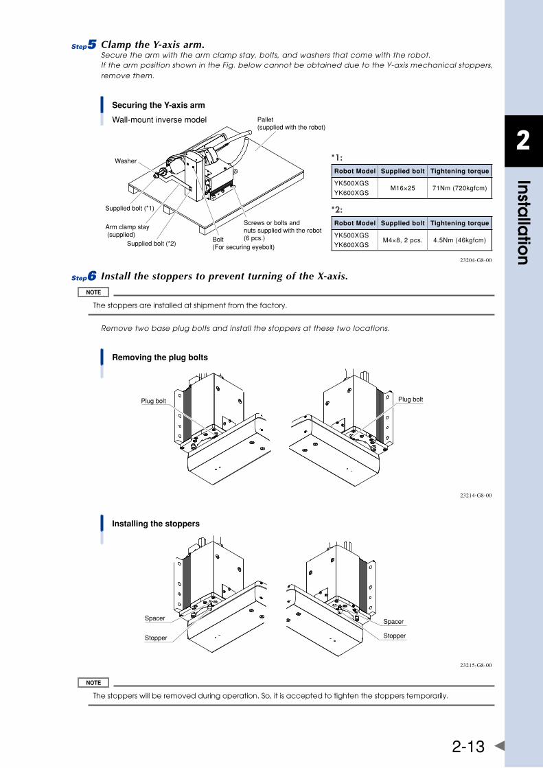
2
Installa
tion
2-13
5 Clamp the Y-axis arm.Secure the arm with the arm clamp stay, bolts, and washers that come with the robot. If the arm position shown in the Fig. below cannot be obtained due to the Y-axis mechanical stoppers, remove them.
Securing the Y-axis arm
Wall-mount inverse model Pallet(supplied with the robot)
Screws or bolts and nuts supplied with the robot(6 pcs.)Bolt
(For securing eyebolt)
Arm clamp stay (supplied)
Supplied bolt (*2)
Supplied bolt (*1)
Washer
23204-G8-00
6 Install the stoppers to prevent turning of the X-axis.
The stoppers are installed at shipment from the factory.
Remove two base plug bolts and install the stoppers at these two locations.
Removing the plug bolts
Plug boltPlug bolt
23214-G8-00
Installing the stoppers
Stopper
SpacerSpacer
Stopper
23215-G8-00
The stoppers will be removed during operation. So, it is accepted to tighten the stoppers temporarily.
*2:Robot Model Supplied bolt Tightening torque
YK500XGS
YK600XGSM4×8,2pcs. 4.5Nm(46kgfcm)
*1:Robot Model Supplied bolt Tightening torque
YK500XGS
YK600XGSM16×25 71Nm(720kgfcm)
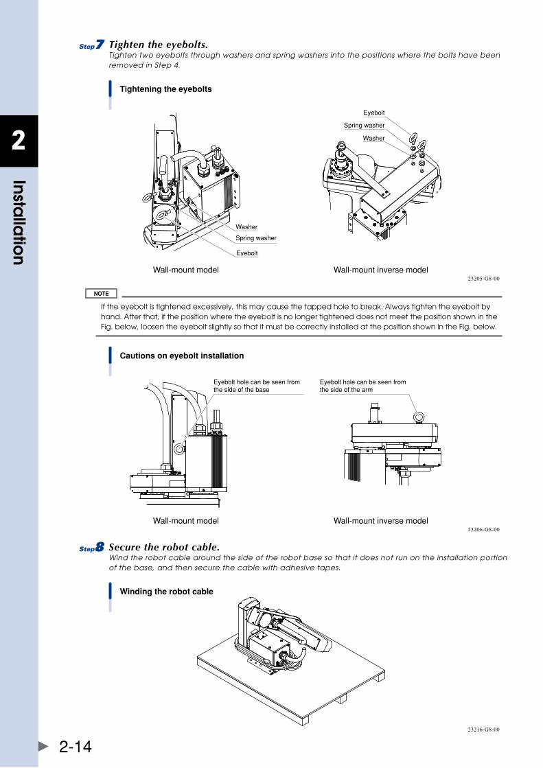
2
Installa
tion
2-14
7 Tighten the eyebolts.Tighten two eyebolts through washers and spring washers into the positions where the bolts have been removed in Step 4.
Tightening the eyebolts
Wall-mount model Wall-mount inverse model
Washer
Eyebolt
Washer
Spring washer
Eyebolt
Spring washer
23205-G8-00
If the eyebolt is tightened excessively, this may cause the tapped hole to break. Always tighten the eyebolt by hand. After that, if the position where the eyebolt is no longer tightened does not meet the position shown in the Fig. below, loosen the eyebolt slightly so that it must be correctly installed at the position shown in the Fig. below.
Cautions on eyebolt installation
Wall-mount model Wall-mount inverse model
Eyebolt hole can be seen from the side of the base
Eyebolt hole can be seen from the side of the arm
23206-G8-00
8 Secure the robot cable.Wind the robot cable around the side of the robot base so that it does not run on the installation portion of the base, and then secure the cable with adhesive tapes.
Winding the robot cable
23216-G8-00
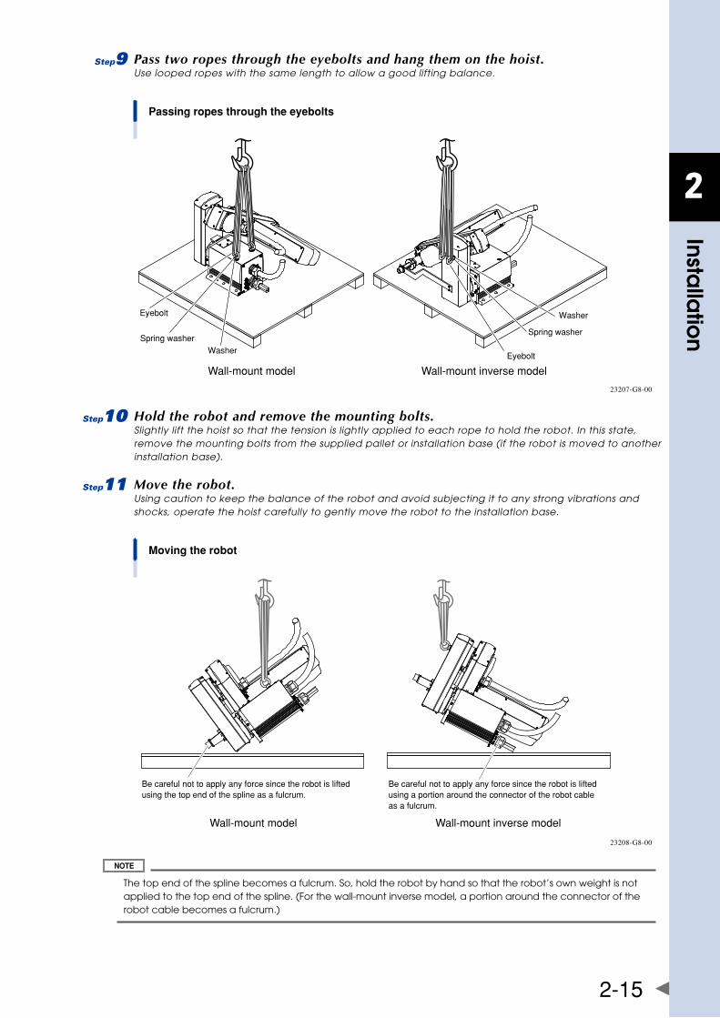
2
Installa
tion
2-15
9 Pass two ropes through the eyebolts and hang them on the hoist.Use looped ropes with the same length to allow a good lifting balance.
Passing ropes through the eyebolts
Wall-mount model Wall-mount inverse model
WasherSpring washer
Eyebolt Washer
Spring washer
Eyebolt
23207-G8-00
0 Hold the robot and remove the mounting bolts.Slightly lift the hoist so that the tension is lightly applied to each rope to hold the robot. In this state, remove the mounting bolts from the supplied pallet or installation base (if the robot is moved to another installation base).
q Move the robot.Using caution to keep the balance of the robot and avoid subjecting it to any strong vibrations and shocks, operate the hoist carefully to gently move the robot to the installation base.
Moving the robot
Wall-mount model Wall-mount inverse model
Be careful not to apply any force since the robot is lifted using the top end of the spline as a fulcrum.
Be careful not to apply any force since the robot is lifted using a portion around the connector of the robot cable as a fulcrum.
23208-G8-00
The top end of the spline becomes a fulcrum. So, hold the robot by hand so that the robot’s own weight is not applied to the top end of the spline. (For the wall-mount inverse model, a portion around the connector of the robot cable becomes a fulcrum.)
2
Installa
tion
2-16
w Temporarily secure the robot to the base by tightening the bolts.
• Fordetailsabouttighteningtorquetosecuretherobotfirmly,see"2.4Installingtherobot". • Wheninstallingtherobot,thepositioningpinscanbeused.Fordetailsaboutpositionsanddimensions,see "1.2 External view and dimensions" in Chapter 7.
e Remove the ropes, eyebolts, washers, and arm clamp stay.
r Remove the X-axis mechanical stoppers.Remove the X-axis mechanical stoppers that have been installed in Step 6.
t Screw the bolts into the eyebolt clamp holes and mechanical stopper clamp holes.
Always attach these bolts to protect the tapped holes. Be sure to keep the eyebolts, arm clamp stay, bolts, and pallet since they may be used to move the robot again.
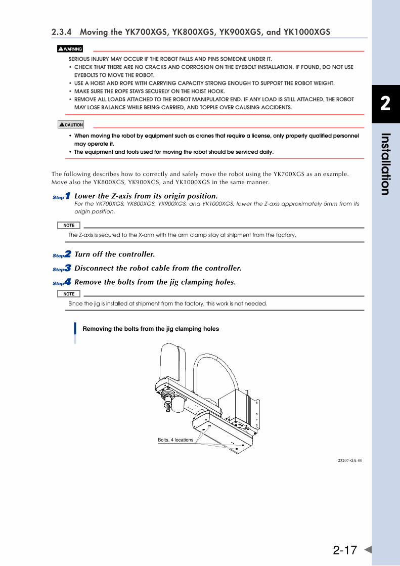
2
Installa
tion
2-17
2.3.4 Moving the YK700XGS, YK800XGS, YK900XGS, and YK1000XGS
SERIOUS InjURy May OCCUR If ThE RObOT fallS anD PInS SOMEOnE UnDER IT. • checKthattherearenocracKsanDcorrosionontheeyeboltinstallation.iffounD,Donotuse EyEbOlTS TO MOvE ThE RObOT. • useahoistanDroPewithcarryingcaPacitystrongenoughtosuPPorttherobotweight. • maKesuretheroPestayssecurelyonthehoisthooK. • removeallloaDsattacheDtotherobotmaniPulatorenD.ifanyloaDisstillattacheD,therobot May lOSE balanCE WhIlE bEIng CaRRIED, anD TOPPlE OvER CaUSIng aCCIDEnTS.
• whenmovingtherobotbyequipmentsuchascranesthatrequirealicense,onlyproperlyqualifiedpersonnel may operate it. • theequipmentandtoolsusedformovingtherobotshouldbeserviceddaily.
ThefollowingdescribeshowtocorrectlyandsafelymovetherobotusingtheYK700XGSasanexample.MovealsotheYK800XGS,YK900XGS,andYK1000XGSinthesamemanner.
1 Lower the Z-axis from its origin position.For the YK700XGS, YK800XGS, YK900XGS, and YK1000XGS, lower the Z-axis approximately 5mm from its origin position.
The Z-axis is secured to the X-arm with the arm clamp stay at shipment from the factory.
2 Turn off the controller.
3 Disconnect the robot cable from the controller.
4 Remove the bolts from the jig clamping holes.
Since the jig is installed at shipment from the factory, this work is not needed.
Removing the bolts from the jig clamping holes
Bolts, 4 locations
23207-GA-00
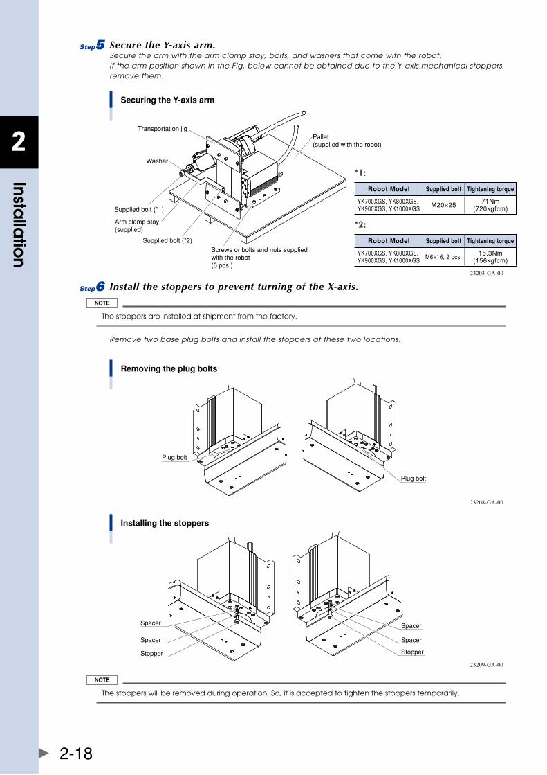
2
Installa
tion
2-18
5 Secure the Y-axis arm.Secure the arm with the arm clamp stay, bolts, and washers that come with the robot. If the arm position shown in the Fig. below cannot be obtained due to the Y-axis mechanical stoppers, remove them.
Securing the Y-axis arm
Pallet(supplied with the robot)
Screws or bolts and nuts supplied with the robot(6 pcs.)
Supplied bolt (*1)
Washer
Arm clamp stay (supplied)
Supplied bolt (*2)
Transportation jig
23203-GA-00
6 Install the stoppers to prevent turning of the X-axis.
The stoppers are installed at shipment from the factory.
Remove two base plug bolts and install the stoppers at these two locations.
Removing the plug bolts
Plug bolt
Plug bolt
23208-GA-00
Installing the stoppers
Stopper
Spacer
Spacer
Stopper
Spacer
Spacer
23209-GA-00
The stoppers will be removed during operation. So, it is accepted to tighten the stoppers temporarily.
*2:
Robot Model Supplied bolt Tightening torque
YK700XGS,YK800XGS,YK900XGS,YK1000XGS M6×16,2pcs. 15.3Nm
(156kgfcm)
*1:
Robot Model Supplied bolt Tightening torque
YK700XGS,YK800XGS,YK900XGS,YK1000XGS M20×25 71Nm
(720kgfcm)
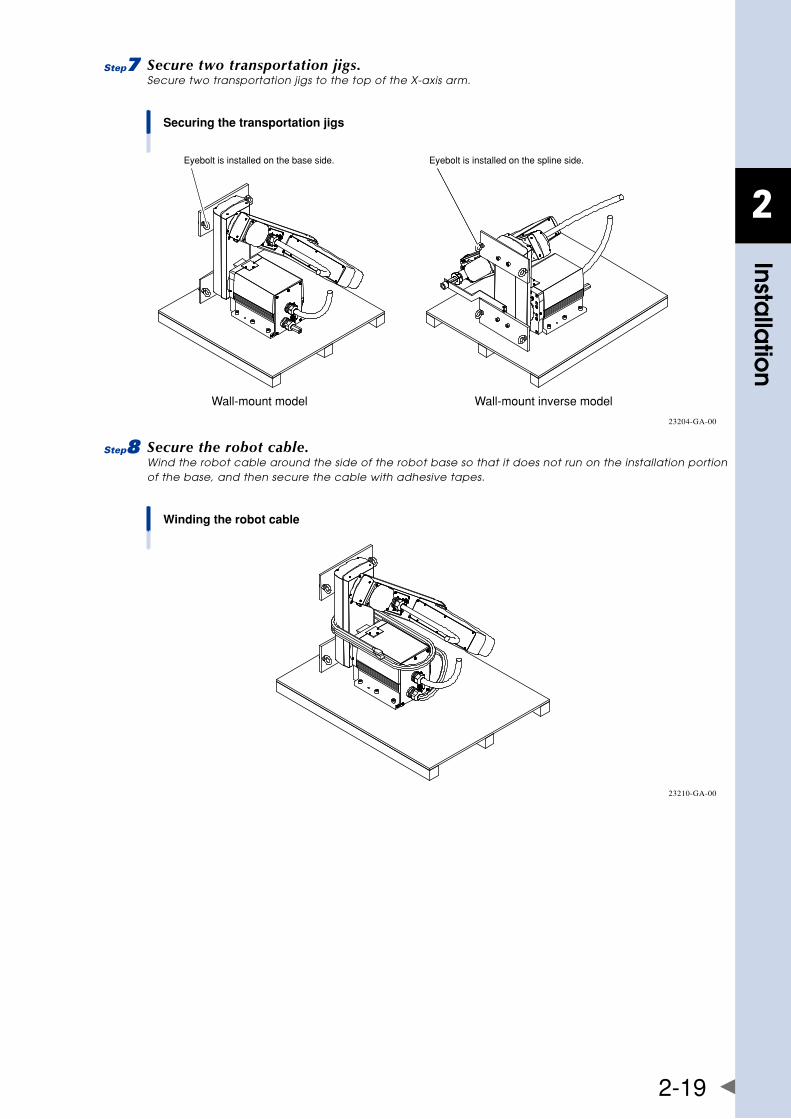
2
Installa
tion
2-19
7 Secure two transportation jigs.Secure two transportation jigs to the top of the X-axis arm.
Securing the transportation jigs
Wall-mount model Wall-mount inverse model
Eyebolt is installed on the base side. Eyebolt is installed on the spline side.
23204-GA-00
8 Secure the robot cable.Wind the robot cable around the side of the robot base so that it does not run on the installation portion of the base, and then secure the cable with adhesive tapes.
Winding the robot cable
23210-GA-00
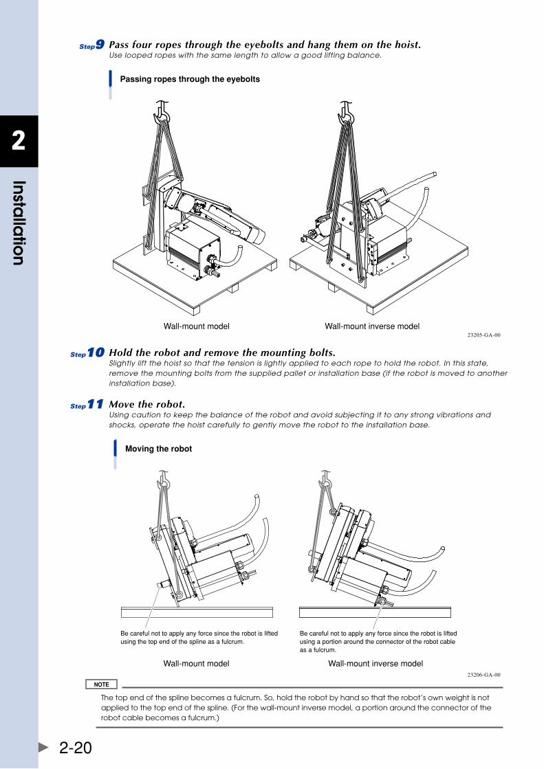
2
Installa
tion
2-20
9 Pass four ropes through the eyebolts and hang them on the hoist.Use looped ropes with the same length to allow a good lifting balance.
Passing ropes through the eyebolts
Wall-mount model Wall-mount inverse model23205-GA-00
0 Hold the robot and remove the mounting bolts.Slightly lift the hoist so that the tension is lightly applied to each rope to hold the robot. In this state, remove the mounting bolts from the supplied pallet or installation base (if the robot is moved to another installation base).
q Move the robot.Using caution to keep the balance of the robot and avoid subjecting it to any strong vibrations and shocks, operate the hoist carefully to gently move the robot to the installation base.
Moving the robot
Wall-mount model Wall-mount inverse model
Be careful not to apply any force since the robot is lifted using the top end of the spline as a fulcrum.
Be careful not to apply any force since the robot is lifted using a portion around the connector of the robot cable as a fulcrum.
23206-GA-00
The top end of the spline becomes a fulcrum. So, hold the robot by hand so that the robot’s own weight is not applied to the top end of the spline. (For the wall-mount inverse model, a portion around the connector of the robot cable becomes a fulcrum.)
2
Installa
tion
2-21
w Temporarily secure the robot to the base by tightening the bolts.
• Fordetailsaboutbolttighteningtorque,see"2.4Installingtherobot"inthisChapter. • Wheninstallingtherobot,thepositioningpinscanbeused.Fordetailsaboutpositionsanddimensions,see "1.2 External view and dimensions" in Chapter 7.
e Remove the ropes, transportation jigs, and arm clamp stay.
r Remove the X-axis mechanical stoppers.Remove the X-axis mechanical stoppers that have been installed in Step 6.
t Attach the bolts to the X-axis arm.
Always attach these bolts to protect the tapped holes. Be sure to keep the transportation jigs, arm clamp stay, bolts, and pallet since they may be used to move the robot again.
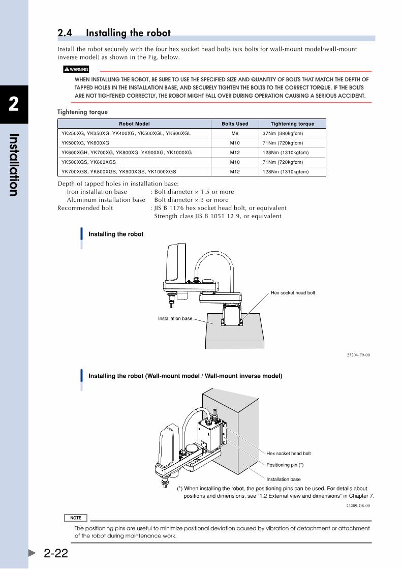
2
Installa
tion
2-22
2.4 Installing the robotInstall the robot securely with the four hex socket head bolts (six bolts for wall-mount model/wall-mount inverse model) as shown in the Fig. below.
WhEn InSTallIng ThE RObOT, bE SURE TO USE ThE SPECIfIED SIzE anD qUanTITy Of bOlTS ThaT MaTCh ThE DEPTh Of TaPPED hOlES In ThE InSTallaTIOn baSE, anD SECUREly TIghTEn ThE bOlTS TO ThE CORRECT TORqUE. If ThE bOlTS aRE nOT TIghTEnED CORRECTly, ThE RObOT MIghT fall OvER DURIng OPERaTIOn CaUSIng a SERIOUS aCCIDEnT.
Tightening torque
Robot Model Bolts Used Tightening torque
YK250XG,YK350XG,YK400XG,YK500XGL,YK600XGL M8 37Nm(380kgfcm)
YK500XG,YK600XG M10 71Nm(720kgfcm)
YK600XGH,YK700XG,YK800XG,YK900XG,YK1000XG M12 128Nm(1310kgfcm)
YK500XGS,YK600XGS M10 71Nm(720kgfcm)
YK700XGS,YK800XGS,YK900XGS,YK1000XGS M12 128Nm(1310kgfcm)
Depth of tapped holes in installation base:Iron installation base : Bolt diameter × 1.5 or moreAluminum installation base Bolt diameter × 3 or more
Recommended bolt : JIS B 1176 hex socket head bolt, or equivalent Strength class JIS B 1051 12.9, or equivalent
Installing the robot
Installation base
Hex socket head bolt
23204-F9-00
Installing the robot (Wall-mount model / Wall-mount inverse model)
Hex socket head bolt
Installation base
Positioning pin (*)
(*) When installing the robot, the positioning pins can be used. For details about positions and dimensions, see “1.2 External view and dimensions” in Chapter 7.
23209-G8-00
The positioning pins are useful to minimize positional deviation caused by vibration of detachment or attachment of the robot during maintenance work.
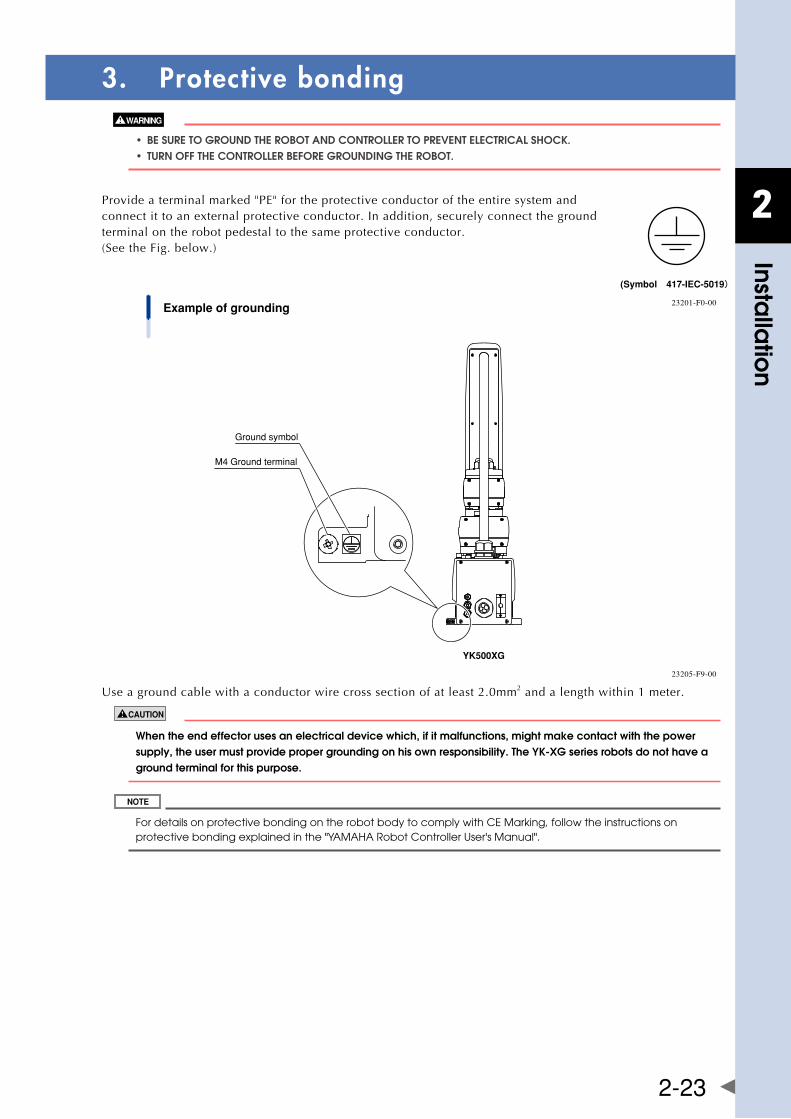
2
Installa
tion
2-23
3. Protective bonding
• besuretogrounDtherobotanDcontrollertoPreventelectricalshocK. • turnoffthecontrollerbeforegrounDingtherobot.
Provideaterminalmarked"PE"fortheprotectiveconductoroftheentiresystemand connect it to an external protective conductor. In addition, securely connect the ground terminal on the robot pedestal to the same protective conductor. (See the Fig. below.)
(Symbol 417-IEC-5019)
23201-F0-00Example of grounding
Ground symbol
M4 Ground terminal
YK500XG
23205-F9-00
Useagroundcablewithaconductorwirecrosssectionofatleast2.0mm2 and a length within 1 meter.
When the end effector uses an electrical device which, if it malfunctions, might make contact with the power supply, the user must provide proper grounding on his own responsibility. The yk-xg series robots do not have a ground terminal for this purpose.
For details on protective bonding on the robot body to comply with CE Marking, follow the instructions on protective bonding explained in the "YAMAHA Robot Controller User's Manual".
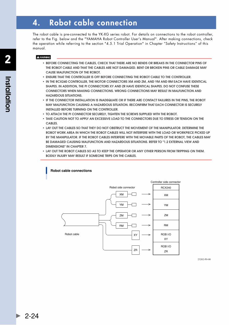
2
Installa
tion
2-24
4. Robot cable connectionTherobotcableispre-connectedtotheYK-XGseriesrobot.Fordetailsonconnectionstotherobotcontroller,refertotheFig.belowandthe"YAMAHARobotControllerUser'sManual".Aftermakingconnections,checktheoperationwhilereferringtothesection"4.5.1TrialOperation"inChapter“SafetyInstructions”ofthismanual.
• beforeconnectingthecables,checKthattherearenobenDsorbreaKsintheconnectorPinsof ThE RObOT CablE anD ThaT ThE CablES aRE nOT DaMagED. bEnT OR bROkEn PInS OR CablE DaMagE May CaUSE MalfUnCTIOn Of ThE RObOT. • ensurethatthecontrollerisoffbeforeconnectingtherobotcabletothecontroller. • inthercx240controller,themotorconnectorsxmanDzm,anDymanDrmeachhaveiDentical ShaPES. In aDDITIOn, ThE PI COnnECTORS xy anD zR havE IDEnTICal ShaPES. DO nOT COnfUSE ThESE COnnECTORS WhEn MakIng COnnECTIOnS. WROng COnnECTIOnS May RESUlT In MalfUnCTIOn anD hazaRDOUS SITUaTIOnS. • iftheconnectorinstallationisinaDequateoriftherearecontactfailuresinthePins,therobot May MalfUnCTIOn CaUSIng a hazaRDOUS SITUaTIOn. RECOnfIRM ThaT EaCh COnnECTOR IS SECUREly InSTallED bEfORE TURnIng On ThE COnTROllER. • toattachthePiconnectorsecurely,tightenthescrewssuPPlieDwiththerobot. • taKecautionnottoaPPlyanexcessiveloaDtotheconnectorsDuetostressortensiononthe CablES. • layoutthecablessothattheyDonotobstructthemovementofthemaniPulator.Determinethe RObOT WORk aREa In WhICh ThE RObOT CablES WIll nOT InTERfERE WITh ThE lOaD OR WORkPIECE PICkED UP by ThE ManIPUlaTOR. If ThE RObOT CablES InTERfERE WITh ThE MOvablE PaRTS Of ThE RObOT, ThE CablES May bE DaMagED CaUSIng MalfUnCTIOn anD hazaRDOUS SITUaTIOnS. REfER TO "1.2 ExTERnal vIEW anD DIMEnSIOnS" In ChaPTER 7. • layouttherobotcablessoastoKeePtheoPeratororanyotherPersonfromtriPPingonthem. bODIly InjURy May RESUlT If SOMEOnE TRIPS On ThE CablES.
Robot cable connections
Robot cable
Robot side connector
XM
YM
ZM
RM
XY
ZR
Controller side connector
RCX240
XM
YM
ZM
RM
ROB I/O
XY
ROB I/O
ZR
23202-F0-00
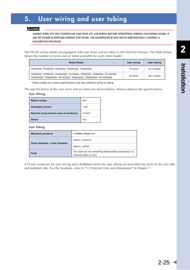
2
Installa
tion
2-25
5. User wiring and user tubing
alWayS TURn Off ThE COnTROllER anD ShUT Off aIR SUPPly bEfORE aTTEMPTIng WIRIng anD PIPIng WORk. If aIR OR POWER IS SUPPlIED DURIng ThIS WORk, ThE ManIPUlaTOR May MOvE ERROnEOUSly CaUSIng a hazaRDOUS SITUaTIOn.
TheYK-XGseriesrobotsareequippedwithuserwiresandairtubesinthemachineharness.Thetablebelowshows the number of wires and air tubes available for each robot model.
Robot Model User wiring User tubing
YK250XG,YK350XG,YK400XG,YK500XGL,YK600XGL 10wires φ4,3tubes
YK500XG,YK600XG,YK600XGH,YK700XG,YK800XG,YK900XG,YK1000XG
YK500XGS,YK600XGS,YK700XGS,YK800XGS,YK900XGS,YK1000XGS20wires φ6,3tubes
*Robotmodelsforcustomspecificationsmayhavedifferentwiringortubing.
The specifications of the user wires and air tubes are shown below. Always observe the specifications.
User Wiring
Rated voltage 30V
Allowable current 1.5A
Nominal cross-section area of conductor 0.2mm2
Shield Yes
User Tubing
Maximum pressure 0.58MPa(6Kgf/cm2)
Outer diameter × inner diameterφ4mm×φ2.5mm
φ6mm×φ4mm
FluidDrycleanairnotcontainingdeterioratedcompressoroil;
filtration40μmorless
A D-sub connector for user wiring and a bulkhead union for user tubing are provided one each on the arm side andpedestalside.Forthelocations,referto"1.2Externalviewanddimensions"inChapter7.
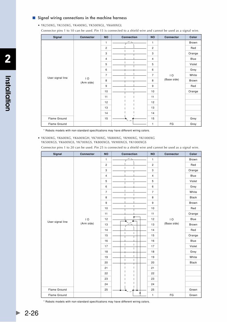
2
Installa
tion
2-26
Signal wiring connections in the machine harness ■
•YK250XG,YK350XG,YK400XG,YK500XGL,YK600XGL
Connector pins 1 to 10 can be used. Pin 15 is connected to a shield wire and cannot be used as a signal wire.
Signal Connector NO Connection NO Connector Color
Usersignalline IO
(Armside)
1 1
IO
(Baseside)
Brown
2 2 Red
3 3 Orange
4 4 Blue
5 5 Violet
6 6 Grey
7 7 White
8 8 Brown
9 9 Red
10 10 Orange
11 11
12 12
13 13
14 14
FlameGround 15 15 Grey
FlameGround 1 FG Grey
*Robotsmodelswithnon-standardspecificationsmayhavedifferentwiringcolors.
•YK500XG,YK600XG,YK600XGH,YK700XG,YK800XG,YK900XG,YK1000XG YK500XGS,YK600XGS,YK700XGS,YK800XGS,YK900XGS,YK1000XGS
Connector pins 1 to 20 can be used. Pin 25 is connected to a shield wire and cannot be used as a signal wire.
Signal Connector NO Connection NO Connector Color
UsersignallineIO
(Armside)
1 1
IO
(Baseside)
Brown
2 2 Red
3 3 Orange
4 4 Blue
5 5 Violet
6 6 Grey
7 7 White
8 8 Black
9 9 Brown
10 10 Red
11 11 Orange
12 12 Blue
13 13 Brown
14 14 Red
15 15 Orange
16 16 Blue
17 17 Violet
18 18 Grey
19 19 White
20 20 Black
21 21
22 22
23 23
24 24
FlameGround 25 25 Green
FlameGround 1 FG Green
*Robotsmodelswithnon-standardspecificationsmayhavedifferentwiringcolors.
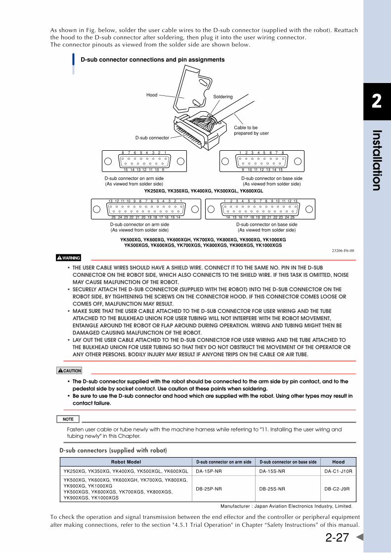
2
Installa
tion
2-27
As shown in Fig. below, solder the user cable wires to the D-sub connector (supplied with the robot). Reattach the hood to the D-sub connector after soldering, then plug it into the user wiring connector. The connector pinouts as viewed from the solder side are shown below.
13 12 11 10 9 8 7 6 5 4 3 2 1
25 24 23 22 21 20 19 18 17 16 15 14
1 2 3 4 5 6 7 8 9 10 11 12 13
14 15 16 17 18 19 20 21 22 23 24 25
8 7 6 5 4 3 2 1
15 14 13 12 11 10 9
1 2 3 4 5 6 7 8
9 10 11 12 13 14 15
D-sub connector connections and pin assignments
Cable to beprepared by user
SolderingHood
D-sub connector
D-sub connector on arm side(As viewed from solder side)
D-sub connector on base side(As viewed from solder side)
YK500XG, YK600XG, YK600XGH, YK700XG, YK800XG, YK900XG, YK1000XGYK500XGS, YK600XGS, YK700XGS, YK800XGS, YK900XGS, YK1000XGS
D-sub connector on arm side(As viewed from solder side)
D-sub connector on base side(As viewed from solder side)
YK250XG, YK350XG, YK400XG, YK500XGL, YK600XGL
23206-F6-00
• theusercablewiresshoulDhaveashielDwire.connectittothesameno.PinintheD-sub COnnECTOR On ThE RObOT SIDE, WhICh alSO COnnECTS TO ThE ShIElD WIRE. If ThIS TaSk IS OMITTED, nOISE May CaUSE MalfUnCTIOn Of ThE RObOT. • securelyattachtheD-subconnector(suPPlieDwiththerobot)intotheD-subconnectoronthe RObOT SIDE, by TIghTEnIng ThE SCREWS On ThE COnnECTOR hOOD. If ThIS COnnECTOR COMES lOOSE OR COMES Off, MalfUnCTIOn May RESUlT. • maKesurethattheusercableattacheDtotheD-subconnectorforuserwiringanDthetube aTTaChED TO ThE bUlkhEaD UnIOn fOR USER TUbIng WIll nOT InTERfERE WITh ThE RObOT MOvEMEnT, EnTanglE aROUnD ThE RObOT OR flaP aROUnD DURIng OPERaTIOn. WIRIng anD TUbIng MIghT ThEn bE DaMagED CaUSIng MalfUnCTIOn Of ThE RObOT. • layouttheusercableattacheDtotheD-subconnectorforuserwiringanDthetubeattacheDto ThE bUlkhEaD UnIOn fOR USER TUbIng SO ThaT ThEy DO nOT ObSTRUCT ThE MOvEMEnT Of ThE OPERaTOR OR any OThER PERSOnS. bODIly InjURy May RESUlT If anyOnE TRIPS On ThE CablE OR aIR TUbE.
• theD-subconnectorsuppliedwiththerobotshouldbeconnectedtothearmsidebypincontact,andtothe pedestal side by socket contact. Use caution at these points when soldering. • besuretousetheD-subconnectorandhoodwhicharesuppliedwiththerobot.usingothertypesmayresultin contact failure.
Fasten user cable or tube newly with the machine harness while referring to "11. Installing the user wiring and tubing newly" in this Chapter.
D-sub connectors (supplied with robot)
Robot Model D-sub connector on arm side D-sub connector on base side Hood
YK250XG,YK350XG,YK400XG,YK500XGL,YK600XGL DA-15P-NR DA-15S-NR DA-C1-J10R
YK500XG,YK600XG,YK600XGH,YK700XG,YK800XG,YK900XG,YK1000XGYK500XGS,YK600XGS,YK700XGS,YK800XGS,YK900XGS,YK1000XGS
DB-25P-NR DB-25S-NR DB-C2-J9R
Manufacturer:JapanAviationElectronicsIndustry,Limited.
To check the operation and signal transmission between the end effector and the controller or peripheral equipment after making connections, refer to the section "4.5.1 Trial Operation" in Chapter “Safety Instructions” of this manual.
2
Installa
tion
2-28
6. Attaching the end effector6.1 R-axis tolerable moment of inertia and acceleration coefficientThe moment of inertia of a load (end effector and workpiece) that can be attached to the R-axis is limited by the strength of the robot drive unit and residual vibration during positioning. It is therefore necessary to reduce the acceleration coefficient in accordance with the moment of inertia.
The R-axis tolerable moment of inertia and the acceleration coefficient versus R-axis moment of inertia for each robot model are shown in "6.1.1 to 6.1.11 Acceleration coefficient vs. moment of inertia".The symbols AX, AY, AZ, and ARineachFig.respectivelyindicatetheaccelerationcoefficientsoftheX-axis,Y-axis,Z-axis,andR-axis.ThesymbolIR (JR) indicates the moment of inertia of the load around the R-axis and the symbol m indicates the tip mass. ItisnecessaryonlyfortheYK250XG,YK350XG,YK400XG,YK500XGL,andYK600XGLtoreducetheZ-axisacceleration according to the moment of inertia around the R-axis so as to ensure the service life of the spline. Thisisshownin"6.1.6Accelerationcoefficientvs.momentofinertia(YK250XG,YK350XG,YK400XG,YK500XGL,YK600XGL)".
Example:YK500XG(Seealso"6.1.7Accelerationcoefficientvs.momentofinertia(YK500XG,YK500XGS)".) Assume that the mass of the load installed to the R-axis is 1.5kg and the moment of inertia around the R-axis is 0.1kgm2 (1.0kgfcmsec2). When the tip mass parameter is set to 2kg, the robot can be operated by reducing the X,YandR-axisaccelerationcoefficientsto62%,ascanbeseenfrom"6.1.7Accelerationcoefficientvs.momentofinertia(YK500XG,YK500XGS)".Besuretoselectanoptimumtipmassandaccelerationcoefficientparameters that meet the mass of the load and moment of inertia before using the robot. To make settings for thetipmassandaccelerationcoefficient,refertotheseparate"YAMAHARobotControllerUser'sManual".
Methodsforcalculatingthemomentofinertiaoftheloadareshownin"6.2Equationformomentofinertiacalculation"and"6.3Exampleofmomentofinertiacalculation".However,itisnoteasytopreciselyfigureoutthese values. If a calculated value smaller than the actual moment of inertia is set, residual vibrations may occur. If this happens, reduce the acceleration coefficient parameter further.
• therobotmustbeoperatedwithcorrecttolerablemomentofinertiaandaccelerationcoefficientsaccording to the manipulator tip mass and moment of inertia. If this is not observed, premature end to the life of the drive units, damage to the robot parts or residual vibration during positioning may result. • Dependingonthez-axisposition,vibrationmayoccurwhenthex,yorr-axismoves.ifthishappens,reduce thex,yorr-axisaccelerationtoanappropriatelevel. • ifthemomentofinertiaistoolarge,vibrationmayoccuronthez-axisdependingonitsoperationposition.if thishappens,reducethez-axisaccelerationtoanappropriatelevel.
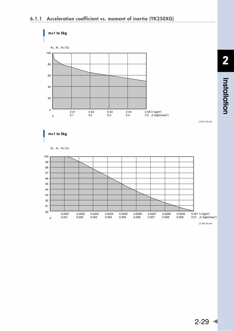
2
Installa
tion
2-29
6.1.1 Acceleration coefficient vs. moment of inertia (YK250XG)
m=1 to 5kg
AX, AY, AR (%)
0.010.1
0.020.2
0.030.3
0.040.4
0.050.5
0
100
80
60
40
20
Ir (kgm2)Jr (kgfcmsec2)0
23207-F6-00
m=1 to 5kg
Ir (kgm2)Jr (kgfcmsec2)
90
0
0.00010.001
0.00020.002
0.00030.003
0.00040.004
0.00090.009
0.00080.008
0.00070.007
0.00060.006
0.00050.005
0.0010.01
100
99
97
98
95
96
93
94
91
92
AX, AY, AR (%)
23208-F6-00
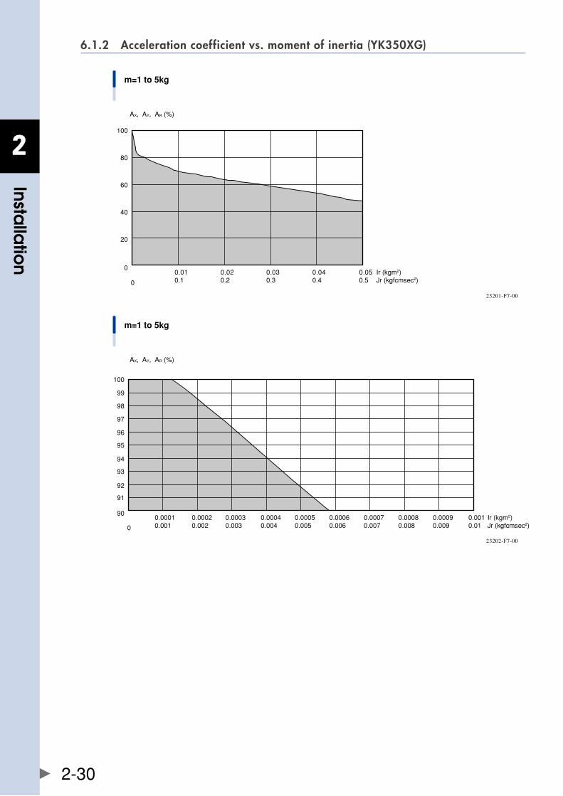
2
Installa
tion
2-30
6.1.2 Acceleration coefficient vs. moment of inertia (YK350XG)
m=1 to 5kg
AX, AY, AR (%)
Ir (kgm2)Jr (kgfcmsec2)
0
0
0.020.2
0.040.4
0.030.3
0.050.5
100
80
60
40
20
0.010.1
23201-F7-00
m=1 to 5kg
Ir (kgm2)Jr (kgfcmsec2)
90
0
0.00010.001
0.00020.002
0.00030.003
0.00040.004
0.00090.009
0.00080.008
0.00070.007
0.00060.006
0.00050.005
0.0010.01
100
91
93
95
97
99
98
96
94
92
AX, AY, AR (%)
23202-F7-00
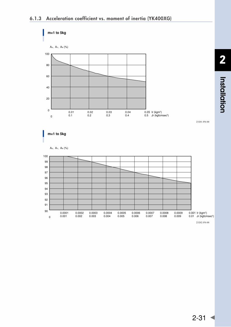
2
Installa
tion
2-31
6.1.3 Acceleration coefficient vs. moment of inertia (YK400XG)
m=1 to 5kg
AX, AY, AR (%)
Ir (kgm2)Jr (kgfcmsec2)
0
0
0.010.1
0.020.2
0.040.4
0.030.3
0.050.5
100
80
60
40
20
23201-F8-00
m=1 to 5kg
Ir (kgm2)Jr (kgfcmsec2)
90
0
0.00010.001
0.00020.002
0.00030.003
0.00040.004
0.00090.009
0.00080.008
0.00070.007
0.00060.006
0.00050.005
0.0010.01
100
91
93
95
97
99
98
96
94
92
AX, AY, AR (%)
23202-F8-00
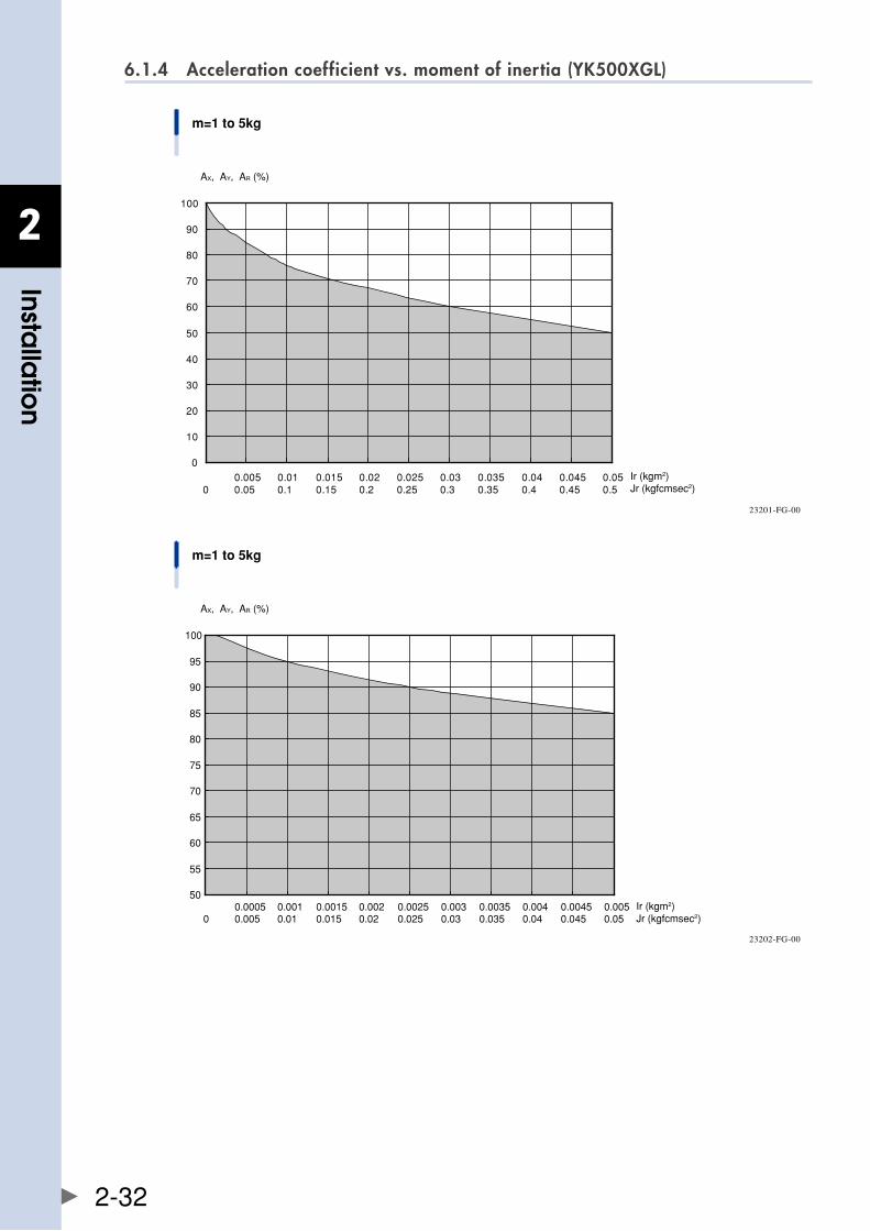
2
Installa
tion
2-32
6.1.4 Acceleration coefficient vs. moment of inertia (YK500XGL)
m=1 to 5kg
AX, AY, AR (%)
0
10
20
30
40
50
60
70
80
90
100
00.005 0.01 0.015 0.02 0.025 0.03 0.035 0.04 0.045 0.050.05 0.1 0.15 0.2 0.25 0.3 0.35 0.4 0.45 0.5
Ir (kgm2)Jr (kgfcmsec2)
23201-FG-00
m=1 to 5kg
AX, AY, AR (%)
50
55
60
65
70
75
80
85
90
95
100
0.0005 0.001 0.0015 0.002 0.0025 0.003 0.0035 0.004 0.0045 0.0050 0.005 0.01 0.015 0.02 0.025 0.03 0.035 0.04 0.045 0.05
Ir (kgm2)Jr (kgfcmsec2)
23202-FG-00
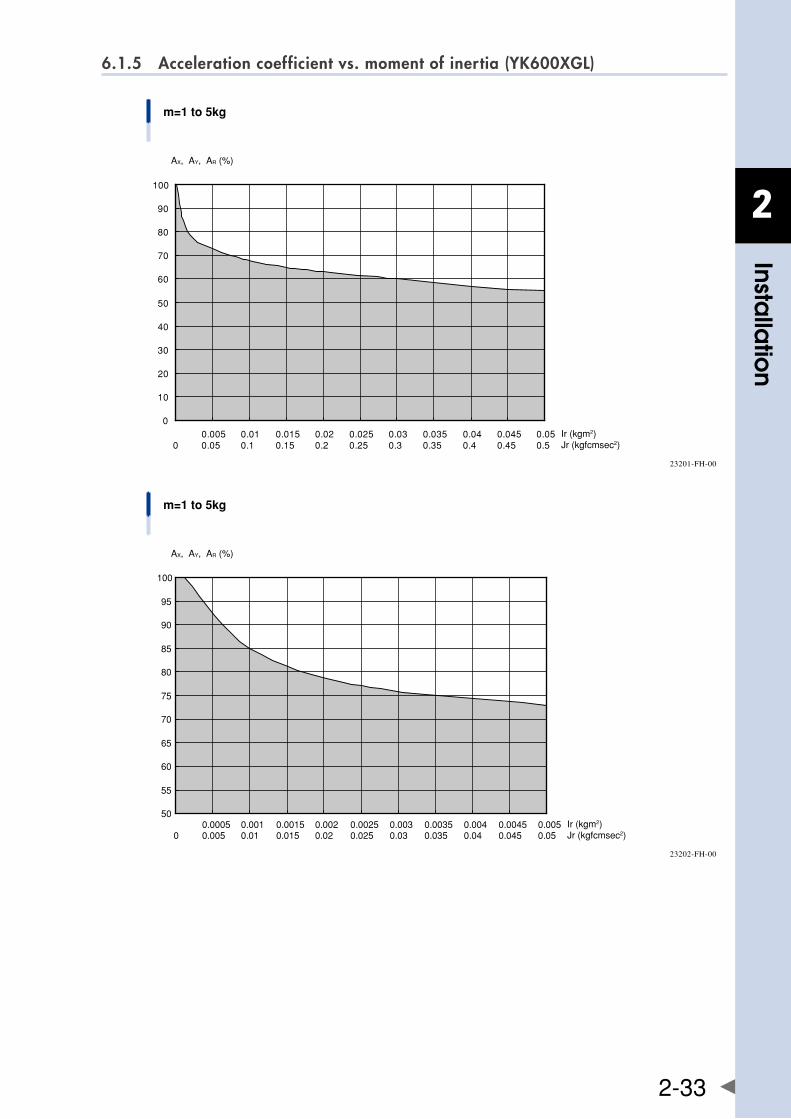
2
Installa
tion
2-33
6.1.5 Acceleration coefficient vs. moment of inertia (YK600XGL)
m=1 to 5kg
AX, AY, AR (%)
Ir (kgm2)Jr (kgfcmsec2)
0
10
20
30
40
50
60
70
80
90
100
00.005 0.01 0.015 0.02 0.025 0.03 0.035 0.04 0.045 0.050.05 0.1 0.15 0.2 0.25 0.3 0.35 0.4 0.45 0.5
23201-FH-00
m=1 to 5kg
AX, AY, AR (%)
50
55
60
65
70
75
80
85
90
95
100
0.0005 0.001 0.0015 0.002 0.0025 0.003 0.0035 0.004 0.0045 0.0050 0.005 0.01 0.015 0.02 0.025 0.03 0.035 0.04 0.045 0.05
Ir (kgm2)Jr (kgfcmsec2)
23202-FH-00
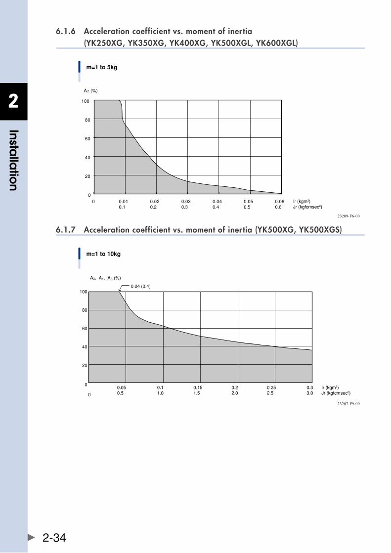
2
Installa
tion
2-34
6.1.6 Acceleration coefficient vs. moment of inertia (YK250XG, YK350XG, YK400XG, YK500XGL, YK600XGL)
m=1 to 5kg
Ir (kgm2)Jr (kgfcmsec2)
0 0.010.1
0.020.2
0.030.3
0.040.4
0.050.5
0.060.6
AZ (%)
0
20
40
60
80
100
23209-F6-00
6.1.7 Acceleration coefficient vs. moment of inertia (YK500XG, YK500XGS)
m=1 to 10kg
Ir (kgm2)Jr (kgfcmsec2)
0
0
0.050.5
0.11.0
0.151.5
0.22.0
0.252.5
0.33.0
100
80
60
40
20
AX, AY, AR (%)
0.04 (0.4)
23207-F9-00
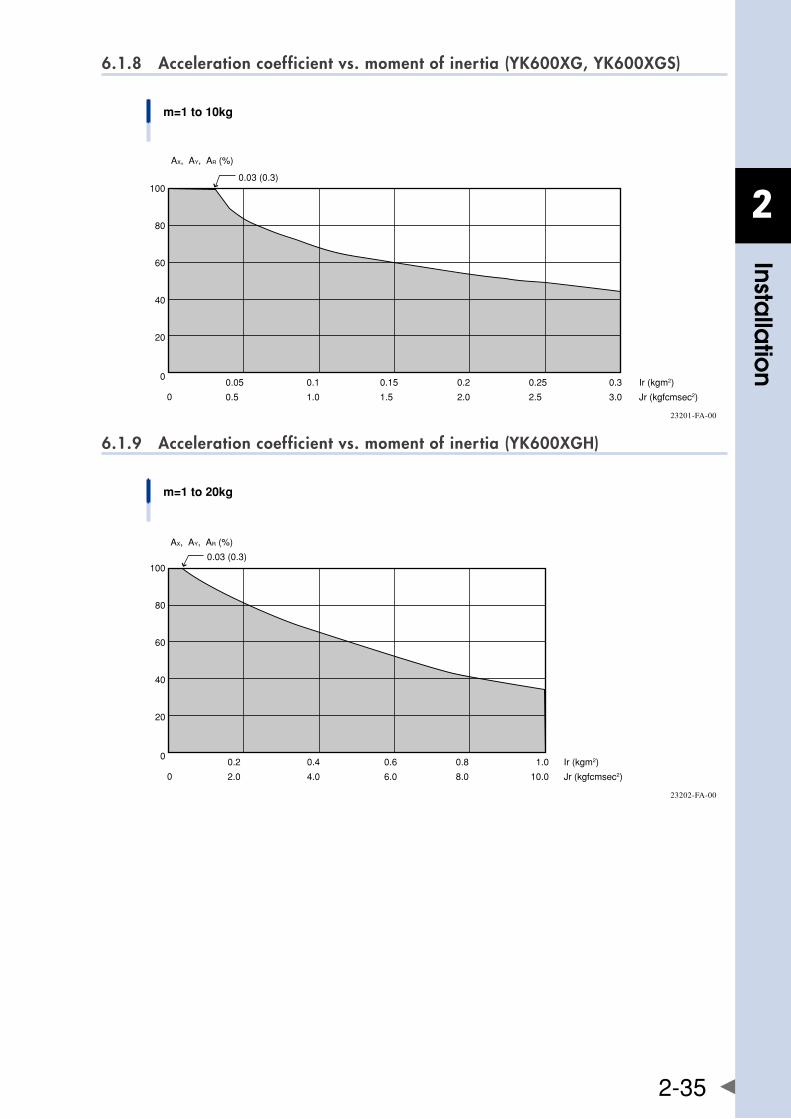
2
Installa
tion
2-35
6.1.8 Acceleration coefficient vs. moment of inertia (YK600XG, YK600XGS)
m=1 to 10kg
Ir (kgm2)
Jr (kgfcmsec2)
0
0
0.05
0.5
0.1
1.0
0.15
1.5
0.2
2.0
0.25
2.5
0.3
3.0
100
80
60
40
20
AX, AY, AR (%)
0.03 (0.3)
23201-FA-00
6.1.9 Acceleration coefficient vs. moment of inertia (YK600XGH)
m=1 to 20kg
Ir (kgm2)
Jr (kgfcmsec2)
0
0
0.2
2.0
0.4
4.0
0.6
6.0
0.8
8.0
1.0
10.0
100
80
60
40
20
AX, AY, AR (%)
0.03 (0.3)
23202-FA-00
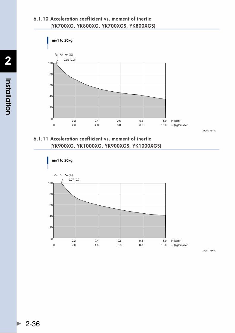
2
Installa
tion
2-36
6.1.10 Acceleration coefficient vs. moment of inertia (YK700XG, YK800XG, YK700XGS, YK800XGS)
m=1 to 20kg
Ir (kgm2)
Jr (kgfcmsec2)
0
0
0.2
2.0
0.4
4.0
0.6
6.0
0.8
8.0
1.0
10.0
100
80
60
40
20
AX, AY, AR (%)
0.02 (0.2)
23201-FB-00
6.1.11 Acceleration coefficient vs. moment of inertia (YK900XG, YK1000XG, YK900XGS, YK1000XGS)
m=1 to 20kg
Ir (kgm2)
Jr (kgfcmsec2)
0
0
0.2
2.0
0.4
4.0
0.6
6.0
0.8
8.0
1.0
10.0
100
80
60
40
20
AX, AY, AR (%)
0.07 (0.7)
23201-FD-00
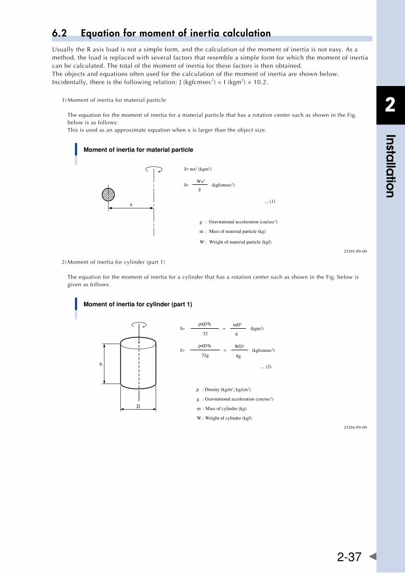
2
Installa
tion
2-37
6.2 Equation for moment of inertia calculationUsuallytheRaxisloadisnotasimpleform,andthecalculationofthemomentofinertiaisnoteasy.Asamethod, the load is replaced with several factors that resemble a simple form for which the moment of inertia can be calculated. The total of the moment of inertia for these factors is then obtained.The objects and equations often used for the calculation of the moment of inertia are shown below. Incidentally, there is the following relation: J (kgfcmsec2) = I (kgm2) × 10.2.
1) Moment of inertia for material particle The equation for the moment of inertia for a material particle that has a rotation center such as shown in the Fig. below is as follows: This is used as an approximate equation when x is larger than the object size.
Moment of inertia for material particle
x
J=Wx2
g(kgfcmsec2)
g : Gravitational acceleration (cm/sec2)
m : Mass of material particle (kg)
... (1)
I= mx2 (kgm2)
W : Weight of material particle (kgf)
23203-F0-00
2) Moment of inertia for cylinder (part 1) The equation for the moment of inertia for a cylinder that has a rotation center such as shown in the Fig. below is given as follows.
Moment of inertia for cylinder (part 1)
D
h
J=ρπD4h
32g
WD2
8g= (kgfcmsec2)
... (2)
I=ρπD4h
32
mD2
8= (kgm2)
ρ : Density (kg/m3, kg/cm3)
g : Gravitational acceleration (cm/sec2)
m : Mass of cylinder (kg)
W : Weight of cylinder (kgf)
23204-F0-00
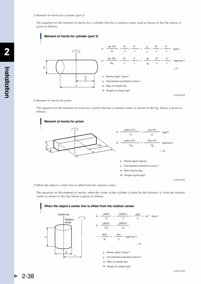
2
Installa
tion
2-38
3) Moment of inertia for cylinder (part 2) The equation for the moment of inertia for a cylinder that has a rotation center such as shown in the Fig. below is given as follows.
Moment of inertia for cylinder (part 2)
h
D
2h
... (3)
J=ρπ D2h
16g
W
4g=
D2
4
h2
3( + )
D2
4
h2
3( + )
I=ρπ D2h
16
m
4=
D2
4
h2
3( + )
D2
4
h2
3( + )
ρ : Density (kg/m3, kg/cm3)
g : Gravitational acceleration (cm/sec2)
m : Mass of cylinder (kg)
W : Weight of cylinder (kgf)
(kgfcmsec2)
(kgm2)
23205-F0-00
4) Moment of inertia for prism The equation for the moment of inertia for a prism that has a rotation center as shown in the Fig. below is given as follows.
Moment of inertia for prism
a
c
b
1/2aJ=
ρabc(a2+b2)
12g
W(a2+b2)
12g=
... (4)
I=ρabc(a2+b2)
12
m(a2+b2)
12=
(kgfcmsec2)
(kgm2)
ρ : Density (kg/m3, kg/cm3)
g : Gravitational acceleration (cm/sec2)
m : Mass of prism (kg)
W : Weight of prism (kgf)
23206-F0-00
5) When the object's center line is offset from the rotation center. The equation for the moment of inertia, when the center of the cylinder is offset by the distance "x" from the rotation center as shown in the Fig. below is given as follows.
When the object’s center line is offset from the rotation center.
D
h
x
Center line
Rotationcenter
J=ρπD4h
32g
WD2
8g=
... (5)
+ρπD2hx2
4g
+Wx2
g
I=ρπD4h
32+
ρπD2hx2
4
mD2
8= mx2+
ρ : Density (kg/m3, kg/cm3)
g : Gravitational acceleration (cm/sec2)
m : Mass of cylinder (kg)
W : Weight of cylinder (kgf)
(kgfcmsec2)
(kgm2)
23207-F0-00
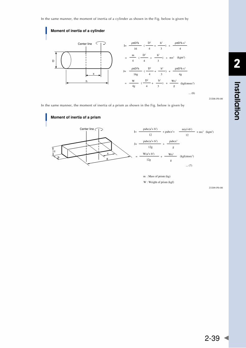
2
Installa
tion
2-39
In the same manner, the moment of inertia of a cylinder as shown in the Fig. below is given by
Moment of inertia of a cylinder
h
D
x
Center line
W
4g=
... (6)
D2
4
h2
3( + )
J=ρπD2h
16g+
D2
4
h2
3( + )
ρπD2h x2
4g
+Wx2
g
I=ρπD2h
16+
D2
4
h2
3( + )
ρπD2h x2
4
=
(kgfcmsec2)
m
4
D2
4
h2
3( + ) + mx2 (kgm2)
23208-F0-00
In the same manner, the moment of inertia of a prism as shown in the Fig. below is given by
Moment of inertia of a prism
a
c
bx
Center line
J=ρabc(a2+ b2)
12g
W(a2+ b2)
12g=
... (7)
+ρabcx2
g
Wx2
g+
I=ρabc(a2+ b2)
12+ ρabcx2=
m(a2+b2)
12
m : Mass of prism (kg)
W : Weight of prism (kgf)
(kgfcmsec2)
+ mx2 (kgm2)
23209-F0-00
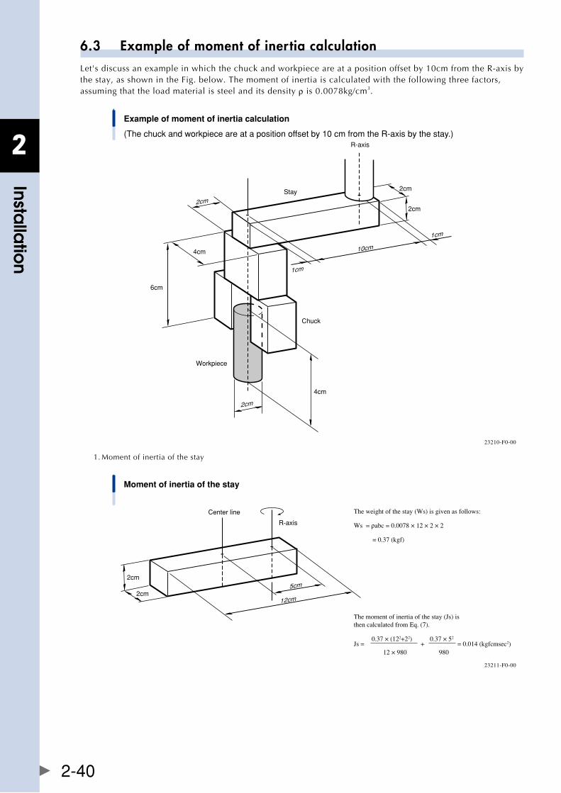
2
Installa
tion
2-40
6.3 Example of moment of inertia calculationLet's discuss an example in which the chuck and workpiece are at a position offset by 10cm from the R-axis by the stay, as shown in the Fig. below. The moment of inertia is calculated with the following three factors, assuming that the load material is steel and its density ρ is 0.0078kg/cm3.
Example of moment of inertia calculation
(The chuck and workpiece are at a position offset by 10 cm from the R-axis by the stay.)
10cm
2cm
2cm
R-axis
1cm
1cm
2cm
2cm
4cm
6cm
4cm
Stay
Chuck
Workpiece
23210-F0-00
1. Moment of inertia of the stay
Moment of inertia of the stay
12cm
2cm
2cm
Center line
5cm
R-axis
The weight of the stay (Ws) is given as follows:
Ws = ρabc = 0.0078 × 12 × 2 × 2
= 0.37 (kgf)
The moment of inertia of the stay (Js) is then calculated from Eq. (7).
Js =0.37 × (122+22)
+0.37 × 52
= 0.014 (kgfcmsec2)12 × 980 980
23211-F0-00
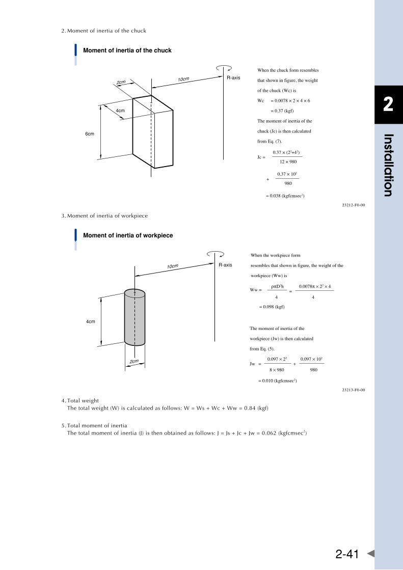
2
Installa
tion
2-41
2. Moment of inertia of the chuck
Moment of inertia of the chuck
10cm2cm
6cm
4cm
R-axis
When the chuck form resembles
that shown in figure, the weight
of the chuck (Wc) is
Wc = 0.0078 × 2 × 4 × 6
= 0.37 (kgf)
The moment of inertia of the
chuck (Jc) is then calculated
from Eq. (7).
Jc =0.37 × (22+42)
12 × 980
0.37 × 10² +
980
= 0.038 (kgfcmsec2)
23212-F0-00
3. Moment of inertia of workpiece
Moment of inertia of workpiece
10cm
4cm
R-axis
2cm
Ww =ρπD2h
= 0.0078π × 22 × 4
4 4
= 0.098 (kgf)
The moment of inertia of the
workpiece (Jw) is then calculated
from Eq. (5).
When the workpiece form
resembles that shown in figure, the weight of the
workpiece (Ww) is
Jw =0.097 × 22
+ 0.097 × 10²
8 × 980 980
= 0.010 (kgfcmsec2)
23213-F0-00
4. Total weight The total weight (W) is calculated as follows: W = Ws + Wc + Ww = 0.84 (kgf)
5. Total moment of inertia The total moment of inertia (J) is then obtained as follows: J = Js + Jc + Jw = 0.062 (kgfcmsec2)
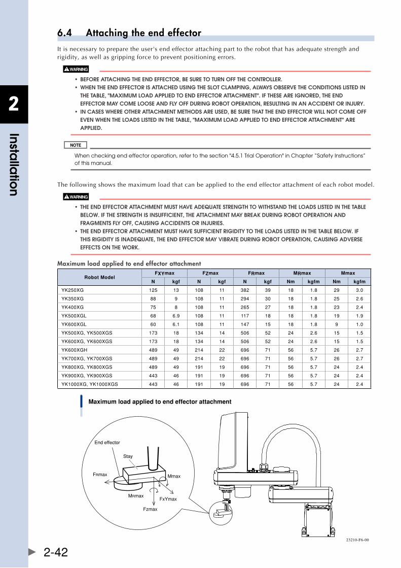
2
Installa
tion
2-42
6.4 Attaching the end effectorIt is necessary to prepare the user's end effector attaching part to the robot that has adequate strength and rigidity, as well as gripping force to prevent positioning errors.
• beforeattachingtheenDeffector,besuretoturnoffthecontroller. • whentheenDeffectorisattacheDusingtheslotclamPing,alwaysobservetheconDitionslisteDin ThE TablE, "MaxIMUM lOaD aPPlIED TO EnD EffECTOR aTTaChMEnT". If ThESE aRE IgnORED, ThE EnD EffECTOR May COME lOOSE anD fly Off DURIng RObOT OPERaTIOn, RESUlTIng In an aCCIDEnT OR InjURy. • incaseswhereotherattachmentmethoDsareuseD,besurethattheenDeffectorwillnotcomeoff EvEn WhEn ThE lOaDS lISTED In ThE TablE, "MaxIMUM lOaD aPPlIED TO EnD EffECTOR aTTaChMEnT" aRE aPPlIED.
When checking end effector operation, refer to the section "4.5.1 Trial Operation" in Chapter “Safety Instructions” of this manual.
The following shows the maximum load that can be applied to the end effector attachment of each robot model.
• theenDeffectorattachmentmusthaveaDequatestrengthtowithstanDtheloaDslisteDinthetable bElOW. If ThE STREngTh IS InSUffICIEnT, ThE aTTaChMEnT May bREak DURIng RObOT OPERaTIOn anD fRagMEnTS fly Off, CaUSIng aCCIDEnTS OR InjURIES. • theenDeffectorattachmentmusthavesufficientrigiDitytotheloaDslisteDinthetablebelow.if ThIS RIgIDITy IS InaDEqUaTE, ThE EnD EffECTOR May vIbRaTE DURIng RObOT OPERaTIOn, CaUSIng aDvERSE EffECTS On ThE WORk.
Maximum load applied to end effector attachment
Robot ModelFXYmax FZmax FRmax MRmax Mmax
N kgf N kgf N kgf Nm kgfm Nm kgfm
YK250XG 125 13 108 11 382 39 18 1.8 29 3.0
YK350XG 88 9 108 11 294 30 18 1.8 25 2.6
YK400XG 75 8 108 11 265 27 18 1.8 23 2.4
YK500XGL 68 6.9 108 11 117 18 18 1.8 19 1.9
YK600XGL 60 6.1 108 11 147 15 18 1.8 9 1.0
YK500XG,YK500XGS 173 18 134 14 506 52 24 2.6 15 1.5
YK600XG,YK600XGS 173 18 134 14 506 52 24 2.6 15 1.5
YK600XGH 489 49 214 22 696 71 56 5.7 26 2.7
YK700XG,YK700XGS 489 49 214 22 696 71 56 5.7 26 2.7
YK800XG,YK800XGS 489 49 191 19 696 71 56 5.7 24 2.4
YK900XG,YK900XGS 443 46 191 19 696 71 56 5.7 24 2.4
YK1000XG,YK1000XGS 443 46 191 19 696 71 56 5.7 24 2.4
Maximum load applied to end effector attachment
FRmax
End effector
Stay
FxYmax
Fzmax
MRmax
Mmax
23210-F6-00
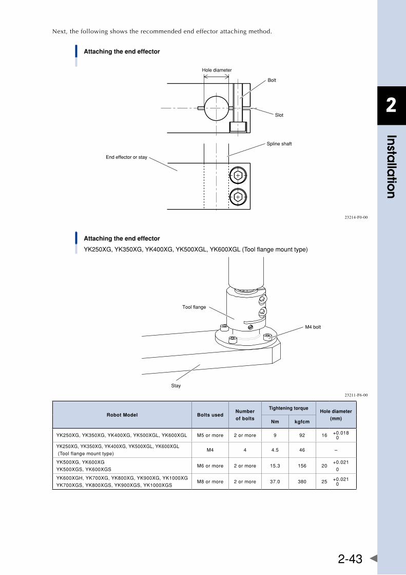
2
Installa
tion
2-43
Next, the following shows the recommended end effector attaching method.
Attaching the end effector
Hole diameter
Bolt
Slot
Spline shaft
End effector or stay
23214-F0-00
Attaching the end effector
YK250XG, YK350XG, YK400XG, YK500XGL, YK600XGL (Tool flange mount type)
Stay
M4 bolt
Tool flange
23211-F6-00
Robot Model Bolts usedNumber
of bolts
Tightening torqueHole diameter
(mm)Nm kgfcm
YK250XG,YK350XG,YK400XG,YK500XGL,YK600XGL M5ormore 2ormore 9 92 16 +0.0180
YK250XG,YK350XG,YK400XG,YK500XGL,YK600XGL
(Toolflangemounttype)M4 4 4.5 46 –
YK500XG,YK600XG
YK500XGS,YK600XGSM6ormore 2ormore 15.3 156 20
+0.021
0
YK600XGH,YK700XG,YK800XG,YK900XG,YK1000XG
YK700XGS,YK800XGS,YK900XGS,YK1000XGSM8ormore 2ormore 37.0 380 25 +0.021
0
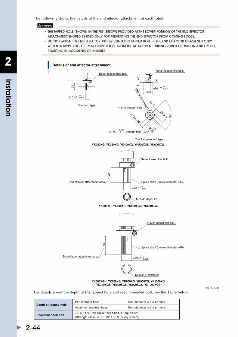
2
Installa
tion
2-44
The following shows the details of the end effector attachment of each robot.
• thetaPPeDhole(showninthefig.below)ProviDeDatthelowerPortionoftheenDeffector aTTaChMEnT ShOUlD bE USED Only fOR PREvEnTIng ThE EnD EffECTOR fROM COMIng lOOSE. • DonotfastentheenDeffectorjustbyusingthistaPPeDhole.iftheenDeffectorisfasteneDonly WITh ThIS TaPPED hOlE, IT May COME lOOSE fROM ThE aTTaChMEnT DURIng RObOT OPERaTIOn anD fly Off, RESUlTIng In aCCIDEnTS OR InjURIES.
Details of end effector attachment
Never loosen this bolt.
Spline shaft (hollow diameter φ14)
φ20 h7 0-0.021
End effector attachment area
M16×2, depth 20
40
YK500XG, YK600XG, YK500XGS, YK600XGS
Never loosen this bolt.
Spline shaft (hollow diameter φ18)
45
φ25 h7 0-0.021
M20×2.5, depth 20
End effector attachment area
YK600XGH, YK700XG, YK800XG, YK900XG, YK1000XGYK700XGS, YK800XGS, YK900XGS, YK1000XGS
Never loosen this bolt.Never loosen this bolt.
φ16 h7 - 0.0180
φ30 h70
46 4
2
φ55
30
22.6
22.6
22.6
22.6
22.6±0.02
4-φ4.5 through hole
φ4 H7 0+0.012
through hole
90°
Hollow
diameterφ11
7±0.
02
-0.021
YK250XG, YK350XG, YK400XG, YK500XGL, YK600XGL
Standard type
Tool flange mount type
23212-F6-00
For details about the depth of the tapped hole and recommended bolt, see the Table below.
Depth of tapped holeIronmaterialbase Boltdiameter×1.5ormore
Aluminummaterialbase Boltdiameter×3.0ormore
Recommended boltJISB1176Hexsocketheadbolt,orequivalent
(Strengthclass:JISB105112.9,orequivalent)
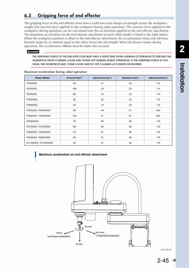
2
Installa
tion
2-45
6.5 Gripping force of end effectorThe gripping force of the end effector must have a sufficient extra margin of strength versus the workpiece weight and reaction force applied to the workpiece during robot operation. The reaction force applied to the workpiece during operation can be calculated from the acceleration applied to the end effector attachment. The maximum acceleration on the end effector attachment of each robot model is listed in the table below. Whentheworkpiecepositionisoffsettotheendeffectorattachment,theaccelerationsAmaxandAXYmaxbecome larger by an amount equal to the offset versus the arm length. When the R-axis rotates during operation, this acceleration ARmax must be taken into account.
ThE gRIPPIng fORCE Of ThE EnD EffECTOR MUST havE a SUffICIEnT ExTRa MaRgIn Of STREngTh TO PREvEnT ThE WORkPIECE fROM COMIng lOOSE anD flyIng Off DURIng RObOT OPERaTIOn. If ThE gRIPPIng fORCE IS TOO WEak, ThE WORkPIECE May COME lOOSE anD fly Off CaUSIng aCCIDEnTS OR InjURIES.
Maximum acceleration during robot operation
Robot Model Amax(m/sec2) AXYmax(m/sec2) AZmax(m/sec2) ARmax(rad/sec2)
YK250XG 88 47 23 110
YK350XG 108 35 23 110
YK400XG 98 24 23 110
YK500XGL 62 22 23 110
YK600XGL 54 16 23 110
YK500XG,YK500XGS 98 48 57 280
YK600XG,YK600XGS 104 41 57 280
YK600XGH 78 60 38 176
YK700XG,YK700XGS 96 60 38 176
YK800XG,YK800XGS 101 51 38 176
YK900XG,YK900XGS 95 51 38 176
YK1000XG,YK1000XGS 95 51 38 176
Maximum acceleration on end effector attachment
ARmax
Azmax
Amax AXYmax
(centrifugal acceleration) (Tangential acceleration)
23213-F6-00
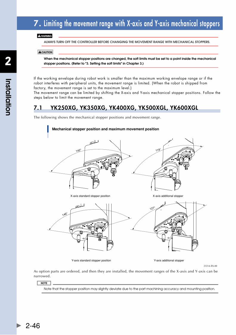
2
Installa
tion
2-46
7. Limiting the movement range with X-axis and Y-axis mechanical stoppers
alWayS TURn Off ThE COnTROllER bEfORE ChangIng ThE MOvEMEnT RangE WITh MEChanICal STOPPERS.
When the mechanical stopper positions are changed, the soft limits must be set to a point inside the mechanical stopperpositions.(referto"3.settingthesoftlimits"inchapter3.)
If the working envelope during robot work is smaller than the maximum working envelope range or if the robot interferes with peripheral units, the movement range is limited. (When the robot is shipped from factory, the movement range is set to the maximum level.) ThemovementrangecanbelimitedbyshiftingtheX-axisandY-axismechanicalstopperpositions.Followthesteps below to limit the movement range.
7.1 YK250XG, YK350XG, YK400XG, YK500XGL, YK600XGLThe following shows the mechanical stopper positions and movement range.
Mechanical stopper position and maximum movement position
X-axis standard stopper position
Y-axis standard stopper position
X-axis additional stopper
Y-axis additional stopper
142°
146°
119°
127°
23214-F6-00
Asoptionpartsareordered,andthentheyareinstalled,themovementrangesoftheX-axisandY-axiscanbenarrowed.
Note that the stopper position may slightly deviate due to the part machining accuracy and mounting position.
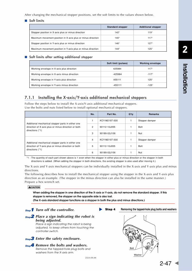
2
Installa
tion
2-47
After changing the mechanical stopper positions, set the soft limits to the values shown below.
Soft limits ■
Standard stopper Additional stopper
StopperpositioninX-axisplusorminusdirection 142° 119°
MaximummovementpositioninX-axisplusorminusdirection 140° 117°
StopperpositioninY-axisplusorminusdirection 146° 127°
MaximummovementpositioninY-axisplusorminusdirection 144° 125°
Soft limits after setting additional stopper ■
Soft limit (pulses) Working envelope
WorkingenvelopeinX-axisplusdirection 425984 117°
WorkingenvelopeinX-axisminusdirection -425984 -117°
WorkingenvelopeinY-axisplusdirection 455111 125°
WorkingenvelopeinY-axisminusdirection -455111 -125°
7.1.1 Installing the X-axis/Y-axis additional mechanical stoppersFollowthestepsbelowtoinstalltheX-axis/Y-axisadditionalmechanicalstoppers.Usetheboltsandnutslistedbelowtoinstalloptionalmechanicalstoppers.
No. Part No. Q'ty Remarks
Additionalmechanicalstopperpartsineitherone
directionofX-axisplusorminusdirectionorboth
directions(*1)
1 KCY-M2197-000 1 Stopperdamper
2 90112-10J055 1 Bolt
3 90189-02J106 1 Nut
Additionalmechanicalstopperpartsineitherone
directionofY-axisplusorminusdirectionorboth
directions(*1)
4 KCY-M2197-000 1 Stopperdamper
5 90112-10J055 1 Bolt
6 90189-02J106 1 Nut
*1:Thequantityofeachpartshownaboveis1evenwhenthestopperineitherplusorminusdirectionorthestopperinboth
directionsisadded.(Whenaddingthestopperinbothdirections,theexistingstopperisalsousedaftermovingit.)
TheX-axisandY-axismechanicalstopperscanbeindividuallyinstalledintheX-axisandY-axisplusandminusdirections. ThefollowingdescribeshowtoinstallthemechanicalstopperusingthestopperintheX-axisandY-axisplusdirection as an example. (The stopper in the minus direction can also be installed in the same manner.) Prepare a hex wrench set.
whenaddingthestopperinonedirectionofthex-axisory-axis,donotremovethestandardstopper.ifthisstopper is removed, the stopper on the opposite side is also lost. (thex-axisstandardstopperfunctionsasastopperinboththeplusandminusdirections.)
1 Turn off the controller.
2 Place a sign indicating the robot is being adjusted.Place a sign indicating the robot is being adjusted, to keep others from touching the controller switch.
3 Enter the safety enclosure.
4 Remove the bolts and washers.Remove the tapped-hole plug bolts and washers from the X-axis arm.
Removing the tapped-hole plug bolts and washersStep 4
Bolt
Washer23215-F6-00
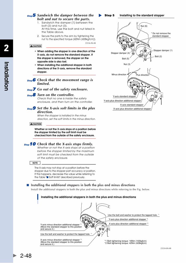
2
Installa
tion
2-48
5 Sandwich the damper between the bolt and nut to secure the parts.1. Sandwich the damper (1) between the
bolt (2) and nut (3). At this time, use the bolt and nut listed in the Table above.
2. Secure the parts to the arm by tightening the nut to the specified torque (42Nm (428kgfcm)).
Installing to the standard stopperStep 5
* Do not remove the standard stopper.
Stopper damper (1)
Bolt (2)
Nut (3)
Stopper damper (4)
Bolt (5)
Nut (6)
Y-axis plus direction additional stopper
X-axis plus direction additional stopper
X-axis standard stopper
Y-axis standard stopper
Minus direction Plus direction
23216-F6-00
• whenaddingthestopperinonedirectionofthe x-axis,donotremovethestandardstopper.if this stopper is removed, the stopper on the opposite side is also lost. • wheninstallingtheadditionalstopperinboth directionsofthex-axis,removethestandard stopper.
6 Check that the movement range is limited.
7 Go out of the safety enclosure.
8 Turn on the controller.Check that no one is inside the safety enclosure, and then turn on the controller.
9 Set the X-axis soft limits in the plus direction.When the stopper is installed in the minus direction, set the soft limits in the minus direction.
whetherornotthex-axisstopsatapositionbeforethe stopper limited by the soft limit must be checked from the outside of the safety enclosure.
0 Check that the X-axis stops firmly.Whether or not the X-axis stops at a position before the stopper limited by the maximum soft limit must be checked from the outside of the safety enclosure.
The X-axis may not stop at a position before the stopper due to the stopper part accuracy or position. If this happens, decrease the value while referring to the Table "■ Soft limits" described previously.
Installing the additional stoppers in both the plus and minus directions ■
Install the additional stoppers in both the plus and minus directions while referring to the Fig. below.
Installing the additional stoppers in both the plus and minus directions
Y-axis plus direction additional stopper *2
X-axis plus direction additional stopper *2
X-axis minus direction additional stopper *2
(Move the standard stopper to this position and secure it.)
Use the bolt and washer to protect the tapped hole. *1
Y-axis minus direction additional stopper *2
(Move the standard stopper to this position and secure it.)
Use the bolt and washer to protect the tapped hole. *1
*1 Bolt tightening torque: 16Nm (163kgfcm)*2 Bolt tightening torque: 42Nm (428kgfcm)
23218-F6-00
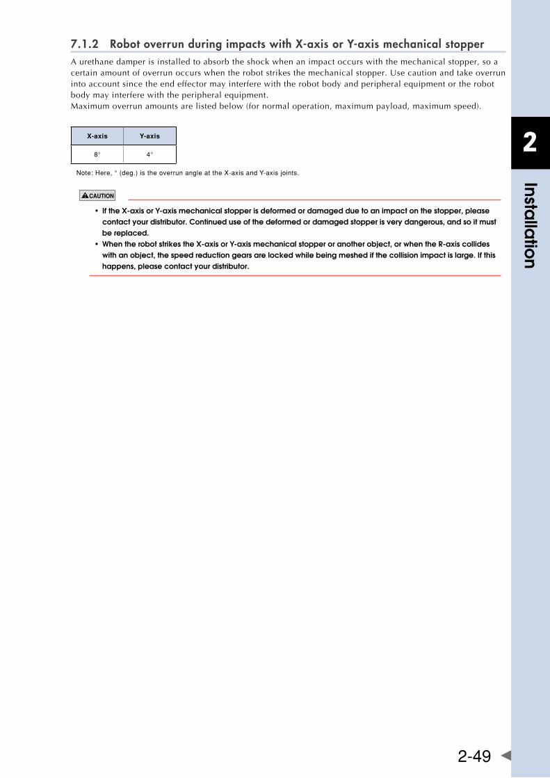
2
Installa
tion
2-49
7.1.2 Robot overrun during impacts with X-axis or Y-axis mechanical stopperA urethane damper is installed to absorb the shock when an impact occurs with the mechanical stopper, so a certainamountofoverrunoccurswhentherobotstrikesthemechanicalstopper.Usecautionandtakeoverruninto account since the end effector may interfere with the robot body and peripheral equipment or the robot body may interfere with the peripheral equipment.Maximum overrun amounts are listed below (for normal operation, maximum payload, maximum speed).
X-axis Y-axis
8° 4°
Note:Here,°(deg.)istheoverrunangleattheX-axisandY-axisjoints.
• ifthex-axisory-axismechanicalstopperisdeformedordamagedduetoanimpactonthestopper,please contact your distributor. Continued use of the deformed or damaged stopper is very dangerous, and so it must be replaced. • whentherobotstrikesthex-axisory-axismechanicalstopperoranotherobject,orwhenther-axiscollides with an object, the speed reduction gears are locked while being meshed if the collision impact is large. If this happens, please contact your distributor.
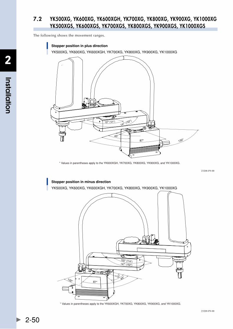
2
Installa
tion
2-50
7.2 YK500XG, YK600XG, YK600XGH, YK700XG, YK800XG, YK900XG, YK1000XG YK500XGS, YK600XGS, YK700XGS, YK800XGS, YK900XGS, YK1000XGSThe following shows the movement ranges.
Stopper position in plus direction
YK500XG, YK600XG, YK600XGH, YK700XG, YK800XG, YK900XG, YK1000XG
* Values in parentheses apply to the YK600XGH, YK700XG, YK800XG, YK900XG, and YK1000XG.
132° 87°
12°
43°
107° (121°)147° (152°)
23208-F9-00
Stopper position in minus direction
YK500XG, YK600XG, YK600XGH, YK700XG, YK800XG, YK900XG, YK1000XG
* Values in parentheses apply to the YK600XGH, YK700XG, YK800XG, YK900XG, and YK1000XG.
102° (114°)
87°132°
12° 43°
147° (152°)
23209-F9-00
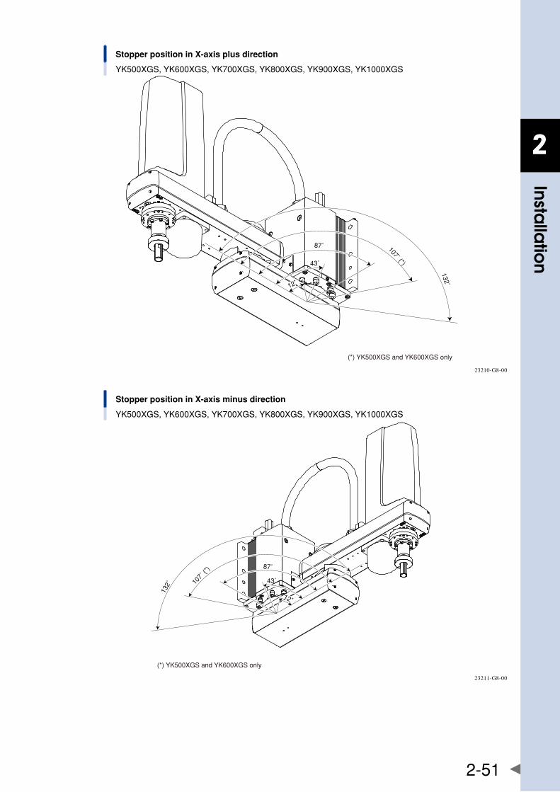
2
Installa
tion
2-51
Stopper position in X-axis plus direction
YK500XGS, YK600XGS, YK700XGS, YK800XGS, YK900XGS, YK1000XGS
(*) YK500XGS and YK600XGS only
87˚ 107˚ (*)
132˚
43˚
12˚12˚
23210-G8-00
Stopper position in X-axis minus direction
YK500XGS, YK600XGS, YK700XGS, YK800XGS, YK900XGS, YK1000XGS
(*) YK500XGS and YK600XGS only
87˚
107˚
(*)
132˚
43˚
12˚12˚
23211-G8-00
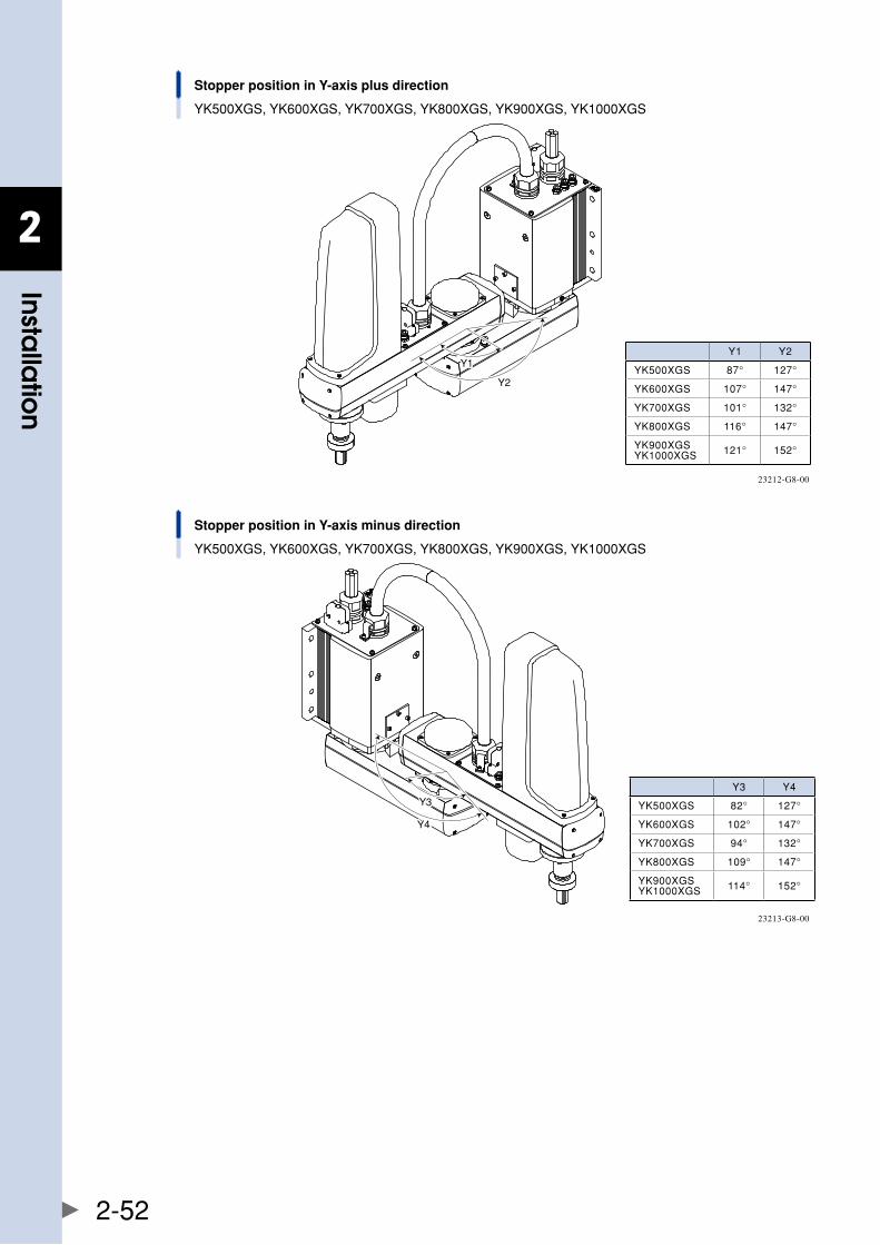
2
Installa
tion
2-52
Stopper position in Y-axis plus direction
YK500XGS, YK600XGS, YK700XGS, YK800XGS, YK900XGS, YK1000XGS
Y2
Y1Y1
23212-G8-00
Stopper position in Y-axis minus direction
YK500XGS, YK600XGS, YK700XGS, YK800XGS, YK900XGS, YK1000XGS
Y4Y4
Y3Y3
23213-G8-00
Y1 Y2
YK500XGS 87° 127°
YK600XGS 107° 147°
YK700XGS 101° 132°
YK800XGS 116° 147°
YK900XGSYK1000XGS 121° 152°
Y3 Y4
YK500XGS 82° 127°
YK600XGS 102° 147°
YK700XGS 94° 132°
YK800XGS 109° 147°
YK900XGSYK1000XGS 114° 152°

2
Installa
tion
2-53
TheX-axisstopperpositioncanbechangedbyshiftingtheexistingstopperposition. The Y-axis stopper position can be changed by installing the supplied parts. The following describes the necessary procedures.
Note that the mechanical stopper position may slightly deviate due to the part machining accuracy.
Additionally, set the soft limits to the values shown below after the mechanical stopper position has been changed.
Soft limits ■
YK500XG, YK600XG, YK600XGH, YK700XG, YK800XG, YK900XG, YK1000XG
X-axis stopper position Soft limit (pulses) Working envelope
±12° ±32768 ±9°
±43° ±145635 ±40°
±87° ±305834 ±84°
±132°(maximumworkingenvelopeposition) ±473315 ±130°
YK500XGS, YK600XGS
X-axis stopper position Soft limit (pulses) Working envelope
±12° ±32768 ±9°
±43° ±145635 ±40°
±87° ±305834 ±84°
±107°(maximumworkingenvelopepositionforYK500XGS) ±382294 ±105°
±132°(maximumworkingenvelopepositionforYK600XGS) ±473315 ±130°
YK700XGS, YK800XGS, YK900XGS, YK1000XGS
X-axis stopper position Soft limit (pulses) Working envelope
±12° ±32768 ±9°
±43° ±145635 ±40°
±87° ±305834 ±84°
±132°(maximumworkingenvelopeposition) ±473315 ±130°
YK500XG, YK600XG
Y-axis stopper position Soft limit (pulses) Working envelope
±147°(maximumworkingenvelopeposition) ±527928 ±145°
+107° +378652 +104°
-102° -360448 -99°
YK600XGH, YK700XG, YK800XG, YK900XG, YK1000XG
Y-axis stopper position Soft limit (pulses) Working envelope
±152°(maximumworkingenvelopeposition) ±546133 ±150°
+121° +429264 +118°
-114° -415061 -111°
YK500XGS
Y-axis stopper position Soft limit (pulses) Working envelope
±127°(maximumworkingenvelopeposition) ±455112 ±125°
+87° +305835 +84°
-82° -287631 -79°
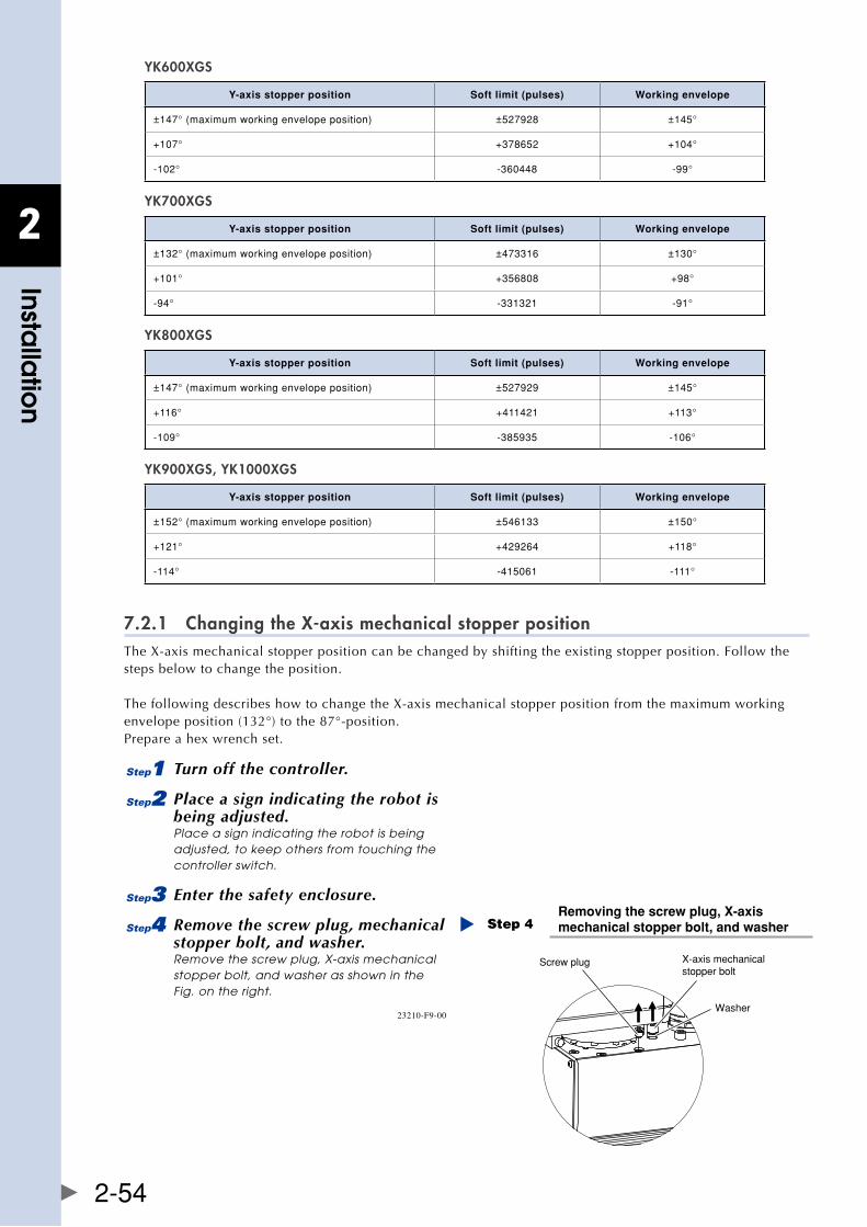
2
Installa
tion
2-54
YK600XGS
Y-axis stopper position Soft limit (pulses) Working envelope
±147°(maximumworkingenvelopeposition) ±527928 ±145°
+107° +378652 +104°
-102° -360448 -99°
YK700XGS
Y-axis stopper position Soft limit (pulses) Working envelope
±132°(maximumworkingenvelopeposition) ±473316 ±130°
+101° +356808 +98°
-94° -331321 -91°
YK800XGS
Y-axis stopper position Soft limit (pulses) Working envelope
±147°(maximumworkingenvelopeposition) ±527929 ±145°
+116° +411421 +113°
-109° -385935 -106°
YK900XGS, YK1000XGS
Y-axis stopper position Soft limit (pulses) Working envelope
±152°(maximumworkingenvelopeposition) ±546133 ±150°
+121° +429264 +118°
-114° -415061 -111°
7.2.1 Changing the X-axis mechanical stopper positionTheX-axismechanicalstopperpositioncanbechangedbyshiftingtheexistingstopperposition.Followthesteps below to change the position.
ThefollowingdescribeshowtochangetheX-axismechanicalstopperpositionfromthemaximumworkingenvelopeposition(132°)tothe87°-position.Prepare a hex wrench set.
1 Turn off the controller.
2 Place a sign indicating the robot is being adjusted.Place a sign indicating the robot is being adjusted, to keep others from touching the controller switch.
3 Enter the safety enclosure.
4 Remove the screw plug, mechanical stopper bolt, and washer.Remove the screw plug, X-axis mechanical stopper bolt, and washer as shown in the Fig. on the right.
Removing the screw plug, X-axis mechanical stopper bolt, and washerStep 4
Screw plug X-axis mechanicalstopper bolt
Washer23210-F9-00
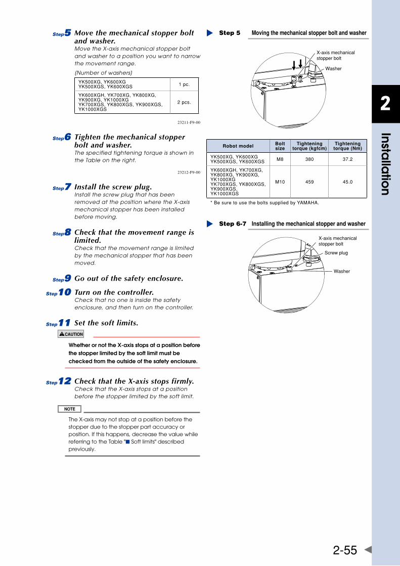
2
Installa
tion
2-55
5 Move the mechanical stopper bolt and washer.Move the X-axis mechanical stopper bolt and washer to a position you want to narrow the movement range.
[Number of washers]
YK500XG,YK600XGYK500XGS,YK600XGS 1pc.
YK600XGH,YK700XG,YK800XG,YK900XG,YK1000XGYK700XGS,YK800XGS,YK900XGS,YK1000XGS
2pcs.
Moving the mechanical stopper bolt and washerStep 5
X-axis mechanicalstopper bolt
Washer
23211-F9-00
6 Tighten the mechanical stopper bolt and washer.The specified tightening torque is shown in the Table on the right.
Installing the mechanical stopper and washerStep 6-7
X-axis mechanicalstopper bolt
Washer
Screw plug
23212-F9-00
7 Install the screw plug.Install the screw plug that has been removed at the position where the X-axis mechanical stopper has been installed before moving.
8 Check that the movement range is limited.Check that the movement range is limited by the mechanical stopper that has been moved.
9 Go out of the safety enclosure.
0 Turn on the controller.Check that no one is inside the safety enclosure, and then turn on the controller.
q Set the soft limits.
whetherornotthex-axisstopsatapositionbeforethe stopper limited by the soft limit must be checked from the outside of the safety enclosure.
w Check that the X-axis stops firmly.Check that the X-axis stops at a position before the stopper limited by the soft limit.
The X-axis may not stop at a position before the stopper due to the stopper part accuracy or position. If this happens, decrease the value while referring to the Table "■ Soft limits" described previously.
Robot model Bolt size
Tightening torque (kgfcm)
Tightening torque (Nm)
YK500XG,YK600XGYK500XGS,YK600XGS M8 380 37.2
YK600XGH,YK700XG,YK800XG,YK900XG,YK1000XGYK700XGS,YK800XGS,YK900XGS,YK1000XGS
M10 459 45.0
*BesuretousetheboltssuppliedbyYAMAHA.
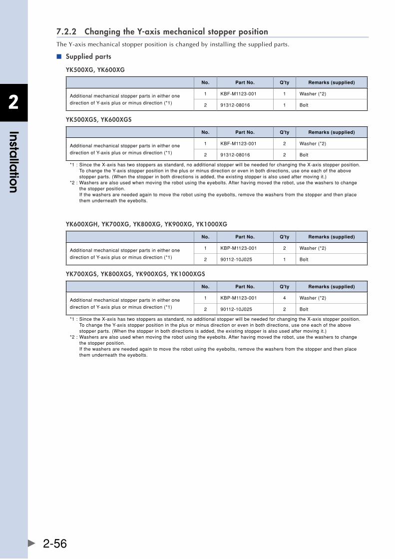
2
Installa
tion
2-56
7.2.2 Changing the Y-axis mechanical stopper positionThe Y-axis mechanical stopper position is changed by installing the supplied parts.
Supplied parts ■
YK500XG, YK600XG
No. Part No. Q'ty Remarks (supplied)
Additionalmechanicalstopperpartsineitherone
directionofY-axisplusorminusdirection(*1)
1 KBF-M1123-001 1 Washer(*2)
2 91312-08016 1 Bolt
YK500XGS, YK600XGS
No. Part No. Q'ty Remarks (supplied)
Additionalmechanicalstopperpartsineitherone
directionofY-axisplusorminusdirection(*1)
1 KBF-M1123-001 2 Washer(*2)
2 91312-08016 2 Bolt
*1:SincetheX-axishastwostoppersasstandard,noadditionalstopperwillbeneededforchangingtheX-axisstopperposition. TochangetheY-axisstopperpositionintheplusorminusdirectionoreveninbothdirections,useoneeachoftheabove stopperparts.(Whenthestopperinbothdirectionsisadded,theexistingstopperisalsousedaftermovingit.)*2:Washersarealsousedwhenmovingtherobotusingtheeyebolts.Afterhavingmovedtherobot,usethewasherstochange thestopperposition. Ifthewashersareneededagaintomovetherobotusingtheeyebolts,removethewashersfromthestopperandthenplace themunderneaththeeyebolts.
YK600XGH, YK700XG, YK800XG, YK900XG, YK1000XG
No. Part No. Q'ty Remarks (supplied)
Additionalmechanicalstopperpartsineitherone
directionofY-axisplusorminusdirection(*1)
1 KBP-M1123-001 2 Washer(*2)
2 90112-10J025 1 Bolt
YK700XGS, YK800XGS, YK900XGS, YK1000XGS
No. Part No. Q'ty Remarks (supplied)
Additionalmechanicalstopperpartsineitherone
directionofY-axisplusorminusdirection(*1)
1 KBP-M1123-001 4 Washer(*2)
2 90112-10J025 2 Bolt
*1:SincetheX-axishastwostoppersasstandard,noadditionalstopperwillbeneededforchangingtheX-axisstopperposition. TochangetheY-axisstopperpositionintheplusorminusdirectionoreveninbothdirections,useoneeachoftheabove stopperparts.(Whenthestopperinbothdirectionsisadded,theexistingstopperisalsousedaftermovingit.)*2:Washersarealsousedwhenmovingtherobotusingtheeyebolts.Afterhavingmovedtherobot,usethewasherstochange thestopperposition. Ifthewashersareneededagaintomovetherobotusingtheeyebolts,removethewashersfromthestopperandthenplace themunderneaththeeyebolts.
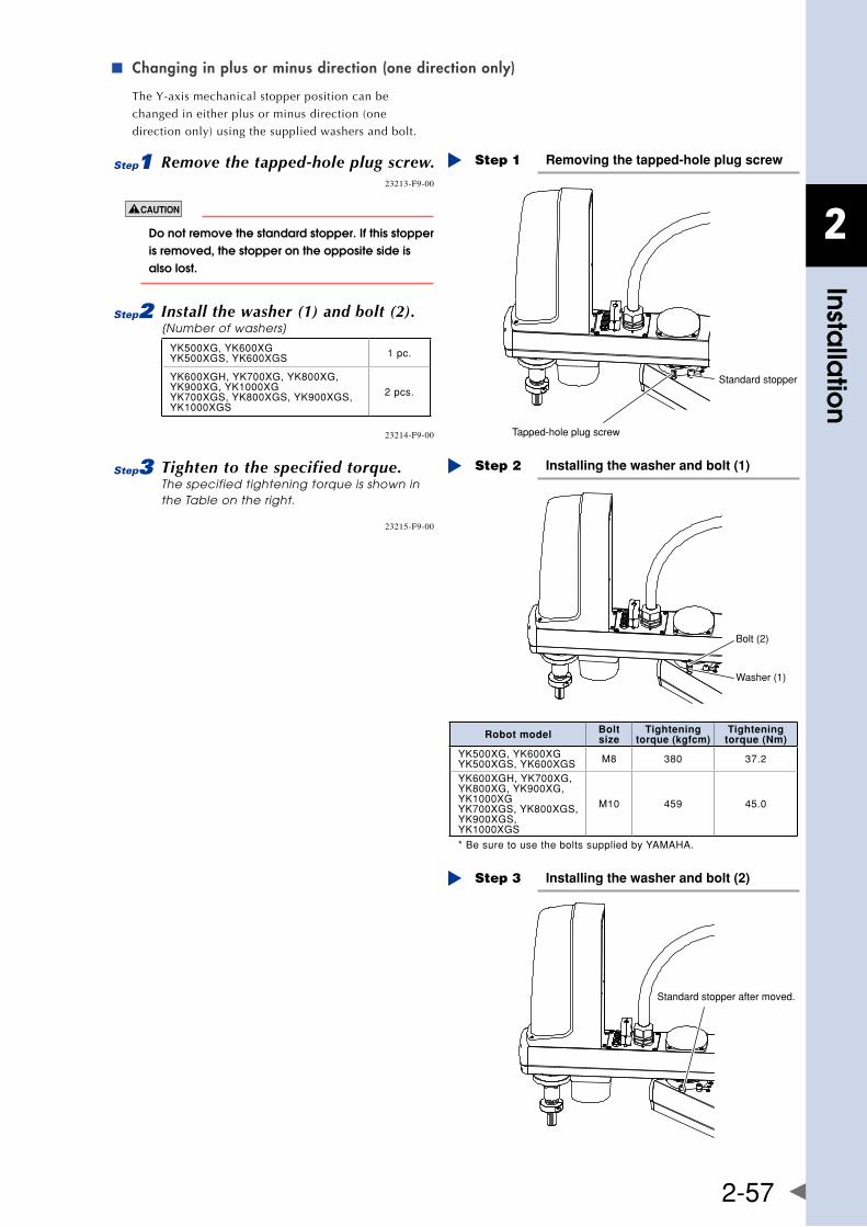
2
Installa
tion
2-57
Changing in plus or minus direction (one direction only) ■
The Y-axis mechanical stopper position can be
changed in either plus or minus direction (one
direction only) using the supplied washers and bolt.
1 Remove the tapped-hole plug screw. Removing the tapped-hole plug screwStep 1
Tapped-hole plug screw
Standard stopper
23213-F9-00
Do not remove the standard stopper. If this stopper is removed, the stopper on the opposite side is also lost.
2 Install the washer (1) and bolt (2).[Number of washers]
YK500XG,YK600XGYK500XGS,YK600XGS 1pc.
YK600XGH,YK700XG,YK800XG,YK900XG,YK1000XGYK700XGS,YK800XGS,YK900XGS,YK1000XGS
2pcs.
Installing the washer and bolt (1)Step 2
Washer (1)
Bolt (2)
23214-F9-00
3 Tighten to the specified torque.The specified tightening torque is shown in the Table on the right.
Installing the washer and bolt (2)Step 3
Standard stopper after moved.
23215-F9-00
Robot model Bolt size
Tightening torque (kgfcm)
Tightening torque (Nm)
YK500XG,YK600XGYK500XGS,YK600XGS M8 380 37.2
YK600XGH,YK700XG,YK800XG,YK900XG,YK1000XGYK700XGS,YK800XGS,YK900XGS,YK1000XGS
M10 459 45.0
*BesuretousetheboltssuppliedbyYAMAHA.
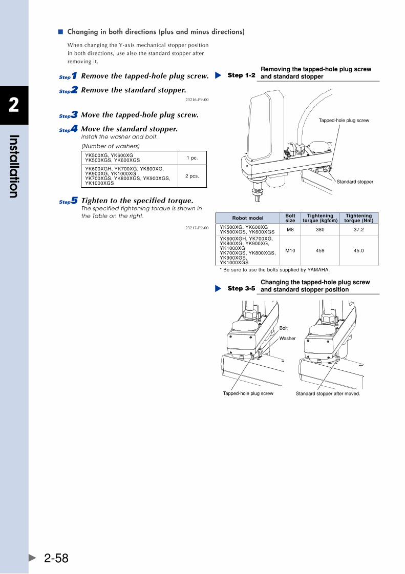
2
Installa
tion
2-58
Changing in both directions (plus and minus directions) ■
When changing the Y-axis mechanical stopper position
in both directions, use also the standard stopper after
removing it.
1 Remove the tapped-hole plug screw.
2 Remove the standard stopper.
Removing the tapped-hole plug screw and standard stopperStep 1-2
Tapped-hole plug screw
Standard stopper
23216-F9-00
3 Move the tapped-hole plug screw.
4 Move the standard stopper.Install the washer and bolt.
[Number of washers]
YK500XG,YK600XGYK500XGS,YK600XGS 1pc.
YK600XGH,YK700XG,YK800XG,YK900XG,YK1000XGYK700XGS,YK800XGS,YK900XGS,YK1000XGS
2pcs.
5 Tighten to the specified torque.The specified tightening torque is shown in the Table on the right.
Changing the tapped-hole plug screw and standard stopper positionStep 3-5
Tapped-hole plug screw
Washer
Bolt
Standard stopper after moved.
23217-F9-00
Robot model Bolt size
Tightening torque (kgfcm)
Tightening torque (Nm)
YK500XG,YK600XGYK500XGS,YK600XGS M8 380 37.2
YK600XGH,YK700XG,YK800XG,YK900XG,YK1000XGYK700XGS,YK800XGS,YK900XGS,YK1000XGS
M10 459 45.0
*BesuretousetheboltssuppliedbyYAMAHA.
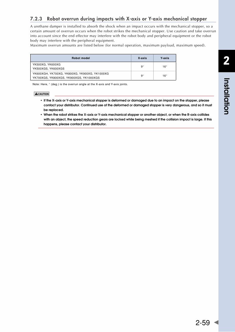
2
Installa
tion
2-59
7.2.3 Robot overrun during impacts with X-axis or Y-axis mechanical stopperA urethane damper is installed to absorb the shock when an impact occurs with the mechanical stopper, so a certainamountofoverrunoccurswhentherobotstrikesthemechanicalstopper.Usecautionandtakeoverruninto account since the end effector may interfere with the robot body and peripheral equipment or the robot body may interfere with the peripheral equipment.Maximum overrun amounts are listed below (for normal operation, maximum payload, maximum speed).
Robot model X-axis Y-axis
YK500XG,YK600XG
YK500XGS,YK600XGS9° 16°
YK600XGH,YK700XG,YK800XG,YK900XG,YK1000XG
YK700XGS,YK800XGS,YK900XGS,YK1000XGS9° 16°
Note:Here,°(deg.)istheoverrunangleattheX-axisandY-axisjoints.
• ifthex-axisory-axismechanicalstopperisdeformedordamagedduetoanimpactonthestopper,please contact your distributor. Continued use of the deformed or damaged stopper is very dangerous, and so it must be replaced. • whentherobotstrikesthex-axisory-axismechanicalstopperoranotherobject,orwhenther-axiscollides with an object, the speed reduction gears are locked while being meshed if the collision impact is large. If this happens, please contact your distributor.
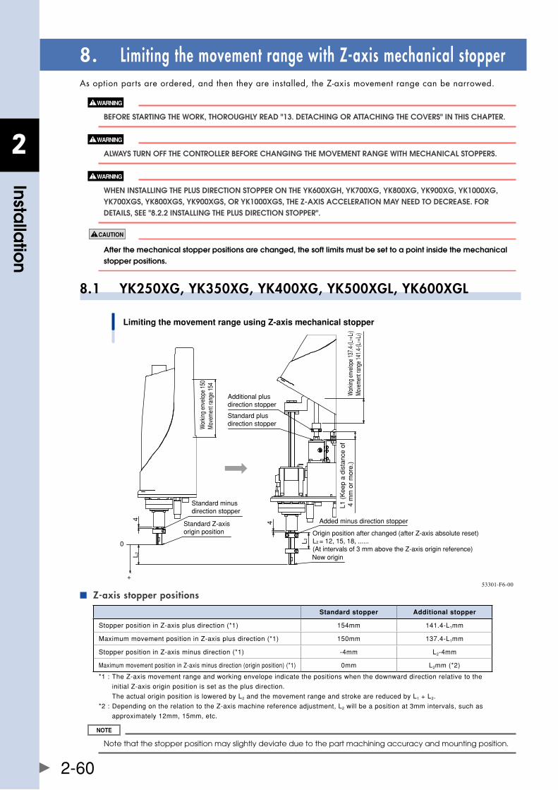
2
Installa
tion
2-60
8. Limiting the movement range with Z-axis mechanical stopperAsoptionpartsareordered,andthentheyareinstalled,theZ-axismovementrangecanbenarrowed.
bEfORE STaRTIng ThE WORk, ThOROUghly REaD "13. DETaChIng OR aTTaChIng ThE COvERS" In ThIS ChaPTER.
alWayS TURn Off ThE COnTROllER bEfORE ChangIng ThE MOvEMEnT RangE WITh MEChanICal STOPPERS.
WhEn InSTallIng ThE PlUS DIRECTIOn STOPPER On ThE yk600xgh, yk700xg, yk800xg, yk900xg, yk1000xg, yk700xgS, yk800xgS, yk900xgS, OR yk1000xgS, ThE z-axIS aCCElERaTIOn May nEED TO DECREaSE. fOR DETaIlS, SEE "8.2.2 InSTallIng ThE PlUS DIRECTIOn STOPPER".
after the mechanical stopper positions are changed, the soft limits must be set to a point inside the mechanical stopper positions.
8.1 YK250XG, YK350XG, YK400XG, YK500XGL, YK600XGL
Limiting the movement range using Z-axis mechanical stopper
Wor
king
enve
lope
137.
4-(L
1 +L2
)M
ovem
ent r
ange
141
.4-(L
1 +L2
)
L1 (
Kee
p a
dist
ance
of
4 m
m o
r m
ore.
)
Added minus direction stopper
Origin position after changed (after Z-axis absolute reset)L2 = 12, 15, 18, ......(At intervals of 3 mm above the Z-axis origin reference)New origin
L 2
Additional plus direction stopper
4
Standard plus direction stopperW
orkin
g en
velo
pe 1
50M
ovem
ent r
ange
154
Standard minus direction stopper
Standard Z-axisorigin position
L24
0
+53301-F6-00
Z-axis stopper positions ■
Standard stopper Additional stopper
StopperpositioninZ-axisplusdirection(*1) 154mm 141.4-L1mm
MaximummovementpositioninZ-axisplusdirection(*1) 150mm 137.4-L1mm
StopperpositioninZ-axisminusdirection(*1) -4mm L2-4mm
MaximummovementpositioninZ-axisminusdirection(originposition)(*1) 0mm L2mm(*2)
*1:TheZ-axismovementrangeandworkingenvelopeindicatethepositionswhenthedownwarddirectionrelativetothe
initialZ-axisoriginpositionissetastheplusdirection.
TheactualoriginpositionisloweredbyL2andthemovementrangeandstrokearereducedbyL1+L2.
*2:DependingontherelationtotheZ-axismachinereferenceadjustment,L2willbeapositionat3mmintervals,suchas
approximately12mm,15mm,etc.
Note that the stopper position may slightly deviate due to the part machining accuracy and mounting position.
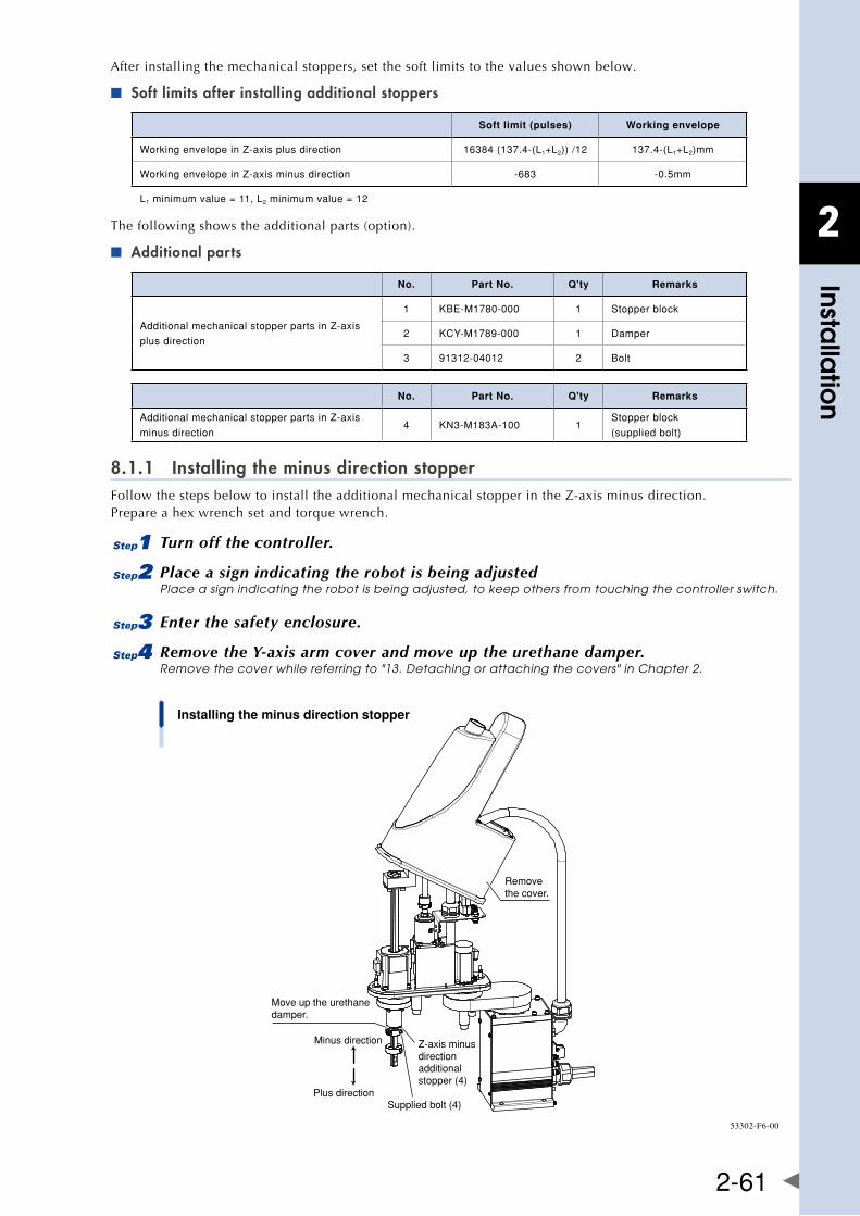
2
Installa
tion
2-61
After installing the mechanical stoppers, set the soft limits to the values shown below.
Soft limits after installing additional stoppers ■
Soft limit (pulses) Working envelope
WorkingenvelopeinZ-axisplusdirection 16384(137.4-(L1+L2))/12 137.4-(L1+L2)mm
WorkingenvelopeinZ-axisminusdirection -683 -0.5mm
L1minimumvalue=11,L2minimumvalue=12
The following shows the additional parts (option).
Additional parts ■
No. Part No. Q'ty Remarks
AdditionalmechanicalstopperpartsinZ-axis
plusdirection
1 KBE-M1780-000 1 Stopperblock
2 KCY-M1789-000 1 Damper
3 91312-04012 2 Bolt
No. Part No. Q'ty Remarks
AdditionalmechanicalstopperpartsinZ-axis
minusdirection4 KN3-M183A-100 1
Stopperblock
(suppliedbolt)
8.1.1 Installing the minus direction stopperFollowthestepsbelowtoinstalltheadditionalmechanicalstopperintheZ-axisminusdirection. Prepare a hex wrench set and torque wrench.
1 Turn off the controller.
2 Place a sign indicating the robot is being adjustedPlace a sign indicating the robot is being adjusted, to keep others from touching the controller switch.
3 Enter the safety enclosure.
4 Remove the Y-axis arm cover and move up the urethane damper.Remove the cover while referring to "13. Detaching or attaching the covers" in Chapter 2.
Installing the minus direction stopper
Remove the cover.
Move up the urethanedamper.
Minus direction
Plus direction
Z-axis minus direction additional stopper (4)
Supplied bolt (4)
53302-F6-00
2
Installa
tion
2-62
5 Install the additional stopper.Install the additional stopper (4) to the spline shaft by tightening the supplied bolts to the specified torque. • Tightening torque: 9 Nm (92 kgfcm) Alternately tighten the bolts a little at a time.
For the minus direction stopper position, depending on the relation to the Z-axis origin reference adjustment, L2 stated in the "■ Z-axis stopper positions" table described previously will be a position at 3mm intervals, such as approximately 12mm, 15mm, etc.
6 Go out of the safety enclosure.
7 Turn on the controller.Check that no one is inside the safety enclosure, and then turn on the controller.
8 Perform the Z-axis absolute reset.
For details about how to perform the Z-axis absolute reset, see "2.3 Absolute reset procedures" in Chapter 3.
9 Make a note of the Z-axis machine reference value.
When adjusting the machine reference value, always follow the steps below to check the adjustment machine reference value.
1. Press the key.
2. Press the key to enter MANUAL mode.
3. Press the ( + ) key to select "ABS Reset".
4. After the Z-axis absolute reset is completed, press the ( + ) key to display the
adjustment machine reference value (%).
When the machine reference is within the allowable range (between 30 and 70%), proceed to step 16. When the machine reference is beyond the allowable range, proceed to step 11.
0 Turn off the controller.
q Enter the safety enclosure.
w Put a mark at the additional stopper position.
e Loosen the stopper bolt.Machine reference value < 30%: Move the additional stopper in the plus direction. Machine reference value > 70%: Move the additional stopper in the minus direction. As an approximate guide, a 3mm-movement equals 100%.
r Check the machine reference value again.Repeat the same procedure from step 5) until the machine reference is within the allowable range.
When the machine reference is set within the allowable range,
t Go out of the safety enclosure.
y Turn on the controller.Check that no one is inside the safety enclosure, and then turn on the controller.
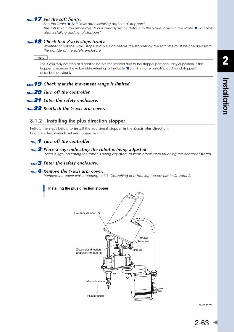
2
Installa
tion
2-63
u Set the soft limits.See the Table "■ Soft limits after installing additional stoppers". The soft limit in the minus direction is already set by default to the value shown in the Table "■ Soft limits after installing additional stoppers".
i Check that Z-axis stops firmly.Whether or not the Z-axis stops at a position before the stopper by the soft limit must be checked from the outside of the safety enclosure.
The X-axis may not stop at a position before the stopper due to the stopper part accuracy or position. If this happens, increase the value while referring to the Table "■ Soft limits after installing additional stoppers" described previously.
o Check that the movement range is limited.
p Turn off the controller.
a Enter the safety enclosure.
s Reattach the Y-axis arm cover.
8.1.2 Installing the plus direction stopperFollowthestepsbelowtoinstalltheadditionalstopperintheZ-axisplusdirection. Prepare a hex wrench set and torque wrench.
1 Turn off the controller.
2 Place a sign indicating the robot is being adjustedPlace a sign indicating the robot is being adjusted, to keep others from touching the controller switch.
3 Enter the safety enclosure.
4 Remove the Y-axis arm cover.Remove the cover while referring to "13. Detaching or attaching the covers" in Chapter 2.
Installing the plus direction stopper
Z-axis plus direction additional stopper (1)
Remove the cover.
Urethane damper (2)
Minus direction
Plus direction
Bolt (3)
53303-F6-00
2
Installa
tion
2-64
5 Install the additional stopper.Install the additional stopper (1) to the ball screw by tightening the bolts (3) to the specified torque shown below. • Tightening torque: 4.5 Nm (46 kgfcm) Alternately tighten the bolts a little at a time. The stopper position in the plus direction L1 must be 4mm or more.
6 Secure the urethane damper.Widen the notch part of the urethane damper (2), pass it through the ball screw shaft, and bond it onto the additional stopper (1) in the Z-axis plus direction using adhesive. Use ThreeBond 1739 instant adhesive as the adhesive. Fully degrease the bonding surfaces before applying the adhesive.
7 Go out of the safety enclosure.
8 Turn on the controller.Check that no one is inside the safety enclosure, and then turn on the controller.
9 Set the soft limits.Set the soft limits in the plus direction while referring to the calculation values shown in the Table "■Soft limits after installing additional stoppers" described previously.
0 Check that Z-axis stops firmly.Whether or not the Z-axis stops at a position before the stopper by the soft limit must be checked from the outside of the safety enclosure.
The Z-axis may not stop at a position before the stopper due to the stopper part accuracy or position. If this happens, decrease the value while referring to the Table "■Soft limits after installing additional stoppers" described previously.
q Check that the movement range is limited.
w Turn off the controller.
e Enter the safety enclosure.
r Reattach the Y-axis arm cover.
8.1.3 Overrun amounts during impacts with Z-axis additional mechanical stopperA urethane damper is installed to absorb the shock when an impact occurs with the mechanical stopper, so a certainamountofoverrunoccurswhentherobotstrikesthemechanicalstopper.Usecautionandtakeoverruninto account since the end effector may interfere with the robot body and peripheral equipment or the robot body may interfere with the peripheral equipment. Maximum overrun amounts are listed below (for normal operation, maximum payload, maximum speed).
Upper end Lower end
1mm 1mm
aftertherobotstrikesthez-axismechanicalstopper,thestopperpositionmayshift,andsocheckthestopperposition. If shifted, move the stopper to the correct position and refasten it securely by following the assembly procedure.
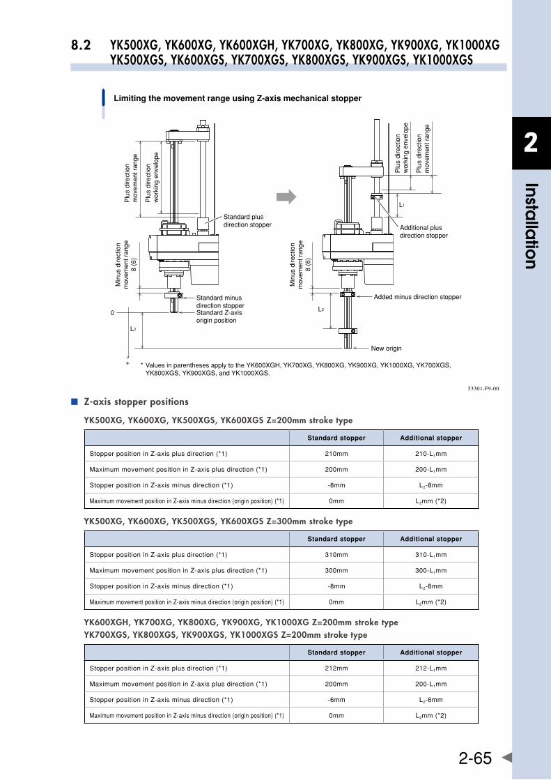
2
Installa
tion
2-65
8.2 YK500XG, YK600XG, YK600XGH, YK700XG, YK800XG, YK900XG, YK1000XG YK500XGS, YK600XGS, YK700XGS, YK800XGS, YK900XGS, YK1000XGS
Limiting the movement range using Z-axis mechanical stopper
Plu
s di
rect
ion
mov
emen
t ran
ge
Plu
s di
rect
ion
mov
emen
t ran
ge
Plu
s di
rect
ion
wor
king
env
elop
e
Plu
s di
rect
ion
wor
king
env
elop
e
Standard plus direction stopper
Standard minus direction stopper
Added minus direction stopper
Standard Z-axisorigin position
New origin
* Values in parentheses apply to the YK600XGH, YK700XG, YK800XG, YK900XG, YK1000XG, YK700XGS, YK800XGS, YK900XGS, and YK1000XGS.
L2
L1
0
+
Min
us d
irect
ion
mov
emen
t ran
ge8
(6)
Additional plus direction stopper
Min
us d
irect
ion
mov
emen
t ran
ge8
(6)
L2
53301-F9-00
Z-axis stopper positions ■
YK500XG, YK600XG, YK500XGS, YK600XGS Z=200mm stroke type
Standard stopper Additional stopper
StopperpositioninZ-axisplusdirection(*1) 210mm 210-L1mm
MaximummovementpositioninZ-axisplusdirection(*1) 200mm 200-L1mm
StopperpositioninZ-axisminusdirection(*1) -8mm L2-8mm
MaximummovementpositioninZ-axisminusdirection(originposition)(*1) 0mm L2mm(*2)
YK500XG, YK600XG, YK500XGS, YK600XGS Z=300mm stroke type
Standard stopper Additional stopper
StopperpositioninZ-axisplusdirection(*1) 310mm 310-L1mm
MaximummovementpositioninZ-axisplusdirection(*1) 300mm 300-L1mm
StopperpositioninZ-axisminusdirection(*1) -8mm L2-8mm
MaximummovementpositioninZ-axisminusdirection(originposition)(*1) 0mm L2mm(*2)
YK600XGH, YK700XG, YK800XG, YK900XG, YK1000XG Z=200mm stroke type YK700XGS, YK800XGS, YK900XGS, YK1000XGS Z=200mm stroke type
Standard stopper Additional stopper
StopperpositioninZ-axisplusdirection(*1) 212mm 212-L1mm
MaximummovementpositioninZ-axisplusdirection(*1) 200mm 200-L1mm
StopperpositioninZ-axisminusdirection(*1) -6mm L2-6mm
MaximummovementpositioninZ-axisminusdirection(originposition)(*1) 0mm L2mm(*2)
2
Installa
tion
2-66
YK600XGH, YK700XG, YK800XG, YK900XG, YK1000XG Z=400mm stroke type YK700XGS, YK800XGS, YK900XGS, YK1000XGS Z=400mm stroke type
Standard stopper Additional stopper
StopperpositioninZ-axisplusdirection(*1) 412mm 412-L1mm
MaximummovementpositioninZ-axisplusdirection(*1) 400mm 400-L1mm
StopperpositioninZ-axisminusdirection(*1) -6mm L2-6mm
MaximummovementpositioninZ-axisminusdirection(originposition)(*1) 0mm L2mm(*2)
*1:TheZ-axismovementrangeandworkingenvelopeindicatethepositionswhenthedownwarddirectionrelativetothe
initialZ-axisoriginpositionissetastheplusdirection.
TheactualoriginpositionisloweredbyL2andthemovementrangeandstrokearereducedbyL1+L2.
*2:DependingontherelationtotheZ-axismachinereferenceadjustment,L2willbeapositionat5mmintervals,suchas
approximately15mm,20mm,etc.
After installing the mechanical stoppers, set the soft limits to the values shown below.
Soft limits after installing additional stoppers ■
Z=200mm stroke type
Soft limit (pulses) Working envelope
WorkingenvelopeinZ-axisplusdirection 16384(200-(L1+L2))/20 200-(L1+L2)mm
WorkingenvelopeinZ-axisminusdirection -819 -1mm
Z=300mm stroke type
Soft limit (pulses) Working envelope
WorkingenvelopeinZ-axisplusdirection 16384(300-(L1+L2))/20 300-(L1+L2)mm
WorkingenvelopeinZ-axisminusdirection -819 -1mm
Z=400mm stroke type
Soft limit (pulses) Working envelope
WorkingenvelopeinZ-axisplusdirection 16384(400-(L1+L2))/20 400-(L1+L2)mm
WorkingenvelopeinZ-axisminusdirection -819 -1mm
L1minimumvalue=14,L2minimumvalue=15
Note that the stopper position may slightly deviate due to the part machining accuracy and mounting position.
The following shows the additional parts (option).
Additional parts ■
No. Part No. Q'ty Remarks
AdditionalmechanicalstopperpartsinZ-axis
plusdirection
1 KBF-M1781-000 1 Stopperblock
2 KBF-M1788-100 1 Damper
3 91312-05016 2 Bolt
YK500XG, YK600XG, YK500XGS, YK600XGS
No. Part No. Q'ty Remarks
AdditionalmechanicalstopperpartsinZ-axis
minusdirection4 KBF-M183A-000 1
Stopperblock
(suppliedbolt)
YK600XGH, YK700XG, YK800XG, YK900XG, YK1000XG YK700XGS, YK800XGS, YK900XGS, YK1000XGS
No. Part No. Q'ty Remarks
AdditionalmechanicalstopperpartsinZ-axis
minusdirection4 KBP-M183A-000 1
Stopperblock
(suppliedbolt)
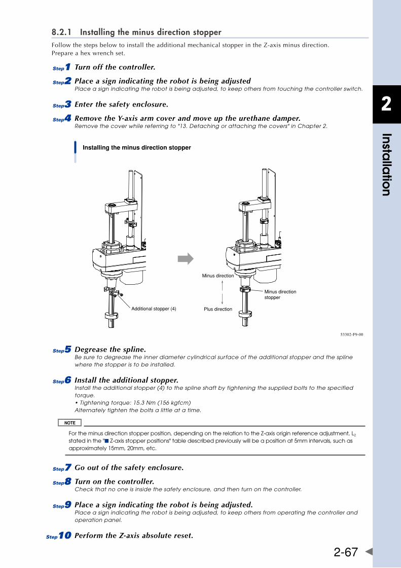
2
Installa
tion
2-67
8.2.1 Installing the minus direction stopperFollowthestepsbelowtoinstalltheadditionalmechanicalstopperintheZ-axisminusdirection. Prepare a hex wrench set.
1 Turn off the controller.
2 Place a sign indicating the robot is being adjustedPlace a sign indicating the robot is being adjusted, to keep others from touching the controller switch.
3 Enter the safety enclosure.
4 Remove the Y-axis arm cover and move up the urethane damper.Remove the cover while referring to "13. Detaching or attaching the covers" in Chapter 2.
Installing the minus direction stopper
Minus directionstopper
Additional stopper (4)
Minus direction
Plus direction
53302-F9-00
5 Degrease the spline.Be sure to degrease the inner diameter cylindrical surface of the additional stopper and the spline where the stopper is to be installed.
6 Install the additional stopper.Install the additional stopper (4) to the spline shaft by tightening the supplied bolts to the specified torque. • Tightening torque: 15.3 Nm (156 kgfcm) Alternately tighten the bolts a little at a time.
For the minus direction stopper position, depending on the relation to the Z-axis origin reference adjustment, L2 stated in the "■ Z-axis stopper positions" table described previously will be a position at 5mm intervals, such as approximately 15mm, 20mm, etc.
7 Go out of the safety enclosure.
8 Turn on the controller.Check that no one is inside the safety enclosure, and then turn on the controller.
9 Place a sign indicating the robot is being adjusted.Place a sign indicating the robot is being adjusted, to keep others from operating the controller and operation panel.
0 Perform the Z-axis absolute reset.
2
Installa
tion
2-68
For details about how to perform the Z-axis absolute reset, see "2.3 Absolute reset procedures" in Chapter 3.
q Make a note of the Z-axis machine reference value.
When adjusting the machine reference value, always follow the steps below to check the adjustment machine reference value.
1. Press the key.
2. Press the key to enter MANUAL mode.
3. Press the ( + ) key to select "ABS Reset".
4. After the Z-axis absolute reset is completed, press the ( + ) key to display the
adjustment machine reference value (%).
When the machine reference is within the allowable range (between 26 and 74%), proceed to step 17. When the machine reference is beyond the allowable range, proceed to step 12.
w Turn off the controller.
e Enter the safety enclosure.
r Put a mark at the additional stopper position.
t Loosen the stopper bolt.Machine reference value < 26%: Move the additional stopper in the plus direction. Machine reference value > 74%: Move the additional stopper in the minus direction. As an approximate guide, a 5mm-movement equals 100%.
y Check the machine reference value again.Repeat the same procedure from step 5) until the machine reference is within the allowable range.
When the machine reference is set within the allowable range,
u Go out of the safety enclosure.
i Turn on the controller.Check that no one is inside the safety enclosure, and then turn on the controller.
o Set the soft limits.See the Table "■Soft limits after installing additional stoppers". The soft limit in the minus direction is already set by default to the value shown in the Table "■Soft limits after installing additional stoppers".
p Check that Z-axis stops firmly.Whether or not the Z-axis stops at a position before the stopper by the soft limit must be checked from the outside of the safety enclosure.
The X-axis may not stop at a position before the stopper due to the stopper part accuracy or position. If this happens, increase the value while referring to the Table "■Soft limits after installing additional stoppers" described previously.
a Check that the movement range is limited.
s Turn off the controller.
d Enter the safety enclosure.
f Reattach the Y-axis arm cover.
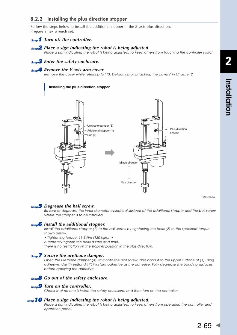
2
Installa
tion
2-69
8.2.2 Installing the plus direction stopperFollowthestepsbelowtoinstalltheadditionalstopperintheZ-axisplusdirection. Prepare a hex wrench set.
1 Turn off the controller.
2 Place a sign indicating the robot is being adjustedPlace a sign indicating the robot is being adjusted, to keep others from touching the controller switch.
3 Enter the safety enclosure.
4 Remove the Y-axis arm cover.Remove the cover while referring to "13. Detaching or attaching the covers" in Chapter 2.
Installing the plus direction stopper
Minus direction
Plus direction
Plus directionstopper
Urethane damper (3)
Additional stopper (1)
Bolt (2)
53303-F9-00
5 Degrease the ball screw.Be sure to degrease the inner diameter cylindrical surface of the additional stopper and the ball screw where the stopper is to be installed.
6 Install the additional stopper.Install the additional stopper (1) to the ball screw by tightening the bolts (2) to the specified torque shown below. • Tightening torque: 11.8 Nm (120 kgfcm) Alternately tighten the bolts a little at a time. There is no restriction on the stopper position in the plus direction.
7 Secure the urethane damper.Open the urethane damper (3), fit it onto the ball screw, and bond it to the upper surface of (1) using adhesive. Use ThreeBond 1739 instant adhesive as the adhesive. Fully degrease the bonding surfaces before applying the adhesive.
8 Go out of the safety enclosure.
9 Turn on the controller.Check that no one is inside the safety enclosure, and then turn on the controller.
0 Place a sign indicating the robot is being adjusted.Place a sign indicating the robot is being adjusted, to keep others from operating the controller and operation panel.
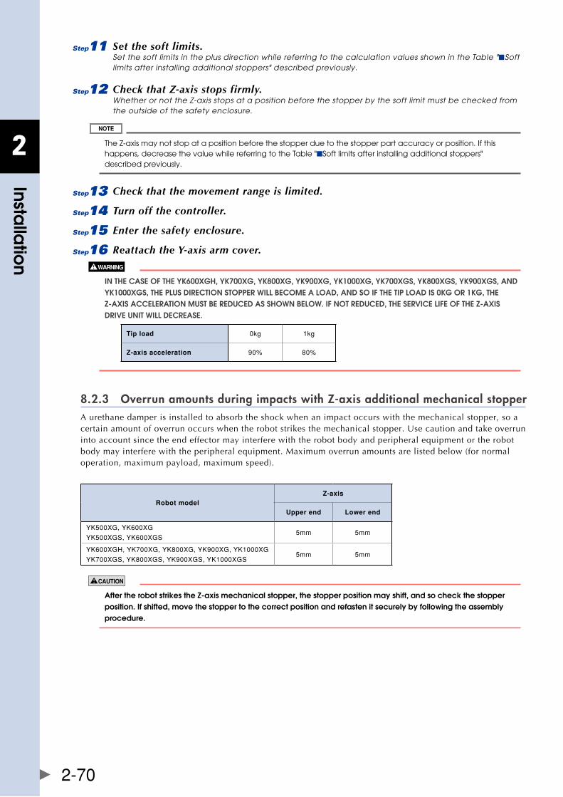
2
Installa
tion
2-70
q Set the soft limits.Set the soft limits in the plus direction while referring to the calculation values shown in the Table "■Soft limits after installing additional stoppers" described previously.
w Check that Z-axis stops firmly.Whether or not the Z-axis stops at a position before the stopper by the soft limit must be checked from the outside of the safety enclosure.
The Z-axis may not stop at a position before the stopper due to the stopper part accuracy or position. If this happens, decrease the value while referring to the Table "■Soft limits after installing additional stoppers" described previously.
e Check that the movement range is limited.
r Turn off the controller.
t Enter the safety enclosure.
y Reattach the Y-axis arm cover.
In ThE CaSE Of ThE yk600xgh, yk700xg, yk800xg, yk900xg, yk1000xg, yk700xgS, yk800xgS, yk900xgS, anD yk1000xgS, ThE PlUS DIRECTIOn STOPPER WIll bECOME a lOaD, anD SO If ThE TIP lOaD IS 0kg OR 1kg, ThE z-axIS aCCElERaTIOn MUST bE REDUCED aS ShOWn bElOW. If nOT REDUCED, ThE SERvICE lIfE Of ThE z-axIS DRIvE UnIT WIll DECREaSE.
Tip load 0kg 1kg
Z-axis acceleration 90% 80%
8.2.3 Overrun amounts during impacts with Z-axis additional mechanical stopperA urethane damper is installed to absorb the shock when an impact occurs with the mechanical stopper, so a certainamountofoverrunoccurswhentherobotstrikesthemechanicalstopper.Usecautionandtakeoverruninto account since the end effector may interfere with the robot body and peripheral equipment or the robot body may interfere with the peripheral equipment. Maximum overrun amounts are listed below (for normal operation, maximum payload, maximum speed).
Robot modelZ-axis
Upper end Lower end
YK500XG,YK600XG
YK500XGS,YK600XGS5mm 5mm
YK600XGH,YK700XG,YK800XG,YK900XG,YK1000XG
YK700XGS,YK800XGS,YK900XGS,YK1000XGS5mm 5mm
aftertherobotstrikesthez-axismechanicalstopper,thestopperpositionmayshift,andsocheckthestopperposition. If shifted, move the stopper to the correct position and refasten it securely by following the assembly procedure.
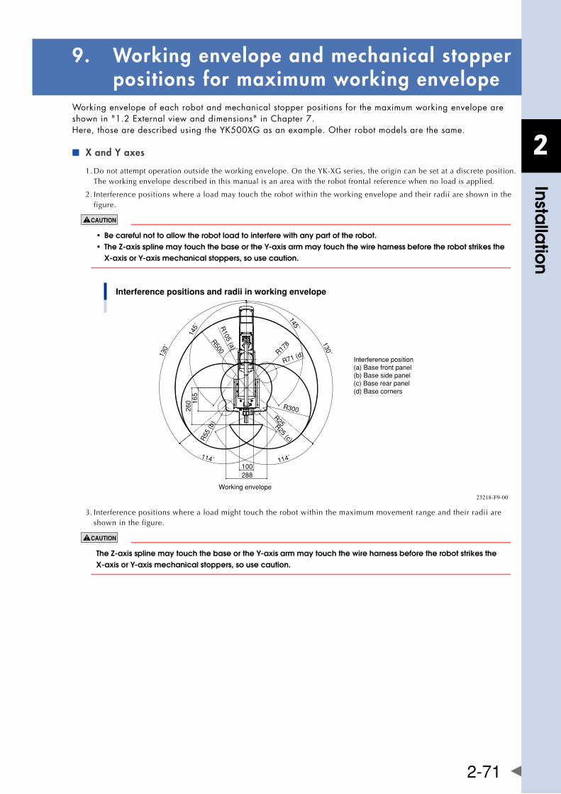
2
Installa
tion
2-71
9. Working envelope and mechanical stopper positions for maximum working envelope
Working envelope of each robot and mechanical stopper positions for the maximum working envelope are shownin"1.2Externalviewanddimensions"inChapter7. Here,thosearedescribedusingtheYK500XGasanexample.Otherrobotmodelsarethesame.
X and Y axes ■
1.Donotattemptoperationoutsidetheworkingenvelope.OntheYK-XGseries,theorigincanbesetatadiscreteposition.The working envelope described in this manual is an area with the robot frontal reference when no load is applied.
2. Interference positions where a load may touch the robot within the working envelope and their radii are shown in the figure.
• becarefulnottoallowtherobotloadtointerferewithanypartoftherobot. • thez-axissplinemaytouchthebaseorthey-axisarmmaytouchthewireharnessbeforetherobotstrikesthe x-axisory-axismechanicalstoppers,sousecaution.
Interference positions and radii in working envelope
145˚
R500R
105 (a)
130˚
260 16
5
R178
R71 (d)
145˚
130˚
R300
R25R25 (c)
114˚
288100
114˚
R55
(b)
Working envelope
Interference position(a) Base front panel(b) Base side panel(c) Base rear panel(d) Base corners
23218-F9-00
3. Interference positions where a load might touch the robot within the maximum movement range and their radii are shown in the figure.
thez-axissplinemaytouchthebaseorthey-axisarmmaytouchthewireharnessbeforetherobotstrikesthex-axisory-axismechanicalstoppers,sousecaution.
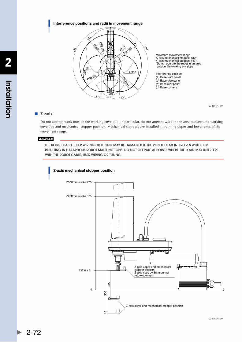
2
Installa
tion
2-72
Interference positions and radii in movement range
113˚
260
132˚
147˚
R500R
82 (a)
R64 (d)
R171 132˚
147˚
R300
R25R25 (c)
113˚
100288
R55 (b)
165
Interference position(a) Base front panel(b) Base side panel(c) Base rear panel(d) Base corners
Maximum movement rangeX-axis mechanical stopper: 132°Y-axis mechanical stopper: 147°*Do not operate the robot in an area outside the working envelope.
23219-F9-00
Z-axis ■
Do not attempt work outside the working envelope. In particular, do not attempt work in the area between the working
envelope and mechanical stopper position. Mechanical stoppers are installed at both the upper and lower ends of the
movement range.
ThE RObOT CablE, USER WIRIng OR TUbIng May bE DaMagED If ThE RObOT lOaD InTERfERES WITh ThEM RESUlTIng In hazaRDOUS RObOT MalfUnCTIOnS. DO nOT OPERaTE aT POInTS WhERE ThE lOaD May InTERfERE WITh ThE RObOT CablE, USER WIRIng OR TUbIng.
Z-axis mechanical stopper position
Z300mm stroke 775
Z200mm stroke 675
137.6 ± 2
0
200
300
1010
Z-axis lower end mechanical stopper position
8
0
Z-axis upper end mechanical stopper positionZ-axis rises by 8mm during return-to-origin.
23220-F9-00
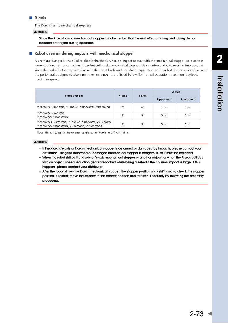
2
Installa
tion
2-73
R-axis ■
The R-axis has no mechanical stoppers.
sincether-axishasnomechanicalstoppers,makecertainthattheendeffectorwiringandtubingdonotbecome entangled during operation.
Robot overrun during impacts with mechanical stopper ■
A urethane damper is installed to absorb the shock when an impact occurs with the mechanical stopper, so a certain
amountofoverrunoccurswhentherobotstrikesthemechanicalstopper.Usecautionandtakeoverrunintoaccount
since the end effector may interfere with the robot body and peripheral equipment or the robot body may interfere with
the peripheral equipment. Maximum overrun amounts are listed below (for normal operation, maximum payload,
maximum speed).
Robot model X-axis Y-axisZ-axis
Upper end Lower end
YK250XG,YK350XG,YK400XG,YK500XGL,YK600XGL 8° 4° 1mm 1mm
YK500XG,YK600XG
YK500XGS,YK600XGS9° 12° 5mm 5mm
YK600XGH,YK700XG,YK800XG,YK900XG,YK1000XG
YK700XGS,YK800XGS,YK900XGS,YK1000XGS9° 12° 5mm 5mm
Note:Here,°(deg.)istheoverrunangleattheX-axisandY-axisjoints.
• ifthex-axis,y-axisorz-axismechanicalstopperisdeformedordamagedbyimpacts,pleasecontactyour distributor. Using the deformed or damaged mechanical stopper is dangerous, so it must be replaced. • whentherobotstrikesthex-axisory-axismechanicalstopperoranotherobject,orwhenther-axiscollides with an object, speed reduction gears are locked while being meshed if the collision impact is large. If this happens, please contact your distributor. • aftertherobotstrikesthez-axismechanicalstopper,thestopperpositionmayshift,andsocheckthestopper position. If shifted, move the stopper to the correct position and refasten it securely by following the assembly procedure.
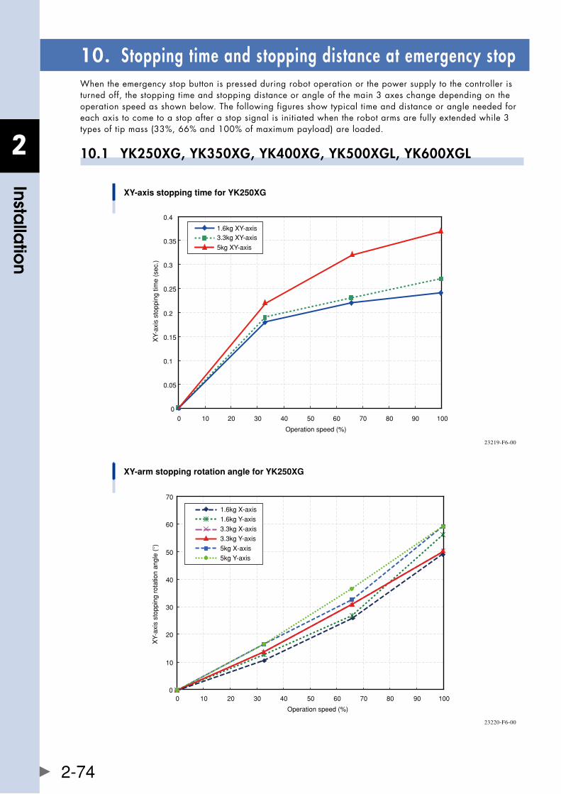
2
Installa
tion
2-74
10. Stopping time and stopping distance at emergency stopWhen the emergency stop button is pressed during robot operation or the power supply to the controller is turned off, the stopping time and stopping distance or angle of the main 3 axes change depending on the operation speed as shown below. The following figures show typical time and distance or angle needed for each axis to come to a stop after a stop signal is initiated when the robot arms are fully extended while 3 typesoftipmass(33%,66%and100%ofmaximumpayload)areloaded.
10.1 YK250XG, YK350XG, YK400XG, YK500XGL, YK600XGL
XY-axis stopping time for YK250XG
Operation speed (%)
XY-
axis
sto
ppin
g tim
e (s
ec.)
0
0.05
0.1
0.15
0.2
0.25
0.3
0.35
0.4
0 10 20 30 40 50 60 70 80 90 100
1.6kg XY-axis3.3kg XY-axis
5kg XY-axis
23219-F6-00
XY-arm stopping rotation angle for YK250XG
Operation speed (%)
XY-
axis
sto
ppin
g ro
tatio
n an
gle
(°)
0
10
20
30
40
50
60
70
0 10 20 30 40 50 60 70 80 90 100
3.3kg X-axis
3.3kg Y-axis
5kg X-axis
5kg Y-axis
1.6kg X-axis
1.6kg Y-axis
23220-F6-00
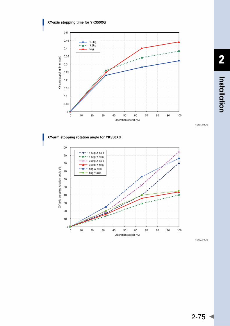
2
Installa
tion
2-75
XY-axis stopping time for YK350XG
0
0.05
0.1
0.15
0.2
0.25
0.3
0.35
0.4
0.45
0.5
0 10 20 30 40 50 60 70 80 90 100
Operation speed (%)
XY-
axis
sto
ppin
g tim
e (s
ec.)
5kg
1.6kg3.3kg
23203-F7-00
XY-arm stopping rotation angle for YK350XG
0
10
20
30
40
50
60
70
80
90
100
0 10 20 30 40 50 60 70 80 90 100
Operation speed (%)
XY-
axis
sto
ppin
g ro
tatio
n an
gle
(°)
3.3kg X-axis
3.3kg Y-axis
5kg X-axis
5kg Y-axis
1.6kg X-axis
1.6kg Y-axis
23204-F7-00
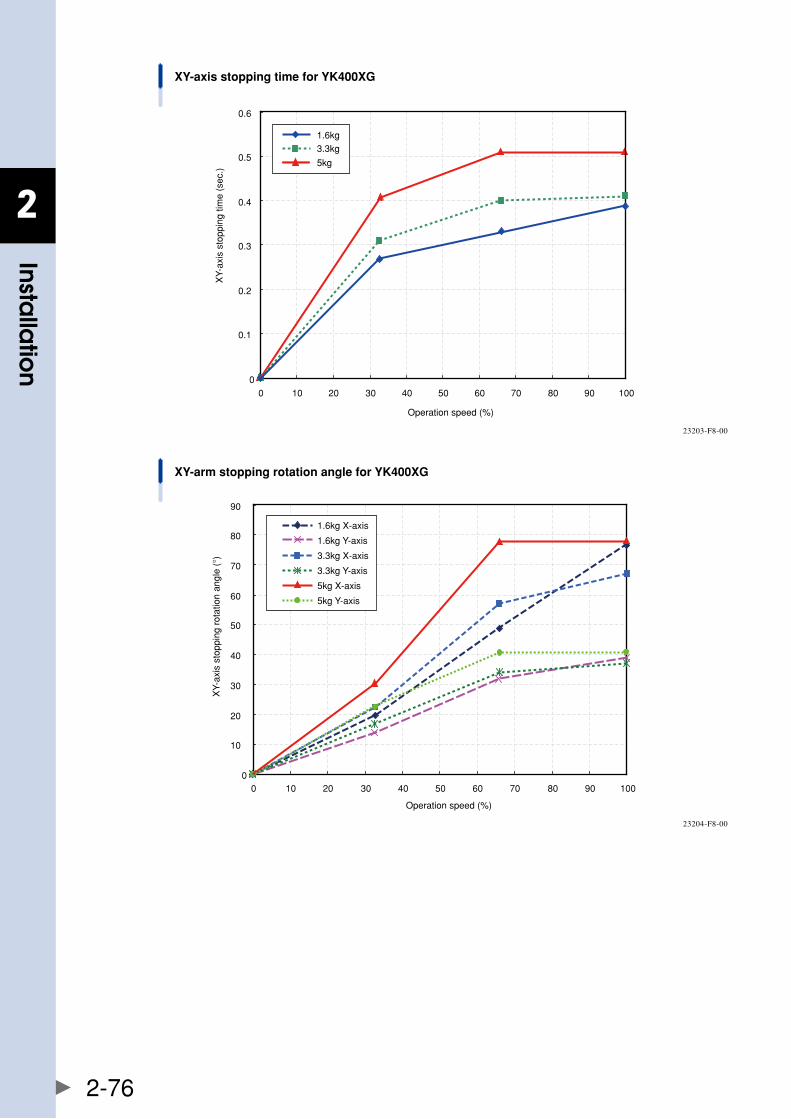
2
Installa
tion
2-76
XY-axis stopping time for YK400XG
Operation speed (%)
XY-
axis
sto
ppin
g tim
e (s
ec.)
0
0.1
0.2
0.3
0.4
0.5
0.6
0 10 20 30 40 50 60 70 80 90 100
5kg
1.6kg3.3kg
23203-F8-00
XY-arm stopping rotation angle for YK400XG
0
10
20
30
40
50
60
70
80
90
0 10 20 30 40 50 60 70 80 90 100
Operation speed (%)
XY-
axis
sto
ppin
g ro
tatio
n an
gle
(°) 3.3kg X-axis
3.3kg Y-axis
5kg X-axis
5kg Y-axis
1.6kg X-axis
1.6kg Y-axis
23204-F8-00
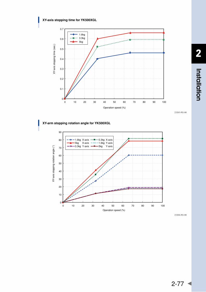
2
Installa
tion
2-77
XY-axis stopping time for YK500XGL
0
0.1
0.2
0.3
0.4
0.5
0.6
0.7
0 10 20 30 40 50 60 70 80 90 100
Operation speed (%)
XY-
axis
sto
ppin
g tim
e (s
ec.)
5kg
1.6kg3.3kg
23203-FG-00
XY-arm stopping rotation angle for YK500XGL
Operation speed (%)
XY-
axis
sto
ppin
g ro
tatio
n an
gle
(°)
0
10
20
30
40
50
60
70
80
90
0 10 20 30 40 50 60 70 80 90 100
1.6kg X-axis 3.3kg X-axis5kg X-axis 1.6kg Y-axis3.3kg Y-axis 5kg Y-axis
23204-FG-00
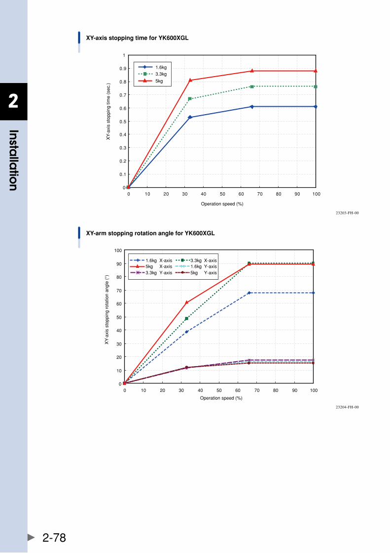
2
Installa
tion
2-78
5kg
1.6kg3.3kg
0
0.1
0.2
0.3
0.4
0.5
0.6
0.7
0.8
0.9
1
0 10 20 30 40 50 60 70 80 90 100
XY-axis stopping time for YK600XGL
Operation speed (%)
XY-
axis
sto
ppin
g tim
e (s
ec.)
23203-FH-00
0
10
20
30
40
50
60
70
80
90
100
0 10 20 30 40 50 60 70 80 90 100
XY-arm stopping rotation angle for YK600XGL
Operation speed (%)
XY-
axis
sto
ppin
g ro
tatio
n an
gle
(°)
1.6kg X-axis 3.3kg X-axis5kg X-axis 1.6kg Y-axis3.3kg Y-axis 5kg Y-axis
23204-FH-00
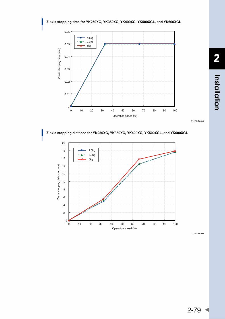
2
Installa
tion
2-79
Z-axis stopping time for YK250XG, YK350XG, YK400XG, YK500XGL, and YK600XGL
Operation speed (%)
Z-a
xis
stop
ping
tim
e (s
ec.)
0
0.01
0.02
0.03
0.04
0.05
0.06
0 10 20 30 40 50 60 70 80 90 100
5kg
1.6kg3.3kg
23221-F6-00
Z-axis stopping distance for YK250XG, YK350XG, YK400XG, YK500XGL, and YK600XGL
0
2
4
6
8
10
12
14
16
18
20
0 10 20 30 40 50 60 70 80 90 100
Operation speed (%)
Z-a
xis
stop
ping
dis
tanc
e (m
m)
5kg
1.6kg
3.3kg
23222-F6-00
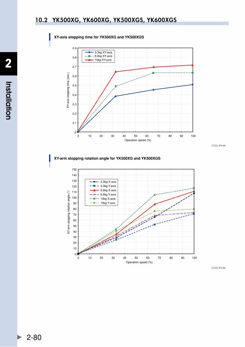
2
Installa
tion
2-80
10.2 YK500XG, YK600XG, YK500XGS, YK600XGS
XY-axis stopping time for YK500XG and YK500XGS
Operation speed (%)
XY-
axis
sto
ppin
g tim
e (s
ec.)
0
0.1
0.2
0.3
0.4
0.5
0.6
0.7
0.8
0.9
0 10 20 30 40 50 60 70 80 90 100
3.3kg XY-axis6.6kg XY-axis10kg XY-axis
23221-F9-00
XY-arm stopping rotation angle for YK500XG and YK500XGS
Operation speed (%)
XY-
arm
sto
ppin
g ro
tatio
n an
gle
(°)
0
10
20
30
40
50
60
70
80
90
100
110
120
130
140
150
0 10 20 30 40 50 60 70 80 90 100
6.6kg X-axis
6.6kg Y-axis
10kg X-axis
10kg Y-axis
3.3kg X-axis
3.3kg Y-axis
23222-F9-00
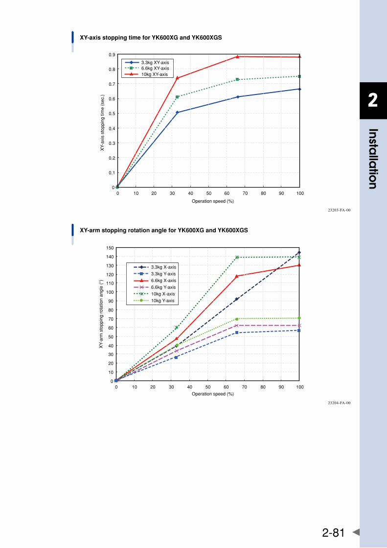
2
Installa
tion
2-81
XY-axis stopping time for YK600XG and YK600XGS
Operation speed (%)
XY-
axis
sto
ppin
g tim
e (s
ec.)
3.3kg XY-axis6.6kg XY-axis10kg XY-axis
0
0.1
0.2
0.3
0.4
0.5
0.6
0.7
0.8
0.9
0 10 20 30 40 50 60 70 80 90 100
23203-FA-00
XY-arm stopping rotation angle for YK600XG and YK600XGS
Operation speed (%)
XY-
arm
sto
ppin
g ro
tatio
n an
gle
(°)
0
10
20
30
40
50
60
70
80
90
100
110
120
130
140
150
0 10 20 30 40 50 60 70 80 90 100
6.6kg X-axis
6.6kg Y-axis
10kg X-axis
10kg Y-axis
3.3kg X-axis
3.3kg Y-axis
23204-FA-00
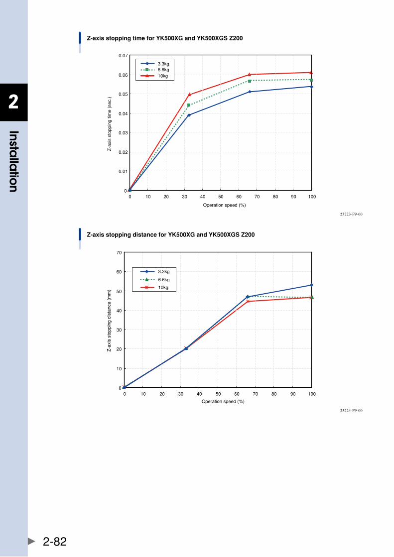
2
Installa
tion
2-82
Z-axis stopping time for YK500XG and YK500XGS Z200
Operation speed (%)
Z-a
xis
stop
ping
tim
e (s
ec.)
0
0.01
0.02
0.03
0.04
0.05
0.06
0.07
0 10 20 30 40 50 60 70 80 90 100
10kg
3.3kg6.6kg
23223-F9-00
Z-axis stopping distance for YK500XG and YK500XGS Z200
Operation speed (%)
Z-a
xis
stop
ping
dis
tanc
e (m
m)
0
10
20
30
40
50
60
70
0 10 20 30 40 50 60 70 80 90 100
10kg
3.3kg
6.6kg
23224-F9-00
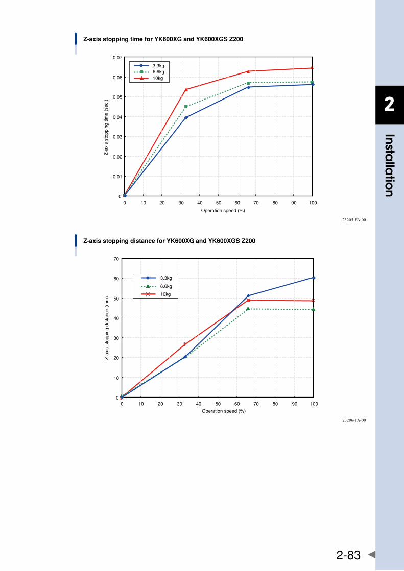
2
Installa
tion
2-83
Z-axis stopping time for YK600XG and YK600XGS Z200
Operation speed (%)
Z-a
xis
stop
ping
tim
e (s
ec.)
0
0.01
0.02
0.03
0.04
0.05
0.06
0.07
0 10 20 30 40 50 60 70 80 90 100
10kg
3.3kg6.6kg
23205-FA-00
Z-axis stopping distance for YK600XG and YK600XGS Z200
Operation speed (%)
Z-a
xis
stop
ping
dis
tanc
e (m
m)
0
10
20
30
40
50
60
70
0 10 20 30 40 50 60 70 80 90 100
10kg
3.3kg
6.6kg
23206-FA-00
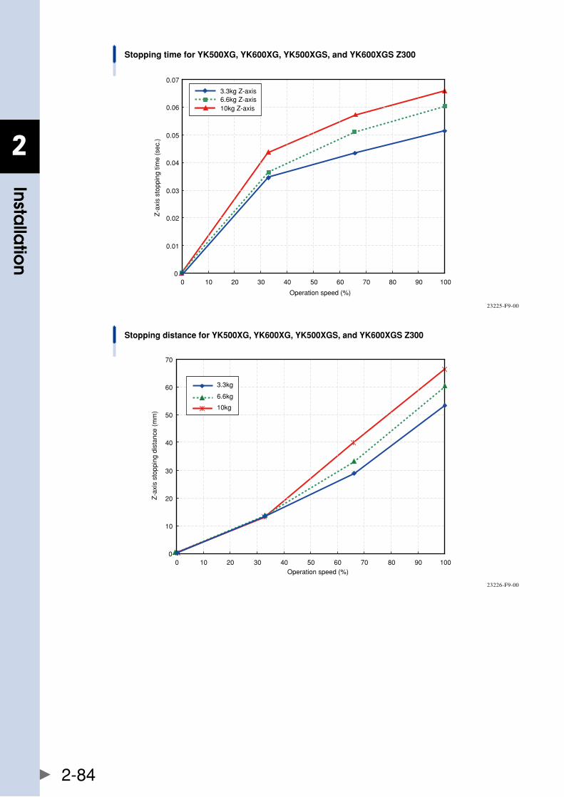
2
Installa
tion
2-84
Stopping time for YK500XG, YK600XG, YK500XGS, and YK600XGS Z300
Operation speed (%)
Z-a
xis
stop
ping
tim
e (s
ec.)
0
0.01
0.02
0.03
0.04
0.05
0.06
0.07
0 10 20 30 40 50 60 70 80 90 100
10kg Z-axis
3.3kg Z-axis6.6kg Z-axis
23225-F9-00
Stopping distance for YK500XG, YK600XG, YK500XGS, and YK600XGS Z300
Operation speed (%)
Z-a
xis
stop
ping
dis
tanc
e (m
m)
0
10
20
30
40
50
60
70
0 10 20 30 40 50 60 70 80 90 100
10kg
3.3kg
6.6kg
23226-F9-00
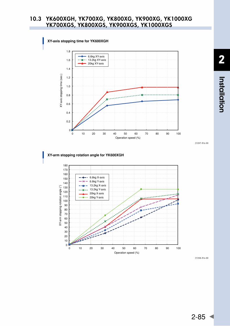
2
Installa
tion
2-85
10.3 YK600XGH, YK700XG, YK800XG, YK900XG, YK1000XG YK700XGS, YK800XGS, YK900XGS, YK1000XGS
XY-axis stopping time for YK600XGH
0
0.2
0.4
0.6
0.8
1.0
1.2
1.4
1.6
1.8
0 10 20 30 40 50 60 70 80 90 100
Operation speed (%)
XY-
axis
sto
ppin
g tim
e (s
ec.)
20kg XY-axis
6.6kg XY-axis13.2kg XY-axis
23207-FA-00
XY-arm stopping rotation angle for YK600XGH
0 10 20 30 40 50 60 70 80 90 1000
10
20
30
40
50
60
70
80
90
100
110
120
130
140
150
160
170
180
Operation speed (%)
XY-
arm
sto
ppin
g ro
tatio
n an
gle
(°)
6.6kg X-axis
6.6kg Y-axis
13.2kg X-axis
13.2kg Y-axis
20kg X-axis
20kg Y-axis
23208-FA-00
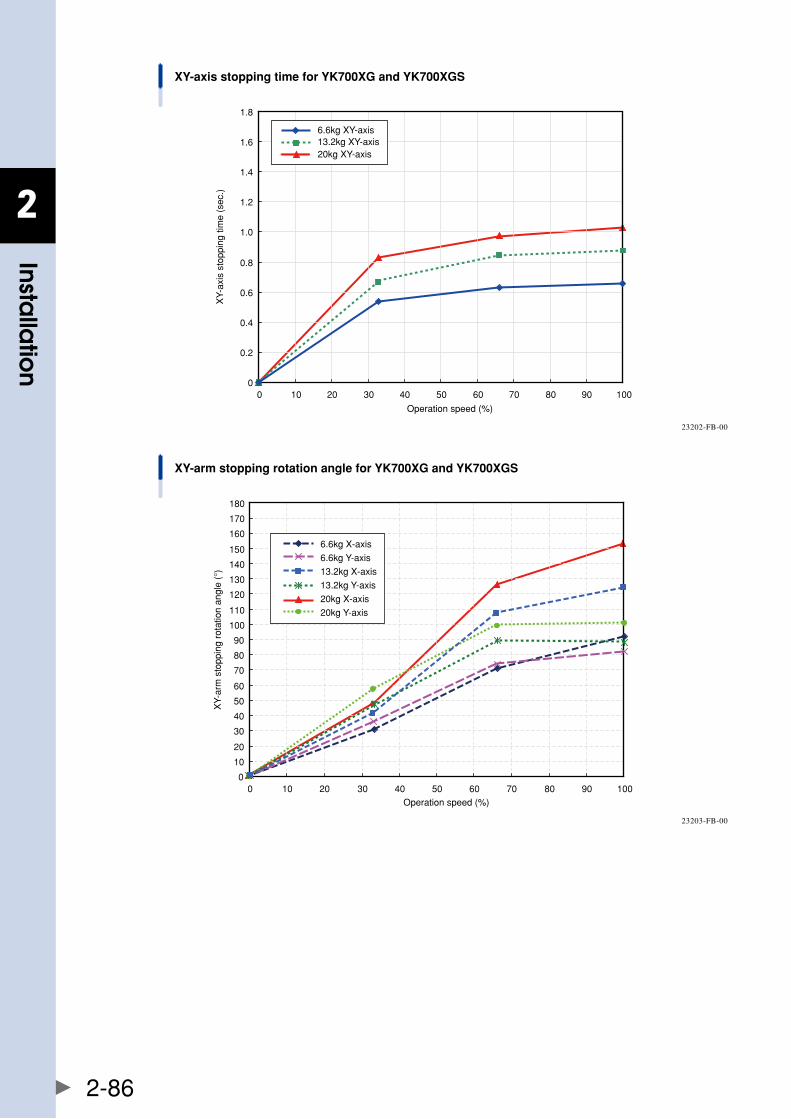
2
Installa
tion
2-86
XY-axis stopping time for YK700XG and YK700XGS
Operation speed (%)
XY-
axis
sto
ppin
g tim
e (s
ec.)
20kg XY-axis
6.6kg XY-axis13.2kg XY-axis
0
0.2
0.4
0.6
0.8
1.0
1.2
1.4
1.6
1.8
0 10 20 30 40 50 60 70 80 90 100
23202-FB-00
XY-arm stopping rotation angle for YK700XG and YK700XGS
Operation speed (%)
XY-
arm
sto
ppin
g ro
tatio
n an
gle
(°)
20kg Y-axis
6.6kg X-axis
6.6kg Y-axis
13.2kg X-axis
13.2kg Y-axis
20kg X-axis
0
10
20
30
40
50
60
70
80
90
100
110
120
130
140
150
160
170
180
0 10 20 30 40 50 60 70 80 90 100
23203-FB-00
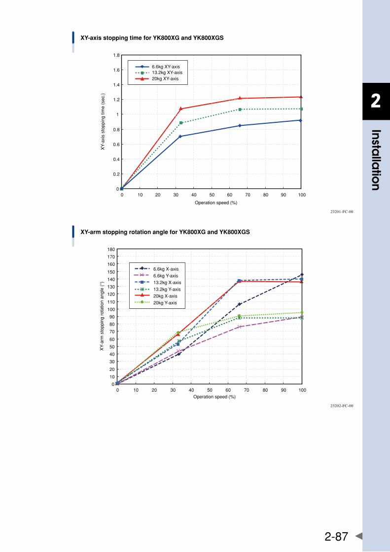
2
Installa
tion
2-87
XY-axis stopping time for YK800XG and YK800XGS
0
0.2
0.4
0.6
0.8
1
1.2
1.4
1.6
1.8
0 10 20 30 40 50 60 70 80 90 100
Operation speed (%)
XY-
axis
sto
ppin
g tim
e (s
ec.)
20kg XY-axis
6.6kg XY-axis13.2kg XY-axis
23201-FC-00
XY-arm stopping rotation angle for YK800XG and YK800XGS
Operation speed (%)
XY-
arm
sto
ppin
g ro
tatio
n an
gle
(°)
6.6kg X-axis
6.6kg Y-axis
13.2kg X-axis
13.2kg Y-axis
20kg X-axis
20kg Y-axis
0
10
20
30
40
50
60
70
80
90
100
110
120
130
140
150
160
170
180
0 10 20 30 40 50 60 70 80 90 100
23202-FC-00
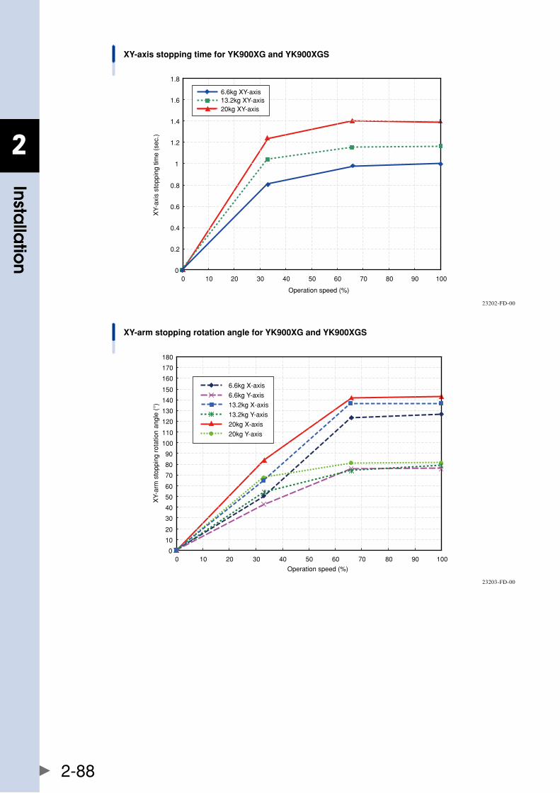
2
Installa
tion
2-88
XY-axis stopping time for YK900XG and YK900XGS
0
0.2
0.4
0.6
0.8
1
1.2
1.4
1.6
1.8
0 10 20 30 40 50 60 70 80 90 100
Operation speed (%)
XY-
axis
sto
ppin
g tim
e (s
ec.)
20kg XY-axis
6.6kg XY-axis13.2kg XY-axis
23202-FD-00
XY-arm stopping rotation angle for YK900XG and YK900XGS
Operation speed (%)
XY-
arm
sto
ppin
g ro
tatio
n an
gle
(°)
6.6kg X-axis
6.6kg Y-axis
13.2kg X-axis
13.2kg Y-axis
20kg X-axis
20kg Y-axis
0
10
20
30
40
50
60
70
80
90
100
110
120
130
140
150
160
170
180
0 10 20 30 40 50 60 70 80 90 100
23203-FD-00
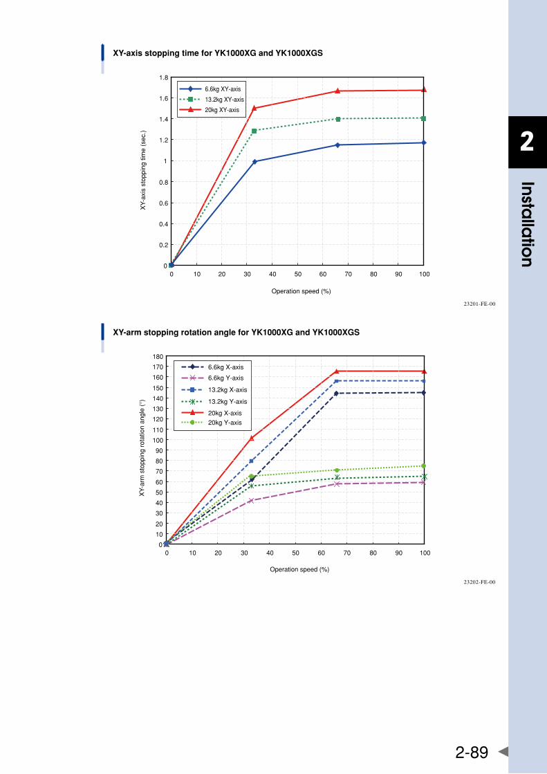
2
Installa
tion
2-89
XY-axis stopping time for YK1000XG and YK1000XGS
0
0.2
0.4
0.6
0.8
1
1.2
1.4
1.6
1.8
0 10 20 30 40 50 60 70 80 90 100
Operation speed (%)
XY-
axis
sto
ppin
g tim
e (s
ec.)
6.6kg XY-axis
13.2kg XY-axis
20kg XY-axis
23201-FE-00
XY-arm stopping rotation angle for YK1000XG and YK1000XGS
Operation speed (%)
XY-
arm
sto
ppin
g ro
tatio
n an
gle
(°)
6.6kg X-axis
6.6kg Y-axis
13.2kg X-axis
13.2kg Y-axis
20kg X-axis
20kg Y-axis
0
10
20
30
40
50
60
70
80
90
100
110
120
130
140
150
160
170
180
0 10 20 30 40 50 60 70 80 90 100
23202-FE-00
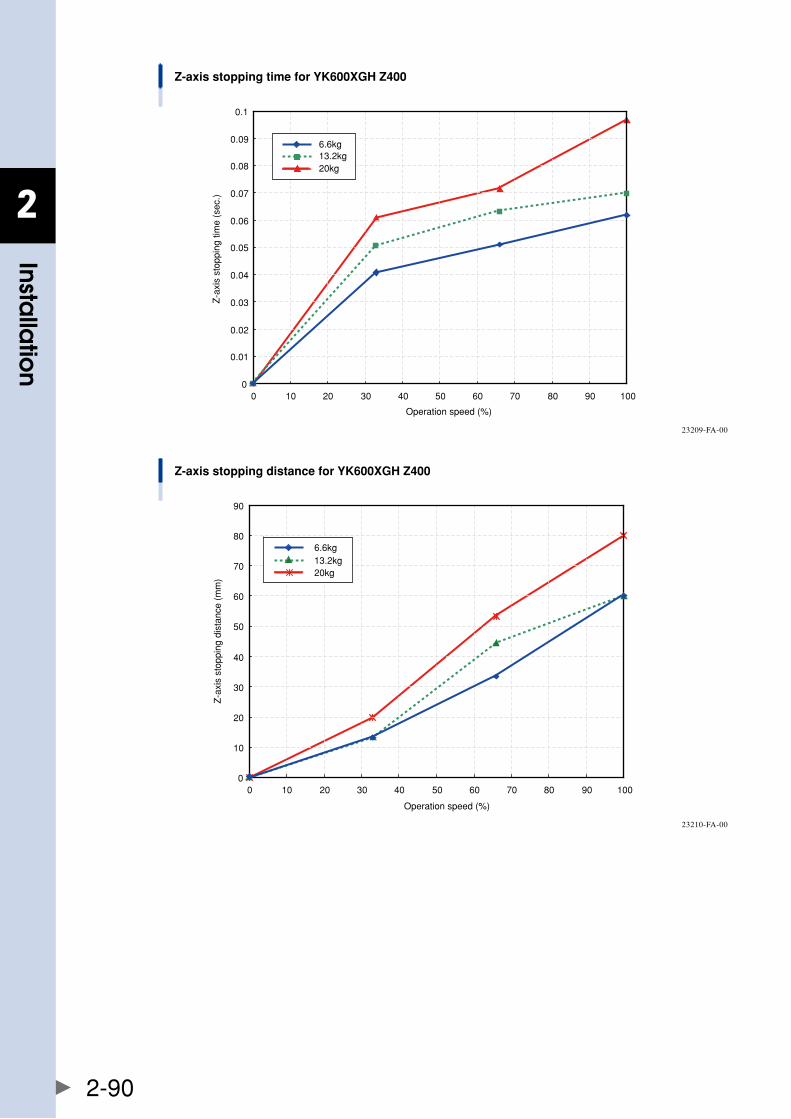
2
Installa
tion
2-90
Z-axis stopping time for YK600XGH Z400
0
0.01
0.02
0.03
0.04
0.05
0.06
0.07
0.08
0.09
0.1
0 10 20 30 40 50 60 70 80 90 100
Operation speed (%)
Z-a
xis
stop
ping
tim
e (s
ec.)
20kg
6.6kg13.2kg
23209-FA-00
Z-axis stopping distance for YK600XGH Z400
0
10
20
30
40
50
60
70
80
90
0 10 20 30 40 50 60 70 80 90 100
Operation speed (%)
Z-a
xis
stop
ping
dis
tanc
e (m
m)
20kg
6.6kg13.2kg
23210-FA-00
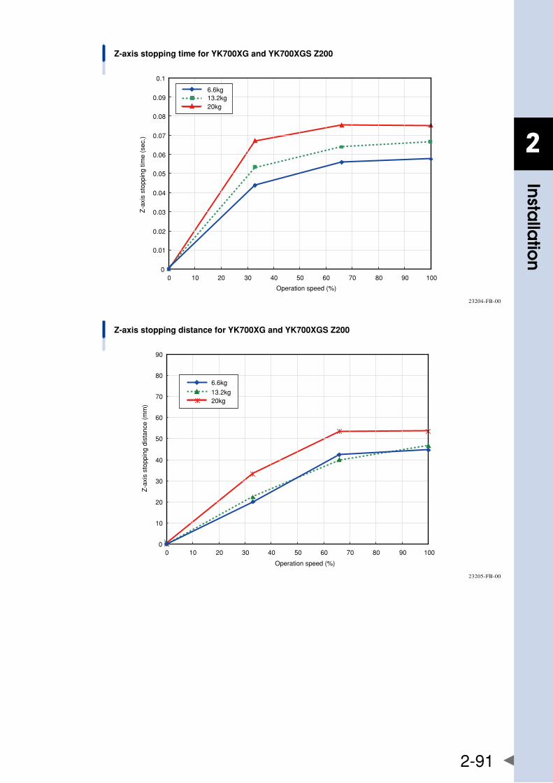
2
Installa
tion
2-91
Z-axis stopping time for YK700XG and YK700XGS Z200
0
0.01
0.02
0.03
0.04
0.05
0.06
0.07
0.08
0.09
0.1
0 10 20 30 40 50 60 70 80 90 100
Operation speed (%)
Z-a
xis
stop
ping
tim
e (s
ec.)
6.6kg13.2kg20kg
23204-FB-00
Z-axis stopping distance for YK700XG and YK700XGS Z200
0
10
20
30
40
50
60
70
80
90
0 10 20 30 40 50 60 70 80 90 100
Operation speed (%)
Z-a
xis
stop
ping
dis
tanc
e (m
m)
6.6kg
13.2kg20kg
23205-FB-00
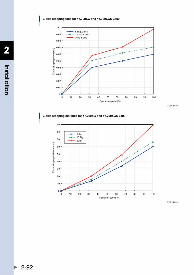
2
Installa
tion
2-92
Z-axis stopping time for YK700XG and YK700XGS Z400
0
0.01
0.02
0.03
0.04
0.05
0.06
0.07
0.08
0.09
0.1
0 10 20 30 40 50 60 70 80 90 100
Operation speed (%)
Z-a
xis
stop
ping
tim
e (s
ec.)
6.6kg Z-axis13.2kg Z-axis20kg Z-axis
23206-FB-00
Z-axis stopping distance for YK700XG and YK700XGS Z400
0
10
20
30
40
50
60
70
80
90
0 10 20 30 40 50 60 70 80 90 100
Operation speed (%)
Z-a
xis
stop
ping
dis
tanc
e (m
m)
6.6kg13.2kg
20kg
23207-FB-00
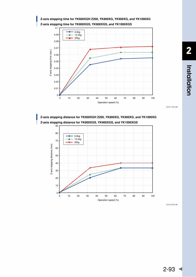
2
Installa
tion
2-93
Z-axis stopping time for YK600XGH Z200, YK800XG, YK900XG, and YK1000XG
Z-axis stopping time for YK800XGS, YK900XGS, and YK1000XGS
0 10 20 30 40 50 60 70 80 90 1000
0.01
0.02
0.03
0.04
0.05
0.06
0.07
0.08
0.09
0.1
Operation speed (%)
Z-a
xis
stop
ping
tim
e (s
ec.)
6.6kg13.2kg20kg
23211-FA-00
Z-axis stopping distance for YK600XGH Z200, YK800XG, YK900XG, and YK1000XG
Z-axis stopping distance for YK800XGS, YK900XGS, and YK1000XGS
0 10 20 30 40 50 60 70 80 90 1000
10
20
30
40
50
60
70
80
90
Operation speed (%)
Z-a
xis
stop
ping
dis
tanc
e (m
m)
6.6kg13.2kg20kg
23212-FA-00
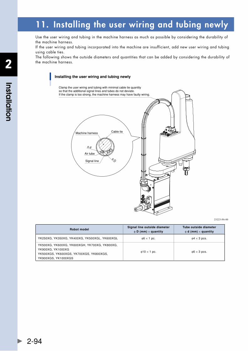
2
Installa
tion
2-94
11. Installing the user wiring and tubing newlyUsetheuserwiringandtubinginthemachineharnessasmuchaspossiblebyconsideringthedurabilityofthe machine harness. If the user wiring and tubing incorporated into the machine are insufficient, add new user wiring and tubing using cable ties. The following shows the outside diameters and quantities that can be added by considering the durability of the machine harness.
Installing the user wiring and tubing newly
Clamp the user wiring and tubing with minimal cable tie quantity so that the additional signal lines and tubes do not deviate.If the clamp is too strong, the machine harness may have faulty wiring.
φ D
φ d
Machine harness
Signal line
Air tube
Cable tie
23223-F6-00
Robot modelSignal line outside diameter
φ D (mm) × quantity
Tube outside diameter
φ d (mm) × quantity
YK250XG,YK350XG,YK400XG,YK500XGL,YK600XGL φ6×1pc. φ4×3pcs.
YK500XG,YK600XG,YK600XGH,YK700XG,YK800XG,
YK900XG,YK1000XG
YK500XGS,YK600XGS,YK700XGS,YK800XGS,
YK900XGS,YK1000XGS
φ10×1pc. φ6×3pcs.
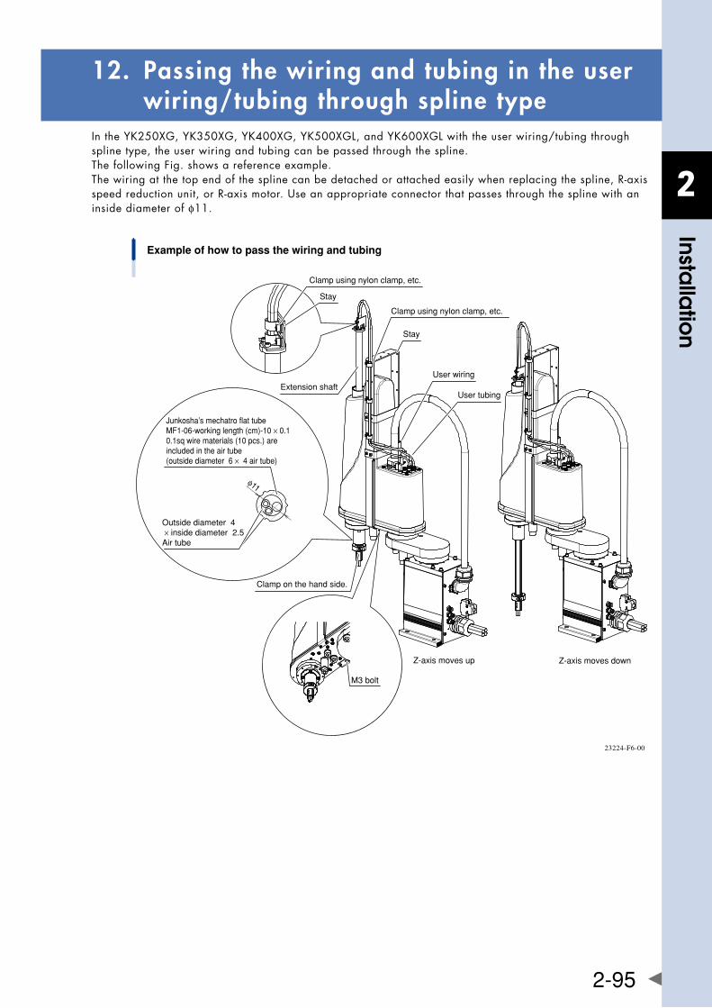
2
Installa
tion
2-95
12. Passing the wiring and tubing in the user wiring/tubing through spline type
IntheYK250XG,YK350XG,YK400XG,YK500XGL,andYK600XGLwiththeuserwiring/tubingthroughspline type, the user wiring and tubing can be passed through the spline. The following Fig. shows a reference example. Thewiringatthetopendofthesplinecanbedetachedorattachedeasilywhenreplacingthespline,R-axisspeedreductionunit,orR-axismotor.Useanappropriateconnectorthatpassesthroughthesplinewithaninside diameter of φ11.
Example of how to pass the wiring and tubing
Clamp using nylon clamp, etc.
Stay
Extension shaft
Clamp using nylon clamp, etc.
Stay
Junkosha’s mechatro flat tubeMF1-06-working length (cm)-10 × 0.10.1sq wire materials (10 pcs.) are included in the air tube (outside diameter �6 × �4 air tube)
Outside diameter �4 × inside diameter �2.5Air tube
Clamp on the hand side.
User wiring
User tubing
φ11
Z-axis moves up Z-axis moves down
M3 bolt
23224-F6-00
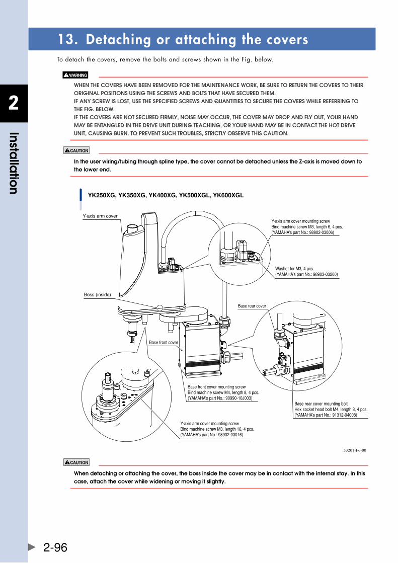
2
Installa
tion
2-96
13. Detaching or attaching the coversTo detach the covers, remove the bolts and screws shown in the Fig. below.
WhEn ThE COvERS havE bEEn REMOvED fOR ThE MaInTEnanCE WORk, bE SURE TO RETURn ThE COvERS TO ThEIR ORIgInal POSITIOnS USIng ThE SCREWS anD bOlTS ThaT havE SECURED ThEM. If any SCREW IS lOST, USE ThE SPECIfIED SCREWS anD qUanTITIES TO SECURE ThE COvERS WhIlE REfERRIng TO ThE fIg. bElOW. If ThE COvERS aRE nOT SECURED fIRMly, nOISE May OCCUR, ThE COvER May DROP anD fly OUT, yOUR hanD May bE EnTanglED In ThE DRIvE UnIT DURIng TEaChIng, OR yOUR hanD May bE In COnTaCT ThE hOT DRIvE UnIT, CaUSIng bURn. TO PREvEnT SUCh TROUblES, STRICTly ObSERvE ThIS CaUTIOn.
intheuserwiring/tubingthroughsplinetype,thecovercannotbedetachedunlessthez-axisismoveddowntothe lower end.
YK250XG, YK350XG, YK400XG, YK500XGL, YK600XGL
Base front cover mounting screwBind machine screw M4, length 8, 4 pcs.(YAMAHA’s part No.: 90990-10J003)
Y-axis arm cover
Base front cover
Base rear cover mounting boltHex socket head bolt M4, length 8, 4 pcs.(YAMAHA’s part No.: 91312-04008)
Base rear cover
Y-axis arm cover mounting screwBind machine screw M3, length 16, 4 pcs.(YAMAHA’s part No.: 98902-03016)
Y-axis arm cover mounting screwBind machine screw M3, length 6, 4 pcs.(YAMAHA’s part No.: 98902-03006)
Washer for M3, 4 pcs.(YAMAHA’s part No.: 98903-03200)
Boss (inside)
53201-F6-00
When detaching or attaching the cover, the boss inside the cover may be in contact with the internal stay. In this case, attach the cover while widening or moving it slightly.

2
Installa
tion
2-97
YK500XG, YK600XG
Y-axis arm end cap
Y-axis arm end cap mounting boltHex socket head bolt M3, length 16, 4 pcs. × 2(YAMAHA’s part No.: 91312-03016)
Harness cover Harness cover mounting screwBind machine screw M4, length 10, 4 pcs.(YAMAHA’s part No.: 90990-10J004)
X-axis arm end cap
X-axis arm end cap mounting boltHex socket head bolt M3, length 16, 4 pcs. × 2(YAMAHA’s part No.: 91312-03016)
Base front cover
Base front cover mounting screwBind machine screw M3, length 8, 4 pcs.(YAMAHA’s part No.: 90990-10J003)
Y-axis arm cover
Y-axis arm cover mounting boltHex socket head bolt M3, length 20, 2 pcs.(YAMAHA’s part No.: 91312-03020)
Y-axis arm cover mounting bolt(Cover is detached vertically.)Hex socket head bolt M3, length 8, 2 pcs.(YAMAHA’s part No.: 91312-03008)
Z-axis motor cover mounting screwBind machine screw M3, length 12, 4 pcs.(YAMAHA’s part No.: 98902-03012)
Z-axis motor cover
Y-axis arm cover mounting bolt (Cover is detached horizontally.)• Hex socket head button bolt M3, length 8, 6 pcs. (Z= 300mm stroke type)• Hex socket head button bolt M3, length 8, 4 pcs. (Z= 200mm stroke type)(YAMAHA’s part No.: 92012-03008)
Y-axis motor cover mounting screwBind machine screw M3, length 8, 4 pcs.(YAMAHA’s part No.: 98902-03008)
Base rear cover mounting screwBind machine screw M4, length 8, 4 pcs.(YAMAHA’s part No.: 90990-10J003)
Base rear cover
Y-axis motor cover
53201-F9-00
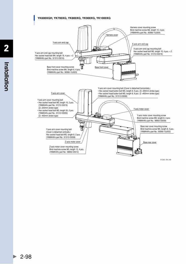
2
Installa
tion
2-98
YK600XGH, YK700XG, YK800XG, YK900XG, YK1000XG
Base rear cover
Y-axis motor cover
Z-axis motor cover
Base rear cover mounting screwBind machine screw M4, length 8, 4 pcs.(YAMAHA’s part No.: 90990-10J003)
Y-axis motor cover mounting screwBind machine screw M3, length 8, 4 pcs.(YAMAHA’s part No.: 98902-03008)
Z-axis motor cover mounting screwBind machine screw M3, length 12, 4 pcs.(YAMAHA’s part No.: 98902-03012)
Y-axis arm cover
Y-axis arm cover mounting bolt• Hex socket head bolt M3, length 16, 2 pcs. (YAMAHA’s part No.: 91312-03016) (Z= 200mm stroke type)• Hex socket head bolt M3, length 50, 2 pcs. (YAMAHA’s part No.: 91312-03050) (Z= 400mm stroke type)
Y-axis arm cover mounting bolt (Cover is detached horizontally.)• Hex socket head button bolt M3, length 8, 6 pcs. (Z= 200mm stroke type)• Hex socket head button bolt M3, length 8, 8 pcs. (Z =400mm stroke type)(YAMAHA’s part No.: 91312-03008)
Y-axis arm cover mounting bolt(Cover is detached vertically.)Hex socket head bolt M3, length 8, 2 pcs.(YAMAHA’s part No.: 91312-03008)
Y-axis arm end capX-axis arm end cap
Base front cover
X-axis arm end cap mounting boltHex socket head bolt M3, length 16, 4 pcs. × 2(YAMAHA’s part No.: 91312-03016)Y-axis arm end cap mounting bolt
Hex socket head bolt M4, length 16, 4 pcs. × 2(YAMAHA’s part No.: 91312-03016)
Harness cover
Harness cover mounting screwBind machine screw M4, length 10, 4 pcs.(YAMAHA’s part No.: 90990-10J004)
Base front cover mounting screwBind machine screw M4, length 8, 4 pcs.(YAMAHA’s part No.: 90990-10J003)
53201-FA-00
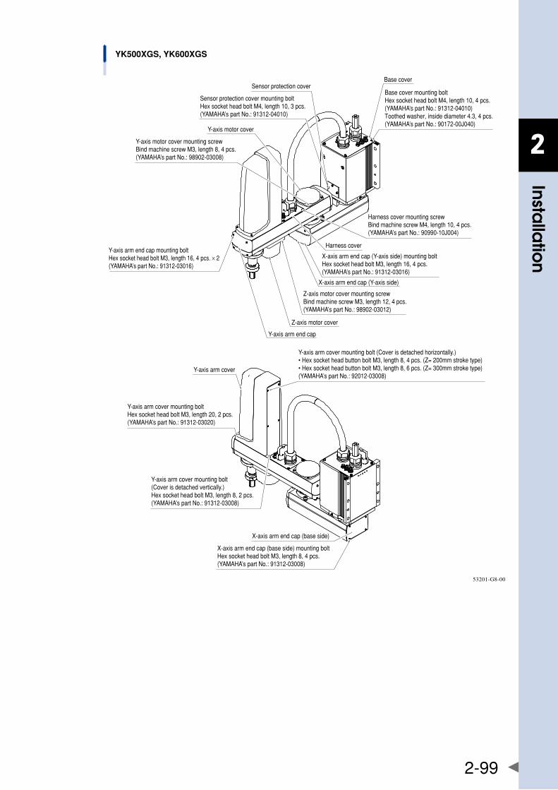
2
Installa
tion
2-99
YK500XGS, YK600XGS
Harness cover
X-axis arm end cap (Y-axis side)
Sensor protection cover
X-axis arm end cap (Y-axis side) mounting boltHex socket head bolt M3, length 16, 4 pcs.(YAMAHA’s part No.: 91312-03016)
Sensor protection cover mounting boltHex socket head bolt M4, length 10, 3 pcs.(YAMAHA’s part No.: 91312-04010)
X-axis arm end cap (base side) mounting boltHex socket head bolt M3, length 8, 4 pcs.(YAMAHA’s part No.: 91312-03008)
Base cover mounting boltHex socket head bolt M4, length 10, 4 pcs.(YAMAHA’s part No.: 91312-04010)Toothed washer, inside diameter 4.3, 4 pcs.(YAMAHA’s part No.: 90172-00J040)
Harness cover mounting screwBind machine screw M4, length 10, 4 pcs.(YAMAHA’s part No.: 90990-10J004)
Base cover
Y-axis motor cover
Y-axis motor cover mounting screwBind machine screw M3, length 8, 4 pcs.(YAMAHA’s part No.: 98902-03008)
Y-axis arm end cap mounting boltHex socket head bolt M3, length 16, 4 pcs. × 2(YAMAHA’s part No.: 91312-03016)
Z-axis motor cover mounting screwBind machine screw M3, length 12, 4 pcs.(YAMAHA’s part No.: 98902-03012)
Z-axis motor cover
Y-axis arm end cap
Y-axis arm cover
Y-axis arm cover mounting boltHex socket head bolt M3, length 20, 2 pcs.(YAMAHA’s part No.: 91312-03020)
Y-axis arm cover mounting bolt(Cover is detached vertically.)Hex socket head bolt M3, length 8, 2 pcs.(YAMAHA’s part No.: 91312-03008)
Y-axis arm cover mounting bolt (Cover is detached horizontally.)• Hex socket head button bolt M3, length 8, 4 pcs. (Z= 200mm stroke type)• Hex socket head button bolt M3, length 8, 6 pcs. (Z= 300mm stroke type)(YAMAHA’s part No.: 92012-03008)
X-axis arm end cap (base side)
53201-G8-00
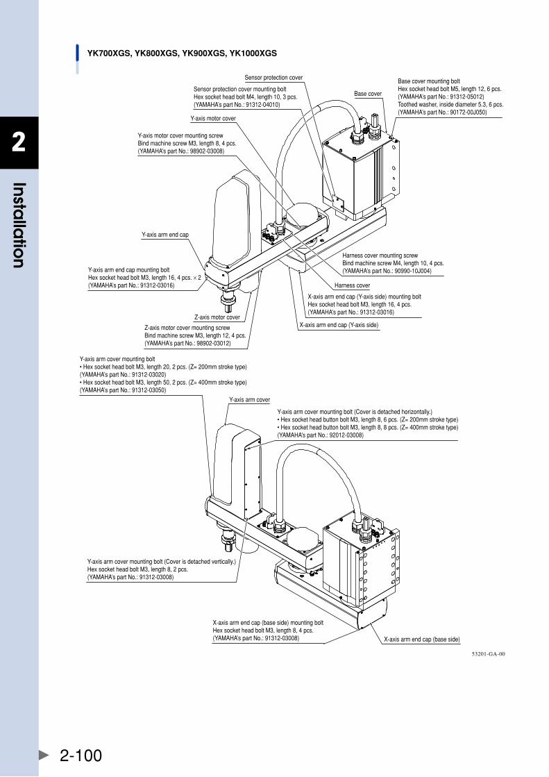
2
Installa
tion
2-100
YK700XGS, YK800XGS, YK900XGS, YK1000XGS
Harness cover
Sensor protection cover Base cover mounting boltHex socket head bolt M5, length 12, 6 pcs.(YAMAHA’s part No.: 91312-05012)Toothed washer, inside diameter 5.3, 6 pcs.(YAMAHA’s part No.: 90172-00J050)
Base coverSensor protection cover mounting boltHex socket head bolt M4, length 10, 3 pcs.(YAMAHA’s part No.: 91312-04010)
Y-axis motor cover
Y-axis motor cover mounting screwBind machine screw M3, length 8, 4 pcs.(YAMAHA’s part No.: 98902-03008)
Y-axis arm end cap
Z-axis motor cover
Z-axis motor cover mounting screwBind machine screw M3, length 12, 4 pcs.(YAMAHA’s part No.: 98902-03012)
Y-axis arm cover mounting bolt (Cover is detached horizontally.)• Hex socket head button bolt M3, length 8, 6 pcs. (Z= 200mm stroke type)• Hex socket head button bolt M3, length 8, 8 pcs. (Z= 400mm stroke type)(YAMAHA’s part No.: 92012-03008)
Y-axis arm cover
Harness cover mounting screwBind machine screw M4, length 10, 4 pcs.(YAMAHA’s part No.: 90990-10J004)
X-axis arm end cap (Y-axis side) mounting boltHex socket head bolt M3, length 16, 4 pcs.(YAMAHA’s part No.: 91312-03016)
X-axis arm end cap (Y-axis side)
Y-axis arm end cap mounting boltHex socket head bolt M3, length 16, 4 pcs. × 2(YAMAHA’s part No.: 91312-03016)
X-axis arm end cap (base side)
X-axis arm end cap (base side) mounting boltHex socket head bolt M3, length 8, 4 pcs.(YAMAHA’s part No.: 91312-03008)
Y-axis arm cover mounting bolt (Cover is detached vertically.)Hex socket head bolt M3, length 8, 2 pcs.(YAMAHA’s part No.: 91312-03008)
Y-axis arm cover mounting bolt• Hex socket head bolt M3, length 20, 2 pcs. (Z= 200mm stroke type)(YAMAHA’s part No.: 91312-03020)• Hex socket head bolt M3, length 50, 2 pcs. (Z= 400mm stroke type)(YAMAHA’s part No.: 91312-03050)
53201-GA-00
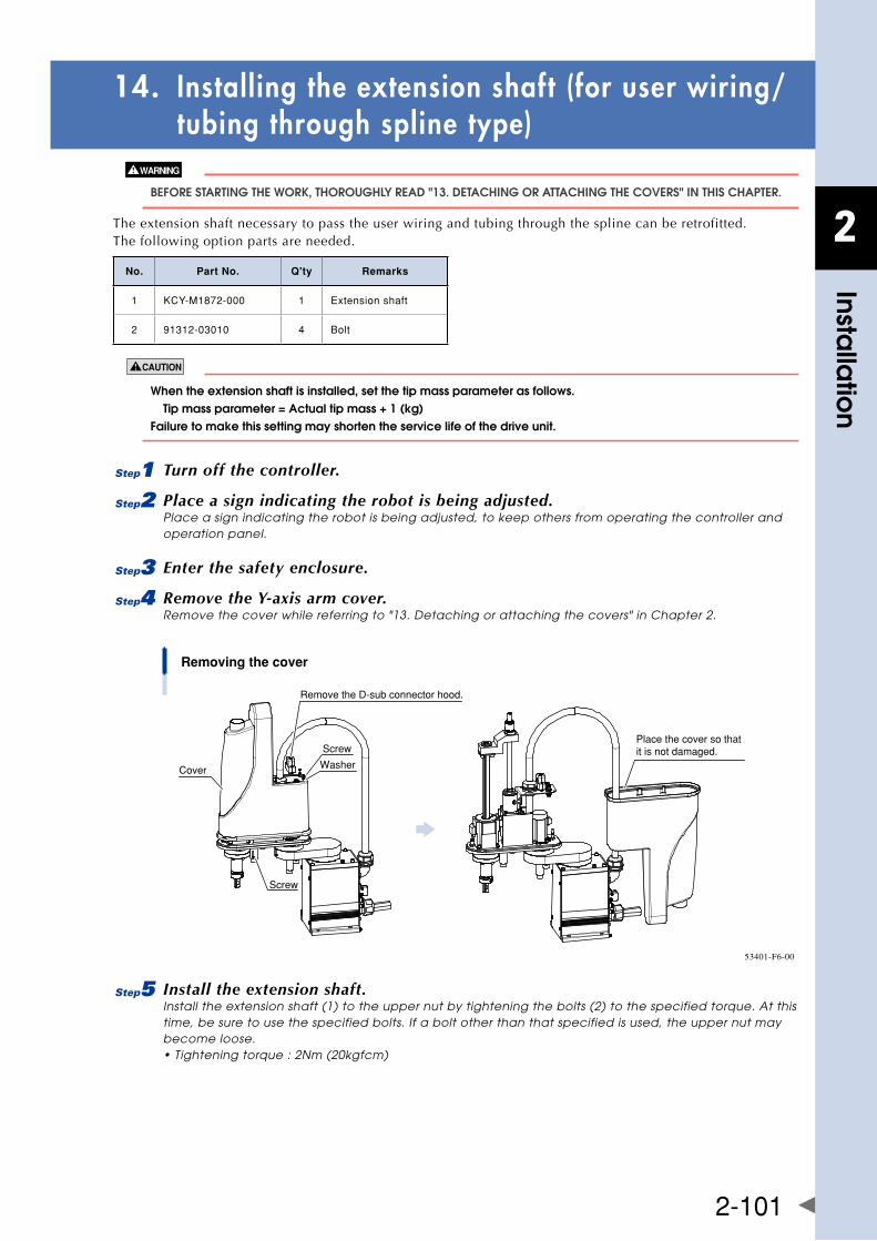
2
Installa
tion
2-101
14. Installing the extension shaft (for user wiring/ tubing through spline type)
bEfORE STaRTIng ThE WORk, ThOROUghly REaD "13. DETaChIng OR aTTaChIng ThE COvERS" In ThIS ChaPTER.
The extension shaft necessary to pass the user wiring and tubing through the spline can be retrofitted. The following option parts are needed.
No. Part No. Q'ty Remarks
1 KCY-M1872-000 1 Extensionshaft
2 91312-03010 4 Bolt
whentheextensionshaftisinstalled,setthetipmassparameterasfollows. tipmassparameter=actualtipmass+1(kg) failure to make this setting may shorten the service life of the drive unit.
1 Turn off the controller.
2 Place a sign indicating the robot is being adjusted.Place a sign indicating the robot is being adjusted, to keep others from operating the controller and operation panel.
3 Enter the safety enclosure.
4 Remove the Y-axis arm cover.Remove the cover while referring to "13. Detaching or attaching the covers" in Chapter 2.
Removing the cover
Cover
Screw
Washer
Screw
Place the cover so that it is not damaged.
Remove the D-sub connector hood.
53401-F6-00
5 Install the extension shaft.Install the extension shaft (1) to the upper nut by tightening the bolts (2) to the specified torque. At this time, be sure to use the specified bolts. If a bolt other than that specified is used, the upper nut may become loose. • Tightening torque : 2Nm (20kgfcm)
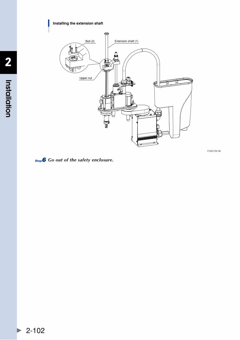
2
Installa
tion
2-102
Installing the extension shaft
Extension shaft (1)
Upper nut
Bolt (2)
53402-F6-00
6 Go out of the safety enclosure.

2
Installa
tion
2-103
15. Installing the tool flangeThe tool flange can be retrofitted. The following option parts are needed.
No. Part No. Q'ty Remarks
1 KCY-M1790-000 1 Toolflange
2 91312-05014 2 Bolt
3 92A08-05308 1 Setscrew
4 90K41-001490 1 Warninglabel
When the tool flange is installed, set the tip mass parameter as follows. tipmassparameter=actualtipmass+1(kg) failure to make this setting may shorten the service life of the drive unit.
1 Turn off the controller.
2 Place a sign indicating the robot is being adjusted.Place a sign indicating the robot is being adjusted, to keep others from operating the controller and operation panel.
3 Enter the safety enclosure.
4 Remove the bolt, and then the stopper.
Removing the stopperStep 4
Stopper Bolt
Urethane damper
23225-F6-00
5 Install the tool flange.Align the orientation of the tapped hole for the tool flange set screw with that of the width across flat part of the spline, and then insert the tool flange all the way inside.
Installing the tool flangeStep 5
Tool flange (1)
Tapped hole for set screw
Width across flat part
Degrease these portions.
23226-F6-00
6 Install the tool flange with the bolt (2).Secure that tool flange after it has been inserted all the way inside. • Tightening torque: 9Nm (92kgfcm) Apply the grease to the bolt thinly to make the tightening torque stable. Installing the tool flangeStep 6-8
Set screw (3)
Bolt (2)Warning label (4)
23227-F6-00
7 Tighten the set screw (3).• Tightening torque: 3.5Nm (36kgfcm) Apply Loctite 262 (Henkel Japan) to the set screw.
8 Affix the warning label (4).
9 Go out of the safety enclosure.

Chapter 3 Robot settings
Contents
1. Overview 3-1
2. adjusting the origin 3-2
2.1 absolute reset method 3-2
2.1.1 Sensor method (X-axis, Y-axis, and R-axis) 3-2
2.1.2 Stroke end method (Z-axis) 3-3
2.2 Machine reference 3-3
2.3 absolute reset procedures 3-4
2.3.1 Sensor method (X-axis, Y-axis, and R-axis) 3-4
2.3.2 Stroke end method (Z-axis) 3-5
2.4 Changing the origin position and adjusting the machine reference 3-7
2.4.1 Sensor method (YK250XG, YK350XG, YK400XG, YK500XGL, YK600XGL) 3-7
2.4.2 Sensor method (YK500XG, YK600XG, YK600XGH, YK700XG, YK800XG, YK900XG, YK1000XG) (YK500XGS, YK600XGS, YK700XGS, YK800XGS, YK900XGS, YK1000XGS) 3-15
2.5 adjustingthemachinereferencevalueofthestrokeendmethod(z-axis) 3-26
2.5.1 Stroke end method (YK250XG, YK350XG, YK400XG, YK500XGL, YK600XGL) 3-26
2.5.2 Stroke end method (YK500XG, YK600XG, YK600XGH, YK700XG, YK800XG, YK900XG, YK1000XG) (YK500XGS, YK600XGS, YK700XGS, YK800XGS, YK900XGS, YK1000XGS) 3-28
3. Setting the soft limits 3-31
3.1 settingthex-axisandy-axissoftlimits 3-31
3.2 settingthez-axissoftlimits 3-32
3.3 settingther-axissoftlimit 3-32
3.4 relationbetweenthex,y,andr-axismovementangle, thez-axismovementdistanceandthenumberofpulses 3-32
4. Setting the standard coordinates 3-33
4.1 Standard coordinate setting using a standard coordinate setup jig 3-34
4.1.1 YK250XG, YK350XG, YK400XG, YK500XGL, YK600XGL 3-34
4.1.2 YK500XG, YK600XG, YK600XGH, YK700XG, YK800XG, YK900XG, YK1000XG YK500XGS, YK600XGS, YK700XGS, YK800XGS, YK900XGS, YK1000XGS 3-35
5. affixingthestickersfororiginpositions,movementdirections,andaxisnames 3-38

3
Rob
ot se
ttings
3-1
1. OverviewVarioussettingshavebeencompletelymadeatthefactoryorbyyourdistributorbeforeshipment,includingthe origin position setting. If the operating conditions are changed and the robot needs to be set again, then follow the procedures described in this chapter.
The following describes the safety precautions to be observed when making various settings.
• readandunderstandthecontentsofthischaptercompletelybeforeattemptingtosettherobot. • Placeaconspicuoussignindicatingtherobotisbeingadjusted,topreventothersfromtouchingthecontroller switch,programmingboxoroperationpanel. • ifasafetyenclosurehasnotyetbeenprovidedrightafterinstallationoftherobot,ropeofforchainoffthe movement range around the manipulator in place of a safety enclosure, and observe the following points. 1. Use stable posts which will not fall over easily. 2. The rope or chain should be easily visible by everyone around the robot. 3. Place a conspicuous sign prohibiting the operator or other personnel from entering the movement range of the manipulator. • tochecktheoperationafterthesettingshavebeenmade,refertothesection"4.5.1trialoperation"inchapter “Safety Instructions” of this manual.
3
Rob
ot se
ttings
3-2
2. Adjusting the originAllmodelsoftheYK-XGseriesrobotsuseanabsolutetypepositiondetector.Theoriginposition(zeropulsepoint)canbedeterminedbyabsolutereset.Onceabsoluteresetisperformed,youdonothavetorepeat absolute reset when turning the power on next time. However, absolute reset is required if any of the following cases occur. The robot is shipped from the factory in condition "3." (below), so please perform absolute reset after installing the robot. For more details on absolute reset, refer to "Absolute Reset" in Chapter4ofthe"YAMAHARobotControllerUser'sManual".
1. Absolute-related error occurred on the axis.
2. Power drop was detected in the absolute battery for the driver installed inside the robot controller.
3. Cable connecting the robot unit to the controller was disconnected. (This is the status when shipped from the factory.)
4. Robot generation was changed.
5. Parameters were initialized.
6. Axis parameters "Origin shift", "Origin method", "Origin direction" or "Motor direction" were changed.
7. Motor was replaced. (Motor wiring connector was removed.)
8. Data in the ALL data file (extension: ALL) or parameter file (extension: PRM) was written into the controller by way of the RS-232C.
The following sections explain how to perform absolute reset.
• ifanyoftheabovecasesoccurafterinstallingtherobot,absoluteresetmustbeperformedagain.toperform absolute reset, move the robot arms back to their origin positions where the robot does not interfere with peripheral equipment after the setup is complete. • afterperformingabsolutereset,movetherobottoaknownpointtocheckwhethertheoriginpositionis correctly set. When doing this check, move the robot at the slowest possible speed. • thestandardcoordinateandpointdatamustberesetwhentheoriginpositionischanged. • makepointdatasettingafterchangingtheoriginposition.afterchangingtheoriginposition,donotusethe previous point data.
TherearethreeabsoluteresetmethodsfortheYK-XGseries:thesensormethod,markmethod,andstrokeendmethod.TheX-axis,Y-axis,andR-axisusethesensormethodastheinitialsetting,whiletheZ-axisusesthestroke end method.
2.1 Absolute reset method
2.1.1 Sensor method (X-axis, Y-axis, and R-axis)In the sensor method, the target axis is automatically operated for the absolute reset, and the absolute reset is performed at the position where the proximity sensor provided on the target axis detects the detection area (dog). The absolute reset in the sensor method can be executed with the programming box (RPB), RS-232C communication, and dedicated input.
SERIOUS InjURy MIghT OCCUR fROM PhySICal COnTaCT WITh ThE RObOT DURIng OPERaTIOn. nEvER EnTER WIThIn ThE RObOT MOvEMEnT RangE DURIng abSOlUTE RESET.
theorigincannotbedetectedinanyaxiswhichisnotpositionedontheplussidefromtheorigin(seethefig.statedinstep6of"2.3.1sensormethod(x-axis,y-axis,andr-axis)"inthischapter)beforestartingthereturn-to-
originoperation.(factorysettingatshipment.)inthiscase,pressthe key to interrupt the return-to-origin
operation,movethetargetaxistotheplussideoftheorigin,andreperformtheoriginreturnoperation.ifthereturn-to-origin operation is not interrupted, the robot will continue the operation and may collide with the mechanicalstopperoraperipheraldevice.sinceamechanicalstopperisnotprovidedinther-axis,thewiringand piping installed on the end effecter may be wound up by the operation.
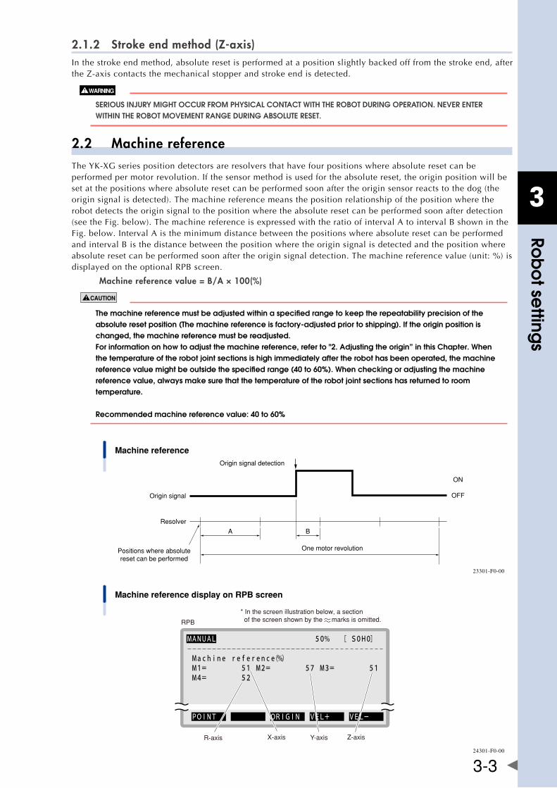
3
Rob
ot se
ttings
3-3
2.1.2 Stroke end method (Z-axis)In the stroke end method, absolute reset is performed at a position slightly backed off from the stroke end, after theZ-axiscontactsthemechanicalstopperandstrokeendisdetected.
SERIOUS InjURy MIghT OCCUR fROM PhySICal COnTaCT WITh ThE RObOT DURIng OPERaTIOn. nEvER EnTER WIThIn ThE RObOT MOvEMEnT RangE DURIng abSOlUTE RESET.
2.2 Machine referenceTheYK-XGseriespositiondetectorsareresolversthathavefourpositionswhereabsoluteresetcanbeperformed per motor revolution. If the sensor method is used for the absolute reset, the origin position will be set at the positions where absolute reset can be performed soon after the origin sensor reacts to the dog (the origin signal is detected). The machine reference means the position relationship of the position where the robot detects the origin signal to the position where the absolute reset can be performed soon after detection (see the Fig. below). The machine reference is expressed with the ratio of interval A to interval B shown in the Fig. below. Interval A is the minimum distance between the positions where absolute reset can be performed and interval B is the distance between the position where the origin signal is detected and the position where absolute reset can be performed soon after the origin signal detection. The machine reference value (unit: %) is displayed on the optional RPB screen.
Machine reference value = B/A × 100(%)
themachinereferencemustbeadjustedwithinaspecifiedrangetokeeptherepeatabilityprecisionoftheabsoluteresetposition(themachinereferenceisfactory-adjustedpriortoshipping).iftheoriginpositionischanged, the machine reference must be readjusted. for information on how to adjust the machine reference, refer to "2. adjusting the origin” in this Chapter. When the temperature of the robot joint sections is high immediately after the robot has been operated, the machine referencevaluemightbeoutsidethespecifiedrange(40to60%).whencheckingoradjustingthemachinereference value, always make sure that the temperature of the robot joint sections has returned to room temperature. recommendedmachinereferencevalue:40to60%
Machine referenceOrigin signal detection
Origin signal
Resolver
Positions where absolutereset can be performed
One motor revolution
BA
ON
OFF
23301-F0-00
Machine reference display on RPB screen
RPB
* In the screen illustration below, a section of the screen shown by the marks is omitted.
R-axis X-axis Y-axis Z-axis
MANUAL 50% [ S0H0]
Machine reference(%) M1= 51 M2= 57 M3= 51 M4= 52
POINT ORIGIN VEL+ VEL-
24301-F0-00
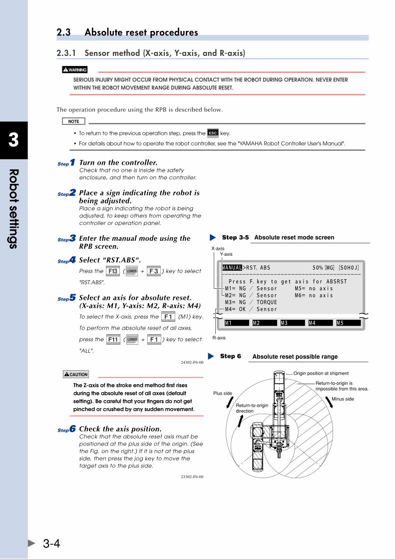
3
Rob
ot se
ttings
3-4
2.3 Absolute reset procedures
2.3.1 Sensor method (X-axis, Y-axis, and R-axis)
SERIOUS InjURy MIghT OCCUR fROM PhySICal COnTaCT WITh ThE RObOT DURIng OPERaTIOn. nEvER EnTER WIThIn ThE RObOT MOvEMEnT RangE DURIng abSOlUTE RESET.
The operation procedure using the RPB is described below.
• Toreturntothepreviousoperationstep,pressthe key.
• Fordetailsabouthowtooperatetherobotcontroller,seethe"YAMAHARobotControllerUser'sManual".
1 Turn on the controller.Check that no one is inside the safety enclosure, and then turn on the controller.
2 Place a sign indicating the robot is being adjusted.Place a sign indicating the robot is being adjusted, to keep others from operating the controller or operation panel.
3 Enter the manual mode using the RPB screen.
4 Select "RST.ABS".Press the ( + ) key to select
"RST.ABS".
5 Select an axis for absolute reset. (X-axis: M1, Y-axis: M2, R-axis: M4)To select the X-axis, press the (M1) key.
To perform the absolute reset of all axes,
press the ( + ) key to select
"ALL".
MANUAL>RST.ABS 50%[MG][S0H0J] Press F.key to get axis for ABSRST M1= NG / Sensor M5= no axis M2= NG / Sensor M6= no axis M3= NG / TORQUE M4= OK / Sensor
M1 M2 M3 M4 M5
----------------------------------------
X-axisY-axis
R-axis
Absolute reset mode screenStep 3-5
24302-F0-00
thez-axisofthestrokeendmethodfirstrisesduringtheabsoluteresetofallaxes(defaultsetting).becarefulthatyourfingersdonotgetpinched or crushed by any sudden movement.
6 Check the axis position.Check that the absolute reset axis must be positioned at the plus side of the origin. (See the Fig. on the right.) If it is not at the plus side, then press the jog key to move the target axis to the plus side.
Absolute reset possible rangeStep 6
Return-to-origin isimpossible from this area.
Origin position at shipment
Return-to-origin direction
Plus sideMinus side
23302-F0-00
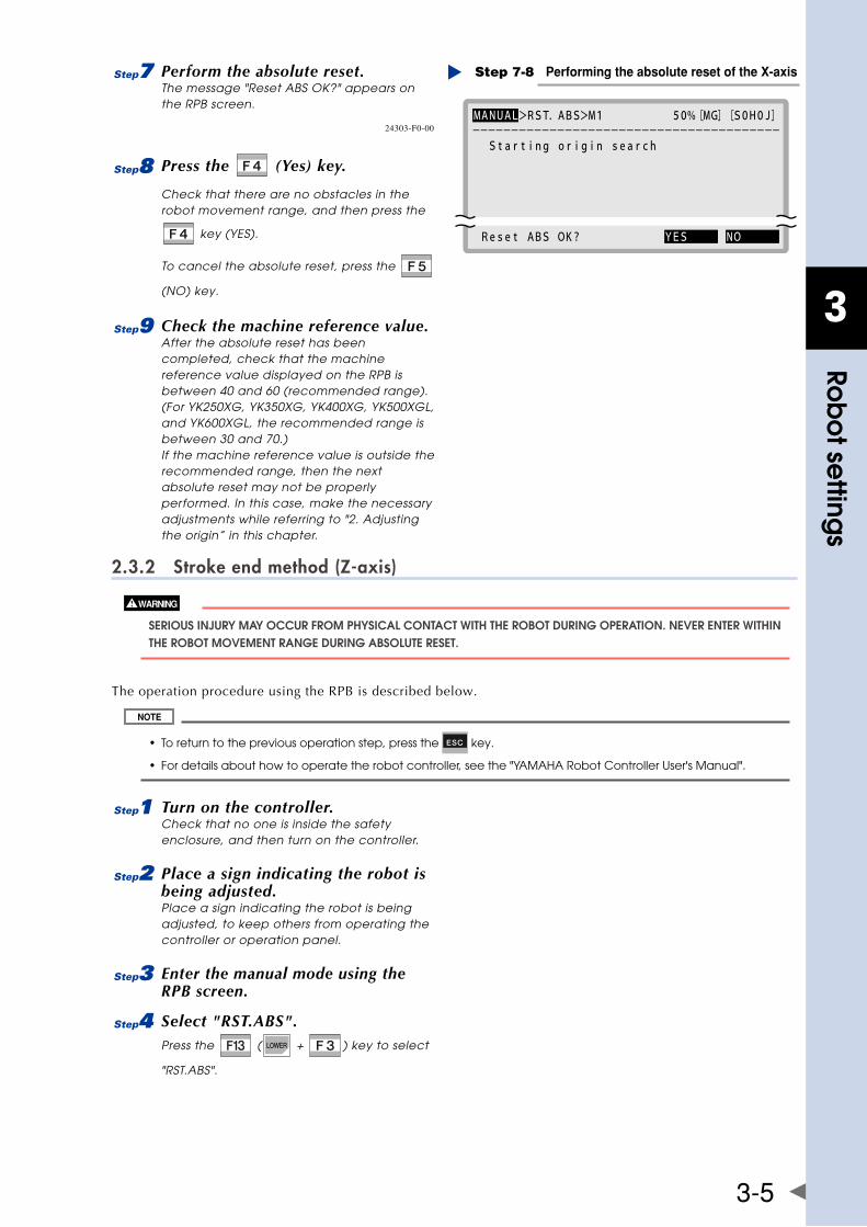
3
Rob
ot se
ttings
3-5
7 Perform the absolute reset.The message "Reset ABS OK?" appears on the RPB screen.
MANUAL>RST.ABS>M1 50%[MG][S0H0J] Starting origin search
Reset ABS OK? YES NO
----------------------------------------
Performing the absolute reset of the X-axisStep 7-8
24303-F0-00
8 Press the (Yes) key.
Check that there are no obstacles in the robot movement range, and then press the
key (YES).
To cancel the absolute reset, press the
(NO) key.
9 Check the machine reference value.After the absolute reset has been completed, check that the machine reference value displayed on the RPB is between 40 and 60 (recommended range). (For YK250XG, YK350XG, YK400XG, YK500XGL, and YK600XGL, the recommended range is between 30 and 70.) If the machine reference value is outside the recommended range, then the next absolute reset may not be properly performed. In this case, make the necessary adjustments while referring to "2. Adjusting the origin” in this chapter.
2.3.2 Stroke end method (Z-axis)
SERIOUS InjURy May OCCUR fROM PhySICal COnTaCT WITh ThE RObOT DURIng OPERaTIOn. nEvER EnTER WIThIn ThE RObOT MOvEMEnT RangE DURIng abSOlUTE RESET.
The operation procedure using the RPB is described below.
• Toreturntothepreviousoperationstep,pressthe key.
• Fordetailsabouthowtooperatetherobotcontroller,seethe"YAMAHARobotControllerUser'sManual".
1 Turn on the controller.Check that no one is inside the safety enclosure, and then turn on the controller.
2 Place a sign indicating the robot is being adjusted.Place a sign indicating the robot is being adjusted, to keep others from operating the controller or operation panel.
3 Enter the manual mode using the RPB screen.
4 Select "RST.ABS".Press the ( + ) key to select
"RST.ABS".
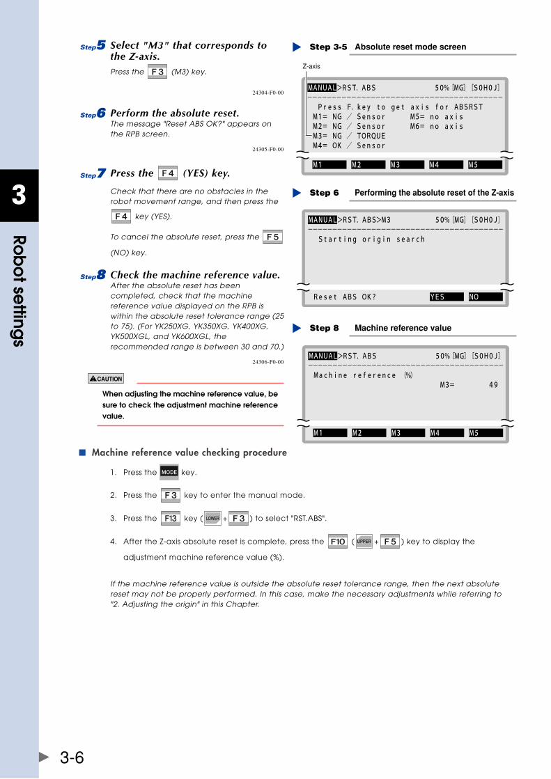
3
Rob
ot se
ttings
3-6
5 Select "M3" that corresponds to the Z-axis.Press the (M3) key.
MANUAL>RST.ABS 50%[MG][S0H0J] Press F.key to get axis for ABSRST M1= NG / Sensor M5= no axis M2= NG / Sensor M6= no axis M3= NG / TORQUE M4= OK / Sensor
M1 M2 M3 M4 M5
----------------------------------------
Z-axis
Absolute reset mode screenStep 3-5
24304-F0-00
6 Perform the absolute reset.The message "Reset ABS OK?" appears on the RPB screen.
MANUAL>RST.ABS>M3 50%[MG][S0H0J] Starting origin search
Reset ABS OK? YES NO
----------------------------------------
Performing the absolute reset of the Z-axisStep 6
24305-F0-00
7 Press the (YES) key.
Check that there are no obstacles in the robot movement range, and then press the
key (YES).
To cancel the absolute reset, press the
(NO) key.
8 Check the machine reference value.After the absolute reset has been completed, check that the machine reference value displayed on the RPB is within the absolute reset tolerance range (25 to 75). (For YK250XG, YK350XG, YK400XG, YK500XGL, and YK600XGL, the recommended range is between 30 and 70.)
MANUAL>RST.ABS 50%[MG][S0H0J] Machine reference (%) M3= 49
M1 M2 M3 M4 M5
----------------------------------------
Machine reference valueStep 8
24306-F0-00
When adjusting the machine reference value, be sure to check the adjustment machine reference value.
Machine reference value checking procedure ■
1. Press the key.
2. Press the key to enter the manual mode.
3. Press the key ( + ) to select "RST.ABS".
4. After the Z-axis absolute reset is complete, press the ( + ) key to display the
adjustment machine reference value (%).
If the machine reference value is outside the absolute reset tolerance range, then the next absolute reset may not be properly performed. In this case, make the necessary adjustments while referring to "2. Adjusting the origin" in this Chapter.
3
Rob
ot se
ttings
3-7
2.4 Changing the origin position and adjusting the machine reference
This section describes how to change the origin position and adjust the machine reference.
bEfORE STaRTIng ThE WORk, ThOROUghly REaD "13. DETaChIng OR aTTaChIng ThE COvERS" In ChaPTER 2.
• iftheoriginpositionhasbeenchanged,thentheabsoluteresetmustbeperformed,themachinereference must be adjusted, and the standard coordinate and point data must be reset. • ifanymachinereferenceisadjusted,theoriginpositionmaychange.beforetheadjustment,markoffthe reference mark at the current origin position on the main body of the robot. after the machine reference is adjusted, be sure to check that the origin position has not deviated. If the origin position changes after the machine reference has been adjusted, then the standard coordinate and point data must be reset.
2.4.1 Sensor method (YK250XG, YK350XG, YK400XG, YK500XGL, YK600XGL)
Adjusting the X-axis machine reference ■
• theoriginpositionmaychangeduetomachinereferenceadjustment.ifitoccurs,youmustsetpointdata again. • whenthereturn-to-origindirectionisreversed,theoriginpositionmaynotbethebasefront.whenusingthe standardsoftlimit,theaxismaycollidewiththemechanicalstopper.atthistime,setthesoftlimit2°ormore inward from the mechanical stopper while referring to "3. Setting the soft limits".
FollowthestepsbelowtoadjusttheX-axismachinereferencevalue.Prepare a wrench for a width across flat of 13 mm.
1 Turn on the controller.Check that no one is inside the safety enclosure, and then turn on the controller.
2 Perform the absolute reset.Perform the absolute reset from outside the safety enclosure. For details about how to perform the absolute reset, see "2.3 Absolute reset procedures".
3 Check the machine reference value.If the machine reference value displayed on the RPB is not in the range between 30 and 70 (recommended range) after the absolute reset has been completed, follow the steps below to adjust the machine reference value.
4 Place a sign indicating the robot is being adjusted.Place a sign indicating the robot is being adjusted, to keep others from operating the controller or operation panel.
5 Turn off the controller.
6 Enter the safety enclosure.
7 Put a mark at the origin position.Scribe a mark at the current origin position on the X-axis joint area of the robot. At this time, be careful to prevent the origin position from deviating since the X-axis arm is touched.
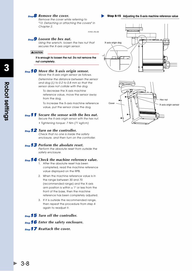
3
Rob
ot se
ttings
3-8
8 Remove the cover.Remove the cover while referring to "13. Detaching or attaching the covers" in Chapter 2.
Adjusting the X-axis machine reference valueStep 8-15
X-axis origin dog
X-axis origin sensorCover
Hex nutL
53501-F6-00
9 Loosen the hex nut.Using the wrench, loosen the hex nut that secures the X-axis origin sensor.
It is enough to loosen the nut. Do not remove the nut completely.
0 Move the X-axis origin sensor.Move the X-axis origin sensor as follows.
Determine the distance between the sensor and dog (L) to 0.2 to 0.8 mm so that the sensor does not collide with the dog.
To decrease the X-axis machine
reference value, move the sensor away
from the dog.
To increase the X-axis machine reference
value, put the sensor close the dog.
q Secure the sensor with the hex nut.Secure the X-axis origin sensor with the hex nut.
• Tightening torque: 7 Nm (71 kgfcm)
w Turn on the controller.Check that no one is inside the safety enclosure, and then turn on the controller.
e Perform the absolute reset.Perform the absolute reset from outside the safety enclosure.
r Check the machine reference value.1. After the absolute reset has been
completed, read the machine reference
value displayed on the RPB.
2. When the machine reference value is in
the range between 30 and 70
(recommended range) and the X-axis
arm position is within ± 1° or less from the
front of the base, then the machine
reference has been completely adjusted.
3. If it is outside the recommended range,
then repeat the procedure from step 4
again to readjust it.
t Turn off the controller.
y Enter the safety enclosure.
u Reattach the cover.
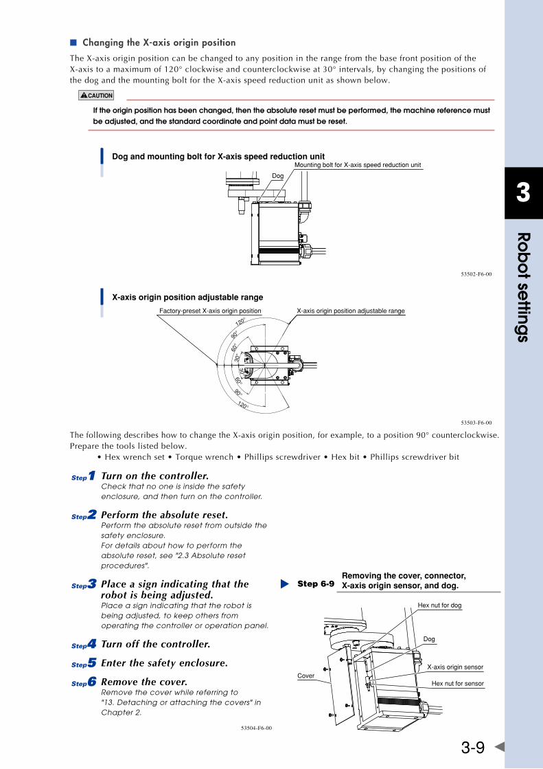
3
Rob
ot se
ttings
3-9
Changing the X-axis origin position ■
TheX-axisoriginpositioncanbechangedtoanypositionintherangefromthebasefrontpositionoftheX-axistoamaximumof120°clockwiseandcounterclockwiseat30°intervals,bychangingthepositionsofthedogandthemountingboltfortheX-axisspeedreductionunitasshownbelow.
If the origin position has been changed, then the absolute reset must be performed, the machine reference must be adjusted, and the standard coordinate and point data must be reset.
Dog and mounting bolt for X-axis speed reduction unit
Dog
Mounting bolt for X-axis speed reduction unit
53502-F6-00
X-axis origin position adjustable range
X-axis origin position adjustable rangeFactory-preset X-axis origin position
120°
90°
60°
30°
30°
60°
90°
120°
53503-F6-00
ThefollowingdescribeshowtochangetheX-axisoriginposition,forexample,toaposition90°counterclockwise.Prepare the tools listed below. •Hexwrenchset•Torquewrench•Phillipsscrewdriver•Hexbit•Phillipsscrewdriverbit
1 Turn on the controller.Check that no one is inside the safety enclosure, and then turn on the controller.
2 Perform the absolute reset.Perform the absolute reset from outside the safety enclosure. For details about how to perform the absolute reset, see "2.3 Absolute reset procedures".
3 Place a sign indicating that the robot is being adjusted.Place a sign indicating that the robot is being adjusted, to keep others from operating the controller or operation panel.
4 Turn off the controller.
5 Enter the safety enclosure.
6 Remove the cover.Remove the cover while referring to "13. Detaching or attaching the covers" in Chapter 2.
Removing the cover, connector, X-axis origin sensor, and dog.Step 6-9
Hex nut for dog
Dog
X-axis origin sensor
Hex nut for sensorCover
53504-F6-00
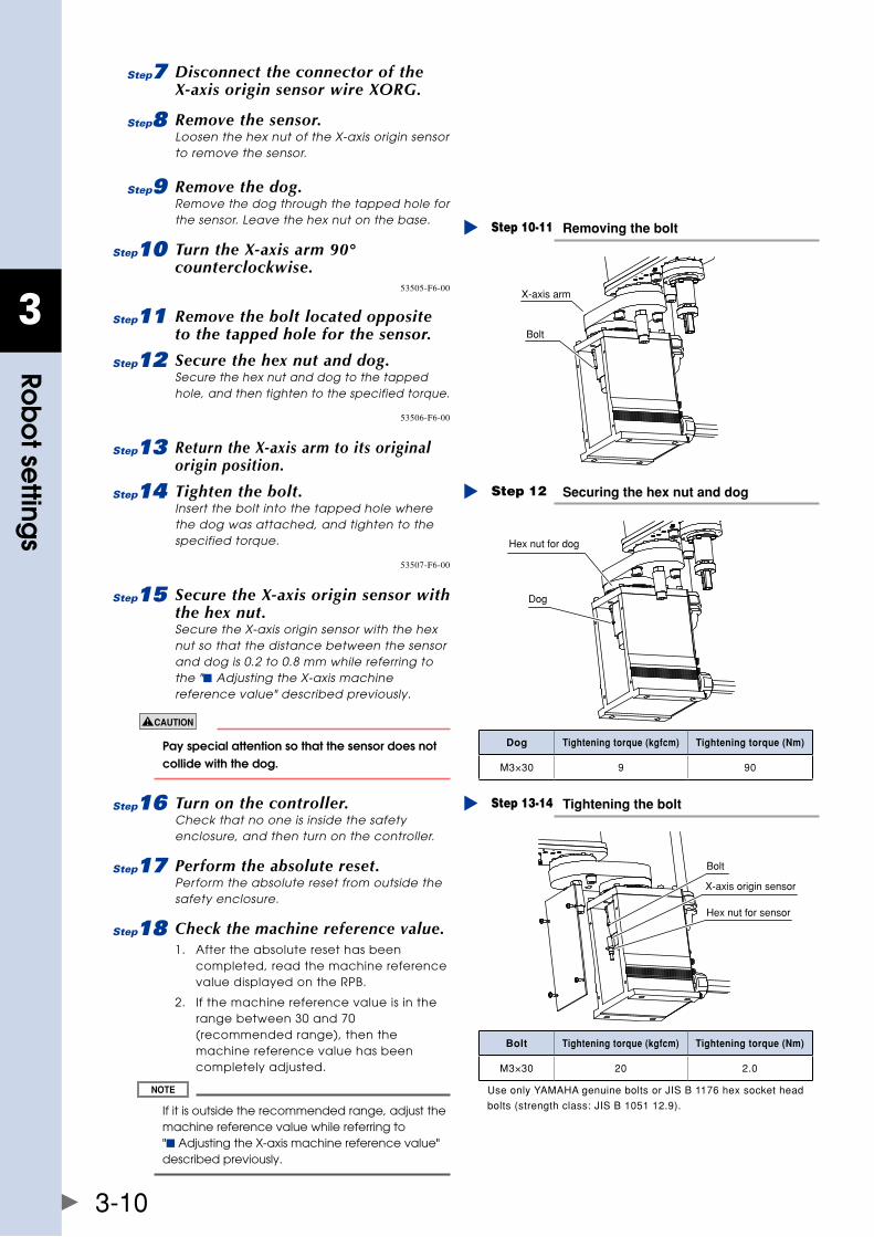
3
Rob
ot se
ttings
3-10
7 Disconnect the connector of the X-axis origin sensor wire XORG.
8 Remove the sensor.Loosen the hex nut of the X-axis origin sensor to remove the sensor.
9 Remove the dog.Remove the dog through the tapped hole for the sensor. Leave the hex nut on the base.
0 Turn the X-axis arm 90° counterclockwise.
Removing the boltStep 10-11
X-axis arm
Bolt
53505-F6-00
q Remove the bolt located opposite to the tapped hole for the sensor.
w Secure the hex nut and dog.Secure the hex nut and dog to the tapped hole, and then tighten to the specified torque.
Securing the hex nut and dogStep 12
Hex nut for dog
Dog
53506-F6-00
e Return the X-axis arm to its original origin position.
r Tighten the bolt.Insert the bolt into the tapped hole where the dog was attached, and tighten to the specified torque.
Tightening the boltStep 13-14
Bolt
X-axis origin sensor
Hex nut for sensor
53507-F6-00
t Secure the X-axis origin sensor with the hex nut.Secure the X-axis origin sensor with the hex nut so that the distance between the sensor and dog is 0.2 to 0.8 mm while referring to the "■ Adjusting the X-axis machine reference value" described previously.
Pay special attention so that the sensor does not collide with the dog.
y Turn on the controller.Check that no one is inside the safety enclosure, and then turn on the controller.
u Perform the absolute reset.Perform the absolute reset from outside the safety enclosure.
i Check the machine reference value.1. After the absolute reset has been
completed, read the machine reference value displayed on the RPB.
2. If the machine reference value is in the range between 30 and 70 (recommended range), then the machine reference value has been completely adjusted.
If it is outside the recommended range, adjust the machine reference value while referring to "■ Adjusting the X-axis machine reference value" described previously.
Dog Tightening torque (kgfcm) Tightening torque (Nm)
M3×30 9 90
Bolt Tightening torque (kgfcm) Tightening torque (Nm)
M3×30 20 2.0
UseonlyYAMAHAgenuineboltsorJISB1176hexsockethead
bolts(strengthclass:JISB105112.9).
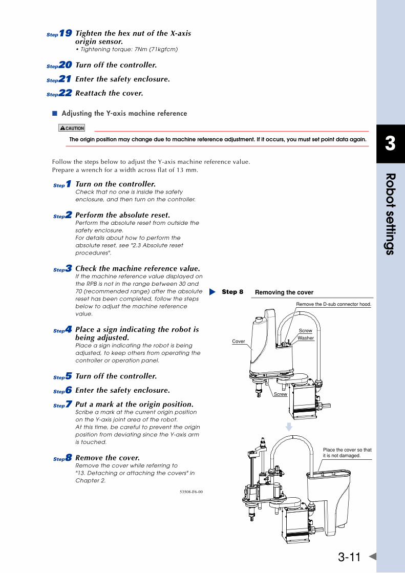
3
Rob
ot se
ttings
3-11
o Tighten the hex nut of the X-axis origin sensor.• Tightening torque: 7Nm (71kgfcm)
p Turn off the controller.
a Enter the safety enclosure.
s Reattach the cover.
Adjusting the Y-axis machine reference ■
The origin position may change due to machine reference adjustment. If it occurs, you must set point data again.
Follow the steps below to adjust the Y-axis machine reference value.Prepare a wrench for a width across flat of 13 mm.
1 Turn on the controller.Check that no one is inside the safety enclosure, and then turn on the controller.
2 Perform the absolute reset.Perform the absolute reset from outside the safety enclosure. For details about how to perform the absolute reset, see "2.3 Absolute reset procedures".
3 Check the machine reference value.If the machine reference value displayed on the RPB is not in the range between 30 and 70 (recommended range) after the absolute reset has been completed, follow the steps below to adjust the machine reference value.
4 Place a sign indicating the robot is being adjusted.Place a sign indicating the robot is being adjusted, to keep others from operating the controller or operation panel.
5 Turn off the controller.
6 Enter the safety enclosure.
7 Put a mark at the origin position.Scribe a mark at the current origin position on the Y-axis joint area of the robot. At this time, be careful to prevent the origin position from deviating since the Y-axis arm is touched.
8 Remove the cover.Remove the cover while referring to "13. Detaching or attaching the covers" in Chapter 2.
Removing the coverStep 8
Cover
Screw
Washer
Screw
Place the cover so that it is not damaged.
Remove the D-sub connector hood.
53508-F6-00
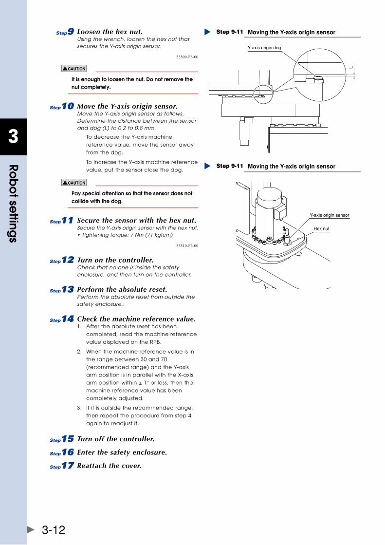
3
Rob
ot se
ttings
3-12
9 Loosen the hex nut.Using the wrench, loosen the hex nut that secures the Y-axis origin sensor.
Moving the Y-axis origin sensorStep 9-11
Y-axis origin dog
L
53509-F6-00
It is enough to loosen the nut. Do not remove the nut completely.
0 Move the Y-axis origin sensor.Move the Y-axis origin sensor as follows. Determine the distance between the sensor and dog (L) to 0.2 to 0.8 mm.
To decrease the Y-axis machine
reference value, move the sensor away
from the dog.
To increase the Y-axis machine reference
value, put the sensor close the dog.
Pay special attention so that the sensor does not collide with the dog.
q Secure the sensor with the hex nut.Secure the Y-axis origin sensor with the hex nut. • Tightening torque: 7 Nm (71 kgfcm)
Moving the Y-axis origin sensorStep 9-11
Y-axis origin sensor
Hex nut
53510-F6-00
w Turn on the controller.Check that no one is inside the safety enclosure, and then turn on the controller.
e Perform the absolute reset.Perform the absolute reset from outside the safety enclosure..
r Check the machine reference value.1. After the absolute reset has been
completed, read the machine reference
value displayed on the RPB.
2. When the machine reference value is in
the range between 30 and 70
(recommended range) and the Y-axis
arm position is in parallel with the X-axis
arm position within ± 1° or less, then the
machine reference value has been
completely adjusted.
3. If it is outside the recommended range,
then repeat the procedure from step 4
again to readjust it.
t Turn off the controller.
y Enter the safety enclosure.
u Reattach the cover.
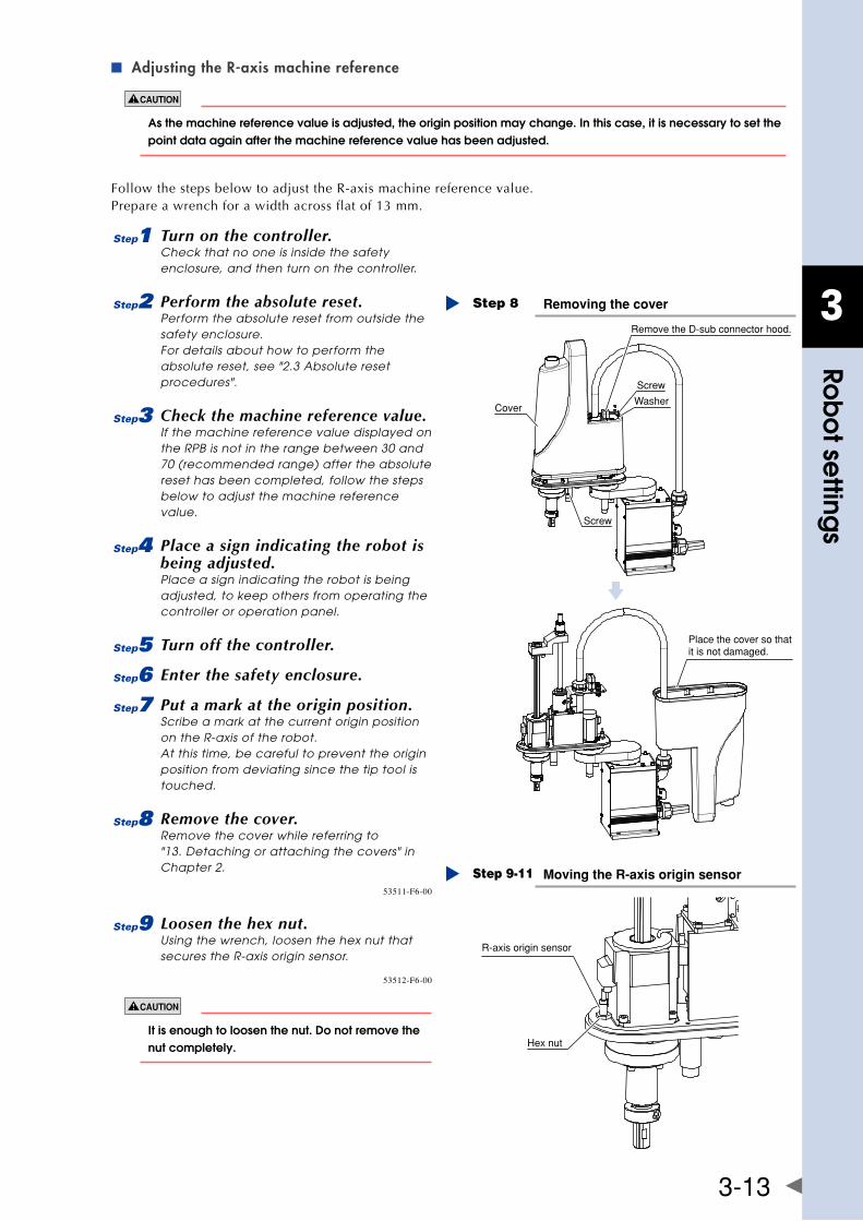
3
Rob
ot se
ttings
3-13
Adjusting the R-axis machine reference ■
as the machine reference value is adjusted, the origin position may change. In this case, it is necessary to set the point data again after the machine reference value has been adjusted.
Follow the steps below to adjust the R-axis machine reference value.Prepare a wrench for a width across flat of 13 mm.
1 Turn on the controller.Check that no one is inside the safety enclosure, and then turn on the controller.
2 Perform the absolute reset.Perform the absolute reset from outside the safety enclosure. For details about how to perform the absolute reset, see "2.3 Absolute reset procedures".
3 Check the machine reference value.If the machine reference value displayed on the RPB is not in the range between 30 and 70 (recommended range) after the absolute reset has been completed, follow the steps below to adjust the machine reference value.
4 Place a sign indicating the robot is being adjusted.Place a sign indicating the robot is being adjusted, to keep others from operating the controller or operation panel.
5 Turn off the controller.
6 Enter the safety enclosure.
7 Put a mark at the origin position.Scribe a mark at the current origin position on the R-axis of the robot. At this time, be careful to prevent the origin position from deviating since the tip tool is touched.
8 Remove the cover.Remove the cover while referring to "13. Detaching or attaching the covers" in Chapter 2.
Removing the coverStep 8
Cover
Screw
Washer
Screw
Place the cover so that it is not damaged.
Remove the D-sub connector hood.
53511-F6-00
9 Loosen the hex nut.Using the wrench, loosen the hex nut that secures the R-axis origin sensor.
Moving the R-axis origin sensorStep 9-11
R-axis origin sensor
Hex nut
53512-F6-00
It is enough to loosen the nut. Do not remove the nut completely.
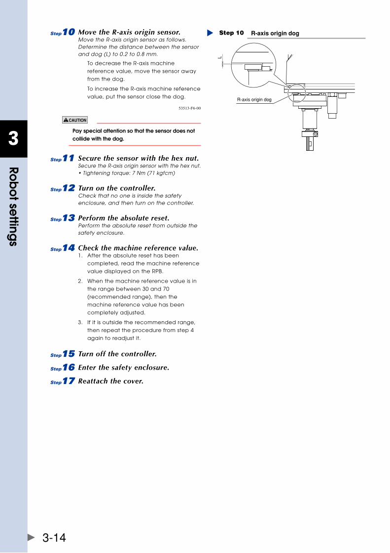
3
Rob
ot se
ttings
3-14
0 Move the R-axis origin sensor.Move the R-axis origin sensor as follows. Determine the distance between the sensor and dog (L) to 0.2 to 0.8 mm.
To decrease the R-axis machine
reference value, move the sensor away
from the dog.
To increase the R-axis machine reference
value, put the sensor close the dog.
R-axis origin dogStep 10
R-axis origin dog
L
53513-F6-00
Pay special attention so that the sensor does not collide with the dog.
q Secure the sensor with the hex nut.Secure the R-axis origin sensor with the hex nut. • Tightening torque: 7 Nm (71 kgfcm)
w Turn on the controller.Check that no one is inside the safety enclosure, and then turn on the controller.
e Perform the absolute reset.Perform the absolute reset from outside the safety enclosure.
r Check the machine reference value.1. After the absolute reset has been
completed, read the machine reference
value displayed on the RPB.
2. When the machine reference value is in
the range between 30 and 70
(recommended range), then the
machine reference value has been
completely adjusted.
3. If it is outside the recommended range,
then repeat the procedure from step 4
again to readjust it.
t Turn off the controller.
y Enter the safety enclosure.
u Reattach the cover.
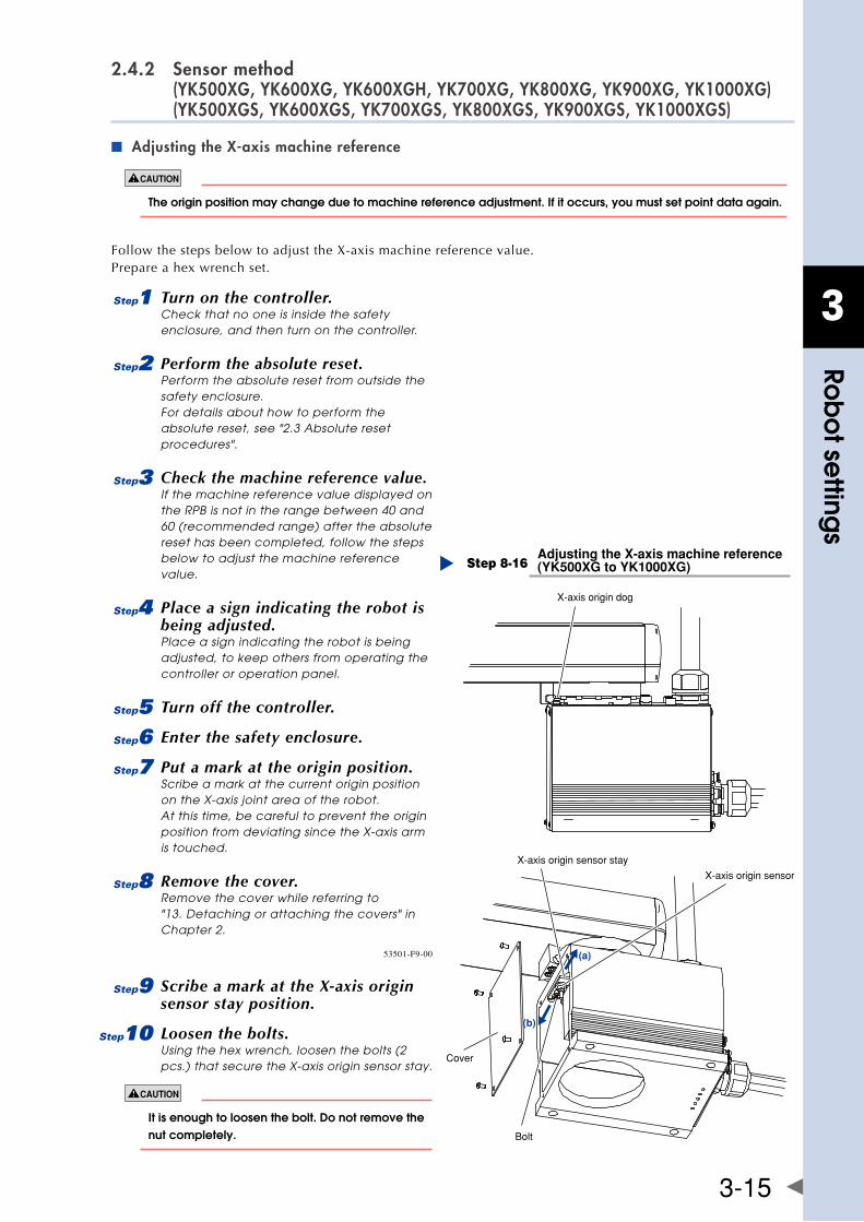
3
Rob
ot se
ttings
3-15
2.4.2 Sensor method (YK500XG, YK600XG, YK600XGH, YK700XG, YK800XG, YK900XG, YK1000XG) (YK500XGS, YK600XGS, YK700XGS, YK800XGS, YK900XGS, YK1000XGS)
Adjusting the X-axis machine reference ■
The origin position may change due to machine reference adjustment. If it occurs, you must set point data again.
FollowthestepsbelowtoadjusttheX-axismachinereferencevalue.Prepare a hex wrench set.
1 Turn on the controller.Check that no one is inside the safety enclosure, and then turn on the controller.
2 Perform the absolute reset.Perform the absolute reset from outside the safety enclosure. For details about how to perform the absolute reset, see "2.3 Absolute reset procedures".
3 Check the machine reference value.If the machine reference value displayed on the RPB is not in the range between 40 and 60 (recommended range) after the absolute reset has been completed, follow the steps below to adjust the machine reference value.
4 Place a sign indicating the robot is being adjusted.Place a sign indicating the robot is being adjusted, to keep others from operating the controller or operation panel.
5 Turn off the controller.
6 Enter the safety enclosure.
7 Put a mark at the origin position.Scribe a mark at the current origin position on the X-axis joint area of the robot. At this time, be careful to prevent the origin position from deviating since the X-axis arm is touched.
8 Remove the cover.Remove the cover while referring to "13. Detaching or attaching the covers" in Chapter 2.
Adjusting the X-axis machine reference(YK500XG to YK1000XG)Step 8-16
X-axis origin dog
X-axis origin sensor stay
X-axis origin sensor
Bolt
Cover
(a)
(b)
53501-F9-00
9 Scribe a mark at the X-axis origin sensor stay position.
0 Loosen the bolts.Using the hex wrench, loosen the bolts (2 pcs.) that secure the X-axis origin sensor stay.
It is enough to loosen the bolt. Do not remove the nut completely.
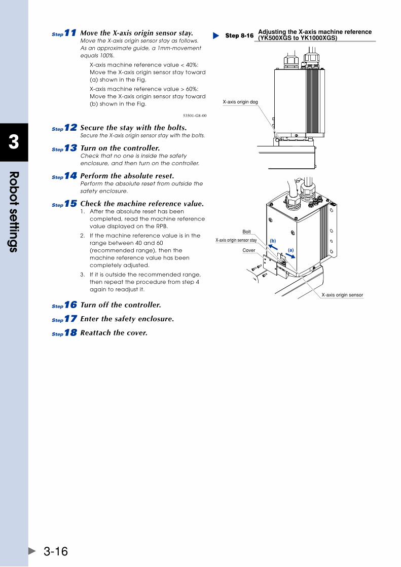
3
Rob
ot se
ttings
3-16
q Move the X-axis origin sensor stay.Move the X-axis origin sensor stay as follows. As an approximate guide, a 1mm-movement equals 100%.
X-axis machine reference value < 40%: Move the X-axis origin sensor stay toward (a) shown in the Fig.
X-axis machine reference value > 60%: Move the X-axis origin sensor stay toward (b) shown in the Fig.
Adjusting the X-axis machine reference(YK500XGS to YK1000XGS)Step 8-16
(a)
(b)
X-axis origin dog
X-axis origin sensor stay
Cover
Bolt
X-axis origin sensor
53501-G8-00
w Secure the stay with the bolts.Secure the X-axis origin sensor stay with the bolts.
e Turn on the controller.Check that no one is inside the safety enclosure, and then turn on the controller.
r Perform the absolute reset.Perform the absolute reset from outside the safety enclosure.
t Check the machine reference value.1. After the absolute reset has been
completed, read the machine reference value displayed on the RPB.
2. If the machine reference value is in the range between 40 and 60 (recommended range), then the machine reference value has been completely adjusted.
3. If it is outside the recommended range, then repeat the procedure from step 4 again to readjust it.
y Turn off the controller.
u Enter the safety enclosure.
i Reattach the cover.
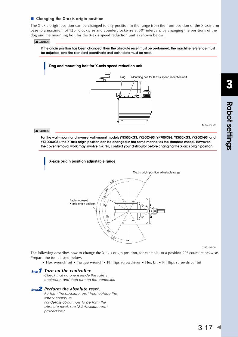
3
Rob
ot se
ttings
3-17
Changing the X-axis origin position ■
TheX-axisoriginpositioncanbechangedtoanypositionintherangefromthefrontpositionoftheX-axisarmbasetoamaximumof120°clockwiseandcounterclockwiseat30°intervals,bychangingthepositionsofthedogandthemountingboltfortheX-axisspeedreductionunitasshownbelow.
If the origin position has been changed, then the absolute reset must be performed, the machine reference must be adjusted, and the standard coordinate and point data must be reset.
Dog and mounting bolt for X-axis speed reduction unit
Dog Mounting bolt for X-axis speed reduction unit
53502-F9-00
forthewall-mountandinversewall-mountmodels(yK500xgs,yK600xgs,yK700xgs,yK800xgs,yK900xgs,andyK1000xgs),thex-axisoriginpositioncanbechangedinthesamemannerasthestandardmodel.however,thecoverremovalworkmayinvolverisk.so,contactyourdistributorbeforechangingthex-axisoriginposition.
120°
90°
60°
30°
120°
90°
60°30°
X-axis origin position adjustable range
Factory-presetX-axis origin position
X-axis origin position adjustable range
53503-F9-00
ThefollowingdescribeshowtochangetheX-axisoriginposition,forexample,toaposition90°counterclockwise.Prepare the tools listed below. •Hexwrenchset•Torquewrench•Phillipsscrewdriver•Hexbit•Phillipsscrewdriverbit
1 Turn on the controller.Check that no one is inside the safety enclosure, and then turn on the controller.
2 Perform the absolute reset.Perform the absolute reset from outside the safety enclosure. For details about how to perform the absolute reset, see "2.3 Absolute reset procedures".
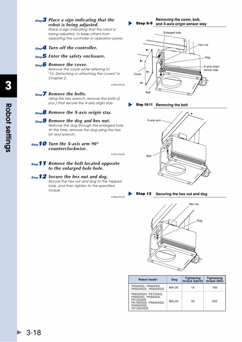
3
Rob
ot se
ttings
3-18
3 Place a sign indicating that the robot is being adjusted.Place a sign indicating that the robot is being adjusted, to keep others from operating the controller or operation panel.
4 Turn off the controller.
5 Enter the safety enclosure.
6 Remove the cover.Remove the cover while referring to "13. Detaching or attaching the covers" in Chapter 2.
Removing the cover, bolt, and X-axis origin sensor stayStep 6-9
Enlarged hole
Bolt
Cover
Hex nut
Dog
X-axis originsensor stay
53504-F9-00
7 Remove the bolts.Using the hex wrench, remove the bolts (2 pcs.) that secure the X-axis origin stay.
8 Remove the X-axis origin stay.
9 Remove the dog and hex nut.Remove the dog through the enlarged hole. At this time, remove the dog using the hex bit and wrench.
0 Turn the X-axis arm 90° counterclockwise.
Removing the boltStep 10-11
Bolt
X-axis arm
53505-F9-00
q Remove the bolt located opposite to the enlarged hole hole.
w Secure the hex nut and dog.Secure the hex nut and dog to the tapped hole, and then tighten to the specified torque.
Securing the hex nut and dogStep 12
Dog
Hex nut
53606-F9-00
Robot model Dog Tightening torque (kgfcm)
Tightening torque (Nm)
YK500XG,YK600XGYK500XGS,YK600XGS M4×30 16 160
YK600XGH,YK700XG,YK800XG,YK900XG,YK1000XGYK700XGS,YK800XGS,YK900XGS,YK1000XGS
M5×40 32 320
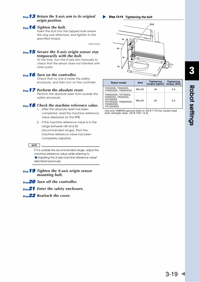
3
Rob
ot se
ttings
3-19
e Return the X-axis arm to its original origin position.
r Tighten the bolt.Insert the bolt into the tapped hole where the dog was attached, and tighten to the specified torque.
Tightening the boltStep 13-14
Bolt
53507-F9-00
t Secure the X-axis origin sensor stay temporarily with the bolt.At this time, turn the X-axis arm manually to check that the sensor does not interfere with other parts.
y Turn on the controller.Check that no one is inside the safety enclosure, and then turn on the controller.
u Perform the absolute reset.Perform the absolute reset from outside the safety enclosure.
i Check the machine reference value.1. After the absolute reset has been
completed, read the machine reference
value displayed on the RPB.
2. If the machine reference value is in the
range between 40 and 60
(recommended range), then the
machine reference value has been
completely adjusted.
If it is outside the recommended range, adjust the machine reference value while referring to "■ Adjusting the X-axis machine reference value" described previously.
o Tighten the X-axis origin sensor mounting bolt.
p Turn off the controller.
a Enter the safety enclosure.
s Reattach the cover.
Robot model Bolt Tightening torque (kgfcm)
Tightening torque (Nm)
YK500XG,YK600XGYK500XGS,YK600XGS M4×30 46 4.5
YK600XGH,YK700XG,YK800XG,YK900XG,YK1000XGYK700XGS,YK800XGS,YK900XGS,YK1000XGS
M5×40 92 9.0
UseonlyYAMAHAgenuineboltsorJISB1176hexsocketheadbolts(strengthclass:JISB105112.9).
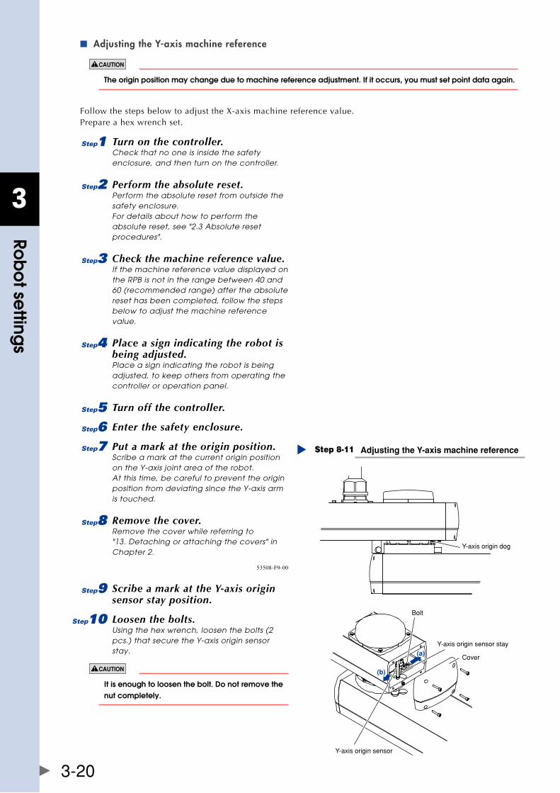
3
Rob
ot se
ttings
3-20
Adjusting the Y-axis machine reference ■
The origin position may change due to machine reference adjustment. If it occurs, you must set point data again.
FollowthestepsbelowtoadjusttheX-axismachinereferencevalue.Prepare a hex wrench set.
1 Turn on the controller.Check that no one is inside the safety enclosure, and then turn on the controller.
2 Perform the absolute reset.Perform the absolute reset from outside the safety enclosure. For details about how to perform the absolute reset, see "2.3 Absolute reset procedures".
3 Check the machine reference value.If the machine reference value displayed on the RPB is not in the range between 40 and 60 (recommended range) after the absolute reset has been completed, follow the steps below to adjust the machine reference value.
4 Place a sign indicating the robot is being adjusted.Place a sign indicating the robot is being adjusted, to keep others from operating the controller or operation panel.
5 Turn off the controller.
6 Enter the safety enclosure.
7 Put a mark at the origin position.Scribe a mark at the current origin position on the Y-axis joint area of the robot. At this time, be careful to prevent the origin position from deviating since the Y-axis arm is touched.
8 Remove the cover.Remove the cover while referring to "13. Detaching or attaching the covers" in Chapter 2.
Adjusting the Y-axis machine referenceStep 8-11
Y-axis origin dog
Y-axis origin sensor stay
Cover
Bolt
Y-axis origin sensor
(a)
(b)
53508-F9-00
9 Scribe a mark at the Y-axis origin sensor stay position.
0 Loosen the bolts.Using the hex wrench, loosen the bolts (2 pcs.) that secure the Y-axis origin sensor stay.
It is enough to loosen the bolt. Do not remove the nut completely.
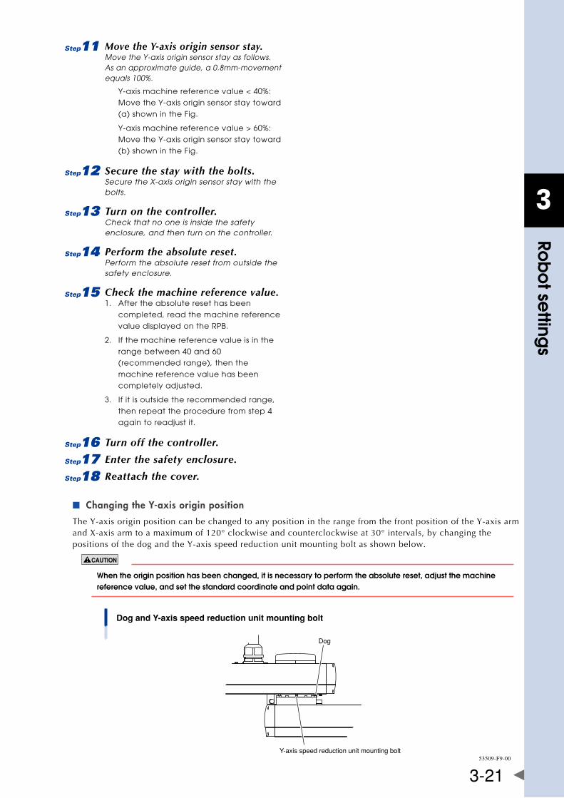
3
Rob
ot se
ttings
3-21
q Move the Y-axis origin sensor stay.Move the Y-axis origin sensor stay as follows. As an approximate guide, a 0.8mm-movement equals 100%.
Y-axis machine reference value < 40%:
Move the Y-axis origin sensor stay toward
(a) shown in the Fig.
Y-axis machine reference value > 60%:
Move the Y-axis origin sensor stay toward
(b) shown in the Fig.
w Secure the stay with the bolts.Secure the X-axis origin sensor stay with the bolts.
e Turn on the controller.Check that no one is inside the safety enclosure, and then turn on the controller.
r Perform the absolute reset.Perform the absolute reset from outside the safety enclosure.
t Check the machine reference value.1. After the absolute reset has been
completed, read the machine reference
value displayed on the RPB.
2. If the machine reference value is in the
range between 40 and 60
(recommended range), then the
machine reference value has been
completely adjusted.
3. If it is outside the recommended range,
then repeat the procedure from step 4
again to readjust it.
y Turn off the controller.
u Enter the safety enclosure.
i Reattach the cover.
Changing the Y-axis origin position ■
The Y-axis origin position can be changed to any position in the range from the front position of the Y-axis arm andX-axisarmtoamaximumof120°clockwiseandcounterclockwiseat30°intervals,bychangingthepositions of the dog and the Y-axis speed reduction unit mounting bolt as shown below.
When the origin position has been changed, it is necessary to perform the absolute reset, adjust the machine reference value, and set the standard coordinate and point data again.
Dog and Y-axis speed reduction unit mounting bolt
Dog
Y-axis speed reduction unit mounting bolt53509-F9-00
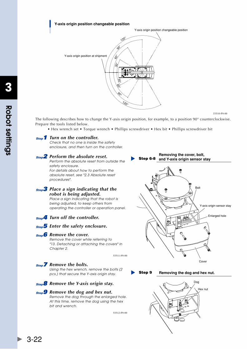
3
Rob
ot se
ttings
3-22
Y-axis origin position changeable position
Y-axis origin position at shipment
Y-axis origin position changeable position
120°
90°
60°
30°
120°
90°
60°30°
53510-F9-00
ThefollowingdescribeshowtochangetheY-axisoriginposition,forexample,toaposition90°counterclockwise.Prepare the tools listed below. •Hexwrenchset•Torquewrench•Phillipsscrewdriver•Hexbit•Phillipsscrewdriverbit
1 Turn on the controller.Check that no one is inside the safety enclosure, and then turn on the controller.
2 Perform the absolute reset.Perform the absolute reset from outside the safety enclosure. For details about how to perform the absolute reset, see "2.3 Absolute reset procedures".
3 Place a sign indicating that the robot is being adjusted.Place a sign indicating that the robot is being adjusted, to keep others from operating the controller or operation panel.
4 Turn off the controller.
5 Enter the safety enclosure.
6 Remove the cover.Remove the cover while referring to "13. Detaching or attaching the covers" in Chapter 2.
Removing the cover, bolt, and Y-axis origin sensor stayStep 6-8
Cover
Enlarged hole
Y-axis origin sensor stay
Bolt
53511-F9-00
7 Remove the bolts.Using the hex wrench, remove the bolts (2 pcs.) that secure the Y-axis origin stay.
8 Remove the Y-axis origin stay.
9 Remove the dog and hex nut.Remove the dog through the enlarged hole. At this time, remove the dog using the hex bit and wrench.
Removing the dog and hex nut.Step 9
Dog
Hex nut
53512-F9-00
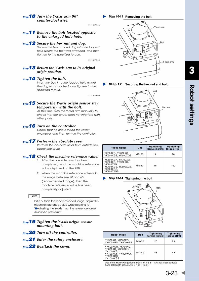
3
Rob
ot se
ttings
3-23
0 Turn the Y-axis arm 90° counterclockwise.
Removing the boltStep 10-11
Bolt
Y-axis arm
X-axis arm
53513-F9-00
q Remove the bolt located opposite to the enlarged hole hole.
w Secure the hex nut and dog.Secure the hex nut and dog into the tapped hole where the bolt was attached, and then tighten to the specified torque.
Securing the hex nut and boltStep 12
Dog
Hex nut
53514-F9-00
e Return the Y-axis arm to its original origin position.
r Tighten the bolt.Insert the bolt into the tapped hole where the dog was attached, and tighten to the specified torque.
Tightening the boltStep 13-14
Bolt
53515-F9-00
t Secure the Y-axis origin sensor stay temporarily with the bolt.At this time, turn the Y-axis arm manually to check that the sensor does not interfere with other parts.
y Turn on the controller.Check that no one is inside the safety enclosure, and then turn on the controller.
u Perform the absolute reset.Perform the absolute reset from outside the safety enclosure.
i Check the machine reference value.1. After the absolute reset has been
completed, read the machine reference
value displayed on the RPB.
2. When the machine reference value is in
the range between 40 and 60
(recommended range), then the
machine reference value has been
completely adjusted.
If it is outside the recommended range, adjust the machine reference value while referring to "■Adjusting the Y-axis machine reference value" described previously.
o Tighten the Y-axis origin sensor mounting bolt.
p Turn off the controller.
a Enter the safety enclosure.
s Reattach the cover.
Robot model Dog Tightening torque (kgfcm)
Tightening torque (Nm)
YK500XG,YK600XGYK500XGS,YK600XGS M3×30 9 90
YK600XGH,YK700XG,YK800XG,YK900XG,YK1000XGYK700XGS,YK800XGS,YK900XGS,YK1000XGS
M4×40 16 160
Robot model Bolt Tightening torque (kgfcm)
Tightening torque (Nm)
YK500XG,YK600XGYK500XGS,YK600XGS M3×30 20 2.0
YK600XGH,YK700XG,YK800XG,YK900XG,YK1000XGYK700XGS,YK800XGS,YK900XGS,YK1000XGS
M4×40 46 4.5
UseonlyYAMAHAgenuineboltsorJISB1176hexsocketheadbolts(strengthclass:JISB105112.9).
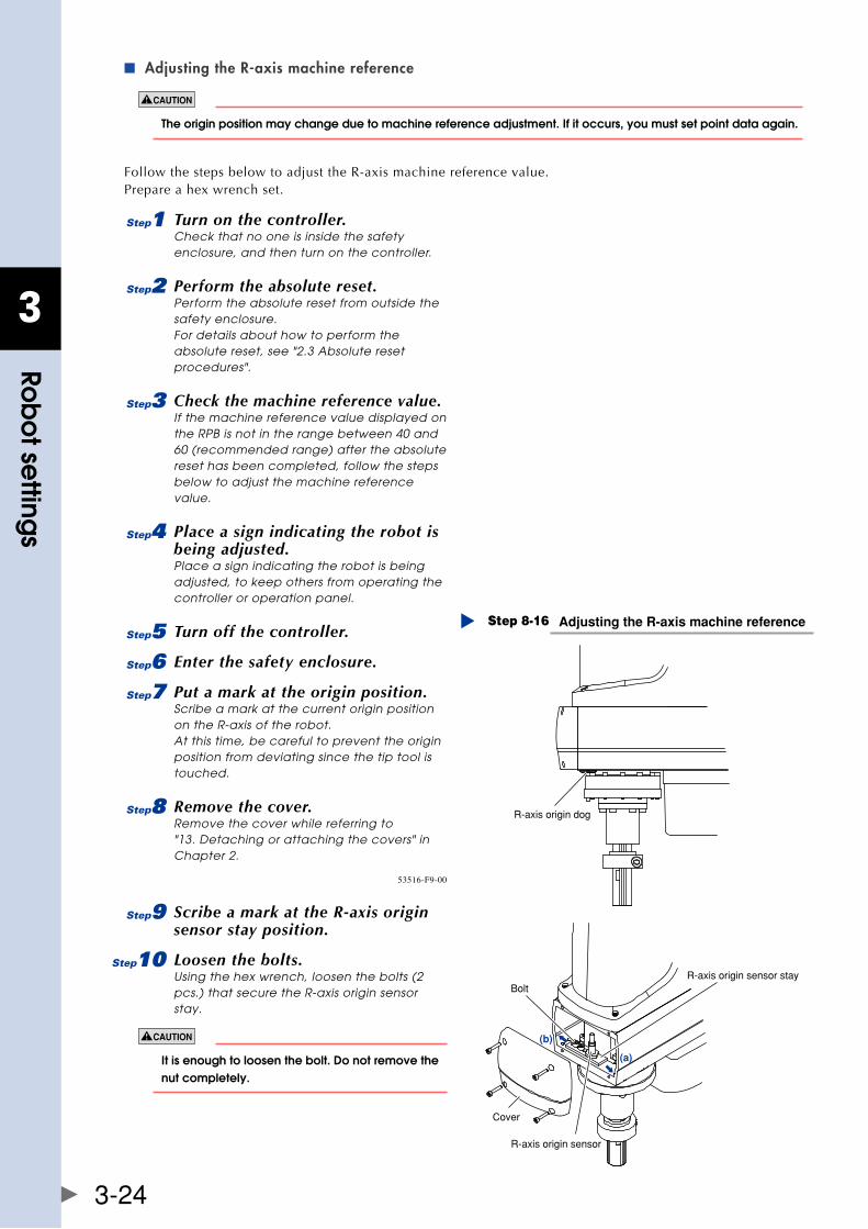
3
Rob
ot se
ttings
3-24
Adjusting the R-axis machine reference ■
The origin position may change due to machine reference adjustment. If it occurs, you must set point data again.
Follow the steps below to adjust the R-axis machine reference value.Prepare a hex wrench set.
1 Turn on the controller.Check that no one is inside the safety enclosure, and then turn on the controller.
2 Perform the absolute reset.Perform the absolute reset from outside the safety enclosure. For details about how to perform the absolute reset, see "2.3 Absolute reset procedures".
3 Check the machine reference value.If the machine reference value displayed on the RPB is not in the range between 40 and 60 (recommended range) after the absolute reset has been completed, follow the steps below to adjust the machine reference value.
4 Place a sign indicating the robot is being adjusted.Place a sign indicating the robot is being adjusted, to keep others from operating the controller or operation panel.
5 Turn off the controller.
6 Enter the safety enclosure.
7 Put a mark at the origin position.Scribe a mark at the current origin position on the R-axis of the robot. At this time, be careful to prevent the origin position from deviating since the tip tool is touched.
8 Remove the cover.Remove the cover while referring to "13. Detaching or attaching the covers" in Chapter 2.
Adjusting the R-axis machine referenceStep 8-16
R-axis origin dog
BoltR-axis origin sensor stay
R-axis origin sensor
Cover
(a)
(b)
53516-F9-00
9 Scribe a mark at the R-axis origin sensor stay position.
0 Loosen the bolts.Using the hex wrench, loosen the bolts (2 pcs.) that secure the R-axis origin sensor stay.
It is enough to loosen the bolt. Do not remove the nut completely.
3
Rob
ot se
ttings
3-25
q Move the R-axis origin sensor stay.Move the R-axis origin sensor stay as follows. As an approximate guide, a 1.9mm-movement equals 100%.
R-axis machine reference value < 40%:
Move the R-axis origin sensor stay toward
(a) shown in the Fig.
R-axis machine reference value > 60%:
Move the R-axis origin sensor stay toward
(b) shown in the Fig.
w Secure the stay with the bolts.Secure the X-axis origin sensor stay with the bolts.
e Turn on the controller.Check that no one is inside the safety enclosure, and then turn on the controller.
r Perform the absolute reset.Perform the absolute reset from outside the safety enclosure.
t Check the machine reference value.1. After the absolute reset has been
completed, read the machine reference
value displayed on the RPB.
2. If the machine reference value is in the
range between 40 and 60
(recommended range), then the
machine reference value has been
completely adjusted.
3. If it is outside the recommended range,
then repeat the procedure from step 4
again to readjust it.
y Turn off the controller.
u Enter the safety enclosure.
i Reattach the cover.
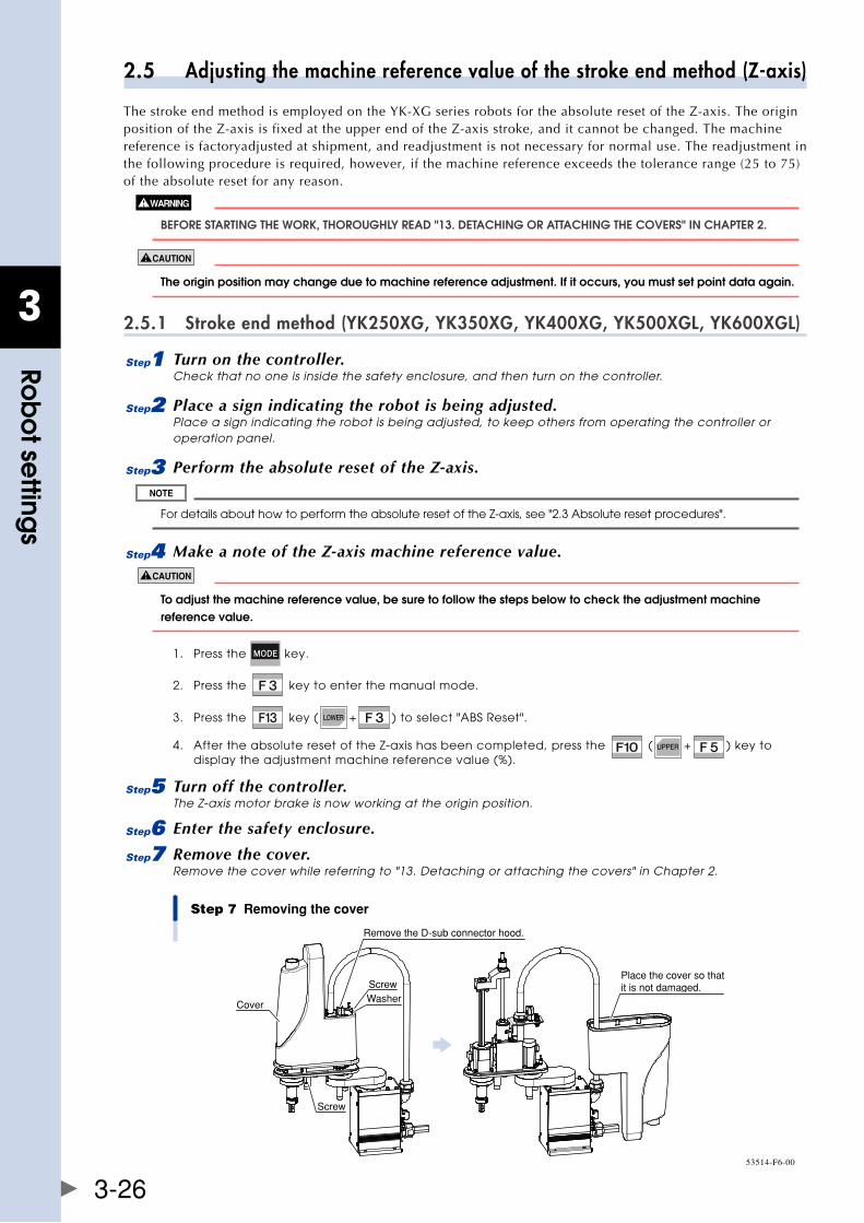
3
Rob
ot se
ttings
3-26
2.5 Adjusting the machine reference value of the stroke end method (Z-axis)
ThestrokeendmethodisemployedontheYK-XGseriesrobotsfortheabsoluteresetoftheZ-axis.TheoriginpositionoftheZ-axisisfixedattheupperendoftheZ-axisstroke,anditcannotbechanged.Themachinereference is factoryadjusted at shipment, and readjustment is not necessary for normal use. The readjustment in the following procedure is required, however, if the machine reference exceeds the tolerance range (25 to 75) of the absolute reset for any reason.
bEfORE STaRTIng ThE WORk, ThOROUghly REaD "13. DETaChIng OR aTTaChIng ThE COvERS" In ChaPTER 2.
The origin position may change due to machine reference adjustment. If it occurs, you must set point data again.
2.5.1 Stroke end method (YK250XG, YK350XG, YK400XG, YK500XGL, YK600XGL)
1 Turn on the controller.Check that no one is inside the safety enclosure, and then turn on the controller.
2 Place a sign indicating the robot is being adjusted.Place a sign indicating the robot is being adjusted, to keep others from operating the controller or operation panel.
3 Perform the absolute reset of the Z-axis.
For details about how to perform the absolute reset of the Z-axis, see "2.3 Absolute reset procedures".
4 Make a note of the Z-axis machine reference value.
To adjust the machine reference value, be sure to follow the steps below to check the adjustment machine reference value.
1. Press the key.
2. Press the key to enter the manual mode.
3. Press the key ( + ) to select "ABS Reset".
4. After the absolute reset of the Z-axis has been completed, press the ( + ) key to display the adjustment machine reference value (%).
5 Turn off the controller.The Z-axis motor brake is now working at the origin position.
6 Enter the safety enclosure.
7 Remove the cover.Remove the cover while referring to "13. Detaching or attaching the covers" in Chapter 2.
Step 7 Removing the cover
Cover
ScrewWasher
Screw
Place the cover so that it is not damaged.
Remove the D-sub connector hood.
53514-F6-00
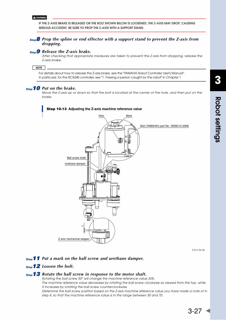
3
Rob
ot se
ttings
3-27
If ThE z-axIS bRakE IS RElEaSED OR ThE bOlT ShOWn bElOW IS lOOSEnED, ThE z-axIS May DROP, CaUSIng SERIOUS aCCIDEnT. bE SURE TO PROP ThE z-axIS WITh a SUPPORT STanD.
8 Prop the spline or end effector with a support stand to prevent the Z-axis from dropping.
9 Release the Z-axis brake.After checking that appropriate measures are taken to prevent the Z-axis from dropping, release the Z-axis brake.
For details about how to release the Z-axis brake, see the "YAMAHA Robot Controller User's Manual". In particular, for the RCX240 controller, see "1. Freeing a person caught by the robot" in Chapter 1
0 Put on the brake.Move the Z-axis up or down so that the bolt is located at the center of the hole, and then put on the brake.
Step 10-13 Adjusting the Z-axis machine reference value
Z-axis mechanical stopper
Ball screw shaft
Urethane damper
Hole Mark
Bolt (YAMAHA’s part No.: 90990-01J068)
L
53515-F6-00
q Put a mark on the ball screw and urethane damper.
w Loosen the bolt.
e Rotate the ball screw in response to the motor shaft.Rotating the ball screw 30° will change the machine reference value 33%. The machine reference value decreases by rotating the ball screw clockwise as viewed from the top, while it increases by rotating the ball screw counterclockwise. Determine the ball screw position based on the Z-axis machine reference value you have made a note of in step 4, so that the machine reference value is in the range between 30 and 70.
3
Rob
ot se
ttings
3-28
r Tighten the bolt.• Tightening torque: 1.1 Nm (11 kgfcm) Carefully tighten the bolt since the hex socket cap of the bolt is crushed easily.
t Go out of the safety enclosure.
y Turn on the controller.Check that no one is inside the safety enclosure, and then turn on the controller.
u Perform the absolute reset of the Z-axis.
For details about how to perform the absolute reset of the Z-axis, see "2.3 Absolute reset procedures".
i Check the Z-axis machine reference value.After the absolute reset has been completed, check that the adjustment machine reference value is within the absolute reset tolerance range (30 to 70). If the adjustment machine reference value is outside the tolerance range (30 to 70), then repeat the procedure from step 5 again to readjust it.
o Turn off the controller.
p Enter the safety enclosure.
a Reattach the cover.When the machine reference value is within the tolerance range, reattach the cover.
2.5.2 Stroke end method (YK500XG, YK600XG, YK600XGH, YK700XG, YK800XG, YK900XG, YK1000XG) (YK500XGS, YK600XGS, YK700XGS, YK800XGS, YK900XGS, YK1000XGS)
1 Turn on the controller.Check that no one is inside the safety enclosure, and then turn on the controller.
2 Place a sign indicating the robot is being adjusted.Place a sign indicating the robot is being adjusted, to keep others from operating the controller or operation panel.
3 Perform the absolute reset of the Z-axis.
For details about how to perform the absolute reset of the Z-axis, see "2.3 Absolute reset procedures".
4 Make a note of the Z-axis machine reference value.
To adjust the machine reference value, be sure to follow the steps below to check the adjustment machine reference value.
1. Press the key.
2. Press the key to enter the manual mode.
3. Press the key ( + ) to select "ABS Reset".
4. After the absolute reset of the Z-axis has been completed, press the ( + ) key to
display the adjustment machine reference value (%).
5 Turn off the controller.The Z-axis motor brake is now working at the origin position.
6 Enter the safety enclosure.
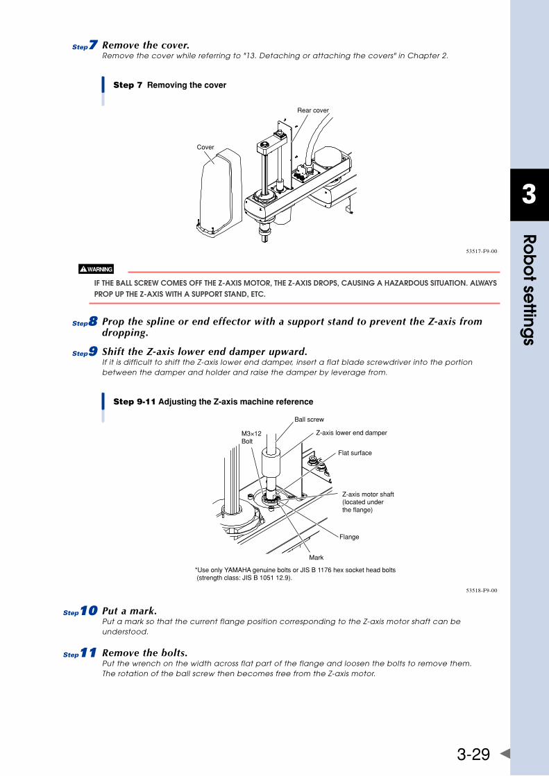
3
Rob
ot se
ttings
3-29
7 Remove the cover.Remove the cover while referring to "13. Detaching or attaching the covers" in Chapter 2.
Step 7 Removing the cover
Cover
Rear cover
53517-F9-00
If ThE ball SCREW COMES Off ThE z-axIS MOTOR, ThE z-axIS DROPS, CaUSIng a hazaRDOUS SITUaTIOn. alWayS PROP UP ThE z-axIS WITh a SUPPORT STanD, ETC.
8 Prop the spline or end effector with a support stand to prevent the Z-axis from dropping.
9 Shift the Z-axis lower end damper upward.If it is difficult to shift the Z-axis lower end damper, insert a flat blade screwdriver into the portion between the damper and holder and raise the damper by leverage from.
Step 9-11 Adjusting the Z-axis machine reference
M3×12Bolt
Ball screw
Z-axis lower end damper
Flat surface
Z-axis motor shaft(located under the flange)
Flange
Mark
*Use only YAMAHA genuine bolts or JIS B 1176 hex socket head bolts (strength class: JIS B 1051 12.9).
53518-F9-00
0 Put a mark.Put a mark so that the current flange position corresponding to the Z-axis motor shaft can be understood.
q Remove the bolts.Put the wrench on the width across flat part of the flange and loosen the bolts to remove them. The rotation of the ball screw then becomes free from the Z-axis motor.
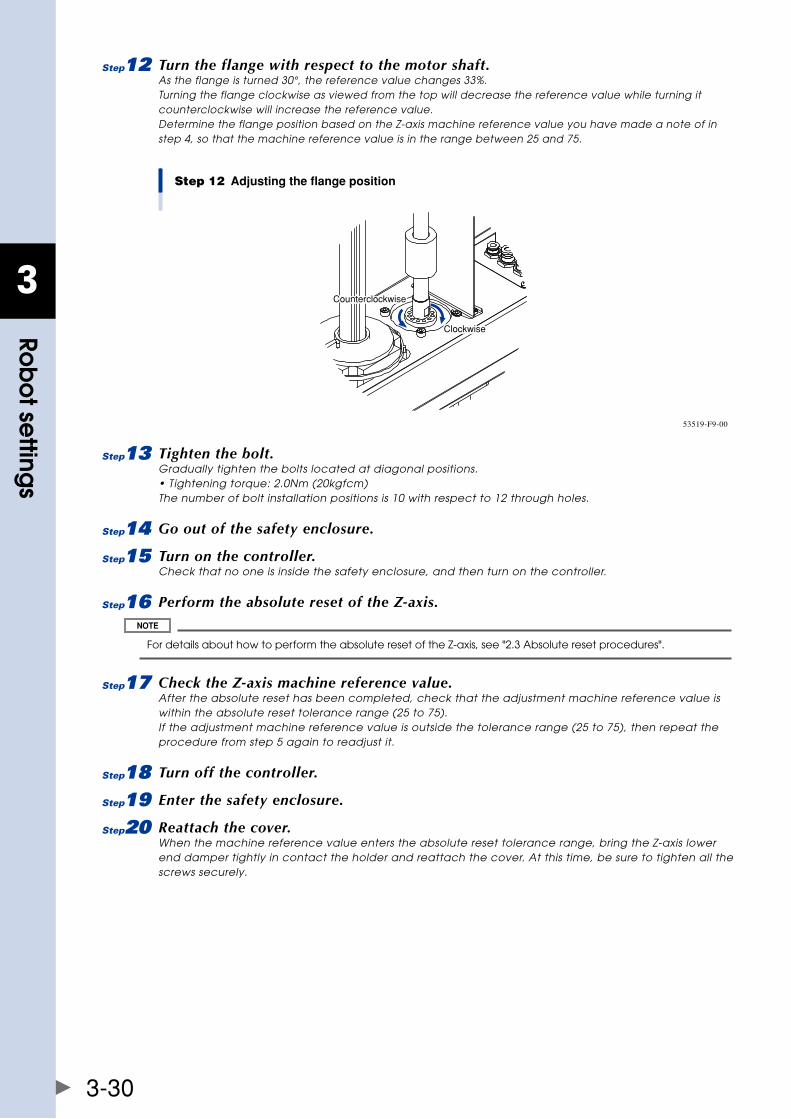
3
Rob
ot se
ttings
3-30
w Turn the flange with respect to the motor shaft.As the flange is turned 30°, the reference value changes 33%. Turning the flange clockwise as viewed from the top will decrease the reference value while turning it counterclockwise will increase the reference value. Determine the flange position based on the Z-axis machine reference value you have made a note of in step 4, so that the machine reference value is in the range between 25 and 75.
Step 12 Adjusting the flange position
Clockwise
Counterclockwise
53519-F9-00
e Tighten the bolt.Gradually tighten the bolts located at diagonal positions. • Tightening torque: 2.0Nm (20kgfcm) The number of bolt installation positions is 10 with respect to 12 through holes.
r Go out of the safety enclosure.
t Turn on the controller.Check that no one is inside the safety enclosure, and then turn on the controller.
y Perform the absolute reset of the Z-axis.
For details about how to perform the absolute reset of the Z-axis, see "2.3 Absolute reset procedures".
u Check the Z-axis machine reference value.After the absolute reset has been completed, check that the adjustment machine reference value is within the absolute reset tolerance range (25 to 75). If the adjustment machine reference value is outside the tolerance range (25 to 75), then repeat the procedure from step 5 again to readjust it.
i Turn off the controller.
o Enter the safety enclosure.
p Reattach the cover.When the machine reference value enters the absolute reset tolerance range, bring the Z-axis lower end damper tightly in contact the holder and reattach the cover. At this time, be sure to tighten all the screws securely.
3
Rob
ot se
ttings
3-31
3. Setting the soft limitsIntheYK-XGSeries,theworkingenvelopeduringmanualandautomaticoperationcanbelimitedbysettingtheplussoftlimit[pulse]andminussoftlimit[pulse]oneachaxis.Theoriginpoint(0[pulse])isusedasthereference to set the soft limits. The working envelope can be limited by specifying the number of pulses from the0pulseposition.
When performing actual checks of the soft limit settings, operate the robot manually from outside the safety enclosure.
Refer to the "YAMAHA Robot Controller User's Manual" for further details. Also refer to "1.2 External view and dimensions" in Chapter 7 for the working envelope area.
3.1 Setting the X-axis and Y-axis soft limitsThe soft limits must be set within the movement range limited by the mechanical stoppers as explained in "7. LimitingthemovementrangewithX-axisandY-axismechanicalstoppers"inChapter2orwithintherangewherethe manipulator does not interfere with the peripheral equipment (but within maximum working envelope). Similarly, set the soft limits when the origin position has been changed. Likewise, in models where the mechanical stopper position cannot be changed, reduce the soft limits to narrow the working envelope when the actual working envelope of the robot is small or the manipulator interferes with the peripheral equipment. Follow the steps below to set the soft limits.
1 Turn on the controller.Check that no one is inside the safety enclosure, and then turn on the controller.
2 Press the emergency stop button.Press the emergency stop button on the RPB to put the robot in the emergency stop status.
For details about emergency stop and how to cancel the emergency stop, see the "YAMAHA Robot Controller User's Manual".
3 Place a sign indicating the robot is being adjusted.Place a sign indicating the robot is being adjusted, to keep others from operating the controller or operation panel.
4 Enter the safety enclosure while holding the RPB.
5 Move the X-axis and Y-axis arms by hand.Move the X-axis and Y-axis to the mechanical stopper positions or to the point where interference with the peripheral equipment occurs.
6 Note the pulse values.Read the X-axis and Y-axis plus (+) and minus (-) direction pulses displayed on the RPB in step 6 and note them.
• beforecancellingtheemergencystop,checkfromoutsidethesafetyenclosurethatnooneisinsidethesafety enclosure. • setthesoftlimitsfromoutsidethesafetyenclosure.
7 Set the soft limits.Set the soft limits to within the figure for the X-axis and Y-axis encoder pulses that you have noted in step 7.
For details about how to set the soft limits, see the "YAMAHA Robot Controller User's Manual".
The origin position factory-adjusted at shipment is not completely aligned with the front face position of the robot. wheninstallingtherobot,besuretosetthesoftlimitswiththenumberofpulsesfromtheoriginposition(0pulseposition).
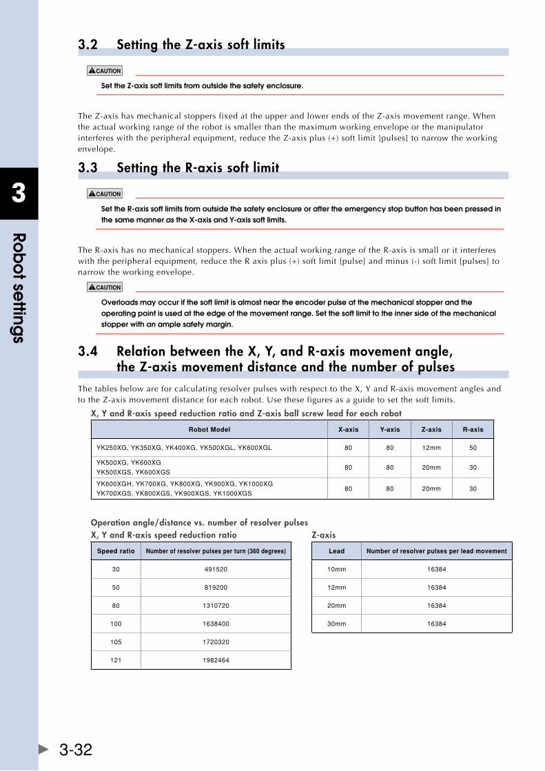
3
Rob
ot se
ttings
3-32
3.2 Setting the Z-axis soft limits
setthez-axissoftlimitsfromoutsidethesafetyenclosure.
TheZ-axishasmechanicalstoppersfixedattheupperandlowerendsoftheZ-axismovementrange.Whenthe actual working range of the robot is smaller than the maximum working envelope or the manipulator interfereswiththeperipheralequipment,reducetheZ-axisplus(+)softlimit[pulses]tonarrowtheworkingenvelope.
3.3 Setting the R-axis soft limit
setther-axissoftlimitsfromoutsidethesafetyenclosureoraftertheemergencystopbuttonhasbeenpressedinthesamemannerasthex-axisandy-axissoftlimits.
The R-axis has no mechanical stoppers. When the actual working range of the R-axis is small or it interferes with the peripheral equipment, reduce the R axis plus (+) soft limit [pulse] and minus (-) soft limit [pulses] to narrow the working envelope.
Overloads may occur if the soft limit is almost near the encoder pulse at the mechanical stopper and the operating point is used at the edge of the movement range. Set the soft limit to the inner side of the mechanical stopper with an ample safety margin.
3.4 Relation between the X, Y, and R-axis movement angle, the Z-axis movement distance and the number of pulsesThetablesbelowareforcalculatingresolverpulseswithrespecttotheX,YandR-axismovementanglesandtotheZ-axismovementdistanceforeachrobot.Usethesefiguresasaguidetosetthesoftlimits.
X, Y and R-axis speed reduction ratio and Z-axis ball screw lead for each robot
Robot Model X-axis Y-axis Z-axis R-axis
YK250XG,YK350XG,YK400XG,YK500XGL,YK600XGL 80 80 12mm 50
YK500XG,YK600XG
YK500XGS,YK600XGS80 80 20mm 30
YK600XGH,YK700XG,YK800XG,YK900XG,YK1000XG
YK700XGS,YK800XGS,YK900XGS,YK1000XGS80 80 20mm 30
Operation angle/distance vs. number of resolver pulses X, Y and R-axis speed reduction ratio Z-axis
Speed ratio Number of resolver pulses per turn (360 degrees) Lead Number of resolver pulses per lead movement
30 491520 10mm 16384
50 819200 12mm 16384
80 1310720 20mm 16384
100 1638400 30mm 16384
105 1720320
121 1982464
3
Rob
ot se
ttings
3-33
4. Setting the standard coordinates
If the standard coordinate settings are incorrect, the acceleration cannot be optimized to match the arm position. This results in too short a service life, damage to the drive unit, or residual vibration during positioning. In addition, the cartesian coordinate accuracy will be impaired.
Setting the standard coordinates enables the following operations and functions.
1. Optimizes acceleration according to arm position during automatic operation.
2. Allows moving robot arm tip at right angles.
3. Allows using shift coordinates.
4.Enablescommandssuchaslinearinterpolationandarmswitching.
The procedure for setting standard coordinates and cautions are shown below.
1 Turn on the controller.Check that no one is inside the safety enclosure, and then turn on the controller.
2 Check that the soft limits are correctly set.If not correctly set, adjust the soft limits while referring to "3. Setting the soft limits".
3 Place a sign indicating the robot is being adjusted.Place a sign indicating the robot is being adjusted, to keep others from operating the controller or operation panel.
4 Enter the safety enclosure while holding the RPB.At this time, stay outside the robot movement range.
never enter the robot movement range.
5 Set the standard coordinates.See "Setting the standard coordinates" stated in the "YAMAHA Robot Controller User's Manual".
The next section, "4.1 Standard coordinate setting using a standard coordinate setup jig (option)", describes how to set the standard coordinates more accurately using an optional setup jig.
6 Check that the standard coordinates are set correctly.1. Check that the robot arm tip can move at right angles in the manual operation (cartesian
coordinates).
2. Check that the values nearly equal to the X-axis and Y-axis arm lengths are entered in "Arm length"
of the axis parameters.
If points 1 and 2 shown above are not satisfied, the standard coordinate settings are incorrect. So, make the standard coordinate settings again.
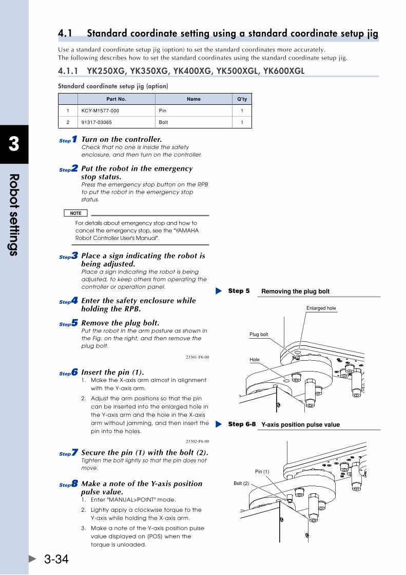
3
Rob
ot se
ttings
3-34
4.1 Standard coordinate setting using a standard coordinate setup jigUseastandardcoordinatesetupjig(option)tosetthestandardcoordinatesmoreaccurately.The following describes how to set the standard coordinates using the standard coordinate setup jig.
4.1.1 YK250XG, YK350XG, YK400XG, YK500XGL, YK600XGL
Standard coordinate setup jig (option)
Part No. Name Q'ty
1 KCY-M1577-000 Pin 1
2 91317-03065 Bolt 1
1 Turn on the controller.Check that no one is inside the safety enclosure, and then turn on the controller.
2 Put the robot in the emergency stop status.Press the emergency stop button on the RPB to put the robot in the emergency stop status.
For details about emergency stop and how to cancel the emergency stop, see the "YAMAHA Robot Controller User's Manual".
3 Place a sign indicating the robot is being adjusted.Place a sign indicating the robot is being adjusted, to keep others from operating the controller or operation panel.
4 Enter the safety enclosure while holding the RPB.
5 Remove the plug bolt.Put the robot in the arm posture as shown in the Fig. on the right, and then remove the plug bolt.
Removing the plug boltStep 5
Plug bolt
Enlarged hole
Hole23301-F6-00
6 Insert the pin (1).1. Make the X-axis arm almost in alignment
with the Y-axis arm.
2. Adjust the arm positions so that the pin
can be inserted into the enlarged hole in
the Y-axis arm and the hole in the X-axis
arm without jamming, and then insert the
pin into the holes.Y-axis position pulse valueStep 6-8
Bolt (2)
Pin (1)
23302-F6-00
7 Secure the pin (1) with the bolt (2).Tighten the bolt lightly so that the pin does not move.
8 Make a note of the Y-axis position pulse value.1. Enter "MANUAL>POINT" mode.
2. Lightly apply a clockwise torque to the
Y-axis while holding the X-axis arm.
3. Make a note of the Y-axis position pulse
value displayed on [POS] when the
torque is unloaded.
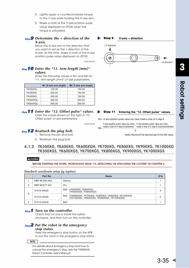
3
Rob
ot se
ttings
3-35
4. Lightly apply a counterclockwise torque
to the Y-axis while holding the X-axis arm.
5. Make a note of the Y-axis position pulse
value displayed on [POS] when the
torque is unloaded.
9 Determine the + direction of the X-axis.Move the X-axis arm in the direction that you want to set as the + direction of the X-axis. At this time, make a note of the X-axis position pulse value displayed on [POS].
X-axis + directionStep 9
+Y direction
+X direction23303-F6-00
0 Enter the "11. Arm length [mm]" values.Enter the following values in M1 and M2 for "11. Arm length [mm]" of axis parameters.
M1 (X-axis arm length) M2 (Y-axis arm length)
YK250XG 100.00 150.00
YK350XG 200.00 150.00
YK400XG 250.00 150.00
YK500XGL 250.00 250.00
YK600XGL 350.00 250.00
q Enter the "12. Offset pulse" values.Enter the values shown on the right in "12. Offset pulse" of axis parameters.
Entering the “12. Offset pulse” valuesStep 11
Note) Round off the decimal part of the M2 value.
M1= X-axis position pulse value you have made a note of in step 9
2M2=
+Y-axis position pulse value you have made a note of in step 8 (clockwise)
Y-axis position pulse value you have made a note of in step 8 (counterclockwise)
23304-F6-00
w Reattach the plug bolt.1. Remove the pin and bolt.
2. Reattach the plug bolt.
4.1.2 YK500XG, YK600XG, YK600XGH, YK700XG, YK800XG, YK900XG, YK1000XG YK500XGS, YK600XGS, YK700XGS, YK800XGS, YK900XGS, YK1000XGS
bEfORE STaRTIng ThE WORk, ThOROUghly REaD "13. DETaChIng OR aTTaChIng ThE COvERS" In ChaPTER 2.
Standard coordinate setup jig (option)Part No. Name Q'ty
1 KBP-M1562-002 Sleeve 1
2 KBP-M1577-001 Pin 1
391312-04025 Bolt (YK500XG,YK600XG)
(YK500XGS,YK600XGS) 2
91312-04030 Bolt (YK600XGH,YK700XG,YK800XG,YK900XG,YK1000XG) (YK700XGS,YK800XGS,YK900XGS,YK1000XGS) 2
4 91312-04045 Bolt 1
1 Turn on the controller.Check that no one is inside the safety enclosure, and then turn on the controller.
2 Put the robot in the emergency stop status.Press the emergency stop button on the RPB to put the robot in the emergency stop status.
For details about emergency stop and how to cancel the emergency stop, see the "YAMAHA Robot Controller User's Manual".
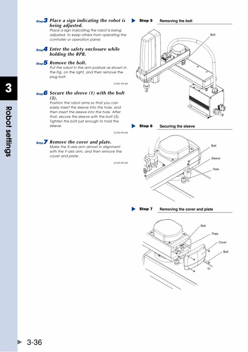
3
Rob
ot se
ttings
3-36
3 Place a sign indicating the robot is being adjusted.Place a sign indicating the robot is being adjusted, to keep others from operating the controller or operation panel.
4 Enter the safety enclosure while holding the RPB.
5 Remove the bolt.Put the robot in the arm posture as shown in the Fig. on the right, and then remove the plug bolt.
Removing the boltStep 5
Bolt
23301-F9-00
6 Secure the sleeve (1) with the bolt (3).Position the robot arms so that you can easily insert the sleeve into the hole, and then insert the sleeve into the hole. After that, secure the sleeve with the bolt (3). Tighten the bolt just enough to hold the sleeve. Securing the sleeveStep 6
Bolt
Sleeve
Hole
23302-F9-00
7 Remove the cover and plate.Make the X-axis arm almost in alignment with the Y-axis arm, and then remove the cover and plate.
Removing the cover and plateStep 7
Bolt
Plate
Cover
Bolt
23303-F9-00
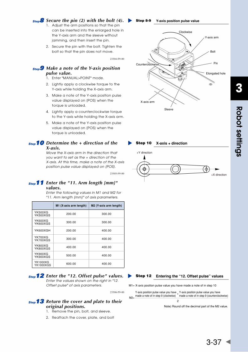
3
Rob
ot se
ttings
3-37
8 Secure the pin (2) with the bolt (4).1. Adjust the arm positions so that the pin
can be inserted into the enlarged hole in
the Y-axis arm and the sleeve without
jamming, and then insert the pin.
2. Secure the pin with the bolt. Tighten the
bolt so that the pin does not move.
Y-axis position pulse valueStep 8-9
Y-axis arm
Bolt
Pin
Sleeve
X-axis arm
Elongated hole
Clockwise
Counterclockwise
23304-F9-00
9 Make a note of the Y-axis position pulse value.1. Enter "MANUAL>POINT" mode.
2. Lightly apply a clockwise torque to the
Y-axis while holding the X-axis arm.
3. Make a note of the Y-axis position pulse
value displayed on [POS] when the
torque is unloaded.
4. Lightly apply a counterclockwise torque
to the Y-axis while holding the X-axis arm.
5. Make a note of the Y-axis position pulse
value displayed on [POS] when the
torque is unloaded.
0 Determine the + direction of the X-axis.Move the X-axis arm in the direction that you want to set as the + direction of the X-axis. At this time, make a note of the X-axis position pulse value displayed on [POS].
X-axis + directionStep 10
+Y direction
+X direction23305-F9-00
q Enter the "11. Arm length [mm]" values.Enter the following values in M1 and M2 for "11. Arm length [mm]" of axis parameters.
M1 (X-axis arm length) M2 (Y-axis arm length)
YK500XGYK500XGS 200.00 300.00
YK600XGYK600XGS 300.00 300.00
YK600XGH 200.00 400.00
YK700XGYK700XGS 300.00 400.00
YK800XGYK800XGS 400.00 400.00
YK900XGYK900XGS 500.00 400.00
YK1000XGYK1000XGS 600.00 400.00
w Enter the "12. Offset pulse" values.Enter the values shown on the right in "12. Offset pulse" of axis parameters.
Entering the “12. Offset pulse” valuesStep 12
Note) Round off the decimal part of the M2 value.
M1= X-axis position pulse value you have made a note of in step 10
2M2=
+Y-axis position pulse value you have made a note of in step 9 (clockwise)
Y-axis position pulse value you have made a note of in step 9 (counterclockwise)
23306-F9-00
e Return the cover and plate to their original positions.1. Remove the pin, bolt, and sleeve.
2. Reattach the cover, plate, and bolt
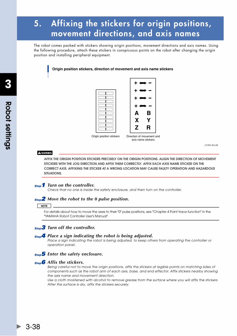
3
Rob
ot se
ttings
3-38
5. Affixing the stickers for origin positions, movement directions, and axis names
Therobotcomespackedwithstickersshowingoriginpositions,movementdirectionsandaxisnames.Usingthe following procedure, attach these stickers in conspicuous points on the robot after changing the origin position and installing peripheral equipment.
A BX YZ R
Origin position stickers, direction of movement and axis name stickers
Direction of movement andaxis name stickers
Origin position stickers
23305-F6-00
affIx ThE ORIgIn POSITIOn STICkERS PRECISEly On ThE ORIgIn POSITIOnS. alIgn ThE DIRECTIOn Of MOvEMEnT STICkERS WITh ThE jOg DIRECTIOn anD affIx ThEM CORRECTly. affIx EaCh axIS naME STICkER On ThE CORRECT axIS. affIxIng ThE STICkER aT a WROng lOCaTIOn May CaUSE faUlTy OPERaTIOn anD hazaRDOUS SITUaTIOnS.
1 Turn on the controller.Check that no one is inside the safety enclosure, and then turn on the controller.
2 Move the robot to the 0 pulse position.
For details about how to move the axes to their "0" pulse positions, see "Chapter 4 Point trace function" in the "YAMAHA Robot Controller User's Manual".
3 Turn off the controller.
4 Place a sign indicating the robot is being adjusted.Place a sign indicating the robot is being adjusted, to keep others from operating the controller or operation panel.
5 Enter the safety enclosure.
6 Affix the stickers.Being careful not to move the origin positions, affix the stickers at legible points on matching sides of components such as the robot arm of each axis, base, and end effector. Affix stickers nearby showing the axis name and movement direction. Use a cloth moistened with alcohol to remove grease from the surface where you will affix the stickers. After the surface is dry, affix the stickers securely.
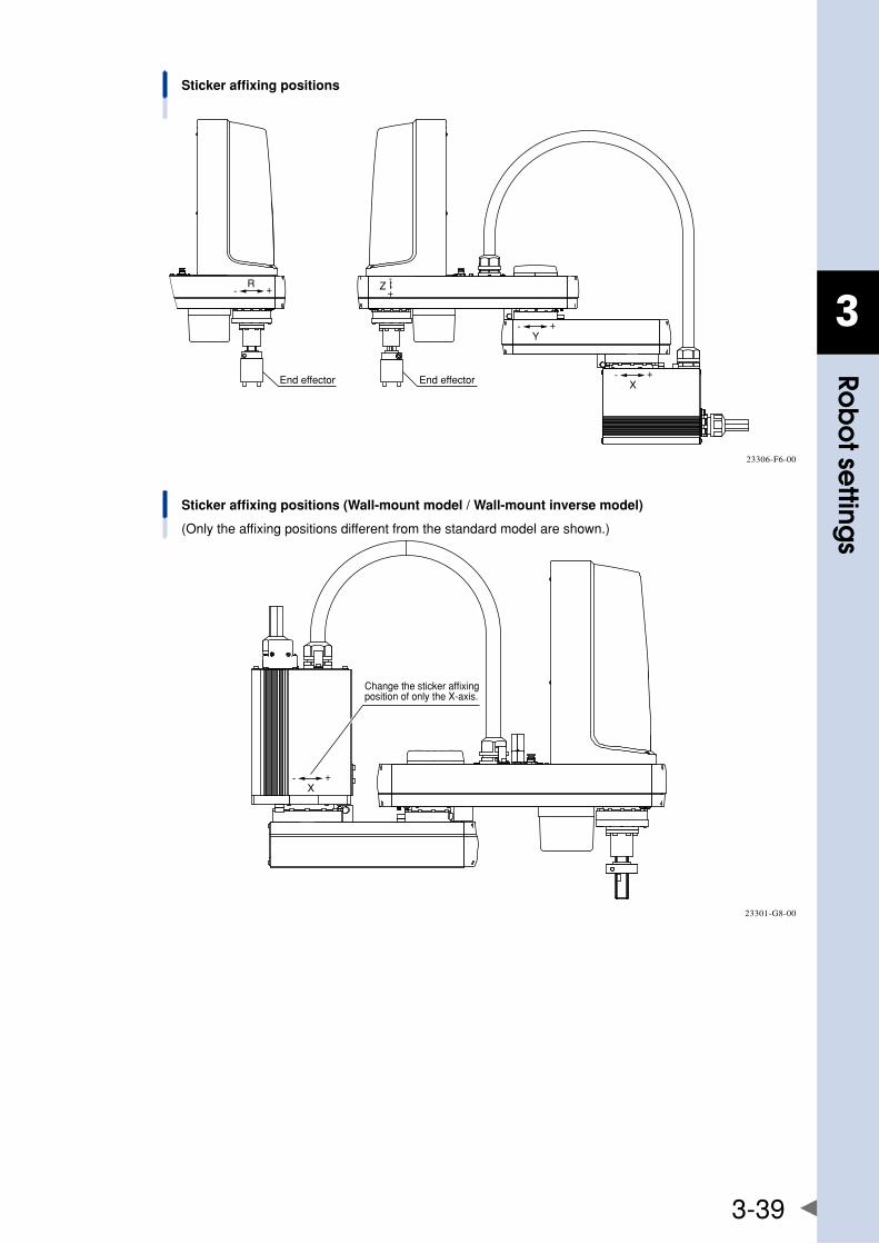
3
Rob
ot se
ttings
3-39
Sticker affixing positions
End effector End effector
R- +
-+
Z
Y- +
X- +
23306-F6-00
Sticker affixing positions (Wall-mount model / Wall-mount inverse model)
(Only the affixing positions different from the standard model are shown.)
X- +
Change the sticker affixing position of only the X-axis.
23301-G8-00

Chapter 4 Periodic inspecition
Contents
1. Overview 4-1
2. list of inspection items 4-2

4
Perio
dic
inspe
citio
n
4-1
1. OverviewDailyandperiodicinspectionoftheYAMAHArobotisessentialinordertoensuresafeandefficientoperation. TheperiodicinspectionforYK-XGseriesconsistsofdailyinspectionand6-monthinspection. Be sure to perform the daily inspection before starting the robot and after completion of the day’s work. Fordetailsaboutinspectionitems,see"2.Listofinspectionitems"inthenextsection. Fordetailsabouthowtoperformtheperiodicinspection,seetheseparateMaintenanceManualforYK-XG.
Before starting the maintenance work, thoroughly read the following cautions and Safety Instructions to strictly observe the instructions.
• whenyouneeDtotouchtheterminalsorconnectorsontheoutsiDeofthecontrollerDuring InSPECTIOn, alWayS fIRST TURn Off ThE COnTROllER POWER SWITCh anD alSO ThE POWER SOURCE In ORDER TO PREvEnT POSSIblE ElECTRICal ShOCk. • nevertouchanyinternalPartsofthecontroller.
Cautions on daily inspection ■
• Periodicinspectionmustbeperformedbyorinthepresenceofpersonnelwhohavereceivedtherobot Training given by your distributor. • Donotattemptanyinspection,adjustment,repairandpartsreplacementnotdescribedinthismanual.this work requires specialized technical knowledge and skill, and may also involve work hazards. • wheninspectionisrequiredinsidethesafetyenclosure,alwaysturnoffthecontrollerandalsotheexternal switch board. • iftheinspectionormaintenanceprocedurecallsforoperationoftherobot,stayoutsidethesafetyenclosure. • Placeasignindicatingtherobotisbeinginspected,tokeepothersfromoperatingthecontrollerswitch, programmingboxoroperationpanel. • useonlythelubricantsspecifiedbyyourdistributor. • To check the operation after inspection, refer to "4.5.1 Trial Operation" in Chapter “Safety Instructions” of this manual.
For precautions on handling the controller, refer to the "YAMAHA Robot Controller User's Manual".
Cautions on 6-month inspection ■
ThE z-axIS WIll SlIDE DOWn WhEn ThE z-axIS bRakE IS RElEaSED, CaUSIng a hazaRDOUS SITUaTIOn. DO nOT RElEaSE ThE bRakE WhEn lUbRICaTIng ThE z-axIS PaRTS.
When lubricating the ball screw and spline shaft, observe the following precautions.
PRECaUTIOnS WhEn hanDlIng gREaSE: • inflammationmayoccurifthisgetsintheeyes. bEfORE hanDlIng ThE gREaSE, WEaR yOUR SafETy gOgglES TO EnSURE ThE gREaSE WIll nOT COME In COnTaCT WITh ThE EyES. • inflammationmayoccurifthegreasecomesintocontactwithsKin.besuretowearProtective glOvES TO PREvEnT COnTaCT WITh SkIn. • DonottaKeorallyoreat.(eatingwillcauseDiarrheaanDvomiting.) • hanDsanDfingersmightbecutwhenoPeningthecontainer,souseProtectivegloves. • KeePoutofthereachofchilDren. • DonotheatthegreaseorPlacenearanoPenflamesincethiscoulDleaDtosParKsanDfires. EMERgEnCy TREaTMEnT: • ifthisgreasegetsintheeyes,washliberallywithPurewaterforabout15minutesanDconsulta PhySICIan fOR TREaTMEnT. • ifthisgreasecomesincontactwiththesKin,washawaycomPletelywithsoaPanDwater. • iftaKeninternally,DonotinDucevomitingbutPromPtlyconsultaPhysicianfortreatment. DISPOSIng Of gREaSE anD ThE COnTaInER: • ProPerDisPosaliscomPulsoryunDerfeDeral,stateanDlocalregulations.taKeaPProPriate MEaSURES In COMPlIanCE WITh lEgal REgUlaTIOnS. • DonotPressurizetheemPtycontainer.PressurizingmaycausethecontainertoruPture. • DonotattemPttowelD,heatuP,Drillholesorcutthiscontainer.thismightcausethecontainerto ExPlODE anD ThE REMaInIng MaTERIalS InSIDE IT TO IgnITE.
unlessgreasespecifiedbyyamahaisused,theservicelifeoftheballscrewandballsplinewillshorten.
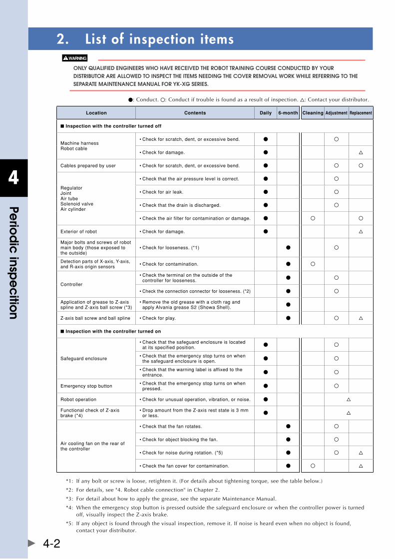
4
Perio
dic
inspe
citio
n
4-2
2. List of inspection items
Only qUalIfIED EngInEERS WhO havE RECEIvED ThE RObOT TRaInIng COURSE COnDUCTED by yOUR DISTRIbUTOR aRE allOWED TO InSPECT ThE ITEMS nEEDIng ThE COvER REMOval WORk WhIlE REfERRIng TO ThE SEPaRaTE MaInTEnanCE ManUal fOR yk-xg SERIES.
: Conduct. : Conduct if trouble is found as a result of inspection. : Contact your distributor.
Location Contents Daily 6-month Cleaning Adjustment Replacement
■ Inspection with the controller turned off
MachineharnessRobotcable
•Checkforscratch,dent,orexcessivebend.
•Checkfordamage.
Cablespreparedbyuser •Checkforscratch,dent,orexcessivebend.
RegulatorJointAirtubeSolenoidvalveAircylinder
•Checkthattheairpressureleveliscorrect.
•Checkforairleak.
•Checkthatthedrainisdischarged.
•Checktheairfilterforcontaminationordamage.
Exteriorofrobot •Checkfordamage.
Majorboltsandscrewsofrobotmainbody(thoseexposedtotheoutside)
•Checkforlooseness.(*1)
DetectionpartsofX-axis,Y-axis,andR-axisoriginsensors •Checkforcontamination.
Controller
•Checktheterminalontheoutsideofthecontrollerforlooseness.
•Checktheconnectionconnectorforlooseness.(*2)
ApplicationofgreasetoZ-axissplineandZ-axisballscrew(*3)
•RemovetheoldgreasewithaclothragandapplyAlvaniagreaseS2(ShowaShell).
Z-axisballscrewandballspline •Checkforplay.
■ Inspection with the controller turned on
Safeguardenclosure
•Checkthatthesafeguardenclosureislocatedatitsspecifiedposition.
•Checkthattheemergencystopturnsonwhenthesafeguardenclosureisopen.
•Checkthatthewarninglabelisaffixedtotheentrance.
Emergencystopbutton •Checkthattheemergencystopturnsonwhenpressed.
Robotoperation •Checkforunusualoperation,vibration,ornoise.
FunctionalcheckofZ-axisbrake(*4)
•DropamountfromtheZ-axisreststateis3mmorless.
Aircoolingfanontherearofthecontroller
•Checkthatthefanrotates.
•Checkforobjectblockingthefan.
•Checkfornoiseduringrotation.(*5)
•Checkthefancoverforcontamination.
*1: If any bolt or screw is loose, retighten it. (For details about tightening torque, see the table below.)
*2: For details, see "4. Robot cable connection" in Chapter 2.
*3: For detail about how to apply the grease, see the separate Maintenance Manual.
*4: When the emergency stop button is pressed outside the safeguard enclosure or when the controller power is turned off,visuallyinspecttheZ-axisbrake.
*5: If any object is found through the visual inspection, remove it. If noise is heard even when no object is found, contact your distributor.
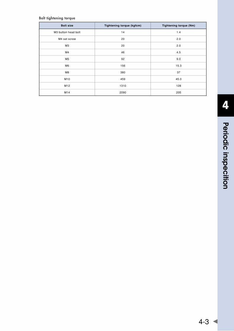
4
Perio
dic
inspe
citio
n
4-3
Bolt tightening torque
Bolt size Tightening torque (kgfcm) Tightening torque (Nm)
M3buttonheadbolt 14 1.4
M4setscrew 20 2.0
M3 20 2.0
M4 46 4.5
M5 92 9.0
M6 156 15.3
M8 380 37
M10 459 45.0
M12 1310 128
M14 2090 205

Chapter 5 Harmonic drive replacement period
Contents
1. Overview 5-1
2. Replacement period 5-2

5
ha
rmonic d
rive repla
cement p
eriod
5-1
1. OverviewTheYK-XGseriesrobotslistedbelowuseaharmonicdriveasthespeedreductiongearfortheX,YandRaxes.Harmonicdrivesneedtobereplacedafterspecifiedoperationhourshaveelapsed.Usetheguidelineexplained below to determine the replacement period and replace the harmonic drive periodically. Since the YK-XGseriesrobotslistedbelowuselong-lifeharmonicgrease,itisnotnecessarytoreplacetheharmonicgrease.
Only aUThORIzED EngInEERS WhO RECEIvED ThE RObOT TRaInIng COURSE COnDUCED by yOUR DISTRIbUTOR MUST REPlaCE ThE haRMOnIC DRIvE WhIlE REfERRIng TO ThE SEPaRaTE yk-xg SERIES MaInTEnanCE ManUal.
Applicablemodels:YK250XG,YK350XG,YK400XG,YK500XGL,YK600XGL YK500XG,YK600XG,YK600XGH,YK700XG,YK800XG,YK900XG,YK1000XG YK500XGS,YK600XGS,YK700XGS,YK800XGS,YK900XGS,YK1000XGS
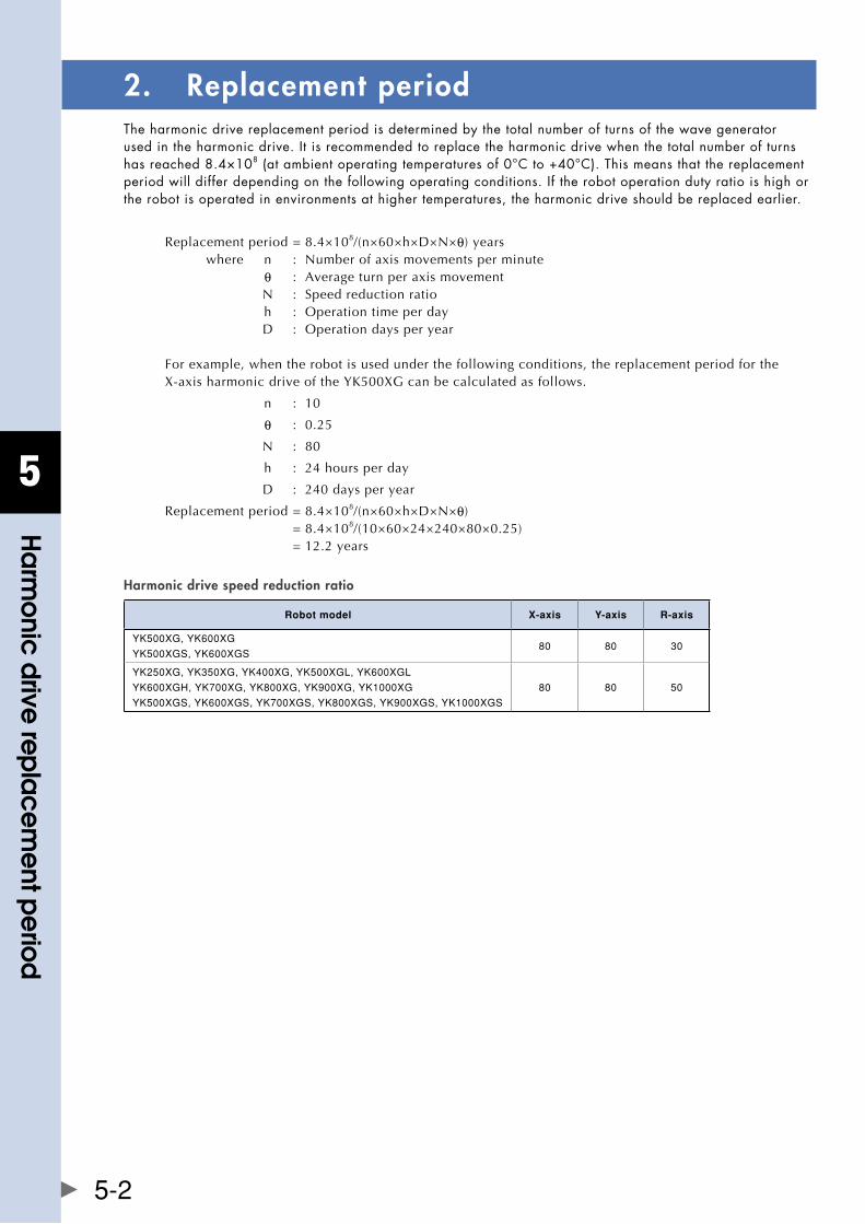
5
ha
rmonic d
rive repla
cement p
eriod
5-2
2. Replacement periodThe harmonic drive replacement period is determined by the total number of turns of the wave generator used in the harmonic drive. It is recommended to replace the harmonic drive when the total number of turns hasreached8.4×108(atambientoperatingtemperaturesof0°Cto+40°C).Thismeansthatthereplacementperiod will differ depending on the following operating conditions. If the robot operation duty ratio is high or the robot is operated in environments at higher temperatures, the harmonic drive should be replaced earlier.
Replacement period = 8.4×10⁸/(n×60×h×D×N×θ) years where n : Number of axis movements per minute θ : Average turn per axis movement N : Speed reduction ratio h : Operation time per day D : Operation days per year
For example, when the robot is used under the following conditions, the replacement period for the X-axisharmonicdriveoftheYK500XGcanbecalculatedasfollows.
n : 10
θ : 0.25
N : 80
h : 24 hours per day
D : 240 days per year
Replacement period = 8.4×10⁸/(n×60×h×D×N×θ) = 8.4×10⁸/(10×60×24×240×80×0.25) = 12.2 years
Harmonic drive speed reduction ratio
Robot model X-axis Y-axis R-axis
YK500XG,YK600XG
YK500XGS,YK600XGS80 80 30
YK250XG,YK350XG,YK400XG,YK500XGL,YK600XGL
YK600XGH,YK700XG,YK800XG,YK900XG,YK1000XG
YK500XGS,YK600XGS,YK700XGS,YK800XGS,YK900XGS,YK1000XGS
80 80 50
Chapter 6 Increasing the robot operating speed
Contents
1. Increasing the robot operating speed 6-1
1.1 Increasing speed by arch motion 6-1
1.2 Increasing the speed with the WEIghT statement 6-3
1.3 Increasing the speed by the tolerance parameter 6-4
1.4 Increasing the speed by the OUT effective position parameter 6-5

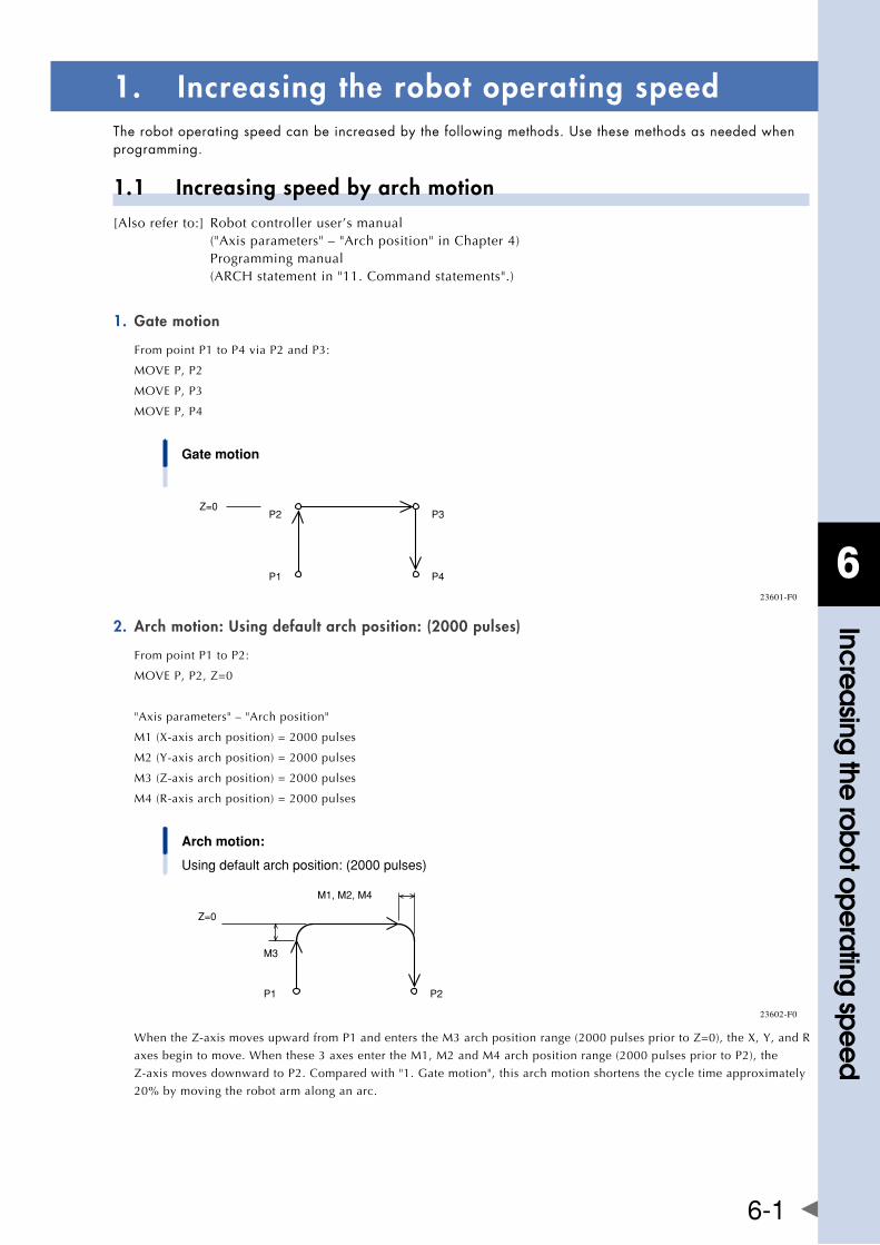
6
Increasing the robot operating speed
6-1
1. Increasing the robot operating speedTherobotoperatingspeedcanbeincreasedbythefollowingmethods.Usethesemethodsasneededwhenprogramming.
1.1 Increasing speed by arch motion[Also refer to:] Robot controller user’s manual ("Axis parameters" – "Arch position" in Chapter 4) Programming manual (ARCH statement in "11. Command statements".)
Gate motion1.
From point P1 to P4 via P2 and P3:
MOVEP,P2
MOVEP,P3
MOVEP,P4
Gate motion
Z=0P2
P1
P3
P4
23601-F0
Arch motion: Using default arch position: (2000 pulses)2.
From point P1 to P2:
MOVEP,P2,Z=0
"Axis parameters" – "Arch position"
M1(X-axisarchposition)=2000pulses
M2 (Y-axis arch position) = 2000 pulses
M3(Z-axisarchposition)=2000pulses
M4 (R-axis arch position) = 2000 pulses
Arch motion:
Using default arch position: (2000 pulses)
Z=0
M1, M2, M4
P1
M3
P2
23602-F0
WhentheZ-axismovesupwardfromP1andenterstheM3archpositionrange(2000pulsespriortoZ=0),theX,Y,andR
axes begin to move. When these 3 axes enter the M1, M2 and M4 arch position range (2000 pulses prior to P2), the
Z-axismovesdownwardtoP2.Comparedwith"1.Gatemotion",thisarchmotionshortensthecycletimeapproximately
20% by moving the robot arm along an arc.
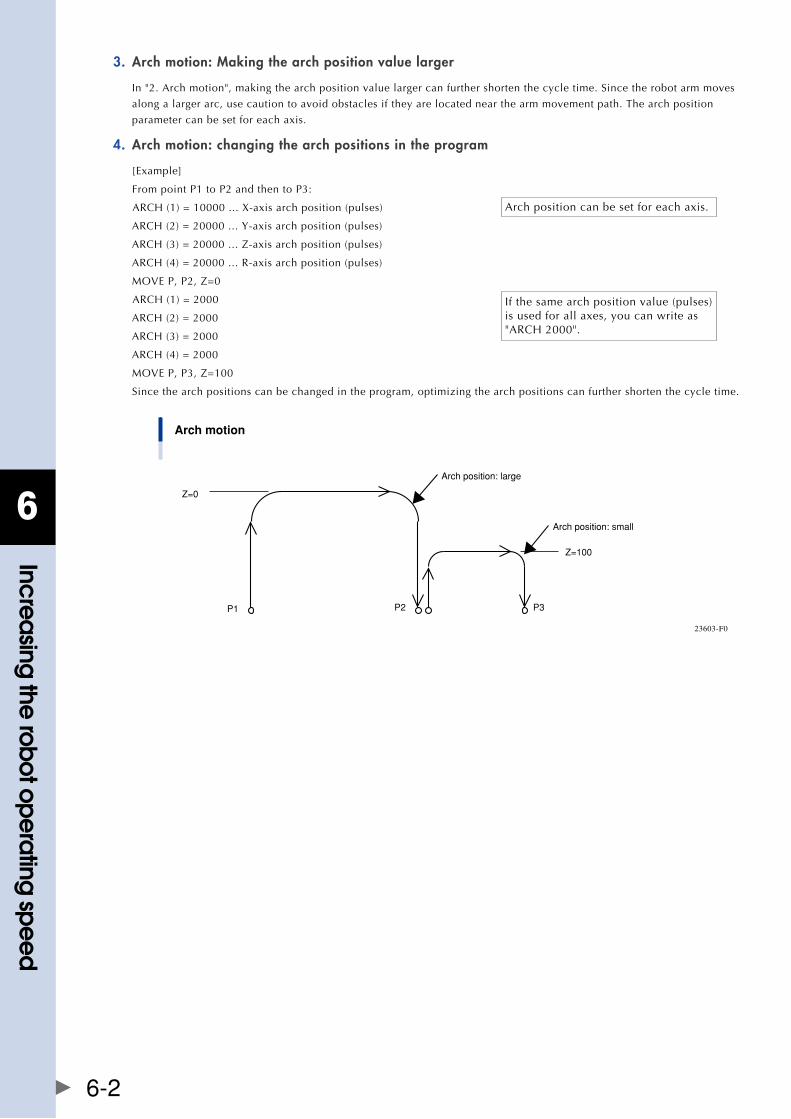
6
Increasing the robot operating speed
6-2
Arch motion: Making the arch position value larger3.
In "2. Arch motion", making the arch position value larger can further shorten the cycle time. Since the robot arm moves
along a larger arc, use caution to avoid obstacles if they are located near the arm movement path. The arch position
parameter can be set for each axis.
Arch motion: changing the arch positions in the program4.
[Example]
From point P1 to P2 and then to P3:
ARCH(1)=10000...X-axisarchposition(pulses)
ARCH (2) = 20000 ... Y-axis arch position (pulses)
ARCH(3)=20000...Z-axisarchposition(pulses)
ARCH (4) = 20000 ... R-axis arch position (pulses)
MOVEP,P2,Z=0
ARCH (1) = 2000
ARCH (2) = 2000
ARCH (3) = 2000
ARCH (4) = 2000
MOVEP,P3,Z=100
Since the arch positions can be changed in the program, optimizing the arch positions can further shorten the cycle time.
Arch motion
Z=0
P1 P2 P3
Z=100
Arch position: large
Arch position: small
23603-F0
Arch position can be set for each axis.
If the same arch position value (pulses) is used for all axes, you can write as "ARCH 2000".
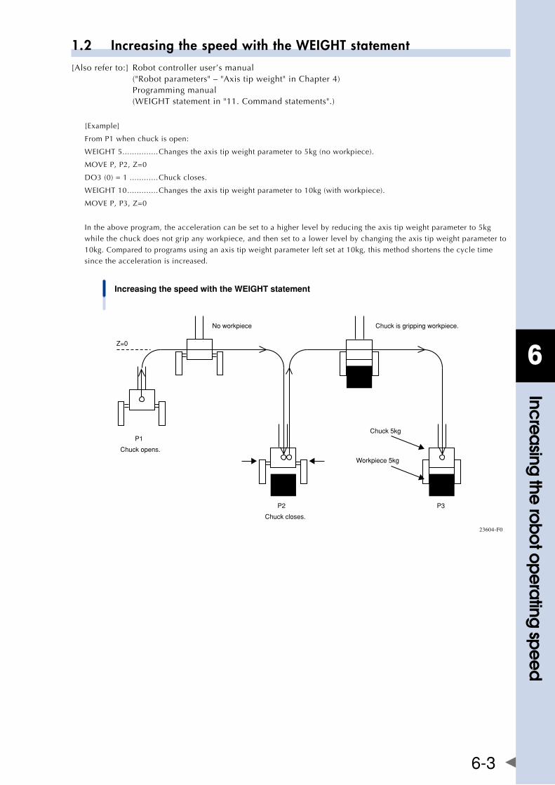
6
Increasing the robot operating speed
6-3
1.2 Increasing the speed with the WEIGHT statement[Also refer to:] Robot controller user’s manual ("Robot parameters" – "Axis tip weight" in Chapter 4) Programming manual (WEIGHTstatementin"11.Commandstatements".)
[Example]
From P1 when chuck is open:
WEIGHT5 ...............Changes the axis tip weight parameter to 5kg (no workpiece).
MOVEP,P2,Z=0
DO3 (0) = 1 ............Chuck closes.
WEIGHT10 .............Changes the axis tip weight parameter to 10kg (with workpiece).
MOVEP,P3,Z=0
In the above program, the acceleration can be set to a higher level by reducing the axis tip weight parameter to 5kg
while the chuck does not grip any workpiece, and then set to a lower level by changing the axis tip weight parameter to
10kg. Compared to programs using an axis tip weight parameter left set at 10kg, this method shortens the cycle time
since the acceleration is increased.
Increasing the speed with the WEIGHT statement
P1
Z=0
Chuck opens.
Chuck 5kg
Workpiece 5kg
P3P2
Chuck closes.
No workpiece Chuck is gripping workpiece.
23604-F0
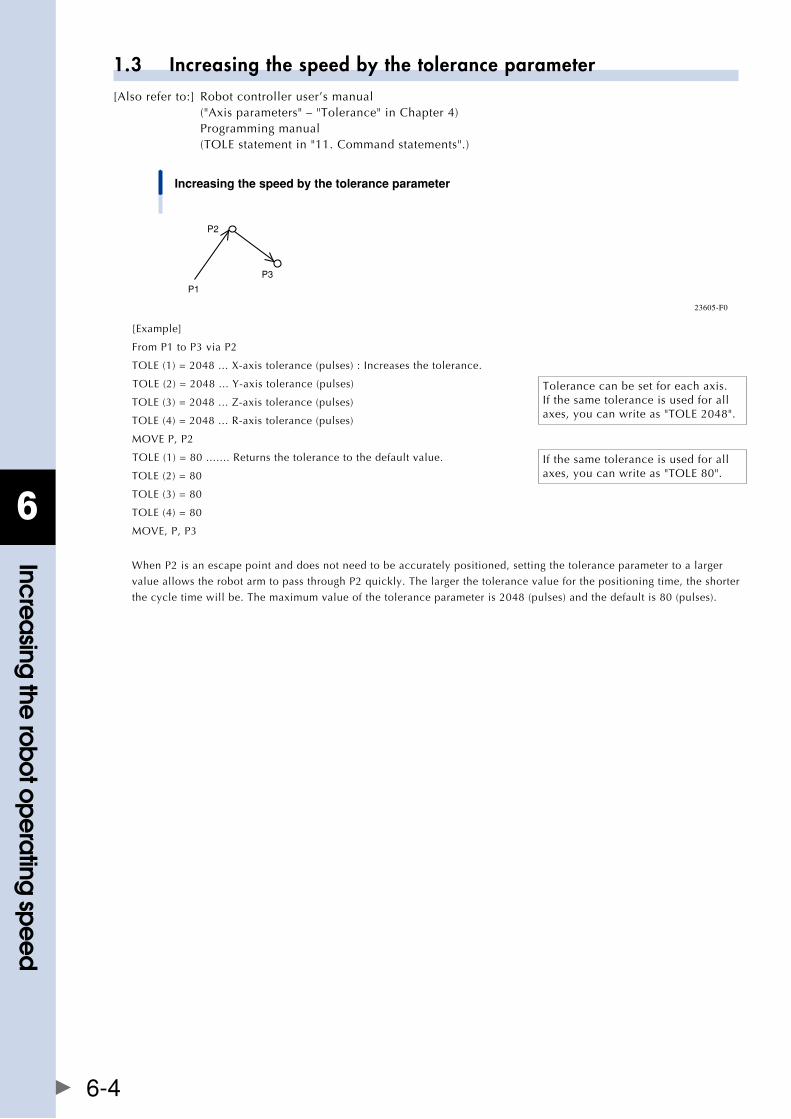
6
Increasing the robot operating speed
6-4
1.3 Increasing the speed by the tolerance parameter[Also refer to:] Robot controller user’s manual ("Axis parameters" – "Tolerance" in Chapter 4) Programming manual (TOLEstatementin"11.Commandstatements".)
Increasing the speed by the tolerance parameter
P1
P2
P3
23605-F0
[Example]
From P1 to P3 via P2
TOLE(1)=2048...X-axistolerance(pulses):Increasesthetolerance.
TOLE(2)=2048...Y-axistolerance(pulses)
TOLE(3)=2048...Z-axistolerance(pulses)
TOLE(4)=2048...R-axistolerance(pulses)
MOVEP,P2
TOLE(1)=80.......Returnsthetolerancetothedefaultvalue.
TOLE(2)=80
TOLE(3)=80
TOLE(4)=80
MOVE,P,P3
When P2 is an escape point and does not need to be accurately positioned, setting the tolerance parameter to a larger
value allows the robot arm to pass through P2 quickly. The larger the tolerance value for the positioning time, the shorter
the cycle time will be. The maximum value of the tolerance parameter is 2048 (pulses) and the default is 80 (pulses).
Tolerance can be set for each axis. If the same tolerance is used for all axes,youcanwriteas"TOLE2048".
If the same tolerance is used for all axes,youcanwriteas"TOLE80".
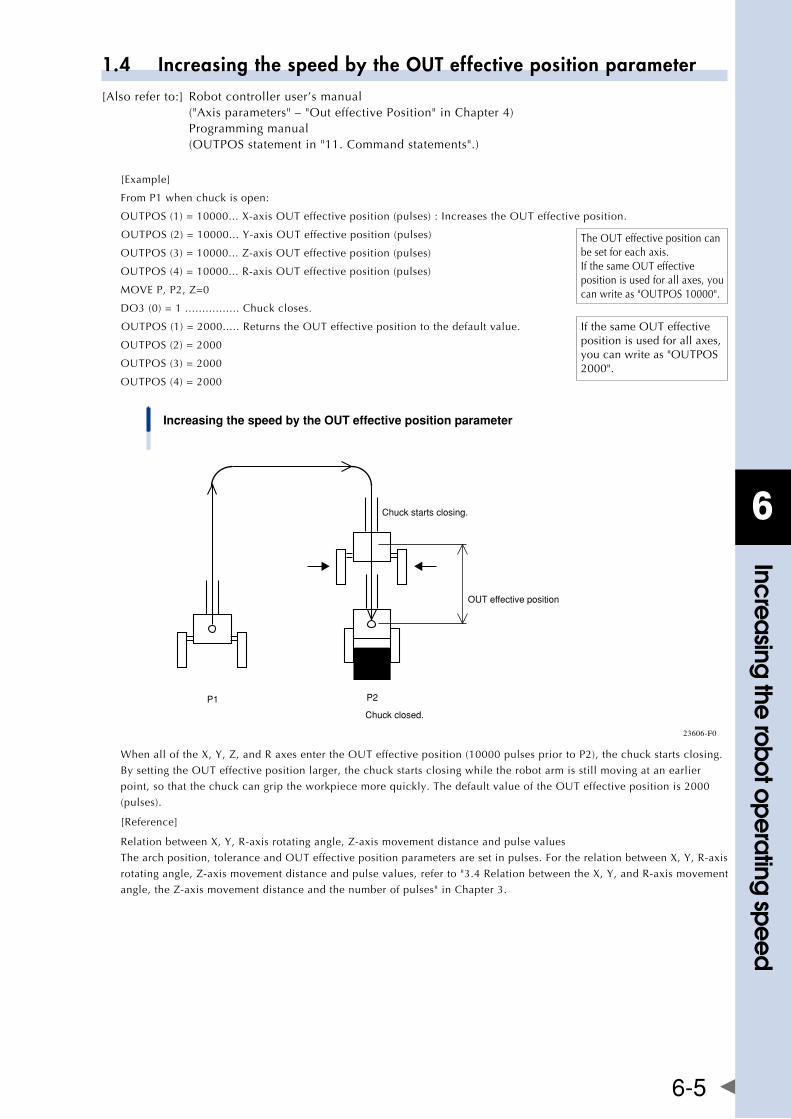
6
Increasing the robot operating speed
6-5
1.4 Increasing the speed by the OUT effective position parameter[Also refer to:] Robot controller user’s manual ("Axis parameters" – "Out effective Position" in Chapter 4) Programming manual (OUTPOSstatementin"11.Commandstatements".)
[Example]
From P1 when chuck is open:
OUTPOS(1)=10000...X-axisOUTeffectiveposition(pulses):IncreasestheOUTeffectiveposition.
OUTPOS(2)=10000...Y-axisOUTeffectiveposition(pulses)
OUTPOS(3)=10000...Z-axisOUTeffectiveposition(pulses)
OUTPOS(4)=10000...R-axisOUTeffectiveposition(pulses)
MOVEP,P2,Z=0
DO3 (0) = 1 ................ Chuck closes.
OUTPOS(1)=2000.....ReturnstheOUTeffectivepositiontothedefaultvalue.
OUTPOS(2)=2000
OUTPOS(3)=2000
OUTPOS(4)=2000
Increasing the speed by the OUT effective position parameter
P1 P2
Chuck closed.
Chuck starts closing.
OUT effective position
23606-F0
WhenalloftheX,Y,Z,andRaxesentertheOUTeffectiveposition(10000pulsespriortoP2),thechuckstartsclosing.
BysettingtheOUTeffectivepositionlarger,thechuckstartsclosingwhiletherobotarmisstillmovingatanearlier
point,sothatthechuckcangriptheworkpiecemorequickly.ThedefaultvalueoftheOUTeffectivepositionis2000
(pulses).
[Reference]
RelationbetweenX,Y,R-axisrotatingangle,Z-axismovementdistanceandpulsevalues
Thearchposition,toleranceandOUTeffectivepositionparametersaresetinpulses.FortherelationbetweenX,Y,R-axis
rotatingangle,Z-axismovementdistanceandpulsevalues,referto"3.4RelationbetweentheX,Y,andR-axismovement
angle,theZ-axismovementdistanceandthenumberofpulses"inChapter3.
TheOUTeffectivepositioncanbe set for each axis. IfthesameOUTeffectiveposition is used for all axes, you canwriteas"OUTPOS10000".
IfthesameOUTeffectiveposition is used for all axes, youcanwriteas"OUTPOS2000".

Chapter 7 Specifications
Contents
1. Manipulator 7-1
1.1 basic specification 7-1
1.1.1 YK250XG, YK350XG, YK400XG, YK500XGL, YK600XGL 7-1
1.1.2 YK500XG, YK600XG, YK600XGH, YK700XG, YK800XG, YK900XG, YK1000XG 7-3
1.1.3 YK500XGS, YK600XGS, YK700XGS, YK800XGS, YK900XGS, YK1000XGS 7-5
1.2 externalviewanddimensions 7-6
1.2.1 YK250XG 7-6
1.2.2 YK350XG 7-10
1.2.3 YK400XG 7-14
1.2.4 YK500XGL 7-18
1.2.5 YK600XGL 7-22
1.2.6 YK500XG 7-26
1.2.7 YK600XG 7-28
1.2.8 YK600XGH 7-30
1.2.9 YK700XG 7-32
1.2.10 YK800XG 7-34
1.2.11 YK900XG 7-36
1.2.12 YK1000XG 7-38
1.2.13 YK500XGS (Wall-mount model) 7-40
1.2.14 YK500XGS (Wall-mount inverse model) 7-42
1.2.15 YK600XGS (Wall-mount model) 7-44
1.2.16 YK600XGS (Wall-mount inverse model) 7-46
1.2.17 YK700XGS (Wall-mount model) 7-48
1.2.18 YK700XGS (Wall-mount inverse model) 7-50
1.2.19 YK800XGS (Wall-mount model) 7-52
1.2.20 YK800XGS (Wall-mount inverse model) 7-54
1.2.21 YK900XGS (Wall-mount model) 7-56
1.2.22 YK900XGS (Wall-mount inverse model) 7-58
1.2.23 YK1000XGS (Wall-mount model) 7-60
1.2.24 YK1000XGS (Wall-mount inverse model) 7-62
1.3 Robot inner wiring diagram 7-64
1.4 Wiring table 7-65

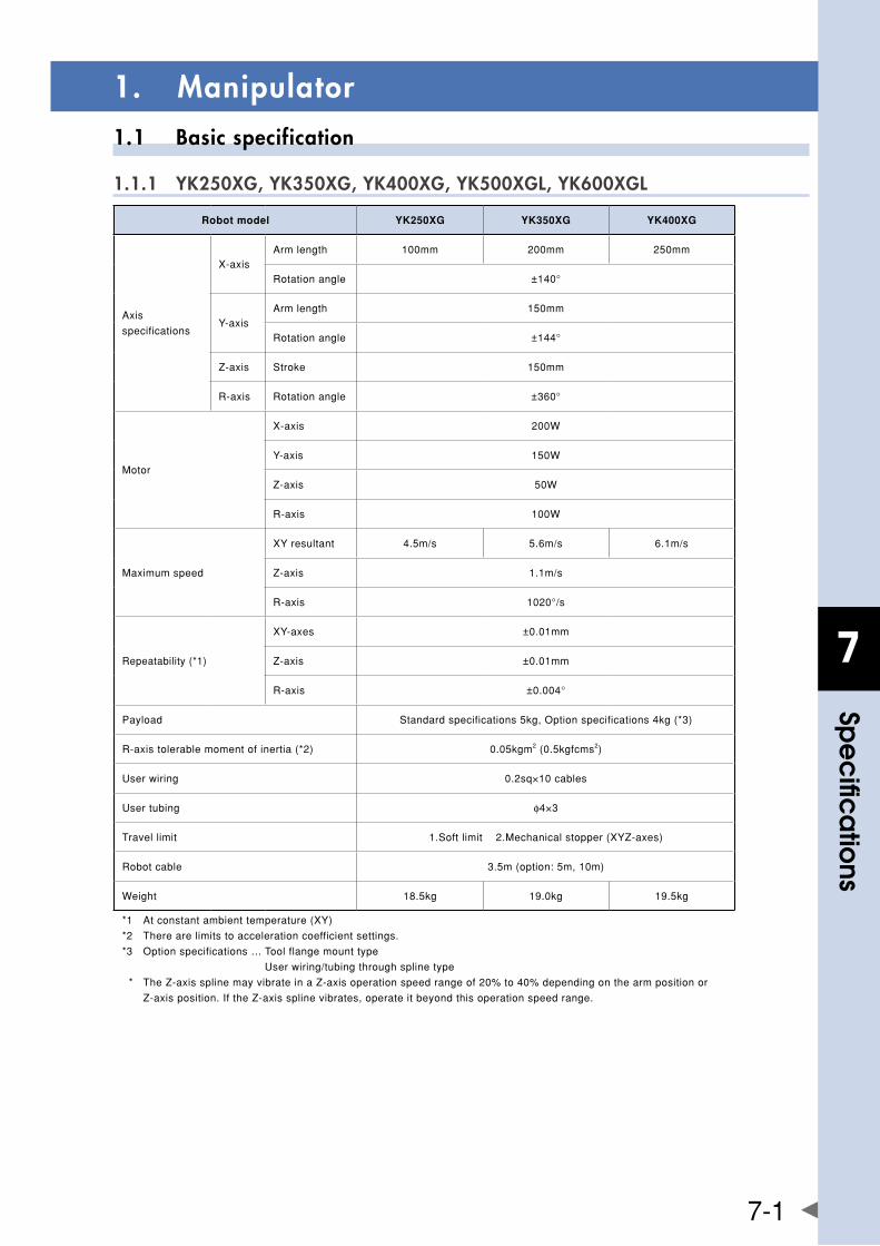
7
spe
cific
atio
ns
7-1
1. Manipulator1.1 Basic specification
1.1.1 YK250XG, YK350XG, YK400XG, YK500XGL, YK600XGL
Robot model YK250XG YK350XG YK400XG
Axis
specifications
X-axisArmlength 100mm 200mm 250mm
Rotationangle ±140°
Y-axisArmlength 150mm
Rotationangle ±144°
Z-axis Stroke 150mm
R-axis Rotationangle ±360°
Motor
X-axis 200W
Y-axis 150W
Z-axis 50W
R-axis 100W
Maximumspeed
XYresultant 4.5m/s 5.6m/s 6.1m/s
Z-axis 1.1m/s
R-axis 1020°/s
Repeatability(*1)
XY-axes ±0.01mm
Z-axis ±0.01mm
R-axis ±0.004°
Payload Standardspecifications5kg,Optionspecifications4kg(*3)
R-axistolerablemomentofinertia(*2) 0.05kgm2(0.5kgfcms2)
Userwiring 0.2sq×10cables
Usertubing φ4×3
Travellimit 1.Softlimit2.Mechanicalstopper(XYZ-axes)
Robotcable 3.5m(option:5m,10m)
Weight 18.5kg 19.0kg 19.5kg
*1 Atconstantambienttemperature(XY)
*2 Therearelimitstoaccelerationcoefficientsettings.
*3 Optionspecifications…Toolflangemounttype
Userwiring/tubingthroughsplinetype
* TheZ-axissplinemayvibrateinaZ-axisoperationspeedrangeof20%to40%dependingonthearmpositionor
Z-axisposition.IftheZ-axissplinevibrates,operateitbeyondthisoperationspeedrange.
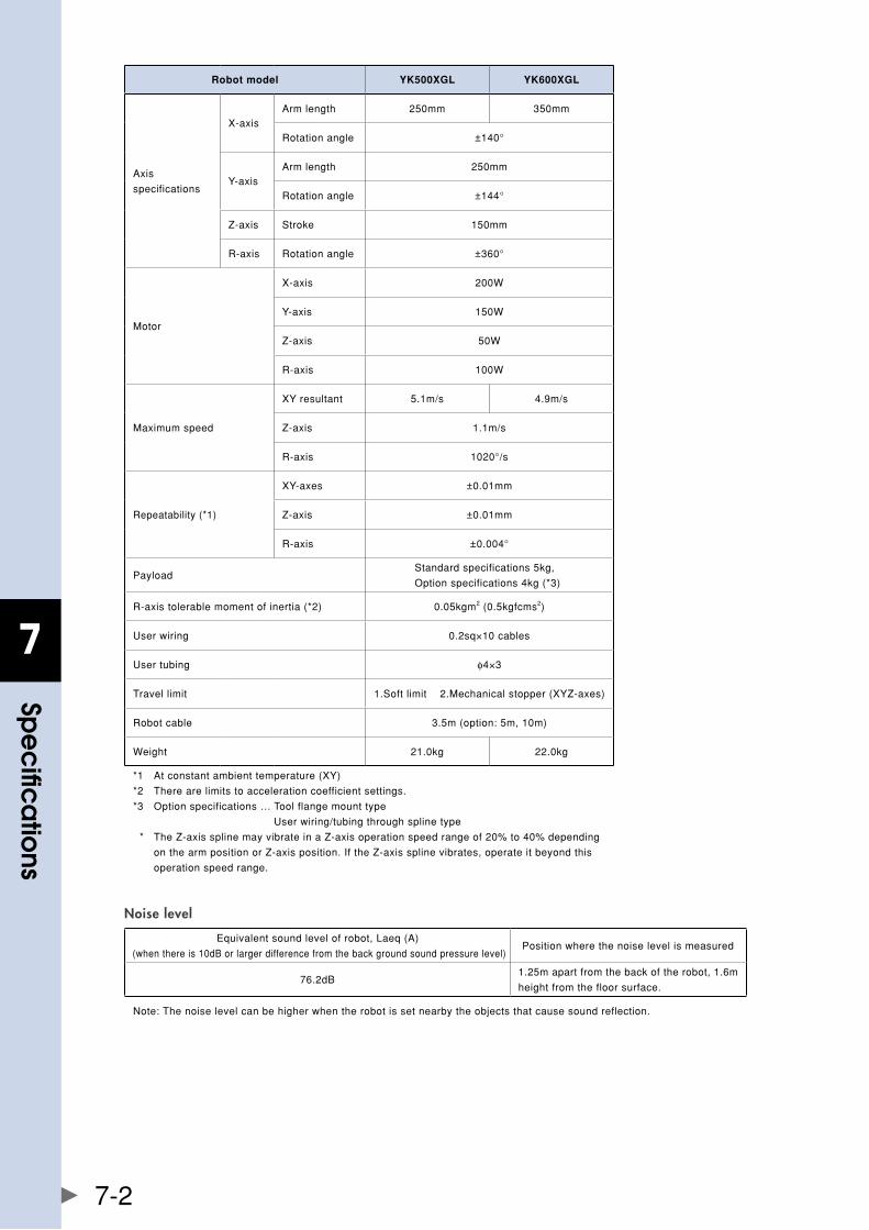
7
spe
cific
atio
ns
7-2
Robot model YK500XGL YK600XGL
Axis
specifications
X-axisArmlength 250mm 350mm
Rotationangle ±140°
Y-axisArmlength 250mm
Rotationangle ±144°
Z-axis Stroke 150mm
R-axis Rotationangle ±360°
Motor
X-axis 200W
Y-axis 150W
Z-axis 50W
R-axis 100W
Maximumspeed
XYresultant 5.1m/s 4.9m/s
Z-axis 1.1m/s
R-axis 1020°/s
Repeatability(*1)
XY-axes ±0.01mm
Z-axis ±0.01mm
R-axis ±0.004°
PayloadStandardspecifications5kg,
Optionspecifications4kg(*3)
R-axistolerablemomentofinertia(*2) 0.05kgm2(0.5kgfcms2)
Userwiring 0.2sq×10cables
Usertubing φ4×3
Travellimit 1.Softlimit2.Mechanicalstopper(XYZ-axes)
Robotcable 3.5m(option:5m,10m)
Weight 21.0kg 22.0kg
*1 Atconstantambienttemperature(XY)
*2 Therearelimitstoaccelerationcoefficientsettings.
*3 Optionspecifications…Toolflangemounttype
Userwiring/tubingthroughsplinetype
* TheZ-axissplinemayvibrateinaZ-axisoperationspeedrangeof20%to40%depending
onthearmpositionorZ-axisposition.IftheZ-axissplinevibrates,operateitbeyondthis
operationspeedrange.
Noise level
Equivalentsoundlevelofrobot,Laeq(A)
(whenthereis10dBorlargerdifferencefromthebackgroundsoundpressurelevel)Positionwherethenoiselevelismeasured
76.2dB1.25mapartfromthebackoftherobot,1.6m
heightfromthefloorsurface.
Note:Thenoiselevelcanbehigherwhentherobotissetnearbytheobjectsthatcausesoundreflection.
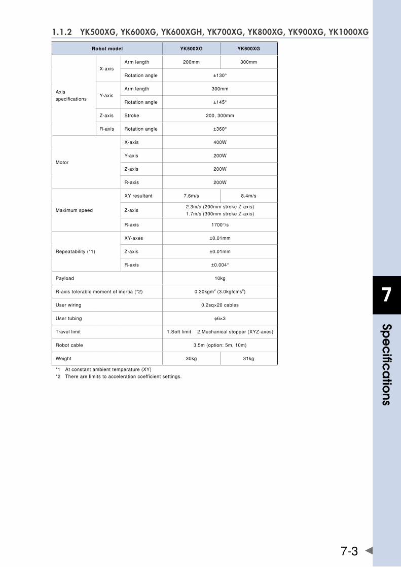
7
spe
cific
atio
ns
7-3
1.1.2 YK500XG, YK600XG, YK600XGH, YK700XG, YK800XG, YK900XG, YK1000XG
Robot model YK500XG YK600XG
Axis
specifications
X-axisArmlength 200mm 300mm
Rotationangle ±130°
Y-axisArmlength 300mm
Rotationangle ±145°
Z-axis Stroke 200,300mm
R-axis Rotationangle ±360°
Motor
X-axis 400W
Y-axis 200W
Z-axis 200W
R-axis 200W
Maximumspeed
XYresultant 7.6m/s 8.4m/s
Z-axis2.3m/s(200mmstrokeZ-axis)
1.7m/s(300mmstrokeZ-axis)
R-axis 1700°/s
Repeatability(*1)
XY-axes ±0.01mm
Z-axis ±0.01mm
R-axis ±0.004°
Payload 10kg
R-axistolerablemomentofinertia(*2) 0.30kgm2(3.0kgfcms2)
Userwiring 0.2sq×20cables
Usertubing φ6×3
Travellimit 1.Softlimit2.Mechanicalstopper(XYZ-axes)
Robotcable 3.5m(option:5m,10m)
Weight 30kg 31kg
*1 Atconstantambienttemperature(XY)
*2 Therearelimitstoaccelerationcoefficientsettings.
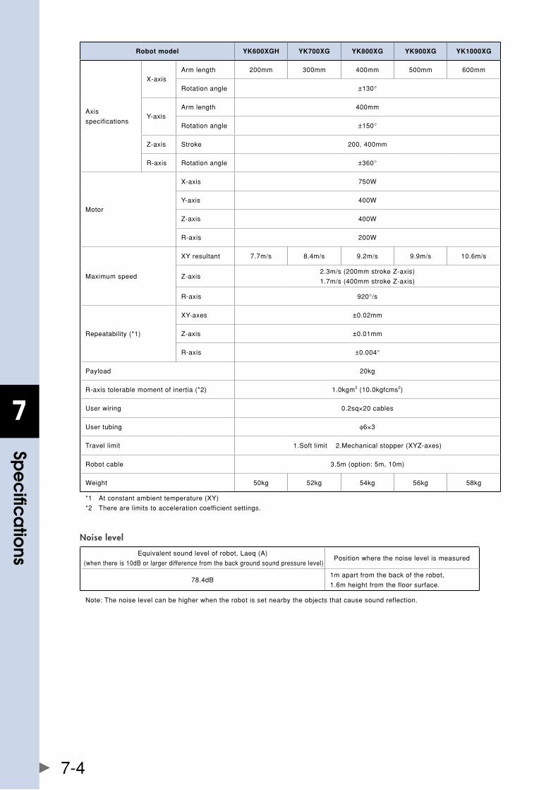
7
spe
cific
atio
ns
7-4
Robot model YK600XGH YK700XG YK800XG YK900XG YK1000XG
Axis
specifications
X-axisArmlength 200mm 300mm 400mm 500mm 600mm
Rotationangle ±130°
Y-axisArmlength 400mm
Rotationangle ±150°
Z-axis Stroke 200,400mm
R-axis Rotationangle ±360°
Motor
X-axis 750W
Y-axis 400W
Z-axis 400W
R-axis 200W
Maximumspeed
XYresultant 7.7m/s 8.4m/s 9.2m/s 9.9m/s 10.6m/s
Z-axis2.3m/s(200mmstrokeZ-axis)
1.7m/s(400mmstrokeZ-axis)
R-axis 920°/s
Repeatability(*1)
XY-axes ±0.02mm
Z-axis ±0.01mm
R-axis ±0.004°
Payload 20kg
R-axistolerablemomentofinertia(*2) 1.0kgm2(10.0kgfcms2)
Userwiring 0.2sq×20cables
Usertubing φ6×3
Travellimit 1.Softlimit2.Mechanicalstopper(XYZ-axes)
Robotcable 3.5m(option:5m,10m)
Weight 50kg 52kg 54kg 56kg 58kg
*1 Atconstantambienttemperature(XY)
*2 Therearelimitstoaccelerationcoefficientsettings.
Noise level
Equivalentsoundlevelofrobot,Laeq(A)
(whenthereis10dBorlargerdifferencefromthebackgroundsoundpressurelevel)Positionwherethenoiselevelismeasured
78.4dB1mapartfromthebackoftherobot,
1.6mheightfromthefloorsurface.
Note:Thenoiselevelcanbehigherwhentherobotissetnearbytheobjectsthatcausesoundreflection.
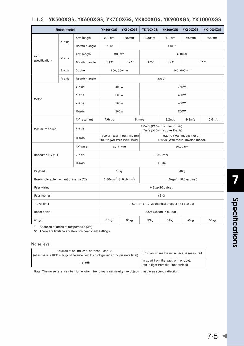
7
spe
cific
atio
ns
7-5
1.1.3 YK500XGS, YK600XGS, YK700XGS, YK800XGS, YK900XGS, YK1000XGS
Robot model YK500XGS YK600XGS YK700XGS YK800XGS YK900XGS YK1000XGS
Axis
specifications
X-axisArmlength 200mm 300mm 300mm 400mm 500mm 600mm
Rotationangle ±105° ±130°
Y-axisArmlength 300mm 400mm
Rotationangle ±125° ±145° ±130° ±145° ±150°
Z-axis Stroke 200,300mm 200,400mm
R-axis Rotationangle ±360°
Motor
X-axis 400W 750W
Y-axis 200W 400W
Z-axis 200W 400W
R-axis 200W 200W
Maximumspeed
XYresultant 7.6m/s 8.4m/s 9.2m/s 9.9m/s 10.6m/s
Z-axis2.3m/s(200mmstrokeZ-axis)
1.7m/s(300mmstrokeZ-axis)
R-axis1700°/s(Wall-mountmodel)
800°/s(Wall-mountinversemodel)
920°/s(Wall-mountmodel)
480°/s(Wall-mountinversemodel)
Repeatability(*1)
XY-axes ±0.01mm ±0.02mm
Z-axis ±0.01mm
R-axis ±0.004°
Payload 10kg 20kg
R-axistolerablemomentofinertia(*2) 0.30kgm2(3.0kgfcms2) 1.0kgm2(10.0kgfcms2)
Userwiring 0.2sq×20cables
Usertubing φ6×3
Travellimit 1.Softlimit2.Mechanicalstopper(XYZ-axes)
Robotcable 3.5m(option:5m,10m)
Weight 30kg 31kg 52kg 54kg 56kg 58kg
*1 Atconstantambienttemperature(XY)
*2 Therearelimitstoaccelerationcoefficientsettings.
Noise level
Equivalentsoundlevelofrobot,Laeq(A)
(whenthereis10dBorlargerdifferencefromthebackgroundsoundpressurelevel)Positionwherethenoiselevelismeasured
78.4dB1mapartfromthebackoftherobot,
1.6mheightfromthefloorsurface.
Note:Thenoiselevelcanbehigherwhentherobotissetnearbytheobjectsthatcausesoundreflection.
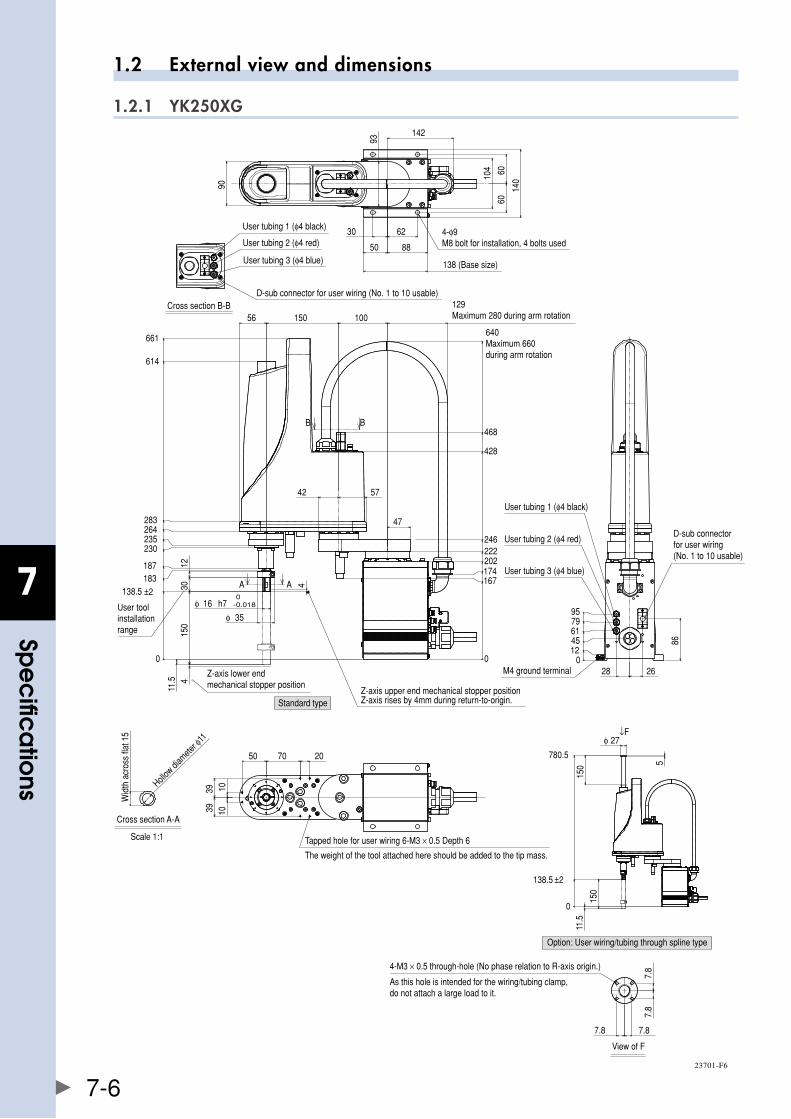
7
spe
cific
atio
ns
7-6
1.2 External view and dimensions
1.2.1 YK250XG
0
138.5 ±2183187
230235264283
4
150
0
167174202222246
4
φ 16 h7 -0.0180
φ 35
3012
11.5
Z-axis upper end mechanical stopper positionZ-axis rises by 4mm during return-to-origin.
User toolinstallation range
Z-axis lower endmechanical stopper position
B B
A A
1010
50 70 20
3939
01245617995
2686
28
D-sub connector for user wiring (No. 1 to 10 usable)
User tubing 1 (φ4 black)
User tubing 2 (φ4 red)
User tubing 3 (φ4 blue)
M4 ground terminal
Cross section B-B
Wid
th a
cros
s fla
t 15
Hollow
diam
eter φ
11
Cross section A-A
Scale 1:1
The weight of the tool attached here should be added to the tip mass.
Tapped hole for user wiring 6-M3 × 0.5 Depth 6
140
6060
104
142
93
62
8850
30
138 (Base size)
4-φ9M8 bolt for installation, 4 bolts used
90User tubing 1 (φ4 black)
User tubing 2 (φ4 red)
User tubing 3 (φ4 blue)
D-sub connector for user wiring (No. 1 to 10 usable)129Maximum 280 during arm rotation
640Maximum 660during arm rotation
428
468
10015056
661
614
42 57
47
138.5 ±2
780.5
150
150
5
φ 27
11.5
↓F
0
Standard type
Option: User wiring/tubing through spline type
7.8
7.8
7.8 7.8
View of F
4-M3 × 0.5 through-hole (No phase relation to R-axis origin.)
As this hole is intended for the wiring/tubing clamp, do not attach a large load to it.
23701-F6
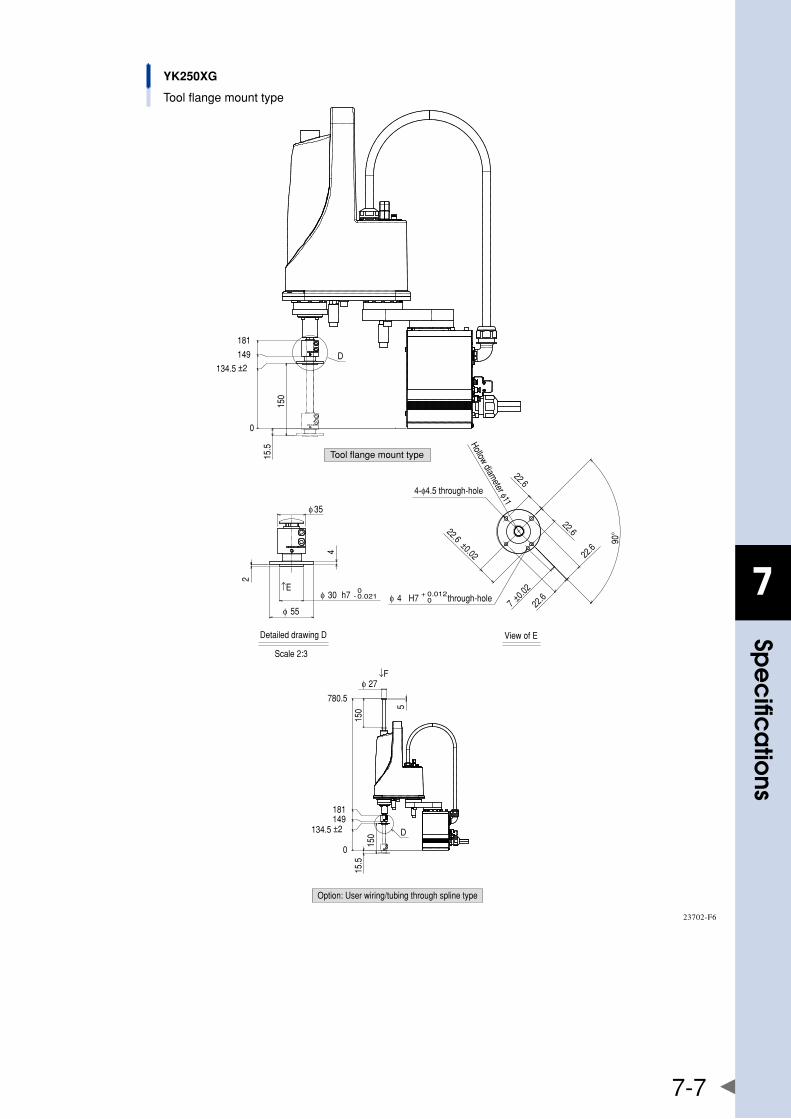
7
spe
cific
atio
ns
7-7
0
134.5 ±2
149
181
150
15.5
D
φ 30 h7 - 0.0210
φ 55
2
4
φ 35
Detailed drawing D
Scale 2:3
↑E
22.6
22.6
22.6
22.6
22.6±0.02
4-φ4.5 through-hole
φ 4 H7 0+ 0.012through-hole
90°
Hollow diameter φ11
7 ±0.02
View of E
YK250XG
Tool flange mount type
D
↓F
0
134.5 ±2149181
780.5
150
15.5
φ 27
150 5
Tool flange mount type
Option: User wiring/tubing through spline type
23702-F6
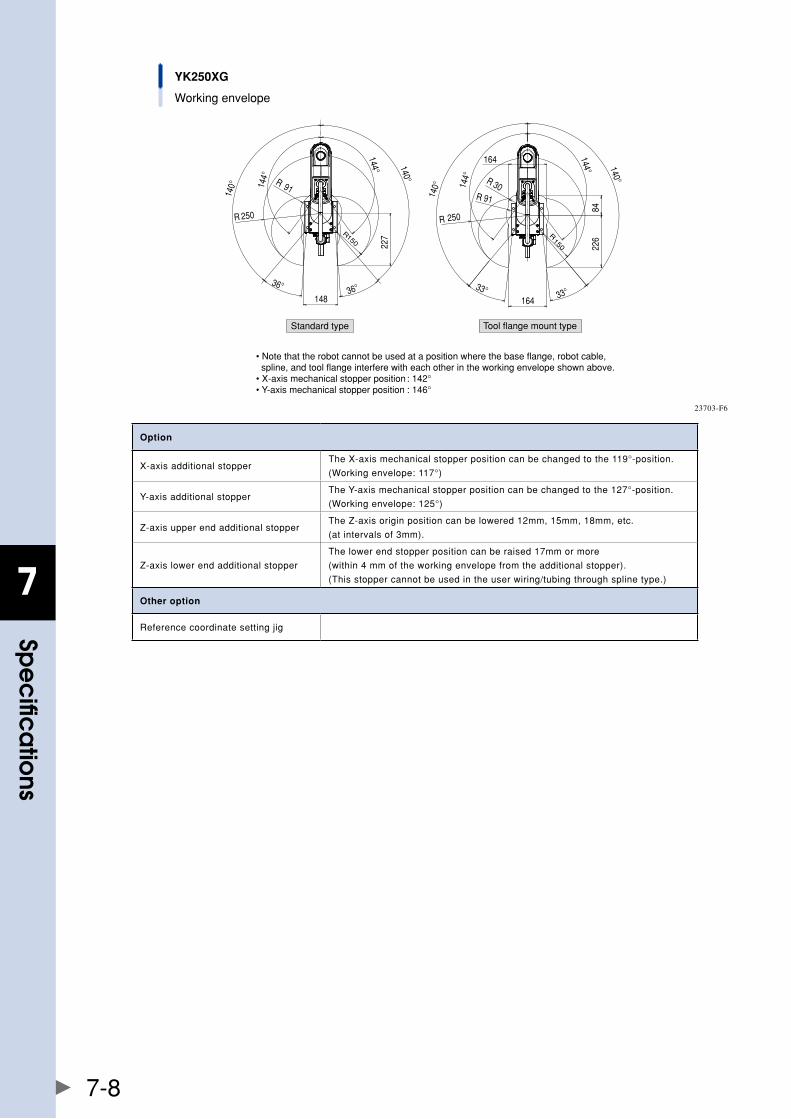
7
spe
cific
atio
ns
7-8
YK250XG
Working envelope
Standard type Tool flange mount type
• Note that the robot cannot be used at a position where the base flange, robot cable, spline, and tool flange interfere with each other in the working envelope shown above.• X-axis mechanical stopper position : 142°• Y-axis mechanical stopper position : 146°
144°
144°
140°
140°
227
36°36°
148
R 250
R150
R 91
140°
140°
144°
144°
226
33°33°
R 250
R150
164
84
R 30
164
R 91
23703-F6
Option
X-axisadditionalstopperTheX-axismechanicalstopperpositioncanbechangedtothe119°-position.
(Workingenvelope:117°)
Y-axisadditionalstopperTheY-axismechanicalstopperpositioncanbechangedtothe127°-position.
(Workingenvelope:125°)
Z-axisupperendadditionalstopperTheZ-axisoriginpositioncanbelowered12mm,15mm,18mm,etc.
(atintervalsof3mm).
Z-axislowerendadditionalstopper
Thelowerendstopperpositioncanberaised17mmormore
(within4mmoftheworkingenvelopefromtheadditionalstopper).
(Thisstoppercannotbeusedintheuserwiring/tubingthroughsplinetype.)
Other option
Referencecoordinatesettingjig
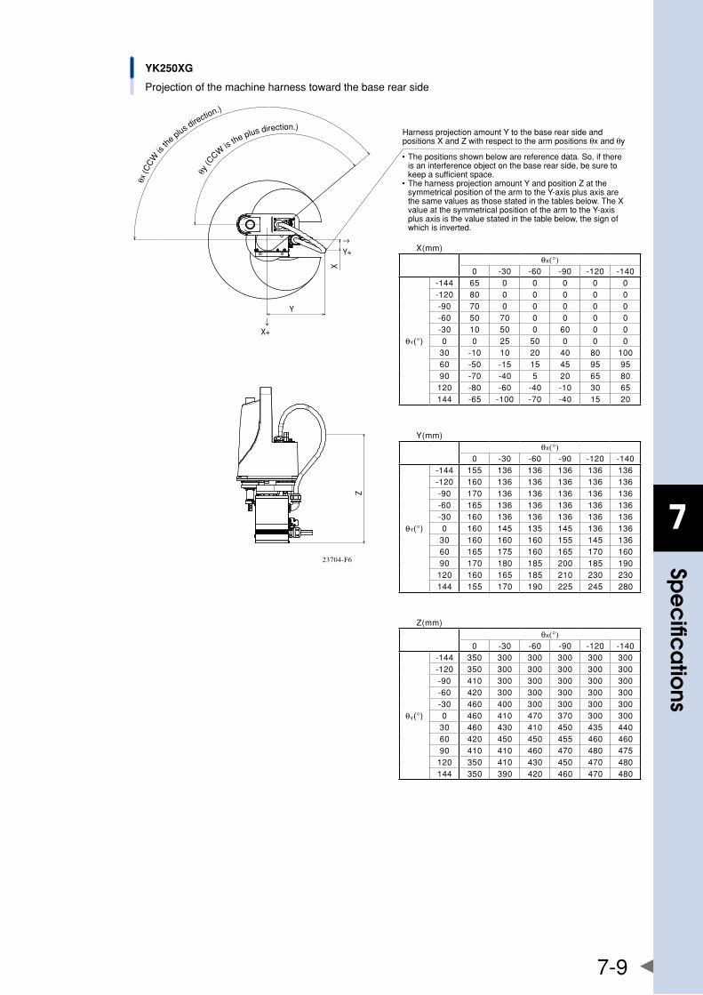
7
spe
cific
atio
ns
7-9
YK250XG
Projection of the machine harness toward the base rear side
↓
Z
X
Y
→Y+
X+
• The positions shown below are reference data. So, if there is an interference object on the base rear side, be sure to keep a sufficient space.
• The harness projection amount Y and position Z at the symmetrical position of the arm to the Y-axis plus axis are the same values as those stated in the tables below. The X value at the symmetrical position of the arm to the Y-axis plus axis is the value stated in the table below, the sign of which is inverted.
θx (C
CW
is th
e plus d
irection.)
θy (C
CW is
the plus direction.)Harness projection amount Y to the base rear side and positions X and Z with respect to the arm positions θx and θy
X(mm)θX(°)
0 -30 -60 -90 -120 -140
θY(°)
-144 65 0 0 0 0 0-120 80 0 0 0 0 0-90 70 0 0 0 0 0-60 50 70 0 0 0 0-30 10 50 0 60 0 00 0 25 50 0 0 0
30 -10 10 20 40 80 10060 -50 -15 15 45 95 9590 -70 -40 5 20 65 80
120 -80 -60 -40 -10 30 65144 -65 -100 -70 -40 15 20
Y(mm)θX(°)
0 -30 -60 -90 -120 -140
θY(°)
-144 155 136 136 136 136 136-120 160 136 136 136 136 136-90 170 136 136 136 136 136-60 165 136 136 136 136 136-30 160 136 136 136 136 1360 160 145 135 145 136 136
30 160 160 160 155 145 13660 165 175 160 165 170 16090 170 180 185 200 185 190
120 160 165 185 210 230 230144 155 170 190 225 245 280
Z(mm)θX(°)
0 -30 -60 -90 -120 -140
θY(°)
-144 350 300 300 300 300 300-120 350 300 300 300 300 300-90 410 300 300 300 300 300-60 420 300 300 300 300 300-30 460 400 300 300 300 3000 460 410 470 370 300 300
30 460 430 410 450 435 44060 420 450 450 455 460 46090 410 410 460 470 480 475
120 350 410 430 450 470 480144 350 390 420 460 470 480
23704-F6
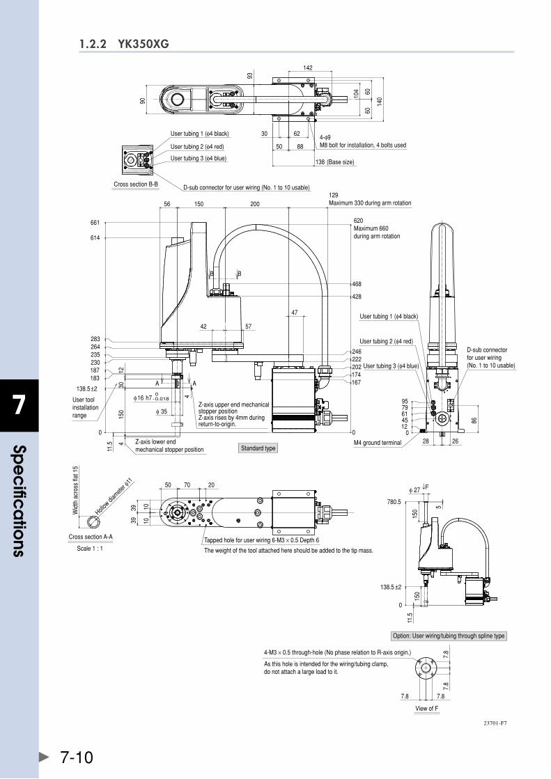
7
spe
cific
atio
ns
7-10
1.2.2 YK350XG
Standard type
Cross section B-B
Cross section A-A
Scale 1 : 1
User toolinstallation range
0
138.5±2
183187230235264283
614
661
4
150
0
167174202222246
428
468
620Maximum 660during arm rotation
4
φ 16 h7 -0.0180
φ 35
42
3012
150
47
129Maximum 330 during arm rotation200
11.5
56
57
Z-axis lower endmechanical stopper position
B B
A A
93
30 62
50 88
138 (Base size)
104 60
60
140
142
9010
10
50 70 20
3939
Tapped hole for user wiring 6-M3 × 0.5 Depth 6
The weight of the tool attached here should be added to the tip mass.
01245617995
26
86
28
D-sub connector for user wiring (No. 1 to 10 usable)
User tubing 1 (φ4 black)
User tubing 2 (φ4 red)
User tubing 3 (φ4 blue)
M4 ground terminal
User tubing 1 (φ4 black)
User tubing 2 (φ4 red)
User tubing 3 (φ4 blue)
D-sub connector for user wiring (No. 1 to 10 usable)
Wid
th a
cros
s fla
t 15
Hollow
diam
eter φ
11
4-φ9M8 bolt for installation, 4 bolts used
Option: User wiring/tubing through spline type
0
138.5 ±2
780.5
150
150
5
φ 27
11.5
↓F
View of F
7.8
7.8
7.8 7.8
4-M3 × 0.5 through-hole (No phase relation to R-axis origin.)
As this hole is intended for the wiring/tubing clamp, do not attach a large load to it.
Z-axis upper end mechanical stopper positionZ-axis rises by 4mm during return-to-origin.
23701-F7

7
spe
cific
atio
ns
7-11
Tool flange mount type
Option: User wiring/tubing through spline type
D
0
134.5 ±2149181
780.5
150
15.5
150 5
φ 27↓F
0
134.5 ±2149
181
0
150
15.5
D
Detailed drawing D
Scale 2 : 3
View of E
φ30 h7-0.0210
φ 55
2
4
φ 35
↑E
22.6
22.6
22.6
22.6
22.6 ±0.02
90°
Hollow diameter φ11
7 ±0.02
0+ 0.012
through-holeφ4 H7
4-φ4.5 through-hole
YK350XG
Tool flange mount type
23702-F7
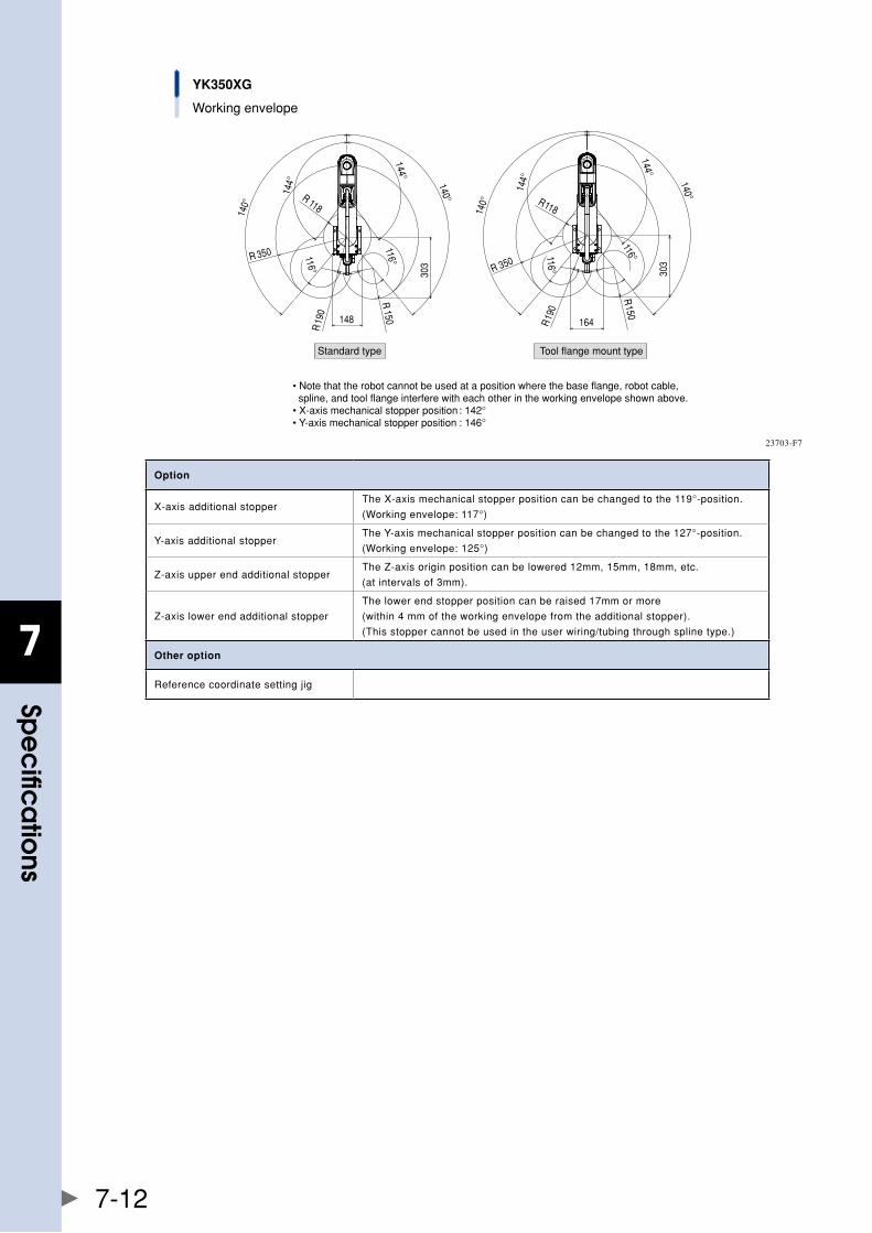
7
spe
cific
atio
ns
7-12
YK350XG
Working envelope
Standard type Tool flange mount type
• Note that the robot cannot be used at a position where the base flange, robot cable, spline, and tool flange interfere with each other in the working envelope shown above.• X-axis mechanical stopper position : 142°• Y-axis mechanical stopper position : 146°
140°
140°
303
116°
116°
144°
144°
148R
190
R150
R 350
R 118 140°
140°144°
144°
116°
116°
303R 350
R118
164
R150
R19
0
23703-F7
Option
X-axisadditionalstopperTheX-axismechanicalstopperpositioncanbechangedtothe119°-position.
(Workingenvelope:117°)
Y-axisadditionalstopperTheY-axismechanicalstopperpositioncanbechangedtothe127°-position.
(Workingenvelope:125°)
Z-axisupperendadditionalstopperTheZ-axisoriginpositioncanbelowered12mm,15mm,18mm,etc.
(atintervalsof3mm).
Z-axislowerendadditionalstopper
Thelowerendstopperpositioncanberaised17mmormore
(within4mmoftheworkingenvelopefromtheadditionalstopper).
(Thisstoppercannotbeusedintheuserwiring/tubingthroughsplinetype.)
Other option
Referencecoordinatesettingjig
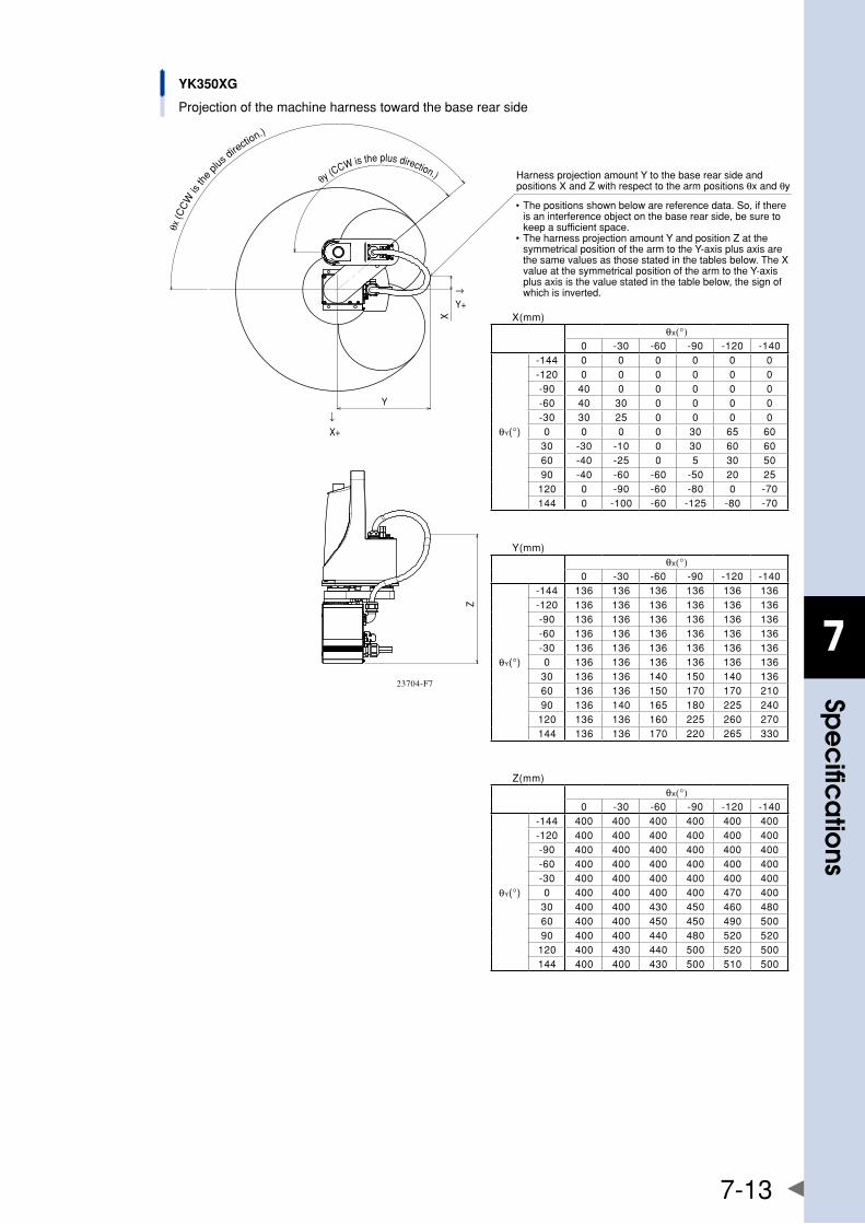
7
spe
cific
atio
ns
7-13
YK350XG
Projection of the machine harness toward the base rear side
Z
X
Y
→Y+
↓X+
θx (C
CW
is th
e plu
s dire
ction.)
θy (CCW is the plus direction.)
• The positions shown below are reference data. So, if there is an interference object on the base rear side, be sure to keep a sufficient space.
• The harness projection amount Y and position Z at the symmetrical position of the arm to the Y-axis plus axis are the same values as those stated in the tables below. The X value at the symmetrical position of the arm to the Y-axis plus axis is the value stated in the table below, the sign of which is inverted.
Harness projection amount Y to the base rear side and positions X and Z with respect to the arm positions θx and θy
X(mm)θX(°)
0 -30 -60 -90 -120 -140
θY(°)
-144 0 0 0 0 0 0-120 0 0 0 0 0 0-90 40 0 0 0 0 0-60 40 30 0 0 0 0-30 30 25 0 0 0 00 0 0 0 30 65 60
30 -30 -10 0 30 60 6060 -40 -25 0 5 30 5090 -40 -60 -60 -50 20 25
120 0 -90 -60 -80 0 -70144 0 -100 -60 -125 -80 -70
Y(mm)θX(°)
0 -30 -60 -90 -120 -140
θY(°)
-144 136 136 136 136 136 136-120 136 136 136 136 136 136-90 136 136 136 136 136 136-60 136 136 136 136 136 136-30 136 136 136 136 136 1360 136 136 136 136 136 136
30 136 136 140 150 140 13660 136 136 150 170 170 21090 136 140 165 180 225 240
120 136 136 160 225 260 270144 136 136 170 220 265 330
Z(mm)θX(°)
0 -30 -60 -90 -120 -140
θY(°)
-144 400 400 400 400 400 400-120 400 400 400 400 400 400-90 400 400 400 400 400 400-60 400 400 400 400 400 400-30 400 400 400 400 400 4000 400 400 400 400 470 400
30 400 400 430 450 460 48060 400 400 450 450 490 50090 400 400 440 480 520 520
120 400 430 440 500 520 500144 400 400 430 500 510 500
23704-F7
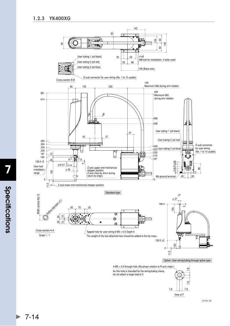
7
spe
cific
atio
ns
7-14
1.2.3 YK400XG
Standard type
Cross section B-B
Cross section A-A
Scale 1 : 1
Z-axis lower end mechanical stopper position
User toolinstallation range
0
138.5 ±2
183187230235264283
614
661
4
150
0
167174202222246
428
468
620Maximum 660during arm rotation
4
φ16 h7 -0.0180
φ 35
42
3012
150
47
129Maximum 380 during arm rotation250
11.5
56
57
Z-axis upper end mechanical stopper positionZ-axis rises by 4mm during return-to-origin.
B B
A A
93
30 62
50 88
138 (Base size)
104 60
60
140
142
9010
10
50 70 20
3939
User tubing 1 (φ4 black)
User tubing 2 (φ4 red)
User tubing 3 (φ4 blue)
D-sub connector for user wiring (No. 1 to 10 usable)
Wid
th a
cros
s fla
t 15
Hollow
diam
eter φ
11
01245617995
26
86
28
D-sub connector for user wiring (No. 1 to 10 usable)
User tubing 1 (φ4 black)
User tubing 2 (φ4 red)
User tubing 3 (φ4 blue)
M4 ground terminal
4-φ9M8 bolt for installation, 4 bolts used
The weight of the tool attached here should be added to the tip mass.
Tapped hole for user wiring 6-M3 × 0.5 Depth 6
0
138.5 ±2
780.5
150
150
5
φ 27
11.5
↓F
Option: User wiring/tubing through spline type
View of F
7.8
7.8
7.8 7.8
As this hole is intended for the wiring/tubing clamp, do not attach a large load to it.
4-M3 × 0.5 through-hole (No phase relation to R-axis origin.)
23701-F8
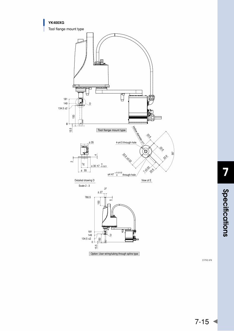
7
spe
cific
atio
ns
7-15
YK400XG
Tool flange mount type
0134.5 ±2
149181
780.5
150
150 5
φ 27
15.5
↓F
D
0
134.5 ±2
149
181
0
150
15.5
D
Detailed drawing D
Scale 2 : 3
View of E
φ 30 h7 -0.0210
φ 55
2
4
φ 35
↑E
22.6
22.6
22.6
22.6
22.6 ±0.02
90°
Hollow diameter φ11
7 ±0.02
0+ 0.012
through-holeφ4 H7
4-φ4.5 through-hole
Tool flange mount type
Option: User wiring/tubing through spline type
23702-F8
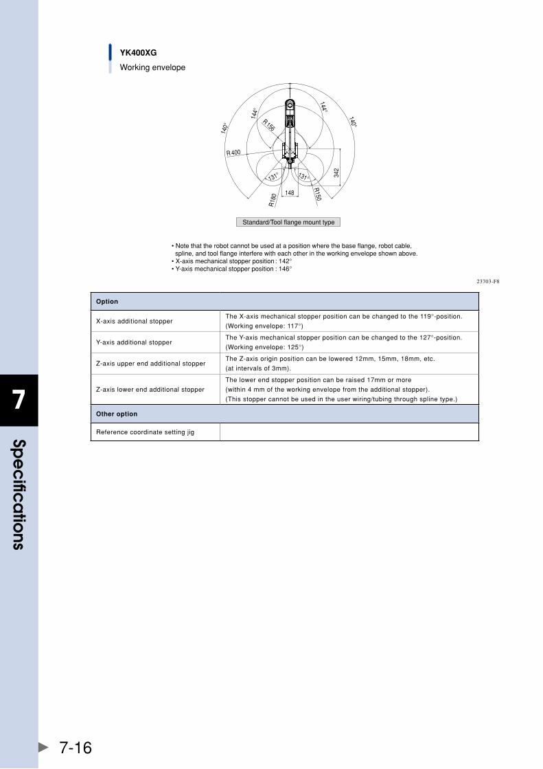
7
spe
cific
atio
ns
7-16
YK400XG
Working envelope
• Note that the robot cannot be used at a position where the base flange, robot cable, spline, and tool flange interfere with each other in the working envelope shown above.• X-axis mechanical stopper position : 142°• Y-axis mechanical stopper position : 146°
Standard/Tool flange mount type144°
144° 140°
140°
131° 131° 342
R 400
R150148
R18
0
R 156
23703-F8
Option
X-axisadditionalstopperTheX-axismechanicalstopperpositioncanbechangedtothe119°-position.
(Workingenvelope:117°)
Y-axisadditionalstopperTheY-axismechanicalstopperpositioncanbechangedtothe127°-position.
(Workingenvelope:125°)
Z-axisupperendadditionalstopperTheZ-axisoriginpositioncanbelowered12mm,15mm,18mm,etc.
(atintervalsof3mm).
Z-axislowerendadditionalstopper
Thelowerendstopperpositioncanberaised17mmormore
(within4mmoftheworkingenvelopefromtheadditionalstopper).
(Thisstoppercannotbeusedintheuserwiring/tubingthroughsplinetype.)
Other option
Referencecoordinatesettingjig
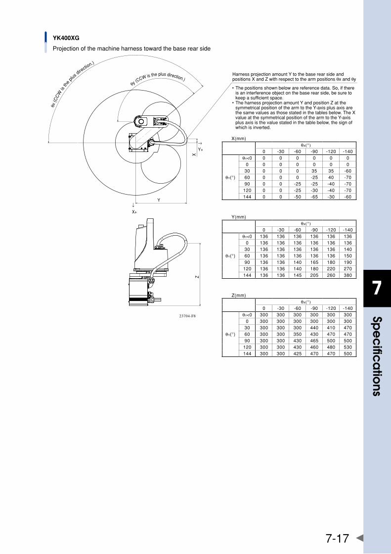
7
spe
cific
atio
ns
7-17
YK400XG
Projection of the machine harness toward the base rear side
ZX
Y
→Y+
↓X+
θx (C
CW
is th
e plu
s dire
ction.)
θy (CCW is the plus direction.)
• The positions shown below are reference data. So, if there is an interference object on the base rear side, be sure to keep a sufficient space.
• The harness projection amount Y and position Z at the symmetrical position of the arm to the Y-axis plus axis are the same values as those stated in the tables below. The X value at the symmetrical position of the arm to the Y-axis plus axis is the value stated in the table below, the sign of which is inverted.
Harness projection amount Y to the base rear side and positions X and Z with respect to the arm positions θx and θy
X(mm)θX(°)
0 -30 -60 -90 -120 -140
θY(°)
θY<0 0 0 0 0 0 00 0 0 0 0 0 0
30 0 0 0 35 35 -6060 0 0 0 -25 40 -7090 0 0 -25 -25 -40 -70
120 0 0 -25 -30 -40 -70144 0 0 -50 -65 -30 -60
Y(mm)θX(°)
0 -30 -60 -90 -120 -140
θY(°)
θY<0 136 136 136 136 136 1360 136 136 136 136 136 136
30 136 136 136 136 136 14060 136 136 136 136 136 15090 136 136 140 165 180 190
120 136 136 140 180 220 270144 136 136 145 205 260 380
Z(mm)θX(°)
0 -30 -60 -90 -120 -140
θY(°)
θY<0 300 300 300 300 300 3000 300 300 300 300 300 300
30 300 300 300 440 410 47060 300 300 350 430 470 47090 300 300 430 465 500 500
120 300 300 430 460 480 530144 300 300 425 470 470 500
23704-F8
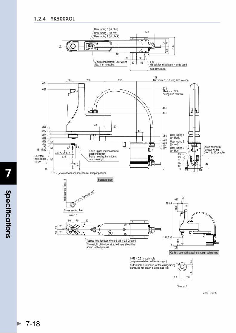
7
spe
cific
atio
ns
7-18
1.2.4 YK500XGL
4
0
151.5 ±2196200243248274277
296
627
674
0
167174202222
256
441
481
4
φ16 h7 -0.0180
φ35
3012
47
56 250 250
42 57
150
1.5
01245617995
86
2628
90
93
142
104 60
60
140
30 62
50 881039
1039
7050 20
0
151.5 ±2
793.5
150
φ27
5
150
1.5
Scale 1:1
A A
Standard type
7.8
7.8
7.8
User tubing 1 (φ4 black)User tubing 2 (φ4 red)User tubing 3 (φ4 blue)
7.8
D-sub connector for user wiring (No. 1 to 10 usable)
4-φ9M8 bolt for installation, 4 bolts used
138 (Base size)
129Maximum 315 during arm rotation
633Maximum 673during arm rotation
User tubing 1 (φ4 black)User tubing 2 (φ4 red)User tubing 3 (φ4 blue)
D-sub connector for user wiring (No. 1 to 10 usable)
Option: User wiring/tubing through spline type
As this hole is intended for the wiring/tubing clamp, do not attach a large load to it.
4-M3 × 0.5 through-hole (No phase relation to R-axis origin.)
View of F
The weight of the tool attached here should be added to the tip mass.
Tapped hole for user wiring 6-M3 × 0.5 Depth 6
Wid
th a
cros
s fla
ts: 1
5
Hollow diameter: φ11
Cross section A-A
Z-axis lower end mechanical stopper position
User toolinstallation range
↓F
Z-axis upper end mechanical stopper positionZ-axis rises by 4mm during return-to-origin.
23701-FG-00
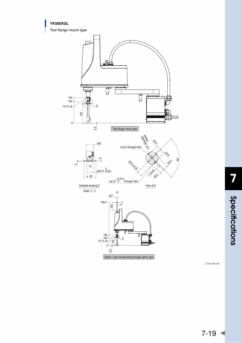
7
spe
cific
atio
ns
7-19
0
162194
150
2.5
2
4
φ30 h7 -0.0210
φ 55
φ35
↑E
90°
22.6
22.6
7 ±0.0
2
22.6
22.622.6 ±0.02
φ4 H7 0+0.012
0
147.5 ±2
147.5 ±2
162194
793.5
150
2.5
150 5
φ27↓F
D
YK500XGL
Tool flange mount type
Tool flange mount type
4-φ4.5 through-hole
Scale 2 : 3
D
Option: User wiring/tubing through spline type
Detailed drawing D View of E
through-hole
Hollow
diameter: φ11
23702-FG-00

7
spe
cific
atio
ns
7-20
YK500XGL
Working envelope
• Note that the robot cannot be used at a position where the base flange, robot cable, spline, and tool flange interfere with each other in the working envelope shown above.• X-axis mechanical stopper position : 142°• Y-axis mechanical stopper position : 146°
Standard/Tool flange mount type
140°
140°
144°
144°
442
133° 133°
R155
R500
R250R
200
23703-FG-00
Option
X-axisadditionalstopperTheX-axismechanicalstopperpositioncanbechangedtothe119°-position.
(Workingenvelope:117°)
Y-axisadditionalstopperTheY-axismechanicalstopperpositioncanbechangedtothe127°-position.
(Workingenvelope:125°)
Z-axisupperendadditionalstopperTheZ-axisoriginpositioncanbelowered12mm,15mm,18mm,etc.
(atintervalsof3mm).
Z-axislowerendadditionalstopper
Thelowerendstopperpositioncanberaised17mmormore
(within4mmoftheworkingenvelopefromtheadditionalstopper).
(Thisstoppercannotbeusedintheuserwiring/tubingthroughsplinetype.)
Other option
Referencecoordinatesettingjig
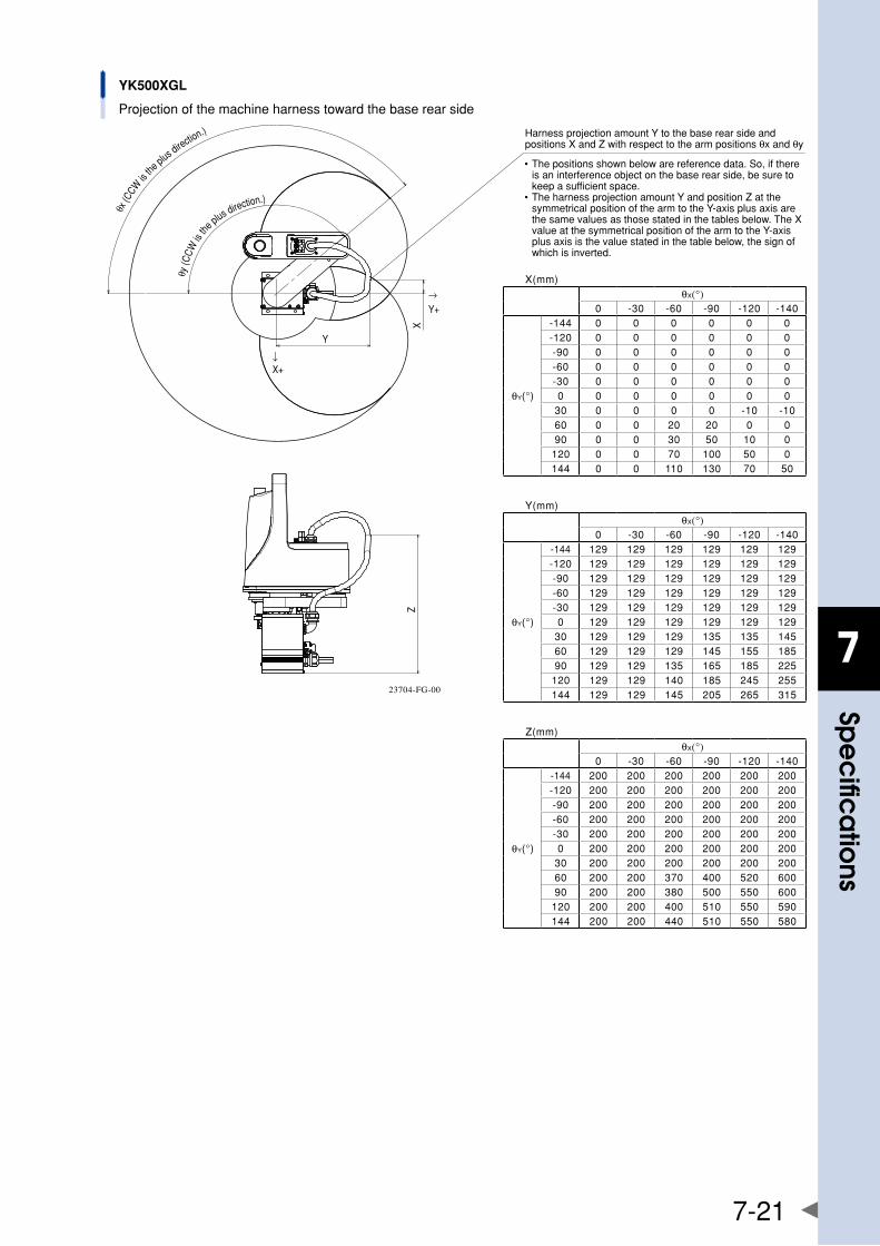
7
spe
cific
atio
ns
7-21
ZX
Y
→Y+
�↓X+
θx (C
CW is
the p
lus direction.)
θy
(CCW
is th
e plus direction.)
YK500XGL
Projection of the machine harness toward the base rear side
• The positions shown below are reference data. So, if there is an interference object on the base rear side, be sure to keep a sufficient space.
• The harness projection amount Y and position Z at the symmetrical position of the arm to the Y-axis plus axis are the same values as those stated in the tables below. The X value at the symmetrical position of the arm to the Y-axis plus axis is the value stated in the table below, the sign of which is inverted.
Harness projection amount Y to the base rear side and positions X and Z with respect to the arm positions θx and θy
X(mm)θX(°)
0 -30 -60 -90 -120 -140
θY(°)
-144 0 0 0 0 0 0-120 0 0 0 0 0 0-90 0 0 0 0 0 0-60 0 0 0 0 0 0-30 0 0 0 0 0 00 0 0 0 0 0 0
30 0 0 0 0 -10 -1060 0 0 20 20 0 090 0 0 30 50 10 0
120 0 0 70 100 50 0144 0 0 110 130 70 50
Y(mm)θX(°)
0 -30 -60 -90 -120 -140
θY(°)
-144 129 129 129 129 129 129-120 129 129 129 129 129 129-90 129 129 129 129 129 129-60 129 129 129 129 129 129-30 129 129 129 129 129 1290 129 129 129 129 129 129
30 129 129 129 135 135 14560 129 129 129 145 155 18590 129 129 135 165 185 225
120 129 129 140 185 245 255144 129 129 145 205 265 315
Z(mm)θX(°)
0 -30 -60 -90 -120 -140
θY(°)
-144 200 200 200 200 200 200-120 200 200 200 200 200 200-90 200 200 200 200 200 200-60 200 200 200 200 200 200-30 200 200 200 200 200 2000 200 200 200 200 200 200
30 200 200 200 200 200 20060 200 200 370 400 520 60090 200 200 380 500 550 600
120 200 200 400 510 550 590144 200 200 440 510 550 580
23704-FG-00
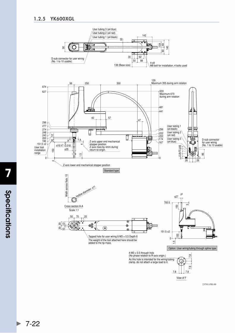
7
spe
cific
atio
ns
7-22
1.2.5 YK600XGL
4
0
151.5 ±2196200243248274277296
627
674
0
167174202222256
441
481
4
-0.0180
φ35
3012
47
56 250 350
42 57
150
1.5
01245617995
86
2628
90
93
142
104 60
60
140
30 6250 88
10391039
7050 20
0
151.5 ±2
793.5
150
φ27
5
150
1.5
↓F
A A
φ16 h7
User tubing 1 (φ4 black)
User tubing 2 (φ4 red)User tubing 3 (φ4 blue)
D-sub connector for user wiring (No. 1 to 10 usable)
138 (Base size)4-φ9M8 bolt for installation, 4 bolts used
129Maximum 355 during arm rotation
633Maximum 673during arm rotation
User tubing 1 (φ4 black)User tubing 2 (φ4 red)User tubing 3 (φ4 blue)
D-sub connector for user wiring (No. 1 to 10 usable)
Standard type
Z-axis lower end mechanical stopper position
User toolinstallation range
Scale 1:1
Wid
th a
cros
s fla
ts: 1
5
Hollow diameter: φ11
Cross section A-A
The weight of the tool attached here should be added to the tip mass.
Tapped hole for user wiring 6-M3 × 0.5 Depth 6
Option: User wiring/tubing through spline type
7.8
7.8
7.87.8
View of F
As this hole is intended for the wiring/tubing clamp, do not attach a large load to it.
4-M3 × 0.5 through-hole (No phase relation to R-axis origin.)
Z-axis upper end mechanical stopper positionZ-axis rises by 4mm during return-to-origin.
23701-FH-00
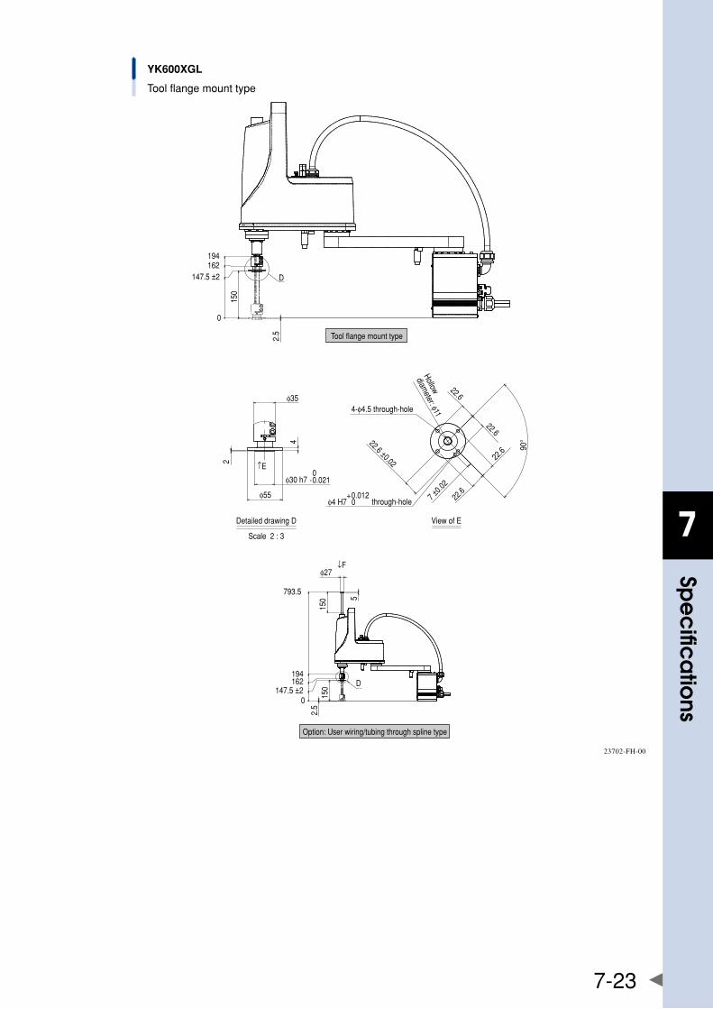
7
spe
cific
atio
ns
7-23
YK600XGL
Tool flange mount type
0
147.5 ±2162194
150
2.5
2
4
φ30 h7 -0.0210
φ55
φ35
↑E
90°
22.6
22.6
7 ±0.0
2
22.6
22.6
22.6 ±0.02
φ4 H7 0+0.012
0147.5 ±2
162194
793.5
150
2.5
150 5
φ27↓F
D
D
Tool flange mount type
4-φ4.5 through-hole
Hollow
diameter: φ11
View of E
through-hole
Scale 2 : 3
Detailed drawing D
Option: User wiring/tubing through spline type
23702-FH-00
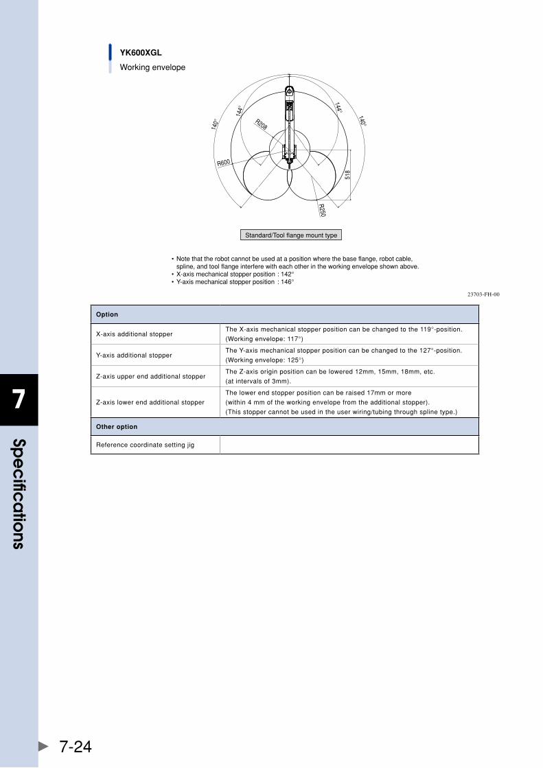
7
spe
cific
atio
ns
7-24
YK600XGL
Working envelope
• Note that the robot cannot be used at a position where the base flange, robot cable, spline, and tool flange interfere with each other in the working envelope shown above.• X-axis mechanical stopper position : 142°• Y-axis mechanical stopper position : 146°
Standard/Tool flange mount type
140°
140°
144°
144°
R600
R208
R250
518
23703-FH-00
Option
X-axisadditionalstopperTheX-axismechanicalstopperpositioncanbechangedtothe119°-position.
(Workingenvelope:117°)
Y-axisadditionalstopperTheY-axismechanicalstopperpositioncanbechangedtothe127°-position.
(Workingenvelope:125°)
Z-axisupperendadditionalstopperTheZ-axisoriginpositioncanbelowered12mm,15mm,18mm,etc.
(atintervalsof3mm).
Z-axislowerendadditionalstopper
Thelowerendstopperpositioncanberaised17mmormore
(within4mmoftheworkingenvelopefromtheadditionalstopper).
(Thisstoppercannotbeusedintheuserwiring/tubingthroughsplinetype.)
Other option
Referencecoordinatesettingjig
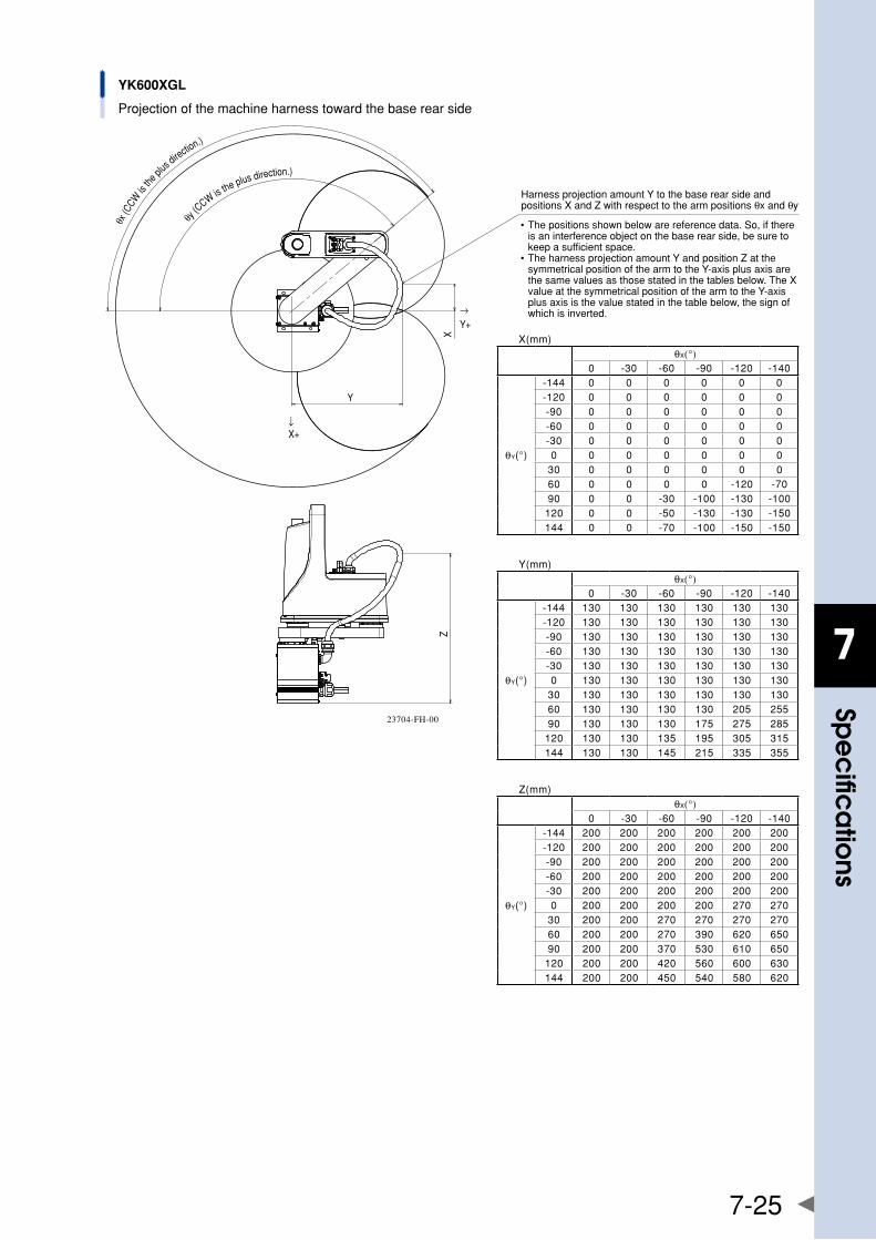
7
spe
cific
atio
ns
7-25
θx (C
CW is
the p
lus directio
n.)
θy (
CCW is the plus direction.)
YK600XGL
Projection of the machine harness toward the base rear side
ZX
Y
→Y+
� ↓X+
• The positions shown below are reference data. So, if there is an interference object on the base rear side, be sure to keep a sufficient space.
• The harness projection amount Y and position Z at the symmetrical position of the arm to the Y-axis plus axis are the same values as those stated in the tables below. The X value at the symmetrical position of the arm to the Y-axis plus axis is the value stated in the table below, the sign of which is inverted.
Harness projection amount Y to the base rear side and positions X and Z with respect to the arm positions θx and θy
X(mm)θX(°)
0 -30 -60 -90 -120 -140
θY(°)
-144 0 0 0 0 0 0-120 0 0 0 0 0 0-90 0 0 0 0 0 0-60 0 0 0 0 0 0-30 0 0 0 0 0 00 0 0 0 0 0 0
30 0 0 0 0 0 060 0 0 0 0 -120 -7090 0 0 -30 -100 -130 -100
120 0 0 -50 -130 -130 -150144 0 0 -70 -100 -150 -150
Y(mm)θX(°)
0 -30 -60 -90 -120 -140
θY(°)
-144 130 130 130 130 130 130-120 130 130 130 130 130 130-90 130 130 130 130 130 130-60 130 130 130 130 130 130-30 130 130 130 130 130 1300 130 130 130 130 130 130
30 130 130 130 130 130 13060 130 130 130 130 205 25590 130 130 130 175 275 285
120 130 130 135 195 305 315144 130 130 145 215 335 355
Z(mm)θX(°)
0 -30 -60 -90 -120 -140
θY(°)
-144 200 200 200 200 200 200-120 200 200 200 200 200 200-90 200 200 200 200 200 200-60 200 200 200 200 200 200-30 200 200 200 200 200 2000 200 200 200 200 270 270
30 200 200 270 270 270 27060 200 200 270 390 620 65090 200 200 370 530 610 650
120 200 200 420 560 600 630144 200 200 450 540 580 620
23704-FH-00
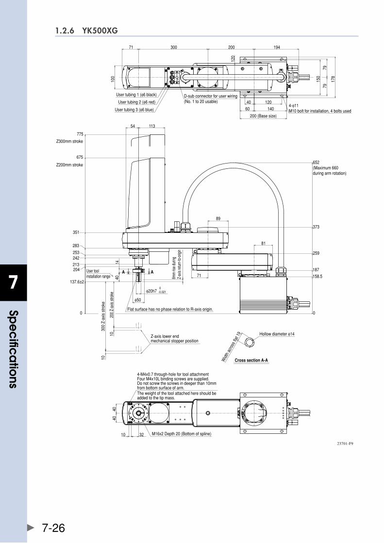
7
spe
cific
atio
ns
7-26
1.2.6 YK500XG
60 140
40 120
200300 19471
120
200 (Base size)
150
178
7979
100
D-sub connector for user wiring (No. 1 to 20 usable)
User tubing 1 (φ6 black)
User tubing 2 (φ6 red)
User tubing 3 (φ6 blue)4-φ11 M10 bolt for installation, 4 bolts used
0
158.5
187
259
373
652(Maximum 660 during arm rotation)
89
81
Flat surface has no phase relation to R-axis origin.
0-0.021
φ50
φ20h7
Z200mm stroke
Z300mm stroke
11354
675
775
0
137.6±2
204
253
283
351
213242
User toolinstallation range 8m
m ris
e dur
ingZ-
axis
retur
n-to-
origi
n
1440
71AA A
200
Z-ax
is st
roke
300
Z-ax
is s
troke
10
10
Z-axis lower end mechanical stopper position
Cross section A-AWidt
h ac
ross
flat 1
9 Hollow diameter φ14
3210
4040
4-M4x0.7 through-hole for tool attachmentFour M4x10L binding screws are supplied.Do not screw the screws in deeper than 10mm from bottom surface of arm.The weight of the tool attached here should be added to the tip mass.
M16x2 Depth 20 (Bottom of spline)
23701-F9
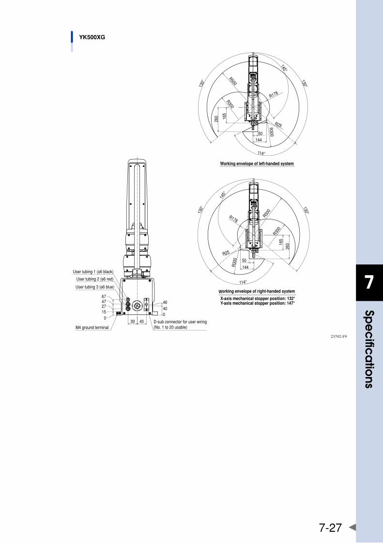
7
spe
cific
atio
ns
7-27
Working envelope of left-handed system
130°
130°
145°
260
50144
165
R300
R178
R25R300
R500114°
145°
130° 130°
165
260
50
144R30
0
R25
R500
R178
114°
Working envelope of right-handed system
X-axis mechanical stopper position: 132°Y-axis mechanical stopper position: 147°
R300
39 40M4 ground terminal
D-sub connector for user wiring(No. 1 to 20 usable)
015274767
04046
User tubing 1 (φ6 black)
User tubing 2 (φ6 red)
User tubing 3 (φ6 blue)
YK500XG
23702-F9
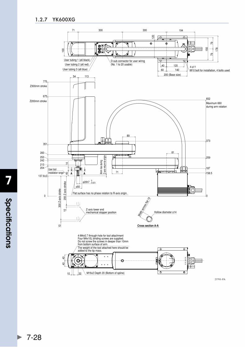
7
spe
cific
atio
ns
7-28
1.2.7 YK600XG
60 140
40 120
300300 19471
120
200 (Base size)
178
7979
100
D-sub connector for user wiring (No. 1 to 20 usable)
150
User tubing 3 (φ6 blue)
User tubing 2 (φ6 red)
User tubing 1 (φ6 black)
4-φ11 M10 bolt for installation, 4 bolts used
Z200mm stroke
Z300mm stroke
11354
675
775
137.6±2
204213
242253
283
351
0
User toolinstallation range
10
10
200
Z-ax
is s
troke
300
Z-ax
is s
troke
Flat surface has no phase relation to R-axis origin.
0-0.021
8mm
rise d
uring
Z-ax
is re
turn-
to-or
igin
AA4014
φ20h7
φ50
71
89
81
0
158.5
187
259
373
652
Maximum 660 during arm rotation
Hollow diameter φ14
Widt
h ac
ross
flat 1
9
Z-axis lower end mechanical stopper position
Cross section A-A
4040
3210
4-M4x0.7 through-hole for tool attachmentFour M4x10L binding screws are supplied.Do not screw the screws in deeper than 10mm from bottom surface of arm.The weight of the tool attached here should be added to the tip mass.
M16x2 Depth 20 (Bottom of spline)
23701-FA
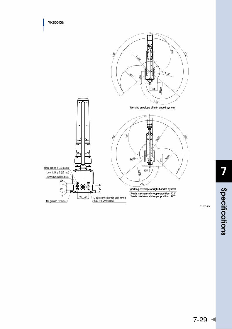
7
spe
cific
atio
ns
7-29
M4 ground terminal
01527
4767
D-sub connector for user wiring(No. 1 to 20 usable)
46
040
39 40X-axis mechanical stopper position: 132°Y-axis mechanical stopper position: 147°
Working envelope of right-handed system
Working envelope of left-handed system
130°
220
130°145°
135
135°
R600
R300
R180
R300
130°
145°
135
220
130°
135°
R600
R300
R30
0
R180
User tubing 1 (φ6 black)
User tubing 2 (φ6 red)
User tubing 3 (φ6 blue)
YK600XG
23702-FA
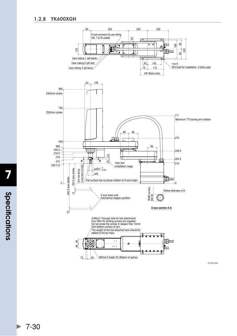
7
spe
cific
atio
ns
7-30
1.2.8 YK600XGH
75
200400
50 145
170
22080
245 (Base size)12
0
D-sub connector for user wiring (No. 1 to 20 usable)
220
9999
189
161
User tubing 3 (φ6 blue)
User tubing 2 (φ6 red)
User tubing 1 (φ6 black)
4-φ14 M12 bolt for installation, 4 bolts used
Z400mm stroke
Z200mm stroke
0
208.7±2273
278319.5333.5
368
440
790
990
63 128
200
Z-ax
is s
troke
400
Z-ax
is s
troke
12
12
Flat surface has no phase relation to R-axis origin.6mm
rise d
uring
Z-ax
is re
turn-
to-or
igin
AUser toolinstallation range 0
-0.021φ25h7
φ55
4514
AA
Z-axis lower end mechanical stopper position
Maximum 770 during arm rotation
0
219
254.5
339.5
476
711
9886
99
Cross section A-A
Wid
th a
cros
s fla
t 24
Hollow diameter φ18
15 36
4848
4-M4x0.7 through-hole for tool attachmentFour M4x10L binding screws are supplied.Do not screw the screws in deeper than 10mm from bottom surface of arm.The weight of the tool attached here should be added to the tip mass.
M20x2.5 Depth 20 (Bottom of spline)
23703-FA
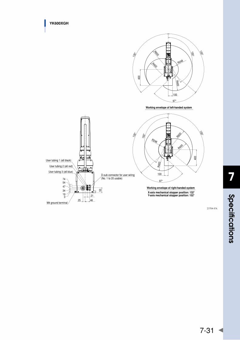
7
spe
cific
atio
ns
7-31
53
D-sub connector for user wiring(No. 1 to 20 usable)
M4 ground terminal
01934475474
21
25 46
R40
0
R248
R600
R400
400
97°
100
130°
130°
150°
Working envelope of left-handed system
150°
130°
130°
100
97°
400
R400
R600
R248R
400
Working envelope of right-handed system
X-axis mechanical stopper position: 132°Y-axis mechanical stopper position: 152°
User tubing 1 (φ6 black)
User tubing 2 (φ6 red)
User tubing 3 (φ6 blue)
YK600XGH
23704-FA
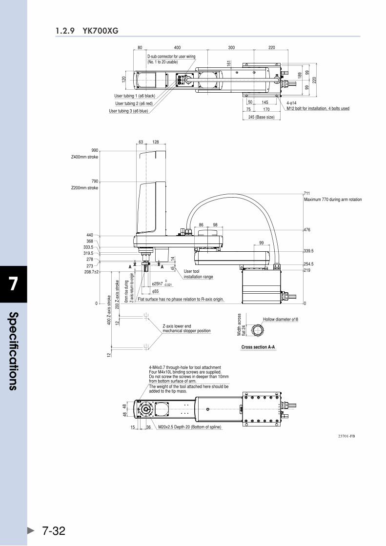
7
spe
cific
atio
ns
7-32
1.2.9 YK700XG
75
300400
50 145
170
22080
245 (Base size)
189 99
99
220
120
161
D-sub connector for user wiring (No. 1 to 20 usable)
Maximum 770 during arm rotation
0
219254.5
339.5
476
711
Z400mm stroke
Z200mm stroke
63 128
208.7±2273
278319.5333.5
368440
790
990
12
1240
0 Z-
axis
stro
ke
6mm
rise d
uring
Z-ax
is re
turn-
to-or
igin
200
Z-ax
is s
troke
0
Z-axis lower end mechanical stopper position
User toolinstallation range
45
0-0.021
Flat surface has no phase relation to R-axis origin.
14
A AA
98
99
86
Cross section A-A
Hollow diameter φ18
Wid
th a
cros
s fla
t 24
4848
15 36
User tubing 3 (φ6 blue)
User tubing 2 (φ6 red)
User tubing 1 (φ6 black)
4-φ14 M12 bolt for installation, 4 bolts used
φ25h7
φ55
4-M4x0.7 through-hole for tool attachmentFour M4x10L binding screws are supplied.Do not screw the screws in deeper than 10mm from bottom surface of arm.The weight of the tool attached here should be added to the tip mass.
M20x2.5 Depth 20 (Bottom of spline)
23701-FB
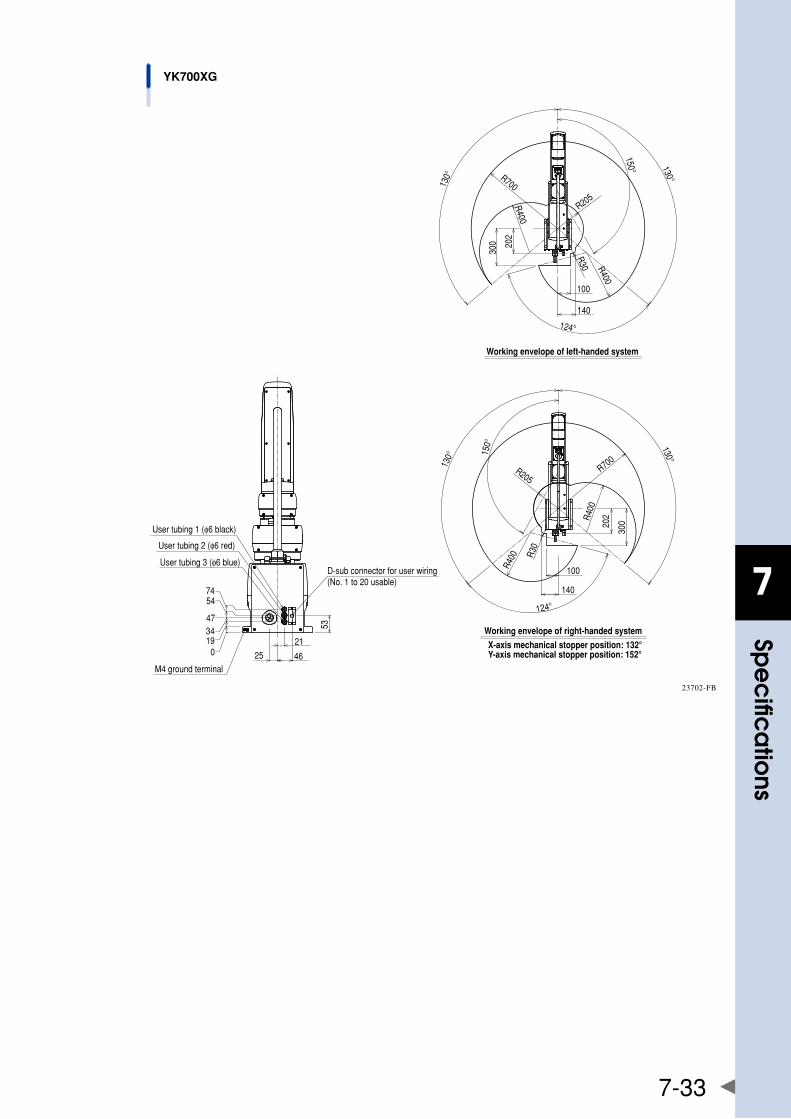
7
spe
cific
atio
ns
7-33
Working envelope of right-handed system
X-axis mechanical stopper position: 132°Y-axis mechanical stopper position: 152°
R700
R400
R205
R400
R400
124°
150° 130°
30020
2
140
100
R30
130°
Working envelope of left-handed system
100
140
202
300
130°
150°
124°
130°
R400R400
R30R205
R400
R700
54
0
74
473419
25
D-sub connector for user wiring(No. 1 to 20 usable)
21
53
46M4 ground terminal
User tubing 1 (φ6 black)
User tubing 2 (φ6 red)
User tubing 3 (φ6 blue)
YK700XG
23702-FB
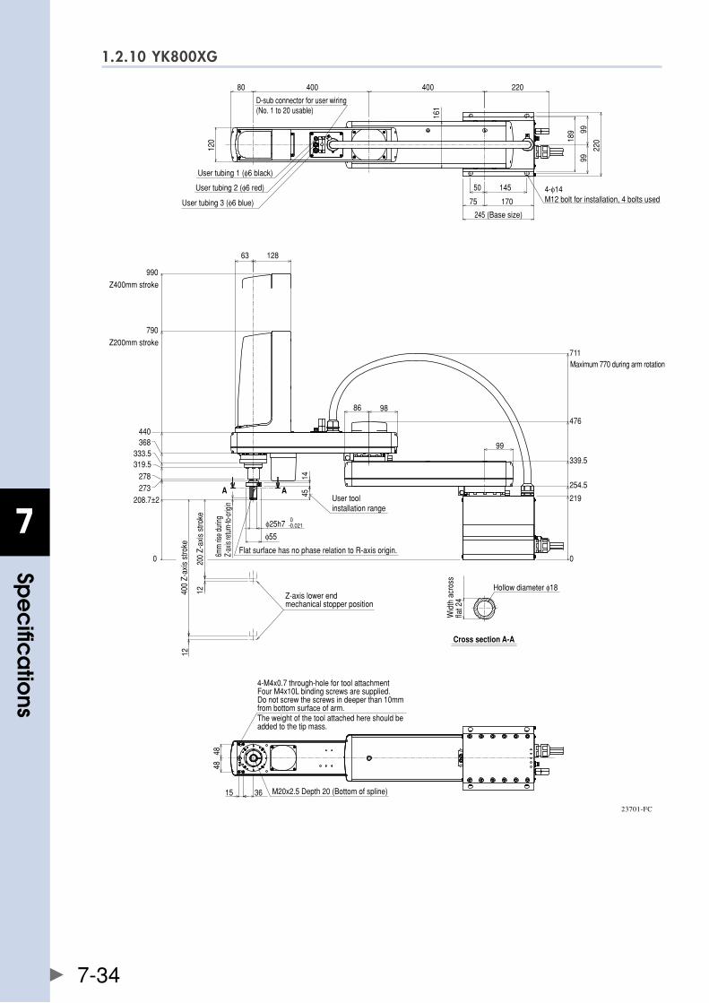
7
spe
cific
atio
ns
7-34
1.2.10 YK800XG
220
161
80 400 400
D-sub connector for user wiring (No. 1 to 20 usable)
75
50 145
170
245 (Base size)12
0 189 99
99
220
Z200mm stroke
Z400mm stroke
333.5
440
790
990
368
319.5278273
208.7±2
63 128
Z-axis lower end mechanical stopper position
200
Z-ax
is s
troke
6mm
rise d
uring
Z-ax
is re
turn-
to-or
igin
400
Z-ax
is s
troke
12
0
12
AAUser toolinstallation range
45
Flat surface has no phase relation to R-axis origin.
0-0.021
14
Cross section A-A
Wid
th a
cros
s fla
t 24
Hollow diameter φ18
Maximum 770 during arm rotation
219
476
339.5
711
254.5
0
99
9886
48
15
48
36
User tubing 3 (φ6 blue)
User tubing 2 (φ6 red)
User tubing 1 (φ6 black)
4-φ14 M12 bolt for installation, 4 bolts used
φ25h7
φ55
4-M4x0.7 through-hole for tool attachmentFour M4x10L binding screws are supplied.Do not screw the screws in deeper than 10mm from bottom surface of arm.The weight of the tool attached here should be added to the tip mass.
M20x2.5 Depth 20 (Bottom of spline)
23701-FC
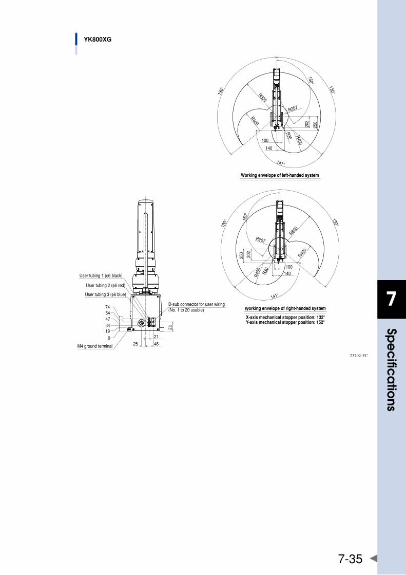
7
spe
cific
atio
ns
7-35
Working envelope of right-handed system
X-axis mechanical stopper position: 132°Y-axis mechanical stopper position: 152°
019
54
M4 ground terminal
3447
74
25
D-sub connector for user wiring(No. 1 to 20 usable)
46
21
53
141°
130°130° 15
0°
R400 R3
0
R207
R400
R800
250
202
140100
100
140
202
250
R800
R400
R207
R30 R400
150°
130°130°
141°
Working envelope of left-handed system
User tubing 1 (φ6 black)
User tubing 2 (φ6 red)
User tubing 3 (φ6 blue)
YK800XG
23702-FC
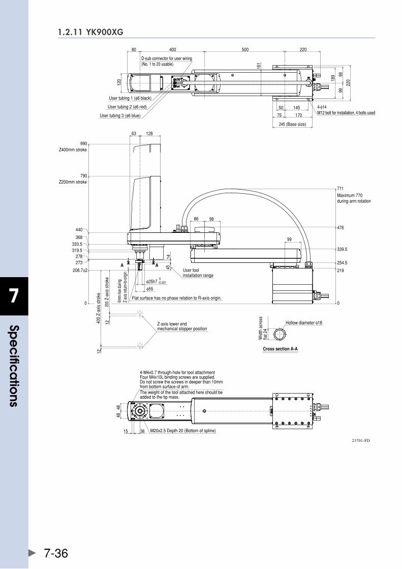
7
spe
cific
atio
ns
7-36
1.2.11 YK900XG
AA
99
161
220
99
189
245 (Base size)
220
170
14550
75
D-sub connector for user wiring (No. 1 to 20 usable)
80 500400
120
Z200mm stroke
Z400mm stroke
333.5368
990
0
273278
319.5
790
440
208.7±2
12400
Z-ax
is s
troke
6mm
rise d
uring
Z-ax
is re
turn-
to-or
igin
12
200
Z-ax
is s
troke
A 45 User toolinstallation range
Z-axis lower end mechanical stopper position
14
0-0.021
Flat surface has no phase relation to R-axis origin.
9886
99
Maximum 770 during arm rotation
0
254.5
711
339.5
476
219
Cross section A-A
Wid
th a
cros
s fla
t 24
Hollow diameter φ18
36
48
15
48
12863
User tubing 3 (φ6 blue)
User tubing 2 (φ6 red)
User tubing 1 (φ6 black)
4-φ14 M12 bolt for installation, 4 bolts used
φ25h7
φ55
4-M4x0.7 through-hole for tool attachmentFour M4x10L binding screws are supplied.Do not screw the screws in deeper than 10mm from bottom surface of arm.The weight of the tool attached here should be added to the tip mass.
M20x2.5 Depth 20 (Bottom of spline)
23701-FD
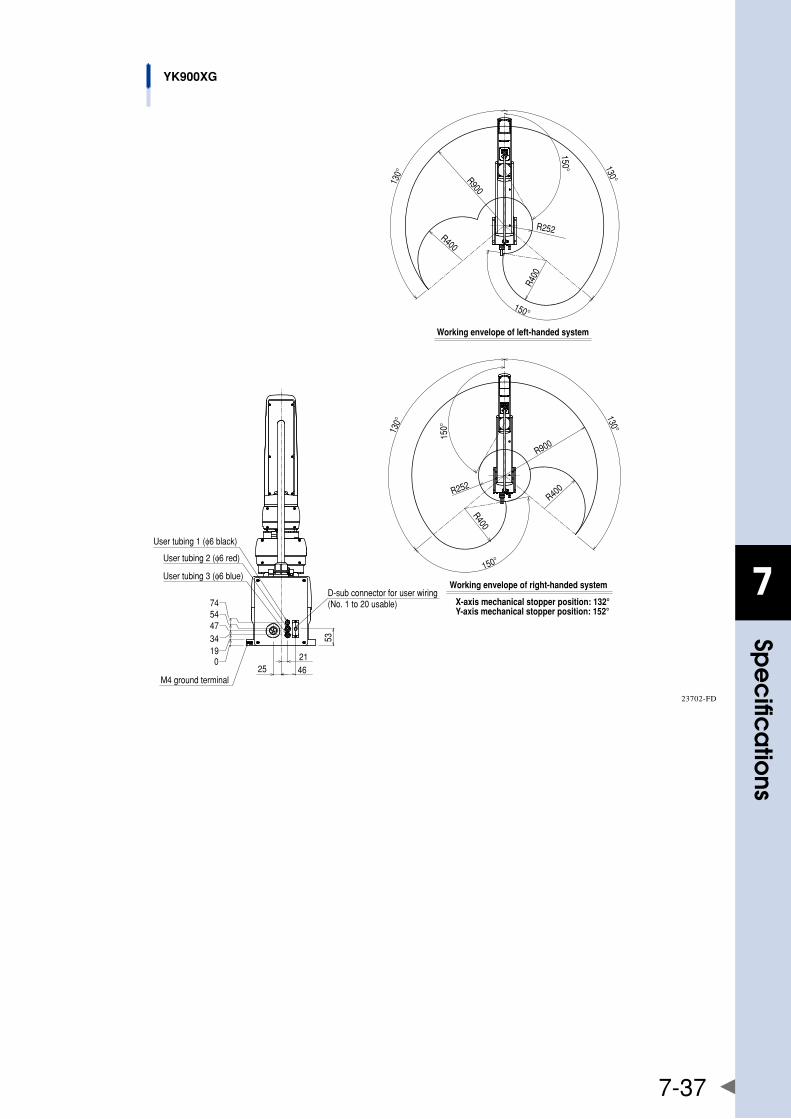
7
spe
cific
atio
ns
7-37
74
53
21
4734
M4 ground terminal46
54
D-sub connector for user wiring(No. 1 to 20 usable)
25
190
Working envelope of right-handed system
X-axis mechanical stopper position: 132°Y-axis mechanical stopper position: 152°
Working envelope of left-handed systemR900
R252
R400
R400
150°
130°130°
150°
150°13
0°
130°
150°
R400
R900
R252
R400
User tubing 1 (φ6 black)
User tubing 2 (φ6 red)
User tubing 3 (φ6 blue)
YK900XG
23702-FD

7
spe
cific
atio
ns
7-38
1.2.12 YK1000XG
A
48
15
48
36
12400
Z-ax
is s
troke
12
200
Z-ax
is s
troke
Z-axis lower endmechanical stopper position
Hollow diameter φ18
Wid
th a
cros
s fla
t 24
Cross section A-A
333.5368
0
273278
319.5
790
440
208.7±2
45
User toolinstallation range
14
0-0.021
6mm
rise d
uring
Z-ax
is re
turn-
to-or
igin
Flat surface has no phase relation to R-axis origin.
99
9886
A A
Z200mm stroke
Z400mm stroke
990
12863
Maximum 770 during arm rotation
0
254.5
711
339.5
476
219
161
22080
D-sub connector for user wiring (No. 1 to 20 usable)
120
600400
99
75
50 145
170
245 (Base size)
189 99
220
User tubing 3 (φ6 blue)
User tubing 2 (φ6 red)
User tubing 1 (φ6 black)
4-φ14 M12 bolt for installation, 4 bolts used
φ25h7
φ55
4-M4x0.7 through-hole for tool attachmentFour M4x10L binding screws are supplied.Do not screw the screws in deeper than 10mm from bottom surface of arm.The weight of the tool attached here should be added to the tip mass.
M20x2.5 Depth 20 (Bottom of spline)
23701-FE
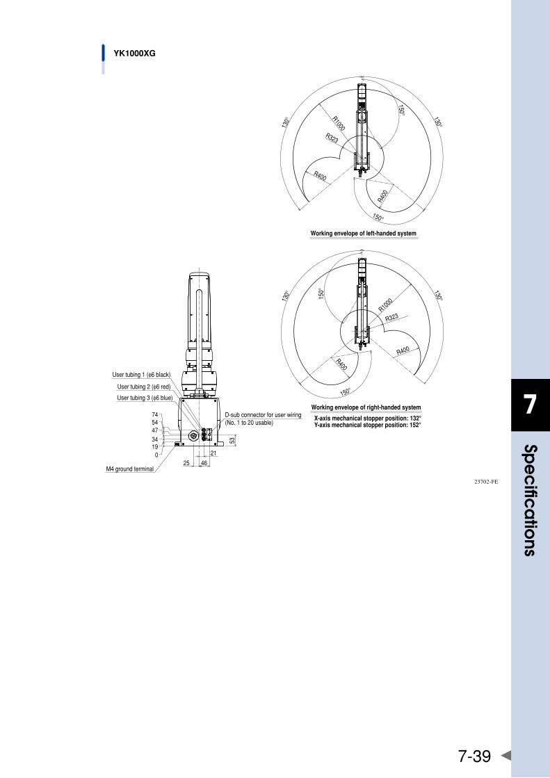
7
spe
cific
atio
ns
7-39
54
M4 ground terminal
3447
74
019
46
21
25
53
D-sub connector for user wiring(No. 1 to 20 usable)
Working envelope of right-handed system
X-axis mechanical stopper position: 132°Y-axis mechanical stopper position: 152°
Working envelope of left-handed system
150°
130°
150°
R400
R1000
R400
R323
R1000
R400
R323
R400
150°
130°
130°
150°
130°
User tubing 1 (φ6 black)
User tubing 2 (φ6 red)
User tubing 3 (φ6 blue)
YK1000XG
23702-FE
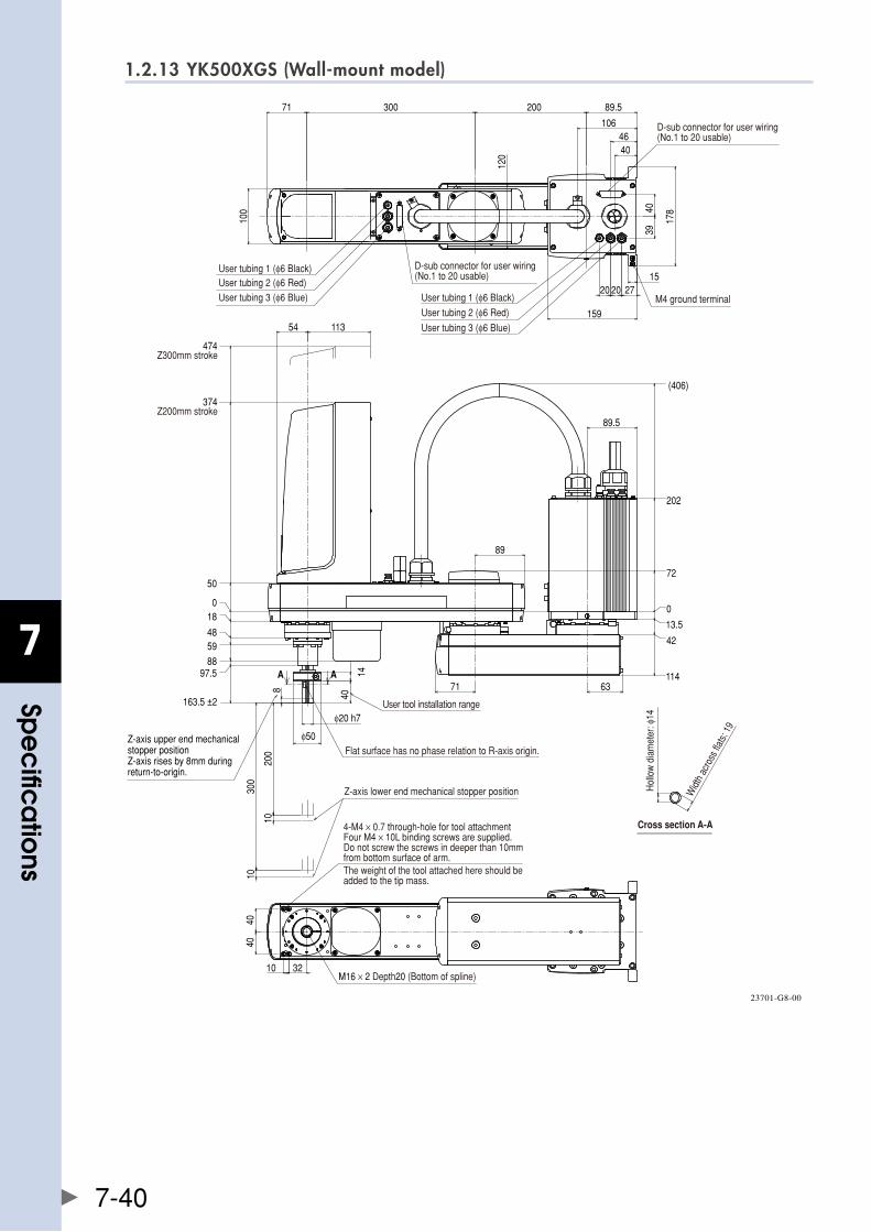
7
spe
cific
atio
ns
7-40
1.2.13 YK500XGS (Wall-mount model)
Widt
h ac
ross
flats:
19
M16 × 2 Depth20 (Bottom of spline)
89.520030071
100
120
178
159
4046
4039
15272020
106 D-sub connector for user wiring(No.1 to 20 usable)
D-sub connector for user wiring(No.1 to 20 usable)
4040
3210
Hol
low
dia
met
er: φ
14
User tubing 1 (φ6 Black)User tubing 2 (φ6 Red)User tubing 3 (φ6 Blue) User tubing 1 (φ6 Black)
User tubing 2 (φ6 Red)
User tubing 3 (φ6 Blue)
M4 ground terminal
4-M4 × 0.7 through-hole for tool attachmentFour M4 × 10L binding screws are supplied.Do not screw the screws in deeper than 10mmfrom bottom surface of arm.The weight of the tool attached here should beadded to the tip mass.
Cross section A-A
89
71
0
13.5
42
114
72
202
(406)
113
10
10
200
300
018
4859
8897.5
163.5 ±2
50
374Z200mm stroke
474Z300mm stroke
8
89.5
63
54
40
14
φ20 h7
φ50Flat surface has no phase relation to R-axis origin.
User tool installation range
A A
Z-axis lower end mechanical stopper position
Z-axis upper end mechanical stopper positionZ-axis rises by 8mm during return-to-origin.
23701-G8-00
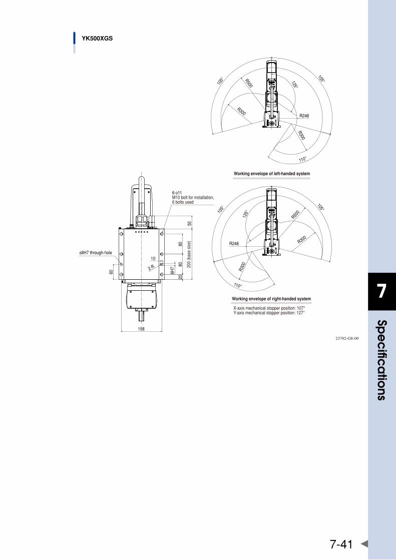
7
spe
cific
atio
ns
7-41
10
2080
80
60
158
200
(bas
e si
ze)
R50010
5°
105°
R248
110°
125°
R300R3
00
R500105°
R248
105°125°
R300
R300
110°
φ8H7 through-hole
Working envelope of right-handed system
X-axis mechanical stopper position: 107°Y-axis mechanical stopper position: 127°
Working envelope of left-handed system
6-φ11M10 bolt for installation, 6 bolts used
2-R
50
8H7
YK500XGS
23702-G8-00
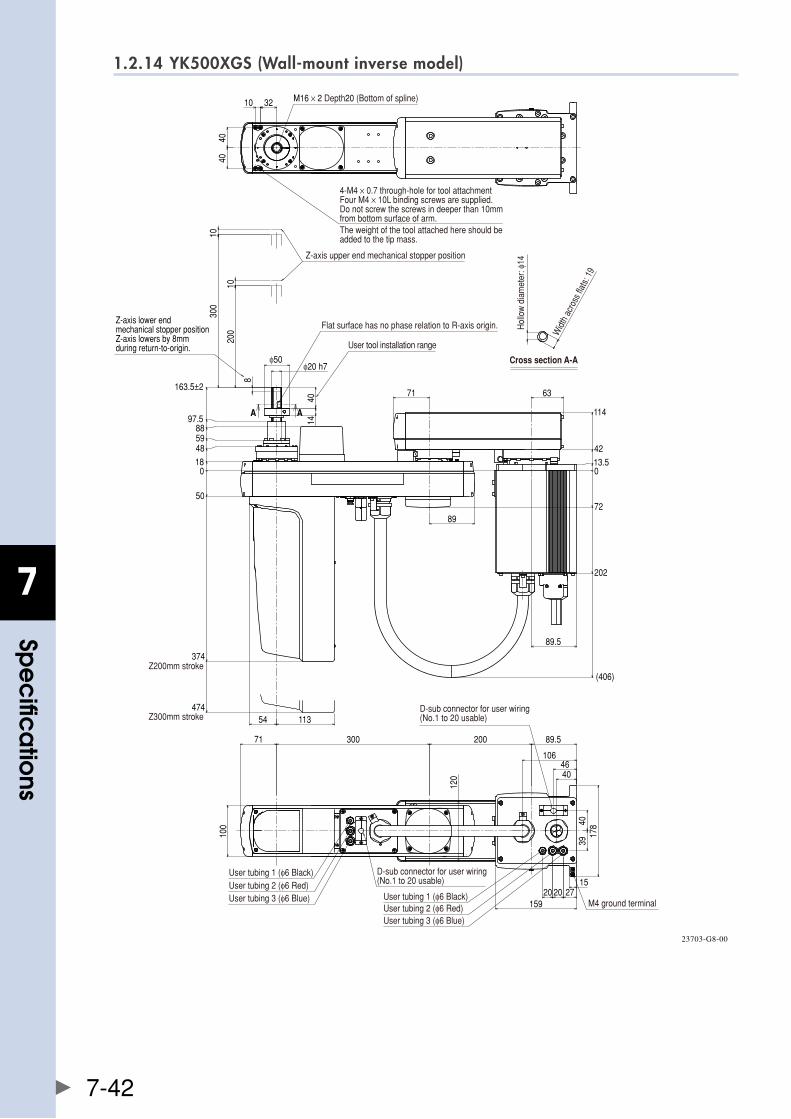
7
spe
cific
atio
ns
7-42
1.2.14 YK500XGS (Wall-mount inverse model)
0
72
202
(406)
13.5
42
114
200
300
0
50
374
474
18
485988
97.5
163.5±2
10
10
8
113
71
89
4014
φ20 h7φ50
54
63
89.5
A A
4040
10 32
71 89.5200300
4039
178
15927
152020
4046
106
100
120
M16 × 2 Depth20 (Bottom of spline)
4-M4 × 0.7 through-hole for tool attachmentFour M4 × 10L binding screws are supplied.Do not screw the screws in deeper than 10mmfrom bottom surface of arm.The weight of the tool attached here should beadded to the tip mass.
Z-axis upper end mechanical stopper position
Flat surface has no phase relation to R-axis origin.
User tool installation range
Widt
h ac
ross
flats:
19
Hol
low
dia
met
er: φ
14
Cross section A-A
Z200mm stroke
Z300mm stroke
User tubing 1 (φ6 Black)User tubing 2 (φ6 Red)User tubing 3 (φ6 Blue)
D-sub connector for user wiring(No.1 to 20 usable)
User tubing 1 (φ6 Black)User tubing 2 (φ6 Red)User tubing 3 (φ6 Blue)
M4 ground terminal
D-sub connector for user wiring(No.1 to 20 usable)
Z-axis lower end mechanical stopper positionZ-axis lowers by 8mm during return-to-origin.
23703-G8-00
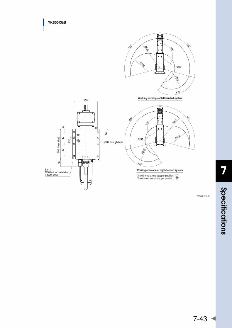
7
spe
cific
atio
ns
7-43
10
2080
80
60
158
2-R
8H7
50
R500105°
105°
R248
110°
125°
R300
R300
R500105°
R248
105°125°R300
R300
110°
YK500XGS
φ8H7 through-hole
200
(bas
e si
ze)
Working envelope of left-handed system
Working envelope of right-handed system
X-axis mechanical stopper position: 107°Y-axis mechanical stopper position: 127°
6-φ11M10 bolt for installation, 6 bolts used
23704-G8-00
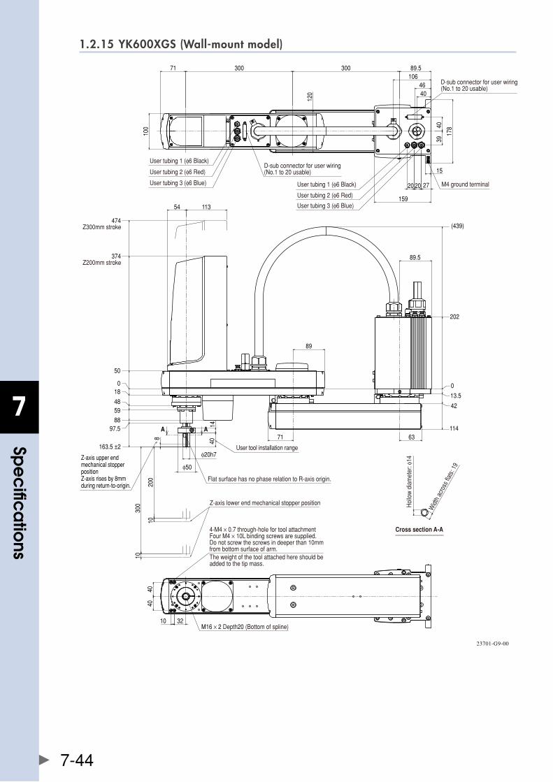
7
spe
cific
atio
ns
7-44
1.2.15 YK600XGS (Wall-mount model)
89.530030071
3940
178
15
272020
159
4046
106
4040
10 32
100
120
10
10
200
300
71
89
114
202
(439)
163.5 ±2
374
474
8
113
63
1440
89.5
54
A A
φ50
φ20h7
0
13.5
42
018
4859
8897.5
50
D-sub connector for user wiring(No.1 to 20 usable)
User tubing 1 (φ6 Black)
User tubing 2 (φ6 Red)
User tubing 3 (φ6 Blue) User tubing 1 (φ6 Black)
User tubing 2 (φ6 Red)
User tubing 3 (φ6 Blue)
D-sub connector for user wiring(No.1 to 20 usable)
M4 ground terminal
Z200mm stroke
Z300mm stroke
4-M4 × 0.7 through-hole for tool attachmentFour M4 × 10L binding screws are supplied.Do not screw the screws in deeper than 10mmfrom bottom surface of arm.The weight of the tool attached here should beadded to the tip mass.
Flat surface has no phase relation to R-axis origin.
User tool installation range
Z-axis lower end mechanical stopper position
M16 × 2 Depth20 (Bottom of spline)
Cross section A-A
Hol
low
dia
met
er: φ
14
Widt
h ac
ross
flats:
19
Z-axis upper end mechanical stopper positionZ-axis rises by 8mm during return-to-origin.
23701-G9-00
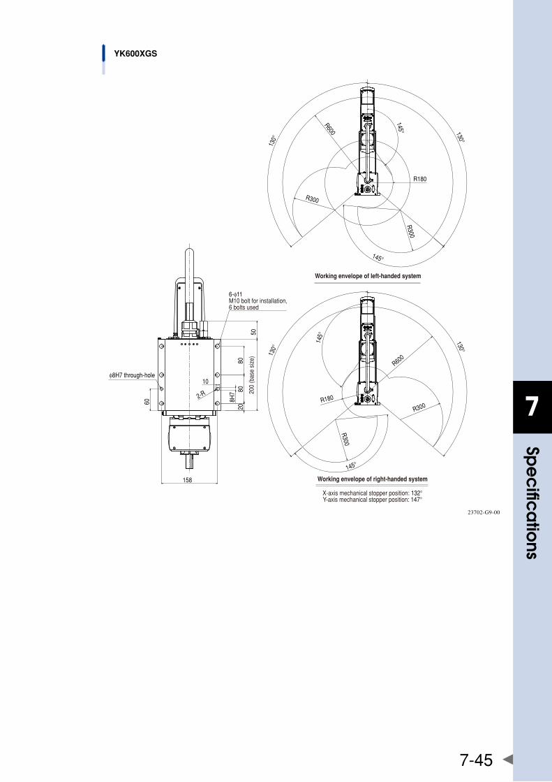
7
spe
cific
atio
ns
7-45
10
60
2080
80
158
R600
R180
130°
130°
R300
145°
R300
145°
R600130°
130°
R300R180
145°
R300
145°
2-R
50
8H7
φ8H7 through-hole
Working envelope of left-handed system
Working envelope of right-handed system
X-axis mechanical stopper position: 132°Y-axis mechanical stopper position: 147°
200
(bas
e si
ze)
6-φ11M10 bolt for installation, 6 bolts used
YK600XGS
23702-G9-00
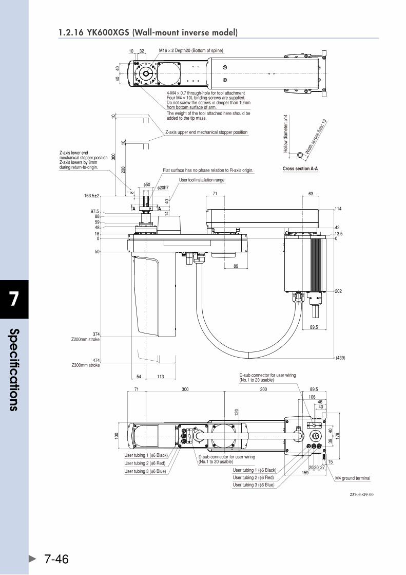
7
spe
cific
atio
ns
7-46
1.2.16 YK600XGS (Wall-mount inverse model)
0
202
(439)
13.542
114
0
50
374
474
18485988
97.5
163.5±2
8
200
10
300
10
113
71
89
1440
φ20h7
54
63
89.5
A A
4040
10 32
89.530030071
100
120
178
3940
15272020
159
4640
106
φ50
M16 × 2 Depth20 (Bottom of spline)
4-M4 × 0.7 through-hole for tool attachmentFour M4 × 10L binding screws are supplied.Do not screw the screws in deeper than 10mmfrom bottom surface of arm.The weight of the tool attached here should beadded to the tip mass.
Z-axis upper end mechanical stopper position
Z-axis lower end mechanical stopper positionZ-axis lowers by 8mm during return-to-origin.
User tool installation range
Flat surface has no phase relation to R-axis origin. Cross section A-A
Hol
low
dia
met
er: φ
14
Widt
h ac
ross
flats:
19
Z200mm stroke
Z300mm stroke
User tubing 1 (φ6 Black)
User tubing 2 (φ6 Red)
User tubing 3 (φ6 Blue)
D-sub connector for user wiring(No.1 to 20 usable)
User tubing 1 (φ6 Black)
User tubing 2 (φ6 Red)
User tubing 3 (φ6 Blue)M4 ground terminal
D-sub connector for user wiring(No.1 to 20 usable)
23703-G9-00
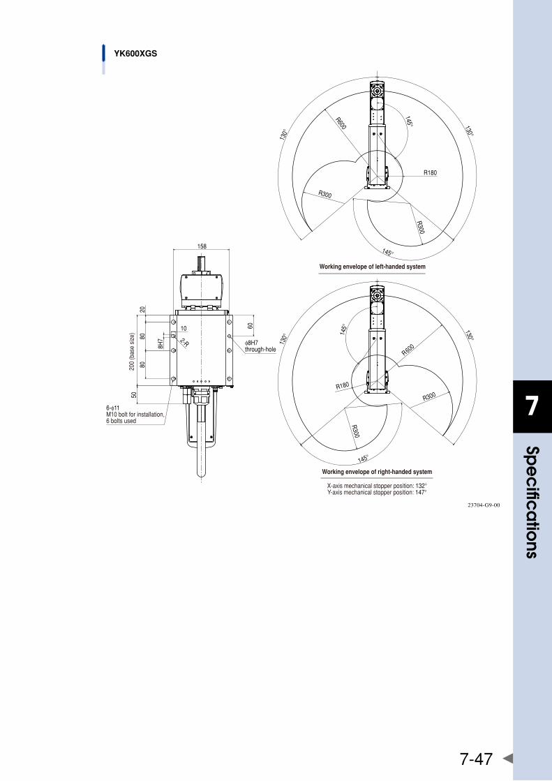
7
spe
cific
atio
ns
7-47
200
(bas
e si
ze)
YK600XGS
10 60
2080
80
158
2-R
8H7
50
R600
R180
130°
130°
R300
145°
R300
145°
R600130°
130°
R300R180
145°
R300
145°
φ8H7 through-hole
Working envelope of left-handed system
Working envelope of right-handed system
X-axis mechanical stopper position: 132°Y-axis mechanical stopper position: 147°
6-φ11M10 bolt for installation, 6 bolts used
23704-G9-00
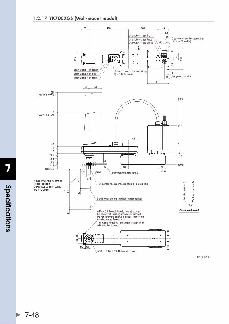
7
spe
cific
atio
ns
7-48
1.2.17 YK700XGS (Wall-mount model)
200
400
12
12
98
86
0
71
247
(520)
3065.5
150.5
6
035
385Z200mm stroke
585Z400mm stroke
3771.585.5
127.3132
79
(114)
φ55
4514
30040080
120
160
114
2521
46
220
47
219
34
20
20
53
1948
48
15 36
A A
196.3 ±2φ25h7
63 128
D-sub connector for user wiring(No.1 to 20 usable)
User tubing 1 (φ6 Black)
User tubing 2 (φ6 Red)
User tubing 3 (φ6 Blue)
User tubing 1 (φ6 Black)User tubing 2 (φ6 Red)User tubing 3 (φ6 Blue)
D-sub connector for user wiring(No.1 to 20 usable)
M4 ground terminal
4-M4 × 0.7 through-hole for tool attachmentFour M4 × 10L binding screws are supplied.Do not screw the screws in deeper than 10mmfrom bottom surface of arm.The weight of the tool attached here should beadded to the tip mass.
Flat surface has no phase relation to R-axis origin.
User tool installation range
Z-axis lower end mechanical stopper position
M20 × 2.5 Depth20 (Bottom of spline)
Cross section A-A
Hol
low
dia
met
er: φ
18
Wid
th a
cros
s fla
ts: 2
4Z-axis upper end mechanical stopper positionZ-axis rises by 6mm during return-to-origin.
23701-GA-00
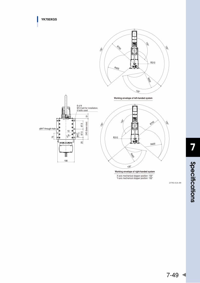
7
spe
cific
atio
ns
7-49
10
198
75
2597
.597
.5
2-R
51
8H7
130°
130°
R310
130°R700
R400
R400
130°
R700
130°
130°
R310
R400
R400
130°
130°
φ8H7 through-hole
245
(bas
e si
ze)
6-φ14M12 bolt for installation, 6 bolts used
Working envelope of left-handed system
Working envelope of right-handed system
X-axis mechanical stopper position: 132°Y-axis mechanical stopper position: 132°
YK700XGS
23702-GA-00

7
spe
cific
atio
ns
7-50
1.2.18 YK700XGS (Wall-mount inverse model)
6
400
200
12
12
86
98
0
71
247
(520)
3065.5
150.5
035
385
585
3771.585.5
127.3132
196.3 ±2
(114)
79
1445
φ55
A A
4848
15 36
30040080 114
2146
25
220
1947
219
3420
20
53
120
160
φ25h7
M20 × 2.5 Depth20 (Bottom of spline)
4-M4 × 0.7 through-hole for tool attachmentFour M4 × 10L binding screws are supplied.Do not screw the screws in deeper than 10mmfrom bottom surface of arm.The weight of the tool attached here should beadded to the tip mass.
User tool installation range
Flat surface has no phase relation to R-axis origin.
Cross section A-A
Hol
low
dia
met
er: φ
18
Wid
th a
cros
s fla
ts: 2
4
D-sub connector for user wiring(No.1 to 20 usable)
D-sub connector for user wiring(No.1 to 20 usable)
User tubing 1 (φ6 Black)
User tubing 2 (φ6 Red)
User tubing 3 (φ6 Blue)
User tubing 1 (φ6 Black)User tubing 2 (φ6 Red)User tubing 3 (φ6 Blue)
M4 ground terminal
Z200mm stroke
Z400mm stroke
Z-axis upper end mechanical stopper position
Z-axis lower end mechanical stopper positionZ-axis lowers by 6mm during return-to-origin.
23703-GA-00
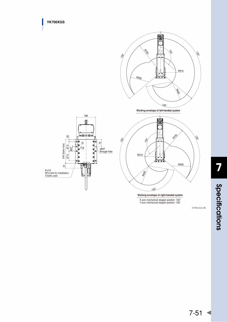
7
spe
cific
atio
ns
7-51
YK700XGS
10
198
75
2597
.597
.5
2-R
8H7
51
R700
130°
130°
130°
R400
R400
130°
R310
R700
130°
R400
R400
130°
R310
130°
130°
6-φ14M12 bolt for installation, 6 bolts used
245
(bas
e si
ze)
φ8H7 through-hole
Working envelope of left-handed system
Working envelope of right-handed system
X-axis mechanical stopper position: 132°Y-axis mechanical stopper position: 132°
23704-GA-00
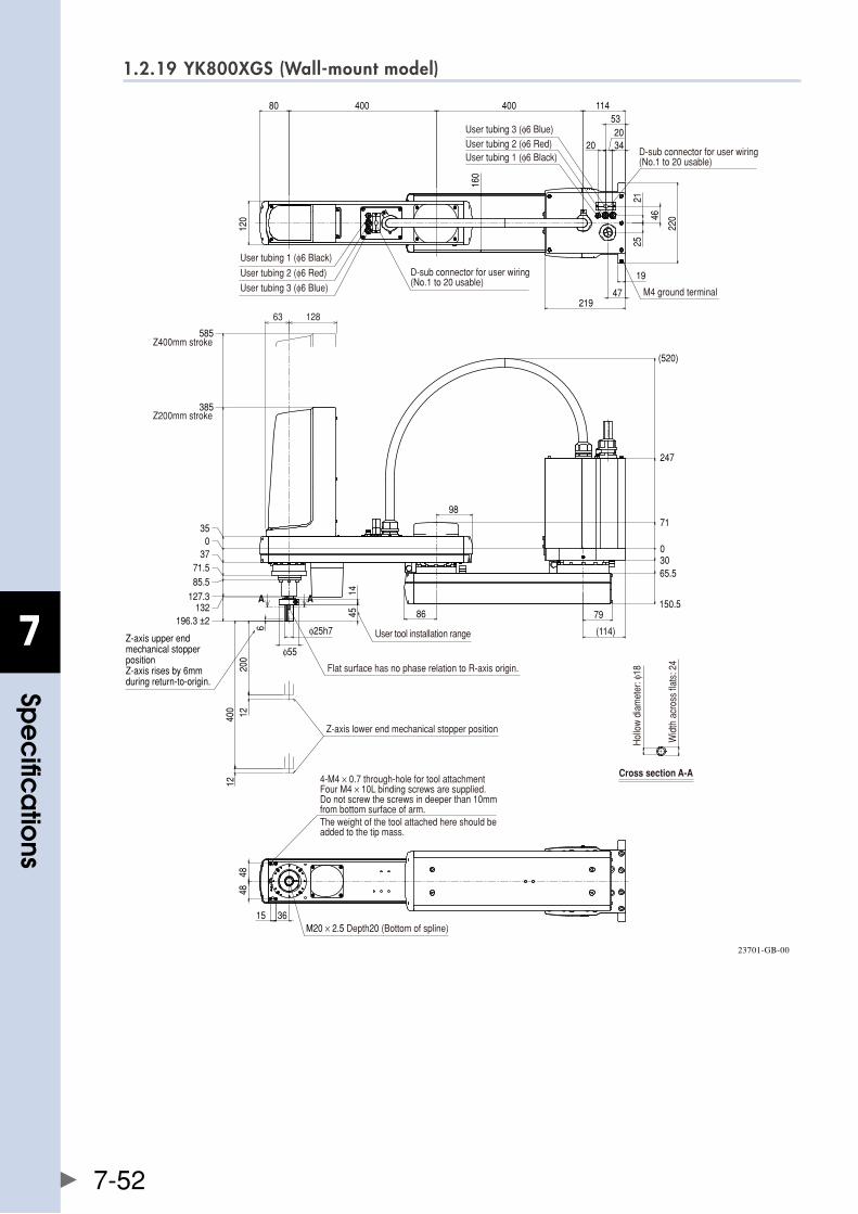
7
spe
cific
atio
ns
7-52
1.2.19 YK800XGS (Wall-mount model)
200
400
6
1212
86
98
0
71
247
(520)
3065.5
150.5
385
585
79
(114)
4514
φ55
φ25h7
40040080 114
160
120
19
47219
2521
46
220
3420
20
53
4848
15 36
A A
63 128
035
3771.585.5
127.3132
196.3 ±2
User tubing 1 (φ6 Black)
User tubing 2 (φ6 Red)
User tubing 3 (φ6 Blue)
User tubing 1 (φ6 Black)User tubing 2 (φ6 Red)User tubing 3 (φ6 Blue)
D-sub connector for user wiring(No.1 to 20 usable)
D-sub connector for user wiring(No.1 to 20 usable)
M4 ground terminal
Z200mm stroke
Z400mm stroke
4-M4 × 0.7 through-hole for tool attachmentFour M4 × 10L binding screws are supplied.Do not screw the screws in deeper than 10mmfrom bottom surface of arm.The weight of the tool attached here should beadded to the tip mass.
Flat surface has no phase relation to R-axis origin.
User tool installation range
Z-axis lower end mechanical stopper position
M20 × 2.5 Depth20 (Bottom of spline)
Cross section A-A
Hol
low
dia
met
er: φ
18
Wid
th a
cros
s fla
ts: 2
4
Z-axis upper end mechanical stopper positionZ-axis rises by 6mm during return-to-origin.
23701-GB-00

7
spe
cific
atio
ns
7-53
10
198
75
2597
.597
.5
2-R
8H7
51
R800130°
130°
R241
R400
R400
145°
145°
R800130°
130°
R241
R400
R400
145°
145°
φ8H7 through-hole
245
(bas
e si
ze)
6-φ14M12 bolt for installation, 6 bolts used Working envelope of left-handed system
Working envelope of right-handed system
X-axis mechanical stopper position: 132°Y-axis mechanical stopper position: 147°
YK800XGS
23702-GB-00
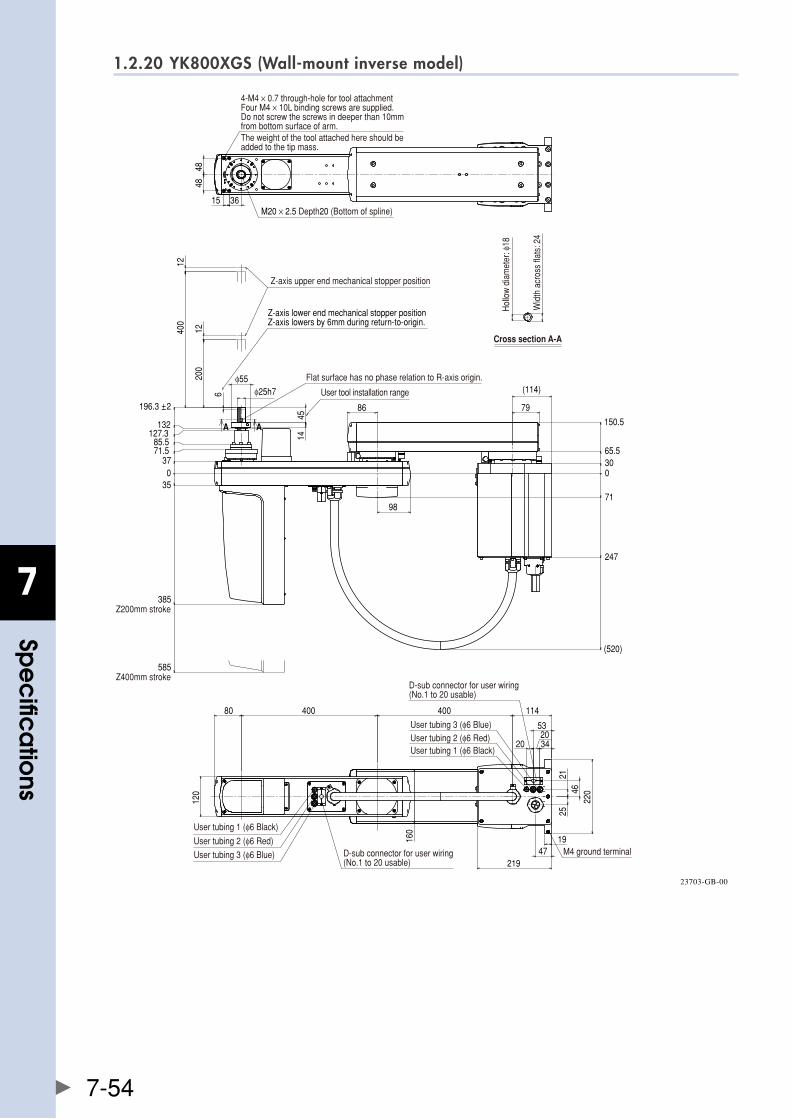
7
spe
cific
atio
ns
7-54
1.2.20 YK800XGS (Wall-mount inverse model)
6
400
200
12
12
86
98
0
71
247
(520)
3065.5
150.5
035
385
585
3771.585.5
127.3132
196.3 ±2 79
(114)φ25h7φ55
4514
A A
4848
15 36
40040080 114
120
160
1947
219
2521
4622
0
3420
20
53
M20 × 2.5 Depth20 (Bottom of spline)
4-M4 × 0.7 through-hole for tool attachmentFour M4 × 10L binding screws are supplied.Do not screw the screws in deeper than 10mmfrom bottom surface of arm.The weight of the tool attached here should beadded to the tip mass.
Cross section A-A
Hol
low
dia
met
er: φ
18
Wid
th a
cros
s fla
ts: 2
4
Flat surface has no phase relation to R-axis origin.
User tool installation range
Z200mm stroke
Z400mm strokeD-sub connector for user wiring(No.1 to 20 usable)
User tubing 1 (φ6 Black)User tubing 2 (φ6 Red)User tubing 3 (φ6 Blue)
D-sub connector for user wiring(No.1 to 20 usable)
M4 ground terminal
User tubing 1 (φ6 Black)
User tubing 2 (φ6 Red)
User tubing 3 (φ6 Blue)
Z-axis upper end mechanical stopper position
Z-axis lower end mechanical stopper positionZ-axis lowers by 6mm during return-to-origin.
23703-GB-00
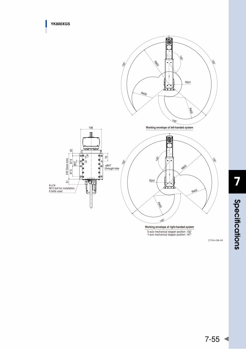
7
spe
cific
atio
ns
7-55
10
198
75
2597
.597
.5
2-R
8H7
51
R800
130°
130°
R241
R400
R400
145°
145°
R800
130°
130°
R241
R400
R400
145°
145°
YK800XGS
6-φ14M12 bolt for installation, 6 bolts used
φ8H7 through-hole
245
(bas
e si
ze)
Working envelope of left-handed system
Working envelope of right-handed system
X-axis mechanical stopper position: 132°Y-axis mechanical stopper position: 147°
23704-GB-00
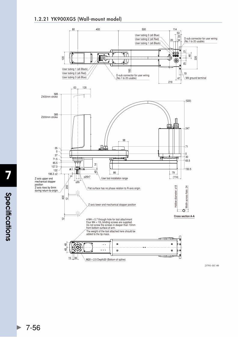
7
spe
cific
atio
ns
7-56
1.2.21 YK900XGS (Wall-mount model)
98
86
0
71
247
(520)
3065.5
150.5
200
1212
400
6
385
585
(114)
79
φ55
4514
11450040080
120
160
19
2521
46
47
3420
20
53
219
220
4848
15 36
A A
φ25h7
12863
035
3771.585.5
127.3132
196.3 ±2
User tubing 1 (φ6 Black)
User tubing 2 (φ6 Red)
User tubing 3 (φ6 Blue)
User tubing 1 (φ6 Black)
User tubing 2 (φ6 Red)User tubing 3 (φ6 Blue)
D-sub connector for user wiring(No.1 to 20 usable)
D-sub connector for user wiring(No.1 to 20 usable)
M4 ground terminal
Z200mm stroke
Z400mm stroke
4-M4 × 0.7 through-hole for tool attachmentFour M4 × 10L binding screws are supplied.Do not screw the screws in deeper than 10mmfrom bottom surface of arm.The weight of the tool attached here should beadded to the tip mass.
Flat surface has no phase relation to R-axis origin.
User tool installation range
Z-axis lower end mechanical stopper position
M20 × 2.5 Depth20 (Bottom of spline)
Cross section A-A
Hol
low
dia
met
er: φ
18
Wid
th a
cros
s fla
ts: 2
4
Z-axis upper end mechanical stopper positionZ-axis rises by 6mm during return-to-origin.
23701-GC-00
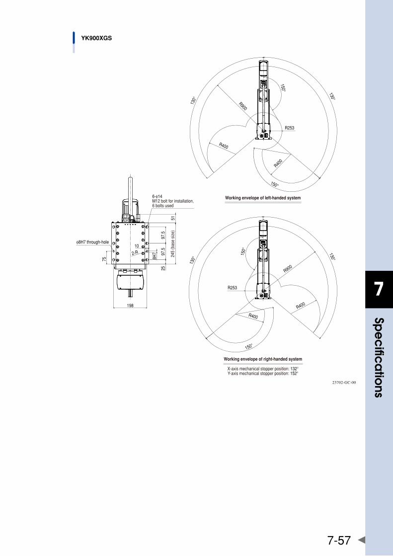
7
spe
cific
atio
ns
7-57
10
198
2597
.597
.5
75
2-R
8H7
51
R900
130°
130°
R400
R253
R400
150°
150°
R900
R253
R400
130°
130°
150°
R400
150°
φ8H7 through-hole
245
(bas
e si
ze)
6-φ14M12 bolt for installation, 6 bolts used
Working envelope of left-handed system
Working envelope of right-handed system
X-axis mechanical stopper position: 132°Y-axis mechanical stopper position: 152°
YK900XGS
23702-GC-00

7
spe
cific
atio
ns
7-58
1.2.22 YK900XGS (Wall-mount inverse model)
400
200
1212
86
98
0
71
247
(520)
3065.5
150.5
035
385
585
3771.585.5
127.3132
196.3 ±2
6
79
(114)φ25h7φ55
4514
A A
4848
15 36
50040080 114
120
160
1947
219
2146
220
25
3420
20
53
M20 × 2.5 Depth20 (Bottom of spline)
4-M4 × 0.7 through-hole for tool attachmentFour M4 × 10L binding screws are supplied.Do not screw the screws in deeper than 10mmfrom bottom surface of arm.The weight of the tool attached here should beadded to the tip mass.
Flat surface has no phase relation to R-axis origin.
User tool installation range
Cross section A-A
Hol
low
dia
met
er: φ
18
Wid
th a
cros
s fla
ts: 2
4
Z200mm stroke
Z400mm stroke
D-sub connector for user wiring(No.1 to 20 usable)
User tubing 1 (φ6 Black)
User tubing 2 (φ6 Red)User tubing 3 (φ6 Blue)
M4 ground terminalD-sub connector for user wiring(No.1 to 20 usable)
User tubing 1 (φ6 Black)User tubing 2 (φ6 Red)
User tubing 3 (φ6 Blue)
Z-axis upper end mechanical stopper position
Z-axis lower end mechanical stopper positionZ-axis lowers by 6mm during return-to-origin.
23703-GC-00

7
spe
cific
atio
ns
7-59
10
198
75
2597
.597
.5
2-R
8H7
51
R900130°
130°
R400
R400
R253
150°
150°
R253
R900130°
130°
R40
0
R400
150°
150°
YK900XGS
φ8H7 through-hole
245
(bas
e si
ze)
6-φ14M12 bolt for installation, 6 bolts used
Working envelope of left-handed system
Working envelope of right-handed system
X-axis mechanical stopper position: 132°Y-axis mechanical stopper position: 152°
23704-GC-00
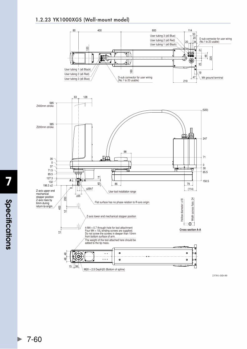
7
spe
cific
atio
ns
7-60
1.2.23 YK1000XGS (Wall-mount model)
A A
6
200
400
12
12
86
98
0
71
247
(520)
3065.5
150.5
385
585
79
(114)
φ55
4514
60040080 114
120
160
219
19
47
2521
46
220
3420
20
53
4848
15 36
φ25h7
12863
035
3771.585.5
127.3132
196.3 ±2
User tubing 1 (φ6 Black)
User tubing 2 (φ6 Red)
User tubing 3 (φ6 Blue)
User tubing 1 (φ6 Black)User tubing 2 (φ6 Red)
User tubing 3 (φ6 Blue)
D-sub connector for user wiring(No.1 to 20 usable)
D-sub connector for user wiring(No.1 to 20 usable)
M4 ground terminal
Z200mm stroke
Z400mm stroke
4-M4 × 0.7 through-hole for tool attachmentFour M4 × 10L binding screws are supplied.Do not screw the screws in deeper than 10mmfrom bottom surface of arm.The weight of the tool attached here should beadded to the tip mass.
Flat surface has no phase relation to R-axis origin.
User tool installation range
Z-axis lower end mechanical stopper position
M20 × 2.5 Depth20 (Bottom of spline)
Cross section A-A
Hol
low
dia
met
er: φ
18
Wid
th a
cros
s fla
ts: 2
4Z-axis upper end mechanical stopper positionZ-axis rises by 6mm during return-to-origin.
23701-GD-00

7
spe
cific
atio
ns
7-61
10
198
75
2597
.597
.5
2-R
8H7
51
R1000130°
130°
R324
150°
R400
R400
150°
R1000
130°
130°
150°
R324
R400
R400
150°
φ8H7 through-hole
245
(bas
e si
ze)
6-φ14M12 bolt for installation, 6 bolts used
Working envelope of left-handed system
Working envelope of right-handed system
X-axis mechanical stopper position: 132°Y-axis mechanical stopper position: 152°
YK1000XGS
23702-GD-00
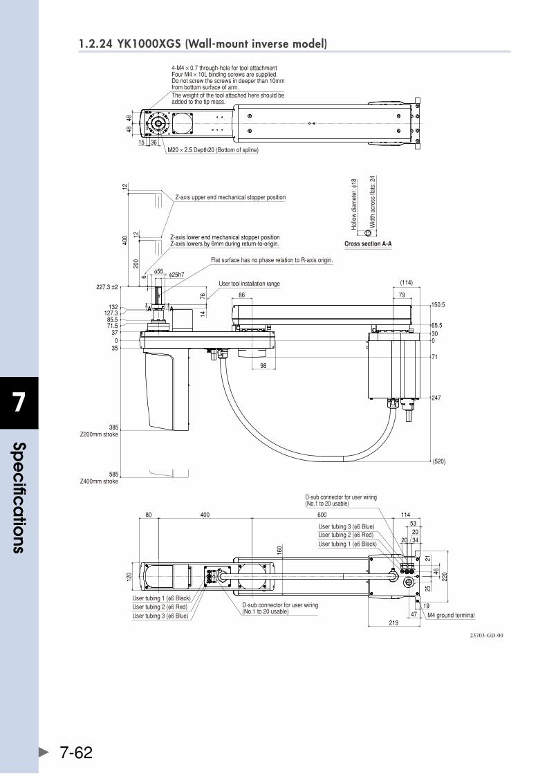
7
spe
cific
atio
ns
7-62
1.2.24 YK1000XGS (Wall-mount inverse model)
400
200
12
12
86
98
0
71
247
(520)
3065.5
150.5
035
385
585
3771.585.5
127.3132
6
79
(114)
7614
φ55
A A
4848
15 36
60040080 114
1947
219
2521
4622
0
3420
20
53
160
120
φ25h7
227.3 ±2
M20 × 2.5 Depth20 (Bottom of spline)
4-M4 × 0.7 through-hole for tool attachmentFour M4 × 10L binding screws are supplied.Do not screw the screws in deeper than 10mmfrom bottom surface of arm.The weight of the tool attached here should beadded to the tip mass.
Flat surface has no phase relation to R-axis origin.
User tool installation range
Cross section A-A
Hol
low
dia
met
er: φ
18
Wid
th a
cros
s fla
ts: 2
4
Z200mm stroke
Z400mm stroke
D-sub connector for user wiring(No.1 to 20 usable)
User tubing 1 (φ6 Black)User tubing 2 (φ6 Red)User tubing 3 (φ6 Blue)
M4 ground terminal
D-sub connector for user wiring(No.1 to 20 usable)
User tubing 1 (φ6 Black)User tubing 2 (φ6 Red)User tubing 3 (φ6 Blue)
Z-axis upper end mechanical stopper position
Z-axis lower end mechanical stopper positionZ-axis lowers by 6mm during return-to-origin.
23703-GD-00

7
spe
cific
atio
ns
7-63
10
198
75
8H7
2597
.597
.5
2-R
51R1000
130°
130°
R324
150°
R400
R40
0
150°
R1000
130°
130°
R324
150°
R400
R400
150°
YK1000XGS
φ8H7 through-hole
6-φ14M12 bolt for installation, 6 bolts used
245
(bas
e si
ze)
Working envelope of left-handed system
Working envelope of right-handed system
X-axis mechanical stopper position: 132°Y-axis mechanical stopper position: 152°
23704-GD-00
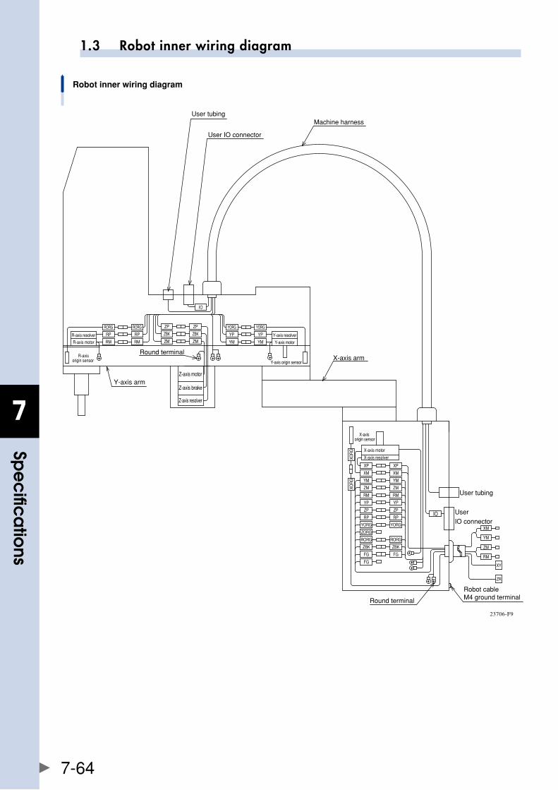
7
spe
cific
atio
ns
7-64
1.3 Robot inner wiring diagram
X-axis resolver
FG
RORGRORG
XORG YM
ZMZM
RMRM
XMXM
YPYP
IOZP
RPRP
YORG YORG
ZORG
ZBK ZBK
X-axis motor
XPXP
XORG
X-axis origin sensor
FG
YM
ZP
FG
XM
YM
XY
ZM
RM
ZR
Y-axis resolver
Y-axis motor
Z-axis brake
Z-axis motor
Z-axis resolver
R-axis resolver
R-axis motor
Y-axis origin sensor R-axis
origin sensor
ZBKZBK
ZM ZM
ZP ZP
RPRP
RM RM
RORG RORG
YP YP
YMYM
YORGYORG
IO
User IO connector
User tubing
Round terminal M4 ground terminal
Round terminal
User IO connector
User tubingMachine harness
X-axis arm
Y-axis arm
Robot inner wiring diagram
Robot cable
23706-F9
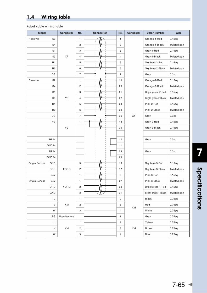
7
spe
cific
atio
ns
7-65
1.4 Wiring table
Robot cable wiring table
Signal Connector No. Connection No. Connector Color/Number Wire
Resolver S2
XP
1 1
XY
Orange-1-Red 0.15sq
S4 2 2 Orange-1-Black Twistedpair
S1 3 3 Gray-1-Red 0.15sq
S3 4 4 Gray-1-Black Twistedpair
R1 5 5 Skyblue-2-Red 0.15sq
R2 6 6 Skyblue-2-Black Twistedpair
DG 7 7 Gray 0.3sq
Resolver S2
YP
1 19 Orange-2-Red 0.15sq
S4 2 20 Orange-2-Black Twistedpair
S1 3 21 Brightgreen-2-Red 0.15sq
S3 4 22 Brightgreen-2-Black Twistedpair
R1 5 23 Pink-2-Red 0.15sq
R2 6 24 Pink-2-Black Twistedpair
DG 7 25 Gray 0.3sq
FG
FG
1 18 Gray-2-Red 0.15sq
36 Gray-2-Black 0.15sq
HLIM 10 Gray 0.3sq
GND24 11
HLIM 28 Gray 0.3sq
GND24 29
OriginSensor GND
XORG
3 13 Skyblue-3-Red 0.15sq
ORG 2 12 Skyblue-3-Black Twistedpair
24V 1 9 Pink-3-Red 0.15sq
OriginSensor 24V
YORG
1 27 Pink-3-Black Twistedpair
ORG 2 30 Brightgreen-1-Red 0.15sq
GND 3 31 Brightgreen-1-Black Twistedpair
U
XM
1 2
XM
Black 0.75sq
V 2 3 Red 0.75sq
W 3 4 White 0.75sq
FG Roundterminal 1 Gray 0.75sq
U
YM
1 2
YM
Yellow 0.75sq
V 2 3 Brown 0.75sq
W 3 4 Blue 0.75sq
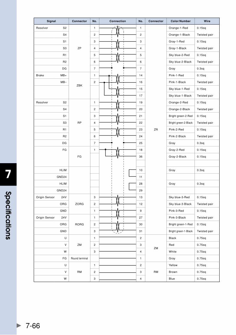
7
spe
cific
atio
ns
7-66
Signal Connector No. Connection No. Connector Color/Number Wire
Resolver S2
ZP
1 1
ZR
Orange-1-Red 0.15sq
S4 2 2 Orange-1-Black Twistedpair
S1 3 3 Gray-1-Red 0.15sq
S3 4 4 Gray-1-Black Twistedpair
R1 5 5 Skyblue-2-Red 0.15sq
R2 6 6 Skyblue-2-Black Twistedpair
DG 7 7 Gray 0.3sq
Brake MB+
ZBK
1 14 Pink-1-Red 0.15sq
MB– 2 16 Pink-1-Black Twistedpair
15 Skyblue-1-Red 0.15sq
17 Skyblue-1-Black Twistedpair
Resolver S2
RP
1 19 Orange-2-Red 0.15sq
S4 2 20 Orange-2-Black Twistedpair
S1 3 21 Brightgreen-2-Red 0.15sq
S3 4 22 Brightgreen-2-Black Twistedpair
R1 5 23 Pink-2-Red 0.15sq
R2 6 24 Pink-2-Black Twistedpair
DG 7 25 Gray 0.3sq
FG
FG
1 18 Gray-2-Red 0.15sq
36 Gray-2-Black 0.15sq
HLIM 10 Gray 0.3sq
GND24 11
HLIM 28 Gray 0.3sq
GND24 29
OriginSensor 24V
ZORG
3 13 Skyblue-3-Red 0.15sq
ORG 2 12 Skyblue-3-Black Twistedpair
GND 1 9 Pink-3-Red 0.15sq
OriginSensor 24V
RORG
1 27 Pink-3-Black Twistedpair
ORG 2 30 Brightgreen-1-Red 0.15sq
GND 3 31 Brightgreen-1-Black Twistedpair
U
ZM
1 2
ZM
Black 0.75sq
V 2 3 Red 0.75sq
W 3 4 White 0.75sq
FG Roundterminal 1 Gray 0.75sq
U
RM
1 2
RM
Yellow 0.75sq
V 2 3 Brown 0.75sq
W 3 4 Blue 0.75sq
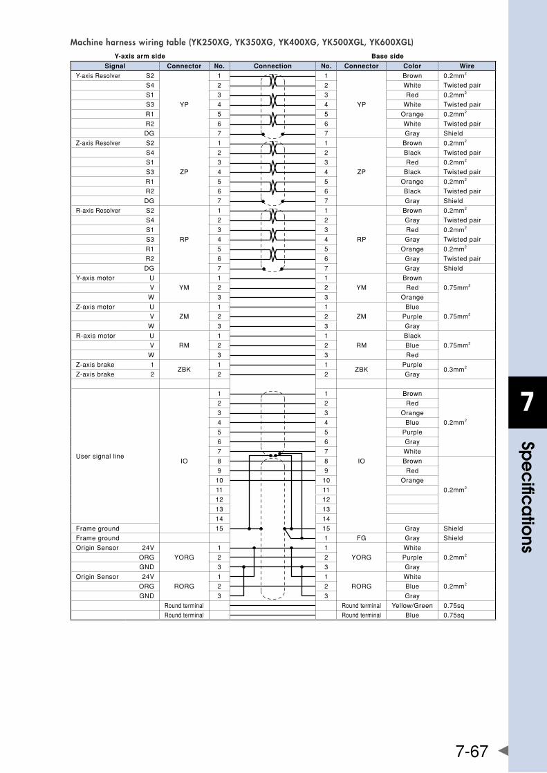
7
spe
cific
atio
ns
7-67
Machine harness wiring table (YK250XG, YK350XG, YK400XG, YK500XGL, YK600XGL)Y-axis arm side Base side
Signal Connector No. Connection No. Connector Color Wire
Y-axisResolver S2
YP
1 1
YP
Brown 0.2mm2
S4 2 2 White Twistedpair
S1 3 3 Red 0.2mm2
S3 4 4 White Twistedpair
R1 5 5 Orange 0.2mm2
R2 6 6 White Twistedpair
DG 7 7 Gray Shield
Z-axisResolver S2
ZP
1 1
ZP
Brown 0.2mm2
S4 2 2 Black Twistedpair
S1 3 3 Red 0.2mm2
S3 4 4 Black Twistedpair
R1 5 5 Orange 0.2mm2
R2 6 6 Black Twistedpair
DG 7 7 Gray Shield
R-axisResolver S2
RP
1 1
RP
Brown 0.2mm2
S4 2 2 Gray Twistedpair
S1 3 3 Red 0.2mm2
S3 4 4 Gray Twistedpair
R1 5 5 Orange 0.2mm2
R2 6 6 Gray Twistedpair
DG 7 7 Gray Shield
Y-axismotor U
YM
1 1
YM
Brown
0.75mm2V 2 2 Red
W 3 3 Orange
Z-axismotor U
ZM
1 1
ZM
Blue
0.75mm2V 2 2 Purple
W 3 3 Gray
R-axismotor U
RM
1 1
RM
Black
0.75mm2V 2 2 Blue
W 3 3 Red
Z-axisbrake 1ZBK
1 1ZBK
Purple0.3mm2
Z-axisbrake 2 2 2 Gray
UsersignallineIO
1 1
IO
Brown
0.2mm2
2 2 Red
3 3 Orange
4 4 Blue
5 5 Purple
6 6 Gray
7 7 White
8 8 Brown
0.2mm2
9 9 Red
10 10 Orange
11 11
12 12
13 13
14 14
Frameground 15 15 Gray Shield
Frameground 1 FG Gray Shield
OriginSensor 24V
YORG
1 1
YORG
White
0.2mm2ORG 2 2 Purple
GND 3 3 Gray
OriginSensor 24V
RORG
1 1
RORG
White
0.2mm2ORG 2 2 Blue
GND 3 3 Gray
Roundterminal Roundterminal Yellow/Green 0.75sq
Roundterminal Roundterminal Blue 0.75sq
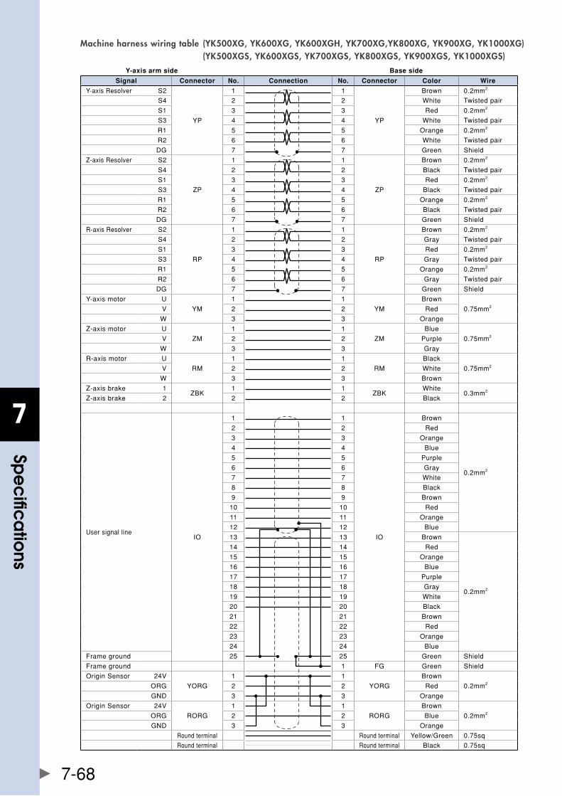
7
spe
cific
atio
ns
7-68
Machine harness wiring table (YK500XG, YK600XG, YK600XGH, YK700XG,YK800XG, YK900XG, YK1000XG) (YK500XGS, YK600XGS, YK700XGS, YK800XGS, YK900XGS, YK1000XGS)
Y-axis arm side Base side
Signal Connector No. Connection No. Connector Color Wire
Y-axisResolver S2
YP
1 1
YP
Brown 0.2mm2
S4 2 2 White Twistedpair
S1 3 3 Red 0.2mm2
S3 4 4 White Twistedpair
R1 5 5 Orange 0.2mm2
R2 6 6 White Twistedpair
DG 7 7 Green Shield
Z-axisResolver S2
ZP
1 1
ZP
Brown 0.2mm2
S4 2 2 Black Twistedpair
S1 3 3 Red 0.2mm2
S3 4 4 Black Twistedpair
R1 5 5 Orange 0.2mm2
R2 6 6 Black Twistedpair
DG 7 7 Green Shield
R-axisResolver S2
RP
1 1
RP
Brown 0.2mm2
S4 2 2 Gray Twistedpair
S1 3 3 Red 0.2mm2
S3 4 4 Gray Twistedpair
R1 5 5 Orange 0.2mm2
R2 6 6 Gray Twistedpair
DG 7 7 Green Shield
Y-axismotor U
YM
1 1
YM
Brown
0.75mm2V 2 2 Red
W 3 3 Orange
Z-axismotor U
ZM
1 1
ZM
Blue
0.75mm2V 2 2 Purple
W 3 3 Gray
R-axismotor U
RM
1 1
RM
Black
0.75mm2V 2 2 White
W 3 3 Brown
Z-axisbrake 1ZBK
1 1ZBK
White0.3mm2
Z-axisbrake 2 2 2 Black
UsersignallineIO
1 1
IO
Brown
0.2mm2
2 2 Red
3 3 Orange
4 4 Blue
5 5 Purple
6 6 Gray
7 7 White
8 8 Black
9 9 Brown
10 10 Red
11 11 Orange
12 12 Blue
13 13 Brown
0.2mm2
14 14 Red
15 15 Orange
16 16 Blue
17 17 Purple
18 18 Gray
19 19 White
20 20 Black
21 21 Brown
22 22 Red
23 23 Orange
24 24 Blue
Frameground 25 25 Green Shield
Frameground 1 FG Green Shield
OriginSensor 24V
YORG
1 1
YORG
Brown
0.2mm2ORG 2 2 Red
GND 3 3 Orange
OriginSensor 24V
RORG
1 1
RORG
Brown
0.2mm2ORG 2 2 Blue
GND 3 3 Orange
Roundterminal Roundterminal Yellow/Green 0.75sq
Roundterminal Roundterminal Black 0.75sq
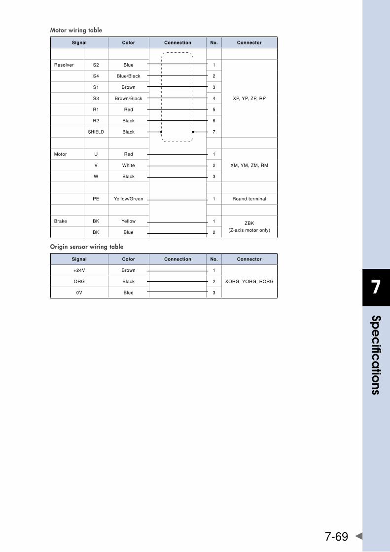
7
spe
cific
atio
ns
7-69
Motor wiring table
Signal Color Connection No. Connector
Resolver S2 Blue 1
XP,YP,ZP,RP
S4 Blue/Black 2
S1 Brown 3
S3 Brown/Black 4
R1 Red 5
R2 Black 6
SHIELD Black 7
Motor U Red 1
XM,YM,ZM,RMV White 2
W Black 3
PE Yellow/Green 1 Roundterminal
Brake BK Yellow 1 ZBK
(Z-axismotoronly)BK Blue 2
Origin sensor wiring table
Signal Color Connection No. Connector
+24V Brown 1
XORG,YORG,RORGORG Black 2
0V Blue 3
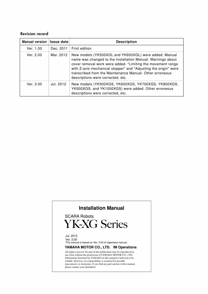
All rights reserved. No part of this publication may be reproduced in any form without the permission of YAMAHA MOTOR CO., LTD. Information furnished by YAMAHA in this manual is believed to be reliable. However, no responsibility is assumed for possible inaccuracies or omissions. If you find any part unclear in this manual, please contact your distributor.
SCARA Robots
Installation Manual
YAMAHA MOTOR CO., LTD. IM Operations
YK-XG Series
Revision record
Manual version Issue date Description
Ver.1.00 Dec.2011 Firstedition
Ver.2.00 Mar.2012 Newmodels(YK500XGLandYK600XGL)wereadded.ManualnamewaschangedtotheInstallationManual.Warningsaboutcoverremovalworkwereadded."LimitingthemovementrangewithZ-axismechanicalstopper"and"Adjustingtheorigin"weretranscribedfromtheMaintenanceManual.Othererroneousdescriptionswerecorrected,etc.
Ver.3.00 Jul.2012 Newmodels(YK500XGS,YK600XGS,YK700XGS,YK800XGS,YK900XGS,andYK1000XGS)wereadded.Othererroneousdescriptionswerecorrected,etc.
Jul.2012Ver.3.00ThismanualisbasedonVer.3.00ofJapanesemanual.


http://www.yamaha-motor.co.jp/global/industrial/robot/
Robot manuals can be downloaded from our company website. Please use the following for more detailed information.
YAMAHA MOTOR CO., LTD.
IM Operations
882 Soude, Nakaku, Hamamatsu, Shizuoka, 435-0054, JapanTel. 81-53-460-6103 Fax. 81-53-460-6811
Related Documents