This content has been downloaded from IOPscience. Please scroll down to see the full text. Download details: IP Address: 95.9.177.224 This content was downloaded on 06/09/2014 at 11:17 Please note that terms and conditions apply. Yaw Systems for wind turbines – Overview of concepts, current challenges and design methods View the table of contents for this issue, or go to the journal homepage for more 2014 J. Phys.: Conf. Ser. 524 012086 (http://iopscience.iop.org/1742-6596/524/1/012086) Home Search Collections Journals About Contact us My IOPscience

Welcome message from author
This document is posted to help you gain knowledge. Please leave a comment to let me know what you think about it! Share it to your friends and learn new things together.
Transcript

This content has been downloaded from IOPscience. Please scroll down to see the full text.
Download details:
IP Address: 95.9.177.224
This content was downloaded on 06/09/2014 at 11:17
Please note that terms and conditions apply.
Yaw Systems for wind turbines – Overview of concepts, current challenges and design
methods
View the table of contents for this issue, or go to the journal homepage for more
2014 J. Phys.: Conf. Ser. 524 012086
(http://iopscience.iop.org/1742-6596/524/1/012086)
Home Search Collections Journals About Contact us My IOPscience
Yaw Systems for wind turbines - Overview of
concepts, current challenges and design methods
M-G Kim and P H Dalhoff
Department of Mechanical Engineering & Production Management, Hamburg University ofApplied Sciences, 20099 Hamburg, GERMANY
E-mail: [email protected]
Abstract. Looking at the upscaling of the rotor diameter not only the loss in power productionbut the aerodynamic loads arising from yaw misalignment will have an increasing impact onthe yaw system design in future wind turbines. This paper presents an overview of yaw systemsused in current wind turbines and a review of patents with regards to the yaw system. Thecurrent state of the art of yaw systems has been analyzed through a systematic literaturereview. Further a patent analysis has been done through the European Patent Office. Todaysdesign and strength requirements as per IEC and GL standards will be reviewed and alternativedesign calculations will be discussed. Over 100 patents have been identified as relevant to theyaw system and have been analyzed. It has been found that most patents are dealing withload reduction possibilities on the yaw system, where fatigue loads seem more of a problemthan ultimate loads. Most of these patents concern especially the yaw actuator, which consistsof multiple electrical motors, reduction gears and shaft pinions. This is due to the nature ofthe gearing in the actuator and the gearing between the shaft pinion and the ring gear. Thiscoincides with the patents for yaw brakes, which mostly aim to reduce the fatigue loads duringyaw maneuverer and during nacelle standstill. Patents for the yaw bearing are incorporatingthe reduction of loads through the usage of friction bearings or different bearing arrangementapproaches. The paper shows that the conventional yaw system designs are still trying tomeet the high requirements regarding the lifetime of a wind turbine and turbulent wind loads.New designs for yaw systems in general are hard to find. Many patents concentrate on controlalgorithms that depend on additional instruments and incorporate electromechanical systems.
1. IntroductionTo reduce the cost of energy of wind turbines and to make them competitive to conventionalpower plants can be considered as the main goal of wind turbine optimization. The yaw systemwhich is responsible to rotate the nacelle around the tower axis, can contribute to it throughthe following points:
• Increasing the energy capture through pointing the rotor swept area steadily towards theincoming wind direction and thus maximize the general power input of the wind turbine.A higher energy capture can also be achieved through a better reliability of the yaw systemwhich increases the general availability of a wind turbine.
• Reduction of the structure load by letting the nacelle passively rotate to compensate yawmoments from aerodynamic loads. This leads to potential lower design loads for the yawsystem and other wind turbine components.
The Science of Making Torque from Wind 2014 (TORQUE 2014) IOP PublishingJournal of Physics: Conference Series 524 (2014) 012086 doi:10.1088/1742-6596/524/1/012086
Content from this work may be used under the terms of the Creative Commons Attribution 3.0 licence. Any further distributionof this work must maintain attribution to the author(s) and the title of the work, journal citation and DOI.
Published under licence by IOP Publishing Ltd 1
• Cost reduction of the yaw system itself and also reduction of the operation and maintenancecost and the energy consumption of the yaw system.
A higher energy capture can be achieved by increasing the yaw control sensitivity. Thismeans the yaw system rotates the nacelle based on a smaller yaw error threshold and on thefoundation of shorter averaged measured times of the wind direction and speed. Oppositelyfrequent yawing duties leads to higher accumulated operation loads and energy consumption.A comparison of different yaw control parameters and the resulting numbers of yaw maneuversbased on simulation models can be found in [1]. Yaw stops lead to torsional oscillations on thetower and thus can lead to higher alternating loads on the yaw system if the time between twoyawing maneuvers is done without a proper delay [2]. An optimum relation between energycapture and yawing duties depends on the environment condition and the yaw design of thewind turbine. The control system depends also on correct measurements of the wind conditions.Currently the measurements are being made on the nacelle leading to measurements of windcondition disturbed by the rotor and thus leading to false yaw behavior and resulting in lowerpower production [3]. Reliability studies by [4] show that the yaw system is the second mostcommon mechanical component that contributes to an overall failure rate defined by the numberof failures of a turbine in a year with the pitch system being first. Equally to the failure rate ofa wind turbine, the yaw system is also the second most mechanical component contributing toan overall downtime of the turbine. This circumstance leads to redundancy system approachessuch as possible temporary yaw operation of a wind turbine even when one yaw drive fails tooperate[5, 6].
Large wind turbines benefit from an overall reduction cost per rated MW [7], which lead tothe development of steadily increasing size of wind turbines over the time [8]. On the downsidethe increase of rotor diameter leads not only to higher weight induced structural loads but alsoto higher and more complex aerodynamic loads as the influence of effects of the turbulence onthe rotor plane increases thus leading also to higher yaw moments [9].
Soft yaw concepts as researched by [10] can result in fatigue and extreme load reductionof the yaw moment without sacrificing the power production of the wind turbine. Also areduction in blade flapwise bending and tower base tilting moments had been observed leadingto potential lower design loads and thus to lighter components. Regardless from the windturbine development, load consideration should be made for typhoon situations, above cut-outwind speeds and after emergency stops leading to higher requirements of the yaw system design[11]. Typhoon characteristics as rapid change of the wind direction and a higher possibilityof grid failure for example, require increased yawing speeds and also reliable yaw operationalfunctionality above cut-out wind speeds.
A percentage-wise cost distribution of different studies have been put together by [12] wherethe yaw system takes 1.3 - 5% of the estimated whole turbine cost. A cost trend analysis by[7] shows that the cost trend exponent of the yaw system is the second highest next to the costtrend exponent of the tower, meaning the cost of the yaw system is more influenced by scalingthan other components.
In this paper the functions of the yaw system and its different design set ups will be presentedfirst to give an understanding of the diversity of current yaw system components. Hereafterthrough a patent analysis current issues and development trends of the yaw system will bepresented which addresses the mentioned methods to reduce the overall cost of energy. Furtherdesign and strength requirements as per IEC and GL standards will be reviewed and alternativedesign calculations will be discussed.
The Science of Making Torque from Wind 2014 (TORQUE 2014) IOP PublishingJournal of Physics: Conference Series 524 (2014) 012086 doi:10.1088/1742-6596/524/1/012086
2
2. Yaw system2.1. Functions of the yaw systemIn contrast to the function of pointing the rotor swept area towards the wind direction foroptimal power input, the yaw system can be used for power regulation above rated wind speeds.This is achieved by reducing the rotor swept area directed to the oncoming wind. A yaw systemfor rapid power regulation requires high yaw speeds as the decrease in power production inrelation to the yaw error is small. Moreover the yaw torque has to overcome high yaw momentsdue to the large moment of inertia of the nacelle and the rotor [13]. Despite these shortcomingsactive yaw control is investigated by [14] for a two bladed rotor teeter hinge wind turbine. Toenable rapid power control the yaw speed is set about 10°/s [5] in contrast to the commonly0.5°/s. This is in line with the teeter hinge design which enables reduced yawing moments andalso leads to reduced gyroscopic loads.
The yaw system can contribute to a general load reduction by either reducing the fatigueloads or by preventing the wind turbine from extreme loads in extreme wind conditions. Fatigueload reduction can be achieved by damping the yaw movement through hydraulic yaw drives.Simulations by [10] showed a reduction of yaw moment fatigue loads by 40% and extreme loadsup to 19%. Prevention of extreme loads during events like wind speeds above cut-out and alsoin combination with wind turbine operation faults can be achieved by rotating the wind turbineout of the wind. Whereas [15, 16] propose to turn the nacelle in leeward position, [14] proposesto rotate the nacelle perpendicular to the oncoming wind to reduce the structure loads.
On a wind park scale yawing of windward turbines can be used to deflect the wake flowproviding the downstream turbines a higher energy yield and thus leading to an overall increase inenergy production of the wind park [17]. Simulations by [18] showed potential in an higher overallpower production trough yawing but also higher yaw bearing bending moments on downstreamturbines most likely because of the resulting partial wake condition. Individual pitch controlscan mitigate additional loads resulting from partial wake conditions [19] and can also potentiallylead to reduced loads on the yaw system in general [20].
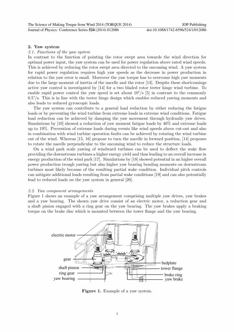
2.2. Yaw component arrangementsFigure 1 shows an example of a yaw arrangement comprising multiple yaw drives, yaw brakesand a yaw bearing. The shown yaw drive consist of an electric motor, a reduction gear anda shaft pinion engaged with a ring gear on the yaw bearing. The yaw brakes apply a brakingtorque on the brake disc which is mounted between the tower flange and the yaw bearing.
electric motor
gear
shaft pinion
ring gear
yaw bearingbrake ringyaw brake
tower flange
bedplate
Figure 1. Example of a yaw system.
The Science of Making Torque from Wind 2014 (TORQUE 2014) IOP PublishingJournal of Physics: Conference Series 524 (2014) 012086 doi:10.1088/1742-6596/524/1/012086
3
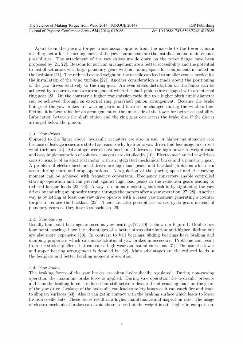
Apart from the yawing torque transmission options from the nacelle to the tower a maindeciding factor for the arrangement of the yaw components are the installation and maintenancepossibilities. The attachment of the yaw drives upside down on the tower flange have beenproposed by [21, 22]. Reasons for such an arrangement are a better accessibility and the potentialto install actuators with large planetary gears without taking space for components installed onthe bedplate [21]. The reduced overall weight on the nacelle can lead to smaller cranes needed forthe installation of the wind turbine [22]. Another consideration is made about the positioningof the yaw drives relatively to the ring gear. An even stress distribution on the flanks can beachieved by a convex/concave arrangement when the shaft pinions are engaged with an internalring gear [23]. On the contrary a higher transmission ratio due to a higher pitch circle diametercan be achieved through an external ring gear/shaft pinion arrangement. Because the brakelinings of the yaw brakes are wearing parts and have to be changed during the wind turbinelifetime it is favourable for an arrangement on the inner side of the tower for better accessibility.Lubrication between the shaft pinion and the ring gear can access the brake disc if the disc isarranged below the pinion.
2.3. Yaw drivesOpposed to the figure above, hydraulic actuators are also in use. A higher maintenance ratebecause of leakage issues are stated as reasons why hydraulic yaw drives find less usage in currentwind turbines [24]. Advantage over electro mechanical drives as the high power to weight ratioand easy implementation of soft yaw concepts are detailed by [10]. Electro mechanical yaw drivesconsist usually of an electrical motor with an integrated mechanical brake and a planetary gear.A problem of electro mechanical drives are high load peaks and backlash problems which canoccur during start and stop operations. A regulation of the yawing speed and the yawingmoment can be achieved with frequency converters. Frequency converters enable controlledstart-up operation and can prevent against high load peaks in the reduction gears leading toreduced fatigue loads [25, 26]. A way to eliminate existing backlash is by tightening the yawdrives by inducing an opposite torque through the motors after a yaw operation [27, 28]. Anotherway is by letting at least one yaw drive operate with a lesser yaw moment generating a countertorque to reduce the backlash [25]. There are also possibilities to use cyclo gears instead ofplanetary gears as they have less backlash [29].
2.4. Yaw bearingUsually four point bearings are used as yaw bearings [24, 30] as shown in Figure 1. Double-rowfour point bearings have the advantages of a better stress distribution and higher lifetime butare also more expensive [30]. In contrast to ball bearings, sliding bearings have braking anddamping properties which can make additional yaw brakes unnecessary. Problems can resultfrom the stick slip effect that can cause high wear and sound emissions [31]. The use of a lowerand upper bearing arrangement is detailed by [32]. Main advantages are the reduced loads inthe bedplate and better bending moment absorption.
2.5. Yaw brakesThe braking forces of the yaw brakes are often hydraulically regulated. During non-yawingoperation the maximum brake force is applied. During yaw operation the hydraulic pressureand thus the braking force is reduced but still active to lessen the alternating loads on the gearsof the yaw drive. Leakage of the hydraulic can lead to safety issues as it can catch fire and leadsto slippery surfaces [33]. Also it can get in contact with the braking surface which leads to lowerfriction coefficients. These issues result in a higher maintenance and inspection rate. The usageof electro mechanical brakes can avoid these issues but the weight is still higher in comparison.
The Science of Making Torque from Wind 2014 (TORQUE 2014) IOP PublishingJournal of Physics: Conference Series 524 (2014) 012086 doi:10.1088/1742-6596/524/1/012086
4
[34] states a commercial deployment of electro mechanical yaw brakes for a prototype windturbine and also retrofit usage in yaw systems with leaking hydraulic yaw brakes.
In contrast to the general yaw system design shown in Figure 1, stands the yaw systemby [35] which is installed in a prototype wind turbine. A yaw drive consists of two hydrauliccylinders and a brake caliper which is engaged with a brake disc, embodying an integrated yawactuator and yaw brake unit. As this yaw concept doesn’t inherit any gearing and no relativemovement between the yaw brakes and the disc, the mentioned drawbacks like backlashes andsound emission are avoided [36].
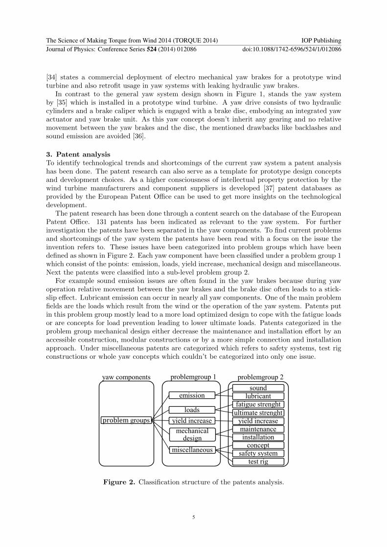
3. Patent analysisTo identify technological trends and shortcomings of the current yaw system a patent analysishas been done. The patent research can also serve as a template for prototype design conceptsand development choices. As a higher consciousness of intellectual property protection by thewind turbine manufacturers and component suppliers is developed [37] patent databases asprovided by the European Patent Office can be used to get more insights on the technologicaldevelopment.
The patent research has been done through a content search on the database of the EuropeanPatent Office. 131 patents has been indicated as relevant to the yaw system. For furtherinvestigation the patents have been separated in the yaw components. To find current problemsand shortcomings of the yaw system the patents have been read with a focus on the issue theinvention refers to. These issues have been categorized into problem groups which have beendefined as shown in Figure 2. Each yaw component have been classified under a problem group 1which consist of the points: emission, loads, yield increase, mechanical design and miscellaneous.Next the patents were classified into a sub-level problem group 2.
For example sound emission issues are often found in the yaw brakes because during yawoperation relative movement between the yaw brakes and the brake disc often leads to a stick-slip effect. Lubricant emission can occur in nearly all yaw components. One of the main problemfields are the loads which result from the wind or the operation of the yaw system. Patents putin this problem group mostly lead to a more load optimized design to cope with the fatigue loadsor are concepts for load prevention leading to lower ultimate loads. Patents categorized in theproblem group mechanical design either decrease the maintenance and installation effort by anaccessible construction, modular constructions or by a more simple connection and installationapproach. Under miscellaneous patents are categorized which refers to safety systems, test rigconstructions or whole yaw concepts which couldn’t be categorized into only one issue.
problem groups
emissionsound
lubricant
loadsfatigue strenght
ultimate strenghtyield increase yield increase
mechanical design
maintenanceinstallation
miscellaneousconcept
safety system
test rig
yaw components problemgroup 1 problemgroup 2
Figure 2. Classification structure of the patents analysis.
The Science of Making Torque from Wind 2014 (TORQUE 2014) IOP PublishingJournal of Physics: Conference Series 524 (2014) 012086 doi:10.1088/1742-6596/524/1/012086
5
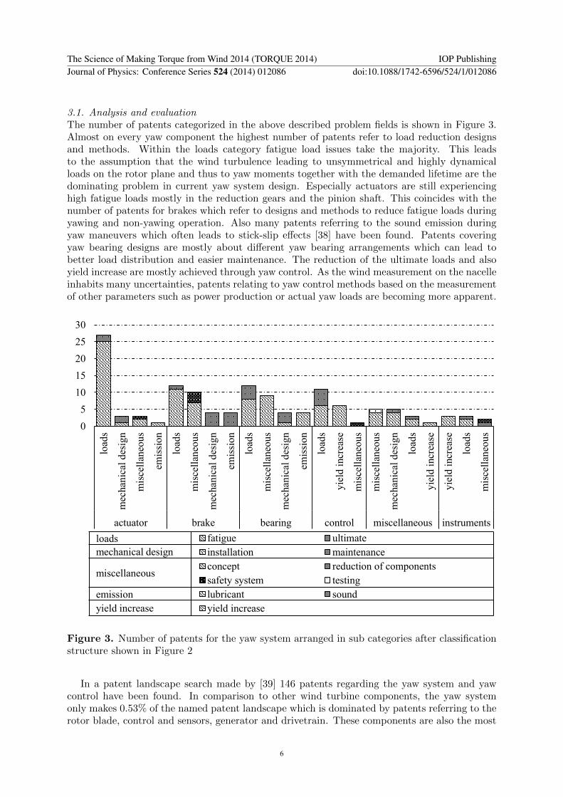
3.1. Analysis and evaluationThe number of patents categorized in the above described problem fields is shown in Figure 3.Almost on every yaw component the highest number of patents refer to load reduction designsand methods. Within the loads category fatigue load issues take the majority. This leadsto the assumption that the wind turbulence leading to unsymmetrical and highly dynamicalloads on the rotor plane and thus to yaw moments together with the demanded lifetime are thedominating problem in current yaw system design. Especially actuators are still experiencinghigh fatigue loads mostly in the reduction gears and the pinion shaft. This coincides with thenumber of patents for brakes which refer to designs and methods to reduce fatigue loads duringyawing and non-yawing operation. Also many patents referring to the sound emission duringyaw maneuvers which often leads to stick-slip effects [38] have been found. Patents coveringyaw bearing designs are mostly about different yaw bearing arrangements which can lead tobetter load distribution and easier maintenance. The reduction of the ultimate loads and alsoyield increase are mostly achieved through yaw control. As the wind measurement on the nacelleinhabits many uncertainties, patents relating to yaw control methods based on the measurementof other parameters such as power production or actual yaw loads are becoming more apparent.
0
5
10
15
20
25
30
load
s
mec
han
ical
des
ign
mis
cell
aneo
us
emis
sion
load
s
mis
cell
aneo
us
mec
han
ical
des
ign
emis
sion
load
s
mis
cell
aneo
us
mec
han
ical
des
ign
emis
sion
load
s
yie
ld i
ncr
ease
mis
cell
aneo
us
mis
cell
aneo
us
mec
han
ical
des
ign
load
s
yie
ld i
ncr
ease
yie
ld i
ncr
ease
load
s
mis
cell
aneo
us
actuator brake bearing control miscellaneous instruments
loads
mechanical design
miscellaneous
emission
yield increase
fatigue ultimate
installation maintenance
concept reduction of components
safety system testing
lubricant sound
yield increase
Figure 3. Number of patents for the yaw system arranged in sub categories after classificationstructure shown in Figure 2
In a patent landscape search made by [39] 146 patents regarding the yaw system and yawcontrol have been found. In comparison to other wind turbine components, the yaw systemonly makes 0.53% of the named patent landscape which is dominated by patents referring to therotor blade, control and sensors, generator and drivetrain. These components are also the most
The Science of Making Torque from Wind 2014 (TORQUE 2014) IOP PublishingJournal of Physics: Conference Series 524 (2014) 012086 doi:10.1088/1742-6596/524/1/012086
6
cost intensive parts [40]. Control systems are a cost-effective alternative to increase the energyproduction and also the load reduction which applies to the yaw control system.
Constructive design concepts for the yaw actuator or the yaw brake were a minority in thepatent analysis. Solutions for load reduction on the actuator are mostly based on load regulationsmethods for the electrical motor. New concepts are bound with high risks and costs which leadsto a rather hesitant development.
4. Design methodsGoal of the standards is to ensure the structural and engineering integrity of the wind turbineover its lifetime. The standard IEC61400-1 [41] forms the foundation of the design for the windturbine. Design parameters are decided upon loads caused by the interaction of the wind turbineand its environment. For the design of the yaw system the loads resulting in the tower top of awind turbine are considered. The wind turbine and its components are designed for a lifetimeof at least 20 years. The standards define design load cases in which external and operationconditions are combined. The frequency in which a certain design case is considered are definedby the standard. For the design of the yaw system components basic standards exist and arereferred to by the wind turbine standards but they don’t consider the loads resulting from theinteraction of the aerodynamic loads and the wind turbine dynamics. Load calculation of thewind turbine together with its components are therefore a critical subject for future standardrevisions [42].
Apart from the aerodynamic loads the design loads are basically put together in dependencefrom two different operation modes: yawing and standstill. A decisive parameter for the analysisof the fatigue loads of the yaw system is the consideration of the yawing time. The operationof the yaw system is considered to occur during 10% of the turbine’s service life independent ofthe real wind direction distribution as per the GL and DNV-standard [43, 44].
For a fatigue strength analysis the tower top loads are simulated under different turbulentwind conditions and then cumulated over the lifetime of the wind turbine in combination of theWeibull distribution for a site. The calculated results are represented in form of a load durationdistribution (LDD). The LDD represent different load levels and their estimated duration. Inregard to the applied design load cases the GL-directive impose the number of occurrences overa year. Usually an average yaw misalignment of ±8◦ have to be considered during the load casesif smaller yaw errors cannot be verified.
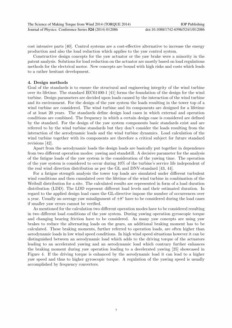
As mentioned for the calculation two different operation modes have to be considered resultingin two different load conditions of the yaw system. During yawing operation gyroscopic torqueand changing bearing friction have to be considered. As many yaw concepts are using yawbrakes to reduce the alternating loads on the gears, an additional braking moment has to becalculated. These braking moments, further referred to operation loads, are often higher thanaerodynamic loads in low wind speed conditions. In high wind speed situations however it can bedistinguished between an aerodynamic load which adds to the driving torque of the actuatorsleading to an accelerated yawing and an aerodynamic load which contrary further enhancesthe braking moment during yaw operation leading to a decelerated yawing [25] showcased inFigure 4. If the driving torque is enhanced by the aerodynamic load it can lead to a higheryaw speed and thus to higher gyroscopic torque. A regulation of the yawing speed is usuallyaccomplished by frequency converters.
The Science of Making Torque from Wind 2014 (TORQUE 2014) IOP PublishingJournal of Physics: Conference Series 524 (2014) 012086 doi:10.1088/1742-6596/524/1/012086
7
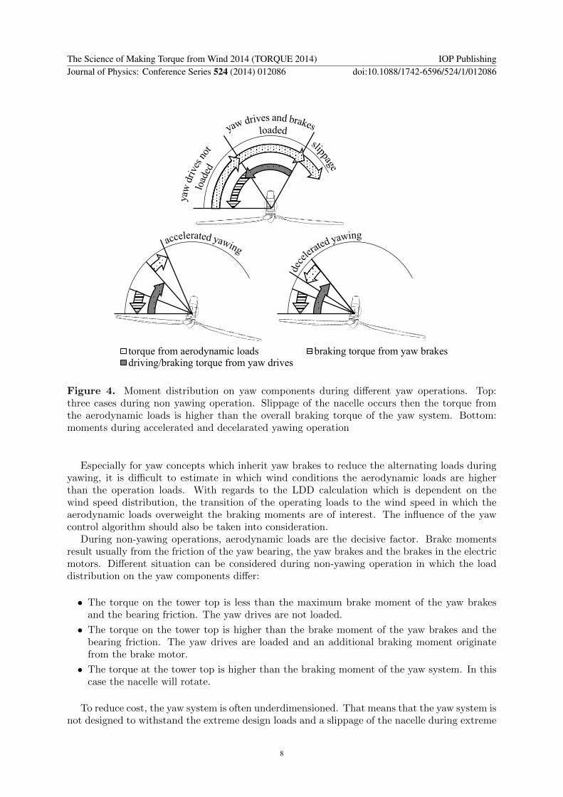
torque from aerodynamic loads braking torque from yaw brakesdriving/braking torque from yaw drives
Figure 4. Moment distribution on yaw components during different yaw operations. Top:three cases during non yawing operation. Slippage of the nacelle occurs then the torque fromthe aerodynamic loads is higher than the overall braking torque of the yaw system. Bottom:moments during accelerated and decelarated yawing operation
Especially for yaw concepts which inherit yaw brakes to reduce the alternating loads duringyawing, it is difficult to estimate in which wind conditions the aerodynamic loads are higherthan the operation loads. With regards to the LDD calculation which is dependent on thewind speed distribution, the transition of the operating loads to the wind speed in which theaerodynamic loads overweight the braking moments are of interest. The influence of the yawcontrol algorithm should also be taken into consideration.
During non-yawing operations, aerodynamic loads are the decisive factor. Brake momentsresult usually from the friction of the yaw bearing, the yaw brakes and the brakes in the electricmotors. Different situation can be considered during non-yawing operation in which the loaddistribution on the yaw components differ:
• The torque on the tower top is less than the maximum brake moment of the yaw brakesand the bearing friction. The yaw drives are not loaded.
• The torque on the tower top is higher than the brake moment of the yaw brakes and thebearing friction. The yaw drives are loaded and an additional braking moment originatefrom the brake motor.
• The torque at the tower top is higher than the braking moment of the yaw system. In thiscase the nacelle will rotate.
To reduce cost, the yaw system is often underdimensioned. That means that the yaw system isnot designed to withstand the extreme design loads and a slippage of the nacelle during extreme
The Science of Making Torque from Wind 2014 (TORQUE 2014) IOP PublishingJournal of Physics: Conference Series 524 (2014) 012086 doi:10.1088/1742-6596/524/1/012086
8
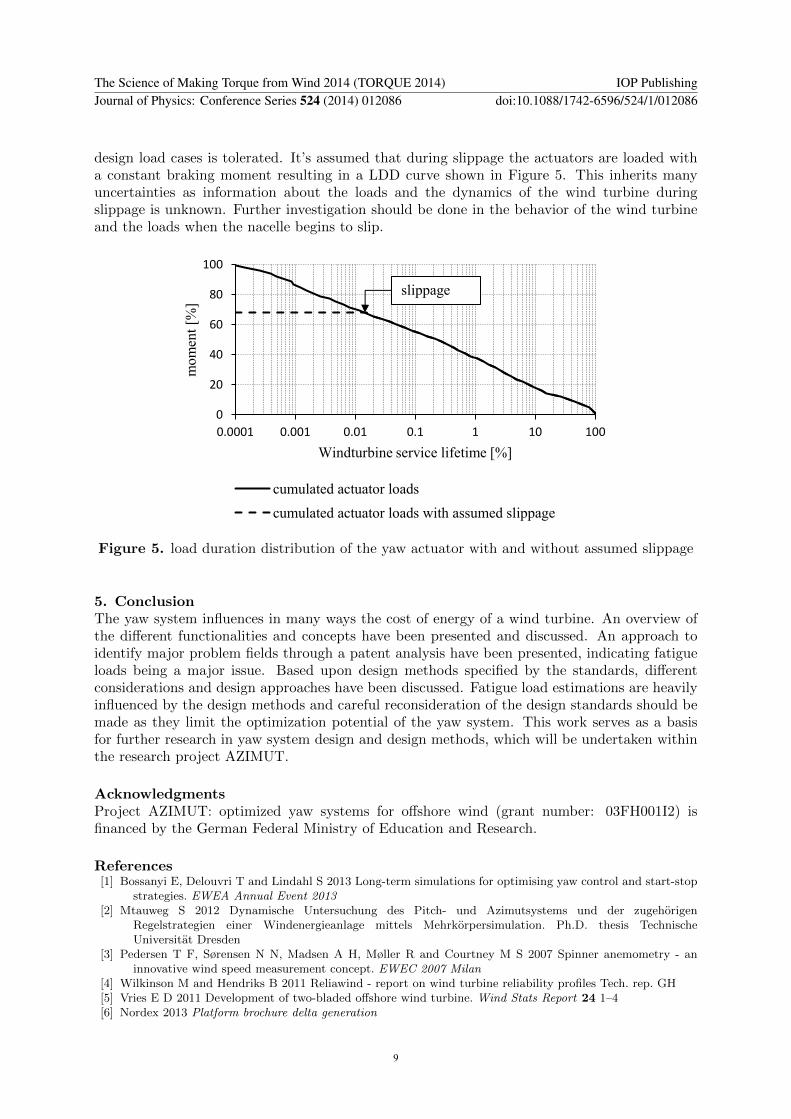
design load cases is tolerated. It’s assumed that during slippage the actuators are loaded witha constant braking moment resulting in a LDD curve shown in Figure 5. This inherits manyuncertainties as information about the loads and the dynamics of the wind turbine duringslippage is unknown. Further investigation should be done in the behavior of the wind turbineand the loads when the nacelle begins to slip.
0
20
40
60
80
100
0.0001 0.001 0.01 0.1 1 10 100
mo
men
t [%
]
Windturbine service lifetime [%]
cumulated actuator loads
cumulated actuator loads with assumed slippage
slippage
Figure 5. load duration distribution of the yaw actuator with and without assumed slippage
5. ConclusionThe yaw system influences in many ways the cost of energy of a wind turbine. An overview ofthe different functionalities and concepts have been presented and discussed. An approach toidentify major problem fields through a patent analysis have been presented, indicating fatigueloads being a major issue. Based upon design methods specified by the standards, differentconsiderations and design approaches have been discussed. Fatigue load estimations are heavilyinfluenced by the design methods and careful reconsideration of the design standards should bemade as they limit the optimization potential of the yaw system. This work serves as a basisfor further research in yaw system design and design methods, which will be undertaken withinthe research project AZIMUT.
AcknowledgmentsProject AZIMUT: optimized yaw systems for offshore wind (grant number: 03FH001I2) isfinanced by the German Federal Ministry of Education and Research.
References[1] Bossanyi E, Delouvri T and Lindahl S 2013 Long-term simulations for optimising yaw control and start-stop
strategies. EWEA Annual Event 2013[2] Mtauweg S 2012 Dynamische Untersuchung des Pitch- und Azimutsystems und der zugehorigen
Regelstrategien einer Windenergieanlage mittels Mehrkorpersimulation. Ph.D. thesis TechnischeUniversitat Dresden
[3] Pedersen T F, Sørensen N N, Madsen A H, Møller R and Courtney M S 2007 Spinner anemometry - aninnovative wind speed measurement concept. EWEC 2007 Milan
[4] Wilkinson M and Hendriks B 2011 Reliawind - report on wind turbine reliability profiles Tech. rep. GH[5] Vries E D 2011 Development of two-bladed offshore wind turbine. Wind Stats Report 24 1–4[6] Nordex 2013 Platform brochure delta generation
The Science of Making Torque from Wind 2014 (TORQUE 2014) IOP PublishingJournal of Physics: Conference Series 524 (2014) 012086 doi:10.1088/1742-6596/524/1/012086
9
[7] Ashuri T 2012 Beyond Classical Upscaling: Integrated Aeroservoelastic Design and Optimization of LargeOffshore Wind Turbines. Ph.D. thesis Delf University of Technology
[8] IWES F 2013 http://windmonitor.iwes.fraunhofer.de
[9] Sieros G, Chaviaropoulos P, Sørensen J D, Bulder B H and Jamieson P 2012 Upscaling wind turbines:theoretical and practical aspects and their impact on the cost of energy. Wind Energy 15 3–17
[10] Stubkier S, Pedersen H C and Markussen K 2013 Hydraulic Soft Yaw System Load Reduction and PrototypeResults. EWEA Annual Event 2013
[11] Freudenreich K, Demant S, Gehlhaar T, Kopte D, Mcke T A and Schacht S 2013 Assessment of WindTurbines under Tropical Cyclone Conditions. American Wind Energy Association Conference 2013
[12] Engels W, Obdam T and Savenije F 2009 Current developments in wind - 2009. ECN Report, ECNE-09-96,2009
[13] Burton T, Jenkins N, Sharpe D and Bossanyi E 2011 Wind Energy Handbook (Wiley) ISBN 0470699752[14] Caruso S, Jakubowski M and Caioli L 2013 System for minimizing yaw torque needed to control power output
in two-bladed, teetering hinge wind turbines that control output by yawing. Patent. WO2013027127A2[15] Shibata M, Furukawa T, Hayashi Y, Yatomi Y and Tsutsumi K 2004 Up-wind type windmill and operating
method therefor. Patent. US20040253093A1[16] Wobben A 2004 Azimuthal control of a wind-energy turbine during a storm. Patent. US20040105751A1[17] J W Wagenaar, L A H Machielse and J G Schepers 2012 Controlling wind in ECN’s scaled wind farm EWEA
Annual Event 2012[18] P Fleming, P Gebraad, S Lee, J W van Wingerden, K Johnson, M Churchfield, J Michalakes, P Spalart and P
Moriarty 2013 High-fidelity simulation comparison of wake mitigation control strategies for a two-turbinecase. ICOWES Conference 2013
[19] Yang Z, Li Y and Seem J E 2011 Improved Individual Pitch Control for Wind Farm Turbine Load Reductionvia Wake Modeling. 49th AIAA Aerospace Sciences Meeting 2011
[20] E A Bossanyi 2003 Individual Blade Pitch Control for Load Reduction Wind Energy 6 119–128[21] Frederiksen T 2011 A wind turbine with improved yaw control. Patent. EP2273104A2[22] Numajiri T 2011 Wind-driven generator and construction method thereof. Patent. EP2302215A1[23] Steinhilper W 2008 Konstruktionselemente des Maschinenbaus 2: Grundlagen von Maschinenelementen fur
Antriebsaufgaben (Springer) ISBN 3540766537[24] Hau E 2008 Windkraftanlagen - Grundlagen, Technik, Einsatz, Wirtschaftlichkeit[25] Keller H, Wiese-Muller L U and VoßE 2009 Verfahren und Vorrichtung zum Drehen einer Komponente einer
Windenergieanlage. Patent. EP2101058A2[26] Wobben A 1999 Azimutantrieb fur Windenergieanlagen. Patent. EP1133638B1[27] Wobben A 2007 Wind power installation with an asynchronous machine for establishing the azimuth position.
Patent. US20070120370A1[28] Nielsen E 1990 Yawing device and method of controlling it. Patent. US4966525A[29] Nabtesco 2012 Yaw/pitch drive for wind turbines - catalogue[30] Terrell E J, Needelman W M and Kyle J P 2012 Green Energy and Technology[31] Wagner J and Wolter D 2011 Erneuerbare Energien Juli 50–53[32] Hennig J 2011 Yaw bearing system for wind turbine. Patent. EP2402599A2[33] Aarnivuo J 2002 Arrangement and method for turning a propulsion unit. Patent. US2002197918A1[34] EMBSystems 2013 Development of electromechanical braking systems for wind turbines.
http://www.emb-systems.com/_englisch/historie_en.html
[35] Mervento 2012 Mervento 3.6-118 technical brochure[36] Holm P 2012 Wind power station. Patent. US20120235420A1[37] Totaro P 2012 worldwind technology 2 18–21[38] Stromag 2011 Hydraulische Bremsvorrichtung fur einen Azimutantrieb einer Windkraftanlage sowie
Steuervorrichtung hierfur. Patent. DE202010014847U1[39] Totaro P 2013 Reduction of cost of energy (coe) through innovation. EWEA Annual Event 2013[40] Martin-Tretton M, Reha M, Drunsic M and Keim M 2012 Data collection for current u.s. wind energy
projects: Component costs, financing, operations, and maintenance. Contract 303 275–3000[41] IEC 2005 Windenergieanlagen - Teil 1: Auslegungsanforderungen (IEC 61400-1:2005 + A1:2010). Standards[42] Grzybowski R and Steingrover K 2007 Das Getriebe fur Windenergieanlagen im Fokus der nationalen und
internationalen Normung. Dresdner Maschinenelemente Kolloquium-DMK 2007[43] Germanischer Lloyd 2010 Richtlinien fur die Zertifizierung von Windenergieanlage. Standards[44] DNV/Risø2002 Guidelines for design of wind turbines. Standards
The Science of Making Torque from Wind 2014 (TORQUE 2014) IOP PublishingJournal of Physics: Conference Series 524 (2014) 012086 doi:10.1088/1742-6596/524/1/012086
10
Related Documents