0.75 to 18.5 kW To properly use the product, read this manual thoroughly and retain for easy reference, inspection, and maintenance. Ensure the end user receives this manual. YASKAWA AC Drive-A1000 High Performance Vector Control Drive Quick Start Guide Type: CIMR-AU A Models: 600 V Class: Receiving Mechanical Installation Electrical Installation Start-Up Programming & Operation Troubleshooting Periodic Inspection & Maintenance Specifications Parameter List Standards Compliance 1 2 3 4 5 6 A B C MANUAL NO. TOEP C710616 31B

Welcome message from author
This document is posted to help you gain knowledge. Please leave a comment to let me know what you think about it! Share it to your friends and learn new things together.
Transcript
0.75 to 18.5 kW
To properly use the product, read this manual thoroughly and retain for easy reference, inspection, and maintenance. Ensure the end user receives this manual.
YASKAWA AC Drive-A1000High Performance Vector Control DriveQuick Start GuideType: CIMR-AU AModels: 600 V Class:
Receiving
Mechanical Installation
Electrical Installation
Start-Up Programming &Operation
Troubleshooting
Periodic Inspection &Maintenance
Specifications
Parameter List
Standards Compliance
1
2
3
4
5
6
A
B
CMANUAL NO. TOEP C710616 31B

This Page Intentionally Blank
2 YASKAWA ELECTRIC TOEP C710616 31B YASKAWA AC Drive - A1000 Quick Start Guide
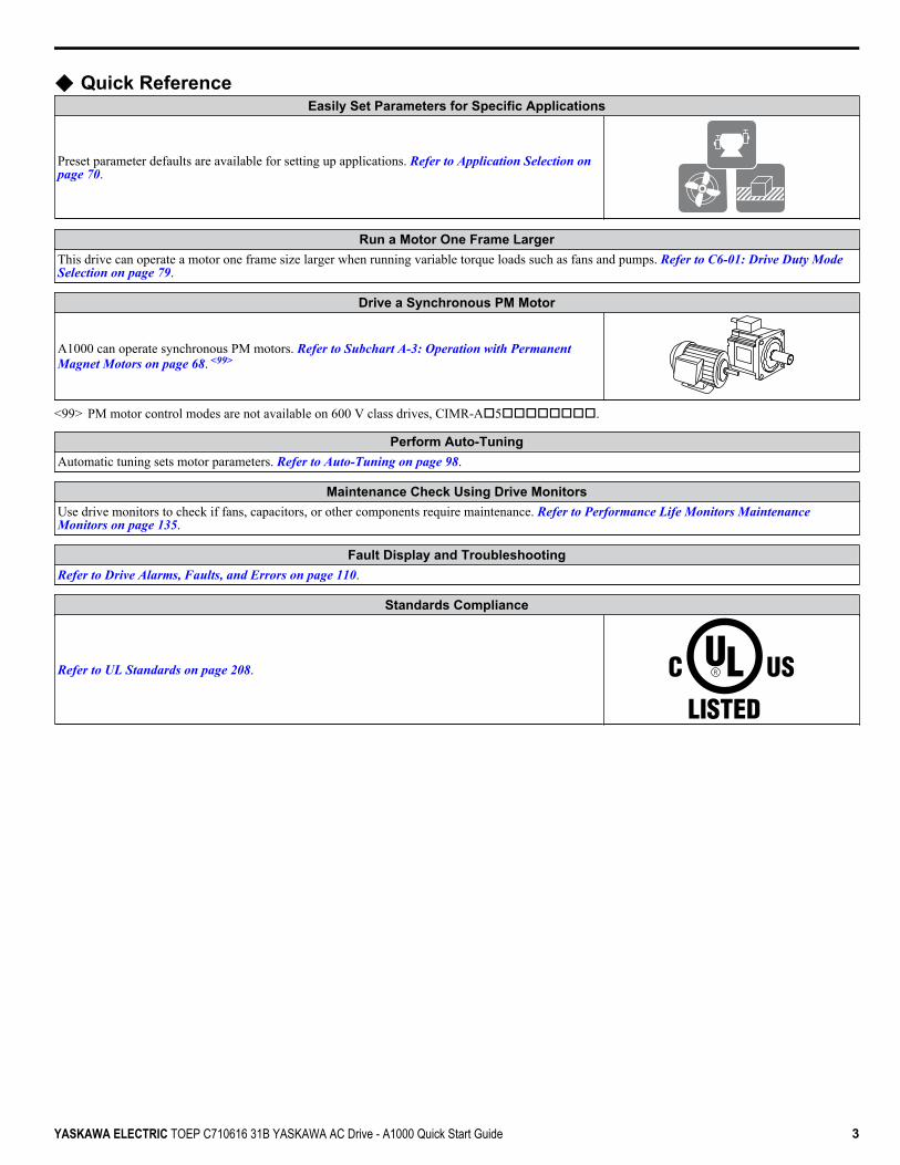
u Quick ReferenceEasily Set Parameters for Specific Applications
Preset parameter defaults are available for setting up applications. Refer to Application Selection on page 70.
Run a Motor One Frame LargerThis drive can operate a motor one frame size larger when running variable torque loads such as fans and pumps. Refer to C6-01: Drive Duty Mode Selection on page 79.
Drive a Synchronous PM Motor
A1000 can operate synchronous PM motors. Refer to Subchart A-3: Operation with Permanent Magnet Motors on page 68. <99>
<99> PM motor control modes are not available on 600 V class drives, CIMR-Ao5oooooooo.
Perform Auto-TuningAutomatic tuning sets motor parameters. Refer to Auto-Tuning on page 98.
Maintenance Check Using Drive MonitorsUse drive monitors to check if fans, capacitors, or other components require maintenance. Refer to Performance Life Monitors Maintenance Monitors on page 135.
Fault Display and TroubleshootingRefer to Drive Alarms, Faults, and Errors on page 110.
Standards Compliance
Refer to UL Standards on page 208.
YASKAWA ELECTRIC TOEP C710616 31B YASKAWA AC Drive - A1000 Quick Start Guide 3

This Page Intentionally Blank
4 YASKAWA ELECTRIC TOEP C710616 31B YASKAWA AC Drive - A1000 Quick Start Guide
Table of ContentsQUICK REFERENCE ....................................................................................... 3
i. PREFACE & GENERAL SAFETY.................................................................. 11i.1 Preface ....................................................................................................................... 12
Applicable Documentation....................................................................................................... 12i.2 General Safety ........................................................................................................... 13
Supplemental Safety Information ............................................................................................ 13Safety Messages..................................................................................................................... 14General Application Precautions ............................................................................................. 15Motor Application Precautions................................................................................................. 17Motor Application Considerations............................................................................................ 18Drive Label Warnings .............................................................................................................. 20Warranty Information............................................................................................................... 20
1. RECEIVING .................................................................................................... 211.1 Model Number and Nameplate Check ..................................................................... 22
Nameplate ............................................................................................................................... 22
2. MECHANICAL INSTALLATION..................................................................... 252.1 Mechanical Installation ............................................................................................. 26
Installation Environment .......................................................................................................... 26Installation Orientation and Spacing........................................................................................ 26
3. ELECTRICAL INSTALLATION ...................................................................... 313.1 Standard Connection Diagram................................................................................. 323.2 Main Circuit Connection Diagram............................................................................ 35
Three-Phase 600 V Class ....................................................................................................... 353.3 Terminal Cover .......................................................................................................... 36
IP20/NEMA Type 1.................................................................................................................. 363.4 Digital Operator and Front Cover............................................................................. 37
Removing/Reattaching the Digital Operator............................................................................ 37Removing/Reattaching the Front Cover .................................................................................. 37
3.5 Top Protective Cover ................................................................................................ 38Removing the Top Protective Cover ....................................................................................... 38Reattaching the Top Protective Cover .................................................................................... 38
3.6 Main Circuit Wiring.................................................................................................... 39Main Circuit Terminal Functions.............................................................................................. 39
YASKAWA ELECTRIC TOEP C710616 31B YASKAWA AC Drive - A1000 Quick Start Guide 5

Protecting Main Circuit Terminals ..................................................................................................... 39Wire Gauges and Tightening Torque ................................................................................................ 39Main Circuit Terminal and Motor Wiring ............................................................................................ 40
3.7 Control Circuit Wiring .........................................................................................................42Control Circuit Connection Diagram.................................................................................................. 42Control Circuit Terminal Block Functions .......................................................................................... 42Terminal Configuration ...................................................................................................................... 44Wiring the Control Circuit Terminal ................................................................................................... 45Switches and Jumpers on the Terminal Board.................................................................................. 47
3.8 Control I/O Connections .....................................................................................................48Sinking/Sourcing Mode Switch for Digital Inputs............................................................................... 48Sinking/Sourcing Mode Selection for Safe Disable Inputs ................................................................ 49Using the Pulse Train Output ............................................................................................................ 49Terminal A2 Input Signal Selection ................................................................................................... 50Terminal A3 Analog/PTC Input Selection.......................................................................................... 50Terminal AM/FM Signal Selection ..................................................................................................... 51MEMOBUS/Modbus Termination ...................................................................................................... 51
3.9 Connect to a PC...................................................................................................................523.10 Wiring Checklist ..................................................................................................................53
4. START-UP PROGRAMMING & OPERATION....................................................... 554.1 Using the Digital Operator ..................................................................................................56
Keys and Displays............................................................................................................................. 56LCD Display ...................................................................................................................................... 57ALARM (ALM) LED Displays............................................................................................................. 58LO/RE LED and RUN LED Indications.............................................................................................. 58Menu Structure for Digital Operator .................................................................................................. 60
4.2 The Drive and Programming Modes..................................................................................61Changing Parameter Settings or Values ........................................................................................... 61Switching Between LOCAL and REMOTE........................................................................................ 62
4.3 Start-Up Flowcharts ............................................................................................................64Flowchart A: Basic Start-Up and Motor Tuning ................................................................................. 65Subchart A-1: Simple Motor Setup Using V/f Control........................................................................ 66Subchart A-2: High Performance Operation Using OLV or CLV ....................................................... 67Subchart A-3: Operation with Permanent Magnet Motors................................................................. 68
4.4 Powering Up the Drive ........................................................................................................69Powering Up the Drive and Operation Status Display....................................................................... 69
4.5 Application Selection..........................................................................................................704.6 Basic Drive Setup Adjustments .........................................................................................714.7 Auto-Tuning .........................................................................................................................98
Types of Auto-Tuning ........................................................................................................................ 98Auto-Tuning Interruption and Fault Codes ...................................................................................... 101Auto-Tuning Operation Example ..................................................................................................... 101
4.8 No-Load Operation Test Run............................................................................................104No-Load Operation Test Run .......................................................................................................... 104
4.9 Test Run with Load Connected........................................................................................106Test Run with the Load Connected ................................................................................................. 106
4.10 Test Run Checklist ............................................................................................................107
Table of Contents
6 YASKAWA ELECTRIC TOEP C710616 31B YASKAWA AC Drive - A1000 Quick Start Guide

5. TROUBLESHOOTING.......................................................................................... 1095.1 Drive Alarms, Faults, and Errors .....................................................................................110
Types of Alarms, Faults, and Errors................................................................................................ 1105.2 Fault Detection ..................................................................................................................111
Fault Displays, Causes, and Possible Solutions ............................................................................. 1115.3 Alarm Detection.................................................................................................................121
Alarm Codes, Causes, and Possible Solutions ............................................................................... 1215.4 Operator Programming Errors .........................................................................................124
Operator Programming Error Codes, Causes, and Possible Solutions........................................... 1245.5 Auto-Tuning Fault Detection ............................................................................................125
Auto-Tuning Codes, Causes, and Possible Solutions..................................................................... 1255.6 Copy Function Related Displays .....................................................................................129
Tasks, Errors, and Troubleshooting ................................................................................................ 1295.7 Diagnosing and Resetting Faults.....................................................................................130
Fault Reset Methods ....................................................................................................................... 130
6. PERIODIC INSPECTION & MAINTENANCE ...................................................... 1316.1 Inspection ..........................................................................................................................132
Recommended Daily Inspection...................................................................................................... 132Recommended Periodic Inspection................................................................................................. 133
6.2 Periodic Maintenance .......................................................................................................135Replacement Parts.......................................................................................................................... 135
6.3 Drive Replacement ............................................................................................................137Replacing the Drive ......................................................................................................................... 137
A. SPECIFICATIONS ................................................................................................ 139A.1 Heavy Duty and Normal Duty Ratings.............................................................................140A.2 Power Ratings ...................................................................................................................141
Three-Phase 600 V Class Drives .................................................................................................... 141A.3 Drive Specifications ..........................................................................................................142
B. PARAMETER LIST............................................................................................... 145B.1 A: Initialization Parameters ..............................................................................................146
A1: Initialization ............................................................................................................................... 146A2: User Parameters....................................................................................................................... 147
B.2 b: Application.....................................................................................................................148b1: Operation Mode Selection......................................................................................................... 148b2: DC Injection Braking and Short Circuit Braking......................................................................... 149b3: Speed Search............................................................................................................................ 149b4: Timer Function .......................................................................................................................... 150b5: PID Control................................................................................................................................ 150b6: Dwell Function........................................................................................................................... 152b7: Droop Control ............................................................................................................................ 152b8: Energy Saving ........................................................................................................................... 152b9: Zero Servo................................................................................................................................. 153
B.3 C: Tuning............................................................................................................................154C1: Acceleration and Deceleration Times ....................................................................................... 154
Table of Contents
YASKAWA ELECTRIC TOEP C710616 31B YASKAWA AC Drive - A1000 Quick Start Guide 7
C2: S-Curve Characteristics............................................................................................................ 155C3: Slip Compensation.................................................................................................................... 155C4: Torque Compensation .............................................................................................................. 156C5: Automatic Speed Regulator (ASR) ........................................................................................... 156C6: Carrier Frequency..................................................................................................................... 158
B.4 d: References.....................................................................................................................159d1: Frequency Reference................................................................................................................ 159d2: Frequency Upper/Lower Limits ................................................................................................. 160d3: Jump Frequency........................................................................................................................ 160d4: Frequency Reference Hold and Up/Down 2 Function............................................................... 161d5: Torque Control .......................................................................................................................... 161d6: Field Weakening and Field Forcing........................................................................................... 162d7: Offset Frequency....................................................................................................................... 162
B.5 E: Motor Parameters .........................................................................................................163E1: V/f Pattern for Motor 1............................................................................................................... 163E2: Motor 1 Parameters .................................................................................................................. 164E3: V/f Pattern for Motor 2............................................................................................................... 165E4: Motor 2 Parameters .................................................................................................................. 165E5: PM Motor Settings .................................................................................................................... 166
B.6 F: Options...........................................................................................................................168F1: PG Speed Control Card (PG-B3/PG-X3) .................................................................................. 168F2: Analog Input Card (AI-A3)......................................................................................................... 169F3: Digital Input Card (DI-A3).......................................................................................................... 170F4: Analog Monitor Card (AO-A3) ................................................................................................... 170F5: Digital Output Card (DO-A3) ..................................................................................................... 171F6: Communication Option Card..................................................................................................... 171
B.7 H Parameters: Multi-Function Terminals ........................................................................174H1: Multi-Function Digital Inputs ..................................................................................................... 174H2: Multi-Function Digital Outputs................................................................................................... 177H3: Multi-Function Analog Inputs .................................................................................................... 179H4: Analog Outputs ......................................................................................................................... 180H5: MEMOBUS/Modbus Serial Communication ............................................................................. 181H6: Pulse Train Input/Output........................................................................................................... 181
B.8 L: Protection Function ......................................................................................................183L1: Motor Protection ........................................................................................................................ 183L2: Momentary Power Loss Ride-Thru............................................................................................ 183L3: Stall Prevention ......................................................................................................................... 184L4: Speed Detection........................................................................................................................ 186L5: Fault Restart.............................................................................................................................. 186L6: Torque Detection....................................................................................................................... 186L7: Torque Limit .............................................................................................................................. 188L8: Drive Protection......................................................................................................................... 188
B.9 n: Special Adjustment.......................................................................................................190n1: Hunting Prevention.................................................................................................................... 190n2: Speed Feedback Detection Control (AFR) Tuning.................................................................... 190n3: High Slip Braking (HSB) and Overexcitation Braking................................................................ 190n5: Feed Forward Control ............................................................................................................... 191n6: Online Tuning ............................................................................................................................ 191n8: PM Motor Control Tuning .......................................................................................................... 191
B.10 o: Operator-Related Settings ...........................................................................................193
Table of Contents
8 YASKAWA ELECTRIC TOEP C710616 31B YASKAWA AC Drive - A1000 Quick Start Guide
o1: Digital Operator Display Selection............................................................................................. 193o2: Digital Operator Keypad Functions ........................................................................................... 193o3: Copy Function ........................................................................................................................... 194o4: Maintenance Monitor Settings................................................................................................... 194
B.11 DriveWorksEZ Parameters ...............................................................................................195q: DriveWorksEZ Parameters.......................................................................................................... 195r: DriveWorksEZ Connection Parameters ....................................................................................... 195
B.12 T: Motor Tuning .................................................................................................................196T1: Induction Motor Auto-Tuning..................................................................................................... 196T2: PM Motor Auto-Tuning .............................................................................................................. 197T3: ASR and Inertia Tuning............................................................................................................. 198
B.13 U: Monitors.........................................................................................................................199U1: Operation Status Monitors ........................................................................................................ 199U2: Fault Trace................................................................................................................................ 201U3: Fault History.............................................................................................................................. 202U4: Maintenance Monitors .............................................................................................................. 202U5: PID Monitors ............................................................................................................................. 203U6: Operation Status Monitors ........................................................................................................ 204U8: DriveWorksEZ Monitors............................................................................................................ 205
C. STANDARDS COMPLIANCE .............................................................................. 207C.1 UL Standards .....................................................................................................................208
UL Standards Compliance .............................................................................................................. 208Drive Motor Overload Protection ..................................................................................................... 210
C.2 Safe Disable Input Function .............................................................................................212Specifications .................................................................................................................................. 212Precautions ..................................................................................................................................... 212Using the Safe Disable Function ..................................................................................................... 212
Table of Contents
YASKAWA ELECTRIC TOEP C710616 31B YASKAWA AC Drive - A1000 Quick Start Guide 9

Table of Contents
This Page Intentionally Blank
10 YASKAWA ELECTRIC TOEP C710616 31B YASKAWA AC Drive - A1000 Quick Start Guide
Preface & General SafetyThis section provides safety messages pertinent to this product that, if not heeded, may result in fatality,personal injury, or equipment damage. Yaskawa is not responsible for the consequences of ignoringthese instructions.
i.1 PREFACE...............................................................................................................12i.2 GENERAL SAFETY...............................................................................................13
i
YASKAWA ELECTRIC TOEP C710616 31B YASKAWA AC Drive - A1000 Quick Start Guide 11

i.1 PrefaceYaskawa manufactures products used as components in a wide variety of industrial systems and equipment. The selection andapplication of Yaskawa products remain the responsibility of the equipment manufacturer or end user. Yaskawa accepts noresponsibility for the way its products are incorporated into the final system design. Under no circumstances should anyYaskawa product be incorporated into any product or design as the exclusive or sole safety control. Without exception, allcontrols should be designed to detect faults dynamically and fail safely under all circumstances. All systems or equipmentdesigned to incorporate a product manufactured by Yaskawa must be supplied to the end user with appropriate warnings andinstructions as to the safe use and operation of that part. Any warnings provided by Yaskawa must be promptly provided tothe end user. Yaskawa offers an express warranty only as to the quality of its products in conforming to standards andspecifications published in the Yaskawa manual. NO OTHER WARRANTY, EXPRESS OR IMPLIED, IS OFFERED.Yaskawa assumes no liability for any personal injury, property damage, losses, or claims arising from misapplication of itsproducts.This manual is designed to ensure correct and suitable application of A1000-Series Drives. Read this manual before attemptingto install, operate, maintain, or inspect a drive and keep it in a safe, convenient location for future reference. Be sure youunderstand all precautions and safety information before attempting application.
u Applicable DocumentationThe following manuals are available for A1000 series drives:
A1000
CIMR-AU5A0009FAA600V 3Phase 5.5kW/3.7kW
A1000 Series AC Drive Quick Start GuideRead this guide first. This guide is packaged together with the product and contains basic informationrequired to install and wire the drive. It also gives an overview of fault diagnostics, maintenance, andparameter settings. The purpose of this guide is to prepare the drive for a trial run with an application andfor basic operation. This manual is available for download on our documentation website,www.yaskawa.com.A1000 Series AC Drive Technical ManualThis manual provides detailed information on parameter settings, drive functions, and MEMOBUS/Modbus specifications. Use this manual to expand drive functionality and to take advantage of higherperformance features. This manual is available for download on our documentation website,www.yaskawa.com.
i.1 Preface
12 YASKAWA ELECTRIC TOEP C710616 31B YASKAWA AC Drive - A1000 Quick Start Guide

i.2 General Safety
u Supplemental Safety InformationGeneral Precautions
• The diagrams in this manual may be indicated without covers or safety shields to show details. Replace the covers or shields beforeoperating the drive and run the drive according to the instructions described in this manual.
• Any illustrations, photographs, or examples used in this manual are provided as examples only and may not apply to all products towhich this manual is applicable.
• The products and specifications described in this manual or the content and presentation of the manual may be changed without noticeto improve the product and/or the manual.
• When ordering a new copy of the manual due to damage or loss, contact your Yaskawa representative or the nearest Yaskawa salesoffice and provide the manual number shown on the front cover.
• If nameplate becomes worn or damaged, order a replacement from your Yaskawa representative or the nearest Yaskawa sales office.
WARNINGRead and understand this manual before installing, operating or servicing this drive. The drive must be installed accordingto this manual and local codes.The following conventions are used to indicate safety messages in this manual. Failure to heed these messages could resultin serious or fatal injury or damage to the products or to related equipment and systems.
DANGERIndicates a hazardous situation, which, if not avoided, will result in death or serious injury.
WARNINGIndicates a hazardous situation, which, if not avoided, could result in death or serious injury.
WARNING! may also be indicated by a bold key word embedded in the text followed by an italicized safety message.
CAUTIONIndicates a hazardous situation, which, if not avoided, could result in minor or moderate injury.
CAUTION! may also be indicated by a bold key word embedded in the text followed by an italicized safety message.
NOTICEIndicates a property damage message.
NOTICE: may also be indicated by a bold key word embedded in the text followed by an italicized safety message.
i.2 General Safety
YASKAWA ELECTRIC TOEP C710616 31B YASKAWA AC Drive - A1000 Quick Start Guide 13

u Safety Messages
DANGERHeed the safety messages in this manual.Failure to comply will result in death or serious injury.The operating company is responsible for any injuries or equipment damage resulting from failure to heed the warnings inthis manual.
Electrical Shock HazardDo not connect or disconnect wiring while the power is on.Failure to comply will result in death or serious injury.Before servicing, disconnect all power to the equipment. The internal capacitor remains charged even after the power supplyis turned off. After shutting off the power, wait for at least the amount of time specified on the drive before touching anycomponents.
WARNINGSudden Movement Hazard
System may start unexpectedly upon application of power, resulting in death or serious injury.Clear all personnel from the drive, motor and machine area before applying power. Secure covers, couplings, shaft keys andmachine loads before applying power to the drive.When using DriveWorksEZ to create custom programming, the drive I/O terminal functions change from factorysettings and the drive will not perform as outlined in this manual.Unpredictable equipment operation may result in death or serious injury.Take special note of custom I/O programming in the drive before attempting to operate equipment.
Electrical Shock HazardDo not attempt to modify or alter the drive in any way not explained in this manual.Failure to comply could result in death or serious injury.Yaskawa is not responsible for any modification of the product made by the user. This product must not be modified.Do not allow unqualified personnel to use equipment.Failure to comply could result in death or serious injury.Maintenance, inspection, and replacement of parts must be performed only by authorized personnel familiar with installation,adjustment and maintenance of AC drives.Do not remove covers or touch circuit boards while the power is on.Failure to comply could result in death or serious injury.
Fire HazardDo not use an improper voltage source.Failure to comply could result in death or serious injury by fire.Verify that the rated voltage of the drive matches the voltage of the incoming power supply before applying power.
Crush HazardDo not use this drive in lifting applications without installing external safety circuitry to prevent accidental droppingof the load.The drive does not possess built-in load drop protection for lifting applications.Failure to comply could result in death or serious injury from falling loads.Install electrical and/or mechanical safety circuit mechanisms independent of drive circuitry.
i.2 General Safety
14 YASKAWA ELECTRIC TOEP C710616 31B YASKAWA AC Drive - A1000 Quick Start Guide

CAUTIONCrush Hazard
Do not carry the drive by the front cover.Failure to comply may result in minor or moderate injury from the main body of the drive falling.
NOTICEObserve proper electrostatic discharge procedures (ESD) when handling the drive and circuit boards.Failure to comply may result in ESD damage to the drive circuitry.Do not perform a withstand voltage test on any part of the drive.Failure to comply could result in damage to the sensitive devices within the drive.Do not operate damaged equipment.Failure to comply could result in further damage to the equipment.Do not connect or operate any equipment with visible damage or missing parts.Install adequate branch circuit short circuit protection per applicable codes.Failure to comply could result in damage to the drive.The drive is suitable for circuits capable of delivering not more than 100,000 RMS symmetrical Amperes, 600 Vac maximum(600 V Class).Do not expose the drive to halogen group disinfectants.Failure to comply may cause damage to the electrical components in the drive.Do not pack the drive in wooden materials that have been fumigated or sterilized.Do not sterilize the entire package after the product is packed.
u General Application Precautionsn SelectionInstalling a ReactorUse an AC or DC reactor in the following situations:• to suppress harmonic current.• to smooth peak current resulting from capacitor switching.• when the power supply is above 600 kVA.• when the drive is running from a power supply system with thyristor converters.
4000
600
0 60 400Drive Capacity (kVA)
Power SupplyCapacity (kVA)
Power supply harmonics reactor required
Reactor unnecessary
Figure i.1 Installing a Reactor
Drive CapacityFor specialized motors, make sure that the motor rated current is less than the rated output current for the drive.When running more than one motor in parallel from a single drive, the capacity of the drive should be larger than [total motorrated current × 1.1].
i.2 General Safety
YASKAWA ELECTRIC TOEP C710616 31B YASKAWA AC Drive - A1000 Quick Start Guide 15
Starting TorqueThe overload rating for the drive determines the starting and accelerating characteristics of the motor. Expect lower torquethan when running from line power. To get more starting torque, use a larger drive or increase both the motor and drive capacity.
Emergency StopWhen the drive faults out, the output shuts off but the motor does not stop immediately. A mechanical brake may be requiredwhen it is necessary to stop the motor faster than the ability of the Fast Stop function of the drive.
OptionsNOTICE: The B1, B2, +1, +2, and +3 terminals are used to connect optional A1000-compatible devices only. Connecting non-Yaskawa-approved devices to these terminals may damage the drive.
Repetitive Starting/StoppingElevators, punching presses, and other applications with frequent starts and stops often exceed 150% of their rated currentvalues. Heat stress generated from repetitive high current can shorten the life span of the IGBTs.Yaskawa recommends lowering the carrier frequency, particularly when audible noise is not a concern. It may also be beneficialto reduce the load, increase the acceleration and deceleration times, or switch to a larger drive to help keep peak current levelsunder 150%. Be sure to check the peak current levels when starting and stopping repeatedly during the initial test run, andmake adjustments accordingly.
n InstallationEnclosure PanelsKeep the drive in a clean environment by installing the drive in an enclosure panel or selecting an installation area free ofairborne dust, lint, and oil mist. Be sure to leave the required space between drives to provide for cooling, and take propermeasures so the ambient temperature remains within allowable limits and keep flammable materials away from the drive.Yaskawa offers protective designs for drives that must be used in areas subjected to oil mist and excessive vibration. ContactYaskawa or your Yaskawa agent for details.
Installation DirectionNOTICE: Install the drive upright as specified in the manual. Refer to Mechanical Installation on page 26 for more information oninstallation. Failure to comply may damage the drive due to improper cooling.
n SettingsMotor CodeWhen using OLV/PM, set the proper motor code to parameter E5-01 before performing a trial run.
Upper LimitsNOTICE: The drive is capable of running the motor up to 400 Hz. Be sure to set the upper limit for the frequency of the drive to prevent thepossible danger of accidentally operating equipment at higher than rated speed. The default setting for the maximum output frequency is60 Hz.
DC Injection BrakingNOTICE: Excessive current during DC Injection Braking and excessive duration of DC Injection Braking can cause motor overheat.
Acceleration/Deceleration TimesAcceleration and deceleration times are affected by the amount of torque generated by the motor, the load torque, and theinertia moment. Set a longer accel/decel time when Stall Prevention is enabled. The accel/decel times are lengthened for aslong as the Stall Prevention function is in operation. Install one of the available braking options or increase the capacity of thedrive for faster acceleration and deceleration.
n General HandlingWiring CheckNOTICE: Do not connect power supply lines to output terminals U/T1, V/T2, or W/T3. Failure to comply will destroy the drive. Be sure toperform a final check of all sequence wiring and other connections before turning on the power and also check for short circuits on thecontrol terminals, which may damage the drive.
Selecting a Circuit Breaker or Leakage Circuit BreakerYaskawa recommends installing a Ground Fault Circuit Interrupter (GFCI) to the power supply side. The GFCI should bedesigned for use with AC drives (e.g., Type B according to IEC 60755).Select a Molded Case Circuit Breaker (MCCB) or GFCI with a rated current 1.5 to 2 times higher than the drive rated currentto avoid nuisance trips caused by harmonics in the drive input current.
i.2 General Safety
16 YASKAWA ELECTRIC TOEP C710616 31B YASKAWA AC Drive - A1000 Quick Start Guide
Magnetic Contactor InstallationWARNING! Fire Hazard. Shut off the drive with a magnetic contactor (MC) when a fault occurs in any external equipment such as brakingresistors. Failure to comply may cause resistor overheating, fire, and injury to personnel.
NOTICE: To get the full performance life out of the electrolytic capacitors and circuit relays, refrain from switching the drive power supplyoff and on more than once every 30 minutes. Frequent use can damage the drive. Use the drive to stop and start the motor.
Inspection and MaintenanceWARNING! Electrical Shock Hazard. Capacitors in the drive do not immediately discharge after shutting off the power. Wait for at least theamount of time specified on the drive before touching any components after shutting off the power. Failure to comply may cause injury topersonnel from electrical shock.
WARNING! Electrical Shock Hazard. When a drive is running a PM motor, voltage continues to be generated at the motor terminals afterthe drive is shut off while the motor coasts to stop. Take the precautions described below to prevent shock and injury:• In applications where the machine can still rotate even though the drive has fully stopped a load, install a switch
to the drive output side to disconnect the motor and the drive.• Do not allow an external force to rotate the motor beyond the maximum allowable speed or to rotate the motor
when the drive has been shut off.• Wait for at least the time specified on the warning label after opening the load switch on the output side before
inspecting the drive or performing any maintenance.• Do not open and close the load switch while the motor is running, as this can damage the drive.• If the motor is coasting, make sure the power to the drive is turned on and the drive output has completely
stopped before closing the load switch.WARNING! Burn Hazard. Because the heatsink can get very hot during operation, take proper precautions to prevent burns. When replacingthe cooling fan, shut off the power and wait at least 15 minutes to be sure that the heatsink has cooled down. Failure to comply may causeburn injury to personnel.
WiringAll wire ends should use ring terminals for UL/cUL compliance. Use only the tools recommended by the terminal manufacturerfor crimping.
Transporting the DriveNOTICE: Never steam clean the drive. During transport, keep the drive from coming into contact with salts, fluorine, bromine, phthalateester, and other such harmful chemicals.
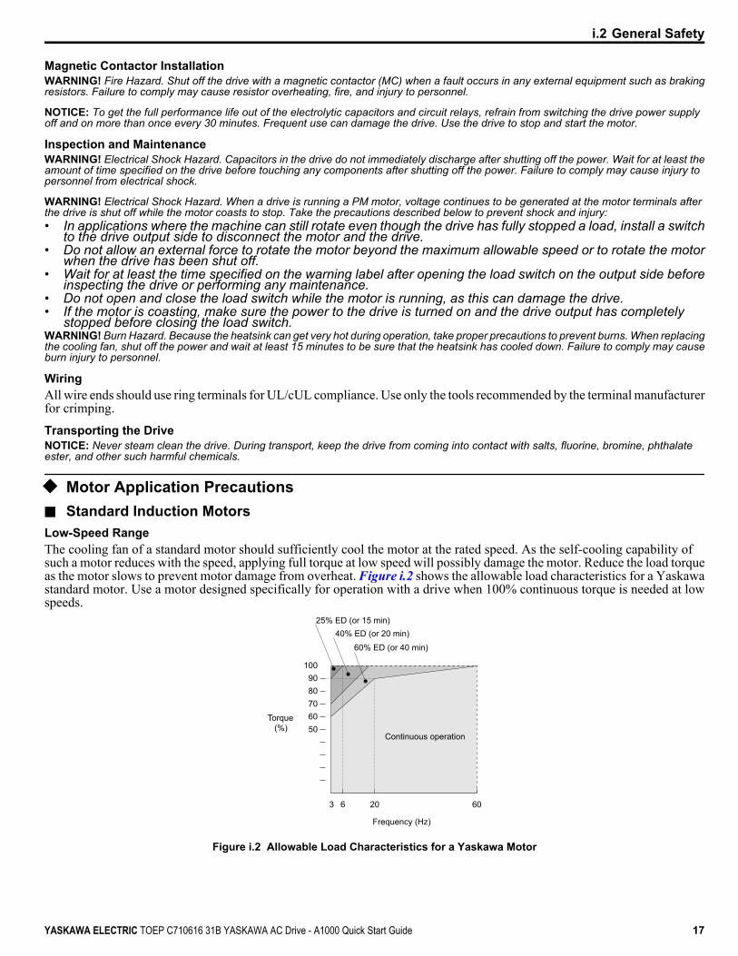
u Motor Application Precautionsn Standard Induction MotorsLow-Speed RangeThe cooling fan of a standard motor should sufficiently cool the motor at the rated speed. As the self-cooling capability ofsuch a motor reduces with the speed, applying full torque at low speed will possibly damage the motor. Reduce the load torqueas the motor slows to prevent motor damage from overheat. Figure i.2 shows the allowable load characteristics for a Yaskawastandard motor. Use a motor designed specifically for operation with a drive when 100% continuous torque is needed at lowspeeds.
50
3 6 60
60708090
100
25% ED (or 15 min)40% ED (or 20 min)
60% ED (or 40 min)
Frequency (Hz)
Continuous operation
Torque(%)
20
Figure i.2 Allowable Load Characteristics for a Yaskawa Motor
i.2 General Safety
YASKAWA ELECTRIC TOEP C710616 31B YASKAWA AC Drive - A1000 Quick Start Guide 17

Insulation ToleranceNOTICE: Consider motor voltage tolerance levels and motor insulation in applications with an input voltage of over 440 V or particularlylong wiring distances.
High-Speed OperationNOTICE: Problems may occur with the motor bearings and dynamic balance of the machine when operating a motor beyond its rated speed.Contact the motor or machine manufacturer.
Torque CharacteristicsTorque characteristics differ compared to operating the motor directly from line power. The user should have a fullunderstanding of the load torque characteristics for the application.
Vibration and ShockThe drive allows selection of high carrier PWM control and low carrier PWM. Selecting high carrier PWM can help reducemotor oscillation.Take particular caution when adding a variable speed drive to an application running a motor from line power at a constantspeed. If resonance occurs, install shock-absorbing rubber around the base of the motor and enable the Jump frequency selectionto prevent continuous operation in the resonant frequency range.
Audible NoiseNoise created during run varies by the carrier frequency setting. When using a high carrier frequency, audible noise from themotor is comparable to the motor noise generated when running from line power. Operating above the rated motor speed cancreate unpleasant motor noise.
n Synchronous Motors• Contact Yaskawa or a Yaskawa agent when planning to use a synchronous motor not endorsed by Yaskawa.• Use a standard induction motor when running multiple synchronous motors simultaneously. A single drive does not have
this capability.• A synchronous motor may rotate slightly in the opposite direction of the Run command at start depending on parameter
settings and rotor position.• The amount of generated starting torque differs depending on the control mode and motor type. Set up the motor with the
drive after verifying the starting torque, allowable load characteristics, impact load tolerance, and speed control range.Contact Yaskawa or a Yaskawa agent when planning to use a motor that does not fall within these specifications:
• In Open Loop Vector Control for PM motors, braking torque is less than 125% when running between 20% and 100% speed,even with a braking resistor. Braking torque drops to less than 50% when running at less than 20% speed.
• In Open Loop Vector Control for PM motors, the allowable load inertia moment is approximately 50× higher than the motorinertia moment.Contact Yaskawa or a Yaskawa agent for questions concerning applications with a larger inertia moment.
• When using a holding brake in Open Loop Vector Control for PM motors, release the brake prior to starting the motor.Failure to set the proper timing can cause speed loss.
• To restart a coasting motor rotating over 200 Hz while in V/f Control, first use the Short Circuit Braking function to bringthe motor to a stop. Short Circuit Braking requires a special braking resistor. Contact Yaskawa or a Yaskawa agent fordetails.
• To restart a coasting motor rotating below 200 Hz, use the Speed Search function if the motor cable is not too long. If themotor cable is relatively long, stop the motor using Short Circuit Braking.
u Motor Application Considerationsn Specialized MotorsMulti-Pole MotorThe rated current of a multi-pole motor differs from that of a standard motor, so be sure to check the maximum current whenselecting a drive. Always stop the motor before switching between the number of motor poles. The motor will coast to stop ifa regen overvoltage (ov) fault occurs or if overcurrent (oC) protection is triggered.
Submersible MotorThe rated current of a submersible motor is greater than that of a standard motor, so select the drive capacity accordingly. Usea motor cable large enough to avoid decreasing the maximum torque level from voltage drop caused by a long motor cable.
i.2 General Safety
18 YASKAWA ELECTRIC TOEP C710616 31B YASKAWA AC Drive - A1000 Quick Start Guide
Explosion-Proof MotorThe motor and the drive must be tested together to be certified as explosion-proof. The drive is not designed for explosion-proof areas.When attaching an encoder to an explosion-proof motor, make sure the encoder is also explosion-proof. Use an insulatingsignal converter to connect the encoder signal lines to the speed feedback option card.
Geared MotorMake sure that the gear and the lubricant are rated for the desired speed range to avoid gear damage when operating at lowspeeds or very high speeds. Consult with the manufacturer for applications that require operation outside the rated speed rangeof the motor or gear box.
Single-Phase MotorVariable speed drives are not designed to operate with single phase motors. Using capacitors to start the motor causes excessivecurrent to flow and can damage drive components. A split-phase start or a repulsion start can burn out the starter coils becausethe internal centrifugal switch is not activated. The drive is for use with three-phase motors only.
Motor with BrakeTake caution when using the drive to operate a motor with a built-in holding brake. If the brake is connected to the output sideof the drive, it may not release at start due to low voltage levels, so be sure to install a separate power supply for the motorbrake. Note that motors with built-in brakes tend to generate a fair amount of noise when running at low speeds.
n Notes on Power Transmission MachineryInstalling an AC drive in machinery that was previously connected directly to the power supply will allow the machine tooperate at variable speeds. Continuous operation outside of the rated speeds can wear on lubrication material in gear boxesand other power transmission parts. Make sure that lubrication is sufficient within the entire speed range to avoid machinedamage. Note that operation above the rated speed can increase the noise generated by the machine.
i.2 General Safety
YASKAWA ELECTRIC TOEP C710616 31B YASKAWA AC Drive - A1000 Quick Start Guide 19

u Drive Label WarningsAlways heed the warning information listed in Figure i.3 in the position shown in Figure i.4.
WARNINGRead manual before installing.Wait 5 minutes for capacitordischarge after disconnectingpower supply.To conform to requirements,make sure to ground the supplyneutral for 575V class.After opening the manual switchbetween the drive and motor,please wait 5 minutes beforeinspecting, performingmaintenance or wiring the drive.
Risk of electric shock.
Hot surfaces Top and Side surfaces maybecome hot. Do not touch.
Figure i.3 Warning Information
Warning Label
A1000
CIMR-AU5A0009FAA600V 3Phase 5.5kW/3.7kW
Figure i.4 Warning Information Position
u Warranty Informationn RestrictionsA1000 was not designed or manufactured for use in devices or systems that may directly affect or threaten human lives orhealth.Customers who intend to use the product described in this manual for devices or systems relating to transportation, healthcare, space aviation, atomic power, electric power, or in underwater applications must first contact their Yaskawarepresentatives or the nearest Yaskawa sales office.WARNING! Injury to Personnel. This product has been manufactured under strict quality-control guidelines. However, if this product is tobe installed in any location where failure of this product could involve or result in a life-and-death situation or loss of human life or in a facilitywhere failure may cause a serious accident or physical injury, safety devices must be installed to minimize the likelihood of any accident.
i.2 General Safety
20 YASKAWA ELECTRIC TOEP C710616 31B YASKAWA AC Drive - A1000 Quick Start Guide

ReceivingThis chapter explains how to inspect the drive upon receipt, and gives an overview of the differentenclosure types and components.
1.1 MODEL NUMBER AND NAMEPLATE CHECK....................................................22
1
YASKAWA ELECTRIC TOEP C710616 31B YASKAWA AC Drive - A1000 Quick Start Guide 21
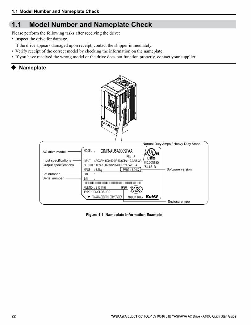
1.1 Model Number and Nameplate CheckPlease perform the following tasks after receiving the drive:• Inspect the drive for damage.
If the drive appears damaged upon receipt, contact the shipper immediately.• Verify receipt of the correct model by checking the information on the nameplate.• If you have received the wrong model or the drive does not function properly, contact your supplier.
u Nameplate
PRG : 504X
IND.CONT.EQ.7J48 B
CIMR-AU5A0009FAA
YASKAWA ELECTRIC CORPORATION MADE IN JAPAN
:
: AC3PH 500-600V 50/60Hz 12.0A/8.3A: AC3PH 0-600V 0-400Hz 9.0A/6.3A: 3.7kg: :
: E131457 IP20 PASS
MODEL
INPUTOUTPUTMASSO/NS/N
FILE NOTYPE 1 ENCLOSURE
AC drive model
Input specificationsOutput specifications
Lot numberSerial number
Software version
Enclosure type
REV : A
Normal Duty Amps / Heavy Duty Amps
Figure 1.1 Nameplate Information Example
1.1 Model Number and Nameplate Check
22 YASKAWA ELECTRIC TOEP C710616 31B YASKAWA AC Drive - A1000 Quick Start Guide

CIMR - A U 5 A 0003 F A A
Drive A1000 Series No.
Enclosure Type
Design Revision Order
No. CustomizedSpecifications
A Standard modelNo. Region
CodeU USA
IP00
F NEMA Type 1
A
No. Voltage Class
No. Environmental Specification <1>
AM
N
StandardHumidity- and dust-resistantOil-resistant
3-phase, 500-600 Vac 5
n Three-Phase 600 VNormal Duty Heavy Duty
No. Max. Motor CapacitykW
Rated OutputCurrent A No. Max. Motor Capacity
kWRated Output
Current A0003 1.5 2.7 0003 0.75 1.70004 2.2 3.9 0004 1.5 3.50006 3.7 6.1 0006 2.2 4.10009 5.5 9 0009 3.7 6.30011 7.5 11 0011 5.5 9.80017 11 17 0017 7.5 12.50022 15 22 0022 11 170027 18.5 27 0027 15 220032 22 32 0032 18.5 27
<1> Drives with these specifications do not guarantee complete protection from the environmental conditions indicated.
1.1 Model Number and Nameplate Check
YASKAWA ELECTRIC TOEP C710616 31B YASKAWA AC Drive - A1000 Quick Start Guide 23
1
Rec
eivi
ng

1.1 Model Number and Nameplate Check
This Page Intentionally Blank
24 YASKAWA ELECTRIC TOEP C710616 31B YASKAWA AC Drive - A1000 Quick Start Guide
Mechanical InstallationThis chapter explains how to properly mount and install the drive.
2.1 MECHANICAL INSTALLATION.............................................................................26
2
YASKAWA ELECTRIC TOEP C710616 31B YASKAWA AC Drive - A1000 Quick Start Guide 25

2.1 Mechanical InstallationThis section outlines specifications, procedures, and the environment for proper mechanical installation of the drive.
u Installation EnvironmentInstall the drive in an environment matching the specifications below to help prolong the optimum performance life of thedrive.
Table 2.1 Installation EnvironmentEnvironment Conditions
Installation Area Indoors
Ambient Temperature
-10 °C to +40 °C (IP20/NEMA Type 1)-10 °C to +50 °C (IP00/Open-Chassis)Drive reliability improves in environments without wide temperature fluctuations.When using the drive in an enclosure panel, install a cooling fan or air conditioner in the area to ensure that the airtemperature inside the enclosure does not exceed the specified levels.Do not allow ice to develop on the drive.
Humidity 95% RH or less and free of condensationStorage Temperature -20 to +60 °C
Surrounding Area
Install the drive in an area free from:• oil mist and dust• metal shavings, oil, water, or other foreign materials• radioactive materials• combustible materials (e.g., wood)• harmful gases and liquids• excessive vibration• chlorides• direct sunlight
Altitude 1000 m or lower, up to 3000 m with deratingVibration 10 to 20 Hz at 9.8 m/s2, 20 to 55 Hz at 5.9 m/s2
Orientation Install the drive vertically to maintain maximum cooling effects.
NOTICE: Avoid placing drive peripheral devices, transformers, or other electronics near the drive as the noise created can lead to erroneousoperation. If such devices must be used in close proximity to the drive, take proper steps to shield the drive from noise.
NOTICE: Prevent foreign matter such as metal shavings and wire clippings from falling into the drive during installation. Failure to complycould result in damage to the drive. Place a temporary cover over the top of the drive during installation. Remove the temporary cover beforedrive start-up, as the cover will reduce ventilation and cause the drive to overheat.
u Installation Orientation and SpacingInstall the drive upright as illustrated in Figure 2.1 to maintain proper cooling.
OK Not OK Not OK
Figure 2.1 Correct Installation Orientation
2.1 Mechanical Installation
26 YASKAWA ELECTRIC TOEP C710616 31B YASKAWA AC Drive - A1000 Quick Start Guide

n Single Drive InstallationFigure 2.2 shows the installation distance required to maintain sufficient space for airflow and wiring. Install the heatsinkagainst a closed surface to avoid diverting cooling air around the heatsink.
A
AB B
Side Clearance Top/Bottom Clearance
C
C D D
A – 50 mm minimumB – 30 mm minimum
C – 120 mm minimumD – Airflow direction
Figure 2.2 Correct Installation Spacing
Note: IP20/NEMA Type 1 and IP00/Open-Chassis models require the same amount of space above and below the drive for installation.
n Multiple Drive Installation (Side-by-Side Installation)Models CIMR-Ao5A0003 through 0011 can take advantage of Side-by-Side installation.When installing multiple drives into the same enclosure panel, mount the drives according to Figure 2.2.When mounting drives with the minimum clearance of 2 mm according to Figure 2.3, set parameter L8-35 to 1 whileconsidering derating. Refer to Parameter List on page 145.
A A
A AB
C
B
Side Clearance
Line up the tops of the drives.
D
D
Top/Bottom Clearance
A – 50 mm minimumB – 30 mm minimum
C – 2 mm minimumD – 120 mm minimum
Figure 2.3 Space Between Drives (Side-by-Side Mounting)
Note: Align the tops of the drives when installing drives of different heights in the same enclosure panel. Leave space between the tops and bottomsof stacked drives for easier cooling fan replacement.
Remove the top protective covers of all drives as shown in Figure 2.4 when mounting IP20/NEMA Type 1 drives side-by-side. Refer to Top Protective Cover on page 38 to remove and reattach the top protective cover.
2.1 Mechanical Installation
YASKAWA ELECTRIC TOEP C710616 31B YASKAWA AC Drive - A1000 Quick Start Guide 27
2M
echa
nica
l Ins
talla
tion
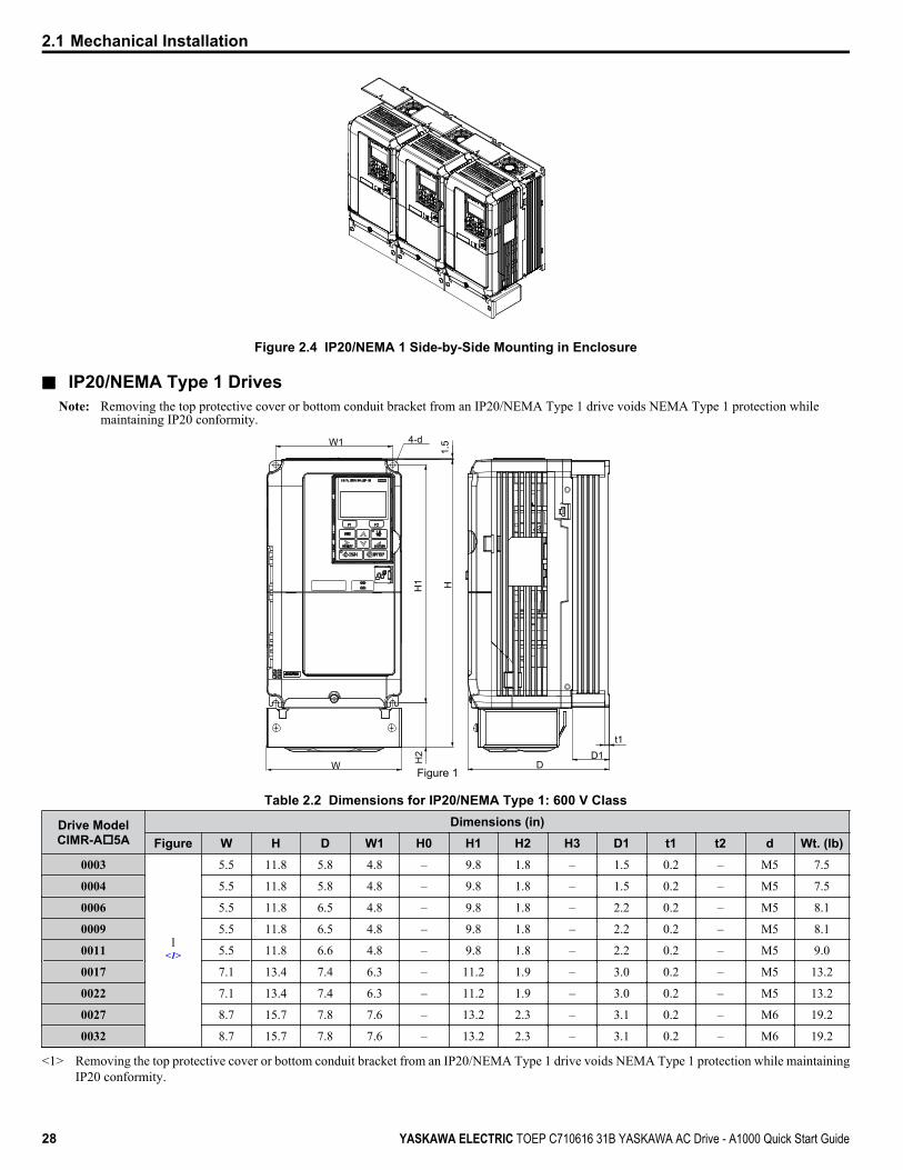
Figure 2.4 IP20/NEMA 1 Side-by-Side Mounting in Enclosure
n IP20/NEMA Type 1 DrivesNote: Removing the top protective cover or bottom conduit bracket from an IP20/NEMA Type 1 drive voids NEMA Type 1 protection while
maintaining IP20 conformity.W1
1.5
HH1
H2
DD1
t1
Figure 1
4-d
W
Table 2.2 Dimensions for IP20/NEMA Type 1: 600 V Class
Drive ModelCIMR-Ao5A
Dimensions (in)Figure W H D W1 H0 H1 H2 H3 D1 t1 t2 d Wt. (lb)
0003
1<1>
5.5 11.8 5.8 4.8 – 9.8 1.8 – 1.5 0.2 – M5 7.5
0004 5.5 11.8 5.8 4.8 – 9.8 1.8 – 1.5 0.2 – M5 7.5
0006 5.5 11.8 6.5 4.8 – 9.8 1.8 – 2.2 0.2 – M5 8.1
0009 5.5 11.8 6.5 4.8 – 9.8 1.8 – 2.2 0.2 – M5 8.1
0011 5.5 11.8 6.6 4.8 – 9.8 1.8 – 2.2 0.2 – M5 9.0
0017 7.1 13.4 7.4 6.3 – 11.2 1.9 – 3.0 0.2 – M5 13.2
0022 7.1 13.4 7.4 6.3 – 11.2 1.9 – 3.0 0.2 – M5 13.2
0027 8.7 15.7 7.8 7.6 – 13.2 2.3 – 3.1 0.2 – M6 19.2
0032 8.7 15.7 7.8 7.6 – 13.2 2.3 – 3.1 0.2 – M6 19.2
<1> Removing the top protective cover or bottom conduit bracket from an IP20/NEMA Type 1 drive voids NEMA Type 1 protection while maintainingIP20 conformity.
2.1 Mechanical Installation
28 YASKAWA ELECTRIC TOEP C710616 31B YASKAWA AC Drive - A1000 Quick Start Guide

D1
WWW1
W1
D D2
1.4d
1.7d
0.9d
Figure 2Figure 1
D3D3
W W
W1 W1
DD2
D1
1.4d
0.9d
Table 2.3 Conduit Bracket Dimensions for IP20/NEMA Type 1: 600 V Class
Drive ModelCIMR-Ao5A
Dimensions (in)Figure W D W1 D1 D2 D3
0003
1<1>
1.7 3.1 1.5 1.5 1.6 2.8
0004 1.7 3.1 1.5 1.5 1.6 2.8
0006 1.7 3.1 1.5 2.2 1.6 2.8
0009 1.7 3.1 1.5 2.2 1.6 2.8
0011 1.7 3.1 1.5 2.2 1.6 2.8
0017
2<1>
1.0 3.3 2.2 3.0 1.9 2.1
0022 1.0 3.3 2.2 3.0 1.9 2.1
0027 1.1 3.4 2.5 3.1 2.0 2.2
0032 1.1 3.4 2.5 3.1 2.0 2.2
<1> Removing the top protective cover or bottom conduit bracket from an IP20/NEMA Type 1 drive voids NEMA Type 1 protection while maintainingIP20 conformity.
2.1 Mechanical Installation
YASKAWA ELECTRIC TOEP C710616 31B YASKAWA AC Drive - A1000 Quick Start Guide 29
2M
echa
nica
l Ins
talla
tion

2.1 Mechanical Installation
This Page Intentionally Blank
30 YASKAWA ELECTRIC TOEP C710616 31B YASKAWA AC Drive - A1000 Quick Start Guide

Electrical InstallationThis chapter explains proper procedures for wiring the control circuit terminals, motor, and powersupply.
3.1 STANDARD CONNECTION DIAGRAM.................................................................323.2 MAIN CIRCUIT CONNECTION DIAGRAM............................................................353.3 TERMINAL COVER................................................................................................363.4 DIGITAL OPERATOR AND FRONT COVER........................................................373.5 TOP PROTECTIVE COVER...................................................................................383.6 MAIN CIRCUIT WIRING.........................................................................................393.7 CONTROL CIRCUIT WIRING................................................................................423.8 CONTROL I/O CONNECTIONS.............................................................................483.9 CONNECT TO A PC...............................................................................................523.10 WIRING CHECKLIST.............................................................................................53
3
YASKAWA ELECTRIC TOEP C710616 31B YASKAWA AC Drive - A1000 Quick Start Guide 31

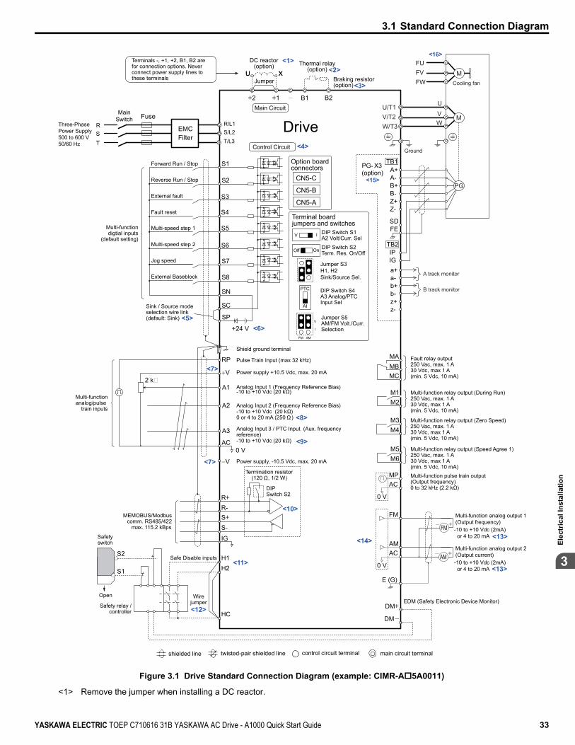
3.1 Standard Connection DiagramConnect the drive and peripheral devices as shown in Figure 3.1. It is possible to set and run the drive via the digital operatorwithout connecting digital I/O wiring. This section does not discuss drive operation; Refer to Start-Up Programming & Operation on page 55 for instructions on operating the drive.NOTICE: Inadequate wiring could result in damage to the drive. Install adequate branch circuit short circuit protection per applicable codes.The drive is suitable for circuits capable of delivering not more than 100,000 RMS symmetrical amperes, 600 Vac maximum (600 V Class).
NOTICE: When the input voltage is 440 V or higher or the wiring distance is greater than 100 meters, pay special attention to the motorinsulation voltage or use a drive duty motor. Failure to comply could lead to motor insulation breakdown.
NOTICE: Do not connect AC control circuit ground to drive enclosure. Improper drive grounding can cause control circuit malfunction.
NOTICE: The minimum load for the relay outputs M1-M2, M3-M4, M5-M6, and MA-MB-MC is 10 mA.
3.1 Standard Connection Diagram
32 YASKAWA ELECTRIC TOEP C710616 31B YASKAWA AC Drive - A1000 Quick Start Guide
+
-
+
-+
++
Terminals -, +1, +2, B1, B2 are for connection options. Never connect power supply lines to these terminals
DC reactor(option)
U XThermal relay
(option)
+
-
+
-+
++
+-
U X
S1
S2
S3
S4
S5
S6
S7
MP
DM
DM
RP
A1
A2
A3
0 VAC
RRSS-
IG
H1H2
HC
Drive
B112 B2
2 kΩ
S8
SC
0 V
0 V
AC
FM
AMAC
E (G)S1
S2
<1><2>
<3>
<11>
<7>
<12>
<13>
<8>
<10>
<7>
<5>
<4>
-
+24 V
+V
MA
M1M2
MBMC
Jumper Braking resistor(option)
Forward Run / Stop
Reverse Run / Stop
External fault
Fault reset
Multi-speed step 1
Multi-speed step 2
External Baseblock
Jog speed
Multi-function digtial inputs
(default setting)
Sink / Source mode selection wire link(default: Sink)
CN5-C
CN5-B
CN5-A
Option board
Pulse Train Input (max 32 kHz)
Shield ground terminal
Multi-function analog/pulse
train inputs
Power supply +10.5 Vdc, max. 20 mA
Analog Input 1 (Frequency Reference Bias)-10 to +10 Vdc (20 k )
Analog Input 2 (Frequency Reference Bias)-10 to +10 Vdc (20 k )0 or 4 to 20 mA (250 )
Analog Input 3 / PTC Input (Aux. frequency reference)-10 to +10 Vdc (20 k )
-V Power supply, -10.5 Vdc, max. 20 mA
Safety switch
MEMOBUS/Modbus comm. RS485/422
max. 115.2 kBps
Safe Disable inputs
Wire jumper
Open
Safety relay / controller
Termination resistor(120 , 1/2 W)
DIP Switch S2
Fault relay output250 Vac, max. 1 A30 Vdc, max 1 A(min. 5 Vdc, 10 mA)
Multi-function relay output (During Run)250 Vac, max. 1 A30 Vdc, max 1 A(min. 5 Vdc, 10 mA)
Multi-function pulse train output(Output frequency)0 to 32 kHz (2.2 k )
Multi-function analog output 1(Output frequency)-10 to +10 Vdc (2mA) or 4 to 20 mA
EDM (Safety Electronic Device Monitor)
Main Circuit
Control Circuit
shielded line twisted-pair shielded line main circuit terminalcontrol circuit terminal
R/L1S/L2T/L3
RST
Main Switch Fuse
EMC Filter
M3M4
Multi-function relay output (Zero Speed)250 Vac, max. 1 A30 Vdc, max 1 A(min. 5 Vdc, 10 mA)
M5M6
Multi-function relay output (Speed Agree 1)250 Vac, max. 1 A30 Vdc, max 1 A(min. 5 Vdc, 10 mA)
SP
SN
<9>
AMFM
V
I
V I DIP Switch S1A2 Volt/Curr. Sel
DIP Switch S4A3 Analog/PTC Input Sel
PTC
AI
Off On DIP Switch S2Term. Res. On/Off
Jumper S3 H1, H2 Sink/Source Sel.
Jumper S5AM/FM Volt./Curr. Selection
Terminal board jumpers and switches
FM
+-AM
<6>
<14>
Ω
ΩΩ
Ω
Ω
Ω
<13>
Multi-function analog output 2(Output current)-10 to +10 Vdc (2mA) or 4 to 20 mA
Three-PhasePower Supply500 to 600 V50/60 Hz
<16>
<15>A+A-
B-
Z-
B+
Z+
a+a-b+b-z+z-
FE
IPIG
TB1
SD
TB2
B track monitor
A track monitor
MU/T1V/T2W/T
U
FUFVFW
VW3
Ground
Cooling fan
PG
M
PG- X3connectors(option)
Figure 3.1 Drive Standard Connection Diagram (example: CIMR-Ao5A0011)
<1> Remove the jumper when installing a DC reactor.
3.1 Standard Connection Diagram
YASKAWA ELECTRIC TOEP C710616 31B YASKAWA AC Drive - A1000 Quick Start Guide 33
3El
ectr
ical
Inst
alla
tion

<2> Set up a thermal relay sequence to disconnect drive main power in the event of an overheat condition on the dynamic brakingoption.
<3> Set L8-55 to 0 to disable the protection function of the built-in braking transistor of the drive when using an optional regenerativeconverter or dynamic braking option. Leaving L8-55 enabled may cause a braking resistor fault (rF). Additionally, disable StallPrevention (L3-04 = 0) when using an optional regenerative converter, regenerative or braking units, or dynamic braking option.Leaving If L3-04 enabled may prevent the drive from stopping within the specified deceleration time.
<4> Supplying power to the control circuit separately from the main circuit requires 24 V power supply (option).<5> This figure illustrates an example of a sequence input to S1 through S8 using a non-powered relay or an NPN transistor. Install
the wire link between terminals SC-SP for Sink mode, between SC-SN for Source mode, or leave the link out for external powersupply. Never short terminals SP and SN, as it will damage the drive.
<6> The maximum current supplied by this voltage source is 150 mA when not using digital input option card DI-A3.<7> The maximum output current capacity for the V+ and V- terminals on the control circuit is 20 mA. Never short terminals V+, V-,
and AC, as it can cause erroneous operation or damage the drive.<8> Set DIP switch S1 to select between a voltage or current input signal to terminal A2. The default setting is for current input.<9> Set DIP switch S4 to select between analog or PTC input for terminal A3.<10> Set DIP switch S2 to the ON position to enable the termination resistor in the last drive in a MEMOBUS/Modbus network.<11> Use jumper S3 to select between Sink mode, Source mode, and external power supply for the Safe Disable inputs.
NOTE: Terminals H1, H2, DM+, and DM- on 600 V class models are designed to the functionality, but are not certified toEN61800-5-1, EN954-1/ISO13849 Cat. 3, IEC/EN61508 SIL2, Insulation coordination: class 1.
<12> Disconnect the wire jumper between H1 - HC and H2 - HC when utilizing the Safe Disable input.NOTE: Terminals H1, H2, DM+, and DM- on 600 V class models are designed to the functionality, but are not certified toEN61800-5-1, EN954-1/ISO13849 Cat. 3, IEC/EN61508 SIL2, Insulation coordination: class 1.
<13> Monitor outputs work with devices such as analog frequency meters, ammeters, voltmeters, and wattmeters. They are notintended for use as a feedback-type signal.
<14> Use jumper S5 to select between voltage or current output signals at terminals AM and FM. Set parameters H4-07 and H4-08accordingly.
<15> This voltage source supplies a maximum current of 150 mA when not using a digital input card DI-A3.<16> Self-cooling motors do not require the same wiring necessary for motors with cooling fans.
WARNING! Sudden Movement Hazard. Do not close the wiring for the control circuit unless the multifunction input terminal parameters areproperly set. Improper sequencing of run/stop circuitry could result in death or serious injury from moving equipment.
WARNING! Sudden Movement Hazard. Ensure start/stop and safety circuits are wired properly and in the correct state before energizingthe drive. Failure to comply could result in death or serious injury from moving equipment. When programmed for 3-Wire control, a momentaryclosure on terminal S1 may cause the drive to start.
WARNING! Sudden Movement Hazard. When using a 3-Wire sequence, set the drive to 3-Wire sequence prior to wiring the control terminalsand set parameter b1-17 to 0 so the drive will not accept a Run command at power up (default). If the drive is wired for a 3-Wire sequencebut set up for a 2-Wire sequence (default), and parameter b1-17 is set to 1 so the drive accepts a Run command at power up, the motorwill rotate in reverse direction at drive power up and may cause injury.
WARNING! Sudden Movement Hazard. Confirm the drive I/O signals and external sequence before executing the application presetfunction. Executing the application preset function or setting A1-06 ≠ 0 will change the drive I/O terminal functions and may cause unexpectedequipment operation. Failure to comply may cause death or serious injury.
NOTICE: When using the automatic fault restart function with wiring designed to shut off the power supply upon drive fault, make sure thedrive does not trigger a fault output during fault restart (L5-02 = 0, default). Failure to comply will prevent the automatic fault restart functionfrom working properly.
3.1 Standard Connection Diagram
34 YASKAWA ELECTRIC TOEP C710616 31B YASKAWA AC Drive - A1000 Quick Start Guide
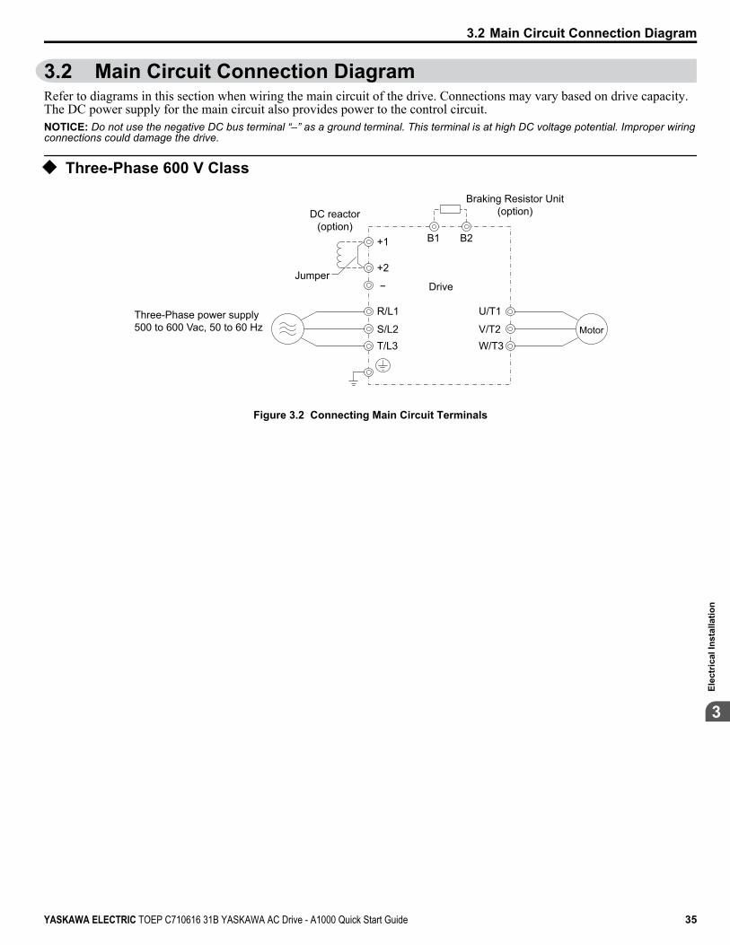
3.2 Main Circuit Connection DiagramRefer to diagrams in this section when wiring the main circuit of the drive. Connections may vary based on drive capacity.The DC power supply for the main circuit also provides power to the control circuit.NOTICE: Do not use the negative DC bus terminal “–” as a ground terminal. This terminal is at high DC voltage potential. Improper wiringconnections could damage the drive.
u Three-Phase 600 V Class
Braking Resistor Unit(option)
Drive
Motor
Jumper
DC reactor(option)
B1+1
R/L1
S/L2T/L3
U/T1
V/T2W/T3
+2
−
B2
Three-Phase power supply500 to 600 Vac, 50 to 60 Hz
Figure 3.2 Connecting Main Circuit Terminals
3.2 Main Circuit Connection Diagram
YASKAWA ELECTRIC TOEP C710616 31B YASKAWA AC Drive - A1000 Quick Start Guide 35
3El
ectr
ical
Inst
alla
tion
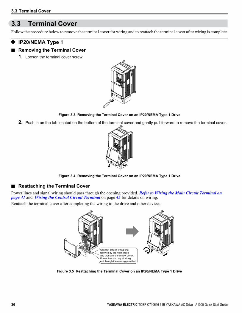
3.3 Terminal CoverFollow the procedure below to remove the terminal cover for wiring and to reattach the terminal cover after wiring is complete.
u IP20/NEMA Type 1n Removing the Terminal Cover
1. Loosen the terminal cover screw.
Figure 3.3 Removing the Terminal Cover on an IP20/NEMA Type 1 Drive
2. Push in on the tab located on the bottom of the terminal cover and gently pull forward to remove the terminal cover.
Figure 3.4 Removing the Terminal Cover on an IP20/NEMA Type 1 Drive
n Reattaching the Terminal CoverPower lines and signal wiring should pass through the opening provided. Refer to Wiring the Main Circuit Terminal on page 41 and Wiring the Control Circuit Terminal on page 45 for details on wiring.Reattach the terminal cover after completing the wiring to the drive and other devices.
Connect ground wiring first, followed by the main circuit, and then wire the control circuit. Power lines and signal wiring exit through the opening provided.
Figure 3.5 Reattaching the Terminal Cover on an IP20/NEMA Type 1 Drive
3.3 Terminal Cover
36 YASKAWA ELECTRIC TOEP C710616 31B YASKAWA AC Drive - A1000 Quick Start Guide

3.4 Digital Operator and Front CoverDetach the digital operator from the drive for remote operation or when opening the front cover to install an option card.NOTICE: Be sure to remove the digital operator prior to opening or reattaching the front cover. Leaving the digital operator plugged into thedrive when removing the front cover can result in erroneous operation caused by a poor connection. Firmly fasten the front cover back intoplace before reattaching the digital operator.
u Removing/Reattaching the Digital Operatorn Removing the Digital OperatorWhile pressing on the tab located on the right side of the digital operator, pull the digital operator forward to remove it fromthe drive.
Figure 3.6 Removing the Digital Operator
n Reattaching the Digital OperatorInsert the digital operator into the opening in the top cover while aligning it with the notches on the left side of the opening.Next, press gently on the right side of the operator until it clicks into place.
Figure 3.7 Reattaching the Digital Operator
u Removing/Reattaching the Front Covern Removing the Front Cover5A0003 to 5A0032After removing the terminal cover and the digital operator, loosen the screw that affixes the front cover (models 5A0022 and5A0027 do not use a screw to affix the front cover) . Pinch in on the tabs found on each side of the front cover, then pullforward to remove it from the drive.
Figure 3.8 Remove the Front Cover
n Reattaching the Front CoverReverse the instructions given in above to reattach the front cover. Pinch inwards on the tabs found on each side of the frontcover while guiding it back into the drive. Make sure it clicks firmly into place.
3.4 Digital Operator and Front Cover
YASKAWA ELECTRIC TOEP C710616 31B YASKAWA AC Drive - A1000 Quick Start Guide 37
3El
ectr
ical
Inst
alla
tion

3.5 Top Protective CoverThe drive is designed to NEMA Type 1 specifications with a protective cover on the top. Removing this top protective coveror the bottom conduit bracket from an IP20/NEMA Type 1 drive voids the NEMA Type 1 protection while maintaining IP20conformity.
u Removing the Top Protective CoverInsert the tip of a straight-edge screwdriver into the small opening located on the front edge of the top protective cover. Gentlyapply pressure as shown in the figure below to free the cover from the drive.
Note: Removing the top protective cover or the bottom conduit bracket from an IP20/NEMA Type 1 drive voids the NEMA Type 1 protection whilemaintaining IP20 conformity.
Figure 3.9 Removing the Top Protective Cover
u Reattaching the Top Protective CoverInsert the two small protruding hooks on the rear side of the top protective cover into the provided mounting holes near theback of the drive, then press down on the front side of the top protective cover to fasten the cover into place.
Protective Cover Mounting Holes
Figure 3.10 Reattaching the Protective Cover
3.5 Top Protective Cover
38 YASKAWA ELECTRIC TOEP C710616 31B YASKAWA AC Drive - A1000 Quick Start Guide

3.6 Main Circuit WiringThis section describes the functions, specifications, and procedures required to safely and properly wire the main circuit inthe drive.NOTICE: Do not solder the ends of wire connections to the drive. Soldered wiring connections can loosen over time. Improper wiring practicescould result in drive malfunction due to loose terminal connections.
NOTICE: Do not switch the drive input to start or stop the motor. Frequently switching the drive on and off shortens the life of the DC buscharge circuit and the DC bus capacitors, and can cause premature drive failures. For the full performance life, refrain from switching thedrive on and off more than once every 30 minutes.
u Main Circuit Terminal FunctionsTable 3.1 Main Circuit Terminal Functions
Terminal TypeFunction Page600 V
Class Model CIMR-Ao 5A0003 to 5A0032
R/L1Main circuit power supply input Connects line power to the drive 33S/L2
T/L3U/T1
Drive output Connects to the motor 33V/T2W/T3
B1Braking resistor Available for connecting a braking resistor or a braking
resistor unit option –B2+2 • DC reactor connection (+1, +2)
(remove the shorting barbetween +1 and +2)
• DC power supply input (+1, –)
For connecting:• a DC power supply
(terminals +1 and – are not UL approved)• dynamic braking options• a DC reactor
–+1
–
+3 Not available
— Grounding terminal 41
u Protecting Main Circuit Terminalsn Insulation Caps or SleevesUse insulation caps or sleeves when wiring the drive with crimp terminals. Take particular care to ensure that the wiring doesnot touch nearby terminals or the surrounding case.
u Wire Gauges and Tightening TorqueSelect the appropriate wires and crimp terminals from Table 3.2.
Note: 1. Wire gauge recommendations based on drive continuous current ratings (ND) using 75 °C 600 Vac vinyl-sheathed wire assuming ambienttemperature within 40 °C and wiring distance less than 100 m.
2. Terminals +1, +2, +3, –, B1 and B2 are for connecting optional devices such as a DC reactor or braking resistor. Do not connect othernonspecific devices to these terminals.
• Consider the amount of voltage drop when selecting wire gauges. Increase the wire gauge when the voltage drop is greaterthan 2% of motor rated voltage. Ensure the wire gauge is suitable for the terminal block. Use the following formula tocalculate the amount of voltage drop: Line drop voltage (V) = 3 × wire resistance (Ω/km) × wire length (m) × current (A) × 10-3
• Refer to instruction manual TOBPC72060000 for braking unit or braking resistor unit wire gauges.• Use terminal +1 and the negative terminal when connecting a braking transistor, regenerative converter, or a regen unit.• Refer to UL Standards Compliance on page 208 for information on UL compliance.
3.6 Main Circuit Wiring
YASKAWA ELECTRIC TOEP C710616 31B YASKAWA AC Drive - A1000 Quick Start Guide 39
3El
ectr
ical
Inst
alla
tion

n Three-Phase 600 V ClassTable 3.2 Wire Gauge and Torque Specifications (Three-Phase 600 V Class)
Model CIMR-Ao Terminal Recomm. Gauge AWG,kcmil <1>
Applicable GaugeAWG, kcmil <1> Size Tightening Torque
N·m (lb.in.)
5A00035A0004
R/L1, S/L2, T/L3 14 14 to 10
M41.2 to 1.5(10.6 to
13.3)
U/T1, V/T2, W/T3 14 14 to 10–, +1, +2 – 14 to 10B1, B2 – 14 to 10
10 14 to 10
5A00065A0009
R/L1, S/L2, T/L3 12 14 to 10
M41.2 to 1.5(10.6 to
13.3)
U/T1, V/T2, W/T3 14 14 to 10–, +1, +2 – 14 to 10B1, B2 – 14 to 10
10 14 to 10
5A0011
R/L1, S/L2, T/L3 10 10 to 6
M41.2 to 1.5(10.6 to
13.3)
U/T1, V/T2, W/T3 10 10 to 6–, +1, +2 – 12 to 6B1, B2 – 12 to 10
10 12 to 10 M52 to 2.5(17.7 to
22.1)
5A00175A0022
R/L1, S/L2, T/L3 6 8 to 6
M52 to 2.5(17.7 to
22.1)
U/T1, V/T2, W/T3 8 8 to 6–, +1, +2 – 6B1, B2 – 10 to 8
6 10 to 6 M64 to 6
(35.4 to53.1)
5A00275A0032
R/L1, S/L2, T/L3 6 6 to 4M6 2 to 2.5
(17.7 to22.1)
U/T1, V/T2, W/T3 6 6 to 4–, +1, +2 – 6 to 4B1, B2 – 10 to 8 M5
6 8 to 6 M64 to 6
(35.4 to53.1)
<1> Gauges listed in Table 3.2 are for use in the United States.
u Main Circuit Terminal and Motor WiringThis section outlines the various steps, precautions, and checkpoints for wiring the main circuit terminals and motor terminals.NOTICE: When connecting the motor to the drive output terminals U/T1, V/T2, and W/T3, the phase order for the drive and motor shouldmatch. Failure to comply with proper wiring practices may cause the motor to run in reverse if the phase order is backward.
NOTICE: Do not connect phase-advancing capacitors or LC/RC noise filters to the output circuits. Failure to comply could result in damageto the drive, phase-advancing capacitors, LC/RC noise filters or ground fault circuit interrupters.
NOTICE: Do not connect the AC power line to the output motor terminals of the drive. Failure to comply could result in death or seriousinjury by fire as a result of drive damage from line voltage application to output terminals.
n Cable Length Between Drive and MotorVoltage drop along the motor cable may cause reduced motor torque when the wiring between the drive and the motor is toolong, especially at low frequency output. This can also be a problem when motors are connected in parallel with a fairly longmotor cable. Drive output current will increase as the leakage current from the cable increases. An increase in leakage currentmay trigger an overcurrent situation and weaken the accuracy of the current detection.Adjust the drive carrier frequency according to Table 3.3. If the motor wiring distance exceeds 100 m because of the systemconfiguration, reduce the ground currents. Refer to C6-02: Carrier Frequency Selection on page 80.
3.6 Main Circuit Wiring
40 YASKAWA ELECTRIC TOEP C710616 31B YASKAWA AC Drive - A1000 Quick Start Guide
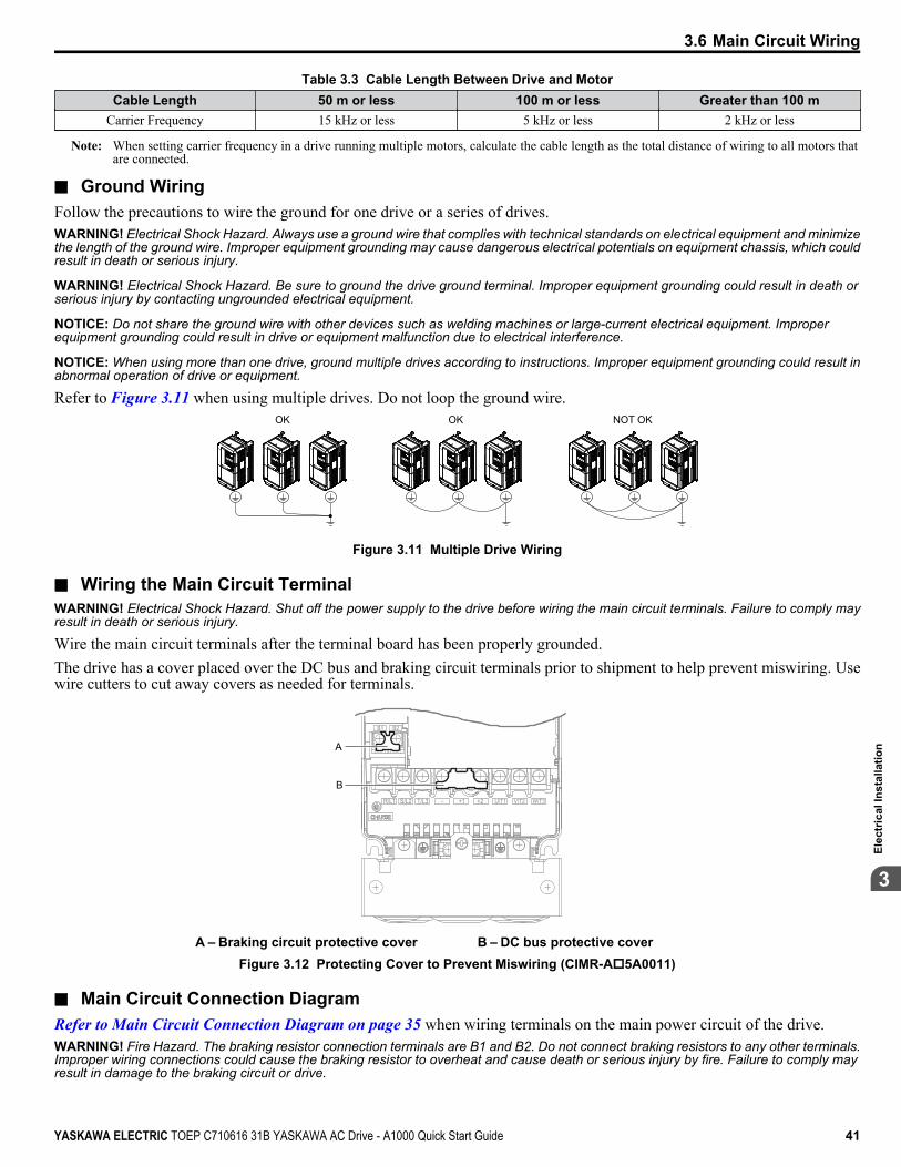
Table 3.3 Cable Length Between Drive and MotorCable Length 50 m or less 100 m or less Greater than 100 m
Carrier Frequency 15 kHz or less 5 kHz or less 2 kHz or less
Note: When setting carrier frequency in a drive running multiple motors, calculate the cable length as the total distance of wiring to all motors thatare connected.
n Ground WiringFollow the precautions to wire the ground for one drive or a series of drives.WARNING! Electrical Shock Hazard. Always use a ground wire that complies with technical standards on electrical equipment and minimizethe length of the ground wire. Improper equipment grounding may cause dangerous electrical potentials on equipment chassis, which couldresult in death or serious injury.
WARNING! Electrical Shock Hazard. Be sure to ground the drive ground terminal. Improper equipment grounding could result in death orserious injury by contacting ungrounded electrical equipment.
NOTICE: Do not share the ground wire with other devices such as welding machines or large-current electrical equipment. Improperequipment grounding could result in drive or equipment malfunction due to electrical interference.
NOTICE: When using more than one drive, ground multiple drives according to instructions. Improper equipment grounding could result inabnormal operation of drive or equipment.
Refer to Figure 3.11 when using multiple drives. Do not loop the ground wire.OK OK NOT OK
Figure 3.11 Multiple Drive Wiring
n Wiring the Main Circuit TerminalWARNING! Electrical Shock Hazard. Shut off the power supply to the drive before wiring the main circuit terminals. Failure to comply mayresult in death or serious injury.
Wire the main circuit terminals after the terminal board has been properly grounded.The drive has a cover placed over the DC bus and braking circuit terminals prior to shipment to help prevent miswiring. Usewire cutters to cut away covers as needed for terminals.
R/L1 S/L2 T/L3 _ +1 +2 U/T1 V/T2 W/T3
B1 B2
A
B
A – Braking circuit protective cover B – DC bus protective coverFigure 3.12 Protecting Cover to Prevent Miswiring (CIMR-Ao5A0011)
n Main Circuit Connection DiagramRefer to Main Circuit Connection Diagram on page 35 when wiring terminals on the main power circuit of the drive.WARNING! Fire Hazard. The braking resistor connection terminals are B1 and B2. Do not connect braking resistors to any other terminals.Improper wiring connections could cause the braking resistor to overheat and cause death or serious injury by fire. Failure to comply mayresult in damage to the braking circuit or drive.
3.6 Main Circuit Wiring
YASKAWA ELECTRIC TOEP C710616 31B YASKAWA AC Drive - A1000 Quick Start Guide 41
3El
ectr
ical
Inst
alla
tion
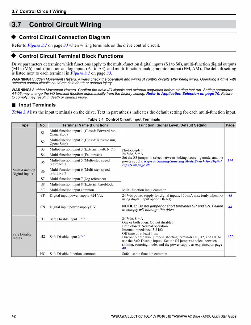
3.7 Control Circuit Wiring
u Control Circuit Connection DiagramRefer to Figure 3.1 on page 33 when wiring terminals on the drive control circuit.
u Control Circuit Terminal Block FunctionsDrive parameters determine which functions apply to the multi-function digital inputs (S1 to S8), multi-function digital outputs(M1 to M6), multi-function analog inputs (A1 to A3), and multi-function analog monitor output (FM, AM). The default settingis listed next to each terminal in Figure 3.1 on page 33.WARNING! Sudden Movement Hazard. Always check the operation and wiring of control circuits after being wired. Operating a drive withuntested control circuits could result in death or serious injury.
WARNING! Sudden Movement Hazard. Confirm the drive I/O signals and external sequence before starting test run. Setting parameterA1-06 may change the I/O terminal function automatically from the factory setting. Refer to Application Selection on page 70. Failureto comply may result in death or serious injury.
n Input TerminalsTable 3.4 lists the input terminals on the drive. Text in parenthesis indicates the default setting for each multi-function input.
Table 3.4 Control Circuit Input TerminalsType No. Terminal Name (Function) Function (Signal Level) Default Setting Page
Multi-FunctionDigital Inputs
S1 Multi-function input 1 (Closed: Forward run,Open: Stop)
Photocoupler24 Vdc, 8 mASet the S3 jumper to select between sinking, sourcing mode, and thepower supply. Refer to Sinking/Sourcing Mode Switch for Digital Inputs on page 48.
174
S2 Multi-function input 2 (Closed: Reverse run,Open: Stop)
S3 Multi-function input 3 (External fault, N.O.)S4 Multi-function input 4 (Fault reset)
S5 Multi-function input 5 (Multi-step speedreference 1)
S6 Multi-function input 6 (Multi-step speedreference 2)
S7 Multi-function input 7 (Jog reference)S8 Multi-function input 8 (External baseblock)SC Multi-function input common Multi-function input commonSP Digital input power supply +24 Vdc 24 Vdc power supply for digital inputs, 150 mA max (only when not
using digital input option DI-A3)
NOTICE: Do not jumper or short terminals SP and SN. Failureto comply will damage the drive.
48
SN Digital input power supply 0 V 48
Safe DisableInputs
H1 Safe Disable input 1 <1> 24 Vdc, 8 mAOne or both open: Output disabledBoth closed: Normal operationInternal impedance: 3.3 kΩOff time of at least 1 msDisconnect the wire jumpers shorting terminals H1, H2, and HC touse the Safe Disable inputs. Set the S5 jumper to select betweensinking, sourcing mode, and the power supply as explained on page48.
212H2 Safe Disable input 2 <1>
HC Safe Disable function common Safe disable function common
3.7 Control Circuit Wiring
42 YASKAWA ELECTRIC TOEP C710616 31B YASKAWA AC Drive - A1000 Quick Start Guide

Type No. Terminal Name (Function) Function (Signal Level) Default Setting Page
Analog Inputs /Pulse TrainInput
RP Multi-function pulse train input (Frequencyreference)
Input frequency range: 0 to 32 kHzSignal Duty Cycle: 30 to 70%High level: 3.5 to 13.2 Vdc, low level: 0.0 to 0.8 VdcInput impedance: 3 kΩ
74181
+V Power supply for analog inputs 10.5 Vdc (max allowable current 20 mA) 72-V Power supply for analog inputs -10.5 Vdc (max allowable current 20 mA) –
A1 Multi-function analog input 1 (Frequencyreference bias) -10 to 10 Vdc, 0 to 10 Vdc (input impedance: 20 kΩ) 72
89
A2 Multi-function analog input 2 (Frequencyreference bias)
-10 to 10 Vdc, 0 to 10 Vdc (input impedance: 20 kΩ)4 to 20 mA, 0 to 20 mA (input impedance: 250 Ω)Voltage or current input must be selected by DIP switch S1 and H3-09
727291
A3 Multi-function analog input 3 (auxiliaryfrequency reference)/PTC Input
-10 to 10 Vdc, 0 to 10 Vdc (input impedance: 20 kΩ)Use DIP switch S4 on the terminal board to select between analog andPTC input.
72
AC Frequency reference common 0 V 72E (G) Ground for shielded lines and option cards – –
<1> Terminals H1, H2, DM+, and DM- on 600 V class models are designed to the functionality, but are not certified to EN61800-5-1, EN954-1/ISO13849Cat. 3, IEC/EN61508 SIL2, Insulation coordination: class 1.
n Output TerminalsTable 3.5 lists the output terminals on the drive. Text in parenthesis indicates the default setting for each multi-function output.
Table 3.5 Control Circuit Output TerminalsType No. Terminal Name (Function) Function (Signal Level) Default Setting Page
Fault RelayMA N.O.
30 Vdc, 10 mA to 1 A; 250 Vac, 10 mA to 1 AMinimum load: 5 Vdc, 10 mA 88MB N.C. output
MC Fault output common
Multi-FunctionDigital Output<1>
M1Multi-function digital output (During run)
30 Vdc, 10 mA to 1 A; 250 Vac, 10 mA to 1 AMinimum load: 5 Vdc, 10 mA 88
M2M3
Multi-function digital output (Zero speed)M4M5
Multi-function digital output (Speed Agree 1)M6
MonitorOutput
MP Pulse train output (Output frequency) 32 kHz (max) 181FM Analog monitor output 1 (Output frequency)
-10 to +10 Vdc, or 0 to +10 Vdc 180AM Analog monitor output 2 (Output current)AC Monitor common 0 V –
Safety MonitorOutput <2>
DM+ Safety monitor output Outputs status of Safe Disable function. Closed when both SafeDisable channels are closed. Up to +48 Vdc 50 mA 214
DM- Safety monitor output common
<1> Refrain from assigning functions to digital relay outputs that involve frequent switching, as doing so may shorten relay performance life. Switchinglife is estimated at 200,000 times (assumes 1 A, resistive load).
<2> Terminals H1, H2, DM+, and DM- on 600 V class models are designed to the functionality, but are not certified to EN61800-5-1, EN954-1/ISO13849Cat. 3, IEC/EN61508 SIL2, Insulation coordination: class 1.
A
B
CD
A – External power, 48 V max.B – Suppression diode
C – CoilD – 50 mA or less
Figure 3.13 Connecting a Suppression Diode
3.7 Control Circuit Wiring
YASKAWA ELECTRIC TOEP C710616 31B YASKAWA AC Drive - A1000 Quick Start Guide 43
3El
ectr
ical
Inst
alla
tion

n Serial Communication TerminalsTable 3.6 Control Circuit Terminals: Serial Communications
Type No. Signal Name Function (Signal Level)
MEMOBUS/ModbusCommunication <1>
R+ Communications input (+)
MEMOBUS/Modbus communication: Use anRS-485 or RS-422 cable to connect the drive.
RS-485/422MEMOBUS/Modbuscommunicationprotocol115.2 kbps (max.)
R- Communications input (-)S+ Communications output (+)S- Communications output (-)IG Shield ground 0 V
<1> Enable the termination resistor in the last drive in a MEMOBUS/Modbus network by setting DIP switch S2 to the ON position. Refer to Control I/O Connections on page 48 for more information on the termination resistor.
u Terminal ConfigurationThe control circuit terminals are arranged as shown in Figure 3.14.
MA MB MC
M1 M2 M5
M3 M6 M4E(G) HC H1 H2 DM+ DM- IG R+ R- S+ S-
S1 S2 S3 S4 S5 S6 S7 S8 SN SC SP
V+ AC V- A1 A2 A3 FM AM AC MP RP AC
Figure 3.14 Control Circuit Terminal Arrangement
n Wire Size and Torque SpecificationsSelect appropriate wire type and gauges from Table 3.7. For simpler and more reliable wiring, use crimp ferrules on the wireends. Refer to Table 3.8 for ferrule terminal types and sizes.
Table 3.7 Wire Gauges
Terminal ScrewSize
TighteningTorque
N•m(lb. in)
Bare Wire Terminal Ferrule-Type Terminal
Wire TypeApplicablewire size
mm2 (AWG)
Recomm.wire size
mm2 (AWG)
Applicablewire size
mm2 (AWG)
Recomm.wire size
mm2 (AWG)S1-S8, SC, SP, SN,RP, V+, V-, A1, A2,A3, AC, M1-M6,MA, MB, MC, MP,AM, FM, AC, S+,S-, R+, R-, IG, HC,H1, H2, DM+, DM-
M3 0.5 to 0.6(4.4 to 5.3)
Stranded wire:0.2 to 1.0(24 to 16)Solid wire:0.2 to 1.5(24 to 16)
0.75 (18) 0.25 to 0.5(24 to 20) 0.5 (20) Shielded wire,
etc.
3.7 Control Circuit Wiring
44 YASKAWA ELECTRIC TOEP C710616 31B YASKAWA AC Drive - A1000 Quick Start Guide
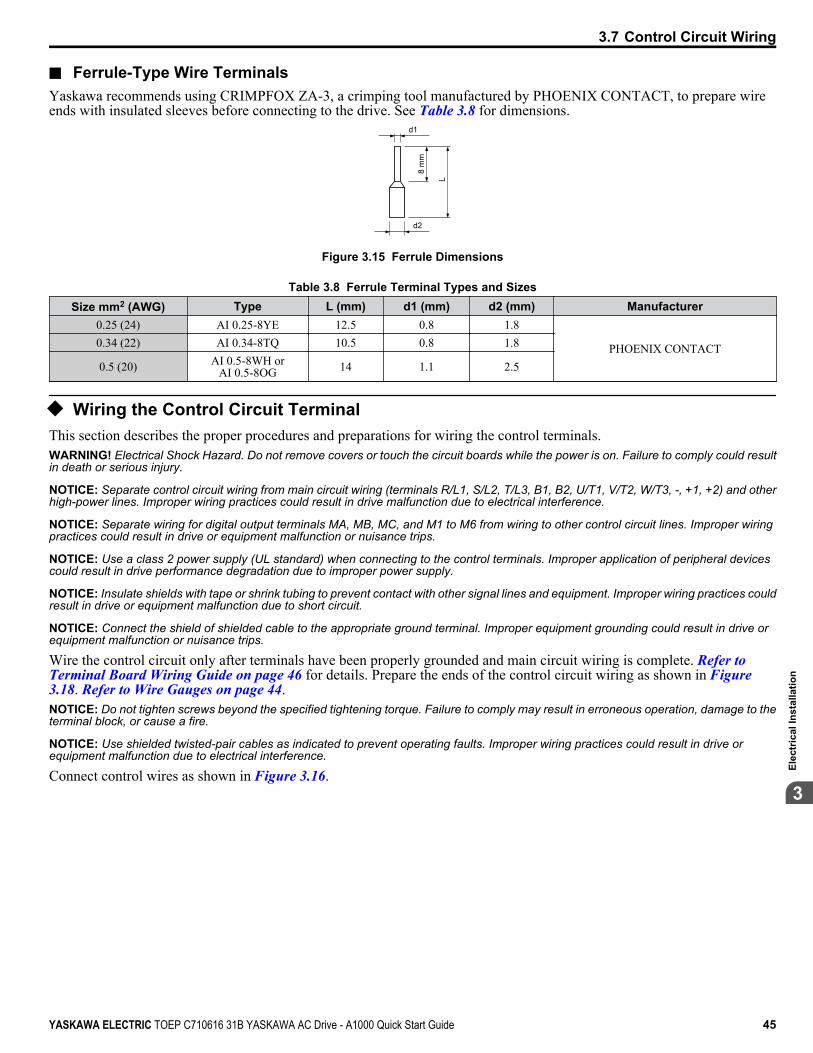
n Ferrule-Type Wire TerminalsYaskawa recommends using CRIMPFOX ZA-3, a crimping tool manufactured by PHOENIX CONTACT, to prepare wireends with insulated sleeves before connecting to the drive. See Table 3.8 for dimensions.
d1
d2
8 m
m
L
Figure 3.15 Ferrule Dimensions
Table 3.8 Ferrule Terminal Types and SizesSize mm2 (AWG) Type L (mm) d1 (mm) d2 (mm) Manufacturer
0.25 (24) AI 0.25-8YE 12.5 0.8 1.8
PHOENIX CONTACT0.34 (22) AI 0.34-8TQ 10.5 0.8 1.8
0.5 (20) AI 0.5-8WH orAI 0.5-8OG 14 1.1 2.5
u Wiring the Control Circuit TerminalThis section describes the proper procedures and preparations for wiring the control terminals.WARNING! Electrical Shock Hazard. Do not remove covers or touch the circuit boards while the power is on. Failure to comply could resultin death or serious injury.
NOTICE: Separate control circuit wiring from main circuit wiring (terminals R/L1, S/L2, T/L3, B1, B2, U/T1, V/T2, W/T3, -, +1, +2) and otherhigh-power lines. Improper wiring practices could result in drive malfunction due to electrical interference.
NOTICE: Separate wiring for digital output terminals MA, MB, MC, and M1 to M6 from wiring to other control circuit lines. Improper wiringpractices could result in drive or equipment malfunction or nuisance trips.
NOTICE: Use a class 2 power supply (UL standard) when connecting to the control terminals. Improper application of peripheral devicescould result in drive performance degradation due to improper power supply.
NOTICE: Insulate shields with tape or shrink tubing to prevent contact with other signal lines and equipment. Improper wiring practices couldresult in drive or equipment malfunction due to short circuit.
NOTICE: Connect the shield of shielded cable to the appropriate ground terminal. Improper equipment grounding could result in drive orequipment malfunction or nuisance trips.
Wire the control circuit only after terminals have been properly grounded and main circuit wiring is complete. Refer to Terminal Board Wiring Guide on page 46 for details. Prepare the ends of the control circuit wiring as shown in Figure 3.18. Refer to Wire Gauges on page 44.NOTICE: Do not tighten screws beyond the specified tightening torque. Failure to comply may result in erroneous operation, damage to theterminal block, or cause a fire.
NOTICE: Use shielded twisted-pair cables as indicated to prevent operating faults. Improper wiring practices could result in drive orequipment malfunction due to electrical interference.
Connect control wires as shown in Figure 3.16.
3.7 Control Circuit Wiring
YASKAWA ELECTRIC TOEP C710616 31B YASKAWA AC Drive - A1000 Quick Start Guide 45
3El
ectr
ical
Inst
alla
tion

A
B
C
DPreparing wireterminal ends
A – Loosen screw to remove wire.B – Single wire or stranded wire
C – Avoid fraying wire strands whenstripping insulation from wire. Striplength 5.5 mm.
D – Blade depth of 0.4 mm or lessBlade width of 2.5 mm or less
Figure 3.16 Terminal Board Wiring Guide
Figure 3.17 Terminal Board Wiring
When setting the frequency by analog reference from an external potentiometer, use shielded twisted-pair wires (preparingwire ends as shown in Figure 3.18) and connect the shield to the ground terminal of the drive.
3.7 Control Circuit Wiring
46 YASKAWA ELECTRIC TOEP C710616 31B YASKAWA AC Drive - A1000 Quick Start Guide

AF C
D
EB
A – Drive sideB – Connect shield to ground terminal
of drive.C – Insulation
D – Control device sideE – Shield sheath (insulate with tape)F – Shield
Figure 3.18 Preparing the Ends of Shielded Cables
NOTICE: The signal lines between the drive and the operator station or peripheral equipment should not exceed 50 meters when using ananalog signal from a remote source to supply the frequency reference. Failure to comply could result in poor system performance.
u Switches and Jumpers on the Terminal BoardThe terminal board is equipped with several switches used to adapt the drive I/Os to the external control signals. Figure 3.19 shows the location of these switches. Refer to Control I/O Connections on page 48 for setting instructions.
V I
DIP Switch S1Terminal A2 Signal
Selection
PTC
AI
DIP Switch S4Terminal A3 Analog/
PTC Input Sel.
Jumper S5Terminal AM/FM Signal
Selection
Jumper S3Terminal H1/H2 Sink/Source Sel.
DIP Switch S2RS-422/485 Termination
ResistorOff On
V
AM
FM
I
Figure 3.19 Locations of Jumpers and Switches on the Terminal Board
3.7 Control Circuit Wiring
YASKAWA ELECTRIC TOEP C710616 31B YASKAWA AC Drive - A1000 Quick Start Guide 47
3El
ectr
ical
Inst
alla
tion
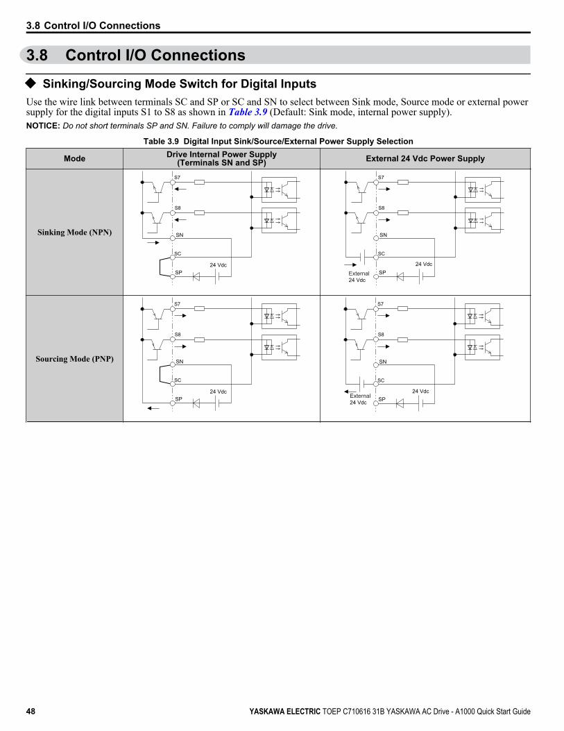
3.8 Control I/O Connections
u Sinking/Sourcing Mode Switch for Digital InputsUse the wire link between terminals SC and SP or SC and SN to select between Sink mode, Source mode or external powersupply for the digital inputs S1 to S8 as shown in Table 3.9 (Default: Sink mode, internal power supply).NOTICE: Do not short terminals SP and SN. Failure to comply will damage the drive.
Table 3.9 Digital Input Sink/Source/External Power Supply Selection
Mode Drive Internal Power Supply(Terminals SN and SP) External 24 Vdc Power Supply
Sinking Mode (NPN)
SC
S8
S7
24 VdcSP
SN
SC
S8
S7
24 VdcSP
SN
External 24 Vdc
Sourcing Mode (PNP)
SC
S8
S7
24 VdcSP
SN
SC
S8
S7
24 VdcSP
SN
External 24 Vdc
3.8 Control I/O Connections
48 YASKAWA ELECTRIC TOEP C710616 31B YASKAWA AC Drive - A1000 Quick Start Guide

u Sinking/Sourcing Mode Selection for Safe Disable InputsNote: Terminals H1, H2, DM+, and DM- on 600 V class models are designed to the functionality, but are not certified to EN61800-5-1, EN954-1/
ISO13849 Cat. 3, IEC/EN61508 SIL2, Insulation coordination: class 1.
Use jumper S3 on the terminal board to select between Sink mode, Source mode or external power supply for the Safe Disableinputs H1 and H2 as shown in Table 3.9 (Default: Source mode, internal power supply). Refer to Switches and Jumpers on the Terminal Board on page 47 for locating jumper S3.
Table 3.10 Safe Disable Input Sink/Source/External Power Supply SelectionMode Drive Internal Power Supply External 24 Vdc Power Supply
Sinking Mode
24 Vdc
H1
H2
HC
Jumper S3
24 Vdc
H1
H2
HC
External24 Vdc
Jumper S3
Sourcing Mode
24 Vdc
H1
H2
HC
Jumper S3
24 Vdc
H1
H2
HC
External24 Vdc
Jumper S3
u Using the Pulse Train OutputThe pulse train output terminal MP can supply power or be used with an external power supply.NOTICE: Connect peripheral devices in accordance with the specifications. Failure to comply may cause unexpected drive operation, andcan damage the drive or connected circuits.
n Using Power from the Pulse Output Terminal (Source Mode)The high voltage level of the pulse output terminal depends on the load impedance.
Load Impedance RL (kΩ) Output Voltage VMP (V) (insulated)1.5 kΩ 5 V4 kΩ 8 V10 kΩ 10 V
Note: The load resistance needed in order to get a certain high level voltage VMP can be calculated by: RL = VMP• 2 / (12 – VMP)
MP
AC
VMP RL
Load Impedance
Figure 3.20 Pulse Output Connection Using Internal Voltage Supply
3.8 Control I/O Connections
YASKAWA ELECTRIC TOEP C710616 31B YASKAWA AC Drive - A1000 Quick Start Guide 49
3El
ectr
ical
Inst
alla
tion
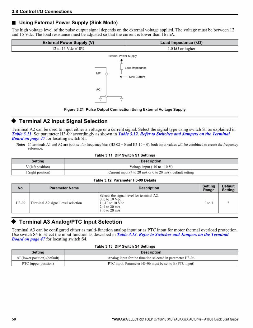
n Using External Power Supply (Sink Mode)The high voltage level of the pulse output signal depends on the external voltage applied. The voltage must be between 12and 15 Vdc. The load resistance must be adjusted so that the current is lower than 16 mA.
External Power Supply (V) Load Impedance (kΩ)12 to 15 Vdc ±10% 1.0 kΩ or higher
MP
AC
Load Impedance
Sink Current
External Power Supply
Figure 3.21 Pulse Output Connection Using External Voltage Supply
u Terminal A2 Input Signal SelectionTerminal A2 can be used to input either a voltage or a current signal. Select the signal type using switch S1 as explained inTable 3.11. Set parameter H3-09 accordingly as shown in Table 3.12. Refer to Switches and Jumpers on the Terminal Board on page 47 for locating switch S1.
Note: If terminals A1 and A2 are both set for frequency bias (H3-02 = 0 and H3-10 = 0), both input values will be combined to create the frequencyreference.
Table 3.11 DIP Switch S1 SettingsSetting Description
V (left position) Voltage input (-10 to +10 V)I (right position) Current input (4 to 20 mA or 0 to 20 mA): default setting
Table 3.12 Parameter H3-09 Details
No. Parameter Name Description SettingRange
DefaultSetting
H3-09 Terminal A2 signal level selection
Selects the signal level for terminal A2.0: 0 to 10 Vdc1: -10 to 10 Vdc2: 4 to 20 mA3: 0 to 20 mA
0 to 3 2
u Terminal A3 Analog/PTC Input SelectionTerminal A3 can be configured either as multi-function analog input or as PTC input for motor thermal overload protection.Use switch S4 to select the input function as described in Table 3.13. Refer to Switches and Jumpers on the Terminal Board on page 47 for locating switch S4.
Table 3.13 DIP Switch S4 SettingsSetting Description
AI (lower position) (default) Analog input for the function selected in parameter H3-06PTC (upper position) PTC input. Parameter H3-06 must be set to E (PTC input)
3.8 Control I/O Connections
50 YASKAWA ELECTRIC TOEP C710616 31B YASKAWA AC Drive - A1000 Quick Start Guide
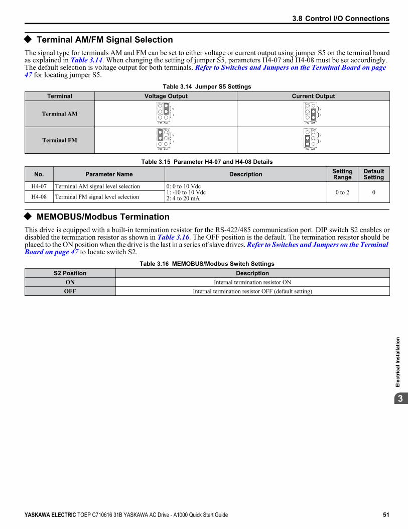
u Terminal AM/FM Signal SelectionThe signal type for terminals AM and FM can be set to either voltage or current output using jumper S5 on the terminal boardas explained in Table 3.14. When changing the setting of jumper S5, parameters H4-07 and H4-08 must be set accordingly.The default selection is voltage output for both terminals. Refer to Switches and Jumpers on the Terminal Board on page 47 for locating jumper S5.
Table 3.14 Jumper S5 SettingsTerminal Voltage Output Current Output
Terminal AMAMFM
V
I
AMFM
V
I
Terminal FMAMFM
V
I
AMFM
V
I
Table 3.15 Parameter H4-07 and H4-08 Details
No. Parameter Name Description SettingRange
DefaultSetting
H4-07 Terminal AM signal level selection 0: 0 to 10 Vdc1: -10 to 10 Vdc2: 4 to 20 mA
0 to 2 0H4-08 Terminal FM signal level selection
u MEMOBUS/Modbus TerminationThis drive is equipped with a built-in termination resistor for the RS-422/485 communication port. DIP switch S2 enables ordisabled the termination resistor as shown in Table 3.16. The OFF position is the default. The termination resistor should beplaced to the ON position when the drive is the last in a series of slave drives. Refer to Switches and Jumpers on the Terminal Board on page 47 to locate switch S2.
Table 3.16 MEMOBUS/Modbus Switch SettingsS2 Position Description
ON Internal termination resistor ONOFF Internal termination resistor OFF (default setting)
3.8 Control I/O Connections
YASKAWA ELECTRIC TOEP C710616 31B YASKAWA AC Drive - A1000 Quick Start Guide 51
3El
ectr
ical
Inst
alla
tion
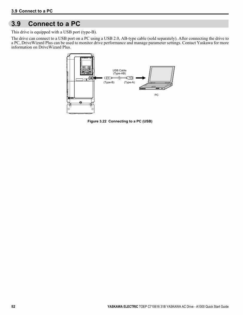
3.9 Connect to a PCThis drive is equipped with a USB port (type-B).The drive can connect to a USB port on a PC using a USB 2.0, AB-type cable (sold separately). After connecting the drive toa PC, DriveWizard Plus can be used to monitor drive performance and manage parameter settings. Contact Yaskawa for moreinformation on DriveWizard Plus.
PC
(Type-B) (Type-A)
USB Cable(Type-AB)
Figure 3.22 Connecting to a PC (USB)
3.9 Connect to a PC
52 YASKAWA ELECTRIC TOEP C710616 31B YASKAWA AC Drive - A1000 Quick Start Guide

3.10 Wiring ChecklistNo. Item Page
Drive, peripherals, option cards1 Check drive model number to ensure receipt of correct model. 22
2 Make sure you have the correct braking resistors, DC reactors, noise filters, and other peripheral devices. –
3 Check the option card model number. –
Installation area and physical setup4 Ensure that the area surrounding the drive complies with specifications. 26
Power supply voltage, output voltage5 The voltage from the power supply should be within the input voltage specification range of the drive. 82
6 The voltage rating for the motor should match the drive output specifications. 22196
7 Verify that the drive is properly sized to run the motor. 22196
Main circuit wiring8 Confirm proper branch circuit protection as specified by national and local codes. 32
9 Properly wire the power supply to drive terminals R/L1, S/L2, and T/L3. 35
10Properly wire the drive and motor together.The motor lines and drive output terminals R/T1, V/T2, and W/T3 should match in order to produce the desired phaseorder. If the phase order is incorrect, the drive will rotate in the opposite direction.
40
11 Use 600 Vac vinyl-sheathed wire for the power supply and motor lines. 39
12
Use the correct wire gauges for the main circuit. Refer to Wire Gauges and Tightening Torque on page 39.• Consider the amount of voltage drop when selecting wire gauges. Increase the wire gauge when the voltage drop is
greater than 2% of motor rated voltage. Ensure the wire gauge is suitable for the terminal block. Use the followingformula to calculate the amount of voltage drop:Line drop voltage (V) = 3 × wire resistance (Ω/km) × wire length (m) × current (A) × 10-3
• If the cable between the drive and motor exceeds 50 m, adjust the carrier frequency set to C6-02 accordingly.
3939
41
13 Properly ground the drive. Review page 41. 41
14 Tightly fasten all terminal screws (control circuit terminals, grounding terminals).Refer to Wire Gauges and Tightening Torque on page 39. 39
15
Set up overload protection circuits when running multiple motors from a single drive.
M1OL1
OL2
OLn
MC1
MC2
MCn
M2
Mn
Drive
MC1 - MCn OL 1 - OLn
... magnetic contactor ... thermal relay
Power supply
Note: Close MC1 through MCn before operating the drive. MC1 through MCn cannot be switched off duringrun.
–
16 Install a magnetic contactor when using a dynamic braking option. Properly install the resistor and ensure that overloadprotection shuts off the power supply using the magnetic contactor. –
17 Verify phase advancing capacitors, input noise filters, or ground fault circuit interrupters are NOT installed on the outputside of the drive. –
Control circuit wiring18 Use twisted-pair line for all drive control circuit wiring. 42
19 Ground the shields of shielded wiring to the GND terminal. 41
20 If using a 3-Wire sequence, properly set parameters for multi-function contact input terminals S1 through S8, and properlywire control circuits. –
21 Properly wire any option cards. 44
22 Check for any other wiring mistakes. Only use a multimeter to check wiring. –
23 Properly fasten the control circuit terminal screws in the drive. Refer to Wire Gauges and Tightening Torque on page 39. 39
24 Pick up all wire clippings. –
3.10 Wiring Checklist
YASKAWA ELECTRIC TOEP C710616 31B YASKAWA AC Drive - A1000 Quick Start Guide 53
3El
ectr
ical
Inst
alla
tion

No. Item Page
25 Ensure that no frayed wires on the terminal block are touching other terminals or connections. –
26 Properly separate control circuit wiring and main circuit wiring. –
27 Analog signal line wiring should not exceed 50 m. –
28 Safe Disable input wiring should not exceed 30 m. <1> –
<1> Terminals H1, H2, DM+, and DM- on 600 V class models are designed to the functionality, but are not certified to EN61800-5-1, EN954-1/ISO13849Cat. 3, IEC/EN61508 SIL2, Insulation coordination: class 1.
3.10 Wiring Checklist
54 YASKAWA ELECTRIC TOEP C710616 31B YASKAWA AC Drive - A1000 Quick Start Guide

Start-Up Programming & OperationThis chapter explains the functions of the digital operator and how to program the drive for initialoperation.
4.1 USING THE DIGITAL OPERATOR........................................................................564.2 THE DRIVE AND PROGRAMMING MODES.........................................................614.3 START-UP FLOWCHARTS...................................................................................644.4 POWERING UP THE DRIVE..................................................................................694.5 APPLICATION SELECTION..................................................................................704.6 BASIC DRIVE SETUP ADJUSTMENTS................................................................714.7 AUTO-TUNING.......................................................................................................984.8 NO-LOAD OPERATION TEST RUN....................................................................1044.9 TEST RUN WITH LOAD CONNECTED...............................................................1064.10 TEST RUN CHECKLIST.......................................................................................107
4
YASKAWA ELECTRIC TOEP C710616 31B YASKAWA AC Drive - A1000 Quick Start Guide 55

4.1 Using the Digital OperatorUse the digital operator to enter Run and Stop commands, edit parameters, and display data including fault and alarminformation.
u Keys and Displays
LORE
F2F1
ESC
RUN STOP
ENTERRESET
ALMDIGITAL OPERATOR JVOP-180 12
11
98
1
2
310
4 5 6 7
Figure 4.1 Keys and Displays on the Digital Operator
No. Display Name Function
1F1
F2
Function Key(F1, F2)
The functions assigned to F1 and F2 vary depending on the currently displayed menu. Thename of each function appears in the lower half of the display window.
2 ESC ESC Key• Returns to the previous display.• Moves the cursor one space to the left.• Pressing and holding this button will return to the Frequency Reference display.
3 RESET Key• Moves the cursor to the right.• Resets the drive to clear a fault situation.
4 RUN RUN Key Starts the drive in LOCAL mode.
5 Up Arrow Key Scrolls up to display the next item, select parameter numbers, and increment setting values.
6 Down Arrow Key Scrolls down to display the next item, select parameter numbers, and increment settingvalues.
7 STOP STOP Key <1> Stops drive operation.
8 ENTER Key• Enters parameter values and settings.• Selects a menu item to move between displays
9 LO/RE Selection Key <2> Switches drive control between the operator (LOCAL) and an external source (REMOTE)for the Run command and frequency reference.
10 RUN Light Lit while the drive is operating the motor. Refer to page 58 for details.
11 LO/RE Light Lit while the operator is selected to run the drive (LOCAL mode). Refer to page 58 fordetails.
12 ALM LED Light Refer to ALARM (ALM) LED Displays on page 58.
<1> The STOP key has highest priority. Pressing the STOP key will always cause the drive to stop the motor, even if a Run command is active at anyexternal Run command source. To disable the STOP key priority, set parameter o2-06 to 0.
<2> The LO/RE key can only switch between LOCAL and REMOTE when the drive is stopped. To disable the LO/RE key to prohibit switching betweenLOCAL and REMOTE, set parameter o2-01 to 0.
4.1 Using the Digital Operator
56 YASKAWA ELECTRIC TOEP C710616 31B YASKAWA AC Drive - A1000 Quick Start Guide
u LCD Display
]
7
65
1 2 3 4
8910
Figure 4.2 LCD Display
Table 4.1 Display and ContentsNo. Name Display Content
1 Operation Mode Menus
MODE Displayed when in Mode Selection.MONITR Displayed when in Monitor Mode.VERIFY Indicates the Verify Menu.PRMSET Displayed when in Parameter Setting Mode.A.TUNE Displayed during Auto-Tuning.SETUP Displayed when in Setup Mode.
2 DriveWorksEZFunction Selection DWEZ Displayed when DriveWorksEZ is set to enable. (A1-07 = 1 or 2)
3 Mode Display AreaDRV Displayed when in Drive Mode.PRG Displayed when in Programming Mode.
4 Ready Rdy Indicates the drive is ready to run.5 Data Display — Displays specific data and operation data.
6FrequencyReference
Assignment <1>
OPR Displayed when the frequency reference is assigned to the LCD Operator Option.AI Displayed when the frequency reference is assigned to the Analog Input of the drive.
COM Displayed when the frequency reference is assigned to the MEMOBUS/Modbus CommunicationInputs of the drive.
OP Displayed when the frequency reference is assigned to an Option Unit of the drive.RP Displayed when the frequency reference is assigned to the Pulse Train Input of the drive.
7 LO/REDisplay <2>
RSEQ Displayed when the run command is supplied from a remote source.LSEQ Displayed when the run command is supplied from the operator keypad.RREF Displayed when the run command is supplied from a remote source.LREF Displayed when the run command is supplied from the operator keypad.
8 Function Key 1(F1)
JOG Pressing F1 executes the Jog function.
HELP Pressing F1 displays the Help menu.
← Pressing F1 scrolls the cursor to the left.
HOME Pressing F1 returns to the top menu (Frequency Reference).
ESC Pressing F1 returns to the previous display.
9 FWD/REVFWD Indicates forward motor operation.REV Indicates reverse motor operation.
4.1 Using the Digital Operator
YASKAWA ELECTRIC TOEP C710616 31B YASKAWA AC Drive - A1000 Quick Start Guide 57
4
Star
t-Up
Prog
ram
min
g&
Ope
ratio
n

No. Name Display Content
10 Function Key 2(F2)
FWD/REV Pressing F2 switches between forward and reverse.
DATA Pressing F2 scrolls to the next display.
→ Pressing F2 scrolls the cursor to the right.
RESET Pressing F2 resets the existing drive fault error.
<1> Displayed when in Frequency Reference Mode.<2> Displayed when in Frequency Reference Mode and Monitor Mode
u ALARM (ALM) LED DisplaysTable 4.2 ALARM (ALM) LED Status and Contents
State Content Display
Illuminated When the drive detects an alarm or error.
Flashing• When an alarm occurs.• When an oPE is detected.• When a fault or error occurs during Auto-Tuning.
Off Normal operation (no fault or alarm).
u LO/RE LED and RUN LED IndicationsTable 4.3 LO/RE LED and RUN LED Indications
LED Lit Flashing Flashing Quickly <1> OffWhen the operator is selectedfor Run command andfrequency reference control(LOCAL)
— —When a device other than the operatoris selected for Run command andfrequency reference control(REMOTE)
During run
• During deceleration tostop
• When a Run command isinput and frequencyreference is 0 Hz
• While the drive was set to LOCAL,a Run command was entered to theinput terminals then the drive wasswitched to REMOTE
• A Run command was entered viathe input terminals while the drivewas not in Drive Mode
• During deceleration when a FastStop command was entered
• The drive output is shut off by theSafe Disable function. <2>
• The STOP key was pressed whilethe drive was running in REMOTEmode
• The drive was powered up withb1-17 = 0 (default) while the Runcommand is active
During stop
Examples
<1> Refer to Figure 4.3 for the difference between “flashing” and “flashing quickly”.<2> Terminals H1, H2, DM+, and DM- on 600 V class models are designed to the functionality, but are not certified to EN61800-5-1, EN954-1/ISO13849
Cat. 3, IEC/EN61508 SIL2, Insulation coordination: class 1.
4.1 Using the Digital Operator
58 YASKAWA ELECTRIC TOEP C710616 31B YASKAWA AC Drive - A1000 Quick Start Guide
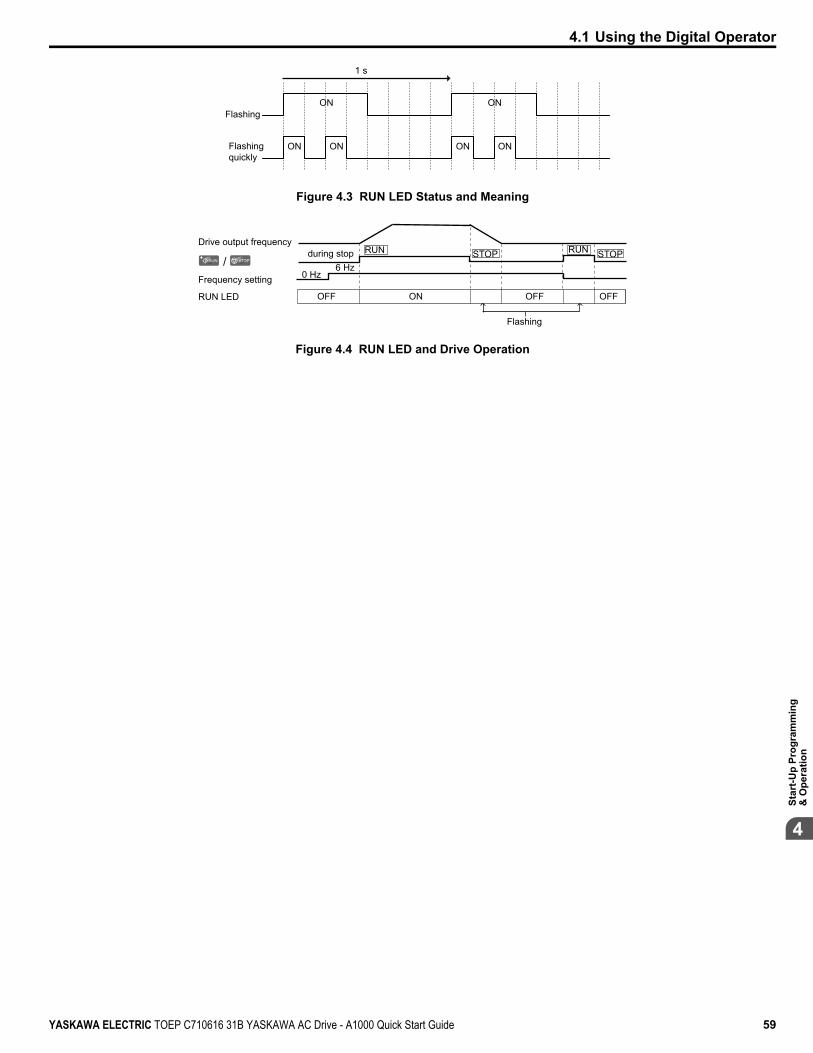
Flashing
ON ON
ON
ON ON
ON
1 s
Flashingquickly
Figure 4.3 RUN LED Status and Meaning
/
Drive output frequencyduring stop
Frequency setting
OFF ON
Flashing
OFFOFFRUN LED
RUN
0 Hz6 Hz
RUNSTOP STOP
Figure 4.4 RUN LED and Drive Operation
4.1 Using the Digital Operator
YASKAWA ELECTRIC TOEP C710616 31B YASKAWA AC Drive - A1000 Quick Start Guide 59
4
Star
t-Up
Prog
ram
min
g&
Ope
ratio
n

u Menu Structure for Digital Operator
- MODE -
U1-01= 0.00HzU1-02= 0.00HzU1-03= 0.00A
DRVFREF (OPR)
Rdy -MONITR-FREF (d1-01)
U1-01= 000.00Hz
<3>
<4>
(0.00~60.00)“0.00Hz”
DRV
← →FWD
Rdy
- MODE -
U1-01= 0.00HzU1-02= 0.00HzU1-03= 0.00A
DRVMonitor Menu
Rdy
- MODE - PRGModified Consts
HELP
HELP
DATA
- MODE - PRGQuick Setting
DATA
HELP
- MODE - PRG RdyAuto-Tuning
DATA
HELP
- MODE - PRG
DATA
Programming
AUTO
-MONITR-
U1 -01= 0.00HzU1-02= 0.00HzU1-03= 0.00A
DRVMonitor
JOG FWD FWD/REV
Rdy -MONITR-
U1- 01 = 0.00HzU1-02= 0.00HzU1-03= 0.00A
DRVFrequency Ref
JOG FWD FWD/REV
Rdy
-MONITR-
U1- 02 = 0.00HzU1-03= 0.00AU1-04= 0
DRVOutput Freq
JOG FWD FWD/REV
Rdy-MONITR-
U2 -01= oCU2-02= oPrU2-03= 0.00Hz
DRVFault Trace
JOG FWD FWD/REV
Rdy
JOG FWD FWD/REV
JOG FWD
FWD
FWD
FWD
FWD
FWD/REV
ModifiedX Parameters
LSEQLREF
LSEQLREF
LSEQLREF
LSEQLREF
LSEQLREF
LSEQLREF
YASKAWA
A1000
A1000XXXV, X.X/X.XkW
XX.XX/XX.XXA<XXXXXXXXX>
Initial Display <5>
<6>
Figure 4.5 Digital Operator Menu and Screen Structure
<1> Pressing RUN will start the motor.<2> Drive cannot operate motor.<3> Flashing characters are shown as 0 .<4> X characters are shown in this manual. The LCD Operator will display the actual setting values.<5> The Frequency Reference appears after the initial display that shows the product name.<6> The information that appears on the display will vary depending on the drive.
4.1 Using the Digital Operator
60 YASKAWA ELECTRIC TOEP C710616 31B YASKAWA AC Drive - A1000 Quick Start Guide

4.2 The Drive and Programming ModesThe drive has a Drive Mode to operate the motor and a Programming Mode to edit parameter settings.Drive Mode: In Drive Mode the user can operate the motor and observe U Monitor parameters. Parameter settings cannot beedited or changed when in Drive Mode.Programming Mode: In Programming Mode the user can edit and verify parameter settings and perform Auto-Tuning. Whenthe drive is in Programming Mode it will not accept a Run command unless b1-08 is set to 1.
Note: 1. If b1-08 is set to 0, the drive will only accept a Run command in Drive Mode. After editing parameters, the user must exit the ProgrammingMode and enter Drive Mode before operating the motor.
2. Set b1-08 to 1 to allow motor operation from the drive while in Programming Mode.
u Changing Parameter Settings or ValuesThis example explains changing C1-02 (Deceleration Time 1) from 10.0 seconds (default) to 20.0 seconds.
Step Display/Result
1. Turn on the power to the drive. The initial display appears.
- MODE -
U1-01= 0.00HzU1-02= 0.00HzU1-03= 0.00A
DRVFREF (OPR)
Rdy
JOG FWD FWD/REV
LSEQLREF
2. Press or until the Parameter Setting Mode screen appears.HELP
- MODE - PRG
DATA
Programming
FWD
3. Press to enter the parameter menu tree.← →
-PRMSET-Initialization
Select Language
PRG
FWD
A1-00= 0
4. Press or to select the C parameter group.← →
-PRMSET-Basic Setup
Accel Time 1
PRG
FWD
C1-01= 10.0 sec
5. Press two times.
← →
-PRMSET-Accel/Decel
Accel Time 1
PRG
FWD
C1-01= 10.0 sec
-PRMSET-
C1-01= 10.0Sec(0.0~6000.0)
“10.0 sec”
PRGAccel Time 1
← →FWD
6. Press or to select parameter C1-02.← →
-PRMSET-
C1-02= 10.0Sec(0.0~6000.0)
“10.0 sec”
PRGDecel Time 1
FWD
7. Press to view the current setting value (10.0 s). The leftmost digit flashes.
-PRMSET-
C1-02= 0010.0Sec(0.0~6000.0)
“10.0 sec”
PRGDecel Time 1
← →FWD
8. Press F1 , F2 , or until the desired number is selected. “1” flashes.
-PRMSET-
C1-02=0010.0Sec(0.0~6000.0)
“10.0 sec”
PRGDecel Time 1
← →FWD
9. Press and enter 0020.0.
-PRMSET-
C1-02=0020.0Sec(0.0~6000.0)
“10.0 sec”
PRGDecel Time 1
← →FWD
4.2 The Drive and Programming Modes
YASKAWA ELECTRIC TOEP C710616 31B YASKAWA AC Drive - A1000 Quick Start Guide 61
4
Star
t-Up
Prog
ram
min
g&
Ope
ratio
n
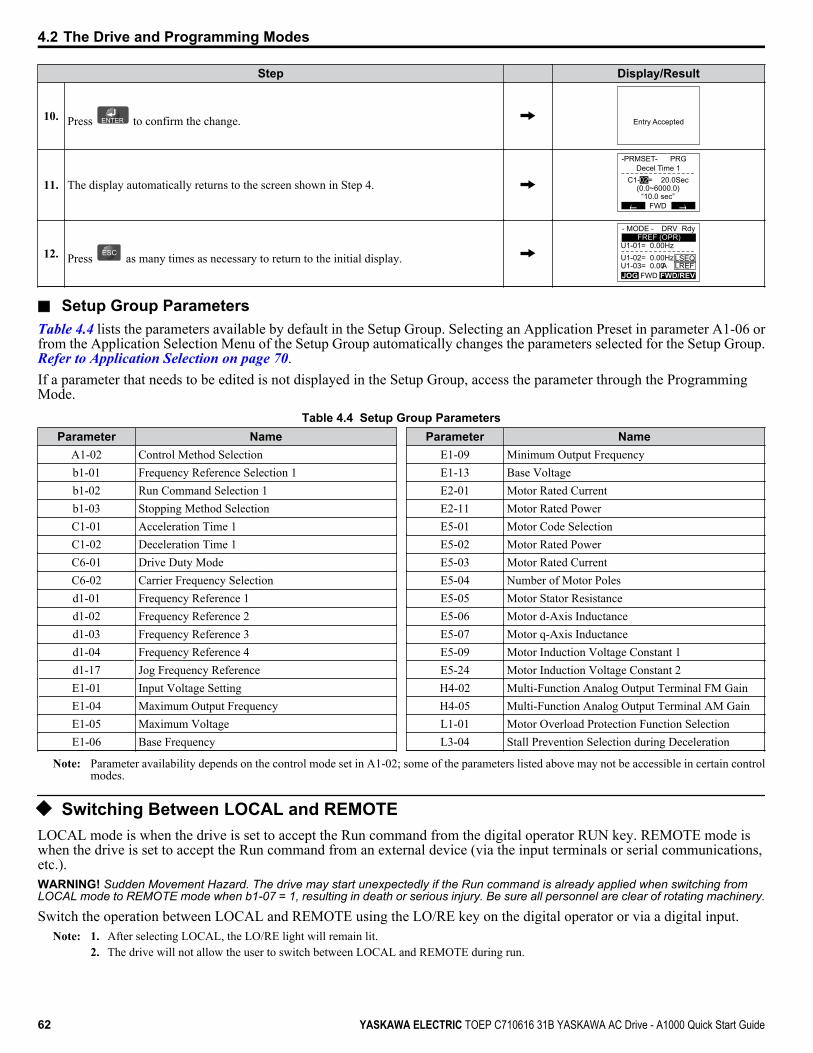
Step Display/Result
10. Press to confirm the change. Entry Accepted
11. The display automatically returns to the screen shown in Step 4.
← →
-PRMSET-
C1-02= 20.0Sec(0.0~6000.0)
“10.0 sec”
PRGDecel Time 1
FWD
12. Press as many times as necessary to return to the initial display.
- MODE -
U1-01= 0.00HzU1-02= 0.00HzU1-03= 0.00A
DRVFREF (OPR)
Rdy
JOG FWD FWD/REV
LSEQLREF
n Setup Group ParametersTable 4.4 lists the parameters available by default in the Setup Group. Selecting an Application Preset in parameter A1-06 orfrom the Application Selection Menu of the Setup Group automatically changes the parameters selected for the Setup Group.Refer to Application Selection on page 70.If a parameter that needs to be edited is not displayed in the Setup Group, access the parameter through the ProgrammingMode.
Table 4.4 Setup Group ParametersParameter Name
A1-02 Control Method Selectionb1-01 Frequency Reference Selection 1b1-02 Run Command Selection 1b1-03 Stopping Method SelectionC1-01 Acceleration Time 1C1-02 Deceleration Time 1C6-01 Drive Duty ModeC6-02 Carrier Frequency Selectiond1-01 Frequency Reference 1d1-02 Frequency Reference 2d1-03 Frequency Reference 3d1-04 Frequency Reference 4d1-17 Jog Frequency ReferenceE1-01 Input Voltage SettingE1-04 Maximum Output FrequencyE1-05 Maximum VoltageE1-06 Base Frequency
Parameter NameE1-09 Minimum Output FrequencyE1-13 Base VoltageE2-01 Motor Rated CurrentE2-11 Motor Rated PowerE5-01 Motor Code SelectionE5-02 Motor Rated PowerE5-03 Motor Rated CurrentE5-04 Number of Motor PolesE5-05 Motor Stator ResistanceE5-06 Motor d-Axis InductanceE5-07 Motor q-Axis InductanceE5-09 Motor Induction Voltage Constant 1E5-24 Motor Induction Voltage Constant 2H4-02 Multi-Function Analog Output Terminal FM GainH4-05 Multi-Function Analog Output Terminal AM GainL1-01 Motor Overload Protection Function SelectionL3-04 Stall Prevention Selection during Deceleration
Note: Parameter availability depends on the control mode set in A1-02; some of the parameters listed above may not be accessible in certain controlmodes.
u Switching Between LOCAL and REMOTELOCAL mode is when the drive is set to accept the Run command from the digital operator RUN key. REMOTE mode iswhen the drive is set to accept the Run command from an external device (via the input terminals or serial communications,etc.).WARNING! Sudden Movement Hazard. The drive may start unexpectedly if the Run command is already applied when switching fromLOCAL mode to REMOTE mode when b1-07 = 1, resulting in death or serious injury. Be sure all personnel are clear of rotating machinery.
Switch the operation between LOCAL and REMOTE using the LO/RE key on the digital operator or via a digital input.Note: 1. After selecting LOCAL, the LO/RE light will remain lit.
2. The drive will not allow the user to switch between LOCAL and REMOTE during run.
4.2 The Drive and Programming Modes
62 YASKAWA ELECTRIC TOEP C710616 31B YASKAWA AC Drive - A1000 Quick Start Guide

n Using the LO/RE Key on the Digital OperatorStep Display/Result
1. Turn on the power to the drive. The initial display appears.- MODE -
U1-01= 0.00HzU1-02= 0.00HzU1-03= 0.00A
DRVFREF (A1/A2)
Rdy
JOG FWD FWD/REV
RSEQRREF
2. Press . The LO/RE light will light up. The drive is now in LOCAL.
To set the drive for REMOTE operation, press the key again.
LORE
F2F1
ESC
RUN STOP
ENTERRESET
ALMDIGITAL OPERATOR JVOP-180
- MODE -
U1-01= 0.00HzU1-02= 0.00HzU1-03= 0.00A
DRVFREF (OPR)
Rdy
JOG FWD FWD/REV
LSEQLREF
n Using Input Terminals S1 through S8 to Switch between LOCAL and REMOTEIt is possible to switch between LOCAL and REMOTE modes using one of the digital input terminals S1 through S8 (set thecorresponding parameter H1-oo to “1”).Refer to Parameter List on page 145 for a list of possible H1-oo digital input selections when setting the multi-functioninput terminals.
Note: Setting H1-oo to 1 disables the LO/RE key on the digital operator.
4.2 The Drive and Programming Modes
YASKAWA ELECTRIC TOEP C710616 31B YASKAWA AC Drive - A1000 Quick Start Guide 63
4
Star
t-Up
Prog
ram
min
g&
Ope
ratio
n

4.3 Start-Up FlowchartsThe flowcharts in this section summarize basic steps required to start the drive. Use the flowcharts to determine the mostappropriate start-up method for a given application. The charts are intended as a quick reference to help familiarize the userwith start-up procedures.
Flowchart Subchart Objective PageA – Basic start-up procedure and motor tuning 65
–
A-1 Simple motor setup using V/f mode 66
A-2 High-performance operation using Open Loop Vector (OLV) or Closed Loop Vector (CLV) motorcontrol 67
A-3Setting up the drive to run a permanent magnet (PM) motor
Note: PM motor control modes are not available on 600 V class drives,CIMR-Ao5oooooooo.
68
Note: Refer to Application Selection on page 70 to set up the drive using one of the Application Presets.
4.3 Start-Up Flowcharts
64 YASKAWA ELECTRIC TOEP C710616 31B YASKAWA AC Drive - A1000 Quick Start Guide

u Flowchart A: Basic Start-Up and Motor TuningFlowchart A in Figure 4.6 describes a basic start-up sequence that varies slightly depending on the application. Use the drivedefault parameter settings in simple applications that do not require high precision.
YES
NO
START
Install and wire the drive as explained in Chapters 1, 2, and 3
Apply main power on to the driveFollow safety messages concerning application of power
Application Presets A1-06 used?
Set the control mode in parameter A1-02 Refer to ApplicationSelection section
To Flowchart A-1
Control ModeA1-02 =
To Flowchart A-2
To Flowchart A-3
Set the basic parameters
b1-01/02 for frequency reference and run command source selection H1-oo,H2-oo,H3-oo,H4-oo,H6-oofor I/O terminal setting d1-oo for using multi-speed references C1-oo and C2-oofor accel/decel and S-curve time settings
C6-01 for heavy/normal duty mode selection
L8-55 = 0 if using a regen converter L3-04 if using dynamic braking options
Fine tune parameters. Adjust application settings if necessary.
Check the machine operation and verify parameter settings.
Drive is ready to run the application.
From Flowchart A-1, A-2, or A-3
0: V/f 1: V/f w/PG
2: OLV 3: CLV
5: OLV/PM 6: AOLV/PM 7: CLV/PM
Figure 4.6 Basic Start-Up
Note: 1. Execute Stationary Auto-Tuning for Line-to-Line Resistance if the drive has been Auto-Tuned and then moved to a different location wherethe motor cable length exceeds 50 m.
2. Perform Auto-Tuning again after installing an AC reactor or other such components to the output side of the drive.
4.3 Start-Up Flowcharts
YASKAWA ELECTRIC TOEP C710616 31B YASKAWA AC Drive - A1000 Quick Start Guide 65
4
Star
t-Up
Prog
ram
min
g&
Ope
ratio
n

u Subchart A-1: Simple Motor Setup Using V/f ControlFlowchart A1 in Figure 4.7 describes simple motor setup for V/f Control, with or without PG feedback. V/f Control is suitedfor more basic applications such as fans and pumps. This procedure illustrates Energy Savings and Speed Estimation SpeedSearch.
Perform Stationary Auto-Tuning for Stator Resistance (T1-01 = 2)
NO
YES
Energy Savings (b8-01 = 1) or
Speed Estimation Speed Search (b3-24 = 1) enabled
when b3-01 = 1 or L2-01 = 1,2 ?
Is the motor cable longer than 50 meters?
Return to Flowchart
A
Perform Rotational Auto-Tuning for V/f Control (T1-01 = 3)
Is there a PG encoder
on the motor?
Set or verify the V/f pattern settings E1-oo.
Enter the number of motor poles to E2-04 (or E4-04 for motor 2).
Set the PG speed feedback parameters (F1-).
Set or verify the V/f pattern settings E1-oo.
NO
YES
YES
NO
Run the motor without load; check the rotation direction and operation.Verify external signal commands to the drive work as desired.
Couple the load or machine to the motor. Run the machine and check for desired operation.
From Flowchart
A
Figure 4.7 Simple Motor Setup with Energy Savings or Speed Search
4.3 Start-Up Flowcharts
66 YASKAWA ELECTRIC TOEP C710616 31B YASKAWA AC Drive - A1000 Quick Start Guide
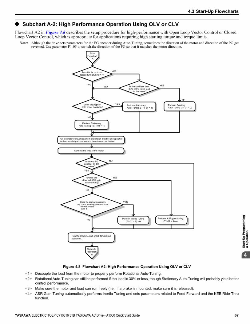
u Subchart A-2: High Performance Operation Using OLV or CLVFlowchart A2 in Figure 4.8 describes the setup procedure for high-performance with Open Loop Vector Control or ClosedLoop Vector Control, which is appropriate for applications requiring high starting torque and torque limits.
Note: Although the drive sets parameters for the PG encoder during Auto-Tuning, sometimes the direction of the motor and direction of the PG getreversed. Use parameter F1-05 to switch the direction of the PG so that it matches the motor direction.
Is the load less than 30% of the rated load
for the motor?
YES
NO
NO
From Flowchart
A
Possible for motor to rotate during tuning? <1>
<2>
Motor test report/ data sheet available?
Perform Stationary Auto-Tuning 2 (T1-01 = 4)
Perform Rotating Auto-Tuning (T1-01 = 0)
Perform StationaryAuto-Tuning 1 (T1-01 = 1)
NO YES
Is there a PG encoder on the
motor?
Feed Forward KEB 2
Perform Inertia Tuning(T1-01 = 8) <3>
Should the drive set ASR gain
automatically?
Return to Flowchart
A
Run the motor without load; check the rotation direction and operation.Verify external signal commands to the drive work as desired.
Connect the load to the motor.
Perform ASR gain tuning.(T1-01 = 9) <4>
Run the machine and check for desired operation.
NO
NO
YES
YES
YES
YES
NO
Does the application require any of the following drive functions?
Figure 4.8 Flowchart A2: High Performance Operation Using OLV or CLV
<1> Decouple the load from the motor to properly perform Rotational Auto-Tuning.<2> Rotational Auto-Tuning can still be performed if the load is 30% or less, though Stationary Auto-Tuning will probably yield better
control performance.<3> Make sure the motor and load can run freely (i.e., if a brake is mounted, make sure it is released).<4> ASR Gain Tuning automatically performs Inertia Tuning and sets parameters related to Feed Forward and the KEB Ride-Thru
function.
4.3 Start-Up Flowcharts
YASKAWA ELECTRIC TOEP C710616 31B YASKAWA AC Drive - A1000 Quick Start Guide 67
4
Star
t-Up
Prog
ram
min
g&
Ope
ratio
n
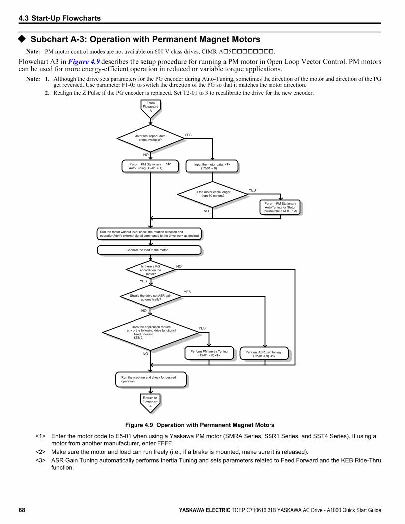
u Subchart A-3: Operation with Permanent Magnet MotorsNote: PM motor control modes are not available on 600 V class drives, CIMR-Ao5oooooooo.
Flowchart A3 in Figure 4.9 describes the setup procedure for running a PM motor in Open Loop Vector Control. PM motorscan be used for more energy-efficient operation in reduced or variable torque applications.
Note: 1. Although the drive sets parameters for the PG encoder during Auto-Tuning, sometimes the direction of the motor and direction of the PGget reversed. Use parameter F1-05 to switch the direction of the PG so that it matches the motor direction.
2. Realign the Z Pulse if the PG encoder is replaced. Set T2-01 to 3 to recalibrate the drive for the new encoder.From
Flowchart A
Motor test report/ data sheet available?
YES
Input the motor data.(T2-01 = 0)
Perform PM Stationary Auto-Tuning (T2-01 = 1)
NO
<1><1>
Is the motor cable longer than 50 meters?
YES
Perform PM Stationary Auto-Tuning for Stator Resistance (T2-01 = 2)NO
Is there a PG encoder on the
motor?
Perform PM Inertia Tuning(T2-01 = 8) <2>
Should the drive set ASR gain automatically?
Return to Flowchart
A
Run the motor without load; check the rotation direction and operation.Verify external signal commands to the drive work as desired.
Connect the load to the motor.
Perform ASR gain tuning. (T2-01 = 9). <3>
Run the machine and check for desired operation.
NO
NO
YES
YES
YES
NO
Does the application require any of the following drive functions?
Feed Forward KEB 2
Figure 4.9 Operation with Permanent Magnet Motors
<1> Enter the motor code to E5-01 when using a Yaskawa PM motor (SMRA Series, SSR1 Series, and SST4 Series). If using amotor from another manufacturer, enter FFFF.
<2> Make sure the motor and load can run freely (i.e., if a brake is mounted, make sure it is released).<3> ASR Gain Tuning automatically performs Inertia Tuning and sets parameters related to Feed Forward and the KEB Ride-Thru
function.
4.3 Start-Up Flowcharts
68 YASKAWA ELECTRIC TOEP C710616 31B YASKAWA AC Drive - A1000 Quick Start Guide
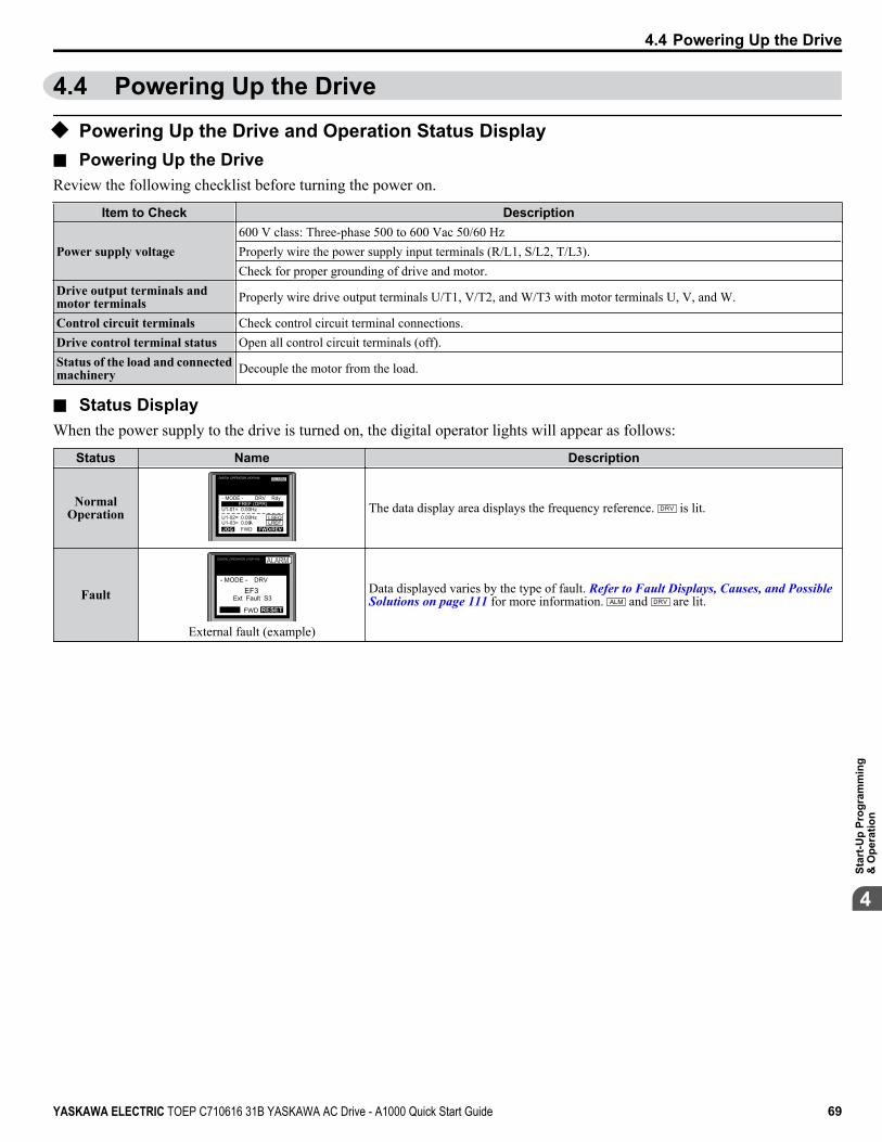
4.4 Powering Up the Drive
u Powering Up the Drive and Operation Status Displayn Powering Up the DriveReview the following checklist before turning the power on.
Item to Check Description
Power supply voltage600 V class: Three-phase 500 to 600 Vac 50/60 HzProperly wire the power supply input terminals (R/L1, S/L2, T/L3).Check for proper grounding of drive and motor.
Drive output terminals andmotor terminals Properly wire drive output terminals U/T1, V/T2, and W/T3 with motor terminals U, V, and W.
Control circuit terminals Check control circuit terminal connections.Drive control terminal status Open all control circuit terminals (off).Status of the load and connectedmachinery Decouple the motor from the load.
n Status DisplayWhen the power supply to the drive is turned on, the digital operator lights will appear as follows:
Status Name Description
NormalOperation
LOREESC
RUN STOP
ENTERRESET
DIGITAL OPERATOR JVOP-180 ALARM
- MODE -
U1-01= 0.00HzU1-02= 0.00HzU1-03= 0.00A
DRVFREF (OPR)
Rdy
JOG FWD FWD/REV
LSEQLREF
The data display area displays the frequency reference. is lit.
Fault
LOREESC
RUN STOP
ENTERRESET
DIGITAL OPERATOR JVOP-180 ALARM
- MODE -
EF3Ext Fault S3
DRV
FWD RESET
External fault (example)
Data displayed varies by the type of fault. Refer to Fault Displays, Causes, and Possible Solutions on page 111 for more information. and are lit.
4.4 Powering Up the Drive
YASKAWA ELECTRIC TOEP C710616 31B YASKAWA AC Drive - A1000 Quick Start Guide 69
4
Star
t-Up
Prog
ram
min
g&
Ope
ratio
n
4.5 Application SelectionSeveral Application Presets are available to facilitate drive setup for commonly used applications. Selecting one of theseApplication Presets automatically assigns functions to the input and output terminals and sets a predefined group of parametersto values appropriate for the selected application.In addition, the parameters most likely to be changed are assigned to the group of User Parameters, A2-01 through A2-16.User Parameters are part of the Setup Group, which provides quicker access by eliminating the need to scroll through multiplemenus.An Application Preset can either be selected from the Application Selection menu in the Setup Group or in parameter A1-06.The following presets can be selected:
Note: 1. Application Presets can only be selected if all drive parameters are at their original default settings. It may be necessary to initialize thedrive by setting A1-03 to “2220” or “3330” prior to selecting an Application Preset.
2. Entering a value to A1-06 to enable an Application Preset will fix that value to the parameter. The value cannot be changed without firstsetting A1-03 to 2220 or 3330 to initialize the drive.
WARNING! Sudden Movement Hazard. Confirm the drive I/O signals and external sequence before performing a test run. Setting parameterA1-06 may automatically change the I/O terminal function from the default setting. Failure to comply may result in death or serious injury.
No. Parameter Name Setting Range Default
A1-06 Application Presets
0: Disabled1: Water supply pump2: Conveyor3: Exhaust fan4: HVAC5: Compressor
0
4.5 Application Selection
70 YASKAWA ELECTRIC TOEP C710616 31B YASKAWA AC Drive - A1000 Quick Start Guide

4.6 Basic Drive Setup AdjustmentsThis section explains the basic settings required for initial drive operation. Checking these basic parameter settings will helpto ensure a successful drive start-up. Refer to Parameter List on page 145 for a complete listing of drive parameters if moreinformation is required for parameters not listed in this section.
n A1-02: Control Method SelectionSelects the Control Method (also referred to as the control mode) that the drive uses to operate the motor. Parameter A1-02determines the control mode for motor 1 when the drive is set up to run two motors.
No. Parameter Name Setting Range DefaultA1-02 Control Method Selection 0, 1, 2, 3, 5, 6, 7 <99> 2
<99> PM motor control modes are not available on 600 V class drives, CIMR-Ao5oooooooo.
Control Modes for Induction Motors (IM)Setting 0: V/f Control for Induction MotorsUse this mode for simple speed control and for multiple motor applications with low demands to dynamic response or speedaccuracy. This control mode is also used when the motor parameters are unknown and Auto-Tuning cannot be performed. Thespeed control range is 1:40.
Setting 1: V/f Control with PG Speed FeedbackUse this mode for general-purpose applications that require high speed accuracy but do not require high dynamic response.This control mode is also used when the motor parameters are unknown and Auto-Tuning cannot be performed. The speedcontrol range is 1:40.
Setting 2: Open Loop Vector ControlUse this mode for general, variable-speed applications with a speed control range of 1:120 that require precise speed control,quick torque response, and high torque at low speed without using a speed feedback signal from the motor.
Setting 3: Closed Loop Vector ControlUse this mode for general, variable-speed applications that require precise speed control down to zero speed, quick torqueresponse or precise torque control, and a speed feedback signal from the motor. The speed control range is up to 1:1500.Control Modes for Permanent Magnet Motors (SPM or IPM)
Note: PM motor control modes are not available on 600 V class drives, CIMR-Ao5oooooooo.
Setting 5: Open Loop Vector Control for PMUse this mode when running a PM motor in variable torque applications that benefit from energy efficiency. The drive cancontrol an SPM or IPM motor with a speed range of 1:20 in this control mode.
Setting 6: Advanced Open Loop Vector Control for PMUse this mode to operate an IPM motor for constant torque applications. Using High Frequency Injection, a speed controlrange as high as 1:100 is possible.
Setting 7: Closed Loop Vector Control for PMUse this mode for high-precision control of a PM motor in constant torque or variable torque applications. The speed controlrange reaches 1:1500. A speed feedback signal is required.
n A1-03: Initialize ParametersResets parameters to their default values. After initialization, the setting for A1-03 automatically returns to 0.
No. Parameter Name Setting Range DefaultA1-03 Initialize Parameters 0, 1110, 2220, 3330, 5550 0
Setting 1110: User InitializeResets parameters to the values selected by the user as User Settings. User Settings are stored when parameter o2-03 is set to“1: Set defaults”.
Note: User Initialization resets all parameters to a user-defined set of default values previously saved to the drive. Set parameter o2-03 to 2 to clearthe user-defined default values.
Setting 2220: 2-Wire InitializationResets parameters to default settings with digital inputs S1 and S2 configured as Forward run and Reverse run, respectively.
4.6 Basic Drive Setup Adjustments
YASKAWA ELECTRIC TOEP C710616 31B YASKAWA AC Drive - A1000 Quick Start Guide 71
4
Star
t-Up
Prog
ram
min
g&
Ope
ratio
n

Setting 3330: 3-Wire InitializationResets parameters to their default settings with digital inputs S1, S2, and S5 configured as Run, Stop, and Forward/Reverserespectively. Refer to Setting 0: 3-Wire Sequence on page 87 for more information on digital input functions.
Setting 5550: oPE04 ResetAn oPE04 error appears on the digital operator when a terminal block with settings saved to its built-in memory is installedin a drive that has edited parameters. Set A1-02 to 5550 to use the parameter settings saved to the terminal block memory.
Notes on Parameter InitializationThe parameters shown in Table 4.5 will not be reset when the drive is initialized by setting A1-03 = 2220 or 3330. Althoughthe control mode in A1-02 is not reset when A1-03 is set to 2220 or 3330, it may change when an application preset is selected.
Table 4.5 Parameters not Changed by Drive InitializationNo. Parameter Name
A1-00 Language SelectionA1-02 Control Method SelectionC6-01 Duty SelectionE1-03 V/f Pattern Selection
E5-01Motor Code Selection (for PM motors)
NOTE: PM motor control modes are not available on 600 V class drives, CIMR-Ao5oooooooo.
F6-08 Comm. Parameter ResetL8-35 Installation Selectiono2-04 Drive/kVA Selection
n b1-01: Frequency Reference Selection 1Selects the frequency reference source 1 for the REMOTE mode.
Note: 1. If a Run command is input to the drive but the frequency reference entered is 0 or below the minimum frequency, the RUN indicator LEDon the digital operator will light and the STOP indicator will flash.
2. Press the LO/RE key to set the drive to LOCAL and use the operator keypad to enter the frequency reference.
No. Parameter Name Setting Range Defaultb1-01 Frequency Reference Selection 1 0 to 4 1
Setting 0: Operator keypadUsing this setting, the frequency reference can be input by:• switching between the multi-speed references in the d1-oo parameters.• entering the frequency reference on the operator keypad.Refer to The Drive and Programming Modes on page 61 for instructions.
Setting 1: Terminals (analog input terminals)Using this setting, an analog frequency reference can be entered as a voltage or current signal from terminals A1, A2, or A3.Voltage InputVoltage input can be used at any of the three analog input terminals. Make the settings as described in Table 4.6 for the inputused.
Table 4.6 Analog Input Settings for Frequency Reference Using Voltage Signals
Terminal Signal LevelParameter Settings
NotesSignal LevelSelection Function Selection Gain Bias
A10 to 10 Vdc H3-01 = 0 H3-02 = 0
(Frequency ReferenceBias)
H3-03 H3-04 --10 to +10 Vdc H3-01 = 1
A20 to 10 Vdc H3-09 = 0 H3-10 = 0
(Frequency ReferenceBias)
H3-11 H3-12 Set DIP switch S1 on the terminalboard to “V” for voltage input.-10 to +10 Vdc H3-09 = 1
4.6 Basic Drive Setup Adjustments
72 YASKAWA ELECTRIC TOEP C710616 31B YASKAWA AC Drive - A1000 Quick Start Guide
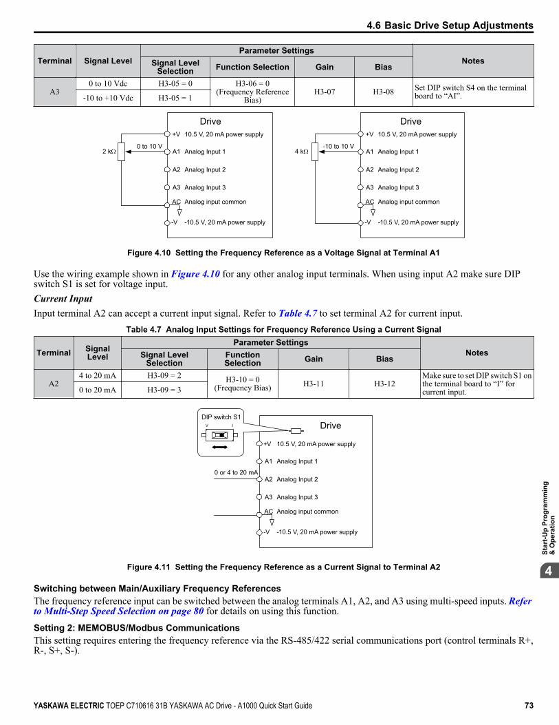
Terminal Signal LevelParameter Settings
NotesSignal LevelSelection Function Selection Gain Bias
A30 to 10 Vdc H3-05 = 0 H3-06 = 0
(Frequency ReferenceBias)
H3-07 H3-08 Set DIP switch S4 on the terminalboard to “AI”.-10 to +10 Vdc H3-05 = 1
Drive
A1 Analog Input 10 to 10 V
AC Analog input common
2 k
+V
-V
10.5 V, 20 mA power supply
-10.5 V, 20 mA power supply
A2 Analog Input 2
A3 Analog Input 3
Drive
A1 Analog Input 1-10 to 10 V
AC Analog input common
4 k
+V
-V
10.5 V, 20 mA power supply
-10.5 V, 20 mA power supply
A2 Analog Input 2
A3 Analog Input 3
Figure 4.10 Setting the Frequency Reference as a Voltage Signal at Terminal A1
Use the wiring example shown in Figure 4.10 for any other analog input terminals. When using input A2 make sure DIPswitch S1 is set for voltage input.Current InputInput terminal A2 can accept a current input signal. Refer to Table 4.7 to set terminal A2 for current input.
Table 4.7 Analog Input Settings for Frequency Reference Using a Current Signal
Terminal SignalLevel
Parameter SettingsNotesSignal Level
SelectionFunctionSelection Gain Bias
A24 to 20 mA H3-09 = 2 H3-10 = 0
(Frequency Bias) H3-11 H3-12Make sure to set DIP switch S1 onthe terminal board to “I” forcurrent input.0 to 20 mA H3-09 = 3
Drive
A1 Analog Input 1
0 or 4 to 20 mA
AC Analog input common
+V
-V
10.5 V, 20 mA power supply
-10.5 V, 20 mA power supply
A2 Analog Input 2
A3 Analog Input 3
DIP switch S1V I
Figure 4.11 Setting the Frequency Reference as a Current Signal to Terminal A2
Switching between Main/Auxiliary Frequency ReferencesThe frequency reference input can be switched between the analog terminals A1, A2, and A3 using multi-speed inputs. Refer to Multi-Step Speed Selection on page 80 for details on using this function.
Setting 2: MEMOBUS/Modbus CommunicationsThis setting requires entering the frequency reference via the RS-485/422 serial communications port (control terminals R+,R-, S+, S-).
4.6 Basic Drive Setup Adjustments
YASKAWA ELECTRIC TOEP C710616 31B YASKAWA AC Drive - A1000 Quick Start Guide 73
4
Star
t-Up
Prog
ram
min
g&
Ope
ratio
n

Setting 3: Option cardThis setting requires entering the frequency reference via an option board plugged into connector CN5-A on the drive controlboard. Consult the option board manual for instructions on integrating the drive with the communication system.
Note: If the frequency reference source is set for an option PCB (b1-01 = 3), but an option board is not installed, an oPE05 Operator ProgrammingError will be displayed on the digital operator and the drive will not run.
Setting 4: Pulse Train InputThis setting requires a pulse train signal to terminal RP to provide the frequency reference. Follow the directions below toverify that the pulse signal is working properly.
Verifying the Pulse Train is Working Properly• Set b1-04 to 4 and set H6-01 to 0.• Set the H6-02 to the pulse train frequency value that equals 100% of the frequency reference.• Enter a pulse train signal to terminal RP and check for the correct frequency reference on the display.
n b1-02: Run Command Selection 1Determines the Run command source 1 in the REMOTE mode.
No. Parameter Name Setting Range Defaultb1-02 Run Command Selection 1 0 to 3 1
Setting 0: OperatorThis setting requires entering the Run command via the digital operator and also illuminates the LO/RE indicator on the digitaloperator.
Setting 1: Control Circuit TerminalThis setting requires entering the Run command via the digital input terminals using one of following sequences:• 2-Wire sequence 1:
Two inputs (FWD/Stop-REV/Stop). Set A1-03 to 2220 to initialize the drive and preset terminals S1 and S2 to thesefunctions. This is the default setting of the drive.
• 2-Wire sequence 2:Two inputs (Start/Stop-FWD/REV).
• 3-Wire sequence:Three inputs (Start-Stop-FWD/REV). Set A1-03 to 3330 to initialize the drive and preset terminals S1, S2, and S5 to thesefunctions. Refer to Setting 0: 3-Wire Sequence on page 87.
Setting 2: MEMOBUS/Modbus CommunicationsThis setting requires entering the Run command via serial communications by connecting the RS-485/422 serialcommunication cable to control terminals R+, R-, S+, and S- on the removable terminal block.
Setting 3: Option CardThis setting requires entering the Run command via the communication option board by plugging a communication optionboard into the CN5-A port on the control PCB. Refer to the option board manual for instructions on integrating the drive intothe communication system.
Note: Setting b1-02 to 3 without first installing an option board in CN5-A will trigger an oPE05 error and the drive will not run.
n b1-03: Stopping Method SelectionSelects how the drive stops the motor when the Run command is removed or when a Stop command is entered.
No. Parameter Name Setting Range Defaultb1-03 Stopping Method Selection 0 to 3 0
Setting 0: Ramp to StopWhen the Run command is removed, the drive will decelerate the motor to stop. The deceleration rate is determined by theactive deceleration time. The default deceleration time is set to parameter C1-02.When the output frequency falls below the level set in parameter b2-01, the drive will start DC injection, Zero Speed Control,or Short Circuit Braking, depending on the selected control mode. Refer to b2-01: DC Injection Braking Start Frequency on page 76 for details.
4.6 Basic Drive Setup Adjustments
74 YASKAWA ELECTRIC TOEP C710616 31B YASKAWA AC Drive - A1000 Quick Start Guide
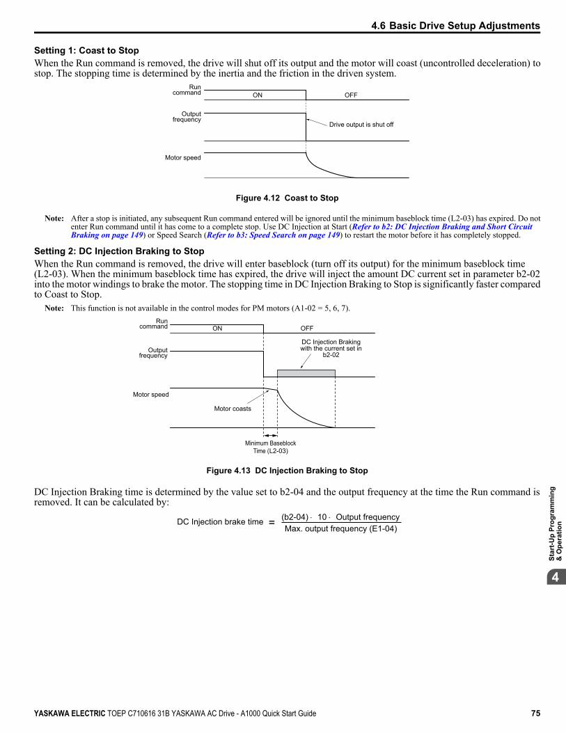
Setting 1: Coast to StopWhen the Run command is removed, the drive will shut off its output and the motor will coast (uncontrolled deceleration) tostop. The stopping time is determined by the inertia and the friction in the driven system.
Drive output is shut off
Run command
Output frequency
Motor speed
ON OFF
Figure 4.12 Coast to Stop
Note: After a stop is initiated, any subsequent Run command entered will be ignored until the minimum baseblock time (L2-03) has expired. Do notenter Run command until it has come to a complete stop. Use DC Injection at Start (Refer to b2: DC Injection Braking and Short Circuit Braking on page 149) or Speed Search (Refer to b3: Speed Search on page 149) to restart the motor before it has completely stopped.
Setting 2: DC Injection Braking to StopWhen the Run command is removed, the drive will enter baseblock (turn off its output) for the minimum baseblock time(L2-03). When the minimum baseblock time has expired, the drive will inject the amount DC current set in parameter b2-02into the motor windings to brake the motor. The stopping time in DC Injection Braking to Stop is significantly faster comparedto Coast to Stop.
Note: This function is not available in the control modes for PM motors (A1-02 = 5, 6, 7).
Motor coasts
DC Injection Braking with the current set in
b2-02
Run command
Output frequency
ON OFF
Motor speed
Minimum Baseblock Time (L2-03)
Figure 4.13 DC Injection Braking to Stop
DC Injection Braking time is determined by the value set to b2-04 and the output frequency at the time the Run command isremoved. It can be calculated by:
DC Injection brake time (b2-04) × 10 × Output frequencyMax. output frequency (E1-04)=
4.6 Basic Drive Setup Adjustments
YASKAWA ELECTRIC TOEP C710616 31B YASKAWA AC Drive - A1000 Quick Start Guide 75
4
Star
t-Up
Prog
ram
min
g&
Ope
ratio
n

Output frequency when Stop command was entered
100%(Maximum output
frequency)
10%
DC Injection braking time
b2-04×10
b2-04
Figure 4.14 DC Injection Braking Time Depending on Output Frequency
Note: If an overcurrent (oC) fault occurs during DC Injection Braking to Stop, lengthen the minimum baseblock time (L2-03) until the fault no longeroccurs.
Setting 3: Coast to Stop with TimerWhen the Run command is removed, the drive will turn off its output and the motor will coast to stop. The drive will not startif a Run command is input before the time t (C1-02) has expired. Cycle the Run command that was activated during time tafter t has expired to start the drive.
Drive output shut off
Run wait time t
Run command
Output frequency
ON ON ONOFF OFF
Figure 4.15 Coast to Stop with Timer
The wait time t is determined by the output frequency when the Run command is removed and by the active deceleration time.
Min output frequency
100%(Max output frequency)
Output frequency when Stop command
was entered
Run wait time t
Active deceleration time
Min Baseblock Time (L2-03)
Figure 4.16 Run Wait Time Depending on Output Frequency
n b2-01: DC Injection Braking Start FrequencyActive when “Ramp to Stop” is selected as the stopping method (b1-03 = 0).
No. Name Setting Range Default
b2-01 DC Injection Braking Start Frequency 0.0 to 10.0 Hz Determined byA1-02
The function triggered by parameter b2-01 depends on the control mode that has been selected.
V/f, V/f w/PG, and OLV (A1-02 = 0, 1, 2)For these control modes, parameter b2-01 sets the starting frequency for DC Injection Braking at Stop. When the outputfrequency falls below the setting of b2-01, DC Injection Braking is enabled for the time set in parameter b2-04.
4.6 Basic Drive Setup Adjustments
76 YASKAWA ELECTRIC TOEP C710616 31B YASKAWA AC Drive - A1000 Quick Start Guide
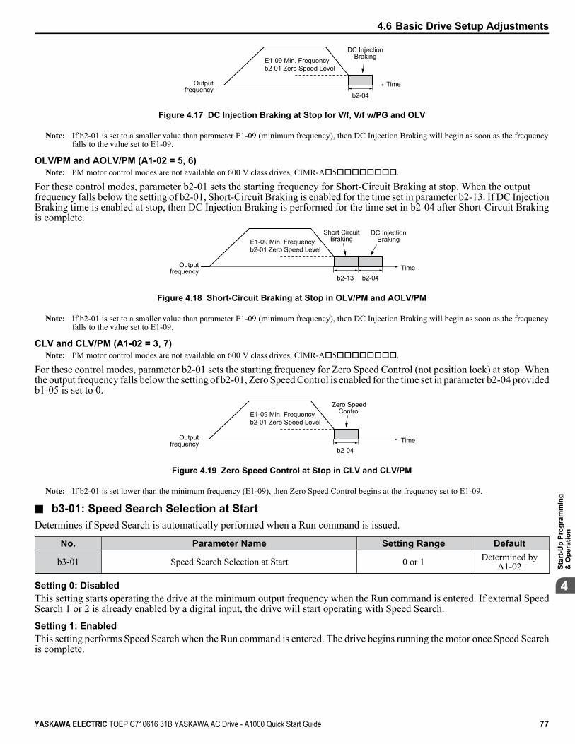
Output frequency
Time
b2-04
DC Injection BrakingE1-09 Min. Frequency
b2-01 Zero Speed Level
Figure 4.17 DC Injection Braking at Stop for V/f, V/f w/PG and OLV
Note: If b2-01 is set to a smaller value than parameter E1-09 (minimum frequency), then DC Injection Braking will begin as soon as the frequencyfalls to the value set to E1-09.
OLV/PM and AOLV/PM (A1-02 = 5, 6)Note: PM motor control modes are not available on 600 V class drives, CIMR-Ao5oooooooo.
For these control modes, parameter b2-01 sets the starting frequency for Short-Circuit Braking at stop. When the outputfrequency falls below the setting of b2-01, Short-Circuit Braking is enabled for the time set in parameter b2-13. If DC InjectionBraking time is enabled at stop, then DC Injection Braking is performed for the time set in b2-04 after Short-Circuit Brakingis complete.
Output frequency Time
DC Injection Braking
b2-04b2-13
Short Circuit BrakingE1-09 Min. Frequency
b2-01 Zero Speed Level
Figure 4.18 Short-Circuit Braking at Stop in OLV/PM and AOLV/PM
Note: If b2-01 is set to a smaller value than parameter E1-09 (minimum frequency), then DC Injection Braking will begin as soon as the frequencyfalls to the value set to E1-09.
CLV and CLV/PM (A1-02 = 3, 7)Note: PM motor control modes are not available on 600 V class drives, CIMR-Ao5oooooooo.
For these control modes, parameter b2-01 sets the starting frequency for Zero Speed Control (not position lock) at stop. Whenthe output frequency falls below the setting of b2-01, Zero Speed Control is enabled for the time set in parameter b2-04 providedb1-05 is set to 0.
Output frequency Time
Zero Speed Control
b2-04
E1-09 Min. Frequencyb2-01 Zero Speed Level
Figure 4.19 Zero Speed Control at Stop in CLV and CLV/PM
Note: If b2-01 is set lower than the minimum frequency (E1-09), then Zero Speed Control begins at the frequency set to E1-09.
n b3-01: Speed Search Selection at StartDetermines if Speed Search is automatically performed when a Run command is issued.
No. Parameter Name Setting Range Default
b3-01 Speed Search Selection at Start 0 or 1 Determined byA1-02
Setting 0: DisabledThis setting starts operating the drive at the minimum output frequency when the Run command is entered. If external SpeedSearch 1 or 2 is already enabled by a digital input, the drive will start operating with Speed Search.
Setting 1: EnabledThis setting performs Speed Search when the Run command is entered. The drive begins running the motor once Speed Searchis complete.
4.6 Basic Drive Setup Adjustments
YASKAWA ELECTRIC TOEP C710616 31B YASKAWA AC Drive - A1000 Quick Start Guide 77
4
Star
t-Up
Prog
ram
min
g&
Ope
ratio
n
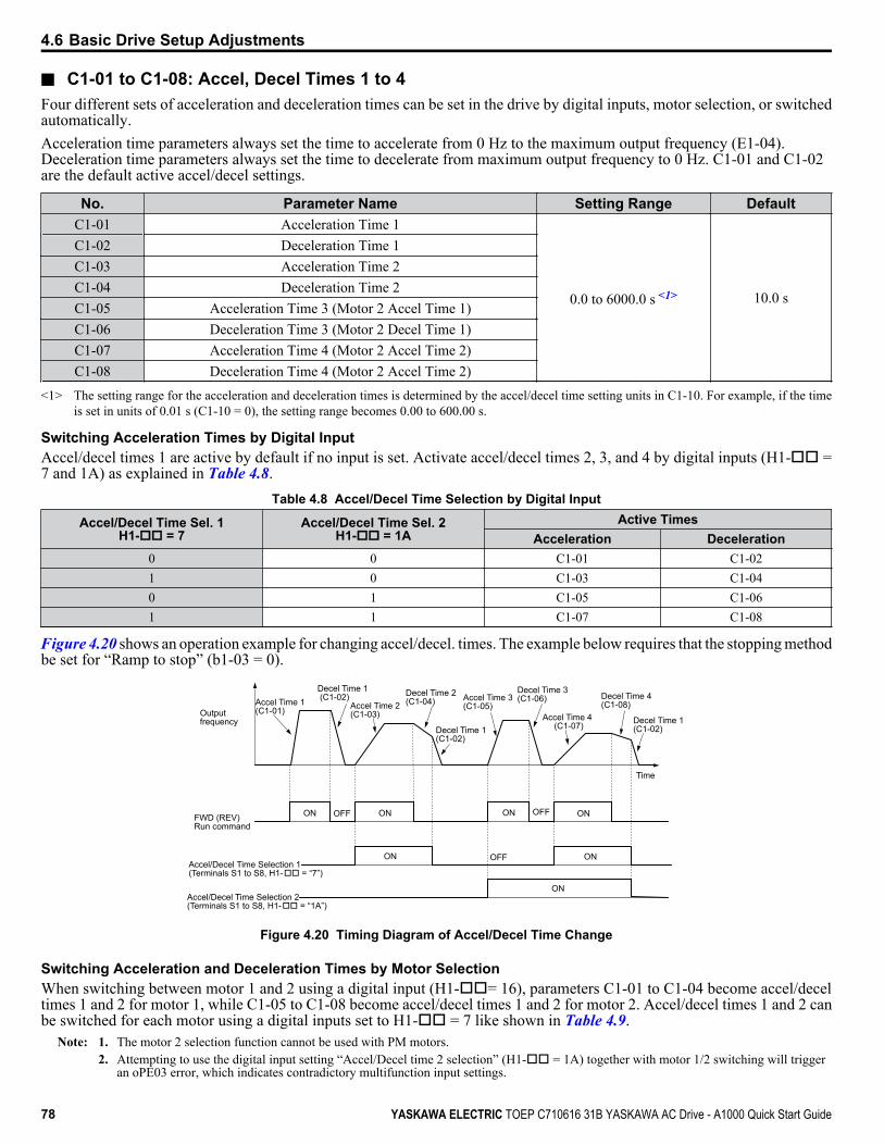
n C1-01 to C1-08: Accel, Decel Times 1 to 4Four different sets of acceleration and deceleration times can be set in the drive by digital inputs, motor selection, or switchedautomatically.Acceleration time parameters always set the time to accelerate from 0 Hz to the maximum output frequency (E1-04).Deceleration time parameters always set the time to decelerate from maximum output frequency to 0 Hz. C1-01 and C1-02are the default active accel/decel settings.
No. Parameter Name Setting Range DefaultC1-01 Acceleration Time 1
0.0 to 6000.0 s <1> 10.0 s
C1-02 Deceleration Time 1C1-03 Acceleration Time 2C1-04 Deceleration Time 2C1-05 Acceleration Time 3 (Motor 2 Accel Time 1)C1-06 Deceleration Time 3 (Motor 2 Decel Time 1)C1-07 Acceleration Time 4 (Motor 2 Accel Time 2)C1-08 Deceleration Time 4 (Motor 2 Accel Time 2)
<1> The setting range for the acceleration and deceleration times is determined by the accel/decel time setting units in C1-10. For example, if the timeis set in units of 0.01 s (C1-10 = 0), the setting range becomes 0.00 to 600.00 s.
Switching Acceleration Times by Digital InputAccel/decel times 1 are active by default if no input is set. Activate accel/decel times 2, 3, and 4 by digital inputs (H1-oo =7 and 1A) as explained in Table 4.8.
Table 4.8 Accel/Decel Time Selection by Digital Input
Accel/Decel Time Sel. 1H1-oo = 7
Accel/Decel Time Sel. 2H1-oo = 1A
Active TimesAcceleration Deceleration
0 0 C1-01 C1-021 0 C1-03 C1-040 1 C1-05 C1-061 1 C1-07 C1-08
Figure 4.20 shows an operation example for changing accel/decel. times. The example below requires that the stopping methodbe set for “Ramp to stop” (b1-03 = 0).
Outputfrequency
Accel Time 1(C1-01)
Decel Time 1 (C1-02)
Accel Time 2 (C1-03)
Decel Time 2(C1-04)
Decel Time 1(C1-02)
Time
FWD (REV) Run command
ON OFF ON
ONAccel/Decel Time Selection 1(Terminals S1 to S8, H1-oo = “7”)
Accel Time 3(C1-05)
Decel Time 3 (C1-06)
Accel Time 4 (C1-07)
Decel Time 4(C1-08)
Decel Time 1(C1-02)
ONOFF
ON OFF ON
Accel/Decel Time Selection 2(Terminals S1 to S8, H1-oo = “1A”)
ON
Figure 4.20 Timing Diagram of Accel/Decel Time Change
Switching Acceleration and Deceleration Times by Motor SelectionWhen switching between motor 1 and 2 using a digital input (H1-oo= 16), parameters C1-01 to C1-04 become accel/deceltimes 1 and 2 for motor 1, while C1-05 to C1-08 become accel/decel times 1 and 2 for motor 2. Accel/decel times 1 and 2 canbe switched for each motor using a digital inputs set to H1-oo = 7 like shown in Table 4.9.
Note: 1. The motor 2 selection function cannot be used with PM motors.2. Attempting to use the digital input setting “Accel/Decel time 2 selection” (H1-oo = 1A) together with motor 1/2 switching will trigger
an oPE03 error, which indicates contradictory multifunction input settings.
4.6 Basic Drive Setup Adjustments
78 YASKAWA ELECTRIC TOEP C710616 31B YASKAWA AC Drive - A1000 Quick Start Guide
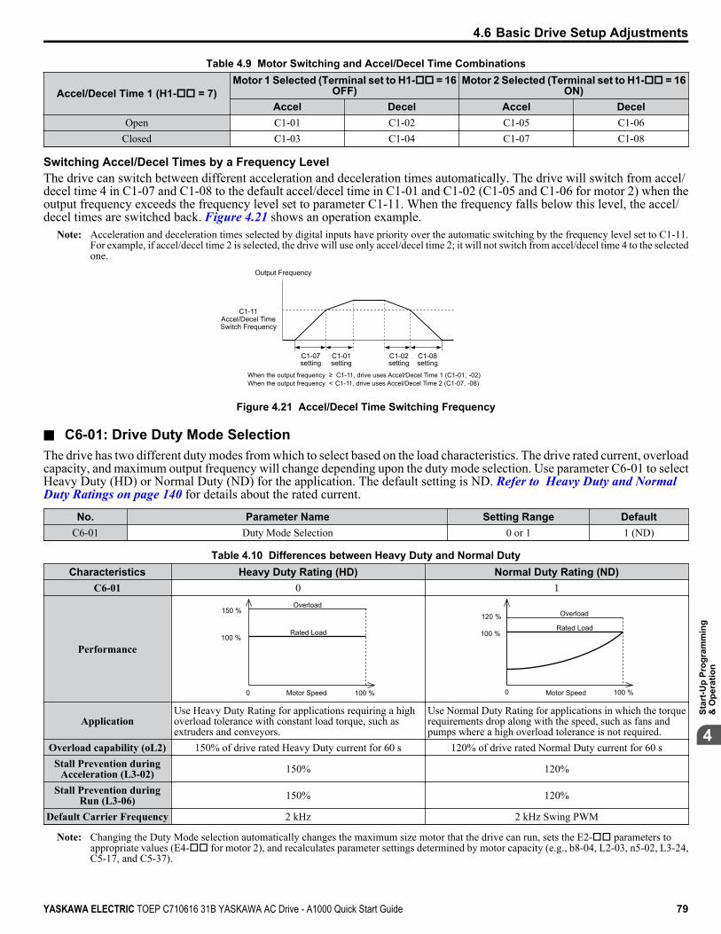
Table 4.9 Motor Switching and Accel/Decel Time Combinations
Accel/Decel Time 1 (H1-oo = 7)Motor 1 Selected (Terminal set to H1-oo = 16
OFF)Motor 2 Selected (Terminal set to H1-oo = 16
ON)Accel Decel Accel Decel
Open C1-01 C1-02 C1-05 C1-06Closed C1-03 C1-04 C1-07 C1-08
Switching Accel/Decel Times by a Frequency LevelThe drive can switch between different acceleration and deceleration times automatically. The drive will switch from accel/decel time 4 in C1-07 and C1-08 to the default accel/decel time in C1-01 and C1-02 (C1-05 and C1-06 for motor 2) when theoutput frequency exceeds the frequency level set to parameter C1-11. When the frequency falls below this level, the accel/decel times are switched back. Figure 4.21 shows an operation example.
Note: Acceleration and deceleration times selected by digital inputs have priority over the automatic switching by the frequency level set to C1-11.For example, if accel/decel time 2 is selected, the drive will use only accel/decel time 2; it will not switch from accel/decel time 4 to the selectedone.
Output Frequency
C1-11Accel/Decel TimeSwitch Frequency
C1-07 setting
When the output frequency C1-11, drive uses Accel/Decel Time 1 (C1-01, -02)When the output frequency < C1-11, drive uses Accel/Decel Time 2 (C1-07, -08)
C1-01 setting
C1-02 setting
C1-08 setting
Figure 4.21 Accel/Decel Time Switching Frequency
n C6-01: Drive Duty Mode SelectionThe drive has two different duty modes from which to select based on the load characteristics. The drive rated current, overloadcapacity, and maximum output frequency will change depending upon the duty mode selection. Use parameter C6-01 to selectHeavy Duty (HD) or Normal Duty (ND) for the application. The default setting is ND. Refer to Heavy Duty and Normal Duty Ratings on page 140 for details about the rated current.
No. Parameter Name Setting Range DefaultC6-01 Duty Mode Selection 0 or 1 1 (ND)
Table 4.10 Differences between Heavy Duty and Normal DutyCharacteristics Heavy Duty Rating (HD) Normal Duty Rating (ND)
C6-01 0 1
Performance100 %
100 %0 Motor Speed
Rated Load
Overload150 %
Motor Speed0
100 %
100 %
120 %Rated Load
Overload
ApplicationUse Heavy Duty Rating for applications requiring a highoverload tolerance with constant load torque, such asextruders and conveyors.
Use Normal Duty Rating for applications in which the torquerequirements drop along with the speed, such as fans andpumps where a high overload tolerance is not required.
Overload capability (oL2) 150% of drive rated Heavy Duty current for 60 s 120% of drive rated Normal Duty current for 60 sStall Prevention during
Acceleration (L3-02) 150% 120%
Stall Prevention duringRun (L3-06) 150% 120%
Default Carrier Frequency 2 kHz 2 kHz Swing PWM
Note: Changing the Duty Mode selection automatically changes the maximum size motor that the drive can run, sets the E2-oo parameters toappropriate values (E4-oo for motor 2), and recalculates parameter settings determined by motor capacity (e.g., b8-04, L2-03, n5-02, L3-24,C5-17, and C5-37).
4.6 Basic Drive Setup Adjustments
YASKAWA ELECTRIC TOEP C710616 31B YASKAWA AC Drive - A1000 Quick Start Guide 79
4
Star
t-Up
Prog
ram
min
g&
Ope
ratio
n
n C6-02: Carrier Frequency SelectionSets the switching frequency of the drive output transistors. Changing the switching frequency lowers audible noise and reducesleakage current.
Note: Increasing the carrier frequency above the default value automatically lowers the drive current rating.
No. Parameter Name Setting Range Default
C6-02 Carrier Frequency Selection 1 to F Determined by A1-02, o2-04.Reset when C6-01 is changed.
Note: The default setting for the carrier frequency differs based on the type of motor and the Duty Mode selection. The default is 2 kHz in HD, and“Swing PWM1” in ND. When using a PM motor, the default carrier frequency is 5.0 Hz.
Settings:C6-02 Carrier Frequency C6-02 Carrier Frequency C6-02 Carrier Frequency
1 2.0 kHz 5 12.5 kHz (10.0 kHz) 9 Swing PWM 32 5.0 kHz (4.0 kHz) 6 15.0 kHz (12.0 kHz) A Swing PWM 43 8.0 kHz (6.0 kHz) 7 Swing PWM 1
F User-defined (C6-03 to C6-05)4 10.0 kHz (8.0 kHz) 8 Swing PWM 2
Note: 1. Swing PWM uses a carrier frequency of 2.0 kHz as a base, then applies a special PWM pattern to reduce the audible noise.2. The value in parenthesis indicates the carrier frequency for AOLV/PM.
Guidelines for Carrier Frequency Parameter Setup
Symptom RemedySpeed and torque are unstable at low speeds
Lower the carrier frequency.Noise from the drive affects peripheral devicesExcessive leakage current from the drive
Wiring between the drive and motor is too long <1>
Audible motor noise is too loud Increase the carrier frequency or use Swing PWM. <2>
<1> The carrier frequency may need to be lowered if the motor cable is too long. Refer to the following table.<2> The default carrier frequency in ND is Swing PWM (C6-02 = 7) using a 2 kHz base. Increasing the carrier frequency is permissible when the drive
is set for ND. The drive rated current is reduced when the carrier frequency is increased.
Wiring Distance Up to 50 m Up to 100 m Greater than 100 m
Recommended setting value for C6-02 1 to F (up to 15 kHz) 1 to 2 (up to 5 kHz), 7 (SwingPWM) 1 (up to 2 kHz), 7 (Swing PWM)
n d1-01 to d1-17: Frequency Reference 1 to 16 and Jog Frequency ReferenceThe drive lets the user switch between up to 17 preset frequency references during run (including the Jog reference) throughthe digital input terminals. The drive uses the acceleration and deceleration times that have been selected when switchingbetween each frequency reference.The Jog frequency overrides all other frequency references and must be selected by a separate digital input.The multi-speed references 1, 2, and 3 can be provided by analog inputs.
No. Parameter Name Setting Range Defaultd1-01 to d1-16 Frequency Reference 1 to 16 0.00 to 400.00 Hz <1> <2> 0.00 Hz <2>
d1-17 Jog Frequency Reference 0.00 to 400.00 Hz <1> <2> 6.00 Hz <2>
<1> The upper limit is determined by the maximum output frequency (E1-04) and upper limit for the frequency reference (d2-01).<2> Setting units are determined by parameter o1-03. The default is “Hz” (o1-03 = 0) in V/f, V/f w/PG, OLV, CLV, and OLV/PM control modes. The
default for AOLV/PM and CLV/PM control modes expresses the frequency reference as a percentage (o1-03 = 1).
Multi-Step Speed SelectionTo use several speed references for a multi-step speed sequence, set the H1-oo parameters to 3, 4, 5, and 32. To assign theJog reference to a digital input, set H1-oo to 6.Notes on using analog inputs as Multi-Speed 1, 2, and 3:• The first frequency reference (Multi-Speed 1) comes from the source specified in b1-01. When using an analog input terminal
to supply the frequency reference, assign the frequency reference source to the control terminals (b1-01 = 1).
4.6 Basic Drive Setup Adjustments
80 YASKAWA ELECTRIC TOEP C710616 31B YASKAWA AC Drive - A1000 Quick Start Guide

• When an analog input is set to “Auxiliary frequency 1” (H3-02, H2-06, or H2-10 = 2), the value set to this input will be usedas the Multi-Step Speed 2 instead of the value set to parameter d1-02. If no analog inputs are set for “Auxiliary frequency1”, then d1-02 becomes the reference for Multi-Step Speed 2.
• When the an analog input is set to “Auxiliary frequency 2” (H3-02, H2-06, or H2-10 = 3), the value set to this input will beused as the Multi-Step Speed 3 instead of the value set to parameter d1-03. If no analog inputs are set for “Auxiliary frequency2”, then d1-03 becomes the reference for Multi-Step Speed 3.
Select the different speed references as shown in Table 4.11. Figure 4.22 illustrates the multi-step speed selection.Table 4.11 Multi-Step Speed Reference and Terminal Switch Combinations
ReferenceMulti-Step
SpeedH1-oo = 3
Multi-StepSpeed 2
H1-oo = 4
Multi-StepSpeed 3
H1-oo = 5
Multi-StepSpeed 4
H1-oo = 32Jog Reference
H1-oo = 6
Frequency Reference 1 (set in b1-01) OFF OFF OFF OFF OFFFrequency Reference 2
(d1-02 or input terminal A1, A2, A3) ON OFF OFF OFF OFF
Frequency Reference 3(d1-03 or input terminal A1, A2, A3) OFF ON OFF OFF OFF
Frequency Reference 4 (d1-04) ON ON OFF OFF OFFFrequency Reference 5 (d1-05) OFF OFF ON OFF OFFFrequency Reference 6 (d1-06) ON OFF ON OFF OFFFrequency Reference 7 (d1-07) OFF ON ON OFF OFFFrequency Reference 8 (d1-08) ON ON ON OFF OFFFrequency Reference 9 (d1-09) OFF OFF OFF ON OFFFrequency Reference 10 (d1-10) ON OFF OFF ON OFFFrequency Reference 11 (d1-11) OFF ON OFF ON OFFFrequency Reference 12 (d1-12) ON ON OFF ON OFFFrequency Reference 13 (d1-13) OFF OFF ON ON OFFFrequency Reference 14 (d1-14) ON OFF ON ON OFFFrequency Reference 15 (d1-15) OFF ON ON ON OFFFrequency Reference 16 (d1-16) ON ON ON ON OFF
Jog Frequency Reference (d1-17) <1> − − − − ON
<1> The Jog frequency overrides all other frequency references.
4.6 Basic Drive Setup Adjustments
YASKAWA ELECTRIC TOEP C710616 31B YASKAWA AC Drive - A1000 Quick Start Guide 81
4
Star
t-Up
Prog
ram
min
g&
Ope
ratio
n

d1-04d1-05
d1-06
d1-07
d1-17
d1-12
d1-13
d1-14d1-15
d1-16
ON
ON
ON
ON
ON
ON
ON
ON
ON
ON
ON ON ON
ON
ON
FWD (REV) Run/Stop
Multi-step Speed Ref. 2
Multi-step Speed Ref. 3
Jog Reference
Time
Multi-step Speed Ref. 1
Multi-step Speed Ref. 4
Frequency reference
d1-01(A1)
d1-02(A2)
d1-01(A3)
Figure 4.22 Preset Reference Timing Diagram
n E1-01: Input Voltage SettingAdjusts the levels of some protective features of the drive (overvoltage, Stall Prevention, etc.). Set this parameter to the nominalvoltage of the AC power supply.NOTICE: Set parameter E1-01 to match the input voltage of the drive. Drive input voltage (not motor voltage) must be set in E1-01 for theprotective features to function properly. Failure to set the correct drive input voltage will result in improper drive operation.
No. Parameter Name Setting Range DefaultE1-01 Input Voltage Setting 446 to 733 V 575 V
E1-01 Related ValuesThe input voltage setting determines the overvoltage and undervoltage detection levels, the operation levels of the brakingtransistor, the KEB function, and the overvoltage suppression function.
Voltage Setting Value of E1-01
(Approximate Values)
Uv Detection Level(L2-05)
Desired DC Bus Voltageduring KEB (L2-11)
ov Suppression /Stall Prevention Level
(L3-17)600 V Class All settings 475 V 635 V 930 V
Note: The braking transistor operation levels are valid for the drive internal braking transistor. When using an external CDBR braking chopper, referto the instruction manual of that unit.
n V/f Pattern Settings (E1-03)The drive uses a V/f pattern to adjust the output voltage relative to the frequency reference. There are 15 different predefinedV/f patterns (setting 0 to E) from which to select, each with varying voltage profiles, saturation levels (frequency at whichmaximum voltage is reached), and maximum frequencies. Additionally, one custom V/f pattern is available (setting F) thatrequires the user to create the pattern using parameters E1-04 through E1-10.
4.6 Basic Drive Setup Adjustments
82 YASKAWA ELECTRIC TOEP C710616 31B YASKAWA AC Drive - A1000 Quick Start Guide
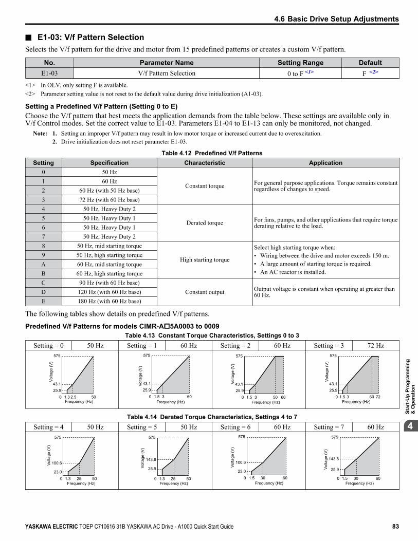
n E1-03: V/f Pattern SelectionSelects the V/f pattern for the drive and motor from 15 predefined patterns or creates a custom V/f pattern.
No. Parameter Name Setting Range DefaultE1-03 V/f Pattern Selection 0 to F <1> F <2>
<1> In OLV, only setting F is available.<2> Parameter setting value is not reset to the default value during drive initialization (A1-03).
Setting a Predefined V/f Pattern (Setting 0 to E)Choose the V/f pattern that best meets the application demands from the table below. These settings are available only inV/f Control modes. Set the correct value to E1-03. Parameters E1-04 to E1-13 can only be monitored, not changed.
Note: 1. Setting an improper V/f pattern may result in low motor torque or increased current due to overexcitation.2. Drive initialization does not reset parameter E1-03.
Table 4.12 Predefined V/f PatternsSetting Specification Characteristic Application
0 50 Hz
Constant torque For general purpose applications. Torque remains constantregardless of changes to speed.
1 60 Hz2 60 Hz (with 50 Hz base)3 72 Hz (with 60 Hz base)4 50 Hz, Heavy Duty 2
Derated torque For fans, pumps, and other applications that require torquederating relative to the load.
5 50 Hz, Heavy Duty 16 50 Hz, Heavy Duty 17 50 Hz, Heavy Duty 28 50 Hz, mid starting torque
High starting torque
Select high starting torque when:• Wiring between the drive and motor exceeds 150 m.• A large amount of starting torque is required.• An AC reactor is installed.
9 50 Hz, high starting torqueA 60 Hz, mid starting torqueB 60 Hz, high starting torqueC 90 Hz (with 60 Hz base)
Constant output Output voltage is constant when operating at greater than60 Hz.D 120 Hz (with 60 Hz base)
E 180 Hz (with 60 Hz base)
The following tables show details on predefined V/f patterns.
Predefined V/f Patterns for models CIMR-Ao5A0003 to 0009Table 4.13 Constant Torque Characteristics, Settings 0 to 3
Setting = 0 50 Hz Setting = 1 60 Hz Setting = 2 60 Hz Setting = 3 72 Hz
025.9
575
1.3 2.5 50
43.1
Volta
ge (V
)
Frequency (Hz)0
25.943.1
575
1.5 3 60
Volta
ge (V
)
Frequency (Hz)0
25.943.1
575
1.5 3 6050
Volta
ge (V
)
Frequency (Hz)0
25.943.1
575
1.5 3 7260
Volta
ge (V
)
Frequency (Hz)
Table 4.14 Derated Torque Characteristics, Settings 4 to 7Setting = 4 50 Hz Setting = 5 50 Hz Setting = 6 60 Hz Setting = 7 60 Hz
023.0
575
1.3 25 50
100.6Volta
ge (V
)
Frequency (Hz)0
25.9
575
1.3 25 50
143.8
Volta
ge (V
)
Frequency (Hz)0
23.0
575
1.5 30 60
100.6
Volta
ge (V
)
Frequency (Hz)0
25.9
575
1.5 30 60
143.8
Volta
ge (V
)
Frequency (Hz)
4.6 Basic Drive Setup Adjustments
YASKAWA ELECTRIC TOEP C710616 31B YASKAWA AC Drive - A1000 Quick Start Guide 83
4
Star
t-Up
Prog
ram
min
g&
Ope
ratio
n
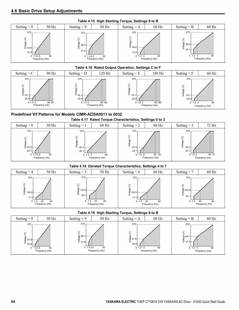
Table 4.15 High Starting Torque, Settings 8 to BSetting = 8 50 Hz Setting = 9 50 Hz Setting = A 60 Hz Setting = B 60 Hz
031.6
575
1.3 2.5 50
54.6Volta
ge (V
)
Frequency (Hz)0
37.4
575
1.3 2.5 50
69.0
Volta
ge (V
)
Frequency (Hz)0
31.6
575
1.5 3 60
54.6Volta
ge (V
)
Frequency (Hz)0
43.1
575
1.5 3 60
69.0
Volta
ge (V
)
Frequency (Hz)
Table 4.16 Rated Output Operation, Settings C to FSetting = C 90 Hz Setting = D 120 Hz Setting = E 180 Hz Setting = F 60 Hz
025.943.1
575
1.5 3 9060
Volta
ge (V
)
Frequency (Hz)0
25.943.1
575
1.5 3 12060
Volta
ge (V
)
Frequency (Hz)0
25.943.1
575
1.5 3 18060
Volta
ge (V
)
Frequency (Hz)0
25.943.1
575
1.5 3 60
Volta
ge (V
)
Frequency (Hz)
Predefined V/f Patterns for Models CIMR-Ao5A0011 to 0032Table 4.17 Rated Torque Characteristics, Settings 0 to 3
Setting = 0 50 Hz Setting = 1 60 Hz Setting = 2 60 Hz Setting = 3 72 Hz
020.1
575
1.3 2.5 50
40.3Volta
ge (V
)
Frequency (Hz)0
20.140.3
575
1.5 3 60
Volta
ge (V
)
Frequency (Hz)
Volta
ge (V
)
Frequency (Hz)0
20.140.3
575
1.5 3 6050 020.140.3
575
1.5 3 7260
Volta
ge (V
)
Frequency (Hz)
Table 4.18 Derated Torque Characteristics, Settings 4 to 7Setting = 4 50 Hz Setting = 5 50 Hz Setting = 6 60 Hz Setting = 7 60 Hz
Volta
ge (V
)
Frequency (Hz)0
17.3
575
1.3 25 50
100.6
0
20.1
575
1.3 25 50
143.8
Volta
ge (V
)
Frequency (Hz)
Volta
ge (V
)
Frequency (Hz)0
17.3
575
1.5 30 60
100.6
0
20.1
575
1.5 30 60
143.8
Volta
ge (V
)
Frequency (Hz)
Table 4.19 High Starting Torque, Settings 8 to BSetting = 8 50 Hz Setting = 9 50 Hz Setting = A 60 Hz Setting = B 60 Hz
025.9
575
1.3 2.5 50
51.8
Volta
ge (V
)
Frequency (Hz)
Volta
ge (V
)
Frequency (Hz)0
31.6
575
1.3 2.5 50
66.1
Volta
ge (V
)
Frequency (Hz)0
25.9
575
1.5 3 60
51.8
0
37.4
575
1.5 3 60
66.1
Volta
ge (V
)
Frequency (Hz)
4.6 Basic Drive Setup Adjustments
84 YASKAWA ELECTRIC TOEP C710616 31B YASKAWA AC Drive - A1000 Quick Start Guide

Table 4.20 Constant Output, Settings C to FSetting = C 90 Hz Setting = D 120 Hz Setting = E 180 Hz Setting = F 60 Hz
020.140.3
575
1.5 3 9060
Volta
ge (V
)
Frequency (Hz)0
20.140.3
575
1.5 3 12060
Volta
ge (V
)
Frequency (Hz)0
20.140.3
575
1.5 3 18060
Volta
ge (V
)
Frequency (Hz)
Volta
ge (V
)
Frequency (Hz)0
20.140.3
575
1.5 3 60
Setting a Custom V/f Pattern (Setting F: Default)Set parameter E1-03 to F to create a custom V/f pattern by setting parameters E1-04 to E1-13.When initialized, the default values for parameters E1-04 to E1-13 will be equal to V/f pattern 1 of the predefined patterns.
n V/f Pattern Settings E1-04 to E1-13If E1-03 is set to a preset V/f pattern (i.e., a value other than F), the user can monitor the V/f pattern in parameters E1-04through E1-13. To create a new V/f pattern, set E1-03 to F. Refer to V/f Pattern on page 85 for an example custom V/fpattern.
Note: Certain E1-oo parameters might not be visible depending on the control mode. Refer to Parameter List on page 145 for details.
No. Parameter Name Setting Range DefaultE1-04 Maximum Output Frequency 40.0 to 400.0 Hz <1> <2>
E1-05 Maximum Voltage 0.0 to 733.1 V <1>
E1-06 Base Frequency 0.0 to [E1-04] <1> <2>
E1-07 Middle Output Frequency 0.0 to [E1-04] <1>
E1-08 Middle Output Frequency Voltage 0.0 to 733.1 V <1>
E1-09 Minimum Output Frequency 0.0 to [E1-04] <1> <2>
E1-10 Minimum Output Frequency Voltage 0.0 to 733.1 V <1>
E1-11 Middle Output Frequency 2 0.0 to [E1-04] 0.0 Hz <4>
E1-12 Middle Output Frequency Voltage 2 0.0 to 733.1 V 0.0 V <3> <4>
E1-13 Base Voltage 0.0 to 733.1 V 0.0 V <3>
<1> Default setting is determined by the control mode.<2> When using PM motors, the default setting is determined by the motor code set to E5-01.<3> The drive changes these settings when Auto-Tuning is performed (Rotational Auto-Tuning, Stationary Auto-Tuning 1, 2).<4> Parameter ignored when E1-11 and E1-12 are set to 0.0.
Output Voltage (V)
Frequency (Hz)
E1-05E1-12
E1-13
E1-08
E1-10
E1-09 E1-07 E1-06 E1-11 E1-04
Figure 4.23 V/f Pattern
Note: 1. The following condition must be true when setting up the V/f pattern: E1-09 ≤ E1-07 < E1-06 ≤ E1-11 ≤ E1-042. To make the V/f pattern a straight line below E1-06, set E1-09 equal to E1-07. In this case the E1-08 setting is disregarded.3. E1-03 is unaffected when the drive is initialized, but E1-04 through E1-13 return to their default values.4. Only use E1-11, E1-12, and E1-13 to fine-tune the V/f pattern in the constant output range. These parameters rarely need to be changed.
4.6 Basic Drive Setup Adjustments
YASKAWA ELECTRIC TOEP C710616 31B YASKAWA AC Drive - A1000 Quick Start Guide 85
4
Star
t-Up
Prog
ram
min
g&
Ope
ratio
n
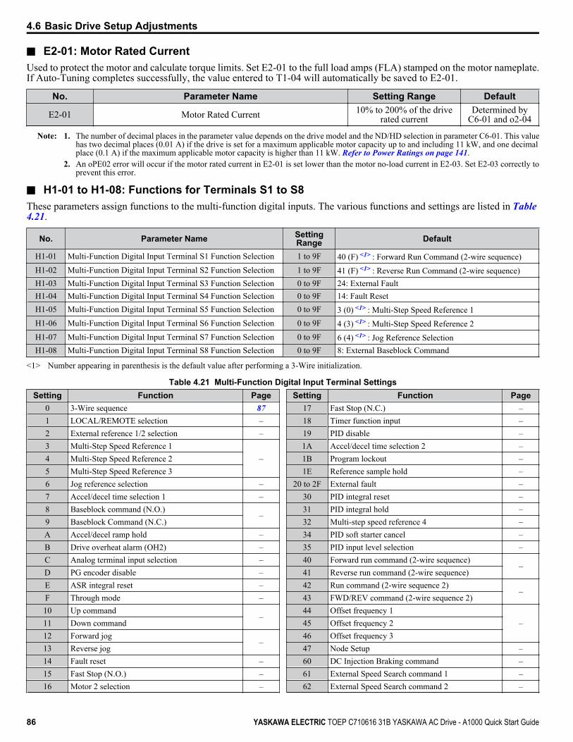
n E2-01: Motor Rated CurrentUsed to protect the motor and calculate torque limits. Set E2-01 to the full load amps (FLA) stamped on the motor nameplate.If Auto-Tuning completes successfully, the value entered to T1-04 will automatically be saved to E2-01.
No. Parameter Name Setting Range Default
E2-01 Motor Rated Current 10% to 200% of the driverated current
Determined byC6-01 and o2-04
Note: 1. The number of decimal places in the parameter value depends on the drive model and the ND/HD selection in parameter C6-01. This valuehas two decimal places (0.01 A) if the drive is set for a maximum applicable motor capacity up to and including 11 kW, and one decimalplace (0.1 A) if the maximum applicable motor capacity is higher than 11 kW. Refer to Power Ratings on page 141.
2. An oPE02 error will occur if the motor rated current in E2-01 is set lower than the motor no-load current in E2-03. Set E2-03 correctly toprevent this error.
n H1-01 to H1-08: Functions for Terminals S1 to S8These parameters assign functions to the multi-function digital inputs. The various functions and settings are listed in Table 4.21.
No. Parameter Name SettingRange Default
H1-01 Multi-Function Digital Input Terminal S1 Function Selection 1 to 9F 40 (F) <1> : Forward Run Command (2-wire sequence)H1-02 Multi-Function Digital Input Terminal S2 Function Selection 1 to 9F 41 (F) <1> : Reverse Run Command (2-wire sequence)H1-03 Multi-Function Digital Input Terminal S3 Function Selection 0 to 9F 24: External FaultH1-04 Multi-Function Digital Input Terminal S4 Function Selection 0 to 9F 14: Fault ResetH1-05 Multi-Function Digital Input Terminal S5 Function Selection 0 to 9F 3 (0) <1> : Multi-Step Speed Reference 1H1-06 Multi-Function Digital Input Terminal S6 Function Selection 0 to 9F 4 (3) <1> : Multi-Step Speed Reference 2H1-07 Multi-Function Digital Input Terminal S7 Function Selection 0 to 9F 6 (4) <1> : Jog Reference SelectionH1-08 Multi-Function Digital Input Terminal S8 Function Selection 0 to 9F 8: External Baseblock Command
<1> Number appearing in parenthesis is the default value after performing a 3-Wire initialization.
Table 4.21 Multi-Function Digital Input Terminal SettingsSetting Function Page
0 3-Wire sequence 871 LOCAL/REMOTE selection –2 External reference 1/2 selection –3 Multi-Step Speed Reference 1
–4 Multi-Step Speed Reference 25 Multi-Step Speed Reference 36 Jog reference selection –7 Accel/decel time selection 1 –8 Baseblock command (N.O.)
–9 Baseblock Command (N.C.)A Accel/decel ramp hold –B Drive overheat alarm (OH2) –C Analog terminal input selection –D PG encoder disable –E ASR integral reset –F Through mode –10 Up command
–11 Down command12 Forward jog
–13 Reverse jog14 Fault reset –15 Fast Stop (N.O.) –16 Motor 2 selection –
Setting Function Page17 Fast Stop (N.C.) –18 Timer function input –19 PID disable –1A Accel/decel time selection 2 –1B Program lockout –1E Reference sample hold –
20 to 2F External fault –30 PID integral reset –31 PID integral hold –32 Multi-step speed reference 4 –34 PID soft starter cancel –35 PID input level selection –40 Forward run command (2-wire sequence)
–41 Reverse run command (2-wire sequence)42 Run command (2-wire sequence 2)
–43 FWD/REV command (2-wire sequence 2)44 Offset frequency 1
–45 Offset frequency 246 Offset frequency 347 Node Setup –60 DC Injection Braking command –61 External Speed Search command 1 –62 External Speed Search command 2 –
4.6 Basic Drive Setup Adjustments
86 YASKAWA ELECTRIC TOEP C710616 31B YASKAWA AC Drive - A1000 Quick Start Guide
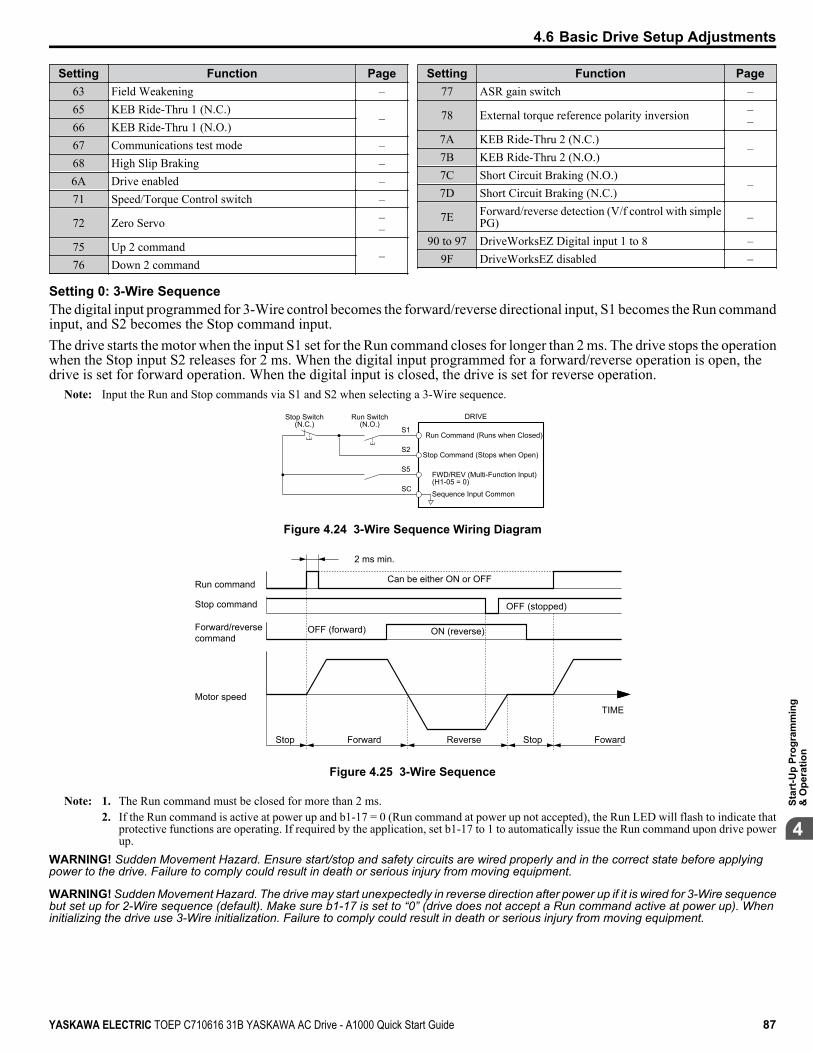
Setting Function Page63 Field Weakening –65 KEB Ride-Thru 1 (N.C.)
–66 KEB Ride-Thru 1 (N.O.)67 Communications test mode –68 High Slip Braking –6A Drive enabled –71 Speed/Torque Control switch –
72 Zero Servo ––
75 Up 2 command–
76 Down 2 command
Setting Function Page77 ASR gain switch –
78 External torque reference polarity inversion ––
7A KEB Ride-Thru 2 (N.C.)–
7B KEB Ride-Thru 2 (N.O.)7C Short Circuit Braking (N.O.)
–7D Short Circuit Braking (N.C.)
7E Forward/reverse detection (V/f control with simplePG) –
90 to 97 DriveWorksEZ Digital input 1 to 8 –9F DriveWorksEZ disabled –
Setting 0: 3-Wire SequenceThe digital input programmed for 3-Wire control becomes the forward/reverse directional input, S1 becomes the Run commandinput, and S2 becomes the Stop command input.The drive starts the motor when the input S1 set for the Run command closes for longer than 2 ms. The drive stops the operationwhen the Stop input S2 releases for 2 ms. When the digital input programmed for a forward/reverse operation is open, thedrive is set for forward operation. When the digital input is closed, the drive is set for reverse operation.
Note: Input the Run and Stop commands via S1 and S2 when selecting a 3-Wire sequence.
S1
S2
S5
SC
Run Command (Runs when Closed)
DRIVEStop Switch(N.C.)
Run Switch(N.O.)
Stop Command (Stops when Open)
FWD/REV (Multi-Function Input)(H1-05 = 0)
Sequence Input Common
Figure 4.24 3-Wire Sequence Wiring Diagram
2 ms min.
Run command
OFF (stopped)
Can be either ON or OFF
OFF (forward)
Motor speed
Forward/reversecommand
Stop command
Stop Reverse Stop Foward
TIME
Forward
ON (reverse)
Figure 4.25 3-Wire Sequence
Note: 1. The Run command must be closed for more than 2 ms.2. If the Run command is active at power up and b1-17 = 0 (Run command at power up not accepted), the Run LED will flash to indicate that
protective functions are operating. If required by the application, set b1-17 to 1 to automatically issue the Run command upon drive powerup.
WARNING! Sudden Movement Hazard. Ensure start/stop and safety circuits are wired properly and in the correct state before applyingpower to the drive. Failure to comply could result in death or serious injury from moving equipment.
WARNING! Sudden Movement Hazard. The drive may start unexpectedly in reverse direction after power up if it is wired for 3-Wire sequencebut set up for 2-Wire sequence (default). Make sure b1-17 is set to “0” (drive does not accept a Run command active at power up). Wheninitializing the drive use 3-Wire initialization. Failure to comply could result in death or serious injury from moving equipment.
4.6 Basic Drive Setup Adjustments
YASKAWA ELECTRIC TOEP C710616 31B YASKAWA AC Drive - A1000 Quick Start Guide 87
4
Star
t-Up
Prog
ram
min
g&
Ope
ratio
n
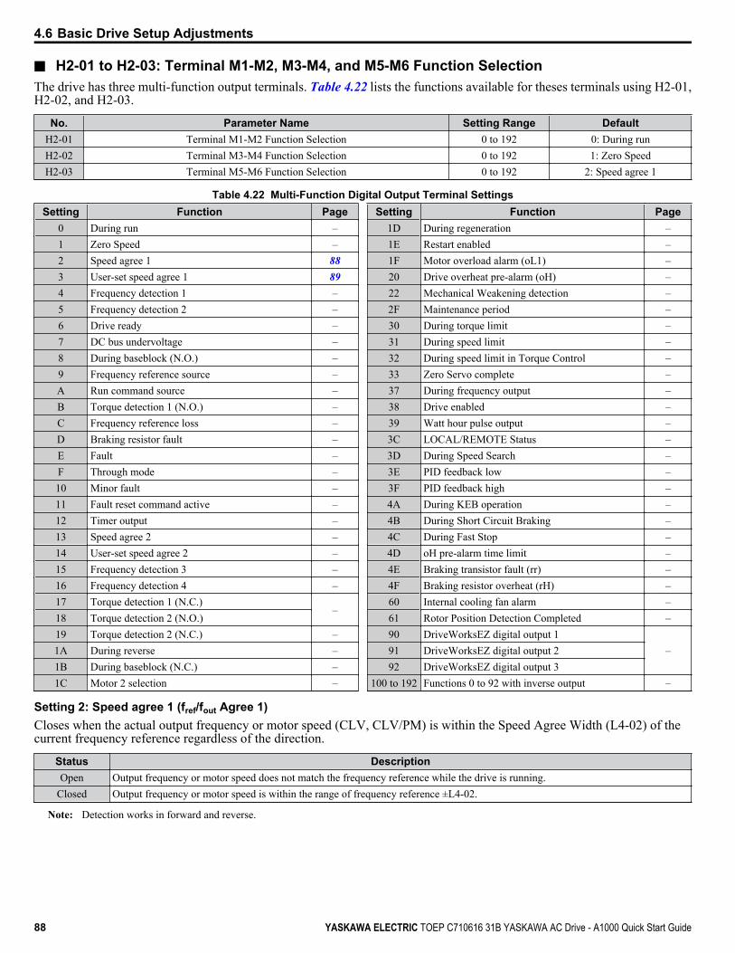
n H2-01 to H2-03: Terminal M1-M2, M3-M4, and M5-M6 Function SelectionThe drive has three multi-function output terminals. Table 4.22 lists the functions available for theses terminals using H2-01,H2-02, and H2-03.
No. Parameter Name Setting Range DefaultH2-01 Terminal M1-M2 Function Selection 0 to 192 0: During runH2-02 Terminal M3-M4 Function Selection 0 to 192 1: Zero SpeedH2-03 Terminal M5-M6 Function Selection 0 to 192 2: Speed agree 1
Table 4.22 Multi-Function Digital Output Terminal SettingsSetting Function Page
0 During run –1 Zero Speed –2 Speed agree 1 883 User-set speed agree 1 894 Frequency detection 1 –5 Frequency detection 2 –6 Drive ready –7 DC bus undervoltage –8 During baseblock (N.O.) –9 Frequency reference source –A Run command source –B Torque detection 1 (N.O.) –C Frequency reference loss –D Braking resistor fault –E Fault –F Through mode –10 Minor fault –11 Fault reset command active –12 Timer output –13 Speed agree 2 –14 User-set speed agree 2 –15 Frequency detection 3 –16 Frequency detection 4 –17 Torque detection 1 (N.C.)
–18 Torque detection 2 (N.O.)19 Torque detection 2 (N.C.) –1A During reverse –1B During baseblock (N.C.) –1C Motor 2 selection –
Setting Function Page1D During regeneration –1E Restart enabled –1F Motor overload alarm (oL1) –20 Drive overheat pre-alarm (oH) –22 Mechanical Weakening detection –2F Maintenance period –30 During torque limit –31 During speed limit –32 During speed limit in Torque Control –33 Zero Servo complete –37 During frequency output –38 Drive enabled –39 Watt hour pulse output –3C LOCAL/REMOTE Status –3D During Speed Search –3E PID feedback low –3F PID feedback high –4A During KEB operation –4B During Short Circuit Braking –4C During Fast Stop –4D oH pre-alarm time limit –4E Braking transistor fault (rr) –4F Braking resistor overheat (rH) –60 Internal cooling fan alarm –61 Rotor Position Detection Completed –90 DriveWorksEZ digital output 1
–91 DriveWorksEZ digital output 292 DriveWorksEZ digital output 3
100 to 192 Functions 0 to 92 with inverse output –
Setting 2: Speed agree 1 (fref/fout Agree 1)Closes when the actual output frequency or motor speed (CLV, CLV/PM) is within the Speed Agree Width (L4-02) of thecurrent frequency reference regardless of the direction.
Status DescriptionOpen Output frequency or motor speed does not match the frequency reference while the drive is running.
Closed Output frequency or motor speed is within the range of frequency reference ±L4-02.
Note: Detection works in forward and reverse.
4.6 Basic Drive Setup Adjustments
88 YASKAWA ELECTRIC TOEP C710616 31B YASKAWA AC Drive - A1000 Quick Start Guide
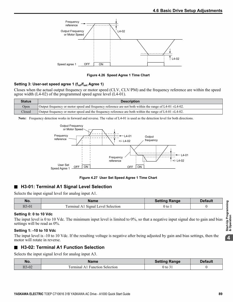
L4-02
L4-02
Frequency reference
Speed agree 1 ONOFF
Output Frequency or Motor Speed
Figure 4.26 Speed Agree 1 Time Chart
Setting 3: User-set speed agree 1 (fref/fset Agree 1)Closes when the actual output frequency or motor speed (CLV, CLV/PM) and the frequency reference are within the speedagree width (L4-02) of the programmed speed agree level (L4-01).
Status DescriptionOpen Output frequency or motor speed and frequency reference are not both within the range of L4-01 ±L4-02.
Closed Output frequency or motor speed and the frequency reference are both within the range of L4-01 ±L4-02.
Note: Frequency detection works in forward and reverse. The value of L4-01 is used as the detection level for both directions.
User Set Speed Agree 1 OFF ON
Frequency reference
OFF ON
Frequency reference
Output frequency
L4-01
+/- L4-02
L4-01
+/- L4-02
Output Frequency or Motor Speed
Figure 4.27 User Set Speed Agree 1 Time Chart
n H3-01: Terminal A1 Signal Level SelectionSelects the input signal level for analog input A1.
No. Name Setting Range DefaultH3-01 Terminal A1 Signal Level Selection 0 to 1 0
Setting 0: 0 to 10 VdcThe input level is 0 to 10 Vdc. The minimum input level is limited to 0%, so that a negative input signal due to gain and biassettings will be read as 0%.
Setting 1: -10 to 10 VdcThe input level is -10 to 10 Vdc. If the resulting voltage is negative after being adjusted by gain and bias settings, then themotor will rotate in reverse.
n H3-02: Terminal A1 Function SelectionSelects the input signal level for analog input A3.
No. Name Setting Range DefaultH3-02 Terminal A1 Function Selection 0 to 31 0
4.6 Basic Drive Setup Adjustments
YASKAWA ELECTRIC TOEP C710616 31B YASKAWA AC Drive - A1000 Quick Start Guide 89
4
Star
t-Up
Prog
ram
min
g&
Ope
ratio
n
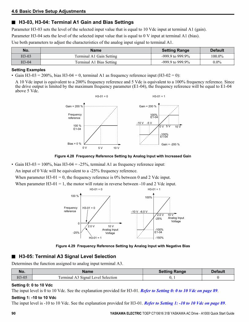
n H3-03, H3-04: Terminal A1 Gain and Bias SettingsParameter H3-03 sets the level of the selected input value that is equal to 10 Vdc input at terminal A1 (gain).Parameter H3-04 sets the level of the selected input value that is equal to 0 V input at terminal A1 (bias).Use both parameters to adjust the characteristics of the analog input signal to terminal A1.
No. Name Setting Range DefaultH3-03 Terminal A1 Gain Setting -999.9 to 999.9% 100.0%H3-04 Terminal A1 Bias Setting -999.9 to 999.9% 0.0%
Setting Examples• Gain H3-03 = 200%, bias H3-04 = 0, terminal A1 as frequency reference input (H3-02 = 0):
A 10 Vdc input is equivalent to a 200% frequency reference and 5 Vdc is equivalent to a 100% frequency reference. Sincethe drive output is limited by the maximum frequency parameter (E1-04), the frequency reference will be equal to E1-04above 5 Vdc.
100%
-100%
5 V 10 V-5 V-10 V
E1-04
E1-04
H3-01 = 0 H3-01 = 1
0 V
10 V5 V0 V
Gain = 200 % Gain = 200 %
100 %
Frequency reference
Bias = 0 %
E1-04
Gain = -200 %
Figure 4.28 Frequency Reference Setting by Analog Input with Increased Gain
• Gain H3-03 = 100%, bias H3-04 = -25%, terminal A1 as frequency reference input:An input of 0 Vdc will be equivalent to a -25% frequency reference.When parameter H3-01 = 0, the frequency reference is 0% between 0 and 2 Vdc input.When parameter H3-01 = 1, the motor will rotate in reverse between -10 and 2 Vdc input.
2.0 V 10 V-6.0 V-10 V
E1-04
0
-100%
-150%
2.0 V 10 V
100 %
Frequency reference
-25%
-25%
H3-01 = 0
H3-01 = 1
H3-01 = 0 H3-01 = 1
100%
Analog Input Voltage
Analog Input Voltage
Figure 4.29 Frequency Reference Setting by Analog Input with Negative Bias
n H3-05: Terminal A3 Signal Level SelectionDetermines the function assigned to analog input terminal A3.
No. Name Setting Range DefaultH3-05 Terminal A3 Signal Level Selection 0, 1 0
Setting 0: 0 to 10 VdcThe input level is 0 to 10 Vdc. See the explanation provided for H3-01. Refer to Setting 0: 0 to 10 Vdc on page 89.Setting 1: -10 to 10 VdcThe input level is -10 to 10 Vdc. See the explanation provided for H3-01. Refer to Setting 1: -10 to 10 Vdc on page 89.
4.6 Basic Drive Setup Adjustments
90 YASKAWA ELECTRIC TOEP C710616 31B YASKAWA AC Drive - A1000 Quick Start Guide

n H3-06: Terminal A3 Function SelectionDetermines the function assigned to analog input terminal A3.
No. Name Setting Range DefaultH3-06 Terminal A3 Function Selection 0 to 31 2
n H3-07, H3-08: Terminal A3 Gain and Bias SettingParameter H3-07 sets the level of the selected input value that is equal to 10 Vdc input at terminal A3 (gain).Parameter H3-08 sets the level of the selected input value that is equal to 0 V input at terminal A3 (bias).
No. Name Setting Range DefaultH3-07 Terminal A3 Gain Setting -999.9 to 999.9% 100.0%H3-08 Terminal A3 Bias Setting -999.9 to 999.9% 0.0%
n H3-09: Terminal A2 Signal Level SelectionSelects the input signal level for analog input A2. Set DIP switch S1 on the terminal board accordingly for a voltage input orcurrent input.
No. Name Setting Range DefaultH3-09 Terminal A2 Signal Level Selection 0 to 3 2
Setting 0: 0 to 10 VdcThe input level is 0 to 10 Vdc. Refer to Setting 0: 0 to 10 Vdc on page 89.
Setting 1: -10 to 10 VdcThe input level is -10 to 10 Vdc. Refer to Setting 1: -10 to 10 Vdc on page 89.
Setting 2: 4 to 20 mA Current InputThe input level is 4 to 20 mA. Negative input values by negative bias or gain settings will be limited to 0%.
Setting 3: 0 to 20 mA Current InputThe input level is 0 to 20 mA. Negative input values by negative bias or gain settings will be limited to 0%.
n H3-10: Terminal A2 Function SelectionDetermines the function assigned to analog input terminal A2.
No. Name Setting Range DefaultH3-10 Terminal A2 Function Selection 0 to 31 0
n H3-11, H3-12: Terminal A2 Gain and Bias SettingParameter H3-11 sets the level of the input value selected that is equal to 10 Vdc input or 20 mA input to terminal A2.Parameter H3-12 sets the level of the input value selected that is equal to 0 V, 4 mA or 0 mA input at terminal A2.Use both parameters to adjust the characteristics of the analog input signal to terminal A2. The setting works in the same wayas parameters H3-03 and H3-04 for analog input A1.
No. Name Setting Range DefaultH3-11 Terminal A2 Gain Setting -999.9 to 999.9% 100.0%H3-12 Terminal A2 Bias Setting -999.9 to 999.9% 0.0%
n H4-01, H4-04: Multi-Function Analog Output Terminal FM, AM Monitor SelectionSets the desired drive monitor parameter Uo-oo to output as an analog value via terminal FM and AM. Refer to U1: Operation Status Monitors on page 199 for a list of all monitors. The “Analog Output Level” column indicates whether amonitor can be used for analog output.Example: Enter “103” for U1-03.
4.6 Basic Drive Setup Adjustments
YASKAWA ELECTRIC TOEP C710616 31B YASKAWA AC Drive - A1000 Quick Start Guide 91
4
Star
t-Up
Prog
ram
min
g&
Ope
ratio
n

No. Name Setting Range DefaultH4-01 Multi-Function Analog Output Terminal FM Monitor Selection 000 to 999 102H4-04 Multi-Function Analog Output Terminal AM Monitor Selection 000 to 999 103
A setting of 031 or 000 applies no drive monitor to the analog output. With this setting, terminal functions as well as FM andAM output levels can be set by a PLC via a communication option or MEMOBUS/Modbus (through mode).
n H4-02, H4-03: Multi-Function Analog Output Terminal FM Gain and BiasH4-05, H4-06: Multi-Function Analog Output Terminal AM Gain and Bias
Parameters H4-02 and H4-05 set the terminal FM and AM output signal level when the value of the selected monitor is at100%. Parameters H4-03 and H4-06 set the terminal FM and AM output signal level when the value of the selected monitoris at 0%. Both are set as a percentage, where 100% equals 10 Vdc or 20 mA analog output and 0% equals 0 V or 4 mA. Theoutput voltage of both terminals is limited to +/-10 Vdc.The output signal range can be selected between 0 to +10 Vdc or -10 to +10 Vdc, or 4 to 20 mA using parameter H4-07 andH4-08. Figure 4.30 illustrates how gain and bias settings work.
No. Name Setting Range DefaultH4-02 Multi-Function Analog Output Terminal FM Gain -999.9 to 999.9% 100.0%H4-03 Multi-Function Analog Output Terminal FM Bias -999.9 to 999.9% 0.0%H4-05 Multi-Function Analog Output Terminal AM Gain -999.9 to 999.9% 50.0%H4-06 Multi-Function Analog Output Terminal AM Bias -999.9 to 999.9% 0.0%
Using Gain and Bias to Adjust Output Signal LevelWhen viewing a gain setting parameter (H4-02 or H4-05) on the digital operator, the analog output will supply a voltage signalequal to 100% of the monitor value (including changes made from bias and gain settings). When viewing a bias settingparameter (H4-03 or H4-06), the analog output voltage will supply a signal equal to 0% monitor value.Example 1: Set H4-02 to 50% for an output signal of 5 V at terminal FM when the monitored value is at 100%.Example 2: Set H4-02 to 150% for an output signal of 10 V at terminal FM when the monitored value is at 76.7%.
Output Voltage
Output Voltage
0 V
5 V
10 VGain 150% Bias 0%
Gain = 150% Bias = 0%
Gain = 100% Bias = 0%Gain = 50% Bias = 0%
Gain 100% Bias 0%
Gain 50% Bias 0%
100%Monitor Value
Monitor Value
0%
H4-07, 08 = 0 H4-07, 08 = 1
10 V
-10 V
100%
5 V
15 V
-5 V
-15 V
-100%
Figure 4.30 Analog Output Gain and Bias Setting Example 1 and 2
Example 3: Set H4-03 to 30% for an output signal of 3 V at terminal FM when the monitored value is at 0%.
4.6 Basic Drive Setup Adjustments
92 YASKAWA ELECTRIC TOEP C710616 31B YASKAWA AC Drive - A1000 Quick Start Guide

Gain = 100% Bias = 30%
Gain = 100% Bias = 0%
Gain 100% Bias 30%
Gain 100% Bias 0%
Monitor Value
Monitor Value
0 V
3 V
10 V
100%0%
Output Voltage
Output Voltage
H4-07, 08 = 0 H4-07, 08 = 1
10V
-10 V
100%
3 V
-4 V
-100%
Figure 4.31 Analog Output Gain and Bias Setting Example 3
n H4-07, H4-08: Multi-Function Analog Output Terminal FM, AM Signal Level SelectionSets the voltage output level of U parameter (monitor parameter) data to terminal FM and terminal AM using parametersH4-07 and H4-08.Set jumper S5 on the terminal board accordingly when changing these parameters. Refer to Terminal AM/FM Signal Selection on page 51 for details on setting S5.
No. Name Setting Range Default
H4-07 Multi-Function Analog Output Terminal FMSignal Level Selection 0 to 2 0
H4-08 Multi-Function Analog Output Terminal AMSignal Level Selection 0 to 2 0
Setting 0: 0 to 10 VSetting 1: -10 V to 10 VSetting 2: 4 to 20 mAn L3-01: Stall Prevention Selection during AccelerationStall Prevention during acceleration prevents tripping with overcurrent (oC), motor overload (oL1), or drive overload (oL2)faults common when accelerating with heavy loads.
No. Name Setting Range DefaultL3-01 Stall Prevention Selection during Acceleration 0 to 2 <1> 1
<1> Setting 2 is not available for PM OLV.
Setting 0: DisabledNo Stall Prevention is provided. If the acceleration time is too short, the drive may not be able to get the motor up to speedfast enough, causing an overload fault.
Setting 1: EnabledEnables Stall Prevention during acceleration. Operation varies depending on the control mode.• V/f Control, V/f Control with PG, and Open Loop Vector Control:
Acceleration is reduced when the output current value exceeds 85% of the level set to parameter L3-02 for a longer than thetime set to L3-27. The acceleration stops when the current exceeds L3-02. Acceleration continues when the current fallsbelow L3-02 for longer than the time set to L3-27.The Stall Prevention level is automatically reduced in the constant power range. Refer to L3-03: Stall Prevention Limit during Acceleration on page 95.
4.6 Basic Drive Setup Adjustments
YASKAWA ELECTRIC TOEP C710616 31B YASKAWA AC Drive - A1000 Quick Start Guide 93
4
Star
t-Up
Prog
ram
min
g&
Ope
ratio
n

Stall Prevention Level During AccelerationL3-02
L3-02 -15%
Output current
Output frequencyTime
Time
Controls the output frequency to prevent the motor from stalling
L3-27 L3-27
Figure 4.32 Stall Prevention during Acceleration for Induction Motors
• Open Loop Vector Control for PM:Note: PM motor control modes are not available on 600 V class drives, CIMR-Ao5oooooooo.
If the output current remains above the Stall Prevention Level set to L3-02 for the time set to L3-27, the drive will begin todecelerate for the deceleration time set to L3-22. Acceleration resumes when the output current falls 15% below the L3-02setting.
Output current
L3-02
Output frequency
Time
Time
Deceleration using L3-22
L3-27L3-27
15 % of L3-02
Figure 4.33 Stall Prevention during Acceleration for Permanent Magnet Motors
Setting 2: Intelligent Stall PreventionThe drive disregards the selected acceleration time and attempts to accelerate in the minimum time. The acceleration rate isadjusted so the current does not exceed the value set to parameter L3-02.
n L3-02: Stall Prevention Level during AccelerationSets the output current level at which the Stall Prevention during acceleration is activated.
No. Name Setting Range DefaultL3-02 Stall Prevention Level during Acceleration 0 to 150% <1> <1>
<1> The upper limit and default value is determined by the duty rating and the carrier frequency derating selection (C6-01 and L8-38 respectively).
• Lower L3-02 if stalling occurs when using a motor that is relatively small compared to the drive.• Also set parameter L3-03 when operating the motor in the constant power range.
4.6 Basic Drive Setup Adjustments
94 YASKAWA ELECTRIC TOEP C710616 31B YASKAWA AC Drive - A1000 Quick Start Guide
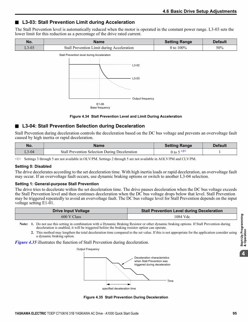
n L3-03: Stall Prevention Limit during AccelerationThe Stall Prevention level is automatically reduced when the motor is operated in the constant power range. L3-03 sets thelower limit for this reduction as a percentage of the drive rated current.
No. Name Setting Range DefaultL3-03 Stall Prevention Limit during Acceleration 0 to 100% 50%
Stall Prevention level during Acceleration
Output frequency
L3-03
E1-06Base frequency
L3-02
Figure 4.34 Stall Prevention Level and Limit During Acceleration
n L3-04: Stall Prevention Selection during DecelerationStall Prevention during deceleration controls the deceleration based on the DC bus voltage and prevents an overvoltage faultcaused by high inertia or rapid deceleration.
No. Name Setting Range DefaultL3-04 Stall Prevention Selection During Deceleration 0 to 5 <1> 1
<1> Settings 3 through 5 are not available in OLV/PM. Settings 2 through 5 are not available in AOLV/PM and CLV/PM.
Setting 0: DisabledThe drive decelerates according to the set deceleration time. With high inertia loads or rapid deceleration, an overvoltage faultmay occur. If an overvoltage fault occurs, use dynamic braking options or switch to another L3-04 selection.
Setting 1: General-purpose Stall PreventionThe drive tries to decelerate within the set deceleration time. The drive pauses deceleration when the DC bus voltage exceedsthe Stall Prevention level and then continues deceleration when the DC bus voltage drops below that level. Stall Preventionmay be triggered repeatedly to avoid an overvoltage fault. The DC bus voltage level for Stall Prevention depends on the inputvoltage setting E1-01.
Drive Input Voltage Stall Prevention Level during Deceleration600 V Class 1084 Vdc
Note: 1. Do not use this setting in combination with a Dynamic Braking Resistor or other dynamic braking options. If Stall Prevention duringdeceleration is enabled, it will be triggered before the braking resistor option can operate.
2. This method may lengthen the total deceleration time compared to the set value. If this is not appropriate for the application consider usinga dynamic braking option.
Figure 4.35 illustrates the function of Stall Prevention during deceleration.Output Frequency
Deceleration characteristics when Stall Prevention wastriggered during deceleration
Time
specified deceleration time
Figure 4.35 Stall Prevention During Deceleration
4.6 Basic Drive Setup Adjustments
YASKAWA ELECTRIC TOEP C710616 31B YASKAWA AC Drive - A1000 Quick Start Guide 95
4
Star
t-Up
Prog
ram
min
g&
Ope
ratio
n

Setting 2: Intelligent Stall PreventionThe drive adjusts the deceleration rate so the DC bus voltage is kept at the level set to parameter L3-17. This produces theshortest possible deceleration time while protecting the motor from stalling. The selected deceleration time is disregarded andthe achievable deceleration time cannot be smaller than 1/10 of the set deceleration time.This function uses the following parameters for adjusting the deceleration rate:• DC bus voltage gain (L3-20)• Deceleration rate calculations gain (L3-21)• Inertia calculations for motor acceleration time (L3-24)• Load inertia ratio (L3-25)
Note: The deceleration time is not constant. Do not use Intelligent Stall Prevention in applications where stopping accuracy is a concern. Use dynamicbraking options instead.
Setting 3: Stall Prevention with dynamic braking optionEnables the Stall Prevention function while using a dynamic braking resistor. Overvoltage problems in the DC bus can occurif Stall Prevention during deceleration is disabled (L3-04) in OLV and a dynamic braking option is installed. Set L3-04 to 3to remedy this situation.
Setting 4: Overexcitation Deceleration 1Overexcitation Deceleration 1 (increasing the motor flux) is faster than deceleration with no Stall Prevention (L3-04 = 0).
Setting 5: Overexcitation Deceleration 2Overexcitation Deceleration 2 slows down the motor while trying to maintain the DC bus voltage at the level set to parameterL3-17. By doing this, the achievable deceleration time can even be shorter than with Overexcitation Deceleration 1.
n L3-05: Stall Prevention Selection during RunDetermines how Stall Prevention works during Run. Stall Prevention during run prevents the motor from stalling byautomatically reducing the speed when a transient overload occurs while the motor is running at constant speed.
No. Name Setting Range DefaultL3-05 Stall Prevention Selection During Run 0 to 2 1
Note: 1. This function is available in V/f, V/f w/PG, and OLV/PM.2. Stall Prevention during run is disabled when the output frequency is 6 Hz or lower regardless of the L3-05 and L3-06 settings.
Setting 0: DisabledDrive runs at the set frequency reference. A heavy load may cause the motor to stall and trip the drive with an oC or oL fault.
Setting 1: Decelerate using C1-02If the current exceeds the Stall Prevention level set in parameter L3-06, the drive will decelerate at decel time 1 (C1-02). Whenthe current level drops below the value of L3-06 minus 2% for 100 ms, the drive accelerates back to the frequency referenceat the active acceleration time.
Setting 2: Decelerate using C1-04Same as setting 1 except the drive decelerates at decel time 2 (C1-04).
n L3-06: Stall Prevention Level during RunSets the current level to trigger Stall Prevention during run. Depending on the setting of parameter L3-23, the level isautomatically reduced in the constant power range (speed beyond base speed).The Stall Prevention level can be adjusted using an analog input.
No. Name Setting Range DefaultL3-06 Stall Prevention Level During Run 30 to 150 <1> <1>
<1> The upper limit and default for this setting is determined by C6-01 and L8-38.
4.6 Basic Drive Setup Adjustments
96 YASKAWA ELECTRIC TOEP C710616 31B YASKAWA AC Drive - A1000 Quick Start Guide

n L7-01 to L7-04: Torque LimitsThese parameters set the torque limits in each operation mode.
No. Name Setting Range DefaultL7-01 Forward Torque Limit 0 to 300% 200%L7-02 Reverse Torque Limit 0 to 300% 200%L7-03 Forward Regenerative Torque Limit 0 to 300% 200%L7-04 Reverse Regenerative Torque Limit 0 to 300% 200%
Note: If the multi-function analog input is programmed for “10: Forward torque limit”, “11: Reverse torque limit”, “12: Regenerative torque limit”,or “15: General torque limit”, the drive uses the lowest value from L7-01 through L7-04, or analog input torque limit.
positive torque reference
negative torque reference
10: Positive Torque Limit 12: Regenerative Torque Limit 15: Torque Limit Parameter L7-04
REV motor rotation
11: Negative Torque Limit15: Torque Limit Parameter L7-03
10: Positive Torque Limit15: Torque Limit Parameter L7-01
FWD motor rotation
11: Negative Torque Limit 12: Regenerative Torque Limit 15: Torque Limit Parameter L7-02
quadrant 2
quadrant 3
quadrant 1
quadrant 4
REV run regenerative
REV run motoring
FWD run motoring
FWD run regenerative
Figure 4.36 Torque Limit Parameters and Analog Input Settings
4.6 Basic Drive Setup Adjustments
YASKAWA ELECTRIC TOEP C710616 31B YASKAWA AC Drive - A1000 Quick Start Guide 97
4
Star
t-Up
Prog
ram
min
g&
Ope
ratio
n
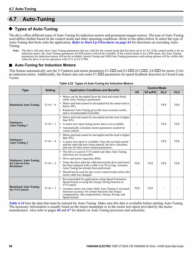
4.7 Auto-Tuning
u Types of Auto-TuningThe drive offers different types of Auto-Tuning for induction motors and permanent magnet motors. The type of Auto-Tuningused differs further based on the control mode and other operating conditions. Refer to the tables below to select the type ofAuto-Tuning that bests suits the application. Refer to Start-Up Flowcharts on page 64 for directions on executing Auto-Tuning.
Note: The drive will only show Auto-Tuning parameters that are valid for the control mode that has been set in A1-02. If the control mode is for aninduction motor, the Auto-Tuning parameters for PM motors will not be available. If the control mode is for a PM motor, the Auto-Tuningparameters for induction motors will not be available. Inertia Tuning and ASR Gain Tuning parameters and setting options will be visible onlywhen the drive is set for operation with CLV or CLV/PM.
n Auto-Tuning for Induction MotorsThis feature automatically sets the V/f pattern and motor parameters E1-oo and E2-oo (E3-oo, E4-oo for motor 2) foran induction motor. Additionally, the feature also sets some F1-oo parameters for speed feedback detection in Closed LoopVector.
Table 4.23 Types of Auto-Tuning for Induction Motors
Type Setting Application Conditions and BenefitsControl Mode
V/f V/f w/PG OLV CLV
Rotational Auto-Tuning T1-01 = 0
• Motor can be decoupled from the load and rotate freelywhile Auto-Tuning is performed.
• Motor and load cannot be decoupled but the motor load isbelow 30%.
• Rotational Auto-Tuning gives the most accurate results,and is recommended if possible.
– – YES YES
StationaryAuto-Tuning 1 T1-01 = 1
• Motor and load cannot be decoupled and the load is higherthan 30%.
• A motor test report listing motor data is not available.• Automatically calculates motor parameters needed for
vector control.
– – YES YES
StationaryAuto-Tuning 2 T1-01 = 4
• Motor and load cannot be decoupled and the load is higherthan 30%.
• A motor test report is available. Once the no-load currentand the rated slip have been entered, the drive calculatesand sets all other motor-related parameters.
– – YES YES
Stationary Auto-Tuningfor Line-to-LineResistance
T1-01 = 2
• The drive is used in V/f Control and other Auto-Tuningselections are not possible.
• Drive and motor capacities differ.• Tunes the drive after the cable between the drive and motor
has been replaced with a cable over 50 m long. AssumesAuto-Tuning has already been performed.
• Should not be used for any vector control modes unless themotor cable has changed.
YES YES YES YES
Rotational Auto-Tuningfor V/f Control T1-01 = 3
• Recommended for applications using Speed EstimationSpeed Search or using the Energy Saving function inV/f Control.
• Assumes motor can rotate while Auto-Tuning is executed.Increases accuracy for certain functions like torquecompensation, slip compensation, Energy Saving, andSpeed Search.
YES YES – –
Table 4.24 lists the data that must be entered for Auto-Tuning. Make sure this data is available before starting Auto-Tuning.The necessary information is usually listed on the motor nameplate or in the motor test report provided by the motormanufacturer. Also refer to pages 66 and 67 for details on Auto-Tuning processes and selections.
4.7 Auto-Tuning
98 YASKAWA ELECTRIC TOEP C710616 31B YASKAWA AC Drive - A1000 Quick Start Guide

Table 4.24 Auto-Tuning Input Data
Input Value InputParameter Unit
Tuning Type (T1-01)
0Standard
1Stationary 1
2Line-to-LineResistance
3Rotational for
V/f Control4
Stationary 2
Motor rated power T1-02 kW YES YES YES YES YESMotor rated voltage T1-03 Vac YES YES – YES YESMotor rated current T1-04 A YES YES YES YES YES
Motor rated frequency T1-05 Hz YES YES – YES YESNumber of motor poles T1-06 - YES YES – YES YES
Motor rated Speed T1-07 r/min YES YES – YES YESPG Number of pulses per
revolution T1-08 - YES <1> YES <1> – – YES <1>
Motor no-load current T1-09 A – YES – – YESMotor rated Slip T1-10 Hz – – – – YESMotor iron loss T1-11 W – – – YES –
<1> Input data is needed for CLV/PM only.
n Auto-Tuning for Permanent Magnet MotorsNote: PM motor control modes are not available on 600 V class drives, CIMR-Ao5oooooooo.
Automatically sets the V/f pattern and motor parameters E1-oo and E5-oo when a PM motor is used. Additionally, thefeature also sets some F1-oo parameters for speed feedback detection in Closed Loop Vector.
Table 4.25 Types of Auto-Tuning for Permanent Magnet Motors
Type Setting Application Conditions and BenefitsControl Mode
OLV/PM AOLV/PM CLV/PM
PM Motor ParameterSettings T2-01 = 0
• Motor does not rotate during Auto-Tuning.• Motor test report or motor data similar to Table 4.26 are
available.YES YES YES
PM Stationary Auto-Tuning T2-01 = 1
• A motor test report listing motor data is not available.• Drive automatically calculates and sets motor parameters.
YES YES YES
PM Stationary Auto-Tuning for StatorResistance
T2-01 = 2
• Useful to tune the drive when the motor data were set upmanually or by motor code and the cable is longer than 50m.
• Should also be performed if the cable length has changedafter prior tuning.
YES YES YES
Z Pulse Offset Tuning T2-01 = 3• PG encoder has been replaced. Calculates the Z Pulse offset.• Requires the motor to rotate with no load or very low load.
– – YES
Table 4.26 lists the data that must be entered for Auto-Tuning. Make sure the data is available before starting Auto-Tuning.The necessary information is usually listed on the motor nameplate or in the motor test report provided by the motormanufacturer. Also refer to page 68 for details on the Auto-Tuning process and selection.
Table 4.26 Auto-Tuning Input Data
Input Value InputParameter Unit
Tuning Type (T2-01)
0Parameter Calculation
1Stationary
2Phase
Resistance
3Z-PulseOffset
Control Mode A1-02 – 5, 6, 7 5 6, 7 5 6, 7 5, 6, 7 7Motor Code (Hex.) T2-02 – <1> <1> <1> <2> <2> <2> <2>
Motor Type T2-03 – – – – YES YES – –Motor rated power T2-04 kW – YES YES YES YES – –Motor rated voltage T2-05 Vac – YES YES YES YES – –Motor rated current T2-06 A – YES YES YES YES YES –
Motor rated frequency T2-07 Hz – YES – YES N/A – –Number of motor poles T2-08 – – YES YES YES YES – –
Motor rated speed T2-09 r/min – – YES – YES – –
4.7 Auto-Tuning
YASKAWA ELECTRIC TOEP C710616 31B YASKAWA AC Drive - A1000 Quick Start Guide 99
4
Star
t-Up
Prog
ram
min
g&
Ope
ratio
n

Input Value InputParameter Unit
Tuning Type (T2-01)
0Parameter Calculation
1Stationary
2Phase
Resistance
3Z-PulseOffset
Control Mode A1-02 – 5, 6, 7 5 6, 7 5 6, 7 5, 6, 7 7Motor Code (Hex.) T2-02 – <1> <1> <1> <2> <2> <2> <2>
Stator single-phaseresistance T2-10 Ω YES YES YES – – – –
d-Axis inductance T2-11 mH YES YES YES – – – –q-Axis inductance T2-12 mH YES YES YES – – – –
Voltage constant <3> T2-13 mVs/rad(el.) YES YES YES – – – –
Voltage constant <3> T2-14 mVmin(mech.) YES YES YES – – – –
Tuning pull-in current T2-15 A – – – YES YES – –PG Number of pulses
per revolution T2-16 – YES <4> – YES <4> N/A YES <4> – –
Z Pulse offset T2-17 deg(mech.) YES <4> – YES <4> N/A YES <4> – –
<1> Input the motor code when using a Yaskawa motor. Select “FFFF” when using a motor from another manufacturer.<2> T2-02 is not available.<3> It is only necessary to input either T2-13 or T2-14. Select one and leave the other empty.<4> Input data is needed for CLV/PM only.
n Inertia Tuning and Speed Control Loop Auto-TuningInertia Tuning can be performed when the drive is using CLV control for either IM or PM motors. Inertia Tuning automaticallycalculates load and motor inertia, and optimizes settings related to the KEB Ride-Thru function (KEB 2) and Feed Forwardcontrol.ASR Gain Auto-Tuning performs the same operation as Inertia Tuning, while also optimizing speed control loop settings.
Table 4.27 Inertia and Speed Control Loop Tuning
TypeSetting
Application Conditions and BenefitsControl Mode
IM Motor PM Motor CLV CLV/PM
Inertia Tuning T1-01 = 8 T2-01 = 8Allows the motor to rotate at a certain speed and applies a test signal.The response to the test signal is analyzed and the necessaryadjustments are made to parameters controlling the Feed Forward andKEB Ride-Thru functions (KEB 2, L2-29 = 1).
YES YES
ASR Gain Auto-Tuning T1-01 = 9 T2-01 = 9 Performs the same operation as Inertia Tuning, while also adjustingthe ASR gain according to the test signal response. YES YES
Table 4.28 explains the data that must be entered to perform the Inertia Tuning and ASR Gain Auto-Tuning. Refer to Auto-Tuning for Permanent Magnet Motors on page 99 for details.
Table 4.28 Auto-Tuning Input Data
Input Value InputParameter Unit
Tuning Type (T1-01 or T2-01)8
Inertia Tuning9
ASR Gain TuningTest signal frequency T3-01 Hz YES YESTest signal amplitude T3-02 rad YES YES
Motor inertia T3-03 kgm2 YES YESSystem response frequency T3-04 Hz – YES
4.7 Auto-Tuning
100 YASKAWA ELECTRIC TOEP C710616 31B YASKAWA AC Drive - A1000 Quick Start Guide

u Auto-Tuning Interruption and Fault CodesIf tuning results are abnormal or the STOP key is pressed before completion, Auto-Tuning will be interrupted and a fault codewill appear on the digital operator.
B
LOREESC
RUN STOP
ENTERRESET
DIGITAL OPERATOR JVOP-180
A
LOREESC
RUN STOP
ENTERRESET
DIGITAL OPERATOR JVOP-180 ALARM ALARM- A.TUNE -
X.XX Hz/ X.XXA
DRVTune Proceeding
Rdy
FWD<<<<<< >>> >>>
- MODE -
Er-03STOP key
DRV
FWD RESET
A – During Auto-Tuning B – Auto-Tuning AbortedFigure 4.37 Auto-Tuning Aborted Display
u Auto-Tuning Operation ExampleThe following example demonstrates Rotational Auto-Tuning when using OLV (A1-02 = 2) and CLV (A1-02 = 3).
n Selecting the Type of Auto-TuningStep Display/Result
1. Turn on the power to the drive. The initial display appears.
- MODE -
U1-01= 0.00HzU1-02= 0.00HzU1-03= 0.00A
DRVFREF (OPR)
Rdy
JOG FWD FWD/REV
LSEQLREF
2. Press or until the Auto-Tuning display appears.HELP
- MODE - PRG Auto-Tuning
DATA
AUTO
FWD
3. Press to begin setting parameters.
- A.TUNE -
T1-01= 0 *0*Standard Tuning
PRGTuning Mode Sel
Rdy
ESC FWD DATA
4. Press to display the value for T1-01. <1>
- A.TUNE -
T1-01= 0 *0*Standard Tuning
PRGTuning Mode Sel
Rdy
FWD“0”
5. Save the setting by pressing . Entry Accepted
6. The display automatically returns to the display shown in Step 3.
- A.TUNE -
T1-01= 0 *0*Standard Tuning
PRGTuning Mode Sel
Rdy
ESC FWD DATA
<1> T1-00 will appear on the display when one of the multi-function inputs has been set to switch between motor 1 and motor 2 (H1-oo = 16).
4.7 Auto-Tuning
YASKAWA ELECTRIC TOEP C710616 31B YASKAWA AC Drive - A1000 Quick Start Guide 101
4
Star
t-Up
Prog
ram
min
g&
Ope
ratio
n

n Enter Data from the Motor NameplateAfter selecting the type of Auto-Tuning, enter the data required from the motor nameplate.
Note: These instructions continue from Step 6 in “Selecting the Type of Auto-Tuning”.
Step Display/Result
1. Press to access the motor output power parameter T1-02.
- A.TUNE -
T1-02= 0.75kW(0.00 ~ 650.00)
PRGMtr Rated Power
Rdy
ESC FWD DATA“0.75kW”
2. Press to view the default setting.
- A.TUNE -
T1-02= 000.75kW(0.00 ~ 650.00)
PRGMtr Rated Power
Rdy
FWD“0.75kW”
3. Press F1
left , F2
right , , , and to enter the motor power nameplate data inkW.
- A.TUNE -
T1-02= 000.40kW(0.00 ~ 650.00)
PRGMtr Rated Power
Rdy
FWD“0.75kW”
4. Press to save the setting. Entry Accepted
5. The display automatically returns to the display in Step 1.
- A.TUNE -
T1-02= 0.40kW(0.00 ~ 650.00)
PRGMtr Rated Power
Rdy
ESC FWD DATA“0.75kW”
6.
Repeat Steps 1 through 5 to set the following parameters:• T1-03, Motor Rated Voltage• T1-04, Motor Rated Current• T1-05, Motor Base Frequency• T1-06, Number of Motor Poles• T1-07, Motor Base Frequency• T1-09, Motor No-Load Current (Stationary Auto-Tuning 1 or 2 only)• T1-10, Motor Rated Slip (Stationary Auto-Tuning 2 only)
- A.TUNE -
T1-10= X.XX Hz(0.00 ~ 20.00)
PRGMtr Rated Slip
ESC FWD DATA“X.XX Hz”
- A.TUNE -
T1-03= 200.0VAC(0.0 ~ 255.0)
PRGRated Voltage
ESC FWD DATA“200.0VAC”
Note: To execute Stationary Auto-Tuning for line-to-line resistance only, set parameters T1-02 and T1-04.
4.7 Auto-Tuning
102 YASKAWA ELECTRIC TOEP C710616 31B YASKAWA AC Drive - A1000 Quick Start Guide

n Starting Auto-TuningWARNING! Sudden Movement Hazard. The drive and motor may start unexpectedly during Auto-Tuning, which could result in death orserious injury. Ensure the area surrounding the drive motor and load are clear before proceeding with Auto-Tuning.
WARNING! Electrical Shock Hazard. High voltage will be supplied to the motor when Stationary Auto-Tuning is performed even with themotor stopped, which could result in death or serious injury. Do not touch the motor until Auto-Tuning has been completed.
NOTICE: Rotational Auto-Tuning will not function properly if a holding brake is engaged on the load. Failure to comply could result in improperoperation of the drive. Ensure the motor can freely spin before beginning Auto-Tuning.
Enter the required information from the motor nameplate. Press to proceed to the Auto-Tuning start display.Note: These instructions continue from Step 6 in “Enter Data from the Motor Nameplate”.
Step Display/Result
1. After entering the data listed on the motor nameplate, press to confirm.
- A.TUNE -
0.00 Hz/ 0.00ATuning Ready ?
DRVAuto-Tuning
Rdy
ESC FWDPress RUN key
2.
Press to activate Auto-Tuning. flashes. The drive begins by injecting currentinto the motor for about 1 min, and then starts to rotate the motor.
Note: The first digit on the display indicates which motor is undergoing Auto-Tuning(motor 1 or motor 2). The second digit indicates the type of Auto-Tuning beingperformed.
- A.TUNE -
X.XX Hz/ X.XXA
DRVTune Proceeding
Rdy
FWD<<<<<< >>> >>>
3. Auto-Tuning finishes in approximately one to two minutes.
- MODE -
EndTune Successful
DRV
FWD RESET
4.7 Auto-Tuning
YASKAWA ELECTRIC TOEP C710616 31B YASKAWA AC Drive - A1000 Quick Start Guide 103
4
Star
t-Up
Prog
ram
min
g&
Ope
ratio
n

4.8 No-Load Operation Test Run
u No-Load Operation Test RunThis section explains how to operate the drive with the motor decoupled from the load during a test run.
n Before Starting the MotorCheck the following items before operation:• Ensure the area around the motor is safe.• Ensure external emergency stop circuitry is working properly and other safety precautions have been taken.
n During OperationCheck the following items during operation:• The motor should rotate smoothly (i.e., no abnormal noise or oscillation).• The motor should accelerate and decelerate smoothly.
n No-Load Operation InstructionsThe following example illustrates a test run procedure using the digital operator.
Note: Before starting the motor, set the frequency reference d1-01 to 6 Hz.
Step Display/Result
1. Turn on the power to the drive. The initial display appears.
- MODE -
U1-01= 0.00HzU1-02= 0.00HzU1-03= 0.00A
DRVFREF (OPR)
Rdy
JOG FWD FWD/REV
LSEQLREF
2. Press to select LOCAL. The LO/RE light will turn on.LORE
F2F1
ESC
RUN STOP
ENTERRESET
ALARMDIGITAL OPERATOR JVOP-180
Off On
- MODE -
U1-01= 0.00HzU1-02= 0.00HzU1-03= 0.00A
DRVFREF (OPR)
Rdy
JOG FWD FWD/REV
LSEQLREF
3. Press to give the drive a Run command. RUN will light and the motor will rotateat 6 Hz.
LORE
F2F1
ESC
RUN STOP
ENTERRESET
ALARMDIGITAL OPERATOR JVOP-180
RUNRUN
Off On
- MODE -
U1-01= 6.00HzU1-02= 0.00HzU1-03= 0.00A
DRVFREF (OPR)
Rdy
JOG FWD FWD/REV
LSEQLREF
4. Ensure the motor is rotating in the correct direction and that no faults or alarms occur.
Motor
Forward
5.If there is no error in step 4, press to increase the frequency reference. Increase thefrequency in increments of 10 Hz, verifying smooth operation at all speeds. For eachfrequency, check the drive output current using monitor U1-03. The current should be wellbelow the motor rated current.
– –
4.8 No-Load Operation Test Run
104 YASKAWA ELECTRIC TOEP C710616 31B YASKAWA AC Drive - A1000 Quick Start Guide

Step Display/Result
6. The drive should operate normally. Press STOP to stop the motor. RUN flashes until themotor comes to a complete stop.
LORE
F2F1
ESC
RUN STOP
ENTERRESET
RUNRUN
Off On
- MODE -
U1-01= 60.00HzU1-02= 0.00HzU1-03= 0.00A
DRVFREF (OPR)
Rdy
JOG FWD FWD/REV
LSEQLREF
4.8 No-Load Operation Test Run
YASKAWA ELECTRIC TOEP C710616 31B YASKAWA AC Drive - A1000 Quick Start Guide 105
4
Star
t-Up
Prog
ram
min
g&
Ope
ratio
n
4.9 Test Run with Load Connected
u Test Run with the Load ConnectedAfter performing a no-load test run, connect the motor and proceed to run the motor and load together.
n Notes on Connected Machinery• Clear the area around the motor.• The motor should come to a complete stop without problems.• Connect the load and machinery to the motor.• Fasten all installation screws properly and check that the motor and connected machinery are held in place.• Confirm that the Fast Stop circuit or mechanical safety measures operate correctly.• Be ready to press the STOP button in case of emergency.
n Checklist Before Operation• The motor should rotate in the proper direction.• The motor should accelerate and decelerate smoothly.
n Operating the Motor under Loaded ConditionsTest run the application similarly to the no-load test procedure when connecting the machinery to the motor.• Monitor U1-03 for overcurrent during operation.• If the application permits running the load in the reverse direction, change the motor direction and the frequency reference
while watching for abnormal motor oscillation or vibration.• Correct any problems that occur with hunting, oscillation, and other control-related issues.
4.9 Test Run with Load Connected
106 YASKAWA ELECTRIC TOEP C710616 31B YASKAWA AC Drive - A1000 Quick Start Guide

4.10 Test Run ChecklistReview the checklist before performing a test run. Check each item that applies.
No. Checklist Page
1 Thoroughly read the manual before performing a test run. –
2 Turn the power on. 69
3 Set the voltage for the power supply to E1-01. 82
4 Select the correct duty rating (C6-01) for the application. –
Check the items that correspond to the control mode being used.WARNING! Sudden Movement Hazard. Ensure start/stop and safety circuits are wired properly and in the correct state before energizingthe drive. Failure to comply could result in death or serious injury from moving equipment. When programmed for 3-Wire control, a momentaryclosure on terminal S1 may cause the drive to start.
No. Checklist Page
V/f Control (A1-02 = 0) and V/f Control with PG (A1-02 = 1)5 Select the best V/f pattern according to the application and motor characteristics. –
6 Perform Rotational Auto-Tuning for V/f Control if using Energy Saving functions. 98V/f Control with PG (A1-02 = 1)
7 Set up the PG feedback parameters correctly and make sure the encoder pulse counting direction is correct. –
8 Set the proportional gain for ASR speed control to C5-01 and the integral time to C5-02. –Open Loop Vector Control (A1-02 = 2) or Closed Loop Vector Control (A1-02=3)
9 Perform Auto-Tuning as described. 98Closed Loop Vector Control (A1-02 = 3)
10 Set the proportional gain for ASR speed control to C5-01 and the integral time to C5-02. Perform ASR Tuning ifpossible. –
Open Loop Vector Control for PM (A1-02 = 5)11 Perform Auto-Tuning as described. 98
Advanced Open Loop Vector Control for PM (A1-02 = 6)12 Perform Auto-Tuning as described. 98
13 Set the proportional gain for ASR speed control to C5-01 and the integral time to C5-02. –Closed Loop Vector Control for PM (A1-02 = 7)
14 Perform Auto-Tuning as described. 98
15 Set the proportional gain for ASR speed control to C5-01 and the integral time to C5-02. Perform ASR Tuning ifpossible. –
16 Set the encoder Z Pulse offset in parameter E5-11. –
Proceed to the following checklist after checking items 5 through 16.
No. Checklist Page
17 The should light after giving a Run command. –
18 To give a Run command and frequency reference from the digital operator, press to set to LOCAL.The LO/RE key will light.
62
20 If the motor rotates in the opposite direction during the test run, switch two of the drive output terminals(U/T1, V/T2, W/T3) or change parameter b1-14. 69
21 Set the correct values for the motor rated current (E2-01, E4-01, E5-03) and motor protection (L1-01) to ensuremotor thermal protection. –
22 If the Run command and frequency reference are provided via the control circuit terminals, set the drive for REMOTEand be sure the LO/RE light is out. 62
23 If the control circuit terminals should supply the frequency reference, select the correct voltage input signal level (0to 10 V) or the correct current input signal level (4 to 20 mA or 0 to 20 mA). 72
24 Set the proper voltage to terminal A1 and A3 (-10 to +10 V). 72
4.10 Test Run Checklist
YASKAWA ELECTRIC TOEP C710616 31B YASKAWA AC Drive - A1000 Quick Start Guide 107
4
Star
t-Up
Prog
ram
min
g&
Ope
ratio
n
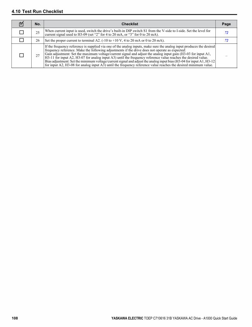
No. Checklist Page
25 When current input is used, switch the drive’s built-in DIP switch S1 from the V-side to I-side. Set the level forcurrent signal used to H3-09 (set “2” for 4 to 20 mA, or “3” for 0 to 20 mA). 72
26 Set the proper current to terminal A2. (-10 to +10 V, 4 to 20 mA or 0 to 20 mA). 72
27
If the frequency reference is supplied via one of the analog inputs, make sure the analog input produces the desiredfrequency reference. Make the following adjustments if the drive does not operate as expected:Gain adjustment: Set the maximum voltage/current signal and adjust the analog input gain (H3-03 for input A1,H3-11 for input A2, H3-07 for analog input A3) until the frequency reference value reaches the desired value.Bias adjustment: Set the minimum voltage/current signal and adjust the analog input bias (H3-04 for input A1, H3-12for input A2, H3-08 for analog input A3) until the frequency reference value reaches the desired minimum value.
–
4.10 Test Run Checklist
108 YASKAWA ELECTRIC TOEP C710616 31B YASKAWA AC Drive - A1000 Quick Start Guide
TroubleshootingThis chapter provides descriptions of the drive faults, alarms, errors, related displays, and guidance fortroubleshooting. This chapter can also serve as a reference guide for tuning the drive during a trial run.
5.1 DRIVE ALARMS, FAULTS, AND ERRORS........................................................1105.2 FAULT DETECTION.............................................................................................1115.3 ALARM DETECTION...........................................................................................1215.4 OPERATOR PROGRAMMING ERRORS............................................................1245.5 AUTO-TUNING FAULT DETECTION..................................................................1255.6 COPY FUNCTION RELATED DISPLAYS...........................................................1295.7 DIAGNOSING AND RESETTING FAULTS.........................................................130
5
YASKAWA ELECTRIC TOEP C710616 31B YASKAWA AC Drive - A1000 Quick Start Guide 109

5.1 Drive Alarms, Faults, and Errors
u Types of Alarms, Faults, and ErrorsCheck the digital operator for information about possible faults if the drive or motor fails to operate. Refer to Using the Digital Operator on page 56.If problems occur that are not covered in this manual, contact the nearest Yaskawa representative with the followinginformation:• Drive model• Software version• Date of purchase• Description of the problemTable 5.1 contains descriptions of the various types of alarms, faults, and errors that may occur while operating the drive.
Table 5.1 Types of Alarms, Faults, and ErrorsType Drive Response
Faults
When the drive detects a fault:• The digital operator displays text indicating the specific fault and the ALM indicator LED remains lit until the fault is reset.• The fault interrupts drive output and the motor coasts to a stop.• Some faults allow the user to select the stopping method when the fault occurs.• Fault output terminals MA-MC will close, and MB-MC will open.The drive will remain inoperable until the fault is cleared. Refer to Fault Reset Methods on page 130.
Minor Faults andAlarms
When the drive detects an alarm or a minor fault:• The digital operator displays text indicating the specific alarm or minor fault, and the ALM indicator LED flashes.• The drive continues running the motor, although some alarms allow the user to select a stopping method when the alarm
occurs.• A multi-function contact output set to be tripped by a minor fault (H2- oo = 10) closes. If the output is set to be tripped
by an alarm, the contact will not close.• The digital operator displays text indicating a specific alarm and the ALM indicator LED flashes.Remove the cause of the problem to reset a minor fault or alarm.
Operation Errors
An operation error occurs when parameter settings conflict or do not match hardware settings (such as with an option card).When the drive detects an operation error:• The digital operator displays text indicating the specific error.• Multi-function contact outputs do not operate.The drive will not operate the motor until the error has been reset. Correct the settings that caused the operation error to clearthe error.
Tuning Errors
Tuning errors occur while performing Auto-Tuning.When the drive detects a tuning error:• The digital operator displays text indicating the specific error.• Multi-function contact outputs do not operate.• Motor coasts to stop.Remove the cause of the error and repeat the Auto-Tuning process.
Copy Function Errors
Copy Function Errors occur when using the digital operator or the USB Copy Unit to copy, read, or verify parameter settings.• The digital operator displays text indicating the specific error.• Multi-function contact outputs do not operate.Pressing any key on the digital operator will clear the fault. Investigate the cause of the problem (such as model incompatibility)and try again.
5.1 Drive Alarms, Faults, and Errors
110 YASKAWA ELECTRIC TOEP C710616 31B YASKAWA AC Drive - A1000 Quick Start Guide
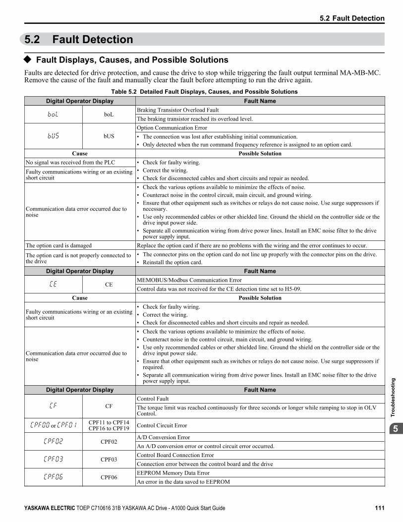
5.2 Fault Detection
u Fault Displays, Causes, and Possible SolutionsFaults are detected for drive protection, and cause the drive to stop while triggering the fault output terminal MA-MB-MC.Remove the cause of the fault and manually clear the fault before attempting to run the drive again.
Table 5.2 Detailed Fault Displays, Causes, and Possible SolutionsDigital Operator Display Fault Name
boLBraking Transistor Overload Fault The braking transistor reached its overload level.
bUSOption Communication Error• The connection was lost after establishing initial communication.• Only detected when the run command frequency reference is assigned to an option card.
Cause Possible SolutionNo signal was received from the PLC • Check for faulty wiring.
• Correct the wiring.• Check for disconnected cables and short circuits and repair as needed.
Faulty communications wiring or an existingshort circuit
Communication data error occurred due tonoise
• Check the various options available to minimize the effects of noise.• Counteract noise in the control circuit, main circuit, and ground wiring.• Ensure that other equipment such as switches or relays do not cause noise. Use surge suppressors if
necessary.• Use only recommended cables or other shielded line. Ground the shield on the controller side or the
drive input power side.• Separate all communication wiring from drive power lines. Install an EMC noise filter to the drive
power supply input.The option card is damaged Replace the option card if there are no problems with the wiring and the error continues to occur.
The option card is not properly connected tothe drive
• The connector pins on the option card do not line up properly with the connector pins on the drive.• Reinstall the option card.
Digital Operator Display Fault Name
CEMEMOBUS/Modbus Communication ErrorControl data was not received for the CE detection time set to H5-09.
Cause Possible Solution
Faulty communications wiring or an existingshort circuit
• Check for faulty wiring.• Correct the wiring.• Check for disconnected cables and short circuits and repair as needed.
Communication data error occurred due tonoise
• Check the various options available to minimize the effects of noise.• Counteract noise in the control circuit, main circuit, and ground wiring.• Use only recommended cables or other shielded line. Ground the shield on the controller side or the
drive input power side.• Ensure that other equipment such as switches or relays do not cause noise. Use surge suppressors if
required.• Separate all communication wiring from drive power lines. Install an EMC noise filter to the drive
power supply input.Digital Operator Display Fault Name
CFControl FaultThe torque limit was reached continuously for three seconds or longer while ramping to stop in OLVControl.
or CPF11 to CPF14CPF16 to CPF19 Control Circuit Error
CPF02A/D Conversion ErrorAn A/D conversion error or control circuit error occurred.
CPF03Control Board Connection ErrorConnection error between the control board and the drive
CPF06EEPROM Memory Data ErrorAn error in the data saved to EEPROM
5.2 Fault Detection
YASKAWA ELECTRIC TOEP C710616 31B YASKAWA AC Drive - A1000 Quick Start Guide 111
5
Trou
bles
hoot
ing
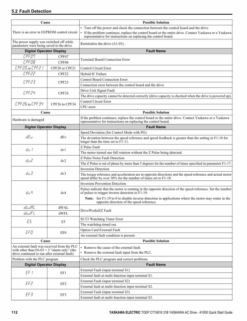
Cause Possible Solution
There is an error in EEPROM control circuit• Turn off the power and check the connection between the control board and the drive.• If the problem continues, replace the control board or the entire drive. Contact Yaskawa or a Yaskawa
representative for instructions on replacing the control board.The power supply was switched off whileparameters were being saved to the drive Reinitialize the drive (A1-03).
Digital Operator Display Fault NameCPF07
Terminal Board Connection ErrorCPF08
or CPF20 or CPF21 Control Circuit ErrorCPF22 Hybrid IC Failure
CPF23Control Board Connection ErrorConnection error between the control board and the drive
CPF24Drive Unit Signal FaultThe drive capacity cannot be detected correctly (drive capacity is checked when the drive is powered up).
to CPF26 to CPF34Control Circuit ErrorCPU error
Cause Possible Solution
Hardware is damaged If the problem continues, replace the control board or the entire drive. Contact Yaskawa or a Yaskawarepresentative for instructions on replacing the control board.
Digital Operator Display Fault Name
dEvSpeed Deviation (for Control Mode with PG)The deviation between the speed reference and speed feedback is greater than the setting in F1-10 forlonger than the time set to F1-11.
dv1Z Pulse FaultThe motor turned one full rotation without the Z Pulse being detected.
dv2Z Pulse Noise Fault DetectionThe Z Pulse is out of phase by more than 5 degrees for the number of times specified in parameter F1-17.
dv3Inversion DetectionThe torque reference and acceleration are in opposite directions and the speed reference and actual motorspeed differ by over 30% for the number of times set to F1-18.
dv4
Inversion Prevention DetectionPulses indicate that the motor is rotating in the opposite direction of the speed reference. Set the numberof pulses to trigger inverse detection to F1-19.
Note: Set F1-19 to 0 to disable inverse detection in applications where the motor may rotate in theopposite direction of the speed reference.
dWALDriveWorksEZ Fault
dWFL
E5SI-T3 Watchdog Timer ErrorThe watchdog timed out.
EF0Option Card External FaultAn external fault condition is present.
Cause Possible SolutionAn external fault was received from the PLCwith other than F6-03 = 3 “alarm only” (thedrive continued to run after external fault)
• Remove the cause of the external fault.• Remove the external fault input from the PLC.
Problem with the PLC program Check the PLC program and correct problems.Digital Operator Display Fault Name
EF1External Fault (input terminal S1)External fault at multi-function input terminal S1.
EF2External Fault (input terminal S2)External fault at multi-function input terminal S2.
EF3External Fault (input terminal S3)External fault at multi-function input terminal S3.
5.2 Fault Detection
112 YASKAWA ELECTRIC TOEP C710616 31B YASKAWA AC Drive - A1000 Quick Start Guide
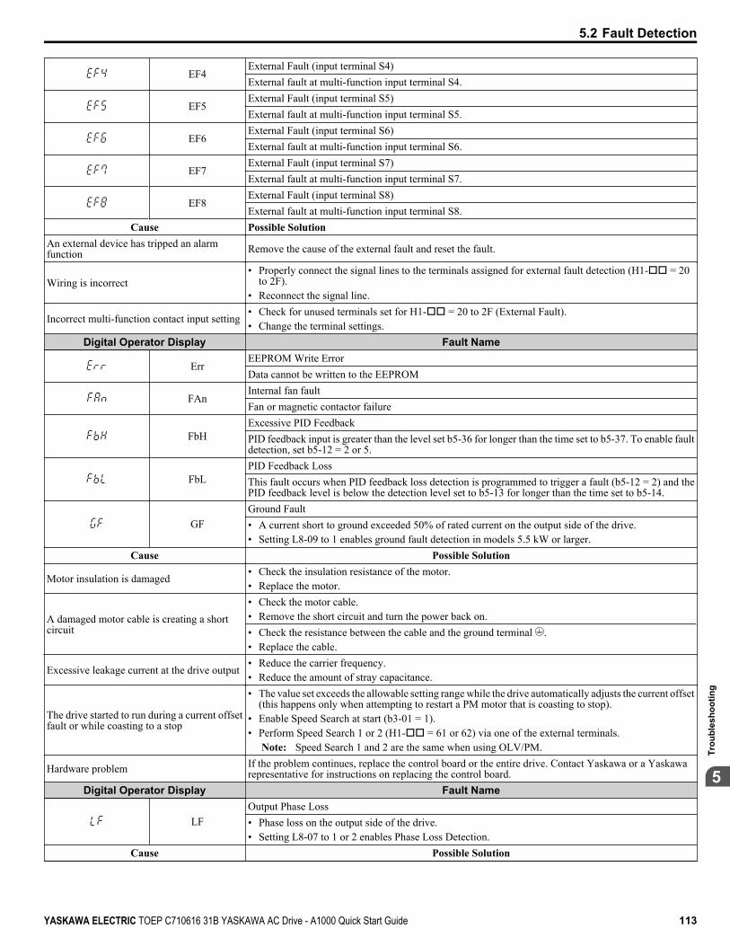
EF4External Fault (input terminal S4)External fault at multi-function input terminal S4.
EF5External Fault (input terminal S5)External fault at multi-function input terminal S5.
EF6External Fault (input terminal S6)External fault at multi-function input terminal S6.
EF7External Fault (input terminal S7)External fault at multi-function input terminal S7.
EF8External Fault (input terminal S8)External fault at multi-function input terminal S8.
Cause Possible SolutionAn external device has tripped an alarmfunction Remove the cause of the external fault and reset the fault.
Wiring is incorrect• Properly connect the signal lines to the terminals assigned for external fault detection (H1-oo = 20
to 2F).• Reconnect the signal line.
Incorrect multi-function contact input setting• Check for unused terminals set for H1-oo = 20 to 2F (External Fault).• Change the terminal settings.
Digital Operator Display Fault Name
ErrEEPROM Write Error Data cannot be written to the EEPROM
FAnInternal fan faultFan or magnetic contactor failure
FbHExcessive PID FeedbackPID feedback input is greater than the level set b5-36 for longer than the time set to b5-37. To enable faultdetection, set b5-12 = 2 or 5.
FbLPID Feedback LossThis fault occurs when PID feedback loss detection is programmed to trigger a fault (b5-12 = 2) and thePID feedback level is below the detection level set to b5-13 for longer than the time set to b5-14.
GFGround Fault• A current short to ground exceeded 50% of rated current on the output side of the drive.• Setting L8-09 to 1 enables ground fault detection in models 5.5 kW or larger.
Cause Possible Solution
Motor insulation is damaged• Check the insulation resistance of the motor.• Replace the motor.
A damaged motor cable is creating a shortcircuit
• Check the motor cable.• Remove the short circuit and turn the power back on.• Check the resistance between the cable and the ground terminal .• Replace the cable.
Excessive leakage current at the drive output• Reduce the carrier frequency.• Reduce the amount of stray capacitance.
The drive started to run during a current offsetfault or while coasting to a stop
• The value set exceeds the allowable setting range while the drive automatically adjusts the current offset(this happens only when attempting to restart a PM motor that is coasting to stop).
• Enable Speed Search at start (b3-01 = 1).• Perform Speed Search 1 or 2 (H1-oo = 61 or 62) via one of the external terminals.
Note: Speed Search 1 and 2 are the same when using OLV/PM.
Hardware problem If the problem continues, replace the control board or the entire drive. Contact Yaskawa or a Yaskawarepresentative for instructions on replacing the control board.
Digital Operator Display Fault Name
LFOutput Phase Loss• Phase loss on the output side of the drive.• Setting L8-07 to 1 or 2 enables Phase Loss Detection.
Cause Possible Solution
5.2 Fault Detection
YASKAWA ELECTRIC TOEP C710616 31B YASKAWA AC Drive - A1000 Quick Start Guide 113
5
Trou
bles
hoot
ing
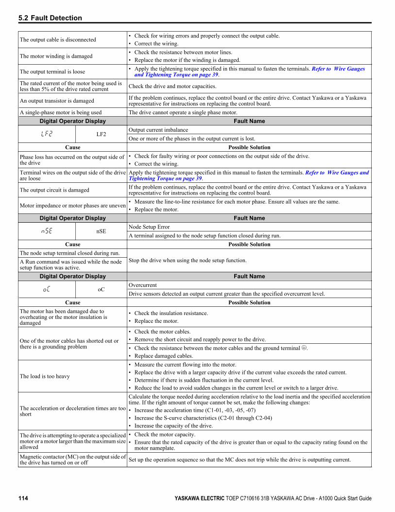
The output cable is disconnected• Check for wiring errors and properly connect the output cable.• Correct the wiring.
The motor winding is damaged• Check the resistance between motor lines.• Replace the motor if the winding is damaged.
The output terminal is loose • Apply the tightening torque specified in this manual to fasten the terminals. Refer to Wire Gauges and Tightening Torque on page 39.
The rated current of the motor being used isless than 5% of the drive rated current Check the drive and motor capacities.
An output transistor is damaged If the problem continues, replace the control board or the entire drive. Contact Yaskawa or a Yaskawarepresentative for instructions on replacing the control board.
A single-phase motor is being used The drive cannot operate a single phase motor.Digital Operator Display Fault Name
LF2Output current imbalanceOne or more of the phases in the output current is lost.
Cause Possible Solution
Phase loss has occurred on the output side ofthe drive
• Check for faulty wiring or poor connections on the output side of the drive.• Correct the wiring.
Terminal wires on the output side of the driveare loose
Apply the tightening torque specified in this manual to fasten the terminals. Refer to Wire Gauges and Tightening Torque on page 39.
The output circuit is damaged If the problem continues, replace the control board or the entire drive. Contact Yaskawa or a Yaskawarepresentative for instructions on replacing the control board.
Motor impedance or motor phases are uneven• Measure the line-to-line resistance for each motor phase. Ensure all values are the same.• Replace the motor.
Digital Operator Display Fault Name
nSENode Setup ErrorA terminal assigned to the node setup function closed during run.
Cause Possible SolutionThe node setup terminal closed during run.
Stop the drive when using the node setup function.A Run command was issued while the nodesetup function was active.
Digital Operator Display Fault Name
oCOvercurrentDrive sensors detected an output current greater than the specified overcurrent level.
Cause Possible SolutionThe motor has been damaged due tooverheating or the motor insulation isdamaged
• Check the insulation resistance.• Replace the motor.
One of the motor cables has shorted out orthere is a grounding problem
• Check the motor cables.• Remove the short circuit and reapply power to the drive.• Check the resistance between the motor cables and the ground terminal .• Replace damaged cables.
The load is too heavy
• Measure the current flowing into the motor.• Replace the drive with a larger capacity drive if the current value exceeds the rated current.• Determine if there is sudden fluctuation in the current level.• Reduce the load to avoid sudden changes in the current level or switch to a larger drive.
The acceleration or deceleration times are tooshort
Calculate the torque needed during acceleration relative to the load inertia and the specified accelerationtime. If the right amount of torque cannot be set, make the following changes:• Increase the acceleration time (C1-01, -03, -05, -07)• Increase the S-curve characteristics (C2-01 through C2-04)• Increase the capacity of the drive.
The drive is attempting to operate a specializedmotor or a motor larger than the maximum sizeallowed
• Check the motor capacity.• Ensure that the rated capacity of the drive is greater than or equal to the capacity rating found on the
motor nameplate.Magnetic contactor (MC) on the output side ofthe drive has turned on or off Set up the operation sequence so that the MC does not trip while the drive is outputting current.
5.2 Fault Detection
114 YASKAWA ELECTRIC TOEP C710616 31B YASKAWA AC Drive - A1000 Quick Start Guide
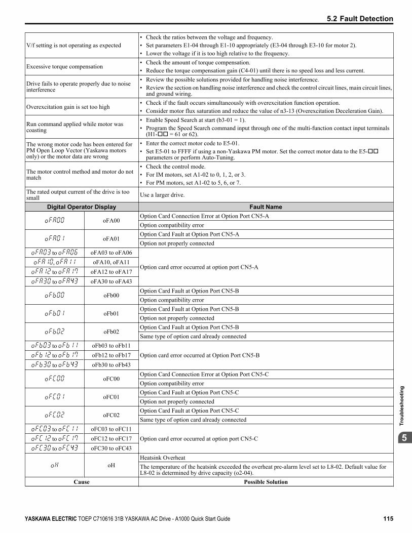
V/f setting is not operating as expected• Check the ratios between the voltage and frequency.• Set parameters E1-04 through E1-10 appropriately (E3-04 through E3-10 for motor 2).• Lower the voltage if it is too high relative to the frequency.
Excessive torque compensation• Check the amount of torque compensation.• Reduce the torque compensation gain (C4-01) until there is no speed loss and less current.
Drive fails to operate properly due to noiseinterference
• Review the possible solutions provided for handling noise interference.• Review the section on handling noise interference and check the control circuit lines, main circuit lines,
and ground wiring.
Overexcitation gain is set too high• Check if the fault occurs simultaneously with overexcitation function operation.• Consider motor flux saturation and reduce the value of n3-13 (Overexcitation Deceleration Gain).
Run command applied while motor wascoasting
• Enable Speed Search at start (b3-01 = 1).• Program the Speed Search command input through one of the multi-function contact input terminals
(H1-oo = 61 or 62).
The wrong motor code has been entered forPM Open Loop Vector (Yaskawa motorsonly) or the motor data are wrong
• Enter the correct motor code to E5-01.• Set E5-01 to FFFF if using a non-Yaskawa PM motor. Set the correct motor data to the E5-oo
parameters or perform Auto-Tuning.
The motor control method and motor do notmatch
• Check the control mode.• For IM motors, set A1-02 to 0, 1, 2, or 3.• For PM motors, set A1-02 to 5, 6, or 7.
The rated output current of the drive is toosmall Use a larger drive.
Digital Operator Display Fault Name
oFA00Option Card Connection Error at Option Port CN5-AOption compatibility error
oFA01Option Card Fault at Option Port CN5-AOption not properly connected
to oFA03 to oFA06
Option card error occurred at option port CN5-A, oFA10, oFA11
to oFA12 to oFA17
to oFA30 to oFA43
oFb00Option Card Fault at Option Port CN5-BOption compatibility error
oFb01Option Card Fault at Option Port CN5-BOption not properly connected
oFb02Option Card Fault at Option Port CN5-BSame type of option card already connected
to oFb03 to oFb11Option card error occurred at Option Port CN5-B to oFb12 to oFb17
to oFb30 to oFb43
oFC00Option Card Connection Error at Option Port CN5-COption compatibility error
oFC01Option Card Fault at Option Port CN5-COption not properly connected
oFC02Option Card Fault at Option Port CN5-CSame type of option card already connected
to oFC03 to oFC11Option card error occurred at option port CN5-C to oFC12 to oFC17
to oFC30 to oFC43
oHHeatsink OverheatThe temperature of the heatsink exceeded the overheat pre-alarm level set to L8-02. Default value forL8-02 is determined by drive capacity (o2-04).
Cause Possible Solution
5.2 Fault Detection
YASKAWA ELECTRIC TOEP C710616 31B YASKAWA AC Drive - A1000 Quick Start Guide 115
5
Trou
bles
hoot
ing

Surrounding temperature is too high
• Check the temperature surrounding the drive. Verify temperature is within drive specifications.• Improve the air circulation within the enclosure panel.• Install a fan or air conditioner to cool the surrounding area.• Remove anything near the drive that might be producing excessive heat.
Load is too heavy• Measure the output current.• Decrease the load.• Lower the carrier frequency (C6-02).
Internal cooling fan is stopped• Replace the cooling fan.• After replacing the drive, reset the cooling fan maintenance parameter (o4-03 = 0).
Digital Operator Display Fault Name
oH1Overheat 1 (Heatsink Overheat)The temperature of the heatsink exceeded the drive overheat level. The overheat level is determined bydrive capacity (o2-04).
Cause Possible Solution
Surrounding temperature is too high
• Check the temperature surrounding the drive.• Improve the air circulation within the enclosure panel.• Install a fan or air conditioner to cool the surrounding area.• Remove anything near the drive that might be producing excessive heat.
Load is too heavy• Measure the output current.• Lower the carrier frequency (C6-02).• Reduce the load.
Digital Operator Display Fault Name
oH3Motor Overheat Alarm (PTC Input)• The motor overheat signal to analog input terminal A1, A2, or A3 exceeded the alarm detection level.• Detection requires setting multi-function analog inputs H3-02, H3-06, or H3-10 to E.
oH4Motor Overheat Fault (PTC Input)• The motor overheat signal to analog input terminal A1, A2, or A3 exceeded the fault detection level.• Detection requires setting multi-function analog inputs H3-02, H3-06, or H3-10 to E.
Cause Possible Solution
Motor has overheated
• Check the size of the load, the accel/decel times, and the cycle times.• Decrease the load.• Increase the acceleration and deceleration times (C1-01 through C1-08).• Adjust the preset V/f pattern (E1-04 through E1-10) by reducing E1-08 and E1-10.• Do not set E1-08 and E1-10 too low. This reduces load tolerance at low speeds.• Check the motor rated current.• Enter the motor rated current as indicated on the motor nameplate (E2-01).• Ensure the motor cooling system is operating normally.• Repair or replace the motor cooling system.
Digital Operator Display Fault Name
oL1Motor OverloadThe electronic motor overload protection tripped.
Cause Possible SolutionLoad is too heavy Reduce the load.Cycle times are too short during accelerationand deceleration Increase the acceleration and deceleration times (C1-01 through C1-08).
A general-purpose motor is driven below therated speed with a high load
• Reduce the load.• Increase the speed.• If the motor is supposed to operate at low speeds, either increase the motor capacity or use a motor
specifically designed to operate in the desired speed range.
The output voltage is too high• Adjust the user-set V/f pattern (E1-04 through E1-10) by reducing E1-08 and E1-10.• Do not set E1-08 and E1-10 too low. This reduces load tolerance at low speeds.
The wrong motor rated current is set to E2-01• Check the motor-rated current.• Enter the value written on the motor nameplate to parameter E2-01.
The maximum output frequency is setincorrectly
• Check the rated frequency indicated on the motor nameplate.• Enter the rated frequency to E1-06 (Base Frequency).
5.2 Fault Detection
116 YASKAWA ELECTRIC TOEP C710616 31B YASKAWA AC Drive - A1000 Quick Start Guide
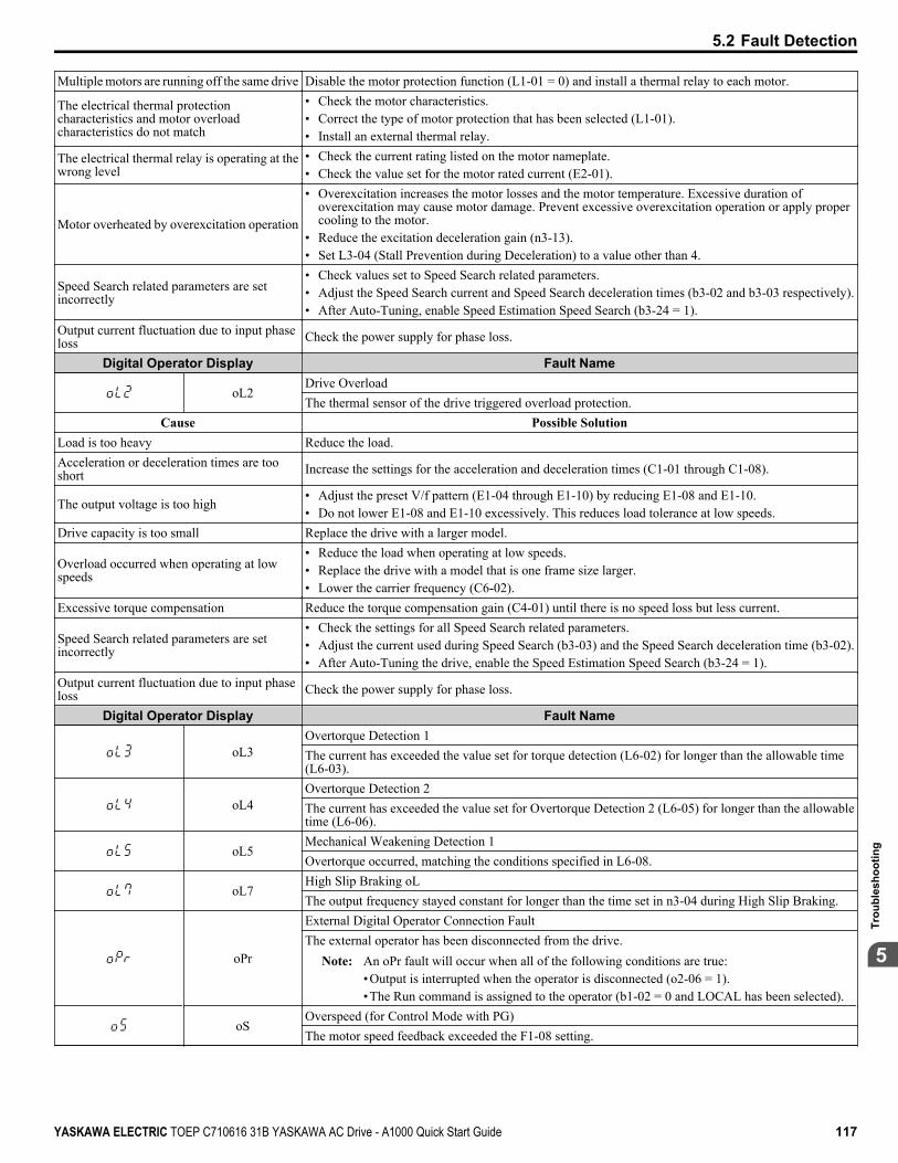
Multiple motors are running off the same drive Disable the motor protection function (L1-01 = 0) and install a thermal relay to each motor.
The electrical thermal protectioncharacteristics and motor overloadcharacteristics do not match
• Check the motor characteristics.• Correct the type of motor protection that has been selected (L1-01).• Install an external thermal relay.
The electrical thermal relay is operating at thewrong level
• Check the current rating listed on the motor nameplate.• Check the value set for the motor rated current (E2-01).
Motor overheated by overexcitation operation
• Overexcitation increases the motor losses and the motor temperature. Excessive duration ofoverexcitation may cause motor damage. Prevent excessive overexcitation operation or apply propercooling to the motor.
• Reduce the excitation deceleration gain (n3-13).• Set L3-04 (Stall Prevention during Deceleration) to a value other than 4.
Speed Search related parameters are setincorrectly
• Check values set to Speed Search related parameters.• Adjust the Speed Search current and Speed Search deceleration times (b3-02 and b3-03 respectively).• After Auto-Tuning, enable Speed Estimation Speed Search (b3-24 = 1).
Output current fluctuation due to input phaseloss Check the power supply for phase loss.
Digital Operator Display Fault Name
oL2Drive OverloadThe thermal sensor of the drive triggered overload protection.
Cause Possible SolutionLoad is too heavy Reduce the load.Acceleration or deceleration times are tooshort Increase the settings for the acceleration and deceleration times (C1-01 through C1-08).
The output voltage is too high• Adjust the preset V/f pattern (E1-04 through E1-10) by reducing E1-08 and E1-10.• Do not lower E1-08 and E1-10 excessively. This reduces load tolerance at low speeds.
Drive capacity is too small Replace the drive with a larger model.
Overload occurred when operating at lowspeeds
• Reduce the load when operating at low speeds.• Replace the drive with a model that is one frame size larger.• Lower the carrier frequency (C6-02).
Excessive torque compensation Reduce the torque compensation gain (C4-01) until there is no speed loss but less current.
Speed Search related parameters are setincorrectly
• Check the settings for all Speed Search related parameters.• Adjust the current used during Speed Search (b3-03) and the Speed Search deceleration time (b3-02).• After Auto-Tuning the drive, enable the Speed Estimation Speed Search (b3-24 = 1).
Output current fluctuation due to input phaseloss Check the power supply for phase loss.
Digital Operator Display Fault Name
oL3Overtorque Detection 1The current has exceeded the value set for torque detection (L6-02) for longer than the allowable time(L6-03).
oL4Overtorque Detection 2The current has exceeded the value set for Overtorque Detection 2 (L6-05) for longer than the allowabletime (L6-06).
oL5Mechanical Weakening Detection 1Overtorque occurred, matching the conditions specified in L6-08.
oL7High Slip Braking oLThe output frequency stayed constant for longer than the time set in n3-04 during High Slip Braking.
oPr
External Digital Operator Connection FaultThe external operator has been disconnected from the drive.
Note: An oPr fault will occur when all of the following conditions are true:•Output is interrupted when the operator is disconnected (o2-06 = 1).•The Run command is assigned to the operator (b1-02 = 0 and LOCAL has been selected).
oSOverspeed (for Control Mode with PG)The motor speed feedback exceeded the F1-08 setting.
5.2 Fault Detection
YASKAWA ELECTRIC TOEP C710616 31B YASKAWA AC Drive - A1000 Quick Start Guide 117
5
Trou
bles
hoot
ing

ov
OvervoltageVoltage in the DC bus has exceeded the overvoltage detection level.Refer to the Overvoltage Protection row in the A.3 Drive Specifications section on page 142 for trip levelvalues.
Cause Possible Solution
Deceleration time is too short and regenerativeenergy is flowing from the motor into the drive
• Increase the deceleration time (C1-02, C1-04, C1-06, C1-08).• Install a dynamic braking resistor or a dynamic braking resistor unit.• Enable stall prevention during deceleration (L3-04 = 1). Stall Prevention is enabled as the default
setting.
Fast acceleration time causes the motor toovershoot the speed reference
• Check if sudden drive acceleration triggers an overvoltage alarm.• Increase the acceleration time.• Use longer S-curve acceleration and deceleration times.• Enable the Overvoltage Suppression function (L3-11 = 1).• Lengthen the S-curve at acceleration end.
Excessive braking load The braking torque was too high, causing regenerative energy to charge the DC bus. Reduce the brakingtorque, use a dynamic braking option, or lengthen decel time.
Surge voltage entering from the drive inputpower
Install a DC reactor.Note: Voltage surge can result from a thyristor convertor and phase advancing capacitor using the
same input power supply.
Ground fault in the output circuit causes theDC bus capacitor to overcharge
• Check the motor wiring for ground faults.• Correct grounding shorts and turn the power back on.
Improper Setting of Speed Search relatedparameters (including Speed Search after amomentary power loss and after a fault restart)
• Check the settings for Speed Search-related parameters.• Enable Speed Search restart function (b3-19 greater than or equal to 1 to 10).• Adjust the current level during Speed Search and the deceleration time (b3-02 and b3-03 respectively).• Perform Stationary Auto-Tuning for line-to-line resistance and then enable Speed Estimation Speed
Search (b3-24 = 1).
Drive input power voltage is too high• Check the voltage.• Lower drive input power voltage within the limits listed in the specifications.
The braking transistor is wired incorrectly• Check braking transistor wiring for errors.• Properly rewire the braking resistor device.
PG cable is disconnected Reconnect the cable.PG cable wiring is wrong Correct the wiring.Noise interference along the PG encoderwiring Separate the wiring from the source of the noise (often the output lines from the drive).
Drive fails to operate properly due to noiseinterference
• Review the list of possible solutions provided for controlling noise.• Review the section on handling noise interference and check the control circuit lines, main circuit lines,
and ground wiring.
Load inertia has been set incorrectly• Check the load inertia settings when using KEB, overvoltage suppression, or Stall Prevention during
deceleration.• Adjust the load inertia ratio in L3-25 to better match the load.
Braking function is being used in OLV/PM Connect a braking resistor.
Motor hunting occurs
• Adjust the parameters that control hunting.• Set the gain for Hunting Prevention (n1-02).• Adjust the AFR time constant (n2-02 and n2-03).• Adjust the speed feedback detection suppression gain for PM motors (n8-45) and the time constant for
pull-in current (n8-47).Digital Operator Display Fault Name
PFInput Phase LossDrive input power has an open phase or has a large imbalance of voltage between phases. Detected whenL8-05 = 1 (enabled).
Cause Possible Solution
There is phase loss in the drive input power• Check for wiring errors in the main circuit drive input power.• Correct the wiring.
There is loose wiring in the drive input powerterminals
• Ensure the terminals are tightened properly.• Apply the tightening torque as specified in this manual. Refer to Wire Gauges and Tightening
Torque on page 39.
5.2 Fault Detection
118 YASKAWA ELECTRIC TOEP C710616 31B YASKAWA AC Drive - A1000 Quick Start Guide

There is excessive fluctuation in the driveinput power voltage
• Check the voltage from the drive input power.• Review the possible solutions for stabilizing the drive input power.
There is poor balance between voltage phases • Stabilize drive input power or disable phase loss detection.
The main circuit capacitors are worn
• Check the maintenance time for the capacitors (U4-05).• Replace the capacitor if U4-05 is greater than 90%. For instructions on replacing the capacitor, contact
Yaskawa or a Yaskawa representative.• Check for problems with the drive input power. If drive input power appears normal but the alarm
continues to occur, replace either the control board or the entire drive. For instructions on replacing thecontrol board, contact Yaskawa or a Yaskawa representative.
Digital Operator Display Fault Name
PGoPG Disconnect (for any control modes using a PG option card)No PG pulses are received for longer than the time set to F1-14.
PGoHPG Hardware Fault (detected when using a PG-X3 option card)PG cable is not connected properly.
rFBraking Resistor FaultThe resistance of the braking resistor is too low.
rHBraking Resistor OverheatBraking resistor protection was triggered.Fault detection is enabled when L8-01 = 1 (disabled as a default).
Cause Possible Solution
Deceleration time is too short and excessiveregenerative energy is flowing back into thedrive
• Check the load, deceleration time, and speed.• Reduce the load inertia.• Increase the deceleration times (C1-02, C1-04, C1-06, C1-08, C1-09).• Replace the dynamic braking option with a larger device that can handle the power that is discharged.
Excessive braking inertia Recalculate braking load and braking power. Reduce the braking load by adjusting braking resistorsettings.
The braking operation duty cycle is too high Check the braking operation duty cycle. Braking resistor protection for ERF-type braking resistors (L8-01= 1) allows a braking duty cycle of maximum 3%.
The proper braking resistor has not beeninstalled
• Check the specifications and conditions for the braking resistor device.• Select the optimal braking resistor.
Note: The magnitude of the braking load trips the braking resistor overheat alarm, NOT the surface temperature. Using the braking resistor morefrequently than it is rated for trips the alarm even when the braking resistor surface is not very hot.
Digital Operator Display Fault Name
rrDynamic Braking TransistorThe built-in dynamic braking transistor failed.
Cause Possible SolutionThe braking transistor is damaged • Cycle power to the drive and check if the fault reoccurs. Refer to Diagnosing and Resetting Faults
on page 130.• Replace either the control board or the entire drive. For instructions on replacing the control board,
contact Yaskawa or a Yaskawa representative.The control circuit is damaged
Digital Operator Display Fault Name
SErToo Many Speed Search RestartsThe number of Speed Search restarts exceeded the value set to b3-19.
SToMotor Pull Out or Step Out DetectionMotor pull out or step out has occurred. Motor has exceeded its pull-out torque.
SvEZero Servo FaultPosition deviation during zero servo.
UL3Undertorque Detection 1The current has fallen below the minimum value set for torque detection (L6-02) for longer than theallowable time (L6-03).
Cause Possible SolutionParameter settings are not appropriate for theload Check the settings of parameters L6-02 and L6-03.
There is a fault on the machine side Check the load for any problems.
5.2 Fault Detection
YASKAWA ELECTRIC TOEP C710616 31B YASKAWA AC Drive - A1000 Quick Start Guide 119
5
Trou
bles
hoot
ing

Digital Operator Display Fault Name
UL4Undertorque Detection 2The current has fallen below the minimum value set for torque detection (L6-05) for longer than theallowable time (L6-06).
UL5Mechanical Weakening Detection 2The operation conditions matched the conditions set to L6-08.
Uv1
DC Bus UndervoltageVoltage in the DC bus fell below the undervoltage detection level (L2-05).Refer to the Undervoltage Protection row in the A.3 Drive Specifications section on page 142 for detectionlevel values.The fault is output only if L2-01 = 0 or L2-01 = 1 and the DC bus voltage has fallen below the level setto L2-05 for longer than the time set to L2-02.
Cause Possible Solution
Input power phase loss• The main circuit drive input power is wired incorrectly.• Correct the wiring.
One of the drive input power wiring terminalsis loose
• Ensure there are no loose terminals.• Apply the tightening torque specified in this manual to fasten the terminals. Refer to Wire Gauges
and Tightening Torque on page 39.
There is a problem with the voltage from thedrive input power
• Check the voltage.• Correct the voltage to be within the range listed in drive input power specifications.• If there is no problem with the power supply to the main circuit, check for problems with the main
circuit magnetic contactor.The power has been interrupted Correct the drive input power.
The main circuit capacitors are worn• Check the maintenance time for the capacitors (U4-05).• Replace either the control board or the entire drive if U4-05 exceeds 90%. For instructions on replacing
the control board, contact Yaskawa or a Yaskawa representative.
The relay or contactor on the soft-chargebypass circuit is damaged
• Cycle power to the drive and see if the fault reoccurs.• If the problem continues, replace either the control board or the entire drive. For instructions on
replacing the control board, contact Yaskawa or a Yaskawa representative.• Check monitor U4-06 for the performance life of the soft-charge bypass.• Replace either the control board or the entire drive if U4-06 exceeds 90%. For instructions on replacing
the control board, contact Yaskawa or a Yaskawa representative.Digital Operator Display Fault Name
Uv2Control Power Supply Voltage FaultVoltage is too low for the control drive input power.
Cause Possible SolutionL2-02 was changed from its default value in adrive that is 7.5 kW or smaller withoutinstalling a Momentary Power Loss Ride-Thruunit
Correct the setting to L2-02 or install an optional Momentary Power Loss Ride-Thru unit.
Control power supply wiring is damaged• Cycle power to the drive. Check if the fault reoccurs.• If the problem continues, replace the control board, the entire drive, or the control power supply. For
instructions on replacing the control board, contact Yaskawa or a Yaskawa representative.
Internal circuitry is damaged• Cycle power to the drive. Check if the fault reoccurs.• If the problem continues, replace either the control board or the entire drive. For instructions on
replacing the control board, contact Yaskawa or a Yaskawa representative.Digital Operator Display Fault Name
Uv3Undervoltage 3 (Soft-Charge Bypass Circuit Fault)The soft-charge bypass circuit failed.
voFOutput Voltage Detection FaultProblem detected with the voltage on the output side of the drive.
5.2 Fault Detection
120 YASKAWA ELECTRIC TOEP C710616 31B YASKAWA AC Drive - A1000 Quick Start Guide

5.3 Alarm Detection
u Alarm Codes, Causes, and Possible SolutionsAlarms are drive protection functions that do not necessarily cause the drive to stop. Once the cause of an alarm is removed,the drive will return to the same status is was before the alarm occurred.When an alarm has been triggered, the ALM light on the digital operator display blinks and the alarm code display flashes. Ifa multi-function output is set for an alarm (H2-oo = 10), that output terminal will be triggered.
Note: If a multi-function output is set to close when an alarm occurs (H2-oo = 10), it will also close when maintenance periods are reached, triggeringalarms LT-1 through LT-4 (triggered only if H2-oo = 2F).
Table 5.3 Alarm Codes, Causes, and Possible SolutionsDigital Operator Display Minor Fault Name
AErCommunication Option Station Number Setting Error (CC-Link, CANopen, MECHATROLINK-II)Option card node address is outside the acceptable setting range.
bbBaseblockDrive output interrupted as indicated by an external baseblock signal.
boLBraking Transistor Overload FaultThe braking transistor in the drive has been overloaded.
bUSOption Communication Error• After initial communication was established, the connection was lost.• Assign a Run command frequency reference to the option card.
CALLSerial Communication Transmission ErrorCommunication has not yet been established.
CEMEMOBUS/Modbus Communication ErrorControl data was not received correctly for two seconds.
CrST Cannot Reset
dEvSpeed Deviation (when using a PG option card)The deviation between the speed reference and speed feedback is greater than the setting in F1-10 for longerthan the time in F1-11.
dnE Drive Disabled
EFForward/Reverse Run Command Input ErrorBoth forward run and reverse run closed simultaneously for over 0.5 s.
EF0Option Card External FaultAn external fault condition is present.
EF1External fault (input terminal S1)External fault at multi-function input terminal S1.
EF2External fault (input terminal S2)External fault at multi-function input terminal S2.
EF3External fault (input terminal S3)External fault at multi-function input terminal S3.
EF4External fault (input terminal S4)External fault at multi-function input terminal S4.
EF5External fault (input terminal S5)External fault at multi-function input terminal S5.
EF6External fault (input terminal S6)External fault at multi-function input terminal S6.
EF7External fault (input terminal S7)External fault at multi-function input terminal S7.
EF8External fault (input terminal S8)External fault at multi-function input terminal S8.
5.3 Alarm Detection
YASKAWA ELECTRIC TOEP C710616 31B YASKAWA AC Drive - A1000 Quick Start Guide 121
5
Trou
bles
hoot
ing
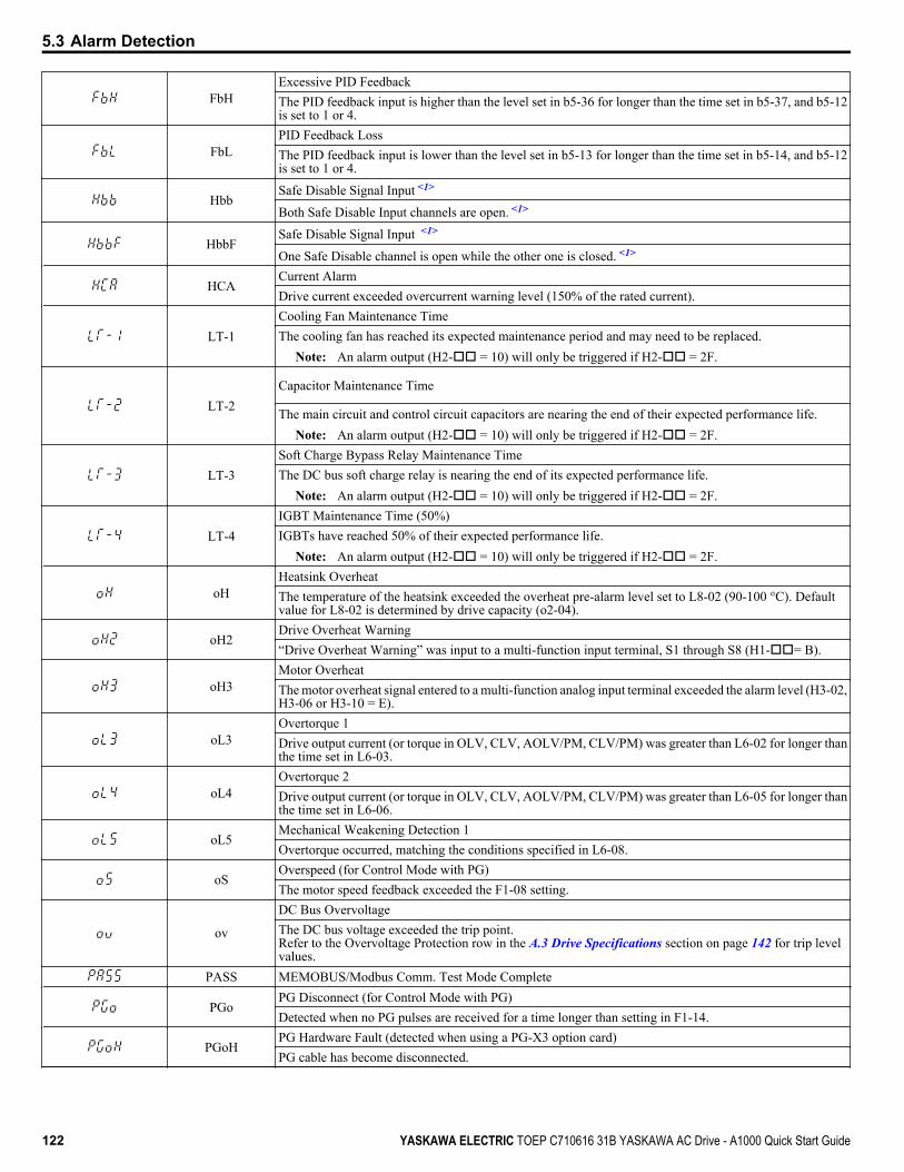
FbHExcessive PID FeedbackThe PID feedback input is higher than the level set in b5-36 for longer than the time set in b5-37, and b5-12is set to 1 or 4.
FbLPID Feedback LossThe PID feedback input is lower than the level set in b5-13 for longer than the time set in b5-14, and b5-12is set to 1 or 4.
HbbSafe Disable Signal Input <1>
Both Safe Disable Input channels are open. <1>
HbbFSafe Disable Signal Input <1>
One Safe Disable channel is open while the other one is closed. <1>
HCACurrent AlarmDrive current exceeded overcurrent warning level (150% of the rated current).
LT-1Cooling Fan Maintenance TimeThe cooling fan has reached its expected maintenance period and may need to be replaced.
Note: An alarm output (H2-oo = 10) will only be triggered if H2-oo = 2F.
LT-2Capacitor Maintenance Time
The main circuit and control circuit capacitors are nearing the end of their expected performance life.Note: An alarm output (H2-oo = 10) will only be triggered if H2-oo = 2F.
LT-3Soft Charge Bypass Relay Maintenance TimeThe DC bus soft charge relay is nearing the end of its expected performance life.
Note: An alarm output (H2-oo = 10) will only be triggered if H2-oo = 2F.
LT-4IGBT Maintenance Time (50%)IGBTs have reached 50% of their expected performance life.
Note: An alarm output (H2-oo = 10) will only be triggered if H2-oo = 2F.
oHHeatsink OverheatThe temperature of the heatsink exceeded the overheat pre-alarm level set to L8-02 (90-100 °C). Defaultvalue for L8-02 is determined by drive capacity (o2-04).
oH2Drive Overheat Warning“Drive Overheat Warning” was input to a multi-function input terminal, S1 through S8 (H1-oo= B).
oH3Motor OverheatThe motor overheat signal entered to a multi-function analog input terminal exceeded the alarm level (H3-02,H3-06 or H3-10 = E).
oL3Overtorque 1Drive output current (or torque in OLV, CLV, AOLV/PM, CLV/PM) was greater than L6-02 for longer thanthe time set in L6-03.
oL4Overtorque 2Drive output current (or torque in OLV, CLV, AOLV/PM, CLV/PM) was greater than L6-05 for longer thanthe time set in L6-06.
oL5Mechanical Weakening Detection 1Overtorque occurred, matching the conditions specified in L6-08.
oSOverspeed (for Control Mode with PG)The motor speed feedback exceeded the F1-08 setting.
ov
DC Bus OvervoltageThe DC bus voltage exceeded the trip point.Refer to the Overvoltage Protection row in the A.3 Drive Specifications section on page 142 for trip levelvalues.
PASS MEMOBUS/Modbus Comm. Test Mode Complete
PGoPG Disconnect (for Control Mode with PG)Detected when no PG pulses are received for a time longer than setting in F1-14.
PGoHPG Hardware Fault (detected when using a PG-X3 option card)PG cable has become disconnected.
5.3 Alarm Detection
122 YASKAWA ELECTRIC TOEP C710616 31B YASKAWA AC Drive - A1000 Quick Start Guide

rUnMotor Switch during RunA command to switch motors was entered during run.
SEMEMOBUS/Modbus Communication Test Mode Error
Note: This alarm will not trigger a multi-function output terminal that is set for alarm output(H2-oo = 10).
TrPCIGBT Maintenance Time (90%)IGBTs have reached 90% of their expected performance life.
UL3Undertorque Detection 1Drive output current (or torque in OLV, CLV, AOLV/PM, CLV/PM) less than L6-02 for longer than L6-03time.
UL4Undertorque Detection 2Drive output current (or torque in OLV, CLV, AOLV/PM, CLV/PM) less than L6-05 for longer than L6-06time.
Uv
UndervoltageOne of the following conditions was true when the drive was stopped and a Run command was entered:• DC bus voltage dropped below the level specified in L2-05.• Contactor to suppress inrush current in the drive was opened.• Low voltage in the control drive input power. This alarm outputs only if L2-01 is not 0 and DC bus voltage
is under L2-05.
voFOutput Voltage Detection FaultThere is a problem with the output voltage.
<1> Terminals H1, H2, DM+, and DM- on 600 V class models are designed to the functionality, but are not certified to EN61800-5-1, EN954-1/ISO13849Cat. 3, IEC/EN61508 SIL2, Insulation coordination: class 1.
5.3 Alarm Detection
YASKAWA ELECTRIC TOEP C710616 31B YASKAWA AC Drive - A1000 Quick Start Guide 123
5
Trou
bles
hoot
ing

5.4 Operator Programming Errors
u Operator Programming Error Codes, Causes, and Possible SolutionsAn Operator Programming Error (oPE) occurs when a contradictory parameter is set or an individual parameter is set to aninappropriate value.The drive will not operate until the parameter or parameters causing the problem are set correctly. An oPE, however, does nottrigger an alarm or fault output. If an oPE occurs, investigate the cause and refer to Table 5.4 for the appropriate action. Whenan oPE appears on the operator display, press the ENTER button to view U1-18 and see which parameter is causing the oPE.
Table 5.4 oPE Codes, Causes, and Possible SolutionsDigital Operator Display Error Name
oPE01Drive Capacity Setting FaultDrive capacity and the value set to o2-04 do not match.
oPE02Parameter Range Setting ErrorUse U1-18 to find parameters set outside the range.
oPE03Multi-Function Input Selection ErrorA contradictory setting is assigned to multi-function contact inputs H1-01to H1-08.
oPE04 Initialization requiredoPE05 Run Command/Frequency Reference Source Selection Error
oPE06Control Method Selection ErrorCorrect the setting for the control method.
oPE07Multi-Function Analog Input Selection ErrorA contradictory setting is assigned to multi-function analog inputs H3-02,H3-06, or H3-10 and PID functions conflict.
oPE08Parameter Selection ErrorA function has been set that cannot be used in the motor control methodselected.
oPE09PID Control Selection FaultPID control function selection is incorrect. Requires that PID control isenabled (b5-01 = 1 to 4).
oPE10
V/f Data Setting ErrorThe following setting errors have occurred where:• E1-04 is greater than or equal to E1-06, E1-06 is greater than or equal to
E1-07, E1-07 is greater than or equal to E1-09, or E1-09 is greater thanor equal to E1-11.
• E3-04 is greater than or equal to E3-06, E3-06 is greater than or equal toE3-07, E3-07 is greater than or equal to E3-09, or E3-09 is greater thanor equal to E3-11.
oPE11Carrier Frequency Setting ErrorCorrect the setting for the carrier frequency.
oPE13Pulse Monitor Selection ErrorIncorrect setting of monitor selection for pulse train (H6-06).
oPE15Torque Control Setting ErrorParameters settings that are not allowed in combination with TorqueControl have been set.
oPE16 Energy Savings Constants Error
oPE18Online Tuning Parameter Setting ErrorParameters controlling online tuning are not set correctly.
5.4 Operator Programming Errors
124 YASKAWA ELECTRIC TOEP C710616 31B YASKAWA AC Drive - A1000 Quick Start Guide

5.5 Auto-Tuning Fault DetectionWhen the Auto-Tuning faults shown below are detected, the fault is displayed on the digital operator and the motor coasts toa stop. Auto-Tuning faults do not trigger a multi-function terminal set for fault or alarm output.An Endo error indicates that although Auto-Tuning has successfully completed, there is some discrepancy in the calculations.If an Endo error occurs, check for the cause of the error using the table below, and perform Auto-Tuning again after fixingthe problem. Start the application if no problem can be diagnosed despite the existence of the Endo error.
u Auto-Tuning Codes, Causes, and Possible SolutionsTable 5.5 Auto-Tuning Codes, Causes, and Possible Solutions
Digital Operator Display Error Name
End1 Excessive V/f Setting (detected only during Rotational Auto-Tuning, and displayed after Auto-Tuning iscomplete)
Cause Possible SolutionsThe torque reference exceeded 20% duringAuto-Tuning.
• Before Auto-Tuning the drive, verify the information written on the motor nameplate and enter that datato T1-03 through T1-05.
• Enter proper information to parameters T1-03 to T1-05 and repeat Auto-Tuning.• If possible, disconnect the motor from the load and perform Auto-Tuning. If the load cannot be uncoupled,
simply use the Auto-Tuning results as they are.The results from Auto-Tuning the no-loadcurrent exceeded 80%.
Digital Operator Display Error Name
End2 Motor Iron-Core Saturation Coefficient (detected only during Rotational Auto-Tuning and displayed afterAuto-Tuning is complete)
Cause Possible Solutions
Motor data entered during Auto-Tuningwas incorrect.
• Make sure the data entered to the T1 parameters match the information written on the motor nameplate.• Restart Auto-Tuning and enter the correct information.
Results from Auto-Tuning are outside theparameter setting range, assigning the iron-core saturation coefficient (E2-07, E2-08)a temporary value.
• Check and correct faulty motor wiring.• Disconnect the motor from machine and perform Rotational Auto-Tuning.
Digital Operator Display Error NameEnd3 Rated Current Setting Alarm (displayed after Auto-Tuning is complete)
Cause Possible Solutions
The correct current rating printed on thenameplate was not entered into T1-04.
• Check the setting of parameter T1-04.• Check the motor data and repeat Auto-Tuning.
Digital Operator Display Error NameEnd4 Adjusted Slip Calculation Error
Cause Possible Solutions
The slip that was calculated is outside theallowable range.
• Make sure the data entered for Auto-Tuning is correct.• Execute Rotational Auto-Tuning instead. If not possible, try Stationary Auto-Tuning 2.
Digital Operator Display Error NameEnd5 Resistance Tuning Error
Cause Possible Solutions
The resistance value that was calculated isoutside the allowable range.
• Double check the data that was entered for the Auto-Tuning process.• Check the motor and motor cable connection for faults.
Digital Operator Display Error NameEnd6 Leakage Inductance Alarm
Cause Possible SolutionsThe leakage inductance value that wascalculated is outside the allowable range. Double check the data that was entered for the Auto-Tuning process.
Digital Operator Display Error NameEnd7 No-Load Current Alarm
Cause Possible SolutionsThe entered no-load current value wasoutside the allowable range. Check and correct faulty motor wiring.
5.5 Auto-Tuning Fault Detection
YASKAWA ELECTRIC TOEP C710616 31B YASKAWA AC Drive - A1000 Quick Start Guide 125
5
Trou
bles
hoot
ing
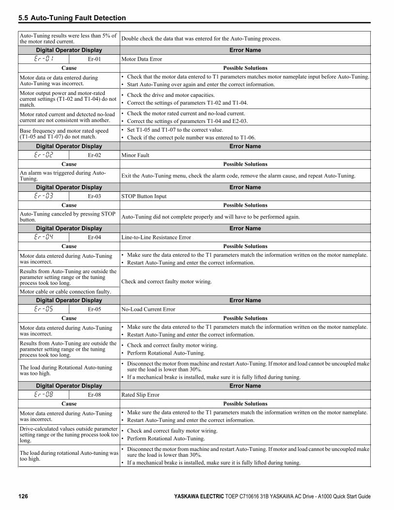
Auto-Tuning results were less than 5% ofthe motor rated current. Double check the data that was entered for the Auto-Tuning process.
Digital Operator Display Error NameEr-01 Motor Data Error
Cause Possible Solutions
Motor data or data entered duringAuto-Tuning was incorrect.
• Check that the motor data entered to T1 parameters matches motor nameplate input before Auto-Tuning.• Start Auto-Tuning over again and enter the correct information.
Motor output power and motor-ratedcurrent settings (T1-02 and T1-04) do notmatch.
• Check the drive and motor capacities.• Correct the settings of parameters T1-02 and T1-04.
Motor rated current and detected no-loadcurrent are not consistent with another.
• Check the motor rated current and no-load current.• Correct the settings of parameters T1-04 and E2-03.
Base frequency and motor rated speed(T1-05 and T1-07) do not match.
• Set T1-05 and T1-07 to the correct value.• Check if the correct pole number was entered to T1-06.
Digital Operator Display Error NameEr-02 Minor Fault
Cause Possible SolutionsAn alarm was triggered during Auto-Tuning. Exit the Auto-Tuning menu, check the alarm code, remove the alarm cause, and repeat Auto-Tuning.
Digital Operator Display Error NameEr-03 STOP Button Input
Cause Possible SolutionsAuto-Tuning canceled by pressing STOPbutton. Auto-Tuning did not complete properly and will have to be performed again.
Digital Operator Display Error NameEr-04 Line-to-Line Resistance Error
Cause Possible Solutions
Motor data entered during Auto-Tuningwas incorrect.
• Make sure the data entered to the T1 parameters match the information written on the motor nameplate.• Restart Auto-Tuning and enter the correct information.
Results from Auto-Tuning are outside theparameter setting range or the tuningprocess took too long. Check and correct faulty motor wiring.
Motor cable or cable connection faulty.Digital Operator Display Error Name
Er-05 No-Load Current ErrorCause Possible Solutions
Motor data entered during Auto-Tuningwas incorrect.
• Make sure the data entered to the T1 parameters match the information written on the motor nameplate.• Restart Auto-Tuning and enter the correct information.
Results from Auto-Tuning are outside theparameter setting range or the tuningprocess took too long.
• Check and correct faulty motor wiring.• Perform Rotational Auto-Tuning.
The load during Rotational Auto-tuningwas too high.
• Disconnect the motor from machine and restart Auto-Tuning. If motor and load cannot be uncoupled makesure the load is lower than 30%.
• If a mechanical brake is installed, make sure it is fully lifted during tuning.Digital Operator Display Error Name
Er-08 Rated Slip ErrorCause Possible Solutions
Motor data entered during Auto-Tuningwas incorrect.
• Make sure the data entered to the T1 parameters match the information written on the motor nameplate.• Restart Auto-Tuning and enter the correct information.
Drive-calculated values outside parametersetting range or the tuning process took toolong.
• Check and correct faulty motor wiring.• Perform Rotational Auto-Tuning.
The load during rotational Auto-tuning wastoo high.
• Disconnect the motor from machine and restart Auto-Tuning. If motor and load cannot be uncoupled makesure the load is lower than 30%.
• If a mechanical brake is installed, make sure it is fully lifted during tuning.
5.5 Auto-Tuning Fault Detection
126 YASKAWA ELECTRIC TOEP C710616 31B YASKAWA AC Drive - A1000 Quick Start Guide
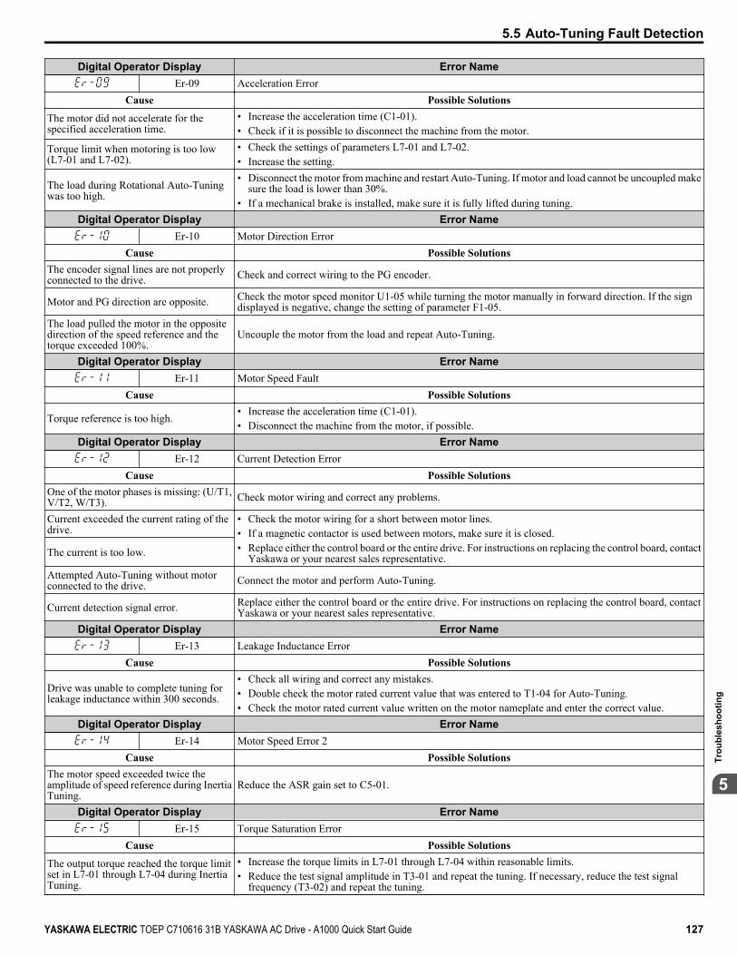
Digital Operator Display Error NameEr-09 Acceleration Error
Cause Possible Solutions
The motor did not accelerate for thespecified acceleration time.
• Increase the acceleration time (C1-01).• Check if it is possible to disconnect the machine from the motor.
Torque limit when motoring is too low(L7-01 and L7-02).
• Check the settings of parameters L7-01 and L7-02.• Increase the setting.
The load during Rotational Auto-Tuningwas too high.
• Disconnect the motor from machine and restart Auto-Tuning. If motor and load cannot be uncoupled makesure the load is lower than 30%.
• If a mechanical brake is installed, make sure it is fully lifted during tuning.Digital Operator Display Error Name
Er-10 Motor Direction ErrorCause Possible Solutions
The encoder signal lines are not properlyconnected to the drive. Check and correct wiring to the PG encoder.
Motor and PG direction are opposite. Check the motor speed monitor U1-05 while turning the motor manually in forward direction. If the signdisplayed is negative, change the setting of parameter F1-05.
The load pulled the motor in the oppositedirection of the speed reference and thetorque exceeded 100%.
Uncouple the motor from the load and repeat Auto-Tuning.
Digital Operator Display Error NameEr-11 Motor Speed Fault
Cause Possible Solutions
Torque reference is too high.• Increase the acceleration time (C1-01).• Disconnect the machine from the motor, if possible.
Digital Operator Display Error NameEr-12 Current Detection Error
Cause Possible SolutionsOne of the motor phases is missing: (U/T1,V/T2, W/T3). Check motor wiring and correct any problems.
Current exceeded the current rating of thedrive.
• Check the motor wiring for a short between motor lines.• If a magnetic contactor is used between motors, make sure it is closed.• Replace either the control board or the entire drive. For instructions on replacing the control board, contact
Yaskawa or your nearest sales representative.The current is too low.
Attempted Auto-Tuning without motorconnected to the drive. Connect the motor and perform Auto-Tuning.
Current detection signal error. Replace either the control board or the entire drive. For instructions on replacing the control board, contactYaskawa or your nearest sales representative.
Digital Operator Display Error NameEr-13 Leakage Inductance Error
Cause Possible Solutions
Drive was unable to complete tuning forleakage inductance within 300 seconds.
• Check all wiring and correct any mistakes.• Double check the motor rated current value that was entered to T1-04 for Auto-Tuning.• Check the motor rated current value written on the motor nameplate and enter the correct value.
Digital Operator Display Error NameEr-14 Motor Speed Error 2
Cause Possible SolutionsThe motor speed exceeded twice theamplitude of speed reference during InertiaTuning.
Reduce the ASR gain set to C5-01.
Digital Operator Display Error NameEr-15 Torque Saturation Error
Cause Possible Solutions
The output torque reached the torque limitset in L7-01 through L7-04 during InertiaTuning.
• Increase the torque limits in L7-01 through L7-04 within reasonable limits.• Reduce the test signal amplitude in T3-01 and repeat the tuning. If necessary, reduce the test signal
frequency (T3-02) and repeat the tuning.
5.5 Auto-Tuning Fault Detection
YASKAWA ELECTRIC TOEP C710616 31B YASKAWA AC Drive - A1000 Quick Start Guide 127
5
Trou
bles
hoot
ing

Digital Operator Display Error NameEr-16 Inertia Detection Error
Cause Possible Solutions
The inertia identified by the drive wasabnormally small or abnormally largeduring Inertia Tuning.
• Reduce the test signal amplitude in T3-01 and repeat the tuning. If necessary, reduce the test signalfrequency (T3-02) and repeat the tuning.
• Check the basic motor inertia value entered to T3-03.Digital Operator Display Error Name
Er-17 Reverse Prohibited Error
Cause Possible Solutions
Drive is prohibited from rotating the motorin reverse while attempting to performInertia Tuning.
• Inertia Auto-Tuning cannot be performed if the drive is restricted from rotating in reverse.• Assuming it is acceptable for the application to rotate in reverse, set b1-04 to 0 and then execute Inertia
Tuning.Digital Operator Display Error Name
Er-18 Induction Voltage ErrorCause Possible Solutions
The induced voltage constant attempted toset a value outside the allowable settingrange.
Double-check the data entered to the T2-oo parameters, and perform Auto-Tuning again.
Digital Operator Display Error NameEr-19 PM Inductance Error
Cause Possible SolutionsThe induced voltage constant attempted toset a value to E5-08 or E5-09 outside theallowable range.
Double-check the data entered to the T2-oo parameters, and perform Auto-Tuning again.
Digital Operator Display Error NameEr-20 Stator Resistance Error
Cause Possible SolutionsStator resistance tuning attempted to set avalue to E5-06 that is outside the allowablesetting range.
Double-check the data entered to the T2-oo parameters, and perform Auto-Tuning again.
Digital Operator Display Error NameEr-21 Z Pulse Correction Error
Cause Possible SolutionsMotor was coasting when Auto-Tuningwas performed. Make sure the motor has stopped completely. Repeat Auto-Tuning.
Either the motor or the PG encoder on themotor is not properly wired. Check the wiring for the motor and the PG encoder. Repeat Auto-Tuning.
The direction for the PG encoder is setincorrectly, or the number of pulses set forthe PG encoder is wrong.
Check the direction and number of pulses set for the PG encoder. Repeat Auto-Tuning.
PG encoder is damaged. Check the signal output from the PG encoder attached to the motor. Replace the PG if damaged.
5.5 Auto-Tuning Fault Detection
128 YASKAWA ELECTRIC TOEP C710616 31B YASKAWA AC Drive - A1000 Quick Start Guide
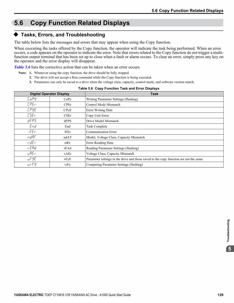
5.6 Copy Function Related Displays
u Tasks, Errors, and TroubleshootingThe table below lists the messages and errors that may appear when using the Copy function.When executing the tasks offered by the Copy function, the operator will indicate the task being performed. When an erroroccurs, a code appears on the operator to indicate the error. Note that errors related to the Copy function do not trigger a multi-function output terminal that has been set up to close when a fault or alarm occurs. To clear an error, simply press any key onthe operator and the error display will disappear.Table 5.6 lists the corrective action that can be taken when an error occurs.
Note: 1. Whenever using the copy function, the drive should be fully stopped.2. The drive will not accept a Run command while the Copy function is being executed.3. Parameters can only be saved to a drive when the voltage class, capacity, control mode, and software version match.
Table 5.6 Copy Function Task and Error DisplaysDigital Operator Display Task
CoPy Writing Parameter Settings (flashing)CPEr Control Mode MismatchCPyE Error Writing DataCSEr Copy Unit ErrordFPS Drive Model MismatchEnd Task CompleteiFEr Communication Error
ndAT Model, Voltage Class, Capacity MismatchrdEr Error Reading DatarEAd Reading Parameter Settings (flashing)vAEr Voltage Class, Capacity MismatchvFyE Parameter settings in the drive and those saved to the copy function are not the samevrFy Comparing Parameter Settings (flashing)
5.6 Copy Function Related Displays
YASKAWA ELECTRIC TOEP C710616 31B YASKAWA AC Drive - A1000 Quick Start Guide 129
5
Trou
bles
hoot
ing

5.7 Diagnosing and Resetting FaultsWhen a fault occurs and the drive stops, follow the instructions below to remove whatever conditions triggered the fault, thenrestart the drive.
u Fault Reset MethodsWhen a fault occurs, the cause of the fault must be removed and the drive must be restarted. The table below lists the differentways to restart the drive.
After the Fault Occurs Procedure
Fix the cause of the fault, restart the drive, andreset the fault Press on the digital operator.
LORE
F2F1
ESC
RUN STOP
ENTERRESET
RESET
- MODE -oC
Overcurrent
DRV
FWD RESET
Resetting via Fault Reset Digital Input S4Close then open the fault signal digital input viaterminal S4. S4 is set for “Fault Reset” as default(H1-04 = 14).
Fault Reset SwitchDrive
S4 Fault Reset Digital Input
SC Digital Input Common
Turn off the main power supply if the above methods do not reset the fault. Reapply power after thedigital operator display has turned off.
ON
OFF
2
1
Note: If the Run command is present, the drive will disregard any attempts to reset the fault. Remove the Run command before attempting to cleara fault situation.
5.7 Diagnosing and Resetting Faults
130 YASKAWA ELECTRIC TOEP C710616 31B YASKAWA AC Drive - A1000 Quick Start Guide
Periodic Inspection & MaintenanceThis chapter describes the periodic inspection and maintenance of the drive to ensure that it receivesthe proper care to maintain overall performance.
6.1 INSPECTION........................................................................................................1326.2 PERIODIC MAINTENANCE.................................................................................1356.3 DRIVE REPLACEMENT.......................................................................................137
6
YASKAWA ELECTRIC TOEP C710616 31B YASKAWA AC Drive - A1000 Quick Start Guide 131
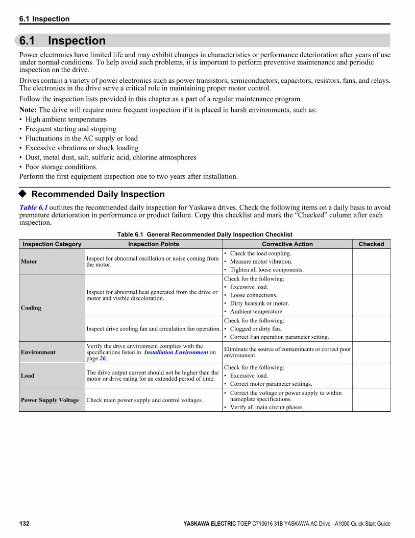
6.1 InspectionPower electronics have limited life and may exhibit changes in characteristics or performance deterioration after years of useunder normal conditions. To help avoid such problems, it is important to perform preventive maintenance and periodicinspection on the drive.Drives contain a variety of power electronics such as power transistors, semiconductors, capacitors, resistors, fans, and relays.The electronics in the drive serve a critical role in maintaining proper motor control.Follow the inspection lists provided in this chapter as a part of a regular maintenance program.Note: The drive will require more frequent inspection if it is placed in harsh environments, such as:• High ambient temperatures• Frequent starting and stopping• Fluctuations in the AC supply or load• Excessive vibrations or shock loading• Dust, metal dust, salt, sulfuric acid, chlorine atmospheres• Poor storage conditions.Perform the first equipment inspection one to two years after installation.
u Recommended Daily InspectionTable 6.1 outlines the recommended daily inspection for Yaskawa drives. Check the following items on a daily basis to avoidpremature deterioration in performance or product failure. Copy this checklist and mark the “Checked” column after eachinspection.
Table 6.1 General Recommended Daily Inspection ChecklistInspection Category Inspection Points Corrective Action Checked
Motor Inspect for abnormal oscillation or noise coming fromthe motor.
• Check the load coupling.• Measure motor vibration.• Tighten all loose components.
Cooling
Inspect for abnormal heat generated from the drive ormotor and visible discoloration.
Check for the following:• Excessive load.• Loose connections.• Dirty heatsink or motor.• Ambient temperature.
Inspect drive cooling fan and circulation fan operation.Check for the following:• Clogged or dirty fan.• Correct Fan operation parameter setting.
EnvironmentVerify the drive environment complies with thespecifications listed in Installation Environment onpage 26.
Eliminate the source of contaminants or correct poorenvironment.
Load The drive output current should not be higher than themotor or drive rating for an extended period of time.
Check for the following:• Excessive load.• Correct motor parameter settings.
Power Supply Voltage Check main power supply and control voltages.• Correct the voltage or power supply to within
nameplate specifications.• Verify all main circuit phases.
6.1 Inspection
132 YASKAWA ELECTRIC TOEP C710616 31B YASKAWA AC Drive - A1000 Quick Start Guide
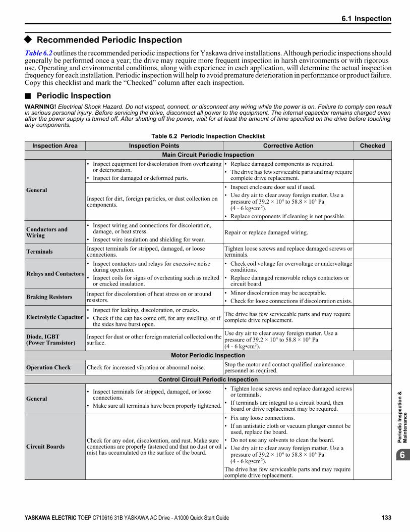
u Recommended Periodic InspectionTable 6.2 outlines the recommended periodic inspections for Yaskawa drive installations. Although periodic inspections shouldgenerally be performed once a year; the drive may require more frequent inspection in harsh environments or with rigoroususe. Operating and environmental conditions, along with experience in each application, will determine the actual inspectionfrequency for each installation. Periodic inspection will help to avoid premature deterioration in performance or product failure.Copy this checklist and mark the “Checked” column after each inspection.
n Periodic InspectionWARNING! Electrical Shock Hazard. Do not inspect, connect, or disconnect any wiring while the power is on. Failure to comply can resultin serious personal injury. Before servicing the drive, disconnect all power to the equipment. The internal capacitor remains charged evenafter the power supply is turned off. After shutting off the power, wait for at least the amount of time specified on the drive before touchingany components.
Table 6.2 Periodic Inspection ChecklistInspection Area Inspection Points Corrective Action Checked
Main Circuit Periodic Inspection
General
• Inspect equipment for discoloration from overheatingor deterioration.
• Inspect for damaged or deformed parts.
• Replace damaged components as required.• The drive has few serviceable parts and may require
complete drive replacement.
Inspect for dirt, foreign particles, or dust collection oncomponents.
• Inspect enclosure door seal if used.• Use dry air to clear away foreign matter. Use a
pressure of 39.2 × 10⁴ to 58.8 × 10⁴ Pa(4 - 6 kg•cm2).
• Replace components if cleaning is not possible.
Conductors andWiring
• Inspect wiring and connections for discoloration,damage, or heat stress.
• Inspect wire insulation and shielding for wear.Repair or replace damaged wiring.
Terminals Inspect terminals for stripped, damaged, or looseconnections.
Tighten loose screws and replace damaged screws orterminals.
Relays and Contactors
• Inspect contactors and relays for excessive noiseduring operation.
• Inspect coils for signs of overheating such as meltedor cracked insulation.
• Check coil voltage for overvoltage or undervoltageconditions.
• Replace damaged removable relays contactors orcircuit board.
Braking Resistors Inspect for discoloration of heat stress on or aroundresistors.
• Minor discoloration may be acceptable.• Check for loose connections if discoloration exists.
Electrolytic Capacitor• Inspect for leaking, discoloration, or cracks.• Check if the cap has come off, for any swelling, or if
the sides have burst open.
The drive has few serviceable parts and may requirecomplete drive replacement.
Diode, IGBT(Power Transistor)
Inspect for dust or other foreign material collected on thesurface.
Use dry air to clear away foreign matter. Use apressure of 39.2 × 10⁴ to 58.8 × 10⁴ Pa(4 - 6 kg•cm2).
Motor Periodic Inspection
Operation Check Check for increased vibration or abnormal noise. Stop the motor and contact qualified maintenancepersonnel as required.
Control Circuit Periodic Inspection
General• Inspect terminals for stripped, damaged, or loose
connections.• Make sure all terminals have been properly tightened.
• Tighten loose screws and replace damaged screwsor terminals.
• If terminals are integral to a circuit board, thenboard or drive replacement may be required.
Circuit BoardsCheck for any odor, discoloration, and rust. Make sureconnections are properly fastened and that no dust or oilmist has accumulated on the surface of the board.
• Fix any loose connections.• If an antistatic cloth or vacuum plunger cannot be
used, replace the board.• Do not use any solvents to clean the board.• Use dry air to clear away foreign matter. Use a
pressure of 39.2 × 10⁴ to 58.8 × 10⁴ Pa(4 - 6 kg•cm2).
The drive has few serviceable parts and may requirecomplete drive replacement.
6.1 Inspection
YASKAWA ELECTRIC TOEP C710616 31B YASKAWA AC Drive - A1000 Quick Start Guide 133
6
Perio
dic
Insp
ectio
n &
Mai
nten
ance
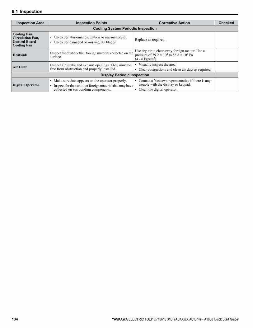
Inspection Area Inspection Points Corrective Action CheckedCooling System Periodic Inspection
Cooling Fan,Circulation Fan,Control BoardCooling Fan
• Check for abnormal oscillation or unusual noise.• Check for damaged or missing fan blades.
Replace as required.
Heatsink Inspect for dust or other foreign material collected on thesurface.
Use dry air to clear away foreign matter. Use apressure of 39.2 × 10⁴ to 58.8 × 10⁴ Pa(4 - 6 kg•cm2).
Air Duct Inspect air intake and exhaust openings. They must befree from obstruction and properly installed.
• Visually inspect the area.• Clear obstructions and clean air duct as required.
Display Periodic Inspection
Digital Operator• Make sure data appears on the operator properly.• Inspect for dust or other foreign material that may have
collected on surrounding components.
• Contact a Yaskawa representative if there is anytrouble with the display or keypad.
• Clean the digital operator.
6.1 Inspection
134 YASKAWA ELECTRIC TOEP C710616 31B YASKAWA AC Drive - A1000 Quick Start Guide
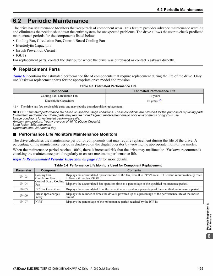
6.2 Periodic MaintenanceThe drive has Maintenance Monitors that keep track of component wear. This feature provides advance maintenance warningand eliminates the need to shut down the entire system for unexpected problems. The drive allows the user to check predictedmaintenance periods for the components listed below.• Cooling Fan, Circulation Fan, Control Board Cooling Fan• Electrolytic Capacitors• Inrush Prevention Circuit• IGBTsFor replacement parts, contact the distributor where the drive was purchased or contact Yaskawa directly.
u Replacement PartsTable 6.3 contains the estimated performance life of components that require replacement during the life of the drive. Onlyuse Yaskawa replacement parts for the appropriate drive model and revision.
Table 6.3 Estimated Performance LifeComponent Estimated Performance Life
Cooling Fan, Circulation Fan 10 yearsElectrolytic Capacitors 10 years <1>
<1> The drive has few serviceable parts and may require complete drive replacement.
NOTICE: Estimated performance life based on specific usage conditions. These conditions are provided for the purpose of replacing partsto maintain performance. Some parts may require more frequent replacement due to poor environments or rigorous use.Usage conditions for estimated performance life:Ambient temperature: Yearly average of 40 °C (Open-Chassis)Load factor: 80% maximumOperation time: 24 hours a day
n Performance Life Monitors Maintenance MonitorsThe drive calculates the maintenance period for components that may require replacement during the life of the drive. Apercentage of the maintenance period is displayed on the digital operator by viewing the appropriate monitor parameter.When the maintenance period reaches 100%, there is increased risk that the drive may malfunction. Yaskawa recommendschecking the maintenance period regularly to ensure maximum performance life.Refer to Recommended Periodic Inspection on page 133 for more details.
Table 6.4 Performance Life Monitors Used for Component ReplacementParameter Component Contents
U4-03 Cooling FanCirculation FanControl Board CoolingFan
Displays the accumulated operation time of the fan, from 0 to 99999 hours. This value is automatically resetto 0 once it reaches 99999.
U4-04 Displays the accumulated fan operation time as a percentage of the specified maintenance period.
U4-05 DC Bus Capacitors Displays the accumulated time the capacitors are used as a percentage of the specified maintenance period.
U4-06 Inrush (pre-charge)Relay
Displays the number of times the drive is powered up as a percentage of the performance life of the inrushcircuit.
U4-07 IGBT Displays the percentage of the maintenance period reached by the IGBTs.
6.2 Periodic Maintenance
YASKAWA ELECTRIC TOEP C710616 31B YASKAWA AC Drive - A1000 Quick Start Guide 135
6
Perio
dic
Insp
ectio
n &
Mai
nten
ance
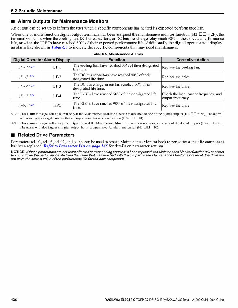
n Alarm Outputs for Maintenance MonitorsAn output can be set up to inform the user when a specific components has neared its expected performance life.When one of multi-function digital output terminals has been assigned the maintenance monitor function (H2-oo = 2F), theterminal will close when the cooling fan, DC bus capacitors, or DC bus pre-charge relay reach 90% of the expected performancelife, or when the IGBTs have reached 50% of their expected performance life. Additionally the digital operator will displayan alarm like shown in Table 6.5 to indicate the specific components that may need maintenance.
Table 6.5 Maintenance AlarmsDigital Operator Alarm Display Function Corrective Action
<1> LT-1 The cooling fans have reached 90% of their designatedlife time. Replace the cooling fan.
<1> LT-2 The DC bus capacitors have reached 90% of theirdesignated life time. Replace the drive.
<1> LT-3 The DC bus charge circuit has reached 90% of itsdesignated life time. Replace the drive.
<1> LT-4 The IGBTs have reached 50% of their designated lifetime.
Check the load, carrier frequency, andoutput frequency.
<2> TrPC The IGBTs have reached 90% of their designated lifetime. Replace the drive.
<1> This alarm message will be output only if the Maintenance Monitor function is assigned to one of the digital outputs (H2-oo = 2F). The alarmwill also trigger a digital output that is programmed for alarm indication (H2-oo = 10).
<2> This alarm message will always be output, even if the Maintenance Monitor function is not assigned to any of the digital outputs (H2-oo = 2F).The alarm will also trigger a digital output that is programmed for alarm indication (H2-oo = 10).
n Related Drive ParametersParameters o4-03, o4-05, o4-07, and o4-09 can be used to reset a Maintenance Monitor back to zero after a specific componenthas been replaced. Refer to Parameter List on page 145 for details on parameter settings.NOTICE: If these parameters are not reset after the corresponding parts have been replaced, the Maintenance Monitor function will continueto count down the performance life from the value that was reached with the old part. If the Maintenance Monitor is not reset, the drive willnot have the correct value of the performance life for the new component.
6.2 Periodic Maintenance
136 YASKAWA ELECTRIC TOEP C710616 31B YASKAWA AC Drive - A1000 Quick Start Guide

6.3 Drive Replacement
u Replacing the DriveWARNING! Electrical Shock Hazard. Do not connect or disconnect wiring while the power is on. Failure to comply can result in seriouspersonal injury. Before servicing the drive, disconnect all power to the equipment. The internal capacitor remains charged even after thepower supply is turned off. After shutting off the power, wait for at least the amount of time specified on the drive before touching anycomponents.
WARNING! Electrical Shock Hazard. Do not allow unqualified personnel to perform work on the drive. Failure to comply could result inserious injury. Installation, maintenance, inspection and servicing must be performed only by authorized personnel familiar with installation,adjustment and maintenance of AC drives.
NOTICE: Observe proper electrostatic discharge procedures (ESD) when handling the drive and circuit boards. Failure to comply may resultin ESD damage to the drive circuitry.
The following procedure explains how to replace a drive.This section provides instructions for drive replacement only.To install option boards or other types of options, refer to the specific manuals for those options.NOTICE: When transferring a braking transistor, braking resistor, or other type of option from a damaged drive to a new replacement drive,make sure it is working properly before reconnecting it to the new drive. Replace broken options to prevent immediate breakdown of thereplacement drive.
1. Remove the terminal cover.
Figure 6.1 Remove the Terminal Cover
2. Loosen the screws holding the terminal board in place. Remove the screw securing the bottom cover and remove thebottom cover from the drive.
Figure 6.2 Unscrew the Terminal Board and Remove the Bottom Cover
3. Slide the terminal board as illustrated by the arrows to remove it from the drive along with the bottom cover.
6.3 Drive Replacement
YASKAWA ELECTRIC TOEP C710616 31B YASKAWA AC Drive - A1000 Quick Start Guide 137
6
Perio
dic
Insp
ectio
n &
Mai
nten
ance

Figure 6.3 Remove the Terminal Board
Figure 6.4 Disconnected Removable Terminal Board
4. Disconnect all option cards and options, making sure they are intact before reusing.5. Replace the drive and wire the main circuit.
n Installing the Drive1. After wiring the main circuit, connect the terminal block to the drive as shown in Figure 6.5. Use the installation screw
to fasten the terminal block into place.
Figure 6.5 Install the Terminal Board
2. Reconnect options for the new drive the same way the options were connected in the old drive. Connect option boardsto the same option ports in the new drive that were used in the old drive.
3. Replace the terminal cover.4. After powering on the drive, all parameter settings are transferred from the terminal board to the drive memory. If an
oPE04 error occurs, load the parameter settings saved on the terminal board to the new drive by setting parameterA1-03 to 5550. Reset the Maintenance Monitor function timers by setting parameters o4-01 through o4-12 to 0, andparameter o4-13 to 1.
6.3 Drive Replacement
138 YASKAWA ELECTRIC TOEP C710616 31B YASKAWA AC Drive - A1000 Quick Start Guide

Specifications
A.1 HEAVY DUTY AND NORMAL DUTY RATINGS.................................................140A.2 POWER RATINGS...............................................................................................141A.3 DRIVE SPECIFICATIONS....................................................................................142
Appendix: A
YASKAWA ELECTRIC TOEP C710616 31B YASKAWA AC Drive - A1000 Quick Start Guide 139
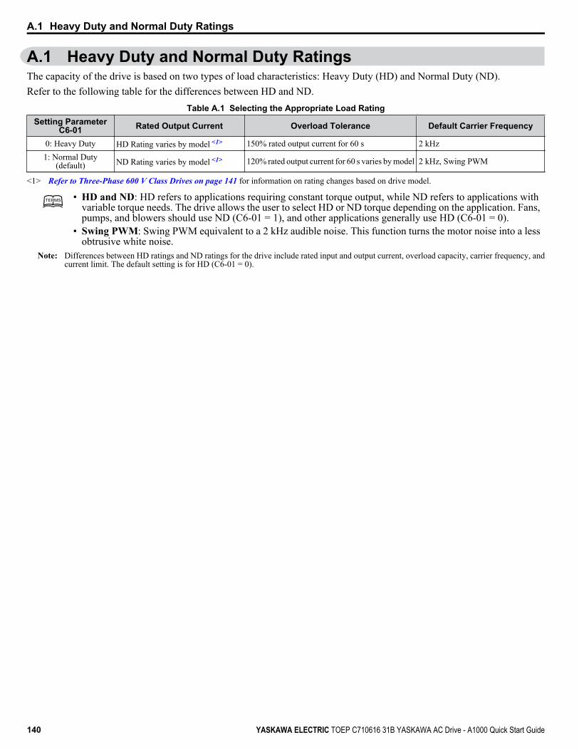
A.1 Heavy Duty and Normal Duty RatingsThe capacity of the drive is based on two types of load characteristics: Heavy Duty (HD) and Normal Duty (ND).Refer to the following table for the differences between HD and ND.
Table A.1 Selecting the Appropriate Load RatingSetting Parameter
C6-01 Rated Output Current Overload Tolerance Default Carrier Frequency
0: Heavy Duty HD Rating varies by model <1> 150% rated output current for 60 s 2 kHz1: Normal Duty
(default) ND Rating varies by model <1> 120% rated output current for 60 s varies by model 2 kHz, Swing PWM
<1> Refer to Three-Phase 600 V Class Drives on page 141 for information on rating changes based on drive model.
TERMSTERMS • HD and ND: HD refers to applications requiring constant torque output, while ND refers to applications withvariable torque needs. The drive allows the user to select HD or ND torque depending on the application. Fans,pumps, and blowers should use ND (C6-01 = 1), and other applications generally use HD (C6-01 = 0).
• Swing PWM: Swing PWM equivalent to a 2 kHz audible noise. This function turns the motor noise into a lessobtrusive white noise.
Note: Differences between HD ratings and ND ratings for the drive include rated input and output current, overload capacity, carrier frequency, andcurrent limit. The default setting is for HD (C6-01 = 0).
A.1 Heavy Duty and Normal Duty Ratings
140 YASKAWA ELECTRIC TOEP C710616 31B YASKAWA AC Drive - A1000 Quick Start Guide
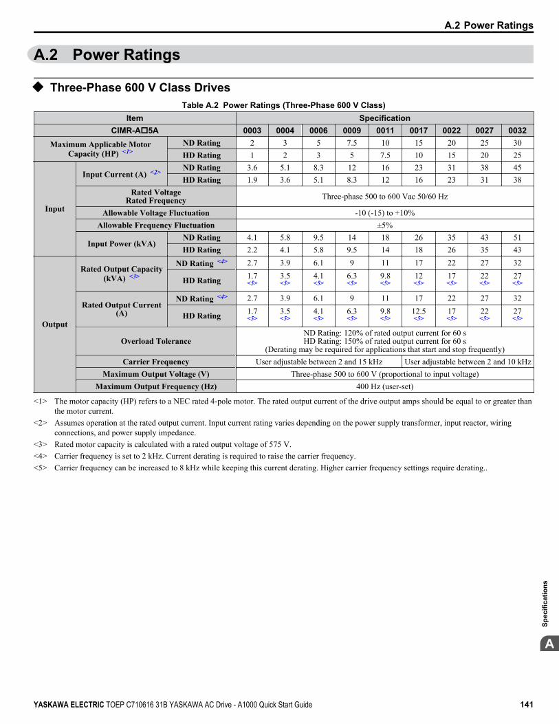
A.2 Power Ratings
u Three-Phase 600 V Class DrivesTable A.2 Power Ratings (Three-Phase 600 V Class)
Item SpecificationCIMR-Ao5A 0003 0004 0006 0009 0011 0017 0022 0027 0032
Maximum Applicable MotorCapacity (HP) <1>
ND Rating 2 3 5 7.5 10 15 20 25 30HD Rating 1 2 3 5 7.5 10 15 20 25
Input
Input Current (A) <2> ND Rating 3.6 5.1 8.3 12 16 23 31 38 45HD Rating 1.9 3.6 5.1 8.3 12 16 23 31 38
Rated VoltageRated Frequency Three-phase 500 to 600 Vac 50/60 Hz
Allowable Voltage Fluctuation -10 (-15) to +10%Allowable Frequency Fluctuation ±5%
Input Power (kVA)ND Rating 4.1 5.8 9.5 14 18 26 35 43 51HD Rating 2.2 4.1 5.8 9.5 14 18 26 35 43
Output
Rated Output Capacity(kVA) <3>
ND Rating <4> 2.7 3.9 6.1 9 11 17 22 27 32
HD Rating 1.7<5>
3.5<5>
4.1<5>
6.3<5>
9.8<5>
12<5>
17<5>
22<5>
27<5>
Rated Output Current(A)
ND Rating <4> 2.7 3.9 6.1 9 11 17 22 27 32
HD Rating 1.7<5>
3.5<5>
4.1<5>
6.3<5>
9.8<5>
12.5<5>
17<5>
22<5>
27<5>
Overload ToleranceND Rating: 120% of rated output current for 60 sHD Rating: 150% of rated output current for 60 s
(Derating may be required for applications that start and stop frequently)Carrier Frequency User adjustable between 2 and 15 kHz User adjustable between 2 and 10 kHz
Maximum Output Voltage (V) Three-phase 500 to 600 V (proportional to input voltage)Maximum Output Frequency (Hz) 400 Hz (user-set)
<1> The motor capacity (HP) refers to a NEC rated 4-pole motor. The rated output current of the drive output amps should be equal to or greater thanthe motor current.
<2> Assumes operation at the rated output current. Input current rating varies depending on the power supply transformer, input reactor, wiringconnections, and power supply impedance.
<3> Rated motor capacity is calculated with a rated output voltage of 575 V.<4> Carrier frequency is set to 2 kHz. Current derating is required to raise the carrier frequency.<5> Carrier frequency can be increased to 8 kHz while keeping this current derating. Higher carrier frequency settings require derating..
A.2 Power Ratings
YASKAWA ELECTRIC TOEP C710616 31B YASKAWA AC Drive - A1000 Quick Start Guide 141
A
Spec
ifica
tions
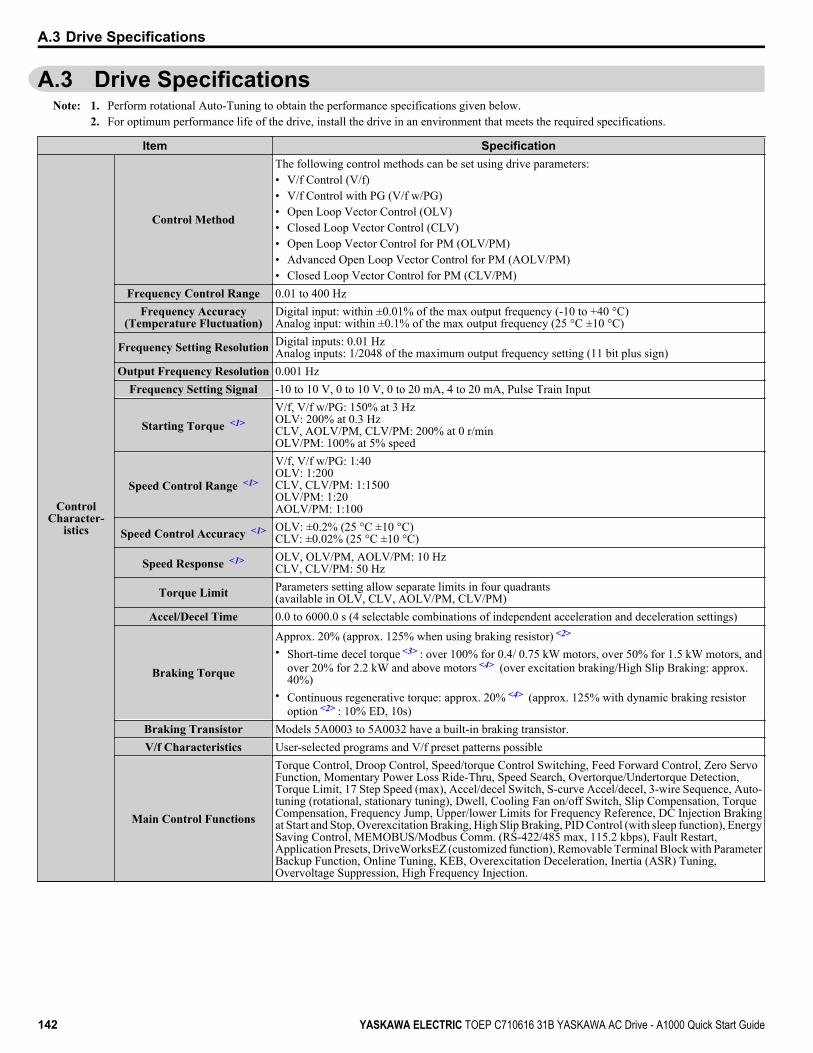
A.3 Drive SpecificationsNote: 1. Perform rotational Auto-Tuning to obtain the performance specifications given below.
2. For optimum performance life of the drive, install the drive in an environment that meets the required specifications.
Item Specification
ControlCharacter-
istics
Control Method
The following control methods can be set using drive parameters:• V/f Control (V/f)• V/f Control with PG (V/f w/PG)• Open Loop Vector Control (OLV)• Closed Loop Vector Control (CLV)• Open Loop Vector Control for PM (OLV/PM)• Advanced Open Loop Vector Control for PM (AOLV/PM)• Closed Loop Vector Control for PM (CLV/PM)
Frequency Control Range 0.01 to 400 HzFrequency Accuracy
(Temperature Fluctuation)Digital input: within ±0.01% of the max output frequency (-10 to +40 °C)Analog input: within ±0.1% of the max output frequency (25 °C ±10 °C)
Frequency Setting Resolution Digital inputs: 0.01 HzAnalog inputs: 1/2048 of the maximum output frequency setting (11 bit plus sign)
Output Frequency Resolution 0.001 HzFrequency Setting Signal -10 to 10 V, 0 to 10 V, 0 to 20 mA, 4 to 20 mA, Pulse Train Input
Starting Torque <1>V/f, V/f w/PG: 150% at 3 HzOLV: 200% at 0.3 HzCLV, AOLV/PM, CLV/PM: 200% at 0 r/minOLV/PM: 100% at 5% speed
Speed Control Range <1>
V/f, V/f w/PG: 1:40OLV: 1:200CLV, CLV/PM: 1:1500OLV/PM: 1:20AOLV/PM: 1:100
Speed Control Accuracy <1> OLV: ±0.2% (25 °C ±10 °C)CLV: ±0.02% (25 °C ±10 °C)
Speed Response <1> OLV, OLV/PM, AOLV/PM: 10 HzCLV, CLV/PM: 50 Hz
Torque Limit Parameters setting allow separate limits in four quadrants(available in OLV, CLV, AOLV/PM, CLV/PM)
Accel/Decel Time 0.0 to 6000.0 s (4 selectable combinations of independent acceleration and deceleration settings)
Braking Torque
Approx. 20% (approx. 125% when using braking resistor) <2>
• Short-time decel torque <3> : over 100% for 0.4/ 0.75 kW motors, over 50% for 1.5 kW motors, andover 20% for 2.2 kW and above motors <4> (over excitation braking/High Slip Braking: approx.40%)
• Continuous regenerative torque: approx. 20% <4> (approx. 125% with dynamic braking resistoroption <2> : 10% ED, 10s)
Braking Transistor Models 5A0003 to 5A0032 have a built-in braking transistor.V/f Characteristics User-selected programs and V/f preset patterns possible
Main Control Functions
Torque Control, Droop Control, Speed/torque Control Switching, Feed Forward Control, Zero ServoFunction, Momentary Power Loss Ride-Thru, Speed Search, Overtorque/Undertorque Detection,Torque Limit, 17 Step Speed (max), Accel/decel Switch, S-curve Accel/decel, 3-wire Sequence, Auto-tuning (rotational, stationary tuning), Dwell, Cooling Fan on/off Switch, Slip Compensation, TorqueCompensation, Frequency Jump, Upper/lower Limits for Frequency Reference, DC Injection Brakingat Start and Stop, Overexcitation Braking, High Slip Braking, PID Control (with sleep function), EnergySaving Control, MEMOBUS/Modbus Comm. (RS-422/485 max, 115.2 kbps), Fault Restart,Application Presets, DriveWorksEZ (customized function), Removable Terminal Block with ParameterBackup Function, Online Tuning, KEB, Overexcitation Deceleration, Inertia (ASR) Tuning,Overvoltage Suppression, High Frequency Injection.
A.3 Drive Specifications
142 YASKAWA ELECTRIC TOEP C710616 31B YASKAWA AC Drive - A1000 Quick Start Guide

Item Specification
ProtectionFunctions
Motor Protection Electronic thermal overload relayMomentary Overcurrent
Protection Drive stops when output current exceeds 200% of Heavy Duty Rating
Overload Protection Drive stops after 60 s at 150% of rated Heavy Duty output current <5>
Overvoltage Protection 600 V class: Stops when DC bus voltage exceeds approx. 1040 VUndervoltage Protection 600 V class: Stops when DC bus voltage falls below approx. 475 V
Momentary Power Loss Ride-Thru
Immediately stop after 15 ms or longer power loss <6> . Continuous operation during power loss than2 s (standard)
Heatsink Overheat Protection ThermistorBraking Resistor Overheat
Protection Overheat input signal for braking resistor (Optional ERF-type, 3% ED)
Stall Prevention Stall Prevention is available during acceleration, deceleration, and during run.Ground Protection Electronic circuit protection <7>
DC Bus Charge LED Remains lit until DC bus voltage falls below 50 V
Environment
Area of Use Indoors
Ambient Temperature -10 to 40 °C (NEMA Type 1), -10 to 50 °C (Open-Chassis), up to 60 °C with output current derating<9>
Humidity 95 RH% or less (no condensation)Storage Temperature -20 to 60 °C (short-term temperature during transportation)
Altitude Up to 1000 meters without derating, up to 3000 m with output current and voltage deratingVibration/Shock 20 to 55 Hz: 5.9 m/s2 (5A0003 to 5A0032)
Safety Standard UL 508 C <8>
Protection Design IP00/Open-Chassis, IP20/NEMA Type 1 enclosure <9>
<1> The accuracy of these values depends on motor characteristics, ambient conditions, and drive settings. Specifications may vary with different motorsand with changing motor temperature. Contact Yaskawa for consultation.
<2> Disable Stall Prevention during deceleration (L3-04 = 0) when using a regenerative converter, a regenerative unit, a braking resistor or the BrakingResistor Unit. The default setting for the Stall Prevention function will interfere with the braking resistor.
<3> Instantaneous average deceleration torque refers to the torque required to decelerate the motor (uncoupled from the load) from the rated motor speeddown to zero in the shortest time.
<4> Actual specifications may vary depending on motor characteristics.<5> Overload protection may be triggered when operating with 150% of the rated output current if the output frequency is less than 6 Hz.<6> May be shorter due to load conditions and motor speed.<7> Ground protection cannot be provided when the impedance of the ground fault path is too low, or when the drive is powered up while a ground
fault is present at the output.<8> Terminals H1, H2, DM+, and DM- on 600 V class models are designed to the functionality, but are not certified to EN61800-5-1, EN954-1/ISO13849
Cat. 3, IEC/EN61508 SIL2, Insulation coordination: class 1.<9> Removing the top protective cover or bottom conduit bracket from an IP20/NEMA Type 1 drive voids NEMA Type 1 protection while maintaining
IP20 conformity.
A.3 Drive Specifications
YASKAWA ELECTRIC TOEP C710616 31B YASKAWA AC Drive - A1000 Quick Start Guide 143
A
Spec
ifica
tions

A.3 Drive Specifications
This Page Intentionally Blank
144 YASKAWA ELECTRIC TOEP C710616 31B YASKAWA AC Drive - A1000 Quick Start Guide

Parameter ListThis appendix contains a full listing of all parameters and settings available in the drive.
B.1 A: INITIALIZATION PARAMETERS....................................................................146B.2 B: APPLICATION.................................................................................................148B.3 C: TUNING............................................................................................................154B.4 D: REFERENCES.................................................................................................159B.5 E: MOTOR PARAMETERS..................................................................................163B.6 F: OPTIONS.........................................................................................................168B.7 H PARAMETERS: MULTI-FUNCTION TERMINALS..........................................174B.8 L: PROTECTION FUNCTION...............................................................................183B.9 N: SPECIAL ADJUSTMENT................................................................................190B.10 O: OPERATOR-RELATED SETTINGS................................................................193B.11 DRIVEWORKSEZ PARAMETERS.......................................................................195B.12 T: MOTOR TUNING..............................................................................................196B.13 U: MONITORS......................................................................................................199
Appendix: B
YASKAWA ELECTRIC TOEP C710616 31B YASKAWA AC Drive - A1000 Quick Start Guide 145

B.1 A: Initialization ParametersTable B.1 Symbols and Icons Used in Parameter Descriptions
Symbol DescriptionParameter can be changed during run.
Motor 2 Refers to a second motor when the drive is operating two motors. Use multi-function input terminals to switchbetween motors.
The A parameter group creates the operating environment for the drive. This includes the parameter Access Level, MotorControl Method, Password, User Parameters and more.
u A1: InitializationNo.
(Addr.Hex)
Name Description Values Page
A1-00(100)
<1>
Language Selection
0: English1: Japanese2: German3: French4: Italian5: Spanish6: Portuguese7: Chinese
Default: 0Range: 0 to 7 –
A1-01(101)
<2>
Access Level Selection
0: View and set A1-01 and A1-04. Uo-ooparameters can also be viewed.1: User Parameters (access to a set of parameters selected by the user, A2-01to A2-32)2: Advanced Access (access to view and set all parameters)
Default: 2Range: 0 to 2 –
A1-02(102)
<1>Control Method Selection
0: V/f Control1: V/f Control with PG2: Open Loop Vector Control3: Closed Loop Vector Control
Default: 2Range: 0 to 3 71
A1-03(103) Initialize Parameters
0: No initialization1110: User Initialize (parameter values must be stored using parameter o2-03)2220: 2-Wire initialization3330: 3-Wire initialization5550: oPE04 error reset
Default: 0Range: 0 to 3330;5550
71
A1-04(104) Password
When the value set into A1-04 does not match the value set into A1-05,parameters A1-01 through A1-03, A1-06, and A2-01 through A2-33 cannotbe changed.
Default: 0000Min.: 0000Max.: 9999
–
A1-05(105) Password Setting
When the value set into A1-04 does not match the value set into A1-05,parameters A1-01 through A1-03, A1-06, and A2-01 through A2-33 cannotbe changed.
Default: 0000Min.: 0000Max.: 9999
–
A1-06(127) Application Preset
0: General-purpose1: Water supply pump2: Conveyor3: Exhaust fan4: HVAC fan5: Air compressor
Default: 0Range: 0 to 7 –
A1-07(128)
DriveWorksEZ FunctionSelection
0: DWEZ Disabled1: DWEZ Enabled2: Digital input (enabled when H1-oo = 9F)
Default: 0Range: 0 to 2 –
<1> Parameter setting value is not reset to the default value when the drive is initialized.<2> Default setting value is dependent on the Application Preset selected with parameter A1-06.
B.1 A: Initialization Parameters
146 YASKAWA ELECTRIC TOEP C710616 31B YASKAWA AC Drive - A1000 Quick Start Guide
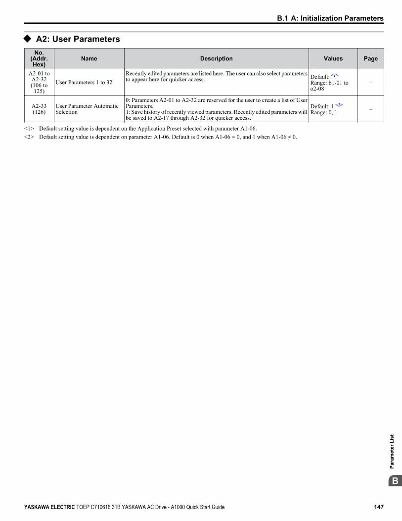
u A2: User ParametersNo.
(Addr.Hex)
Name Description Values Page
A2-01 toA2-32(106 to
125)User Parameters 1 to 32
Recently edited parameters are listed here. The user can also select parametersto appear here for quicker access. Default: <1>
Range: b1-01 too2-08
–
A2-33(126)
User Parameter AutomaticSelection
0: Parameters A2-01 to A2-32 are reserved for the user to create a list of UserParameters.1: Save history of recently viewed parameters. Recently edited parameters willbe saved to A2-17 through A2-32 for quicker access.
Default: 1 <2>
Range: 0, 1 –
<1> Default setting value is dependent on the Application Preset selected with parameter A1-06.<2> Default setting value is dependent on parameter A1-06. Default is 0 when A1-06 = 0, and 1 when A1-06 ≠ 0.
B.1 A: Initialization Parameters
YASKAWA ELECTRIC TOEP C710616 31B YASKAWA AC Drive - A1000 Quick Start Guide 147
B
Para
met
er L
ist
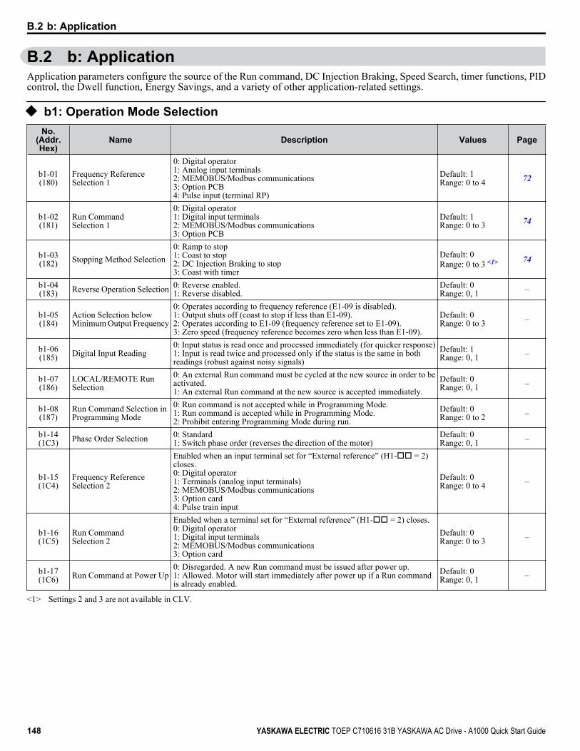
B.2 b: ApplicationApplication parameters configure the source of the Run command, DC Injection Braking, Speed Search, timer functions, PIDcontrol, the Dwell function, Energy Savings, and a variety of other application-related settings.
u b1: Operation Mode SelectionNo.
(Addr.Hex)
Name Description Values Page
b1-01(180)
Frequency ReferenceSelection 1
0: Digital operator1: Analog input terminals2: MEMOBUS/Modbus communications3: Option PCB4: Pulse input (terminal RP)
Default: 1Range: 0 to 4 72
b1-02(181)
Run CommandSelection 1
0: Digital operator1: Digital input terminals2: MEMOBUS/Modbus communications3: Option PCB
Default: 1Range: 0 to 3 74
b1-03(182) Stopping Method Selection
0: Ramp to stop1: Coast to stop2: DC Injection Braking to stop3: Coast with timer
Default: 0Range: 0 to 3 <1> 74
b1-04(183) Reverse Operation Selection 0: Reverse enabled.
1: Reverse disabled.Default: 0Range: 0, 1 –
b1-05(184)
Action Selection belowMinimum Output Frequency
0: Operates according to frequency reference (E1-09 is disabled).1: Output shuts off (coast to stop if less than E1-09).2: Operates according to E1-09 (frequency reference set to E1-09).3: Zero speed (frequency reference becomes zero when less than E1-09).
Default: 0Range: 0 to 3 –
b1-06(185) Digital Input Reading
0: Input status is read once and processed immediately (for quicker response)1: Input is read twice and processed only if the status is the same in bothreadings (robust against noisy signals)
Default: 1Range: 0, 1 –
b1-07(186)
LOCAL/REMOTE RunSelection
0: An external Run command must be cycled at the new source in order to beactivated.1: An external Run command at the new source is accepted immediately.
Default: 0Range: 0, 1 –
b1-08(187)
Run Command Selection inProgramming Mode
0: Run command is not accepted while in Programming Mode.1: Run command is accepted while in Programming Mode.2: Prohibit entering Programming Mode during run.
Default: 0Range: 0 to 2 –
b1-14(1C3) Phase Order Selection 0: Standard
1: Switch phase order (reverses the direction of the motor)Default: 0Range: 0, 1 –
b1-15(1C4)
Frequency ReferenceSelection 2
Enabled when an input terminal set for “External reference” (H1-oo = 2)closes.0: Digital operator1: Terminals (analog input terminals)2: MEMOBUS/Modbus communications3: Option card4: Pulse train input
Default: 0Range: 0 to 4 –
b1-16(1C5)
Run CommandSelection 2
Enabled when a terminal set for “External reference” (H1-oo = 2) closes.0: Digital operator1: Digital input terminals2: MEMOBUS/Modbus communications3: Option card
Default: 0Range: 0 to 3 –
b1-17(1C6) Run Command at Power Up
0: Disregarded. A new Run command must be issued after power up.1: Allowed. Motor will start immediately after power up if a Run commandis already enabled.
Default: 0Range: 0, 1 –
<1> Settings 2 and 3 are not available in CLV.
B.2 b: Application
148 YASKAWA ELECTRIC TOEP C710616 31B YASKAWA AC Drive - A1000 Quick Start Guide

u b2: DC Injection Braking and Short Circuit BrakingNo.
(Addr.Hex)
Name Description Values Page
b2-01(189)
DC Injection Braking StartFrequency
Sets the frequency at which DC Injection Braking starts when “Ramp to stop”(b1-03 = 0) is selected.
Default: <1>
Min.: 0.0 HzMax.: 10.0 Hz
76
b2-02(18A)
DC Injection BrakingCurrent
Sets the DC Injection Braking current as a percentage of the drive rated current. Default: 50%Min.: 0Max.: 100
–
b2-03(18B)
DC Injection Braking Timeat Start
Sets DC Injection Braking (Zero Speed Control when in CLV and CLV/PM)time at start. Disabled when set to 0.00 seconds.
Default: 0.00 sMin.: 0.00Max.: 10.00
–
b2-04(18C)
DC Injection Braking Timeat Stop
Sets DC Injection Braking (Zero Speed Control when in CLV and CLV/PM)time at stop.
Default: <1>
Min.: 0.00 sMax.: 10.00 s
–
b2-08(190)
Magnetic FluxCompensation Value
Sets the magnetic flux compensation as a percentage of the no-load currentvalue (E2-03).
Default: 0%Min.: 0Max.: 1000
–
b2-12(1BA)
Short Circuit Brake Time atStart
Sets the time for Short Circuit Braking operation at start. <2> Default: 0.00 sMin.: 0.00Max.: 25.50
–
b2-13(1BB)
Short Circuit Brake Time atStop
Sets the Short Circuit Braking operation time at stop. <2> Default: 0.50 sMin.: 0.00Max.: 25.50
–
b2-18(177)
Short Circuit BrakingCurrent
Determines the current level for Short Circuit Braking. Set as a percentage ofthe motor rated current.
Default: 100.0%Min.: 0.0Max.: 200.0
–
<1> Default setting is determined by parameter A1-02, Control Mode Setting.<2> A coasting motor may require a braking resistor circuit to bring the motor to a stop in the required time.
u b3: Speed SearchNo.
(AddrHex.)
Name Description Values Page
b3-01(191)
Speed Search Selection atStart
0: Disabled1: Enabled
Default: <1>
Range: 0, 1 77
b3-02(192)
Speed Search DeactivationCurrent
Sets the current level at which the speed is assumed to be detected and SpeedSearch is ended. Set as a percentage of the drive rated current.
Default: <1>
Min.: 0%Max.: 200%
–
b3-03(193)
Speed Search DecelerationTime
Sets output frequency reduction time during Speed Search. Default: 2.0 sMin.: 0.1Max.: 10.0
–
b3-04(194)
V/f Gain during SpeedSearch
Determines how much to lower the V/f ratio during Speed Search.Output voltage during Speed Search equals the V/f setting multiplied by b3-04.
Default: <2>
Min.: 10%Max.: 100%
–
b3-05(195) Speed Search Delay Time
When using an external contactor on the output side, b3-05 delays executingSpeed Search after a momentary power loss to allow time for the contactor toclose.
Default: 0.2 sMin.: 0.0Max.: 100.0
–
b3-06(196)
Output Current 1 duringSpeed Search
Sets the current injected to the motor at the beginning of Speed EstimationSpeed Search. Set as a coefficient for the motor rated current.
Default: <2>
Min.: 0.0Max.: 2.0
–
b3-10(19A)
Speed Search DetectionCompensation Gain
Sets the gain which is applied to the speed detected by Speed Estimation SpeedSearch before the motor is reaccelerated. Increase this setting if ov occurswhen performing Speed Search after a relatively long period of baseblock.
Default: 1.05Min.: 1.00Max.: 1.20
–
b3-14(19E)
Bi-Directional Speed SearchSelection
0: Disabled (uses the direction of the frequency reference)1: Enabled (drive detects which way the motor is rotating)
Default: <1>
Range: 0, 1 –
b3-17(1F0)
Speed Search RestartCurrent Level
Sets the Speed Search restart current level as a percentage of the drive ratedcurrent.
Default: 150%Min.: 0Max.: 200
–
B.2 b: Application
YASKAWA ELECTRIC TOEP C710616 31B YASKAWA AC Drive - A1000 Quick Start Guide 149
B
Para
met
er L
ist

No.(AddrHex.)
Name Description Values Page
b3-18(1F1)
Speed Search RestartDetection Time
Sets the time to detect Speed Search restart. Default: 0.10 sMin.: 0.00Max.: 1.00
–
b3-19(1F2)
Number of Speed SearchRestarts
Sets the number of times the drive can attempt to restart when performingSpeed Search.
Default: 3Min.: 0Max.: 10
–
b3-24(1C0)
Speed Search MethodSelection
0: Current Detection1: Speed Estimation
Default: 0Range: 0, 1 –
b3-25(1C8) Speed Search Wait Time
Sets the time the drive must wait between each Speed Search restart attempt. Default: 0.5 sMin.: 0.0Max.: 30.0
–
<1> Default setting is determined by parameter A1-02, Control Mode Setting.<2> Default setting is dependent on parameter o2-04, Drive Model Selection.
u b4: Timer FunctionNo.
(Addr.Hex)
Name Description Values Page
b4-01(1A3)
Timer Function On-DelayTime
Sets the on-delay and off-delay times for a digital timer output(H2-oo=12).The output is triggered by a digital input programmed toH1-oo=18).
Default: 0.0 sMin.: 0.0Max.: 3000.0
–
b4-02(1A4)
Timer Function Off-DelayTime
Default: 0.0 sMin.: 0.0Max.: 3000.0
–
u b5: PID ControlNo.
(Addr.Hex)
Name Description Values Page
b5-01(1A5) PID Function Setting
0: Disabled1: Enabled (PID output becomes output frequency reference, deviation Dcontrolled)2: Enabled (PID output becomes output frequency reference, feedback Dcontrolled)3: Enabled (PID output added to frequency reference, deviation D controlled)4: Enabled (PID output added to frequency reference, feedback D controlled)
Default: 0Range: 0 to 4 –
b5-02(1A6) Proportional Gain Setting
(P)
Sets the proportional gain of the PID controller. Default: 1.00Min.: 0.00Max.: 25.00
–
b5-03(1A7) Integral Time Setting (I)
Sets the integral time for the PID controller. Default: 1.0 sMin.: 0.0Max.: 360.0
–
b5-04(1A8) Integral Limit Setting
Sets the maximum output possible from the integrator as a percentage of themaximum output frequency.
Default: 100.0%Min.: 0.0Max.: 100.0
–
b5-05(1A9) Derivative Time (D)
Sets D control derivative time. Default: 0.00 sMin.: 0.00Max.: 10.00
–
b5-06(1AA) PID Output Limit
Sets the maximum output possible from the entire PID controller as apercentage of the maximum output frequency.
Default: 100.0%Min.: 0.0Max.: 100.0
–
b5-07(1AB) PID Offset Adjustment
Applies an offset to the PID controller output. Set as a percentage of themaximum output frequency.
Default: 0.0%Min.: -100.0Max.: 100.0
–
b5-08(1AC) PID Primary Delay Time
Constant
Sets a low pass filter time constant on the output of the PID controller. Default: 0.00 sMin.: 0.00Max.: 10.00
–
B.2 b: Application
150 YASKAWA ELECTRIC TOEP C710616 31B YASKAWA AC Drive - A1000 Quick Start Guide

No.(Addr.Hex)
Name Description Values Page
b5-09(1AD) PID Output Level Selection 0: Normal output (direct acting)
1: Reverse output (reverse acting)Default: 0Range: 0, 1 –
b5-10(1AE) PID Output Gain Setting
Sets the gain applied to the PID output. Default: 1.00Min.: 0.00Max.: 25.00
–
b5-11(1AF)
PID Output ReverseSelection
0: Negative PID output triggers zero limit.1: Rotation direction reverses with negative PID output.
Note: When using setting 1, make sure reverse operation is permitted byb1-04.
Default: 0Range: 0, 1 –
b5-12(1B0)
PID Feedback LossDetection Selection
0: No fault. Digital output only.1: Fault detection. Alarm output, drive continues operation.2: Fault detection. Fault output, drive output is shut off.3: No fault. Digital output only. No fault detection when PID control isdisabled.4: Fault detection. Alarm is triggered and drive continues to run. Faultdetection even when PID is disabled.5: Fault detection. Drive output shuts off. No fault detection when PID controlis disabled.
Default: 0Range: 0 to 5 –
b5-13(1B1)
PID Feedback LossDetection Level
Sets the PID feedback loss detection level as a percentage of the maximumoutput frequency.
Default: 0%Min.: 0Max.: 100
–
b5-14(1B2)
PID Feedback LossDetection Time
Sets a delay time for PID feedback loss. Default: 1.0 sMin.: 0.0Max.: 25.5
–
b5-15(1B3)
PID Sleep Function StartLevel
Sets the frequency level that triggers the sleep function. Default: 0.0 HzMin.: 0.0Max.: 400.0
–
b5-16(1B4) PID Sleep Delay Time
Sets a delay time before the sleep function is triggered. Default: 0.0 sMin.: 0.0Max.: 25.5
–
b5-17(1B5) PID Accel/Decel Time
Sets the acceleration and deceleration time to PID setpoint. Default: 0.0 sMin.: 0.0Max.: 6000.0
–
b5-18(1DC) PID Setpoint Selection 0: Disabled
1: EnabledDefault: 0Range: 0, 1 –
b5-19(1DD) PID Setpoint Value
Sets the PID target value when b5-18 = 1. Set as a percentage of the maximumoutput frequency.
Default: 0.00%Min.: 0.00Max.: 100.00
–
b5-20(1E2) PID Setpoint Scaling
0: 0.01 Hz units1: 0.01% units (100% = max output frequency)2: r/min (number of motor poles must entered)3: User-set (set scaling to b5-38 and b5-39)
Default: 1Range: 0 to 3 –
b5-34(19F) PID Output Lower Limit
Sets the minimum output possible from the PID controller as a percentage ofthe maximum output frequency.
Default: 0.00%Min.: -100.00Max.: 100.00
–
b5-35(1A0) PID Input Limit
Limits the PID control input (deviation signal) as a percentage of the maximumoutput frequency. Acts as a bipolar limit.
Default: 1000.0%Min.: 0.0Max.: 1000.0
–
b5-36(1A1)
PID Feedback HighDetection Level
Sets the PID feedback high detection level as a percentage of the maximumoutput frequency.
Default: 100%Min.: 0Max.: 100
–
b5-37(1A2)
PID Feedback HighDetection Time
Sets the PID feedback high level detection delay time. Default: 1.0 sMin.: 0.0Max.: 25.5
–
b5-38(1FE) PID Setpoint User Display
Sets the display value of U5-01 and U5-04 when the maximum frequency isoutput.
Default: <1>
Min.: 1Max.: 60000
–
b5-39(1FF) PID Setpoint Display Digits
0: No decimal places1: One decimal place2: Two decimal places3: Three decimal places
Default: <1>
Range: 0 to 3 –
B.2 b: Application
YASKAWA ELECTRIC TOEP C710616 31B YASKAWA AC Drive - A1000 Quick Start Guide 151
B
Para
met
er L
ist

No.(Addr.Hex)
Name Description Values Page
b5-40(17F)
Frequency ReferenceMonitor Content during PID
0: Display the frequency reference (U1-01) after PID compensation has beenadded.1: Display the frequency reference (U1-01) before PID compensation has beenadded.
Default: 0Range: 0, 1 –
<1> Default setting is dependent on PID setpoint scaling (b5-20).
u b6: Dwell FunctionNo.
(Addr.Hex)
Name Description Values Page
b6-01(1B6) Dwell Reference at Start
Parameters b6-01 and b6-02 set the frequency to hold and the time to maintainthat frequency at start.
Default: 0.0 HzMin.: 0.0Max.: 400.0
–
b6-02(1B7) Dwell Time at Start
Default: 0.0 sMin.: 0.0Max.: 10.0
–
b6-03(1B8) Dwell Reference at Stop
Parameters b6-03 and b6-04 set the frequency to hold and the time to maintainthat frequency at stop.
Default: 0.0 HzMin.: 0.0Max.: 400.0
–
b6-04(1B9) Dwell Time at Stop
Default: 0.0 sMin.: 0.0Max.: 10.0
–
u b7: Droop ControlNo.
(Addr.Hex)
Name Description Values Page
b7-01(1CA) Droop Control Gain
Sets the speed reduction gain applied at a torque reference of 100%. Set as apercentage of motor base speed.
Default: 0.0%Min.: 0.0Max.: 100.0
–
b7-02(1CB) Droop Control Delay Time
Adjusts the responsiveness of Droop Control. Default: 0.05 sMin.: 0.03Max.: 2.00
–
u b8: Energy SavingNo.
(Addr.Hex)
Name Description Values Page
b8-01(1CC)
Energy Saving ControlSelection
0: Disabled1: Enabled
Default: <1>
Range: 0, 1 –
b8-02(1CD) Energy Saving Gain
Sets the gain used for Energy Saving. Default: <1>
Min.: 0.0Max.: 10.0
–
b8-03(1CE) Energy Saving Control Filter
Time Constant
Sets a time constant for Energy Saving. Default: <2>
Min.: 0.00 sMax.: 10.00 s
–
b8-04(1CF)
Energy Saving CoefficientValue
Determines the level of maximum motor efficiency. Setting range is 0.0 to2000.0 for drives 3.7 kW and smaller.
Default: <3> <4>
Min.: 0.00Max.: 655.00
–
b8-05(1D0) Power Detection Filter Time
Sets a time constant filter for output power detection. Default: 20 msMin.: 0Max.: 2000
–
b8-06(1D1)
Search Operation VoltageLimit
Sets the limit for the voltage search operation as a percentage of the motorrated voltage.
Default: 0%Min.: 0Max.: 100
–
<1> Default setting is determined by parameter A1-02, Control Mode Setting.<2> Default setting is dependent on parameters A1-02, Control Method Selection, C6-01, Drive Duty Selection, and o2-04, Drive Model Selection.
B.2 b: Application
152 YASKAWA ELECTRIC TOEP C710616 31B YASKAWA AC Drive - A1000 Quick Start Guide

<3> Default setting is dependent on parameter o2-04, Drive Model Selection, and C6-01, Drive Duty Selection.<4> Parameter value changes automatically if E2-11 is manually changed or changed by Auto-Tuning.
u b9: Zero ServoNo.
(Addr.Hex)
Name Description Values Page
b9-01(1DA) Zero Servo Gain
Sets the position loop gain for the Zero Servo function. Default: 5Min.: 0Max.: 100
–
b9-02(1DB)
Zero Servo CompletionWidth
Sets the range to trigger an output terminal set for “Zero Servo Complete”during Zero Servo operation.
Default: 10Min.: 0Max.: 16383
–
B.2 b: Application
YASKAWA ELECTRIC TOEP C710616 31B YASKAWA AC Drive - A1000 Quick Start Guide 153
B
Para
met
er L
ist

B.3 C: TuningC parameters are used to adjust the acceleration and deceleration times, S-curves, slip compensation, torque compensation,and carrier frequency selections.
u C1: Acceleration and Deceleration TimesNo.
(Addr.Hex)
Name Description Values Page
C1-01(200) Acceleration Time 1
Sets the time to accelerate from 0 to maximum frequency.
Default: 10.0 sMin.: 0.0Max.: 6000.0 <1>
78
C1-02(201) Deceleration Time 1
Sets the time to decelerate from maximum frequency to 0.78
C1-03(202) Acceleration Time 2
Sets the time to accelerate from 0 to maximum frequency.
Default: 10.0 sMin.: 0.0Max.: 6000.0 <1>
78
C1-04(203) Deceleration Time 2
Sets the time to decelerate from maximum frequency to 0.78
C1-05(204) Acceleration Time 3 (Motor
2 Accel Time 1)
Sets the time to accelerate from 0 to maximum frequency.
Default: 10.0 sMin.: 0.0Max.: 6000.0 <1>
78
C1-06(205) Deceleration Time 3 (Motor
2 Decel Time 1)
Sets the time to decelerate from maximum frequency to 0.78
C1-07(206) Acceleration Time 4 (Motor
2 Accel Time 2)
Sets the time to accelerate from 0 to maximum frequency.
Default: 10.0 sMin.: 0.0Max.: 6000.0 <1>
78
C1-08(207) Deceleration Time 4 (Motor
2 Decel Time 2)
Sets the time to decelerate from maximum frequency to 0.78
C1-09(208) Fast Stop Time
Sets the time for the Fast Stop function. Default: 10.0 sMin.: 0.0Max.: 6000.0 <1>
–
C1-10(209)
Accel/Decel Time SettingUnits
0: 0.01 s (0.00 to 600.00 s)1: 0.1 s (0.0 to 6000.0 s)
Default: 1Range: 0, 1 –
C1-11(20A)
Accel/Decel TimeSwitching Frequency
Sets the frequency to switch between accel/decel time settings Default: 0.0 HzMin.: 0.0Max.: 400.0
–
<1> Setting range value is dependent on parameter C1-10, Accel/Decel Time Setting Units. When C1-10 = 0 (units of 0.01 seconds), the setting rangebecomes 0.00 to 600.00 seconds.
B.3 C: Tuning
154 YASKAWA ELECTRIC TOEP C710616 31B YASKAWA AC Drive - A1000 Quick Start Guide

u C2: S-Curve CharacteristicsNo.
(Addr.Hex)
Name Description Values Page
C2-01(20B)
S-Curve Characteristic atAccel Start
The S-curve can be controlled at the four points shown below.
Run Command
Time
Output Frequency
C2-01 C2-04
C2-02 C2-03
ON OFF
Default: 0.20 s <1>
Min.: 0.00Max.: 10.00
–
C2-02(20C)
S-Curve Characteristic atAccel End
Default: 0.20 sMin.: 0.00Max.: 10.00
–
C2-03(20D)
S-Curve Characteristic atDecel Start
Default: 0.20 sMin.: 0.00Max.: 10.00
–
C2-04(20E)
S-Curve Characteristic atDecel End
Default: 0.00 sMin.: 0.00Max.: 10.00
–
<1> Default setting is determined by parameter A1-02, Control Mode Setting.
u C3: Slip CompensationNo.
(Addr.Hex)
Name Description Values Page
C3-01(20F) Slip Compensation Gain
Sets the gain for the motor slip compensation function used for motor 1. Default: <1>
Min.: 0.0Max.: 2.5
–
C3-02(210) Slip Compensation Primary
Delay Time
Adjusts the slip compensation function delay time used for motor 1. Default: <1>
Min.: 0 msMax.: 10000 ms
–
C3-03(211) Slip Compensation Limit
Sets an upper limit for the slip compensation function as a percentage of motorrated slip for motor 1 (E2-02).
Default: 200%Min.: 0Max.: 250
–
C3-04(212)
Slip CompensationSelection duringRegeneration
0: Disabled.1: Enabled above 6 Hz.2: Enabled whenever slip compensation is possible.
Default: 0Range: 0 to 2 –
C3-05(213)
Output Voltage LimitOperation Selection
0: Disabled.1: Enabled. Automatically decreases motor flux when output voltagesaturation is reached.
Default: 0Range: 0, 1 –
C3-21(33E) Motor 2 Slip Compensation
Gain
Sets the slip compensation gain used for motor 2. Default: <2>
Min.: 0.0Max.: 2.5
–
C3-22(241) Motor 2 Slip Compensation
Primary Delay Time
Sets the slip compensation delay time used for motor 2. Default: <1>
Min.: 0 msMax.: 10000 ms
–
C3-23(242)
Motor 2 Slip CompensationLimit
Sets the upper limit for the slip compensation function for motor 2. Set as apercentage of the motor rated slip (E4-02).
Default: 200%Min.: 0Max.: 250
–
C3-24(243)
Motor 2 Slip CompensationSelection DuringRegeneration
0: Disabled.1: Enabled above 6 Hz.2: Enabled whenever slip compensation is possible.
Default: 0Range: 0 to 2 –
<1> Default setting is determined by parameter A1-02, Control Mode Setting.<2> Default setting is determined by the control mode for motor 2 (E3-01).
B.3 C: Tuning
YASKAWA ELECTRIC TOEP C710616 31B YASKAWA AC Drive - A1000 Quick Start Guide 155
B
Para
met
er L
ist
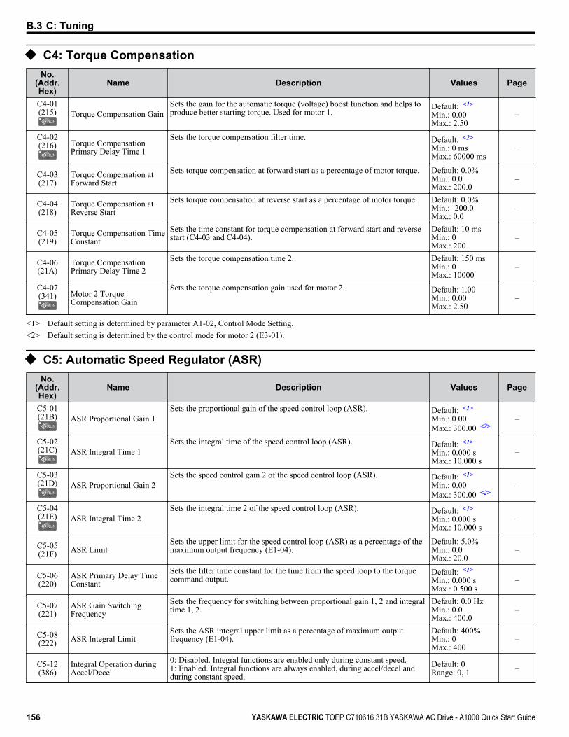
u C4: Torque CompensationNo.
(Addr.Hex)
Name Description Values Page
C4-01(215) Torque Compensation Gain
Sets the gain for the automatic torque (voltage) boost function and helps toproduce better starting torque. Used for motor 1.
Default: <1>
Min.: 0.00Max.: 2.50
–
C4-02(216) Torque Compensation
Primary Delay Time 1
Sets the torque compensation filter time. Default: <2>
Min.: 0 msMax.: 60000 ms
–
C4-03(217)
Torque Compensation atForward Start
Sets torque compensation at forward start as a percentage of motor torque. Default: 0.0%Min.: 0.0Max.: 200.0
–
C4-04(218)
Torque Compensation atReverse Start
Sets torque compensation at reverse start as a percentage of motor torque. Default: 0.0%Min.: -200.0Max.: 0.0
–
C4-05(219)
Torque Compensation TimeConstant
Sets the time constant for torque compensation at forward start and reversestart (C4-03 and C4-04).
Default: 10 msMin.: 0Max.: 200
–
C4-06(21A)
Torque CompensationPrimary Delay Time 2
Sets the torque compensation time 2. Default: 150 msMin.: 0Max.: 10000
–
C4-07(341) Motor 2 Torque
Compensation Gain
Sets the torque compensation gain used for motor 2. Default: 1.00Min.: 0.00Max.: 2.50
–
<1> Default setting is determined by parameter A1-02, Control Mode Setting.<2> Default setting is determined by the control mode for motor 2 (E3-01).
u C5: Automatic Speed Regulator (ASR)No.
(Addr.Hex)
Name Description Values Page
C5-01(21B) ASR Proportional Gain 1
Sets the proportional gain of the speed control loop (ASR). Default: <1>
Min.: 0.00Max.: 300.00 <2>
–
C5-02(21C) ASR Integral Time 1
Sets the integral time of the speed control loop (ASR). Default: <1>
Min.: 0.000 sMax.: 10.000 s
–
C5-03(21D) ASR Proportional Gain 2
Sets the speed control gain 2 of the speed control loop (ASR). Default: <1>
Min.: 0.00Max.: 300.00 <2>
–
C5-04(21E) ASR Integral Time 2
Sets the integral time 2 of the speed control loop (ASR). Default: <1>
Min.: 0.000 sMax.: 10.000 s
–
C5-05(21F) ASR Limit
Sets the upper limit for the speed control loop (ASR) as a percentage of themaximum output frequency (E1-04).
Default: 5.0%Min.: 0.0Max.: 20.0
–
C5-06(220)
ASR Primary Delay TimeConstant
Sets the filter time constant for the time from the speed loop to the torquecommand output.
Default: <1>
Min.: 0.000 sMax.: 0.500 s
–
C5-07(221)
ASR Gain SwitchingFrequency
Sets the frequency for switching between proportional gain 1, 2 and integraltime 1, 2.
Default: 0.0 HzMin.: 0.0Max.: 400.0
–
C5-08(222) ASR Integral Limit
Sets the ASR integral upper limit as a percentage of maximum outputfrequency (E1-04).
Default: 400%Min.: 0Max.: 400
–
C5-12(386)
Integral Operation duringAccel/Decel
0: Disabled. Integral functions are enabled only during constant speed.1: Enabled. Integral functions are always enabled, during accel/decel andduring constant speed.
Default: 0Range: 0, 1 –
B.3 C: Tuning
156 YASKAWA ELECTRIC TOEP C710616 31B YASKAWA AC Drive - A1000 Quick Start Guide
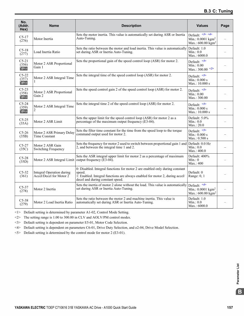
No.(Addr.Hex)
Name Description Values Page
C5-17(276) Motor Inertia
Sets the motor inertia. This value is automatically set during ASR or InertiaAuto-Tuning.
Default: <3> <4>
Min.: 0.0001 kgm2
Max.: 600.00 kgm2–
C5-18(277) Load Inertia Ratio
Sets the ratio between the motor and load inertia. This value is automaticallyset during ASR or Inertia Auto-Tuning.
Default: 1.0Min.: 0.0Max.: 6000.0
–
C5-21(356) Motor 2 ASR Proportional
Gain 1
Sets the proportional gain of the speed control loop (ASR) for motor 2. Default: <5>
Min.: 0.00Max.: 300.00 <2>
–
C5-22(357) Motor 2 ASR Integral Time
1
Sets the integral time of the speed control loop (ASR) for motor 2. Default: <5>
Min.: 0.000 sMax.: 10.000 s
–
C5-23(358) Motor 2 ASR Proportional
Gain 2
Sets the speed control gain 2 of the speed control loop (ASR) for motor 2. Default: <5>
Min.: 0.00Max.: 300.00
–
C5-24(359) Motor 2 ASR Integral Time
2
Sets the integral time 2 of the speed control loop (ASR) for motor 2. Default: <5>
Min.: 0.000 sMax.: 10.000 s
–
C5-25(35A) Motor 2 ASR Limit
Sets the upper limit for the speed control loop (ASR) for motor 2 as apercentage of the maximum output frequency (E3-04).
Default: 5.0%Min.: 0.0Max.: 20.0
–
C5-26(35B)
Motor 2 ASR Primary DelayTime Constant
Sets the filter time constant for the time from the speed loop to the torquecommand output used for motor 2.
Default: <5>
Min.: 0.000 sMax.: 0.500 s
–
C5-27(35C)
Motor 2 ASR GainSwitching Frequency
Sets the frequency for motor 2 used to switch between proportional gain 1 and2, and between the integral time 1 and 2.
Default: 0.0 HzMin.: 0.0Max.: 400.0
–
C5-28(35D) Motor 2 ASR Integral Limit
Sets the ASR integral upper limit for motor 2 as a percentage of maximumoutput frequency (E3-04).
Default: 400%Min.: 0Max.: 400
–
C5-32(361)
Integral Operation duringAccel/Decel for Motor 2
0: Disabled. Integral functions for motor 2 are enabled only during constantspeed.1: Enabled. Integral functions are always enabled for motor 2, during accel/decel and during constant speed.
Default: 0Range: 0, 1 –
C5-37(278) Motor 2 Inertia
Sets the inertia of motor 2 alone without the load. This value is automaticallyset during ASR or Inertia Auto-Tuning.
Default: <4>
Min.: 0.0001 kgm2
Max.: 600.00 kgm2–
C5-38(279) Motor 2 Load Inertia Ratio
Sets the ratio between the motor 2 and machine inertia. This value isautomatically set during ASR or Inertia Auto-Tuning.
Default: 1.0Min.: 0.0Max.: 6000.0
–
<1> Default setting is determined by parameter A1-02, Control Mode Setting.<2> The setting range is 1.00 to 300.00 in CLV and AOLV/PM control modes.<3> Default setting is dependent on parameter E5-01, Motor Code Selection.<4> Default setting is dependent on parameters C6-01, Drive Duty Selection, and o2-04, Drive Model Selection.<5> Default setting is determined by the control mode for motor 2 (E3-01).
B.3 C: Tuning
YASKAWA ELECTRIC TOEP C710616 31B YASKAWA AC Drive - A1000 Quick Start Guide 157
B
Para
met
er L
ist

u C6: Carrier FrequencyNo.
(Addr.Hex)
Name Description Values Page
C6-01(223) Drive Duty Selection 0: Heavy Duty (HD) for constant torque applications.
1: Normal Duty (ND) for variable torque applications.Default: 1Range: 0, 1 79
C6-02(224) Carrier Frequency Selection
1: 2.0 kHz2: 5.0 kHz3: 8.0 kHz4: 10.0 kHz5: 12.5 kHz6: 15.0 kHz7: Swing PWM1 (Audible sound 1)8: Swing PWM2 (Audible sound 2)9: Swing PWM3 (Audible sound 3)A: Swing PWM4 (Audible sound 4)B to E: No setting possibleF: User-defined (determined by C6-03 through C6-05)
Default: <1>
Range: 1 to 9;A, F
80
C6-03(225)
Carrier Frequency UpperLimit
Note: C6-04 and C6-05 are available only in V/f and V/f w/PG controlmodes.
Determines the upper and lower limits for the carrier frequency.In OLV, C6-03 determines the upper limit of the carrier frequency.
Carrier Frequency
E1-04Max Output Frequency
Output Frequency× (C6-05) × K
Output Frequency
C6-03
C6-04
Default: <2>
Min.: 1.0 kHzMax.: 15.0 kHz
–
C6-04(226)
Carrier Frequency LowerLimit
Default: <2>
Min.: 1.0 kHzMax.: 15.0 kHz
–
C6-05(227)
Carrier FrequencyProportional Gain
Default: <2>
Min.: 0Max.: 99
–
C6-09(22B)
Carrier Frequency duringRotational Auto-Tuning
0: Carrier Frequency = 5 kHz1: Setting value for C6-03
Default: 0Range: 0, 1 –
<1> Default setting value is dependent on the drive model (o2-04), the control mode (A1-02), and the Drive Duty (C6-01).<2> Default setting value is dependent on parameter C6-02, Carrier Frequency Selection.
B.3 C: Tuning
158 YASKAWA ELECTRIC TOEP C710616 31B YASKAWA AC Drive - A1000 Quick Start Guide
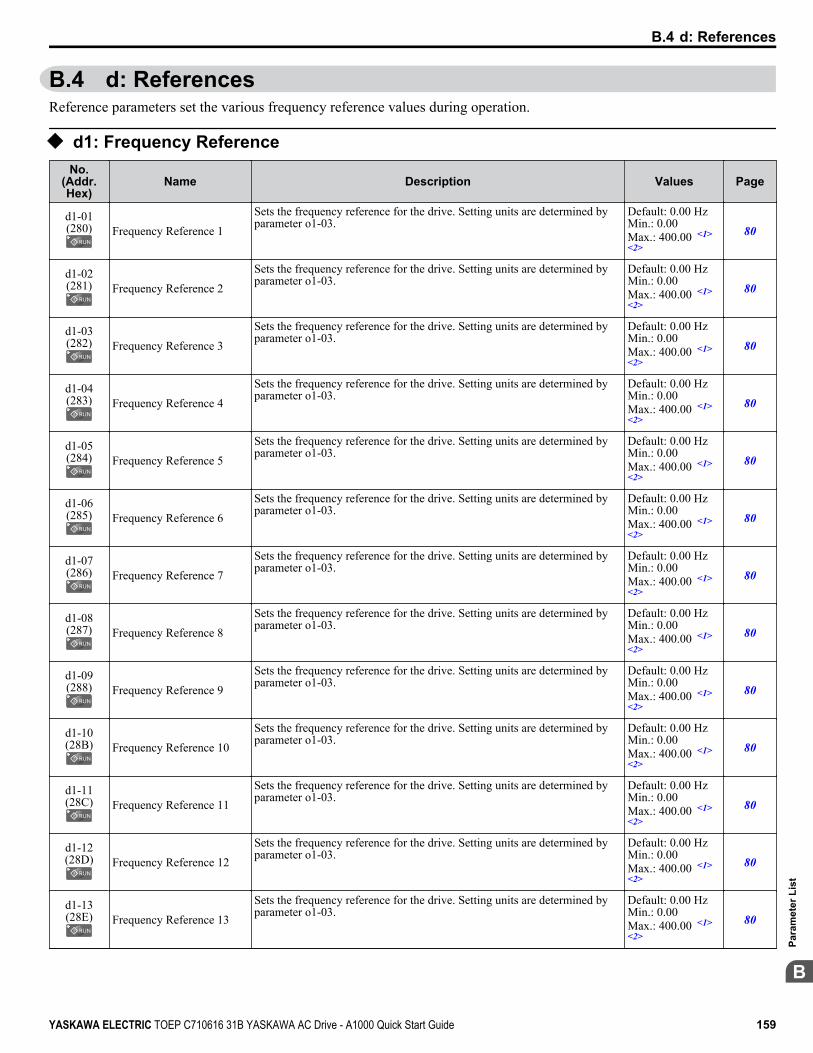
B.4 d: ReferencesReference parameters set the various frequency reference values during operation.
u d1: Frequency ReferenceNo.
(Addr.Hex)
Name Description Values Page
d1-01(280) Frequency Reference 1
Sets the frequency reference for the drive. Setting units are determined byparameter o1-03.
Default: 0.00 HzMin.: 0.00Max.: 400.00 <1><2>
80
d1-02(281) Frequency Reference 2
Sets the frequency reference for the drive. Setting units are determined byparameter o1-03.
Default: 0.00 HzMin.: 0.00Max.: 400.00 <1><2>
80
d1-03(282) Frequency Reference 3
Sets the frequency reference for the drive. Setting units are determined byparameter o1-03.
Default: 0.00 HzMin.: 0.00Max.: 400.00 <1><2>
80
d1-04(283) Frequency Reference 4
Sets the frequency reference for the drive. Setting units are determined byparameter o1-03.
Default: 0.00 HzMin.: 0.00Max.: 400.00 <1><2>
80
d1-05(284) Frequency Reference 5
Sets the frequency reference for the drive. Setting units are determined byparameter o1-03.
Default: 0.00 HzMin.: 0.00Max.: 400.00 <1><2>
80
d1-06(285) Frequency Reference 6
Sets the frequency reference for the drive. Setting units are determined byparameter o1-03.
Default: 0.00 HzMin.: 0.00Max.: 400.00 <1><2>
80
d1-07(286) Frequency Reference 7
Sets the frequency reference for the drive. Setting units are determined byparameter o1-03.
Default: 0.00 HzMin.: 0.00Max.: 400.00 <1><2>
80
d1-08(287) Frequency Reference 8
Sets the frequency reference for the drive. Setting units are determined byparameter o1-03.
Default: 0.00 HzMin.: 0.00Max.: 400.00 <1><2>
80
d1-09(288) Frequency Reference 9
Sets the frequency reference for the drive. Setting units are determined byparameter o1-03.
Default: 0.00 HzMin.: 0.00Max.: 400.00 <1><2>
80
d1-10(28B) Frequency Reference 10
Sets the frequency reference for the drive. Setting units are determined byparameter o1-03.
Default: 0.00 HzMin.: 0.00Max.: 400.00 <1><2>
80
d1-11(28C) Frequency Reference 11
Sets the frequency reference for the drive. Setting units are determined byparameter o1-03.
Default: 0.00 HzMin.: 0.00Max.: 400.00 <1><2>
80
d1-12(28D) Frequency Reference 12
Sets the frequency reference for the drive. Setting units are determined byparameter o1-03.
Default: 0.00 HzMin.: 0.00Max.: 400.00 <1><2>
80
d1-13(28E) Frequency Reference 13
Sets the frequency reference for the drive. Setting units are determined byparameter o1-03.
Default: 0.00 HzMin.: 0.00Max.: 400.00 <1><2>
80
B.4 d: References
YASKAWA ELECTRIC TOEP C710616 31B YASKAWA AC Drive - A1000 Quick Start Guide 159
B
Para
met
er L
ist
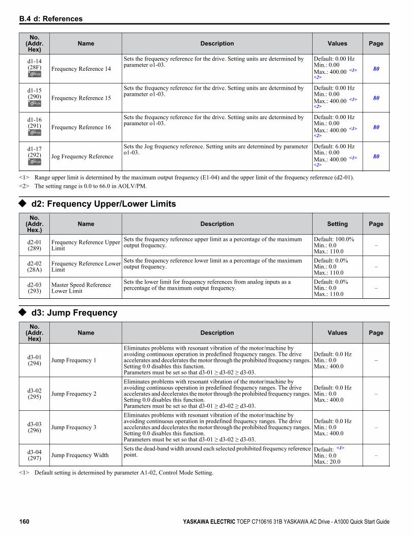
No.(Addr.Hex)
Name Description Values Page
d1-14(28F) Frequency Reference 14
Sets the frequency reference for the drive. Setting units are determined byparameter o1-03.
Default: 0.00 HzMin.: 0.00Max.: 400.00 <1><2>
80
d1-15(290) Frequency Reference 15
Sets the frequency reference for the drive. Setting units are determined byparameter o1-03.
Default: 0.00 HzMin.: 0.00Max.: 400.00 <1><2>
80
d1-16(291) Frequency Reference 16
Sets the frequency reference for the drive. Setting units are determined byparameter o1-03.
Default: 0.00 HzMin.: 0.00Max.: 400.00 <1><2>
80
d1-17(292) Jog Frequency Reference
Sets the Jog frequency reference. Setting units are determined by parametero1-03.
Default: 6.00 HzMin.: 0.00Max.: 400.00 <1><2>
80
<1> Range upper limit is determined by the maximum output frequency (E1-04) and the upper limit of the frequency reference (d2-01).<2> The setting range is 0.0 to 66.0 in AOLV/PM.
u d2: Frequency Upper/Lower LimitsNo.
(Addr.Hex.)
Name Description Setting Page
d2-01(289)
Frequency Reference UpperLimit
Sets the frequency reference upper limit as a percentage of the maximumoutput frequency.
Default: 100.0%Min.: 0.0Max.: 110.0
–
d2-02(28A)
Frequency Reference LowerLimit
Sets the frequency reference lower limit as a percentage of the maximumoutput frequency.
Default: 0.0%Min.: 0.0Max.: 110.0
–
d2-03(293)
Master Speed ReferenceLower Limit
Sets the lower limit for frequency references from analog inputs as apercentage of the maximum output frequency.
Default: 0.0%Min.: 0.0Max.: 110.0
–
u d3: Jump FrequencyNo.
(Addr.Hex)
Name Description Values Page
d3-01(294) Jump Frequency 1
Eliminates problems with resonant vibration of the motor/machine byavoiding continuous operation in predefined frequency ranges. The driveaccelerates and decelerates the motor through the prohibited frequency ranges.Setting 0.0 disables this function.Parameters must be set so that d3-01 ≥ d3-02 ≥ d3-03.
Default: 0.0 HzMin.: 0.0Max.: 400.0
–
d3-02(295) Jump Frequency 2
Eliminates problems with resonant vibration of the motor/machine byavoiding continuous operation in predefined frequency ranges. The driveaccelerates and decelerates the motor through the prohibited frequency ranges.Setting 0.0 disables this function.Parameters must be set so that d3-01 ≥ d3-02 ≥ d3-03.
Default: 0.0 HzMin.: 0.0Max.: 400.0
–
d3-03(296) Jump Frequency 3
Eliminates problems with resonant vibration of the motor/machine byavoiding continuous operation in predefined frequency ranges. The driveaccelerates and decelerates the motor through the prohibited frequency ranges.Setting 0.0 disables this function.Parameters must be set so that d3-01 ≥ d3-02 ≥ d3-03.
Default: 0.0 HzMin.: 0.0Max.: 400.0
–
d3-04(297) Jump Frequency Width
Sets the dead-band width around each selected prohibited frequency referencepoint.
Default: <1>
Min.: 0.0Max.: 20.0
–
<1> Default setting is determined by parameter A1-02, Control Mode Setting.
B.4 d: References
160 YASKAWA ELECTRIC TOEP C710616 31B YASKAWA AC Drive - A1000 Quick Start Guide
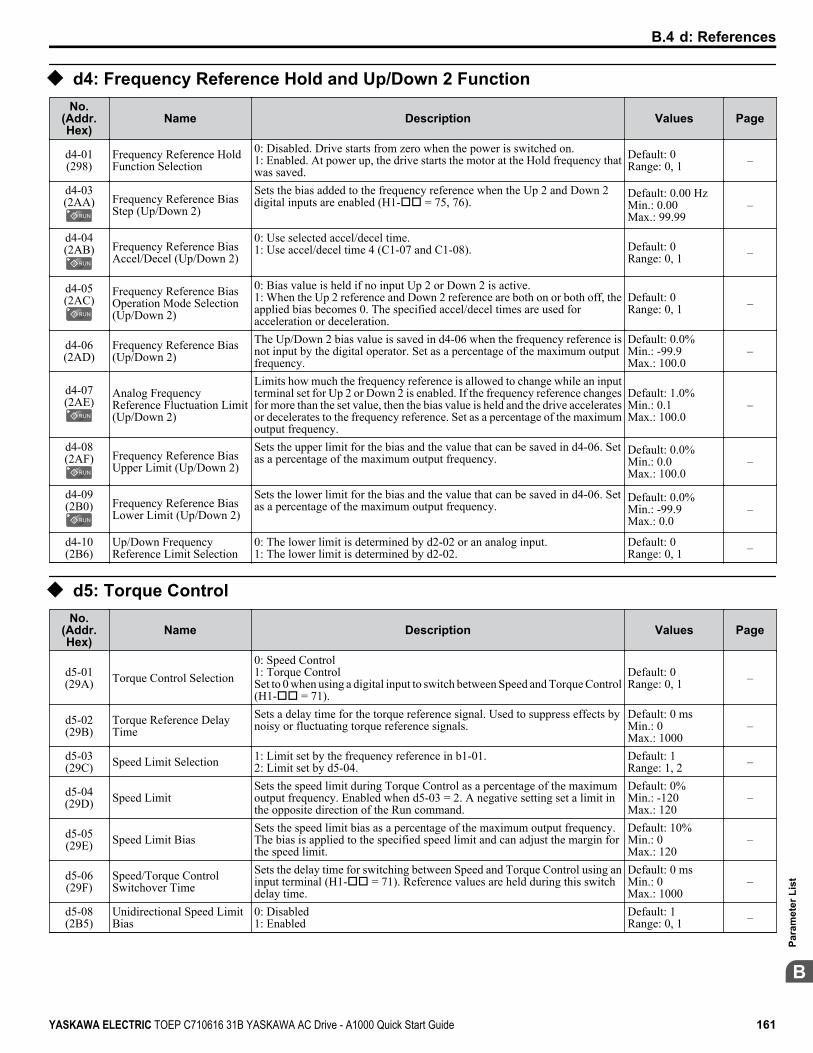
u d4: Frequency Reference Hold and Up/Down 2 FunctionNo.
(Addr.Hex)
Name Description Values Page
d4-01(298)
Frequency Reference HoldFunction Selection
0: Disabled. Drive starts from zero when the power is switched on.1: Enabled. At power up, the drive starts the motor at the Hold frequency thatwas saved.
Default: 0Range: 0, 1 –
d4-03(2AA) Frequency Reference Bias
Step (Up/Down 2)
Sets the bias added to the frequency reference when the Up 2 and Down 2digital inputs are enabled (H1-oo = 75, 76).
Default: 0.00 HzMin.: 0.00Max.: 99.99
–
d4-04(2AB) Frequency Reference Bias
Accel/Decel (Up/Down 2)
0: Use selected accel/decel time.1: Use accel/decel time 4 (C1-07 and C1-08). Default: 0
Range: 0, 1 –
d4-05(2AC)
Frequency Reference BiasOperation Mode Selection(Up/Down 2)
0: Bias value is held if no input Up 2 or Down 2 is active.1: When the Up 2 reference and Down 2 reference are both on or both off, theapplied bias becomes 0. The specified accel/decel times are used foracceleration or deceleration.
Default: 0Range: 0, 1 –
d4-06(2AD)
Frequency Reference Bias(Up/Down 2)
The Up/Down 2 bias value is saved in d4-06 when the frequency reference isnot input by the digital operator. Set as a percentage of the maximum outputfrequency.
Default: 0.0%Min.: -99.9Max.: 100.0
–
d4-07(2AE)
Analog FrequencyReference Fluctuation Limit(Up/Down 2)
Limits how much the frequency reference is allowed to change while an inputterminal set for Up 2 or Down 2 is enabled. If the frequency reference changesfor more than the set value, then the bias value is held and the drive acceleratesor decelerates to the frequency reference. Set as a percentage of the maximumoutput frequency.
Default: 1.0%Min.: 0.1Max.: 100.0
–
d4-08(2AF) Frequency Reference Bias
Upper Limit (Up/Down 2)
Sets the upper limit for the bias and the value that can be saved in d4-06. Setas a percentage of the maximum output frequency.
Default: 0.0%Min.: 0.0Max.: 100.0
–
d4-09(2B0) Frequency Reference Bias
Lower Limit (Up/Down 2)
Sets the lower limit for the bias and the value that can be saved in d4-06. Setas a percentage of the maximum output frequency.
Default: 0.0%Min.: -99.9Max.: 0.0
–
d4-10(2B6)
Up/Down FrequencyReference Limit Selection
0: The lower limit is determined by d2-02 or an analog input.1: The lower limit is determined by d2-02.
Default: 0Range: 0, 1 –
u d5: Torque ControlNo.
(Addr.Hex)
Name Description Values Page
d5-01(29A) Torque Control Selection
0: Speed Control1: Torque ControlSet to 0 when using a digital input to switch between Speed and Torque Control(H1-oo = 71).
Default: 0Range: 0, 1 –
d5-02(29B)
Torque Reference DelayTime
Sets a delay time for the torque reference signal. Used to suppress effects bynoisy or fluctuating torque reference signals.
Default: 0 msMin.: 0Max.: 1000
–
d5-03(29C) Speed Limit Selection 1: Limit set by the frequency reference in b1-01.
2: Limit set by d5-04.Default: 1Range: 1, 2 –
d5-04(29D) Speed Limit
Sets the speed limit during Torque Control as a percentage of the maximumoutput frequency. Enabled when d5-03 = 2. A negative setting set a limit inthe opposite direction of the Run command.
Default: 0%Min.: -120Max.: 120
–
d5-05(29E) Speed Limit Bias
Sets the speed limit bias as a percentage of the maximum output frequency.The bias is applied to the specified speed limit and can adjust the margin forthe speed limit.
Default: 10%Min.: 0Max.: 120
–
d5-06(29F)
Speed/Torque ControlSwitchover Time
Sets the delay time for switching between Speed and Torque Control using aninput terminal (H1-oo = 71). Reference values are held during this switchdelay time.
Default: 0 msMin.: 0Max.: 1000
–
d5-08(2B5)
Unidirectional Speed LimitBias
0: Disabled1: Enabled
Default: 1Range: 0, 1 –
B.4 d: References
YASKAWA ELECTRIC TOEP C710616 31B YASKAWA AC Drive - A1000 Quick Start Guide 161
B
Para
met
er L
ist
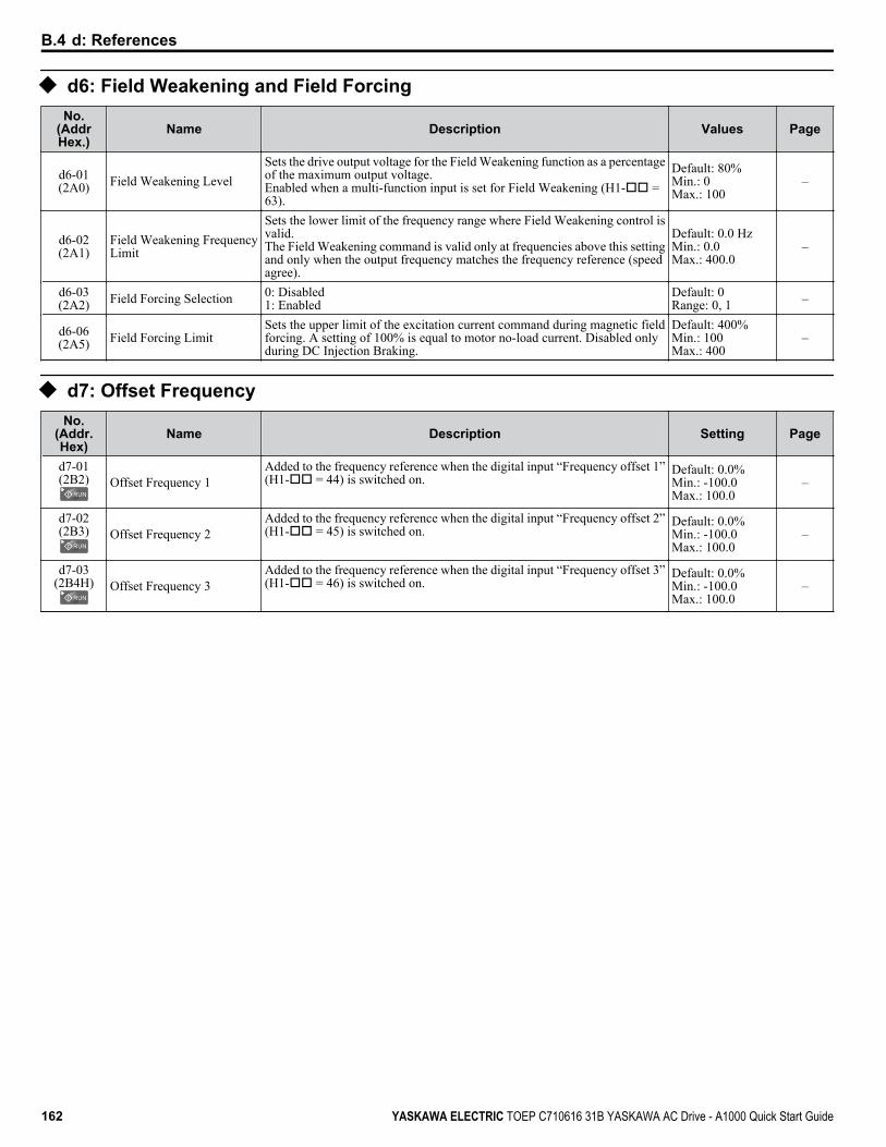
u d6: Field Weakening and Field ForcingNo.
(AddrHex.)
Name Description Values Page
d6-01(2A0) Field Weakening Level
Sets the drive output voltage for the Field Weakening function as a percentageof the maximum output voltage.Enabled when a multi-function input is set for Field Weakening (H1-oo =63).
Default: 80%Min.: 0Max.: 100
–
d6-02(2A1)
Field Weakening FrequencyLimit
Sets the lower limit of the frequency range where Field Weakening control isvalid.The Field Weakening command is valid only at frequencies above this settingand only when the output frequency matches the frequency reference (speedagree).
Default: 0.0 HzMin.: 0.0Max.: 400.0
–
d6-03(2A2) Field Forcing Selection 0: Disabled
1: EnabledDefault: 0Range: 0, 1 –
d6-06(2A5) Field Forcing Limit
Sets the upper limit of the excitation current command during magnetic fieldforcing. A setting of 100% is equal to motor no-load current. Disabled onlyduring DC Injection Braking.
Default: 400%Min.: 100Max.: 400
–
u d7: Offset FrequencyNo.
(Addr.Hex)
Name Description Setting Page
d7-01(2B2) Offset Frequency 1
Added to the frequency reference when the digital input “Frequency offset 1”(H1-oo = 44) is switched on.
Default: 0.0%Min.: -100.0Max.: 100.0
–
d7-02(2B3) Offset Frequency 2
Added to the frequency reference when the digital input “Frequency offset 2”(H1-oo = 45) is switched on.
Default: 0.0%Min.: -100.0Max.: 100.0
–
d7-03(2B4H) Offset Frequency 3
Added to the frequency reference when the digital input “Frequency offset 3”(H1-oo = 46) is switched on.
Default: 0.0%Min.: -100.0Max.: 100.0
–
B.4 d: References
162 YASKAWA ELECTRIC TOEP C710616 31B YASKAWA AC Drive - A1000 Quick Start Guide

B.5 E: Motor Parameters
u E1: V/f Pattern for Motor 1No.
(Addr.Hex)
Name Description Values Page
E1-01(300) Input Voltage Setting
This parameter must be set to the power supply voltage.
WARNING! Electrical Shock Hazard. Drive input voltage (not motorvoltage) must be set in E1-01 for the protective features of the drive tofunction properly. Failure to do so may result in equipment damageand/or death or personal injury.
Default: 575 VMin.: 155Max.: 733
82
E1-03(302) V/f Pattern Selection
0: 50 Hz, Constant torque 11: 60 Hz, Constant torque 22: 60 Hz, Constant torque 3 (50 Hz base)3: 72 Hz, Constant torque 4 (60 Hz base)4: 50 Hz, Variable torque 15: 50 Hz, Variable torque 26: 60 Hz, Variable torque 37: 60 Hz, Variable torque 48: 50 Hz, High starting torque 19: 50 Hz, High starting torque 2A: 60 Hz, High starting torque 3B: 60 Hz, High starting torque 4C: 90 Hz (60 Hz base)D: 120 Hz (60 Hz base)E: 180 Hz (60 Hz base)F: Custom V/f, E1-04 through E1-13 settings define the V/f pattern
Default: F <1>
Range: 0 to 9;A to F <2>
83
E1-04(303)
Maximum OutputFrequency
These parameters are only applicable when E1-03 is set to F.To set linear V/f characteristics, set the same values for E1-07 and E1-09.In this case, the setting for E1-08 will be disregarded. Ensure that the fourfrequencies are set according to these rules:E1-09 ≤ E1-07 < E1-06 ≤ E1-11 ≤ E1-04
Output Voltage (V)
Frequency (Hz)
E1-05E1-12
E1-13
E1-08
E1-10
E1-09 E1-07 E1-06 E1-11 E1-04
Note: Some parameters may not be available depending on the controlmode.
• E1-07, E1-08, and E1-10 are available only in the following control modes:V/f Control, V/f with PG, Open Loop Vector.
• E1-11, E1-12, and E1-13 are available only in the following control modes:V/f Control, V/f with PG, Open Loop Vector, Closed Loop Vector.
Default: <3> <4>
Min.: 40.0Max.: 400.0 <5>
85
E1-05(304) Maximum Voltage
Default: <3> <4>
Min.: 0.0 VMax.: 733.1 V
85
E1-06(305) Base Frequency
Default: <3> <4>
Min.: 0.0Max.: E1-04 <5>
85
E1-07(306) Middle Output Frequency
Default: <3>
Min.: 0.0Max.: E1-04
85
E1-08(307)
Middle Output FrequencyVoltage
Default: <3>
Min.: 0.0 VMax.: 733.1 V
85
E1-09(308) Minimum Output Frequency
Default: <3> <4>
Min.: 0.0Max.: E1-04 <5><6>
85
E1-10(309)
Minimum Output FrequencyVoltage
Default: <3>
Min.: 0.0 VMax.: 733.1 V
85
E1-11(30A)
<8>Middle Output Frequency 2
Default: 0.0 HzMin.: 0.0Max.: E1-04 <6>
85
E1-12(30B)
<8>Middle Output FrequencyVoltage 2
Default: 0.0 VMin.: 0.0Max.: 733.1
85
E1-13(30C) Base Voltage
Default: 0.0 V <7>
Min.: 0.0Max.: 733.1
85
<1> Parameter setting value is not reset to the default value when the drive is initialized.<2> The setting value is F in OLV modes.<3> Default setting is dependent on parameters A1-02, Control Model Selection, C6-01, Drive Duty Selection, and o2-04, Drive Model Selection.<4> Default setting is dependent on parameter E5-01, Motor Code Selection.
B.5 E: Motor Parameters
YASKAWA ELECTRIC TOEP C710616 31B YASKAWA AC Drive - A1000 Quick Start Guide 163
B
Para
met
er L
ist

<5> In OLV/PM, setting range varies according to the motor code entered to E5-01. The setting range is 0.0 to 400.0 Hz when E5-01 is set to FFFF.<6> The setting range is 0.0 to 66.0 in AOLV/PM.<7> When Auto-Tuning is performed, E1-13 and E1-05 will be set to the same value.<8> Parameter ignored when E1-11 (Motor 1 Mid Output Frequency 2) and E1-12 (Motor 1 Mid Output Frequency Voltage 2) are set to 0.0.
u E2: Motor 1 ParametersNo.
(Addr.Hex)
Name Description Values Page
E2-01(30E) Motor Rated Current
Sets the motor nameplate full load current in amps. Automatically set duringAuto-Tuning.
Default: <1>
Min.: 10% of driverated currentMax.: 200% ofdrive rated current<2>
86
E2-02(30F) Motor Rated Slip
Sets the motor rated slip. Automatically set during Auto-Tuning. Default: <1>
Min.: 0.00 HzMax.: 20.00 Hz
–
E2-03(310) Motor No-Load Current
Sets the no-load current for the motor. Automatically set during Auto-Tuning. Default: <1>
Min.: 0 AMax.: E2-01 <2>
–
E2-04(311) Number of Motor Poles
Sets the number of motor poles. Automatically set during Auto-Tuning. Default: 4Min.: 2Max.: 48
–
E2-05(312)
Motor Line-to-LineResistance
Sets the phase-to-phase motor resistance. Automatically set duringAuto-Tuning.
Default: <1>
Min.: 0.000 ΩMax.: 65.000 Ω
–
E2-06(313) Motor Leakage Inductance
Sets the voltage drop due to motor leakage inductance as a percentage of motorrated voltage. Automatically set during Auto-Tuning.
Default: <1>
Min.: 0.0%Max.: 40.0%
–
E2-07(314)
Motor Iron-Core SaturationCoefficient 1
Sets the motor iron saturation coefficient at 50% of magnetic flux.Automatically set during Auto-Tuning.
Default: 0.50Min.: E2-07Max.: 0.50
–
E2-08(315)
Motor Iron-Core SaturationCoefficient 2
Sets the motor iron saturation coefficient at 75% of magnetic flux.Automatically set during Auto-Tuning.
Default: 0.75Min.: E2-07Max.: 0.75
–
E2-09(316) Motor Mechanical Loss
Sets the motor mechanical loss as a percentage of motor rated power (kW). Default: 0.0%Min.: 0.0Max.: 10.0
–
E2-10(317)
Motor Iron Loss for TorqueCompensation
Sets the motor iron loss. Default: <1>
Min.: 0 WMax.: 65535 W
–
E2-11(318) Motor Rated Power
Sets the motor rated power in kilowatts (1 HP = 0.746 kW). Automatically setduring Auto-Tuning.
Default: <1>
Min.: 0.00 kWMax.: 650.00 kW
–
<1> Default setting is dependent on parameters C6-01, Drive Duty Selection, and o2-04, Drive Model Selection.<2> The number of decimal places in the parameter value depends on the drive model and the ND/HD selection in parameter C6-01. This value has two
decimal places (0.01 A) if the drive is set for a maximum applicable motor capacity up to and including 11 kW, and one decimal place (0.1 A) ifthe maximum applicable motor capacity is higher than 11 kW.
B.5 E: Motor Parameters
164 YASKAWA ELECTRIC TOEP C710616 31B YASKAWA AC Drive - A1000 Quick Start Guide
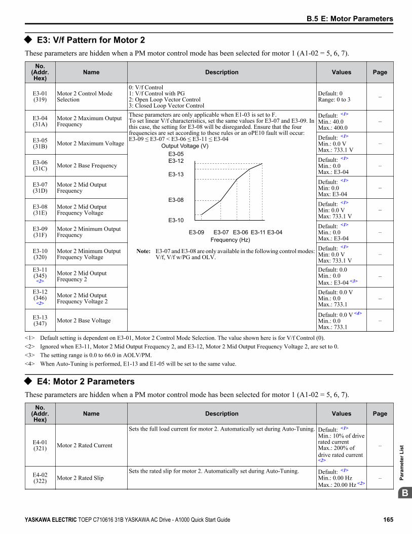
u E3: V/f Pattern for Motor 2These parameters are hidden when a PM motor control mode has been selected for motor 1 (A1-02 = 5, 6, 7).
No.(Addr.Hex)
Name Description Values Page
E3-01(319)
Motor 2 Control ModeSelection
0: V/f Control1: V/f Control with PG2: Open Loop Vector Control3: Closed Loop Vector Control
Default: 0Range: 0 to 3 –
E3-04(31A)
Motor 2 Maximum OutputFrequency
These parameters are only applicable when E1-03 is set to F.To set linear V/f characteristics, set the same values for E3-07 and E3-09. Inthis case, the setting for E3-08 will be disregarded. Ensure that the fourfrequencies are set according to these rules or an oPE10 fault will occur:E3-09 ≤ E3-07 < E3-06 ≤ E3-11 ≤ E3-04
Output Voltage (V)
Frequency (Hz)
E3-05E3-12
E3-13
E3-08
E3-10
E3-09 E3-07 E3-06 E3-11 E3-04
Note: E3-07 and E3-08 are only available in the following control modes:V/f, V/f w/PG and OLV.
Default: <1>
Min.: 40.0Max.: 400.0
–
E3-05(31B) Motor 2 Maximum Voltage
Default: <1>
Min.: 0.0 VMax.: 733.1 V
–
E3-06(31C) Motor 2 Base Frequency
Default: <1>
Min.: 0.0Max.: E3-04
–
E3-07(31D)
Motor 2 Mid OutputFrequency
Default: <1>
Min: 0.0Max: E3-04
–
E3-08(31E)
Motor 2 Mid OutputFrequency Voltage
Default: <1>
Min: 0.0 VMax: 733.1 V
–
E3-09(31F)
Motor 2 Minimum OutputFrequency
Default: <1>
Min.: 0.0Max.: E3-04
–
E3-10(320)
Motor 2 Minimum OutputFrequency Voltage
Default: <1>
Min: 0.0 VMax: 733.1 V
–
E3-11(345)
<2>Motor 2 Mid OutputFrequency 2
Default: 0.0Min.: 0.0Max.: E3-04 <3>
–
E3-12(346)
<2>Motor 2 Mid OutputFrequency Voltage 2
Default: 0.0 VMin.: 0.0Max.: 733.1
–
E3-13(347) Motor 2 Base Voltage
Default: 0.0 V <4>
Min.: 0.0Max.: 733.1
–
<1> Default setting is dependent on E3-01, Motor 2 Control Mode Selection. The value shown here is for V/f Control (0).<2> Ignored when E3-11, Motor 2 Mid Output Frequency 2, and E3-12, Motor 2 Mid Output Frequency Voltage 2, are set to 0.<3> The setting range is 0.0 to 66.0 in AOLV/PM.<4> When Auto-Tuning is performed, E1-13 and E1-05 will be set to the same value.
u E4: Motor 2 ParametersThese parameters are hidden when a PM motor control mode has been selected for motor 1 (A1-02 = 5, 6, 7).
No.(Addr.Hex)
Name Description Values Page
E4-01(321) Motor 2 Rated Current
Sets the full load current for motor 2. Automatically set during Auto-Tuning. Default: <1>
Min.: 10% of driverated currentMax.: 200% ofdrive rated current<2>
–
E4-02(322) Motor 2 Rated Slip
Sets the rated slip for motor 2. Automatically set during Auto-Tuning. Default: <1>
Min.: 0.00 HzMax.: 20.00 Hz <2>
–
B.5 E: Motor Parameters
YASKAWA ELECTRIC TOEP C710616 31B YASKAWA AC Drive - A1000 Quick Start Guide 165
B
Para
met
er L
ist
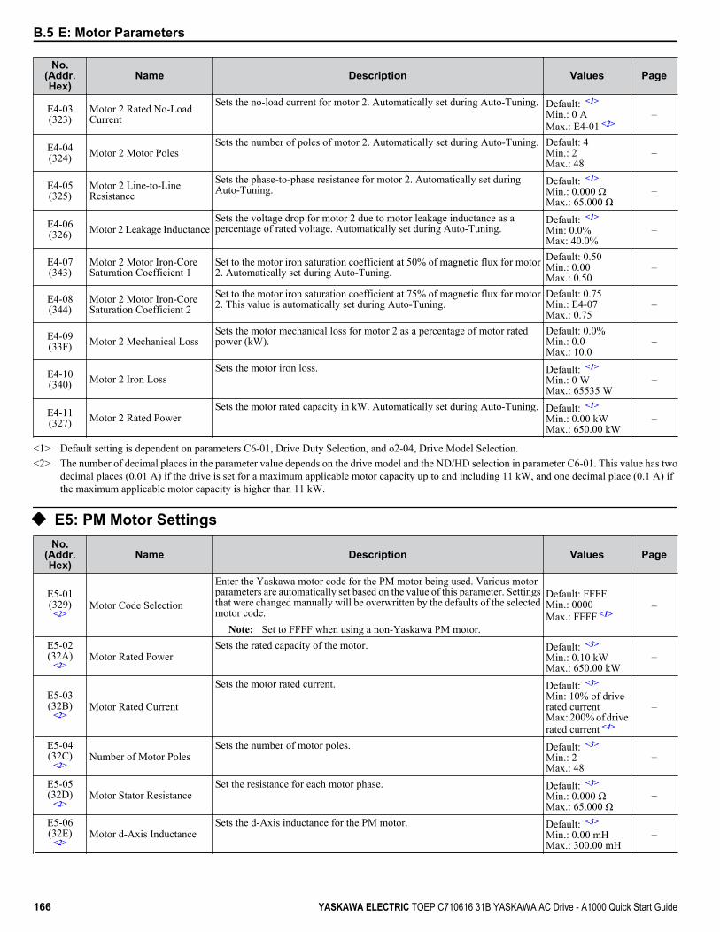
No.(Addr.Hex)
Name Description Values Page
E4-03(323)
Motor 2 Rated No-LoadCurrent
Sets the no-load current for motor 2. Automatically set during Auto-Tuning. Default: <1>
Min.: 0 AMax.: E4-01 <2>
–
E4-04(324) Motor 2 Motor Poles
Sets the number of poles of motor 2. Automatically set during Auto-Tuning. Default: 4Min.: 2Max.: 48
–
E4-05(325)
Motor 2 Line-to-LineResistance
Sets the phase-to-phase resistance for motor 2. Automatically set duringAuto-Tuning.
Default: <1>
Min.: 0.000 ΩMax.: 65.000 Ω
–
E4-06(326) Motor 2 Leakage Inductance
Sets the voltage drop for motor 2 due to motor leakage inductance as apercentage of rated voltage. Automatically set during Auto-Tuning.
Default: <1>
Min: 0.0%Max: 40.0%
–
E4-07(343)
Motor 2 Motor Iron-CoreSaturation Coefficient 1
Set to the motor iron saturation coefficient at 50% of magnetic flux for motor2. Automatically set during Auto-Tuning.
Default: 0.50Min.: 0.00Max.: 0.50
–
E4-08(344)
Motor 2 Motor Iron-CoreSaturation Coefficient 2
Set to the motor iron saturation coefficient at 75% of magnetic flux for motor2. This value is automatically set during Auto-Tuning.
Default: 0.75Min.: E4-07Max.: 0.75
–
E4-09(33F) Motor 2 Mechanical Loss
Sets the motor mechanical loss for motor 2 as a percentage of motor ratedpower (kW).
Default: 0.0%Min.: 0.0Max.: 10.0
–
E4-10(340) Motor 2 Iron Loss
Sets the motor iron loss. Default: <1>
Min.: 0 WMax.: 65535 W
–
E4-11(327) Motor 2 Rated Power
Sets the motor rated capacity in kW. Automatically set during Auto-Tuning. Default: <1>
Min.: 0.00 kWMax.: 650.00 kW
–
<1> Default setting is dependent on parameters C6-01, Drive Duty Selection, and o2-04, Drive Model Selection.<2> The number of decimal places in the parameter value depends on the drive model and the ND/HD selection in parameter C6-01. This value has two
decimal places (0.01 A) if the drive is set for a maximum applicable motor capacity up to and including 11 kW, and one decimal place (0.1 A) ifthe maximum applicable motor capacity is higher than 11 kW.
u E5: PM Motor SettingsNo.
(Addr.Hex)
Name Description Values Page
E5-01(329)
<2>Motor Code Selection
Enter the Yaskawa motor code for the PM motor being used. Various motorparameters are automatically set based on the value of this parameter. Settingsthat were changed manually will be overwritten by the defaults of the selectedmotor code.
Note: Set to FFFF when using a non-Yaskawa PM motor.
Default: FFFFMin.: 0000Max.: FFFF <1>
–
E5-02(32A)
<2>Motor Rated Power
Sets the rated capacity of the motor. Default: <3>
Min.: 0.10 kWMax.: 650.00 kW
–
E5-03(32B)
<2>Motor Rated Current
Sets the motor rated current. Default: <3>
Min: 10% of driverated currentMax: 200% of driverated current <4>
–
E5-04(32C)
<2>Number of Motor Poles
Sets the number of motor poles. Default: <3>
Min.: 2Max.: 48
–
E5-05(32D)
<2>Motor Stator Resistance
Set the resistance for each motor phase. Default: <3>
Min.: 0.000 ΩMax.: 65.000 Ω
–
E5-06(32E)
<2>Motor d-Axis Inductance
Sets the d-Axis inductance for the PM motor. Default: <3>
Min.: 0.00 mHMax.: 300.00 mH
–
B.5 E: Motor Parameters
166 YASKAWA ELECTRIC TOEP C710616 31B YASKAWA AC Drive - A1000 Quick Start Guide

No.(Addr.Hex)
Name Description Values Page
E5-07(32F)
<2>Motor q-Axis Inductance
Sets the q-Axis inductance for the PM motor. Default: <3>
Min.: 0.00 mHMax.: 600.00 mH
–
E5-09(331)
<2>Motor Induction VoltageConstant 1
Sets the induced phase peak voltage in units of 0.1 mV (rad/s) [electricalangle]. Set this parameter when using a Yaskawa SSR1-Series PM motor withderated torque, or a Yaskawa SST4-Series motor with constant torque.Set E5-24 to 0 when setting this parameter.
Default: <3>
Min.: 0.0 mV/(rad/s)Max.: 2000.0 mV/(rad/s)
–
E5-11(333) Encoder Z Pulse Offset
Sets the offset between the rotor magnetic axis and the Z Pulse of anincremental encoder during Z Pulse offset tuning.
Default: 0.0 degMin.: -180Max.: 180
–
E5-24(353)
<2>Motor Induction VoltageConstant 2
Set the induced phase-to-phase rms voltage in units of 0.1 mV/(r/min)[mechanical angle]. Set this parameter when using a Yaskawa SMRA-SeriesSPM motor.
Default: <3>
Min.: 0.0 mV/(r/min)Max.: 2000.0 mV/(r/min)
–
<1> Selections may vary depending on the motor code entered to E5-01.<2> Setting value is not reset to the default when drive is initialized.<3> Default setting is dependent on parameter E5-01, Motor Code Selection.<4> The number of decimal places in the parameter value depends on the drive model and the ND/HD selection in parameter C6-01. This value has two
decimal places (0.01 A) if the drive is set for a maximum applicable motor capacity up to and including 11 kW, and one decimal place (0.1 A) ifthe maximum applicable motor capacity is higher than 11 kW.
B.5 E: Motor Parameters
YASKAWA ELECTRIC TOEP C710616 31B YASKAWA AC Drive - A1000 Quick Start Guide 167
B
Para
met
er L
ist
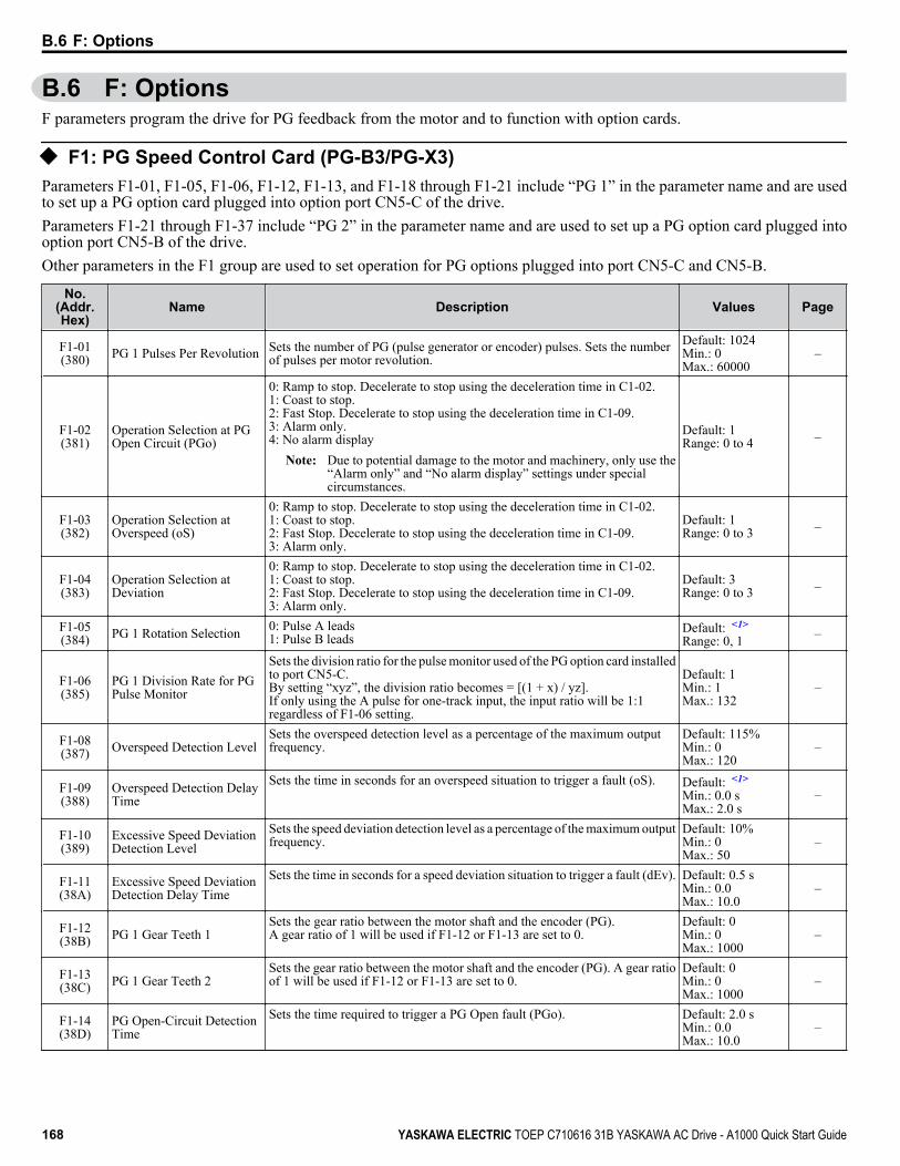
B.6 F: OptionsF parameters program the drive for PG feedback from the motor and to function with option cards.
u F1: PG Speed Control Card (PG-B3/PG-X3)Parameters F1-01, F1-05, F1-06, F1-12, F1-13, and F1-18 through F1-21 include “PG 1” in the parameter name and are usedto set up a PG option card plugged into option port CN5-C of the drive.Parameters F1-21 through F1-37 include “PG 2” in the parameter name and are used to set up a PG option card plugged intooption port CN5-B of the drive.Other parameters in the F1 group are used to set operation for PG options plugged into port CN5-C and CN5-B.
No.(Addr.Hex)
Name Description Values Page
F1-01(380) PG 1 Pulses Per Revolution Sets the number of PG (pulse generator or encoder) pulses. Sets the number
of pulses per motor revolution.Default: 1024Min.: 0Max.: 60000
–
F1-02(381)
Operation Selection at PGOpen Circuit (PGo)
0: Ramp to stop. Decelerate to stop using the deceleration time in C1-02.1: Coast to stop.2: Fast Stop. Decelerate to stop using the deceleration time in C1-09.3: Alarm only.4: No alarm display
Note: Due to potential damage to the motor and machinery, only use the“Alarm only” and “No alarm display” settings under specialcircumstances.
Default: 1Range: 0 to 4 –
F1-03(382)
Operation Selection atOverspeed (oS)
0: Ramp to stop. Decelerate to stop using the deceleration time in C1-02.1: Coast to stop.2: Fast Stop. Decelerate to stop using the deceleration time in C1-09.3: Alarm only.
Default: 1Range: 0 to 3 –
F1-04(383)
Operation Selection atDeviation
0: Ramp to stop. Decelerate to stop using the deceleration time in C1-02.1: Coast to stop.2: Fast Stop. Decelerate to stop using the deceleration time in C1-09.3: Alarm only.
Default: 3Range: 0 to 3 –
F1-05(384) PG 1 Rotation Selection 0: Pulse A leads
1: Pulse B leadsDefault: <1>
Range: 0, 1 –
F1-06(385)
PG 1 Division Rate for PGPulse Monitor
Sets the division ratio for the pulse monitor used of the PG option card installedto port CN5-C.By setting “xyz”, the division ratio becomes = [(1 + x) / yz].If only using the A pulse for one-track input, the input ratio will be 1:1regardless of F1-06 setting.
Default: 1Min.: 1Max.: 132
–
F1-08(387) Overspeed Detection Level
Sets the overspeed detection level as a percentage of the maximum outputfrequency.
Default: 115%Min.: 0Max.: 120
–
F1-09(388)
Overspeed Detection DelayTime
Sets the time in seconds for an overspeed situation to trigger a fault (oS). Default: <1>
Min.: 0.0 sMax.: 2.0 s
–
F1-10(389)
Excessive Speed DeviationDetection Level
Sets the speed deviation detection level as a percentage of the maximum outputfrequency.
Default: 10%Min.: 0Max.: 50
–
F1-11(38A)
Excessive Speed DeviationDetection Delay Time
Sets the time in seconds for a speed deviation situation to trigger a fault (dEv). Default: 0.5 sMin.: 0.0Max.: 10.0
–
F1-12(38B) PG 1 Gear Teeth 1
Sets the gear ratio between the motor shaft and the encoder (PG).A gear ratio of 1 will be used if F1-12 or F1-13 are set to 0.
Default: 0Min.: 0Max.: 1000
–
F1-13(38C) PG 1 Gear Teeth 2
Sets the gear ratio between the motor shaft and the encoder (PG). A gear ratioof 1 will be used if F1-12 or F1-13 are set to 0.
Default: 0Min.: 0Max.: 1000
–
F1-14(38D)
PG Open-Circuit DetectionTime
Sets the time required to trigger a PG Open fault (PGo). Default: 2.0 sMin.: 0.0Max.: 10.0
–
B.6 F: Options
168 YASKAWA ELECTRIC TOEP C710616 31B YASKAWA AC Drive - A1000 Quick Start Guide

No.(Addr.Hex)
Name Description Values Page
F1-18(3AD) dv3 Detection Selection
0: Disabledn: Number of dv3 occurrences that must be detected to trigger a dv3 fault.
Default: 10Min.: 0Max.: 10
–
F1-19(3AE) dv4 Detection Selection
0: Disabledn: Number of pulses that the A and B pulse are reversed that triggers dv4detection.
Default: 128Min.: 0Max.: 5000
–
F1-20(3B4)
PG Option Card DisconnectDetection 1
0: Disabled1: Enabled
Default: 1Range: 0, 1 –
F1-21(3BC) PG 1 Signal Selection 0: A pulse detection
1: AB pulse detectionDefault: 0Range: 0, 1 –
F1-30(3AA)
PG Card Option Port forMotor 2 Selection
Sets the port for the PG option card used by motor 2.0: CN5-C1: CN5-B
Default: 1Range: 0, 1 –
F1-31(3B0) PG 2 Pulses Per Revolution Sets the number of pulses for a PG option card connected to port CN5-B.
Default: 1024 pprMin.: 0Max.: 60000
–
F1-32(3B1) PG 2 Rotation Selection 0: Pulse A leads
1: Pulse B leadsDefault: 0Range: 0, 1 –
F1-33(3B2) PG 2 Gear Teeth 1
Sets the gear ratio between the motor shaft and the encoder (PG).A gear ratio of 1 will be used if F1-33 or F1-34 are set to 0.
Default: 0Min.: 0Max.: 1000
–
F1-34(3B3) PG 2 Gear Teeth 2
Sets the gear ratio between the motor shaft and the encoder (PG). A gear ratioof 1 will be used if F1-33 or F1-34 are set to 0.
Default: 0Min.: 0Max.: 1000
–
F1-35(3BE)
PG 2 Division Rate for PulseMonitor
Sets the division ratio for the pulse monitor used of the PG option card 2installed to port CN5-B.By setting “xyz”, the division ratio becomes = [(1 + x) / yz].
Default: 1Min.: 1Max.: 132
–
F1-36(3B5)
PG Option Card DisconnectDetection 2
0: Disabled1: Enabled
Default: 1Range: 0, 1 –
F1-37(3BD) PG 2 Signal Selection 0: A pulse detection
1: AB pulse detectionDefault: 0Range: 0, 1 –
<1> Default setting is determined by parameter A1-02, Control Mode Setting.
u F2: Analog Input Card (AI-A3)No.
(Addr.Hex)
Name Description Values Page
F2-01(38F)
Analog Input Option CardOperation Selection
0: Option card input terminals V1, V2, and V3 replace drive input terminalsA1, A2, and A3.1: Input signals to terminals V1, V2, and V3 are added together to create thefrequency reference.
Default: 0Range: 0, 1 –
F2-02(368) Analog Input Option Card
Gain
Sets the gain for the input signal to the analog card. Default: 100.0%Min.: -999.9Max.: 999.9
–
F2-03(369) Analog Input Option Card
Bias
Sets the bias for the input signal to the analog card. Default: 0.0%Min.: -999.9Max.: 999.9
–
B.6 F: Options
YASKAWA ELECTRIC TOEP C710616 31B YASKAWA AC Drive - A1000 Quick Start Guide 169
B
Para
met
er L
ist
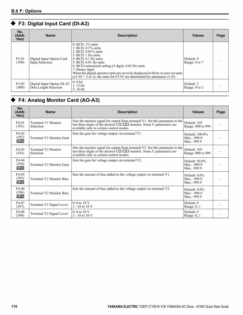
u F3: Digital Input Card (DI-A3)No.
(Addr.Hex)
Name Description Values Page
F3-01(390)
Digital Input Option CardInput Selection
0: BCD, 1% units1: BCD, 0.1% units2: BCD, 0.01% units3: BCD, 1 Hz units4: BCD, 0.1 Hz units5: BCD, 0.01 Hz units6: BCD customized setting (5 digit), 0.02 Hz units7: Binary inputWhen the digital operator units are set to be displayed in Hertz or user-set units(o1-03 = 2 or 3), the units for F3-01 are determined by parameter o1-03.
Default: 0Range: 0 to 7 –
F3-03(3B9)
Digital Input Option DI-A3Data Length Selection
0: 8 bit1: 12 bit2: 16 bit
Default: 2Range: 0 to 2 –
u F4: Analog Monitor Card (AO-A3)No.
(Addr.Hex)
Name Description Values Page
F4-01(391)
Terminal V1 MonitorSelection
Sets the monitor signal for output from terminal V1. Set this parameter to thelast three digits of the desired Uo-oo monitor. Some U parameters areavailable only in certain control modes.
Default: 102Range: 000 to 999 –
F4-02(392) Terminal V1 Monitor Gain
Sets the gain for voltage output via terminal V1. Default: 100.0%Min.: -999.9Max.: 999.9
–
F4-03(393)
Terminal V2 MonitorSelection
Sets the monitor signal for output from terminal V2. Set this parameter to thelast three digits of the desired Uo-oo monitor. Some U parameters areavailable only in certain control modes.
Default: 103Range: 000 to 999 –
F4-04(394) Terminal V2 Monitor Gain
Sets the gain for voltage output via terminal V2. Default: 50.0%Min.: -999.9Max.: 999.9
–
F4-05(395) Terminal V1 Monitor Bias
Sets the amount of bias added to the voltage output via terminal V1. Default: 0.0%Min.: -999.9Max.: 999.9
–
F4-06(396) Terminal V2 Monitor Bias
Sets the amount of bias added to the voltage output via terminal V2. Default: 0.0%Min.: -999.9Max.: 999.9
–
F4-07(397) Terminal V1 Signal Level 0: 0 to 10 V
1: -10 to 10 VDefault: 0Range: 0, 1 –
F4-08(398) Terminal V2 Signal Level 0: 0 to 10 V
1: -10 to 10 VDefault: 0Range: 0, 1 –
B.6 F: Options
170 YASKAWA ELECTRIC TOEP C710616 31B YASKAWA AC Drive - A1000 Quick Start Guide
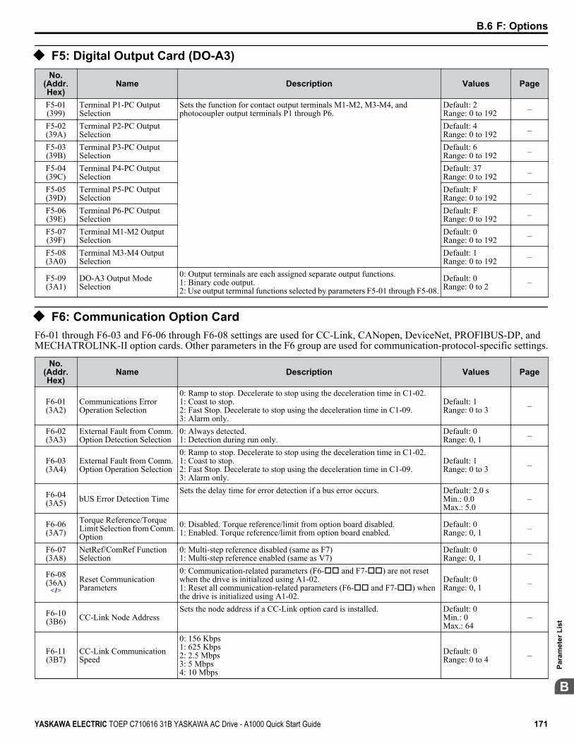
u F5: Digital Output Card (DO-A3)No.
(Addr.Hex)
Name Description Values Page
F5-01(399)
Terminal P1-PC OutputSelection
Sets the function for contact output terminals M1-M2, M3-M4, andphotocoupler output terminals P1 through P6.
Default: 2Range: 0 to 192 –
F5-02(39A)
Terminal P2-PC OutputSelection
Default: 4Range: 0 to 192 –
F5-03(39B)
Terminal P3-PC OutputSelection
Default: 6Range: 0 to 192 –
F5-04(39C)
Terminal P4-PC OutputSelection
Default: 37Range: 0 to 192 –
F5-05(39D)
Terminal P5-PC OutputSelection
Default: FRange: 0 to 192 –
F5-06(39E)
Terminal P6-PC OutputSelection
Default: FRange: 0 to 192 –
F5-07(39F)
Terminal M1-M2 OutputSelection
Default: 0Range: 0 to 192 –
F5-08(3A0)
Terminal M3-M4 OutputSelection
Default: 1Range: 0 to 192 –
F5-09(3A1)
DO-A3 Output ModeSelection
0: Output terminals are each assigned separate output functions.1: Binary code output.2: Use output terminal functions selected by parameters F5-01 through F5-08.
Default: 0Range: 0 to 2 –
u F6: Communication Option CardF6-01 through F6-03 and F6-06 through F6-08 settings are used for CC-Link, CANopen, DeviceNet, PROFIBUS-DP, andMECHATROLINK-II option cards. Other parameters in the F6 group are used for communication-protocol-specific settings.
No.(Addr.Hex)
Name Description Values Page
F6-01(3A2)
Communications ErrorOperation Selection
0: Ramp to stop. Decelerate to stop using the deceleration time in C1-02.1: Coast to stop.2: Fast Stop. Decelerate to stop using the deceleration time in C1-09.3: Alarm only.
Default: 1Range: 0 to 3 –
F6-02(3A3)
External Fault from Comm.Option Detection Selection
0: Always detected.1: Detection during run only.
Default: 0Range: 0, 1 –
F6-03(3A4)
External Fault from Comm.Option Operation Selection
0: Ramp to stop. Decelerate to stop using the deceleration time in C1-02.1: Coast to stop.2: Fast Stop. Decelerate to stop using the deceleration time in C1-09.3: Alarm only.
Default: 1Range: 0 to 3 –
F6-04(3A5) bUS Error Detection Time
Sets the delay time for error detection if a bus error occurs. Default: 2.0 sMin.: 0.0Max.: 5.0
–
F6-06(3A7)
Torque Reference/TorqueLimit Selection from Comm.Option
0: Disabled. Torque reference/limit from option board disabled.1: Enabled. Torque reference/limit from option board enabled.
Default: 0Range: 0, 1 –
F6-07(3A8)
NetRef/ComRef FunctionSelection
0: Multi-step reference disabled (same as F7)1: Multi-step reference enabled (same as V7)
Default: 0Range: 0, 1 –
F6-08(36A)
<1>Reset CommunicationParameters
0: Communication-related parameters (F6-oo and F7-oo) are not resetwhen the drive is initialized using A1-02.1: Reset all communication-related parameters (F6-oo and F7-oo) whenthe drive is initialized using A1-02.
Default: 0Range: 0, 1 –
F6-10(3B6) CC-Link Node Address
Sets the node address if a CC-Link option card is installed. Default: 0Min.: 0Max.: 64
–
F6-11(3B7)
CC-Link CommunicationSpeed
0: 156 Kbps1: 625 Kbps2: 2.5 Mbps3: 5 Mbps4: 10 Mbps
Default: 0Range: 0 to 4 –
B.6 F: Options
YASKAWA ELECTRIC TOEP C710616 31B YASKAWA AC Drive - A1000 Quick Start Guide 171
B
Para
met
er L
ist

No.(Addr.Hex)
Name Description Values Page
F6-14(3BB)
CC-Link bUS Error AutoReset
0: Disabled1: Enabled
Default: 0Range: 0, 1 –
F6-20(36B)
MECHATROLINK StationAddress
Sets the station address when the MECHATROLINK-II option has beeninstalled.
Default: 21Min.: 20Max.: 3F
—
F6-21(36C)
MECHATROLINK FrameSize
0: 32 byte1: 17 byte
Default: 0Range: 0, 1 —
F6-22(36D)
MECHATROLINK LinkSpeed
0: 10 Mbps1: 4 Mbps
Default: 0Range: 0, 1 —
F6-23(36E)
MECHATROLINKMonitor Selection (E) Sets the MECHATROLINK-II monitor (E).
Default: 0Min.: 0Max.: FFFF
—
F6-24(36F)
MECHATROLINKMonitor Selection (F) Sets the MECHATROLINK-II monitor (F).
Default: 0Min.: 0Max.: FFFF
—
F6-25(3C9)
Operation Selection atWatchdog Timer Error (E5)
0: Ramp to stop. Decelerate using the deceleration time in C1-02.1: Coast to stop2: Fast stop. Decelerate using the deceleration time in C1-09.3: Alarm only
Default: 1Range: 0 to 3 —
F6-26(3CA)
MECHATROLINK bUSErrors Detected Sets the number of option communication errors (bUS).
Default: 2Min.: 2Max.: 10
—
F6-30(3CB)
PROFIBUS-DP NodeAddress
Sets the node address. Default: 0Min.: 0Max.: 125
–
F6-31(3CC)
PROFIBUS-DP Clear ModeSelection
0: Resets drive operation with a Clear mode command.1: Maintains the previous operation state when Clear mode command is given.
Default: 0Range: 0, 1 –
F6-32(3CD)
PROFIBUS-DP DataFormat Selection
0: PPO Type1: Conventional
Default: 0Range: 0, 1 –
F6-35(3D0)
CANopen Node IDSelection
Sets the node address. Default: 0Min.: 0Max.: 126
–
F6-36(3D1)
CANopen CommunicationSpeed
0: Auto-detection1: 10 kbps2: 20 kbps3: 50 kbps4: 125 kbps5: 250 kbps6: 500 kbps7: 800 kbps8: 1 Mbps
Default: 6Range: 0 to 8 –
F6-50(3C1) DeviceNet MAC Address
Selects the drive MAC address. Default: 63Min.: 0Max.: 64
–
F6-51(3C2)
DeviceNet CommunicationSpeed
0: 125 kbps1: 250 kbps2: 500 kbps3: Adjustable from network4: Detect automatically
Default: 3Range: 0 to 4 –
F6-52(3C3) DeviceNet PCA Setting
Sets the format of the data set from the DeviceNet master to the drive. Default: 0Min.: 0Max.: 255
–
F6-53(3C4) DeviceNet PPA Setting
Sets the format of the data set from the drive to the DeviceNet master. Default: 0Min.: 0Max.: 255
–
F6-54(3C5)
DeviceNet Idle Mode FaultDetection
0: Enabled1: Disabled, no fault detection
Default: 0Range: 0, 1 –
F6-55(3C6)
DeviceNet Baud RateMonitor
Verifies the baud rate running on the network.0: 125 kbps1: 250 kbps2: 500 kbps
Default: 0Range: 0 to 2 –
B.6 F: Options
172 YASKAWA ELECTRIC TOEP C710616 31B YASKAWA AC Drive - A1000 Quick Start Guide
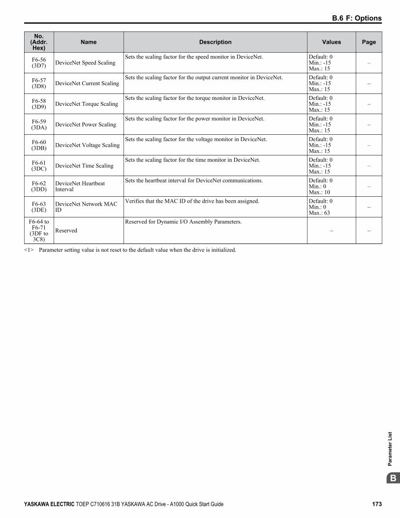
No.(Addr.Hex)
Name Description Values Page
F6-56(3D7) DeviceNet Speed Scaling
Sets the scaling factor for the speed monitor in DeviceNet. Default: 0Min.: -15Max.: 15
–
F6-57(3D8) DeviceNet Current Scaling
Sets the scaling factor for the output current monitor in DeviceNet. Default: 0Min.: -15Max.: 15
–
F6-58(3D9) DeviceNet Torque Scaling
Sets the scaling factor for the torque monitor in DeviceNet. Default: 0Min.: -15Max.: 15
–
F6-59(3DA) DeviceNet Power Scaling
Sets the scaling factor for the power monitor in DeviceNet. Default: 0Min.: -15Max.: 15
–
F6-60(3DB) DeviceNet Voltage Scaling
Sets the scaling factor for the voltage monitor in DeviceNet. Default: 0Min.: -15Max.: 15
–
F6-61(3DC) DeviceNet Time Scaling
Sets the scaling factor for the time monitor in DeviceNet. Default: 0Min.: -15Max.: 15
–
F6-62(3DD)
DeviceNet HeartbeatInterval
Sets the heartbeat interval for DeviceNet communications. Default: 0Min.: 0Max.: 10
–
F6-63(3DE)
DeviceNet Network MACID
Verifies that the MAC ID of the drive has been assigned. Default: 0Min.: 0Max.: 63
–
F6-64 toF6-71
(3DF to3C8)
ReservedReserved for Dynamic I/O Assembly Parameters.
– –
<1> Parameter setting value is not reset to the default value when the drive is initialized.
B.6 F: Options
YASKAWA ELECTRIC TOEP C710616 31B YASKAWA AC Drive - A1000 Quick Start Guide 173
B
Para
met
er L
ist
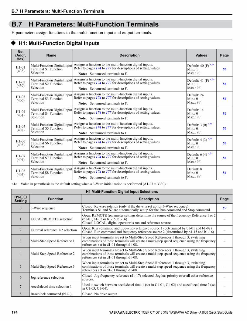
B.7 H Parameters: Multi-Function TerminalsH parameters assign functions to the multi-function input and output terminals.
u H1: Multi-Function Digital InputsNo.
(Addr.Hex)
Name Description Values Page
H1-01(438)
Multi-Function Digital InputTerminal S1 FunctionSelection
Assigns a function to the multi-function digital inputs.Refer to pages 174 to 177 for descriptions of setting values.
Note: Set unused terminals to F.
Default: 40 (F) <1>
Min.: 1Max.: 9F
86
H1-02(439)
Multi-Function Digital InputTerminal S2 FunctionSelection
Assigns a function to the multi-function digital inputs.Refer to pages 174 to 177 for descriptions of setting values.
Note: Set unused terminals to F.
Default: 41 (F) <1>
Min.: 1Max.: 9F
86
H1-03(400)
Multi-Function Digital InputTerminal S3 FunctionSelection
Assigns a function to the multi-function digital inputs.Refer to pages 174 to 177 for descriptions of setting values.
Note: Set unused terminals to F.
Default: 24Min.: 0Max.: 9F
86
H1-04(401)
Multi-Function Digital InputTerminal S4 FunctionSelection
Assigns a function to the multi-function digital inputs.Refer to pages 174 to 177 for descriptions of setting values.
Note: Set unused terminals to F.
Default: 14Min.: 0Max.: 9F
86
H1-05(402)
Multi-Function Digital InputTerminal S5 FunctionSelection
Assigns a function to the multi-function digital inputs.Refer to pages 174 to 177 for descriptions of setting values.
Note: Set unused terminals to F.
Default: 3 (0) <1>
Min.: 0Max.: 9F
86
H1-06(403)
Multi-Function Digital InputTerminal S6 FunctionSelection
Assigns a function to the multi-function digital inputs.Refer to pages 174 to 177 for descriptions of setting values.
Note: Set unused terminals to F.
Default: 4 (3) <1>
Min.: 0Max.: 9F
86
H1-07(404)
Multi-Function Digital InputTerminal S7 FunctionSelection
Assigns a function to the multi-function digital inputs.Refer to pages 174 to 177 for descriptions of setting values.
Note: Set unused terminals to F.
Default: 6 (4) <1>
Min.: 0Max.: 9F
86
H1-08(405)
Multi-Function Digital InputTerminal S8 FunctionSelection
Assigns a function to the multi-function digital inputs.Refer to pages 174 to 177 for descriptions of setting values.
Note: Set unused terminals to F.
Default: 8Min.: 0Max.: 9F
86
<1> Value in parenthesis is the default setting when a 3-Wire initialization is performed (A1-03 = 3330).
H1 Multi-Function Digital Input SelectionsH1-ooSetting Function Description Page
0 3-Wire sequence Closed: Reverse rotation (only if the drive is set up for 3-Wire sequence)Terminals S1 and S2 are automatically set up for the Run command and Stop command. 87
1 LOCAL/REMOTE selectionOpen: REMOTE (parameter settings determine the source of the frequency Reference 1 or 2(b1-01, b1-02 or b1-15, b1-16)Closed: LOCAL, digital operator is run and reference source
–
2 External reference 1/2 selection Open: Run command and frequency reference source 1 (determined by b1-01 and b1-02)Closed: Run command and frequency reference source 2 (determined by b1-15 and b1-16) –
3 Multi-Step Speed Reference 1When input terminals are set to Multi-Step Speed References 1 through 3, switchingcombinations of those terminals will create a multi-step speed sequence using the frequencyreferences set in d1-01 through d1-08.
–
4 Multi-Step Speed Reference 2When input terminals are set to Multi-Step Speed References 1 through 3, switchingcombinations of those terminals will create a multi-step speed sequence using the frequencyreferences set in d1-01 through d1-08.
–
5 Multi-Step Speed Reference 3When input terminals are set to Multi-Step Speed References 1 through 3, switchingcombinations of those terminals will create a multi-step speed sequence using the frequencyreferences set in d1-01 through d1-08.
–
6 Jog reference selection Closed: Jog frequency reference (d1-17) selected. Jog has priority over all other referencesources. –
7 Accel/decel time selection 1 Used to switch between accel/decel time 1 (set in C1-01, C1-02) and accel/decel time 2 (setin C1-03, C1-04). –
8 Baseblock command (N.O.) Closed: No drive output –
B.7 H Parameters: Multi-Function Terminals
174 YASKAWA ELECTRIC TOEP C710616 31B YASKAWA AC Drive - A1000 Quick Start Guide

H1 Multi-Function Digital Input SelectionsH1-ooSetting Function Description Page
9 Baseblock command (N.C.) Open: No drive output –
A Accel/decel ramp holdOpen: Accel/decel is not heldClosed: The drive pauses during acceleration or deceleration and maintains the outputfrequency.
–
B Drive overheat alarm (oH2) Closed: Closes when an oH2 alarm occurs –
C Analog terminal input selection Open: Function assigned by H3-14 is disabled.Closed: Function assigned by H3-14 is enabled. –
D PG encoder disable Open: Speed feedback for V/f Control with PG is enabled.Closed: Speed feedback disabled. –
E ASR integral reset Open: PI controlClosed: Integral reset –
F Through modeSelect this setting when using the terminal in a pass-through mode. The terminal does nottrigger a drive function but can be used as digital input for the controller the drive is connectedto.
–
10 Up commandThe drive accelerates when the Up command terminal closes, and decelerates when the Downcommand closes. When both terminals are closed or both are open, the drive holds thefrequency reference. The Up and Down commands must always be used in conjunction withone another.
–
11 Down commandThe drive accelerates when the Up command terminal closes, and decelerates when the Downcommand closes. When both terminals are closed or both are open, the drive holds thefrequency reference. The Up and Down commands must always be used in conjunction withone another.
–
12 Forward Jog Closed: Runs forward at the Jog frequency d1-17. –13 Reverse Jog Closed: Runs reverse at the Jog frequency d1-17. –14 Fault reset Closed: Resets faults if the cause is cleared and the Run command is removed. –15 Fast Stop (N.O.) Closed: Decelerates at the Fast Stop time set to C1-09. –
16 Motor 2 selection Open: Motor 1 (E1-oo, E2-oo)Closed: Motor 2 (E3-oo, E4-oo) –
17 Fast Stop (N.C.) Open: Decelerates to stop at the Fast Stop time set to C1-09. –
18 Timer function input Triggers the timer set up by parameters b4-01 and b4-02. Must be set in conjunction with thetimer function output (H2-oo = 12). –
19 PID disable Open: PID control enabledClosed: PID control disabled –
1A Accel/decel time selection 2 Used in conjunction with an input terminal set for “Accel/decel time selection 1” (H1-oo= 7), and allows the drive to switch between accel/decel times 3 and 4. –
1B Program lockoutOpen: Parameters cannot be edited (except for U1-01 if the reference source is assigned tothe digital operator).Closed: Parameters can be edited and saved.
–
1E Reference sample hold Closed: Samples the analog frequency reference and operates the drive at that speed. –
20 to 2F External fault
20: N.O., Always detected, ramp to stop21: N.C., Always detected, ramp to stop22: N.O., During run, ramp to stop23: N.C., During run, ramp to stop24: N.O., Always detected, coast to stop25: N.C., Always detected, coast to stop26: N.O., During run, coast to stop27: N.C., During run, coast to stop28: N.O., Always detected, Fast Stop29: N.C., Always detected, Fast Stop2A: N.O., During run, Fast Stop2B: N.C., During run, Fast Stop2C: N.O., Always detected, alarm only (continue running)2D: N.C., Always detected, alarm only (continue running)2E: N.O., During run, alarm only (continue running)2F: N.C., During run, alarm only (continue running)
–
30 PID integral reset Closed: Resets the PID control integral value. –
31 PID integral hold Open: Performs integral operation.Closed: Maintains the current PID control integral value. –
32 Multi-Step SpeedReference 4
Used in combination with input terminals set to Multi-Step Speed Reference 1, 2, and 3. Useparameters d1-09 to d1-16 to set reference values. –
B.7 H Parameters: Multi-Function Terminals
YASKAWA ELECTRIC TOEP C710616 31B YASKAWA AC Drive - A1000 Quick Start Guide 175
B
Para
met
er L
ist

H1 Multi-Function Digital Input SelectionsH1-ooSetting Function Description Page
34 PID soft starter cancel Open: PID soft starter is enabled.Closed: Disables the PID soft starter b5-17. –
35 PID input level selection Closed: Inverts the PID input signal. –
40 Forward run command(2-Wire sequence)
Open: StopClosed: Forward run
Note: Cannot be set together with settings 42 or 43.–
41 Reverse run command(2-Wire sequence)
Open: StopClosed: Reverse run
Note: Cannot be set together with settings 42 or 43.–
42 Run command(2-wire sequence 2)
Open: StopClosed: Run
Note: Cannot be set together with settings 40 or 41.–
43 FWD/REV command(2-Wire sequence 2)
Open: ForwardClosed: Reverse
Note: Determines motor direction, but does not issue a Run command. Cannot be settogether with settings 40 or 41.
–
44 Offset frequency 1 Closed: Adds d7-01 to the frequency reference. –45 Offset frequency 2 Closed: Adds d7-02 to the frequency reference. –46 Offset frequency 3 Closed: Adds d7-03 to the frequency reference. –47 Node setup Closed: Node setup for SI-S3 enabled. –60 DC Injection Braking command Closed: Triggers DC Injection Braking. –
61 External Speed Searchcommand 1
Closed: Activates Current Detection Speed Search from the maximum output frequency(E1-04). –
62 External Speed Searchcommand 2 Closed: Activates Current Detection Speed Search from the frequency reference. –
63 Field weakening Closed: The drive performs Field Weakening control as set for d6-01 and d6-02. –65 KEB Ride-Thru 1 (N.C.) Open: KEB Ride-Thru 1 enabled. –66 KEB Ride-Thru 1 (N.O.) Closed: KEB Ride-Thru 1 enabled. –
67 Communications test mode Tests the MEMOBUS/Modbus RS-485/422 interface. Displays “PASS” if the test completessuccessfully. –
68 High slip braking Closed: Activates High Slip Braking to stop the drive. –
6A Drive enableOpen: Drive disabled. If this input is opened during run, the drive will stop as specified byb1-03.Closed: Ready for operation.
–
71 Speed/Torque control Sswitch Open: Speed ControlClosed: Torque Control –
72 Zero servo Closed: Zero Servo enabled. –
75 Up 2 command Used to control the bias added to the frequency reference by the Up/Down 2 function. TheUp 2 and Down 2 commands must always be used in conjunction with one another. –
76 Down 2 command Used to control the bias added to the frequency reference by the Up/Down 2 function. TheUp 2 and Down 2 commands must always be used in conjunction with one another. –
77 ASR gain switch Open: ASR proportional gain 1 (C5-01).Closed: ASR proportional gain 2 (C5-03). –
78 External torque reference polarityinversion
Open: Forward torque reference.Closed: Reverse polarity. –
7A KEB Ride-Thru 2 (N.C.) Open: KEB Ride-Thru 2 enabled. Drive disregards L2-29 and performs Single Drive KEBRide-Thru 2. –
7B KEB Ride-Thru 2 (N.O.) Closed: KEB Ride-Thru 2 enabled. Drive disregards L2-29 and performs Single Drive KEBRide-Thru 2. –
7C Short circuit braking (N.O.) Closed: Short Circuit Braking enabled. –7D Short circuit braking (N.C.) Open: Short Circuit Braking enabled. –
7EForward/reverse detection(V/f Control with Simple PGfeedback)
Direction of rotation detection (for V/f with Simple PG Feedback). –
B.7 H Parameters: Multi-Function Terminals
176 YASKAWA ELECTRIC TOEP C710616 31B YASKAWA AC Drive - A1000 Quick Start Guide
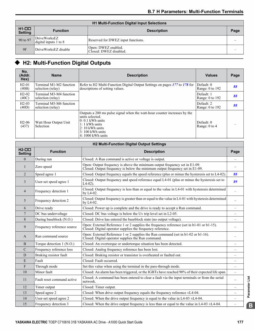
H1 Multi-Function Digital Input SelectionsH1-ooSetting Function Description Page
90 to 97 DriveWorksEZdigital inputs 1 to 8 Reserved for DWEZ input functions. –
9F DriveWorksEZ disable Open: DWEZ enabled.Closed: DWEZ disabled. –
u H2: Multi-Function Digital OutputsNo.
(Addr.Hex)
Name Description Values Page
H2-01(40B)
Terminal M1-M2 functionselection (relay)
Refer to H2 Multi-Function Digital Output Settings on pages 177 to 178 fordescriptions of setting values.
Default: 0Range: 0 to 192 88
H2-02(40C)
Terminal M3-M4 functionselection (relay)
Default: 1Range: 0 to 192 88
H2-03(40D)
Terminal M5-M6 functionselection (relay)
Default: 2Range: 0 to 192 88
H2-06(437)
Watt Hour Output UnitSelection
Outputs a 200 ms pulse signal when the watt-hour counter increases by theunits selected.0: 0.1 kWh units1: 1 kWh units2: 10 kWh units3: 100 kWh units4: 1000 kWh units
Default: 0Range: 0 to 4 –
H2 Multi-Function Digital Output SettingsH2-ooSetting Function Description Page
0 During run Closed: A Run command is active or voltage is output. –
1 Zero speed Open: Output frequency is above the minimum output frequency set in E1-09.Closed: Output frequency is below the minimum output frequency set in E1-09. –
2 Speed agree 1 Closed: Output frequency equals the speed reference (plus or minus the hysteresis set to L4-02). 88
3 User-set speed agree 1 Closed: Output frequency and speed reference equal L4-01 (plus or minus the hysteresis set toL4-02). 89
4 Frequency detection 1 Closed: Output frequency is less than or equal to the value in L4-01 with hysteresis determinedby L4-02. –
5 Frequency detection 2 Closed: Output frequency is greater than or equal to the value in L4-01 with hysteresis determinedby L4-02. –
6 Drive ready Closed: Power up is complete and the drive is ready to accept a Run command. –7 DC bus undervoltage Closed: DC bus voltage is below the Uv trip level set in L2-05. –8 During baseblock (N.O.) Closed: Drive has entered the baseblock state (no output voltage). –
9 Frequency reference source Open: External Reference 1 or 2 supplies the frequency reference (set in b1-01 or b1-15).Closed: Digital operator supplies the frequency reference. –
A Run command source Open: External Reference 1 or 2 supplies the Run command (set in b1-02 or b1-16).Closed: Digital operator supplies the Run command. –
B Torque detection 1 (N.O.) Closed: An overtorque or undertorque situation has been detected. –C Frequency reference loss Closed: Analog frequency reference has been lost. –D Braking resistor fault Closed: Braking resistor or transistor is overheated or faulted out. –E Fault Closed: Fault occurred. –F Through mode Set this value when using the terminal in the pass-through mode. –10 Minor fault Closed: An alarm has been triggered, or the IGBTs have reached 90% of their expected life span. –
11 Fault reset command active Closed: A command has been entered to clear a fault via the input terminals or from the serialnetwork. –
12 Timer output Closed: Timer output. –13 Speed agree 2 Closed: When drive output frequency equals the frequency reference ±L4-04. –14 User-set speed agree 2 Closed: When the drive output frequency is equal to the value in L4-03 ±L4-04. –15 Frequency detection 3 Closed: When the drive output frequency is less than or equal to the value in L4-03 ±L4-04. –
B.7 H Parameters: Multi-Function Terminals
YASKAWA ELECTRIC TOEP C710616 31B YASKAWA AC Drive - A1000 Quick Start Guide 177
B
Para
met
er L
ist

H2 Multi-Function Digital Output SettingsH2-ooSetting Function Description Page
16 Frequency detection 4 Closed: When the output frequency is greater than or equal to the value in L4-03 ±L4-04. –17 Torque detection 1 (N.C.) Open: Overtorque or undertorque has been detected.
–18 Torque detection 2 (N.O.) Closed: Overtorque or undertorque has been detected.19 Torque detection 2 (N.C.) Open: Overtorque or undertorque has been detected. –1A During reverse Closed: Drive is running in the reverse direction. –1B During baseblock (N.C.) Open: Drive has entered the baseblock state (no output voltage). –1C Motor 2 selection Closed: Motor 2 is selected by a digital input (H1-oo = 16) –1D During regeneration Closed: Motor is regenerating energy into the drive. –1E Restart enabled Closed: An automatic restart is performed –1F Motor overload alarm (oL1) Closed: oL1 is at 90% of its trip point or greater. An oH3 situation also triggers this alarm. –20 Drive overheat pre-alarm (oH) Closed: Heatsink temperature exceeds the parameter L8-02 value. –
22 Mechanical weakeningdetection
Closed: Mechanical weakening detected. –
2F Maintenance period Closed: Cooling fan, electrolytic capacitors, IGBTs, or the soft charge bypass relay may requiremaintenance. –
30 During torque limit Closed: When the torque limit has been reached. –31 During speed limit Closed: Speed limit has been reached. –
32 During speed limit in TorqueControl
Closed: Speed limit has been reached while using Torque Control. –
33 Zero Servo complete Closed: Zero Servo operation has finished. –
37 During frequency outputOpen: Either the drive has stopped or baseblock, DC Injection Braking, or Initial Excitation isbeing performed.Closed: Drive is running the motor (not in a baseblock state and DC Injection is not beingperformed).
–
38 Drive enabled Closed: Multi-function input set for “Drive enable” is closed (H1-oo = 6A). –39 Watt hour pulse output Output units are determined by H2-06. Outputs a pulse every 200 ms to indicate the kWh count. –
3C LOCAL/REMOTE status Open: REMOTEClosed: LOCAL –
3D During speed search Closed: Speed Search is being executed. –3E PID feedback low Closed: PID feedback level is too low. –3F PID feedback high Closed: The PID feedback level is too high. –4A During KEB Ride-Thru Closed: KEB Ride-Thru is being performed. –4B During short circuit braking Closed: Short Circuit Braking is active. –4C During fast stop Closed: A Fast Stop command has been entered from the operator or input terminals. –4D oH Pre-alarm time limit Closed: oH pre-alarm time limit has passed. –4E Braking transistor fault (rr) Closed: The built-in dynamic braking transistor failed. –4F Braking resistor overheat (oH) Closed: The dynamic braking resistor has overheated. –60 Internal cooling fan alarm Closed: Internal cooling fan alarm –
61 Rotor position detectioncomplete
Closed: Drive has successfully detected the rotor position of the PM motor. –
90 to 92 DriveWorksEZdigital outputs 1 to 3
Reserved for DWEZ digital output functions. –
100 to 192 Function 0 to 92 with inverseoutput
Inverts the output switching of the multi-function output functions.Set the last two digits of 1oo to reverse the output signal of that specific function. –
B.7 H Parameters: Multi-Function Terminals
178 YASKAWA ELECTRIC TOEP C710616 31B YASKAWA AC Drive - A1000 Quick Start Guide
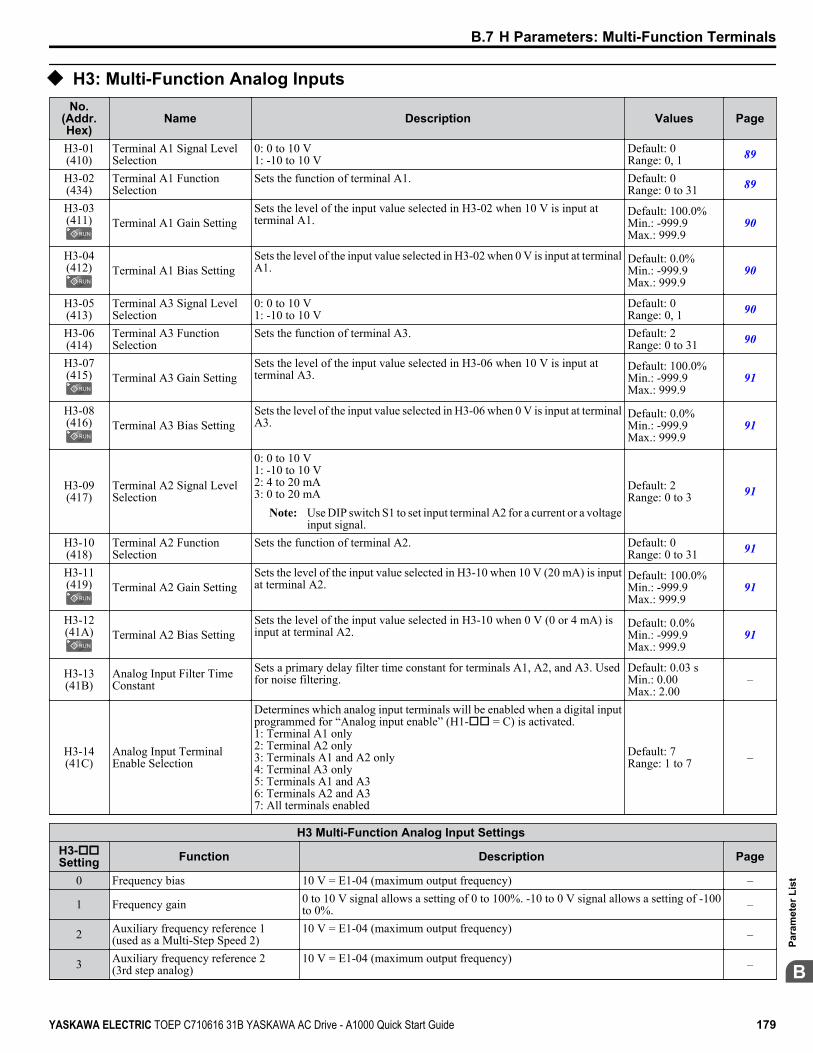
u H3: Multi-Function Analog InputsNo.
(Addr.Hex)
Name Description Values Page
H3-01(410)
Terminal A1 Signal LevelSelection
0: 0 to 10 V1: -10 to 10 V
Default: 0Range: 0, 1 89
H3-02(434)
Terminal A1 FunctionSelection
Sets the function of terminal A1. Default: 0Range: 0 to 31 89
H3-03(411) Terminal A1 Gain Setting
Sets the level of the input value selected in H3-02 when 10 V is input atterminal A1.
Default: 100.0%Min.: -999.9Max.: 999.9
90
H3-04(412) Terminal A1 Bias Setting
Sets the level of the input value selected in H3-02 when 0 V is input at terminalA1.
Default: 0.0%Min.: -999.9Max.: 999.9
90
H3-05(413)
Terminal A3 Signal LevelSelection
0: 0 to 10 V1: -10 to 10 V
Default: 0Range: 0, 1 90
H3-06(414)
Terminal A3 FunctionSelection
Sets the function of terminal A3. Default: 2Range: 0 to 31 90
H3-07(415) Terminal A3 Gain Setting
Sets the level of the input value selected in H3-06 when 10 V is input atterminal A3.
Default: 100.0%Min.: -999.9Max.: 999.9
91
H3-08(416) Terminal A3 Bias Setting
Sets the level of the input value selected in H3-06 when 0 V is input at terminalA3.
Default: 0.0%Min.: -999.9Max.: 999.9
91
H3-09(417)
Terminal A2 Signal LevelSelection
0: 0 to 10 V1: -10 to 10 V2: 4 to 20 mA3: 0 to 20 mA
Note: Use DIP switch S1 to set input terminal A2 for a current or a voltageinput signal.
Default: 2Range: 0 to 3 91
H3-10(418)
Terminal A2 FunctionSelection
Sets the function of terminal A2. Default: 0Range: 0 to 31 91
H3-11(419) Terminal A2 Gain Setting
Sets the level of the input value selected in H3-10 when 10 V (20 mA) is inputat terminal A2.
Default: 100.0%Min.: -999.9Max.: 999.9
91
H3-12(41A) Terminal A2 Bias Setting
Sets the level of the input value selected in H3-10 when 0 V (0 or 4 mA) isinput at terminal A2.
Default: 0.0%Min.: -999.9Max.: 999.9
91
H3-13(41B)
Analog Input Filter TimeConstant
Sets a primary delay filter time constant for terminals A1, A2, and A3. Usedfor noise filtering.
Default: 0.03 sMin.: 0.00Max.: 2.00
–
H3-14(41C)
Analog Input TerminalEnable Selection
Determines which analog input terminals will be enabled when a digital inputprogrammed for “Analog input enable” (H1-oo = C) is activated.1: Terminal A1 only2: Terminal A2 only3: Terminals A1 and A2 only4: Terminal A3 only5: Terminals A1 and A36: Terminals A2 and A37: All terminals enabled
Default: 7Range: 1 to 7 –
H3 Multi-Function Analog Input Settings H3-ooSetting Function Description Page
0 Frequency bias 10 V = E1-04 (maximum output frequency) –
1 Frequency gain 0 to 10 V signal allows a setting of 0 to 100%. -10 to 0 V signal allows a setting of -100to 0%. –
2 Auxiliary frequency reference 1(used as a Multi-Step Speed 2)
10 V = E1-04 (maximum output frequency) –
3 Auxiliary frequency reference 2(3rd step analog)
10 V = E1-04 (maximum output frequency) –
B.7 H Parameters: Multi-Function Terminals
YASKAWA ELECTRIC TOEP C710616 31B YASKAWA AC Drive - A1000 Quick Start Guide 179
B
Para
met
er L
ist
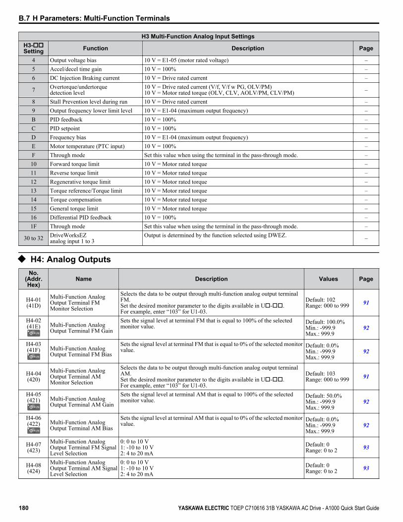
H3 Multi-Function Analog Input Settings H3-ooSetting Function Description Page
4 Output voltage bias 10 V = E1-05 (motor rated voltage) –5 Accel/decel time gain 10 V = 100% –6 DC Injection Braking current 10 V = Drive rated current –
7 Overtorque/undertorquedetection level
10 V = Drive rated current (V/f, V/f w PG, OLV/PM)10 V = Motor rated torque (OLV, CLV, AOLV/PM, CLV/PM) –
8 Stall Prevention level during run 10 V = Drive rated current –9 Output frequency lower limit level 10 V = E1-04 (maximum output frequency) –B PID feedback 10 V = 100% –C PID setpoint 10 V = 100% –D Frequency bias 10 V = E1-04 (maximum output frequency) –E Motor temperature (PTC input) 10 V = 100% –F Through mode Set this value when using the terminal in the pass-through mode. –10 Forward torque limit 10 V = Motor rated torque –11 Reverse torque limit 10 V = Motor rated torque –12 Regenerative torque limit 10 V = Motor rated torque –13 Torque reference/Torque limit 10 V = Motor rated torque –14 Torque compensation 10 V = Motor rated torque –15 General torque limit 10 V = Motor rated torque –16 Differential PID feedback 10 V = 100% –1F Through mode Set this value when using the terminal in the pass-through mode. –
30 to 32 DriveWorksEZanalog input 1 to 3
Output is determined by the function selected using DWEZ. –
u H4: Analog OutputsNo.
(Addr.Hex)
Name Description Values Page
H4-01(41D)
Multi-Function AnalogOutput Terminal FMMonitor Selection
Selects the data to be output through multi-function analog output terminalFM.Set the desired monitor parameter to the digits available in Uo-oo.For example, enter “103” for U1-03.
Default: 102Range: 000 to 999 91
H4-02(41E) Multi-Function Analog
Output Terminal FM Gain
Sets the signal level at terminal FM that is equal to 100% of the selectedmonitor value.
Default: 100.0%Min.: -999.9Max.: 999.9
92
H4-03(41F) Multi-Function Analog
Output Terminal FM Bias
Sets the signal level at terminal FM that is equal to 0% of the selected monitorvalue.
Default: 0.0%Min.: -999.9Max.: 999.9
92
H4-04(420)
Multi-Function AnalogOutput Terminal AMMonitor Selection
Selects the data to be output through multi-function analog output terminalAM.Set the desired monitor parameter to the digits available in Uo-oo.For example, enter “103” for U1-03.
Default: 103Range: 000 to 999 91
H4-05(421) Multi-Function Analog
Output Terminal AM Gain
Sets the signal level at terminal AM that is equal to 100% of the selectedmonitor value.
Default: 50.0%Min.: -999.9Max.: 999.9
92
H4-06(422) Multi-Function Analog
Output Terminal AM Bias
Sets the signal level at terminal AM that is equal to 0% of the selected monitorvalue.
Default: 0.0%Min.: -999.9Max.: 999.9
92
H4-07(423)
Multi-Function AnalogOutput Terminal FM SignalLevel Selection
0: 0 to 10 V1: -10 to 10 V2: 4 to 20 mA
Default: 0Range: 0 to 2 93
H4-08(424)
Multi-Function AnalogOutput Terminal AM SignalLevel Selection
0: 0 to 10 V1: -10 to 10 V2: 4 to 20 mA
Default: 0Range: 0 to 2 93
B.7 H Parameters: Multi-Function Terminals
180 YASKAWA ELECTRIC TOEP C710616 31B YASKAWA AC Drive - A1000 Quick Start Guide
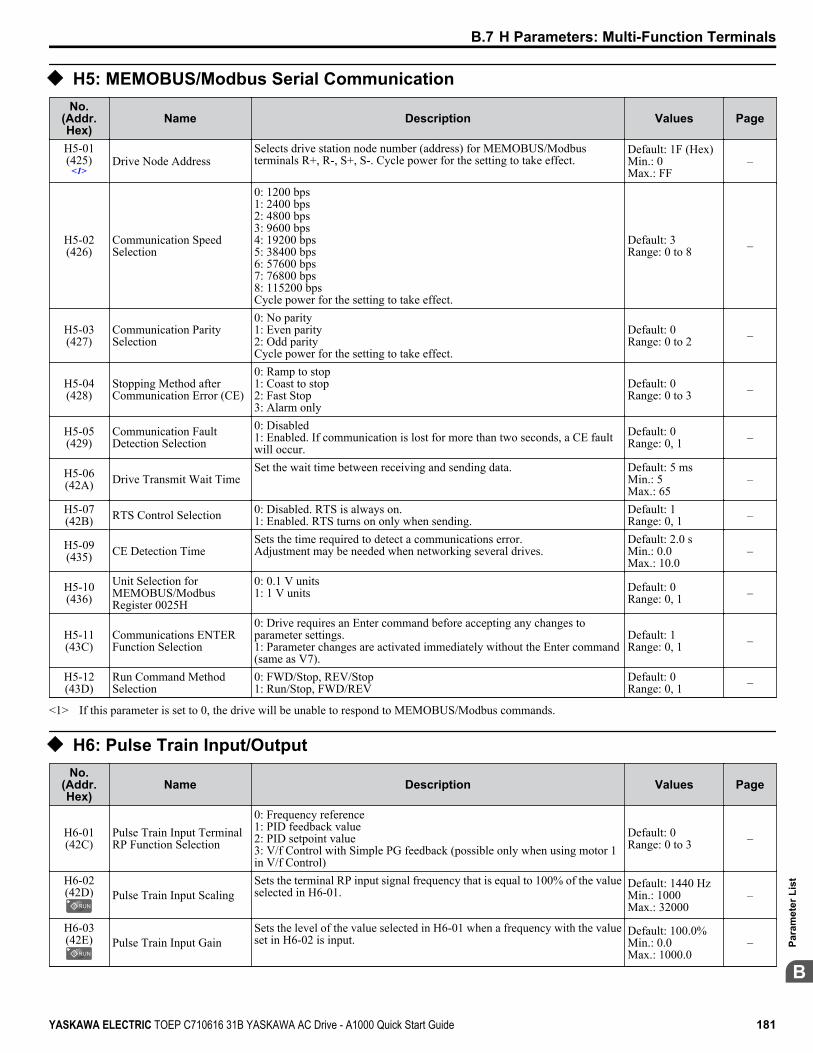
u H5: MEMOBUS/Modbus Serial CommunicationNo.
(Addr.Hex)
Name Description Values Page
H5-01(425)
<1>Drive Node Address
Selects drive station node number (address) for MEMOBUS/Modbusterminals R+, R-, S+, S-. Cycle power for the setting to take effect.
Default: 1F (Hex)Min.: 0Max.: FF
–
H5-02(426)
Communication SpeedSelection
0: 1200 bps1: 2400 bps2: 4800 bps3: 9600 bps4: 19200 bps5: 38400 bps6: 57600 bps7: 76800 bps8: 115200 bpsCycle power for the setting to take effect.
Default: 3Range: 0 to 8 –
H5-03(427)
Communication ParitySelection
0: No parity1: Even parity2: Odd parityCycle power for the setting to take effect.
Default: 0Range: 0 to 2 –
H5-04(428)
Stopping Method afterCommunication Error (CE)
0: Ramp to stop1: Coast to stop2: Fast Stop3: Alarm only
Default: 0Range: 0 to 3 –
H5-05(429)
Communication FaultDetection Selection
0: Disabled1: Enabled. If communication is lost for more than two seconds, a CE faultwill occur.
Default: 0Range: 0, 1 –
H5-06(42A) Drive Transmit Wait Time
Set the wait time between receiving and sending data. Default: 5 msMin.: 5Max.: 65
–
H5-07(42B) RTS Control Selection 0: Disabled. RTS is always on.
1: Enabled. RTS turns on only when sending.Default: 1Range: 0, 1 –
H5-09(435) CE Detection Time
Sets the time required to detect a communications error.Adjustment may be needed when networking several drives.
Default: 2.0 sMin.: 0.0Max.: 10.0
–
H5-10(436)
Unit Selection forMEMOBUS/ModbusRegister 0025H
0: 0.1 V units1: 1 V units Default: 0
Range: 0, 1 –
H5-11(43C)
Communications ENTERFunction Selection
0: Drive requires an Enter command before accepting any changes toparameter settings.1: Parameter changes are activated immediately without the Enter command(same as V7).
Default: 1Range: 0, 1 –
H5-12(43D)
Run Command MethodSelection
0: FWD/Stop, REV/Stop1: Run/Stop, FWD/REV
Default: 0Range: 0, 1 –
<1> If this parameter is set to 0, the drive will be unable to respond to MEMOBUS/Modbus commands.
u H6: Pulse Train Input/OutputNo.
(Addr.Hex)
Name Description Values Page
H6-01(42C)
Pulse Train Input TerminalRP Function Selection
0: Frequency reference1: PID feedback value2: PID setpoint value3: V/f Control with Simple PG feedback (possible only when using motor 1in V/f Control)
Default: 0Range: 0 to 3 –
H6-02(42D) Pulse Train Input Scaling
Sets the terminal RP input signal frequency that is equal to 100% of the valueselected in H6-01.
Default: 1440 HzMin.: 1000Max.: 32000
–
H6-03(42E) Pulse Train Input Gain
Sets the level of the value selected in H6-01 when a frequency with the valueset in H6-02 is input.
Default: 100.0%Min.: 0.0Max.: 1000.0
–
B.7 H Parameters: Multi-Function Terminals
YASKAWA ELECTRIC TOEP C710616 31B YASKAWA AC Drive - A1000 Quick Start Guide 181
B
Para
met
er L
ist

No.(Addr.Hex)
Name Description Values Page
H6-04(42F) Pulse Train Input Bias
Sets the level of the value selected in H6-01 when 0 Hz is input. Default: 0.0%Min.: -100.0Max.: 100.0
–
H6-05(430) Pulse Train Input Filter Time
Sets the pulse train input filter time constant. Default: 0.10 sMin.: 0.00Max.: 2.00
–
H6-06(431) Pulse Train Monitor
Selection
Select the pulse train monitor output function (value of the o-oo part ofUo-oo).For example, enter “501” for U5-01.
Default: 102Range: 000 to 809 –
H6-07(432) Pulse Train Monitor Scaling
Sets the terminal MP output signal frequency when the monitor value is 100%.To have the pulse train monitor output equal the output frequency, set H6-06to 2 and H6-07 to 0.
Default: 1440 HzMin.: 0Max.: 32000
–
H6-08(43F)
Pulse Train Input MinimumFrequency
Sets the minimum frequency for the pulse train input to be detected. Enabledwhen H6-01 = 0, 1, or 2.
Default: 0.5 HzMin.: 0.1Max.: 1000.0
–
B.7 H Parameters: Multi-Function Terminals
182 YASKAWA ELECTRIC TOEP C710616 31B YASKAWA AC Drive - A1000 Quick Start Guide
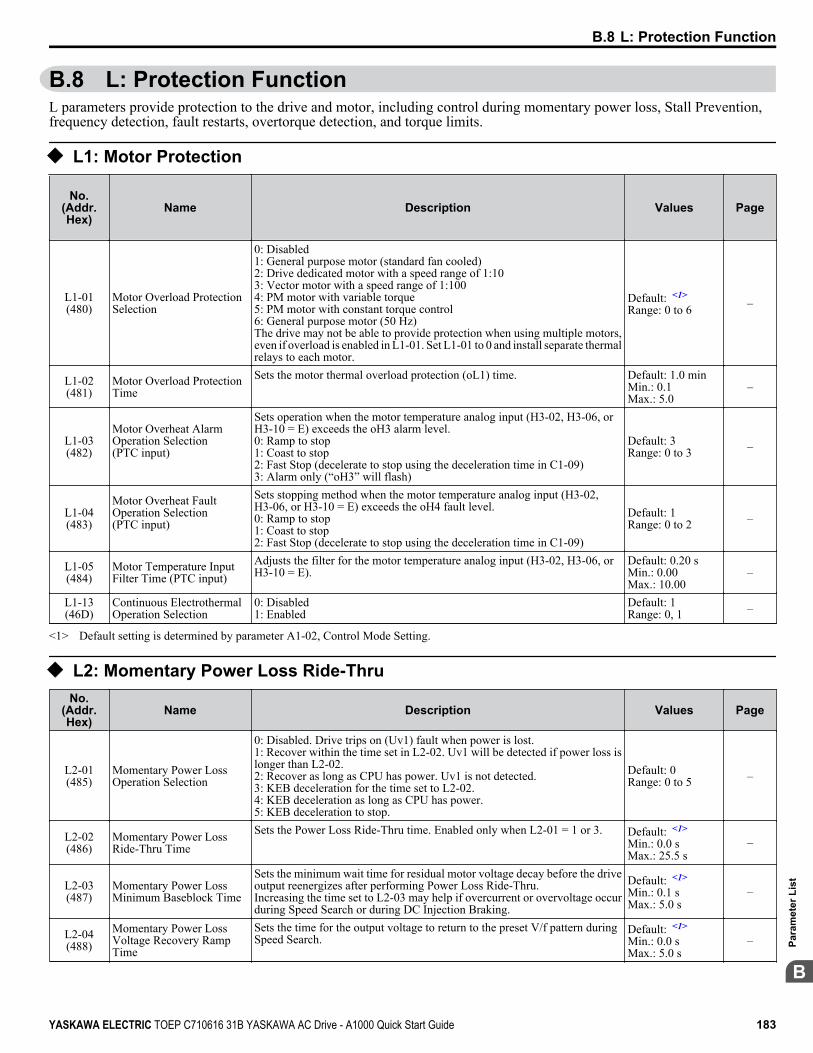
B.8 L: Protection FunctionL parameters provide protection to the drive and motor, including control during momentary power loss, Stall Prevention,frequency detection, fault restarts, overtorque detection, and torque limits.
u L1: Motor Protection
No.(Addr.Hex)
Name Description Values Page
L1-01(480)
Motor Overload ProtectionSelection
0: Disabled1: General purpose motor (standard fan cooled)2: Drive dedicated motor with a speed range of 1:103: Vector motor with a speed range of 1:1004: PM motor with variable torque5: PM motor with constant torque control6: General purpose motor (50 Hz)The drive may not be able to provide protection when using multiple motors,even if overload is enabled in L1-01. Set L1-01 to 0 and install separate thermalrelays to each motor.
Default: <1>
Range: 0 to 6 –
L1-02(481)
Motor Overload ProtectionTime
Sets the motor thermal overload protection (oL1) time. Default: 1.0 minMin.: 0.1Max.: 5.0
–
L1-03(482)
Motor Overheat AlarmOperation Selection(PTC input)
Sets operation when the motor temperature analog input (H3-02, H3-06, orH3-10 = E) exceeds the oH3 alarm level.0: Ramp to stop1: Coast to stop2: Fast Stop (decelerate to stop using the deceleration time in C1-09)3: Alarm only (“oH3” will flash)
Default: 3Range: 0 to 3 –
L1-04(483)
Motor Overheat FaultOperation Selection(PTC input)
Sets stopping method when the motor temperature analog input (H3-02,H3-06, or H3-10 = E) exceeds the oH4 fault level.0: Ramp to stop1: Coast to stop2: Fast Stop (decelerate to stop using the deceleration time in C1-09)
Default: 1Range: 0 to 2 –
L1-05(484)
Motor Temperature InputFilter Time (PTC input)
Adjusts the filter for the motor temperature analog input (H3-02, H3-06, orH3-10 = E).
Default: 0.20 sMin.: 0.00Max.: 10.00
–
L1-13(46D)
Continuous ElectrothermalOperation Selection
0: Disabled1: Enabled
Default: 1Range: 0, 1 –
<1> Default setting is determined by parameter A1-02, Control Mode Setting.
u L2: Momentary Power Loss Ride-ThruNo.
(Addr.Hex)
Name Description Values Page
L2-01(485)
Momentary Power LossOperation Selection
0: Disabled. Drive trips on (Uv1) fault when power is lost.1: Recover within the time set in L2-02. Uv1 will be detected if power loss islonger than L2-02.2: Recover as long as CPU has power. Uv1 is not detected.3: KEB deceleration for the time set to L2-02.4: KEB deceleration as long as CPU has power.5: KEB deceleration to stop.
Default: 0Range: 0 to 5 –
L2-02(486)
Momentary Power LossRide-Thru Time
Sets the Power Loss Ride-Thru time. Enabled only when L2-01 = 1 or 3. Default: <1>
Min.: 0.0 sMax.: 25.5 s
–
L2-03(487)
Momentary Power LossMinimum Baseblock Time
Sets the minimum wait time for residual motor voltage decay before the driveoutput reenergizes after performing Power Loss Ride-Thru.Increasing the time set to L2-03 may help if overcurrent or overvoltage occurduring Speed Search or during DC Injection Braking.
Default: <1>
Min.: 0.1 sMax.: 5.0 s
–
L2-04(488)
Momentary Power LossVoltage Recovery RampTime
Sets the time for the output voltage to return to the preset V/f pattern duringSpeed Search.
Default: <1>
Min.: 0.0 sMax.: 5.0 s
–
B.8 L: Protection Function
YASKAWA ELECTRIC TOEP C710616 31B YASKAWA AC Drive - A1000 Quick Start Guide 183
B
Para
met
er L
ist
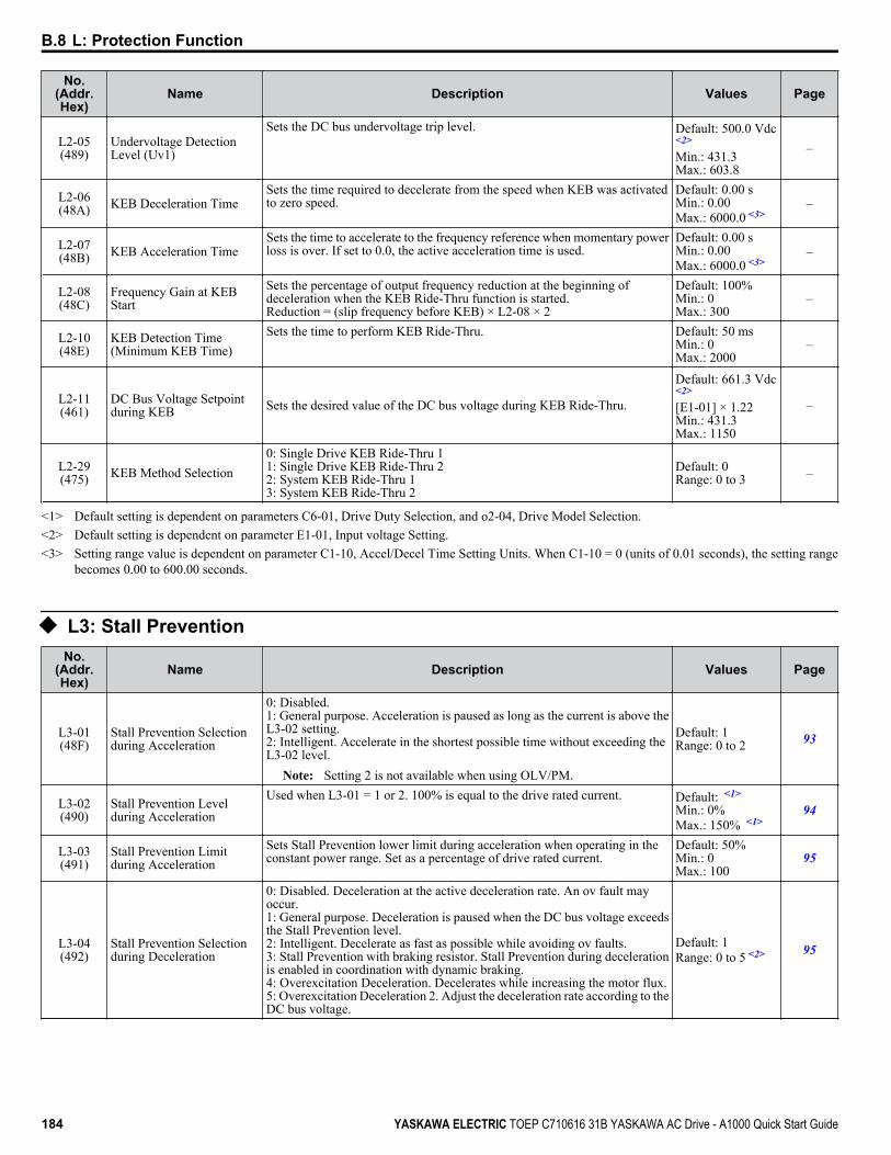
No.(Addr.Hex)
Name Description Values Page
L2-05(489)
Undervoltage DetectionLevel (Uv1)
Sets the DC bus undervoltage trip level. Default: 500.0 Vdc<2>
Min.: 431.3Max.: 603.8
–
L2-06(48A) KEB Deceleration Time
Sets the time required to decelerate from the speed when KEB was activatedto zero speed.
Default: 0.00 sMin.: 0.00Max.: 6000.0 <3>
–
L2-07(48B) KEB Acceleration Time
Sets the time to accelerate to the frequency reference when momentary powerloss is over. If set to 0.0, the active acceleration time is used.
Default: 0.00 sMin.: 0.00Max.: 6000.0 <3>
–
L2-08(48C)
Frequency Gain at KEBStart
Sets the percentage of output frequency reduction at the beginning ofdeceleration when the KEB Ride-Thru function is started.Reduction = (slip frequency before KEB) × L2-08 × 2
Default: 100%Min.: 0Max.: 300
–
L2-10(48E)
KEB Detection Time(Minimum KEB Time)
Sets the time to perform KEB Ride-Thru. Default: 50 msMin.: 0Max.: 2000
–
L2-11(461)
DC Bus Voltage Setpointduring KEB Sets the desired value of the DC bus voltage during KEB Ride-Thru.
Default: 661.3 Vdc<2>
[E1-01] × 1.22Min.: 431.3Max.: 1150
–
L2-29(475) KEB Method Selection
0: Single Drive KEB Ride-Thru 11: Single Drive KEB Ride-Thru 22: System KEB Ride-Thru 13: System KEB Ride-Thru 2
Default: 0Range: 0 to 3 –
<1> Default setting is dependent on parameters C6-01, Drive Duty Selection, and o2-04, Drive Model Selection.<2> Default setting is dependent on parameter E1-01, Input voltage Setting.<3> Setting range value is dependent on parameter C1-10, Accel/Decel Time Setting Units. When C1-10 = 0 (units of 0.01 seconds), the setting range
becomes 0.00 to 600.00 seconds.
u L3: Stall PreventionNo.
(Addr.Hex)
Name Description Values Page
L3-01(48F)
Stall Prevention Selectionduring Acceleration
0: Disabled.1: General purpose. Acceleration is paused as long as the current is above theL3-02 setting.2: Intelligent. Accelerate in the shortest possible time without exceeding theL3-02 level.
Note: Setting 2 is not available when using OLV/PM.
Default: 1Range: 0 to 2 93
L3-02(490)
Stall Prevention Levelduring Acceleration
Used when L3-01 = 1 or 2. 100% is equal to the drive rated current. Default: <1>
Min.: 0%Max.: 150% <1>
94
L3-03(491)
Stall Prevention Limitduring Acceleration
Sets Stall Prevention lower limit during acceleration when operating in theconstant power range. Set as a percentage of drive rated current.
Default: 50%Min.: 0Max.: 100
95
L3-04(492)
Stall Prevention Selectionduring Deceleration
0: Disabled. Deceleration at the active deceleration rate. An ov fault mayoccur.1: General purpose. Deceleration is paused when the DC bus voltage exceedsthe Stall Prevention level.2: Intelligent. Decelerate as fast as possible while avoiding ov faults.3: Stall Prevention with braking resistor. Stall Prevention during decelerationis enabled in coordination with dynamic braking.4: Overexcitation Deceleration. Decelerates while increasing the motor flux.5: Overexcitation Deceleration 2. Adjust the deceleration rate according to theDC bus voltage.
Default: 1Range: 0 to 5 <2> 95
B.8 L: Protection Function
184 YASKAWA ELECTRIC TOEP C710616 31B YASKAWA AC Drive - A1000 Quick Start Guide

No.(Addr.Hex)
Name Description Values Page
L3-05(493)
Stall Prevention Selectionduring Run
0: Disabled. Drive runs at a set frequency. A heavy load may cause speed loss.1: Decel time 1. Uses the deceleration time set to C1-02 while Stall Preventionis performed.2: Decel time 2. Uses the deceleration time set to C1-04 while Stall Preventionis performed.
Default: 1Range: 0 to 2 96
L3-06(494)
Stall Prevention Levelduring Run
Enabled when L3-05 is set to 1 or 2. 100% is equal to the drive rated current. Default: <1>
Min.: 30%Max.: 150% <1>
96
L3-11(4C7)
Overvoltage SuppressionFunction Selection
Enables or disables the ov suppression function, which allows the drive tochange the output frequency as the load changes to prevent an ov fault.0: Disabled1: Enabled
Default: 0Range: 0, 1 –
L3-17(462)
Target DC Bus Voltage forOvervoltage Suppressionand Stall Prevention
Sets the desired value for the DC bus voltage during overvoltage suppressionand Stall Prevention during deceleration.
Default: 1064 Vdc<3>
Min.: 431.3Max.: 1150
–
L3-20(465)
DC Bus Voltage AdjustmentGain
Sets the proportional gain for KEB Ride-Thru, Stall Prevention, andovervoltage suppression.
Default: <4>
Min.: 0.00Max.: 5.00
–
L3-21(466)
Accel/Decel RateCalculation Gain
Sets the proportional gain used to calculate the deceleration rate during KEBRide-Thru, ov suppression function, and Stall Prevention during deceleration(L3-04 = 2).
Default: 1.00Min.: 0.10Max.: 10.00
–
L3-22(4F9)
Deceleration Time at StallPrevention duringAcceleration
Sets the deceleration time used for Stall Prevention during acceleration inOLV/PM.
Default: 0.0 sMin.: 0.0Max.: 6000
–
L3-23(4FD)
Automatic ReductionSelection for StallPrevention during Run
0: Sets the Stall Prevention level set in L3-04 that is used throughout the entirefrequency range.1: Automatic Stall Prevention level reduction in the constant output range. Thelower limit value is 40% of L3-06.
Default: 0Range: 0, 1 –
L3-24(46E)
Motor Acceleration Time forInertia Calculations
Sets the time needed to accelerate the uncoupled motor at rated torque fromstop to the maximum frequency.
Default: <5> <6><7>
Min: 0.001 sMax: 10.000 s
–
L3-25(46F) Load Inertia Ratio
Sets the ratio between the motor and machine inertia. Default: 1.0Min.: 1.0Max.: 1000.0
–
L3-26(455)
Additional DC BusCapacitors
When DC bus capacitors have been added externally, be sure to add thosevalues to the internal capacitor table for proper DC bus calculations.
Default: 0 μFMin: 0Max: 65000
–
L3-27(456)
Stall Prevention DetectionTime
Sets the time the current must exceed the Stall Prevention level to activateStall Prevention.
Default: 50 msMin.: 0Max.: 5000
–
<1> Upper limit is dependent on parameters C6-01, Drive Duty Selection, and L8-38, Frequency Reduction Selection.<2> The setting range is 0 to 2 in CLV, OLV/PM, or AOLV/PM, control modes.<3> Default setting is dependent on parameter E1-01, Input voltage Setting.<4> Default setting is determined by parameter A1-02, Control Mode Setting.<5> Parameter value changes automatically if E2-11 is manually changed or changed by Auto-Tuning.<6> Default setting is dependent on parameters C6-01, Drive Duty Selection, and o2-04, Drive Model Selection.<7> Default setting is dependent on parameter E5-01, Motor Code Selection.
B.8 L: Protection Function
YASKAWA ELECTRIC TOEP C710616 31B YASKAWA AC Drive - A1000 Quick Start Guide 185
B
Para
met
er L
ist

u L4: Speed DetectionNo.
(Addr.Hex)
Name Description Values Page
L4-01(499)
Speed Agreement DetectionLevel
L4-01 sets the frequency detection level for digital output functions H2-oo= 2, 3, 4, 5.
Default: 0.0 HzMin.: 0.0Max.: 400.0
–
L4-02(49A)
Speed Agreement DetectionWidth
L4-02 sets the hysteresis or allowable margin for speed detection. Default: 2.0 Hz <1>
Min.: 0.0Max.: 20.0
–
L4-03(49B)
Speed Agreement DetectionLevel (+/-)
L4-03 sets the frequency detection level for digital output functions H2-oo= 2, 3, 4, 5.
Default: 0.0 HzMin.: -400.0Max.: 400.0
–
L4-04(49C)
Speed Agreement DetectionWidth (+/-)
L4-04 sets the hysteresis or allowable margin for speed detection. Default: 2.0 Hz <1>
Min.: 0.0Max.: 20.0
–
L4-05(49D)
Frequency Reference LossDetection Selection
0: Stop. Drive stops when the frequency reference is lost.1: Run. Drive runs at a reduced speed when the frequency reference is lost.
Default: 0Range: 0, 1 –
L4-06(4C2)
Frequency Reference atReference Loss
Sets the percentage of the frequency reference that the drive should run withwhen the frequency reference is lost.
Default: 80%Min.: 0.0Max.: 100.0
–
L4-07(470)
Speed Agreement DetectionSelection
0: No detection during baseblock.1: Detection always enabled.
Default: 0Range: 0, 1 –
<1> Default setting is dependent on parameter A1-02, Control Mode Selection.
u L5: Fault RestartNo.
(Addr.Hex)
Name Description Values Page
L5-01(49E)
Number of Auto RestartAttempts
Sets the number of times the drive may attempt to restart after the followingfaults occur: GF, LF, oC, ov, PF, rH, rr, oL1, oL2, oL3, oL4, STo, Uv1.
Default: 0Min.: 0Max.: 10
–
L5-02(49F)
Auto Restart Fault OutputOperation Selection
0: Fault output not active.1: Fault output active during restart attempt.
Default: 0Range: 0, 1 –
L5-04(46C) Fault Reset Interval Time
Sets the amount of time to wait between performing fault restarts. Default: 10.0 sMin.: 0.5Max.: 600.0
–
L5-05(467)
Fault Reset OperationSelection
0: Continuously attempt to restart while incrementing restart counter only ata successful restarts (same as F7 and G7).1: Attempt to restart with the interval time set in L5-04 and increment therestart counter with each attempt (same as V7).
Default: 0Range: 0, 1 –
u L6: Torque DetectionNo.
(Addr.Hex)
Name Description Values Page
L6-01(4A1)
Torque DetectionSelection 1
0: Disabled1: oL3 detection only active during speed agree, operation continues afterdetection2: oL3 detection always active during run, operation continues after detection3: oL3 detection only active during speed agree, output shuts down on an oL3fault4: oL3 detection always active during run, output shuts down on an oL3 fault5: UL3 detection only active during speed agree, operation continues afterdetection6: UL3 detection always active during run, operation continues after detection7: UL3 detection only active during speed agree, output shuts down on an oL3fault8: UL3 detection always active during run, output shuts down on an oL3 fault
Default: 0Range: 0 to 8 –
L6-02(4A2)
Torque DetectionLevel 1
Sets the overtorque and undertorque detection level. Default: 150%Min.: 0Max.: 300
–
B.8 L: Protection Function
186 YASKAWA ELECTRIC TOEP C710616 31B YASKAWA AC Drive - A1000 Quick Start Guide
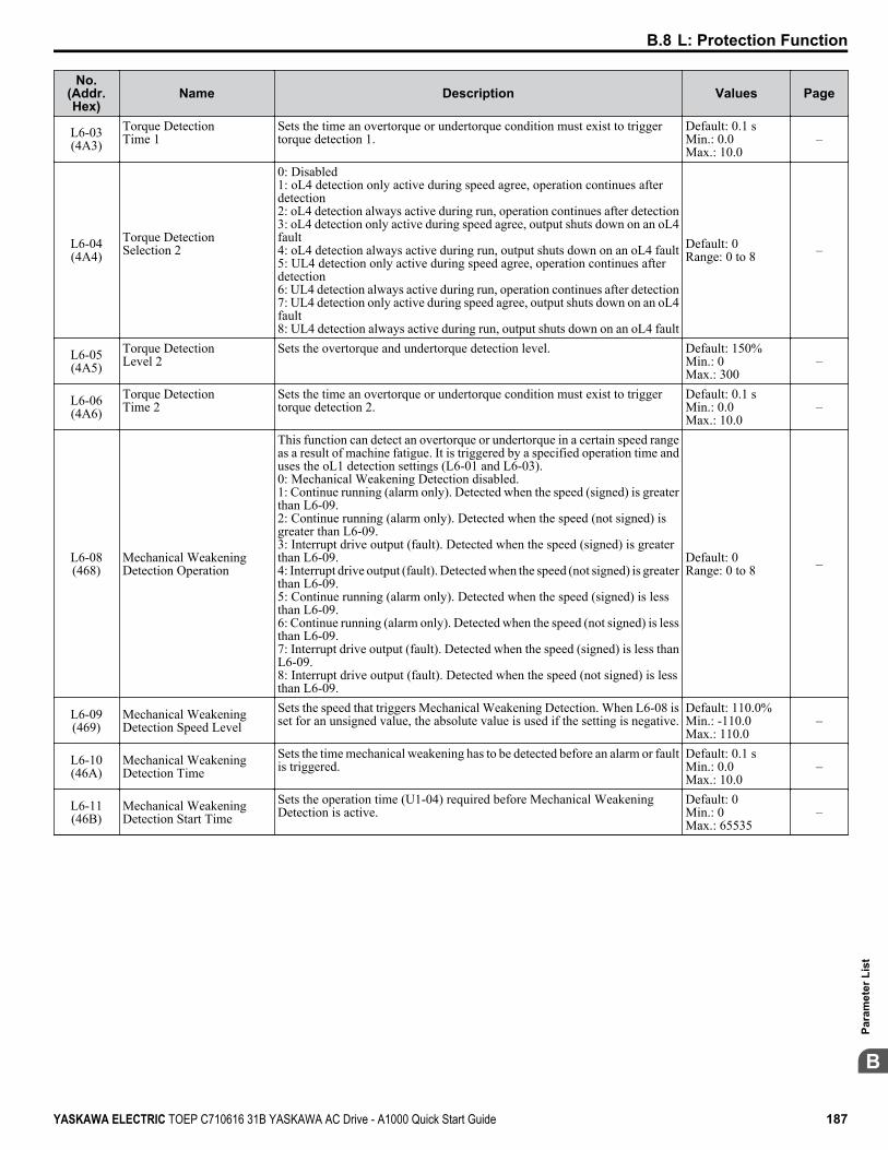
No.(Addr.Hex)
Name Description Values Page
L6-03(4A3)
Torque DetectionTime 1
Sets the time an overtorque or undertorque condition must exist to triggertorque detection 1.
Default: 0.1 sMin.: 0.0Max.: 10.0
–
L6-04(4A4)
Torque DetectionSelection 2
0: Disabled1: oL4 detection only active during speed agree, operation continues afterdetection2: oL4 detection always active during run, operation continues after detection3: oL4 detection only active during speed agree, output shuts down on an oL4fault4: oL4 detection always active during run, output shuts down on an oL4 fault5: UL4 detection only active during speed agree, operation continues afterdetection6: UL4 detection always active during run, operation continues after detection7: UL4 detection only active during speed agree, output shuts down on an oL4fault8: UL4 detection always active during run, output shuts down on an oL4 fault
Default: 0Range: 0 to 8 –
L6-05(4A5)
Torque DetectionLevel 2
Sets the overtorque and undertorque detection level. Default: 150%Min.: 0Max.: 300
–
L6-06(4A6)
Torque DetectionTime 2
Sets the time an overtorque or undertorque condition must exist to triggertorque detection 2.
Default: 0.1 sMin.: 0.0Max.: 10.0
–
L6-08(468)
Mechanical WeakeningDetection Operation
This function can detect an overtorque or undertorque in a certain speed rangeas a result of machine fatigue. It is triggered by a specified operation time anduses the oL1 detection settings (L6-01 and L6-03).0: Mechanical Weakening Detection disabled.1: Continue running (alarm only). Detected when the speed (signed) is greaterthan L6-09.2: Continue running (alarm only). Detected when the speed (not signed) isgreater than L6-09.3: Interrupt drive output (fault). Detected when the speed (signed) is greaterthan L6-09.4: Interrupt drive output (fault). Detected when the speed (not signed) is greaterthan L6-09.5: Continue running (alarm only). Detected when the speed (signed) is lessthan L6-09.6: Continue running (alarm only). Detected when the speed (not signed) is lessthan L6-09.7: Interrupt drive output (fault). Detected when the speed (signed) is less thanL6-09.8: Interrupt drive output (fault). Detected when the speed (not signed) is lessthan L6-09.
Default: 0Range: 0 to 8 –
L6-09(469)
Mechanical WeakeningDetection Speed Level
Sets the speed that triggers Mechanical Weakening Detection. When L6-08 isset for an unsigned value, the absolute value is used if the setting is negative.
Default: 110.0%Min.: -110.0Max.: 110.0
–
L6-10(46A)
Mechanical WeakeningDetection Time
Sets the time mechanical weakening has to be detected before an alarm or faultis triggered.
Default: 0.1 sMin.: 0.0Max.: 10.0
–
L6-11(46B)
Mechanical WeakeningDetection Start Time
Sets the operation time (U1-04) required before Mechanical WeakeningDetection is active.
Default: 0Min.: 0Max.: 65535
–
B.8 L: Protection Function
YASKAWA ELECTRIC TOEP C710616 31B YASKAWA AC Drive - A1000 Quick Start Guide 187
B
Para
met
er L
ist
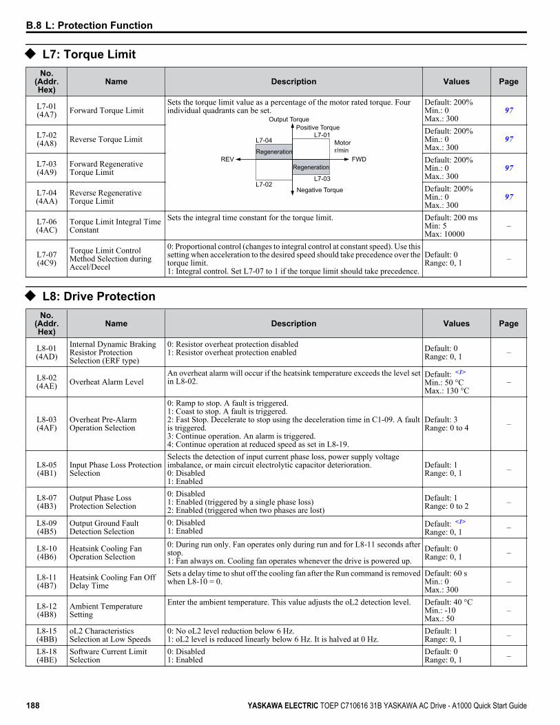
u L7: Torque LimitNo.
(Addr.Hex)
Name Description Values Page
L7-01(4A7) Forward Torque Limit
Sets the torque limit value as a percentage of the motor rated torque. Fourindividual quadrants can be set.
L7-01
L7-03L7-02
L7-04
Output TorquePositive Torque
REV
Negative Torque
FWD
Motor r/minRegeneration
Regeneration
Default: 200%Min.: 0Max.: 300
97
L7-02(4A8) Reverse Torque Limit
Default: 200%Min.: 0Max.: 300
97
L7-03(4A9)
Forward RegenerativeTorque Limit
Default: 200%Min.: 0Max.: 300
97
L7-04(4AA)
Reverse RegenerativeTorque Limit
Default: 200%Min.: 0Max.: 300
97
L7-06(4AC)
Torque Limit Integral TimeConstant
Sets the integral time constant for the torque limit. Default: 200 msMin: 5Max: 10000
–
L7-07(4C9)
Torque Limit ControlMethod Selection duringAccel/Decel
0: Proportional control (changes to integral control at constant speed). Use thissetting when acceleration to the desired speed should take precedence over thetorque limit.1: Integral control. Set L7-07 to 1 if the torque limit should take precedence.
Default: 0Range: 0, 1 –
u L8: Drive ProtectionNo.
(Addr.Hex)
Name Description Values Page
L8-01(4AD)
Internal Dynamic BrakingResistor ProtectionSelection (ERF type)
0: Resistor overheat protection disabled1: Resistor overheat protection enabled Default: 0
Range: 0, 1 –
L8-02(4AE) Overheat Alarm Level
An overheat alarm will occur if the heatsink temperature exceeds the level setin L8-02.
Default: <1>
Min.: 50 °CMax.: 130 °C
–
L8-03(4AF)
Overheat Pre-AlarmOperation Selection
0: Ramp to stop. A fault is triggered.1: Coast to stop. A fault is triggered.2: Fast Stop. Decelerate to stop using the deceleration time in C1-09. A faultis triggered.3: Continue operation. An alarm is triggered.4: Continue operation at reduced speed as set in L8-19.
Default: 3Range: 0 to 4 –
L8-05(4B1)
Input Phase Loss ProtectionSelection
Selects the detection of input current phase loss, power supply voltageimbalance, or main circuit electrolytic capacitor deterioration.0: Disabled1: Enabled
Default: 1Range: 0, 1 –
L8-07(4B3)
Output Phase LossProtection Selection
0: Disabled1: Enabled (triggered by a single phase loss)2: Enabled (triggered when two phases are lost)
Default: 1Range: 0 to 2 –
L8-09(4B5)
Output Ground FaultDetection Selection
0: Disabled1: Enabled
Default: <1>
Range: 0, 1 –
L8-10(4B6)
Heatsink Cooling FanOperation Selection
0: During run only. Fan operates only during run and for L8-11 seconds afterstop.1: Fan always on. Cooling fan operates whenever the drive is powered up.
Default: 0Range: 0, 1 –
L8-11(4B7)
Heatsink Cooling Fan OffDelay Time
Sets a delay time to shut off the cooling fan after the Run command is removedwhen L8-10 = 0.
Default: 60 sMin.: 0Max.: 300
–
L8-12(4B8)
Ambient TemperatureSetting
Enter the ambient temperature. This value adjusts the oL2 detection level. Default: 40 °CMin.: -10Max.: 50
–
L8-15(4BB)
oL2 CharacteristicsSelection at Low Speeds
0: No oL2 level reduction below 6 Hz.1: oL2 level is reduced linearly below 6 Hz. It is halved at 0 Hz.
Default: 1Range: 0, 1 –
L8-18(4BE)
Software Current LimitSelection
0: Disabled1: Enabled
Default: 0Range: 0, 1 –
B.8 L: Protection Function
188 YASKAWA ELECTRIC TOEP C710616 31B YASKAWA AC Drive - A1000 Quick Start Guide

No.(Addr.Hex)
Name Description Values Page
L8-19(4BF)
Frequency Reduction Rateduring Overheat Pre-Alarm
Specifies the frequency reference reduction gain at overheat pre-alarm whenL8-03 = 4.
Default: 0.8Min.: 0.1Max.: 0.9
–
L8-27(4DD) Overcurrent Detection Gain
Sets the gain for overcurrent detection as a percentage of the motor ratedcurrent. Overcurrent is detected using the lower value between the overcurrentlevel of the drive or the value set to L8-27.
Default: 300.0%Min.: 0.0Max.: 300.0
–
L8-29(4DF)
Current UnbalanceDetection (LF2)
0: Disabled1: Enabled
Default: 1Range: 0, 1 –
L8-35(4EC)
Installation MethodSelection
0: IP00 enclosure1: Side-by-Side mounting2: NEMA Type 1 enclosure3: Finless model drive or external heatsink installation
Default: 2 <2>
Range: 0 to 3 –
L8-38(4EF)
Carrier FrequencyReduction
0: Disabled1: Enabled below 6 Hz2: Enabled for the entire speed range
Default: <3>
Range: 0 to 2 –
L8-40(4F1)
Carrier FrequencyReduction Off Delay Time
Sets the time that the drive continues running with reduced carrier frequencyafter the carrier reduction condition is gone. Setting 0.00 s disables the carrierfrequency reduction time.
Default: <4>
Min.: 0.00 sMax.: 2.00 s
–
L8-41(4F2)
High Current AlarmSelection
0: Disabled1: Enabled. An alarm is triggered at output currents above 150% of drive ratedcurrent.
Default: 0Range: 0, 1 –
L8-55(45F)
Internal Braking TransistorProtection
0: Disabled. L8-55 should be disabled when using a regen converter or anoptional braking unit.1: Protection enabled.
Default: 1Range: 0, 1 –
<1> Default setting is dependent on parameters C6-01, Drive Duty Selection, and o2-04, Drive Model Selection.<2> Parameter setting value is not reset to the default value when the drive is initialized.<3> Default setting is dependent on parameters A1-02, Control Method Selection, and o2-04, Drive Model Selection.<4> Default setting is dependent on parameter A1-02, Control Method Selection.
B.8 L: Protection Function
YASKAWA ELECTRIC TOEP C710616 31B YASKAWA AC Drive - A1000 Quick Start Guide 189
B
Para
met
er L
ist
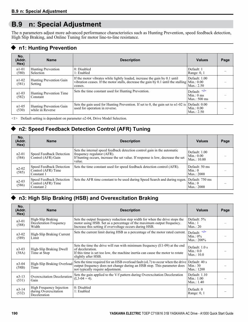
B.9 n: Special AdjustmentThe n parameters adjust more advanced performance characteristics such as Hunting Prevention, speed feedback detection,High Slip Braking, and Online Tuning for motor line-to-line resistance.
u n1: Hunting PreventionNo.
(Addr.Hex)
Name Description Values Page
n1-01(580)
Hunting PreventionSelection
0: Disabled1: Enabled
Default: 1Range: 0, 1 –
n1-02(581)
Hunting Prevention GainSetting
If the motor vibrates while lightly loaded, increase the gain by 0.1 untilvibration ceases. If the motor stalls, decrease the gain by 0.1 until the stallingceases.
Default: 1.00Min.: 0.00Max.: 2.50
–
n1-03(582)
Hunting Prevention TimeConstant
Sets the time constant used for Hunting Prevention. Default: <1>
Min.: 0 msMax.: 500 ms
–
n1-05(530)
Hunting Prevention Gainwhile in Reverse
Sets the gain used for Hunting Prevention. If set to 0, the gain set to n1-02 isused for operation in reverse.
Default: 0.00Min.: 0.00Max.: 2.50
–
<1> Default setting is dependent on parameter o2-04, Drive Model Selection.
u n2: Speed Feedback Detection Control (AFR) TuningNo.
(Addr.Hex)
Name Description Values Page
n2-01(584)
Speed Feedback DetectionControl (AFR) Gain
Sets the internal speed feedback detection control gain in the automaticfrequency regulator (AFR).If hunting occurs, increase the set value. If response is low, decrease the setvalue.
Default: 1.00Min.: 0.00Max.: 10.00
–
n2-02(585)
Speed Feedback DetectionControl (AFR) TimeConstant 1
Sets the time constant used for speed feedback detection control (AFR). Default: 50 msMin.: 0Max.: 2000
–
n2-03(586)
Speed Feedback DetectionControl (AFR) TimeConstant 2
Sets the AFR time constant to be used during Speed Search and during regen. Default: 750 msMin.: 0Max.: 2000
–
u n3: High Slip Braking (HSB) and Overexcitation BrakingNo.
(Addr.Hex)
Name Description Values Page
n3-01(588)
High-Slip BrakingDeceleration FrequencyWidth
Sets the output frequency reduction step width for when the drive stops themotor using HSB. Set as a percentage of the maximum output frequency.Increase this setting if overvoltage occurs during HSB.
Default: 5%Min.: 1Max.: 20
–
n3-02(589)
High-Slip Braking CurrentLimit
Sets the current limit during HSB as a percentage of the motor rated current. Default: <1>
Min.: 0%Max.: 200%
–
n3-03(58A)
High-Slip Braking DwellTime at Stop
Sets the time the drive will run with minimum frequency (E1-09) at the endof deceleration.If this time is set too low, the machine inertia can cause the motor to rotateslightly after HSB.
Default: 1.0 sMin.: 0.0Max.: 10.0
–
n3-04(58B)
High-Slip Braking OverloadTime
Sets the time required for an HSB overload fault (oL7) to occur when the driveoutput frequency does not change during an HSB stop. This parameter doesnot typically require adjustment.
Default: 40 sMin.: 30Max.: 1200
–
n3-13(531)
Overexcitation DecelerationGain
Sets the gain applied to the V/f pattern during Overexcitation Deceleration(L3-04 = 4).
Default: 1.10Min.: 1.00Max.: 1.40
–
n3-14(532)
High Frequency Injectionduring OverexcitationDeceleration
0: Disabled1: Enabled Default: 0
Range: 0, 1 –
B.9 n: Special Adjustment
190 YASKAWA ELECTRIC TOEP C710616 31B YASKAWA AC Drive - A1000 Quick Start Guide

No.(Addr.Hex)
Name Description Values Page
n3-21(579)
High-Slip SuppressionCurrent Level
Sets output current level at which the drive will start reducing theoverexcitation gain in order to prevent a too high motor slip duringOverexcitation Deceleration. Set as a percentage of the drive rated current.
Default: 100%Min.: 0Max.: 150
–
n3-23(57B)
Overexcitation OperationSelection
0: Enabled in both directions1: Enabled only when rotating forward2: Enabled only when in reverse
Default: 0Range: 0 to 2 –
<1> Default setting is dependent on parameters C6-01, Drive Duty Selection, and L8-38, Frequency Reduction Selection.
u n5: Feed Forward ControlNo.
(Addr.Hex)
Name Description Values Page
n5-01(5B0)
Feed Forward ControlSelection
0: Disabled1: Enabled
Default: 0Range: 0, 1 –
n5-02(5B1) Motor Acceleration Time
Sets the time required to accelerate the motor at the rated torque from stop torated speed.
Default: <1> <2>
Min.: 0.001 sMax.: 10.000 s
–
n5-03(5B2) Feed Forward Control Gain
Sets the ratio between motor and load inertia. Lower this setting if overshootoccurs at the end of acceleration.
Default: 1.00Min.: 0.00Max.: 100.00
–
<1> Default setting is dependent on parameter E5-01, Motor Code Selection.<2> Default setting is dependent on parameters C6-01, Drive Duty Selection, and o2-04, Drive Model Selection.
u n6: Online TuningNo.
(Addr.Hex)
Name Description Values Page
n6-01(570) Online Tuning Selection
0: Disabled1: Line-to-line resistance tuning2: Voltage correction. Setting not possible when Energy Saving is enabled(b8-01).
Default: 0Range: 0 to 2 –
n6-05(5C7) Online Tuning Gain
Decrease this setting for motors with a relatively large rotor time constant. Ifoverload occurs, increase this setting slowly in increments of 0.10.
Default: 1.00Min.: 0.10Max.: 5.00
–
u n8: PM Motor Control TuningNo.
(Addr.Hex)
Name Description Values Page
n8-01(540)
Initial Rotor PositionEstimation Current
Sets the current used for initial rotor position estimation as a percentage of themotor rated current (E5-03). If the motor nameplate lists an “Si” value, thatvalue should be entered here.
Default: 50%Min.: 0Max.: 100
–
n8-02(541) Pole Attraction Current
Sets the current during initial polar attraction as a percentage of the motor ratedcurrent. Enter a high value when attempting to increase starting torque.
Default: 80%Min.: 0Max.: 150
–
n8-35(562)
Initial Rotor PositionDetection Selection
0: Pull-in1: High frequency injection2: Pulse injection
Default: 1Range: 0 to 2 –
n8-45(538)
Speed Feedback DetectionControl Gain
Increase this setting if hunting occurs. Decrease to lower the response. Default: 0.80Min.: 0.00Max.: 10.00
–
n8-47(53A)
Pull-In CurrentCompensation TimeConstant
Sets the time constant to make the pull-in current reference and actual currentvalue agree. Decrease the value if the motor begins to oscillate, and increasethe value if it takes too long for the current reference to equal the output current.
Default: 5.0 sMin.: 0.0Max.: 100.0
–
n8-48(53B) Pull-In Current
Defines the d-Axis current reference during no-load operation at a constantspeed. Set as a percentage of the motor rated current. Increase this setting ifhunting occurs while running at constant speed.
Default: 30%Min.: 20Max.: 200
–
B.9 n: Special Adjustment
YASKAWA ELECTRIC TOEP C710616 31B YASKAWA AC Drive - A1000 Quick Start Guide 191
B
Para
met
er L
ist

No.(Addr.Hex)
Name Description Values Page
n8-49(53C)
d-Axis Current for HighEfficiency Control
Sets the d-Axis current reference when running a high load at constant speed.Set as a percentage of the motor rated current.
Default: <1>
Min.: -200.0%Max.: 0.0%
–
n8-51(53E)
Acceleration/DecelerationPull-In Current
Sets the d-Axis current reference during acceleration/deceleration as apercentage of the motor rated current. Set to a high value when more startingtorque is needed.
Default: 50%Min.: 0Max.: 200
–
n8-54(56D)
Voltage Error CompensationTime Constant
Adjusts the value when hunting occurs at low speed. If hunting occurs withsudden load changes, increase n8-54 in increments of 0.1. Reduce this settingif oscillation occurs at start.
Default: 1.00 sMin.: 0.00Max.: 10.00
–
n8-55(56E) Load Inertia
For large inertia loads or to increase the speed control response, increase thissetting. Too high of a setting when driving a very light load or load with verylow inertia can result in oscillation.
Default: 0Min.: 0Max.: 3
–
n8-57(574) High Frequency Injection
0: Disabled. Disable when using an SPM motor.1: Enabled. Use this setting to enhance the speed control range when using anIPM motor.
Default: 0Range: 0, 1 –
n8-62(57D) Output Voltage Limit Prevents output voltage saturation. Should be set just below the voltage
provided by the input power supply.Default: 575.0 VMin.: 0.0Max.: 661.3
–
n8-65(65C)
Speed Feedback DetectionControl Gain during ovSuppression
Sets the gain used for internal speed feedback detection during ov suppression. Default: 1.50Min.: 0.00Max.: 10.00
–
<1> Default setting is dependent on parameter E5-01, Motor Code Selection.
B.9 n: Special Adjustment
192 YASKAWA ELECTRIC TOEP C710616 31B YASKAWA AC Drive - A1000 Quick Start Guide

B.10 o: Operator-Related SettingsThe o parameters set up the digital operator displays.
u o1: Digital Operator Display SelectionNo.
(Addr.Hex)
Name Description Values Page
o1-01(500) Drive Mode Unit Monitor
Selection
Selects the content of the last monitor that is shown when scrolling throughDrive Mode display. Enter the last three digits of the monitor parameternumber to be displayed: Uo-oo.
Default: 106(Monitor U1-06)Range: 104 to 809
–
o1-02(501) User Monitor Selection after
Power Up
1: Frequency reference (U1-01)2: Direction3: Output frequency (U1-02)4: Output current (U1-03)5: User-selected monitor (set by o1-01)
Default: 1Range: 1 to 5 –
o1-03(502)
Digital Operator DisplaySelection
Sets the units the drive should use to display the frequency reference and motorspeed monitors.0: 0.01 Hz1: 0.01% (100% = E1-04)2: r/min (calculated using the number of motor poles setting in E2-04, E4-04,or E5-04)3: User-selected units (set by o1-10 and o1-11)
Default: <1>
Range: 0 to 3 –
o1-04(503) V/f Pattern Display Unit 0: Hz
1: r/minDefault: <1>
Range: 0, 1 –
o1-10(520)
User-Set Display UnitsMaximum Value
These settings define the display values when o1-03 is set to 3.o1-10 sets the display value that is equal to the maximum output frequency.o1-11 sets the position of the decimal position.
Default: <2>
Range: 1 to 60000 –
o1-11(521)
User-Set Display UnitsDecimal Display
Default: <2>
Range: 0 to 3 –
<1> Default setting is dependent on parameter A1-02, Control Mode Selection.<2> Default setting is dependent on parameter o1-03, Digital Operator Display Selection.
u o2: Digital Operator Keypad FunctionsNo.
(Addr.Hex)
Name Description Values Page
o2-01(505)
LO/RE Key FunctionSelection
0: Disabled1: Enabled. LO/RE key switches between LOCAL and REMOTE operation.
Default: 1Range: 0, 1 –
o2-02(506)
STOP Key FunctionSelection
0: Disabled. STOP key is disabled in REMOTE operation.1: Enabled. STOP key is always enabled.
Default: 1Range: 0, 1 –
o2-03(507)
User Parameter DefaultValue
0: No change.1: Set defaults. Saves parameter settings as default values for a UserInitialization.2: Clear all. Clears the default settings that have been saved for a UserInitialization.
Default: 0Range: 0 to 2 –
o2-04(508) Drive Model Selection
Enter the drive model. Setting required only if installing a new control board. Default:Determined bydrive capacity
–
o2-05(509)
Frequency ReferenceSetting Method Selection
0: ENTER key must be pressed to enter a frequency reference.1: ENTER key is not required. The frequency reference can be adjusted usingthe up and down arrow keys only.
Default: 0Range: 0, 1 –
o2-06(50A)
Operation Selection whenDigital Operator isDisconnected
0: The drive continues operating if the digital operator is disconnected.1: A fault is triggered (oPr) and the motor coasts to stop. Default: 0
Range: 0, 1 –
o2-07(527)
Motor Direction at PowerUp when Using Operator
0: Forward1: ReverseThis parameter requires that drive operation be assigned to the digital operator.
Default: 0Range: 0, 1 –
o2-09(50D) Reserved – – –
B.10 o: Operator-Related Settings
YASKAWA ELECTRIC TOEP C710616 31B YASKAWA AC Drive - A1000 Quick Start Guide 193
B
Para
met
er L
ist
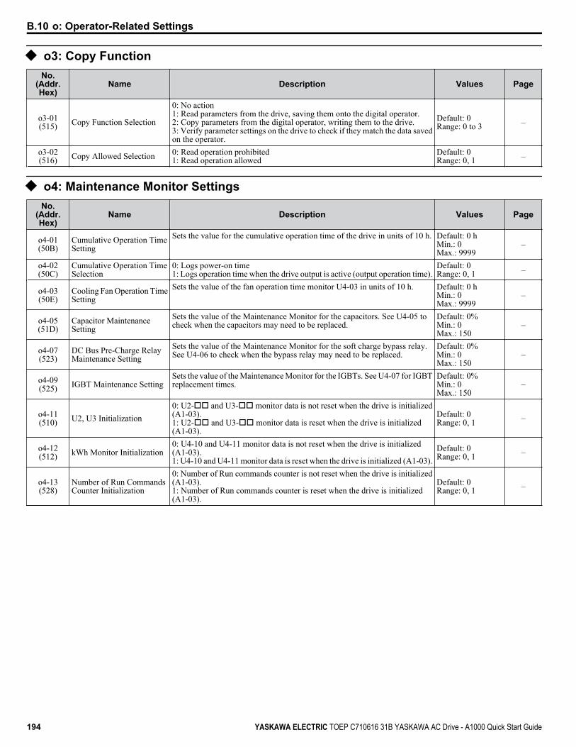
u o3: Copy FunctionNo.
(Addr.Hex)
Name Description Values Page
o3-01(515) Copy Function Selection
0: No action1: Read parameters from the drive, saving them onto the digital operator.2: Copy parameters from the digital operator, writing them to the drive.3: Verify parameter settings on the drive to check if they match the data savedon the operator.
Default: 0Range: 0 to 3 –
o3-02(516) Copy Allowed Selection 0: Read operation prohibited
1: Read operation allowedDefault: 0Range: 0, 1 –
u o4: Maintenance Monitor SettingsNo.
(Addr.Hex)
Name Description Values Page
o4-01(50B)
Cumulative Operation TimeSetting
Sets the value for the cumulative operation time of the drive in units of 10 h. Default: 0 hMin.: 0Max.: 9999
–
o4-02(50C)
Cumulative Operation TimeSelection
0: Logs power-on time1: Logs operation time when the drive output is active (output operation time).
Default: 0Range: 0, 1 –
o4-03(50E)
Cooling Fan Operation TimeSetting
Sets the value of the fan operation time monitor U4-03 in units of 10 h. Default: 0 hMin.: 0Max.: 9999
–
o4-05(51D)
Capacitor MaintenanceSetting
Sets the value of the Maintenance Monitor for the capacitors. See U4-05 tocheck when the capacitors may need to be replaced.
Default: 0%Min.: 0Max.: 150
–
o4-07(523)
DC Bus Pre-Charge RelayMaintenance Setting
Sets the value of the Maintenance Monitor for the soft charge bypass relay.See U4-06 to check when the bypass relay may need to be replaced.
Default: 0%Min.: 0Max.: 150
–
o4-09(525) IGBT Maintenance Setting
Sets the value of the Maintenance Monitor for the IGBTs. See U4-07 for IGBTreplacement times.
Default: 0%Min.: 0Max.: 150
–
o4-11(510) U2, U3 Initialization
0: U2-oo and U3-oo monitor data is not reset when the drive is initialized(A1-03).1: U2-oo and U3-oo monitor data is reset when the drive is initialized(A1-03).
Default: 0Range: 0, 1 –
o4-12(512) kWh Monitor Initialization
0: U4-10 and U4-11 monitor data is not reset when the drive is initialized(A1-03).1: U4-10 and U4-11 monitor data is reset when the drive is initialized (A1-03).
Default: 0Range: 0, 1 –
o4-13(528)
Number of Run CommandsCounter Initialization
0: Number of Run commands counter is not reset when the drive is initialized(A1-03).1: Number of Run commands counter is reset when the drive is initialized(A1-03).
Default: 0Range: 0, 1 –
B.10 o: Operator-Related Settings
194 YASKAWA ELECTRIC TOEP C710616 31B YASKAWA AC Drive - A1000 Quick Start Guide
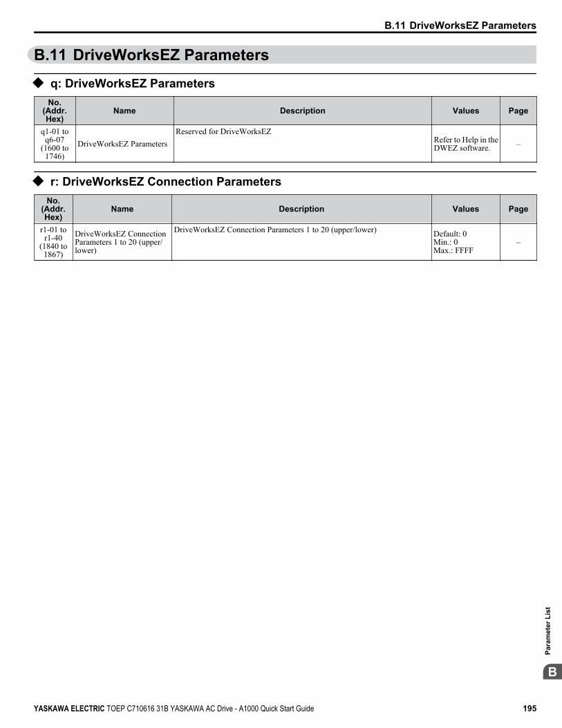
B.11 DriveWorksEZ Parameters
u q: DriveWorksEZ ParametersNo.
(Addr.Hex)
Name Description Values Page
q1-01 toq6-07
(1600 to1746)
DriveWorksEZ ParametersReserved for DriveWorksEZ
Refer to Help in theDWEZ software. –
u r: DriveWorksEZ Connection ParametersNo.
(Addr.Hex)
Name Description Values Page
r1-01 tor1-40
(1840 to1867)
DriveWorksEZ ConnectionParameters 1 to 20 (upper/lower)
DriveWorksEZ Connection Parameters 1 to 20 (upper/lower) Default: 0Min.: 0Max.: FFFF
–
B.11 DriveWorksEZ Parameters
YASKAWA ELECTRIC TOEP C710616 31B YASKAWA AC Drive - A1000 Quick Start Guide 195
B
Para
met
er L
ist
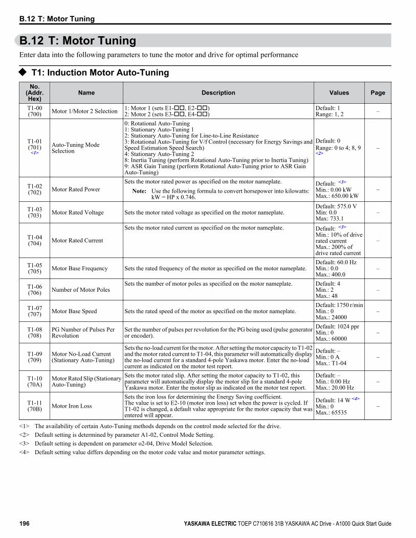
B.12 T: Motor TuningEnter data into the following parameters to tune the motor and drive for optimal performance
u T1: Induction Motor Auto-TuningNo.
(Addr.Hex)
Name Description Values Page
T1-00(700) Motor 1/Motor 2 Selection 1: Motor 1 (sets E1-oo, E2-oo)
2: Motor 2 (sets E3-oo, E4-oo)Default: 1Range: 1, 2 –
T1-01(701)
<1>Auto-Tuning ModeSelection
0: Rotational Auto-Tuning1: Stationary Auto-Tuning 12: Stationary Auto-Tuning for Line-to-Line Resistance3: Rotational Auto-Tuning for V/f Control (necessary for Energy Savings andSpeed Estimation Speed Search)4: Stationary Auto-Tuning 28: Inertia Tuning (perform Rotational Auto-Tuning prior to Inertia Tuning)9: ASR Gain Tuning (perform Rotational Auto-Tuning prior to ASR GainAuto-Tuning)
Default: 0Range: 0 to 4; 8, 9<2>
–
T1-02(702) Motor Rated Power
Sets the motor rated power as specified on the motor nameplate.Note: Use the following formula to convert horsepower into kilowatts:
kW = HP x 0.746.
Default: <3>
Min.: 0.00 kWMax.: 650.00 kW
–
T1-03(703) Motor Rated Voltage Sets the motor rated voltage as specified on the motor nameplate.
Default: 575.0 VMin: 0.0Max: 733.1
–
T1-04(704) Motor Rated Current
Sets the motor rated current as specified on the motor nameplate. Default: <3>
Min.: 10% of driverated currentMax.: 200% ofdrive rated current
–
T1-05(705) Motor Base Frequency Sets the rated frequency of the motor as specified on the motor nameplate.
Default: 60.0 HzMin.: 0.0Max.: 400.0
–
T1-06(706) Number of Motor Poles
Sets the number of motor poles as specified on the motor nameplate. Default: 4Min.: 2Max.: 48
–
T1-07(707) Motor Base Speed Sets the rated speed of the motor as specified on the motor nameplate.
Default: 1750 r/minMin.: 0Max.: 24000
–
T1-08(708)
PG Number of Pulses PerRevolution
Set the number of pulses per revolution for the PG being used (pulse generatoror encoder).
Default: 1024 pprMin.: 0Max.: 60000
–
T1-09(709)
Motor No-Load Current(Stationary Auto-Tuning)
Sets the no-load current for the motor. After setting the motor capacity to T1-02and the motor rated current to T1-04, this parameter will automatically displaythe no-load current for a standard 4-pole Yaskawa motor. Enter the no-loadcurrent as indicated on the motor test report.
Default: –Min.: 0 AMax.: T1-04
–
T1-10(70A)
Motor Rated Slip (StationaryAuto-Tuning)
Sets the motor rated slip. After setting the motor capacity to T1-02, thisparameter will automatically display the motor slip for a standard 4-poleYaskawa motor. Enter the motor slip as indicated on the motor test report.
Default: –Min.: 0.00 HzMax.: 20.00 Hz
–
T1-11(70B) Motor Iron Loss
Sets the iron loss for determining the Energy Saving coefficient.The value is set to E2-10 (motor iron loss) set when the power is cycled. IfT1-02 is changed, a default value appropriate for the motor capacity that wasentered will appear.
Default: 14 W <4>
Min.: 0Max.: 65535
–
<1> The availability of certain Auto-Tuning methods depends on the control mode selected for the drive.<2> Default setting is determined by parameter A1-02, Control Mode Setting.<3> Default setting is dependent on parameter o2-04, Drive Model Selection.<4> Default setting value differs depending on the motor code value and motor parameter settings.
B.12 T: Motor Tuning
196 YASKAWA ELECTRIC TOEP C710616 31B YASKAWA AC Drive - A1000 Quick Start Guide

u T2: PM Motor Auto-TuningNo.
(Addr.Hex)
Name Description Values Page
T2-01(750)
PM Motor Auto-TuningMode Selection
0: PM Motor Parameter Settings1: PM Stationary Auto-Tuning2: PM Stationary Auto-Tuning for Stator Resistance3: Z Pulse Offset Tuning8: Inertia Tuning9: ASR Gain Auto-TuningPrior to executing Inertia Tuning or ASR Gain Auto-Tuning be sure to takethe following steps:• Perform Auto-Tuning for motor data (T2-01 = 0, 1, or 2) or set the motor
code to E5-01.• Verify all motor data entered to the drive with the motor nameplate or the
motor test report.
Default: 0Range: 0 to 3;8, 9 <1>
–
T2-02(751) PM Motor Code Selection
Enter the motor code when using a Yaskawa PM motor. Once the motor codeis entered, the drive automatically sets parameters T2-03 through T2-14. Whenusing a motor that is not supported motor code or a non-Yaskawa motor, setFFFF here and then adjust the other T2 parameters according the motornameplate or the motor test report.
Default: <2>
Min: 0000Max: FFFF
–
T2-03(752) PM Motor Type 0: IPM motor
1: SPM motor. Parameter T2-17 will not be displayed with this setting.Default: 1Range: 0, 1 –
T2-04(730) PM Motor Rated Power
Sets the motor rated power.Note: Use the following formula to convert horsepower into kilowatts:
kW = HP x 0.746.
Default: <3>
Min.: 0.00 kWMax.: 650.00 kW
–
T2-05(732) PM Motor Rated Voltage Enter the motor rated voltage as indicated on the motor nameplate.
Default: 575.0 VMin.: 0.0Max.: 733.1
–
T2-06(733) PM Motor Rated Current
Enter the motor rated current as indicated on the motor nameplate. Default: <3>
Min.: 10% of driverated currentMax.: 200% ofdrive rated current
–
T2-07(753) PM Motor Base Frequency
Enter the motor base frequency as indicated on the motor nameplate. Default: 87.5 HzMin.: 0.0Max.: 400.0
–
T2-08(734) Number of PM Motor Poles
Enter the number of motor poles for the PM motor as indicated on the motornameplate.
Default: 6Min.: 2Max.: 48
–
T2-09(731) PM Motor Base Speed
Enter the base speed for the PM motor as indicated on the motor nameplate. Default: 1750r/minMin.: 0Max.: 24000
–
T2-10(754) PM Motor Stator Resistance
Enter the rotor resistance for the PM motor as indicated on the motornameplate.
Default: <4>
Min.: 0.000 ΩMax.: 65.000 Ω
–
T2-11(735) PM Motor d-Axis Inductance
Enter the d-axis inductance for the PM motor as indicated on the motornameplate.
Default: <4>
Min.: 0.00 mHMax.: 600.00 mH
–
T2-12(736) PM Motor q-Axis Inductance
Enter the q-axis inductance for the PM motor as indicated on the motornameplate.
Default: <4>
Min.: 0.00 mHMax.: 600.00 mH
–
T2-13(755)
Induced Voltage ConstantUnit Selection
0: mV/(r/min). E5-09 will automatically be set to 0.0, and E5-24 will be used.1: mV/(rad/sec). E5-24 will automatically be set to 0.0, and E5-09 will be used.
Default: 1Range: 0, 1 –
T2-14(737)
PM Motor Induced VoltageConstant
Enter the induced voltage coefficient for the PM motor as indicated on themotor nameplate.
Default: <4>
Min.: 0.1Max.: 2000.0
–
T2-15(756)
Pull-In Current Level for PMMotor Tuning
Sets the amount of pull-in current to use for Auto-Tuning as a percentage ofthe motor rated current. Increase this setting for high inertia loads.
Default: 30%Min.: 0Max.: 120
–
T2-16(738)
PG Number of Pulses PerRevolution for PM MotorTuning
Sets the number of pulses per revolution for the PG being used (pulse generatoror encoder). Default: 1024 ppr
Range: 1 to 15000 –
B.12 T: Motor Tuning
YASKAWA ELECTRIC TOEP C710616 31B YASKAWA AC Drive - A1000 Quick Start Guide 197
B
Para
met
er L
ist
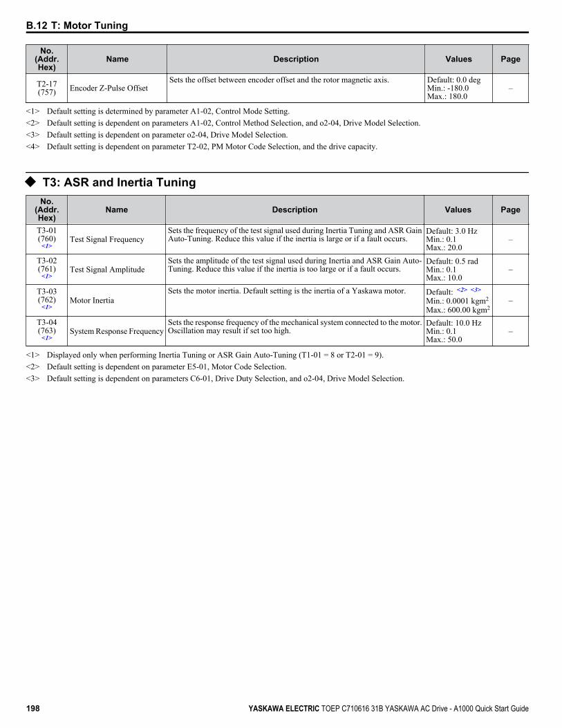
No.(Addr.Hex)
Name Description Values Page
T2-17(757) Encoder Z-Pulse Offset
Sets the offset between encoder offset and the rotor magnetic axis. Default: 0.0 degMin.: -180.0Max.: 180.0
–
<1> Default setting is determined by parameter A1-02, Control Mode Setting.<2> Default setting is dependent on parameters A1-02, Control Method Selection, and o2-04, Drive Model Selection.<3> Default setting is dependent on parameter o2-04, Drive Model Selection.<4> Default setting is dependent on parameter T2-02, PM Motor Code Selection, and the drive capacity.
u T3: ASR and Inertia TuningNo.
(Addr.Hex)
Name Description Values Page
T3-01(760)
<1>Test Signal Frequency
Sets the frequency of the test signal used during Inertia Tuning and ASR GainAuto-Tuning. Reduce this value if the inertia is large or if a fault occurs.
Default: 3.0 HzMin.: 0.1Max.: 20.0
–
T3-02(761)
<1>Test Signal Amplitude
Sets the amplitude of the test signal used during Inertia and ASR Gain Auto-Tuning. Reduce this value if the inertia is too large or if a fault occurs.
Default: 0.5 radMin.: 0.1Max.: 10.0
–
T3-03(762)
<1>Motor Inertia
Sets the motor inertia. Default setting is the inertia of a Yaskawa motor. Default: <2> <3>
Min.: 0.0001 kgm2
Max.: 600.00 kgm2–
T3-04(763)
<1>System Response Frequency
Sets the response frequency of the mechanical system connected to the motor.Oscillation may result if set too high.
Default: 10.0 HzMin.: 0.1Max.: 50.0
–
<1> Displayed only when performing Inertia Tuning or ASR Gain Auto-Tuning (T1-01 = 8 or T2-01 = 9).<2> Default setting is dependent on parameter E5-01, Motor Code Selection.<3> Default setting is dependent on parameters C6-01, Drive Duty Selection, and o2-04, Drive Model Selection.
B.12 T: Motor Tuning
198 YASKAWA ELECTRIC TOEP C710616 31B YASKAWA AC Drive - A1000 Quick Start Guide

B.13 U: MonitorsMonitor parameters allow the user to view drive status, fault information, and other data concerning drive operation.
u U1: Operation Status MonitorsNo.
(Addr.Hex)
Name Description Analog OutputLevel Unit
U1-01(40) Frequency Reference Monitors the frequency reference. Display units are determined by o1-03. 10 V: Max frequency 0.01 Hz
U1-02(41) Output Frequency Displays the output frequency. Display units are determined by o1-03. 10 V: Max frequency 0.01 Hz
U1-03(42) Output Current Displays the output current. 10 V: Drive rated
current<1> <2>
U1-04(43) Control Method
0: V/f Control1: V/f Control with PG2: Open Loop Vector Control3: Closed Loop Vector Control
No signal outputavailable –
U1-05(44) Motor Speed Displays the motor speed feedback. Display units are determined by o1-03. 10 V: Max Frequency 0.01 Hz
U1-06(45)
Output Voltage Reference Displays the output voltage. 10 V: 575 Vrms 0.1 Vac
U1-07(46) DC Bus Voltage Displays the DC bus voltage. 10 V: 1150 V 1 Vdc
U1-08(47) Output Power Displays the output power (this value is calculated internally). 10 V: Drive rated power
(kW)<3>
U1-09(48) Torque Reference Monitors the internal torque reference. 10 V: Motor rated
torque 0.1%
U1-10(49) Input Terminal Status
Displays the input terminal status.U1 - 10=00000000
Digital input 1 (terminal S1 enabled)Digital input 2 (terminal S2 enabled)Digital input 3 (terminal S3 enabled)Digital input 4 (terminal S4 enabled)Digital input 5 (terminal S5 enabled)Digital input 6 (terminal S6 enabled)Digital input 7 (terminal S7 enabled)Digital input 8 (terminal S8 enabled)
11111111
No signal outputavailable –
U1-11(4A) Output Terminal Status
Displays the output terminal status.
U1 - 11=00000000Multi-Function Digital Output (terminal M1-M2)
Digital Output (terminal M3-M4)
Digital Output (terminal M5-M6)
Multi-Function
Multi-Function
Not UsedFault Relay(terminal MA-MC closed
MA-MC open)
1
1
1
10
No signal outputavailable –
B.13 U: Monitors
YASKAWA ELECTRIC TOEP C710616 31B YASKAWA AC Drive - A1000 Quick Start Guide 199
B
Para
met
er L
ist
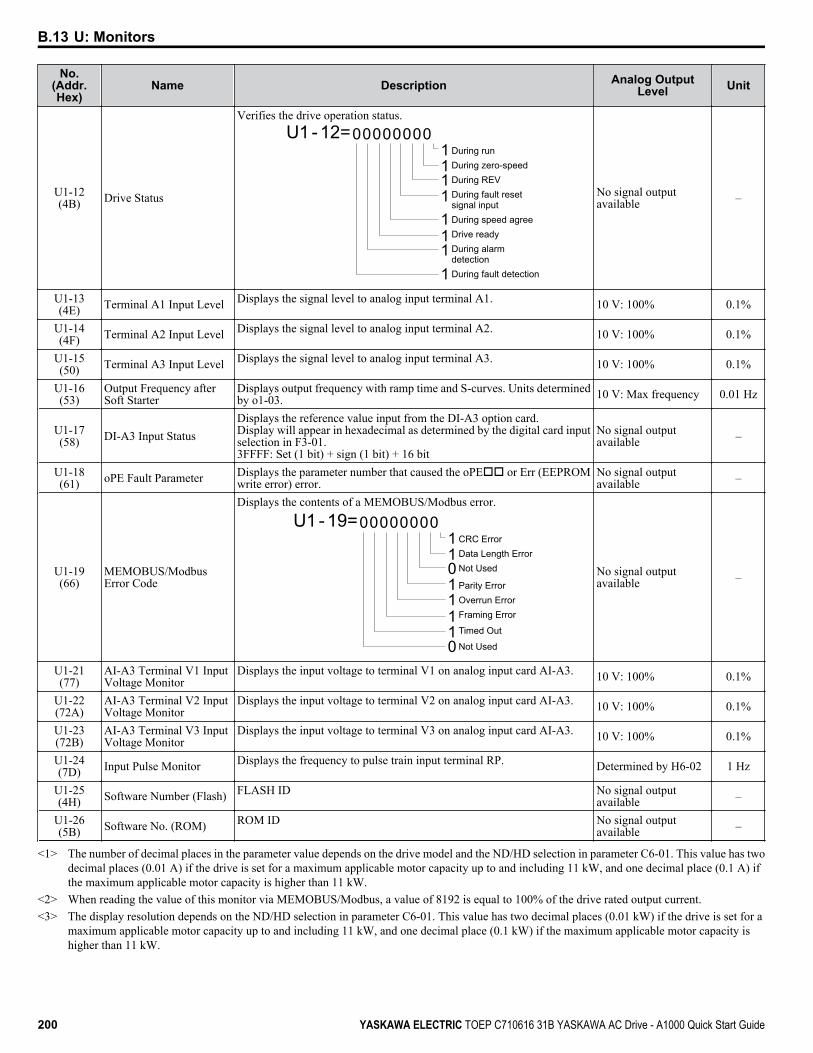
No.(Addr.Hex)
Name Description Analog OutputLevel Unit
U1-12(4B) Drive Status
Verifies the drive operation status.U1 - 12=00000000
During runDuring zero-speedDuring REVDuring fault reset signal inputDuring speed agreeDrive readyDuring alarm detectionDuring fault detection
11111111
No signal outputavailable –
U1-13(4E) Terminal A1 Input Level Displays the signal level to analog input terminal A1. 10 V: 100% 0.1%
U1-14(4F) Terminal A2 Input Level Displays the signal level to analog input terminal A2. 10 V: 100% 0.1%
U1-15(50) Terminal A3 Input Level Displays the signal level to analog input terminal A3. 10 V: 100% 0.1%
U1-16(53)
Output Frequency afterSoft Starter
Displays output frequency with ramp time and S-curves. Units determinedby o1-03. 10 V: Max frequency 0.01 Hz
U1-17(58) DI-A3 Input Status
Displays the reference value input from the DI-A3 option card.Display will appear in hexadecimal as determined by the digital card inputselection in F3-01.3FFFF: Set (1 bit) + sign (1 bit) + 16 bit
No signal outputavailable –
U1-18(61) oPE Fault Parameter Displays the parameter number that caused the oPEoo or Err (EEPROM
write error) error.No signal outputavailable –
U1-19(66)
MEMOBUS/ModbusError Code
Displays the contents of a MEMOBUS/Modbus error.
U1 - 19=00000000CRC ErrorData Length ErrorNot Used
Parity ErrorOverrun ErrorFraming Error
Timed Out
Not Used
11011110
No signal outputavailable –
U1-21(77)
AI-A3 Terminal V1 InputVoltage Monitor
Displays the input voltage to terminal V1 on analog input card AI-A3. 10 V: 100% 0.1%
U1-22(72A)
AI-A3 Terminal V2 InputVoltage Monitor
Displays the input voltage to terminal V2 on analog input card AI-A3. 10 V: 100% 0.1%
U1-23(72B)
AI-A3 Terminal V3 InputVoltage Monitor
Displays the input voltage to terminal V3 on analog input card AI-A3. 10 V: 100% 0.1%
U1-24(7D) Input Pulse Monitor Displays the frequency to pulse train input terminal RP. Determined by H6-02 1 Hz
U1-25(4H) Software Number (Flash) FLASH ID No signal output
available –
U1-26(5B) Software No. (ROM) ROM ID No signal output
available –
<1> The number of decimal places in the parameter value depends on the drive model and the ND/HD selection in parameter C6-01. This value has twodecimal places (0.01 A) if the drive is set for a maximum applicable motor capacity up to and including 11 kW, and one decimal place (0.1 A) ifthe maximum applicable motor capacity is higher than 11 kW.
<2> When reading the value of this monitor via MEMOBUS/Modbus, a value of 8192 is equal to 100% of the drive rated output current.<3> The display resolution depends on the ND/HD selection in parameter C6-01. This value has two decimal places (0.01 kW) if the drive is set for a
maximum applicable motor capacity up to and including 11 kW, and one decimal place (0.1 kW) if the maximum applicable motor capacity ishigher than 11 kW.
B.13 U: Monitors
200 YASKAWA ELECTRIC TOEP C710616 31B YASKAWA AC Drive - A1000 Quick Start Guide
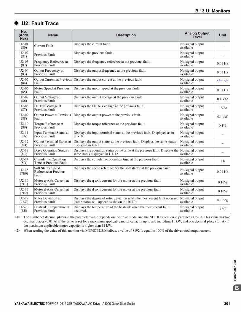
u U2: Fault TraceNo.
(Addr.Hex)
Name Description Analog OutputLevel Unit
U2-01(80) Current Fault Displays the current fault. No signal output
available –
U2-02(81) Previous Fault Displays the previous fault. No signal output
available –
U2-03(82)
Frequency Reference atPrevious Fault
Displays the frequency reference at the previous fault. No signal outputavailable 0.01 Hz
U2-04(83)
Output Frequency atPrevious Fault
Displays the output frequency at the previous fault. No signal outputavailable 0.01 Hz
U2-05(84)
Output Current at PreviousFault
Displays the output current at the previous fault. No signal outputavailable
<1> <2>
U2-06(85)
Motor Speed at PreviousFault
Displays the motor speed at the previous fault. No signal outputavailable 0.01 Hz
U2-07(86)
Output Voltage atPrevious Fault
Displays the output voltage at the previous fault. No signal outputavailable 0.1 Vac
U2-08(87)
DC Bus Voltage atPrevious Fault
Displays the DC bus voltage at the previous fault. No signal outputavailable 1 Vdc
U2-09(88)
Output Power at PreviousFault
Displays the output power at the previous fault. No signal outputavailable 0.1 kW
U2-10(89)
Torque Reference atPrevious Fault
Displays the torque reference at the previous fault. No signal outputavailable 0.1%
U2-11(8A)
Input Terminal Status atPrevious Fault
Displays the input terminal status at the previous fault. Displayed as inU1-10.
No signal outputavailable –
U2-12(8B)
Output Terminal Status atPrevious Fault
Displays the output status at the previous fault. Displays the same statusdisplayed in U1-11.
No signal outputavailable –
U2-13(8C)
Drive Operation Status atPrevious Fault
Displays the operation status of the drive at the previous fault. Displays thesame status displayed in U1-12.
No signal outputavailable –
U2-14(8D)
Cumulative OperationTime at Previous Fault
Displays the cumulative operation time at the previous fault. No signal outputavailable 1 h
U2-15(7E0)
Soft Starter SpeedReference at PreviousFault
Displays the speed reference for the soft starter at the previous fault. No signal outputavailable 0.01 Hz
U2-16(7E1)
Motor q-Axis Current atPrevious Fault
Displays the q-axis current for the motor at the previous fault. No signal outputavailable 0.10%
U2-17(7E2)
Motor d-Axis Current atPrevious Fault
Displays the d-axis current for the motor at the previous fault. No signal outputavailable 0.10%
U2-19(7EC)
Rotor Deviation atPrevious Fault
Displays the degree of rotor deviation when the most recent fault occurred(same status will appear as shown in U6-10).
No signal outputavailable 0.1 deg
U2-20(8E)
Heatsink Temperature atPrevious Fault
Displays the temperature of the heatsink when the most recent faultoccurred.
No signal outputavailable 1 °C
<1> The number of decimal places in the parameter value depends on the drive model and the ND/HD selection in parameter C6-01. This value has twodecimal places (0.01 A) if the drive is set for a maximum applicable motor capacity up to and including 11 kW, and one decimal place (0.1 A) ifthe maximum applicable motor capacity is higher than 11 kW.
<2> When reading the value of this monitor via MEMOBUS/Modbus, a value of 8192 is equal to 100% of the drive rated output current.
B.13 U: Monitors
YASKAWA ELECTRIC TOEP C710616 31B YASKAWA AC Drive - A1000 Quick Start Guide 201
B
Para
met
er L
ist

u U3: Fault HistoryNo.
(Addr.Hex)
Name Description Analog OutputLevel Unit
U3-01 toU3-04
(90 to 93(800 to803))
First to 4th Most RecentFault
Displays the first to the fourth most recent faults.No signal outputavailable –
U3-05 toU3-10(804 to
809)
5th to 10th Most RecentFault
Displays the fifth to the tenth most recent faults.No signal outputavailable –
U3-11 toU3-14
(94 to 97(80A to80D))
Cumulative OperationTime at 1st to 4th MostRecent Fault
Displays the cumulative operation time when the first to the fourth mostrecent faults occurred. No signal output
available 1 h
U3-15 toU3-20(80E to
813)
Cumulative OperationTime at 5th to 10th MostRecent Fault
Displays the cumulative operation time when the fifth to the tenth mostrecent faults occurred. No signal output
available 1 h
u U4: Maintenance MonitorsNo.
(Addr.Hex)
Name Description Analog OutputLevel Unit
U4-01(4C)
Cumulative OperationTime
Displays the cumulative operation time of the drive. The value for thecumulative operation time counter can be reset in parameter o4-01. Useparameter o4-02 to determine if the operation time should start as soon asthe power is switched on or only while the Run command is present. Themaximum number displayed is 99999, after which the value is reset to 0.
No signal outputavailable 1 h
U4-02(75)
Number of RunCommands
Displays the number of times the Run command is entered. Reset thenumber of Run commands using parameter o4-13. This value will reset to0 and start counting again after reaching 65535.
No signal outputavailable 1 Time
U4-03(67)
Cooling Fan OperationTime
Displays the cumulative operation time of the cooling fan. The default valuefor the fan operation time is reset in parameter o4-03. This value will resetto 0 and start counting again after reaching 99999.
No signal outputavailable 1 h
U4-04(7E) Cooling Fan Maintenance Displays main cooling fan usage time as a percentage of its expected
performance life. Parameter o4-03 can be used to reset this monitor.No signal outputavailable 1%
U4-05(7C) Capacitor Maintenance Displays main circuit capacitor usage time as a percentage of their expected
performance life. Parameter o4-05 can be used to reset this monitor.No signal outputavailable 1%
U4-06(7D6)
Soft Charge Bypass RelayMaintenance
Displays the soft charge bypass relay maintenance time as a percentage ofits estimated performance life. Parameter o4-07 can be used to reset thismonitor.
No signal outputavailable 1%
U4-07(7D7) IGBT Maintenance Displays IGBT usage time as a percentage of the expected performance
life. Parameter o4-09 can be used to reset this monitor.No signal outputavailable 1%
U4-08(68) Heatsink Temperature Displays the heatsink temperature. 10 V: 100 °C 1 °C
U4-09(5E) LED Check Lights all segments of the LED to verify that the display is working
properly.No signal outputavailable –
U4-10(5C) kWh, Lower 4 Digits Monitors the drive output power. The value is shown as a 9-digit number
displayed across two monitor parameters, U4-10 and U4-11.Example:12345678.9 kWh is displayed as:U4-10: 678.9 kWhU4-11: 12345 MWh
No signal outputavailable 1 kWh
U4-11(5D) kWh, Upper 5 Digits No signal output
available 1 MWh
U4-13(7CF) Peak Hold Current Displays the highest current value that occurred during run. No signal output
available0.01 A
<1>
U4-14(7D0)
Peak Hold OutputFrequency
Displays the output frequency when the current value shown in U4-13occurred.
No signal outputavailable 0.01 Hz
U4-16(7D8)
Motor Overload Estimate(oL1)
Shows the value of the motor overload detection accumulator. 100% isequal to the oL1 detection level. 10 V: 100% 0.1%
B.13 U: Monitors
202 YASKAWA ELECTRIC TOEP C710616 31B YASKAWA AC Drive - A1000 Quick Start Guide
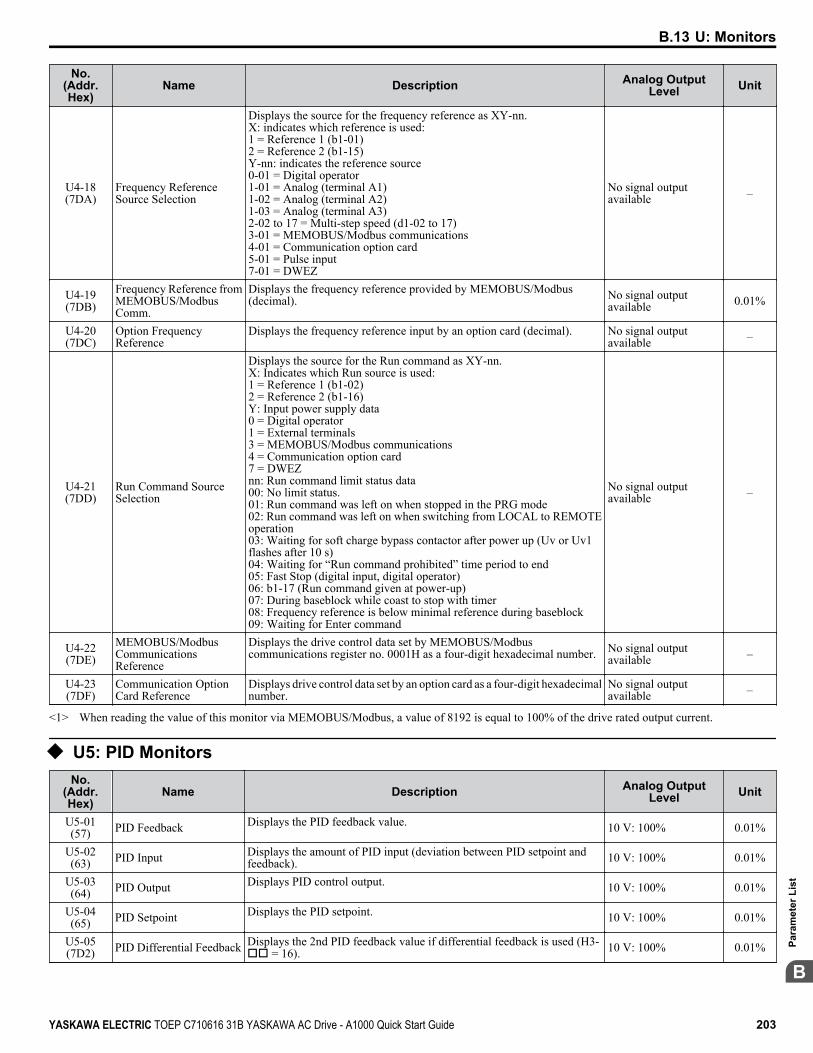
No.(Addr.Hex)
Name Description Analog OutputLevel Unit
U4-18(7DA)
Frequency ReferenceSource Selection
Displays the source for the frequency reference as XY-nn.X: indicates which reference is used:1 = Reference 1 (b1-01)2 = Reference 2 (b1-15)Y-nn: indicates the reference source0-01 = Digital operator1-01 = Analog (terminal A1)1-02 = Analog (terminal A2)1-03 = Analog (terminal A3)2-02 to 17 = Multi-step speed (d1-02 to 17)3-01 = MEMOBUS/Modbus communications4-01 = Communication option card5-01 = Pulse input7-01 = DWEZ
No signal outputavailable –
U4-19(7DB)
Frequency Reference fromMEMOBUS/ModbusComm.
Displays the frequency reference provided by MEMOBUS/Modbus(decimal). No signal output
available 0.01%
U4-20(7DC)
Option FrequencyReference
Displays the frequency reference input by an option card (decimal). No signal outputavailable –
U4-21(7DD)
Run Command SourceSelection
Displays the source for the Run command as XY-nn.X: Indicates which Run source is used:1 = Reference 1 (b1-02)2 = Reference 2 (b1-16)Y: Input power supply data0 = Digital operator1 = External terminals3 = MEMOBUS/Modbus communications4 = Communication option card7 = DWEZnn: Run command limit status data00: No limit status.01: Run command was left on when stopped in the PRG mode02: Run command was left on when switching from LOCAL to REMOTEoperation03: Waiting for soft charge bypass contactor after power up (Uv or Uv1flashes after 10 s)04: Waiting for “Run command prohibited” time period to end05: Fast Stop (digital input, digital operator)06: b1-17 (Run command given at power-up)07: During baseblock while coast to stop with timer08: Frequency reference is below minimal reference during baseblock09: Waiting for Enter command
No signal outputavailable –
U4-22(7DE)
MEMOBUS/ModbusCommunicationsReference
Displays the drive control data set by MEMOBUS/Modbuscommunications register no. 0001H as a four-digit hexadecimal number. No signal output
available –
U4-23(7DF)
Communication OptionCard Reference
Displays drive control data set by an option card as a four-digit hexadecimalnumber.
No signal outputavailable –
<1> When reading the value of this monitor via MEMOBUS/Modbus, a value of 8192 is equal to 100% of the drive rated output current.
u U5: PID MonitorsNo.
(Addr.Hex)
Name Description Analog OutputLevel Unit
U5-01(57) PID Feedback Displays the PID feedback value. 10 V: 100% 0.01%
U5-02(63) PID Input Displays the amount of PID input (deviation between PID setpoint and
feedback). 10 V: 100% 0.01%
U5-03(64) PID Output Displays PID control output. 10 V: 100% 0.01%
U5-04(65) PID Setpoint Displays the PID setpoint. 10 V: 100% 0.01%
U5-05(7D2) PID Differential Feedback Displays the 2nd PID feedback value if differential feedback is used (H3-
oo = 16). 10 V: 100% 0.01%
B.13 U: Monitors
YASKAWA ELECTRIC TOEP C710616 31B YASKAWA AC Drive - A1000 Quick Start Guide 203
B
Para
met
er L
ist

No.(Addr.Hex)
Name Description Analog OutputLevel Unit
U5-06(7D3) PID Adjusted Feedback
Displays the difference of both feedback values if differential feedback isused (U5-01 - U5-05). If differential feedback is not used, then U5-01 andU5-06 will be the same.
10 V: 100% 0.01%
u U6: Operation Status MonitorsNo.
(Addr.Hex)
Name Description Analog OutputLevel Unit
U6-01(51)
Motor Secondary Current(Iq)
Displays the value of the motor secondary current (Iq). Motor ratedsecondary current is 100%.
10 V: Motor secondaryrated current 0.1%
U6-02(52)
Motor Excitation Current(Id)
Displays the value calculated for the motor excitation current (Id). Motorrated secondary current is 100%.
10 V: Motor secondaryrated current 0.1%
U6-03(54) ASR Input Displays the input and output values when using ASR control. 10 V: Max frequency
0.01%U6-04(55) ASR Output 10 V: Motor secondary
rated currentU6-05(59)
Output Voltage Reference(Vq) Output voltage reference (Vq) for the q-Axis. 10 V: 575 Vrms 0.1 Vac
U6-06(5A)
Output Voltage Reference(Vd) Output voltage reference (Vd) for the d-Axis. 10 V: 575 Vrms 0.1 Vac
U6-07(5F) q-Axis ACR Output Displays the output value for current control relative to motor secondary
current (q-Axis). 10 V: 575 Vrms 0.1%
U6-08(60) d-Axis ACR Output Displays the output value for current control relative to motor secondary
current (d-Axis). 10 V: 575 Vrms 0.1%
U6-09(7C0)
Advance PhaseCompensation (Δ θ)
Displays the degree of forward phase correction after calculating thedeviation of Δθcmp.
10 V: 180 deg-10 V: -180 deg 0.1 deg
U6-10(7C1)
Control Axis Deviation(Δθ)
Displays the amount of deviation between the actual d-Axis / q-Axis andthe γ-Axis / δ-Axis used for motor control.
10 V: 180 deg-10 V: -180 deg 0.1 deg
U6-13(7CA)
Flux Position Detection(sensor)
Monitors the value of the flux position detection (sensor). 10 V: 180 deg-10 V: -180 deg 0.1 deg
U6-14(7CB)
Flux Position Estimation(observer)
Monitors the value of the flux position estimation. 10 V: 180 deg-10 V: -180 deg 0.1 deg
U6-18(7CD)
Speed Detection PG1Counter
Monitors the number of pulses for speed detection (PG1). 10 V: 65536 1 pulse
U6-19(7E5)
Speed Detection PG2Counter
Monitors the number of pulses for speed detection (PG2). 10 V: 65536 1 pulse
U6-20(7D4)
Frequency Reference Bias(Up/Down 2)
Displays the bias value used to adjust the frequency reference. 10 V: Max frequency 0.1%
U6-21(7D5) Offset Frequency Displays the frequency added to the main frequency reference. – 0.1%
U6-22(62)
Zero Servo PulseMovement
Displays how far the rotor has moved from its last position in PG pulses(multiplied by 4).
10 V: No. of pulses perrevolution 1
U6-25(6B) Feedback Control Output Output monitor for the ASR speed loop. 10 V: Motor secondary
rated current 0.01%
U6-26(6C)
Feed Forward ControlOutput
Output monitor for Feed Forward control. 10 V: Motor secondaryrated current 0.01%
B.13 U: Monitors
204 YASKAWA ELECTRIC TOEP C710616 31B YASKAWA AC Drive - A1000 Quick Start Guide

u U8: DriveWorksEZ MonitorsNo.
(Addr.Hex)
Name Description Analog OutputLevel Unit
U8-01 toU8-10
(1950 to1959)
DriveWorksEZ CustomMonitor 1 to 10
DriveWorksEZ Custom Monitor 1 to 10.10 V: 100% 0.01%
U8-11 toU8-13
(195A to195C)
DriveWorksEZ VersionControl Monitor 1 to 3
DriveWorksEZ Version Control Monitor 1 to 3.No signal outputavailable –
B.13 U: Monitors
YASKAWA ELECTRIC TOEP C710616 31B YASKAWA AC Drive - A1000 Quick Start Guide 205
B
Para
met
er L
ist

B.13 U: Monitors
This Page Intentionally Blank
206 YASKAWA ELECTRIC TOEP C710616 31B YASKAWA AC Drive - A1000 Quick Start Guide

Standards ComplianceThis appendix explains the guidelines and criteria for maintaining UL standards.
C.1 UL STANDARDS..................................................................................................208C.2 SAFE DISABLE INPUT FUNCTION....................................................................212
Appendix: C
YASKAWA ELECTRIC TOEP C710616 31B YASKAWA AC Drive - A1000 Quick Start Guide 207
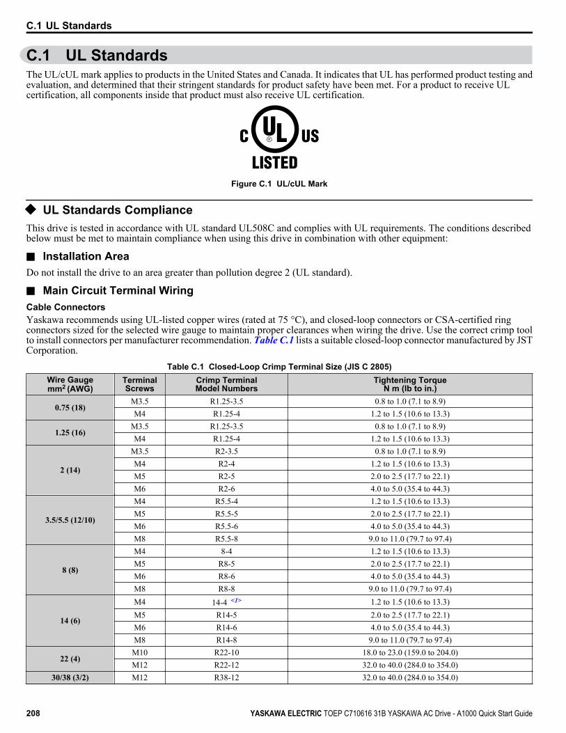
C.1 UL StandardsThe UL/cUL mark applies to products in the United States and Canada. It indicates that UL has performed product testing andevaluation, and determined that their stringent standards for product safety have been met. For a product to receive ULcertification, all components inside that product must also receive UL certification.
Figure C.1 UL/cUL Mark
u UL Standards ComplianceThis drive is tested in accordance with UL standard UL508C and complies with UL requirements. The conditions describedbelow must be met to maintain compliance when using this drive in combination with other equipment:
n Installation AreaDo not install the drive to an area greater than pollution degree 2 (UL standard).
n Main Circuit Terminal WiringCable ConnectorsYaskawa recommends using UL-listed copper wires (rated at 75 °C), and closed-loop connectors or CSA-certified ringconnectors sized for the selected wire gauge to maintain proper clearances when wiring the drive. Use the correct crimp toolto install connectors per manufacturer recommendation. Table C.1 lists a suitable closed-loop connector manufactured by JSTCorporation.
Table C.1 Closed-Loop Crimp Terminal Size (JIS C 2805)Wire Gaugemm2 (AWG)
TerminalScrews
Crimp TerminalModel Numbers
Tightening TorqueN m (lb to in.)
0.75 (18)M3.5 R1.25-3.5 0.8 to 1.0 (7.1 to 8.9)M4 R1.25-4 1.2 to 1.5 (10.6 to 13.3)
1.25 (16)M3.5 R1.25-3.5 0.8 to 1.0 (7.1 to 8.9)M4 R1.25-4 1.2 to 1.5 (10.6 to 13.3)
2 (14)
M3.5 R2-3.5 0.8 to 1.0 (7.1 to 8.9)M4 R2-4 1.2 to 1.5 (10.6 to 13.3)M5 R2-5 2.0 to 2.5 (17.7 to 22.1)M6 R2-6 4.0 to 5.0 (35.4 to 44.3)
3.5/5.5 (12/10)
M4 R5.5-4 1.2 to 1.5 (10.6 to 13.3)M5 R5.5-5 2.0 to 2.5 (17.7 to 22.1)M6 R5.5-6 4.0 to 5.0 (35.4 to 44.3)M8 R5.5-8 9.0 to 11.0 (79.7 to 97.4)
8 (8)
M4 8-4 1.2 to 1.5 (10.6 to 13.3)M5 R8-5 2.0 to 2.5 (17.7 to 22.1)M6 R8-6 4.0 to 5.0 (35.4 to 44.3)M8 R8-8 9.0 to 11.0 (79.7 to 97.4)
14 (6)
M4 14-4 <1> 1.2 to 1.5 (10.6 to 13.3)M5 R14-5 2.0 to 2.5 (17.7 to 22.1)M6 R14-6 4.0 to 5.0 (35.4 to 44.3)M8 R14-8 9.0 to 11.0 (79.7 to 97.4)
22 (4)M10 R22-10 18.0 to 23.0 (159.0 to 204.0)M12 R22-12 32.0 to 40.0 (284.0 to 354.0)
30/38 (3/2) M12 R38-12 32.0 to 40.0 (284.0 to 354.0)
C.1 UL Standards
208 YASKAWA ELECTRIC TOEP C710616 31B YASKAWA AC Drive - A1000 Quick Start Guide

Wire Gaugemm2 (AWG)
TerminalScrews
Crimp TerminalModel Numbers
Tightening TorqueN m (lb to in.)
50/60 (1/ 1/0) M12 R60-12 32.0 to 40.0 (284.0 to 354.0)80 (2/0) M12 R80-12 32.0 to 40.0 (284.0 to 354.0)100 (4/0) M12 R100-12 32.0 to 40.0 (284.0 to 354.0)
150 (250/300MCM)M10 150-10 18.0 to 23.0 (159.0 to 204.0)M12 150-12 32.0 to 40.0 (284.0 to 354.0)
200 (400MCM)M10 200-10 18.0 to 23.0 (159.0 to 204.0)M12 R200-12 32.0 to 40.0 (284.0 to 354.0)
325 (600/650MCM) M12 325-12 32.0 to 40.0 (284.0 to 354.0)
<1> Use the specified crimp terminals (Model 14-NK4) when using CIMR-Ao5A0011, with 6 AWG (14 mm2).
Note: Use crimp insulated terminals or insulated shrink tubing for wiring connections. Wires should have a continuous maximum allowabletemperature of 75 °C 600 Vac UL-approved vinyl-sheathed insulation.
Input Fuse InstallationAlways install input fuses at the drive input side of the drive to prevent damage from short circuits.Select the appropriate fuse from the table below.
Table C.2 Recommended Input Fuse Selection
Model CIMR-AoFuse Type
Manufacturer: BussmannModel Fuse Ampere Rating
Three-Phase 600 V Class5A0003 FWP-50B 505A0004 FWP-50B 505A0006 FWP-60B 605A0009 FWP-60B 605A0011 FWP-70B 705A0017 FWP-100B 1005A0022 FWP-100B 1005A0027 FWP-125A 1255A0032 FWP-125A 125
n Low Voltage Wiring for Control Circuit TerminalsWire low voltage wires with NEC Class 1 circuit conductors. Refer to national, state, or local codes for wiring. Use a class 2(UL regulations) power supply for the control circuit terminal when not using the internal control power supply of the drive.
Table C.3 Control Circuit Terminal Power SupplyInput / Output Terminal Signal Power Supply Specifications
Multi-function digital inputs S1, S2, S3, S4, S5, S6, S7, S8, SC
Use the internal control power supply of the drive or anexternal class 2 power supply.
Multi-function analog inputs A1, A2, A3, ACPulse train input RP, ACPulse train output MP, AC
n Drive Short Circuit RatingThis drive has undergone the UL short circuit test, which certifies that during a short circuit in the power supply, the currentflow will not rise above 100,000 amps at 600 V for 600 V class drives.• The circuit breaker protection and fuse ratings shall be equal to or greater than the short-circuit tolerance of the power supply
being used.• Suitable for use on a circuit capable of delivering not more than 100,000 RMS symmetrical amperes for 600 V in 600 V
class drives motor overload protection.
C.1 UL Standards
YASKAWA ELECTRIC TOEP C710616 31B YASKAWA AC Drive - A1000 Quick Start Guide 209C
Stan
dard
s C
ompl
ianc
e

u Drive Motor Overload ProtectionSet parameter E2-01 (motor rated current) to the appropriate value to enable motor overload protection. The internal motoroverload protection is UL listed and in accordance with the NEC and CEC.
n E2-01: Motor Rated CurrentSetting Range: Model-dependentDefault Setting: Model-dependentParameter E2-01 protects the motor when parameter L1-01 is not set to 0. The default for L1-01 is 1, which enables protectionfor standard induction motors.If Auto-Tuning has been performed successfully, the motor data entered to T1-04 is automatically written to parameter E2-01.If Auto-Tuning has not been performed, manually enter the correct motor rated current to parameter E2-01.
n L1-01: Motor Overload Protection SelectionThe drive has an electronic overload protection function (oL1) based on time, output current, and output frequency that protectsthe motor from overheating. The electronic thermal overload function is UL-recognized, so it does not require an externalthermal relay for single motor operation.This parameter selects the motor overload curve used according to the type of motor applied.
Table C.4 Overload Protection SettingsSetting Description
0 Disabled Disabled the internal motor overload protection of the drive.
1 Standard fan-cooled motor (default)Selects protection characteristics for a standard self-cooled motor with limited cooling capabilitieswhen running below the rated speed. The motor overload detection level (oL1) is automaticallyreduced when running below the motor rated speed.
2 Drive duty motor with a speed range of 1:10Selects protection characteristics for a motor with self-cooling capability within a speed range of10:1. The motor overload detection level (oL1) is automatically reduced when running below1/10 of the motor rated speed.
3 Vector motor with a speed range of 1:100Selects protection characteristics for a motor capable of cooling itself at any speed including zerospeed (externally cooled motor). The motor overload detection level (oL1) is constant over theentire speed range.
4 Permanent Magnet motor with variabletorque
Selects protection characteristics for a variable torque PM motor. The motor overload detectionlevel (oL1) is automatically reduced when running below the motor rated speed.
5 Permanent Magnet motor with constanttorque
Selects protection characteristics for a constant torque PM motor. The motor overload detectionlevel (oL1) is constant over the whole speed range.
6 Standard fan-cooled motor (50 Hz)Selects protection characteristics for a standard self-cooled motor with limited cooling capabilitieswhen running below the rated speed. The motor overload detection level (oL1) is automaticallyreduced when running below the motor rated speed.
When connecting the drive to more than one motor for simultaneous operation, disable the electronic overload protection(L1-01 = 0) and wire each motor with its own motor thermal overload relay.Enable motor overload protection (L1-01 = 1 to 5) when connecting the drive to a single motor, unless another motor overloadpreventing device is installed. The drive electronic thermal overload function causes an oL1 fault, which shuts off the outputof the drive and prevents additional overheating of the motor. The motor temperature is continually calculated while the driveis powered up.
C.1 UL Standards
210 YASKAWA ELECTRIC TOEP C710616 31B YASKAWA AC Drive - A1000 Quick Start Guide

n L1-02: Motor Overload Protection TimeSetting Range: 0.1 to 5.0 minFactory Default: 1.0 minParameter L1-02 determines how long the motor is allowed to operate before the oL1 fault occurs when the drive is runningat 60 Hz and at 150% of the full load amp rating (E2-01) of the motor. Adjusting the value of L1-02 can shift the set of oL1curves up the y axis of the diagram below, but will not change the shape of the curves.
107
3
1
0.4
0.10 100 200150
Cold Start
Hot Start
Motor Current (%) (E2-01=100 %)
Time (min)
Figure C.2 Motor Overload Protection Time
C.1 UL Standards
YASKAWA ELECTRIC TOEP C710616 31B YASKAWA AC Drive - A1000 Quick Start Guide 211C
Stan
dard
s C
ompl
ianc
e
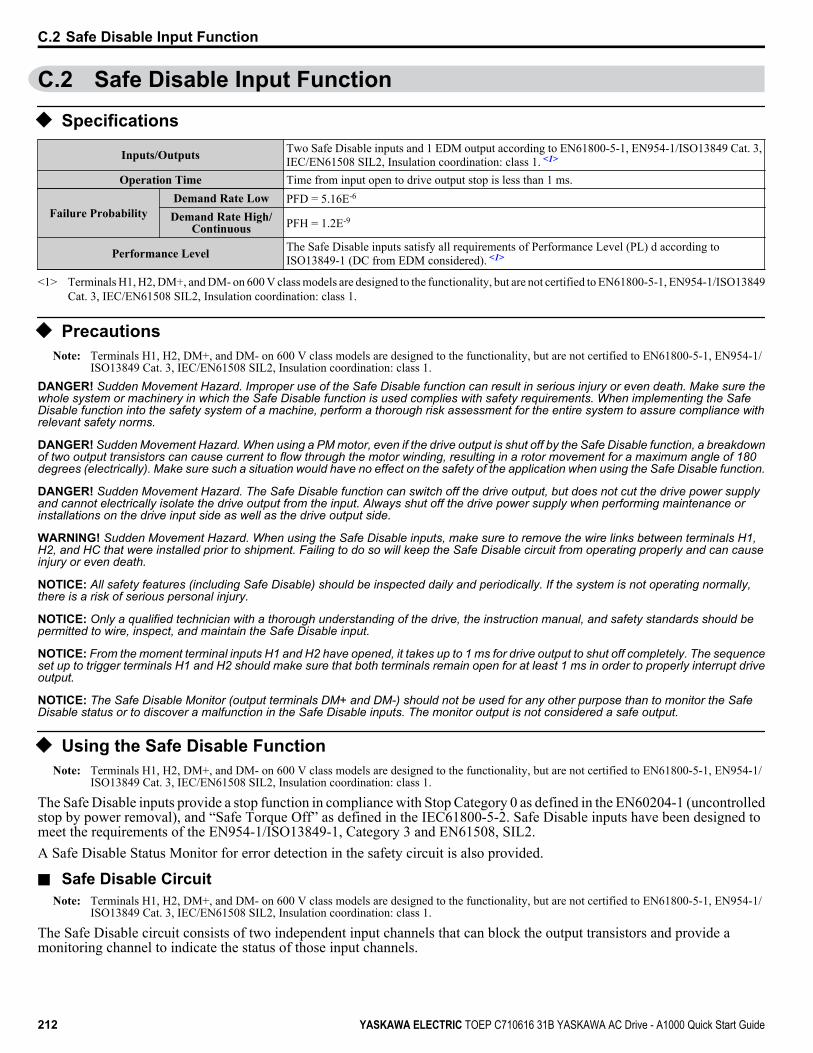
C.2 Safe Disable Input Function
u Specifications
Inputs/Outputs Two Safe Disable inputs and 1 EDM output according to EN61800-5-1, EN954-1/ISO13849 Cat. 3,IEC/EN61508 SIL2, Insulation coordination: class 1. <1>
Operation Time Time from input open to drive output stop is less than 1 ms.
Failure ProbabilityDemand Rate Low PFD = 5.16E-6
Demand Rate High/Continuous PFH = 1.2E-9
Performance Level The Safe Disable inputs satisfy all requirements of Performance Level (PL) d according toISO13849-1 (DC from EDM considered). <1>
<1> Terminals H1, H2, DM+, and DM- on 600 V class models are designed to the functionality, but are not certified to EN61800-5-1, EN954-1/ISO13849Cat. 3, IEC/EN61508 SIL2, Insulation coordination: class 1.
u PrecautionsNote: Terminals H1, H2, DM+, and DM- on 600 V class models are designed to the functionality, but are not certified to EN61800-5-1, EN954-1/
ISO13849 Cat. 3, IEC/EN61508 SIL2, Insulation coordination: class 1.DANGER! Sudden Movement Hazard. Improper use of the Safe Disable function can result in serious injury or even death. Make sure thewhole system or machinery in which the Safe Disable function is used complies with safety requirements. When implementing the SafeDisable function into the safety system of a machine, perform a thorough risk assessment for the entire system to assure compliance withrelevant safety norms.
DANGER! Sudden Movement Hazard. When using a PM motor, even if the drive output is shut off by the Safe Disable function, a breakdownof two output transistors can cause current to flow through the motor winding, resulting in a rotor movement for a maximum angle of 180degrees (electrically). Make sure such a situation would have no effect on the safety of the application when using the Safe Disable function.
DANGER! Sudden Movement Hazard. The Safe Disable function can switch off the drive output, but does not cut the drive power supplyand cannot electrically isolate the drive output from the input. Always shut off the drive power supply when performing maintenance orinstallations on the drive input side as well as the drive output side.
WARNING! Sudden Movement Hazard. When using the Safe Disable inputs, make sure to remove the wire links between terminals H1,H2, and HC that were installed prior to shipment. Failing to do so will keep the Safe Disable circuit from operating properly and can causeinjury or even death.
NOTICE: All safety features (including Safe Disable) should be inspected daily and periodically. If the system is not operating normally,there is a risk of serious personal injury.
NOTICE: Only a qualified technician with a thorough understanding of the drive, the instruction manual, and safety standards should bepermitted to wire, inspect, and maintain the Safe Disable input.
NOTICE: From the moment terminal inputs H1 and H2 have opened, it takes up to 1 ms for drive output to shut off completely. The sequenceset up to trigger terminals H1 and H2 should make sure that both terminals remain open for at least 1 ms in order to properly interrupt driveoutput.
NOTICE: The Safe Disable Monitor (output terminals DM+ and DM-) should not be used for any other purpose than to monitor the SafeDisable status or to discover a malfunction in the Safe Disable inputs. The monitor output is not considered a safe output.
u Using the Safe Disable FunctionNote: Terminals H1, H2, DM+, and DM- on 600 V class models are designed to the functionality, but are not certified to EN61800-5-1, EN954-1/
ISO13849 Cat. 3, IEC/EN61508 SIL2, Insulation coordination: class 1.
The Safe Disable inputs provide a stop function in compliance with Stop Category 0 as defined in the EN60204-1 (uncontrolledstop by power removal), and “Safe Torque Off” as defined in the IEC61800-5-2. Safe Disable inputs have been designed tomeet the requirements of the EN954-1/ISO13849-1, Category 3 and EN61508, SIL2.A Safe Disable Status Monitor for error detection in the safety circuit is also provided.
n Safe Disable CircuitNote: Terminals H1, H2, DM+, and DM- on 600 V class models are designed to the functionality, but are not certified to EN61800-5-1, EN954-1/
ISO13849 Cat. 3, IEC/EN61508 SIL2, Insulation coordination: class 1.
The Safe Disable circuit consists of two independent input channels that can block the output transistors and provide amonitoring channel to indicate the status of those input channels.
C.2 Safe Disable Input Function
212 YASKAWA ELECTRIC TOEP C710616 31B YASKAWA AC Drive - A1000 Quick Start Guide

The input can use the internal power supply of the drive or an external power supply and it will support Sink mode or Sourcemode. the mode selected for the digital input terminals S1 to S8 by switch S3 will also be used for the Safe Disable inputs.Refer to Sinking/Sourcing Mode Switch for Digital Inputs on page 48 for more information.The Safe Disable Monitor uses a single channel photocoupler output. Refer to Output Terminals on page 43 for signalspecifications when using this output.
24 Vdc
Safety Outputs
Power Module PN
M
Gate Block 2
Gate Block 1
ControlCircuit
Main Power
H1
H2
HC
Drive
Jumper S3Setting:SINK
>=1DM+
DM-
Feedback
Safety Relay or PLC with safety functionality
Figure C.3 Safe Disable Function Wiring Example (SINK Mode)
n Disabling and Enabling the Drive Output (“Safe Torque Off”)Note: Terminals H1, H2, DM+, and DM- on 600 V class models are designed to the functionality, but are not certified to EN61800-5-1, EN954-1/
ISO13849 Cat. 3, IEC/EN61508 SIL2, Insulation coordination: class 1.
Figure C.4 illustrates the Safe Disable input operation.
H1, H2 Input
Drive Output
ON (Safe Disable off)
Normal operation
OFF (Safe Disable activated)
Safe Torque-Off
Run Command Run Stop
Baseblock (Not Safe!)
Output Frequency
Motor coasts to stop
Run Command must be released to deactivate
Safe Disable Drive is ready for operation
Figure C.4 Safe Disable Operation
Entering the “Safe Torque Off” StateNote: Terminals H1, H2, DM+, and DM- on 600 V class models are designed to the functionality, but are not certified to EN61800-5-1, EN954-1/
ISO13849 Cat. 3, IEC/EN61508 SIL2, Insulation coordination: class 1.
Whenever either one Safe Disable input or both inputs open, the motor torque is shut off by switching off the drive output. Ifthe motor was running before the Safe Disable inputs opened, then the motor will coast to stop, regardless of the stoppingmethod set in parameter b1-03.Notice that the “Safe Torque Off” state can only be achieved using the Safe Disable function. Removing the Run commandstops the drive and shuts the output off (baseblock), but does not create a “Safe Torque Off” status.
Note: To avoid an uncontrolled stop during normal operation, make sure that the Safe Disable inputs are opened first when the motor has completelystopped.
Returning to Normal Operation after Safe DisableNote: Terminals H1, H2, DM+, and DM- on 600 V class models are designed to the functionality, but are not certified to EN61800-5-1, EN954-1/
ISO13849 Cat. 3, IEC/EN61508 SIL2, Insulation coordination: class 1.
The Safe Disable function can only be deactivated when a Run command is not active.
C.2 Safe Disable Input Function
YASKAWA ELECTRIC TOEP C710616 31B YASKAWA AC Drive - A1000 Quick Start Guide 213C
Stan
dard
s C
ompl
ianc
e

If Safe Disable was activated during stop, turn on both Safe Disable inputs by deactivating “Safe Torque Off” to resume normaloperation.If Safe Disable was activated during run, remove the Run command then turn on the Safe Disable inputs before restarting thedrive.
n Safe Disable Monitor Output Function and Digital Operator DisplayNote: Terminals H1, H2, DM+, and DM- on 600 V class models are designed to the functionality, but are not certified to EN61800-5-1, EN954-1/
ISO13849 Cat. 3, IEC/EN61508 SIL2, Insulation coordination: class 1.
Table C.5 explains the drive output and Safe Disable monitor state depending on the Safe Disable inputs.Table C.5 Safety Input and EDM Terminal Status
Safe Disable Input Status Safe Disable StatusMonitor,DM+ DM-
Drive Output Status Digital Operator DisplayInput 1, H1-HC Input 2, H2-HC
OFF OFF OFF Safely disabled,“Safe Torque Off” Hbb (flashes)
ON OFF ON Safely disabled,“Safe Torque Off” HbbF (flashes)
OFF ON ON Safely disabled,“Safe Torque Off” HbbF (flashes)
ON ON ON Baseblock,ready for operation Normal display
Safe Disable Status MonitorNote: Terminals H1, H2, DM+, and DM- on 600 V class models are designed to the functionality, but are not certified to EN61800-5-1, EN954-1/
ISO13849 Cat. 3, IEC/EN61508 SIL2, Insulation coordination: class 1.
With the Safe Disable monitor output (terminals DM+ and DM-), the drive provides a safety status feedback signal. This signalshould be read by the device that controls the Safe Disable inputs (PLC or a safety relay) in order to prohibit leaving the “SafeTorque Off” status in case the safety circuit malfunctions. Refer to the instruction manual of the safety device for details onthis function.
Digital Operator DisplayNote: Terminals H1, H2, DM+, and DM- on 600 V class models are designed to the functionality, but are not certified to EN61800-5-1, EN954-1/
ISO13849 Cat. 3, IEC/EN61508 SIL2, Insulation coordination: class 1.
When both Safe Disable inputs are open, “Hbb” will flash in the digital operator display.If one Safe Disable channels is on while the other is off, “HbbF” will flash in the display to indicate that there is a problem inthe safety circuit or in the drive. This display should not appear under normal conditions if the Safe Disable circuit is utilizedproperly. Refer to Alarm Codes, Causes, and Possible Solutions on page 121 to resolve possible errors.
C.2 Safe Disable Input Function
214 YASKAWA ELECTRIC TOEP C710616 31B YASKAWA AC Drive - A1000 Quick Start Guide

This Page Intentionally Blank
215 YASKAWA ELECTRIC TOEP C710616 31B YASKAWA AC Drive - A1000 Quick Start Guide

Revision HistoryThe revision dates and the numbers of the revised manuals appear on the bottom of the back cover.
MANUAL NO. TOEP C710616 31B Published in USA November 2009 09-6
Date of publication Date of original
publication
Date of Publication RevisionNumber Section Revised Content
June 2009 – – First Edition. This manual supports drive software versionsVSA90504.
November 2009 1 Added models CIMR-AU5A0017, 5A0022, 5A0027, 5A0032
216 YASKAWA ELECTRIC TOEP C710616 31B YASKAWA AC Drive - A1000 Quick Start Guide

This Page Intentionally Blank
YASKAWA ELECTRIC TOEP C710616 31B YASKAWA AC Drive - A1000 Quick Start Guide 217

YASKAWA AC Drive-A1000High Performance Vector Control DriveQuick Start Guide
IRUMA BUSINESS CENTER (SOLUTION CENTER)480, Kamifujisawa, Iruma, Saitama, 358-8555, JapanPhone: 81-4-2962-5696 Fax: 81-4-2962-6138
YASKAWA ELECTRIC CORPORATIONNew Pier Takeshiba South Tower, 1-16-1, Kaigan, Minatoku, Tokyo, 105-6891, JapanPhone: 81-3-5402-4511 Fax: 81-3-5402-4580http://www.yaskawa.co.jp
YASKAWA ELECTRIC AMERICA, INC.2121 Norman Drive South, Waukegan, IL 60085, U.S.A.Phone: (800) YASKAWA (800-927-5292) or 1-847-887-7000 Fax: 1-847-887-7310http://www.yaskawa.com
YASKAWA ELÉTRICO DO BRASIL COMÉRCIO LTDA.Avenda Fagundes Filho, 620 Bairro Saude, São Paulo, SP04304-000, BrasilPhone: 55-11-3585-1100 Fax: 55-11-5581-8795http://www.yaskawa.com.br
YASKAWA ELECTRIC EUROPE GmbHHauptstra?e 185, 65760 Eschborn, GermanyPhone: 49-6196-569-300 Fax: 49-6196-569-398
YASKAWA ELECTRIC UK LTD.1 Hunt Hill Orchardton Woods, Cumbernauld, G68 9LF, United KingdomPhone: 44-1236-735000 Fax: 44-1236-458182
YASKAWA ELECTRIC KOREA CORPORATION7F, Doore Bldg. 24, Yeoido-dong, Youngdungpo-Ku, Seoul, 150-877, KoreaPhone: 82-2-784-7844 Fax: 82-2-784-8495
YASKAWA ELECTRIC (SINGAPORE) PTE. LTD.151 Lorong Chuan, #04-01, New Tech Park, 556741, SingaporePhone: 65-6282-3003 Fax: 65-6289-3003
YASKAWA ELECTRIC (SHANGHAI) CO., LTD.No. 18 Xizang Zhong Road, Room 1702-1707, Harbour Ring Plaza, Shanghai, 200001, ChinaPhone: 86-21-5385-2200 Fax: 86-21-5385-3299
YASKAWA ELECTRIC (SHANGHAI) CO., LTD. BEIJING OFFICERoom 1011A, Tower W3 Oriental Plaza, No. 1 East Chang An Ave.,Dong Cheng District, Beijing, 100738, ChinaPhone: 86-10-8518-4086 Fax: 86-10-8518-4082
YASKAWA ELECTRIC TAIWAN CORPORATION9F, 16, Nanking E. Rd., Sec. 3, Taipei, TaiwanPhone: 886-2-2502-5003 Fax: 886-2-2505-1280
YASKAWA ELECTRIC CORPORATION
In the event that the end user of this product is to be the military and said product is to be employed in any weapons systems or the manufacturethereof, the export will fall under the relevant regulations as stipulated in the Foreign Exchange and Foreign Trade Regulations. Therefore, be sureto follow all procedures and submit all relevant documentation according to any and all rules, regulations and laws that may apply.Specifications are subject to change without notice for ongoing product modifications and improvements.© 2009 YASKAWA ELECTRIC CORPORATION. All rights reserved.
YASKAWA
MANUAL NO. TOEP C710616 31B
Published in U.S.A. November 2009 09-609-1
1 -0
Related Documents