The Yagi, J-Pole and NVIS Dipole And a glance at Antenna Design using 3D EM Software Brian Mileshosky N5ZGT High Desert Amateur Radio Club 15 Feb 2013

Welcome message from author
This document is posted to help you gain knowledge. Please leave a comment to let me know what you think about it! Share it to your friends and learn new things together.
Transcript

The Yagi, J-Pole and NVIS Dipole And a glance at Antenna Design using 3D EM Software
Brian Mileshosky N5ZGT
High Desert Amateur Radio Club
15 Feb 2013

Antennas
The most critical piece of any transmitting/receiving system.
Come in many shapes (linear, helical, aperture, reflective, horns, loops, mixtures of
each) and sizes (100+ foot tower down to something less than the size of a stamp).


Antennas
The most critical piece of any transmitting/receiving system.
Come in many shapes (linear, helical, aperture, reflective, horns, loops, mixtures of each) and sizes (100+ foot tower down to something less than the size of a stamp).
Design criteria: gain, bandwidth, physical size, directivity, polarization, efficiency, feed method, power handling, price, ease of fabrication, etc.
Key point: Antennas are reciprocal devices – they behave the same while transmitting as they do while receiving (radiation pattern, gain, polarity, etc)
Designed using a variety of theory and computational tools
NEC (Free)
4NEC2 (Free, and pretty incredible)
EZ NEC ($89)
PCAAD ($499)
CST Microwave Studio or ANSYS HFSS (>$50,000)
Other resources:
ARRL Antenna Book
LB Cebik’s website (www.cebik.com)
Antenna Engineering Handbook (Johnson)
Antenna Theory (Balanis)
Microwave Engineering (Pozar)

The Yagi Uda antenna
Described and published by S. Uda and H. Yagi in the 1920s
Did not receive full acclaim in the United States until 1928.
Driven element is excited directly via feedline, all other elements excited parasitically.
Element lengths/diameters and element spacing determine antenna behavior.
Typical driven element: a bit less than l/2.
Typical director length: 0.4-0.45l
If multiple directors are used, they are not necessarily the same length or diameter.
Typical separation between directors is 0.3-0.4l, but not necessarily equally spaced.
Typical separation between driven element and reflector: 0.25l.
Little performance is added with the addition of more than one reflector.
Significant performance is added with the addition of more directors.
Input impedance is usually low; Gamma matches often used to match to 50W.
The Yagi Uda antenna
Typical gain of Yagi-Uda antennas:
3 elements: 7 dBi
4 elements: 9 dBi
6 elements: 10.5 dBi
8 elements: 12.5 dBi
12 elements: 14.5 dBi
15 elements: 15.5 dBi
18 elements: 16.5 dBi
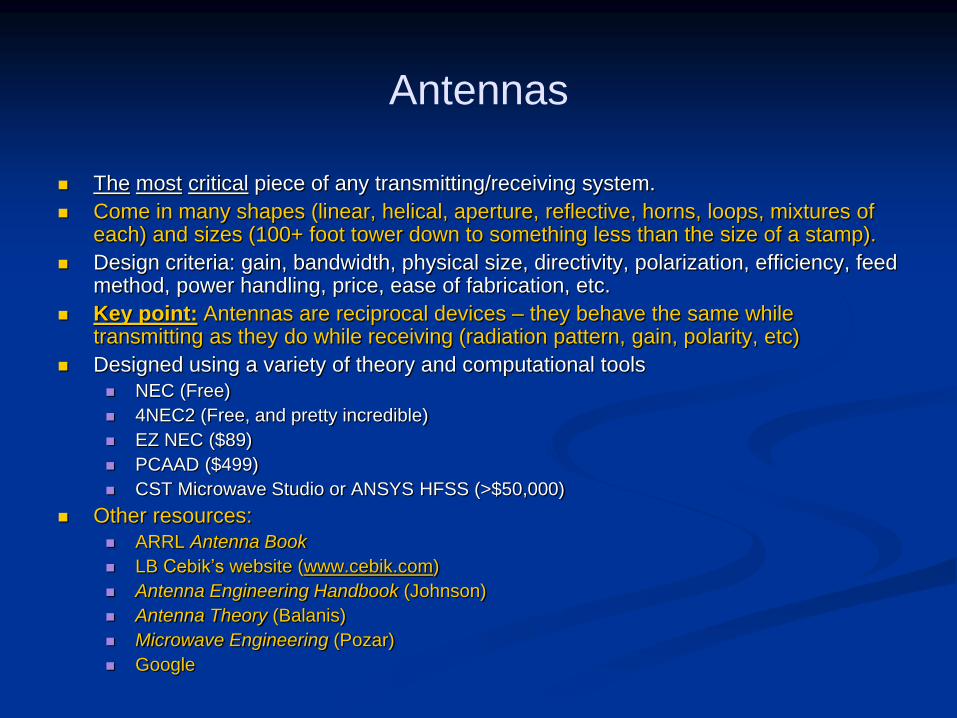
(Source: Antenna Engineering Handbook, Johnson)
dBi = dBd + 2.14

Let’s start with a Driven Element...
Driven element only…essentially a dipole
(PVC boom / handle shown, too)

Let’s start with a Driven Element...
Total gain (horizontal + vertical)

Let’s start with a Driven Element...
Return loss (resonance at 146.0 MHz)
Return loss of -10 dB = SWR of 1.92. SWR of 2 means approx. 90% power is transmitted.
Return loss of -15 dB = SWR of 1.43
Return loss of -20 dB = SWR of 1.22

Then add a Director.
Driven element plus director

Then add a Director.
Total gain (horizontal + vertical; elevation)

Then add a Director.
Total gain (horizontal + vertical; azimuth)

And finally, add a Reflector.
Driven element, reflector, and director. A 3-element yagi.

And finally, add a Reflector.
Total gain (horizontal + vertical; elevation)

And finally, add a Reflector.
Total gain (horizontal + vertical; azimuth)

And finally, add a Reflector.
2D antenna pattern cut – there is room to optimize this yagi to reduce the backlobe further

And finally, add a Reflector.
Cross-polarization gain
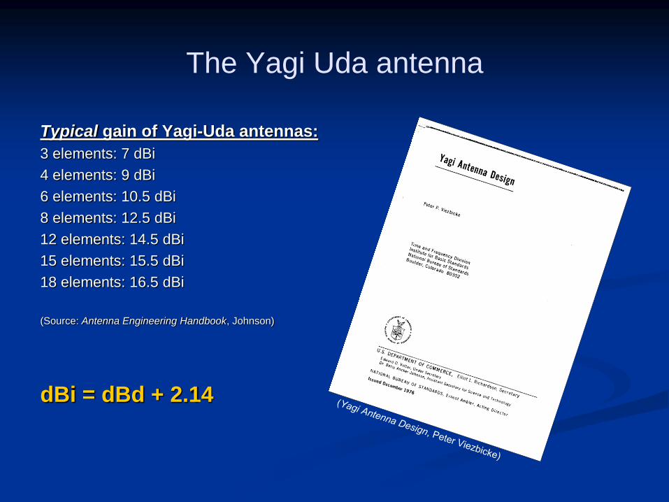
How the Yagi shapes up.
Driven element only
Gain: 1.98 dBi
Driven element and director
Gain: 5.7 dBi
Driven element, director and reflector
Gain: 7.74 dBi

The Tape Measure Yagi…

The Tape Measure Yagi
Original design by Joe Leggio WB2HOL at: http://theleggios.net/wb2hol/projects/rdf/tape_bm.htm
Easily built from PVC, tape measure material, hose clamps and a short piece of coax.
Total cost, on average: < $15 if you have some parts lying in your garage.
Can achieve up to 7-dBi of gain from this simple antenna – perfect for use in the field, or from home. Excellent antenna for direction finding on 2 meters. Just as excellent for reaching distant stations or repeater while in the field, public service applications, etc.
Not intended for permanent installation – elements will collapse briefly when blown by a gust of wind, affecting SWR.
Not intended for high power use – you will be in the near-field of this antenna when transmitting. Common sense and safety highly encouraged.
Tip: Use silver solder since tape measure material is generally stainless steel.
Tip: Don’t use RG-58…too clumsy. RG-174 with BNC or SMA recommended.
Tip: Round off metal corners, laminate with electrical tape, or dip in liquid rubber to prevent cuts.

The Tape Measure Yagi
Courtesy Joe Leggio WB2HOL

A brief look at other antennas…

2-meter J-Pole antenna
Model of 2-meter copper J-Pole antenna
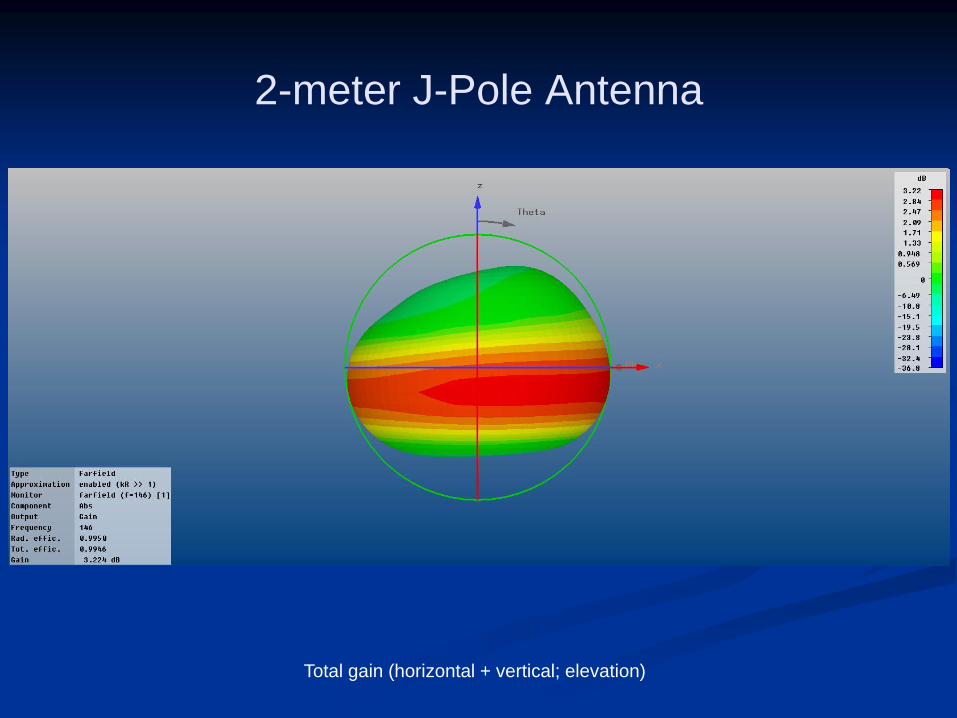
2-meter J-Pole Antenna
Total gain (horizontal + vertical; elevation)

2-meter J-Pole Antenna
Total gain (horizontal + vertical; azimuth)

10 GHz Horn antenna
Model of a round horn antenna fed by rectangular waveguide

10 GHz Horn antenna
Total gain (horizontal + vertical; elevation)

10 GHz Horn antenna
10 GHz horn antenna field view

A quick look at Dipoles and NVIS
An excellent presentation on what Near Vertical Incidence Skywave (NVIS) is all about:
http://www.arrl.org/nvis

Dipole in free space (no ground effects)
Dipole, no ground plane

Dipole in free space (no ground effects)
Free space; no ground effects
Total gain (horizontal + vertical polarization)

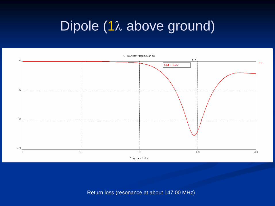
Dipole (1l above ground)
Dipole modeled over perfect, infinite ground. Total gain (horizontal + vertical polarizations).
Note that most of radiation is taking off at a somewhat low angle. This is a non-NVIS case.
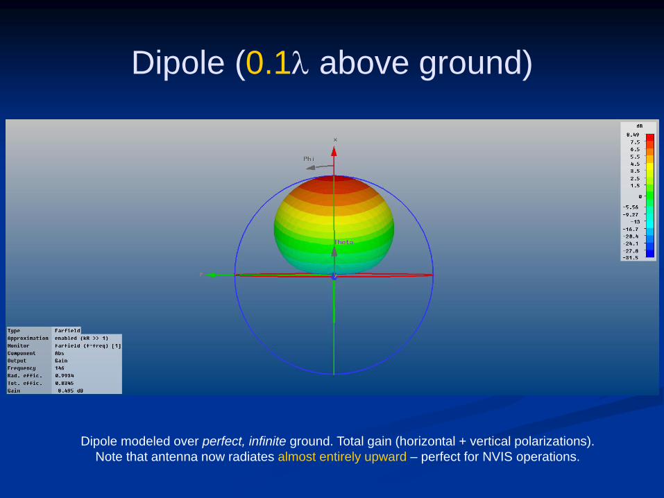
Dipole (0.1l above ground)
Dipole modeled over perfect, infinite ground. Total gain (horizontal + vertical polarizations).
Note that antenna now radiates almost entirely upward – perfect for NVIS operations.

Selected Web Resources
Yagis: Yagi Antenna Design, Peter Viezbicke, December 1976:
http://tf.nist.gov/timefreq/general/pdf/451.pdf
J-Poles: Compilation of articles:
http://www.arrl.org/vhf-omni
NVIS: Excellent Powerpoint presentation with links to websites: http://www.arrl.org/nvis
Antenna design & software: L.B. Cebik W4RNL (SK): http://www.cebik.com
ARRL Technical Information Service: http://www.arrl.org/technical-information-service
NEC: http://www.nec2.org
4NEC2: http://home.ict.nl/~arivoors
EZ NEC: http://www.eznec.com
ANSYS HFSS: http://www.ansys.com/Products/Simulation+Technology/Electromagnetics
CST Microwave Studio: http://www.cst.com/Content/Products/MWS/Overview.aspx

Backup

Driven element only
Return loss (resonance at 146.0 MHz)

Driven element plus director
Return loss (resonance at 145.60 MHz)

Driven element, reflector & director
Return loss (resonance at about 144.8 MHz)
Dipole (1l above ground)
Return loss (resonance at about 147.00 MHz)

Dipole (0.1l above ground)
Return loss (resonance at about 142.00 MHz)
Related Documents