International Journal of Energy and Power Engineering 2016; 5(4-1): 43-58 http://www.sciencepublishinggroup.com/j/ijepe doi: 10.11648/j.ijepe.s.2016050401.16 ISSN: 2326-957X (Print); ISSN: 2326-960X (Online) Xu's Sealing Theory and Rectangular & O-Shaped Ring Seals Xu Changxiang Zhejiang China Valve Co. Ltd., Wenzhou, Zhejiang, 325024, China Email address: [email protected] To cite this article: Xu Changxiang. Xu's Sealing Theory and Rectangular & O-Shaped Ring Seals. International Journal of Energy and Power Engineering. Special Issue: Xu's Sealing and Flowing Theories of Fluids. Vol. 5, No. 4-1, 2016, pp. 43-58. doi: 10.11648/j.ijepe.s.2016050401.16 Received: June 22, 2016; Accepted: June 25, 2016; Published: August 24, 2016 Abstract: The difficulty for a sealing element to create and maintain a leak-free joint is determined by its sealing difficulty factor m 1 , m 1 = elastic modulus E c of its sealing contact layer/elastic modulus E s of its sealing contact layer substrate. Therefore, theoretically the contact layer of a sealing element shall be soft & inelastic and assembled up to its fully yielded deformation to provide a contact layer with a lower value of active elastic modulus E c , and the contact layer substrate shall be strong & elastic and assembled up to its fully elastic deformation to provide a contact layer substrate with a higher value of active elastic modulus E s . It is the most difficult for a rubber sealing element to create a leak-free joint because its E c ≡ E s , and it is far easier for a metal sealing element than for a rubber sealing element because the metal sealing element can be designed and coated to ensure that assembling can cause its E c < E s . Keywords: Seal, Categorization of seals, Circle-based system of O-ring seals, Minimum necessary sealing stress y, Sealing difficul- ty factor m 1 , Leak-free maintenance factor m 2 , Self-sealing mechanism for material (Mechanism of self-sealing Poisson's deformation caused by fluid pressure), Self-sealing mechanism for O-rings (Mechanism of self-sealing deformation caused by fluid seepage) 1 Categorization of Seals [1] Seals are to create either a leak-free butt joint of two flat end surfaces or a leak-free fit of two cylindrical surfaces, and hence can be divided into an end face (butt joint) seal and a cylinder (fit) seal according to a shape of sealing surfaces. As shown in Fig.1a, an O-ring (Φd 1o ) or a rectangular ring (Φd 1r ) can be used for a self-sealing joint of two end faces. As shown in Fig.1b, O-ring seals used as a self-sealing joint of two cyl- inders can be divided into a rod seal (Φd 12 ) for a rod/hole fit and a piston seal (Φd 13 ) for a piston/cylinder fit. As shown in Fig.1c, one of O-ring seals (Φd 11 ~Φd 13 ) can be substituted for the self-energizing O-ring seal (Φd 1o ) for two end faces. If the substitute seals indicated by Φd 12 and Φd 13 in Fig.1c are re- spectively regarded as static rod seals and piston seals, the seal indicated by Φd 11 in Fig.1c and substituted for the seal indi- cated by Φd 1o can be undoubtedly called a port seal for a cylinder port or hole port. Given that the threaded port seal (Φd 11 ) in Fig.1d is the same as the port seal (Φd 11 ) and that the size series and the cavity's fill characteristic of the original face seal (Φd 1o ) can be the same as those of a port seal (Φd 11 ), the self-energizing seals for a joint and a fit of surfaces can be unifiedly studied and disposed by being divided into a rec- tangular ring seal (Φd 1r ) and three O-ring seals called port seal (Φd 11 ), rod seal (Φd 12 ) and piston (Φd 13 ) seal. A non-self-energizing seal opposite to a self-energizing seal is called a pressure-tight seal, or a non-self-sealing joint op- posite to a self-sealing joint is called a pressure-tight joint. 2 Flange Gasket Seals of the Prior Art [2] The flange joint of the prior art, achieving their fastening connection by some bolts and their sealing connection by a gasket between two end faces as shown in Fig.2, is a pres- sure-tight joint that is different from the self-sealing joint with a rectangular ring (Φd 1r ) in Fig.1. As shown in Fig.3, the two flanges have a wide touch width b due to no bending before tightened, a narrowed touch width b due to some bending after tightened, and a more narrowed touch width b due to more bending under a fluid pressure. Generally speaking, any tight- ening assembly is causing a gasket to be loaded or resulting in a gasket increasing its sealing stress, and any fluid pressure is causing a gasket to be unloaded or resulting in a gasket de- creasing its sealing stress. Therefore, any flange gasket seal of the prior art has the following four inherent fatal problems: a. It will leak, no matter how it is constructed. Any sealing needs to deform a sealing surface into some

Welcome message from author
This document is posted to help you gain knowledge. Please leave a comment to let me know what you think about it! Share it to your friends and learn new things together.
Transcript

International Journal of Energy and Power Engineering 2016; 5(4-1): 43-58
http://www.sciencepublishinggroup.com/j/ijepe
doi: 10.11648/j.ijepe.s.2016050401.16
ISSN: 2326-957X (Print); ISSN: 2326-960X (Online)
Xu's Sealing Theory and Rectangular & O-Shaped Ring Seals
Xu Changxiang
Zhejiang China Valve Co. Ltd., Wenzhou, Zhejiang, 325024, China
Email address: [email protected]
To cite this article: Xu Changxiang. Xu's Sealing Theory and Rectangular & O-Shaped Ring Seals. International Journal of Energy and Power Engineering.
Special Issue: Xu's Sealing and Flowing Theories of Fluids. Vol. 5, No. 4-1, 2016, pp. 43-58. doi: 10.11648/j.ijepe.s.2016050401.16
Received: June 22, 2016; Accepted: June 25, 2016; Published: August 24, 2016
Abstract: The difficulty for a sealing element to create and maintain a leak-free joint is determined by its sealing difficulty
factor m1, m1 = elastic modulus Ec of its sealing contact layer/elastic modulus Es of its sealing contact layer substrate. Therefore,
theoretically the contact layer of a sealing element shall be soft & inelastic and assembled up to its fully yielded deformation to
provide a contact layer with a lower value of active elastic modulus Ec, and the contact layer substrate shall be strong & elastic
and assembled up to its fully elastic deformation to provide a contact layer substrate with a higher value of active elastic modulus
Es. It is the most difficult for a rubber sealing element to create a leak-free joint because its Ec ≡ Es, and it is far easier for a metal
sealing element than for a rubber sealing element because the metal sealing element can be designed and coated to ensure that
assembling can cause its Ec < Es.
Keywords: Seal, Categorization of seals, Circle-based system of O-ring seals, Minimum necessary sealing stress y, Sealing difficul-
ty factor m1, Leak-free maintenance factor m2, Self-sealing mechanism for material (Mechanism of self-sealing Poisson's deformation
caused by fluid pressure), Self-sealing mechanism for O-rings (Mechanism of self-sealing deformation caused by fluid seepage)
1 Categorization of Seals [1]
Seals are to create either a leak-free butt joint of two flat end
surfaces or a leak-free fit of two cylindrical surfaces, and
hence can be divided into an end face (butt joint) seal and a
cylinder (fit) seal according to a shape of sealing surfaces. As
shown in Fig.1a, an O-ring (Φd1o) or a rectangular ring (Φd1r)
can be used for a self-sealing joint of two end faces. As shown
in Fig.1b, O-ring seals used as a self-sealing joint of two cyl-
inders can be divided into a rod seal (Φd12) for a rod/hole fit
and a piston seal (Φd13) for a piston/cylinder fit. As shown in
Fig.1c, one of O-ring seals (Φd11 ~Φd13) can be substituted for
the self-energizing O-ring seal (Φd1o) for two end faces. If the
substitute seals indicated by Φd12 and Φd13 in Fig.1c are re-
spectively regarded as static rod seals and piston seals, the seal
indicated by Φd11 in Fig.1c and substituted for the seal indi-
cated by Φd1o can be undoubtedly called a port seal for a
cylinder port or hole port. Given that the threaded port seal
(Φd11) in Fig.1d is the same as the port seal (Φd11) and that the
size series and the cavity's fill characteristic of the original
face seal (Φd1o) can be the same as those of a port seal (Φd11),
the self-energizing seals for a joint and a fit of surfaces can be
unifiedly studied and disposed by being divided into a rec-
tangular ring seal (Φd1r) and three O-ring seals called port seal
(Φd11), rod seal (Φd12) and piston (Φd13) seal.
A non-self-energizing seal opposite to a self-energizing seal
is called a pressure-tight seal, or a non-self-sealing joint op-
posite to a self-sealing joint is called a pressure-tight joint.
2 Flange Gasket Seals of the Prior Art [2]
The flange joint of the prior art, achieving their fastening
connection by some bolts and their sealing connection by a
gasket between two end faces as shown in Fig.2, is a pres-
sure-tight joint that is different from the self-sealing joint with a
rectangular ring (Φd1r) in Fig.1. As shown in Fig.3, the two
flanges have a wide touch width b due to no bending before
tightened, a narrowed touch width b due to some bending after
tightened, and a more narrowed touch width b due to more
bending under a fluid pressure. Generally speaking, any tight-
ening assembly is causing a gasket to be loaded or resulting in a
gasket increasing its sealing stress, and any fluid pressure is
causing a gasket to be unloaded or resulting in a gasket de-
creasing its sealing stress. Therefore, any flange gasket seal of
the prior art has the following four inherent fatal problems:
a. It will leak, no matter how it is constructed.
Any sealing needs to deform a sealing surface into some

44 Xu Changxiang: Xu's sealing theory and rectangular & o-shaped ring seals
imperfections on a being sealed surface, whereas any
leaking is a process for a leaking fluid on the two contact
surfaces to output a contact-separating force whose limit
equals “contact area x pressure”. Hence, the mechanical
condition for a gasket to create a leak-free joint is to ena-
ble the gasket to provide both a full deformation and a
fully strong support for its sealing contact. The soft and
inelastic gasket material, such as grease, can easily provide
a full deformation but not a fully strong support for its
sealing contact, and the strong and elastic gasket material
can only conversely provide the deformation and the sup-
port. In the prior art, there is not such a designing idea or
method resulting in a both soft and strong sealing contact
layer that spiral wound gaskets and Kammprofile gaskets
that are inadvertently in good accordance with the design-
ing idea cannot yet have a fully strong support underneath
the sealing surface. Therefore, any pressure-tight gasket
seal of the prior art, however it is constructed, must leak at
a certain temperature and pressure that are not high.
Φd11 Φd13
Φd 1
2
Φd 1
3
Φdo
Φd0-1.5P
(Φd0-P)
Φd0xPS
ΦD1
Φd0xP
Φd11
Φd12
(a) Face (butting joint) seals(b) Cylinder seals including a piston seal and a rod Seal
(d) (Threaded) Port seal
Φd1r
Φdo
Φd1o
(c) Port seals and cylinder seals substituted for face seals
Fig.1 Categorization of seals
Fig.2 Bolted flanges of the prior art
Fig.3 Flange rotation of the prior art
b. It will leak, no matter how it is assembled.
Any sealing is deforming a sealing surface into some
roughness-caused imperfections on a being sealed surface,
whereas an economically machined surface roughness for
flange faces is not greater than Ra 3.2 μm; i.e. any flange
gasket shall have a compressive deformation with its cir-
cumferential uniformity within μms, otherwise any great
tightening load is not fully useful or sufficient. Because any
torque controlling method of the prior art, as shown in Fig.3,
cannot result in a tightened deformation with its circum-
ferential uniformity within μms, thus any pressure-tight
gasket seal of the prior art must be a leaking device how-
ever it is assembled, even if its sealing contact layer can be
as close to being both soft and strong as that of spiral wound
gaskets and Kammprofile gaskets.
c. Any fluid pressure is to worsen its sealing performance.
Any fluid pressure acting on an equivalent flange cover,
whether it is great or small, is to cause gasket's compressive
stress or sealing performance to decrease. Any fluid pressure
acting on gasket's internal cylinder is to cause a gasket to be at
risk of blowout. To protect gasket from being blown out, the
prior standards specify that a flange face shall have an ab-
normal surface roughness of Ra 3.2 ~ 6.3 μm, which is so

International Journal of Energy and Power Engineering 2016; 5(4-1): 43-58 45
against the ordinary technical ideas of “the smoother the butt
joint surface, the easier to be sealed” and “the more precise
the machining, the better” as to have an extra leaking risk.
d. Any cold flow is to worsen its sealing performance.
Any sealing material has some cold flow causing gasket's
compressive stress or sealing performance to decrease at a
more than 0.5 homologous temperature.
Therefore, the flange gasket seal of the prior art is originally
only a leaking device under Xu's sealing theory.
3 O-Ring Seals of the Prior Art [1, 3-4]
According to ISO 3601: 2008, an installed O-ring shall not
have such a more than 85% fill in its cavity that it can be
compressed only in axial direction in face seals and called an
axial seal, and compressed only in radial direction in rod and
piston seals and called a radial seal; i.e. any installed O-ring
of the prior art is compressed at two sides, never at four sides.
As shown in Fig.4a, an installed O-ring shall be flattened to
ra ≥ 0.75ru according to the required sealing power or support
or according to the requirement that its sealing actuation area
of fluid shall be greater than its sealing contact area (its un-
sealing actuation area of leaking fluid); and, as shown in
Fig.4b, an installed O-ring shall be flattened to ra ≤ 0.5ru ac-
cording to the minimum tight contact required to resist an
atmospheric seepage through the contact; i.e. an O-ring seal of
the prior art is irreconcilable in designs under Xu's sealing
theory, or the O-ring of the prior art cannot at the same time
meet its assembly squeeze requirements as qualified initial
and working seals. An installed standard O-ring of the prior
art, as shown in Fig.4c, is flattened to ra ≥ 0.7 ~ 0.85ru only to
have an assembled stress of 0.14 ~ 0.12 MPa, which is inferior
to 0.2 MPa required to achieve its minimum tight contact, and
also to be unable to move or deform against the third wall and
start its self-sealing action below a fluid pressure of 0.5 ~ 1.5
MPa because of its enormous static friction coefficient of 1~4
and its total sealing contact area of 3~5 times its sealing actu-
ation area (see Annex A.4.); or, under Xu's sealing theory, any
O-ring seal of the prior art is leaking in low pressure systems
and at the starting and ceasing stages of ordinary pressure
systems; however, the O-ring seal has been used as the best
sealing means at low pressures. Besides, any standard O-ring
seal of the prior art at a high pressure, as shown in Fig.4d, can
only work as a weak small-great end piston and will leak
without stopping once it gets leaking, especially when O-rings
deteriorate in elasticity or flexibility, because any leaking will
not only cause its unsealing actuation force of leaking fluid on
its sealing contact area to get greater than its sealing actuation
force of fluid on its O-ring but also cause its sealing actuation
surface to lessen in curvature radius (from ra to rx) and get
more resistant to fluid pressure or cause its O-ring to need a
greater power for a self-sealing move or deformation.
(c) Leaking at low pressure (d) Leaking at high pressure
Rod Rod
HoleHole
rx
Rod
Holera
Rod
ra
Hole
Φ2ru Φ2ru Φ2ru Φ2ru
Φd 1
2
Φd 1
2
Φd 1
2
Φd 1
2
rara
(b) As initial seal, ra ≤ 0.5ru(a) As working seal, ra ≥ 0.75ru
Fig.4 Problems of assembly squeeze of O-ring seals of the prior art
The isotropic softness, incompressibility and elasticity of
rubber cause its O-ring to be like such a ring of shaped elastic
liquid as to make its internal pressure raise and lower syn-
chronously with its external pressure. Given that there can
only be a uniform fluid pressure on a rubber O-ring in its
cavity, its fluid compression surface and its extrusion surface
are two different radii of single round surfaces tangent to its
cavity walls. They can be seen by observing a sectional shape
of flattened O-rings and an external surface shape of stretched
O-rings. However, US 2180795 (original O-ring seal patent)
and ISO 3601: 2008 (standard for O-ring seals) deem the
section of an O-ring flattened in its cavity an ellipse (see An-
nex A.5.). In other words, the prior art has not at all known any
sealing mechanism for O-rings and has been unable to
properly specify their design, manufacture and assembly by
relating their maximum working pressures with their sectional
diameter and material strength.
The stronger the strength and the elasticity of a sealing
contact layer, the more difficult for its sealing element to create
or maintain a fully deformed contact; whereas the stronger the
strength and the elasticity of a contact layer substrate, the easier
for its sealing element to create or maintain a fully deformed
contact. Hence, it is the most difficult for a rubber element to
create a leak-free joint whose contact's elastic modulus (Ec)
divided by its substrate's elastic modulus (Es) identically equals
one (or Ec/Es ≡ 1), the easiest for a greased hard element whose
contact's elastic modulus (Ec) divided by its substrate's elastic
modulus (Es) equals zero (or Ec/Es = 0), and more difficult than
for a greased hard element and more easier than for a rubber
element for the other sealing elements whose contact layer is
yieldable to cause Ec/Es to be greater than zero and smaller than
one (or 0 < Ec/Es < 1); i.e. a rubber O-ring seal is the most
difficult to create a leak-free joint under Xu's sealing theory,
but mistaken for the easiest by the prior art.
The Gough-Joule effect tells us that a stretched rubber piece
will not elongate but will shorten in its stretch direction when
warmed up, and meanwhile, its tensile modulus will increase but
not decrease (see Annex A.3.). Hence, any stretched rubber
O-ring in two-wall-touching assembly of its radial seal applica-
tion will radially shrink in its cross-section to cause a possible

46 Xu Changxiang: Xu's sealing theory and rectangular & o-shaped ring seals
leak during a warm start in the morning after further stretched in
the colder night. Obviously, the effective means to overcome the
Gough-Joule shrinkage influence is to have an assembly of
rubber O-rings that uniformly touches their four walls of cavity.
Each solid rocket motor case of Space Shuttle Challenger is
made of 11 individual cylindrical weld steel sections about 12
feet in diameter. As shown in Fig.5, the 11 sections of the motor
case are joined by tang-and-clevis joints held together by 177
steel pins around the circumference of each joint, and separated
by controlled explosion ejection of the pins. Joint sealing is
provided by two rubber O-ring piston seals. The installed
O-rings were heavily greased and stretched in their cavities, and
hence had more circumferential being shortened in time caused
both by more cold shrinkage at time of the disaster launch
whose ambient temperature was 36 degrees Fahrenheit, or 15
degrees lower than the next coldest previous launch, and by
more Gough-Joule circumferential warm shrinkage after igni-
tion; i.e. the O-rings for the disaster launch successively had in
cross-sections, because of circumferential being stretched, such
an installed radial shrinkage according to the prior standard
specification, a more cold radial shrinkage at a colder ambient
temperature and a more Gough-Joule warm radial shrinkage
after ignition, and had such a gap increase between the tang and
the inside leg of the clevis under combustion gas pressure as to
jointly make these O-rings be continually off the sealed tang
surface and cause the grease to be blown out to form a leak. In
other words, from Xu's sealing theory and the records in the
Report of Presidential Commission on the Space Shuttle Chal-
lenger Accident, it can be seen that the Space Shuttle Chal-
lenger disaster was caused by a greased standard O-ring seal,
whose O-ring is in a radially clamped assembly that cannot
resist any influence of cold and warm radial shrinkages on its
tight contact. However, the Report neither pays any attention to
the Gough-Joule effect of rubber nor pays any attention to the
influence of grease coating on O-rings only to incorrectly deem
the disaster to be caused by the O-ring seal design that can result
in a possible four-wall-touching assembly or that cannot ensure
the O-rings a two-wall-clamped assembly or a two-wall-
touching assembly (see Annex A.4.).
Tang
Clevis
Case
Φd
Case
Φd
O-Ring Clevis pin
Cork insulationPin retainer band
Retainer clip
Fig.5 O-ring seals causing Space Shuttle Challenger Disaster
Therefore, the O-ring seal of the prior art has been severely
mistaken and has a risk causing some major accidents.
4 Designs and Parameters (the minimum necessary sealing stress y and the seal-ing difficulty factor m1) for a Sealing Element [2, 4]
Any leak-free connection results from loading a sealing
contact layer first up to its fully deformed contact and then up
to its fully tight contact, or needs first to create a fully de-
formed contact that can seat a sealing surface into irregularities
on a surface to be sealed and then to create a fully tight contact
that can resist a seepage through the sealing contact, and any
full seepage or leaking is a process for a leaking fluid on the
two contact surfaces to output a contact separating force whose
limit equals “contact area x pressure”; hence the minimum
stress needed to resist an atmospheric seepage through the
contact is the minimum necessary sealing stress y for a seal,
and the contact whose stress is up to the minimum necessary
sealing stress y is called the minimum necessary tight contact.
In order to achieve a fully deformed contact without any flaw,
it is better to load the sealing contact layer up to its fully
yielded deformation. In order to achieve a fully tight contact, it
is needed to load the sealing contact layer substrate up to its
fully elastic deformation to provide a fully powerful support
for the contact. Therefore, the contact stress at loading a seal-
ing contact just up to its fully deformed contact without any
flaw at atmospheric pressure is the flaw-blocking or seal-
ing-beginning stress Gb; the assembled stress Sa up to the fully
elastic deformation of the substrate shall approach the yield
strength Se of the substrate material; the contact stress at un-
loading a fully leak-free contact just up to being leaving its
fully tight contact is the leakage-starting stress or the minimum
necessary sealing stress y; the contact stress at further unload-
ing the contact just up to being leaving its fully deformed con-
tact is the flaw-reproducing or sealing-stopping stress Gs; and y
= ye + ya, where ye is the component for loading the sealing
contact just up to restoring its full deformation along unloading
line, and ya = 0.1 MPa is the component for loading the fully
deformed contact just up to restoring its minimum necessary
tight contact that can fully resist the atmospheric seepage
through contact along unloading line.
The stronger the strength and the elasticity of a sealing contact
layer, the more difficult for its sealing element to create or
maintain a fully deformed contact; whereas the stronger the
strength and the elasticity of a contact layer substrate, the easier
for its sealing element to create or maintain a fully deformed
contact; i.e. the difficulty for a sealing element to create or
maintain a leak-free joint is determined by its sealing difficulty
factor m1, m1 = contact layer's elastic modulus Ec/ substrate's
elastic modulus Es; or the greater the value of m1 = Ec/Es for a
sealing element, the more difficult for it to create or maintain a
leak-free joint, and also the greater the values of the seal-
ing-stopping stress Gs and the minimum necessary sealing stress
y. As shown in Fig.6, the contact layer's elastic modulus (Ec) for
a general sealing element can be the residual elastic modulus of
its yielded material, and the substrate's elastic modulus (Es), the
elastic modulus of its unyielded material; and for a rubber seal-
ing element without yielding, Ec = Es. Therefore, it is the easiest
for a grease coating to create a leak-free joint whose Ec = 0 or m1
= 0; it is the most difficult for a rubber sealing element to do
whose Ec = Es or m1 = 1; and it is far easier than for a rubber
sealing element for any other sealing element such as a metal
element to do whose contact layer can be weakened by design-
ing or coating to cause its Ec < Es or m1 < 1.
From the fact that grease can be easily deformed and not re-

International Journal of Energy and Power Engineering 2016; 5(4-1): 43-58 47
turn to its original shape at atmospheric pressure, it can be seen
that the internal pressure caused by the elastic strength of a
free grease body is 0 MPa; i.e. for a grease coating, Gb = Gs = 0,
or ye = 0. From the fact that rubber can be easily deformed and
return to its original shape at atmospheric pressure, it can be
seen that the internal pressure caused by the elastic strength of
a free rubber body is 0.1 MPa; i.e. for a rubber element, Gb =
Gs = 0.1 MPa, or ye = 0.1 MPa. Therefore, as to any qualified
sealing element, its lower limit of sealing-stopping stresses
Gsmin = 0 (equals Gb value of grease coatings), its upper limit of
sealing-stopping stresses Gsmax = 0.1 MPa (equals Gb value of
rubber elements), its lower limit of minimum necessary sealing
stresses ymin = 0.1 MPa (equals y value of grease coatings), its
upper limit of minimum necessary sealing stresses ymax = 0.2
MPa (equals y value of rubber elements), and Gsmax - Gsmin = ymax
- ymin = y - Gs = 0.1 MPa (standard atmospheric pressure); or any
sealing element is unqualified whose minimum necessary
sealing stress y is more than 0.2 MPa.
Ec
EsEc=Es
σ
ε
elastomer (rubber)
ductile
material
yieldpoint
Fig.6 Xu's sealing difficulty factor m1 = Ec/Es
Any leaking through a sealing contact starts at the moment
when the contact-tightening stress is less than the fluid pressure,
and tries to cause the contact-tightening stress to be counteracted
and cause the fluid to be decompressed up to atmospheric pres-
sure by fluid separation of contact. Because the contact separat-
ing force increases as the seepage-wetted area increases before a
full leaking and lowers as the fluid pressure lowers after a full
leaking, thus the moment when the contact-separating force is to
be up to the limit of “contact area x fluid pressure” is the moment
when the contact-tightening force and stress are to be thoroughly
counteracted and cause a full leakage or a full decompression of
fluid. If at this moment adding a tightening stress not less than
atmospheric pressure to the contact surface, the contact tighten-
ing stress will not be less than the fluid pressure that is lowering
up to atmospheric pressure and can prevent the sealing contact
from leaving its fully tight state. In other words,
a. any sealing contact can never be unloaded to leave its fully
tight state and, even if separated by a disturbing force for a
moment, will return to its fully tight state right after a full
leaking as long as the contact-tightening force is positively
greater than the contact-separating force limit of “contact
area x fluid pressure”;
b. the contact stress that can resist an atmospheric seepage
through the contact is the minimum necessary sealing stress
y for a seal; c. any seal can never leak as long as its sealing stress can be
always not less than its minimum necessary sealing stress y
or any leaking cannot happen until the sealing stress is less
than the stress y, and
d. any seal shall be designed to make its minimum necessary
sealing stress y not more than 0.2 MPa.
Therefore, any sealing element shall be designed to have a
sealing difficulty factor m1 less than 1 or a minimum necessary
sealing stress y less than 0.2 MPa; or ideally, any sealing ele-
ment shall be designed to have both a soft & inelastic contact
layer and a strong & elastic contact layer substrate or support,
and assembled to form a fully plastically deformed contact and
a fully elastically deformed support at the same time.
5 Total Necessary Fastener Loads for a Leak-Free Connection (the leak-free maintenance factor or the disturbance resistance factor m2)
According to the definitions of the foregoing minimum
necessary sealing stress y and the leak-free maintenance fac-
tor m2, m2 = joint's sealing actuation force Fs/joint's unsealing
actuation force Fu, for a sealing joint, where Fs = the fastener
or fluid actuation force causing a tight contact and Fu = con-
tact separating force limit = pAu, the condition for a pres-
sure-tight joint to maintain its leak-free contact is:
(Fs - Fu) ≥ yAu → (m2pAu - pAu) ≥ yAu → m2 ≥ (1 + y/p);
the condition for a self-sealing joint to maintain its leak-free
contact is:
(Fs - Fu) ≥ yAu → (pAs - pAu) ≥ yAu → m2 = As/Au ≥ (1 + y/p);
where y = minimum necessary sealing stress, p = fluid pres-
sure, As = fluid pressure actuation area of a self-sealing ring,
and Au = sealing contact area of a sealing element.
Given that y ≤ 0.2 MPa, thus, if any joint whose pressure
rating pn ≤ 1 MPa can be designed according to pn = 1 MPa,
then the condition for any joint to be up to resisting a seepage
through the sealing contact at an ultimate pressure of pb = 4pn
= ultimate strength of its jointed body, whether it is a pres-
sure-tight joint or a self-sealing joint, can be its sealing
maintenance factor m2 > (1 + y/pb) = (1 + 0.2/4) = 1, m2 being
required for Fs = m2Fu; i.e. the total fastener load (F∑) needed
by any sealing joint is F∑ ≥ πpnd 2, where pn = pressure rating,
and d = external diameter of a sealing ring. For example, as
for the self-sealing joint shown in Figs.7 and 12, F∑ = Fs +
pbA1r = m2pbAu + pbA1r ≥ pb(Au + A1r) = pbA2 = πpnd22.
6 The Mechanism of Self-Sealing Pois-son's Deformation of Material Caused by Fluid Pressure [5-8]
Any self-energizing seal is virtually causing a sealing ring,
for example, a face sealing ring (02) in Fig.7, to exactly or-
thogonally transmit a fluid pressure (p) or to exactly convert
the fluid pressure (p) on its internal cylinder into the sealing
stress (S) on its end faces, and hence any material with a full
liquid behavior can be simply used for self-sealing rings.
As shown in Fig.8, any object will shorten in its com-
pressed direction y and elongate in its non-compressed direc-

48 Xu Changxiang: Xu's sealing theory and rectangular & o-shaped ring seals
tions x and z. The orthogonal strain ratio εx/εy or εz/εy of the
non-compressive direction to the compressive direction is
known as Poisson's ratio υ. The property that a liquid can
transmit a pressure equally in each direction originates from
its volume incompressibility during flow and deformation
under a pressure. It can be seen from bulk modulus K =
E/[3(1-2υ)] that an object whose Poisson's ratio υ is closer to
0.5 has a volume incompressibility closer to infinity. The
Poisson's ratio of a general object under normal temperature
is greater than zero and smaller than 0.5, but will be close to
0.5 when its homologous temperature, which is the ratio of
its absolute temperature to its melting absolute temperature,
is higher than 0.5, and the closer to 1 (melting point) its ho-
mologous temperature, the closer to 0.5 its Poisson's ratio,
and vice versa. Thus it can be said that the Poisson's ratio is
an index of liquid behavior and incompressibility of a general
object and that the closer to 0.5 its Poisson's ratio, the fuller
its liquid behavior; i.e. or a general solid object has both a
solid property and a liquid property (see Annex A.1.). There-
fore, any material that has a Poisson's ratio close to 0.5 and
can be deformed under a fluid pressure, such as rubber, PTFE,
lead, gold etc., can be simply used for self-sealing rings.
h=
kb
Φd1r
Φd2
02
b
A
B
P
S
S
A Designed (port) end B Fully flat (cover) end
Fig.7 Behavior of self-energizing seals
y
x
Poisson's ratio υ = εx/εy = εz/εy
Fig.8 Poisson's orthogonal deformation
Now that the behavior of a self-energizing seal is causing a
self-sealing ring to exactly orthogonally transmit a fluid
pressure, and determined by whether its orthogonal strain
ratio or Poisson's ratio of its material can be up to 0.5 or not
under a fluid pressure, thus any pliable solid material, no
matter how smaller than 0.5 its Poisson's ratio is, can be used
for a self-sealing ring by compensating for its orthogonal
strain ratio up to 0.5 by an angle θl shown in Fig.9. In short,
the compensation of a self-sealing ring for its orthogonal
strain is actually compressing a general compressible
self-sealing ring from a great room to a small room to make it
virtually have the same incompressibility as a liquid and ex-
actly orthogonally transmit a pressure.
h=
kb
Φd1r
Φd2
02
b
A
B
Θl
P
S
S
A Designed (port) end B Fully flat (cover) end
Fig.9 Compensation for orthogonal deformation
As shown in Fig.10, any radial clearance (C) between the
sealing ring (02) and its bonding wall (Φd2′) will result in a
Poisson's deformation making it increased in circumference and
decreased in height at a certain pressure, and cause it to be away
from its previous sealed contact. Actually, it is only when a
self-sealing ring with full liquid behavior has no axial and radial
contact clearances that it can in time depend on its incompressi-
bility to exactly orthogonally transmit a pressure or function as a
self-energizing seal. However, manufacture error and thermal
cycling often cause it to have a radial contact clearance, and
hence any self-sealing ring with full liquid behavior still needs
such an angle (θc) compensating for its radial contact as to be
able to in time offset its orthogonal deformation that is propor-
tional to its Poisson's ratio and caused by its possible radial
clearance. Besides, Poisson's ratio almost changes as synchro-
nously with temperature and time as creep strain does, and also
needs compensating for its lagging (see Annex A.2.).
h=
kb
Φd1r
Φd2'
02
b
A
B
C
Θc
A Designed (port) end B Fully flat (cover) end
Fig.10 Offset of orthogonal deformation
The compensation of a sealing ring for its Poisson's or-
thogonal deformation or for its liquid behavior is aimed at

International Journal of Energy and Power Engineering 2016; 5(4-1): 43-58 49
compensating for its insufficient increase in height caused by
its Poisson's ratio less than 0.5 when its radial contact has no
clearance, and the compensation for its radial contact, aimed
at offsetting its decrease in height that is proportional to its
Poisson's ratio and caused by its possible radial clearance; i.e.
it is necessary for a self-sealing ring to be compensated for its
liquid behavior and for its radial contact, and both are to in-
crease its deformation in height under a fluid pressure. Be-
cause a general sealing material has a Poisson's ratio ranging
from 0 to 0.5, any self-sealing ring needs or has one angle (θl)
fully compensating for its liquid behavior and one angle (θc)
fully compensating for its contact whose magnitudes are both
determined by the Poisson's ratio limit (0.5) if the compensa-
tion for its liquid behavior is done from 0 to 0.5 and the com-
pensation for its contact is done from 0.5 to 0. The two full
compensation angles can be unifiedly called an essential
Poisson's deformation compensation or offset angle (θe):
tgθe = Δh/Δr
= (Δh/h)/(Δr/h)
= [(Δh/h)]/[(Δr/r)/(h/r)]
= [(h/r)(Δh/h)]/[(Δr/r)]
= [(h/r)][(εh)/(εc)]
= [(h/r)][υ]
tgθe = (υh)/r = h/d (when υ = 0.5),
where εh = strain of a self-sealing ring in height
εc = strain of a self-sealing ring in circumference
h = height of a self-sealing ring
d = 2r = internal diameter of a self-sealing ring
υ = εh/εc = Poisson's ratio definition
υ = 0.5 = Poisson's ratio limit.
A self-sealing ring is designed to deform under any pres-
sure. The wedging function of its essential Poisson's defor-
mation compensation or offset angle (θe) can only cause it to
have some useful sealing deformation. However great the
angle θe is, what it changes is only the time for the ring mate-
rial to reach its virtual Poisson's ratio limit 0.5 or 0 but never
the magnitude of the two limits, or at most compensates the
ring material for its orthogonal deformation ratio from 0 to
0.5 or offsets its orthogonal deformation ratio from 0.5 to 0
as soon as possible, or at most eliminates the lagging of its
orthogonal deformation ratio behind its final value. Therefore,
any material of self-sealing rings, however great its Poisson's
ratio is, can use one angle θx greater than θe as its liquid be-
havior compensation angle θl and offset angle θc when the
influence from its thermal coefficient can be ignored.
7 The Mechanism of Self-Sealing Deformation of O-Rings Caused by Fluid Seepage [5-6, 9]
Rubber's softness and Poisson's ratio close to 0.5 mean that
rubber is a thickest liquid. Hence, adding its best elasticity and
weakest solid behavior, rubber can be regarded as a shaped elas-
tic liquid whose internal pressure can raise and lower synchro-
nously with its external pressure, so that a rubber O-ring can be
regarded as a ring of fully liquid-filled tubing whose wall thick-
ness is infinitesimal. Given that there can only be a uniform fluid
pressure on a “rubber O-ring tubing” in its cavity, there can be
also only such a fluid pressure inside the “rubber O-ring tubing”
that causes its external surface at high pressure sides to be uni-
formly compressed and causes its internal surface at low pressure
sides to be uniformly stretched as to make its fluid compression
surface and its extrusion surface respectively tangent to its cavity
walls by two different radii of single round surfaces. If a rubber
O-ring is further regarded as a ring of metallic thin-walled tubing
fully filled with pure liquid (see Fig.11a), it can be seen from the
strength formula (p = σt/r) of thin-walled tubes that:
pxrx = σkt = a constant for a compressed O-ring,
because both the virtual tubing strength σk and the virtual
wall thickness t = kru are invariable for a certain O-ring; i.e.:
pxrx = puru or px = puru/rx,
Where px = internal pressure of a compressed O-ring, pu = internal pressure of an uncompressed O-ring,
rx = free extrusion radius of a compressed O-ring,
ru = free (extrusion) radius of an uncompressed O-ring
σk = virtual tubing strength of an O-ring,
t = virtual wall thickness of an O-ring.
Since an externally compressed O-ring always has an exter-
nal compressing pressure slightly greater than its internal pres-
sure, from the fact that an O-ring can be easily deformed and
return to its original shape at atmospheric pressure it can be
seen that the assembled stress Sa or internal pressure pa = puru/ra
= 0.1ru/ra (MPa) for an O-ring, supposing the internal pressure
(pu) caused by the elastic strength of an unassembled O-ring is
0.1 MPa (standard atmospheric pressure), where ru/ra = free
extrusion radius's ratio of the unassembled to assembled O-ring.
As shown in Fig.11a, given that the virtual tubing is metal-
lic, its wall thickness t, t = kru, is infinitesimal. Hence, ac-
cording to the principle that the tensile capacity of the virtual
tubing should equal the tensile capacity of the actual O-ring
in cross-sections or according to the expression: (2πru∙kru∙σk)
= (πru2σb) → 2kσk = σb, it can be found that:
● the maximum pressure that an unassembled “O-ring tub-
ing” or a free “O-ring tubing” can withstand is
pum = σk(t/ru) = σk(kru/ru) = kσk = 0.5σb, and that
● the maximum pressure or the maximum working pressure
that an assembled “O-ring tubing” can withstand is
pm = 0.5σbru/re
where re = extrusion radius of a rubber O-ring at extrusion gap
ru = free (extrusion) radius of an uncompressed rubber O-ring
σb = tensile strength of rubber O-ring material.
Any compressing of an ordinary soft object will cause it to en-
large in cross-sectional area and get stronger, and any stretching
of it will cause it to reduce in cross-sectional area and get weaker;
whereas any compressing of a rubber piece will cause it to have
more liquid behavior and get weaker, and any stretching of it will
cause it to have more solid behavior and get stronger. Thus, as
shown in Fig.11b, the solid behavior of rubber O-rings unassem-
bled in its cavity is equivalent to some elastic concentric circles
on its cross-sections; as shown in Fig.11c, the solid behavior of
rubber O-rings assembled in its square cavity is equivalent to
some elastic square curves with four corners rounded by being
stretched and strengthened and capable of withstanding a higher
internal pressure; and as shown in Fig.11d, a rubber O-ring in
service has a compressed region that has more liquid behavior

50 Xu Changxiang: Xu's sealing theory and rectangular & o-shaped ring seals
and can exactly transmit fluid pressure and a stretched region that
has more solid behavior and can withstand higher internal pres-
sure. Therefore, the greater the rubber O-ring in cross-sectional
diameter, the more massive its region (with more solid behavior)
out of its region (2ri) with more liquid behavior, and the higher
the fluid pressure that it can withstand (see Annex A.3.). In other
words, a rubber O-ring increased in cross-sectional diameter can
save an anti-extrusion back ring in high pressure applications. 2a 2a 2a
r i=a
re
(b) Unassembled
2a
2a
2a
2ru
t=kru
σktru Sa = 0.1ru/ra (MPa)
(a) Model of O-rings
ru>a ra<a
(c) Assembled (d) Pressurized
p = pu = 0.1 (MPa)
pum=0.5σb (MPa)
pm = 0.5σbru/re
Fig.11 Sealing behavior of rubber O-rings
A rubber O-ring in a four-wall-touching assembly, as
shown in Fig.11c, has a fluid compression corner (right lower)
and a free extrusion corner (left lower) in its cross-sections,
and its sealing is to resist a seepage from the compression
corner to the extrusion corner. In the compression corner, the
O-ring is continuously compressed by fluid from a small
room into a great room, which causes it to continuously get
off its cavity wall and causes its fluid actuation area and
force to get greater and greater. In the extrusion corner, the
O-ring is continuously compressed by the increasing actua-
tion force from a great room into a small room and causes its
sealing state to get better and better (see Fig.9). Accordingly,
if an inscribed arc surface of the square cavity is substituted
for the other two corners, the O-ring has only a fluid com-
pression corner and a free extrusion corner, or has not any
power consuming unnecessary flow and enormous friction,
so that any fluid pressure capable of causing it to start seep-
ing can cause its sealing actuation area and force to start a
continuous increase and cause its tightness to start a contin-
uous enhancement, or that any fluid pressure capable of
causing an O-ring whose cross-sectional circle is not less
than the inscribed circle of its cavity to start seeping can
cause it to automatically reach its fully leak-free state and
that it does not need to be assembled up to its fully tight con-
tact. Therefore, the key to a self-energizing seal of O-rings is
their seepage-accompanied self-sealing behavior caused by a
fluid compression corner and a free extrusion corner formed
by a uniformly each-side-touching assembly in cavity.
As to the rubber O-ring in radial seal applications, if as-
sembly only causes its two radial sides of cross-sections to
touch its cavity wall (see Fig.4c), then the Gough-Joule warm
shrinkage causing it to inward shrink will cause its radial
external side of cross-sections to get off its sealed surface and
cause some leakage. If assembly causes all its four sides of
cross-sections to touch its cavity wall (see Fig.11c), then its
axial wall will effectively contain its radial inward shrinkage
caused by the Gough-Joule warm shrinkage and make it have
a fluid compression corner and a free extrusion corner that
can start its self-energizing deformation at any time and be
thoroughly rid of any possible leakage.
8 The Design of Power for Self-Sealing Rings
A rectangular self-sealing ring whose design and assembly
both are qualified can exactly convert a fluid pressure p on its
internal cylinder into a sealing stress S on its end faces by de-
forming as soon as the fluid pressure p arises. As shown in Fig.9,
the fluid pressure p on the internal cylinder is causing the ring's
height to increase, and the seeping fluid pressure p on the end
faces, causing the ring's height to decrease. Therefore, it is only
when the ring has an internal cylinder area not less than its end
face area that it can be ensured that it has an enough power for its
sealing deformation and for its tight maintenance; i.e. the pow-
er-designing condition for a rectangular self-sealing ring shall be:
πd1rh ≥ π(d1r + b)b
d1rkb ≥ (d1r + b)b
k ≥ (1 + b/d1r)
where b = wall thickness of a rectangular ring
h = kb = height of a rectangular ring
d1r = internal diameter of a rectangular ring.
Any rubber O-ring in a two-wall-touching assembly of the
prior art needs to move a distance before starting its sealing
deformation against the third wall, and hence its sealing power
shall be designed at least for its fluid action area to be greater
than its sealing contact area in order to be able to overcome its
static friction. Any rubber O-ring assembled by a uniform
touch of its each cavity wall, without enormous static friction,
can deform/move or move/deform to automatically reach its
most efficient self-sealing state once under somewhat of a
fluid pressure; i.e. any initial seeping can cause it to auto-
matically reach a compressed state without any unnecessary
touch of its cavity wall or cause it to automatically work as a
powerful great-small end piston against its sealing contact
surface and does not need to consider its self-energizing
power when designed.
9 Xu's Rectangular Ring Seal [2]

International Journal of Energy and Power Engineering 2016; 5(4-1): 43-58 51
Xu's rectangular ring seal is designed for a self-sealing
joint of two opposing flat faces or flange faces, and has some
more unique advantages over a face seal of O-rings.
As shown in Fig.12, Xu's flange joint includes a designed
(port) end (A) and a fully flat (cover) end (B). on the designed
end, there are a supporting macrosawtooth ring (05), two seal-
ing microsawtooth rings (04) used to provide a pressure-tight
joint, and a rectangular ring cavity (Φd2) used to provide a
self-sealing joint, dually ensuring a safest seal.
Φd1r
Φdo
Φd2
Φd3
Φd1r
h=
kb
b
Φd2
Φd3
Xs Xs
Zt
Φdo
A Designed end
B Fully flat end
01 Arc bonding wall
02 Self-sealing ring
04 Microsawtooth ring
05 Macrosawtooth ring
B
A
r
01
02
04 04
05
Fig.12 Xu's Flange Joint
The microsawtooth rings (04) are equivalent to a surface
weakening design for lowering the rigidity of the sealing
contact layer and ensuring a sealing difficulty factor less than
one. The sawtooth height (Zt) equals 0.02~0.03 mm, ap-
proximately being 10~15 times surface roughness Ra of butt
faces. The ratio of the sawtooth pitch (Xs) to the sawtooth
height (Zt) is 20~500 so as to ensure that the sawtooths are
both easily deformed into the imperfections caused by a sur-
face roughness Ra not more than 3.2 μm and repeatedly used
without any plastic deformation.
The top of the supporting macrosawtooth ring (05) and the
top of the sealing microsawtooth rings (04) are on the same
plane, and hence the structure that can virtually withstand the
tightening compressive load is the microsawtooth but not the
macrosawtooth because the former has a substrate far strong-
er than the later, so that the macrosawtooth ring does not in-
fluence any sealing deformation of the microsawtooth rings
at all. However, it is impossible for the first round of uniform
hard tightening by fingers and for the second round of uni-
form snug tightening by wrench and more impossible for
each following round of uniform hard tightening by wrench
to cause the macrosawtooth to be more compressed for more
than 1μm in a partial direction in one round when tightened
by a sequence of multiple cross-tightening rounds with
torque increased by rounds, so that the difference of the fin-
ished sealing compressive deformation in circumference is at
most within one or two μms and enables the calculated seal-
ing stress to fully approach the actual sealing stress.
It is still necessary to point out that the peripheral macro-
sawtooth ring (05) is also useful for bolted self-sealing joints
and that the macrosawtooth ring (05) and microsawtooth ring
(04) are also very easily machined and inspected.
As shown in Fig.13, the arc bonding wall (01) is so diame-
trally inward bulged as to be capable of providing both an
elastic deformation rotation fulcrum with r as the rotating
radius and two full Poisson's deformation compensation and
offset angles (θx) for a rectangular self-sealing ring (02) that
touches its cavity wall at the middle, and hence any fluid
pressure can cause the ring to work as two rigid self-sealing
wedges before the ring yields and as two pliable self-sealing
lumps after the ring yields or can cause the ring to get into a
full self-sealing state as long as the ring can first deform in
the joint system under a fluid pressure.
As shown in Fig.13 again, the self-sealing ring (02) is de-
signed to outwards acuminate or dwindle its both end walls
according to “height (h1) of ring between two weakening
ridge bottoms < depth (h) of ring cavity < height (h2) of ring
between two weakening ridge tops”, so that any fasteners that
have potentiality to cause the ring ends to be crushed may not
have any chance to cause the ring body to yield, absolutely
ensuring itself a sealing difficulty factor (m1) less than one.
However, any film, such as grease film, and any compressed
material, such as water and rubber, without extrusion gaps
have such an infinite compressive strength that the ring's
sealing contact layer can only be compressed into a film and
cannot be forever crushed. Therefore, any bolted flange con-
nection appropriately designed according to “total fastener
tensile capacity/area > pipe tensile capacity/area > ring body
section area > ring end contact area” can ensure that:
a. fasteners, being stronger than the connected pipe in tensile
capacity, have a strength condition that can cause both the
ring ends a full plastic deformation and the ring body a full
elastic deformation,
b. a deformation that first and more happens during assembly
and service is the ring's sealing deformation but not any
other deformation of the other components, and thus
c. a flange seal never has any failure caused by its own sealing
capability and its own strength when the ring is so designed
in accordance with k > 1 + b/d1r as to ensure “its sealing
actuation force (Fs) > its unsealing actuation force (Fu)”.
Φd1r
h=
kb
b
Φd2
Φdo
r
02
h 1
01
04
h2 A
B
A Designed end (Port end) B Fully flat end (Cover end) 01 Arc bonding wall 02 Self-sealing ring 04 Microsawtooth ring r = Elastic deformation rotation radius
causing ring ends to wedge h = Depth of ring cavity h1 = Height between ridge bottoms h2 = Height between ridge tops do = Nominal external diameter of
connected pipes b = Nominal wall thickness of ring k > 1 + b/d1r to ensure Fs > Fu.
To ensure ring 02 has an enough sealing deformation until its piping breaks,
be supposed to:
● make its total fastener tensile capacity/area > its pipe tensile capacity/area >
its body cross-sectional area > its end contact area, and had better ● make it have both a body made of the same material as the flange and
two ends coated with a low elastic, low tensile and high inert material.
Fig.13 Rectangular ring seal in Xu's flange joints

52 Xu Changxiang: Xu's sealing theory and rectangular & o-shaped ring seals
The Xu's self-sealing ring (body) and flange made with a
similar material can ensure that there is no thermal expansion
coefficient difference that can create any contact clearance
therebetween in thermally cycled services, and the Poisson's
deformation provided by their assembly can eliminate any
radial contact clearance therebetween caused by manufactured
errors. Therefore, any Xu's rectangular metal ring in any
thermally cycled service can be deformed up to a full
self-sealing state once under somewhat of a fluid pressure.
Some coatings of low elastic, low tensile, high inert materials
such as gold and nickel can further lower the sealing difficulty
factor (m1) of Xu's rectangular metal ring up to the extent that
the value of m1 is far less than one, and ensure it has such a
minimum necessary sealing stress (y) approaching zero as not
only to more easily realize and maintain its leak-free joint but
also to more easily pass any pressure test up to a burst pressure
with it uniformly loosened to a finger-tightened state in the
original position after tightened to a fully deformed state.
On the one hand, any fluid pressure on the Xu's self-sealing
ring, before its fasteners and its connected body are broken,
not only does not cause its compressive stress to decrease but
also can cause it to recover its compressive stress decrease
caused by cold flow; on the other hand, any ring in elastic
compression may not get to a finger-tightened state due to
cold flow. Hence, it can be said that Xu's self-sealing ring seal
can withstand any relaxation caused by cold flow of material.
Therefore, Xu's rectangular ring seal can be a most ideal
face seal because it can be made with a material similar to
pressure vessel and not limited by any working temperature
and pressure, any thermal expansion coefficient, any corrosion
resistance and any manufacturing technology of materials.
10 Xu's O-Ring Seal [2]
10.1 The Circle-Based System of O-Ring Seals
It can be seen from the foregoing self-sealing mechanism
for O-rings that an ideal rubber O-ring seal, in cross-sections,
shall have only a fluid compression corner and a free extrusion
corner formed by a uniformly each-side-touching assembly of
its O-ring in its cavity, or shall have a round-wall cavity whose
round wall is tangent to the straight walls of its only two
corners and concentric with its free O-ring, and so, because its
O-ring can have a cross-sectional circle nominally equal to
its round-wall circle of cavity, can be called a circle-based
system of O-ring seals.
The circle-based system of O-ring seals can be categorized
into a square-based round-wall cavity O-ring seal (see Fig.14),
a right-triangle-based (or polygon-based) round-wall cavity
O-ring seal (see Fig.15) and an isosceles-right-triangle-based
round-wall cavity O-ring seal (see Fig.16), if their cavity is
regarded as a geometry formed by revolving a closed curve
consisting of the incircle and the selected sides of a polygon.
As to the square-based round-wall cavity of O-ring seals
shown in Fig.14, excluding its overflow chamber area ra2,
its section area Ac = 2a2 - 2ra2 + 0.5πra
2 + 0.5πa2
= (2 + 0.5π)a2 - (2 - 0.5π)ra2
its void section area Av = 2ra2 - 0.5πra
2
= (2 - 0.5π)ra2
its void percentage Cv = Av/Ac
= (2 - 0.5π)ra2/[(2 + 0.5π)a2 - (2 - 0.5π)ra
2]
= (2 - 0.5π)/π (when ra = a)
= 2/π - 0.5
= 14% (maximum void percentage)
The additional overflow chamber (raxra) in Fig.14 is nec-
essary for an O-ring with a severe saturated swell in fluid and
a severe thermal expansion relative to its cavity, because the
original void of the cavity is too few.
CoverPort
2a
r a
raΦd11
2a
2a
r a
raRod
Φd 1
2
2a
2a
r ara
Piston
Φd 1
3
Cylinder
Hole
ra
ra
rara
rara
2a
(a) Port seals (b) Rod seals (c) Piston seals
Fig.14 Square-based round-wall cavity of O-ring seals
As to the right-triangle-based round-wall cavity of O-ring
seals shown in Fig.15, which is also regarded as a cavity based
on polygon AEFD or square ABCD (2ax2a),
its section area Ac = (1 + 3 + π/4 + π/6)a2
= 4.0410a2
its void section area Av = ra2 - πra
2/4 + 3ra2 - πra
2/3
= (1 + 3 - π/4 - π/3)ra2
= 0.8994ra2
its void percentage Cv = Av/Ac
= 0.8994ra2/4.0410a2
= 0.2226ra2/a2
= 22% (max. void pct., when ra = a)
Generally, the cavity in Fig.15 may not need any addition-
al overflow chamber for a saturated swell and a thermal ex-
pansion of O-rings, but its sealing ability at positive and neg-
ative pressures are somewhat different from each other.

International Journal of Energy and Power Engineering 2016; 5(4-1): 43-58 53
As to the isosceles-right-triangle-based round-wall cavity
of O-ring seals shown in Fig.16,
its incircle radius a = 2a'tg22.5° = 0.5858a'
its half leg side length a' = a/( 2tg22.5°) = 1.7071a
its section area Ac = 2(2a' - a)a + 0.25πa2
= 4a2/( 2tg22.5°) - 2a2 + 0.25πa2
= [4/( 2tg22.5°) - 2 + 0.25π]a2
= 5.6138a2
its void section area Av = 2ra2/tg22.5° - 0.75πra
2
= 2.4722ra2
its void percentage Cv = Av/Ac
= 0.4404ra2/a2
= 44% (max. void pct., when ra = a)
2aCoverPort
2a Φd11
2a
2a
Rod
Φd 1
2
2a
2a
Piston
Φd 1
3
Cylinder
Hole
ra
ra
A B
D F C
E
G
raraA B
D F C
E
G
ra
A B
D F C
Era
30° 30°
30°
G(a) Port seals (b) Rod seals (c) Piston seals
Fig.15 Right-triangle-based round-wall cavity of O-ring seals
CoverPort
2a' Φd11
Rod
Φd 1
2
Piston Φd 1
3
Cylinder
Hole
A B
D
D B
Cra
ra
2a' 2a'
D B
C
ra ra
ri=a
2a' 2a'
ra ra
ri=a
2a
2aC
2a'
(a) Port seals (b) Rod seals (c) Piston seals
Fig.16 Isosceles-right-triangle-based round-wall cavity of O-ring seals
The cavity in Fig.16 has both an enough void for a satu-
rated swell and a thermal expansion of rubber O-rings and an
identical sealing ability at positive and negative pressures,
but needs either a greater disposing space or a smaller O-ring
in cross-sections. To reduce its disposing space or to avoid its
O-ring's excessive deformation in corners, some corner im-
proving designs can be used, such as a mini-truncated corner
shown in Fig.17a, a corner filled with anti-extrusion rings
shown in Fig.17b and an optional much-truncated corner
shown in Fig.17c.
D B
C ri=a
D B
ri=aC
D B
C ri=a
(a) Mini-truncated corners (b) Corners filled with backup rings (c) Optional much-truncated corners
Fig.17 Truncated or filled corners of isosceles-right-triangle-based round-wall cavities
Given that any rubber O-ring can only accept fluid com-
pression by one single arc surface tangent to its cavity wall, it
will get fully off its round wall of cavity and reach its most
efficient self-sealing state without any unnecessary friction

54 Xu Changxiang: Xu's sealing theory and rectangular & o-shaped ring seals
shown in Fig.18 once compressed in the compression corner
to get to the same as its cavity incircle in diameter or once the
seepage is up to the tangent point of the straight wall and the
round wall; i.e. as to a circle-based system of rubber O-rings,
the fewer its assembled bulge beyond the incircle, the easier to
reach its most efficient self-sealing state instantly under a fluid
pressure.
It is necessary to further point out that any rubber O-ring
whose cross-sectional circle diameter equals its base circle
diameter can only deform and move to its sealing state under
a fluid pressure as shown in Fig.18, because any fluid pres-
sure that can cause it to deform/move or move/deform a little
can cause it to have such an inner pressure increment causing
its freer extrusion surface to outward bulge that any O-ring
with somewhat of damping or moving or deforming reaction
to seepage can reach its most efficient self-sealing state in-
stantly under a fluid pressure. For example, the O-ring in a
square cavity in Fig.18a, whose cross-sectional circle diame-
ter equals its base circle diameter, can only deform to its
sealing state shown in the continuous wide line but not to its
leaking state shown in the dashed wide line under a fluid
pressure, because the deformation shown in the dashed line
will cause a pressure field with a higher upper pressure that
can only cause a deformation shown in the continuous line.
In other words, the deformation of any O-ring whose sec-
tional circle diameter is not less than its base circle diameter
can only be a sealing deformation but not a leaking defor-
mation in a circle-based system of cavities under a fluid
pressure. However, as for the deforming move distance (e), es
(in square cavities) > et (in isosceles-right-triangle-based
cavities) > ep (in the other polygon-based cavities) ≤ μms; i.e.
as for a circle-based system of O-ring seals, the more the
round wall portion of its cavity, the faster the speed at that it
is self-energized to reach its most efficient self-sealing state.
(a) Square cavities (d) Isosceles-R.T.B. cavities
Hole
Rod
2a
2a
Φd 1
2
Rod
2a
2a
Φd 1
2es ep≤μms
Rod
2a
2a
Φd 1
2ep≤μms Rod
Φd 1
2
2a' 2a'
D B
C
ri=a
e t
Hole
Hole
Hole
(b) Square-based cavities (c) Right-triangle-based cavities
Fig.18 Fully self-energized state of circle-based system O-ring seals
Therefore, an O-ring of the circle-based system of O-ring
seals has an cross-sectional circle used as the cross-sectional
size of it and its cavity and nominally equal to the inscribed
circle of the base polygon of its cavity, but each cavity of a
size can have different compression and extrusion corners, and
the rubber O-rings of a size can be grouped according to
volume or weight errors. In other words, the designing of any
rubber O-ring seal is to simply selects a combination of a
cavity having different compression and extrusion corners
with an O-ring having a volume error range within a size to
ensure that its O-ring can have both an enough expansion
space in a possible high temperature service and a safe initial
wall-touching state at a possible low temperature.
10.2 Ideal O-Rings
Theoretically, a sealing contact layer of any sealing element
shall be soft & inelastic and assembled to its full (plastic)
deformation, whereas the contact layer substrate shall be
strong & elastic and assembled to its full elastic deformation.
Hence, any soft material (such as rubber, PTFE, lead, indium
etc.) O-ring with a spring core (07) shown in Fig.19, a plating
core (08) shown in Fig.20a, a perforated O-tubing core (09)
shown in Fig.20b or a C-tubing core (10) shown in Fig.20c is
more ideal than the traditional rubber O-ring without any
support core, being capable of raising both its temperature
limit and its corrosion resistance in services.
As shown in Fig.18, the softer the O-ring body material, the
higher the requirement of its resilience; and the poorer the
resilience of the O-ring body material, the higher the re-
quirement of its strength resisting a plastic deformation.
Hence, any metal O-ring, with a very poor resilience, shall
have an enough tensile strength for resistance to any plastic
deformation under a maximum working pressure or a proof
test pressure. Because not only some soft coatings can meet
the deformation requirements of metal O-rings in interference
assembly and in service but also the O-ring body and the
cavity body can be such a similar metal that there will be no
longer any thermal expansion or saturated swell problem, thus
any solid or hollow (11) metal O-ring and any metal C-ring
(12), as shown in Fig.21, with a soft coating such as PTFE,
indium, lead, nickel, gold etc. can be more ideal than the tra-
ditional rubber O-ring, especially in thermally cycled services,
as long as it has an appropriate strength.
Therefore, the O-ring in the future widest use will no
longer be any traditional rubber O-ring without any
strengthening core because a large number of gasket seals
will also be replaced by some rubber and non-rubber O-rings
with cores and by some coated metal O-rings or C-rings, and
the word O-ring will also no longer only refer to the tradi-
tional rubber O-ring.
11 Conclusions
Under Xu's sealing theory, the only criterion of a qualified
seal is that its minimum necessary sealing stress y ≤ 0.2 MPa.

International Journal of Energy and Power Engineering 2016; 5(4-1): 43-58 55
However, all the sealing ideas and standards of the prior art
are so mistaking black for white and unscientific as to be
unable to ensure that seal's y ≤ 0.2 MPa. The ROTT method
and EN 13555 have fully confirmed that there is no leak-free
gasket seal in the prior art. From the statement that “con-
formance to the dimensional information in ISO 6149 does
not guarantee rated performance” in ISO 6149 that shall be
but cannot be in accordance with ISO 3601, it can be seen
that the O-ring seal of the prior art is a severe problem. The
Report on the Space Shuttle Challenger Accident cannot find
but positively records that the disaster was caused by the
sealing idea or standards of the prior O-ring seal.
Note: This paper was initially published in Chinese magazine
of Petro-Chemical Equipment, 2013, Volume 42 (2): 75-85.
Fig.19a Soft O-rings with spring core
Fig.20a Soft O-ring with plating core Fig.20b Soft O-ring with O-tubing core Fig.20c Soft O-ring with C-tubing core
Fig.19b Soft O-ring with spring core Fig.21a Metal O-ring with coatings Fig.21b Metal C-ring with coatings
References
[1] ISO 3601:2008 Fluid Power Systems - O-Rings - Part 2:
Housing Dimensions for General Applications
[2] XU Changxiang. XU's Designs and Parameters for Sealing
Elements [J]. Petro-Chemical Equipment, 2013, 42(3): 58-63.
[3] The Presidential Commission. The Report of the Presidential
Commission on the Space Shuttle Challenger Accident [R].
USA Washington, 1986-06-06.
(history.nasa.gov/rogersrep/genindex.htm)
[4] Parker Hannifin Corporation. Parker O-Ring Handbook ORD
5700 (Fig.3-8 O-Ring Leak Rate, 3-19) [Z]. Cleveland USA, 2007.
(www.parker.com/literature/ORD%205700%20Parker_O-Rin
g_Handbook.pdf)
[5] He Manjun, Zhang Hongdong, Chen Weixiao etc. Polymer Physics
(Version 3) [M]. Shanghai: Fudan University Press, 2006: 106~107.
[6] Jin Wang etc. Observing a True Liquid Behavior on Polymer Thin
Film Surfaces. [R] Argonne National Laboratory Reports. Argonne
USA, 1999. (www.aps.anl.gov/Science/Reports/1999/wangj4.pdf)
[7] Mechanics of Materials Laboratory. Chapter 8 Time Dependant
Behavior: Creep, ME 354 [M]. USA: the University of Wash-
ington, 2007. (courses.washington.edu/me354a/chap8.pdf)
[8] R. S. Lakes. On Poisson's Ratio in Linearly Viscoelastic Solids
[J]. J Elasticity, 2006, 85: 45–63.
(silver.neep.wisc.edu/~lakes/VEPoisson.pdf)
[9] Polymer Science Learning Center. Rubber and Rubberiness,
Level three, the Macrogalleria of Polymers and Polymer Sci-
ence [Z]. USA: the University of Southern Mississippi, 2005.
(www.pslc.ws/macrog/level3.htm)
56 Xu Changxiang: Xu's sealing theory and rectangular & o-shaped ring seals
Annex A Further Dissections of the Prior Art
A.1 The Prior Art Has Found that Some Material Has Both Solid Behavior and Liquid Behavior
Professor He etc. (see ref. 5) tell us that amorphous poly-
mers exist in the three mechanical states of glassy state, rub-
bery state and viscous flow state with temperature changes,
and feature both a solid behavior and a liquid behavior in the
rubbery state. They adds “This results from each moving
situation of two different sizes of moving monomers: each
segment of molecular chains behaves like a liquid, and each
molecular chain as a whole behaves like a solid. Therefore, the
condensed state matter exhibits a duplicity in behavior, or both
a solid behavior and a liquid behavior.”
From ref. 6, it can be seen that Jin Wang further observes a
true liquid behavior on polymer thin film surfaces by instru-
ment.
It can be seen from refs. 5 and 6 that the people have found
for a few dozens of years that an amorphous polymer can
behave like both liquid and solid, but so far the liquid behavior
of polymers has not been intentionally used to transmit a fluid
pressure in sealing devices.
In fact, it can be seen from bulk modulus K = E/[3(1-2υ)]
that a general object can behave more or less like a liquid,
because any liquid features a flowability or deformability and
an incompressibility or a great bulk modulus, or features a
Poisson's ratio close to 0.5, and a general object's Poisson's
ratio is above 0 and below 0.5. Accordingly, it can be said
that Poisson's deformation ratio has been discovered for the
sealing application of materials for more than one hundred
years.
A.2 The Prior Art Has Found that Poisson's Ratio Changes with temperature & time
Ref. 7 tells us that any object can undergo some delayed
creep deformations at a homologous temperature more than
0.5, i.e. any object has some temperature-and-time-dependent
creep strains (see Fig.A.1).
Ref. 8 further tells us that Poisson's ratio for a crept material
is the total deformation ratio at the creep finish, or Poisson's
ratio for an object can almost change as synchronously with
temperature and time as creep strain does.
Therefore, it is imaginable that any self-sealing ring needs a
Poisson's deformation compensation angle for adding its or-
thogonal deformation response to fluid pressures so as to
instantly fully perform its sealing duty once under a fluid
pressure. In other words, the rubber O-ring seal of the prior art
has a terrible sealing performance at a start or impulse pres-
sure, or is not so perfect as originally expected, because it
cannot instantly produce any deforming movement from a
great room into a small room to start its self-sealing actions on
being under a fluid pressure.
Total creep curve Elastic sudden strain Plastic transient strain Viscous strain
Fig.A.1 Superposition of Various Phenomenological Aspects of Creep
A.3 The Prior Art Has Found that Rubber Has Some Properties that Are Exactly Opposite to a General Material
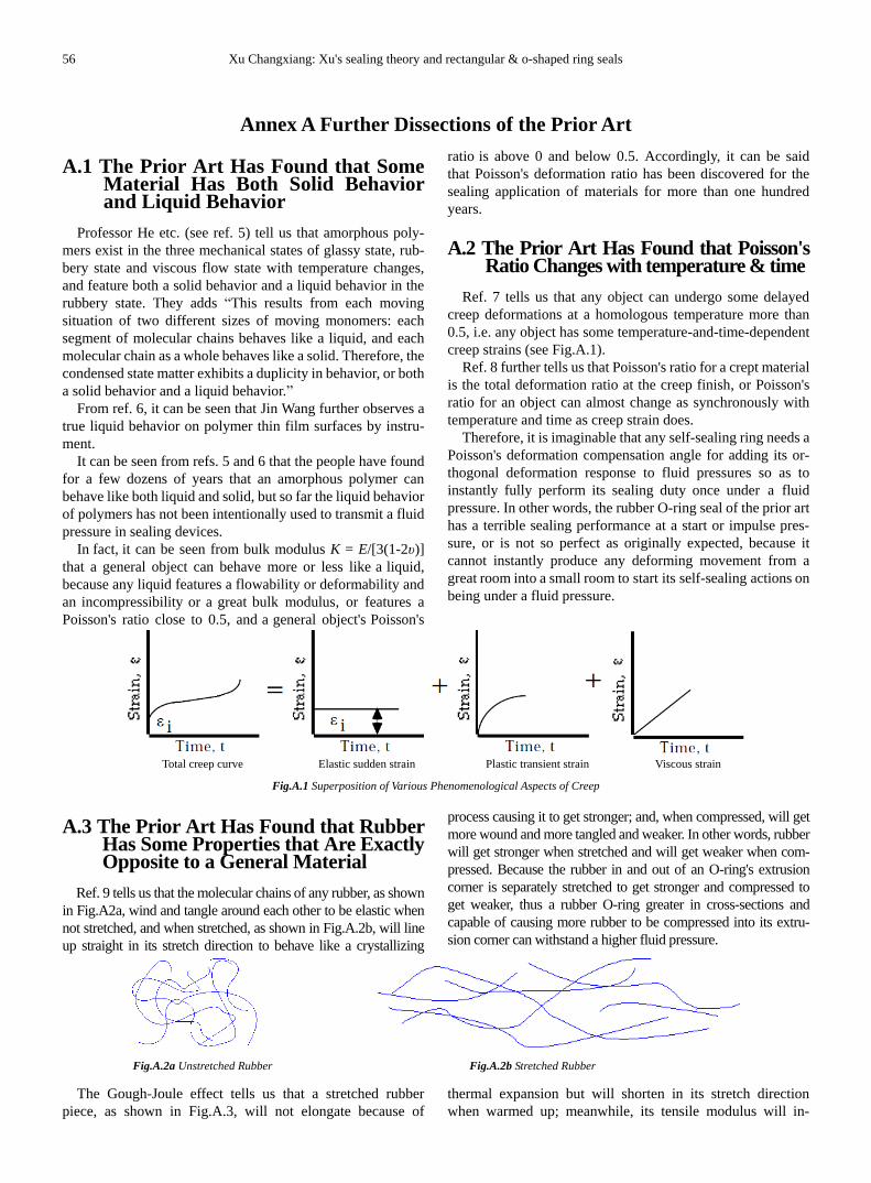
Ref. 9 tells us that the molecular chains of any rubber, as shown
in Fig.A2a, wind and tangle around each other to be elastic when
not stretched, and when stretched, as shown in Fig.A.2b, will line
up straight in its stretch direction to behave like a crystallizing
process causing it to get stronger; and, when compressed, will get
more wound and more tangled and weaker. In other words, rubber
will get stronger when stretched and will get weaker when com-
pressed. Because the rubber in and out of an O-ring's extrusion
corner is separately stretched to get stronger and compressed to
get weaker, thus a rubber O-ring greater in cross-sections and
capable of causing more rubber to be compressed into its extru-
sion corner can withstand a higher fluid pressure.
Fig.A.2a Unstretched Rubber Fig.A.2b Stretched Rubber
The Gough-Joule effect tells us that a stretched rubber
piece, as shown in Fig.A.3, will not elongate because of
thermal expansion but will shorten in its stretch direction
when warmed up; meanwhile, its tensile modulus will in-

International Journal of Energy and Power Engineering 2016; 5(4-1): 43-58 57
crease but not decrease; for molecular chains being warmed
up are ceaselessly acquiring some energy recovering its
original wound and tangled state, and the more being
stretched the rubber and the faster the temperature rise, the
greater and the more violent the recovering shrinkage force.
Fig.A.3 Gough-Joule Effect
Obviously, a rubber O-ring in a four-side-touching assem-
bly can effectively avoid the influence or leak caused by both
any cold shrinkage or cold being stretched and any
Gough-Joule warm shrinkage of rubber O-rings.
The Report on the Space Shuttle Challenger Accident
cannot pay any attention to the influence that the O-rings have
more cold being stretched at a colder ambient temperature and
have more Gough-Joule warm shrinkage after ignition, and so
is incorrect.
A.4 Dissection of Parker's Leak Test of Rubber O-Rings of the Prior Art
A.4.1 Parker's Test Device and Results for Rubber O-Ring
Leak Rate of the Prior Art
Parker's test device for O-ring leak rate is a face seal shown in
Fig.A.4 (left), having a Butyl O-ring of 4.850 Inch I.D. at 15%,
30% and 50% squeezes tested under 0.41 MPa at 25ºC. The tests
achieve a squeeze-leak rate curve shown in Fig.A.4 (right).
Parker's leak rate curve shows that grease coatings can re-
duce the leakage of the O-ring at squeezes less than 50%, but
neither the O-ring at 50% squeeze can create a fully leak-free
joint nor its sealing performance can be further improved by
grease coatings (see Ref. 4).
r ur u
Any rubber O-ring of the
prior art can not move
to start its self-sealing
actions at a pressure
less than 0.5~1.5 MPa
because of enormous
friction, as shown right.
Any rubber O-ring of
the prior art can only
work as a weak
small-great end piston
as shown in the right,
even if moved at a
higher pressure.
b1=0.5πru(1/η-0.5η) Φd1
h 1=
k 1b 1
b1'=0.5πru(1/η-η) Φd1'
rx=ηru
h 1=
k 1b 1
'
rx=ηru
Fig.A.4 Parker's Leak Test of Rubber O-Rings
A.4.2 The Structural Problem with Rubber O-Ring Seals of
the Prior Art
As to an O-ring just assembled into its cavity (see Fig.A.4,
upper left),
∵ its assembled stress Sa = puru/rx = 0.1ru/rx (MPa), where ru
and rx are separately the cross-sectional radii of the O-ring
before and after assembled into cavity (see Clause 7),
∴ at 50% squeeze or at ru/rx = 2, Sa = 0.1ru/ra = 0.1x2 = 0.2 (MPa);
in other words, any rubber O-ring in a two-wall-touching as-
sembly shall have an assembly squeeze (1 – η) more than 50% in
order to ensure that the O-ring at least has an assembled stress not
less than 0.2 MPa that can resist atmospheric seepage through the
sealing contact, because the minimum necessary sealing stress y
for a rubber sealing element is 0.2 MPa (see Clause 4).
As to an O-ring in its working state (see Fig.A.4, lower left),
given that its cross-sectional area is the same as the area before
assembled into its cavity, then
∵ πru2 = 0.5πrx
2 + 2rxb1, where ru and rx are separately the
cross-sectional radii of the O-ring before and after as-
sembled into cavity,
∴ b1 = 0.5πru(1/η - 0.5η);
∵ (h1 = k1b1 =) k10.5πru(1/η – 0.5η) = 2ηru
or η2 = πk1/(4 + 0.5πk1) = 1/(0.5 +4/πk1)
∴ To ensure k1 > (1 + b1/d1) > 1(see Clause 8), be supposed
to ensure η2 > πk1/(4 + 0.5πk1) = 1/(0.5 +4/πk1).
It can be seen from the above inequality that at k1 = 1, η > 0.75,
(1 – η) < 25%. Hence, be supposed to ensure an O-ring a max-
imum assembly squeeze less than 25% in order to ensure that it
has an enough sealing power. In other words, any rubber O-ring
in a two-wall-touching assembly shall have an assembly squeeze
(1 – η) less than 25% so as to ensure that it shall not work as a
weak small-great end piston as shown in Fig.A.4 (left).
Therefore, it is impossible to make a rubber O-ring of the
prior art have an assembly squeeze that can at the same time
meet the necessary requirements of its initial sealing stress and
working power by designing.

58 Xu Changxiang: Xu's sealing theory and rectangular & o-shaped ring seals
A.4.3 Dissections of Parker's test results on Xu's sealing theory
—— Why can grease coating reduce the leakage of rubber
O-rings at less than 50% squeezes?
Because the minimum necessary sealing stress y of a grease
coating is 0.1 MPa, the minimum necessary sealing stress y of a
sealing element of rubber is 0.2 MPa, and a rubber O-ring whose
assembly squeeze is less than 50% can only reach an assembled
stress Sa < 0.2 MPa or does not reach its fully leak-free tight level
that can withstand 0.1 MPa (atmospheric pressure); i.e. because
grease coatings can lower the minimum necessary sealing stress
y of a rubber O-ring at less than 50% squeeze and improve its
initial sealing tightness. Note: It have been proved that a greased O-ring that was once compressed and
decompressed by a fluid pressure is worse than a not greased O-ring in
initial sealing tightness at no fluid pressure.
—— Why can the rubber O-ring seal at 50% squeeze yet
leak under 0.41 MPa?
Because any rubber O-ring at 50% squeeze just reaches an as-
sembled stress Sa = 0.2 MPa or just reaches its fully leak-free tight
contact that can withstand 0.1 MPa, and a fluid pressure of 0.41 MPa
cannot yet cause the O-ring to move or deform to automatically
reach its fully leak-free tight contact that can withstand 0.41 MPa.
—— Why cannot grease coatings further improve the rub-
ber O-ring seal at 50% squeeze?
Because what the rubber O-ring at 50% squeeze needs for its
fully leak-free tight contact under 0.41 MPa is only that its
cross-section can have an adding movement/deformation that
can cause it to reach a tighter contact, but the fluid pressure of
0.41 MPa cannot cause its cross-section to move/deform.
—— Conclusions
Parker's leak tests have proved that the minimum necessary
sealing stress y of a rubber sealing element is 0.2 MPa, the
minimum necessary sealing stress y of a grease coating is less
than 0.2 MPa, and a rubber O-ring whose assembly squeeze is
up to 50% just reaches its fully leak-free tight level that can
withstand 0.1 MPa (atmospheric pressure); or Parker's leak
tests have proved Xu's sealing theory scientific.
A.5 The O-Ring Seal Standards of the Prior Art Far Away from the ABC of Seals
The isotropic softness, incompressibility and elasticity of
rubber cause its O-ring to be like a ring of shaped elastic liquid,
whose internal pressure raises and lowers synchronously with its
external pressure. Given that there can only be a uniform fluid
pressure on a rubber O-ring in its cavity, its fluid compression
surface always resists the compression from its external fluid
pressure by a single round surface with a uniform compressive
ability, and its extrusion surface always resists the stretching from
its internal pressure by another single round surface with a uni-
form tensile ability. In other words, both the fluid compression
surface and the free extrusion surface of a rubber O-ring can only
be a single round surface that is tangential to its cavity walls.
However, Patent US 2180795 in 1937 explicitly taught us
that a rubber O-ring is perfectly circular in cross section prior
to its assembly and insertion in a cylinder, and, when slid with
the piston into the cylinder, compressed to the shapes with
somewhat of an ellipsoidal or rather square or rectangular cross
section. As shown in Fig.A.5, ISO 3601:2008 (left) deems the
rubber O-rings in a two-wall-touching assembly ellipsoidal in
section, and Parker (right) also deems them somewhat rec-
tangular. In other words, for about 75 years the prior art of
rubber O-ring seals has not deemed the fluid compression
surface and the free extrusion surface of a rubber O-ring in its
cavity two different radii of single round surfaces tangent to its
cavity wall; i.e. the prior art has not known how for a rubber
O-ring to deform or work, or what fluid pressure limit or rating
for a rubber O-ring to withstand, or how to design a rubber
O-ring seal. Actually, a rubber O-ring is virtually a length of
water-filled soft thin wall tubing, which has a definite working
pressure limit or rating that can be calculated.
Therefore, all the technical standards of rubber O-ring seals
were drafted at will before knowing their relative ABC, having
no coordination. For example, Clause 6.3 of ISO 3601-2:2008
specifies, “Housing fill of the installed O-ring should not be
more than 85 % to allow for possible O-ring thermal expansion,
volume swell due to fluid exposure and effects of tolerances.”
This specification is thoroughly neglected in ISO 6149. If the
specification in ISO 3601is scientific, there should be no ISO
6149 at all. Perhaps, it is because it is diametrically against the
ISO 3601 that it has to declare “conformance to the dimen-
sional information in ISO 6149 does not guarantee rated per-
formance” to evade its responsibility.
Fig.A.5 The O-Ring's Sectional Shape Mistaken in ISO 3601 (left) and in Parker's O-Ring Handbook (right)
Related Documents