XUM2ApXBp Photo-electric sensors - Miniature design Wiring precaution www.tesensors.com 1/7 01 - 2021 xxxxxxxx_00 Electrical equipment should be installed, operated and maintained only by qualified personnel. No responsibility is assumed by Schneider Electric for any consequences arising out of the use of this material. © 2021 Schneider Electric. “All Rights Reserved.” We welcome your comments about this document. You can reach us through the customer support page on your local website. Package Content (Example) http://qr.tesensors.com/XU0008 Thru-beam Scan the Qr-code to access this Instruction Sheet in different languages or you can download it from our website at: www.tesensors.com NPN - M8 Connector : XUM2ANXBM8 ( * ) PNP - M8 Connector : XUM2APXBM8 ( * ) NPN - 2 m Cable : XUM2ANXBL2 ( * ) PNP - 2 m Cable : XUM2APXBL2 ( * ) T R T R T R T R T R T R T R Sensitivity Control Stability LED (green) Power ON LED (green) Output status LED (yellow) LEDs and Setting Mounting and Tightening torques Screws M3 (supplied with the bracket) Screws M3 (not provided) XUZA50 Wiring diagrams M8 Connector - 4 pins 1 3 2 4 UNINTENDED EQUIPMENT OPERATION CAUTION Do not apply excessive impact on the sensor during the installation process, so as to prevent damage or deterioration in the degree of protection. Failure to follow these instructions can result in injury or equipment damage. mm in. 100 3.93 Transmitter Transmitter Receiver Receiver + - 3 1 4 + - 3 1 XUM2APXBM8 XUM2APXBL2 XUM2ANXBM8 XUM2ANXBL2 PNP + - BU BN BK + - BU BN PNP + - 3 1 + - 3 1 4 NPN + - BU BN + - BU BN BK NPN ( * ): Sold by pair Failure to follow these instructions can result in death, serious injury, or equipment damage. WARNING IMPROPER SETUP OR INSTALLATION p This equipment must only be installed and serviced by qualified personnel. p Read, understand, and follow the compliance below, before installing the XUM Photo-electric sensor. p Do not tamper with or make alterations on the unit. p Comply with the wiring and mounting instructions. p Check the connections and fastening during maintenance operations. p The proper functioning of the XUM photoelectric sensor and its operating line must be checked regularly and according to the application (for example number of operations, level of environmental pollution, etc.). DANGER HAZARD OF ELECTRIC SHOCK, EXPLOSION OR ARC FLASH p Disconnect all power before servicing equipment. p Do not connect this device to AC power. p The power voltage must not exceed the rated range. Failure to follow these instructions will result in death or serious injury. Light-On / Dark-On Setting 0,4...0,5 Nm (3.54...4.43 lb-in) 0,4...0,5 Nm (3.54...4.43 lb-in) 0,2...0,4 Nm (1.77... 3.54 lb-in) XU M 2 A P X BM8 2 m Cable - 3 wires Do not pull on the sensor cable so as to prevent damage or deterioration in the degree of protection UNINTENDED EQUIPMENT OPERATION NOTICE Failure to follow these instructions can result in equipment damage.

Welcome message from author
This document is posted to help you gain knowledge. Please leave a comment to let me know what you think about it! Share it to your friends and learn new things together.
Transcript

XUM2ApXBpPhoto-electric sensors - Miniature design
Wiring precaution
www.tesensors.com
1/701 - 2021xxxxxxxx_00
Electrical equipment should be installed, operated and maintained only by qualified personnel.No responsibility is assumed by Schneider Electric for any consequences arising out of the use of this material.© 2021 Schneider Electric. “All Rights Reserved.”
We welcome your comments about this document. You can reach us through the customer support page on your local website.
Package Content(Example)
http://qr.tesensors.com/XU0008
Thru-beam
Scan the Qr-code to access this Instruction Sheet in different languages or you can download it from our website at: www.tesensors.com
NPN - M8 Connector : XUM2ANXBM8 (*)PNP - M8 Connector : XUM2APXBM8 (*)
NPN - 2 m Cable : XUM2ANXBL2 (*)PNP - 2 m Cable : XUM2APXBL2 (*)
T
R
T
R
T R
T R T R
T R T R
SensitivityControl
Stability LED(green)
Power ON LED(green)
Output status LED(yellow)
LEDs and SettingMounting and Tightening torquesScrews M3
(supplied withthe bracket) Screws M3
(not provided)
XUZA50
Wiring diagrams
M8 Connector - 4 pins
1 3
2 4
UNINTENDED EQUIPMENT OPERATION
CAUTION
Do not apply excessive impact on the sensorduring the installation process, so as to preventdamage or deterioration in the degree of protection. Failure to follow these instructions can resultin injury or equipment damage.
mmin.
100
3.93
Transmitter
Transmitter
Receiver
Receiver
+
-3
1
4
+
- 3
1
XUM2APXBM8 XUM2APXBL2
XUM2ANXBM8 XUM2ANXBL2
PNP
+
-BU
BN
BK
+
- BU
BN
PNP
+
- 3
1 +
-3
14
NPN
+
- BU
BN +
-BU
BNBK
NPN
(*): Sold by pair
Failure to follow these instructions can result in death, serious injury, or equipment damage.
WARNINGIMPROPER SETUP OR INSTALLATIONp This equipment must only be installed and serviced by qualified personnel.p Read, understand, and follow the compliance below, before installing the XUM Photo-electric sensor.p Do not tamper with or make alterations on the unit.p Comply with the wiring and mounting instructions.p Check the connections and fastening during maintenance operations.p The proper functioning of the XUM photoelectric sensor and its operating line must be checked regularly and according to the application (for example number of operations, level of environmental pollution, etc.).
DANGERHAZARD OF ELECTRIC SHOCK, EXPLOSION OR ARC FLASHp Disconnect all power before servicing equipment.p Do not connect this device to AC power.p The power voltage must not exceed the rated range.Failure to follow these instructions will result in death or serious injury.
Light-On / Dark-OnSetting0,4...0,5 Nm
(3.54...4.43 lb-in) 0,4...0,5 Nm(3.54...4.43 lb-in)
0,2...0,4 Nm(1.77...
3.54 lb-in)
XUM2APXBM8
2 m Cable - 3 wires
Do not pull on the sensor cable so as to prevent damage or deterioration in the degree of protection
UNINTENDED EQUIPMENT OPERATION NOTICE
Failure to follow these instructions can result in equipmentdamage.

XUM2ApXBpDimensions mm
in.
2/7xxxxxxxx_00
www.tesensors.com
1 mm = 0.0397 in.
2xM3
31,5
1.24
ø3,5
ø0.14
19,50.77
25,4 1
10,8
0.43 3,4
0.13
1,2
0.05
M8
Transmitteror
Receiver
17,1
0.67
19,2
0.76
7,40.29
10,8
0.43
8,20.32
11,80.46
2,9
0.11
Width “A”
0,5 0.02
mm in.
1 0.04
0.082
Horizontal slitVertical slit Round slit
XUZDVM05 XUZDHM05 XUZDRM05
XUZDVM10 XUZDHM10 XUZDRM10
XUZDVM20 XUZDHM20 XUZDRM20
XUZA50
5°
180.71
3 x 40.12 x 0.16
30.12
41 1.6125
,5 1
4,5
0.18
40.
16
7,5
0.3
3,20.138,3
0.33
150.59 8,2 x 3,2
0.32 x 0.13
XUZASM02
15,3
0.6
25,4 1
8,4
0.33
41°
4,50.18 12
0.47 50.2
4,5
0.18
1,20.05 14,6
0.57
34,8
1.37
55 2.17
10,6
0.42
21,50.8512,70.5
60.
24 17,60.69
ø3,4ø0.13
XUZASM04
140.558
0.31 3,40.05
40.
16
32 1.26 24 0.94
7 0.28
7 0.28
301.18 25
0.985
0.2
70.28
1,20.05
25,4 1
3,2
0.13
10°
XUZASM03
25 0.98
25 0.98
3,2
0.13
25 0.98
190.75
14°4
0.167°
60.24
552.1739
1.54
19 0.75
29 1.14
70.28
20°
40°
5,5
0.22
5,5
0.22
R9,5R0.3
7
6,20.24
46 1.81
180.71
130.51
2,5
0.1
18 0.71
8,20.32
32,1
1.26
A
6,10.24
0,30.01
XUZDVM05XUZDVM10XUZDVM20
A
8,20.32
32,1
1.26
4,4
0.17
6,50.26
XUZDHM05XUZDHM10XUZDHM20
8,20.32
32,1
1.26
4,4
0.17 øA
XUZDRM05XUZDRM10XUZDRM20
mmin.

XUM2ApXBp
3/7xxxxxxxx_00
www.tesensors.comAccessories
XUZASM04
XUZASM03
XUZASM02
XUZA50
Mounting Brackets (to order separately)
Screws M3 × 12 (supplied with the brackets)

XUM2ApXBp
4/7xxxxxxxx_00
www.tesensors.comAccessories (continued)
Pre-Wired Female Connectors
Slits for thru-beam model (to order separately)
0,512
0,512
0,512
0.020.040.080.020.040.080.020.040.08
2,53,5
623
5,50,81,52,5
8.211.519.76.569.84182.624.928.2
11,53,50,71,5
30,08
0,31,2
3.284.9211.52.34.929.840.260.983.94
777777555
0.280.280.280.280.280.280.20.20.2
0,512
0,40,71,50,30,61,5
0.020.040.080.0160.0280.060.0120.0240.06
XUZDHM05XUZDHM10XUZDHM20
XUZDVM05XUZDVM10XUZDVM20
XUZDRM05XUZDRM10XUZDRM20
Slit and Sensing Range
Slit mounting
A slit, which changes the beam size of through-beam sensors, can easily be attached to the sensing side of the through-beam projector and receiver.Three different slit widths are available.
Note: Used on one side: Slit is attached to the receiver only.
Slit Sensing Range Minimum DetectableObject Width
ReferenceWidth: A Used on Used on Used on Used on
R TR + R TR +
T R
A
A øA
mm in. mm in. mm in.m ft. m ft.
M8, 4 pins M8 - M12,4 pins
Cable length
2 m / 6.56 ft.
5 m / 16.4 ft.
Jumper length
1 m / 3.28 ft.
2 m / 6.56 ft.
10 m / 32.8 ft.
PVC
PVC cable for general usePUR cable for severe industrial environments
PUR PVC PUR PUR
XZCPV0941L2
XZCPV0941L5
XZCPV0941L10
XZCPV1041L2
XZCPV1041L5
XZCPV1041L10
XZCP0941L2
XZCP0941L5
XZCP0941L10
XZCP1041L2 XZCR1509041J1
XZCR1509041J2
XZ CR1510041J1
XZCR1510041J2XZCP1041L5
XZCP1041L10
PUR

XUM2ApXBp
5/7xxxxxxxx_00
www.tesensors.com
Stability LED (green):ON
- Translate the transmitter or receiver, up/down and left/right. When the setting is optimal, the stability indicator (green) is lit.- Check sensor operation with the object and adjust the sensor, if necessary.
Sensor Position Adjustment
Sensor Sensitivity Adjustment
Output mode setting: Light-On or Dark-On (Light-On by default)
R
T
R
Opaqueobject
Opaqueobject
Light-On /Normally Closed
Dark-On /Normally Open
Transmitter Receiver Transmitter Receiver
Transmitter Receiver Transmitter Receiver
The Output is ON
The Output is ON
The Output is OFF
The Output is OFF
T
R
R
R
R
min.max.A
min.max.A
B
min.max.A
BC
Light-on Dark-on
1-Before settings, start with the potentiometer the maximum position (resulting to point A).
2-Connect the two sensors to the power supply (see page 1 for the wire connection & page 7 for the power voltage)Align the two sensors, as shown on the picture, until seeing the output led (yellow) & the stability led (green) switch on.
3-On the receiver, turn the potentiometer counter-clockwise until the stability led (green) switch off (resulting to point B).
4-Set the middle point between the point A and B (resulting to point C).The receiver is set and ready to detect

XUM2ApXBp
6/7xxxxxxxx_00
www.tesensors.comDetection curves
Through-beam Type SA1E-T (Infrared LED w/sensitivity adjustment)SA1E-TA (Red LED w/sensitivity adjustment)
• E )tils tuohtiW( elgnA•)tils tuohtiW( tnemecalpsiD laretaL•)tils tuohtiW( niaG ssecx
• Excess Gain (With vertical slit) • Excess Gain (With horizontal slit) • Excess Gain (With round slit)
• Lateral Displacement (With 0.5-mm vertical slit) • Lateral Displacement (With 1.0-mm vertical slit) • Lateral Displacement (With 2.0-mm vertical slit)
• Lateral Displacement (With 0.5-mm horizontal slit) • Lateral Displacement (With 1.0-mm horizontal slit) • Lateral Displacement (With 2.0-mm horizontal slit)
• Lateral Displacement (With ø0.5-mm round slit) • Lateral Displacement (With ø1.0-mm round slit) • Lateral Displacement (With ø2.0-mm round slit)
0 5 10
10
1
100
15 20Sensing Distance (m)
Exce
ss G
ain
OperationLevel
Sensing Distance X (m)La
tera
l Dis
plac
emen
t Y (m
m)
-600
-400
-200
0
200
400
600
0 5 10 15 20
X
Y
-60
-40
-20
0
20
40
60
0
XX
θ
Sensing Distance X (m)
Rec
eive
r Ang
le θ
(º)
Exce
ss G
ain
Sensing Distance (m)
1
10
100
0 1 2 3 4 5 6 7 8
1.0 mmslits onboth sides
2.0 mmslits onboth sides0.5 mm
slits onboth sidesOperation
Level
Sensing Distance (m)
Exce
ss G
ain
1
10
100
0 1 2 3 4 5 6 7
2.0 mmslits onboth sides
1.0 mmslits onboth sides
0.5 mmslits onboth sides
OperationLevel
Exce
ss G
ain
1
10
100
0 0.5 1.0 1.5 2.0 2.5 3.0
ø2.0mmslits onboth sides
ø0.5mmslits onboth sides
ø1.0mmslits onboth sides
Sensing Distance (m)
OperationLevel
Sensing Distance X (m)
Late
ral D
ispl
acem
ent Y
(mm
)
-20010 2 3 4 5 6
-150
-100
-50
50
0
100
150
200
XX
YY
Slits onboth sides
One slit onreceiver
Sensing Distance X (m)
Late
ral D
ispl
acem
ent Y
(mm
)
-250-200-150-100-50
050
100150200250
0 2 4 6 8XX
YY
One slit onreceiver
Slits onboth sides
Sensing Distance X (m)
Late
ral D
ispl
acem
ent Y
(mm
)
-400-300
-200
-100
0
100
200
300
400
0 2 4 6 8 10 12XX
YY
One slit onreceiver
Slits onboth sides
Late
ral D
ispl
acem
ent Y
(mm
)
Sensing Distance X (m)
-150
-100
-50
0
50
100
150
0 1 2 3 4 5
X
Y
One slit onreceiver
Slits onboth sides
Late
ral D
ispl
acem
ent Y
(mm
)
Sensing Distance X (m)
-200
-150
-100
-50
0
50
100
150
200
0 1 2 3 4 5 6 7
X
Y
One slit onreceiver
Slits onboth sides
Late
ral D
ispl
acem
ent Y
(mm
)
Sensing Distance X (m)
-250-200-150-100-50
050
100150200250
0 2 4 6 8 10
X
Y
One slit onreceiver
Slits onboth sides
Late
ral D
ispl
acem
ent Y
(mm
)
Sensing Distance X (m)
-50-40-30-20-10
01020304050
0 0.2 0.4 0.6 0.8 1.0 1.2 1.4 1.6
X
Y
One slit onreceiver
Slits onboth sides
Late
ral D
ispl
acem
ent Y
(mm
)
Sensing Distance X (m)
-80
-60
-40
-20
0
20
40
60
80
0 0.5 1.0 1.5 2.0 2.5 3.0 3.5
X
Y
One slit onreceiver
Slits onboth sides
Late
ral D
ispl
acem
ent Y
(mm
)
Sensing Distance X (m)
-150
-100
-50
0
50
100
150
0 1 2 3 4 5 6
X
Y
One slit onreceiver
Slits onboth sideswa
iting
the
true
curv
es
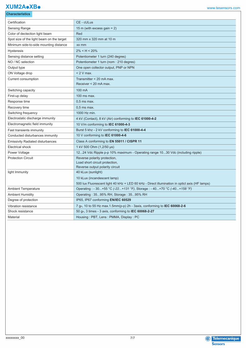
Characteristics
XUM2ApXBp
7/7xxxxxxxx_00
www.tesensors.com
Power Voltage
Sensing Range
12...24 Vdc Ripple p-p 10% maximum - Operating range 10...30 Vdc (including ripple)
15 m (with excess gain = 2)
Protection Circuit
Ambient Temperature
Ambient HumidityDegree of protection
Material
Reverse polarity protection, Load short circuit protection,Reverse output polarity circuit
Operating : - 30...+55 °C (-22...+131 °F), Storage : - 40...+70 °C (-40...+158 °F)
Operating : 35...95% RH, Storage : 35...95% RHIP65, IP67 conforming EN/IEC 60529
Housing : PBT, Lens : PMMA, Display : PC
Electrostatic discharge immunity 4 kV (Contact), 8 kV (Air) conforming to IEC 61000-4-2Electromagnetic field immunity 10 V/m conforming to IEC 61000-4-3Fast transients immunity Burst 5 khz - 2 kV conforming to IEC 61000-4-4Conducted disturbances immunity 10 V conforming to IEC 61000-4-6
Emissivity Radiated disturbances Class A conforming to EN 55011 / CISPR 11Electrical shock 1 kV 500 Ohm (1,2/50 µs)
Vibration resistance 7 gn, 10 to 55 Hz max.1.5mm(p-p) 2h - 3axis, conforming to IEC 60068-2-6Shock resistance 50 gn, 3 times - 3 axis, conforming to IEC 60068-2-27
Color of dectection light beam RedSpot size of the light beam on the target 320 mm x 320 mm at 10 m
xx mm
Hysteresis 2% < H < 20%
Sensing distance setting Potentiometer 1 turn (240 degres)NO / NC selection Potentiometer 1 turn (nom : 210 degres)Output type One open collector output, PNP or NPNON Voltage drop < 2 V max.
Switching capacity 100 mAFirst-up delay 100 ms max.Response time 0,5 ms max.
Recovery time 0,5 ms max.Switching frequency 1000 Hz min.
Certification CE - cULus
light Immunity
Minimum side-to-side mounting distance
40 kLux (sunlight)
10 kLux (incandescent lamp)500 lux Fluorescent light 40 kHz + LED 60 kHz - Direct illumination in opticl axis (HF lamps)
Current consumption Transmitter < 20 mA max.Receiver < 20 mA max.
Related Documents