XTend vB Radio Frequency (RF) Module User Guide

Welcome message from author
This document is posted to help you gain knowledge. Please leave a comment to let me know what you think about it! Share it to your friends and learn new things together.
Transcript

XTend vBRadio Frequency (RF) Module
User Guide

Revision history—90001478
Revision Date Description
A December2015
Baseline release of the document.
B May 2016 Added information on the Australian variant. Updated cyclic sleep numbers.Added the HS command.
Trademarks and copyrightDigi, Digi International, and the Digi logo are trademarks or registered trademarks in the UnitedStates and other countries worldwide. All other trademarks mentioned in this document are theproperty of their respective owners.© 2018 Digi International Inc. All rights reserved.
DisclaimersInformation in this document is subject to change without notice and does not represent acommitment on the part of Digi International. Digi provides this document “as is,” without warranty ofany kind, expressed or implied, including, but not limited to, the implied warranties of fitness ormerchantability for a particular purpose. Digi may make improvements and/or changes in this manualor in the product(s) and/or the program(s) described in this manual at any time.
WarrantyTo view product warranty information, go to the following website:www.digi.com/howtobuy/terms
Send commentsDocumentation feedback: To provide feedback on this document, send your comments [email protected].
Customer supportDigi Technical Support: Digi offers multiple technical support plans and service packages to help ourcustomers get the most out of their Digi product. For information on Technical Support plans andpricing, contact us at +1 952.912.3444 or visit us at www.digi.com/support.
XTend vB RF Module User Guide 2

Contents
XTend vB RF Module User GuideApplicable firmware and hardware 9XTend replacement numbers 9Certification overview 9
Technical specificationsGeneral specifications 11Performance specifications 11Networking specifications 12Power requirements 12
Cyclic sleep current (mA, average) 12Regulatory conformity summary 13
HardwareConnect the hardware 15Mechanical drawings 16Pin signals 16
ModesTransparent and API operating modes 20
Transparent operating mode 20API operating mode 20
Additional modes 20Command mode 20Binary Command mode 20Idle mode 20Receive mode 21Sleep modes 21Shutdown mode 21Transmit mode 21Enter Command mode 21Send AT commands 22Exit Command mode 22Enter Binary Command mode 22Exit Binary Command mode 23Binary Command mode FAQs 23
XTend vB RF Module User Guide 3

XTend vB RF Module User Guide 4
Sleep modes 24Pin Sleep (SM = 1) 24Serial Port Sleep (SM = 2) 25Cyclic Sleep Mode (SM = 4-8) 25
OperationSerial interface 28UART data flow 28Serial data 28Flow control 28
Data In (DIN) buffer and flow control 29Data Out (DO) buffer and flow control 30
Configure the XTend vB RF ModuleConfigure the device using XCTU 32
Program the XTend vB RF ModuleProgramming examples 33
Connect the device to a PC 33Modify a device address 33Restore device defaults 34Send binary commands 34Query binary commands 35
CommandsCommand mode options 38
AT (Guard Time After) 38BT (Guard Time Before) 39CC (Command Sequence Character) 39CF (Number Base) 39CN (Exit Command Mode) 40CT (Command Mode Timeout) 40E0 (Echo Off) 41E1 (Echo On) 41
Diagnostic commands 41%V (Board Voltage) 41DB command 42GD (Receive Good Count) 42HV (Hardware Version) 43RC (Ambient Power - Single Channel) 43RE (Restore Defaults) 43RM (Ambient Power) 45RP (RSSI PWM Timer) 45SH (Serial Number High) 46SL (Serial Number Low) 46TP (Board Temperature) 47TR command 47VL (Firmware Version - Verbose) 47VR (Firmware Version - Short) 48

XTend vB RF Module User Guide 5
WA (Active Warning Numbers) 48WN (Warning Data) 49WS (Sticky Warning Numbers) 50HS (Hardware Series) 51
MAC/PHY commands 51AM (Auto-set MY) 51DT (Destination Address) 51HP (Preamble ID) 52ID (Network ID) 52MK command 53MT (Multi-transmit) 53MY (Source Address) 54RN (Delay Slots) 54RR command 55TT (Streaming Limit) 55
RF interfacing commands 55BR (RF Data Rate) 56FS (Forced Synch Time) 56MD (RF Mode) 57PB (Polling Begin Address) 57PD command 57PE (Polling End Address) 58PK command 58PL command 59TX (Transmit Only) 59
Security commands 60KY command 60
Serial interfacing commands 60API Enable 60BD (Interface Data Rate) 61CD (GP02 Configuration) 62CS (GP01 Configuration) 63FL (Software Flow Control) 63FT command 63NB command 64RB (Packetization Threshold) 64RO (Packetization Timeout) 65RT (GPI1 Configuration) 65SB command 66
Sleep commands 66FH (Force Wakeup Initializer) 66HT (Time before Wake-up Initializer) 67LH (Wakeup Initializer Timer) 67PW (Pin Wakeup) 68SM (Sleep Mode) 68ST command 69
Special commands 69WR (Write) 69
API operationAPI mode overview 72
API frame specifications 72Calculate and verify checksums 74Escaped characters in API frames 74

XTend vB RF Module User Guide 6
Frame descriptions 76RF Module Status frame - 0x8A 77Transmit Request: 16-bit address frame - 0x01 78Transmit Status frame - 0x89 80Receive Packet: 16-bit address frame - 0x81 81
Regulatory informationFCC (United States) 84
OEM labeling requirements 84FCC notices 84Dipole antennas 85Yagi antennas 85Omni-directional base station antennas 86Dome antennas 88Monopole antennas 88Antenna options 90
Industry Canada (IC) 95Labeling requirements 95Transmitters for detachable antennas 95Detachable antennas 95
ACMA (Australia) 96Power requirements 96
Network configurationsNetwork topologies 98
Point-to-point networks 98Point-to-multipoint networks 98Peer to peer networks 99
Addressing 100Address recognition 101
Basic communications 101Streaming mode (default) 101Multi-transmit mode 102Repeater mode 103Polling mode (basic) 107
Acknowledged communications: Acknowledged mode 108Acknowledged mode connection sequence 108Polling mode (acknowledged) 109
Development KitDevelopment Kit contents 112Interface hardware 112XTIB-R RS-232/485 Interface Board 113
Configuration switch 113I/O and Power LEDs 114Serial port 114RSSI LEDs 114Power connector 114XTIB-R DIP switch 114
Adapters 116

XTend vB RF Module User Guide 7
NULL Modem Adapter (male-to-male) 116NULL Modem Adapter (female-to-female) 117Serial Loopback Adapter 117Male DB-9 to RJ-45 Adapter 118Female DB-9 to RJ-45 Adapter 118
Interface protocols 118RS-232 operation 119RS-485 (2-wire) operation 121RS-485 (4-wire) and RS-422 operation 123
XTend vB RF Module User Guide
The XTend vB RF Module was engineered to provide customers with an easy-to-use radio frequency(RF) solution that provides reliable delivery of critical data between remote devices. The moduletransfers a standard asynchronous serial data stream, operates within the ISM 900 MHz frequencyband and offers two RF data rates of 10 kb/s and 125 kb/s for the United States and Canada variant.It offers two RF data rates of 10 kb/s and 105 kb/s for the Australia variant.
Applicable firmware and hardware 9XTend replacement numbers 9Certification overview 9
XTend vB RF Module User Guide 8
XTend vB RF Module User Guide Applicable firmware and hardware
XTend vB RF Module User Guide 9
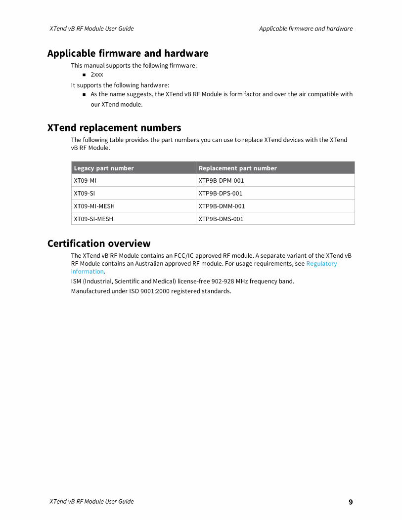
Applicable firmware and hardwareThis manual supports the following firmware:
n 2xxx
It supports the following hardware:n As the name suggests, the XTend vB RF Module is form factor and over the air compatible with
our XTend module.
XTend replacement numbersThe following table provides the part numbers you can use to replace XTend devices with the XTendvB RF Module.
Legacy part number Replacement part number
XT09-MI XTP9B-DPM-001
XT09-SI XTP9B-DPS-001
XT09-MI-MESH XTP9B-DMM-001
XT09-SI-MESH XTP9B-DMS-001
Certification overviewThe XTend vB RF Module contains an FCC/IC approved RF module. A separate variant of the XTend vBRF Module contains an Australian approved RF module. For usage requirements, see Regulatoryinformation.ISM (Industrial, Scientific and Medical) license-free 902-928 MHz frequency band.Manufactured under ISO 9001:2000 registered standards.
Technical specifications
The following tables provide the device's technical specifications.
WARNING! When operating at 1 W power output, observe a minimum separationdistance of 6 ft (2 m) between devices. Transmitting in close proximity of other devicescan damage the device's front end.
General specifications 11Performance specifications 11Networking specifications 12Power requirements 12Regulatory conformity summary 13
XTend vB RF Module User Guide 10

Technical specifications General specifications
XTend vB RF Module User Guide 11
General specificationsThe following table describes the general specifications for the devices.
Specification Value
Dimensions (RF/pin connectors not included) 3.70 x 6.10 x 0.48 cm (1.457 x 2.402 x 0.190 in)
Weight 16 g
RoHS Compliant
Manufacturing ISO 9001:2000 registered standards
Connector 20 pin 2 mm pitch header
Antenna connector options MMCX or RPSMA
Antenna impedance 50 Ω unbalanced
Operating temperature -40 °C to 85 °C
Maximum input RF level at antenna port 6 dBm
Digital outputs 2 output lines
Performance specificationsThe following table describes the performance specifications for the devices.
Specification Value
Frequency range 902 to 928 MHz US/Canada915 to 928 MHz Australia
RF data rate (software selectable) 10 kb/s to 125 kb/s US/Canada10 kb/s to 105 kb/s Australia
Transmit power (software selectable) Up to 30 dBm (see Power requirements)
Channels 10 hopping sequences share 50 frequencies
Outdoor line of sight 10 kb/s Up to 40 miles1
125 kb/s Up to 7 miles
Indoor range line of sight 10 kb/s Up to 1,000 feet (300 m)
125 kb/s Up to 500 feet (150 m)
Receiver sensitivity 10 kb/s -110 dBm
125 kb/s -100 dBm
UART data rate 1200-230400 baud
1Estimated based on a 9 mile range test with dipole antennas.

Technical specifications Networking specifications
XTend vB RF Module User Guide 12
Networking specificationsThe following table provides the networking specifications for the device.
Specification Value
Modulation Frequency Shift Keying
Spread Spectrum Frequency Hopping Spread Spectrum (FHSS)
Supported NetworkTopologies (softwareselectable)
Peer-to-peer (master/slave relationship not required), point-to-point/point-to-multipoint, mesh
Encryption 256-bit or 128-bit AES CBC encryption depending on region. 256-bit is onlyavailable on the North America variant. 128-bit is only available oninternational variants.
Power requirementsThe following table describes the power requirements for the XTend vB RF Module.Specifications are given at 5 V, 25 °C unless otherwise noted.
Requirement Value
Supply voltage 2.8 to 5.5 VDC, 5 V typical
Receive current @ 5 V 35 mA
Transmit current See the following table
Shutdown mode current 1 µA
Sleep current < 147 µA
Cyclic sleep current (mA, average)
Sleep mode Cycle time RF data rate Cyclic sleep current (mA, average)
SM = 8 16 seconds BR = 0 0.65
BR = 1 0.23
SM = 7 8 seconds BR = 0 1.13
BR = 1 0.31
SM = 6 4 seconds BR = 0 2.06
BR = 1 0.46
SM = 5 2 seconds BR = 0 3.77
BR = 1 0.77

Technical specifications Regulatory conformity summary
XTend vB RF Module User Guide 13
Sleep mode Cycle time RF data rate Cyclic sleep current (mA, average)
SM = 4 1 second BR = 0 6.68
BR = 1 1.36
Transmit power level 21.5 dBm 27 dBm 30 dBm
Supply voltage range 2.8 to 5.5 V 3.2 to 5.5 V 4.75 to 5.5 V
Transmit current (5 V, typical) 260 mA 470 mA 710 mA
Transmit current (3.3 V, typical) 340 mA 615 mA N/A
Regulatory conformity summaryThis table describes the agency approvals for the devices.
Nation Approval
United States Contains FCC ID: MCQ-XBPSX
Canada Contains IC: 1846A-XBPSX
Australia RCM

Hardware
Connect the hardware 15Mechanical drawings 16Pin signals 16
XTend vB RF Module User Guide 14

Hardware Connect the hardware
XTend vB RF Module User Guide 15
Connect the hardwareThe following figure shows the XTend vB RF Module and accessories you need to get started and howto connect them. The accessories are in the XT09-DK development kit.
Item Description
1 Antenna, RPSMA (female)
2 XTend vB module, RPSMA version shown
3 DIP switches
4 9 V power supply
5 DB9 serial cable

Hardware Mechanical drawings
XTend vB RF Module User Guide 16
Mechanical drawingsThe following drawings show the dimensions of the device.
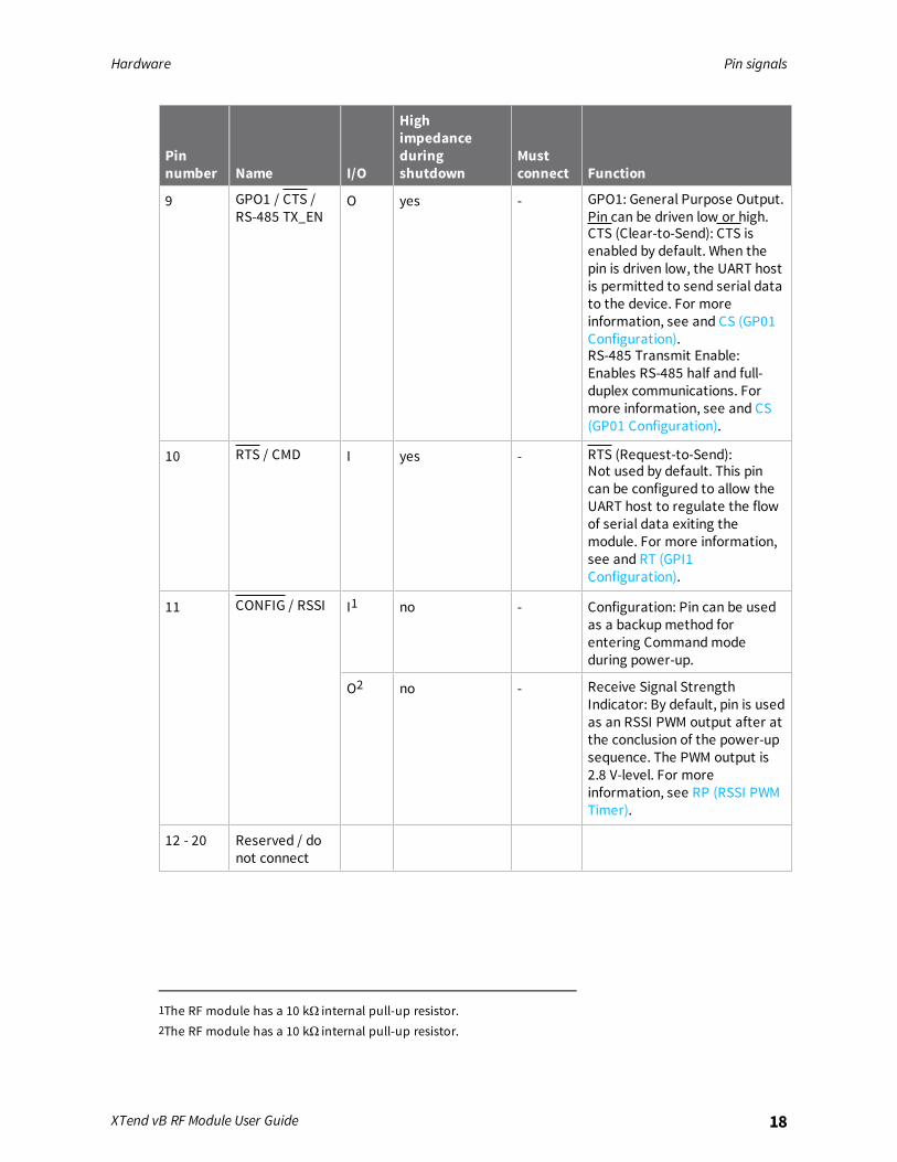
Pin signalsThe following drawing shows the location of the pins.
When integrating the module with a Host PC board, leave all lines that you do not use disconnected(floating).
Pinnumber Name I/O
Highimpedanceduringshutdown
Mustconnect Function
1 GND - - yes Ground

Hardware Pin signals
XTend vB RF Module User Guide 17
Pinnumber Name I/O
Highimpedanceduringshutdown
Mustconnect Function
2 VCC I - yes Power: 2.8 - 5.5 VDC
3 GPO2 / RXLED O - yes GPO2: General Purpose Output.Default (CD = 2) drives this pinlow.RX LED: Pin is driven high duringRF data reception; otherwise,the pin is driven low. To enablethis pin, see CD (GP02Configuration).
4 TX _PWR O yes - Transmit_Power: Pin pulseslow during RF transmission;otherwise, the pin is driven highto indicate power is on and thedevice is not in Sleep orShutdown Mode.
5 DIN I yes yes Data In: Serial data enteringthe device (from the UARThost). For more information,see .
6 DOUT O yes - Data Out: Serial data exitingthe module (to the UART host).For more information, see .
7 SHDN I no yes Shutdown: Drive this pin high toenable normal operation andlow during Shutdown.Shutdown enables the lowestpower mode available to themodule.
8 SLEEP I yes - SLEEP: By default, SLEEP is notused. To configure this pin toenable Sleep modes, refer toSleep modes, SM (Sleep Mode)and PW (Pin Wakeup).
Hardware Pin signals
XTend vB RF Module User Guide 18
Pinnumber Name I/O
Highimpedanceduringshutdown
Mustconnect Function
9 GPO1 / CTS /RS-485 TX_EN
O yes - GPO1: General Purpose Output.Pin can be driven low or high.CTS (Clear-to-Send): CTS isenabled by default. When thepin is driven low, the UART hostis permitted to send serial datato the device. For moreinformation, see and CS (GP01Configuration).RS-485 Transmit Enable:Enables RS-485 half and full-duplex communications. Formore information, see and CS(GP01 Configuration).
10 RTS / CMD I yes - RTS (Request-to-Send):Not used by default. This pincan be configured to allow theUART host to regulate the flowof serial data exiting themodule. For more information,see and RT (GPI1Configuration).
11 CONFIG / RSSI I1 no - Configuration: Pin can be usedas a backup method forentering Command modeduring power-up.
O2 no - Receive Signal StrengthIndicator: By default, pin is usedas an RSSI PWM output after atthe conclusion of the power-upsequence. The PWM output is2.8 V-level. For moreinformation, see RP (RSSI PWMTimer).
12 - 20 Reserved / donot connect
1The RF module has a 10 kΩ internal pull-up resistor.2The RF module has a 10 kΩ internal pull-up resistor.

Modes
The XTend vB RF Module is in Receive Mode when it is not transmitting data. The device shifts into theother modes of operation under the following conditions:
n Transmit mode (Serial data in the serial receive buffer is ready to be packetized)
n Sleep mode
n Command Mode (Command mode sequence is issued (not available when using the SPI port))
Transparent and API operating modes 20Additional modes 20Sleep modes 24
XTend vB RF Module User Guide 19

Modes Transparent and API operating modes
XTend vB RF Module User Guide 20
Transparent and API operating modesThe firmware operates in several different modes. Two top-level modes establish how the devicecommunicates with other devices through its serial interface: Transparent operating mode and APIoperating mode.
Transparent operating modeDevices operate in this mode by default. The device acts as a serial line replacement when it is inTransparent operating mode. The device queues all UART data it receives through the DIN pin for RFtransmission. When a device receives RF data, it sends the data out through the DOUT pin. You can setthe configuration parameters using the AT Command interface.
API operating modeAPI operating mode is an alternative to Transparent mode. API mode is a frame-based protocol thatallows you to direct data on a packet basis. It can be particularly useful in large networks where youneed control over the operation of the radio network or when you need to know which node a datapacket originated from. The device communicates UART data in packets, also known as API frames.This mode allows for structured communications with serial devices. It is helpful in managing largernetworks and is more appropriate for performing tasks such as collecting data from multiple locationsor controlling multiple devices remotely.For more information, see API frame specifications.
Additional modesIn addition to the serial communication modes, several modes apply to how to configure devices andhow devices communicate with each other.
Command modeCommand mode is a state in which the firmware interprets incoming characters as commands.Command mode allows you to modify the device’s firmware using parameters you can set using ATcommands. When you want to read or set any setting of the device, you have to send it an ATcommand. Every AT command starts with the letters "AT" followed by the two characters that identifythe command the device issues and then by some optional configuration values. For more details, seeEnter Command mode.
Binary Command modeBinary Command mode allows you to configure a device at a faster rate than AT commands will allow.Using binary commands to send and receive parameter values is the fastest way to change theoperating parameters of the device. Use binary commands to:
n Sample signal strength and/or error counts;
n Change device addresses and channels for polling systems when a quick response is necessary.
For more details, see Enter Binary Command mode and DB command.
Idle modeWhen not receiving or transmitting data, the device is in Idle mode. During Idle mode, the devicelistens for valid data on the serial port.
Modes Additional modes
XTend vB RF Module User Guide 21
Receive modeIf a destination node receives a valid RF packet, the destination node transfers the data to its serialtransmit buffer. For the serial interface to report receive data on the RF network, that data mustmeet the following criteria:
n ID match
n Channel match
n Address match
Sleep modesSleep Modes enable the device to enter states of low-power consumption when not in use. The devicesupport three software sleep modes:
n Pin Sleep: the host controls this
n Serial Port Sleep: wakes when it detects serial port activity
n Cyclic Sleep: wakes when it detects RF activity
For more information, see Sleep modes.
Shutdown modeShutdown mode offers the lowest power mode available to the device. This is helpful for applicationsthat must keep power consumption to a minimum during idle periods.When you drive the SHDN pin (pin 7) low, it forces the device into Shutdown mode. This halts anycommunication in progress (transmit or receive) and any buffered data is lost. For any other mode ofoperation, you must drive or pull SHDN high.Immediately after the SHDN pin changes states from low to high, the device resets. After reset, theapplication must observe a delay time of <100 ms.While SHDN is driven low, the device sets the following pins to high impedance: DCD, TX_PWR, RX LED,DO and CTS. The SHDN line is driven low during shutdown.The following input pins may continue to be driven by external circuitry when in shutdown mode: RTS,DI and SHDN.Because the DO pin is set to high impedance during Shutdown, if the XTend vB RF Module is connectedto a processor, the UART receive pin could be floating. Place a weak pull-up between the device andthe microcontroller so that the application does not misinterpret noise as data.
Transmit modeWhen the device receives serial data and is ready to packetize it, the device exits Idle mode andattempts to transmit the serial data.
Enter Command modeThere are two ways to enter Command mode:
1. To get a device to switch into this mode, you must issue a unique string of text in a special way:+++ (default). When the device sees a full second of silence in the data stream followed by thestring +++ (without Enter or Return) and another full second of silence, it knows to stopsending data through and start accepting commands locally.Do not press Return or Enter after typing +++ because it will interrupt the guard time silence
Modes Additional modes
XTend vB RF Module User Guide 22
and prevent you from entering Command mode.
2. Assert (low) the CONFIG pin. Turn the power going to the device off and back on.
The device sends the letters OK followed by a carriage return out of the UART to indicate that itentered Command mode.You can customize the guard times and timeout in the device’s configuration settings. See CC(Command Sequence Character), BT (Guard Time Before) and AT (Guard Time After).
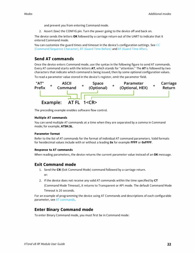
Send AT commandsOnce the device enters Command mode, use the syntax in the following figure to send AT commands.Every AT command starts with the letters AT, which stands for "attention." The AT is followed by twocharacters that indicate which command is being issued, then by some optional configuration values.To read a parameter value stored in the device’s register, omit the parameter field.
The preceding example enables software flow control.
Multiple AT commandsYou can send multiple AT commands at a time when they are separated by a comma in Commandmode; for example, ATSH,SL.
Parameter formatRefer to the list of AT commands for the format of individual AT command parameters. Valid formatsfor hexidecimal values include with or without a leading 0x for example FFFF or 0xFFFF.
Response to AT commandsWhen reading parameters, the device returns the current parameter value instead of an OK message.
Exit Command mode1. Send the CN (Exit Command Mode) command followed by a carriage return.
or:
2. If the device does not receive any valid AT commands within the time specified by CT(Command Mode Timeout), it returns to Transparent or API mode. The default Command ModeTimeout is 20 seconds.
For an example of programming the device using AT Commands and descriptions of each configurableparameter, see AT commands.
Enter Binary Command modeTo enter Binary Command mode, you must first be in Command mode:

Modes Additional modes
XTend vB RF Module User Guide 23
1. Set RT to 1; see RT (GPI1 Configuration).
2. Assert CMD by driving pin 10 high to enter Binary Command mode.
3. Disable hardware flow control.
CTS (pin ) is high when the firmware executes a command. That is why you must disable hardwareflow control, because CTS holds off parameter bytes.
Exit Binary Command modeTo exit Binary Command mode, de-assert CMD by driving pin 10 low.
Binary Command mode FAQsSince sending and receiving binary commands takes place through the same serial data path as livedata, interference between the two types of data can be a concern. Some common questions aboutusing binary commands are:
n What are the implications of asserting CMD while the device is sending or receiving live data?
You must assert the CMD pin (pin 10) in order to send binary commands to the device. You canassert the CMD pin to recognize binary commands anytime during the transmission or reception ofdata.The device only checks the status of the CMD signal at the end of the stop bit as the byte shiftsinto the serial port.The firmware does not allow control over when the device receives data, except by waiting fordead time between bursts of communication.If the command is sent in the middle of a stream of payload data, the device executes thecommand in the order it is received. If the device is continuously receiving data, it waits for a breakin the data it receives before executing the command.n After sending serial data, is there a minimum time delay before you can assert CMD?
n Is a time delay required after CMD is de-asserted before payload data can be sent?
The host must observe a minimum time delay of 100 µs after sending the stop bit of the commandbyte before the host de-asserts the CMD pin. The command executes after the host sends all of itsassociated parameters. If the device does not receive all of these parameters within 0.5 seconds,the device returns to Idle mode.
Note When a host sends parameters, they are two bytes long with the least significant byte sent first.Binary commands that return one parameter byte must be written with two parameter bytes.Example: to set PL to 3, send the following data: 0x3A 0x03 0x00 (Binary Command, LSB, MSB).
n How do I discern between live data and data received in response to a command?
To query command parameters using Binary Command mode, set the most significant bit of thebinary command. This can be accomplished by logically ORing (bit-wise) the binary command withhexadecimal 0x80. The parameter bytes are returned in hexadecimal bytes with the leastsignificant bit first (if multiple bytes are returned).Example: to query HP in Binary Command mode, instead of setting it, send 0x11 (HP binarycommand) as 0x91 with no parameter bytes.The device must be in Binary Command mode in order for the device to recognize a binarycommand; see Enter Binary Command mode.

Modes Sleep modes
XTend vB RF Module User Guide 24
If the device is not in Binary Command mode (the RT parameter value is not 1), the device does notrecognize that the CMD pin is asserted and therefore does not recognize the data as binarycommands.For an example of binary programming, see Send binary commands.
Sleep modesFor the device to enter one of the sleep modes, SM must have a non-zero parameter value, and itmust meet one of the following conditions:
1. The device is idle (no data transmission or reception) for the amount of time defined by the STparameter. ST is only active when SM = 4-5.
2. The host asserts SLEEP (pin 10). This only applies to the Pin Sleep option.
When in Sleep mode, the device does not transmit or receive data until it transitions to Idle mode.Use the SM command to enable or disable all Sleep modes. The following table shows the transitionsinto and out of Sleep modes.
Sleepmode(setting)
Transition intoSleep mode
Transition out of Sleepmode (wake)
Relatedcommands
Powerconsumption
Pin Sleep(SM = 1)
Assert (high) SLEEP pin. Amicrocontroller can shut downand wake devices via theSLEEP pin.The device completes atransmission or receptionbefore activating Pin Sleep.
De-assert (low) SLEEP pin SM < 147 µA
SerialPortSleep(SM = 2)
Automatic transition to SleepMode occurs after a user-defined period of inactivity (notransmitting or receiving ofdata).Period of inactivity is definedby the ST command.
When a serial byte isreceived on the DI pin
(SM), ST 7.3 mA
CyclicSleep(SM = 4 -8)
The device transitions in and out of Sleep Mode in cycles(you set the sleep interval of time using the SM command).The cyclic sleep interval of time must be shorter than theinterval of time that is defined by the LH command.You can for the device into Idle Mode using the SLEEP pin ifyou issue the PW command.
(SM), ST,HT, LH, PW
See Powerrequirements
The SM (Sleep Mode) command is central to setting all Sleep Mode configurations. By default, SleepModes are disabled (SM = 0) and the device remains in Idle/Receive Mode. When in this state, thedevice remains constantly ready to respond to serial or RF activity.
Pin Sleep (SM = 1)After enabling Pin Sleep, the SLEEP pin controls whether the device is active or sleeping. When thehost de-asserts SLEEP, the device is fully operational. When the host asserts SLEEP, the device

Modes Sleep modes
XTend vB RF Module User Guide 25
transitions to Sleep mode and remains in its lowest power-consuming state until the host de-assertsthe pin. This pin is only active if the device is setup to operate in this mode; otherwise the firmwareignores the pin.Once in Pin Sleep, the device de-asserts (high) CTS (pin 9) , indicating that other devices should notsend data to the device. The device also de-asserts (low) the TX_PWR line (pin 4) when the device is inPin Sleep mode.You cannot assert the SLEEP (pin9) until the transmission of the second byte has started.
Note The device completes a transmission or reception before activating Pin Sleep.
Serial Port Sleep (SM = 2)n Wake on serial port activity
Serial Port Sleep is a Sleep mode in which the device runs in a low power state until it detects serialdata on the DI pin.The ST command determines the period of time that the device sleeps. Once it receives a characterthrough the DI pin, the device returns to Idle mode and is fully operational.
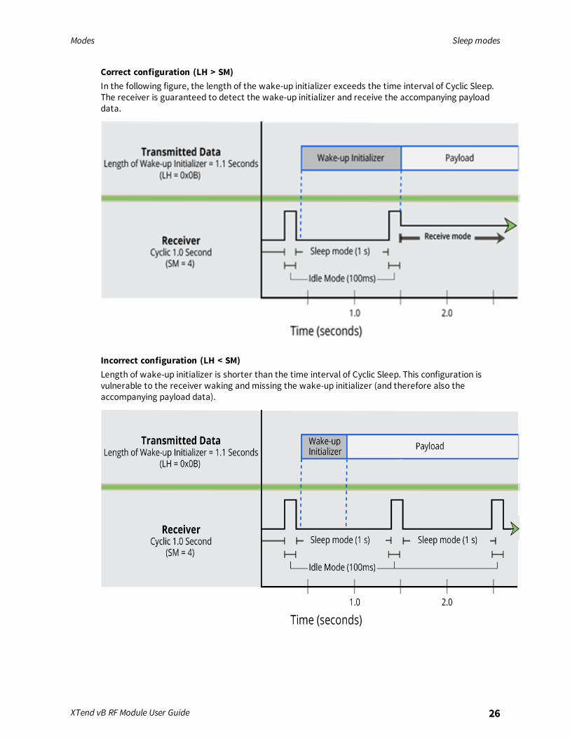
Cyclic Sleep Mode (SM = 4-8)Cyclic Sleep modes allow device wakes according to the times designated by the cyclic sleep settings.If the device detects a wake-up initializer during the time it is awake, the device synchronizes with thetransmitting device and receives data after the wake-up initializer runs its duration. Otherwise, thedevice returns to Sleep mode and continues to cycle in and out of activity until a wake-up initializer isdetected.While the device is in Cyclic Sleep mode, it de-asserts (high) CTS (pin 9) to indicate not to send data tothe device. When the device awakens to listen for data, it asserts CTS and transmits any data receivedon the DI pin. The device also de-asserts (low) the TX_PWR (pin 4) when it is in Cyclic Sleep mode.The device remains in Sleep mode for a user-defined period of time ranging from 1 second to 16seconds (SM parameters 4 through 8). After this interval of time, the device returns to Idle mode andlistens for a valid data packet. The listen time depends on the BR parameter setting. The default BRsetting of 1 requires at least a 35 ms wake time, while the BR setting of 0 requires a wake time of upto 225 ms. If the device does not detect valid data on any frequency, it returns to Sleep mode. If itdetects valid data, it transitions into Receive mode and receives the incoming RF packets. The devicethen returns to Sleep mode after a period of inactivity determined by the ST parameter.You can also configure the device to wake from cyclic sleep when the SLEEP pin is de-asserted. Toconfigure a device to operate in this manner, you must issue the PW (Pin Wake-up) command. Whenyou de-assert the SLEEP pin, it forces the device into Idle mode and it can begin transmitting orreceiving data. It remains active until it no longer detects data for the time that ST specifies, at whichpoint it resumes its low-power cyclic state.
Cyclic scanningEach RF transmission consists of an RF initializer and payload. The RF initializer contains initializationinformation and all receiving devices must wake during the wake-up initializer portion of datatransmission in order to synchronize with the transmitting device and receive the data.The cyclic interval time defined by the SM (Sleep Mode) command must be shorter than the intervaltime defined by LH (Wake-up Initializer Timer) command.
Modes Sleep modes
XTend vB RF Module User Guide 26
Correct configuration (LH > SM)In the following figure, the length of the wake-up initializer exceeds the time interval of Cyclic Sleep.The receiver is guaranteed to detect the wake-up initializer and receive the accompanying payloaddata.
Incorrect configuration (LH < SM)Length of wake-up initializer is shorter than the time interval of Cyclic Sleep. This configuration isvulnerable to the receiver waking and missing the wake-up initializer (and therefore also theaccompanying payload data).

Operation
WARNING! When operating at 1 W power output, observe a minimum separationdistance of 6 ft (2 m) between devices. Transmitting in close proximity of other devicescan damage the device's front end.
Serial interface 28UART data flow 28Serial data 28Flow control 28
XTend vB RF Module User Guide 27

Operation Serial interface
XTend vB RF Module User Guide 28
Serial interfaceThe XTend vB RF Module interfaces to a host device through a TTL-level asynchronous serial port.Through its serial port, the XTend vB RF Module can communicate with any UART voltage compatibledevice or through a level translator to any serial device, for example: RS-232/485/422 or a USBinterface board.
UART data flowDevices that have a UART interface connect directly to the pins of the XTend vB RF Module as shown inthe following figure. The figure shows system data flow in a UART-interfaced environment. Low-asserted signals have a horizontal line over the signal name.
Serial dataA device sends data to the XTend vB RF Module's UART through pin 5 DIN as an asynchronous serialsignal. When the device is not transmitting data, the signals should idle high.For serial communication to occur, you must configure the UART of both devices (the microcontrollerand the XTend vB RF Module) with compatible settings for the baud rate, parity, start bits, stop bits,and data bits.Each data byte consists of a start bit (low), 8 data bits (least significant bit first) and a stop bit (high).The following diagram illustrates the serial bit pattern of data passing through the device. Thediagram shows UART data packet 0x1F (decimal number 31) as transmitted through the device.
Flow controlThe RTS and CTS device pins provide RTS and/or CTS flow control. CTS flow control signals the host tostop sending serial data to the device. RTS flow control lets the host signal the device so it will notsend the data in the serial transmit buffer out the UART. The following diagram shows the internaldata flow, with the five most common pin signals.

Operation Flow control
XTend vB RF Module User Guide 29
The firmware has Hardware flow control (CTS) configured by default. You must configure CTS flowcontrol on the host side for it to work.You must configure Software flow control (XON) on both the host and device side for it to work.If you change the CS command from 0, then CTS flow control will not work even if you have itconfigured on the host.
Data In (DIN) buffer and flow controlWhen serial data enters the device through the DIN pin (pin 5), it stores the data in the DIN buffer untilit can process the data.When the firmware satisfies the RB and RO parameter thresholds, the device attempts to initialize anRF transmission. If the device is already receiving RF data, it stores the serial data in the device's DINbuffer.The device creates and transmits data packets when it meets one of the following conditions:
1. The device does not receive any serial characters for the amount of time set with in the ROcommand; see RO (Packetization Timeout).
2. The device receives the maximum number of characters that fits in an RF packet.
3. The device receives the Command Mode sequence.
If the DIN buffer becomes full, you must implement hardware or software flow control in order toprevent overflow (loss of data between the host and the device). To eliminate the need for flowcontrol:
1. Send messages that are smaller than the DIN buffer size. The size of the DIN buffer variesaccording to the packet size (PK parameter) and the parity setting (NB parameter) you use.
2. Interface at a lower baud rate (BD parameter) than the RF data rate of the firmware (BRparameter) of the firmware.
In the following situations, the DIN buffer may become full and overflow:1. If you set the serial interface data rate higher than the RF data rate of the device, the device
receives data from the host faster than it can transmit the data over-the-air.
2. If the device receives a continuous stream of RF data or if the device monitors data on anetwork, it places any serial data that arrives on the DIN pin (pin 5) in the DIN buffer. Ittransmits the data in the DIN buffer over-the-air when the device no longer detects RF data inthe network.

Operation Flow control
XTend vB RF Module User Guide 30
Hardware flow control (CTS)The firmware asserts CTS before the DIN buffer is full so it has time to send the signal and the hosthas time to stop sending data.When the DIN buffer is full, the firmware de-asserts CTS (high) to signal the host to stop sending data;refer to FT command and CS (GP01 Configuration).The firmware re-asserts CTS after the DIN buffer has 34 bytes of memory available.
Hardware flow control (RTS)If you enable RTS for flow control (RT parameter = 2), the device will not send data out the DOUTbuffer as long as the RTS pin (pin 10) is de-asserted.
Software flow control (XON/OFF)Use FL to enable XON/XOFF software flow control. This option only works with ASCII data.
Data Out (DO) buffer and flow controlWhen a device receives RF data, the data enters the DOUT buffer and the device sends it out the serialport to a host device. Once the DOUT buffer reaches capacity, it loses any additional incoming RF data.The DOUT buffer stores at least 2.1 kB.In the following situations, the DOUT buffer may become full and overflow:
1. If you set the interface data rate higher than the RF data rate of the device, the receivingdevice receives data from the transmitting device faster than it can send the data to the host.
2. If the host does not allow the device to transmit data out from the DOUT buffer because ofbeing held off by hardware or software flow control.
Hardware flow control (RTS)If you enable RTS for flow control (RT Parameter = 2), data will not be sent out the DO Buffer as longas RTS (pin 16) is de-asserted.
Software flow control (XOFF)You can enable XON/XOFF software flow control using the FL (Software Flow Control) Command. Thisoption only works with ASCII data.
Configure the XTend vB RF Module
Configure the device using XCTU 32
XTend vB RF Module User Guide 31

Configure the XTend vB RF Module Configure the device using XCTU
XTend vB RF Module User Guide 32
Configure the device using XCTUXBee Configuration and Test Utility (XCTU) is a multi-platform program that enables users to interactwith Digi radio frequency (RF) devices through a graphical interface. The application includes built-intools that make it easy to set up, configure, and test Digi RF devices.For instructions on downloading and using XCTU, see the XCTU User Guide.

Program the XTend vB RF Module
Programming examplesFor steps on sending AT commands to a device, refer to:
n Send AT commands
n Exit Command mode
For more information, refer to the XCTU online help at:https://docs.digi.com/display/XCTU/XCTU+Overview
Connect the device to a PCThe programming examples that follow require the installation of XCTU and a serial connection to aPC. Digi stocks connector boards to facilitate interfacing with a PC.
1. Download XCTU from the Digi website:http://www.digi.com/products/xbee-rf-solutions/xctu-software/xctu#resources
2. After the .exe file downloads to the PC, double-click the file to launch the XCTU Setup Wizard.Follow the steps in the wizard to completely install XCTU.
3. Mount the device to an interface board, then connect the assembly to a PC.
4. Launch XCTU and click the Add devices tab on the upper left corner of the screen.
5. Verify that the baud rate and parity settings of the Serial/USB port match those of the device.
Note Failure to enter Command mode is commonly due to baud rate mismatch. Ensure thatthe Baud Rate: setting on the Add radio device window matches the interface data rate of thedevice. By default, the BD parameter = 9600 b/s.
Modify a device addressThe following programming example shows you how to modify the device's destination address.
1. Once you add the device in XCTU, click on it in the Radio Modules pane to display theConfiguration working mode. This mode shows most of the device’s parameters that you canedit.
2. Scroll down in the Radio Configuration pane until you find the parameter you want to edit, inthis case the DT (Destination Address) parameter, or use the search box and type DT. XCTUautomatically scrolls to the selected parameter.
XTend vB RF Module User Guide 33

Program the XTend vB RF Module Programming examples
XTend vB RF Module User Guide 34
3. When you locate the parameter, change its value, for example to 1A0D. If you do not save theparameter, the color of the surrounding container is light green.
4. Click the write button to save the value to non-volatile memory; it is the pencil icon to the rightof the parameter . If you change other parameters but have not saved them, you can use theWrite radio settings button to save them. It is the white and blue pencil icon on the top of the
configuration panel .
Restore device defaultsThe following programming example shows you how to restore a device's default parameters.
1. After establishing a connection between the device and a PC click the Configuration workingmode tab of XCTU .
2. Click the Load default firmware settings button and agree to restore the default values. Thebutton is the factory icon .
3. The restored parameters have a light green surrounding color, which means that they havebeen changed but not saved.
4. Click the Write module settings button to save all of the parameters simultaneously.
5. All the parameters surrounding box must change to gray indicating that their values are nowsaved in the device's non-volatile memory.
Send binary commands
ExampleUse XCTU's Serial Console tool to change the device's DT (Destination Address) parameter and savethe new address to non-volatile memory.This example requires XCTU and a serial connection to a PC.To send binary commands:
1. Set the RT command to 1 to enable binary command programming; do this in Command modeor configure it through XCTU.
2. Drive pin 10 high to assert CMD by de-asserting the RTS line in XCTU. The device enters BinaryCommand mode.
3. Send hexadecimal bytes (parameter bytes must be 2 bytes long). The next four lines areexamples, not required values:00 (Send binary command DT)0D (Least significant byte of parameter bytes)1A (Most significant byte of parameter bytes)08 (Send binary command WR)
4. Drive pin 10 low to de-assert CMD. After you send the commands, CTS (pin 9) de-asserts (drivenlow) temporarily. The device exits Binary Command mode.
The default flow control is NONE, so if you are using XCTU, CTS is not an issue. However, you can still
Program the XTend vB RF Module Programming examples
XTend vB RF Module User Guide 35
observe the behavior of the CTS line by monitoring the CTS indicator in the terminal or console.
Query binary commandsExample: use XCTU's Serial Console tool to query the device's DT (Destination Address) and DB(Received Signal strength) parameters. In order to query a parameter instead of setting it, you mustlogically OR the binary command byte with 0x80.
1. Set the RT command to 1 to enable binary command programming. To do this, you must eitherbe in Command mode or use XCTU to configure the device.
2. Assert CMD by driving pin 29 high. To do this de-assert the RTS line in XCTU.
3. Send hexadecimal bytes:80 (Binary command DT (0x00) ORed with 0x80)B6 (Binary command DB (0x36) ORed with 0x80)
4. Read the device's output for the parameter values of the two commands.
5. De-assert CMD by driving pin 29 low. The device exits Binary Command mode.
When querying commands in binary command mode, the output is the least significant byte followedby the most significant byte and is always represented in hexadecimal values.

Commands
The following table lists the AT and binary commands in the XTend vB RF Module firmware and links tothe description of the individual command.By default, the device expects numerical values in hexadecimal since the default value of the CF(Number Base) Parameter is 1. Hexadecimal values are designated by the 0x prefix and decimalvalues by the d suffix.
AT command Binary command
%V (Board Voltage) 0x3B (59d)
AM (Auto-set MY) 0x41 (65d)
API Enable --
AT (Guard Time After) 0x05 (5d)
BD (Interface Data Rate) 0x15 (21d)
BR (RF Data Rate) 0x39 (57d)
BT (Guard Time Before) 0x04 (4d)
CC (Command Sequence Character) 0x13 (19d)
CD (GP02 Configuration) 0x28 (40d)
CF (Number Base) --
CN (Exit Command Mode) 0x09 (9d)
CS (GP01 Configuration) 0x1F (31d)
CT (Command Mode Timeout) 0x06 (6d)
DB command 0x36 (54d)
DT (Destination Address) 0x00 (0d)
E0 (Echo Off) 0x0A (10d)
E1 (Echo On) 0x0B (11d)
ER (Receive Count Error) 0x0F (15d)
FH (Force Wakeup Initializer) 0x0D (13d)
XTend vB RF Module User Guide 36

Commands
XTend vB RF Module User Guide 37
AT command Binary command
FL (Software Flow Control) 0x07 (7d)
FS (Forced Synch Time) 0x3F (63d)
FT command 0x24 (36d)
GD (Receive Good Count) 0x10 (16d)
HP (Preamble ID) 0x11 (17d)
HS (Hardware Series) --
HT (Time before Wake-up Initializer) 0x03 (3d)
HV (Hardware Version) --
ID (Network ID) 0x27 (39d)
KY command 0x43 (67d)
LH (Wakeup Initializer Timer) 0x0C (12d)
MD (RF Mode) 0x31 (49d)
MK command 0x12 (18d)
MT (Multi-transmit) 0x3E (62d)
MY (Source Address) 0x2A (42d)
NB command 0x23 (35d)
PB (Polling Begin Address) 0x45 (69d)
PD command 0x47 (71d)
PE (Polling End Address) 0x46 (70d)
PK command 0x29 (41d)
PL command 0x3A (58d)
PW (Pin Wakeup) 0x1D (29d)
RB (Packetization Threshold) 0x20 (32d)
RC (Ambient Power - Single Channel) --
RE (Restore Defaults) 0x0E (14d)
RM (Ambient Power) --
RN (Delay Slots) 0x19 (25d)
RO (Packetization Timeout) 0x21 (33d)
RP (RSSI PWM Timer) 0x22 (34d)

Commands Command mode options
XTend vB RF Module User Guide 38
AT command Binary command
RR command 0x18 (24d)
RT (GPI1 Configuration) 0x16 (22d)
SB command 0x37 (55d)
SH (Serial Number High) 0x25 (37d)
SL (Serial Number Low) 0x26 (38d)
SM (Sleep Mode) 0x01 (1d)
ST command 0x02 (2d)
TP (Board Temperature) 0x38 (56d)
TR command 0x1B (27d)
TT (Streaming Limit) 0x1A (26d)
TX (Transmit Only) 0x40 (64d)
VL (Firmware Version - Verbose) --
VR (Firmware Version - Short) 0x14 (20d)
WA (Active Warning Numbers) --
WN (Warning Data) --
WR (Write) 0x08 (8d)
WS (Sticky Warning Numbers) --
Command mode optionsThe following commands are Command mode option commands.
AT (Guard Time After)Sets or displays the time-of-silence that follows the CC (Command Sequence Character) of theCommand mode sequence (BT + CC + AT). By default, one second must elapse before and after thecommand sequence character.The times-of-silence surrounding the Command Sequence Character prevent the device frominadvertently entering Command mode.
Binary command0x05 (5 decimal)
Parameter range
Default0xA (1 second)
Bytes returned2
Commands Command mode options
XTend vB RF Module User Guide 39
BT (Guard Time Before)Sets the DI pin silence time that must precede the Command Sequence Character (CC command) ofthe Command mode sequence.
Binary command0x04 (4 decimal)
Parameter range
Default0x0A (1 second)
Bytes returned2
CC (Command Sequence Character)Sets or displays the character the device uses between guard times of the AT Command modesequence. The AT Command mode sequence causes the device to enter Command Mode (from IdleMode).
Binary command0x13 (19 decimal)
Parameter range0x20 - 0x7F
Default0x2B (ASCII “+”)
Bytes returned1
CF (Number Base)Sets or displays the command formatting setting.The firmware always enters and reads the following commands in hex, no matter what the CF settingis:
VR (Firmware Version)HV (Hardware Version)KY (AES Encryption Key)
Binary commandN/A
Command typeCommand mode options

Commands Command mode options
XTend vB RF Module User Guide 40
Parameter range0 - 2
Parameter Configuration
0 Commands use the default number base; decimal commands may output units.
1 All commands are forced to unsigned, unit-less hex.
2 Commands use their default number base; no units are output.
Default1
Bytes returned1
CN (Exit Command Mode)Makes the device exit Command mode.
Binary command0x09 (9 decimal)
Parameter rangeN/A
DefaultN/A
Bytes returnedN/A
CT (Command Mode Timeout)Set or read the Command mode timeout parameter. If a device does not receive any valid commandswithin this time period, it returns to Idle mode from Command mode.Use the CN (Exit Command mode) command to exit Command mode manually.
Binary command0x06 (6 decimal)
Parameter range
Default0xC8 (20 seconds)
Bytes returned2

Commands Diagnostic commands
XTend vB RF Module User Guide 41
E0 (Echo Off)Turns off the character echo in Command mode.By default, echo is off.
Binary command0x0A (10 decimal)
Parameter rangeN/A
DefaultN/A
Bytes returnedN/A
E1 (Echo On)Enables character echo in Command mode. Each character that you type echoes back to the terminalwhen E1 is active. E0 (Echo Off) is the default.
Binary command0x0B (11 decimal)
Parameter rangeN/A
DefaultN/A
Bytes returnedN/A
Diagnostic commandsThe following AT commands are diagnostic commands. Diagnostic commands are typically volatile andwill not persist across a power cycle.
%V (Board Voltage)Reads the supply voltage to the module's VCC (pin 2).The conversion of the hex value returned by %V to Volts is VAL/65536 = Volts.Example:2.8 VDC = 2.8 * 65536 = 0x2CCCD3.3 VDC = 3.3 * 65536 = 0x34CCD
Sample output3.27 V (when CF = 0)

Commands Diagnostic commands
XTend vB RF Module User Guide 42
345E3 (when CF = 1) 1
3.27 (when CF = 2)
Binary command0x3B (59 decimal)
Parameter range[read-only]:0x2CCCA - 0x5BFFA (2.80 to 5.75 V)
DefaultN/A
Bytes returned4
DB commandThis command reports the received signal strength of the last received RF data packet or APSacknowledgment. The DB command only indicates the signal strength of the last hop. It does notprovide an accurate quality measurement for a multihop link.The DB command value is measured in -dBm. For example, if DB returns 0x50, then the RSSI of the lastpacket received was -80 dBm. Set DB to 0 to clear the current value, and it will be updated with thenext valid packet received.
Parameter rangeObserved ranges:XBee-PRO - 0x1A - 0x58XBee- 0x 1A - 0x5C
DefaultN/A
GD (Receive Good Count)Sets or displays the number of RF packets with valid MAC headers that the device receivessuccessfully on the RF interface. When the value reaches 0xFFFF, it stays there until you manuallychange the maximum count value or reset the device.Its parameter value is reset to 0 after every device reset and is not non-volatile; the parameter valuedoes not persist in the device's memory after a power-up sequence.Pin, serial port or cyclic sleep modes do not reset the GD parameter.
Parameter range0 - 0xFFFF
Default0
1When CF = 1 (default), the firmware shows a hex integer that is equal to (voltage * 65536d).

Commands Diagnostic commands
XTend vB RF Module User Guide 43
Bytes returned2
HV (Hardware Version)Reads the device's hardware version number.
Binary commandN/A
Command typeDiagnostics
Parameter range[read-only]: 0 - 0xFFFF
DefaultN/A
Bytes returnedN/A
RC (Ambient Power - Single Channel)Reads and reports the power level on a given channel.
Sample output-78 dBm (when CF = 0)4e (when CF = 1)-78 (when CF = 2)
Binary commandN/A
Parameter range[read-only]: 0 - 0x31 [dBm]
DefaultN/A
Bytes returned1
RE (Restore Defaults)Restore device parameters to factory defaults.RE does not cause the device to store default values to non-volatile (persistent) memory. You mustsend the WR command prior to power-down or reset to save the default settings in the device's non-volatile memory.

Commands Diagnostic commands
XTend vB RF Module User Guide 44
Binary command0x0E (14 decimal)
Parameter rangeN/A
DefaultN/A
Bytes returnedN/A

Commands Diagnostic commands
XTend vB RF Module User Guide 45
RM (Ambient Power)Reads and reports power levels on all channels. If you do not provide a parameter, the device scansthe channels one time. If you do provide a parameter, the device scans the channels repeatedly forthe number of seconds that the parameter calls for. The firmware reports the maximum power levelseen for each channel (in other words, peak hold).To implement a graphical spectrum analyzer, repeatedly send RM with no arguments and read theresulting 50 power levels. This is easiest to do when CF = 1 or 2.
Sample output when CF = 0: Ch 0: -100 dBm
Ch 1: -103 dBm
...
Ch 49: -99 dBm
Sample output when CF = 1: 64 64
67
...
63
Sample output when CF = 2: 100 100
-103
...
-99
Binary commandN/A
Command typeDiagnostics
Parameter rangeno parameter - 0x7D0
DefaultN/A
Bytes returned2
RP (RSSI PWM Timer)Enables a pulse-width modulated (PWM) output on the CONFIG /RSSI pin (pin 11 of the device). Wecalibrate the pin to show the difference between received signal strength and the sensitivity level ofthe device. PWM pulses vary from zero to 95 percent. Zero percent means the RF signal the devicereceives is at or below the device's sensitivity level.

Commands Diagnostic commands
XTend vB RF Module User Guide 46
The following table shows dB levels above sensitivity and PWM values. The total time period of thePWM output is 8.32 ms. PWM output consists of 40 steps, so the minimum step size is 0.208 ms.
dB above sensitivity PWM percentage (high period / total period)
10 30%
20 45%
30 60%
A non-zero value defines the time that PWM output is active with the RSSI value of the last RF packetthe device receives. After the set time when the device has not received RF packets, it sets the PWMoutput low (0 percent PWM) until the device receives another RF packet. It also sets PWM output lowat power-up. A parameter value of 0xFF permanently enables PWM output and always reflects thevalue of the last received RF packet.The PWM output and Config input share the CONFIG /RSSI pin. When the device is powered, the Configpin is an input. During the power-up sequence, if RP is a non-zero value, the firmware configures theConfig pin as an output and sets it low until the device receives the first RF packet. With a non-zero RPparameter, the CONFIG pin is an input for RP ms after power up.
Binary command0x22 (34 decimal)
Parameter range0 - 0xFF [x 100 ms]
Default0x20 (3.2 seconds)
Bytes returned1
SH (Serial Number High)
Binary command0x25 (37 decimal)
Parameter range
Default
Bytes returned2
SL (Serial Number Low)
Binary command0x26 (38 decimal)

Commands Diagnostic commands
XTend vB RF Module User Guide 47
Parameter range0 - 0xFFFF [read-only]
Default
Bytes returned2
TP (Board Temperature)The current module temperature in degrees Celsius in 8-bit two’s compliment format. For example0x1A = 26 °C, and 0xF6 = -10 °C.
Sample output26 C when CF = 01A when CF = 126 when CF = 2
Binary command0x38 (56 decimal)
Parameter range0 - 0x7F [read-only]
DefaultN/A
Bytes returned1
TR commandReads the number of RF packets where retries expire without receiving an ACK (when RR > 0).
Binary command0x1B (27 decimal)
Parameter range0 - 0xFFFF
Default0
Bytes returned2
VL (Firmware Version - Verbose)Reads the verbose firmware version of the device.
Commands Diagnostic commands
XTend vB RF Module User Guide 48
Binary commandN/A
Parameter rangeReturns a string
Default0
Bytes returned2
VR (Firmware Version - Short)Reads the firmware version on a device.Firmware versions contain four significant digits: A.B.C.D. If B = 2, the device is programmed foroperation in Australia only.
Binary command0x14 (20 decimal)
Parameter range[read-only]: 0 - 0xFFFF
DefaultN/A
Bytes returned2
WA (Active Warning Numbers)Reports the warning numbers of all active warnings, one warning number per line. It does not showfurther information and does not reset warning counts. For information on what the warning numbersmean, see WN (Warning Data).
Sample output (indicates warnings 1 and 3 are currently active)13OK
Binary commandN/A
Command typeDiagnostics
Parameter rangeReturns a string: one warning number per line.

Commands Diagnostic commands
XTend vB RF Module User Guide 49
DefaultN/A
Bytes returnedN/A
WN (Warning Data)Reports the following data for all active and sticky warnings:
n Warning number and description
n Number of occurrences since the last WN or WS command
n Whether the warning is currently active
WN does not display warnings that are not currently active and have not been active since the lastissuance of the WN or WS commands. WN resets all non-zero warning counts except for warnings thatare presently active, which are set to 1.
Sample outputWarning 4: Over-temperature5 occurrences; presently inactive.
Warning# Description
1 Under-voltage. This is caused if the supply voltage falls below the minimum threshold forthe lowest power level (2.8 V). If/when the voltage rises above the threshold, the warningis deactivated. The device does not transmit below this voltage threshold.
2 Deprecated.
3 Under-temperature. This is caused if the temperature sensed by the device is less than -40° C. The device does not artificially limit operation while this warning is active, butdevice functionality is not guaranteed.
4 Over-temperature. This is caused if the temperature sensed by the device is greater than105° C. The device does not allow transmission nor reception while this warning is active.The warning is deactivated when the temperature falls below 100° C.
5 Power reduced. This is caused if the transmit power has to be reduced from the levelprogrammed by PL due to insufficient supply voltage.PL4: 30 dBm (1 Watt) power level requires 4.75 V or higher.PL3: 27 dBm (500 mW) power level requires 3.2 V or higher.PL2 - PL0: 21.5 dBm (100 mW) power levels require 2.8 V or higher.
6 Deprecated.

Commands Diagnostic commands
XTend vB RF Module User Guide 50
Warning# Description
7 Default configuration parameters in flash. This is caused if user-modifiable parameters(i.e. those stored by WR) in flash are all the compiled-in default values. This is caused ifthe user configuration is found to be not present or invalid at power-up and there is nocustom configuration, or if no user-modifiable parameters have been modified from thecompiled-in defaults. Modification of one or more parameters without the subsequentWR to commit the changes to flash will not deactivate this warning, since it reflects thestatus of the parameters in flash. This warning does not reflect usage of the customconfiguration defaults, only usage of the compiled-in defaults.
8 Default factory configuration parameters in flash. This is caused if the factoryparameters in flash are all the default values. This is caused if the factory configuration isfound to be not present or invalid at power-up, or if no factory parameters have beenmodified.
9 Watchdog reset occurred.
10 PK was reduced by BR.
11 RB was reduced by PK.
12 One or more parameters overridden due to conflict.
Binary commandN/A
Command typeDiagnostics
Parameter rangeReturns a string
DefaultN/A
Bytes returnedN/A
WS (Sticky Warning Numbers)Reports warning numbers of all warnings active since the last use of WS or WN, including anywarnings that are currently active. WS also resets all non-zero warning counts, except for warningsthat are presently active, which are set to 1.
Binary commandN/A
Command typeDiagnostics

Commands MAC/PHY commands
XTend vB RF Module User Guide 51
Parameter range[read-only]: 1 - 8
DefaultN/A
Bytes returned1
The following AT commands are firmware commands.
HS (Hardware Series)Read the device's hardware series number.
Parameter rangeN/A
Default0x2A00 - set in the firmware
MAC/PHY commandsThe following AT commands are MAC/PHY commands.
AM (Auto-set MY)Sets the MY (Source Address) parameter from the factory-set serial number of the device. Theaddress consists of bits 29, 28 and 13-0 of the serial number, in that order.Sending AM displays the address.
Binary command
Parameter rangeN/A
DefaultN/A
Bytes returnedN/A
DT (Destination Address)Sets or displays the networking address of a device. The devices use three filtration layers:
n Vendor ID Number (ID)
n Channel (HP)
n Destination Address (DT)

Commands MAC/PHY commands
XTend vB RF Module User Guide 52
Binary command0x00 (0 decimal)
Parameter range0 - 0xFFFF
Default0
Bytes returned2
HP (Preamble ID)Set or read the device's hopping channel number. A channel is one of three layers of filtration availableto the device.In order for devices to communicate with each other, the devices must have the same channelnumber since each channel uses a different hopping sequence. Devices can use different channels toprevent devices in one network from listening to transmissions of another.When a device receives a packet it checks HP before the network ID, as it is encoded in the preambleand the network ID is encoded in the MAC header.
Binary command0x11 (17 decimal)
Parameter range0 - 9
Default0
Bytes returned1
ID (Network ID)Sets or displays the Vendor Identification Number (VID) of the device. Devices must have matchingVIDs in order to communicate. If the device uses OEM network IDs, 0xFFFF uses the factory value.
Binary command0x27 (39 decimal)
Parameter range0x11 - 0x7FFF (user-settable)0 - 0x10 and 0x8000 - 0xFFFF (factory-set)
Default0x3332N/A

Commands MAC/PHY commands
XTend vB RF Module User Guide 53
Bytes returned2
MK commandSets or read the device's Address Mask.All RF data packets contain the Destination Address of the transmitting (TX) device. When a devicereceives a packet, the TX device's Destination Address is logically combined bitwise (in other words,joined with AND) with the Address Mask of the receiving (RX) device. The resulting value must matchthe Destination Address or Address Mask of the RX device for the packet to be received and sent outthe RX device's DO (Data Out) pin. If the combined value does not match the Destination Address orAddress Mask of the RX device, it discards the packet.The firmware treats all 0 values as irrelevant and ignores them. For more information, see Addressing.
Binary command0x12 (18 decimal)
Parameter range0 - 0xFFFF
Default0xFFFF
Bytes returned2
MT (Multi-transmit)Enables multiple transmissions of RF data packets. When you enable Multi-transmit mode (MT > 0),packets do not request an ACK from the receiving devices. MT takes precedence over RR, so if bothMT and RR are non-zero, then a device sends MT+1 packets with no ACK requests.When a receiving device receives a packet with remaining forced retransmissions, it calculates thelength of the packet and inhibits transmission for the amount of time required for all retransmissions.From that time on, the device inserts a random number of delay slots between 0 and RN beforeallowing transmission from the receiving devices. This prevents all listening devices from transmittingat once upon conclusion of a multiple transmission event (when RN > 0).
Note The actual number of forced transmissions is the parameter value plus one. For example, if MT =1, a devices sends two transmissions of each packet.
For more information, see Multi-transmit mode.
Binary command0x3E (62d)
Command typeMAC/PHY
Parameter range0 - 0xFF
Commands MAC/PHY commands
XTend vB RF Module User Guide 54
Default0 (no forced retransmissions)
Bytes returned1
MY (Source Address)Sets or displays the Source Address of a device.For more information, see DT (Destination Address) and Addressing.
Binary command0x2A (42 decimal)
Parameter range0 - 0xFFFF
Default0xFFFF (Disabled - DT (Destination Address) parameter serves as both source and destinationaddress).
Bytes returned2
Note This command is only supported on S3B modules.
RN (Delay Slots)Sets or displays the time delay that the transmitting device inserts before attempting to resend apacket. If the transmitting device fails to receive an acknowledgment after sending a packet, itinserts a random number of delay slots (ranging from 0 to (RN minus 1)) before attempting to resendthe packet. Each delay slot is 5 ms when BR = 1 and 54 ms when BR = 0.If two devices attempt to transmit at the same time, the random time delay after packet failure onlyallows one device to transmit the packet successfully, while the other device waits until the channel isavailable for RF transmission.RN is only applicable if:
n You enable retries using the RR command, or
n You insert forced delays into a transmission using the TT command
Binary command0x19 (25 decimal)
Parameter range0 - 0xFF [38 ms delay slots]
Default0 (no delay slots inserted)

Commands RF interfacing commands
XTend vB RF Module User Guide 55
Bytes returned1
RR commandSets or displays the maximum number of retries sent for a given RF packet. When you enable RR (RR >0), it enables RF packet retries and ACKs.After transmitting a packet, the transmitting device waits to receive an ACK from a receiving device. Ifit does not receive the ACK in the time that RN specifies, it transmits the original packet again. Thetransmitting device transmits the RF packet repeatedly until it receives an ACK or until it sends thepacket RR times.
Note You must have retries enabled for all modules in the network for retries to work.
Binary command0x18 (24 decimal)
Parameter range0 - 0xFF
Default
Bytes returned1
TT (Streaming Limit)Sets or displays the limit on the number of bytes that a device can send before issuing a random delay.If a device is sending a continuous stream of RF data, it inserts a delay that stops its transmission andgives other devices time to transmit once it sends TT bytes of data. The random delay it inserts lastsbetween 1 and RN + 1 delay slots .You can use TT to simulate full-duplex behavior.
Binary command0x1A (26 decimal)
Parameter range
Default
Bytes returned2
RF interfacing commandsThe following AT commands are RF interfacing commands.
Commands RF interfacing commands
XTend vB RF Module User Guide 56
BR (RF Data Rate)Sets and reads the device's RF data rate (the rate at which the device transmits and receives RF dataover-the-air).
Binary command0x39 (57 decimal)
Parameter range0 - 1
Parameter RF data rate
0 10 kb/s
1 125 kb/s
Default1
Bytes returned1
FS (Forced Synch Time)The FS command only applies to streaming data. Normally, only the first packet of a continuousstream contains the full RF initializer. The RF devices then remain synchronized for subsequentpackets of the stream.You can use this parameter to periodically force an RF initializer during such streaming. Any break inUART character reception that is long enough to drain the DI buffer and cause a pause in RF datatransmission also causes the firmware to insert an RF initializer on the next transmission.
Binary command0x3F (63 decimal)
Command typeRF interfacing
Parameter range0 - 0xFFFF[x 10 milliseconds]
Default0
Bytes returned2
Commands RF interfacing commands
XTend vB RF Module User Guide 57
MD (RF Mode)
Binary command
Parameter range
Default0
Bytes returned1
PB (Polling Begin Address)Sets or displays the device’s Polling Begin Address, which is the first address polled when you enablePolling mode.
Binary command0x45 (69 decimal)
Command typeRF interface
Parameter range0 - 0xFFFF
Default0
Bytes returned2
PD commandSets or displays the Polling Delay (Base, MD = 3) or Polling Timeout (Remote, MD = 4).Polling Delay (Base) is the time between polling cycles. The Polling Base starts the polling cycle aftersending the first poll. After the polling cycle completes, the timer restarts.Polling Timeout (Remote) is the amount of time the remote device holds data from the serial portbefore discarding it. The device transmits data entered within the PD time of the poll and does notdiscard it.
Binary command0x47 (71 decimal)
Command typeRF interface
Parameter range0 - 0xFFFF (Base: [x 1ms], Remote: [x 10ms])

Commands RF interfacing commands
XTend vB RF Module User Guide 58
Default0x64
Bytes returned2
PE (Polling End Address)Sets or displays the device’s Polling End Address; which is the last address polled when you enablePolling mode.
Binary command0x46 (70 decimal)
Command typeRF interface
Parameter range0 - 0xFFFF
Default0
Bytes returned2
PK commandSets or displays the maximum size of RF packets that a device in Transparent operating mode (AP = 0)transmits. You can use the maximum packet size along with the RB and RO parameters to implicitlyset the channel dwell time.Changes to the PK parameter may have a secondary effect on the RB (Packetization Threshold)parameter. RB must always be less than or equal to PK. If you change PK to a value that is less thanthe current value of RB, the RB value lowers to be equal to PK.
Binary command0x29 (41 decimal)
Parameter range1 - 0x800 [Bytes]
Default0x100 (BR = 0) 0x800 (BR = 1)1
Bytes returned2
1When BR = 0 (9600 baud), the maximum PK value is 0x100 (256 bytes). When BR = 1 (115,200 baud), themaximum PK value is 0x800 (2048 bytes).
Commands RF interfacing commands
XTend vB RF Module User Guide 59
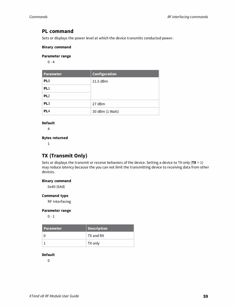
PL commandSets or displays the power level at which the device transmits conducted power.
Binary command
Parameter range0 - 4
Parameter Configuration
PL0 21.5 dBm
PL1
PL2
PL3 27 dBm
PL4 30 dBm (1 Watt)
Default4
Bytes returned1
TX (Transmit Only)Sets or displays the transmit or receive behaviors of the device. Setting a device to TX-only (TX = 1)may reduce latency because the you can not limit the transmitting device to receiving data from otherdevices.
Binary command0x40 (64d)
Command typeRF Interfacing
Parameter range0 - 1
Parameter Description
0 TX and RX
1 TX only
Default0

Commands Security commands
XTend vB RF Module User Guide 60
Bytes returned1
Security commandsThe following AT commands are security commands.
KY commandSets the 256-bit Advanced Encryption Standard (AES) key for encrypting or decrypting data. Once set,you cannot read the key cannot out of the device by any means. The firmware encrypts the entirepayload of the packet using the key and computes the CRC across the ciphertext. When you enableencryption, each packet carries an additional 16 bytes to convey the random cipher-block chaining(CBC) Initialization Vector (IV) to the receiver(s). Set 256-bit key (64 hex digits) on multiple devices forencrypted RF communication. Set to 0 to disable encryption. Reading the parameter returns a 0(encryption disabled) or 1 (enabled). The key cannot be read for security reasons.A device with the wrong key (or no key) receives encrypted data, but the data driven out the serialport is meaningless. Likewise, a device with a key receives unencrypted data sent from a devicewithout a key, but the output is meaningless. Because it uses CBC mode, repetitive data appearsdifferently in different transmissions due to the randomly-generated IV.
Note For international (non-U.S.) variants of XTC devices, the encryption key is 128-bit AES. Thecommand operates the same except the key length is 16 bytes rather than 32 bytes. This pertains topart numbers ending with 128, no matter which firmware version is loaded. This also pertains to theAustralia version of firmware 22xx.
Binary command0x43 (67d)
Command typeSecurity
Parameter range0 - (64 hex digits all set to 'F')
Default0 (disabled)
Bytes returned2
Serial interfacing commandsThe following AT commands are serial interfacing commands.
API EnableSet or read the API mode setting. The device can format the RF packets it receives into API framesand send them out the serial port.
Commands Serial interfacing commands
XTend vB RF Module User Guide 61
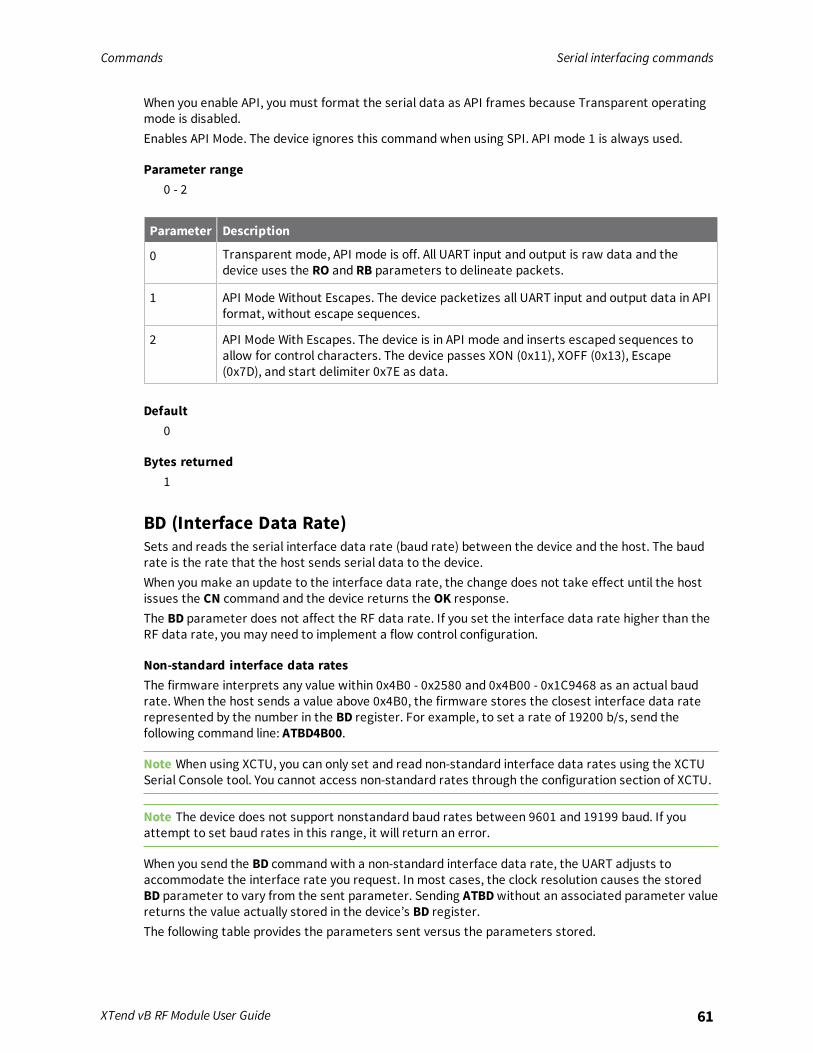
When you enable API, you must format the serial data as API frames because Transparent operatingmode is disabled.Enables API Mode. The device ignores this command when using SPI. API mode 1 is always used.
Parameter range0 - 2
Parameter Description
0 Transparent mode, API mode is off. All UART input and output is raw data and thedevice uses the RO and RB parameters to delineate packets.
1 API Mode Without Escapes. The device packetizes all UART input and output data in APIformat, without escape sequences.
2 API Mode With Escapes. The device is in API mode and inserts escaped sequences toallow for control characters. The device passes XON (0x11), XOFF (0x13), Escape(0x7D), and start delimiter 0x7E as data.
Default0
Bytes returned1
BD (Interface Data Rate)Sets and reads the serial interface data rate (baud rate) between the device and the host. The baudrate is the rate that the host sends serial data to the device.When you make an update to the interface data rate, the change does not take effect until the hostissues the CN command and the device returns the OK response.The BD parameter does not affect the RF data rate. If you set the interface data rate higher than theRF data rate, you may need to implement a flow control configuration.
Non-standard interface data ratesThe firmware interprets any value within 0x4B0 - 0x2580 and 0x4B00 - 0x1C9468 as an actual baudrate. When the host sends a value above 0x4B0, the firmware stores the closest interface data raterepresented by the number in the BD register. For example, to set a rate of 19200 b/s, send thefollowing command line: ATBD4B00.
Note When using XCTU, you can only set and read non-standard interface data rates using the XCTUSerial Console tool. You cannot access non-standard rates through the configuration section of XCTU.
Note The device does not support nonstandard baud rates between 9601 and 19199 baud. If youattempt to set baud rates in this range, it will return an error.
When you send the BD command with a non-standard interface data rate, the UART adjusts toaccommodate the interface rate you request. In most cases, the clock resolution causes the storedBD parameter to vary from the sent parameter. Sending ATBD without an associated parameter valuereturns the value actually stored in the device’s BD register.The following table provides the parameters sent versus the parameters stored.

Commands Serial interfacing commands
XTend vB RF Module User Guide 62
Binary command0x15 (21 decimal)
Parameter ranges
Parameter Configuration (b/s)
0 1200
1 2400
2 4800
3 9600
4 19200
5 38400
6 57600
Default
Bytes returned4
CD (GP02 Configuration)Selects or reads the behavior of the GPO2 line (pin 3).
Binary command0x28 (40 decimal)
Parameter range0 - 4
Parameter Configuration
0 RX LED
1 Static high
2 Static low
3 Reserved
4 RX LED (valid address only)
Default2
Bytes returned1

Commands Serial interfacing commands
XTend vB RF Module User Guide 63
CS (GP01 Configuration)Sets or displays the behavior of the GPO1 line (pin 9). This output can provide RS-232 flow control andcontrols the TX enable signal for RS-485 or RS-422 operations.By default, GP01 provides RS-232 Clear-to-Send (CTS ) flow control.
Binary command0x1F (31 decimal)
Parameter range0 - 4
Parameter Configuration
0 RS-232 CTS flow control
1 RS-485 TX enable low
2 Static high
3 RS-485 TX enable high
4 Static low
Default0
Bytes returned1
FL (Software Flow Control)The XON character used is 0x11 (17 decimal).The XOFF character used is 0x13 (19 decimal).
Binary command0x07 (7 decimal)
Parameter range0 - 1
Default0
Bytes returned1
FT commandSets or displays the flow control threshold.De-assert CTS when the number of bytes specified by the FT parameter are in the DIN buffer. Re-assert CTS when less than FT - 16 bytes are in the UART receive buffer.

Commands Serial interfacing commands
XTend vB RF Module User Guide 64
Binary command0x24 (36 decimal)
Parameter range0x11 - 0xC00 [bytes]
Default0xBBF (DI buffer size minus 0x11)
Bytes returned2
NB commandSet or read the parity settings for UART communications.
Parameter range
Parameter Configuration
0 8-bit (no parity )
1 8-bit even
2 8-bit odd
3 8-bit mark
4 8-bit space
Default0
Bytes returned1
RB (Packetization Threshold)Sets or displays the character threshold value.RF transmission begins after a device receives data in the DIN buffer and meets either of the followingcriteria:
n The UART receives RB characters
n The UART receive lines detect RO character times of silence after receiving at least 1 byte ofdata
If a device lowers PK below the value of RB, RB is automatically lowers to match the PK value.If RO = 0, the device must receive RB bytes before beginning transmission.RB and RO criteria only apply to the first packet of a multi-packet transmission. If data remains in theDIN buffer after the first packet, transmissions continue in a streaming manner until there is no dataleft in the DIN buffer.
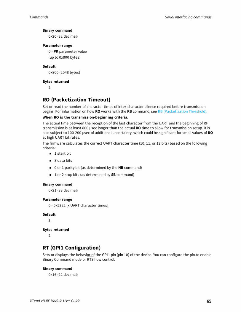
Commands Serial interfacing commands
XTend vB RF Module User Guide 65
Binary command0x20 (32 decimal)
Parameter range0 - PK parameter value(up to 0x800 bytes)
Default0x800 (2048 bytes)
Bytes returned2
RO (Packetization Timeout)Set or read the number of character times of inter-character silence required before transmissionbegins. For information on how RO works with the RB command, see RB (Packetization Threshold).When RO is the transmission-beginning criteria:The actual time between the reception of the last character from the UART and the beginning of RFtransmission is at least 800 µsec longer than the actual RO time to allow for transmission setup. It isalso subject to 100-200 µsec of additional uncertainty, which could be significant for small values of ROat high UART bit rates.The firmware calculates the correct UART character time (10, 11, or 12 bits) based on the followingcriteria:
n 1 start bit
n 8 data bits
n 0 or 1 parity bit (as determined by the NB command)
n 1 or 2 stop bits (as determined by SB command)
Binary command0x21 (33 decimal)
Parameter range0 - 0x53E2 [x UART character times]
Default3
Bytes returned2
RT (GPI1 Configuration)Sets or displays the behavior of the GPI1 pin (pin 10) of the device. You can configure the pin to enableBinary Command mode or RTS flow control.
Binary command0x16 (22 decimal)

Commands Sleep commands
XTend vB RF Module User Guide 66
Parameter range0 - 2
Parameter Configuration
0 Disabled
1 Binary Command enable
2 RTS flow control enable
Default0 (disabled)
Bytes returned1
SB commandSets or displays the number of stop bits in the data packet.
Binary command0x37 (55 decimal)0x36 (54 decimal)
Parameter range0 - 1
Parameter Configuration
0 One stop bit
1 Two stop bits
Default0
Bytes returned1
Sleep commandsThe following AT commands are sleep commands.
FH (Force Wakeup Initializer)Forces the device to send a wake-up initializer on the next transmission.Only use FH with cyclic sleep modes active on remote devices.You do not need to issue the WR (Write) command with FH.
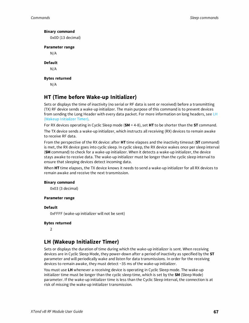
Commands Sleep commands
XTend vB RF Module User Guide 67
Binary command0x0D (13 decimal)
Parameter rangeN/A
DefaultN/A
Bytes returnedN/A
HT (Time before Wake-up Initializer)Sets or displays the time of inactivity (no serial or RF data is sent or received) before a transmitting(TX) RF device sends a wake-up initializer. The main purpose of this command is to prevent devicesfrom sending the Long Header with every data packet. For more information on long headers, see LH(Wakeup Initializer Timer).For RX devices operating in Cyclic Sleep mode (SM = 4-8), set HT to be shorter than the ST command.The TX device sends a wake-up initializer, which instructs all receiving (RX) devices to remain awaketo receive RF data.From the perspective of the RX device: after HT time elapses and the inactivity timeout (ST command)is met, the RX device goes into cyclic sleep. In cyclic sleep, the RX device wakes once per sleep interval(SM command) to check for a wake-up initializer. When it detects a wake-up initializer, the devicestays awake to receive data. The wake-up initializer must be longer than the cyclic sleep interval toensure that sleeping devices detect incoming data.When HT time elapses, the TX device knows it needs to send a wake-up initializer for all RX devices toremain awake and receive the next transmission.
Binary command0x03 (3 decimal)
Parameter range
Default0xFFFF (wake-up initializer will not be sent)
Bytes returned2
LH (Wakeup Initializer Timer)Sets or displays the duration of time during which the wake-up initializer is sent. When receivingdevices are in Cyclic Sleep Mode, they power-down after a period of inactivity as specified by the STparameter and will periodically wake and listen for data transmissions. In order for the receivingdevices to remain awake, they must detect ~35 ms of the wake-up initializer.You must use LH whenever a receiving device is operating in Cyclic Sleep mode. The wake-upinitializer time must be longer than the cyclic sleep time, which is set by the SM (Sleep Mode)parameter. If the wake-up initializer time is less than the Cyclic Sleep interval, the connection is atrisk of missing the wake-up initializer transmission.

Commands Sleep commands
XTend vB RF Module User Guide 68
Binary command0x0C (12 decimal)
Parameter range0 - 0xFF [x100 milliseconds]
Default1
Bytes returned1
PW (Pin Wakeup)Enables or disables the sleep pin.Under normal operation, a device in Cyclic Sleep mode cycles from an active state to a low-powerstate at regular intervals until it is ready to receive data. If you set PW to 1, you can use the SLEEP pin(pin 26) to wake the device from Cyclic Sleep. When you de-assert (low) the SLEEP pin, the device isoperational and will not go into Cyclic Sleep.Once you assert the SLEEP pin, the device remains active for the period of time specified by the STparameter and returns to Cyclic Sleep mode if no data is ready to transmit. PW is only valid if CyclicSleep is enabled.
Binary command0x1D (29 decimal)
Parameter range0 - 1
Parameter Configuration
0 Disabled
1 Enabled
Default0
Bytes returned1
SM (Sleep Mode)
Binary command0x01

Commands Special commands
XTend vB RF Module User Guide 69
Parameter range
Default0
Bytes returned1
ST commandYou can only use this command if you use SM to select Cyclic Sleep or Serial Port Sleep mode settings;see SM (Sleep Mode).
Binary command0x02 (2 decimal)
Parameter range
Default0x64 (10 seconds)
Bytes returned2
Special commandsThe following commands are special commands.
WR (Write)Writes parameter values to non-volatile memory so that parameter modifications persist throughsubsequent resets.If you make changes without writing them to non-volatile memory, the device reverts to previouslysaved parameters the next time it is powered on.If the non-volatile user configuration is not correct, WR will re-attempt up to three times. If all threeattempts fail, the command returns an ERROR alert.
Binary command0x08
Command typeSpecial
Parameter rangeN/A
DefaultN/A

Commands Special commands
XTend vB RF Module User Guide 70
Bytes returnedN/A

API operation
API mode overview 72Frame descriptions 76
XTend vB RF Module User Guide 71

API operation API mode overview
XTend vB RF Module User Guide 72
API mode overviewBy default, the XTend vB RF Module acts as a serial line replacement (Transparent operation), itqueues all UART data that it receive through the DI pin for RF transmission. When the device receivesan RF packet, it sends the data out the DO pin with no additional information.The following behaviors are inherent to Transparent operation:
n If device parameter registers are to be set or queried, a special operation is required fortransitioning the device into Command Mode; refer to Enter Command mode.
n In point-to-multipoint systems, the host application must send XTend vBa if the receivingdevice(s) need to distinguish between data coming from different remotes.
API operating mode is an alternative to transparent mode. API mode is a frame-based protocol thatallows you to direct data on a packet basis. It can be particularly useful in large networks where youneed to control the destination of individual data packets or when you need to know which node adata packet was sent from. The device communicates UART data in packets, also known as APIframes. This mode allows for structured communications with serial devices. It is helpful in managinglarger networks and is more appropriate for performing tasks such as collecting data from multiplelocations or controlling multiple devices remotely.
API frame specificationsThe firmware supports two API operating modes: without escaped characters and with escapedcharacters. Use the AP command to enable either mode. To configure a device to one of these modes,set the following AP parameter values:
AP commandsetting Description
AP = 0 Transparent operating mode, UART serial line replacement with API modesdisabled. This is the default option.
AP = 1 API operation.
AP = 2 API operation with escaped characters (only possible on UART).
The API data frame structure differs depending on what mode you choose.The firmware silently discards any data it receives prior to the start delimiter. If the device does notreceive the frame correctly or if the checksum fails, the device discards the frame.
API operation (AP parameter = 1)We recommend this API mode for most applications. The following table shows the data framestructure when you enable this mode:
Frame fields Byte Description
Start delimiter 1 0x7E
Length 2 - 3 Most Significant Byte, Least Significant Byte
Frame data 4 - n API-specific structure
Checksum n + 1 1 byte

API operation API mode overview
XTend vB RF Module User Guide 73
API operation-with escaped characters (AP parameter = 2)Set API to 2 to allow escaped control characters in the API frame. Due to its increased complexity, weonly recommend this API mode in specific circumstances. API 2 may help improve reliability if theserial interface to the device is unstable or malformed frames are frequently being generated.When operating in API 2, if an unescaped 0x7E byte is observed, it is treated as the start of a new APIframe and all data received prior to this delimiter is silently discarded. For more information on usingthis API mode, refer to the following knowledge base article:http://knowledge.digi.com/articles/Knowledge_Base_Article/Escaped-Characters-and-API-Mode-2The following table shows the structure of an API frame with escaped characters:
Frame fields Byte Description
Start delimiter 1 0x7E
Length 2 - 3 Most Significant Byte, Least Significant Byte Characters escaped if needed
Frame data 4 - n API-specific structure
Checksum n + 1 1 byte
Escape charactersWhen sending or receiving a UART data frame, you must escape (flag) specific data values so they donot interfere with the data frame sequencing. To escape an interfering data byte, insert 0x7D andfollow it with the byte to be escaped XOR’d with 0x20. If not escaped, 0x11 and 0x13 are sent as is.Data bytes that need to be escaped:
n 0x7E – Frame delimiter
n 0x7D – Escape
n 0x11 – XON
n 0x13 – XOFF
Example - Raw UART data frame (before escaping interfering bytes): 0x7E 0x00 0x02 0x23 0x11 0xCB0x11 needs to be escaped which results in the following frame: 0x7E 0x00 0x02 0x23 0x7D 0x31 0xCB
Note In the previous example, the length of the raw data (excluding the checksum) is 0x0002 and thechecksum of the non-escaped data (excluding frame delimiter and length) is calculated as:0xFF - (0x23 + 0x11) = (0xFF - 0x34) = 0xCB.
Start delimiterThis field indicates the beginning of a frame. It is always 0x7E. This allows the device to easily detect anew incoming frame.
Length
Frame dataThis field contains the information that a device receives or will transmit. The structure of frame datadepends on the purpose of the API frame:

API operation API mode overview
XTend vB RF Module User Guide 74
Startdelimiter Length
Frame data
ChecksumFrametype Data
1 2 3 4 5 6 7 8 9 ... n n+1
0x7E MSB LSB API frame type Data Single byte
n Frame type is the API frame type identifier. It determines the type of API frame and indicateshow the Data field organizes the information.
n Data contains the data itself. This information and its order depend on the what type of framethat the Frame type field defines.
Checksum
Calculate and verify checksumsTo calculate the checksum of an API frame:
1. Add all bytes of the packet, except the start delimiter 0x7E and the length (the second andthird bytes).
2. Keep only the lowest 8 bits from the result.
3. Subtract this quantity from 0xFF.
To verify the checksum of an API frame:1. Add all bytes including the checksum; do not include the delimiter and length.
2. If the checksum is correct, the last two digits on the far right of the sum equal 0xFF.
ExampleTo calculate the check sum you add all bytes of the packet, excluding the frame delimiter 7E and thelength (the second and third bytes):Add these hex bytes:If an API data packet is composed with an incorrect checksum, the XTend vB RF Module will considerthe packet invalid and will ignore the data.To verify the check sum of an API packet add all bytes including the checksum (do not include thedelimiter and length) and if correct, the last two far right digits of the sum will equal FF.
Escaped characters in API framesIf operating in API mode with escaped characters (AP parameter = 2), when sending or receiving aserial data frame, specific data values must be escaped (flagged) so they do not interfere with thedata frame sequencing. To escape an interfering data byte, insert 0x7D and follow it with the byte tobe escaped (XORed with 0x20).The following data bytes need to be escaped:
n 0x7E: start delimiter
n 0x7D: escape character

API operation API mode overview
XTend vB RF Module User Guide 75
n 0x11: XON
n 0x13: XOFF
To escape a character:1. Insert 0x7D (escape character).
2. Append it with the byte you want to escape, XORed with 0x20.
In API mode with escaped characters, the length field does not include any escape characters in theframe and the firmware calculates the checksum with non-escaped data.
Example: escape an API frameTo express the following API non-escaped frame in API operating mode with escaped characters:
Start delimiter Length Frame typeFrame Data
ChecksumData
7E 00 0F 17 01 00 13 A2 00 40 AD 14 2E FF FE 02 4E 49 6D
You must escape the 0x13 byte:1. Insert a 0x7D.
2. XOR byte 0x13 with 0x20: 13 ⊕ 20 = 33
The following figure shows the resulting frame. Note that the length and checksum are the same asthe non-escaped frame.
Start delimiter Length Frame typeFrame Data
ChecksumData
7E 00 0F 17 01 00 7D 33 A2 00 40 AD 14 2E FF FE 02 4E 49 6D
The length field has a two-byte value that specifies the number of bytes in the frame data field. It doesnot include the checksum field.

API operation Frame descriptions
XTend vB RF Module User Guide 76
Frame descriptionsThe following sections describe the API frames.

API operation Frame descriptions
XTend vB RF Module User Guide 77
RF Module Status frame - 0x8A
DescriptionDevices send the status messages in this frame in response to specific conditions.
FormatThe following table provides the contents of the frame. For details on frame structure, see API framespecifications.
Frame data fields Offset Description
Frame type 3 0x8A
Status 4 0x00 = Hardware reset0x01 = Watchdog timer reset
ExampleWhen a device powers up, it returns the following API frame:
Frame fields Offset Example
Start Delimiter 0 0x7E
Length MSB 1 0x00
LSB 2 0x02
Frame Type 3 0x8A
Status 4 0x00
Checksum 5 0x75
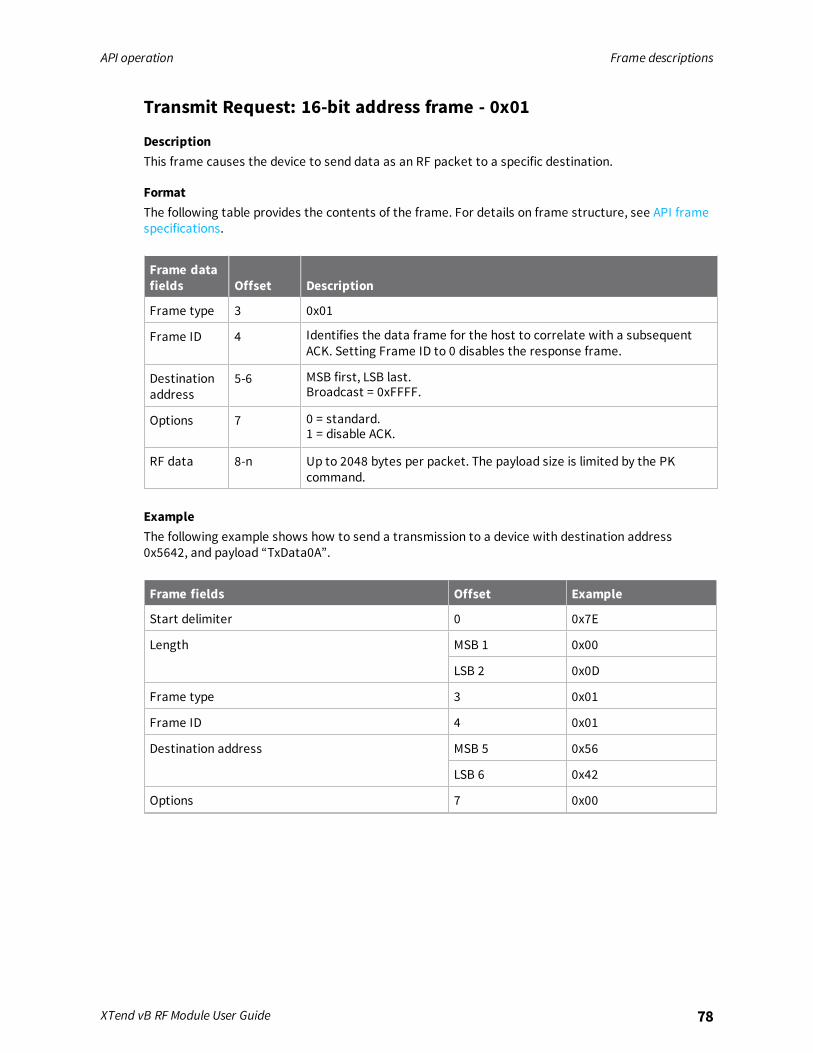
API operation Frame descriptions
XTend vB RF Module User Guide 78
Transmit Request: 16-bit address frame - 0x01
DescriptionThis frame causes the device to send data as an RF packet to a specific destination.
FormatThe following table provides the contents of the frame. For details on frame structure, see API framespecifications.
Frame datafields Offset Description
Frame type 3 0x01
Frame ID 4 Identifies the data frame for the host to correlate with a subsequentACK. Setting Frame ID to 0 disables the response frame.
Destinationaddress
5-6 MSB first, LSB last.Broadcast = 0xFFFF.
Options 7 0 = standard.1 = disable ACK.
RF data 8-n Up to 2048 bytes per packet. The payload size is limited by the PKcommand.
ExampleThe following example shows how to send a transmission to a device with destination address0x5642, and payload “TxData0A”.
Frame fields Offset Example
Start delimiter 0 0x7E
Length MSB 1 0x00
LSB 2 0x0D
Frame type 3 0x01
Frame ID 4 0x01
Destination address MSB 5 0x56
LSB 6 0x42
Options 7 0x00
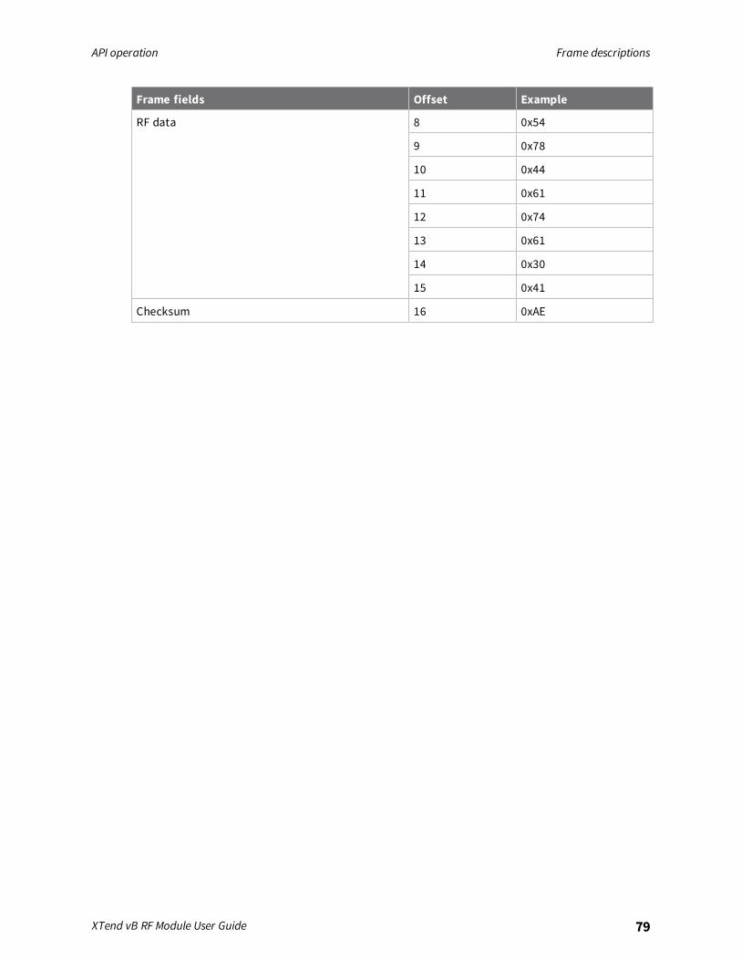
API operation Frame descriptions
XTend vB RF Module User Guide 79
Frame fields Offset Example
RF data 8 0x54
9 0x78
10 0x44
11 0x61
12 0x74
13 0x61
14 0x30
15 0x41
Checksum 16 0xAE

API operation Frame descriptions
XTend vB RF Module User Guide 80
Transmit Status frame - 0x89
DescriptionWhen a TX Request is completed, the device sends a TX Status message. This message will indicate ifthe packet was transmitted successfully or if there was a failure.
FormatThe following table provides the contents of the frame. For details on frame structure, see API framespecifications.
Framedata fields Offset Description
Frame type 3 0x89
Frame ID 4 Identifies the data frame for the host to correlate with a subsequent ACK.Setting Frame ID to 0 disables the response frame.
Status 5 0 = success.1 = all retries expired and no ACK received.3 = a packet is purged due to a Polled Remote not receiving a poll.
ExampleIn the following example, the destination device reports that a unicast data transmission wassuccessful using a frame ID of 0x47.
Frame fields Offset Example
Start Delimiter 0 0x7E
Length MSB 1 0x00
LSB 2 0x03
Frame type 3 0x89
Frame ID 4 0x47
Options 5 0x00
Checksum 6 0x2F

API operation Frame descriptions
XTend vB RF Module User Guide 81
Receive Packet: 16-bit address frame - 0x81
DescriptionWhen the device receives an RF packet from a device configured to use 16 bit addressing (MY < FFFE),it sends this frame out the serial interface.
FormatThe following table provides the contents of the frame. For details on frame structure, see API framespecifications.
Frame datafields Offset Description
Frame type 3 0x81
Sourceaddress
4-5 MSB firstLSB last
RSSI 6 RSSI = hexadecimal equivalent of -dBm value. For example, if RX signalstrength = -40 dBm, it returns 0x28 (40 decimal).
Options 7 Bit 0 = ACKBit 1 = indicate broadcastbits 2-7 = reserved
RF data 8-n Up to 2048 bytes per packet.
ExampleIn the following example, a device with a source address of 0xA35E sent a unicast data transmissionto a remote device with a payload of "RxData". The receiving device would send the following frameout its UART:
Frame data fields Offset Example
Start Delimiter 0 0x7E
Length MSB 1 0x00
LSB 2 0x0B
Frame type 3 0x81
Source address MSB 4 0xA3
LSB5 0x5E
RSSI 6 0x5D
Options 7 0x01

API operation Frame descriptions
XTend vB RF Module User Guide 82
Frame data fields Offset Example
RF data 8 0x52
9 0x78
10 0x44
11 0x61
12 0x74
13 0x61
Checksum 14 0xDB
Regulatory information
FCC (United States) 84Industry Canada (IC) 95ACMA (Australia) 96
XTend vB RF Module User Guide 83

Regulatory information FCC (United States)
XTend vB RF Module User Guide 84
FCC (United States)These RF modules comply with Part 15 of the FCC rules and regulations. Compliance with the labelingrequirements, FCC notices and antenna usage guidelines is required.In order to operate under Digi’s FCC Certification, integrators must comply with the followingregulations:
1. The integrator must ensure that the text provided with this device (in the labelingrequirements section that follows) is placed on the outside of the final product and within thefinal product operation manual.
2. The device may only be used with antennas that have been tested and approved for use withthis device; refer to FCC antenna certifications.
OEM labeling requirementsThe following text is the required FCC label for OEM products containing the XTend vB RF Module:Contains FCC ID: MCQ-XBPSXThe enclosed device complies with Part 15 of the FCC Rules. Operation is subject to the following twoconditions: (i.) this device may not cause harmful interference and (ii.) this device must accept anyinterference received, including interference that may cause undesired operation.
FCC noticesIMPORTANT:These RF modules have been certified by the FCC for use with other products withoutany further certification (as per FCC section 2.1091). Modifications not expressly approved by Digicould void the user’s authority to operate the equipment.IMPORTANT:Integrators must test final product to comply with unintentional radiators (FCC sections15.107 & 15.109) before declaring compliance of their final product to Part 15 of the FCC rules.IMPORTANT:These RF modules have been certified for remote and base radio applications. If themodule will be used for portable applications, the device must undergo SAR testing.This equipment has been tested and found to comply with the limits for a Class B digital device,pursuant to Part 15 of the FCC Rules. These limits are designed to provide reasonable protectionagainst harmful interference in a residential installation. This equipment generates, uses and canradiate radio frequency energy and, if not installed and used in accordance with the instructions, maycause harmful interference to radio communications. However, there is no guarantee thatinterference will not occur in a particular installation.If this equipment does cause harmful interference to radio or television reception, which can bedetermined by turning the equipment off and on, the user is encouraged to try to correct theinterference by one or more of the following measures: Re-orient or relocate the receiving antenna,Increase the separation between the equipment and receiver, Connect equipment and receiver tooutlets on different circuits, or Consult the dealer or an experienced radio/TV technician for help.

Regulatoryinform
ationFCC
(UnitedStates)
XTendvB
RFModule
UserGuide85
Dipole antennasAll antenna part numbers followed by an asterisk (*) are not available from Digi. Consult with an antenna manufacturer for an equivalent option.
Part number Type Connector Gain Required antenna cable loss Application
A09-HSM-7 Straight half-wave RPSMA 2.1 dBi 0.4 dB Fixed/mobile
A09-HASM-675 Articulated half-wave RPSMA 2.1 dBi 0.4 dB Fixed/mobile
A09-HABMM-P5I Swivel half wave with 5" pigtail MMCX 2.1 dBi 0.4 dB Fixed/mobile
A09-HBMM-P5I Straight half-wave with 6" pigtail MMCX 2.1 dBi 0.4 dB Fixed/mobile
A09-HASM-7* Articulated half-wave RPSMA 2.1 dBi 0.4 dB Fixed
A09-HRSM* Right angle half-wave RPSMA 2.1 dBi 0.4 dB Fixed
A09-HG* Glass mounted half-wave RPSMA 2.1dBi 0.4 dB Fixed
A09-HATM* Articulated half-wave RPTNC 2.1 dBi 0.4 dB Fixed
A09-H* Half-wave dipole RPSMA 2.1 dBi 0.4 dB Fixed
Yagi antennasAll antenna part numbers followed by an asterisk (*) are not available from Digi. Consult with an antenna manufacturer for an equivalent option.
Part number Type Gain Connector Required antenna cable loss Application
A09-Y6NF* 2 element Yagi 6.1 dBi N - Fixed/mobile
A09-Y7NF* 3 element Yagi 7.1 dBi N - Fixed/mobile
A09-Y8NF 4 element Yagi 8.1 dBi N - Fixed/mobile
A09-Y9NF* 4 element Yagi 9.1 dBi N - Fixed/mobile

Regulatoryinform
ationFCC
(UnitedStates)
XTendvB
RFModule
UserGuide86
Part number Type Gain Connector Required antenna cable loss Application
A09-Y10NF* 5 element Yagi 10.1 dBi N - Fixed/mobile
A09-Y11NF 6 element Yagi 11.1 dBi N - Fixed/mobile
A09-Y12NF* 7 element Yagi 12.1 dBi N - Fixed/mobile
A09-Y13NF* 9 element Yagi 13.1 dBi N - Fixed/mobile
A09-Y14NF* 10 element Yagi 14.1 dBi N - Fixed/mobile
A09-Y14NF-ALT* 12 element Yagi 14.1 dBi N - Fixed/mobile
A09-Y15NF 13 element Yagi 15.1 dBi N 0.7 dB Fixed/mobile
A09-Y15NF-ALT* 15 element Yagi 15.1 dBi N 0.7 dB Fixed/mobile
A09-Y6TM* 2 element Yagi 6.1 dBi RPTNC - Fixed/mobile
A09-Y7TM* 3 element Yagi 7.1 dBi RPTNC - Fixed/mobile
A09-Y8TM* 4 element Yagi 8.1 dBi RPTNC - Fixed/mobile
A09-Y9TM* 4 element Yagi 9.1 dBi RPTNC - Fixed/mobile
A09-Y10TM-P10* 5 element Yagi 10.1 dBi RPTNC - Fixed/mobile
A09-Y11TM* 6 element Yagi 11.1 dBi RPTNC - Fixed/mobile
A09-Y12TM* 7 element Yagi 12.1 dBi RPTNC - Fixed/mobile
A09-Y13TM* 9 element Yagi 13.1 dBi RPTNC - Fixed/mobile
A09-Y14TM* 10 element Yagi 14.1 dBi RPTNC - Fixed/mobile
A09-Y14TM-ALT* 12 element Yagi 14.1 dBi RPTNC - Fixed/mobile
A09-Y15TM* 13 element Yagi 15.1 dBi RPTNC 0.7 dB Fixed/mobile
A09-Y15TM-P10I 15 element Yagi 15.1 dBi RPTNC 0.7 dB Fixed/mobile
Omni-directional base station antennasAll antenna part numbers followed by an asterisk (*) are not available from Digi. Consult with an antenna manufacturer for an equivalent option.

Regulatoryinform
ationFCC
(UnitedStates)
XTendvB
RFModule
UserGuide87
Part number Type Gain Connector Required antenna cable loss Application
A09-F0NF* Fiberglass Base Station 0 dBi N - Fixed
A09-F1NF* Fiberglass Base Station 1.0 dBi N - Fixed
A09-F2NF-M* Fiberglass Base Station 2.1 dBi N - Fixed
A09-F3NF* Fiberglass Base Station 3.1 dBi N - Fixed
A09-F4NF* Fiberglass Base Station 4.1 dBi N - Fixed
A09-F5NF-M Fiberglass Base Station 5.1 dBi N - Fixed
A09-F6NF* Fiberglass Base Station 6.1 dBi N - Fixed
A09-F7NF* Fiberglass Base Station 7.1 dBi N - Fixed
A09-F8NF-M Fiberglass Base Station 8.1 dBi N 0.7 dB Fixed
A09-F0SM* Fiberglass Base Station 0 dBi RPSMA - Fixed
A09-F1SM* Fiberglass Base Station 1.0 dBi RPSMA - Fixed
A09-F2SM* Fiberglass Base Station 2.1 dBi RPSMA - Fixed
A09-F3SM* Fiberglass Base Station 3.1 dBi RPSMA - Fixed
A09-F4SM* Fiberglass Base Station 4.1 dBi RPSMA - Fixed
A09-F5SM* Fiberglass Base Station 5.1 dBi RPSMA - Fixed
A09-F6SM* Fiberglass Base Station 6.1 dBi RPSMA - Fixed
A09-F7SM* Fiberglass Base Station 7.1 dBi RPSMA - Fixed
A09-F8SM* Fiberglass Base Station 8.1 dBi RPSMA 0.7 dB Fixed
A09-F0TM* Fiberglass Base Station 0 dBi RPTNC - Fixed
A09-F1TM* Fiberglass Base Station 1.0 dBi RPTNC - Fixed
A09-F2TM* Fiberglass Base Station 2.1 dBi RPTNC - Fixed

Regulatoryinform
ationFCC
(UnitedStates)
XTendvB
RFModule
UserGuide88
Part number Type Gain Connector Required antenna cable loss Application
A09-F3TM* Fiberglass Base Station 3.1 dBi RPTNC - Fixed
A09-F4TM* Fiberglass Base Station 4.1 dBi RPTNC - Fixed
A09-F5TM* Fiberglass Base Station 5.1 dBi RPTNC - Fixed
A09-F6TM* Fiberglass Base Station 6.1 dBi RPTNC - Fixed
A09-F7TM* Fiberglass Base Station 7.1 dBi RPTNC - Fixed
A09-F8TM* Fiberglass Base Station 8.1 dBi RPTNC 0.7 dB Fixed
A09-W7* Wire Base Station 7.1 dBi RPN - Fixed
A09-W7SM* Wire Base Station 7.1 dBi RPSMA - Fixed
A09-W7TM* Wire Base Station 7.1 dBi RPTNC - Fixed
Dome antennasAll antenna part numbers followed by an asterisk (*) are not available from Digi. Consult with an antenna manufacturer for an equivalent option.
Part number Type Gain Connector Required antenna cable loss Application
A09-D3PNF* Omnidirectional permanent mount 3.0 dBi N 0.4 dB Fixed/mobile
A09-D3NF* Omnidirectional magnetic mount 3.0 dBi N 0.4 dB Fixed/mobile
A09-D3PTM* Omnidirectional permanent mount 3.0 dBi RPTNC 0.4 dB Fixed/mobile
A09-D3PSM* Omnidirectional permanent mount 3.0 dBi RPSMA 0.4 dB Fixed/mobile
Monopole antennasAll antenna part numbers followed by an asterisk (*) are not available from Digi. Consult with an antenna manufacturer for an equivalent option.

Regulatoryinform
ationFCC
(UnitedStates)
XTendvB
RFModule
UserGuide89
Part number Type Gain Connector Required antenna cable loss Application
A09-QRAMM 3" Quarter wave wire 2.1 dBi MMCX - Fixed/mobile
A09-QRSM-2.1* Quarter wave 2.1" right angle 3.3 dBi RPSMA 0.4 dB Fixed/mobile
A09-QW* Quarter wave wire 1.9 dBi Permanent - Fixed/mobile
A09-QSM-3* Quarter wave straight 1.9 dBi RPSMA - Fixed/mobile
A09-QSM-3H* Heavy duty quarter wave straight 1.9 dBi RPSMA - Fixed/mobile
A09-QBMM-P6I* Quarter wave w/ 6" pigtail 1.9 dBi MMCX - Fixed/mobile
A09-QHSM-2* 2" straight 1.9 dBi RPSMA - Fixed/mobile
A09-QHRSM-2* 2" right angle 1.9 dBi RPSMA - Fixed/mobile
A09-QHRSM-170* 1.7" right angle 1.9 dBi RPSMA - Fixed/mobile
A09-QRSM-380* 3.8" right angle 1.9 dBi RPSMA - Fixed/mobile
A09-QAPM-520* 5.2" articulated screw mount 1.9 dBi Permanent - Fixed/mobile
A09-QSPM-3* 3" straight screw mount 1.9 dBi Permanent - Fixed/mobile
A09-QAPM-3* 3" articulated screw mount 1.9 dBi Permanent - Fixed/mobile
A09-QAPM-3H* 3" articulated screw mount 1.9 dBi Permanent - Fixed/mobile

Regulatoryinform
ationFCC
(UnitedStates)
XTendvB
RFModule
UserGuide90
Antenna optionsThe following tables cover the antennas that are approved for use with the XTend vB RF Module. If applicable, the tables show the required cable lossbetween the device and the antenna.Digi does not carry all of these antenna variants. Contact Digi Sales for available antennas.
Dipole antennasAll antenna part numbers followed by an asterisk (*) are not available from Digi. Consult with an antenna manufacturer for an equivalent option.
Part number Type Connector Gain Application
A09-HSM-7 Straight half-wave RPSMA 2.1 dBi Fixed / mobile
A09-HASM-675 Articulated half-wave RPSMA 2.1 dBi Fixed / mobile
A09-HABMM-P5I Swivel half wave with 5" pigtail MMCX 2.1 dBi Fixed / mobile
A09-HBMM-P5I Straight half-wave with 6" pigtail MMCX 2.1 dBi Fixed / mobile
A09-HASM-7* Articulated half-wave RPSMA 2.1 dBi Fixed
A09-HRSM* Right angle half-wave RPSMA 2.1 dBi Fixed
A09-HG* Glass mounted half-wave RPSMA 2.1 dBi Fixed
A09-HATM* Articulated half-wave RPTNC 2.1 dBi Fixed
A09-H* Half-wave dipole RPSMA 2.1 dBi Fixed
Yagi antennasAll antenna part numbers followed by an asterisk (*) are not available from Digi. Consult with an antenna manufacturer for an equivalent option.

Regulatoryinform
ationFCC
(UnitedStates)
XTendvB
RFModule
UserGuide91
Part number Type Gain ConnectorRequired antennacable loss Application
A09-Y6NF* 2 element Yagi 6.1 dBi N 2.0 dB Fixed/mobile
A09-Y7NF* 3 element Yagi 7.1 dBi N 3.0 dB Fixed/mobile
A09-Y8NF 4 element Yagi 8.1 dBi N 4.0 dB Fixed/mobile
A09-Y9NF* 4 element Yagi 9.1 dBi N 5.0 dB Fixed/mobile
A09-Y10NF* 5 element Yagi 10.1 dBi N 6.0 dB Fixed/mobile
A09-Y11NF 6 element Yagi 11.1 dBi N 7.0 dB Fixed/mobile
A09-Y12NF* 7 element Yagi 12.1 dBi N 8.0 dB Fixed/mobile
A09-Y13NF* 9 element Yagi 13.1 dBi N 9.0 dB Fixed/mobile
A09-Y14NF* 14 element Yagi 14.0 dBi N 9.9 dB Fixed/mobile
A09-Y6TM* 2 element Yagi 6.1 dBi RPTNC 2.0 dB Fixed/mobile
A09-Y7TM* 3 element Yagi 7.1 dBi RPTNC 3.0 dB Fixed/mobile
A09-Y8TM* 4 element Yagi 8.1 dBi RPTNC 4.0 dB Fixed/mobile
A09-Y9TM* 4 element Yagi 9.1 dBi RPTNC 5.0 dB Fixed/mobile
A09-Y10TM-P10I 5 element Yagi 10.1 dBi RPTNC 6.0 dB Fixed/mobile
A09-Y11TM* 6 element Yagi 11.1 dBi RPTNC 7.0 dB Fixed/mobile
A09-Y12TM* 7 element Yagi 12.1 dBi RPTNC 8.0 dB Fixed/mobile
A09-Y13TM* 9 element Yagi 13.1 dBi RPTNC 9.0 dB Fixed/mobile
A09-Y14TM* 14 element Yagi 14.0 dBi RPTNC 9.9 dB Fixed/mobile
Omni-directional base station antennasAll antenna part numbers followed by an asterisk (*) are not available from Digi. Consult with an antenna manufacturer for an equivalent option.

Regulatoryinform
ationFCC
(UnitedStates)
XTendvB
RFModule
UserGuide92
Part number Type Gain Connector Required antenna cable loss Application
A09-F0NF* Fiberglass base station 0 dBi N - Fixed
A09-F1NF* Fiberglass base station 1.0 dBi N - Fixed
A09-F2NF-M Fiberglass base station 2.1 dBi N - Fixed
A09-F3NF* Fiberglass base station 3.1 dBi N - Fixed
A09-F4NF* Fiberglass base station 4.1 dBi N - Fixed
A09-F5NF-M Fiberglass base station 5.1 dBi N - Fixed
A09-F6NF* Fiberglass base station 6.1 dBi N 0.9 dB Fixed
A09-F7NF* Fiberglass base station 7.1 dBi N 1.9 dB Fixed
A09-F8NF-M Fiberglass base station 8.1 dBi N 2.9 dB Fixed
A09-F0SM* Fiberglass base station 0 dBi RPSMA - Fixed
A09-F1SM* Fiberglass base station 1.0 dBi RPSMA - Fixed
A09-F2SM* Fiberglass base station 2.1 dBi RPSMA - Fixed
A09-F3SM* Fiberglass base station 3.1 dBi RPSMA - Fixed
A09-F4SM* Fiberglass base station 4.1 dBi RPSMA - Fixed
A09-F5SM* Fiberglass base station 5.1 dBi RPSMA - Fixed
A09-F6SM* Fiberglass base station 6.1 dBi RPSMA 0.9 dB Fixed
A09-F7SM* Fiberglass base station 7.1 dBi RPSMA 1.9 dB Fixed
A09-F8SM* Fiberglass base station 8.1 dBi RPSMA 2.9 dB Fixed
A09-F0TM* Fiberglass base station 0 dBi RPTNC - Fixed
A09-F1TM* Fiberglass base station 1.0 dBi RPTNC - Fixed
A09-F2TM* Fiberglass base station 2.1 dBi RPTNC - Fixed

Regulatoryinform
ationFCC
(UnitedStates)
XTendvB
RFModule
UserGuide93
Part number Type Gain Connector Required antenna cable loss Application
A09-F3TM* Fiberglass base station 3.1 dBi RPTNC - Fixed
A09-F4TM* Fiberglass base station 4.1 dBi RPTNC - Fixed
A09-F5TM* Fiberglass base station 5.1 dBi RPTNC - Fixed
A09-F6TM* Fiberglass base station 6.1 dBi RPTNC 0.9 dB Fixed
A09-F7TM* Fiberglass base station 7.1 dBi RPTNC 1.9 dB Fixed
A09-F8TM* Fiberglass base station 8.1 dBi RPTNC 2.9 dB Fixed
A09-W7* Wire base station 7.1 dBi RPN 1.9 dB Fixed
A09-W7SM* Wire base station 7.1 dBi RPSMA 1.9 dB Fixed
A09-W7TM* Wire base station 7.1 dBi RPTNC 1.9 dB Fixed
Dome antennasAll antenna part numbers followed by an asterisk (*) are not available from Digi. Consult with an antenna manufacturer for an equivalent option.
Part number Type Gain Connector Required antenna cable loss Application
A09-D3PNF* Omnidirectional permanent mount 3.0 dBi N 0.4 dB Fixed/mobile
A09-D3NF* Omnidirectional magnetic mount 3.0 dBi N 0.4 dB Fixed/mobile
A09-D3PTM* Omnidirectional permanent mount 3.0 dBi RPTNC 0.4 dB Fixed/mobile
A09-D3PSM* Omnidirectional permanent mount 3.0 dBi RPSMA 0.4 dB Fixed/mobile
Monopole antennasAll antenna part numbers followed by an asterisk (*) are not available from Digi. Consult with an antenna manufacturer for an equivalent option.

Regulatoryinform
ationFCC
(UnitedStates)
XTendvB
RFModule
UserGuide94
Part number Type Gain Connector Required antenna cable loss Application
A09-QRAMM 3" Quarter wave wire 2.1 dBi MMCX - Fixed/mobile
A09-QRSM-2.1* Quarter wave 2.1" right angle 3.3 dBi RPSMA 0.4 dB Fixed/mobile
A09-QW* Quarter wave wire 1.9 dBi Permanent - Fixed/mobile
A09-QSM-3* Quarter wave straight 1.9 dBi RPSMA - Fixed/mobile
A09-QSM-3H* Heavy duty quarter wave straight 1.9 dBi RPSMA - Fixed/mobile
A09-QBMM-P6I* Quarter wave w/ 6" pigtail 1.9 dBi MMCX - Fixed/mobile
A09-QHSM-2* 2" straight 1.9 dBi RPSMA - Fixed/mobile
A09-QHRSM-2* 2" right angle 1.9 dBi RPSMA - Fixed/mobile
A09-QHRSM-170* 1.7" right angle 1.9 dBi RPSMA - Fixed/mobile
A09-QRSM-380* 3.8" right angle 1.9 dBi RPSMA - Fixed/mobile
A09-QAPM-520* 5.2" articulated screw mount 1.9 dBi Permanent - Fixed/mobile
A09-QSPM-3* 3" straight screw mount 1.9 dBi Permanent - Fixed/mobile
A09-QAPM-3* 3" articulated screw mount 1.9 dBi Permanent - Fixed/mobile
A09-QAPM-3H* 3" articulated screw mount 1.9 dBi Permanent - Fixed/mobile

Regulatory information Industry Canada (IC)
XTend vB RF Module User Guide 95
Industry Canada (IC)This device complies with Industry Canada license-exempt RSS standard(s). Operation is subject tothe following two conditions: (1) this device may not cause interference, and (2) this device mustaccept any interference, including interference that may cause undesired operation of the device.Le présent appareil est conforme aux CNR d'Industrie Canada applicables aux appareils radio exempts delicence. L'exploitation est autorisée aux deux conditions suivantes : (1) l'appareil ne doit pas produire debrouillage, et (2) l'utilisateur de l'appareil doit accepter tout brouillage radioélectrique subi, même si lebrouillage est susceptible d'en compromettre le fonctionnement.
Labeling requirementsLabeling requirements for Industry Canada are similar to those of the FCC. A clearly visible label onthe outside of the final product must display the following text:
Contains Model XBPSX Radio, IC: 1846A-XBPSXThe integrator is responsible for its product to comply with IC ICES-003 and FCC Part 15, Sub. B -Unintentional Radiators. ICES-003 is the same as FCC Part 15 Sub. B and Industry Canada acceptsFCC test report or CISPR 22 test report for compliance with ICES-003.
Transmitters for detachable antennasThis radio transmitter has been approved by Industry Canada to operate with the antenna typeslisted in the tables in FCC antenna certifications with the maximum permissible gain and requiredantenna impedance for each antenna type indicated. Antenna types not included in this list, having again greater than the maximum gain indicated for that type, are strictly prohibited for use with thisdevice. The required antenna impedance is 50 ohms.Le présent émetteur radio a été approuvé par Industrie Canada pour fonctionner avec les types d'antenneénumérés ci-dessous et ayant un gain admissible maximal et l'impédance requise pour chaque typed'antenne. Les types d'antenne non inclus dans cette liste, ou dont le gain est supérieur au gain maximalindiqué, sont strictement interdits pour l'exploitation de l'émetteur.
Detachable antennasUnder Industry Canada regulations, this radio transmitter may only operate using an antenna of atype and maximum (or lesser) gain approved for the transmitter by Industry Canada. To reducepotential radio interference to other users, the antenna type and its gain should be so chosen that theequivalent isotropically radiated power (EIRP) is not more than that necessary for successfulcommunication.Conformément à la réglementation d'Industrie Canada, le présent émetteur radio peut fonctionner avecune antenne d'un type et d'un gain maximal (ou inférieur) approuvé pour l'émetteur par Industrie Canada.Dans le but de réduire les risques de brouillage radioélectrique à l'intention des autres utilisateurs, il fautchoisir le type d'antenne et son gain de sorte que la puissance isotrope rayonnée équivalente (p.i.r.e.) nedépasse pas l'intensité nécessaire àl'établissement d'une communication satisfaisante.

Regulatory information ACMA (Australia)
XTend vB RF Module User Guide 96
ACMA (Australia)
Power requirementsRegulations in Australia stipulate a maximum of 30 dBm EIRP (Effective Isotropic Radiated Power).The EIRP equals the sum (in dBm) of power output, antenna gain and cable loss and cannot notexceed 30 dBm.The EIRP formula for Australia is:
power output + antenna gain - cable loss <= 30 dBm
Note The maximum EIRP for the FCC (United States) and IC (Canada) is 36 dBm.
These modules comply with requirements to be used in end products in Australia. All products withEMC and radio communications must have a registered RCM mark. Registration to use the compliancemark will only be accepted from Australian manufacturers or importers, or their agent, in Australia. Inorder to have a RCM mark on an end product, a company must comply with a or b below:
a. have a company presence in Australia.
b. have a company/distributor/agent in Australia that will sponsor the import of the end product.
Contact Digi for questions related to locating a contact in Australia.

Network configurations
Network topologies 98Addressing 100Basic communications 101Acknowledged communications: Acknowledged mode 108
XTend vB RF Module User Guide 97

Network configurations Network topologies
XTend vB RF Module User Guide 98
Network topologiesThe device supports three different network topologies:
n Point-to-point
n Point-to-multipoint
n Peer-to-peer
Point-to-point networksThis following section provides the RF communication type and RF mode for point-to-point networks.
DefinitionPoint-to-point means an RF data link between two devices.
Sample network profile (Broadcast communications)Use the default values for all devices.
Sample network profile (Acknowledged communications)
Note Assume the default value for all parameters that are not in this list. These profiles do not reflectaddressing implementations.
1. Use XCTU or another terminal program to send the AM command. See AM (Auto-set MY) fordetails.
2. Set the destination address to 0xFFFF, send: DT FFFF
Basic RF modesStreaming, Multi-Transmit, Repeater.
Acknowledged RF modeAcknowledged mode.
Point-to-multipoint networksThis following section provides the RF communication type and RF mode for point-to-multipointnetworks.
DefinitionPoint-to-multipoint means a network with RF data links between one base and multiple remotes.

Network configurations Network topologies
XTend vB RF Module User Guide 99
Sample network profile (Broadcast communications)
Note Assume the default value for all parameters that are not in this list. These profiles do not reflectaddressing implementations.
Base:1. Send MY 0 to set the source address to 0x00.
2. Send DT FFFF to set the destination address to 0xFFFF.
Remotes:1. Use XCTU or another terminal program to send the AM command. See AM (Auto-set MY) for
details.
2. Send DT 0 to set the destination address to 0x00.
Sample network profile (Acknowledged communications)
Note Assume the default value for all parameters that are not in this list. These profiles do not reflectaddressing implementations.
Base:1. Send MY 0 to set the source address to 0x00.
2. Send DT FFFF to set the destination address to 0xFFFF.
3. Send RR 3 to set the number of retries to 3.
Remotes:1. Use XCTU or another terminal program to send the AM command.
2. Send DT FFFF to set the destination address to 0xFFFF.
3. Send RR 3 to set the number of retries to 3.
Basic RF modesStreaming, Multi-Transmit, Repeater, and Polling.
Acknowledged RF modeAcknowledged and Polling.
Peer to peer networksThis following section provides the RF communication type and RF mode for peer-to-peer networks.

Network configurations Addressing
XTend vB RF Module User Guide 100
DefinitionIn Peer-to-peer networks, devices remain synchronized without the use of master/slavedependencies. Each device shares the roles of master and slave. Digi's peer-to-peer architecturefeatures fast synch times (35 ms to synchronize devices) and fast cold start times (50 ms beforetransmission).
Sample network profile (Broadcast communications)
Note Assume the default value for all parameters that are not in this list. These profiles do not reflectaddressing implementations.
Use the default values for all devices.
Sample network profile (Acknowledged communications)
Note Assume the default value for all parameters that are not in this list. These profiles do not reflectaddressing implementations.
All devices:1. Send MY 0 to set the source address to 0x00.
2. Send DT FFFF to set the destination address to 0xFFFF.
3. Send RR 3 to set the number of retries to 3.
Basic RF modesStreaming.
Acknowledged RF modeAcknowledged.
AddressingEach RF packet contains addressing information that the receiving devices use to filter incoming RFdata. Receiving devices inspect the Preamble ID (HP parameter), Vendor Identification Number (IDparameter) and Destination Address (DT parameter) in each RF packet. A receiving device discards alldata that does not pass through all three network security layers.The following image illustrates the addressing layers in the RF packet header.

Network configurations Basic communications
XTend vB RF Module User Guide 101
Address recognitionThe transmitting device can address transmissions to a specific device or group of devices using theDT and MK commands. A receiving device only accepts a packet if it determines that the packet isaddressed to it, either as a global or local packet. The receiving device makes this determination byinspecting the destination address of the packet and comparing it to its own address and addressmask.The transmitting device determines whether the packet is for a specific node (local address) ormultiple nodes (global address) by comparing the packet's destination address (DT) and its ownaddress mask (MK). This assumes you program the address masks on the transmitting device andreceiving device to the same value for proper operation in each RF communication mode.For more information, see DT (Destination Address) and MK command.
Basic communicationsBasic communications includes two sub-types:
n Broadcast. By default, the XTend vB RF Modules communicate through Broadcastcommunications and within a peer-to-peer network topology. When any device transmits, allother devices within range receive the data and pass it directly to their host device.
n Addressed. If addressing parameters match, the device forwards the RF data it receives to theDOUT buffer; otherwise, it discards the RF data.
When using Basic communications, the integrator handles any functions, such as acknowledgments,at the application layer. The Broadcast modes provide transparent communications, meaning that theRF link replaces a wired link.
Streaming mode (default)Streaming mode is most appropriate for data systems that are more sensitive to latency and/or jitterthan to occasional packet loss; for example: streaming audio or video.

Network configurations Basic communications
XTend vB RF Module User Guide 102
Characteristics Highest data throughputLowest latency and jitterReduced immunity to interferenceTransmissions never acknowledged (ACK) by receiving device(s)
Required parameter values (TXdevice)
RR = 0
Related commands Networking (DT, MK, MY), Serial interfacing (PK, RB, RO, TT)
Streaming mode connection sequenceEvents and processes in this mode are common to all of the other RF modes.When streaming data, the firmware only observes the RB and RO parameters on the first packet.After transmission begins, the transmission event continues without interruption until the DIN bufferis empty or the device reaches the streaming limit (TT parameter). As with the first packet, thepayload of each subsequent packet includes up to the maximum packet size (PK parameter).The TX (transmitting) device specifies the TT parameter as the maximum number of bytes the TXdevice can send in one transmission event. After the device reaches the TT parameter threshold, theTX device forces a random delay of 1 to RN delay slots; exactly 1 delay slot if RN = 0.The TX device sends subsequent packets without an RF initializer since RX (receiving) devices remainsynchronized with the TX device for the duration of the transmission (from preceding packetinformation). However, due to interference, some RX devices may lose data (and synchronization tothe TX device), particularly during long transmission events.Once the TX device has sent all pending data or has reached the TT limit, the transmission event ends.The TX device does not transmit again for exactly RN delay slots if the local (for example the TXdevice's) RN parameter is set to a nonzero value. The RX device(s) do not transmit for a randomnumber of delay slots between 0 and (RN-1) if the local (for example the RX device's) RN parameter isset to a non-zero value. These delays lessen congestion following long bursts of packets from a singleTX device, during which several RX devices may have become ready to transmit.
Multi-transmit modeUse Multi-transmit mode for applications that require reliable delivery without using retries andacknowledgments.
Characteristics Reliable delivery through forcing the transmission of every RFpacket.Every RF packet is sent exactly MT + 1 times, with no delaysbetween packets.Diminished throughput and increased latency.
Required parameter values(TX device)
MT ≥ 1.
Related commands Networking (DT, MK, MY, RN, TT), Serial interfacing (BR, PK, RB, RO),RF interfacing (FS).

Network configurations Basic communications
XTend vB RF Module User Guide 103
Multi-transmit mode connection sequenceIn Multi-transmit mode, the device re-transmits each packet MT times, for a total of (MT+1)transmissions. There is no delay between retransmissions, and the TX (transmitting) device neverreceives RF data between retransmissions. Each retransmission includes an RF initializer. Atransmission event may include follow-on packets, each of which retransmit MT times. Devices ignorethe Forced Sync (FS) parameter in Multi-Transmit Mode.The firmware does not apply the RB and RO parameters to follow-on packets, meaning that oncetransmission has begun, it continues without interruption until the DIN buffer is empty or the devicereaches the streaming limit (TT parameter). As with the first packet, the payload of each follow-onpacket includes up to the maximum packet size (PK parameter) bytes, and the TX device checks formore pending data near the end of each packet. The device does not send follow-on packets until itfinishes all retransmissions of the previous packet.The TX device specifies the streaming limit (TT) as the maximum number of bytes that the TX devicecan send in one transmission event, which may consist of many packets. If the device reaches the TTparameter limit, the TX device forces a random delay of 1 to RN delay slots (exactly 1 delay slot if RN iszero). In Multi-transmit mode, the firmware counts each packet only once when tracking thestreaming limit (TT), no matter how many times it is retransmitted.When an RX (receiving) device receives a Multi-transmit packet, it calculates the amount of timeremaining in the Multi-transmit event, and inhibits its own transmissions for the duration of the Multi-transmit event, plus a random number of delay slots between 0 and (RN-1). If the local RN parameteris zero, the delay is only for the calculated duration of the event. An RX device only needs to receiveone of the transmissions, and it keep the channel off until the TX device is complete. If follow-onpackets are coming, the RX devices move to the new frequency and listen for the follow-on packet fora specific period of time.
Repeater modeUse Repeater mode in networks where you need intermediary devices to relay data to devices beyondthe transmission range of the base device.
Characteristics Low power consumption.Minimizes interferenceTags each RF packet with a unique Packet ID (PID).Each repeater only repeats a packet once (the PID tracks the packet).Increases latency and decreases throughput. The number of hops determinelatency and throughput, not the number of repeaters. Multiple repeaters withinrange of a source node count as one hop.All RF packets propagate to every device in the network (filtering rules apply).Packet destination addresses (DT) determine which packets the device sends outthe serial port and/or retransmits.Broadcast communications: each packet comes out every node exactly once.Addressed communications: all devices see every packet. Only the devices with amatching address forward it to the DOUT buffer.
Constraints Requires that each device have a unique MY parameter.System must introduce only one packet at a time to the network for transmission.The PK parameter determines the maximum number of bytes.Each hop (H) decreases network throughput by a factor of 1/(H+1). Additionalrepeaters add network redundancy without decreasing throughput.

Network configurations Basic communications
XTend vB RF Module User Guide 104
Suggestions Insert a variable delay before repeating packets to avoid collisions (based on RSSI).Buffer any incoming serial data and delay response packet transmissions until theprevious packet clears out of the network.For best results, use the RO and RB commands to ensure that the RF packets alignwith the underlying protocol packets as the network can only accept one RFpacket at a time.
Requiredparametervalues (TXdevice)
MD = 5 or 6.MY = unique value. You can accomplish this by issuing the AM and WR commands toall devices in the network.
Relatedcommands
Networking (MD, DT, MY, AM), Serial interfacing (RN, PK, RO, RB)
Repeater mode theory of operationYou can extend the effective range and reliability of your data system by forwarding traffic throughone or more repeaters. Instead of using routing tables and path discovery to establish dynamic pathsthrough a network, the repeater system uses a sophisticated algorithm to propagate each RF packetthrough the entire network.The network supports RF packets up to 2048 bytes when the RF data rate is set at 9600 bps (BR = 0).The repeater network can operate using broadcast or addressed communications for multi-dropnetworks, and it works well in many systems with no special configuration.When in Repeater mode, the network repeats each message among all available devices exactly onetime. This mechanism eliminates the need for configuring specific routes. The following figureillustrates the Repeater network topology.
Configure a repeater networkIf an RF link is weak, a device is out-of-range or a difficult RF environment is present; you can userepeaters to extend the effective range and reliability of the network.A network may consist of End Nodes (EN), End/Repeater Nodes (ERN) and a Base Node (BN). The basenode initiates all communications. Both Repeater Nodes and End Nodes can source data, allowingconnection to host devices. Repeater Nodes however, are able to repeat information in a simple storeand forward fashion. As an example, one End Node (which can be a base or remote) must send amessage to another End Node. Because the End Node is out of range of the base device, you can use arepeater to forward information from the Base to the End Node.You can configure a repeater network to operate using Basic Broadcast or Basic Addressedcommunications. The addressing capabilities of the device allow integrators to send a packet as aglobal packet (DT = 0xFFFF) and shift out of every device in the network (Basic Broadcast). Alternately,you can send the packet with a specific DT parameter so that only a specific remote node accepts it(Basic Addressed).
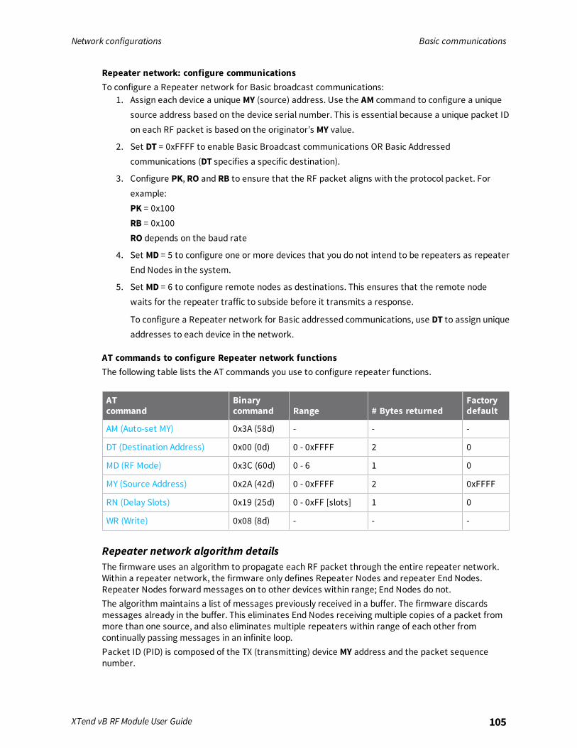
Network configurations Basic communications
XTend vB RF Module User Guide 105
Repeater network: configure communicationsTo configure a Repeater network for Basic broadcast communications:
1. Assign each device a unique MY (source) address. Use the AM command to configure a uniquesource address based on the device serial number. This is essential because a unique packet IDon each RF packet is based on the originator’s MY value.
2. Set DT = 0xFFFF to enable Basic Broadcast communications OR Basic Addressedcommunications (DT specifies a specific destination).
3. Configure PK, RO and RB to ensure that the RF packet aligns with the protocol packet. Forexample:PK = 0x100RB = 0x100RO depends on the baud rate
4. Set MD = 5 to configure one or more devices that you do not intend to be repeaters as repeaterEnd Nodes in the system.
5. Set MD = 6 to configure remote nodes as destinations. This ensures that the remote nodewaits for the repeater traffic to subside before it transmits a response.
To configure a Repeater network for Basic addressed communications, use DT to assign uniqueaddresses to each device in the network.
AT commands to configure Repeater network functionsThe following table lists the AT commands you use to configure repeater functions.
ATcommand
Binarycommand Range # Bytes returned
Factorydefault
AM (Auto-set MY) 0x3A (58d) - - -
DT (Destination Address) 0x00 (0d) 0 - 0xFFFF 2 0
MD (RF Mode) 0x3C (60d) 0 - 6 1 0
MY (Source Address) 0x2A (42d) 0 - 0xFFFF 2 0xFFFF
RN (Delay Slots) 0x19 (25d) 0 - 0xFF [slots] 1 0
WR (Write) 0x08 (8d) - - -
Repeater network algorithm detailsThe firmware uses an algorithm to propagate each RF packet through the entire repeater network.Within a repeater network, the firmware only defines Repeater Nodes and repeater End Nodes.Repeater Nodes forward messages on to other devices within range; End Nodes do not.The algorithm maintains a list of messages previously received in a buffer. The firmware discardsmessages already in the buffer. This eliminates End Nodes receiving multiple copies of a packet frommore than one source, and also eliminates multiple repeaters within range of each other fromcontinually passing messages in an infinite loop.Packet ID (PID) is composed of the TX (transmitting) device MY address and the packet sequencenumber.

Network configurations Basic communications
XTend vB RF Module User Guide 106
The firmware ignores incoming packets with a PID already in the buffer.Each device maintains a PID buffer 4-deep of previously received packets (managed as FIFO).The firmware may shift packets out the serial port and/or repeat them depending on the DTparameter in the RF packet. The following table shows the basis for these decisions.
Address Match Send out serial port? Repeat?
Global Yes Yes
Local Yes No
None No Yes
Repeat delay based on RSSIA transmitted packet may be received by more that one repeater at the same time. In order to reducethe probability that the repeaters will transmit at the same instant, resulting in a collision andpossible data loss; the firmware uses an algorithm that allows a variable back-off prior to a repeaterretransmitting the packet. The algorithm allows devices that receive the packet with a stronger RFsignal (RSSI) to have the first opportunity to retransmit the packet.Use the RN (Delay Slots) parameter to configure this delay. Set RN = 0 (no delays) for small networkswith few repeaters or repeaters that are not within range of each other. Set RN = 1 for systems withtwo to five repeaters that may be within range of each other.The actual length of the delay is computed by the formula:
Delay (ms) = L * DSDS = (-41-RSSI)/10*RN)+RandomInt(0,RN)
Where L is the length of the transmitted packet in milliseconds, DS is the number of delay slots towait, RSSI is the received signal strength in dBm, RN is the value of the RN register and RandomInt (A,B) is a function that returns a random integer from A to B-0
Response packet delayAs a packet propagates through the repeater network, if any node receives the data and generates aquick response, the network needs to delay the response so as not to collide with subsequentretransmissions of the original packet. To reduce collisions, both repeater and end node devices in arepeater network delay transmission of data shifted in the serial port to allow any repeaters withinrange to complete their retransmissions.The time for this delay is computed by the formula:
Maximum Delay (ms) = L * DSDS = ((-41-(-100))/10)*RN)+RN+1
Where L is the length of the transmitted packet in milliseconds, DS is the number of delay slots towait, RSSI is the received signal strength in dBm, and RN is the value of the RN register.
Bandwidth considerationsUsing broadcast repeaters in a network reduces the overall network data throughput as eachrepeater must buffer an entire packet before retransmitting it. For example: if the destination iswithin range of the transmitter and the packet is 32-bytes long, the transmission takes 12 ms on adevice operating at 115,200 baud. If the same packet must propagate through two repeaters, it takes12 ms to arrive at the first repeater, 12 ms to get to the second and a final 12 ms to reach thedestination for a total of 36 ms. Accounting for UART transfer times (~1 ms/byte at 9600 baud), thetime for a server to send a 32-byte query and receive a 32-byte response is about 200 ms, allowing for

Network configurations Basic communications
XTend vB RF Module User Guide 107
five polls per second. With the two repeaters in the path, the same query/response sequence wouldtake about 500 ms for two polls per second.Generally, network throughput decreases by a factor of 1/(R+1), with R representing the number ofrepeaters between the source and destination.
Polling mode (basic)Polling mode (basic) and Polling mode (acknowledged) operate in the same way. The only differencebetween the two modes is in their means of achieving reliable delivery of data. Polling mode (basic)uses multiple transmissions to achieve reliable delivery.
Characteristics Uses a high percentage of available network bandwidth.Eliminates collisions.Works with reliable delivery (RR or MT parameters).Supports binary data transfers.Base device requests packets from remote device by polling a sequential range ofaddresses.Base device is configured to specify the range of addresses being polled.Uses inter-character delay to create RF packet lengths aligned with protocolpacket lengths up to 2048 bytes long.
Constraints The minimum time interval between polling cycles is configurable. However, if theremote devices cannot all be processed within that time interval, the polling cycleis ineffective (that is, it will impose no additional delay). In order to ensure a pausebetween polling cycles, you must set PD to a value that is large enough toaccommodate the pause.
Recommendeduse
Use for point-to-multipoint applications that require Reliable Delivery of data. Usethis mode when it is critical that a base device be able to discern data coming frommultiple devices.
Requiredparametervalues (Base)
MD (RF Mode) = 3PB (Polling Begin Address)PE (Polling End Address)
Requiredparametervalues(Remote)
MD (RF Mode) = 4
Relatedcommands
Networking: MT, PD, DT, MY, and AM
Polling mode theory of operationA Polling Base device cycles through a sequential range of addresses. The Polling Base polls eachPolling Remote device, waits for a response, then poll the next remote address in the sequence. EachPolling Remote responds by sending the data from its DIN buffer following the RB and RO parameters.When there is no eligible data to send, the Polling Remote does not respond. The Polling Base polls thenext address in the polling sequence after a short delay.
Configure a Polling BaseTo configure a device as a Polling Base:

Network configurations Acknowledged communications: Acknowledged mode
XTend vB RF Module User Guide 108
1. Set MD = 3.
2. Set MY = 0.
3. Set the sequential range of polling addresses using PB and PE.
4. (Optional) Enable Basic Reliable Delivery (MT ≥ 0). The firmware also supports AcknowledgedReliable Delivery. For more information, see Polling mode (acknowledged).
5. (Optional) Use PD to configure a delay between polls to slow down the system, if needed.
6. (Optional) Enable API Mode to address remote devices within polling range on a packet-by-packet basis.
Configure a Polling RemoteTo configure a device as a Polling Remote:
1. Set MD = 4.
2. Configure sequential source addresses for all remote devices using MY.
3. Set DT to point to the Polling Base (DT = 0x0000).
4. (Optional) Enable Basic Reliable Delivery (MT >= 0). The firmware also supports AcknowledgedReliable Delivery. For more information, see Polling mode (acknowledged).
Acknowledged communications: Acknowledged modeUse Acknowledged mode for applications that need reliable delivery. If messages are smaller than 256bytes, use the RB and RO commands to align RF packets to application packets.
Characteristics Reliable delivery through positive acknowledgments for each packet.Throughput, latency and jitter vary depending on the quality of thechannel and the strength of the signal.
Required parametervalues (TX device)
RR (Retries) >= 1
Related commands Networking (DT, MK, RR), Serial Interfacing (PK, RN, RO, RB, TT)
Acknowledged mode connection sequenceAfter sending a packet while in Acknowledged mode, the TX (transmitting) device listens for anacknowledgment (ACK). If it receives the ACK, it either moves on to sending a subsequent packet ifmore transmit data is pending or waits for exactly RN random delay slots before allowing anothertransmission if no more data is pending transmit.If the TX device does not receive the ACK within the allotted time, it retransmits the packet with anew RF initializer following the ACK slot. There is no delay between the first ACK slot and the firstretransmission. Subsequent retransmissions incur a delay of a random number of delay slots,between 0 and RN. If RN is set to 0 on the TX device, there are never any back-off delays betweenretransmissions. During back-off delays, the TX device goes into Idle Mode and may receive RF data.This can have the effect of increasing the back-off delay, as the device cannot return to Transmit (orretransmit) mode as long as it is receiving RF data.After receiving and acknowledging a packet, the RX (receiving) device moves to the next frequencyand listens for either a retransmission or new data for a specific period of time. Even if the TX device
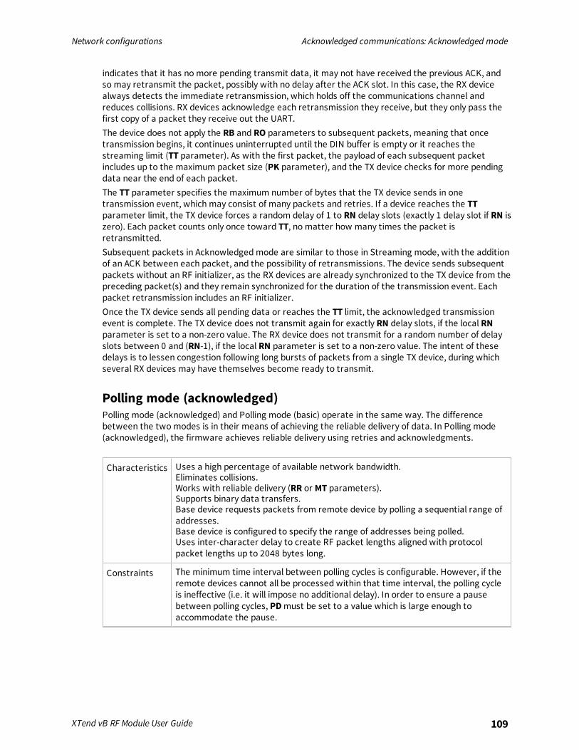
Network configurations Acknowledged communications: Acknowledged mode
XTend vB RF Module User Guide 109
indicates that it has no more pending transmit data, it may not have received the previous ACK, andso may retransmit the packet, possibly with no delay after the ACK slot. In this case, the RX devicealways detects the immediate retransmission, which holds off the communications channel andreduces collisions. RX devices acknowledge each retransmission they receive, but they only pass thefirst copy of a packet they receive out the UART.The device does not apply the RB and RO parameters to subsequent packets, meaning that oncetransmission begins, it continues uninterrupted until the DIN buffer is empty or it reaches thestreaming limit (TT parameter). As with the first packet, the payload of each subsequent packetincludes up to the maximum packet size (PK parameter), and the TX device checks for more pendingdata near the end of each packet.The TT parameter specifies the maximum number of bytes that the TX device sends in onetransmission event, which may consist of many packets and retries. If a device reaches the TTparameter limit, the TX device forces a random delay of 1 to RN delay slots (exactly 1 delay slot if RN iszero). Each packet counts only once toward TT, no matter how many times the packet isretransmitted.Subsequent packets in Acknowledged mode are similar to those in Streaming mode, with the additionof an ACK between each packet, and the possibility of retransmissions. The device sends subsequentpackets without an RF initializer, as the RX devices are already synchronized to the TX device from thepreceding packet(s) and they remain synchronized for the duration of the transmission event. Eachpacket retransmission includes an RF initializer.Once the TX device sends all pending data or reaches the TT limit, the acknowledged transmissionevent is complete. The TX device does not transmit again for exactly RN delay slots, if the local RNparameter is set to a non-zero value. The RX device does not transmit for a random number of delayslots between 0 and (RN-1), if the local RN parameter is set to a non-zero value. The intent of thesedelays is to lessen congestion following long bursts of packets from a single TX device, during whichseveral RX devices may have themselves become ready to transmit.
Polling mode (acknowledged)Polling mode (acknowledged) and Polling mode (basic) operate in the same way. The differencebetween the two modes is in their means of achieving the reliable delivery of data. In Polling mode(acknowledged), the firmware achieves reliable delivery using retries and acknowledgments.
Characteristics Uses a high percentage of available network bandwidth.Eliminates collisions.Works with reliable delivery (RR or MT parameters).Supports binary data transfers.Base device requests packets from remote device by polling a sequential range ofaddresses.Base device is configured to specify the range of addresses being polled.Uses inter-character delay to create RF packet lengths aligned with protocolpacket lengths up to 2048 bytes long.
Constraints The minimum time interval between polling cycles is configurable. However, if theremote devices cannot all be processed within that time interval, the polling cycleis ineffective (i.e. it will impose no additional delay). In order to ensure a pausebetween polling cycles, PD must be set to a value which is large enough toaccommodate the pause.

Network configurations Acknowledged communications: Acknowledged mode
XTend vB RF Module User Guide 110
Recommendeduse
Use for point-to-multipoint applications that require Reliable Delivery of data. Usethis mode when it is critical that a base device be able to discern data coming frommultiple devices.
Requiredparametervalues (Base)
MD (RF Mode) = 3,PB (Polling Begin Address)PE (Polling End Address)
Requiredparametervalues(Remote)
MD (RF Mode) = 4
Relatedcommands
Networking (RR, PD, DT, MY, AM)
For configuration and theory of operation information, see Polling mode theory of operation,Configure a Polling Base and Configure a Polling Remote.

Development Kit
Development Kit contents 112Interface hardware 112XTIB-R RS-232/485 Interface Board 113Adapters 116Interface protocols 118
XTend vB RF Module User Guide 111
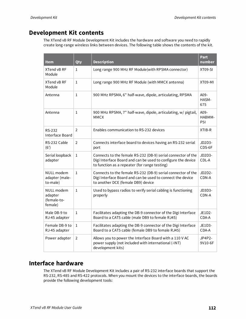
Development Kit Development Kit contents
XTend vB RF Module User Guide 112
Development Kit contentsThe XTend vB RF Module Development Kit includes the hardware and software you need to rapidlycreate long-range wireless links between devices. The following table shows the contents of the kit.
Item Qty DescriptionPartnumber
XTend vB RFModule
1 Long range 900 MHz RF Module(with RPSMA connector) XT09-SI
XTend vB RFModule
1 Long range 900 MHz RF Module (with MMCX antenna) XT09-MI
Antenna 1 900 MHz RPSMA, 6" half-wave, dipole, articulating, RPSMA A09-HASM-675
Antenna 1 900 MHz RPSMA, 7" half-wave, dipole, articulating, w/ pigtail,MMCX
A09-HABMM-P5I
RS-232Interface Board
2 Enables communication to RS-232 devices XTIB-R
RS-232 Cable(6')
2 Connects interface board to devices having an RS-232 serialport
JD2D3-CDS-6F
Serial loopbackadapter
1 Connects to the female RS-232 (DB-9) serial connector of theDigi Interface Board and can be used to configure the deviceto function as a repeater (for range testing)
JD2D3-CDL-A
NULL modemadapter (male-to-male)
1 Connects to the female RS-232 (DB-9) serial connector of theDigi Interface Board and can be used to connect the deviceto another DCE (female DB9) device
JD2D2-CDN-A
NULL modemadapter(female-to-female)
1 Used to bypass radios to verify serial cabling is functioningproperly
JD3D3-CDN-A
Male DB-9 toRJ-45 adapter
1 Facilitates adapting the DB-9 connector of the Digi InterfaceBoard to a CAT5 cable (male DB9 to female RJ45)
JE1D2-CDA-A
Female DB-9 toRJ-45 adapter
1 Facilitates adapting the DB-9 connector of the Digi InterfaceBoard to a CAT5 cable (female DB9 to female RJ45)
JE1D3-CDA-A
Power adapter 2 Allows you to power the Interface Board with a 110 V ACpower supply (not included with international (-INT)development kits)
JP4P2-9V10-6F
Interface hardwareThe XTend vB RF Module Development Kit includes a pair of RS-232 interface boards that support theRS-232, RS-485 and RS-422 protocols. When you mount the devices to the interface boards, the boardsprovide the following development tools:

Development Kit XTIB-R RS-232/485 Interface Board
XTend vB RF Module User Guide 113
n Fast and direct connection to serial devices (such as PCs) and easy access to the deviceregistries. The parameters stored in the registry allow you to customize the devices to suit thespecific needs of your data systems.
n External DIP switch to automatically configure common device profiles.
n Signal conversion between TTL levels and RS-232 levels.
The Digi Interface board can connect the device to any device that has an available RS-232, RS-485 orRS-422 connection.This documentation refers to a XTend vB RF Module mounted to an interface board as a "ModuleAssembly."
XTIB-R RS-232/485 Interface BoardThe following figure shows a front view of the board. The table explains the numbered callouts in thefigure.
Number Description
1 Configuration switch
2 I/O and Power LEDs
3 DB-9 Serial port
4 RSSI LEDs
5 Power connector
Configuration switchThe Configuration switch provides an alternate method for entering Command mode. To enterCommand mode at the device's default RF data rate, hold the Configuration switch down for twoseconds.

Development Kit XTIB-R RS-232/485 Interface Board
XTend vB RF Module User Guide 114
I/O and Power LEDsThe LEDS visualize status information and indicate device activity as follows:
LEDcolor
LEDlocation Indication
Yellow Top Serial data out (to the host)
Green Middle Serial data in (from the host)
Red Bottom Power/TX indicator (the red light is on when powered, it pulses on and offbriefly during RF transmission)
Serial portThe serial port is a standard female DB-9 (RS-232) connector. You can also use this connector for RS-485 and RS-422 connections.
RSSI LEDsThe RSSI LEDs indicate the amount of fade margin present in an active wireless link. Fade margin isthe difference between the incoming signal strength and the device's receiver sensitivity. The LEDindications are as follows:
Number of LEDs on Indicates
3 Very strong signal (> 30 dB fade margin)
2 Strong signal (> 20 dB fade margin)
1 Moderate signal (> 10 dB fade margin)
0 Weak signal (< 10 dB fade margin)
Power connector7-28 VDC power connector (center positive, 5.5/2.1 mm). The XTIB-R interface board can acceptvoltages as low as 5 V. Contact Digi Technical Support to enable this option.
XTIB-R DIP switch
The DIP switch automatically configures the device to operate in different modes during the power-onsequence. Each time the Module Assembly (interface board with a device) powers-on, intelligence onthe board programs the attached device according to the positions of the DIP Switch.The following figure illustrates the DIP switch settings.

Development Kit XTIB-R RS-232/485 Interface Board
XTend vB RF Module User Guide 115
Automatic DIP switch configurationsEach time you power on the Module Assembly, the firmware sends AT commands to the on-board RFmodule as dictated by the positions of the DIP switches. The following figure shows the DIP switchwith the various configurations.
The following table shows the commands that the firmware sends to the module as a result of DIPswitch settings. DIP switches 3 and 4 are only used for RS-485/422 termination and do not affect theconfiguration of the device. In the tables, SW means switch.
Switchcondition Behavior Commands sent during power-up
Switches 1 and 2: Restore defaults / serial interfacing
SW1: ON (up)SW2: ON (up)
Restoredefaults
RE (restore defaults)WR (write defaults to non-volatile memory)
SW1: ON (up)SW2: OFF(down)
RS-232operation
CS 0 (RS-232, CTS flow control)
SW1: OFF(down)SW2: OFF(down)
RS-485/422operation
CS 3 (RS-485 or RS-422 operation)
Switches 5 and 6: TX/TX modes
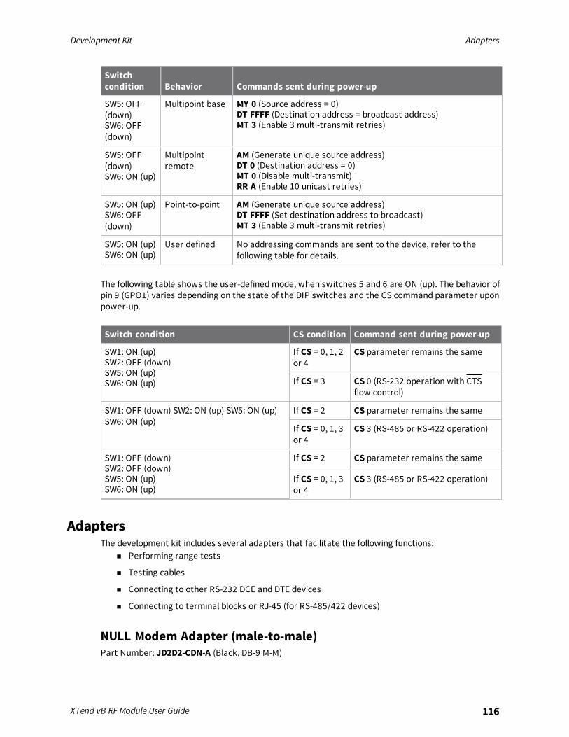
Development Kit Adapters
XTend vB RF Module User Guide 116
Switchcondition Behavior Commands sent during power-up
SW5: OFF(down)SW6: OFF(down)
Multipoint base MY 0 (Source address = 0)DT FFFF (Destination address = broadcast address)MT 3 (Enable 3 multi-transmit retries)
SW5: OFF(down)SW6: ON (up)
Multipointremote
AM (Generate unique source address)DT 0 (Destination address = 0)MT 0 (Disable multi-transmit)RR A (Enable 10 unicast retries)
SW5: ON (up)SW6: OFF(down)
Point-to-point AM (Generate unique source address)DT FFFF (Set destination address to broadcast)MT 3 (Enable 3 multi-transmit retries)
SW5: ON (up)SW6: ON (up)
User defined No addressing commands are sent to the device, refer to thefollowing table for details.
The following table shows the user-defined mode, when switches 5 and 6 are ON (up). The behavior ofpin 9 (GPO1) varies depending on the state of the DIP switches and the CS command parameter uponpower-up.
Switch condition CS condition Command sent during power-up
SW1: ON (up)SW2: OFF (down)SW5: ON (up)SW6: ON (up)
If CS = 0, 1, 2or 4
CS parameter remains the same
If CS = 3 CS 0 (RS-232 operation with CTSflow control)
SW1: OFF (down) SW2: ON (up) SW5: ON (up)SW6: ON (up)
If CS = 2 CS parameter remains the same
If CS = 0, 1, 3or 4
CS 3 (RS-485 or RS-422 operation)
SW1: OFF (down)SW2: OFF (down)SW5: ON (up)SW6: ON (up)
If CS = 2 CS parameter remains the same
If CS = 0, 1, 3or 4
CS 3 (RS-485 or RS-422 operation)
AdaptersThe development kit includes several adapters that facilitate the following functions:
n Performing range tests
n Testing cables
n Connecting to other RS-232 DCE and DTE devices
n Connecting to terminal blocks or RJ-45 (for RS-485/422 devices)
NULL Modem Adapter (male-to-male)Part Number: JD2D2-CDN-A (Black, DB-9 M-M)

Development Kit Adapters
XTend vB RF Module User Guide 117
The male-to-male NULL modem adapter is used to connect two DCE devices. A DCE device connectswith a straight-through cable to the male serial port of a computer (DTE). The following image showsthe Male NULL modem adapter and its pinouts.
NULL Modem Adapter (female-to-female)Part Number: JD3D3-CDN-A (Gray, DB-9 F-F)Use the female-to-female NULL modem adapter to verify that serial cabling is functioning properly. Totest cables, insert the female-to-female NULL modem adapter in place of a pair of device assemblies(RS-232 interface board and XTend vB RF Module) and test the connection without devices in theconnection.The following figure shows the adapter and its pinouts.
Serial Loopback AdapterPart Number: JD2D3-CDL-A (Red, DB-9 M-F)Use the serial loopback adapter for range testing. During a range test, the serial loopback adaptercauses the device to function as a repeater by looping serial data back into the device forretransmission.The following image shows the adapter and its pinouts.

Development Kit Interface protocols
XTend vB RF Module User Guide 118
Male DB-9 to RJ-45 AdapterPart Number: JD2D2-CDN-A (Yellow)This adapter facilitates adapting the DB-9 connector of the Interface Board to a CAT5 cable (male DB9to female RJ45).For connection guidelines, see RS-485 (4-wire) and RS-422 operation.The following image shows the adapter and its pinouts.
Female DB-9 to RJ-45 AdapterPart Number: JD3D3-CDN-A (Green) This adapter facilitates adapting the DB-9 Connector of theInterface Board to a CAT5 cable (female DB9 to female RJ45).For connection guidelines, see ‘RS-485 (4-wire) & RS-422 Operation’ sections.The following image shows the adapter and its pinouts.
Interface protocolsThe XTend vB RF Module Module Assembly supports the following interfacing protocols:
n RS-232
n RS-485 (2-wire) half-duplex
n RS-485 (4-wire) and RS-422

Development Kit Interface protocols
XTend vB RF Module User Guide 119
RS-232 operationThe following figures show the RS-232 DIP switch settings and the pins used on the female RS-232(DB-9) serial connector. The Module Assembly reads and applies the DIP switch settings only duringpower-on.
The following table provides the RS-232 signals and their implementations on the Module Assembly.Low-asserted signals have a horizontal line over the pin name.
DB-9pin
RS-232name
XCTUname Description Implementation
1 DCD GPO2 Data-Carrier-Detect
Connected to DSR (pin6 of DB-9)
2 RXD DOUT ReceivedData
Serial data exiting the Module Assembly (to host)
3 TXD DIN TransmittedData
Serial data entering into the Module Assembly (from host)
4 DTR GPI2 Data-Terminal-Ready
Can enable power-down on the Module Assembly
5 GND - GroundSignal
Ground
6 DSR GPO2 Data-Set-Ready
Connected to DCD (pin1 of DB-9)
7 RTS /CMD
GPI1 Request-to-Send /CommandMode
Provides RTS flow control or enables Command mode

Development Kit Interface protocols
XTend vB RF Module User Guide 120
DB-9pin
RS-232name
XCTUname Description Implementation
8 CTS GPO1 Clear-to-Send
Provides CTS flow control
9 RI - RingIndicator
Optional power input that is connected internally to thepositive lead of the front power connector
RS-232 wiring diagramsThe following diagram shows the DTE device (RS-232, male DB-9 connector) wired to a DCE ModuleAssembly (female DB-9).
The following diagram shows the DCE Module Assembly (female DB-9 connector) wired to a DCEdevice (RS-232, male DB-9).

Development Kit Interface protocols
XTend vB RF Module User Guide 121
RS-485 (2-wire) operationWhen operating within the RS-485 protocols, all communications are half-duplex. The ModuleAssembly reads and applies the DIP switch settings only during power-on.The following figure shows the RS-485 (2-wire) half-duplex DIP switch settings.
The following figure shows the RS-485 (2-wire) with termination (optional) DIP switch settings.
Enabling termination activates a 120 Ω resistor between T+ and T-.The following figure shows the pins that the female RS-232 (DB-9) serial connector uses.

Development Kit Interface protocols
XTend vB RF Module User Guide 122
For the RJ-45 connector pin designations to use in RS-485/422 environments see Male DB-9 to RJ-45Adapter and Female DB-9 to RJ-45 Adapter.The following table provides the RS-485 (2-wire half-duplex) signals and their implementations on theModule Assembly.
DB-9 PinRS-485name Description Implementation
2 T/R- (TRA) Negative dataline
Transmit serial data to and from the ModuleAssembly
5 GND Ground signal Ground
8 T/R+ (TRB) Positive data line Transmit serial data to and from the ModuleAssembly
9 PWR Power Optional power input that is connected internallyto the front power connector
1, 3, 4, 6,7
not used
RS-485 wiring diagramsThe following diagram shows the Module Assembly in an RS-485 (2-wire) half-duplex environment.
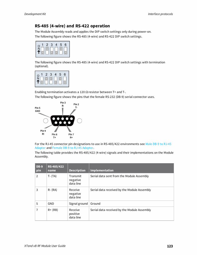
Development Kit Interface protocols
XTend vB RF Module User Guide 123
RS-485 (4-wire) and RS-422 operationThe Module Assembly reads and applies the DIP switch settings only during power-on.The following figure shows the RS-485 (4-wire) and RS-422 DIP switch settings.
The following figure shows the RS-485 (4-wire) and RS-422 DIP switch settings with termination(optional).
Enabling termination activates a 120 Ω resistor between T+ and T-.The following figure shows the pins that the female RS-232 (DB-9) serial connector uses.
For the RJ-45 connector pin designations to use in RS-485/422 environments see Male DB-9 to RJ-45Adapter and Female DB-9 to RJ-45 Adapter.The following table provides the RS-485/422 (4-wire) signals and their implementations on the ModuleAssembly.
DB-9pin
RS-485/422name Description Implementation
2 T- (TA) Transmitnegativedata line
Serial data sent from the Module Assembly
3 R- (RA) Receivenegativedata line
Serial data received by the Module Assembly
5 GND Signal ground Ground
7 R+ (RB) Receivepositivedata line
Serial data received by the Module Assembly

Development Kit Interface protocols
XTend vB RF Module User Guide 124
DB-9pin
RS-485/422name Description Implementation
8 T+ (TB) Transmitpositivedata line
Serial data sent from the Module Assembly
9 PWR Power Optional power input that is connected internally to thefront power connector
1, 4, 6 not used
RS-422 wiring diagramsThe following figure shows the Module Assembly in an RS-485 (4-wire) environment.
The following figure shows the Module Assembly in an RS-422 environment.
RS-485/422 connection guidelinesThe RS-485/422 protocol provides a solution for wired communications that can tolerate high noiseand push signals over long cable lengths. RS-485/422 signals can communicate as far as 4000 feet

Development Kit Interface protocols
XTend vB RF Module User Guide 125
(1200 m). RS-232 signals are suitable for cable distances up to 100 feet (30.5 m).RS-485 offers multi-drop capability in which you can connect up to 32 nodes. Use the RS-422 protocolfor point-to-point communications.To integrate the XTend vB RF Module with the RS-485/422 protocol, we suggest the following:
1. When using Ethernet twisted pair cabling: connect T+ and T- to each wire in a twisted pair.Likewise, connect R+ and R- to a twisted pair. For example, tie the green and white/greenwires to T+ and T-.
2. For straight-through Ethernet cable (not cross-over cable), the following wiring pattern workswell: Pin 3 to T+, Pin 4 to R+, Pin 5 to R-, Pin 6 to T-.
3. The connecting cable only requires 4 wires, even though there are 8 wires.
4. When using phone cabling (RJ-11), Pin 2 in the cable maps to Pin 3 on the opposite end of cableand Pin 1 maps to Pin 4 respectively.
Related Documents