3A3320J EN Operation and Parts XP ™ and XP-hf ™ PressureTrak Kit Monitors pressures to provide ratio assurance on XP and XP-hf plural-component sprayers in hazardous or non-hazardous locations. For professional use only. 17G807: N3400 PressureTrak Kit 17G808: N6500 PressureTrak Kit 25C452: XP-hf PressureTrak Kit 26C426: XL3400 PressureTrak Kit 26C427: XL6500 PressureTrak Kit See page 2 for Agency Approvals. Important Safety Instructions Read all warnings and instructions in this manual and the XP-hf sprayer operation manual. Save these instructions.

Welcome message from author
This document is posted to help you gain knowledge. Please leave a comment to let me know what you think about it! Share it to your friends and learn new things together.
Transcript

3A3320JEN
Operation and Parts
XP™ and XP-hf™ PressureTrak KitMonitors pressures to provide ratio assurance on XP and XP-hf plural-component sprayers in hazardous or non-hazardous locations. For professional use only.
17G807: N3400 PressureTrak Kit17G808: N6500 PressureTrak Kit25C452: XP-hf PressureTrak Kit26C426: XL3400 PressureTrak Kit26C427: XL6500 PressureTrak Kit
See page 2 for Agency Approvals.
Important Safety InstructionsRead all warnings and instructions in this manual and the XP-hf sprayer operation manual. Save these instructions.

Related Manuals
2 3A3320J
ContentsRelated Manuals . . . . . . . . . . . . . . . . . . . . . . . . . . . . . . . . . 2Agency Approvals . . . . . . . . . . . . . . . . . . . . . . . . . . . . . . . 2Warnings . . . . . . . . . . . . . . . . . . . . . . . . . . . . . . . . . . . . . . . 3Overview . . . . . . . . . . . . . . . . . . . . . . . . . . . . . . . . . . . . . . . 4
Operating Window . . . . . . . . . . . . . . . . . . . . . . . . . . . . 4Component Identification . . . . . . . . . . . . . . . . . . . . . . . . . 5
XP Proportioner (Model 571100 Shown) . . . . . . . . . . . 5XP-hf Proportioner (Model 572407 Shown) . . . . . . . . . 6XP Sprayer . . . . . . . . . . . . . . . . . . . . . . . . . . . . . . . . . . 7User Interface . . . . . . . . . . . . . . . . . . . . . . . . . . . . . . . . 8Display Screens . . . . . . . . . . . . . . . . . . . . . . . . . . . . . . 9
Installation . . . . . . . . . . . . . . . . . . . . . . . . . . . . . . . . . . . . 10Installation for XP System with NXT Motor . . . . . . . . . 10Installation for XP-hf System with XL 10000
Air Motor . . . . . . . . . . . . . . . . . . . . . . . . . . . . . . . 12Installation for XP System with XL Air Motor . . . . . . . 14
Operation . . . . . . . . . . . . . . . . . . . . . . . . . . . . . . . . . . . . . 16Startup . . . . . . . . . . . . . . . . . . . . . . . . . . . . . . . . . . . . 16Shutdown . . . . . . . . . . . . . . . . . . . . . . . . . . . . . . . . . . 16Setup . . . . . . . . . . . . . . . . . . . . . . . . . . . . . . . . . . . . . 16
Alarms, Deviations, and Advisories . . . . . . . . . . . . . . . . 17Clear Alarms . . . . . . . . . . . . . . . . . . . . . . . . . . . . . . . . 17View Current Alarms . . . . . . . . . . . . . . . . . . . . . . . . . . 18View Error Log . . . . . . . . . . . . . . . . . . . . . . . . . . . . . . 18Error Codes . . . . . . . . . . . . . . . . . . . . . . . . . . . . . . . . 19
Repair . . . . . . . . . . . . . . . . . . . . . . . . . . . . . . . . . . . . . . . . 23Replace the PressureTrak Module Battery or
Fuse . . . . . . . . . . . . . . . . . . . . . . . . . . . . . . . . . . 23Retract a Solenoid With a Dead Battery . . . . . . . . . . . 24
Parts . . . . . . . . . . . . . . . . . . . . . . . . . . . . . . . . . . . . . . . . . 25Kits 17G807 and 17G808 . . . . . . . . . . . . . . . . . . . . . . 25Kit 25C452 . . . . . . . . . . . . . . . . . . . . . . . . . . . . . . . . . 26Kits 26C426 and 26C427 . . . . . . . . . . . . . . . . . . . . . . 27
Appendix A: User Setup Display . . . . . . . . . . . . . . . . . . 28Setup Mode Details . . . . . . . . . . . . . . . . . . . . . . . . . . 28Setup Screen 1 . . . . . . . . . . . . . . . . . . . . . . . . . . . . . . 28Setup Screen 2 . . . . . . . . . . . . . . . . . . . . . . . . . . . . . . 29Setup Screen 3 . . . . . . . . . . . . . . . . . . . . . . . . . . . . . . 29Set Password . . . . . . . . . . . . . . . . . . . . . . . . . . . . . . . 30
Appendix B: Run Screen Details . . . . . . . . . . . . . . . . . . 31Circulation Mode . . . . . . . . . . . . . . . . . . . . . . . . . . . . . 31Spray Mode Active . . . . . . . . . . . . . . . . . . . . . . . . . . . 31Alarm Active . . . . . . . . . . . . . . . . . . . . . . . . . . . . . . . . 31Deviation Active . . . . . . . . . . . . . . . . . . . . . . . . . . . . . 32Information Screen . . . . . . . . . . . . . . . . . . . . . . . . . . . 32Manual Bypass Mode . . . . . . . . . . . . . . . . . . . . . . . . . 32
Accessories . . . . . . . . . . . . . . . . . . . . . . . . . . . . . . . . . . . 33Technical Specifications . . . . . . . . . . . . . . . . . . . . . . . . . 33California Proposition 65 . . . . . . . . . . . . . . . . . . . . . . . . 33Graco Standard Warranty . . . . . . . . . . . . . . . . . . . . . . . . 34
Related Manuals
Agency Approvals
Manual in English Description
3A3320 PressureTrak Manual, Instructions and Parts3A0420 XP Sprayer, Instructions and Parts3A4381 XP-hf Proportioner, Instructions and Parts334644 XL 10000 Air Motor, Instructions and Parts3A5423 XL6500 and 3400 Air Motor, Instructions and Parts
Model Agency Approval
17N936*17G80717G80818C025**
* 17N936 is the agency approved PressureTrak included in kits 25C452.** 18C025 is the agency approved PressureTrak included in kits 26C426 and 26C427
2575

Warnings
3A3320J 3
WarningsThe following warnings are for the setup, use, grounding, maintenance, and repair of this equipment. The exclama-tion point symbol alerts you to a general warning and the hazard symbols refer to procedure-specific risks. When these symbols appear in the body of this manual or on warning labels, refer back to these Warnings. Product-specific hazard symbols and warnings not covered in this section may appear throughout the body of this manual where applicable.
WARNINGSPECIAL CONDITIONS FOR SAFE USEEquipment must comply with the following conditions to avoid a hazardous condition which can cause fire or explosion. • All label and marketing material must be cleaned with a damp cloth (or equivalent).• The electronic monitoring system is required to be grounded. See Grounding instructions in your
pump operation manual.
FIRE AND EXPLOSION HAZARD Flammable fumes, such as solvent and paint fumes, in work area can ignite or explode. Paint or solvent flowing through the equipment can cause static sparking. To help prevent fire and explosion:• Use equipment only in well-ventilated area.• Eliminate all ignition sources; such as pilot lights, cigarettes, portable electric lamps, and plastic drop
cloths (potential static sparking). • Ground all equipment in the work area. See Grounding instructions in your pump operation manual.• Never spray or flush solvent at high pressure.• Keep work area free of debris, including solvent, rags and gasoline.• Do not plug or unplug power cords, or turn power or light switches on or off when flammable fumes
are present.• Use only grounded hoses.• Hold gun firmly to side of grounded pail when triggering into pail. Do not use pail liners unless they
are anti-static or conductive.• Stop operation immediately if static sparking occurs or you feel a shock. Do not use equipment
until you identify and correct the problem.• Keep a working fire extinguisher in the work area.

Overview
4 3A3320J
OverviewThe purpose of the XP PressureTrak is to shut down the sprayer if abnormal pressure conditions are detected in order to prevent spraying material that is not mixed on ratio.
Two pressure transducers read the A and B fluid pressures in the outlet manifold and send the readings back to the XP PressureTrak.
The XP PressureTrak monitors the difference between the A and B fluid pressures, alerting the user when an imbalance is detected. An imbalance may be due to a plug, leak, or running out of fluid.
When an imbalance is detected, the electric solenoid disables the air motor, an alarm is displayed on the screen, and the LED on the front of the display flashes. For more error code information see Alarms, Deviations, and Advisories page 17.
The following alarms can occur:
• Differential Pressure (B>A)• Differential Pressure (A>B)• Pressure A High• Pressure B High• Electric Solenoid Disconnected• Pressure A Disconnected• Pressure B Disconnected• Low Battery• Blown Fuse
Operating Window
Below Minimum Spray PressureThe air motor is allowed to automatically operate in Circulation Mode any time the fluid pressures are below the minimum spray pressure. This allows for loading the system and circulating the fluids without alarms or shutdowns.
Above Minimum Spray PressureWhen the XP PressureTrak detects the fluid pressures above the minimum spray pressure for 30 seconds, and the pressures are balanced within the pre-set limits, it will automatically start pressure monitoring. If the XP PressureTrak does not see balanced pressures within 30 seconds of going above the minimum spray pressure it will detect the fault and disable the air motor. The default minimum spray pressure is 2000 psi (14 MPa, 138 bar). Enter Setup Mode to change the minimum spray pressure as necessary (see Setup Mode Details, page 28).
Maximum Spray PressureThe XP PressureTrak will alarm and shutdown if it detects either A or B fluid pressures above the maximum working pressure (see table below). Enter Setup Mode to reduce the maximum allowable pressure set point (see Setup Mode Details, page 28).
Model Maximum Spray Pressure17G807
7250 psi (500 Bar, 50 MPa)17G80825C452
7500 psi (517 Bar, 51.7 MPa)26C42626C427

Component Identification
3A3320J 5
Component Identification
XP Proportioner (Model 571100 Shown)
,
Ref. DescriptionXA ModuleXB HousingXC CoverXD Pressure SensorsXE SolenoidXM Air Motor

Component Identification
6 3A3320J
XP-hf Proportioner (Model 572407 Shown)
,
Ref. DescriptionXA ModuleXB HousingXD Pressure SensorsXE SolenoidXM Air Motor
Component Identification
3A3320J 7
XP Sprayer
Ref. DescriptionXA ModuleXB HousingXD Pressure SensorsXE SolenoidXM Air MotorXN Cover
,
XN

Component Identification
8 3A3320J
User Interface
Table 1: LCM Button Functions Table 2: Display Soft Key Icons
NOTE: The display will turn OFF after one minute of inactivity to save battery life. The PressureTrak will continue to monitor the pressures. Press any key to wake the XP PressureTrak display.
Button FunctionArrows Up/Down Navigate up or down within a
screen or to a new screen.
Soft Keys Soft keys activate the mode or action represented by the icon next to each soft key.
See Table 2 for soft key icons and actions. Top Soft Key: Edit data, accept edited data, or move right within a selected field.Bottom Soft Key: Enter a screen, exit a screen, or cancel edited data.
NOTICETo prevent damage to soft key buttons, do not press the buttons with sharp objects such as pens, plastic cards, or fingernails.
Icon FunctionEnter Screen In screens that have editable
fields, press to access the fields and make changes.
Exit Screen In screens that have editable fields, press to exit edit mode.
Enter In screens that have editable fields, press to make data selections or to enter changes.
Right In screens that have editable fields, press to move to the right while in a field.
Cancel Cancel a selection or edited data. Returns to the original data.
Clear Error Log Clear entire error log.

Component Identification
3A3320J 9
Display ScreensTable 3: Display Screens, identifies components shown on the Spray Mode Active, Circulation Mode Active, Alarm Active, and Deviation Active Run screens. For more information see Appendix B: Run Screen Details, page 31.
Spray Mode Active Screen
Circulation Mode Active Screen
Alarm Active Screen
Deviation Active Screen
Table 3: Display ScreensIcon Function
Actual spray pressures.
Differential pressure alarm bar graph and pressure units.
Indicates that you are in spray mode.
Indicates that you are in circulation mode.
Indicates that there is an active alarm.
Indicates that there is an active deviation.

Installation
10 3A3320J
Installation
Installation for XP System with NXT Motor
The procedures in this section are specific to each component of the XP PressureTrak. For sprayer installation instructions, refer to the sprayer operation manual.
1. Perform Pressure Relief Procedure. See your XP Sprayer manual.
2. Remove the existing NXT air motor cover and front (D) of the motor cover.
3. Remove the insert from the solenoid hole (F).
4. Install the solenoid (XE). Use the retainer (G) and two bolts (H) to secure the solenoid.
NOTE: The holes in the casting may not have threads, but the screws are thread-forming.
5. Pass the pressure sensor (4a and 4b) through slot (K) and the solenoid (XE) through slot (J) in the housing (XB) and secure the housing to the air motor with two bolts (6).
6. Reinstall the front (D) and install the XP PressureTrak cover (3).
7. Connect the pressure sensor cables to the connectors on the circuit board.
NOTE: Be sure to match the color codes (connect the blue cord to J6, circuit board labeled A and green cord to J7, circuit board labeled B). Connect the solenoid to J3, then connect the battery to the battery terminals.
8. Slide the module (XA) into the channel of the housing (XB) and secure with two screws (5).
9. Insert o-ring (11) on pressure sensor (4a). Lubricate o-ring and install into the A side (blue) of the manifold. Torque sensor nut to 40-50 in-lb (54-67 N•m). Insert o-ring (11) on pressure sensor (4b). Lubricate o-ring and install into the B side (green) of the manifold. Torque sensor nut to 40-50 in-lb (54-67 N•m).
10. Install the pressure sensor harness (XD) through clamp (10) and secure to the frame with screw (8) and nut (9).
To reduce the risk of skin injection and shock, shut down the XP Sprayer before installing your XP PressureTrak. Follow the Shutdown and Pressure Relief procedures in the XP Sprayer operation manual.

Installation
3A3320J 11
XP System with NXT Motor

Installation
12 3A3320J
Installation for XP-hf System with XL 10000 Air Motor
The procedures in this section are specific to each component of the XP PressureTrak. For sprayer installation instructions, refer to your sprayer operation manual.
1. Perform Pressure Relief Procedure. See your XP-hf Proportioner manual.
2. Remove the two top bolts (L) on the XL motor manifold. Use the bolts to install the XP-hf module bracket and PressureTrak.
3. Remove the plug (126) and 0-ring (125) by removing the retaining ring (127).
4. Remove two screws (23) from the XL 10000 air motor valve near the solenoid hole. If screws (23) are not present, remove the two right side bolts (24) from the XL 10000 air motor valve.
5. Install solenoid (3d) into the solenoid hole.
6. Bolt down the solenoid bracket (17) with mounting screws (23), or solenoid bracket (18) with bolts (24), depending on the air valve.
7. Insert o-ring (3j) on pressure sensor (3c). Lubricate o-ring and install into the A side (blue) of the manifold. Torque sensor nut to 40-50 in-lb (54-67 N•m). Insert o-ring (3j) on pressure sensor (3c). Lubricate o-ring and install into the B side (green) of the manifold. Torque sensor nut to 40-50 in-lb (54-67 N•m).
8. Install the pressure sensor harness (XD) through clamp (20) and secure to the frame with screw (4).
9. Remove screws (3e) to slide out module (XA).
10. Connect the battery to the battery terminals.
11. Slide the module (XA) into the channel of the housing (XB) and secure with two screws (3e).
To reduce the risk of skin injection and shock, shut down the XP Sprayer before installing your XP PressureTrak. Follow the Shutdown and Pressure Relief procedures in the XP Sprayer operation manual.

Installation
3A3320J 13
XP-hf System with XL 10000 Air Motor

Installation
14 3A3320J
Installation for XP System with XL Air Motor
The procedures in this section are specific to each component of the XP PressureTrak. For sprayer installation instructions, refer to your sprayer operation manual.
1. Perform Pressure Relief Procedure. See your XP Operation manual.
2. Remove the air valve cover (VC).
3. Remove the top exhaust manifold bolts, then use the bolts to attach the module bracket and PressureTrak.
4. Remove the plug (126) and the o-ring (125) by removing the retaining ring (127).
5. Attach the solenoid (3d) and bracket (17) to the air valve and tighten screws (23).
6. Insert o-ring (3j) on the presser sensor (3c). Lubricate the o-ring and install it into the A side (blue) of the manifold. Torque the sensor nut to 40-50 in-lb (54-67 N•m). Insert o-ring (3j) on the presser sensor (3c). Lubricate the o-ring and install it into the B side (green) of the manifold. Torque the sensor nut to 40-50 in-lb (54-67 N•m).
7. Install the pressure sensor harness (XD) through clamp (20) and secure to the frame with screw (4) and nut (5).
8. Remove screws (3e) to slide out the PressureTrak module (XA).
9. Connect the battery to the battery terminals.
10. Slide the PressureTrak module (XA) into the channel of the housing (XB) and secure with two screws (3e).
11. Replace the original air valve cover with the new air valve cover (VC)
To reduce the risk of skin injection and shock, shut down the XP Sprayer before installing your XP PressureTrak. Follow the Shutdown and Pressure Relief procedures in the XP Sprayer operation manual.

Installation
3A3320J 15
XP System with XL Air Motor
Operation
16 3A3320J
Operation
Startup1. Refer to your XP sprayer operation manual for
sprayer startup instructions.
NOTE: The XP PressureTrak modifies XP sprayers. However, the operation procedures from the XP sprayer operation manual still apply.
2. Press any key to wake the XP PressureTrak. The display will turn off in one minute to save battery life, but will continue to monitor the pressures.
NOTE: To enter into Setup, press and hold any button for three seconds.
ShutdownRefer to your XP sprayer operation manual for sprayer shutdown instructions. The XP PressureTrak will enter a hibernation mode to save battery life.
Setup1. To enter into Setup, press and hold any button for
three seconds.
2. Set the system parameters before spraying. These can be changed as necessary (see Setup Mode Details, page 28).

Alarms, Deviations, and Advisories
3A3320J 17
Alarms, Deviations, and AdvisoriesThere are three types of errors that can occur: Alarms, Deviations, and Advisories. Errors are indicated by the flashing red LED as well as on the display.
Alarms, indicated by , require immediate attention;
therefore, the XP PressureTrak disables the air motor and the alarm screen automatically displays.
Deviations, indicated by , require attention, but not
immediately.
Advisories, indicated by , do not require attention.
Therefore, if a deviation or advisory occur, the system
continues running and or is displayed on the run
screen.
The following table shows the status of the front LED for Alarms and Advisories.
Clear Alarms1. Turn the air valve to OFF.
2. Reduce the air pressure regulator to minimum.
3. Wait for the air pressure to drop.
4. XL air motors only: Press the manual shuttle override button on your air motor air valve. Refer to
your air motor manual. XL3400 and XL6500 air motors have a hole in the cover (VC) to access the air valve.
5. Clear the cause of the error.
6. Press .
NOTE: If the system has air pressure when is pressed, the screen will display how to reset the system and clear an alarm. See FIG. 1 or FIG. 2, or FIG. 3. Press the lower arrow key to stop the demonstration sequence and return to the alarm screen.
7. Turn the air valve to ON.
8. Increase the pressure to achieve the best pattern.
NOTE: When trying to clear an error and the screen displays the “X”, the unit did not retract the solenoid and is in an 8 second delay period before an attempt can be tried to retract the solenoid. Verify air pressure has dropped.
Front LED DescriptionOFF System is powered up and
monitoring pressure. OFF In Circulation Mode or Manual
Bypass Mode.
OFF A deviation exists.
Red Flash An alarm exists and the system
shuts down.
FIG. 1: NXT Air Motor PressureTrak Sequence
FIG. 2: XL10000 (XP-HF) Air Motor PressureTrak Sequence
FIG. 3: XL3400 (XP35) and XL6500 (XP50 / 70) PressureTrak Sequence

Alarms, Deviations, and Advisories
18 3A3320J
View Current AlarmsTo toggle the screens between the Alarm Information screen and the Run Alarm Active screen,
press or .
View Error LogSetup Screen 3 is the error log screen. It displays the most recent error on the top of the list with the past 20 errors below it. This screen displays a list of advisory or alarm error codes and the time the error occurred since the unit went to spray mode. The timer will restart when the pressure falls and unit enters into circulation mode, or when the timer rolls over 23:59.
Alarms, Deviations, and Advisories
3A3320J 19
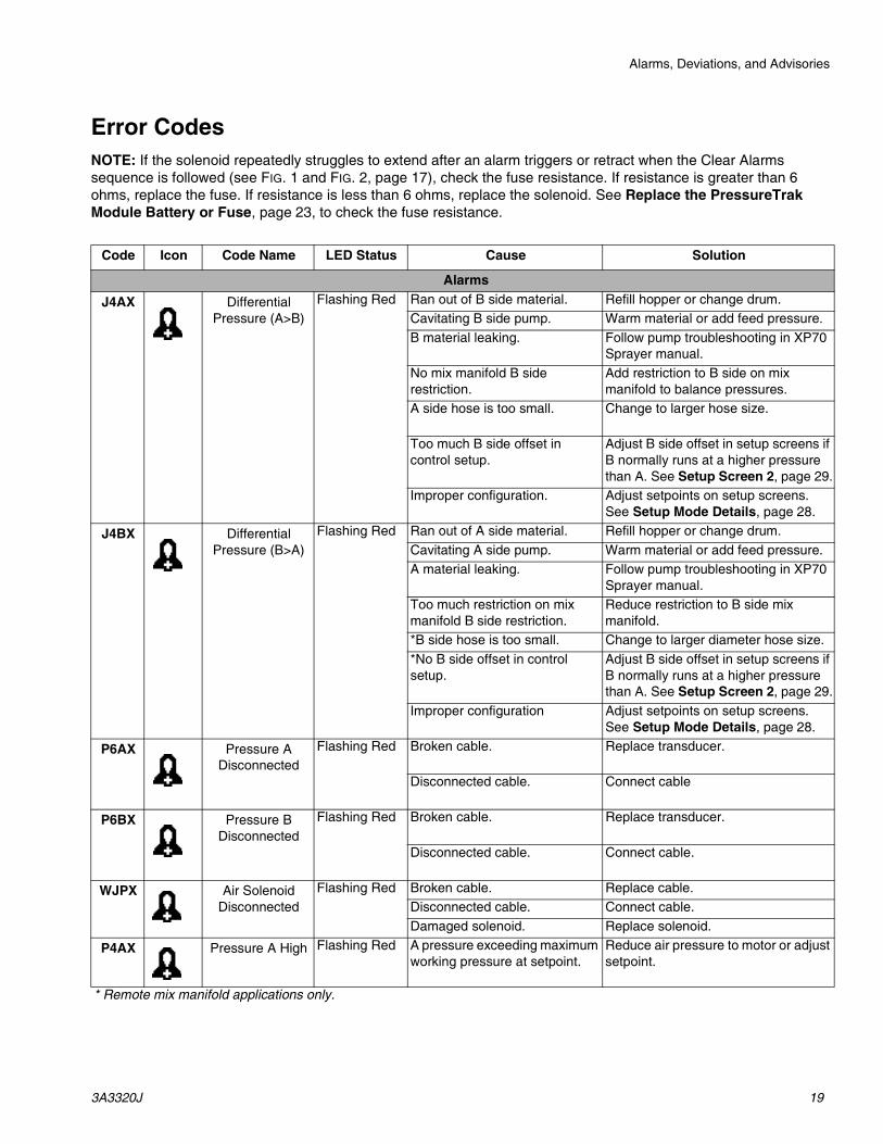
Error CodesNOTE: If the solenoid repeatedly struggles to extend after an alarm triggers or retract when the Clear Alarms sequence is followed (see FIG. 1 and FIG. 2, page 17), check the fuse resistance. If resistance is greater than 6 ohms, replace the fuse. If resistance is less than 6 ohms, replace the solenoid. See Replace the PressureTrak Module Battery or Fuse, page 23, to check the fuse resistance.
Code Icon Code Name LED Status Cause Solution
Alarms
J4AX Differential Pressure (A>B)
Flashing Red Ran out of B side material. Refill hopper or change drum.Cavitating B side pump. Warm material or add feed pressure. B material leaking. Follow pump troubleshooting in XP70
Sprayer manual.No mix manifold B side restriction.
Add restriction to B side on mix manifold to balance pressures.
A side hose is too small. Change to larger hose size.
Too much B side offset in control setup.
Adjust B side offset in setup screens if B normally runs at a higher pressure than A. See Setup Screen 2, page 29.
Improper configuration. Adjust setpoints on setup screens. See Setup Mode Details, page 28.
J4BX Differential Pressure (B>A)
Flashing Red Ran out of A side material. Refill hopper or change drum.Cavitating A side pump. Warm material or add feed pressure. A material leaking. Follow pump troubleshooting in XP70
Sprayer manual.Too much restriction on mix manifold B side restriction.
Reduce restriction to B side mix manifold.
*B side hose is too small. Change to larger diameter hose size.*No B side offset in control setup.
Adjust B side offset in setup screens if B normally runs at a higher pressure than A. See Setup Screen 2, page 29.
Improper configuration Adjust setpoints on setup screens. See Setup Mode Details, page 28.
P6AX Pressure A Disconnected
Flashing Red Broken cable. Replace transducer.
Disconnected cable. Connect cable
P6BX Pressure B Disconnected
Flashing Red Broken cable. Replace transducer.
Disconnected cable. Connect cable.
WJPX Air Solenoid Disconnected
Flashing Red Broken cable. Replace cable.Disconnected cable. Connect cable.Damaged solenoid. Replace solenoid.
P4AX Pressure A High Flashing Red A pressure exceeding maximum working pressure at setpoint.
Reduce air pressure to motor or adjust setpoint.
* Remote mix manifold applications only.

Alarms, Deviations, and Advisories
20 3A3320J
Alarms
P4BX Pressure B High Flashing Red A pressure exceeding maximum working pressure setpoint.
Reduce air pressure to motor or adjust setpoint.
Open down stream valve.
Too much restriction on mix manifold B side restriction.
Reduce restriction to B side on mix manifold.
Blockage in B line downstream. Reduce downstream restriction.
Clean mix manifold.
BATT Low Battery Flashing Red Battery is low. NOTE: If the battery is less than 8.5 volts, this alarm is shown. If the battery is less than 8.3 volts this alarm is shown and the solenoid pin is extended to stop the pump.
See Repair, page 23.
FUSE Blown Fuse Flashing Red Fuse is blown. See Repair, page 23 for information on how to check the fuse.
Fuse not seated in fuse holder. Place fuse in fuse holder.
Bent pins on the fuse. Straighten pins on the fuse, install back into fuse holder.
Code Icon Code Name LED Status Cause Solution

Alarms, Deviations, and Advisories
3A3320J 21
System Pressurized
Flashing Red The PressureTrak controller detected air pressure when trying to clear an alarm.
NOTE: The images in the code and icon columns will display on your screen. These screens demonstrate how to properly clear an alarm. Press the lower left arrow to stop the demonstration sequence and return to the alarm screen.
Shut off air pressure and wait for air pressure to drop.
NOTE: XL air motors only: Press the valve pin fully into the valve. Press
to follow remaining prompts to
clear the alarm. See Clear Alarms, page 17.
System Pressurized (after system
depressurization)
Flashing Red Check fuse resistance. If resistance is less than 6 ohms, replace the solenoid.
Check fuse resistance. If resistance is greater than 6 ohms, replace the fuse. See Replace the PressureTrak Module Battery or Fuse, page 23.
Faulty solenoid due to wear. Replace solenoid.
❖ Only the XL air motors will show the air valve reset images if the air pressure is not turned down.
◆ XL3400 and XL6500 air motors will show the air valve underneath the cover.
Code Icon Code Name LED Status Cause Solution
❖
❖
◆
◆
◆

Alarms, Deviations, and Advisories
22 3A3320J
Deviations
J3AX Differential Pressure (A>B)
OFF Ran out of B Side B material. Refill hopper or change drum.
Cavitating B side pump. Warm material or add feed pressure.
B material leaking. Follow pump troubleshooting in XP70 Sprayer manual.
No mix manifold B side restriction.
Add restriction to B side on mix manifold to balance pressures.
A side hose is too small. Change to larger hose size.
J3BX Differential Pressure (B>A)
OFF Ran out of A side material. Refill hopper or change drum.
Cavitating A side pump. Warm material or add feed pressure.
A material leaking. Follow pump troubleshooting in XP70 Sprayer manual.
Too much restriction on mix manifold B side restriction.
Reduce restriction to B side on mix manifold.
*B side hose too small. Change to a larger hose size.
*No B side offset in control setup.
Add B side offset in setup screen.
Events and Advisories
EERX Under Minimum Spray Pressure, Circulation, Loading
OFF Under minimum spray pressure. Normal for circulation mode.
EVRX Entered into spray mode
OFF Pressure went above minimum spray limit.
Normal for spray mode.
* Remote mix manifold applications only.
Code Icon Code Name LED Status Cause Solution

Repair
3A3320J 23
Repair
Replace the PressureTrak Module Battery or Fuse
1. Remove the two screws (135). Carefully slide the PressureTrak module (131) out of the housing (132).
NXT Air Motor
XL10000 (XP-HF) Air Motor
XL3400 and XL6500 Air Motor
2. Disconnect the electric solenoid (7) and pressure sensor cables (4) from the module board.
3. Take the PressureTrak module (131) to a non-hazardous location
4. To replace the battery, disconnect the used battery and replace with an approved battery.
5. Checking the fuse (12) resistance:
a. Remove the fuse from the circuit board.
b. Use an ohm meter to measure the resistance of the fuse.
NOTE: Less than 6 ohms means the fuse is good. 6 ohms or more means the fuse must be replaced.
s
The battery and fuse must be replaced in a non-hazardous location.
s
Use only the following approved replacement batteries. Use of an unapproved battery will void the Graco warranty, as well as Intertek and Ex approvals.• Ultralife® brand lithium U9VL• Duracell® brand alkaline MN1604• Energizer® brand alkaline 522• Varta® brand alkaline 4922.
s
Use only a Graco-approved replacement fuse (12) Graco part number 24V216
Repair
24 3A3320J
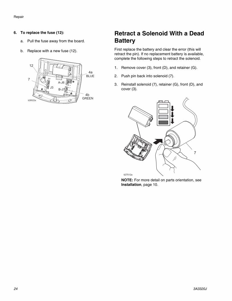
6. To replace the fuse (12):
a. Pull the fuse away from the board.
b. Replace with a new fuse (12).
Retract a Solenoid With a Dead BatteryFirst replace the battery and clear the error (this will retract the pin). If no replacement battery is available, complete the following steps to retract the solenoid.
1. Remove cover (3), front (D), and retainer (G).
2. Push pin back into solenoid (7).
3. Reinstall solenoid (7), retainer (G), front (D), and cover (3).
NOTE: For more detail on parts orientation, see Installation, page 10.
Parts
3A3320J 25
Parts
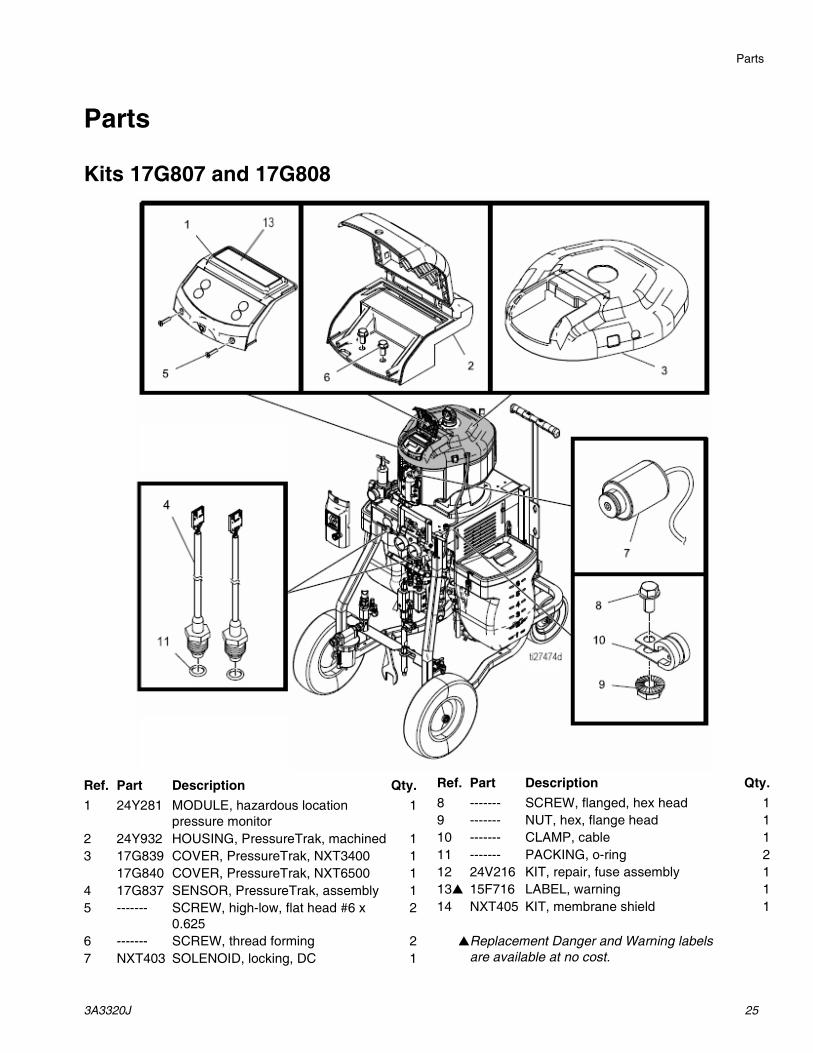
Kits 17G807 and 17G808
Ref. Part Description Qty.1 24Y281 MODULE, hazardous location
pressure monitor1
2 24Y932 HOUSING, PressureTrak, machined 13 17G839 COVER, PressureTrak, NXT3400 1
17G840 COVER, PressureTrak, NXT6500 14 17G837 SENSOR, PressureTrak, assembly 15 ------- SCREW, high-low, flat head #6 x
0.6252
6 ------- SCREW, thread forming 27 NXT403 SOLENOID, locking, DC 1
8 ------- SCREW, flanged, hex head 19 ------- NUT, hex, flange head 110 ------- CLAMP, cable 111 ------- PACKING, o-ring 212 24V216 KIT, repair, fuse assembly 113▲ 15F716 LABEL, warning 114 NXT405 KIT, membrane shield 1
▲Replacement Danger and Warning labels are available at no cost.
Ref. Part Description Qty.

Parts
26 3A3320J
Kit 25C452
Ref. Part Description Qty.1 17P845 BRACKET, XP-hf 12 16C251 GROMMET 13 17N936 MONITOR, PressureTrak
(includes 3a-3j)1
3a 24Y932 HOUSING 13b 24Z940 MODULE 13c 17R447 SENSOR, PressureTrak, assembly 23d 15F477 SOLENOID, locking, DC 13e - - - - - SCREW, high-low, flat head #6 x 0.625 23f 24V216 KIT, repair, fuse assembly (not shown) 13g▲ 15F716 LABEL, warning 13h NXT405 KIT, membrane shield (pack of 20) 1
3j - - - - - PACKING, o-ring 24 - - - - - SCREW 25 - - - - - NUT, hex, flange head 217 17R738 BRACKET, XL motor, solenoid 118 17P748 BRACKET, XP-hf, solenoid 120 - - - - - CLAMP, cable 1
▲ Replacement Danger and Warning labels are available at no cost.
Ref. Part Description Qty.
Parts
3A3320J 27
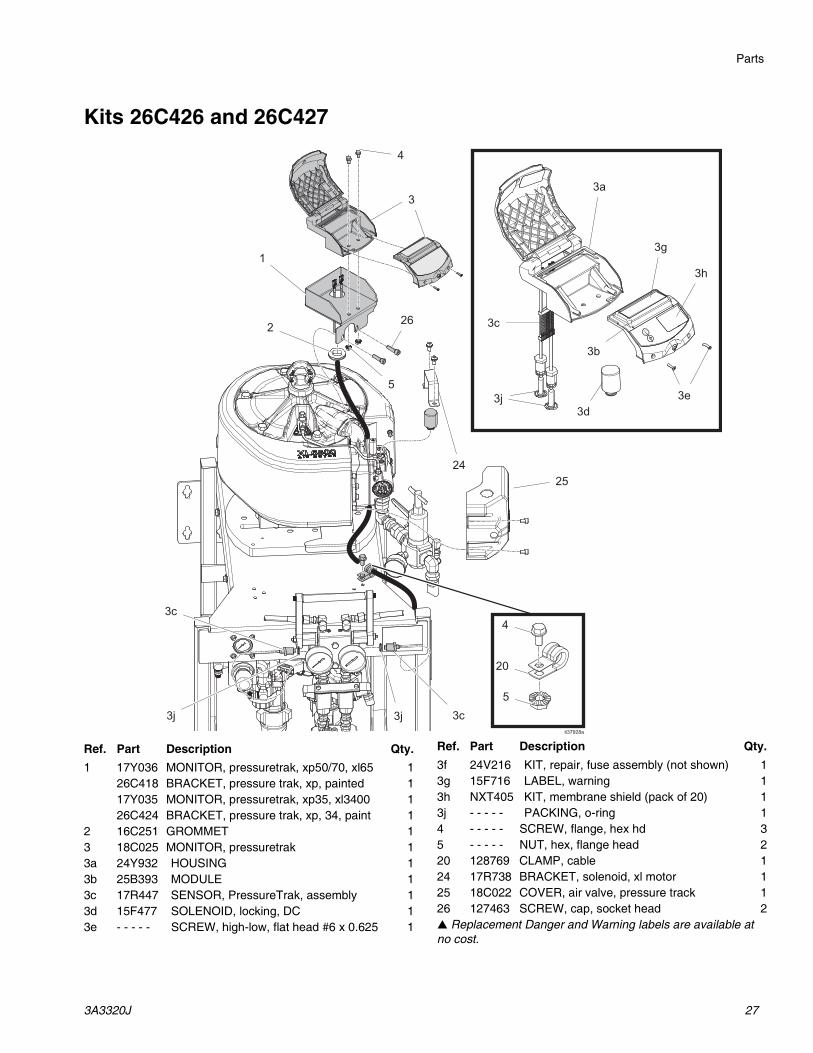
Kits 26C426 and 26C427
Ref. Part Description Qty.1 17Y036 MONITOR, pressuretrak, xp50/70, xl65 1
26C418 BRACKET, pressure trak, xp, painted 117Y035 MONITOR, pressuretrak, xp35, xl3400 126C424 BRACKET, pressure trak, xp, 34, paint 1
2 16C251 GROMMET 13 18C025 MONITOR, pressuretrak 13a 24Y932 HOUSING 13b 25B393 MODULE 13c 17R447 SENSOR, PressureTrak, assembly 13d 15F477 SOLENOID, locking, DC 13e - - - - - SCREW, high-low, flat head #6 x 0.625 1
3f 24V216 KIT, repair, fuse assembly (not shown) 13g 15F716 LABEL, warning 13h NXT405 KIT, membrane shield (pack of 20) 13j - - - - - PACKING, o-ring 14 - - - - - SCREW, flange, hex hd 35 - - - - - NUT, hex, flange head 220 128769 CLAMP, cable 124 17R738 BRACKET, solenoid, xl motor 125 18C022 COVER, air valve, pressure track 126 127463 SCREW, cap, socket head 2▲ Replacement Danger and Warning labels are available at no cost.
Ref. Part Description Qty.

Appendix A: User Setup Display
28 3A3320J
Appendix A: User Setup Display
Setup Mode DetailsSet the system parameters before spraying. These can be changed as necessary. Press and hold any of the four keys on the User Interface Display for three seconds and the XP PressureTrak will enter into the Setup Mode.
Setup mode screens enable the user to view or modify system configuration data. The user can set:
• Units of pressure
• Differential pressure deviation value
• Differential pressure alarm value
• High pressure limit value
• Minimum spray pressure value
• Normal B pressure offset value
Setup Screen 1Setup Screen 1 enables the user to set units of measurement that will display on other screens, pressure warning and pressure alarm. Additionally, this screen displays the software number and version. Refer to the following table for more information.
Icon FunctionDeviation Pressure
Adjust the differential pressure deviation setpoint.
Default: 400 psi (2.75 MPa, 27.5 Bar)
Range: 0-2000 psi (13.8 MPa, 138 Bar)Alarm Pressure
Adjust the differential pressure alarm setpoint.
This is the main setting that determines how far apart the A and B pressures can be before shutting down the machine. If the machine shuts down too easily, increase this to a higher setpoint.
Default: 600 psi (4.13 MPa, 41.3 Bar)
Range: 0-2000 psi (13.8 MPa, 138 Bar)
Appendix A: User Setup Display
3A3320J 29
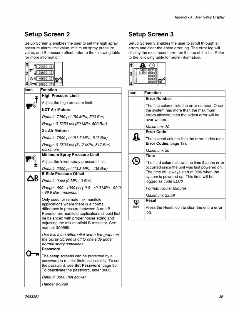
Setup Screen 2Setup Screen 2 enables the user to set the high spray pressure alarm limit value, minimum spray pressure value, and B pressure offset. refer to the following table for more information.
Setup Screen 3Setup Screen 3 enables the user to scroll through all errors and clear the entire error log. The error log will display the most recent error on the top of the list. Refer to the following table for more information.
Icon FunctionHigh Pressure Limit
Adjust the high pressure limit.
NXT Air Motors:
Default: 7250 psi (50 MPa, 500 Bar)
Range: 0-7250 psi (50 MPa, 500 Bar)
XL Air Motors:
Default: 7500 psi (51.7 MPa, 517 Bar)
Range: 0-7500 psi (51.7 MPa, 517 Bar) maximumMinimum Spray Pressure Limit
Adjust the lower spray pressure limit.
Default: 2000 psi (13.8 MPa, 138 Bar)B Side Pressure Offset
Default: 0 psi (0 MPa, 0 Bar)
Range: -999 - +999 psi (-9.9 - +9.9 MPa, -99.9 - 99.9 Bar) maximum
Only used for remote mix manifold applications where there is a normal difference in pressure between A and B. Remote mix manifold applications should first be balanced with proper house sizing and adjusting the mix manifold B restrictor. See manual 3A0590.
Use this if the differential alarm bar graph on the Spray Screen is off to one side under normal spray conditions. Password
The setup screens can be protected by a password to restrict their accessibility. To set the password, see Set Password, page 30. To deactivate the password, enter 0000.
Default: 0000 (not active)
Range: 0-9999
Icon FunctionError Number
The first column lists the error number. Once the system has more than the maximum errors allowed, then the oldest error will be over-written.
Maximum: 20Error Code
The second column lists the error codes (see Error Codes, page 19).
Maximum: 20Time
The third column shows the time that the error occurred since the unit was last powered on. The time will always start at 0:00 when the system is powered up. This time will be logged as code ELCX.
Format: Hours: Minutes
Maximum: 23:59Reset
Press the Reset icon to clear the entire error log.

Appendix A: User Setup Display
30 3A3320J
Set PasswordNOTE: When the password is “0000” the setup screens can be accessed without entering a password.
1. Navigate to Setup Screen 2.
2. Press to access fields to make changes.
3. Press to navigate to the password field.
Press to edit data.
4. Press and to increment or decrement
to the desired digits of the password.
5. Press to accept the password or press to
cancel.
6. Press to exit edit mode.
NOTE: The password screen is shown when the setup screens are accessed and the password function has been enabled by changing the “0000” password.
NOTE: If you set and forget the password, please contact Graco Technical Assistance for a default password.
Appendix B: Run Screen Details
3A3320J 31
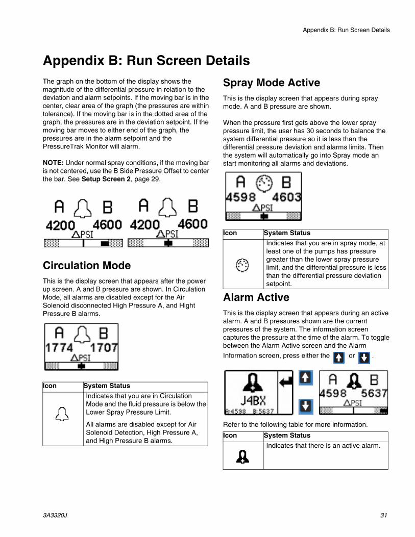
Appendix B: Run Screen DetailsThe graph on the bottom of the display shows the magnitude of the differential pressure in relation to the deviation and alarm setpoints. If the moving bar is in the center, clear area of the graph (the pressures are within tolerance). If the moving bar is in the dotted area of the graph, the pressures are in the deviation setpoint. If the moving bar moves to either end of the graph, the pressures are in the alarm setpoint and the PressureTrak Monitor will alarm.
NOTE: Under normal spray conditions, if the moving bar is not centered, use the B Side Pressure Offset to center the bar. See Setup Screen 2, page 29.
Circulation ModeThis is the display screen that appears after the power up screen. A and B pressure are shown. In Circulation Mode, all alarms are disabled except for the Air Solenoid disconnected High Pressure A, and Hight Pressure B alarms.
Spray Mode ActiveThis is the display screen that appears during spray mode. A and B pressure are shown.
When the pressure first gets above the lower spray pressure limit, the user has 30 seconds to balance the system differential pressure so it is less than the differential pressure deviation and alarms limits. Then the system will automatically go into Spray mode an start monitoring all alarms and deviations.
Alarm ActiveThis is the display screen that appears during an active alarm. A and B pressures shown are the current pressures of the system. The information screen captures the pressure at the time of the alarm. To toggle between the Alarm Active screen and the Alarm Information screen, press either the or .
Refer to the following table for more information.
Icon System StatusIndicates that you are in Circulation Mode and the fluid pressure is below the Lower Spray Pressure Limit.
All alarms are disabled except for Air Solenoid Detection, High Pressure A, and High Pressure B alarms.
Icon System StatusIndicates that you are in spray mode, at least one of the pumps has pressure greater than the lower spray pressure limit, and the differential pressure is less than the differential pressure deviation setpoint.
Icon System StatusIndicates that there is an active alarm.

Appendix B: Run Screen Details
32 3A3320J
Deviation ActiveThis is the display screen that appears during an active deviation. A and B pressure are shown. Refer to the following table for more information.
Information ScreenThe information screen is displayed when an alarm is active. It shows the active alarm code and the A and B pressure conditions at the time of the alarm, if applicable.
To toggle between the Alarm Active screen and the Alarm Information screen, press:
The red LED will flash when an alarm is present. Refer to the following table for more information.
NOTE: To clear the alarm, see Clear Alarms, page 17.
Manual Bypass ModeIf the user needs to spray with one of the above errors active, set the Lower Spray Pressure Limit equal to the High Pressure Alarm Limit to enter Manual Bypass Mode. Only use Manual Bypass Mode for emergency operation. The XP PressureTrak no longer monitors the pressures and will not shut off the sprayer.
Icon System StatusIndicates that there is an active deviation.
Icon System StatusIndicates that there is an active alarm. The red light on the front LED will be flashing and the system is disabled. Alarm Active Code
(see Error Codes, page 19).
Accessories
3A3320J 33
Accessories
Technical Specifications
California Proposition 65
Part DescriptionNXT405 Membrane Shield Kit
(20 shields included) Removable clear shield to protect the membrane switch from daily wear.
PressureTrak KitsUS Metric
Fluid Pressure RangeNXT Air Motors 200–7250 psi 1.4–50 MPa, 13.8–500 BarXL Air Motors 200–7500 psi 1.4–51.7 MPa, 13.8–517 BarNotesAll trademarks or registered trademarks are the property of their respective owners.
CALIFORNIA RESIDENTS
WARNING: Cancer and reproductive harm – www.P65warnings.ca.gov.

All written and visual data contained in this document reflects the latest product information available at the time of publication. Graco reserves the right to make changes at any time without notice.
Original instructions. This manual contains English. MM 3A3320Graco Headquarters: Minneapolis
International Offices: Belgium, China, Japan, Korea
GRACO INC. AND SUBSIDIARIES • P.O. BOX 1441 • MINNEAPOLIS MN 55440-1441 • USACopyright 2020, Graco Inc. All Graco manufacturing locations are registered to ISO 9001.
www.graco.comRevision J, March 2020
Graco Standard WarrantyGraco warrants all equipment referenced in this document which is manufactured by Graco and bearing its name to be free from defects in material and workmanship on the date of sale to the original purchaser for use. With the exception of any special, extended, or limited warranty published by Graco, Graco will, for a period of twelve months from the date of sale, repair or replace any part of the equipment determined by Graco to be defective. This warranty applies only when the equipment is installed, operated and maintained in accordance with Graco’s written recommendations.
This warranty does not cover, and Graco shall not be liable for general wear and tear, or any malfunction, damage or wear caused by faulty installation, misapplication, abrasion, corrosion, inadequate or improper maintenance, negligence, accident, tampering, or substitution of non-Graco component parts. Nor shall Graco be liable for malfunction, damage or wear caused by the incompatibility of Graco equipment with structures, accessories, equipment or materials not supplied by Graco, or the improper design, manufacture, installation, operation or maintenance of structures, accessories, equipment or materials not supplied by Graco.
This warranty is conditioned upon the prepaid return of the equipment claimed to be defective to an authorized Graco distributor for verification of the claimed defect. If the claimed defect is verified, Graco will repair or replace free of charge any defective parts. The equipment will be returned to the original purchaser transportation prepaid. If inspection of the equipment does not disclose any defect in material or workmanship, repairs will be made at a reasonable charge, which charges may include the costs of parts, labor, and transportation.
THIS WARRANTY IS EXCLUSIVE, AND IS IN LIEU OF ANY OTHER WARRANTIES, EXPRESS OR IMPLIED, INCLUDING BUT NOT LIMITED TO WARRANTY OF MERCHANTABILITY OR WARRANTY OF FITNESS FOR A PARTICULAR PURPOSE.
Graco’s sole obligation and buyer’s sole remedy for any breach of warranty shall be as set forth above. The buyer agrees that no other remedy (including, but not limited to, incidental or consequential damages for lost profits, lost sales, injury to person or property, or any other incidental or consequential loss) shall be available. Any action for breach of warranty must be brought within two (2) years of the date of sale.
GRACO MAKES NO WARRANTY, AND DISCLAIMS ALL IMPLIED WARRANTIES OF MERCHANTABILITY AND FITNESS FOR A PARTICULAR PURPOSE, IN CONNECTION WITH ACCESSORIES, EQUIPMENT, MATERIALS OR COMPONENTS SOLD BUT NOT MANUFACTURED BY GRACO. These items sold, but not manufactured by Graco (such as electric motors, switches, hose, etc.), are subject to the warranty, if any, of their manufacturer. Graco will provide purchaser with reasonable assistance in making any claim for breach of these warranties.
In no event will Graco be liable for indirect, incidental, special or consequential damages resulting from Graco supplying equipment hereunder, or the furnishing, performance, or use of any products or other goods sold hereto, whether due to a breach of contract, breach of warranty, the negligence of Graco, or otherwise.
FOR GRACO CANADA CUSTOMERSThe Parties acknowledge that they have required that the present document, as well as all documents, notices and legal proceedings entered into, given or instituted pursuant hereto or relating directly or indirectly hereto, be drawn up in English. Les parties reconnaissent avoir convenu que la rédaction du présente document sera en Anglais, ainsi que tous documents, avis et procédures judiciaires exécutés, donnés ou intentés, à la suite de ou en rapport, directement ou indirectement, avec les procédures concernées.
Graco InformationFor the latest information about Graco products, visit www.graco.com.For patent information, see www.graco.com/patents. TO PLACE AN ORDER, contact your Graco distributor or call to identify the nearest distributor.Phone: 612-623-6921 or Toll Free: 1-800-328-0211 Fax: 612-378-3505
Related Documents
![[HF] FREEWEIGHT PRODUCTS - HOIST Fitness · [hf] flat bench hf-5163 [hf] 7-position folding f.i.d. bench hf-5167 new! warranty new! warranty [hf] 7-position f.i.d. olympic bench hf-5170](https://static.cupdf.com/doc/110x72/5b5909d87f8b9ad0048c899a/hf-freeweight-products-hoist-fitness-hf-flat-bench-hf-5163-hf-7-position.jpg)