PRODUCT FAMILY DATA SHEET Cree LED / 4400 Silicon Drive / Durham, NC 27703 USA / +1.919.313.5330 / www.cree-led.com © 2012-2021 Cree LED. The information in this document is subject to change without notice. Cree ® and the Cree logo are registered trademarks, and the Cree LED logo is a trademark, of Wolfspeed, Inc. XLamp ® is a registered trademark of Cree LED. UL ® and the UL logo are registered trademarks of UL LLC. Other trademarks, product, and company names are the property of their respective owners and do not imply specific product and/or vendor endorsement, sponsorship or association. CLD-DS51 REV 18B 1 XLamp ® XP-G2 LEDs XP-G2 Standard LED XP-G2 High Efficacy LED PRODUCT DESCRIPTION The original XLamp ® XP-G2 LED pioneered a broad set of LED applications for the industry, including outdoor and area lighting, and has since served as a preferred choice by manufacturers that require advanced output, efficacy and optical control. The compact and proven 3.45‑mm XP platform has an excellent ecosystem of optics and system solutions available, enabling lighting manufacturers to simplify their design process and shorten time to market. XP-G2 LEDs are now available in two different White versions: Standard and High Efficacy (HE). XP‑G2 Standard is the same breakthrough product that enabled a broad set of new LED applications for ceramic high‑power LEDs. The new High Efficacy version extends this legacy with a drop‑in upgrade for existing designs optimized around XP‑G2 LEDs. XP‑G2 HE LEDs leverage Cree LED’s latest high-power chip technology to deliver 25 percent more light output via a higher maximum current of 2000 mA and higher efficacy and lower thermal resistance. FEATURES • Available in white, outdoor white and 80‑, 85‑ and 90‑CRI white • ANSI‑compatible chromaticity bins • Binned at 85 °C • Maximum drive current: Standard: 1500 mA, HE: 2000 mA • Low thermal resistance: Standard: 4 °C/W, HE: 3 °C/W • Wide viewing angle: Standard: 120°, HE: 125° • Unlimited floor life at ≤ 30 ºC/85% RH • Reflow solderable ‑ JEDEC J‑STD‑020C • Electrically neutral thermal path • RoHS and REACh compliant • UL ® recognized component (E349212)

Welcome message from author
This document is posted to help you gain knowledge. Please leave a comment to let me know what you think about it! Share it to your friends and learn new things together.
Transcript

PRODUCT FAMILY DATA SHEET
Cree LED / 4400 Silicon Drive / Durham, NC 27703 USA / +1.919.313.5330 / www.cree-led.com
© 2012-2021 Cree LED. The information in this document is subject to change without notice. Cree® and the Cree logo are registered trademarks, and the Cree LED logo is a trademark, of Wolfspeed, Inc. XLamp® is a registered trademark of Cree LED. UL® and the UL logo are registered trademarks of UL LLC. Other trademarks, product, and company names are the property of their respective owners and do not imply specific product and/or vendor endorsement, sponsorship or association.
CLD-DS51REV 18B 1
XLamp® XP-G2 LEDs
XP-G2 Standard LED XP-G2 High Efficacy LED
LED pictures and labels underneath are in a table
PRODUCT DESCRIPTION
The original XLamp® XP-G2 LED pioneered a broad set of LED
applications for the industry, including outdoor and area lighting,
and has since served as a preferred choice by manufacturers
that require advanced output, efficacy and optical control. The
compact and proven 3.45‑mm XP platform has an excellent
ecosystem of optics and system solutions available, enabling
lighting manufacturers to simplify their design process and
shorten time to market.
XP-G2 LEDs are now available in two different White versions:
Standard and High Efficacy (HE). XP‑G2 Standard is the same
breakthrough product that enabled a broad set of new LED
applications for ceramic high‑power LEDs.
The new High Efficacy version extends this legacy with a drop‑in
upgrade for existing designs optimized around XP‑G2 LEDs. XP‑G2
HE LEDs leverage Cree LED’s latest high-power chip technology to
deliver 25 percent more light output via a higher maximum current
of 2000 mA and higher efficacy and lower thermal resistance.
FEATURES
• Available in white, outdoor white and 80‑, 85‑ and 90‑CRI white
• ANSI‑compatible chromaticity bins
• Binned at 85 °C
• Maximum drive current: Standard: 1500 mA, HE: 2000 mA
• Low thermal resistance: Standard: 4 °C/W, HE: 3 °C/W
• Wide viewing angle: Standard: 120°, HE: 125°
• Unlimited floor life at ≤ 30 ºC/85% RH
• Reflow solderable ‑ JEDEC J‑STD‑020C
• Electrically neutral thermal path
• RoHS and REACh compliant
• UL® recognized component (E349212)

XLAMP® XP-G2 LED
© 2012-2021 Cree LED. The information in this document is subject to change without notice. Cree® and the Cree logo are registered trademarks, and the Cree LED logo is a trademark, of Wolfspeed, Inc. XLamp® is a registered trademark of Cree LED. UL® and the UL logo are registered trademarks of UL LLC. Other trademarks, product, and company names are the property of their respective owners and do not imply specific product and/or vendor endorsement, sponsorship or association.
CLD-DS51REV 18B 2
TABLE OF CONTENTS
Characteristics ....................................................................................................................................................................................................... 3
Flux Characteristics ‑ High Efficacy ...................................................................................................................................................................... 4
Flux Characteristics ‑ Standard ............................................................................................................................................................................. 9
Relative Spectral Power Distribution .................................................................................................................................................................. 15
Relative Flux vs. Junction Temperature .............................................................................................................................................................. 15
Electrical Characteristics ‑ High Efficacy............................................................................................................................................................ 16
Electrical Characteristics - Standard .................................................................................................................................................................. 16
Relative Flux vs. Current ‑ High Efficacy ............................................................................................................................................................. 17
Relative Flux vs. Current ‑ Standard .................................................................................................................................................................... 17
Relative Chromaticity vs Current and Temperature ‑ High Efficacy .................................................................................................................. 18
Relative Chromaticity vs Current and Temperature - Standard ......................................................................................................................... 19
Typical Spatial Distribution ‑ High Efficacy......................................................................................................................................................... 20
Typical Spatial Distribution - Standard ............................................................................................................................................................... 20
Thermal Design ‑ High Efficacy ........................................................................................................................................................................... 21
Thermal Design - Standard .................................................................................................................................................................................. 21
Performance Groups – Luminous Flux............................................................................................................................................................... 22
Performance Groups – Chromaticity .................................................................................................................................................................. 23
Standard Cool White Kits Plotted on ANSI Standard Chromaticity Regions .................................................................................................... 26
Standard Warm and Neutral White Kits Plotted on ANSI Standard Chromaticity Regions ............................................................................. 28
Standard Chromaticity Kits ................................................................................................................................................................................. 30
Bin and Order Code Formats ............................................................................................................................................................................... 31
Reflow Soldering Characteristics ........................................................................................................................................................................ 32
Notes .................................................................................................................................................................................................................... 33
Mechanical Dimensions ...................................................................................................................................................................................... 35
Tape and Reel ....................................................................................................................................................................................................... 37
Packaging ............................................................................................................................................................................................................. 38
XLAMP® XP-G2 LED
© 2012-2021 Cree LED. The information in this document is subject to change without notice. Cree® and the Cree logo are registered trademarks, and the Cree LED logo is a trademark, of Wolfspeed, Inc. XLamp® is a registered trademark of Cree LED. UL® and the UL logo are registered trademarks of UL LLC. Other trademarks, product, and company names are the property of their respective owners and do not imply specific product and/or vendor endorsement, sponsorship or association.
CLD-DS51REV 18B 3
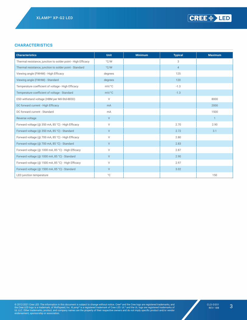
CHARACTERISTICS
Characteristics Unit Minimum Typical Maximum
Thermal resistance, junction to solder point ‑ High Efficacy °C/W 3
Thermal resistance, junction to solder point - Standard °C/W 4
Viewing angle (FWHM) ‑ High Efficacy degrees 125
Viewing angle (FWHM) ‑ Standard degrees 120
Temperature coefficient of voltage ‑ High Efficacy mV/°C ‑1.3
Temperature coefficient of voltage ‑ Standard mV/°C ‑1.3
ESD withstand voltage (HBM per Mil‑Std‑883D) V 8000
DC forward current ‑ High Efficacy mA 2000
DC forward current - Standard mA 1500
Reverse voltage V 1
Forward voltage (@ 350 mA, 85 °C) ‑ High Efficacy V 2.70 2.90
Forward voltage (@ 350 mA, 85 °C) ‑ Standard V 2.72 3.1
Forward voltage (@ 700 mA, 85 °C) ‑ High Efficacy V 2.80
Forward voltage (@ 700 mA, 85 °C) ‑ Standard V 2.83
Forward voltage (@ 1000 mA, 85 °C) ‑ High Efficacy V 2.87
Forward voltage (@ 1000 mA, 85 °C) ‑ Standard V 2.90
Forward voltage (@ 1500 mA, 85 °C) ‑ High Efficacy V 2.97
Forward voltage (@ 1500 mA, 85 °C) ‑ Standard V 3.02
LED junction temperature °C 150
forward voltage values for HE from graphics/ SA products Vf data sheet update.xlsx
XLAMP® XP-G2 LED
© 2012-2021 Cree LED. The information in this document is subject to change without notice. Cree® and the Cree logo are registered trademarks, and the Cree LED logo is a trademark, of Wolfspeed, Inc. XLamp® is a registered trademark of Cree LED. UL® and the UL logo are registered trademarks of UL LLC. Other trademarks, product, and company names are the property of their respective owners and do not imply specific product and/or vendor endorsement, sponsorship or association.
CLD-DS51REV 18B 4
Notes• Cree LED maintains a tolerance of ±7% on flux and power measurements, ±0.005 on chromaticity (CCx, CCy) measurements and a tolerance of ±2 on
CRI measurements. See the Measurements section (page 33).• XP‑G2 LED order codes specify only a minimum flux bin and not a maximum. Cree may ship reels in flux bins higher than the minimum specified by
the order code without advance notice. Shipments will always adhere to the chromaticity bin restrictions specified by the order code.* Flux values @ 25 °C are calculated and for reference only.
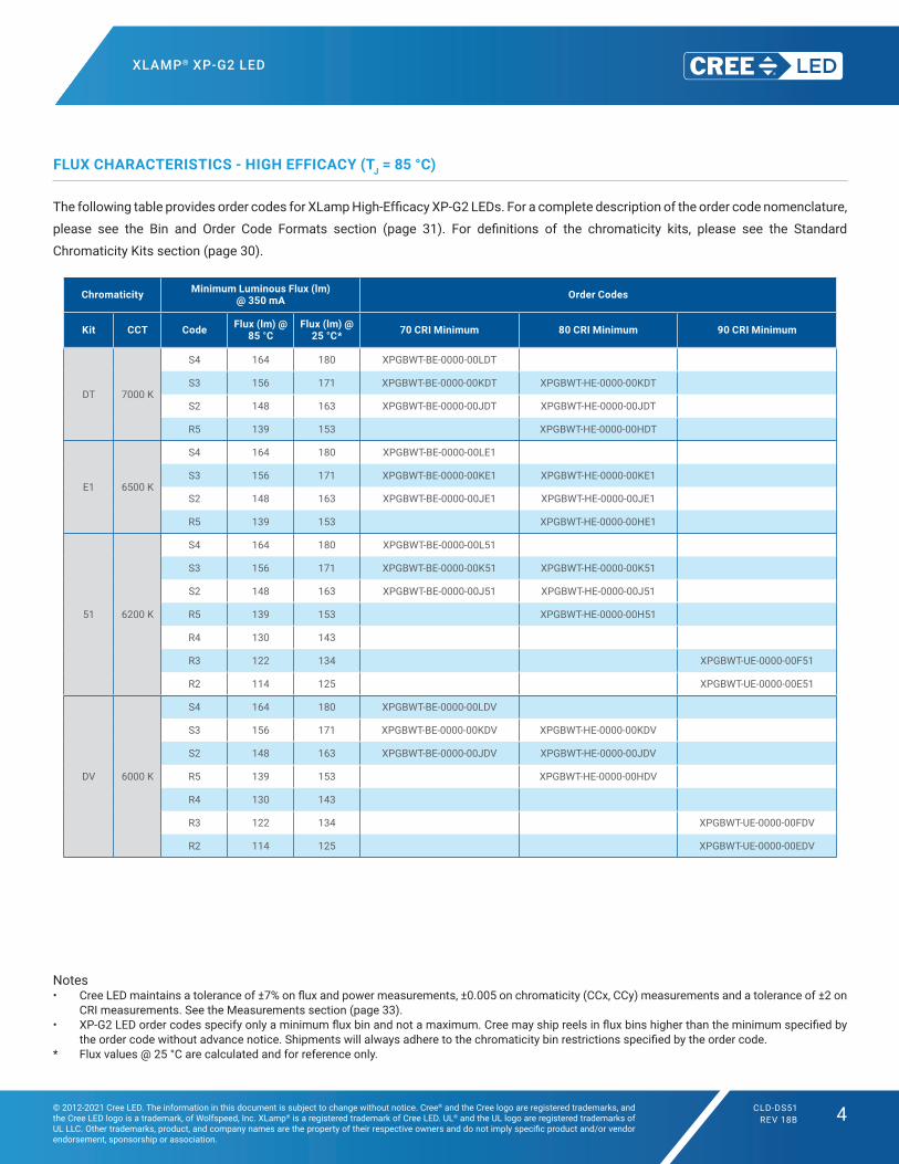
FLUX CHARACTERISTICS - HIGH EFFICACY (TJ = 85 °C)
The following table provides order codes for XLamp High‑Efficacy XP‑G2 LEDs. For a complete description of the order code nomenclature,
please see the Bin and Order Code Formats section (page 31). For definitions of the chromaticity kits, please see the Standard
Chromaticity Kits section (page 30).
Chromaticity Minimum Luminous Flux (lm) @ 350 mA Order Codes
Kit CCT Code Flux (lm) @ 85 °C
Flux (lm) @ 25 °C* 70 CRI Minimum 80 CRI Minimum 90 CRI Minimum
DT 7000 K
S4 164 180 XPGBWT-BE-0000-00LDT
S3 156 171 XPGBWT-BE-0000-00KDT XPGBWT-HE-0000-00KDT
S2 148 163 XPGBWT‑BE‑0000‑00JDT XPGBWT‑HE‑0000‑00JDT
R5 139 153 XPGBWT-HE-0000-00HDT
E1 6500 K
S4 164 180 XPGBWT-BE-0000-00LE1
S3 156 171 XPGBWT-BE-0000-00KE1 XPGBWT-HE-0000-00KE1
S2 148 163 XPGBWT‑BE‑0000‑00JE1 XPGBWT‑HE‑0000‑00JE1
R5 139 153 XPGBWT-HE-0000-00HE1
51 6200 K
S4 164 180 XPGBWT-BE-0000-00L51
S3 156 171 XPGBWT-BE-0000-00K51 XPGBWT-HE-0000-00K51
S2 148 163 XPGBWT‑BE‑0000‑00J51 XPGBWT‑HE‑0000‑00J51
R5 139 153 XPGBWT-HE-0000-00H51
R4 130 143
R3 122 134 XPGBWT-UE-0000-00F51
R2 114 125 XPGBWT-UE-0000-00E51
DV 6000 K
S4 164 180 XPGBWT-BE-0000-00LDV
S3 156 171 XPGBWT-BE-0000-00KDV XPGBWT-HE-0000-00KDV
S2 148 163 XPGBWT‑BE‑0000‑00JDV XPGBWT‑HE‑0000‑00JDV
R5 139 153 XPGBWT-HE-0000-00HDV
R4 130 143
R3 122 134 XPGBWT-UE-0000-00FDV
R2 114 125 XPGBWT-UE-0000-00EDV

XLAMP® XP-G2 LED
© 2012-2021 Cree LED. The information in this document is subject to change without notice. Cree® and the Cree logo are registered trademarks, and the Cree LED logo is a trademark, of Wolfspeed, Inc. XLamp® is a registered trademark of Cree LED. UL® and the UL logo are registered trademarks of UL LLC. Other trademarks, product, and company names are the property of their respective owners and do not imply specific product and/or vendor endorsement, sponsorship or association.
CLD-DS51REV 18B 5
Notes• Cree LED maintains a tolerance of ±7% on flux and power measurements, ±0.005 on chromaticity (CCx, CCy) measurements and a tolerance of ±2 on
CRI measurements. See the Measurements section (page 33).• XP‑G2 LED order codes specify only a minimum flux bin and not a maximum. Cree may ship reels in flux bins higher than the minimum specified by
the order code without advance notice. Shipments will always adhere to the chromaticity bin restrictions specified by the order code.* Flux values @ 25 °C are calculated and for reference only.
Chromaticity Minimum Luminous Flux (lm) @ 350 mA Order Codes
Kit CCT Code Flux (lm) @ 85 °C
Flux (lm) @ 25 °C* 70 CRI Minimum 80 CRI Minimum 90 CRI Minimum
50 6000 K
S4 164 180 XPGBWT-BE-0000-00L50
S3 156 171 XPGBWT-BE-0000-00K50 XPGBWT-HE-0000-00K50
S2 148 163 XPGBWT‑BE‑0000‑00J50 XPGBWT‑HE‑0000‑00J50
R5 139 153 XPGBWT-HE-0000-00H50
R4 130 143
R3 122 134 XPGBWT-UE-0000-00F50
R2 114 125 XPGBWT-UE-0000-00E50
E2 5700 K
S4 164 180 XPGBWT-BE-0000-00LE2
S3 156 171 XPGBWT-BE-0000-00KE2 XPGBWT-HE-0000-00KE2
S2 148 163 XPGBWT‑BE‑0000‑00JE2 XPGBWT‑HE‑0000‑00JE2
R5 139 153 XPGBWT-HE-0000-00HE2
R4 130 143 XPGBWT-UE-0000-00GE2
R3 122 134 XPGBWT-UE-0000-00FE2
R2 114 125 XPGBWT-UE-0000-00EE2
E3 5000 K
S4 164 180 XPGBWT-BE-0000-00LE3
S3 156 171 XPGBWT-BE-0000-00KE3 XPGBWT-HE-0000-00KE3
S2 148 163 XPGBWT‑BE‑0000‑00JE3 XPGBWT‑HE‑0000‑00JE3
R5 139 153 XPGBWT-HE-0000-00HE3
R4 130 143
R3 122 134 XPGBWT-UE-0000-00FE3
R2 114 125 XPGBWT-UE-0000-00EE3
F4 4750 K
S4 164 180 XPGBWT‑BE‑0000‑00LF4
S3 156 171 XPGBWT‑BE‑0000‑00KF4 XPGBWT‑HE‑0000‑00KF4
S2 148 163 XPGBWT‑BE‑0000‑00JF4 XPGBWT‑HE‑0000‑00JF4
R5 139 153 XPGBWT‑HE‑0000‑00HF4
R4 130 143
R3 122 134 XPGBWT‑UE‑0000‑00FF4
R2 114 125 XPGBWT‑UE‑0000‑00EF4
Q5 107 118 XPGBWT‑UE‑0000‑00DF4
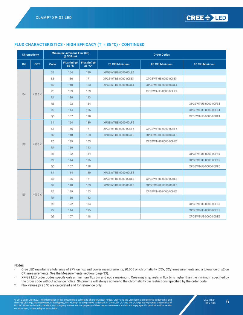
FLUX CHARACTERISTICS - HIGH EFFICACY (TJ = 85 °C) - CONTINUED
XLAMP® XP-G2 LED
© 2012-2021 Cree LED. The information in this document is subject to change without notice. Cree® and the Cree logo are registered trademarks, and the Cree LED logo is a trademark, of Wolfspeed, Inc. XLamp® is a registered trademark of Cree LED. UL® and the UL logo are registered trademarks of UL LLC. Other trademarks, product, and company names are the property of their respective owners and do not imply specific product and/or vendor endorsement, sponsorship or association.
CLD-DS51REV 18B 6
Notes• Cree LED maintains a tolerance of ±7% on flux and power measurements, ±0.005 on chromaticity (CCx, CCy) measurements and a tolerance of ±2 on
CRI measurements. See the Measurements section (page 33).• XP‑G2 LED order codes specify only a minimum flux bin and not a maximum. Cree may ship reels in flux bins higher than the minimum specified by
the order code without advance notice. Shipments will always adhere to the chromaticity bin restrictions specified by the order code.* Flux values @ 25 °C are calculated and for reference only.
Chromaticity Minimum Luminous Flux (lm) @ 350 mA Order Codes
Kit CCT Code Flux (lm) @ 85 °C
Flux (lm) @ 25 °C* 70 CRI Minimum 80 CRI Minimum 90 CRI Minimum
E4 4500 K
S4 164 180 XPGBWT‑BE‑0000‑00LE4
S3 156 171 XPGBWT‑BE‑0000‑00KE4 XPGBWT‑HE‑0000‑00KE4
S2 148 163 XPGBWT‑BE‑0000‑00JE4 XPGBWT‑HE‑0000‑00JE4
R5 139 153 XPGBWT‑HE‑0000‑00HE4
R4 130 143
R3 122 134 XPGBWT‑UE‑0000‑00FE4
R2 114 125 XPGBWT‑UE‑0000‑00EE4
Q5 107 118 XPGBWT‑UE‑0000‑00DE4
F5 4250 K
S4 164 180 XPGBWT-BE-0000-00LF5
S3 156 171 XPGBWT-BE-0000-00KF5 XPGBWT-HE-0000-00KF5
S2 148 163 XPGBWT‑BE‑0000‑00JF5 XPGBWT‑HE‑0000‑00JF5
R5 139 153 XPGBWT-HE-0000-00HF5
R4 130 143
R3 122 134 XPGBWT-UE-0000-00FF5
R2 114 125 XPGBWT-UE-0000-00EF5
Q5 107 118 XPGBWT-UE-0000-00DF5
E5 4000 K
S4 164 180 XPGBWT-BE-0000-00LE5
S3 156 171 XPGBWT-BE-0000-00KE5 XPGBWT-HE-0000-00KE5
S2 148 163 XPGBWT‑BE‑0000‑00JE5 XPGBWT‑HE‑0000‑00JE5
R5 139 153 XPGBWT-HE-0000-00HE5
R4 130 143
R3 122 134 XPGBWT-UE-0000-00FE5
R2 114 125 XPGBWT-UE-0000-00EE5
Q5 107 118 XPGBWT-UE-0000-00DE5
FLUX CHARACTERISTICS - HIGH EFFICACY (TJ = 85 °C) - CONTINUED
XLAMP® XP-G2 LED
© 2012-2021 Cree LED. The information in this document is subject to change without notice. Cree® and the Cree logo are registered trademarks, and the Cree LED logo is a trademark, of Wolfspeed, Inc. XLamp® is a registered trademark of Cree LED. UL® and the UL logo are registered trademarks of UL LLC. Other trademarks, product, and company names are the property of their respective owners and do not imply specific product and/or vendor endorsement, sponsorship or association.
CLD-DS51REV 18B 7
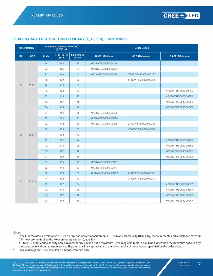
Notes• Cree LED maintains a tolerance of ±7% on flux and power measurements, ±0.005 on chromaticity (CCx, CCy) measurements and a tolerance of ±2 on
CRI measurements. See the Measurements section (page 33).• XP‑G2 LED order codes specify only a minimum flux bin and not a maximum. Cree may ship reels in flux bins higher than the minimum specified by
the order code without advance notice. Shipments will always adhere to the chromaticity bin restrictions specified by the order code.* Flux values @ 25 °C are calculated and for reference only.
Chromaticity Minimum Luminous Flux (lm) @ 350 mA Order Codes
Kit CCT Code Flux (lm) @ 85 °C
Flux (lm) @ 25 °C* 70 CRI Minimum 80 CRI Minimum 90 CRI Minimum
F6 3750 K
S4 164 180 XPGBWT-BE-0000-00LF6
S3 156 171 XPGBWT-BE-0000-00KF6
S2 148 163 XPGBWT‑BE‑0000‑00JF6 XPGBWT‑HE‑0000‑00JF6
R5 139 153 XPGBWT-HE-0000-00HF6
R4 130 143
R3 122 134 XPGBWT-UE-0000-00FF6
R2 114 125 XPGBWT-UE-0000-00EF6
Q5 107 118 XPGBWT-UE-0000-00DF6
Q4 100 110 XPGBWT-UE-0000-00CF6
E6 3500 K
S4 164 180 XPGBWT-BE-0000-00LE6
S3 156 171 XPGBWT-BE-0000-00KE6
S2 148 163 XPGBWT‑BE‑0000‑00JE6 XPGBWT‑HE‑0000‑00JE6
R5 139 153 XPGBWT-HE-0000-00HE6
R4 130 143
R3 122 134 XPGBWT-UE-0000-00FE6
R2 114 125 XPGBWT-UE-0000-00EE6
Q5 107 118 XPGBWT-UE-0000-00DE6
Q4 100 110 XPGBWT-UE-0000-00CE6
F7 3250 K
S3 156 171 XPGBWT-BE-0000-00KF7
S2 148 163 XPGBWT‑BE‑0000‑00JF7
R5 139 153 XPGBWT-BE-0000-00HF7 XPGBWT-HE-0000-00HF7
R4 130 143 XPGBWT-HE-0000-00GF7
R3 122 134 XPGBWT-UE-0000-00FF7
R2 114 125 XPGBWT-UE-0000-00EF7
Q5 107 118 XPGBWT-UE-0000-00DF7
Q4 100 110 XPGBWT-UE-0000-00CF7
FLUX CHARACTERISTICS - HIGH EFFICACY (TJ = 85 °C) - CONTINUED

XLAMP® XP-G2 LED
© 2012-2021 Cree LED. The information in this document is subject to change without notice. Cree® and the Cree logo are registered trademarks, and the Cree LED logo is a trademark, of Wolfspeed, Inc. XLamp® is a registered trademark of Cree LED. UL® and the UL logo are registered trademarks of UL LLC. Other trademarks, product, and company names are the property of their respective owners and do not imply specific product and/or vendor endorsement, sponsorship or association.
CLD-DS51REV 18B 8
Notes• Cree LED maintains a tolerance of ±7% on flux and power measurements, ±0.005 on chromaticity (CCx, CCy) measurements and a tolerance of ±2 on
CRI measurements. See the Measurements section (page 33).• XP‑G2 LED order codes specify only a minimum flux bin and not a maximum. Cree may ship reels in flux bins higher than the minimum specified by
the order code without advance notice. Shipments will always adhere to the chromaticity bin restrictions specified by the order code.* Flux values @ 25 °C are calculated and for reference only.
Chromaticity Minimum Luminous Flux (lm) @ 350 mA Order Codes
Kit CCT Code Flux (lm) @ 85 °C
Flux (lm) @ 25 °C* 70 CRI Minimum 80 CRI Minimum 90 CRI Minimum
E7 3000 K
S3 156 171 XPGBWT-BE-0000-00KE7
S2 148 163 XPGBWT‑BE‑0000‑00JE7
R5 139 153 XPGBWT-BE-0000-00HE7 XPGBWT-HE-0000-00HE7
R4 130 143 XPGBWT-HE-0000-00GE7
R3 122 134 XPGBWT-UE-0000-00FE7
R2 114 125 XPGBWT-UE-0000-00EE7
Q5 107 118 XPGBWT-UE-0000-00DE7
Q4 100 110 XPGBWT-UE-0000-00CE7
F8 2850 K
S3 156 171 XPGBWT-BE-0000-00KF8
S2 148 163 XPGBWT‑BE‑0000‑00JF8
R5 139 153 XPGBWT-BE-0000-00HF8 XPGBWT-HE-0000-00HF8
R4 130 143 XPGBWT-HE-0000-00GF8
R3 122 134
R2 114 125 XPGBWT-UE-0000-00EF8
Q5 107 118 XPGBWT-UE-0000-00DF8
Q4 100 110 XPGBWT-UE-0000-00CF8
E8 2700 K
S3 156 171 XPGBWT-BE-0000-00KE8
S2 148 163 XPGBWT‑BE‑0000‑00JE8
R5 139 153 XPGBWT-BE-0000-00HE8 XPGBWT-HE-0000-00HE8
R4 130 143 XPGBWT-HE-0000-00GE8
R3 122 134
R2 114 125 XPGBWT-UE-0000-00EE8
Q5 107 118 XPGBWT-UE-0000-00DE8
Q4 100 110 XPGBWT-UE-0000-00CE8
FLUX CHARACTERISTICS - HIGH EFFICACY (TJ = 85 °C) - CONTINUED

XLAMP® XP-G2 LED
© 2012-2021 Cree LED. The information in this document is subject to change without notice. Cree® and the Cree logo are registered trademarks, and the Cree LED logo is a trademark, of Wolfspeed, Inc. XLamp® is a registered trademark of Cree LED. UL® and the UL logo are registered trademarks of UL LLC. Other trademarks, product, and company names are the property of their respective owners and do not imply specific product and/or vendor endorsement, sponsorship or association.
CLD-DS51REV 18B 9
Notes• Cree LED maintains a tolerance of ±7% on flux and power measurements, ±0.005 on chromaticity (CCx, CCy) measurements and a tolerance of ±2 on
CRI measurements. See the Measurements section (page 33).• XP‑G2 LED order codes specify only a minimum flux bin and not a maximum. Cree may ship reels in flux bins higher than the minimum specified by
the order code without advance notice. Shipments will always adhere to the chromaticity bin restrictions specified by the order code.* Flux values @ 25 °C are calculated and for reference only.
FLUX CHARACTERISTICS - STANDARD (TJ = 85 °C)
The following table provides order codes for XLamp Standard XP‑G2 LEDs. For a complete description of the order code nomenclature,
please see the Bin and Order Code Formats section (page 31). For definitions of the chromaticity kits, please see the Standard
Chromaticity Kits section (page 30).
Chromaticity Minimum Luminous Flux (lm) @ 350 mA Order Codes
Kit CCT Code Flux (lm) @ 85 °C
Flux (lm) @ 25 °C* 70 CRI Typical
51 6200 K
S4 164 180 XPGBWT-L1-0000-00L51
S3 156 171 XPGBWT-L1-0000-00K51
S2 148 163 XPGBWT‑L1‑0000‑00J51
R5 139 153 XPGBWT-L1-0000-00H51
R4 130 143 XPGBWT-L1-0000-00G51
R3 122 134 XPGBWT-L1-0000-00F51
53 6000 K
S4 164 180 XPGBWT-L1-0000-00L53
S3 156 171 XPGBWT-L1-0000-00K53
S2 148 163 XPGBWT‑L1‑0000‑00J53
R5 139 153 XPGBWT-L1-0000-00H53
R4 130 143 XPGBWT-L1-0000-00G53
R3 122 134 XPGBWT-L1-0000-00F53
50 6200 K
S4 164 180 XPGBWT-L1-0000-00L50
S3 156 171 XPGBWT-L1-0000-00K50
S2 148 163 XPGBWT‑L1‑0000‑00J50
R5 139 153 XPGBWT-L1-0000-00H50
R4 130 143 XPGBWT-L1-0000-00G50
R3 122 134 XPGBWT-L1-0000-00F50
E1 6500 K
S5 172 189 XPGBWT-L1-0000-00ME1
S4 164 180 XPGBWT-L1-0000-00LE1
S3 156 171 XPGBWT-L1-0000-00KE1
S2 148 163 XPGBWT‑L1‑0000‑00JE1
R5 139 153 XPGBWT-L1-0000-00HE1
R4 130 143 XPGBWT-L1-0000-00GE1
R3 122 134 XPGBWT-L1-0000-00FE1

XLAMP® XP-G2 LED
© 2012-2021 Cree LED. The information in this document is subject to change without notice. Cree® and the Cree logo are registered trademarks, and the Cree LED logo is a trademark, of Wolfspeed, Inc. XLamp® is a registered trademark of Cree LED. UL® and the UL logo are registered trademarks of UL LLC. Other trademarks, product, and company names are the property of their respective owners and do not imply specific product and/or vendor endorsement, sponsorship or association.
CLD-DS51REV 18B 10
Notes• Cree LED maintains a tolerance of ±7% on flux and power measurements, ±0.005 on chromaticity (CCx, CCy) measurements and a tolerance of ±2 on
CRI measurements. See the Measurements section (page 33).• XP‑G2 LED order codes specify only a minimum flux bin and not a maximum. Cree may ship reels in flux bins higher than the minimum specified by
the order code without advance notice. Shipments will always adhere to the chromaticity bin restrictions specified by the order code.* Flux values @ 25 °C are calculated and for reference only.
Chromaticity Minimum Luminous Flux (lm) @ 350 mA Order Codes
Kit CCT Code Flux (lm) @ 85 °C
Flux (lm) @ 25 °C* 70 CRI Typical
E2 5700 K
S5 172 189 XPGBWT-L1-0000-00ME2
S4 164 180 XPGBWT-L1-0000-00LE2
S3 156 171 XPGBWT-L1-0000-00KE2
S2 148 163 XPGBWT‑L1‑0000‑00JE2
R5 139 153 XPGBWT-L1-0000-00HE2
R4 130 143 XPGBWT-L1-0000-00GE2
R3 122 134 XPGBWT-L1-0000-00FE2
Chromaticity Minimum Luminous Flux (lm) @ 350 mA Order Codes
Kit CCT Code Flux (lm) @ 85 °C
Flux (lm) @25 °C* 70 CRI Typical 80 CRI Minimum
E3 5000 K
S5 172 189 XPGBWT-01-0000-00ME3
S4 164 180 XPGBWT-01-0000-00LE3
S3 156 171 XPGBWT-01-0000-00KE3
S2 148 163 XPGBWT‑01‑0000‑00JE3
R5 139 153 XPGBWT-01-0000-00HE3
R4 130 143 XPGBWT-01-0000-00GE3
R3 122 134 XPGBWT-01-0000-00FE3
R2 114 125 XPGBWT-01-0000-00EE3
F4 4750 K
S4 164 180 XPGBWT‑01‑0000‑00LF4
S3 156 171 XPGBWT‑01‑0000‑00KF4
S2 148 163 XPGBWT‑01‑0000‑00JF4
R5 139 153 XPGBWT‑01‑0000‑00HF4
R4 130 143 XPGBWT‑01‑0000‑00GF4
R3 122 134 XPGBWT‑01‑0000‑00FF4
R2 114 125 XPGBWT‑01‑0000‑00EF4
FLUX CHARACTERISTICS - STANDARD (TJ = 85 °C) - CONTINUED

XLAMP® XP-G2 LED
© 2012-2021 Cree LED. The information in this document is subject to change without notice. Cree® and the Cree logo are registered trademarks, and the Cree LED logo is a trademark, of Wolfspeed, Inc. XLamp® is a registered trademark of Cree LED. UL® and the UL logo are registered trademarks of UL LLC. Other trademarks, product, and company names are the property of their respective owners and do not imply specific product and/or vendor endorsement, sponsorship or association.
CLD-DS51REV 18B 11
Notes• Cree LED maintains a tolerance of ±7% on flux and power measurements, ±0.005 on chromaticity (CCx, CCy) measurements and a tolerance of ±2 on
CRI measurements. See the Measurements section (page 33).• XP‑G2 LED order codes specify only a minimum flux bin and not a maximum. Cree may ship reels in flux bins higher than the minimum specified by
the order code without advance notice. Shipments will always adhere to the chromaticity bin restrictions specified by the order code.* Flux values @ 25 °C are calculated and for reference only.
Chromaticity Minimum Luminous Flux (lm) @ 350 mA Order Codes
Kit CCT Code Flux (lm) @ 85 °C
Flux (lm) @25 °C* 70 CRI Typical 80 CRI Minimum
E4 4500 K
S4 164 180 XPGBWT‑01‑0000‑00LE4
S3 156 171 XPGBWT‑01‑0000‑00KE4
S2 148 163 XPGBWT‑01‑0000‑00JE4
R5 139 153 XPGBWT‑01‑0000‑00HE4
R4 130 143 XPGBWT‑01‑0000‑00GE4
R3 122 134 XPGBWT‑01‑0000‑00FE4
R2 114 125 XPGBWT‑01‑0000‑00EE4
F5 4250 K
S4 164 180 XPGBWT-01-0000-00LF5
S3 156 171 XPGBWT-01-0000-00KF5
S2 148 163 XPGBWT‑01‑0000‑00JF5
R5 139 153 XPGBWT-01-0000-00HF5
R4 130 143 XPGBWT-01-0000-00GF5
R3 122 134 XPGBWT-01-0000-00FF5
R2 114 125 XPGBWT-01-0000-00EF5
E5 4000 K
S4 164 180 XPGBWT-01-0000-00LE5
S3 156 171 XPGBWT-01-0000-00KE5
S2 148 163 XPGBWT‑01‑0000‑00JE5
R5 139 153 XPGBWT-01-0000-00HE5 XPGBWT-H1-0000-00HE5
R4 130 143 XPGBWT-01-0000-00GE5 XPGBWT-H1-0000-00GE5
R3 122 134 XPGBWT-01-0000-00FE5 XPGBWT-H1-0000-00FE5
R2 114 125 XPGBWT-01-0000-00EE5 XPGBWT-H1-0000-00EE5
Q5 107 118 XPGBWT-H1-0000-00DE5
Z5 4000 K
R5 139 153 XPGBWT-H1-0000-00HZ5
R4 130 143 XPGBWT-H1-0000-00GZ5
R3 122 134 XPGBWT-H1-0000-00FZ5
R2 114 125 XPGBWT-H1-0000-00EZ5
Q5 107 118 XPGBWT-H1-0000-00DZ5
FLUX CHARACTERISTICS - STANDARD (TJ = 85 °C) - CONTINUED

XLAMP® XP-G2 LED
© 2012-2021 Cree LED. The information in this document is subject to change without notice. Cree® and the Cree logo are registered trademarks, and the Cree LED logo is a trademark, of Wolfspeed, Inc. XLamp® is a registered trademark of Cree LED. UL® and the UL logo are registered trademarks of UL LLC. Other trademarks, product, and company names are the property of their respective owners and do not imply specific product and/or vendor endorsement, sponsorship or association.
CLD-DS51REV 18B 12
Notes• Cree LED maintains a tolerance of ±7% on flux and power measurements, ±0.005 on chromaticity (CCx, CCy) measurements and a tolerance of ±2 on
CRI measurements. See the Measurements section (page 33).• XP‑G2 LED order codes specify only a minimum flux bin and not a maximum. Cree may ship reels in flux bins higher than the minimum specified by
the order code without advance notice. Shipments will always adhere to the chromaticity bin restrictions specified by the order code.* Flux values @ 25 °C are calculated and for reference only.
FLUX CHARACTERISTICS - STANDARD (TJ = 85 °C) - CONTINUED
Chromaticity Minimum Luminous Flux (lm) @ 350 mA Order Codes
Kit CCT Code Flux (lm) @ 85 °C
Flux (lm) @25 °C* 70 CRI Typical 80 CRI Typical 80 CRI Minimum 90 CRI Minimum
F6 3750 K
S2 148 163 XPGBWT‑01‑0000‑00JF6
R5 139 153 XPGBWT-01-0000-00HF6 XPGBWT-L1-0000-00HF6 XPGBWT-H1-0000-00HF6
R4 130 143 XPGBWT-01-0000-00GF6 XPGBWT-L1-0000-00GF6 XPGBWT-H1-0000-00GF6
R3 122 134 XPGBWT-01-0000-00FF6 XPGBWT-L1-0000-00FF6 XPGBWT-H1-0000-00FF6
R2 114 125 XPGBWT-01-0000-00EF6 XPGBWT-L1-0000-00EF6 XPGBWT-H1-0000-00EF6
Q5 107 118 XPGBWT-01-0000-00DF6 XPGBWT-L1-0000-00DF6 XPGBWT-H1-0000-00DF6
E6 3500 K
S2 148 163 XPGBWT‑01‑0000‑00JE6
R5 139 153 XPGBWT-01-0000-00HE6 XPGBWT-L1-0000-00HE6 XPGBWT-H1-0000-00HE6
R4 130 143 XPGBWT-01-0000-00GE6 XPGBWT-L1-0000-00GE6 XPGBWT-H1-0000-00GE6
R3 122 134 XPGBWT-01-0000-00FE6 XPGBWT-L1-0000-00FE6 XPGBWT-H1-0000-00FE6
R2 114 125 XPGBWT-01-0000-00EE6 XPGBWT-L1-0000-00EE6 XPGBWT-H1-0000-00EE6
Q5 107 118 XPGBWT-01-0000-00DE6 XPGBWT-L1-0000-00DE6 XPGBWT-H1-0000-00DE6
Z6 3500 K
R4 130 143 XPGBWT-L1-0000-00GZ6 XPGBWT-H1-0000-00GZ6
R3 122 134 XPGBWT-L1-0000-00FZ6 XPGBWT-H1-0000-00FZ6
R2 114 125 XPGBWT-L1-0000-00EZ6 XPGBWT-H1-0000-00EZ6
Q5 107 118 XPGBWT-L1-0000-00DZ6 XPGBWT-H1-0000-00DZ6
F7 3250 K
S2 148 163 XPGBWT‑01‑0000‑00JF7
R5 139 153 XPGBWT-01-0000-00HF7 XPGBWT-L1-0000-00HF7 XPGBWT-H1-0000-00HF7
R4 130 143 XPGBWT-01-0000-00GF7 XPGBWT-L1-0000-00GF7 XPGBWT-H1-0000-00GF7
R3 122 134 XPGBWT-01-0000-00FF7 XPGBWT-L1-0000-00FF7 XPGBWT-H1-0000-00FF7
R2 114 125 XPGBWT-01-0000-00EF7 XPGBWT-L1-0000-00EF7 XPGBWT-H1-0000-00EF7
Q5 107 118 XPGBWT-L1-0000-00DF7 XPGBWT-H1-0000-00DF7

XLAMP® XP-G2 LED
© 2012-2021 Cree LED. The information in this document is subject to change without notice. Cree® and the Cree logo are registered trademarks, and the Cree LED logo is a trademark, of Wolfspeed, Inc. XLamp® is a registered trademark of Cree LED. UL® and the UL logo are registered trademarks of UL LLC. Other trademarks, product, and company names are the property of their respective owners and do not imply specific product and/or vendor endorsement, sponsorship or association.
CLD-DS51REV 18B 13
Notes• Cree LED maintains a tolerance of ±7% on flux and power measurements, ±0.005 on chromaticity (CCx, CCy) measurements and a tolerance of ±2 on
CRI measurements. See the Measurements section (page 33).• XP‑G2 LED order codes specify only a minimum flux bin and not a maximum. Cree may ship reels in flux bins higher than the minimum specified by
the order code without advance notice. Shipments will always adhere to the chromaticity bin restrictions specified by the order code.* Flux values @ 25 °C are calculated and for reference only.
Chromaticity Minimum Luminous Flux (lm) @ 350 mA Order Codes
Kit CCT Code Flux (lm) @ 85 °C
Flux (lm) @25 °C* 70 CRI Typical 80 CRI Typical 80 CRI Minimum 90 CRI Minimum
E7 3000 K
S2 148 163 XPGBWT‑01‑0000‑00JE7
R5 139 153 XPGBWT-01-0000-00HE7 XPGBWT-L1-0000-00HE7 XPGBWT-H1-0000-00HE7
R4 130 143 XPGBWT-01-0000-00GE7 XPGBWT-L1-0000-00GE7 XPGBWT-H1-0000-00GE7
R3 122 134 XPGBWT-01-0000-00FE7 XPGBWT-L1-0000-00FE7 XPGBWT-H1-0000-00FE7
R2 114 125 XPGBWT-01-0000-00EE7 XPGBWT-L1-0000-00EE7 XPGBWT-H1-0000-00EE7 XPGBWT-U1-0000-00EE7
Q5 107 118 XPGBWT-L1-0000-00DE7 XPGBWT-H1-0000-00DE7 XPGBWT-U1-0000-00DE7
Q4 100 110 XPGBWT-L1-0000-00CE7 XPGBWT-H1-0000-00CE7 XPGBWT-U1-0000-00CE7
Q3 93.9 103 XPGBWT-U1-0000-00BE7
Q2 87.4 96.1 XPGBWT‑U1‑0000‑00AE7
P4 80.6 88.6 XPGBWT‑U1‑0000‑009E7
P3 73.9 81.2 XPGBWT-U1-0000-008E7
Z7 3000 K
R4 130 143 XPGBWT-L1-0000-00GZ7 XPGBWT-H1-0000-00GZ7
R3 122 134 XPGBWT-L1-0000-00FZ7 XPGBWT-H1-0000-00FZ7
R2 114 125 XPGBWT-L1-0000-00EZ7 XPGBWT-H1-0000-00EZ7
Q5 107 118 XPGBWT-L1-0000-00DZ7 XPGBWT-H1-0000-00DZ7 XPGBWT-U1-0000-00DZ7
Q4 100 110 XPGBWT-L1-0000-00CZ7 XPGBWT-H1-0000-00CZ7 XPGBWT-U1-0000-00CZ7
Q3 93.9 103 XPGBWT-U1-0000-00BZ7
Q2 87.4 96.1 XPGBWT‑U1‑0000‑00AZ7
P4 80.6 88.6 XPGBWT‑U1‑0000‑009Z7
P3 73.9 81.2 XPGBWT-U1-0000-008Z7
F8 2850 K
R4 130 143 XPGBWT-L1-0000-00GF8 XPGBWT-H1-0000-00GF8
R3 122 134 XPGBWT-L1-0000-00FF8 XPGBWT-H1-0000-00FF8
R2 114 125 XPGBWT-L1-0000-00EF8 XPGBWT-H1-0000-00EF8
Q5 107 118 XPGBWT-L1-0000-00DF8 XPGBWT-H1-0000-00DF8 XPGBWT-U1-0000-00DF8
Q4 100 110 XPGBWT-L1-0000-00CF8 XPGBWT-H1-0000-00CF8 XPGBWT-U1-0000-00CF8
Q3 93.9 103 XPGBWT-L1-0000-00BF8 XPGBWT-H1-0000-00BF8 XPGBWT-U1-0000-00BF8
Q2 87.4 96.1 XPGBWT‑U1‑0000‑00AF8
P4 80.6 88.6 XPGBWT‑U1‑0000‑009F8
P3 73.9 81.2 XPGBWT-U1-0000-008F8
P2 67.2 73.9 XPGBWT-U1-0000-007F8
FLUX CHARACTERISTICS - STANDARD (TJ = 85 °C) - CONTINUED

XLAMP® XP-G2 LED
© 2012-2021 Cree LED. The information in this document is subject to change without notice. Cree® and the Cree logo are registered trademarks, and the Cree LED logo is a trademark, of Wolfspeed, Inc. XLamp® is a registered trademark of Cree LED. UL® and the UL logo are registered trademarks of UL LLC. Other trademarks, product, and company names are the property of their respective owners and do not imply specific product and/or vendor endorsement, sponsorship or association.
CLD-DS51REV 18B 14
Notes• Cree LED maintains a tolerance of ±7% on flux and power measurements, ±0.005 on chromaticity (CCx, CCy) measurements and a tolerance of ±2 on
CRI measurements. See the Measurements section (page 33).• XP‑G2 LED order codes specify only a minimum flux bin and not a maximum. Cree may ship reels in flux bins higher than the minimum specified by
the order code without advance notice. Shipments will always adhere to the chromaticity bin restrictions specified by the order code.* Flux values @ 25 °C are calculated and for reference only.
Chromaticity Minimum Luminous Flux (lm) @ 350 mA Order Codes
Kit CCT Code Flux (lm) @ 85 °C
Flux (lm) @25 °C* 70 CRI Typical 80 CRI Typical 80 CRI Minimum 90 CRI Minimum
E8 2700 K
R4 130 143 XPGBWT-L1-0000-00GE8 XPGBWT-H1-0000-00GE8
R3 122 134 XPGBWT-L1-0000-00FE8 XPGBWT-H1-0000-00FE8
R2 114 125 XPGBWT-L1-0000-00EE8 XPGBWT-H1-0000-00EE8
Q5 107 118 XPGBWT-L1-0000-00DE8 XPGBWT-H1-0000-00DE8
Q4 100 110 XPGBWT-L1-0000-00CE8 XPGBWT-H1-0000-00CE8 XPGBWT-U1-0000-00CE8
Q3 93.9 103 XPGBWT-L1-0000-00BE8 XPGBWT-H1-0000-00BE8 XPGBWT-U1-0000-00BE8
Q2 87.4 96.1 XPGBWT‑U1‑0000‑00AE8
P4 80.6 88.6 XPGBWT‑U1‑0000‑009E8
P3 73.9 81.2 XPGBWT-U1-0000-008E8
P2 67.2 73.9 XPGBWT-U1-0000-007E8
Z8 2700 K
R3 122 134 XPGBWT-L1-0000-00FZ8 XPGBWT-H1-0000-00FZ8
R2 114 125 XPGBWT-L1-0000-00EZ8 XPGBWT-H1-0000-00EZ8
Q5 107 118 XPGBWT-L1-0000-00DZ8 XPGBWT-H1-0000-00DZ8
Q4 100 110 XPGBWT-L1-0000-00CZ8 XPGBWT-H1-0000-00CZ8
Q3 93.9 103 XPGBWT-L1-0000-00BZ8 XPGBWT-H1-0000-00BZ8 XPGBWT-U1-0000-00BZ8
Q2 87.4 96.1 XPGBWT‑U1‑0000‑00AZ8
P4 80.6 88.6 XPGBWT‑U1‑0000‑009Z8
P3 73.9 81.2 XPGBWT-U1-0000-008Z8
P2 67.2 73.9 XPGBWT-U1-0000-007Z8
FLUX CHARACTERISTICS - STANDARD (TJ = 85 °C) - CONTINUED

XLAMP® XP-G2 LED
© 2012-2021 Cree LED. The information in this document is subject to change without notice. Cree® and the Cree logo are registered trademarks, and the Cree LED logo is a trademark, of Wolfspeed, Inc. XLamp® is a registered trademark of Cree LED. UL® and the UL logo are registered trademarks of UL LLC. Other trademarks, product, and company names are the property of their respective owners and do not imply specific product and/or vendor endorsement, sponsorship or association.
CLD-DS51REV 18B 15
RELATIVE SPECTRAL POWER DISTRIBUTION
RELATIVE FLUX VS. JUNCTION TEMPERATURE (IF = 350 mA)
Relative Spectral Power
0%
20%
40%
60%
80%
100%
380 430 480 530 580 630 680 730 780
Rela
tive
Radi
ant P
ower
Wavelength (nm)
5000 K - 8300 K CCT
3700 K - 5000 K CCT
2600 K - 3700 K CCT
Relative Flux Output vs. Junction Temperature
0%
20%
40%
60%
80%
100%
120%
25 50 75 100 125 150
Rela
tive
Lum
inou
s Fl
ux
Junction Temperature (ºC)

XLAMP® XP-G2 LED
© 2012-2021 Cree LED. The information in this document is subject to change without notice. Cree® and the Cree logo are registered trademarks, and the Cree LED logo is a trademark, of Wolfspeed, Inc. XLamp® is a registered trademark of Cree LED. UL® and the UL logo are registered trademarks of UL LLC. Other trademarks, product, and company names are the property of their respective owners and do not imply specific product and/or vendor endorsement, sponsorship or association.
CLD-DS51REV 18B 16
ELECTRICAL CHARACTERISTICS - HIGH EFFICACY (TJ = 85 °C)
ELECTRICAL CHARACTERISTICS - STANDARD (TJ = 85 °C)
Electrical Characteristics (Tj = 85ºC) - high efficacy
data from: graphics/SA products Vf data sheet update.xlsx
0
250
500
750
1000
1250
1500
1750
2000
2.55 2.60 2.65 2.70 2.75 2.80 2.85 2.90 2.95 3.00 3.05 3.10
Forw
ard
Curr
ent (
mA
)
Forward Voltage (V)
Electrical Characteristics (Tj = 85ºC) - standard efficacy
0
250
500
750
1000
1250
1500
2.55 2.60 2.65 2.70 2.75 2.80 2.85 2.90 2.95 3.00 3.05 3.10
Forw
ard
Curr
ent (
mA
)
Forward Voltage (V)

XLAMP® XP-G2 LED
© 2012-2021 Cree LED. The information in this document is subject to change without notice. Cree® and the Cree logo are registered trademarks, and the Cree LED logo is a trademark, of Wolfspeed, Inc. XLamp® is a registered trademark of Cree LED. UL® and the UL logo are registered trademarks of UL LLC. Other trademarks, product, and company names are the property of their respective owners and do not imply specific product and/or vendor endorsement, sponsorship or association.
CLD-DS51REV 18B 17
RELATIVE FLUX VS. CURRENT - HIGH EFFICACY (TJ = 85 °C)
RELATIVE FLUX VS. CURRENT - STANDARD (TJ = 85 °C)
Relative Intensity vs. Current (Tj = 85ºC) - high efficacy
0%
50%
100%
150%
200%
250%
300%
350%
400%
450%
0 250 500 750 1000 1250 1500 1750 2000
Rela
tive
Lum
inou
s Fl
ux
Forward Current (mA)
Relative Intensity vs. Current (Tj = 85ºC) - standard
0%
50%
100%
150%
200%
250%
300%
350%
0 250 500 750 1000 1250 1500
Rela
tive
Lum
inou
s Fl
ux
Forward Current (mA)

XLAMP® XP-G2 LED
© 2012-2021 Cree LED. The information in this document is subject to change without notice. Cree® and the Cree logo are registered trademarks, and the Cree LED logo is a trademark, of Wolfspeed, Inc. XLamp® is a registered trademark of Cree LED. UL® and the UL logo are registered trademarks of UL LLC. Other trademarks, product, and company names are the property of their respective owners and do not imply specific product and/or vendor endorsement, sponsorship or association.
CLD-DS51REV 18B 18
RELATIVE CHROMATICITY VS CURRENT AND TEMPERATURE - HIGH EFFICACY (WARM WHITE)Delta CCT vs. Current - high efficacy - warm white
-0.020
-0.015
-0.010
-0.005
0.000
0.005
0.010
0.015
0.020
0 250 500 750 1000 1250 1500 1750 2000
Current (mA)
ΔCCx
ΔCCy
TJ = 85 °C
Delta CCT vs Temp - high efficacy - warm white
-0.020
-0.015
-0.010
-0.005
0.000
0.005
0.010
0.015
0.020
25 50 75 100 125 150
Tsp (°C)
ΔCCx
ΔCCy
IF = 350 mA
XLAMP® XP-G2 LED
© 2012-2021 Cree LED. The information in this document is subject to change without notice. Cree® and the Cree logo are registered trademarks, and the Cree LED logo is a trademark, of Wolfspeed, Inc. XLamp® is a registered trademark of Cree LED. UL® and the UL logo are registered trademarks of UL LLC. Other trademarks, product, and company names are the property of their respective owners and do not imply specific product and/or vendor endorsement, sponsorship or association.
CLD-DS51REV 18B 19
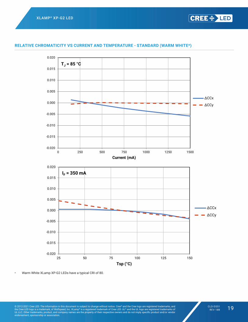
RELATIVE CHROMATICITY VS CURRENT AND TEMPERATURE - STANDARD (WARM WHITE*)
• Warm White XLamp XP‑G2 LEDs have a typical CRI of 80.
Delta CCT vs. Current - standard - warm white
-0.020
-0.015
-0.010
-0.005
0.000
0.005
0.010
0.015
0.020
0 250 500 750 1000 1250 1500
Current (mA)
ΔCCx
ΔCCy
TJ = 85 °C
Delta CCT vs Temp - standard - warm white
-0.020
-0.015
-0.010
-0.005
0.000
0.005
0.010
0.015
0.020
25 50 75 100 125 150
Tsp (°C)
ΔCCx
ΔCCy
IF = 350 mA

XLAMP® XP-G2 LED
© 2012-2021 Cree LED. The information in this document is subject to change without notice. Cree® and the Cree logo are registered trademarks, and the Cree LED logo is a trademark, of Wolfspeed, Inc. XLamp® is a registered trademark of Cree LED. UL® and the UL logo are registered trademarks of UL LLC. Other trademarks, product, and company names are the property of their respective owners and do not imply specific product and/or vendor endorsement, sponsorship or association.
CLD-DS51REV 18B 20
TYPICAL SPATIAL DISTRIBUTION - HIGH EFFICACY
TYPICAL SPATIAL DISTRIBUTION - STANDARD
Typical Spatial Radiation Pattern - high efficacy
0%
20%
40%
60%
80%
100%
-90 -70 -50 -30 -10 10 30 50 70 90
Rela
tive
Lum
inou
s In
tens
ity
Angle (º)
Typical Spatial Radiation Pattern - standard efficacy
0%
20%
40%
60%
80%
100%
-90 -70 -50 -30 -10 10 30 50 70 90
Rela
tive
Lum
inou
s In
tens
ity
Angle (º)

XLAMP® XP-G2 LED
© 2012-2021 Cree LED. The information in this document is subject to change without notice. Cree® and the Cree logo are registered trademarks, and the Cree LED logo is a trademark, of Wolfspeed, Inc. XLamp® is a registered trademark of Cree LED. UL® and the UL logo are registered trademarks of UL LLC. Other trademarks, product, and company names are the property of their respective owners and do not imply specific product and/or vendor endorsement, sponsorship or association.
CLD-DS51REV 18B 21
THERMAL DESIGN - HIGH EFFICACY
The maximum forward current is determined by the thermal resistance between the LED junction and ambient. It is crucial for the end
product to be designed in a manner that minimizes the thermal resistance from the solder point to ambient in order to optimize lamp life
and optical characteristics.
THERMAL DESIGN - STANDARD
Thermal Design - high efficacy
0
200
400
600
800
1000
1200
1400
1600
1800
2000
2200
0 20 40 60 80 100 120 140 160
Max
imum
Cur
rent
(mA
)
Ambient Temperature (ºC)
Rj-a = 10°C/W
Rj-a = 15°C/W
Rj-a = 20°C/W
Rj-a = 25°C/W
Thermal Design - standard efficacy
0
200
400
600
800
1000
1200
1400
1600
0 20 40 60 80 100 120 140 160
Max
imum
Cur
rent
(mA
)
Ambient Temperature (ºC)
Rj-a = 10°C/W
Rj-a = 15°C/W
Rj-a = 20°C/W
Rj-a = 25°C/W

XLAMP® XP-G2 LED
© 2012-2021 Cree LED. The information in this document is subject to change without notice. Cree® and the Cree logo are registered trademarks, and the Cree LED logo is a trademark, of Wolfspeed, Inc. XLamp® is a registered trademark of Cree LED. UL® and the UL logo are registered trademarks of UL LLC. Other trademarks, product, and company names are the property of their respective owners and do not imply specific product and/or vendor endorsement, sponsorship or association.
CLD-DS51REV 18B 22
PERFORMANCE GROUPS – LUMINOUS FLUX
XLamp XP‑G2 LEDs are tested for luminous flux and placed into one of the following luminous‑flux groups:
Group Code Minimum Luminous Flux (lm) @ 350 mA
Maximum Luminous Flux (lm) @ 350 mA
P2 67.2 73.9
P3 73.9 80.6
P4 80.6 87.4
Q2 87.4 93.9
Q3 93.9 100
Q4 100 107
Q5 107 114
R2 114 122
R3 122 130
R4 130 139
R5 139 148
S2 148 156
S3 156 164
S4 164 172
S5 172 180
S6 180 188

XLAMP® XP-G2 LED
© 2012-2021 Cree LED. The information in this document is subject to change without notice. Cree® and the Cree logo are registered trademarks, and the Cree LED logo is a trademark, of Wolfspeed, Inc. XLamp® is a registered trademark of Cree LED. UL® and the UL logo are registered trademarks of UL LLC. Other trademarks, product, and company names are the property of their respective owners and do not imply specific product and/or vendor endorsement, sponsorship or association.
CLD-DS51REV 18B 23
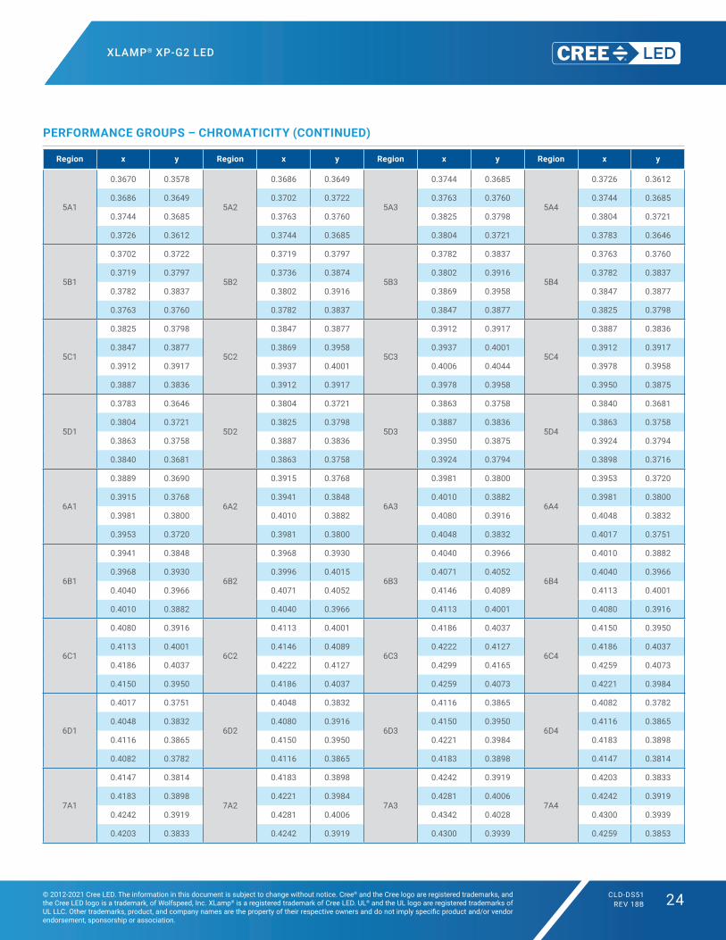
PERFORMANCE GROUPS – CHROMATICITY
Region x y Region x y Region x y Region x y
0A
0.2950 0.2970
0B
0.2920 0.3060
0C
0.2984 0.3133
0D
0.2984 0.3133
0.2920 0.3060 0.2895 0.3135 0.2962 0.3220 0.3048 0.3207
0.2984 0.3133 0.2962 0.3220 0.3028 0.3304 0.3068 0.3113
0.3009 0.3042 0.2984 0.3133 0.3048 0.3207 0.3009 0.3042
0R
0.2980 0.2880
0S
0.2895 0.3135
0T
0.2962 0.3220
0U
0.3037 0.2937
0.2950 0.2970 0.2870 0.3210 0.2937 0.3312 0.3009 0.3042
0.3009 0.3042 0.2937 0.3312 0.3005 0.3415 0.3068 0.3113
0.3037 0.2937 0.2962 0.3220 0.3028 0.3304 0.3093 0.2993
1A
0.3048 0.3207
1B
0.3028 0.3304
1C
0.3115 0.3391
1D
0.3130 0.3290
0.3130 0.3290 0.3115 0.3391 0.3205 0.3481 0.3213 0.3373
0.3144 0.3186 0.3130 0.3290 0.3213 0.3373 0.3221 0.3261
0.3068 0.3113 0.3048 0.3207 0.3130 0.3290 0.3144 0.3186
1R
0.3068 0.3113
1S
0.3005 0.3415
1T
0.3099 0.3509
1U
0.3144 0.3186
0.3144 0.3186 0.3099 0.3509 0.3196 0.3602 0.3221 0.3261
0.3161 0.3059 0.3115 0.3391 0.3205 0.3481 0.3231 0.3120
0.3093 0.2993 0.3028 0.3304 0.3115 0.3391 0.3161 0.3059
2A
0.3215 0.3350
2B
0.3207 0.3462
2C
0.3290 0.3538
2D
0.3290 0.3417
0.3290 0.3417 0.3290 0.3538 0.3376 0.3616 0.3371 0.3490
0.3290 0.3300 0.3290 0.3417 0.3371 0.3490 0.3366 0.3369
0.3222 0.3243 0.3215 0.3350 0.3290 0.3417 0.3290 0.3300
2R
0.3222 0.3243
2S
0.3196 0.3602
2T
0.3290 0.3690
2U
0.3290 0.3300
0.3290 0.3300 0.3290 0.3690 0.3381 0.3762 0.3366 0.3369
0.3290 0.3180 0.3290 0.3538 0.3376 0.3616 0.3361 0.3245
0.3231 0.3120 0.3207 0.3462 0.3290 0.3538 0.3290 0.3180
3A
0.3371 0.3490
3B
0.3376 0.3616
3C
0.3463 0.3687
3D
0.3451 0.3554
0.3451 0.3554 0.3463 0.3687 0.3551 0.3760 0.3533 0.3620
0.3440 0.3427 0.3451 0.3554 0.3533 0.3620 0.3515 0.3487
0.3366 0.3369 0.3371 0.3490 0.3451 0.3554 0.3440 0.3427
3R
0.3366 0.3369
3S
0.3381 0.3762
0.3440 0.3428 0.3480 0.3840
0.3429 0.3307 0.3463 0.3687
0.3361 0.3245 0.3376 0.3616
4A
0.3530 0.3597
4B
0.3548 0.3736
4C
0.3641 0.3804
4D
0.3615 0.3659
0.3615 0.3659 0.3641 0.3804 0.3736 0.3874 0.3702 0.3722
0.3590 0.3521 0.3615 0.3659 0.3702 0.3722 0.3670 0.3578
0.3512 0.3465 0.3530 0.3597 0.3615 0.3659 0.3590 0.3521
XLAMP® XP-G2 LED
© 2012-2021 Cree LED. The information in this document is subject to change without notice. Cree® and the Cree logo are registered trademarks, and the Cree LED logo is a trademark, of Wolfspeed, Inc. XLamp® is a registered trademark of Cree LED. UL® and the UL logo are registered trademarks of UL LLC. Other trademarks, product, and company names are the property of their respective owners and do not imply specific product and/or vendor endorsement, sponsorship or association.
CLD-DS51REV 18B 24
Region x y Region x y Region x y Region x y
5A1
0.3670 0.3578
5A2
0.3686 0.3649
5A3
0.3744 0.3685
5A4
0.3726 0.3612
0.3686 0.3649 0.3702 0.3722 0.3763 0.3760 0.3744 0.3685
0.3744 0.3685 0.3763 0.3760 0.3825 0.3798 0.3804 0.3721
0.3726 0.3612 0.3744 0.3685 0.3804 0.3721 0.3783 0.3646
5B1
0.3702 0.3722
5B2
0.3719 0.3797
5B3
0.3782 0.3837
5B4
0.3763 0.3760
0.3719 0.3797 0.3736 0.3874 0.3802 0.3916 0.3782 0.3837
0.3782 0.3837 0.3802 0.3916 0.3869 0.3958 0.3847 0.3877
0.3763 0.3760 0.3782 0.3837 0.3847 0.3877 0.3825 0.3798
5C1
0.3825 0.3798
5C2
0.3847 0.3877
5C3
0.3912 0.3917
5C4
0.3887 0.3836
0.3847 0.3877 0.3869 0.3958 0.3937 0.4001 0.3912 0.3917
0.3912 0.3917 0.3937 0.4001 0.4006 0.4044 0.3978 0.3958
0.3887 0.3836 0.3912 0.3917 0.3978 0.3958 0.3950 0.3875
5D1
0.3783 0.3646
5D2
0.3804 0.3721
5D3
0.3863 0.3758
5D4
0.3840 0.3681
0.3804 0.3721 0.3825 0.3798 0.3887 0.3836 0.3863 0.3758
0.3863 0.3758 0.3887 0.3836 0.3950 0.3875 0.3924 0.3794
0.3840 0.3681 0.3863 0.3758 0.3924 0.3794 0.3898 0.3716
6A1
0.3889 0.3690
6A2
0.3915 0.3768
6A3
0.3981 0.3800
6A4
0.3953 0.3720
0.3915 0.3768 0.3941 0.3848 0.4010 0.3882 0.3981 0.3800
0.3981 0.3800 0.4010 0.3882 0.4080 0.3916 0.4048 0.3832
0.3953 0.3720 0.3981 0.3800 0.4048 0.3832 0.4017 0.3751
6B1
0.3941 0.3848
6B2
0.3968 0.3930
6B3
0.4040 0.3966
6B4
0.4010 0.3882
0.3968 0.3930 0.3996 0.4015 0.4071 0.4052 0.4040 0.3966
0.4040 0.3966 0.4071 0.4052 0.4146 0.4089 0.4113 0.4001
0.4010 0.3882 0.4040 0.3966 0.4113 0.4001 0.4080 0.3916
6C1
0.4080 0.3916
6C2
0.4113 0.4001
6C3
0.4186 0.4037
6C4
0.4150 0.3950
0.4113 0.4001 0.4146 0.4089 0.4222 0.4127 0.4186 0.4037
0.4186 0.4037 0.4222 0.4127 0.4299 0.4165 0.4259 0.4073
0.4150 0.3950 0.4186 0.4037 0.4259 0.4073 0.4221 0.3984
6D1
0.4017 0.3751
6D2
0.4048 0.3832
6D3
0.4116 0.3865
6D4
0.4082 0.3782
0.4048 0.3832 0.4080 0.3916 0.4150 0.3950 0.4116 0.3865
0.4116 0.3865 0.4150 0.3950 0.4221 0.3984 0.4183 0.3898
0.4082 0.3782 0.4116 0.3865 0.4183 0.3898 0.4147 0.3814
7A1
0.4147 0.3814
7A2
0.4183 0.3898
7A3
0.4242 0.3919
7A4
0.4203 0.3833
0.4183 0.3898 0.4221 0.3984 0.4281 0.4006 0.4242 0.3919
0.4242 0.3919 0.4281 0.4006 0.4342 0.4028 0.4300 0.3939
0.4203 0.3833 0.4242 0.3919 0.4300 0.3939 0.4259 0.3853
PERFORMANCE GROUPS – CHROMATICITY (CONTINUED)

XLAMP® XP-G2 LED
© 2012-2021 Cree LED. The information in this document is subject to change without notice. Cree® and the Cree logo are registered trademarks, and the Cree LED logo is a trademark, of Wolfspeed, Inc. XLamp® is a registered trademark of Cree LED. UL® and the UL logo are registered trademarks of UL LLC. Other trademarks, product, and company names are the property of their respective owners and do not imply specific product and/or vendor endorsement, sponsorship or association.
CLD-DS51REV 18B 25
Region x y Region x y Region x y Region x y
7B1
0.4221 0.3984
7B2
0.4259 0.4073
7B3
0.4322 0.4096
7B4
0.4281 0.4006
0.4259 0.4073 0.4299 0.4165 0.4364 0.4188 0.4322 0.4096
0.4322 0.4096 0.4364 0.4188 0.4430 0.4212 0.4385 0.4119
0.4281 0.4006 0.4322 0.4096 0.4385 0.4119 0.4342 0.4028
7C1
0.4342 0.4028
7C2
0.4385 0.4119
7C3
0.4449 0.4141
7C4
0.4403 0.4049
0.4385 0.4119 0.4430 0.4212 0.4496 0.4236 0.4449 0.4141
0.4449 0.4141 0.4496 0.4236 0.4562 0.4260 0.4513 0.4164
0.4403 0.4049 0.4449 0.4141 0.4513 0.4164 0.4465 0.4071
7D1
0.4259 0.3853
7D2
0.4300 0.3939
7D3
0.4359 0.3960
7D4
0.4316 0.3873
0.4300 0.3939 0.4342 0.4028 0.4403 0.4049 0.4359 0.3960
0.4359 0.3960 0.4403 0.4049 0.4465 0.4071 0.4418 0.3981
0.4316 0.3873 0.4359 0.3960 0.4418 0.3981 0.4373 0.3893
8A1
0.4373 0.3893
8A2
0.4418 0.3981
8A3
0.4475 0.3994
8A4
0.4428 0.3906
0.4418 0.3981 0.4465 0.4071 0.4523 0.4085 0.4475 0.3994
0.4475 0.3994 0.4523 0.4085 0.4582 0.4099 0.4532 0.4008
0.4428 0.3906 0.4475 0.3994 0.4532 0.4008 0.4483 0.3919
8B1
0.4465 0.4071
8B2
0.4513 0.4164
8B3
0.4573 0.4178
8B4
0.4523 0.4085
0.4513 0.4164 0.4562 0.4260 0.4624 0.4274 0.4573 0.4178
0.4573 0.4178 0.4624 0.4274 0.4687 0.4289 0.4634 0.4193
0.4523 0.4085 0.4573 0.4178 0.4634 0.4193 0.4582 0.4099
8C1
0.4582 0.4099
8C2
0.4634 0.4193
8C3
0.4695 0.4207
8C4
0.4641 0.4112
0.4634 0.4193 0.4687 0.4289 0.4750 0.4304 0.4695 0.4207
0.4695 0.4207 0.4750 0.4304 0.4813 0.4319 0.4756 0.4221
0.4641 0.4112 0.4695 0.4207 0.4756 0.4221 0.4700 0.4126
8D1
0.4483 0.3919
8D2
0.4532 0.4008
8D3
0.4589 0.4021
8D4
0.4538 0.3931
0.4532 0.4008 0.4582 0.4099 0.4641 0.4112 0.4589 0.4021
0.4589 0.4021 0.4641 0.4112 0.4700 0.4126 0.4646 0.4034
0.4538 0.3931 0.4589 0.4021 0.4646 0.4034 0.4593 0.3944
PERFORMANCE GROUPS – CHROMATICITY (CONTINUED)
XLAMP® XP-G2 LED
© 2012-2021 Cree LED. The information in this document is subject to change without notice. Cree® and the Cree logo are registered trademarks, and the Cree LED logo is a trademark, of Wolfspeed, Inc. XLamp® is a registered trademark of Cree LED. UL® and the UL logo are registered trademarks of UL LLC. Other trademarks, product, and company names are the property of their respective owners and do not imply specific product and/or vendor endorsement, sponsorship or association.
CLD-DS51REV 18B 26
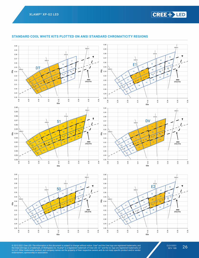
STANDARD COOL WHITE KITS PLOTTED ON ANSI STANDARD CHROMATICITY REGIONS
5000 K
5700 K
6500 K
8000 K
0A
0B
0C
0D
0R
0S
0T
0U
1A
1B
1C
1D
2A
2B
2C
2D
1R
1S
1T
1U
2R
2S
2T
2U
0.28
0.29
0.30
0.31
0.32
0.33
0.34
0.35
0.36
0.37
0.38
0.39
0.40
0.28
0.29
0.30
0.31
0.32
0.33
0.34
0.35
0.36
CCy
CCx
ANSIC78.377A
DT
5000 K
5700 K
6500 K
8000 K
0A
0B
0C
0D
0R
0S
0T
0U
1A
1B
1C
1D
2A
2B
2C
2D
3A
3B
1R
1S
1T
1U
2R
2S
2T
2U
3R
3S
0.28
0.29
0.30
0.31
0.32
0.33
0.34
0.35
0.36
0.37
0.38
0.39
0.40
0.28
0.29
0.30
0.31
0.32
0.33
0.34
0.35
0.36
CCy
CCx
ANSIC78.377A
50
5000 K
5700 K
6500 K
8000 K
0A
0B
0C
0D
0R
0S
0T
0U
1A
1B
1C
1D
2A
2B
2C
2D
3A
3B
1R
1S
1T
1U
2R
2S
2T
2U
3R
3S
0.28
0.29
0.30
0.31
0.32
0.33
0.34
0.35
0.36
0.37
0.38
0.39
0.40
0.28
0.29
0.30
0.31
0.32
0.33
0.34
0.35
0.36
CCy
CCx
ANSIC78.377A
E1
5000 K
5700 K
6500 K
8000 K
0A
0B
0C
0D
0R
0S
0T
0U
1A
1B
1C
1D
2A
2B
2C
2D
3A
3B
1R
1S
1T
1U
2R
2S
2T
2U
3R
3S
0.28
0.29
0.30
0.31
0.32
0.33
0.34
0.35
0.36
0.37
0.38
0.39
0.40
0.28
0.29
0.30
0.31
0.32
0.33
0.34
0.35
0.36
CCy
CCx
ANSIC78.377A
E2
5000 K
5700 K
6500 K
8000 K
0A
0B
0C
0D
0R
0S
0T
0U
1A
1B
1C
1D
2A
2B
2C
2D
3A
3B
1R
1S
1T
1U
2R
2S
2T
2U
3R
3S
0.28
0.29
0.30
0.31
0.32
0.33
0.34
0.35
0.36
0.37
0.38
0.39
0.40
0.28
0.29
0.30
0.31
0.32
0.33
0.34
0.35
0.36
CCy
CCx
ANSIC78.377A
51
5000 K
5700 K
6500 K
8000 K
0A
0B
0C
0D
0R
0S
0T
0U
1A
1B
1C
1D
2A
2B
2C
2D
1R
1S
1T
1U
2R
2S
2T
2U
0.28
0.29
0.30
0.31
0.32
0.33
0.34
0.35
0.36
0.37
0.38
0.39
0.400.
28
0.29
0.30
0.31
0.32
0.33
0.34
0.35
0.36
CCy
CCx
ANSIC78.377A
DV

XLAMP® XP-G2 LED
© 2012-2021 Cree LED. The information in this document is subject to change without notice. Cree® and the Cree logo are registered trademarks, and the Cree LED logo is a trademark, of Wolfspeed, Inc. XLamp® is a registered trademark of Cree LED. UL® and the UL logo are registered trademarks of UL LLC. Other trademarks, product, and company names are the property of their respective owners and do not imply specific product and/or vendor endorsement, sponsorship or association.
CLD-DS51REV 18B 27
STANDARD COOL WHITE KITS PLOTTED ON ANSI STANDARD CHROMATICITY REGIONS - CONTINUED
5000 K
5700 K
6500 K
8000 K
0A
0B
0C
0D
0R
0S
0T
0U
1A
1B
1C
1D
2A
2B
2C
2D
3A
3B
1R
1S
1T
1U
2R
2S
2T
2U
3R
3S
0.28
0.29
0.30
0.31
0.32
0.33
0.34
0.35
0.36
0.37
0.38
0.39
0.40
0.28
0.29
0.30
0.31
0.32
0.33
0.34
0.35
0.36
CCy
CCx
ANSIC78.377A
53

XLAMP® XP-G2 LED
© 2012-2021 Cree LED. The information in this document is subject to change without notice. Cree® and the Cree logo are registered trademarks, and the Cree LED logo is a trademark, of Wolfspeed, Inc. XLamp® is a registered trademark of Cree LED. UL® and the UL logo are registered trademarks of UL LLC. Other trademarks, product, and company names are the property of their respective owners and do not imply specific product and/or vendor endorsement, sponsorship or association.
CLD-DS51REV 18B 28
STANDARD WARM AND NEUTRAL WHITE KITS PLOTTED ON ANSI STANDARD CHROMATICITY REGIONS
2700 K3000 K
3500 K
4000 K
4500 K
5000 K
3A
3B
3C
3D4A
4B
4C
4D 5A1
5A25A3
5A4
5B1
5B25B3
5B45C1
5C25C3
5C4
5D1
5D25D3
5D4 6A1
6A26A3
6A4
6B1
6B26B3
6B46C1
6C26C3
6C4
6D1
6D26D3
6D47A1
7A27A3
7A4
7B1
7B27B3
7B47C1
7C27C3
7C4
7D1
7D27D3
7D4 8A1
8A2 8A3
8A4
8B1
8B2 8B3
8B4 8C1
8C2 8C3
8C4
8D1
8D2 8D3
8D4
0.33
0.34
0.35
0.36
0.37
0.38
0.39
0.40
0.41
0.42
0.43
0.44
0.45
0.460.
33
0.34
0.35
0.36
0.37
0.38
0.39
0.40
0.41
0.42
0.43
0.44
0.45
0.46
0.47
0.48
0.49
CCy
CCx
ANSIC78.377A
E3E4
E5E6
E8E7
2700 K3000 K
3500 K
4000 K
4500 K
5000 K
3A
3B
3C
3D4A
4B
4C
4D 5A1
5A25A3
5A4
5B1
5B25B3
5B45C1
5C25C3
5C4
5D1
5D25D3
5D4 6A1
6A26A3
6A4
6B1
6B26B3
6B46C1
6C26C3
6C4
6D1
6D26D3
6D47A1
7A27A3
7A4
7B1
7B27B3
7B47C1
7C27C3
7C4
7D1
7D27D3
7D4 8A1
8A2 8A3
8A4
8B1
8B2 8B3
8B4 8C1
8C2 8C3
8C4
8D1
8D2 8D3
8D4
0.33
0.34
0.35
0.36
0.37
0.38
0.39
0.40
0.41
0.42
0.43
0.44
0.45
0.46
0.33
0.34
0.35
0.36
0.37
0.38
0.39
0.40
0.41
0.42
0.43
0.44
0.45
0.46
0.47
0.48
0.49
CCy
CCx
ANSIC78.377A
F4
F6F7
F5
F8
XLAMP® XP-G2 LED
© 2012-2021 Cree LED. The information in this document is subject to change without notice. Cree® and the Cree logo are registered trademarks, and the Cree LED logo is a trademark, of Wolfspeed, Inc. XLamp® is a registered trademark of Cree LED. UL® and the UL logo are registered trademarks of UL LLC. Other trademarks, product, and company names are the property of their respective owners and do not imply specific product and/or vendor endorsement, sponsorship or association.
CLD-DS51REV 18B 29
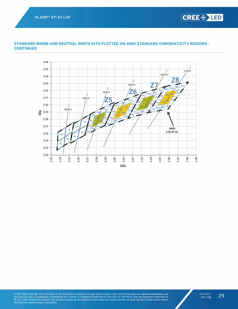
STANDARD WARM AND NEUTRAL WHITE KITS PLOTTED ON ANSI STANDARD CHROMATICITY REGIONS - CONTINUED
2700 K3000 K
3500 K
4000 K
4500 K
5000 K
3A
3B
3C
3D4A
4B
4C
4D 5A1
5A25A3
5A4
5B1
5B25B3
5B45C1
5C25C3
5C4
5D1
5D25D3
5D4 6A1
6A26A3
6A4
6B1
6B26B3
6B46C1
6C26C3
6C4
6D1
6D26D3
6D47A1
7A27A3
7A4
7B1
7B27B3
7B47C1
7C27C3
7C4
7D1
7D27D3
7D4 8A1
8A2 8A3
8A4
8B1
8B2 8B3
8B4 8C1
8C2 8C3
8C4
8D1
8D2 8D3
8D4
0.33
0.34
0.35
0.36
0.37
0.38
0.39
0.40
0.41
0.42
0.43
0.44
0.45
0.46
0.33
0.34
0.35
0.36
0.37
0.38
0.39
0.40
0.41
0.42
0.43
0.44
0.45
0.46
0.47
0.48
0.49
CCy
CCx
ANSIC78.377A
Z6Z7
Z5
Z8
XLAMP® XP-G2 LED
© 2012-2021 Cree LED. The information in this document is subject to change without notice. Cree® and the Cree logo are registered trademarks, and the Cree LED logo is a trademark, of Wolfspeed, Inc. XLamp® is a registered trademark of Cree LED. UL® and the UL logo are registered trademarks of UL LLC. Other trademarks, product, and company names are the property of their respective owners and do not imply specific product and/or vendor endorsement, sponsorship or association.
CLD-DS51REV 18B 30
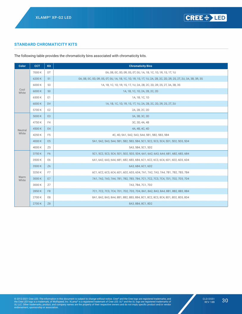
STANDARD CHROMATICITY KITS
The following table provides the chromaticity bins associated with chromaticity kits.
Color CCT Kit Chromaticity Bins
Cool White
7000 K DT 0A, 0B, 0C, 0D, 0R, 0S, 0T, 0U, 1A, 1B, 1C, 1D, 1R, 1S, 1T, 1U
6200 K 51 0A, 0B, 0C, 0D, 0R, 0S, 0T, 0U, 1A, 1B, 1C, 1D, 1R, 1S, 1T, 1U, 2A, 2B, 2C, 2D, 2R, 2S, 2T, 2U, 3A, 3B, 3R, 3S
6000 K 53 1A, 1B, 1C, 1D, 1R, 1S, 1T, 1U, 2A, 2B, 2C, 2D, 2R, 2S, 2T, 3A, 3B, 3S
6000 K 50 1A, 1B, 1C, 1D, 2A, 2B, 2C, 2D
6500 K E1 1A, 1B, 1C, 1D
6000 K DV 1A, 1B, 1C, 1D, 1R, 1S, 1T, 1U, 2A, 2B, 2C, 2D, 2R, 2S, 2T, 2U
5700 K E2 2A, 2B, 2C, 2D
Neutral White
5000 K E3 3A, 3B, 3C, 3D
4750 K F4 3C, 3D, 4A, 4B
4500 K E4 4A, 4B, 4C, 4D
4250 K F5 4C, 4D, 5A1, 5A2, 5A3, 5A4, 5B1, 5B2, 5B3, 5B4
4000 K E5 5A1, 5A2, 5A3, 5A4, 5B1, 5B2, 5B3, 5B4, 5C1, 5C2, 5C3, 5C4, 5D1, 5D2, 5D3, 5D4
4000 K Z5 5A3, 5B4, 5C1, 5D2
Warm White
3750 K F6 5C1, 5C2, 5C3, 5C4, 5D1, 5D2, 5D3, 5D4, 6A1, 6A2, 6A3, 6A4, 6B1, 6B2, 6B3, 6B4
3500 K E6 6A1, 6A2, 6A3, 6A4, 6B1, 6B2, 6B3, 6B4, 6C1, 6C2, 6C3, 6C4, 6D1, 6D2, 6D3, 6D4
3500 K Z6 6A3, 6B4, 6C1, 6D2
3250 K F7 6C1, 6C2, 6C3, 6C4, 6D1, 6D2, 6D3, 6D4, 7A1, 7A2, 7A3, 7A4, 7B1, 7B2, 7B3, 7B4
3000 K E7 7A1, 7A2, 7A3, 7A4, 7B1, 7B2, 7B3, 7B4, 7C1, 7C2, 7C3, 7C4, 7D1, 7D2, 7D3, 7D4
3000 K Z7 7A3, 7B4, 7C1, 7D2
2850 K F8 7C1, 7C2, 7C3, 7C4, 7D1, 7D2, 7D3, 7D4, 8A1, 8A2, 8A3, 8A4, 8B1, 8B2, 8B3, 8B4
2700 K E8 8A1, 8A2, 8A3, 8A4, 8B1, 8B2, 8B3, 8B4, 8C1, 8C2, 8C3, 8C4, 8D1, 8D2, 8D3, 8D4
2700 K Z8 8A3, 8B4, 8C1, 8D2

XLAMP® XP-G2 LED
© 2012-2021 Cree LED. The information in this document is subject to change without notice. Cree® and the Cree logo are registered trademarks, and the Cree LED logo is a trademark, of Wolfspeed, Inc. XLamp® is a registered trademark of Cree LED. UL® and the UL logo are registered trademarks of UL LLC. Other trademarks, product, and company names are the property of their respective owners and do not imply specific product and/or vendor endorsement, sponsorship or association.
CLD-DS51REV 18B 31
BIN AND ORDER CODE FORMATS
XP‑G2 bin codes and order codes are configured in the following manner:
Order Code Bin Code
SSSCCC-BD-HHHH-NNNNNKit number
Version 1 = Standard E = High Efficacy
Color BWT = Gen 2 White
Series XPG = XP-G
Color specification 0 = Outdoor White B = 70 CRI minimum L = Standard CRI H = 80 CRI minimum U = 90 CRI minimum
Internal code
SSSCCC-BD-WWW-FF-G-AALuminous flux group
Version 1 = Standard E = High Efficacy
Color BWT = Gen 2 White
Series XPG = XP-G
Color specification 0 = Outdoor White B = 70 CRI minimum L = Standard CRI H = 80 CRI minimum U = 90 CRI minimum
Chromaticity bin
Internal code

XLAMP® XP-G2 LED
© 2012-2021 Cree LED. The information in this document is subject to change without notice. Cree® and the Cree logo are registered trademarks, and the Cree LED logo is a trademark, of Wolfspeed, Inc. XLamp® is a registered trademark of Cree LED. UL® and the UL logo are registered trademarks of UL LLC. Other trademarks, product, and company names are the property of their respective owners and do not imply specific product and/or vendor endorsement, sponsorship or association.
CLD-DS51REV 18B 32
REFLOW SOLDERING CHARACTERISTICS
In testing, Cree LED has found XLamp XP‑G2 LEDs to be compatible with JEDEC J‑STD‑020C, using the parameters listed below. As a
general guideline, Cree LED recommends that users follow the recommended soldering profile provided by the manufacturer of the solder
paste used, and therefore it is the lamp or luminaire manufacturer’s responsibility to determine applicable soldering requirements.
Note that this general guideline may not apply to all PCB designs and configurations of reflow soldering equipment.
Profile Feature Lead-Free Solder
Average Ramp‑Up Rate (Tsmax to Tp) 1.2 °C/second
Preheat: Temperature Min (Tsmin) 120 °C
Preheat: Temperature Max (Tsmax) 170 °C
Preheat: Time (tsmin to tsmax) 65-150 seconds
Time Maintained Above: Temperature (TL) 217 °C
Time Maintained Above: Time (tL) 45‑90 seconds
Peak/Classification Temperature (Tp) 235 ‑ 245 °C
Time Within 5 °C of Actual Peak Temperature (tp) 20‑40 seconds
Ramp-Down Rate 1 ‑ 6 °C/second
Time 25 °C to Peak Temperature 4 minutes max.
Note: All temperatures refer to topside of the package, measured on the package body surface.
IPC/JEDEC J‑STD‑020C
TP
TL
Tem
pera
ture
Timet 25˚C to Peak
Preheatts
tS
tP
25
Ramp-down
Ramp-up
Critical ZoneTL to TP
Tsmax
Tsmin

XLAMP® XP-G2 LED
© 2012-2021 Cree LED. The information in this document is subject to change without notice. Cree® and the Cree logo are registered trademarks, and the Cree LED logo is a trademark, of Wolfspeed, Inc. XLamp® is a registered trademark of Cree LED. UL® and the UL logo are registered trademarks of UL LLC. Other trademarks, product, and company names are the property of their respective owners and do not imply specific product and/or vendor endorsement, sponsorship or association.
CLD-DS51REV 18B 33
NOTES
Measurements
The luminous flux, radiant power, chromaticity, forward voltage and CRI measurements in this document are binning specifications only
and solely represent product measurements as of the date of shipment. These measurements will change over time based on a number
of factors that are not within Cree LED’s control and are not intended or provided as operational specifications for the products. Calculated
values are provided for informational purposes only and are not intended or provided as specifications.
Pre-Release Qualification Testing
Please read the LED Reliability Overview for details of the qualification process Cree LED applies to ensure long‑term reliability for XLamp
LEDs and details of Cree LED’s pre‑release qualification testing for XLamp LEDs.
Lumen Maintenance
Cree LED now uses standardized IES LM‑80‑08 and TM‑21‑11 methods for collecting long‑term data and extrapolating LED lumen
maintenance. For information on the specific LM‑80 data sets available for this LED, refer to the public LM-80 results document.
Please read the Long-Term Lumen Maintenance application note for more details on Cree LED’s lumen maintenance testing and
forecasting. Please read the Thermal Management application note for details on how thermal design, ambient temperature, and drive
current affect the LED junction temperature.
Moisture Sensitivity
Cree LED recommends keeping XLamp LEDs in the provided, resealable moisture‑barrier packaging (MBP) until immediately prior to
soldering. Unopened MBPs that contain XLamp LEDs do not need special storage for moisture sensitivity.
Once the MBP is opened, XLamp XP‑G2 LEDs may be stored as MSL 1 per JEDEC J‑STD‑033, meaning they have unlimited floor life in
conditions of ≤ 30 ºC/85% relative humidity (RH). Regardless of the storage condition, Cree LED recommends sealing any unsoldered
LEDs in the original MBP.
RoHS Compliance
The levels of RoHS restricted materials in this product are below the maximum concentration values (also referred to as the threshold
limits) permitted for such substances, or are used in an exempted application, in accordance with EU Directive 2011/65/EC (RoHS2), as
implemented January 2, 2013. RoHS Declarations for this product can be obtained from your Cree LED representative or from the Product
Ecology section of the Cree LED website.
REACh Compliance
REACh substances of very high concern (SVHCs) information is available for this product. Since the European Chemical Agency (ECHA)
has published notice of their intent to frequently revise the SVHC listing for the foreseeable future, please contact a Cree LED representative
to insure you get the most up‑to‑date REACh Declaration. REACh banned substance information (REACh Article 67) is also available upon
request.

XLAMP® XP-G2 LED
© 2012-2021 Cree LED. The information in this document is subject to change without notice. Cree® and the Cree logo are registered trademarks, and the Cree LED logo is a trademark, of Wolfspeed, Inc. XLamp® is a registered trademark of Cree LED. UL® and the UL logo are registered trademarks of UL LLC. Other trademarks, product, and company names are the property of their respective owners and do not imply specific product and/or vendor endorsement, sponsorship or association.
CLD-DS51REV 18B 34
UL® Recognized Component
This product meets the requirements to be considered a UL Recognized Component with Level 4 enclosure consideration. The LED
package or a portion thereof has been investigated as a fire and electrical enclosure per ANSI/UL 8750.
Vision Advisory
WARNING: Do not look at an exposed lamp in operation. Eye injury can result. For more information about LEDs and eye safety, please
refer to the LED Eye Safety application note.
NOTES - CONTINUED
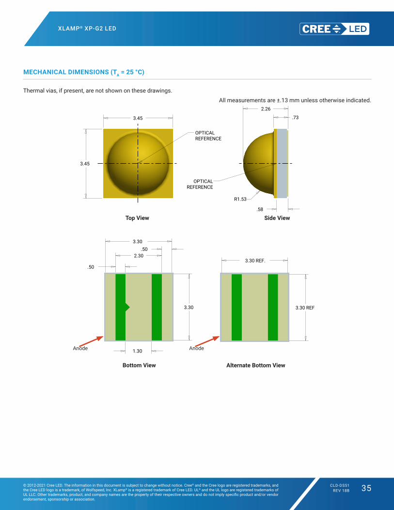
XLAMP® XP-G2 LED
© 2012-2021 Cree LED. The information in this document is subject to change without notice. Cree® and the Cree logo are registered trademarks, and the Cree LED logo is a trademark, of Wolfspeed, Inc. XLamp® is a registered trademark of Cree LED. UL® and the UL logo are registered trademarks of UL LLC. Other trademarks, product, and company names are the property of their respective owners and do not imply specific product and/or vendor endorsement, sponsorship or association.
CLD-DS51REV 18B 35
MECHANICAL DIMENSIONS (TA = 25 °C)
Thermal vias, if present, are not shown on these drawings.
All measurements are ±.13 mm unless otherwise indicated.
Side ViewTop View
SIZE
TITLE
OF
REV.
SHEETC
DRAWING NO.
DATE
DATE
DATE
CHECK
FINAL PROTECTIVE FINISH
MATERIAL
APPROVED
DRAWN BY
THIRD ANGLE PROJECTION
SCALE
A
B
C
D
123456
6 5 4 3 2 1
A
B
C
D
Phone (919) 313-5300Fax (919) 313-5558
4600 Silicon DriveDurham, N.C 27703
UNAUTHORIZED PERSON WITHOUT THE WRITTEN CONSENTMAY NOT BE COPIED, REPRODUCED OR DISCLOSED TO ANY CONFIDENTIAL INFORMATION OF CREE, INC. THIS PLOT CONTAINED WITHIN ARE THE PROPRIETARY ANDCREE CONFIDENTIAL. THIS PLOT AND THE INFORMATION
OF CREE INC.
NOTICE
X° ± .5°.XXX ± .25.XX ± .75.X ± 1.5
FOR SHEET METAL PARTS ONLY
.XX ± .25
.XXX ± .125X° ± .5°
UNLESS OTHERWISE SPECIFIEDDIMENSIONS ARE IN
MILLIMETERS AND AFTER FINISH.TOLERANCE UNLESS SPECIFIED:
SURFACE FINISH: 1.6
3.30
3.30
.73
2.26
R1.53
1.30
.50
2.30.50
3.45
3.45
.58
.50
3.30
2.30
.64
.25
.75
1.01
3.30
.50
3.30
.50
1.30
3.30
3.30 REF.
3.30 REF.
1/122.000C2610-00066
OUTLINE DRAWING XPG G3
10/6/15D. CRONIN
REVISONSREV DESCRIPTION BY DATE APP'D
RECOMMENDED PCB SOLDER PAD RECOMMENDED STENCIL PATTERN(HATCHED AREA IS OPENING)
ALL DIMENSIONS ARE ± .13MM UNLESS OTHERWISE NOTED
PRIMARYALTERNATIVE
OPTICALREFERENCE
OPTICALREFERENCE
Bottom View Alternate Bottom View
AnodeAnode
SIZE
TITLE
OF
REV.
SHEETC
DRAWING NO.
DATE
DATE
DATE
CHECK
FINAL PROTECTIVE FINISH
MATERIAL
APPROVED
DRAWN BY
THIRD ANGLE PROJECTION
SCALE
A
B
C
D
123456
6 5 4 3 2 1
A
B
C
D
Phone (919) 313-5300Fax (919) 313-5558
4600 Silicon DriveDurham, N.C 27703
UNAUTHORIZED PERSON WITHOUT THE WRITTEN CONSENTMAY NOT BE COPIED, REPRODUCED OR DISCLOSED TO ANY CONFIDENTIAL INFORMATION OF CREE, INC. THIS PLOT CONTAINED WITHIN ARE THE PROPRIETARY ANDCREE CONFIDENTIAL. THIS PLOT AND THE INFORMATION
OF CREE INC.
NOTICE
X° ± .5°.XXX ± .25.XX ± .75.X ± 1.5
FOR SHEET METAL PARTS ONLY
.XX ± .25
.XXX ± .125X° ± .5°
UNLESS OTHERWISE SPECIFIEDDIMENSIONS ARE IN
MILLIMETERS AND AFTER FINISH.TOLERANCE UNLESS SPECIFIED:
SURFACE FINISH: 1.6
3.30
3.30
.73
2.26
R1.53
1.30
.50
2.30.50
3.45
3.45
.58
.50
3.30
2.30
.64
.25
.75
1.01
3.30
.50
3.30
.50
1.30
3.30
3.30 REF.
3.30 REF.
1/122.000C2610-00066
OUTLINE DRAWING XPG G3
10/6/15D. CRONIN
REVISONSREV DESCRIPTION BY DATE APP'D
RECOMMENDED PCB SOLDER PAD RECOMMENDED STENCIL PATTERN(HATCHED AREA IS OPENING)
ALL DIMENSIONS ARE ± .13MM UNLESS OTHERWISE NOTED
PRIMARYALTERNATIVE
OPTICALREFERENCE
OPTICALREFERENCE

XLAMP® XP-G2 LED
© 2012-2021 Cree LED. The information in this document is subject to change without notice. Cree® and the Cree logo are registered trademarks, and the Cree LED logo is a trademark, of Wolfspeed, Inc. XLamp® is a registered trademark of Cree LED. UL® and the UL logo are registered trademarks of UL LLC. Other trademarks, product, and company names are the property of their respective owners and do not imply specific product and/or vendor endorsement, sponsorship or association.
CLD-DS51REV 18B 36
MECHANICAL DIMENSIONS (TA = 25 °C) - CONTINUED
Notes:• Cree LED recommends using thermal pad kickouts to maximize component thermal performance.• Cree LED recommends using white solder mask material to minimize system optical loss.* This stencil has been tested and optimized for the avoidance of voiding when using ALPHA® LUMET® P30 Maxrel solder paste. For other solder
pastes, a “window pane” design for the thermal pad stencil may result in a lower voiding percentage. Contact your local Cree LED Field Applications Engineer for consultation regarding your specific application.
Recommended Solder Pad(Solder Mask Pattern)
Recommended Stencil Openings*
SIZE
TITLE
OF
REV.
SHEETC
DRAWING NO.
DATE
DATE
DATE
CHECK
FINAL PROTECTIVE FINISH
MATERIAL
APPROVED
DRAWN BY
THIRD ANGLE PROJECTION
SCALE
A
B
C
D
123456
6 5 4 3 2 1
A
B
C
D
Phone (919) 313-5300Fax (919) 313-5558
4600 Silicon DriveDurham, N.C 27703
UNAUTHORIZED PERSON WITHOUT THE WRITTEN CONSENTMAY NOT BE COPIED, REPRODUCED OR DISCLOSED TO ANY CONFIDENTIAL INFORMATION OF CREE, INC. THIS PLOT CONTAINED WITHIN ARE THE PROPRIETARY ANDCREE CONFIDENTIAL. THIS PLOT AND THE INFORMATION
OF CREE INC.
NOTICE
X° ± .5°.XXX ± .25.XX ± .75.X ± 1.5FOR SHEET METAL PARTS ONLY
.XX ± .25.XXX ± .125X° ± .5°
UNLESS OTHERWISE SPECIFIEDDIMENSIONS ARE IN MILLIMETERS AND AFTER FINISH.TOLERANCE UNLESS SPECIFIED:
SURFACE FINISH: 1.6
3.30
3.30
.73
2.26
R 1.531.30
.50
2.30.50
3.45
3.45
.58
3.30 REF.
3.30 REF.
3.50
.70
.30
1.50
.30
3.50
3.30
.50
.50
1.30
.503.30
.43.29.83
.18 .56
.18
.50
.50
.56.56
.18
3.30
3.30
.09
.18
1/122.000E2610-00066
OUTLINE DRAWING XPG G3
10/6/15D. CRONIN
REVISONSREV DESCRIPTION BY DATE APP'D
RECOMMENDED SOLDER PAD (SOLDER RESIST PATTERN)
ALL DIMENSIONS ARE ± .13MM UNLESS OTHERWISE NOTED
PRIMARY ALTERNATIVE
OPTICAL REFERENCE
RECOMMENDED COPPER LAYOUTRECOMMENDED STENCIL OPENINGS
OPTICALREFERENCE
Recommended Copper Layout
SIZE
TITLE
OF
REV.
SHEETC
DRAWING NO.
DATE
DATE
DATE
CHECK
FINAL PROTECTIVE FINISH
MATERIAL
APPROVED
DRAWN BY
THIRD ANGLE PROJECTION
SCALE
A
B
C
D
123456
6 5 4 3 2 1
A
B
C
D
Phone (919) 313-5300Fax (919) 313-5558
4600 Silicon DriveDurham, N.C 27703
UNAUTHORIZED PERSON WITHOUT THE WRITTEN CONSENTMAY NOT BE COPIED, REPRODUCED OR DISCLOSED TO ANY CONFIDENTIAL INFORMATION OF CREE, INC. THIS PLOT CONTAINED WITHIN ARE THE PROPRIETARY ANDCREE CONFIDENTIAL. THIS PLOT AND THE INFORMATION
OF CREE INC.
NOTICE
X° ± .5°.XXX ± .25.XX ± .75.X ± 1.5FOR SHEET METAL PARTS ONLY
.XX ± .25.XXX ± .125X° ± .5°
UNLESS OTHERWISE SPECIFIEDDIMENSIONS ARE IN MILLIMETERS AND AFTER FINISH.TOLERANCE UNLESS SPECIFIED:
SURFACE FINISH: 1.6
3.30
3.30
.73
2.26
R 1.531.30
.50
2.30.50
3.45
3.45
.58
3.30 REF.
3.30 REF.
3.50
.70
.30
1.50
.30
3.50
3.30
.50
.50
1.30
.503.30
.43.29.83
.18 .56
.18
.50
.50
.56.56
.18
3.30
3.30
.09
.18
1/122.000E2610-00066
OUTLINE DRAWING XPG G3
10/6/15D. CRONIN
REVISONSREV DESCRIPTION BY DATE APP'D
RECOMMENDED SOLDER PAD (SOLDER RESIST PATTERN)
ALL DIMENSIONS ARE ± .13MM UNLESS OTHERWISE NOTED
PRIMARY ALTERNATIVE
OPTICAL REFERENCE
RECOMMENDED COPPER LAYOUTRECOMMENDED STENCIL OPENINGS
OPTICALREFERENCE

XLAMP® XP-G2 LED
© 2012-2021 Cree LED. The information in this document is subject to change without notice. Cree® and the Cree logo are registered trademarks, and the Cree LED logo is a trademark, of Wolfspeed, Inc. XLamp® is a registered trademark of Cree LED. UL® and the UL logo are registered trademarks of UL LLC. Other trademarks, product, and company names are the property of their respective owners and do not imply specific product and/or vendor endorsement, sponsorship or association.
CLD-DS51REV 18B 37
TAPE AND REEL
All Cree LED carrier tapes conform to EIA‑481D, Automated Component Handling Systems Standard.
All dimensions in mm.
SIZE
TITLE
OF
REV.
SHEET
CDRAWING NO.
DATE
DATE
DATE
CHECK
FINAL PROTECTIVE FINISH
MATERIAL
APPROVED
DRAWN BY
THIRD ANGLE PROJECTION
SCALE
A
B
C
D
123456
6 5 4 3 2 1
A
B
C
D
Phone (919) 313-5300Fax (919) 313-5558
4600 Silicon DriveDurham, N.C 27703
UNAUTHORIZED PERSON WITHOUT THE WRITTEN CONSENTMAY NOT BE COPIED, REPRODUCED OR DISCLOSED TO ANY CONFIDENTIAL INFORMATION OF CREE, INC. THIS PLOT CONTAINED WITHIN ARE THE PROPRIETARY ANDCREE CONFIDENTIAL. THIS PLOT AND THE INFORMATION
OF CREE INC.
NOTICE
X° ± .5 °.XXX ± .25.XX ± .75.X ± 1.5
FOR SHEET METAL PARTS ONLY
.XX ± .25
.XXX ± .125X° ± .5 °
UNLESS OTHERWISE SPECIFIEDDIMENSIONS ARE IN
MILLIMETERS AND AFTER FINISH.TOLERANCE UNLESS SPECIFIED:
SURFACE FINISH: 1.6
Trailer160mm (min) of
empty pocketssealed with tape
(20 pockets min.)
Loaded Pockets(1000 Lamps)
Leader400mm (min.) of
empty pockets with at least 100mmsealed by tape
(50 empty pockets min.)
12.0+.3-.0
1.75±.10
4±.18±.1 2.5±.1
1/13.000
B2402-00014
XP HEW LOADING SPEC
--
--
----
----
11/29/10D. CRONIN
REVISONS
REV DESCRIPTION BY DATE APP'D
B ADDED CATHODE AND ANODE NOTEREORIENTED DEVICE DC 2/26/12
END START
User Feed Direction
CATHODE SIDE
ANODE SIDE
User Feed Direction
7"
1.5± .1
13mm
Pocket Tape
Carrier Tape
Ø13
Ø61 ± 0.5
12.40 0+2.00
MEASURED AT HUB
12.40MEASURED AT INSIDE EDGE
16.40
SHEET 1 OF 11:2
2400-00005SIZE
TITLE
REV.
CDRAWING NO.
DATE
DATE
DATE
CHECK
FINAL PROTECTIVE FINISH
MATERIAL
APPROVED
DRAWN BY
THIRD ANGLE PROJECTION
.X ± 0.3
X° ± 2°
.XX ± .10
.X ± .25FOR SHEET METAL PARTS ONLY
.XX ± .13
X° ± 1°
UNLESS OTHERWISE SPECIFIEDDIMENSIONS ARE IN
MILLIMETERS & BEFORE FINISH.TOLERANCE UNLESS SPECIFIED:
SCALE
A
B
C
D
123456
6 5 4 3 2 1
A
B
C
D
Phone (919) 361-4770
4600 Silicon DriveDurham, N.C 27703
NOTICECREE CONFIDENTIAL. THIS PLOT AND THE INFORMATIONCONTAINED WITHIN ARE THE PROPRIETARY ANDCONFIDENTIAL INFORMATION OF CREE, INC. THIS PLOTMAY NOT BE COPIED, REPRODUCED OR DISCLOSED TO ANYUNAUTHORIZED PERSON WITHOUT THE WRITTEN CONSENTOF CREE, INC.
Reel, 7" x 12mm Wide
B
LIUDEZHI 2012/5/25
PS
Ø190
½öÓÃÓÚÆÀ¹À¡£°æȨËùÓÐ (c) by Foxit Software Company, 2004ÓÉ Foxit PDF Editor ±à¼-
OD 7.5''
Y
Y
X X
REF 0.59
W
F(III)
P1D11.5 MIN.
Bo
Ao
R0.2TYPICAL
REF 4.375
Ko
Other material available.(IV)
(III)
(II)
(I)
hole to centerline of pocket.Measured from centerline of sprocketholes is ± 0.20.Cumulative tolerance of 10 sprocketto centerline of pocket.Measured from centerline of sprocket hole
SECTION Y-Y
SECTION X-X
2.0 ±0.05 (I)P2
1.55 ±0.05Do
4.0 ±0.1 (II)Po
1.75
±0.1
E1
0.30 ±0.05T
REF R2.24
2.40Ko +0.0/-0.13.70
1W
F
P
+/- 0.05
+/- 0.1+0.3/-0.1
5.508.00
12.00
Ao 3.70 +/- 0.1
Bo +/- 0.1
Y
Y
X X
REF 0.59
W
F(III)
P1D11.5 MIN.
Bo
Ao
R0.2TYPICAL
REF 4.375
Ko
Other material available.(IV)
(III)
(II)
(I)
hole to centerline of pocket.Measured from centerline of sprocketholes is ± 0.20.Cumulative tolerance of 10 sprocketto centerline of pocket.Measured from centerline of sprocket hole
SECTION Y-Y
SECTION X-X
2.0 ±0.05 (I)P2
1.55 ±0.05Do
4.0 ±0.1 (II)Po
1.75
±0.1
E1
0.30 ±0.05T
REF R2.24
2.40Ko +0.0/-0.13.70
1W
F
P
+/- 0.05
+/- 0.1+0.3/-0.1
5.508.00
12.00
Ao 3.70 +/- 0.1
Bo +/- 0.1
CATHODE SIDE
ANODE SIDE

XLAMP® XP-G2 LED
© 2012-2021 Cree LED. The information in this document is subject to change without notice. Cree® and the Cree logo are registered trademarks, and the Cree LED logo is a trademark, of Wolfspeed, Inc. XLamp® is a registered trademark of Cree LED. UL® and the UL logo are registered trademarks of UL LLC. Other trademarks, product, and company names are the property of their respective owners and do not imply specific product and/or vendor endorsement, sponsorship or association.
CLD-DS51REV 18B 38
PACKAGING
Patent Label(on bottom of box)
Label with Cree Bin Code, Quantity, Reel ID
Label with Cree Bin Code, Quantity, Reel ID
Label with Cree Order Code, Quantity, Reel ID, PO #
Label with Cree Order Code, Quantity, Reel ID, PO #
Label with Cree Bin Code, Quantity, Reel ID
Unpackaged Reel
Packaged Reel
Boxed Reel
CREE Bin Code& Barcode Label
Vacuum-SealedMoisture Barrier Bag
Label with CustomerP/N, Qty, Lot #, PO #
Label with Cree Bin Code, Qty, Lot #
Label with Cree Bin Code, Qty, Lot #
Vacuum-Sealed Moisture Barrier Bag
Patent Label
Label with Customer Order Code, Qty, Reel ID, PO #
Related Documents