AMS CONTROLS, INC. Controls Division XL200 Model AMS Version 1 Controllers Addendu m

Welcome message from author
This document is posted to help you gain knowledge. Please leave a comment to let me know what you think about it! Share it to your friends and learn new things together.
Transcript
AMS CONTROLS, INC. Controls Division
XL200 Model AMS Version 1 Controllers
Addendum

Table of Contents
PAGE TITLE
Introduction Open loop switch settings Open loop inputs/outputs Closed loop switch settings Closed loop inputs/outputs Function Keys Cutout mounting dimensions Open loop schematic Closed loop schematic
PAGES
10-1
10-2
10-3
10-4,5,6
10-7
10-8
10-9
10-10
10-11

A M S C O N T R O L S , I N C .
10101010----1111
I N T R O D U C T I O N
The information of this addendum is added to assist in the setup, calibration and programming of the Model XL200 Series of controllers. The XL200 series of controllers are the latest in control innovation for the roll forming industry.
A greater number of inputs and outputs, larger display screen and communications capability, gives the XL200 the power and flexibility not seen in other controllers.
Programming for the XL200 model controller is similar to the XL100 Series, making the transition between the XL100 and the XL200 series of controllers easier.
The following pages include:
• The cutout dimensions for mounting the controllers.
• Input/Output settings.
• Dipswitch settings.
• Identification of the function keys.
• Schematic drawings.
These pages are provided to assist in interconnecting and programming the controller.
A M S C O N T R O L S , I N C .
10101010----2222
O P E N L O O P S W I T C H S E T T I N G S
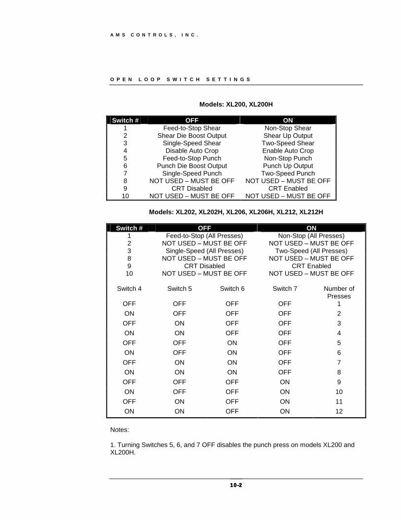
Models: XL200, XL200H
Switch # OFF ON
1 Feed-to-Stop Shear Non-Stop Shear 2 Shear Die Boost Output Shear Up Output 3 Single-Speed Shear Two-Speed Shear 4 Disable Auto Crop Enable Auto Crop 5 Feed-to-Stop Punch Non-Stop Punch 6 Punch Die Boost Output Punch Up Output 7 Single-Speed Punch Two-Speed Punch 8 NOT USED – MUST BE OFF NOT USED – MUST BE OFF 9 CRT Disabled CRT Enabled 10 NOT USED – MUST BE OFF NOT USED – MUST BE OFF
Models: XL202, XL202H, XL206, XL206H, XL212, XL212H
Switch # OFF ON
1 Feed-to-Stop (All Presses) Non-Stop (All Presses) 2 NOT USED – MUST BE OFF NOT USED – MUST BE OFF 3 Single-Speed (All Presses) Two-Speed (All Presses) 8 NOT USED – MUST BE OFF NOT USED – MUST BE OFF 9 CRT Disabled CRT Enabled 10 NOT USED – MUST BE OFF NOT USED – MUST BE OFF
Switch 4 Switch 5 Switch 6 Switch 7 Number of Presses
OFF OFF OFF OFF 1 ON OFF OFF OFF 2 OFF ON OFF OFF 3 ON ON OFF OFF 4 OFF OFF ON OFF 5 ON OFF ON OFF 6 OFF ON ON OFF 7 ON ON ON OFF 8 OFF OFF OFF ON 9 ON OFF OFF ON 10 OFF ON OFF ON 11 ON ON OFF ON 12
Notes: 1. Turning Switches 5, 6, and 7 OFF disables the punch press on models XL200 and XL200H.
A M S C O N T R O L S , I N C .
10101010----3333
O P E N L O O P I N P U T S A N D O U T P U T S
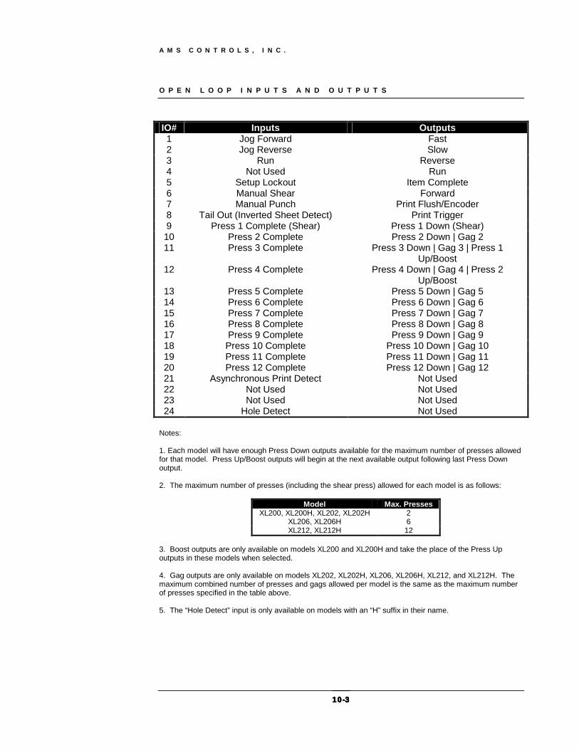
IO# Inputs Outputs 1 Jog Forward Fast 2 Jog Reverse Slow 3 Run Reverse 4 Not Used Run 5 Setup Lockout Item Complete 6 Manual Shear Forward 7 Manual Punch Print Flush/Encoder 8 Tail Out (Inverted Sheet Detect) Print Trigger 9 Press 1 Complete (Shear) Press 1 Down (Shear) 10 Press 2 Complete Press 2 Down | Gag 2 11 Press 3 Complete Press 3 Down | Gag 3 | Press 1
Up/Boost 12 Press 4 Complete Press 4 Down | Gag 4 | Press 2
Up/Boost 13 Press 5 Complete Press 5 Down | Gag 5 14 Press 6 Complete Press 6 Down | Gag 6 15 Press 7 Complete Press 7 Down | Gag 7 16 Press 8 Complete Press 8 Down | Gag 8 17 Press 9 Complete Press 9 Down | Gag 9 18 Press 10 Complete Press 10 Down | Gag 10 19 Press 11 Complete Press 11 Down | Gag 11 20 Press 12 Complete Press 12 Down | Gag 12 21 Asynchronous Print Detect Not Used 22 Not Used Not Used 23 Not Used Not Used 24 Hole Detect Not Used
Notes: 1. Each model will have enough Press Down outputs available for the maximum number of presses allowed for that model. Press Up/Boost outputs will begin at the next available output following last Press Down output. 2. The maximum number of presses (including the shear press) allowed for each model is as follows:
Model Max. Presses XL200, XL200H, XL202, XL202H 2
XL206, XL206H 6 XL212, XL212H 12
3. Boost outputs are only available on models XL200 and XL200H and take the place of the Press Up outputs in these models when selected. 4. Gag outputs are only available on models XL202, XL202H, XL206, XL206H, XL212, and XL212H. The maximum combined number of presses and gags allowed per model is the same as the maximum number of presses specified in the table above. 5. The “Hole Detect” input is only available on models with an “H” suffix in their name.

A M S C O N T R O L S , I N C .
10101010----4444
C L O S E D L O O P S W I T C H S E T T I N G S
Models: XL200CL
Switch 1 Switch 2 Description OFF OFF Feed-to-Stop, One Encoder ON OFF Feed-to-Stop, Two Encoders OFF ON Single-Speed Die Accelerator ON ON Two-Speed Die Accelerator
Switch # OFF ON
3 NOT USED – MUST BE OFF NOT USED – MUST BE OFF 4 CW Encoder 1 Direction CCW Encoder 1 Direction 5 CW Encoder 2 Direction CCW Encoder 2 Direction 6 Normal Analog Voltage Polarity Inverted Analog Voltage Polarity 7 Disable Punch Enable Punch 8 NOT USED – MUST BE OFF NOT USED – MUST BE OFF 9 CRT Disabled CRT Enabled 10 NOT USED – MUST BE OFF NOT USED – MUST BE OFF
Models: XL200HCL
Switch 1 Switch 2 Description OFF OFF INVALID ON OFF INVALID OFF ON Single-Speed Die Accelerator ON ON Two-Speed Die Accelerator
Switch # OFF ON
3 NOT USED – MUST BE OFF NOT USED – MUST BE OFF 4 CW Encoder 1 Direction CCW Encoder 1 Direction 5 CW Encoder 2 Direction CCW Encoder 2 Direction 6 Normal Analog Voltage Polarity Inverted Analog Voltage Polarity 7 NOT USED – MUST BE OFF NOT USED – MUST BE OFF 8 NOT USED – MUST BE OFF NOT USED – MUST BE OFF 9 CRT Disabled CRT Enabled 10 NOT USED – MUST BE OFF NOT USED – MUST BE OFF

A M S C O N T R O L S , I N C .
10101010----5555
Models: XL202CLF, XL202HCLF, XL206CLF, XL206HCLF, XL212CLF, XL212HCLF
Switch # OFF ON 1 CW Encoder 1 Direction CCW Encoder 1 Direction 2 Normal Analog Voltage Polarity Inverted Analog Voltage Polarity 3 CW Encoder 2 Direction CCW Encoder 2 Direction 4 Single Speed Two Speed 5 NOT USED – MUST BE OFF NOT USED – MUST BE OFF 6 NOT USED – MUST BE OFF NOT USED – MUST BE OFF 7 NOT USED – MUST BE OFF NOT USED – MUST BE OFF 8 NOT USED – MUST BE OFF NOT USED – MUST BE OFF 9 CRT Disabled CRT Enabled 10 NOT USED – MUST BE OFF NOT USED – MUST BE OFF
Models: XL202CL, XL206CL, XL212CL
Switch # OFF ON 1 CW Encoder 1 Direction CCW Encoder 1 Direction 2 Normal Analog Voltage Polarity Inverted Analog Voltage Polarity 3 One Encoder Two Encoders 8 NOT USED – MUST BE OFF NOT USED – MUST BE OFF 9 CRT Disabled CRT Enabled 10 NOT USED – MUST BE OFF NOT USED – MUST BE OFF
Switch 4 Switch 5 Switch 6 Switch 7 Number of Presses
OFF OFF OFF OFF 1 ON OFF OFF OFF 2 OFF ON OFF OFF 3 ON ON OFF OFF 4 OFF OFF ON OFF 5 ON OFF ON OFF 6 OFF ON ON OFF 7 ON ON ON OFF 8 OFF OFF OFF ON 9 ON OFF OFF ON 10 OFF ON OFF ON 11 ON ON OFF ON 12
A M S C O N T R O L S , I N C .
10101010----6666
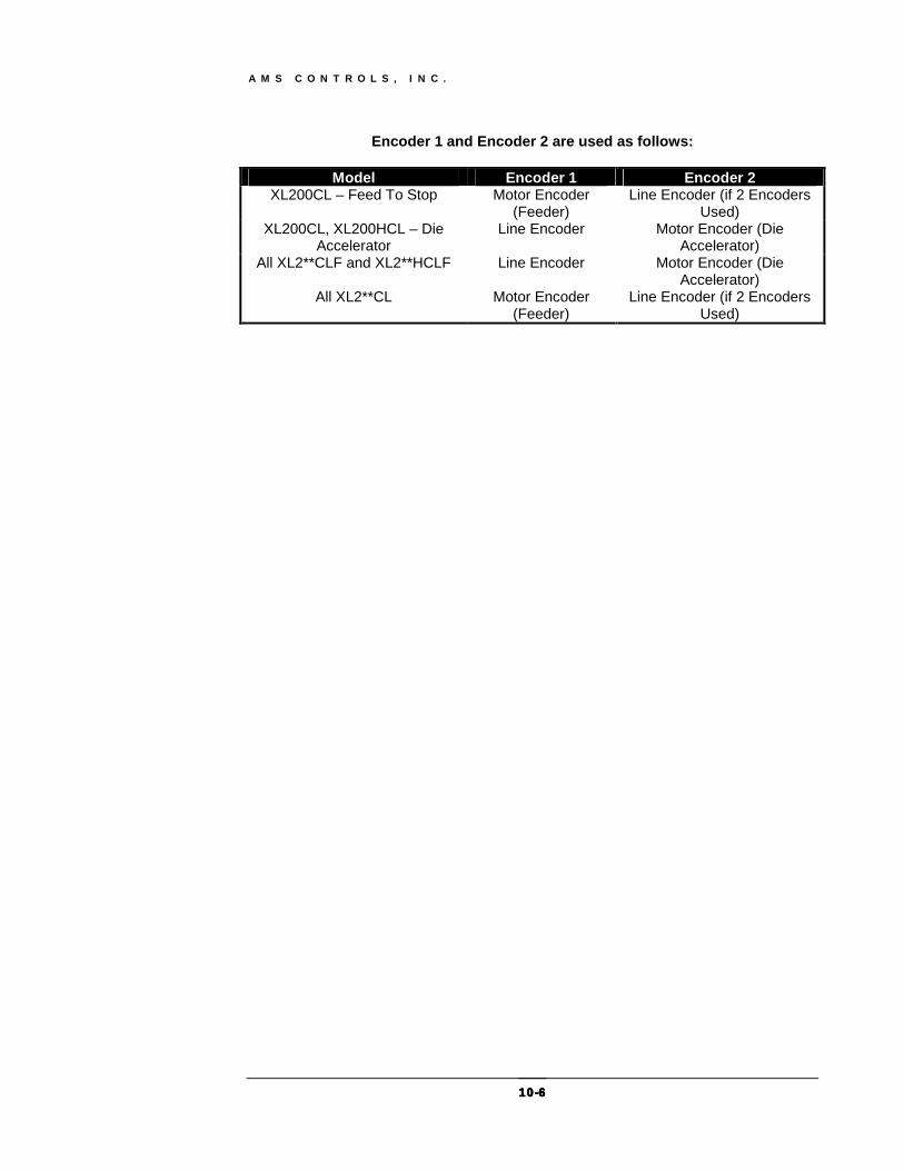
Encoder 1 and Encoder 2 are used as follows:
Model Encoder 1 Encoder 2 XL200CL – Feed To Stop Motor Encoder
(Feeder) Line Encoder (if 2 Encoders
Used) XL200CL, XL200HCL – Die
Accelerator Line Encoder Motor Encoder (Die
Accelerator) All XL2**CLF and XL2**HCLF Line Encoder Motor Encoder (Die
Accelerator) All XL2**CL Motor Encoder
(Feeder) Line Encoder (if 2 Encoders
Used)
A M S C O N T R O L S , I N C .
10101010----7777
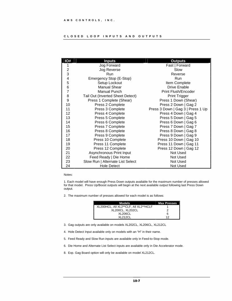
C L O S E D L O O P I N P U T S A N D O U T P U T S
IO# Inputs Outputs 1 Jog Forward Fast | Forward 2 Jog Reverse Slow 3 Run Reverse 4 Emergency Stop (E-Stop) Run 5 Setup Lockout Item Complete 6 Manual Shear Drive Enable 7 Manual Punch Print Flush/Encoder 8 Tail Out (Inverted Sheet Detect) Print Trigger 9 Press 1 Complete (Shear) Press 1 Down (Shear) 10 Press 2 Complete Press 2 Down | Gag 2 11 Press 3 Complete Press 3 Down | Gag 3 | Press 1 Up 12 Press 4 Complete Press 4 Down | Gag 4 13 Press 5 Complete Press 5 Down | Gag 5 14 Press 6 Complete Press 6 Down | Gag 6 15 Press 7 Complete Press 7 Down | Gag 7 16 Press 8 Complete Press 8 Down | Gag 8 17 Press 9 Complete Press 9 Down | Gag 9 18 Press 10 Complete Press 10 Down | Gag 10 19 Press 11 Complete Press 11 Down | Gag 11 20 Press 12 Complete Press 12 Down | Gag 12 21 Asynchronous Print Input Not Used 22 Feed Ready | Die Home Not Used 23 Slow Run | Alternate List Select Not Used 24 Hole Detect Not Used
Notes: 1. Each model will have enough Press Down outputs available for the maximum number of presses allowed for that model. Press Up/Boost outputs will begin at the next available output following last Press Down output. 2. The maximum number of presses allowed for each model is as follows:
Models Max Presses
XL200HCL, All XL2**CLF, All XL2**HCLF 1 XL200CL, XL202CL 2
XL206CL 6 XL212CL 12
3. Gag outputs are only available on models XL202CL, XL206CL, XL212CL 4. Hole Detect Input available only on models with an “H” in their name. 5. Feed Ready and Slow Run inputs are available only in Feed-to-Stop mode. 6. Die Home and Alternate List Select inputs are available only in Die Accelerator mode. 8. Exp. Gag Board option will only be available on model XL212CL.

A M S C O N T R O L S , I N C .
10101010----8888
F U N C T I O N K E Y S
XL200 KEY NAME KEY FUNCTION • F1 NEXT LINE • F2 SKIP LINE • F3 ADD LINE • F4 DELETE LINE • F5 PRINT • F6 DECREASE QUANTITY • DIAGNOSTICS NO FUNCTION DEFINED • INC. QUANTITY INCREASE QUANTITY • PRODUCTION DATA FOOTAGE TOTALIZER • INS PICK
Note: Function keys designated above are for the version 1 series of the XL200 controllers. Higher versions will have different functions for the keys.

A M S C O N T R O L S , I N C .
10101010----9999
C U T O U T M O U N T I N G D I M E N S I O N S

A M S C O N T R O L S , I N C .
10101010----10101010
O P E N L O O P E L E C T R I C A L S C H E M A T I C
Note: AMS provides this drawing for illustration purposes only. It is not to be taken as a literal example for wiring your machine. Each machine is different, having its own safety considerations. The customer is responsible for the installation of adequate emergency stop circuitry, safety guards and enclosing all equipment potentially hazardous to personnel.

A M S C O N T R O L S , I N C .
10101010----11111111
C L O S E D L O O P S C H E M A T I C
Note: AMS provides this drawing for illustration purposes only. It is not to be taken as a literal example for wiring your machine. Each machine is different, having its own safety considerations. The customer is responsible for the installation of adequate emergency stop circuitry, safety guards and enclosing all equipment potentially hazardous to personnel.
Related Documents