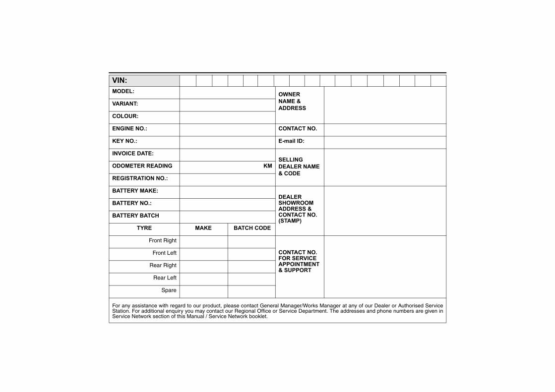
XKP< OQFGN< QYPGT PCOG"(" CFFTGUU XCTKCPV< EQNQWT< GPIKPG"PQ0< EQPVCEV"PQ0 MG["PQ0< G/ockn"KF< KPXQKEG"FCVG< UGNNKPI FGCNGT"PCOG" ("EQFG QFQOGVGT"TGCFKPI MO TGIKUVTCVKQP"PQ0< DCVVGT["OCMG< FGCNGT UJQYTQQO CFFTGUU"(" EQPVCEV"PQ0" *UVCOR+ DCVVGT["PQ0< DCVVGT["DCVEJ V[TG """""""OCMG""""""""""""""DCVEJ"EQFG Front Right EQPVCEV"PQ0" HQT"UGTXKEG" CRRQKPVOGPV ("UWRRQTV Front Left Rear Right Rear Left Spare For any assistance with regard to our product, please contact General Manager/Works Manager at any of our Dealer or Authorised Service Station. For additional enquiry you may contact our Regional Office or Service Department. The addresses and phone numbers are given in Service Network section of this Manual / Service Network booklet.

Welcome message from author
This document is posted to help you gain knowledge. Please leave a comment to let me know what you think about it! Share it to your friends and learn new things together.
Transcript
XKP<OQFGN<
QYPGTPCOG"("CFFTGUU
XCTKCPV<
EQNQWT<
GPIKPG"PQ0< EQPVCEV"PQ0
MG["PQ0< G/ockn"KF<
KPXQKEG"FCVG<UGNNKPIFGCNGT"PCOG"("EQFG
QFQOGVGT"TGCFKPI MO
TGIKUVTCVKQP"PQ0<
DCVVGT["OCMG<FGCNGTUJQYTQQOCFFTGUU"("EQPVCEV"PQ0"*UVCOR+
DCVVGT["PQ0<
DCVVGT["DCVEJ
V[TG """""""OCMG""""""""""""""DCVEJ"EQFG
Front Right
EQPVCEV"PQ0"HQT"UGTXKEG"CRRQKPVOGPV("UWRRQTV
Front Left
Rear Right
Rear Left
Spare
For any assistance with regard to our product, please contact General Manager/Works Manager at any of our Dealer or Authorised ServiceStation. For additional enquiry you may contact our Regional Office or Service Department. The addresses and phone numbers are given inService Network section of this Manual / Service Network booklet.
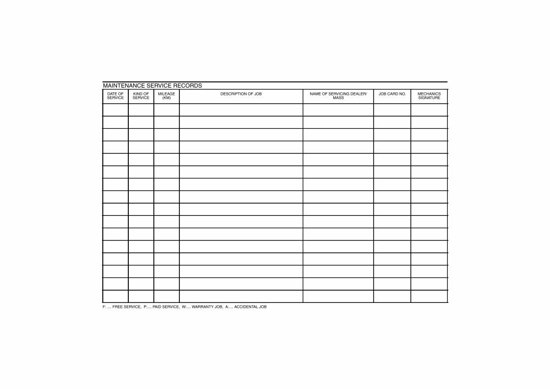
DATE OFSERVICE
KIND OFSERVICE
MILEAGE(KM)
DESCRIPTION OF JOB NAME OF SERVICING DEALER/MASS
JOB CARD NO. MECHANICSSIGNATURE
MAINTENANCE SERVICE RECORDS
F: .... FREE SERVICE, P:.... PAID SERVICE, W:.... WARRANTY JOB, A:.... ACCIDENTAL JOB
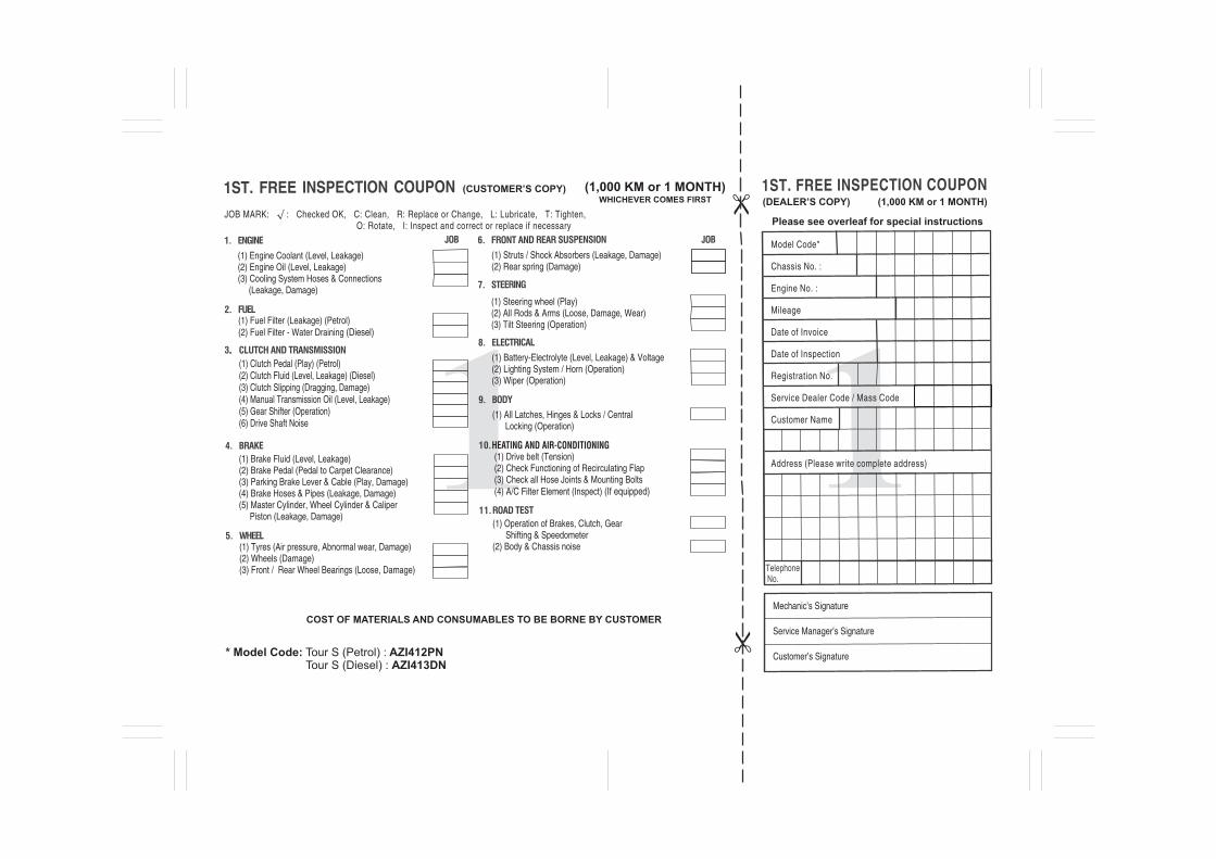
COST OF MATERIALS AND CONSUMABLES TO BE BORNE BY CUSTOMER
(1) Tyres (Air pressure, Abnormal wear, Damage)(2) Wheels (Damage)(3) Front / Rear Wheel Bearings (Loose, Damage)
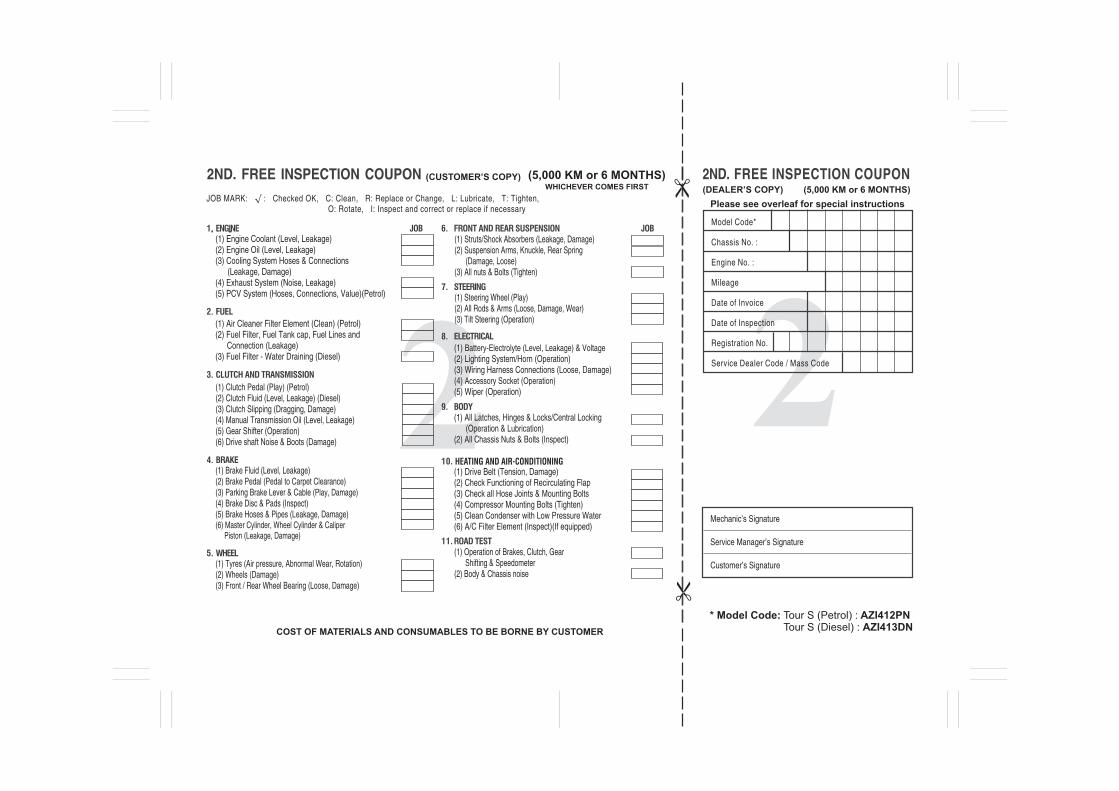
Please see overleaf for special instructionsJOB MARK: √ : Checked OK, C: Clean, R: Replace or Change, L: Lubricate, T: Tighten, O: Rotate, I: Inspect and correct or replace if necessary
(CUSTOMER’S COPY)WHICHEVER COMES FIRST
(1,000 KM or 1 MONTH)(DEALER’S COPY) (1,000 KM or 1 MONTH)
Mechanic’s Signature
Service Manager’s Signature
Customer’s Signature
(1) Steering wheel (Play)(2) All Rods & Arms (Loose, Damage, Wear)(3) Tilt Steering (Operation)
(1) Brake Fluid (Level, Leakage)(2) Brake Pedal (Pedal to Carpet Clearance)(3) Parking Brake Lever & Cable (Play, Damage)(4) Brake Hoses & Pipes (Leakage, Damage)(5) Master Cylinder, Wheel Cylinder & Caliper Piston (Leakage, Damage)
* Model Code: Tour S (Petrol) : AZI412PN Tour S (Diesel) : AZI413DN
(1) Fuel Filter (Leakage) (Petrol) (2) Fuel Filter - Water Draining (Diesel)
(1) Engine Coolant (Level, Leakage)(2) Engine Oil (Level, Leakage)(3) Cooling System Hoses & Connections (Leakage, Damage)
(1) All Latches, Hinges & Locks / Central Locking (Operation)
(1) Battery-Electrolyte (Level, Leakage) & Voltage(2) Lighting System / Horn (Operation)(3) Wiper (Operation)
(1) Operation of Brakes, Clutch, Gear Shifting & Speedometer (2) Body & Chassis noise
HEATING AND AIR-CONDITIONING(1) Drive belt (Tension) (2) Check Functioning of Recirculating Flap (3) Check all Hose Joints & Mounting Bolts(4) A/C Filter Element (Inspect) (If equipped)
(1) Clutch Pedal (Play) (Petrol)(2) Clutch Fluid (Level, Leakage) (Diesel) (3) Clutch Slipping (Dragging, Damage)(4) Manual Transmission Oil (Level, Leakage)(5) Gear Shifter (Operation)(6) Drive Shaft Noise
(1) Struts / Shock Absorbers (Leakage, Damage)(2) Rear spring (Damage)
Model Code*
Chassis No. :
Engine No. :
Mileage
Date of Invoice
Date of Inspection
Registration No.
Service Dealer Code / Mass Code
Customer Name
Address (Please write complete address)
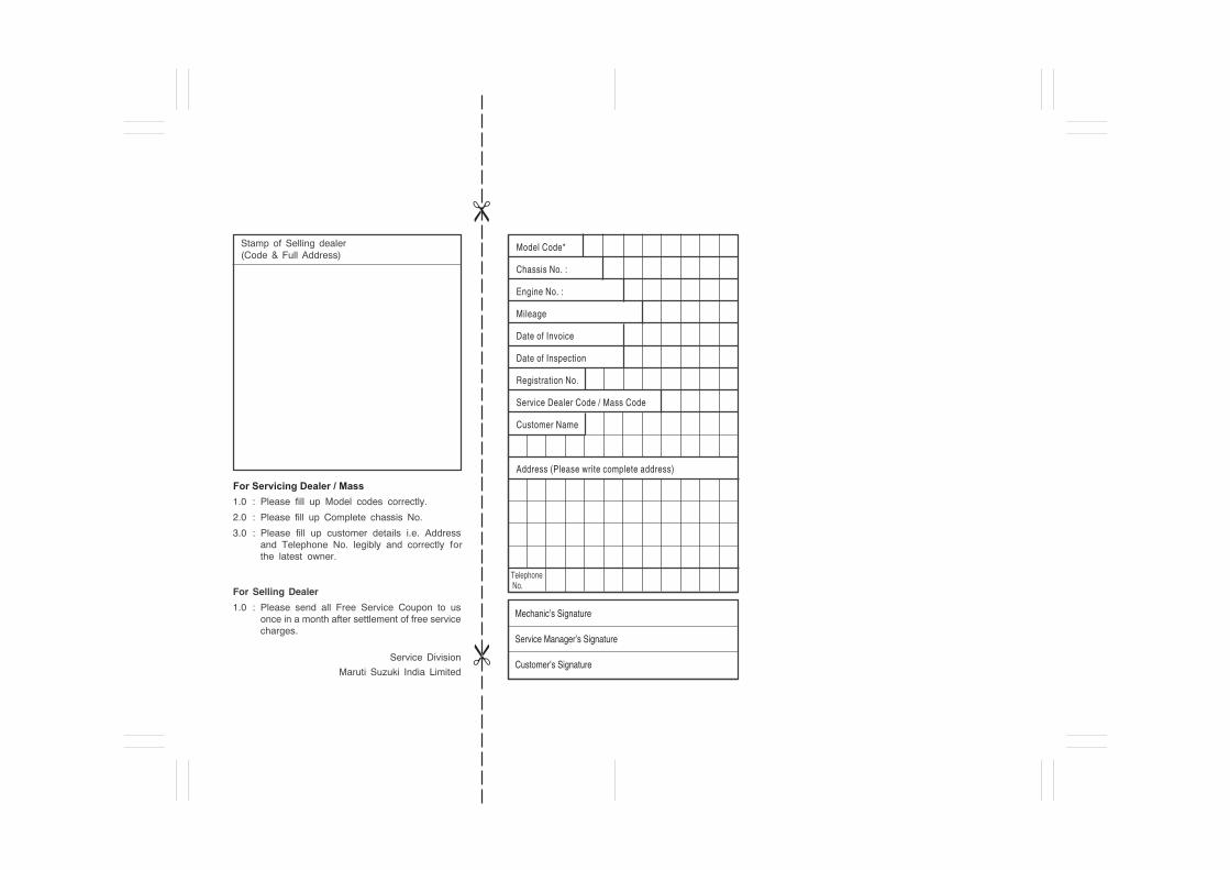
Mechanic’s Signature
Service Manager’s Signature
Customer’s Signature
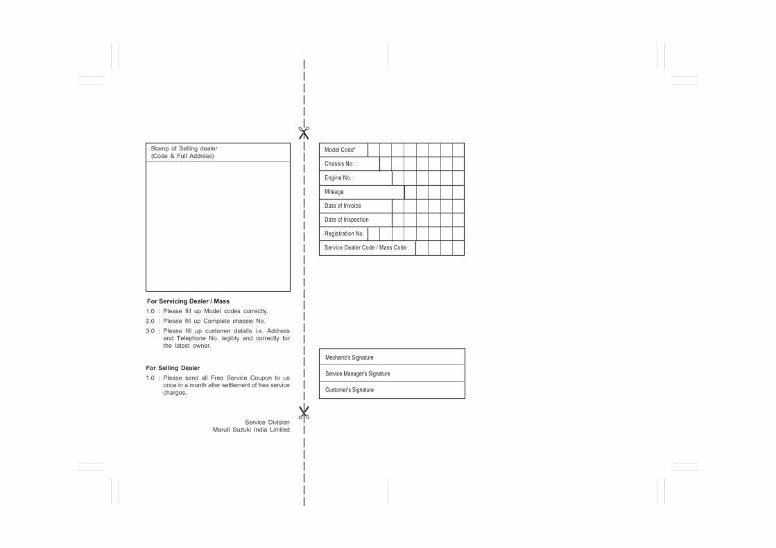
For Servicing Dealer / Mass
Model Code*
Chassis No. :
Engine No. :
Mileage
Date of Invoice
Date of Inspection
Registration No.
Service Dealer Code / Mass Code
Customer Name
Address (Please write complete address)
(CUSTOMER’S COPY)
COST OF MATERIALS AND CONSUMABLES TO BE BORNE BY CUSTOMER
(1) Steering Wheel (Play) (2) All Rods & Arms (Loose, Damage, Wear) (3) Tilt Steering (Operation)
Please see overleaf for special instructionsJOB MARK: √ : Checked OK, C: Clean, R: Replace or Change, L: Lubricate, T: Tighten, O: Rotate, I: Inspect and correct or replace if necessary
WHICHEVER COMES FIRST
(5,000 KM or 6 MONTHS)
Mechanic’s Signature
Service Manager’s Signature
Customer’s Signature
(DEALER’S COPY) (5,000 KM or 6 MONTHS)
Model Code*
Chassis No. :
Engine No. :
Mileage
Date of Invoice
Date of Inspection
Registration No.
Service Dealer Code / Mass Code
(1) Engine Coolant (Level, Leakage)(2) Engine Oil (Level, Leakage)(3) Cooling System Hoses & Connections (Leakage, Damage) (4) Exhaust System (Noise, Leakage)(5) PCV System (Hoses, Connections, Value)(Petrol)
(1) Brake Fluid (Level, Leakage)(2) Brake Pedal (Pedal to Carpet Clearance)(3) Parking Brake Lever & Cable (Play, Damage)(4) Brake Disc & Pads (Inspect)(5) Brake Hoses & Pipes (Leakage, Damage)(6) Master Cylinder, Wheel Cylinder & Caliper Piston (Leakage, Damage)
(1) Tyres (Air pressure, Abnormal Wear, Rotation) (2) Wheels (Damage)(3) Front / Rear Wheel Bearing (Loose, Damage)
(1) Struts/Shock Absorbers (Leakage, Damage) (2) Suspension Arms, Knuckle, Rear Spring (Damage, Loose) (3) All nuts & Bolts (Tighten)
(1) Air Cleaner Filter Element (Clean) (Petrol)(2) Fuel Filter, Fuel Tank cap, Fuel Lines and Connection (Leakage) (3) Fuel Filter - Water Draining (Diesel)
(1) Clutch Pedal (Play) (Petrol)(2) Clutch Fluid (Level, Leakage) (Diesel)(3) Clutch Slipping (Dragging, Damage)(4) Manual Transmission Oil (Level, Leakage)(5) Gear Shifter (Operation)(6) Drive shaft Noise & Boots (Damage)
(1) Battery-Electrolyte (Level, Leakage) & Voltage(2) Lighting System/Horn (Operation) (3) Wiring Harness Connections (Loose, Damage) (4) Accessory Socket (Operation)(5) Wiper (Operation)
(1) All Latches, Hinges & Locks/Central Locking (Operation & Lubrication) (2) All Chassis Nuts & Bolts (Inspect)
(1) Drive Belt (Tension, Damage) (2) Check Functioning of Recirculating Flap (3) Check all Hose Joints & Mounting Bolts (4) Compressor Mounting Bolts (Tighten) (5) Clean Condenser with Low Pressure Water (6) A/C Filter Element (Inspect)(If equipped)
(1) Operation of Brakes, Clutch, Gear Shifting & Speedometer (2) Body & Chassis noise
HEATING AND AIR-CONDITIONING
* Model Code: Tour S (Petrol) : AZI412PN Tour S (Diesel) : AZI413DN
Mechanic’s Signature
Service Manager’s Signature
Customer’s Signature
For Servicing Dealer / Mass
Model Code*
Chassis No. :
Engine No. :
Mileage
Date of Invoice
Date of Inspection
Registration No.
Service Dealer Code / Mass Code
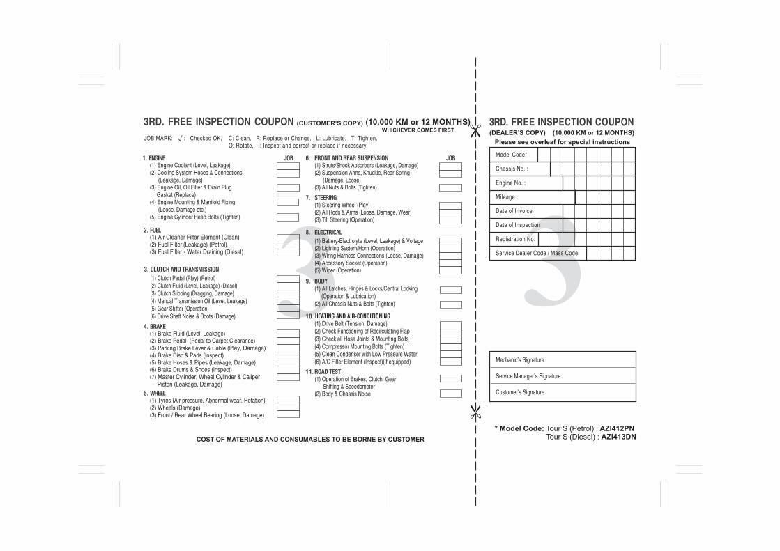
(DEALER’S COPY) (10,000 KM or 12 MONTHS)
(1) Steering Wheel (Play)(2) All Rods & Arms (Loose, Damage, Wear)(3) Tilt Steering (Operation)
(1) Tyres (Air pressure, Abnormal wear, Rotation) (2) Wheels (Damage) (3) Front / Rear Wheel Bearing (Loose, Damage)
(1) Struts/Shock Absorbers (Leakage, Damage) (2) Suspension Arms, Knuckle, Rear Spring (Damage, Loose) (3) All Nuts & Bolts (Tighten)
Please see overleaf for special instructions
(CUSTOMER’S COPY)WHICHEVER COMES FIRST
(10,000 KM or 12 MONTHS)
JOB MARK: √ : Checked OK, C: Clean, R: Replace or Change, L: Lubricate, T: Tighten, O: Rotate, I: Inspect and correct or replace if necessary
Mechanic’s Signature
Service Manager’s Signature
Customer’s Signature
Model Code*
Chassis No. :
Engine No. :
Mileage
Date of Invoice
Date of Inspection
Registration No.
Service Dealer Code / Mass Code
COST OF MATERIALS AND CONSUMABLES TO BE BORNE BY CUSTOMER
(1) Air Cleaner Filter Element (Clean) (2) Fuel Filter (Leakage) (Petrol)(3) Fuel Filter - Water Draining (Diesel)
(1) Brake Fluid (Level, Leakage) (2) Brake Pedal (Pedal to Carpet Clearance) (3) Parking Brake Lever & Cable (Play, Damage)(4) Brake Disc & Pads (Inspect) (5) Brake Hoses & Pipes (Leakage, Damage) (6) Brake Drums & Shoes (Inspect)(7) Master Cylinder, Wheel Cylinder & Caliper Piston (Leakage, Damage)
(1) Engine Coolant (Level, Leakage) (2) Cooling System Hoses & Connections (Leakage, Damage)(3) Engine Oil, Oil Filter & Drain Plug Gasket (Replace)(4) Engine Mounting & Manifold Fixing (Loose, Damage etc.)(5) Engine Cylinder Head Bolts (Tighten)
(1) Clutch Pedal (Play) (Petrol)(2) Clutch Fluid (Level, Leakage) (Diesel)(3) Clutch Slipping (Dragging, Damage)(4) Manual Transmission Oil (Level, Leakage)(5) Gear Shifter (Operation)(6) Drive Shaft Noise & Boots (Damage)
(1) Operation of Brakes, Clutch, Gear Shifting & Speedometer (2) Body & Chassis Noise
(1) Battery-Electrolyte (Level, Leakage) & Voltage(2) Lighting System/Horn (Operation)(3) Wiring Harness Connections (Loose, Damage)(4) Accessory Socket (Operation)(5) Wiper (Operation)
(1) All Latches, Hinges & Locks/Central Locking (Operation & Lubrication) (2) All Chassis Nuts & Bolts (Tighten)
(1) Drive Belt (Tension, Damage) (2) Check Functioning of Recirculating Flap (3) Check all Hose Joints & Mounting Bolts (4) Compressor Mounting Bolts (Tighten) (5) Clean Condenser with Low Pressure Water (6) A/C Filter Element (Inspect)(If equipped)
HEATING AND AIR-CONDITIONING
* Model Code: Tour S (Petrol) : AZI412PN Tour S (Diesel) : AZI413DN

Mechanic’s Signature
Service Manager’s Signature
Customer’s Signature
Model Code*
Chassis No. :
Engine No. :
Mileage
Date of Invoice
Date of Inspection
Registration No.
Service Dealer Code / Mass Code
For Servicing Dealer / Mass
0-1
82PH0-74E
FOREWORDThis manual is an essential part of yourvehicle and should remain with the vehiclewhen resold or otherwise transferred to anew owner or operator. Please read thismanual carefully before operating yournew MARUTI SUZUKI and review themanual from time to time. It containsimportant information on safety, operationand maintenance. You are invited to availthe three Free Inspection Services asdescribed in the manual. Three freeinspection coupons are attached to thismanual. Please show this manual to yourdealer while you take your MARUTISUZUKI for any Service.To prolong the life of your vehicle andreduce maintenance cost, the periodicmaintenance must be carried out accord-ing to “PERIODIC MAINTENANCESCHEDULE” described in “INSPECTIONAND MAINTENANCE” section of this man-ual. It is essential for preventing troubleand accidents to ensure your satisfactionand safety.Daily inspection and care as per “DAILYINSPECTION CHECKLIST” described inthe “INSPECTION AND MAINTENANCE”section of this manual is essential for pro-longing the life of the vehicle and for safedriving.
MARUTI SUZUKI INDIA LIMITED believesin conservation and protection of Earth’snatural resources.To that end, we encourage every vehicleowner to recycle, trade-in or properly dis-pose of, as appropriate, used Engine Oil,coolant and other fluids, batteries andtyres etc.
MARUTI SUZUKI INDIA LIMITED
All information in this manual is basedon the latest product information avail-able at the time of publication. Due toimprovements or other changes, theremay be discrepancies between informa-tion in this manual and your vehicle.MARUTI SUZUKI INDIA LIMITEDreserves the right to make productionchanges at any time, without notice andwithout incurring any obligation tomake the same or similar changes tovehicles previously built or sold.
This vehicle may not comply withstandards or regulations of othercountries. Before attempting to regis-ter this vehicle in any other country,check all applicable regulations andmake any necessary modifications.
0-2
82PH0-74E
IMPORTANTWARNING/ CAUTION/NOTICE/
NOTEPlease read this manual and follow itsinstructions carefully. To emphasize spe-cial information, the symbol and the wordsWARNING, CAUTION, NOTICE andNOTE have special meanings. Pay partic-ular attention to messages highlighted bythese signal words:
NOTE:Indicates special information to makemaintenance easier or instructions clearer.
75F135
The circle with a slash in this manualmeans “Don’t do this” or “Don’t let this hap-pen”.
MODIFICATION WARN-ING
WARNINGIndicates a potential hazard thatcould result in death or seriousinjury.
CAUTIONIndicates a potential hazard thatcould result in minor or moderateinjury.
NOTICEIndicates a potential hazard thatcould result in vehicle damage.
WARNINGDo not modify your vehicle. Modifica-tion could adversely affect safety,handling, performance, or durabilityand may violate governmental regula-tions. In addition, damage or perfor-mance problems resulting frommodification may not be coveredunder warranty.
NOTICEImproper installation of mobile com-munication equipment such as cellu-lar telephones, CB (Citizen’s Band)radios or any other wireless transmit-ters may cause electronic interfer-ence with your vehicle’s ignitionsystem, resulting in vehicle perfor-mance problems. Consult yourauthorised Maruti Suzuki workshopor qualified service technician foradvice.
NOTICESevere damage may be caused bythe use of either poor quality fueland/or lubricants not recommendedby MARUTI SUZUKI.
0-3
82PH0-74E
WARRANTY POLICY
Maruti Suzuki India Limited (hereinafter called “Maruti Suzuki”),warrants that each new Maruti Suzuki vehicle distributed in Indiaby Maruti Suzuki and sold by an authorised Maruti Suzuki dealerwill be free, under normal use and service, from any defects inmaterial and workmanship at the time of manufacture SUBJECTTO THE FOLLOWING TERMS AND CONDITIONS:
(1) Qualification:To qualify for this warranty the vehicle must be delivered by aMaruti Suzuki authorised dealer and set-up, and serviced by aMaruti Suzuki authorised dealer / service station.
(2) Term:The term of the warranty shall be twenty-four (24) months or40,000 kilometers (whichever occurs first) from the date ofinvoice to the first owner.
(3) Maruti Suzuki Warranty Obligation:If any defect(s) should be found in a Maruti Suzuki vehicle withinthe term stipulated above, Maruti Suzuki’s only obligation is torepair or replace at its sole discretion any part shown to be defec-tive, with a new part or the equivalent at no cost to the owner forparts or labour, when Maruti Suzuki acknowledges that such adefect is attributable to faulty material or workmanship at the timeof manufacture. The owner is responsible for any repair orreplacements which are not covered by this warranty.
(4) Limitation:This warranty shall not apply to: (a) Normal maintenance service required other than the three
free services, including without limitation, oil and fluidchanges, headlight aiming, fastener retightening, wheel bal-ancing, wheel alignment and tyre rotation, cleaning of injec-tors, adjustments of ignition timing, clutch and valveclearance.
(b) The replacement of normal wear parts including without lim-itation, bulbs, tyres and tubes, spark plugs, belts, hoses, fil-ters, wiper blades, brushes, contact points, fuses, clutchdisc, brake shoes, brake pads, cable and all rubber parts(except oil seal and glass run).
(c) Any vehicle which has been used for competition or racing.(d) Any repairs or replacement required as a result of accidents
or collision.(e) Any defects caused by misuse, negligence, abnormal use or
insufficient care.(f) Any vehicle which has been modified or altered, including
without limitation, the installation of performance accesso-ries.
(g) Any vehicle on which parts or accessories not approved byMaruti Suzuki have been used.
(h) Any vehicle which has not been operated in accordance withthe operating instructions in this Owner’s Manual and Ser-vice Booklet.
(i) Any vehicle which has not received, during the warranty term,the service inspections prescribed in this Owner’s Manualand Service Booklet.
(j) Any vehicle which has been assembled, disassembled,adjusted or repaired by other than an Maruti Suzuki autho-rised dealer/service station.
(k) Any vehicle which has been used for purposes other thanwhat it was designed for.
0-4
82PH0-74E
(l) Any damage or deterioration caused by industrial pollutionand bird droppings.
(m) Insignificant defects which do not affect the function of thevehicle including without limitation, sound, vibration and fluidseep.
(n) Any natural wear and tear including without limitation, ageingetc.
(o) Installation and usage of domestic LPG gas/LPG Cylinder.(p) V-belts, hoses and gas leaks.(q) Any vehicle retrofitted with LPG/CNG kits.
(5) Extent of Warranty:This warranty is the entire written warranty given by Maruti Suzukifor Maruti Suzuki vehicles and no dealer or its or his agent oremployee is authorised to extend or enlarge this warranty and nodealer or its or his agent or employee is authorised to make anyoral warranty on Maruti Suzuki’s behalf.Maruti Suzuki reserves the right to add any improvements orchange the design of any model at any time with no obligation tomake the same changes on units previously sold.
(6) Warranty Service:To obtain warranty service, the complete vehicle must be pre-sented at the owner’s expenses to any authorised Maruti Suzukiworkshop.
(7) Owner’s Warranty Responsibilities:It is responsibility of each owner to:
– Make certain that the PDl card was completed at the time ofdelivery of the vehicle;
– Have performed, at his own expenses, by an Maruti Suzukiauthorised dealer/service station all the service inspectionsspecified in the Maruti Suzuki “Owner’s Manual and Service
Booklet” and maintain adequate proof that such serviceinspections have been performed.
– Make certain that the Maruti Suzuki authorised dealer/ser-vice station performing the service inspection has certifiedthe work on the “Maintenance Service Record” page in the“Owner’s Manual and Service Booklet” and
– Present the Maruti Suzuki “Owner’s Manual and ServiceBooklet” to the authorised Maruti Suzuki dealer wheneverrequesting service inspections or warranty service.
If the “Owner’s Manual and Service Booklet” should be lost ordestroyed the owner should consult the authorised Maruti Suzukidealer from whom the vehicle was purchased for instructions con-cerning replacement of the “Owner’s Manual and Service Book-let”.
(8) Disclaimer of Consequential Damage:Maruti Suzuki assumes no responsibility for loss of vehicle, loss oftime, inconvenience or any other indirect incidental or consequen-tial damage resulting from the vehicle not being available to theowner because of any defect covered by this warranty.
(9) Change of OwnerEven if ownership of the vehicle changes, the remaining warrantyperiod is effective for the new owner.
0-5
82PH0-74E
EMISSION WARRANTY POLICY
Maruti Suzuki offers the Emission Warranty on all Maruti Suzukivehicles (apart from the Regular Warranty and will run parallel tothe regular product warranty) only in four metropolitan cities (NewDelhi, Kolkata, Mumbai and Chennai) with effect from July 1st,2001.
Terms:The Emission Warranty will be applicable for 80,000 kms or 3years (Whichever comes earlier) from the date of invoice to thefirst owner. The remaining warranty terms will be valid in case ofany change in ownership provided the production of all valid docu-ments.
Conditions:1. Under Emission Warranty, Warranty claims will be admitted for
a prima facie examination, in case vehicle fails to meet theEmission Standard as specified in sub rule (2) of rule no. 115 ofCentral Motor Vehicles Rules (CMVR), 1989.
2. The warranty claims will only be accepted after examinationcarried out by Maruti Suzuki or it’s dealer which leads to firmconclusions that thea) Original settings have not been tampered in any case. b) Part (as given in Annexure - A) has a manufacturing defect. c) Vehicle is unable to meet the Emission Standards (as given
in 1.), inspite of the vehicle having been maintained andused in accordance with the instructions as specified inOwner’s Manual and Service Booklet and the used fuel anddifferent oils (Engine oil, Transmission oil, Brake oil etc.) arealso as per specification.
3. The method of examination for deciding the warranty of theparts will be at the sole discretion of Maruti Suzuki and it’sdealer and results of the examination will be final and binding.If after examination, the warrantable condition is not estab-lished, Maruti Suzuki and it’s dealer has the right to charge all,or part of the cost of such examination.
4. Under Emission Warranty, the parts (as given in Annexure - A)will be changed free of cost, but the consumables will becharged as per actual.
5. If the part covered under Emission Warranty or the associatedparts, are not independently replaceable, on account of thesebeing integral parts of a complete assembly, Maruti Suzuki andit’s dealer will have the sole discretion to replace either theentire assembly or by using some of the parts of the systemthrough suitable repairs or modifications.
6. Any consequential repairs or replacement of parts which maybe found necessary to establish compliance of Emission War-ranty, will not be considered under warranty, unless the sameis under product warranty. The consumable will be charged asper actual under such repair or replacement.
7. Maruti Suzuki will not be responsible for the cost of transporta-tion of the vehicle to the nearest Maruti Suzuki dealer work-shop or any loss due to non-availability of the vehicle duringthe period of lodging of a warranty claim and examination and/or repair by Maruti Suzuki dealer.
8. Maruti Suzuki will not be responsible for any penalty that maybe charged by statutory authorities on account of failure tocomply with the EMISSION STANDARDS.
9. Emission Warranty will not be affected on the change of owner,provided all the documents are available.
0-6
82PH0-74E
10.All maintenance actions (as specified in the Owner’s Manualand Service Booklet) need to be followed and recorded in themanual for emission warranty.
11.The customer needs to produce the PUC (Pollution UnderControl) certificate valid for the period preceding the test duringwhich the failure is discovered. The receipts (for the mainte-nance of the vehicle as per specification in Owner’s Manualand Service Booklet from the date of original purchase of thevehicle) will also be required.
Conditions under which the Emission Warranty is notAPPLICABLE1. In the absence of valid PUC certificate.2. Vehicle not serviced from Maruti Suzuki authorised workshop
as per the schedule specified in this Owner’s Manual and Ser-vice Booklet.
3. Vehicle subjected to abnormal use (accident, motor race, ral-lies or for the purpose of establishing the records etc).
4. Use of non MGP (Maruti Genuine Part).5. Vehicle that has been tampered with.6. Tampering with odometer so that the actual kilometer reading
can not be determined.7. Use of adulterated fuel and/or unspecified oils (Engine oil,
Transmission oil and Brake oil etc).
Annexure - AList of parts covered under Emission Warranty
1. Fuel Injection Assembly, Pressure Regulator, Throttle BodyAssembly
2. Electronic Control Module (ECM).3. Intake Manifold.4. EGR valve.5. Ignition Coil.6. Canister Assembly.7. Vapour Liquid Seperator.8. Fuel Tank and Filler Cap.9. PCV (Positive Crankcase Ventilation) Valve.
10. Oil Filler Cap.11. Catalytic Convertor.12. Exhaust Manifold.13. All Fuel Injection System related sensors.14. High Pressure Fuel Pump.15. Glow Plug.16. Glow Plug Controller.
56RH0-74E
TABLE OF CONTENTS FUEL RECOMMENDATION 1
BEFORE DRIVING 2
OPERATING YOUR VEHICLE 3
DRIVING TIPS 4
OTHER CONTROLS AND EQUIPMENT 5
VEHICLE LOADING AND TOWING 6
INSPECTION AND MAINTENANCE 7
EMERGENCY SERVICE 8
APPEARANCE CARE 9
GENERAL INFORMATION 10
SPECIFICATIONS 11
SERVICE NETWORK 12

FUEL RECOMMENDATION
1
56RH0-74E
65D394
FUEL RECOMMENDATIONFuel Recommendation ........................................................ 1-1
1-1
FUEL RECOMMENDATION
56RH0-74E
Fuel RecommendationPetrol engineTo avoid damaging catalytic converter youmust use unleaded petrol with an octanenumber (RON) of 91 or higher.Petrol/Ethanol blendsBlends of unleaded petrol and ethanol(grain alcohol), also known as gasohol, arecommercially available in certain areas.Blends of this type may be used in yourvehicle if they are no more than 10% etha-nol.Make sure this petrol-ethanol blend hasoctane ratings no lower than those recom-mended for the petrol.Petrol/Methanol blendsBlends of unleaded petrol and methanol(wood alcohol) are also commerciallyavailable in some areas. DO NOT USEfuels containing more than 5% methanolunder any circumstances. Fuel systemdamage or vehicle performance problemsresulting from the use of such fuels are notthe responsibility of MARUTI SUZUKI andmay not be covered under the New VehicleWarranty.Fuels containing 5% or less methanol maybe suitable for use in your vehicle if theycontain cosolvents and corrosion inhibi-tors.
NOTE:If you are not satisfied with the driveabilityor fuel economy of your vehicle when youare using a petrol/alcohol blend, youshould switch back to unleaded petrol con-taining no alcohol.
Diesel engineThe diesel fuel should be with CetaneNumber (CN) higher than 51 and sulfurcontent less than 50 ppm (parts per mil-lion). MARUTI SUZUKI recommends touse the diesel fuel conformable to EN590.Do not use marine diesel fuel, heating oilsand so forth.NOTICE
The fuel tank has an air space toallow for fuel expansion in hotweather. If you continue to add fuelafter the filler nozzle has automati-cally shut off or an initial blowbackoccurs, the air chamber will becomefull. Exposure to heat when fullyfuelled in this manner will result inleakage due to fuel expansion. Toprevent such fuel leakage, stop fillingafter the filler nozzle has automati-cally shut off, or when using an alter-native non-automatic system, initialvent blowback occurs.
NOTICEBe careful not to spill fuel containingalcohol while refueling. If fuel isspilled on the vehicle body, wipe it upimmediately. Fuels containing alco-hol can cause paint damage, which isnot covered under the New VehicleLimited Warranty.
NOTICEThe fuel tank has an air space toallow for fuel expansion in hotweather. If you continue to add fuelafter the filler nozzle has automati-cally shut off or an initial blowbackoccurs, the air chamber will becomefull. Exposure to heat when fullyfuelled in this manner will result inleakage due to fuel expansion. Toprevent such fuel leakage, stop fillingafter the filler nozzle has automati-cally shut off, or when using an alter-native non-automatic system, initialvent blowback occurs.
NOTICEBe careful not to spill fuel containingalcohol while refueling. If fuel isspilled on the vehicle body, wipe it upimmediately. Fuels containing alco-hol can cause paint damage, which isnot covered under the New VehicleLimited Warranty.
BEFORE DRIVING
74LH0-74E
60G404
BEFORE DRIVINGKeys .........................................................................................2-1Door Locks ..............................................................................2-2Keyless Entry System Transmitter .......................................2-4Security System .....................................................................2-5Transmitter Battery ................................................................2-10Windows ..................................................................................2-13Mirrors .....................................................................................2-14Front Seats ..............................................................................2-14Seat Belts and Child Restraint Systems ..............................2-16Instrument Cluster .................................................................2-24Speedometer ...........................................................................2-25Fuel Gauge ..............................................................................2-25Temperature Gauge ...............................................................2-25Brightness Control .................................................................2-26Information Display ................................................................2-26Warning and Indicator Lights ................................................2-29Lighting Control Lever ...........................................................2-33Headlight Leveling Switch .....................................................2-34Turn Signal Control Lever .....................................................2-34Hazard Warning Switch .........................................................2-35Windshield Wiper and Washer Lever ...................................2-35Tilt Steering Lock Lever .........................................................2-36Horn ........................................................................................ 2-37
2
2-1
BEFORE DRIVING
74LH0-74E
Keys
54G489
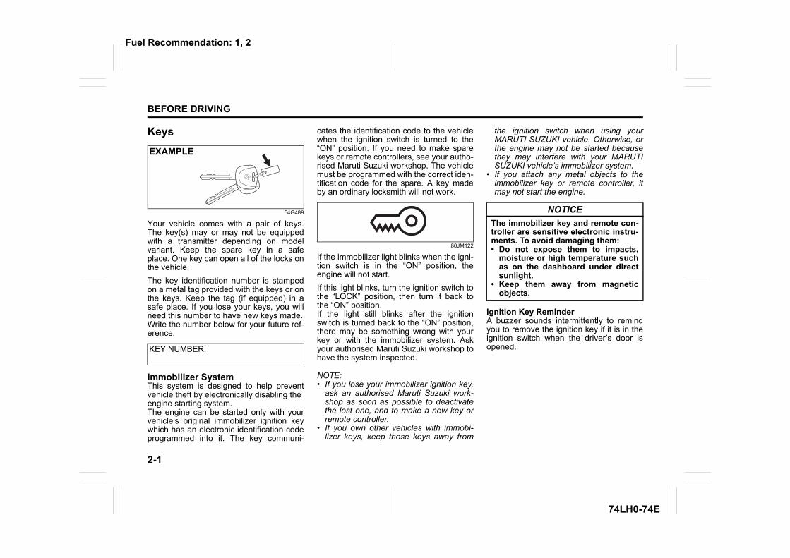
Your vehicle comes with a pair of keys.The key(s) may or may not be equippedwith a transmitter depending on modelvariant. Keep the spare key in a safeplace. One key can open all of the locks onthe vehicle.The key identification number is stampedon a metal tag provided with the keys or onthe keys. Keep the tag (if equipped) in asafe place. If you lose your keys, you willneed this number to have new keys made.Write the number below for your future ref-erence.
Immobilizer SystemThis system is designed to help preventvehicle theft by electronically disabling theengine starting system.The engine can be started only with yourvehicle’s original immobilizer ignition keywhich has an electronic identification codeprogrammed into it. The key communi-
cates the identification code to the vehiclewhen the ignition switch is turned to the“ON” position. If you need to make sparekeys or remote controllers, see your autho-rised Maruti Suzuki workshop. The vehiclemust be programmed with the correct iden-tification code for the spare. A key madeby an ordinary locksmith will not work.
80JM122
If the immobilizer light blinks when the igni-tion switch is in the “ON” position, theengine will not start.If this light blinks, turn the ignition switch tothe “LOCK” position, then turn it back tothe “ON” position.If the light still blinks after the ignitionswitch is turned back to the “ON” position,there may be something wrong with yourkey or with the immobilizer system. Askyour authorised Maruti Suzuki workshop tohave the system inspected.
NOTE:• If you lose your immobilizer ignition key,
ask an authorised Maruti Suzuki work-shop as soon as possible to deactivatethe lost one, and to make a new key orremote controller.
• If you own other vehicles with immobi-lizer keys, keep those keys away from
the ignition switch when using yourMARUTI SUZUKI vehicle. Otherwise, orthe engine may not be started becausethey may interfere with your MARUTISUZUKI vehicle’s immobilizer system.
• If you attach any metal objects to theimmobilizer key or remote controller, itmay not start the engine.
Ignition Key ReminderA buzzer sounds intermittently to remindyou to remove the ignition key if it is in theignition switch when the driver’s door isopened.KEY NUMBER:
EXAMPLE
NOTICEThe immobilizer key and remote con-troller are sensitive electronic instru-ments. To avoid damaging them:• Do not expose them to impacts,
moisture or high temperature suchas on the dashboard under directsunlight.
• Keep them away from magneticobjects.
Fuel Recommendation: 1, 2
2-2
BEFORE DRIVING
74LH0-74E
Door LocksSide Door Locks
60B008
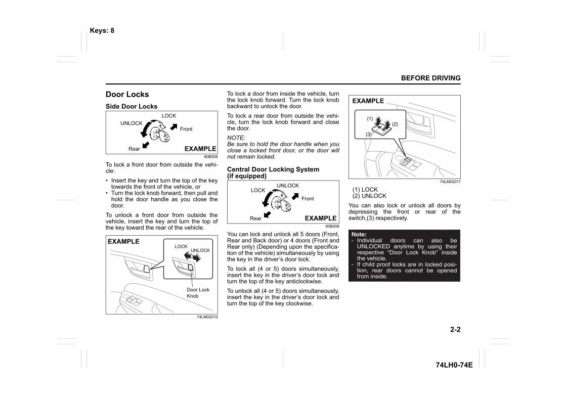
To lock a front door from outside the vehi-cle:• Insert the key and turn the top of the key
towards the front of the vehicle, or• Turn the lock knob forward, then pull and
hold the door handle as you close thedoor.
To unlock a front door from outside thevehicle, insert the key and turn the top ofthe key toward the rear of the vehicle.
74LM02010
To lock a door from inside the vehicle, turnthe lock knob forward. Turn the lock knobbackward to unlock the door.To lock a rear door from outside the vehi-cle, turn the lock knob forward and closethe door. NOTE:Be sure to hold the door handle when youclose a locked front door, or the door willnot remain locked.
Central Door Locking System(if equipped)
60B008
You can lock and unlock all 5 doors (Front,Rear and Back door) or 4 doors (Front andRear only) (Depending upon the specifica-tion of the vehicle) simultaneously by usingthe key in the driver’s door lock.To lock all (4 or 5) doors simultaneously,insert the key in the driver’s door lock andturn the top of the key anticlockwise.To unlock all (4 or 5) doors simultaneously,insert the key in the driver’s door lock andturn the top of the key clockwise.
74LM02011
(1) LOCK(2) UNLOCK
You can also lock or unlock all doors bydepressing the front or rear of theswitch,(3) respectively.
UNLOCKLOCK
Front
Rear EXAMPLE
UNLOCK
EXAMPLE
Door LockKnob
LOCK
UNLOCKLOCK
Front
Rear EXAMPLE
(2)(1)
(3)
EXAMPLE
Keys: 8
2-3
BEFORE DRIVING
74LH0-74E
NOTE:You can also lock or unlock all doors byoperating the transmitter. Refer to “KeylessEntry System Transmitter” in this section.NOTE:• All doors are automatically unlocked when
you change the ignition mode to “LOCK”(OFF) and pull out the key.
• All doors are automatically locked forsafety when the vehicle speed reaches15 km/h.
Child-Proof Locks (rear door)
68LM203
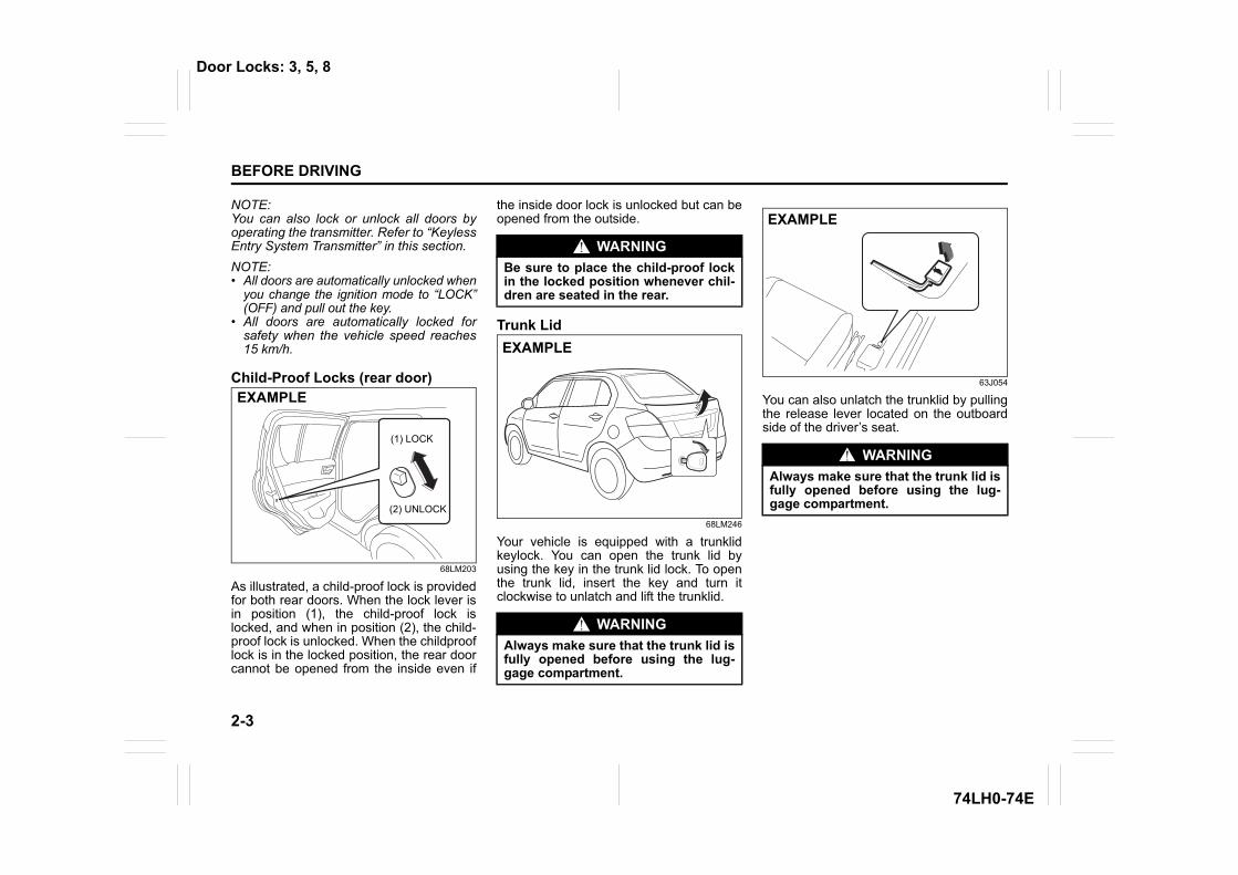
As illustrated, a child-proof lock is providedfor both rear doors. When the lock lever isin position (1), the child-proof lock islocked, and when in position (2), the child-proof lock is unlocked. When the childprooflock is in the locked position, the rear doorcannot be opened from the inside even if
the inside door lock is unlocked but can beopened from the outside.
Trunk Lid
68LM246
Your vehicle is equipped with a trunklidkeylock. You can open the trunk lid byusing the key in the trunk lid lock. To openthe trunk lid, insert the key and turn itclockwise to unlatch and lift the trunklid.
63J054
You can also unlatch the trunklid by pullingthe release lever located on the outboardside of the driver’s seat.
(1) LOCK
(2) UNLOCK
EXAMPLE
WARNINGBe sure to place the child-proof lockin the locked position whenever chil-dren are seated in the rear.
WARNINGAlways make sure that the trunk lid isfully opened before using the lug-gage compartment.
EXAMPLE
WARNINGAlways make sure that the trunk lid isfully opened before using the lug-gage compartment.
EXAMPLE
Door Locks: 3, 5, 8
2-4
BEFORE DRIVING
74LH0-74E
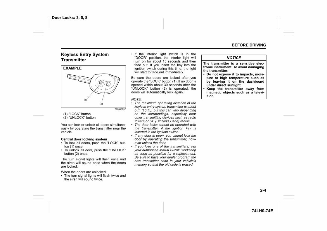
Keyless Entry System Transmitter
79MH0237
(1) “LOCK” button(2) “UNLOCK” button
You can lock or unlock all doors simultane-ously by operating the transmitter near thevehicle.
Central door locking system• To lock all doors, push the “LOCK” but-
ton (1) once.• To unlock all door, push the “UNLOCK”
button (2) once.The turn signal lights will flash once andthe siren will sound once when the doorsare locked.When the doors are unlocked:• The turn signal lights will flash twice and
the siren will sound twice.
• If the interior light switch is in the“DOOR” position, the interior light willturn on for about 15 seconds and thenfade out. If you insert the key into theignition switch during this time, the lightwill start to fade out immediately.
Be sure the doors are locked after youoperate the “LOCK” button (1). If no door isopened within about 30 seconds after the“UNLOCK” button (2) is operated, thedoors will automatically lock again.
NOTE:• The maximum operating distance of the
keyless entry system transmitter is about5 m (16 ft.), but this can vary dependingon the surroundings, especially nearother transmitting devices such as radiotowers or CB (Citizen’s Band) radios.
• The door locks cannot be operated withthe transmitter, if the ignition key isinserted in the ignition switch.
• If any door is open, you cannot lock thedoor by operating the transmitter, how-ever unlock the door.
• If you lose one of the transmitters, askyour authorised Maruti Suzuki workshopas soon as possible for a replacement.Be sure to have your dealer program thenew transmitter code in your vehicle’smemory so that the old code is erased.
(1)
(2)
EXAMPLE
NOTICEThe transmitter is a sensitive elec-tronic instrument. To avoid damagingthe transmitter:• Do not expose it to impacts, mois-
ture or high temperature such asby leaving it on the dashboardunder direct sunlight.
• Keep the transmitter away frommagnetic objects such as a televi-sion.
Door Locks: 3, 5, 8
2-5
BEFORE DRIVING
74LH0-74E
Security System
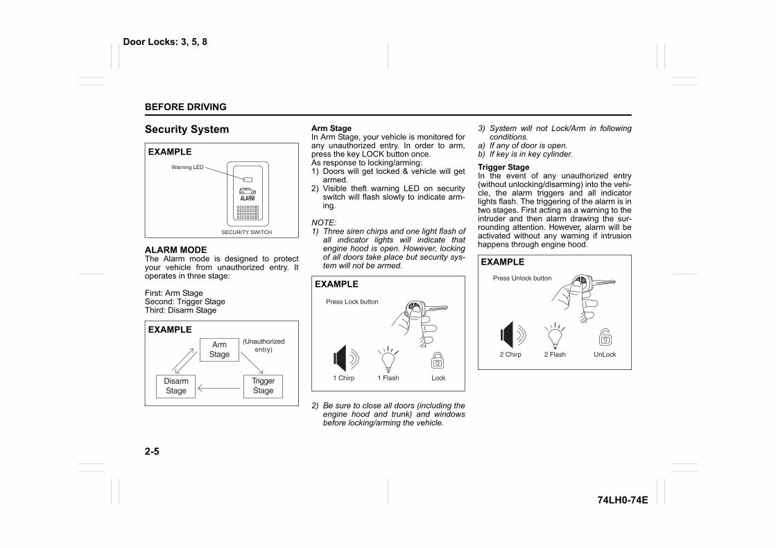
ALARM MODEThe Alarm mode is designed to protectyour vehicle from unauthorized entry. Itoperates in three stage:
First: Arm StageSecond: Trigger StageThird: Disarm Stage
Arm StageIn Arm Stage, your vehicle is monitored forany unauthorized entry. In order to arm,press the key LOCK button once.As response to locking/arming:1) Doors will get locked & vehicle will get
armed. 2) Visible theft warning LED on security
switch will flash slowly to indicate arm-ing.
NOTE:1) Three siren chirps and one light flash of
all indicator lights will indicate thatengine hood is open. However, lockingof all doors take place but security sys-tem will not be armed.
2) Be sure to close all doors (including theengine hood and trunk) and windowsbefore locking/arming the vehicle.
3) System will not Lock/Arm in followingconditions.
a) If any of door is open.b) If key is in key cylinder.Trigger StageIn the event of any unauthorized entry(without unlocking/disarming) into the vehi-cle, the alarm triggers and all indicatorlights flash. The triggering of the alarm is intwo stages. First acting as a warning to theintruder and then alarm drawing the sur-rounding attention. However, alarm will beactivated without any warning if intrusionhappens through engine hood.
Warning LED
EXAMPLE
EXAMPLE
EXAMPLE
EXAMPLE
Door Locks: 3, 5, 8
2-6
BEFORE DRIVING
74LH0-74E
Disarm StageSystem should be brought in Disarm Modewhile you are entering the vehicle. In orderto disarm: Press the key UNLOCK buttononce.
As response to unlocking/disarming:1) Doors will unlock and vehicle will dis-
arm. 2) Visible theft warning LED on security
switch will flash faster than in arm stageindicating Auto rearm (described inauto rearm section).
GENERAL FEATURESIlluminated EntryWhen vehicle is unlocked, the room lampwill turn ON to facilitate illuminated entryinto the vehicle. If no door is opened inabout 15 seconds of above operation,room lamp will fade out.If any door is opened after 15 seconds, theroom lamp turns ON again and after 15seconds of closing all doors room lamp willfade out.If within 15 seconds after closing all thedoors the driver inserts the key into the keycylinder, then the room lamp will fade out.Illuminated ExitWhen key is removed from the key cylin-der, the room lamp will turn ON to facilitateilluminated exit. If no door is opened inabout 15 seconds of key removal from keycylinder, the room lamp will fade out.When door is opened to exit the vehicle,the room lamp will turn ON again (if it hasturned OFF after 15 seconds of keyremoval from key cylinder) and will turnOFF after 15 seconds of closing all thedoors.If within 15 seconds of all doors closure,vehicle is locked by pressing the LOCKbutton, the room lamp will fade out.NOTE: Room lamp will fade out graduallyapproximately in 2 seconds.
Mute Lock/UnlockTo Lock/Unlock the vehicle without sirenchirps use this function.a) Press and release the Key LOCK &
UNLOCK buttons simultaneously.b) Press and release Key LOCK or
UNLOCK button for desired function.Example: To Lock the system without theSiren chirp sound, press and release theKey LOCK & UNLOCK button simultane-ously, then press and release the KeyLOCK button once.
Auto RearmIn case of accidental Unlock/Disarm ofvehicle by Key, vehicle will automaticallyLock & Arm within 30 sec. without any indi-cation. Auto rearm cycle gets canceled ifuser does any of the following operationwithin 30sec : 1. Open any door (including back door).2. Open Engine Hood.3. Key On.
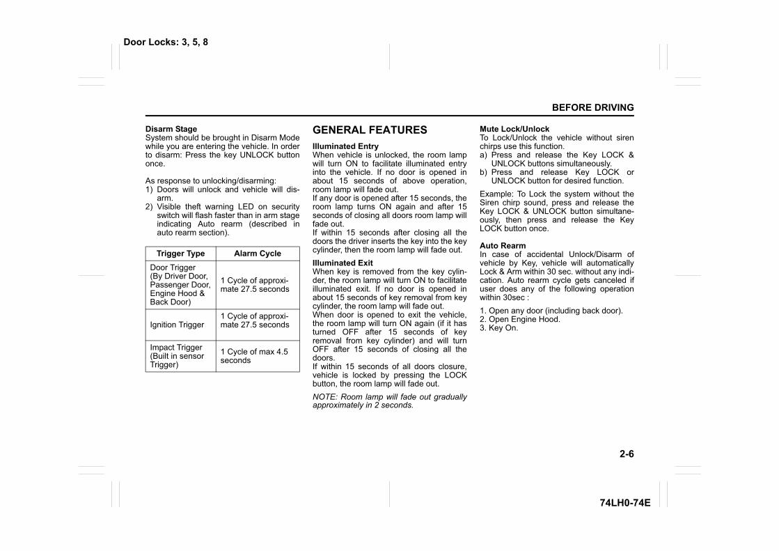
Trigger Type Alarm CycleDoor Trigger(By Driver Door, Passenger Door,Engine Hood & Back Door)
1 Cycle of approxi-mate 27.5 seconds
Ignition Trigger 1 Cycle of approxi-mate 27.5 seconds
Impact Trigger(Built in sensor Trigger)
1 Cycle of max 4.5 seconds
Door Locks: 3, 5, 8
2-7
BEFORE DRIVING
74LH0-74E
Radio Frequency Lock OutKey Lock/Unlock/Car locator function willcease to function when Key is inside Keycylinder.
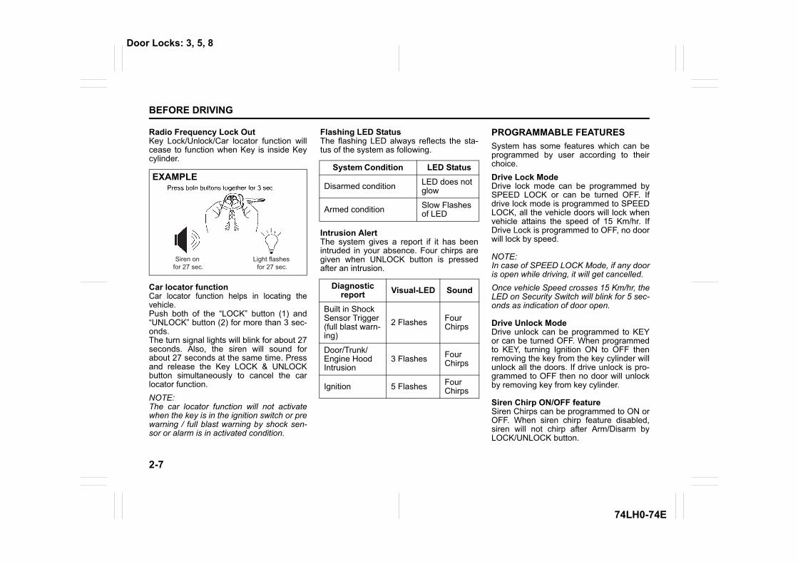
Car locator functionCar locator function helps in locating thevehicle. Push both of the “LOCK” button (1) and“UNLOCK” button (2) for more than 3 sec-onds. The turn signal lights will blink for about 27seconds. Also, the siren will sound forabout 27 seconds at the same time. Pressand release the Key LOCK & UNLOCKbutton simultaneously to cancel the carlocator function.NOTE:The car locator function will not activatewhen the key is in the ignition switch or prewarning / full blast warning by shock sen-sor or alarm is in activated condition.
Flashing LED StatusThe flashing LED always reflects the sta-tus of the system as following.
Intrusion AlertThe system gives a report if it has beenintruded in your absence. Four chirps aregiven when UNLOCK button is pressedafter an intrusion.
PROGRAMMABLE FEATURESSystem has some features which can beprogrammed by user according to theirchoice.Drive Lock ModeDrive lock mode can be programmed bySPEED LOCK or can be turned OFF. Ifdrive lock mode is programmed to SPEEDLOCK, all the vehicle doors will lock whenvehicle attains the speed of 15 Km/hr. IfDrive Lock is programmed to OFF, no doorwill lock by speed.
NOTE:In case of SPEED LOCK Mode, if any dooris open while driving, it will get cancelled. Once vehicle Speed crosses 15 Km/hr, theLED on Security Switch will blink for 5 sec-onds as indication of door open.
Drive Unlock ModeDrive unlock can be programmed to KEYor can be turned OFF. When programmedto KEY, turning Ignition ON to OFF thenremoving the key from the key cylinder willunlock all the doors. If drive unlock is pro-grammed to OFF then no door will unlockby removing key from key cylinder.
Siren Chirp ON/OFF feature Siren Chirps can be programmed to ON orOFF. When siren chirp feature disabled,siren will not chirp after Arm/Disarm byLOCK/UNLOCK button.
Siren on for 27 sec.
Light flashes for 27 sec.
EXAMPLESystem Condition LED Status
Disarmed condition LED does not glow
Armed condition Slow Flashes of LED
Diagnostic report Visual-LED Sound
Built in ShockSensor Trigger (full blast warn-ing)
2 Flashes Four Chirps
Door/Trunk/Engine Hood Intrusion
3 Flashes Four Chirps
Ignition 5 Flashes Four Chirps
Door Locks: 3, 5, 8
2-8
BEFORE DRIVING
74LH0-74E
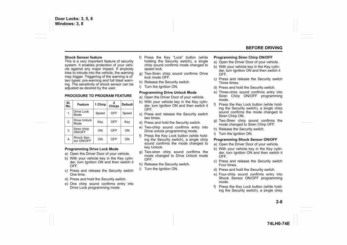
Shock Sensor feature This is a very important feature of securitysystem. It enables protection of your vehi-cle against any major impact. If anybodytries to intrude into the vehicle, the warningmay trigger. Triggering of the warning is oftwo types: pre-warning and full blast warn-ing. The sensitivity of shock sensor can beadjusted as desired by the user.
PROCEDURE TO PROGRAM FEATURE
Programming Drive Lock Modea) Open the Driver Door of your vehicle.b) With your vehicle key in the Key cylin-
der, turn Ignition ON and then switch itOFF.
c) Press and release the Security switchOne time.
d) Press and hold the Security switch.e) One chirp sound confirms entry into
Drive Lock programming mode.
f) Press the Key “Lock” button (whileholding the Security switch), a singlechirp sound confirms mode changed tospeed lock.
g) Two-Siren chirp sound confirms Drivelock mode OFF.
h) Release the Security switch.i) Turn the Ignition ON.Programming Drive Unlock Modea) Open the Driver Door of your vehicle.b) With your vehicle key in the Key cylin-
der, turn Ignition ON and then switch itOFF.
c) Press and release the Security switchtwo times.
d) Press and hold the Security switch.e) Two-chirp sound confirms entry into
Drive unlock programming mode.f) Press the Key Lock button (while hold-
ing the Security switch), a single chirpsound confirms the mode changed tokey Unlock.
g) Two-siren chirp sound confirms themode changed to Drive Unlock modeOFF.
h) Release the Security switch.i) Turn the Ignition ON.
Programming Siren Chirp ON/OFFa) Open the Driver Door of your vehicle.b) With your vehicle key in the Key cylin-
der, turn Ignition ON and then switch it OFF.
c) Press and release the Security switchThree times.
d) Press and hold the Security switch.e) Three-chirp sound confirms entry into
Siren Chirp ON/OFF programmingmode.
f) Press the Key Lock button (while hold-ing the Security switch), a single chirpsound confirms the mode changed toSiren Chirp ON.
g) Two-Siren chirp sound confirms themode changed to Siren Chirp OFF.
h) Release the Security switch.i) Turn the Ignition ON.Programming Shock Sensor ON/OFFa) Open the Driver Door of your vehicle.b) With your vehicle key in the Key cylin-
der, turn Ignition ON and then switch itOFF.
c) Press and release the Security switchFour times.
d) Press and hold the Security switch.e) Four-chirp sound confirms entry into
Shock Sensor ON/OFF programmingmode.
f) Press the Key Lock button (while hold-ing the Security switch), a single chirp
Sl. No. Feature 1 Chirp 2
Chirps Default
1. Drive Lock Mode Speed OFF Speed
2. Drive Unlock Mode Key OFF Key
3. Siren chirp ON/OFF ON OFF ON
4. Shock Sen-sor ON/OFF ON OFF ON
Door Locks: 3, 5, 8Windows: 3, 8
2-9
BEFORE DRIVING
74LH0-74E
sound confirms the mode changed toshock sensor ON.
g) Two-Siren chirp sound confirms themode changed to shock sensor OFF.
h) Release the Security switch.i) Turn the Ignition ON.Shock Sensor Sensitivity Adjustmentvia Key
Full Blast adjustmentFull Blast can be adjusted in 16 levels asmentioned below.a) Press Unlock button on Key to Unlock/
Disarm the System.b) Press Lock button (within 2 seconds of
key UNLOCK) on Key to Lock/Arm theSystem.
c) Within 2 sec press Lock & Unlock buttonsimultaneously for at least 3 sec. Sirenwill give Long chirp to confirm entry intosensitivity adjustment modei) Press Lock button to adjust the sen-
sitivity one step lower. Siren will giveone chirp every time lock button ispressed till at level 1 where it willgive a long chirp. When adjusted tolevel 1, Full Blast will turn OFF
ii) Press unlock button to adjust thesensitivity one step higher. Siren willgive two chirp every time unlock but-ton is pressed till at level 16 where itwill give a long chirp.
Pre-warn AdjustmentPre-warn can be adjusted in 16 levels asmentioned below:a) Press Lock button on Key to Lock/Arm
the Systemb) Press Unlock button (within 2 seconds
of key LOCK) on Key to Unlock/Disarmthe System
c) Within 2 sec press Lock & Unlock buttonsimultaneously for at least 3 sec. Sirenwill give Long chirp to confirm entry intoSensitivity Adjustment Mode.i) Press Lock button to adjust the sen-
sitivity one step lower. Siren will giveone chirp every time lock button ispressed till at level 1 where it willgive a long chirp. When adjusted tolevel 1, pre-warn will turn OFF.
ii) Press Unlock button to adjust thesensitivity one step higher. Siren willgive two Chirp every time Unlockbutton is pressed till at level 16where it will give a long chirp.
Program Customer Pin-code (Personalized Pin-code)If transmitter is not working properly, then itis possible to disarm the system by Per-sonalized pin code.The Personalized 4-digit number can bechanged from the factory default to ensurePersonalized Security.
Pin code entrya) Disarm the system.b) Open the Driver Door.c) Turn Ignition ON then OFF.d) Within 5 seconds press and release
Valet switch 5 times. A short chirp fol-lowed by long chirps confirms entry intoPin Code programming mode.
e) Press Lock button on Key, after a singlechirp enter the First digit (within 1-9) bypressing Valet switch (for e.g. to enter 2press and release Valet switch twotimes).
f) Press Lock button on Key, after twochirp enter the Second digit (within 1-9)by pressing Valet switch.
g) Press Lock button on Key, after 3-chirps enter the Third digit (within 1-9)by pressing Valet switch.
h) Press Lock button on Key, after 4-chirps enter the Fourth digit (within 1-9)by pressing Valet switch.
Windows: 3, 8
2-10
BEFORE DRIVING
74LH0-74E
Emergency Disarm by Personalized pincodeThe Personalized 4- Digit Pin Code acts asa secret Key, to Emergency Disarm thevehicle.a) Turn the Ignition ON, OFF and then
ON.b) Enter the First digit (for e. g. to enter 2
press and release Valet switch twice)c) Turn the Ignition OFF then ON.d) Enter the Second digit.e) Turn the Ignition OFF and then ON.f) Enter the Third Digit.g) Turn the Ignition OFF and then ONh) Enter the Last Digit.i) Turn the Ignition OFF and then ON.j) The vehicle will get disarmed.NOTE:The default pin will be provided by thedealer at the time of delivery. It is recom-mended to personalize the pin forincreased security. The pin must beremembered as it is not possible to retrievea lost pin.
Transmitter battery Replacement of the Battery
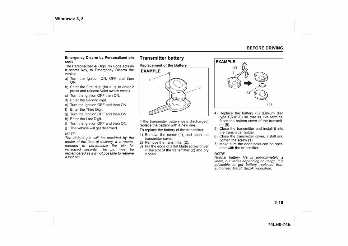
If the transmitter battery gets discharged,replace the battery with a new one. To replace the battery of the transmitter: 1) Remove the screw (1), and open the
transmitter cover. 2) Remove the transmitter (2).3) Put the edge of a flat blade screw driver
in the slot of the transmitter (2) and pryit open.
4) Replace the battery (3) (Lithium disctype CR1620) so that its +ve terminalfaces the bottom cover of the transmit-ter (5).
5) Close the transmitter and install it intothe transmitter holder.
6) Close the transmitter cover, install andtighten the screw (1).
7) Make sure the door locks can be oper-ated with the transmitter.
NOTE:Normal battery life is approximately 2years, but varies depending on usage. It isadvisable to get battery replaced fromauthorised Maruti Suzuki workshop.
EXAMPLE(2)
(3)
(5)
EXAMPLE
Windows: 3, 8
2-11
BEFORE DRIVING
74LH0-74E
CAUTIONDo not remove the screw from thekey Unnecessarily as it damages thescrew head. Kindly replace the screwonce the transmitter battery ischanged.
CAUTIONDispose off the used battery properlyaccording to applicable rules or regu-lations. Do not dispose off lithiumbatteries with ordinary householdtrash.
WARNINGSwallowing a lithium battery maycause serious internal injury. Do notallow anyone to swallow a lithiumbattery. Keep lithium batteries awayfrom children and pets. If swallowed,contact a physician immediately.
EXAMPLE
Mirrors: 3, 8
2-12
BEFORE DRIVING
74LH0-74E
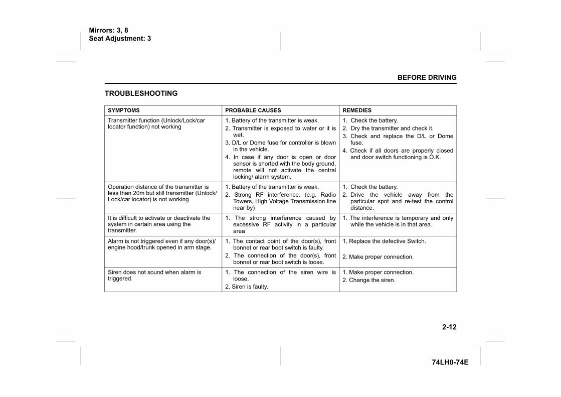
TROUBLESHOOTING
SYMPTOMS PROBABLE CAUSES REMEDIES
Transmitter function (Unlock/Lock/car locator function) not working
1. Battery of the transmitter is weak. 2. Transmitter is exposed to water or it is
wet.3. D/L or Dome fuse for controller is blown
in the vehicle. 4. In case if any door is open or door
sensor is shorted with the body ground,remote will not activate the centrallocking/ alarm system.
1. Check the battery. 2. Dry the transmitter and check it. 3. Check and replace the D/L or Dome
fuse.4. Check if all doors are properly closed
and door switch functioning is O.K.
Operation distance of the transmitter is less than 20m but still transmitter (Unlock/Lock/car locator) is not working
1. Battery of the transmitter is weak. 2. Strong RF interference. (e.g. Radio
Towers, High Voltage Transmission linenear by)
1. Check the battery. 2. Drive the vehicle away from the
particular spot and re-test the controldistance.
It is difficult to activate or deactivate the system in certain area using the transmitter.
1. The strong interference caused byexcessive RF activity in a particulararea
1. The interference is temporary and onlywhile the vehicle is in that area.
Alarm is not triggered even if any door(s)/engine hood/trunk opened in arm stage.
1. The contact point of the door(s), frontbonnet or rear boot switch is faulty.
2. The connection of the door(s), frontbonnet or rear boot switch is loose.
1. Replace the defective Switch.
2. Make proper connection.
Siren does not sound when alarm is triggered.
1. The connection of the siren wire isloose.
2. Siren is faulty.
1. Make proper connection. 2. Change the siren.
Mirrors: 3, 8Seat Adjustment: 3
2-13
BEFORE DRIVING
74LH0-74E
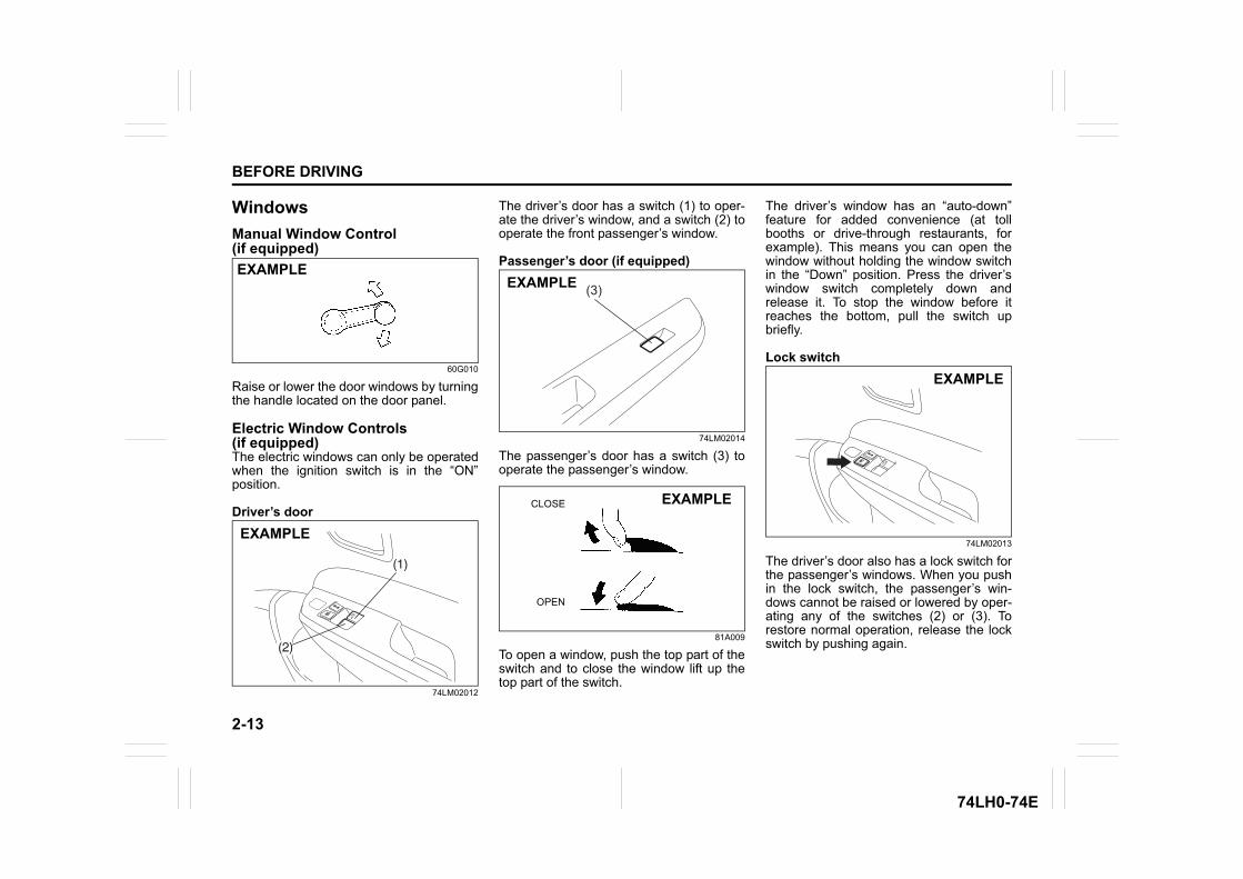
WindowsManual Window Control (if equipped)
60G010
Raise or lower the door windows by turningthe handle located on the door panel.
Electric Window Controls (if equipped)The electric windows can only be operatedwhen the ignition switch is in the “ON”position.
Driver’s door
74LM02012
The driver’s door has a switch (1) to oper-ate the driver’s window, and a switch (2) tooperate the front passenger’s window.
Passenger’s door (if equipped)
74LM02014
The passenger’s door has a switch (3) tooperate the passenger’s window.
81A009
To open a window, push the top part of theswitch and to close the window lift up thetop part of the switch.
The driver’s window has an “auto-down”feature for added convenience (at tollbooths or drive-through restaurants, forexample). This means you can open thewindow without holding the window switchin the “Down” position. Press the driver’swindow switch completely down andrelease it. To stop the window before itreaches the bottom, pull the switch upbriefly.
Lock switch
74LM02013
The driver’s door also has a lock switch forthe passenger’s windows. When you pushin the lock switch, the passenger’s win-dows cannot be raised or lowered by oper-ating any of the switches (2) or (3). Torestore normal operation, release the lockswitch by pushing again.
EXAMPLE
(1)
(2)
EXAMPLE
(3)EXAMPLE
CLOSE
OPEN
EXAMPLE
EXAMPLE
2-14
BEFORE DRIVING
74LH0-74E
NOTE:If you drive with one of the rear windowsopen, you may hear a loud sound causedby air vibration. To reduce the sound, openthe driver’s or front passenger’s window, ornarrow the rear window opening.
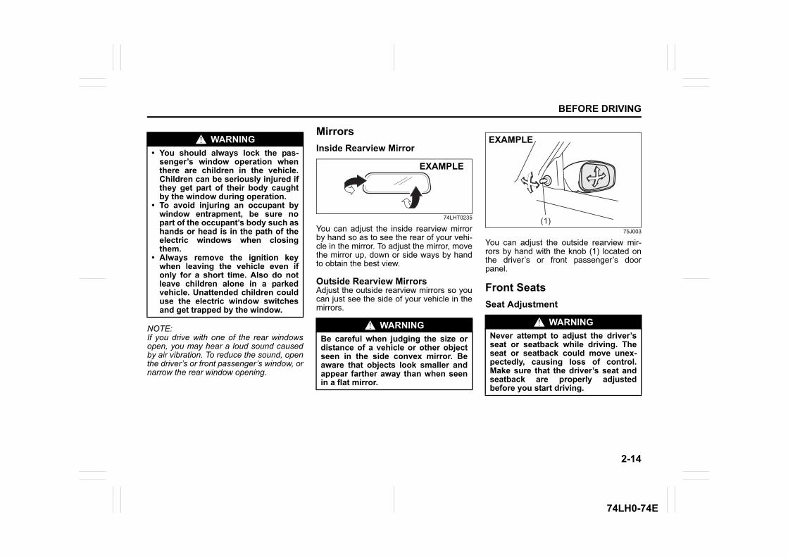
MirrorsInside Rearview Mirror
74LHT0235
You can adjust the inside rearview mirrorby hand so as to see the rear of your vehi-cle in the mirror. To adjust the mirror, movethe mirror up, down or side ways by handto obtain the best view.
Outside Rearview MirrorsAdjust the outside rearview mirrors so youcan just see the side of your vehicle in themirrors.
75J003
You can adjust the outside rearview mir-rors by hand with the knob (1) located onthe driver’s or front passenger’s doorpanel.
Front SeatsSeat Adjustment
WARNING• You should always lock the pas-
senger’s window operation whenthere are children in the vehicle.Children can be seriously injured ifthey get part of their body caughtby the window during operation.
• To avoid injuring an occupant bywindow entrapment, be sure nopart of the occupant’s body such ashands or head is in the path of theelectric windows when closingthem.
• Always remove the ignition keywhen leaving the vehicle even ifonly for a short time. Also do notleave children alone in a parkedvehicle. Unattended children coulduse the electric window switchesand get trapped by the window.
WARNINGBe careful when judging the size ordistance of a vehicle or other objectseen in the side convex mirror. Beaware that objects look smaller andappear farther away than when seenin a flat mirror.
EXAMPLE
WARNINGNever attempt to adjust the driver’sseat or seatback while driving. Theseat or seatback could move unex-pectedly, causing loss of control.Make sure that the driver’s seat andseatback are properly adjustedbefore you start driving.
(1)
EXAMPLE
2-15
BEFORE DRIVING
74LH0-74E
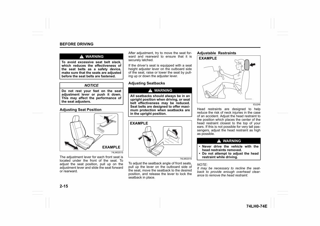
Adjusting Seat Position
74LM02015
The adjustment lever for each front seat islocated under the front of the seat. Toadjust the seat position, pull up on theadjustment lever and slide the seat forwardor rearward.
After adjustment, try to move the seat for-ward and rearward to ensure that it issecurely latched.If the driver’s seat is equipped with a seatheight adjuster lever on the outboard sideof the seat, raise or lower the seat by pull-ing up or down the adjuster lever.
Adjusting Seatbacks
74LM02016
To adjust the seatback angle of front seats,pull up the lever on the outboard side ofthe seat, move the seatback to the desiredposition, and release the lever to lock theseatback in place.
Adjustable Restraints
63J246
Head restraints are designed to helpreduce the risk of neck injuries in the caseof an accident. Adjust the head restraint tothe position which places the center of thehead restraint closest to the top of yourears. If this is not possible for very tall pas-sengers, adjust the head restraint as highas possible.
NOTE:It may be necessary to recline the seat-back to provide enough overhead clear-ance to remove the head restraint.
WARNINGTo avoid excessive seat belt slack,which reduces the effectiveness ofthe seat belts as a safety device,make sure that the seats are adjustedbefore the seat belts are fastened.
NOTICEDo not rest your feet on the seatadjustment lever or push it down.This may affect the performance ofthe seat adjusters.
EXAMPLE
WARNINGAll seatbacks should always be in anupright position when driving, or seatbelt effectiveness may be reduced.Seat belts are designed to offer maxi-mum protection when seatbacks arein the upright position.
EXAMPLE
WARNING• Never drive the vehicle with the
head restraints removed.• Do not attempt to adjust the head
restraint while driving.
EXAMPLE
2-16
BEFORE DRIVING
74LH0-74E
Front
80JS082
To raise the front head restraint, pullupward on the restraint until it clicks. Tolower the restraint, push down on therestraint while holding in the lock lever. If ahead restraint must be removed (for clean-ing, replacement, etc.), push in the locklever and pull the head restraint all the wayout.
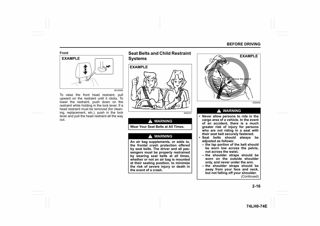
Seat Belts and Child Restraint Systems
65D231
65D606
EXAMPLE
WARNINGWear Your Seat Belts at All Times.
WARNINGAn air bag supplements, or adds to,the frontal crash protection offeredby seat belts. The driver and all pas-sengers must be properly restrainedby wearing seat belts at all times,whether or not an air bag is mountedat their seating position, to minimizethe risk of severe injury or death inthe event of a crash.
EXAMPLE
WARNING• Never allow persons to ride in the
cargo area of a vehicle. In the eventof an accident, there is a muchgreater risk of injury for personswho are not riding in a seat withtheir seat belt securely fastened.
• Seat belts should always beadjusted as follows:– the lap portion of the belt should
be worn low across the pelvis,not across the waist.
– the shoulder straps should beworn on the outside shoulderonly, and never under the arm.
– the shoulder straps should beaway from your face and neck,but not falling off your shoulder.
(Continued)
Above the pelvis
EXAMPLE
2-17
BEFORE DRIVING
74LH0-74E
65D201 65D199
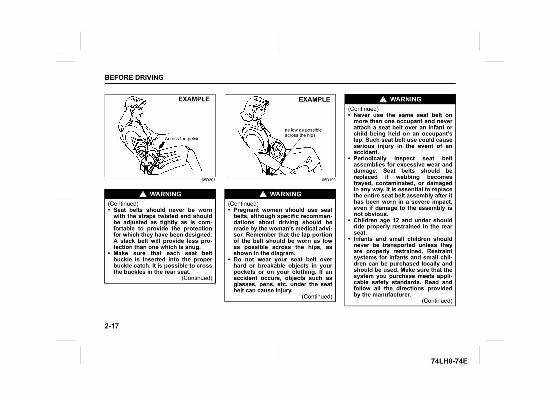
WARNING(Continued)• Seat belts should never be worn
with the straps twisted and shouldbe adjusted as tightly as is com-fortable to provide the protectionfor which they have been designed.A slack belt will provide less pro-tection than one which is snug.
• Make sure that each seat beltbuckle is inserted into the properbuckle catch. It is possible to crossthe buckles in the rear seat.
(Continued)
Across the pelvis
EXAMPLE
WARNING(Continued)• Pregnant women should use seat
belts, although specific recommen-dations about driving should bemade by the woman’s medical advi-sor. Remember that the lap portionof the belt should be worn as lowas possible across the hips, asshown in the diagram.
• Do not wear your seat belt overhard or breakable objects in yourpockets or on your clothing. If anaccident occurs, objects such asglasses, pens, etc. under the seatbelt can cause injury.
(Continued)
as low as possible across the hips
EXAMPLE WARNING(Continued)• Never use the same seat belt on
more than one occupant and neverattach a seat belt over an infant orchild being held on an occupant’slap. Such seat belt use could causeserious injury in the event of anaccident.
• Periodically inspect seat beltassemblies for excessive wear anddamage. Seat belts should bereplaced if webbing becomesfrayed, contaminated, or damagedin any way. It is essential to replacethe entire seat belt assembly after ithas been worn in a severe impact,even if damage to the assembly isnot obvious.
• Children age 12 and under shouldride properly restrained in the rearseat.
• Infants and small children shouldnever be transported unless theyare properly restrained. Restraintsystems for infants and small chil-dren can be purchased locally andshould be used. Make sure that thesystem you purchase meets appli-cable safety standards. Read andfollow all the directions providedby the manufacturer.
(Continued)
2-18
BEFORE DRIVING
74LH0-74E
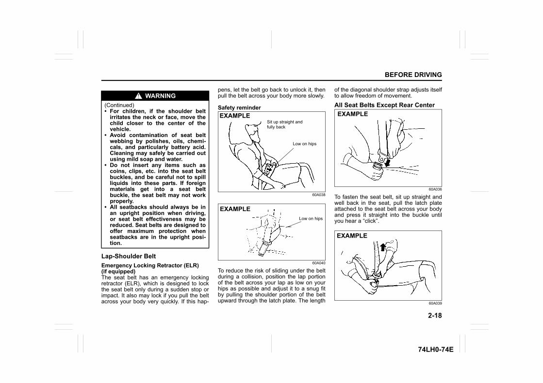
Lap-Shoulder BeltEmergency Locking Retractor (ELR) (if equipped)The seat belt has an emergency lockingretractor (ELR), which is designed to lockthe seat belt only during a sudden stop orimpact. It also may lock if you pull the beltacross your body very quickly. If this hap-
pens, let the belt go back to unlock it, thenpull the belt across your body more slowly.
Safety reminder
60A038
60A040
To reduce the risk of sliding under the beltduring a collision, position the lap portionof the belt across your lap as low on yourhips as possible and adjust it to a snug fitby pulling the shoulder portion of the beltupward through the latch plate. The length
of the diagonal shoulder strap adjusts itselfto allow freedom of movement.
All Seat Belts Except Rear Center
60A036
To fasten the seat belt, sit up straight andwell back in the seat, pull the latch plateattached to the seat belt across your bodyand press it straight into the buckle untilyou hear a “click”.
60A039
WARNING(Continued)• For children, if the shoulder belt
irritates the neck or face, move thechild closer to the center of thevehicle.
• Avoid contamination of seat beltwebbing by polishes, oils, chemi-cals, and particularly battery acid.Cleaning may safely be carried outusing mild soap and water.
• Do not insert any items such ascoins, clips, etc. into the seat beltbuckles, and be careful not to spillliquids into these parts. If foreignmaterials get into a seat beltbuckle, the seat belt may not workproperly.
• All seatbacks should always be inan upright position when driving,or seat belt effectiveness may bereduced. Seat belts are designed tooffer maximum protection whenseatbacks are in the upright posi-tion.
Sit up straight and fully back
Low on hips
EXAMPLE
Low on hips
EXAMPLE
EXAMPLE
EXAMPLE
2-19
BEFORE DRIVING
74LH0-74E
To unfasten the seat belt, push the red“PRESS” button on the buckle and retractthe belt slowly while attaching a hand tothe belt or/and the latch plate.
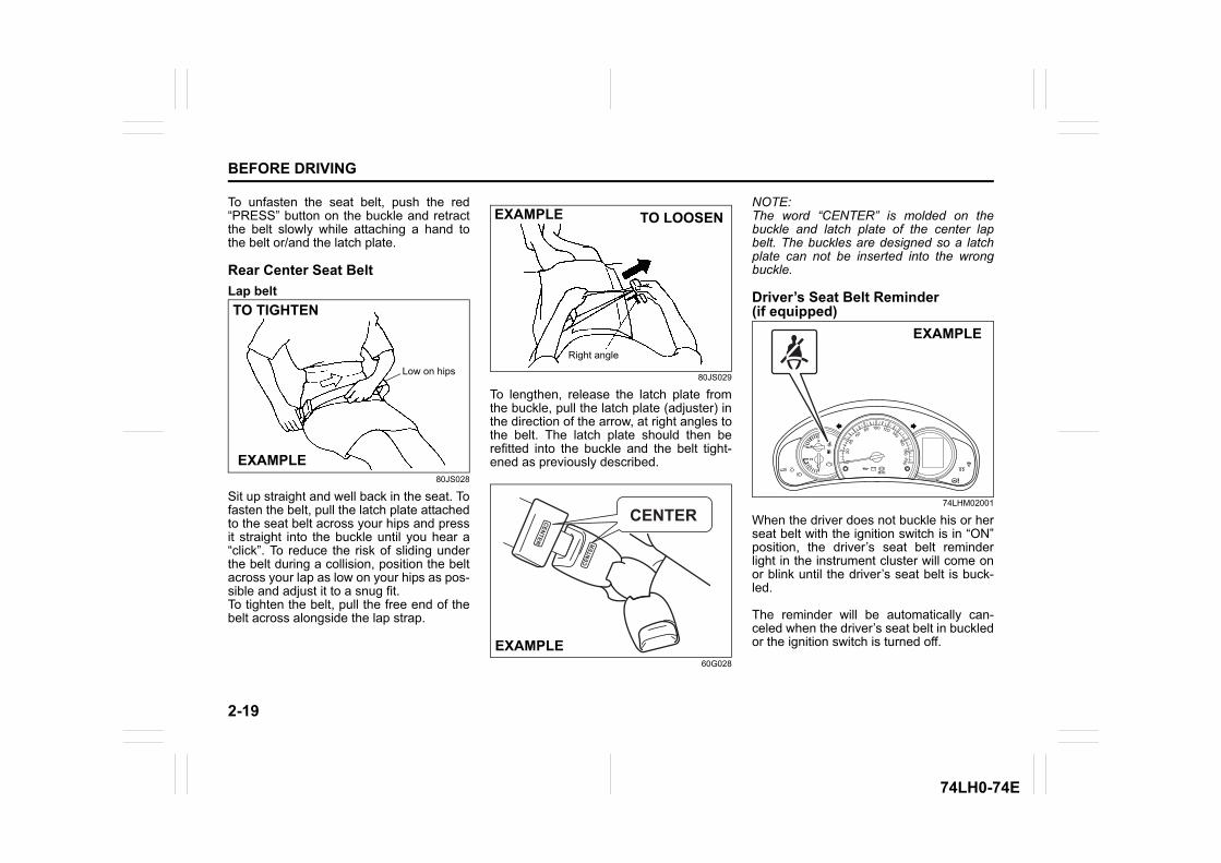
Rear Center Seat BeltLap belt
80JS028
Sit up straight and well back in the seat. Tofasten the belt, pull the latch plate attachedto the seat belt across your hips and pressit straight into the buckle until you hear a“click”. To reduce the risk of sliding underthe belt during a collision, position the beltacross your lap as low on your hips as pos-sible and adjust it to a snug fit.To tighten the belt, pull the free end of thebelt across alongside the lap strap.
80JS029
To lengthen, release the latch plate fromthe buckle, pull the latch plate (adjuster) inthe direction of the arrow, at right angles tothe belt. The latch plate should then berefitted into the buckle and the belt tight-ened as previously described.
60G028
NOTE:The word “CENTER” is molded on thebuckle and latch plate of the center lapbelt. The buckles are designed so a latchplate can not be inserted into the wrongbuckle.
Driver’s Seat Belt Reminder (if equipped)
74LHM02001
When the driver does not buckle his or herseat belt with the ignition switch is in “ON”position, the driver’s seat belt reminderlight in the instrument cluster will come onor blink until the driver’s seat belt is buck-led.
The reminder will be automatically can-celed when the driver’s seat belt in buckledor the ignition switch is turned off.
Low on hips
TO TIGHTEN
EXAMPLE
EXAMPLE
Right angle
TO LOOSEN
EXAMPLE
EXAMPLE
2-20
BEFORE DRIVING
74LH0-74E
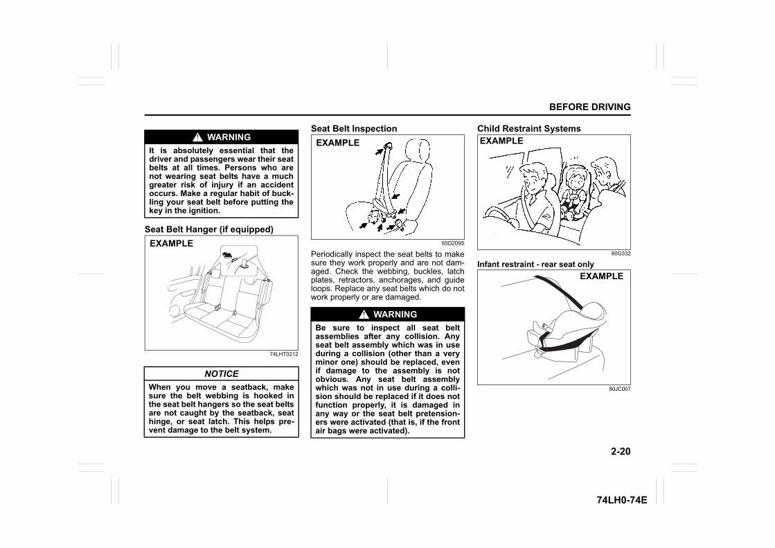
Seat Belt Hanger (if equipped)
74LHT0212
Seat Belt Inspection
65D209S
Periodically inspect the seat belts to makesure they work properly and are not dam-aged. Check the webbing, buckles, latchplates, retractors, anchorages, and guideloops. Replace any seat belts which do notwork properly or are damaged.
Child Restraint Systems
60G332
Infant restraint - rear seat only
80JC007
WARNINGIt is absolutely essential that thedriver and passengers wear their seatbelts at all times. Persons who arenot wearing seat belts have a muchgreater risk of injury if an accidentoccurs. Make a regular habit of buck-ling your seat belt before putting thekey in the ignition.
NOTICEWhen you move a seatback, makesure the belt webbing is hooked inthe seat belt hangers so the seat beltsare not caught by the seatback, seathinge, or seat latch. This helps pre-vent damage to the belt system.
EXAMPLE
WARNINGBe sure to inspect all seat beltassemblies after any collision. Anyseat belt assembly which was in useduring a collision (other than a veryminor one) should be replaced, evenif damage to the assembly is notobvious. Any seat belt assemblywhich was not in use during a colli-sion should be replaced if it does notfunction properly, it is damaged inany way or the seat belt pretension-ers were activated (that is, if the frontair bags were activated).
EXAMPLE EXAMPLE
EXAMPLE
2-21
BEFORE DRIVING
74LH0-74E
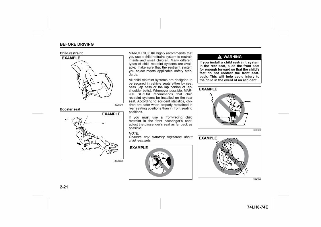
Child restraint
80JC016
Booster seat
80JC008
MARUTI SUZUKI highly recommends thatyou use a child restraint system to restraininfants and small children. Many differenttypes of child restraint systems are avail-able; make sure that the restraint systemyou select meets applicable safety stan-dards.All child restraint systems are designed tobe secured in vehicle seats either by seatbelts (lap belts or the lap portion of lap-shoulder belts). Whenever possible, MAR-UTI SUZUKI recommends that childrestraint systems be installed on the rearseat. According to accident statistics, chil-dren are safer when properly restrained inrear seating positions than in front seatingpositions.If you must use a front-facing childrestraint in the front passenger’s seat,adjust the passenger’s seat as far back aspossible.NOTE:Observe any statutory regulation aboutchild restraints.
65D608
65D609
EXAMPLE
EXAMPLE
EXAMPLE
WARNINGIf you install a child restraint systemin the rear seat, slide the front seatfor enough forward so that the child’sfeet do not contact the front seat-back. This will help avoid injury tothe child in the event of an accident.
EXAMPLE
EXAMPLE
2-22
BEFORE DRIVING
74LH0-74E
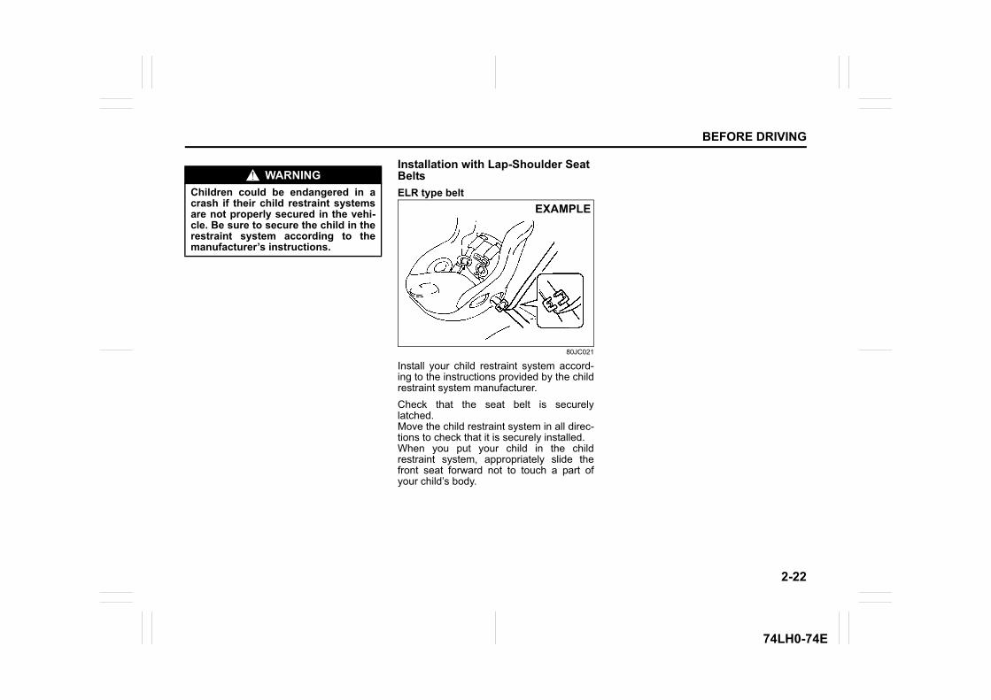
Installation with Lap-Shoulder Seat BeltsELR type belt
80JC021
Install your child restraint system accord-ing to the instructions provided by the childrestraint system manufacturer.Check that the seat belt is securelylatched.Move the child restraint system in all direc-tions to check that it is securely installed.When you put your child in the childrestraint system, appropriately slide thefront seat forward not to touch a part ofyour child’s body.
WARNINGChildren could be endangered in acrash if their child restraint systemsare not properly secured in the vehi-cle. Be sure to secure the child in therestraint system according to themanufacturer’s instructions.
EXAMPLE
2-23
BEFORE DRIVING
74LH0-74E
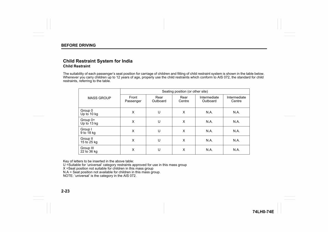
Child Restraint System for IndiaChild Restraint
The suitability of each passenger’s seat position for carriage of children and fitting of child restraint system is shown in the table below. Whenever you carry children up to 12 years of age, properly use the child restraints which conform to AIS 072, the standard for child restraints, referring to the table.
MASS GROUP
Seating position (or other site)
Front Passenger
Rear Outboard
Rear Centre
Intermediate Outboard
Intermediate Centre
Group 0Up to 10 kg X U X N.A. N.A.
Group 0+Up to 13 kg X U X N.A. N.A.
Group I9 to 18 kg X U X N.A. N.A.
Group II15 to 25 kg X U X N.A. N.A.
Group III22 to 36 kg X U X N.A. N.A.
Key of letters to be inserted in the above table:U =Suitable for ‘universal’ category restraints approved for use in this mass groupX =Seat position not suitable for children in this mass groupN.A = Seat position not available for children in this mass group. NOTE: ‘universal’ is the category in the AIS 072.
2-24
BEFORE DRIVING
74LH0-74E
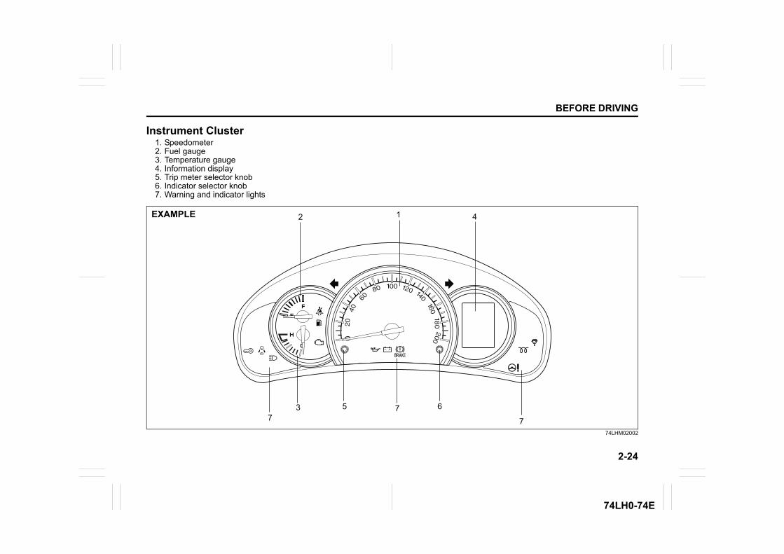
Instrument Cluster1. Speedometer2. Fuel gauge3. Temperature gauge4. Information display5. Trip meter selector knob6. Indicator selector knob7. Warning and indicator lights
74LHM02002
12
3
4
5 677 7
EXAMPLE
2-25
BEFORE DRIVING
74LH0-74E
Speedometer
74LM02003
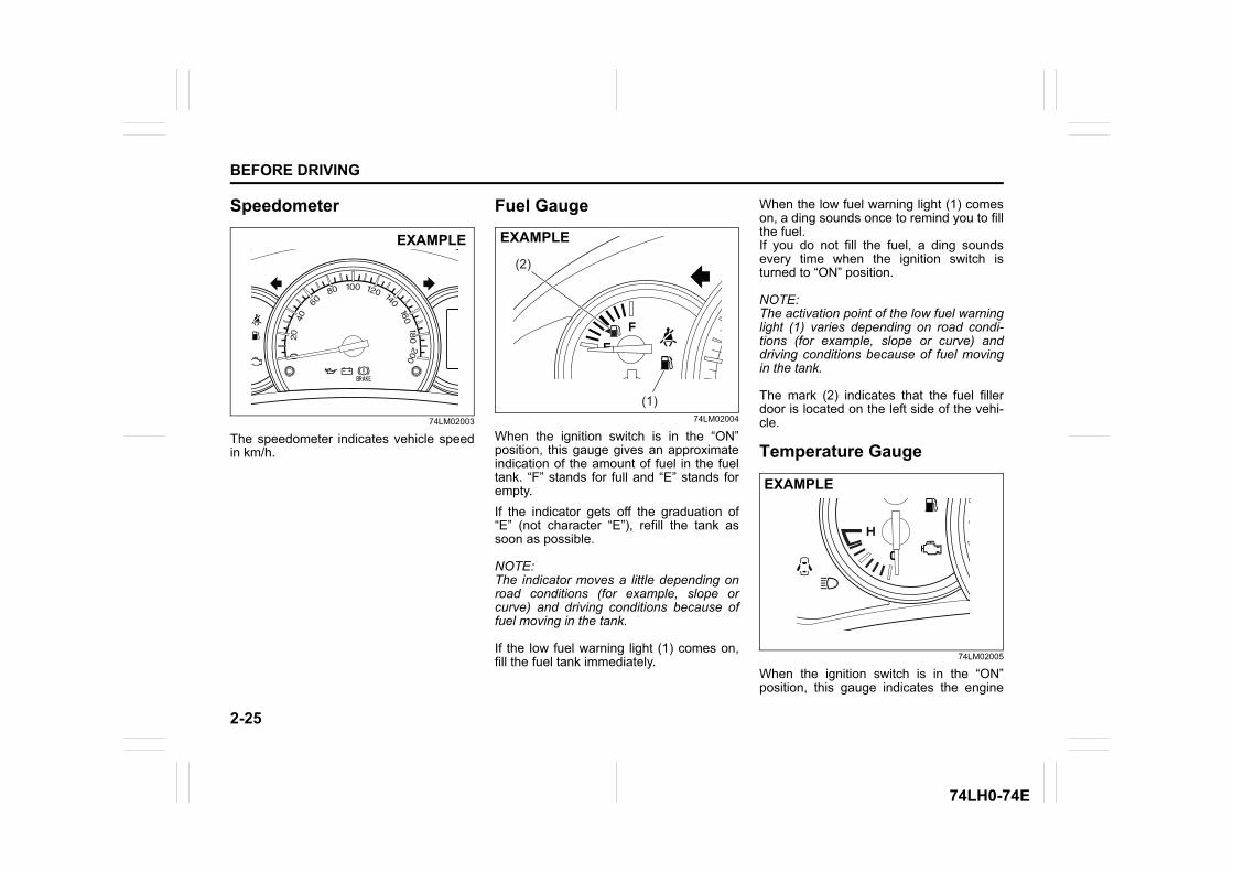
The speedometer indicates vehicle speedin km/h.
Fuel Gauge
74LM02004
When the ignition switch is in the “ON”position, this gauge gives an approximateindication of the amount of fuel in the fueltank. “F” stands for full and “E” stands forempty.If the indicator gets off the graduation of“E” (not character “E”), refill the tank assoon as possible.
NOTE:The indicator moves a little depending onroad conditions (for example, slope orcurve) and driving conditions because offuel moving in the tank.
If the low fuel warning light (1) comes on,fill the fuel tank immediately.
When the low fuel warning light (1) comeson, a ding sounds once to remind you to fillthe fuel.If you do not fill the fuel, a ding soundsevery time when the ignition switch isturned to “ON” position.
NOTE:The activation point of the low fuel warninglight (1) varies depending on road condi-tions (for example, slope or curve) anddriving conditions because of fuel movingin the tank.
The mark (2) indicates that the fuel fillerdoor is located on the left side of the vehi-cle.
Temperature Gauge
74LM02005
When the ignition switch is in the “ON”position, this gauge indicates the engine
EXAMPLE
(1)
(2)
EXAMPLE
EXAMPLE
2-26
BEFORE DRIVING
74LH0-74E
coolant temperature. Under normal drivingconditions, the indicator should stay withinthe normal, acceptable temperature rangebetween “H” and “C”. If the indicatorapproaches “H”, overheating is indicated.Follow the instructions for engine over-heating in the “EMERGENCY SERVICE”section.
Brightness Control
74LM02006
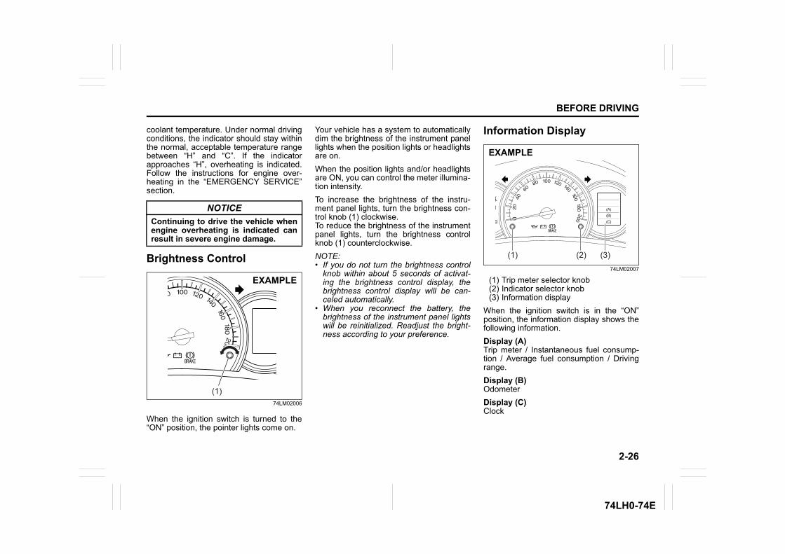
When the ignition switch is turned to the“ON” position, the pointer lights come on.
Your vehicle has a system to automaticallydim the brightness of the instrument panellights when the position lights or headlightsare on. When the position lights and/or headlightsare ON, you can control the meter illumina-tion intensity.To increase the brightness of the instru-ment panel lights, turn the brightness con-trol knob (1) clockwise.To reduce the brightness of the instrumentpanel lights, turn the brightness controlknob (1) counterclockwise.NOTE:• If you do not turn the brightness control
knob within about 5 seconds of activat-ing the brightness control display, thebrightness control display will be can-celed automatically.
• When you reconnect the battery, thebrightness of the instrument panel lightswill be reinitialized. Readjust the bright-ness according to your preference.
Information Display
74LM02007
(1) Trip meter selector knob(2) Indicator selector knob(3) Information display
When the ignition switch is in the “ON”position, the information display shows thefollowing information.Display (A)Trip meter / Instantaneous fuel consump-tion / Average fuel consumption / Drivingrange.Display (B)OdometerDisplay (C)Clock
NOTICEContinuing to drive the vehicle whenengine overheating is indicated canresult in severe engine damage.
(1)
EXAMPLE
(C)
(A)
(B)
(1) (2) (3)
EXAMPLE
2-27
BEFORE DRIVING
74LH0-74E
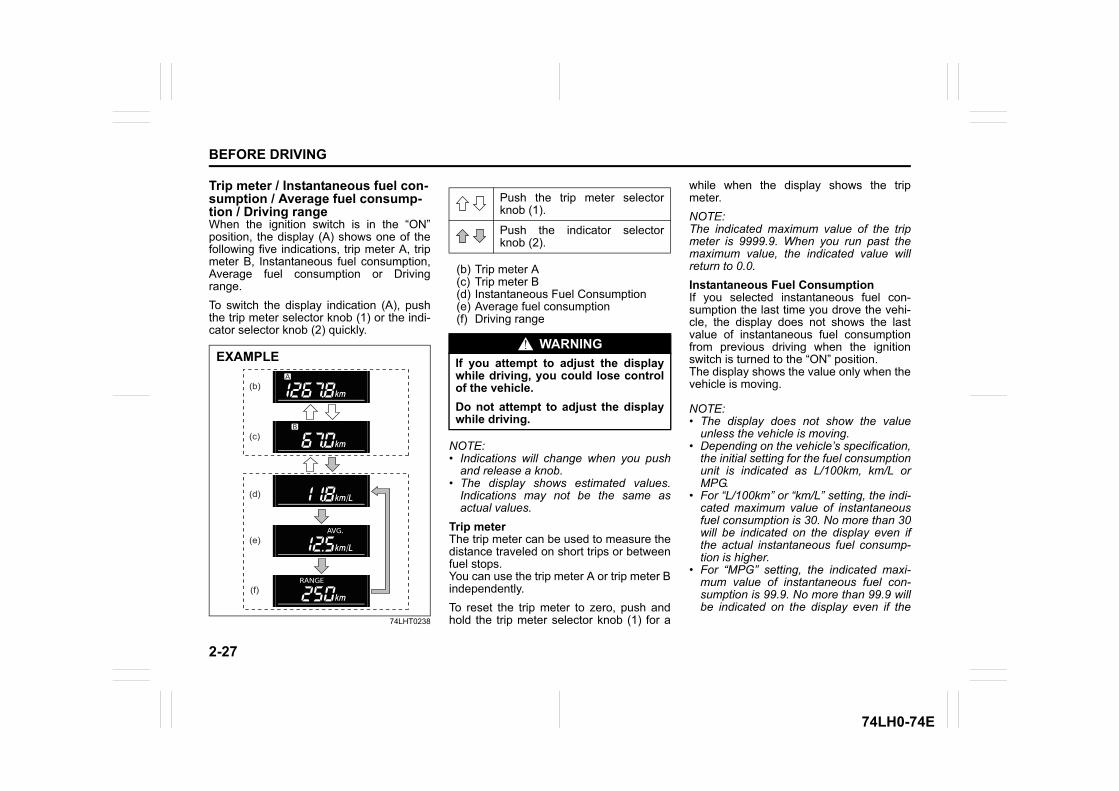
Trip meter / Instantaneous fuel con-sumption / Average fuel consump-tion / Driving rangeWhen the ignition switch is in the “ON”position, the display (A) shows one of thefollowing five indications, trip meter A, tripmeter B, Instantaneous fuel consumption,Average fuel consumption or Drivingrange.To switch the display indication (A), pushthe trip meter selector knob (1) or the indi-cator selector knob (2) quickly.
74LHT0238
(b) Trip meter A(c) Trip meter B(d) Instantaneous Fuel Consumption(e) Average fuel consumption(f) Driving range
NOTE:• Indications will change when you push
and release a knob.• The display shows estimated values.
Indications may not be the same asactual values.
Trip meterThe trip meter can be used to measure thedistance traveled on short trips or betweenfuel stops.You can use the trip meter A or trip meter Bindependently.To reset the trip meter to zero, push andhold the trip meter selector knob (1) for a
while when the display shows the tripmeter.NOTE:The indicated maximum value of the tripmeter is 9999.9. When you run past themaximum value, the indicated value willreturn to 0.0.Instantaneous Fuel ConsumptionIf you selected instantaneous fuel con-sumption the last time you drove the vehi-cle, the display does not shows the lastvalue of instantaneous fuel consumptionfrom previous driving when the ignitionswitch is turned to the “ON” position. The display shows the value only when thevehicle is moving.
NOTE:• The display does not show the value
unless the vehicle is moving.• Depending on the vehicle’s specification,
the initial setting for the fuel consumptionunit is indicated as L/100km, km/L orMPG.
• For “L/100km” or “km/L” setting, the indi-cated maximum value of instantaneousfuel consumption is 30. No more than 30will be indicated on the display even ifthe actual instantaneous fuel consump-tion is higher.
• For “MPG” setting, the indicated maxi-mum value of instantaneous fuel con-sumption is 99.9. No more than 99.9 willbe indicated on the display even if the
EXAMPLE
(b)
(c)
(d)
(e)
(f)
Push the trip meter selectorknob (1).
Push the indicator selectorknob (2).
WARNINGIf you attempt to adjust the displaywhile driving, you could lose controlof the vehicle.Do not attempt to adjust the displaywhile driving.
2-28
BEFORE DRIVING
74LH0-74E
actual instantaneous fuel consumption ishigher.
• The indication on the display may bedelayed if fuel consumption is greatlyaffected by driving conditions.
• The display shows estimated values.Indications may not be the same asactual values.
• For “L/100km” or “km/L” setting, you canchange the units that instantaneous fuelconsumption is displayed in. Refer to“Average fuel consumption” in this sec-tion.
NOTE:When you reconnect the negative (–) ter-minal to the battery, the indication of theinstantaneous fuel consumption will bereinitialized. Change the indication againto your preference.Average fuel consumptionIf you selected average fuel consumptionthe last time you drove the vehicle, the dis-play shows the last value of average fuelconsumption from previous driving whenthe ignition switch is turned to the “ON”position. Unless you reset the value of
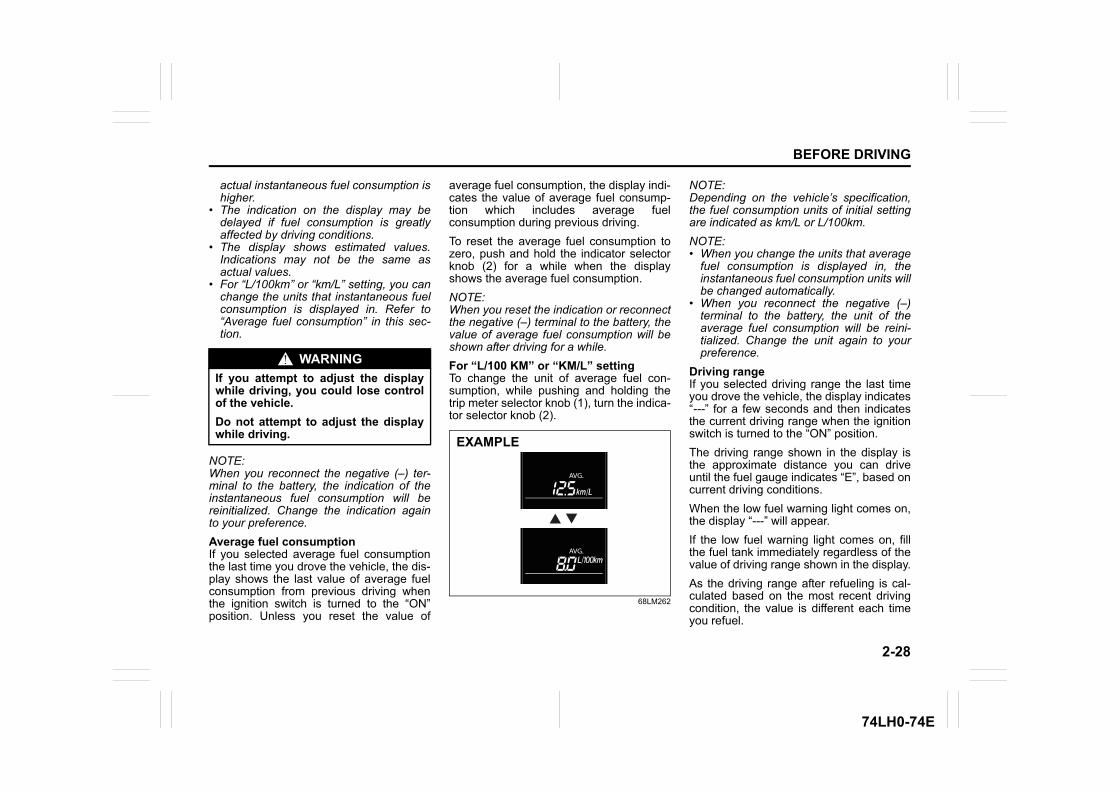
average fuel consumption, the display indi-cates the value of average fuel consump-tion which includes average fuelconsumption during previous driving.To reset the average fuel consumption tozero, push and hold the indicator selectorknob (2) for a while when the displayshows the average fuel consumption.NOTE:When you reset the indication or reconnectthe negative (–) terminal to the battery, thevalue of average fuel consumption will beshown after driving for a while.For “L/100 KM” or “KM/L” settingTo change the unit of average fuel con-sumption, while pushing and holding thetrip meter selector knob (1), turn the indica-tor selector knob (2).
68LM262
NOTE:Depending on the vehicle’s specification,the fuel consumption units of initial settingare indicated as km/L or L/100km.NOTE:• When you change the units that average
fuel consumption is displayed in, theinstantaneous fuel consumption units willbe changed automatically.
• When you reconnect the negative (–)terminal to the battery, the unit of theaverage fuel consumption will be reini-tialized. Change the unit again to yourpreference.
Driving rangeIf you selected driving range the last timeyou drove the vehicle, the display indicates“---” for a few seconds and then indicatesthe current driving range when the ignitionswitch is turned to the “ON” position.The driving range shown in the display isthe approximate distance you can driveuntil the fuel gauge indicates “E”, based oncurrent driving conditions.When the low fuel warning light comes on,the display “---” will appear.If the low fuel warning light comes on, fillthe fuel tank immediately regardless of thevalue of driving range shown in the display.As the driving range after refueling is cal-culated based on the most recent drivingcondition, the value is different each timeyou refuel.
WARNINGIf you attempt to adjust the displaywhile driving, you could lose controlof the vehicle.Do not attempt to adjust the displaywhile driving. EXAMPLE
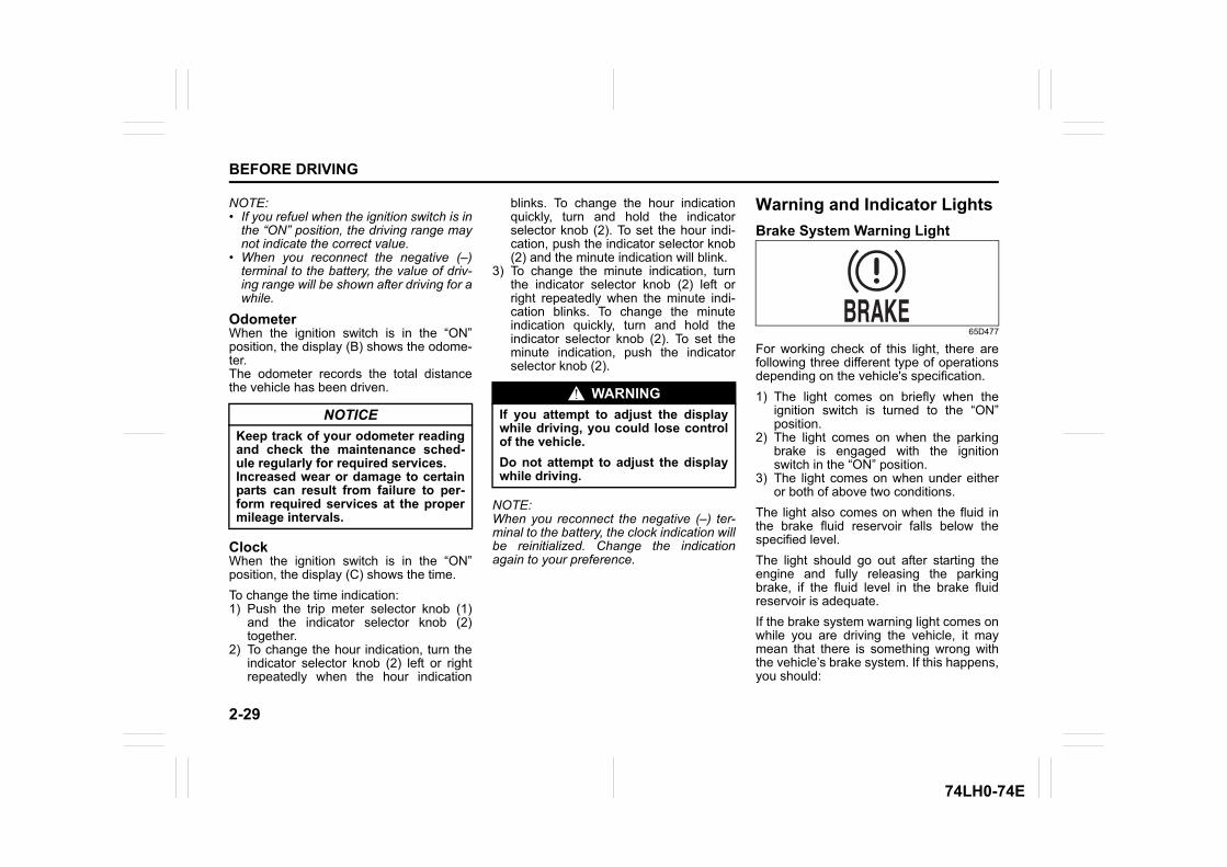
2-29
BEFORE DRIVING
74LH0-74E
NOTE:• If you refuel when the ignition switch is in
the “ON” position, the driving range maynot indicate the correct value.
• When you reconnect the negative (–)terminal to the battery, the value of driv-ing range will be shown after driving for awhile.
OdometerWhen the ignition switch is in the “ON”position, the display (B) shows the odome-ter.The odometer records the total distancethe vehicle has been driven.
ClockWhen the ignition switch is in the “ON”position, the display (C) shows the time.To change the time indication: 1) Push the trip meter selector knob (1)
and the indicator selector knob (2)together.
2) To change the hour indication, turn theindicator selector knob (2) left or rightrepeatedly when the hour indication
blinks. To change the hour indicationquickly, turn and hold the indicatorselector knob (2). To set the hour indi-cation, push the indicator selector knob(2) and the minute indication will blink.
3) To change the minute indication, turnthe indicator selector knob (2) left orright repeatedly when the minute indi-cation blinks. To change the minuteindication quickly, turn and hold theindicator selector knob (2). To set theminute indication, push the indicatorselector knob (2).
NOTE:When you reconnect the negative (–) ter-minal to the battery, the clock indication willbe reinitialized. Change the indicationagain to your preference.
Warning and Indicator LightsBrake System Warning Light
65D477
For working check of this light, there arefollowing three different type of operationsdepending on the vehicle's specification.1) The light comes on briefly when the
ignition switch is turned to the “ON”position.
2) The light comes on when the parkingbrake is engaged with the ignitionswitch in the “ON” position.
3) The light comes on when under eitheror both of above two conditions.
The light also comes on when the fluid inthe brake fluid reservoir falls below thespecified level.The light should go out after starting theengine and fully releasing the parkingbrake, if the fluid level in the brake fluidreservoir is adequate.If the brake system warning light comes onwhile you are driving the vehicle, it maymean that there is something wrong withthe vehicle’s brake system. If this happens,you should:
NOTICEKeep track of your odometer readingand check the maintenance sched-ule regularly for required services.Increased wear or damage to certainparts can result from failure to per-form required services at the propermileage intervals.
WARNINGIf you attempt to adjust the displaywhile driving, you could lose controlof the vehicle.Do not attempt to adjust the displaywhile driving.
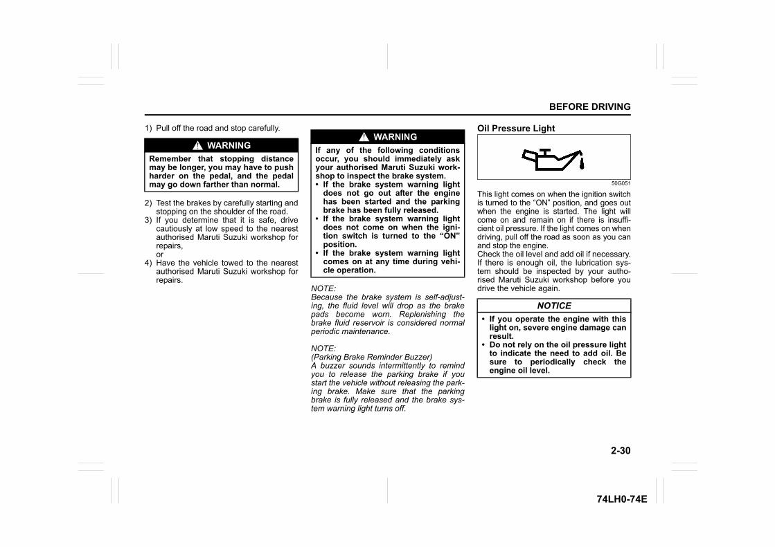
2-30
BEFORE DRIVING
74LH0-74E
1) Pull off the road and stop carefully.
2) Test the brakes by carefully starting andstopping on the shoulder of the road.
3) If you determine that it is safe, drivecautiously at low speed to the nearestauthorised Maruti Suzuki workshop forrepairs,or
4) Have the vehicle towed to the nearestauthorised Maruti Suzuki workshop forrepairs.
NOTE:Because the brake system is self-adjust-ing, the fluid level will drop as the brakepads become worn. Replenishing thebrake fluid reservoir is considered normalperiodic maintenance.
NOTE:(Parking Brake Reminder Buzzer)A buzzer sounds intermittently to remindyou to release the parking brake if youstart the vehicle without releasing the park-ing brake. Make sure that the parkingbrake is fully released and the brake sys-tem warning light turns off.
Oil Pressure Light
50G051
This light comes on when the ignition switchis turned to the “ON” position, and goes outwhen the engine is started. The light willcome on and remain on if there is insuffi-cient oil pressure. If the light comes on whendriving, pull off the road as soon as you canand stop the engine. Check the oil level and add oil if necessary.If there is enough oil, the lubrication sys-tem should be inspected by your autho-rised Maruti Suzuki workshop before youdrive the vehicle again.
WARNINGRemember that stopping distancemay be longer, you may have to pushharder on the pedal, and the pedalmay go down farther than normal.
WARNINGIf any of the following conditionsoccur, you should immediately askyour authorised Maruti Suzuki work-shop to inspect the brake system.• If the brake system warning light
does not go out after the enginehas been started and the parkingbrake has been fully released.
• If the brake system warning lightdoes not come on when the igni-tion switch is turned to the “ON”position.
• If the brake system warning lightcomes on at any time during vehi-cle operation.
NOTICE• If you operate the engine with this
light on, severe engine damage canresult.
• Do not rely on the oil pressure lightto indicate the need to add oil. Besure to periodically check theengine oil level.
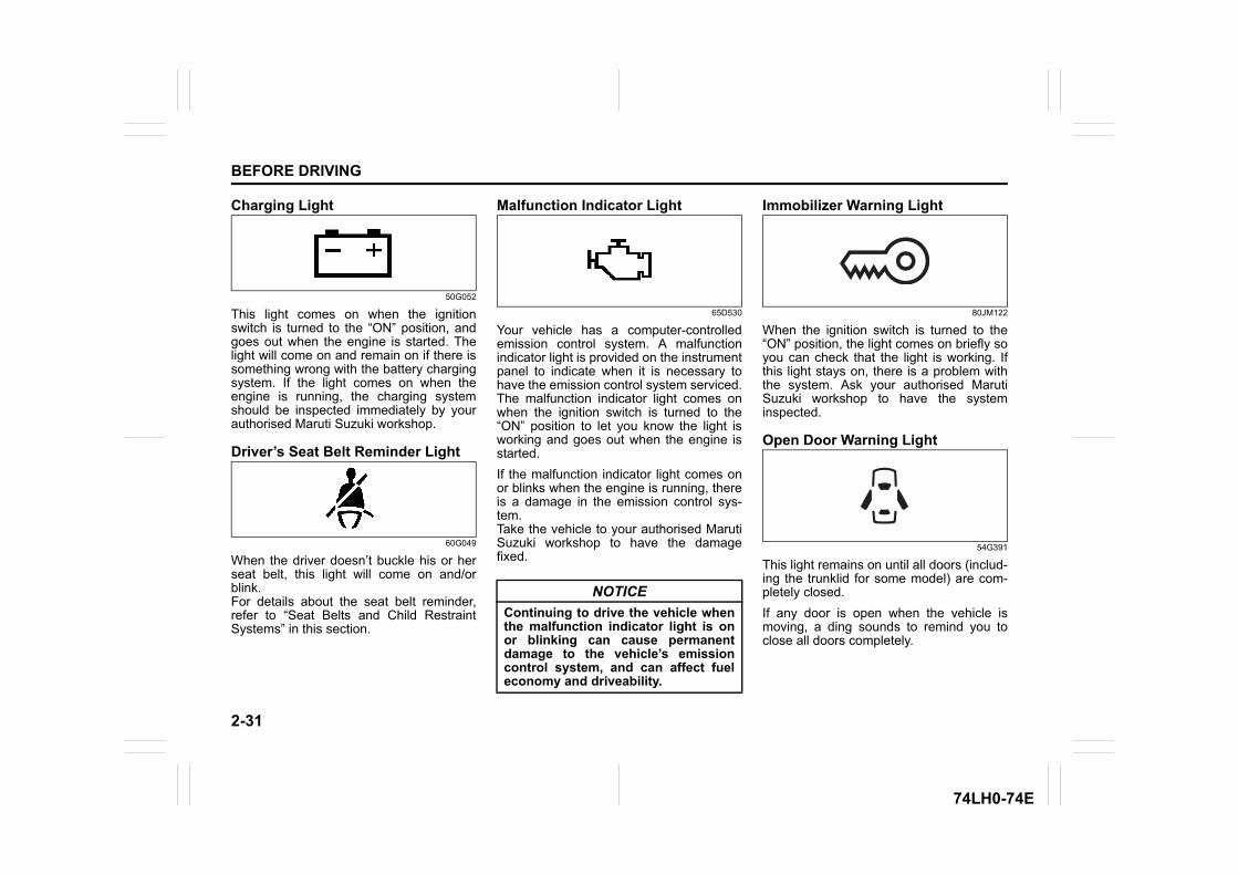
2-31
BEFORE DRIVING
74LH0-74E
Charging Light
50G052
This light comes on when the ignitionswitch is turned to the “ON” position, andgoes out when the engine is started. Thelight will come on and remain on if there issomething wrong with the battery chargingsystem. If the light comes on when theengine is running, the charging systemshould be inspected immediately by yourauthorised Maruti Suzuki workshop.
Driver’s Seat Belt Reminder Light
60G049
When the driver doesn’t buckle his or herseat belt, this light will come on and/orblink.For details about the seat belt reminder,refer to “Seat Belts and Child RestraintSystems” in this section.
Malfunction Indicator Light
65D530
Your vehicle has a computer-controlledemission control system. A malfunctionindicator light is provided on the instrumentpanel to indicate when it is necessary tohave the emission control system serviced.The malfunction indicator light comes onwhen the ignition switch is turned to the“ON” position to let you know the light isworking and goes out when the engine isstarted. If the malfunction indicator light comes onor blinks when the engine is running, thereis a damage in the emission control sys-tem.Take the vehicle to your authorised MarutiSuzuki workshop to have the damagefixed.
Immobilizer Warning Light
80JM122
When the ignition switch is turned to the“ON” position, the light comes on briefly soyou can check that the light is working. Ifthis light stays on, there is a problem withthe system. Ask your authorised MarutiSuzuki workshop to have the systeminspected.
Open Door Warning Light
54G391
This light remains on until all doors (includ-ing the trunklid for some model) are com-pletely closed.If any door is open when the vehicle ismoving, a ding sounds to remind you toclose all doors completely.
NOTICEContinuing to drive the vehicle whenthe malfunction indicator light is onor blinking can cause permanentdamage to the vehicle’s emissioncontrol system, and can affect fueleconomy and driveability.
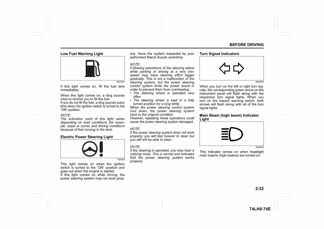
2-32
BEFORE DRIVING
74LH0-74E
Low Fuel Warning Light
54G343
If this light comes on, fill the fuel tankimmediately.When this light comes on, a ding soundsonce to remind you to fill the fuel.If you do not fill the fuel, a ding sounds everytime when the ignition switch is turned to the“ON” position.NOTE:The activation point of this light variesdepending on road conditions (for exam-ple, slope or curve) and driving conditionsbecause of fuel moving in the tank.
Electric Power Steering Light
79J039
This light comes on when the ignitionswitch is turned to the “ON” position andgoes out when the engine is started.If this light comes on while driving, thepower steering system may not work prop-
erly. Have the system inspected by yourauthorised Maruti Suzuki workshop.
NOTE:Following operations of the steering wheelwhile parking or driving at a very low-speed may have steering effort biggergradually. This is not a malfunction of thesteering system, but the power steeringcontrol system limits the power assist inorder to prevent them from overheating.• The steering wheel is operated very
often.• The steering wheel is kept in a fully
turned position for a long while. When the power steering control systemcool down, the power steering systemback to the original condition.However, repeating these operations couldcause the power steering system damaged.
NOTE:If the power steering system does not workproperly, you will feel heavier to steer butyou still will be able to steer.
NOTE:If the steering is operated, you may hear arubbing noise. This is normal and indicatesthat the power steering system worksproperly.
Turn Signal Indicators
50G055
When you turn on the left or right turn sig-nals, the corresponding green arrow on theinstrument panel will flash along with therespective turn signal lights. When youturn on the hazard warning switch, botharrows will flash along with all of the turnsignal lights.
Main Beam (high beam) IndicatorLight
50G056
This indicator comes on when headlightmain beams (high beams) are turned on.
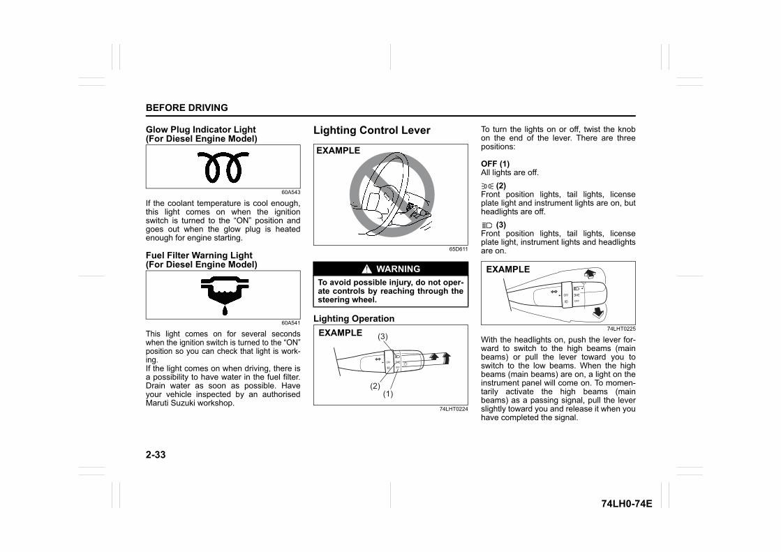
2-33
BEFORE DRIVING
74LH0-74E
Glow Plug Indicator Light (For Diesel Engine Model)
60A543
If the coolant temperature is cool enough,this light comes on when the ignitionswitch is turned to the “ON” position andgoes out when the glow plug is heatedenough for engine starting.
Fuel Filter Warning Light (For Diesel Engine Model)
60A541
This light comes on for several secondswhen the ignition switch is turned to the “ON”position so you can check that light is work-ing.If the light comes on when driving, there isa possibility to have water in the fuel filter.Drain water as soon as possible. Haveyour vehicle inspected by an authorisedMaruti Suzuki workshop.
Lighting Control Lever
65D611
Lighting Operation
74LHT0224
To turn the lights on or off, twist the knobon the end of the lever. There are threepositions:
OFF (1)All lights are off.
(2)Front position lights, tail lights, licenseplate light and instrument lights are on, butheadlights are off.
(3)Front position lights, tail lights, licenseplate light, instrument lights and headlightsare on.
74LHT0225
With the headlights on, push the lever for-ward to switch to the high beams (mainbeams) or pull the lever toward you toswitch to the low beams. When the highbeams (main beams) are on, a light on theinstrument panel will come on. To momen-tarily activate the high beams (mainbeams) as a passing signal, pull the leverslightly toward you and release it when youhave completed the signal.
WARNINGTo avoid possible injury, do not oper-ate controls by reaching through thesteering wheel.
EXAMPLE
(3)
(2)(1)
EXAMPLE
EXAMPLE
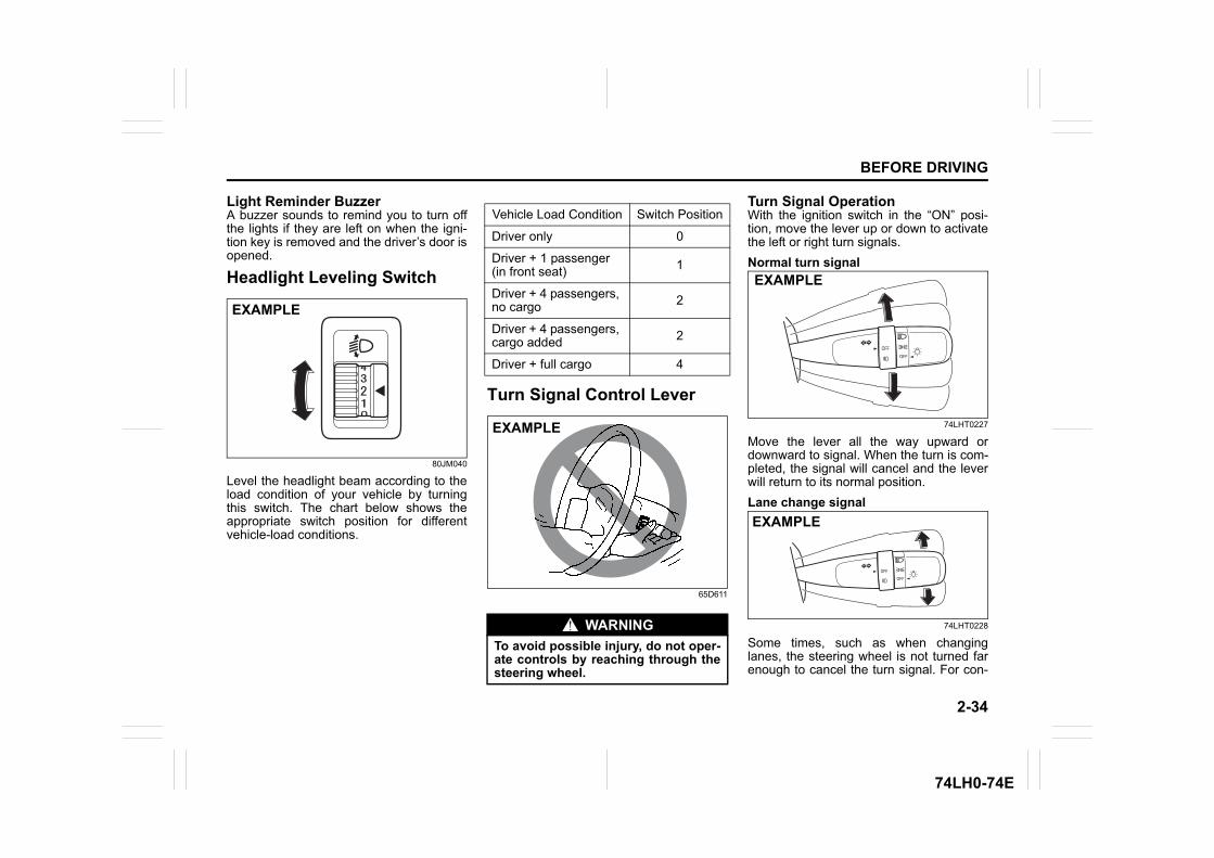
2-34
BEFORE DRIVING
74LH0-74E
Light Reminder Buzzer A buzzer sounds to remind you to turn offthe lights if they are left on when the igni-tion key is removed and the driver’s door isopened.
Headlight Leveling Switch
80JM040
Level the headlight beam according to theload condition of your vehicle by turningthis switch. The chart below shows theappropriate switch position for differentvehicle-load conditions.
Turn Signal Control Lever
65D611
Turn Signal OperationWith the ignition switch in the “ON” posi-tion, move the lever up or down to activatethe left or right turn signals.Normal turn signal
74LHT0227
Move the lever all the way upward ordownward to signal. When the turn is com-pleted, the signal will cancel and the leverwill return to its normal position.Lane change signal
74LHT0228
Some times, such as when changinglanes, the steering wheel is not turned farenough to cancel the turn signal. For con-
EXAMPLE
Vehicle Load Condition Switch Position
Driver only 0
Driver + 1 passenger (in front seat) 1
Driver + 4 passengers, no cargo 2
Driver + 4 passengers, cargo added 2
Driver + full cargo 4
WARNINGTo avoid possible injury, do not oper-ate controls by reaching through thesteering wheel.
EXAMPLE
EXAMPLE
EXAMPLE
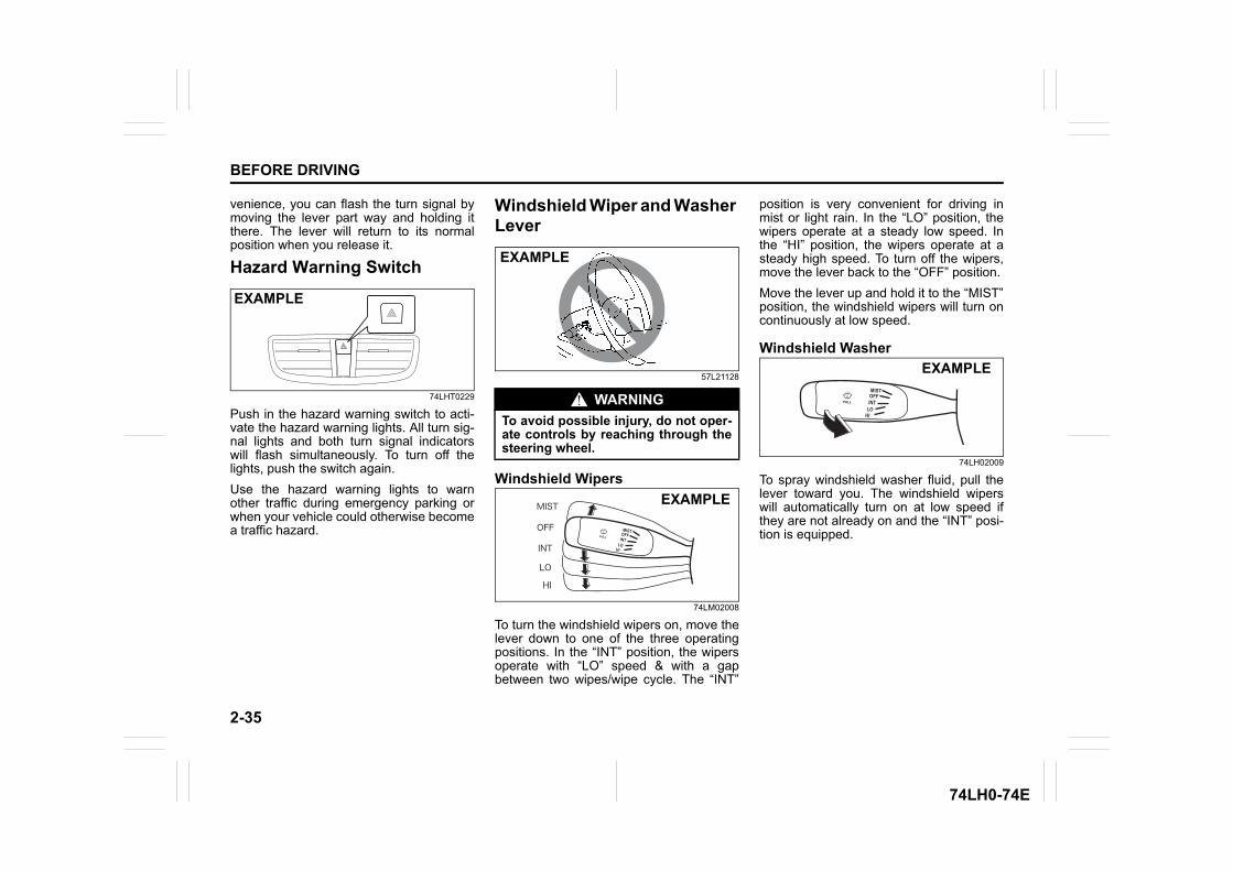
2-35
BEFORE DRIVING
74LH0-74E
venience, you can flash the turn signal bymoving the lever part way and holding itthere. The lever will return to its normalposition when you release it.
Hazard Warning Switch
74LHT0229
Push in the hazard warning switch to acti-vate the hazard warning lights. All turn sig-nal lights and both turn signal indicatorswill flash simultaneously. To turn off thelights, push the switch again.Use the hazard warning lights to warnother traffic during emergency parking orwhen your vehicle could otherwise becomea traffic hazard.
Windshield Wiper and Washer Lever
57L21128
Windshield Wipers
74LM02008
To turn the windshield wipers on, move thelever down to one of the three operatingpositions. In the “INT” position, the wipersoperate with “LO” speed & with a gapbetween two wipes/wipe cycle. The “INT”
position is very convenient for driving inmist or light rain. In the “LO” position, thewipers operate at a steady low speed. Inthe “HI” position, the wipers operate at asteady high speed. To turn off the wipers,move the lever back to the “OFF” position.Move the lever up and hold it to the “MIST”position, the windshield wipers will turn oncontinuously at low speed.
Windshield Washer
74LH02009
To spray windshield washer fluid, pull thelever toward you. The windshield wiperswill automatically turn on at low speed ifthey are not already on and the “INT” posi-tion is equipped.
EXAMPLE
WARNINGTo avoid possible injury, do not oper-ate controls by reaching through thesteering wheel.
EXAMPLE
LOHI
INTOFFMIST
EXAMPLE
LOHI
INTOFFMIST
EXAMPLE
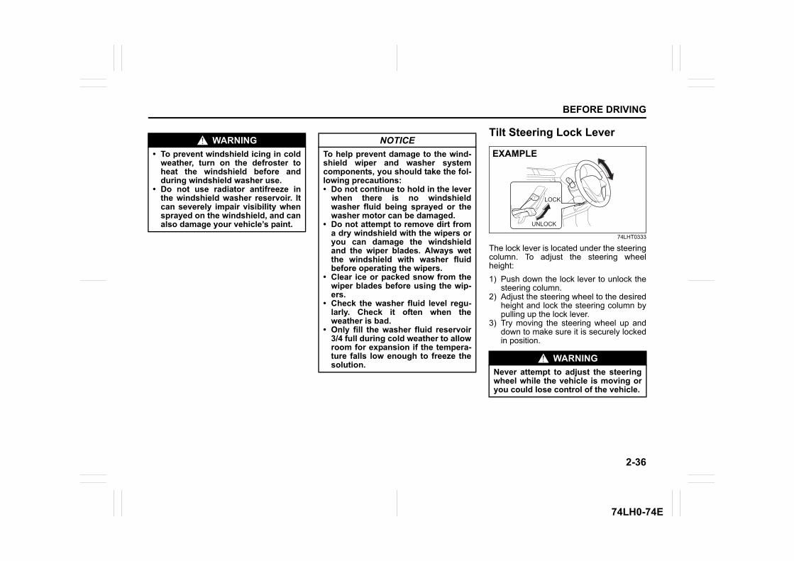
2-36
BEFORE DRIVING
74LH0-74E
Tilt Steering Lock Lever
74LHT0333
The lock lever is located under the steeringcolumn. To adjust the steering wheelheight:1) Push down the lock lever to unlock the
steering column.2) Adjust the steering wheel to the desired
height and lock the steering column bypulling up the lock lever.
3) Try moving the steering wheel up anddown to make sure it is securely lockedin position.
WARNING• To prevent windshield icing in cold
weather, turn on the defroster toheat the windshield before andduring windshield washer use.
• Do not use radiator antifreeze inthe windshield washer reservoir. Itcan severely impair visibility whensprayed on the windshield, and canalso damage your vehicle’s paint.
NOTICETo help prevent damage to the wind-shield wiper and washer systemcomponents, you should take the fol-lowing precautions:• Do not continue to hold in the lever
when there is no windshieldwasher fluid being sprayed or thewasher motor can be damaged.
• Do not attempt to remove dirt froma dry windshield with the wipers oryou can damage the windshieldand the wiper blades. Always wetthe windshield with washer fluidbefore operating the wipers.
• Clear ice or packed snow from thewiper blades before using the wip-ers.
• Check the washer fluid level regu-larly. Check it often when theweather is bad.
• Only fill the washer fluid reservoir3/4 full during cold weather to allowroom for expansion if the tempera-ture falls low enough to freeze thesolution.
WARNINGNever attempt to adjust the steeringwheel while the vehicle is moving oryou could lose control of the vehicle.
UNLOCK
LOCK
EXAMPLE
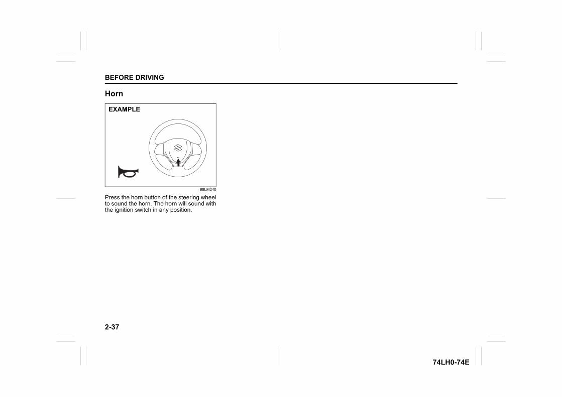
2-37
BEFORE DRIVING
74LH0-74E
Horn
68LM240
Press the horn button of the steering wheelto sound the horn. The horn will sound withthe ignition switch in any position.
EXAMPLE
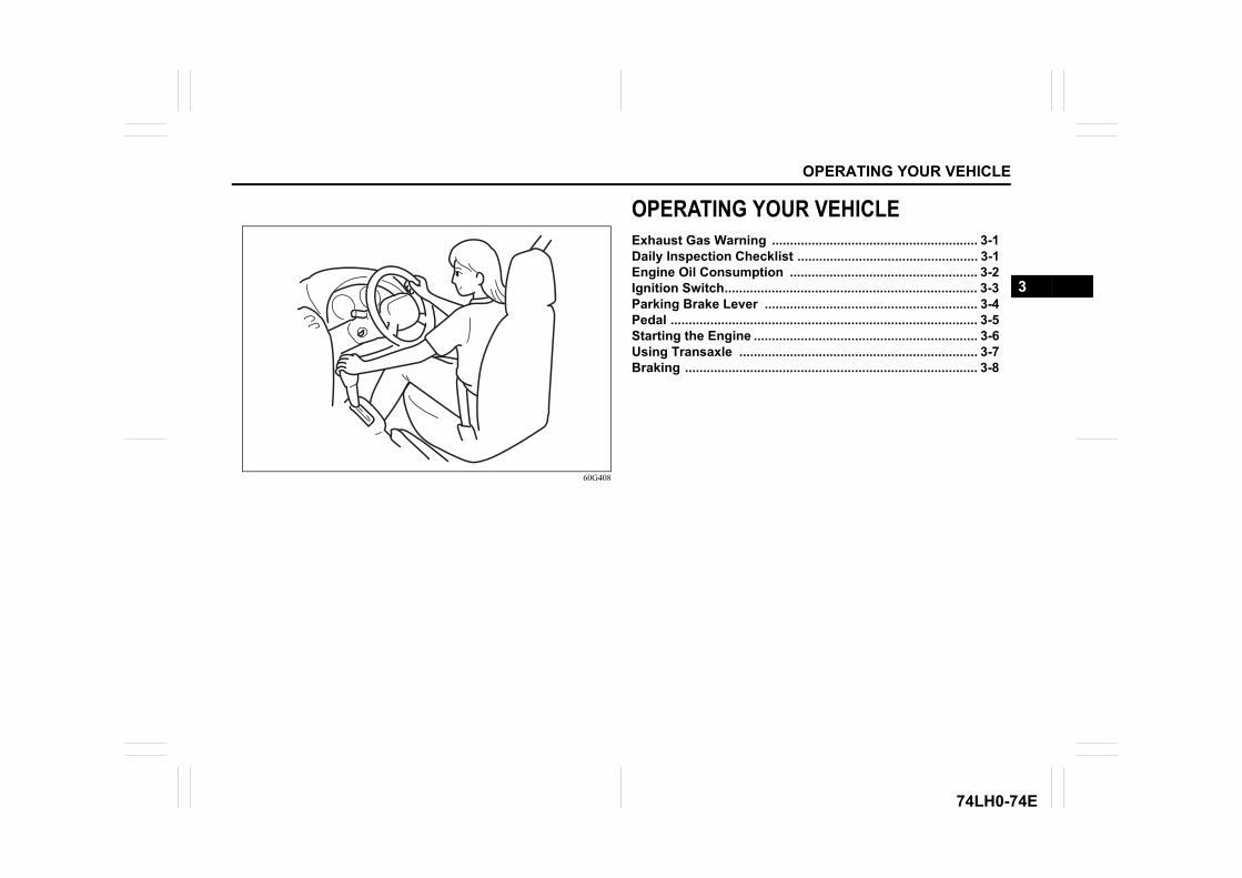
OPERATING YOUR VEHICLE
74LH0-74E
60G408
OPERATING YOUR VEHICLEExhaust Gas Warning ......................................................... 3-1Daily Inspection Checklist .................................................. 3-1Engine Oil Consumption .................................................... 3-2Ignition Switch...................................................................... 3-3Parking Brake Lever ........................................................... 3-4Pedal ..................................................................................... 3-5Starting the Engine .............................................................. 3-6Using Transaxle .................................................................. 3-7Braking ................................................................................. 3-8
3
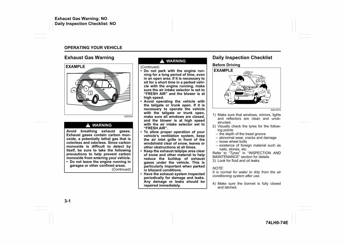
3-1
OPERATING YOUR VEHICLE
74LH0-74E
Exhaust Gas Warning
52D334
Daily Inspection ChecklistBefore Driving
60A187S
1) Make sure that windows, mirrors, lightsand reflectors are clean and unob-structed.
2) Visually check the tyres for the follow-ing points:
– the depth of the tread groove– abnormal wear, cracks and damage– loose wheel bolts– existence of foreign material such as
nails, stones, etc.Refer to “Tyres” in “INSPECTION ANDMAINTENANCE” section for details.3) Look for fluid and oil leaks.
NOTE:It is normal for water to drip from the airconditioning system after use.
4) Make sure the bonnet is fully closedand latched.
WARNINGAvoid breathing exhaust gases.Exhaust gases contain carbon mon-oxide, a potentially lethal gas that iscolorless and odorless. Since carbonmonoxide is difficult to detect byitself, be sure to take the followingprecautions to help prevent carbonmonoxide from entering your vehicle.• Do not leave the engine running in
garages or other confined areas.(Continued)
EXAMPLEWARNING
(Continued)• Do not park with the engine run-
ning for a long period of time, evenin an open area. If it is necessary tosit for a short time in a parked vehi-cle with the engine running, makesure the air intake selector is set to“FRESH AIR” and the blower is athigh speed.
• Avoid operating the vehicle withthe tailgate or trunk open. If it isnecessary to operate the vehiclewith the tailgate or trunk open,make sure all windows are closed,and the blower is at high speedwith the air intake selector set to“FRESH AIR”.
• To allow proper operation of yourvehicle’s ventilation system, keepthe air inlet grille in front of thewindshield clear of snow, leaves orother obstructions at all times.
• Keep the exhaust tailpipe area clearof snow and other material to helpreduce the buildup of exhaustgases under the vehicle. This isparticularly important when parkedin blizzard conditions.
• Have the exhaust system inspectedperiodically for damage and leaks.Any damage or leaks should berepaired immediately.
EXAMPLE
Exhaust Gas Warning: NODaily Inspection Checklist: NO
3-2
OPERATING YOUR VEHICLE
74LH0-74E
5) Check the headlights, turn signal lights,brake lights and horn for proper opera-tion.
6) Adjust the seat and adjustable headrestraint (if equipped).
7) Check the brake pedal and the parkingbrake lever.
8) Adjust the mirrors.9) Make sure that you and all passengers
have properly fastened your seat belts.10)Make sure that all warning lights come
on as the key is turned to the “ON” posi-tion.
11)Check all gauges.12)Make sure that the BRAKE SYSTEM
WARNING light turns off when the park-ing brake is released.
Once a week, or each time you fill your fueltank, perform the following under-hoodchecks:1) Engine oil level2) Coolant level3) Brake fluid level4) Battery solution level5) Windshield washer fluid level6) Hood latch operation
Pull the bonnet hood release handleinside the vehicle. Make sure that youcannot open the hood all the way with-out releasing the secondary latch. Besure to close the hood securely afterchecking for proper latch operation.See “All latches, hinges and locks” of“CHASSIS AND BODY” in the “Periodic
Maintenance Schedule” in the“INSPECTION AND MAINTENANCE”section for lubrication schedule.
Once a month, or each time you fill yourfuel tank, check the tire pressure using atire pressure gauge. Also check the tirepressure of the spare tire.
Engine Oil ConsumptionIt is normal for the engine to consumesome engine oil during normal vehicleoperation.The amount of engine oil consumeddepends on the viscosity of the oil, thequality of the oil and the conditions thevehicle is driven under.More oil is consumed during high-speeddriving and when there is frequent acceler-ation and deceleration. Under high loads,your engine also will consume more oil.A new engine also consumes more oil,since its pistons, piston rings and cylinderwalls have not yet become conditioned.New engines reach the normal level of oilconsumption only after approximately5000 km driving.
Oil consumption: Max. 1.0 L per 1000 km When judging the amount of oil consump-tion, note that the oil may become dilutedand make it difficult to accurately judge thetrue oil level.As an example, if a vehicle is used forrepeated short trips, and consumes a nor-mal amount of oil, the dipstick may notshow any drop in the oil level at all, evenafter 1000 km or more of driving. This isbecause the oil is gradually becomingdiluted with fuel or moisture, making itappear that the oil level has not changed.You should also be aware that the dilutingingredients evaporate out when the vehicleis subsequently driven at high speeds,such as on an expressway, making itappear that oil is excessively consumedafter high-speed driving.
WARNINGMake sure the hood is fully closedand latched before driving. If it is not,it can fly up unexpectedly duringdriving, obstructing your view andresulting in an accident.
Daily Inspection Checklist: NOEngine Oil Consumption:
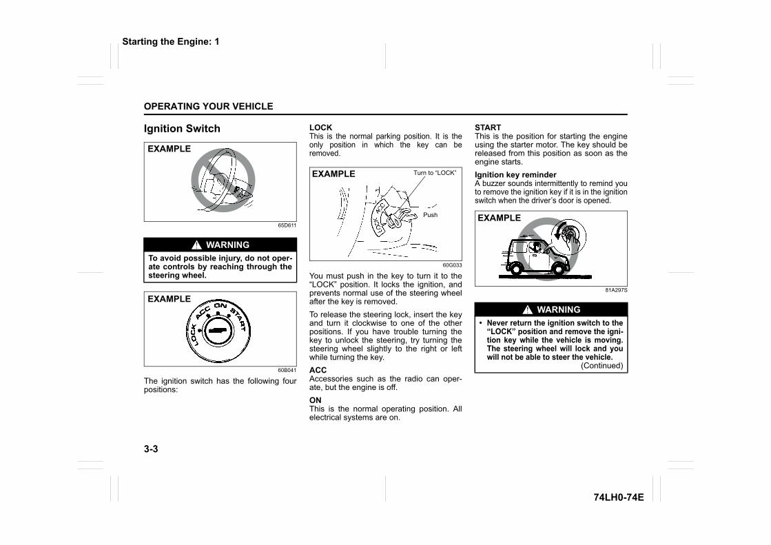
3-3
OPERATING YOUR VEHICLE
74LH0-74E
Ignition Switch
65D611
60B041
The ignition switch has the following fourpositions:
LOCKThis is the normal parking position. It is theonly position in which the key can beremoved.
60G033
You must push in the key to turn it to the“LOCK” position. It locks the ignition, andprevents normal use of the steering wheelafter the key is removed.To release the steering lock, insert the keyand turn it clockwise to one of the otherpositions. If you have trouble turning thekey to unlock the steering, try turning thesteering wheel slightly to the right or leftwhile turning the key.ACCAccessories such as the radio can oper-ate, but the engine is off.ONThis is the normal operating position. Allelectrical systems are on.
STARTThis is the position for starting the engineusing the starter motor. The key should bereleased from this position as soon as theengine starts.Ignition key reminderA buzzer sounds intermittently to remind youto remove the ignition key if it is in the ignitionswitch when the driver’s door is opened.
81A297S
WARNINGTo avoid possible injury, do not oper-ate controls by reaching through thesteering wheel.
EXAMPLE
EXAMPLE
Turn to “LOCK”
Push
EXAMPLE
WARNING• Never return the ignition switch to the
“LOCK” position and remove the igni-tion key while the vehicle is moving.The steering wheel will lock and youwill not be able to steer the vehicle.
(Continued)
EXAMPLE
Starting the Engine: 1
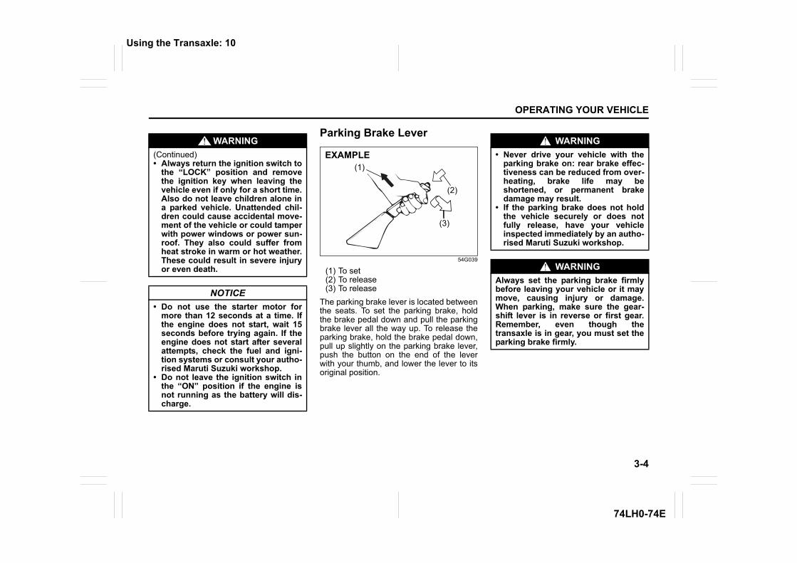
3-4
OPERATING YOUR VEHICLE
74LH0-74E
Parking Brake Lever
54G039
(1) To set(2) To release(3) To release
The parking brake lever is located betweenthe seats. To set the parking brake, holdthe brake pedal down and pull the parkingbrake lever all the way up. To release theparking brake, hold the brake pedal down,pull up slightly on the parking brake lever,push the button on the end of the leverwith your thumb, and lower the lever to itsoriginal position.
WARNING(Continued)• Always return the ignition switch to
the “LOCK” position and removethe ignition key when leaving thevehicle even if only for a short time.Also do not leave children alone ina parked vehicle. Unattended chil-dren could cause accidental move-ment of the vehicle or could tamperwith power windows or power sun-roof. They also could suffer fromheat stroke in warm or hot weather.These could result in severe injuryor even death.
NOTICE• Do not use the starter motor for
more than 12 seconds at a time. Ifthe engine does not start, wait 15seconds before trying again. If theengine does not start after severalattempts, check the fuel and igni-tion systems or consult your autho-rised Maruti Suzuki workshop.
• Do not leave the ignition switch inthe “ON” position if the engine isnot running as the battery will dis-charge.
(2)
(3)
(1)EXAMPLE
WARNING• Never drive your vehicle with the
parking brake on: rear brake effec-tiveness can be reduced from over-heating, brake life may beshortened, or permanent brakedamage may result.
• If the parking brake does not holdthe vehicle securely or does notfully release, have your vehicleinspected immediately by an autho-rised Maruti Suzuki workshop.
WARNINGAlways set the parking brake firmlybefore leaving your vehicle or it maymove, causing injury or damage.When parking, make sure the gear-shift lever is in reverse or first gear.Remember, even though thetransaxle is in gear, you must set theparking brake firmly.
Using the Transaxle: 10
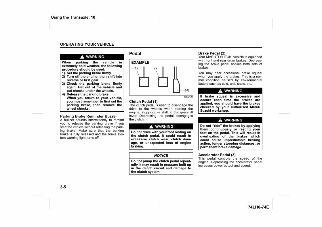
3-5
OPERATING YOUR VEHICLE
74LH0-74E
Parking Brake Reminder BuzzerA buzzer sounds intermittently to remindyou to release the parking brake if youstart the vehicle without releasing the park-ing brake. Make sure that the parkingbrake is fully released and the brake sys-tem warning light turns off.
Pedal
80J2121
Clutch Pedal (1)The clutch pedal is used to disengage thedrive to the wheels when starting theengine, stopping, or shifting the gearshiftlever. Depressing the pedal disengagesthe clutch.
Brake Pedal (2)Your MARUTI SUZUKI vehicle is equippedwith front and rear drum brakes. Depress-ing the brake pedal applies both sets ofbrakes.You may hear occasional brake squealwhen you apply the brakes. This is a nor-mal condition caused by environmentalfactors such as cold, wet, snow, etc.
Accelerator Pedal (3)This pedal controls the speed of theengine. Depressing the accelerator pedalincreases power output and speed.
WARNINGWhen parking the vehicle inextremely cold weather, the followingprocedure should be used:1) Set the parking brake firmly.2) Turn off the engine, then shift into
reverse or first gear. 3) Check the parking brake firmly
again. Get out of the vehicle andput chocks under the wheels.
4) Release the parking brake. When you return to your vehicle,you must remember to first set theparking brake, then remove thewheel chocks.
WARNINGDo not drive with your foot resting onthe clutch pedal. It could result inexcessive clutch wear, clutch dam-age, or unexpected loss of enginebraking.
NOTICEDo not pump the clutch pedal repeat-edly. It may result in pressure built upin the clutch circuit and damage tothe clutch system.
(2)(1)
(3)
EXAMPLE
WARNINGIf brake squeal is excessive andoccurs each time the brakes areapplied, you should have the brakeschecked by your authorised MarutiSuzuki workshop.
WARNINGDo not “ride” the brakes by applyingthem continuously or resting yourfoot on the pedal. This will result inoverheating of the brakes whichcould cause unpredictable brakingaction, longer stopping distances, orpermanent brake damage.
Using the Transaxle: 10
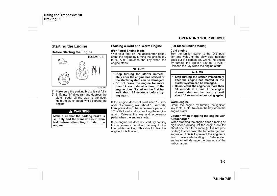
3-6
OPERATING YOUR VEHICLE
74LH0-74E
Starting the EngineBefore Starting the Engine
74LM03001
1) Make sure the parking brake is set fully.2) Shift into “N” (Neutral) and depress the
clutch pedal all the way to the floor.Hold the clutch pedal while starting theengine.
Starting a Cold and Warm Engine(For Petrol Engine Model)With your foot off the accelerator pedal,crank the engine by turning the ignition keyto “START”. Release the key when theengine starts.
If the engine does not start after 12 sec-onds of cranking, wait about 15 seconds,then press down the accelerator pedal to1/3 of its travel and try cranking the engineagain. Release the key and acceleratorpedal when the engine starts.If the engine still does not start, try holdingthe accelerator pedal all the way to thefloor while cranking. This should clear theengine if it is flooded.
(For Diesel Engine Model)Cold engineTurn the ignition switch to the “ON” posi-tion and wait until the glow plug indicatorgoes out if it comes on. Crank the engineby turning the ignition key to “START”.Release the key when the engine starts.
Warm engineCrank the engine by turning the ignitionkey to “START”. Release the key when theengine starts.Caution when stopping the engine withturbochargerWhen stopping the engine after climbing orhigh speed driving, let the engine idle forabout one minute or more (if it is not pro-hibited) to cool down the turbocharger andengine oil. This is to prevent the engine oilfrom over-deteriorating. Deterioratedengine oil will damage the bearings of theturbocharger.
WARNINGMake sure that the parking brake isset fully and the transaxle is in Neu-tral before attempting to start theengine.
EXAMPLE
NOTICE• Stop turning the starter immedi-
ately after the engine has started orthe starter system can be damaged.
• Do not crank the engine for morethan 12 seconds at a time. If theengine doesn’t start on the first try,wait about 15 seconds before try-ing again.
NOTICE• Stop turning the starter immediately
after the engine has started or thestarter system can be damaged.
• Do not crank the engine for more than30 seconds at a time. If the enginedoesn’t start on the first try, waitabout 15 seconds before trying again.
Using the Transaxle: 10Braking: 6
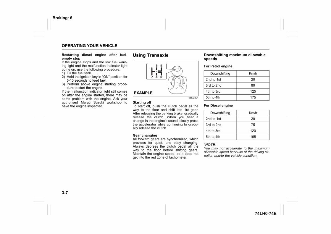
3-7
OPERATING YOUR VEHICLE
74LH0-74E
Restarting diesel engine after fuel-empty stopIf the engine stops and the low fuel warn-ing light and the malfunction indicator lightcome on, use the following procedure:1) Fill the fuel tank.2) Hold the ignition key in “ON” position for
5-10 seconds to feed fuel.3) Perform above engine starting proce-
dure to start the engine.If the malfunction indicator light still comeson after the engine started, there may besome problem with the engine. Ask yourauthorised Maruti Suzuki workshop tohave the engine inspected.
Using Transaxle
68LM324
Starting offTo start off, push the clutch pedal all theway to the floor and shift into 1st gear.After releasing the parking brake, graduallyrelease the clutch. When you hear achange in the engine’s sound, slowly pressthe accelerator while continuing to gradu-ally release the clutch.
Gear changingAll forward gears are synchronized, whichprovides for quiet, and easy changing.Always depress the clutch pedal all theway to the floor before shifting gears.Maintain the engine speed, so it does notget into the red zone of tachometer.
Downshifting maximum allowable speeds
For Petrol engine
For Diesel engine
*NOTE:You may not accelerate to the maximumallowable speed because of the driving sit-uation and/or the vehicle condition.
EXAMPLE
Downshifting Km/h
2nd to 1st 20
3rd to 2nd 80
4th to 3rd 125
5th to 4th 175
Downshifting Km/h
2nd to 1st 20
3rd to 2nd 75
4th to 3rd 120
5th to 4th 165
Braking: 6
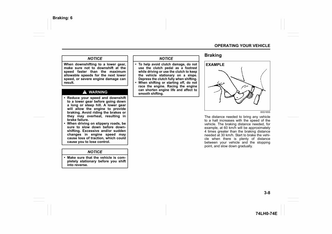
3-8
OPERATING YOUR VEHICLE
74LH0-74E
Braking
60G165S
The distance needed to bring any vehicleto a halt increases with the speed of thevehicle. The braking distance needed, forexample, at 60 km/h will be approximately4 times greater than the braking distanceneeded at 30 km/h. Start to brake the vehi-cle when there is plenty of distancebetween your vehicle and the stoppingpoint, and slow down gradually.
NOTICEWhen downshifting to a lower gear,make sure not to downshift at thespeed faster than the maximumallowable speeds for the next lowerspeed, or severe engine damage canresult.
WARNING• Reduce your speed and downshift
to a lower gear before going downa long or steep hill. A lower gearwill allow the engine to providebraking. Avoid riding the brakes orthey may overheat, resulting inbrake failure.
• When driving on slippery roads, besure to slow down before down-shifting. Excessive and/or suddenchanges in engine speed maycause loss of traction, which couldcause you to lose control.
NOTICE• Make sure that the vehicle is com-
pletely stationary before you shiftinto reverse.
NOTICE• To help avoid clutch damage, do not
use the clutch pedal as a footrestwhile driving or use the clutch to keepthe vehicle stationary on a slope.Depress the clutch fully when shifting.
• When shifting or starting off, do notrace the engine. Racing the enginecan shorten engine life and affect tosmooth shifting.
EXAMPLE
Braking: 6
3-9
OPERATING YOUR VEHICLE
74LH0-74E
Power-Assisted Brakes Your vehicle has power-assisted brakes. Ifpower assistance is lost due to a stalledengine or other failures, the system is stillfully operational on reserve power and youcan bring the vehicle to a complete stop bypressing the brake pedal once and holdingit down. The reserve power is partly usedup when you depress the brake pedal andreduces each time the pedal is pressed.Apply smooth and even pressure to thepedal. Do not pump the pedal.
WARNINGIf water gets into the brake drums,brake performance may become poorand unpredictable. After drivingthrough water or washing the under-side of the vehicle, test the brakeswhile driving at a slow speed to see ifthey have maintained their normaleffectiveness. If the brakes are lesseffective than normal, dry them byrepeatedly applying the brakes whiledriving slowly until the brakes haveregained their normal effectiveness.
WARNINGEven without reserve power in thebrake system, you can still stop thevehicle by pressing the brake pedalharder than normally required. How-ever, the stopping distance may belonger.
DRIVING TIPS
4
74LH0-74E
60G409
DRIVING TIPSRunning-in ........................................................................... 4-1Catalytic Converter ............................................................. 4-1Improving Fuel Economy ................................................... 4-2Highway Driving .................................................................. 4-3Driving on Hills .................................................................... 4-3Driving on Slippery Roads ................................................. 4-4Driving on Wet Roads ......................................................... 4-5Do’s & Don’ts for Safe Driving ........................................... 4-6Margin for Safety ................................................................. 4-8
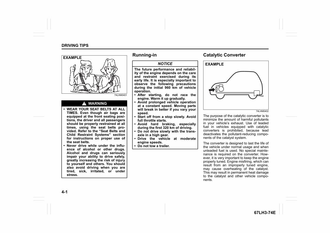
4-1
DRIVING TIPS
67LH3-74E
74LHM0401
Running-in Catalytic Converter
74LHM0402
The purpose of the catalytic converter is tominimize the amount of harmful pollutantsin your vehicle’s exhaust. Use of leadedfuel in vehicles equipped with catalyticconverters is prohibited, because leaddeactivates the pollutant-reducing compo-nents of the catalyst system.The converter is designed to last the life ofthe vehicle under normal usage and whenunleaded fuel is used. No special mainte-nance is required on the converter. How-ever, it is very important to keep the engineproperly tuned. Engine misfiring, which canresult from an improperly tuned engine,may cause overheating of the catalyst.This may result in permanent heat damageto the catalyst and other vehicle compo-nents.
WARNING• WEAR YOUR SEAT BELTS AT ALL
TIMES. Even though air bags areequipped at the front seating posi-tions, the driver and all passengersshould be properly restrained at alltimes, using the seat belts pro-vided. Refer to the “Seat Belts andChild Restraint Systems” sectionfor instructions on proper use ofthe seat belts.
• Never drive while under the influ-ence of alcohol or other drugs.Alcohol and drugs can seriouslyimpair your ability to drive safely,greatly increasing the risk of injuryto yourself and others. You shouldalso avoid driving when you aretired, sick, irritated, or understress.
EXAMPLENOTICE
The future performance and reliabil-ity of the engine depends on the careand restraint exercised during itsearly life. It is especially important toobserve the following precautionsduring the initial 960 km of vehicleoperation.• After starting, do not race the
engine. Warm it up gradually.• Avoid prolonged vehicle operation
at a constant speed. Moving partswill break in better if you vary yourspeed.
• Start off from a stop slowly. Avoidfull throttle starts.
• Avoid hard braking, especiallyduring the first 320 km of driving.
• Do not drive slowly with the trans-axle in a high gear.
• Drive the vehicle at moderateengine speeds.
• Do not tow a trailer.
EXAMPLE
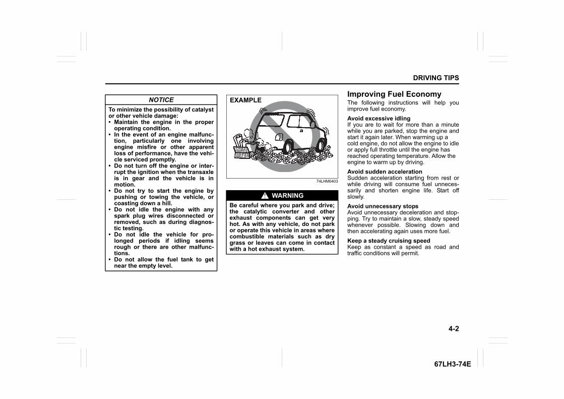
4-2
DRIVING TIPS
67LH3-74E
74LHM0403
Improving Fuel EconomyThe following instructions will help youimprove fuel economy.Avoid excessive idlingIf you are to wait for more than a minutewhile you are parked, stop the engine andstart it again later. When warming up acold engine, do not allow the engine to idleor apply full throttle until the engine hasreached operating temperature. Allow theengine to warm up by driving.Avoid sudden accelerationSudden acceleration starting from rest orwhile driving will consume fuel unneces-sarily and shorten engine life. Start offslowly.Avoid unnecessary stopsAvoid unnecessary deceleration and stop-ping. Try to maintain a slow, steady speedwhenever possible. Slowing down andthen accelerating again uses more fuel.Keep a steady cruising speedKeep as constant a speed as road andtraffic conditions will permit.
NOTICETo minimize the possibility of catalystor other vehicle damage:• Maintain the engine in the proper
operating condition.• In the event of an engine malfunc-
tion, particularly one involvingengine misfire or other apparentloss of performance, have the vehi-cle serviced promptly.
• Do not turn off the engine or inter-rupt the ignition when the transaxleis in gear and the vehicle is inmotion.
• Do not try to start the engine bypushing or towing the vehicle, orcoasting down a hill.
• Do not idle the engine with anyspark plug wires disconnected orremoved, such as during diagnos-tic testing.
• Do not idle the vehicle for pro-longed periods if idling seemsrough or there are other malfunc-tions.
• Do not allow the fuel tank to getnear the empty level.
WARNINGBe careful where you park and drive;the catalytic converter and otherexhaust components can get veryhot. As with any vehicle, do not parkor operate this vehicle in areas wherecombustible materials such as drygrass or leaves can come in contactwith a hot exhaust system.
EXAMPLE
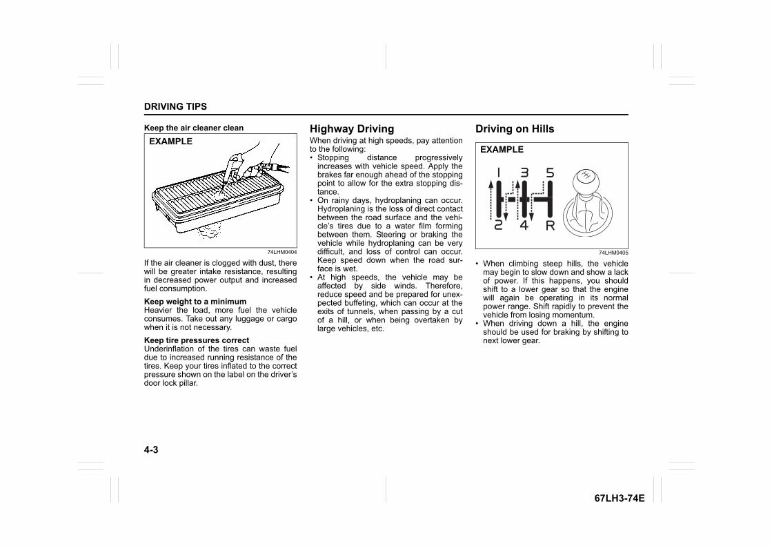
4-3
DRIVING TIPS
67LH3-74E
Keep the air cleaner clean
74LHM0404
If the air cleaner is clogged with dust, therewill be greater intake resistance, resultingin decreased power output and increasedfuel consumption.Keep weight to a minimumHeavier the load, more fuel the vehicleconsumes. Take out any luggage or cargowhen it is not necessary.Keep tire pressures correctUnderinflation of the tires can waste fueldue to increased running resistance of thetires. Keep your tires inflated to the correctpressure shown on the label on the driver’sdoor lock pillar.
Highway DrivingWhen driving at high speeds, pay attentionto the following:• Stopping distance progressively
increases with vehicle speed. Apply thebrakes far enough ahead of the stoppingpoint to allow for the extra stopping dis-tance.
• On rainy days, hydroplaning can occur.Hydroplaning is the loss of direct contactbetween the road surface and the vehi-cle’s tires due to a water film formingbetween them. Steering or braking thevehicle while hydroplaning can be verydifficult, and loss of control can occur.Keep speed down when the road sur-face is wet.
• At high speeds, the vehicle may beaffected by side winds. Therefore,reduce speed and be prepared for unex-pected buffeting, which can occur at theexits of tunnels, when passing by a cutof a hill, or when being overtaken bylarge vehicles, etc.
Driving on Hills
74LHM0405
• When climbing steep hills, the vehiclemay begin to slow down and show a lackof power. If this happens, you shouldshift to a lower gear so that the enginewill again be operating in its normalpower range. Shift rapidly to prevent thevehicle from losing momentum.
• When driving down a hill, the engineshould be used for braking by shifting tonext lower gear.
EXAMPLEEXAMPLE
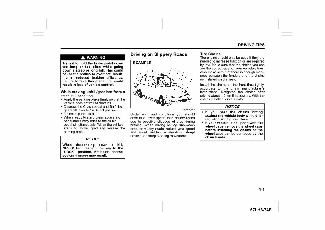
4-4
DRIVING TIPS
67LH3-74E
While moving uphill/gradient from astand still condition• Apply the parking brake firmly so that the vehicle does not roll backwards.• Depress the Clutch pedal and Shift the
gearshift lever to 1st Select position.• Do not slip the clutch.• When ready to start, press accelerator
pedal and slowly release the clutchpedal simultaneously. When the vehiclestarts to move, gradually release theparking brake.
Driving on Slippery Roads
74LHM0407
Under wet road conditions you shoulddrive at a lower speed than on dry roadsdue to possible slippage of tires duringbraking. When driving on icy, snow-cov-ered, or muddy roads, reduce your speedand avoid sudden acceleration, abruptbraking, or sharp steering movements.
Tire ChainsTire chains should only be used if they areneeded to increase traction or are requiredby law. Make sure that the chains you useare the correct size for your vehicle’s tires.Also make sure that there is enough clear-ance between the fenders and the chainsas installed on the tires.Install the chains on the front tires tightly,according to the chain manufacturer’sinstructions. Retighten the chains afterdriving about 1.0 km if necessary. With thechains installed, drive slowly.
WARNINGTry not to hold the brake pedal downtoo long or too often while goingdown a steep or long hill. This couldcause the brakes to overheat, result-ing in reduced braking efficiency.Failure to take this precaution couldresult in loss of vehicle control.
NOTICEWhen descending down a hill,NEVER turn the ignition key to the“LOCK” position. Emission controlsystem damage may result.
EXAMPLE
NOTICE• If you hear the chains hitting
against the vehicle body while driv-ing, stop and tighten them.
• If your vehicle is equipped with fullwheel caps, remove the wheel capsbefore installing the chains or thewheel caps can be damaged by thechain bands.
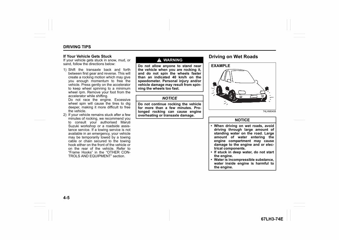
4-5
DRIVING TIPS
67LH3-74E
If Your Vehicle Gets StuckIf your vehicle gets stuck in snow, mud, orsand, follow the directions below:1) Shift the transaxle back and forth
between first gear and reverse. This willcreate a rocking motion which may giveyou enough momentum to free thevehicle. Press gently on the acceleratorto keep wheel spinning to a minimumwheel rpm. Remove your foot from theaccelerator while shifting. Do not race the engine. Excessivewheel spin will cause the tires to digdeeper, making it more difficult to freethe vehicle.
2) If your vehicle remains stuck after a fewminutes of rocking, we recommend youto consult your authorised MarutiSuzuki workshop or a roadside assis-tance service. If a towing service is notavailable in an emergency, your vehiclemay be temporarily towed by a towingcable or chain secured to the towinghook either on the front of the vehicle oron the rear of the vehicle. Refer to“Frame Hooks” in the “OTHER CON-TROLS AND EQUIPMENT” section.
Driving on Wet Roads
74LHM0408
WARNINGDo not allow anyone to stand nearthe vehicle when you are rocking it,and do not spin the wheels fasterthan an indicated 40 km/h on thespeedometer. Personal injury and/orvehicle damage may result from spin-ning the wheels too fast.
NOTICEDo not continue rocking the vehiclefor more than a few minutes. Pro-longed rocking can cause engineoverheating or transaxle damage.
NOTICE• When driving on wet roads, avoid
driving through large amount ofstanding water on the road. Largeamount of water entering theengine compartment may causedamage to the engine and or elec-trical components.
• If stuck in deep water, do not startthe engine.
• Water is incompressible substance,water inside engine is harmful tothe engine.
EXAMPLE
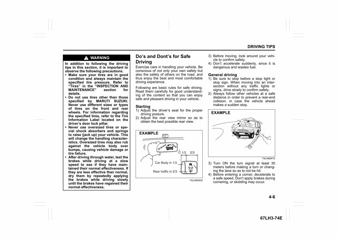
4-6
DRIVING TIPS
67LH3-74E
Do’s and Dont’s for Safe DrivingExercise care in handling your vehicle. Beconscious of not only your own safety butalso the safety of others on the road, andthus enjoy the best and most comfortabledriving experience.Following are basic rules for safe driving.Read them carefully for good understand-ing of the content so that you can enjoysafe and pleasant driving in your vehicle.
Starting1) Adjust the driver’s seat for the proper
driving posture.2) Adjust the rear view mirror so as to
obtain the best possible rear view.
74LHM0409
3) Before moving, look around your vehi-cle to confirm safety.
4) Don’t accelerate suddenly, since it isdangerous and wastes fuel.
General driving1) Be sure to stop before a stop light or
stop sign. When moving into an inter-section without any traffic lights orsigns, drive slowly to confirm safety.
2) Always follow other vehicles at a safedistance in order to prevent a rear-endcollision, in case the vehicle aheadmakes a sudden stop.
74LHM0410
3) Turn ON the turn signal at least 30meters before making a turn or chang-ing the lane so as to not be hit.
4) Before entering a corner, decelerate toa safe speed. Don’t apply brakes duringcornering, or skidding may occur.
WARNINGIn addition to following the drivingtips in this section, it is important toobserve the following precautions.• Make sure your tires are in good
condition and always maintain thespecified tire pressure. Refer to“Tires” in the “INSPECTION ANDMAINTENANCE” section fordetails.
• Do not use tires other than thosespecified by MARUTI SUZUKI.Never use different sizes or typesof tires on the front and rearwheels. For information regardingthe specified tires, refer to the TireInformation Label located on thedriver’s door lock pillar.
• Never use oversized tires or spe-cial shock absorbers and springsto raise (jack up) your vehicle. Thiswill change the handling character-istics. Oversized tires may also rubagainst the vehicle body overbumps, causing vehicle damage ortire failure.
• After driving through water, test thebrakes while driving at a slowspeed to see if they have main-tained their normal effectiveness. Ifthey are less effective than normal,dry them by repeatedly applyingthe brakes while driving slowlyuntil the brakes have regained theirnormal effectiveness.
EXAMPLE
EXAMPLE
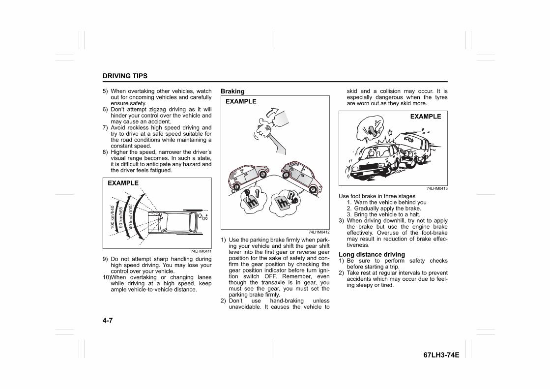
4-7
DRIVING TIPS
67LH3-74E
5) When overtaking other vehicles, watchout for oncoming vehicles and carefullyensure safety.
6) Don’t attempt zigzag driving as it willhinder your control over the vehicle andmay cause an accident.
7) Avoid reckless high speed driving andtry to drive at a safe speed suitable forthe road conditions while maintaining aconstant speed.
8) Higher the speed, narrower the driver’svisual range becomes. In such a state,it is difficult to anticipate any hazard andthe driver feels fatigued.
74LHM0411
9) Do not attempt sharp handling duringhigh speed driving. You may lose yourcontrol over your vehicle.
10)When overtaking or changing laneswhile driving at a high speed, keepample vehicle-to-vehicle distance.
Braking
74LHM0412
1) Use the parking brake firmly when park-ing your vehicle and shift the gear shiftlever into the first gear or reverse gearposition for the sake of safety and con-firm the gear position by checking thegear position indicator before turn igni-tion switch OFF. Remember, eventhough the transaxle is in gear, youmust see the gear, you must set theparking brake firmly.
2) Don’t use hand-braking unlessunavoidable. It causes the vehicle to
skid and a collision may occur. It isespecially dangerous when the tyresare worn out as they skid more.
74LHM0413
Use foot brake in three stages1. Warn the vehicle behind you2. Gradually apply the brake.3. Bring the vehicle to a halt.
3) When driving downhill, try not to applythe brake but use the engine brakeeffectively. Overuse of the foot-brakemay result in reduction of brake effec-tiveness.
Long distance driving1) Be sure to perform safety checks
before starting a trip.2) Take rest at regular intervals to prevent
accidents which may occur due to feel-ing sleepy or tired.
EXAMPLE
EXAMPLE
EXAMPLE
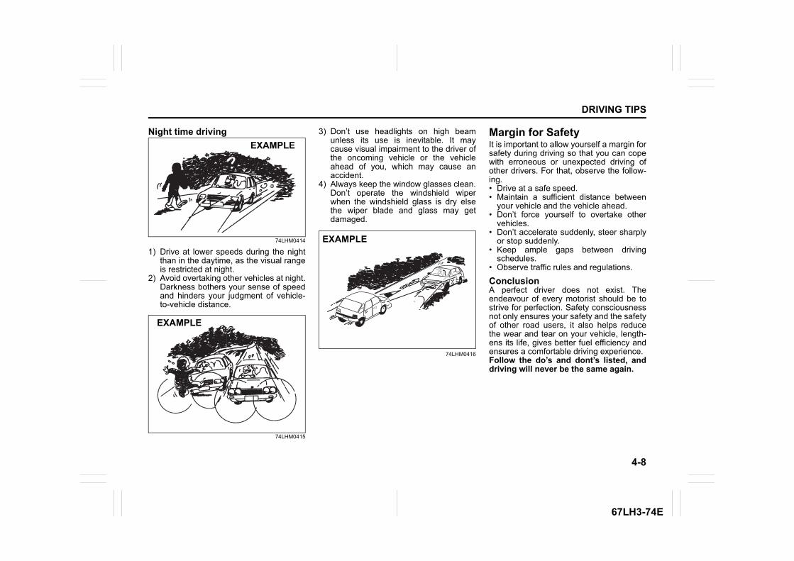
4-8
DRIVING TIPS
67LH3-74E
Night time driving
74LHM0414
1) Drive at lower speeds during the nightthan in the daytime, as the visual rangeis restricted at night.
2) Avoid overtaking other vehicles at night.Darkness bothers your sense of speedand hinders your judgment of vehicle-to-vehicle distance.
74LHM0415
3) Don’t use headlights on high beamunless its use is inevitable. It maycause visual impairment to the driver ofthe oncoming vehicle or the vehicleahead of you, which may cause anaccident.
4) Always keep the window glasses clean.Don’t operate the windshield wiperwhen the windshield glass is dry elsethe wiper blade and glass may getdamaged.
74LHM0416
Margin for SafetyIt is important to allow yourself a margin forsafety during driving so that you can copewith erroneous or unexpected driving ofother drivers. For that, observe the follow-ing.• Drive at a safe speed.• Maintain a sufficient distance between
your vehicle and the vehicle ahead.• Don’t force yourself to overtake other
vehicles.• Don’t accelerate suddenly, steer sharply
or stop suddenly.• Keep ample gaps between driving
schedules.• Observe traffic rules and regulations.
ConclusionA perfect driver does not exist. Theendeavour of every motorist should be tostrive for perfection. Safety consciousnessnot only ensures your safety and the safetyof other road users, it also helps reducethe wear and tear on your vehicle, length-ens its life, gives better fuel efficiency andensures a comfortable driving experience.Follow the do’s and dont’s listed, anddriving will never be the same again.
EXAMPLE
EXAMPLE
EXAMPLE

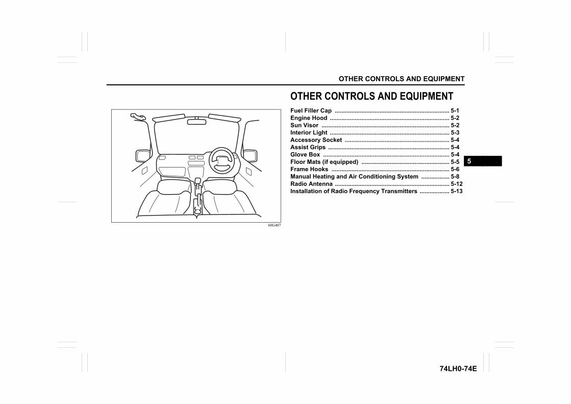
OTHER CONTROLS AND EQUIPMENT
74LH0-74E
60G407
OTHER CONTROLS AND EQUIPMENTFuel Filler Cap ..................................................................... 5-1Engine Hood ........................................................................ 5-2Sun Visor ............................................................................. 5-2Interior Light ........................................................................ 5-3Accessory Socket ............................................................... 5-4Assist Grips ......................................................................... 5-4Glove Box ............................................................................ 5-4Floor Mats (if equipped) ..................................................... 5-5Frame Hooks ....................................................................... 5-6Manual Heating and Air Conditioning System ................. 5-8Radio Antenna ..................................................................... 5-12Installation of Radio Frequency Transmitters .................. 5-13
5
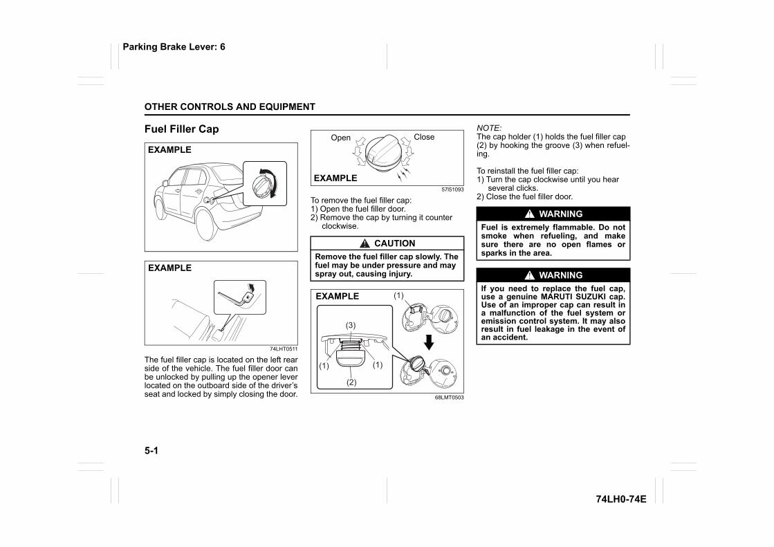
5-1
OTHER CONTROLS AND EQUIPMENT
74LH0-74E
Fuel Filler Cap
74LHT0511
The fuel filler cap is located on the left rearside of the vehicle. The fuel filler door canbe unlocked by pulling up the opener leverlocated on the outboard side of the driver’sseat and locked by simply closing the door.
57l51093
To remove the fuel filler cap:1) Open the fuel filler door.2) Remove the cap by turning it counter clockwise.
68LMT0503
NOTE:The cap holder (1) holds the fuel filler cap(2) by hooking the groove (3) when refuel-ing.
To reinstall the fuel filler cap:1) Turn the cap clockwise until you hear several clicks.2) Close the fuel filler door.
EXAMPLE
EXAMPLE
CAUTIONRemove the fuel filler cap slowly. Thefuel may be under pressure and mayspray out, causing injury.
EXAMPLE
Open Close
(1)
(2)
(3)
(1)
(1)
EXAMPLE
WARNINGFuel is extremely flammable. Do notsmoke when refueling, and makesure there are no open flames orsparks in the area.
WARNINGIf you need to replace the fuel cap,use a genuine MARUTI SUZUKI cap.Use of an improper cap can result ina malfunction of the fuel system oremission control system. It may alsoresult in fuel leakage in the event ofan accident.
Parking Brake Lever: 6
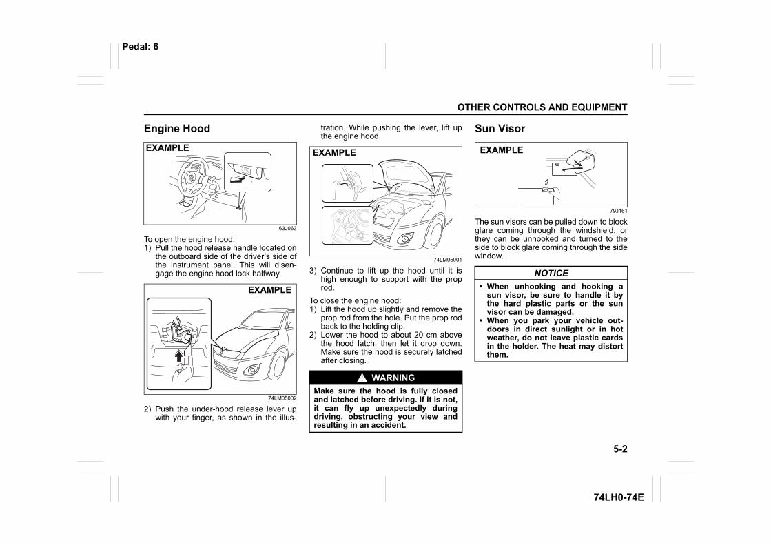
5-2
OTHER CONTROLS AND EQUIPMENT
74LH0-74E
Engine Hood
63J063
To open the engine hood:1) Pull the hood release handle located on
the outboard side of the driver’s side ofthe instrument panel. This will disen-gage the engine hood lock halfway.
74LM05002
2) Push the under-hood release lever upwith your finger, as shown in the illus-
tration. While pushing the lever, lift upthe engine hood.
74LM05001
3) Continue to lift up the hood until it ishigh enough to support with the proprod.
To close the engine hood:1) Lift the hood up slightly and remove the
prop rod from the hole. Put the prop rodback to the holding clip.
2) Lower the hood to about 20 cm abovethe hood latch, then let it drop down.Make sure the hood is securely latchedafter closing.
Sun Visor
79J161
The sun visors can be pulled down to blockglare coming through the windshield, orthey can be unhooked and turned to theside to block glare coming through the sidewindow.
EXAMPLE
EXAMPLE
WARNINGMake sure the hood is fully closedand latched before driving. If it is not,it can fly up unexpectedly duringdriving, obstructing your view andresulting in an accident.
EXAMPLE
NOTICE• When unhooking and hooking a
sun visor, be sure to handle it bythe hard plastic parts or the sunvisor can be damaged.
• When you park your vehicle out-doors in direct sunlight or in hotweather, do not leave plastic cardsin the holder. The heat may distortthem.
EXAMPLE
Pedal: 6
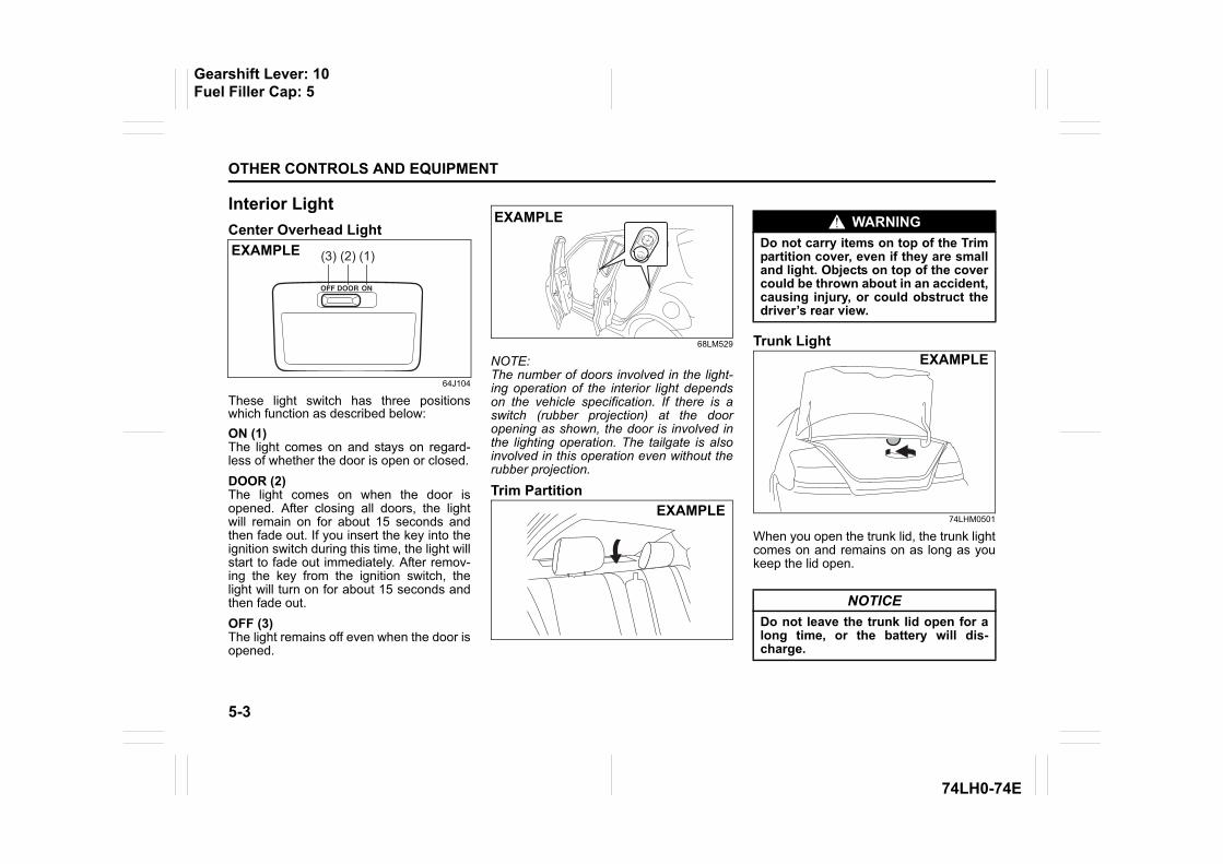
5-3
OTHER CONTROLS AND EQUIPMENT
74LH0-74E
Interior Light Center Overhead Light
64J104
These light switch has three positionswhich function as described below:ON (1)The light comes on and stays on regard-less of whether the door is open or closed.DOOR (2)The light comes on when the door isopened. After closing all doors, the lightwill remain on for about 15 seconds andthen fade out. If you insert the key into theignition switch during this time, the light willstart to fade out immediately. After remov-ing the key from the ignition switch, thelight will turn on for about 15 seconds andthen fade out.OFF (3)The light remains off even when the door isopened.
68LM529
NOTE:The number of doors involved in the light-ing operation of the interior light dependson the vehicle specification. If there is aswitch (rubber projection) at the dooropening as shown, the door is involved inthe lighting operation. The tailgate is alsoinvolved in this operation even without therubber projection.
Trim Partition
Trunk Light
74LHM0501
When you open the trunk lid, the trunk lightcomes on and remains on as long as youkeep the lid open.
(1)(2)(3)EXAMPLE
EXAMPLE
EXAMPLE
WARNINGDo not carry items on top of the Trimpartition cover, even if they are smalland light. Objects on top of the covercould be thrown about in an accident,causing injury, or could obstruct thedriver’s rear view.
NOTICEDo not leave the trunk lid open for along time, or the battery will dis-charge.
EXAMPLE
Gearshift Lever: 10Fuel Filler Cap: 5
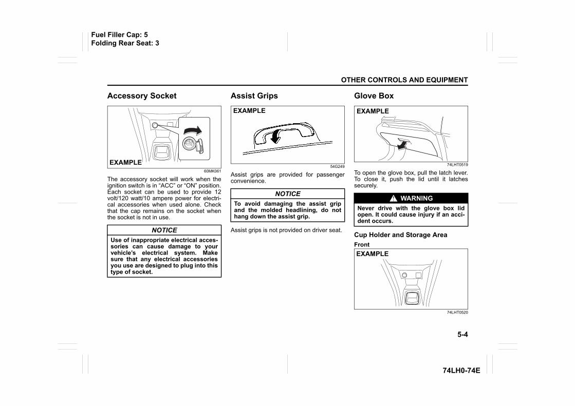
5-4
OTHER CONTROLS AND EQUIPMENT
74LH0-74E
Accessory Socket
60MK061
The accessory socket will work when theignition switch is in “ACC” or “ON” position.Each socket can be used to provide 12volt/120 watt/10 ampere power for electri-cal accessories when used alone. Checkthat the cap remains on the socket whenthe socket is not in use.
Assist Grips
54G249
Assist grips are provided for passengerconvenience.
Assist grips is not provided on driver seat.
Glove Box
74LHT0519
To open the glove box, pull the latch lever.To close it, push the lid until it latchessecurely.
Cup Holder and Storage Area Front
74LHT0520
NOTICEUse of inappropriate electrical acces-sories can cause damage to yourvehicle’s electrical system. Makesure that any electrical accessoriesyou use are designed to plug into thistype of socket.
EXAMPLE
NOTICETo avoid damaging the assist gripand the molded headlining, do nothang down the assist grip.
EXAMPLE
WARNINGNever drive with the glove box lidopen. It could cause injury if an acci-dent occurs.
EXAMPLE
EXAMPLE
Fuel Filler Cap: 5Folding Rear Seat: 3
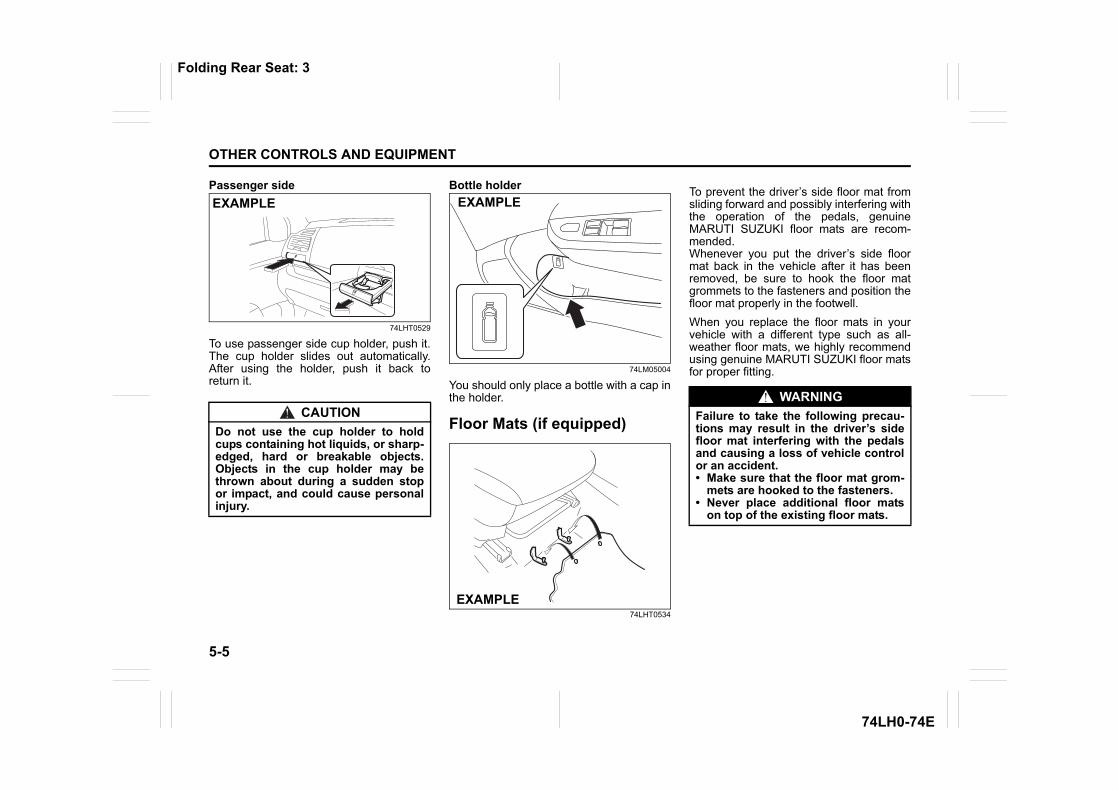
5-5
OTHER CONTROLS AND EQUIPMENT
74LH0-74E
Passenger side
74LHT0529
To use passenger side cup holder, push it.The cup holder slides out automatically.After using the holder, push it back toreturn it.
Bottle holder
74LM05004
You should only place a bottle with a cap inthe holder.
Floor Mats (if equipped)
74LHT0534
To prevent the driver’s side floor mat fromsliding forward and possibly interfering withthe operation of the pedals, genuineMARUTI SUZUKI floor mats are recom-mended.Whenever you put the driver’s side floormat back in the vehicle after it has beenremoved, be sure to hook the floor matgrommets to the fasteners and position thefloor mat properly in the footwell.When you replace the floor mats in yourvehicle with a different type such as all-weather floor mats, we highly recommendusing genuine MARUTI SUZUKI floor matsfor proper fitting.
CAUTIONDo not use the cup holder to holdcups containing hot liquids, or sharp-edged, hard or breakable objects.Objects in the cup holder may bethrown about during a sudden stopor impact, and could cause personalinjury.
EXAMPLE EXAMPLE
EXAMPLE
WARNINGFailure to take the following precau-tions may result in the driver’s sidefloor mat interfering with the pedalsand causing a loss of vehicle controlor an accident.• Make sure that the floor mat grom-
mets are hooked to the fasteners.• Never place additional floor mats
on top of the existing floor mats.
Folding Rear Seat: 3
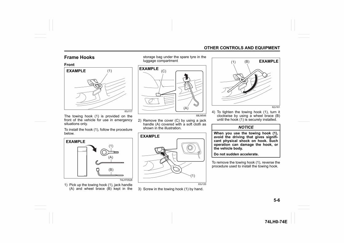
5-6
OTHER CONTROLS AND EQUIPMENT
74LH0-74E
Frame Hooks Front
63J117
The towing hook (1) is provided on thefront of the vehicle for use in emergencysituations only.To install the hook (1), follow the procedurebelow.
74LHT0528
1) Pick up the towing hook (1), jack handle(A) and wheel brace (B) kept in the
storage bag under the spare tyre in theluggage compartment
68LM546
2) Remove the cover (C) by using a jackhandle (A) covered with a soft cloth asshown in the illustration.
63J120
3) Screw in the towing hook (1) by hand.
62J161
4) To tighten the towing hook (1), turn itclockwise by using a wheel brace (B)until the hook (1) is securely installed.
To remove the towing hook (1), reverse theprocedure used to install the towing hook.
(1)EXAMPLE
(1)
(A)
(B)
EXAMPLE
(C)
(A)
EXAMPLE
(1)
EXAMPLE
NOTICEWhen you use the towing hook (1),avoid the driving that gives signifi-cant physical shock on hook. Suchoperation can damage the hook, orthe vehicle body. Do not sudden accelerate.
(1) (B) EXAMPLE
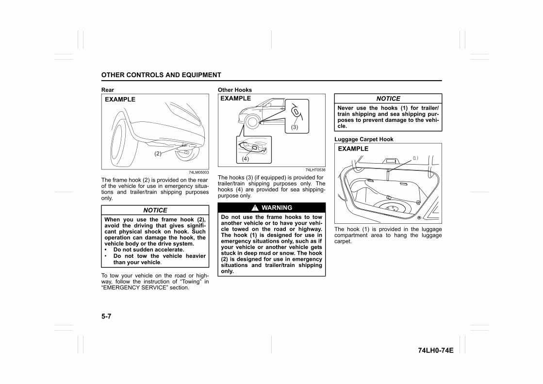
5-7
OTHER CONTROLS AND EQUIPMENT
74LH0-74E
Rear
74LM05003
The frame hook (2) is provided on the rearof the vehicle for use in emergency situa-tions and trailer/train shipping purposesonly.
To tow your vehicle on the road or high-way, follow the instruction of “Towing” in“EMERGENCY SERVICE” section.
Other Hooks
74LHT0536
The hooks (3) (if equipped) is provided fortrailer/train shipping purposes only. Thehooks (4) are provided for sea shipping-purpose only.
Luggage Carpet Hook
The hook (1) is provided in the luggagecompartment area to hang the luggagecarpet.
NOTICEWhen you use the frame hook (2),avoid the driving that gives signifi-cant physical shock on hook. Suchoperation can damage the hook, thevehicle body or the drive system.• Do not sudden accelerate.• Do not tow the vehicle heavier
than your vehicle.
(2)
EXAMPLE
WARNINGDo not use the frame hooks to towanother vehicle or to have your vehi-cle towed on the road or highway.The hook (1) is designed for use inemergency situations only, such as ifyour vehicle or another vehicle getsstuck in deep mud or snow. The hook(2) is designed for use in emergencysituations and trailer/train shippingonly.
(4)
(3)
EXAMPLE NOTICENever use the hooks (1) for trailer/train shipping and sea shipping pur-poses to prevent damage to the vehi-cle.
(1)
EXAMPLE
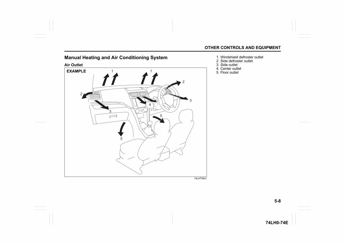
5-8
OTHER CONTROLS AND EQUIPMENT
74LH0-74E
Manual Heating and Air Conditioning SystemAir Outlet
74LHT0501
1
2
2
3
3
4
5
5
1EXAMPLE
1. Windshield defroster outlet2. Side defroster outlet3. Side outlet4. Center outlet5. Floor outlet
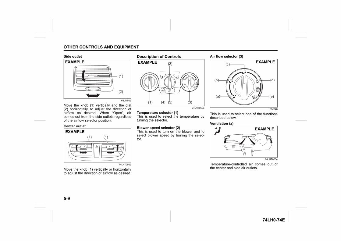
5-9
OTHER CONTROLS AND EQUIPMENT
74LH0-74E
Side outlet
68LM502
Move the knob (1) vertically and the dial(2) horizontally, to adjust the direction ofairflow as desired. When “Open”, aircomes out from the side outlets regardlessof the airflow selector position.Center outlet
74LHT0502
Move the knob (1) vertically or horizontallyto adjust the direction of airflow as desired.
Description of Controls
74LHT0503
Temperature selector (1)This is used to select the temperature byturning the selector.
Blower speed selector (2)This is used to turn on the blower and toselect blower speed by turning the selec-tor.
Air flow selector (3)
63J048
This is used to select one of the functionsdescribed below.Ventilation (a)
74LHT0504
Temperature-controlled air comes out ofthe center and side air outlets.
(1)
(2)
EXAMPLE
EXAMPLE(1) (1)
(1) (4) (5)
(2)
(3)
EXAMPLE
(a)
(b)
(e)
(d)
(c) EXAMPLE
EXAMPLE
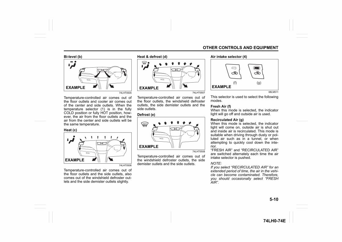
5-10
OTHER CONTROLS AND EQUIPMENT
74LH0-74E
Bi-level (b)
74LHT0505
Temperature-controlled air comes out ofthe floor outlets and cooler air comes outof the center and side outlets. When thetemperature selector (1) is in the fullyCOLD position or fully HOT position, how-ever, the air from the floor outlets and theair from the center and side outlets will bethe same temperature.Heat (c)
74LHT0506
Temperature-controlled air comes out ofthe floor outlets and the side outlets, alsocomes out of the windshield defroster out-lets and the side demister outlets slightly.
Heat & defrost (d)
74LHT0507
Temperature-controlled air comes out ofthe floor outlets, the windshield defrosteroutlets, the side demister outlets and theside outlets.Defrost (e)
74LHT0508
Temperature-controlled air comes out ofthe windshield defroster outlets, the sidedemister outlets and the side outlets.
Air intake selector (4)
68LM511
This selector is used to select the followingmodes.Fresh Air (f)When this mode is selected, the indicatorlight will go off and outside air is used.Recirculated Air (g)When this mode is selected, the indicatorlight will come on, outside air is shut outand inside air is recirculated. This mode issuitable when driving through dusty or pol-luted air such as in a tunnel, or whenattempting to quickly cool down the inte-rior.“FRESH AIR” and “RECIRCULATED AIR”are switched alternately each time the airintake selector is pushed.NOTE:If you select “RECIRCULATED AIR” for anextended period of time, the air in the vehi-cle can become contaminated. Therefore,you should occasionally select “FRESHAIR”.
EXAMPLE
EXAMPLE
EXAMPLE
EXAMPLE
(f) (g)EXAMPLE
5-11
OTHER CONTROLS AND EQUIPMENT
74LH0-74E
Air conditioning switch (5)To turn on the air conditioning system,push in the “A/C” switch and set the blowerspeed selector to a position other than“OFF”. With this “A/C” switch operation, aindicator light will come on when the airconditioning system is on. To turn off theair conditioning system, push the “A/C”switch again.During operation of the air conditioner, youmay notice slight changes in enginespeed. These changes are normal, thesystem is designed so that the compressorturns on or off to maintain the desired tem-perature.Less operation of the compressor resultsin better fuel economy.
System Operating InstructionsNatural ventilationSelect “VENTILATION” and “FRESH AIR”,the temperature selector to the desiredtemperature position, and the blowerspeed selector to “OFF”. Fresh air will flowthrough the vehicle during driving.Forced ventilationThe control settings are the same as fornatural ventilation except you set theblower speed selector to a position otherthan “OFF”.Normal heating (using outside air)Select “HEAT” and “FRESH AIR”, the tem-perature selector to the desired tempera-
ture position and the blower speed selectorto the desired blower speed position. Set-ting the blower speed selector to a higherblower speed position increases heatingefficiency.Quick heating (using recirculated air)The control settings are the same as fornormal heating except you select “RECIR-CULATED AIR”. If you use this heatingmethod for an extended period of time, theair in the vehicle can become contami-nated and the windows can become misty.Therefore, use this method only for quickheating and change to the normal heatingmethod as soon as possible.Cool face/warm feetSelect “BI-LEVEL” and “FRESH AIR”, thetemperature selector to the desired tem-perature position, and the blower speedselector to the desired blower speed posi-tion. Unless the temperature selector is inthe fully COLD position or fully HOT posi-tion, the air that comes out of the centerand side outlets will be cooler than the airthat comes out of the floor outlets.Normal coolingTurn on the “A/C” switch, set the air flowselector to “VENTILATION”, the tempera-ture selector to the desired temperatureposition and the blower speed selector tothe desired blower speed position. Settingthe blower speed selector to a higherblower speed position increases coolingefficiency.
You can switch the air intake selector toeither “FRESH AIR” or “RECIRCULATEDAIR” as you desire. Choosing “RECIRCU-LATED AIR” increases cooling efficiency.Quick cooling (using recirculated air)The control settings are the same as fornormal cooling except you select “RECIR-CULATED AIR” and the highest blowerspeed.
NOTE:• If you select “RECIRCULATED AIR” for
an extended period of time, the air in thevehicle can become contaminated.Therefore, you should occasionallyselect “FRESH AIR”.
• If your vehicle has been left in the sunwith the windows closed, it will coolfaster if you open the windows brieflywhile you operate the air conditioner withthe air intake selector at “FRESH AIR”and the blower at high speed.
DehumidifyingTurn on the “A/C” switch, set the air flowselector to a desired air flow selector posi-tion, and select “FRESH AIR”, the tem-perature selector to the desiredtemperature position, and the blowerspeed selector to the desired blower speedposition.
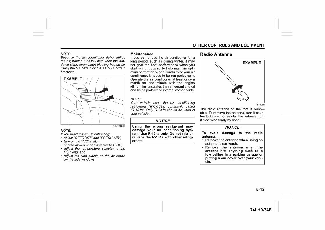
5-12
OTHER CONTROLS AND EQUIPMENT
74LH0-74E
NOTE:Because the air conditioner dehumidifiesthe air, turning it on will help keep the win-dows clear, even when blowing heated airusing the “DEMIST” or “HEAT & DEMIST”functions.
74LHT0509
NOTE:If you need maximum defrosting:• select “DEFROST” and “FRESH AIR”,• turn on the “A/C” switch,• set the blower speed selector to HIGH,• adjust the temperature selector to the
HOT end, and• adjust the side outlets so the air blows
on the side windows.
MaintenanceIf you do not use the air conditioner for along period, such as during winter, it maynot give the best performance when youstart using it again. To help maintain opti-mum performance and durability of your airconditioner, it needs to be run periodically.Operate the air conditioner at least once amonth for one minute with the engineidling. This circulates the refrigerant and oiland helps protect the internal components.
NOTE:Your vehicle uses the air conditioningrefrigerant HFC-134a, commonly called“R-134a”. Only R-134a should be used inyour vehicle.
Radio Antenna
63J055
The radio antenna on the roof is remov-able. To remove the antenna, turn it coun-terclockwise. To reinstall the antenna, turnit clockwise firmly by hand.
EXAMPLE
NOTICEUsing the wrong refrigerant maydamage your air conditioning sys-tem. Use R-134a only. Do not mix orreplace the R-134a with other refrig-erants.
NOTICETo avoid damage to the radioantenna:• Remove the antenna when using an
automatic car wash.• Remove the antenna when the
antenna hits anything such as alow ceiling in a parking garage orputting a car cover over your vehi-cle.
EXAMPLE
5-13
OTHER CONTROLS AND EQUIPMENT
74LH0-74E
Installation of Radio Frequency TransmittersWe recommend that you always ask aauthorised Maruti Suzuki workshop aboutfrequency band, max output power,antenna position at vehicle and specificconditions for installation and/or use beforeinstalling a radio transmitter in your vehi-cle. Such equipments may cause the elec-tronic control system to malfunction if theyare incorrectly installed or they are notsuited for the vehicle.
VEHICLE LOADING AND TOWING
74LH0-74E
54G215
VEHICLE LOADING AND TOWINGVehicle Loading ................................................................... 6-1Trailer Towing ...................................................................... 6-1
6
6-1
VEHICLE LOADING AND TOWING
74LH0-74E
Vehicle LoadingYour vehicle was designed for specificweight capacities. The weight capacities ofyour vehicle are indicated by the GrossVehicle Weight Rating (GVWR) and theGross Axle Weight Rating (GAWR, frontand rear). The GVWR and GAWR (frontand rear) are listed in the “SPECIFICA-TIONS” section.GVWR – Maximum permissible overallweight of the fully loaded vehicle (includingall the occupants, accessories and cargoplus the trailer nose weight if towing atrailer).GAWR – (Front and Rear) Maximum per-missible weight on an individual axle.
Actual weight of the loaded vehicle andactual loads at the front and rear axles canonly be determined by weighing the vehi-cle. Compare these weights to the GVWRand GAWR (front and rear). If the grossvehicle weight or the load on either axleexceeds these ratings, you must removeenough weight to bring the load down tothe rated capacity.
Trailer TowingYour MARUTI SUZUKI was originallydesigned to carry people and a normalamount of cargo, not to tow a trailer.
WARNINGNever overload your vehicle. Thegross vehicle weight (sum of theweights of the vehicle, all the occu-pants, accessories, cargo plus trailernose weight if towing a trailer) mustnever exceed the Gross VehicleWeight Rating (GVWR). In addition,never distribute a load so that theweight on either the front or rear axleexceeds the Gross Axle Weight Rat-ing (GAWR).
WARNINGAlways distribute cargo evenly. Toavoid personal injury or damage toyour vehicle, always secure cargo toprevent it from shifting if the vehiclemoves suddenly. Place heavierobjects on the floor and as far for-ward in the cargo area as possible.Never pile cargo higher than the topof the seat backs.
Vehicle Loading: 11Trailer Towing: 5, 11
INSPECTION AND MAINTENANCE
74LH0-74E
60G410
INSPECTION AND MAINTENANCEMaintenance Schedule ....................................................... 7-2Periodic Maintenance Schedule ........................................ 7-2Drive Belt ............................................................................. 7-6Engine Oil and Filter ........................................................... 7-6Engine Coolant .................................................................... 7-10Air Cleaner ........................................................................... 7-12Spark Plugs (Petrol Engine)................................................ 7-12Gear Oil ................................................................................ 7-13Clutch Pedal ........................................................................ 7-13Fuel Filter (Diesel Engine) .................................................. 7-15Brakes .................................................................................. 7-15Steering ................................................................................ 7-17Tires ...................................................................................... 7-18Battery .................................................................................. 7-20Fuses .................................................................................... 7-21Bulb Replacement ............................................................... 7-24Wiper Blades ....................................................................... 7-26Windshield Washer Fluid ................................................... 7-28Air Conditioning System .................................................... 7-28
7
7-1
INSPECTION AND MAINTENANCE
74LH0-74E
60B128S
WARNINGYou should take extreme care whenworking on your vehicle to preventaccidental injury. Here are a few pre-cautions that you should be espe-cially careful to observe. • Do not leave the engine running in
garages or other confined areas.• When the engine is running, keep
hands, clothing, tools, and otherobjects away from the fan and drivebelt. Even though the fan may notbe moving, it can automaticallyturn on without warning.
• When it is necessary to do servicework with the engine running, makesure that the parking brake is setfully and the transmission is inNeutral.
(Continued)
EXAMPLE WARNING• Do not touch ignition wires or other
ignition system parts when startingthe engine or when the engine isrunning, or you could receive anelectric shock.
• Be careful not to touch a hotengine, exhaust manifold andpipes, muffler, radiator and waterhoses.
• Do not allow smoking, sparks, orflames around fuel or the battery.Flammable fumes are present.
• Do not get under your vehicle if it issupported only with the portablejack provided in your vehicle.
• Be careful not to cause accidentalshort circuits between the positiveand negative battery terminals.
• Keep used oil, coolant, and otherfluids away from children and pets.Dispose of used fluids properly;never pour them on the ground,into sewers, etc.
7-2
INSPECTION AND MAINTENANCE
74LH0-74E
Maintenance ScheduleThe following table shows the times whenyou should perform regular maintenanceon your vehicle. This table shows in kilo-meters and months when you should per-form inspections, adjustments, lubricationand other services.
Periodic Maintenance Schedule“C”: Clean“R”: Replace or Change“I”: Inspect, clean, adjust, lubricate or
replace as necessary“L”: Lubricate“T”: Tighten to Specified Torque “O”: Rotate
NOTE:This table includes services as scheduledup to 80,000 km mileage. Beyond 80,000km, carry out the same services at thesame intervals respectively.
WARNINGMARUTI SUZUKI recommends thatmaintenance on your Maruti Suzukivehicle should be performed byauthorised Maruti Suzuki workshop.
NOTICEWhenever it becomes necessary toreplace parts on your vehicle, it isrecommended that you use MARUTIgenuine replacement parts or theirequivalent.
Periodic Maintenance Schedule: 1, 2, 3, 4, 5, 6, 9, 10
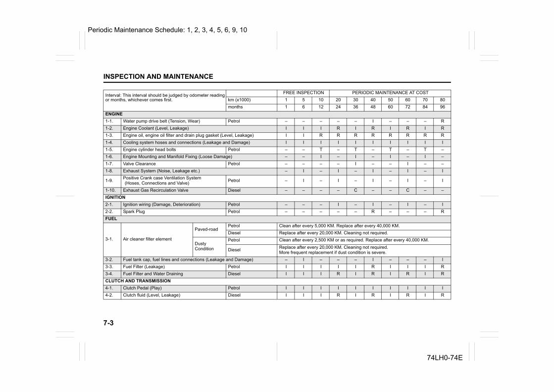
7-3
INSPECTION AND MAINTENANCE
74LH0-74E
Interval: This interval should be judged by odometer readingor months, whichever comes first.
FREE INSPECTION PERIODIC MAINTENANCE AT COSTkm (x1000) 1 5 10 20 30 40 50 60 70 80months 1 6 12 24 36 48 60 72 84 96
ENGINE1-1. Water pump drive belt (Tension, Wear) Petrol – – – – – I – – – R1-2. Engine Coolant (Level, Leakage) I I I R I R I R I R1-3. Engine oil, engine oil filter and drain plug gasket (Level, Leakage) I I R R R R R R R R1-4. Cooling system hoses and connections (Leakage and Damage) I I I I I I I I I I1-5. Engine cylinder head bolts Petrol – – T – T – T – T –1-6. Engine Mounting and Manifold Fixing (Loose Damage) – – I – I – I – I –1-7. Valve Clearance Petrol – – – – I – – I – –1-8. Exhaust System (Noise, Leakage etc.) – I – I – I – I – I
1-9. Positive Crank case Ventilation System (Hoses, Connections and Valve) Petrol – I – I – I – I – I
1-10. Exhaust Gas Recirculation Valve Diesel – – – – C – – C – –IGNITION2-1. Ignition wiring (Damage, Deterioration) Petrol – – – I – I – I – I2-2. Spark Plug Petrol – – – – – R – – – RFUEL
3-1. Air cleaner filter element
Paved-roadPetrol Clean after every 5,000 KM. Replace after every 40,000 KM.Diesel Replace after every 20,000 KM. Cleaning not required.
Dusty Condition
Petrol Clean after every 2,500 KM or as required. Replace after every 40,000 KM.
Diesel Replace after every 20,000 KM. Cleaning not required.More frequent replacement if dust condition is severe.
3-2. Fuel tank cap, fuel lines and connections (Leakage and Damage) – I – – – I – – – I3-3. Fuel Filter (Leakage) Petrol I I I I I R I I I R3-4. Fuel Filter and Water Draining Diesel I I I R I R I R I RCLUTCH AND TRANSMISSION4-1. Clutch Pedal (Play) Petrol I I I I I I I I I I4-2. Clutch fluid (Level, Leakage) Diesel I I I R I R I R I R
Periodic Maintenance Schedule: 1, 2, 3, 4, 5, 6, 9, 10
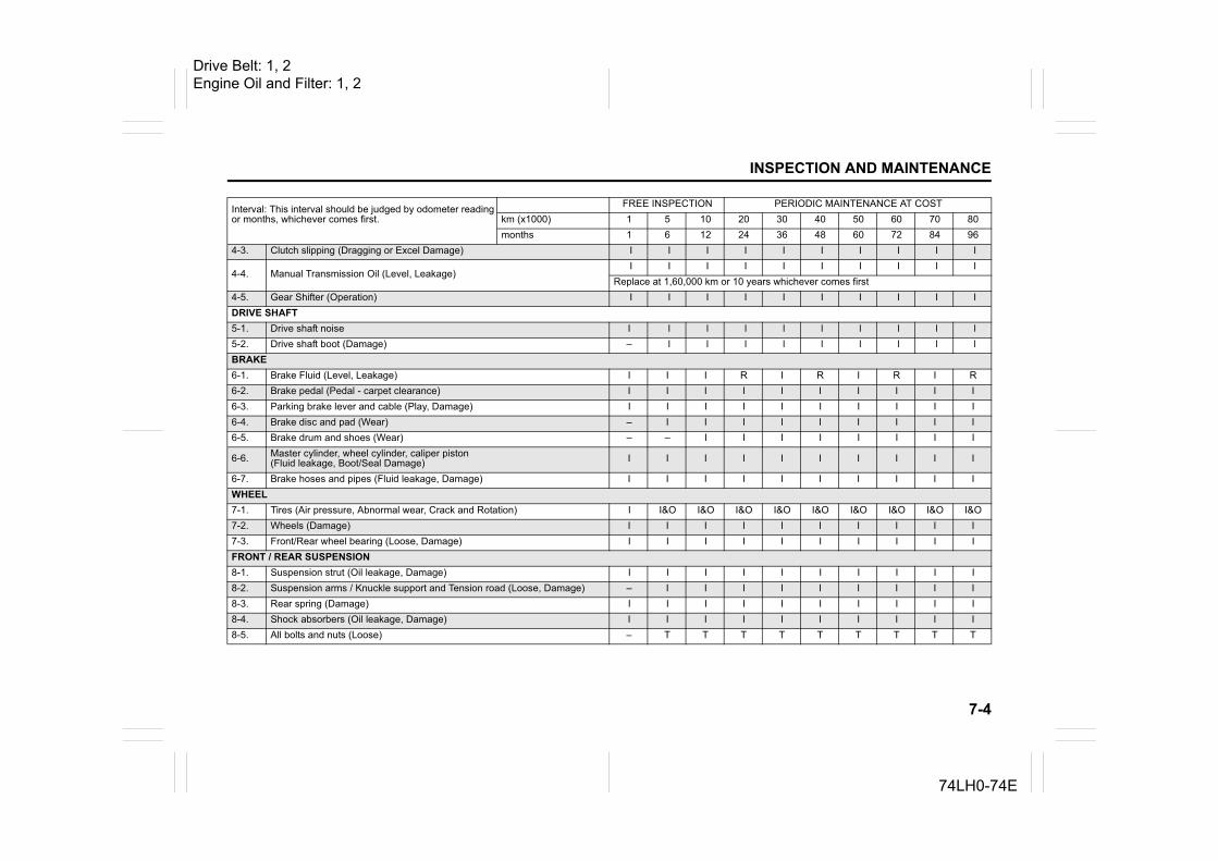
7-4
INSPECTION AND MAINTENANCE
74LH0-74E
4-3. Clutch slipping (Dragging or Excel Damage) I I I I I I I I I I
4-4. Manual Transmission Oil (Level, Leakage)I I I I I I I I I I
Replace at 1,60,000 km or 10 years whichever comes first4-5. Gear Shifter (Operation) I I I I I I I I I IDRIVE SHAFT5-1. Drive shaft noise I l l l l l l l l l5-2. Drive shaft boot (Damage) – l l l l l l l l lBRAKE6-1. Brake Fluid (Level, Leakage) I I I R I R I R I R6-2. Brake pedal (Pedal - carpet clearance) I I I I I I I I I I6-3. Parking brake lever and cable (Play, Damage) I I I I I I I I I I6-4. Brake disc and pad (Wear) – I I I I I I I I I6-5. Brake drum and shoes (Wear) – – I I I I I I I I
6-6. Master cylinder, wheel cylinder, caliper piston (Fluid leakage, Boot/Seal Damage) I I I I I I I I I I
6-7. Brake hoses and pipes (Fluid leakage, Damage) I I I I I I I I I IWHEEL7-1. Tires (Air pressure, Abnormal wear, Crack and Rotation) I I&O I&O I&O I&O I&O I&O I&O I&O I&O7-2. Wheels (Damage) I I I I I I I I I I7-3. Front/Rear wheel bearing (Loose, Damage) I I I I I I I I I IFRONT / REAR SUSPENSION8-1. Suspension strut (Oil leakage, Damage) I I I I I I I I I I8-2. Suspension arms / Knuckle support and Tension road (Loose, Damage) – I I I I I I I I I8-3. Rear spring (Damage) I I I I I I I I I I8-4. Shock absorbers (Oil leakage, Damage) I I I I I I I I I I8-5. All bolts and nuts (Loose) – T T T T T T T T T
Interval: This interval should be judged by odometer readingor months, whichever comes first.
FREE INSPECTION PERIODIC MAINTENANCE AT COSTkm (x1000) 1 5 10 20 30 40 50 60 70 80months 1 6 12 24 36 48 60 72 84 96
Drive Belt: 1, 2Engine Oil and Filter: 1, 2
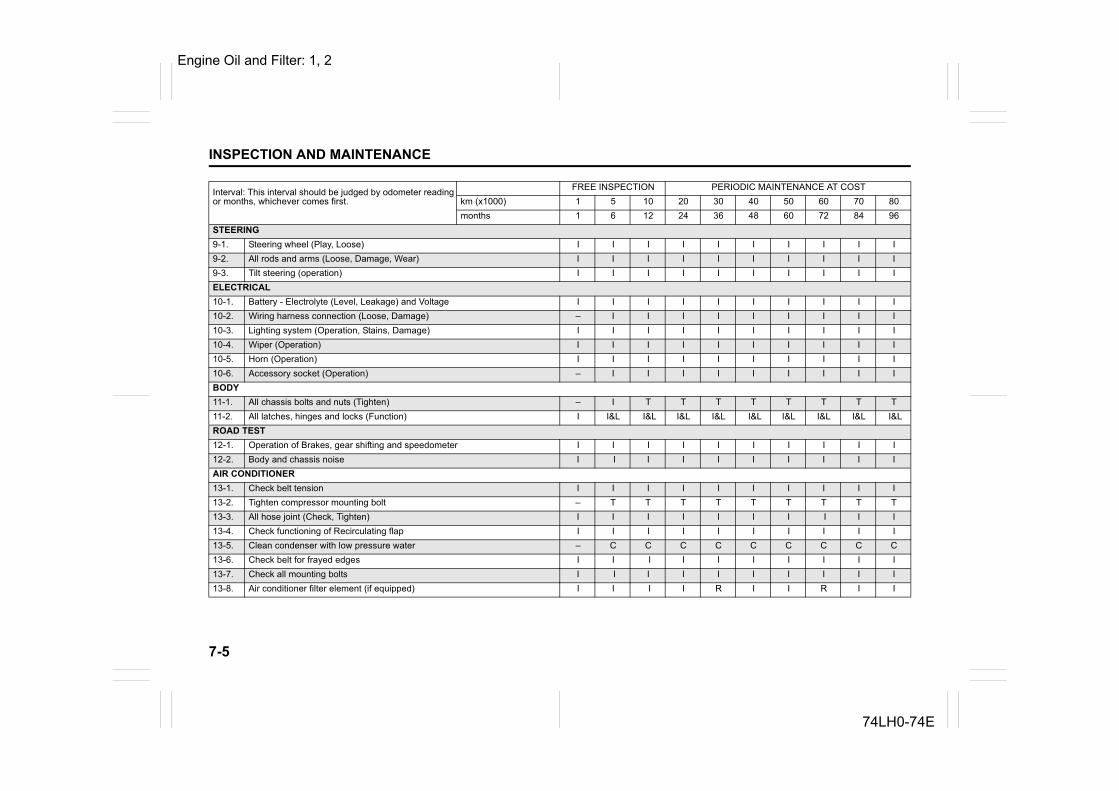
7-5
INSPECTION AND MAINTENANCE
74LH0-74E
STEERING9-1. Steering wheel (Play, Loose) I I I I I I I I I I9-2. All rods and arms (Loose, Damage, Wear) I I I I I I I I I I9-3. Tilt steering (operation) I I I I I I I I I IELECTRICAL10-1. Battery - Electrolyte (Level, Leakage) and Voltage I I I I I I I I I I10-2. Wiring harness connection (Loose, Damage) – I I I I I I I I I10-3. Lighting system (Operation, Stains, Damage) I I I I I I I I I I10-4. Wiper (Operation) I I I I I I I I I I10-5. Horn (Operation) I I I I I I I I I I10-6. Accessory socket (Operation) – I I I I I I I I IBODY11-1. All chassis bolts and nuts (Tighten) – I T T T T T T T T11-2. All latches, hinges and locks (Function) I I&L I&L I&L I&L I&L I&L I&L I&L I&LROAD TEST12-1. Operation of Brakes, gear shifting and speedometer I I I I I I I I I I12-2. Body and chassis noise I I I I I I I I I IAIR CONDITIONER13-1. Check belt tension I I I I I I I I I I13-2. Tighten compressor mounting bolt – T T T T T T T T T13-3. All hose joint (Check, Tighten) I I I I I I I I I I13-4. Check functioning of Recirculating flap I I I I I I I I I I13-5. Clean condenser with low pressure water – C C C C C C C C C13-6. Check belt for frayed edges I I I I I I I I I I13-7. Check all mounting bolts I I I I I I I I I I13-8. Air conditioner filter element (if equipped) I I I I R I I R I I
Interval: This interval should be judged by odometer readingor months, whichever comes first.
FREE INSPECTION PERIODIC MAINTENANCE AT COSTkm (x1000) 1 5 10 20 30 40 50 60 70 80months 1 6 12 24 36 48 60 72 84 96
Engine Oil and Filter: 1, 2
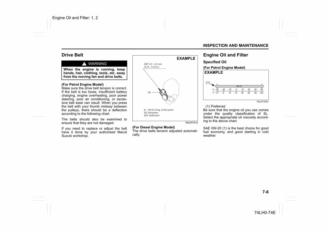
7-6
INSPECTION AND MAINTENANCE
74LH0-74E
Drive Belt
(For Petrol Engine Model)Make sure the drive belt tension is correct.If the belt is too loose, insufficient batterycharging, engine overheating, poor powersteering, poor air conditioning, or exces-sive belt wear can result. When you pressthe belt with your thumb midway betweenthe pulleys, there should be a deflectionaccording to the following chart.The belts should also be examined toensure that they are not damaged.If you need to replace or adjust the belthave it done by your authorised MarutiSuzuki workshop.
68LM70703
(For Diesel Engine Model)The drive belts tension adjusted automati-cally.
Engine Oil and FilterSpecified Oil (For Petrol Engine Model)
74LHT7001
(1) Preferred Be sure that the engine oil you use comesunder the quality classification of SL.Select the appropriate oil viscosity accord-ing to the above chart.
SAE 0W-20 (1) is the best choice for goodfuel economy, and good starting in coldweather.
WARNINGWhen the engine is running, keephands, hair, clothing, tools, etc. awayfrom the moving fan and drive belts.
� : 100 N (10 kg, 22 lbs) pressGE: GeneratorDEF: Deflection
DEF: 4.0 – 4.5 mm(0.16 – 0.18 in.)
GE
EXAMPLE
(1)
EXAMPLE
Engine Oil and Filter: 1, 2
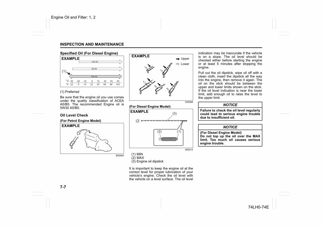
7-7
INSPECTION AND MAINTENANCE
74LH0-74E
Specified Oil (For Diesel Engine)
(1) PreferredBe sure that the engine oil you use comesunder the quality classification of ACEAA5/B5. The recommended Engine oil is5W30 A5/B5.
Oil Level Check(For Petrol Engine Model)
80G064
52D084
(For Diesel Engine Model)
84E012
(1) MIN(2) MAX(3) Engine oil dipstick
It is important to keep the engine oil at thecorrect level for proper lubrication of yourvehicle’s engine. Check the oil level withthe vehicle on a level surface. The oil level
indication may be inaccurate if the vehicleis on a slope. The oil level should bechecked either before starting the engineor at least 5 minutes after stopping theengine.Pull out the oil dipstick, wipe oil off with aclean cloth, insert the dipstick all the wayinto the engine, then remove it again. Theoil on the stick should be between theupper and lower limits shown on the stick.If the oil level indication is near the lowerlimit, add enough oil to raise the level tothe upper limit.
5W-30
(1)
-30-22 -4 14 32 50 68 86 104
-20 -10 10 20 30 400
15W-40
5W-40
EXAMPLE
EXAMPLE
Upper
Lower
EXAMPLE
(3)
(2) (1)
EXAMPLE
NOTICEFailure to check the oil level regularlycould lead to serious engine troubledue to insufficient oil.
NOTICE(For Diesel Engine Model)Do not top up the oil over the MAXlimit. Too much oil causes seriousengine trouble.
Engine Oil and Filter: 1, 2
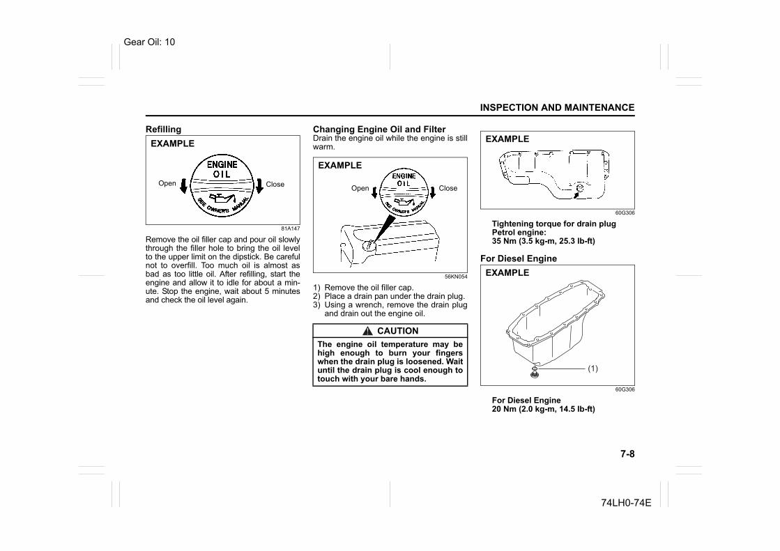
7-8
INSPECTION AND MAINTENANCE
74LH0-74E
Refilling
81A147
Remove the oil filler cap and pour oil slowlythrough the filler hole to bring the oil levelto the upper limit on the dipstick. Be carefulnot to overfill. Too much oil is almost asbad as too little oil. After refilling, start theengine and allow it to idle for about a min-ute. Stop the engine, wait about 5 minutesand check the oil level again.
Changing Engine Oil and FilterDrain the engine oil while the engine is stillwarm.
56KN054
1) Remove the oil filler cap.2) Place a drain pan under the drain plug.3) Using a wrench, remove the drain plug
and drain out the engine oil.
60G306
Tightening torque for drain plugPetrol engine: 35 Nm (3.5 kg-m, 25.3 lb-ft)
For Diesel Engine
60G306
For Diesel Engine20 Nm (2.0 kg-m, 14.5 Ib-ft)
CloseOpen
EXAMPLE
CAUTIONThe engine oil temperature may behigh enough to burn your fingerswhen the drain plug is loosened. Waituntil the drain plug is cool enough totouch with your bare hands.
Open Close
EXAMPLE
EXAMPLE
(1)
EXAMPLE
Gear Oil: 10
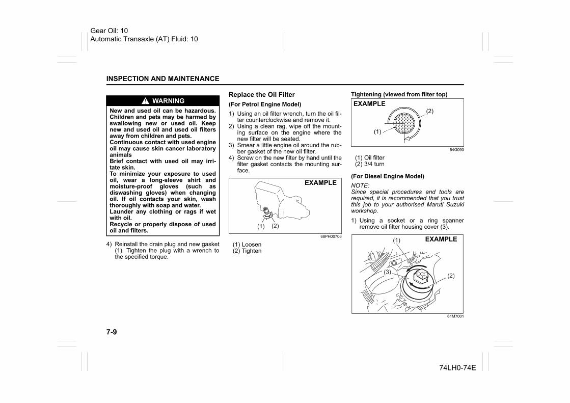
7-9
INSPECTION AND MAINTENANCE
74LH0-74E
4) Reinstall the drain plug and new gasket(1). Tighten the plug with a wrench tothe specified torque.
Replace the Oil Filter(For Petrol Engine Model)1) Using an oil filter wrench, turn the oil fil-
ter counterclockwise and remove it.2) Using a clean rag, wipe off the mount-
ing surface on the engine where thenew filter will be seated.
3) Smear a little engine oil around the rub-ber gasket of the new oil filter.
4) Screw on the new filter by hand until thefilter gasket contacts the mounting sur-face.
68PH00706
(1) Loosen(2) Tighten
Tightening (viewed from filter top)
54G093
(1) Oil filter(2) 3/4 turn
(For Diesel Engine Model)NOTE:Since special procedures and tools arerequired, it is recommended that you trustthis job to your authorised Maruti Suzukiworkshop.1) Using a socket or a ring spanner
remove oil filter housing cover (3).
61M7001
WARNINGNew and used oil can be hazardous.Children and pets may be harmed byswallowing new or used oil. Keepnew and used oil and used oil filtersaway from children and pets.Continuous contact with used engineoil may cause skin cancer laboratoryanimalsBrief contact with used oil may irri-tate skin.To minimize your exposure to usedoil, wear a long-sleeve shirt andmoisture-proof gloves (such asdiswashing gloves) when changingoil. If oil contacts your skin, washthoroughly with soap and water.Launder any clothing or rags if wetwith oil.Recycle or properly dispose of usedoil and filters.
(1) (2)
EXAMPLE
(1)
(2)EXAMPLE
(1)
(3) (2)
EXAMPLE
Gear Oil: 10Automatic Transaxle (AT) Fluid: 10
7-10
INSPECTION AND MAINTENANCE
74LH0-74E
(1) Loosen(2) Tighten
2) Remove the old oil filter element andreplace it with a new oil filter element.
3) Clean the surface of oil filter cap andreplace the O-ring.
4) Tighten the oil filter housing cover onthe oil filter housing using a socket orring spanner to the specified torque.Tightening torque for oil filterDiesel engine : 25 Nm (2.5 kg-m, 18.5 lb-ft)
Refill with Oil and Check for Leaks1) Pour oil through the filler hole and
install the filler cap. For the approximate capacity of the oil,refer to the “Capacities” item in the“SPECIFICATIONS” section.
2) Start the engine and look carefully forleaks at the oil filter and drain plug. Runthe engine at various speeds for at least5 minutes.
3) Stop the engine and wait about 5 min-utes. Check the oil level again and addoil if necessary. Check for leaks again.
Engine CoolantSelection of CoolantTo maintain optimum performance anddurability of your engine, use MARUTISUZUKI Genuine Coolant or equivalent.
This type of coolant is best for your coolingsystem as it:• Helps maintain proper engine tempera-
ture.• Gives proper protection against freezing
and boiling.• Gives proper protection against corro-
sion and rust.Failure to use the proper coolant can dam-age your cooling system. Your authorisedMaruti Suzuki workshop can help youselect the proper coolant.
Coolant Level CheckCheck the coolant level at the reservoirtank, not at the radiator. With the enginecool, the coolant level should be betweenthe “FULL” and “LOW” marks.
NOTICETo prevent oil leakage, make surethat the oil filter is tight, but do notover-tighten it.
NOTICE• When replacing the oil filter, it is
recommended that you use a MAR-UTI genuine replacement filter.
• Oil leaks from around the oil filteror drain plug indicate incorrectinstallation or gasket damage. Ifyou find any leaks or are not surethat the filter has been properlytightened, have the vehicleinspected by your authorisedMaruti Suzuki workshop.
NOTICETo avoid damaging your cooling sys-tem:• Always use a high quality ethylene
glycol base non-silicate type cool-ant diluted with distilled water atthe correct mixture concentration.
• Make sure that the proper mix is 50/50 coolant to distilled water (Die-sel) and 30/70 (Petrol). Concentra-tions greater than this may causeoverheating conditions.
• Neither use 100% coolant nor 100%Plain water.
• Do not add extra inhibitors or addi-tives. They may not be compatiblewith your cooling system.
• Do not mix different types of basecoolants. Doing so may result inaccelerated seal wear and/or thepossibility of severe overheatingand extensive engine/automatictransaxle damage.
Automatic Transaxle (AT) Fluid: 10
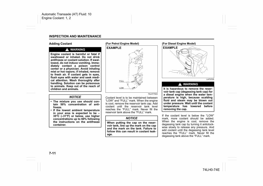
7-11
INSPECTION AND MAINTENANCE
74LH0-74E
Adding Coolant (For Petrol Engine Model)
74LHT7003
Coolant level is to be maintained between“LOW” and “FULL” mark. When the engineis cool, remove the reservoir tank cap. Addcoolant until the reservoir tank levelreaches the “FULL” mark. Never fill thereservoir tank above the “FULL” mark.
(For Diesel Engine Model)
LHT0705
If the coolant level is below the “LOW”mark, more coolant should be added.When the engine is cool, remove thedegassing tank cap by turning it anticlock-wise slowly to release any pressure. Andadd coolant until the degassing tank levelreaches the “FULL” mark. Never fill thedegassing tank above the “FULL” mark.
WARNINGEngine coolant is harmful or fatal ifswallowed or inhaled. Do not drinkantifreeze or coolant solution. If swal-lowed, do not induce vomiting. Imme-diately contact a poison controlcenter or a physician. Avoid inhalingmist or hot vapors; if inhaled, removeto fresh air. If coolant gets in eyes,flush eyes with water and seek medi-cal attention. Wash thoroughly afterhandling. Solution can be poisonousto animals. Keep out of the reach ofchildren and animals.
NOTICE• The mixture you use should con-
tain 50% concentration of anti-freeze.
• If the lowest ambient temperaturein your area is expected to be –35°C (–31°F) or below, use higherconcentrations up to 60% followingthe instructions on the antifreezecontainer.
NOTICEWhen putting the cap on the reser-voir tank, line up the mark on the capand the mark on the tank. Failure tofollow this can result in coolant leak-age.
FULL
LOW
FULL
LOW
EXAMPLE
WARNINGIt is hazardous to remove the reser-voir tank cap (degassing tank cap) fora diesel engine when the water tem-perature is high, because scaldingfluid and steam may be blown outunder pressure. Wait until the coolanttemperature has lowered beforeremoving the cap.
EXAMPLE
Automatic Transaxle (AT) Fluid: 10Engine Coolant: 1, 2
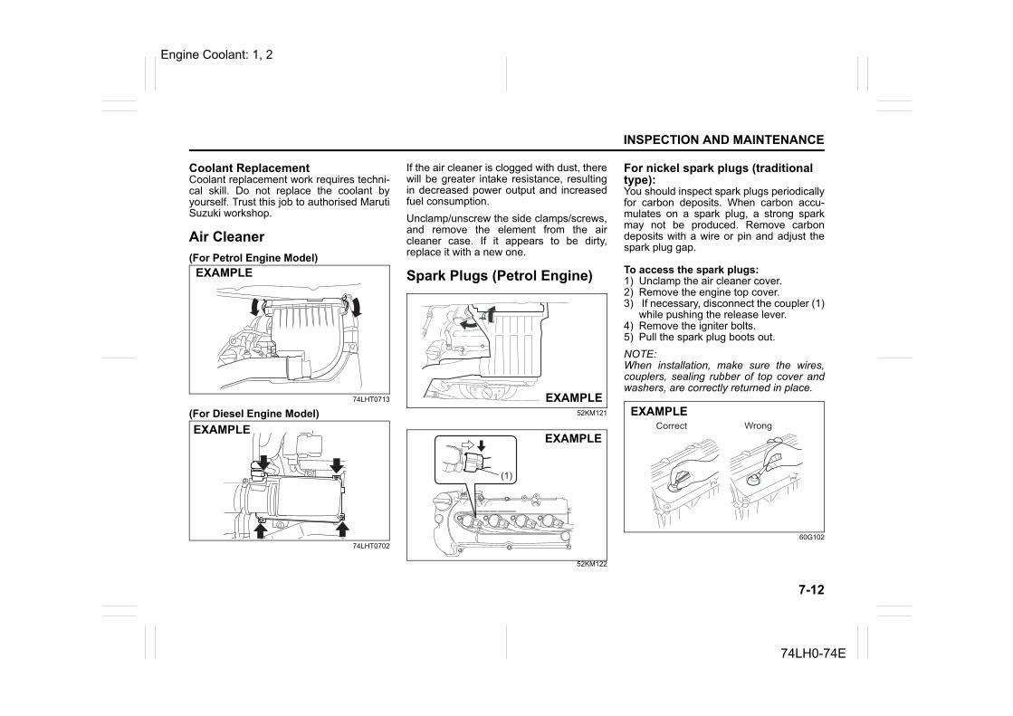
7-12
INSPECTION AND MAINTENANCE
74LH0-74E
Coolant ReplacementCoolant replacement work requires techni-cal skill. Do not replace the coolant byyourself. Trust this job to authorised MarutiSuzuki workshop.
Air Cleaner(For Petrol Engine Model)
74LHT0713
(For Diesel Engine Model)
74LHT0702
If the air cleaner is clogged with dust, therewill be greater intake resistance, resultingin decreased power output and increasedfuel consumption.Unclamp/unscrew the side clamps/screws,and remove the element from the aircleaner case. If it appears to be dirty,replace it with a new one.
Spark Plugs (Petrol Engine)
52KM121
52KM122
For nickel spark plugs (traditional type):You should inspect spark plugs periodicallyfor carbon deposits. When carbon accu-mulates on a spark plug, a strong sparkmay not be produced. Remove carbondeposits with a wire or pin and adjust thespark plug gap.
To access the spark plugs:1) Unclamp the air cleaner cover.2) Remove the engine top cover.3) If necessary, disconnect the coupler (1)
while pushing the release lever.4) Remove the igniter bolts.5) Pull the spark plug boots out.NOTE:When installation, make sure the wires,couplers, sealing rubber of top cover andwashers, are correctly returned in place.
60G102
EXAMPLE
EXAMPLE
EXAMPLE
(1)
EXAMPLE
EXAMPLE
Engine Coolant: 1, 2
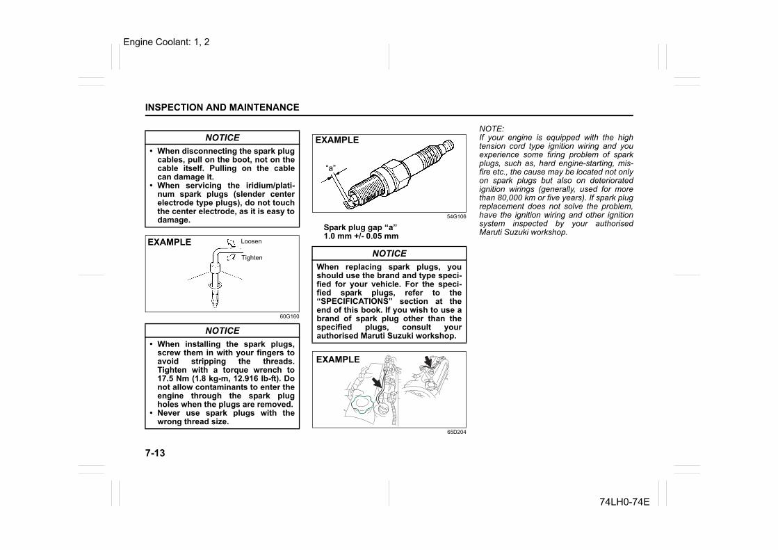
7-13
INSPECTION AND MAINTENANCE
74LH0-74E
60G160
54G106
Spark plug gap “a”1.0 mm +/- 0.05 mm
65D204
NOTE:If your engine is equipped with the hightension cord type ignition wiring and youexperience some firing problem of sparkplugs, such as, hard engine-starting, mis-fire etc., the cause may be located not onlyon spark plugs but also on deterioratedignition wirings (generally, used for morethan 80,000 km or five years). If spark plugreplacement does not solve the problem,have the ignition wiring and other ignitionsystem inspected by your authorisedMaruti Suzuki workshop.
NOTICE• When disconnecting the spark plug
cables, pull on the boot, not on thecable itself. Pulling on the cablecan damage it.
• When servicing the iridium/plati-num spark plugs (slender centerelectrode type plugs), do not touchthe center electrode, as it is easy todamage.
NOTICE• When installing the spark plugs,
screw them in with your fingers toavoid stripping the threads.Tighten with a torque wrench to17.5 Nm (1.8 kg-m, 12.916 lb-ft). Donot allow contaminants to enter theengine through the spark plugholes when the plugs are removed.
• Never use spark plugs with thewrong thread size.
EXAMPLE Loosen
Tighten NOTICEWhen replacing spark plugs, youshould use the brand and type speci-fied for your vehicle. For the speci-fied spark plugs, refer to the“SPECIFICATIONS” section at theend of this book. If you wish to use abrand of spark plug other than thespecified plugs, consult yourauthorised Maruti Suzuki workshop.
EXAMPLE
“a”
EXAMPLE
Engine Coolant: 1, 2
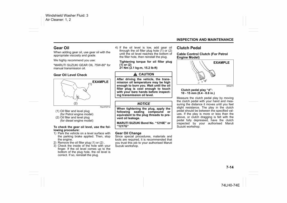
7-14
INSPECTION AND MAINTENANCE
74LH0-74E
Gear OilWhen adding gear oil, use gear oil with theappropriate viscosity and grade.We highly recommend you use:"MARUTI SUZUKI GEAR OIL 75W-80" formanual transmission oil.
Gear Oil Level Check
74LHT0714
(1) Oil filler and level plug(for Petrol engine model)
(2) Oil filler and level plug(for diesel engine model)
To check the gear oil level, use the fol-lowing procedure:1) Park the vehicle on a level surface with
the parking brake applied. Then, stopthe engine.
2) Remove the oil filler plug (1) or (2) .3) Check the inside of the hole with your
finger. If the oil level comes up to thebottom of the plug hole, the oil level iscorrect. If so, reinstall the plug.
4) If the oil level is low, add gear oilthrough the oil filler plug hole (1) or (2)until the oil level reaches the bottom ofthe filler hole, then reinstall the plug.Tightening torque for oil filler plug(1) or (2)21 Nm (2.1 kg-m, 15.2 lb-ft)
Gear Oil ChangeSince special procedures, materials andtools are required, it is recommended thatyou trust this job to your authorised MarutiSuzuki workshop.
Clutch PedalCable Control Clutch (For Petrol Engine Model)
54G274
Clutch pedal play “d”:10 - 15 mm (0.4 - 0.6 in.)
Measure the clutch pedal play by movingthe clutch pedal with your hand and mea-suring the distance it moves until you feelslight resistance. The play in the clutchpedal should be between the specified val-ues. If the play is more or less than theabove, or clutch dragging is felt with thepedal fully depressed, have the clutchinspected by your authorised MarutiSuzuki workshop.
(1)
(2)
EXAMPLE
CAUTIONAfter driving the vehicle, the trans-mission oil temperature may be highenough to burn you. Wait until the oilfiller plug is cool enough to touchwith your bare hands before inspect-ing transmission oil level.
NOTICEWhen tightening the plug, apply thefollowing sealing compound orequivalent to the plug threads to pre-vent oil leakage.MARUTI SUZUKI Bond No. “1216E” or“1217G”
EXAMPLE
“d”
Windshield Washer Fluid: 3Air Cleaner: 1, 2
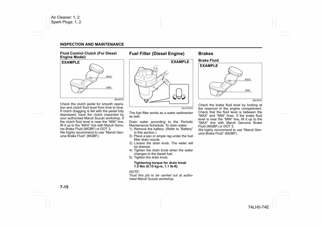
7-15
INSPECTION AND MAINTENANCE
74LH0-74E
Fluid Control Clutch (For Diesel Engine Model)
68LM703
Check the clutch pedal for smooth opera-tion and clutch fluid level from time to time.If clutch dragging is felt with the pedal fullydepressed, have the clutch inspected byyour authorised Maruti Suzuki workshop. Ifthe clutch fluid level is near the “MIN” line,fill it up to the “MAX” line with Maruti Genu-ine Brake Fluid (MGBF) or DOT 3.We highly recommend to use “Maruti Gen-uine Brake Fluid” (MGBF).
Fuel Filter (Diesel Engine)
74LHT0703
The fuel filter works as a water sedimentoras well.Drain water according to the PeriodicMaintenance Schedule. To drain water:1) Remove the battery. (Refer to “Battery”
in this section.)2) Place a pan or ample rag under the fuel
filter drain nozzle.3) Loosen the drain knob. The water will
be drained.4) Tighten the drain knob when the water
changes to the diesel fuel.5) Tighten the drain knob.
Tightening torque for drain knob1.5 Nm (0.15 kg-m, 1.1 lb-ft)
NOTE:Trust this job to be carried out at autho-rised Maruti Suzuki workshop.
BrakesBrake Fluid
68LM703
Check the brake fluid level by looking atthe reservoir in the engine compartment.Check that the fluid level is between the“MAX” and “MIN” lines. If the brake fluidlevel is near the “MIN” line, fill it up to the“MAX” line with Maruti Genuine BrakeFluid (MGBF) or DOT 3.We highly recommend to use “Maruti Gen-uine Brake Fluid” (MGBF).
EXAMPLE EXAMPLEEXAMPLE
Air Cleaner: 1, 2Spark Plugs: 1, 2
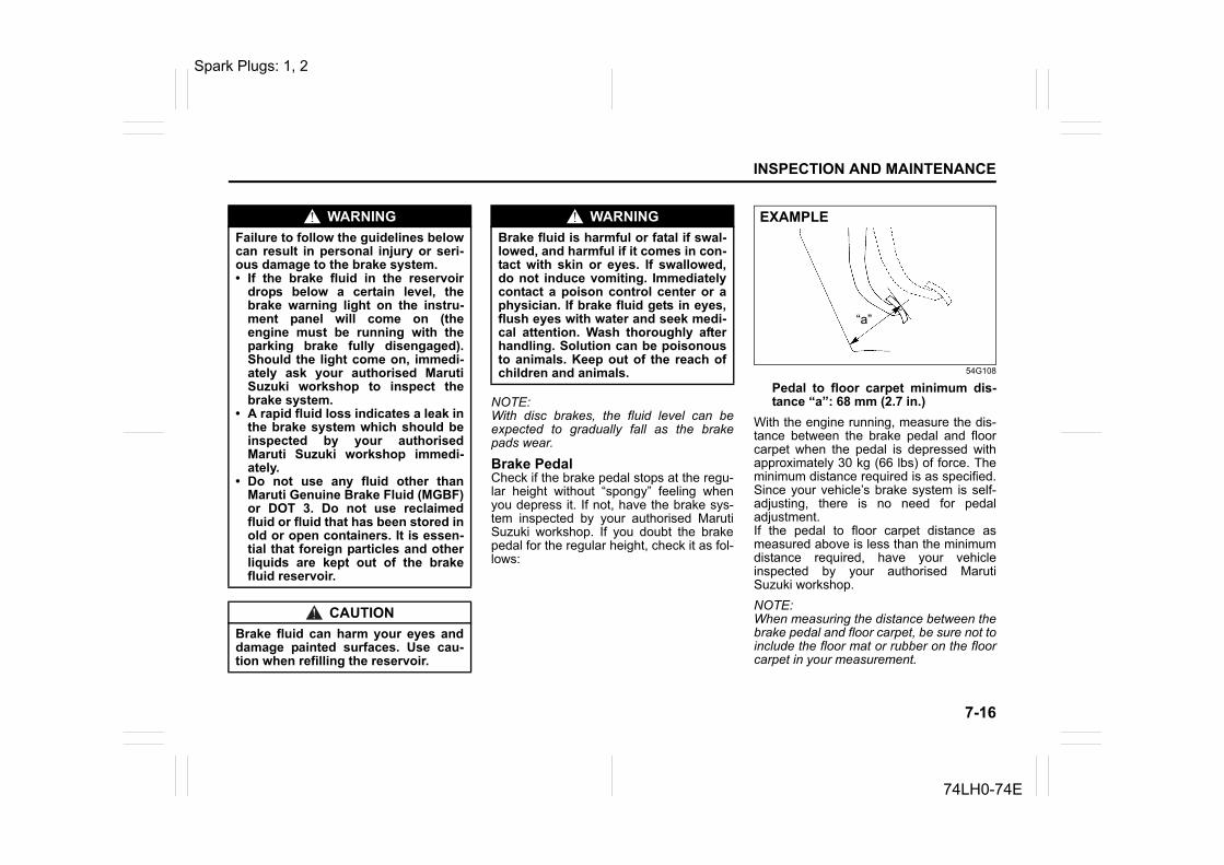
7-16
INSPECTION AND MAINTENANCE
74LH0-74E
NOTE:With disc brakes, the fluid level can beexpected to gradually fall as the brakepads wear.
Brake PedalCheck if the brake pedal stops at the regu-lar height without “spongy” feeling whenyou depress it. If not, have the brake sys-tem inspected by your authorised MarutiSuzuki workshop. If you doubt the brakepedal for the regular height, check it as fol-lows:
54G108
Pedal to floor carpet minimum dis-tance “a”: 68 mm (2.7 in.)
With the engine running, measure the dis-tance between the brake pedal and floorcarpet when the pedal is depressed withapproximately 30 kg (66 lbs) of force. Theminimum distance required is as specified.Since your vehicle’s brake system is self-adjusting, there is no need for pedaladjustment. If the pedal to floor carpet distance asmeasured above is less than the minimumdistance required, have your vehicleinspected by your authorised MarutiSuzuki workshop.NOTE:When measuring the distance between thebrake pedal and floor carpet, be sure not toinclude the floor mat or rubber on the floorcarpet in your measurement.
WARNINGFailure to follow the guidelines belowcan result in personal injury or seri-ous damage to the brake system.• If the brake fluid in the reservoir
drops below a certain level, thebrake warning light on the instru-ment panel will come on (theengine must be running with theparking brake fully disengaged).Should the light come on, immedi-ately ask your authorised MarutiSuzuki workshop to inspect thebrake system.
• A rapid fluid loss indicates a leak inthe brake system which should beinspected by your authorisedMaruti Suzuki workshop immedi-ately.
• Do not use any fluid other thanMaruti Genuine Brake Fluid (MGBF)or DOT 3. Do not use reclaimedfluid or fluid that has been stored inold or open containers. It is essen-tial that foreign particles and otherliquids are kept out of the brakefluid reservoir.
CAUTIONBrake fluid can harm your eyes anddamage painted surfaces. Use cau-tion when refilling the reservoir.
WARNINGBrake fluid is harmful or fatal if swal-lowed, and harmful if it comes in con-tact with skin or eyes. If swallowed,do not induce vomiting. Immediatelycontact a poison control center or aphysician. If brake fluid gets in eyes,flush eyes with water and seek medi-cal attention. Wash thoroughly afterhandling. Solution can be poisonousto animals. Keep out of the reach ofchildren and animals.
EXAMPLE
“a”
Spark Plugs: 1, 2
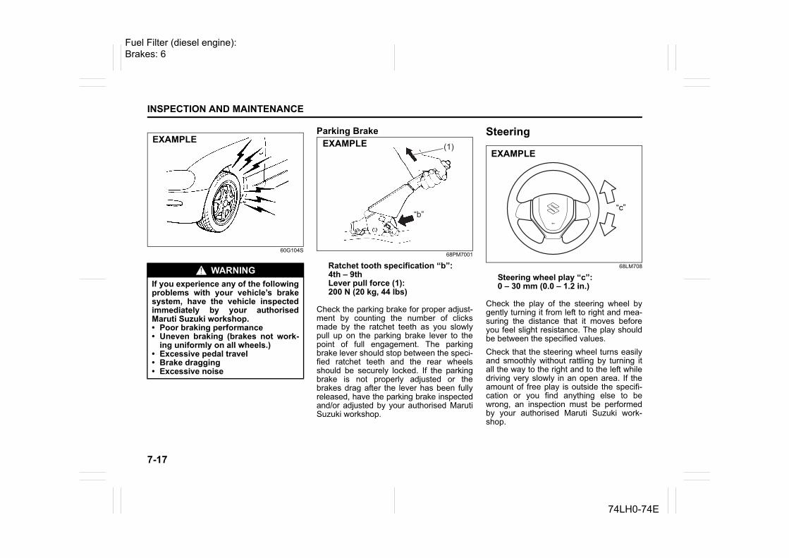
7-17
INSPECTION AND MAINTENANCE
74LH0-74E
60G104S
Parking Brake
68PM7001
Ratchet tooth specification “b”: 4th – 9thLever pull force (1):200 N (20 kg, 44 lbs)
Check the parking brake for proper adjust-ment by counting the number of clicksmade by the ratchet teeth as you slowlypull up on the parking brake lever to thepoint of full engagement. The parkingbrake lever should stop between the speci-fied ratchet teeth and the rear wheelsshould be securely locked. If the parkingbrake is not properly adjusted or thebrakes drag after the lever has been fullyreleased, have the parking brake inspectedand/or adjusted by your authorised MarutiSuzuki workshop.
Steering
68LM708
Steering wheel play “c”: 0 – 30 mm (0.0 – 1.2 in.)
Check the play of the steering wheel bygently turning it from left to right and mea-suring the distance that it moves beforeyou feel slight resistance. The play shouldbe between the specified values. Check that the steering wheel turns easilyand smoothly without rattling by turning itall the way to the right and to the left whiledriving very slowly in an open area. If theamount of free play is outside the specifi-cation or you find anything else to bewrong, an inspection must be performedby your authorised Maruti Suzuki work-shop.
WARNINGIf you experience any of the followingproblems with your vehicle’s brakesystem, have the vehicle inspectedimmediately by your authorisedMaruti Suzuki workshop.• Poor braking performance• Uneven braking (brakes not work-
ing uniformly on all wheels.)• Excessive pedal travel• Brake dragging• Excessive noise
EXAMPLE(1)
“b”
EXAMPLE
“c”
EXAMPLE
“c”
Fuel Filter (diesel engine): Brakes: 6
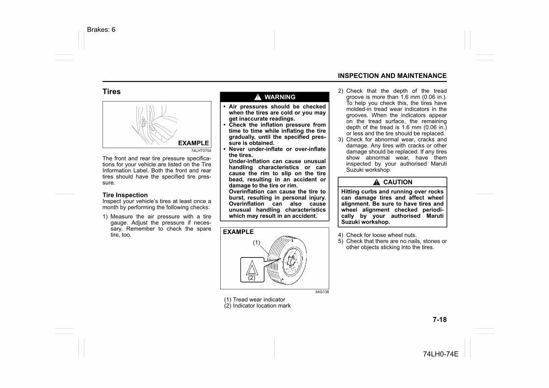
7-18
INSPECTION AND MAINTENANCE
74LH0-74E
Tires
74LHT0704
The front and rear tire pressure specifica-tions for your vehicle are listed on the TireInformation Label. Both the front and reartires should have the specified tire pres-sure.
Tire InspectionInspect your vehicle’s tires at least once amonth by performing the following checks:1) Measure the air pressure with a tire
gauge. Adjust the pressure if neces-sary. Remember to check the sparetire, too.
54G136
(1) Tread wear indicator(2) Indicator location mark
2) Check that the depth of the treadgroove is more than 1.6 mm (0.06 in.).To help you check this, the tires havemolded-in tread wear indicators in thegrooves. When the indicators appearon the tread surface, the remainingdepth of the tread is 1.6 mm (0.06 in.)or less and the tire should be replaced.
3) Check for abnormal wear, cracks anddamage. Any tires with cracks or otherdamage should be replaced. If any tiresshow abnormal wear, have theminspected by your authorised MarutiSuzuki workshop.
4) Check for loose wheel nuts.5) Check that there are no nails, stones or
other objects sticking into the tires.
EXAMPLE
WARNING• Air pressures should be checked
when the tires are cold or you mayget inaccurate readings.
• Check the inflation pressure fromtime to time while inflating the tiregradually, until the specified pres-sure is obtained.
• Never under-inflate or over-inflatethe tires. Under-inflation can cause unusualhandling characteristics or cancause the rim to slip on the tirebead, resulting in an accident ordamage to the tire or rim. Overinflation can cause the tire toburst, resulting in personal injury.Overinflation can also causeunusual handling characteristicswhich may result in an accident.
EXAMPLE(1)
(2)
CAUTIONHitting curbs and running over rockscan damage tires and affect wheelalignment. Be sure to have tires andwheel alignment checked periodi-cally by your authorised MarutiSuzuki workshop.
Brakes: 6
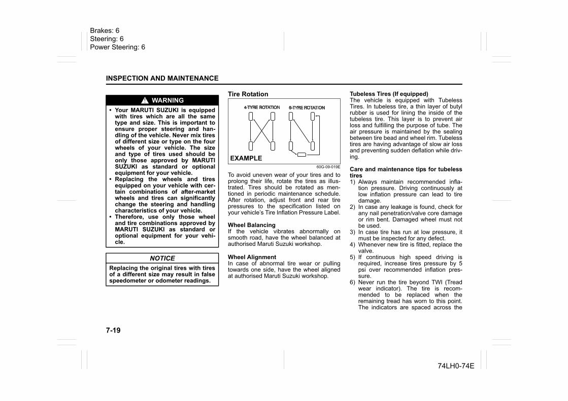
7-19
INSPECTION AND MAINTENANCE
74LH0-74E
Tire Rotation
60G-09-019E
To avoid uneven wear of your tires and toprolong their life, rotate the tires as illus-trated. Tires should be rotated as men-tioned in periodic maintenance schedule.After rotation, adjust front and rear tirepressures to the specification listed onyour vehicle’s Tire Inflation Pressure Label.
Wheel BalancingIf the vehicle vibrates abnormally onsmooth road, have the wheel balanced atauthorised Maruti Suzuki workshop.
Wheel AlignmentIn case of abnormal tire wear or pullingtowards one side, have the wheel alignedat authorised Maruti Suzuki workshop.
Tubeless Tires (If equipped)The vehicle is equipped with TubelessTires. In tubeless tire, a thin layer of butylrubber is used for lining the inside of thetubeless tire. This layer is to prevent airloss and fulfilling the purpose of tube. Theair pressure is maintained by the sealingbetween tire bead and wheel rim. Tubelesstires are having advantage of slow air lossand preventing sudden deflation while driv-ing.
Care and maintenance tips for tubelesstires1) Always maintain recommended infla-
tion pressure. Driving continuously atlow inflation pressure can lead to tiredamage.
2) In case any leakage is found, check forany nail penetration/valve core damageor rim bent. Damaged wheel must notbe used.
3) In case tire has run at low pressure, itmust be inspected for any defect.
4) Whenever new tire is fitted, replace thevalve.
5) If continuous high speed driving isrequired, increase tires pressure by 5psi over recommended inflation pres-sure.
6) Never run the tire beyond TWI (Treadwear indicator). The tire is recom-mended to be replaced when theremaining tread has worn to this point.The indicators are spaced across the
WARNING• Your MARUTI SUZUKI is equipped
with tires which are all the sametype and size. This is important toensure proper steering and han-dling of the vehicle. Never mix tiresof different size or type on the fourwheels of your vehicle. The sizeand type of tires used should beonly those approved by MARUTISUZUKI as standard or optionalequipment for your vehicle.
• Replacing the wheels and tiresequipped on your vehicle with cer-tain combinations of after-marketwheels and tires can significantlychange the steering and handlingcharacteristics of your vehicle.
• Therefore, use only those wheeland tire combinations approved byMARUTI SUZUKI as standard oroptional equipment for your vehi-cle.
NOTICEReplacing the original tires with tiresof a different size may result in falsespeedometer or odometer readings.
EXAMPLE
Brakes: 6Steering: 6Power Steering: 6
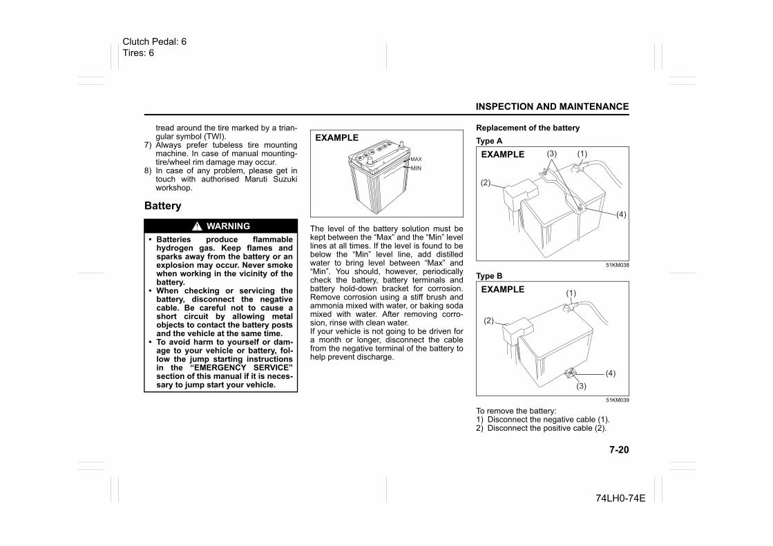
7-20
INSPECTION AND MAINTENANCE
74LH0-74E
tread around the tire marked by a trian-gular symbol (TWI).
7) Always prefer tubeless tire mountingmachine. In case of manual mounting-tire/wheel rim damage may occur.
8) In case of any problem, please get intouch with authorised Maruti Suzukiworkshop.
Battery
The level of the battery solution must bekept between the “Max” and the “Min” levellines at all times. If the level is found to bebelow the “Min” level line, add distilledwater to bring level between “Max” and“Min”. You should, however, periodicallycheck the battery, battery terminals andbattery hold-down bracket for corrosion.Remove corrosion using a stiff brush andammonia mixed with water, or baking sodamixed with water. After removing corro-sion, rinse with clean water.If your vehicle is not going to be driven fora month or longer, disconnect the cablefrom the negative terminal of the battery tohelp prevent discharge.
Replacement of the batteryType A
51KM038
Type B
51KM039
To remove the battery:1) Disconnect the negative cable (1).2) Disconnect the positive cable (2).
WARNING• Batteries produce flammable
hydrogen gas. Keep flames andsparks away from the battery or anexplosion may occur. Never smokewhen working in the vicinity of thebattery.
• When checking or servicing thebattery, disconnect the negativecable. Be careful not to cause ashort circuit by allowing metalobjects to contact the battery postsand the vehicle at the same time.
• To avoid harm to yourself or dam-age to your vehicle or battery, fol-low the jump starting instructionsin the “EMERGENCY SERVICE”section of this manual if it is neces-sary to jump start your vehicle.
EXAMPLE
(1)
(2)
(3)
(4)
EXAMPLE
(1)
(2)
(3)(4)
EXAMPLE
Clutch Pedal: 6Tires: 6
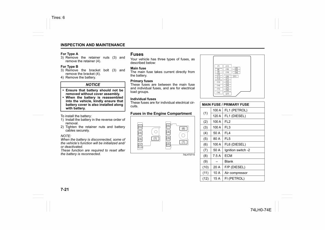
7-21
INSPECTION AND MAINTENANCE
74LH0-74E
For Type A3) Remove the retainer nuts (3) and
remove the retainer (4).For Type B3) Remove the bracket bolt (3) and
remove the bracket (4).4) Remove the battery.
To install the battery:1) Install the battery in the reverse order of
removal.2) Tighten the retainer nuts and battery
cables securely.NOTE:When the battery is disconnected, some ofthe vehicle’s function will be initialized and/or deactivated.These function are required to reset afterthe battery is reconnected.
FusesYour vehicle has three types of fuses, asdescribed below:Main fuseThe main fuse takes current directly fromthe battery.Primary fusesThese fuses are between the main fuseand individual fuses, and are for electricalload groups.
Individual fusesThese fuses are for individual electrical cir-cuits.
Fuses in the Engine Compartment
74LHT0715
NOTICE• Ensure that battery should not be
removed without cover assembly. • When the battery is reassembled
into the vehicle, kindly ensure thatbattery cover is also installed alongwith battery.
(5)
(3)
(4)
(2)
(1)
(5)
(4)
(3)
(2)(1)
(6)
MAIN FUSE / PRIMARY FUSE
(1)100 A FL1 (PETROL)
120 A FL1 (DIESEL)
(2) 100 A FL2
(3) 100 A FL3
(4) 50 A FL4
(5) 80 A FL5
(6) 100 A FL6 (DIESEL)
(7) 50 A Ignition switch -2
(8) 7.5 A ECM
(9) – Blank
(10) 20 A F/P (DIESEL)
(11) 10 A Air compressor
(12) 15 A FI (PETROL)
(7)
(8)(9)(10)(11)(12)
(13)
(14)
(15)
(16)
(17)(18)
(20)
(19)
(21)(22)(23)
(25)(24)
(26)
(27)
(28)(29)(30)
(31)
Tires: 6
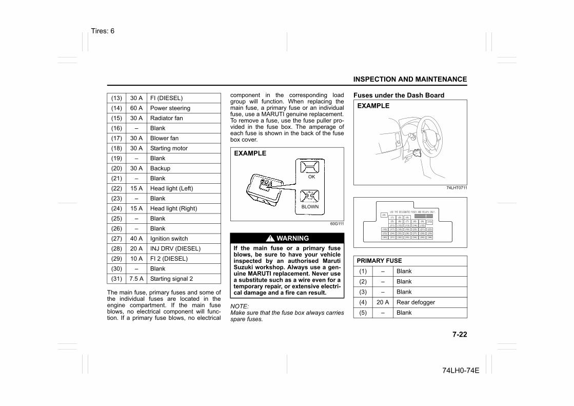
7-22
INSPECTION AND MAINTENANCE
74LH0-74E
The main fuse, primary fuses and some ofthe individual fuses are located in theengine compartment. If the main fuseblows, no electrical component will func-tion. If a primary fuse blows, no electrical
component in the corresponding loadgroup will function. When replacing themain fuse, a primary fuse or an individualfuse, use a MARUTI genuine replacement.To remove a fuse, use the fuse puller pro-vided in the fuse box. The amperage ofeach fuse is shown in the back of the fusebox cover.
60G111
NOTE:Make sure that the fuse box always carriesspare fuses.
Fuses under the Dash Board
74LHT0711
(13) 30 A FI (DIESEL)
(14) 60 A Power steering
(15) 30 A Radiator fan
(16) – Blank
(17) 30 A Blower fan
(18) 30 A Starting motor
(19) – Blank
(20) 30 A Backup
(21) – Blank
(22) 15 A Head light (Left)
(23) – Blank
(24) 15 A Head light (Right)
(25) – Blank
(26) – Blank
(27) 40 A Ignition switch
(28) 20 A INJ DRV (DIESEL)
(29) 10 A FI 2 (DIESEL)
(30) – Blank
(31) 7.5 A Starting signal 2
WARNINGIf the main fuse or a primary fuseblows, be sure to have your vehicleinspected by an authorised MarutiSuzuki workshop. Always use a gen-uine MARUTI replacement. Never usea substitute such as a wire even for atemporary repair, or extensive electri-cal damage and a fire can result.
EXAMPLE
BLOWN
OK
PRIMARY FUSE(1) – Blank
(2) – Blank
(3) – Blank
(4) 20 A Rear defogger
(5) – Blank
EXAMPLE
(3)
(12)(10)
(13)
(36)
(1) (2) (4)
(5) (6) (7) (8) (9)
(11) (14) (15)
(16) (17) (18) (19) (20) (21) (22)
(23) (24) (25) (26) (27) (28) (29)
(30) (31) (32) (33) (34) (35)
Tires: 6
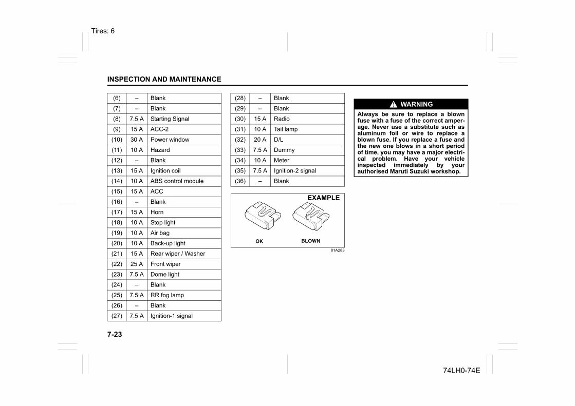
7-23
INSPECTION AND MAINTENANCE
74LH0-74E
81A283
(6) – Blank
(7) – Blank
(8) 7.5 A Starting Signal
(9) 15 A ACC-2
(10) 30 A Power window
(11) 10 A Hazard
(12) – Blank
(13) 15 A Ignition coil
(14) 10 A ABS control module
(15) 15 A ACC
(16) – Blank
(17) 15 A Horn
(18) 10 A Stop light
(19) 10 A Air bag
(20) 10 A Back-up light
(21) 15 A Rear wiper / Washer
(22) 25 A Front wiper
(23) 7.5 A Dome light
(24) – Blank
(25) 7.5 A RR fog lamp
(26) – Blank
(27) 7.5 A Ignition-1 signal
(28) – Blank
(29) – Blank
(30) 15 A Radio
(31) 10 A Tail lamp
(32) 20 A D/L
(33) 7.5 A Dummy
(34) 10 A Meter
(35) 7.5 A Ignition-2 signal
(36) – Blank
OK BLOWN
EXAMPLE
WARNINGAlways be sure to replace a blownfuse with a fuse of the correct amper-age. Never use a substitute such asaluminum foil or wire to replace ablown fuse. If you replace a fuse andthe new one blows in a short periodof time, you may have a major electri-cal problem. Have your vehicleinspected immediately by yourauthorised Maruti Suzuki workshop.
Tires: 6
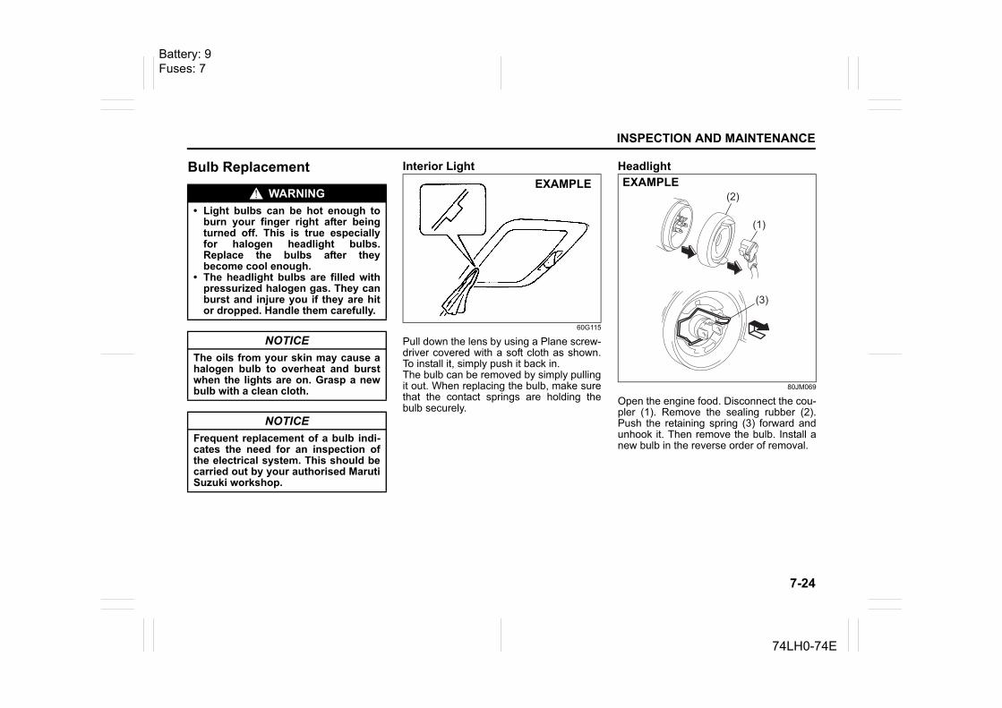
7-24
INSPECTION AND MAINTENANCE
74LH0-74E
Bulb Replacement Interior Light
60G115
Pull down the lens by using a Plane screw-driver covered with a soft cloth as shown.To install it, simply push it back in.The bulb can be removed by simply pullingit out. When replacing the bulb, make surethat the contact springs are holding thebulb securely.
Headlight
80JM069
Open the engine food. Disconnect the cou-pler (1). Remove the sealing rubber (2).Push the retaining spring (3) forward andunhook it. Then remove the bulb. Install anew bulb in the reverse order of removal.
WARNING• Light bulbs can be hot enough to
burn your finger right after beingturned off. This is true especiallyfor halogen headlight bulbs.Replace the bulbs after theybecome cool enough.
• The headlight bulbs are filled withpressurized halogen gas. They canburst and injure you if they are hitor dropped. Handle them carefully.
NOTICEThe oils from your skin may cause ahalogen bulb to overheat and burstwhen the lights are on. Grasp a newbulb with a clean cloth.
NOTICEFrequent replacement of a bulb indi-cates the need for an inspection ofthe electrical system. This should becarried out by your authorised MarutiSuzuki workshop.
EXAMPLE(2)
(1)
(3)
EXAMPLE
Battery: 9Fuses: 7
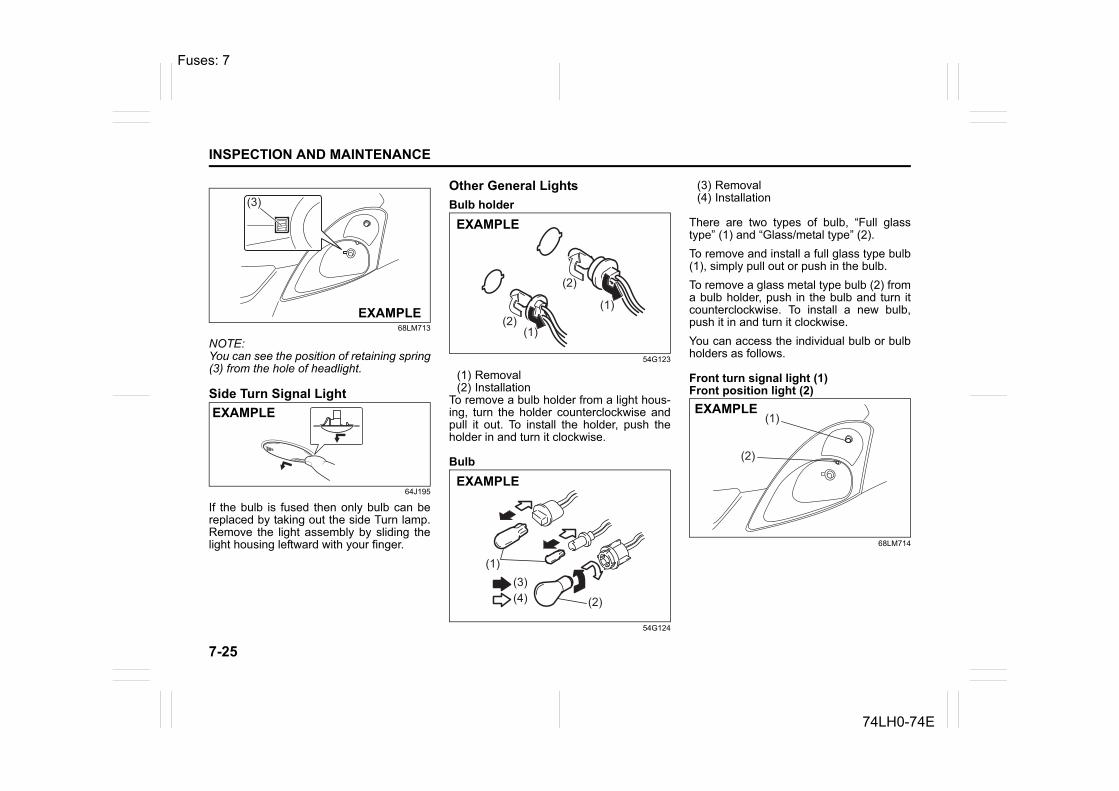
7-25
INSPECTION AND MAINTENANCE
74LH0-74E
68LM713
NOTE:You can see the position of retaining spring(3) from the hole of headlight.
Side Turn Signal Light
64J195
If the bulb is fused then only bulb can bereplaced by taking out the side Turn lamp.Remove the light assembly by sliding thelight housing leftward with your finger.
Other General LightsBulb holder
54G123
(1) Removal(2) Installation
To remove a bulb holder from a light hous-ing, turn the holder counterclockwise andpull it out. To install the holder, push theholder in and turn it clockwise.
Bulb
54G124
(3) Removal(4) Installation
There are two types of bulb, “Full glasstype” (1) and “Glass/metal type” (2).To remove and install a full glass type bulb(1), simply pull out or push in the bulb.To remove a glass metal type bulb (2) froma bulb holder, push in the bulb and turn itcounterclockwise. To install a new bulb,push it in and turn it clockwise.You can access the individual bulb or bulbholders as follows.
Front turn signal light (1)Front position light (2)
68LM714
(3)
EXAMPLE
EXAMPLE
(1)
(1)(2)
(2)
EXAMPLE
(1)
(2)
(3)(4)
EXAMPLE
(1)
(2)
EXAMPLE
Fuses: 7
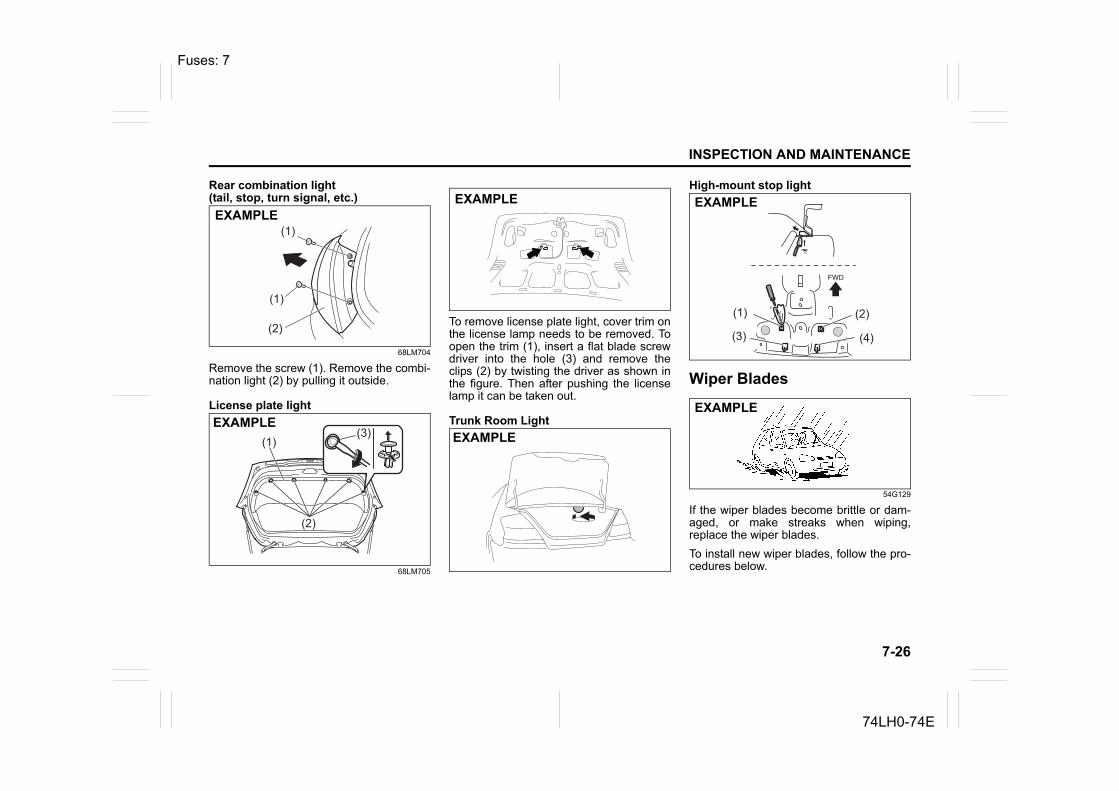
7-26
INSPECTION AND MAINTENANCE
74LH0-74E
Rear combination light (tail, stop, turn signal, etc.)
68LM704
Remove the screw (1). Remove the combi-nation light (2) by pulling it outside.
License plate light
68LM705
To remove license plate light, cover trim onthe license lamp needs to be removed. Toopen the trim (1), insert a flat blade screwdriver into the hole (3) and remove theclips (2) by twisting the driver as shown inthe figure. Then after pushing the licenselamp it can be taken out.
Trunk Room Light
High-mount stop light
Wiper Blades
54G129
If the wiper blades become brittle or dam-aged, or make streaks when wiping,replace the wiper blades.To install new wiper blades, follow the pro-cedures below.
(1)
(1)
(2)
EXAMPLE
(2)
(3)(1)
EXAMPLE
EXAMPLE
EXAMPLE
(1) (2)
(4)(3)
EXAMPLE
EXAMPLE
Fuses: 7
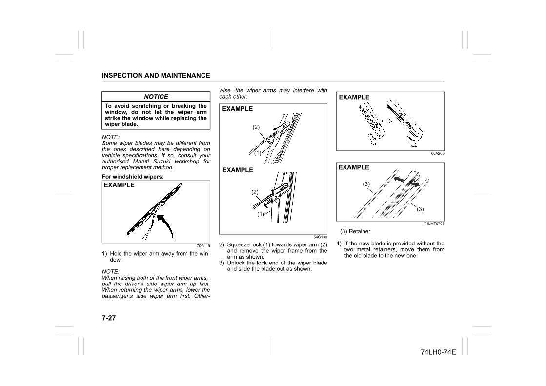
7-27
INSPECTION AND MAINTENANCE
74LH0-74E
NOTE:Some wiper blades may be different fromthe ones described here depending onvehicle specifications. If so, consult yourauthorised Maruti Suzuki workshop forproper replacement method.For windshield wipers:
70G119
1) Hold the wiper arm away from the win-dow.
NOTE:When raising both of the front wiper arms,pull the driver’s side wiper arm up first.When returning the wiper arms, lower thepassenger’s side wiper arm first. Other-
wise, the wiper arms may interfere witheach other.
54G130
2) Squeeze lock (1) towards wiper arm (2)and remove the wiper frame from thearm as shown.
3) Unlock the lock end of the wiper bladeand slide the blade out as shown.
60A260
71LMT0708
(3) Retainer
4) If the new blade is provided without thetwo metal retainers, move them fromthe old blade to the new one.
NOTICETo avoid scratching or breaking thewindow, do not let the wiper armstrike the window while replacing thewiper blade.
EXAMPLE
EXAMPLE
EXAMPLE
(2)
(1)
(2)
(1)
EXAMPLE
(3)
(3)
EXAMPLE
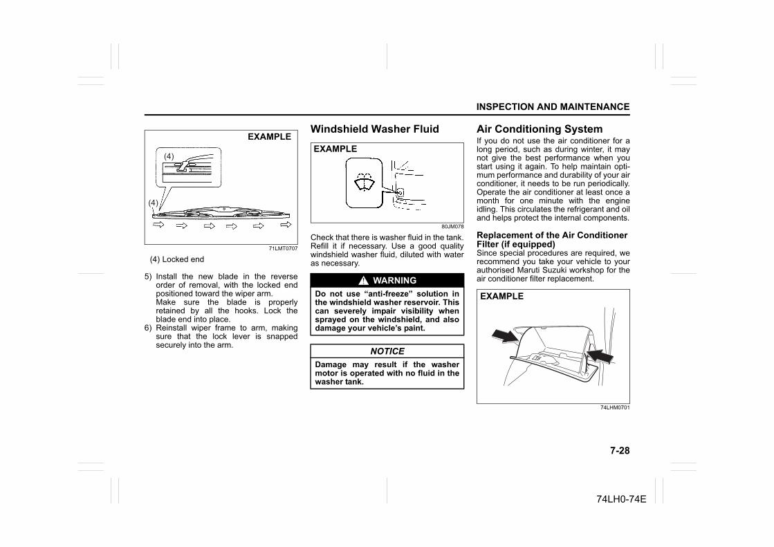
7-28
INSPECTION AND MAINTENANCE
74LH0-74E
71LMT0707
(4) Locked end
5) Install the new blade in the reverseorder of removal, with the locked endpositioned toward the wiper arm. Make sure the blade is properlyretained by all the hooks. Lock theblade end into place.
6) Reinstall wiper frame to arm, makingsure that the lock lever is snappedsecurely into the arm.
Windshield Washer Fluid
80JM078
Check that there is washer fluid in the tank.Refill it if necessary. Use a good qualitywindshield washer fluid, diluted with wateras necessary.
Air Conditioning SystemIf you do not use the air conditioner for along period, such as during winter, it maynot give the best performance when youstart using it again. To help maintain opti-mum performance and durability of your airconditioner, it needs to be run periodically.Operate the air conditioner at least once amonth for one minute with the engineidling. This circulates the refrigerant and oiland helps protect the internal components.
Replacement of the Air Conditioner Filter (if equipped)Since special procedures are required, werecommend you take your vehicle to yourauthorised Maruti Suzuki workshop for theair conditioner filter replacement.
74LHM0701
(4)
(4)
EXAMPLE
WARNINGDo not use “anti-freeze” solution inthe windshield washer reservoir. Thiscan severely impair visibility whensprayed on the windshield, and alsodamage your vehicle’s paint.
NOTICEDamage may result if the washermotor is operated with no fluid in thewasher tank.
EXAMPLE
EXAMPLE
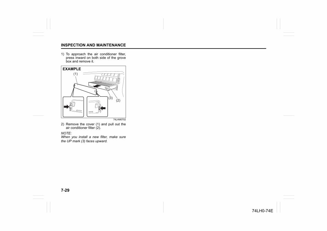
7-29
INSPECTION AND MAINTENANCE
74LH0-74E
1) To approach the air conditioner filter,press inward on both side of the grovebox and remove it.
74LHM0702
2) Remove the cover (1) and pull out theair conditioner filter (2).
NOTE:When you install a new filter, make surethe UP mark (3) faces upward.
(1)
(2)(3)
EXAMPLE
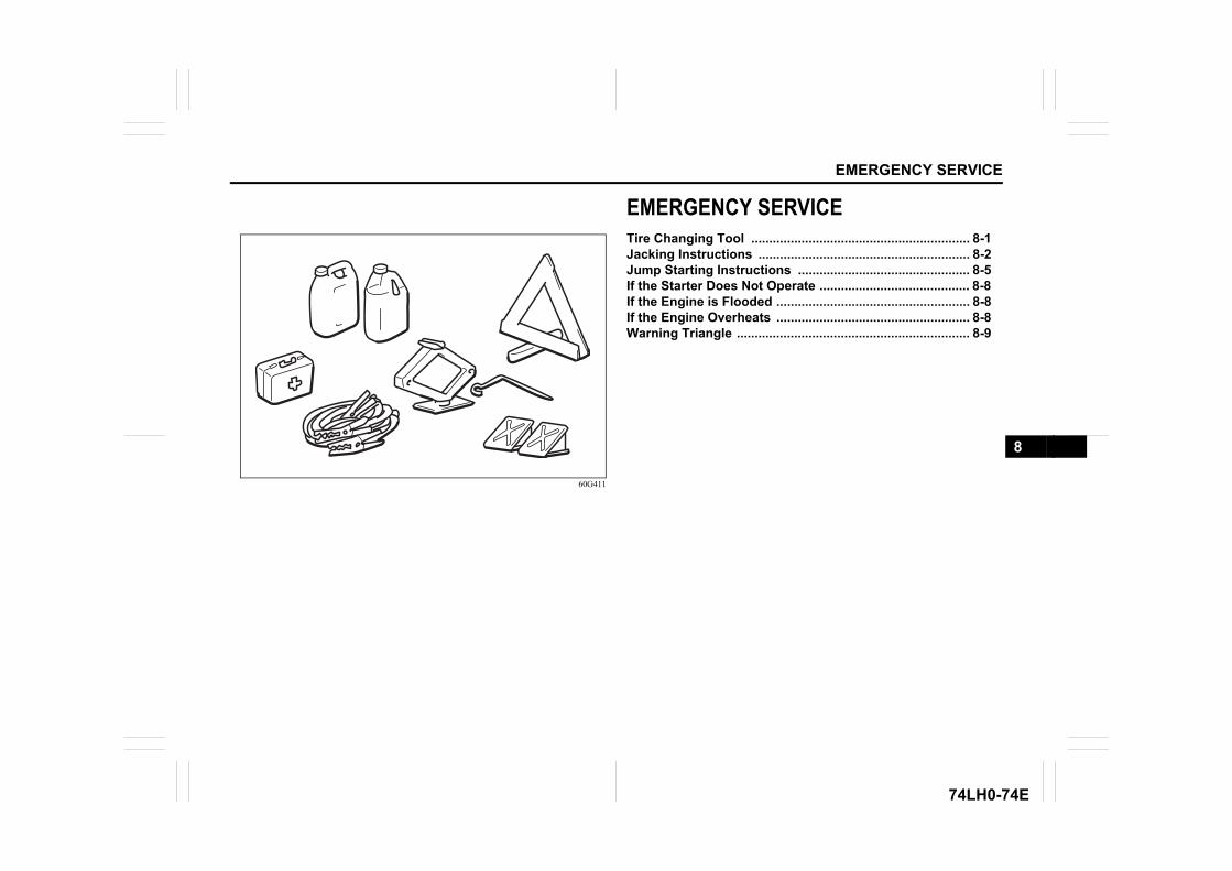
EMERGENCY SERVICE
74LH0-74E
60G411
EMERGENCY SERVICETire Changing Tool ............................................................. 8-1Jacking Instructions ........................................................... 8-2Jump Starting Instructions ................................................ 8-5If the Starter Does Not Operate .......................................... 8-8If the Engine is Flooded ...................................................... 8-8If the Engine Overheats ...................................................... 8-8Warning Triangle ................................................................. 8-9
8
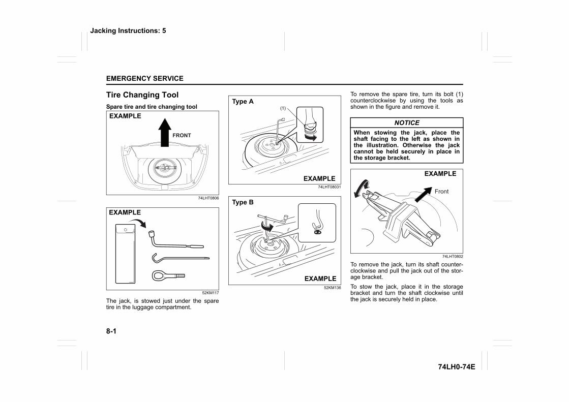
8-1
EMERGENCY SERVICE
74LH0-74E
Tire Changing ToolSpare tire and tire changing tool
74LHT0806
52KM117
The jack, is stowed just under the sparetire in the luggage compartment.
74LHT08031
52KM136
To remove the spare tire, turn its bolt (1)counterclockwise by using the tools asshown in the figure and remove it.
74LHT0802
To remove the jack, turn its shaft counter-clockwise and pull the jack out of the stor-age bracket.To stow the jack, place it in the storagebracket and turn the shaft clockwise untilthe jack is securely held in place.
EXAMPLE
EXAMPLE
(1)Type A
EXAMPLE
Type B
EXAMPLE
NOTICEWhen stowing the jack, place theshaft facing to the left as shown inthe illustration. Otherwise the jackcannot be held securely in place inthe storage bracket.
EXAMPLE
Jacking Instructions: 5
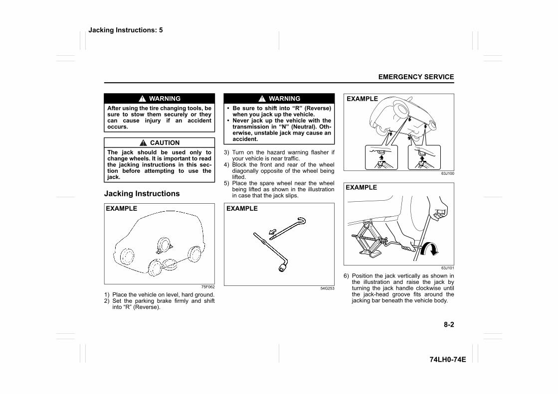
8-2
EMERGENCY SERVICE
74LH0-74E
Jacking Instructions
75F062
1) Place the vehicle on level, hard ground.2) Set the parking brake firmly and shift
into “R” (Reverse).
3) Turn on the hazard warning flasher ifyour vehicle is near traffic.
4) Block the front and rear of the wheeldiagonally opposite of the wheel beinglifted.
5) Place the spare wheel near the wheelbeing lifted as shown in the illustrationin case that the jack slips.
54G253
63J100
63J101
6) Position the jack vertically as shown inthe illustration and raise the jack byturning the jack handle clockwise untilthe jack-head groove fits around thejacking bar beneath the vehicle body.
WARNINGAfter using the tire changing tools, besure to stow them securely or theycan cause injury if an accidentoccurs.
CAUTIONThe jack should be used only tochange wheels. It is important to readthe jacking instructions in this sec-tion before attempting to use thejack.
EXAMPLE
WARNING• Be sure to shift into “R” (Reverse)
when you jack up the vehicle.• Never jack up the vehicle with the
transmission in “N” (Neutral). Oth-erwise, unstable jack may cause anaccident.
EXAMPLE
EXAMPLE
EXAMPLE
Jacking Instructions: 5
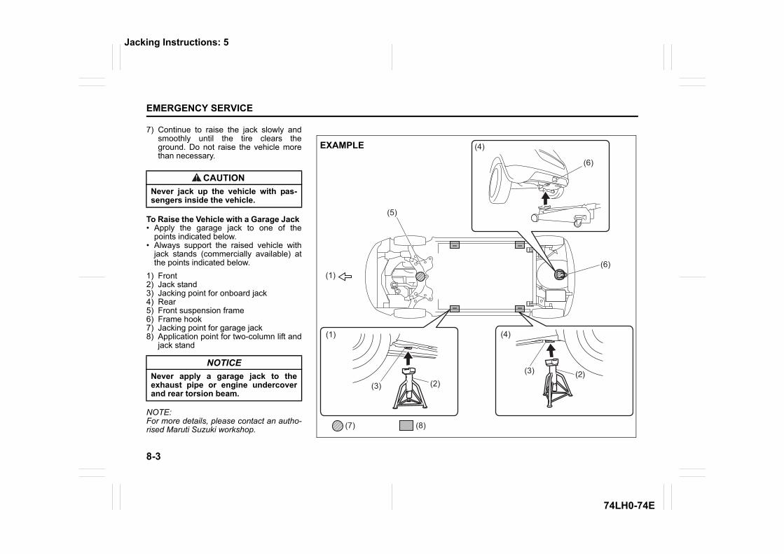
8-3
EMERGENCY SERVICE
74LH0-74E
7) Continue to raise the jack slowly andsmoothly until the tire clears theground. Do not raise the vehicle morethan necessary.
To Raise the Vehicle with a Garage Jack• Apply the garage jack to one of the
points indicated below.• Always support the raised vehicle with
jack stands (commercially available) atthe points indicated below.
1) Front2) Jack stand3) Jacking point for onboard jack4) Rear5) Front suspension frame6) Frame hook7) Jacking point for garage jack8) Application point for two-column lift and
jack stand
NOTE:For more details, please contact an autho-rised Maruti Suzuki workshop.
CAUTIONNever jack up the vehicle with pas-sengers inside the vehicle.
NOTICENever apply a garage jack to theexhaust pipe or engine undercoverand rear torsion beam.
(1)
(1)
(2)(2)
(3)
(4)
(5)
(7) (8)
(6)
(6)
(4)
(3)
EXAMPLE
Jacking Instructions: 5
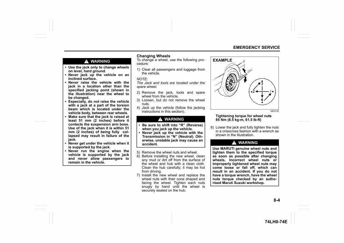
8-4
EMERGENCY SERVICE
74LH0-74E
Changing WheelsTo change a wheel, use the following pro-cedure:1) Clear all passengers and luggage from
the vehicle.NOTE:The Jack and tools are located under thespare wheel.2) Remove the jack, tools and spare
wheel from the vehicle.3) Loosen, but do not remove the wheel
nuts.4) Jack up the vehicle (follow the jacking
instructions in this section).
5) Remove the wheel nuts and wheel.6) Before installing the new wheel, clean
any mud or dirt off from the surface ofthe wheel and hub with a clean cloth.Clean the hub carefully; it may be hotfrom driving.
7) Install the new wheel and replace thewheel nuts with their cone shaped endfacing the wheel. Tighten each nutssnugly by hand until the wheel issecurely seated on the hub.
54G116
Tightening torque for wheel nuts85 Nm (8.5 kg-m, 61.5 lb-ft)
8) Lower the jack and fully tighten the nutsin a crisscross fashion with a wrench asshown in the illustration.
WARNING• Use the jack only to change wheels
on level, hard ground.• Never jack up the vehicle on an
inclined surface.• Never raise the vehicle with the
jack in a location other than thespecified jacking point (shown inthe illustration) near the wheel tobe changed.
• Especially, do not raise the vehiclewith a jack at a part of the torsionbeam which is located under thevehicle body, between rear wheels.
• Make sure that the jack is raised atleast 51 mm (2 inches) before itcontacts the suspension arm boss.Use of the jack when it is within 51mm (2 inches) of being fully col-lapsed may result in failure of thejack.
• Never get under the vehicle when itis supported by the jack.
• Never run the engine when thevehicle is supported by the jackand never allow passengers toremain in the vehicle.
WARNING• Be sure to shift into “R” (Reverse)
when you jack up the vehicle.• Never jack up the vehicle with the
Transmission in “N” (Neutral). Oth-erwise, unstable jack may cause anaccident. WARNING
Use MARUTI genuine wheel nuts andtighten them to the specified torqueas soon as possible after changingwheels. Incorrect wheel nuts orimproperly tightened wheel nuts maycome loose or fall off, which canresult in an accident. If you do nothave a torque wrench, have the wheelnuts torque checked by an autho-rised Maruti Suzuki workshop.
EXAMPLE
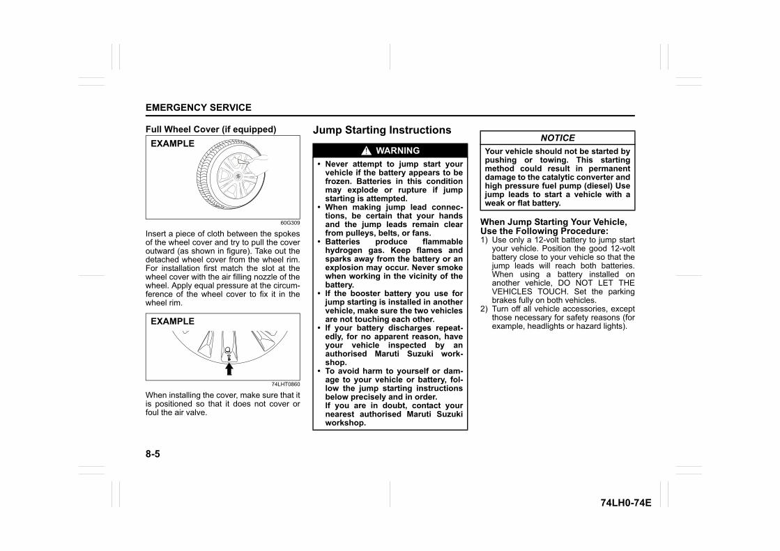
8-5
EMERGENCY SERVICE
74LH0-74E
Full Wheel Cover (if equipped)
60G309
Insert a piece of cloth between the spokesof the wheel cover and try to pull the coveroutward (as shown in figure). Take out thedetached wheel cover from the wheel rim.For installation first match the slot at thewheel cover with the air filling nozzle of thewheel. Apply equal pressure at the circum-ference of the wheel cover to fix it in thewheel rim.
74LHT0860
When installing the cover, make sure that itis positioned so that it does not cover orfoul the air valve.
Jump Starting Instructions
When Jump Starting Your Vehicle, Use the Following Procedure:1) Use only a 12-volt battery to jump start
your vehicle. Position the good 12-voltbattery close to your vehicle so that thejump leads will reach both batteries.When using a battery installed onanother vehicle, DO NOT LET THEVEHICLES TOUCH. Set the parkingbrakes fully on both vehicles.
2) Turn off all vehicle accessories, exceptthose necessary for safety reasons (forexample, headlights or hazard lights).
EXAMPLE
EXAMPLE
WARNING• Never attempt to jump start your
vehicle if the battery appears to befrozen. Batteries in this conditionmay explode or rupture if jumpstarting is attempted.
• When making jump lead connec-tions, be certain that your handsand the jump leads remain clearfrom pulleys, belts, or fans.
• Batteries produce flammablehydrogen gas. Keep flames andsparks away from the battery or anexplosion may occur. Never smokewhen working in the vicinity of thebattery.
• If the booster battery you use forjump starting is installed in anothervehicle, make sure the two vehiclesare not touching each other.
• If your battery discharges repeat-edly, for no apparent reason, haveyour vehicle inspected by anauthorised Maruti Suzuki work-shop.
• To avoid harm to yourself or dam-age to your vehicle or battery, fol-low the jump starting instructionsbelow precisely and in order. If you are in doubt, contact yournearest authorised Maruti Suzukiworkshop.
NOTICEYour vehicle should not be started bypushing or towing. This startingmethod could result in permanentdamage to the catalytic converter andhigh pressure fuel pump (diesel) Usejump leads to start a vehicle with aweak or flat battery.
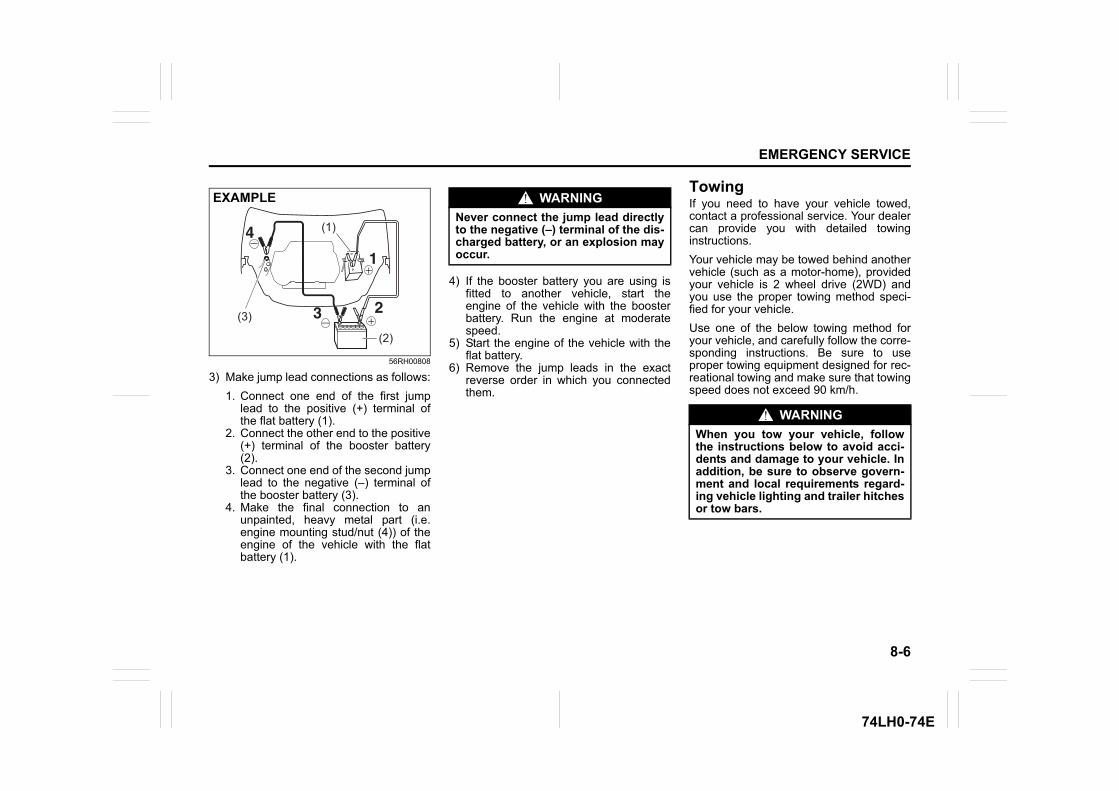
8-6
EMERGENCY SERVICE
74LH0-74E
56RH00808
3) Make jump lead connections as follows:1. Connect one end of the first jump
lead to the positive (+) terminal ofthe flat battery (1).
2. Connect the other end to the positive(+) terminal of the booster battery(2).
3. Connect one end of the second jumplead to the negative (–) terminal ofthe booster battery (3).
4. Make the final connection to anunpainted, heavy metal part (i.e.engine mounting stud/nut (4)) of theengine of the vehicle with the flatbattery (1).
4) If the booster battery you are using isfitted to another vehicle, start theengine of the vehicle with the boosterbattery. Run the engine at moderatespeed.
5) Start the engine of the vehicle with theflat battery.
6) Remove the jump leads in the exactreverse order in which you connectedthem.
TowingIf you need to have your vehicle towed,contact a professional service. Your dealercan provide you with detailed towinginstructions.Your vehicle may be towed behind anothervehicle (such as a motor-home), providedyour vehicle is 2 wheel drive (2WD) andyou use the proper towing method speci-fied for your vehicle.Use one of the below towing method foryour vehicle, and carefully follow the corre-sponding instructions. Be sure to useproper towing equipment designed for rec-reational towing and make sure that towingspeed does not exceed 90 km/h.
(2)
(1)
(3)
EXAMPLE WARNINGNever connect the jump lead directlyto the negative (–) terminal of the dis-charged battery, or an explosion mayoccur.
WARNINGWhen you tow your vehicle, followthe instructions below to avoid acci-dents and damage to your vehicle. Inaddition, be sure to observe govern-ment and local requirements regard-ing vehicle lighting and trailer hitchesor tow bars.
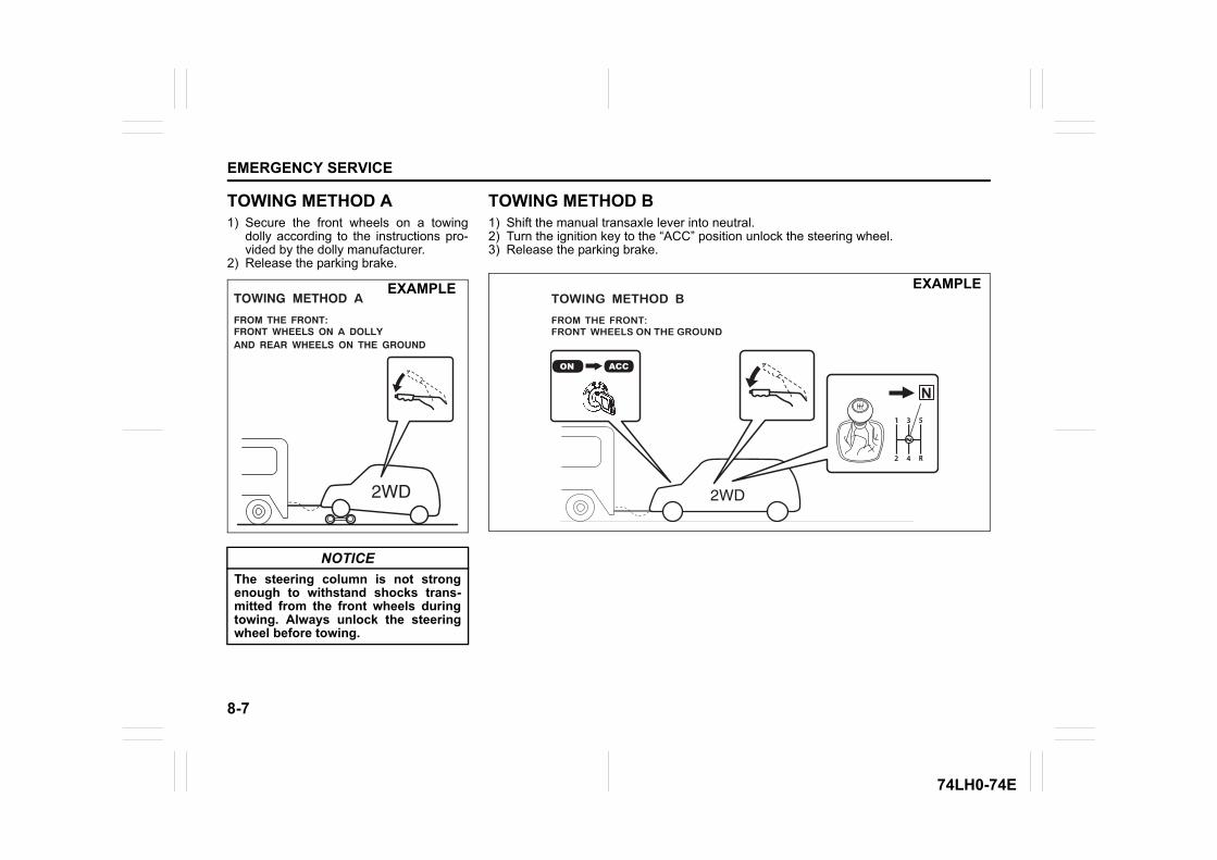
8-7
EMERGENCY SERVICE
74LH0-74E
TOWING METHOD A1) Secure the front wheels on a towing
dolly according to the instructions pro-vided by the dolly manufacturer.
2) Release the parking brake.
NOTICEThe steering column is not strongenough to withstand shocks trans-mitted from the front wheels duringtowing. Always unlock the steeringwheel before towing.
TOWING METHOD A
FROM THE FRONT:FRONT WHEELS ON A DOLLYAND REAR WHEELS ON THE GROUND
EXAMPLE
TOWING METHOD B1) Shift the manual transaxle lever into neutral.2) Turn the ignition key to the “ACC” position unlock the steering wheel.3) Release the parking brake.
ACC
N
TOWING METHOD B
FROM THE FRONT:FRONT WHEELS ON THE GROUND
EXAMPLE
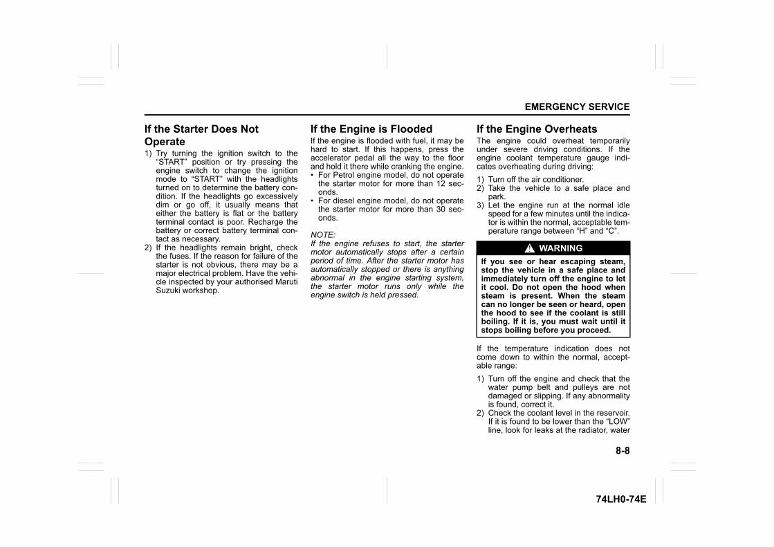
8-8
EMERGENCY SERVICE
74LH0-74E
If the Starter Does Not Operate1) Try turning the ignition switch to the
“START” position or try pressing theengine switch to change the ignitionmode to “START” with the headlightsturned on to determine the battery con-dition. If the headlights go excessivelydim or go off, it usually means thateither the battery is flat or the batteryterminal contact is poor. Recharge thebattery or correct battery terminal con-tact as necessary.
2) If the headlights remain bright, checkthe fuses. If the reason for failure of thestarter is not obvious, there may be amajor electrical problem. Have the vehi-cle inspected by your authorised MarutiSuzuki workshop.
If the Engine is FloodedIf the engine is flooded with fuel, it may behard to start. If this happens, press theaccelerator pedal all the way to the floorand hold it there while cranking the engine.• For Petrol engine model, do not operate
the starter motor for more than 12 sec-onds.
• For diesel engine model, do not operatethe starter motor for more than 30 sec-onds.
NOTE:If the engine refuses to start, the startermotor automatically stops after a certainperiod of time. After the starter motor hasautomatically stopped or there is anythingabnormal in the engine starting system,the starter motor runs only while theengine switch is held pressed.
If the Engine OverheatsThe engine could overheat temporarilyunder severe driving conditions. If theengine coolant temperature gauge indi-cates overheating during driving:1) Turn off the air conditioner.2) Take the vehicle to a safe place and
park.3) Let the engine run at the normal idle
speed for a few minutes until the indica-tor is within the normal, acceptable tem-perature range between “H” and “C”.
If the temperature indication does notcome down to within the normal, accept-able range:1) Turn off the engine and check that the
water pump belt and pulleys are notdamaged or slipping. If any abnormalityis found, correct it.
2) Check the coolant level in the reservoir.If it is found to be lower than the “LOW”line, look for leaks at the radiator, water
WARNINGIf you see or hear escaping steam,stop the vehicle in a safe place andimmediately turn off the engine to letit cool. Do not open the hood whensteam is present. When the steamcan no longer be seen or heard, openthe hood to see if the coolant is stillboiling. If it is, you must wait until itstops boiling before you proceed.
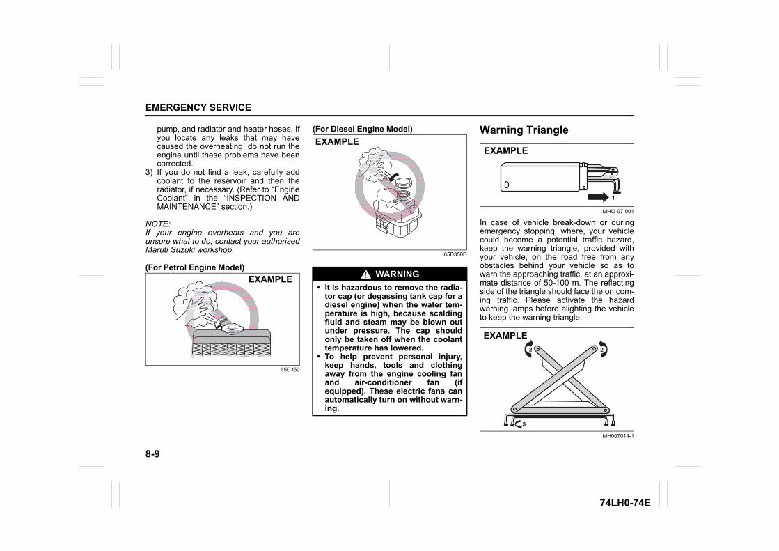
8-9
EMERGENCY SERVICE
74LH0-74E
pump, and radiator and heater hoses. Ifyou locate any leaks that may havecaused the overheating, do not run theengine until these problems have beencorrected.
3) If you do not find a leak, carefully addcoolant to the reservoir and then theradiator, if necessary. (Refer to “EngineCoolant” in the “INSPECTION ANDMAINTENANCE” section.)
NOTE:If your engine overheats and you areunsure what to do, contact your authorisedMaruti Suzuki workshop.
(For Petrol Engine Model)
65D350
(For Diesel Engine Model)
65D350D
Warning Triangle
MHO-07-001
In case of vehicle break-down or duringemergency stopping, where, your vehiclecould become a potential traffic hazard,keep the warning triangle, provided withyour vehicle, on the road free from anyobstacles behind your vehicle so as towarn the approaching traffic, at an approxi-mate distance of 50-100 m. The reflectingside of the triangle should face the on com-ing traffic. Please activate the hazardwarning lamps before alighting the vehicleto keep the warning triangle.
MH007014-1
EXAMPLE WARNING• It is hazardous to remove the radia-
tor cap (or degassing tank cap for adiesel engine) when the water tem-perature is high, because scaldingfluid and steam may be blown outunder pressure. The cap shouldonly be taken off when the coolanttemperature has lowered.
• To help prevent personal injury,keep hands, tools and clothingaway from the engine cooling fanand air-conditioner fan (ifequipped). These electric fans canautomatically turn on without warn-ing.
EXAMPLEEXAMPLE
EXAMPLE
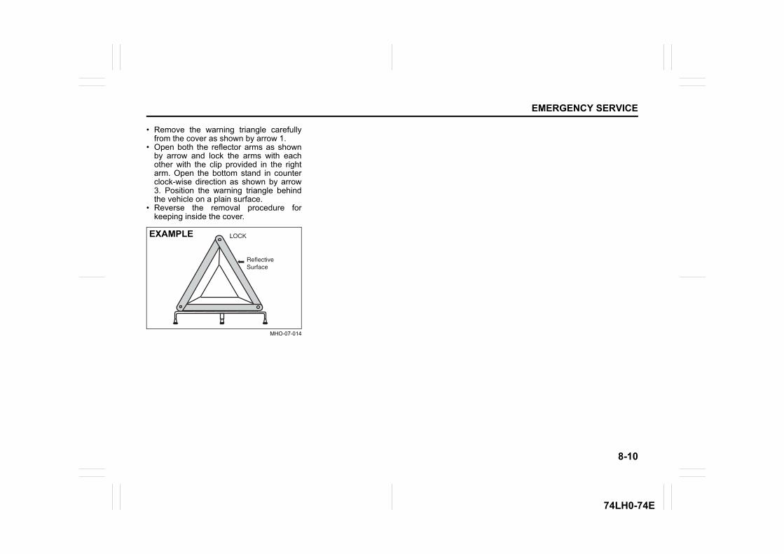
8-10
EMERGENCY SERVICE
74LH0-74E
• Remove the warning triangle carefullyfrom the cover as shown by arrow 1.
• Open both the reflector arms as shownby arrow and lock the arms with eachother with the clip provided in the rightarm. Open the bottom stand in counterclock-wise direction as shown by arrow3. Position the warning triangle behindthe vehicle on a plain surface.
• Reverse the removal procedure forkeeping inside the cover.
MHO-07-014
EXAMPLE

APPEARANCE CARE
9
56RH0-74E
60G412
APPEARANCE CARECorrosion prevention .......................................................... 9-1Vehicle cleaning .................................................................. 9-2
9-1
APPEARANCE CARE
56RH0-74E
Corrosion preventionIt is important to take good care of yourvehicle to protect it from corrosion. Listedbelow are instructions for how to maintainyour vehicle to prevent corrosion. Pleaseread and follow these instructions carefully.
Important information about corro-sionCommon causes of corrosion1) Accumulation of road salt, dirt, moisture
or chemicals in hard-to-reach areas ofthe vehicle underbody or frame.
2) Chipping, scratches and any damage totreated or painted metal surfacesresulting from minor accidents or abra-sion by stones and gravel.
Environmental conditions which accel-erate corrosion1) Road salt, dust control chemicals, sea
breeze or industrial pollution will allaccelerate the corrosion of metal.
2) High humidity will increase the rate ofcorrosion particularly when the tem-perature range is just above the freez-ing point.
3) Moisture in certain areas of a vehiclefor an extended period of time may pro-mote corrosion even though other bodysections may be completely dry.
4) High temperatures will cause an accel-erated rate of corrosion to parts of thevehicle which are not well-ventilated topermit quick drying.
This information illustrates the necessity ofkeeping your vehicle (particularly theunderbody) as clean and dry as possible. Itis equally important to repair any damageto the paint or protective coatings as soonas possible.
How to help prevent corrosionWash your vehicle frequentlyThe best way to preserve the finish on yourvehicle and to help avoid corrosion is tokeep it clean with frequent washing.Wash your vehicle at least once during thewinter and once immediately after the win-ter. Keep your vehicle, particularly theunderside, as clean and dry as possible.If you frequently drive on salted roads,your vehicle should be washed at leastonce a month during the winter. If you livenear the ocean, your vehicle should bewashed at least once a month throughoutthe year.For washing instructions, refer to “Vehiclecleaning” section.
Remove foreign material depositsForeign material such as salts, chemicals,road oil or tar, tree sap, bird droppings andindustrial fall-out may damage the finish ofyour vehicle if it is left on painted surfaces.Remove these types of deposits as quicklyas possible. If these deposits are difficult towash off, an additional cleaner may berequired. Check that any cleaner you useis not harmful to painted surfaces and is
specifically intended for your purposes.Follow the manufacturer’s directions whenusing these special cleaners.
Repair finish damageCarefully examine your vehicle for damageto the painted surfaces. Should you findany chips or scratches in the paint, touchthem up immediately to prevent corrosionfrom starting. If the chips or scratches havegone through to the bare metal, have aqualified body shop make the repair.
Keep passenger and luggage compart-ments cleanMoisture, dirt or mud can accumulateunder the floor mats and may cause corro-sion. Occasionally, check under thesemats to ensure that this area is clean anddry. More frequent checks are necessary ifthe vehicle is used for off-road driving or inwet weather.Certain cargos such as chemicals, fertiliz-ers, cleaners, salts, etc. are extremely cor-rosive by nature. These products shouldbe transported in sealed containers. If theyare spilled or leaked, clean and dry thearea immediately.
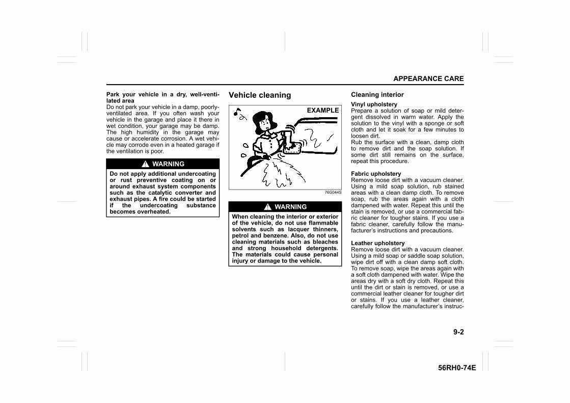
9-2
APPEARANCE CARE
56RH0-74E
Park your vehicle in a dry, well-venti-lated areaDo not park your vehicle in a damp, poorly-ventilated area. If you often wash yourvehicle in the garage and place it there inwet condition, your garage may be damp.The high humidity in the garage maycause or accelerate corrosion. A wet vehi-cle may corrode even in a heated garage ifthe ventilation is poor.
Vehicle cleaning
76G044S
Cleaning interiorVinyl upholsteryPrepare a solution of soap or mild deter-gent dissolved in warm water. Apply thesolution to the vinyl with a sponge or softcloth and let it soak for a few minutes toloosen dirt.Rub the surface with a clean, damp clothto remove dirt and the soap solution. Ifsome dirt still remains on the surface,repeat this procedure.
Fabric upholsteryRemove loose dirt with a vacuum cleaner.Using a mild soap solution, rub stainedareas with a clean damp cloth. To removesoap, rub the areas again with a clothdampened with water. Repeat this until thestain is removed, or use a commercial fab-ric cleaner for tougher stains. If you use afabric cleaner, carefully follow the manu-facturer’s instructions and precautions.
Leather upholsteryRemove loose dirt with a vacuum cleaner.Using a mild soap or saddle soap solution,wipe dirt off with a clean damp soft cloth.To remove soap, wipe the areas again witha soft cloth dampened with water. Wipe theareas dry with a soft dry cloth. Repeat thisuntil the dirt or stain is removed, or use acommercial leather cleaner for tougher dirtor stains. If you use a leather cleaner,carefully follow the manufacturer’s instruc-
WARNINGDo not apply additional undercoatingor rust preventive coating on oraround exhaust system componentssuch as the catalytic converter andexhaust pipes. A fire could be startedif the undercoating substancebecomes overheated.
WARNINGWhen cleaning the interior or exteriorof the vehicle, do not use flammablesolvents such as lacquer thinners,petrol and benzene. Also, do not usecleaning materials such as bleachesand strong household detergents.The materials could cause personalinjury or damage to the vehicle.
EXAMPLE
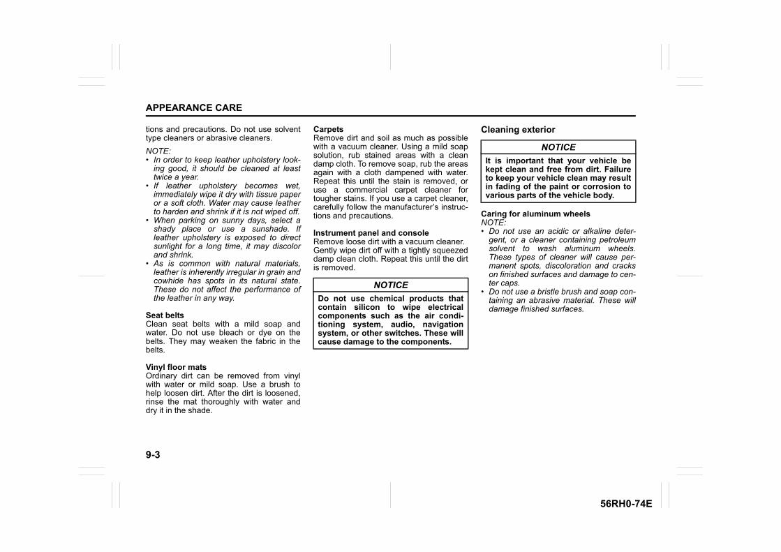
9-3
APPEARANCE CARE
56RH0-74E
tions and precautions. Do not use solventtype cleaners or abrasive cleaners.NOTE:• In order to keep leather upholstery look-
ing good, it should be cleaned at leasttwice a year.
• If leather upholstery becomes wet,immediately wipe it dry with tissue paperor a soft cloth. Water may cause leatherto harden and shrink if it is not wiped off.
• When parking on sunny days, select ashady place or use a sunshade. Ifleather upholstery is exposed to directsunlight for a long time, it may discolorand shrink.
• As is common with natural materials,leather is inherently irregular in grain andcowhide has spots in its natural state.These do not affect the performance ofthe leather in any way.
Seat beltsClean seat belts with a mild soap andwater. Do not use bleach or dye on thebelts. They may weaken the fabric in thebelts.
Vinyl floor matsOrdinary dirt can be removed from vinylwith water or mild soap. Use a brush tohelp loosen dirt. After the dirt is loosened,rinse the mat thoroughly with water anddry it in the shade.
CarpetsRemove dirt and soil as much as possiblewith a vacuum cleaner. Using a mild soapsolution, rub stained areas with a cleandamp cloth. To remove soap, rub the areasagain with a cloth dampened with water.Repeat this until the stain is removed, oruse a commercial carpet cleaner fortougher stains. If you use a carpet cleaner,carefully follow the manufacturer’s instruc-tions and precautions.
Instrument panel and consoleRemove loose dirt with a vacuum cleaner.Gently wipe dirt off with a tightly squeezeddamp clean cloth. Repeat this until the dirtis removed.
Cleaning exterior
Caring for aluminum wheelsNOTE:• Do not use an acidic or alkaline deter-
gent, or a cleaner containing petroleumsolvent to wash aluminum wheels.These types of cleaner will cause per-manent spots, discoloration and crackson finished surfaces and damage to cen-ter caps.
• Do not use a bristle brush and soap con-taining an abrasive material. These willdamage finished surfaces.
NOTICEDo not use chemical products thatcontain silicon to wipe electricalcomponents such as the air condi-tioning system, audio, navigationsystem, or other switches. These willcause damage to the components.
NOTICEIt is important that your vehicle bekept clean and free from dirt. Failureto keep your vehicle clean may resultin fading of the paint or corrosion tovarious parts of the vehicle body.
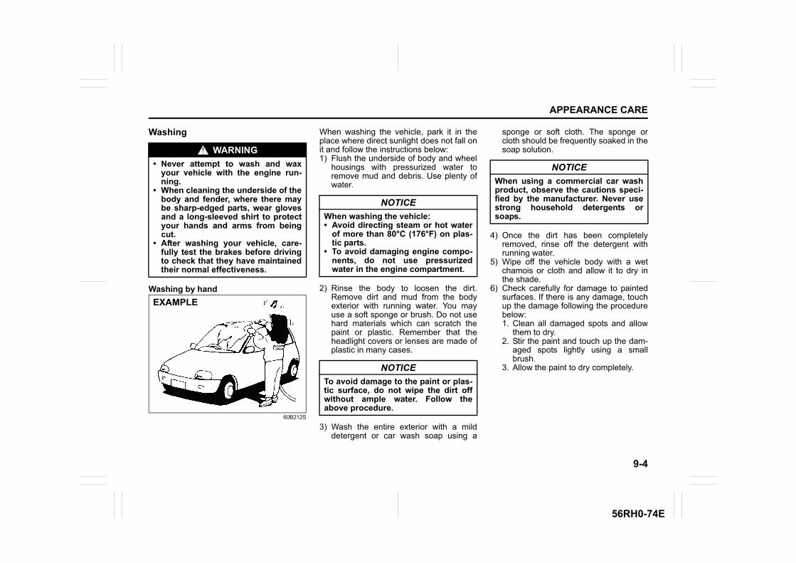
9-4
APPEARANCE CARE
56RH0-74E
Washing
Washing by hand
60B212S
When washing the vehicle, park it in theplace where direct sunlight does not fall onit and follow the instructions below:1) Flush the underside of body and wheel
housings with pressurized water toremove mud and debris. Use plenty ofwater.
2) Rinse the body to loosen the dirt.Remove dirt and mud from the bodyexterior with running water. You mayuse a soft sponge or brush. Do not usehard materials which can scratch thepaint or plastic. Remember that theheadlight covers or lenses are made ofplastic in many cases.
3) Wash the entire exterior with a milddetergent or car wash soap using a
sponge or soft cloth. The sponge orcloth should be frequently soaked in thesoap solution.
4) Once the dirt has been completelyremoved, rinse off the detergent withrunning water.
5) Wipe off the vehicle body with a wetchamois or cloth and allow it to dry inthe shade.
6) Check carefully for damage to paintedsurfaces. If there is any damage, touchup the damage following the procedurebelow:1. Clean all damaged spots and allow
them to dry.2. Stir the paint and touch up the dam-
aged spots lightly using a smallbrush.
3. Allow the paint to dry completely.
WARNING• Never attempt to wash and wax
your vehicle with the engine run-ning.
• When cleaning the underside of thebody and fender, where there maybe sharp-edged parts, wear glovesand a long-sleeved shirt to protectyour hands and arms from beingcut.
• After washing your vehicle, care-fully test the brakes before drivingto check that they have maintainedtheir normal effectiveness.
EXAMPLE
NOTICEWhen washing the vehicle:• Avoid directing steam or hot water
of more than 80°C (176°F) on plas-tic parts.
• To avoid damaging engine compo-nents, do not use pressurizedwater in the engine compartment.
NOTICETo avoid damage to the paint or plas-tic surface, do not wipe the dirt offwithout ample water. Follow theabove procedure.
NOTICEWhen using a commercial car washproduct, observe the cautions speci-fied by the manufacturer. Never usestrong household detergents orsoaps.
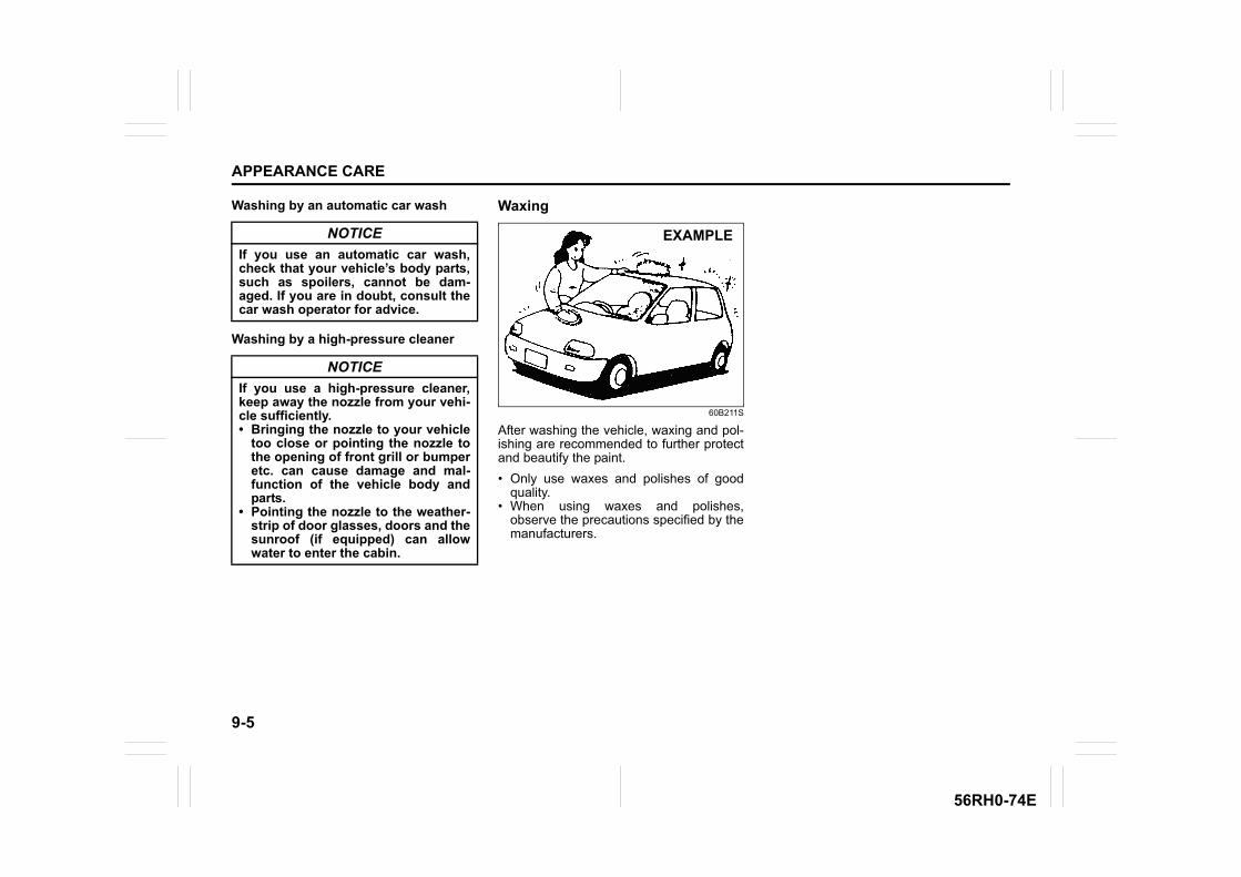
9-5
APPEARANCE CARE
56RH0-74E
Washing by an automatic car wash
Washing by a high-pressure cleaner
Waxing
60B211S
After washing the vehicle, waxing and pol-ishing are recommended to further protectand beautify the paint.• Only use waxes and polishes of good
quality.• When using waxes and polishes,
observe the precautions specified by themanufacturers.
NOTICEIf you use an automatic car wash,check that your vehicle’s body parts,such as spoilers, cannot be dam-aged. If you are in doubt, consult thecar wash operator for advice.
NOTICEIf you use a high-pressure cleaner,keep away the nozzle from your vehi-cle sufficiently.• Bringing the nozzle to your vehicle
too close or pointing the nozzle tothe opening of front grill or bumperetc. can cause damage and mal-function of the vehicle body andparts.
• Pointing the nozzle to the weather-strip of door glasses, doors and thesunroof (if equipped) can allowwater to enter the cabin.
EXAMPLE
GENERAL INFORMATION
10
56RH0-74E
84MM01001
GENERAL INFORMATIONVehicle identification .......................................................... 10-1Radio frequency identification (RFID) tag .......................... 10-1
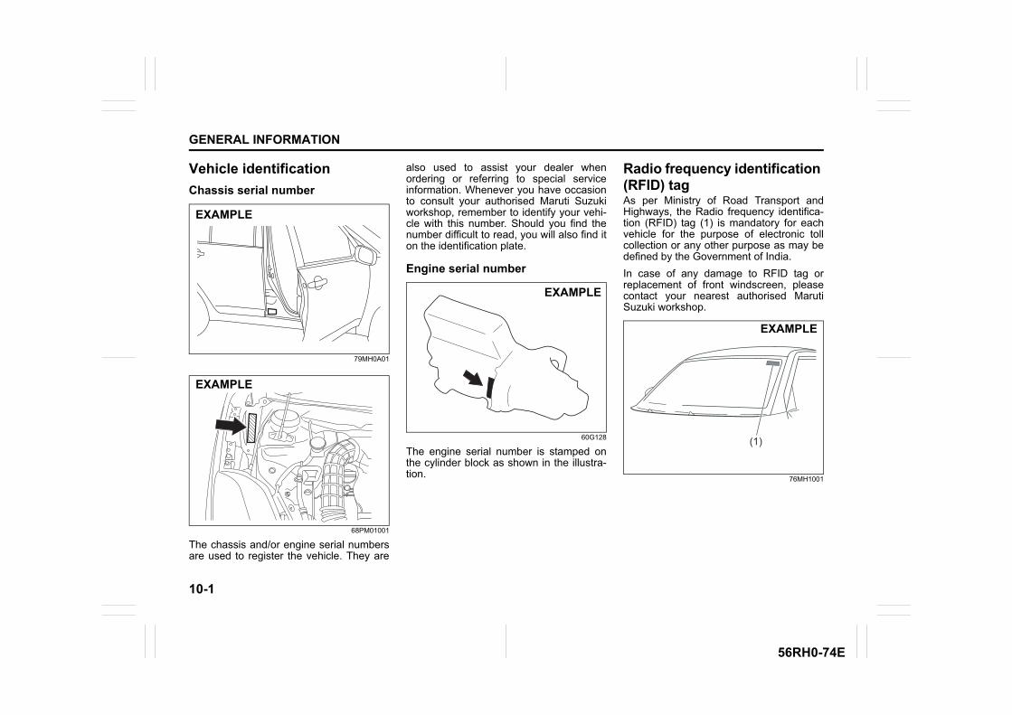
10-1
GENERAL INFORMATION
56RH0-74E
Vehicle identificationChassis serial number
79MH0A01
68PM01001
The chassis and/or engine serial numbersare used to register the vehicle. They are
also used to assist your dealer whenordering or referring to special serviceinformation. Whenever you have occasionto consult your authorised Maruti Suzukiworkshop, remember to identify your vehi-cle with this number. Should you find thenumber difficult to read, you will also find iton the identification plate.
Engine serial number
60G128
The engine serial number is stamped onthe cylinder block as shown in the illustra-tion.
Radio frequency identification (RFID) tagAs per Ministry of Road Transport andHighways, the Radio frequency identifica-tion (RFID) tag (1) is mandatory for eachvehicle for the purpose of electronic tollcollection or any other purpose as may bedefined by the Government of India. In case of any damage to RFID tag orreplacement of front windscreen, pleasecontact your nearest authorised MarutiSuzuki workshop.
76MH1001
EXAMPLE
EXAMPLE
EXAMPLE
(1)
EXAMPLE
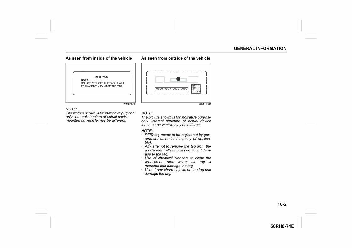
10-2
GENERAL INFORMATION
56RH0-74E
As seen from inside of the vehicle
76MH1002
NOTE:The picture shown is for indicative purpose only. Internal structure of actual device mounted on vehicle may be different.
As seen from outside of the vehicle
76MH1003
NOTE:The picture shown is for indicative purposeonly. Internal structure of actual devicemounted on vehicle may be different. NOTE:• RFID tag needs to be registered by gov-
ernment authorised agency (if applica-ble).
• Any attempt to remove the tag from thewindscreen will result in permanent dam-age to the tag.
• Use of chemical cleaners to clean thewindscreen area where the tag ismounted can damage the tag.
• Use of any sharp objects on the tag candamage the tag.

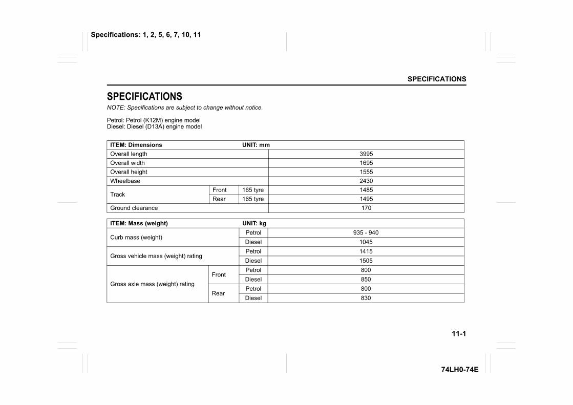
11-1
SPECIFICATIONS
74LH0-74E
SPECIFICATIONSNOTE: Specifications are subject to change without notice.
Petrol: Petrol (K12M) engine model Diesel: Diesel (D13A) engine model
ITEM: Dimensions UNIT: mmOverall length 3995Overall width 1695Overall height 1555Wheelbase 2430
TrackFront 165 tyre 1485Rear 165 tyre 1495
Ground clearance 170
ITEM: Mass (weight) UNIT: kg
Curb mass (weight)Petrol 935 - 940Diesel 1045
Gross vehicle mass (weight) ratingPetrol 1415Diesel 1505
Gross axle mass (weight) ratingFront
Petrol 800Diesel 850
RearPetrol 800Diesel 830
Specifications: 1, 2, 5, 6, 7, 10, 11
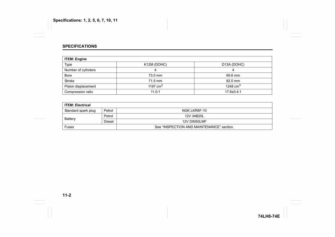
11-2
SPECIFICATIONS
74LH0-74E
ITEM: EngineType K12M (DOHC) D13A (DOHC)Number of cylinders 4 4Bore 73.0 mm 69.6 mmStroke 71.5 mm 82.0 mmPiston displacement 1197 cm3 1248 cm3
Compression ratio 11.0:1 17.6±0.4:1
ITEM: ElectricalStandard spark plug Petrol NGK LKR6F-10
BatteryPetrol 12V 34B20LDiesel 12V DIN50LMF
Fuses See “INSPECTION AND MAINTENANCE” section.
Specifications: 1, 2, 5, 6, 7, 10, 11
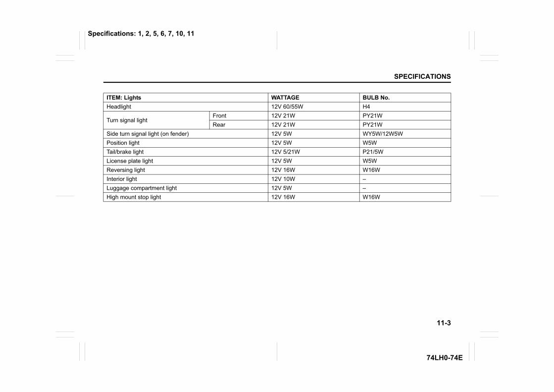
11-3
SPECIFICATIONS
74LH0-74E
ITEM: Lights WATTAGE BULB No.Headlight 12V 60/55W H4
Turn signal lightFront 12V 21W PY21WRear 12V 21W PY21W
Side turn signal light (on fender) 12V 5W WY5W/12W5WPosition light 12V 5W W5WTail/brake light 12V 5/21W P21/5WLicense plate light 12V 5W W5WReversing light 12V 16W W16WInterior light 12V 10W –Luggage compartment light 12V 5W –High mount stop light 12V 16W W16W
Specifications: 1, 2, 5, 6, 7, 10, 11
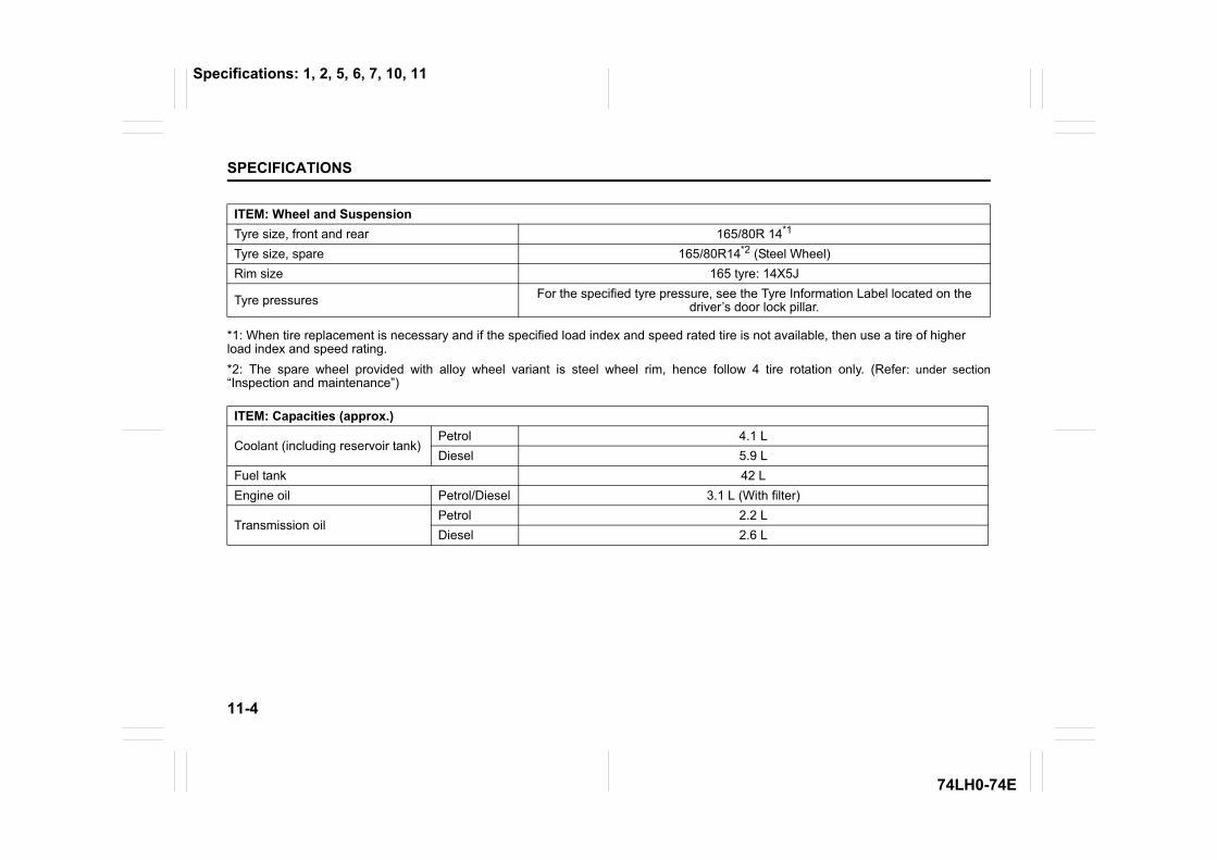
11-4
SPECIFICATIONS
74LH0-74E
*1: When tire replacement is necessary and if the specified load index and speed rated tire is not available, then use a tire of higherload index and speed rating.*2: The spare wheel provided with alloy wheel variant is steel wheel rim, hence follow 4 tire rotation only. (Refer: under section“Inspection and maintenance”)
ITEM: Wheel and SuspensionTyre size, front and rear 165/80R 14*1
Tyre size, spare 165/80R14*2 (Steel Wheel)Rim size 165 tyre: 14X5J
Tyre pressures For the specified tyre pressure, see the Tyre Information Label located on the driver’s door lock pillar.
ITEM: Capacities (approx.)
Coolant (including reservoir tank)Petrol 4.1 L Diesel 5.9 L
Fuel tank 42 LEngine oil Petrol/Diesel 3.1 L (With filter)
Transmission oilPetrol 2.2 L Diesel 2.6 L
Specifications: 1, 2, 5, 6, 7, 10, 11
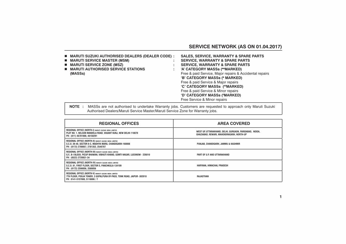
1
� MARUTI SUZUKI AUTHORISED DEALERS (DEALER CODE) : SALES, SERVICE, WARRANTY & SPARE PARTS� MARUTI SERVICE MASTER (MSM) : SERVICE, WARRANTY & SPARE PARTS� MARUTI SERVICE ZONE (MSZ) : SERVICE, WARRANTY & SPARE PARTS� MARUTI AUTHORISED SERVICE STATIONS : ‘A’ CATEGORY MASSs (**MARKED)
(MASSs) Free & paid Service, Major repairs & Accidental repairs‘B’ CATEGORY MASSs (* MARKED)Free & paid Service & Major repairs‘C’ CATEGORY MASSs (##MARKED)Free & paid Service & Minor repairs‘D’ CATEGORY MASSs (#MARKED)Free Service & Minor repairs
NOTE : MASSs are not authorised to undertake Warranty jobs. Customers are requested to approach only Maruti Suzuki Authorised Dealers/Maruti Service Master/Maruti Service Zone for Warranty jobs.
REGIONAL OFFICES AREA COVERED
REGIONAL OFFICE (NORTH-I) MARUTI SUZUKI INDIA LIMITED
PLOT NO. 1, NELSON MANDELA ROAD, VASANT KUNJ, NEW DELHI-110070 PH : (011) 46781000, 46150291
WEST UP, UTTARAKHAND, DELHI, GURGAON, FARIDABAD, NOIDA, GHAZIABAD, REWARI, MAHENDRAGARH, NORTH-UP
REGIONAL OFFICE (NORTH-II) MARUTI SUZUKI INDIA LIMITED
S.C.O. 39-40, SECTOR 8-C, MADHYA MARG, CHANDIGARH-160008 PH : (0172) 2780057, 2781352, 2540787
PUNJAB, CHANDIGARH, JAMMU & KASHMIR
REGIONAL OFFICE (NORTH-III) MARUTI SUZUKI INDIA LIMITED
G.F., B-I BLOCK, PICUP BHAWAN, VIBHUTI KHAND, GOMTI NAGAR, LUCKNOW - 226010 PH : (0522) 2720931-34
PART OF U.P. AND UTTARAKHAND
REGIONAL OFFICE (NORTH-IV) MARUTI SUZUKI INDIA LIMITED
HARYANA, HIMACHAL PRADESH
REGIONAL OFFICE (NORTH-V) MARUTI SUZUKI INDIA LIMITED
7TH FLOOR, POOJA TOWER, 3 GOPALPURA BY-PASS, TONK ROAD, JAIPUR -302018 PH : 0141-5157000, 5118006 / 7
RAJASTHAN
SERVICE NETWORK (AS ON ����������)
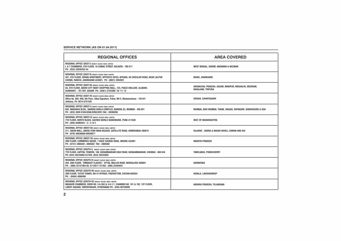
2
REGIONAL OFFICES AREA COVERED
REGIONAL OFFICE (EAST-I) MARUTI SUZUKI INDIA LIMITED
L & T CHAMBERS, 4TH FLOOR, 16 CAMAC STREET, KOLKATA - 700 017 PH : (033) 22835252-54
WEST BENGAL, SIKKIM, ANDAMAN & NICOBAR
REGIONAL OFFICE (EAST-II) MARUTI SUZUKI INDIA LIMITED
401, 4TH FLOOR, ROHINI APARTMENT, OPPOSITE HOTEL APSARA, 56 CIRCULAR ROAD, NEAR LALPUR CHOWK, RANCHI, JHARKHAND-834001, PH : (0651) 2563931
BIHAR, JHARKHAND
REGIONAL OFFICE (EAST-III) MARUTI SUZUKI INDIA LIMITED
5A, 5TH FLOOR, ABOVE CITY MART SHOPPING MALL, 724, PEACE ENCLAVE, ULUBARI, GUWAHATI – 781 007, ASSAM PH.: (0361) 2734308/ 10/ 11/ 12
ARUNACHAL PRADESH, ASSAM, MANIPUR, MEGHALYA, MIZORAM, NAGALAND, TRIPURA
REGIONAL OFFICE ( ) MARUTI SUZUKI INDIA LIMITED
3RD FLOOR, COMMERCE HOUSE, 7 RACE COURSE ROAD, INDORE-452001 PH : (0731) 4069481, 4069382 FAX : 4069382
MADHYA PRADESH
ODISHA, CHHATISGARH
REGIONAL OFFICE (WEST-I) MARUTI SUZUKI INDIA LIMITED
602, MADHAVA BLDG., BANDRA KURLA COMPLEX, BANDRA (E), MUMBAI - 400 051 PH : (022) 2659 0165/0286/0290/0291 FAX : 26590285
MUMBAI, NAVI MUMBAI, THANE, RAIGAD, RATNAGIRI, SINDHUDURG & GOA
REGIONAL OFFICE (WEST-II) MARUTI SUZUKI INDIA LIMITED
7TH FLOOR, NORTH BLOCK, SACRED WORLD WANOWARIE, PUNE-411040 PH : (020) 64002641 / 2 / 3 /0 4
REST OF MAHARASHTRA
REGIONAL OFFICE (WEST-III) MARUTI SUZUKI INDIA LIMITED
211, ISKON MALL, ABOVE STAR INDIA BAZAAR, SATELLITE ROAD, AHMEDABAD-380015 PH : (079) 40036660/40036671
GUJARAT , DADRA & NAGAR HAVELI, DAMAN AND DIU
REGIONAL OFFICE (SOUTH-I) MARUTI SUZUKI INDIA LIMITED
7TH FLOOR, CAPITAL TOWERS, 180, KODAMBAKKAM HIGH ROAD, NUNGAMBAKKAM, CHENNAI - 600 034 PH: (044) 28233050-53 FAX: (044) 28242059
TAMILNADU, PONDICHERRY
REGIONAL OFFICE (SOUTH-II) MARUTI SUZUKI INDIA LIMITED
204, 2ND FLOOR, “EMBASSY CLASSIC”, VITTAL MALLYA ROAD, BENGALURU-560001 PH. : (080) 22127384-85, 5112017-18 FAX : (080) 22484841
KARNATAKA
REGIONAL OFFICE (SOUTH-III) MARUTI SUZUKI INDIA LIMITED
2ND FLOOR, TUTUS TOWER, NH-47 BYPASS, PADIVATTOM, COCHIN-682024 PH. : (0484) 4088400
KERALA, LAKSHADWEEP
REGIONAL OFFICE (SOUTH-IV) MARUTI SUZUKI INDIA LIMITED
MAHAVIR CHAMBERS, DOOR NO. 3-6-363 & 3-6-1/1, CHAMBER NO. 101 & 102, 1ST FLOOR,LIBERY SQUARE, HIMYATNAGAR, HYDERABAD PH : (040) 66729999
ANDHRA PRADESH
��� �������������������������
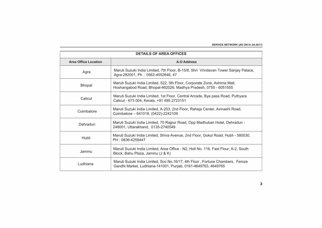
3
��������������� ��
������������ ��� ���������
Agra
Bhopal
Maruti Suzuki India Limited, 7th Floor, B-15/8, Shri Vrindavan Tower Sanjay Palace, Agra-282001, Ph. : 0562-4052646, 47
Calicut
Coimbatore Maruti Suzuki India Limited, A-203, 2nd Floor, Raheja Center, Avinashi Road, Coimbatore – 641018� (0422)-2242109
Dehradun
HubliMaruti Suzuki India Limited, Shiva Avenue, 2nd Floor, Gokul Road, Hubli - 580030����������� �����
Jammu
Ludhiana
�����������������������������!����"##�$����% ���&''�%&*�++��;�<��;'&����!� ���&��=�>'&$���>�=���'�����?�����@?�E�KN
��� �������������������������
Maruti Suzuki India Limited, 522, 5th Floor, Corporate Zone, Ashima Mall, Hoshangabod Road, Bhopal-462026, Madhya Pradesh, 0755 - 6051555
Maruti Suzuki India Limited, 1st Floor, Central Arcade, Bye pass Road, Puthyara Calicut - 673 004, Kerala� +91 495 2723151�
Maruti Suzuki India Limited, 70 Rajpur Road, Opp Madhuban Hotel, Dehradun�-�248001��Uttarakhand�� 0135-2740549�
������������������������������$&�%&*+X+�����=�;'&&����;&������Y=��[��<���;��&���\���=�������������=�����+�+��+�����]�[���++������������
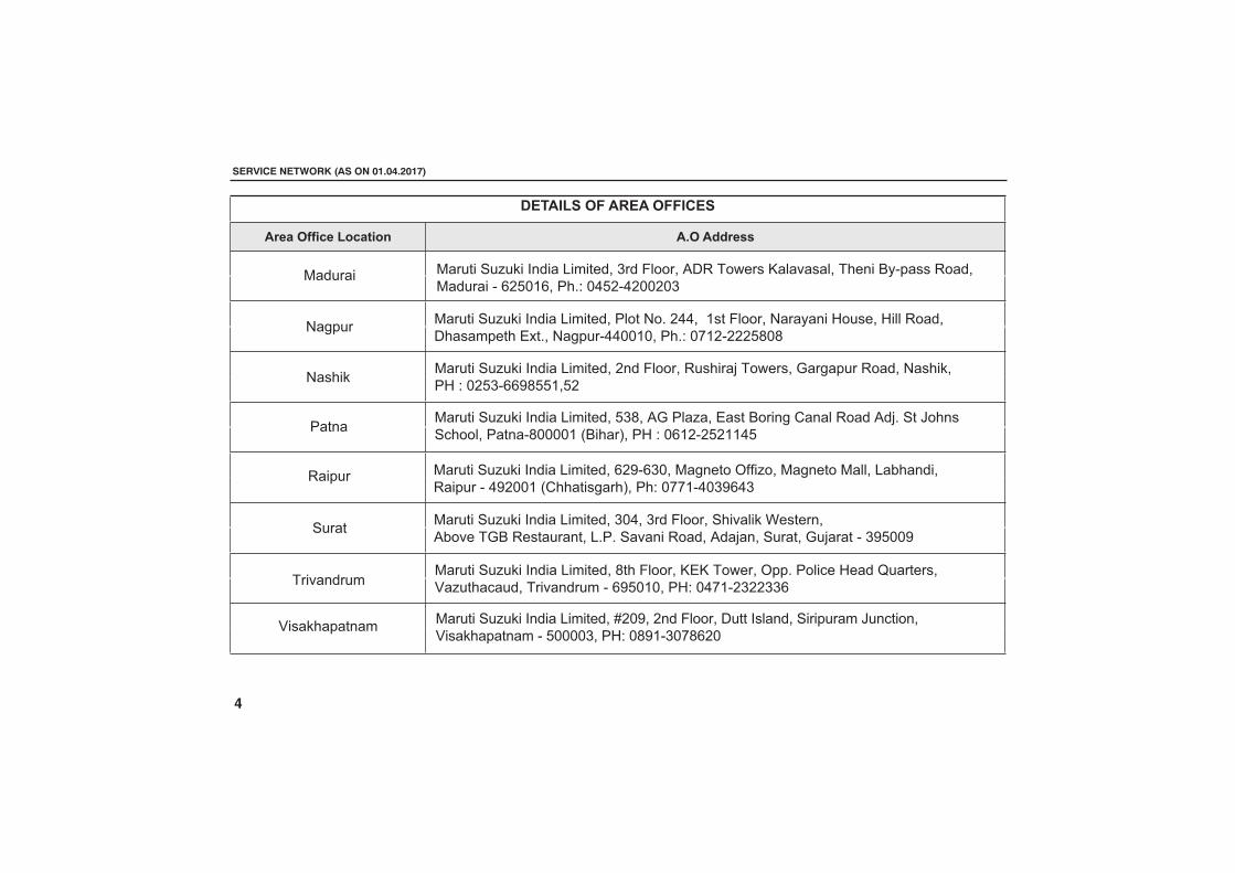
��������������� ��
������������ ��� ���������
�������
����
������� ������������������������������������������� ���!�������"����#$%������������������%�&'()*&��+",-�).('%.'))')�
���"��
+���� ������� ���������������������(�/���0�+������1����#�����2������������3,� ��4�"��� 5"�����+����%/))))*�6#�"��7��+8�-�)&*'%'('**.(
�����
���� ������� ����������������������).������������� "�!�����9���������:�!���0#��������������,+,� �!�������������3���� ������0�3�����%��;());
���!������
<����"������
������� ���������������������/�"�������� 1 ��������=,�+���5��8����>���������<����"�5��������!�������%�&;()*)��+8-�).?*%'�''��&
������������ ������������������
������� ���������������������+������,�'..���*��������������$����8������8�����������"������"�1@�,������%..))*)��+",-�)?*'%'''(/)/
������� ���������������������'�������������"���3���������0���������������"���+8�-�)'(�%&&;/((*�('
������� ���������������������&';%&�)���������=AA��������������������:"������������%�.;'))*�62""������"7��+"-�)??*%.)�;&.�
������� ���������������������B');��'����������������������� ��������4��5������<����"�������%�())))���+8-�)/;*%�)?/&')
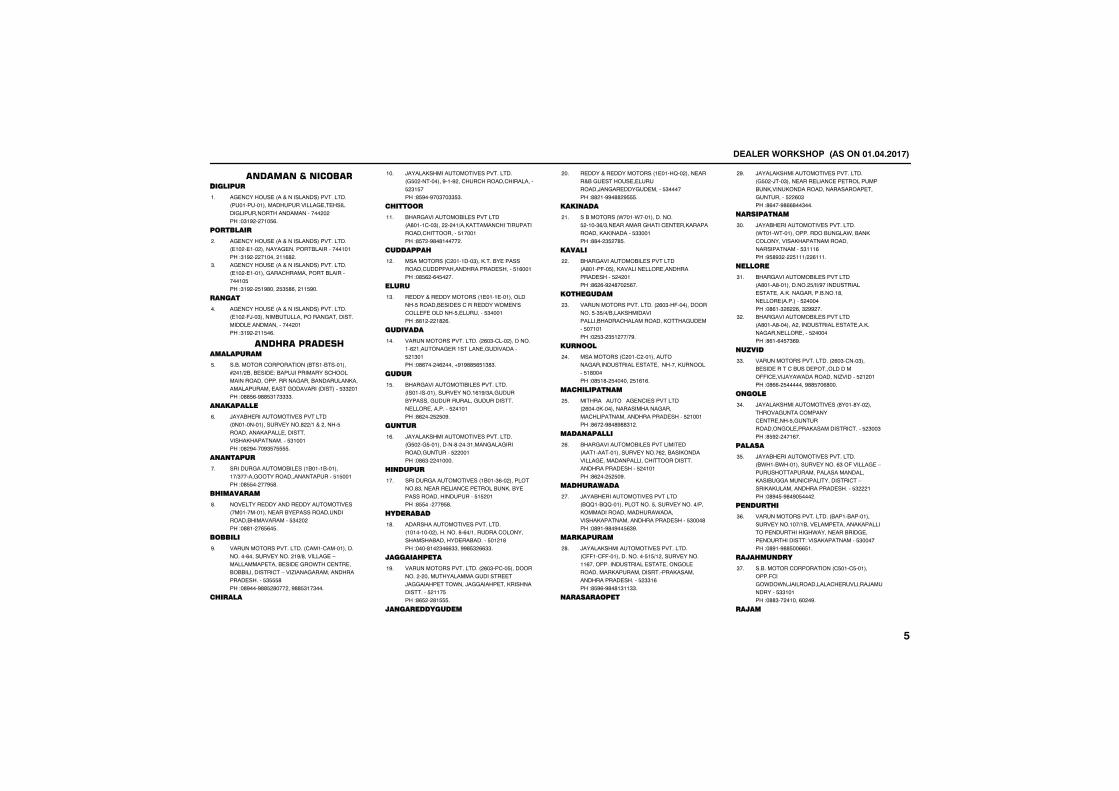
����������� �������������������
������������������������
����������� ������������������������� ������������������������������������������������������������� � ��!�"�# � ���$%�
��
�������
����������� ������������������������� ��� ����� ���������������&���������������!"�# � ������ ��%' �
�
����������� ������������������������� ��� ������������������������&������������$��!"�# � $�#'��� $"$'%�� ��$#��
"�
�� ��
����������� ������������������������� ��� �()��"������&�������������������������������������������� ����!"�# � ��$�%�
��
��� ��������� ����������
��&��������������� &����&��������* ��+ &��&�����!�&���)��������������������������������������&���������,���������������������������� ��������$"" ����!�''$%�#''$"��""""�
$�
� ��������
)���&���������������������� ����������������������' +���� ����$���������,�������������������,�����������$"������!�' #����#"$�$$$$�
%�
� � ����
��������������&����� �&����&��������+"��������������������������$�$�����!�'$$�� ��#$'�
��
����������
��������������������������������� ������������������&��������������������&�����������$"� � ��!�''�� �%$%�$�
'�
������
��������������������� ����������������������%������������� �#+'����������-���������������&��������.����������&&&��������������-���/���������������������������$"$$$'��!�'#���#''$ '��� ��#''$"��"���
#�
�������
)�����,������������������������ �$� ���������#���# ���������������������$ "�$���!'$#��#��"��""$"�
���
����
&�����������&������������� �'�������"��� � ��+��,��������������������������������$�������!'$� �#'�'����� �
���
���������
��������� � �������"���,����&������������������������������������$�%�����!�'$% �%�$� ��
� �
�����
������������������� ������������������$�����&�����������������.���0������(�������$����������$"������!''� � �' %�
�"�
��������
��������������������� %�"����� ����������% �������������������������������$ �"����!�'%��� �% ����1#�#''$%$�"'"�
���
�����
&�������������&��������������� �����������������������%�#+"��������&������������������������������������������������$ ������!'% �� $ $�#�
�$�
�� ��
)�����,������������������������ �$� ��$����������'� ��"����������������������������$ �����!�'%"� ������
�%�
�� �����
�������������������� �&���"%�� ���������'"����������������������&��,��&�����������������������$�$ ����!'$$��� ��#$'�
���
���������
��������������������������� ��������� ��������'�%�+��������������������&���������&������$�� �'��!����'�� "�%%""��##'$" %%""�
�'�
�����������
��������������������� %�"�����$��������� � ��������������������������)�����������.���)�����������,���������������$ ���$��!'%$ � '�$$$�
�#�
�� ������������
������������������� �����2�� ����������&���������������������)������������������$"������!'' ��##�'' #$$$�
��
���� ���
��&������ .����.�������������$ ����"%+"�����������������������,�����������,�,��������$""�����!''�� "$ �'$�
��
������
&�����������&������������� �'����(��$���,����������������������������$ � ����!'% %�# �'�� $%��
�
��������
��������������������� %�"�(������������$�"$+�+&���,��������������&���������������,�����������$�������!� $"� "$� ��+�#�
"�
��� �
��������� � ���� �����������������������������������������,�������$�'�����!�'$�'� $������ $�%�%�
��
��������� ��
������3����3����������������� %����,��������������������������������������������������$ ������!'%� �#'�'#''"� �
$�
���� ������
&�����������&����������������� ������������������������% ��&���,�����������������������������������������������������$ ������!'% �� $ $�#�
%�
�����������
)���&���������������������� &22��&22�������������$�������������+���,�����������������.���������,������������������������$"���'��!�'#��#'�#��$%"#�
��
����������
)�����,������������������������ �((���((��������������$�$+� ��������������%���������������������������������������,������������������,����������������������$ ""�%��!'$#%�#'�'�"��""�
'�
���������
)�����,������������������������ �$� �)���"����������������������������&��,�����,��������������������������������$ %�"��!'%���#'%%'��"���
#�
������ ��
)���&������������������������ .����.��������������&�����.��&��,�����������,���������������������������$"���%��!#$'#" � $���+ %����
"��
�����
&�����������&������������� �'����'���������� $+��+#�����������������������,�����������&����'�������� ��������$ ������!�'%��" % %��" ## ��
"��
&�����������&������������� �'����'������� ����������������������,������������������$ ������!'%��%�$�"%#�
" �
�����
��������������������� %�"�����"���&������������&����������������((������)���.�����������/������$ � ����!�'%%� $�������#''$��%'���
""�
���
)�����,�������������� '����'��� �����������������������������$��������������������,�����������������$ "��"��!'$# � ���%��
"��
������
)���&������������������������ &.��&.����������������%"�(���������-�������������������������������,���&����������������������������-����,�,����������������������$" ���!�'#�$�#'�#�$��� �
"$�
�� �����
��������������������� &����&��������������������+�&����������������,��������������������.���������&���������������������!�����,����������$"������!�'#��#''$��%%$��
"%�
������� ���
��&��������������� �$����$���������(����.�.��)���������������������)����������$""�����!�''"�� �����%� �#�
"��
�����
���
����������� �������������������
��������������������� &�)��&�)���������������������������������)��������������������)�������������������,�,���������������������$" � ���!�'#���#��"����%%�
"'�
�����������
��������������������� �%�"�.%��#������������������������������ ��������,�,��������$" �����!�'#� � �'"��
"#�
�������
�������������������� &����&�������������������#"�����������������������������������������������������������������$�' �"��!'%'��'��''####$�� �$� �$��
���
� ���
����������������������������� &�� �&����������$�����������.���4����������&�������������������������,��������!�.����������� ����������������$"� ����!�''�#�##$��������
���
� ���
)�����,�������������� �������������,������)���������������������������������������������$ �� ��!'%��� %���� �����
� �
������
,�������������������� �#'���#�������'�"�%��,��&����������������������!�'���� ""�$��� "�����
�"�
&�����������&������������� �'����#�� �����+%%+�������������������������������������$��$����!'���%�$#�����
���
� �
�����&�&������� ���������� ,����,�������������%$�"���$+�������(�����.������������������������������������������������������$""�����!�''$���%%�'#"'''�
�$�
����������
������3����3����������������� %��� %������������"�����������������������������)���.������$ ������!�'%%�%" '"��%""�%'�
�%�
��������������������� %�"� %�������'�����+�������������)���.������$ ���'��!�'%%� $�$�$"�
���
��������������������� %�"� %��%������������$%�+���$% +$���$%�+"��$% +%�,�������������)���.�����,�����������������������$ ��� ��!'%%�#''$"' ����
�'�
������������������������ %��� %���������������� "+$�����������%�+ ��,�������������������������������������)���.�����,��������������������������������$ ������!�'%%���##�'�#%#�� $$ % �
�#�
��������� ��
)���&������������������������ �%�%��%��"���������������#+%��,����������������)�.�,������������/��������������������$"���%��!�'#�� $��#�#��#'�#��$%"#�
$��
��������������������� �%�"��%��'���������$'+ �&��,����$�&���)�������������������������������������������$'���"��!�'#�� $ $''$�
$��
��������������������� �%�"��%������������''�&�������������������������������)�.�,����$"�� %��!�'#�� $�"�$��
$ �
��������������������� �%�"��%��(����� $����������������������������������&�����������������,�����������������,������������$"������!�'#�� ��$"�$�
$"�
)���&������������������������ �%�%��%���������������#�������������������������,�������������������������$"���'��!�'#�� $�%'"��
$��
)���&������������������������ �%�%��%�� ������!$����� �����$��,����������������,�������� �����������������$"���"��!�'#��3��##�� � �
$$�
��������������������� �%����%������������'��,������������������&����������������&��,�������,�������������������������������������.��������,�����������$"������!�'#��#''$"�"����
$%�
��������������������� �%�"��%��,�������������"#����"#$����������������������-�������������������-����������������������-�����,�������������������������$"������!"�$$$$��
$��
����� ������
��������������������� �%�"��'��������������������������(����������������/�������������/������������$"$�����!'# ���##%%%##'�
$'�
����� ������
)���&�������������� �'����'������������&��������'�" ��������������'+� ������#+ ����������������������������������������������������/��������������������������$"$�����!�'# �� $$"%%� $$"���'��'""" " �
$#�
����� ��������� �� ����
�&������&����� �$'���$��������������������!����������������������!�"%�� � '�"�
%��
&��������������� �$����$�������0���������������������������������������#������!�"%�� �$��"�� �$����
%��
&��������������� �$����$�� �����$ ���&�������.������������ �������������������������������������#�� "��!�"%�� %%"' �
% �
&��������������� �$����$��������������������&�(�������������������������������������������������������#������!#�"%����"��
%"�
��������
&��������������� �$���'���"�������������&�/���������������������������������#��� ��!"%'�#�"$�' %$�+ ���'�
%��
��������������������
�������������� ������� &����&������������������ �����������������/��-�&�&��,���������-�&������������������������-�,����������������'�"'���!"%��#'%��$ �''�
%$�
������
�������������������.�,�� �/'���/����������((�����&�����������������������.�����������������!�"%%%� %�"�"� % ��"�
%%�
&���������� ������� ������/�� ���������������"�����������&�����������������'�"�"��!"%%�% %���%�
%��
���� ����
����������.���� ���������������+����&�)������������������������������,������������&�)����������'�� $��!"% "�#'$�� �"#%�
%'�
������
�����,������� &����&������������)��������������"�������������.����������&,�,����������������� ����������'%$� ��!�"����#�"$�$�#"'�
%#�
� �����
&���������� ������� ���������������������������&�����������'""'"���!"%%���##$���$%��#+ "�$'�+#'$##�'#$'�
���
����������
������������������������������ &�5��&�5������������ � ��,������������''����������&�,����������/��&������&���������$����,��)�������������������������������'������!�"%��#'$� $'� $�
���
�������
���,����������������� ��������� �������������,���������$ �����)�� ����������'��$���!"�$ �##$�'"�$"'�
� �
���������
)���&�������������������������� �����������������������������������,��������������&������ ����������'%�����!�"�"� " ���'�� " #"���
�"�
�����
����������.�������������� &����&��������&�&����������������������&����"'������-����&������������-������,���������������'%�����!"�$��#�"$'%������
���
�������
&��������� 5''��5'�������������&�������������������)�����!�"��� '�� $$�
�$�
)���&�������������������������� ��������������)��&���������������������������������������)�����������&���������'%%� ��!�"���''���#'$�%�
�%�
�������
&��������������������� ��������������!�,�����������������!����������+�!��������!�"�����������!�������������������'�"����!'�%�#'$$$��
���
������
���
����������� �������������������
�����,������� )"� �)"����������"#�������)�����!�������������������������'$% ���!�"�� �"%�#����"%�#���
�'�
��������
&���������������� �#����#������)���,&�������.���������'������!�"%��%��""$��$���"��
�#�
&���������������� �#�"��#����������������&������������������&����.���.�����&��������.��������'�� ���!�"%��#'%�$� $��$+�%�
'��
�������������� ������� �#� ��#��������������� ���5�����������(�(������.��(������5�������,��������������������.��������'�� ��!"%�� "%"�#�+# +#"�� "%���#�� "%'#'��� "%� ""�
'��
����������.������������ �#����#�����������&���������������.��������'��"%��!�"%�� ""�#%#������ ""�#�$�
' �
&���������������� �#����#�� ���&���&����&����������������������"����.��������'�� '��!�"%��'�'%�� #�"+#� �
'"�
&���������������� �#�"��#��"���&������������������������&������/��������.���������������'���$��!�"%�� ��" +#'$��$��#��
'��
����������/��� �#�%��#��������"�����������������&�����������������.����������������'�� #��!�"%�� "�##$��
'$�
����������/��� �#�%��#�� �����"���&�������������������,��������.��������'�� '��!�"%��#'%� #%%%%�
'%�
�������������� ������� �#� ��#�� ���������� ������������� "�����������-�)���,�������/��-�&��������,��/����������.���������������-�,�����������������'��"���!#'%��$ �''�
'��
����������.���� �#�$��#��������"�������������,������������.����� �����������'�� #��!�"%������������#�"$$$$'$"�
''�
&���������������� �#����#��"������&��������)����������������������&�������.���������������'������!�"%��#'%����$ $�
'#�
����
������������������������������ ��������������,���������!�"� +"(��)���������������������&��,�����,������������)�������������-������������������' �"$��!�"%���#���$$%'%'�
#��
��������
������������������������������ �)����&�� ���)������������������.����������' �����!�"%�'�#�"$$%#$ %�
#��
����
�����,������� �#����#��������������������)�&������)���������������'$�����!�"�%�"%�#����"%�#���
# �
������� �
)��������� %#����������������������������,�������)�����������''�����!"'�"� % �'��
#"�
�������
����������.�������������� ��/����/��������������������5���������"#��,��,��������������-�,��&��������������' �%���!#��%���"%%�
#��
�� �����
����������.���� �.����.���������������$ ������������������������������'���$��!�"%���#����$ ����
#$�
���������
����������.�������������� ������������������������.���&�����������������������"'����������������������'%�'���!�"�$�� �����
#%�
���
������������������������������ �)����)������,���,��������&���������������' �� ��!�"� � "%����
#��
������
&���������������� # ���# �������.,&�/�������&�����)���������&�������������&�������'�""$��!�"%�� ��"��
#'�
������������
���,����������������� ������������������������$ ������������,����������������'��"���!"�$ � " � � " �$��
##�
���,����������������� ���������"���,��������.��������������$ ��������,����������������'������!�"�$ � " � �
����
�� ���
����������.�������������� %5���%5��������������.���.�������$������������&���������������������������������������3�������,������ ����������'�"$���!�"%��#�����$#$'�
����
��������
�����,������� �#����#�� �������,������&�����������������������������&����������'$%����!�"�� � � "��� � $��
�� �
�������
)��������� %#���) �� ���,�����������5�����������������������������''��%��!�"'� � %�%���% �
��"�
� ����
&���������������� ��2����2�������������������������"�����������������,���������������!#�"$�����$�
����
�����
������������������������������ ��� �����������������&���������������,�������������/��������������'��$���!�"%���'� ��'�#���
��$�
� �����
����������.���� )����)�������������������������������,����������������,�������������'%�'"��!�"��� "� $� �
��%�
�� ��������
������������������������� ����������������&����������)������������������������������������(�&�����)������������������&������'$�"�'��!�%�$$�'�#��#%�� +�$�$'"��� �
����
�����
����������� ������������� �������(������������������&����������������������������������������������.������"�������� &�������'� "����!%�' �#"��%'$'''�
��'�
���������
��������� ��������������������������.,����"���&����������&������'$������!# ���$% �%�
��#�
�����
������������������������ �����������&�����������������.������� '�&���������������,��&������ &��������'�$�"'��!% $�� "�$�+#����'%�'"�
����
���������
������������������������� �'� ��'������&����������������)������������������������������)��&�����������'� ��$��!�%���'�#��#%�� +'�#��#%��#�
����
�����������
�����������&����� ���������"�������������������������������.�����������������������������������&�������(��������������������&������'�"�����!��%� #$ #��
�� �
�����
����������� ��������������+�����������������������������&�������������&�5�����'� �����!%�'"�' #�%"�%�$+' #�%"�%� �
��"�
������
�����������&����� �������� �����%���������"'��������������)�������������������������&�,�����.,���������&������'��"����!# %"%"�%�%�
����
�� ����
����,����������������������� �$������� �����)����������������)�������������������������������������'����'��!#"'%'#'�$'�
��$�
������ ��
,����������� �������������,������%�#"%����������.,��&�)�������&�������"����������&������&������'�%��#��!# ��$$ ��$�
��%�
,����������� ���������"���������������������������&����� &�������'�%��"��!# ��$$ ��$�
����
����
,��������&������������� �%����%������&����������������' � "���!%"����%"� �� �����#��' "�%���
��'�
������ �
���
����������� �������������������
������������������������ "���"�������� '��������������������)������������)� &�������'��� "��!�%�$%� # #�+#����'%�"#�
��#�
��������
�����������&����� �������������,����%�����,�����"$�+�%�$�������������������������������������������)����� �������������'�������!# %"%" �%"�
� ��
������
������������������������� %���%������������&��������������������������,������������������,��������'$���$��!%�$ �'�#��#%� �+'�#��#%��#�
� ��
����� �� �
������������������������� �5����5���������������������������������������!,����.���������,�������)� &��������'$$�����!�%�$%� ""���+'�#��#%��"�
� �
��� ��
����������� �.����.������������&�5���������������������' ���#��!%�'��' #�%"�%" +' #�%"�%�#�
� "�
������
��)�������&������������� �����(��"�����������������.,��&�������� '������������.����&������'�$�����!% $ � ����$��# "�%�#%%#�
� ��
�����������
��)�������&������������� �������������������������������������/������������/�((�������&������'� �� ��!�% �� � %%�+##��"��#�'+# "�%�#%���
� $�
��)�������&������������� ��������� �������������������������&����������������������/�((��������.������'� �� ��!�%����"#�'+# "��$%'���
� %�
��������
������������������������� �(����(������������������������������"���������������,�����������������������-�&���������&�������'$" ����!'�#��#%�����'�#��#%� ��
� ��
�����
�����������&����� ������)�������#���������,��������"��$���"�� ���������0��((�����������������������������.�����&������'�$�����!# %"%" �$%�
� '�
�� �
������������������ �$' ��$������#+������������������������������������������������������!�%� � %$#�%�#""���$###�
� #�
,��������&������������� �$� ��$�����������&�������)���������������&�������'����"��!%� �0�#"�� � ��#+#"�� ��� ��
�"��
���0������&���� �$�"��$������&������������������������������������������������'�������!#�����%�� �
�"��
����,������������������������������� �$����$��"�����������'���#��&��������������������������������������)����������������,���)�������������'�������!%� � $ '��$+�##"�� � ���
�" �
��� ��
������������������������� %����%���������"�����������,����������������&�&����������� &�������'$�" %��!�%�$�� " #+'�#�#�#%����
�""�
�������
��������� ���������� ������������������������&������'$ ����!# %"%"'�$%�
�"��
���������
,����������� �.����.������,��������"�#��#$��,��������%��������������������������&�������'�'�����!# ���%�%���
�"$�
�������
����������� �5����5���������������#��������� �������������������� &�������' ���$��!%�'��' #�%"�%� +' #�%"�%�$�
�"%�
��������
��)�������&��������������� �����������������������������������������������'�""����!# "�%�#%���
�"��
����
���������������������� $���$���������������������������������'$����.�����'�� "%��!%�$��#����'%���+#����'%�" �
�"'�
������� ��� ������
�����������.�,� ������� ���$�������������*�� ���"���������������������������������������%��� ��!#'�'� ���
�"#�
����������&����� ��� �������������.�������������������������%��� ��!���� �%$�$$$���%$%"""�
����
����������������������� ���%����������������"����������������������������������������%�� #��!��� �$ �� $��
����
������������������ ���������"���&�� ����������������������������������������%��� ��!��� �$��"����
�� �
������� ��������� ������
������������� #�������� ��������� #+%����������������������� ��������������%��� ��!��� �� �
��"�
�������� ���������
�������������������������� ��������������������������������&�,��������������������#������!����� "�'$ ��$"�
����
������������
�,������&����� $�����)��������&��,����.,��������������&�����&�/�������������������#""" ��!�� �� %�%�
��$�
�������
�������������� �&����&�������&��������������(������������&�������� ��������������#�""$��!#%�� %��$��
��%�
��������
����������&����� &&)��&&)������������������&�������� ��������������#"��'��!## %% %%% �
����
������
�������������� '"�"�'"��"���������������������������������������������������&���������#�� %��!�''���"���������$����
��'�
��������
����������&����� �"����"��"�������������������� ����������������������������&����������������������#$�����!��$ �%�$��'�� $ � ��
��#�
�������
�,������&����� �������������,������� "'+ ����������&�������������������������#"��"���������������# ��#��!'''###'%� �
�$��
����
�������������� �.� ��.���������)�������������&�(�����������.,�����������,�������������������#������!�''�#' %%�"����
�$��
������� �
����������&����� �������������������������������������������������&�������������������$%�" ��!#%%#%"'''"�
�$ �
���������
�,������&����� �������������������������)������������������������#������!���' � "�$��+ "��#'�
�$"�
�� ����
����������&����� �"���#��� ��������,,�������.������������������������� ����)��)�������#$%%'��!��'���##'� %���"�
�$��
�� ���
�,������&����� $����,���%�����/���������������&������"���,��,��������������-�,��,�����������������#�""���!��� � ""����
�$$�
��������
�������������� ������������������,��������)��������&����������,�.����������,�.����� ��������,�&����������������������#�##$��!������ �$$#��
�$%�
����
����������&����� ���������"������������������������������,�&�����#$%'���!���$#� '�%��� '�%'�� '�%#�
�$��
�������� �
����������&����� $�� �#��� ���&�������.�,��&��&���������������������!�� "� �''��
�$'�
�� � �������
�������������������������� �����&���� ���.������ ������"����&�,�������������������������������������������������,��������#��� ��!''�� ' �%��
�$#�
�� ����
����������&�������������� &����&��������,�������� ��+ ��&����������������������������������'%��%'��!##'� %%%%����'��#�
�%��
�������
���
����������� �������������������
�������������������������� &5��&5������,��������$%�+ ���������������������-�)���������������������#%��'��!'''##$$$$'�
�%��
������
����������&����� ��������������������� '�+���������������������������������������������������%���'��!#��#%�$$$ �
�% �
�������
��,�������&����� ��'����������������������,�&����.,��&��)����������������������!#"����%�#%�
�%"�
����������&����� ��� ���������)���������������������#%�����!���% � '���� �$'���
�%��
������
�,������&����� $����$������������������&��&�/���������������# �����!������ ������
�%$�
�,������&����� $����$��� ���,�,����������������������������# �����!��������#����
�%%�
����������&����� $�� �$�����������������,�����������������������������,�����)�������������������������# �����!������ �
�%��
�,������&����� $����$���������)������.���(���������&������������������� ������������������������# ��"��!#� $ ���$��
�%'�
�,������&����� $����$���$����������,��������,������������������# �����!�������" $�$�
�%#�
�,������&����� $��"�$���������������������������&������������� ��������# ��%��!������ ������
����
����������&����� $�� �$����������������&��,������������������������������# �����!������ �"�
����
����������&����� $�� �$���$���������"������������������������������������������&����������������!## %% %%% �
�� �
�����
����������&����� $�� ����"���������������������������������������������������)�������#"''���!����� "�$$%�
��"�
��� � ���
�������������� '"�"��2����������������������������������,�����%����)������������#������!����� #�� ��
����
���������
�,������&��������������� &�(��&�(������,��������' +$������' +%�����������������������������������������������������#"$$'��!�� $���"���������$����
��$�
���� ����
����������&�������������� &����&��������,����������+����"+ ����+ ���$+�������%+ �����������&�,���,���������������������������������""�$���!##'� %%%%���'��#�
��%�
�������������� �������������
,�����������&�������������� �����������������������������������������������������������������"#% "���!� %��� %$��$�+$%�
����
���������������
,�����������&�������������� �����#'��'���������,��.������������������.����������������������������������������"#% ����!� %��''%%�� �##+ ���� �
��'�
��� ������
)�)�����5� ������������������������ �''"��'��"����������#�����������������������������,��������������)�����������������,���.��(�����������������""��!��������$$��������$$���
��#�
)�)�����5� ������������������������ �''"��'������(�"#�,�����������������������������.������������ ���!������%� �#�����%'$$���
�'��
���������������������� ������ �'����'����������#�������������������������������������.������������ '��!�����$$����"�
�'��
��������&����� ��������(�&����&����������������� �'#���'�������'#�#������.�����������������!�����' '�����
�' �
����5������&����� �''���'������'���������������������,���������.��������!�����" �%%%%�
�'"�
������������������������� �'&���'������&� ���,������������.������������� ���!�����%%%�'''��%%%�###�
�'��
&��������,��������������� �'����'������"#$�����������)���������������������)���.������������# ��!�����%�'''"����%�'''"��
�'$�
&��������,��������������� �'����'�� ������,����� �����&�����������������,����&�����.�������������$��!���� "$ �%�%�� "$ % %�
�'%�
�������������&����������� �'�%��'������'#$+��'������)����������������&��������������.������������"���!������� ��������� �����
�'��
�������������&����������� �'�%��'��"���������"���/�����������������#%��!�����$"������
�''�
���������� �'& ��'����������������������.����,������������������������������!���� $#%"$"$���'%�%$���
�'#�
���������� �'�"��'�������������������������������.������������%���!������'�$������#"�$ " �
�#��
���������� �'�"��'������$��.�/������������������������)��������.�/�����������������������.������������"���!���� ��$"##%�##�� ��$��%%�%��
�#��
,���������������������� �'����'������������#����������������������������,�������������.�������������%"��!�����" '''''�
�# �
�������������������� �'''��'��������#"������ �������������������������������%���!������'������
�#"�
�������������������� �'&���'�������������%'+"������������.��������������$��!�����"���������"���� ��
�#��
�������������������� �'&���'�� ����������!�&���������,�����������������������""��!�����$#������
�#$�
���,����������������&������������� �''���'�������'��,���������������������������"����.������������ ���!������######����####���
�#%�
������������������ �'����'�� ��������,�����������������������������.������������ ���!�������������
�#��
�������������� �''%��'������(�#+&����������������������������������������������������������������!������$%�#������%�# $ � $#�
�#'�
���������&��������������� �'�'��'��"����� �� ������,�������������.������������""��!�������'''''�
�##�
�������.����������������� �'�#��'������""���"������������������������5��������,�������.�/���&�������������������#���!��������$"""�
���
�������.����������������� �'�#��'�� ���&�%������������������������������������'��&��������.������������� ��!��������'"""�
���
�������.����������������� �'�#��'�������������$�'��(�������������������������������������)�������# ��!����#'�"'$�"""�
� �
�������.����������������� �'�"��'���������������+�#���,���������������������� ���!��������#"""�
�"�
���������&����� �'�'��'� &���,�������� ������,�����������������������������������������������&����������������""��!���� ��"�" $�� ��"�'$%�
���
�������������&������������� �'�%��'��$���&�'"��������������������.�������������$��!������ %'#'��
�$�
&��������,��������������� �'����'��"�����������%�'���������(�����������������������������&�&�������������������������(�����������������,��)����.����������������!�����$%'''''���$%'''���
�%�
������������������ �'����'������&�%+%��,������������������������������.������������ ���!������'������� %"'##"��
���
�������������&����� �'�%��'��%�����������)������������(�����������.�������!����'"�����#'�+'�+� �
�'�
������������������ �'����'��$�����'����)�������������������������/������(��������,���������,�������������������������������#��������������""��!������%�####��� �������
�#�
�������������������� �'&'��'������,�������� ���� �'��������������������������� ����.��,����.�����������������!##����$$����#'�'$$$%%#�
���
,���������������������� �'�#��'��"�����"��.�/�����������������������������������$ ��!����� � ������##����� $$�
���
���
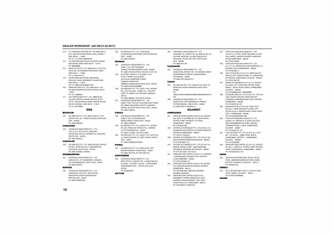
����������� �������������������
�������.����������������� �'� ��'������&��#��������������������������������������.�������������%���!��������#"""��####��#""��
� �
���������� �'�"��'��$���#+$$�,�������������������������������.�������������$��!####�"'''�
�"�
�������������������� �'�$��'���������������#����$������������)��������������������.�������������# ��!����#'�'�������
���
�������� �'�"��'��%���'$&�����)�������������������,��.�������)�(�������.��������������"��!����####� �'��+####� �#���
�$�
�������������������� �'����'������,����'��+ �����������������.,�������������"���!����� "#�����
�%�
������������������������� �'&#��'��"������������������,�������'�+"��'�+'���'�+�"+�����������,��������������������%�%������,�����.����������������!����%%��''''�
���
����������
���������������������� &���&�����������������������%+�����������.�����&��������������"$ #��!�'" � "'$$���
�'�
�� �� �
�.��������������������������� ������������������������������������������������������������������������������"�� ��!�'" � %""����
�#�
�� ����
���������������������� "�� �����%������������%�+��������"���������������������������������������"��"��!�'" � �%"�% �� �%"�%"�
��
������ ���
�.��������������������������� "��'������������,�����������������������&������������������"�����!�'" � "�$ ��
��
������
�.��������������������������� "��'�'/��"�����������#+ ��������������������������,����.�������������������"$����!�'" � $'���+$+%�
�
���������������������� "�� �'/��$����� +#������������������������������������������"$����!�'" � %�����
"�
�����
�.��������������������������� "��'��������������������������(�������������������"%� ��!�'" � ��#���� ��#�"$��%#��'����� "���"#�
��
���������������������� "��#���������������.������$����������"�+"�"�+����������������.�����(������&����������������������������"� ��!�'" � ��%���+ '$''##�
$�
���������������������� "�� ����� ������������� � +����������������������!������������5�������������������������������"��'��!�'" � ''"����� �#��#$��#��# �#%�
%�
�.��������������������������� "��'�����'������������$'�������$#�������"&����������������������������������������������������������������"� ��!�'" � �' ����
��
�� ���
�.��������������������������� "��'����� �����&�&����,�������������������)���������"�����!�'" � �""���+ �
'�
���������������������� "�� �����������������!�"%+����������(����������!�&����/���������������������"$����!�'" �� ��# ���� ���" ���� �'��
#�
���������������������� "�� ���������������������,�����������������/������)��������������"�����!�'" � # + $ �
"��
� ��
���������������������� "�� �"���"���((����)�����.����������������"�����!�'" � " ���%�� "���##�� " �� ��
"��
�� �����
�.�������������������������� &�,��&�,���������������������&��������"����������-������������,��-��������������������������-������������������"��%��!'" %$ "���
" �
�����
�.��������������������������� "��'�&�����������������%�����&���������$�������������������������������������������������,��������������������������"$�$��!�'" �%����'��
""�
������
�.��������������������������� "��'�����%�������������� ����&�����������,��.���������������,��.�������������������"�����!�'" � �"��##� "� ���
"��
����
���������������������� "�� �����������5������,������������,�����������������"'� ��!�'" � $� $'�+ $ %��'+ $ %���+#'$�$$#� $� ���" ��
"$�
�.��������������������������� "��'�����#������&������������������������&������������������"'� ��!�'" � $��� �+'""$���"��
"%�
����������������
,������������������ ��� ������������������� �$+"���������������"�������,�����������������������������������������&�����"'��%���!��#�%$�$�$$$�
"��
,�����������&�������������� ��������������+'�&�����������������������������������.�)�������&�����"'���%��!��#� ����$"+$��
"'�
,�����������&�������������� ���������$��������,,���&������������������"'���'��!��#� �%�$��+� �
"#�
,�����������&�������������� �������������&��������������������������,��&�������������,��&�������.�����"'��$���!��#�"��� """�+�"��� "� �
���
,������������������ ��� ������������,�)����������������.���������)�������&�����&�����"'��$���!� � �%���#$$��%��
���
,������������������ ��� ����� ���&�����������.�����,�)����������.���������&�����"' ����!��#� %'#�'%"�� %'#���#��%$�$#$$$��%$ '$$$��%$ #$$$��
� �
,������������������ ��� �����"���&��������������������������������������������������������(���������������������������&�����"#���$��!��#� %# ����� %# �"""�
�"�
�������.������� ����������������� ���$���������������������&���������������������������������.���������������������&�����"' ��"��!��#�%�#�" " �
���
�������.������� ����������������� �������������&��������������&��������������.������������&�����"'��$���!��#�%$�$'����
�$�
�����������,� ���"������������������5���������������������(���������������������,��.����������&������)�������"' �"���!��#�"�# �����
�%�
����������&����� ����������������������� #+"�������,�����������������������������������������������&������)��������"' ��$��!��#�''%%$$'�'��+�'�%��''''"�
���
�������������� ������� ���$������������������"+ ������������������������.������������,����������������������������&�����"' ""���!��#� #����$�+$"�
�'�
,���������� ��� ����� ���(�����������""+�+�������������������������������������������������,���������,��������������&�����"' ""���!��#�%�� �$$$+%�� �$$$�
�#�
�������.������� ����������������� ���#���������&��������&�������������������.��������������,�����������.����������������������&������)��������"'������!��#�"��#������� �
$��
�������������������� ���%������������������%��&����-���&��������&�����������&�������������-������&������)��������"'��$'��!��#�%�##""���
$��
,������������������ ��� �������������������' +�+���������������������������������������,����������&�����"'���$��!��#�%$�$�$$$�+�$�$�
$ �
���
��������������� ('���/���"�����������,��)��&�����&�����������������������!�&��������)��������"# �����!#%'�%#���%�
$"�
������
���������� #����#������������&����������������������)��������"%$%����!� �# �'���#�#�#'�
$��
� � �
����
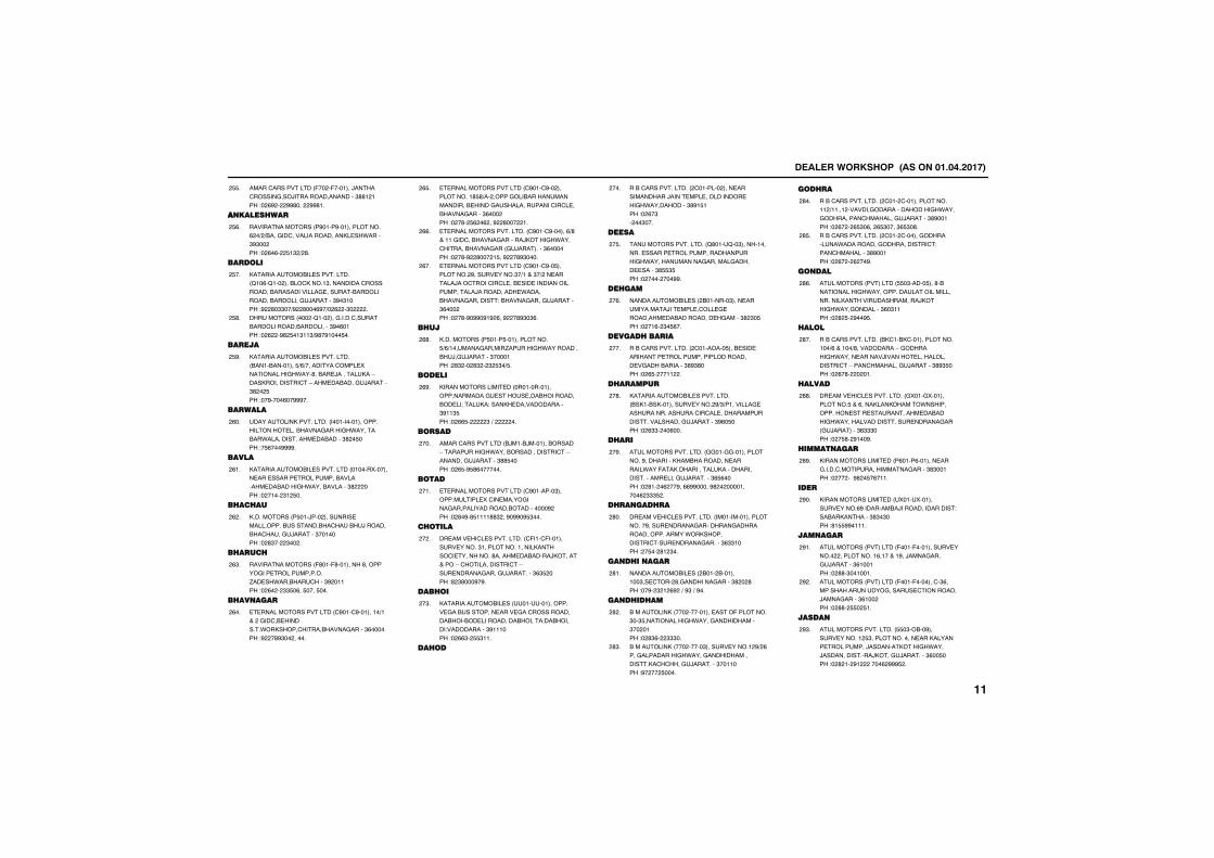
����������� �������������������
������������������ (�� �(�������)��������������)�����������������"''� ���!� %# � ##'��� ##'��
$$�
�� ���������
��������������� �#����#�������������% �+ +&����������������������,���.�����"#"�� ��!� %�%� $�" + '�
$%�
������
,�����������&��������������� 2��%�2��� ���&��,����"��������������������&�����������������������&�����������&���������)�������"#�"����!# '�""��+# '���%#�+� % �"� �
$��
��������� ��� �2��� �����������������&����������&���������"#�%����!� % �#' $��"��"+#'�#����$��
$'�
������
,�����������&��������������� &����&��������$+%+���������������5�����������.���'��&���)��������,��-����,�������������-������&������)�������"' � $��!��#����%��###��
$#�
�������
�����������,����������� ���������������������������&����������.�������&��.����������������&�����"' �$���!�$%���####�
%��
�����
,�����������&�������������� ������5�����������������������������&�����������&�����.����&�������"' ���!� ���� "� $��
%��
�������
,��������� �$���)��� ��������������������&���������&�����&�)������&��������)�������"�������!� '"�� "�� �
% �
�������
��������������� ('���('��������'������������������������/����.���&�������"# �����!� %� � ""$�%��$����$���
%"�
���� ����
��������������������� �#����#��������+���� ������&���������.�,���������&����������"%������!# �'#"�� �����
%��
��������������������� �#����#�� �����������'$'+�� �������&������������������&�����������������������������&����������"%��� ��!� �'� $% �% ��# '��� ��
%$�
����������������������� �#����#������%+'������������&������������),����.�����������&�������� ��)���������"%������!� �'�# '��� �$��# �'#"����
%%�
��������������������� �#����#��$��������� #�����������"�+����"�+ ����������)���������������&��������������������������)����������.�����&��������������!�&�����������)�������"%��� ��!� �'�#�##�#�# %��# �'#"�"%�
%��
����
,��������� �$����$�������������$+%+���������������/�������.���������&�)���)�������"�������! '" �� '" � " $"�+$�
%'�
�����
,������������������ ������������������������������������&�������&����������,�!����,��������������"#��"$��!� %%$� "�+� ��
%#�
�����
������������������ &)���&)�������&�����-�����������.����&����������������-����������)�������"''$����!� %$�#$'%�������
���
���
��������������������� �#�������"��������������5������������������������������&����������# ��!� '�#�'$����''" ��#�##�#$"���
���
�����
������������������������ �(����(�����������������"����������������,�����������������'��������&�����),����������-�����������������-������������������)��������"%"$ ���!' "'���#�#�
� �
�����
,�����������&����� ����������������������&������������������������������&��&������������&�����!��&�����!����������"#������!� %%"� $$"���
�"�
����
��&���������������� �������� �����������������)�����������������������.���������"'#�$���!� %�"� ��"���
���
�����
�������������������� 2'����2��"������������������������������������������.����������������������������������"'$$"$��!� ���� ���##�
�$�
������
����������&����� &�������"������������������)�������������������������&����������������"' "�$��!� ��%� "�$%��
�%�
�������������
��&���������������� ��������$���&�������������������������������������������&�������"'#"'���!� %$� ���� �
���
���������
,�����������&��������������� &�,��&�,��������������� #+"+���������������������������������������������������������������)�������"#%�$���!� %""� ��%���
�'�
�����
�������������������� ��������������������#���������,��&����������������.���(���,������������,����������������������������)��������"%$%����!� '�� �% ��#��%%##�����#' � ����������% """$ �
�#�
���� ������
������������������������ ���������������������#�����������������������������������������.�,������������������������������"%""����! �$�� '� "��
'��
�� ���� ����
����������&����� &��� &���������"������� '���������������"' � '��!��#� " � %# �+�#"�+�#��
'��
�� �������
&���������,� ��� ��������������(��������"��"$�����������.���������������"�� ����!� '"%� """��
' �
&���������,� ��� �����"������������� #+ %���������������.���������������������,�������)��������"�������!#� �� $����
'"�
�����
��&���������������� ���� ���������������� +����� ���������������������.����������������������)�������"'#�����!� %� � %$"�%�� %$"����"%$"�'�
'��
��&���������������� ���� �����������������.�����������������������!������������"'#�����!� %� � % ��#�
'$�
� ���
���������� ��������� $$�"�����$���'�&�����������.�������������������������������,������������������),����.�����������"%�"����!� ' $� #��#$�
'%�
����
��&���������������� &,���&,�����������������+%������+'����������-��������.������������)������������������������-�������������)�������"'#"$���!� %�'� � ���
'��
������
������������������������ �5����5������������$���%����,���,�����.��������������������������������&�����.������������������������������� ��)��������"%"""���!� �$'� #���#�
''�
����� ����
,������������������ �%����%�����������������������������������������"'"�����!� �� �3#' �$�%����
'#�
����
,������������������ �5����5���������������%#��������&�)����������������!���&��,�������"'"�"���!'�$$##�����
#��
��� ����
���������� ��������� (����(����������������� ����������%�������#��)�����������)�������"%������!� ''�"�������
#��
���������� ��������� (����(���������"%�����������������������������������)����������"%��� ��!� ''� $$� $��
# �
�����
�������������������� $$�"�&��#�������������� $"�����������������,������������������)��������,����.����)���������������),�����)��������"%��$���!� ' �� #� ����% ###$ �
#"�
����
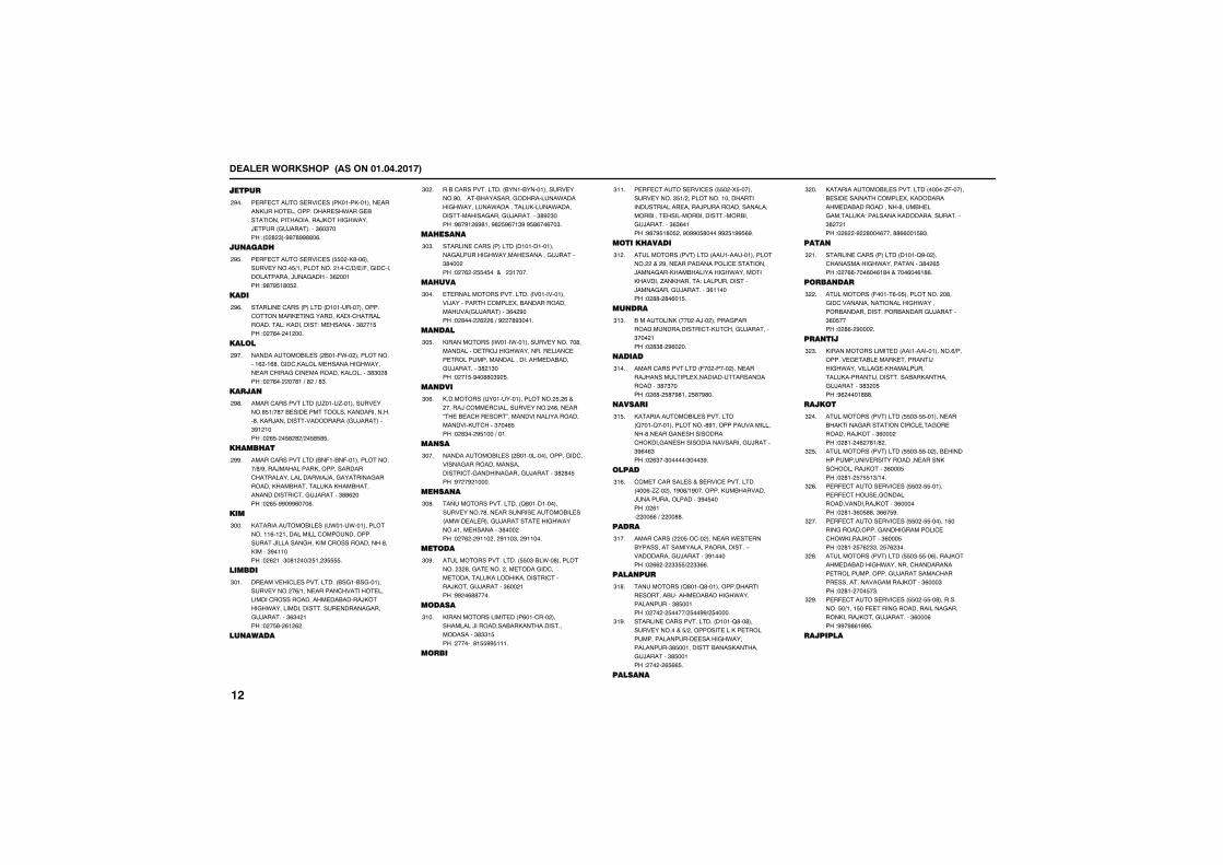
����������� �������������������
������
���(����������������� �,����,�������������,�����������������.�����&��������������������),����.����)������ ��)���������"%�"����! � ' "��##�'##''�%�
#��
�� �����
���(����������������� $$� �,'��%�������������$+���������� ����+�+�+(��������������������)���������"% �����!#'�#$�'�$ �
#$�
����
�������������� ������� �������������������������,������������,�������������������!�,���������!����������"' ��$��!� �%�� �� ���
#%�
����
����������&����� &���(.�� ������������% ��%'�������,�������������.���������������������������,�������"'"� '��!� �%�� ��'��+�' �+�'"�
#��
�����
������������������ �/����/���������������'$�+�'��&���������������,������������'��,��)������������������� ��)��������"#� ����!� %$� �$' ' + �$'$'$�
#'�
�������
������������������ &�(��&�(��������������+'+#����)��������,������������������������������.�)���������������������,��&��������,��,��&����������������������)�������"''% ���!� %$�##�##%���%�
##�
���
,�����������&����� �.����.���������������%�� ������������������������������)�����������,���������������'��,�����"#������!� % ���"�'� ��+ $�� "$$$$�
"���
������
������������������������ &����&����������������� �%+�������������������������������������������&�����),����.�����������������������������������)��������"%"� ���!� �$'� %� % �
"���
�� �����
��&���������������� &����&�����������������#��3����&�����������������.������.��������.����������,�����.�����������������������)��������"'# "���!#'�#� %#'���#' $#%��"#�#$'%��%��"�
"� �
������ �
�������������� ������� ������������������������.���������������)������"'��� ��!� �% � $$�$������� "�����
"�"�
������
����������������������� ���������������)���������������5��&���������������� ��)��������"%� #���!� '��� % %�+�# �'#"����
"���
�� ���
,���������� �.����.������������������'���������������)���.����������������������������������������!������&������)��������"' �"���!� ��$�#��''�"# $�
"�$�
�� ���
,�������� ������������������� $� %��� �����)��������������������� �%�������6���&���������7����������������������������,������"���%$��!� '"�� #$����+����
"�%�
�� ��
����������&����� &�����������������������������������������������������������������)�������"' '�$��!#� �# �����
"���
����� �
�������������������� 2'���������������������'�������������������&����� ��.������������)�������������.������������������"'��� ��!� �% � #��� �� #���"�� #�����
"�'�
����
�������������������� $$�"�&�.��'���������� " '���������� �������������������������,�����,����������������),�����)�������"%�� ���!## �%''����
"�#�
�����
,������������������ �%������� ����������)��������&��,��������������������"'""�$��! ����3'�$$##$����
"���
����
���(����������������� $$� �5$����������������"$�+ ��������������������������������������)��������������������&������������&������������&�����)��������"%"%����!#'�#$�'�$ ��#�##�$'����## $�##$%#�
"���
����������
���������� ��������� �������������������� ��� #����������������������������)��������,��&��������.��������,������/��,������!����������������)�����������)��������"%������!� ''� '�%��$�
"� �
�� ���
&���������,� ��� ��)�� �������������������������������,�������)��������"��� ���!� '"'� #%� ��
"�"�
�����
������������������ (�� ����� ����������)������������5�������������������������"'�"����!� %'� $'�#'��� $'�#'��
"���
������
,�����������&�������������� 2����2��������������'#��������������������'��������������������,���������������������������)������"#%�%"��!� %"��"�����+"���"#�
"�$�
����
����������������������������������� ���%�//�� ����#�%+�#��������,��&�������)�����������������"#�$����!� %�� ��%%�+� ��''�
"�%�
�����
���������� �$���� ��������.�������&���������������������������������-������������)�������"#������!� %% � ""$$+ ""%%�
"���
���� ���
���������� 2'���2'�����������������������&��������&�����.���������������"'$�����!� �� � $����+ $��##+ $�����
"�'�
������������������������ �����2'��'����������������$+ �����������,������������������������������.�������������"'$�����������&����,��������)�������"'$�����! �� � %$%%$�
"�#�
����� �
,�����������&�������������� �����/(������&������������������5��,������������&�����������'����&�����������,�!���������,�����������������"' � ���!� % �# '���%����''%%���$#"�
" ��
���
�������������� ������� �����2#�� �������������.������������"'� %$��!� �%%����%��%�'�������%��%�'%�
" ��
���� ���
���������� (�����%��$���������� �'�������������������������.�������&���������������&��������)�������"%�$����!� '%� #��� �
" �
��� ��
,������������������ ����������������%+�������������&������,����������)���.������������,�������������,��������)�����������&��,��������)�������"'" �$��!#% ����'''�
" "�
����
���������� ��������� $$�"�$$�����������&�,������������������������������������),����"%��� ��!� '�� �% �'�+' �
" ��
���������� ��������� $$�"�$$�� ���&�����������������������������������,��������),����"%���$��!� '�� $�$$�"+���
" $�
���(����������������� $$� �$$���������(��������������������������),����"%������!� '��"%�$''��"%%�$#�
" %�
���(����������������� $$� �$$�������$��������������������������������.,����),����"%���$��!� '�� $�% ""�� $�% "��
" ��
���������� ��������� $$�"�$$��%�����),�������&�����.������������������������������������)����������������������������������),����"%���"��!� '�� ���$�"�
" '�
���(����������������� $$� �$$��'�����������$�+����$��(����������������������������,�����),�����)��������"%���%��!##�#'%�##$�
" #�
��������
����
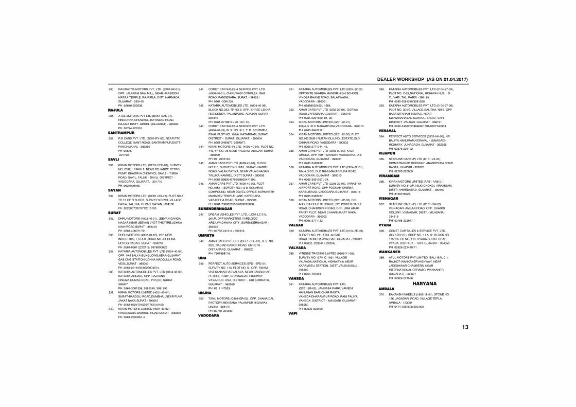
����������� �������������������
������������������������� #5���#5����������)���������.������������������������)������������)�����������!������������)�������"#"��$��!� %��� "$�'�
""��
�������
������������������ &�,��&�,��������������.,����)�(��&����������)������������������ ��)��������"%$$%���!� �#�� �$���
""��
�� ������
��&���������������� ��������"������������������������������������������������������������"'# %���!� %�$� ��$ �
"" �
�����
,��������������� �(����(����������������� $# +����,,�� ����������������������������&�������.,����������-����&������������������,�-�����������������-������������)��������"#������!#% ��##�#$�
"""�
����
,��������������� ���������������%������(���&��,����������� �#���������������������,�!���������������"#��"���!# '����"�+#�� �������
""��
����
��������� ��� ���������)�����������������������)������)��������������������������������"#� ����!� %����%���+� �
""$�
��������� ��� �����&��� ������.��������������������������%��������������������������"#� ����!� %��� %�� � ��'+�##�'#��'% �
""%�
,�����������&�������������� ��������������������������&����.���������)����������������������������������������������������"#$�����!� %�� ����$+# '���%���
""��
,�����������&�������������� ���������$���,��������������������)�������������������������������������"#$�����!� %��"�'� "'��"�'� ����"�'� $��
""'�
,������������������ �������������������&�������������&�������������)�,�����,����������"#$�����!� %��#' ����$#�+#�� �������
""#�
,������������������ ��������� �������������&������������������"#$�� ��!� %�� %"�"%����
"���
����������������������������������� ���%�����������,�.���������5���&��������������������������"#� ���!� %���"�#� "��
"���
,�����������&���������� ���������'���&��,��� ""�������'�������������,��������������������������)������������"#�"����!� %�� ��''���+� ��+�"��+����
"� �
����������������������������������� ���%�����"������������"����������������"��(�������������� +���,�������������������������-����������)��������"#$�����!� %�� �'�'���� %��'���
"�"�
,���������� �������� ���$������������������"��(����� %��)�������������)������������"#$��#��!#�� �������
"���
������������������ ���#���������&��,�����%������������ '+���������,����)����������,������������������,������������,��,����)�������!��������"#$��%��!� %��'#'��� �##+'#'�����'##�
"�$�
������������������ ���#����� �����������������������������#����������������������������((�����,���������������������������,����������������������������"#$��%��!� %����%#� %$$$+��%#� %%%%�
"�%�
���� ��� ����
������������������������ ������������� %�+���������,���������������������.��.�������������������������"%"�"���!� �$ � ��"���+�%$�$�%�
"���
�����
�������������������� �(����(����������������"�+ �����������,�����������������������������)��������"'' ���!�$%�'#'��%�
"�'�
� �
���(����������������� &(���&(�������������������"���������%��������.��������,����������������������&��������������������&����������.��������)�������������������-��������������)��������"% $%���!'$�����$ "�
"�#�
� ���
���������� 2'������� ����������������(������������������������.������)����"'������!� �� � ��##�
"$��
�������
,�����������&�������������� ��� �� ����������������������������������&��&��������������.���������������"#������!�''%%�� �' �+��$'��
"$��
������������������ �"� ��������.����������������)��������"#���%��!� %$� #�$��������� �
"$ �
,������������������ ��� ������#�#+������������,�����������������"#������!� %$� %� � �
"$"�
,������������������ ��� �� ����������%����&�����������)������������������������������������"#��� ��!� %$� ���������$�
"$��
������������������ �"� �� ���,�������������,�������������������������!������������)�������"#������!� %$� � ' ' �
"$$�
,�����������&�������������� ��� ������#'�+�������������'���,�����������������������)�������"#������!� %$�"�#� $��+�"��
"$%�
������������������ �$� �������������������������������������������,�����&���������������)�������"#���%��!� %$� �''�'��
"$��
,������������������ ��� ��"����+���&����������������' "��.�����&�������������������������������������������������������)�,�����,�������������"#��� ��!� %$� ���� �
"$'�
������
,�����������&�������������� ����� ���%������������� �������������������������������������)�������"#%� ���!� %" �� "" ���+� "" �$�
"$#�
�������
������������������������ �$�"�����$�������������"�+��2���'+����������������������������.���'�������,����&������������������������ ��)����"#%��$��!� %���'�"���
"%��
�� ���
,�����������&��������������� 2�����&�� ���)����&�����,����������������&�����������������������������������������(������������������������-������������)�������"#%$'���!� %"�� "�#��
"%��
����
,�����������&�������������� �����#���"������������ #�����������.���'���������������������������������"#%�#$��!� %��"�'� ��+"�'� %��
"% �
,�����������&�������������� �����#���#����������"��+ ����������&���������'�����&�&������������������������.��������������������������������������������������)�������"%#�#���!� %�� ��' � +''%%���$#�+#" ����#�"�
"%"�
�������
���(����������������� $$� ����$�������&�����������������������)���������.����)����������)�������"% %$��!� '�%� �� �
"%��
�������
�������������� ������� ������ �������������������.���������������������������)�������"' '����!� �%"� ��$#�
"%$�
��������
,������������������ ��&����&���������������"�#+������,���,�������������������!������&������)��������"' �$���!'�$%��% �
"%%�
��� ����
�������������� ������� ������.��$���������������&�)�������������������������������������������������"'�"�$��!� �%$� #���
"%��
�����
����������������������������������� &����&�������������������� ��&��,������$+�+�����������"�����������������������������������-���������)�������"#�%$���!� % %� ����+���
"%'�
�� �� ��
���������������������� &����&����������),��.��,�������.���������)����.������&��������������������������������.��,����� ��)��������"%"% ���!� ' '� �$$%�
"%#�
������������
��,����.����� �'� ��'��������������� %��)������������������������������&�������""�����!����� ' $���%���#���
"���
����
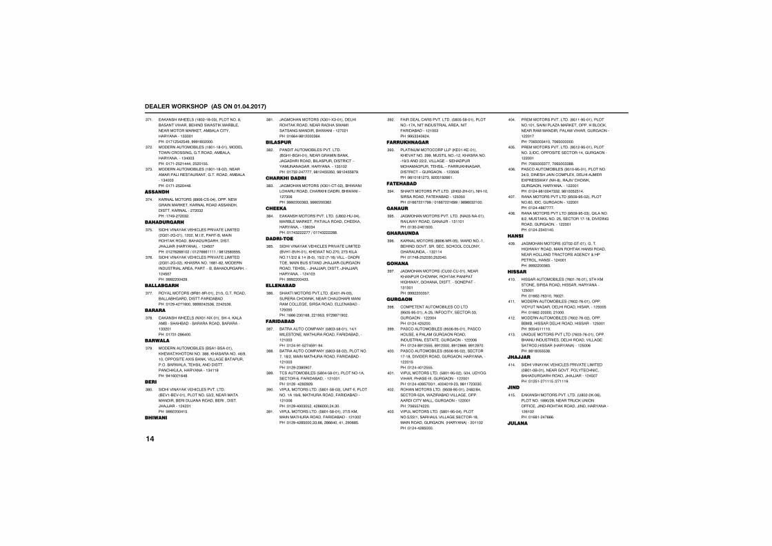
����������� �������������������
��,����.����� �'� ��'��"����������'��&������������&������.����,����&����������������,������&��������������������""�����!���� $� $�#��###�'� ����
"���
����������&����� �'����'������������.����������������������&����������������"���"��!����� $ ������ $ ��$$�
"� �
����������&����� �'����'�� ������������������������������������������&�������"���"��!����� $ ���'�
"�"�
����� ��
,����������� '#�%���������������.����������,����,�������������������������,�������� � �" ��!���#� � �" �
"���
�����������
�����������,������������������������� ���� �������� � ��������������&����������,������&����������������)�))��� ������������ �$����!�� �% %'�� �+��� �%%%�����+�#'� $'�$$$�
"�$�
�����������,������������������������� ���� ��� ���,���������%'��' ������������������������������-�&��&������������� �$����!### ��� #�
"�%�
����������
���������� #�'��#������� �+$������������&����&������������(�����&����!�� #�� ��'����#'## � $"%�� � $"%�
"���
������
��,����.����� �5����5�����������,������&�����&�����&�����������&���������"" ����!���"�� '%����
"�'�
�������
����������&����� &����&��������,�.��+,�������"''��,����������%+#��������������5���&��,����������&������������&��.��������������������������,���������������"���'��!#��%� �%�'�
"�#�
����
�����������,������������������� &����&���������������$"+ ��������������������&������)���������&������������)�))������ � ����!### ����$�
"'��
����� �
)����������� 5"���5"��������������,�����������������.��������������������&�.������� �� ���!��%%��#'� ���"%��
"'��
��������
�����������&��������������� &���&�������������������&��,��)������������&������������������-�������������������������"$�� ��!���" � �������#'� �$$"$���#'� �$$'�#�
"' �
�������������
)����������� 5"������� ���&�.�����������������,���������&�.������� �"�%��!### ��"%"��### ��"% �
"'"�
������
��,������������������� �'� �����������&������,��������������������,��������������"%�"���!����" ���+�����" ''�
"'��
�������
�����������,������������������������� &���&�������,�.����� ���� �"�,��������+ + ������ '������$+ � ���%������������������������&���������)�))�����������������������)�))�����������)�))��������������� ���"��!### ���""�
"'$�
���� ����
��,����������������� ���������"�����������.�,�������������������������������������������������&������ $�$$��!�%%%� "��%'�� �#$"��#� #'��#� �
"'%�
���������
&���������������� $'�"�$'��������+������������������������(�����&������� ���"��!�� ��#��$ ��$#��#��
"'��
&���������������� $'�"�$'�� ��������������'+ �������������������(�����&������ ���"��!�� #� "'�#���
"''�
��������&����� $'���$'����������������������%��(�����&������� ������!�� #��� # # #�
"'#�
���������������� $'���$'��"�����������������������#+%��������������(�����&������ ���%��!�� #����"�$ ��� '%���� ��"��
"#��
���������������� $'���$'������ �+$�,��������������������(�����&������ ��� ��!�� #�� '$����""�%%�� '%%�������� #�%'$�
"#��
(������������������������ $'�$�$'�������������������������������������������(�����&������ ���"��!##$""��% ��
"# �
������� ����
������������������� ,����,�������,�������� ##������������� ��,���������#+"����� + ����������-�������������������������-�(����,����������������-������������ "$�%��!#'���'� �"��# �$�# %%��
"#"�
��������
��,����������������� � � �����������������������(����&������ $�$���!��%%� ��##�+���%%� �%##�+�#'#%�" ����
"#��
�� ���
)��������������������� ���"�������������.������������������"������!��"�� �%�$���
"#$�
������ ��
,����������� '#�%�����$���.����������&�������������������������������������������" �����!����'� $ �"�� $ ����
"#%�
��� �
)����������� ��� ��������������,�������.�,�����,�����������.�����������������������������"�"����!### ��"$��
"#��
�����
�������������&����������� #$�$�#$�������� $����(������������""������������ �����!�� ��� $ ���
"#'�
���������&����� #$�%�#$����������������%������������������������������������������������ ��%��!�� ��'#� $$$��'#� �����'#� '%#��'#� '���
"##�
���������&����� #$�%�#$�� �������������'���������������������������������� ��$��!�� ����� $$$�
����
���������������� $'���#$�� ���$����������������������������������� �����!�� ���"#$���+���������#� "��#'��� "�"��
����
�������������� #$�'�#$������ �' +'���������$ ���.�/���&������������������������������������������� �����!��%$$�� ��
�� �
���������������� $'���#$������������$+ +�������������������������'�������������������� ���������� ���� ��!�� ��� '$����
��"�
�������������������� #$���#$��������������������������/�����,���������&��,����������������������������������������� �����!��%$��"�������%$�������
����
�������������������� #$� �#$�������������"��������������������������������� �����!��%$��""������%$��""''�
��$�
���������&����� #$���#$�������������"�+"��������)���������5��������)�����5�����.��� ��'�����)����.,��������������������� �����!�� ��#'�����"" ��#'���$ $���
��%�
������������������ #$�#�#$�� ���������%������������������ �����!�� ���'%�����
����
������������������ #$�#�#$��"���2�������'+ �������,������ $������������'��������������������������� �����!�� �� "������
��'�
�� ��
)����������� ��� �����������������.����������������,�������������������������������������������������������� ������!### ��"'"�
��#�
������
����������&����� �%����%������$��,������������������������������������ $�����!��%% ��%"�����%� ��
����
����������&����� �%� ��%������������������������������������������� $��$��!��%% � ������ �����
����
����������&����� �%� ��%�� �������&&�&��������������������������� $�����!#"$�$������
�� �
���2���������������� �%�"��%����������&���������������������������������!������������� ����������� $��%��!''�'�$$$"'�
��"�
�������
�����������,������������������������� �&����&���������������������������&��������������)�))������ �$����!�� $�� ����$�+ ����#�
����
�� �
��,������������������� �'� � ,��%�����������'#�+ #�����������,������((�����)�������,������)��������������� %�� ��!��%'�� ��%%%�
��$�
���� �
����
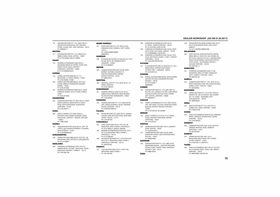
����������� �������������������
��,������������������� �������������)�������,�����������������.�&����������)�������������)��������������� %�����!'"#$#�%����
��%�
�������
��,������������������� �'� ��'��������&�����������%$��,���������"%� ���!����%� $#$#�� #�����"�#""��
����
�����
����������&����� ��� �����������)����������������������������������������� ��,��,������������-�����,���������������"""� ��!���"� �###+ �$$$�
��'�
��� ��
,����������� '#�%�'#��������+"��������������������,���������" �����!��'�� $$$$$�� ��"'��
��#�
,����������� '#�%�'#�� �������&������������&���������������.����,���������" �����!��'�� �� '��
� ��
����������&����� '#���'#��������������������.,��������������,���������" �����!��'�� � $�"�
� ��
��������
)���������������� &����&������������,���������,������������������������������������&��,��,��,��� �����������"��� ��!��"�� $'�����
� �
����
�������.��������� �����������������������)����������������������������,��������������-���.������������������� ""� ��!��' ��� � �
� "�
�� ���
)����������� ��� �����������������((����������,�������&���������,��������������������"������!��"��'�$##��$"$�
� ��
����������
,����������� '#�%��%��"�����������$%������������������������� ��,���,�������!������ " ' ��
� $�
��������
�����������&����� �(,���(,����������������������������������������������������������������-�������������" ��"��!��'�� %%��''�
� %�
�� ����������
��,����������������� �����,��� �������������������&.��������������������� $�����!��%%'� ##''� ##%%#'#%� "$���
� ��
�� ����
������������������� ���� ������������� ' ������%�������������������������������� �$ ��!�� �� %$%$���
� '�
�����
)����������� �%����/��'�����������,��������������.����������,������������������������������,���� ������!### ���"���
� #�
������
��������������������� &�'��&�������������������������!��"�� �' "��
�"��
���� ����
��,����.����� �'� ����� ������ ����&����,������&�����������������(����������������������������"� �"��!��"�� '$$���
�"��
���� �
��,������������������� �'� ��.��"��������(�����.�� ����%$���,���������������.������� %��%��!��%'��#'�"$'"����
�" �
������
�������������� ����������������.��������������������������������������������.������ ������!� �$�"������
�""�
�� ������
�������,��� ,"'��,"�������������"%������������������������ ������,�����!��� � $# "���� $#�"����$�%�""%�
�"��
����������&����� ��� �,"��"����������"�'������������������������ ������,�������"���"��!��� � $#� ���
�"$�
�����������.�,���������� ���$�,"��"����������$�������������������������������,����������������"���"��!#'�'� ��% �
�"%�
�� ���
��)�������� �"'���"���������*��"%���������������������������!�'�������#��
�"��
�����������&����� �"����"���������������������������������" ��"��!���� �%� # ��%� $��%��' �
�"'�
�����������&����� �"����"��"��������)�������������������������������" ��"��!��'� %''�''����'���#�'���
�"#�
�����������&����� �"����"������������ "�������� $�������������������������� ������������" ��"��!��'�� %%��##� %%��''�
����
������
������������������� &��"�&������������������������������������������������������������������� $�"��!�� �� %� ����
����
�����
,����������� '#�%� ���%������������������������������,���,�������������.�����"%� '��!����� �#��###%�"'''��
�� �
�� ���
��,������������������� &((��&((������,�������"+����,�.��� ����������������(���������������,������������������������,�����������������"%� %��!'"#$#�%����
��"�
������
�����������&�������������� � ������� �������)�����������������������&���������������������������������������������"$�����!���" � '"�%$��#'� �$$''��
����
������
�������.��������� ��� ���������&�.�������������&���������������.���� ������������ "�����!� ��� %�"���
��$�
����
)����������� �%����%���������������������,���� ������!�� % �$$�� �$�
��%�
)����������� �%����%��"����������,������.,�������&���������������,����� ������!### ��"'$�
����
������
��,������������������� �'� �)���$��������&��,��������������������������������������������������((���������������)������� %�� ��!#'#%�$$"�$�
��'�
����
���)�&������������.�,�� �''���'���������"����/��������������������������&�����!����� ' %%#��#'#%�� �%#�
��#�
���������
�����������,������������������������� &�2��&�2������,�������$$���,��������% +��+ ������'+ ��#���#+�+� "�����)�))���,�������� �������������������&���((���������������-������.�������������-�)�))��������������� ���%��!#�%��%$����
�$��
��������
�����������&����� �"������� ���������������������������������,�����������������������������" �����!'%������ �
�$��
������
)��������������������� �����������������������������(8����������,������������������������,���� �$����!#'� ���"$��
�$ �
��������
,��������������������� ��������������,�.�������%���,���������'%��,������������������������&�����������,���,����������"%�"$��!###% �%����
�$"�
�����
��,����������������� ���������������&&�������������������������� $�$$��!��%%%�"��%'�
�$��
�� �
���������&����� #$�%�,/��"������������������������������������������������� ��"��!�� ���#$ ����
�$$�
� ���
)����������� )$���)$�� �������������������������������������� �����������"������!#'� %�$����
�$%�
� ���
)����������� )$���)$������&����������������������.������������������"������!�� %�� "������ "%��%����
�$��
����
���������&����� &����&��������,�������"�+�+ ����.������������������������.��������������� ��$��!'%'"���#� ��#'�"����#��
�$'�
����

����������� �������������������
�� �
��,����������������� 5����5���������������������������&���������������������������� $� ���!��%# � ��##� ��##�
�$#�
����
)����������� �������������&�.�������������������������&�.�������� ������!�� $"�'�$##��$%%�
�%��
���� � ����
��������������� � '��� �������������%������)�����,�������������������������������������������!��" � %�#"��
�%��
�����������&�������������� � ���� ���������������������)�����������������������"$�����!���" �"��##�
�% �
�����������&�������������� � ���� ��"�����������'����������������������������������������� �����������"$�����!###%� %����
�%"�
��� ��������� ���� ��
,����������������� &&���&&������������)������������&��)������� ���,������������������������&��)������������,����������%��$��!��'# � $�"�#�
�%��
�� ����
,��������������������������� &.���&.�������,���������#��,����,������� "��&���,��������������������������&������%"�"��!��'##� $��'%�� " �"%��#��'��''�"�
�%$�
��������
�������������&������������� %����%�������,�.������'+'�,��������,���������"�+"���"������/��,������������#�������-����������������-���������������&����������������������������������!��#�'��'��'��""��+��'��'������
�%%�
������
,����������������� �#� �)(��"��������������������&����&����������&������%"����!��'## �'%���#��'�$# $ �
�%��
,��������������������������� �#� �)(��$���,��������''+#%�����,�������% '+ �%�����������������������������������&����������������������%"����!##''����"��
�%'�
�����
,����������������� �#� ���� ������������������������������������������,����������������!��#��� "�����
�%#�
������
,����������������� &&���&&�����������������.���� ����/�����&����������������������������,��������������������������% �#��!#'$�%�$����
����
��������
�������������&����������� .#���.#����������������,,����������.������������������������������������!��#� � $% '��'��
����
������
�������������������� ''��'�������������������,�������)����������������������!��'#"� %$$$�
�� �
��� ���� ����
�������������&������������� &&��&&������������������������)������������� ���������$��$��!�%# �#��' %"�%$�
��"�
�����
�������������&����� 2��� 2�����������������&��������������������������,���������$� %��!�#� � %�%%$��#% $�#�'���
����
�� ����
�������������������� &&5��&&5������,�������-�������������,��������,��������������-���,������������-�������������������������" ����!#'�'�"'�� �
��$�
�� ���
�������������&������������� &,���&,����������������������� ����������������������������������������,������ ���������$�"���!�#� �#��'"'��%$�
��%�
�� ��
�������������&������������� &"���&"���������,���������������������������������������� �����,������������� �$����!��#�$� "'%$�
����
����
�������������&������������� &5���&5���������������)������,��������'"������������������������������������������������������������!��#� � " '%$�
��'�
����
,����������������� �#� ��#����������������������&��.����,���������������%�����!��'# � $�"�#�� $�"'��
��#�
����������
,��������������������������� �#� ��#��%���)�,�����&�������/����&�������������������&��.�������������������,�������������������������%�����!��'# � $�"�#�� $�"'��
�'��
�������
���������� �&� ��&��������������������������������������������������������������������������� ���������������!#��'�%#%� �
�'��
�����
,����������������� �#� �)���������������)������)����������������������������,����������% ����!��'#"� %�'#�� %"""�
�' �
��������
,����������������� ���� ����������������������,����������������������������������,��������������������������%�%���!�'#�� "% ��
�'"�
�� �������
�������������������� �#���'��� ������&�&�)����,��������������������������������������� �����������&�����"� $��!#��'�%�� '�
�'��
�������
�������������������� &)5��&)5������,�������$��+$�$����'+"��,��������-�"'+#'�����������������������������)����������-���)��������������-�����������������������������"�����!#'�'�"'�� �
�'$�
��������������
�������������������� &�(��&�(������,��������' �+' $�����������$$+"#%���%"+�����������������������������������-������������������-������������ �����!#��'" �$�$ �
�'%�
����
���������� )/���)/�������������������������������������������������� ����!#��'��'�� �
�'��
������
�������������������� �#����#���������������������� ���������������!����� "�'� �
�''�
���
�������������������� �������������������������������" ����!���# � ��� �
�'#�
� �
�������������&����� 2����2���������������������������)����������������������!���������"�"��!�#� � $% '��'��
�#��
����������� ���� � ��
���,���������������� ���� ���������������/��������������������������������� '�%$��!�#" � '�%$�
�#��
�� �����
)��,�������������� ,����������������� � �$���������)���&����������)�,����#"$� ��!��#$�� $�'$�
�# �
��������
)��,������������ ,���������������� '����'������������������������.������&�����������#"�����!��#�� �"'#$��
�#"�
���
)�,������������ /��� /����������������������,����&���������������������������� )�,�����' � ��!�##% ""��%�
�#��
�� ������
)��,�������������� ,���������������� /����/���������������&����������&��� )�,�����#� ����!��#�� ��%�$%�
�#$�
�����
)��,���������������������� ""�%�""������������&�������������������������)��������'���$��!��#���%%%'����%�"����"�'�
�#%�
)��,���������������������� ""�%�""�� ����������������&�����������������((�����&���������)��������'������!��#�� $�% "$�� $�"#"$�� $ �" "�
�#��
����
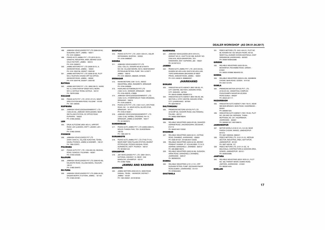
����������� �������������������
)��,���������������������� ""�%�""���������).�����������)��������'������!��#�� �%'$���
�#'�
���,������)�������������� ""���""�������������������������������&�������������(�������)��������'������!��#�� �'�'�"�
�##�
)������������������� ""�'�""������%���,��������)���������'������!��#�� $����%�� $$ #���� $�$�'"�
$���
)������������������� ""�'�""�� ��������� ����)�����������������((������,��������)��������'��� ��!��#�� $����%�� $$ #���� $�$�'"�
$���
������
)�������������������� "&� �"&������.�������"����,����������������������������,�����������,��������'������!�'"�%�"�"%�
$� �
������
���,���������������� ��������������������������������������,���������#� � ��!�#"�� %��"��
$�"�
�������
)��,������������ ,���������������� � �$��5��"���)��,�����������������������(������������������((��������,��.�������#" "��!��#$$� $"" �
$���
���
���,����/��� #����#���������������������� ����,��������������,��������#������!��#' � $���$�
$�$�
� ��
)��,���������������������� ��.����.��������������,��������������������������)�������,����������'$� ���!�#%$� #� �
$�%�
�������
���,���������������� � �������"�����������������������.�������# "����!��#""� �� %�
$���
������
)��,���������������������� ""�%�,���%���,���,����������������&�������)�������'$�"���!��#% � %�#�"�
$�'�
�������
)��,���������������������� ""�%�)���"�������������������������)���������'��� ��!��# "� $�#$��
$�#�
�����
���,���������������� ���������������������(�����������������# "�"��!��#�� �%%%�%��
$���
������
)��,���������������������� ��������������,�������'����,������������������������������������&���������������������������������������)��������'���#��!��#�� %% � ��� %% � $�� $�% "$�
$���
��� ����
���������� � '��� �����������������������������������������������!��#�� �"$#�#�
$� �
�����������&������������� � � �� ��������.����������������#������!��#���$ $�#����## '�
$�"�
)��,������������ ,���������������� � �$�� ���������������&����������������������������#���$��!��#�� �"$$�%�
$���
���,���������������� � ���� ������&�������������������������������������������������������#������!��#�� �"� %��
$�$�
)��,������������ ,���������������� � �$�� ��$������&����������������������������)�������,���������#������!#��#��""� �
$�%�
�� ����� �
���,������)�������������� ��� ������������/������������������������&�������'$�$"��!�#%�� ""��#�
$���
���� ��
���,������)�������������� ��� ��������������,�����,����(���������������&�����������������������������������,���������!��������'$�����!#��'""��� �
$�'�
��������
)�,���������������������� �'����'����������������.������������3��,�&����.�������������' �����!��## ��% %%�
$�#�
������������� ������ �
)���������� 5� � 5������������������,����������-��,���������������)��������'� ����!�# �� $ � ���#��#��#�% �
$ ��
�� �����
)��,�������������� &����&��������,�.�����"���,������� #'������������"�%�+�'�%���/��&����������������.�����������,��.�����)�,����#" ���!#��#����� �
$ ��
�����
���,������)��������������� ""���""�� ���,�������� $���� %��,������� $���� %��������,������ &��,�����(�&�������������,��������)���������'������!��#�� �'�'�"��#$#%% ��$��
$ �
� ��� �������
�������������������� &$���&$�� �����������������������������&,���������������&,�����' ������!�%$� � ""%#�+�# %"%"�"�$�
$ "�
�������������������� &$���&$��"���� �������������������������&,�������������� )��,�������' ������!# ���#%����
$ ��
��� �� �
�������������������������� $��"����� ���,�������������������)�����������' �����!�%$% �#"'%�%'"���
$ $�
������
�����&�������������� $ � �,���"��������������������)��������������������'���� ��!�%�" �#�"�� $"" �
$ %�
��� ���
�����&�������������� $ � �$ ������,��������������&����)��,�������' %�����!�" %�"��$����"��$�'�#�"�� $"" �
$ ��
�����&�������������� $ � �$ �� ���&��������&���,�&������!�,��,���������,��������������������������&�����' '� ���!" %�'#'%��#�� �
$ '�
�����&�������������� $ � �$ ��%���������������,��������������������&����)��,�������' '� ���!#'"$'"� � �
$ #�
�����
�����&�������������� �������������������������������������������,����������,�� �)��,�������'�������!#��'$$$# ��
$"��
��������
��&������������ ���������������������%'��,�������� '�����/����������""�������(������������.,�������������������&��� )��,�������'" "�"��!�%$'$�#"�'�"""''�
$"��
�������
�����&�������������� $ � �"��������������������&�����������������'�$"����!�%$" � #%#+�##"� �$� "�
$" �
����
�����&�������������� $ � ��)��$�������&�����.,��������������������'���""��!#�"�� ���#�
$""�
�����
��������������������������� $��"� ���������������������5������������������� "�������������������'"$ ����!�%$ �� �����
$"��
����������
�������������������� �#����#������������&�������&�����������������/���&������' $"����!# %"%"�" ��
$"$�
�������������������� �#����#�� ���������� ""����� "��������������������((��������� $����/���&����)��,�������' $"����!# %"%"�" ���#�"��#'��$�
$"%�
����������
����.���� "�� �"����������""��������������.,��������)�����������'"��� ��!�%$�� "%�"�%�� "%�"���
$"��
��&������������ "����"�������������������������������������������������)�����������'"������!�%$����#��%������
$"'�
��&������������ "����"��� ����%�&�����������������������.���������������)�����������'"������!#"�'�"""''�
$"#�
������
�����&�������������� &5��&5��������������'"�����.���&��������,�������)��������)��,�������'�$"$���!#'"$'������
$���
�������
����
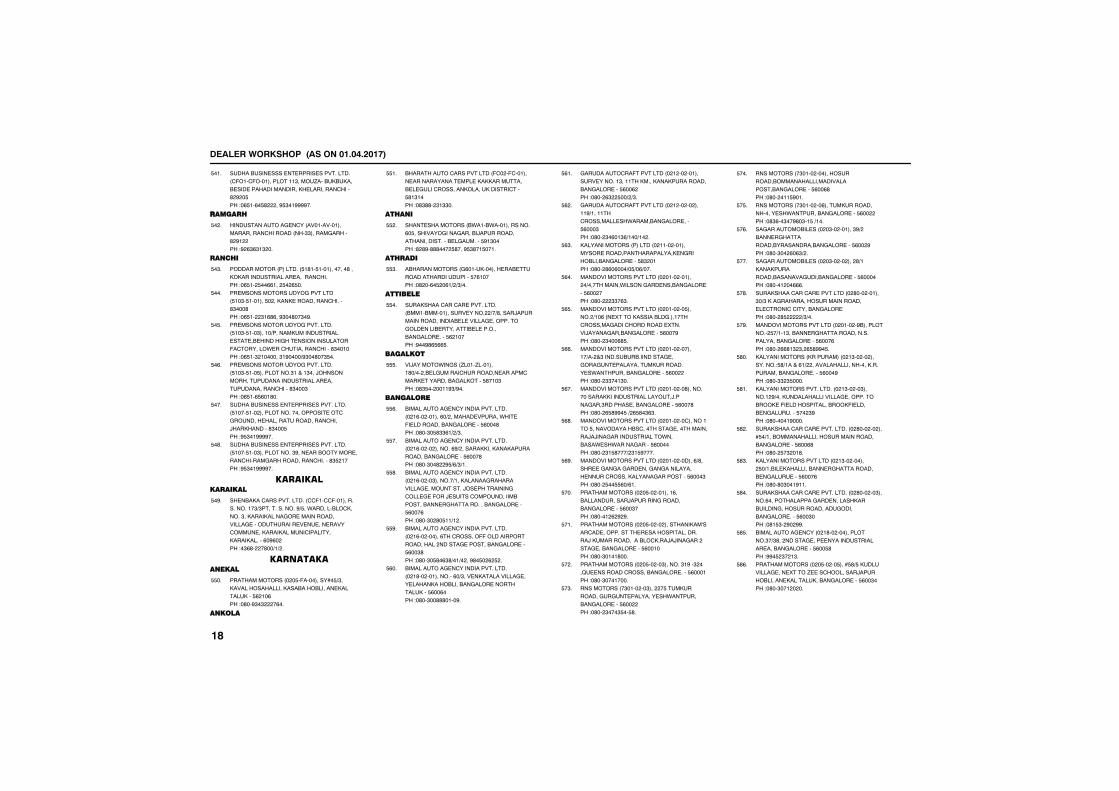
����������� �������������������
�����&������������������������������� �(���(������������"����/���&�,&�,���&��������������������,���������������' # �$��!�%$��%�$' ��#$"��####��
$���
��������
�������������������� ������������������������������ ��""������������' #� ��!# %"%"�" ��
$� �
�� ���
���������� �������� $�'��$������������'���,,�����������������������������!�%$�� $��%%��� $� %$��
$�"�
�������������������������� $��"�$�������$� ��,��,����������������'"���'��!�%$�� "�%'%��#"��'��"�#�
$���
��������������������������� $��"�$���"�����+������,���������������������&������������������������(��������.������������������'"������!�%$��" �������"�#����+#"��'��"$��
$�$�
��������������������������� $��"�$���$���������"�����"���)����������������������������������������������������'"���"��!�%$��%$%��'��
$�%�
�����&������������������������������ $����$��� �����������������������������������������������������)��,������'"���$��!#$"��####��
$���
�����&������������������������������ $����$���"����������"#�������&�����������������������������������'"$ ����!#$"��####��
$�'�
����������������
���&�,����������������� ��(����(�����������������"+"�������������#+$��.�������&��,�����"��,����,�������������������������������������������������������������,����,�����������������,����,������%�#%� ��!�"%'� �'��+�+ �
$�#�
���������� ����
������������ � �$�(���������*�$+"��,�������������,���&��&�������,�������,���$% ��%��!�'��#"�" �%��
$$��
� ���
&���������������������� (�� �(����������������������������,�,,����������&����������������,�����,������������$'�"����!�'"''� "�""��
$$��
��� �
������������� &.���&.�������������%�$�����������������&�)�������������������������&����������$#�"����!' '#�'''��� $'���#$"'��$����
$$ �
������
�&���������� �%����,���������&������������������������$�%�����!�' ��%�$ �%�+ +"+��
$$"�
������
����,����������������������� &����&����������������� +�+'�����)��������������������&���������������������������&����������&���������&�����������$% �����!#��#'%$%%$�
$$��
������
��)�����.����� /����/��������'�+�� �&������������������������������,���������&����,����$'���"��!�'"$�� ����#"+#��
$$$�
�� �����
&�������������������������������� � �%�� ������%�+ ��������������.����(����������&����������$%���'��!�'��"�$'""%�+ +"�
$$%�
&�������������������������������� � �%�� �� ������%#+ ������,,���,���,�����������&����������$%���'��!�'��"��' #$+%+"+��
$$��
&�������������������������������� � �%�� ��"������+���,�������������������������������)��������������������(��)������������������&������&�����������������&����������$%���%��!�'��"� '�$��+� �
$$'�
&�������������������������������� � �%�� ������%��������((������������������� ��������������&����������$%��"'��!�'��"�$'�%"'+��+� ��#'�$� % $ �
$$#�
&�������������������������������� � �'�� ����������%�+"�����,���������������������,��&����&����������������,���$%��%���!�'��"��'''����#�
$%��
�������������(���������� � � �� �����������������"������,����,���,����������&����������$%��% ��!�'�� %" $��+ +"�
$%��
�������������(���������� � � �� �� �����#+������������������.�����&�����������$%���"��!�'�� "�%��"%+���+�� �
$% �
,������������ ������� � ���� �����������������������������,������&���&����������$'" ����!�'�� '%�%���+�$+�%+���
$%"�
�������������������� � ���� ������ �+����������.�������������&����������$%�� ���!�'�� ""�%"�
$%��
�������������������� � ���� ��$����� +��%� ��5����,������&�������������������������������5������)���������&����������$%���#��!�'�� "���%'$�
$%$�
�������������������� � ���� ��������+�� �"�������&��&��������������������������������,�����������.��������&����������$%�� ��!�'�� ""���"��
$%%�
�������������������� � ���� ��'�������������,,�������������������)���������"���������&����������$%���'��!�'�� %$'##�$�+ %$'�"%"�
$%��
�������������������� � ���� ������������$����������&�������������������������)�)�������������������.���&���.��.�����������$%������!�'�� "�$'���+ "�$#����
$%'�
�������������������� � ���� ������%+'�����������������������������������������������,����������������$%���"��!�'�� $��$$%�+%��
$%#�
������������ � �$�� �������%��&�������������)���������������&����������$%��"���!�'���� % # #�
$���
������������ � �$�� �� ��������,��0��������������������������������������)�,�������������&��,���)�)������� ��������&����������$%������!�'��"����'���
$���
������������ � �$�� ��"������"�#��" ���2����������������&�����������$%������!�'��"��������
$� �
��������� �"���� ��"��� �$����,��������������������������.��������&����������$%�� ��!�'�� "���"$��$'�
$�"�
��������� �"���� ��������������&�����������������������&����������$%��%'��!�'�� ���$#���
$���
��������� �"���� ��%������,����������������.��������&����������$%�� ��!�'"%��"��#'�"��$�+���
$�$�
����������&����� � �"�� ������"#+ �&���������������&����������&����������$%�� #��!�'��"�� %�%"+ �
$�%�
����������&����� � �"�� �� ��� '+��,���,���������&������������&����������$%������!�'���� ��%%%�
$���
����,��������������������� � '��� ������"�+"�,����������������������������������������&���������!�'�� '$ +"+��
$�'�
�������������������� � ���� �#&���������� $�+���"��&����������������������������&����������$%���%��!�'�� %%'�" "� %$'##�$�
$�#�
,������������ ,��������� � �"�� �� ���������!$'+�����%�+ ������������������,�����������&�����������$%���#��!�'��"" "$����
$'��
,���������������������� � �"�� ��"������ #+���,��������������������������&�,��(�������������&�,(������&������������$�� "#��!�'������#����
$'��
����,����������������������� � '��� �� ���*$�+���&�������������������������&����������$%��%'��!�'�� $�" ��'�
$' �
,�������������������� � �"�� ������ $�+��&���,�������&����������������&������������$%���%��!�'��'�"���#���
$'"�
����,����������������������� � '��� ��"�����%�����������������������,����&��������������������������&�����������$%��"���!�'�$"� #� ##�
$'��
&���������������� � �'�� ������������"�+"'�� ����������������������������������&����������$%��$'��!##�$ "� �"�
$'$�
������������ � �$�� ��$���*$'+$�,����������������5����/�����������)�����&�������,�������,��&����������$%��"���!�'��"��� � ��
$'%�
����
����������� �������������������
����������������� �"���� ������������ #��,���&�������������������&&��������������&�����������)���������,������&����������$% �$'��!�'���"��� ���
$'��
�������������(���������� � � �� ��"�����+����&&����������,����,���&��&����������������&����������$%�� ���!�'�� "% �"" �
$''�
&�������������������������������� � '%�� ������*�'�+�'$������(����������������.����(���������������&����������$%��%%��!�'��"�%#"�%#�
$'#�
����,����������������������� � '��� �������������'���#����5����&��������5�����&��,������(�������,�����������&���������,������,����$%��"���!�'�� $$ #��#+��+���
$#��
,��������������������� � '��� ������*���+$�����������������,�������������������&���������,������,����$%��$%��!�'��"��"%"""�
$#��
�������������������� � ���� ���������� + ��������������������5������������������������)���������&���������,������,����$%���"��!#�"����"���
$# �
&�������������������������������� � �%�� ��%����������' �������&����.��������������&����������������������5��������������������&����.�����&���������,������,����$%��""��!�'������"�%'�
$#"�
�������������������� � ���� �����&&���������.������'"��)�������������������������������.����������&����������$%��#"��!�'�� $"�����+���
$#��
,���������������������� � �"�� ��$������������+$�����������������������&&���((�����,��������&����&�����������$%���"��!�'��##��$###�%�
$#$�
,�����������&��������������� � #��� ���������$���$��������,�������������������������������-����������&�����������$%��"���!�'��###'�'%� ��
$#%�
���������������������� � ���� ������,�������������������������,�����,�������������������,�������&�����������������&����������$%��%���!##�$ "$$�%�
$#��
�������������������� � ���� ����������! %���&���������������������&���&�����������������,�����$%��� ��!�'�� $����%�+�%+% +%"+%��
$#'�
��������� �"���� ��������%+���&��������������������������&��,��������������������&&���(�������&��������� ,������,�����$%��# ��!�'�� "$"� '%�
$##�
��������������������� � # �� ���������� +�#�%������%�+ �����.��������������������&��&��.�������������)�)���������&�����������$%�� ��!�'�� "�'$$$$��##'$"�� ���
%���
��������������������� � # �� �� ���&���������� �+���� �+ ��������������+"���� +��&��������������������������������������.���������&������������������������&�����������$%���"��!�""' '%� #�
%���
��� �����
����,���������������������� ������������'�+�����������������,����&��������������&��������� ,������,�����$%"�����!�' �$"� #� ##�
%� �
�� ���
�������������������� ����������������$����������������&���������&���.����,�������,����$�� "���!�'�� ���� "�
%�"�
�������
������������ ������� �'����'��������)�.���������������������&����������$#������!�'"�� ��""�'+� ��$ "+ ��%�% �
%���
������������ ������� �'����'��"����������$��/��������&����������$#���%��!�'"�� ���'���
%�$�
������������ ������� �'����'�������������'������������ $�+$�������,�����������&��������� #������!�'"�� � $���+ �
%�%�
�������
,���(���������� � ���� ��������&�����$'�&�������������������������&���������$'"�����!�'"# � "�%%%+%'$�
%���
,���(���������� � ���� ��"�����������������.���0����������&����������������������������������&����������$'"��"��!�'"# � $'#���
%�'�
����� ����
&���������������������� �$�"������������������&�����������&��������������,��,������������$�� ����!�' $%� "��"��
%�#�
������
&���������������������� ��(����(�����������������$�+ ���������������������%%��&��,���������,�����������������,������,�����$'�" ���!'"' �#��'#�#$"��
%���
�����
�������������������� �5����5���������$�+$���������������������������,���&���������������������&����&�������$'$�� ��!�'�' � " #�$�
%���
�������
��������� �"�������������������� $,+����������������������������)��������&�)������������,������,����$'%��#��!�'"$ � � ' ��
%� �
�� ��
�&�������������������� &���&�������"� $%���"� $����������,�������5����%%���������������������&������,������������,�����������������$�% ����!�' $���'##�$�����
%�"�
�������� ����
���������������������� ���������������)�,�����&���������������������������,��������5�������������)������ ,������,�����$��"�"��!�' %� '$�+'$'�
%���
��� �����
����������� &�2��&�2���������������$����������,�������������(��������������������������������"�������������������������������$�� �"��!�'�'#��'###"���"�
%�$�
��� ��� �
,�������������������� &�5��&�5����������������$'����������������������&�������������������,������������������������$% �%���!�'�� '��'###�
%�%�
��� ������� �
���,�������� ������������������"'#��"%+"���" +���&��������������������������������������������������������������!��������,������,�����$�"��%��!�'�� �� $%% ���#'��"������
%���
�������������
&�������������������������������� ,)� �,)����������%#+����������,��������,�������������,���&��&������,&��������������������$% �����!�'�$%�"��$��+� +��
%�'�
������ �����
����������� &����"(�� ���������������,���������,�����������$���� ��!�' % � ��'"9 ��'��
%�#�
������
������������� �'���/&��$���������������������&�,�������������)��������,,����,������,����$#� ����!�'""'� �"� �� � ����
% ��
��� ��� �
��������������������� � �$�&2��%�������������""����5������)��������������������������������,��������������������������������������,������,����$%"� $��!�'##�%�"���
% ��
����������
��,�������&����� ����������������������������5����������������������������$� �"���!�'�" � �����
% �
���� ����
����������� ������������������������������������&������������������,������,����$�������!�'�# �#%%""��%$$�
% "�
���� ������
&���������������� .���.��������������� ��+���+%������.�����&&������������������&�������������!���$% �����!�'�� �%'���'�
% ��
�������
�����,������������������ &�5��&�5���������������������������������&����������,���&��,�����������������������.����,������,����$'������!�'"%� ���%%%�
% $�
�����
��������� �"����,�������������%����������������������������������((������&���������������������������$' ��"��!�'"� � "��� � "���%�
% %�
�� ������
����
����������� �������������������
������������ �����,���"���)��������������5�������������������������$'" ���!�'$""� ���$$�
% ��
���������� ��
�������������������� &����&����������$# +$ �����������������������)�������,�����&�������������&��������.������������,&����������$%� ����!##�$ "$$"��
% '�
����
��������������������� ��������������������%+"�+ ��������������,�,��&����������������$#�"����!�'"" � %��%�
% #�
� ������
�������������������� $����"������,��,���������������,���������$�� �"��!�' ��� �#'���
%"��
��������
���������� �#� ��#������������������������,�(������&����������&�������$'$�����!�'�� � $'�� �
%"��
���������� ������
������������ ��������(������������������������������� &�5��&�5��������������� �+ ����� �+"��&��,��� ��.������!"�������&�������������������&�������������������$'" � ��!�'"#�� %% ��
%" �
�����
���,�������� �'� ��'���������" %����������.��������������������������������$�" ����!�'�� � �"��$+����
%""�
������
�����,���������������� &&���&&���������������������������������)�����,���������&��������������$'������!�'"�$� "$#���
%"��
����
&�������������������������������� � �%�����$������ �$+��'���������������,�������,��,���&���,����.�����������&����������$% �����!�'��'���"#'����
%"$�
����
������������ �������������&��������������,���������������$'" �"��!�'"#�� %% %�
%"%�
�����
��������� �"����"�������������&��������������,�����&�����$'�� $��!�'"%� ��' $+ �� "#�
%"��
��������� �"����"��(����,��������������.���&��������&�����$'��"���!�'"%� "%�$�+$ �
%"'�
�����,���������������� �"�"��"�������������%$+���.����������������������������&��� ,������,�����$'�� #��!�'"%�%%�""" �
%"#�
������
�������������������� &����&��������������������+ ���,�������,���&���������,����,���������������,������,����$�� ���!�' $�� %�"$��
%���
�����
����������� &2���&2����������������� ������������5�����,���,���������������������&��&��������,���������������-���,�����������$��$�'��!�� ���% ��
%���
�� �������
,���������������������� &5���&5��������������������+�&��,���&��&����&��������������������,���,���,�����������������������������,������,�����$% �����!##���$��"��
%� �
�������
�&���������� �%������"������"�����������,������,���������,�����,��,������$�������!�' $'� ""�$$9 ""�'$�
%�"�
������
&���������������������� ')���')�����������������$#+ &���$%+ &������$%+"�������,�������������,��.�������,��������,�����������������,������,�����$'�"����!�'"' � %$$"��
%���
�� ����
,������������ ������� � ������"�������������,�������&��������������$%��$#��!�'�� '%���$��
%�$�
����
�������������������� � ���2���(���%�+"�&�����������������.����,�����)������������������������������,�������$%"�����!'�$ � ������
%�%�
�����
,�(��������� ����������������� '"+��������������������������,��������������3�%"��,�������$'" "'��!�'$"#� $$���
%���
����
&���������������������� �(� ��(�������������0������������%%������,���,��&������������,����� ,������,�����$'�""���!�'"'%� """��
%�'�
�� �����
�&���������� �%������� �����������,,������,����������� � '����!�' $�� � '���
%�#�
�� ����
��,�������&����� �2����2�����������,�����������&�������,�����������,�������������,������,����$� �"���!�'�" � �����
%$��
������� ����
������������ �����������������!''������������,������������������������,������,������,����$�� "���!�' �%� � "%$� �""%$�
%$��
�� �������
������������ ��������(������������������������������� &2��&2�����������������&������������5���������������������������������,������,����$'�� ��!'$" � $�$$$�
%$ �
��������
(������������� ����������������� $� �25�� ���&���������������&�������������.�����������,����,�����������������$�� ����!�' � � #����#����'$$""�#����'$$''�
%$"�
�� ���
�������������������� $���&���%����%%�+���,����������5��������������������$�������!�' " � "� %��
%$��
�� �����
&���������������������� �$�"��$������������,����,���)������������&������������)���������������������$�$�����!�' �� "�"��
%$$�
�������������������� �$� ��$�������������&���������&������������������,�����������������$�$�����!�' �� ���� "�� ���� '�
%$%�
�������������������� �$� ��$��"���������������.��������������������'�������������$�$�����!�' �� �$� "�
%$��
�������������������� �$� ��$������&�������������������������������������������,������,����$�$��'��!�' ��"�#�� "�
%$'�
&���������������������� �$�"��$��%���������� #�+��� #�+���,����&���������������5����&�����&�����.�,�������������&�����������,��������������������,������,����$�$�� ��!�' �� ""��
%$#�
�������������������� �$� ��$��'��������� �%"+�����)���&�������������������������������������-���,�����,��������,������,����$�$�� ��!�' �� #'$� "�
%%��
��������
&���������������������� �$�"����"���&�����&�����������������������0������������&�������$�� ���!�' $'� "'%"��
%%��
�����
&���������������������� �$�"�2���$���&�����&���������������������,����$���$���!�' �� #"�"��
%% �
�����������
��������� �"����'�� ������������������&�&���������������.����,������,����$'�"$���!�'"'$� %� #$+#%+#��
%%"�
�����
(������������� $� � $�������������������������������������������������$����'��!�' �����$ ���
%%��
�������������������� $��� $��$������' +��$+���&���������������������������������,������,����$�������!�' ��� ������+��������
%%$�
�������������������� $��� $��'��� ��+ ����������������,���������������,������,����$�������!�' �����##���
%%%�
�������������������� $��� $�������!�$�,������������������$����$��!�' ��� ������
%%��
� �� ���
����
����������� �������������������
(������������� &�,��&�,�������"��+��$#+��������������������)����������������-��������,������,�����$��"����!' �� #������� $# $$$$'�
%%'�
����� ����
����������������� &&��&&���������%�+ �����,��������,���&��&���������������������&�������������������&����������,������,����$% � "��!�'�� ���� �$�
%%#�
����
&���������������������� �$�"��/�� �����������.���������������������������$��$'"��!�' $�� "� "��
%���
�������
������������ �����",�� ���*� ����%���������������������&���������������$'������!�'$" �#��#'������
%���
���� ������
,������������ ������� � ���)&�� ���*,�"�'+ �"���������������������&��������������������$��$����!�'�� � �$##�+ +"+��
%� �
�����
����������� .(���.(������&���������������������������&��,� &����&��������� �%������������������������$�������!�'�'"� � "�
%�"�
������
����������� &����&�������,���$##�����,��������������������$�� ����!�'�' � ��#�%�
%���
����������� &����&���"���&��,��������������������������&�������������&��,����������������������$�� ����!�'�' � $����� ��#�%�
%�$�
����������� &����&���$���������������+"�����+�����������������������������������!�'�' �#'�$"##"%��
%�%�
��������
&������������������������ &����&������������������ �������������������&��,��)���������������-����������,�-��������������������-��������,����������$'�"$$��!$'�"$$��#��'#�#$"��
%���
�� ��� ��
,�(�������������� (5���(5�����������������$$+���������%��� �%+"�.��������#�����������������������������������,������,����$'�� '��!�'$"$� � ##�
%�'�
�����
��������� �"����2������,��&���������������$'��� ��!�'"'�� "�'$��
%�#�
�������
�������������������� �$� ��.��������&�����������������������������,������,����$�� "#��!�' $�� " " $9 " "���
%'��
��������
�������������������� �$� ����� ���,��������������,�����$���$'��!�' ��� $%#'�+� $''##�
%'��
���
&���������������������� 2.���2.��������%%��,���,�����������,�������,�����,����������������$�$�����!�' �� �%�%"��
%' �
����
��,�������&����� �������"���&�������������������������������! �%����������,������,����$� ����!�'�"�� $"%%"�
%'"�
�����
��,�������&����� ������������������������,�����$� ��%��!�'�%� $%�""+%%�
%'��
�����
�&���������� �%����%������������������������������$�%��"��!�' ��%�$����+ +"""+����
%'$�
�&�������������������� �%����%��$�������"�$+����������$�$��������.��������������������������������������������������$�%�����!#'�$ � ����
%'%�
�����
&���������������������� &.���&.���������������� "�� &��������������������������������������������������������������������)�����&��������������,������������,�����,��������,������,�����$�� ����!' $%� "� "���##'%$�"�"��
%'��
���� � ����
�������������������� �$� �����$����������������������������������"�����,,���������������������$�� ����!�' $�� $ � "+� '+� #�
%''�
����
���������������������� ���������������������� '�� #���)����������5����������.�������,��-�&���.�������������-���,����,���������$�� �"��!' $$ "#� "�
%'#�
���������
����������������������� �� ��)������������������������������������������������%'#$�'��!���"��#��$##'"�"�
%#��
�������������� �$����)�� ���,�����,����,������������������������������,��������%#�$ "��!���"��#��%"$$#���
%#��
��������
������������&������������������ ������� �$����$���������&�������������������������%''�����!����#'��$'�����
%# �
������������&������������������ ������� �$����$��"����������������������������/����%''$ ���!�����#���� �� �
%#"�
������
&�������.������������ &�.��&�.�����������������$%+'���$$+'���$$+#��������,,������,������������������������������,�������,,�������������,��������%�'%' ��!#��$%"�###�
%#��
�����
&�������.��������� ������&2��#���������������""�+���������,���������������������������������������������������%'"�� ��!��'��'$'#�#�#�"�
%#$�
� ������
����������������������� �� �).��(�������������,������������������������������%'"$� ��!#��$##'�"��
%#%�
������������������������������� ����).�������' ��������)����������������������������������%'"$� ��!'�'%'#'�� �
%#��
�� ���
������������������������������� �%����5�����������,����������,������������������������������%#$�� ��!'�'%��'�''�
%#'�
�������������
������������������������������� �%����2�������������������/���,,���&����������������������������������������%#$$����!�����'#�""�$# �
%##�
������
����������������������� ��������������������.�,��������,,���������������������,,������%�"�����!��#$�#��$##'��#�
����
����������������������� ���������%���,�������)�������������������������.�������������������%�"��$��!��#$�#��$##'� ��
����
����������������������� ���������'�������������������5����������������������%�"%$$��!��#$�#��$##'��'�
�� �
������������������������������� ��� ����� ���&��������������.��������������������������������������������%�"��%��!��#$�'�'%��'%$��
��"�
������������������������������� ��� ��������������&������������,,�������������&�������,/�,��������������%�"��#��!'�'%��'%$��
����
���������
&�������.���� /)� �/)������������������������,������%'�"�%��!��'���#$%�'%# "#�
��$�
�����������
������������������������������� ����'�����������������,��������������,��������������,�����,��������%'�"����!##�%���%$"�
��%�
��� ����������
��������� ������������������������������,�����������������,������������������������,��������%�#$'$��!#'#$�$%��'�
����
��������
����
����������� �������������������
&�������.��������� ������)��%�������������������,,�����������������������%'�$� ��!#%�$#%"###�
��'�
���� �� ��
���������������� ���������%���������,����������������������������������,��������/�� ��������%'#� ���!##�� ��%%$�
��#�
�������������
,�������������������� �&����&�����������������$�+����������$�+�����������-���������������������,�-���������������������-�����,,�����%�#$�"��!��%% �#���� �$' �� '�����
����
��������
����������������������� ���"�����������������������������������������������,��)�,,�/�����������������/����������%''$$ ��!#��$##�%""�
����
��� ���� ��
������������&������������������ ������� �%����%��������������� #�+#�� #�+#+ ������������,����������������������������,������� ,���������%'%$"���!#'��"�$#%#�
�� �
�������� �
������������&������������������ ������� &����&����������������������"+�����������-������������,��-����������������������-�������������,���������%#$$��
��"�
����
����������������������� �� � ��� ���&�����������������������5��������������������%' ��$��!�'��#��$##'����
����
����������������������� �� � ���#���������������,�,����������,�,��������������%' �"���!��'��#��$##'��"�
��$�
������������������������������� ���� �������������������������,���������,,������������%' � $��!��'��#'�%���� $�
��%�
������������������������������� ���� ���������������������������������&���&��,����������%' ��'��!#'�%�#'%�%�
����
���������������������� ��$� �������$�+���$�����������������������������������%' � ���!�'��#%�$��%�#$�
��'�
���������������������� ��$� ��� ��������������������������������������%' � ���!#%�$��$�$��
��#�
����������������������� �� � ��������,������������������������������������������������������������%' ��#��!#��$## ����
� ��
���������������������� ��$� ���'���,����/�����,�������������)�������������������,����������� ,���������%' �����!#%�$��%""#�
� ��
���������)�����&��������������� ��#� ������������$+�$ ��$+�$ ���$+�$"������������������)������������,���������������������������,��������������%'"�����!��'���$$###�'%���� "�����
� �
�������
������������������������������� ��� �����$���,/�,��������,��������������������������������%�#$' ��!##�%���%'��
� "�
�� ������
��������������������������������� �'�� ������������������������������������������,������������!#'��$ ��� �
� ��
�������
���������������������� &����&��������������'"+�� ����������,����������������������������������,,��������(���,�����%' ��$��!#%�$��%�"'�
� $�
��� ��������
&�������.��������� �����,2��$���,��������������������)���,���������������%'�%����!#$"#��%###�
� %�
����
������������������������ �� ��)�� ��������������'��&����������� �������������&�����������,�������,��������%����"��!#���$$�# #�
� ��
������� �����
���������������������� ��$�����������/����&��������,������������������������%'�%'���!#%�$��$�$"�
� '�
�����������
����������������������� �� �2"������,������������������.���������,�����������,��������%'"��%��!��'��#��$##'�� �
� #�
�����������
������������&������������������ ������� �%�"�2/���������*���+ +$����,������������������,�����&�������������,��/������,����������������%#$%�$��!'�'%��#����
�"��
������
����������������������� �����)�������������������,�,,����������������,��������.��������%�"$#���!#��$##'$# �
�"��
�� �� ���
,�������� "����, �� �����������������,���������������,����������%��"�$��!#%�$���###�
�" �
������������������������������� ��� �, ��%�����.���)�������,�����������������,����������%'#%����!�%'�#'�%���"���
�""�
����������������������� �����, ��(�������������#�+"��������#�+"� ���)��������������,���������������������,��,���������������,���������%��$����!#��$##'� ��
�"��
�� ���������
����������������������� �����#��� �������,��&�����,��������,�����&�����������,��)�����������%'%$�%��!#��$##'��#�
�"$�
�� ��
�������� ,����,������������������,���������������������,��������%����%��!��#��#$"#��#"# �
�"%�
�������� ,����,���"������������,������������,,����������&�/����,��������%���� ��!#$"#��#��$�
�"��
������������� ������� �����,�������&����,�����)����,���������������,��������%#������!��#�����#��$##'� "�
�"'�
,�������� "����,����������"�%$��&�����������)����,���������������������,,��������,�������,��������%�������!��#���$$'� '''#�
�"#�
������������������������������� ��� �,���(���������' +%��������������������������������,�����,�������������/������� ����,��������%����'��!��#��#'�%���"���
����
��������
&�������.��������� ��������� ���&���������������������,���,,����,�����,�������%'�$�#��!###$'��$##�
����
���� ��������
���������������� ������2��$���,���������������,������,��������������,��������%#�$����!##�� ���%$�
�� �
�������
,�������� "����"��������������������������� ���������,���������%��� "��!��##��#����������
��"�
������������������������������� ��� �"������������,��������������� ����,���������%��"����!�##��'�'%��''%��
����
������������������������ �� �"���"������������"'�+"��������������������������������������,����������%��$����!#���$$�����
��$�
����� �
���������� /����/�������,�������������,,��,�������&�������������,��������������,,�� ����������%'$$�'��!��'%'�#��%��"�%��
��%�
����������
������������&������������������ ������� �$���'�������������,���,���������)��������,����,�������������/�������,��������%#�$� ��!���#�##�����' ��
����
����������������������� �� �'���$���,�������,����������,����,����������������/�����������%#�$� ��!���#�#��$##'��$�
��'�
������������������������������� &'� �'���"���������,���,����������,����,����������������/������������%#�$� ��!���#�##�%��$%���
��#�
�����������
������������������������������� �%����%��$�����������)������������������,������������������������%#$�� ��!'$'### �"��
�$��
����
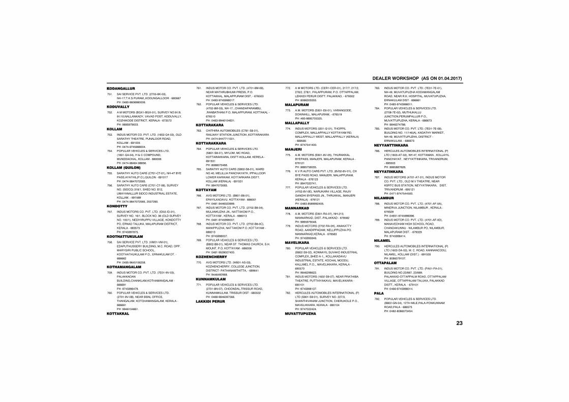
����������� �������������������
���� ������
���������������������� ��$�',��"����������,����������,�����������%'�%%���!��'��'%�%#'���%�
�$��
��������
��������� &�5��&�5��������������!#�+#��#�+���������,����������������,���������,/�,�������������,��������%�"$� ��!#'#$#�#� "�
�$ �
�����
����������������������� �%� �2���"���������������������������������,�������%#���$��!�����#��$##'����
�$"�
������������������������������� �%���2���������������������������,����,�������%'���%��!�����#'�%��#'%$%�
�$��
����������� �
���������������� ������������������&�������������� �����2�������%#������!�����#'���� �%$�
�$$�
���������������� ���������'������������� ������"�'+����������&� ��������������������������������������,��������%#�$'#��!�����#'���� �%$�� $"� '��
�$%�
� ��
������������������������ ��� ��������������������%+���&��,����"%� ����������������+�������������������������,�������������������,�����������������������,��������%'"$�"��!#��$##�'�$�
�$��
���������
���������������������� ��������������������������&����������������������������������&���������,����,��������������,�����������%'%%% ��!��'$�#%�$��% $'�
�$'�
����� �����
����������������������� �����#���"�������,,�����&�����������,����,�������������%'%%#���!#��$##'��#�
�$#�
������������������������������� ����#���&��������&����((���������������,������������,��������%'%%#���!##�%���%%��
�%��
������
����������������������� �����'���#�������������&���������������,���,,�����������������������%�%$�"��!��#"�#��$##'����
�%��
������������������������������� ��� �'���"��������������������&�������&����������������������,���,�����%�%$����!��'"�##�%���%"��
�% �
��������
�����������&����� ��'���'����������.����������)��������,�����,�����!�����#����������
�%"�
���������
������������������������������� �'����'��������������������,�����,,�����������,������,��������%#�$"���!'�'%��"�%%�
�%��
���������������� �'� ��'������.��������������������������������������.���,���,����,����,�����������,����� ,���������%#�$"���!##����"�%$�
�%$�
�����
�������������� &'���&'������������,�������,���������%'%�����!��'��#��%" "###�
�%%�
����������������������� �� �&'�����������,�/��)���������,�������,���������,��������%'%��"��!��'��#��$##'����
�%��
����������������������� �� �&'�������������/��������,������,���������%'%��"��!#��$##'����
�%'�
������������������������������� &'� �&'����������������������������������������,���������%'%��%��!��'��#$"#�������
�%#�
���� ������
�������������� .'�������"���,/����������������)����������������������������������%'#%����!#��%�# #''�
����
�� �������
������������������������������� ����'��������������������������,�����,���������������������%'�$� ��!��''�#'�%"#��%%�
����
�������������
�������������� �������������� ��+��� ��+ �� �'+ �� �'+��������������������������������,,���������������������,,������%�#"� ��!'�'%"�$$$$�
�� �
���������
���������� �%����%�����������������.�������������������%�%$�#��!�#"�#'#$��$" $�
��"�
����������
����������� � ���� �����������������5��������������,�����������������������.����������������� ,���������%'#$'$��!#���$������
����
�� ����
���������� �%���'���$�������,,���&�����������)����������������,��������%�%� ���!#'#$�$%�"$�
��$�
,������������������������ '�� �'���������&����������������)�����������������,��������%�%� "��!##��� �����
��%�
������������������������������� ��� �'�����������,���������������)���������&�������)�������,,�������)���� ,���������%�%� ���!��'"�'$'### ��$�
����
�� �����
���������� �%������������� �"��������,��������������,,�����%�'$' ��!#'#$#�#��'�
��'�
����������� �� �����,������,�������������������������������/�����������,���,��������%�'$'"��!#��$##$#�%�
��#�
����������
������������������������������� &'� ��#�� ���,�����������,�����������������5������������,���,�������������������������,���������,��������������������,,�����,��������%#�$����!#'�% #'% �
�'��
����������� �%� ��#����������������&�����������������,�����������,,������%#������!#��$##'�"��
�'��
������������&������������������ ������� �#����#���������������� �+"�������������)������������,��������������,,�����,��������%#������!#���� � ��
�' �
����������
����������������������� ����������������#����������/��,�����������������������,������������������/�������,������������%'%%%���!��'$�#��$##'����
�'"�
������������������������������� ��'����� �������,�����)���������������������������������/���,��������%'%%�"��!#'�%"���'%�
�'��
����������������������� ���������'���&�������������+��% ����,���������,�������#�����������/������������������,��������%'%%�"
�'$�
���� � ����
������������&������������������ ������� �%�"����� ���������,���������,���������������������������,�������������������%#$$�"��!###$'%�% '�
�'%�
����� ����
����������� ���������������������������������������������������������,�����&�������������������,�����3�������������������%#$� ���!�����#���$��$���
�'��
�������
����������������������� ������(��������������)�������������&�����,��������%�#" #��!��#"��#��$##'"#%�
�''�
����������������������� ������(���������������������������������,������������&�����������&����������������������%�#" #��!#��$##'����
�'#�
������
������������&������������������ ������� �%�"�����"��������������,�������������������,����� ���������%#�$"$��!'�'%��#����
�#��
������
����������������������� �������������&���������� "+%%��� "+%%#������,,��������������������������������������������������,�������,,�����������,���������%�#�����!��%%�#��$##'����
�#��
����
������������������������������� &'� ���������� ��������������,�����������������%'%$�$��!��' �'�'%��"�$��
�# �
����
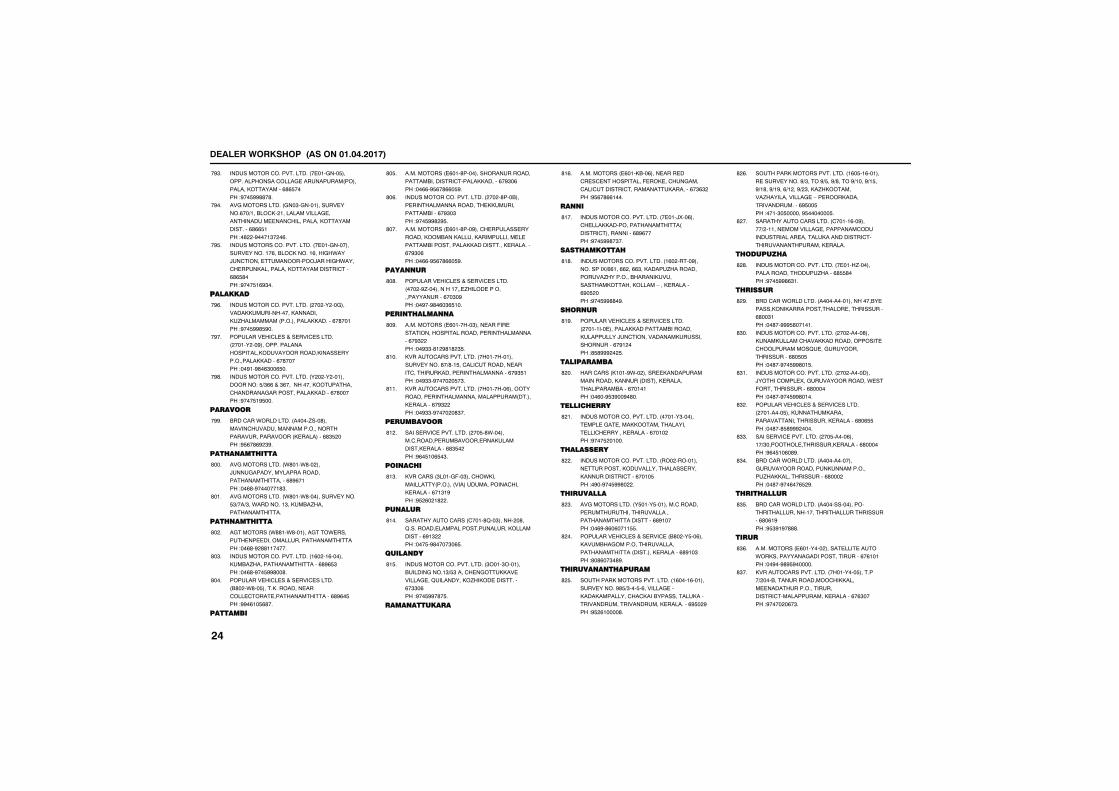
����������� �������������������
����������������������� ���������$������������������������������� ����������,���������%'%$����!#��$##''�'�
�#"�
�������������� ���"������������������%��+���&��,� ��������������������������������������������,���������������%'%%$���!�' �#����"� �%�
�#��
������������������������ �������������������������%��&��,�����%����.���)������������������)�����.����������,����������,������������������%'%$'���!#���$�%#"��
�#$�
���������
����������������������� �� �� ����������,,������������,��������,�/��������� ����������,,������%�'�����!#��$##'$#��
�#%�
������������������������������� ����� ��#���������������������,�����������,�����������������,,�����%�'�����!��#��#'�%"��%$��
�#��
����������������������� � � �� ����������!�$+"%%���"%����������,�����������������������������,,�����%�'�����!#���$�#$���
�#'�
������
&�������.��������� �����/���'������������������������������������������������ ,���������%'"$ ���!#$%�'%# "#�
�##�
���� �����
�������������� .'���.'�� ���)�����������������������������������������%'#%����!��%'�#�������'"�
'���
�������������� .'���.'����������������$"+��+"��.��������"��,��&�/����������������
'���
��� �����
��������� .''��.'�����������.���������������������������������������!��%'�# ''�������
'� �
����������������������� �%� ��%������,��&�/������������������%'#%$"��!��%'�#��$##'��'�
'�"�
������������������������������� &'� �.'��$�����,��������������������������������������%'#%�$��!##�%��$%'��
'���
������
���������� �%���'�������������������������&����������������,,������%�#"�%��!��%%�#$%�'%%�$#�
'�$�
����������������������� �� �'���&������������������������,,�������������&����%�#"�"��!#��$##' #$�
'�%�
���������� �%���'���#���������������������,�&���,������,����������������������&�����������,,�����������,���������%�#"�%��!��%%�#$%�'%%�$#�
'���
���� ��
������������������������������� ��� �#/��������������/����������������������%��"�#��!��#��#'�%�"%$���
'�'�
���� ����� �
���������� �%������"��������(����������������������������������������%�#" ��!��#""�'� #'�' "$�
'�#�
,��������������������� ���������������������'�+'��$������������������������������,��������������������%�#"$���!��#""�#���� �$�"�
'���
,��������������������� �������%������������������������������������ ������,��������%�#" ��!��#""�#���� �'"��
'���
���������
���������������������� ��$�'.�������������������&��������,����������,��������%'"$� ��!#%�$��%$�"�
'� �
�� ����
,�������� "�����(��"����.,������������ ������ ��������������������,��������%��"�#��!#$ %� �' �
'�"�
�� ����
���������������� �����'2��"����� �'��2�����������������������������,������������%#�" ��!���$�#'����"�%$�
'���
����� ��
����������������������� "���"������&�����������"+$"�����������,,�������������2���������,/�,������������%�""�%��!#��$##�'�$�
'�$�
���� ������
���������� �%���,&��%�����������������������������(��,��������������������������������������,�������%�"%" ��!#$%�'%%����
'�%�
�� �
����������������������� �����)5��%��������,,������������������ ��������������������%'#%����!#��$##'�"��
'���
���������
������������������������ �%� �����#����������5+%%���%% ��%%"��,�����/������������/�������&�����,�����������,�����,�����-���,��������%#�$ ���!#��$##''�#�
'�'�
��� ��
������������������������������� ����������������,,���������&�������,����������)���������������,����������������%�#� ���!'$'### � $�
'�#�
����������
�������� ,����#.�� �������,��������������������,������ �������,����������������&����%�������!��%��#$"#��#�'��
' ��
����������
����������������������� ������"���������������������,,��������������������������,��������%���� ��!#���$ �����
' ��
���������
����������������������� �� ��������������������,��������������������,�����������������%����$��!�#��#��$##'� �
' �
���������
�������������� �$����$�������������������������������������������������������������%'#�����!��%#�'%�%����$$�
' "�
������������������������� &'� ��$��%���,����&�������������������������������� ��������,��������%'#��"��!'�'%��"�'#�
' ��
������ � �������
�������,���������������� �%����%����������������#'$+"���$�%������������,���,������������,���&�����������,����������������������������,���������%#$� #��!#$ %�����'�
' $�
�������,���������������� �%�$��%�������������������#+"����#+$��#+'����#+����#+�$��#+�'��#+�#��%+� ��#+ "��,�/,�������/���������������-�����,�������������������%#$��$��!����"�$������#$�������$�
' %�
��������������������� ������%��#�����+ ����������������������������������������������������,���������������������������������,������
' ��
��������
����������������������� �����/���������������������/����%'$$'���!#��$##'%"��
' '�
�������
&�������.��������� ������������������&��������,��,��������������������������%'��"���!��'��###$'������
' #�
����������������������� �� �����'���,����,����������,,�������������������������2����������������������%'�$�$��!��'��#��$##'��$�
'"��
����������������������� �� ���������)���������5����������������.����(��������������%'������!��'��#��$##'����
'"��
������������������������������� ��������$���,�������,���������������������������,��������%'�%$$��!��'��'$'### ����
'" �
���������������������� ��$�����%�����+"���������������,��������%'������!#%�$��%�'#�
'""�
&�������.��������� ������������������������������,�������������/�,,��������������%'��� ��!��'��#��%��%$ #�
'"��
���������
&�������.��������� �����������������������������������������������������%'�%�#��!#$"#�#�'''�
'"$�
����
���������� �%������� �����������������.�,����������������������������%�%�����!��#��#'#$#������
'"%�
,��������������������� ��������$��������+ ���&���������������,,������������������������������������������������,��������%�%"����!#���� �%�"�
'"��
����
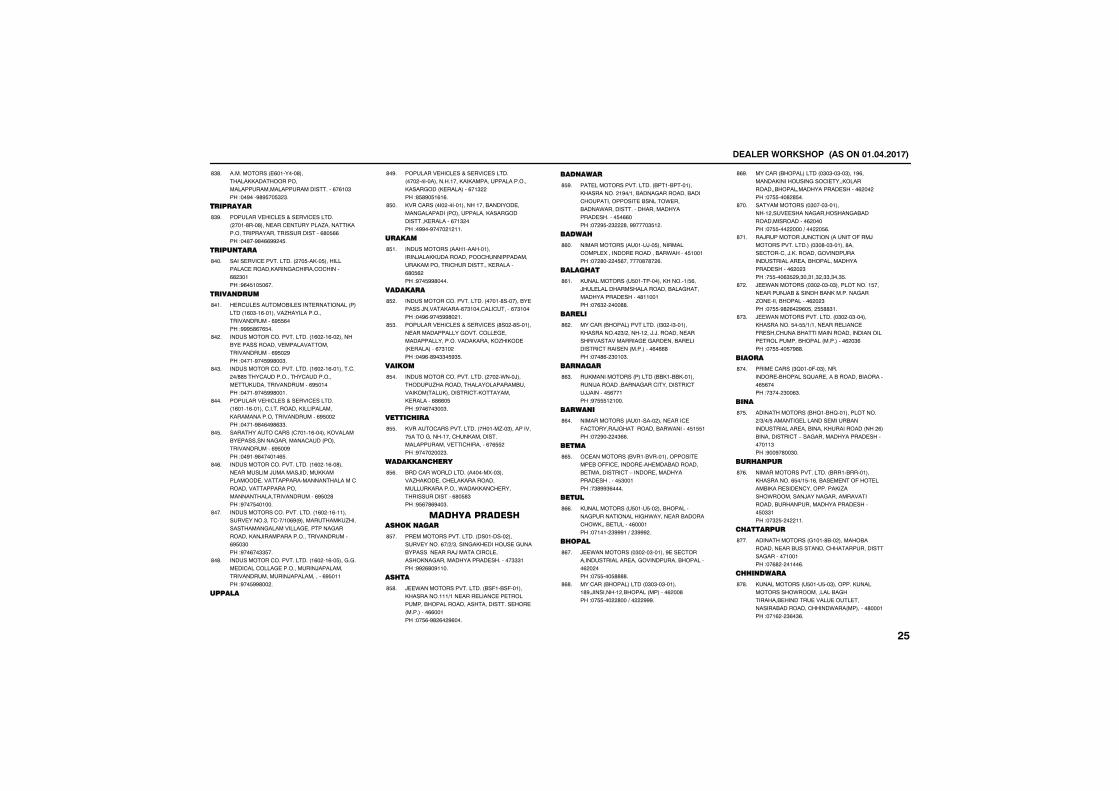
����������� �������������������
���������� �%�������'�������,,����������������������������������������%�%��"��!��#���#'#$��$" "�
'"'�
��������
������������������������������� ����'���'�������������������/��������,��������������������������������%'�$%%��!��'��#'�%%## �$�
'"#�
���� ���
���������������������� ��$��,��$������������������,������������������%' "����!#%�$��$�%��
'���
���� ����
������������&������������������ ������� �%�"��%��������/������������������������%#$$%���!###$'%�%$��
'���
����������������������� �%� ��%�� �����&����������������������������������������%#$� #��!�����#��$##'��"�
'� �
����������������������� �%� ��%����������� �+''$������������������������������,������������������%#$�����!�����#��$##'����
'�"�
������������������������������� �%����%������������������,�����������,�������������������������%#$�� ��!�����#'�%�#'%""�
'���
���������������� ������%������,������&�������������������������� �����������������%#$��#��!��#��#'������%$�
'�$�
����������������������� �%� ��%��'���������������)�������)������,,��������������������������������������������������������������������������������%#$� '��!#���$������
'�%�
������������������������ �%� ��%���������������"������+��%# #����������,�/�����������������������������������������,��)���������������������������%#$�"���!#��%��""$��
'���
����������������������� �%� ��%��$���������������������������������)��������������������������)������������%#$�����!#��$##'�� �
'�'�
������
������������������������������� ��� ����������������,��,������������������,������� ,���������%��" ��!'$'#�$�%�%�
'�#�
,�������� ��� ���������������&��������������������� ������������,��������������,��������%��" ���!�##��#���� � ���
'$��
������
����������� ����������������)���,,��������������������������,���������������������,��������%'�$% ��!#��$##'����
'$��
��������
����������������������� �����'�������&��������)������,����%�"���������������%�"�����!��#%�#��$##'� ��
'$ �
�������������������������� '�� �'��������������������������������������������������������,�����,/�,��� ,���������%�"�� ��!��#%�'#�""�$#"$�
'$"�
�����
����������������������� �� �.���)��������/�������������������&������,� ����,������������,��������,��������%'%%�$��!#��%��"��"�
'$��
��������
,��������������������� �����/��"�����������$����������������,�����������������������������������%�%$$ ��!#���� �� "�
'$$�
������� �����
&�������.��������� ������5��"�����/�,��������,���������������,���������.���,,�����������������������%'�$'"��!#$%�'%#��"�
'$%�
��� ��������� ����� ����
�������������������� ��������� �������������%�+ +"�������,�������������&��������������)����������������,�������������������������"""���!## %'�#����
'$��
����
)��.������������������ &�(��&�(������,����������+����������������������������&��������������������������� ���������%%�����!��$%�#' %� #%���
'$'�
��� ����
��������������������� &����&��������,�������� �#�+���&�������������&�������������������&�����.����&����.�����������������������������������$�%%���!�� #$� " '��##����"$� �
'$#�
������
����������� ������)��$���������������5���������������&��.�����$������!�� '�� �$%�������'�'� %�
'%��
�������
,���������� �$�����������,�����+$%��)���������������������&������������������������'�������!��%" � ���''�
'%��
������
������� &�������������� �"� ��"������,�������� "+ ����� ��)�)���������������������������������������&���������������������� ���������%�%%'��!���'%� "���"�
'% �
��� ����
��,���������� ������� &&,��&&,����������)�������&������������������������))�������$%�����!#�$$$� ����
'%"�
����� �
����������� ��������� ������������(��������)����������&��.�������$�$$���!�� #�� �"%%�
'%��
����
���������� &����&������������������&�((����������������&��������&���������������-��������������������������$"�����!�"'##"%����
'%$�
����
,���������� �$����$�� ���&�����������������������.���������&������.,���&��������%������!������ "###��+� "### �
'%%�
�����
)��.�������� �"� ��"������#��������������������������������������&�������% � ���!��$$���$''''�
'%��
������� &��������� �"�"��"�������'#�)�������� �&���� �������% ��'��!��$$��� '���+�� ###�
'%'�
������� &��������� �"�"��"��"����#%�������,������������������,���������&��������������������% �� ��!��$$���' '$��
'%#�
������������ �"����"��������� ��������������������&�����������������% �����!��$$��� ����+��� �$%�
'���
��)��������)������� �������(���)����������������� �"�'��"������'������������)�,����������������������������������&���������������������% � "��!�$$���%"$ #�"��"��" �""�"��"$�
'���
)��.�������� �"� ��"��"�����������$�����������)�&��������&��,������������/�������&�������% � "��!��$$�#' %� #%�$�� $$''"��
'� �
)��.������������������ �"� ��"������,��������$��$$+�+�����������������(���������&�������������������������������������&���� ���������% �"%��!��$$���$�#''�
'�"�
�����
����������� "2����(��"�������������&�����2��������&������&��������%$%����!�"��� "��%"�
'���
�� �
������������ &2��&2������������� +"+�+$�����������������������&��������������������&�����,��������� �� %��&��������������-����������������������������"��!#��#�'��"��
'�$�
����� ���
��������������������� &����&��������,��������%$�+�$��%��&��������(�������&�,�������������������,�/���.�������)������������������������&�������������������������$�""���!��" $� � ���
'�%�
��������
������������ �����'&�� �����&������������&������������������������������������������!��%' � ����%�
'���
���� �����
,���������� �$����$��"�������,�����������.���������&���������&�����������������������������&������������.��� ��������'������!���% � "%�"%�
'�'�
����
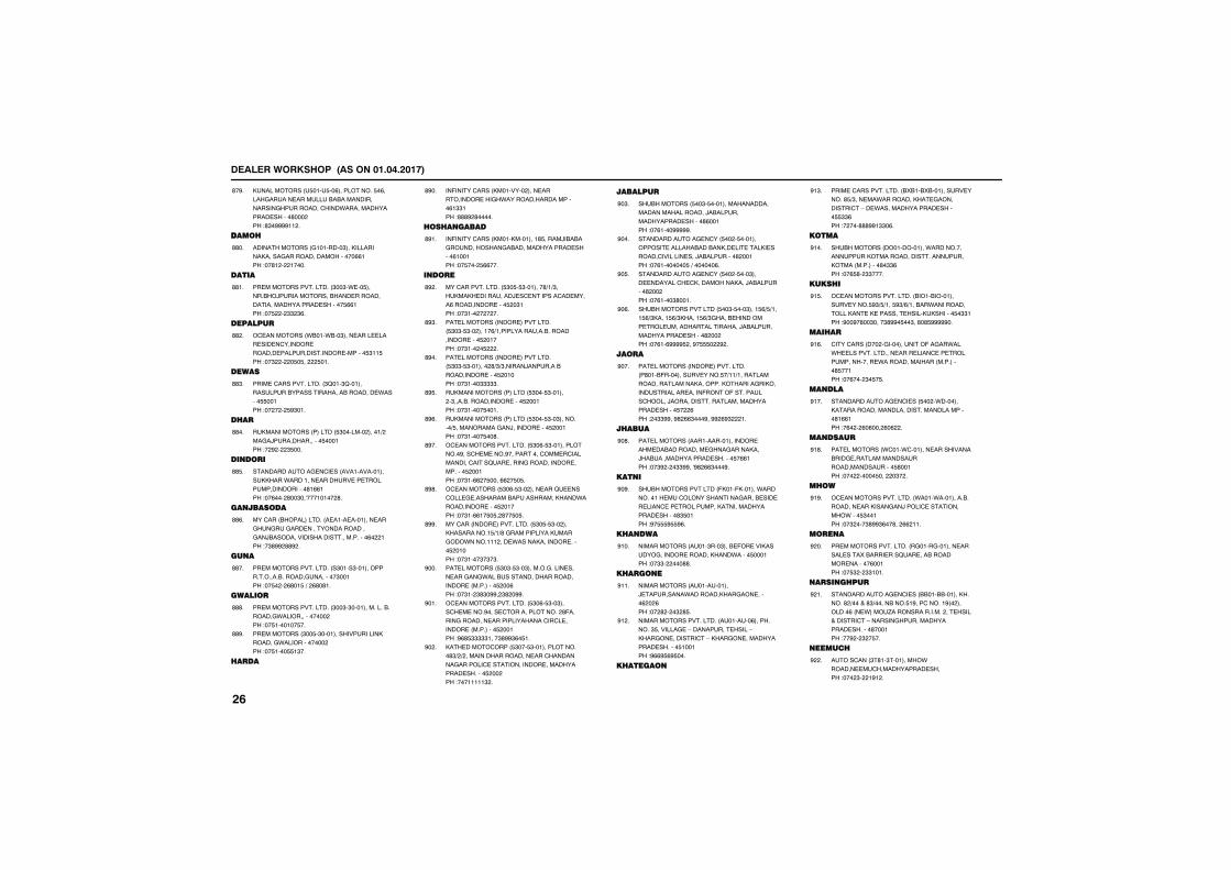
����������� �������������������
,���������� �$����$��%����������$�%���������������������&�&������������������������������.���������������������'��� ��!'"�####�� �
'�#�
�����
������������ ���������"���,���������,�����������������������%%���!��'� � �����
''��
����
�������������������� "��"�.���$������&)������������&�����������������������������������$%%���!��$ � "" "%�
''��
��������
���������� .&���.&��"������������������������������������������������������������$"��$��!��" � �$�$�� $���
'' �
�����
��������������������� "2���"2���������������&��������������&��������.������$$�����!�� � � $#"���
''"�
����
��,���������� ������� $"������� �����+ �����)��������������$������!� # � "$���
''��
�� ���
���������������������� ����������������,,���.���������������������������������������'�%%���!��%��� '��"��0�������� '�
''$�
�� ������
������� &���������� ��������������������������������������������������)&�����������������������������%� ���!�"'## ''# �
''%�
�� �
�������������������� �"����"�����������������&����������������"�����!��$� � %'��$�+� %'�'��
''��
������
�������������������� "��"�"�������������&�������.�������������� ��!��$�������$��
'''�
���������� "��$�"������������������,�������.������������ ��!��$����$$�"��
''#�
�����
��(����������� ,�������� �������������������.������������������%�""���!'''# '�����
'#��
���� �����
��(����������� ,����,��������'$�����)�&�&��������������&��������������������%������!��$��� $%%���
'#��
� ���
����������������� $"�$�$"�������'+�+"���,��,�����������)���������������������%��������������$ �"���!��"��� � � ��
'# �
����������� ���������������� $"�"�$"�� �����%+���������������&����������������$ �����!��"��� �$ �
'#"�
����������� ���������������� $"�"�$"������� '+"+"������)��������&��������������$ �����!��"����"""""�
'#��
��,���������� ������� $"���$"������ �"����&���������������$ �����!��"�����$����
'#$�
��,���������� ������� $"���$"��"��������+$�������������)�����������$ �����!��"�����$��'�
'#%�
�������������������� $"�%�$"�������������#����������#����������������������������������2������������������������������$ �����!��"��%% �$����%% �$�$�
'#��
���������� $"�%�$"�� ��������2��������������������&�����������,���.���������������$ �����!��"��%%��$�$� '��$�$�
'#'�
������� ����������������� $"�$�$"�� ���,���������$+�+'��������������,�������.������� ����.�����,�������������$ �����!��"����"�"�"�
'##�
����������� $"�"�$"��"�������������������������.���&������������������������� ���������$ ��%��!��"�� "'"�##� "' �##�
#���
�������������������� $"�%�$"��"�����������#������������������� '(������������������������������������������� ���������$ �����!#%'$"""""����"'##"%�$��
#���
,����������� $"���$"��������������'"+ + ������������������������������������������������������������������������$ �� ��!��������" �
#� �
��������
��&������ $��"�$���������������������������������)�&����������������������'%�����!��%����#####�
#�"�
�������������������� $�� �$�������������������&���&��,�����������,���������������������)�&���������' �����!��%��������$�+�������%�
#���
�������������������� $�� �$���"����������������,��������,���)�&���������' �� ��!��%����"'����
#�$�
��&�������������� $��"�$���"����$%+$+����$%+",����$%+",����$%+"����&��������������������������������)�&�����������������������' �� ��!��%��%####$ ��#�$$$� # �
#�%�
����
����������� ����������������� �'���&(����������������$�+��+������������������������,�������,���������,���������������������(����(���������������)������������������������������������$� %��! �""##��#' %%"���#��## %#" ��
#���
������
����������� �������������������������&�������������������,���)�&���������������������$�%%���!��"# � �""##��0#' %%"���#�
#�'�
�� �
��&�������������� (,���(,������.��������������������������������&���������������������������,����������������������'"$����!#�$$$#$$#%�
#�#�
��� ���
����������� �����"���"���&�(�����,��������������������,���.�����$������!��""� ���''�
#���
����� �
����������� �������������)�����������.�������,�����������% � %��!�� ' � �" '$�
#���
��������������������� ���������%���������"$����������-����������������-�,����������������-�,������������������������$������!#%%#$%#$���
#� �
������
��������������������� &5&��&5&����������������'$+"������.��������,�����������������-���.��������������������$$""%��!� ���'''##�""�%�
#�"�
���
��&������ �����������.������������������,�������������������������,���� ���������'�""%��!��%$'� ""����
#���
������
�������������������� &���&����������������$#"+$+���$#"+%+���&��.�������������,�����,��������������,�,������$�""���!#��#�'��"����"'##�$��"��'�'$#####��
#�$�
������
���������� ��� ��������������(�����.���.�������������������������������������������������.������������� ���������'$�����!��%��� "�$�$�
#�%�
�� ���
���������������������� $�� �.�������,��������������������������������������'�%%���!�%� � %�%��� %�% �
#���
�� �����
����������� .����.�������������������&��������������������������������������$'�����!��� �����$��� �"� �
#�'�
���
�������������������� .����.���������&������������,�������)����������������.����$"�����!��" ���"'##"%��'�� %% ���
#�#�
��� �
�������������������� ��������������������������5�&��������2�������&���������������%�����!��$" � ""����
# ��
���� �����
���������������������� &&���&&������,�����' +�����'"+�����&���$�#���������# � �������%� ��.����/��������������� �������������������-������������������������������'������!��# � " �$��
# ��
������
��������� "�'��"��������.��������������������������!��� "� �#� �
# �
����
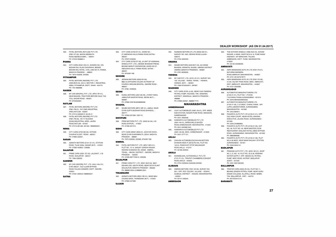
����������� �������������������
����������� ����������������� �'���"��� ����.������������������ ���������$'�����!��� "� %"''"���
# "�
��� �
���������� �2����2������,��������"�'��������)��������������&������������)��������������������$���������������������������''�����!�%� � "� %�� $#"�
# ��
��������
����������� ����������������� $"�"�&�������� $�������������������������������������������������������$���$��!� ��##�###�
# $�
�����
������� &��������������� �(����(�����������&�������������&�(����������5������������������%� ���!#�$$$$��%��
# %�
�����
����������� ���������������� �'����'�������%���������������������������������$ �����!���� ��� $ #�"��" �""����
# ��
����������� ���������������� �'����'��"����'�+��+�'��������������������������)������������������$������!���� � %��%"�� %��%���0## %#" ��
# '�
����
���������� ��� �� ��"�������������������������.�����' �����!��%% � � ��
# #�
�����
������������ �����������������������������,����)�������� ����������������!��$' ���"#" �+� %$%��
#"��
�������
����������� "2���/��� ���������������&��������)��������%$�����!�"%�� %"""�
#"��
�� ���
������� ����������������� ��)����)����������"$%+"+�������))����&��������������,�����.���������������������$"$$���!��" �� ���"��"'## �$���
#" �
�� �
���������� ��� ���������.��������� ��������,�����������������������'$�����!��%� � "� %�
#""�
���������� ��� �����$��� �������(�����.���.�����������������&������&��,����������&�������������.����.������ ���������,�������������������������'$�����!#�$�"���##�
#"��
�����
)��.�������� �"� ���� ���'%#+�+ �((��������������(����(������������&������������������%%�����!��$%�� %����
#"$�
�� �
,���������� �$���'5��$���)��������,���)�&����������������������� ���������'�%%���!��%# � '�$'�'"�#### %#�
#"%�
�����
��&������ �(����(������)����������������������&������������������'������!��%$ � "�"$'�+� "�����
#"��
��������
�������������������� "��"�"���������&�������������������"$$���!���# � � �$�
#"'�
�����
���������� &,���&,��������������,�����������������,����������������������������'%%%���!�%� � "� %�� $#"��#�$�"���##�
#"#�
�����
��������������������� &/���&/���������������"��������)����������������������,���.��������������������������-��.�����������-��������������������������$ � ���!�� #$�##����"$� �� " '�
#���
��������
��������������������� "2���&)������"%"+��������)������������������������������)�����������������������%$"""��!'''##�""������'''##�""���
#���
��������
������������ ������������������������������,�����,������ ���������� �����!��%'"� ���%#�
#� �
�����
��,���������� ������� ".� �".����������������$#+"����.��������))�������$%�����!��"����$ ����
#�"�
������
��&������ $��"�&��������'+ ������&������,��������,���������������������������� �����������������'�%%���!��%��%��#"""�
#���
�������
����������������� ������������������������� ����������-��������������-����������������� ����������%������!�$# �#�$$$$������ #��%��
#�$�
������
���������� ��� �))�� ����������)���&�����������������,�����������.��������������������������������������������'%''%��!��%% � � ���'''##������
#�%�
�� ���� �������� ����
��)�������&����� �$'���$�������������&���&�������������������������,������������������!� ��� $$���#�
#���
,��,����������&������������� �$����$������������������������������������������������������������!� ���#��"#%�$���
#�'�
,��,����������&������������� �$����$��$��������������������������"��!� ��� ����"��
#�#�
�����
����������&���� ���������������������������� &�� �����������������$+"��������������������������������,��)�����"�����!� �'$� "�""�
#$��
����
,�����.������.�������������� (����(�������������������&����������������,����������$��!�� �� � #���� �����#� � ��%��
#$��
�������
������������ �����"5��$�������������"�+���������(���������������-�����������&��������������-����������������������� ����!� ���� %"���
#$ �
������
���,�����.����� �#�%������������������������.����������'����%�����������,���.�����+��������������,�!���&�����������!���������������������$�"��!� �" � "�'"+#"�
#$"�
�������
�����&����������� ������� ( ���( ��������������&������������������������������������%����!�� �� $����$+�%+���
#$��
�����&����������� ������� ( ���( ��$�����+� �����&��������������������������������!���������������������������%����!�� �� $ ��'$�
#$$�
���� �����
�������������(�������������� �� � ������������������&������%���,��������������&������"� ����!� ���%%��$��+%%��$$$�
#$%�
�������������(�������������� �� � ���"����� ����������,����������+����������&����������������&�����������������"���%��! ��� �'�#���
#$��
��������������������� ��"� ����������������������������������,���5���������)������������������&������"���$��!� ��� ��%%$#� �
#$'�
��������������������� ��"� ���$�����������%���������$����������������,������������ ,�����������&����&������������������&�����������������"���$��!#'%�###�%'�
#$#�
��������������������� ��"� ���%�����������"$���������������������.������������������&������"������!� ���%$������
#%��
��������
���,����������������� #���#������������ ���������%��������� $��� %��,������.�������������������������������������������������,�������&�������� ��������� �$�"��!� $��#" �"$ """�
#%��
���������
������������� "� �/����������������&�����/�.������������������������������,������������������������&����������&��������������������� �����!# � �� +�"�
#% �
�������
����
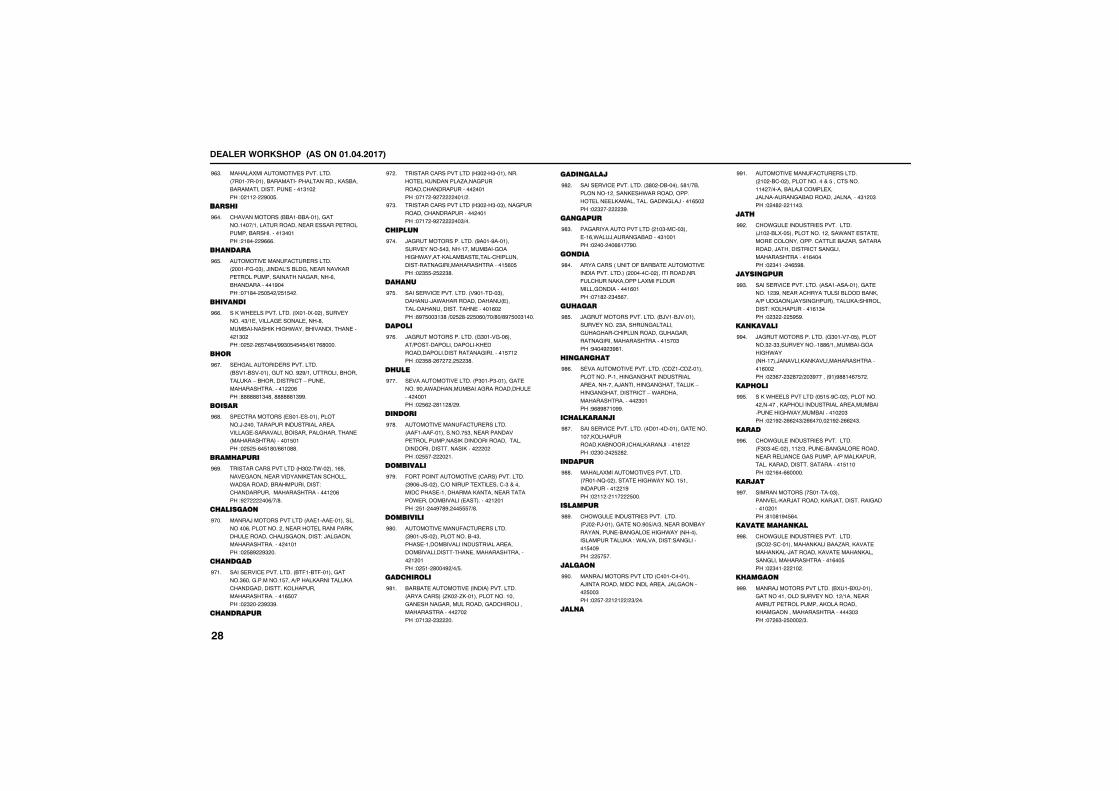
����������� �������������������
�����5����������������������� �������������&���������������������,��&���&������������������������"�� ��!� �� � #��$�
#%"�
�������
����������� &&���&&�����������������+�������������������������������������&����������"�����! �'�� #%%%�
#%��
��� ����
�������������(�������������� ����(���"���)�����0��&�������������,�������������������������������%��&������������#����!���'�� $�$� + $�$� �
#%$�
����� ��
��,�.��������������� �5����5�� ��������������"+���������������������'�����&�������,���.����&���������������� �"� ��!� $ � %$��'�+##"�$�$�$�+%��%'����
#%%�
���
�������������������������� &����&���������������# #+�����������&�������,��-�&������������-���������������������� �%��!''''''�"�'��''''''�"##�
#%��
�����
������������� �������������������)� �����������������������������������������������&������������������� ����������������$����!� $ $�%�$�'�+%%��''�
#%'�
����������
��������������������� "� ��.�� ����%$�����������������������,�����������.����������&�������������!���������������������������� �%��!# � ��%+�+'�
#%#�
��������
�����)�������������� ����������������������%��������� �������������������,��������������������������!�)��������������������� ������!� $'# #" ��
#���
��� ����
���������������������� &�(��&�(������������"%������������$����+����,���������,������������������,����������������������%$����!� " �� "#""#�
#���
��� ������
��������������������� "� �"��������������,���������/��������������������������� �����!���� �# � ���+ �
#� �
��������������������� "� �"��"����������������������������� �����!���� �# � ��"+��
#�"�
������
)������������������� #����#����������������$�"�����������&��������.������,����&����������������������������������������������$%�$��!� "$$� $ "'�
#���
���� �
���������������������� �#�������"���������)�.�������������� �������������������������������%� ��!'#�$��"�"'�+� $ '� $�%�+��+'�+'#�$��"����
#�$�
�����
)������������������� �"�������%�����+�����������������,����������������������������������$�� ��!� "$'� %� � � $ "'�
#�%�
�����
������������������� �"����"��������������#���.��������&�������������������� ������!� $% � '�� '+ #�
#���
�� ���
�������������(�������������� ��(����(�����������$"�����������������������������,��������������������������������������,���� � ��!� $$�� � ��
#�'�
��������
(����������������� ���������������� "#�%�)��� ����+���������5���������"�������������������������,�����������������.������&������ ���������� � ����! $�� ��#�'#� ��$$$�+'�
#�#�
��������
�������������(�������������� "#���)��� ����������&��"�����������&�������������������������&�������������������������������� � ����!� $�� '���# +�+$�
#'��
���������
&��&������������� ����������������� ����������� /,� �/,���������������������������������������������������������������� �� ��!���" � " ��
#'��
���� �����
���������������������� "'� ��&������$'�+�&��������� �����,��.��������������������,�������������������)�����%$� ��!� " �� "#�
#' �
�� �����
��������������������� ��"�����"������%�.���)��������&������"������!� ��� ��%%���#��
#'"�
� ���
���������� ������(�&��&������������������������������ �������� ���������������(��������,�������5���(��������������������%����!���' � "�$%��
#'��
�������
)��������������������� &)���&)����������������� "��������������������������������������������������������������������$��"��!#���# "#'��
#'$�
�� �� ���
������������������������ ��/����/��������������������������������������������������)��������������������,�-��������������������-�.��������������������� "����!#%'#'���##�
#'%�
��������� ��
���������������������� �������������������������,����������,�&�������,����)������%� ��!� "�� � $ ' �
#'��
� �����
�����5����������������������� ������2�� �����������.�������$��������������� �#��!� �� � ��� $���
#''�
��������
�.��������������������������� �)� ��)�������������#�$+�+"�������&�&���������������&���������.��� �������������������,��!�.����������!�����������$��#��! $�$��
#'#�
�����
�����)�������������� ��������������)��������������������������)��������� $��"��!� $�� � � + "+ ��
##��
��� �
�������������(�������������� �� �&��� ��������������$������������� �+�����&���)�������5��)������������&��������)���������"� �"��!� �' � ���"�
##��
���
�.��������������������������� )�� �&�5��$����������� ����.���������������������������������&�/����������������)�����������������������������������%�����!� "���� �%$#'�
## �
����� ����
���������������������� ����������������������� "#�������������������&���&��,���+������� )����������������,�!����������!�,����������%�"���!� " � $#$#�
##"�
�� ������
)������������������� �"�������$���������" �""������������''%+������&��������.��� ������)�������,��,�������������������%�� ��!� "%�� " '� + �"#����� #��#''��%�$� �
##��
������
��,�.������������� �$�$�#��� ����������� ��������,������������������������&�����������.������&�������� �"��!� �# � %% �"+ %%����� �# � %% �"�
##$�
�����
�.��������������������������� ("�"����� ����� +"�������&��������������������������������������+�����,�����������,������������������������$�����!� �%��%%�����
##%�
�����
������������ ���������"����������,��)��������,��)���������������������� ����!'��'�#�$%��
##��
���������� ���
�.��������������������������� ��� �������������,����&��/����,����������,���)��������,����������,��������������������������%��$��!� "��� �� �
##'�
������
�����)��������������� &5���&5������������������������������� +����������������������������,��������,�����������������������"�"��!�� %"� $��� +"�
###�
����
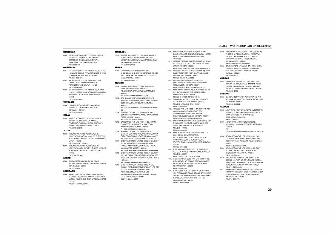
����������� �������������������
���������
�5���������������������� ������������������������� +�"#��,������������������������������������.����,������������������������� ����!� �%$###����
�����
�������
���������������������� "'� �"'������������������.�����&����������������,���������)��������������,����������%��'��!� "�� %%�%�%�
�����
���������������������� "'�"�"'��������%���������������������������������������,����������%� ��!� "�� �%'"�%�
��� �
���������������������� "'� �"'��%�������������'+���������� '���������������,����&������������,����������������������%�� ��!� "�� " #�#$�
���"�
� ��
���,����������������� "#�"��/�� ������������� %+� ��#'+"'����������,��������� �"� ��!� $ � '� %��
�����
�����
)��������������������� #&���#&����������������$�+$��$�+$���+��������������&����������,��-�,���������������-��������������������������%$ ���!� "% � � � "�
���$�
����
�������������(�������������� �'����'�� ���������� '�� #��"�������������"%����������������������������&��������������������"$� ��!� "' �%�#���+%�# �
���%�
�������������(�������������� �'����'��������������������� #%��������������������������������������������"$� ��!� "' �%%�#�#�
�����
�����
������������ ������5���������������������������������������������������������������� "����!� ��$� "� "�
���'�
������
�������������������������� "��"�((�� ����������$� +'�������������������������&������������������������,������������ " �"��!� $$�� "� ��+ "� ���
���#�
�� ��
���������������������� &����&�����������������#��������������������������&��������.���������������������������������� �����!� ���� %���'�
�����
�����
�.��������������������������� )�� �����"���� ��������.���������.�������������������,������)�������������������������������%�����!� ""� %�" ��� �
�����
������
�5���������������������� �$����$��������������������������������,���������������/���������&���������#'��!� �%���"'''� %%$" � ���"���%�
��� �
�������������������������������� �$�$��$���������,����������������((����&����������������.�������&����������"��!� � �# $�$ +$"+$��� �#%$"�#+'���# $�$ ��$"�
���"�
���������������������� �$����$�������% ����������&����������.������,���.������������&����������"��!� ��"�"����+�"�"�����
�����
���������������������� �$����$�� �������������&�����#���������,���������������� ����������&���������%#��!� ��"�"�%�%�+%���'"$% � ��
���$�
���������������������� �$����$�������+���,��������������.��������������������������&������� ���������&���������%%��!� ��"�"�����+��"+���+��'+� �� '�������
���%�
��������������������� �$�'��$����������������$�����������.���0��������������������������5����,��������������� .��������&���������%���!� �%�%#%�%"+% +%$+'�+'$+$'+%'+#��''#'###�
�����
��������������������� �$�'��$�� �����������%$����&������������(��������((�.��������5��������.����&������ ������������%%��!� �%%#�'' "+%%#�'' %� '$� �'$�
���'�
��������������������� �$�'��$��"�������������,������������������������(������������&���������������5������,����,���������������&����������,����.��������&���������'%��!� �%%�������+%%������+�##%�����'%�%%�������
���#�
��������������������� �$ "��$������������������������&�������&�������������!� �� $ ��%��+ $ ��##�+� $ ��"���+ $ �'%%%�
�� ��
������������������������ �$�"��$��������������������������������,������������� .���������&���������$'��!� � %�"��'�+ %�"� '�+ %�"� #%�%"%���'�
�� ��
������������������������ �$�"��$�� �������(����,��������((�����������,������������&����������&��������� $��!� � � #����� "#""�
�� �
�������������(�������������� "#����$���������������'��&�/���.�����,���� .����������&�������������!� �%�$%"�"��+�%�$%"����+�%�$%"��$�
�� "�
(�������� �$ ���$�� �����#������������ ���������������������������/�������������������&���������#%��!� ����$������� �" � �+ �"��
�� ��
���������/��� �$"���$���������,���������������������,������� .���������&��������������������%���!� ����#####�
�� $�
������������������ �$�"��$�������������$#��,��������������������������������������������������������������,���,��������� .������&���������%���!� � '%���$"+ '%���$�� � #����
�� %�
����������������������� �$�'��$�������+����&����������������/������,���((�������,��������&�������.��������&����������# ��!� � '#'''���
�� ��
(���������������� ���������������� �$ ���$��"����+��������������������������������������&������������&�������.����������������������,������������������&�������������!� �%�$$�%$��
�� '�
,������������������������ �$' ��$�� ����+��/���������$�������)�������&�����������&��������� ���!� � "�$� "�� "�$ "��+ +"+$+%�
�� #�
���������.��������������� "#����$�� ������������������%"#+ �%���������������(��������������������� �������&���������������������%$��!� � '��"�� �
��"��
��,�.��������������� �$$���$��������������$���������������������������������5������������.���������������.������������ .���������&���-�������������������������������!� �##"�$�$�$��
��"��
����������/��� ������������� �$"���$�� ����������' ��&����,�����������������������������������,������((��������,���,��������� .���������&���������������������%���!� �#'��#"���������#####�
��" �
,�������������������� �$����$�������������&�% +������������������������((����.����,������������� .���������&����������$"��!����#"�$�$�
��""�
������
���,����������������� &���&�����������������%�+ ��,�����������&����������������-�������������,��-����&�������������-��������������������� �%�$��!#� '"� � $�
��"��
������
���������������������� �.����.����������������''+����+��������������,�!�,����������!�,����������% �#��!� " $�� %$$$"�
��"$�
�����
���������� ������(�&��&������������������������������ ���� ��������������������,�� �����������%��&������������������������"$��!��� �%%''"""�
��"%�
�������������(�������������� ���� ��� ���$�$�,������������������ %��������� %��!��� � %"�$$�+%%% ���+%%% ���+ %$ $$�+ %�'"���
��"��
������������������� �� � �������"�+"��,���������������������������������&��������.�������������������������������� "��!��� � $�� "�+%%$ '���
��"'�
������������������� �� � ���"����������""�����������������������������������������������������%��!������%%%����
��"#�
�������������(����������������� ���� ���$����������"'+��������&����������������������&���������,����������������������������������������!��� �%$$$��"+���
�����
���������� �����(�&��&������������������������������ ���� �������������������.���������,��������������������������������������'��!��� �%%%�����
�����
����
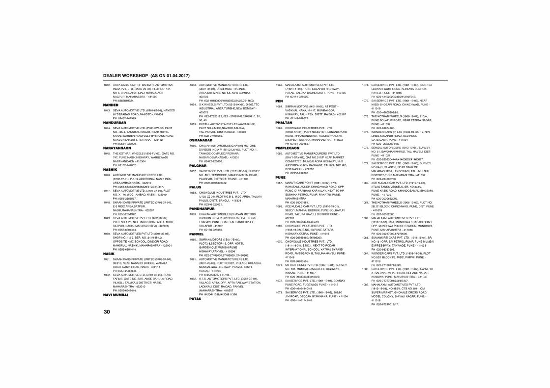
����������� �������������������
���������� �����(�&��&������������������������������ ���� ��� �����������"�����%��&��������������������������������������������� � ��!'''''�#$ ��
��� �
� ���
������������������� %'���%'������������������&������������������"�%����!� �% � ��$##�
���"�
� ������
������������������� �"���,.�� �����������"�����&������������������������,������������.(�����&�������������������&��������������������� $�� ��!� $%�� ""����
�����
����� ��
���,�����.����� �#�%�(��� �������������������������,���.����.����.���������������������$����!� �" � ���� �
���$�
�����
�������������(�������������� "�� �"������������ ���������������,��������������&�������,���� �����!� $"�%%"%"��+%%"%" #+"� +"��+"���
���%�
������������������� "����"��������������5����%����������&��������,���� �����!� $"� "'%$"��
�����
�������������������������� "��"�"���������"������������������������,�������������� �����!� $"� "$�"� �
���'�
���������������������� "����"��������������� "������������������������������������������,� �������������� ��%��!� $"�%%������
���#�
����������������������� "����"���'������������� ���������� ��+��&��+ ������������������������������������������,��������������� �����!� $"�%%$�����
��$��
����
�������������������������� "��"�"��������"+'�����������������&�������.���������������,����������,���� �����!� $"� "%�'��
��$��
������������������� "����"���%��������(��������������' + ����&��&���������������������,������������!�����,��������������� �����!� $"�%%� ����
��$ �
����������
�������������(�������������� "#���#,�������� "��������������������������������������.�&�&�����������%��!� ����'"#��+���'"# "+ �+ '��%��%�"�
��$"�
��,�.������������� �$�$�#,�������� %�������������������������&����.�&�&����������$��!� � �% $� ��� ��� �% $�� � �%'##���� ���"������
��$��
�5���������������������� �����#,�� ���������#����������������)�������������������������������� �'��!� � ���$$$$�
��$$�
��� ����
����������&���� ���������������������������� &�� ��.��"���������������.���������5��������������������&��������"$����!� �� � '%%%�
��$%�
�������
���������������������� �����������������������'%+������&�����������������������������������!����������������! $ $�'"�''�%� �
��$��
�����
�.��������������������������� )�� ��/������������&�"�����������������,����������������������������%"�'��!� "�%� #� ��
��$'�
�� �������
����������&���� ���������������������������� &�� ����$���������$%�����&������������������!����������������������"�����!� �'%� '%%%�
��$#�
�� ���
������������ ���������������� �'��������$�����������������������&����������.��������������� �%��!� � ��''���� ��% %�$�� ��#�"%$�
��%��
�������������(�������������� "#�������"��������!# +�����������,��,������&��������.������������������������������� �%��!�# � "�������#���
��%��
,������������������������ �$' ����������������!��������������������.���������������.���������!���������������� ���������������� ����!#� �%��"$%+#� �%%��" %�
��% �
����
�����5����������������������� ���������"�����������������.���������������,������������������������"��%��!� ���� $��#�
��%"�
��
������������ #����#��������������-����,�����,������������&��������.��������-������������������������ �����!� ��"� %#��"�
��%��
�����
�.��������������������������� ,� �,������������'"+�&+��������������������������.���������,�!����������������!������������������������$$ "��!� �%�� ���$$�
��%$�
��������
�������������(����������������� &����&��������������$��+����������,����������������&����������.�����"��+������������&��.���������,�!�����������������,���� � ��!� $$�� $ '�'�
��%%�
�� �
����������������� �#'���#�� �����+���������������������.����������������0�0����&���,�����������5��������&�,���������������������������������������!� ��%$���#'��
��%��
����,�������������������� �#����#������"%+ �+��������)�&����,�����������������������,��������������������������� ����!� ��"��$%���+���+��"�
��%'�
�.��������������������������� �#�'��#�� ��������$"���������������.���,����)�������������%��!� �� %#$#�%�9�%%�'% ���
��%#�
�.��������������������������� �#����#���������������5���������������������������,����)�&�������������&�����&������,���������������������%��!� ��%%'�"$$$�
�����
������� �������������� �#����#�����������������"������&���&����������.����.�,���������������$���!� ��"#''"""+"#'��# ��
�����
���������������������� �#����#������&�&�������������(���.����������������� ��!� ���%������+�'�
��� �
���������������������� �#����#�� ���''#+#��)������������������,��������������������!� ����������+���
���"�
���������������������� �#����#��"��������$�����.������������,��.��&����,���������������������%��!� ������ + ��+ ��+ � + �"�
�����
���������������������� �#����#��$��������������&��������������.����������������#��!� ���%%�$###+#$�
���$�
���,�����.����� �#�%��#���������+�������������������������(������������������������"#��!� ��%%'������
���%�
.���������� ������� �#�"��#�� ���� ��������������������������������������������������������!� ��� %"" #"�+"$�
�����
���������������� �#�"��#����������������$���&������,��������!������������!������������ ���!� ��'"�'"�����+���%"% $+���%"% ��
���'�
���������������������� �#����#��%������������ ��+�����������������&��,�(����������������.������������������������������������������������$���!� �� �� ������
���#�
����,�������������������� �#����#�� ������������,����������������� " + �����������,������,���&������&������������������"#��!� �� �"�%% ��#�
��'��
���,�����.����� �#�%��#��"���������� &�����&��,������.����������������������������#��!� ��%%"$ %���
��'��
�����5����������������������� �#� ��#��"���$#+�������.��,�������������������.��������������������.�������������������������"%��!� ��"� ������%� ������
��' �
�����,�������������������� �#�$��#�������������"������������������������������&����5�����.������.����������������""��!� ��%%""" �#�
��'"�
.�������������������� �#�"��#��"���������$ +��&��,�( �����������������������������'��!� �� ��"����+ +"+'�
��'��
���������������������� �#����#�������+�+�����+"���������,������������&������������,��.���������������������������'��!� ����� ����+ +"+�+$+%+��
��'$�
�����5����������������������� �#� ��#���������'$+��������������������������,�����,�����������������������������)���������������������%��!� ��%� #���'+���
��'%�
����
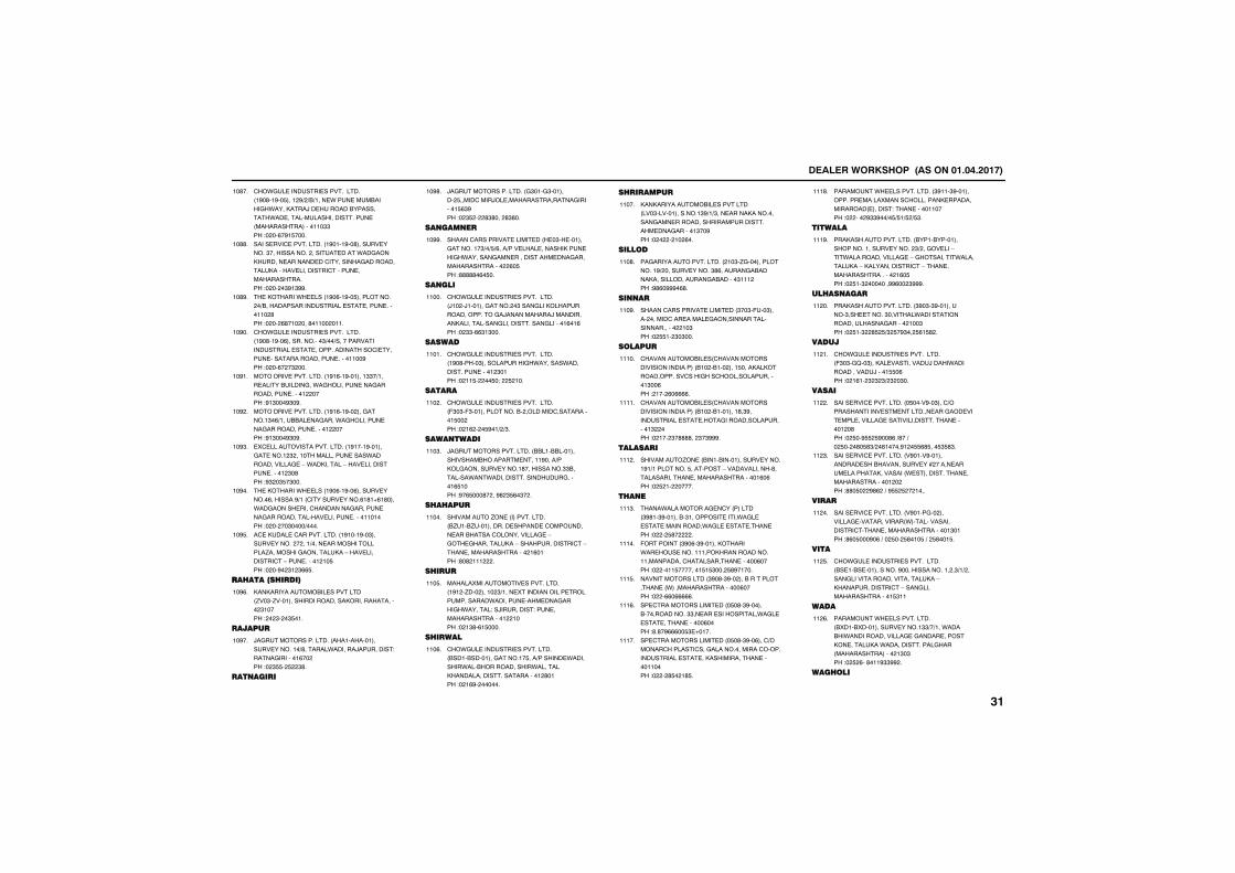
����������� �������������������
�.��������������������������� �#�'��#��$���� #+ +&+�����.���������&�����.����,����)���������&����������.����������������������������� �����������������""��!� ��%�#�$����
��'��
���������������������� �#����#��'�������������"����������� ��������������.������,����������������������������������������,����������������������������������������!� �� �"#�"##�
��''�
���,�����.����� �#�%��#��$���������� �+&����������������������������������������� '��!� �� %'��� ���'����� ����
��'#�
�.��������������������������� �#�'��#��%������������"+��+����������������������������������������������������������������������������������#��!� ��%� �" ���
��#��
������������������� �#�%��#�������""�+�����������&���������.�������������������������������� ����!#�"���#"�#�
��#��
������������������� �#�%��#�� ����������"�%+����&&����������.�������������������������������� ����!#�"���#"�#�
��# �
�5������������������������ �#����#�������������� " ��������������������.����������������-�.��,�������-����������������������� "�'��!#" �"$�"���
��#"�
���,�����.����� �#�%��#��%�������������%�������#+�� ��������������%�'�1%�'����.���������������������������������������������������������������������!� �� ��"����+����
��#��
����,�������������������� �#����#��"������������� � ���+�������������������/����������������,��-�����������������-����������� ��$��!� ��#� "� "%%$�
��#$�
���������������
,��,����������&������������� /��"�/��������������������,�������������� "�����! � "� �"$���
��#%�
�������
)������������������� ������������������������+'�������.�������)����������!���������������%�� ��!� "$$� $ "'�
��#��
�� �����
)������������������� �"����"�������� $����������)���������������������������$%"#��!� "$ � '"'��� '"'��
��#'�
�� ��� ��
�������������������������� ��"�����������������"+�+$+%���+��������������,��������.��������������������������������������������� %�$��!'''''�%�$��
��##�
�� ���
�.��������������������������� )�� �)������������� �"��������,�������������������)����������)�����������,�����������������������������������%��%��!� ""�%%"�"���
�����
������
�.��������������������������� �#�'����"������������.�������.������������������� "����!� ��$� ��$�9� $ ���
�����
�����
�.��������������������������� ("�"�("�������������&� ��������������������$�� ��!� �% � �$#��+ +"�
��� �
���� ����
)��������������������� &&���&&�������������&��������������#����+��,����������������'����������""&��������.���.���������������������������%$����!#�%$���'� ��#' "$%�"� �
���"�
��������
����������/��� ������������� &/���&/���������������������������������&�������������������-�������������,��-�����������������-�������������������� �%����!'�' ��� �
�����
������
�����5����������������������� �#� �/��� ����� "+�����5�����������������������������.����������������������.�������!��)����������!��������������������� ����!� �"'�%�$����
���$�
�������
�.�������������������������� &����&����������������$���+�������.��������.���&����������.��������,�������������������������� '����!� �%#� ������
���%�
����������
,��,����������&������������� ���"��������������"#+�+"���������,�����������������������������������������������������"��#��!� � � �� %��
�����
�����
����������������������� ��"�/���������������#+ �������������"'%���������&�����,�����������������&������"��� ��!#'%�###�%'�
���'�
�� ��
�������������������������� "��"�(���"����� ��������������������������������������������� ��"��!� $$�� "�"���
���#�
������
����������&���� ���������������������������� &�� �&��� ����$����,��,����������������������������������"��%��! ��� %�%%%%�
�����
����������&���� ���������������������������� &�� �&��������'�"#�����������������������������������������" ���!� ��� "�''''�� "�"###�
�����
�������
���������/��� &����&�������������������#�+���������$���������-�������������'���������������������������������%�%��!� $ �� �����
��� �
�� �
����.��������������� ������� "#'��"#������&�"��������������.���������������������.������������������!� � $'� �
���"�
(�������� "#�%�"#������,�����.���������������,������������������������������������������%����!� ����$��������$�$"��� $'#�����
�����
���������������� "#�'�"#�� ���&��������������� .������������������%����!� �%%�%%%%%�
���$�
��������������������� �$�'�"#������&�����������""�����������������.�����������������������%����!'�'�#%%%��$"�1����
���%�
��������������������� �$�'�"#��%����+��������������������������������������������������������,������������������������!� � '$� �'$�
�����
���������.��������������� "#���"#������������������5�������������,��������������� ��������!����������������!� ��� #""#��+�$+$�+$ +$"�
���'�
�����
���,����������������� &����&��������������������������� "+ ��������-����.�����������������-�����������.���������,��-�,����������������-���������������������� �%�$��!� $��" �������##%�� "###�
���#�
����� ����
���,����������������� "#�"�"#����������"���������"�������.����������������������������� ���"��!� $��" '$ $+" $�#"�� $%�$' �
�� ��
�����
�.��������������������������� ("�"��2��"���,��������������)����.��������������)�����$$�%��!� �%�� " " "+ " �"��
�� ��
�����
���������������������� �$����#��"����+�������������������������������������������������������������������������������� �'��!� $��#$$ $#��'%�+'��+�� $�� �'�$'"+ �'�����#� �$$%'$���$"$'"�
�� �
���������������������� �#����#���������������&�������������* �������������������,�������� .��������������������������������� � ��!''�$� #'% �+�#$$ $ � ����
�� "�
�����
���������������������� �#������� ����������������������� .��������������������������������������������"����!'%�$���#�%�+�� $�� $'���$�+� $'���$�
�� ��
���
�.��������������������������� &����&�������������#�������������� �"+�+ �����������������������������,��-�,�����������������-�����������������������$"��
�� $�
����
���������.��������������� &5���&5�����������������""+�+���.����&�.�������������������������������,��������,��.������������������� �������������� �"�"��!� $ %��'���#""## �
�� %�
������
����
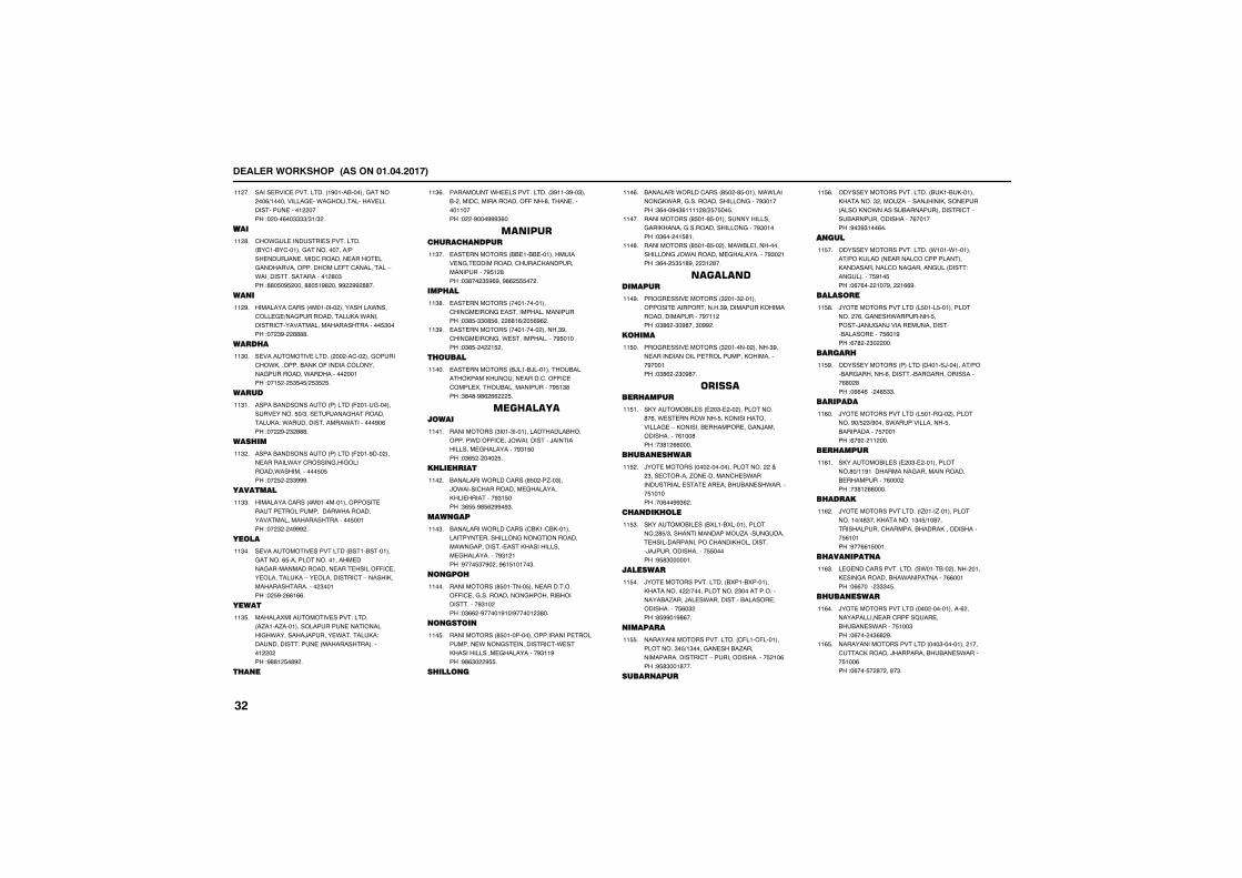
����������� �������������������
���������������������� �#����&������������ ��%+���������������.�������������������������������� ����!� ���%��""""+"�+" �
�� ��
����
�.�������������������������� &����&���������������������+��������)�������������������������������������������(�������������-�.���������������������� '�"��!''�$�#$ ����''�$�#' ���## ## ''��
�� '�
�� �
������������� ��������� ���������.����������+����������������,�!.��������������������������������������$"����!�� "#� ''''�
�� #�
������
������������������� �� ����� ����������.,�������&��,�(�������������������������.��������� �����!���$ � $"$�$+ $"$ $�
��"��
�����
�����&����������� ������� ( ���������������������$�+"�������)����������������,�!�.����������������.���������#�%��!�� #� " '''�
��"��
������
�����&����������� ������� ( ���#��� ������������.��������������������.�����������$�$��!�� $ � ""###�
��" �
�������
������������� �����������������������������������������.�������������������������������$�����!�� " � �### �
��""�
����
����������������������� &����&���������������%$�������������������������������������������������((���������������,��-����������������-�����,����������������� "�����!� $#� %%�%%�
��"��
����
�����5����������������������� �/����/�����������������������������.�������)��������.��������,�!�������������!������ ���������������� � ��!#''� $�'# �
��"$�
�� �
���������.��������������� "#���"#��"���&� ������������������((���'������������������!� �#���###"%��
��"%�
��������������� ����
������������� &&���&&�����������������������������������������������������#$� '��!�"'�� "$#%#��#'% $$$�� �
��"��
������
������������� ����������������������������������������������!�"'$�""�'$%�� %'�%+ �$%#% �
��"'�
������������� ��������� �����"#��������������.���������������#$�����!�"'$� � �$ �
��"#�
�����
������������� &)���&)���������&�����,����,���������������((���������5����&���������������#$�"'��!"'�'�#'% %% $�
�����
��� ���������
���������� "����"���������������&�������.��((�����).�����������)�������������������������#"�$���!�"%$ � ��� $�
�����
���������
&��������.��������� '$� ��/��"���).������������������������,�����������#"�$���!"%$$�#'$% ##�#"�
��� �
��� ���
&��������.��������� �&,���&,���������������������������������������.�����������������,�����������������������#"� ���!#���$"�#� ��#%�$�����"�
���"�
���
���������� '$�������$��������������((�����������������������&������������#"�� ��!�"%% �#�����#��+#����� "'��
�����
���
���������� '$����������������������������������.��������������������.����,����������������������#"��#��!#'%"� #$$�
���$�
����� �
&��������.��������� '$� �'$��������.�������,.������������������������#"�����!"%���#�"%���� '+ $�$��$�
���%�
���������� '$���'$����������������������,������������������������#"�����!�"%�� ��$'��
�����
���������� '$���'$�� �����.&������������������).���������������������#"� ���!"%�� $"$�'#�� "� '��
���'�
���������������
���������������� " ���" ������������������������"#����������,��������������������#��� ��!�"'% �"�#'���"�## �
���#�
�����
���������������� " ������� �����"#�����������������������������,��������#������!�"'% � "�#'��
��$��
���������
�,������&����� � �"�� �� ����������'�%��.��������.���$��,�����������������-�,������&������������)�������������%���'��!�"'� %%����
��$��
����� ������
)��������� ��� ���������������� ��� "�����������/������������.���������������������������&�&����.�������$������!��%��##"% �
��$ �
��� ������
�,������&����� &5���&5������������� '$+"�����������������/����������������������������������,���������)�)��������������$$�����!#$'"�������
��$"�
��������
)������������������� &5���&5�������,�������� +������������ "����������������&�/����)����.�����������&�����������������$%�" ��!'$##��#'%��
��$��
�������
������������������������ �(����(��������������"�$+�"����������&�/�����������������������-����������������$ ��%��!#$'"���'���
��$$�
����� ����
���������������������� &�,��&�,������,�������" ����/��-����)���,��������� ����,�.�������&�������������������-���&����������������%������!#�"#"���%��
��$%�
�����
�� ���
���������������������� .����.���������+��,����� ����������������������,��������������������������� �����!������������$#��$��!�%�%�� ���#�� �%%#�
��$��
�������
)����������������� �$����$������������� �%�������.��������$������)������)�������������������&����������$%��#��!%�' � "� ���
��$'�
�������
������������ ������� ������)��������+���&���������%���������&����������������%'� '��!�%%�%3� �%$""�
��$#�
��������
)����������������� �$����2�� ����������#�+$ "+#�����.��������������$��&�����������$������!%�# � �� ���
��%��
���������
�,������&����� � �"�� ������������'�+��#��������������������������&�����������%��� ��!�"'� %%����
��%��
�������
)������������������ �/����/���������������+�'"���,��������"�$+��'����������������������&����,�����������$%�����!#��%%�$����
��% �
����� ��� �
���������������������� �.����&�� ����� ����,������������&�.������������%%�����!�%%��3� """�$�
��%"�
����� �����
)����������������� ��� �����������% ��������������������(��2������&�&����.������$���"��!�%��� �"%' #�
��%��
���������������������� ���"��������� ����������,������)��������&�&����.������$���%��!�%���$� '� ��'�"�
��%$�
����
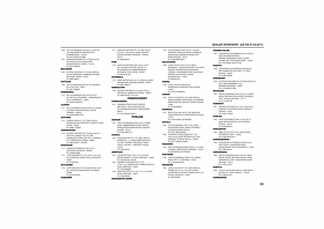
����������� �������������������
�,������&����� ���������������������"$+�'%%�������,�����2������������&�&���.�������$�� ��!%��� � $#� + � $## �
��%%�
���������������������� ���"����� ���������$%�����$������������&�&����.������������$������!�%��� $''��%�
��%��
���� ���
������������ ������� ������.��"����� ������������������&�����������&�����������������%������!%%$ � "��"��
��%'�
�����
�,������&����� %����%��� ���&����������$��������,����$"�����!�%��� %'%$ ��
��%#�
��� �� ��
�,������&����� %�������������������"%+���"��,���������������������������� �����,���������$#�����!�%�% � �"��'��#�
�����
������
�,������&����� %�����/��$������)���������,�����,��)��������)�)���������������$$"��#��!�%� %�#$'"����� �
�����
������
���������������������� �.����.��"������������)������������,���������������������%������!�%'$�3� "�% ��
��� �
����������
�������������������� &)���&)�������,��������%%+$� ���������#%%��)����������.�����������������&���������)�������������������%' ����!�%%"���"���������$����
���"�
�� ����
,���������&����� ��'�������������������,��)�����������!�%�%%� $%�%%�
�����
)������������������� ��������������� �$�����������&��&��������,��)�������$'�����!#��%%�$����
���$�
�������
)����������������� ��� ����� �����������"�#+"�$���,���������������������$ �%#��!�%�$"� $"#��
���%�
��������
���������������������� ��������������������"'����������������������.,���2��������������������������$������!#$'"� � ��
�����
����
�������������� �2����2��������������#�+ ��#��,�������'��+" ������&���������������,����������&����������������������$ �� ��!�%�$ � "�" "�
���'�
�������
�&�������� '����'����������������������������&�������,�������������%#�����!�%%�� %%�����
���#�
���������
������������ ������� ���������������������������&����������������%'�����!�%%"�$ �� ����"������$�
��'��
���� ����� ��������
���&�,����������������������� #%���#%�������""+�������,���������������������������������������%�$�����!���"� #""#�+# +#"�
��'��
�����������
���������&����� $���$����������������)��&��.����.,�������������������������&��������&�������)�&����$ ��%��!��%"�� '"�"����
��' �
�� ���
�.������������������� �&����&�������,�������������)�����������������������������&��,����������������������)������������������������������)�&������"�� ��!�'$'� �����
��'"�
�������
)����������� ��� ��������� �����������������������������������������"��%��!��'"�$'�""���$'�""$�
��'��
����&��(��.��������������� ���"������������������������5��&������������������������"�����!��'"� %""%#�
��'$�
�.�������������� �������������'�������������������������"�����!��'"���������
��'%�
� � �����������
������������� (���(����������������������������������������������������&�������������������&�����������������)�&������� "��!��''��#$# #�%'���
��'��
���������
����������� 5����5��������������������-�������)�����������������,��������.�����������������.������������������&��������������������&�������������)�&� ��.������������$ ���!#'�'� �#���
��''�
�� ��
����������� "$�"�����"�����.������)�������������&����������$�$��!��' "��"$$$%�$$��
��'#�
�� ��
����������������������� &����&�����������������,����������������5�&��������&�������)�������.����&���������)�&������%����!���% �%%�''��
��#��
��� ���
��5������ ��������������������������.,�������&��������&����������)�&����$������!��%�#� '$� ��# �%$ # ��
��#��
�����
���������&����� �$'���$����������������.������������&�������,��)�������������&��������!��'���#'� �� � $"�
��# �
�����,����������������������� ������$��$������������������������������&���,����������&����������"$�$��!��'��� �% �%�� �% �$�
��#"�
�����
��������&����� &����&�������������������.������&�������&���������� � ��!''� �"��"���# ����' "%�
��#��
���� ��
���������&����� ��� �������������������������������&����������$������!��%�� "$"�#��$��
��#$�
������
��������������������� &����&��������,��������"�+�������+ ��'+ � "�������)�������������,����.��������)�����������&���������� ����!#'� �"���%�
��#%�
��� ������
������������&����� �(����(��������������)������������������������������������������������������(����������&�������"����!��%"� �'��$��#'�$�"��%%�
��#��
������
������������&����� �� �'�������������������������������������������������� �$��!��''"� "''# �
��#'�
���������
�����������.�,� ������� ���$��.�� �������� �����������&����������&�����������&����������$����!���% �#'�$���%%#�
��##�
��������
��������&����� ������������������������.��������������������������������������� ���)�&�������������!���$� %"��$ �
� ���
������
����,��������������������� ��� ���������(����,���,�,�����������(����,������)�&����$� ����!��%"#�3 $"����
� ���
�������
���������&����� $�������"��������������������,����&�����������������(�/��,�����$ ��%��!��%"'� %� �"�
� � �
��������
&�&������� ����������������������(��/��������������$ �� ��!��%" �''� ��" ���
� �"�
������� ���
������������&����� �� ����� ���������������������������������,�����������������������$ ���!��''�� '"�$��
� ���
����������
��������&����� �������������������&�����.,��&������������������������&�����������������,��������&� ���)�&�����$ �����!��%"�� "�$���
� �$�
�����
����������� &)���&)��������������������������������������������������#��!��' %� %�����
� �%�
���������
����
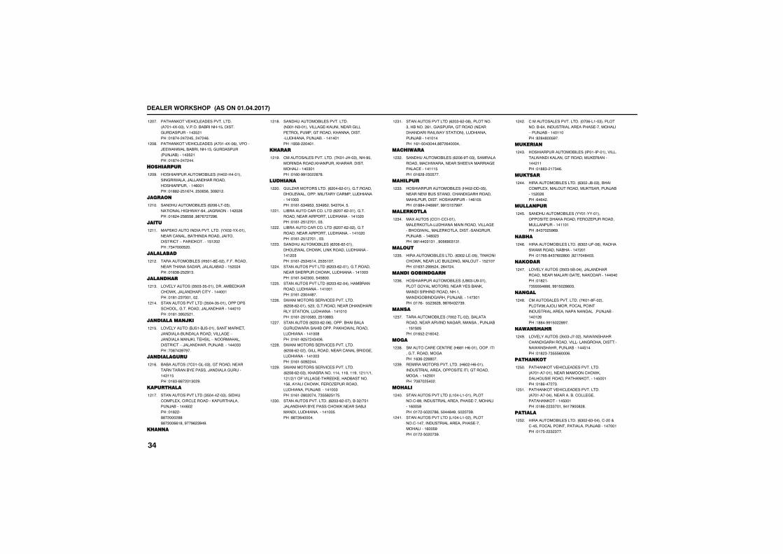
����������� �������������������
�����,����������������������� ������5��"���������&�&������$����������������������"$ ���!��'��� �� �$�� �� �%�
� ���
�����,������������� ������5��%��������)��.��.���&�&�������$������������ ���)�&������"$ ���!��'��� �� ���
� �'�
����������
������������&����� �� ��������������.�����)���������������������������%�����!��'' � $�%���� $�%$%��"�# � �
� �#�
�����
����������&����� % �%�����$�������������.���%���)���������� � %��!��% �� $'$$'��#'�%� � #%�
� ���
����
����,��������������������� �5� ��5������������������&������������)��������������-�(����,������$� � ��!�"�����$ ��
� ���
���������
���������&����� $���'��� ���(�(������������������������)�����&������$ � ���!��%"'� $ #�"�
� � �
���� ����
����������� "$�"�"$������������&��,����.,��)�����������������������!��'�� "������� �
� �"�
������������������ "$���"$����������������������������)������������������!��'��"#$ $ ��
� ���
�� �������� ���
���������� &)���&)���������������,����)��������&��������������������-�)�����������),���������-������������������-�)������������)�&��������""��!��'��"#�#��
� �$�
�� ���������
&�&������� ���������"���������������������������&���������)�����������������"��$��!��'"�''� ��"� #�
� �%�
���������
������������������ "$����/��"�������������5���������������,�������������)�&������%� ��!��' �''� ��� ''''� ��%%�'��#��#% "#�#�
� ���
��� �
����������&��������������� �"����"��������������,������������������������������������,������������������������)�&������������!�'$'� �����
� �'�
������
���������������������� �,���)��"�����#$�������������,�������,����������������������"����!��%��##�$� '�'�
� �#�
������ �
���/������������� % ���% ������������������.���������������������������������������"��!��%��$"�#$"��$"�#$ ��$�"�����$�
� ��
��&������������������ % ���% ������������������������������������������� ���!��%�� $� ������"�
� ��
��&������������������ % ���% �� ���������������������������������������� ���!��%�� $� �������"�
� �
����������&����� % �%�% ���������.����.,�����,������������������� �"��!��%�� $"�$���� $"$����
� "�
������������������ % �"�% ����������������������������.,�����������������"��!��%��$� "����$�$'���
� ��
������������������ % �"�% ��������&���������������������������!��%�� "���'��
� $�
�.���������������������������� % �'�% ������$ "������������������������������������������������������!��%�� $��$'"�� $��''"�
� %�
���������� % �"�% ��%�������&���&���������.�������&�������,.�����������������������'��!��%��# $� �"��%�
� ��
�.���������������������������� % �'�% �� ������������������������&����������������������"��!��%��$�# ���
� '�
�.���������������������������� % �'�% ��"���,���������������'����#��� �+�+���� �+ +��(�������������,�����&��������$%���������.,��(��/����������������������)�&���������"��!��%�� '� ������"$$' $��$�
� #�
�������������������� % �"�% ������&�" +�$��)��������&���������.,��������&)�������������������������$��!''� %������
� "��
������������������ % �"�% ��'����������"��&���� %�������������������� �����������������.������������������������)�&�����������!�%��$��"����''� %�������
� "��
���������
����������&����� % �%�#���"��������������������.���������������������������������������$��!��% '� $�$���
� " �
��������
������������&����� �� �����$����������.�&���������������������������������������������������%��$��!��''�� �%##���##�$�$�##��
� ""�
��������
��5������ �������������������,��������������������������������&��.���������,�����������������������)�&������'� "��!#'����"�"����#�$%#�"�"��
� "��
����
��������&���������� %"� �����$������,����.,�����������&������������������$ �����!��%"�� ##$ ��� %�� ��
� "$�
�� ������ �����
������������&����� �#�"��#������������������������������&��,�������������������������������&�����������)�&�������"����!���%�3$$ "% '��#'�'�" �"#�
� "%�
�� ��
���������&����� ��� ����� ���&�����������������������������������������)�&����$�$�$��!��%$ � �%�� �
� "��
���
������������������� %'��%������������������������������!�%"%� %'���
� "'�
���������������������� %� �%���������������������������������������������������� �����!��'�� $�� �
� "#�
�����
������������������ ���������������������'#�����������������������������������%��$#��!��� �$� ��'%��$���'�#��$� ��"#�
� ���
������������������ ��������� �������������������������������������������������%��$#��!��� �$� ��"#�
� ���
����������������������� ���%�����"����������&�%��������������������������������-����)�&�����������!' '�'��$#��
� � �
�������
������������&����� ����������������������.�����,����������������,����������� ����!��''"� ��"�%�
� �"�
������
��������&���������� %"� �)'��"���&��������5���������������,���������)�&����$ � %��!%�%� �
� ���
����� ���
����������&����� ����������������������,�������(��/������������������������������!'�"�� $#%#�
� �$�
����
��������&���������� %"� ��(��%���������.�����������&������� ����!���%$�'�"�%� '����# ����'��"�
� �%�
�����
����������� "$�"�$&������)���������������������������������,��������������!��' ���"$$$$�%%%��##�$� '%�"�
� ���
� ���
���������������������� �,���'(�� ������*"%��)�������(�������������������������������������������)�&������� %��!�''��##�$� '#��
� �'�
��� �����
����������� "$�"�)��� �����.���������������������������������������!����.����������)�&������$����!��' "��"$$$%���%�
� �#�
���� �
�����,����������������������� ������������������������.,��������������������,�������$�����!��'%��� �"�
� $��
�����,����������������������� ���������������������&����������������,������$�����!��'%� ""�����#���#��' '�
� $��
������
��������&���������� %"� �%"�������� �������$��(����������������������)�&�����������!���$� " "���
� $ �
����
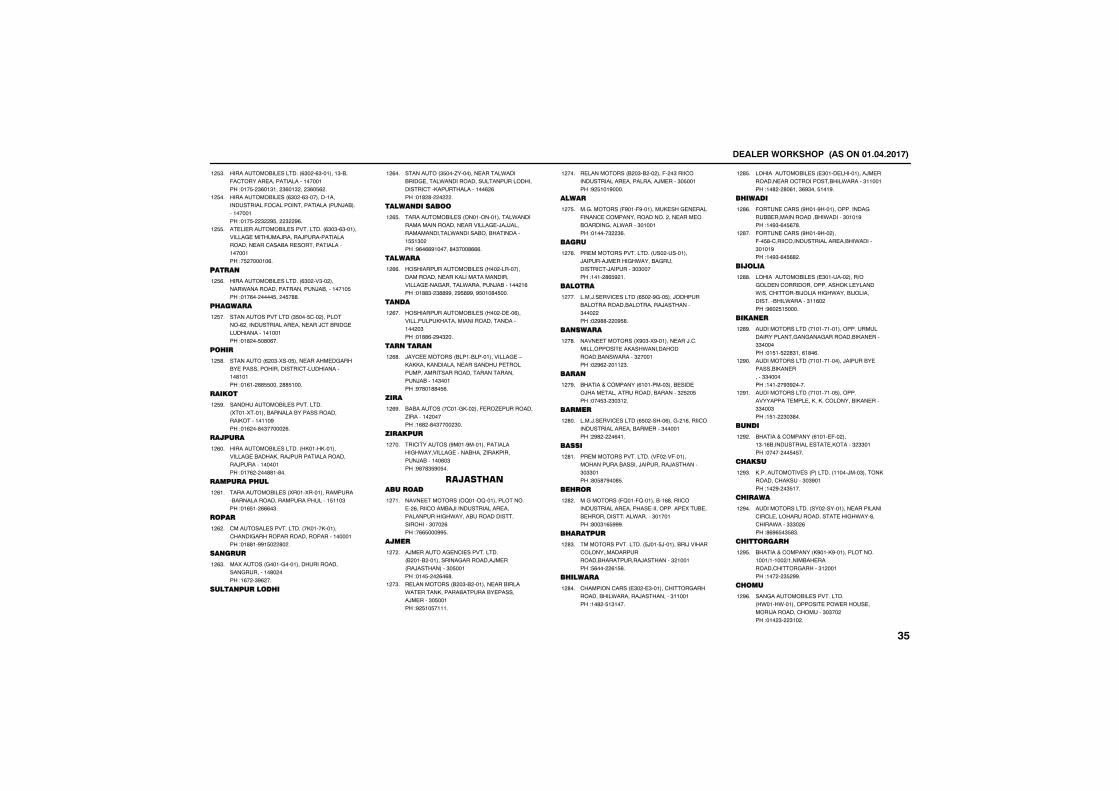
����������� �������������������
��������&���������� %"� �%"�������"�&��(������������������������������!���$� "%��"��� "%��" �� "%�$% �
� $"�
��������&����� %"� �%"�����������������������(������������������ ���)�&�������������!���$� " #$�� " #%�
� $��
������������&��������������� %"�"�%"��������������������)������)���������������������������&���������������������������!�$ ������%�
� $$�
�����
��������&���������� %"� ��"�� ������.��������������������)�&���������$��!���%�� ����$�� �$�''�
� $%�
��������
������������������ "$���$��� ���������% ������������������������)���&������������������������!��' ��$�'�%��
� $��
����
��������� % �"�5���$����������������&�����������������������������������'�����!��%�� ''$$���� ''$����
� $'�
����
����������&��������������� 5����5�������&�������&���������������,���������#��!��% ��'�"����� %�
� $#�
�������
��������&���������� ,���,��������������&���,����)�������������������)���������������!���% � ��''��'��
� %��
������������
���������&����� 5����5����������������&���������������������������$���"��!��%$�� %%%�"�
� %��
����
���������������������� �,����,����������������������������������������!��''��##�$� '� �
� % �
�� ����
��5������ ������������������������������������'� ���!�%� �"#% ��
� %"�
���� ��������
��������� "$���/���������������.����&����������.�����������������������������������,��������������% %��!��' '� � �
� %��
���� ������
���������&����� ��������������.���������������������������������)�))�����������������.�������&��&����������$$�"� ��!#%�%%#������'�"���'%%%�
� %$�
������
������������&����� �� �����������������������,�����������������������������������.��������)�&������ �%��!��''"� "''##�� #$'##��#$���'�$���
� %%�
� ��
������������&����� �� �����%�������������,��������������������������� �"��!��''%� #�" ��
� %��
�� ����
)����������� &����&����������������-�,�,,���,��������������������������������������������������������������)�&�����"�����!#�'��''�$%�
� %'�
����
&�&������� ������,�� ���(��/����������/�������� �����!�%' �'�"���� "��
� %#�
��������
������������� #����#�����������������.���������������&���/���,��������)�&������%�"��!#'�'"$#�$��
� ���
������ ���������
������������� 2���2��������������� %���������&�)������������������������������.�����&��������������������"��� %��!�%%$���##$�
� ���
�����
�)��������������������������� & ���& ��������������������)���� ��)���������"�$�����!���$� � %�%'�
� � �
����������� & �"�& �����������&�����.��������,������&�������&���������)������"�$�����!# $��$�����
� �"�
����������� & �"�& �� ���(� �"�������������������������������)������"�$�����!# $���#����
� ���
�����
���������� (#���(#��������,�����������(���������������������� ����������&����������.�����"�������!������" "%�
� �$�
�����
�������������������� ��� ���������)�������)������.����&���������������)��������"�"�����!���� '%$# ��
� �%�
�����
����)�������������� %$� �#���$���)�����&����������&���������)��������"��� ��!� #''� �#$'�
� ���
�� �����
������������� 5#�"�5#�����������)�����������������,��.������������&���.������" ������!� #% � ��� "�
� �'�
����
&�������������� %��������"���&������)�������������������&�������" $ �$��!���$"� "�"� �
� �#�
������
����)�������������� %$� ����%����� �%������������������������&��������"�������! #' � �%���
� '��
�����
�������������������� �(� ��(���������������&������)���������)��������"�""����!'�$'�#��'$�
� '��
�����
��������� (2���(2������&��%'����������������������������������������5���&���&����������!���.������"�������!'��"�%$###�
� ' �
��������
������������������ $)���$)������&��)�������������������������&����������)��������" ������!$%��� %�$%�
� '"�
��������
������������ �"� ��"��������������������&��.�������)���������"�������!��' �$�"����
� '��
���������&����� �"��������������)����������������������&��.������"�������!��' � '�%���"%#"���$���#�
� '$�
�������
(����������� #���#������������������&&�������������&�.������"����#��!��#"�%�$%�'�
� '%�
(����������� #���#�� ���(��$'������������������������&�.������"����#��!��#"�%�$%' �
� '��
������
���������&����� �"������� ����+���������������������,���������.+���������&�)������.����&�)������������&��.������"��%� ��!#%� $�$����
� ''�
���� ��
�������������� ��������������������������������������������������&�,�������""������!��$��$ '"���%�'�%�
� '#�
�������������� �������������)������&��������&�,��������""������!���� �#"# ����
� #��
�������������� ���������$������������������������,��,��������&�,�������""���"��!�$�� "�"'��
� #��
�� ��
&�������������� %�����(�� ����"��%&�������������������,�����" ""����!����� ��$�$��
� # �
������
,�������������� �������� �����)���"�����,��������,�����"�"#����!�� #� �"$���
� #"�
�������
��������������� ��� �����������������������������������������������.���'������.����"""� %��!'%#%$�"$'"�
� #��
��������
&�������������� ,#���,#�����������������+����� +�����&��������������������"� �����!��� � "$ ##�
� #$�
����
����������&��������������� .���.��������������.�����������)�������������"�"�� ��!��� "� "�� �
� #%�
����
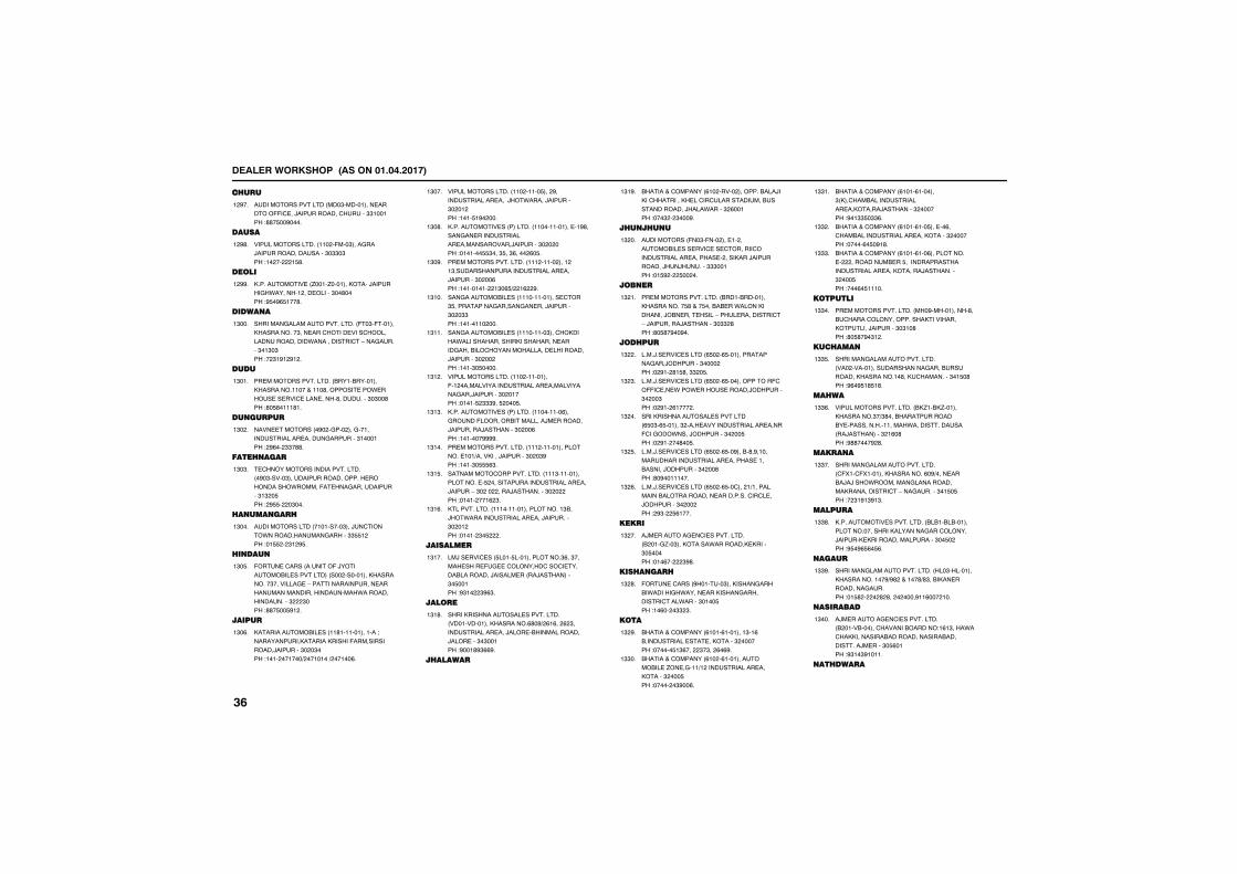
����������� �������������������
������
������������������ ���"�����������������((�����)������������������""������!''�$��#����
� #��
�����
���������������� ��� �(���"��������)�������������������"�""�"��!�� �� �$'�
� #'�
����
,������������� /����/�������,����)��������.������� ���������"��'����!#$�#%$���'�
� ##�
����� �
��������������������������� (��"�(�������,���������"�����������������������������������.���������������-�����������"��"�"��!� "�#� #� �
�"���
����
�������������������� &����&��������,�����������������'����������.�����������������������'����������"�"��'��!'�$'����'��
�"���
�� ������
������������� �#� ����� ��������������������������������������"�������! #%�� ""�''�
�"� �
���� ����
��������������������������� �#�"�����"����������������������������.�����(��������������������"�" �$��! #$$� �"���
�"�"�
�� ��� ����
�������������� ���������"���)��������.������������������""$$� ��!��$$ � "� #$�
�"���
�� ���
(����������� �������(�)��������&�������������� ��� ���������,���������"�����������-�����������������������������������������������.�����������������" "���!''�$��$#� �
�"�$�
������
,�����������&����� ��'��������������9�������������,�������,�����(��������������)��������"� �"���!���� ������+ �������+ �����%�
�"�%�
���������������� ��� �����$��� #��������������������)�.�����)��������"� �� ��!����$�#� ���
�"���
,�������������� �������� ����������������#'�������������������������������������)��������"� � ���!�������$$"���"$��"%���� %�$�
�"�'�
�������������������� ��� ����� ���� ��"�������������������������������)��������"� ��%��!��������� �"�%$+ �% #�
�"�#�
����������&����� �������������������"$�������������������������)��������"� �""��!�������� ���
�"���
����������&����� ���������"����,����.�������������,�������������������&������������������������)��������"� �� ��!����"�$�����
�"���
���������������� ��� ���������(�� �����������������������������������������)��������"� �����!�����$ """#��$ ���$�
�"� �
,�������������� �������� ���������%���������(�����&����������)���������)���������)��������"� ��%��!�������####�
�"�"�
�������������������� ��� ��������������������+����,����)��������"� �"#��!����"�$$$%"�
�"���
����������������������� ���"������������������$ �����������������������������)������-�"� �� ����)���������"� � ��!����� ���% "�
�"�$�
,������������� ���������������������"&��)�.���������������������)���������"� �� ��!����� "�$ �
�"�%�
���������
��)���������� $����$�������������"%��"����������(�����������������������&��������)��������� ��)���������"�$�����!#"�� "#%"�
�"���
�����
����,������������������������� �������������,�������%'�#+ %�%�� % "�������������������)�����&�����������)�������"�"�����!#���'#"%%#�
�"�'�
��������
&�������������� %�� ����� �������&���)��,����������,���������������������&��������������)���.�����" %�����!���" � "���#�
�"�#�
��� ��� �
���������� (��"�(��� ������ ������&����������������������������������������������� ����,���)�����������)��)�������"""�����!��$# � $�� ��
�" ��
�� ��
�������������������� &����&��������,���������$'����$���&�&���.����,��������)&�����������-������������������-�)���������)��������"�"" '��!'�$'�#��#��
�" ��
������
����)�������������� %$� �%$�������������������)�������"���� ��!� #�� '�$'��"" �$�
�" �
����)�������������� %$� �%$������������(��((������.��.�����������)�������"� ��"��!� #�� %���� �
�" "�
����,����������������������� %$�"�%$������" ���������������������������(�����.����)�������"� ��$��!� #�� ��'��$�
�" ��
����)�������������� %$� �%$��#���&�'�#��������������������������������������&������)�������"� ��'��!'�#��������
�" $�
����)�������������� %$� �%$������ �+������������&�������������������������������)�������"� �� ��! #"� $%����
�" %�
�����
�)��������������������������� & ����/��"���,�����.�������,�,�����"�$�����!���%�� "#'�
�" ��
����� ����
(����������� #�������"���,��������&�.������.���������,��������������������.�����"����$��!��%�� �"" "�
�" '�
��
&�������������� %����%��������"��%�&��������������������,�����" ������!������$�"%��� "�"�� %�%#�
�" #�
&�������������� %�� �%������������&����/�������+� ������������������,�����" ���$��!����� �"#��%�
�""��
&�������������� %����%�������" ,�����&�������������������,�����)��������" ������!#��""$�""%�
�""��
&�������������� %����%���$������%�����&��������������������,�����" ������!�����%�$�#�'�
�"" �
&�������������� %����%���%������������ ���������&���$��������������������������������,������)���������" ���$��!���%�$�����
�"""�
�����
�������������������� ��#����������'��&������������������,���������,��������)��������"�"��'��!'�$'�#�"� �
�""��
�������
��������������������������� ��� �������������������������&����������,���������'��,����������"��$�'��!#%�#$�'$�'�
�""$�
�����
��������������������� &,/��&,/������,�������"�+"'���&������������&�������������������.���������������� ��)���������" �%�'��!#''����# '�
�""%�
����� �
��������������������������� �(5���(5�������,��������%�#+��������&�)�)��.��������������������,���������������-�����������"��$�$��!� "�#�"#�"�
�""��
�������
,������������������������ &�&��&�&��������������������,������������������)������,�,������������������"��$� ��!#$�#%$%�$%�
�""'�
�����
�������������������������� ��"��������,�����������#+#' ������'+'"��&�,�������������������!��$' � � ' '�� � ����#��%��� ���
�""#�
��������
�)��������������������������� & ����&�������������&�����!�%�"���.����,,���������&��������������&������������)������"�$%����!#"��"#�����
�"���
�������
����
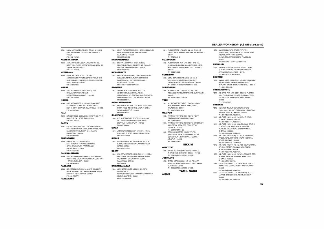
����������� �������������������
���������&����� 5 ����/�� �����'������&�������.�������������!���)���������"�""����! #$"� "��%��
�"���
��������� �
)��������&����� ������� ,��������"���������������/���,�����������������,����������,�����"" ��"��!�$��� "�$�$�
�"� �
����� �
(����������� �������(�)��������&�������������� �����������(�� ���� &��������������������������!�&��������������.�����"����$��!''�$���"$%�
�"�"�
���
�������������� ��� �����������������.�������������������������������������""$$ "��!�$$$� ��'$�
�"���
���
��������������� �$����$������(��%��������5���������,���������������������,���������&�,����� ��)���������""�'�"��!''�$���$$$�
�"�$�
����
��)���������� %$� �)#��"���,�����������+���)����������������������"�%�����! #" � $% ���
�"�%�
���
,����������������������� &���&����������������,���"������������,���'#�������&��������������������'����������)���������"�"��%��!#�% %'%��'�
�"���
���������
&����������� ������������������������������������������&��&���������������� ��)���������"� %�$��!#���"#��� �
�"�'�
����� �� ����
���������� &,��&,�������������� ������������������������������������������-������������������""$�$���!##' %"'$�%�
�"�#�
�������
�������� ���������������.�����,�������������.����������������.�������������)�������������.�����"����'��!#����'�����
�"$��
������� �
���������&����� 5 ���5 ������&��.��������,��,������)����������������)���������"�""����! #$ �" ��%��
�"$��
����� ��� ��
&�������������� &�/��&�/������,����&��������,����������$"��������������������)���������" %$�#��!#����'$�#��
�"$ �
��������
&���������������� )2���)2���������������������������������,����������.��&������������������������)���������" ""����!���$� ��###�#�% ��# #��
�"$"�
�������
��������������������������� �,����,������&���.����������������,���������������)��������.�������������������������)��������"��� $��!#$"�"�%#���
�"$��
�������������
�������������������� (��"�(���������������������������������������,��������.������������" �����!'�$'�#�%"'�
�"$$�
��������
,�������������� �������� ��������$�������������)�������������������&��������'�����������"�"��"��!'%#%#"�#%��
�"$%�
�����
)��������&����� ������� ,����,�������(�$���)���������� ��������,�����"" �����!�$� � �$$�$�
�"$��
�����
������������� �#� ��,��"����������'�&������������������������������������"�������! #� � #���
�"$'�
���
��)��������������� &.���&.�������,��������-��'%+�����'���������,���������.�,�����������������)�������)��������"�%�����!"�%����
�"$#�
����� �� ����
�������������� � ���� ��������.�����&�������,�������������������������������������������""$�����!��$�� �%% $�
�"%��
�������������� � ���� ��"�����,�����������$�������������������)��������""$�����!##' %"'$�%�
�"%��
���� ����
�������������������� &�&��&�&������,��������$#+"""�����������������������)����������)����������������������""�$����!�%%$� '%��
�"% �
��������
����)���������������� %$� �����'��������)�,�����������������������������������������������������"�%#� ��!� #""�� ��#��� ��#�'�#������%�#�
�"%"�
��������
�������������� � ������� ������������������������������$�������������""$'����!�$�#� � ��� � '�
�"%��
�
,��������������������� �������������(�#���������������������������,�����)��������"�������!��" �'%#%# $ $ �
�"%$�
�������
������������� �#����#����������������������������������"�"�����!� #����$��"�
�"%%�
������������� �#� ��#��������������������������������������&����((���������������"�"�� ��!� #�� �#��$��$$�
�"%��
��������������������������� �#�"��#�� �����'�������������������������������)����������������������������"�"�� ��! #$$� �"���
�"%'�
�������� ��
����������� &#���&#������%�����������������������,����,,������"��� ��!"$# �%�#� $�� " "���� " �$#��
�"%#�
���� �
����������� &#������� ��������������,�������)��������.������,,����)���������"�� ���!"$#$� $��"��� $�� ��� $��%#�
�"���
����������� ��
)���,������������������������� ��������������(��� %%+�&�����������������������������,����������������&����� �������������������%��%$"��!�� ��� $�� % ���+�#�'''$��""�
�"���
��������
������������� �&����&���������+������������������������)����,������������������� ���������������% ������!#�� '�"� +�#�� ��'�$��
�"� �
����� �
��&������� ��������$�����$+��� ����,������������������������������� ������&������������ ���������������������%"'"�%��!�� �� "���'�
�"�"�
��� ������
������������������� &&���&&��������������#'+���������,,����������������������������������,�������������������������%�"�� ��!� ##�$�"'��
�"���
��� ��
)�)�����5� ������������������������ ��'$���������*�#�� ������������,��������������������������������������%���" ��!�����"$%""%%���"$%""%��
�"�$�
��&������� ��������������� �����������������������������%���" ��!����� $�$����� $�$$��
�"�%�
��&������� ���������$����+� ��&�����������������5������&��������,���������� ����������������������������������%���#"��!���� "%$��''�� "%$��#��
�"���
��&������� ���������%���������� ����������������������������������������������������������%��� ���!���� ��%$'����� ��%$'�$�
�"�'�
��&������� ����������������� ��,��������������������������������������������������%����%��!����� %�%�"��� %�% ��
�"�#�
��&������� ������������� #��.�����������������&���������������������&����������������%���$'��!����� '�� �+��'�
�"'��
������������������������ ���"����������%���������������������������&����������������%���$'��!���� %"$#%����� #��#���
�"'��
������������������������ ���"����� �����������������&���������������������������%��� ���!���� ��%�$'��� ��%�$'���
�"' �
����
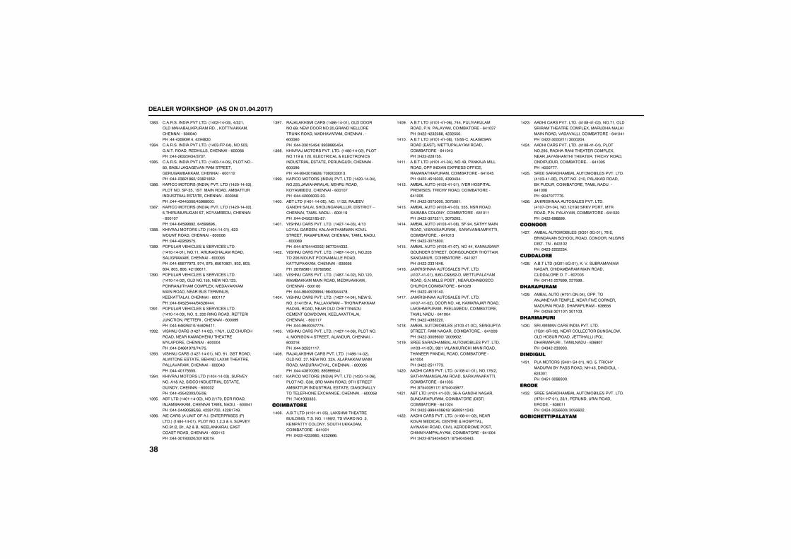
����������� �������������������
������������������������ ���"�����"����+" ���������&���,������������,�����,,�������������%�������!����"$#�#����� #�'"��
�"'"�
������������������������ ���"�(���������$�"��������������������������������%���%%��!���� %" "�"�+"�"��
�"'��
������������������������ ���"�����$�����������'���&�&��)����������������������������&�,,�������������%���� ��!���� "' �'% +� "' �'$ �
�"'$�
,���������� ���������������� �� ������"�������������"$�������������������&����������������������������������%���$'��!�����"��$���+�$#%'����
�"'%�
,���������� ���������������� �� ������ ���$�����������������,���&��������������%�������!����%�$##'# ��%�$##'#%��
�"'��
,����)���������� �������������% "��������������������%����%��!����� %#$�$�
�"''�
������������������������������� ��������������������������������������������������������%���#"��!����%$'��#�"��#����#�$��%$%��'����'� ��'�"��'����'�$��'�%��� �"%%���
�"'#�
������������������������������� ��������� ���������$$����.���� "�������)����������5��������,,������������������&�������������,��,������������������%�������!����%�$ $���+%�$ %����
�"#��
������������������������������� ���������"������"�� ���������������������)���������������������������%���##��!����%�% %���+�%�% %����
�"#��
����������� �� ������ �����%+�����/����������������,���������������������������������%�������!���� �%%�#�"+��+�$�
�"# �
����������� �� �������������#��������������.�������������&�������5��������������������������������%����"��!��������$$$$�
�"#"�
,����)���������� ���������"������������������ �������������������������������������������%���" ��!�����"$� "�"+�$+�%�
�"#��
�&������ ��������������� +����������������)��&�,,�������������������������%�������!���� ��#�$'$+'%��� '������� '���#�
�"#$�
��������� �������(������������������ ��������� ��'������������������ �"���������������#�+ ��&���� ���&��������,������������������������������%����$��!����"��#"� �+"��#"��#�
�"#%�
��)���,��������� ��'%�����������������%#����.������ �������������������,����������������������������%���%���!����""��$�$�+�'#"###$�$��
�"#��
,����)���������������� ��'������ �����������#���� ������������������������������������������������������������������%���#%��!���#��"��#% %+���# �""��"�
�"#'�
,���������� ���������������� �� ������������ $�)�.������������������,���&��������������%�������!����� ��%���� "�
�"##�
�&������ �����������������+�" ����)����������������������������������������-�����������������������%����#��!���� �$� �'$�'��
�����
��������������������� �� ������"����+�"��������������,�����������,���������������������������������������������%���'#��!����'�$������ +�#%�� ��"" �
�����
��������������������� ��'������������ �"��� �%��������������������,������,,�������������%���$%��! %�# #%�+� %�# #% �
��� �
��������������������� ��'������ ������ ������&�,,�������������������,,�������������%�������!����#'��# ###�+�#'��#����'�
���"�
��������������������� �� ������������.�������"��+�&���������������-�������,,�����������������������������������������.�.���,����,�������������������%�������!����##���$���$�
�����
��������������������� �� ������%������������������������������������������������%����%��!����" $"�����
���$�
��)���,������������������� ��'%����� ��������� �����.���� ��������,,�����������������������������������%���#$��!�����"'���#���'#"###$���
���%�
,���������� ���������������� �� ������%�����������"���"�������������#�����������&����������������������������������������������5�����������������%���$'��!����#"�""$�
�����
��������
��&������� ���������$�����,�����������&�������������������##+ �����.�������"��,�������������������,,���������&�������%�������!�� �� " %%���� " %%%�
���'�
��&������� ���������%��������������,���������������������������&�������%���"���!�� �� " $''��� " $$��
���#�
��&������� ���������'����$+$$����������������� ����������������������������&�������%����"��!�� � '�$$�
�����
��&������� ����������������#�����,�)�����������������������5������((�����������������������&�������%����$��!�� ��$�%������"#��"��
�����
��&������� ���"���������������������������������������������&�������%����$��!�� �"��$�����"��$����
��� �
��&������� ���"�����"���$$$��������������&�&�����������&�������%�������!�� �"��$ ����"��$ �"��
���"�
��&������� ���"�����'����(�#���������������������.�������������������������������&��������%����"��!�� �"��$'���
�����
��&������� ���"���������������,����������������������������������������������������&�������%��� ���!�� � ""�%�%�
���$�
)��,�������������������������� �������������'+%����'+% ������������������������������������������)�&�����������&�������%��� #��!�� ��$�#����
���%�
)��,�������������������������� ��������� ����������'��,�����)����������,������������������������&�������������������%�������!�� ��"'" ��
�����
��&�������&����� ���"����������������������������������������&��������%����#��!�� �"��#%��+�0"��#%� �
���'�
������������&�������&��������������� ���"���������#'+�������,��������������������������������������&�������%�������!�� � $����"�
���#�
�������������������� ���'�������������%+ ���������������������������������������&�������%���"$��!'�$���#���+�'�$���$#���
�� ��
�&������ �������������"%���������������������������������&����� ���������&�������%��� ���!�� �###���'%�'+�#$��#�� �"�
�� ��
�������������������� ���'����� ��������,���������������������������������������������������������������������������������&�������%�������!�� �'�$���$� �+�'�$���$��"�
�� �
�������������������� ���'�����"�������������������������������5���������������������������������������&�������%�������!�� �"��� ��+�"��� ���
�� "�
�������������������� ���'��������������� #$������������������������5�������)�����������������������������������������&���������%����$��!��������
�� ��
������������&�������&��������������� ���"���������������� ��������,��������&,�����������&��������������������%����'��!#��������$�
�� $�
)��,�������������������������� �������������� +�#����,���������������������������������&�������%��� ���!�� �%#''##�
�� %�
� �
��&�������&����� "����"��������'����&������������������������������������������%�"�� ��!�� "� � $��
�� ��
��������
��&������� $2���$2������,�������&���������������������&������������������������������%����"��!���� � �%##�� �$##��
�� '�
����������
��&������� ����2���������������)��������������������(������������������������������������%"'%$%��!�� $'�"�����+�"����"�
�� #�
����������
������������������������������� �2���$��� ����������������&�����.��������������)��������� ����������������������������%"%'����!��"� � ""#""�
��"��
�� �����
��������� ����������������$����������������&���������������$�������������% ������!��$��"�#'"���
��"��
����
������������&�������&��������������� ����������� "+�����������������������������%"'�����!�� ��"�$%%��+�"�$%%� �
��" �
��������������
����
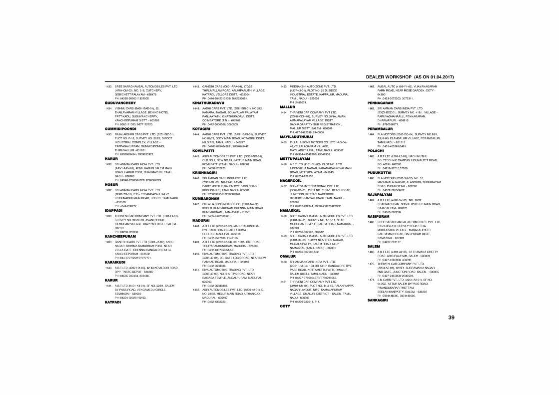
����������� �������������������
������������&�������&��������������� ����2���"������"�'������������&����������������%"'��%��!�� '$�"� ���+�"� ��$�
��""�
������� �����
����������� &����&��������$ ����������������������&��������������,�������������������,��������������������%�" �"��!#$��� �$$"+�#%��� $�
��"��
�������� ��
��)���,������������������� &�/��&�/�������������(��"������������ % + ������������������������5����������-��������,����������������������������������%�� ����!'#"###$�$��+�'#"#'$"#� �
��"$�
�����
������������������������������� ��������������� #+#���������������������������������������������������������%"%#�"��!��"�%�#�#���� �"+�#�#���� �#�
��"%�
����
������������������������������� �2����2�����������������������������,�������������������������������������%"$��#��!�"��� %� ���
��"��
��������
���������������������������� ��������������������""�+"&�&��������������,�����������������������������������������%"������!�� '"� "���
��"'�
�� ���������
������������������� �%���)��� �����&�����������������������������������������������������&�������������,�������������%"�$� ��!����%� �$ + � ������
��"#�
���������
��&������� � � �5��$���� ��"�,���������������������������%"�"� ��!��$%$� " �'��� " �'%��
�����
�����
��&������� ,����,��������(����$ #+���������&�����������������������������������������%"#�� ��!��" �� %�+% +%"�
�����
������
����������� �%���������������+ &�������������������������������������,������������������������%" �����!���%�#'� "�"�"#+�#'� """�%��
��� �
�� ���������
�������������������� &&���&&��������� � ��,�����)����������������������������)�������,�����,����������������&����� ��������%� ��#��!�� �"���$�%+�"���$�$�
���"�
������
�������������������� &����&�����������������'#+�#���������������,���������������������������������������%�" ����!�� %%�'�$���$'#�+�'�$���$�� �
�����
�������
���������&��������������� ���������������������.����"�������������������,��������� ��������������% '$����!��%" � " ��
���$�
����� �����
������������������������������� �2���2���"�����������������������������������&�������������,�����������������������%"$�����!#�$�%##$$$+�' ���#"�'�
���%�
������ ��
���������������������� ��������� ���"%#+ �&��,��&�,���������������������,��&�,���������)�������%� $����!��"$� �� $%%�%$�
�����
�������
��&������� � � �� �� ��������������������&�����������������(�����������������������% $��'��!��$ � $����'�� $��� $�
���'�
��&������� � � �� �������#����#���������������������,������������������% $��$��!��$ ��"'��$�+$�+$ �
���#�
�������������������������������� � �$�� ������ ����������,�������������.�����������������������% $��%��!��$ � %'''''�
��$��
�������������������������������� � �$�� �� ������%������,��������������&�&���������������������������������% $��"��!��$ � %'''''#�
��$��
���������&��������������� � �%�� ������������ '+$&����������������������,����������������% $�����!��$ ��"' ��
��$ �
�����,�������/������������� � ���� ������������� $����������������������������,��������������������������������% $��'��! �'#����
��$"�
������
���������������������������� ���������������������$�+�������������������������������������!���������������&�������������������������������������%"%"�#��!� �� � "##�� �������
��$��
�������������
���������������������� ��������������%��������������������������������������������������%�#�����!��"%���"$� "�"+��"$� "�%�
��$$�
����������
��&������� ��������������������%���#�����/���������,���������,�����������������������������%����"��!�� $�� '�$$�
��$%�
�������
�������������������������������� �$� ��$�������������"�&�����&��������)��������,�������������������������,����,���������������������% #�� ��!��%$ � " "���� "%"��+�'#�"� """ �
��$��
�������
������������&�������&��������������� 5����5������������������+�������������������������������������������,,�����%"������!�� '%�"��$����"��$� �
��$'�
������������&�������&��������������� 5����5���"����+�� +���������������������������������������������������,,��� ��������������%"������!�� '%�"��$���$� �
��$#�
�����
������������������������������� �2������������ "��"&�������&��������&�������������,���������������������������� ���������������������%"%�� ��!�� ���#�#���� �"+�#�$��##$$$�
��%��
���������������������������� ��������������������������$��������������������������������,������������������������������������-���������������������%"%"�#��!�� #�� %��������
��%��
�
��&������� ���"�����$�����)�����������(�������������������������������%�"�����!�� "�"��$"�"��"��$"���
��% �
�� ������
������������������������������� &5/��&5/������������������#+�����������-������������������������������������������%"%'����!#�#��"%"���
��%"�
����������
��������� "�$��2���������������''+����"���$������&�������������������&������������������% � � ��!��"����""%�+"�%��
��%��
������
��&������� �"����"��������������������������������������������������������%� ��"��!�� $#�"�����"�� ��
��%$�
�������
��������� "�$�$��� ���������������������������������������������������������,��������% ��"��!��" � %$$%%+%��
��%%�
����������
��&������� � � �$���"��������+" ����������������������������������������)����������% %� $��!��$%"� %� #'�
��%��
���������
������������&�������&��������������� &�)��&�)��������������!��+��&�������,�����������������,�����������������������������������������������,,�����%"������!�� '�� "�����
��%'�
�����
��&������� ������ ��"���" �����������������������������������������%"%��#��!�� ����%%#''����%###�
��%#�
���������������������������� � �"�� ������� + ������&��������������� ���������)���������������������%"%��$��!�� �� ������+� ""%$##�
�����
������������������� � ���� �������(����%�+ �"��������������&������������������,�������������������,������������������%"% � ��!��#���'�������"���#����
�����
�� ������
����
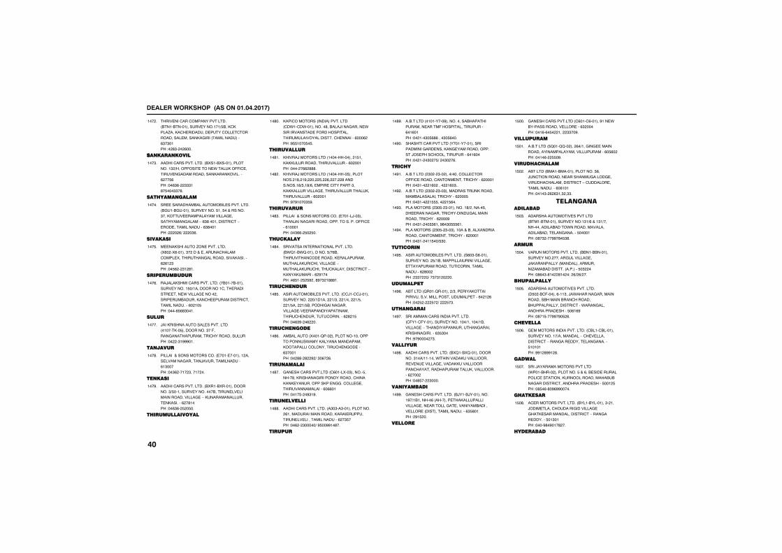
����������� �������������������
���������������������������� &����&��������������������+$&��,�,����/���,������������������������������������������,������ ��������������%"�"����!� '"� � %���
��� �
��� ���� ����
�������������������� &5���&5���������������" +�������������.�����,�((��������������������������,����,�������% ��$%��!��%"%� """�'�$���""�'�
���"�
������� �����
������������&�������&��������������� &����&������������������$���$����������"���,����������������������������������������-�%"'���������������-��������������������%"'�����! � %+� �"%�
�����
��������
�����,�������/������������� 5%� �5%������"� ������������������������5����������������������,�������% %� "��!��$% � "� '��
���$�
�������������
��)���,������������������� �&����&�����������������$�+������������������������������.������������ ����������&������,�����������������������������������%� ��$��!����%$%'"����
���%�
�����
)���,������������������������� ������,��$���������"��(������������������������������������!�� �"�###���
�����
� �����
���������������������� �������������� ��������������������)������������������%�"�����!��"% ���� "����� ��
���'�
� ����
�������������������� &5���&5�������������"+$������������������&��������������������������������-�,������������������,�������% �'����!��%"%� $ �$��
���#�
��������������
,���������� ���������������� ��.����.����������'��&���)�����������.����������������(�����������������������������������������%���% ��!#$$����$�$�
��'��
����������
,����)���������� ����������� �$���,�,,�����������������������%� �����!���� �%% '''�
��'��
,����)���������� �������$���������� �'� �#� �� $� %� �� '�����������'+$��'+%�������������������"��,�,,������������������������������,���������������%� �����!#�#����"$#�
��' �
���������
���������������������� ������)��"������)���������������������������((������%�������!��"%%� $� $��
��'"�
��������
�������������������������������� &.2��&.2�����������$+�%&��������������������,������������������,���������������-�������,����������,����������������-�,����,��������% #�����!�%$�� $ $# ��'#�" �'''��
��'��
������ ���
���������&��������������� ��)����)���������������� �+������ �+"�� �+��� �+$�� �+$��� �+$&���������������������������������������������������������������������% ' �$��!��%"#� �% ��
��'$�
������ ���
��&������� 5����2��� �����������������������.����,�����������������,���������������������������%"������!�� ''� ' # +�"�%� %�
��'%�
��� ������
������������������� �%����5��"������$�����'��,��������������������������,��,������������,���������������������������������%�%%����!����$� �#"�#�
��'��
��� �������
�������������������� �"�"��"������������� %���������������������,���������������������������������������% �"$���!��% � "�����+�#$��##��'��
��''�
������
��&������� ���������#�����������&��������������������(�������������������%��%����!�� ���"�$%'%����"�$%���
��'#�
������������������ ����������������������������������,��������������������)�������������������%��%����!�� �� �"� �$+� �"� �%�
��#��
�����
��&������� "� � "�� ����+������������((����������������������������% ������!��"��� �%� ���� �%�"��
��#��
��&������� "� � "��"��������������,���������&������������������% ���$��!��"��� �$$$��� �$%��
��# �
��������� "�$� "����������'+ ������$�������������������������������������������������% ���#��!��"�� ��""%���#'�"�$$$%��
��#"�
��������� "�$� "��"���������&����5�������������������������������% ������!��"�� ���$��+$"��
��#��
�����
���������&��������������� �%�"��%���������������� $+�&������������������������������������������������������������������% '�� ��! ""� �+��"�"� � ��
��#$�
��������
�&������ 2����2������� +"��������,����������������������������������������%� � %��!�� $ � $� +� $�"�
��#%�
��� �����
������������������������������� �(����(��������������������+������+�&����������-���������������������������,�������������%"$"����!#�#���� �"�
��#��
��������
�������������������� &52��&52������������"���+�������.���������,�������������������������������,,���������������������������������,������������% ��� ��!��'$�� "����
��#'�
�� ��������
��������������������� &)���&)�����������#�+�&������%� ����������,�����������������������������������������&������������� ���������������������%"$'����! #�$ ��
��##�
������
������������������� �%����%������#����.�&���������������������%" �����!���%�%�$� ��� ""��#�
�$���
����������
��&������� $2���22�� ��� %�+������������������������������������������������%�$%� ��!����%� $$�#�
�$���
�������������
�&������ &����&���������������$%��)�����������������������������������������������������-�������������������������%�%�����!����"� % %"��" �""�
�$� �
�����������������
������������������������� &����&����������������!�"�+%����"�+��������������&����.��������������������&�����������������$�������!�'�" ���##�'�$"'�
�$�"�
�����
��������������������� &&���&&���������������� �������������������)�,���������� ������������������/���&���������� ��������$�" ���!�'%�"�'�� '�� �!� %+ %+ ��
�$���
�����������
��������������������������� �$� �&�(������%���"��)�.����������������������&������&����������&�����������������������.������������������������$�%�%#��!�'��$���##�#�$ %�
�$�$�
��������
������������������������� �&����&�������������������+����������-�������������������-���������������������������$�������!##� '##� '�
�$�%�
������
����)��������������������� .����&��� ����������$���%��&��������������������������,�������������&�&��������������������������������$��� $��!�'$�%�'�#%##�����
�$���
��������
�������������������� &����&��������"� ���)�������������������������������,����������������������-����������������$��"����!����#'�#���' ��
�$�'�
���������
����
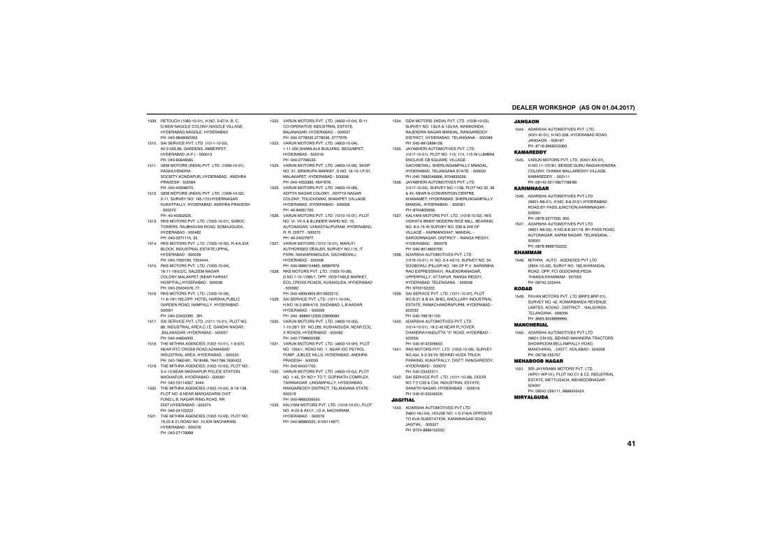
����������� �������������������
������ ��' �������������"�%�+���&���������.��������������������������������&���������������&����!����#'�'�% %"�
�$�#�
���������������������� ��������� ���* �"�$�$���������������&������������&��� ��������$����"��!����%$%�%$%$�
�$���
��������� ����������������� ���#���������������������������,�������������&��������������������$���'���!������$�%����
�$���
��������� ����������������� ���#����� ��� �������������!��%$��� ������������,�,��������������&�������������������$���� ��!�����"� $ $�
�$� �
�,����������������� ���"�����������&���.�������)&�������������)������������&�����$���' ��!����""����$��""�
�$�"�
�,����������������� ���"����� ������+������&��,��������������������������������&�����$���"#��!����� ���#"��� ������
�$���
�,����������������� ���"����������%�����#+$+ +�������������������������,���� �����(������������������&�����$���"%��!���� "�"�$�%�����
�$�$�
�,����������������� ���"�����$������%��#�+�# ����������������&�������������������������������&�����$�������!���� "�" "#����"#��
�$�%�
���������������������� ��������������������''���������������������������������������&���������������&�����$���"���!������%������
�$���
������������������ ��� �����������'�%�����������������������/���&��������������������������&������$��� ���!�����%% �'����%�'�''���%���'%��%"�� �
�$�'�
������������������ ��� �����"����������"�����������������������������������������������&�����$���'���!���� "���$%���"����
�$�#�
������������������ ��� ���������'��'��"'���������'���������������������(������&�������������������������������&�����$�������!���� �� �
�$ ��
������������������ ��� �����$�����������#� ���� ������������������������������&�����$����%��!���� ���%###�
�$ ��
��������������������� �%�"���������&����������������������������������&���������������&������$���"���!����"��'�"$�"��'�"%��"���#�#�
�$ �
��������������������� �%�"�������������� �����������&���������&��������������&�����$����%��!���� ��%%$""�
�$ "�
��������������������� �%�"�����%���������"������,��������,����������%�����+(+"�������,�����������&�����$���"%��!�����$$""#$���$��%�%�
�$ ��
��������������������� �%�"�����&����������������������������������������������.,������,���� ��������������&���������&�����$����'��!���%�$$�����
�$ $�
��������������������� ��������������������������������&�������.�������������������������������������������&������������������$�������!��� �� �%���
�$ %�
����������� ��� ��������������������������������������������$��������,������,�������������&.���������&�����$����'��!����##'$���'%���%###�#�#�
�$ ��
�,����������������� ���"�����'�������������+ '$+�������������&������,��������������������,���������������&�����$���% ��!�����#�$�#�$�#���' ���
�$ '�
���������������������� �����������������%� �'"#+�+���������&������&�������������&������$���$#��!�����'''%$� "�#� "'�'�'��
�$ #�
��������������������� �%�"�������������� '+�������� '$��,��������������������5������������&�����$���% ��!������##%���#'�
�$"��
��������������������� �%�"����������������"$�+���������������������������������)�&���������������&�������������������$���""��!����%�$$�����
�$"��
��������������������� �%�"�����)�������������$������!�������������������5�������������������������������&�������������������������������������������$����#��!����#''$ �%$$$�
�$" �
,���������������������� ���'������������������ "����"�+������������������������&������$����%��!����%%#'$$$$��#������'���
�$""�
��������� ����������������� ���#�����"��������������"$+�����"$+��������,�������)����������������������������������������������&�����������������$���'#��!����##� '##� '�
�$"��
)���&������������������������ ����������������������"���������$�������&�������������&��2��������������-�����&.��������������������������������&�����������������������$���" ��!�����%'���%%%%��#���'"$$$%�
�$"$�
)���&������������������������ ��������� ��������������+"%��������" ��"#�������������������������������,�������������&��������������������������������&������$���'���!#���'"$$$%�
�$"%�
,���������������������� ���'����� ����+���������&����������������������&����������'����$�������������� "#��� ���(���������-�,�����������������-���������������������-�������������������&������$����#��!����#���%������
�$"��
��������������������������� ���#�������������� ����"+�$������������"�����&.��� �����������'$�(������������������5�����.�������)���������������������������������������������������&�����������������$����'��!#��"�$ �
�$"'�
���������������������� �������������������&� ����&�"���&�����������������������������������������������������&�����$� �" ��!�����%%�'�����
�$"#�
��������������������������� ��������������'� ��$������(����������������������:5:����������&�����$����$��!����'�� " %%""�
�$���
�,����������������� ���"�����#�������������"���$�$�""+�#��&�������������,����,�����,�,��������������!������������������&�����$���� ��!���� "�" "���
�$���
���������������������� ���������'���������� ��""����"����������������������������������������&������$����'��!����#�"""�%"���
�$� �
��������
������������������������� �%��������������������$� �%+�����������,�����&��������,���������������)����������$�$" ���!'� ��'''%�$ �
�$�"�
�� ��
��������������������������� ,����,����������""#�������&��������)���������$�%�%���!'��%�##$# ""#"�
�$���
���������
��������������������� ,5���,5���������������+%���&�����!������������������������������������������������,������������$�"�����!�'�� �$$��%%+��+''+##�
�$�$�
����� ����
������������������������� �%����%����������'�%�"�"+�������&�������&�������)�������,������������$�$�����!�'�'� �� ����"���
�$�%�
������������������������� �%����%��$������'�%�"��+�'��&����������������������,�������������������������$�$�����!�'�'�'''%�$ �
�$���
�������
������3����3����������������� %������� �������������' �.�����������������(�����.��������������,��������$����"��!�'�� � ����
�$�'�
����
�������������������� &�� �&������������������� ��,���&����������������������,���������������-����������������������$�' �%��!'%'"�'��''####$�
�$�#�
�� �������
������������������������� �%�������"���&����������������������.���&�����������������������������������������&�����$�� �'��!�'�"%� $$�$��
�$$��
������� ����
����)����������������������� .����.������������������� ����������������������������������&&��������$�������!�'$� � $%�����#'%%$�$� ��
�$$��
����������
����
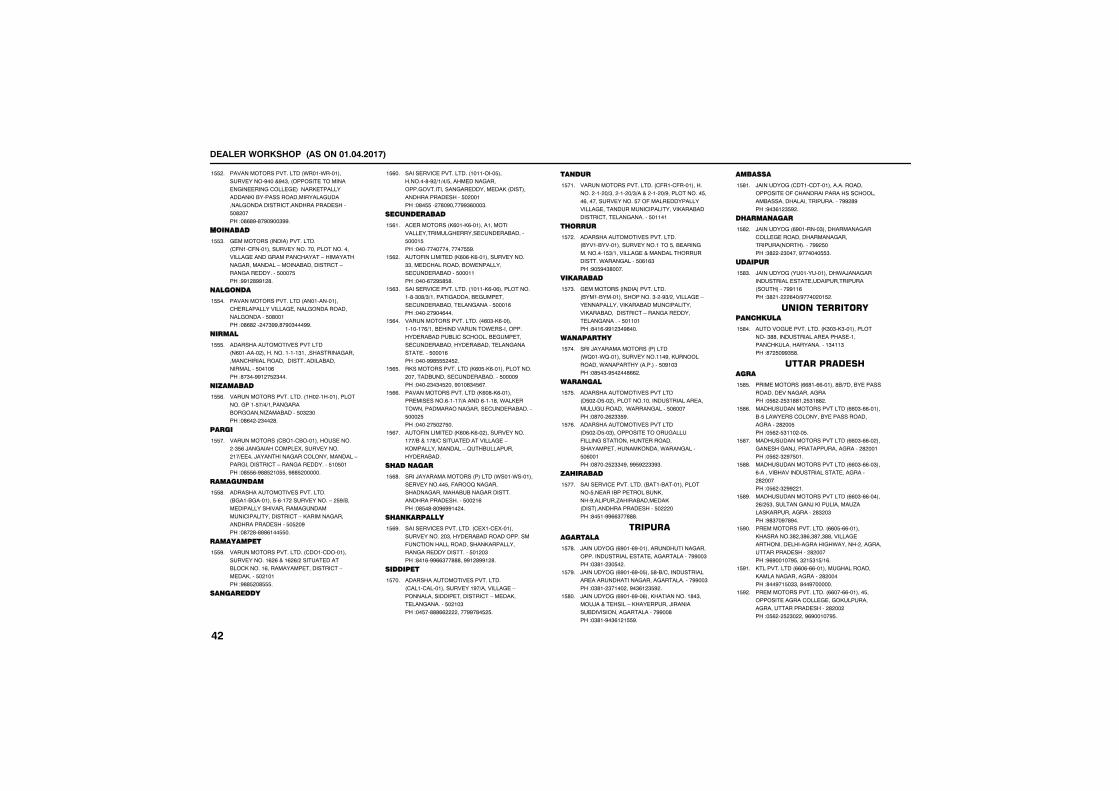
����������� �������������������
�������������������� .����.����������������#����#�"�� ��������������������������������������,�������������,��&��������������������������������������������������������$�' ����!�'%'#�'�#�#��"##�
�$$ �
��� ����
��������� ����������������� �(����(���������������������������������������������������������-����������������������-�����&������������-����������������$����$��!##� '##� '�
�$$"�
��� ��
�������������������� ��������������������������������������������������������$�'�����!�'%' �� ��"##�'�#�"���##�
�$$��
�����
������������������������� �%������� �������������"����������������������������������������������&�������������$����%��!'�"��##� �$ "���
�$$$�
��������
��������������������� �� ��������������������$�+�+����������&�������/���&�����$�" "���!�'%� � "�� '�
�$$%�
�����
����������� �&���&������������� �"$%�)������������5������������ ��+�����)��������������������������-�����������������-����������������$��$����!�'$$%�#''$ ��$$��#''$ ������
�$$��
������ ���
��������������������������� &����&��������$�%��� �����������-� $#+&�����������������������������������������������������-�,���������������������������$�$ �#��!�'� '�'''%���$$��
�$$'�
���������
��������������������� �����������������������% %����% %+ �������������&��,�����%�����������������������-�����,����$� �����!#''$ �'$$$�
�$$#�
�� �������
���������������������� ��������$��������'�# +�+�+$������������������������������������������,� ����������������������$� �����!�'�$$�� �'�#����##"%���"�
�$%��
���� �������
���������� ,%���,%������������������������������������������&������$����$��!�����������������$$#�
�$%��
���(����������� ,%�%�,%����������������""��������������&.������������������&�����$�������!����%� #$'$'�
�$% �
���������������������� �����,%��%������������'�"�'+"+��������������&������������������&����������������$����%��!���� �#��%���
�$%"�
��������������������� �%�"�,%�������������%+���&������������.����������������&�����&���������&������������������&���������&�����������������������$����%��!����##'$$$ �$ �
�$%��
�,���������������� ,%�$�,%������������� �������&��������������&������$����#��!���� "�"�$ ���#���'"�$%��
�$%$�
�������������������� ,%�'�,%�����������������%�����+������%����'��.��,����.���������������������������&������$��� $��!���� �$� �$��
�$%%�
���(����������� ,%�%�,%�� ����������������+&�����'+����������������������-�,���������������-�2��&��������������&���
�$%��
����� ����
����)������������� ������� .����.������������������$��(��2���������������������&�&������������������������������$�� �%��!�'$�'�'�#%##�� ��
�$%'�
��� ��������
����������������������� ��5����5���������������� �"�������&��������������(�������������������,������������������������������$�� �"��!'��%�##%%"��'''��##� '##� '�
�$%#�
�������
��������������������������� ����������������������#�+�����������-����������������������������-�����,���������������$� ��"��!��$��'''%% ����##�'�$ $�
�$���
� ���
��������������������� �(����(������������ ��� �+"�� ��� �+"+���� ��� �+#����������$���%����������������$��(�����������������������������������������������,���&��������������������������$�����
�$���
�����
��������������������������� &����&���������������������$��&���������������$"+���������������������������������.����������$�%�%"��!#�$#�"'����
�$� �
���������
��������� ����������������� &����&��������������"� �#"+ ����������-���������������,���&������������������,���&��������������-����������������������������$�������!'��%�##� "�#'���
�$�"�
�� ������
����)������������� ������� .2���.2������������������#��,����������.��������� ��������$�#��"��!�'$�"�#$� ��'%% �
�$���
���� ���
������������������������� �$� ��$�� �������������������������������������������.�����������$�%�����!�'��� % ""$#�
�$�$�
������������������������� �$� ��$��"��������������������(����������������������������������������,�����.����������$�%�����!�'��� $ ""�#��##$# ""#"�
�$�%�
���������
���������������������� &����&��������������$�������&��������&��,����#��������/����&�������,� ���������������������$� ���!'�$��##%%"��'''�
�$���
��������������
)��������� %#���%#���������������������������������������������������������##��"��!�"'�� "�$� �
�$�'�
)��������� %#���%#��$���$'�&+������������������������������������������������##��"��!�"'�� "���� ��#�"%� "$# �
�$�#�
)��������� %#���%#��%���,����������'�"����)����������-�,���������)���������&���������������������##��'��!�"'��#�"%� �$$#�
�$'��
�������
)��������� �������������������������������(�����������������������&�������������������������## '#��!#�"%� "$# �
�$'��
������ ����
)��������� %#�������"��������������������������������������������� ���������## $���!"' � "�����#������$$"�
�$' �
�������
)��������� ��������������.�)����������������������������������������� ��������##��%��!"' �� %��+#���� ��$ �
�$'"�
��������������� ������
������������������� ,"�"�,"�������������"''������������������������������,����������������"���"��!'� $�##"$'�
�$'��
������������ ����
����������� %%'��%%������'&+����&������������������������������!�$% � $"�''�� $"�'' �
�$'$�
����������������������� %%�"�%%������&�$���.�����������&�������������������� ' ��$��!�$% �$"��� ��$�
�$'%�
����������������������� %%�"�%%�� ������������)��������������������� ' �����!�$% �" #�$���
�$'��
����������������������� %%�"�%%��"���%�������&���������������������������� ' �����!�$% �" ## ��
�$''�
����������������������� %%�"�%%������ %+ $"������������)�,������������/�����,�������������� '" �"��!#'"��#�'#��
�$'#�
�������������������� %%�$�%%������,�������"' �"'%�"'��"''�����������������������������.������ ����������������������� ' �����!#%#�����#$��" �$"�$+�%�
�$#��
,������������ %%�%�%%�����������������,������������������� ' �����!'��#��$�""��'��#�������
�$#��
�������������������� %%���%%�������$�����������������������,����������������������������� ' �� ��!�$% � $ "� ��#%#�����#$�
�$# �
����
����������� �������������������
,������������ %%�%�%%�� ���,���������������.���)�����.������������������������������� ' �����!�$% ��������
�$#"�
,������������� %%�%�%%��"�����+" ��&�����)��&�����&�����.,���������� ' �����!�$% �'��#��$�#����%������%�
�$#��
���������
,�������������� '������"���,������������,&�������� �# �%��!���'��#"���
�$#$�
�����.��������������� � ������'�������������������&������������,���������,&������,&���������������&��,��������� �������� �� ��! ��$���
�$#%�
�������
������������ ��/�� &%'��&%�� ������������"'���"#��������������������������������������������!##����"�$ ��#$' � "$'%�
�$#��
���������� ������� &%���&%�����������&����������������������������� � �����!�$���$ �����
�$#'�
���������
�������������� #��� #������ %����������������������������&����� �������!�$" � %"%"���� �"%"%��
�$##�
��������������� #�"� #��������������������������������������)�������&����� �������!�$" �#'"'����"$�
�%���
��������������� #�"� #��"���$ +"%����,�����)�������&����� �����
�%���
�����
,����������� �"� ����������������-���" ��������������������,����������������������)������!��������������� ���#��!�$"%'� ����$�
�%� �
�������
,������������ 2)���2)����������������������������,���������������������� �% ����!# "$"$'����
�%�"�
��������
���������� ,$���,$��������&�����������������/�������� �%�����!�$�% �" $"'��
�%���
���������� ,$���,$��"�����������-�&��������������������-�����������������-��/����������������������� �%�"'��!#'"'�� # "�
�%�$�
������
,��������������������� &�&��&�&������,��������$"���$"���$" ��$""�����������������������������������&���������������-�&������������������������ �" ����!�'#$#'�����
�%�%�
��������
����������� �"���$/��$������,�.�����&��������������������� ��'����!�'%��'%�%��
�%���
��������������
&�������.�������������������� �"�$��������������!�$����%���,������&����&�������&,�������������������������������&�,���,������&�����,�.��� %� ���!#'"'��$#%���#% '"������
�%�'�
������
���������� ,$���&��� ����������������)����������&�������� �������!#'"'�� #���
�%�#�
���������
������������������������ 5&���5&�����������&������������������������������&������������������������ �� ����!�$ %"� " ����
�%���
�� ��
����������������� '�"�,���"���,���,���������.���������&������� �������!#'"#� #'%'�
�%���
������ ��
&�������.�������������������� �"�$�%���"����������������������,�.��������.�&���)��&���&��,���� $�����!#'"'��$#%��
�%� �
�����
��)����������������������� �'�"�����������������������������������������,��������������������������,������&�������� $�%����!#'"�$'���#�
�%�"�
��������
���������� �������� $%� �$%������������������&���������� �"�����!�$'��$$#�#��
�%���
���������� �������� $%� �$%��"�������&���&��������������5�����������&����������&������������������������ �"�� ��!�$'���$'�� $$�# �
�%�$�
,��������������������� $%���$%���������,�����������������������&��,���)��&���������� �"$� ��!�$'���'�����$�%���'�
�%�%�
����
�����.��������������� � ���%&��$�����������������������������)������&������� ���� ��!�$$� � '% #��
�%���
������
������������������������ '�� ����� ����������������&������ ������!#'"'"%�%% �
�%�'�
��� �
��)����������������������� �'�"�%���"�����������(��������������������������������������������������&�)������ �%�����!��"� � �%����
�%�#�
��������
�,��,�������&��������������� &����&����������'����������������&��2������������������������������������������������������&������������������-����������� ��# ���!�'#$%����$��� ��'����#�
�% ��
�����
���������� �������� $%� ��(��������������� ��&����������������.����&�����������������������" ��"��!#'"�'#�'�%�
�% ��
���� ������
�,���������� �$'���$�� ���,�������� %�����������������&���������,������������&�����������!�$�" � "$����
�% �
���� ������
�������������� � ����$�� ���������$%�����������������,&������������������������������&�������������������������� �"�����!#�$'��'$�%�
�% "�
��� �����
�,��,�������&��������������� 5����5��������/����������������.�������������� &������������� � �� ��! $�����
�% ��
���� �
������������&����� 5,���5,���������������������������//�(����������.������&������ �������!�$�� $��� �
�% $�
�����
�����.��������������� �%����%�������������������������������"������������������������������������������������������������������������ �������!�$$%'�3���$'��%� �
�% %�
���
�������������������������������� 5����5��������� ���������������������� ��� $��!#'"��#�'#��
�% ��
�����
,������������ %����%���������,,��&����,��������������.���� �%�����!�$%''� $�� #�
�% '�
��������
�����.��������������� � ���($�� �������������)�����,�.������(��/�&�������������������� ������!�$ �'�"�#"""�
�% #�
�����������
����������������� '�"�����������,����,������(����,�&����� �#% $��!#'"#� #'%'�
�%"��
��������
,����������� &�2��&�2������,���������"�+�"�����������)�������������,����������(����&�������������-���������������������� '"�����!'��#��$�%"�
�%"��
�������
,�������������� '������������� ���������((�����,�����������(��������� � %����!���'��#"���
�%" �
��������
������������������������������ �(����(��������%������������,�)������������)��,����������������� ��(��/�&����� '" �"��!�$%� �#%#���"�"$�
�%""�
��������
�,��,�������&��������������� 5����5�������)���,���������������������������������������������)�������� �� "$��!#'#��%#" #�
�%"��
���������
����������&����� $#'"�$#�������������&���������&"�����������������/��&����!####���'����###��#"� �
�%"$�
����
����������� �������������������
,�������&��������������� $#'��$#��������&��,�������������������������/��&����! �����"��# ��� % ���
�%"%�
�������������,�� ������� $#� �$#����������+#�������������������������"����������������/��&����� �������!�� �� ��%�"��"����� ���%��#���#���#���
�%"��
�������������� $#���$#�������" ���,����������������������/��&����� �������!�� ���"�$�' ���"��������"���%����"� �'�
�%"'�
��������� $#���$#�� ����������%���������������������������/��&����� ���� ��!�� ��#���"''"""�##���%%%���
�%"#�
�������.����������������� $#�$�$#��������������#%����)������������������������������������������/��&���������������/��&����������� �������!�$�"" %$%��
�%���
���������
��������&��������������� '��"�,���"����,&,������������������&�����&�/������/������� """�����!�$� � "%��"%�
�%���
� ��
�����.��������������� � ���(/������)��,����������������������������&��������������������������������� �������! ""$#'�
�%� �
��������
�����.��������������� � ���� ���������������� ���������������������,���� �������� �"�� ��! �� %���"�#�#�%�
�%�"�
�����.��������������� � ���� ��%����������&���������������������������������,������ �"�� ��!�$$��"�#�#�%�
�%���
�����.��������������� � � �� ������������������������#�����������,������� �" �#��!# "$�������
�%�$�
������� ���
�������������� � ���� ������%"�������������������������������������������� ��"�%��!�� ���$�"�"#�����#����� $%�$%��� $%##'��'$��"�# $#��
�%�%�
��������
,�������� 2���2���������������������,��������������������� ��"����!���'��#"����# "$��"��"�
�%���
�����
��������� %����%���������������������������������������������������������������/��&����� �$�����!1�� "�" �"�
�%�'�
�����
���������������������� 2����2�����������,����)�����,�.������������� �������!#�# #���#%�
�%�#�
���������������������� 2����2���������������%�#����%�$�������&�5��������&�����������������,��������.�������������������������� �������!�%����$'$��
�%$��
������
���������� ������� &%�������"����������������������������������������� �������!##���"$$���
�%$��
����������
&�������.��������������������� 5����5�������,���������(��,�������,�.���������������)������������������������ �'����!�%�"'�#� �$ %#%����#% '"��'���
�%$ �
��� ���
,����,��)�����&��������������� %���%������,�������,&����,���������������� �����!#$$�#$�� %�
�%$"�
��� ��
���������&����� %����%�������"% +��������������������������)������� '������!""�'���
�%$��
�� ���
,�������������� '�������$������������"�����,&�������,�����)��� �#� $��!���'��#"���
�%$$�
�� ���
,�������������� '��� '������#+�%��&���)�&�������������������,�������� �'�� ��!�$� � #��$#�
�%$%�
,�������������� '��� '�� �����������,����������������������,�������� �'�����!�$� ����"#��
�%$��
����������������� '�"� '������'�+$�����)���&��.,�������������,�������� �'��"��!�$� �"#'''""�
�%$'�
����������������� '�"� '�� ������%�������������,�������������������,�������� �'� ��!�$� � %#��$%�
�%$#�
��&�������������� '�%� '��������&���(�/�����/��,�������� �'�� ��!�$� � ��%%��
�%%��
����������������� '�"� '��$���''��&��,����(������������(�/�����)��,�������� �'�����!�$� �"�%�%���
�%%��
��&�������������� '�%� '��$����+%�����&��,�����������.�����,����,����������,�������� �'�����!���'�"�"%$�
�%% �
���������
��������������� �����������������������������������������������)�������,�����&���� �������!##�# � ��"���#'"'����% �
�%%"�
������
�������������������� &)/��&)/�������������������������,���.����������������-�)��������.����,���.��������������-����������������������� '"� ��!��$$���%�%�
�%%��
���������
������������������������ . ����"�� �����������%%������������.������������,������,������ � �����! % $'"+�+$�
�%%$�
�������
���������&����� %����%)��"���)���������������������������� '������!#�$��#%��$�
�%%%�
���� �
,���������(�� �"'���"�������%+"��&���������������&������������������,�.��!�$ � ��""%#�
�%%��
������������������������ �"����"����������,����(��/�&������������������,�.��� ���$��!�$ �"�$�#���"�$�# ��"�$�������'�����%#�
�%%'�
������������������������ �"����"�� �����������������������&�/�������,�.��� %��%��!�$ �"�#' $�����'�����%"�
�%%#�
������������������������ �"����"��������"���������,����������)�����,�.��� %� ���!�$ 3�3���"��%+���+��'����'�����%��
�%���
&�������.�������������������� �"�$��"��������+����%����,�����������������������,�.��� %� ��!�$ � �"#$���
�%���
,����������� �"� ��"�� ����������������������������(��/�&�����������,�.��� ���$��!�$ �"�$"���
�%� �
,����������� �"� ��"��"����������������������(��/�&�����������,�.����������������� %��%��!�$ � "���'"�'%�
�%�"�
,����������� �"� ��"������&���������,�����������������������,�����,���������������&�������,�.��� %��$��!##�'�$� �
�%���
��������������������������� �"�%��"���������%�����������������,��������������,�.��,��������������,�.��� %�� ��!##�'���'���
�%�$�
��������������������������� �"�%��"��"�������������������������������������,�.��� %��$��!#'"#��$��%�
�%�%�
&�������.�������������������� �"�$��"�� ����������������������������������������,�.��� %� ���!#'"'��$#%��
�%���
�������������������������� �"�%��"��������������+$�������,��������������������,���������������������,�.����������������� %�����!�$ ��$ ��#�"%%%���##�'��� #��
�%�'�
&�������.�������������������� �"�$��"��$����������%'��&���������)��&��������������,�.���� %�����!���$#��' $��#'"'��$# #�
�%�#�
������ �
���������������������� &���&�������,��������������������.������������������)��������������� �������!�%��%#%%%%�
�%'��
��������� �
�����.��������������� ����������������������������5������������������������������������)���)�������������)���)������������������ �""�"��!�$$ "����$'�"��"�
�%'��
����������
���������������������� �����������������(����(��.��������������������������&��� �������� %� �"��!�$'%�� $"'#"�
�%' �
�����
���������&����� %�������� �������������������.,����������������&������������������� '������!$ '�� ��"����#�$��#%��$�
�%'"�
��� ����
,������������ %�������� ����,����������������� �$�����!# "$ $'����
�%'��
����
����������� �������������������
����������
��������������������������� &���&�������,��������" %+������" ��������������������������-������&�������������-����,�.������������������ ������!##�'����'��
�%'$�
������
������������������� '���'������%'������������)��������������������� ��,���������%����������� '������!�$%$� �%"��"+�% #�����
�%'%�
�����
���2���������������� �''���'�����������!$��+�������)�,������������������!#$%'�����'�
�%'��
��)����������������������� �'�"��'������ �������������������������)�������������� $������!�� �� ��'�"'�
�%''�
��)����������������������� �'�"��'�� ������������������������������������������������������� $���"��!� �� ��'�"��"$�
�%'#�
����������� �'� ��'������"$����������,��&�����&�������������������� $������!�� ���� ���%��%�'' #�
�%#��
����������� �'� ��'��"�������������������������������� $������!�� ���� % �'�� %$'��'���#�����
�%#��
��)������������������������ �'�"��'��$����������,������������������������������������������������� $��� ��!#$%'���"�"��#'"�$'���#�
�%# �
��)��������������� �������� �'�"��'��%�������,���,��������������)�����������������,��������������� �������� $��� ��!�� �� $�$�'��� $�$�#��
�%#"�
���������������&��������������� �'����'��������������-�&������,�������������������(��������������������������������������� $��� ��!��$%�������
�%#��
��������
���������� %,� �%,�����������,�������������������/��������������������� "������!#�$�$��#%��
�%#$�
��� ����
������(������������������ $#�"����� ��������������������������)����������������������$'������������� �� ����!�� " �� ������# �#���$$��
�%#%�
��� ������ �
&�������.�������������������� &.���&.�������,������������$'�����������������������������������������������)�����,�.������������������������ �"�$��!�$��#�$#%%�
�%#��
��������
�,��,�������&��������������� &����&�����������������$��,��������&��� �������� �������!�$#�� �'$���� �'�'''�� �'�� �
�%#'�
�,��,�������&��������������� &����&���"���$��,�����������������&����� �������!# �#�������
�%##�
�,��,�������&��������������� &����&�������,��������$%#�$������������-�,�)�������,��������������&�������������������� �������!�'#$%����$�
�����
�������� ����
����������� #�"�#���������$'��� ��,��������&�����������������������������������/�((���������� $������!#�� ��"���
�����
������
�����.��������������� 2����2��������������,��������������������������������������� � �$��!�$$��� ����'�
��� �
���
(��������,��������������������������� ��'$������������"��������%"����������&���������!� ���$'����+"��
���"�
),������� ��'������������ $�������#���������������&���������������!�� ����$ ����
�����
������(���������������� ��'������ ������ $�������%"��������!�� �� �� %���� �
���$�
������(���������������� ��'����������(�'���#�������'�������!�� ��$"" �
���%�
(������������������������ ���"�����������"#����������������� ��"����!�� ������"����"���
�����
�������������� ��� �����������'+#�������������������� ��"����!�� ������#���� �#�"��" � $ #����� $"�$"$�� $"# #��� $$%%%"�
���'�
�������������� ��� ����� ��������������������������������������� ��"����!�� �������#���� �#�"��" ��
���#�
������(������������������ $#�"�����"�����"#������������������� ��"����!#'�'%%������#'��$������
�����
���������������� ��������� ���&�� ����&�� $��������-�$����������������������� ��"����!''���'$$" ��#'�'%������
�����
��������������������� ���%���������)�����������%"����������������������&���������� �������� ��"����!�� ����$'%�$�
��� �
���
��&�������������� '�%����� ���,����������������� '$�����!#"�� �#"�"�
���"�
�������
���������� �������� �������������&�����������������&����������� % �����!#'"�'#�'�%�
�����
���������
��������������� #�"��,�� ���������,���������)������������&�������������������� "������!#'"'��$�$��
���$�
���� ���
���������� �������� ��������������,���������%'����������������-�,�����������������������-�����&��������������������������-���������������������&������ % � ���!�$''��#'"�'#�'�%��## ����� ��
���%�
�����������
,����������� �"� ����$�����������$$����������������,��.������)����������������&���������� #"�"��!�$" �#"����������$�
�����
��� ����
������������������������ 5����5�������&������,����������������������� ���"���!�$#��� ' ��"�
���'�
������
�,��,�������&��������������� &����%��� ���)���������������������������������� ��#����!�$#$�# �#��$ $�
���#�
����
������������������� &5,��&5,����������������������������,������������������������������������������������������������������� �������� '� ����!#'"� �� $��
�� ��
������ ���
������������&��������������� � � �� �����������&������������&��������������������� �������!���"� "#$����
�� ��
���������
(��������,����������� �#'���#��������������+�&+ ��"����������������������������������&�&�������������/��&��� ��������!#$%�'%'����
�� �
(������������������������ �'�$��#������� +%�������������������������������&�&������/��&���������#$��!�� ��������#+�� +�"%�
�� "�
������(������������������ $#�"��#�����������������������&�&���������������������������&����.,�����&�&����� �������!�� ����� �+���� �
�� ��
�������.����������������� �'�#��#��"��� '+�+���������������&�&����������������������������/��&������������������� �������! ���$""����#'��� �"""�
�� $�
���,����������������&������������� �''���#�� ����������$�#���$����.�/���&������������������������������������&�&������������/��&���������� ����$��!#'�" #'�� �#'�'�###���
�� %�
�������
�,��,�������&��������������� &&���&&��������������"�"���������)����,�(������������&������&�����������&������������������� ��"� ��!�$# �" " ����
�� ��
�� ����
���������������������� .����.���������������)�&���������&��,�����,�.���������&�&�������������� �� ����!�$'$�� ������
�� '�
��������
���������������������� ��5����5����������������)���������&����� ��� ���!#�$��'"��%�
�� #�
�������� ���
������������������������ . ���. ��������������������� �����)��������� � �����!�$'� � �"""�� ""#�#�
��"��
������
���������������&��������������� 5)���5)������,����,������������3��.����������������,��������������������������������� ����%��!�"#'� ��$���� ��$� ��"�
��"��
����
����������� �������������������
����������
������������������������������� 5���5������ $�'��,�����������������&���������(������������� ��&���������������,�&���������!�(��/�&������������������ '" �"��!#�'"��#�'#$�1��#�
��" �
������
���������������������� 2����%��� ������,�.������������� �����������)��������������������� %������!#�%� '�����
��""�
���� ���
,����,��)�����&��������������� ���������������������������������������������,�.���.������$%� (��/�&���&������������������� '�����!�$"% � ��%���� �����
��"��
����������
�,��,�������&��������������� ,���,������ �,��������&�������������)�����,����&������&����)� ���������)�����,���.�������������&������������������ ��%����!�'#$#'�$�#�
��"$�
� ������
,������������� �"� ����%��������&������,�.������������������������������.�������$�3��������������������!����&�������� #�����!#�$��""'"'�
��"%�
� �
������.����������������� �"' �,����������������%���,���������,�.�&������������������������������!�$�$� '"�%��� '"� �'�
��"��
��&������ '�%�,��������������������&������,���������,�.���.�������������������� �#'����!$�$"�#'"#'������ � ��$�
��"'�
���� ���
����������������� '�'��'��������� ��%$"+�� �����&����������������!�$� � $����%#��#��$ �"%���
��"#�
��������&��������������� '��"�'�������&�"'+ ����������)������������������������ ������!�$� � "%��"%�
�����
������������������������ '�� �'�������������������������������������� ������!�$� � $�#�%'�� $�#�%#�
�����
������������������������ '�� �'���"�������)���� ������'��������������������������������)�����&����������� �������� ��� ��!#'"'"%�%% �
��� �
������� ��������
������������������������ )%�"��2��������.���&�.����)���,�����)���������������������������� %"%����!#%"#��%'#$�
���"�
���������
������������������������ )%�"�'���$���,��,�������&����.������ %"%� ��!## ���'' �
�����
������
�,��,�������&���� �������������������� ��������������,��������#%+ ����������-�&�����������������������-�&�/�����������,������� % �����!#'"� �' $%�
���$�
��������
�,��,�������&����� �������������������� ���"��(��"�������,��������������������.����������,������ % $ "��!�$#%$3�3 "��""�
���%�
�������
���������� $����$�������#�'+ ������������������������������������������!��"$� ��$""���"���" �
�����
(����������.������������� $��%�$�������,��������',������&�.�������������������������������� �'�����!�� #��� ��'���
���'�
�������������� $�� �$��������"�+����,��������������������������������� �'�����!��"$� $"�#$$��% �$�#��% %�#��
���#�
�������������� $�� �$��� ��� $�+ ����������������������)���������)���,����������������������� �'�����!��"$� � �"� +�"+���
��$��
��������
�������������� $�� �����"�������������������������(���������������.������"�� '��!��"� � $�$� �
��$��
������ �
������������������������ )%�"�)%��������������)�������������$��,�����������������.������ %"�"#��!#%"#��%'#$�
��$ �
������������������������ )%�"�)%�� ���,�����������������&���������������������.������ %"�"#��!#%"#��%'#$�
��$"�
��������
��,��&��������&����� ������� %�� �%���������$+%�����������������������.����� �#�����!��""��"��%�%��" ��" �
��$��
��������
�,��,�������&����� �������������������� ���"����� ���&�/���������,��������� ����"��!# �#��'� $�
��$$�
������
�,��,�������&����� �������������������� 5����5��������������!�,�����������,��� ����&)����"������(�������������������&��������,�����������������������������,������ % "�'��!'�#����'�"�
��$%�
�����
��,��&��������&����� ������� %�� � ��� ��������� "���"�������������������������&�����,��.��������������� ���.����������,������ �#�����!'�$$##'��$�## ���'' �
��$��
���������
������������������������ )%�"�����"�������������������������������������������������� % $����!#%"#��%'#$�
��$'�
�� ����
������������������������ �5����5����������������������������(�����������,����������������� ������,������� %"%�$��!�$#% � "� $��
��$#�
���������
(����������.����� ��������������%������5����)�������������,��������������������������,������ �# ����!��"$� �" "'��
��%��
�����
��,��&��������&����� ������� ��� ������"���,���������������,�����.������������������&��,����,�������������.����� ��%%���!��"" �" %�%���� %����% �%�
��%��
�����������
��������� �,����,����������&����&��������������������������� �%�����!�"%�� ""��'�
��% �
��������
�,��,�������&����� �������������������� ���"���������,����&����������������������������������������� %"�$"��!�$#��� �� �"�
��%"�
������ �
�,��,�������&����� �������������������� ������������������� '+$����� '+%�,�������������������)��������������������������,������� % ��$��!'�# ���"�$�
��%��
��� ����
��,��&��������&����� ��������������������������������������������������������������������������� �%�����!�"�%� ��$��� ��$� ��"�
��%$�
����
���������� $�������� ����������$����������'��������������.�������� �#�����!��"�%� ""����
��%%�
���������������������
����������.�������������� &/��&/������&���������������&���������&����������,��������������������������.����&����������"%� ���!�"$%��#'��%""""'�
��%��
��� ��
&��,��������������� (%���(%��������������������� �������������""����!"��� "���"�+"�+ "�"#�'��##" ��#� $�
��%'�
���������
&��,��������������� �"����)�� ���&,������� ������������������"���&������������������������&�������� �����!"�' � %�"���
��%#�
�� ����
&�����������&���������� �����%2�� �����������$%��,������"�����������/�����+��&��,���� .&����� �����!"� � � $%�%%�
�����
������
����
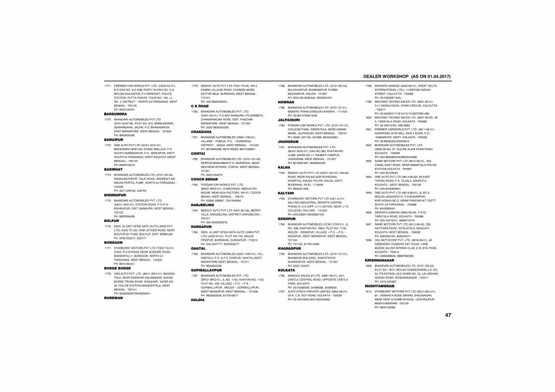
����������� �������������������
������������.�������������� 5/�"�5/�����������������$� ���������������������$�"����/��,��,���������&��������������������!���������,������/�������%��)������������������-����� ������������.����&������������ $��!'� �� ����
�����
������ ���
&�����������&������������� �����&).��$����������%����&�������������.�������)������������&�.�����������������������.����&��������� �%$���!##""�$$$"#�
��� �
��������
��������������� ������������������������,������,���������,�����������&���������������&�������������������� ������������.����,�,���� .����&��������������$��!'$'���'��"�
���"�
�������
&�����������&���������� 5��������"������������������,�������&���������������������������������� ����������������"� '��!" ��� �#�# �� �#�#��
�����
���� ����
&�����������&��������������� ����������������������������1�����&�������������!�&��,�����.����&��������� � ��!##""�$$$"#�
���$�
�����
�.��� �������(���������������,������������ ��� �����"���,�&��)���&�����������&�����&��������&����������!�&��&����!"�%"� $ $���� $ ����
���%�
� ��
����&������������������ �2� ��2������"�%+�������&�����������)�����������&�,���������&���������� ������������.����&����������" "$��!#'���#$�$��
�����
�����������
����������������� &����&��������������������������,����,�����������&�����&���������,��������,������.������� �������������������������.����&����������������!'""$�$�"$�+'�� '"�����
���'�
������
&��,��������������� �"����"��"����� ����������������������������������������������&���.����.����&����������"�����!�""�##" ��#�$��
���#�
�������
&�����������&��������������� ���������������!����&��,�������!���&�����������,�������������������������������.����&��������� � $ ��!" �##""�$$$"#�
��'��
��������
&�����������&����� �������������������-�������������-���,��������������-��������.����&������������ ��!#��"#��"%'��#%���"$"�"��#%���%#����
��'��
� ��
&�����������&���������� ���������"����������&����&����������������������������&��������������.����&��������� ������!" �� $�$� �
��' �
���������
����������.�������������� &./��&./��������,��,�������,����&�/�������������(���������"������&�����.����&����������"%�����!�"$' � $'$%�����"���$$#��
��'"�
�������� �
&��,��������������� �"���%���$�������������������)��������������������)�����������"������!"$��# ""$"#$�#�
��'��
��������
�.��� �������(���������������,������������ ��� �����������������"�����/��(��������&���.�����������������" �"��!"�"� $�������# ""$�� ���
��'$�
�����
&�����������&����� �����������������������������������������������������.�������������.����&��������� � ����!##""�$$$"#�
��'%�
������������
&�����������&��������������� &�2��&�2������)��������"��,������������"����������"'����������1�����1������-����&������������/��-����&���������.��������������.����&���������� �$�%��!##""�$$$"#��'�����'$���
��'��
������
&�����������&���������� �������������&�����������&�&�����������&���������������������� �%$���!" ��'��%�' "����# ""$� � ��
��''�
�����
&�����������&���������� 5����5�������&��,����������)���.�����������"��!""�%%�"�$ '+�'+�%�
��'#�
����������
����������.�������������� 5����5�����������������������������������������������)�����������.����&����������"$�����!�"$%�� $��$$�� $��%%��'#�$$"�# ��
��#��
��������
&�����������&��������������� &����&��������������"'"��,��������)�"#%��.������������)&������������)��������.����&��������� �$����!'��%�'� #���##""�$$$"#�
��#��
��� �
&��,��������������� ./���./������,���������������,�������&�������������������,�������1��!�,�������������&���.���� .�&�������"��#��!##" $��'"�
��# �
����� �
����&������������������ �)����)������,��������������������.����������������������$� ��������������������!�)��������������,������������� "���!�""� $' ��"#+ $' �����
��#"�
�������
&�����������&����� ��������������)�����""'��,����������'%+ ������������#����/��-�,���������������1�����1������-�,�������.��������������.����&���������� ��$���!� ��$���'������ '#�
��#��
���������
&�����������&���������� �������������&�������&���������)����������,���������.����&��������� �"����!" ��$$$"��
��#$�
�����
����������� �������� �%'���%������ $+��������������������������������������,��,�,�����!""� �$%'" %�� ��'%$%'�� �$%'" $�
��#%�
������������������������� �%����%������"������������������,�,����������"#��!""��� �' ���' "�+' +' % �
��#��
��.��0��������� �%�$��%������ ����������������������������������&������������������������������������%#��!""� �'""#�� ����
��#'�
���������������������� �%����%������ �+������������� ���,�����������������������������!""�"� '$"��+�'+�%+� +�$��' � #'��%%�
��##�
���������������������� �%����%�� ����'������������������,�,����������%%��!""� �#�"�$$�� �#�"##"�
�'���
�����������.�������������� �%����%���������������)���������� '�&�����������!�,����������������,�,����������$'��!""�%%�%$$$$+ $ "$#���
�'���
&�����������&��������������� �%�#��%�� ���"���������)������,��������,�,�����������"#��!�""�##�"'$��� +#'"�����'#�
�'� �
������������������� �%� ��%�������%+ ��������������������������,������������������,�,����������%���!�""�"���"��"�
�'�"�
��������������� �%����%�� ���% �������������������������)�������������,�,������.����&�������������$��!�""�'�� '"�����
�'���
��������������� �%����%������)����"����/��)�������������!���������,��������� ���������������������������� ������������������##��!'�� '"�����
�'�$�
��.��0��������� �%�$��%��"����� �+ ����������������,�,����������''��!�""� ���������'$'���$ �"�
�'�%�
������������������� �%� ��%�� ��� "$���������������������������&���������,�,�����.����&������������$#��!'$'��$��'���#$'��$����
�'���
������������������� �%�%��%�������#���&���������������������������&�����������������������&�������&���������,�,�����������$��!""%#�%%#�%���'%#�#' '"�
�'�'�
����� � ����
&�����������&���������� 5�������� �����������'������/���&�������,�)�,�����#������,�.������.������� �������������������,��������������� �����!"�� � "$'��
�'�#�
�����������
����&������������������ &5)��&5)������#+����������&�����������&������������������(������&������������)���������������������� #��!#'"��"� %$�
�'���
����
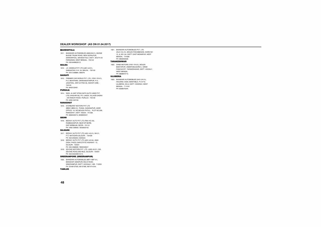
����������� �������������������
����������
&�����������&����� �%�#��%������&�����&���������,��������.�������������,��������������������������� ������������.����&�������������"��!�""�%�##$""�+ �
�'���
�����
)�,��.������������� �'����'��������&����������"�������������" ��"��!"$� � $'''��� %%"�#�
�'� �
�����
������������.�������������� �����������������&���������������,���������������)�������������� ������ ����������� .&������"� "��!'� �� �$��
�'�"�
�������
�.��� �������(���������������,������������ ��� �%.�� ��������,���������������,���������������������������� "��#��!" $ � � ����
�'���
�� ����
����&������������������ &&.��&&.����������!�����������������((������$������/���������3�������"�#����������������!������������ "'��!'$'���� �$��'""%#""����
�'�$�
����
&��,��������������� (%���,��� ������&���������������������������&��&������������"������!"�% � $#�$$�+�# ""$�"�$"�
�'�%�
��������
&��,��������������� �"����"��������"�����������������������������"�� '��!"$"� �� $���%$""$$��
�'���
&��,��������������� �"����"��������������������&������������.����� ��������������"������!"$"� $%'$# ��0##" ��#"���
�'�'�
���,����������������� �"� ��"������ ""�����,������ ���������������������"������!"$"� $�$"�#+� +�"�
�'�#�
�����������������������
&�����������&����� &&���&&�������&�������� �����������������������������������!������.&����� �"��!""�%%�"�$�$��%%�"�$'$��#%�����$���
�' ��
�����
&�����������&��������������� �������������/�������&������.����������)���!����������!����������������.����&��������� �%"%��!##""�$$$"#�
�' ��
����������
����������� �������������/��&����������������&������ �����������������������,��.����������������.����&��������!#'"%'� ����
�' �
��������
&�����������&����� ���� �������������� � ���&�����&������1���!����&��������%�������!�.����.����&�����������"�%��!'""%���"���
�' "�
����
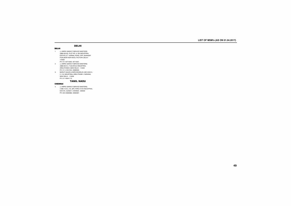
������������ ����������������
�����������
������������ ���������������������������������������������������� ���������������������������������������������� ������������ ����!�����"���������##�������$�##�%�&#''����%�&#''�#�
#�
������������ �����������������������������#���!������������� ����������������������� ���������##��(����$�##�%#)#(#�%��%�)�''���
(�
��� ���������*�����������������#������#�����##������ �������������������������������� ���������##��(����$�##�%''%###��
��
���������������
������������ ��������������������#%�'�#%��#���+������������ ���������� ���������������� ���"������������)����(���$�%%�%�')��))��%�')��)&�
%�
����
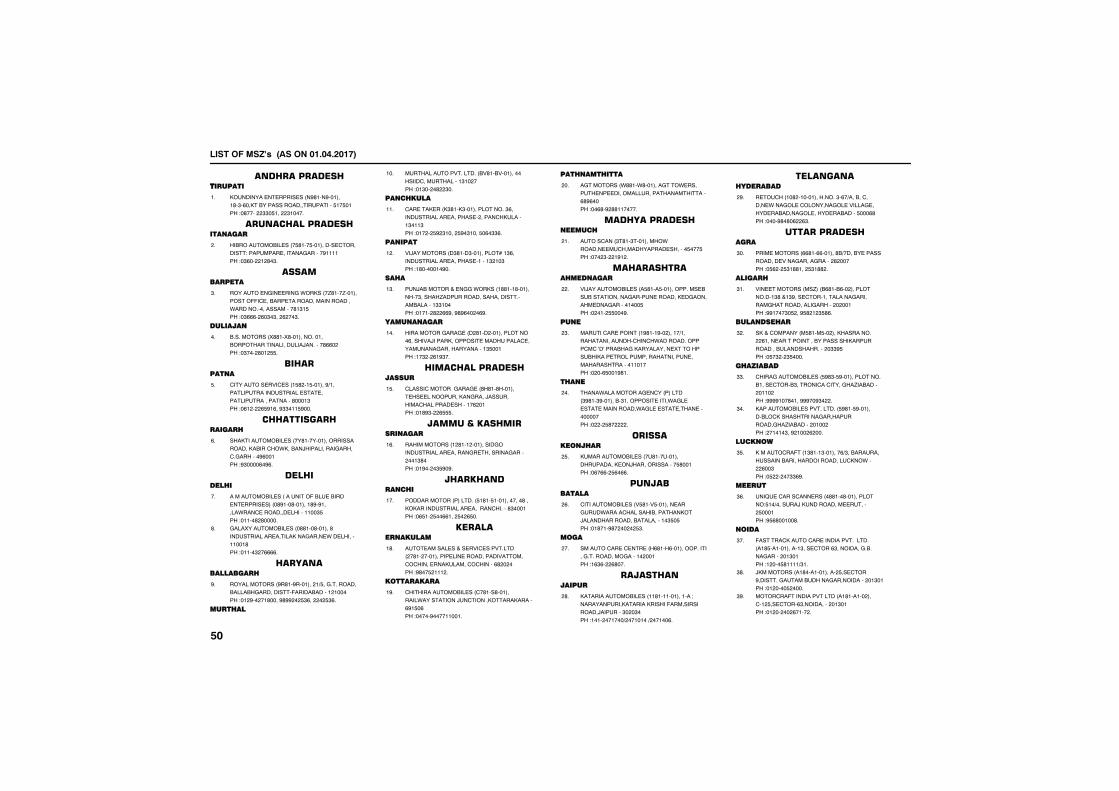
������������������������������
���������������������
��������������� ������������������������������ ���������������������������������������������� �!
�!
�����������������������
���������"���# ����������������� $������ ������"���������%������������������������� �!
�!
�����������
���������%�����%�&��� ���'����'�������� ��((�$��������������"�����������&������!� ��� �"����������������������� ������� �!
�!
�������
�! !�"��� ��(����(���������!�����������������#�����#��)��!���������������� ��������!
!
� ��������
$������� �*�$ ����������������+������#���������� ���#� �����#������������������������������������������ ������!
�!
����� �����������
��������"���# ������������������� ��������������$��&������)����#������%�����$!%������ ���������������� ��!
�!
��� � �
��"����"���# ����������(��#������������ �������������������������#�&���$��������#������������������� �������!
�!
%�#�(�����"���# ��������������������� ���#������#�����%����&��#�������������������� �������!
�!
����������������
����#�"��� �����������������+���%!!���������##���%������� �(���������������� ��������� ������������� �������� ����!
�!
���� ��
"����#������*!�#�!���*����*������ �� ���$��"����#������������������� �����!
��!
���� ����
$����������������������#����!��������� ���#��������� �������$���#������ ������������������������ �������� ���!
��!
�������
*�)���"��� ����������������#�,���������� ���#��������� ������������������� ��� ��!
��!
�� �
���)���"����-��%%�&��� ���������������������� ���'������������ ������� !���"��#��������� ���������������������� �� ��!
��!
�����������
�����"����%���%����������������#����� ��� ��*�)������������ ��"�������#�$����"�����%�����������������������������������!
� !
� ������������������
$#� �$�"�����%���%���������������� #������������%����)� ������"�$��#����� ��������������������������!
��!
������������� ���������
����"�"��� ��������������� ��%������ ���#���������%���� ����%������ ��� ������� �� �����!
��!
������������� �
�������"��������#�!��������������� ��� �������������� ���#����������$��!����� �������������� ������� ����!
��!
�������������
����"� �# �-� �*�$ ��*!#�������������������#�������������*��"��$�$����������#�"��$�$����������� ������ �������!
��!
�����������
$����������"���# ��$���� ����������#&��� �����)��$���������������������������� � �� �������!
��!
��� ���� ����
�%�"��� ��&����&��������%��&� ������������"�##����������"���������� ������ ���������� ��!
��!
������������������
���� $���������������"��&�������"�$��"��������� ����� � ��������� ���������!
��!
������������ ������
*�)������"���# ������������������!�" �� ��� ��������%���������������%�������"���%����� � ��������� ������� �!
��!
���
"�����$������������������������+������������������$���$�&�������!������$"$�.�.�������%������#�����(������ ����������#���"����������������"����� ������ ���������������������!
��!
� ��
����&�#��"�����%�$������#�������������������������� �����&�%#� ��"���������&�%#� �������� ���������������������!
� !
�� ������� ��
��"������"���# ����������������������������)�������� ����������������������� ��!
��!
������������
$������"���# ��*����*�����������%����&�����$��#� ��������������)�#����������������#������ ������������������ �� ���!
��!
����
"�����$���$��������������������!������%!!�������"�%����� �������������������!
��!
���������������
����������"���# �������������������/����������������������� ���(��"� �� �������)������������� ����� ��� ��� �+� ���� �+� �� ��!
��!
�������� �����
���$�����������������!��!�����+������$�����&���%�#�$�#������%�#�*�##�%�������������%�#������������������������ ���� �������!
��!
�����������������
���"�"��� �����������������+��������� ��������*���%�����%������������������������������������!
��!
������
*���"��� ��" '�����������������#����!������-����� $�������#����%�������"%����������#�%�������������������� �����������������!
��!
������ ��
��-�$�"������"����"���������� �����!������������������������ � ������������������#��� ����!���������������������� ��!
��!
� ������
$����%����"���# ����������������#����!����� $�����������$��$����%��'�������������������������� ���������� ��!
��!
�������"���# ��*!�#�!������������������#�$�� �� ������%��������������%��'��������������������� � �������������!
� !
�������
��"����$��(�����������������+�������������� �����������������������#�$���&������������������� �����!
��!
����
���0��$��� $���� �� ���� ��������#������� + �� ���)������������"��������������������������!
��!
����
(� ���$������$����������*!��#�!��������������������� $��������������%!�!���%������������������� ������+��!
��!
)�"�"��� ����� �������������� $������� !�%���"��������%�������������������������� ��� ��!
��!
"���$��(��������*�#����������������$����� $������������������������������� ��������!
��!
� ��
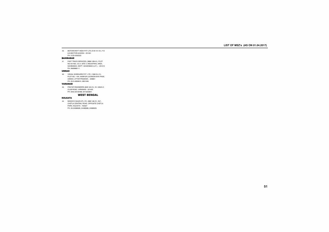
������������������������������
"���$��(��������*�#����������������(���-��� $�����������������������������������!
�!
��� �����
(� ���$�� �*�$ ���"����"��������#����! �+��+�����-� �� �� ������ ���#������ ������������ !�%��'��������!�!�!�����������������������!
�!
�����
*� ��#�&�#� ��*!�#�!��������#�������#����!���� ���������#�$���&������ ����������������� ���������������������������������� �!
�!
��������
�������%��� ��� ���� ������ �������+�����$#���������*����� ���������������� ������� ����� ������ �!
�!
�����������������
"���$�� �# �����#�!�����������������+���$�#��$���#����������� ��$�#����������#�������������������� ��������� �������� ������!
!
� ��
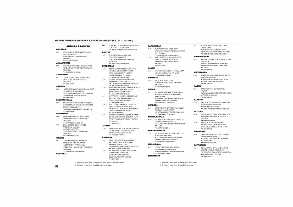
������������������� ������������������������������������
�����������������������
����������������� ��������������������������� ������������������������������������ ����!���"�#�$��%���$� $!$�
!���
���������
������������$#� �����&'������������������������ �&������'������������ $$��!���"�## (��$(! ()�$ �#%�
����
������
&�*�������+� �&&��*�������(�!����� �������������������������� ! ��!���"�# ����(� �
$�,,
����
��� �������������������%$������������(�� ��� ������� ���-�'����������������'���.������������������� �������� �$������"�%#�#�� (!%�
����
� ���� ����
����� ��������������'�� ���#$!��������� ���' ������������'��� & �&������&����&��������������'����������������� ��!!!���"�%�%��%��(%�
���
��������
�� �� ��� �*���������!�$�����������������'������������������ !(��!���"�%�����#�$�)%�����$�(!�
(���
����/���������$�� ���� ��� ������������������������������������������������������������ ������� !(������"�# (��%#�%!!$!#%�
����
������
��/�����������#(������� ������������ ���&��*���-������� ���������������&������ &�������&�/*������������� ������� ����#���"�%#�%##$(( ���#� ��$$��#�
#��
�������
������������������� ������ ������������&���������� ! #�����"�%������#$!�)%%($$��!�%)%����#!�%�
%���
����
��������������%�(��������/�'�'��� & �/�'�'��� & ������&�������������� ������� ����(���"�%#�#��$ �$)%$% $($(�
!����
�������
'��������'����'����������!�� ���!���(� )�)$�+�(���* ���������������� �������������������&� ���� ���������� ��$#����"�%#�%�! ((���%��(��� ((!�
!!���
�������+������ ������((�����$�$�����������������-�'������������ �� ���� ���������� ���!$���"����( # �#�)%%%�(�% ���
!����
�������������$�(���������!��!�$#�)�) �+�(�'������ �������������&����������� ���������� ���!!���"���������� %)%��(! �(��
!$���
�������������$ �����!�%�)��� ��������������� �������&���0�0��������� ���������� ��������"����%#�%���� %�
!��,
� *� '���'�������� ���' ����������!���(��)�$)!)'���� �������&����������������������� ����������������� �������� ����%���"����%%�#�$% ! �
! ���
� �* ���������� ��� �$�����������������$���������&��������/���������������� ����������������� ������� ��������"�%�%�!� !���
!(���
�������
����� ��*�����������$# !������������--�' ���������'����/�&��������������&�������������� � $�����"�#����%%!�((�( %�
!����
�������
���������'�� �� �$#���� �������������� �� �� �'���������������������'� ���&������������������� ������� $$��!���"�##���$�#!%#��%#�#$!$ %%�
!#���
��������������� '���'��-���!� %���'��� ��� ��'���'�� �' �� ���&�����������'������������������� $$��$���"�%�������!!�
!%���
�������
��������������!�$������������������ ������������������&�������������� � ��!���"�#�#�%#�%!($�%(��%�#��$ (!��
���,,
������������ ! ����#�(�!##�������������������&��������'����������&�������������� ������� � ��!���"�%��!�� $ ��
�!���
������
�������������$#�����!��! ��$)/$��������'��������������������� ����!���"�#(�(�##�!���###�
�����
� �����
�' �����'�� ��!��$���!���� �)!�������' �� ������������� ����!���"�#����%#�#! ($($�
�$���
�����
������������� ���' ���������((��������� ������������� �����������'������������&������������'����&����������������� �������� �#��(���"�%#�#� �#!$��%%!�(!(� %�
����
�����
�����*������&���& �� !����������������������������'��������������������� ������� !#��$���"�%������((���#!#(#!(#�#�
� ��
��� ��������
���������� '����'���*�������!���������� ��'����������������!�) �!���'��������������������� ������� �!��!���"�#(��%��� $#�!��
�(���
�� ��������
�����������������'����'��$%�!������������������ ������������ �&��������������&��������������� �������� �%��!���"�# �����!#��)%��� (%� %�
�����
��� ����
���������������!�%����� $�������������'� ����������'��������������������� ������� ����#���"�#�$(�%## �###�
�#���
��������
��� ��������'�� ���#((�����������!� %)������������������� �������'� ���&������������������� ������� $$$�%���"�## ��$!#$%���$$((���%#�%!%#�%��
�%��
��� ������
������ �� ���' �' �� ���#(����� ��� � � '��'�����������������*���������'������������������������� ������� $���!���"�%���!(���(�
$���
���������
&�� ����������� $(���������(�$((�������'���� �����&����������������&������&��������������������� �������� �#������"�%��!�%�#���
$!���
����
�/����� ���' �' � ��� #������������������&���������'�'����������������� ������� !� #$���"�%#�%��!��%�
$���
�����
�������������($ ����(�!$�������&����� &� �'��� & ������������������������� !# �!���"�# !���#�( )%��%�%%#��)%��� �!(��
$$���
�����
��������� ���' �������(�����!()�%(�����������&��������� ���� ����������� ����!���"�#(!�%��( %%�(#�
$����
������������!�(���!()!� !���&������� �����&�����'�� �'���� ���� ���� ������������ ����!���"�%�����#��$�
$ �,,
��������
������� ���'��&��!��!���')���������'��������������� ����!�%�#$$������&��������.����������������� �$��$���"�#�(��%#�#��!��#�
$(���
���������
������������� ��(�������������+��'� �' �'��� & ���������������������� !#$��������'������������������� ������� !#$�����"�%#(($(�#���
$���
����
,, ��'1234567��188�"�-633�+�91:;��36<:=3���1>56�6391:68�+��==:;3?21@�6391:68 , ��'1234567��188�"�-633�+�91:;��36<:=3�+��1>56�6391:68
�� '�'1234567��188�"�-633�+�91:;��36<:=3�+��:?56�6391:68 � ��'1234567��188�"�-633��36<:=3�+��:?56�6391:68
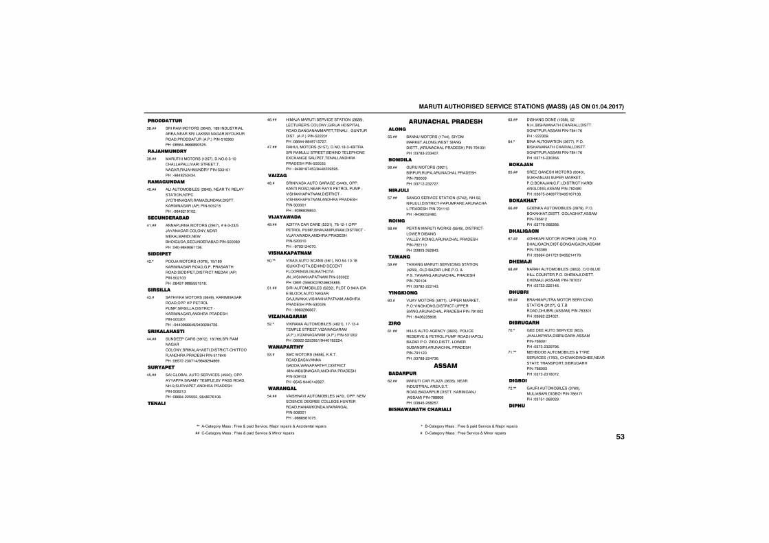
������������������� ������������������������������������
���������
���������������$(�����!#%������������ ��� ����������������&��������������������������������� !($(����"�# (��%(((#%� � �
$#���
��� ����
�������������!� ���������(�$�!��'����������������� �����&�����/������������ $$!�!���"�%#�#� $�$��
$%���
��������
����������� ����#�%���� ������ ������������'�/������&�������&�����������������&������������ � �! ���"�%#�#�!%!���
�����
����������
�����������������%�������(�$��$) �/�����&���'������� ���� ���������� *�����&���� '�� ���������� ���#����"����%#�%�(!!$(�
�!���
��������
���/������������(���!%)!#���������&��������&����������������������� ������'�� ������������� ��!�$���"�#� ��%## ! !#�
���,
�������
��������������� (�%����������&���������������� ����������������������'����������&�������������� ������� � $�!���"�%���%(((�%)%�%��#���(�
�$��
������ ����
��� ��'����� %�����!()�(%�����������&���'�����������������������'�'����������������� ������� !�(�����"�# ����$��!�)%#�#�%�#(%�
�����
�������
����&���������� ���' ���� ������������������*���� ��� ������������������%������ ������������ ������� �#�!$���"�#(#���� ���%#�#��(!�#�
� ���
�����
����/�������� ���' ���������#�#���� '� �A��'������&���/���������������&��&������� � �������&������������������� ����!���"�#(���%#�%�! ����
�(���
������������ ! ���������!#�$������������������ �� ����� � ���� � �'���& ������ � ���������������� ������� ���$ ���"�%�%�!#�� $)%�����% % �
�����
������
�������������&���& �� ���������������������� ��������� �����������������������������'���������������������������� ������� ����!���"�%$%(#$%# $�
�#��
����������
������'���'�� �� �$!����(�!��!������ �������������������������'�����/���*��������������� ������� ���!����"�%��$!������
�%���
��� ��������
����&�����'������(!������ ��!��!#���������� ������ ' ��-������&����������/��������������������� $�������"�#%!�� ($��)%��((� ## �
��,,
������������ ��� �$����������%�)������ ����'�������&����&�/*����������������������������� ������� $���(���"�%%($�%(((��
!���
����������
��������������� ����(�!���!��!$��� ��� ��� ���.����&��������������.����&���������������� $!������"�#%����� $% !)%���!%�����
��,
������ �
��'�������� ( #������������������������&�����*��������������'����������&�������������� ������� �%!�$���"# � �%���!��%���
$��
������
����������������� ��������������� *��'� �' �� &� �'��� & ��� ������������������*����&������� �(��!���"�%#(( (!�� �
����
�������������������
������������!���������������� �����&�* ������&�����������'�������� ���������%!��!���"�$�#$��$$����
���
�������
&���������$%�!�����������������'�������� ��������%���$���"�$�!���$�����
(���
�����
���&��� ���' �������� ��������� ������/��������'�������� �����'�������� ��������%!!!����"�%�$(� ��#��
����
���
� ���������*������ � ��������'����* �������&����� ������&�����'�������� ��������%�!!����"�$#�$��(�#�$�
#���
�����
�*��&������� ���'��&���������� ���������.������ ������+�������*��&�����'�������� ��������%�!�����"�$�#�����!�$�
%���
�������
��/���������� %�!����� ������ �����"���&����&������'��� ������&�����'�������� ��������%!������"�%�$(��##�#�
(���
���
����������& �'���$%���������' �� � �� �+�� ����������������������.��������.�����������* ���������������'�������� ��������%!!�����"�$�##�����$(�
(!���
�����������
�����'������.���$($ ���� �������������� �����������������������������&��/��������������###�(���"�$#� ��(#� ��
(����
��� ����� �� �����
������&���� ��!� #��� �����������*�����'�������������������������������#�!�(���"����$�%�
($���
��������������$(���������������*�����'�������������������������������#�!�(���"�$�! ��$�$ (�
(��,
������
�� �&�� ����������(�����������/����� ������ �����"����/���'�-��������'���������&���&������������#��#����"�$(� ���(%��)%�$ !(�!$#�
( ���
����� ��
&� ����������� ����#�#���������������������&���&��������������# (!����"�$��(��(#$((�
((���
� ������
��������������*���������%�������������&�����������&��&���������������#$$# ���"�$((����!��!)%�$ �!�!�(�
(����
� �����
������������� ���$# ����')���� ������'�� ��������� ��/��������� ��/���������������#�� ����"�$� $��� !�(�
(#���
� ���
���������������� ���'��&��������$!�����&����������������������������#$$�!���"�$((���$���!�
(%���
������
& �� ����� ���' ��% $���/�������������&���������������#(��!���"�$�$��$�%�%(�
���,
� ������������� ��+��� �� ���' ���!�(����'��*�����&� �� ����� �������������&���������#(��$���"�$�$��$!#����
�!�,,
������
&����������� ���$�(���������������&���������#(!�!���"�$� !��(%��%�
���,,
��� �
,, ��'1234567��188�"�-633�+�91:;��36<:=3���1>56�6391:68�+��==:;3?21@�6391:68 , ��'1234567��188�"�-633�+�91:;��36<:=3�+��1>56�6391:68
�� '�'1234567��188�"�-633�+�91:;��36<:=3�+��:?56�6391:68 � ��'1234567��188�"�-633��36<:=3�+��:?56�6391:68����
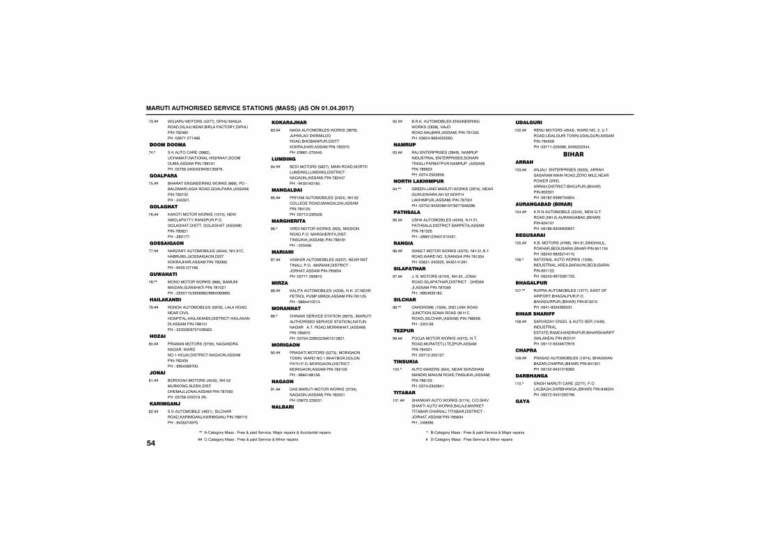
������������������� ������������������������������������
*�/�����������$������������/�����������/��� ���������-�'��������������#��(����"�$(�!���!�((�
�$���
�����������
�������'�� ��$%(����'����������������&�*�����������������������#(! !���"�$� %������$)%�$ !$ #�(�
���,
�������
������ �&�� ���&�*������%(%������������������&��������&���������������������#$!�����"����$�!�
� ���
����� ��
�����������*������!������� *�������������&��������&���&��������&���&����������������# (�!���"��#$!���
�(���
���������
���.����������� ���� ��������$!'����������&�����&�������������/���������������#$$(����"�%�$ !��!((�
�����
���� ���
����������*������%((����������������&*����������#!��!���"�� �!! )�( (%#�)%#(��(�(( �
�#�,,
��������
������������� ��� %�#��������������� ���'�����������������������������'�����������������������##! !���"���$$�#)%�����# ($�
�%���
����
�������������� �$������&��������&����*�������!���/��������'���&���������������#��$ ���"�%% �$(%����
#����
����
���������������� � ������ �������&��� ��������� ��/��/����������������#��(����"�$� #�����!%�����
#!���
�������
����������� ���%$!������'��������������&��/������&��/������##�!����"�%�$ ���%� �
#����
������ �
��&��������� ��*������$#�%���/�*�����*�������������������������������/���������������#$$�����"�$((!��� � �
#$���
������
� ���������� #�������������������������&������&������'�����&�����������������#�������"�%�$ !($!# �
#����
��������
�������������� ������������� ���'��� & ���������&�����������������#�!� ���"�$�!$��$� �#�
# ���
��� ����
�����������*������% ������������������������&� �����������������������������#(!#!���"������(�
#(�,
�����
�������������� ��� �$����� ������������������"�������������'���/����������������# ($����"�$��!��%$#!��
#����
����
������������� ����� %��������$��� ���� �����������.�������������#!!� ���"�%#(��!��!$�
##���
��� ��
'�������� ���' ���������%�$��������������� ��� ���' ��������������&�����������������������������������# (�����"�$� ����% ��)%��! !�#�!�
#%�,
������
���&���������� ��$�������&�����*���*�������!����������������������"����&���������'�������&���������������#�!� ���"�%#(�!#%! #�
%����
����
��������������*������$�$������&�����������������#���!���"�$(����� �$!�
%!���
�����
�������������� �� �&�� ���&�*�������#$#�����/����������������������������#!$$ ���"�$(���%% �� �� ��
%����
����
��/� � ����� ���$#�%������������������ � ����� ��������������������������������������������#((�$���"�$���� ��# (�
%$���
�� ���� ����
&� ������������*�������%������ ���&��*������� �����������������������������#���!���"�$� ��%�$ �#(!%�)% ��(�(�%(�
%��,,
��� ����
����������� ��������������$!���������������'����� �������������#!$� ���"��((�!�)%��!$!��$!�
% ���
����
�* ������*�������$� ������$!����������*�������� ����&��������#!$ ����"�$(�!���� � ��%�$ !�!�%!�
%(���
������� �
/������������ ��$������ ���/�������������������������'����� ���/�������������#�� %���"�%% �($ !#��
%����
���� �
'������ ��! %�����������������/�'��������������������'����������'�����������������##��(���"��� !�#�
%#�,,
�����
���/�������*�������$�$��������������� ��� .��������������#���!���"�$�!�����!���
%%���
�������
������ ����%$����� �������������������������������������������������#(!� ���"�$����$ �#�!�
!���,
������
�����������*������ !�����')�"��������������*���������/������ �������'�������������������'���/����������������# ($����"���%�%(�
!�!���
�������
� ���������� �$���*����������������������&����*�����&��������������#� �%���"�$�!!��� �%(��%�$ ���$���
!�����
� �����
��/����� � ����� ��� $$���������������������������. ������ �� �����* ��&����������������'����/���������������#��$�!���"�(!#��%$#(�$�#���
!�$���
������������ ��
������������� ���������� *�&�������������������&�����������������#��!�!���"�(!#(�%$��%$�( ��
!�����
��������
��������������(#������$!����&������������� &����������������# !!$����"�(��$�%#$ �!�!! �
!� ���
�����������*������! $(�������������� ���������� &����������# !!�����"�(��$�%%�$$#!�$$�
!�(�,
� ������
������������ ���! ����� ����-�����������&�������������������������������#!$�!����"�(�!�%$$�$# $!�
!���,,
�� ��� ����
��������� �&&��+����� ���! �%������������ �� ����'�������������������--���������������#�$!�!���"�(!!��%$$�(��%!%�
!�#���
� ���
�������������� ���!%��������&*�����.���'������������������#�!$�!���"�(! ��%�$!�!($(��
!�%���
��� ���
���&�������'�� �������������������&���������&��������������#�(������"�(����%�$!�%$�%(�
!!��,
����
����
,, ��'1234567��188�"�-633�+�91:;��36<:=3���1>56�6391:68�+��==:;3?21@�6391:68 , ��'1234567��188�"�-633�+�91:;��36<:=3�+��1>56�6391:68
�� '�'1234567��188�"�-633�+�91:;��36<:=3�+��:?56�6391:68 � ��'1234567��188�"�-633��36<:=3�+��:?56�6391:68
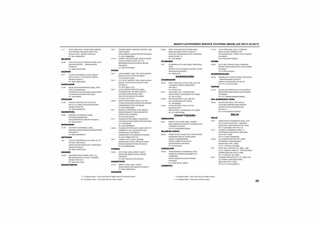
������������������� ������������������������������������
���'�� ��$��������&���������������'�� �/ ���� �� �������������'�����&�����������������#�$��!���"�($!�%%$%���%�#�
!!!�,
�����
��-������ � �������*���'��*�����!$����/���������'����������������������#��!�!���"�(����%�$!$��%( �
!!����
�����
��� '��������� ��$!�$���&������� ����������!%���/�������������������������#��!�!���"�(����%#$ ��� ���
!!$�,,
�� �����
�����&���� � ����� ��� #�������'�������&��&���&�����'��*����������������&���������'����&���������������#!$��$���"�%�$!�($ #�
!!����
� �����
��&�*���� ���' ���������$��������$!������������'��� & ����&�����������������# !������"�(����%�$��(��� �
!! ���
��� ����
��������������� ����($%��������������&��*������������ ����������������# ��!$���"�(��(���$$! �
!!(���
��� ����
���������������� ����$�����������&��&���&����������������������#���!!���"�(��(�% $��%#!�$�
!!����
���� ��
�/��������� ���$!������ ������������ ������������#�'��������������� ���'���������������������#� ��!���"�(� ��%��%� ��%%�
!!#�,
����
���� ��� �&&�*������! $$���! ��� *�����.�������+��������& ���������������#!!��!���"($���%�$!�!#%�!�
!!%���
���������
������'������� ���' �' �� ��!!($������������������&���&�����.�--���������#��������"�(�!�%$#(#$� % �
!���,,
� �- '��������$�( ���� ���'�������'����/�����������"�������"������������.�--�����������������#����$���"�(�!�%���� ��(��
!�!���
����
'����'��� ���! ����������������������&��'���������������#��������"�(!��%�$!�!($���
!���,,
'������� ���' ��!� ����� �������������� ���������'���������������#���!$���"�(!��%$$�!!�����
!�$�,,
&����*� �'��� ���' ���$$(���������&���������������� ��'���'��� & ����������&������������������������������#��������"�(!�������������
!���,,
������������ ����#��������������$�� �����/ �������&����� ������& ����������&�����������#��������"�(!��%$�� (�$#��
!� ���
�������������� ���!��%���� ������ � �� �������-������� �����������������������#����!���"�(!��%�$!�%�$���
!�(�,
���/����������$(( ����������������� �������������������������'�������#����%���"�(!��%$$��#�$�$�
!���,,
� ����� ���������%������ ���* ���-�'������������� ���������� ���������� ����������������������������������������#����$���"�(!���(#(���)�(�!�! �
!�#���
����������!% (�������������� ����� �������������� �������������/���.������������#���!����"�(!��%#$ � ��%��
!�%�,,
����
����������$��(������������� ���������� ���.������ ��������������# �$�!���"�(�!�%$$��(!( !)%������ �!�
!$����
���������
�����'�� ��! �(����/�����������������������������#�#!�!���"�(����%#$ �$��(!�
!$!���
������
�����'���� ���' �' �� �� $ ���� ���� ����' �� ��������&��������������������������'�������������������#�!!! ���"�%�$!�# %��
!$����
������ �
������������'�� ��(� ��������������� �����/����������������������'��������������������#�$$�����"�%�$��!��$��
!$$�,
���� ���� �����
������� ���' ���������(%���� '���!�������������&�'�����&��������!(��!����"�%�!(��! (!�
!$����
'���'����'��!�%���!�#������������ ������ ����'�����&��������!(�������"�%�!��!(�#��
!$ �,,
������������!! ���� '����$�'�'�����&��������!(���$���"�%#!���#$$ �
!$(���
��� ������.�����$�����������( #������������ ������ �!�'�����&��������!(�������"�!���%#�� (�#(#�
!$����
����� � �����������
��������'�� ���#$%������������������������������'���&/��'����&���������%���!���"�����%�� � (�#�)�#��%��
!$#��
���������� ���
���� �A�����'�� �����������������������������������'��*��� ���������'��������� ���--�' �/����������������'����&����������% ��!���"��� ���������
!$%���
��������
����*�������������� �����(������/�������������������� ����-�'��� �' ������/�&������'�����&���������%���!���"���#����$!%(����#����
!�����
��������
���'�� ��$#�$�����$�/���'���� ���������'������/��������� ������&�����������������'����&����������% � ����"��� %��$$�%�)�$$$ $�
!�!���
����
���� �-�� ���' �� ����������������� ���������������������������������% (�����"��� %����� �)� !�
!�����
�������
����������' �� �� $ ������������������� ����&���������'������ ��'�����&���������%�������"����!���!#��)�! $� �
!�$���
����
�������'���� ���' ��������������������������������������'����&���������%���(���"���!�$�%� ��)� ($�%$)$�%� ���
!�����
����������� �
�����������$(���������� ����'��� & ����������&���&�����&�*�������#����/����&���������%!��!���"��������#�$$)%!�%�%!� !�
!� ���
��� ��� �
��������������� ��� �� ����������$!������'��� '�����$���*��������������� ����*��������!!��$%���"�!!�%#!�((#�! )%�!���!!!#�
!�(�,,
��� ��������� ����%$����$��������&��/������������ ��� *�� ��������!!��%����"�!!���!($�!%)( �%�$�(�
!���,,
��� �&���� ���' ������#��$���������� ���*��� ��*�����&���� ��������!!���%���"�!!����$!��!)���$!#$%�
!�#���
���� �* ���� ���' ������#((���!)�#(��&�'����'���� ��������&����������������&��� ��� *�� ��������!!��% ���"�!!��� � �!!)��!!%# %�
!�%�,
��/������� ���' �����������#�(����� �&������������������������� ��� ��������!!��$$���"�!!���!!�%! )��$#� !��
! ��,,
,, ��'1234567��188�"�-633�+�91:;��36<:=3���1>56�6391:68�+��==:;3?21@�6391:68 , ��'1234567��188�"�-633�+�91:;��36<:=3�+��1>56�6391:68
�� '�'1234567��188�"�-633�+�91:;��36<:=3�+��:?56�6391:68 � ��'1234567��188�"�-633��36<:=3�+��:?56�6391:68����
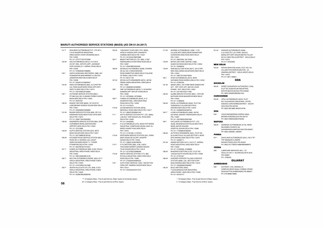
������������������� ������������������������������������
���������������� ����������#�!���'�%!)%�*�.���������������� ��������������'������&�� ��������!!�� ����"�!!���$���!#)��$�$�%(�
! !�,,
*�&�������� ���#�!������$�������'������������ �� �������/����&�������'��*���&���������������� ��������!!��$$���"�!!���(%�(�%)��(%(# �
! ����
��������������������������#(%���(�)�������&������������� ���$����'��/��������� *�� ����� *�� ��������!!�� #���"�!!�� ��! �)� (��%���
! $�,
������������ ���# ��������'�� �������������/�-&�������������������&������� *�� ��������!!��! ���"�!!�� �!#�%�)� !��( �
! ����
��*�� �� ���' ��������#��!������$#��&�������!����������������������&��� *�� ��������!!��� ���"�!!��#�(!��!�
! �,
�������������#��$����#���������� �� ������'��������� �� *�� ��������!!���!���"�!!��$ �% (()�$$�(#(��
! (���
�������� ���' ��������#$���������������������������� �������&� �� *�� ��������!!��!����"�!!�� #�!�%�)� #��# ��
! ����
�&�� ���� ���' ��������#$���������������������&����-���/��&���������� *�� ��������!!���$���"�!!��� !�(%(�
! #���
&���� ���' ��������#�����������&����&��� *�� ��������!!���!���"�!!��(!��%#%)�(!%�!(��
! %���
��'�� �������� ���' ��������#(�������������!���� �������/�&�������������&�� ��������* ������������ ��������!!��$����"�!!�( $� (�()��$! $�!�
!(����
������������ ���# ������#!������������������ ������ ���� *�� ��������!!�������"�!!��(#!� (()�(#!$!$��
!(!�,,
������������ � �&�����# $������)!������������������ ������ ����� *�� ��������!!�������"�!!��!(!��% )�!(!��%(�
!(��,,
� � ��������������������#�#�������)!������������������ ������ ����� *�� ��������!!�������"�!!��($##�(()�($##�(#�
!($�,,
����*������' �� ��������#�������-��'���� � ������'��������'�� ����� *�� ��������!!���!���"�!!���!�����)�(#�($##�
!(����
���&�����������������## ���'��($�� ��&������ �����&������� ��������!!��#����"�!!�� �(�## ) � ���(�
!( �,,
��������/��������� ��#�$#�������������$$�!$)��!���������*������������ ������ ���� ����'��� & ��-� �&&���� ��������!!�������"�!!�( ! !!�%�
!((���
����������� �&�� ����#�������#�) %�� ���&���������������� ��� ��������!!��#����"�!!�� �(�%��)��$ ( #!�
!(����
'���������� ���#��$���'�!#��������&��� ������������������� ��������!!��%����"�!!���� ��#$����� ��#��
!(#�,
������������� ���#��%�����! �*�.������������� ����������&������� ��������!!�� ����"�!!��!��� ���
!(%�,,
B���� ���' ��������#��#���� ������������ *�� ��������!!��!����"�!!��( ����()�( (!����
!�����
������ ���' ����������������$(� ��������'����������&���/���������� *�� ��������!!��(����"�!!�� �$�%�(�
!�!�,
����������� �����$�����*���� �� �����������'���������������-��������&���������/�� *�� ��������!!�������"�!!��!�(!��(���!�(!#!��
!���,,
���� ���� ���' ��������$$����������������������������������������&���� ��������!!��$ ���"�!!��$( $!��)( �%(��%�
!�$���
����&��������$( �����%%��!�$'��� �'��������� �&�� �����&������������&���� ��������!!��!#���"�!!���!$�# �)� %%(�%%�
!���,,
��� ��� ���' ��������������##$�������������������� ��-���������������� ��������!!��# ���"�!!���� � )(�(%� ���
!� ���
��������� ���' ��!�(�������������������������� �����&���� *�� ��������!!��! ���"�!!�� �$����)� !�!����
!�(�,
�������������� ���!%$%���!!)�#������& �������&��� ������������&��*�������&������� *�� ��������!!���!���"�!!��(#� � ����(!!#�(��
!�����
�����'���'�� �' �� ��!%$(��������������� *�� ��������!!���$���"�!!��$$#%$$��
!�#���
���������/��'����'�����(������$)!�������� *����/���������/�-&����� *�� ��������!!���$���"�!!��#�!����)( ��#$���
!�%���
����������� ���� ������������-�������������� ���� ��������!!�������"�!!����#��#��
!#��,
���& ��� (!�����'������ �������'��������������������������������������� ���� ���� ��������!!��%!���"�!!����!(%!�)���!� %��
!#!���
&��� �� ���' ��������$($!���!#������������������������� *�� ��������!!�������"�!!��!#%#$$$�
!#����
�' ��������� ���$$��������������#���&����������& �� '���#���*������ *�� ��������!!��� ���"�!!�� $((���)( �(%� ��
!#$���
���� �������� ���$$(�����#�)$ ������������� �� ��&������ ��������!!��#����"�!!�� ��#%$ )� �#��((�
!#��,,
�'���� �������� �����������$ �(���%#����&������������ '������� ���/�����&��� ������������������ ��������!!��# ���"�!!��!(�(%()$��#$$$%�
!# �,
�� '�� �&�� ����� !������������������������������& �� '���$��� ��������*������ *�� ��������!!��� ���"�!!�� �#$�!!�
!#(���
����������������!��������&�������������������������� ��� *�� ��������!!��$$���"�!!�����(� (�����((#$ �
!#����
���&��������������$������������! $) �$������������ ��������!!��$%���"�!!����(!$�!�
!##���
���� ��� �' ��-�����&�+�� ���' ���������%$%�����'��� '���%������������*������ *�� ��������!!��� ���"�!!�� �#�%(()� �#�%(��
!#%���
��/�/���������%������ )�������&����������������� ������ �!�� *�� ��������!!��#$���"�!!�( !(�!���
!%����
��������������� ��� �(������)!'�� �����������������/�����&������������&���� �������������$�!�� *�� ���������'���� ����� ��������!!��! ���"�!!�� �$�% (�
!%!���
������ �
������� ���' ��� ������������"!� �������& ���'������� '������$��*����������'���� �����* ���� ��������!!��� ���"�!!�%%!!!#�#���
!%����
����� ����
��� �&��������*������!��%�����������(���'��������������� �� ���'������&���������$ �%���"�#$���$(�(��)%#�$#$! �
!%$���
��� ���
������������ ��� $�(������������#�%�������������������� ���������'�'��� �������'�������&���&���������$��(���"�#$���( !###)��%����!#��(�
!%����
���
������ �&�� ���&�*�������% $����������������&���������$!�����"�#$���$%(�$$)%#�$�#�$$ �
!% �,
������
���� ����������� ����!�(���� �������&� ��'��'��!%��&����*����������&���������$ �����"�#$���� ($ �����(�$(!�
!%(���
����
����������������� ������!������ ���������������������������&���������&���������$��!���"�#$���$!��(%)�$! (##)%#%�((%#�%�
!%��,
���
����'�� �� ���' ����(!���������&���������!����� �����' �&���������$(�!���"���%�����
!%#�,
������� �������
��*����!� ������&�����'���� ��� �����/����'�� ���'������������������ ����������$#�������"��%�%#%#�!(###�
!%%�,
����
,, ��'1234567��188�"�-633�+�91:;��36<:=3���1>56�6391:68�+��==:;3?21@�6391:68 , ��'1234567��188�"�-633�+�91:;��36<:=3�+��1>56�6391:68
�� '�'1234567��188�"�-633�+�91:;��36<:=3�+��:?56�6391:68 � ��'1234567��188�"�-633��36<:=3�+��:?56�6391:68
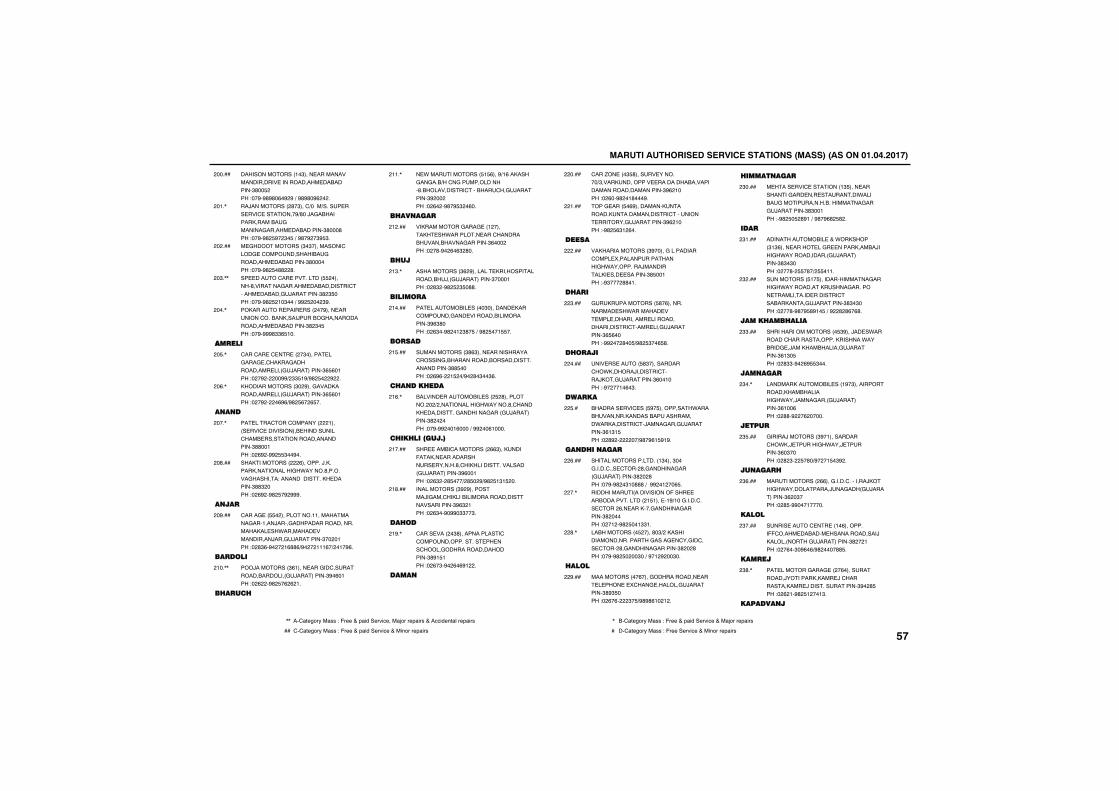
������������������� ������������������������������������
���������������!�$���� �������������������� ������������ ����������$#�� ����"��%�%#%#�(�%�%�)�%#%#�%(����
������
��/�����������#�$���')����)����� ��� ���' ��������%)#��/�&�����������������&��������&������ ����������$#���#���"��%�%#� %��$� �)�%#�%��$% $�
��!�,
� &������������$�$����������'����& �'��������������&��������� ����������$#�������"��%�%#� �##��#�
������
�� �����'�� ��������� ��������#��������&������ �����������'������ ������&/��������$#�$ ����"��%�%#� �!�$���)�%%� ����$%�
��$�,,
���������� ���� �������%���� ��������'�����������/�����&������������������ ����������$#�$� ���"��%�%%%#$$( !��
����,
������
'���'�� �' �� ����$������ ��&���& �'�����&������������ ����&/���������$( (�!���"���%������%%)�$$ !%)%#� ���%���
�� �,
���������������$��%���&��������������� ����&/���������$( (�!���"���%�����(%()%#� (��( ��
��(�,
���
�� ����'���'�����������!����� ���' ������������ ����������'���� ������������������������$##��!���"��(%��%%� $��%��
����,
����������������(��������/�������������������&�*������#��������&�������"��������������� �������$##$�����"��(%��%#� �%�%%%�
��#���
���
'����& �� ������������!!�����������&���!���/����&�������������������������� ��*�������� �����������/���&/��������$����!���"��#$(�%����!(##()%����!!!(�)��!�%(�
��%���
������
���/���������$(!���� ���&��'�������������������&/���������$%�(�!���"��(���%#� �(�(�!�
�!��,,
� ���
� *������������� ! (���%)!(�������&��&���)��'�&�������������#�������������'�������'��&/��������$%�������"��(���%#�% $��(��
�!!�,
� �����
������������&���& ��!�������� ��*�������� ���'�������������������&�������$(�������"���#�%��(�($�#��
�!����
� ��
������������$(�%������� �������������������/��&/���������$����!���"��#$��%#� �$ �##�
�!$�,
�������
�� ��������� �����$�������� ����'�������&��� ���������������������$%($#����"��($��%#��!�$#� �)�%#� ��! ��
�!����
�����
������������$#($���� ������������'������&�����������������������������������$## �����"��(%(���! ��)%��#�$��$(�
�! ���
� ���� ���
������� ��������� ���� �#�������������)������������&�*������#�'������� ��������&��������&����&/���������$#�������"��%�%%���!(����)�%%���(!����
�!(�,
� �� ���������
��� �����'����������(($��������-����� ������������� �������#�'��������������������&/���������$%(��!���"��($���# ���)�# ��%)%#� !$! ���
�!����
������������$%�%���������/�&���'������������������������������������$%($�!���"��($��%�%%�$$��$�
�!#���
�� ��
'���� ������$#�������������'�'���������������� �� ���'�����&���������������������$#%! !���"��(�$�%��(�(%!���
�!%�,
����
'���.�� ���$ #������ ��������)$�������������� ��������������������������������������$%(�!����"��(��%#��!#���%�
������
���& ���� �(%���������������������������������'�������� �������&/��������$%(�!����"�%#� ($!�(��
��!���
�����
����������������$%�����&����������'���� ������������������&�*����������/����������� ��� �������$# ��!���"�%$����##�!�
������
� ��
&������������� #�(������������� ��*�������� �� ��� ����������� ��������������������'���� ���&/��������$( (�����"�%%����#�� )%#� $��( #�
��$���
� ����
��� �� ����� #$�����������'��*�������/�������'����/���&/��������$(��!����"�%����!�(�$�
������
�����
�������� ���' ��� %� ����������*���������������������������������*����������'�/����&���&/��������$(!$! ���"��#%��������)%#�%(! %!%�
�� ��
��� �����
�������������������!$����$���&�����'��� '����#�&�������&�����&/���������$#���#���"��%�%#��$!�###�)��%%��!���( �
��(���
������������������������-���� �����������������! !��� �!%)!��&�����'��� '����(�� �������&�������&�������$#�������"���!��%#� ��!$$!�
����,
������������� �����#�$)�������������������������&����& �'��&��'��� '����#�&�������&�������$#���#���"��%�%#� ����$��)�%�!�%���$��
��#�,
����
�������������(����&������������ ��� � ���� � �'���& �������&/��������$#%$ ����"��(�(����$� )%#%#(!��!��
��%���
��������
� ���� ���' ��������!$ ���� ���������&��� ��� ��������*������&����������������������&���&/��������$#$��!���"�%#� � �#%!�)�%#�%(#� #��
�$����
���
�������������� �+�*���������$!$(���� ����� ��&� �����������/����&�*��������������&/���������$#$�$����"����#�� �#�)� �!!�
�$!���
���������� !� ���������������&�����&�*����������������&�������� ���������� �������'�����������&/��������$#$�$����"����#�%#�% #%!� �)�%��#�#(�(#�
�$����
����� ��� ����
��������������������� $%���/�� �*��������'����������������������*�������& �/��������������&/��������$(!$� ���"��#$$�%��(% $���
�$$���
������
���������������� ���!%�$����������������������������&�*���/����&����&/���������$(!��(���"��##�%���(������
�$��,
�����
&�����/��������$%�!����������'��*��/ �����&�*���/ �������$(�$�����"��#�$��� �#�)%���! �$%��
�$ ���
�����
�������������((���&�����'��������/�����&�*������������/��&����&/���������$(��$����"��# �%%���!�����
�$(���
�����
����� ����' �� ��!�(���������--'����� ������� ��������������/�������������&/���������$#���!���"���(��$�%(�()%#�����## �
�$����
�����
�� �������&���& ����(�������������/������������� /�'������������� /��������������$%��# ���"��(�!�%#� !���!$�
�$#�,
��������
,, ��'1234567��188�"�-633�+�91:;��36<:=3���1>56�6391:68�+��==:;3?21@�6391:68 , ��'1234567��188�"�-633�+�91:;��36<:=3�+��1>56�6391:68
�� '�'1234567��188�"�-633�+�91:;��36<:=3�+��:?56�6391:68 � ��'1234567��188�"�-633��36<:=3�+��:?56�6391:68����
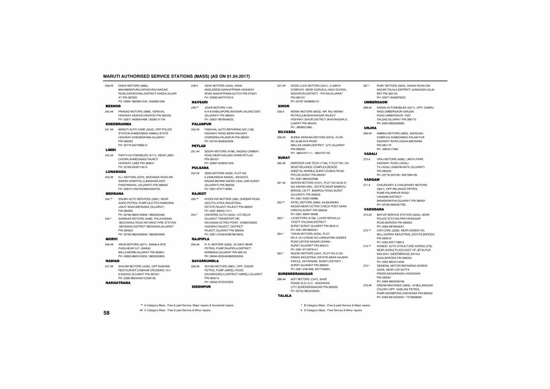
������������������� ������������������������������������
������������� %(�����������������������/���������������������/������'��� ���&/��������$#�(�����"��(%!�%#� (�!����)�%��($(! �#�
�$%���
���� ��
��������������$%(%���� ��������&�*���� ������ ���������$(�������"��#�!�%��(����##�)�%$�#���!�$��
������
� ���� ��
��������'�� �� $�������������' ���������� ����������/���� ���&�*����� ��������&/��������$#�� ���"���� �%���$(% !��
��!���
�����
������������ ����!�!���� ���������'��*����� ��������/�����&�*�������������$($(�!���"���($�%��(�!� !��
������
�������
��/����������$�������������������������- ������������*�������"����'��������&/���������$#%�$����"��(����� ����)%%� �� �����
��$���
�� ���
��������� ���' ���$$(����� ����&���� �����������������������/���������� �������&/���������$#�������"���(��%#� !��# %�)�%#� $���(��
����,,
��������������� �(#���������������� '����/������������&'�-�� ��������� �����������'�� ������&/��������$#�������"���(��%#� ��($ %�)�%#� (��% %�
�� �,
����
��������������!������������ ������� ���&����&����&�������������&/��������$($(�!���"��#���%#� !��� $�)�%#� ���#� �
��(���
�����
����������������$���������������� �������������'������&������#��������&/��������$#���!���"��(#�%#��$�$ ! )� #! (�
������
�� ����
�������������$������������&��� ���������������&�*�������������������'������$����!���"��#$ �%������$! �
��#��
�����
/�&����������!$$�������#���������� ����������������������&/���������$%(������"��($��%#�% �% $$�
��%�,,
������
���'�������� ������&�*���!$#�����&�*��������� �������*���'������&�������������$# ��!���"������%��($�$�%��
� ����
������
���������������!((����������'������������ ����������������� ��������$#���!���"��(%��%��%�$!$�$�
� !���
������
. ����������� $ ����������� �.������������.�������������&���� �������- ��'������������&/���������$% ��(���"��(!�%����!%�#��
� ����
�����
����������������$ (����� ����������������������������� �� ���/�����/�������$(���!���"��#!�%%� $!!�!!�
� $�,,
��� �� ����� �����')��� ����&/��������������������&����'������������� ��������&�*�����/���������'�����/���&/��������$#�������"��#!���� (�$)%#�%(!((�$�
� ��,
�������
������������� � ������&��'�� ���� ����������/�����������'�����������&/��������$%$!� ���"��(������ �%)%%� $� $���
� ���
���������
������������� %(!�������� ������ ����������� �������������������������'���� ���&/��������$(� ! ���"��#� �%������%�$�
� (���
���� ��
&�����'��������� $�!����������'���� ���� ���&������&���'������������������'��������&/��������$#�! !���"���(��%��#(( !$!�
� ����
�� �
�������������(�$����������/�������� ������������&�����/�����&�*��������������'�������&���&/��������$(�������"�%%�% �!%#��
� #��
��������
��� ���������������� $��������������$�((�����������������������������'�����&/��������$%(�$����"�%%�����!!!�)��%%�����!�$�
� %���
����
�� ����'��� '���!��#���-��������!����� ���� ����' �'���� ��� ��� ��� �������� �������������������������������$% ������"��(!�%#� �$$$%(�
�(����
� ������������$!(!�����������%� �� !������������������ �� �� ���������������& �!���-��������������������&/���������$ %������"��(!�%��(!�%%%(�
�(!���
�� ���������$�(����(����/���&���&���� ����'����'� '��������������'�����������$% ��(���"��(!�%%�%!�%�%#�
�(��,,
/���������� ! #������������������������&��������'�����������&/��������$%� !����"��(!�%%�%#( !�
�($�,
����������� � �������������!�)!�������������������&��������������&���&��������������&/��������$%��!����"��(!�%�!�%�(!�!�
�(��,
��� ���������� $�������������!)�$���������������� �� �� ���&�/ ���'��'� ������&�������������'�������&/��������$% ������"��(!���#!#$(��%$��!(�( ��
�( �,
���������
�����������!������ ��)������ �����&�����'���*���*���'����� ������&�������$($�$ ���"��� ��%#� ��#�� �
�((���
������
����������� %���������������������&��������������'�/��&����&/��������$(�! ����"��#���%��(%� ����
�(��,
�������
������������� ���� �!�������������*������ �&�������/���������� �&�����������������&/��������$%(!�����"��(��%#�($$( #$�
�(#���
�� �
��������������$%$�������&��'���� ����� �����������������&�*���������/���� ����������$#�!�����"�%#�� !�$#��
�(%���
������
���/��������� (�����������������&�*�����������������������������������&/���������$#$�$ ���"����#����!�%�)�%���$(�!�%�
�����
������
'��������+�'��������������� ( !�������� ����' �� ��������������������������&��������'��������������&/��������$# ��!���"���%$�%%� � ��#$�
��!��
�������
������ ���' ���������������� �������' ��������������&�������������������$%�������"��( �%#�%� $�$!�
������
'���'�� �����%���� ���&���������������&��*����������� �� ������������$%��!(���"��( �%���!�(%! �
��$�,,
��� �������'� �*��������%���� ������.����.�� ����-�/ ���������*����� �����& �����/��&�/������������$%��� ���"��( �%#���!���(�
����,,
& � ���������� ������&�*������� �%���� ������������� �����&��*�����������������$%���!���"��( �%#� ��(!�(�
�� �,
�� �����'��� ����%$$���!%���/���&���'�����������&� ������ ����������.�������������������$%�������"��( �%%!$�������)�� � #�%%$%�
��(���
����
,, ��'1234567��188�"�-633�+�91:;��36<:=3���1>56�6391:68�+��==:;3?21@�6391:68 , ��'1234567��188�"�-633�+�91:;��36<:=3�+��1>56�6391:68
�� '�'1234567��188�"�-633�+�91:;��36<:=3�+��:?56�6391:68 � ��'1234567��188�"�-633��36<:=3�+��:?56�6391:68
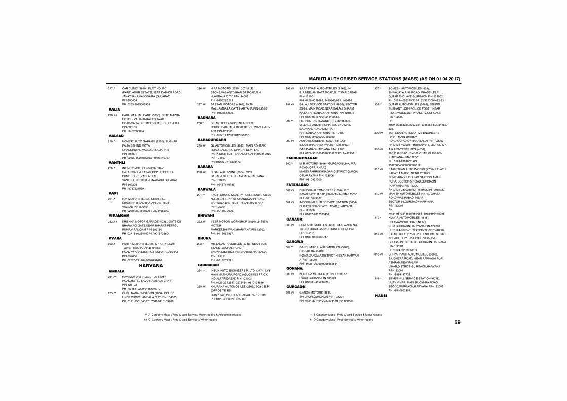
������������������� ������������������������������������
'���'����'���(��������������������������� �� �� ����������������/������������������&/���������$%�������"��( �%%� ��$ #�
����,
������
�����������'�� �� � ����� �����.����� ��������������� ��*�������������������'�����'��&/�������$%$!$ ���"�%���$$(�%��
��#���
������
��� �����&���& ����������&����-������ ���������&���'��*�����������&/���������$%(��!���"��($��%%� � (���)�%��(!!��(��
��%�,
��� ��
��-������������ %($���A���������A������-������������ ������������������������������������'�/��&����&/��������$(��� ���"�%�$� �!#%%�
�#��,
����
������������ ������� �����������������#�����������������'��������������$%(!%!���"��(��%#��!� %%�)�%#���� %%�
�#!�,
�������
�������������&���& ����$#������� �����*����&� �� ���������� �������������&�������$#�! ����"���! �%��(�! ����)�%�!(��((���
�#����
����
������������ ��������!�'�����&���* ����������������������������������'�����&/��������$%�( ����"��(�(���!�#�)%#%#�%�����
�#$��
�������������
������������!% ����!� ���--�������� ���������������'�������!�(!�����"�%$! !!���%)%�!((���!��
�#��,,
&�����������������$(�������' ���� ��'��*���������'�������!$���$���"�!�!�� !(� )� !��(!)%�!(! %�(�
�# �,,
�������������������������� ���� �������������&�����������!��������'�������!$���$���"�%� �# �!��
�#(���
���������������%(����%%���������������'��������������!$$��!���"�%�((�������
�#����
��� ��
����������� �$ ���� ���� ����� ��������������'����*����������������!�$$�#���"�%� !�!�##)%#!�� !� ��
�##�,
�� �����
&��������� ��� �($�������������������������������'���� ������������������'���������&����������������!�� �����"�!��(�%�!($�$��$�
�#%���
����
�������.�� �� $$��������������������'����������������������!$$��$���"��%�(�!!(�# �
�%����
������
-�B���'�����B�����- ���� �$ �������������������������( �'�����&��������������*���������'���������������������!� ��!���"�%�! �������
�%!�,,
� ����
� �������*���������!# �������� *���������� ����*�����������������!����!���"�%�!(� �# ��
�%����
� ��
������������ ��� ��#���� ������������/�����������������������'�-� ������������������!� !!!���"�%#!$�����!�
�%$�,
��������
�������� �&�� �����������$�����!$)$��������������������/�����&�-��'���������-�������������!�!��$���"�!�%����� #��������#���%#!�!$ !(�
�%��,,
�������������� ����#($���$')(�������������� � ������������������-�������������!�!��!���"�!�%��� (������� (��!�
�% ���
�����*���������� �����( ����������� ������������������-�������������!�!��!���"�!�%����%(( �����%(( )%#!!��((#(�
�%(���
����/��� ���' ���������% (���� '����$���������������� �������/������������-���������������������!�!������"�!�%�%#!#������)�!���( �
�%����
� �- '���.�� ����������� ((���������& ��������������� '��!�������������������������'���-���������������������!�!��!���"�!�%���(����)��(��$��
�%#�,,
��� �&�� ���� $ ����!$!���-����������� ������ �!������'���-���������������������!�!��!���"�!�%�%#!����$!#)%$!� �� !!)�!�� !!�
�%%���
���� ���
����������� %�(���&�&����/��//������������������.�������-�������&��������'�&�&����������������!�$ �(���"�%#!�#$!����
$���,,
���� ����
����&���������� ���!# (���&��������-� ��������������������!� � ����"�%�!(��%!(��
$�!���
������������� ���' ��������$�(�������������-� ��������������������!� � ����"�!((��%#!�$� � ��
$�����
����
����������� �����(����$����*��������!����������&������������� �������!$!!�!���"�!$��%�!(�(�����
$�$���
�����
���'�������������� ��� %(#������������/&���������&��&*�������'��������������������!� ��!���"�%��#!����%)%� (� (��
$���,,
�� ��
����������������!$���������������&����������!$!$�!���"�!�($�%�!(�!$ %(�
$� ���
�����
&��&���������$($�����������&�&��������!����!���"�!����$!�%��)�$���#�)%#!��$�(��#�
$�(���
��� ���������� ���� ��������������� (����������� �����-�B��� �'��� �&�&��������!��������"�!����� �� )�$ �!(�)%�!$�%��#��#$�
$���,,
B���������� ���$((#���� ���������������������' ��������� ������& *������-����� ����&�&��������!��������"�!����$# $$$)%��(�$$�)���(( #� %)%#!!(#�$$$�
$�#�,,
���& ��������� � �&�� ������(���������/�����������&�&������������������!����$���"�!�����$%�!!��%#!�$���!!��%#%!�$%����
$�%���
��+��� � ����� ����($%���$%(����� �������&�������&�&������������������!����!���"�!����$%%#(���($��%$!��($� �)%#(# %%#!��
$!����
��/���������*��������(��������������������&��� ���� ���������������-�����&������������������ '��� ������&�&������������������!����!���"�!����$���$#)%�!!#!%���)%#!�� #����
$!!���
�������������� ����������&���������*�.��������� ���� '��� (�&�&����������������!����!���"�!���%#�$��$# #)%#%% (! % )%#%%�� �##�
$!����
������������ ����#�#���� �������������� ������#�&�&����������������!����!���"�!���%#�$�$!(%()��! (%()%#�$��##���
$!$�,
��&�������� � (�����������%���� '���$����' �'����������&������������&�&���������'�&�&����������������!����!���"�!���%%!�% !!$�
$!����
������������������� ��� #(������/&� ���������� ����������������������� *������������������'�&�&����������������!����!���"�%#%%! ���%�
$! ���
� � �������� ���' ��������(�$#�����/������������������������������� '�$��&�&����������������!��������"�%#!�(��$ ��
$!(�,,
���
,, ��'1234567��188�"�-633�+�91:;��36<:=3���1>56�6391:68�+��==:;3?21@�6391:68 , ��'1234567��188�"�-633�+�91:;��36<:=3�+��1>56�6391:68
�� '�'1234567��188�"�-633�+�91:;��36<:=3�+��:?56�6391:68 � ��'1234567��188�"�-633��36<:=3�+��:?56�6391:68����
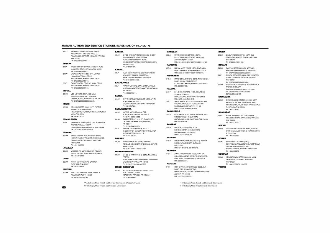
������������������� ������������������������������������
������������� ������������������� ��������/������ �������&�������������������'����������������������!� ��!���"�!(($�%�((��#�$��
$!��,,
����
���'�������&���& ����$%���%(�������� ��������������������!� ��!���"�!((��%#%($�$�$$�
$!#�,
��������������$ ���������������&���&� �������� ����������������������������!� ��!���"�!((��%$ �#(�!(�
$!%�,,
����������� ��� �(����������� ����������������������������!� ��!���"�!((��%#!�%����(�
$���,
����
� ������������������&�*��������� �������*���������'��*���������-��������������!�!!�(���"�!�� ��$(�$#)%� � (%���
$�!���
���
�������������(��!��������������-�����&����������*������� ����������������'��������������������!$���!���"�%#%(�$���!�
$�����
����������
���������������(� ���������������/������' ��������������������������������������������!$(!�%���"�%�!(� ��#!)%%%(�� ($(�
$�$�,
����
�������������������� ���(� !���������������������������'�'��� & ��������������'��������������������!$�!�$���"�%%!!$((�$��
$�����
� ����
����������������!�(����� *���������/��//�����������������!��!�$���"�%#!��!�!#��
$� ���
���
������������! �������-�����&� �/��������!�(!�����"�%$ !�%#���
$�(���
���� ��
������������ ���!# #��������������������������!$(������"�$�%(���!(��� ����
$�����
����
��� ���������������� % $������������&������ ��� ���� �������������� �&����������������������'������� �&����������������!�$������"�%�(�(�!(�#�
$�#���
����
�������������$�����#)$�����'�� �������� ��'��*������������� ���������������������!$���!���"�!#��%#%($� ($$�
$�%�,,
� �� ���
�������������� ��!������������������������������'���� ���������������!$!������"��%#%(!� !(!�
$$��,
�����
������������������ ����(�#���/���������� ��������'��������& �������������������!$!��#���"�%#!!����#��
$$!���
����� ���
�������������!(� ���� ������������ �������!$�!!#���"�!����%#%(�� %���
$$����
��������������!$!���&������������'��*������� �����������������!$(!!#���"�!����%#%(!#$%$!�
$$$���
������������� $�%���������( �((�� '��������������������� ������� �������!$�!!#���"�!������!$�$�
$$��,,
�� ��
���*����������(��#������*��������������������'����*����������������!����!���"�!� !�%�((!!�%��)�!��$%�
$$ ���
�� �����
��� �������������� #�$���� �������'�� ����������� �� �&���������'���� �� �&������������������!�$��%���"�!�# �������)%�!(�( # �
$$(���
�����������
���������& �'� ����%((���!!$�! �������� ����������������������������!� � ����"�!((%��$$���
$$����
�����
������� ���' ���������$�#�������#�� ����/������������� �����&�&���������!����!���"�!�����%�$�%)%�!��!��%$)%%!!!��!���
$$#���
����
������������ ��! �!������&�������������������������������!�$��!���"�!�#��� !(� )� !(��)%�((�$��# �
$$%���
���� ��
�� �� ���������� ��%���� *�� ����������������� ��������'�������������� ���������������!$�!!����"�%%%($�#�$��
$�����
������
�����+�������������!! %���� ������������� ��������������*�����������������!�!!�����"�!�� �� �(��)� !#!(�
$�!�,,
�� ���������� !�!����������'�����'��'����--�' �&������������'���-���������������������!�!!�����"�!�� �%�!(�((� !)��! �!�
$���,
��� ����
���'��������� ���' ���!%�%����������$������� ���������������� �����'�������������������!$�!�%���"�%%! �$�!%(�
$�$�,,
������
�� �����������((����������!$��� '���� ������������� �������������!$�!�$���"�!����%�!(�$#��(�
$���,,
�������
�������������� ����(�!���� *��������������������&�&��������!�� �$���"�!����(��%����%#!�(( ����
$� ���
�� ���
������������ �������������������'��� & �������������� ��*������������ �����������������!$(!�#���"�%#%(���%���
$�(�,
����
������������������� ��� # �������������������� ������ �������������������'��������&���������������!$ !$$���"!$ !$$�%� % ��!��
$���,
���
���&����������$��%���� ������������������������������������������!� ��(���"�!(%#�%�!(�!!�$#�
$�#���
����
&�����������!#$����������������� *������������������!�$��!���"�!������#% )���$% )$� �% �
$�%���
�������� ���' ���!�((��������' ������'�����&����������������� *��������!�$��!���"�!����� �#� )%�!(�##$�!�
$ ��,
���������������(($���� ���������������' �'��'���������� *����������������!�$��!���"�!����%�!(�(��$#)�� ��$#)�� �%$#)%% %($!(#�
$ !���
��� ���
��� �&�� ���������� % %���� ��������������� �����������������������������������'��������&���������������!$$������"�%#!$$�(�(��
$ ����
� � ����
�����������������$ �������*���������������������������������������!$(!$ ���"����$$��!%$$�
$ $�,,
�����
&�� ���������� ��� %$!����������������*���������'����*����������������!����(���"�%#!��������
$ ����
�� �
������������������ % !���������&��������� ��������� ���&��&� ������ ����������'�����������������������!��!�$���"�% #�$ ���%�
$ �,,
������
� *���&�*���������� � ��������� ������������ ���������������!$!��!���"��%#!� $�!������$�%%%�
$ (���
����
����
,, ��'1234567��188�"�-633�+�91:;��36<:=3���1>56�6391:68�+��==:;3?21@�6391:68 , ��'1234567��188�"�-633�+�91:;��36<:=3�+��1>56�6391:68
�� '�'1234567��188�"�-633�+�91:;��36<:=3�+��:?56�6391:68 � ��'1234567��188�"�-633��36<:=3�+��:?56�6391:68
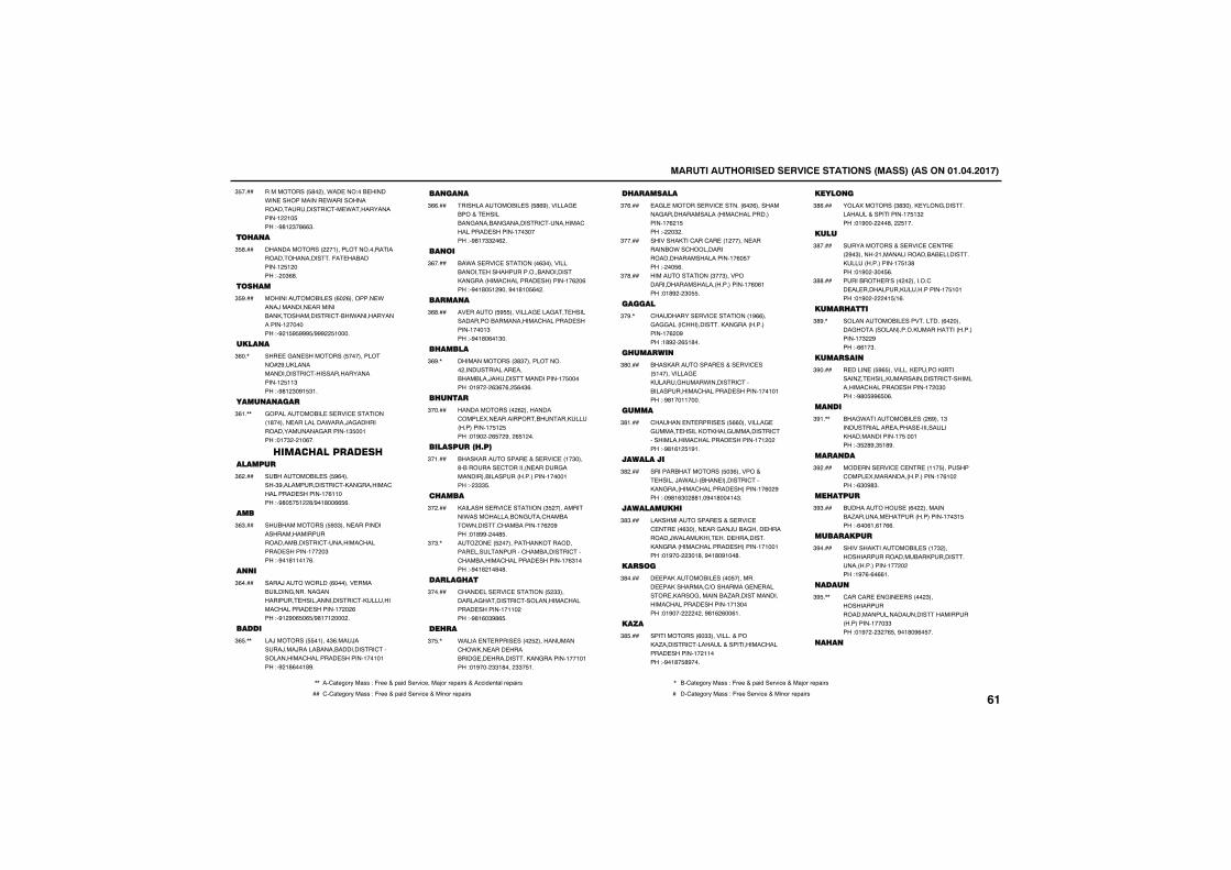
������������������� ������������������������������������
����������� #�����*�� ���"��� �����*�� ������������ *�����������������������'�� *��������������!��!� ���"�%#!�$�#(($�
$ ����
��� ��
�����������������!���������������������������������-� ����������!� !�����"���$(#�
$ #���
��� ��
�������������� ���(��(�������� *����/�������� ������������������������'����*����������������!��������"�%�! % %%% )%%%�� !����
$ %���
�����
��� �&�� ���������� ��������������%������������������'��������������������!� !!$���"�%#!�$�%! $!�
$(��,
��������
&������������ �� ���' ��������!#������ ���������*����/�&������������������&�������!$ ��!���"�!�$���!�(��
$(!�,,
� ������������������
����������� ��� %(�������$%�������������'����&�������'�������� �������!�(!!����"�%#� � !��#)%�!#��(( (�
$(����
���
�������������� %$$���� ��������������������������������������'��������'�������� �������!����$���"�%�!#!!�!�(�
$($���
��
����/����*������(������� ����������&�������&���������� ���������������'���������'�������� �������!����(���"�%!�%�( �( )%#!�!������
$(����
�����
��/�������� �!����$(���/�����/���/���������������������'�������������'�������� �������!��!�!���"�%�!#(��!#%�
$( �,,
�����
�������������� ��� #(%��������& �����+� ��������&�������&���������'��������'�������� �������!��$�����"�%#!�$$��(��
$((���
����
��*��� ���' ���������($��������������� ���������������������������&��������'�������� ��������!�(��(���"�%�!#� !�%���%�!#!� (���
$(����
�����
�� ������ % ��������& ���&�� ��������������������������'�������� �������!���!$���"�%�!#�(�!$��
$(#���
� �����
��������������$#$�������������������������� �����������/�����������������!� ������"�!%����($(�(�� (�$(�
$(%�,
� ���
���������������(����������'���� ��� ������������������������������!� !� ���"�!%����( ��%���( !���
$�����
��������� ���
��������������� �+�� ���' ��!�$����#��������� '�������� �����&�����������������������������!����!���"��$$$ �
$�!���
� ����
��������� ���' ���������$ ������������*��������������&��'�������*������'����������!�(��%���"�!#%%����# �
$�����
��.�� �� ����������������������� �����������'�����������'���'����������'�������� �������!�($!����"�%�!#�!�#�#�
$�$�,
����� ��
'���� ��� ���' �������� �$$��������&��������'�����������'�������� �������!�!!�����"�%#!(�$%#( �
$�����
�� �
*����� � ����� ����� �����������'��*��� ���� ��������& �� ������������&�������!��!�!���"�!%����$$!#����$$� !�
$� �,
� �������
�&� ������� ���' ������(��(����������&�������������������'��������������!�(�! ���"����$��
$�(���
�����������'���'�� ��!������� ���������*��'�������������������������������!�(� ����"���� (�
$�����
��������������$��$�����������������������������������!�(�(!���"�!#%���$� �
$�#���
������
'��������� ���' ��������!%((���&�&&�����'�������������&��������������!�(��%���"!#%���( !#��
$�%�,
� �����
��������������� ��+�� ���' ��� !����������& ������&����*��������'���������������'�������� �������!��!�!���"�%#!��!!����
$#����
�����
'������ � ����� ��� ((���������& �&���� ������������&���������'��������������'�������� �������!�!������"�%#!(!� !%!�
$#!���
���������
������������������ �$(�������+� ������/�*��������� ��������'������&��������'�������� ��������!�(��%���"��%#!($��##!��%�!#���!�$�
$#����
��������� �
��������������� ��+�� ���' �' �� ���($����� ���&��/���&���� ���������/*�������� ���� ������������&��������'�������� ��������!�!��!���"�!%�����$�!#��%�!#�%!��#�
$#$���
�����
� ����������� ����� ��������� �����������')���������& � ������� ������&���������.������������������'�������� �������!�!$�����"�!%�����������%#!(�(��(!�
$#����
����
������������(�$$���������+������.�������'�������+����������'�������� �������!��!!����"�%�!#� #%���
$# ���
������
�������������$#$����� ����&������������+����������!� !$����"�!%�������#���� !��
$#(���
����
�����������+�� ���' �' �� ���%�$�������!���������������� �����������������������!� !$#���"�!%���$�� (�
$#����
�������� �A��������������'�� �� ��������������������!� !�!���"�!%�������! )!(�
$##���
���� ����
������������� �����������(��������&������������������������������������!�$��%���"�((!�$�
$#%�,
�������
� ����� �� %( ���������� ��������������.� �������������������'������������'�������� �������!���$����"�%#� %%( �(�
$%����
����
���&*���������� ����(%���!$������������ ������ �������������������������!� ���!���"�$ �#%�$ !#%�
$%!�,,
�����
��� ���� ���' �' �� ��!!� ��������'���� ���������������������!�(!�����"�($�%#$�
$%����
�� ����
����������� ��(�������������.������� ���������������!��$! ���"�(��(!�(!�((�
$%$���
��������
������������������ ���!�$����������������������������������������������!��������"!%�(�(�((!�
$%����
����
'���'�� � �&�� �������$����������������������������������������������������!���$$���"�!%����$��( ��%�!#�%(� ��
$% �,,
� �
,, ��'1234567��188�"�-633�+�91:;��36<:=3���1>56�6391:68�+��==:;3?21@�6391:68 , ��'1234567��188�"�-633�+�91:;��36<:=3�+��1>56�6391:68
�� '�'1234567��188�"�-633�+�91:;��36<:=3�+��:?56�6391:68 � ��'1234567��188�"�-633��36<:=3�+��:?56�6391:68����
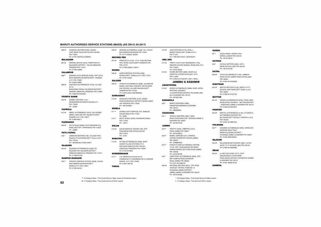
������������������� ������������������������������������
�&��*����������$$$����&���&���� ��� � '���'����������������!�$��!���"�!����� (�%�����$ #����
$%(���
�����
�������������� �� ���� ������������&���������'�������������'�������� �������!��!�!���"�!�% ���$ (!�
$%����
�������
���&�������� ���' ��(�$�����������������������������������������&��������������!�(�(!���"�!#%��$�(# �
$%#�,,
��������������� ������(��������& �+���������*����� ������������������'�����&��������'�������� ��������!�(�(!���"�!#%��%�!#!#�$(��
$%%���
�������� ��
�� ��������!��!��������� ���������������������������!�$�� ���"����(��
������
������
������������� ���$��������/�������������+������� ������/������������&��������������!�(������"�!#%��(# !��
��!���
������
��������� ���(��#������������*���������������� '���!����*���������!�$������"�$�(# �
������
�������� ��
/����&�����������(���������& �������������������������������������������!� !�%���"�%#!(��������!%�����#���
��$�,
����
��/&����������� ��� � #��������/&���� ����/&���������'��������������'�������� �������!�$!�!���"�!�%%���!� �
������
�������� �
��&�*���� ���' ���������(�%���'������&�������������������������������������!����!���"�!�#��$���$�
�� �,,
��������������� ����$#��������'������&������������������!����!���"�!����$$��(���$$�%!�
��(���
��������
�����������!$���������������� '��&�� �� �������������������������������!��!�����"�!�#(���(� $����(�!��
������
� �
������ ���' ���������$$#�������������������������������!�!������"�!�#!�$��$��
��#���
����� �
������������ ���$#$#���/��������������������������&�*����������� ��������'����������& �������������������������!��!�#���"�!%�����$�!��%#!#�%�%���
��%���
����� ��
��������������� � �������������������&��������'�����������'�������� �������!� ������"�%#!�#!##���
�!����
� ����
&���/����� ���' ��� ��������� �'��*������������!�!��!���"�( #�
�!!�,,
����*������(�$$����������������������!�!������"���%!��
�!��,,
����
������� ���' �' �� ���(������ ������� ����*���--�' �����������!�$�!����"�$!�%�
�!$���
����� �
������������� ���� #���� ���������-�����&�����������������������������������������'�������� ��������!�$��(���"�!�%���� (�(�
�!����
�������
������ ���' ��������$������'�����������������&������!���� ����&���������������!��������"�!%����(�!$��
�! �,,
� ���
/���������������#������������.���� �&������������������������!�!��!���"!�#$�%#!(!��� !��#(�%���� !�
�!(���
���� ��
���������-��� �&�� ����!� ����������'���������&����������������������!��$�$���"�!%� ��( ���
�!����
������������$%� ���� ���������������'��*�����������������������!��$�$���"�!%$ �� !$���������� �!!��� ����
�!#���
������������� ���������
� ����������� ��� %$#�������������������������&�*���!���*�������������'���*����/����+�������������!%�!�����"�%�!% ���% �
�!%���
�������
�������� �����$(%���������������������������������!%$!�!���"�%%�( %%���
����,
� �����
� ��'� ���� �����((!�������������'���������������&���/����+�������������!%���!���"�%�!%�� ��#�
��!�,
�����
�*���-����$�$���������������'�������/��������!#���!���"�%�!%!#�(� �
����,,
��� ��&���& �����!������*���'��*������������&���/��������!#�������"�%�%(#������
��$�,,
'� '����'�� �������� �' �� ��!��$��������&��*�����������&�����������*����� �����������/��������!#���(���"�%�!%!%��%(�
����,,
'�� ������������� ����( �����������-�'�����������������������/��������!#�������"�!%!�%�!%�#$! !�
�� �,
��������������� ��������������������������� �����������!����/*����/���������'���/����/����+�������������!#��!����"�%�!%!%�$(#�
��(���
�����
.�.���� �&&��*������$��������&��������������!%�!�$���"�%�!%!�(�!��
����,
��� ��
������������$$�$����������� �������/+�������!#�!�����"�%�!%! �!$(�
��#�,
����
������������� ���!!( ���/���������������/���������������/+�������!#�$�!���"�!%%!�%�!%!(�$$%�
��%���
��� ���
��������������!$$���� ���������'��'���������*�������������/�+��������!#���!���"�!%% �%�!%! �!���
�$����
�����
�������������� ��� ��#���������&���������� ���&�*���������������'���������&�/����+�������������!%�!�!���"�!%$��%�!%�� (���
�$!���
� ���
�������������� ����!�%���')���������������� ����� �� �������*����������������� ���/�+��������!#���$���"�!%�!�%�!%(%!%!(�
�$����
�������
��������������� ��� $ ���������&�����������������-�����������*���������'�����*����/����+�������������!%�$�!���"�!%$$�%%�(�%%$���
�$$�,,
�����
���� ����������� ����%$����������&� ��'������/�����/+�������!# !$����"�!%(��%�!%$�%�#(�
�$����
����
���� �'���'����'�����!���&�����&���� ����/�������������� ���������'���������/����+��������������!#�!�!���"�!%%!�%%�(�! ! ��
�$ ���
���� �
����
,, ��'1234567��188�"�-633�+�91:;��36<:=3���1>56�6391:68�+��==:;3?21@�6391:68 , ��'1234567��188�"�-633�+�91:;��36<:=3�+��1>56�6391:68
�� '�'1234567��188�"�-633�+�91:;��36<:=3�+��:?56�6391:68 � ��'1234567��188�"�-633��36<:=3�+��:?56�6391:68
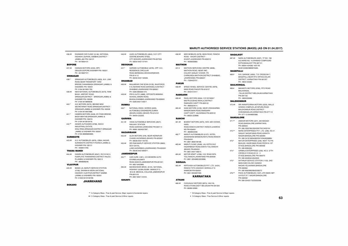
������������������� ������������������������������������
��������'���'����'�� !�(�������������&�*�����*���������������'���/����/+������!#�!�!���"�%�!%%$�! !�
�$(���
������
����������������$������'�� �� ������� �������������!%$��!���"�%�!% %�����
�$����
�����
�����&���������� ����%� ������������������� ��������������������& �'�������&�������&����/����+��������������!%���!���"�!%��%�!%��!�%$�
�$#�,
� *���������������� ��� ��$���������&���������������������&��������'��������&���/����+�������������!%���%���"�!%��%�!%%�% �#�
�$%���
������������ ������� ������ *�� '� ���������������&��������'��������&���/����+�������������!%���%���"�!%��%�!%���%((�
����,
��� ��������� ��%���������������& ����&��� ���������&���/����+�������������!%��!%���"�!%��%�!% !#�!(�
��!�,
����A������� ��� �((������'����������� �� ������ �&������&��������'������&���/����+�������������!%���!���"�!%��%%�( #��#%$�
����,,
������
������������ ��� %�(����B������&���������� ������'�����'��/����+�������������!# !�!���"�%�(%�!��( �
��$���
� �������
�������������� ���(�������)��*����$������� ����������������'���/����/����+�������������!# �!����"�%# #%$#��#�
������
�������
���������������� ���' �����������#����*���������������������&�*�����/����������'��������/����+��������������!#���!���"�!%�$�%�!%!�(�%#�
�� ���
��������������
��������� ����#� ������!�'���' �� ��������� ��'����������/�������������#��������"�( ���%�$!!����!�
��(���
���� �
&��& �������� �����(����������'��� ��� �' �'��'������������������� �&���������������#!�!!����"�(�$��%�$!!$� �(�
����,
� ����
��/�����'����'���� !$ �����-��' ����&������������������� ��������'�����������/�������������#�#$�!���"�$�(�%#$ $(!����
��#���
�����������#(#��������� �������&��'���������������������&����������/�������������#�#$�!���"�$�(�%�$!!��#!��
��%���
�����
�������� �&&��*������ ������������� � �&�� ���������������������������������#!�!�!���"�(�$�����$� �
� ��,
�� ��
������������� �� ���' ����(���������*��������������&���*��.������������#��!!����"�( (!�%��� ���#��
� !���
�������
������������$�%���� ������������'��*����.�����&�������������#� $�!���"�( �(�%�$!!������
� ����
�������������� ���' ��������$(($���� ������������ ���.�����&��/��������������#� $�!���"�( �(�%�$!$#�#���
� $���
���� ����
'���'� ��!�(!���')����� ��������� ������������������'���/���� ��������#$!��!���"�( ��(� �%( �
� ��,,
��� ��*����������� !���������������&�*���$$�����&�������&���������&����� ��'���'��� & �/���� ��������#$!�!#���"�( ��%�$!!������
� ���
� ���
��������� ��� �%�����������������'��������������������'��������/�������������#$ �!����"�%��(� ##$�
� (���
���� �
�������� ���'��&�' �� �� #$#����������������� �����'�'���������/���'��*������'��������������������'����������/��������������#�#������"����%��$����
� ���
����
�� ��*� ��� ���' �' �� ���%�(����������������������#!(!�����"�%�$�!�!%!��
� #���
����
������������� � ����')��������������������������������'����&����'�������#�%!�����"�%#$ $�� !��
� %���
������������� !�(���� ������*���������������������������&����'����������.�����&�����#�%!�����"�( $���$(%%�
�(����
�� �
������������� %����������/ �'��*���������������'��������'����'���/�������������#$���!���"�%(�# ��� #�
�(!���
������������ ��� !������� �������*�����������������������'�������#$���!���"�( !�%#$ ! (!#(�
�(��,,
�����'����'��� �#������������������.�����&�������������������'����������������#$���!���"�( !�%�$!!�%�!��
�($���
��������-����(%�������������������������'���/�������������#$���%���"�( !�$� �%( )$��$(((�
�(����
������
���������������� ���������������������'��������&�*�������������������������#$���!���"�( !�%$$�( ��%��
�( ���
����������� ��
'��&� ��������$#���������������������������� �&������� %!$�����"�#�#%� �%%��
�((���
��������
������������ ����$ ����������! #��)��*��������!����������'������� �����&��������� #�!�!���"�#$ ������%�)���$!�#)�%��#!���%$)%##�#� % �
�(����
���������
�����&���& ����($�������'�������������& ������� �������--�' ������������'��������������� (!������"�%#� !� �(��
�(#��
���� ����
�������������� �($������������������&�������������'�� �&���������������� %!!�����"�%%��� ((�
�(%��
���� ��
���������������������� � $������� �&�*���'���� ��/��������������� ����������������'���'������&����������������� ��!!����" ��!!��%��%(��$((�
������
�������
�� ������������������$����&������������&���� ���������������� (���$���"�#��$$ $�((�$$ �$$%�-��"$���!���
��!�,,
����� � ����� ������������$#�������!����/�����&���������������*�����&������&���� ����� (��%����"�#��$�!#! #)%��#��$ !$)%��#$ ###��
����,,
����� � ����� �����%���� ��������������������������������� ����!����& ����&���� ����� (�� #���"�#��#$% �($�
��$�,
&�����/�� � ����� ���� #�������������'���������������������������& ����&���� ����� (�������"�#��( �%����( �� ���
����,
������� ���' ��������!! $����������������'������&��������&���� �����������&���� ����� (��(����"�#��# (�%% )%#� �$#$���
�� �,
��' �������� ���!� ����(���������������������&������&���� ����� (��$����"�#���$�$�!�$)�$$$�$$#�
��(�,,
,, ��'1234567��188�"�-633�+�91:;��36<:=3���1>56�6391:68�+��==:;3?21@�6391:68 , ��'1234567��188�"�-633�+�91:;��36<:=3�+��1>56�6391:68
�� '�'1234567��188�"�-633�+�91:;��36<:=3�+��:?56�6391:68 � ��'1234567��188�"�-633��36<:=3�+��:?56�6391:68����
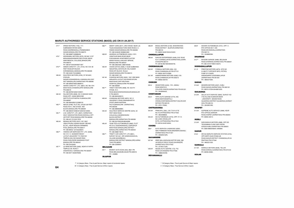
������������������� ������������������������������������
�� ���������!� ����!�)!����������������������������� ���������������������&������&���� ����� (�������"�#��((%%�!()((%#��#�
����,
� ������������������ ������%�$���!��������������������������& ��� ��������� ��'���'��� & �����&���� ����� (�������"�#��(�!���$)%��#��!�(��
��#�,
&� ��'��������������! �������!�)(��#��- ������(�����'����������&�������&���� ����� (��% ���"�#�� $ !�#� $%($ �
��%�,,
���� '�����������(����������#�)����A��.����&�������� � ���������&���������'����&����������������� ((�# ���"�#��%#� ���(�$�((%�(!$�
�#����
���*��'��������������#��������!%(�� ������������'������/�� ����&���� ����� (��!#���"�#��((�%�!%)%$�!��#�$!�
�#!�,
��/���������#�%������!����&������������������������� ��'�� ����� ����& ���������&���� ����� (��%!���"�#��%#� �%$�!$)$�#(! $�
�#����
� ������(#������������� )$�!�#��- �������������������& ���������'�����&���� ����� (��%����"�#��%#���!$�$()$�!����)$�!�$$���
�#$�,,
����'��������������#��������������&��-�����'����������������������--������������������&���� ����� (���#���"�#�� �!!�!�) �!�%�%�
�#��,,
� ������������$�$�������! #)��������������&������&����� ������� ������� ���� �����*�����&���������&���� ����� (��!����"�#��%#� ��!��!() �$(��!�
�# ���
���*���'���� ���' �����������$�$#������!�!)!�'������� ��� ������������/�' ������������ ��� �����������&������&������'� � � � �����*�����������&���� ����� (���$���"�#��� �� (�%�
�#(�,,
� �������������$�(����� ����������� ��� ����������������������������&���� ����� (�� ����"�#��#$�!!#$)#$�(� #�
�#��,,
�����'�����$ �!���$���'������� ���/������ ����&&��������������������'������������&������&���� ����� (��%$���"�#�� ��(�#!)%$$((��$(��
�##�,,
��������������� ���� $�����%��������������������� ������������������ ����- ������������������*�������& �����&���� ����� (��$����"�#���# �� ���%##�!% �( �
�#%���
���������&���(�(������ )�#�&���������������� �� �������/�����������(�����'�����/�/����&������&���� ����� (��!����"�#���$$ !!�$�
�%����
���������������(�����!� )!�������������/����������������������������������������������������������&���� ����� (��%����"�#�� (��%��
�%!���
��������������($#�������$(������& ��*�'������������ ��*�����&������&���� ����� (���%���"�#��%#� $%����
�%��,,
'����������������#���������%���� ����������&���������������������������������������&���� ����������������� (�� (���"�#��%##�( %#(��
�%$���
���� '��� ���' �' �� �� �� ��� ��- ������������������������ ��*�������'�������'������&���� �������������� (��# ���"�#��$��!%��$)%��#��(�#%�
�%����
��� '��������� ��� ((�������������)���������������������/�����������������&���� ������'������&���� �������������� (��$����"�#��%%#(!�( !$�
�% ���
������'���'�� ��������� # !������ ����� �)!������&������������������& ���&������������&���� ������'����&���� �������������� (��%!���"�#���$$�(��!�
�%(�,,
��������
����������'����$ ����#%�)!���������� �&���� �&������� %��!(���"��$$#% �
�%��,
������
��&����������� ! %�������������������������'�����/����������������� #(!�����"�#$ ��%��#!�����)��$�$�
�%#���
� ���������
���� � � ����� ���$��(���������������������'������������������������������������ (�!�!���"�#! �# �!#)%��#�$ �$ �
�%%���
� ��������
-�������������$$#�������������'�����&�������� ��!�!���"�#�(��$�$�����$(%�
�����
�������������������$�(�������������'�����&�������� � �! ���"�#�(���$�����
�!���
� �����
������������� ���!� !��������������� �������'��� & �'�������������������� %!��!���"�%��#�#� �$�
����
� ������
�������&���& �� �������&������� �����& ������'�����'��������������'�������������������� ($!� ���"�%�$!!�# %��
�$��
� �������
����'������� ���/���������������������$�'������&������ �� �����"�%#���### #�
�����
����������� ������$��������������������������'�����/'�� ����'������&������ �� �!���"�#!%��%��#! �%� �
� ���
����
���� ���' �+��& �'� ���� �����& ��������������������� �������&����������������� �!��!���"�($ #)( !(����
�(�,
�������
�� ���������/�����������%����(%�/���� ���'��'� �����������& � ���������������� ��������"�$��%) !! ����
�����
� &� ����' �� ��!��������������������& � ����� ����(���"��##(�) ���#�
�#���
����� ����
�������������� �����$!����������������--�' ������������������ ����������������������� (�!!����"�%��#((�$(��
�%��
� ����
����� �&���& ����(#���� �&������������*������������������ #���!���"�#�����$��)%#��!$$��$�
!��,,
������������
�� ��& ���������#� ����� ����� !)�#)��!�������� ���'��� �������� ��*������� ��&��� ����������������������������� (!��$���"�%%����� %��
!!��
�����
��� �����������$$��������������&���&���������������� #�!�$���"�#$�����$$��)%��##����$�
!����
�������
� ������� ���' �� #�������� �������)#������& ��������� �������� ������� ����������&����&�������'�&����&����������������� # !�����"�%���%%!�%��
!$���
�����
��� � ����� ���' ��� (%���� �������--�' ������������������ ���������������� #$��$���"�#$%��$� !$�
!����
����
��������������������%(#����������� &&�������'����'�����'���������������������������� #���!���"�#$(�%%#��� (��)���(�(%��
! ���
����
��������������� ���' �������� �� ����������'��������������������������'�'�����&����������������� �� �#���"�%($���!$���
!(��
������
���������������$ �%��� ��������������������������������� ��!�����"�#� #���$(��
!����
����
����
,, ��'1234567��188�"�-633�+�91:;��36<:=3���1>56�6391:68�+��==:;3?21@�6391:68 , ��'1234567��188�"�-633�+�91:;��36<:=3�+��1>56�6391:68
�� '�'1234567��188�"�-633�+�91:;��36<:=3�+��:?56�6391:68 � ��'1234567��188�"�-633��36<:=3�+��:?56�6391:68
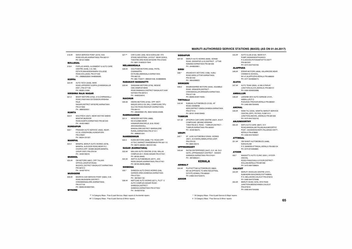
������������������� ������������������������������������
������� ���' ��������������������������������������������� ($!�!���"�#! ���$#%��
!#���
���������
-������*� �����&�� ��+����'�� �' �� �����%���'�#������� �� ������ ��*����'��� & ���������� &������� �!������"��%##(� �#$$)�%��# % %��
!%��
�����
��� '���$��#��������������� �� ��������'�����&�������������� ��!�(���"�#�( ��!#$#�
�����
��� ���������
������������ � �����!)��'������������������������� � ����������������/����&��������'������ �������������� �!(�����"�%##�$��� !�
�!��
�����
���� '���� ������ �������������������������������������������������� #!$�$���"�%��#!�%(���
����
������
������������ ���' ��� ������ ��"��� ������� ������������������� �(��!���"�#� ���$!$���
�$�,
������
����������������*������� �#������������� ����������� �����'��'��'���������&�����.������������������������� �(!�����"�%��#!�#$!#�
����
��� ��
���������� # ��������������--�' �������������������������'���&������������������ #�$!$���"�%��#��(����
� ���
�������
��������'���� ���' ������� $(�����������������& � ������'��'�������&���� ����������������� ��!$����"�#�($�%��#����%��
�(���
�����
'���'����'��$�(������#�&������������& ����������������� ���&����� �� ��������������� ����� ��������"�#�!� !(� ) !�(���
���,,
���������
&�������������$$������ ��'��������� ���� �����&����������������� (�!�$���"�#�����������%##�� ! �(��%��#((#%�(�
�#���
����������� ����
���&����������� ��(���� ��� �'�'�������������������������������'���&������������������ #�$!����"�%�#� $�%!(�
�%���
��� �
� ����������$�$����������������/�������/�����������'�����������������������'������������������ #�!�!���"��# $�$�( !�����%#� ! ($��� � %#�
$����
�������
� � . ����������%(%�����"$! )�%#��� ������������'��'� ��������������'��������������&���� ������'����&���� ������������������� �! !!���"�%%#($�!� ��
$!��
�����
��. ���������� (#������������������������'����� ���� � �������� #!!! ���"�#$�$��(($(���%#����!�#��
$���
��������������
�����������' �� ���!$$����������'���� ��������������&������� ����!���"�#!#$��%�� �
$$���
������������� ����������/�&��������&������������������ ����!���"�#!#$��#�$(��#($(�
$����
� �����
�����&����� �&&�*��������(���&��� ���� �������&��������������� ����!���"�%#!%$�!!$��
$ �,
� �� ����*������ ��!�������� ����'���� ����&���������������&�������'��������&��������������� ��������"�%��#$!%� #�
$(���
�������
��������*������ $$ ���������������������������������'�������������������������� #!$ ���"�%��# � #�!�
$����
����
���������������!� #������������������������������������� #!������"�%#� �%##���
$#�,
�����
�������� �������� �$�����&��� �����������& ��������'���'������&��������& ���������������� ��!$%���"�#�( �%��#!������
$%��
��� ����
������������ ��� !$$�����������' � � �� ��������'����&������&��������������� ���!����"�#!#!�%��#! %�($�
�����
�����
��������'���'�� �' �� �� $������������'��������� �������������� �� ���&������������������'�������������������� (���!���"�%��#!((�� �
�!���
�����
���/� �������� � �&&��*������� �!����������&��������������������� �(!�$���"�#����$$!%�
���,
���������
����� � ����� ��� ������������#������&� ��������&���������'������������������������������� ����!���"�%%��%% $�!�
�$���
������������
��������������� ���$#(��������%������� ����������������� �� �������������(# (!���"��#(��%�����$��$�
�����
����
���'�����!$����� ������������������������������������������������������(%! �$���"���$�%������!#��
� ���
��������
�������������% %����������� �� ���'���������'�����������������.���� ���������(##��$���"�����%��%%$#����
�(���
�����
��� �����($�����)!#%��������/�'����������� ����������(#$!�!���"��#��%$�%� �(%#�
�����
�������
��������� ������&���& ���!$�������������������������'���� ���������(#�$�!���"��#��%#�����%�%�
�#���
�� ��
������/��� $���������/������� ���' �' �� ��������� �������������/�'������'������ ����������(%!$�(���"��� �%���� $�� �
�%���
������� �
��-�����'�� ��$#�����������������&�������������/������������������ �'� ������������������ ���������(�#(#$���"��%��%���$�$$���
����
�������
���������������� �����((�����.���������������������&���� ���������(% !�����"�����%���( #(#!�
!���
����
���������'����'�� � !������������'�������������'�����������������'����������� ���������(%!$�(���"��� �%#���##(���
��,
�������
������ ��'� ��' �� �����������������������&���������������� ������ �'���'�����(�$�!(���"��% �%����� �%%�
$���
������'����!(� ����� ������/�'����� �'������'���'�����(�$�!#���"��% �%���$� ��#�
����
,, ��'1234567��188�"�-633�+�91:;��36<:=3���1>56�6391:68�+��==:;3?21@�6391:68 , ��'1234567��188�"�-633�+�91:;��36<:=3�+��1>56�6391:68
�� '�'1234567��188�"�-633�+�91:;��36<:=3�+��:?56�6391:68 � ��'1234567��188�"�-633��36<:=3�+��:?56�6391:68����
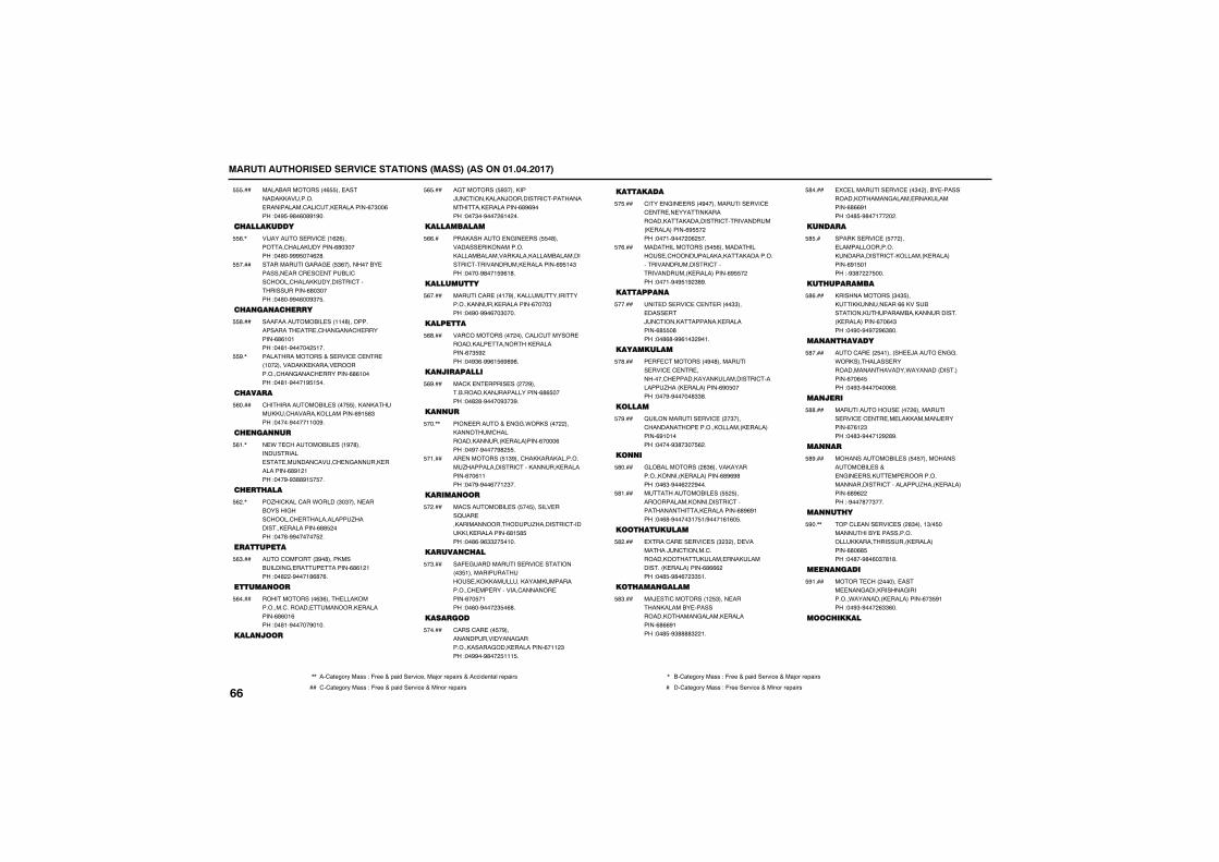
������������������� ������������������������������������
����������������( ��� ����������������� ����������'���'�� ���������(�$��(���"��% �%#�(�#%!%��
���
�� ���������
��/������� ���' ��!(�(�������'������������(#�$�����"��#��%%% ���(�#�
(�,
���������&���& �� $(����������� ������� ���'� �' ������'��'�����'��������������'��������������(#�$�����"��#��%%�(��%$� �
����
� ����� ��
���-���������� ���!!�#���������������� �� �'���&���'� ��������(#(!�!���"��#!�%������ !��
#���
��������������+�� ���' �' �� ��!������������ ������ ����������'���&���'� ��������(#(!�����"��#!�%���!% ! ��
%�,
� ����
'�������������� ����� ��������������'������������������(%! #$���"�����%����!!��%�
(����
� ����
� *� '��������� ���!%�#������������ �� ������'���'� �&������ ���������(#%!�!���"���%�%$##%! � ��
(!�,
� �� ���
��.��'����'���*������$�$����� ����������&���'�����'� �����������.��������� ���������(## �����"���#�%%������ ��
(��,
���������
���'��-����$%�#��������������&� ��� ������(#(!�!���"��#���%���!#(#�(�
($���
��������
�������������($(���� ��������������'������� �������� ���������(#(�!(���"��#!�%�����%�!��
(����
�������
�&�������� %$��������/�'���������/���������'������������� ���������(#%(%����"���$��%����(!����
( ���
�����������
����������� �&�� ���� �#��������� ��������������������������������������������������'����������� ���������(% !�$���"�����%#��! %(!#�
((��
����������
�����'�� ���!�%��������������������������� ���������(����$���"��%��%%�(��$����
(����
��������
���'����������������'���'������ ���������� �������� ���������(�$ %����"��%$(�%%(! (%#%#�
(#���
����������
��'�� � ����� ������%��������������/������������(#( �����"��#�#�%����%$�$%�
(%���
���
���� �����+� �&&�*��������������������'����������������� ���������(����(���"��%��%����%#� �
���,,
�� ��������� !$%���'�����������������.�������������'���������� ���������(��(!!���"���%�%��(��!�$��
�!���
�������
��'��������� ��� �� ������� ���B�� ������������������.��������'�������� ���������(#! # ���"��#(�%($$�� �!��
�����
������ ��
��- &���������� ���' ���������$ !��������������� ����������������������������'� �� ���������'������� �����(�� �!���"��(��%����$ �(#�
�$���
�������
'����'�� ��� �%������������������&���������������&���� ���������(�!!�$���"��%%��%#��� !!! �
�����
���������
'��� �&�� �����%����������� ���' �' �� �� ����������������������������'������������ ����������(% �����"���!�%�����(� ��
� ���
��������������� � (�������������� �'�����������������������������������������'�������������� ����������(% �����"���!�%�% !%�$#%�
�(���
���������
�� ��� ���' �' � �����$$��� ���� ��/�'�������������� ���������(# �#���"��#(#�%%(!�$�%�!�
�����
����������
� �- '���������%�#��������� ���' �' �� ��������'� ��������������������'������.����� ����������(%� �����"���%�%�����#$$#�
�#���
������
B����������� ���' ����$����'���������� ��������������� ����������(%!�!����"�����%$#�$�� (��
�%���
���
&��������������#$(������������������������ ����������(#%(%#���"��($�%��(���%���
#����
����������� ��� � �������������������������'��������������� ���������(#%(%!���"��(#�%����$!� !)%���!(!(� �
#!���
���� ��������
����'�� �� ���' ���$�$����� ��������/�'������'����������������� ��������������� ����������(#(((����"��# �%#�(��$$ !�
#����
��� ��������
��/ ��'��������!� $���� �������������� ������������������&������ ���������(#((%!���"��# �%$####$��!�
#$���
�' �������� ���' ���$������� ������������������&����� ������������(#((%!���"��# �%#��!������
#����
�����
������� ���' �� ������ ����������������������������'���������� ����������(%! �!���"�%$#���� ���
# ��
��� �������
���������������$�$ ����������� ���((������������������������������������ ����������(��(�$���"��%��%�%��%($#��
#(���
���� �����
���'�� ��� �!������ /����� �&&��*������������ ��������������������*������������������(��(� ���"��%$�%�������(#�
#����
�����
����������� �����(��������� ���' �' �� �� ����������/ �������(�(!�$���"��#$�%���!�%�#%�
##���
���
�������������� ��� � ������������������ ��+� �&�� ���� �� ����������������������'��������.����� ����������(#%(�����"�%���#��$���
#%���
���� �
���'� ���� ���' ����#$����!$)� ����������� ����������������������������� ����������(#�(# ���"��#��%#�(�$�#!#�
%��,,
��������
����� '���������� ���� ���&�����������&���������*��������� ����������(�$ %!���"��%$�%����($$(��
%!���
���� �����
����
,, ��'1234567��188�"�-633�+�91:;��36<:=3���1>56�6391:68�+��==:;3?21@�6391:68 , ��'1234567��188�"�-633�+�91:;��36<:=3�+��1>56�6391:68
�� '�'1234567��188�"�-633�+�91:;��36<:=3�+��:?56�6391:68 � ��'1234567��188�"�-633��36<:=3�+��:?56�6391:68
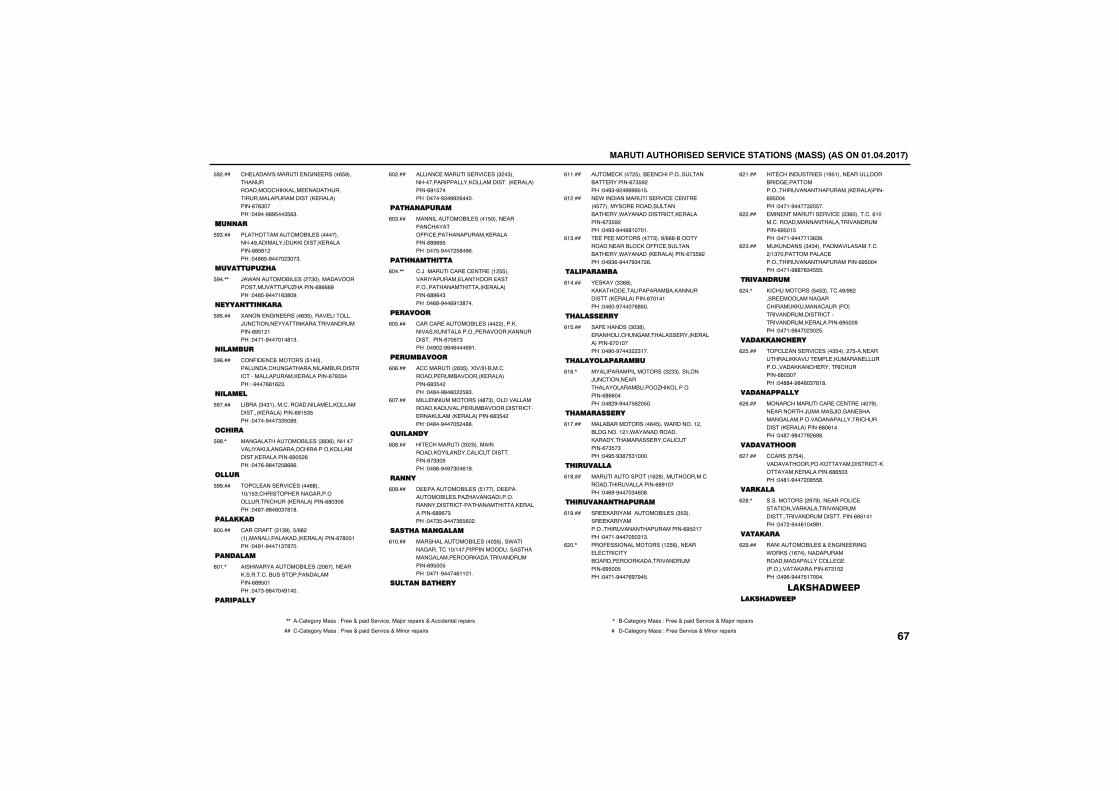
������������������� ������������������������������������
'� �����A������� �&�� �����( %����������������'�������� ��������������������������� ����������(�($�����"��%��%#% ��$ ($�
%����
����
��������������� ��������������%�������������������� ���������(# (!����"��#( �%�����$��$�
%$���
���������� �
/�*���������� �����$���������������������.�������(#(((%���"��# �%���!($#�%�
%��,,
����������
������ �&�� �����($ ������ �������/�'����� �����������������������(% !�!���"���!�%����!�#!$�
% ���
������
'��-�� �' �������� !������������'��&�������������������'�������������� ���������(�%$$����"�%���(#!(�$�
%(���
������
�������$�$!�����'������������ ���������������� ����������(%! $ ���"�����%���$$ �#%�
%����
�� ��
���&������������ ���$#$(�������������������&�����'��������������������� ���������(%� �(���"���(�%#��� #(%(�
%#�,
����
��'� ���� ���' �����(#���!�)! $�'������� ����&��������������'����� ����������(#�$�(���"��#��%#�(�$�#!#�
%%���
��������
'���'��-���!$%��� )(#���!������������������� ����������(�#��!���"��%!�%���!$�#���
(�����
�������
����*������������ �����(����� ����������'����������������������(#% �!���"���$�%#����%!���
(�!�,
��������
������' ������� ���' ���$��$���������������������������������� ����������(%! �����"�����%$�%%�(����
(�����
��� ������
�������������� ����! ����� ������'������--�' ������������� ���������(#%(% ���"��� �%���� #�%(�
(�$���
��� ��� ����
'�/�������'�� �' �� ��!� �������������� �������� ��������������������� ����������(#%(�$���"��(#�%��(%!$#���
(���,,
������
'���'�� �������� ���������������������������������� �����������������������(��(�$���"��%���%%�(���(%!�
(� ���
���������
�''��������#$ ������)��������'�������� ����������� ����������(#$ �����"��#��%#�(��� %$�
(�(���
���� �������������#�$��������������������������� ��������������'� ���������� ����������(#$ �����"��#��%���� ��##�
(�����
�������
�� '��������$�� �����������������������'���'����������(�$$� ���"��%(�%�%�$��(!%�
(�#���
��
� ���������� ��� !������ ���������� ����.�����&��������������������'������������� ���������(#%(�$���"���$ �%���$( (���
(�%���
���� ���������
��������������� �����$ ����*�����&����'�!�)!�������������������������&������ ����������������������(% �� ���"���!�%����(!!�!�
(!����
��������� ��
��� '������ ���� �'��������������� �������(�$ %����"��%$�%��%%%% ! �
(!!���
� *�������������� ���' �' �� ��� ���������� �������������� ���*������������'�� ���������(�$ %����"��%$�%��(#!���!�
(!����
�� �����������$���%)((#������������� ������'���--�' ��������� ���*��������� ����������(�$ %����"��%$(�%���%$���(�
(!$���
����������
� ������$$(#���������� �������������������������� ����������(��!�!���"��(��%�����(# ��
(!����
� �������
��- ��������$�$#��� ��������'��&��������� ����� ����������(��!�����"��%��%���$��$!��
(! ���
� �������������
���������������������$�$$���������/�'����� �������������������.��������������(#((�����"��#�%�%��� (�� ��
(!(�,
� ��������
����������������(� ���*��������!������&�����!�!�*���������������������������� ���'���'�����(�$ �$���"��% �%$#� $!����
(!����
� �������
�������������!(�#�����������'�������������������(#%!�����"��(%�%����$�(�#�
(!#���
� ������ �����
�� ���������������� ���$ $����� ��������������������������������(% �!����"���!�%���� �$!$�
(!%���
���- ���������������!� (���� ��� � '��'���������� ����������������������(% �� ���"���!�%���(%�%� �
(���,
�� '�������� ���!% !���� �������������& ���������������������������� ���������(% ������"���!�%����$�� ��
(�!���
��� �������� ���' ���$(�����'��(!�������'�������������������������������(% �! ���"���!�%����!$($%�
(�����
���������$�$������������������'���)!$������������' �������������������������(% ������"���!�%##�#$� �
(�$���
�������
��'��������� � $���'��%)%(����� ���������&���'������������'����������������������'������������� ���������(% ��%���"���!�%#����$�� �
(���,
�������� ��
��'� ���� ���' ����$ ������ ���� ������������� ��� ������� �����������������'� ������'�������(#�$�����"��##��%#�(�$�#!#�
(� ���
�����������
�����'�������'�� �' �� �����%���� ��������/������/���&�� �������&�����������������������'��������� ����������(#�(!����"��#��%#���%�(%#�
(�(���
������� ��
''����� � ������������������������������'��������� ���������(#( �$���"��#!�%�����# #�
(�����
������
�������������%�%���� �������' �����������������������������������������������(% !�!���"�����%��(!��%%!�
(�#�,
�������
������������ ��+� �&�� ���&�*������!(�����������������������������'��� & ��������������������(�$!�����"��%(�%��� !�����
(�%���
�������������� ������
,, ��'1234567��188�"�-633�+�91:;��36<:=3���1>56�6391:68�+��==:;3?21@�6391:68 , ��'1234567��188�"�-633�+�91:;��36<:=3�+��1>56�6391:68
�� '�'1234567��188�"�-633�+�91:;��36<:=3�+��:?56�6391:68 � ��'1234567��188�"�-633��36<:=3�+��:?56�6391:68����
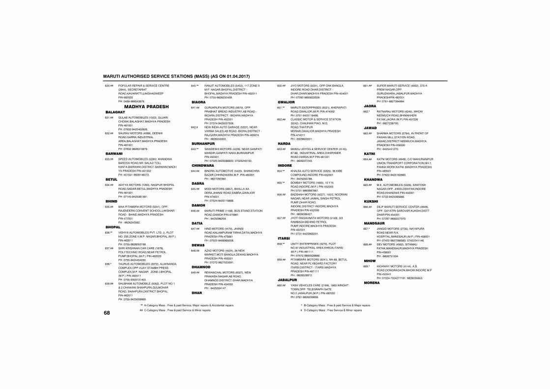
������������������� ������������������������������������
�������� �����+�� ���' �' �� ���%������ '� �������������������������* ������(#� ���"��#%�%#% �$#�(�
($����
�������������������� ��
&����������� ���! $���&/����'��*������&�������������� ��������#!��!���"��($��%�� ���%�(�
($!���
���������������(%���� ���������&���������������� ������&�������������� ��������#!��!���"��($��%#�($!�%�%�
($����
�����
�� ��������� ��� �(���������*����������������������/��������������*���������'����*��������������� �������� ! ����"� ! !�%%�(!�(��$�
($$���
�����
�������������!�($�����&���������������������� ������������� ��������(!��!���"��!���%�� $#! #!�
($����
� ��
������������������� ��!����������/ �� ���'��� ���'������������������������������������� ������������!���"�%#�(��� #��
($ ���
� ����
�������������� �����������������������$ �.�� �����������&����������������������(��!!���"�� �%#�(� $!%#�
($(�,,
��������������'���'�� ��!(�%������� '���'������� ���� ���������������������������(���$���"�� �%���� ��$��
($����
����������� ���$$���������������'���� ��������/����������� ���'���� ���������&�����.�� ����������������������(��!!���"�� �%$�$!$!��$�
($#�,
�������������� �� � �����������!�+���'��*������������&��������������������������'�������������(��!!���"�� �%�� ��%#(%�
($%���
���/��������� ��� � ����!!��.�� �������������&���������������'��������������������� ��������(��!!���"�� �%#�(� ��$%�
(���,,
�����
&������������� (������������������ ��������������������������������'��������������������� �������� ���!���"��$���%�� �$� �(�
(�!���
� *����������&���& �� $$����� ������������ ����������������������'�����/&��������������� ��������( (�����"�%#�( ����
(����
�� ���
�*�� ��������������%���� ���&�������������&������������������������ �$$!���"��$� �%�� �#(%������$� �� ! ��
(�$�,,
� �����
������������� �� �����������'������.���'�����*��������������#���!���"�%#���%�$%��
(�����
����
������������$# ��������������� ���/�����������������&*���������������!���"�� ���%�� !!%###�
(� ���
����
��������� ��!! (�����������������������������������((!���"�%�� �%(��%�
(�(���
�����
�������������������/������������������������������������������ ��������� ((!���"�� ���%��(%(%��(�
(�����
�����
�.����������� $�����(�� *����� ��������&���� *�������������� �������� ��!���"������%#�� $$ %!�
(�#���
� ����
� *��'�����������(������� *�����������&�������������������������'����������������� �������� � ����"�%�� $$�!���
(�%���
� �
/����������� �$!��������������&��������� ����������������'������������������������ �������� ���!���"���%��%#%$($$ %�
( ����
������
����� � ����� ���$��!����� �����������&*�������������������������"�� !�%�� !!(�((�
( !�,,
'�����'������+�� ���' �������� ������'��������������&�������������������&*����������������� �����������!!���"�%$�%(�$��!�
( ����
���
����/����&�+�� ���' �' � ����!� ���#��##�������������� ��'������ ����������������������(!$$!���"�%#�(����� �
( $���
����
����������� ���' �� $� ���$(���� �'������������ ������ ���!���"�%�� � �##�
( ��,,
��������������!( ���!����������������� ������������� ���$���"��$!�%#%$##�#(��
( �,,
��������������� ������! �)�������������&����� ���/���������&��� ������������������������ ������'������ ������������ �������� ���#���"�%#�(�%#����
( (���
/������&������������ !�%���$)$������&��� ������ ������������� ������������ �������� ���!���"��$!�%�� %( ��!�
( ����
�����
���� � ����� ���$�������������%������������� ���� ���������������������(!!!!���"�� ���%#%$ �#(#%�
( #�,,
���������������� ��!������(%��� ��������� ������������-�'���������������'�������������������� ��������(!!!!���"�%#�( �#%!��
( %���
�������
������ ��'� ��'�� ���!(%���!(($�*��&���*������� � &�����&� ������/�������������������#�������"��(!�%#�(� %# %�
((����
�� �������� ���' ���% ����$� ����� ����&��������&��*����/������������������ �������#���!���"��(!�%#���%�%%��
((!���
����
������/����������� ������*�� �'�������������� ���-����/���������������� ���(���"�%#���$#����
((��,
�����
�������������� �(�������-�����-���*��������������������/�*��������'�� �'������������� �������� #$$����"�%�� ��!����
(($���
����
�������������%�%���')�������������������������'�������������������������������������������� ���������#$ �!���"��(���%�� !(�((��
((����
� ����
������������ ��� $�(������������&��������/� ������������� �����������*������� ���!���"��$$�%�� �# (((�
(( ���
���� �
������������ ���' �' � ����(�%��������&���������������������������������� �$$!���"���%��%#%$�������
(((���
������
/��&������������$ ����������������� ������������������������������������ #��!���"������%#���(( #$���������!!�(�
((��,
� ���������� (����������-����������������������� �������� #��!���"�%#�(� ! $��
((#���
� ��
��&�*�����������!������������������&��&�������*������ ���������� $��!���"��$����$�����!#!��%#�(�$ ( $�
((%�,
����
����
,, ��'1234567��188�"�-633�+�91:;��36<:=3���1>56�6391:68�+��==:;3?21@�6391:68 , ��'1234567��188�"�-633�+�91:;��36<:=3�+��1>56�6391:68
�� '�'1234567��188�"�-633�+�91:;��36<:=3�+��:?56�6391:68 � ��'1234567��188�"�-633��36<:=3�+��:?56�6391:68
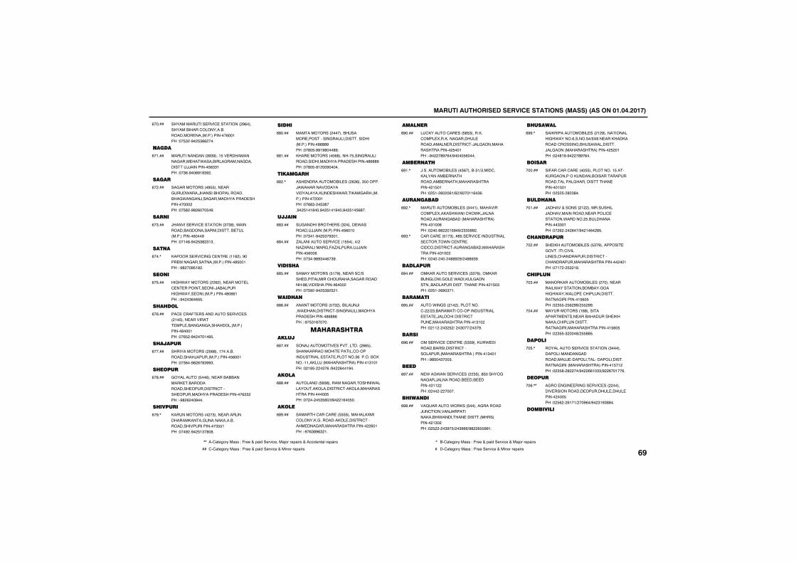
������������������� ������������������������������������
������������ ���' ���������%(����������������'������������������� ����������������(��!���"�� $��%�� $((����
(�����
����
�������������$%$%���! �� ����������&���� ��*���������&������&��������//��������� ($$!���"��$(�%��(%!#$%��
(�!���
����
��&�����������% ���� ���&��*����/����������������������&*��&��/���&�������������� ����������������"�� #��%#�(��� �%�
(�����
���
/������� ���' ��������$�$#���������������&����������������� ��������������(���%���"��!�(�%�� $#�$!$�
(�$���
����
�������� ���'��&�' �� ��!!(����%���� ����&��������������������# ��!���"�%#���% !#��
(���,
����
��&�*������������(����� ����� ��' � �������� ����/���������&�*���� ����������������#�((!���"�%���$(�( �
(� ���
� � ���
��' �'��- ����������� ���' ����!� ���� �������� ��� ����&��&����������������������#���!���"��( ��%�����!�% �
(�(���
� �����
��������������� (#���!�����������������/���������������� (��!���"��$(��%#�(�#$%%$�
(�����
� ����
&��������� ��(���� ��������������� ��������������� ���������'����� ��������������� ���������($$����"�%#�(���%���
(�#���
� �����
���������������$���� ������������������&��������������������������������$ !���"���%��%�� !$�#�#�
(�%�,
��� �
��������������������������� ����������&����������������������������#(##%���"��#� �%%!%#���#%�
(#����
���� ����������(#������� ����&��������������������������� ��������#(##%���"��#� �#!���%�����
(#!���
�������
��� ������������ ����($(���$ �������/�*��������������������������� ��*�������&��������������������!���"��(#$��� $#���%�� !�!#���%�� !�!%���%�� !� (#��
(#��,
�����
�&���������� ����$������ *��������//��������������� (�!����"��$�!�%�� $�%$�!�
(#$���
.���������� ���' ��! �����)����.���������&�-�.������//��������� (��(���"��$��%#%$��(�$%�
(#����
����� �
������������� !�%���� ����')���� ����������'���������&�����������#(��������������(�������"�� %��%�� $%� �!�
(# ���
���� �
������������ �$���������/���*������������'����&���������������� ��������#(##(���"�%� $!(�����
(#(���
����������������
����/������� ������������(( ������������������ ������'�������������� �� ��������$(���������������!!����/�������������������!$!�!���"��!# ����$�(�)%���(��!%��
(#����
�����
�������� %$(���������&��������*�������������������'��������������������������� ���"������� $ (�)�%���!(�� ��
(##���
�����
�������'���'�� �� �������������'��������&����������� ������'������ ���&���������������������(�!���"�%�($#%($�!�
(#%���
�����
�'������'�� ��� # $��������'���� ���������&������ ����������� �������'�/��&��������������������� ��!���"�%����#%�(�)%���� (����
(%����
������
/����������� ���� (������$!)$����'������������ ������������� ����������������������! �!���"�� !��(���(!)(�)%$��!!(�$(�
(%!�,
��������
������������ ���$��!�����������'���� �������*����'��*��/��������������&�����������������������$!��#���"�����%#���! %�%)�$$�%%��
(%��,
'���'�� �� !�$����# �� ���' ����������� '����*��' �� ��'��'�������'�����&���������������������$!��$���"�����������##%�%)��##%$%�
(%$�,
�������
���������� ���' ���$$�(�����������&��*�&�� �*������&��������������������������� �������! �$���"�� !��(%�$�!�
(%����
�������
���*��&����!�������������'���)�$���������'�������������� �� �/���'��������'��� �����������������!$!�����"��!!����$� �)���$���)��$�%�
(% ���
����
���� ���' �' �� �� $ %�����* �������������������'�����������������������������!$��!���"�%# ��$���$�
(%(���
����
� *��&*���� ���' �����$ ���# ������&���&���/����������� ��� �������$!!�����"�������������
(%����
� �����
��B������*������ ������&��������/�'�������/��������������*�������� ������������������!$�����"�� �����$%� )��$%(()%#��( %%!�
(%#���
� ������
���������������� ����!�%�������������&�*������(������ �) �(�� ���������������'������&�����*��������/��&����������������������� ��!���"���#!%�%����#%�(��
(%%�,
�����
��-���'���'�� ���� �����������! ������&��������������������������������������&������������ �������! �!���"�� � ��#�$#��
������
���� ��
/������+��������!��������������/����������������� �������' �������*�������� ���������������$$�!���"���(�����(��)%��!�(��# �
��!���
� �����
�� ����������� ��� $�%��������� �&�������'�������� ��'��������������'���'�����������������������������!���"��!���� $�!#�
������
� ����
���������������� ���������� �������*����������������&�����&�*���*���� �'���������������&���������! (� ���"��$ �� (�%%)� �%%�
��$���
������������!(#������������ ���� ������������ ���������'���������������&��������������������! (� ���"��$ �$����#)� ## �
������
������
���������� ���' ��������$�������������������&����������/ ����������������������������&����������������������! �!����"��$ #��#����)%���((!�$$)%��(��!��(�
�� �,
�����
�&��� �&�� ���&�� ���' ������������� ������������ ������� ���� ���������� ���"�� (���(!�!)���%(�)%��$!%$##��
��(�,,
���������
,, ��'1234567��188�"�-633�+�91:;��36<:=3���1>56�6391:68�+��==:;3?21@�6391:68 , ��'1234567��188�"�-633�+�91:;��36<:=3�+��1>56�6391:68
�� '�'1234567��188�"�-633�+�91:;��36<:=3�+��:?56�6391:68 � ��'1234567��188�"�-633��36<:=3�+��:?56�6391:68����
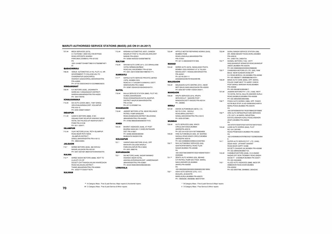
������������������� ������������������������������������
� &��� ���' ���� �$�����!�$����� �!�� *�������������������������� ����������������'����������������!��$���"�� !����##��)���#%��)%#�!�!��$()%%#��%�!%��
������
������ ����
� ���������� ���!�����������������&�� ��� �����'��� & ���/���'���������&���'���������&�*���&���'�������������������������(� ���"��!$���$$���)%���! !���)%(#%��#����
��#���
���� ��
����������� $����/�&������*������������&��&��������'���*������������������������$�!���"�%��!��(����
��%���
�� �������
�������� �����$#�!����) %�����&���� ���'��������/��������������������!(!! ���"��$���$ #��)�$%����
�!����
�����
�/�������������$#(#����������$$���#���� ����������&�*���� ����� ����������' ��)���������������� ������!$!�(���"��!!��� ��!�
�!!���
�������
��/���������� !$����� ���������������� ���� ���������������������'������&�������������������!(!!����"�%#(���(�#��
�!����
������
��� ��������$������$(�������/����&���/��&���������� ���!���"�� �����!%���%#�$! ����)%���� �����
�!$�,
�����
��� ��������������� ((#���� ������������'�������'� �����*�������*������ &������������*��*�������'������ ���������������������(� ���"�(� $����)� �����#)�%�
�!��,,
�����
�������������� ����$����&�� �����&���������+���������*��������������������$ �!���"�� %��%����$$!$�)#�#�%##�$ �
�! ���
�����
����������'�� �� �!���')��&����������������������������������������������������!$�����"�� !��$�! !#)( !#���)%#(���!��!�
�!(���
�������
����� ����� ���' ������ ����� ���!%� ���������&������������!������������������������������&������!((�����"��$(���$$�$�)�$!%$�)%����$���!�
�!��,,
�����
����/��� ���' �������� %(������������������'���*��&������������&��&�����������&���������'���&��������������������!$�����"��!!��%�($#(�!���
�!#���
� �����
/��� ������������%���� ���� ����' �� ������������������������&���������'�����������������������������$�$���"���($�%# �$ �#�()%%��%!��!%�
�!%���
� ��
�������& �'� ���� �#������������������������!���� ������&�������������! (�!���"��$ (��($$�%)�(�$�%)�%��%����#!)%���%!���%�
������
��� ���
����������������$!�����������������'��� & ���&����������������������!(��$���"��$!��(#�����
��!�,
�������
��������������%�����&������������&�*���� ����� ��������������&������������ ���&����������������������$(�!���"����$�%$�(�$%���)%# �(#�$#��
����,
�������
������������� ������&�*������� �$����������� �������������������������������!���!���"��!!���#�$$�)%$����!%� �
��$���
�� ��
��� ������ �������&��*�����������������&�����&�*�����+����������������������&���������������������$�!���"��!� ��$$!!!)���$� ()%����% �%�)%����% �%%�
������
�������
��� &�������' �� ��$��!���� ���������&��������� &����������$��$���"�� �%$�!$�(%!!)�� ��� �!!�
�� ���
�����
������ ���' ��� ����������� ���' ����"������ �����"����&�����������&����������!�����"��($$($�
��(���
����
������������� ��� (�����'������"���'�'����������/�����������/������'������&�������������������!(�!����"��$$��$� %(!�
������
������
���� ���' ��� �(������&A��'��'� ����&����������������������!%���"������!�!�$!)��!�!#��)( #��#�%�
��#���
������������ ��� �����%��� *� �*��������������&A��'��'� ���������������������!%���"�������%((#�)���%( ��)���$�%���
��%���
������������ �� ���' ��� $���&�������������������������&�����������������#%���"����� ����#�)$�%�%�(�)� ��!( ()( � � $!)� �%$ #��
�$��,,
. �������*������ � ���� ���������� ��������������������������������� ���� ����������������������� %���"�����#$��( %)�#���( $)�#$%�# �)�#�!#%�(�
�$!�,,
��������� ���' �� ���������'��� �� ����������������&�������������������������"��( � $$#���( �(�##��%#������%!�
�$��,
���/����&���� ���' ���������$#����������� �� ���������*�������������������!#���"���%$!�������%��� ��
�$$���
��������������!! ���������*�������������������������������* ������������������#���"����� (( �(()(� �� ��)� (((�( �
�$��,,
'���������������������� �����������&��� ���������������--��������������������*����������������%����"�����#($ (��)��#�%�###)�#(!(��!�
�$ �,,
���������'�� ��(� $������������������' �'����� ������� ��'� '��������������������������������������� %���"�����#$�%#!()�#$�%#!��
�$(���
/�&�������������������! (���� ������ ����������� ����� ���������������&��&��������������� %���"�����# �� %�)�# ��%#$�
�$����
��*������*������!((������������'�������������!%������������'���������&���*������������������(���"����� ���$ #)� ���!�()� ��##��)� ��$#�(�
�$#�,,
����������-����'� �� ���' ������!%�!���%����������������� �� ����� ����������������� ���� ������������������ %���"����(����!��)(������!)(�����!()(��������
�$%�,,
���������*������� ������������!��!�������������������� ������������������ ���"������$�# (()��$�#�##)��$�!���)%#��$�$(�(�
������
�� ������ ���' ������������$����� ����*�����/��*�����*��������� ������������ ���'� �����������*����������������(#���"�����#%$��$%)�#%��!���
��!�,
'� ������������ �(���$!)����������&����--���������������������������'� ����'� �������������������!���"����� ��$($%�
������
���� ������& �'� ����(((���#()���������� ����������������������������� ����"�����(����((���(�%## ����(��� ���
��$�,
����
,, ��'1234567��188�"�-633�+�91:;��36<:=3���1>56�6391:68�+��==:;3?21@�6391:68 , ��'1234567��188�"�-633�+�91:;��36<:=3�+��1>56�6391:68
�� '�'1234567��188�"�-633�+�91:;��36<:=3�+��:?56�6391:68 � ��'1234567��188�"�-633��36<:=3�+��:?56�6391:68
������������������� ������������������������������������
����' �� ���' �' � ���$������$��&��� �����������&����� �� �&���������* �����������������#(���"����� ��!$#$)� ��!$$$�
������
'�����-�������� �� ���' ������������( ������'�&���*������ ������������� �� ��--������������ ���������������������������*����������������#����"�� (�#�� )()���%#���%(%���
�� �,,
� �������'�� ���������#�#�������'��&������������� �� ���������������'�����������������*�����������������������������(����"����%#(����$$�)�#(� $(()�#�#�((!�
��(�,,
���'��-���� %�����������!���� �������/������/������ �� ��������&������������*����������������#$���"����� �#$ #()� %���� )%$�$! !�!��
����,,
��*������*�������%((���&�������!�)! )!(��������&���!�'�*��&�������������������'������������ �����������*�����������%���"����� !�$%#()� !�$%(!)� !�$!�()� !�$!���
��#�,,
���-���'����������� ��� ! �������������������������* ��������������'���������������������������!�$���"�����#% !��()�#%$�$� �
��%�,
'���&��������� �$����'��� ���-�*��� �������+�� ����������������������( �!���������������������������(���"����(( �#$#�) )()��
� ����
�����'���'�� �� �$(��������*������� �������--��������&�� ��������������� �������'�������������������������������#���"����� %(!#$!)$�)$$)%#!%! %����
� !�,,
������
/��� ��������� ��� (�(������������������&�*������������ ��������&���� ����������"�����������'���� ������������������!��!���"�� ���(#��(�)%��$$���!%)%��(#������
� ����
�����
����� ���' ���������! #���� �����&������&�*�������& ���&������������&�*�����&���������������&�������������������!�!!!���"���!� (�!!�!)�%#���!(�#()���#$$(�
� $�,
����
������&���& �����!�����������&�����&�������������������!���"��!��� #�%��) $$#� �
� ��,,
��� / �� ���' ����������'�������������������������&�����������!#���"��!�����(���)����!(%��
� ���
��&���������� ����((��������������� ��� ���' ��������������$���� ���� ��������*�������������//*�����&�����&������������ ���"��!����%$�!$)�$�% �!)�%���!� $( )%%(�(% #�$�
� (�,
����/���������$��#����������!#)���� ������������!���������������&���������!!!!���"��!���%%(�($��(#�
� ��,
�������������$��$���(%�����������������&��/���&������������#���"��!����$�$��)%���!!$�##�
� #���
��&���������� ����%�!�����! )�#����'����������&������������ ���"�%���!� $( )# ��#��#��
� %�,,
����� ���' ��� $$%���!������������&��������&�������&��������'�����&����������������������!����"�%$�$���#���
�(����
����
�����'�� ������'������� ��#����������&�����'����� ��-��������� ������ �������'����� ������������������$!(� ���"�%�� � !����
�(!���
�����
��� ����������$(������ ������!$�)������������$�����������&������.���������������������������������� �!����"��$(��%#��$��%$!)�(!$���
�(��,
�� ��
��''��� ���' ��$����������������''�����''��'���������������������������������������"�� $�� ��#$�)#�%(%$%%(�)#�#�%�� %��
�($���
����������� ���$�����������'���� ��������� ����������������������������������������!�!���"�%#�����%$!)��(�$���
�(����
�� '������ ���' ����� !������ ��*�����&���������������&������&��&������������������������ ���"�� $�%�� !����!�
�( ���
����������
�������( ����)���������� �� '�������������������������������� ���"������#$!$ �)��#$!$ #�
�((�,
'� ����������$!�$����������� )���� '���!%)�������&� �������������.���� ������������������'�������������������������������������� ���"������#�� (�)��#�� ( )��#�! ((�
�(��,,
'�&���������!$#���������$��'������������ ������� ����������� �����*������������ ��� ������������������������������!���"�%#�!(% $ ��%#��%$$$$#�
�(#���
����
������& �'����#����� !()�����������������&������ ������!!������"�����( �($!)�( �%((�
�(%���
�� ��
���������� ���' ���������� ���������������&�����������������������������������������!�!���"�� �����$��)���$�!�
������
�����
��� ��*������������ ���' ��� #�����$!!)!������������ �����������%��� �&�������'���������������������������!$(�(���"���� �� �!%%)%���%$ ( (�
��!���
��� ��
���/�������� ���' �' �� �� (������������ ��� ����&������������������ ������'����������'���/��&������������������������!���"�� %(�%#%�$��#�$)� %(���!���
������
���� �
�������������� $���� ��� � ������&�� ����������&����������'������ ������������������!������"�� � �� (��()��%#%�(�%!���
��$���
�����
�� ���������� ������%����� ������ ��������#$����� �����������'����� �� ��������� ������'������&���������������������!���(���"������� !(��)�� �)$! �#��%�
����,,
&��&�����������%$�����������"!� �!���� '���!���������� �� �����'��'��&���*��� *����� �������'������&���������������������!���(���"�������(� � �
�� �,,
��� ��
����� ���'��&�' �� �� � ������) ����'��������������������������$!��!���"��� ����%�%%)%$�(!���(��
��(���
��� �
�����'������/������� ��#������ ����� )�����*������������������������'����� ��� �����������������!!��!���"�%%%(��$$(��
����,
��� ���
��&���������� %�%�������� �������'� �����&���������������������������'���� ���&�������������������!�!�����"���!����%$�%)%#��!%�%(%�
��#���
��
����������� (����������� ����*�����������������������&�*���!������� �������'����&���������������������!�����"��!�$�� %�#�
��%���
� ����
����������� ����$(�������&����������������������������! �$���"��!((��$ (�)%���(�(�%(�
�#����
���������
���*�� ����������$ ���0���*�� ��0��������&�����&�*�������� &�����������������������������%���"�� ��%�(((���(�)#�� �! (���
�#!���
���
,, ��'1234567��188�"�-633�+�91:;��36<:=3���1>56�6391:68�+��==:;3?21@�6391:68 , ��'1234567��188�"�-633�+�91:;��36<:=3�+��1>56�6391:68
�� '�'1234567��188�"�-633�+�91:;��36<:=3�+��:?56�6391:68 � ��'1234567��188�"�-633��36<:=3�+��:?56�6391:68����
������������������� ������������������������������������
�������������� �������� ���! (%������ �����$(���������!����&���������������&��������� ���&� ��-� ����� ���� ������!!��!���"�%#%�!((##(�
�#��,,
�������'���'�� ���� $������������.��$�)���*��&������ ����� ���* ��-� ����� ���&���������� ������!!�!����"����((#��%%�
�#$�,
����� ���' ���������%������&)� ���!!)!��� ��� � ���� � �'���& ����'������������ �������������������!!��(���"����%����� $$�)��!�$#$#�
�#��,
����������� �� ��%�������������� ��� ������������#!�������!(������*����������������������� �����&������������������!�!!����"�%$�!�!� % �
�# ���
�������'���� ���' ��� !(!���&/����'����������-���� �� �������.�'�������������� �����������������!!�$#���"�%%(�(%�� !)%%(�(%��(!�
�#(�,
������������ �� ��$������ ������)�������������� ����!������ ���&������� ������'����� �����������������!!� ����"����( ����$%)%#����$����
�#��,
�����'�� �������$$$������������$) ���� ��������������������������� ���� �����������������!!�� ���"���� (($�$!�
�##�,
� ��
��������������! �������-�����-����*������ ����&���������������)��������������������&�������������������!$������"����(��$ ((�)%#��� %!#�)%#��! %!#��
�#%�,
���
�'�����������($!�������������� ��� ���' ���������� �������/��&����������������������� �#���"�� #��%��$!##$��)%��$%���(�)� �$���
�%����
� �
������������%�������������������� �����������������'������&���������������������!�%���"��!%��%����%(!�%)�$$�%��
�%!�,
�����
��� ������ ���' �' �� �� $�������&����������������&���������� ��/ * �����"���������"�����������'������ ���&���������������������(�#���"�%%����!����
�%����
������
������������#������ ���&� *����������� ���������������&��� ���������� ���&������������������(�#���"��������� !$�
�%$�,
�����
������������� ���$��$��� % )����&���������&��������!(�!(���"��$$�$� %(!)%#�$� $ %(�
�%��,,
����/������ ���' ��! (������������$�&��� ����������������������&���������'����&�������������������!(�!(���"�%#��!�(!�(�
�% ���
�*��������������������������'������� ��������&�������������&����&������������������!(�! ���"�%�������#��
�%(�,
�����
������������� �$��������*�����&����������������������������'��������������������������!!�!����"�%#%��!(� ��
�%����
�����
�������������� ��� �(�����%�)��� &��������������������������������'������������'��������������������������! ������"�%#(�($%$(#�
�%#���
���������
� ��� �������'�� ��!( %�����������!��������&�����&�*������&�����������*��*��������������������!( !����"��$($����!(�)��! $$)%��$$��($%�
�%%�,
� � ���
������ �������� ����#�������� #����������������'����������������������������������������������������� ��%���"�� ( ���(�$�)���$��)%#%� $�%$�)%��!��(�$�)%��$#�!�#��
#�����
� ���
��� �&�� ������'�� ����(#��������������������������� ���&���������$!�����"����$���$!%�)���$� �)%�����(� ��
#�!���
� �����
����/���������!%$����# $(��)!�����/��� ������������� �������--�' �������������!$������"�(�%(%()�(�% % )%#�$!!!!!��
#���,,
� �����
&������������#�!������������������������������� ���&��������!$��%���"% �����#��(����%��
#�$�,
� ��
����'���������� ��� �%���$�������&����� ��+��--�' �'���� ���&���������� ���������������(�!���"����� ��!!� )%%#�!� #((�
#���,
����*����������& �'���$�����������/���&�����������&�� ���������*���'��'� ���� ��������(�����"����(�$������
#� �,,
� ����&������&���& �� �������������� �������� ���������������������� ��������(�!���"����� #%�$� )�� #%�#%�)� #%!%#!)%����!%�# �
#�(�,,
���& ���������� ����#�����������&���&������ ������������������������ ��*���������(�!���"����(� �%��!)(� �(����
#���,
� ���������� $���������������������*������������������������������������� ������������������!$�!���"�%$����$!�$�
#�#�,
�� �����
��� ���'���'�� ��$�(����!�!)����������������� ��� �����������������������������&���������&��������������������!��$���"�� !���$����)%$�� �����)%#!%(%�����
#�%�,
'������������� ���$#� ���� �����/���� ���������������'������������*���������������������&���������!��$���"�� !�� ��%�)� (!(���
#!��,
��
����������� ��� (( ����� ���&�*������ (�� ���/����������/����������& �����������'������&�������������������!���(���"�(��!$ $$�
#!!���
����
����������+�� ���' �' �� �� (� �����&���� ����� �����������!$�$������'������ ������������������!$�$���"�%����� $$�
#!����
����
����������� �� (�!�������*�����&���� ���*� ��������������!�������������'������&�������������������! $!!���"�%%(���#����
#!$���
���
���������� ���' �����!���*��������������*�������������������!�#�$���"��!(��%��$%�!�� �
#!����
��� �
������������!($!�����&�����������*����*��������������������������!���"��! ��%##! ##$##�
#! ���
����
����������� �� #�$�����&���'����������������������������������*�����*�����������'�'���������������������������%�����"��!�(��#!�%%)%��(!!#!( �
#!(���
��������
��� �����������������&��� �������������������������������� ��!���"���$����$$$�)��(((��
#!����
����
,, ��'1234567��188�"�-633�+�91:;��36<:=3���1>56�6391:68�+��==:;3?21@�6391:68 , ��'1234567��188�"�-633�+�91:;��36<:=3�+��1>56�6391:68
�� '�'1234567��188�"�-633�+�91:;��36<:=3�+��:?56�6391:68 � ��'1234567��188�"�-633��36<:=3�+��:?56�6391:68
������������������� ������������������������������������
�������������(�������������������&�*������������������������ ��!���"���%���)( ! ( �
#!#���
������
��/������������ ��$��!�����&���������������� ��������������������������������� ��� ���"�� %��%%�$����� )%��$!# �� �
#!%���
��� ������ ��
������������&���& ���#�%���������&�������������&��������������������% ��!���"�$# �%�$(��$( %)�� �(�)� $( !�
#�����
�������
����������*�������(��������$%��������������� ������������������% !�(���"�%�$(���(�!)%�$(���%$#�
#�!���
�� ��������
��������� ��� '�������$����������� '�- ��' �����&���*��� *�/����������������� ���������%���!���"�$( !�#%���$�����
#�����
� ������ �����
�������'����*������ �������� ����������&��.����&������� *�'��������'�������������'�'����������.����������%(��!���"�%#(��� �! �
#�$��
������
��*��� �&�� ���&�*������$!� �������'��B�� ���&� ����.����������%(��!���"�$����$� �$ �
#�����
�� ����������
�/����������#�!���!�$������'���������������&�����������%�!!����"�$#(���$!###�
#� �,,
�� �������
. �������� ���! �$������'����&��������������&�������������� %!� ���"�(�(����!## )%�$��( � $�
#�(���
������
�����*���������� �*������$!��������/��&���& ������������������&��������(���!���"�(( ���$$$� )�$!#%(�
#�����
����� ��
���'�� ���$���������.�������������� �������� ������ ���!���"�(�#��(� $�!��%�$�� !%��)%�$��# (�(�
#�#���
�����������$(((������)%������������ ������������������ ��������������� (��$���"�(�#���((#�%)%�$�% $ % )%#(!�$�%%��
#�%�,
�����
�����������$��!������-�����-������������ ��/�������������&�*������������������������ #�$ ���"�(�(����(! #)���(���)%$$�$#$%���
#$����
����
'���'����!!(����������!)!���������� �� �����*�����������������&���������(#��#���"�((�(��$�#���
#$!���
� �������
�����/������ ���' ���%$(�����������!#��!%��$��+�$!�����&���������������� �� ���"��������������� ��*��������������� ��!%���"�(��������$$��( � (����%#(!!��((���%#(!�% ����
#$����
�������
��&��� ���' �' �� ��������� ������������������������������������������ �������'�'������� $�!����"�(�!��$!!�(!)�$! �(��
#$$�,
����� �����(������������'�'������� $�!����"�(�!��$!!(�()�$��(�(�)�$��(�(�
#$��,
� �����
������������� ��� ��%�����������&�������-�����-�������������������'����� ��������������������� %��!���"�(�(��%�$��!�%��)��$����
#$ ���
� �������
���� '���������($#��������!��� � ������/����&���������������(#��$���"�((� ���$ !�)%����#���!�
#$(���
������ �����
&�������������� ���$!�#�������������������� ����������&�/�������������������(!������"�(#! �$���( )%�$�!����$�
#$����
���
������������� ������� ���&�����������'��*��������!������'��������������������� ���!���"�(� ����$#��)%��(��#��#)%#(!!!��� �
#$#���
��������
��������'�� ���#$������������&�'���������'�������������������������������������������(#��!���"�(($�%�$��(#���)���$���)�%#(!��#��$�
#$%��
����������
�������������� �$ ������������������$�� ����&��������'���������������������(��$(���"�%!%�$��� �!�)%%$%($%� ��
#�����
���� ������������
����� '����((%������!����������������&��� �������������������&'���������������'���������������'� ��������(�%(�����"��$(#����!�!)%#��$#$!� �
#�!���
����� ��
���������������!����������!��!���- �������.�������� ������������������� ������'� ��������(� ������"��!$��$ # ��)%#�$�� (#%�
#���,,
��������������������(������������(�&���������������� ������&���� ���!���- �����������'� ��������(� �� ���"��!$�����#��)%#%�� %����
#�$�,
�������������� �(����(����&�� ��������&����������/�����������'������������'� ������������������������'� ��������(� ��%���"��!$����!!��)%�#( #%����
#�����
������
� �����
&������������ ����#���������������� ������������������&�������'������ �&�������/��������!�!��!���"�!(�#�%#�## �!!#�
#� ���
�����
����*�������������� (((���� �����������������������/����������'���-� �&������������/�������!����(���"�%#!� �#�#��
#�(��
����
�������������� #������ ���� ������&��'��� & �����������������'�-� ��&������������/�������!��$�!���"�%#!�##�����
#�����
������
������A��������� ���$�����)���������������'���'��������&�����������/�������������������/��������!�$��!���"�%#!��!$!!$�
#�#�,,
��&&�� ���' ���������$$������ ����� ������������/���������������/��������!�$��!���"�%###�� (!��
#�%�,
�������������� ���!��������B���������&��������������������!�$��!���"�%#! !(�((%C#����!�%##�
# ��,,
/�'���������'�����$(����!(�'��������� ��������&����& �'��������������!�$��!���"�%#!��%%%���
# !�,,
���
������� ���' ����������$$�����������������������������������/��������!��(�!���"�%#! %!$� �
# ����
�����
��/��������&���& ��(������������������������������/���������������/��������!�#!�!���"�%#�(!$�$(��
# $�,
&�������������%(������������������������������'����&�����/�������!�#!�!���"�!(�%�%$!� !�%!(�
# ����
� ����
-�� �������������$$�������������������������������������/��������!��������"�%#! �����#�
# ���
,, ��'1234567��188�"�-633�+�91:;��36<:=3���1>56�6391:68�+��==:;3?21@�6391:68 , ��'1234567��188�"�-633�+�91:;��36<:=3�+��1>56�6391:68
�� '�'1234567��188�"�-633�+�91:;��36<:=3�+��:?56�6391:68 � ��'1234567��188�"�-633��36<:=3�+��:?56�6391:68����
������������������� ������������������������������������
�� �����
�� ��������� ���(�$�����������&������������������������! !��!���"�!(��%#!��$(!($�
# (���
��� ����������(�$��������������* �������������������������! !��!���"�%#!�!���� �
# ��,,
�������������� �!������- ����� �������� ���� ���� �'����� ���������������������/�������! !��!���"�!(��%###(�!#!��
# #���
��� ��� �
/������������� ����!������ ������� ���������������������������������������! ! �����"�%#! !(%(��
# %���
��������
�������������� ���!��#���'�����&������������������������������ �� �������������!�� �����"�!�(��%%!���%�!!�
#(����
� ��
������������!%(����� ����'�����������&�����������������!�#������"�%#��# !�(#�
#(!���
������
����������� ���' ��������$$$$���&���������������&��������&����������/��������!�$ $!���"�%#!�(% �$$�
#(����
����
� ��&���� '����'���*������� (����/�������&����������������������&������/��������!�#�$ ���"�!(������ � �
#($���
��� �
-� ������������#���&�����������������������������!�!��!���"�!(�#�%#!��$!�#��
#(��,
�������
������������(��%���������������-�.���������! �!�$���"�!($#�%###(�� ��
#( ���
�������
�� /�������� ���$ (#���&��������- ��. ���'������/��������! ���!���"�!($��%#! !���%��
#((���
�������������$�#���� �����-�'��������&�������- ��. ���'�������! ���!���"�!($��%#!��%�$$!�
#(����
������� �
/�*���'���' �� ��$�������������������������������&�*���&��� ������������� �������/��������! �!�!���"�!($��%#!��$��#(�
#(#�,
���������� ��
�����������$ $�������������'��*��&����*�������������������������/��������!�$��%���"�!# %�%%!�(%%!�!�
#(%���
�����
&������������� �����$����&��������&�������������&*������/�������!����%���"�!#���%#!����(!��
#�����
�������
��/���� ���' ����������%���� �������*���'������&��������������&����������/��������!����!���"�%#!��$�($��
#�!�,
�� ����
/�&��� �����������(#����� ������������������������������!�(��!���"�%�!( !%�($�
#�����
�����
�����*���������� �����$ ���� ����/����� ��������&��������/�&���������������������/��������!�!��$���"�!(���%#!�$!#(���
#�$���
����� �
�������� ����� ���&�������/������������/��������!����!���"�!#!��$!%$#�
#���,,
��/��������&���& ��! � �������'��*��&��������/�������������!����#���"�%$!� !�$(��
#� �,
������������&���& ��!(�%��������������'��� & ���������������/���������'�������!����#���"�%#! �$# $�
#�(�,
'��������� ���' ��������� �#����������&��������� ���������' �� ������� ��� & �������/�������������!����#���"�!#!�%###$#�� �
#�����
����� ���
����*�������������(�����������*���/����������������������������!��(�!���"�%$ ��!! � �
#�#���
�������� '��� $�%������/���������� ����'���������������/�������!��(�!���"�%###�(���(�
#�%���
�����
����*��������������$$$ ������������' �-�'����'�����&������������������/��������!��!�$���"�!###�%#!���$#�$�
##����
����
����������������������'�� ���������������'�����&����������������������������/�������!����!���"�%�!(�(%###�
##!���
��� ���
��/������' �� ��(��!������� � ���� � �'���& ���������&���'��*��������������!�!��!���"�%# !!���$�
##��,,
� ����������� �� ���' ���!!�(��������/���������* ����� �'�����&���������������������!�!�!����"�!(!��(#�$�%�
##$�,
�������������� ���!�(����&������������ *���������������!�!��$���"�%#! ��(�(��
##����
�����������*���������� $$�����������������-���.��������������������!�!��!���"�!(!�%# ��# %!�
## ���
����������( ����/�����������������&��������������������!�!��$���"�!(!�%�!(#������
##(���
������
� �����������(�� ����������'��*������������������������! �!�����"�%#!�#���(!�
##����
������������
���������������!������&��������� �����+��������������&�����&��������!��$�!���"�%#�(!#!#�!�
###���
����
��/�������� ����!(����� ��������'��� & ����������/��������! ! � ���"�!( ��%#��(�% %!�
##%���
����
&�������������� ���*������$����&���������&�����/��������!����!���"�%%!�!�!$#��
#%��,
�� ���
��������������� (���'� ������������ ������ �������������&��������������!(�� ���"�% �! �(�( �
#%!�,,
� ������������������������� �! %������������ ������� ������������/�������!(�� ���"�%#!�$������
#%��,,
�������� ��$����������� %$������������ ������ �����������������'�������������/��������!(�� ���"�%$!(!�#$���
#%$���
� �.�����'���� �$���� �! $������ �������������� ���������������'����������/�������!(�� %���"�!���%#! ( �$�$�
#%��,,
����������
&������ ���' ��������(�$������������/����������������������������������'����&�����/�������!�#�$$���"��#���$�((���
#% ���
�����
��������������' ��!�������������������������������!��!�!���"�%#!#(!�����
#%(���
������
� *���� ���������� �����$����&���������� �������/�������!���!!���"�!##$�%�($�%��!$�
#%����
����������� ��'����������� � !������������������ ��������������������&�&�������� ����������'���������������/�������!���!!���"�%#��$$ %�$�
#%#�,
������
����
,, ��'1234567��188�"�-633�+�91:;��36<:=3���1>56�6391:68�+��==:;3?21@�6391:68 , ��'1234567��188�"�-633�+�91:;��36<:=3�+��1>56�6391:68
�� '�'1234567��188�"�-633�+�91:;��36<:=3�+��:?56�6391:68 � ��'1234567��188�"�-633��36<:=3�+��:?56�6391:68
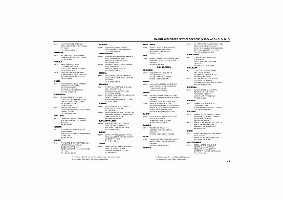
������������������� ������������������������������������
���*�������' �� ����(�������������������������/�������! ���(���"�!($$�%%!�!$$%#��
#%%���
�����
� ����������$ $!������������������������������������!�!$!����"�%#! (���#��
%�����
�������
��/��������������%$ ���'�!������������-�'�����������������/�������!����!���"�!� �%$!(���$$ �
%�!���
����������������#������������ ���� ����� ��-���� ��-�'������ �����������/�������!����!���"�%#!��#%#(!�
%���,,
�����
���������� ����������������������� ����������*���������&���������������������/��������!�$��!���"�!# !�%#�($��#�$�
%�$���
� �����
�*�����������$�������������*)�����������������&&���� ��������&�����������&*����������������������!����!���"�%#! !��%#%�
%�����
�������������������&�����������&*���������'������������/�������!���($���"�!#���%#!�$!���!�
%� ���
� �����
����/��������!(�������� ����������������������/�������������!���!����"�%#!�� �%($�
%�(���
�����
��� '��������� ����%� �������������������������B�����������'�&���������/�������!�$ !(���"�%�(��((��%�
%����
�����
�������� � ������&���& ��$�$����� ���&��*���������������������������� ���������������������������������/��������!�!!�%���"�!(���%#!��( �%!�
%�#���
�����
������������$�� �����������������/�������/��������!����!���"�!�(��%# ��!�#(�
%�%���
������ ��
�����������&���& ��$��(������������������������������������������/��������! !!�$���"�!( !�%#! ����!��
%!����
����/��������� ������$�����������������������������������������/�������! !!�$���"�!( !�%#! ��$����
%!!���
�����
'����������!#(�����������!!���������������������������������/��������!��!�!���"�!�(��%#!�#(�!#��
%!��,
����
��� ��������� ���' ��($� ���/������� ���������� ��� ���������� ���������&�������!�#��!���"�!(���%#!��(�����
%!$�,,
���&��������' �� ��!($�����������������������������'��������&������/��������!�#��!���"��!(����$�$���
%!����
�� ��
�����������'���� ���' ��!�(����&��������������������!����(���"�%�!��� %� �
%! ���
����������������( �����������'�� �����--�' �������������-� �&������������/�������!����(���"�%#! #����#) ��(���
%!(���
����������� �
����������������(�����*����������������������������������������/��������!��(�(���"�!#�#�%#!��!$!!$�
%!����
����
������������ ���$%������������������ ����'���������������������&�������!�#��#���"��!(�(�$��(!!#�
%!#���
����
���*�����'�� �' �� �����$���&������������������������������������������/��������!�(��!���"�%#!�$%�!�$�
%!%���
������
&�� ���������� ����'��������������������������'������������/�������!�$��!���"�%$ (!! !�!�
%�����
���
� *�������� ��� ������� *���*�����������.���������'������&����/�������!��������"�!(#��%�($����$!�
%�!���
����������������
��B ���������%�$��������������������������������/�����������$����(���"��%�����#�!�)%%�%!���#!�
%�����
����
������������� ���!!�!����� ������������������������� ���/� �����/�����������$� ��!���"�!� ��(% �$$)�(% ��(�
%�$���
����
� � ��������� �����������!%�����'����������*����*��&��������*�������$�!��!���"�!����$$ �$$)�$��!!�)%#�#�$$�%%�
%�����
���/��������� �$%������/��������� ������������ ���������� ������������&��������*��������'�����*�����/����������$�!��!���"�!���%�!�(����%)����%�!)�$�!$#��
%� ���
����
��������������� ����������#���/� ����������&�������'���/�������/����������$����!���"�!�!��#(� ��) !�$�!!�
%�(���
����
� *�� ���' ��!�$#�����!#!�+�!#�����'������ �����/�����������$����!���"��%#����$$�%)���$$%)%�!�! # #��
%���,
�����
���������������� $ #���� ���������������������'���/�������/����������$�� � ���"�!��%�%�!�$!� �)���$!��
%�#���
�� �
������� ���������������� ���!�($���� ����/�������&�*��������& ����������������������� ������ ������������*������/�����������$�!��!���"�!�%����!$%()%�!��!�(�$�
%�%���
� �����
'�����'���������$�#���� &��������� ��&� ������������/�����������$�!��!���"� (�����%$�!)%�!���( � �
%$��,,
� �����
B�'��� ���' ���$��$�����������&����������/�������&�'� �����*��������$!!��!���"�!�#����( $()��$� (�
%$!�,
��������� ���' �' � �����(!������&�� ��'�������������������*������/����������$!!��!���"�!�#��$�% #()� (!�(�
%$����
� �����
&�/���������� (������������������������ ��� ���������������������'���/�������/����������$�$��%���"��%(%��%�%(��
%$$���
� �����
*� ����'�������(��� ������������ �!�� ������'��'��*�����*������/����������$�!�!%���"�!�%$��� )�%�%(��
%$��,,
�����
& � ����������� ���!!�$����������.������*���'������&������ �����/�����������$$���!���"�! !�����$$#)� �%����
%$ ���
������������� %���������� �����������������.�������� �������'�������� ����/����������$$���!���"�%#�%���!�#�
%$(���
����
��� �/����������!�������������������������/��&� ���������/����������$�$��!���"��������$!#!) !��� �
%$����
� ������
��������������� (�$���$!���������������� ���� �����������'����&���������'���'����&������/����������$!���!���"�!������!��(�
%$#���
,, ��'1234567��188�"�-633�+�91:;��36<:=3���1>56�6391:68�+��==:;3?21@�6391:68 , ��'1234567��188�"�-633�+�91:;��36<:=3�+��1>56�6391:68
�� '�'1234567��188�"�-633�+�91:;��36<:=3�+��:?56�6391:68 � ��'1234567��188�"�-633��36<:=3�+��:?56�6391:68����
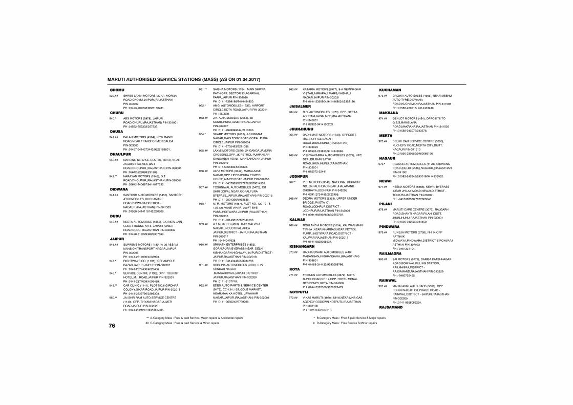
������������������� ������������������������������������
�� ���
��� ��������������$����������/�������'����/��������/�����������$�$������"�!��$������#)%#�#!(��#!�
%$%���
� ��
������������%�#���/����������'������/�����������$$!��!���"�! (��� �$$$)� �$$$�
%���,
�����
����/���������� (����� *������������� �������-��� �����������$�$$�$���"�!����%�!���$��$)%#�#!(%(�!�
%�!���
� �����
������&�� ���' �' �� ��$������� ���/�&��������� ����������������������/�����������$�#��!���"� (�����$###)�$!###�
%�����
���������������$$� ���&������������������/�����������$�#��!���"� (������(%�)%�!����$$ �
%�$�,,
������
�������������� ��� � ������������������ ����'��������������*���������'�����&������/�����������$�!$�$���"�! #��%�!�!!#!��)���%�%�
%�����
����
� ��������� ���# ���')��� *�/����& ����� ����#��/������/� �������������/����������$����(���"�!��#� !$��%)%#�#$�� (��
%� ���
�����
��� � ��������!!$������� �������������������������&���/���������$����$���"�!�!��(!��$�)��$$%%$�
%�(���
��&�*����'����!!$!������������ ���.���/�����/���������$����!���"�!�!��$���$()�����$(�
%���,
� ���' �' �� ��!!$%��������������� ������������/���������$����!���"�!�!��$����%)���%�(%�
%�#�,
'���'����'��!!�!����������(�&�������'�����������������/���������$���!$���"�!�!���$��%�)$�%$$�#�
%�%�,,
/���������������� ���' �' �� ��!!������������������&����/� �������/���������$����(���"�!�!����!��!)%#�%� (� �
% ��,,
��������������!�(�������������������������� '���%$��&��*���-����/���������$��������"�!�!��$%%!%()%�!�� �#���
% !�,,
��&��������� ���!%$#����������'��'� ����������/���������$���!!���"� �(#%�
% ��,
/����������� ����� #���$#�����������/� �������/���������$��������"�!�!�%%�#%%%���)�#!� ���
% $���
���������������$����/�$���������&�����������������&���������'��'� �/���������$��������"�!�!���� �%$)��!!$#(�
% ��,
�������������� �(������&��&��/�����'������&������/��� ��������� ������&�� ��������������������/���������$���!%���"�!�� � !#%�) !� #%��
% ���
��-���������$$�����������������&��������� ��������* ����� ��/� �������/���������$����(���"�!�!�(� �%#%)��%���%)%#�%�!�% %�
% (���
�����*���������� ���$�� ���!$!������&������&���&���������� �����/��������/�����������$���! ���"�!�!�� ���%() �($#$(�
% ����
��������������# ������������!���!�!�+�!� �!�(���� �����������-��� ������/��*����/��������/�����������$���!(���"�!�!�%$!�##! �#)�$��!%(�
% #�,
��!���������# (������#�����������&��������������� ��/����������'���/�������/����������$���!����"�%�!����(�#�
% %���
������� � ����� ����# ����&���������� ������ ����� ����������&������&�*����/����������'���/�������/����������$���!#���"�!�!�%�!����( )$�$��%#�
%(����
��������������� ��� $($����������������&���������������/����������'���/�������/����������$��������"�!�!�$!����#�
%(!���
� ����������+�� ���' �' � ��� ��$���''�!$���!$ ��&�� ����� ��� ������������ ���/�*�������&���/��������/�����������$��������"�!�!��( ����)%�%%�%(�
%(����
��������������� �����%���� ����&���������������������&������������&���/���������$����!���"�!�!��$ �%��)%�!��(#���)�$ �!$(�
%($���
��������
������������ ���!��$��������& ���������/������ �����/�����������$� ��!���"��%%��%�!�! ���$�
%(����
� �� ��
����������������!(�#��������� ��� ���--�' ���&��������/��/������/�����������$$$��$���"�! %���$$# $)%�!�$�( (��
%( ���
����*�������������� ���$��!�����'�� �� �����������������/��/������/�����������$$$��!���"�! %���$���!�
%((���
��� ��
������������$$���������������&�*�������( ������������ ���/���������'�������/����������$���� ���"��%!������# )�����% �
%(��,
� ����������� $ $����� ���� ������& �������A'A������/�����������'���/��������/����������$����(���"��%!�%#�%��(�(%)� �����
%(#���
�����
����������������� �������*���������������� ������������ ���� ���������/��*��������������'������*�����/����������$���!����"�!�!�%#�%� ($��
%(%���
��� ���
�������*����������� ��������������&��/�������&�������/�����������$� #�!���"�!�($������$)%� �� %�%#�
%�����
����
-�� ����������� ���$(�%��������������������!��������� ��� ����� ��� �'����������$����#���"������$��$(�)%#�# �%��%�
%�!���
��������
�������������%��������#�� �������&����& �'��&���*����������/����������$�$!�#���"!��!�%$ �$��$!$�
%�����
��� ���
������������ ���� ( ���� ���� ������� ����*����������'��������/����������$�! �#���"�! #(�����! )�%�!��$$����
%�$���
�����
& ������������ ���������� ���&��������&��������������������/����������$�! � ���"�! ##���$��()��$$�(�
%�����
����
� ���'���� ���' �' �� ��$# (����'� ��������� ���'����������&�������$�! !����"�! %���$� %)%�(��((!%(�
%� ���
����
'�����'�������� ���!!�%������*����������� ����&� ����&������/�����������$�!��!���"�! #�����(�()��$�!%)%�!��$ ��
%�(�,
����
� ���������� (#���� *����� ������� ���/������������ *��������'���������/����������$����!���"�%�!$�($$�(��#��(($��(�
%�����
�����
�����'�� �' �� ��$��$�����/&�����������������&���������������/��/�����/����������$$$�$!���"�! %(�����$�)���� %�
%�#���
������
�� /��������� � #������!����������������*��������*���������'����������/����������$��������"�%�(!��!!���
%�%���
�������
����������� ��%����������-� ���&������������*���-�����&��������������&��������'�����/���������/����������$!$$�%���"�%�(��� � �
%#����
�����
�������������'����� ((����������������&���������&������������*��������'���/�������/����������$���� ���"�!�!�%%�#�#%����
%#!���
�������
����
,, ��'1234567��188�"�-633�+�91:;��36<:=3���1>56�6391:68�+��==:;3?21@�6391:68 , ��'1234567��188�"�-633�+�91:;��36<:=3�+��1>56�6391:68
�� '�'1234567��188�"�-633�+�91:;��36<:=3�+��:?56�6391:68 � ��'1234567��188�"�-633��36<:=3�+��:?56�6391:68
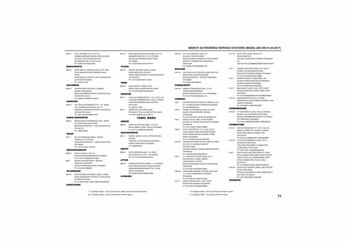
������������������� ������������������������������������
��������������!�����')����������������� �������*����� �� �'�� ��--�' ����&������/��&����������/����������/�������$!$�$�(���"��% �����!�#)��$ �#�
%#����
����� ���
����������&���& �� %�������������� ��������������������� ��������������*�����������'�'����&������/����������$�$$� ���"�%�(!��!!���
%#$���
�������
�*������������ %�����&�� ���&����������*����������������������'���������/����������$!$������"��%�(��$!�(%)%�!�� %$�!�
%#����
��� �
���������������� ����������� #�#���!%��������������(�$)� �����! ��&�����������'���������'�/�������/����������$�$��!���"�%�%���$���)%%#��!�$#!�
%# ���
��������� ���
����������������� ��� � ����*����������� �����������������������������'���������/�����������$$��! ���"�%##��%#�$$�
%#(���
����
��/�������� ��� $���������������&�'�������������������������'�����������/����������$$���!���"�! ��������!)�������
%#��,,
���������
��������&��!!$����� ������'�����&��&���&�������$$ ��!���"�! ��%�!��%$ ( )����#�$�
%##���
��&�����������$$�!�����&����'���� ����������'��'� ����&��&���&�������$$ ��!���"�! ��%�!��%�(((�
%#%�,
������
�����'�����/���������%����������������/��&���������'�'�����/����������$$! �(���"�! (#�����%!)�%#�#!!##��)%�#$� � �
%%����
������
������� ���' ���������(�(�������! ������� ������������&��������* ����� ����&�������/�����������$$ #�����"�! �%���� !�)%�!$$��%!��
%%!���
�����
���/���������� #� �����*��������� ��������*����-�����/���������'���*�����/����������$�!��!���"�%�!��! #� )%� !�! #� �
%%����
���
����������� ((������������������/����������$����!���"�!�$�%�!�( %��%)�� $��#�
%%$���
������
������������ �����������!%����������'��� & ��� ��� �������������� ��������� �����������������������$!$��!���"��%���!!�($�
%%��,,
��� �����'���'�� ���$�(�����/�*������������������$!$��!���"��%��$�%%%�!)%�!�!((����
%% �,,
��� ���������
��������������#(����!��'���'���������������������������($ #�����"��!������##�)%��$($�(� �
%%(���
�������� �
&�*���������� ����������� ���'��� ���������������������'��������'��������������������($%��!���"�%%%�#!#��$�
%%���
����
������& �'� ����(#���!�����������������'���������������($� �$���"��!����$�� �)%����� ����
%%#���
����
&�� ������������ $#���!)!�������&���������&������ ��'����� ������������������&������������������������($(!�#���"���#��%��$��$#(()�#!%((�
%%%���
����� �
������������ �� ������-�����(�)�����������������������������&�����������������������'�'������� �������������(�!( ����"���%(��� �#�)%%%�%$��#��
!������
� ����
'���.�� ����� ���' �� $$����� �����������������/�������������������'��� ��� �������������($#$�!���"��� (�%#���# (���
!��!���
� �������
������������ ����%�!��� ���)!������.�������������'� �&���������������(�$������"��������!� %)%#��$� !!��
!������
� ���
������������������ ����� ���!�$!���*�!!���������&���'� ���������(��������"����%#��#���!��
!��$�,
�*����������� ���� (����$�'������/�������� &��� �'� ���������(����#���"�����#!%�#! )��#!%�!$ )�%#��#%!%!(�
!����,,
*� ��������(%����������������&���!��'����������������'� ���������(��������"���������%�!)%#��!$####�
!�� �,
�����������������������!������������ ��'� ��������������������&�������������������'� ��������������������(���%!���"������ #!#! #!)%����#!$%��
!��(�,,
������������������ ����� �����$(����'�!�$������ � ��������'�������������&���'� �����'� ��������������������(��������"�����((!�#$�)%#��#���!��
!������
������ ���' ���������$�(�������!�&��������/���� ����������&���� ���!���- �������&���������������'� ���������(����(���"����� �!��� )%#��$�#�� �
!��#�,
�������� �� ���' �' �� ��� �%���(�#����������������� �'� ���������(���#!���"����� %!�(�!)%#�!��� #%�
!��%���
������ ����� $!�����������������������'� ���������(��� ����"�����( ��!��)%%���%% ���
!�!��,,
��� '���$�� ������(�&��������������'���'���������������'� ���������(��������"�������!#$! )��$####)��$#$%��)%#��$� ���
!�!!���
����������������� �%����) �����/����� ��������������������������������'� ���������(����!���"������ ���$$))%#��!$####�
!�!��,
� �- '������'�� ���($�������� !)�(����������������/�����������������'� ���������(����#���"����%�#%%��$��)��$�$$�#�
!�!$�,
�����������%� ����)��������'�������������������'�������������������(����!���"�������%$#$%)%#�!����$�)%##�$�$( ��
!�!��,,
��������������� !$!���(������� �������'������ ��'� �����������������(���%����"����%#���!� #)�$(!�#�(�
!�! ���
� ��������
��� '��������$�$!������� ������� ����&������������������ �����������'����������������'�'������ �������������(�#��!���"�������# #%)% # $#(�!)% # $#(���
!�!(���
���������
���������� �����������!(����%��� ����� �������������������������� ��� ��'������� �����(�!������"������ ��#%#)� �� �!)%% �$��(((�
!�!����
����������� ����� #���!(���������������������� �'��� & �� ��� ��'������� ����������������(�!������"������((��!���%)%#���( !$$�
!�!#���
�������������������������� ����%�)$���������������� �����'������' �'� '������'������ ������ �����������'������� ����������������(�!�!����"�����%#�$$! �( ��( (� �)� %� �%�
!�!%�,
&�����&���& ���%( ����)%#����&��������� ���������--�' �'��������������'��������������������(���!����"�����%#�$� (���)�(� �% �
!������
�����
,, ��'1234567��188�"�-633�+�91:;��36<:=3���1>56�6391:68�+��==:;3?21@�6391:68 , ��'1234567��188�"�-633�+�91:;��36<:=3�+��1>56�6391:68
�� '�'1234567��188�"�-633�+�91:;��36<:=3�+��:?56�6391:68 � ��'1234567��188�"�-633��36<:=3�+��:?56�6391:68����
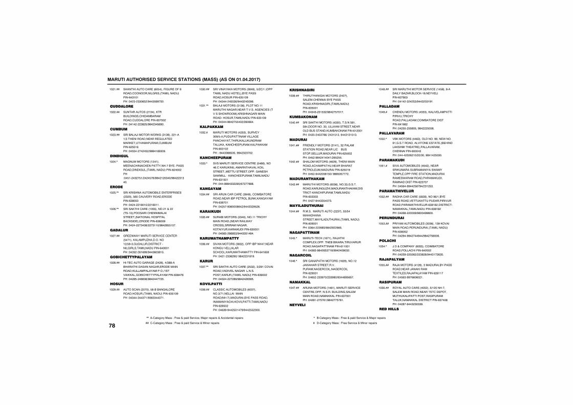
������������������� ������������������������������������
����������'�� ��(� ����-�&� ��-�#������'����������&�������������������(�$!�!���"���$��$$�( �)%��$�#%� ��
!��!���
���������
�����������!$�������������&��'����������������'������ �����(��������"��!�����$#� )%#��$� (%��
!������
������
��������/�������*������$!$%�����!����!)$�� ��������� ���� &�� ������ ����������'��������(� !(���"�� ������� �)%%%�!(%$�%�
!��$���
�������
��&����������!��!���� ��'�����'� ������������� �����������������&�����������������(��������"�� !���$�� !)���� �#)%#��!��$��)%#���$!$���
!����,
����
������������������� � � ����� ����$����� (��'�� �������� ��� �����($#��$���"�������!#�!�)��!#�!!�
!�� �,,
����������'�� ��!� �������!�+����������!�����������'� ����������� ��������������������'���� �� ��� �����($#��%���"��������$�$#)���$!!�)%#��# ! ��
!��(�,,
������
&� �*��������� ���' �' � ��� ��!���������.�����������!�) %�$�&����������'������&�����������������(�$��!���"���(���(!(%%)%��$(�$#! �
!������
����� �����������
��� '����&���& �����(����)$##�������������������&��� ��� ����������������������������)!����������&���'� �������������($#��(���"���# ���(($()%#������� �
!��#���
���
����'����������� #������&���� ��������������������������($ !�%���"��$������$�!)%$($$��$�!�
!��%���
��������������������$#�#��� )�')!����������������� ����� ��������������������($ !�%���"��$����� �$()%��$�� �%(�
!�$����
����/��������� !$(����������!!���������&���� ����������& �'� �����������*�������������&��������������������������������($ !�%���"��$���%#��� ���)�(�((��
!�$!�,,
���������
�������������� $������ ��$�%) �����������������& ����'���������������������������'� �������������������(�$!�����"�%��$$(( $ ��%#��$�$����
!�$���
��� ������
���������� ���' �' �� �� �((�������(�'���������������������������� ��� ��� ������&�� ������*����������'� �����������������($! �!���"����%%%�$$��%�)(����###�
!�$$�,
�������
��������'���'�� ��$%�%���'������� ������� �������� �����������&���������($#��!���"��� ��%$(���#(��)%��$$�% �(�
!�$����
��������
��������������$��������!!���'��������������� �������*���'���������������&������������������������($���!���"�� ( ��#(# $)%��$$ !�#��
!�$ ���
������ �������
�������������$#$������������������ ������&�� ��������'��������������������(�!( %���"���!��$$(�%�)�%#���$!#!%�
!�$(���
���
�������������'�� ��� $����$)�%!�'��������������� ����&�����������������������������������($%������"��$�������#%)%#����( # �
!�$��,,
����������
'�����'�������� ���(�$�������$)�!�� �������������������������������� ���������������������'������������������������(�# �����"��($%�%��� �!��%)%��� �����
!�$#���
��� ����
�������&�������������������� ��'� ������� ������������������&������������������($ ��!���"��$�$��$! $�)%#��� ��!��
!�$%���
���������
������������������$$��������� #!�� #�����������$����������� �� �����������������������������(!���!���"��$ ����$�#()���$! !$��%��$!$! !$�
!������
������
-�� ������������$!�!���$�������������������� �����'������������ ���������������(� ������"�� ��%#���!���!)�( � �
!��!���
���������������(�%���� ��������������'�������� ���������� ��� �������������(� �!%���"�� ��%���� #! �)�%#( $ �����
!������
������ ����
�������������(�$(������$$�&��������������&.��������������������'����'�������������������(�$$�$���"�����%��$$ ���$�
!��$���
��������� ���
�������������������$���� $) �������������� ����������������������������(�%��!���"�$(�����(# )%#��%��(( �
!������
����������
����� '���!(�!�����/����'���� �������� �����������������������&������������(!!��!���"��$( �%#��( $�!#)%%����%�$��
!�� �,
�������
����&���������������!(�%������!��/�*������� �������������& �'������& �'��������(�%��!���"��( ���$$%��)�$$%#�)%$��(% ( ��
!��(�,
�������
������������!�(!��������� ���' �' �� �������������������&���� �������������������������($���!���"���#!��� �(!)%#���� �(!�
!������
������
���������������� ���' ��!� #���#�����������.������'��!%�� �� �������(��#�$���"��!���$��� $)%��$��$!%!�
!��#���
��������
'� �����������$$$�������� ���������������'�����������������'������� ���������(�!((����"��� �� #� ��%#���� � #�
!��%��
���������
�������������($�����������%%��� *�����%!�&���������������� � �� ��� �������������� �� ��������������'� ���������(����$���"������$�(�!�)��)$���%#�!�� �$��
!� ��,
���������
������������ ���� ������ ������������������������*���� ��� �����-�� ����������������� �*������������������������������������(�$������"�� (��%%��� #�%�)�$!� $�
!� !��
������ �����
������'���'�� �� #�#������%()!��� ������������ ����������������������������� ���($#!#�������'����������������������($#!#����"���(#������%)%(���%%(���
!� ����
�������
�������������� ���$�$(���!$%������������������ ����������������������($#� ����"���%��%#�����%��)%#��� (��(�
!� $���
����� �
/���+�'��������(� ���'������� �����������'�������(��������"��� %�����(�)��$#�#)%��$!��($ �
!� ��,
���������
��/����������!�#���$���������������������� ���/���������� ��� ����/�������������(�(!!����"�� ($�%%�((�(��!�
!� ���
�������
���������'������� ���� )!������������ ������������� ����'�� ���������������������������������������������'�����($���#���"���#��%��$�$�$$%�
!� (���
��� ����
���
,, ��'1234567��188�"�-633�+�91:;��36<:=3���1>56�6391:68�+��==:;3?21@�6391:68 , ��'1234567��188�"�-633�+�91:;��36<:=3�+��1>56�6391:68
�� '�'1234567��188�"�-633�+�91:;��36<:=3�+��:?56�6391:68 � ��'1234567��188�"�-633��36<:=3�+��:?56�6391:68
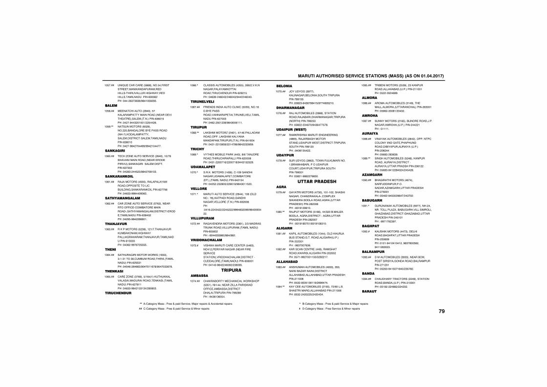
������������������� ������������������������������������
��B �'���'�� �� #(#������ ��-������ ���������������� �������������������&�*���� ���������������������(���(����"�����($�$%$%)%#�!� %�% �
!� ����
������
� ��'��������%����� ������������������������� ���� ���� �� ����� ������������($(�! ���"�����%��$��!��!)�� ���(�
!� #���
������������(��%�������������&���� ��� ��������������������������������� �������'���� ��������������($(�!����"�����%#������%%)%%��!������
!� %�,,
�������
'��.�� ����� ���' ���(�����!�)�#��������������������� ��� ��� �������������&�������� �����������($�$�$���"���#$���� �$)%#����%!�$�
!�(����
���������
��/���������� �������������������������� �����'�������&������������������(��� (���"��($$�%%%���%$($�
!�(!���
��� ���������
'���.�� ����� ���' �� �(����� �������--�' �'������� ��������������������&����������'� ��� �������������($#������"���% �%#���#(#�!�
!�(����
� �����
������������� �$#���!�!)�����/����������������&�*���������&�����������/����������������(!$��$���"��$(��%%�(�� �
!�($���
� ��
�����&���������*������!( ����$�!�$!���$(�'���������� ������������������(� $!���"�� �(��(�(($)%����!!(�#)%����$$(�#�
!�(����
� �����
'�� �.�� ��$�((��� )!(��!����������������������������� ���������������������(��#!!���"��($$�%#��!$$!$�)�#�#�$�
!�( ���
���� ���
'�������������� ����$ ����(%)����������&����������������������'� ��������(�#�! ���"��($%���(��$)��(��$)%�����(��$�
!�((�,
���������
-�� �������������'����'�� �$�������!(����� ������������������� ������ �� ���������������(����$���"��(��� �!�$#)%#�$��(!!!�
!�(����
�����
������������.����(!����)!�(������������������������������������������������������������(�!(�����"���!���! % %)��!��%%)%#���$$% %�
!�(#�,,
��� �
��� ������� ���������$���#)(���/�� ���������'��������������(����#���"��$!������!()�����!#)%��$! � �%�
!�(%�,
����������
��������������!� (���'�!�%�&��������&���������� �'������� ���������������������(��! ����"��� ���$�#� )��%�!%)%#�$�!! ���
!����,
������
��������� ���' ���#�����!�(���������"��#��������������&��������&���� ���� �����������($���(���"��!(����$���)��� ���)%%%�#$��%%)%#�$�%$����
!��!�,
���������
��&�� �������������$(!����)$�����������������������������������������(� (�����"�%��� #(�)#(�)#(��
!������
���� �� ����
����*�������'�� �' � ��� �($������!��� ��������&����� ���-�� �� ���' ���������������'�����������'���'������ ���������������(�(��!���"��!�$�%#����(�%�)�$#�% �
!��$��
�� �����������
'����������� '����'���*��������� $ !����������� ���.����������*����--�' ��������������'���������������������%%�#%���"�%�$(!$(� ��
!������
������
/������&��$%�����������&���� ���������������������%%! ���"�$#�$�%�$(�%%�! )%���#� �!��
!�� ���
� ������
��/�������� ����#(#����������������/��������������&���������������������%%� $���"�$#����$�(��)%�$(��� �#�
!��(���
�������������
���������������� �&�� ���&���#( �����/����&������������������* �������'����������������%%!�����"�%�$(!$ ����
!������
������
������&��$%($����*��-�����������!�����������������������'������������������������%%��!���"�$#�!�%#(���(( ��
!��#���
����������������
&���������������$����!�!�!��������������&����'������������'���� �����������������������&����������� ���������#���#���"�%$!%!�%%!��
!��%���
��/��������� !((�����)$�������.����������&��������'����&���������� ��������#�������"�%$!%!# � !)%$!%!�#$!��
!�#��,,
�����
������������� ���!$������������/����������&�����������&������������������!���"�%#$����($(�
!�#!���
�����'���' �� ����%������&���������*��������&�����������������"� �!�%%����!!$$)$�%��!��
!�#����
���� ����
��������������� ����%$$���$ $����������.��������������'���������������������������� ��������!!��#���"� $��%$$ !$#!!%)�(%(����
!�#$���
����' �������� ����! �����)(�����������������&����������������!!��(���"� $�������� )�����$��
!�#��,,
��� ����������� $%����$���������������������������������!!��!���"� $���(��(%%�
!�# ���
�����
������������� ���$!�%���� ������������������'����������($��!���"� %(��$$�#!)$$�$��
!�#(���
��� �
�������������!( �����/��� ������/������&�������������������������!���"� !!!!�
!�#����
������
��������������� ����#������������'�'�����������&� ������������������������������������������(������"� (#$��#$($%�
!�##���
���&��������� ��� ��#���������������������������'��������������������������(!�����"� (#$�%�!��#����)�� ��#�
!�#%�,,
������
���&��������������(��������-�������������������.��&����������� ���������(��!���"� �(��%� ���%(��)��$����
!�%����
������
&�������������� ��� %�����������������������.������&������������������&��.�����������'�&��.������������� ��������� !�!���"�%%�!�%�$%��
!�%!�,
��� ���
�����������������$���� �����������&����������� �������� �(�%���"�!�!�%�!��!��!���%#$�#�� #���%�!!�($��$�
!�%���
�������
����������� ���$%$$���� ����'���������������&�������������������������!��!���"� �($�%�! ��!#��)�$ �#��
!�%$���
����
'����������'��������%�������������������������������!���!���"� !%�����##�)�������
!�%����
�����
,, ��'1234567��188�"�-633�+�91:;��36<:=3���1>56�6391:68�+��==:;3?21@�6391:68 , ��'1234567��188�"�-633�+�91:;��36<:=3�+��1>56�6391:68
�� '�'1234567��188�"�-633�+�91:;��36<:=3�+��:?56�6391:68 � ��'1234567��188�"�-633��36<:=3�+��:?56�6391:68����
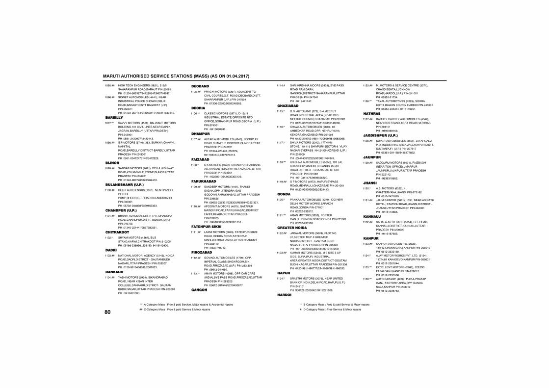
������������������� ������������������������������������
��&�� '�� �&�� �����#�!����!() �������������������������� �(!!���"�!�$���($$��)%�!��� ��)%#$�!(##��
!�% ���
��&� �������� ������!���� ����������������' �'��*���� ��������������������&�������������� �(!!���"�!�$���(�!(�)%�!�#$!!�!)%#�!!#$$!���
!�%(���
��������
�������������� %������*���������������&�!$!�'�������� ��� ����������/�&������� ������������� ����������$��!���"� #!�����%��)�����!�$�
!�%��,,
����������� ��(���$#$��������'��*�������������������� ����������'���� ����������� ���������$��!���"� #!��%�!���%!��)��!�#�%�
!�%#���
����
���������������(�!���� ������&�*����������������� ���� ���/����������� ���������(��!���"�!$���%#$��( ��()�(��!��
!�%%���
������ � �������
� ������� �&����!$ !���� ���������� ��������������&������������������������$��!���"� �$���$�###)%$ %! $$$�
!!�����
� �����������
������������� ���!�������������������'��������������/����������������(�� ���"�!$� ���!��!)%#$�$#� !�
!!�!���
� �������
��������������$(���������������*��'�������������!��� ���"� !%#��$(%%(���$ ! ���%�! !�$%���
!!���,
����
���������������& �'��� !�$�������������������������'���&���������&���������� ���������$������"�!���%#!#�#(###)�((��$$�
!!�$���
�����
������������ %$����������������������� ����������� ��'��� & �������������'��&����������&���������� ���������$��!���"�%�!��%! %��
!!�����
������
���'����������$$(!�����/�' ����'�����'����&��������� ���������������������������������� ����"�!$$(���%��)%$ %��( # �
!!� ���
�����
'�����'���������%�!�����!$)!����������� �� ������� �����--�' �&�������������� ���������������������!���"�%�! �#�%#!�
!!�(�,,
� ����
����������� ����#�(���������������������������'���/����������� ���������(�(!���"�!$������������$������%�!!#$$!���%#%���$!!$�
!!�����
��������
������������(�����'���������������������������������%(�-��.������������ ������������!���"�%$$ %#!$(�)%$$ $� !�%�
!!�#�,
���� ����
���� ����������!(!��������������������/� �����&���&���*��-���������������� ���������%(� ���"� (%����#$�!)��#�� )%#$##��$���$�!�
!!�%���
����������������(� ����������������������-���������������'�-����������������� ���������%(� ���"�%� !##�( �)%$$(� !! !�
!!!����
���� �������
������������� %�$���-� ������������������ ���������-� ���������������'��&���������� ��������#$!!����"�%#$���%%�%�
!!!!���
��������
&������������� ���!�$%����������� �����&��������*���������������-���.����������������#$���$���"� (!�����( ��
!!!����
�������������$((�������'���'�� ����������� �����������-���.������������ ��������#$��$���"� (!���#! �()%�!%���#���
!!!$�,,
����
�������������������� %$%����� ���������������&�����&��&��������'������������������ ����������$�!���"�%�!%��!����
!!!���
� �������
������������������� ���� ������������������ ���� �������� ��'��&���&��.������������!��!���"�!���( �!�$�)����$!()%#!�!������
!!! �,
'��*���������� ����(�$���(����� ���������������� �������� �����&��.������������!��$���"�!�����%���!)%#!!���%�%)%#!�(($$((�
!!!(�,
�������������$$�$���!��������� �!!#�!!%���������� '���%����/�����&����� ������������&��.������������������!��%���"��������)$�$� %�)%#%!�(�$�%�
!!!��,
��������������� ��� $ (���!�!�������������������������������������������'���&��.������������� ���������!��!���"�%#!�$!!�� )%%%% �(#���
!!!#�,,
������������%�$��������������������� ������&��.������������!��!���"�!���%$ �%$(�(�)�#����$�
!!!%���
����
�����/�������� ���!$�����')��� *�� ���������*����������'�������&�����������!��!���"� �(���$�#!��
!!���,
������������$# #������ ��&��/��'���*������&�����������!��!���"� �(���$! �(�
!!�!�,,
����������
/���*���������� ��#�����������$!�� '���������&� � �������������'���&����������&��������� ���������!$�#���"�%#!��(��(%)(�# ���)%�!�!���(%�
!!�����
������������ $�$�����#��� � ������ �����/��������������� ��&� � �������������'�&����������&���������� ���������!$�(���"�!���%%!!�%#���)�$�!�##)%#!!�%#$$$�
!!�$���
���
��������������$��(���� ����� ��������-�������� �������������������������� !�!���"% �!����$� #��)�%�!���!(�#�
!!���,
����
���������+�� ���' �' �� ��$$�!���'������ ����'���*�������������������������!��!���"� # ���!�$��
!!� ���
����������� �����( ����������������*���'��&���������������!��!���"� # ���$�$!���%�! !�%% !�
!!�(�,,
�� ��
���� ������ ��������� ����$������ ������������&����������������������!�!���"�%#%��(%! %�
!!�����
������ ���������
�� ��������� ���$ (����/�-��&��/����������������� ��/�&���������������������������������#!����"� $(!��%!!(#)%�! !��##��
!!�#���
�����
���&��������� ��!���-��.��&���� �������--�' ��������/�����/������������ ����������!�����"�%#$%$!#( $�
!!�%���
� ���
������������(����������� ������/������������$!(����"� !�����!#( �
!!$��,
/��������� ��� ((!���!� !��� ������������ ��������������/�����������'���/������������� ��������#���!���"�%�! !!$ ((�
!!$!���
�����
����������'�� �� # ����&��������������/������'������/�������� ���������%������"�%�! !(� �$�
!!$����
����
���������' �� ���#�$���!�)!���'����&��/�������������#�!����"� !��� $$!(��
!!$$���
�/��������*��������������$!$����!!�)�)#!������ ���������������#��!���"� !��� �!����
!!$��,
�' �� ����������%(#���!�$)�%$��-�.��&��/�������������#�!����"� !����$ ((�
!!$ �,,
���&���& ����((����������������&��/��-�'������ ������&����������������������#�!����"� !����$(�($�
!!$(�,,
����
,, ��'1234567��188�"�-633�+�91:;��36<:=3���1>56�6391:68�+��==:;3?21@�6391:68 , ��'1234567��188�"�-633�+�91:;��36<:=3�+��1>56�6391:68
�� '�'1234567��188�"�-633�+�91:;��36<:=3�+��:?56�6391:68 � ��'1234567��188�"�-633��36<:=3�+��:?56�6391:68
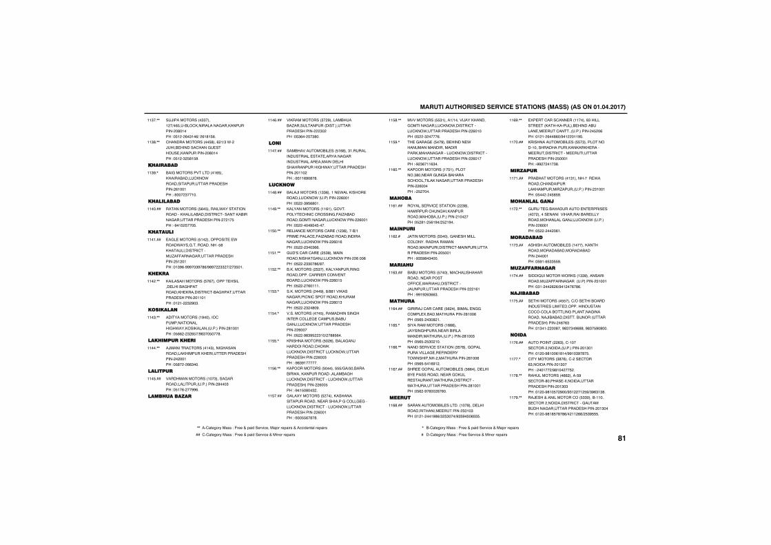
������������������� ������������������������������������
�/������������$$����!��)�( �����'�����������&���������������#�!����"� !���(�$!�()��(!#! (�
!!$��,,
'���������������� #���(�!)$�*���/���� �������'����& ����� �������������#�!����"� !��$� #! %�
!!$#�,,
�� ������
���&���������������!( ��������������'���*������������������� ��������(!��!���"�%$���$��!��
!!$%�,
� ��������
������������ (� �������*��������������������������������'��������������&���������� ����������!� ���"�%�! � ��� �
!!�����
� ������
�&� �������� !����������� � *�����*����&������������� #�������������'����.�--����&���������� �������� !��!���"�!$%(�%%%��$%�#()%#%���$$��)��$ �!�
!!�!���
� ���
���������������� �(�������� ������� ������&����������� ���������'���&����������� ���������!!�!���"�!�!���$�%�$�
!!���,,
��������
�������������!%�������'���������������&�*������������������������#!��!���"� ((���$�( �)%#$�� ���#�
!!�$�,,
��� ������ ��
�/�������'������!�$�����&���������������������� ��� ������ ������������!���"� #����(($���
!!���,,
�������
����������������!��$�����&��������������������������#���$���"� !�(����%%(�
!!� ���
���� �������
��������������$��%������������.������������������������ ����������$�����"� $(��� �$#��
!!�(���
���
��������������� ��� !(#���$!��������������� �� ��������&�������������� �������� ����������������&�*���������� ���������!!�����"�%$!!(%�#�#�
!!�����
������
����/���������!$$(���!�� *��������� �������'���*������������(��!���"� ���$% (#�!�
!!�#���
��������������!!(!���&�������� '���'�'������&�-��.����������&������&����'���*�������(��!���"� ������% � ����
!!�%�,,
� ����' �������'�� ��!�$(������)!����� �����' �-��.�������������������&����'���*�������(�!(���"� ����$��$((�
!! ��,,
&�A��'���'�� ��� $#������������������&��/��'���*�������(���(���"� ����$$��#()#��
!! !�,,
������������� $����������������&�����������'���� ��'��� ���������'���*�������(�! ���"� �����(�!!!�
!! ��,,
���������������%���#)##!���������&�����'��'������������������&����'���*�������(�!$���"� ����$��#�%�
!! $�,
��������������� ���������������&���� ��'��� & �'���������&��/��'���*�������� ���������(������"� ���%#$% ��$!�)��## (��
!! ��,
��������������� ��(�������&��/�������������'��*���'���*������'��'���*�������� ���������(��$���"�%#$%!������
!! �,
�������������� ������ )&�) ����������*���������������������&���'���*������'����'���*��������� ����������(�� ���"�%�! �#��$��
!! (�,,
&������������� ��������������������������� ����������&�'���& &����'���*������'����'���*�������� ���������(��!���"�%$� (�#�#�
!! ����
����������� $!����!)!�����/����������&������&����'���*������'����'���*�������� ���������(�!����"� ���$�����(�
!! #�,,
� �&���& �� ��%���� ������ *���������������������������������&������'���*������'����'���*�������� ���������(�!����"�%�$(�!!($��
!! %�,
��������������!� !����������$#��� ���&�&����������'������������&���������� ���������(������"�� �����
!!(��,,
�� ���
������� ���' ����������$#�����������'��&��������������������������������!�������"� �#!�� (!%�)� �!%��
!!(!���
������
/����������� �����&�� ��������'�������������������������������������'���������������� ��������� ��!���"�%$ %#�$����
!!(���
���� �
����������� ��������'������������������ ��������--�' �������������'���/������������ ����������!(!���"�%%!%�($(($�
!!($���
��� ��
&�����/�'���'�� �� (����������� �&&�'���� �����������������#!��(���"� ( ���$�#�!�
!!(����
����������������!(((���/�����&������ ���������������������������������#!��$���"� ( �� $��!��
!!( �,
������ ���' ��������$ �#���&��������������& �� -��� ����*����������������������#!��(���"� ( � �!(%!��
!!((�,,
��� �&������������ ��� ((����� ������ ������������� ���&����� �����������������'���������������� ��������#!��!���"� (��%�(���(�(��
!!(����
�����
������������� �������!��#���� ����������������� ������� �!�$���"�!�!����!%#()$� $���)%$ %� �( �
!!(#���
�� ��'����'��� ���!!�����#$�������� �������������� ����������� �� ��'���������������� ��(���"�!�!��(��#(�)%�!���!!% �
!!(%�,,
��������������� ��� �$������������!����������������������� ������ �������'���� ���������� �������� ���!���"�%%����!�$#�
!!�����
������
���������������!$!���������� *�������'���������������������.���������������$!��!���"� ������ # %�
!!�!���
�� ��������
&�� &����������� � ����� ������������� ������������������� �������������������&��/��'���*�������������(��!���"� ��������(!�
!!���,,
��������
�������������� ���!���������������������������������������������!���"� %!�( $$ %�
!!�$���
����������
�����B�������*������!$$%����������������.�--����&�������������� !��!���"�$!�����(�()%�!���(�#(�
!!�����
��������
� ����������� ����')��� ��������������� ������ ���������������'�'��'���������&��������&������������/��������������/������������ ����������(�($���"�!$�!�����#���%#$�$�%(##��%#$� %�#���
!!� ���
����
�����������($���'�!���� '�����������������������!$�!���"�!���%#!��(!#!�)%%!�$%�#� �
!!�(���
'����������$#�(���'���� '���($�������������!$�����"����!���)%#!����� ��
!!���,
�������������((������ %�� '���#������ ����������������� ���������!$�$���"�!���%#!� ��%��)%$!���!� %)$%($!$#�
!!�#�,,
��/ ���+�����������'��� $$������!!���� '����������������'���&����������&���������� ���������!$�����"�!���%#!# �#�#()��!!�(()� $% �
!!�%�,,
,, ��'1234567��188�"�-633�+�91:;��36<:=3���1>56�6391:68�+��==:;3?21@�6391:68 , ��'1234567��188�"�-633�+�91:;��36<:=3�+��1>56�6391:68
�� '�'1234567��188�"�-633�+�91:;��36<:=3�+��:?56�6391:68 � ��'1234567��188�"�-633��36<:=3�+��:?56�6391:68����
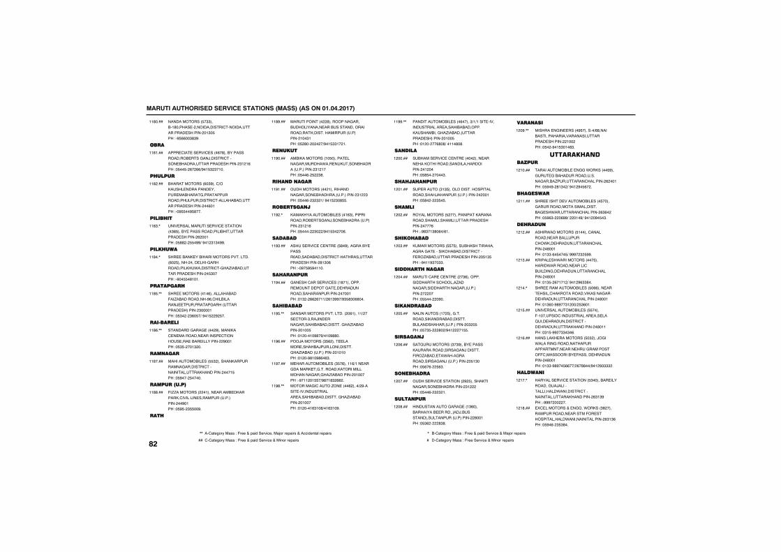
������������������� ������������������������������������
������������� �$$�����!#������ ��������������'�������������� ���������!$� ���"�% ((��$#$%�
!!#����
����
���� '�� �� ���' ����(�#������������������� ���&��/������'������ �������������� ��������$!�!(���"� �� ��(��(()%�! $�$�!��
!!#!���
� ����
�������������(�$%���')������� ��������� ����� �������&�������������������������'������������������ ����������(�!���"��% ��% #���
!!#����
����� ��
��� ����������� ���' ���������$( ����� �������������������������� ��������(���!���"� ##��� �%%)�%�!�$!$�%%�
!!#$�,
���� ���
��� ����� ������������������������(�� ����������� ����&��������������*�������'�&��.������������� ��������� $�����"�%�� �#!�!�
!!#��,
�������
��� ���������!�(�������������-��.�������������%(�'�����������/ ��������&������������ ���������$����!���"� $����$(� �)�%�! ��%� ��
!!# �,,
��������
��������&���& �����%����������' � ��������� ������� '������� ��� ���� �����������%��!���"� $ ����!$���
!!#(�,,
�����
������������ ��� $�������������������&��������'���������������������������! ���"� %���� �����
!!#����
����������
-�..������������!���� ������ ����������'�������� ���������������������%�!���"� % ��$ ��%�
!!##���
��
��������������#����������&���������������� �������������������������������������������������!��$!���"� �#��������)%�! $$!��!�
!!#%���
�����
��������������!� ������ ����&��������*��� ������������������������$!�!����"� ��(�� ��$#�
!!%����
� ������
��������������!������������&������ �������������������$!��$���"� ��(��$�$�!)�%�! �$�# �
!!%!���
��������
���������������� ����!($����������������� ��&��/���� �����������������$!�!(���"� ������$���)%�! $����(�
!!%��,
�������
����� ���' �' �� �� #�%����&����� ������������������������'��������������� ��������#!$�(���"��%� % %�!!��
!!%$���
�� ����
&�� ���'���� ���' ���!#�!��������� ����� ���&� �� ������������������������������!���"�!$���((�(�!!)�(!$%%�)%$ #$�(#���
!!%����
�� ������
������������������������(!���!!)���� '���$���/��� ����&������������������&��.������������!�� ���"�!����!�%#�%)�!�%##��
!!% �,,
���/���������$ (���� ������� �������/�������������&��.������������������!�!����"�!���%#!�%#(�($�
!!%(���
� ����������� ���$ �(���!!()!�� ���&������� �&�����������������������������&���&��.������������!������"�%�!!��! �)%#�!#$�((��
!!%����
�������&�'����.�� ����(�����)�%����� ��������������� �����������������&��.������������!������"�!����!($!�#)�!($!�%�
!!%#�,,
������������� ����(�����$)!)!��� ���������������� ���������������������������&��.�������������� ����������!�� ���"�!������(#�#)��!!�#�#�
!!%%�,,
������
������� ���' �' �� ���������� ���� ����������������������������������!������"� # �������$�
!������
� � �� ���
�� ������$!$ �����������������������������/����������������������!���"� #�����$ � �
!��!���
� ����
������������� ���������������������������������������������� ������������(���"�%#$�!$#�(�)(!�
!������
� ��� ����
������������ � ������������������&���&� ������������������'���- ��.������������ ��������� !$ ���"�%�!!%$��$$�
!��$���
���� �� ����
�����'�� �' �� ����$(������������������'������.�����&��������������&����������������������"� ������%��
!������
���������
�����������!�� ���&�������������������������������������������������$�� ���"� �$ ����#��)%�!����! �
!�� ���
�������
��&���������$�$%����� �����������������������&��/������-���.����� �*����&�������������&��/������������� !$����"� (�(��� ($�
!��(���
���� ���
����� ���' ���������%� �����������&������ ������������$!������"� ��(��$�$�!�
!������
�������
�����������&���& ��!$(�������������� ���������/����������������������������#��!���"� $(�����#$#�
!��#���
������
������� �&�� �����% �������)(#����������������������������������� ���������!������"� ���%�! $�!�#$�
!��%�,,
����������������
������������ � �&&�*�������� %���&� &�������������������&�����.�������'���������(���!���"� %�%��#!$��)�%�!�%� (���
!�!����
� ������
��� ������ ��������� ���� �����&��������������������������& ��*�������'���������($(�����"� %($����(%%)����!�%)�%�!��%� �$�
!�!!���
�� ���
�����*���������� !�����'����������� ����������'��*��� ����������'����������#��!���"�!$$�(� ��� )�%%%��$� %%�
!�!����
������ ��*�������������� ��������*��������� �����'�������&�� ����������'����������#��!���"�!$ ��(�!�!�)�%�!�%($$#��
!�!$���
��� ������������ ��� �((���� ��� �����'��������������������&����� ����������'����������#��!���"�!$(��%#%��$!���)� $(�!�
!�!��,
��� ������������ ��� �����-�!�������'������������ ��� ���B��� �����������'���� ��������������������#�!!���"�$! �%%��$$�$�(�
!�! ���
��������� ���������� �$����/�&��*�������&���������������������� ���� ���&���������--'������������ ������� ������������#��!���"�!$$�%#%�� ((��)�(�##��)%�!�%$$$$��
!�!(���
������
�������� ���' �������� $�������� ����������&�/���������������*���������'�������������������������($!$%���"�%%%��������
!�!��,
�' ��������+� �&&��*������$#����������������� ������-�� ��������������*�����������������($!$(���"� %�(��$ $#��
!�!#���
����
,, ��'1234567��188�"�-633�+�91:;��36<:=3���1>56�6391:68�+��==:;3?21@�6391:68 , ��'1234567��188�"�-633�+�91:;��36<:=3�+��1>56�6391:68
�� '�'1234567��188�"�-633�+�91:;��36<:=3�+��:?56�6391:68 � ��'1234567��188�"�-633��36<:=3�+��:?56�6391:68
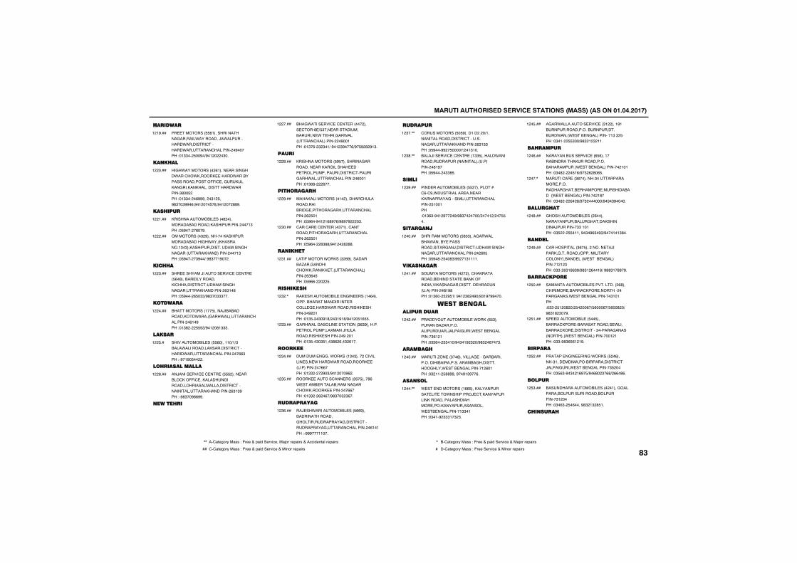
������������������� ������������������������������������
�����
�� �������� (!��������������&�������*���������/�*�����������*��������'�������*�������'����������%������"�!$$��� ��%�)%�!�����$��
!�!%���
��� ��
��&�*������������(!���� ������&���*���'��*������� �����*���������������������--�' ��&�������&��������������������*�������$#�� ����"�!$$����(%%%����$!� ��%#$��$%%�(�%�!���� �#�%�!����##%�
!������
��� ���
��������������� ����#������������������������������������!$���"� %�����(��%�
!��!���
�����������$�%�����������������������������&�*��������������!$�$����������������������&����&����������������������!$���"� %�����$%��)�%#$��!%����
!������
��� �
��� �������/������ ���' �' �� �� (�#������ ������������'���������'���������&����&����������������($!�#���"� %����( �$$)%#$��$$$���
!��$���
�������
�����������!�� �����/����������������*�����&���*��������'����������(!�%���"�!$#���� $)%�!��#!$$$�
!������
�����
������������ ��� (����!!�)!)$�����*���������������������'��������*�������'�����������(($���"�%�!%� �����
!�� ��
�� �����������
��/����� ���' �' �� �� ����� ������'���--�' ���������&���������������������������'�������������������������($!$%���"�%#$��%#(%%�
!��(���
����� �
���&*���� ���' �' � ����������� '���# ) $��� ����������������� *� ����&��*�������'������������%��!���"�!$�(��$�$�!)�%�!�$%���()%� %�#�%!$�
!������
����
��������������� % ����������&���������� ������&������� ��� �������������������'������&���*������'����������(��!���"�!$(#����(���
!��#���
��� ����
�����������������!���������'�����������������& �������&��������'���������(� �!���"� %(��%�!�!(#%�()%#%�%����$�
!��%���
'���'�� �' � ����$�!���'��������������&��������'���������(� �!���"� %(����#$##)%�!���#�##�
!�$����
��� ��
���-������*������$�(%�����������.���&������'��*�������� ������'����������($(� ���"� %((������ �
!�$!���
�� ����
��� ���������� � �&�� ����!�(������������������������ ��'��� & �����*�������������� ���������%��!���"�!$ ���$�%!#)��$!%!#)%�!�� !( �
!�$��,
&���*���&������ ��������$($%��������� ���������������/��������������� ���������%���!���"�!$ ��$�$ !��$#(�(��$�(!��
!�$$���
�����
������ �&&��*������!$�$������'�������� ��� *�����*������������� �������������((����"�!$$�����%�$)%�!����%(��
!�$����
����� �����'��� �����(� ����#(�* ����� �������������&���'��*������� ��������((����"�!$$���(��(�)%#$��$�$(��
!�$ ���
��������
��/ ��*����������� ��� ((%������������������&���������������&������'������������&�����'����������(!�!���"�%%%���!!���
!�$(���
�����
'����������� � %����!������)!�������������������'���������&�����������������($! $���"� %���%%�� �����)��!$!��
!�$��,,
����/��� ���' �' �� ��!$$ �������*�������������������������������������#!%����"� %�����$$# �
!�$#�,,
�����
���� ��������� ��� �����������'(�'%������������ ��� �������������&�������������'��������� !��!���"�!$($�%�!�%����%)%#$�������)����!�)��� ��
!�$%���
�������
���������������� #$$����&��*������*������ ���������������&��/������'���������&����&�������'�����������(� ���"� %�#�� ��#$)%%��!$!!!!�
!������
��������
��������������������'������������� ������� �������-��������������&��������� �����������������#!%#���"�!$(��� �% !)�%�!�$#��%�)%$!%�%%����
!��!���
�������� ����������
��������������� �*�����( $����������.�����������������/�����&���* ��� �&��������$(!�!���"�$ (��� �!�)%�$�!%�$��)%#$��#���$�
!������
������
�����.�� ��$��#��������& ���&����������������������������������&����������&����* ��� �&��������!�(�!���"�$�!!�� ##%%��%��%!$%��(�
!��$���
������
* �� ����������!(( �������������� �� ��*���������/ '���������������������������������� ���������������������* �� �&��������!$$�!���"�$�!�%�$$$!�$�$�
!����,,
�&��*��������� ���' ��$!�����!#!�����������������������������*����* ��� �&����������!$�$� ���"�$�!��� $��)%#$�!�$�!!�
!�� ���
�� ����
������������ ���' ��( (���!�������������������������������������* ��� �&�����������!�!���"�$�#����� !()%�$�(�#�( �
!��(���
�����'�� ��$(��������$������������ ������������&���� ������� ��������������* ��� �&�����������!#����"�$�#����(��#)%�$�������)%�$�$%�����
!����,
����� ��
&������������ ����(�������������������&���������������/��������$$�!�!���"�$ ���� �!!��%�$�%($�%$)%���!�!$#��
!��#���
�����
'������������$(� ���������� �/�������&����������������������'����������� ���* ���� �&���������!�!�$���"�$$��($!#($%)%#$!�(��!()�%##$!�##�%�
!��%���
��������
�������������� ������������(#���'������� ������'���� �������������&�����* ��� �&���������$!�!���"�$$�� !��#��)� ����(�) (���(�) (��#��)�%#$!#�$��%�
!� ����
�� ��������� �� �� ��������'���� �������������� *���������'��� �����'�����������&�������������* ��� �&�����������!�!���"�$$�%#$( (!�!%�
!� !���
�����
������ �&�� ���&�*������ ��(������$!��� ����������������������'�/�����&���* ��� �&��������$ ������"�$ ($�%�$��!(%� )%�(#��$�(#)�((�#(�
!� ����
�����
����������������� ������!���&�����������������������������������$!������"�$�($�� �(����%#$�!$�# !�
!� $���
� ����
,, ��'1234567��188�"�-633�+�91:;��36<:=3���1>56�6391:68�+��==:;3?21@�6391:68 , ��'1234567��188�"�-633�+�91:;��36<:=3�+��1>56�6391:68
�� '�'1234567��188�"�-633�+�91:;��36<:=3�+��:?56�6391:68 � ��'1234567��188�"�-633��36<:=3�+��:?56�6391:68����
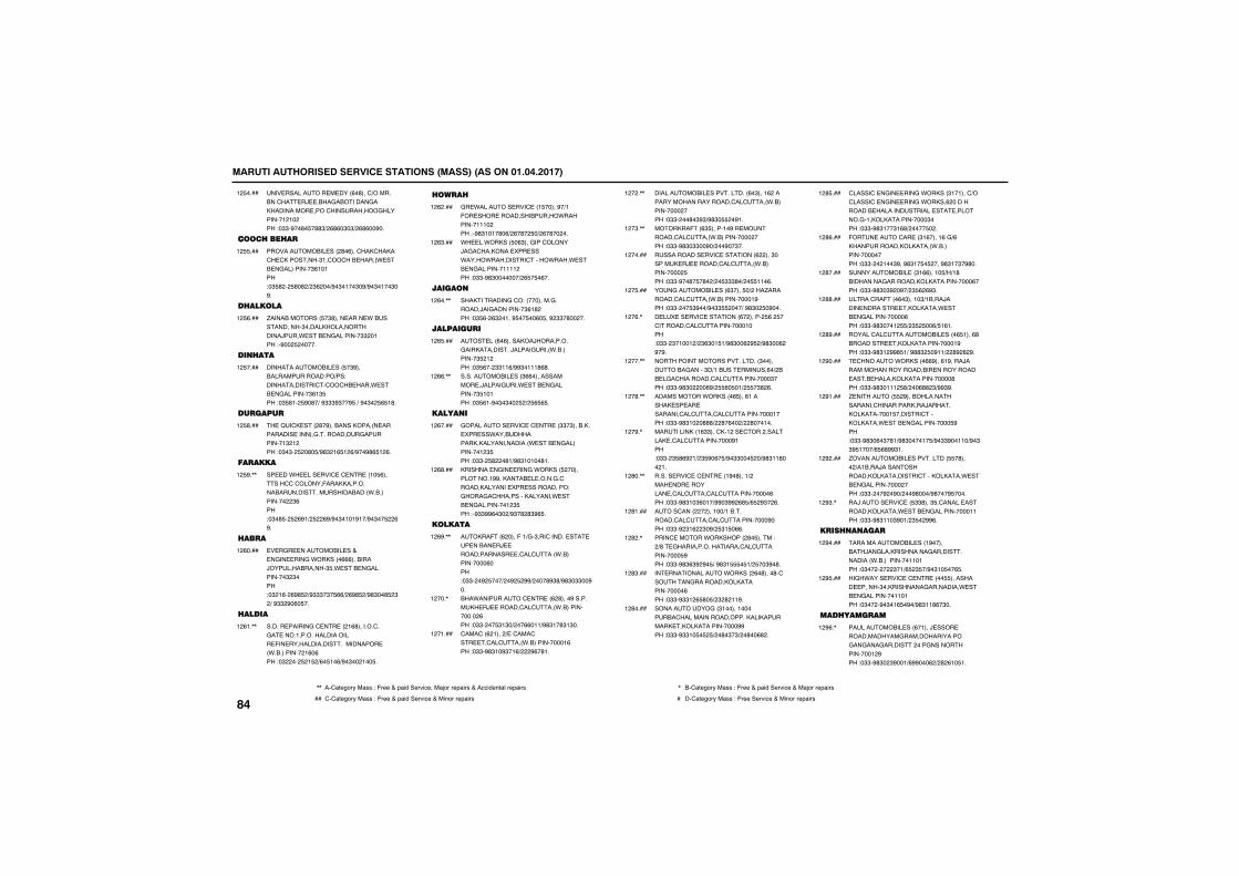
������������������� ������������������������������������
��� ��������� � ����(�#���')���������'�� �/ ����&��������&������������� ����'�����������&���������!�!�����"�$$�%��#� �##$)�(#(�$�$)�(#(��%��
!� ����
����� ��� �
������������� ����#�(���'���'�����'� '���������$!�'��'��� �����* ��� �&���������$(!�!���"�$ #��� #�#�)�$(���)%�$�!��$�%)%�$�!��$�%�
!� ���
� ������
.������������� �$#���� ���� *�������������$��������������������/���* ��� �&��������$$��!���"�%��� ������
!� (���
�� ���
�������������� ��� �$%�������������������)��"�������������'�'��'�� ����* ��� �&��������$(!$ ���"�$ #!�� %�#�)�%$$$%$��% �)�%�$�� ( !#�
!� ����
������
� �B�'� ����#�%��������������� ���������� ������&����������&���������!$�!����"�$�$�� ��#� )%#$�!( !�()%��%#( !�(�
!� #���
������
�� ��*� ��� ���' �' �� ��!� (������''�'������-������������������������������������*�������������$(���"�$�# �� �(%!)� ��(%)%�$�!�!%!�)%�$�� ��(%�
!� %�,,
���
� �&� ��������� ��+�� �&�� ���&�*�������(((��������/��������������$ �* ��� �&���������$�$����"�$�!(��(%# �)%$$$�$� (()�(%# �)%#$��# �$�)�%$$�%�(� ��
!�(����
�����
������ ������&�' �� ���!(#�������'��&� ����!������������������ -�� ������������������������ ��*�����������!(�(���"�$����� �! �)(� !�()%�$���!�� �
!�(!�,,
���
&� *������� ���' ��! �����%�)!�-�� ���� ���������������*���������!!!�����"�%#$!�!�#�()�(�#�� �)�(�#�����
!�(����
*� ��*������ �($���&���'������/�&�'�������� ��� ���*�����*���������'�����*����* ��� �&��������!!!!����"�$$�%#$�������)�( � �(��
!�($���
������
�����������&�'������������&�������/��&���������$(!#����"�$ (��($��!��% �� ��(� ��%�$$�#�����
!�(��,,
���������
��� ���(�(��������/����������&������������/�����&����*����������$ �!����"�$ (���$$!!()%%$�!!!#(#�
!�( ���
������������ ���$((������������� �/�����&���* ��� �&��������$ !�!���"�$ (!�%�$�$��� �)� ( ( �
!�((�,,
������
&��������� ���' �' �� ��$$�$�������� ��� ��*�����������������������������* ��� �&����������!�$ ���"�$$�� #���#!)%#$!�!��#!�
!�(����
�������� �&�� ���&�*������ �������������!%%������� � �����&�'�������������� ��� �����������"�&����&�'�����������������* ��� �&���������!�$ ���"�%$$%%(�$��)%$�#�#$%( �
!�(#���
�������
�����-��(�����-�!)&�$���'������ �� �� ����� �/ ������������� �'��'���*������������(����"�$$���%� ���)��%� �%%)����#%$#)%#$�$$��%��
!�(%�,,
���*���������' �� ��(�#����%��������� �/ ������'��'���*���������������(���"�$$���� $!$�)���((�!!)%#$!�#$!$��
!����,
'���'��(�!����) �'���'��� �'��'���*������������!(���"�$$�%#$!�%$�!()���%(�#!�
!��!���
������������ �����������(�$���!(������������������������'��'���*�����������������"�$$����#�$%$)%#$� ��%!�
!����,,
�������-��($ �����!�%�� ���������'��'���*�����������������"�$$�%#$�$$��%�)���%��$��
!��$�,,
����������� ���' ��������(�����$������� �/ ������'��'���*������������� ���"�$$�%��#� �#��)�� $$$#�)�� !!�(�
!������
���&�������� ���($���� �)����.���������'��'���*������������!%���"�$$���� $%��)%�$$ ����)�%#$�� �%���
!�� ���
� �� �� ���' ��������(�������� (�� ��'�������'��'����������!����"�$$��$�!��!�)�$($�! !)%#$��(�% �)%#$��(�%�%�
!��(�,
�������������������������$����������&�����$�)!���� ������(�)���� �&�'���������'��'����������$����"�$$�%#$�����(%)� (� �!)� �$#�(�
!����,,
�����������*�������( ���(!������� �� �� ��������'��'��'��'����������!����"�$$�%#$!���###)��#�(���)��#���!��
!��#�,,
�����������!($$���'��!��� '������������ �'��'����������%!���"�$$��$ #(%�!)�$ %�(� )%�$$��� ��)%#$!!#���!�
!��%�,
������ ���' �' �� ��!%�#���!)����� ��� �������� �'��'��'��'�����������(���"�$$�%#$!�$(�!�)%%�$%%�(# )( �%$��(�
!�#��,,
����'�����������!��)!����������'��'��'��'����������%����"�$$�%�$!(��$�%)� $! �((�
!�#!���
����' ������*����������#� ��������)#� &������������������'��'���������� %���"�$$�%#$($%�%� )�%#$! � !)� ��$%�#�
!�#��,
�� ������������*�������(�#����#�'�������&������������������������(���"�$$�%$$!�( #� )�$�#�!!%�
!�#$���
�����������&��$!�����!��������'�������������������������������� ����������������%%���"�$$�%$$!� � � )��#�$�$)��#��(#��
!�#����
'�����'� �&�� ���&�*������$!�!���')��'�����'� �&�� ���&�*�����(������������� �������������� �� ��������&�!����������������$����"�$$�%#$!��$!(#)����� ���
!�# ���
-��� ����'�� ��$!(����!(�&)(���������������������*������������������"�$$����!��$%��%#$!� � ����%#$!�$�%#��
!�#(���
������������ ��$!((���!� )�)!#����������&�����������������������(����"�$$�%#$�$%��%�)�$ (�(%$�
!�#����
����'��-���(�$���!�$)!����/����� ������� ��������* ��� �&������������(���"�$$�%#$���!� )�$ � ��() !(!�
!�##���
������'��'��������� ����( !���(#��������� ����������������!%���"�$$�%#$!�%%# !)�%##$� �%!!)��#%�#�%�
!�#%���
'�������*�������((%���(!%����/������������������������ ����������� ���� ���������������������#���"�$$�%#$�!!!� #)���(##�$)%%$%�
!�%����
. �������� �%��������������������'�������������/����������������! �������'����������* ��� �&����������� %���"�$$�%#$�(�$�#!)%#$����!� )%�$$%��!!�)%�$$% !���)( (#%%$!�
!�%!���
.������������ ���������� �#�����)�!����/��������������������������'����������* ��� �&����������������"�$$����%��%�)���%#���)%#���% ����
!�%����
��/����� ���' �� $$#���$ �'����� ���������������* ��� �&�����������!!���"�$$�%#$!!�$%�!)�$ ��%%(�
!�%$�,
��� ����
�������������� ���!%��������/��&�������������&���������������*������������!!�!���"�$��������$�!)( �$ �)%�$!� ��( �
!�%����
��&�*���� ���' �' �� ���� ��������� ������$�����������&���������* ��� �&���������!!�!���"�$����%�$�!( �%�)%#$!!#(�$��
!�% ���
��� ������
����������� ���(�!���/ ���� �������������&����������������&��&���&�����������&���������������!�%���"�$$�%#$��$%��!)(%%���(�)�#�(!� !�
!�%(�,
����
,, ��'1234567��188�"�-633�+�91:;��36<:=3���1>56�6391:68�+��==:;3?21@�6391:68 , ��'1234567��188�"�-633�+�91:;��36<:=3�+��1>56�6391:68
�� '�'1234567��188�"�-633�+�91:;��36<:=3�+��:?56�6391:68 � ��'1234567��188�"�-633��36<:=3�+��:?56�6391:68
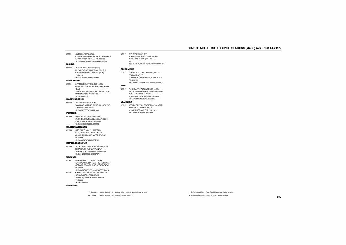
������������������� ������������������������������������
/��&�� ���������( $����������&��&���&����������&������������* ��� �&�����������!�%���"�$$�%#$!�%��$�)� �(#�%�)(� !! !(�
!�%���
������
����� �����' �� ��!%�(�������$��� ���������� ���'��������������������������������*����������$�!�!���"�$ !��%�$��( $(�)� $%#��
!�%#���
�������
'�� �/ �������� ���%(�������������&��*���� ������/��&����� ���� ����'������������� ������'���'������������ �������!!�!���"�%�$���$ #�
!�%%��
������
������������ ���$!� ��������&�.����� ��������������* ��� �&�����������!�$���"�$$�%#$(�$#%�!)�����$����
!$�����
������
��� �/ ����� ���' ��(������������ �/ �������������������'���������������*����������$!�!���"�$� ��%�$�( (%��)��$��#�
!$�!���
�� ��� ���
���*� ��������������������$��&�����������&�����&��/�������������* ��� �&������������� ���"�$�##�%�$��#$#(()�(��#!�
!$�����
��������
�������������$������������������������'��*���&����������������'�������������*��������!$$�$���"�$�!�� !$#��)%�$�!���#��
!$�$���
�������
���*���������&���& ���#������������&���������� ������������*�������*������������&���* ��� �&��������$��� ���"�$ #�%�$�! �!��)�%�$�$�(#(�)� ���!#�
!$����
������*�������#$ ���� ���� ��������'��'��������'���������&���������&���* ��� �&��������$���$���"�%#$��(# $��
!$� ��
������
'���'�� ��!% ���������������� �������"���'����������&�������������������!! ���"�$$�� #$��#$)� #$��#()� ($ #��)%#$���%!���
!$�(�,,
������
��������' �� ���!(����# )!#�&���������* ������"�����������������������&����*����������!���$���"�$$�%#$!�%% �$)�%$$!##� %)�(�� ($��
!$���,
���
���'������������� ����� (������/��&����������&������� �*��������'��������&�*������ �����* ��� �&��������$!!�!���"�$�(��%#$!#�$��%)� %��!#��
!$�#���
�������
�������� ���' ��������$$������ ������������'� '�����������(��� �����*����������!!$!(���"�$$�%#$(�#� ��)�((!�( (�
!$�%���
,, ��'1234567��188�"�-633�+�91:;��36<:=3���1>56�6391:68�+��==:;3?21@�6391:68 , ��'1234567��188�"�-633�+�91:;��36<:=3�+��1>56�6391:68
�� '�'1234567��188�"�-633�+�91:;��36<:=3�+��:?56�6391:68 � ��'1234567��188�"�-633��36<:=3�+��:?56�6391:68����
MEMO

MEMO

MEMO

MEMO

68PH0-74E
MEMO
MEMO
68PH0-74E
MEMO
Related Documents