LS ELECTRIC strives to maximize your profits in gratitude for choosing us as your partner. Programmable Logic Control XGT Ethernet Module XGL-EFMTB XGL-EFMFB XGL-EFMHB XOL-ES4T XOL-ES4H XGL-EH5T XGL-EFMT XGL-EFMF XGT Series

Welcome message from author
This document is posted to help you gain knowledge. Please leave a comment to let me know what you think about it! Share it to your friends and learn new things together.
Transcript

LS ELECTRIC strives to maximize your profits in gratitude for choosing us as your partner.
Programmable Logic Control
XGT Ethernet Module
XGL-EFMTB
XGL-EFMFB
XGL-EFMHB
XOL-ES4T
XOL-ES4H
XGL-EH5T
XGL-EFMT
XGL-EFMF
XGT Series
Safety Instruction
1
Before using the product …
For your safety and effective operation, please read the safety instructions thoroughly before using the product.
Safety Instructions should always be observed in order to prevent accident or risk with the safe and proper use
the product.
Instructions are divided into “Warning” and “Caution”, and the meaning of the terms is as follows.
This symbol indicates the possibility of serious injury or death if some applicable
instruction is violated
This symbol indicates the possibility of severe or slight injury, and property
damages if some applicable instruction is violated
Moreover, even classified events under its caution category may develop into serious accidents relying
on situations. Therefore we strongly advise users to observe all precautions properly just like warnings.
The marks displayed on the product and in the user’s manual have the following meanings.
Be careful! Danger may be expected.
Be careful! Electric shock may occur.
The user’s manual even after read shall be kept available and accessible to any user of the product.
Warning
Caution
Safety Instruction
2
Safety Instructions for design process
1. Please install a protection circuit on the exterior of PLC so that the whole system may
operate safely regardless of failures from external power or PLC. Any abnormal output or
operation from PLC may cause serious problems to safety in whole system.
- Install protection units on the exterior of PLC like an interlock circuit that deals with opposite
operations such as emergency stop, protection circuit, and forward/reverse rotation or install an
interlock circuit that deals with high/low limit under its position controls.
- If any system error (watch-dog timer error, module installation error, etc.) is detected during
CPU operation in PLC, all output signals are designed to be turned off and stopped for safety.
However, there are cases when output signals remain active due to device failures in Relay and
TR which can’t be detected. Thus, you are recommended to install an addition circuit to monitor
the output status for those critical outputs which may cause significant problems.
2. Never overload more than rated current of output module nor allow to have a short circuit.
Over current for a long period time may cause a fire .
3. Never let the external power of the output circuit to be on earlier than PLC power, which may
cause accidents from abnormal output or operation.
4. Please install interlock circuits in the sequence program for safe operations in the system
when exchange data with PLC or modify operation modes using a computer or other
external equipments Read specific instructions thoroughly when conducting control operations
with PLC.
Warning

Safety Instruction
3
Safety Instructions for design process
Safety Instructions on installation process
I/O signal or communication line shall be wired at least 100mm away from a high-voltage cable or
power line. Fail to follow this instruction may cause malfunctions from noise
Caution
1. Use PLC only in the environment specified in PLC manual or general standard of data
sheet. If not, electric shock, fire, abnormal operation of the product may be caused.
2. Before install or remove the module, be sure PLC power is off. If not, electric shock or
damage on the product may be caused.
3. Be sure that every module is securely attached after adding a module or an extension
connector. If the product is installed loosely or incorrectly, abnormal operation, error or dropping
may be caused. In addition, contact failures under poor cable installation will be causing
malfunctions as well.
4. Be sure that screws get tighten securely under vibrating environments. Fail to do so will
put the product under direct vibrations which will cause electric shock, fire and abnormal operation.
5. Do not come in contact with conducting parts in each module, which may cause electric
shock, malfunctions or abnormal operation.
Caution
Safety Instruction
4
Safety Instructions for wiring process
1. Prior to wiring works, make sure that every power is turned off. If not, electric shock or
damage on the product may be caused.
2. After wiring process is done, make sure that terminal covers are installed properly before
its use. Fail to install the cover may cause electric shocks.
Warning
1. Check rated voltages and terminal arrangements in each product prior to its wiring
process. Applying incorrect voltages other than rated voltages and misarrangement among
terminals may cause fire or malfunctions.
2. Secure terminal screws tightly applying with specified torque. If the screws get loose, short
circuit, fire or abnormal operation may be caused. Securing screws too tightly will cause damages
to the module or malfunctions, short circuit, and dropping.
3. Be sure to earth to the ground using Class 3 wires for FG terminals which is exclusively
used for PLC. If the terminals not grounded correctly, abnormal operation or electric shock may
be caused.
4. Don’t let any foreign materials such as wiring waste inside the module while wiring,
which may cause fire, damage on the product or abnormal operation.
5. Make sure that pressed terminals get tighten following the specified torque. External
connector type shall be pressed or soldered using proper equipments.
Caution
Safety Instruction
5
Safety Instructions for test-operation and maintenance
1. Don’t touch the terminal when powered. Electric shock or abnormal operation may occur.
2. Prior to cleaning or tightening the terminal screws, let all the external power off including
PLC power. If not, electric shock or abnormal operation may occur.
3. Don’t let the battery recharged, disassembled, heated, short or soldered. Heat, explosion or
ignition may cause injuries or fire.
Warning
1. Do not make modifications or disassemble each module. Fire, electric shock or abnormal
operation may occur.
2. Prior to installing or disassembling the module, let all the external power off including PLC
power. If not, electric shock or abnormal operation may occur.
3. Keep any wireless equipment such as walkie-talkie or cell phones at least 30cm away from
PLC. If not, abnormal operation may be caused.
4. When making a modification on programs or using run to modify functions under PLC
operations, read and comprehend all contents in the manual fully. Mismanagement will cause
damages to products and accidents.
5. Avoid any physical impact to the battery and prevent it from dropping as well. Damages to
battery may cause leakage from its fluid. When battery was dropped or exposed under strong
impact, never reuse the battery again. Moreover skilled workers are needed when exchanging
batteries.
Caution

Safety Instruction
6
Safety Instructions for waste disposal
Product or battery waste shall be processed as industrial waste. The waste may discharge
toxic materials or explode itself.
Caution
Revision History
7
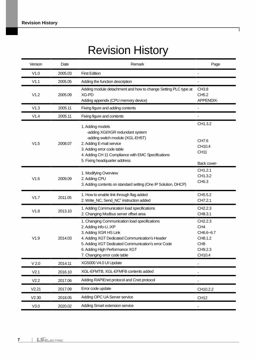
Revision History Version Date Remark Page
V1.0 2005.03 First Edition -
V1.1 2005.05 Adding the function description -
V1.2 2005.09
Adding module detachment and how to change Setting PLC type at
XG-PD
Adding appendix (CPU memory device)
CH3.8
CH5.2
APPENDIX-
V1.3 2005.11 Fixing figure and adding contents -
V1.4 2005.11 Fixing figure and contents -
V1.5 2008.07
1. Adding models
-adding XGI/XGR redundant system
-adding switch module (XGL-EH5T)
2. Adding E-mail service
3. Adding error code table
4. Adding CH 11 Compliance with EMC Specifications
5. Fixing headquarter address
CH1.3.2
CH7.6
CH10.4
CH11
Back cover-
V1.6 2009.09
1. Modifying Overview
2. Adding CPU
3. Adding contents on standard setting (One IP Solution, DHCP)
CH1.2.1
CH1.3.2
CH5.3
V1.7 2011.05 1. How to enable link through flag added
2. Write_NC, Send_NC” instruction added
CH5.5.2
CH7.2.1
V1.8 2013.10 1. Adding Communication load specifications
2. Changing Modbus server offset area
CH2.2.3
CH8.3.1
V1.9 2014.03
1. Changing Communication load specifications
2. Adding info-U, iXP
3. Adding XGR HS Link
4. Adding XGT Dedicated Communication’s Header
5. Adding XGT Dedicated Communication’s error Code
6. Adding High Performance XGT
7. Changing error code table
CH2.2.3
CH4
CH6.6~6.7
CH8.1.2
CH8
CH9.2.3
CH10.4
V 2.0 2014.11 XG5000 V4.0 UI Update -
V2.1 2016.10 XGL-EFMTB, XGL-EFMFB contents added -
V2.2 2017.06 Adding RAPIEnet protocol and Cnet protocol -
V2.21 2017.09 Error code update CH10.2.2
V2.30 2018.05 Adding OPC UA Server service CH12
V3.0 2020.02 Adding Smart extension service -

Revision History
8
Version Date Remark Page
V3.1 2020.06
1. Format and contents modification according to the change of
company name(LSIS -> LS ELECTRIC)
2. Adding RAPIEnet+ autoscan
3. Adding Smart Extension service diagnostic variables
ALL
CH3.6
CH4, CH9
About User’s Manual
9
Thank you for purchasing PLC of LS ELECTRIC Co., Ltd.
Before use, make sure to carefully read and understand the User’s Manual about the functions, performances, installation and
programming of the product you purchased in order for correct use and importantly, let the end user and maintenance
administrator to be provided with the User’s Manual.
The User’s Manual describes the product. If necessary, you may refer to the following description and order accordingly. In
addition, you may connect our website (http://www.lselectric.co.kr/) and download the information as a PDF file.
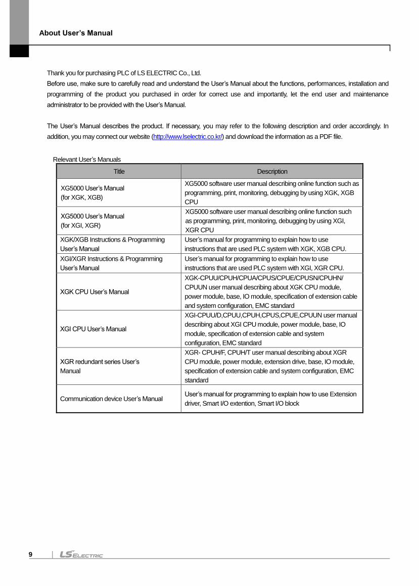
Relevant User’s Manuals
Title Description
XG5000 User’s Manual
(for XGK, XGB)
XG5000 software user manual describing online function such as
programming, print, monitoring, debugging by using XGK, XGB
CPU
XG5000 User’s Manual
(for XGI, XGR)
XG5000 software user manual describing online function such
as programming, print, monitoring, debugging by using XGI,
XGR CPU
XGK/XGB Instructions & Programming
User’s Manual
User’s manual for programming to explain how to use
instructions that are used PLC system with XGK, XGB CPU.
XGI/XGR Instructions & Programming
User’s Manual
User’s manual for programming to explain how to use
instructions that are used PLC system with XGI, XGR CPU.
XGK CPU User’s Manual
XGK-CPUU/CPUH/CPUA/CPUS/CPUE/CPUSN/CPUHN/
CPUUN user manual describing about XGK CPU module,
power module, base, IO module, specification of extension cable
and system configuration, EMC standard
XGI CPU User’s Manual
XGI-CPUU/D,CPUU,CPUH,CPUS,CPUE,CPUUN user manual
describing about XGI CPU module, power module, base, IO
module, specification of extension cable and system
configuration, EMC standard
XGR redundant series User’s
Manual
XGR- CPUH/F, CPUH/T user manual describing about XGR
CPU module, power module, extension drive, base, IO module,
specification of extension cable and system configuration, EMC
standard
Communication device User’s Manual User’s manual for programming to explain how to use Extension
driver, Smart I/O extention, Smart I/O block
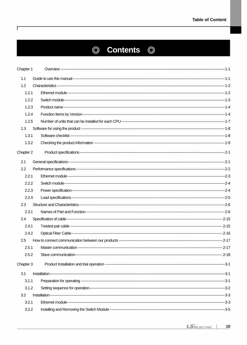
Table of Content
10
Contents
Chapter 1 Overview ------------------------------------------------------------------------------------------------------------------------------------------ 1-1
1.1 Guide to use this manual -------------------------------------------------------------------------------------------------------------------------------- 1-1
1.2 Characteristics --------------------------------------------------------------------------------------------------------------------------------------------- 1-2
1.2.1 Ethernet module ------------------------------------------------------------------------------------------------------------------------------------ 1-2
1.2.2 Switch module --------------------------------------------------------------------------------------------------------------------------------------- 1-3
1.2.3 Product name --------------------------------------------------------------------------------------------------------------------------------------- 1-4
1.2.4 Function Items by Version ------------------------------------------------------------------------------------------------------------------------ 1-4
1.2.5 Number of units that can be installed for each CPU --------------------------------------------------------------------------------------- 1-7
1.3 Software for using the product ------------------------------------------------------------------------------------------------------------------------- 1-8
1.3.1 Software checklist ---------------------------------------------------------------------------------------------------------------------------------- 1-8
1.3.2 Checking the product information -------------------------------------------------------------------------------------------------------------- 1-9
Chapter 2 Product specifications -------------------------------------------------------------------------------------------------------------------------- 2-1
2.1 General specifications ------------------------------------------------------------------------------------------------------------------------------------ 2-1
2.2 Performance specifications ----------------------------------------------------------------------------------------------------------------------------- 2-2
2.2.1 Ethernet module ------------------------------------------------------------------------------------------------------------------------------------ 2-3
2.2.2 Switch module --------------------------------------------------------------------------------------------------------------------------------------- 2-4
2.2.3 Power specification--------------------------------------------------------------------------------------------------------------------------------- 2-4
2.2.4 Load specifications --------------------------------------------------------------------------------------------------------------------------------- 2-5
2.3 Structure and Characteristics--------------------------------------------------------------------------------------------------------------------------- 2-6
2.3.1 Names of Part and Function --------------------------------------------------------------------------------------------------------------------- 2-6
2.4 Specification of cable ----------------------------------------------------------------------------------------------------------------------------------- 2-15
2.4.1 Twisted pair cable -------------------------------------------------------------------------------------------------------------------------------- 2-15
2.4.2 Optical Fiber Cable ------------------------------------------------------------------------------------------------------------------------------- 2-16
2.5 How to connect communication between our products --------------------------------------------------------------------------------------- 2-17
2.5.1 Master communication -------------------------------------------------------------------------------------------------------------------------- 2-17
2.5.2 Slave communication ---------------------------------------------------------------------------------------------------------------------------- 2-18
Chapter 3 Product Installation and trial operation ----------------------------------------------------------------------------------------------------- 3-1
3.1 Installation --------------------------------------------------------------------------------------------------------------------------------------------------- 3-1
3.1.1 Preparation for operating ------------------------------------------------------------------------------------------------------------------------- 3-1
3.1.2 Setting sequence for operation ------------------------------------------------------------------------------------------------------------------ 3-2
3.2 Installation --------------------------------------------------------------------------------------------------------------------------------------------------- 3-3
3.2.1 Ethernet module ------------------------------------------------------------------------------------------------------------------------------------ 3-3
3.2.2 Installing and Removing the Switch Module ------------------------------------------------------------------------------------------------- 3-5
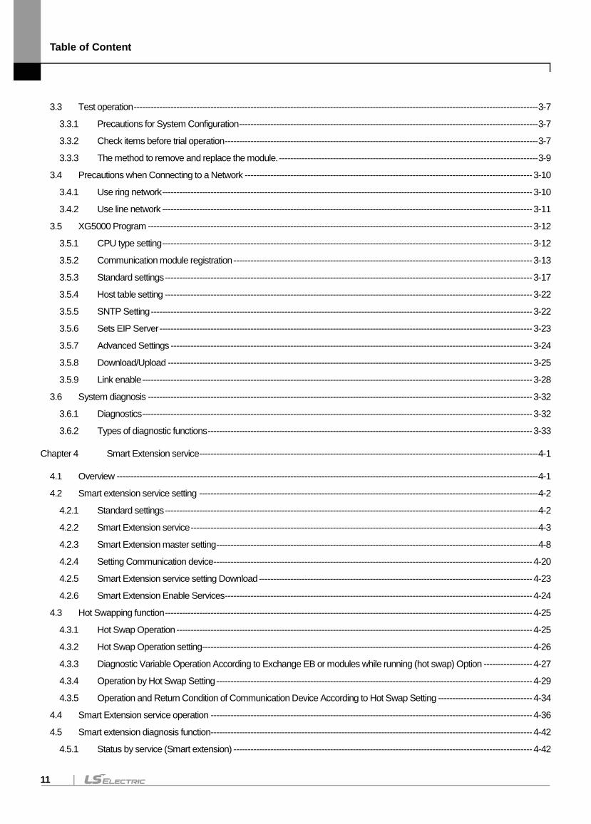
Table of Content
11
3.3 Test operation ---------------------------------------------------------------------------------------------------------------------------------------------- 3-7
3.3.1 Precautions for System Configuration --------------------------------------------------------------------------------------------------------- 3-7
3.3.2 Check items before trial operation -------------------------------------------------------------------------------------------------------------- 3-7
3.3.3 The method to remove and replace the module. ------------------------------------------------------------------------------------------- 3-9
3.4 Precautions when Connecting to a Network ----------------------------------------------------------------------------------------------------- 3-10
3.4.1 Use ring network ---------------------------------------------------------------------------------------------------------------------------------- 3-10
3.4.2 Use line network ---------------------------------------------------------------------------------------------------------------------------------- 3-11
3.5 XG5000 Program --------------------------------------------------------------------------------------------------------------------------------------- 3-12
3.5.1 CPU type setting ---------------------------------------------------------------------------------------------------------------------------------- 3-12
3.5.2 Communication module registration --------------------------------------------------------------------------------------------------------- 3-13
3.5.3 Standard settings --------------------------------------------------------------------------------------------------------------------------------- 3-17
3.5.4 Host table setting --------------------------------------------------------------------------------------------------------------------------------- 3-22
3.5.5 SNTP Setting -------------------------------------------------------------------------------------------------------------------------------------- 3-22
3.5.6 Sets EIP Server ----------------------------------------------------------------------------------------------------------------------------------- 3-23
3.5.7 Advanced Settings ------------------------------------------------------------------------------------------------------------------------------- 3-24
3.5.8 Download/Upload -------------------------------------------------------------------------------------------------------------------------------- 3-25
3.5.9 Link enable ----------------------------------------------------------------------------------------------------------------------------------------- 3-28
3.6 System diagnosis --------------------------------------------------------------------------------------------------------------------------------------- 3-32
3.6.1 Diagnostics ----------------------------------------------------------------------------------------------------------------------------------------- 3-32
3.6.2 Types of diagnostic functions ------------------------------------------------------------------------------------------------------------------ 3-33
Chapter 4 Smart Extension service ----------------------------------------------------------------------------------------------------------------------- 4-1
4.1 Overview ---------------------------------------------------------------------------------------------------------------------------------------------------- 4-1
4.2 Smart extension service setting ----------------------------------------------------------------------------------------------------------------------- 4-2
4.2.1 Standard settings ----------------------------------------------------------------------------------------------------------------------------------- 4-2
4.2.2 Smart Extension service -------------------------------------------------------------------------------------------------------------------------- 4-3
4.2.3 Smart Extension master setting ----------------------------------------------------------------------------------------------------------------- 4-8
4.2.4 Setting Communication device ---------------------------------------------------------------------------------------------------------------- 4-20
4.2.5 Smart Extension service setting Download ------------------------------------------------------------------------------------------------ 4-23
4.2.6 Smart Extension Enable Services ------------------------------------------------------------------------------------------------------------ 4-24
4.3 Hot Swapping function --------------------------------------------------------------------------------------------------------------------------------- 4-25
4.3.1 Hot Swap Operation ----------------------------------------------------------------------------------------------------------------------------- 4-25
4.3.2 Hot Swap Operation setting -------------------------------------------------------------------------------------------------------------------- 4-26
4.3.3 Diagnostic Variable Operation According to Exchange EB or modules while running (hot swap) Option ----------------- 4-27
4.3.4 Operation by Hot Swap Setting --------------------------------------------------------------------------------------------------------------- 4-29
4.3.5 Operation and Return Condition of Communication Device According to Hot Swap Setting --------------------------------- 4-34
4.4 Smart Extension service operation ----------------------------------------------------------------------------------------------------------------- 4-36
4.5 Smart extension diagnosis function ----------------------------------------------------------------------------------------------------------------- 4-42
4.5.1 Status by service (Smart extension) --------------------------------------------------------------------------------------------------------- 4-42
Table of Content
12
4.5.2 View Communication Module Log ----------------------------------------------------------------------------------------------------------- 4-44
4.6 Smart extension system configuration ------------------------------------------------------------------------------------------------------------- 4-47
4.6.1 Typical Configuration ---------------------------------------------------------------------------------------------------------------------------- 4-47
4.6.2 Ring / Line configuration. ----------------------------------------------------------------------------------------------------------------------- 4-48
4.6.3 Auto Speed Sync Operation ------------------------------------------------------------------------------------------------------------------- 4-49
Chapter 5 High speed link service ------------------------------------------------------------------------------------------------------------------------ 5-1
5.1 Overview ---------------------------------------------------------------------------------------------------------------------------------------------------- 5-1
5.2 HS link send / receive data processing -------------------------------------------------------------------------------------------------------------- 5-2
5.3 HS link setting ---------------------------------------------------------------------------------------------------------------------------------------------- 5-3
5.3.1 Standard settings ----------------------------------------------------------------------------------------------------------------------------------- 5-3
5.3.2 HS Link Service ------------------------------------------------------------------------------------------------------------------------------------- 5-4
5.3.3 Communication device configuration (Smart I / O block v1 version) ----------------------------------------------------------------- 5-10
5.4 HS Link operation --------------------------------------------------------------------------------------------------------------------------------------- 5-18
5.5 HS Link Information ------------------------------------------------------------------------------------------------------------------------------------- 5-24
5.5.1 High speed link flag ------------------------------------------------------------------------------------------------------------------------------ 5-24
5.5.2 HS Link Information Monitor ------------------------------------------------------------------------------------------------------------------- 5-26
5.6 XGR Redundancy Program Method --------------------------------------------------------------------------------------------------------------- 5-28
5.6.1 When configuring an XGR redundant network ------------------------------------------------------------------------------------------- 5-28
5.6.2 When configuring an XGR Single network ------------------------------------------------------------------------------------------------- 5-30
5.7 XGR Redundant High Speed Link Setting Program ------------------------------------------------------------------------------------------- 5-31
5.7.1 When configuring an XGR redundant network ------------------------------------------------------------------------------------------- 5-31
5.7.2 When configuring an XGR Single network ------------------------------------------------------------------------------------------------- 5-38
5.8 Ethernet System Configuration ---------------------------------------------------------------------------------------------------------------------- 5-41
5.8.1 Configuration of Ethernet System Using Dedicated Network ------------------------------------------------------------------------- 5-42
5.8.2 Mix of Dedicated Networks and Third-Party Ethernet Systems ---------------------------------------------------------------------- 5-42
5.8.3 Mix of public, dedicated and third party Ethernet systems ----------------------------------------------------------------------------- 5-43
5.8.4 System configuration using InfoU, PLC-to-PLC Dedicated Ethernet in XGR system ------------------------------------------- 5-43
5.8.5 System configuration using single network Ethernet in XGR system --------------------------------------------------------------- 5-44
Chapter 6 P2P service --------------------------------------------------------------------------------------------------------------------------------------- 6-1
6.1 Overview ---------------------------------------------------------------------------------------------------------------------------------------------------- 6-1
6.1.1 Overview of P2P service -------------------------------------------------------------------------------------------------------------------------- 6-1
6.1.2 P2P parameter configuration -------------------------------------------------------------------------------------------------------------------- 6-1
6.2 Type of P2P service -------------------------------------------------------------------------------------------------------------------------------------- 6-2
6.2.1 Type of P2P command --------------------------------------------------------------------------------------------------------------------------- 6-2
6.2.2 Type of P2P service ------------------------------------------------------------------------------------------------------------------------------- 6-2
6.3 P2P service setting --------------------------------------------------------------------------------------------------------------------------------------- 6-4
6.3.1 Ethernet (server) driver ---------------------------------------------------------------------------------------------------------------------------- 6-4
Table of Content
13
6.3.2 P2P channel ----------------------------------------------------------------------------------------------------------------------------------------- 6-4
6.3.3 P2P block --------------------------------------------------------------------------------------------------------------------------------------------- 6-7
6.4 P2P service operation ------------------------------------------------------------------------------------------------------------------------------------ 6-9
6.5 User frame definition ----------------------------------------------------------------------------------------------------------------------------------- 6-19
6.5.1 Overview of a user frame definition ---------------------------------------------------------------------------------------------------------- 6-19
6.5.2 User frame definition setting ------------------------------------------------------------------------------------------------------------------- 6-19
6.5.3 Operation of a user frame definition ---------------------------------------------------------------------------------------------------------- 6-24
6.6 E-mail Service -------------------------------------------------------------------------------------------------------------------------------------------- 6-32
6.6.1 Email setting --------------------------------------------------------------------------------------------------------------------------------------- 6-32
6.6.2 Writing address ----------------------------------------------------------------------------------------------------------------------------------- 6-33
6.6.3 Create block --------------------------------------------------------------------------------------------------------------------------------------- 6-37
6.7 Downloading and diagnosis of P2P parameter -------------------------------------------------------------------------------------------------- 6-38
6.7.1 Downloading a P2P parameter --------------------------------------------------------------------------------------------------------------- 6-38
6.7.2 P2P service operation --------------------------------------------------------------------------------------------------------------------------- 6-39
6.7.3 P2P service diagnosis --------------------------------------------------------------------------------------------------------------------------- 6-40
6.8 XGR Redundancy Program Method --------------------------------------------------------------------------------------------------------------- 6-41
Chapter 7 Server service ------------------------------------------------------------------------------------------------------------------------------------ 7-1
7.1 XGT server-------------------------------------------------------------------------------------------------------------------------------------------------- 7-1
7.1.1 Overview ---------------------------------------------------------------------------------------------------------------------------------------------- 7-1
7.1.2 Request to read information and status(PC/HMI -> PLC) -------------------------------------------------------------------------------- 7-7
7.1.3 Server operation ---------------------------------------------------------------------------------------------------------------------------------- 7-11
7.2 Modbus Server ------------------------------------------------------------------------------------------------------------------------------------------ 7-14
7.2.1 Overview -------------------------------------------------------------------------------------------------------------------------------------------- 7-14
7.2.2 Server operation ---------------------------------------------------------------------------------------------------------------------------------- 7-16
7.3 EtherNet / IP server ------------------------------------------------------------------------------------------------------------------------------------- 7-18
7.3.1 Overview -------------------------------------------------------------------------------------------------------------------------------------------- 7-18
7.3.2 Operation Sequence----------------------------------------------------------------------------------------------------------------------------- 7-20
7.3.3 Parameter setting --------------------------------------------------------------------------------------------------------------------------------- 7-21
7.3.4 Client setting --------------------------------------------------------------------------------------------------------------------------------------- 7-22
7.3.5 Server setting -------------------------------------------------------------------------------------------------------------------------------------- 7-28
7.3.6 Tag register ---------------------------------------------------------------------------------------------------------------------------------------- 7-30
7.3.7 Setting Download --------------------------------------------------------------------------------------------------------------------------------- 7-33
7.3.8 EtherNet/IP periodic communication operation example ------------------------------------------------------------------------------- 7-34
7.3.9 Diagnosis ------------------------------------------------------------------------------------------------------------------------------------------- 7-49
7.3.10 System configuration ---------------------------------------------------------------------------------------------------------------------------- 7-50
7.4 OPC UA function ---------------------------------------------------------------------------------------------------------------------------------------- 7-51
7.4.1 Overview -------------------------------------------------------------------------------------------------------------------------------------------- 7-52
7.4.2 Parameter setting --------------------------------------------------------------------------------------------------------------------------------- 7-56
Table of Content
14
7.4.3 OPC UA settings --------------------------------------------------------------------------------------------------------------------------------- 7-57
7.4.4 Variable registration ------------------------------------------------------------------------------------------------------------------------------ 7-60
7.4.5 Setting Download --------------------------------------------------------------------------------------------------------------------------------- 7-61
Chapter 8 Additional functions ----------------------------------------------------------------------------------------------------------------------------- 8-1
8.1 Remote communication --------------------------------------------------------------------------------------------------------------------------------- 8-1
8.2 XG5000 setting and connection ----------------------------------------------------------------------------------------------------------------------- 8-2
8.2.1 Remote 1-stage connection(when using USB ) -------------------------------------------------------------------------------------------- 8-2
8.2.2 Remote 2-stage connection (when using USB ) ------------------------------------------------------------------------------------------- 8-4
8.2.3 CPU access directly from PC connected to Ethernet ------------------------------------------------------------------------------------- 8-6
8.3 System configuration using switch module --------------------------------------------------------------------------------------------------------- 8-9
8.3.1 Ethernet, RAPIEnet mixed system configuration (supported by Ethernet V6.0 or higher, switch V1.1 or higher) ---------- 8-9
Chapter 9 Troubleshooting --------------------------------------------------------------------------------------------------------------------------------- 9-1
9.1 LED Error Check ------------------------------------------------------------------------------------------------------------------------------------------ 9-2
9.1.1 Abnormal operation indication of XGL-EFMT / EFMF ------------------------------------------------------------------------------------ 9-2
9.1.2 Abnormal operation indication of XGL-EFMTB / EFMF ---------------------------------------------------------------------------------- 9-3
9.1.3 Abnormal operation display of XGL-EH5T --------------------------------------------------------------------------------------------------- 9-5
9.1.4 Abnormal operation display of XOL-ES4T/ES4H ------------------------------------------------------------------------------------------ 9-6
9.2 Error checking method by XG5000 connection --------------------------------------------------------------------------------------------------- 9-7
9.2.1 Error / Warning check during PLC operation ------------------------------------------------------------------------------------------------ 9-7
9.2.2 Error / Warning check during communication module operation --------------------------------------------------------------------- 9-14
9.2.3 View Communication Module Log ----------------------------------------------------------------------------------------------------------- 9-27
9.3 XGT dedicated communication error code ------------------------------------------------------------------------------------------------------- 9-28
9.3.1 STATUS value that can be checked in communication frame ------------------------------------------------------------------------ 9-28
9.4 Troubleshooting by error ------------------------------------------------------------------------------------------------------------------------------ 9-29
9.4.1 Troubleshooting ----------------------------------------------------------------------------------------------------------------------------------- 9-29
Chapter 10 EMC Standard ------------------------------------------------------------------------------------------------------------------------------ 10-1
10.1 The requirements for compliance with EMC standards --------------------------------------------------------------------------------------- 10-1
10.1.1 EMC Standard ------------------------------------------------------------------------------------------------------------------------------------ 10-1
10.1.2 Panel ------------------------------------------------------------------------------------------------------------------------------------------------- 10-2
10.1.3 Cable ------------------------------------------------------------------------------------------------------------------------------------------------ 10-3
10.2 Requirement to conform to the Low-voltage Directive ----------------------------------------------------------------------------------------- 10-4
10.2.1 Standards applicable to XGT series --------------------------------------------------------------------------------------------------------- 10-4
10.2.2 Selection of XGT Series PLC------------------------------------------------------------------------------------------------------------------ 10-4
Appendix ----------------------------------------------------------------------------------------------------------------------------------------------------------------- A-1
A.1 XGT CPU memory device list ----------------------------------------------------------------------------------------------------------------------------- A-1
A.1.1 XGK CPU devices -------------------------------------------------------------------------------------------------------------------------------------- A-1

www.lselectric.co.kr
Overseas Subsidiaries
• LS ELECTRIC Japan Co., Ltd. (Tokyo, Japan)
Tel: 81-3-6268-8241 E-Mail: [email protected]
• LS ELECTRIC (Dalian) Co., Ltd. (Dalian, China)
Tel: 86-411-8730-6495 E-Mail: [email protected]
• LS ELECTRIC (Wuxi) Co., Ltd. (Wuxi, China)
Tel: 86-510-6851-6666 E-Mail: [email protected]
• LS ELECTRIC Shanghai Office (China)
Tel: 86-21-5237-9977 E-Mail: [email protected]
• LS ELECTRIC Vietnam Co., Ltd.
Tel: 84-93-631-4099 E-Mail: [email protected] (Hanoi)
Tel: 84-28-3823-7890 E-Mail: [email protected] (Hochiminh)
• LS ELECTRIC Middle East FZE (Dubai, U.A.E.)
Tel: 971-4-886-5360 E-Mail: [email protected]
• LS ELECTRIC Europe B.V. (Hoofddorf, Netherlands)
Tel: 31-20-654-1424 E-Mail: [email protected]
• LS ELECTRIC America Inc. (Chicago, USA)
Tel: 1-800-891-2941 E-Mail: [email protected]
Headquarter
LS-ro 127(Hogye-dong) Dongan-gu, Anyang-si, Gyeonggi-Do, 14119,
Korea
Seoul Office
LS Yongsan Tower, 92, Hangang-daero, Yongsan-gu, Seoul, 04386,
Korea
Tel: 82-2-2034-4033, 4888, 4703 Fax: 82-2-2034-4588
E-mail: [email protected]
Factory
56, Samseong 4-gil, Mokcheon-eup, Dongnam-gu, Cheonan-si,
Chungcheongnam-do, 31226, Korea
©2005. LS ELECTRIC Co., Ltd. All Rights Reserved.
2020.06

Table of Content
16
Chapter 1 Overview
1-1
Chapter 1 Overview
1.1 Guide to use this manual
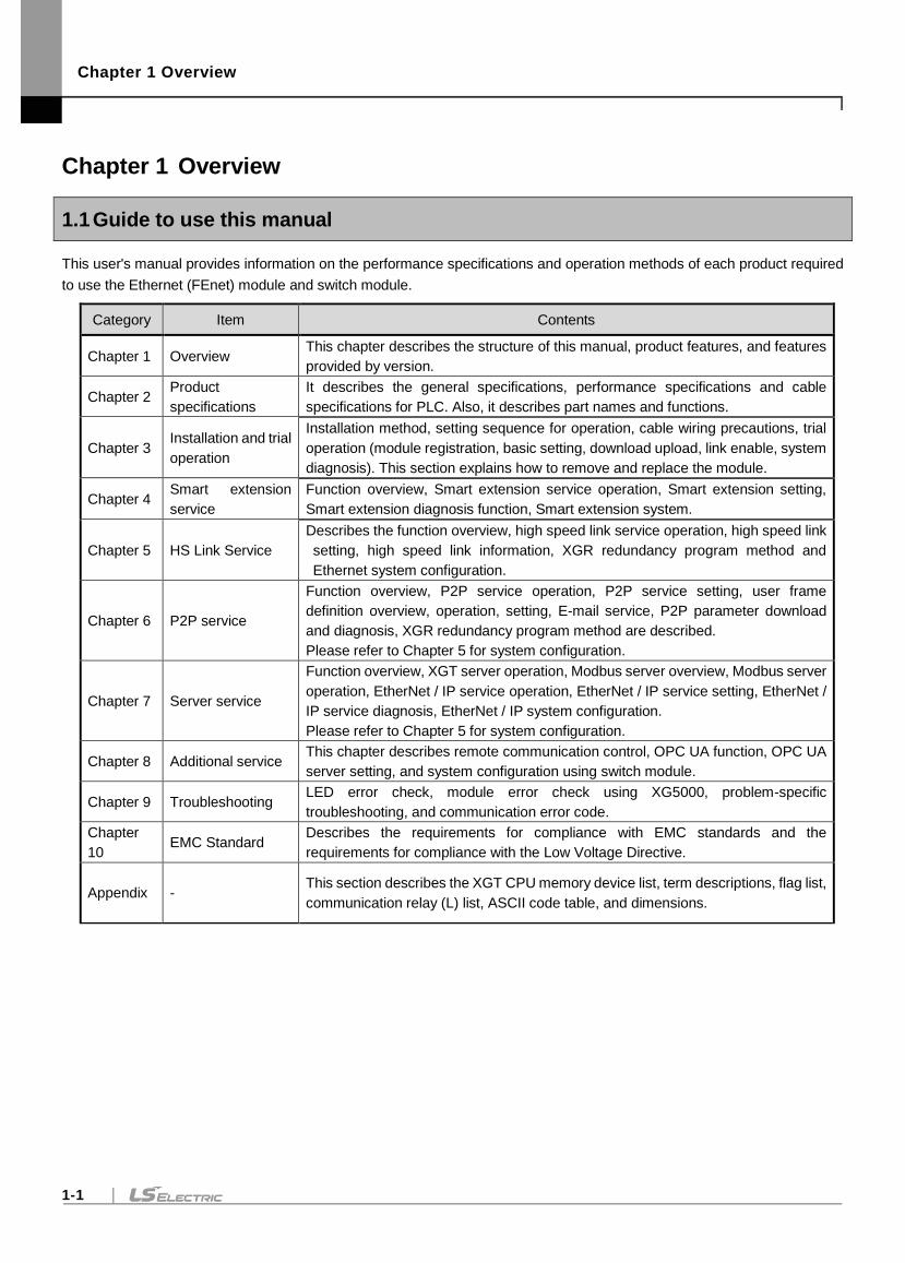
This user's manual provides information on the performance specifications and operation methods of each product required
to use the Ethernet (FEnet) module and switch module.
Category Item Contents
Chapter 1 Overview This chapter describes the structure of this manual, product features, and features
provided by version.
Chapter 2 Product
specifications
It describes the general specifications, performance specifications and cable
specifications for PLC. Also, it describes part names and functions.
Chapter 3 Installation and trial
operation
Installation method, setting sequence for operation, cable wiring precautions, trial
operation (module registration, basic setting, download upload, link enable, system
diagnosis). This section explains how to remove and replace the module.
Chapter 4 Smart extension
service
Function overview, Smart extension service operation, Smart extension setting,
Smart extension diagnosis function, Smart extension system.
Chapter 5 HS Link Service
Describes the function overview, high speed link service operation, high speed link
setting, high speed link information, XGR redundancy program method and
Ethernet system configuration.
Chapter 6 P2P service
Function overview, P2P service operation, P2P service setting, user frame
definition overview, operation, setting, E-mail service, P2P parameter download
and diagnosis, XGR redundancy program method are described.
Please refer to Chapter 5 for system configuration.
Chapter 7 Server service
Function overview, XGT server operation, Modbus server overview, Modbus server
operation, EtherNet / IP service operation, EtherNet / IP service setting, EtherNet /
IP service diagnosis, EtherNet / IP system configuration.
Please refer to Chapter 5 for system configuration.
Chapter 8 Additional service This chapter describes remote communication control, OPC UA function, OPC UA
server setting, and system configuration using switch module.
Chapter 9 Troubleshooting LED error check, module error check using XG5000, problem-specific
troubleshooting, and communication error code.
Chapter
10 EMC Standard
Describes the requirements for compliance with EMC standards and the
requirements for compliance with the Low Voltage Directive.
Appendix - This section describes the XGT CPU memory device list, term descriptions, flag list,
communication relay (L) list, ASCII code table, and dimensions.
Chapter 1 Overview
1-2
1.2 Characteristics
Ethernet is a 'technical standard' established by the IEEE, which enables easy network construction and high-speed, high-
capacity data collection through CSMA / CD communication. Ethernet module is a module for data transmission between
upper system such as PC device or PLC using electric / optical media. The Ethernet module supports TCP / IP and UDP / IP
protocols and has the following characteristics.
1.2.1 Ethernet module
Easy module change using module change switch of CPU and module change wizard of XG5000.
Up to 24 Ethernet modules can be installed regardless of the main base and the extension base.(XGR CPU only
supports main base)
Media support based on the IEEE802.3 standard.
Check parameter and service setting, module and network status using communication configuration tool (XG5000).
Dynamic Host Configuration Protocol (DHCP) support for dynamically setting IP addresses.
Provide access table to secure communication with host PC (HMI).
Smart extension service for easy configuration and high speed data communication between our products.
High speed link support for high speed data communication between our products.
Possible to set high speed link block to transfer data between modules(Maximum transmission 32 blocks x 200
words, maximum reception 32 blocks x 200 words, maximum transmission and reception 128 blocks x 200 words).
Communication with up to 16 modules is available in addition to the high speed link.(Dedicated communication
server + P2P communication) (up to 32 modules in Ethernet V6.0 or higher).
The loader service through the Ethernet (XG5000) is supported: (Dedicated TCP/IP PORT: 2002 assignment)
Easy connection with 3rd party modules (system) using P2P communication and XG5000.
Support for dedicated protocols (XGT) and open protocols (EtherNet / IP, Modbus / TCP).
Simple client function for communication between our communication module and other company's modules
(Dedicated Communication, EtherNet / IP, Modbus / TCP, User frame definition client functions).
Provides various diagnostic functions and module and network status information.
- Status of communication module
- Communication service(Smart extension, high speed link,P2P,Dedicated protocol server) status
- The Auto Scan function that provides our module information connected to the network is provided.
- The PING function that allows you to check the existence of a other module is provided.
- The type of packet and data average received by module are provided (Forecast the network load).
- The function to diagnose the communication module through the network is provided.
Provide email service(ASCII)
Provide One IP Solution function
Notes
Supported OS versions of each function are as follows.
1) FEnet OS V 6.0 or higher: Support XGT Cnet dedicated protocol, MODBUS RTU protocol, MODBUS ASCII
protocol ,RAPIEnet protocol.
2) FEnet OS V 8.0 or higher: Supported Smart extension service and EtherNet / IP protocol.
3) XGR CPU OS V2.4 or higher: : Supported One IP Solution function
Chapter 1 Overview
1-3
1.2.2 Switch module
A switch module is a hub module that has a switching function for interfacing between XGT series Ethernet modules. Mounting
XGT base module to connect PLC-to-PLC or system-to-system by Ethernet communication.
(1) Can be mounted on XGK / I / R base module (XGL-EH5T)
It can be mounted on XGT base without external power, and its compact size makes it easy to install in small spaces.
(2) Supported 1Gbps communication (XOL-ES4T, XOL-ES4H)
100M / 1Gbps communication can be selected. It also supports electric and optical mixing modules.
(3) Supported Ring configuration (XOL-ES4T, XOL-ES4H)
Ring 1 is available between Port1 and Port2, Ring2 is available between Port3 and Port4.
(4) Reliability of Industrial Device Standards
Compared to commercial switches, it guarantees environmental and noise reliability.
(5) Built-in crossover function (provides convenience in cable work)
Direct cables between routers and switch or between PC and switches, cross cables between routers and routers or
switch and switches. Auto Crossover is a device that provides auto-detecting function and can be connected between
same devices by direct cable.
(6) High speed link operation guarantee
Broadcast Storm, that is, the switch keeps broadcasting traffic and releases the function that causes network down,
so the high speed link packet operates normally.
(7) Provide CHS(chassis) GROUND on RJ-45 connectors.
Transmission error rate is improved when using shielded cables (STP) on RJ-45 connectors.
Chapter 1 Overview
1-4
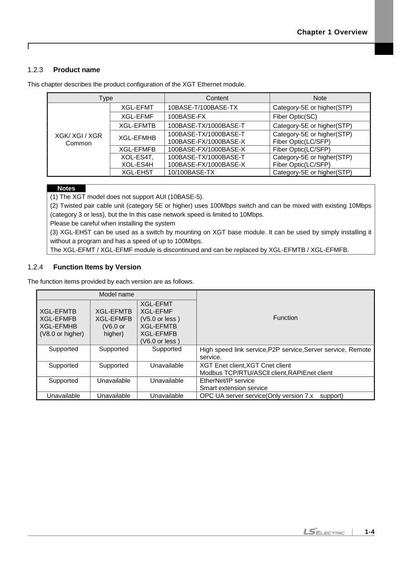
1.2.3 Product name
This chapter describes the product configuration of the XGT Ethernet module.
Type Content Note
XGK/ XGI / XGR Common
XGL-EFMT 10BASE-T/100BASE-TX Category-5E or higher(STP)
XGL-EFMF 100BASE-FX Fiber Optic(SC)
XGL-EFMTB 100BASE-TX/1000BASE-T Category-5E or higher(STP)
XGL-EFMHB 100BASE-TX/1000BASE-T 100BASE-FX/1000BASE-X
Category-5E or higher(STP) Fiber Optic(LC/SFP)
XGL-EFMFB 100BASE-FX/1000BASE-X Fiber Optic(LC/SFP)
XOL-ES4T, XOL-ES4H
100BASE-TX/1000BASE-T 100BASE-FX/1000BASE-X
Category-5E or higher(STP) Fiber Optic(LC/SFP)
XGL-EH5T 10/100BASE-TX Category-5E or higher(STP)
Notes
(1) The XGT model does not support AUI (10BASE-5).
(2) Twisted pair cable unit (category 5E or higher) uses 100Mbps switch and can be mixed with existing 10Mbps
(category 3 or less), but the In this case network speed is limited to 10Mbps.
Please be careful when installing the system
(3) XGL-EH5T can be used as a switch by mounting on XGT base module. It can be used by simply installing it
without a program and has a speed of up to 100Mbps.
The XGL-EFMT / XGL-EFMF module is discontinued and can be replaced by XGL-EFMTB / XGL-EFMFB.
1.2.4 Function Items by Version
The function items provided by each version are as follows.
Model name
Function XGL-EFMTB XGL-EFMFB XGL-EFMHB (V8.0 or higher)
XGL-EFMTB XGL-EFMFB
(V6.0 or higher)
XGL-EFMT XGL-EFMF (V5.0 or less ) XGL-EFMTB XGL-EFMFB (V6.0 or less )
Supported Supported Supported High speed link service,P2P service,Server service, Remote service.
Supported Supported Unavailable XGT Enet client,XGT Cnet client Modbus TCP/RTU/ASCll client,RAPIEnet client
Supported Unavailable Unavailable EtherNet/IP service Smart extension service
Unavailable Unavailable Unavailable OPC UA server service(Only version 7.x support)
Chapter 1 Overview
1-5
(2) HS Link Service
The high speed link is the communication method between the XGB PLC and XGK PLC communication modules
and data is transmitted and received periodically according to the high speed link parameter setting. The high speed
link service transmits a frame to the subnet broadcast using the UDP protocol. Devices in the same subnet receive
broadcast frame at the same time, and if the relevant frame is registered in the reception list, the data it will processed.
(3) P2P service
The P2P service is the client function in the following client/server model. This function requests the server for
reading/writing data. When the starting condition of each block is On, this function creates a request frame with the
protocol specified as the relevant channel, receives and processes the response.
The parameter consists of up to 64 P2P blocks.
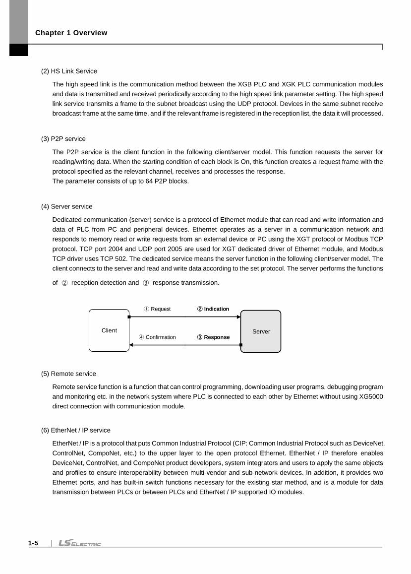
(4) Server service
Dedicated communication (server) service is a protocol of Ethernet module that can read and write information and
data of PLC from PC and peripheral devices. Ethernet operates as a server in a communication network and
responds to memory read or write requests from an external device or PC using the XGT protocol or Modbus TCP
protocol. TCP port 2004 and UDP port 2005 are used for XGT dedicated driver of Ethernet module, and Modbus
TCP driver uses TCP 502. The dedicated service means the server function in the following client/server model. The
client connects to the server and read and write data according to the set protocol. The server performs the functions
of ② reception detection and ③ response transmission.
Client Server
Request Indication
Confirmation Response
(5) Remote service
Remote service function is a function that can control programming, downloading user programs, debugging program
and monitoring etc. in the network system where PLC is connected to each other by Ethernet without using XG5000
direct connection with communication module.
(6) EtherNet / IP service
EtherNet / IP is a protocol that puts Common Industrial Protocol (CIP: Common Industrial Protocol such as DeviceNet,
ControlNet, CompoNet, etc.) to the upper layer to the open protocol Ethernet. EtherNet / IP therefore enables
DeviceNet, ControlNet, and CompoNet product developers, system integrators and users to apply the same objects
and profiles to ensure interoperability between multi-vendor and sub-network devices. In addition, it provides two
Ethernet ports, and has built-in switch functions necessary for the existing star method, and is a module for data
transmission between PLCs or between PLCs and EtherNet / IP supported IO modules.
Chapter 1 Overview
1-6
(7) OPC UA server service
OPC Unified Architecture (IEC 62541) is an interoperability standard for secure and reliable information exchange,
making it suitable for industrial applications. Based on client-server model, it is a communication protocol applicable
from sensor level to cloud and has the following features.
Multi / cross platform support
Unlike OPC Classic, which was dependent on the Windows operating system, it can be operated on an embedded
device without being limited to one operating system or programming language.
- Strong security
Supports authentication and authorization through signing, encryption and data integrity, and uses X.509 certificates
for authentication.
- Service Oriented Architecture
(8) Smart expansion service
Smart extension service is a service between Ethernet (B type) module and communication device (expansion driver,
Smart I / O extension, Smart I / O block) product. It is a service that can control and monitor multiple connected PLCs
with simple setting.
Among EtherNet / IP functions, client functions are integrated in the Smart expansion service.
(9) RAPIEnet service
Based on Ethernet communication, it communicates between XGT series PLCs and provides two Ethernet ports
capable of line (daisy chain) and ring configuration. It provides a flexible network configuration method compared to
the existing STAR type PLC-to-PLC communication module. The RAPIEnet module is divided into two electric ports
(100BASE-TX /1000BASE-T), two optical ports (100BASE-FX/1000BASE-X) and mixed (100BASE-TX/1000BASE-
T, 100BASE-FX//1000BASE-X) according to the media type. This service is for data transmission.
(10) Ethernet switch
It uses CSMA / CD to control communication, establishes an easy network, and enables high-speed, high-capacity
data collection.
(11) RAPIEnet switch(MRS)
MRS(Multi-port RAPIEnet Switch) is based on Ethernet and can be configured in a ring / line topology and enables
high speed and high capacity data collection. It acts as a switch to connect between its our RAPIEnet network
modules.
Notes
(1) Interoperability is a feature that enables seamless communication between information system devices and
services of the same or different types, and provides the ability to accurately perform information exchange or a
series of processes.
(2) The applicable products by product category are shown in the table below.
Product category Product Note
Extension driver XGL-DBDT, XGL-DBDF, XGL-DBDH
Smart I/O expansion XEL-BSSRT, XEL-BSSRF, XEL-BSSRH
Smart I/O block GEL-TR4C1, GEL-DT4C1, GEL-D24C, GEL-RY2C, GEL-AV8C, GEL-AC8C, GEL-DV4C, GEL-DC4C
Chapter 1 Overview
1-7
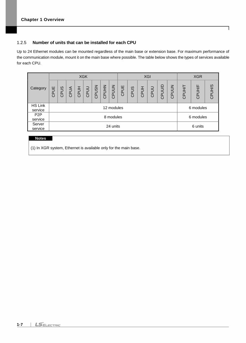
1.2.5 Number of units that can be installed for each CPU
Up to 24 Ethernet modules can be mounted regardless of the main base or extension base. For maximum performance of
the communication module, mount it on the main base where possible. The table below shows the types of services available
for each CPU.
Category
XGK XGI XGR
CP
UE
CP
US
CP
UA
CP
UH
CP
UU
CP
US
N
CP
UH
N
CP
UU
N
C
PU
E
CP
US
CP
UH
CP
UU
CP
UU
/D
CP
UU
N
CP
UH
/T
CP
UH
/F
CP
UH
/S
HS Link service
12 modules 6 modules
P2P service
8 modules 6 modules
Server service
24 units 6 units
Notes
(1) In XGR system, Ethernet is available only for the main base.
Chapter 1 Overview
1-8
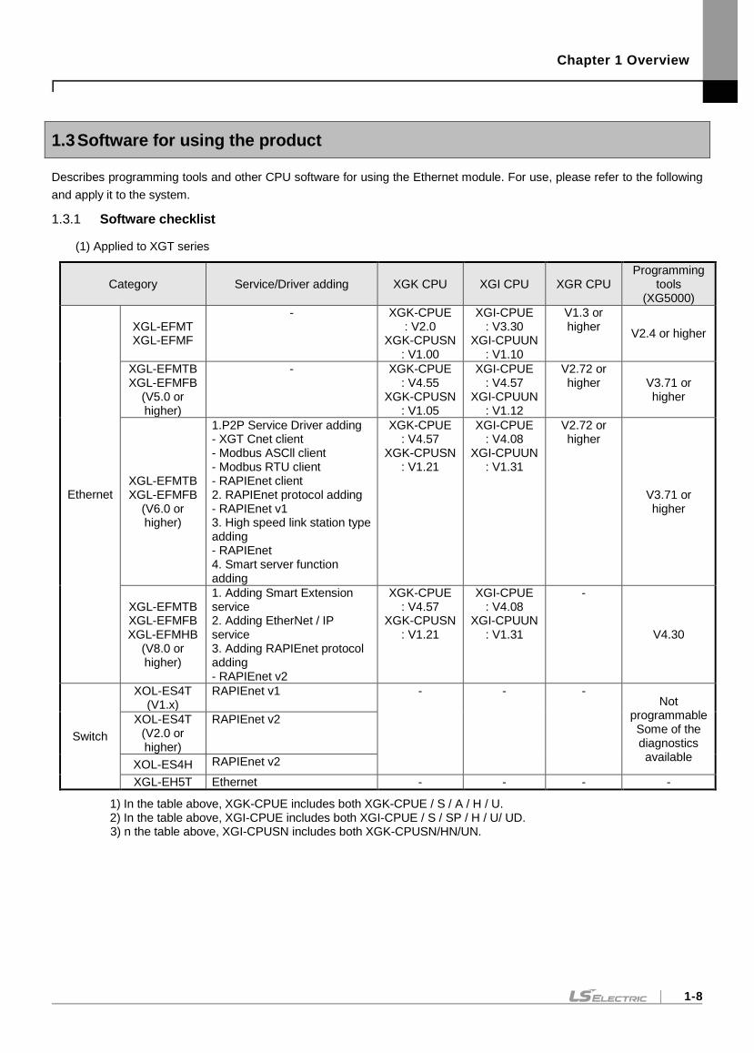
1.3 Software for using the product
Describes programming tools and other CPU software for using the Ethernet module. For use, please refer to the following
and apply it to the system.
1.3.1 Software checklist
(1) Applied to XGT series
Category Service/Driver adding XGK CPU XGI CPU XGR CPU Programming
tools (XG5000)
Ethernet
XGL-EFMT XGL-EFMF
- XGK-CPUE : V2.0
XGK-CPUSN : V1.00
XGI-CPUE : V3.30
XGI-CPUUN : V1.10
V1.3 or higher
V2.4 or higher
XGL-EFMTB XGL-EFMFB
(V5.0 or higher)
- XGK-CPUE : V4.55
XGK-CPUSN : V1.05
XGI-CPUE : V4.57
XGI-CPUUN : V1.12
V2.72 or higher V3.71 or
higher
XGL-EFMTB XGL-EFMFB
(V6.0 or higher)
1.P2P Service Driver adding - XGT Cnet client - Modbus ASCll client - Modbus RTU client - RAPIEnet client 2. RAPIEnet protocol adding - RAPIEnet v1 3. High speed link station type adding - RAPIEnet 4. Smart server function adding
XGK-CPUE : V4.57
XGK-CPUSN : V1.21
XGI-CPUE : V4.08
XGI-CPUUN : V1.31
V2.72 or higher
V3.71 or higher
XGL-EFMTB XGL-EFMFB XGL-EFMHB
(V8.0 or higher)
1. Adding Smart Extension service 2. Adding EtherNet / IP service 3. Adding RAPIEnet protocol adding - RAPIEnet v2
XGK-CPUE : V4.57
XGK-CPUSN : V1.21
XGI-CPUE : V4.08
XGI-CPUUN : V1.31
-
V4.30
Switch
XOL-ES4T (V1.x)
RAPIEnet v1 - - - Not
programmable Some of the diagnostics available
XOL-ES4T (V2.0 or higher)
RAPIEnet v2
XOL-ES4H RAPIEnet v2
XGL-EH5T Ethernet - - - -
1) In the table above, XGK-CPUE includes both XGK-CPUE / S / A / H / U. 2) In the table above, XGI-CPUE includes both XGI-CPUE / S / SP / H / U/ UD. 3) n the table above, XGI-CPUSN includes both XGK-CPUSN/HN/UN.
Chapter 1 Overview
1-9
Notes
(1) The above program can be downloaded and used from the current website If you can not use the Internet, visit
the nearest distributor and use the installation CD-ROM.
Website address: http://www.lselectric.co.kr/
(2) XG5000 can be programmed with RS-232C port and USB of CPU module. Refer to XGK CPU Module or XGI
CPU Module User's Manual for wiring type.
(3) Some functions may not work normally if a version other than stated above is used. Please check compatibility.
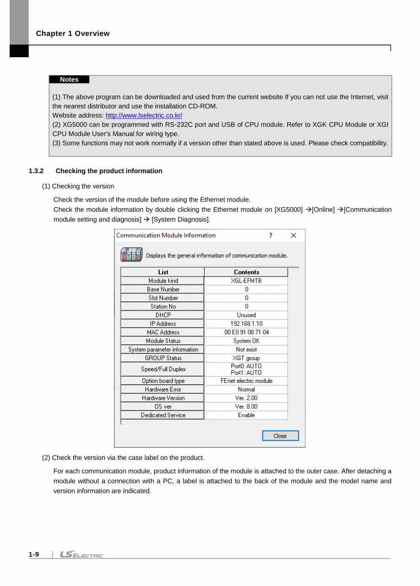
1.3.2 Checking the product information
(1) Checking the version
Check the version of the module before using the Ethernet module.
Check the module information by double clicking the Ethernet module on [XG5000] [Online] [Communication
module setting and diagnosis] [System Diagnosis].
(2) Check the version via the case label on the product.
For each communication module, product information of the module is attached to the outer case. After detaching a
module without a connection with a PC, a label is attached to the back of the module and the model name and
version information are indicated.

Chapter 1 Overview
1-10
Chapter 2 Product specifications
2-1
Chapter 2 Product specifications
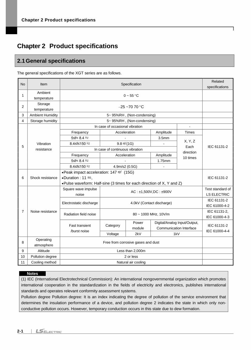
2.1 General specifications
The general specifications of the XGT series are as follows.
No Item Specification Related
specifications
1 Ambient
temperature 0 ~ 55 C
2 Storage
temperature 25 ~70 70 C
3 Ambient Humidity 5~ 95%RH , (Non-condensing)
4 Storage humidity 5~ 95%RH , (Non-condensing)
5 Vibration
resistance
In case of occasional vibration -
Frequency Acceleration Amplitude Times
IEC 61131-2
5≤f< 8.4 - 3.5mm X, Y, Z
Each
direction
10 times
8.4≤f≤150 9.8(1G) -
In case of continuous vibration
Frequency Acceleration Amplitude
5≤f< 8.4 - 1.75mm
8.4≤f≤150 4.9m/s2 (0.5G) -
6 Shock resistance
Peak impact acceleration: 147 (15G)
Duration : 11,
Pulse waveform: Half-sine (3 times for each direction of X, Y and Z)
IEC 61131-2
7 Noise resistance
Square wave impulse
noise AC : ±1,500V,DC : ±900V
Test standard of
LS ELECTRIC
Electrostatic discharge 4.0kV (Contact discharge) IEC 61131-2
IEC 61000-4-2
Radiation field noise 80 ~ 1000 MHz, 10V/m IEC 61131-2,
IEC 61000-4-3
Fast transient
/burst noise
Category Power
module
Digital/Analog Input/Output,
Communication Interface IEC 61131-2
IEC 61000-4-4 Voltage 2kV 1kV
8 Operating
atmosphere Free from corrosive gases and dust
9 Altitude Less than 2,000m
10 Pollution degree 2 or less
11 Cooling method Natural air cooling
Notes
(1) IEC (International Electrotechnical Commission): An international nongovernmental organization which promotes
international cooperation in the standardization in the fields of electricity and electronics, publishes international
standards and operates relevant conformity assessment systems.
Pollution degree Pollution degree: It is an index indicating the degree of pollution of the service environment that
determines the insulation performance of a device, and pollution degree 2 indicates the state in which only non-
conductive pollution occurs. However, temporary conduction occurs in this state due to dew formation.
Chapter 2 Product specifications
2-2
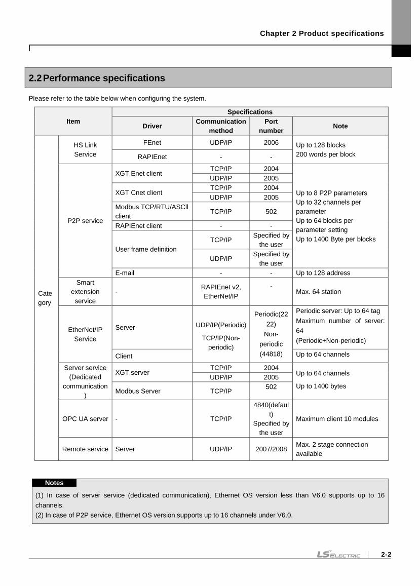
2.2 Performance specifications
Please refer to the table below when configuring the system.
Item
Specifications
Driver Communication
method
Port
number Note
Cate
gory
HS Link
Service
FEnet UDP/IP 2006 Up to 128 blocks
200 words per block RAPIEnet - -
P2P service
XGT Enet client TCP/IP 2004
Up to 8 P2P parameters
Up to 32 channels per
parameter
Up to 64 blocks per
parameter setting
Up to 1400 Byte per blocks
UDP/IP 2005
XGT Cnet client TCP/IP 2004
UDP/IP 2005
Modbus TCP/RTU/ASCll
client TCP/IP 502
RAPIEnet client - -
User frame definition
TCP/IP Specified by
the user
UDP/IP Specified by
the user
E-mail - - Up to 128 address
Smart
extension
service
- RAPIEnet v2,
EtherNet/IP
- Max. 64 station
EtherNet/IP
Service
Server UDP/IP(Periodic)
TCP/IP(Non-
periodic)
Periodic(22
22)
Non-
periodic
(44818)
Periodic server: Up to 64 tag
Maximum number of server:
64
(Periodic+Non-periodic)
Client Up to 64 channels
Server service
(Dedicated
communication
)
XGT server TCP/IP 2004
Up to 64 channels
Up to 1400 bytes
UDP/IP 2005
Modbus Server TCP/IP 502
OPC UA server - TCP/IP
4840(defaul
t)
Specified by
the user
Maximum client 10 modules
Remote service Server UDP/IP 2007/2008 Max. 2 stage connection
available
Notes
(1) In case of server service (dedicated communication), Ethernet OS version less than V6.0 supports up to 16
channels.
(2) In case of P2P service, Ethernet OS version supports up to 16 channels under V6.0.
Chapter 2 Product specifications
2-3
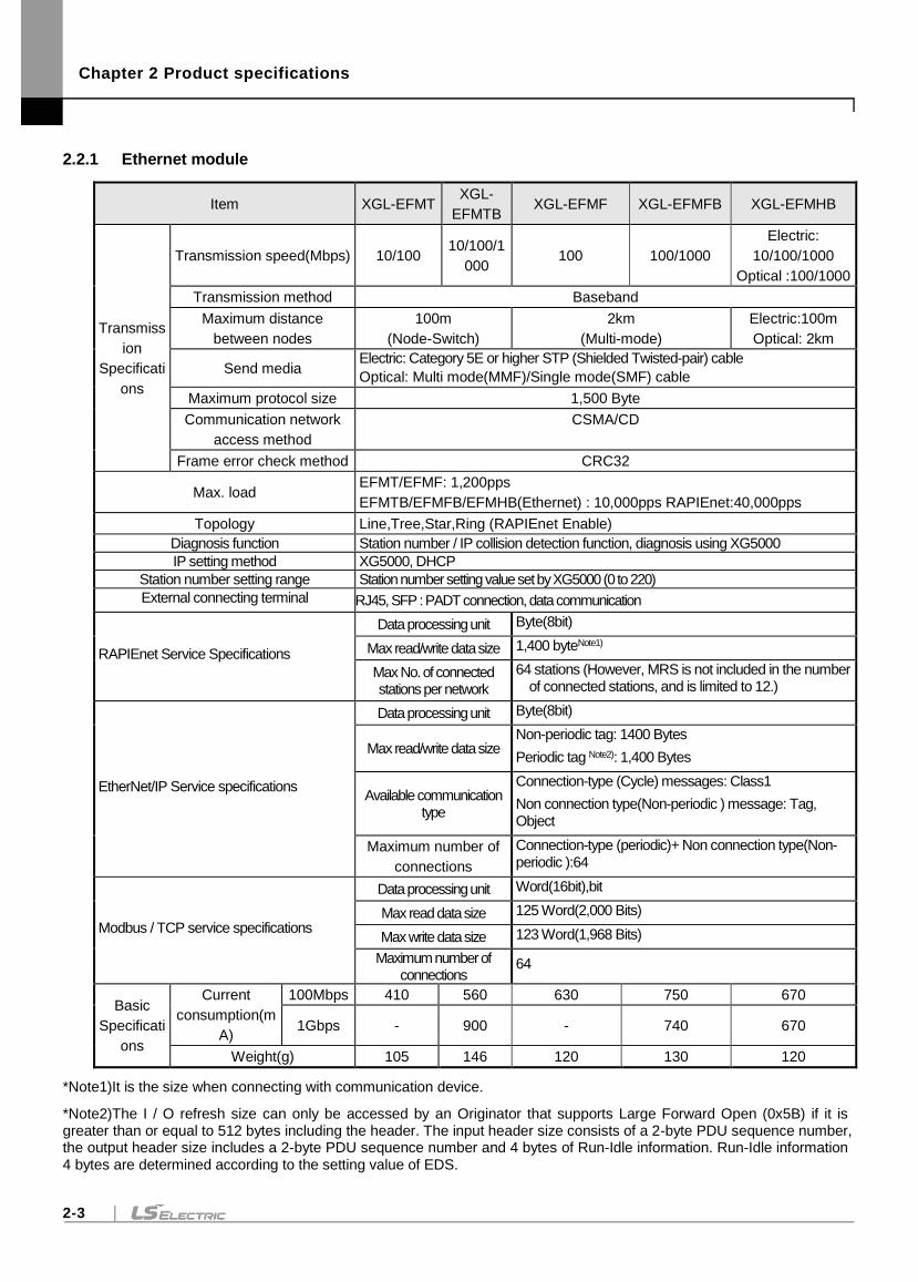
2.2.1 Ethernet module
Item XGL-EFMT XGL-
EFMTB XGL-EFMF XGL-EFMFB XGL-EFMHB
Transmiss
ion
Specificati
ons
Transmission speed(Mbps) 10/100 10/100/1
000 100 100/1000
Electric:
10/100/1000
Optical :100/1000
Transmission method Baseband
Maximum distance
between nodes
100m
(Node-Switch)
2km
(Multi-mode)
Electric:100m
Optical: 2km
Send media Electric: Category 5E or higher STP (Shielded Twisted-pair) cable
Optical: Multi mode(MMF)/Single mode(SMF) cable
Maximum protocol size 1,500 Byte
Communication network
access method
CSMA/CD
Frame error check method CRC32
Max. load EFMT/EFMF: 1,200pps
EFMTB/EFMFB/EFMHB(Ethernet) : 10,000pps RAPIEnet:40,000pps
Topology Line,Tree,Star,Ring (RAPIEnet Enable)
Diagnosis function Station number / IP collision detection function, diagnosis using XG5000
IP setting method XG5000, DHCP
Station number setting range Station number setting value set by XG5000 (0 to 220)
External connecting terminal RJ45, SFP : PADT connection, data communication
RAPIEnet Service Specifications
Data processing unit Byte(8bit)
Max read/write data size 1,400 byteNote1)
Max No. of connected stations per network
64 stations (However, MRS is not included in the number of connected stations, and is limited to 12.)
EtherNet/IP Service specifications
Data processing unit Byte(8bit)
Max read/write data size Non-periodic tag: 1400 Bytes
Periodic tag Note2): 1,400 Bytes
Available communication type
Connection-type (Cycle) messages: Class1
Non connection type(Non-periodic ) message: Tag, Object
Maximum number of
connections
Connection-type (periodic)+ Non connection type(Non-periodic ):64
Modbus / TCP service specifications
Data processing unit Word(16bit),bit
Max read data size 125 Word(2,000 Bits)
Max write data size 123 Word(1,968 Bits)
Maximum number of connections
64
Basic
Specificati
ons
Current
consumption(m
A)
100Mbps 410 560 630 750 670
1Gbps - 900 - 740 670
Weight(g) 105 146 120 130 120
*Note1)It is the size when connecting with communication device.
*Note2)The I / O refresh size can only be accessed by an Originator that supports Large Forward Open (0x5B) if it is greater than or equal to 512 bytes including the header. The input header size consists of a 2-byte PDU sequence number, the output header size includes a 2-byte PDU sequence number and 4 bytes of Run-Idle information. Run-Idle information 4 bytes are determined according to the setting value of EDS.
Chapter 2 Product specifications
2-4
Notes
(1) Baud rate can be set as shown above when RAPIEnet is set to Disable. However, when setting RAPIEnet v1 in
driver setting, only 100M is supported for electrical and optical ports, and setting 100/1000 for electrical and optical
ports when setting to RAPIEnet v2.
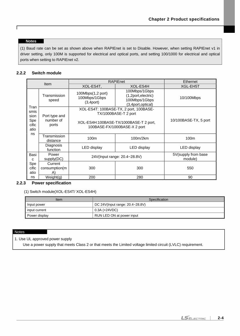
2.2.2 Switch module
Item RAPIEnet Ethernet
XOL-ES4T, XOL-ES4H XGL-EH5T
Transmission Specifications
Transmission speed
100Mbps(1,2 port) 100Mbps/1Gbps
(3,4port)
100Mbps/1Gbps (1,2port,electric) 100Mbps/1Gbps (3,4port,optical)
10/100Mbps
Port type and number of
ports
XOL-ES4T: 100BASE-TX, 2 port, 100BASE-TX/1000BASE-T 2 port
XOL-ES4H:100BASE-TX/1000BASE-T 2 port,
100BASE-FX/1000BASE-X 2 port
10/100BASE-TX, 5 port
Transmission distance
100m 100m/2km 100m
Diagnosis function
LED display LED display LED display
Basic
Specifications
Power supply(DC)
24V(Input range: 20.4~28.8V) 5V(supply from base
module)
Current consumption(m
A) 300 300 550
Weight(g) 200 280 90
2.2.3 Power specification
(1) Switch module(XOL-ES4T/ XOL-ES4H)
Item Specification
Input power DC 24V(Input range: 20.4~28.8V)
input current 0.3A (+24VDC)
Power display RUN LED ON at power input
Notes
1. Use UL approved power supply
Use a power supply that meets Class 2 or that meets the Limited voltage limited circuit (LVLC) requirement.
Chapter 2 Product specifications
2-5
2.2.4 Load specifications
Communication load is divided into the load by media interrupt received per second from Ethernet media and the
transmission load transmitted by CPU module to Ethernet module. If the load due to the media interrupt guaranteed by the
Ethernet module and the transmission load are exceeded, it may not operate normally.
(1) Communication load due to media interrupt
1) The amount of packets generated per second due to the load on the data frames delivered to the media is
measured.
2) The maximum load of the Ethernet module delivered to the media (based on server operation) is up to
10,000 packages / sec.
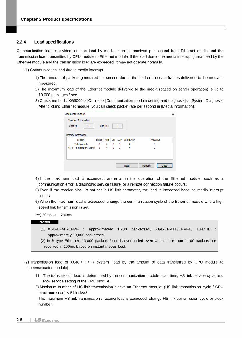
3) Check method : XG5000-> [Online]-> [Communication module setting and diagnosis]-> [System Diagnosis]
After clicking Ethernet module, you can check packet rate per second in [Media Information].
4) If the maximum load is exceeded, an error in the operation of the Ethernet module, such as a
communication error, a diagnostic service failure, or a remote connection failure occurs.
5) Even if the receive block is not set in HS link parameter, the load is increased because media interrupt
occurs.
6) When the maximum load is exceeded, change the communication cycle of the Ethernet module where high
speed link transmission is set.
ex) 20ms → 200ms
Notes
(1) XGL-EFMT/EFMF : approximately 1,200 packet/sec, XGL-EFMTB/EFMFB/ EFMHB :
approximately 10,000 packet/sec
(2) In B type Ethernet, 10,000 packets / sec is overloaded even when more than 1,100 packets are
received in 100ms based on instantaneous load.
(2) Transmission load of XGK / I / R system (load by the amount of data transferred by CPU module to
communication module)
1) The transmission load is determined by the communication module scan time, HS link service cycle and
P2P service setting of the CPU module.
2) Maximum number of HS link transmission blocks on Ethernet module: (HS link transmission cycle / CPU
maximum scan) × 8 blocks/2
The maximum HS link transmission / receive load is exceeded, change HS link transmission cycle or block
number.
Chapter 2 Product specifications
2-6
2.3 Structure and Characteristics
2.3.1 Names of Part and Function
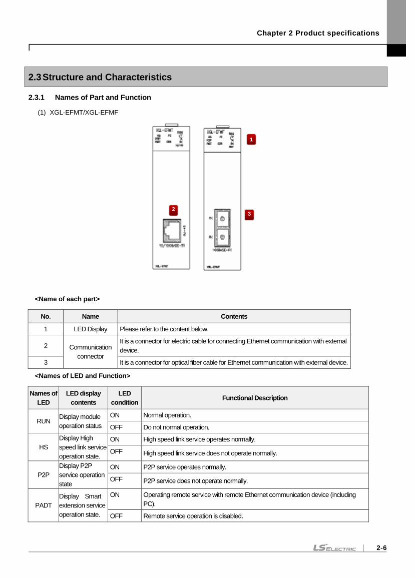
(1) XGL-EFMT/XGL-EFMF
<Name of each part>
No. Name Contents
1 LED Display Please refer to the content below.
2 Communication
connector
It is a connector for electric cable for connecting Ethernet communication with external
device.
3 It is a connector for optical fiber cable for Ethernet communication with external device.
<Names of LED and Function>
Names of
LED
LED display
contents
LED
condition Functional Description
RUN Display module
operation status
ON Normal operation.
OFF Do not normal operation.
HS
Display High
speed link service
operation state.
ON High speed link service operates normally.
OFF High speed link service does not operate normally.
P2P
Display P2P
service operation
state
ON P2P service operates normally.
OFF P2P service does not operate normally.
PADT
Display Smart
extension service
operation state.
ON Operating remote service with remote Ethernet communication device (including
PC).
OFF Remote service operation is disabled.
1
3 2
Chapter 2 Product specifications
2-7
Names of
LED
LED display
contents
LED
condition Functional Description
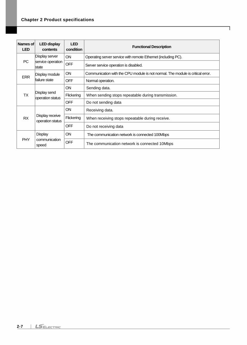
PC
Display server
service operation
state
ON Operating server service with remote Ethernet (including PC).
OFF Server service operation is disabled.
ERR Display module
failure state
ON Communication with the CPU module is not normal. The module is critical error.
OFF Normal operation.
TX Display send
operation status
ON Sending data.
Flickering When sending stops repeatable during transmission.
OFF Do not sending data
RX Display receive
operation status
ON Receiving data.
Flickering When receiving stops repeatable during receive.
OFF Do not receiving data
PHY
Display
communication
speed
ON The communication network is connected 100Mbps
OFF The communication network is connected 10Mbps
Chapter 2 Product specifications
2-8
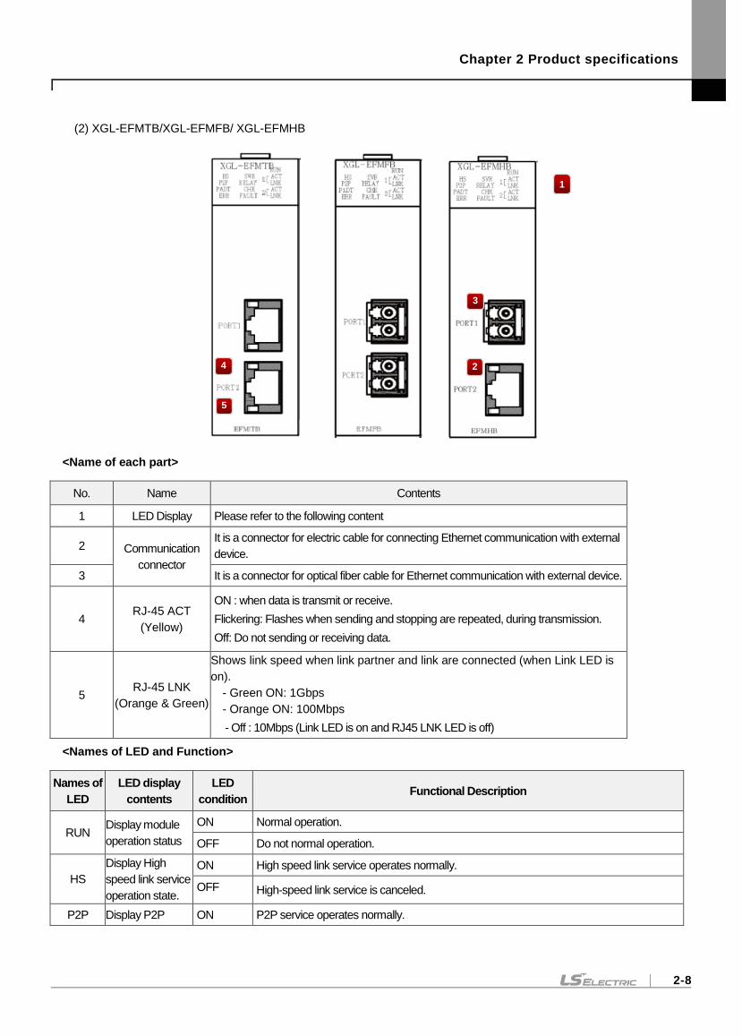
(2) XGL-EFMTB/XGL-EFMFB/ XGL-EFMHB
<Name of each part>
No. Name Contents
1 LED Display Please refer to the following content
2 Communication
connector
It is a connector for electric cable for connecting Ethernet communication with external
device.
3 It is a connector for optical fiber cable for Ethernet communication with external device.
4 RJ-45 ACT
(Yellow)
ON : when data is transmit or receive.
Flickering: Flashes when sending and stopping are repeated, during transmission.
Off: Do not sending or receiving data.
5 RJ-45 LNK
(Orange & Green)
Shows link speed when link partner and link are connected (when Link LED is
on).
- Green ON: 1Gbps
- Orange ON: 100Mbps
- Off : 10Mbps (Link LED is on and RJ45 LNK LED is off)
<Names of LED and Function>
Names of
LED
LED display
contents
LED
condition Functional Description
RUN Display module
operation status
ON Normal operation.
OFF Do not normal operation.
HS
Display High
speed link service
operation state.
ON High speed link service operates normally.
OFF High-speed link service is canceled.
P2P Display P2P ON P2P service operates normally.
1
3
4
5
2
Chapter 2 Product specifications
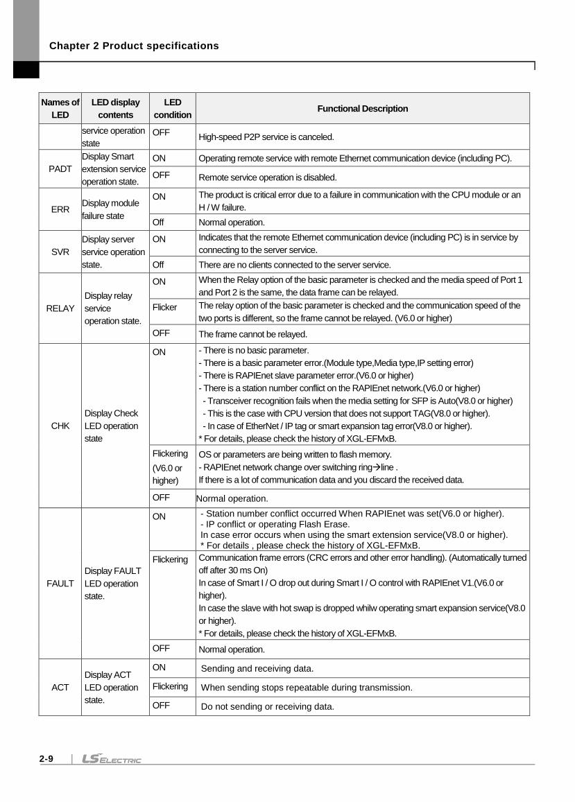
2-9
Names of
LED
LED display
contents
LED
condition Functional Description
service operation
state
OFF High-speed P2P service is canceled.
PADT
Display Smart
extension service
operation state.
ON Operating remote service with remote Ethernet communication device (including PC).
OFF Remote service operation is disabled.
ERR Display module
failure state
ON The product is critical error due to a failure in communication with the CPU module or an
H / W failure.
Off Normal operation.
SVR
Display server
service operation
state.
ON Indicates that the remote Ethernet communication device (including PC) is in service by
connecting to the server service.
Off There are no clients connected to the server service.
RELAY
Display relay
service
operation state.
ON When the Relay option of the basic parameter is checked and the media speed of Port 1
and Port 2 is the same, the data frame can be relayed.
Flicker The relay option of the basic parameter is checked and the communication speed of the
two ports is different, so the frame cannot be relayed. (V6.0 or higher)
OFF The frame cannot be relayed.
CHK
Display Check
LED operation
state
ON - There is no basic parameter.
- There is a basic parameter error.(Module type,Media type,IP setting error)
- There is RAPIEnet slave parameter error.(V6.0 or higher)
- There is a station number conflict on the RAPIEnet network.(V6.0 or higher)
- Transceiver recognition fails when the media setting for SFP is Auto(V8.0 or higher)
- This is the case with CPU version that does not support TAG(V8.0 or higher).
- In case of EtherNet / IP tag or smart expansion tag error(V8.0 or higher).
* For details, please check the history of XGL-EFMxB.
Flickering
(V6.0 or
higher)
OS or parameters are being written to flash memory.
- RAPIEnet network change over switching ringline .
If there is a lot of communication data and you discard the received data.
OFF Normal operation.
FAULT
Display FAULT
LED operation
state.
ON - Station number conflict occurred When RAPIEnet was set(V6.0 or higher). - IP conflict or operating Flash Erase. In case error occurs when using the smart extension service(V8.0 or higher). * For details , please check the history of XGL-EFMxB.
Flickering Communication frame errors (CRC errors and other error handling). (Automatically turned
off after 30 ms On)
In case of Smart I / O drop out during Smart I / O control with RAPIEnet V1.(V6.0 or
higher).
In case the slave with hot swap is dropped whilw operating smart expansion service(V8.0
or higher).
* For details, please check the history of XGL-EFMxB.
OFF Normal operation.
ACT
Display ACT
LED operation
state.
ON Sending and receiving data.
Flickering When sending stops repeatable during transmission.
OFF Do not sending or receiving data.
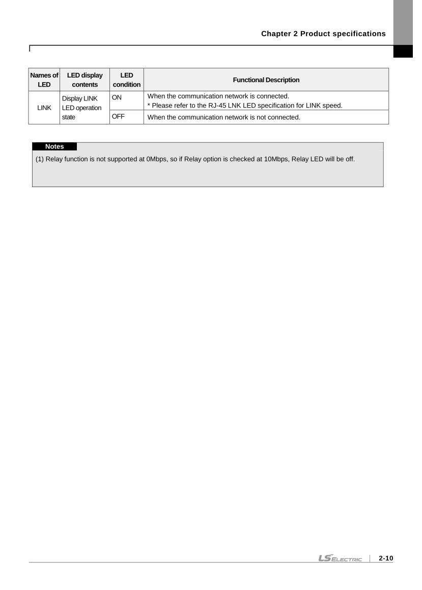
Chapter 2 Product specifications
2-10
Names of
LED
LED display
contents
LED
condition Functional Description
LINK
Display LINK
LED operation
state
ON When the communication network is connected.
* Please refer to the RJ-45 LNK LED specification for LINK speed.
OFF When the communication network is not connected.
Notes
(1) Relay function is not supported at 0Mbps, so if Relay option is checked at 10Mbps, Relay LED will be off.
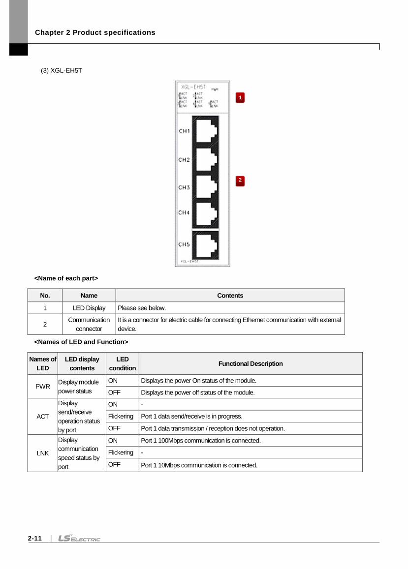
Chapter 2 Product specifications
2-11
(3) XGL-EH5T
<Name of each part>
No. Name Contents
1 LED Display Please see below.
2 Communication
connector
It is a connector for electric cable for connecting Ethernet communication with external
device.
<Names of LED and Function>
Names of
LED
LED display
contents
LED
condition Functional Description
PWR Display module
power status
ON Displays the power On status of the module.
OFF Displays the power off status of the module.
ACT
Display
send/receive
operation status
by port
ON -
Flickering Port 1 data send/receive is in progress.
OFF Port 1 data transmission / reception does not operation.
LNK
Display
communication
speed status by
port
ON Port 1 100Mbps communication is connected.
Flickering -
OFF Port 1 10Mbps communication is connected.
1
2
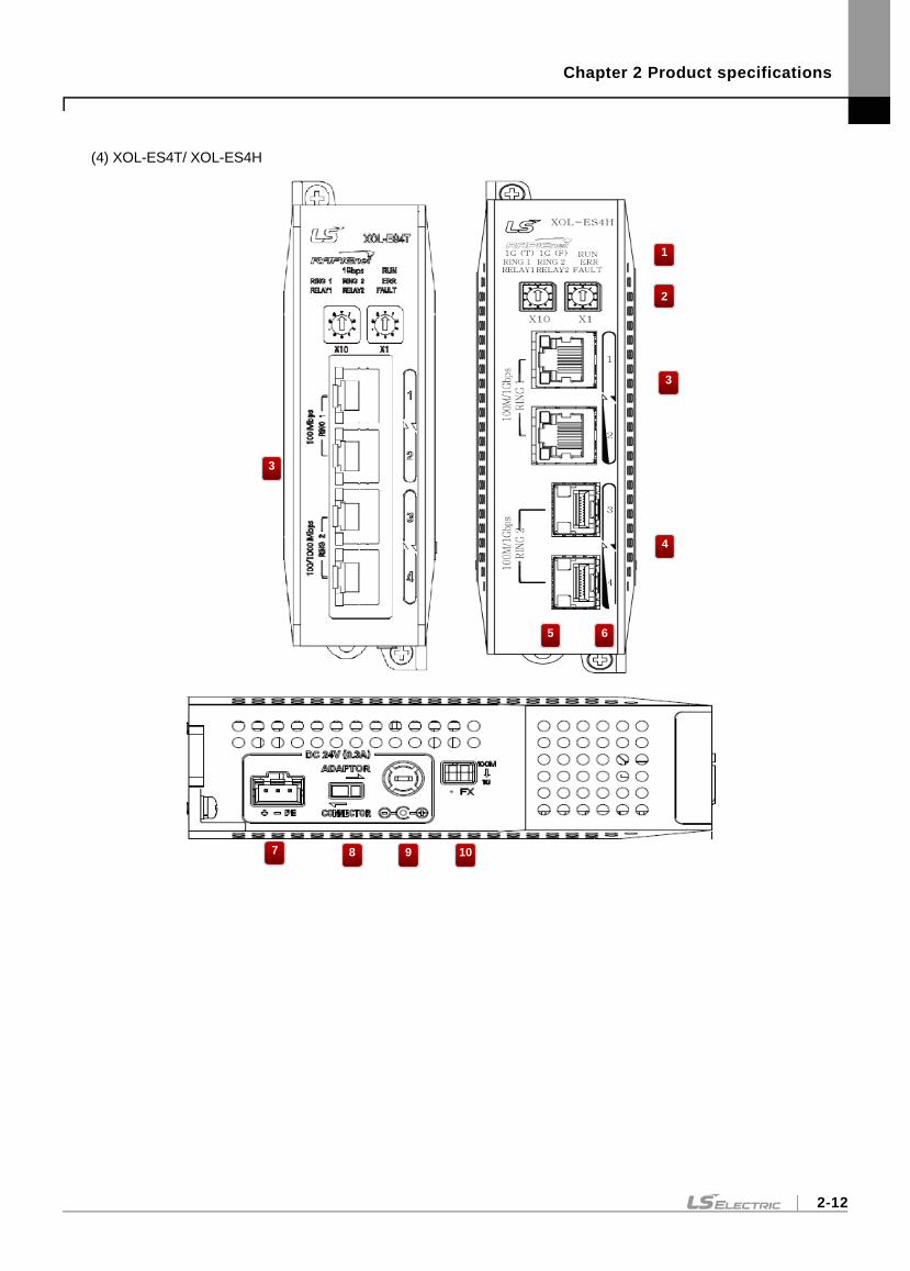
Chapter 2 Product specifications
2-12
(4) XOL-ES4T/ XOL-ES4H
2
1
3
3
4
5 6
7 8 9 10
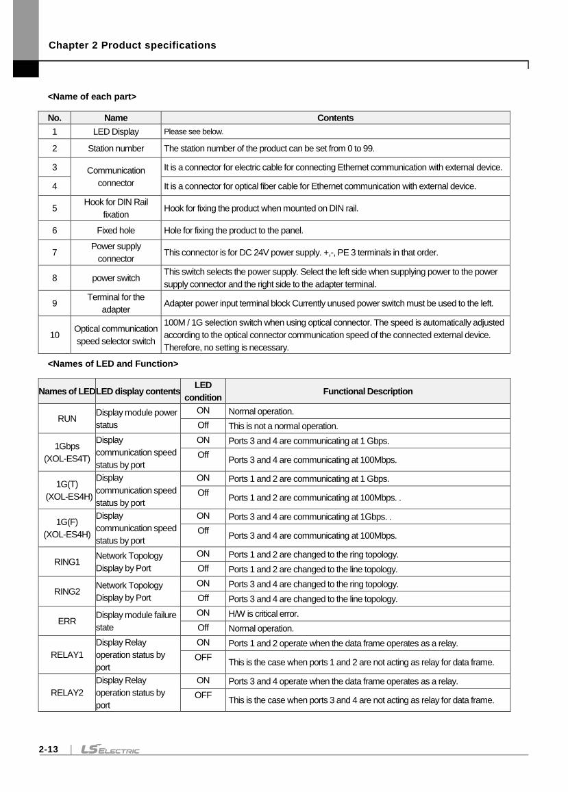
Chapter 2 Product specifications
2-13
<Name of each part>
No. Name Contents
1 LED Display Please see below.
2 Station number The station number of the product can be set from 0 to 99.
3 Communication
connector
It is a connector for electric cable for connecting Ethernet communication with external device.
4 It is a connector for optical fiber cable for Ethernet communication with external device.
5 Hook for DIN Rail
fixation Hook for fixing the product when mounted on DIN rail.
6 Fixed hole Hole for fixing the product to the panel.
7 Power supply
connector This connector is for DC 24V power supply. +,-, PE 3 terminals in that order.
8 power switch This switch selects the power supply. Select the left side when supplying power to the power
supply connector and the right side to the adapter terminal.
9 Terminal for the
adapter Adapter power input terminal block Currently unused power switch must be used to the left.
10 Optical communication
speed selector switch
100M / 1G selection switch when using optical connector. The speed is automatically adjusted
according to the optical connector communication speed of the connected external device.
Therefore, no setting is necessary.
<Names of LED and Function>
Names of LED LED display contents LED
condition Functional Description
RUN Display module power
status
ON Normal operation.
Off This is not a normal operation.
1Gbps
(XOL-ES4T)
Display
communication speed
status by port
ON Ports 3 and 4 are communicating at 1 Gbps.
Off Ports 3 and 4 are communicating at 100Mbps.
1G(T)
(XOL-ES4H)
Display
communication speed
status by port
ON Ports 1 and 2 are communicating at 1 Gbps.
Off Ports 1 and 2 are communicating at 100Mbps. .
1G(F)
(XOL-ES4H)
Display
communication speed
status by port
ON Ports 3 and 4 are communicating at 1Gbps. .
Off Ports 3 and 4 are communicating at 100Mbps.
RING1 Network Topology
Display by Port
ON Ports 1 and 2 are changed to the ring topology.
Off Ports 1 and 2 are changed to the line topology.
RING2 Network Topology
Display by Port
ON Ports 3 and 4 are changed to the ring topology.
Off Ports 3 and 4 are changed to the line topology.
ERR Display module failure
state
ON H/W is critical error.
Off Normal operation.
RELAY1
Display Relay
operation status by
port
ON Ports 1 and 2 operate when the data frame operates as a relay.
OFF This is the case when ports 1 and 2 are not acting as relay for data frame.
RELAY2
Display Relay
operation status by
port
ON Ports 3 and 4 operate when the data frame operates as a relay.
OFF This is the case when ports 3 and 4 are not acting as relay for data frame.
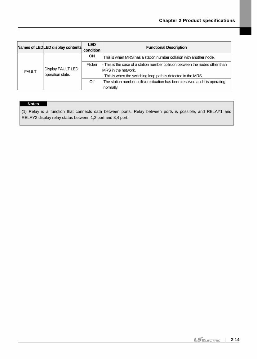
Chapter 2 Product specifications
2-14
Names of LED LED display contents LED
condition Functional Description
FAULT Display FAULT LED
operation state.
ON This is when MRS has a station number collision with another node.
Flicker - This is the case of a station number collision between the nodes other than
MRS in the network.
- This is when the switching loop path is detected in the MRS.
Off The station number collision situation has been resolved and it is operating
normally.
Notes
(1) Relay is a function that connects data between ports. Relay between ports is possible, and RELAY1 and
RELAY2 display relay status between 1,2 port and 3,4 port.
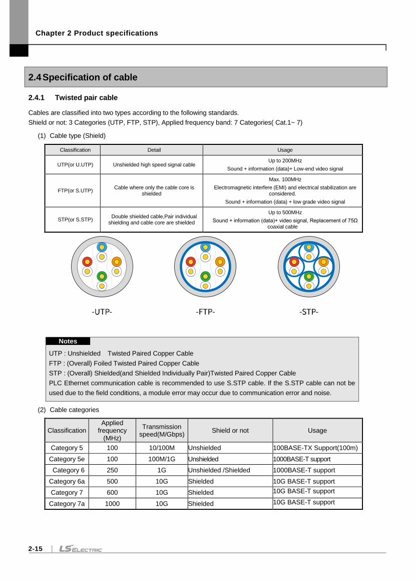
Chapter 2 Product specifications
2-15
2.4 Specification of cable
2.4.1 Twisted pair cable
Cables are classified into two types according to the following standards.
Shield or not: 3 Categories (UTP, FTP, STP), Applied frequency band: 7 Categories( Cat.1~ 7)
(1) Cable type (Shield)
Classification Detail Usage
UTP(or U.UTP) Unshielded high speed signal cable Up to 200MHz
Sound + information (data)+ Low-end video signal
FTP(or S.UTP) Cable where only the cable core is
shielded
Max. 100MHz
Electromagnetic interfere (EMI) and electrical stabilization are considered.
Sound + information (data) + low grade video signal
STP(or S.STP) Double shielded cable,Pair individual
shielding and cable core are shielded
Up to 500MHz
Sound + information (data)+ video signal, Replacement of 75Ω coaxial cable
Notes
UTP : Unshielded Twisted Paired Copper Cable
FTP : (Overall) Foiled Twisted Paired Copper Cable
STP : (Overall) Shielded(and Shielded Individually Pair)Twisted Paired Copper Cable
PLC Ethernet communication cable is recommended to use S.STP cable. If the S.STP cable can not be
used due to the field conditions, a module error may occur due to communication error and noise.
(2) Cable categories
Classification Applied
frequency (MHz)
Transmission speed(M/Gbps)
Shield or not Usage
Category 5 100 10/100M Unshielded 100BASE-TX Support(100m)
Category 5e 100 100M/1G Unshielded 1000BASE-T support
Category 6 250 1G Unshielded /Shielded 1000BASE-T support
Category 6a 500 10G Shielded 10G BASE-T support
Category 7 600 10G Shielded 10G BASE-T support
Category 7a 1000 10G Shielded 10G BASE-T support
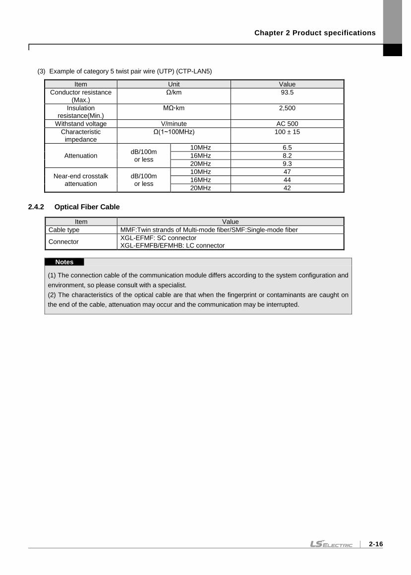
Chapter 2 Product specifications
2-16
(3) Example of category 5 twist pair wire (UTP) (CTP-LAN5)
Item Unit Value
Conductor resistance (Max.)
Ω/km 93.5
Insulation resistance(Min.)
MΩ·km 2,500
Withstand voltage V/minute AC 500
Characteristic impedance
Ω(1~100MHz) 100 ± 15
Attenuation dB/100m or less
10MHz 6.5
16MHz 8.2
20MHz 9.3
Near-end crosstalk attenuation
dB/100m or less
10MHz 47
16MHz 44
20MHz 42
2.4.2 Optical Fiber Cable
Item Value
Cable type MMF:Twin strands of Multi-mode fiber/SMF:Single-mode fiber
Connector XGL-EFMF: SC connector XGL-EFMFB/EFMHB: LC connector
Notes
(1) The connection cable of the communication module differs according to the system configuration and
environment, so please consult with a specialist.
(2) The characteristics of the optical cable are that when the fingerprint or contaminants are caught on
the end of the cable, attenuation may occur and the communication may be interrupted.
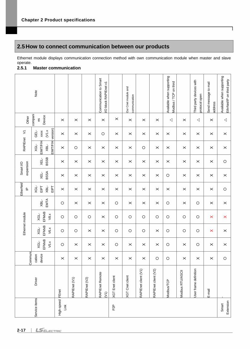
Chapter 2 Product specifications
2-17
2.5 How to connect communication between our products
Ethernet module displays communication connection method with own communication module when master and slave operate.
2.5.1 Master communication
Note
Com
munic
ation to S
mart
I/O
blo
ck R
AP
IEnet v1
Our
Cnet m
odule
and
com
munic
ation
(When u
sin
g C
net to
Enet
convert
er)
A
vaila
ble
when s
upport
ing
Modbus / T
CP
on third
part
y d
evic
es
Third p
art
y d
evic
es w
ith
pro
tocol open
Send m
essage to m
ail
addre
ss
Availa
ble
when s
upport
ing
Eth
rNet/IP
on third p
art
y
devic
es
Oth
er
com
pani
es
Devic
e
X
X
X
X
X
X
X
X
X
X
RA
PIE
net
V
1
GE
L-
xxxx
(V1.x
vers
ion)
X
X
X
X
X
X
X
X
X
X
X
X
XG
L-
EIM
T/F
/H
XB
L-
EIM
T/F
/H
X
X
X
X
X
X
X
X
X
X
X
Sm
art
I/O
expansio
n
XE
L-
BS
SB
X
X
X
X
X
X
X
X
X
X
X
X
XE
L-
BS
SA
X
X
X
X
X
X
X
X
X
X
X
X
Eth
erN
et/
IP
XG
L-
EIP
T
XB
L-
EIP
T
X
X
X
X
X
X
X
X
X
X
X
X
Eth
ern
et m
odule
XB
L-
EM
TA
X
X
X
X
X
X
X
X
X
XG
L-
EF
MxB
V8.x
X
X
X
XG
L-
EF
MxB
V6.x
X
X
X
X
X
XG
L-
EF
MxB
V5.x
X
X
X
X
X
X
X
X
X
Com
muni
cation
devic
e
X
X
X
X
X
X
X
X
X
X
Driver
FE
net
RA
PIE
net (V
1)
RA
PIE
net (V
2)
RA
PIE
net R
em
ote
(V1)
XG
T E
net clie
nt
XG
T C
net clie
nt
RA
PIE
net clie
nt (V
1)
RA
PIE
net clie
nt (V
2)
Modbus/T
CP
Modbus R
TU
/AS
CII
User
fram
e d
efinitio
n
E-m
ail
-
Serv
ice ite
ms
Hig
h-s
peed
Lin
k
P2P
Sm
art
Exte
nsio
n
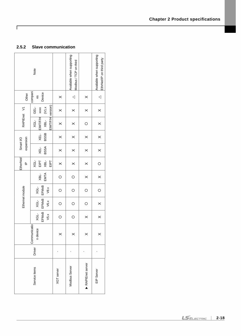
Chapter 2 Product specifications
2-18
2.5.2 Slave communication
Note
Availa
ble
when s
upport
ing
Modbus / T
CP
on third
part
y d
evic
es
Availa
ble
when s
upport
ing
Eth
rNet/IP
on third p
art
y
devic
es
Oth
er
com
pani
es
Devic
e
X
X
RA
PIE
net
V
1
GE
L-
xxxx
(V1.x
vers
ion)
X
X
X
X
XG
L-
EIM
T/F
/H
XB
L-
EIM
T/F
/H
X
X
X
Sm
art
I/O
expansio
n
XE
L-
BS
SB
X
X
X
X
XE
L-
BS
SA
X
X
X
X
Eth
erN
et/
IP
XG
L-
EIP
T
XB
L-
EIP
T
X
X
X
Eth
ern
et m
odule
XB
L-
EM
TA
X
X
XG
L-
EF
MxB
V8.x
XG
L-
EF
MxB
V6.x
X
XG
L-
EF
MxB
V5.x
X
X
Com
munic
atio
n d
evic
e
X
X
X
X
Driver
- - - -
Serv
ice ite
ms
XG
T s
erv
er
Modbus S
erv
er
R
AP
IEnet serv
er
EIP
Serv
er

Chapter 3 Product Installation and trial operation
1
Chapter 3 Product Installation and trial operation
3.1 Installation
3.1.1 Preparation for operating
(1) Ethernet module system configuration
1) Check the basic elements necessary for the system configuration and select a proper communication
module.
2) Select a cable for the communication module.
3) When installing the Communication module, make sure that there is no foreign substance in the base
connector to be mounted, and check that the connector pin of this module is not damaged.
4) Ethernet module can be mounted on the main base and expansion base, but it is recommended to use it on
the main base. However, in case of XGR system, it can be installed only on the main base.
5) When installing the module, insert the raised part of the lower part of the module into the base groove
without connecting the communication cable, and apply enough force until the upper part is completely
locked with the base locking device. If it is not locked, there may be abnormality in the interface with the CPU
module.
6) Cables used for communication module should be installed referring to the standard.
7) Ethernet switches and cables required for communication with the Ethernet module should be selected as
standard products.
(2) Switch module system configuration
1) When installing the switch module, make sure that there is no foreign substance in the base connector to be
mounted, and check that the connector pin of this module is not damaged.
2) XGL-EH5T module is powered from the base module. Therefore, the switch module is not recognized by the
CPU and can be installed in either the expansion or the main base slot.
3) When installing the module, insert the raised part of the lower part of the module into the base groove
without connecting the communication cable, and enough force until the upper part is completely locked with
the base locking device. If the lock is not locked, the module may be detached from the base module.
4) The XOL-ES4T / ES4H Switch module should be fixed to the panel and supplied with a 24 VDC connector.
Chapter 3 Product Installation and trial operation
3-2
3.1.2 Setting sequence for operation
Describes the order of installation and operation of the product. When the installation of the product is completed, please
install and set up the system in the following order.
1) Mount Ethernet module on base module.
2) Connect the cable of Ethernet module with other communication module.
3) Power on the system where Ethernet module has installed.
4) Setting basic parameter in XG5000.
5) Reset the module after downloading the basic parameters.
6) After resetting the module, Check if RUN and CHK LEDs are normal.
7) If Ethernet module and CPU module are confirmed as normal operation, check [System Diagnostics]
[PLC Information] using XG5000.
8) To check the network connection, check if the response is received from the PC to the network using PING,
or if the network is not connected to the PC, select the Ethernet module on the monitor in
[Online][Communication module setting and Diagnostics][System Diagnostics] of the XG5000 and then
click the mouse. Check the response using the right-click Ping Test item.
9) Set up and download communication services.
10) Allow Service Enable.
11) Write a program in xG5000 and download it to CPU module to start operation.
Notes
If the station number and IP address of the Ethernet module are set, be sure to reset the module. Initial station
number and IP address (including frame) keep the value read from communication module at initialization.
Parameter changes during communication are not applied during operation.
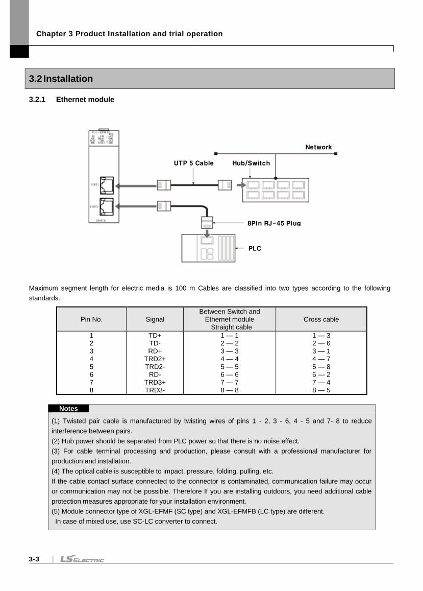
Chapter 3 Product Installation and trial operation
3-3
3.2 Installation
3.2.1 Ethernet module
Hub/SwitchUTP 5 Cable
Network
PLC
8Pin RJ-45 Plug
Maximum segment length for electric media is 100 m Cables are classified into two types according to the following
standards.
Pin No. Signal Between Switch and
Ethernet module Straight cable
Cross cable
1 2 3 4 5 6 7 8
TD+ TD- RD+
TRD2+ TRD2-
RD- TRD3+ TRD3-
1 — 1 2 — 2 3 — 3 4 — 4 5 — 5 6 — 6 7 — 7 8 — 8
1 — 3 2 — 6 3 — 1 4 — 7 5 — 8 6 — 2 7 — 4 8 — 5
Notes
(1) Twisted pair cable is manufactured by twisting wires of pins 1 - 2, 3 - 6, 4 - 5 and 7- 8 to reduce
interference between pairs.
(2) Hub power should be separated from PLC power so that there is no noise effect.
(3) For cable terminal processing and production, please consult with a professional manufacturer for
production and installation.
(4) The optical cable is susceptible to impact, pressure, folding, pulling, etc.
If the cable contact surface connected to the connector is contaminated, communication failure may occur
or communication may not be possible. Therefore If you are installing outdoors, you need additional cable
protection measures appropriate for your installation environment.
(5) Module connector type of XGL-EFMF (SC type) and XGL-EFMFB (LC type) are different.
In case of mixed use, use SC-LC converter to connect.
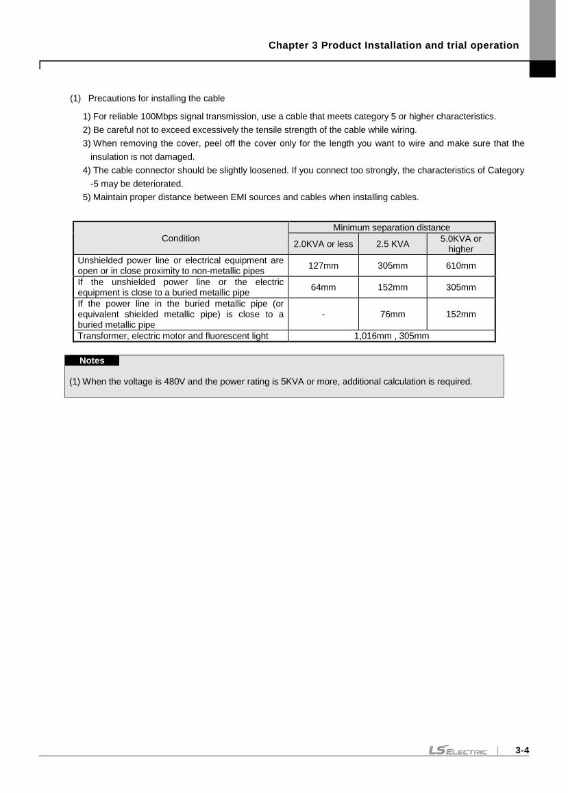
Chapter 3 Product Installation and trial operation
3-4
(1) Precautions for installing the cable
1) For reliable 100Mbps signal transmission, use a cable that meets category 5 or higher characteristics.
2) Be careful not to exceed excessively the tensile strength of the cable while wiring.
3) When removing the cover, peel off the cover only for the length you want to wire and make sure that the
insulation is not damaged.
4) The cable connector should be slightly loosened. If you connect too strongly, the characteristics of Category
-5 may be deteriorated.
5) Maintain proper distance between EMI sources and cables when installing cables.
Condition
Minimum separation distance
2.0KVA or less 2.5 KVA 5.0KVA or
higher
Unshielded power line or electrical equipment are open or in close proximity to non-metallic pipes
127mm 305mm 610mm
If the unshielded power line or the electric equipment is close to a buried metallic pipe
64mm 152mm 305mm
If the power line in the buried metallic pipe (or equivalent shielded metallic pipe) is close to a buried metallic pipe
- 76mm 152mm
Transformer, electric motor and fluorescent light 1,016mm , 305mm
Notes
(1) When the voltage is 480V and the power rating is 5KVA or more, additional calculation is required.
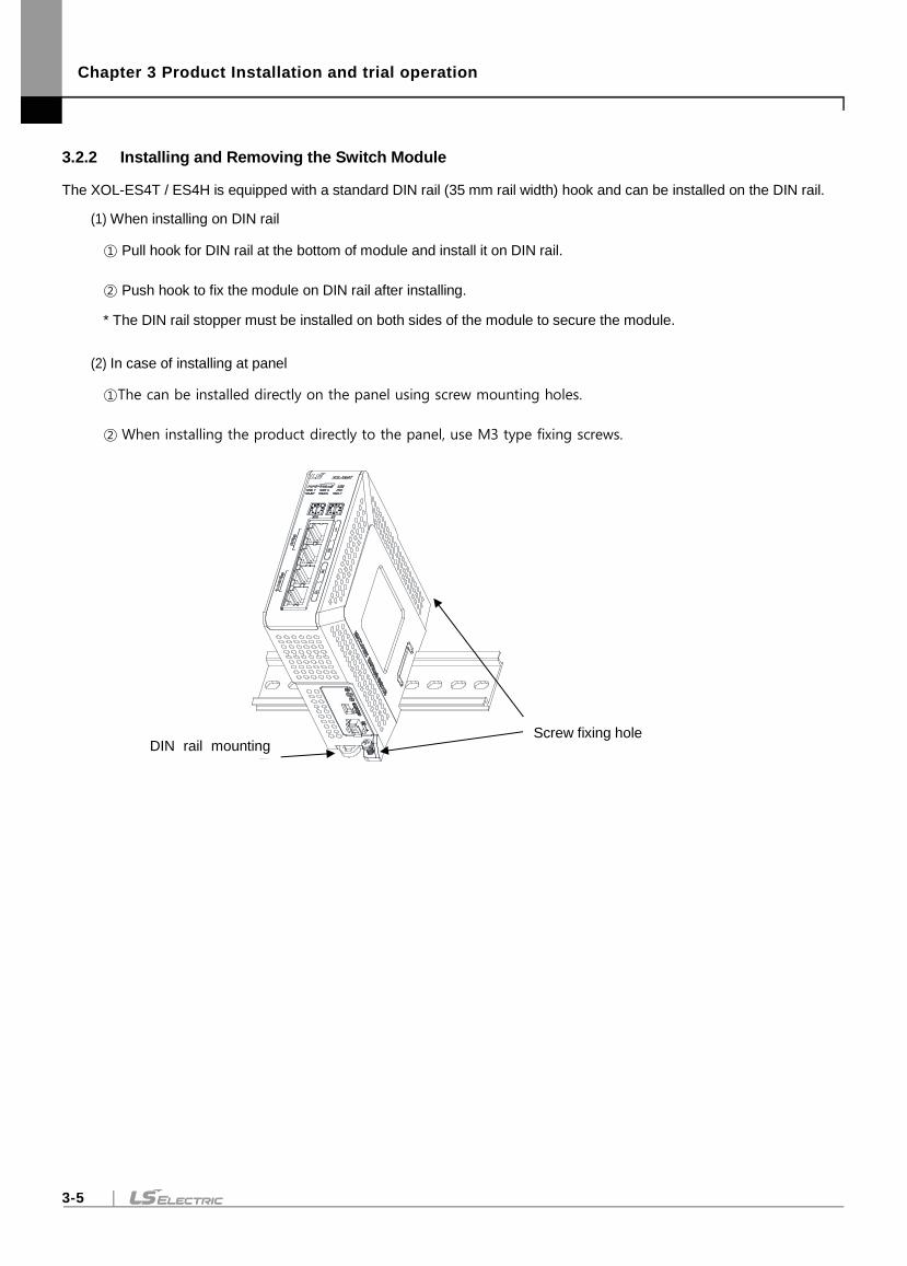
Chapter 3 Product Installation and trial operation
3-5
3.2.2 Installing and Removing the Switch Module
The XOL-ES4T / ES4H is equipped with a standard DIN rail (35 mm rail width) hook and can be installed on the DIN rail.
(1) When installing on DIN rail
① Pull hook for DIN rail at the bottom of module and install it on DIN rail.
② Push hook to fix the module on DIN rail after installing.
* The DIN rail stopper must be installed on both sides of the module to secure the module.
(2) In case of installing at panel
①The can be installed directly on the panel using screw mounting holes.
② When installing the product directly to the panel, use M3 type fixing screws.
DIN rail mounting
hook
Screw fixing hole
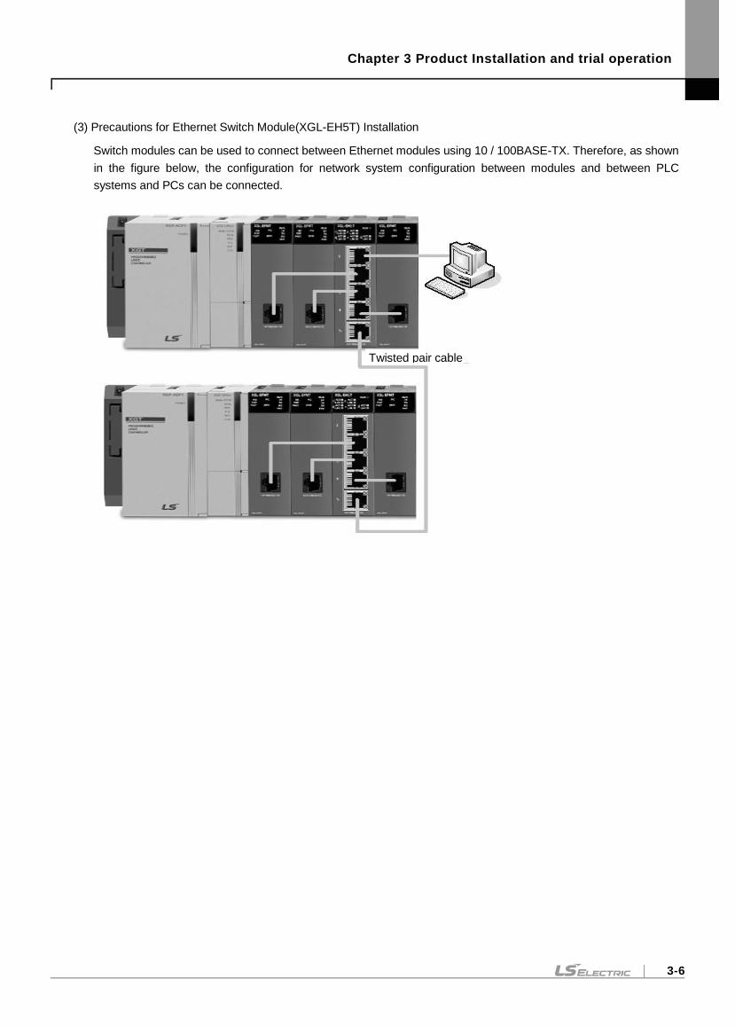
Chapter 3 Product Installation and trial operation
3-6
(3) Precautions for Ethernet Switch Module(XGL-EH5T) Installation
Switch modules can be used to connect between Ethernet modules using 10 / 100BASE-TX. Therefore, as shown
in the figure below, the configuration for network system configuration between modules and between PLC
systems and PCs can be connected.
Twisted pair cable
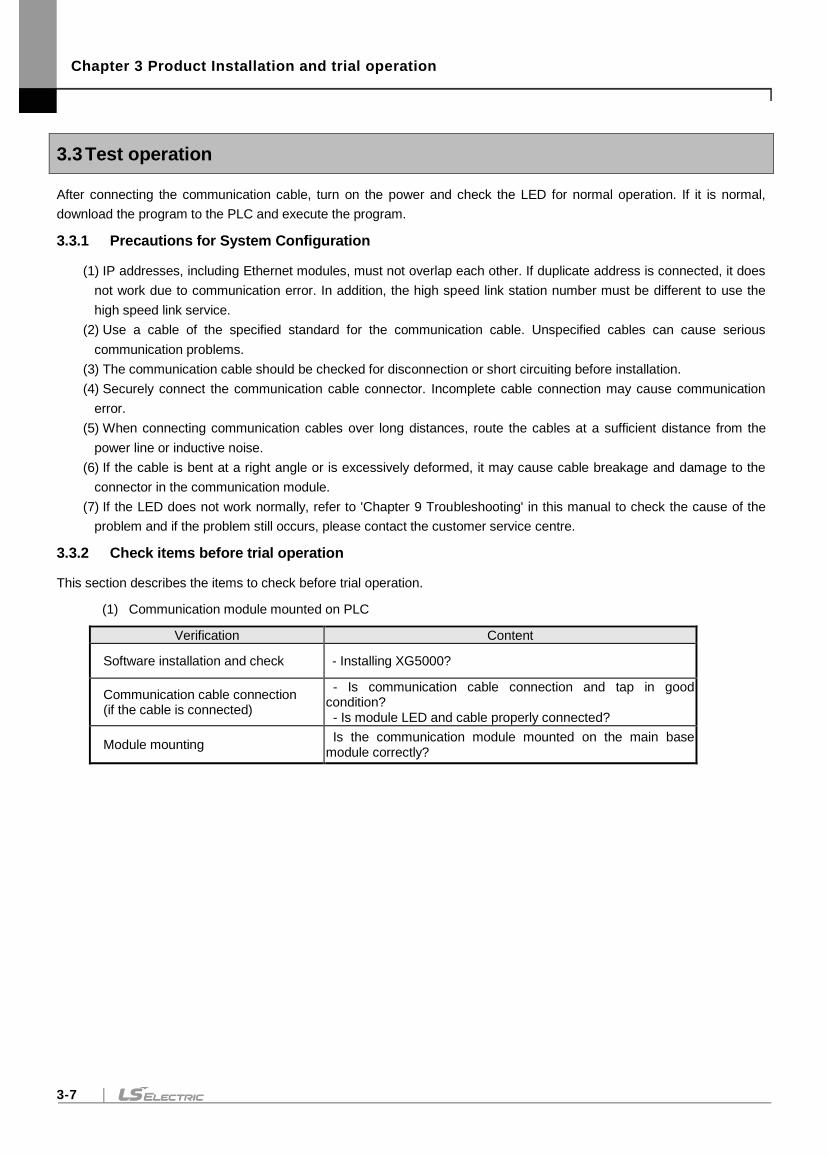
Chapter 3 Product Installation and trial operation
3-7
3.3 Test operation
After connecting the communication cable, turn on the power and check the LED for normal operation. If it is normal,
download the program to the PLC and execute the program.
3.3.1 Precautions for System Configuration
(1) IP addresses, including Ethernet modules, must not overlap each other. If duplicate address is connected, it does
not work due to communication error. In addition, the high speed link station number must be different to use the
high speed link service.
(2) Use a cable of the specified standard for the communication cable. Unspecified cables can cause serious
communication problems.
(3) The communication cable should be checked for disconnection or short circuiting before installation.
(4) Securely connect the communication cable connector. Incomplete cable connection may cause communication
error.
(5) When connecting communication cables over long distances, route the cables at a sufficient distance from the
power line or inductive noise.
(6) If the cable is bent at a right angle or is excessively deformed, it may cause cable breakage and damage to the
connector in the communication module.
(7) If the LED does not work normally, refer to 'Chapter 9 Troubleshooting' in this manual to check the cause of the
problem and if the problem still occurs, please contact the customer service centre.
3.3.2 Check items before trial operation
This section describes the items to check before trial operation.
(1) Communication module mounted on PLC
Verification Content
Software installation and check - Installing XG5000?
Communication cable connection (if the cable is connected)
- Is communication cable connection and tap in good condition? - Is module LED and cable properly connected?
Module mounting Is the communication module mounted on the main base module correctly?
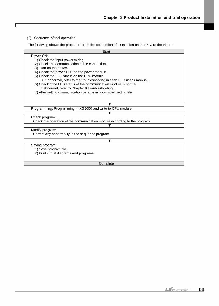
Chapter 3 Product Installation and trial operation
3-8
(2) Sequence of trial operation
The following shows the procedure from the completion of installation on the PLC to the trial run.
Start
Power ON: 1) Check the input power wiring. 2) Check the communication cable connection. 3) Turn on the power. 4) Check the power LED on the power module. 5) Check the LED status on the CPU module. -> If abnormal, refer to the troubleshooting in each PLC user's manual. 6) Check if the LED status of the communication module is normal. If abnormal, refer to Chapter 9 Troubleshooting. 7) After setting communication parameter, download setting file.
Programming: Programming in XG5000 and write to CPU module.
Check program: Check the operation of the communication module according to the program.
Modify program: Correct any abnormality in the sequence program.
Saving program: 1) Save program file. 2) Print circuit diagrams and programs.
Complete
Chapter 3 Product Installation and trial operation
3-9
3.3.3 The method to remove and replace the module.
If you want to replace or remove the module due to hardware error or system change, follow the procedure below.
(1) Order of exchanging communication module
1) Turn off the power module of the base where the communication module is installed.
2) Disconnect the network cable.
3) Operate the module according to the setting procedure in Section 3.3.2.
(2) Communication module exchange using the module change switch of the CPU.
Refer to “6.10 Changing Module during Operation” of CPU Module User's Manual.
(3) Communication module exchange using x5000 module change wizard
Refer to “10.23 Module Change Wizard” of XG5000 user's manual.
Notes
(1) When replacing the Ethernet module, reset the external device (MMI or PC). The timeout of the Ethernet module may result in an unrequested connection from the external device or a loss of communication.
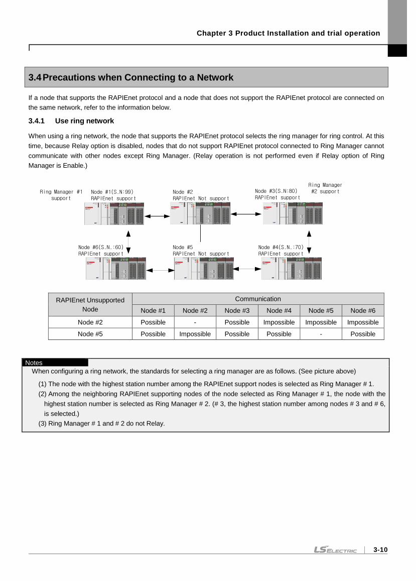
Chapter 3 Product Installation and trial operation
3-10
3.4 Precautions when Connecting to a Network
If a node that supports the RAPIEnet protocol and a node that does not support the RAPIEnet protocol are connected on
the same network, refer to the information below.
3.4.1 Use ring network
When using a ring network, the node that supports the RAPIEnet protocol selects the ring manager for ring control. At this
time, because Relay option is disabled, nodes that do not support RAPIEnet protocol connected to Ring Manager cannot
communicate with other nodes except Ring Manager. (Relay operation is not performed even if Relay option of Ring
Manager is Enable.)
Ring Manager #1 support
Node #1(S.N:99)RAPIEnet support
Node #6(S.N.:60)RAPIEnet support
Node #5RAPIEnet Not support
Node #4(S.N.:70)RAPIEnet support
Node #2RAPIEnet Not support
Node #3(S.N:80)RAPIEnet support
Ring Manager #2 support
RAPIEnet Unsupported
Node
Communication
Node #1 Node #2 Node #3 Node #4 Node #5 Node #6
Node #2 Possible - Possible Impossible Impossible Impossible
Node #5 Possible Impossible Possible Possible - Possible
Notes
When configuring a ring network, the standards for selecting a ring manager are as follows. (See picture above)
(1) The node with the highest station number among the RAPIEnet support nodes is selected as Ring Manager # 1.
(2) Among the neighboring RAPIEnet supporting nodes of the node selected as Ring Manager # 1, the node with the
highest station number is selected as Ring Manager # 2. (# 3, the highest station number among nodes # 3 and # 6,
is selected.)
(3) Ring Manager # 1 and # 2 do not Relay.
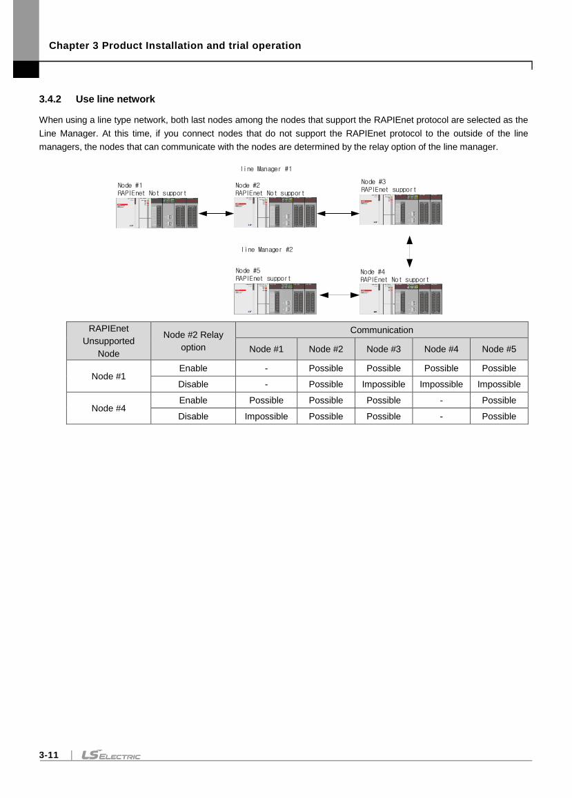
Chapter 3 Product Installation and trial operation
3-11
3.4.2 Use line network
When using a line type network, both last nodes among the nodes that support the RAPIEnet protocol are selected as the
Line Manager. At this time, if you connect nodes that do not support the RAPIEnet protocol to the outside of the line
managers, the nodes that can communicate with the nodes are determined by the relay option of the line manager.
Node #1RAPIEnet Not support
Node #5RAPIEnet support
Node #4RAPIEnet Not support
Node #2RAPIEnet Not support
Node #3RAPIEnet support
line Manager #1
line Manager #2
RAPIEnet
Unsupported
Node
Node #2 Relay
option
Communication
Node #1 Node #2 Node #3 Node #4 Node #5
Node #1 Enable - Possible Possible Possible Possible
Disable - Possible Impossible Impossible Impossible
Node #4 Enable Possible Possible Possible - Possible
Disable Impossible Possible Possible - Possible
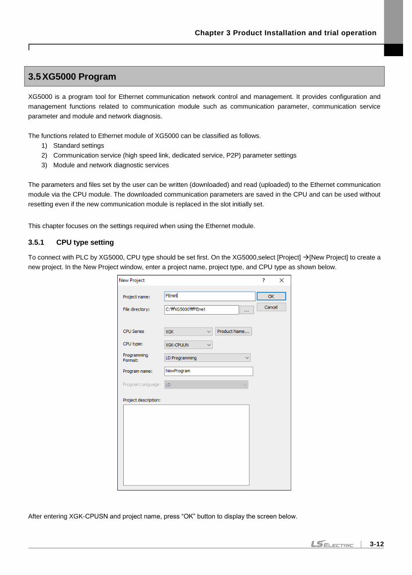
Chapter 3 Product Installation and trial operation
3-12
3.5 XG5000 Program
XG5000 is a program tool for Ethernet communication network control and management. It provides configuration and
management functions related to communication module such as communication parameter, communication service
parameter and module and network diagnosis.
The functions related to Ethernet module of XG5000 can be classified as follows.
1) Standard settings
2) Communication service (high speed link, dedicated service, P2P) parameter settings
3) Module and network diagnostic services
The parameters and files set by the user can be written (downloaded) and read (uploaded) to the Ethernet communication
module via the CPU module. The downloaded communication parameters are saved in the CPU and can be used without
resetting even if the new communication module is replaced in the slot initially set.
This chapter focuses on the settings required when using the Ethernet module.
3.5.1 CPU type setting
To connect with PLC by XG5000, CPU type should be set first. On the XG5000,select [Project] [New Project] to create a
new project. In the New Project window, enter a project name, project type, and CPU type as shown below.
After entering XGK-CPUSN and project name, press “OK” button to display the screen below.
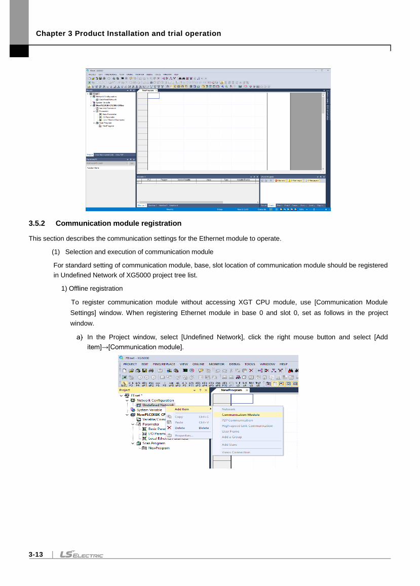
Chapter 3 Product Installation and trial operation
3-13
3.5.2 Communication module registration
This section describes the communication settings for the Ethernet module to operate.
(1) Selection and execution of communication module
For standard setting of communication module, base, slot location of communication module should be registered
in Undefined Network of XG5000 project tree list.
1) Offline registration
To register communication module without accessing XGT CPU module, use [Communication Module
Settings] window. When registering Ethernet module in base 0 and slot 0, set as follows in the project
window.
In the Project window, select [Undefined Network], click the right mouse button and select [Add
item]→[Communication module].
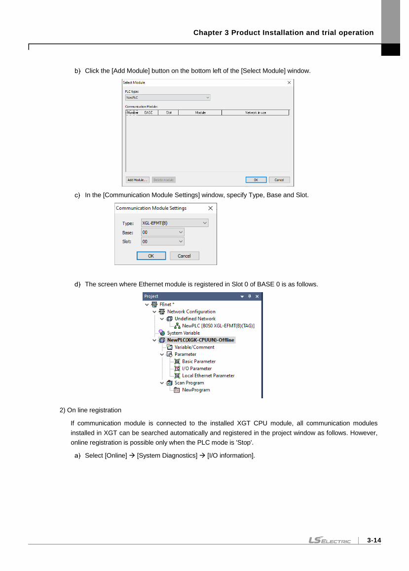
Chapter 3 Product Installation and trial operation
3-14
Click the [Add Module] button on the bottom left of the [Select Module] window.
In the [Communication Module Settings] window, specify Type, Base and Slot.
The screen where Ethernet module is registered in Slot 0 of BASE 0 is as follows.
2) On line registration
If communication module is connected to the installed XGT CPU module, all communication modules
installed in XGT can be searched automatically and registered in the project window as follows. However,
online registration is possible only when the PLC mode is 'Stop'.
Select [Online] [System Diagnostics] [I/O information].

Chapter 3 Product Installation and trial operation
3-15
Press the "I/O Sync" button at the bottom left of the [I / O Information] window.
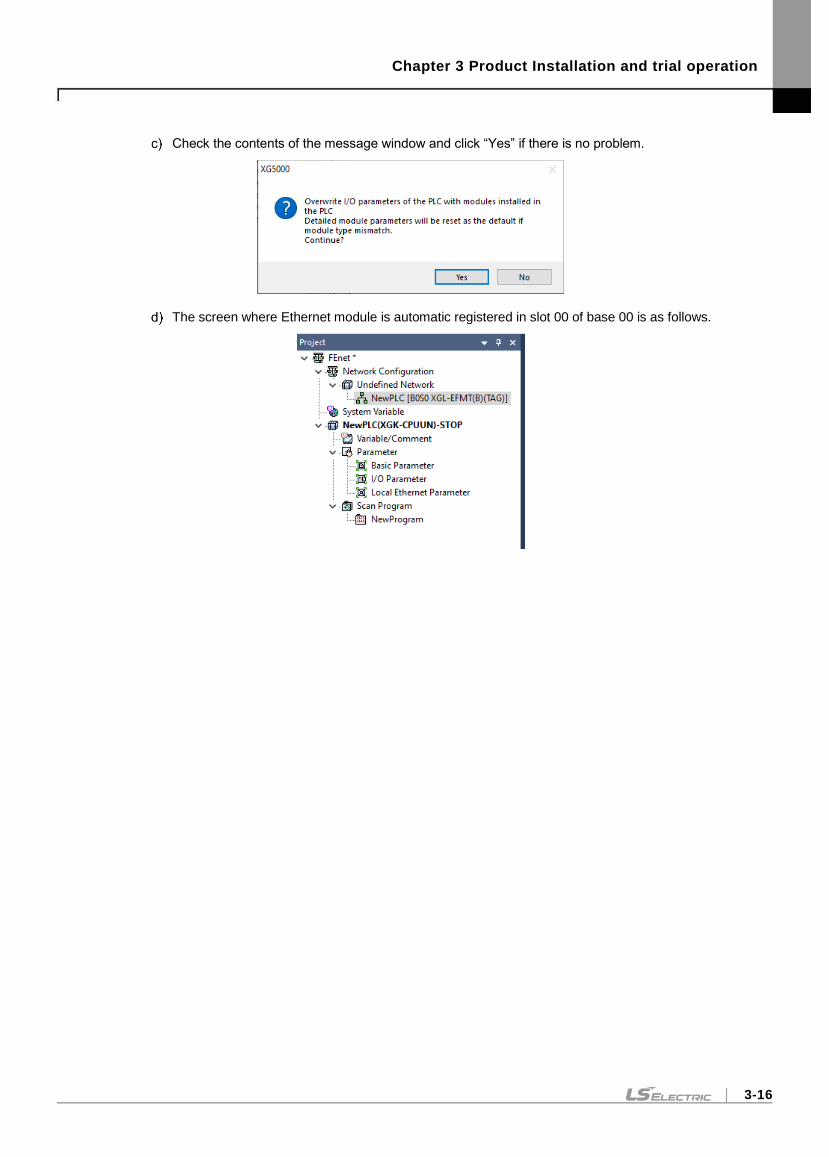
Chapter 3 Product Installation and trial operation
3-16
Check the contents of the message window and click “Yes” if there is no problem.
The screen where Ethernet module is automatic registered in slot 00 of base 00 is as follows.
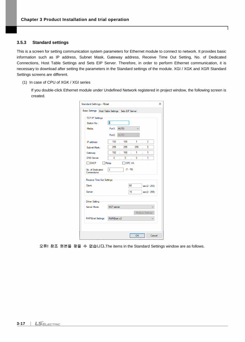
Chapter 3 Product Installation and trial operation
3-17
3.5.3 Standard settings
This is a screen for setting communication system parameters for Ethernet module to connect to network. It provides basic
information such as IP address, Subnet Mask, Gateway address, Receive Time Out Setting, No. of Dedicated
Connections, Host Table Settings and Sets EIP Server. Therefore, in order to perform Ethernet communication, it is
necessary to download after setting the parameters in the Standard settings of the module. XGI / XGK and XGR Standard
Settings screens are different.
(1) In case of CPU of XGK / XGI series
If you double-click Ethernet module under Undefined Network registered in project window, the following screen is
created.
오류! 참조 원본을 찾을 수 없습니다.The items in the Standard Settings window are as follows.
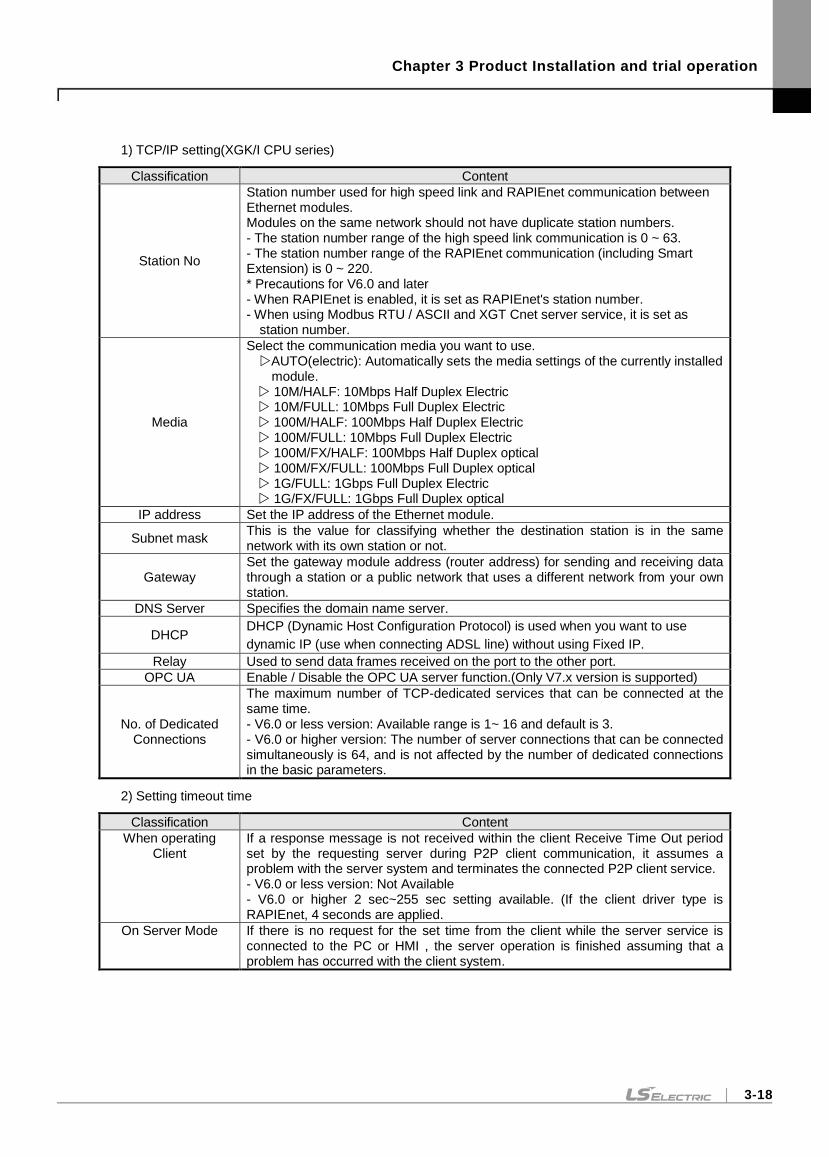
Chapter 3 Product Installation and trial operation
3-18
1) TCP/IP setting(XGK/I CPU series)
Classification Content
Station No
Station number used for high speed link and RAPIEnet communication between Ethernet modules. Modules on the same network should not have duplicate station numbers. - The station number range of the high speed link communication is 0 ~ 63. - The station number range of the RAPIEnet communication (including Smart Extension) is 0 ~ 220. * Precautions for V6.0 and later - When RAPIEnet is enabled, it is set as RAPIEnet's station number. - When using Modbus RTU / ASCII and XGT Cnet server service, it is set as
station number.
Media
Select the communication media you want to use. AUTO(electric): Automatically sets the media settings of the currently installed
module. 10M/HALF: 10Mbps Half Duplex Electric 10M/FULL: 10Mbps Full Duplex Electric 100M/HALF: 100Mbps Half Duplex Electric 100M/FULL: 10Mbps Full Duplex Electric 100M/FX/HALF: 100Mbps Half Duplex optical 100M/FX/FULL: 100Mbps Full Duplex optical 1G/FULL: 1Gbps Full Duplex Electric 1G/FX/FULL: 1Gbps Full Duplex optical
IP address Set the IP address of the Ethernet module.
Subnet mask This is the value for classifying whether the destination station is in the same network with its own station or not.
Gateway Set the gateway module address (router address) for sending and receiving data through a station or a public network that uses a different network from your own station.
DNS Server Specifies the domain name server.
DHCP DHCP (Dynamic Host Configuration Protocol) is used when you want to use
dynamic IP (use when connecting ADSL line) without using Fixed IP.
Relay Used to send data frames received on the port to the other port.
OPC UA Enable / Disable the OPC UA server function.(Only V7.x version is supported)
No. of Dedicated Connections
The maximum number of TCP-dedicated services that can be connected at the same time. - V6.0 or less version: Available range is 1~ 16 and default is 3. - V6.0 or higher version: The number of server connections that can be connected simultaneously is 64, and is not affected by the number of dedicated connections in the basic parameters.
2) Setting timeout time
Classification Content
When operating Client
If a response message is not received within the client Receive Time Out period set by the requesting server during P2P client communication, it assumes a problem with the server system and terminates the connected P2P client service. - V6.0 or less version: Not Available - V6.0 or higher 2 sec~255 sec setting available. (If the client driver type is RAPIEnet, 4 seconds are applied.
On Server Mode If there is no request for the set time from the client while the server service is connected to the PC or HMI , the server operation is finished assuming that a problem has occurred with the client system.
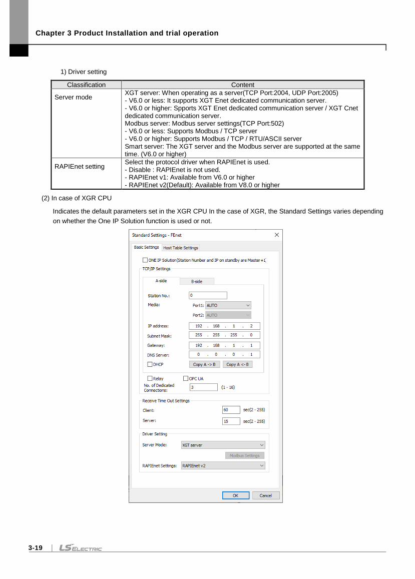
Chapter 3 Product Installation and trial operation
3-19
1) Driver setting
Classification Content
Server mode XGT server: When operating as a server(TCP Port:2004, UDP Port:2005) - V6.0 or less: It supports XGT Enet dedicated communication server. - V6.0 or higher: Spports XGT Enet dedicated communication server / XGT Cnet dedicated communication server. Modbus server: Modbus server settings(TCP Port:502) - V6.0 or less: Supports Modbus / TCP server - V6.0 or higher: Supports Modbus / TCP / RTU/ASCII server Smart server: The XGT server and the Modbus server are supported at the same time. (V6.0 or higher)
RAPIEnet setting Select the protocol driver when RAPIEnet is used. - Disable : RAPIEnet is not used. - RAPIEnet v1: Available from V6.0 or higher - RAPIEnet v2(Default): Available from V8.0 or higher
(2) In case of XGR CPU
Indicates the default parameters set in the XGR CPU In the case of XGR, the Standard Settings varies depending
on whether the One IP Solution function is used or not.
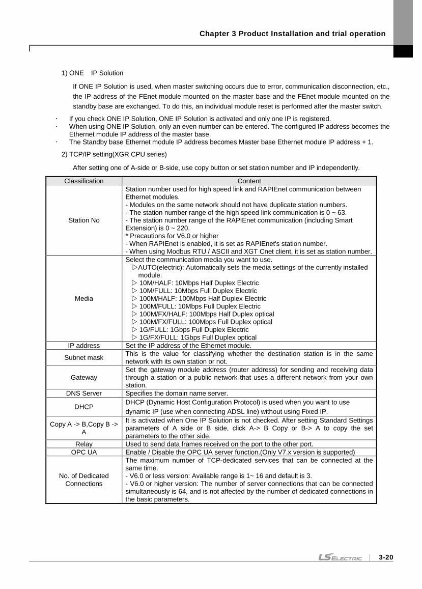
Chapter 3 Product Installation and trial operation
3-20
1) ONE IP Solution
If ONE IP Solution is used, when master switching occurs due to error, communication disconnection, etc.,
the IP address of the FEnet module mounted on the master base and the FEnet module mounted on the
standby base are exchanged. To do this, an individual module reset is performed after the master switch.
If you check ONE IP Solution, ONE IP Solution is activated and only one IP is registered. When using ONE IP Solution, only an even number can be entered. The configured IP address becomes the
Ethernet module IP address of the master base. The Standby base Ethernet module IP address becomes Master base Ethernet module IP address + 1.
2) TCP/IP setting(XGR CPU series)
After setting one of A-side or B-side, use copy button or set station number and IP independently.
Classification Content
Station No
Station number used for high speed link and RAPIEnet communication between Ethernet modules. - Modules on the same network should not have duplicate station numbers. - The station number range of the high speed link communication is 0 ~ 63. - The station number range of the RAPIEnet communication (including Smart Extension) is 0 ~ 220. * Precautions for V6.0 or higher - When RAPIEnet is enabled, it is set as RAPIEnet's station number. - When using Modbus RTU / ASCII and XGT Cnet client, it is set as station number.
Media
Select the communication media you want to use. AUTO(electric): Automatically sets the media settings of the currently installed
module. 10M/HALF: 10Mbps Half Duplex Electric 10M/FULL: 10Mbps Full Duplex Electric 100M/HALF: 100Mbps Half Duplex Electric 100M/FULL: 10Mbps Full Duplex Electric 100M/FX/HALF: 100Mbps Half Duplex optical 100M/FX/FULL: 100Mbps Full Duplex optical 1G/FULL: 1Gbps Full Duplex Electric 1G/FX/FULL: 1Gbps Full Duplex optical
IP address Set the IP address of the Ethernet module.
Subnet mask This is the value for classifying whether the destination station is in the same network with its own station or not.
Gateway Set the gateway module address (router address) for sending and receiving data through a station or a public network that uses a different network from your own station.
DNS Server Specifies the domain name server.
DHCP DHCP (Dynamic Host Configuration Protocol) is used when you want to use
dynamic IP (use when connecting ADSL line) without using Fixed IP.
Copy A -> B,Copy B -> A
It is activated when One IP Solution is not checked. After setting Standard Settings parameters of A side or B side, click A-> B Copy or B-> A to copy the set parameters to the other side.
Relay Used to send data frames received on the port to the other port.
OPC UA Enable / Disable the OPC UA server function.(Only V7.x version is supported)
No. of Dedicated Connections
The maximum number of TCP-dedicated services that can be connected at the same time. - V6.0 or less version: Available range is 1~ 16 and default is 3. - V6.0 or higher version: The number of server connections that can be connected simultaneously is 64, and is not affected by the number of dedicated connections in the basic parameters.
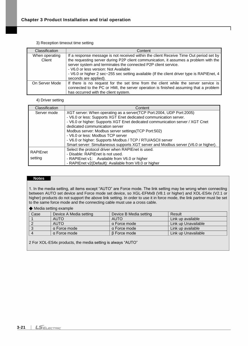
Chapter 3 Product Installation and trial operation
3-21
3) Reception timeout time setting
Classification Content
When operating Client
If a response message is not received within the client Receive Time Out period set by the requesting server during P2P client communication, it assumes a problem with the server system and terminates the connected P2P client service. - V6.0 or less version: Not Available - V6.0 or higher 2 sec~255 sec setting available (If the client driver type is RAPIEnet, 4 seconds are applied).
On Server Mode If there is no request for the set time from the client while the server service is connected to the PC or HMI, the server operation is finished assuming that a problem has occurred with the client system.
4) Driver setting
Classification Content
Server mode XGT server: When operating as a server(TCP Port:2004, UDP Port:2005) - V6.0 or less: Supports XGT Enet dedicated communication server. - V6.0 or higher: Supports XGT Enet dedicated communication server / XGT Cnet dedicated communication server Modbus server: Modbus server settings(TCP Port:502) - V6.0 or less: Modbus TCP server - V6.0 or higher: Supports Modbus / TCP / RTU/ASCII server Smart server: Simultaneous supports XGT server and Modbus server (V6.0 or higher).
RAPIEnet
setting
Select the protocol driver when RAPIEnet is used. - Disable: RAPIEnet is not used. - RAPIEnet v1: Available from V6.0 or higher - RAPIEnet v2(Default): Available from V8.0 or higher
Notes
1. In the media setting, all items except “AUTO” are Force mode. The link setting may be wrong when connecting between AUTO set device and Force mode set device, so XGL-EFMxB (V8.1 or higher) and XOL-ES4x (V2.1 or higher) products do not support the above link setting. In order to use it in force mode, the link partner must be set to the same force mode and the connecting cable must use a cross cable.
Media setting example
Case Device A Media setting Device B Media setting Result
1 AUTO AUTO Link up available
2 AUTO α Force mode Link up Unavailable
3 α Force mode α Force mode Link up available
4 α Force mode β Force mode Link up Unavailable
2 For XOL-ES4x products, the media setting is always “AUTO”
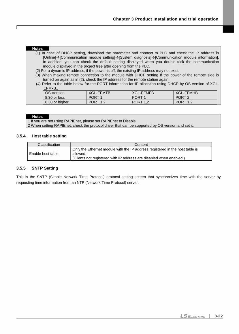
Chapter 3 Product Installation and trial operation
3-22
Notes
(1) In case of DHCP setting, download the parameter and connect to PLC and check the IP address in [Online][Communication module setting][System diagnosis][Communication module information]. In addition, you can check the default setting displayed when you double-click the communication module displayed in the project tree after opening from the PLC.
(2) For a dynamic IP address, if the power is off, the existing IP address may not exist. (3) When making remote connection to the module with DHCP setting If the power of the remote side is
turned on again as in (2), check the IP address for the remote station again. (4) Refer to the table below for the PORT information for IP allocation using DHCP by OS version of XGL-
EFMxB..
OS Version XGL-EFMTB XGL-EFMFB XGL-EFMHB
8.30 or less PORT 1 PORT 1 PORT 2
8.30 or higher PORT 1,2 PORT 1,2 PORT 1,2
Notes
1 If you are not using RAPIEnet, please set RAPIEnet to Disable 2 When setting RAPIEnet, check the protocol driver that can be supported by OS version and set it.
3.5.4 Host table setting
Classification Content
Enable host table Only the Ethernet module with the IP address registered in the host table is allowed. (Clients not registered with IP address are disabled when enabled.)
3.5.5 SNTP Setting
This is the SNTP (Simple Network Time Protocol) protocol setting screen that synchronizes time with the server by
requesting time information from an NTP (Network Time Protocol) server.
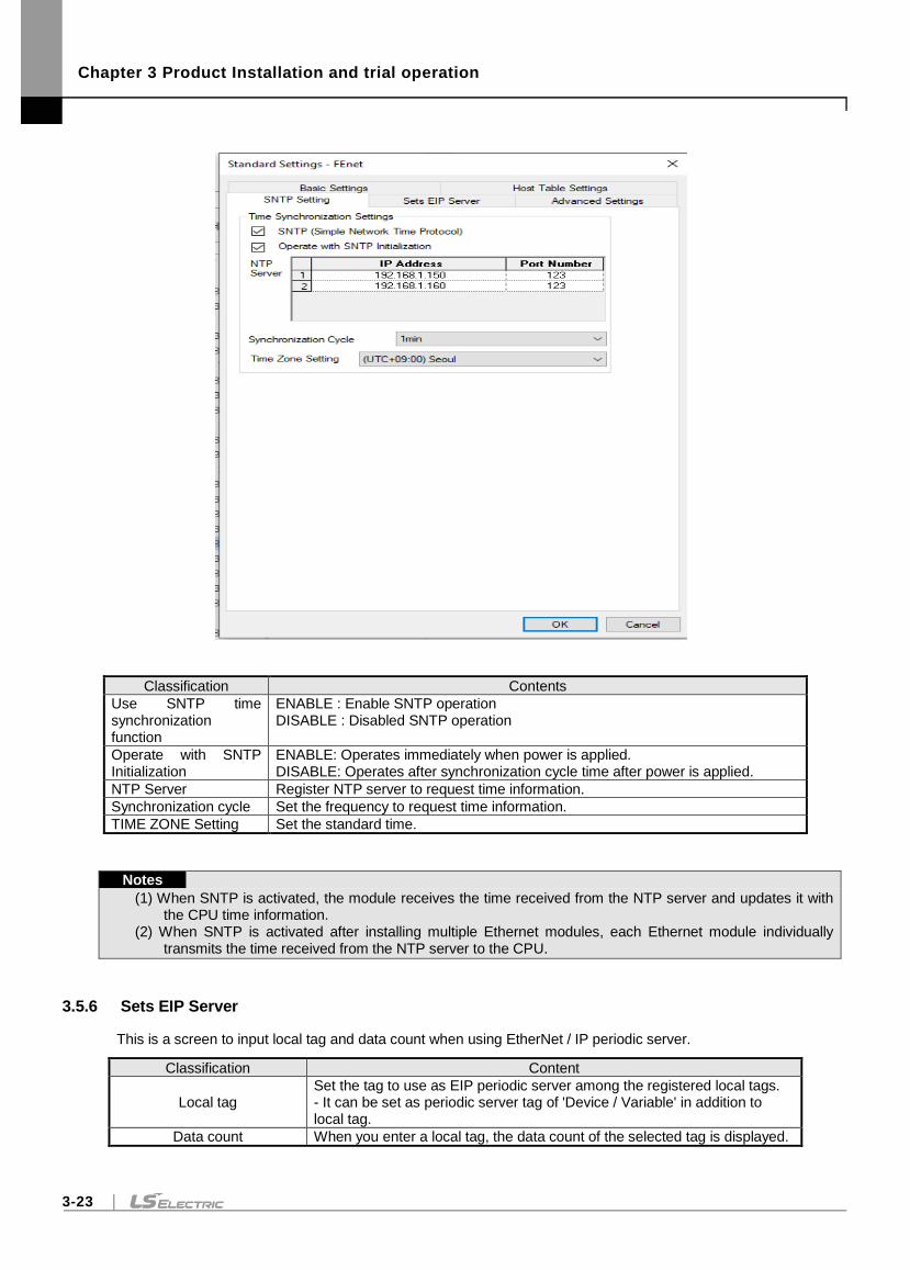
Chapter 3 Product Installation and trial operation
3-23
Classification Contents
Use SNTP time synchronization function
ENABLE : Enable SNTP operation DISABLE : Disabled SNTP operation
Operate with SNTP Initialization
ENABLE: Operates immediately when power is applied. DISABLE: Operates after synchronization cycle time after power is applied.
NTP Server Register NTP server to request time information.
Synchronization cycle Set the frequency to request time information.
TIME ZONE Setting Set the standard time.
Notes
(1) When SNTP is activated, the module receives the time received from the NTP server and updates it with the CPU time information.
(2) When SNTP is activated after installing multiple Ethernet modules, each Ethernet module individually transmits the time received from the NTP server to the CPU.
3.5.6 Sets EIP Server
This is a screen to input local tag and data count when using EtherNet / IP periodic server.
Classification Content
Local tag Set the tag to use as EIP periodic server among the registered local tags. - It can be set as periodic server tag of 'Device / Variable' in addition to local tag.
Data count When you enter a local tag, the data count of the selected tag is displayed.
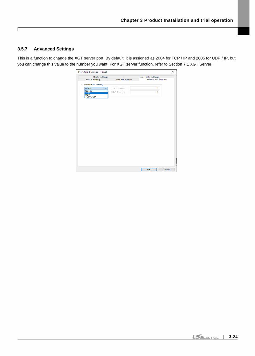
Chapter 3 Product Installation and trial operation
3-24
3.5.7 Advanced Settings
This is a function to change the XGT server port. By default, it is assigned as 2004 for TCP / IP and 2005 for UDP / IP, but
you can change this value to the number you want. For XGT server function, refer to Section 7.1 XGT Server.
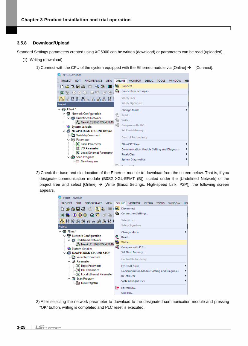
Chapter 3 Product Installation and trial operation
3-25
3.5.8 Download/Upload
Standard Settings parameters created using XG5000 can be written (download) or parameters can be read (uploaded).
(1) Writing (download)
1) Connect with the CPU of the system equipped with the Ethernet module via [Online] [Connect].
2) Check the base and slot location of the Ethernet module to download from the screen below. That is, if you
designate communication module (B0S2 XGL-EFMT (B)) located under the [Undefined Network] of the
project tree and select [Online] [Write (Basic Settings, High-speed Link, P2P)], the following screen
appears.
3) After selecting the network parameter to download to the designated communication module and pressing
“OK” button, writing is completed and PLC reset is executed.
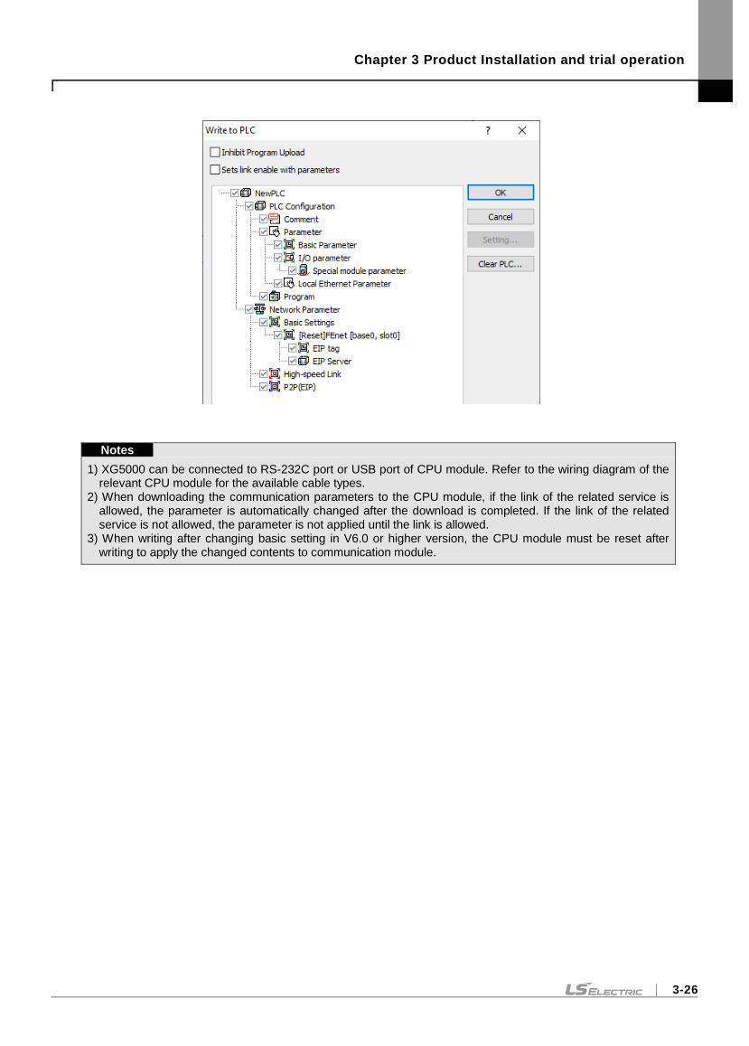
Chapter 3 Product Installation and trial operation
3-26
Notes
1) XG5000 can be connected to RS-232C port or USB port of CPU module. Refer to the wiring diagram of the relevant CPU module for the available cable types.
2) When downloading the communication parameters to the CPU module, if the link of the related service is allowed, the parameter is automatically changed after the download is completed. If the link of the related service is not allowed, the parameter is not applied until the link is allowed.
3) When writing after changing basic setting in V6.0 or higher version, the CPU module must be reset after writing to apply the changed contents to communication module.
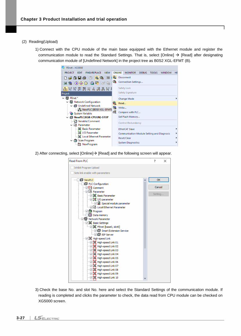
Chapter 3 Product Installation and trial operation
3-27
(2) Reading(Upload)
1) Connect with the CPU module of the main base equipped with the Ethernet module and register the
communication module to read the Standard Settings. That is, select [Online] [Read] after designating
communication module of [Undefined Network] in the project tree as B0S2 XGL-EFMT (B).
2) After connecting, select [Online] [Read] and the following screen will appear.
3) Check the base No. and slot No. here and select the Standard Settings of the communication module. If
reading is completed and clicks the parameter to check, the data read from CPU module can be checked on
XG5000 screen.
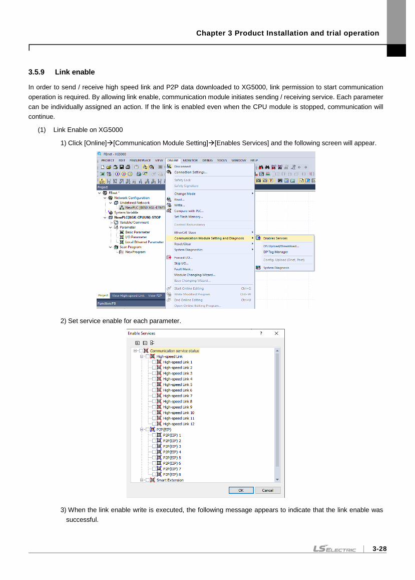
Chapter 3 Product Installation and trial operation
3-28
3.5.9 Link enable
In order to send / receive high speed link and P2P data downloaded to XG5000, link permission to start communication
operation is required. By allowing link enable, communication module initiates sending / receiving service. Each parameter
can be individually assigned an action. If the link is enabled even when the CPU module is stopped, communication will
continue.
(1) Link Enable on XG5000
1) Click [Online][Communication Module Setting][Enables Services] and the following screen will appear.
2) Set service enable for each parameter.
3) When the link enable write is executed, the following message appears to indicate that the link enable was
successful.
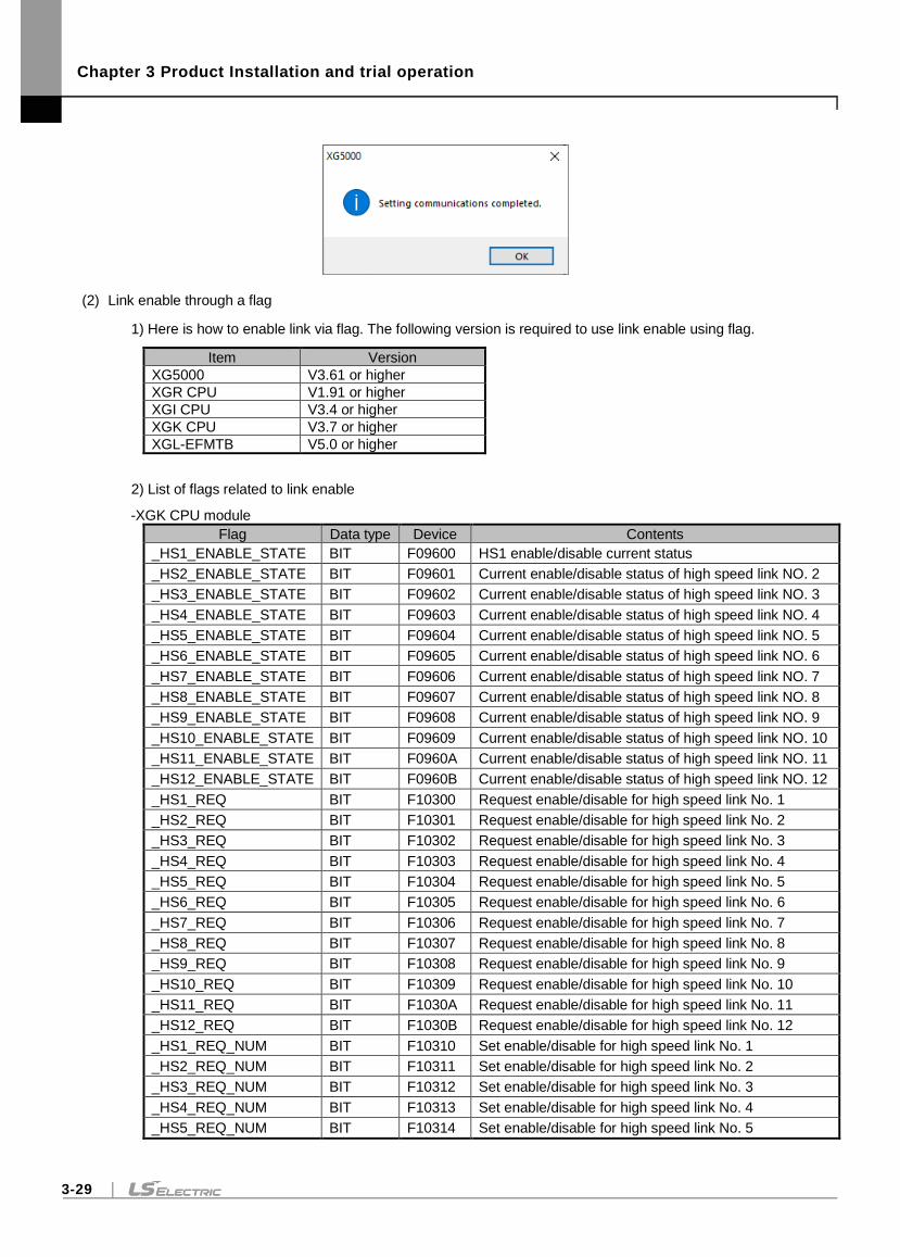
Chapter 3 Product Installation and trial operation
3-29
(2) Link enable through a flag
1) Here is how to enable link via flag. The following version is required to use link enable using flag.
Item Version
XG5000 V3.61 or higher
XGR CPU V1.91 or higher
XGI CPU V3.4 or higher
XGK CPU V3.7 or higher
XGL-EFMTB V5.0 or higher
2) List of flags related to link enable
-XGK CPU module
Flag Data type Device Contents
_HS1_ENABLE_STATE BIT F09600 HS1 enable/disable current status
_HS2_ENABLE_STATE BIT F09601 Current enable/disable status of high speed link NO. 2
_HS3_ENABLE_STATE BIT F09602 Current enable/disable status of high speed link NO. 3
_HS4_ENABLE_STATE BIT F09603 Current enable/disable status of high speed link NO. 4
_HS5_ENABLE_STATE BIT F09604 Current enable/disable status of high speed link NO. 5
_HS6_ENABLE_STATE BIT F09605 Current enable/disable status of high speed link NO. 6
_HS7_ENABLE_STATE BIT F09606 Current enable/disable status of high speed link NO. 7
_HS8_ENABLE_STATE BIT F09607 Current enable/disable status of high speed link NO. 8
_HS9_ENABLE_STATE BIT F09608 Current enable/disable status of high speed link NO. 9
_HS10_ENABLE_STATE BIT F09609 Current enable/disable status of high speed link NO. 10
_HS11_ENABLE_STATE BIT F0960A Current enable/disable status of high speed link NO. 11
_HS12_ENABLE_STATE BIT F0960B Current enable/disable status of high speed link NO. 12
_HS1_REQ BIT F10300 Request enable/disable for high speed link No. 1
_HS2_REQ BIT F10301 Request enable/disable for high speed link No. 2
_HS3_REQ BIT F10302 Request enable/disable for high speed link No. 3
_HS4_REQ BIT F10303 Request enable/disable for high speed link No. 4
_HS5_REQ BIT F10304 Request enable/disable for high speed link No. 5
_HS6_REQ BIT F10305 Request enable/disable for high speed link No. 6
_HS7_REQ BIT F10306 Request enable/disable for high speed link No. 7
_HS8_REQ BIT F10307 Request enable/disable for high speed link No. 8
_HS9_REQ BIT F10308 Request enable/disable for high speed link No. 9
_HS10_REQ BIT F10309 Request enable/disable for high speed link No. 10
_HS11_REQ BIT F1030A Request enable/disable for high speed link No. 11
_HS12_REQ BIT F1030B Request enable/disable for high speed link No. 12
_HS1_REQ_NUM BIT F10310 Set enable/disable for high speed link No. 1
_HS2_REQ_NUM BIT F10311 Set enable/disable for high speed link No. 2
_HS3_REQ_NUM BIT F10312 Set enable/disable for high speed link No. 3
_HS4_REQ_NUM BIT F10313 Set enable/disable for high speed link No. 4
_HS5_REQ_NUM BIT F10314 Set enable/disable for high speed link No. 5
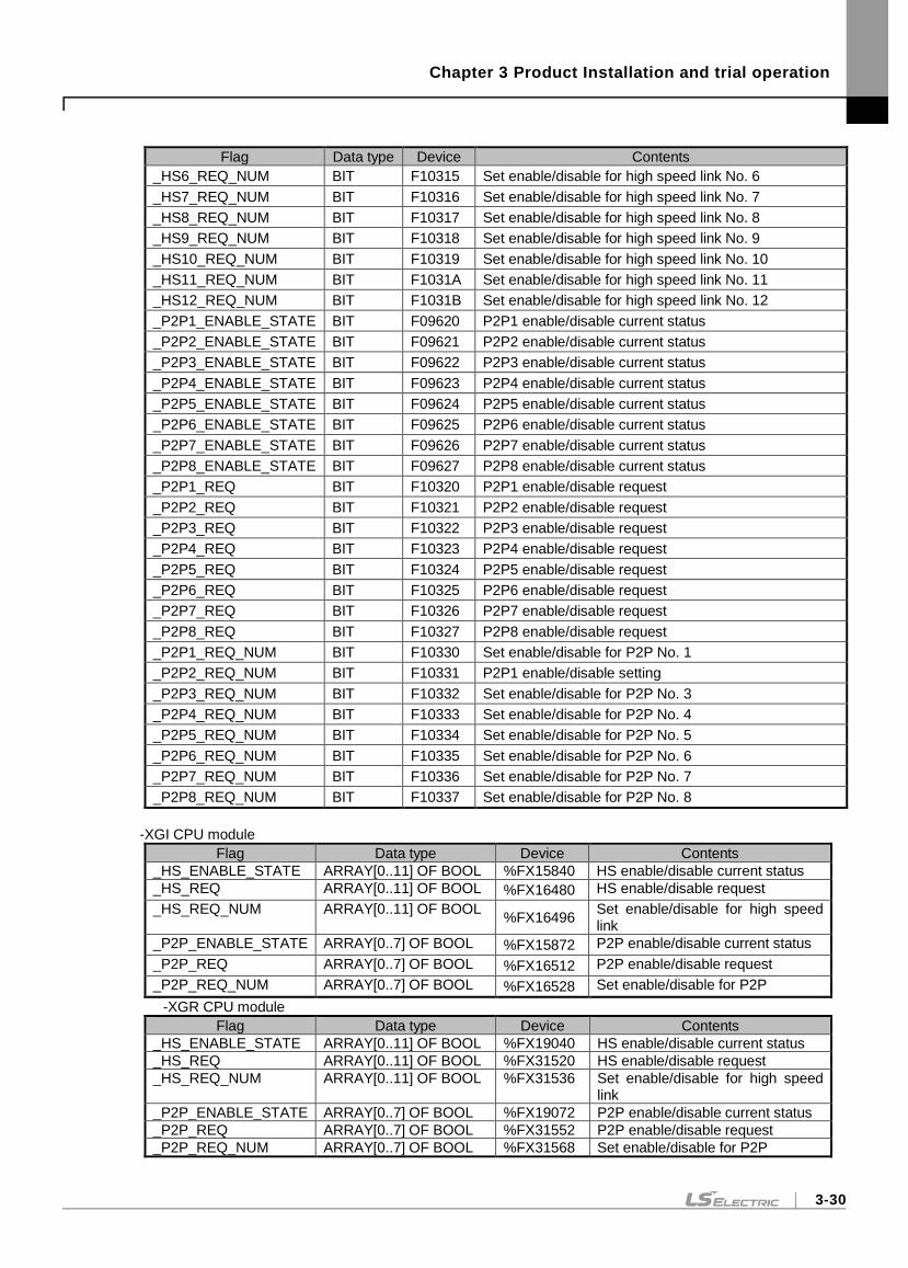
Chapter 3 Product Installation and trial operation
3-30
Flag Data type Device Contents
_HS6_REQ_NUM BIT F10315 Set enable/disable for high speed link No. 6
_HS7_REQ_NUM BIT F10316 Set enable/disable for high speed link No. 7
_HS8_REQ_NUM BIT F10317 Set enable/disable for high speed link No. 8
_HS9_REQ_NUM BIT F10318 Set enable/disable for high speed link No. 9
_HS10_REQ_NUM BIT F10319 Set enable/disable for high speed link No. 10
_HS11_REQ_NUM BIT F1031A Set enable/disable for high speed link No. 11
_HS12_REQ_NUM BIT F1031B Set enable/disable for high speed link No. 12
_P2P1_ENABLE_STATE BIT F09620 P2P1 enable/disable current status
_P2P2_ENABLE_STATE BIT F09621 P2P2 enable/disable current status
_P2P3_ENABLE_STATE BIT F09622 P2P3 enable/disable current status
_P2P4_ENABLE_STATE BIT F09623 P2P4 enable/disable current status
_P2P5_ENABLE_STATE BIT F09624 P2P5 enable/disable current status
_P2P6_ENABLE_STATE BIT F09625 P2P6 enable/disable current status
_P2P7_ENABLE_STATE BIT F09626 P2P7 enable/disable current status
_P2P8_ENABLE_STATE BIT F09627 P2P8 enable/disable current status
_P2P1_REQ BIT F10320 P2P1 enable/disable request
_P2P2_REQ BIT F10321 P2P2 enable/disable request
_P2P3_REQ BIT F10322 P2P3 enable/disable request
_P2P4_REQ BIT F10323 P2P4 enable/disable request
_P2P5_REQ BIT F10324 P2P5 enable/disable request
_P2P6_REQ BIT F10325 P2P6 enable/disable request
_P2P7_REQ BIT F10326 P2P7 enable/disable request
_P2P8_REQ BIT F10327 P2P8 enable/disable request
_P2P1_REQ_NUM BIT F10330 Set enable/disable for P2P No. 1
_P2P2_REQ_NUM BIT F10331 P2P1 enable/disable setting
_P2P3_REQ_NUM BIT F10332 Set enable/disable for P2P No. 3
_P2P4_REQ_NUM BIT F10333 Set enable/disable for P2P No. 4
_P2P5_REQ_NUM BIT F10334 Set enable/disable for P2P No. 5
_P2P6_REQ_NUM BIT F10335 Set enable/disable for P2P No. 6
_P2P7_REQ_NUM BIT F10336 Set enable/disable for P2P No. 7
_P2P8_REQ_NUM BIT F10337 Set enable/disable for P2P No. 8
-XGI CPU module
Flag Data type Device Contents
_HS_ENABLE_STATE ARRAY[0..11] OF BOOL %FX15840 HS enable/disable current status
_HS_REQ ARRAY[0..11] OF BOOL %FX16480 HS enable/disable request
_HS_REQ_NUM ARRAY[0..11] OF BOOL %FX16496
Set enable/disable for high speed link
_P2P_ENABLE_STATE ARRAY[0..7] OF BOOL %FX15872 P2P enable/disable current status
_P2P_REQ ARRAY[0..7] OF BOOL %FX16512 P2P enable/disable request
_P2P_REQ_NUM ARRAY[0..7] OF BOOL %FX16528 Set enable/disable for P2P
-XGR CPU module
Flag Data type Device Contents
_HS_ENABLE_STATE ARRAY[0..11] OF BOOL %FX19040 HS enable/disable current status
_HS_REQ ARRAY[0..11] OF BOOL %FX31520 HS enable/disable request
_HS_REQ_NUM ARRAY[0..11] OF BOOL %FX31536 Set enable/disable for high speed link
_P2P_ENABLE_STATE ARRAY[0..7] OF BOOL %FX19072 P2P enable/disable current status
_P2P_REQ ARRAY[0..7] OF BOOL %FX31552 P2P enable/disable request
_P2P_REQ_NUM ARRAY[0..7] OF BOOL %FX31568 Set enable/disable for P2P
Chapter 3 Product Installation and trial operation
3-31
Link enable method
- Set On for high speed link/P2P enable/disable setting flag high speed link/P2P enable/disable request flag On
Disable enable method
- Set Off for high speed link/P2P enable/disable setting flag high speed link/P2P enable/disable request flag On
The enable / disable status flag of HS link / P2P can be used to monitor the enable / disable status of the HS
link.
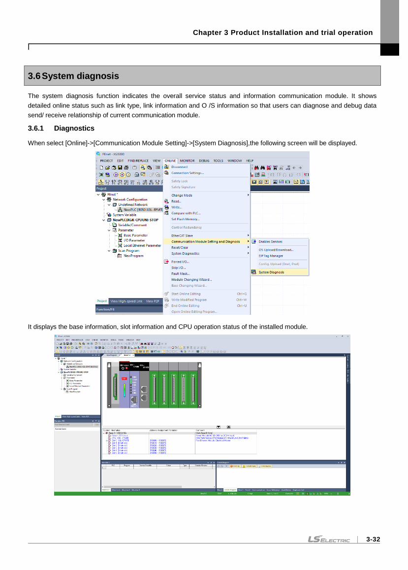
Chapter 3 Product Installation and trial operation
3-32
3.6 System diagnosis
The system diagnosis function indicates the overall service status and information communication module. It shows
detailed online status such as link type, link information and O /S information so that users can diagnose and debug data
send/ receive relationship of current communication module.
3.6.1 Diagnostics
When select [Online]->[Communication Module Setting]->[System Diagnosis],the following screen will be displayed.
It displays the base information, slot information and CPU operation status of the installed module.
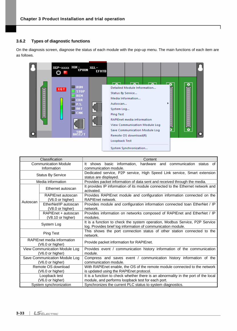
Chapter 3 Product Installation and trial operation
3-33
3.6.2 Types of diagnostic functions
On the diagnosis screen, diagnose the status of each module with the pop-up menu. The main functions of each item are
as follows.
Classification Content
Communication Module Information
It shows basic information, hardware and communication status of communication module.
Status By Service Dedicated service, P2P service, High Speed Link service, Smart extension status are displayed.
Media information Provides packet information of data sent and received through the media.
Autoscan
Ethernet autoscan It provides IP information of its module connected to the Ethernet network and activated.
RAPIEnet autoscan (V6.0 or higher)
Provides RAPIEnet module and configuration information connected on the RAPIEnet network.
EtherNet/IP autoscan (V8.0 or higher)
Provides module and configuration information connected toan EtherNet / IP network.
RAPIEnet + autoscan (V8.10 or higher)
Provides information on networks composed of RAPIEnet and EtherNet / IP modules.
System Log It is a function to check the system operation, Modbus Service, P2P Service log. Provides brief log information of communication module.
Ping Test This shows the port connection status of other station connected to the network.
RAPIEnet media information (V6.0 or higher)
Provide packet information for RAPIEnet.
View Communication Module Log (V6.0 or higher)
Provides event / communication history information of the communication module.
Save Communication Module Log (V6.0 or higher)
Compress and saves event / communication history information of the communication module.
Remote OS download (V6.0 or higher)
With RAPIEnet enable, the OS of the remote module connected to the network is updated using the RAPIEnet protocol.
Loopback test (V6.0 or higher)
It is a function to check whether there is an abnormality in the port of the local module, and performs loopback test for each port.
System synchronization Synchronizes the current PLC status to system diagnostics.
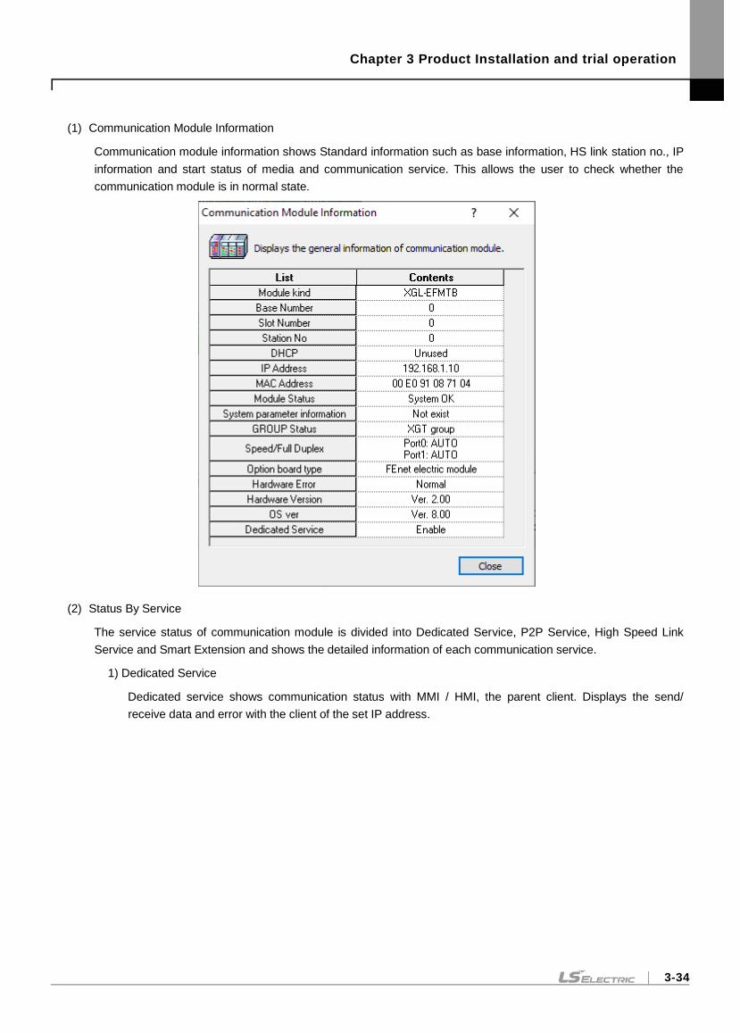
Chapter 3 Product Installation and trial operation
3-34
(1) Communication Module Information
Communication module information shows Standard information such as base information, HS link station no., IP
information and start status of media and communication service. This allows the user to check whether the
communication module is in normal state.
(2) Status By Service
The service status of communication module is divided into Dedicated Service, P2P Service, High Speed Link
Service and Smart Extension and shows the detailed information of each communication service.
1) Dedicated Service
Dedicated service shows communication status with MMI / HMI, the parent client. Displays the send/
receive data and error with the client of the set IP address.
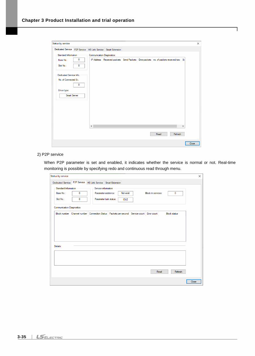
Chapter 3 Product Installation and trial operation
3-35
2) P2P service
When P2P parameter is set and enabled, it indicates whether the service is normal or not. Real-time
monitoring is possible by specifying redo and continuous read through menu.
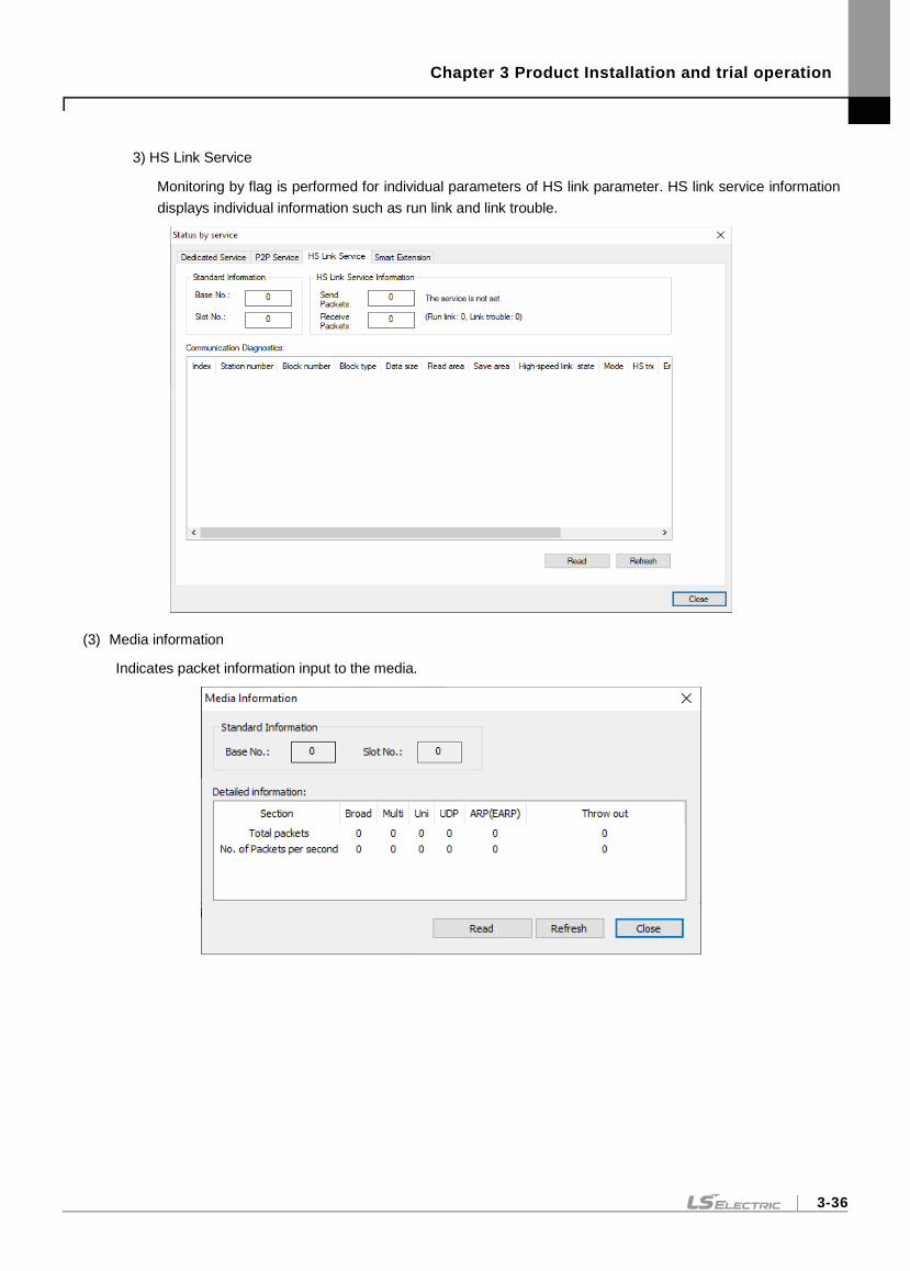
Chapter 3 Product Installation and trial operation
3-36
3) HS Link Service
Monitoring by flag is performed for individual parameters of HS link parameter. HS link service information
displays individual information such as run link and link trouble.
(3) Media information
Indicates packet information input to the media.
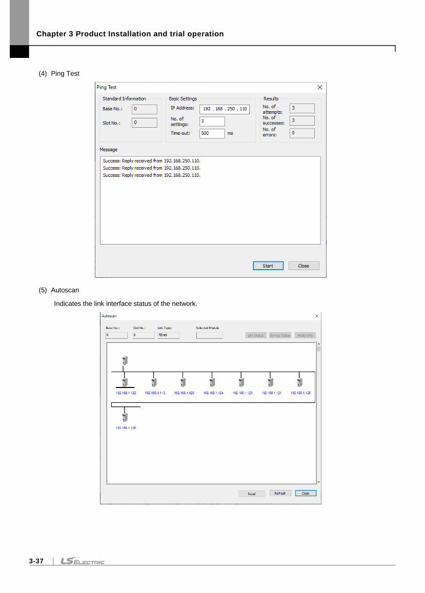
Chapter 3 Product Installation and trial operation
3-37
(4) Ping Test
(5) Autoscan
Indicates the link interface status of the network.
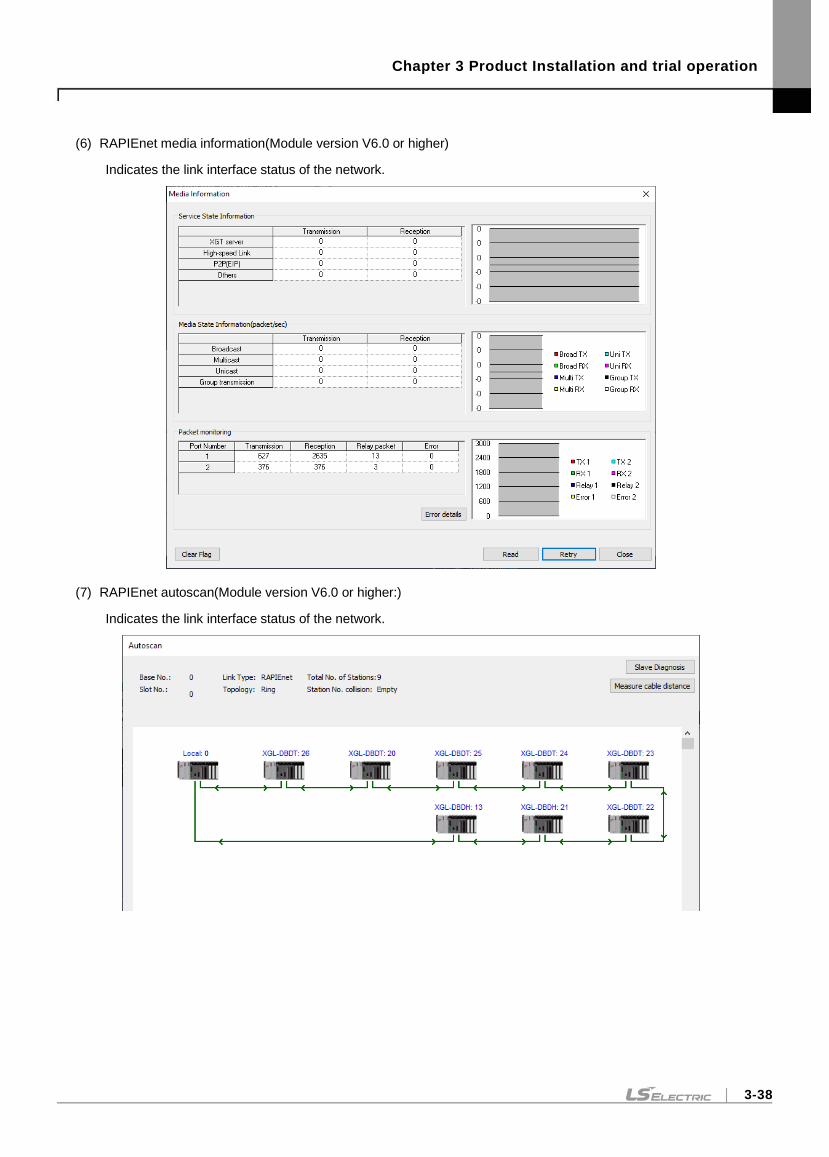
Chapter 3 Product Installation and trial operation
3-38
(6) RAPIEnet media information(Module version V6.0 or higher)
Indicates the link interface status of the network.
(7) RAPIEnet autoscan(Module version V6.0 or higher:)
Indicates the link interface status of the network.
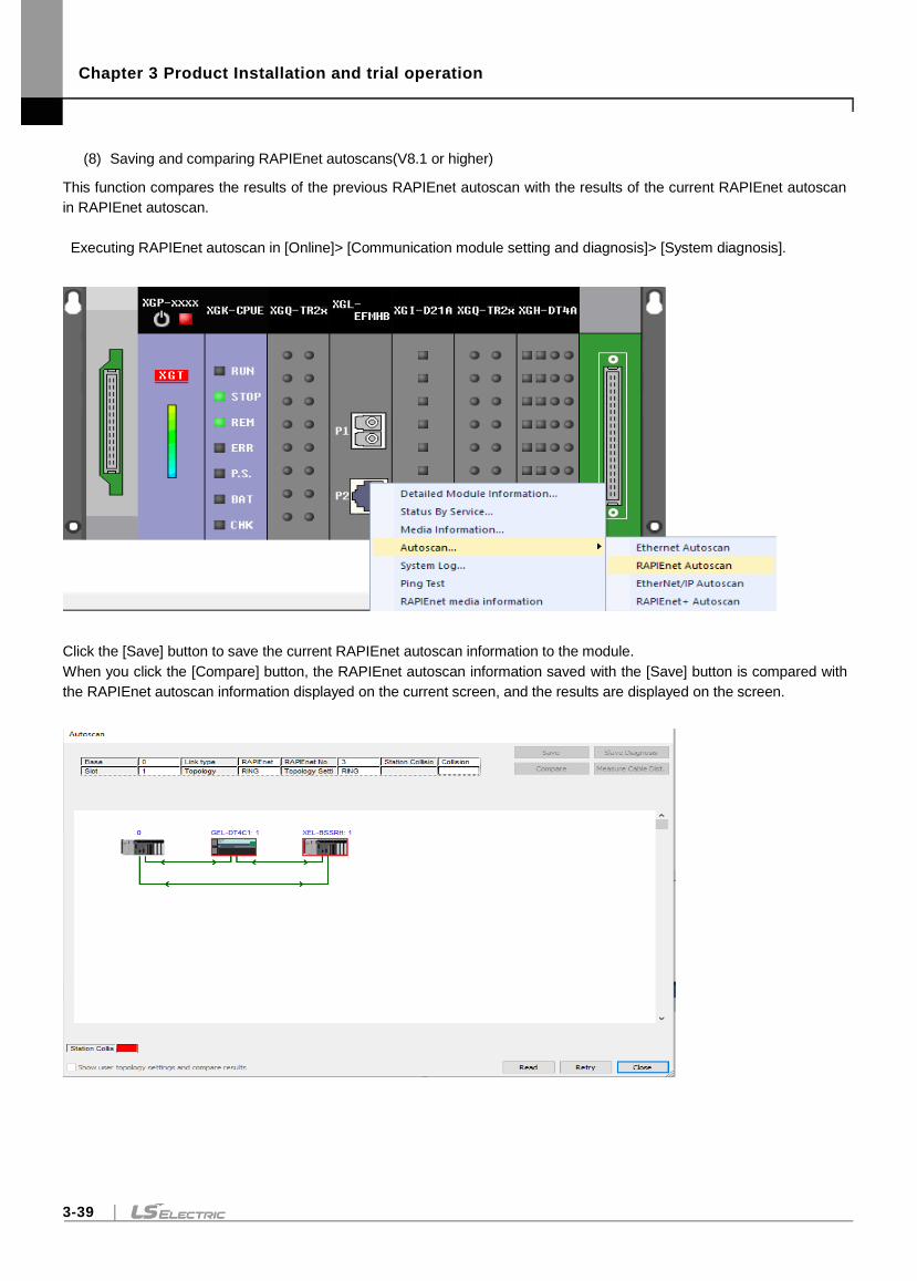
Chapter 3 Product Installation and trial operation
3-39
(8) Saving and comparing RAPIEnet autoscans(V8.1 or higher)
This function compares the results of the previous RAPIEnet autoscan with the results of the current RAPIEnet autoscan
in RAPIEnet autoscan.
Executing RAPIEnet autoscan in [Online]> [Communication module setting and diagnosis]> [System diagnosis].
Click the [Save] button to save the current RAPIEnet autoscan information to the module.
When you click the [Compare] button, the RAPIEnet autoscan information saved with the [Save] button is compared with
the RAPIEnet autoscan information displayed on the current screen, and the results are displayed on the screen.
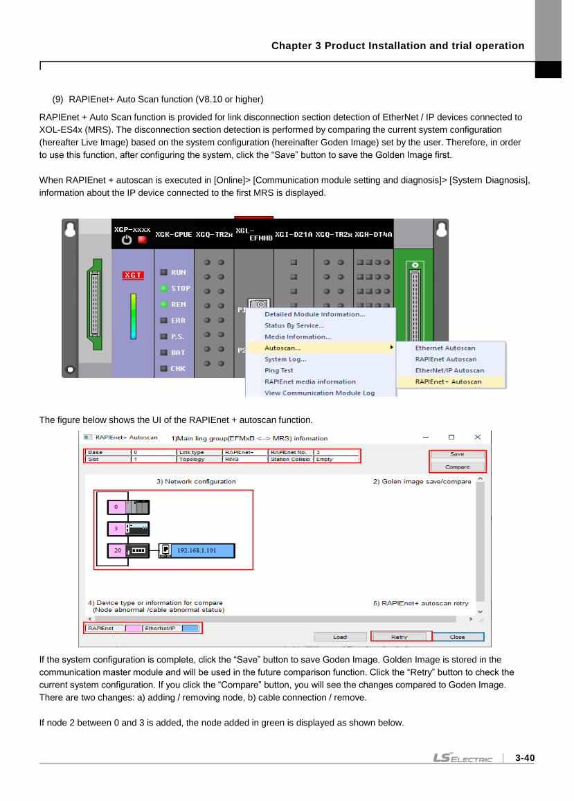
Chapter 3 Product Installation and trial operation
3-40
(9) RAPIEnet+ Auto Scan function (V8.10 or higher)
RAPIEnet + Auto Scan function is provided for link disconnection section detection of EtherNet / IP devices connected to
XOL-ES4x (MRS). The disconnection section detection is performed by comparing the current system configuration
(hereafter Live Image) based on the system configuration (hereinafter Goden Image) set by the user. Therefore, in order
to use this function, after configuring the system, click the “Save” button to save the Golden Image first.
When RAPIEnet + autoscan is executed in [Online]> [Communication module setting and diagnosis]> [System Diagnosis],
information about the IP device connected to the first MRS is displayed.
The figure below shows the UI of the RAPIEnet + autoscan function.
If the system configuration is complete, click the “Save” button to save Goden Image. Golden Image is stored in the
communication master module and will be used in the future comparison function. Click the “Retry” button to check the
current system configuration. If you click the “Compare” button, you will see the changes compared to Goden Image.
There are two changes: a) adding / removing node, b) cable connection / remove.
If node 2 between 0 and 3 is added, the node added in green is displayed as shown below.
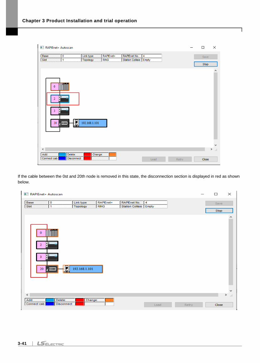
Chapter 3 Product Installation and trial operation
3-41
If the cable between the 0st and 20th node is removed in this state, the disconnection section is displayed in red as shown
below.
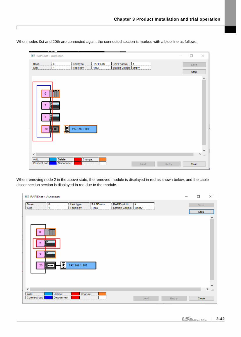
Chapter 3 Product Installation and trial operation
3-42
When nodes 0st and 20th are connected again, the connected section is marked with a blue line as follows.
When removing node 2 in the above state, the removed module is displayed in red as shown below, and the cable
disconnection section is displayed in red due to the module.
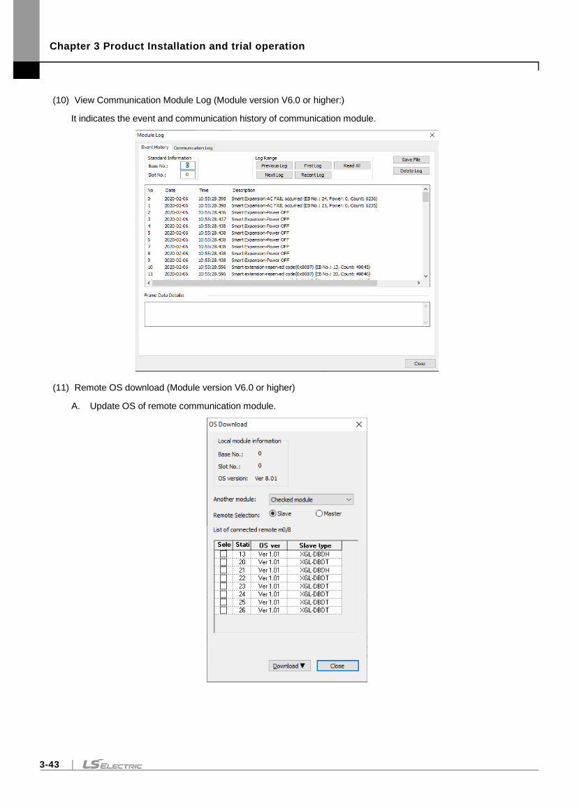
Chapter 3 Product Installation and trial operation
3-43
(10) View Communication Module Log (Module version V6.0 or higher:)
It indicates the event and communication history of communication module.
(11) Remote OS download (Module version V6.0 or higher)
A. Update OS of remote communication module.
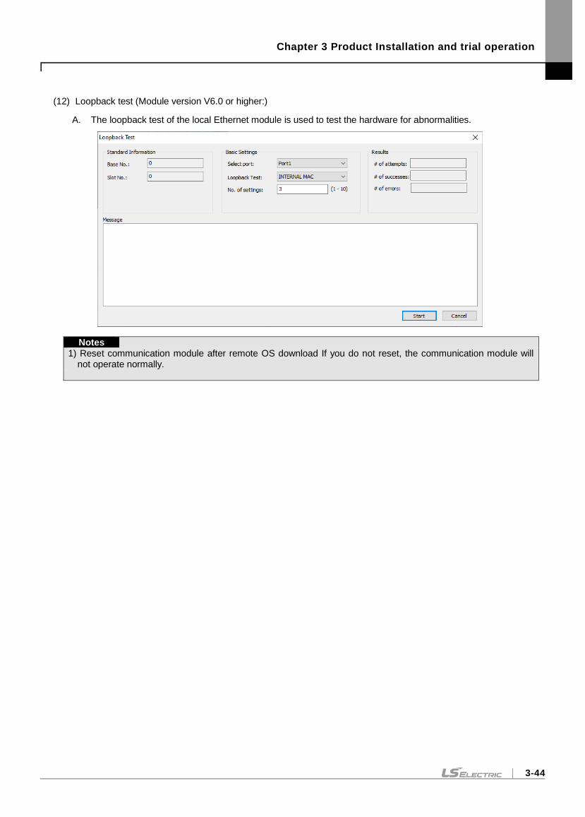
Chapter 3 Product Installation and trial operation
3-44
(12) Loopback test (Module version V6.0 or higher:)
A. The loopback test of the local Ethernet module is used to test the hardware for abnormalities.
Notes
1) Reset communication module after remote OS download If you do not reset, the communication module will not operate normally.
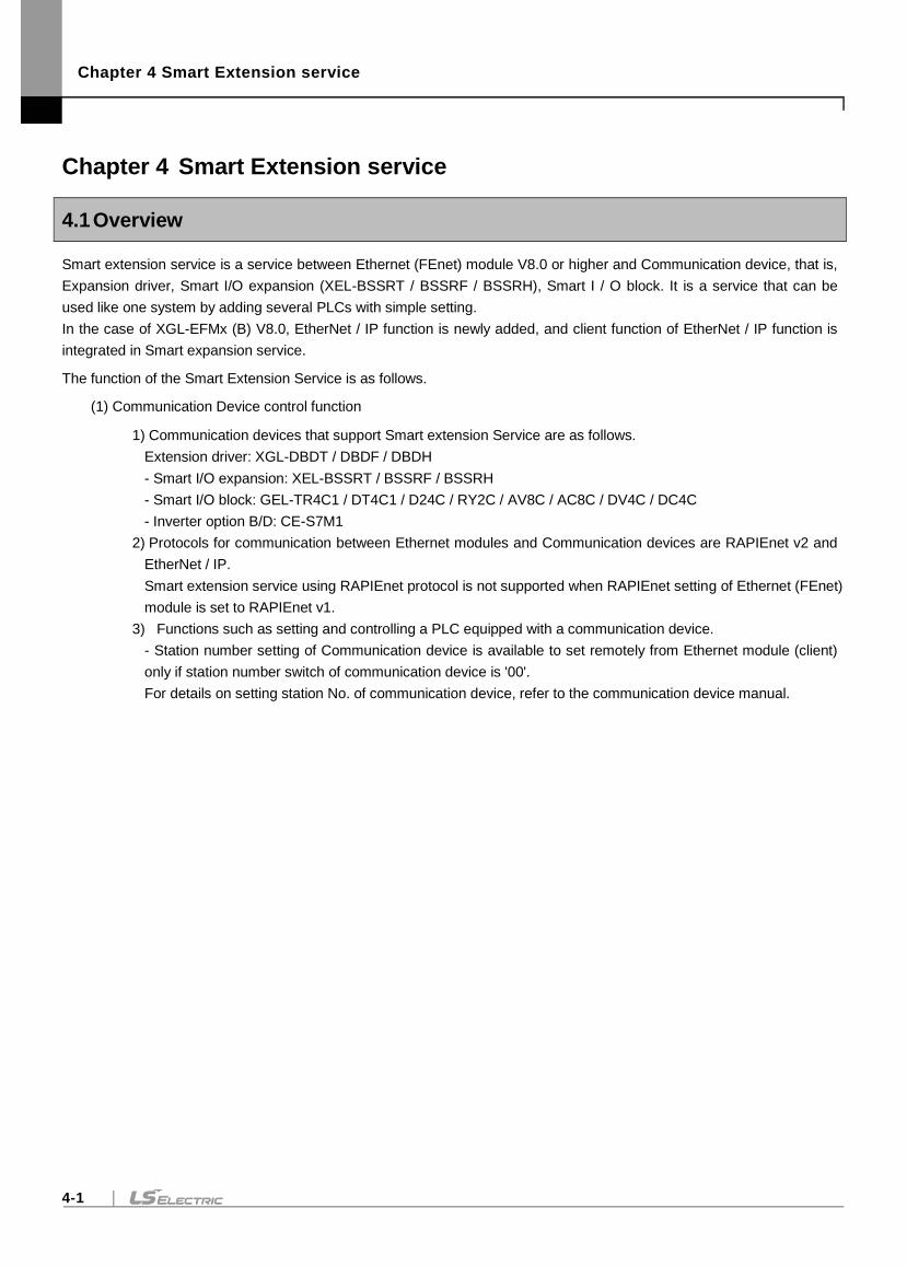
Chapter 4 Smart Extension service
4-1
Chapter 4 Smart Extension service
4.1 Overview
Smart extension service is a service between Ethernet (FEnet) module V8.0 or higher and Communication device, that is,
Expansion driver, Smart I/O expansion (XEL-BSSRT / BSSRF / BSSRH), Smart I / O block. It is a service that can be
used like one system by adding several PLCs with simple setting.
In the case of XGL-EFMx (B) V8.0, EtherNet / IP function is newly added, and client function of EtherNet / IP function is
integrated in Smart expansion service.
The function of the Smart Extension Service is as follows.
(1) Communication Device control function
1) Communication devices that support Smart extension Service are as follows.
Extension driver: XGL-DBDT / DBDF / DBDH
- Smart I/O expansion: XEL-BSSRT / BSSRF / BSSRH
- Smart I/O block: GEL-TR4C1 / DT4C1 / D24C / RY2C / AV8C / AC8C / DV4C / DC4C
- Inverter option B/D: CE-S7M1
2) Protocols for communication between Ethernet modules and Communication devices are RAPIEnet v2 and
EtherNet / IP.
Smart extension service using RAPIEnet protocol is not supported when RAPIEnet setting of Ethernet (FEnet)
module is set to RAPIEnet v1.
3) Functions such as setting and controlling a PLC equipped with a communication device.
- Station number setting of Communication device is available to set remotely from Ethernet module (client)
only if station number switch of communication device is '00'.
For details on setting station No. of communication device, refer to the communication device manual.
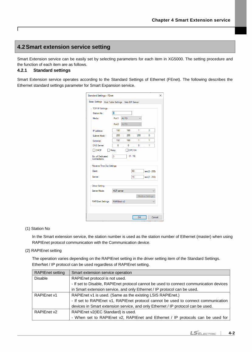
Chapter 4 Smart Extension service
4-2
4.2 Smart extension service setting
Smart Extension service can be easily set by selecting parameters for each item in XG5000. The setting procedure and
the function of each item are as follows.
4.2.1 Standard settings
Smart Extension service operates according to the Standard Settings of Ethernet (FEnet). The following describes the
Ethernet standard settings parameter for Smart Expansion service.
(1) Station No
In the Smart extension service, the station number is used as the station number of Ethernet (master) when using
RAPIEnet protocol communication with the Communication device.
(2) RAPIEnet setting
The operation varies depending on the RAPIEnet setting in the driver setting item of the Standard Settings.
EtherNet / IP protocol can be used regardless of RAPIEnet setting.
RAPIEnet setting Smart extension service operation
Disable RAPIEnet protocol is not used.
- If set to Disable, RAPIEnet protocol cannot be used to connect communication devices
in Smart extension service, and only Ethernet / IP protocol can be used.
RAPIEnet v1 RAPIEnet v1 is used. (Same as the existing LSIS RAPIEnet.)
- If set to RAPIEnet v1, RAPIEnet protocol cannot be used to connect communication
devices in Smart extension service, and only Ethernet / IP protocol can be used.
RAPIEnet v2 RAPIEnet v2(IEC Standard) is used.
- When set to RAPIEnet v2, RAPIEnet and Ethernet / IP protocols can be used for
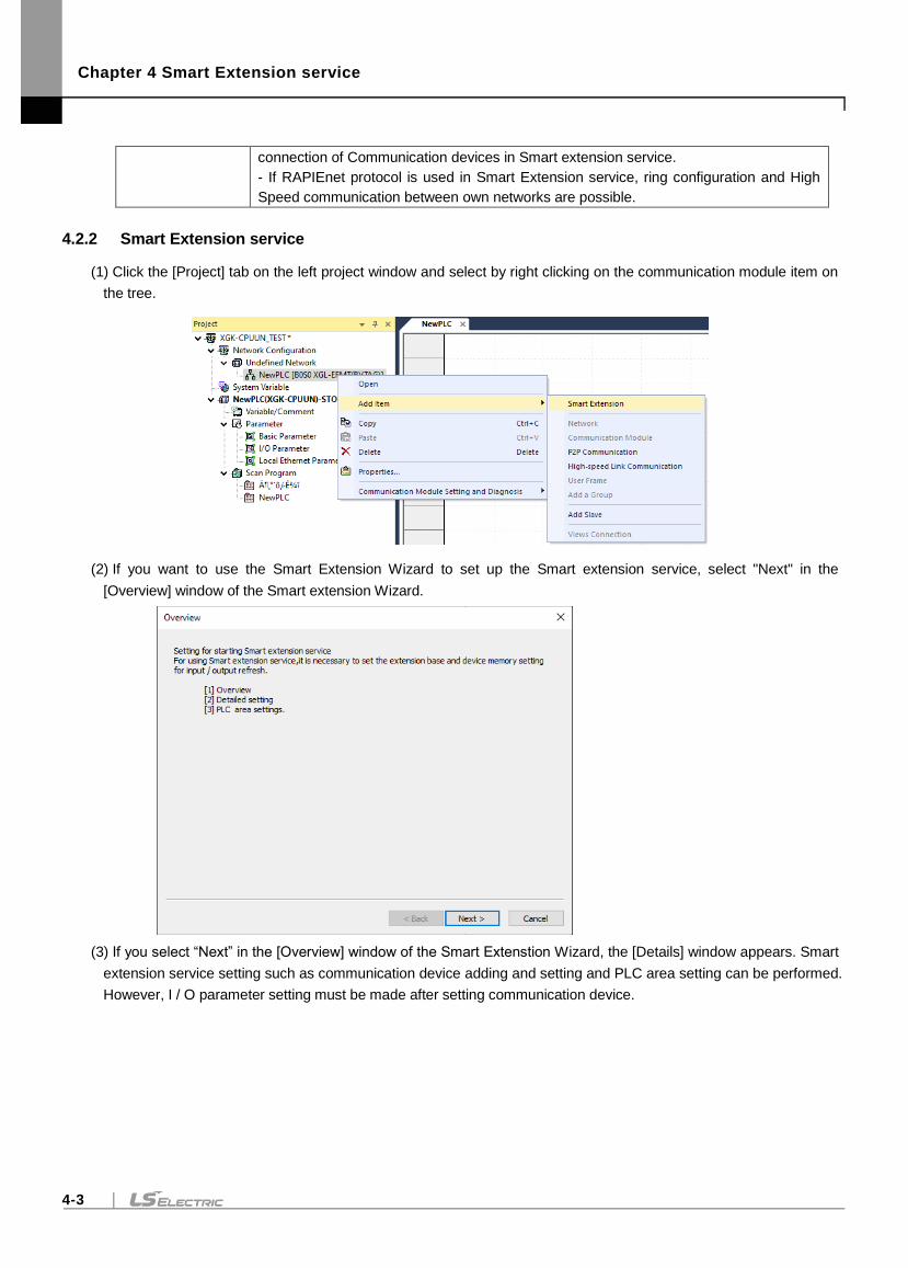
Chapter 4 Smart Extension service
4-3
connection of Communication devices in Smart extension service.
- If RAPIEnet protocol is used in Smart Extension service, ring configuration and High
Speed communication between own networks are possible.
4.2.2 Smart Extension service
(1) Click the [Project] tab on the left project window and select by right clicking on the communication module item on
the tree.
(2) If you want to use the Smart Extension Wizard to set up the Smart extension service, select "Next" in the
[Overview] window of the Smart extension Wizard.
(3) If you select “Next” in the [Overview] window of the Smart Extenstion Wizard, the [Details] window appears. Smart
extension service setting such as communication device adding and setting and PLC area setting can be performed.
However, I / O parameter setting must be made after setting communication device.
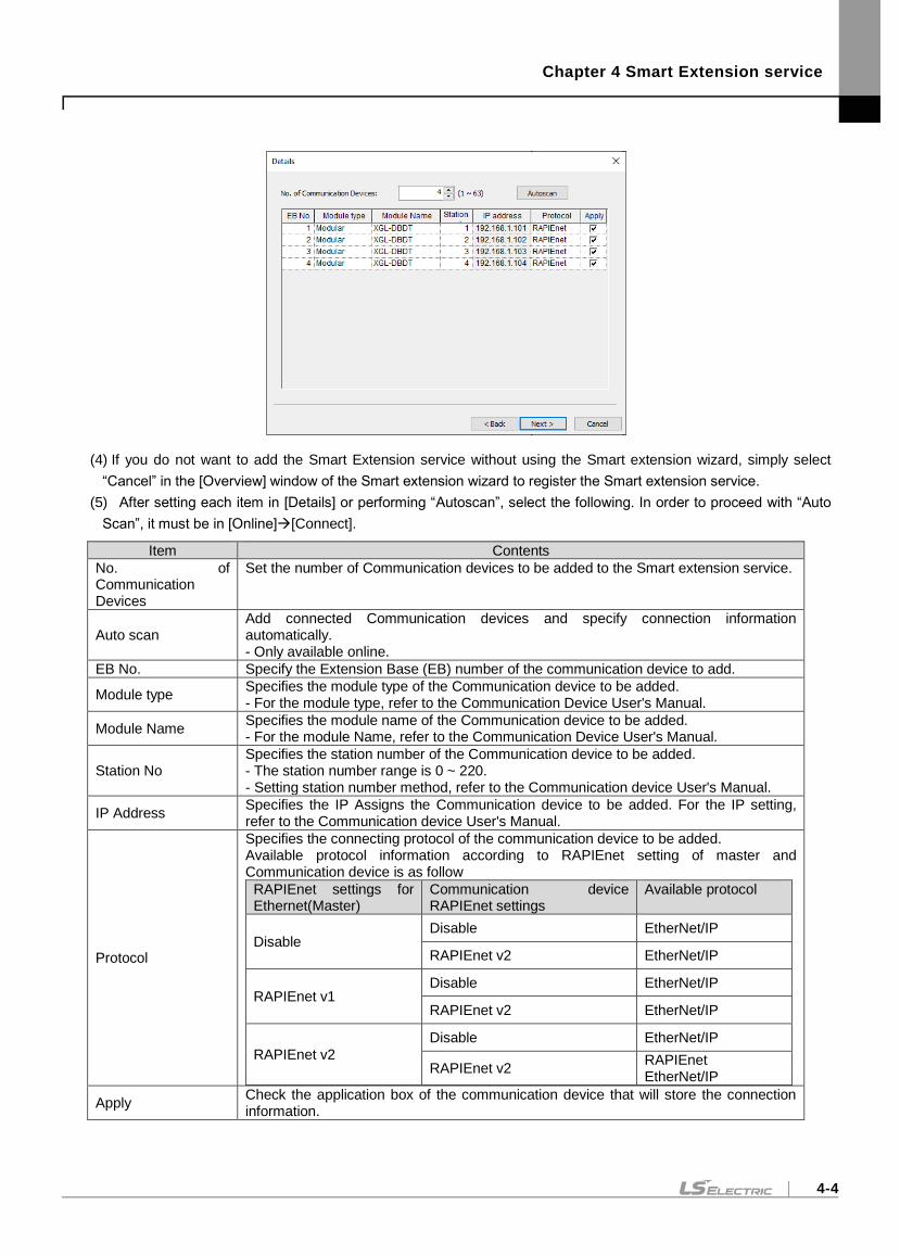
Chapter 4 Smart Extension service
4-4
(4) If you do not want to add the Smart Extension service without using the Smart extension wizard, simply select
“Cancel” in the [Overview] window of the Smart extension wizard to register the Smart extension service.
(5) After setting each item in [Details] or performing “Autoscan”, select the following. In order to proceed with “Auto
Scan”, it must be in [Online][Connect].
Item Contents
No. of Communication Devices
Set the number of Communication devices to be added to the Smart extension service.
Auto scan Add connected Communication devices and specify connection information automatically. - Only available online.
EB No. Specify the Extension Base (EB) number of the communication device to add.
Module type Specifies the module type of the Communication device to be added. - For the module type, refer to the Communication Device User's Manual.
Module Name Specifies the module name of the Communication device to be added. - For the module Name, refer to the Communication Device User's Manual.
Station No Specifies the station number of the Communication device to be added. - The station number range is 0 ~ 220. - Setting station number method, refer to the Communication device User's Manual.
IP Address Specifies the IP Assigns the Communication device to be added. For the IP setting, refer to the Communication device User's Manual.
Protocol
Specifies the connecting protocol of the communication device to be added. Available protocol information according to RAPIEnet setting of master and Communication device is as follow
RAPIEnet settings for Ethernet(Master)
Communication device RAPIEnet settings
Available protocol
Disable Disable EtherNet/IP
RAPIEnet v2 EtherNet/IP
RAPIEnet v1 Disable EtherNet/IP
RAPIEnet v2 EtherNet/IP
RAPIEnet v2
Disable EtherNet/IP
RAPIEnet v2 RAPIEnet EtherNet/IP
Apply Check the application box of the communication device that will store the connection information.
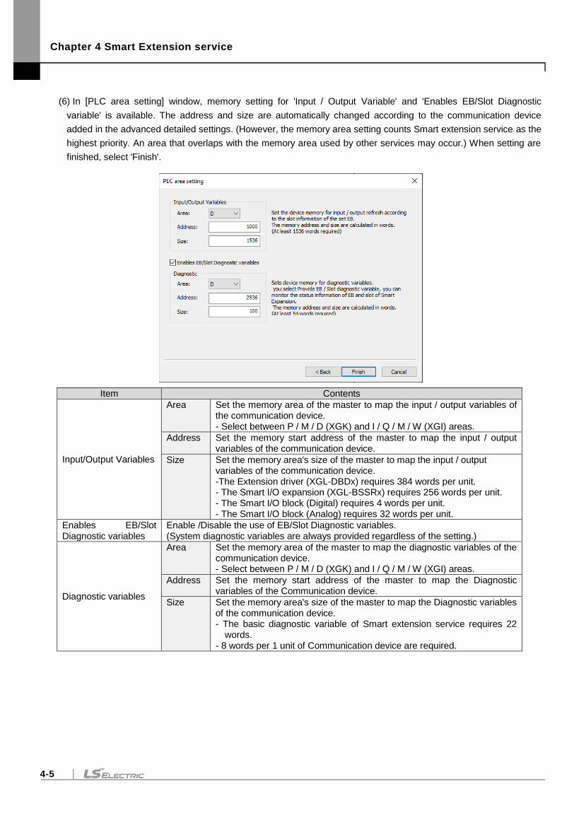
Chapter 4 Smart Extension service
4-5
(6) In [PLC area setting] window, memory setting for 'Input / Output Variable' and 'Enables EB/Slot Diagnostic
variable' is available. The address and size are automatically changed according to the communication device
added in the advanced detailed settings. (However, the memory area setting counts Smart extension service as the
highest priority. An area that overlaps with the memory area used by other services may occur.) When setting are
finished, select 'Finish'.
Item Contents
Input/Output Variables
Area Set the memory area of the master to map the input / output variables of the communication device. - Select between P / M / D (XGK) and I / Q / M / W (XGI) areas.
Address Set the memory start address of the master to map the input / output variables of the communication device.
Size Set the memory area's size of the master to map the input / output variables of the communication device. -The Extension driver (XGL-DBDx) requires 384 words per unit. - The Smart I/O expansion (XGL-BSSRx) requires 256 words per unit. - The Smart I/O block (Digital) requires 4 words per unit. - The Smart I/O block (Analog) requires 32 words per unit.
Enables EB/Slot Diagnostic variables
Enable /Disable the use of EB/Slot Diagnostic variables. (System diagnostic variables are always provided regardless of the setting.)
Diagnostic variables
Area Set the memory area of the master to map the diagnostic variables of the communication device. - Select between P / M / D (XGK) and I / Q / M / W (XGI) areas.
Address Set the memory start address of the master to map the Diagnostic variables of the Communication device.
Size Set the memory area's size of the master to map the Diagnostic variables of the communication device. - The basic diagnostic variable of Smart extension service requires 22
words. - 8 words per 1 unit of Communication device are required.
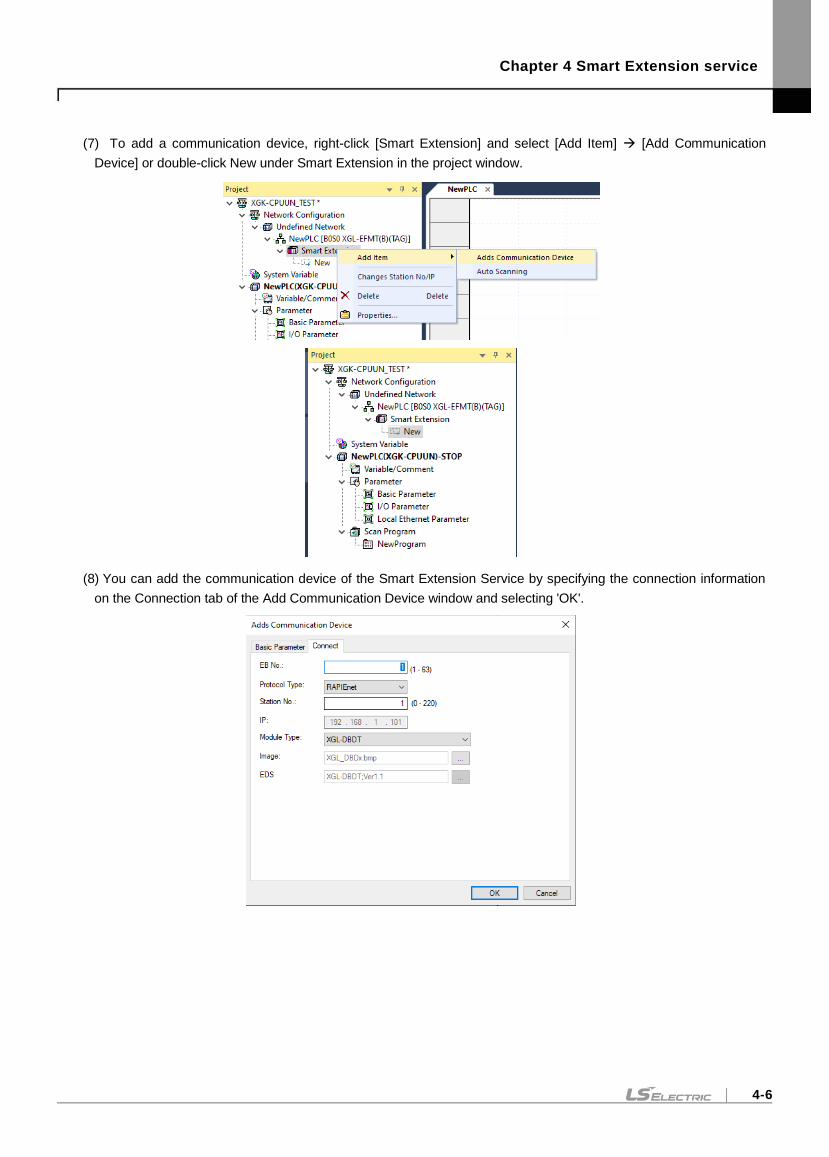
Chapter 4 Smart Extension service
4-6
(7) To add a communication device, right-click [Smart Extension] and select [Add Item] [Add Communication
Device] or double-click New under Smart Extension in the project window.
(8) You can add the communication device of the Smart Extension Service by specifying the connection information
on the Connection tab of the Add Communication Device window and selecting 'OK'.
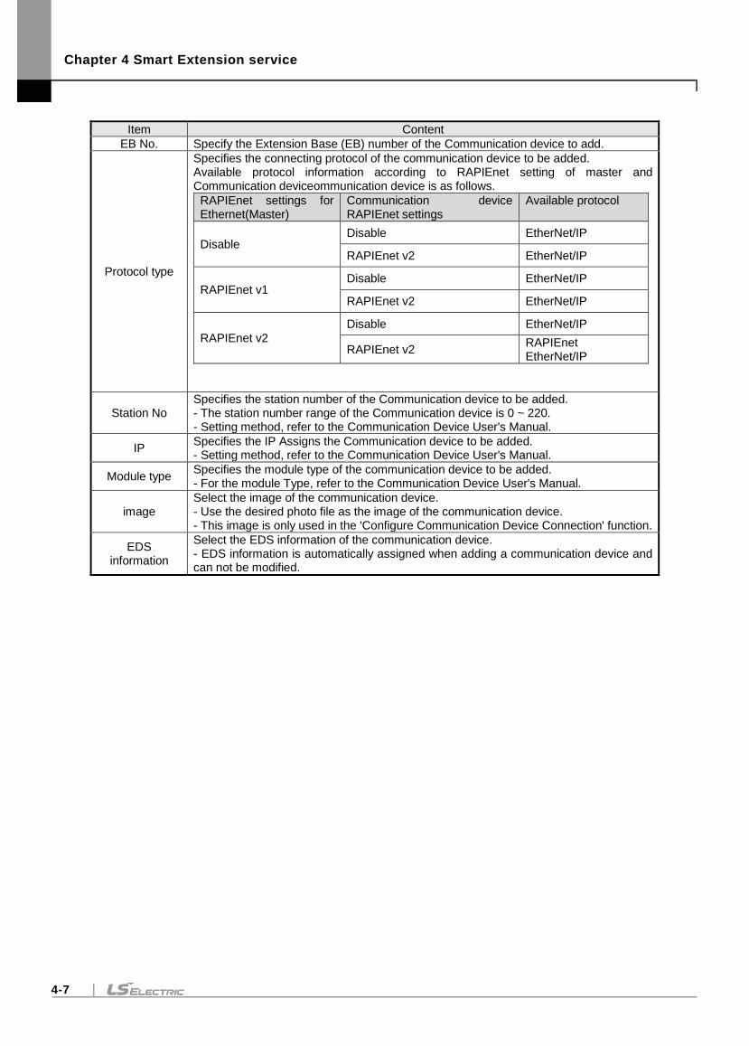
Chapter 4 Smart Extension service
4-7
Item Content
EB No. Specify the Extension Base (EB) number of the Communication device to add.
Protocol type
Specifies the connecting protocol of the communication device to be added. Available protocol information according to RAPIEnet setting of master and Communication deviceommunication device is as follows.
RAPIEnet settings for Ethernet(Master)
Communication device RAPIEnet settings
Available protocol
Disable Disable EtherNet/IP
RAPIEnet v2 EtherNet/IP
RAPIEnet v1 Disable EtherNet/IP
RAPIEnet v2 EtherNet/IP
RAPIEnet v2
Disable EtherNet/IP
RAPIEnet v2 RAPIEnet EtherNet/IP
Station No Specifies the station number of the Communication device to be added. - The station number range of the Communication device is 0 ~ 220. - Setting method, refer to the Communication Device User's Manual.
IP Specifies the IP Assigns the Communication device to be added. - Setting method, refer to the Communication Device User's Manual.
Module type Specifies the module type of the communication device to be added. - For the module Type, refer to the Communication Device User's Manual.
image Select the image of the communication device. - Use the desired photo file as the image of the communication device. - This image is only used in the 'Configure Communication Device Connection' function.
EDS information
Select the EDS information of the communication device. - EDS information is automatically assigned when adding a communication device and can not be modified.
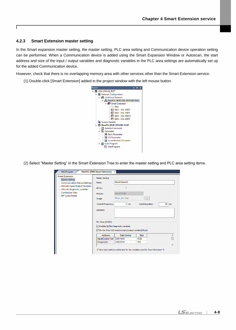
Chapter 4 Smart Extension service
4-8
4.2.3 Smart Extension master setting
In the Smart expansion master setting, the master setting, PLC area setting and Communication device operation setting
can be performed. When a Communication device is added using the Smart Expansion Window or Autoscan, the start
address and size of the input / output variables and diagnostic variables in the PLC area settings are automatically set up
for the added Communication device.
However, check that there is no overlapping memory area with other services other than the Smart Extension service.
(1) Double-click [Smart Extension] added in the project window with the left mouse button.
(2) Select “Master Setting” in the Smart Extension Tree to enter the master setting and PLC area setting items.
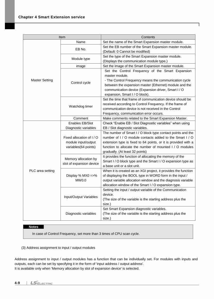
Chapter 4 Smart Extension service
4-9
Item Contents
Master Setting
Name Set the name of the Smart Expansion master module.
EB No. Set the EB number of the Smart Expansion master module.
(Default: 0 Cannot be modified)
Module type Set the type of the Smart Expansion master module.
(Displays the communication module type.)
image Set the image of the Smart Expansion master module.
Control cycle
Set the Control Frequency of the Smart Expansion
master module.
- The Control Frequency means the communication cycle
between the expansion master (Ethernet) module and the
communication device (Expansion driver, Smart I / O
expansion, Smart I / O block).
Watchdog timer
Set the time that frame of communication device should be
received according to Control Frequency. If the frame of
communication device is not received in the Control
Frequency, communication error occurs.
Comment Make comments related to the Smart Expansion Master.
PLC area setting
Enables EB/Slot
Diagnostic variables
Check “Enable EB / Slot Diagnostic variables” when using
EB / Slot diagnostic variables.
Fixed allocation of I / O
module input/output
variables(64 points)
The number of Smart I / O block type contact points and the
number of I / O module contacts added to the Smart I / O
extension type is fixed to 64 points, or it is provided with a
function to allocate the number of mounted I / O modules
gradually. (At least 32 points)
Memory allocation by
slot of expansion device
It provides the function of allocating the memory of the
Smart I / O block type and the Smart I / O expansion type as
a base unit or a slot unit.
Display % MX0 =>%
MW0.0
When it is created as an XGI project, it provides the function
of displaying the BOOL type in WORD form in the input /
output variable allocation window and the diagnosis variable
allocation window of the Smart I / O expansion type.
Input/Output Variables
Setting the input / output variable of the Communication
device.
(The size of the variable is the starting address plus the
size.)
Diagnostic variables
Set Smart Expansion diagnostic variables.
(The size of the variable is the starting address plus the
size.)
Notes
In case of Control Frequency, set more than 3 times of CPU scan cycle.
(3) Address assignment to input / output modules
Address assignment to input / output modules has a function that can be individually set. For modules with inputs and
outputs, each can be set by specifying it in the form of 'input address / output address'.
It is available only when 'Memory allocation by slot of expansion device' is selected.
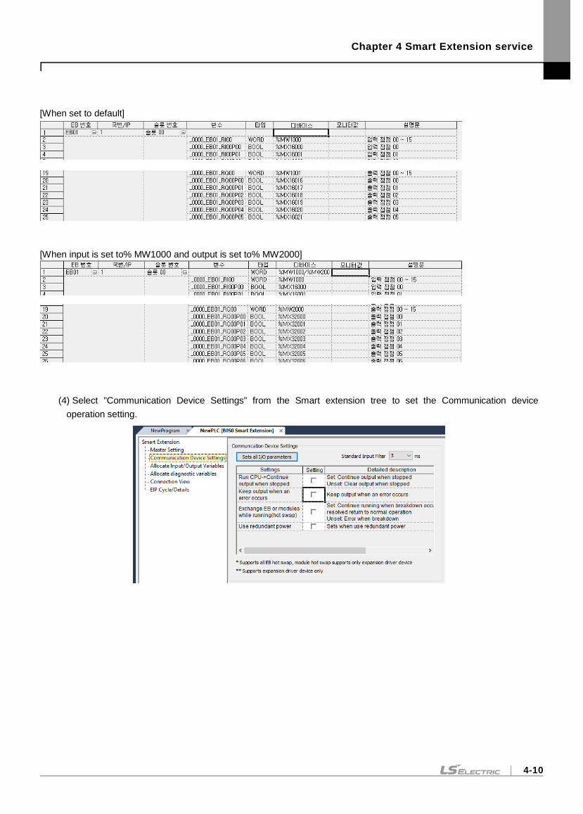
Chapter 4 Smart Extension service
4-10
[When set to default]
[When input is set to% MW1000 and output is set to% MW2000]
(4) Select "Communication Device Settings" from the Smart extension tree to set the Communication device
operation setting.
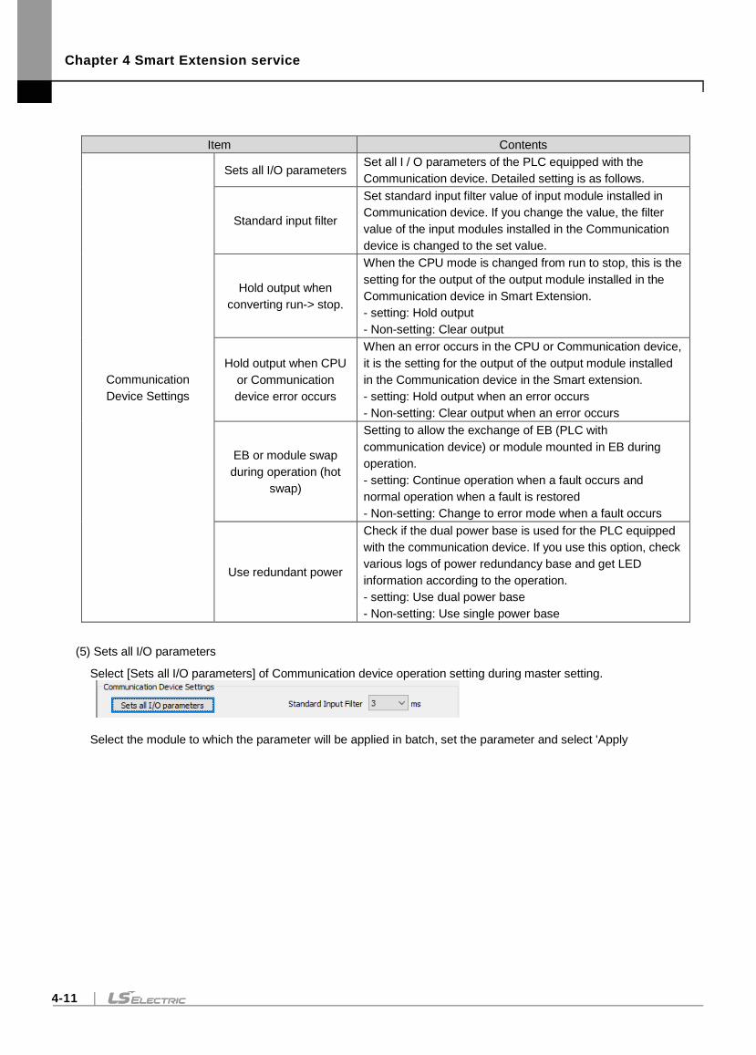
Chapter 4 Smart Extension service
4-11
Item Contents
Communication
Device Settings
Sets all I/O parameters Set all I / O parameters of the PLC equipped with the
Communication device. Detailed setting is as follows.
Standard input filter
Set standard input filter value of input module installed in
Communication device. If you change the value, the filter
value of the input modules installed in the Communication
device is changed to the set value.
Hold output when
converting run-> stop.
When the CPU mode is changed from run to stop, this is the
setting for the output of the output module installed in the
Communication device in Smart Extension.
- setting: Hold output
- Non-setting: Clear output
Hold output when CPU
or Communication
device error occurs
When an error occurs in the CPU or Communication device,
it is the setting for the output of the output module installed
in the Communication device in the Smart extension.
- setting: Hold output when an error occurs
- Non-setting: Clear output when an error occurs
EB or module swap
during operation (hot
swap)
Setting to allow the exchange of EB (PLC with
communication device) or module mounted in EB during
operation.
- setting: Continue operation when a fault occurs and
normal operation when a fault is restored
- Non-setting: Change to error mode when a fault occurs
Use redundant power
Check if the dual power base is used for the PLC equipped
with the communication device. If you use this option, check
various logs of power redundancy base and get LED
information according to the operation.
- setting: Use dual power base
- Non-setting: Use single power base
(5) Sets all I/O parameters
Select [Sets all I/O parameters] of Communication device operation setting during master setting.
Select the module to which the parameter will be applied in batch, set the parameter and select 'Apply
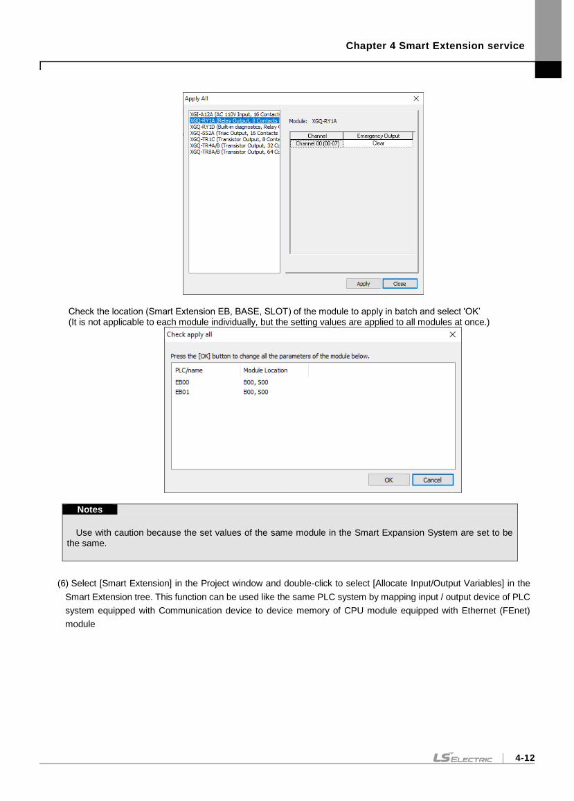
Chapter 4 Smart Extension service
4-12
Check the location (Smart Extension EB, BASE, SLOT) of the module to apply in batch and select 'OK’ (It is not applicable to each module individually, but the setting values are applied to all modules at once.)
Notes
Use with caution because the set values of the same module in the Smart Expansion System are set to be the same.
(6) Select [Smart Extension] in the Project window and double-click to select [Allocate Input/Output Variables] in the
Smart Extension tree. This function can be used like the same PLC system by mapping input / output device of PLC
system equipped with Communication device to device memory of CPU module equipped with Ethernet (FEnet)
module
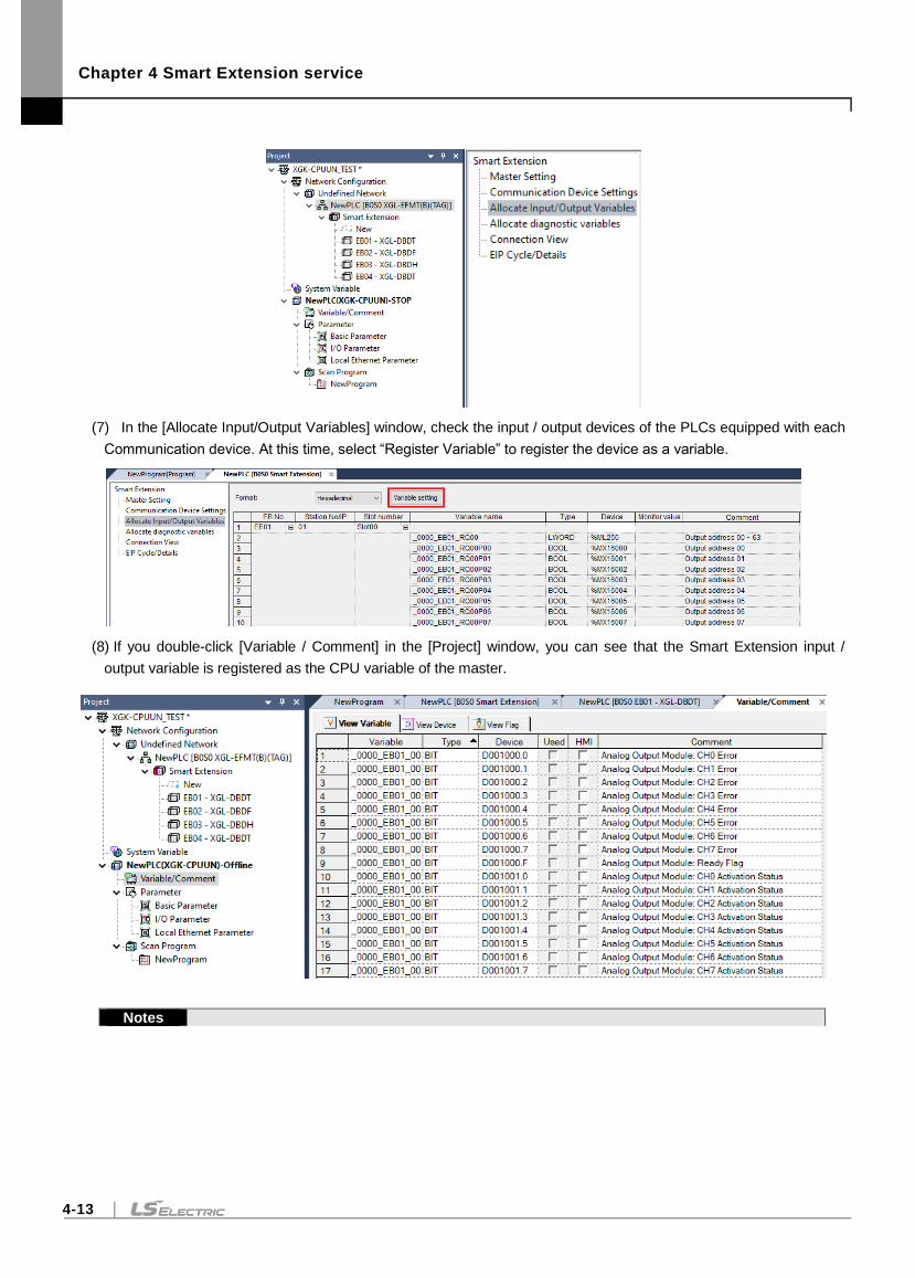
Chapter 4 Smart Extension service
4-13
(7) In the [Allocate Input/Output Variables] window, check the input / output devices of the PLCs equipped with each
Communication device. At this time, select “Register Variable” to register the device as a variable.
(8) If you double-click [Variable / Comment] in the [Project] window, you can see that the Smart Extension input /
output variable is registered as the CPU variable of the master.
Notes
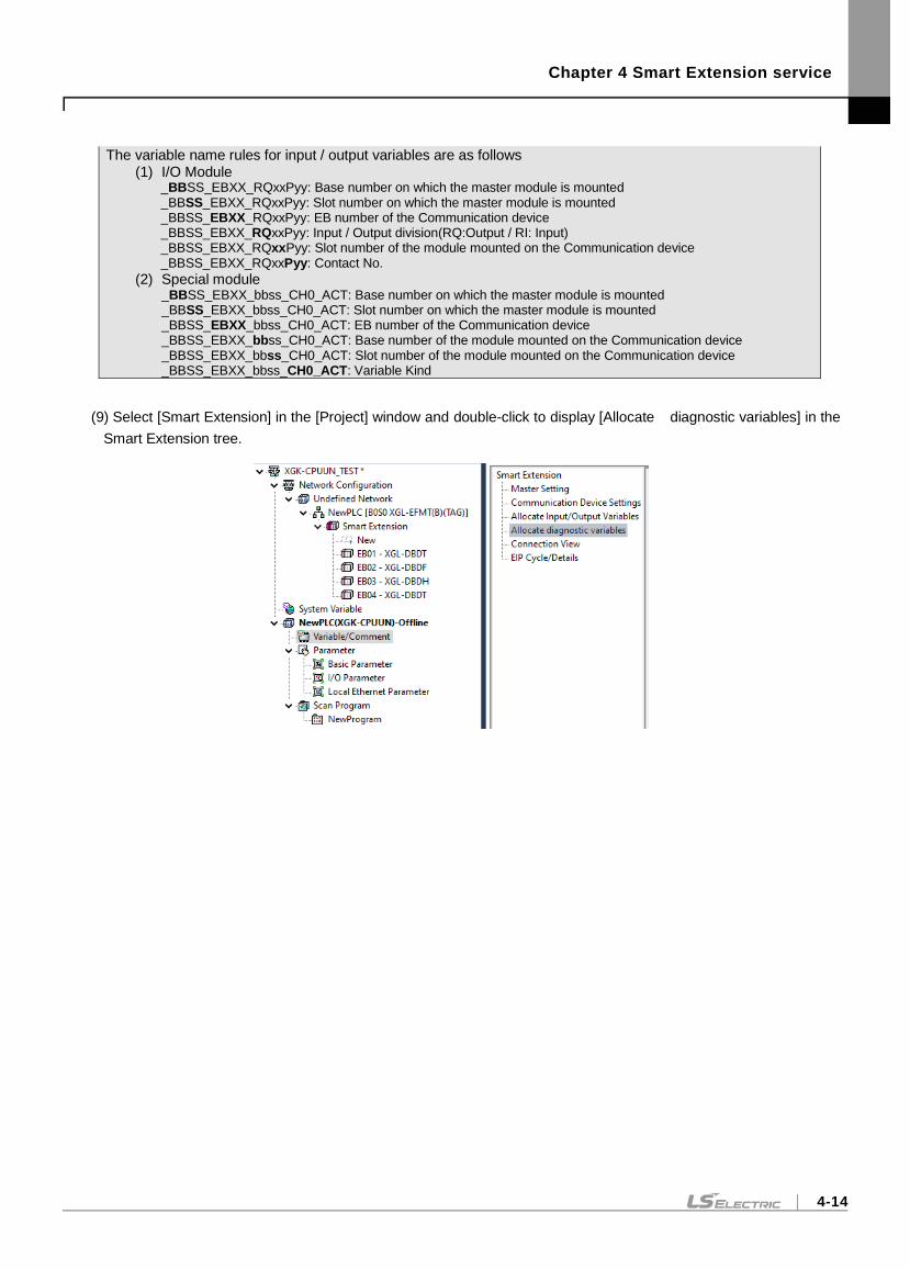
Chapter 4 Smart Extension service
4-14
The variable name rules for input / output variables are as follows (1) I/O Module
_BBSS_EBXX_RQxxPyy: Base number on which the master module is mounted _BBSS_EBXX_RQxxPyy: Slot number on which the master module is mounted _BBSS_EBXX_RQxxPyy: EB number of the Communication device _BBSS_EBXX_RQxxPyy: Input / Output division(RQ:Output / RI: Input) _BBSS_EBXX_RQxxPyy: Slot number of the module mounted on the Communication device _BBSS_EBXX_RQxxPyy: Contact No.
(2) Special module _BBSS_EBXX_bbss_CH0_ACT: Base number on which the master module is mounted _BBSS_EBXX_bbss_CH0_ACT: Slot number on which the master module is mounted _BBSS_EBXX_bbss_CH0_ACT: EB number of the Communication device _BBSS_EBXX_bbss_CH0_ACT: Base number of the module mounted on the Communication device _BBSS_EBXX_bbss_CH0_ACT: Slot number of the module mounted on the Communication device _BBSS_EBXX_bbss_CH0_ACT: Variable Kind
(9) Select [Smart Extension] in the [Project] window and double-click to display [Allocate diagnostic variables] in the
Smart Extension tree.
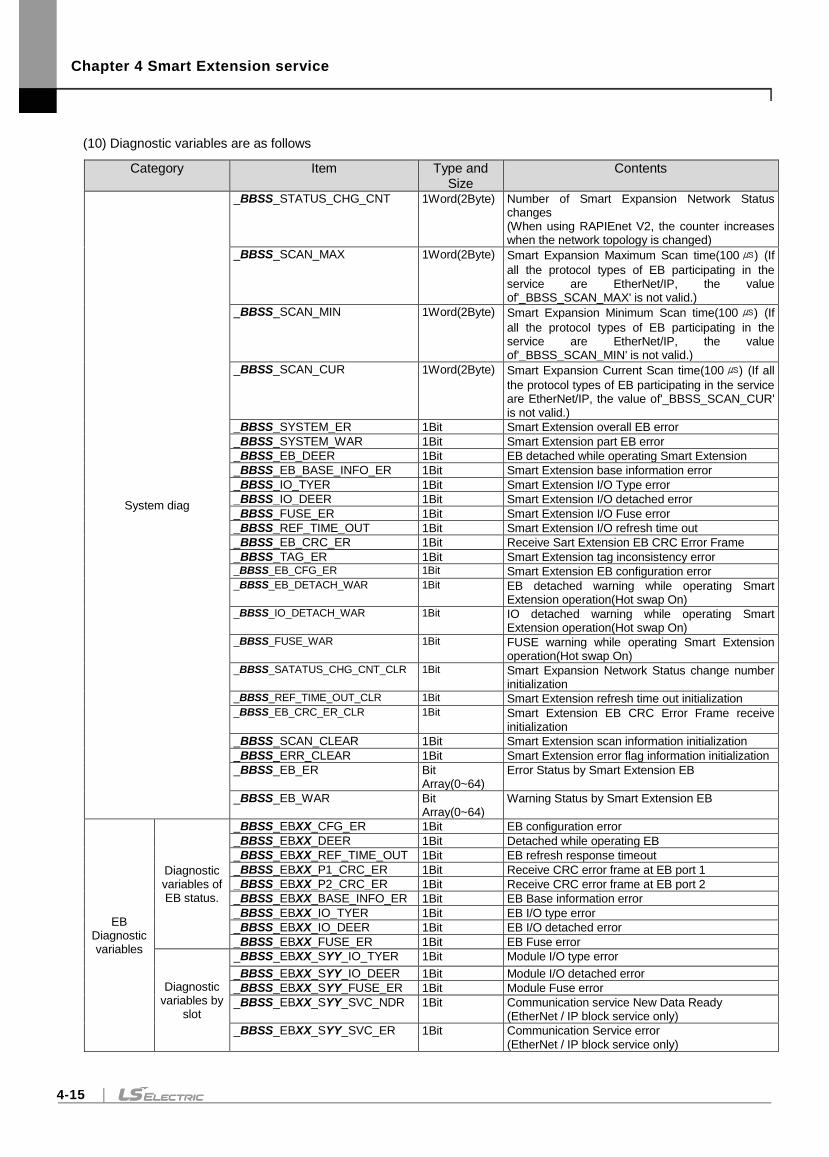
Chapter 4 Smart Extension service
4-15
(10) Diagnostic variables are as follows
Category Item Type and Size
Contents
System diag
_BBSS_STATUS_CHG_CNT 1Word(2Byte) Number of Smart Expansion Network Status changes (When using RAPIEnet V2, the counter increases when the network topology is changed)
_BBSS_SCAN_MAX 1Word(2Byte) Smart Expansion Maximum Scan time(100 ) (If
all the protocol types of EB participating in the service are EtherNet/IP, the value of'_BBSS_SCAN_MAX' is not valid.)
_BBSS_SCAN_MIN 1Word(2Byte) Smart Expansion Minimum Scan time(100 ) (If
all the protocol types of EB participating in the service are EtherNet/IP, the value of'_BBSS_SCAN_MIN' is not valid.)
_BBSS_SCAN_CUR 1Word(2Byte) Smart Expansion Current Scan time(100 ) (If all
the protocol types of EB participating in the service are EtherNet/IP, the value of'_BBSS_SCAN_CUR' is not valid.)
_BBSS_SYSTEM_ER 1Bit Smart Extension overall EB error
_BBSS_SYSTEM_WAR 1Bit Smart Extension part EB error
_BBSS_EB_DEER 1Bit EB detached while operating Smart Extension
_BBSS_EB_BASE_INFO_ER 1Bit Smart Extension base information error
_BBSS_IO_TYER 1Bit Smart Extension I/O Type error
_BBSS_IO_DEER 1Bit Smart Extension I/O detached error
_BBSS_FUSE_ER 1Bit Smart Extension I/O Fuse error
_BBSS_REF_TIME_OUT 1Bit Smart Extension I/O refresh time out
_BBSS_EB_CRC_ER 1Bit Receive Sart Extension EB CRC Error Frame
_BBSS_TAG_ER 1Bit Smart Extension tag inconsistency error _BBSS_EB_CFG_ER 1Bit Smart Extension EB configuration error _BBSS_EB_DETACH_WAR 1Bit EB detached warning while operating Smart
Extension operation(Hot swap On) _BBSS_IO_DETACH_WAR 1Bit IO detached warning while operating Smart
Extension operation(Hot swap On) _BBSS_FUSE_WAR 1Bit FUSE warning while operating Smart Extension
operation(Hot swap On) _BBSS_SATATUS_CHG_CNT_CLR 1Bit Smart Expansion Network Status change number
initialization _BBSS_REF_TIME_OUT_CLR 1Bit Smart Extension refresh time out initialization _BBSS_EB_CRC_ER_CLR 1Bit Smart Extension EB CRC Error Frame receive
initialization
_BBSS_SCAN_CLEAR 1Bit Smart Extension scan information initialization
_BBSS_ERR_CLEAR 1Bit Smart Extension error flag information initialization
_BBSS_EB_ER Bit Array(0~64)
Error Status by Smart Extension EB
_BBSS_EB_WAR Bit Array(0~64)
Warning Status by Smart Extension EB
EB Diagnostic variables
Diagnostic variables of EB status.
_BBSS_EBXX_CFG_ER 1Bit EB configuration error
_BBSS_EBXX_DEER 1Bit Detached while operating EB
_BBSS_EBXX_REF_TIME_OUT 1Bit EB refresh response timeout
_BBSS_EBXX_P1_CRC_ER 1Bit Receive CRC error frame at EB port 1
_BBSS_EBXX_P2_CRC_ER 1Bit Receive CRC error frame at EB port 2
_BBSS_EBXX_BASE_INFO_ER 1Bit EB Base information error
_BBSS_EBXX_IO_TYER 1Bit EB I/O type error
_BBSS_EBXX_IO_DEER 1Bit EB I/O detached error
_BBSS_EBXX_FUSE_ER 1Bit EB Fuse error
Diagnostic variables by
slot
_BBSS_EBXX_SYY_IO_TYER 1Bit Module I/O type error
_BBSS_EBXX_SYY_IO_DEER 1Bit Module I/O detached error
_BBSS_EBXX_SYY_FUSE_ER 1Bit Module Fuse error
_BBSS_EBXX_SYY_SVC_NDR 1Bit Communication service New Data Ready (EtherNet / IP block service only)
_BBSS_EBXX_SYY_SVC_ER 1Bit Communication Service error (EtherNet / IP block service only)
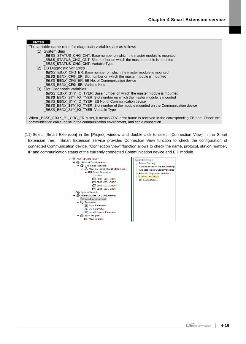
Chapter 4 Smart Extension service
4-16
Notes
The variable name rules for diagnostic variables are as follows (1) System diag
_BBSS_STATUS_CHG_CNT: Base number on which the master module is mounted _BBSS_STATUS_CHG_CNT: Slot number on which the master module is mounted _BBSS_STATUS_CHG_CNT: Variable Type
(2) EB Diagnostic variables _BBSS_EBXX_CFG_ER: Base number on which the master module is mounted _BBSS_EBXX_CFG_ER: Slot number on which the master module is mounted _BBSS_EBXX_CFG_ER: EB No. of Communication device _BBSS_EBXX_CFG_ER: Variable Kind
(3) Slot Diagnostic variables _BBSS_EBXX_SYY_IO_TYER: Base number on which the master module is mounted _BBSS_EBXX_SYY_IO_TYER: Slot number on which the master module is mounted _BBSS_EBXX_SYY_IO_TYER: EB No. of Communication device _BBSS_EBXX_SYY_IO_TYER: Slot number of the module mounted on the Communication device _BBSS_EBXX_SYY_IO_TYER: Variable Type
When _BBSS_EBXX_P1_CRC_ER is set, it means CRC error frame is received in the corresponding EB port. Check the communication cable, noise in the communication environment, and cable connection.
(11) Select [Smart Extension] in the [Project] window and double-click to select [Connection View] in the Smart
Extension tree. Smart Extension service provides Connection View function to check the configuration of
connected Communication device. “Connection View” 'function allows to check the name, protocol, station number,
IP and communication status of the currently connected Communication device and EIP module.
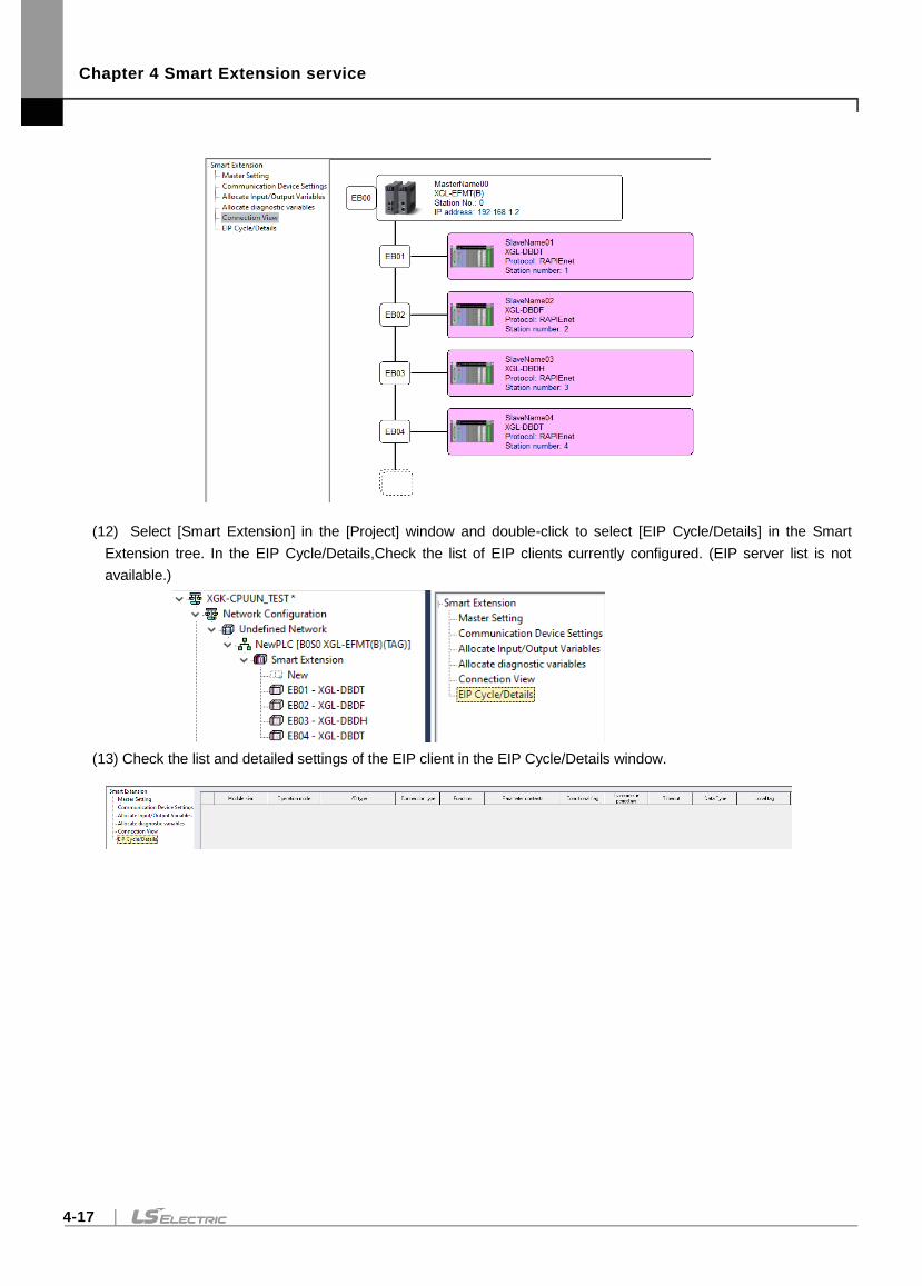
Chapter 4 Smart Extension service
4-17
(12) Select [Smart Extension] in the [Project] window and double-click to select [EIP Cycle/Details] in the Smart
Extension tree. In the EIP Cycle/Details,Check the list of EIP clients currently configured. (EIP server list is not
available.)
(13) Check the list and detailed settings of the EIP client in the EIP Cycle/Details window.
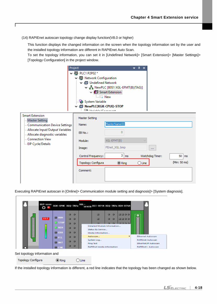
Chapter 4 Smart Extension service
4-18
(14) RAPIEnet autoscan topology change display function(V8.0 or higher)
This function displays the changed information on the screen when the topology information set by the user and
the installed topology information are different in RAPIEnet Auto Scan.
To set the topology information, you can set it in [Undefined Network]> [Smart Extension]> [Master Settings]>
[Topology Configuration] in the project window.
Executing RAPIEnet autoscan in [Online]> Communication module setting and diagnosis]> [System diagnosis].
Set topology information and
If the installed topology information is different, a red line indicates that the topology has been changed as shown below.
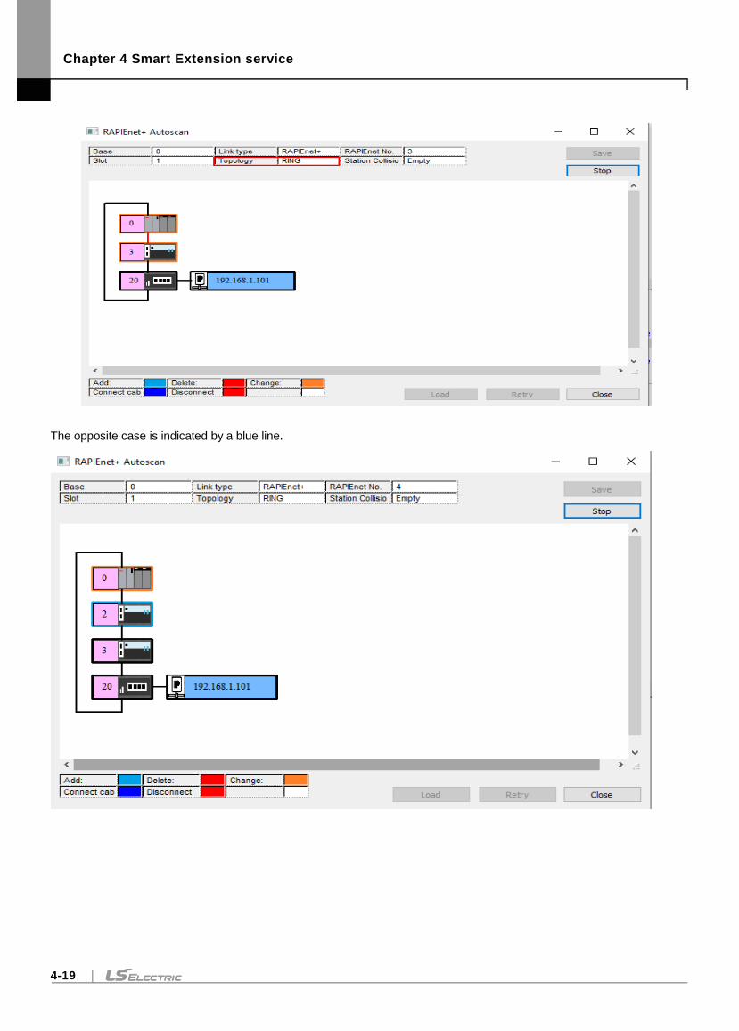
Chapter 4 Smart Extension service
4-19
The opposite case is indicated by a blue line.
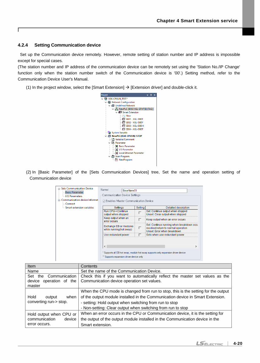
Chapter 4 Smart Extension service
4-20
4.2.4 Setting Communication device
Set up the Communication device remotely. However, remote setting of station number and IP address is impossible
except for special cases.
(The station number and IP address of the communication device can be remotely set using the 'Station No./IP Change'
function only when the station number switch of the Communication device is '00'.) Setting method, refer to the
Communication Device User's Manual.
(1) In the project window, select the [Smart Extension] [Extension driver] and double-click it.
(2) In [Basic Parameter] of the [Sets Communication Devices] tree, Set the name and operation setting of
Communication device
Item Contents
Name Set the name of the Communication Device.
Set the Communication device operation of the master
Check this if you want to automatically reflect the master set values as the Communication device operation set values.
Hold output when converting run-> stop.
When the CPU mode is changed from run to stop, this is the setting for the output
of the output module installed in the Communication device in Smart Extension.
- setting: Hold output when switching from run to stop
- Non-setting: Clear output when switching from run to stop
Hold output when CPU or communication device error occurs.
When an error occurs in the CPU or Communication device, it is the setting for
the output of the output module installed in the Communication device in the
Smart extension.
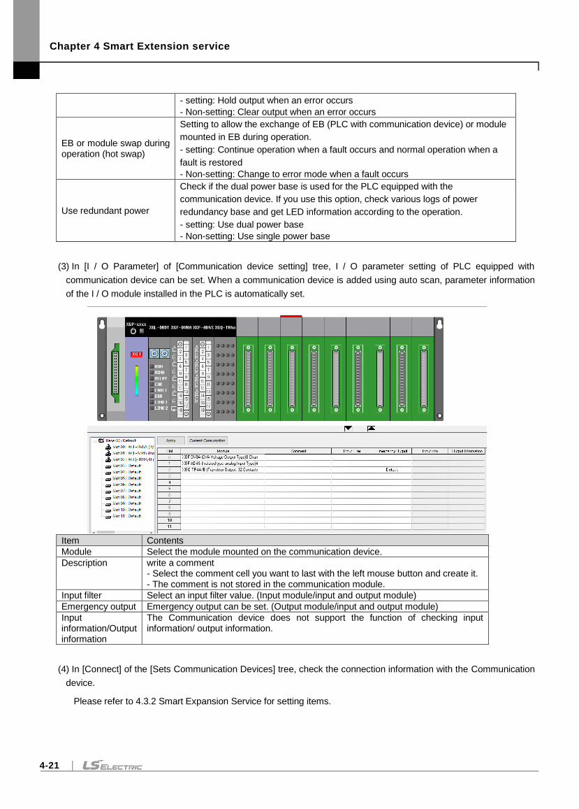
Chapter 4 Smart Extension service
4-21
- setting: Hold output when an error occurs
- Non-setting: Clear output when an error occurs
EB or module swap during operation (hot swap)
Setting to allow the exchange of EB (PLC with communication device) or module
mounted in EB during operation.
- setting: Continue operation when a fault occurs and normal operation when a
fault is restored
- Non-setting: Change to error mode when a fault occurs
Use redundant power
Check if the dual power base is used for the PLC equipped with the
communication device. If you use this option, check various logs of power
redundancy base and get LED information according to the operation.
- setting: Use dual power base
- Non-setting: Use single power base
(3) In [I / O Parameter] of [Communication device setting] tree, I / O parameter setting of PLC equipped with
communication device can be set. When a communication device is added using auto scan, parameter information
of the I / O module installed in the PLC is automatically set.
Item Contents
Module Select the module mounted on the communication device.
Description write a comment - Select the comment cell you want to last with the left mouse button and create it. - The comment is not stored in the communication module.
Input filter Select an input filter value. (Input module/input and output module)
Emergency output Emergency output can be set. (Output module/input and output module)
Input information/Output information
The Communication device does not support the function of checking input information/ output information.
(4) In [Connect] of the [Sets Communication Devices] tree, check the connection information with the Communication
device.
Please refer to 4.3.2 Smart Expansion Service for setting items.
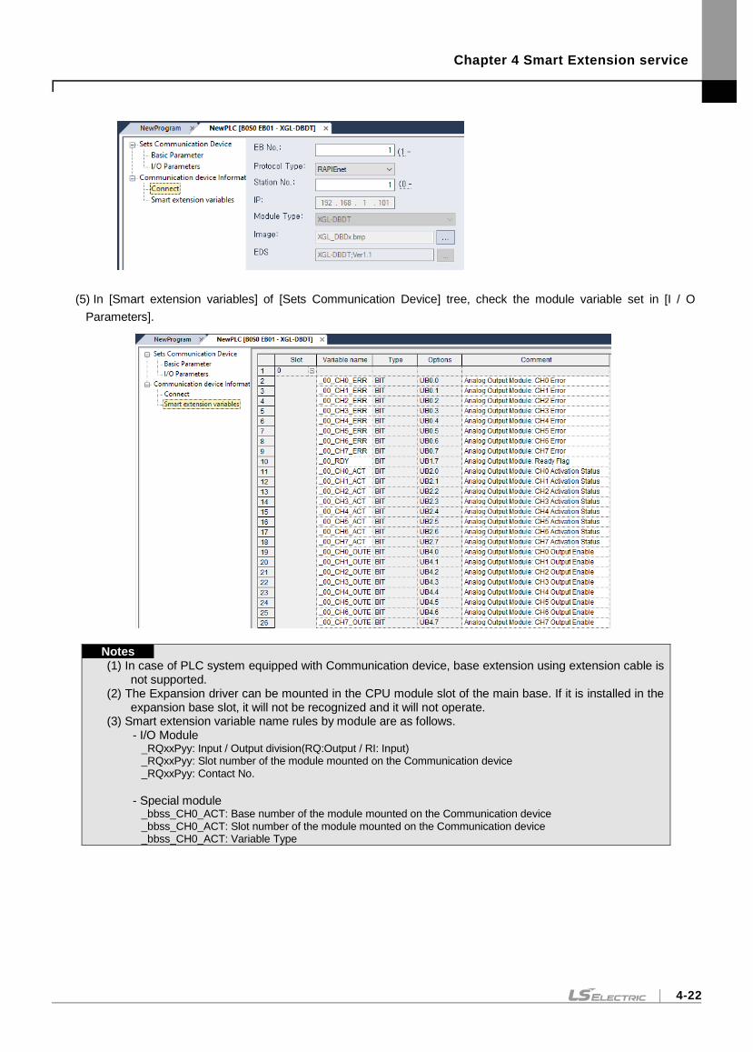
Chapter 4 Smart Extension service
4-22
(5) In [Smart extension variables] of [Sets Communication Device] tree, check the module variable set in [I / O
Parameters].
Notes
(1) In case of PLC system equipped with Communication device, base extension using extension cable is not supported.
(2) The Expansion driver can be mounted in the CPU module slot of the main base. If it is installed in the expansion base slot, it will not be recognized and it will not operate.
(3) Smart extension variable name rules by module are as follows. - I/O Module
_RQxxPyy: Input / Output division(RQ:Output / RI: Input) _RQxxPyy: Slot number of the module mounted on the Communication device _RQxxPyy: Contact No.
- Special module
_bbss_CH0_ACT: Base number of the module mounted on the Communication device _bbss_CH0_ACT: Slot number of the module mounted on the Communication device _bbss_CH0_ACT: Variable Type
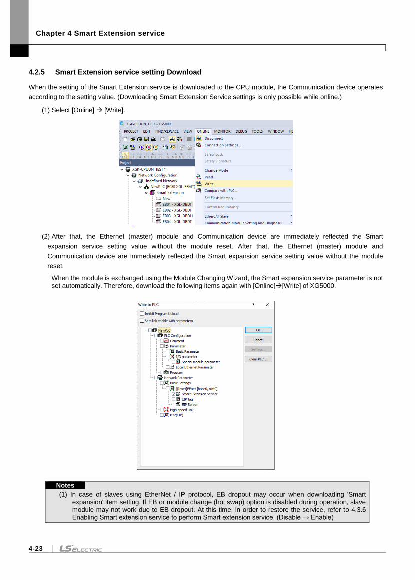
Chapter 4 Smart Extension service
4-23
4.2.5 Smart Extension service setting Download
When the setting of the Smart Extension service is downloaded to the CPU module, the Communication device operates
according to the setting value. (Downloading Smart Extension Service settings is only possible while online.)
(1) Select [Online] [Write].
(2) After that, the Ethernet (master) module and Communication device are immediately reflected the Smart
expansion service setting value without the module reset. After that, the Ethernet (master) module and
Communication device are immediately reflected the Smart expansion service setting value without the module
reset.
When the module is exchanged using the Module Changing Wizard, the Smart expansion service parameter is not set automatically. Therefore, download the following items again with [Online][Write] of XG5000.
Notes
(1) In case of slaves using EtherNet / IP protocol, EB dropout may occur when downloading 'Smart expansion' item setting. If EB or module change (hot swap) option is disabled during operation, slave module may not work due to EB dropout. At this time, in order to restore the service, refer to 4.3.6 Enabling Smart extension service to perform Smart extension service. (Disable → Enable)
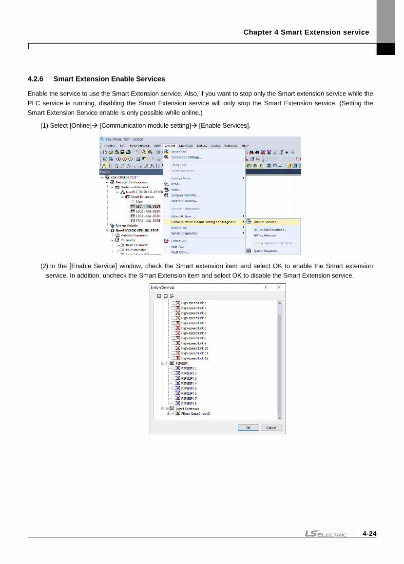
Chapter 4 Smart Extension service
4-24
4.2.6 Smart Extension Enable Services
Enable the service to use the Smart Extension service. Also, if you want to stop only the Smart extension service while the
PLC service is running, disabling the Smart Extension service will only stop the Smart Extension service. (Setting the
Smart Extension Service enable is only possible while online.)
(1) Select [Online] [Communication module setting] [Enable Services].
(2) In the [Enable Service] window, check the Smart extension item and select OK to enable the Smart extension
service. In addition, uncheck the Smart Extension item and select OK to disable the Smart Extension service.
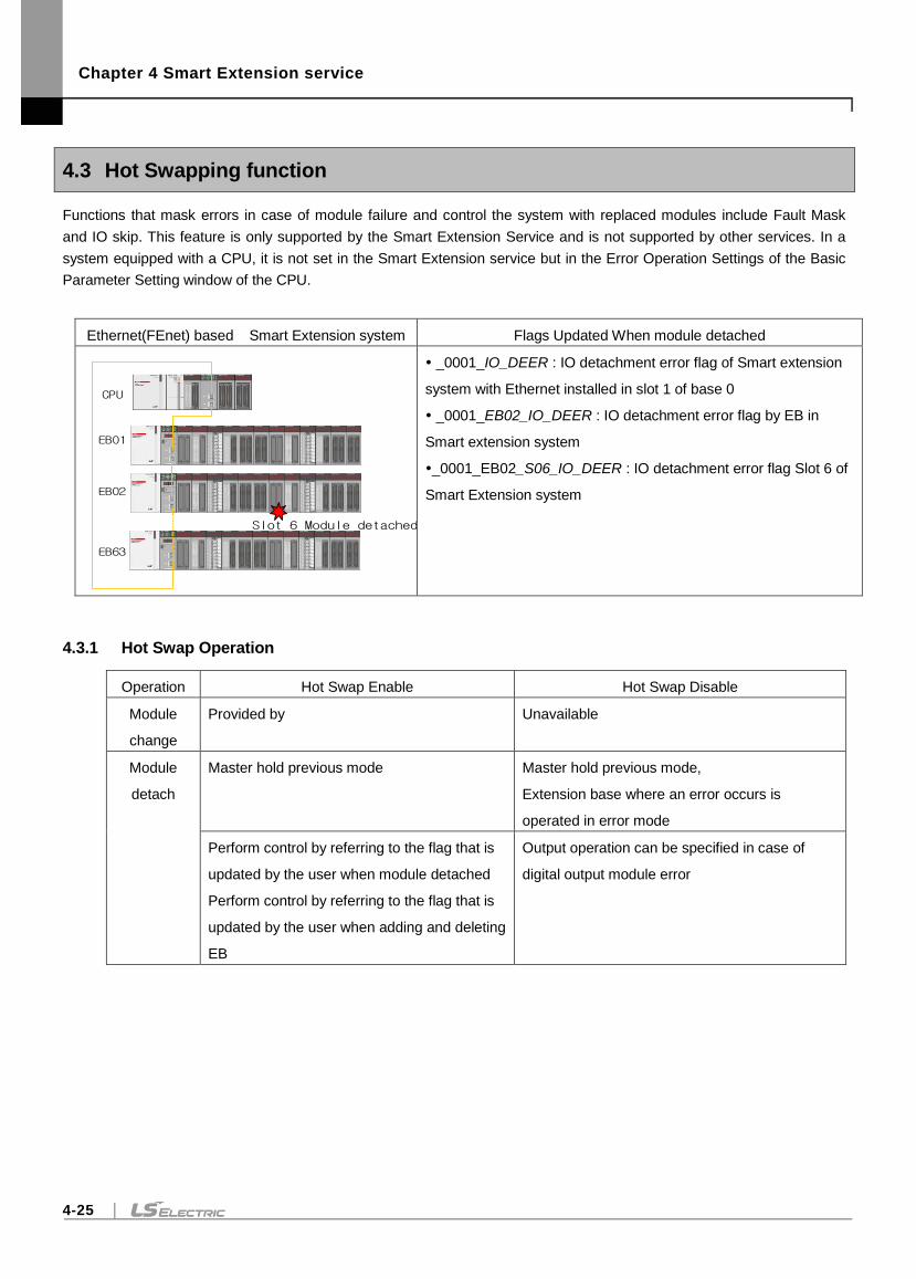
Chapter 4 Smart Extension service
4-25
4.3 Hot Swapping function
Functions that mask errors in case of module failure and control the system with replaced modules include Fault Mask
and IO skip. This feature is only supported by the Smart Extension Service and is not supported by other services. In a
system equipped with a CPU, it is not set in the Smart Extension service but in the Error Operation Settings of the Basic
Parameter Setting window of the CPU.
Ethernet(FEnet) based Smart Extension system Flags Updated When module detached
_0001_IO_DEER : IO detachment error flag of Smart extension
system with Ethernet installed in slot 1 of base 0
_0001_EB02_IO_DEER : IO detachment error flag by EB in
Smart extension system
_0001_EB02_S06_IO_DEER : IO detachment error flag Slot 6 of
Smart Extension system
4.3.1 Hot Swap Operation
Operation Hot Swap Enable Hot Swap Disable
Module
change
Provided by Unavailable
Module
detach
Master hold previous mode Master hold previous mode,
Extension base where an error occurs is
operated in error mode
Perform control by referring to the flag that is
updated by the user when module detached
Perform control by referring to the flag that is
updated by the user when adding and deleting
EB
Output operation can be specified in case of
digital output module error
CPU
EB01
EB02
EB63
Slot 6 Module detached
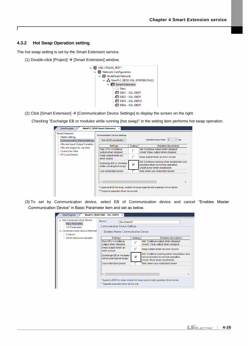
Chapter 4 Smart Extension service
4-26
4.3.2 Hot Swap Operation setting
The hot swap setting is set by the Smart Extension service.
(1) Double-click [Project] [Smart Extension] window.
(2) Click [Smart Extension] [Communication Device Settings] to display the screen on the right.
Checking "Exchange EB or modules while running (hot swap)" in the setting item performs hot swap operation.
(3) To set by Communication device, select EB of Communication device and cancel “Enables Master
Communication Device” in Basic Parameter item and set as below.
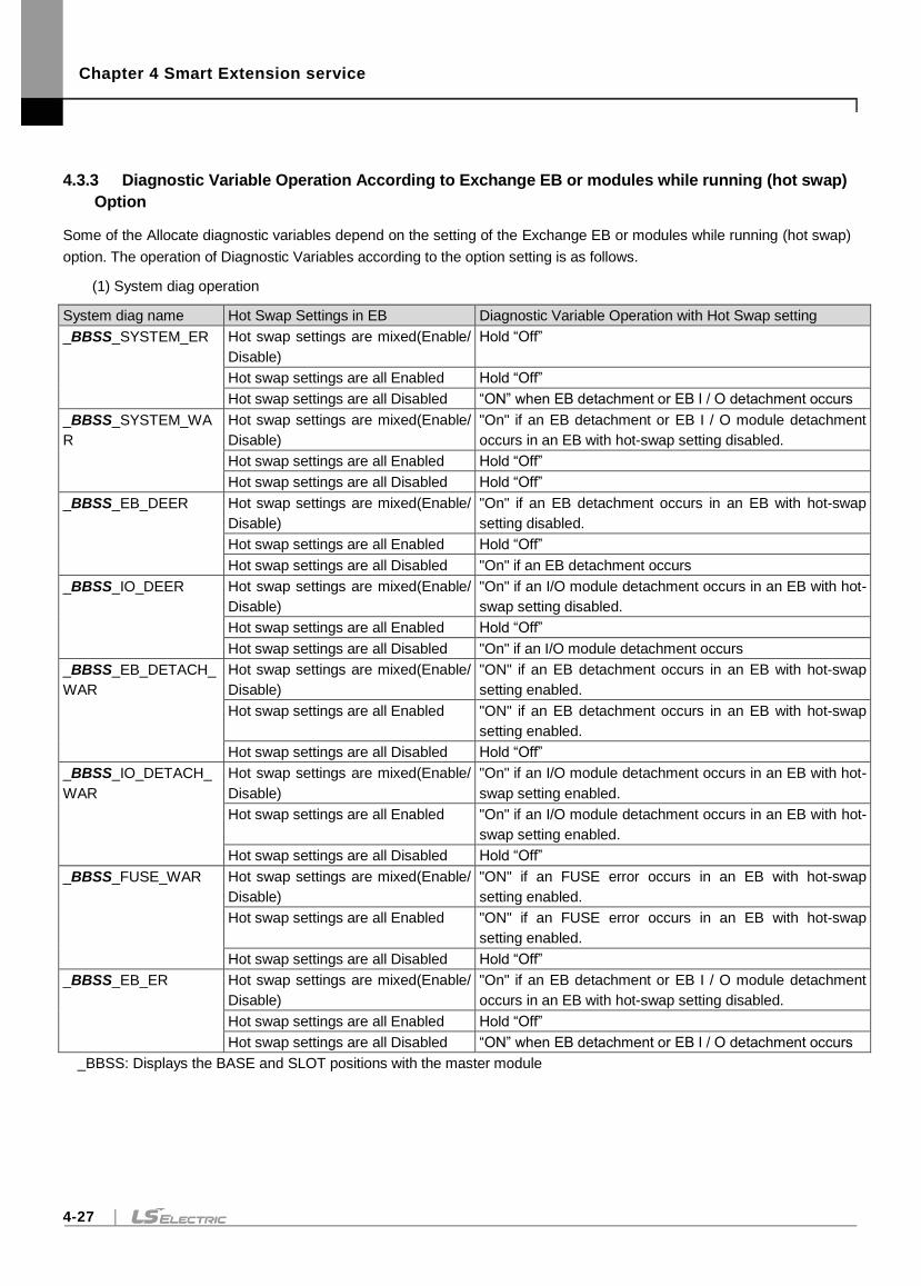
Chapter 4 Smart Extension service
4-27
4.3.3 Diagnostic Variable Operation According to Exchange EB or modules while running (hot swap)
Option
Some of the Allocate diagnostic variables depend on the setting of the Exchange EB or modules while running (hot swap)
option. The operation of Diagnostic Variables according to the option setting is as follows.
(1) System diag operation
System diag name Hot Swap Settings in EB Diagnostic Variable Operation with Hot Swap setting
_BBSS_SYSTEM_ER Hot swap settings are mixed(Enable/
Disable)
Hold “Off”
Hot swap settings are all Enabled Hold “Off”
Hot swap settings are all Disabled “ON” when EB detachment or EB I / O detachment occurs
_BBSS_SYSTEM_WA
R
Hot swap settings are mixed(Enable/
Disable)
"On" if an EB detachment or EB I / O module detachment
occurs in an EB with hot-swap setting disabled.
Hot swap settings are all Enabled Hold “Off”
Hot swap settings are all Disabled Hold “Off”
_BBSS_EB_DEER Hot swap settings are mixed(Enable/
Disable)
"On" if an EB detachment occurs in an EB with hot-swap
setting disabled.
Hot swap settings are all Enabled Hold “Off”
Hot swap settings are all Disabled "On" if an EB detachment occurs
_BBSS_IO_DEER Hot swap settings are mixed(Enable/
Disable)
"On" if an I/O module detachment occurs in an EB with hot-
swap setting disabled.
Hot swap settings are all Enabled Hold “Off”
Hot swap settings are all Disabled "On" if an I/O module detachment occurs
_BBSS_EB_DETACH_
WAR
Hot swap settings are mixed(Enable/
Disable)
"ON" if an EB detachment occurs in an EB with hot-swap
setting enabled.
Hot swap settings are all Enabled "ON" if an EB detachment occurs in an EB with hot-swap
setting enabled.
Hot swap settings are all Disabled Hold “Off”
_BBSS_IO_DETACH_
WAR
Hot swap settings are mixed(Enable/
Disable)
"On" if an I/O module detachment occurs in an EB with hot-
swap setting enabled.
Hot swap settings are all Enabled "On" if an I/O module detachment occurs in an EB with hot-
swap setting enabled.
Hot swap settings are all Disabled Hold “Off”
_BBSS_FUSE_WAR Hot swap settings are mixed(Enable/
Disable)
"ON" if an FUSE error occurs in an EB with hot-swap
setting enabled.
Hot swap settings are all Enabled "ON" if an FUSE error occurs in an EB with hot-swap
setting enabled.
Hot swap settings are all Disabled Hold “Off”
_BBSS_EB_ER Hot swap settings are mixed(Enable/
Disable)
"On" if an EB detachment or EB I / O module detachment
occurs in an EB with hot-swap setting disabled.
Hot swap settings are all Enabled Hold “Off”
Hot swap settings are all Disabled “ON” when EB detachment or EB I / O detachment occurs
_BBSS: Displays the BASE and SLOT positions with the master module
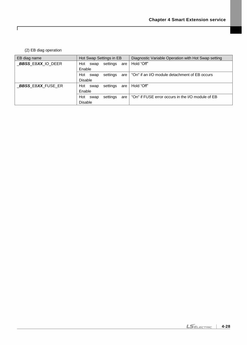
Chapter 4 Smart Extension service
4-28
(2) EB diag operation
EB diag name Hot Swap Settings in EB Diagnostic Variable Operation with Hot Swap setting
_BBSS_EBXX_IO_DEER Hot swap settings are
Enable
Hold “Off”
Hot swap settings are
Disable
"On" if an I/O module detachment of EB occurs
_BBSS_EBXX_FUSE_ER Hot swap settings are
Enable
Hold “Off”
Hot swap settings are
Disable
"On" if FUSE error occurs in the I/O module of EB
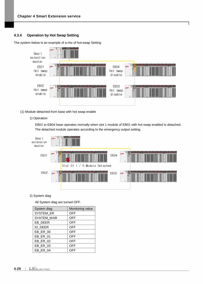
Chapter 4 Smart Extension service
4-29
4.3.4 Operation by Hot Swap Setting
The system below is an example of a mix of hot-swap Setting
Smart extention master
EB01Hot swap enable
EB02Hot swap enable
EB03Hot swap disable
EB04Hot swap disable
(1) Module detached from base with hot swap enable
1) Operation
EB01 to EB04 base operates normally when slot 1 module of EB01 with hot swap enabled is detached.
The detached module operates according to the emergency output setting.
Smart extension master
EB01
EB02 EB03
EB04
Slot 01 I / O Module Detached
2) System diag
All System diag are turned OFF.
System diag Monitoring value
SYSTEM_ER OFF
SYATEM_WAR OFF
EB_DEER OFF
IO_DEER OFF
EB_ER_00 OFF
EB_ER_01 OFF
EB_ER_02 OFF
EB_ER_03 OFF
EB_ER_04 OFF
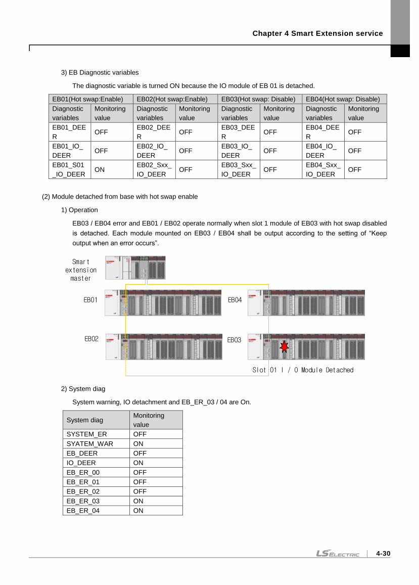
Chapter 4 Smart Extension service
4-30
3) EB Diagnostic variables
The diagnostic variable is turned ON because the IO module of EB 01 is detached.
EB01(Hot swap:Enable) EB02(Hot swap:Enable) EB03(Hot swap: Disable) EB04(Hot swap: Disable)
Diagnostic
variables
Monitoring
value
Diagnostic
variables
Monitoring
value
Diagnostic
variables
Monitoring
value
Diagnostic
variables
Monitoring
value
EB01_DEE
R OFF
EB02_DEE
R OFF
EB03_DEE
R OFF
EB04_DEE
R OFF
EB01_IO_
DEER OFF
EB02_IO_
DEER OFF
EB03_IO_
DEER OFF
EB04_IO_
DEER OFF
EB01_S01
_IO_DEER ON
EB02_Sxx_
IO_DEER OFF
EB03_Sxx_
IO_DEER OFF
EB04_Sxx_
IO_DEER OFF
(2) Module detached from base with hot swap enable
1) Operation
EB03 / EB04 error and EB01 / EB02 operate normally when slot 1 module of EB03 with hot swap disabled
is detached. Each module mounted on EB03 / EB04 shall be output according to the setting of “Keep
output when an error occurs”.
Smart extension master
EB01
EB02 EB03
Slot 01 I / O Module Detached
EB04
2) System diag
System warning, IO detachment and EB_ER_03 / 04 are On.
System diag Monitoring
value
SYSTEM_ER OFF
SYATEM_WAR ON
EB_DEER OFF
IO_DEER ON
EB_ER_00 OFF
EB_ER_01 OFF
EB_ER_02 OFF
EB_ER_03 ON
EB_ER_04 ON
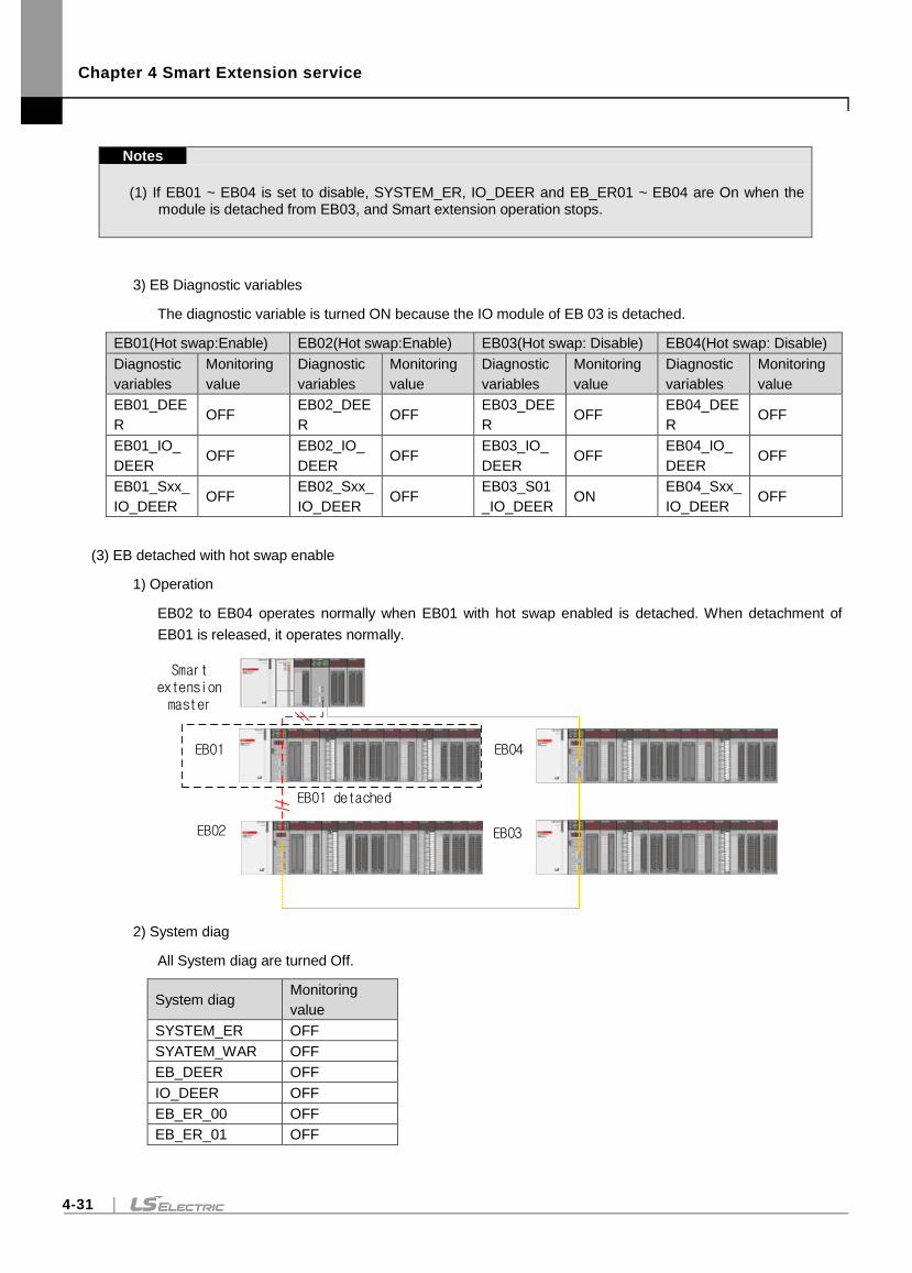
Chapter 4 Smart Extension service
4-31
Notes
(1) If EB01 ~ EB04 is set to disable, SYSTEM_ER, IO_DEER and EB_ER01 ~ EB04 are On when the module is detached from EB03, and Smart extension operation stops.
3) EB Diagnostic variables
The diagnostic variable is turned ON because the IO module of EB 03 is detached.
EB01(Hot swap:Enable) EB02(Hot swap:Enable) EB03(Hot swap: Disable) EB04(Hot swap: Disable)
Diagnostic
variables
Monitoring
value
Diagnostic
variables
Monitoring
value
Diagnostic
variables
Monitoring
value
Diagnostic
variables
Monitoring
value
EB01_DEE
R OFF
EB02_DEE
R OFF
EB03_DEE
R OFF
EB04_DEE
R OFF
EB01_IO_
DEER OFF
EB02_IO_
DEER OFF
EB03_IO_
DEER OFF
EB04_IO_
DEER OFF
EB01_Sxx_
IO_DEER OFF
EB02_Sxx_
IO_DEER OFF
EB03_S01
_IO_DEER ON
EB04_Sxx_
IO_DEER OFF
(3) EB detached with hot swap enable
1) Operation
EB02 to EB04 operates normally when EB01 with hot swap enabled is detached. When detachment of
EB01 is released, it operates normally.
Smart extension master
EB01
EB02 EB03
EB04
EB01 detached
2) System diag
All System diag are turned Off.
System diag Monitoring
value
SYSTEM_ER OFF
SYATEM_WAR OFF
EB_DEER OFF
IO_DEER OFF
EB_ER_00 OFF
EB_ER_01 OFF
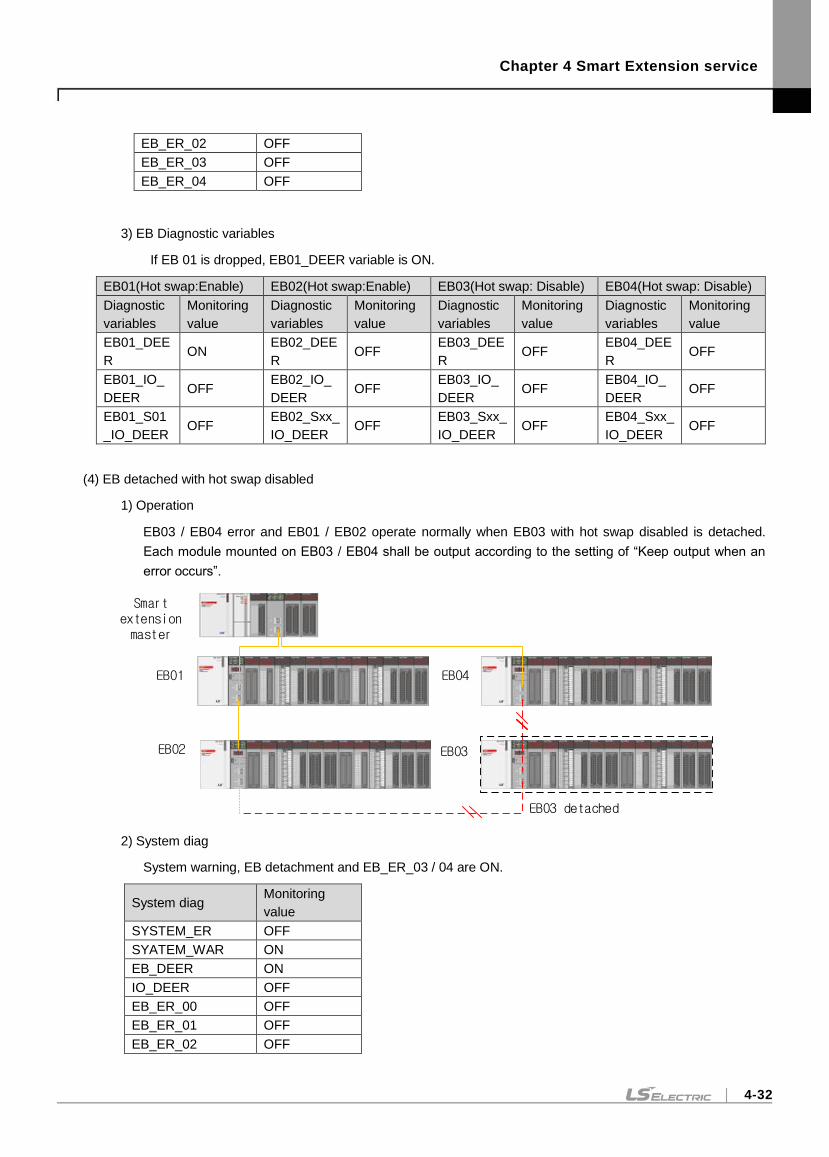
Chapter 4 Smart Extension service
4-32
EB_ER_02 OFF
EB_ER_03 OFF
EB_ER_04 OFF
3) EB Diagnostic variables
If EB 01 is dropped, EB01_DEER variable is ON.
EB01(Hot swap:Enable) EB02(Hot swap:Enable) EB03(Hot swap: Disable) EB04(Hot swap: Disable)
Diagnostic
variables
Monitoring
value
Diagnostic
variables
Monitoring
value
Diagnostic
variables
Monitoring
value
Diagnostic
variables
Monitoring
value
EB01_DEE
R ON
EB02_DEE
R OFF
EB03_DEE
R OFF
EB04_DEE
R OFF
EB01_IO_
DEER OFF
EB02_IO_
DEER OFF
EB03_IO_
DEER OFF
EB04_IO_
DEER OFF
EB01_S01
_IO_DEER OFF
EB02_Sxx_
IO_DEER OFF
EB03_Sxx_
IO_DEER OFF
EB04_Sxx_
IO_DEER OFF
(4) EB detached with hot swap disabled
1) Operation
EB03 / EB04 error and EB01 / EB02 operate normally when EB03 with hot swap disabled is detached.
Each module mounted on EB03 / EB04 shall be output according to the setting of “Keep output when an
error occurs”.
Smart extension master
EB01
EB02 EB03
EB04
EB03 detached
2) System diag
System warning, EB detachment and EB_ER_03 / 04 are ON.
System diag Monitoring
value
SYSTEM_ER OFF
SYATEM_WAR ON
EB_DEER ON
IO_DEER OFF
EB_ER_00 OFF
EB_ER_01 OFF
EB_ER_02 OFF
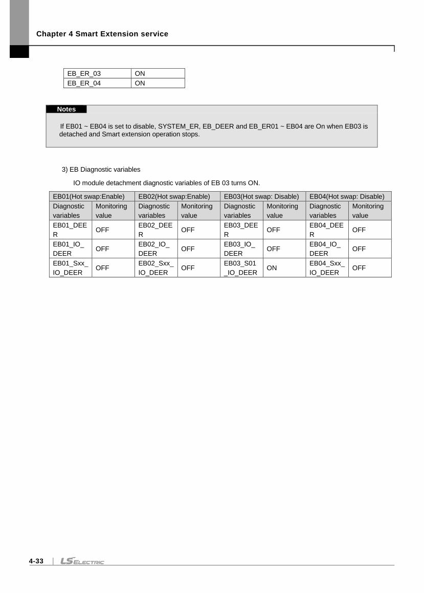
Chapter 4 Smart Extension service
4-33
EB_ER_03 ON
EB_ER_04 ON
Notes
If EB01 ~ EB04 is set to disable, SYSTEM_ER, EB_DEER and EB_ER01 ~ EB04 are On when EB03 is detached and Smart extension operation stops.
3) EB Diagnostic variables
IO module detachment diagnostic variables of EB 03 turns ON.
EB01(Hot swap:Enable) EB02(Hot swap:Enable) EB03(Hot swap: Disable) EB04(Hot swap: Disable)
Diagnostic
variables
Monitoring
value
Diagnostic
variables
Monitoring
value
Diagnostic
variables
Monitoring
value
Diagnostic
variables
Monitoring
value
EB01_DEE
R OFF
EB02_DEE
R OFF
EB03_DEE
R OFF
EB04_DEE
R OFF
EB01_IO_
DEER OFF
EB02_IO_
DEER OFF
EB03_IO_
DEER OFF
EB04_IO_
DEER OFF
EB01_Sxx_
IO_DEER OFF
EB02_Sxx_
IO_DEER OFF
EB03_S01
_IO_DEER ON
EB04_Sxx_
IO_DEER OFF
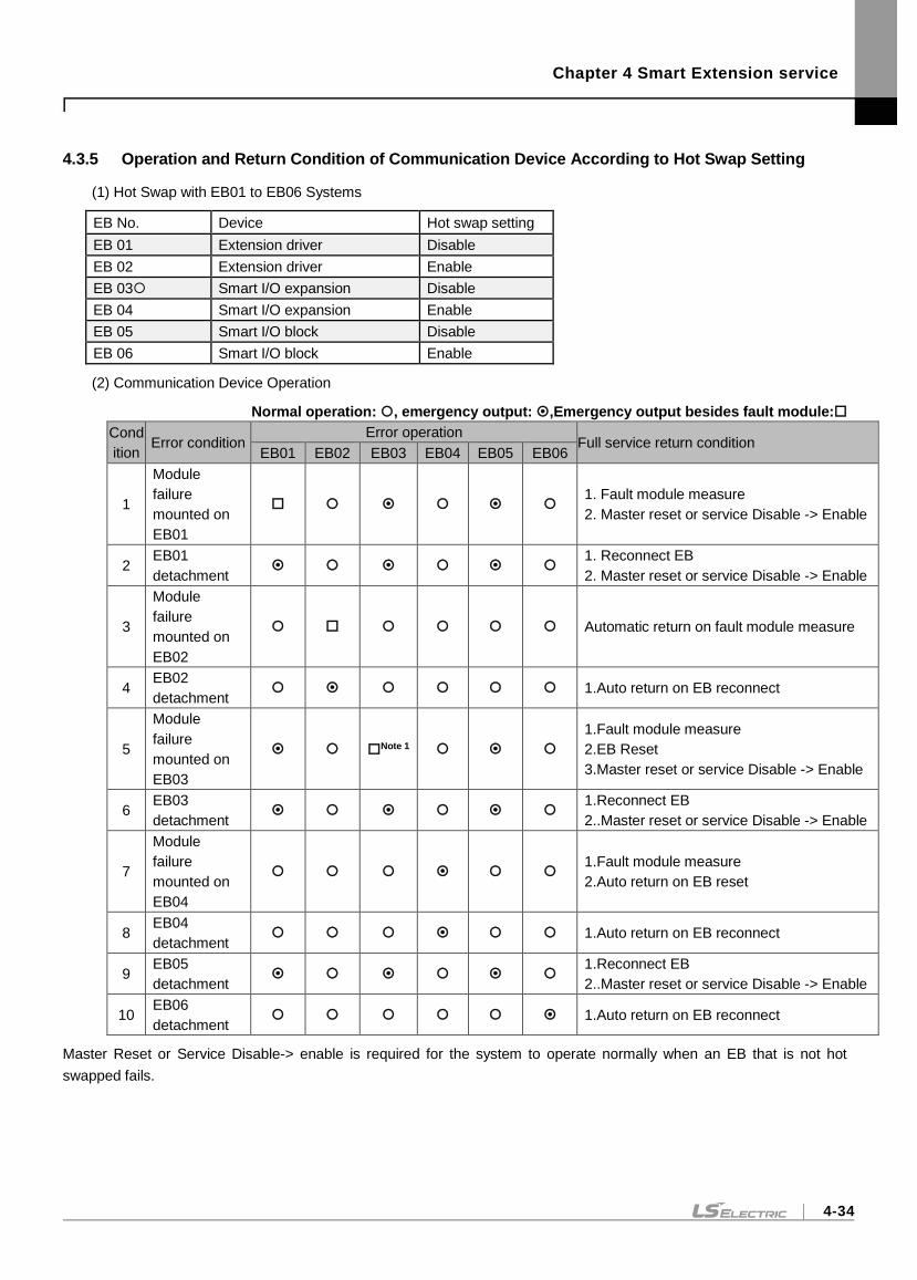
Chapter 4 Smart Extension service
4-34
4.3.5 Operation and Return Condition of Communication Device According to Hot Swap Setting
(1) Hot Swap with EB01 to EB06 Systems
EB No. Device Hot swap setting
EB 01 Extension driver Disable
EB 02 Extension driver Enable
EB 03 Smart I/O expansion Disable
EB 04 Smart I/O expansion Enable
EB 05 Smart I/O block Disable
EB 06 Smart I/O block Enable
(2) Communication Device Operation
Normal operation: , emergency output: ,Emergency output besides fault module:
Cond
ition Error condition
Error operation Full service return condition
EB01 EB02 EB03 EB04 EB05 EB06
1
Module
failure
mounted on
EB01
1. Fault module measure
2. Master reset or service Disable -> Enable
2 EB01
detachment
1. Reconnect EB
2. Master reset or service Disable -> Enable
3
Module
failure
mounted on
EB02
Automatic return on fault module measure
4 EB02
detachment 1.Auto return on EB reconnect
5
Module
failure
mounted on
EB03
Note 1
1.Fault module measure
2.EB Reset
3.Master reset or service Disable -> Enable
6 EB03
detachment
1.Reconnect EB
2..Master reset or service Disable -> Enable
7
Module
failure
mounted on
EB04
1.Fault module measure
2.Auto return on EB reset
8 EB04
detachment 1.Auto return on EB reconnect
9 EB05
detachment
1.Reconnect EB
2..Master reset or service Disable -> Enable
10 EB06
detachment 1.Auto return on EB reconnect
Master Reset or Service Disable-> enable is required for the system to operate normally when an EB that is not hot
swapped fails.

Chapter 4 Smart Extension service
4-35
Notes
(1) When hot swap of each country operated by Smart extension service is set to Enable and the media is set to Auto, each station automatically operates by adjusting the communication speed. If there is only 100M of station number, the system communicates with 100M.
(2) When hot swap of each country operated by Smart extension service is set to Disable and the media is set to Auto, each station automatically operates by adjusting the communication speed However, if 100M and 1G media are mixed, EB will be detached when connecting to media with different speeds. In this case, Smart extension service can be operated after setting communication media setting of each station from Auto to 100M.
(3) Smart I / O expansion does not support hot swap function of expansion module.
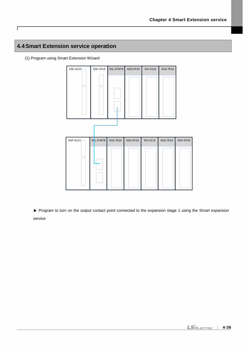
Chapter 4 Smart Extension service
4-36
4.4 Smart Extension service operation
(1) Program using Smart Extension Wizard
XGI-D22AXGL-EFMTBXGP-AC23 XGK-CPUE XGQ-RY2A XGQ-TR2A
XGI-D21AXGP-AC23 XGQ-TR2A XGH-DT4AXGQ-TR2AXGL-EFMTB XGQ-RY2A
Program to turn on the output contact point connected to the expansion stage 1 using the Smart expansion
service
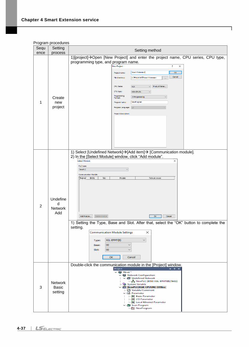
Chapter 4 Smart Extension service
4-37
Program procedures
Sequence
Setting process
Setting method
1 Create
new project
1)[project]Open [New Project] and enter the project name, CPU series, CPU type, programming type, and program name.
2
Undefined
Network Add
1) Select [Undefined Network][Add item] [Communication module]. 2) In the [Select Module] window, click “Add module”.
1) Setting the Type, Base and Slot. After that, select the “OK” button to complete the setting.
3 Network
Basic setting
Double-click the communication module in the [Project] window.
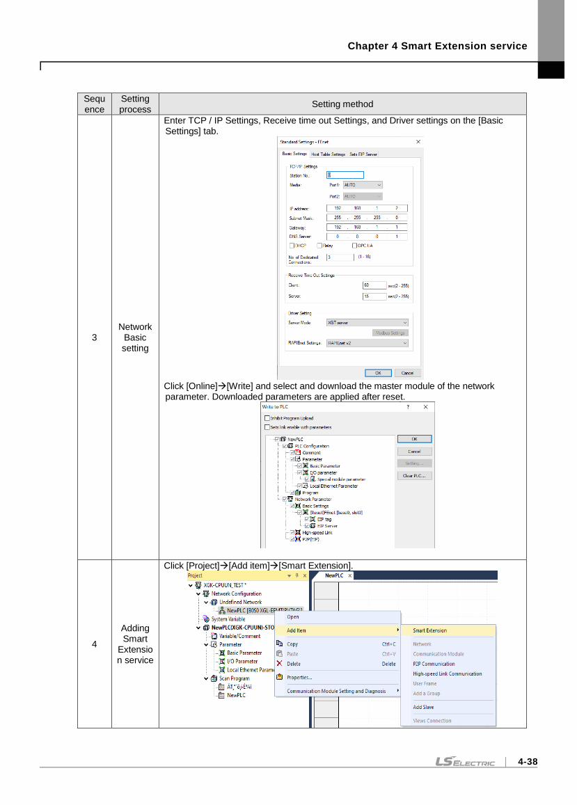
Chapter 4 Smart Extension service
4-38
Sequence
Setting process
Setting method
3 Network
Basic setting
Enter TCP / IP Settings, Receive time out Settings, and Driver settings on the [Basic Settings] tab.
Click [Online][Write] and select and download the master module of the network parameter. Downloaded parameters are applied after reset.
4
Adding Smart
Extension service
Click [Project][Add item][Smart Extension].
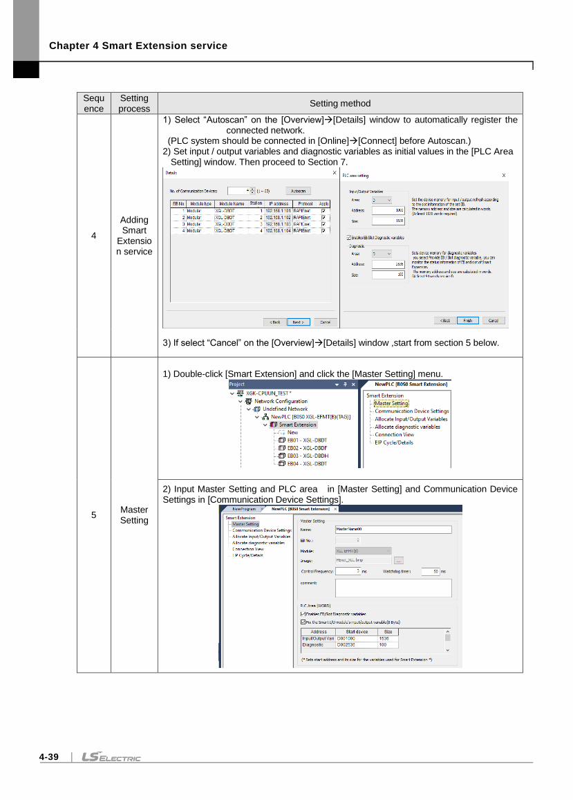
Chapter 4 Smart Extension service
4-39
Sequence
Setting process
Setting method
4
Adding Smart
Extension service
1) Select “Autoscan” on the [Overview][Details] window to automatically register the connected network.
(PLC system should be connected in [Online][Connect] before Autoscan.) 2) Set input / output variables and diagnostic variables as initial values in the [PLC Area
Setting] window. Then proceed to Section 7.
3) If select “Cancel” on the [Overview][Details] window ,start from section 5 below.
5 Master Setting
1) Double-click [Smart Extension] and click the [Master Setting] menu.
2) Input Master Setting and PLC area in [Master Setting] and Communication Device Settings in [Communication Device Settings].
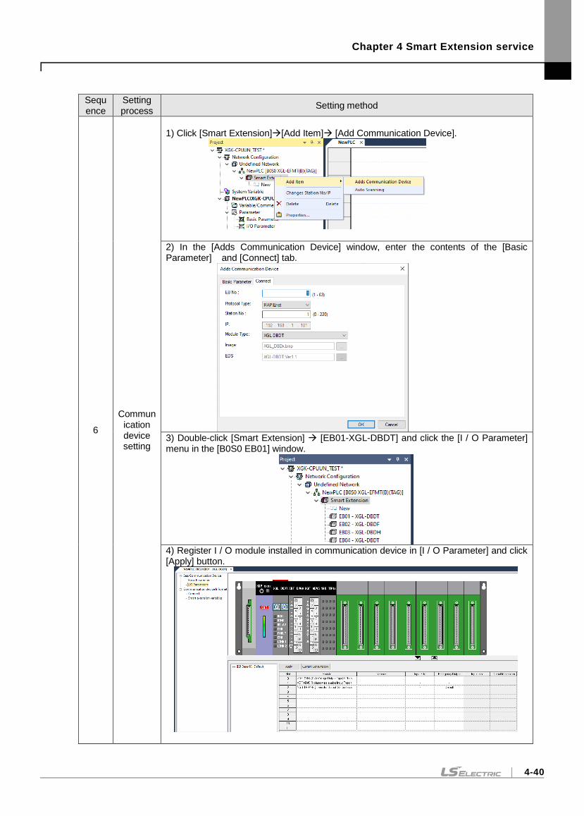
Chapter 4 Smart Extension service
4-40
Sequence
Setting process
Setting method
6
Communication device setting
1) Click [Smart Extension][Add Item] [Add Communication Device].
2) In the [Adds Communication Device] window, enter the contents of the [Basic Parameter] and [Connect] tab.
3) Double-click [Smart Extension] [EB01-XGL-DBDT] and click the [I / O Parameter] menu in the [B0S0 EB01] window.
4) Register I / O module installed in communication device in [I / O Parameter] and click [Apply] button.
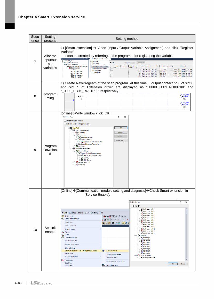
Chapter 4 Smart Extension service
4-41
Sequence
Setting process
Setting method
7
Allocate input/out
put variables
1) [Smart extension] Open [Input / Output Variable Assignment] and click "Register Variable". It can be created by referring to the program after registering the variable
8 program
ming
1) Create NewProgeam of the scan program. At this time, output contact no.0 of slot 0 and slot 1 of Extension driver are displayed as “_0000_EB01_RQ00P00” and “_0000_EB01_RQ01P00” respectively.
9 Program Downloa
d
[online]Write window click [OK].
10 Set link enable
[Online][Communication module setting and diagnosis]Check Smart extension in [Service Enable].
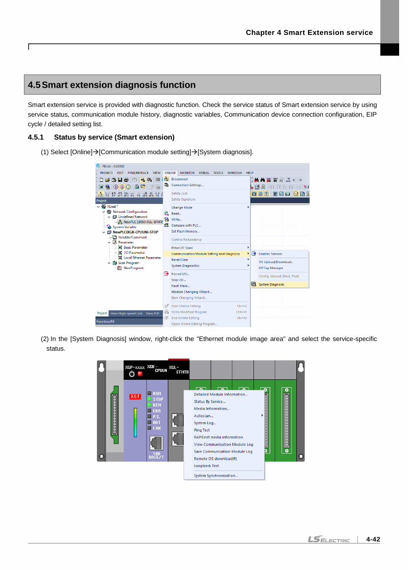
Chapter 4 Smart Extension service
4-42
4.5 Smart extension diagnosis function
Smart extension service is provided with diagnostic function. Check the service status of Smart extension service by using
service status, communication module history, diagnostic variables, Communication device connection configuration, EIP
cycle / detailed setting list.
4.5.1 Status by service (Smart extension)
(1) Select [Online][Communication module setting][System diagnosis].
(2) In the [System Diagnosis] window, right-click the "Ethernet module image area" and select the service-specific
status.
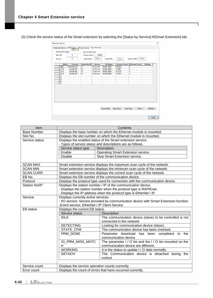
Chapter 4 Smart Extension service
4-43
(3) Check the service status of the Smart extension by selecting the [Status by Service][Smart Extension] tab.
Item Contents
Base Number Displays the base number on which the Ethernet module is mounted.
Slot No. Displays the slot number on which the Ethernet module is mounted.
Service status Displays the enabled status of the Smart extension service. - Types of service status and descriptions are as follows.
Service status type Description
Enable Operating Smart Extension service.
Disable Stop Smart Extension service.
SCAN MAX Smart extension service displays the maximum scan cycle of the network.
SCAN MIN Smart extension service displays the minimum scan cycle of the network.
SCAN CURR Smart extension service displays the current scan cycle of the network.
EB No. Displays the EB number of the communication device.
Protocol Displays the protocol type used for connection with the communication device.
Station No/IP Displays the station number / IP of the communication device. - Displays the station number when the protocol type is RAPIEnet. - Displays the IP address when the protocol type is EtherNet / IP.
Service Displays currently active services. - I/O service: Service provided by communication device with Smart Extension function -Event service: EtherNet / IP Client Service
EB status Displays the current EB status.
Service status Description
IDLE The communication device (slave) to be controlled is not connected in the network.
DETECTING Looking for communication device (slave).
STATE_CFM The communication device has been checked.
PRM_DONE Parameter download has been completed to the communication device.
IO_PRM_MISS_MATCH
The parameter I / O list and the I / O list mounted on the communication device are different.
WORKING It is the status to update I / O data normally.
DETACH The Communication device is detached during the control.
Service count Displays the service operation counts currently.
Error count Displays the count of errors that have occurred currently.
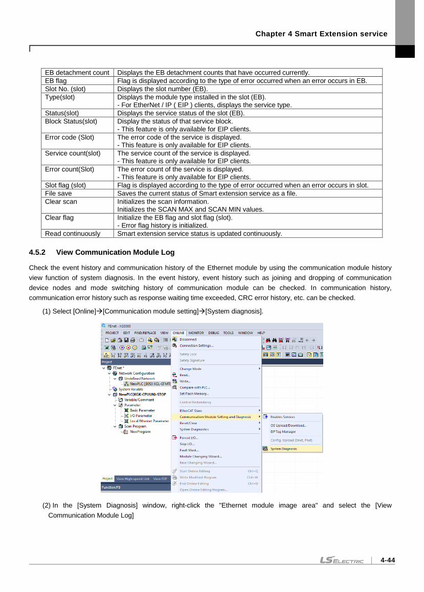
Chapter 4 Smart Extension service
4-44
EB detachment count Displays the EB detachment counts that have occurred currently.
EB flag Flag is displayed according to the type of error occurred when an error occurs in EB.
Slot No. (slot) Displays the slot number (EB).
Type(slot) Displays the module type installed in the slot (EB). - For EtherNet / IP ( EIP ) clients, displays the service type.
Status(slot) Displays the service status of the slot (EB).
Block Status(slot) Display the status of that service block. - This feature is only available for EIP clients.
Error code (Slot) The error code of the service is displayed. - This feature is only available for EIP clients.
Service count(slot) The service count of the service is displayed. - This feature is only available for EIP clients.
Error count(Slot) The error count of the service is displayed. - This feature is only available for EIP clients.
Slot flag (slot) Flag is displayed according to the type of error occurred when an error occurs in slot.
File save Saves the current status of Smart extension service as a file.
Clear scan Initializes the scan information. Initializes the SCAN MAX and SCAN MIN values.
Clear flag Initialize the EB flag and slot flag (slot). - Error flag history is initialized.
Read continuously Smart extension service status is updated continuously.
4.5.2 View Communication Module Log
Check the event history and communication history of the Ethernet module by using the communication module history
view function of system diagnosis. In the event history, event history such as joining and dropping of communication
device nodes and mode switching history of communication module can be checked. In communication history,
communication error history such as response waiting time exceeded, CRC error history, etc. can be checked.
(1) Select [Online][Communication module setting][System diagnosis].
(2) In the [System Diagnosis] window, right-click the "Ethernet module image area" and select the [View
Communication Module Log]
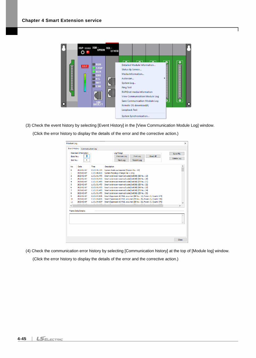
Chapter 4 Smart Extension service
4-45
(3) Check the event history by selecting [Event History] in the [View Communication Module Log] window.
(Click the error history to display the details of the error and the corrective action.)
(4) Check the communication error history by selecting [Communication history] at the top of [Module log] window.
(Click the error history to display the details of the error and the corrective action.)
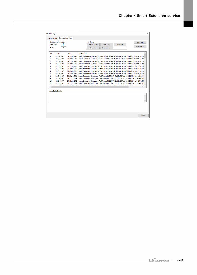
Chapter 4 Smart Extension service
4-46
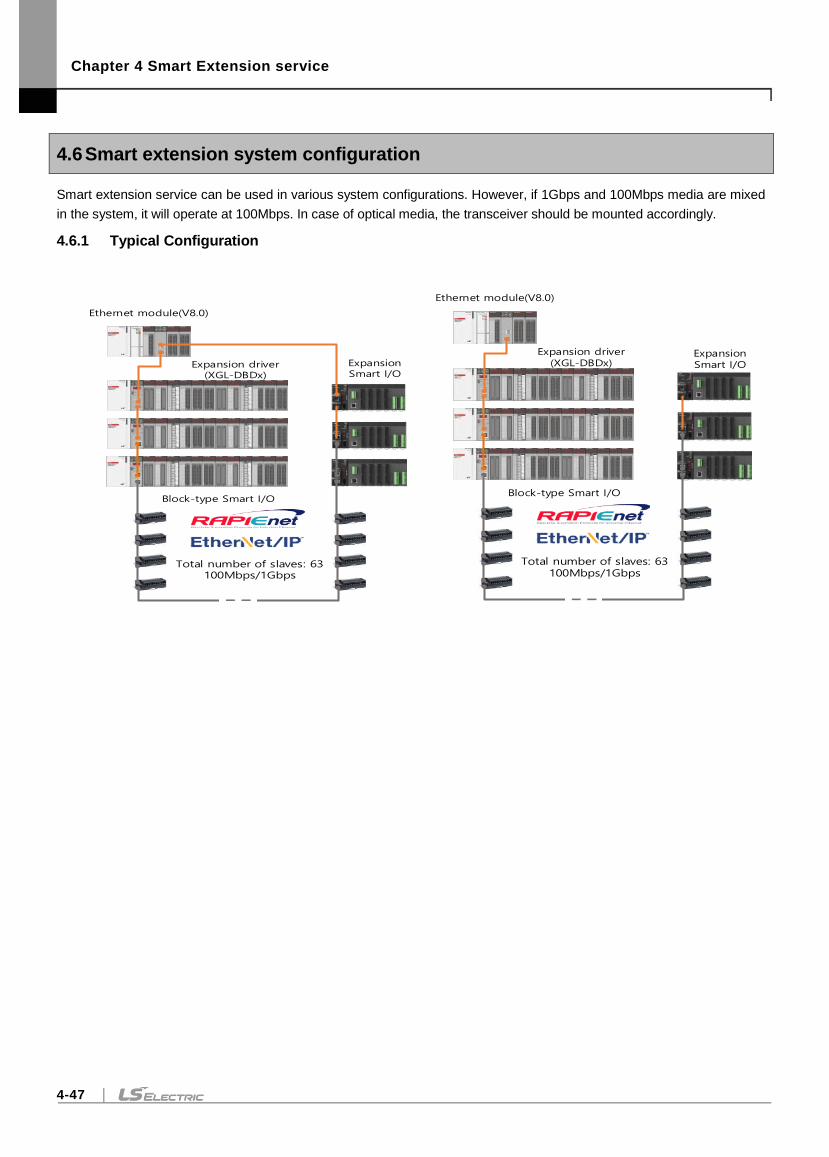
Chapter 4 Smart Extension service
4-47
4.6 Smart extension system configuration
Smart extension service can be used in various system configurations. However, if 1Gbps and 100Mbps media are mixed
in the system, it will operate at 100Mbps. In case of optical media, the transceiver should be mounted accordingly.
4.6.1 Typical Configuration
Total number of slaves: 63100Mbps/1Gbps
Ethernet module(V8.0)
Expansion driver(XGL-DBDx)
Expansion Smart I/O
Block-type Smart I/O
Total number of slaves: 63100Mbps/1Gbps
Ethernet module(V8.0)
Expansion driver(XGL-DBDx)
Expansion Smart I/O
Block-type Smart I/O
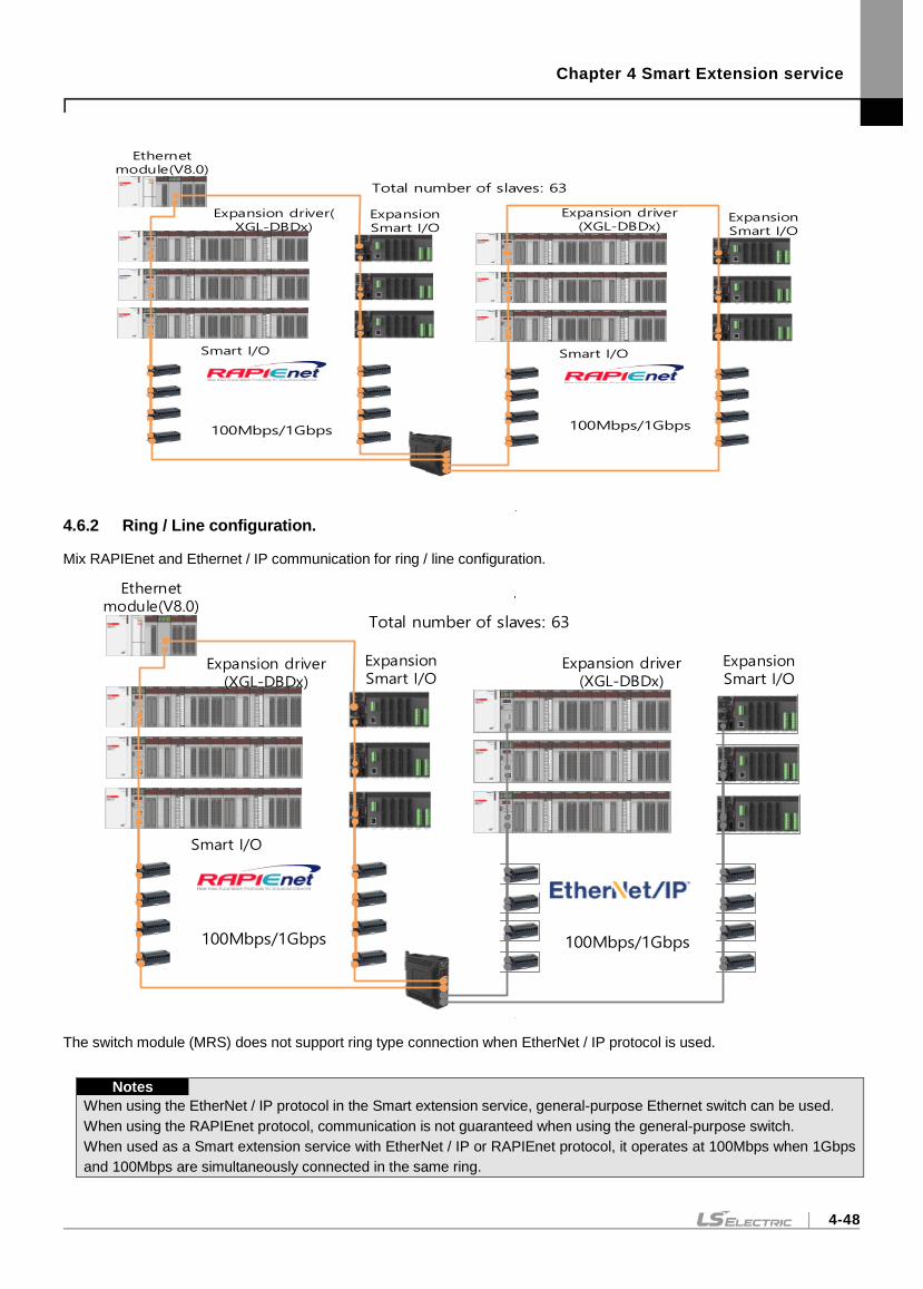
Chapter 4 Smart Extension service
4-48
100Mbps/1Gbps
Ethernet module(V8.0)
Expansion driver(XGL-DBDx)
Expansion Smart I/O
Smart I/O
100Mbps/1Gbps
Expansion driver(XGL-DBDx)
Expansion Smart I/O
Smart I/O
Total number of slaves: 63
4.6.2 Ring / Line configuration.
Mix RAPIEnet and Ethernet / IP communication for ring / line configuration.
100Mbps/1Gbps
Ethernet module(V8.0)
Expansion driver(XGL-DBDx)
Expansion Smart I/O
Smart I/O
Expansion driver(XGL-DBDx)
100Mbps/1Gbps
Expansion Smart I/O
Total number of slaves: 63
The switch module (MRS) does not support ring type connection when EtherNet / IP protocol is used.
Notes
When using the EtherNet / IP protocol in the Smart extension service, general-purpose Ethernet switch can be used.
When using the RAPIEnet protocol, communication is not guaranteed when using the general-purpose switch.
When used as a Smart extension service with EtherNet / IP or RAPIEnet protocol, it operates at 100Mbps when 1Gbps
and 100Mbps are simultaneously connected in the same ring.
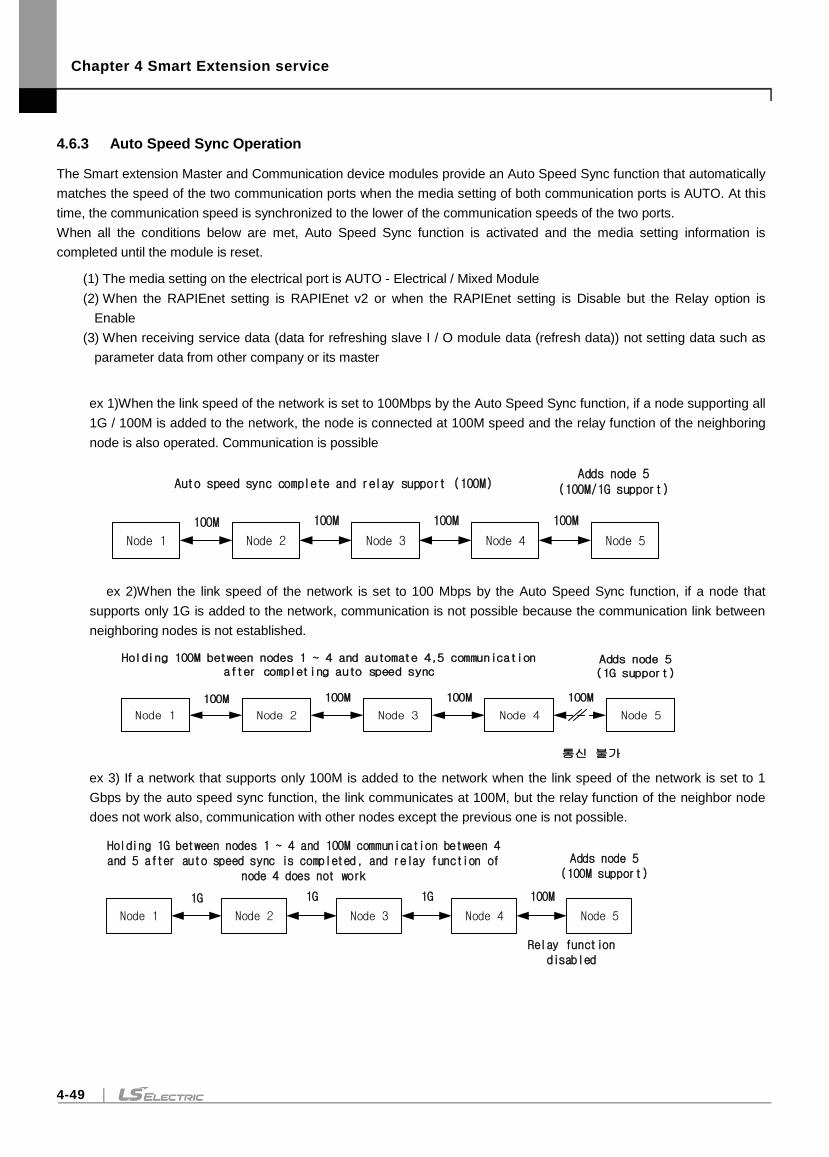
Chapter 4 Smart Extension service
4-49
4.6.3 Auto Speed Sync Operation
The Smart extension Master and Communication device modules provide an Auto Speed Sync function that automatically
matches the speed of the two communication ports when the media setting of both communication ports is AUTO. At this
time, the communication speed is synchronized to the lower of the communication speeds of the two ports.
When all the conditions below are met, Auto Speed Sync function is activated and the media setting information is
completed until the module is reset.
(1) The media setting on the electrical port is AUTO - Electrical / Mixed Module
(2) When the RAPIEnet setting is RAPIEnet v2 or when the RAPIEnet setting is Disable but the Relay option is
Enable
(3) When receiving service data (data for refreshing slave I / O module data (refresh data)) not setting data such as
parameter data from other company or its master
ex 1)When the link speed of the network is set to 100Mbps by the Auto Speed Sync function, if a node supporting all
1G / 100M is added to the network, the node is connected at 100M speed and the relay function of the neighboring
node is also operated. Communication is possible
Node 1 Node 2 Node 3 Node 4 Node 5
Auto speed sync complete and relay support (100M)
100M 100M 100M 100M
Adds node 5(100M/1G support)
ex 2)When the link speed of the network is set to 100 Mbps by the Auto Speed Sync function, if a node that
supports only 1G is added to the network, communication is not possible because the communication link between
neighboring nodes is not established.
Node 1 Node 2 Node 3 Node 4 Node 5
Holding 100M between nodes 1 ~ 4 and automate 4,5 communication after completing auto speed sync
100M 100M 100M 100M
Adds node 5(1G support)
통신 불가
ex 3) If a network that supports only 100M is added to the network when the link speed of the network is set to 1
Gbps by the auto speed sync function, the link communicates at 100M, but the relay function of the neighbor node
does not work also, communication with other nodes except the previous one is not possible.
Node 1 Node 2 Node 3 Node 4 Node 5
Holding 1G between nodes 1 ~ 4 and 100M communication between 4 and 5 after auto speed sync is completed, and relay function of
node 4 does not work
1G 1G 1G 100M
Adds node 5(100M support)
Relay function disabled
Chapter 4 Smart Extension service
4-50
Notes
(1) The optical module determines the link speed based on the Transceiver's 100M or 1G even when
the media is set to AUTO. However, in case of the mixing module, if 100M Transceiver is
connected to the optical port, if the electrical port is set to AUTO, the communication is connected
to 100M according to the optical port speed.
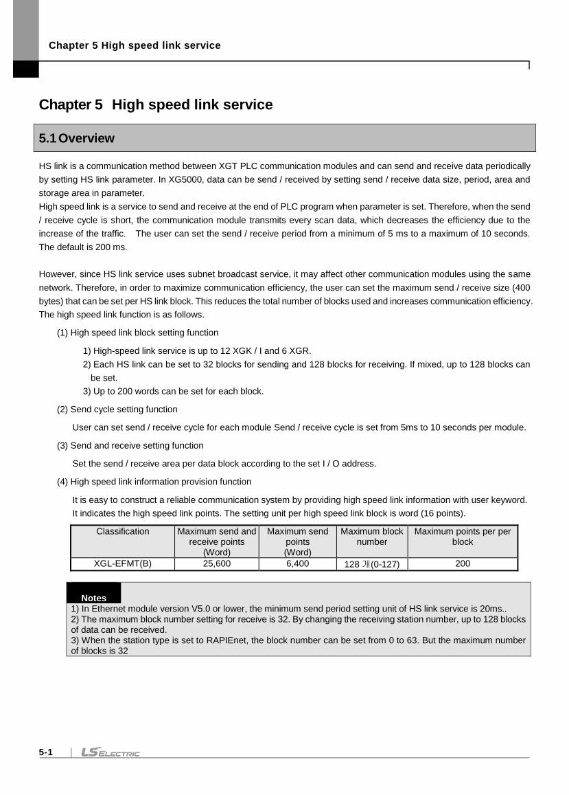
Chapter 5 High speed link service
5-1
Chapter 5 High speed link service
5.1 Overview
HS link is a communication method between XGT PLC communication modules and can send and receive data periodically
by setting HS link parameter. In XG5000, data can be send / received by setting send / receive data size, period, area and
storage area in parameter.
High speed link is a service to send and receive at the end of PLC program when parameter is set. Therefore, when the send
/ receive cycle is short, the communication module transmits every scan data, which decreases the efficiency due to the
increase of the traffic. The user can set the send / receive period from a minimum of 5 ms to a maximum of 10 seconds.
The default is 200 ms.
However, since HS link service uses subnet broadcast service, it may affect other communication modules using the same
network. Therefore, in order to maximize communication efficiency, the user can set the maximum send / receive size (400
bytes) that can be set per HS link block. This reduces the total number of blocks used and increases communication efficiency.
The high speed link function is as follows.
(1) High speed link block setting function
1) High-speed link service is up to 12 XGK / I and 6 XGR.
2) Each HS link can be set to 32 blocks for sending and 128 blocks for receiving. If mixed, up to 128 blocks can
be set.
3) Up to 200 words can be set for each block.
(2) Send cycle setting function
User can set send / receive cycle for each module Send / receive cycle is set from 5ms to 10 seconds per module.
(3) Send and receive setting function
Set the send / receive area per data block according to the set I / O address.
(4) High speed link information provision function
It is easy to construct a reliable communication system by providing high speed link information with user keyword.
It indicates the high speed link points. The setting unit per high speed link block is word (16 points).
Classification Maximum send and receive points
(Word)
Maximum send points (Word)
Maximum block number
Maximum points per per block
XGL-EFMT(B) 25,600 6,400 128 개(0-127) 200
Notes
1) In Ethernet module version V5.0 or lower, the minimum send period setting unit of HS link service is 20ms.. 2) The maximum block number setting for receive is 32. By changing the receiving station number, up to 128 blocks of data can be received. 3) When the station type is set to RAPIEnet, the block number can be set from 0 to 63. But the maximum number of blocks is 32
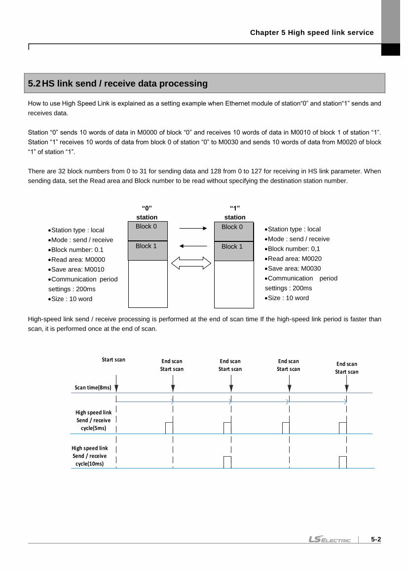
Chapter 5 High speed link service
5-2
5.2 HS link send / receive data processing
How to use High Speed Link is explained as a setting example when Ethernet module of station“0” and station“1” sends and
receives data.
Station “0” sends 10 words of data in M0000 of block “0” and receives 10 words of data in M0010 of block 1 of station “1”.
Station “1” receives 10 words of data from block 0 of station “0” to M0030 and sends 10 words of data from M0020 of block
“1” of station “1”.
There are 32 block numbers from 0 to 31 for sending data and 128 from 0 to 127 for receiving in HS link parameter. When
sending data, set the Read area and Block number to be read without specifying the destination station number.
High-speed link send / receive processing is performed at the end of scan time If the high-speed link period is faster than
scan, it is performed once at the end of scan.
Scan time(8ms)
High speed linkSend / receive
cycle(5ms)
High speed linkSend / receive
cycle(10ms)
End scanStart scan
Start scan End scanStart scan
End scanStart scan
End scanStart scan
“0”
station
Station type : local
Mode : send / receive
Block number: 0.1
Read area: M0000
Save area: M0010
Communication period
settings : 200ms
Size : 10 word
Block 0
Block 1
“1”
station
Station type : local
Mode : send / receive
Block number: 0,1
Read area: M0020
Save area: M0030
Communication period
settings : 200ms
Size : 10 word
Block 0
Block 1
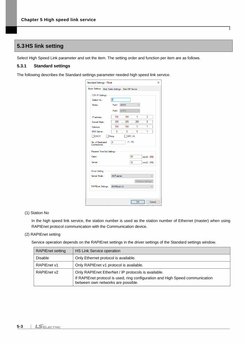
Chapter 5 High speed link service
5-3
5.3 HS link setting
Select High Speed Link parameter and set the item. The setting order and function per item are as follows.
5.3.1 Standard settings
The following describes the Standard settings parameter needed high speed link service.
(1) Station No
In the high speed link service, the station number is used as the station number of Ethernet (master) when using
RAPIEnet protocol communication with the Communication device.
(2) RAPIEnet setting
Service operation depends on the RAPIEnet settings in the driver settings of the Standard settings window.
RAPIEnet setting HS Link Service operation
Disable Only Ethernet protocol is available.
RAPIEnet v1 Only RAPIEnet v1 protocol is available.
RAPIEnet v2 Only RAPIEnet EtherNet / IP protocols is available.
If RAPIEnet protocol is used, ring configuration and High Speed communication between own networks are possible.
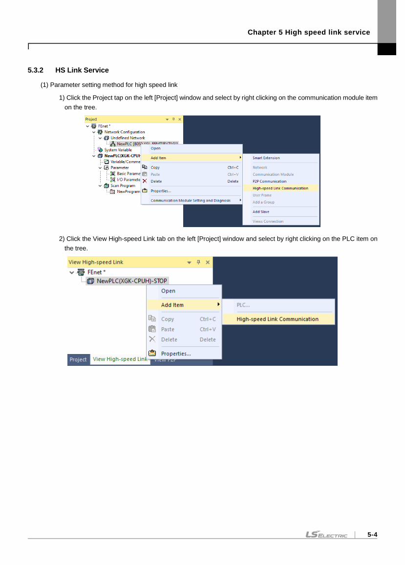
Chapter 5 High speed link service
5-4
5.3.2 HS Link Service
(1) Parameter setting method for high speed link
1) Click the Project tap on the left [Project] window and select by right clicking on the communication module item
on the tree.
2) Click the View High-speed Link tab on the left [Project] window and select by right clicking on the PLC item on
the tree.
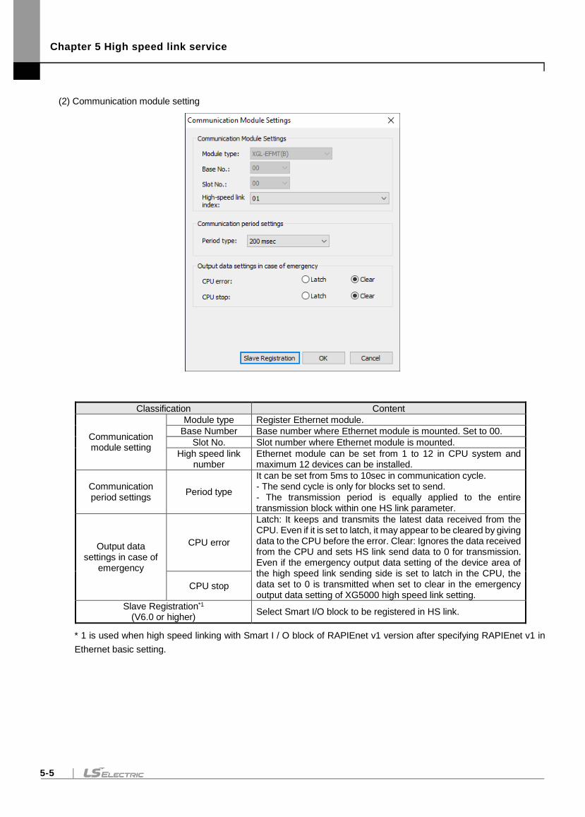
Chapter 5 High speed link service
5-5
(2) Communication module setting
Classification Content
Communication module setting
Module type Register Ethernet module.
Base Number Base number where Ethernet module is mounted. Set to 00.
Slot No. Slot number where Ethernet module is mounted.
High speed link number
Ethernet module can be set from 1 to 12 in CPU system and maximum 12 devices can be installed.
Communication period settings
Period type
It can be set from 5ms to 10sec in communication cycle. - The send cycle is only for blocks set to send. - The transmission period is equally applied to the entire transmission block within one HS link parameter.
Output data settings in case of
emergency
CPU error
Latch: It keeps and transmits the latest data received from the CPU. Even if it is set to latch, it may appear to be cleared by giving data to the CPU before the error. Clear: Ignores the data received from the CPU and sets HS link send data to 0 for transmission. Even if the emergency output data setting of the device area of the high speed link sending side is set to latch in the CPU, the data set to 0 is transmitted when set to clear in the emergency output data setting of XG5000 high speed link setting.
CPU stop
Slave Registration*1 (V6.0 or higher)
Select Smart I/O block to be registered in HS link.
* 1 is used when high speed linking with Smart I / O block of RAPIEnet v1 version after specifying RAPIEnet v1 in
Ethernet basic setting.
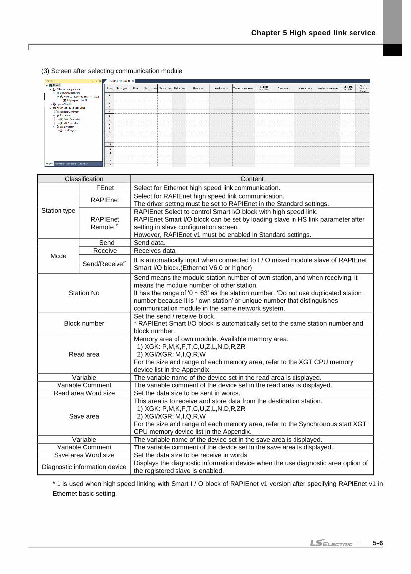
Chapter 5 High speed link service
5-6
(3) Screen after selecting communication module
Classification Content
Station type
FEnet Select for Ethernet high speed link communication.
RAPIEnet Select for RAPIEnet high speed link communication. The driver setting must be set to RAPIEnet in the Standard settings.
RAPIEnet Remote *1
RAPIEnet Select to control Smart I/O block with high speed link. RAPIEnet Smart I/O block can be set by loading slave in HS link parameter after setting in slave configuration screen. However, RAPIEnet v1 must be enabled in Standard settings.
Mode
Send Send data.
Receive Receives data.
Send/Receive*1 It is automatically input when connected to I / O mixed module slave of RAPIEnet Smart I/O block.(Ethernet V6.0 or higher)
Station No
Send means the module station number of own station, and when receiving, it means the module number of other station. It has the range of '0 ~ 63' as the station number. ‘Do not use duplicated station number because it is ' own station’ or unique number that distinguishes communication module in the same network system.
Block number Set the send / receive block. * RAPIEnet Smart I/O block is automatically set to the same station number and block number.
Read area
Memory area of own module. Available memory area. 1) XGK: P,M,K,F,T,C,U,Z,L,N,D,R,ZR 2) XGI/XGR: M,I,Q,R,W
For the size and range of each memory area, refer to the XGT CPU memory device list in the Appendix.
Variable The variable name of the device set in the read area is displayed.
Variable Comment The variable comment of the device set in the read area is displayed.
Read area Word size Set the data size to be sent in words.
Save area
This area is to receive and store data from the destination station. 1) XGK: P,M,K,F,T,C,U,Z,L,N,D,R,ZR 2) XGI/XGR: M,I,Q,R,W
For the size and range of each memory area, refer to the Synchronous start XGT CPU memory device list in the Appendix.
Variable The variable name of the device set in the save area is displayed.
Variable Comment The variable comment of the device set in the save area is displayed..
Save area Word size Set the data size to be receive in words
Diagnostic information device Displays the diagnostic information device when the use diagnostic area option of the registered slave is enabled.
* 1 is used when high speed linking with Smart I / O block of RAPIEnet v1 version after specifying RAPIEnet v1 in
Ethernet basic setting.
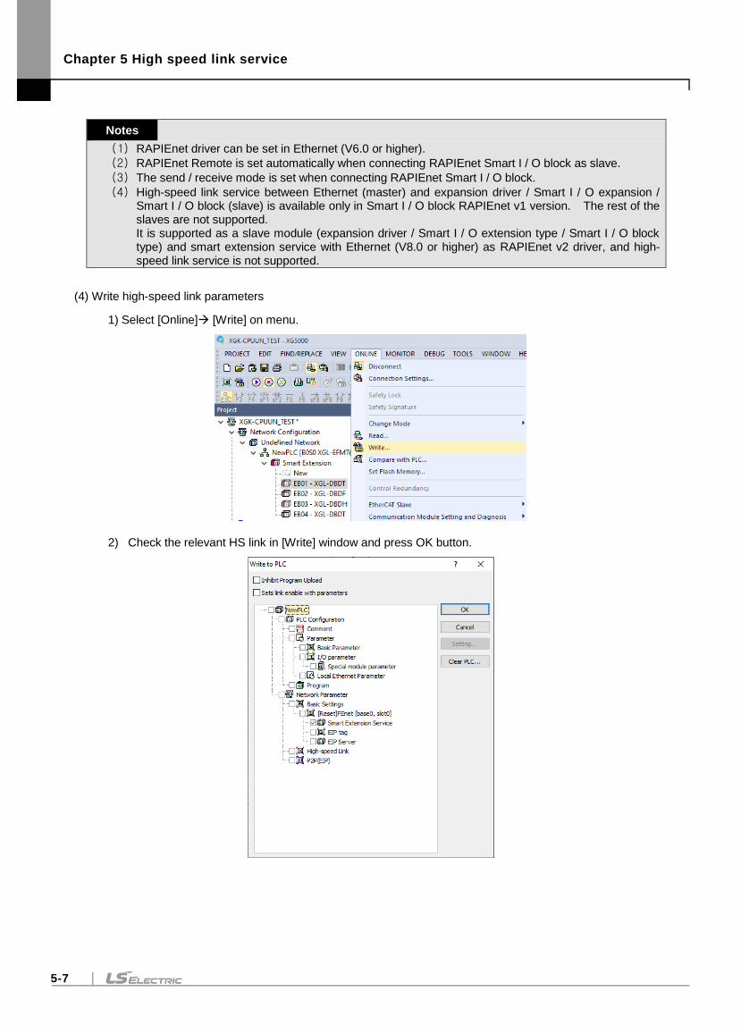
Chapter 5 High speed link service
5-7
Notes
(1) RAPIEnet driver can be set in Ethernet (V6.0 or higher).
(2) RAPIEnet Remote is set automatically when connecting RAPIEnet Smart I / O block as slave.
(3) The send / receive mode is set when connecting RAPIEnet Smart I / O block.
(4) High-speed link service between Ethernet (master) and expansion driver / Smart I / O expansion / Smart I / O block (slave) is available only in Smart I / O block RAPIEnet v1 version. The rest of the slaves are not supported. It is supported as a slave module (expansion driver / Smart I / O extension type / Smart I / O block type) and smart extension service with Ethernet (V8.0 or higher) as RAPIEnet v2 driver, and high-speed link service is not supported.
(4) Write high-speed link parameters
1) Select [Online] [Write] on menu.
2) Check the relevant HS link in [Write] window and press OK button.
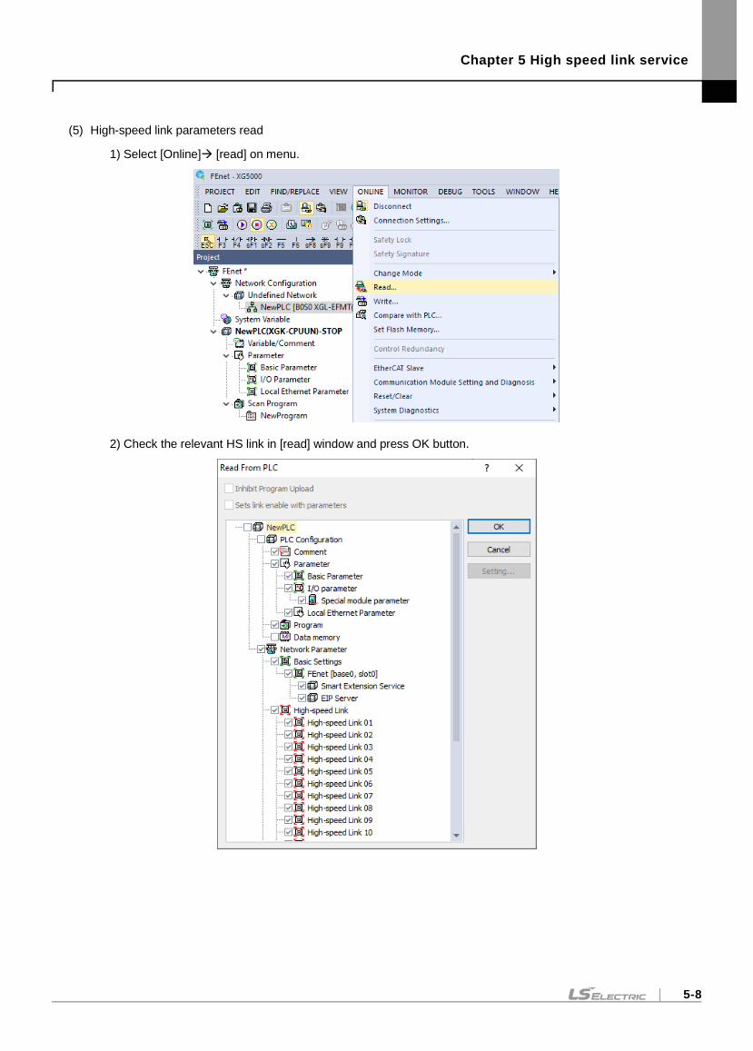
Chapter 5 High speed link service
5-8
(5) High-speed link parameters read
1) Select [Online] [read] on menu.
2) Check the relevant HS link in [read] window and press OK button.
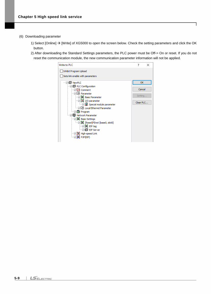
Chapter 5 High speed link service
5-9
(6) Downloading parameter
1) Select [Online] [Write] of XG5000 to open the screen below. Check the setting parameters and click the OK
button.
2) After downloading the Standard Settings parameters, the PLC power must be Off-> On or reset. If you do not
reset the communication module, the new communication parameter information will not be applied.
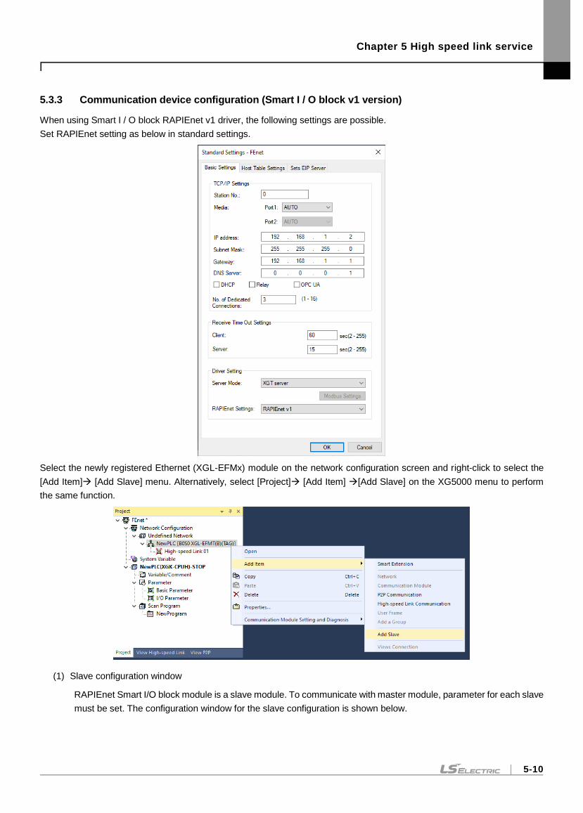
Chapter 5 High speed link service
5-10
5.3.3 Communication device configuration (Smart I / O block v1 version)
When using Smart I / O block RAPIEnet v1 driver, the following settings are possible.
Set RAPIEnet setting as below in standard settings.
Select the newly registered Ethernet (XGL-EFMx) module on the network configuration screen and right-click to select the
[Add Item] [Add Slave] menu. Alternatively, select [Project] [Add Item] [Add Slave] on the XG5000 menu to perform
the same function.
(1) Slave configuration window
RAPIEnet Smart I/O block module is a slave module. To communicate with master module, parameter for each slave
must be set. The configuration window for the slave configuration is shown below.
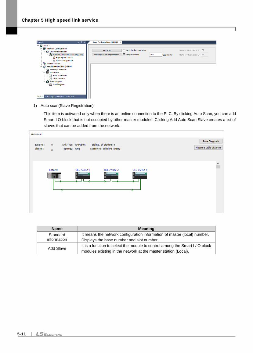
Chapter 5 High speed link service
5-11
1) Auto scan(Slave Registration)
This item is activated only when there is an online connection to the PLC. By clicking Auto Scan, you can add
Smart I O block that is not occupied by other master modules. Clicking Add Auto Scan Slave creates a list of
slaves that can be added from the network.
Name Meaning
Standard information
It means the network configuration information of master (local) number.
Displays the base number and slot number.
Add Slave It is a function to select the module to control among the Smart I / O block
modules existing in the network at the master station (Local).
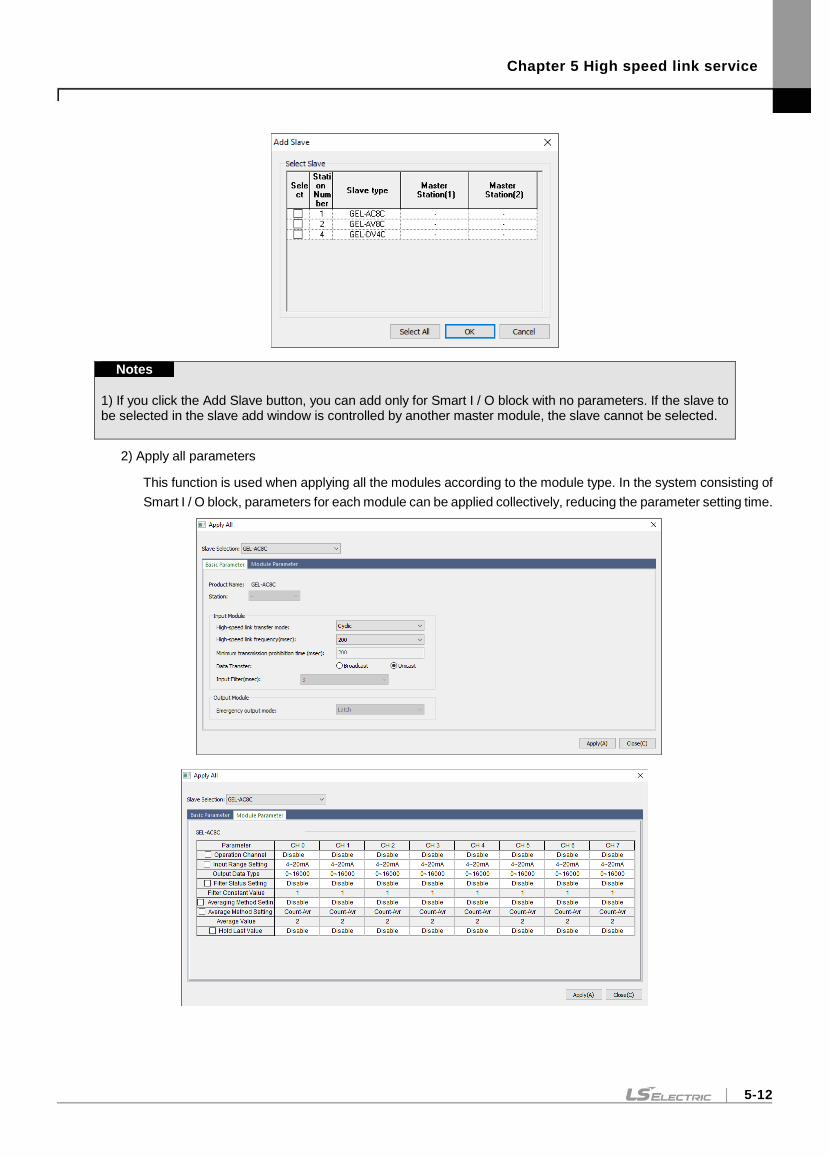
Chapter 5 High speed link service
5-12
Notes
1) If you click the Add Slave button, you can add only for Smart I / O block with no parameters. If the slave to be selected in the slave add window is controlled by another master module, the slave cannot be selected.
2) Apply all parameters
This function is used when applying all the modules according to the module type. In the system consisting of
Smart I / O block, parameters for each module can be applied collectively, reducing the parameter setting time.
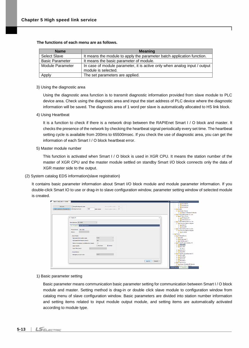
Chapter 5 High speed link service
5-13
The functions of each menu are as follows.
Name Meaning
Select Slave It means the module to apply the parameter batch application function.
Basic Parameter It means the basic parameter of module.
Module Parameter In case of module parameter, it is active only when analog input / output module is selected.
Apply The set parameters are applied.
3) Using the diagnostic area
Using the diagnostic area function is to transmit diagnostic information provided from slave module to PLC
device area. Check using the diagnostic area and input the start address of PLC device where the diagnostic
information will be saved. The diagnosis area of 1 word per slave is automatically allocated to HS link block.
4) Using Heartbeat
It is a function to check if there is a network drop between the RAPIEnet Smart I / O block and master. It
checks the presence of the network by checking the heartbeat signal periodically every set time. The heartbeat
setting cycle is available from 200ms to 65500msec. If you check the use of diagnostic area, you can get the
information of each Smart I / O block heartbeat error.
5) Master module number
This function is activated when Smart I / O block is used in XGR CPU. It means the station number of the
master of XGR CPU and the master module settled on standby Smart I/O block connects only the data of
XGR master side to the output.
(2) System catalog EDS information(slave registration)
It contains basic parameter information about Smart I/O block module and module parameter information. If you
double-click Smart IO to use or drag-in to slave configuration window, parameter setting window of selected module
is created.
1) Basic parameter setting
Basic parameter means communication basic parameter setting for communication between Smart I / O block
module and master. Setting method is drag-in or double click slave module to configuration window from
catalog menu of slave configuration window. Basic parameters are divided into station number information
and setting items related to input module output module, and setting items are automatically activated
according to module type.
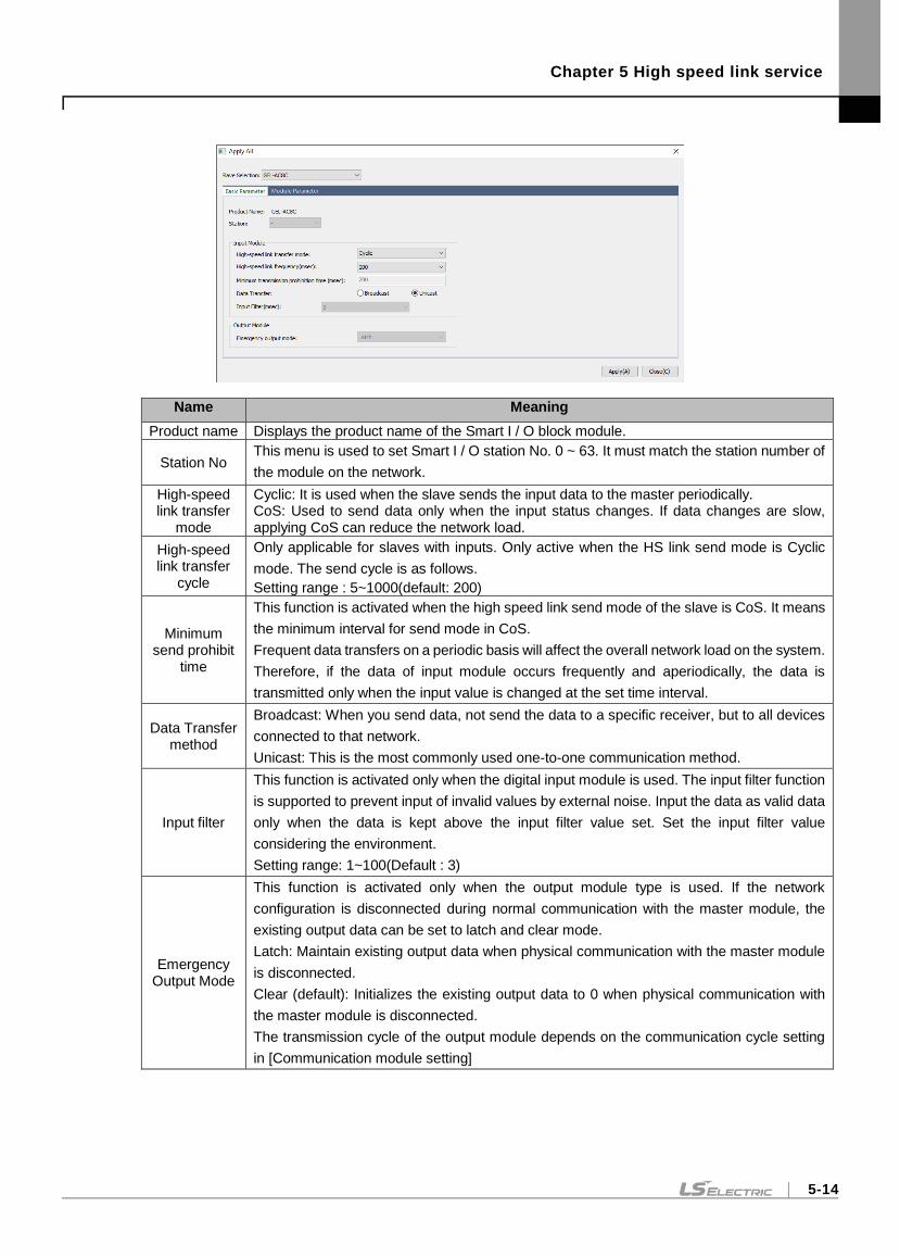
Chapter 5 High speed link service
5-14
Name Meaning
Product name Displays the product name of the Smart I / O block module.
Station No This menu is used to set Smart I / O station No. 0 ~ 63. It must match the station number of
the module on the network.
High-speed link transfer
mode
Cyclic: It is used when the slave sends the input data to the master periodically. CoS: Used to send data only when the input status changes. If data changes are slow, applying CoS can reduce the network load.
High-speed link transfer
cycle
Only applicable for slaves with inputs. Only active when the HS link send mode is Cyclic
mode. The send cycle is as follows.
Setting range : 5~1000(default: 200)
Minimum send prohibit
time
This function is activated when the high speed link send mode of the slave is CoS. It means
the minimum interval for send mode in CoS.
Frequent data transfers on a periodic basis will affect the overall network load on the system.
Therefore, if the data of input module occurs frequently and aperiodically, the data is
transmitted only when the input value is changed at the set time interval.
Data Transfer method
Broadcast: When you send data, not send the data to a specific receiver, but to all devices
connected to that network.
Unicast: This is the most commonly used one-to-one communication method.
Input filter
This function is activated only when the digital input module is used. The input filter function
is supported to prevent input of invalid values by external noise. Input the data as valid data
only when the data is kept above the input filter value set. Set the input filter value
considering the environment.
Setting range: 1~100(Default : 3)
Emergency Output Mode
This function is activated only when the output module type is used. If the network
configuration is disconnected during normal communication with the master module, the
existing output data can be set to latch and clear mode.
Latch: Maintain existing output data when physical communication with the master module
is disconnected.
Clear (default): Initializes the existing output data to 0 when physical communication with
the master module is disconnected.
The transmission cycle of the output module depends on the communication cycle setting
in [Communication module setting]
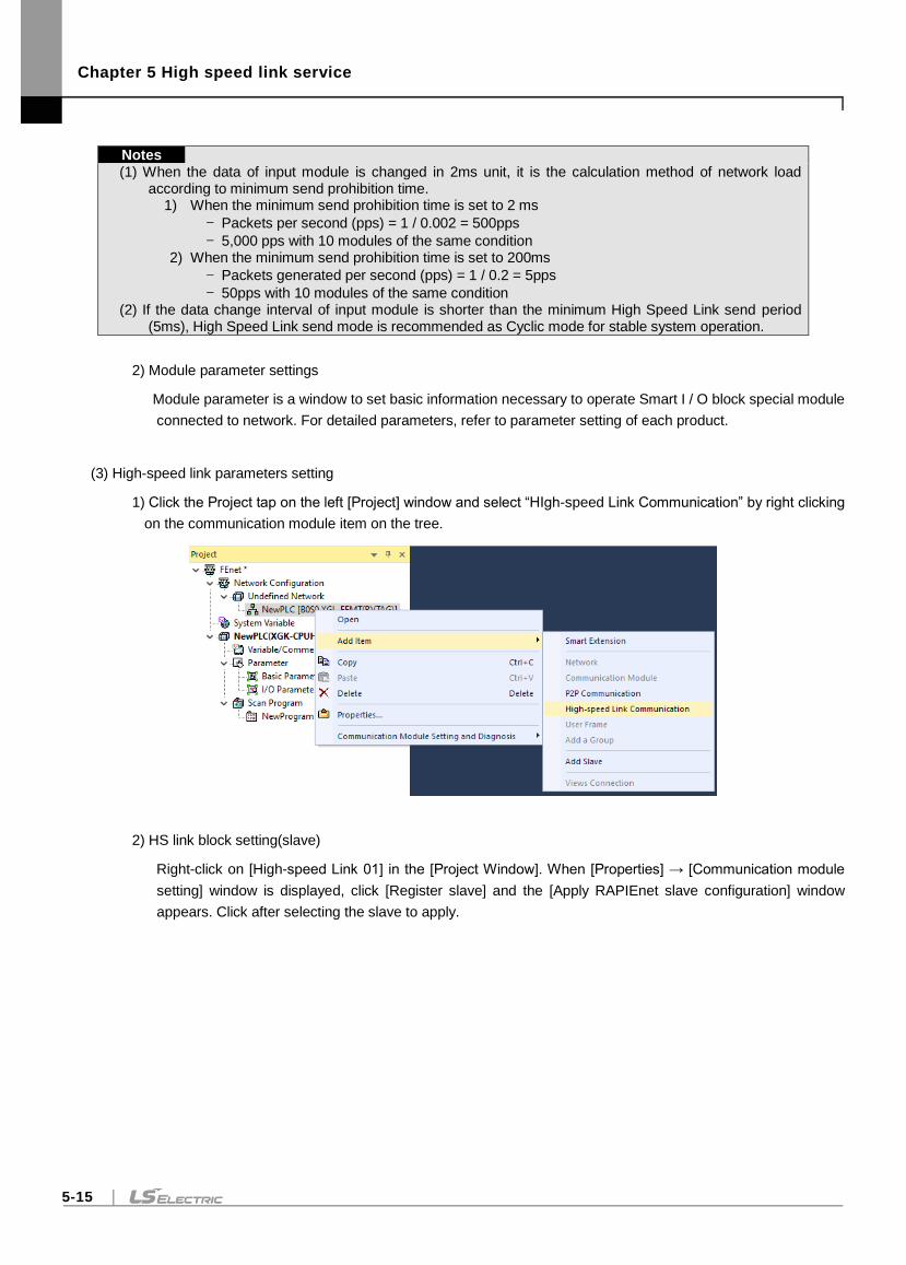
Chapter 5 High speed link service
5-15
Notes
(1) When the data of input module is changed in 2ms unit, it is the calculation method of network load according to minimum send prohibition time.
1) When the minimum send prohibition time is set to 2 ms
- Packets per second (pps) = 1 / 0.002 = 500pps
- 5,000 pps with 10 modules of the same condition 2) When the minimum send prohibition time is set to 200ms
- Packets generated per second (pps) = 1 / 0.2 = 5pps
- 50pps with 10 modules of the same condition (2) If the data change interval of input module is shorter than the minimum High Speed Link send period
(5ms), High Speed Link send mode is recommended as Cyclic mode for stable system operation.
2) Module parameter settings
Module parameter is a window to set basic information necessary to operate Smart I / O block special module
connected to network. For detailed parameters, refer to parameter setting of each product.
(3) High-speed link parameters setting
1) Click the Project tap on the left [Project] window and select “HIgh-speed Link Communication” by right clicking
on the communication module item on the tree.
2) HS link block setting(slave)
Right-click on [High-speed Link 01] in the [Project Window]. When [Properties] → [Communication module
setting] window is displayed, click [Register slave] and the [Apply RAPIEnet slave configuration] window
appears. Click after selecting the slave to apply.
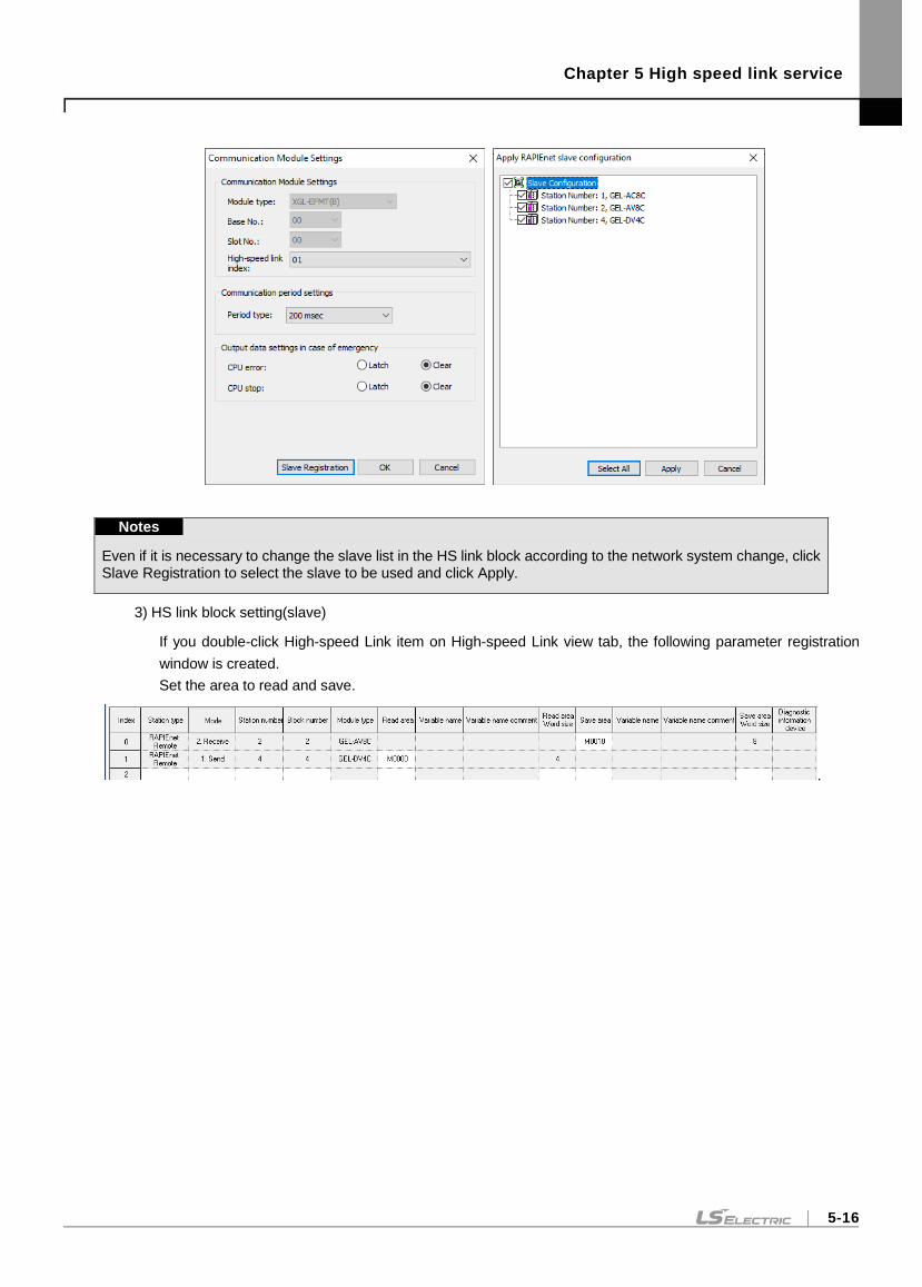
Chapter 5 High speed link service
5-16
Notes
Even if it is necessary to change the slave list in the HS link block according to the network system change, click Slave Registration to select the slave to be used and click Apply.
3) HS link block setting(slave)
If you double-click High-speed Link item on High-speed Link view tab, the following parameter registration
window is created.
Set the area to read and save.
.
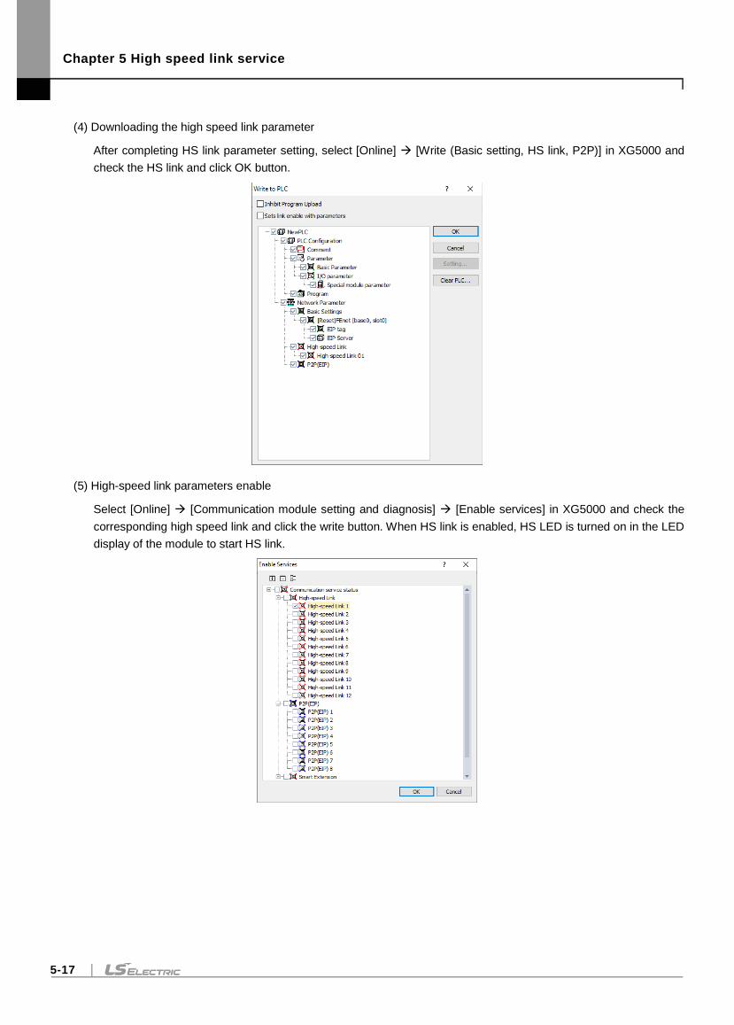
Chapter 5 High speed link service
5-17
(4) Downloading the high speed link parameter
After completing HS link parameter setting, select [Online] [Write (Basic setting, HS link, P2P)] in XG5000 and
check the HS link and click OK button.
(5) High-speed link parameters enable
Select [Online] [Communication module setting and diagnosis] [Enable services] in XG5000 and check the
corresponding high speed link and click the write button. When HS link is enabled, HS LED is turned on in the LED
display of the module to start HS link.
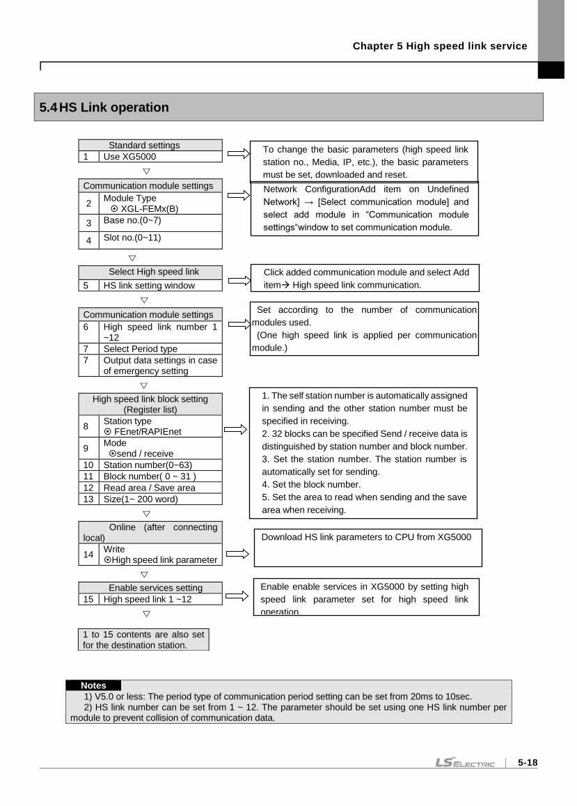
Chapter 5 High speed link service
5-18
5.4 HS Link operation
Standard settings
1 Use XG5000
Communication module settings
2 Module Type XGL-FEMx(B)
3 Base no.(0~7)
4 Slot no.(0~11)
Select High speed link
5 HS link setting window
Communication module settings
6 High speed link number 1 ~12
7 Select Period type
7 Output data settings in case of emergency setting
High speed link block setting (Register list)
8 Station type FEnet/RAPIEnet
9 Mode send / receive
10 Station number(0~63)
11 Block number( 0 ~ 31 )
12 Read area / Save area
13 Size(1~ 200 word)
Online (after connecting local)
14 Write High speed link parameter
Enable services setting
15 High speed link 1 ~12
Notes
1) V5.0 or less: The period type of communication period setting can be set from 20ms to 10sec. 2) HS link number can be set from 1 ~ 12. The parameter should be set using one HS link number per
module to prevent collision of communication data.
1 to 15 contents are also set for the destination station.
To change the basic parameters (high speed link
station no., Media, IP, etc.), the basic parameters
must be set, downloaded and reset.
Click added communication module and select Add
item High speed link communication.
Set according to the number of communication
modules used.
(One high speed link is applied per communication
module.)
2. Set the Communication period settings and Output
data settings in case of emergency . (Period type:
5ms~10sec) 1. The self station number is automatically assigned
in sending and the other station number must be
specified in receiving.
2. 32 blocks can be specified Send / receive data is
distinguished by station number and block number.
3. Set the station number. The station number is
automatically set for sending.
4. Set the block number.
5. Set the area to read when sending and the save
area when receiving.
6. The size can be set up to 200 Word.
Download HS link parameters to CPU from XG5000
Enable enable services in XG5000 by setting high
speed link parameter set for high speed link
operation.
Network ConfigurationAdd item on Undefined
Network] → [Select communication module] and
select add module in “Communication module
settings“window to set communication module.
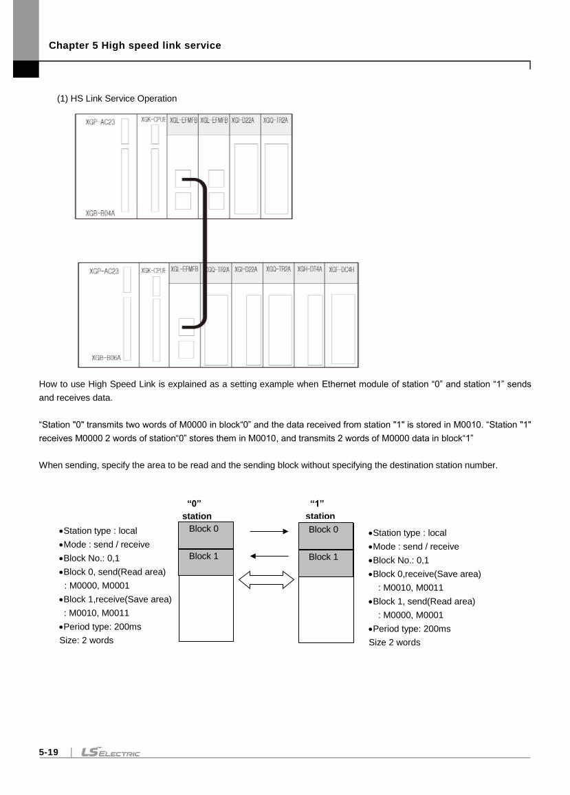
Chapter 5 High speed link service
5-19
(1) HS Link Service Operation
How to use High Speed Link is explained as a setting example when Ethernet module of station “0” and station “1” sends
and receives data.
“Station "0" transmits two words of M0000 in block“0” and the data received from station "1" is stored in M0010. “Station "1"
receives M0000 2 words of station“0” stores them in M0010, and transmits 2 words of M0000 data in block“1”
When sending, specify the area to be read and the sending block without specifying the destination station number.
“0”
station
Station type : local
Mode : send / receive
Block No.: 0,1
Block 0, send(Read area)
: M0000, M0001
Block 1,receive(Save area)
: M0010, M0011
Period type: 200ms
Size: 2 words
Block 0
Block 1
“1”
station
Station type : local
Mode : send / receive
Block No.: 0,1
Block 0,receive(Save area)
: M0010, M0011
Block 1, send(Read area)
: M0000, M0001
Period type: 200ms
Size 2 words
Block 0
Block 1
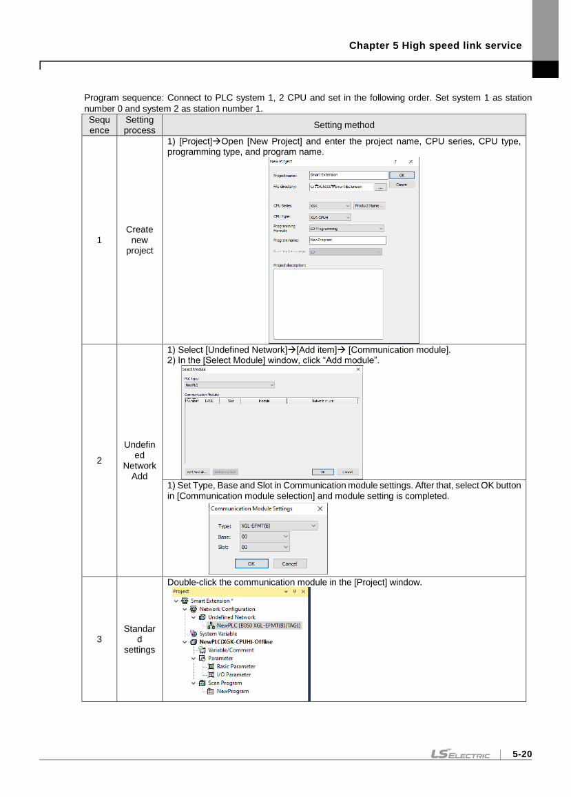
Chapter 5 High speed link service
5-20
Program sequence: Connect to PLC system 1, 2 CPU and set in the following order. Set system 1 as station
number 0 and system 2 as station number 1.
Sequence
Setting process
Setting method
1 Create
new project
1) [Project]Open [New Project] and enter the project name, CPU series, CPU type, programming type, and program name.
2
Undefined
Network Add
1) Select [Undefined Network][Add item] [Communication module]. 2) In the [Select Module] window, click “Add module”.
1) Set Type, Base and Slot in Communication module settings. After that, select OK button in [Communication module selection] and module setting is completed.
3 Standar
d settings
Double-click the communication module in the [Project] window.
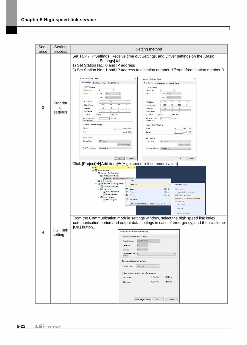
Chapter 5 High speed link service
5-21
Sequence
Setting process
Setting method
3 Standar
d settings
Set TCP / IP Settings, Receive time out Settings, and Driver settings on the [Basic Settings] tab.
1) Set Station No.: 0 and IP address 2) Set Station No.: 1 and IP address to a station number different from station number 0.
4 HS link setting
Click [Project][Add item][High speed link communication].
From the Communication module settings window, select the high speed link index, communication period and output data settings in case of emergency, and then click the [OK] button.
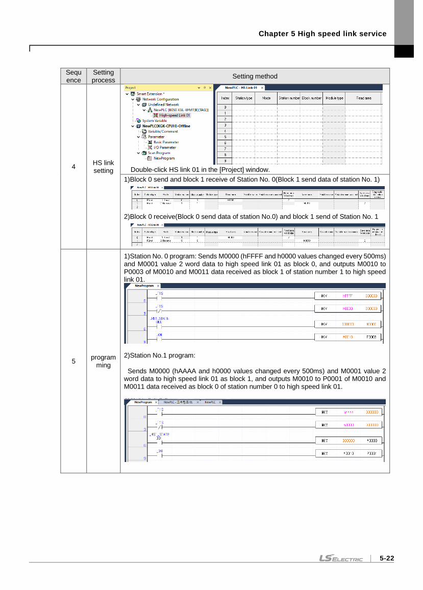
Chapter 5 High speed link service
5-22
Sequence
Setting process
Setting method
4 HS link setting
Double-click HS link 01 in the [Project] window.
1)Block 0 send and block 1 receive of Station No. 0(Block 1 send data of station No. 1)
2)Block 0 receive(Block 0 send data of station No.0) and block 1 send of Station No. 1
5 program
ming
1)Station No. 0 program: Sends M0000 (hFFFF and h0000 values changed every 500ms) and M0001 value 2 word data to high speed link 01 as block 0, and outputs M0010 to P0003 of M0010 and M0011 data received as block 1 of station number 1 to high speed link 01.
2)Station No.1 program: Sends M0000 (hAAAA and h0000 values changed every 500ms) and M0001 value 2 word data to high speed link 01 as block 1, and outputs M0010 to P0001 of M0010 and M0011 data received as block 0 of station number 0 to high speed link 01.
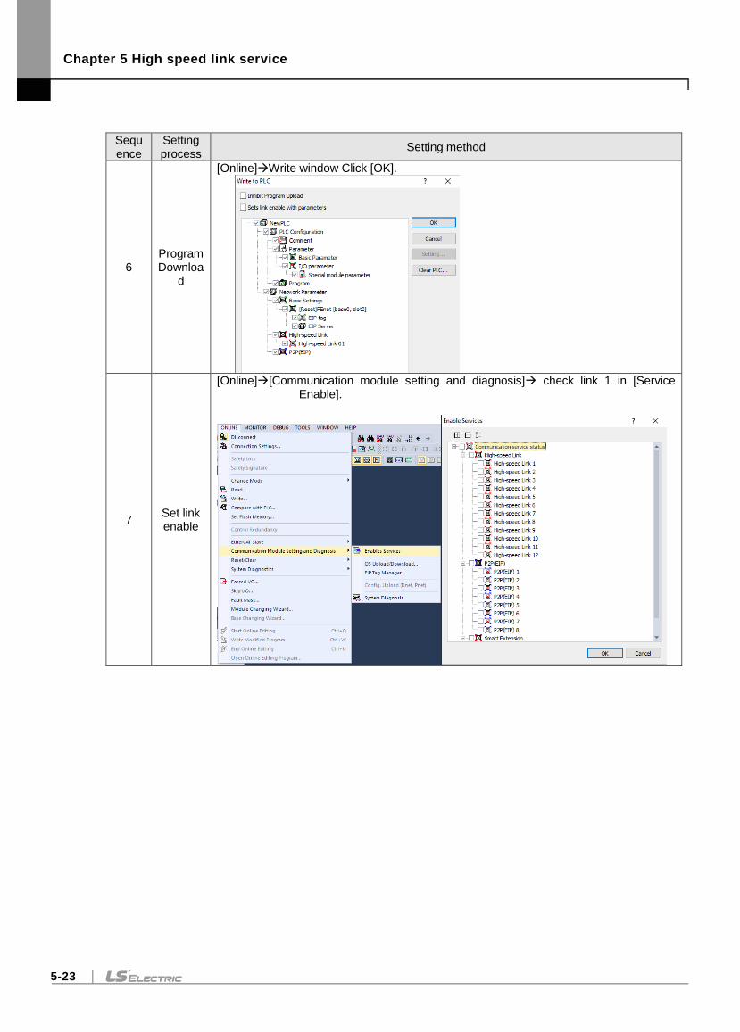
Chapter 5 High speed link service
5-23
Sequence
Setting process
Setting method
6 Program Downloa
d
[Online]Write window Click [OK].
7 Set link enable
[Online][Communication module setting and diagnosis] check link 1 in [Service Enable].
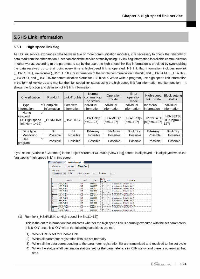
Chapter 5 High speed link service
5-24
5.5 HS Link Information
5.5.1 High speed link flag
As HS link service exchanges data between two or more communication modules, it is necessary to check the reliability of
data read from the other station. User can check the service status by using HS link flag information for reliable communication.
In other words, according to the parameters set by the user, the high-speed link flag information is provided by synthesizing
the data received up to that point every time a high-speed link is operated. HS link flag information includes run-link
(_HSxRLINK), link-trouble (_HSxLTRBL) for information of the whole communication network, and _HSxSTATE, _HSxTRX,
_HSxMOD, and _HSxERR for communication status for 128 blocks. When write a program, use high speed link information
in the form of keywords and monitor the high speed link status using the high speed link flag information monitor function. It
shows the function and definition of HS link information.
Classification Run-Link Link-Trouble Normal
communication status
Operation mode
Error operation
mode
High-speed link state
Block setting status
Type of information
Complete information
Complete information
Individual information
Individual information
Individual information
Individual information
Individual information
Name of keyword
(X: High speed link No = 1~12)
_HSxRLINK _HSxLTRBL _HSxTRX[n] (n=0..127)
_HSxMOD[n] (n=0..127)
_HSxERR[n](n=0..127)
_HSxSTATE[n](n=0..127)
_HSxSETBLOCK[n](n=0..127)
Data type Bit Bit Bit-Array Bit-Array Bit-Array Bit-Array Bit-Array
Monitoring Possible Possible Possible Possible Possible Possible Possible
Use of program
Possible Possible Possible Possible Possible Possible Possible
If you select [Variable / Comment] in the project screen of XG5000, [View Flag] screen is displayed. It is displayed when the
flag type is “high speed link” in this screen.
(1) Run-link (_HSxRLINK, x=High speed link No.(1~12))
This is the entire information that indicates whether the high speed link is normally executed with the set parameters.
If it is 'ON' once, it is 'ON' when the following conditions are met.
1) When ‘ON’ is set for Enable Link
2) When all parameter registration lists are set normally
3) When all the data corresponding to the parameter registration list are transmitted and received to the set cycle
4) When the status of all destination stations set for the parameter are in RUN status and there is no error at that
time
Chapter 5 High speed link service
5-25
(2) Link-trouble(_HSxLTRBL, x=High speed link No.(1~12)
Total Information that indicates whether the High Speed Link is normal with the set parameters. It is OFF when Run
Link is ON and it is on Run Link is Off.
(3) Normal communication status(_HSxTRX[0..127], x=High speed link No.(1~12))
Up to 128 send / receive information as individual information representing the send / receive status of block link
parameter. If registered sending / receiving operation is done according to period time, corresponding bit is ON and
if not, it is OFF.
(4) Operation mode(_HSxMODE[0..127], x=High speed link No.(1~12))
This is the individual information that shows the block operation status of HS link parameter and shows 128 operation
mode information which is the maximum number of registered. If the station set for the Block item is in Run mode,
the relevant bit will become ON. If it is in Stop/Pause/Debug mode, the relevant bit will become OFF.
(5) Error operation mode(_HSxERR[0..127], x=High speed link No.(1~12))
Individual information indicating the operation status of each high-speed link parameter for each block. Up to 128
blocks of error information are displayed. When the user program cannot be executed, it indicates that the other
station PLC is operating normally when it is OFF, and when it is ON, the other station is in abnormal status.
(6) High-speed link state(_HSxSTATE[0..127], x=High speed link No.(1~12))
As individual information that shows the operation status of each HS block parameter, it displays up to 128 HS link
states and displays the information for each item by block. That is, if the sending / receiving status of each list is
normal, the operation mode is run, if there is no error, it is ON and if it is not satisfied, the item is OFF.
(7) Block setting status(_HSxSETBLOCK[0..127], x=High speed link No.(1~12))
As individual information that shows the operation status of each HS block parameter, it displays up to 128 block
setting states and displays the information for each item by block. That is, if the sending / receiving status of each
block is normal, the operation mode is run, if there is no error, it is ON and if it is not satisfied, the item is OFF.
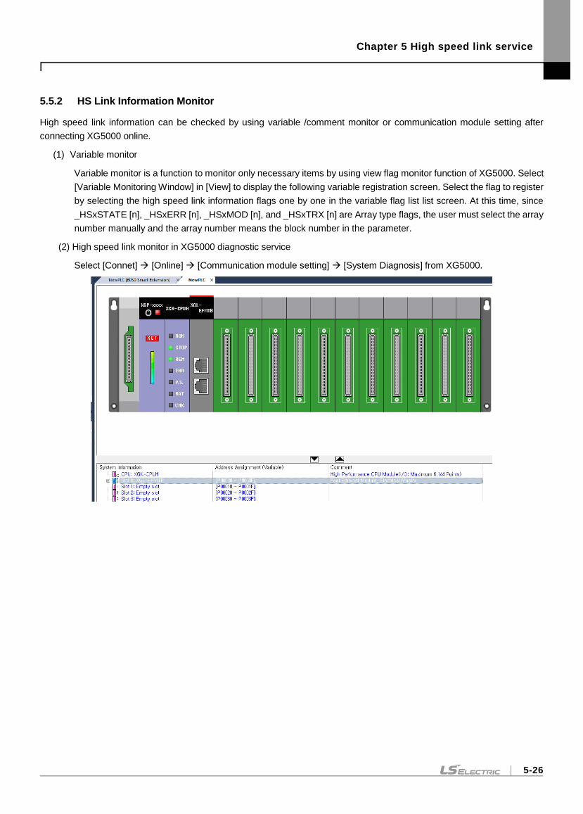
Chapter 5 High speed link service
5-26
5.5.2 HS Link Information Monitor
High speed link information can be checked by using variable /comment monitor or communication module setting after
connecting XG5000 online.
(1) Variable monitor
Variable monitor is a function to monitor only necessary items by using view flag monitor function of XG5000. Select
[Variable Monitoring Window] in [View] to display the following variable registration screen. Select the flag to register
by selecting the high speed link information flags one by one in the variable flag list list screen. At this time, since
_HSxSTATE [n], _HSxERR [n], _HSxMOD [n], and _HSxTRX [n] are Array type flags, the user must select the array
number manually and the array number means the block number in the parameter.
(2) High speed link monitor in XG5000 diagnostic service
Select [Connet] [Online] [Communication module setting] [System Diagnosis] from XG5000.
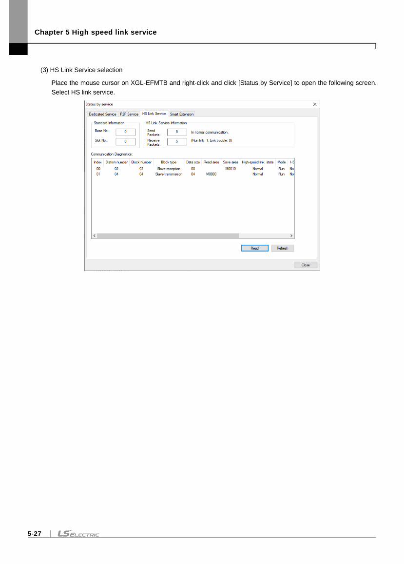
Chapter 5 High speed link service
5-27
(3) HS Link Service selection
Place the mouse cursor on XGL-EFMTB and right-click and click [Status by Service] to open the following screen.
Select HS link service.
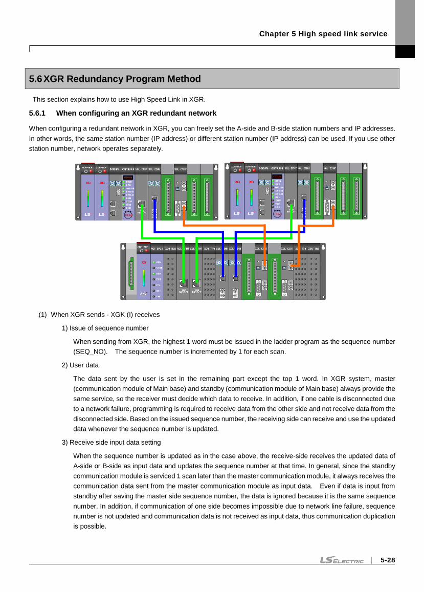
Chapter 5 High speed link service
5-28
5.6 XGR Redundancy Program Method
This section explains how to use High Speed Link in XGR.
5.6.1 When configuring an XGR redundant network
When configuring a redundant network in XGR, you can freely set the A-side and B-side station numbers and IP addresses.
In other words, the same station number (IP address) or different station number (IP address) can be used. If you use other
station number, network operates separately.
(1) When XGR sends - XGK (I) receives
1) Issue of sequence number
When sending from XGR, the highest 1 word must be issued in the ladder program as the sequence number
(SEQ_NO). The sequence number is incremented by 1 for each scan.
2) User data
The data sent by the user is set in the remaining part except the top 1 word. In XGR system, master
(communication module of Main base) and standby (communication module of Main base) always provide the
same service, so the receiver must decide which data to receive. In addition, if one cable is disconnected due
to a network failure, programming is required to receive data from the other side and not receive data from the
disconnected side. Based on the issued sequence number, the receiving side can receive and use the updated
data whenever the sequence number is updated.
3) Receive side input data setting
When the sequence number is updated as in the case above, the receive-side receives the updated data of
A-side or B-side as input data and updates the sequence number at that time. In general, since the standby
communication module is serviced 1 scan later than the master communication module, it always receives the
communication data sent from the master communication module as input data. Even if data is input from
standby after saving the master side sequence number, the data is ignored because it is the same sequence
number. In addition, if communication of one side becomes impossible due to network line failure, sequence
number is not updated and communication data is not received as input data, thus communication duplication
is possible.
Chapter 5 High speed link service
5-29
4) High speed link function block
In XGR and XGI, function block is used for receiving data processing. In XGK, there is no function block, so
you can use the program written in the below letter.
Notes
Send/ receive using sequence number is a basic data send / receive algorithm method. Depending on your application service, you do not need to use it if you have a specific data pattern.
(2) When XGK(I) sends - XGR receives
1) Set data send and receive
The XGK (I) side to be transmitted should use two communication modules to service the same data with the
same setting. At this time, sequence number is not necessary and the receiving side receives communication
data coming into the master as input data. If STATE FLAG is turned off with STATE FLAG as a contact in the
condition of receiving input data in consideration of network failure, copy the standby data to the master by
SYNC command and receive the data.
Notes
Since the block setting is the same for A-side and B-side, if the station number of the sending side is different, the receiving block should be Setting Value to twice the desired block.
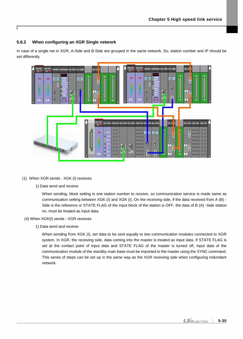
Chapter 5 High speed link service
5-30
5.6.2 When configuring an XGR Single network
In case of a single net in XGR, A-Side and B-Side are grouped in the same network. So, station number and IP should be
set differently.
(1) When XGR sends - XGK (I) receives
1) Data send and receive
When sending, block setting is one station number to receive, so communication service is made same as
communication setting between XGK (I) and XGK (I). On the receiving side, if the data received from A (B) -
Side is the reference or STATE FLAG of the input block of the station is OFF, the data of B (A) -Side station
no. must be treated as input data.
(4) When XGK(I) sends - XGR receives
1) Data send and receive
When sending from XGK (I), set data to be sent equally to two communication modules connected to XGR
system. In XGR, the receiving side, data coming into the master is treated as input data. If STATE FLAG is
set at the contact point of input data and STATE FLAG of the master is turned off, input data of the
communication module of the standby main base must be imported to the master using the SYNC command.
This series of steps can be set up in the same way as the XGR receiving side when configuring redundant
network.
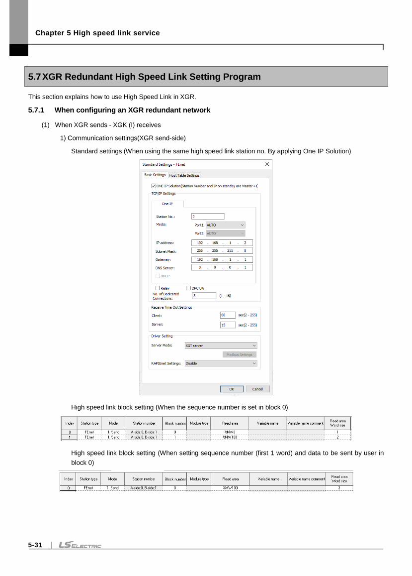
Chapter 5 High speed link service
5-31
5.7 XGR Redundant High Speed Link Setting Program
This section explains how to use High Speed Link in XGR.
5.7.1 When configuring an XGR redundant network
(1) When XGR sends - XGK (I) receives
1) Communication settings(XGR send-side)
Standard settings (When using the same high speed link station no. By applying One IP Solution)
High speed link block setting (When the sequence number is set in block 0)
High speed link block setting (When setting sequence number (first 1 word) and data to be sent by user in
block 0)
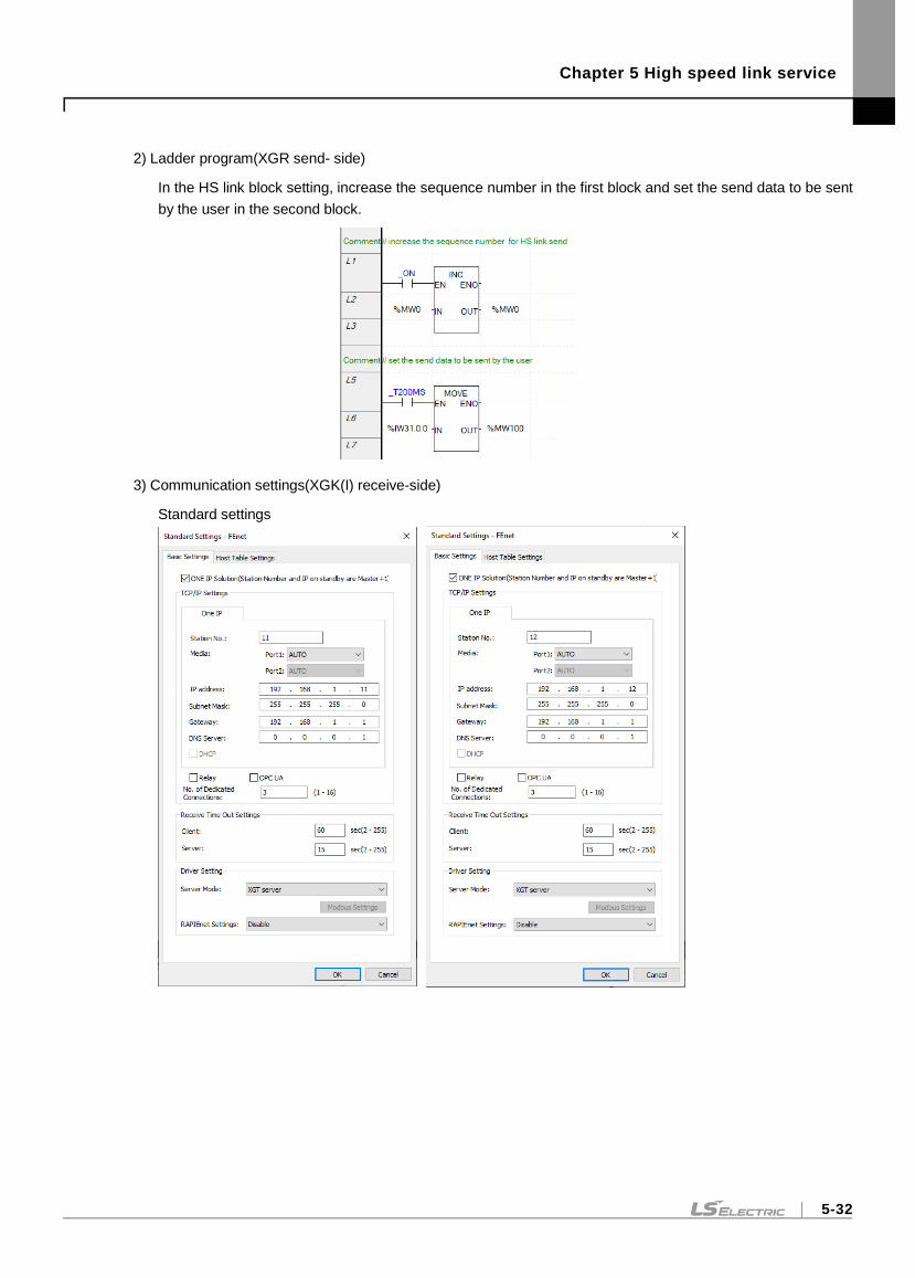
Chapter 5 High speed link service
5-32
2) Ladder program(XGR send- side)
In the HS link block setting, increase the sequence number in the first block and set the send data to be sent
by the user in the second block.
3) Communication settings(XGK(I) receive-side)
Standard settings
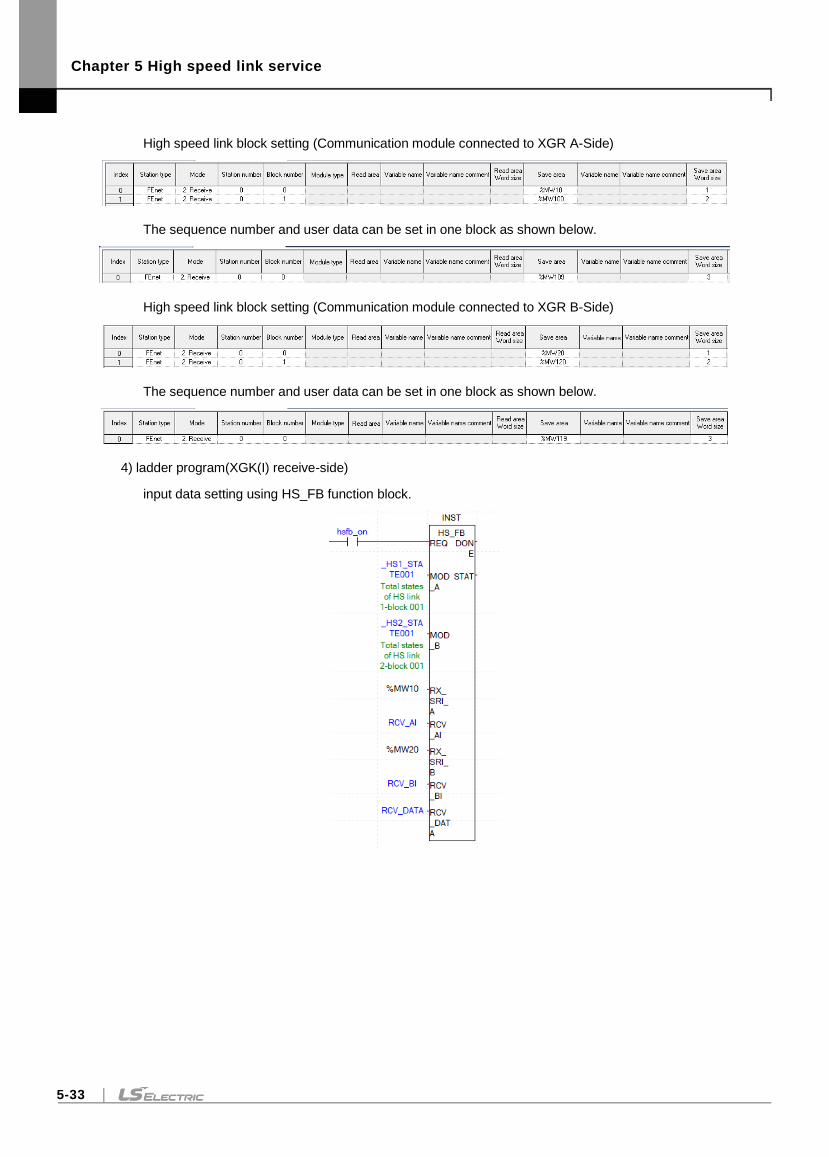
Chapter 5 High speed link service
5-33
High speed link block setting (Communication module connected to XGR A-Side)
The sequence number and user data can be set in one block as shown below.
High speed link block setting (Communication module connected to XGR B-Side)
The sequence number and user data can be set in one block as shown below.
4) ladder program(XGK(I) receive-side)
input data setting using HS_FB function block.
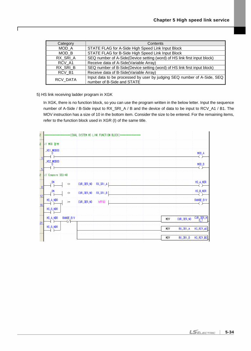
Chapter 5 High speed link service
5-34
Category Contents
MOD_A STATE FLAG for A-Side High Speed Link Input Block
MOD_B STATE FLAG for B-Side High Speed Link Input Block
RX_SRI_A SEQ number of A-Side(Device setting (word) of HS link first input block)
RCV_A1 Receive data of A-Side(Variable Array)
RX_SRI_B SEQ number of B-Side(Device setting (word) of HS link first input block)
RCV_B1 Receive data of B-Side(Variable Array)
RCV_DATA Input data to be processed by user by judging SEQ number of A-Side, SEQ number of B-Side and STATE
5) HS link receiving ladder program in XGK
In XGK, there is no function block, so you can use the program written in the below letter. Input the sequence
number of A-Side / B-Side input to RX_SRI_A / B and the device of data to be input to RCV_A1 / B1. The
MOV instruction has a size of 10 in the bottom item. Consider the size to be entered. For the remaining items,
refer to the function block used in XGR (I) of the same title.
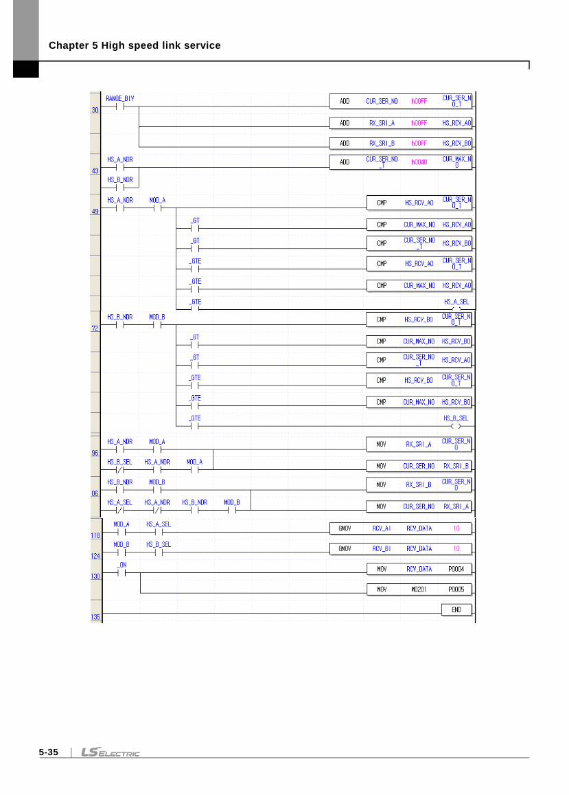
Chapter 5 High speed link service
5-35
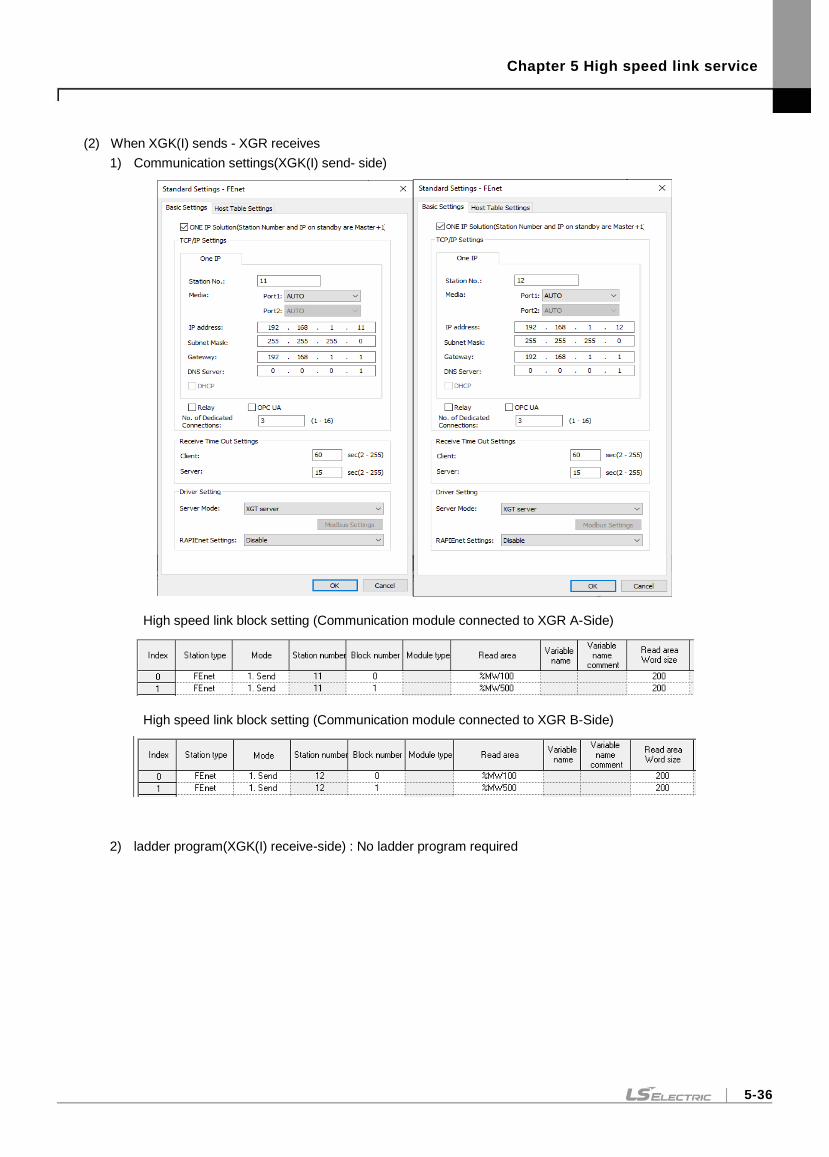
Chapter 5 High speed link service
5-36
(2) When XGK(I) sends - XGR receives
1) Communication settings(XGK(I) send- side)
High speed link block setting (Communication module connected to XGR A-Side)
High speed link block setting (Communication module connected to XGR B-Side)
2) ladder program(XGK(I) receive-side) : No ladder program required
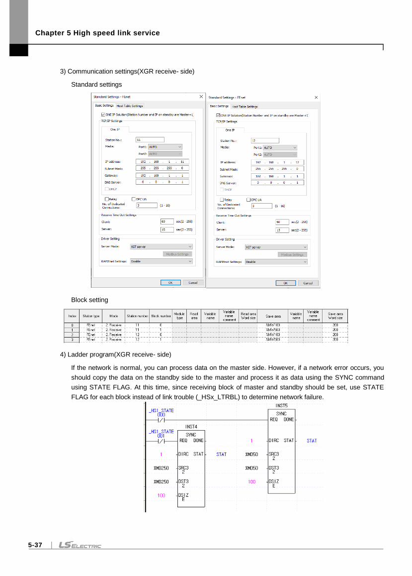
Chapter 5 High speed link service
5-37
3) Communication settings(XGR receive- side)
Standard settings
Block setting
4) Ladder program(XGR receive- side)
If the network is normal, you can process data on the master side. However, if a network error occurs, you
should copy the data on the standby side to the master and process it as data using the SYNC command
using STATE FLAG. At this time, since receiving block of master and standby should be set, use STATE
FLAG for each block instead of link trouble (_HSx_LTRBL) to determine network failure.
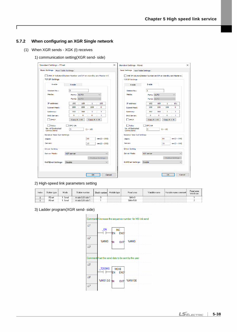
Chapter 5 High speed link service
5-38
5.7.2 When configuring an XGR Single network
(1) When XGR sends - XGK (I) receives
1) communication setting(XGR send- side)
2) High-speed link parameters setting
3) Ladder program(XGR send- side)
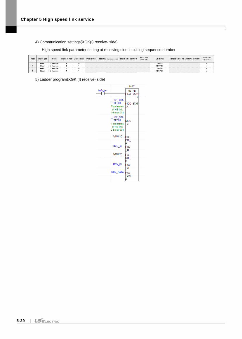
Chapter 5 High speed link service
5-39
4) Communication settings(XGK(I) receive- side)
High speed link parameter setting at receiving side including sequence number
5) Ladder program(XGK (I) receive- side)
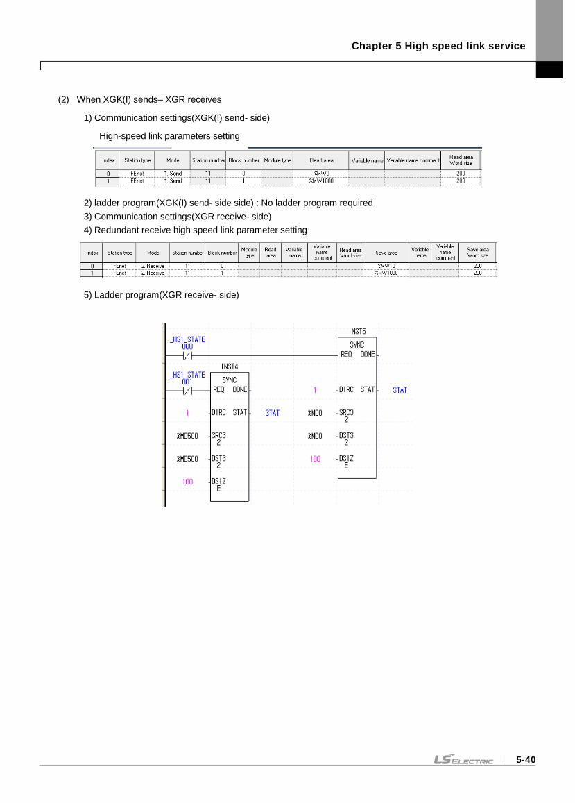
Chapter 5 High speed link service
5-40
(2) When XGK(I) sends– XGR receives
1) Communication settings(XGK(I) send- side)
High-speed link parameters setting
2) ladder program(XGK(I) send- side side) : No ladder program required
3) Communication settings(XGR receive- side)
4) Redundant receive high speed link parameter setting
5) Ladder program(XGR receive- side)
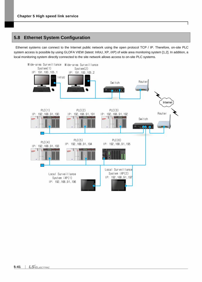
Chapter 5 High speed link service
5-41
5.8 Ethernet System Configuration
Ethernet systems can connect to the Internet public network using the open protocol TCP / IP. Therefore, on-site PLC
system access is possible by using GLOFA VIEW (latest: InfoU, XP, iXP) of wide area monitoring system [1,2]. In addition, a
local monitoring system directly connected to the site network allows access to on-site PLC systems.
Local Surveillance System iXP(2)
IP: 192,168,91,197
EtherNet/IP서버
Wide-area Surveillance System(1)
IP: 191,100,105,1
Wide-area Surveillance System(2)
IP: 191,100,105,2
Switch Router
PLC(1)IP: 192,168,91,190
PLC(2)IP: 192,168,91,191
PLC(3)IP: 192,168,91,192
Switch
Router
PLC(4)IP: 192,168,91,193
PLC(5)IP: 192,168,91,194
PLC(6)IP: 192,168,91,195
Local Surveillance System iXP(1)
IP: 192,168,91,196
Internet
InfoU
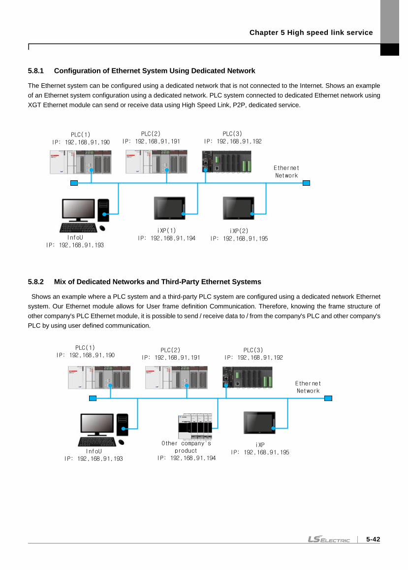
Chapter 5 High speed link service
5-42
5.8.1 Configuration of Ethernet System Using Dedicated Network
The Ethernet system can be configured using a dedicated network that is not connected to the Internet. Shows an example
of an Ethernet system configuration using a dedicated network. PLC system connected to dedicated Ethernet network using
XGT Ethernet module can send or receive data using High Speed Link, P2P, dedicated service.
iXP(2)IP: 192,168,91,195
Ethernet Network
PLC(1)IP: 192,168,91,190
PLC(2)IP: 192,168,91,191
PLC(3)IP: 192,168,91,192
iXP(1)IP: 192,168,91,194InfoU
IP: 192,168,91,193
5.8.2 Mix of Dedicated Networks and Third-Party Ethernet Systems
Shows an example where a PLC system and a third-party PLC system are configured using a dedicated network Ethernet
system. Our Ethernet module allows for User frame definition Communication. Therefore, knowing the frame structure of
other company's PLC Ethernet module, it is possible to send / receive data to / from the company's PLC and other company's
PLC by using user defined communication.
iXPIP: 192,168,91,195
Ethernet Network
PLC(2)IP: 192,168,91,191
PLC(3)IP: 192,168,91,192
Other company's product
IP: 192,168,91,194InfoU
IP: 192,168,91,193
PLC(1)IP: 192,168,91,190
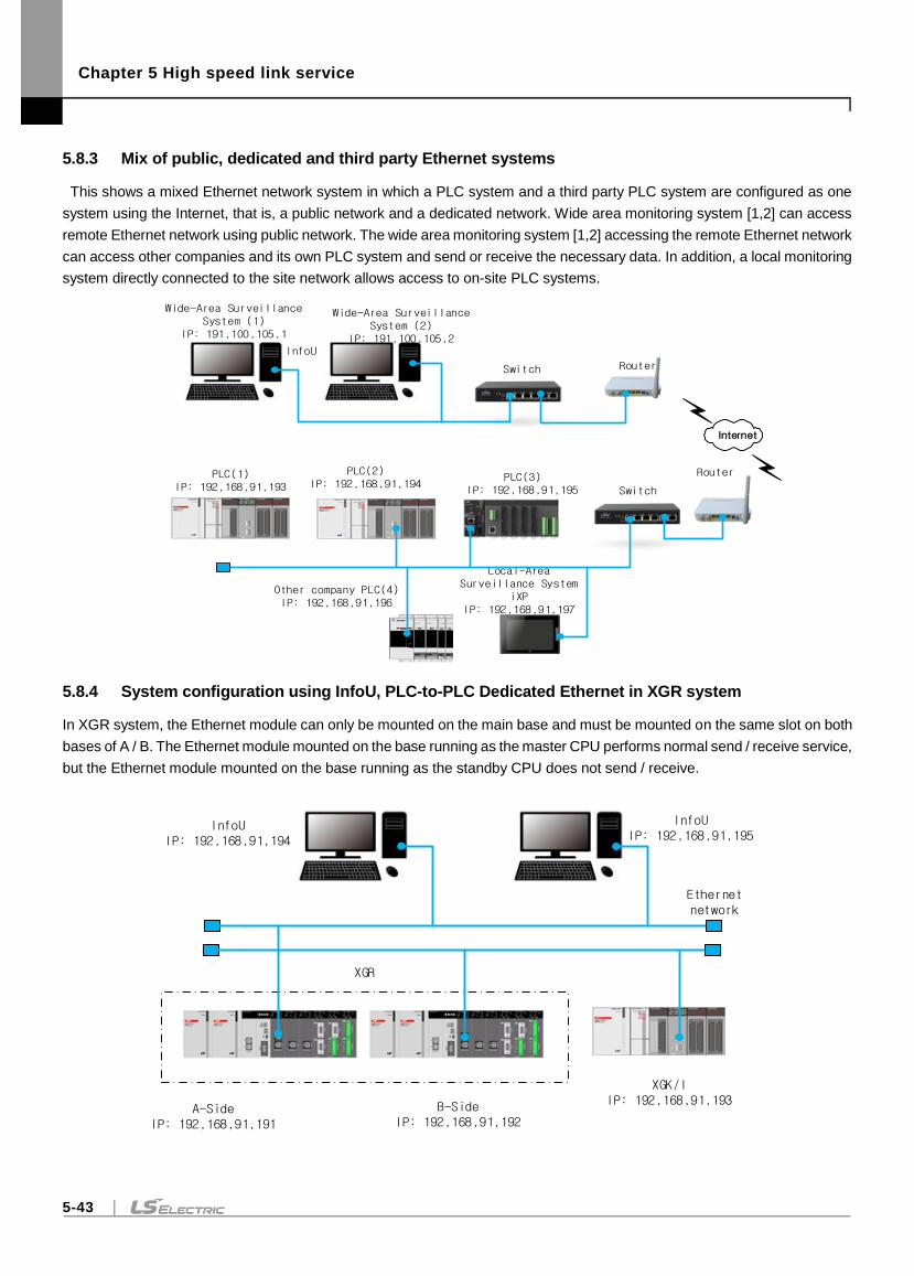
Chapter 5 High speed link service
5-43
5.8.3 Mix of public, dedicated and third party Ethernet systems
This shows a mixed Ethernet network system in which a PLC system and a third party PLC system are configured as one
system using the Internet, that is, a public network and a dedicated network. Wide area monitoring system [1,2] can access
remote Ethernet network using public network. The wide area monitoring system [1,2] accessing the remote Ethernet network
can access other companies and its own PLC system and send or receive the necessary data. In addition, a local monitoring
system directly connected to the site network allows access to on-site PLC systems.
Local-Area Surveillance System
iXPIP: 192,168,91,197
EtherNet/IP서버
Wide-Area Surveillance System (1)
IP: 191,100,105,1
Wide-Area Surveillance System (2)
IP: 191,100,105,2
Switch Router
Switch
RouterPLC(1)IP: 192,168,91,193
PLC(2)IP: 192,168,91,194
PLC(3)IP: 192,168,91,195
Other company PLC(4)IP: 192,168,91,196
Internet
InfoU
5.8.4 System configuration using InfoU, PLC-to-PLC Dedicated Ethernet in XGR system
In XGR system, the Ethernet module can only be mounted on the main base and must be mounted on the same slot on both
bases of A / B. The Ethernet module mounted on the base running as the master CPU performs normal send / receive service,
but the Ethernet module mounted on the base running as the standby CPU does not send / receive.
XGK/I IP: 192,168,91,193
Ethernet network
A-SideIP: 192,168,91,191
InfoUIP: 192,168,91,194
InfoUIP: 192,168,91,195
B-SideIP: 192,168,91,192
XGR
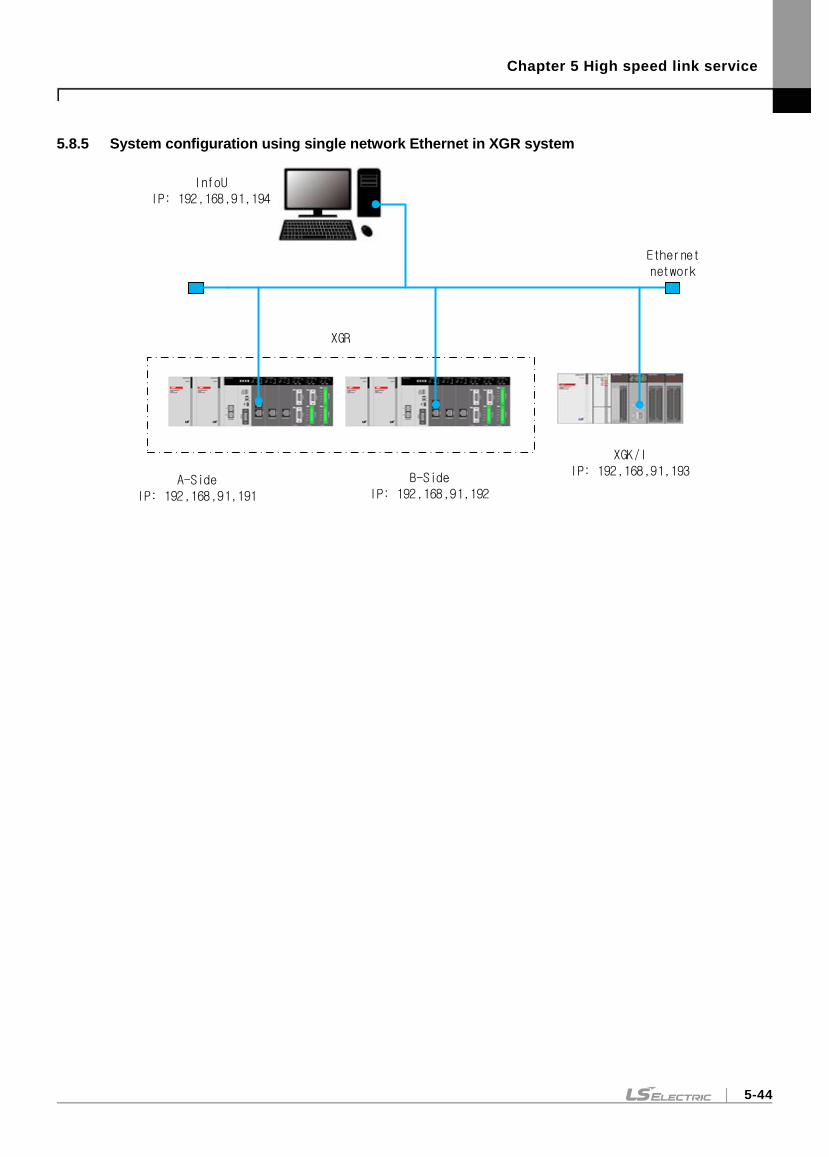
Chapter 5 High speed link service
5-44
5.8.5 System configuration using single network Ethernet in XGR system
XGK/I IP: 192,168,91,193
Ethernet network
A-SideIP: 192,168,91,191
InfoUIP: 192,168,91,194
B-SideIP: 192,168,91,192
XGR
Chapter 6 P2P service
6-1
Chapter 6 P2P service
6.1 Overview
6.1.1 Overview of P2P service
P2P service is the master operation of communication module. It is the function implemented by function, block
(command) by parameter setting. There are seven P2P commands available in the Ethernet module: Read, Write,
Write_NC, Send, Send_NC, Receive, and ESend.
Up to 8 P2P parameters can be set on the XG5000 for P2P service registration and editing. Each P2P parameter
consists of up to 64 P2P blocks.
(1) P2P parameter registration
- Up to eight P2P parameters can be set per CPU.
- Multiple P2P parameters can be set for the same communication module.
However, enable only one of many P2P parameters for the same communication module.
- The each P2P parameter consists of P2P channel, P2P block, user frame definition and email.
(2) P2P editing
- Up to 64 P2P blocks that can be registered for each P2P parameter.
- A frame can be registered separately for each driver.
6.1.2 P2P parameter configuration
In order to use P2P service, user carry should set it for desired operation in P2P parameter window. P2P
parameter configuration consists of 4 pieces of information.
(1) P2P channel
- Set the logical channels (IP, PORT, dedicated driver) of the carry P2P service
- Configurable P2P Driver
1) User frame definition
2) XGT client
3) Modbus TCP client
4) Modbus RTU client( V6.0 or higher)
5) Modbus ASCII client( V6.0 or higher)
6) XGT Cnet client( V6.0 or higher)
7) RAPIEnet client (V6.0 or higher)
(2) P2P block
- Set 64 P2P blocks that operate independently
(3) User frame definition
- Register of a user frame definition
(4) E-mail
Register a frame for transmitting and receiving an- E-mail frame
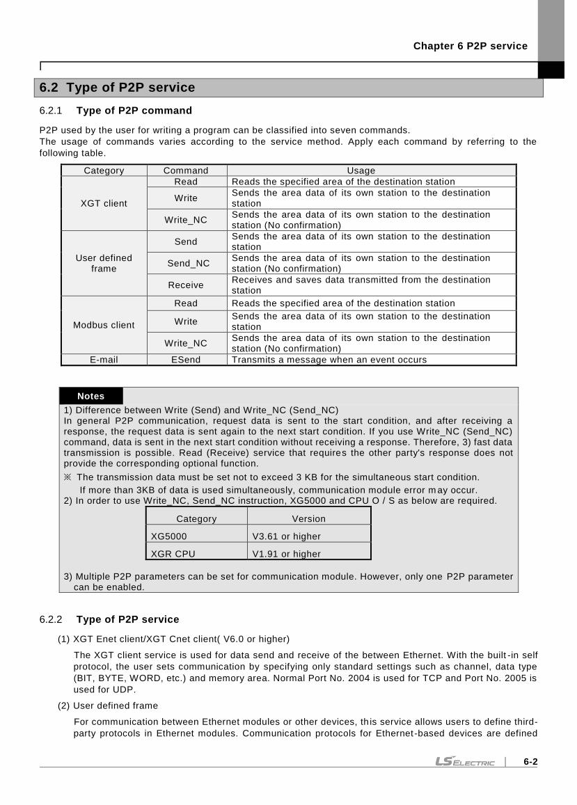
Chapter 6 P2P service
6-2
6.2 Type of P2P service
6.2.1 Type of P2P command
P2P used by the user for writing a program can be classified into seven commands.
The usage of commands varies according to the service method. Apply each command by referring to the
following table.
Category Command Usage
XGT client
Read Reads the specified area of the destination station
Write Sends the area data of its own station to the destination station
Write_NC Sends the area data of its own station to the destination station (No confirmation)
User defined frame
Send Sends the area data of its own station to the destination station
Send_NC Sends the area data of its own station to the destination station (No confirmation)
Receive Receives and saves data transmitted from the destination station
Modbus client
Read Reads the specified area of the destination station
Write Sends the area data of its own station to the destination station
Write_NC Sends the area data of its own station to the destination station (No confirmation)
E-mail ESend Transmits a message when an event occurs
Notes
1) Difference between Write (Send) and Write_NC (Send_NC) In general P2P communication, request data is sent to the start condition, and after receiving a response, the request data is sent again to the next start condition. If you use Write_NC (Send_NC) command, data is sent in the next start condition without receiving a response. Therefore, 3) fast data transmission is possible. Read (Receive) service that requires the other party's response does not provide the corresponding optional function.
※ The transmission data must be set not to exceed 3 KB for the simultaneous start condition.
If more than 3KB of data is used simultaneously, communication module error m ay occur. 2) In order to use Write_NC, Send_NC instruction, XG5000 and CPU O / S as below are required.
Category Version
XG5000 V3.61 or higher
XGR CPU V1.91 or higher
3) Multiple P2P parameters can be set for communication module. However, only one P2P parameter
can be enabled.
6.2.2 Type of P2P service
(1) XGT Enet client/XGT Cnet client( V6.0 or higher)
The XGT client service is used for data send and receive of the between Ethernet. With the built -in self
protocol, the user sets communication by specifying only standard settings such as channel, data type
(BIT, BYTE, WORD, etc.) and memory area. Normal Port No. 2004 is used for TCP and Port No. 2005 is
used for UDP.
(2) User defined frame
For communication between Ethernet modules or other devices, th is service allows users to define third-
party protocols in Ethernet modules. Communication protocols for Ethernet -based devices are defined
Chapter 6 P2P service
6-3
differently by the manufacturer, which can be edited to suit the characteristics of each communication
module. The user frame definition has basic structure of HEAD, BODY and TAIL.
(3) Modbus TCP / Modbus RTU( V6.0 or higher)/Modbus ASCII( V6.0 or higher) Client
Ethernet module supports various Modbus protocol in addition to user frame definition protocol.
(4) RAPIEnet client (V6.0 or higher)
If RAPIEnet is set in the standard settings, the RAPIEnet client service is available.
(5) E-mail
E-mail service is a service to notify the remote administrator of the status by using the system when a
problem occurs in the system. If the status of the CPU has changed or an event occurred during operation,
you can deliver the status information using the mail server.
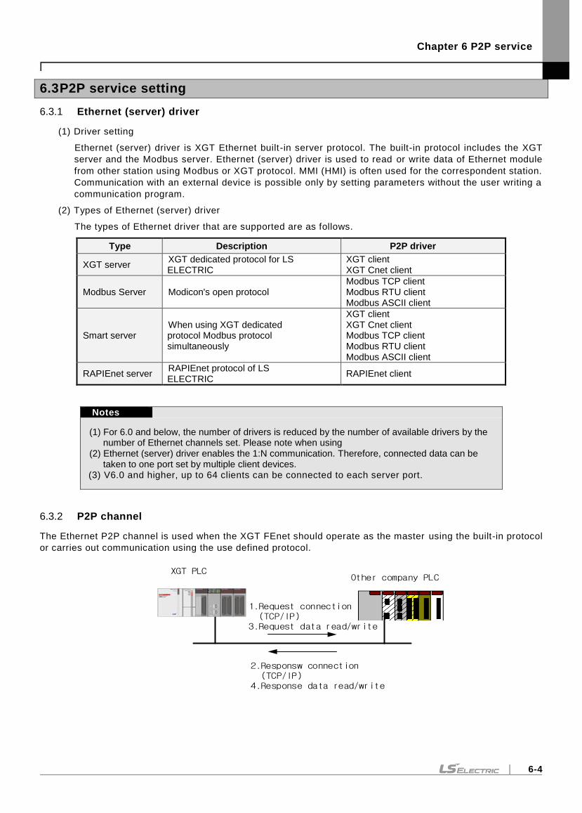
Chapter 6 P2P service
6-4
6.3 P2P service setting
6.3.1 Ethernet (server) driver
(1) Driver setting
Ethernet (server) driver is XGT Ethernet built-in server protocol. The built-in protocol includes the XGT
server and the Modbus server. Ethernet (server) driver is used to read or write data of Ethernet module
from other station using Modbus or XGT protocol. MMI (HMI) is often used for the correspondent station.
Communication with an external device is possible only by setting parameters without the user writing a
communication program.
(2) Types of Ethernet (server) driver
The types of Ethernet driver that are supported are as follows.
Type Description P2P driver
XGT server XGT dedicated protocol for LS ELECTRIC
XGT client XGT Cnet client
Modbus Server Modicon's open protocol Modbus TCP client Modbus RTU client Modbus ASCII client
Smart server When using XGT dedicated protocol Modbus protocol simultaneously
XGT client XGT Cnet client Modbus TCP client Modbus RTU client Modbus ASCII client
RAPIEnet server RAPIEnet protocol of LS ELECTRIC
RAPIEnet client
Notes
(1) For 6.0 and below, the number of drivers is reduced by the number of available drivers by the number of Ethernet channels set. Please note when using
(2) Ethernet (server) driver enables the 1:N communication. Therefore, connected data can be taken to one port set by multiple client devices.
(3) V6.0 and higher, up to 64 clients can be connected to each server port.
6.3.2 P2P channel
The Ethernet P2P channel is used when the XGT FEnet should operate as the master using the built-in protocol
or carries out communication using the use defined protocol.
XGT PLCOther company PLC
1.Request connection (TCP/IP)3.Request data read/write
2.Responsw connection (TCP/IP)4.Response data read/write
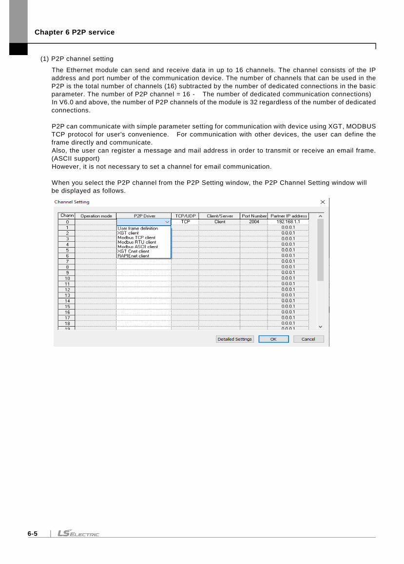
Chapter 6 P2P service
6-5
(1) P2P channel setting
The Ethernet module can send and receive data in up to 16 channels. The channel consists of the IP
address and port number of the communication device. The number of channels that can be used in the
P2P is the total number of channels (16) subtracted by the number of dedicated connections in the basic
parameter. The number of P2P channel = 16 - The number of dedicated communication connections)
In V6.0 and above, the number of P2P channels of the module is 32 regardless of the number of dedicated
connections.
P2P can communicate with simple parameter setting for communication with device using XGT, MODBUS
TCP protocol for user's convenience. For communication with other devices, the user can define the
frame directly and communicate.
Also, the user can register a message and mail address in order to transmit or receive an email frame.
(ASCII support)
However, it is not necessary to set a channel for email communication.
When you select the P2P channel from the P2P Setting window, the P2P Channel Setting window will
be displayed as follows.
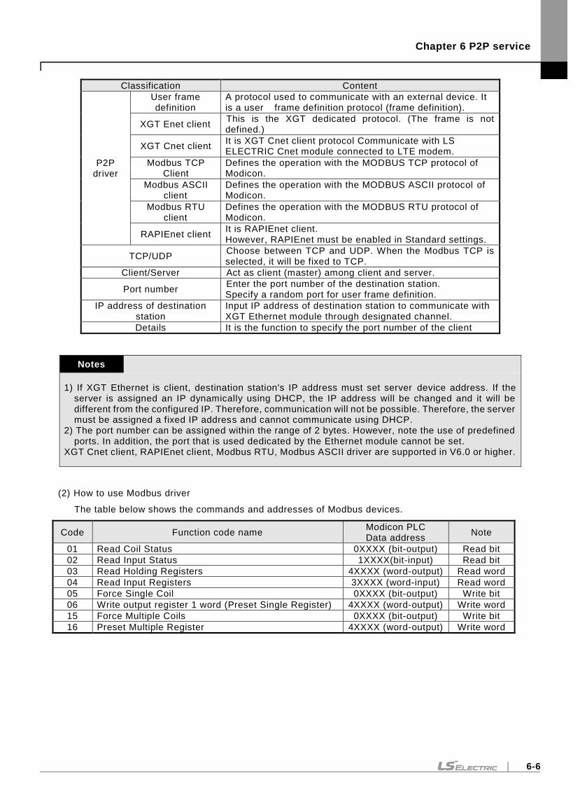
Chapter 6 P2P service
6-6
Classification Content
P2P driver
User frame definition
A protocol used to communicate with an external device. It is a user frame definition protocol (frame definition).
XGT Enet client This is the XGT dedicated protocol. (The frame is not defined.)
XGT Cnet client It is XGT Cnet client protocol Communicate with LS ELECTRIC Cnet module connected to LTE modem.
Modbus TCP Client
Defines the operation with the MODBUS TCP protocol of Modicon.
Modbus ASCII client
Defines the operation with the MODBUS ASCII protocol of Modicon.
Modbus RTU client
Defines the operation with the MODBUS RTU protocol of Modicon.
RAPIEnet client It is RAPIEnet client. However, RAPIEnet must be enabled in Standard settings.
TCP/UDP Choose between TCP and UDP. When the Modbus TCP is selected, it will be fixed to TCP.
Client/Server Act as client (master) among client and server.
Port number Enter the port number of the destination station. Specify a random port for user frame definition.
IP address of destination station
Input IP address of destination station to communicate with XGT Ethernet module through designated channel.
Details It is the function to specify the port number of the client
Notes
1) If XGT Ethernet is client, destination station's IP address must set server device address. If the server is assigned an IP dynamically using DHCP, the IP address will be changed and it will be different from the configured IP. Therefore, communication will not be possible. Therefore, the server must be assigned a fixed IP address and cannot communicate using DHCP.
2) The port number can be assigned within the range of 2 bytes. However, note the use of predefined ports. In addition, the port that is used dedicated by the Ethernet module cannot be set.
XGT Cnet client, RAPIEnet client, Modbus RTU, Modbus ASCII driver are supported in V6.0 or higher.
(2) How to use Modbus driver
The table below shows the commands and addresses of Modbus devices.
Code Function code name Modicon PLC Data address
Note
01 Read Coil Status 0XXXX (bit-output) Read bit
02 Read Input Status 1XXXX(bit-input) Read bit
03 Read Holding Registers 4XXXX (word-output) Read word
04 Read Input Registers 3XXXX (word-input) Read word
05 Force Single Coil 0XXXX (bit-output) Write bit
06 Write output register 1 word (Preset Single Register) 4XXXX (word-output) Write word
15 Force Multiple Coils 0XXXX (bit-output) Write bit
16 Preset Multiple Register 4XXXX (word-output) Write word
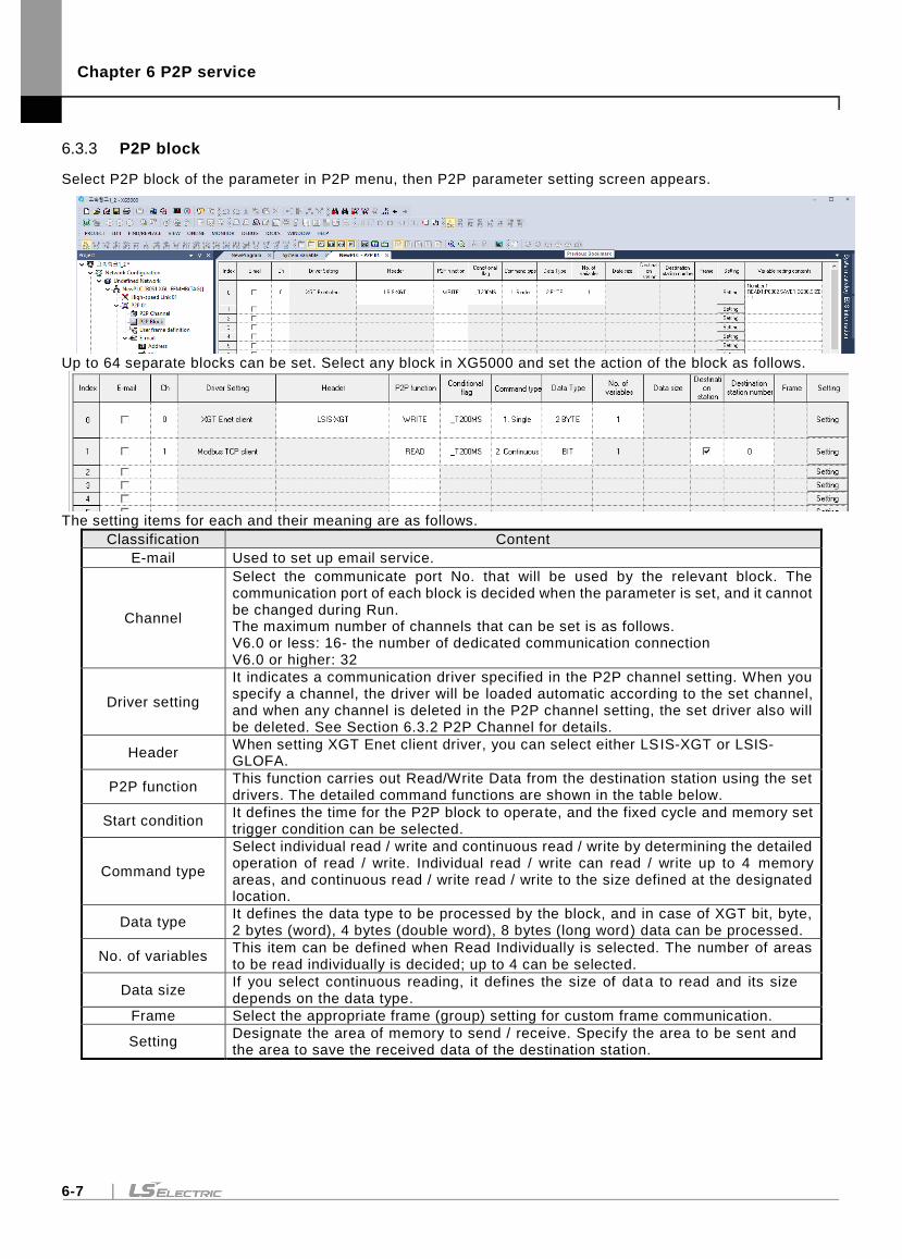
Chapter 6 P2P service
6-7
6.3.3 P2P block
Select P2P block of the parameter in P2P menu, then P2P parameter setting screen appears.
Up to 64 separate blocks can be set. Select any block in XG5000 and set the action of the block as follows.
The setting items for each and their meaning are as follows.
Classification Content
E-mail Used to set up email service.
Channel
Select the communicate port No. that will be used by the relevant block. The communication port of each block is decided when the parameter is set, and it cannot be changed during Run. The maximum number of channels that can be set is as follows. V6.0 or less: 16- the number of dedicated communication connection V6.0 or higher: 32
Driver setting
It indicates a communication driver specified in the P2P channel setting. When you specify a channel, the driver will be loaded automatic according to the set channel, and when any channel is deleted in the P2P channel setting, the set driver also will be deleted. See Section 6.3.2 P2P Channel for details.
Header When setting XGT Enet client driver, you can select either LSIS-XGT or LSIS-GLOFA.
P2P function This function carries out Read/Write Data from the destination station using the set drivers. The detailed command functions are shown in the table below.
Start condition It defines the time for the P2P block to operate, and the fixed cycle and memory set trigger condition can be selected.
Command type
Select individual read / write and continuous read / write by determining the detailed operation of read / write. Individual read / write can read / write up to 4 memory areas, and continuous read / write read / write to the size defined at the designated location.
Data type It defines the data type to be processed by the block, and in case of XGT bit, byte, 2 bytes (word), 4 bytes (double word), 8 bytes (long word) data can be processed.
No. of variables This item can be defined when Read Individually is selected. The number of areas to be read individually is decided; up to 4 can be selected.
Data size If you select continuous reading, it defines the size of data to read and its size depends on the data type.
Frame Select the appropriate frame (group) setting for custom frame communication.
Setting Designate the area of memory to send / receive. Specify the area to be sent and the area to save the received data of the destination station.
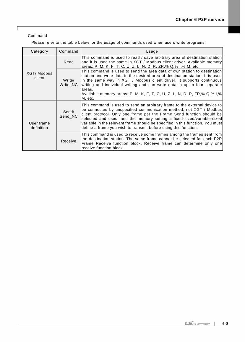
Chapter 6 P2P service
6-8
Command
Please refer to the table below for the usage of commands used when users write programs.
Category Command Usage
XGT/ Modbus client
Read This command is used to read / save arbitrary area of destination station and it is used the same in XGT / Modbus client driver. Available memory areas: P, M, K, F, T, C, U, Z, L, N, D, R, ZR,% Q,% I,% M, etc.
Write/ Write_NC
This command is used to send the area data of own station to destination station and write data in the desired area of destination station. It is used in the same way in XGT / Modbus client driver. It supports continuous writing and individual writing and can write data in up to four separate areas. Available memory areas: P, M, K, F, T, C, U, Z, L, N, D, R, ZR,% Q,% I,% M, etc.
User frame definition
Send/ Send_NC
This command is used to send an arbitrary frame to the external device to be connected by unspecified communication method, not XGT / Modbus client protocol. Only one frame per the Frame Send function should be selected and used, and the memory setting a fixed-sized/variable-sized variable in the relevant frame should be specified in this funct ion. You must define a frame you wish to transmit before using this function.
Receive
This command is used to receive some frames among the frames sent from the destination station. The same frame cannot be selected for each P2P Frame Receive function block. Receive frame can determine only one receive function block.
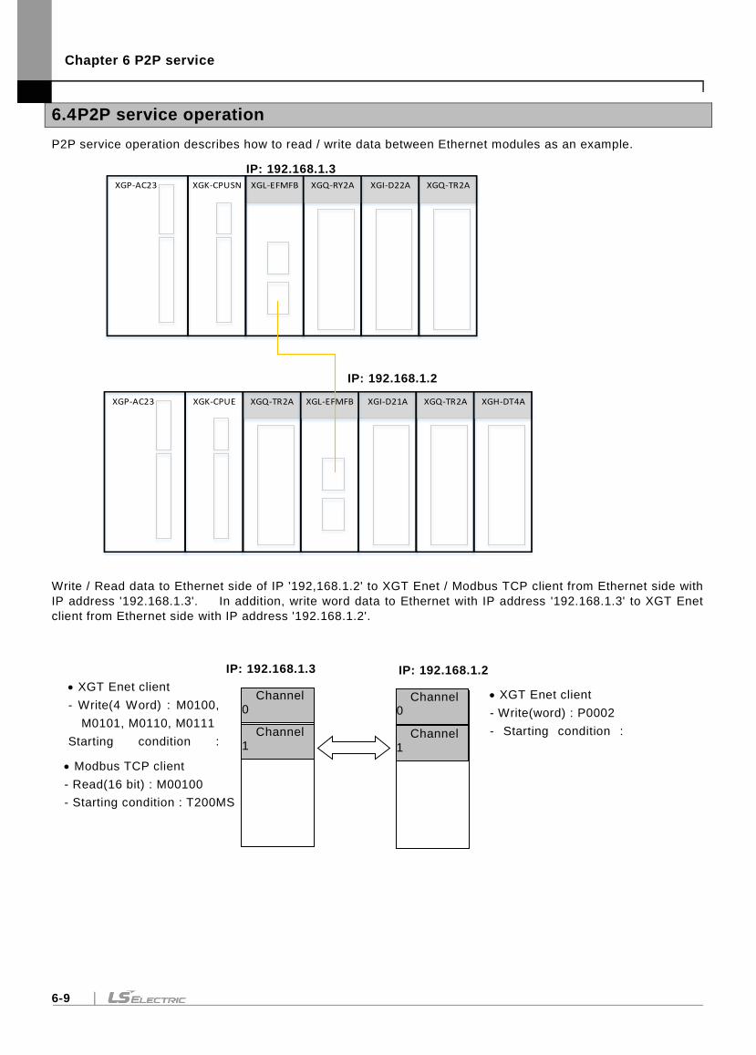
Chapter 6 P2P service
6-9
6.4 P2P service operation
P2P service operation describes how to read / write data between Ethernet modules as an example.
XGI-D22AXGL-EFMFBXGP-AC23 XGK-CPUSN XGQ-RY2A XGQ-TR2A
XGI-D21AXGP-AC23 XGK-CPUE XGQ-TR2A XGH-DT4AXGQ-TR2A XGL-EFMFB
Write / Read data to Ethernet side of IP '192,168.1.2' to XGT Enet / Modbus TCP client from Ethernet side with
IP address '192.168.1.3'. In addition, write word data to Ethernet with IP address '192.168.1.3' to XGT Enet
client from Ethernet side with IP address '192.168.1.2'.
IP: 192.168.1.2
XGT Enet client
- Write(4 Word) : M0100,
M0101, M0110, M0111
Starting condition :
T200MS
Channel 0
Channel 1
XGT Enet client
- Write(word) : P0002
- Starting condition :
T200MS
Channel 0
Channel 1
IP: 192.168.1.3
IP: 192.168.1.3
IP: 192.168.1.2
Modbus TCP client
- Read(16 bit) : M00100
- Starting condition : T200MS
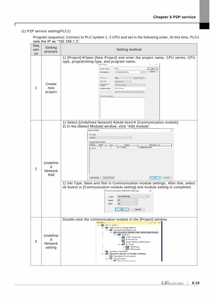
Chapter 6 P2P service
6-10
(1) P2P service setting(PLC1)
Program sequence: Connect to PLC system 1, 2 CPU and set in the following order. At this time, PLC1
sets the IP as “192.168.1.3”.
Sequence
Setting process
Setting method
1 Create
new project
1) [Project]Open [New Project] and enter the project name, CPU series, CPU type, programming type, and program name.
2
Undefined
Network Add
1) Select [Undefined Network][Add item] [Communication module]. 2) In the [Select Module] window, click “Add module”.
1) Set Type, Base and Slot in Communication module settings. After that, select ok button in [Communication module setting] and module setting is completed.
3
Undefined
Network setting
Double-click the communication module in the [Project] window.
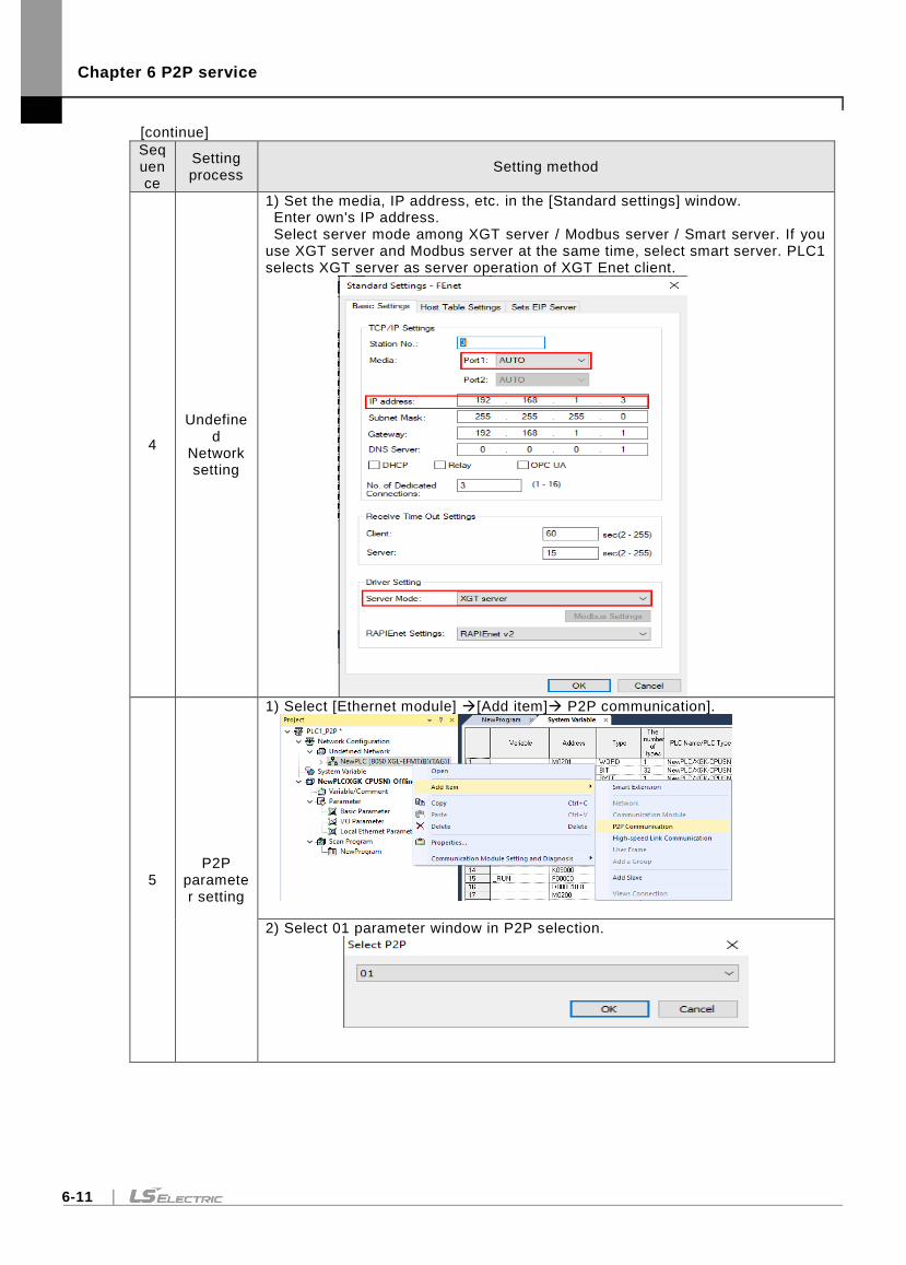
Chapter 6 P2P service
6-11
[continue]
Sequence
Setting process
Setting method
4
Undefined
Network setting
1) Set the media, IP address, etc. in the [Standard settings] window. Enter own's IP address. Select server mode among XGT server / Modbus server / Smart server. If you use XGT server and Modbus server at the same time, select smart server. PLC1 selects XGT server as server operation of XGT Enet client.
5 P2P
parameter setting
1) Select [Ethernet module] [Add item] P2P communication].
2) Select 01 parameter window in P2P selection.
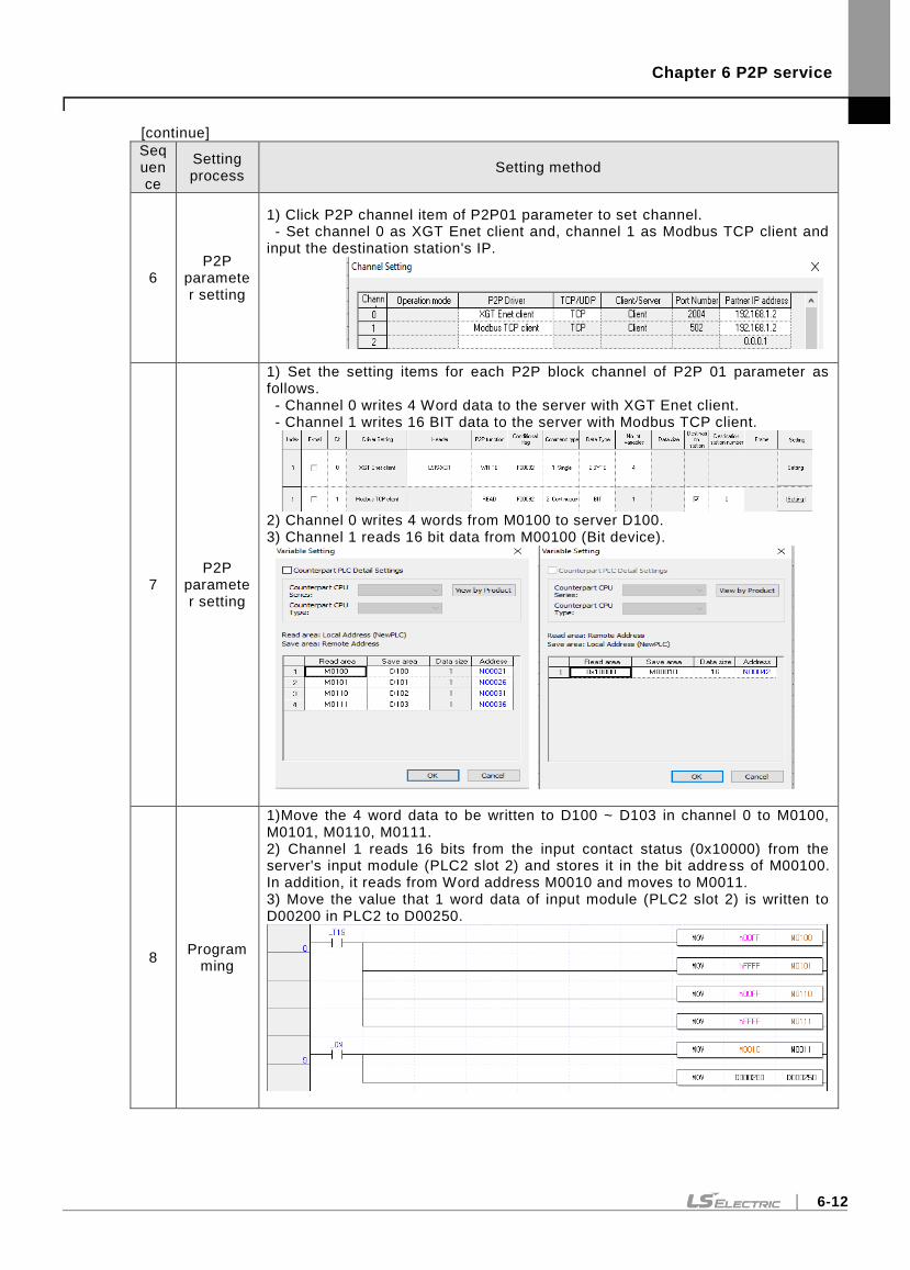
Chapter 6 P2P service
6-12
[continue]
Sequence
Setting process
Setting method
6 P2P
parameter setting
1) Click P2P channel item of P2P01 parameter to set channel. - Set channel 0 as XGT Enet client and, channel 1 as Modbus TCP client and input the destination station's IP.
7 P2P
parameter setting
1) Set the setting items for each P2P block channel of P2P 01 parameter as follows. - Channel 0 writes 4 Word data to the server with XGT Enet client. - Channel 1 writes 16 BIT data to the server with Modbus TCP client.
2) Channel 0 writes 4 words from M0100 to server D100. 3) Channel 1 reads 16 bit data from M00100 (Bit device).
8 Program
ming
1)Move the 4 word data to be written to D100 ~ D103 in channel 0 to M0100, M0101, M0110, M0111. 2) Channel 1 reads 16 bits from the input contact status (0x10000) from the server's input module (PLC2 slot 2) and stores it in the bit address of M00100. In addition, it reads from Word address M0010 and moves to M0011. 3) Move the value that 1 word data of input module (PLC2 slot 2) is written to D00200 in PLC2 to D00250.
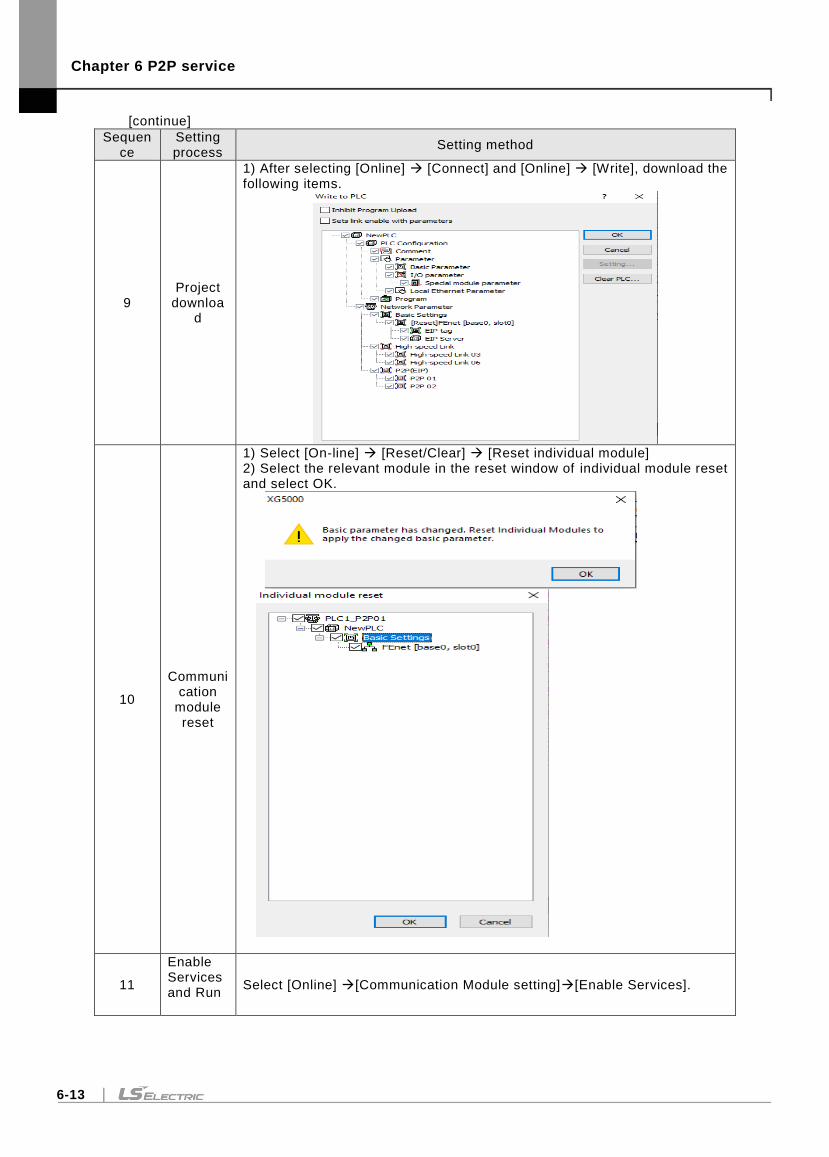
Chapter 6 P2P service
6-13
[continue]
Sequence
Setting process
Setting method
9 Project
download
1) After selecting [Online] [Connect] and [Online] [Write], download the following items.
10
Communication
module reset
1) Select [On-line] [Reset/Clear] [Reset individual module] 2) Select the relevant module in the reset window of individual module reset and select OK.
11
Enable Services and Run
Select [Online] [Communication Module setting][Enable Services].
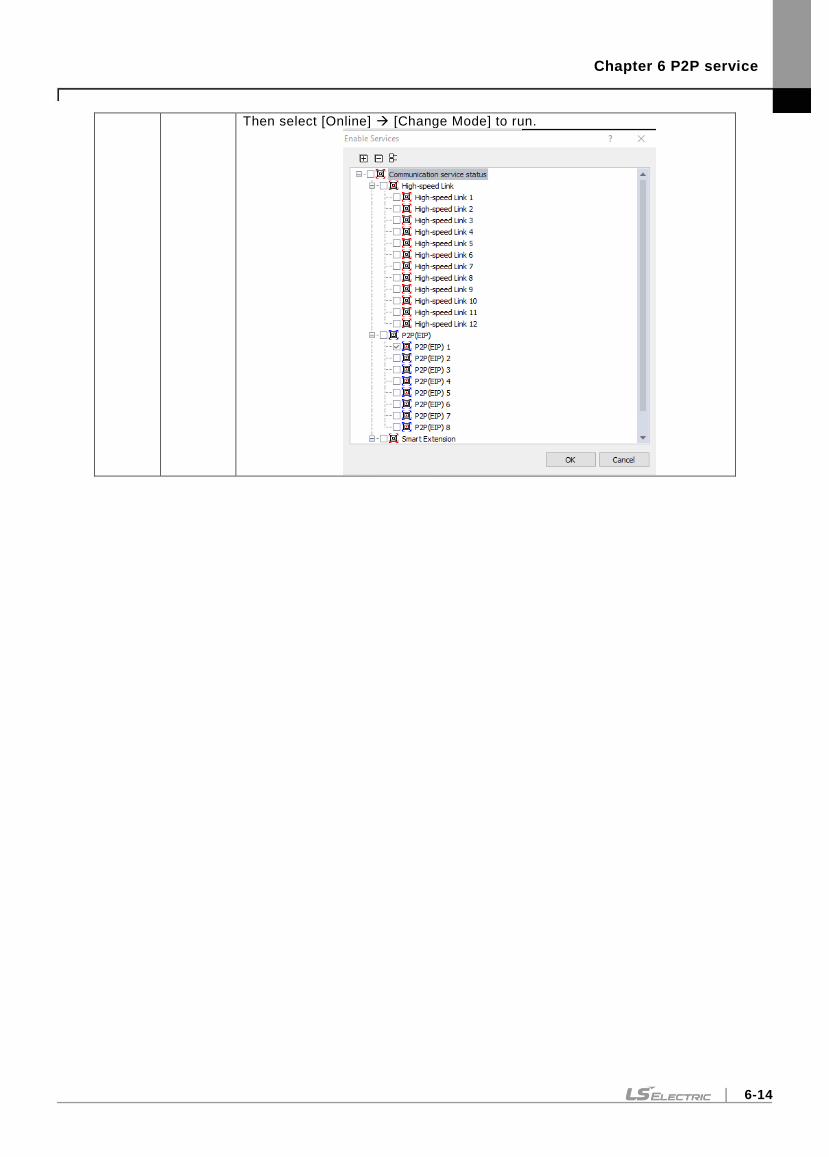
Chapter 6 P2P service
6-14
Then select [Online] [Change Mode] to run.
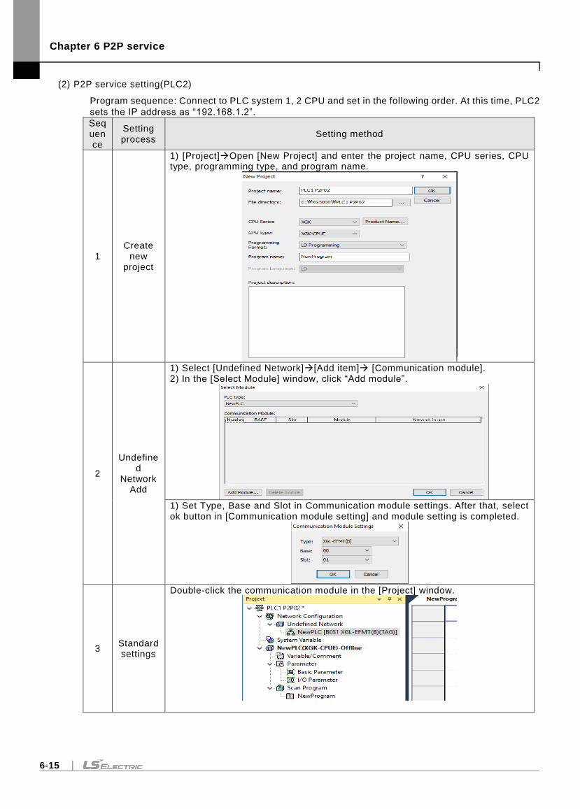
Chapter 6 P2P service
6-15
(2) P2P service setting(PLC2)
Program sequence: Connect to PLC system 1, 2 CPU and set in the following order. At this time, PLC2
sets the IP address as “192.168.1.2”.
Sequence
Setting process
Setting method
1 Create
new project
1) [Project]Open [New Project] and enter the project name, CPU series, CPU type, programming type, and program name.
2
Undefined
Network Add
1) Select [Undefined Network][Add item] [Communication module]. 2) In the [Select Module] window, click “Add module”.
1) Set Type, Base and Slot in Communication module settings. After that, select ok button in [Communication module setting] and module setting is completed.
3 Standard settings
Double-click the communication module in the [Project] window.
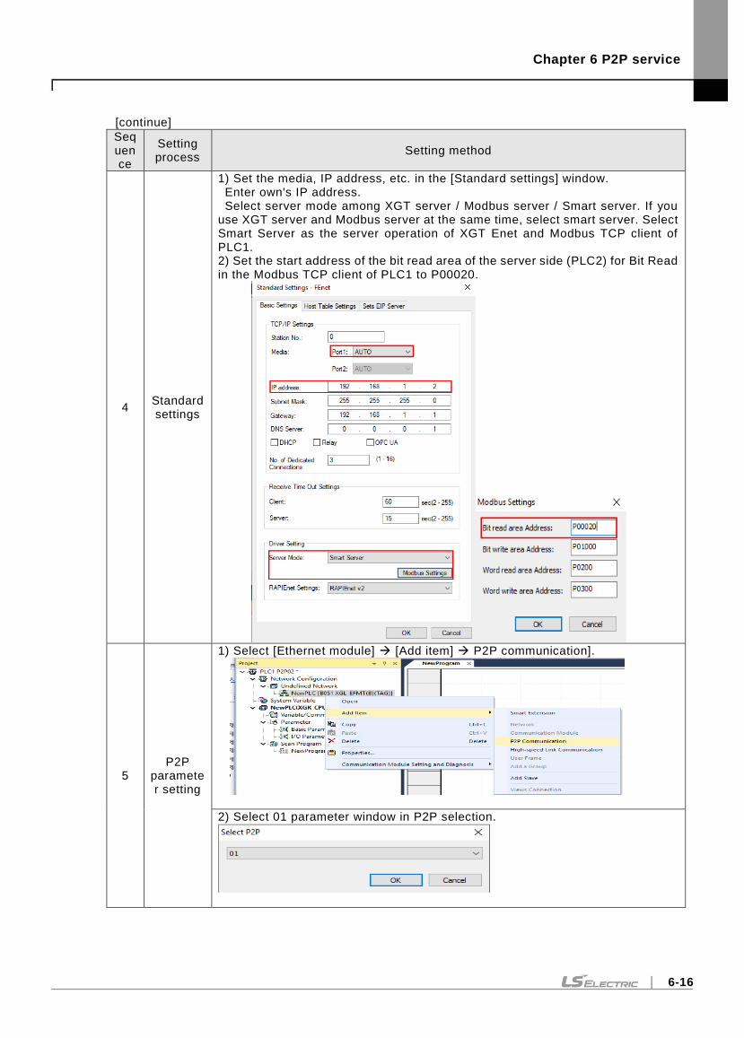
Chapter 6 P2P service
6-16
[continue]
Sequence
Setting process
Setting method
4 Standard settings
1) Set the media, IP address, etc. in the [Standard settings] window. Enter own's IP address. Select server mode among XGT server / Modbus server / Smart server. If you use XGT server and Modbus server at the same time, select smart server. Select Smart Server as the server operation of XGT Enet and Modbus TCP client of PLC1. 2) Set the start address of the bit read area of the server side (PLC2) for Bit Read in the Modbus TCP client of PLC1 to P00020.
5 P2P
parameter setting
1) Select [Ethernet module] [Add item] P2P communication].
2) Select 01 parameter window in P2P selection.
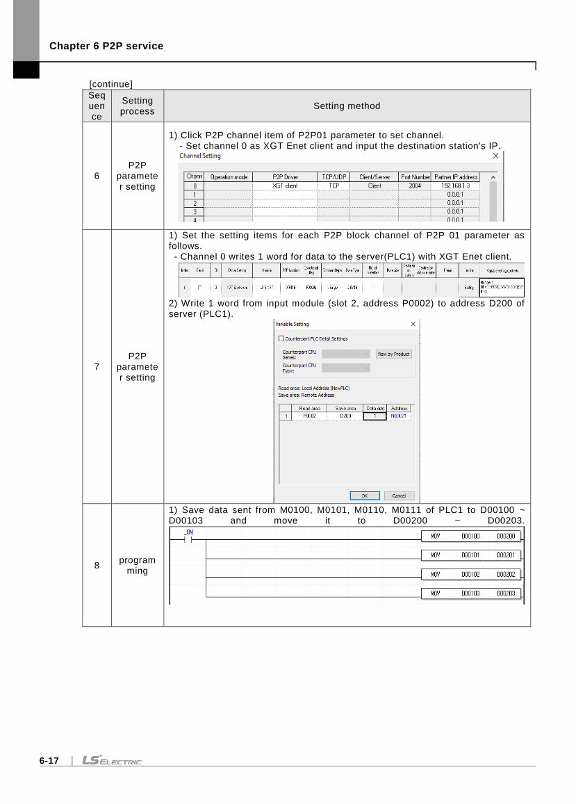
Chapter 6 P2P service
6-17
[continue]
Sequence
Setting process
Setting method
6 P2P
parameter setting
1) Click P2P channel item of P2P01 parameter to set channel. - Set channel 0 as XGT Enet client and input the destination station's IP.
7 P2P
parameter setting
1) Set the setting items for each P2P block channel of P2P 01 parameter as follows. - Channel 0 writes 1 word for data to the server(PLC1) with XGT Enet client.
2) Write 1 word from input module (slot 2, address P0002) to address D200 of server (PLC1).
8 program
ming
1) Save data sent from M0100, M0101, M0110, M0111 of PLC1 to D00100 ~ D00103 and move it to D00200 ~ D00203.
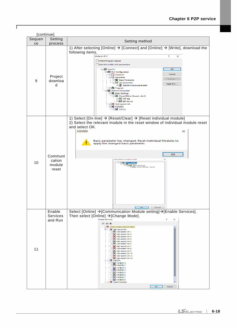
Chapter 6 P2P service
6-18
[continue]
Sequence
Setting process
Setting method
9 Project
download
1) After selecting [Online] [Connect] and [Online] [Write], download the following items.
10
Communication
module reset
1) Select [On-line] [Reset/Clear] [Reset individual module] 2) Select the relevant module in the reset window of individual module reset and select OK.
11
Enable Services and Run
Select [Online] [Communication Module setting][Enable Services]. Then select [Online] [Change Mode].
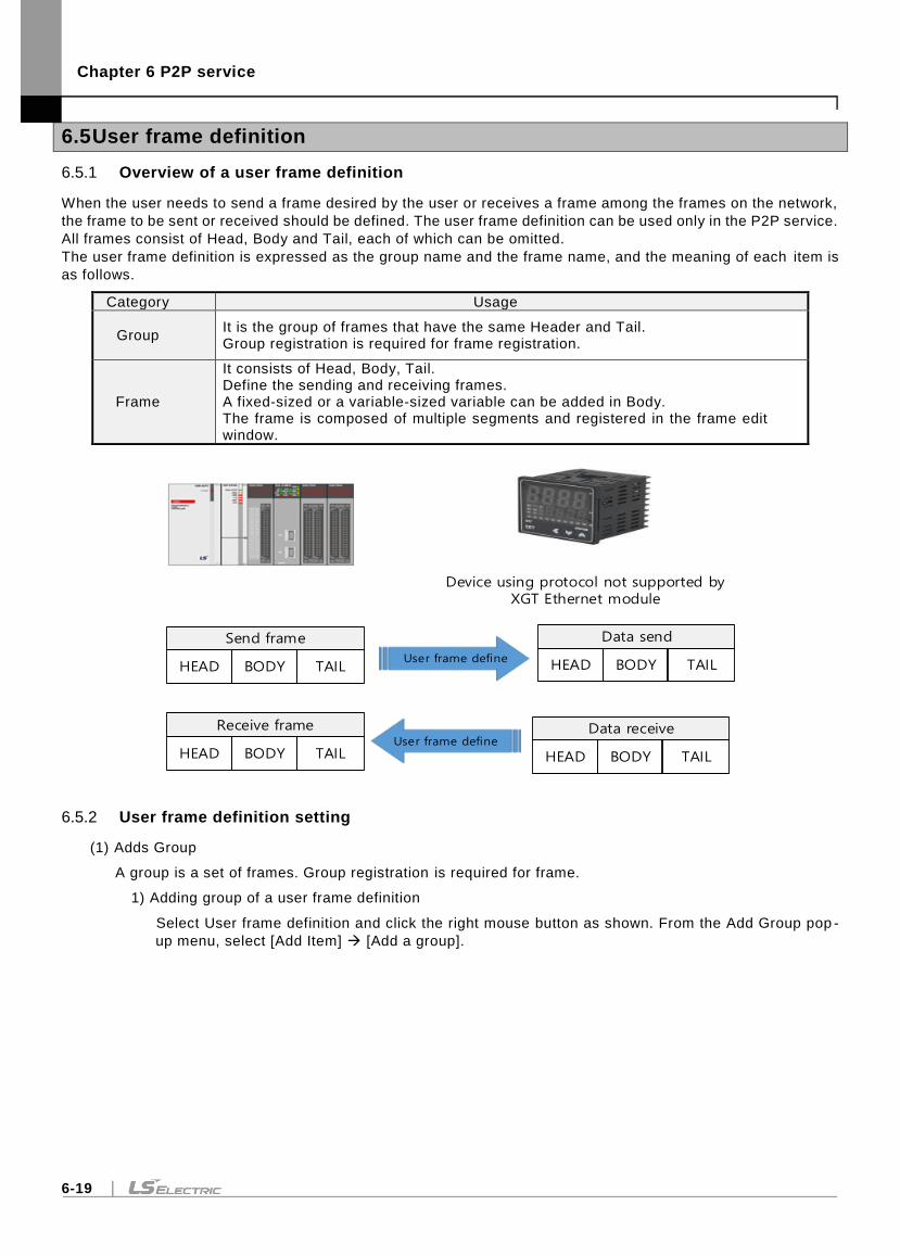
Chapter 6 P2P service
6-19
6.5 User frame definition
6.5.1 Overview of a user frame definition
When the user needs to send a frame desired by the user or receives a frame among the frames on the network,
the frame to be sent or received should be defined. The user frame definition can be used only in the P2P service.
All frames consist of Head, Body and Tail, each of which can be omitted.
The user frame definition is expressed as the group name and the frame name, and the meaning of each item is
as follows.
Category Usage
Group It is the group of frames that have the same Header and Tail. Group registration is required for frame registration.
Frame
It consists of Head, Body, Tail. Define the sending and receiving frames. A fixed-sized or a variable-sized variable can be added in Body. The frame is composed of multiple segments and registered in the frame edit window.
Send frame
HEAD BODY TAIL
Data send
HEAD BODY TAIL
Receive frame
HEAD BODY TAIL
Data receive
HEAD BODY TAIL
User frame define
Device using protocol not supported by XGT Ethernet module
User frame define
6.5.2 User frame definition setting
(1) Adds Group
A group is a set of frames. Group registration is required for frame.
1) Adding group of a user frame definition
Select User frame definition and click the right mouse button as shown. From the Add Group pop -
up menu, select [Add Item] [Add a group].
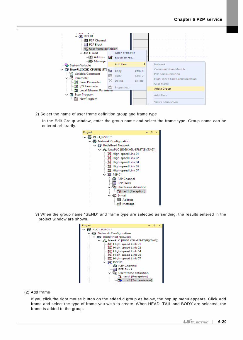
Chapter 6 P2P service
6-20
2) Select the name of user frame definition group and frame type
In the Edit Group window, enter the group name and select the frame type. Group name can be
entered arbitrarily.
3) When the group name “SEND” and frame type are selected as sending, the results entered in the
project window are shown.
(2) Add frame
If you click the right mouse button on the added d group as below, the pop up menu appears. Click Add
frame and select the type of frame you wish to create. When HEAD, TAIL and BODY are selected, the
frame is added to the group.
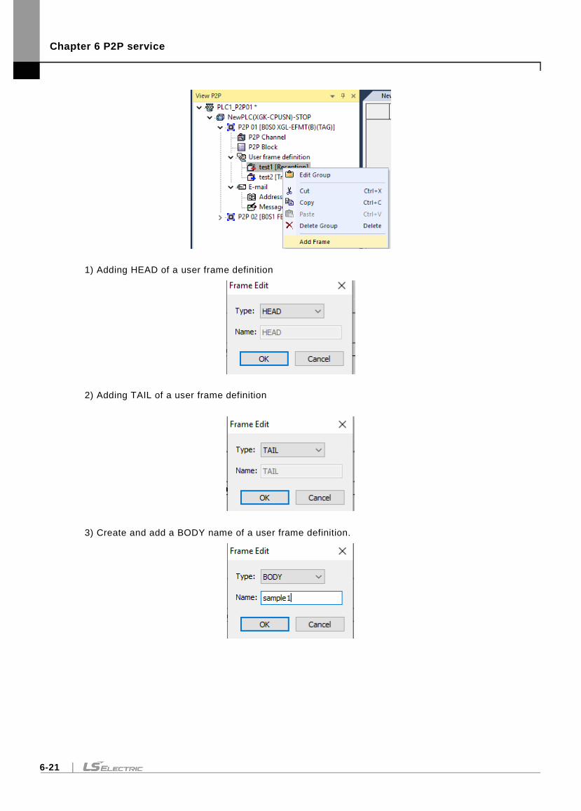
Chapter 6 P2P service
6-21
1) Adding HEAD of a user frame definition
2) Adding TAIL of a user frame definition
3) Create and add a BODY name of a user frame definition.
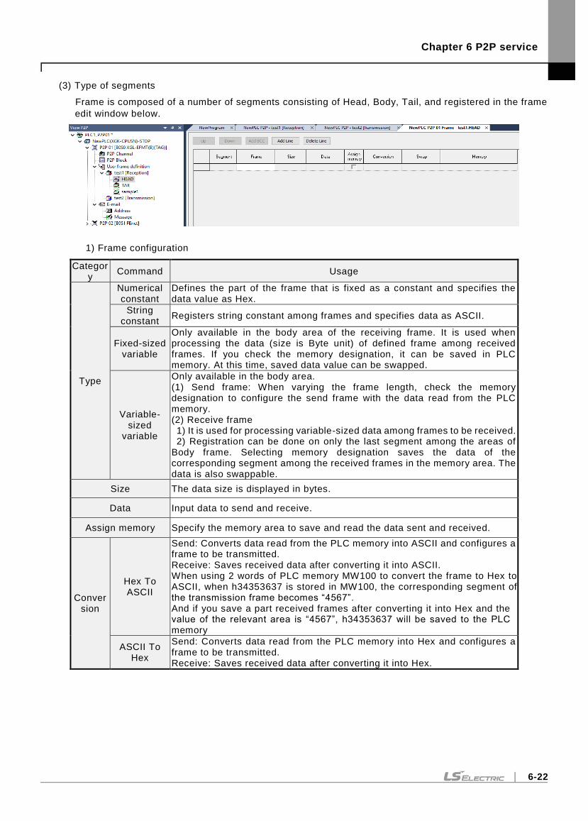
Chapter 6 P2P service
6-22
(3) Type of segments
Frame is composed of a number of segments consisting of Head, Body, Tail, and registered in the frame
edit window below.
1) Frame configuration
Category
Command Usage
Type
Numerical constant
Defines the part of the frame that is fixed as a constant and specifies the data value as Hex.
String constant
Registers string constant among frames and specifies data as ASCII.
Fixed-sized variable
Only available in the body area of the receiving frame. It is used when processing the data (size is Byte unit) of defined frame among received frames. If you check the memory designation, it can be saved in PLC memory. At this time, saved data value can be swapped.
Variable-sized
variable
Only available in the body area. (1) Send frame: When varying the frame length, check the memory designation to configure the send frame with the data read from the PLC memory. (2) Receive frame 1) It is used for processing variable-sized data among frames to be received. 2) Registration can be done on only the last segment among the areas of
Body frame. Selecting memory designation saves the data of the corresponding segment among the received frames in the memory area. The data is also swappable.
Size The data size is displayed in bytes.
Data Input data to send and receive.
Assign memory Specify the memory area to save and read the data sent and received.
Conversion
Hex To ASCII
Send: Converts data read from the PLC memory into ASCII and configures a frame to be transmitted. Receive: Saves received data after converting it into ASCII. When using 2 words of PLC memory MW100 to convert the frame to Hex to ASCII, when h34353637 is stored in MW100, the corresponding segment of the transmission frame becomes “4567”. And if you save a part received frames after converting it into Hex and the value of the relevant area is “4567”, h34353637 will be saved to the PLC memory
ASCII To Hex
Send: Converts data read from the PLC memory into Hex and configures a frame to be transmitted. Receive: Saves received data after converting it into Hex.
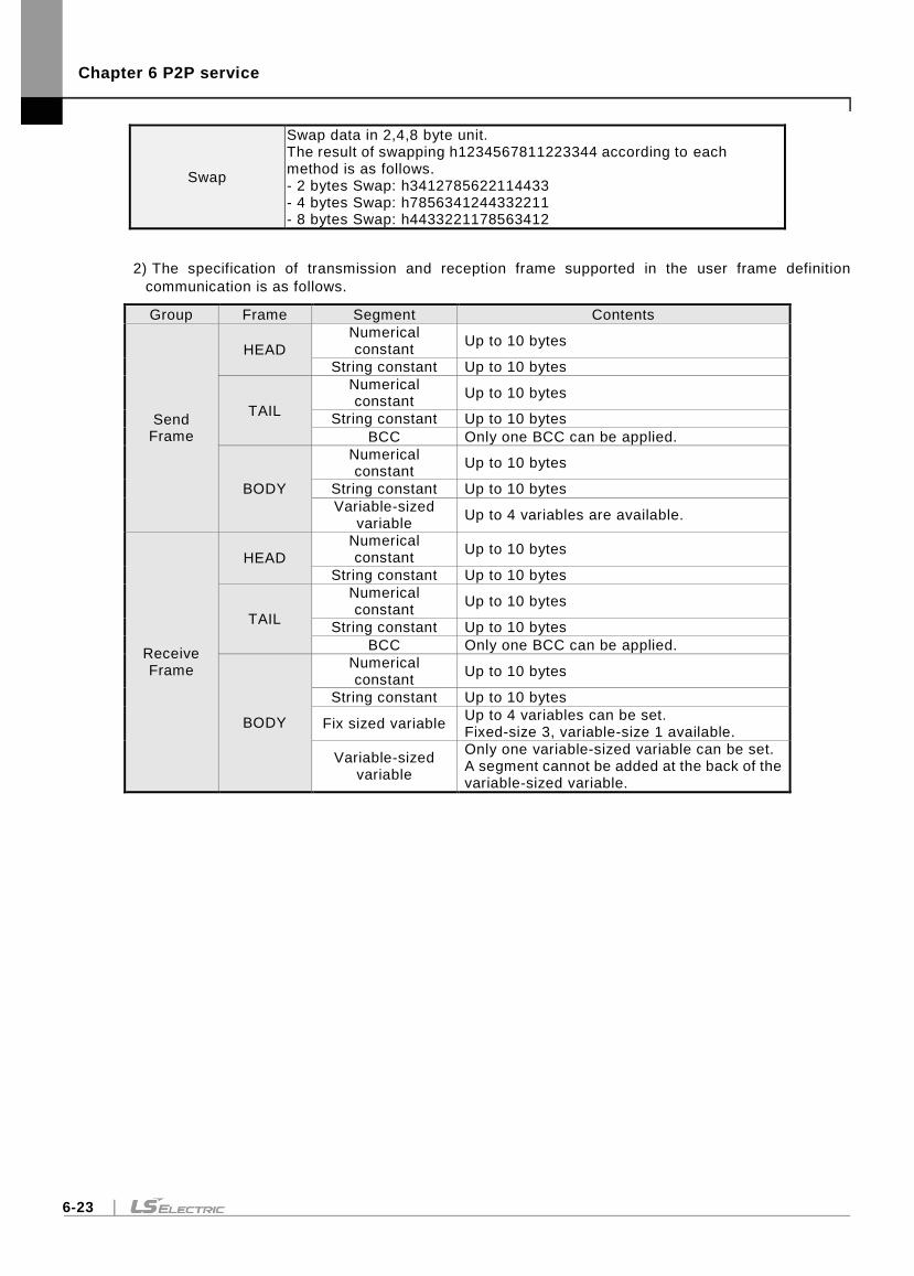
Chapter 6 P2P service
6-23
Swap
Swap data in 2,4,8 byte unit. The result of swapping h1234567811223344 according to each method is as follows. - 2 bytes Swap: h3412785622114433 - 4 bytes Swap: h7856341244332211 - 8 bytes Swap: h4433221178563412
2) The specification of transmission and reception frame supported in the user frame definition
communication is as follows.
Group Frame Segment Contents
Send Frame
HEAD
Numerical constant
Up to 10 bytes
String constant Up to 10 bytes
TAIL
Numerical constant
Up to 10 bytes
String constant Up to 10 bytes
BCC Only one BCC can be applied.
BODY
Numerical constant
Up to 10 bytes
String constant Up to 10 bytes
Variable-sized variable
Up to 4 variables are available.
Receive Frame
HEAD
Numerical constant
Up to 10 bytes
String constant Up to 10 bytes
TAIL
Numerical constant
Up to 10 bytes
String constant Up to 10 bytes
BCC Only one BCC can be applied.
BODY
Numerical constant
Up to 10 bytes
String constant Up to 10 bytes
Fix sized variable Up to 4 variables can be set. Fixed-size 3, variable-size 1 available.
Variable-sized variable
Only one variable-sized variable can be set. A segment cannot be added at the back of the variable-sized variable.
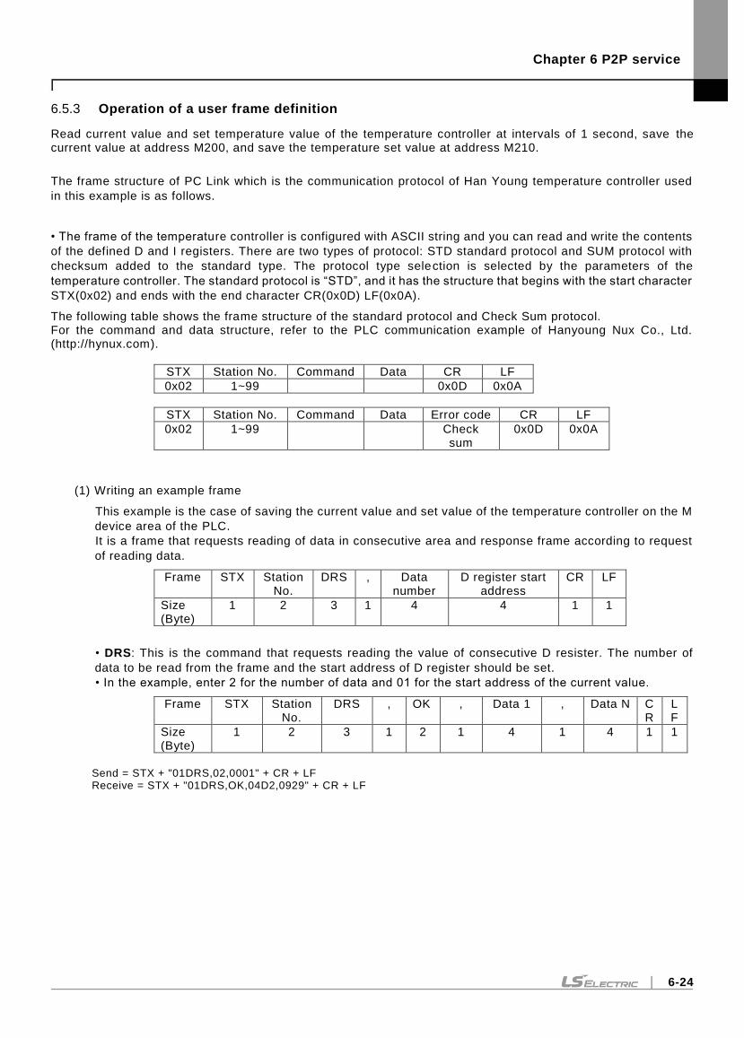
Chapter 6 P2P service
6-24
6.5.3 Operation of a user frame definition
Read current value and set temperature value of the temperature controller at intervals of 1 second, save the current value at address M200, and save the temperature set value at address M210.
The frame structure of PC Link which is the communication protocol of Han Young temperature controller used
in this example is as follows.
• The frame of the temperature controller is configured with ASCII string and you can read and write the contents
of the defined D and I registers. There are two types of protocol: STD standard protocol and SUM protocol with
checksum added to the standard type. The protocol type selection is selected by the parameters of the
temperature controller. The standard protocol is “STD”, and it has the structure that begins with the start character
STX(0x02) and ends with the end character CR(0x0D) LF(0x0A).
The following table shows the frame structure of the standard protocol and Check Sum protocol. For the command and data structure, refer to the PLC communication example of Hanyoung Nux Co., Ltd. (http://hynux.com).
STX Station No. Command Data CR LF
0x02 1~99 0x0D 0x0A
STX Station No. Command Data Error code CR LF
0x02 1~99 Check sum
0x0D 0x0A
(1) Writing an example frame
This example is the case of saving the current value and set value of the temperature controller on the M
device area of the PLC.
It is a frame that requests reading of data in consecutive area and response frame according to request
of reading data.
Frame STX Station No.
DRS , Data number
D register start address
CR LF
Size (Byte)
1 2 3 1 4 4 1 1
• DRS: This is the command that requests reading the value of consecutive D resister. The number of
data to be read from the frame and the start address of D register should be set.
• In the example, enter 2 for the number of data and 01 for the start address of the current value.
Frame STX Station No.
DRS , OK , Data 1 , Data N CR
LF
Size (Byte)
1 2 3 1 2 1 4 1 4 1 1
Send = STX + "01DRS,02,0001" + CR + LF Receive = STX + "01DRS,OK,04D2,0929" + CR + LF
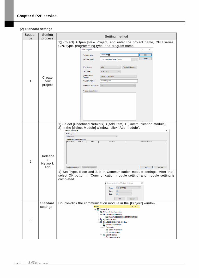
Chapter 6 P2P service
6-25
(2) Standard settings
Sequence
Setting process
Setting method
1 Create
new project
1)[Project]Open [New Project] and enter the project name, CPU series, CPU type, programming type, and program name.
2
Undefined
Network Add
1) Select [Undefined Network][Add item] [Communication module]. 2) In the [Select Module] window, click “Add module”.
1) Set Type, Base and Slot in Communication module settings. After that, select OK button in [Communication module setting] and module setting is completed.
3
Standard settings
Double-click the communication module in the [Project] window.
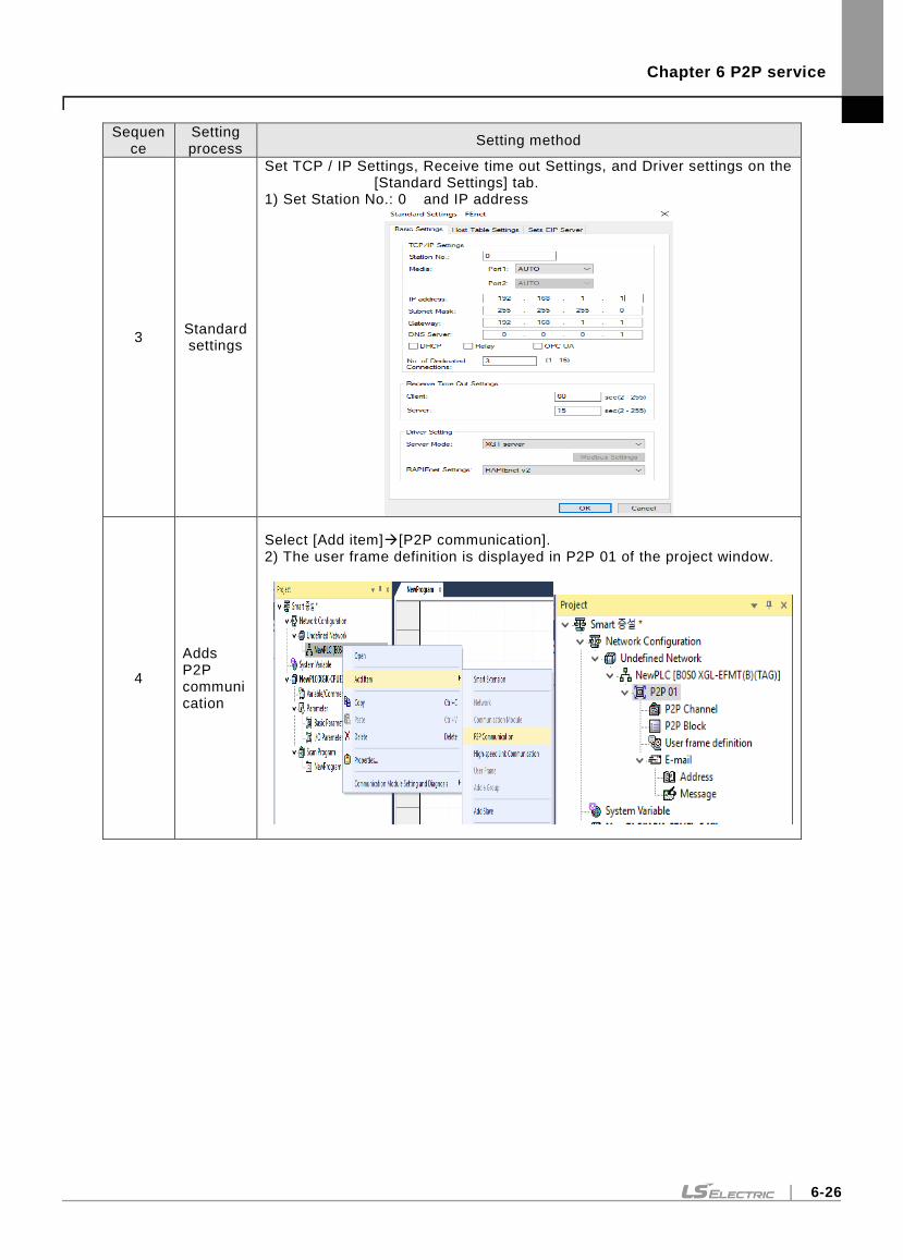
Chapter 6 P2P service
6-26
Sequence
Setting process
Setting method
3 Standard settings
Set TCP / IP Settings, Receive time out Settings, and Driver settings on the [Standard Settings] tab.
1) Set Station No.: 0 and IP address
4
Adds P2P communication
Select [Add item][P2P communication]. 2) The user frame definition is displayed in P2P 01 of the project window.
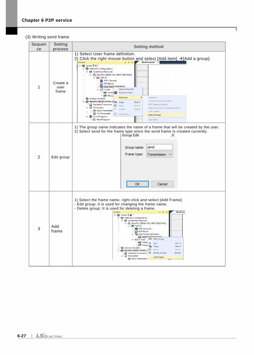
Chapter 6 P2P service
6-27
(3) Writing send frame
Sequence
Setting process
Setting method
1 Create a
user frame
1) Select User frame definition. 2) Click the right mouse button and select [Add item] [Add a group].
2 Edit group
1) The group name indicates the name of a frame that will be created by the user. 2) Select send for the frame type since the send frame is created currently.
3 Add frame
1) Select the frame name, right-click and select [Add Frame]. - Edit group: It is used for changing the frame name. - Delete group: It is used for deleting a frame.
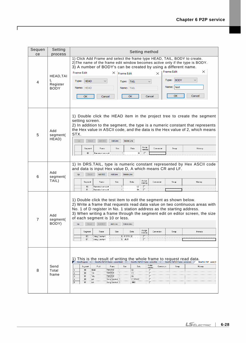
Chapter 6 P2P service
6-28
Sequence
Setting process
Setting method
4
HEAD,TAIL Register BODY
1) Click Add Frame and select the frame type HEAD, TAIL, BODY to create. 2)The name of the frame edit window becomes active only if the type is BODY.
3) A number of BODY's can be created by using a different name.
5 Add segment(HEAD)
1) Double click the HEAD item in the project tree to create the segment setting screen. 2) In addition to the segment, the type is a numeric constant that represents the Hex value in ASCII code, and the data is the Hex value of 2, which means STX.
6 Add segment(TAIL)
1) In DRS.TAIL, type is numeric constant represented by Hex ASCII code and data is input Hex value D, A which means CR and LF.
7 Add segment(BODY)
1) Double click the test item to edit the segment as shown below. 2) Write a frame that requests read data value on two continuous areas with No. 1 of D register in No. 1 station address as the starting address. 3) When writing a frame through the segment edit on editor screen, the size of each segment is 10 or less.
8 Send Total frame
1) This is the result of writing the whole frame to request read data.
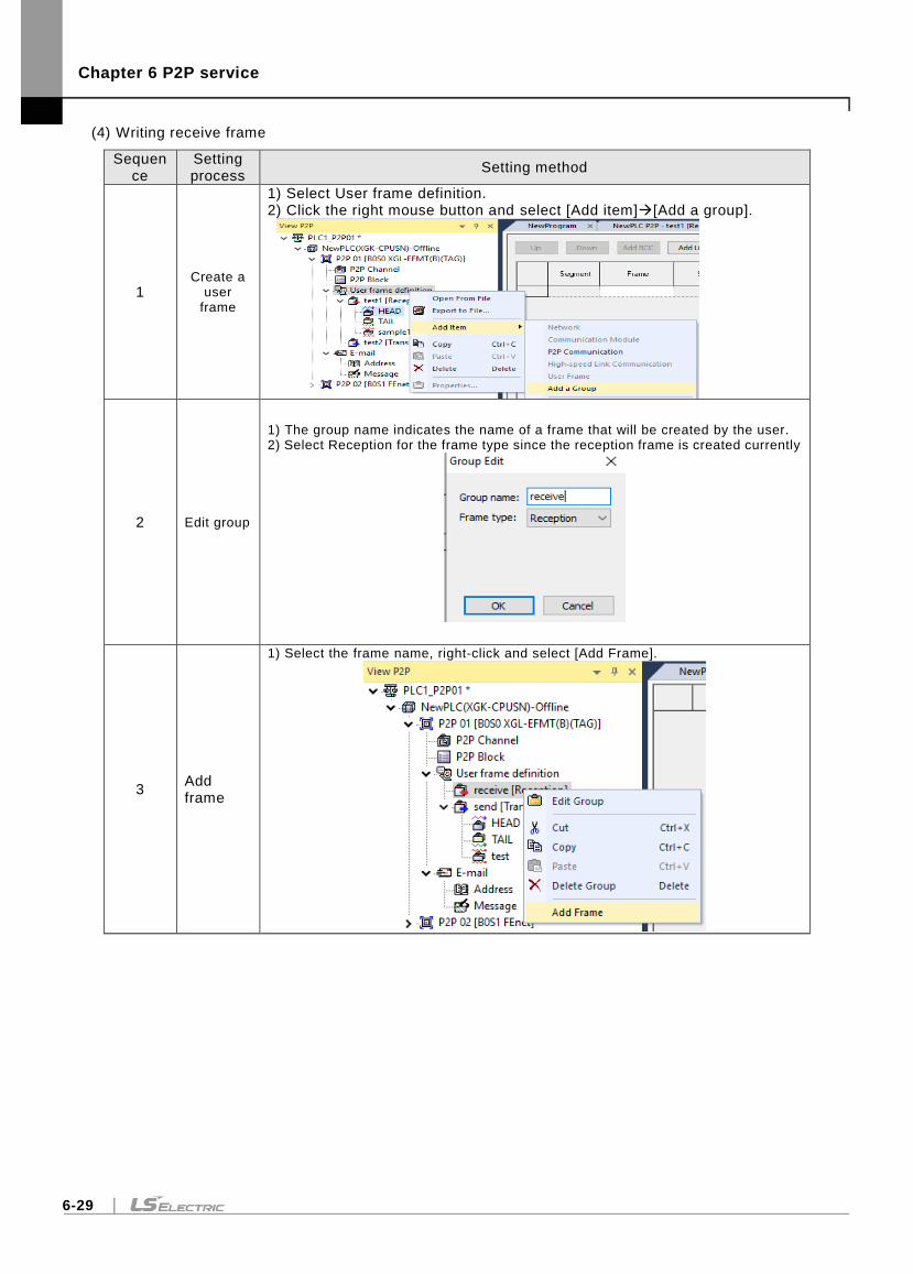
Chapter 6 P2P service
6-29
(4) Writing receive frame
Sequence
Setting process
Setting method
1 Create a
user frame
1) Select User frame definition. 2) Click the right mouse button and select [Add item][Add a group].
2 Edit group
1) The group name indicates the name of a frame that will be created by the user. 2) Select Reception for the frame type since the reception frame is created currently
3 Add frame
1) Select the frame name, right-click and select [Add Frame].
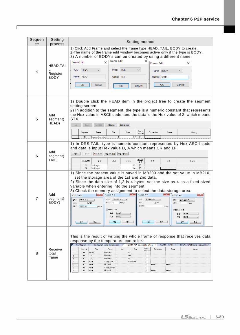
Chapter 6 P2P service
6-30
Sequence
Setting process
Setting method
4
HEAD,TAIL Register BODY
1) Click Add Frame and select the frame type HEAD, TAIL, BODY to create. 2)The name of the frame edit window becomes active only if the type is BODY.
3) A number of BODY's can be created by using a different name.
5 Add segment(HEAD)
1) Double click the HEAD item in the project tree to create the segment setting screen. 2) In addition to the segment, the type is a numeric constant that represents the Hex value in ASCII code, and the data is the Hex value of 2, which means STX.
6 Add segment(TAIL)
1) In DRS.TAIL, type is numeric constant represented by Hex ASCII code and data is input Hex value D, A which means CR and LF.
7 Add segment(BODY)
1) Since the present value is saved in MB200 and the set value in MB210, set the storage area of the 1st and 2nd data.
2) Since the data size of 1,2 is 4 bytes, set the size as 4 as a fixed sized variable when entering into the segment. 3) Check the memory assignment to select the data storage area.
8 Receive total frame
This is the result of writing the whole frame of response that receives data response by the temperature controller.
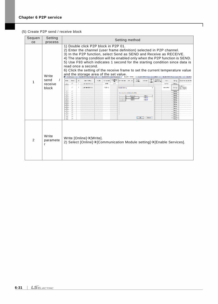
Chapter 6 P2P service
6-31
(5) Create P2P send / receive block
Sequence
Setting process
Setting method
1
Write send / receive block
1) Double click P2P block in P2P 01. 2) Enter the channel (user frame definition) selected in P2P channel. 3) In the P2P function, select Send as SEND and Receive as RECEIVE. 4) The starting condition will be enabled only when the P2P function is SEND. 5) Use F93 which indicates 1 second for the starting condition since data is read once a second. 6) Click the setting of the receive frame to set the current temperature value and the storage area of the set value.
2 Write parameter
Write [Online][Write]. 2) Select [Online][Communication Module setting][Enable Services].
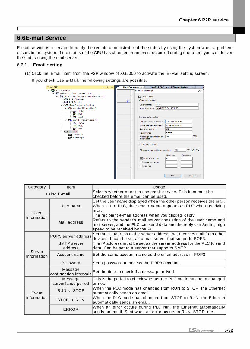
Chapter 6 P2P service
6-32
6.6 E-mail Service
E-mail service is a service to notify the remote administrator of the status by using the system when a problem
occurs in the system. If the status of the CPU has changed or an event occurred during operation, you can deliver
the status using the mail server.
6.6.1 Email setting
(1) Click the 'Email' item from the P2P window of XG5000 to activate the 'E-Mail setting screen.
If you check Use E-Mail, the following settings are possible.
Category Item Usage
using E-mail Selects whether or not to use email service. This item must be checked before the email can be used.
User information
User name Set the user name displayed when the other person receives the mail. When set to PLC, the sender name appears as PLC when receiving mail.
Mail address
The recipient e-mail address when you clicked Reply. Refers to the sender's mail server consisting of the user name and mail server, and the PLC can send data and the reply can Setting high speed to be received by the PC.
Server Information
POP3 server address Set the IP address to the server address that receives mail from other devices. It can be set as a mail server that supports POP3.
SMTP server address
The IP address must be set as the server address for the PLC to send data. Can be set to a server that supports SMTP.
Account name Set the same account name as the email address in POP3.
Password Set a password to access the POP3 account.
Message confirmation intervals
Set the time to check if a message arrived.
Event information
Message surveillance period
This is the period to check whether the PLC mode has been changed or not.
RUN -> STOP When the PLC mode has changed from RUN to STOP, the Ethernet automatically sends an email.
STOP -> RUN When the PLC mode has changed from STOP to RUN, the Ethernet automatically sends an email.
ERROR When an error occurs during PLC run, the Ethernet automatically sends an email. Sent when an error occurs in RUN, STOP, etc.
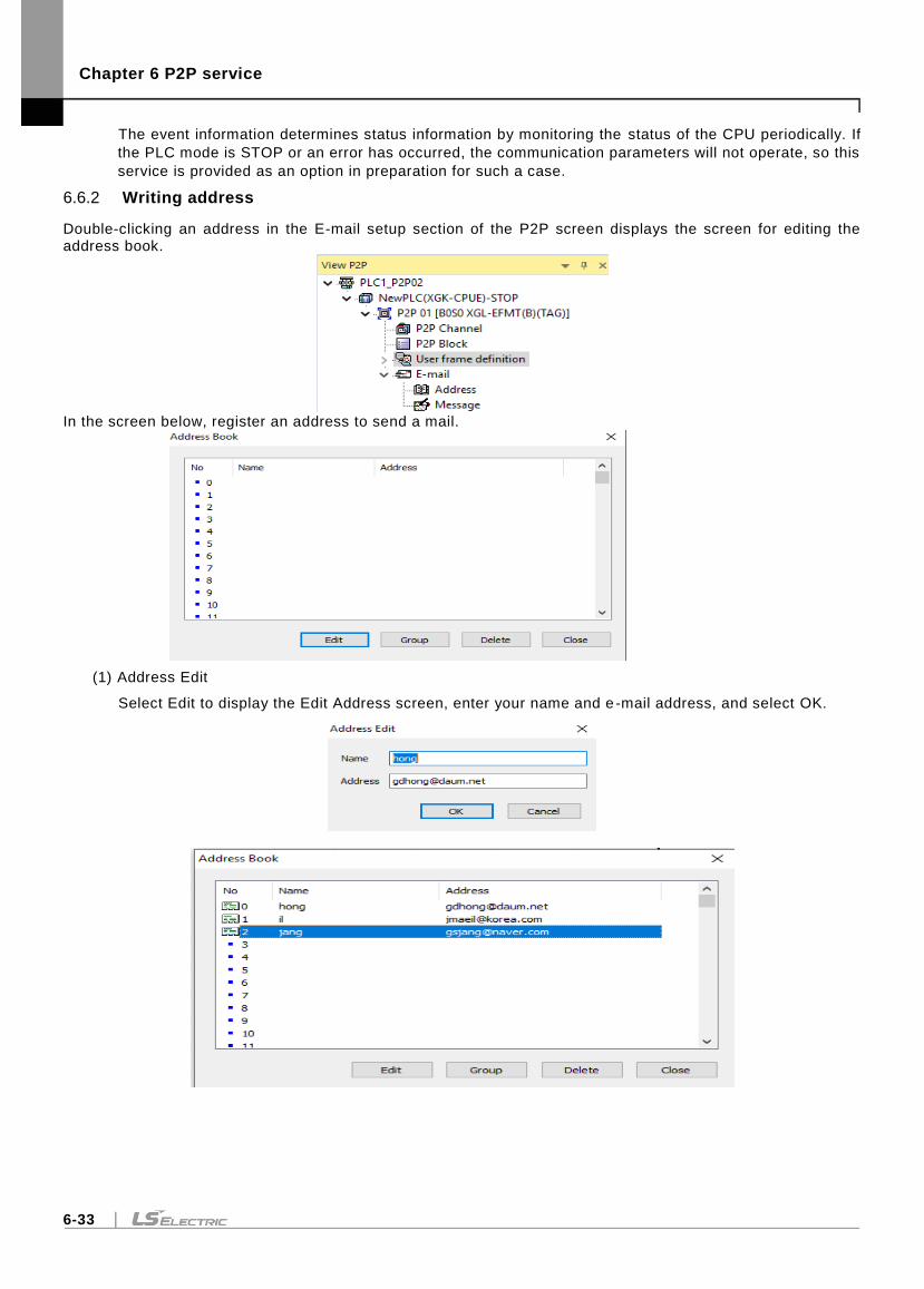
Chapter 6 P2P service
6-33
The event information determines status information by monitoring the status of the CPU periodically. If
the PLC mode is STOP or an error has occurred, the communication parameters will not operate, so this
service is provided as an option in preparation for such a case.
6.6.2 Writing address
Double-clicking an address in the E-mail setup section of the P2P screen displays the screen for editing the address book.
In the screen below, register an address to send a mail.
(1) Address Edit
Select Edit to display the Edit Address screen, enter your name and e -mail address, and select OK.
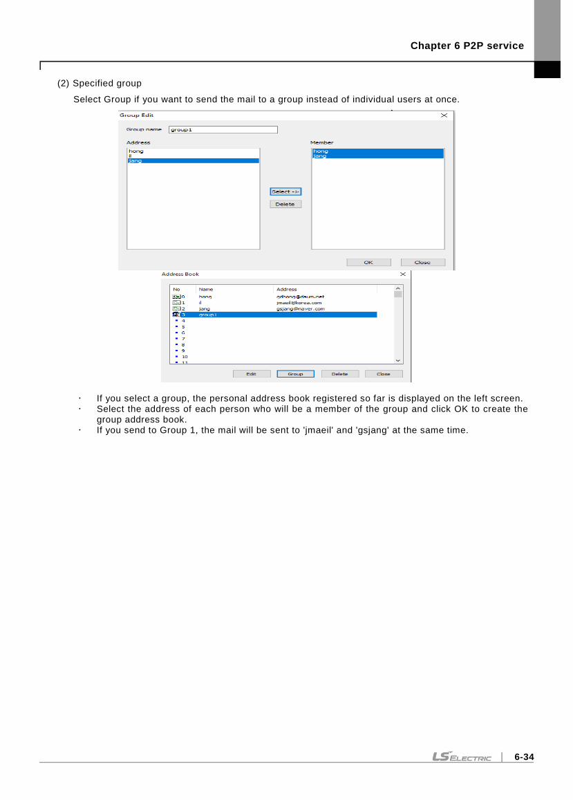
Chapter 6 P2P service
6-34
(2) Specified group
Select Group if you want to send the mail to a group instead of individual users at once.
If you select a group, the personal address book registered so far is displayed on the left screen. Select the address of each person who will be a member of the group and click OK to create the
group address book. If you send to Group 1, the mail will be sent to 'jmaeil' and 'gsjang' at the same time.
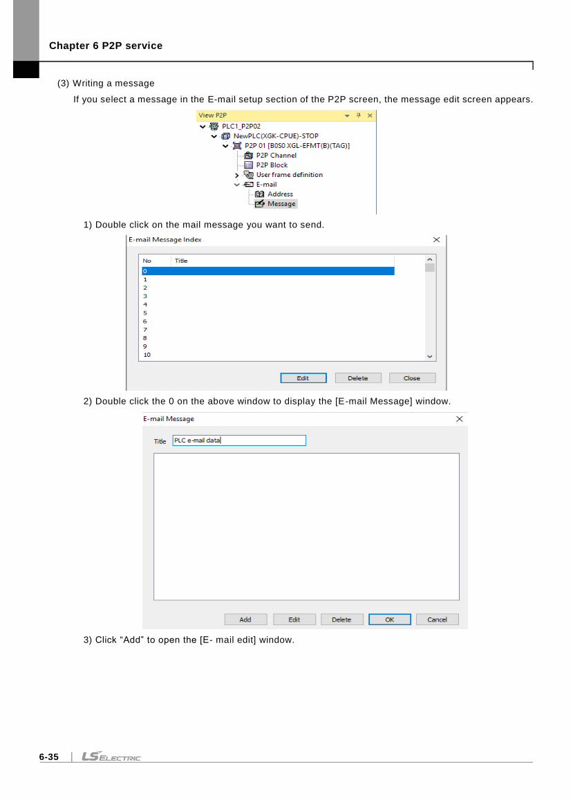
Chapter 6 P2P service
6-35
(3) Writing a message
If you select a message in the E-mail setup section of the P2P screen, the message edit screen appears.
1) Double click on the mail message you want to send.
2) Double click the 0 on the above window to display the [E-mail Message] window.
3) Click “Add” to open the [E- mail edit] window.
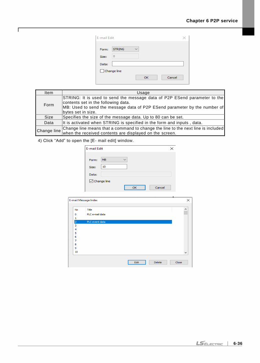
Chapter 6 P2P service
6-36
Item Usage
Form
STRING: It is used to send the message data of P2P ESend parameter to the contents set in the following data. MB: Used to send the message data of P2P ESend parameter by the number of bytes set in size.
Size Specifies the size of the message data. Up to 80 can be set.
Data It is activated when STRING is specified in the form and inputs , data.
Change line Change line means that a command to change the line to the next line is included when the received contents are displayed on the screen.
4) Click “Add” to open the [E- mail edit] window.
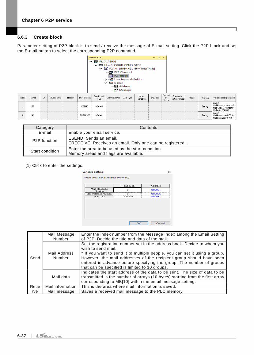
Chapter 6 P2P service
6-37
6.6.3 Create block
Parameter setting of P2P block is to send / receive the message of E-mail setting. Click the P2P block and set
the E-mail button to select the corresponding P2P command.
Category Contents
E-mail Enable your email service.
P2P function ESEND: Sends an email. ERECEIVE: Receives an email. Only one can be registered. .
Start condition Enter the area to be used as the start condition. Memory areas and flags are available.
(1) Click to enter the settings.
Send
Mail Message Number
Enter the index number from the Message Index among the Email Setting of P2P. Decide the title and data of the mail.
Mail Address Number
Set the registration number set in the address book. Decide to whom you wish to send mail. * If you want to send it to multiple people, you can set it using a group. However, the mail addresses of the recipient group should have been entered in advance before specifying the group. The number of groups that can be specified is limited to 10 groups.
Mail data Indicates the start address of the data to be sent. The size of data to be transmitted is the number of arrays (10 bytes) starting from the first array corresponding to MB[10] within the email message setting.
Receive
Mail information This is the area where mail information is saved.
Mail message Saves a received mail message to the PLC memory.
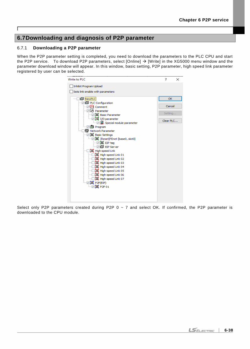
Chapter 6 P2P service
6-38
6.7 Downloading and diagnosis of P2P parameter
6.7.1 Downloading a P2P parameter
When the P2P parameter setting is completed, you need to download the parameters to the PLC CPU and start
the P2P service. To download P2P parameters, select [Online] [Write] in the XG5000 menu window and the
parameter download window will appear. In this window, basic setting, P2P parameter, high speed link parameter
registered by user can be selected.
Select only P2P parameters created during P2P 0 ~ 7 and select OK. If confirmed, the P2P parameter is
downloaded to the CPU module.
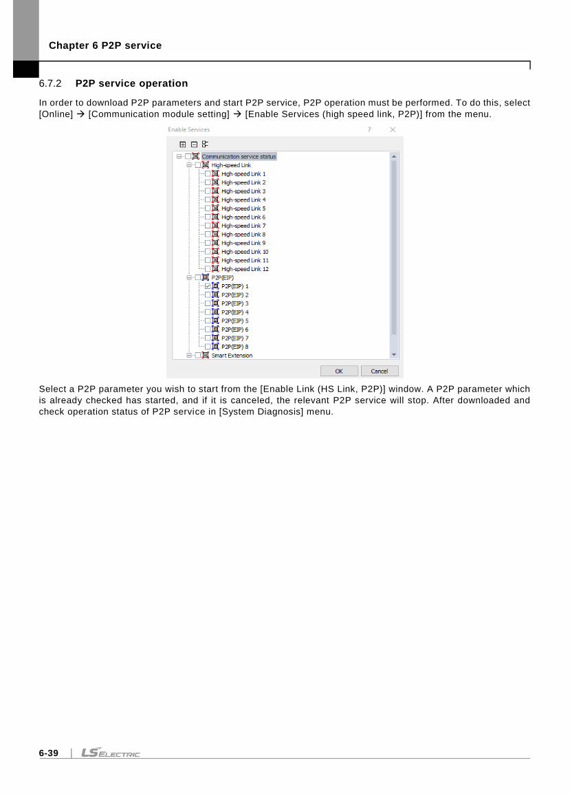
Chapter 6 P2P service
6-39
6.7.2 P2P service operation
In order to download P2P parameters and start P2P service, P2P operation must be performed. To do this, select
[Online] [Communication module setting] [Enable Services (high speed link, P2P)] from the menu.
Select a P2P parameter you wish to start from the [Enable Link (HS Link, P2P)] window. A P2P parameter which
is already checked has started, and if it is canceled, the relevant P2P service will stop. After downloaded and
check operation status of P2P service in [System Diagnosis] menu.
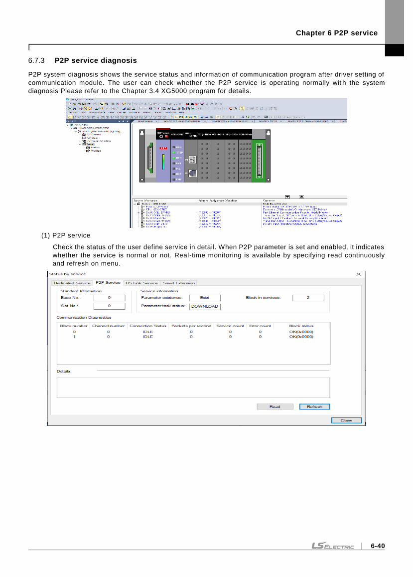
Chapter 6 P2P service
6-40
6.7.3 P2P service diagnosis
P2P system diagnosis shows the service status and information of communication program after driver setting of
communication module. The user can check whether the P2P service is operating normally wit h the system
diagnosis Please refer to the Chapter 3.4 XG5000 program for details.
(1) P2P service
Check the status of the user define service in detail. When P2P parameter is set and enabled, it indicates
whether the service is normal or not. Real-time monitoring is available by specifying read continuously
and refresh on menu.
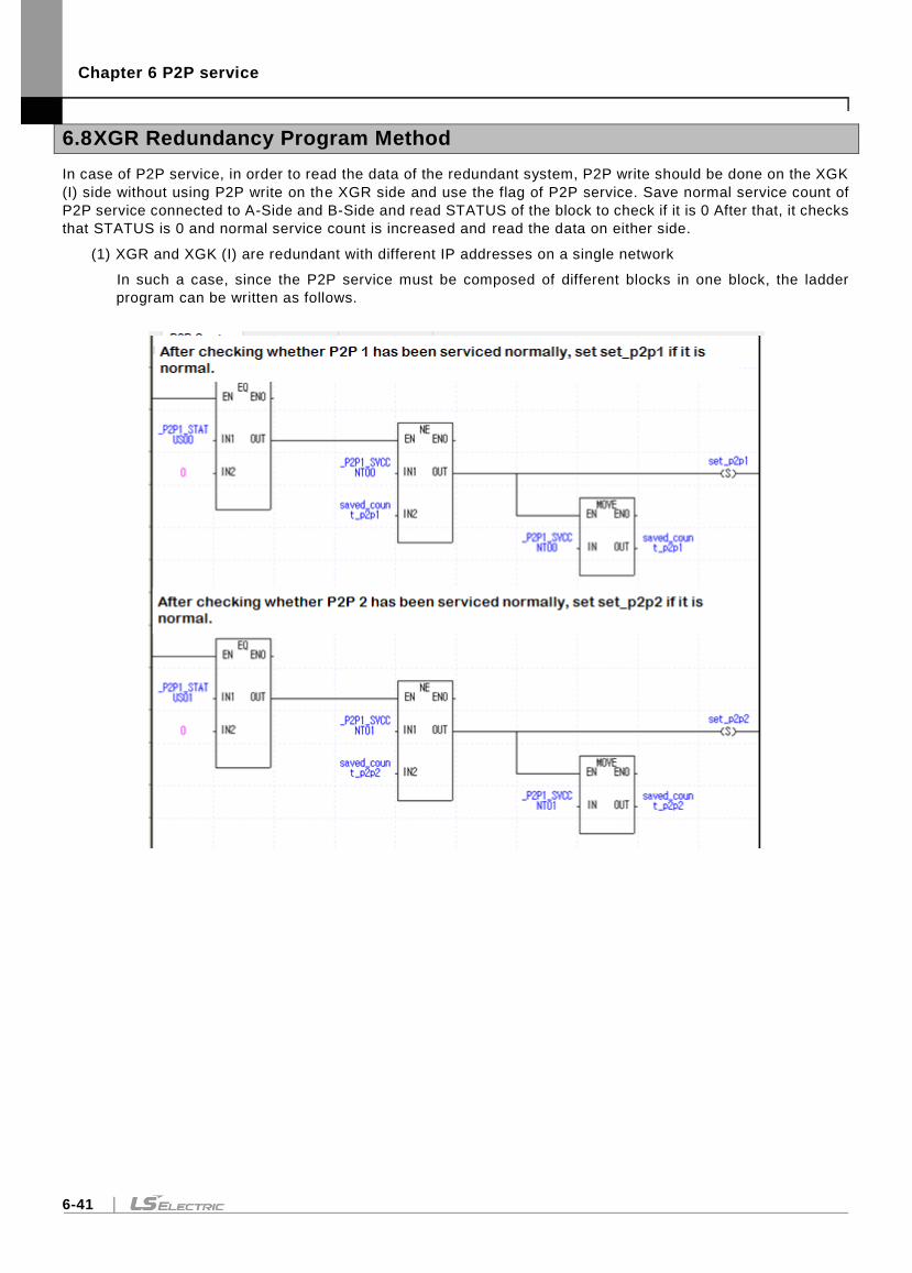
Chapter 6 P2P service
6-41
6.8 XGR Redundancy Program Method
In case of P2P service, in order to read the data of the redundant system, P2P write should be done on the XGK
(I) side without using P2P write on the XGR side and use the flag of P2P service. Save normal service count of
P2P service connected to A-Side and B-Side and read STATUS of the block to check if it is 0 After that, it checks
that STATUS is 0 and normal service count is increased and read the data on either side.
(1) XGR and XGK (I) are redundant with different IP addresses on a single network
In such a case, since the P2P service must be composed of different blocks in one block, the ladder
program can be written as follows.
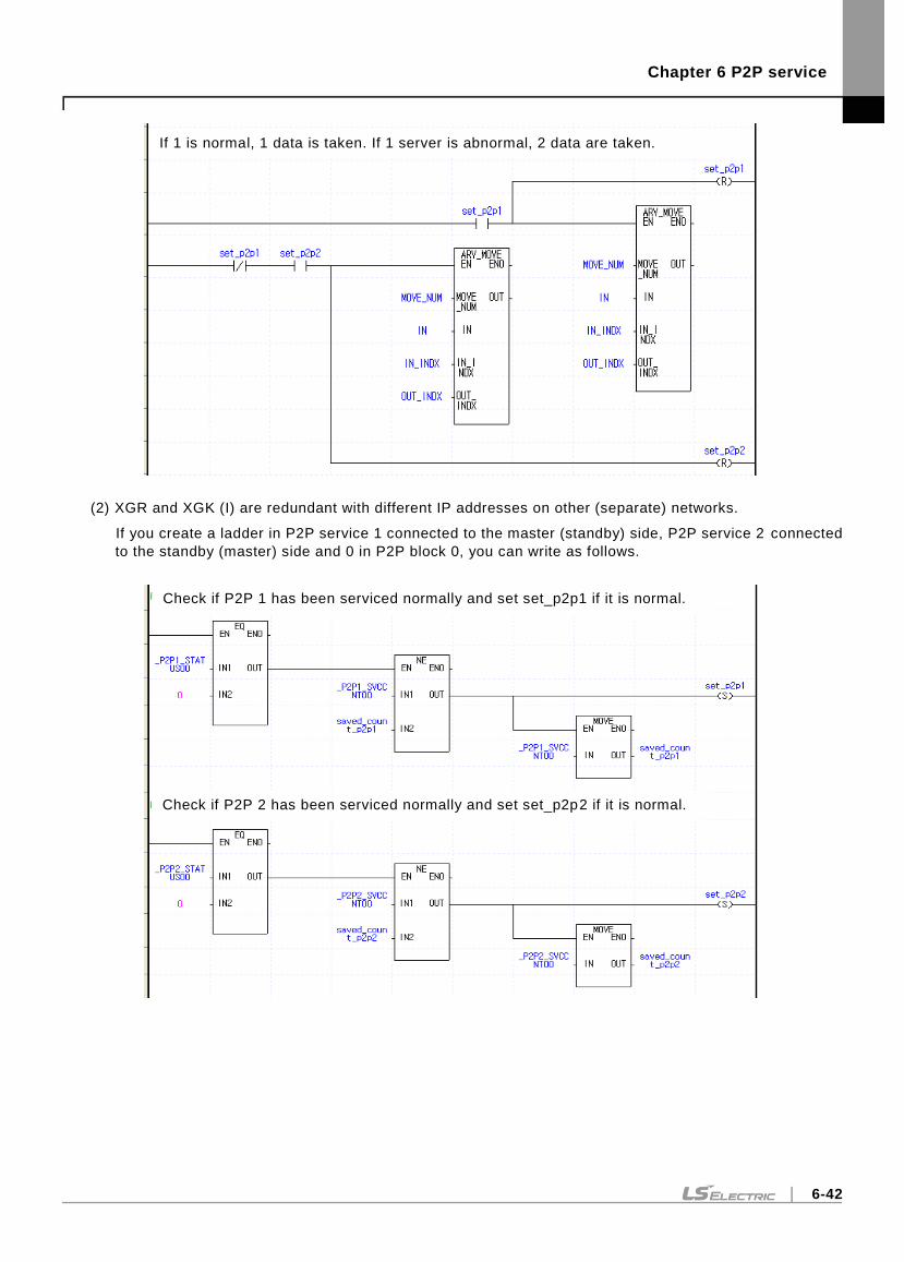
Chapter 6 P2P service
6-42
(2) XGR and XGK (I) are redundant with different IP addresses on other (separate) networks.
If you create a ladder in P2P service 1 connected to the master (standby) side, P2P service 2 connected
to the standby (master) side and 0 in P2P block 0, you can write as follows.
If 1 is normal, 1 data is taken. If 1 server is abnormal, 2 data are taken.
Check if P2P 1 has been serviced normally and set set_p2p1 if it is normal.
Check if P2P 2 has been serviced normally and set set_p2p2 if it is normal.
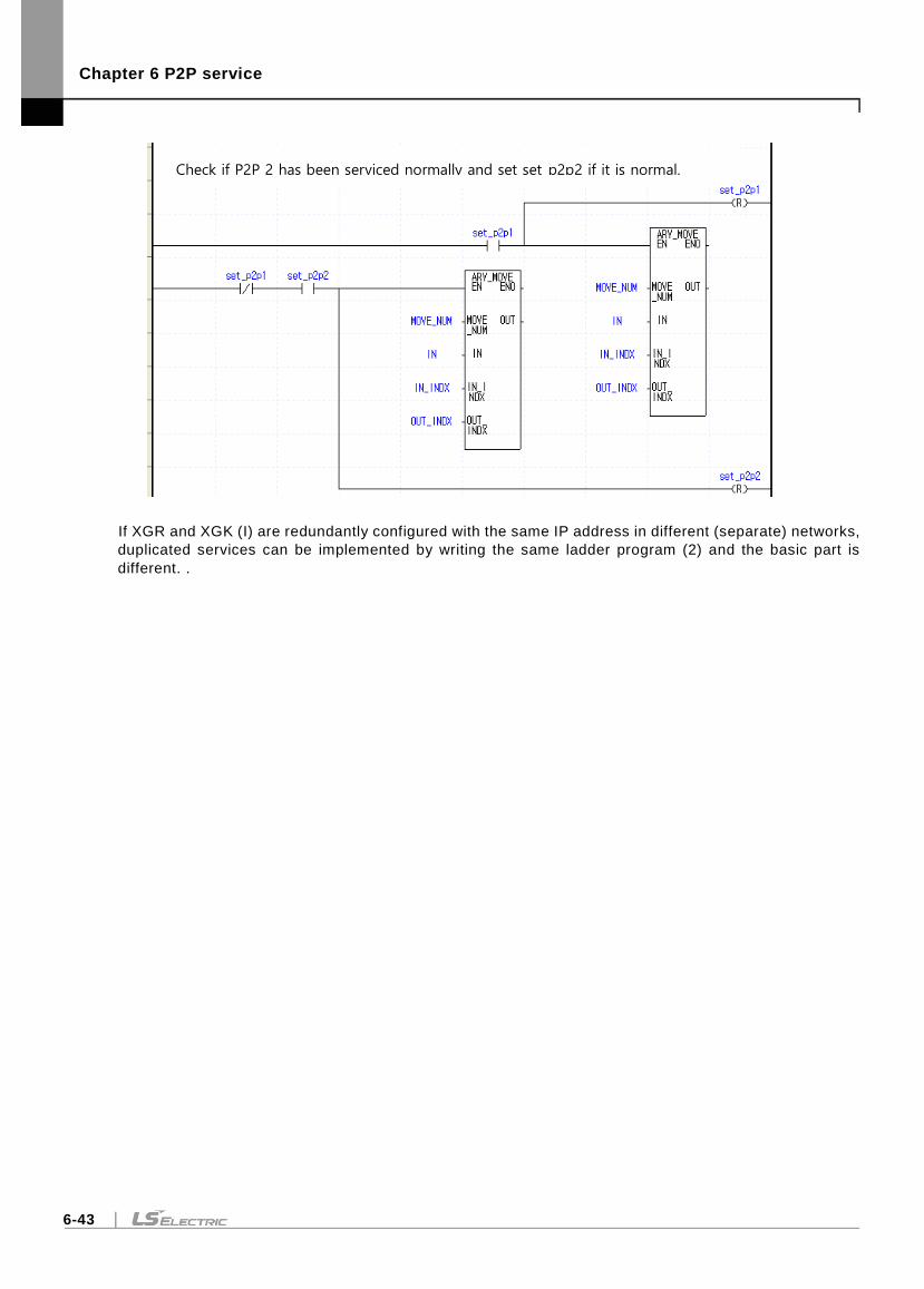
Chapter 6 P2P service
6-43
If XGR and XGK (I) are redundantly configured with the same IP address in different (separate) networks,
duplicated services can be implemented by writing the same ladder program (2) and the basic part is
different. .
Check if P2P 2 has been serviced normally and set set_p2p2 if it is normal.

Chapter 6 P2P service
6-44
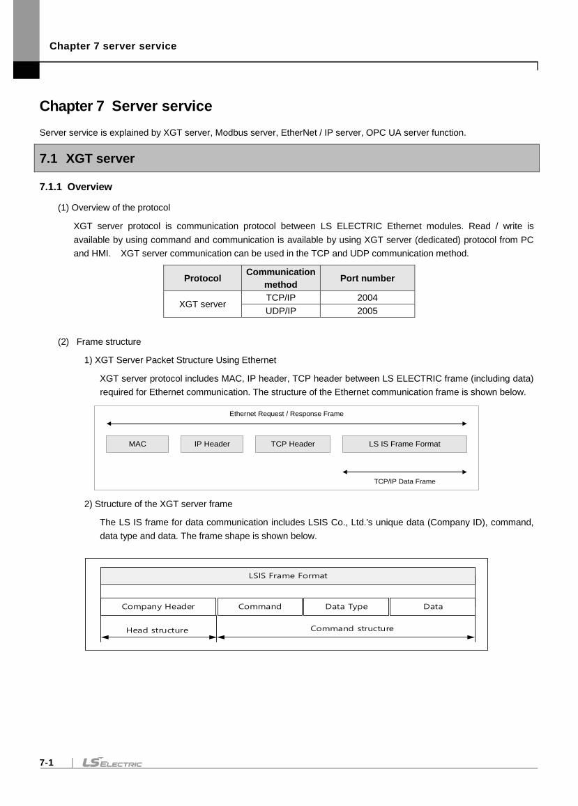
Chapter 7 server service
7-1
Chapter 7 Server service
Server service is explained by XGT server, Modbus server, EtherNet / IP server, OPC UA server function.
7.1 XGT server
7.1.1 Overview
(1) Overview of the protocol
XGT server protocol is communication protocol between LS ELECTRIC Ethernet modules. Read / write is
available by using command and communication is available by using XGT server (dedicated) protocol from PC
and HMI. XGT server communication can be used in the TCP and UDP communication method.
Protocol Communication
method Port number
XGT server TCP/IP 2004
UDP/IP 2005
(2) Frame structure
1) XGT Server Packet Structure Using Ethernet
XGT server protocol includes MAC, IP header, TCP header between LS ELECTRIC frame (including data)
required for Ethernet communication. The structure of the Ethernet communication frame is shown below.
2) Structure of the XGT server frame
The LS IS frame for data communication includes LSIS Co., Ltd.'s unique data (Company ID), command,
data type and data. The frame shape is shown below.
LSIS Frame Format
Company Header Command Data Type Data
Head structure Command structure
IP HeaderMAC TCP Header LS IS Frame Format
TCP/IP Data Frame
Ethernet Request / Response Frame
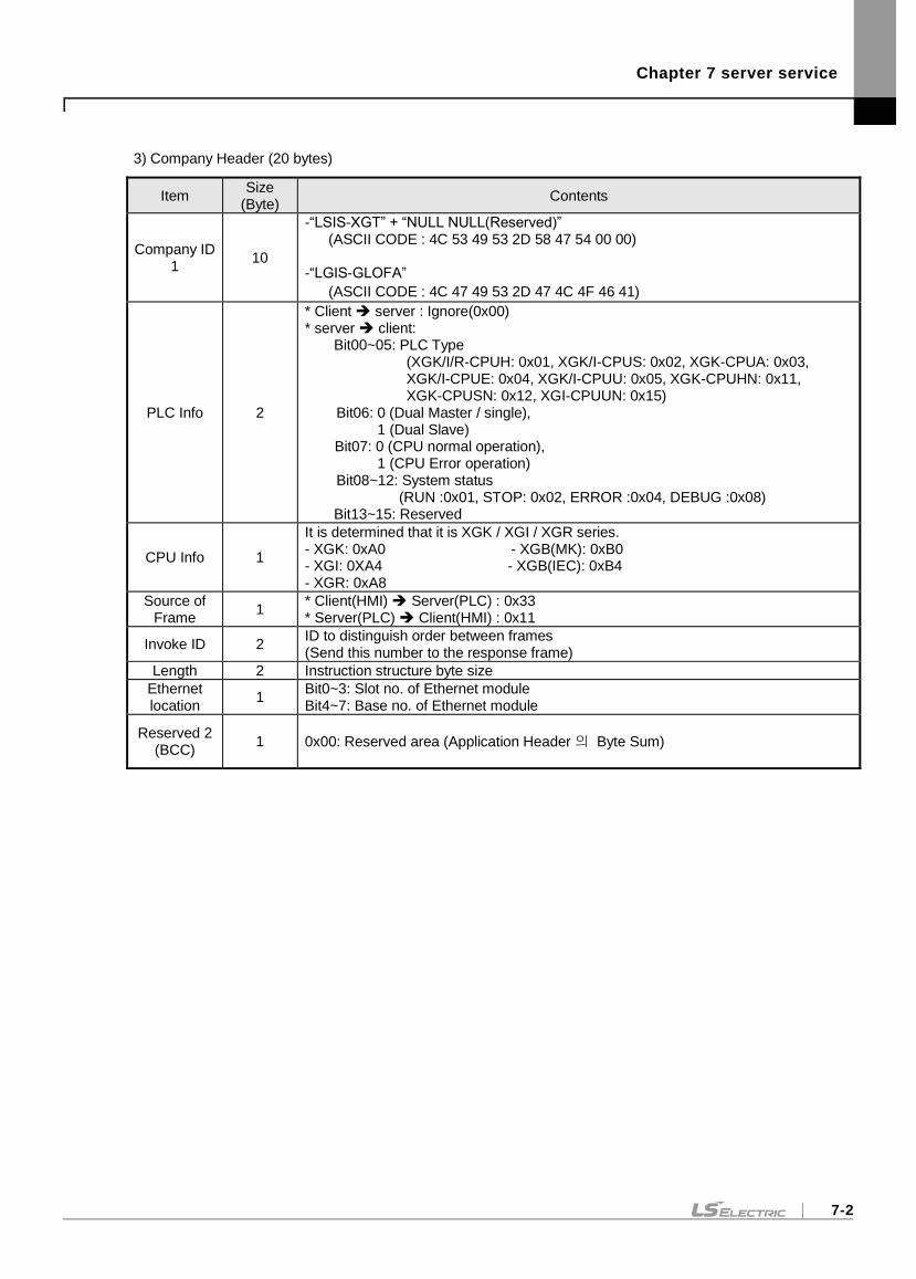
Chapter 7 server service
7-2
3) Company Header (20 bytes)
Item Size
(Byte) Contents
Company ID 1
10
-“LSIS-XGT” + “NULL NULL(Reserved)” (ASCII CODE : 4C 53 49 53 2D 58 47 54 00 00) -“LGIS-GLOFA”
(ASCII CODE : 4C 47 49 53 2D 47 4C 4F 46 41)
PLC Info 2
* Client server : Ignore(0x00) * server client:
Bit00~05: PLC Type (XGK/I/R-CPUH: 0x01, XGK/I-CPUS: 0x02, XGK-CPUA: 0x03, XGK/I-CPUE: 0x04, XGK/I-CPUU: 0x05, XGK-CPUHN: 0x11, XGK-CPUSN: 0x12, XGI-CPUUN: 0x15)
Bit06: 0 (Dual Master / single), 1 (Dual Slave)
Bit07: 0 (CPU normal operation), 1 (CPU Error operation)
Bit08~12: System status (RUN :0x01, STOP: 0x02, ERROR :0x04, DEBUG :0x08)
Bit13~15: Reserved
CPU Info 1
It is determined that it is XGK / XGI / XGR series. - XGK: 0xA0 - XGB(MK): 0xB0 - XGI: 0XA4 - XGB(IEC): 0xB4 - XGR: 0xA8
Source of Frame
1 * Client(HMI) Server(PLC) : 0x33 * Server(PLC) Client(HMI) : 0x11
Invoke ID 2 ID to distinguish order between frames (Send this number to the response frame)
Length 2 Instruction structure byte size
Ethernet location
1 Bit0~3: Slot no. of Ethernet module Bit4~7: Base no. of Ethernet module
Reserved 2 (BCC)
1 0x00: Reserved area (Application Header 의 Byte Sum)
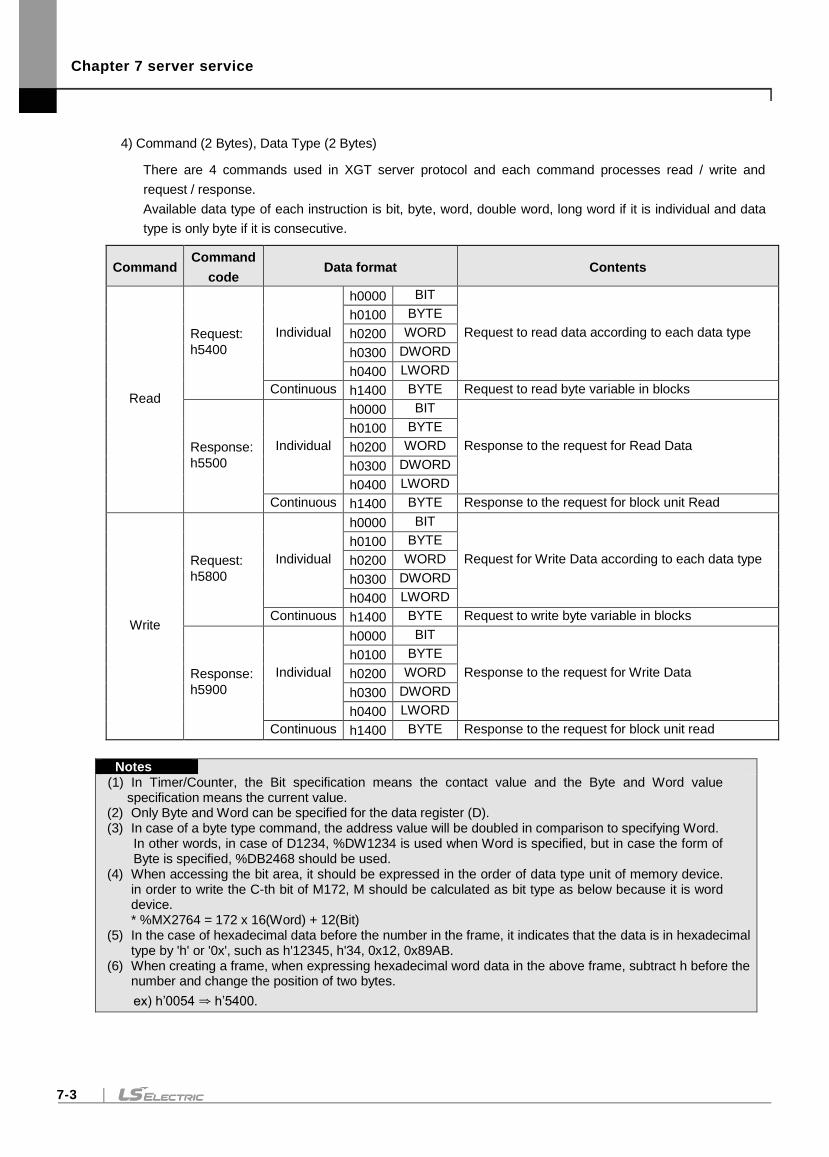
Chapter 7 server service
7-3
4) Command (2 Bytes), Data Type (2 Bytes)
There are 4 commands used in XGT server protocol and each command processes read / write and
request / response.
Available data type of each instruction is bit, byte, word, double word, long word if it is individual and data
type is only byte if it is consecutive.
Command Command
code Data format Contents
Read
Request:
h5400
Individual
h0000 BIT
Request to read data according to each data type
h0100 BYTE
h0200 WORD
h0300 DWORD
h0400 LWORD
Continuous h1400 BYTE Request to read byte variable in blocks
Response:
h5500
Individual
h0000 BIT
Response to the request for Read Data
h0100 BYTE
h0200 WORD
h0300 DWORD
h0400 LWORD
Continuous h1400 BYTE Response to the request for block unit Read
Write
Request:
h5800
Individual
h0000 BIT
Request for Write Data according to each data type
h0100 BYTE
h0200 WORD
h0300 DWORD
h0400 LWORD
Continuous h1400 BYTE Request to write byte variable in blocks
Response:
h5900
Individual
h0000 BIT
Response to the request for Write Data
h0100 BYTE
h0200 WORD
h0300 DWORD
h0400 LWORD
Continuous h1400 BYTE Response to the request for block unit read
Notes (1) In Timer/Counter, the Bit specification means the contact value and the Byte and Word value
specification means the current value. (2) Only Byte and Word can be specified for the data register (D). (3) In case of a byte type command, the address value will be doubled in comparison to specifying Word.
In other words, in case of D1234, %DW1234 is used when Word is specified, but in case the form of Byte is specified, %DB2468 should be used.
(4) When accessing the bit area, it should be expressed in the order of data type unit of memory device. in order to write the C-th bit of M172, M should be calculated as bit type as below because it is word device. * %MX2764 = 172 x 16(Word) + 12(Bit)
(5) In the case of hexadecimal data before the number in the frame, it indicates that the data is in hexadecimal type by 'h' or '0x', such as h'12345, h'34, 0x12, 0x89AB.
(6) When creating a frame, when expressing hexadecimal word data in the above frame, subtract h before the number and change the position of two bytes.
ex) h’0054 ⇒ h’5400.
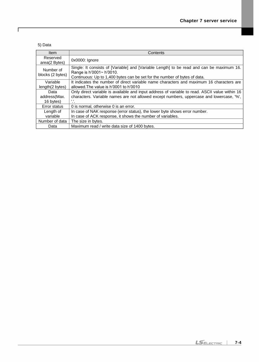
Chapter 7 server service
7-4
5) Data
Item Contents
Reserved area(2 Bytes)
0x0000: Ignore
Number of blocks (2 bytes)
Single: It consists of [Variable] and [Variable Length] to be read and can be maximum 16. Range is h’0001~ h’0010. Continuous: Up to 1,400 bytes can be set for the number of bytes of data.
Variable length(2 bytes)
It indicates the number of direct variable name characters and maximum 16 characters are allowed.The value is h’0001 to h’0010
Data address(Max.
16 bytes)
Only direct variable is available and input address of variable to read. ASCII value within 16 characters. Variable names are not allowed except numbers, uppercase and lowercase, '%', '.'.
Error status 0 is normal, otherwise 0 is an error.
Length of variable
In case of NAK response (error status), the lower byte shows error number. In case of ACK response, it shows the number of variables.
Number of data The size in bytes.
Data Maximum read / write data size of 1400 bytes.
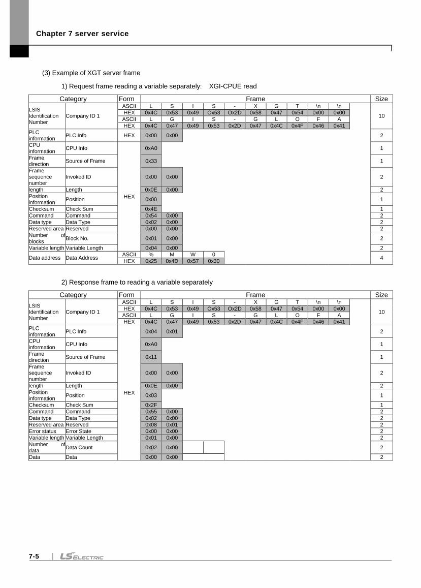
Chapter 7 server service
7-5
(3) Example of XGT server frame
1) Request frame reading a variable separately: XGI-CPUE read
Category Form Frame Size
LSIS Identification Number
Company ID 1
ASCII L S I S - X G T \n \n
10 HEX 0x4C 0x53 0x49 Ox53 Ox2D 0x58 0x47 0x54 0x00 0x00
ASCII L G I S - G L O F A
HEX 0x4C 0x47 0x49 0x53 0x2D 0x47 0x4C 0x4F 0x46 0x41
PLC information
PLC Info HEX 0x00 0x00 2
CPU information
CPU Info
HEX
0xA0 1
Frame direction
Source of Frame 0x33 1
Frame sequence number
Invoked ID 0x00 0x00 2
length Length 0x0E 0x00 2
Position information
Position 0x00 1
Checksum Check Sum 0x4E 1
Command Command 0x54 0x00 2
Data type Data Type 0x02 0x00 2
Reserved area Reserved 0x00 0x00 2
Number of blocks
Block No. 0x01 0x00 2
Variable length Variable Length 0x04 0x00 2
Data address Data Address ASCII % M W 0
4 HEX 0x25 0x4D 0x57 0x30
2) Response frame to reading a variable separately
Category Form Frame Size
LSIS Identification Number
Company ID 1
ASCII L S I S - X G T \n \n
10 HEX 0x4C 0x53 0x49 Ox53 Ox2D 0x58 0x47 0x54 0x00 0x00
ASCII L G I S - G L O F A
HEX 0x4C 0x47 0x49 0x53 0x2D 0x47 0x4C 0x4F 0x46 0x41
PLC information
PLC Info
HEX
0x04 0x01 2
CPU information
CPU Info 0xA0 1
Frame direction
Source of Frame 0x11 1
Frame sequence number
Invoked ID 0x00 0x00 2
length Length 0x0E 0x00 2
Position information
Position 0x03 1
Checksum Check Sum 0x2F 1
Command Command 0x55 0x00 2
Data type Data Type 0x02 0x00 2
Reserved area Reserved 0x08 0x01 2
Error status Error State 0x00 0x00 2
Variable length Variable Length 0x01 0x00 2
Number of data
Data Count 0x02 0x00 2
Data Data 0x00 0x00 2
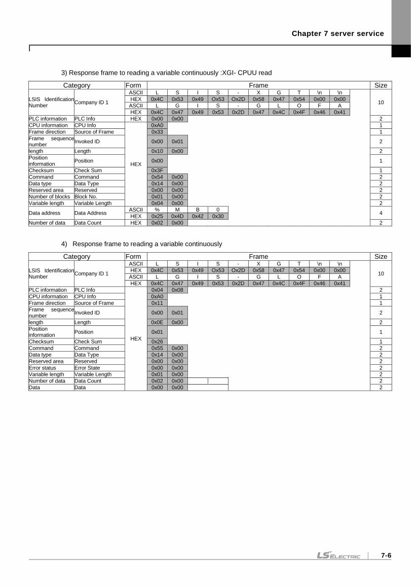
Chapter 7 server service
7-6
3) Response frame to reading a variable continuously :XGI- CPUU read
Category Form Frame Size
LSIS Identification Number
Company ID 1
ASCII L S I S - X G T \n \n
10 HEX 0x4C 0x53 0x49 Ox53 Ox2D 0x58 0x47 0x54 0x00 0x00
ASCII L G I S - G L O F A
HEX 0x4C 0x47 0x49 0x53 0x2D 0x47 0x4C 0x4F 0x46 0x41
PLC information PLC Info HEX 0x00 0x00 2
CPU information CPU Info
HEX
0xA0 1
Frame direction Source of Frame 0x33 1
Frame sequence number
Invoked ID 0x00 0x01 2
length Length 0x10 0x00 2
Position information
Position 0x00 1
Checksum Check Sum 0x3F 1
Command Command 0x54 0x00 2
Data type Data Type 0x14 0x00 2
Reserved area Reserved 0x00 0x00 2
Number of blocks Block No. 0x01 0x00 2
Variable length Variable Length 0x04 0x00 2
Data address Data Address ASCII % M B 0
4 HEX 0x25 0x4D 0x42 0x30
Number of data Data Count HEX 0x02 0x00 2
4) Response frame to reading a variable continuously
Category Form Frame Size
LSIS Identification Number
Company ID 1
ASCII L S I S - X G T \n \n
10 HEX 0x4C 0x53 0x49 Ox53 Ox2D 0x58 0x47 0x54 0x00 0x00
ASCII L G I S - G L O F A
HEX 0x4C 0x47 0x49 0x53 0x2D 0x47 0x4C 0x4F 0x46 0x41
PLC information PLC Info
HEX
0x04 0x08 2
CPU information CPU Info 0xA0 1
Frame direction Source of Frame 0x11 1
Frame sequence number
Invoked ID 0x00 0x01 2
length Length 0x0E 0x00 2
Position information
Position 0x01 1
Checksum Check Sum 0x26 1
Command Command 0x55 0x00 2
Data type Data Type 0x14 0x00 2
Reserved area Reserved 0x00 0x00 2
Error status Error State 0x00 0x00 2
Variable length Variable Length 0x01 0x00 2
Number of data Data Count 0x02 0x00 2
Data Data 0x00 0x00 2
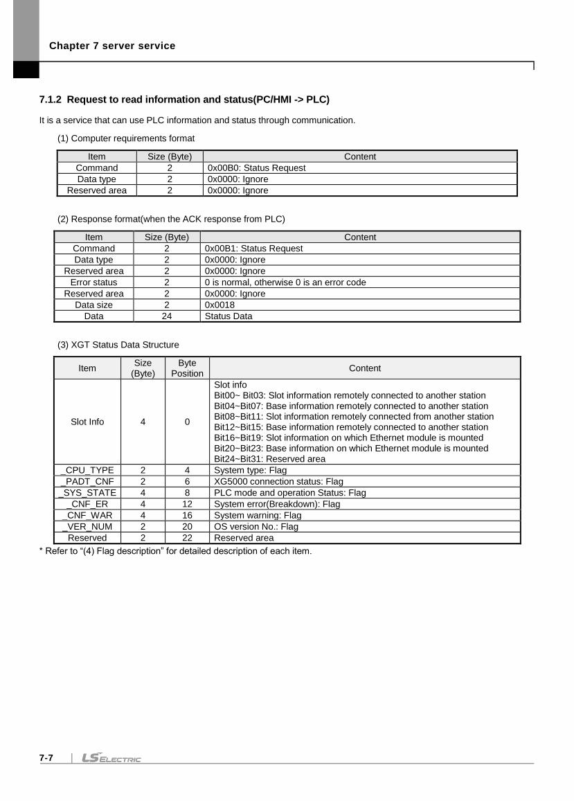
Chapter 7 server service
7-7
7.1.2 Request to read information and status(PC/HMI -> PLC)
It is a service that can use PLC information and status through communication.
(1) Computer requirements format
Item Size (Byte) Content
Command 2 0x00B0: Status Request
Data type 2 0x0000: Ignore
Reserved area 2 0x0000: Ignore
(2) Response format(when the ACK response from PLC)
Item Size (Byte) Content
Command 2 0x00B1: Status Request
Data type 2 0x0000: Ignore
Reserved area 2 0x0000: Ignore
Error status 2 0 is normal, otherwise 0 is an error code
Reserved area 2 0x0000: Ignore
Data size 2 0x0018
Data 24 Status Data
(3) XGT Status Data Structure
Item Size
(Byte) Byte
Position Content
Slot Info 4 0
Slot info Bit00~ Bit03: Slot information remotely connected to another station Bit04~Bit07: Base information remotely connected to another station Bit08~Bit11: Slot information remotely connected from another station Bit12~Bit15: Base information remotely connected to another station Bit16~Bit19: Slot information on which Ethernet module is mounted Bit20~Bit23: Base information on which Ethernet module is mounted Bit24~Bit31: Reserved area
_CPU_TYPE 2 4 System type: Flag
_PADT_CNF 2 6 XG5000 connection status: Flag
_SYS_STATE 4 8 PLC mode and operation Status: Flag
_CNF_ER 4 12 System error(Breakdown): Flag
_CNF_WAR 4 16 System warning: Flag
_VER_NUM 2 20 OS version No.: Flag
Reserved 2 22 Reserved area
* Refer to “(4) Flag description” for detailed description of each item.
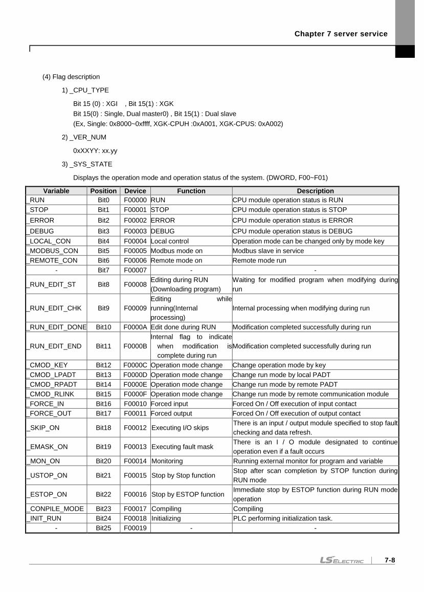
Chapter 7 server service
7-8
(4) Flag description
1) _CPU_TYPE
Bit 15 (0) : XGI , Bit 15(1) : XGK
Bit 15(0) : Single, Dual master0) , Bit 15(1) : Dual slave
(Ex, Single: 0x8000~0xffff, XGK-CPUH :0xA001, XGK-CPUS: 0xA002)
2) _VER_NUM
0xXXYY: xx.yy
3) _SYS_STATE
Displays the operation mode and operation status of the system. (DWORD, F00~F01)
Variable Position Device Function Description
_RUN Bit0 F00000 RUN CPU module operation status is RUN
_STOP Bit1 F00001 STOP CPU module operation status is STOP
_ERROR Bit2 F00002 ERROR CPU module operation status is ERROR
_DEBUG Bit3 F00003 DEBUG CPU module operation status is DEBUG
_LOCAL_CON Bit4 F00004 Local control Operation mode can be changed only by mode key
_MODBUS_CON Bit5 F00005 Modbus mode on Modbus slave in service
_REMOTE_CON Bit6 F00006 Remote mode on Remote mode run
- Bit7 F00007 - -
_RUN_EDIT_ST Bit8 F00008 Editing during RUN
(Downloading program)
Waiting for modified program when modifying during
run
_RUN_EDIT_CHK Bit9 F00009
Editing while
running(Internal
processing)
Internal processing when modifying during run
_RUN_EDIT_DONE Bit10 F0000A Edit done during RUN Modification completed successfully during run
_RUN_EDIT_END Bit11 F0000B
Internal flag to indicate
when modification is
complete during run
Modification completed successfully during run
_CMOD_KEY Bit12 F0000C Operation mode change Change operation mode by key
_CMOD_LPADT Bit13 F0000D Operation mode change Change run mode by local PADT
_CMOD_RPADT Bit14 F0000E Operation mode change Change run mode by remote PADT
_CMOD_RLINK Bit15 F0000F Operation mode change Change run mode by remote communication module
_FORCE_IN Bit16 F00010 Forced input Forced On / Off execution of input contact
_FORCE_OUT Bit17 F00011 Forced output Forced On / Off execution of output contact
_SKIP_ON Bit18 F00012 Executing I/O skips There is an input / output module specified to stop fault
checking and data refresh.
_EMASK_ON Bit19 F00013 Executing fault mask There is an I / O module designated to continue
operation even if a fault occurs
_MON_ON Bit20 F00014 Monitoring Running external monitor for program and variable
_USTOP_ON Bit21 F00015 Stop by Stop function Stop after scan completion by STOP function during
RUN mode
_ESTOP_ON Bit22 F00016 Stop by ESTOP function Immediate stop by ESTOP function during RUN mode
operation
_CONPILE_MODE Bit23 F00017 Compiling Compiling
_INIT_RUN Bit24 F00018 Initializing PLC performing initialization task.
- Bit25 F00019 - -
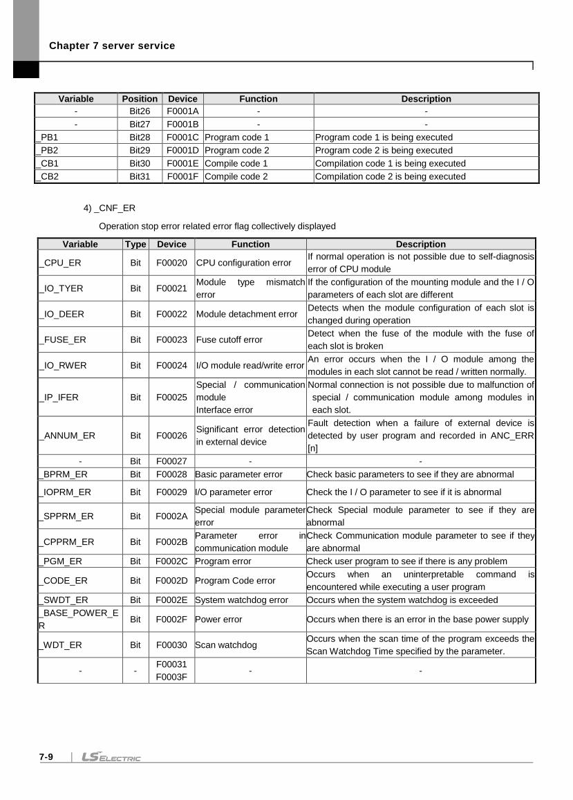
Chapter 7 server service
7-9
Variable Position Device Function Description
- Bit26 F0001A - -
- Bit27 F0001B - -
_PB1 Bit28 F0001C Program code 1 Program code 1 is being executed
_PB2 Bit29 F0001D Program code 2 Program code 2 is being executed
_CB1 Bit30 F0001E Compile code 1 Compilation code 1 is being executed
_CB2 Bit31 F0001F Compile code 2 Compilation code 2 is being executed
4) _CNF_ER
Operation stop error related error flag collectively displayed
Variable Type Device Function Description
_CPU_ER Bit F00020 CPU configuration error If normal operation is not possible due to self-diagnosis
error of CPU module
_IO_TYER Bit F00021 Module type mismatch
error
If the configuration of the mounting module and the I / O
parameters of each slot are different
_IO_DEER Bit F00022 Module detachment error Detects when the module configuration of each slot is
changed during operation
_FUSE_ER Bit F00023 Fuse cutoff error Detect when the fuse of the module with the fuse of
each slot is broken
_IO_RWER Bit F00024 I/O module read/write error An error occurs when the I / O module among the
modules in each slot cannot be read / written normally.
_IP_IFER Bit F00025
Special / communication
module
Interface error
Normal connection is not possible due to malfunction of
special / communication module among modules in
each slot.
_ANNUM_ER Bit F00026 Significant error detection
in external device
Fault detection when a failure of external device is
detected by user program and recorded in ANC_ERR
[n]
- Bit F00027 - -
_BPRM_ER Bit F00028 Basic parameter error Check basic parameters to see if they are abnormal
_IOPRM_ER Bit F00029 I/O parameter error Check the I / O parameter to see if it is abnormal
_SPPRM_ER Bit F0002A Special module parameter
error
Check Special module parameter to see if they are
abnormal
_CPPRM_ER Bit F0002B Parameter error in
communication module
Check Communication module parameter to see if they
are abnormal
_PGM_ER Bit F0002C Program error Check user program to see if there is any problem
_CODE_ER Bit F0002D Program Code error Occurs when an uninterpretable command is
encountered while executing a user program
_SWDT_ER Bit F0002E System watchdog error Occurs when the system watchdog is exceeded
_BASE_POWER_E
R Bit F0002F Power error Occurs when there is an error in the base power supply
_WDT_ER Bit F00030 Scan watchdog Occurs when the scan time of the program exceeds the
Scan Watchdog Time specified by the parameter.
- - F00031
F0003F - -
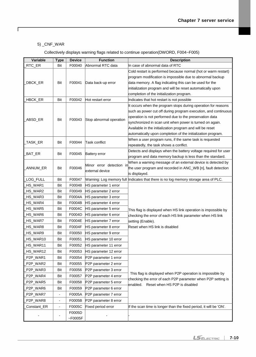
Chapter 7 server service
7-10
5) _CNF_WAR
Collectively displays warning flags related to continue operation(DWORD, F004~F005)
Variable Type Device Function Description
_RTC_ER Bit F00040 Abnormal RTC data In case of abnormal data of RTC
_DBCK_ER Bit F00041 Data back-up error
Cold restart is performed because normal (hot or warm restart)
program modification is impossible due to abnormal backup
data memory. A flag indicating this can be used for the
initialization program and will be reset automatically upon
completion of the initialization program.
_HBCK_ER Bit F00042 Hot restart error Indicates that hot restart is not possible
_ABSD_ER Bit F00043 Stop abnormal operation
It occurs when the program stops during operation for reasons
such as power cut off during program execution, and continuous
operation is not performed due to the preservation data
synchronized in scan unit when power is turned on again.
Available in the initialization program and will be reset
automatically upon completion of the initialization program.
_TASK_ER Bit F00044 Task conflict When a user program runs, if the same task is requested
repeatedly, the task shows a conflict.
_BAT_ER Bit F00045 Battery error Detects and displays when the battery voltage required for user
program and data memory backup is less than the standard.
_ANNUM_ER Bit F00046 Minor error detection in
external device
When a warning message of an external device is detected by
the user program and recorded in ANC_WB [n], fault detection
is displayed.
_LOG_FULL Bit F00047 Warning: Log memory full Indicates that there is no log memory storage area of PLC.
_HS_WAR1 Bit F00048 HS parameter 1 error
This flag is displayed when HS link operation is impossible by
checking the error of each HS link parameter when HS link
setting (Enable).
Reset when HS link is disabled
_HS_WAR2 Bit F00049 HS parameter 2 error
_HS_WAR3 Bit F0004A HS parameter 3 error
_HS_WAR4 Bit F0004B HS parameter 4 error
_HS_WAR5 Bit F0004C HS parameter 5 error
_HS_WAR6 Bit F0004D HS parameter 6 error
_HS_WAR7 Bit F0004E HS parameter 7 error
_HS_WAR8 Bit F0004F HS parameter 8 error
_HS_WAR9 Bit F00050 HS parameter 9 error
_HS_WAR10 Bit F00051 HS parameter 10 error
_HS_WAR11 Bit F00052 HS parameter 11 error
_HS_WAR12 Bit F00053 HS parameter 12 error
_P2P_WAR1 Bit F00054 P2P parameter 1 error
This flag is displayed when P2P operation is impossible by
checking the error of each P2P parameter when P2P setting is
enabled. Reset when HS P2P is disabled
_P2P_WAR2 Bit F00055 P2P parameter 2 error
_P2P_WAR3 Bit F00056 P2P parameter 3 error
_P2P_WAR4 Bit F00057 P2P parameter 4 error
_P2P_WAR5 Bit F00058 P2P parameter 5 error
_P2P_WAR6 Bit F00059 P2P parameter 6 error
_P2P_WAR7 - F0005A P2P parameter 7 error
_P2P_WAR8 - F0005B P2P parameter 8 error
_Constant_ER - F0005C Fixed period error If the scan time is longer than the fixed period, it will be 'ON'.
- - F0005D
~F0005F - -
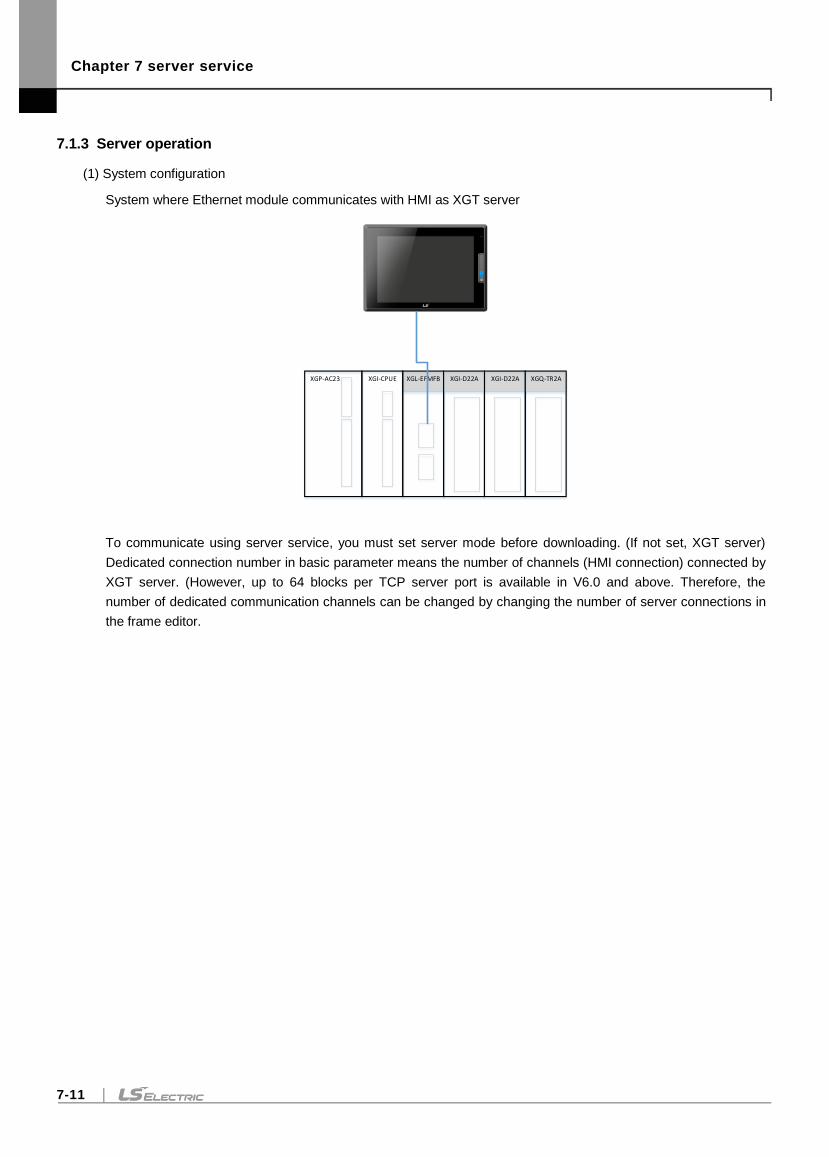
Chapter 7 server service
7-11
7.1.3 Server operation
(1) System configuration
System where Ethernet module communicates with HMI as XGT server
XGI-D22AXGL-EFMFBXGP-AC23 XGI-CPUE XGI-D22A XGQ-TR2A
To communicate using server service, you must set server mode before downloading. (If not set, XGT server)
Dedicated connection number in basic parameter means the number of channels (HMI connection) connected by
XGT server. (However, up to 64 blocks per TCP server port is available in V6.0 and above. Therefore, the
number of dedicated communication channels can be changed by changing the number of server connections in
the frame editor.
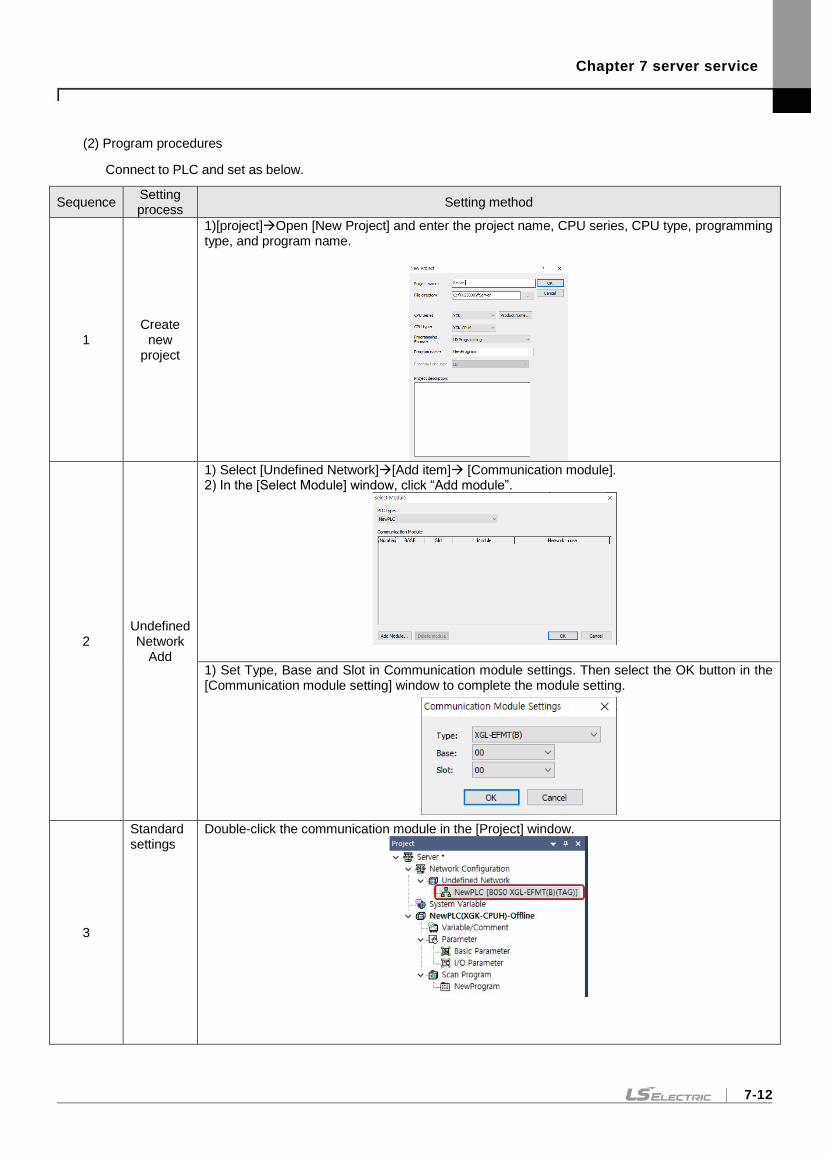
Chapter 7 server service
7-12
(2) Program procedures
Connect to PLC and set as below.
Sequence Setting process
Setting method
1 Create
new project
1)[project]Open [New Project] and enter the project name, CPU series, CPU type, programming type, and program name.
2 Undefined Network
Add
1) Select [Undefined Network][Add item] [Communication module]. 2) In the [Select Module] window, click “Add module”.
1) Set Type, Base and Slot in Communication module settings. Then select the OK button in the [Communication module setting] window to complete the module setting.
3
Standard settings
Double-click the communication module in the [Project] window.
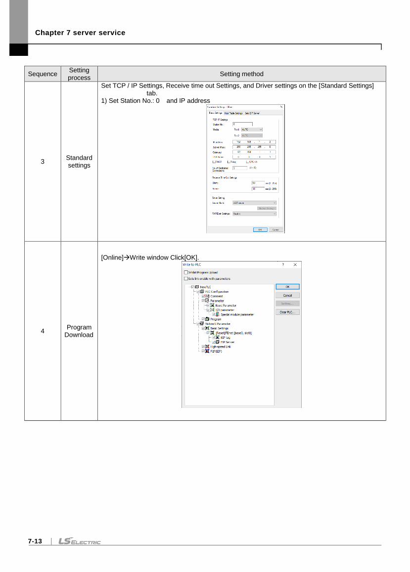
Chapter 7 server service
7-13
Sequence Setting process
Setting method
3 Standard settings
Set TCP / IP Settings, Receive time out Settings, and Driver settings on the [Standard Settings] tab.
1) Set Station No.: 0 and IP address
4 Program
Download
[Online]Write window Click[OK].
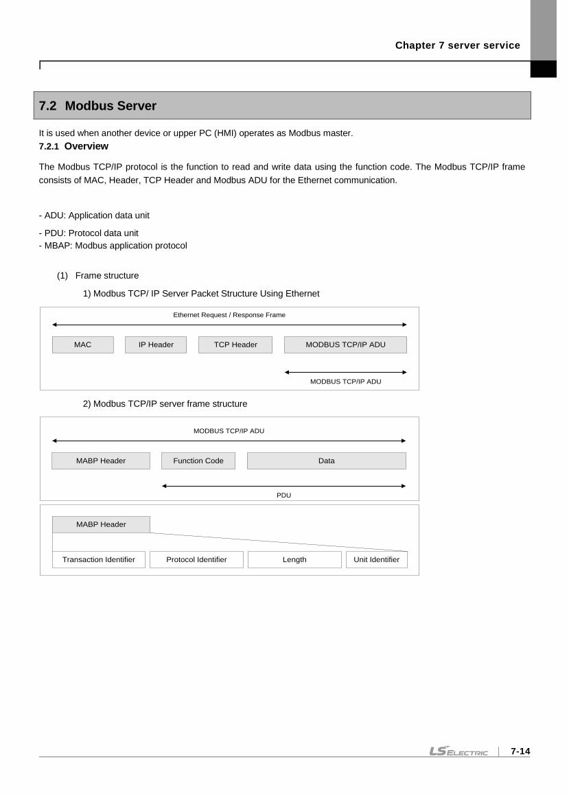
Chapter 7 server service
7-14
7.2 Modbus Server
It is used when another device or upper PC (HMI) operates as Modbus master.
7.2.1 Overview
The Modbus TCP/IP protocol is the function to read and write data using the function code. The Modbus TCP/IP frame
consists of MAC, Header, TCP Header and Modbus ADU for the Ethernet communication.
- ADU: Application data unit
- PDU: Protocol data unit
- MBAP: Modbus application protocol
(1) Frame structure
1) Modbus TCP/ IP Server Packet Structure Using Ethernet
2) Modbus TCP/IP server frame structure
IP HeaderMAC TCP Header MODBUS TCP/IP ADU
MODBUS TCP/IP ADU
Ethernet Request / Response Frame
MABP Header Function Code Data
MODBUS TCP/IP ADU
PDU
MABP Header
Transaction Identifier Protocol Identifier Length Unit Identifier
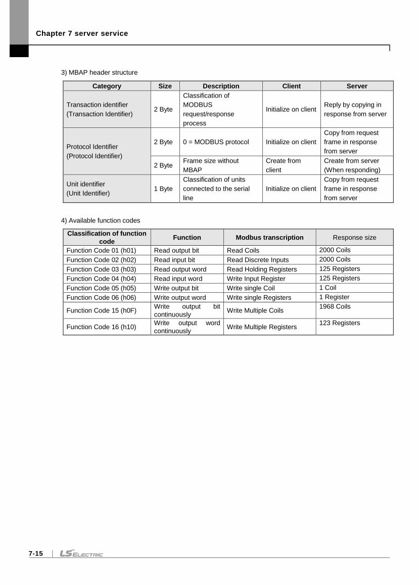
Chapter 7 server service
7-15
3) MBAP header structure
Category Size Description Client Server
Transaction identifier
(Transaction Identifier) 2 Byte
Classification of
MODBUS
request/response
process
Initialize on client Reply by copying in
response from server
Protocol Identifier
(Protocol Identifier)
2 Byte 0 = MODBUS protocol Initialize on client
Copy from request
frame in response
from server
2 Byte Frame size without
MBAP
Create from
client
Create from server
(When responding)
Unit identifier
(Unit Identifier) 1 Byte
Classification of units
connected to the serial
line
Initialize on client
Copy from request
frame in response
from server
4) Available function codes
Classification of function
code Function Modbus transcription Response size
Function Code 01 (h01) Read output bit Read Coils 2000 Coils
Function Code 02 (h02) Read input bit Read Discrete Inputs 2000 Coils
Function Code 03 (h03) Read output word Read Holding Registers 125 Registers
Function Code 04 (h04) Read input word Write Input Register 125 Registers
Function Code 05 (h05) Write output bit Write single Coil 1 Coil
Function Code 06 (h06) Write output word Write single Registers 1 Register
Function Code 15 (h0F) Write output bit
continuously Write Multiple Coils
1968 Coils
Function Code 16 (h10) Write output word
continuously Write Multiple Registers
123 Registers
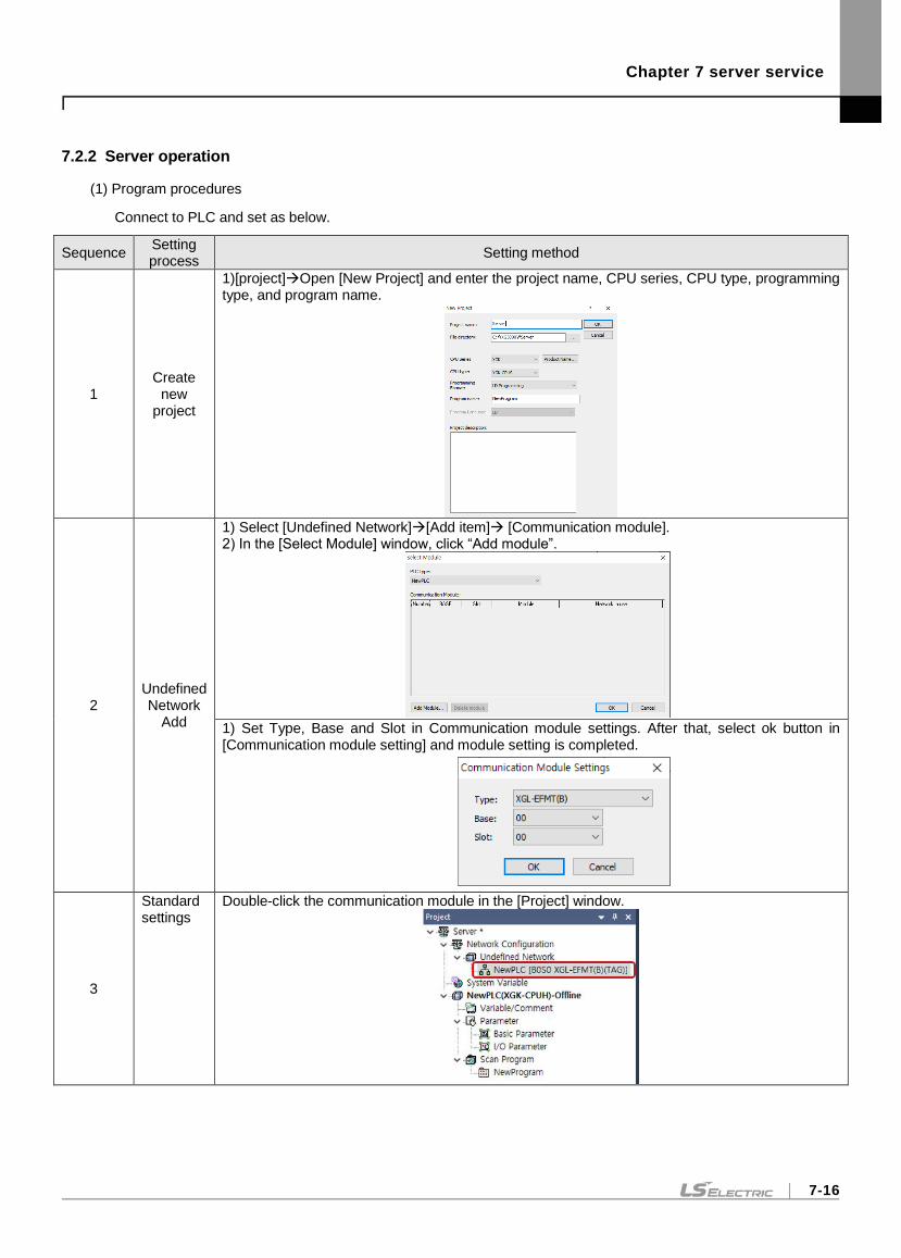
Chapter 7 server service
7-16
7.2.2 Server operation
(1) Program procedures
Connect to PLC and set as below.
Sequence Setting process
Setting method
1 Create
new project
1)[project]Open [New Project] and enter the project name, CPU series, CPU type, programming type, and program name.
2 Undefined Network
Add
1) Select [Undefined Network][Add item] [Communication module]. 2) In the [Select Module] window, click “Add module”.
1) Set Type, Base and Slot in Communication module settings. After that, select ok button in [Communication module setting] and module setting is completed.
3
Standard settings
Double-click the communication module in the [Project] window.
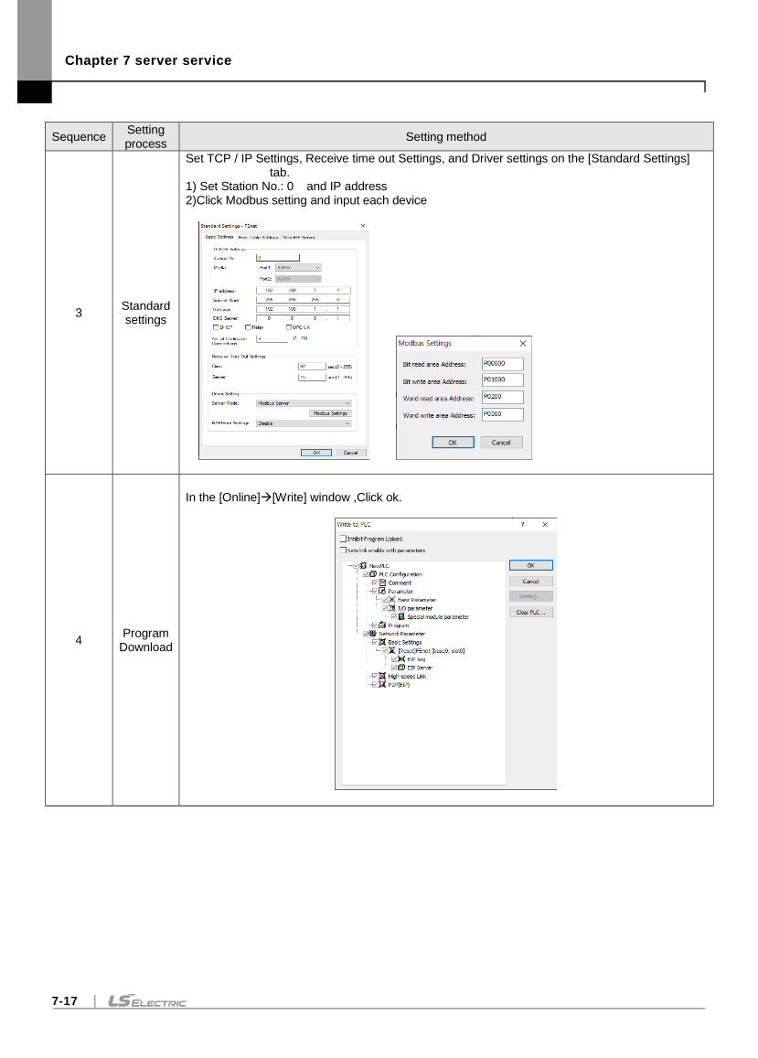
Chapter 7 server service
7-17
Sequence Setting process
Setting method
3 Standard settings
Set TCP / IP Settings, Receive time out Settings, and Driver settings on the [Standard Settings] tab.
1) Set Station No.: 0 and IP address 2)Click Modbus setting and input each device
4 Program
Download
In the [Online][Write] window ,Click ok.
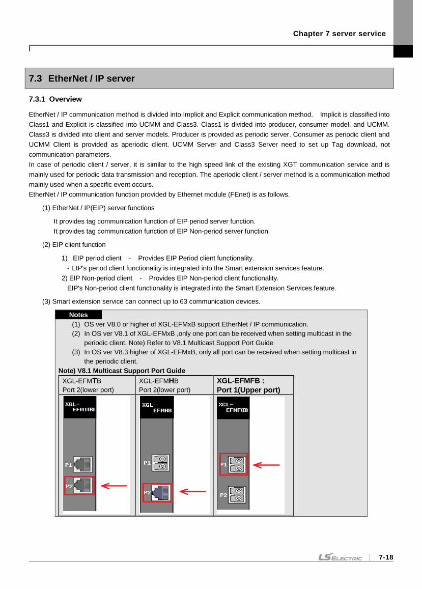
Chapter 7 server service
7-18
7.3 EtherNet / IP server
7.3.1 Overview
EtherNet / IP communication method is divided into Implicit and Explicit communication method. Implicit is classified into
Class1 and Explicit is classified into UCMM and Class3. Class1 is divided into producer, consumer model, and UCMM.
Class3 is divided into client and server models. Producer is provided as periodic server, Consumer as periodic client and
UCMM Client is provided as aperiodic client. UCMM Server and Class3 Server need to set up Tag download, not
communication parameters.
In case of periodic client / server, it is similar to the high speed link of the existing XGT communication service and is
mainly used for periodic data transmission and reception. The aperiodic client / server method is a communication method
mainly used when a specific event occurs.
EtherNet / IP communication function provided by Ethernet module (FEnet) is as follows.
(1) EtherNet / IP(EIP) server functions
It provides tag communication function of EIP period server function.
It provides tag communication function of EIP Non-period server function.
(2) EIP client function
1) EIP period client - Provides EIP Period client functionality.
- EIP's period client functionality is integrated into the Smart extension services feature.
2) EIP Non-period client - Provides EIP Non-period client functionality.
EIP's Non-period client functionality is integrated into the Smart Extension Services feature.
(3) Smart extension service can connect up to 63 communication devices.
Notes
(1) OS ver V8.0 or higher of XGL-EFMxB support EtherNet / IP communication.
(2) In OS ver V8.1 of XGL-EFMxB ,only one port can be received when setting multicast in the
periodic client. Note) Refer to V8.1 Multicast Support Port Guide
(3) In OS ver V8.3 higher of XGL-EFMxB, only all port can be received when setting multicast in
the periodic client.
Note) V8.1 Multicast Support Port Guide
XGL-EFMTB
Port 2(lower port)
XGL-EFMHB
Port 2(lower port)
XGL-EFMFB :
Port 1(Upper port)
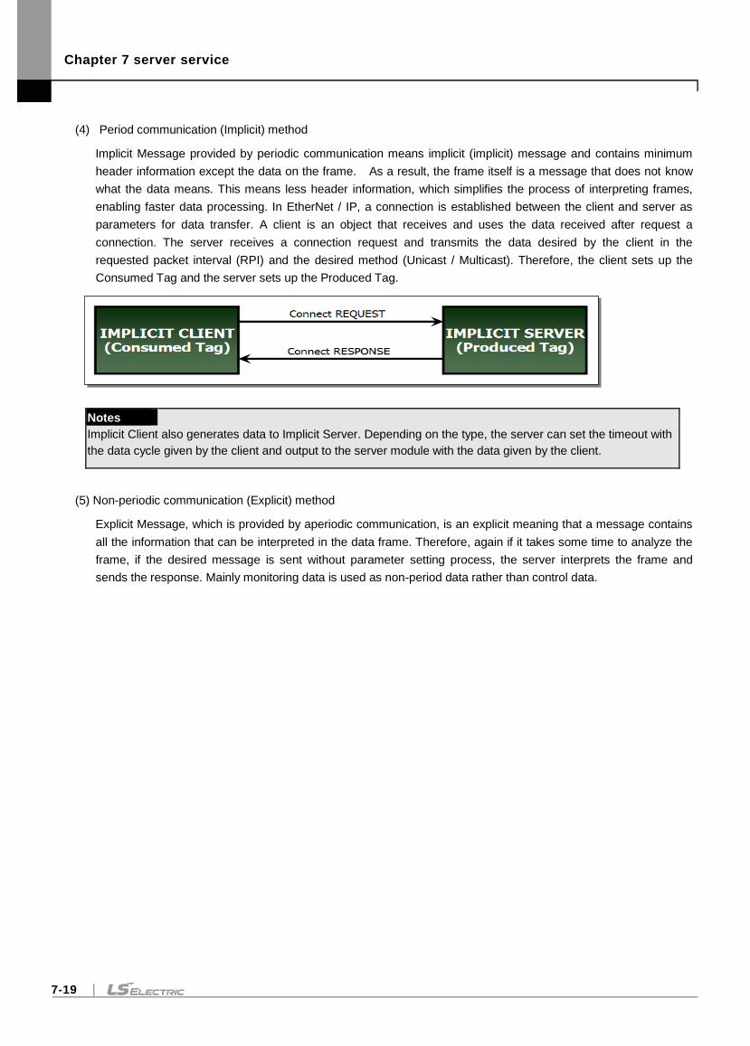
Chapter 7 server service
7-19
(4) Period communication (Implicit) method
Implicit Message provided by periodic communication means implicit (implicit) message and contains minimum
header information except the data on the frame. As a result, the frame itself is a message that does not know
what the data means. This means less header information, which simplifies the process of interpreting frames,
enabling faster data processing. In EtherNet / IP, a connection is established between the client and server as
parameters for data transfer. A client is an object that receives and uses the data received after request a
connection. The server receives a connection request and transmits the data desired by the client in the
requested packet interval (RPI) and the desired method (Unicast / Multicast). Therefore, the client sets up the
Consumed Tag and the server sets up the Produced Tag.
Notes
Implicit Client also generates data to Implicit Server. Depending on the type, the server can set the timeout with
the data cycle given by the client and output to the server module with the data given by the client.
(5) Non-periodic communication (Explicit) method
Explicit Message, which is provided by aperiodic communication, is an explicit meaning that a message contains
all the information that can be interpreted in the data frame. Therefore, again if it takes some time to analyze the
frame, if the desired message is sent without parameter setting process, the server interprets the frame and
sends the response. Mainly monitoring data is used as non-period data rather than control data.
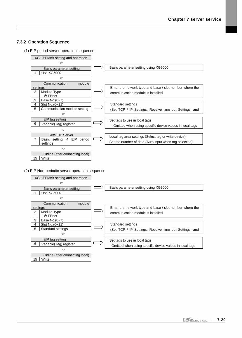
Chapter 7 server service
7-20
7.3.2 Operation Sequence
(1) EIP period server operation sequence
XGL-EFMxB setting and operation
Basic parameter setting
1 Use XG5000
Communication module settings
2 Module Type FEnet
3 Base No.(0~7)
4 Slot No.(0~11)
5 Communication module setting
EIP tag setting
6 Variable(Tag) register
Sets EIP Server
7 Basic setting EIP period settings
Online (after connecting local)
15 Write
(2) EIP Non-periodic server operation sequence
XGL-EFMxB setting and operation
Basic parameter setting
1 Use XG5000
Communication module settings
2 Module Type FEnet
3 Base No.(0~7)
4 Slot No.(0~11)
5 Standard settings
EIP tag setting
6 Variable(Tag) register
Online (after connecting local)
15 Write
Basic parameter setting using XG5000
Standard settings
(Set TCP / IP Settings, Receive time out Settings, and
Driver settings)
Enter the network type and base / slot number where the
communication module is installed
Set tags to use in local tags
- Omitted when using specific device values in local tags
Local tag area settings (Select tag or write device)
Set the number of data (Auto input when tag selection)
Standard settings
(Set TCP / IP Settings, Receive time out Settings, and
Driver settings)
Enter the network type and base / slot number where the
communication module is installed
Set tags to use in local tags
- Omitted when using specific device values in local tags
Basic parameter setting using XG5000
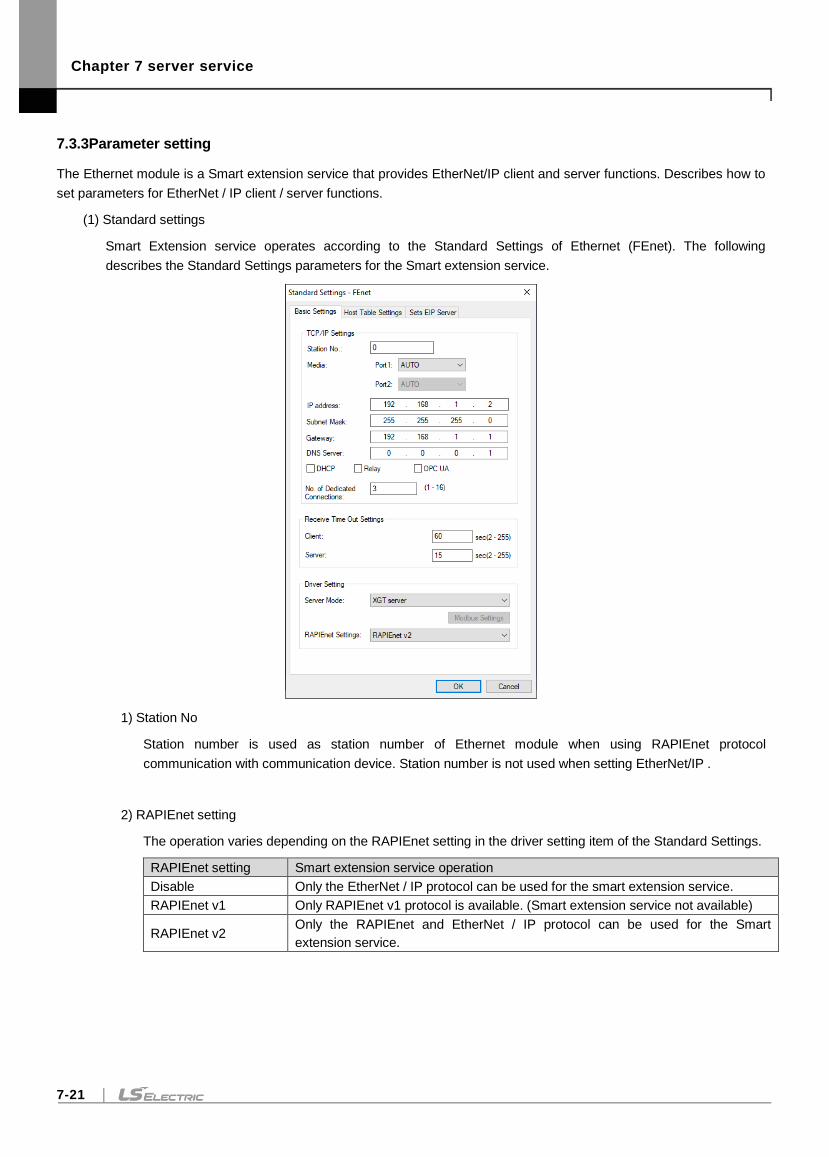
Chapter 7 server service
7-21
7.3.3Parameter setting
The Ethernet module is a Smart extension service that provides EtherNet/IP client and server functions. Describes how to
set parameters for EtherNet / IP client / server functions.
(1) Standard settings
Smart Extension service operates according to the Standard Settings of Ethernet (FEnet). The following
describes the Standard Settings parameters for the Smart extension service.
1) Station No
Station number is used as station number of Ethernet module when using RAPIEnet protocol
communication with communication device. Station number is not used when setting EtherNet/IP .
2) RAPIEnet setting
The operation varies depending on the RAPIEnet setting in the driver setting item of the Standard Settings.
RAPIEnet setting Smart extension service operation
Disable Only the EtherNet / IP protocol can be used for the smart extension service.
RAPIEnet v1 Only RAPIEnet v1 protocol is available. (Smart extension service not available)
RAPIEnet v2 Only the RAPIEnet and EtherNet / IP protocol can be used for the Smart
extension service.
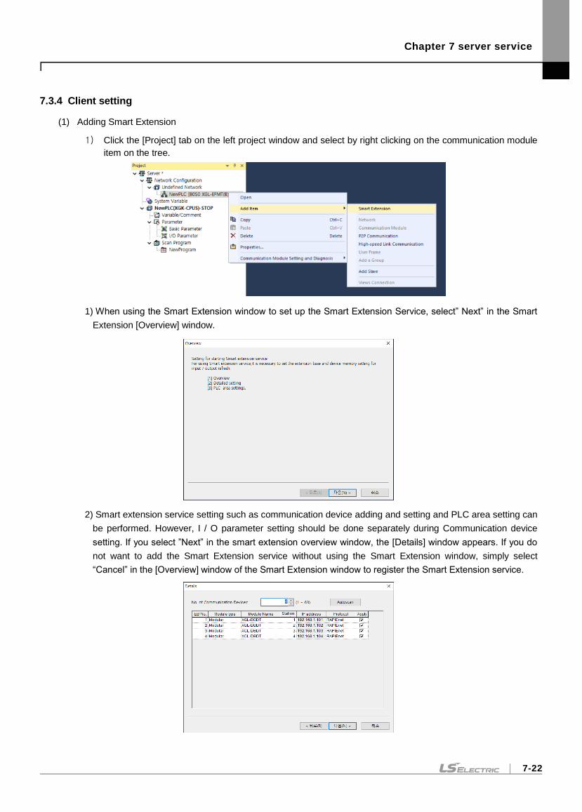
Chapter 7 server service
7-22
7.3.4 Client setting
(1) Adding Smart Extension
1) Click the [Project] tab on the left project window and select by right clicking on the communication module
item on the tree.
1) When using the Smart Extension window to set up the Smart Extension Service, select” Next” in the Smart
Extension [Overview] window.
2) Smart extension service setting such as communication device adding and setting and PLC area setting can
be performed. However, I / O parameter setting should be done separately during Communication device
setting. If you select ”Next” in the smart extension overview window, the [Details] window appears. If you do
not want to add the Smart Extension service without using the Smart Extension window, simply select
“Cancel” in the [Overview] window of the Smart Extension window to register the Smart Extension service.
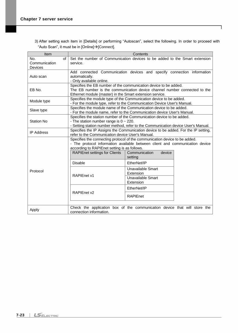
Chapter 7 server service
7-23
3) After setting each item in [Details] or performing “Autoscan”, select the following. In order to proceed with
“Auto Scan”, it must be in [Online][Connect].
Item Contents
No. of Communication Devices
Set the number of Communication devices to be added to the Smart extension service.
Auto scan Add connected Communication devices and specify connection information automatically. - Only available online.
EB No. Specifies the EB number of the communication device to be added. The EB number is the communication device channel number connected to the Ethernet module (master) in the Smart extension service.
Module type Specifies the module type of the Communication device to be added. - For the module type, refer to the Communication Device User's Manual.
Slave type Specifies the module name of the Communication device to be added. - For the module name, refer to the Communication device User's Manual.
Station No Specifies the station number of the Communication device to be added. - The station number range is 0 ~ 220. - Setting station number method, refer to the Communication device User's Manual.
IP Address Specifies the IP Assigns the Communication device to be added. For the IP setting, refer to the Communication device User's Manual.
Protocol
Specifies the connecting protocol of the communication device to be added. - The protocol information available between client and communication device according to RAPIEnet setting is as follows.
RAPIEnet settings for Clients Communication device setting
Disable EtherNet/IP
RAPIEnet v1
Unavailable Smart Extension
Unavailable Smart Extension
RAPIEnet v2 EtherNet/IP
RAPIEnet
Apply Check the application box of the communication device that will store the connection information.
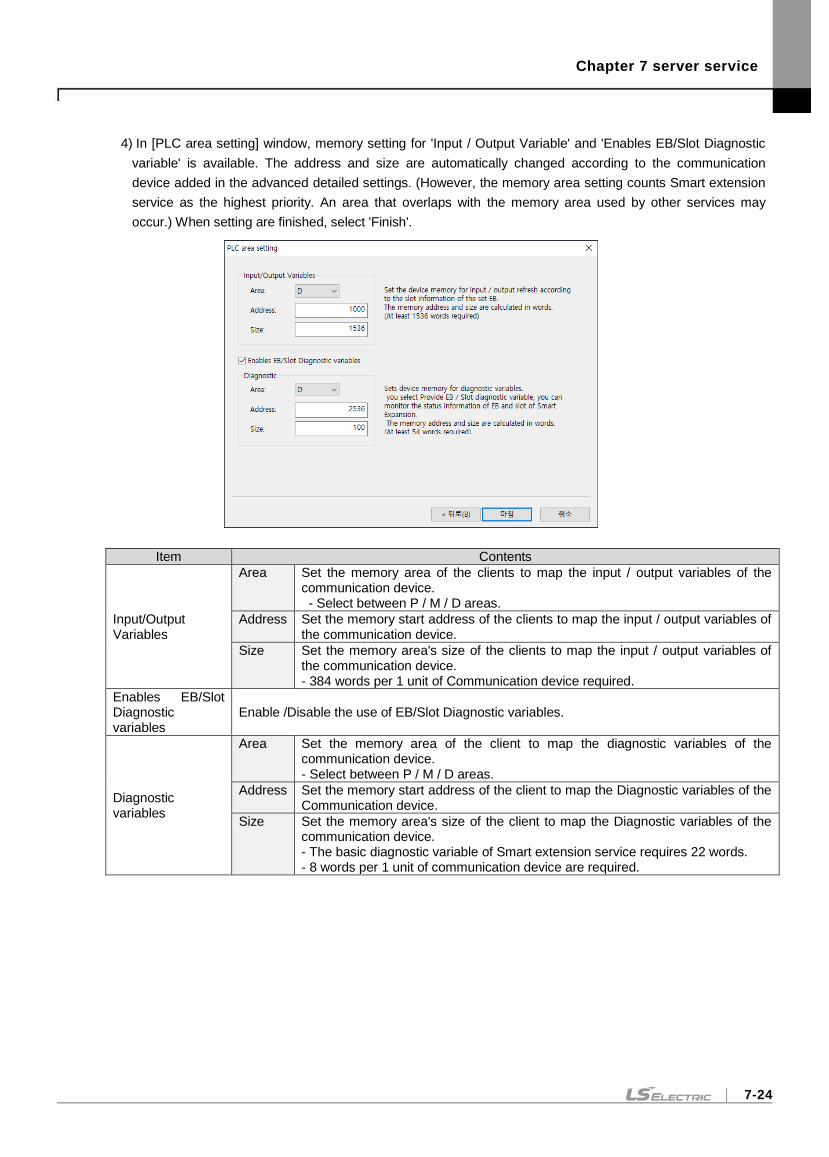
Chapter 7 server service
7-24
4) In [PLC area setting] window, memory setting for 'Input / Output Variable' and 'Enables EB/Slot Diagnostic
variable' is available. The address and size are automatically changed according to the communication
device added in the advanced detailed settings. (However, the memory area setting counts Smart extension
service as the highest priority. An area that overlaps with the memory area used by other services may
occur.) When setting are finished, select 'Finish'.
Item Contents
Input/Output Variables
Area Set the memory area of the clients to map the input / output variables of the communication device. - Select between P / M / D areas.
Address Set the memory start address of the clients to map the input / output variables of the communication device.
Size Set the memory area's size of the clients to map the input / output variables of the communication device. - 384 words per 1 unit of Communication device required.
Enables EB/Slot Diagnostic variables
Enable /Disable the use of EB/Slot Diagnostic variables.
Diagnostic variables
Area Set the memory area of the client to map the diagnostic variables of the communication device. - Select between P / M / D areas.
Address Set the memory start address of the client to map the Diagnostic variables of the Communication device.
Size Set the memory area's size of the client to map the Diagnostic variables of the communication device. - The basic diagnostic variable of Smart extension service requires 22 words. - 8 words per 1 unit of communication device are required.
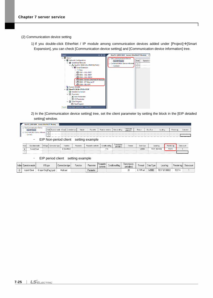
Chapter 7 server service
7-25
(2) Communication device setting
1) If you double-click EtherNet / IP module among communication devices added under [Project][Smart
Expansion], you can check [Communication device setting] and [Communication device information] tree.
2) In the [Communication device setting] tree, set the client parameter by setting the block in the [EIP detailed
setting] window.
- EIP Non-period client setting example
- EIP period client setting example
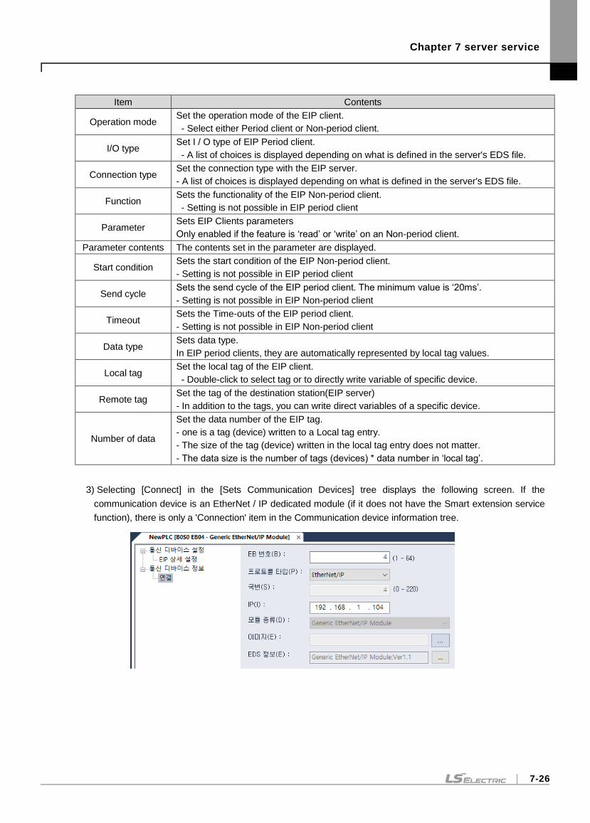
Chapter 7 server service
7-26
Item Contents
Operation mode Set the operation mode of the EIP client.
- Select either Period client or Non-period client.
I/O type Set I / O type of EIP Period client.
- A list of choices is displayed depending on what is defined in the server's EDS file.
Connection type Set the connection type with the EIP server.
- A list of choices is displayed depending on what is defined in the server's EDS file.
Function Sets the functionality of the EIP Non-period client.
- Setting is not possible in EIP period client
Parameter Sets EIP Clients parameters
Only enabled if the feature is ‘read’ or ‘write’ on an Non-period client.
Parameter contents The contents set in the parameter are displayed.
Start condition Sets the start condition of the EIP Non-period client.
- Setting is not possible in EIP period client
Send cycle Sets the send cycle of the EIP period client. The minimum value is ‘20ms’.
- Setting is not possible in EIP Non-period client
Timeout Sets the Time-outs of the EIP period client.
- Setting is not possible in EIP Non-period client
Data type Sets data type.
In EIP period clients, they are automatically represented by local tag values.
Local tag Set the local tag of the EIP client.
- Double-click to select tag or to directly write variable of specific device.
Remote tag Set the tag of the destination station(EIP server)
- In addition to the tags, you can write direct variables of a specific device.
Number of data
Set the data number of the EIP tag.
- one is a tag (device) written to a Local tag entry.
- The size of the tag (device) written in the local tag entry does not matter.
- The data size is the number of tags (devices) * data number in ‘local tag’.
3) Selecting [Connect] in the [Sets Communication Devices] tree displays the following screen. If the
communication device is an EtherNet / IP dedicated module (if it does not have the Smart extension service
function), there is only a 'Connection' item in the Communication device information tree.
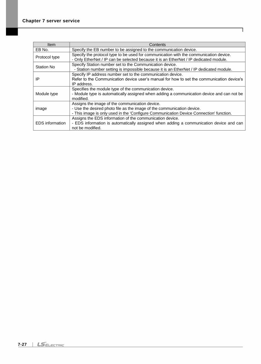
Chapter 7 server service
7-27
Item Contents
EB No. Specify the EB number to be assigned to the communication device.
Protocol type Specify the protocol type to be used for communication with the communication device. - Only EtherNet / IP can be selected because it is an EtherNet / IP dedicated module.
Station No Specify Station number set to the Communication device. - Station number setting is impossible because it is an EtherNet / IP dedicated module.
IP Specify IP address number set to the communication device. Refer to the Communication device user’s manual for how to set the communication device's IP address.
Module type Specifies the module type of the communication device. - Module type is automatically assigned when adding a communication device and can not be modified.
image Assigns the image of the communication device. - Use the desired photo file as the image of the communication device. - This image is only used in the 'Configure Communication Device Connection' function.
EDS information Assigns the EDS information of the communication device. - EDS information is automatically assigned when adding a communication device and can not be modified.
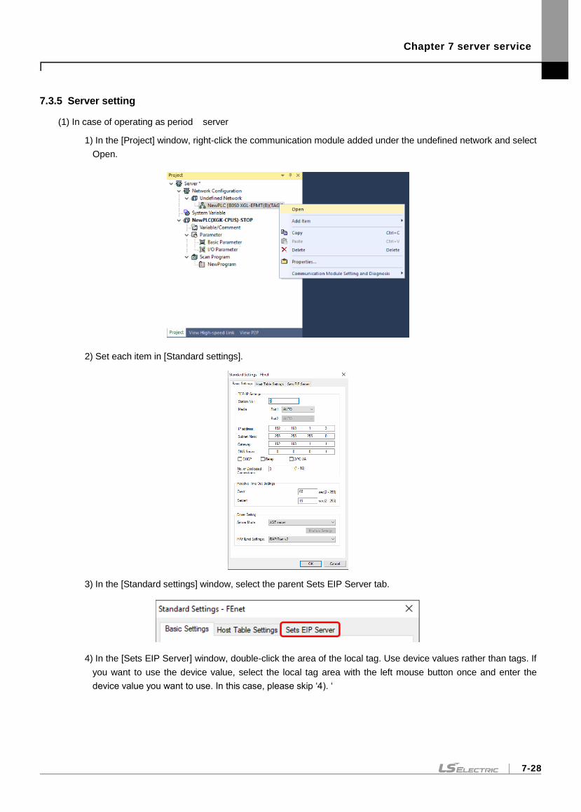
Chapter 7 server service
7-28
7.3.5 Server setting
(1) In case of operating as period server
1) In the [Project] window, right-click the communication module added under the undefined network and select
Open.
2) Set each item in [Standard settings].
3) In the [Standard settings] window, select the parent Sets EIP Server tab.
4) In the [Sets EIP Server] window, double-click the area of the local tag. Use device values rather than tags. If
you want to use the device value, select the local tag area with the left mouse button once and enter the
device value you want to use. In this case, please skip ‘4). ‘
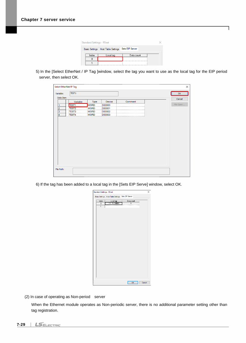
Chapter 7 server service
7-29
5) In the [Select EtherNet / IP Tag ]window, select the tag you want to use as the local tag for the EIP period
server, then select OK.
6) If the tag has been added to a local tag in the [Sets EIP Serve] window, select OK.
(2) In case of operating as Non-period server
When the Ethernet module operates as Non-periodic server, there is no additional parameter setting other than
tag registration.
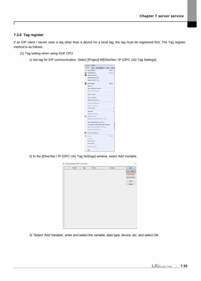
Chapter 7 server service
7-30
7.3.6 Tag register
If an EIP client / server uses a tag other than a device for a local tag, the tag must be registered first. The Tag register
method is as follows.
(1) Tag setting when using XGK CPU
1) Set tag for EIP communication. Select [Project][EtherNet / IP (OPC UA) Tag Settings].
2) In the [EtherNet / IP (OPC UA) Tag Settings] window, select Add Variable.
3) “Select 'Add Variable', enter and select the variable, data type, device, etc. and select OK.
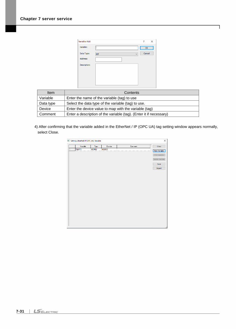
Chapter 7 server service
7-31
Item Contents
Variable Enter the name of the variable (tag) to use
Data type Select the data type of the variable (tag) to use.
Device Enter the device value to map with the variable (tag)
Comment Enter a description of the variable (tag). (Enter it if necessary)
4) After confirming that the variable added in the EtherNet / IP (OPC UA) tag setting window appears normally,
select Close.
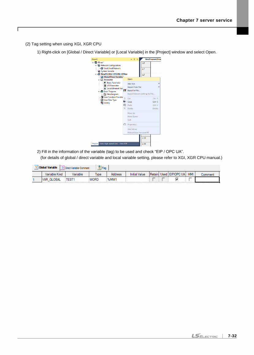
Chapter 7 server service
7-32
(2) Tag setting when using XGI, XGR CPU
1) Right-click on [Global / Direct Variable] or [Local Variable] in the [Project] window and select Open.
2) Fill in the information of the variable (tag) to be used and check “EIP / OPC UA”.
(for details of global / direct variable and local variable setting, please refer to XGI, XGR CPU manual.)
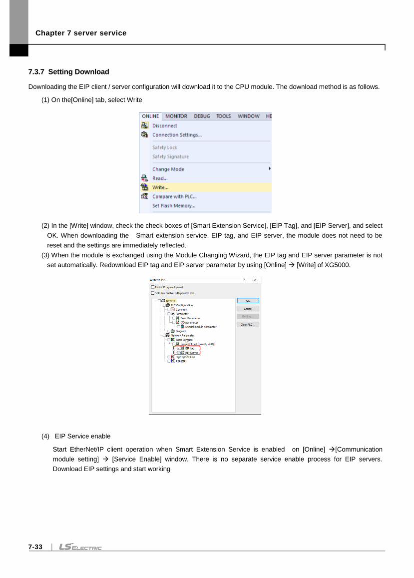
Chapter 7 server service
7-33
7.3.7 Setting Download
Downloading the EIP client / server configuration will download it to the CPU module. The download method is as follows.
(1) On the[Online] tab, select Write
(2) In the [Write] window, check the check boxes of [Smart Extension Service], [EIP Tag], and [EIP Server], and select
OK. When downloading the Smart extension service, EIP tag, and EIP server, the module does not need to be
reset and the settings are immediately reflected.
(3) When the module is exchanged using the Module Changing Wizard, the EIP tag and EIP server parameter is not
set automatically. Redownload EIP tag and EIP server parameter by using [Online] [Write] of XG5000.
(4) EIP Service enable
Start EtherNet/IP client operation when Smart Extension Service is enabled on [Online] [Communication
module setting] [Service Enable] window. There is no separate service enable process for EIP servers.
Download EIP settings and start working
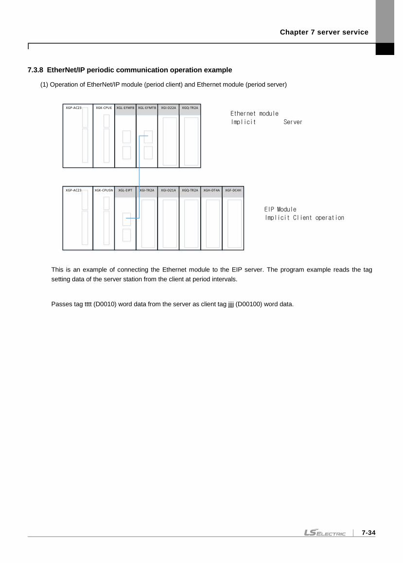
Chapter 7 server service
7-34
7.3.8 EtherNet/IP periodic communication operation example
(1) Operation of EtherNet/IP module (period client) and Ethernet module (period server)
This is an example of connecting the Ethernet module to the EIP server. The program example reads the tag
setting data of the server station from the client at period intervals.
Passes tag tttt (D0010) word data from the server as client tag jjjj (D00100) word data.
Ethernet module
Implicit Server
operation
EIP Module
Implicit Client operation
XGI-D21AXGL-EIPTXGP-AC23 XGK-CPUSN XGI-TR2A XGQ-TR2A
XGL-EFMFBXGP-AC23 XGK-CPUE XGI-D22A XGQ-TR2AXGL-EFMTB
XGH-DT4A XGF-DC4H
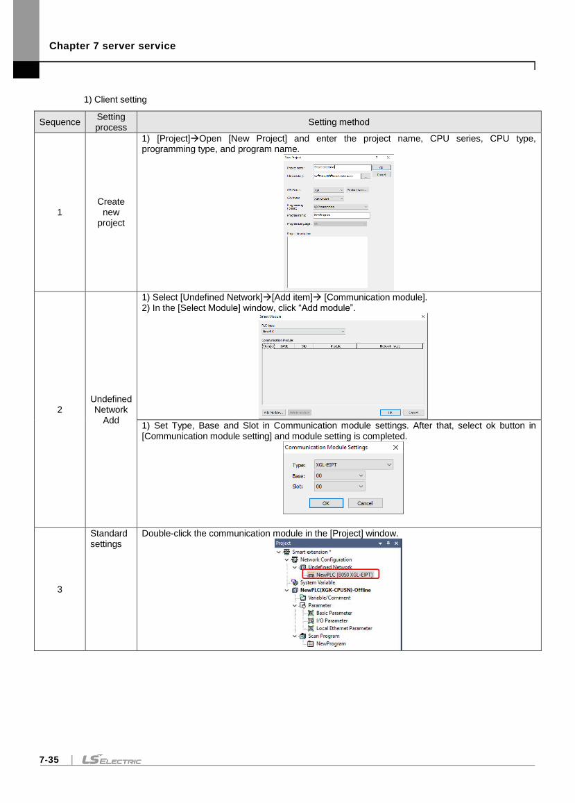
Chapter 7 server service
7-35
1) Client setting
Sequence Setting process
Setting method
1 Create
new project
1) [Project]Open [New Project] and enter the project name, CPU series, CPU type, programming type, and program name.
2 Undefined Network
Add
1) Select [Undefined Network][Add item] [Communication module]. 2) In the [Select Module] window, click “Add module”.
1) Set Type, Base and Slot in Communication module settings. After that, select ok button in [Communication module setting] and module setting is completed.
3
Standard settings
Double-click the communication module in the [Project] window.
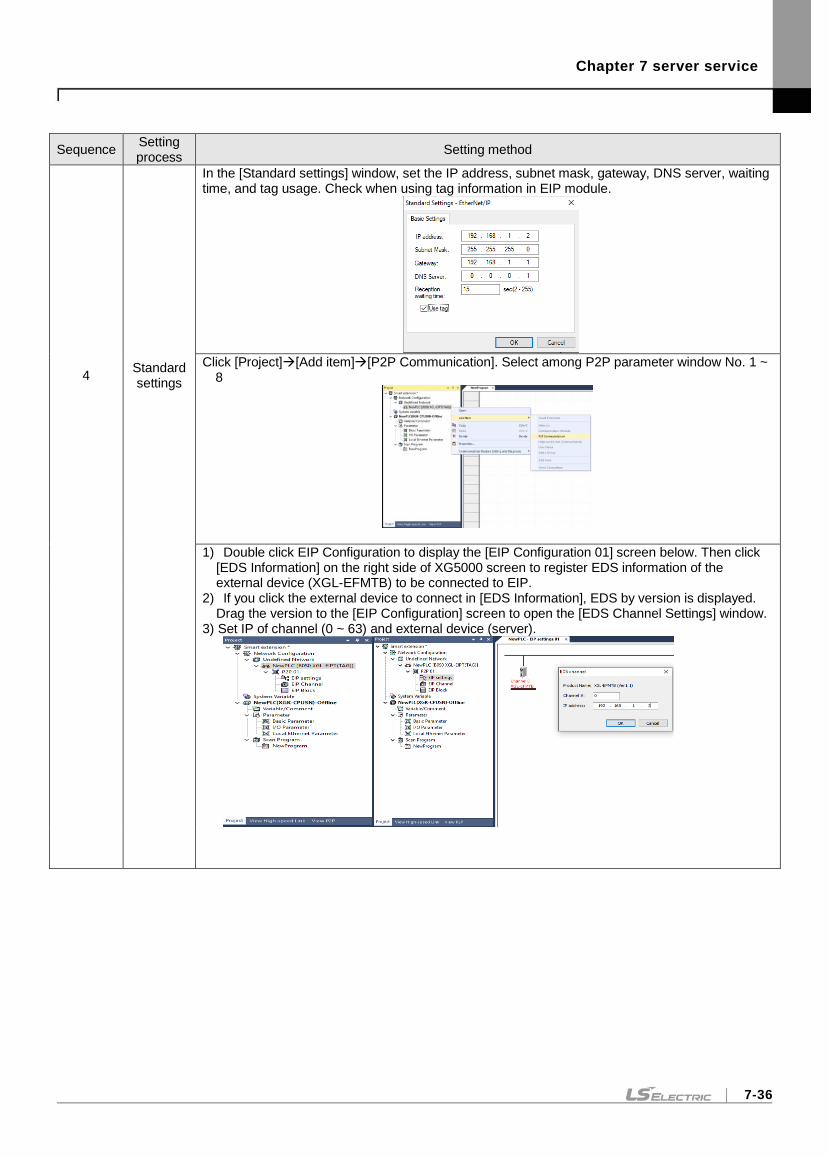
Chapter 7 server service
7-36
Sequence Setting process
Setting method
4 Standard settings
In the [Standard settings] window, set the IP address, subnet mask, gateway, DNS server, waiting time, and tag usage. Check when using tag information in EIP module.
Click [Project][Add item][P2P Communication]. Select among P2P parameter window No. 1 ~
8
1) Double click EIP Configuration to display the [EIP Configuration 01] screen below. Then click [EDS Information] on the right side of XG5000 screen to register EDS information of the external device (XGL-EFMTB) to be connected to EIP.
2) If you click the external device to connect in [EDS Information], EDS by version is displayed. Drag the version to the [EIP Configuration] screen to open the [EDS Channel Settings] window.
3) Set IP of channel (0 ~ 63) and external device (server).
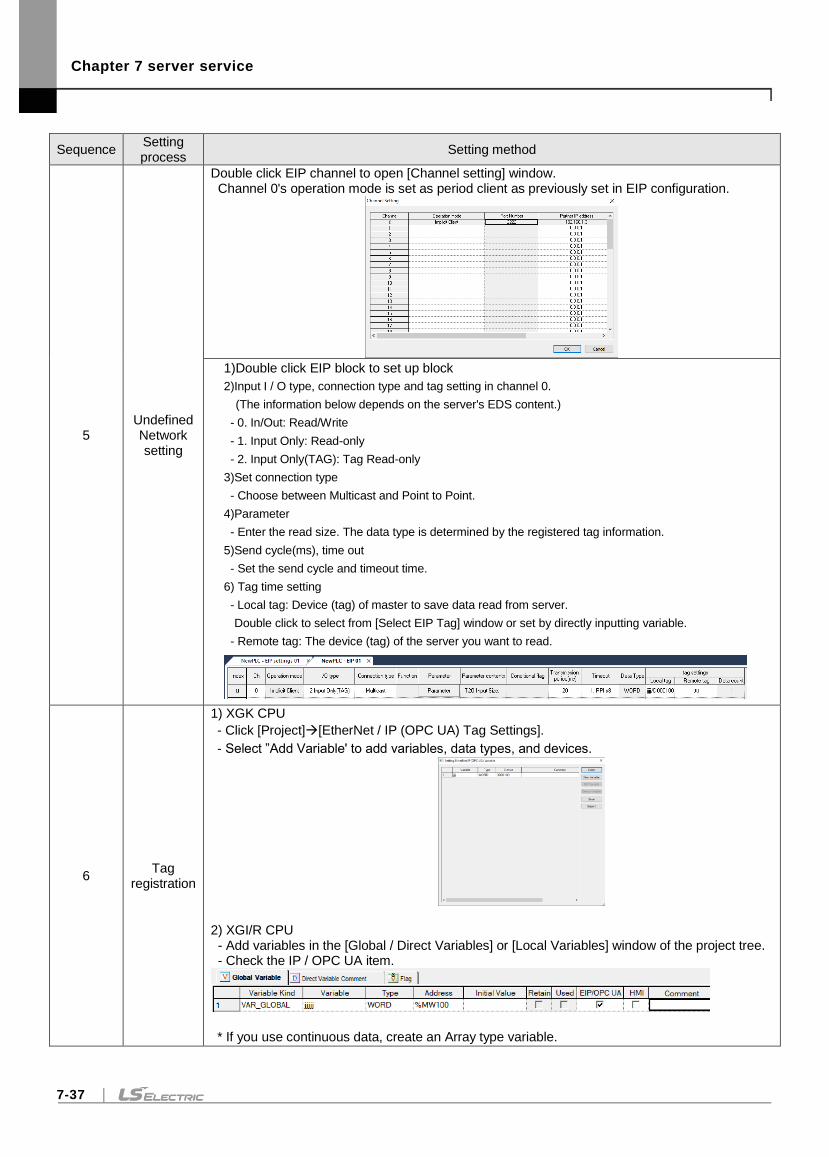
Chapter 7 server service
7-37
Sequence Setting process
Setting method
5 Undefined Network setting
Double click EIP channel to open [Channel setting] window. Channel 0's operation mode is set as period client as previously set in EIP configuration.
1)Double click EIP block to set up block
2)Input I / O type, connection type and tag setting in channel 0.
(The information below depends on the server's EDS content.)
- 0. In/Out: Read/Write
- 1. Input Only: Read-only
- 2. Input Only(TAG): Tag Read-only
3)Set connection type
- Choose between Multicast and Point to Point.
4)Parameter
- Enter the read size. The data type is determined by the registered tag information.
5)Send cycle(ms), time out
- Set the send cycle and timeout time.
6) Tag time setting
- Local tag: Device (tag) of master to save data read from server.
Double click to select from [Select EIP Tag] window or set by directly inputting variable.
- Remote tag: The device (tag) of the server you want to read.
6 Tag
registration
1) XGK CPU
- Click [Project][EtherNet / IP (OPC UA) Tag Settings].
- Select ”Add Variable' to add variables, data types, and devices.
2) XGI/R CPU - Add variables in the [Global / Direct Variables] or [Local Variables] window of the project tree. - Check the IP / OPC UA item.
* If you use continuous data, create an Array type variable.
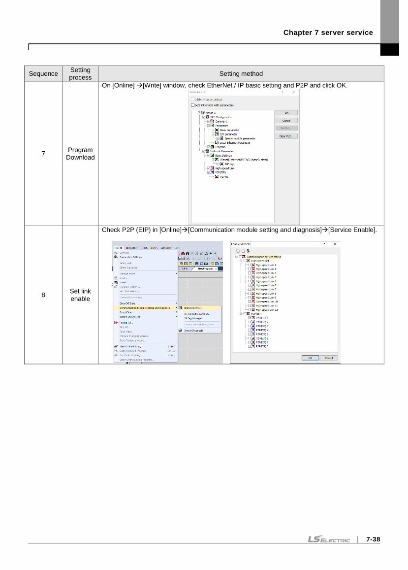
Chapter 7 server service
7-38
Sequence Setting process
Setting method
7 Program
Download
On [Online] [Write] window, check EtherNet / IP basic setting and P2P and click OK.
8 Set link enable
Check P2P (EIP) in [Online][Communication module setting and diagnosis][Service Enable].
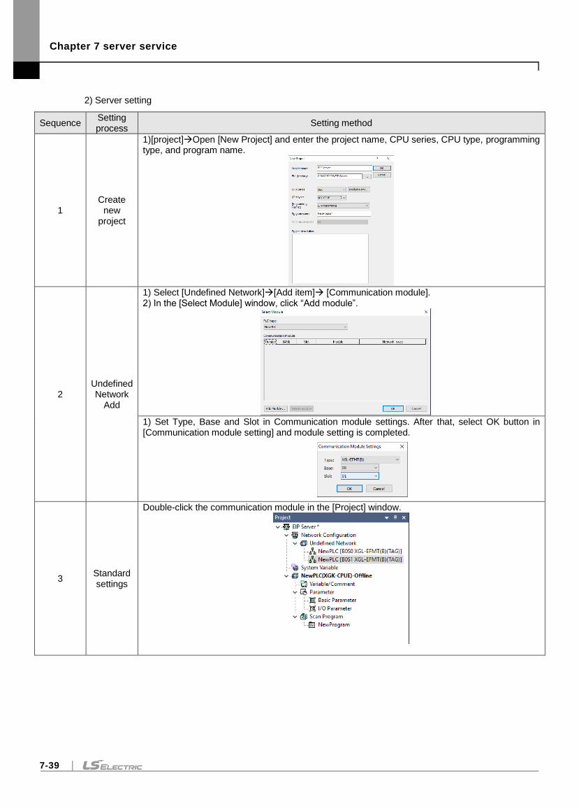
Chapter 7 server service
7-39
2) Server setting
Sequence Setting process
Setting method
1 Create
new project
1)[project]Open [New Project] and enter the project name, CPU series, CPU type, programming type, and program name.
2 Undefined Network
Add
1) Select [Undefined Network][Add item] [Communication module]. 2) In the [Select Module] window, click “Add module”.
1) Set Type, Base and Slot in Communication module settings. After that, select OK button in [Communication module setting] and module setting is completed.
3 Standard settings
Double-click the communication module in the [Project] window.
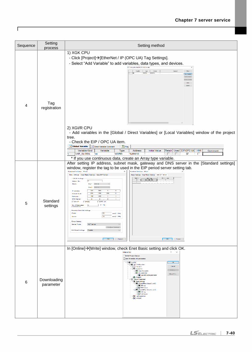
Chapter 7 server service
7-40
Sequence Setting process
Setting method
4 Tag
registration
1) XGK CPU
- Click [Project][EtherNet / IP (OPC UA) Tag Settings].
- Select “Add Variable” to add variables, data types, and devices.
2) XGI/R CPU - Add variables in the [Global / Direct Variables] or [Local Variables] window of the project tree. - Check the EIP / OPC UA item.
* If you use continuous data, create an Array type variable.
5 Standard settings
After setting IP address, subnet mask, gateway and DNS server in the [Standard settings] window, register the tag to be used in the EIP period server setting tab.
6 Downloading
parameter
In [Online][Write] window, check Enet Basic setting and click OK.
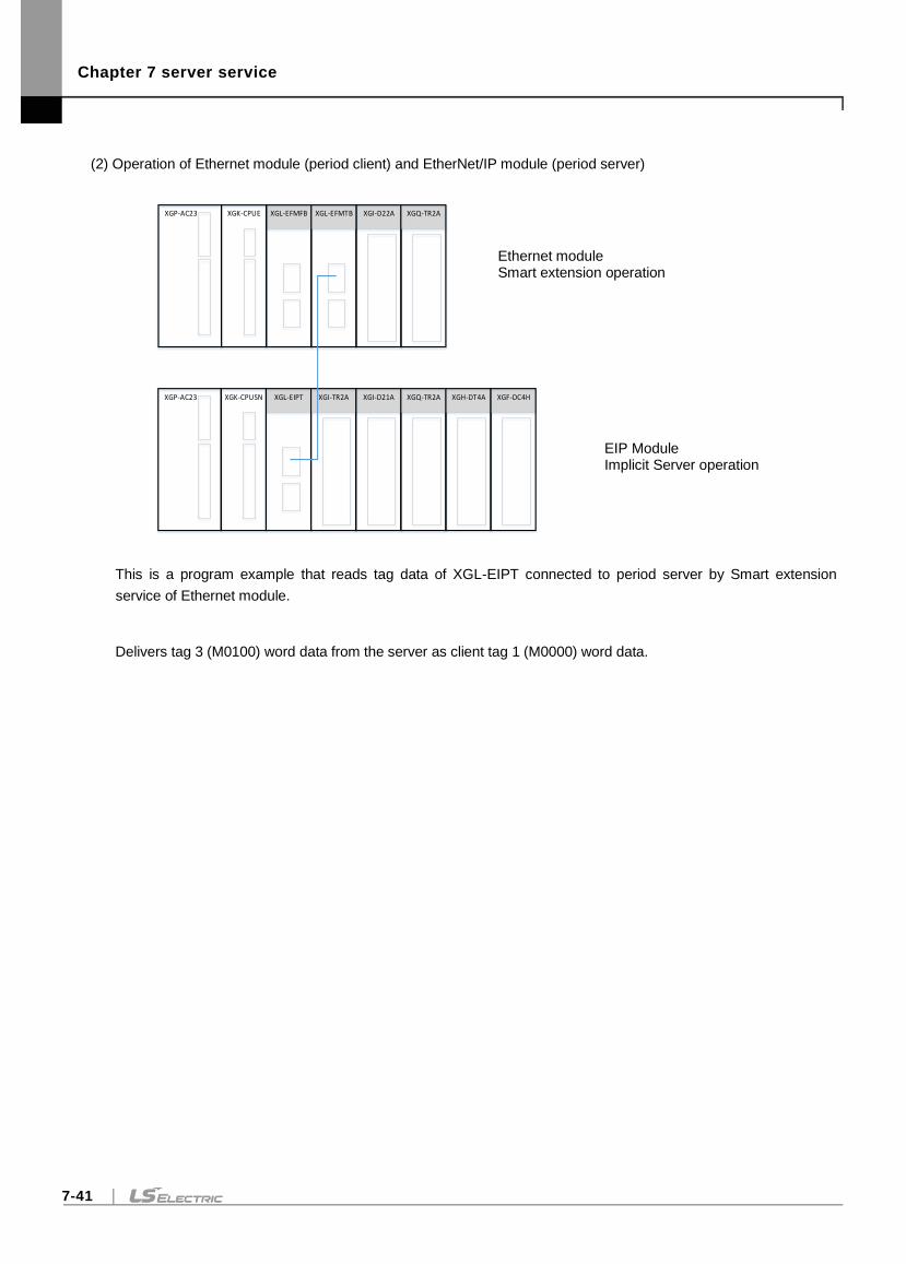
Chapter 7 server service
7-41
(2) Operation of Ethernet module (period client) and EtherNet/IP module (period server)
This is a program example that reads tag data of XGL-EIPT connected to period server by Smart extension
service of Ethernet module.
Delivers tag 3 (M0100) word data from the server as client tag 1 (M0000) word data.
Ethernet module Smart extension operation
EIP Module Implicit Server operation
XGI-D21AXGL-EIPTXGP-AC23 XGK-CPUSN XGI-TR2A XGQ-TR2A
XGL-EFMFBXGP-AC23 XGK-CPUE XGI-D22A XGQ-TR2AXGL-EFMTB
XGH-DT4A XGF-DC4H
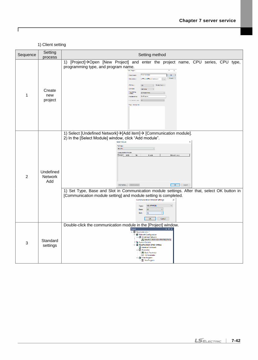
Chapter 7 server service
7-42
1) Client setting
Sequence Setting process
Setting method
1 Create
new project
1) [Project]Open [New Project] and enter the project name, CPU series, CPU type, programming type, and program name.
2 Undefined Network
Add
1) Select [Undefined Network][Add item] [Communication module]. 2) In the [Select Module] window, click “Add module”.
1) Set Type, Base and Slot in Communication module settings. After that, select OK button in [Communication module setting] and module setting is completed.
3 Standard settings
Double-click the communication module in the [Project] window.
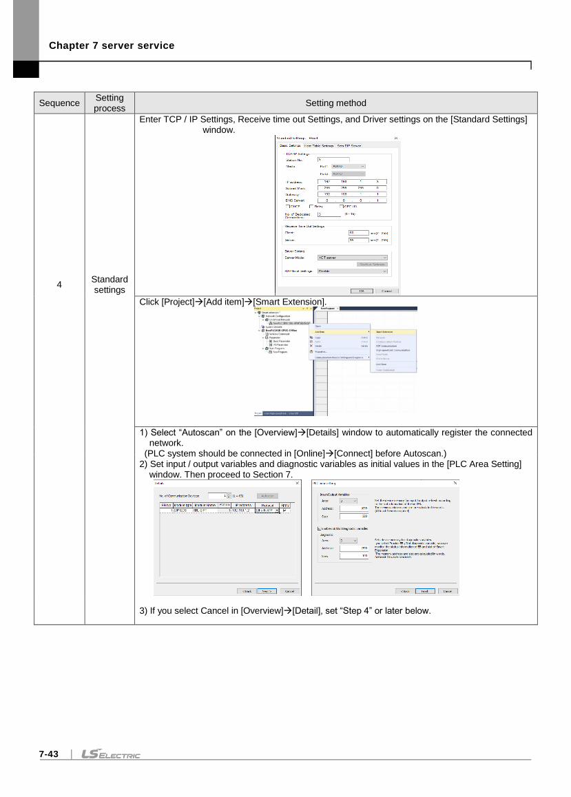
Chapter 7 server service
7-43
Sequence Setting process
Setting method
4 Standard settings
Enter TCP / IP Settings, Receive time out Settings, and Driver settings on the [Standard Settings] window.
Click [Project][Add item][Smart Extension].
1) Select “Autoscan” on the [Overview][Details] window to automatically register the connected network.
(PLC system should be connected in [Online][Connect] before Autoscan.) 2) Set input / output variables and diagnostic variables as initial values in the [PLC Area Setting]
window. Then proceed to Section 7.
3) If you select Cancel in [Overview][Detail], set “Step 4” or later below.
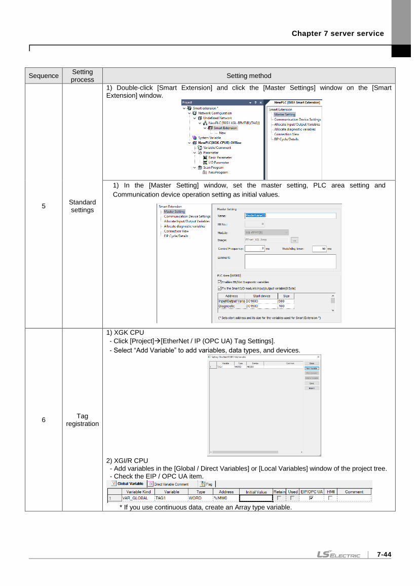
Chapter 7 server service
7-44
Sequence Setting process
Setting method
5 Standard settings
1) Double-click [Smart Extension] and click the [Master Settings] window on the [Smart Extension] window.
1) In the [Master Setting] window, set the master setting, PLC area setting and
Communication device operation setting as initial values.
6 Tag
registration
1) XGK CPU
- Click [Project][EtherNet / IP (OPC UA) Tag Settings].
- Select “Add Variable” to add variables, data types, and devices.
2) XGI/R CPU - Add variables in the [Global / Direct Variables] or [Local Variables] window of the project tree. - Check the EIP / OPC UA item.
* If you use continuous data, create an Array type variable.
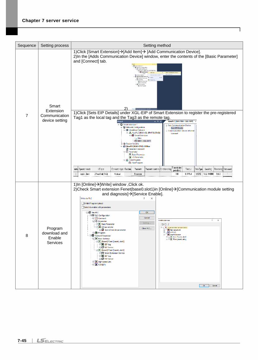
Chapter 7 server service
7-45
Sequence Setting process Setting method
7
Smart Extension
Communication device setting
1)Click [Smart Extension][Add Item] [Add Communication Device]. 1) 2)In the [Adds Communication Device] window, enter the contents of the [Basic Parameter]
and [Connect] tab.
2) 3) 1)Click [Sets EIP Details] under XGL-EIP of Smart Extension to register the pre-registered
Tag1 as the local tag and the Tag3 as the remote tag.
8
Program download and
Enable Services
1)In [Online][Write] window ,Click ok. 2)Check Smart extension Fenet(base0.slot1)in [Online][Communication module setting
and diagnosis][Service Enable].
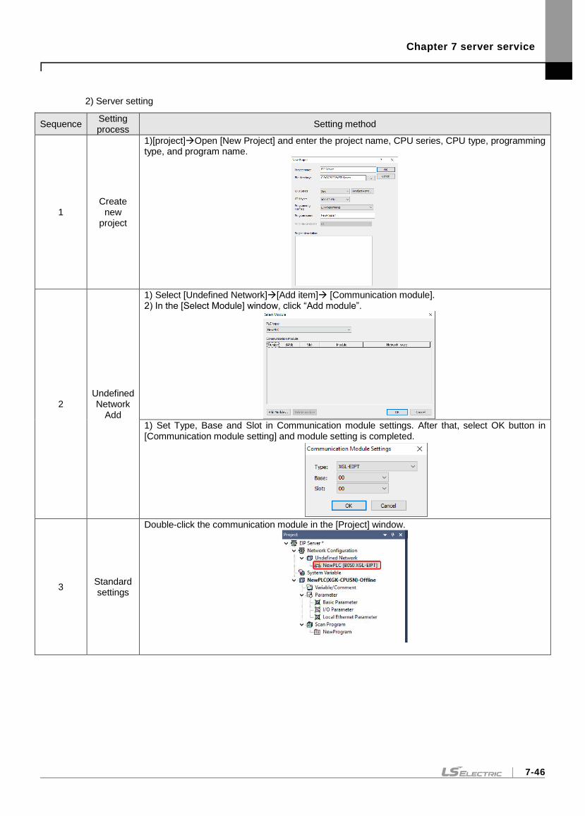
Chapter 7 server service
7-46
2) Server setting
Sequence Setting process
Setting method
1 Create
new project
1)[project]Open [New Project] and enter the project name, CPU series, CPU type, programming type, and program name.
2 Undefined Network
Add
1) Select [Undefined Network][Add item] [Communication module]. 2) In the [Select Module] window, click “Add module”.
1) Set Type, Base and Slot in Communication module settings. After that, select OK button in [Communication module setting] and module setting is completed.
3 Standard settings
Double-click the communication module in the [Project] window.
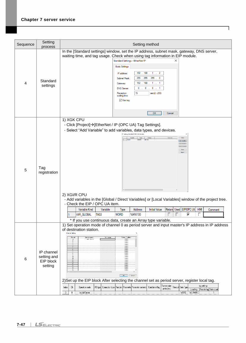
Chapter 7 server service
7-47
Sequence Setting process
Setting method
4 Standard settings
In the [Standard settings] window, set the IP address, subnet mask, gateway, DNS server, waiting time, and tag usage. Check when using tag information in EIP module.
5 Tag registration
1) XGK CPU
- Click [Project][EtherNet / IP (OPC UA) Tag Settings].
- Select “Add Variable” to add variables, data types, and devices.
2) XGI/R CPU - Add variables in the [Global / Direct Variables] or [Local Variables] window of the project tree. - Check the EIP / OPC UA item.
* If you use continuous data, create an Array type variable.
6
IP channel setting and EIP block
setting
1) Set operation mode of channel 0 as period server and input master's IP address in IP address of destination station.
2)Set up the EIP block After selecting the channel set as period server, register local tag.
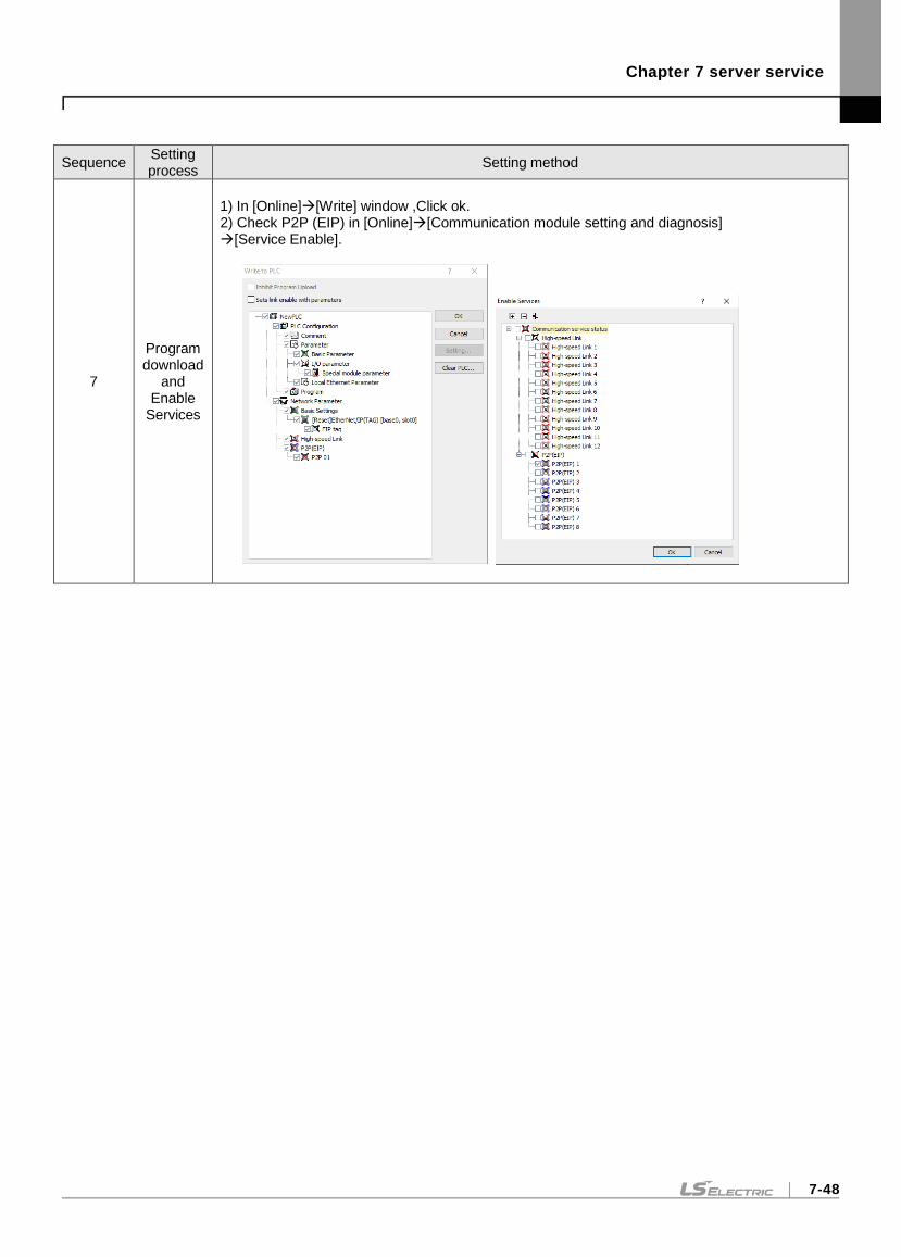
Chapter 7 server service
7-48
Sequence Setting process
Setting method
7
Program download
and Enable
Services
1) In [Online][Write] window ,Click ok. 2) Check P2P (EIP) in [Online][Communication module setting and diagnosis] [Service Enable].
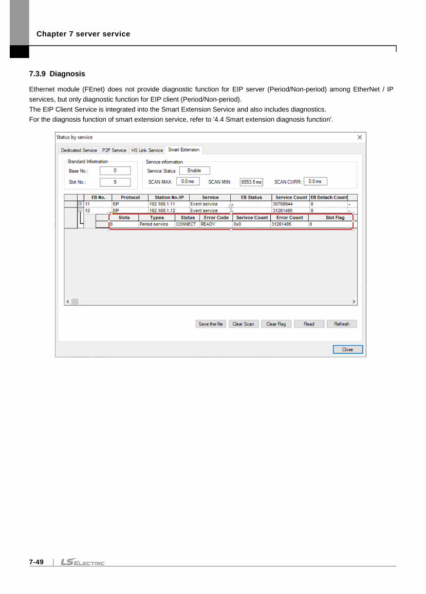
Chapter 7 server service
7-49
7.3.9 Diagnosis
Ethernet module (FEnet) does not provide diagnostic function for EIP server (Period/Non-period) among EtherNet / IP
services, but only diagnostic function for EIP client (Period/Non-period).
The EIP Client Service is integrated into the Smart Extension Service and also includes diagnostics.
For the diagnosis function of smart extension service, refer to '4.4 Smart extension diagnosis function'.
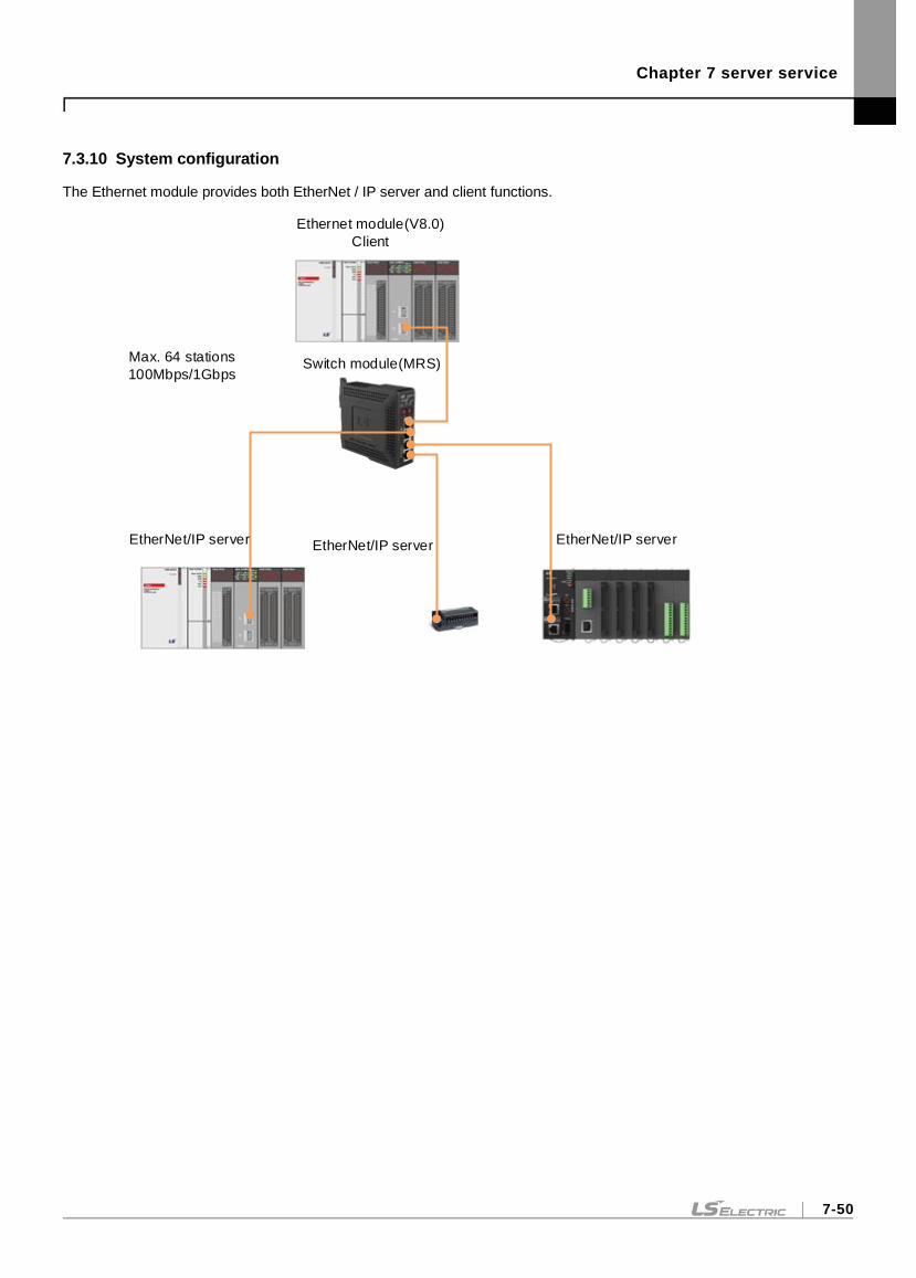
Chapter 7 server service
7-50
7.3.10 System configuration
The Ethernet module provides both EtherNet / IP server and client functions.
Ethernet module(V8.0)
Client
Switch module(MRS)
EtherNet/IP server EtherNet/IP server EtherNet/IP server
Max. 64 stations
100Mbps/1Gbps
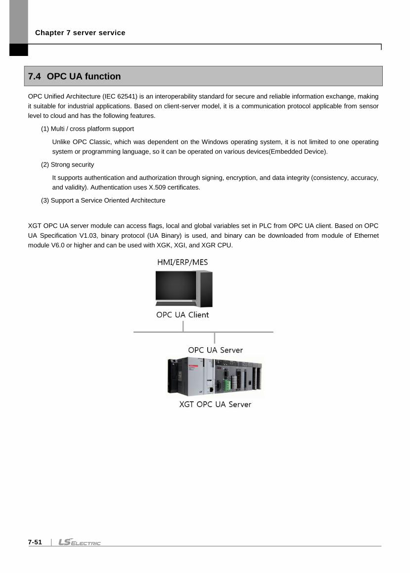
Chapter 7 server service
7-51
7.4 OPC UA function
OPC Unified Architecture (IEC 62541) is an interoperability standard for secure and reliable information exchange, making
it suitable for industrial applications. Based on client-server model, it is a communication protocol applicable from sensor
level to cloud and has the following features.
(1) Multi / cross platform support
Unlike OPC Classic, which was dependent on the Windows operating system, it is not limited to one operating
system or programming language, so it can be operated on various devices(Embedded Device).
(2) Strong security
It supports authentication and authorization through signing, encryption, and data integrity (consistency, accuracy,
and validity). Authentication uses X.509 certificates.
(3) Support a Service Oriented Architecture
XGT OPC UA server module can access flags, local and global variables set in PLC from OPC UA client. Based on OPC
UA Specification V1.03, binary protocol (UA Binary) is used, and binary can be downloaded from module of Ethernet
module V6.0 or higher and can be used with XGK, XGI, and XGR CPU.
Chapter 7 server service
7-52
7.4.1 Overview
XGT OPC UA module has the following features
Message encryption feature
Authentication via Certificate
User security functions
Variable read / write function
Variable Monitoring (MonitoredItem) Function through Subscription
Alarm / Event function for variables
History function for variables
The maximum performance specification of XGT OPC UA module is as follows.
Connect with up to 10 OPC UA clients (Connect 10 Sessions with OPC UA Client).
Up to 7000 variables can be set for OPC UA.
Have up to 50 subscription channels, 10 per session.
Register 1000 and up to 5000 variables (MonitoredItem) per subscription channel.
Security Profiles support No Security, 128Rsa15 Sign, 128Rsa15 Sign & Encrypt, 256 Sign, 256 Sign & Encrypt,
256Sha256 Sign, 256Sha256 Sign & Encrypt.
Alarm / Event can register up to 100 LimitLevel and OffNormal.
History function can save up to 3,000 history of maximum 64 for variables.

Chapter 7 server service
7-53
(1) OPC UA server available version
To use the OPC UA server, you must use the version below.
XG5000: V4.25 or higher
XGK CPU OS: V4.57 or higher
XGK CPU(N) OS: V1.21 or higher
XGI CPU OS: V4.08 or higher
XGI CPU(N) OS: V1.31 or higher
XGR CPU OS: V2.73 or higher
(2) Ethernet module OS upgrade to use OPC UA server
To use the OPC UA server, you need to upgrade the OS of the Ethernet module. (Only V7.x version is supported)
1) Download OPC UA server OS from LS ELECTRIC website (http://www.lselectric.co.kr/).
2) After installing the Ethernet module on the system, supply power to the PLC
3) Connect to PLC with XG5000 and change the operation mode to STOP.
4) Select on [Online]-[Communication module setting]-[OS download / upload].
5) Check the base / slot number where the Ethernet module is installed, select the module and click the
[BBMBoot] button. The PLC will reset to operate in BBMBoot mode.
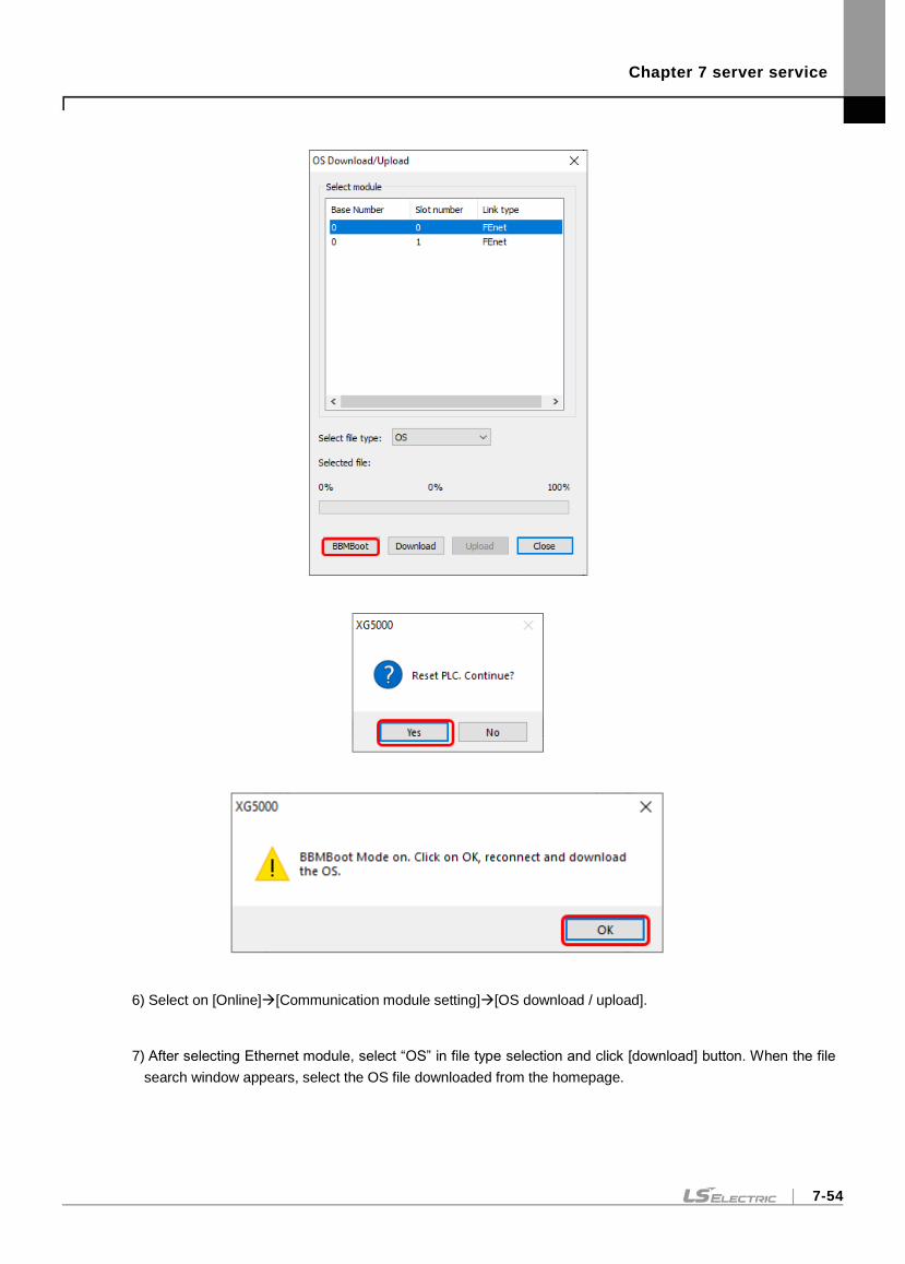
Chapter 7 server service
7-54
6) Select on [Online][Communication module setting][OS download / upload].
7) After selecting Ethernet module, select “OS” in file type selection and click [download] button. When the file
search window appears, select the OS file downloaded from the homepage.
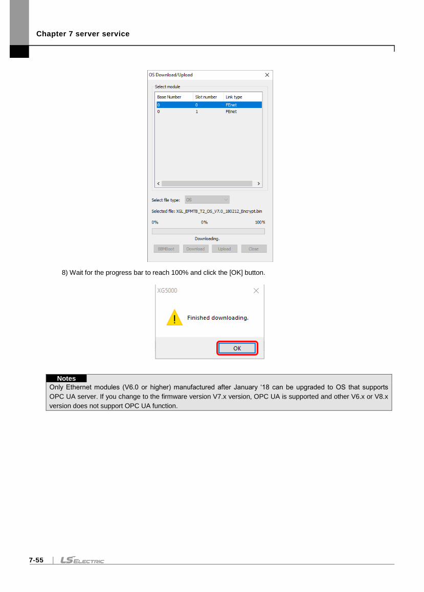
Chapter 7 server service
7-55
8) Wait for the progress bar to reach 100% and click the [OK] button.
Notes
Only Ethernet modules (V6.0 or higher) manufactured after January ‘18 can be upgraded to OS that supports
OPC UA server. If you change to the firmware version V7.x version, OPC UA is supported and other V6.x or V8.x
version does not support OPC UA function.
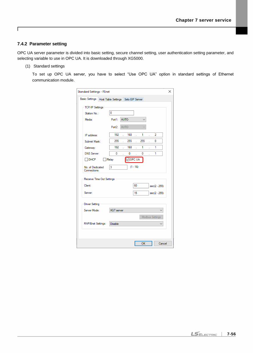
Chapter 7 server service
7-56
7.4.2 Parameter setting
OPC UA server parameter is divided into basic setting, secure channel setting, user authentication setting parameter, and
selecting variable to use in OPC UA. It is downloaded through XG5000.
(1) Standard settings
To set up OPC UA server, you have to select “Use OPC UA” option in standard settings of Ethernet
communication module.
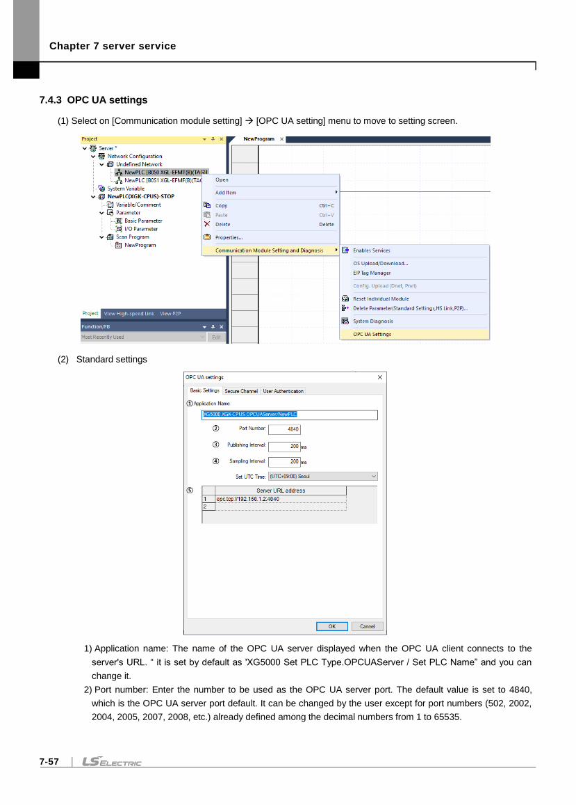
Chapter 7 server service
7-57
7.4.3 OPC UA settings
(1) Select on [Communication module setting] [OPC UA setting] menu to move to setting screen.
(2) Standard settings
1) Application name: The name of the OPC UA server displayed when the OPC UA client connects to the
server's URL. “ it is set by default as 'XG5000 Set PLC Type.OPCUAServer / Set PLC Name” and you can
change it.
2) Port number: Enter the number to be used as the OPC UA server port. The default value is set to 4840,
which is the OPC UA server port default. It can be changed by the user except for port numbers (502, 2002,
2004, 2005, 2007, 2008, etc.) already defined among the decimal numbers from 1 to 65535.
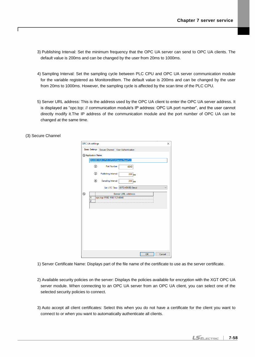
Chapter 7 server service
7-58
3) Publishing Interval: Set the minimum frequency that the OPC UA server can send to OPC UA clients. The
default value is 200ms and can be changed by the user from 20ms to 1000ms.
4) Sampling Interval: Set the sampling cycle between PLC CPU and OPC UA server communication module
for the variable registered as MonitoredItem. The default value is 200ms and can be changed by the user
from 20ms to 1000ms. However, the sampling cycle is affected by the scan time of the PLC CPU.
5) Server URL address: This is the address used by the OPC UA client to enter the OPC UA server address. It
is displayed as “opc.tcp: // communication module's IP address: OPC UA port number”, and the user cannot
directly modify it.The IP address of the communication module and the port number of OPC UA can be
changed at the same time.
(3) Secure Channel
1) Server Certificate Name: Displays part of the file name of the certificate to use as the server certificate.
2) Available security policies on the server: Displays the policies available for encryption with the XGT OPC UA
server module. When connecting to an OPC UA server from an OPC UA client, you can select one of the
selected security policies to connect.
3) Auto accept all client certificates: Select this when you do not have a certificate for the client you want to
connect to or when you want to automatically authenticate all clients.
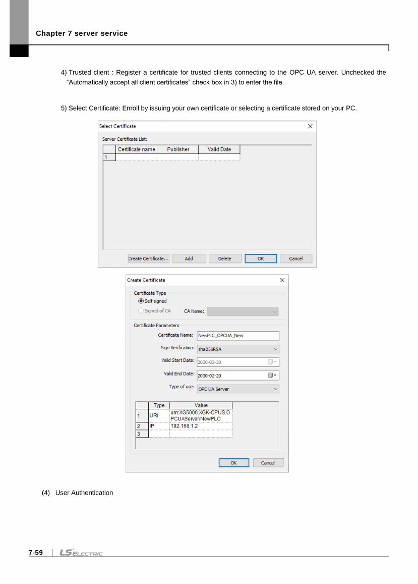
Chapter 7 server service
7-59
4) Trusted client : Register a certificate for trusted clients connecting to the OPC UA server. Unchecked the
“Automatically accept all client certificates” check box in 3) to enter the file.
5) Select Certificate: Enroll by issuing your own certificate or selecting a certificate stored on your PC.
(4) User Authentication
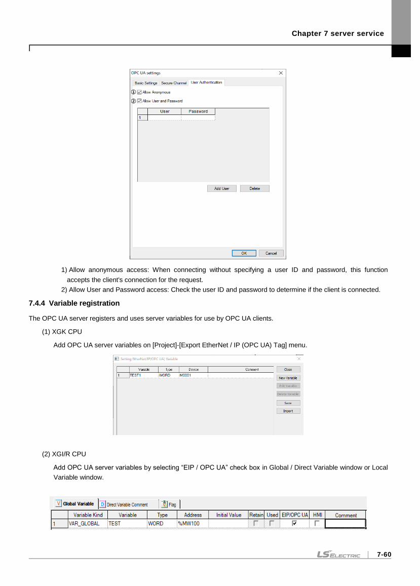
Chapter 7 server service
7-60
1) Allow anonymous access: When connecting without specifying a user ID and password, this function
accepts the client's connection for the request.
2) Allow User and Password access: Check the user ID and password to determine if the client is connected.
7.4.4 Variable registration
The OPC UA server registers and uses server variables for use by OPC UA clients.
(1) XGK CPU
Add OPC UA server variables on [Project]-[Export EtherNet / IP (OPC UA) Tag] menu.
(2) XGI/R CPU
Add OPC UA server variables by selecting “EIP / OPC UA” check box in Global / Direct Variable window or Local
Variable window.
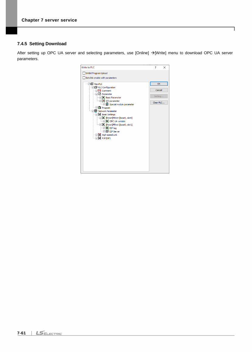
Chapter 7 server service
7-61
7.4.5 Setting Download
After setting up OPC UA server and selecting parameters, use [Online] [Write] menu to download OPC UA server
parameters.

Chapter 7 server service
7-62
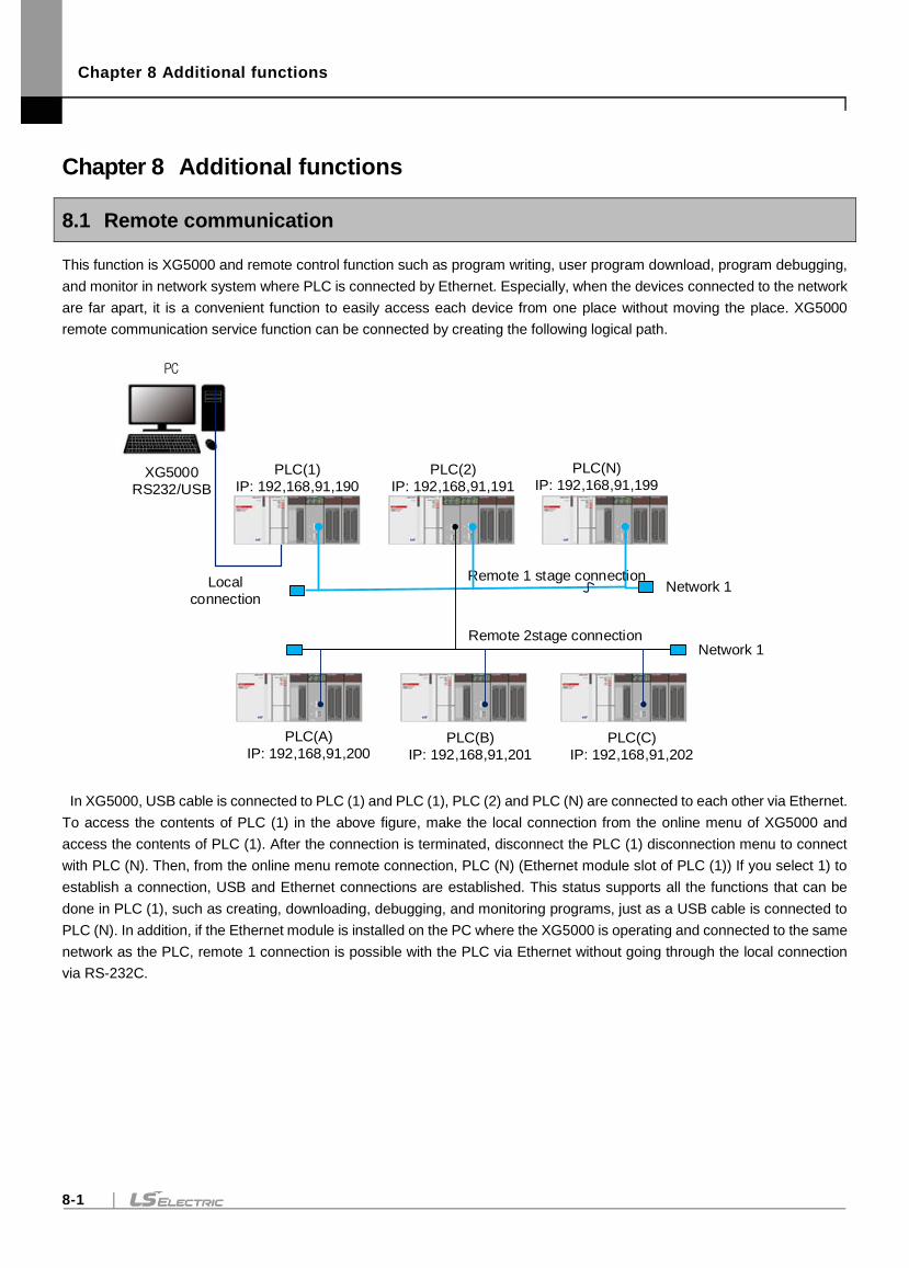
Chapter 8 Additional functions
8-1
Chapter 8 Additional functions
8.1 Remote communication
This function is XG5000 and remote control function such as program writing, user program download, program debugging,
and monitor in network system where PLC is connected by Ethernet. Especially, when the devices connected to the network
are far apart, it is a convenient function to easily access each device from one place without moving the place. XG5000
remote communication service function can be connected by creating the following logical path.
PC
PLC(1)
IP: 192,168,91,190
PLC(2)
IP: 192,168,91,191
PLC(N)
IP: 192,168,91,199XG5000
RS232/USB
Local
connection
Remote 1 stage connection
PLC(A)
IP: 192,168,91,200PLC(B)
IP: 192,168,91,201
PLC(C)
IP: 192,168,91,202
Network 1
Network 1Remote 2stage connection
In XG5000, USB cable is connected to PLC (1) and PLC (1), PLC (2) and PLC (N) are connected to each other via Ethernet.
To access the contents of PLC (1) in the above figure, make the local connection from the online menu of XG5000 and
access the contents of PLC (1). After the connection is terminated, disconnect the PLC (1) disconnection menu to connect
with PLC (N). Then, from the online menu remote connection, PLC (N) (Ethernet module slot of PLC (1)) If you select 1) to
establish a connection, USB and Ethernet connections are established. This status supports all the functions that can be
done in PLC (1), such as creating, downloading, debugging, and monitoring programs, just as a USB cable is connected to
PLC (N). In addition, if the Ethernet module is installed on the PC where the XG5000 is operating and connected to the same
network as the PLC, remote 1 connection is possible with the PLC via Ethernet without going through the local connection
via RS-232C.
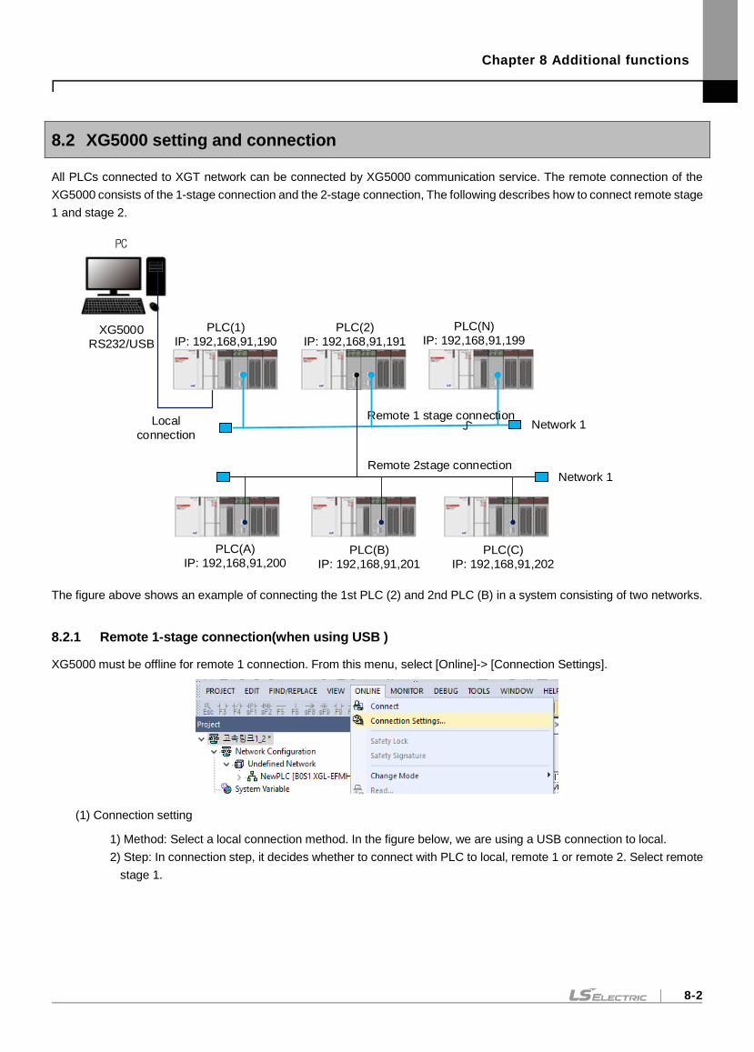
Chapter 8 Additional functions
8-2
8.2 XG5000 setting and connection
All PLCs connected to XGT network can be connected by XG5000 communication service. The remote connection of the
XG5000 consists of the 1-stage connection and the 2-stage connection, The following describes how to connect remote stage
1 and stage 2.
PC
PLC(1)
IP: 192,168,91,190
PLC(2)
IP: 192,168,91,191
PLC(N)
IP: 192,168,91,199XG5000
RS232/USB
Local
connection
Remote 1 stage connection
PLC(A)
IP: 192,168,91,200PLC(B)
IP: 192,168,91,201
PLC(C)
IP: 192,168,91,202
Network 1
Network 1Remote 2stage connection
The figure above shows an example of connecting the 1st PLC (2) and 2nd PLC (B) in a system consisting of two networks.
8.2.1 Remote 1-stage connection(when using USB )
XG5000 must be offline for remote 1 connection. From this menu, select [Online]-> [Connection Settings].
(1) Connection setting
1) Method: Select a local connection method. In the figure below, we are using a USB connection to local.
2) Step: In connection step, it decides whether to connect with PLC to local, remote 1 or remote 2. Select remote
stage 1.
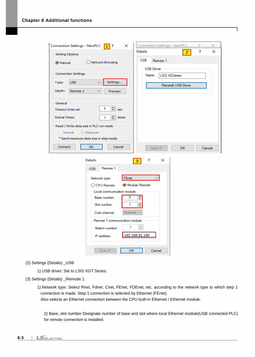
Chapter 8 Additional functions
8-3
(2) Settings (Details) _USB
1) USB driver: Set to LSIS XGT Series.
(3) Settings (Details) _Remode 1
1) Network type: Select Rnet, Fdnet, Cnet, FEnet, FDEnet, etc. according to the network type to which step 1
connection is made. Step 1 connection is selected by Ethernet (FEnet).
Also selects an Ethernet connection between the CPU built-in Ethernet / Ethernet module.
2) Base, slot number Designate number of base and slot where local Ethernet module(USB connected PLC)
for remote connection is installed.
192.168.91.190
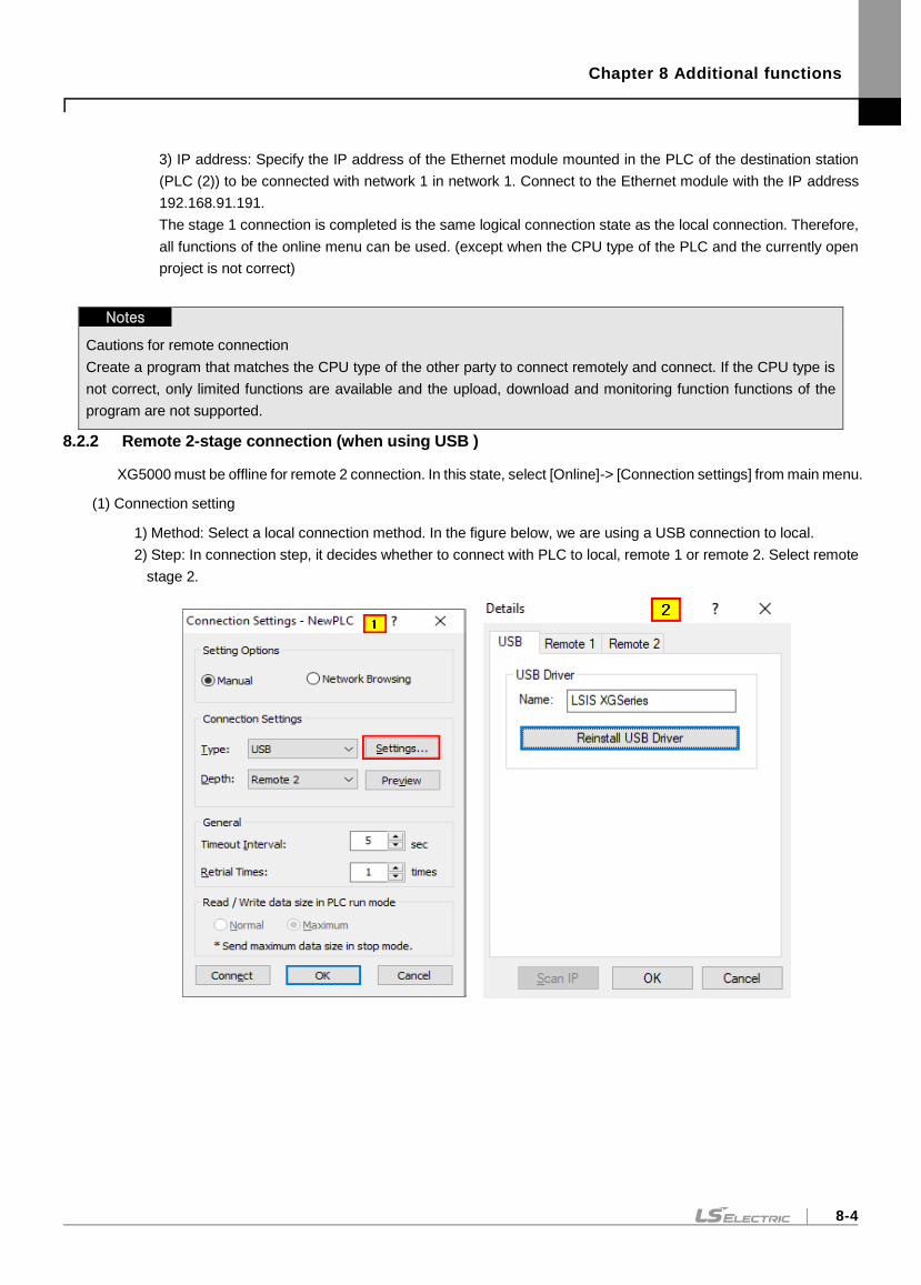
Chapter 8 Additional functions
8-4
3) IP address: Specify the IP address of the Ethernet module mounted in the PLC of the destination station
(PLC (2)) to be connected with network 1 in network 1. Connect to the Ethernet module with the IP address
192.168.91.191.
The stage 1 connection is completed is the same logical connection state as the local connection. Therefore,
all functions of the online menu can be used. (except when the CPU type of the PLC and the currently open
project is not correct)
Notes
Cautions for remote connection
Create a program that matches the CPU type of the other party to connect remotely and connect. If the CPU type is
not correct, only limited functions are available and the upload, download and monitoring function functions of the
program are not supported.
8.2.2 Remote 2-stage connection (when using USB )
XG5000 must be offline for remote 2 connection. In this state, select [Online]-> [Connection settings] from main menu.
(1) Connection setting
1) Method: Select a local connection method. In the figure below, we are using a USB connection to local.
2) Step: In connection step, it decides whether to connect with PLC to local, remote 1 or remote 2. Select remote
stage 2.
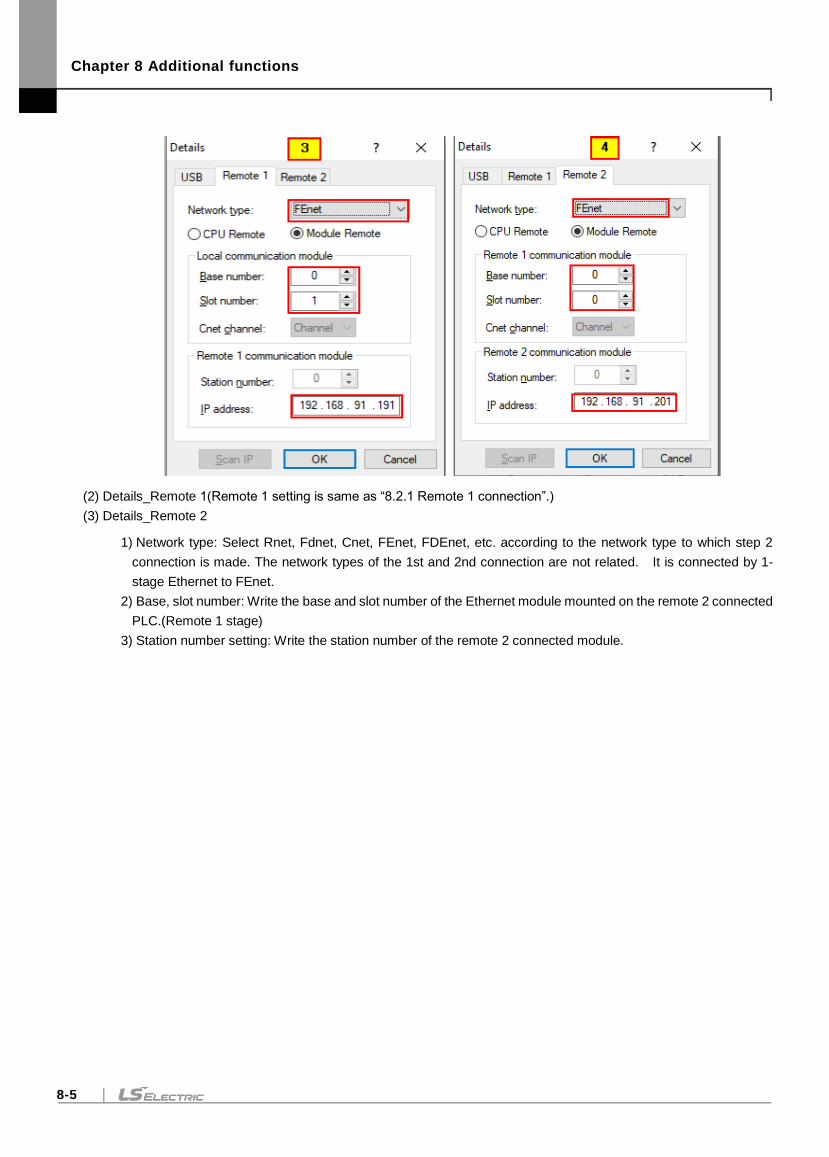
Chapter 8 Additional functions
8-5
(2) Details_Remote 1(Remote 1 setting is same as “8.2.1 Remote 1 connection”.)
(3) Details_Remote 2
1) Network type: Select Rnet, Fdnet, Cnet, FEnet, FDEnet, etc. according to the network type to which step 2
connection is made. The network types of the 1st and 2nd connection are not related. It is connected by 1-
stage Ethernet to FEnet.
2) Base, slot number: Write the base and slot number of the Ethernet module mounted on the remote 2 connected
PLC.(Remote 1 stage)
3) Station number setting: Write the station number of the remote 2 connected module.
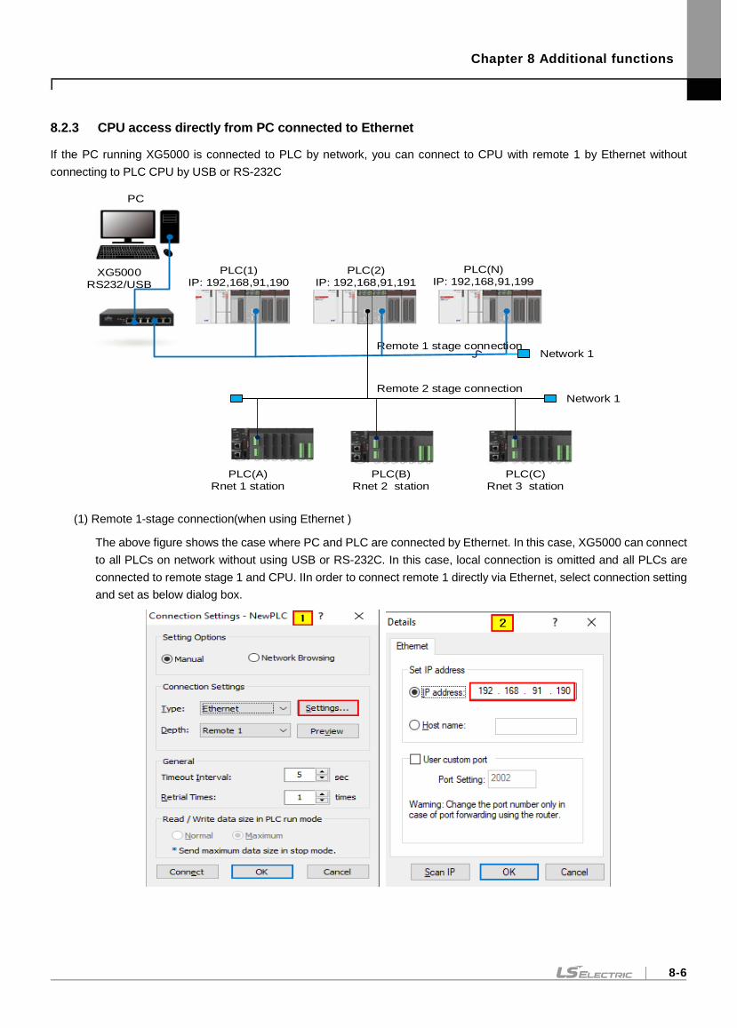
Chapter 8 Additional functions
8-6
8.2.3 CPU access directly from PC connected to Ethernet
If the PC running XG5000 is connected to PLC by network, you can connect to CPU with remote 1 by Ethernet without
connecting to PLC CPU by USB or RS-232C
PC
PLC(1)
IP: 192,168,91,190
PLC(2)
IP: 192,168,91,191
PLC(N)
IP: 192,168,91,199XG5000
RS232/USB
Remote 1 stage connection
PLC(A)
Rnet 1 station
PLC(B)
Rnet 2 station
PLC(C)
Rnet 3 station
Network 1
Network 1Remote 2 stage connection
(1) Remote 1-stage connection(when using Ethernet )
The above figure shows the case where PC and PLC are connected by Ethernet. In this case, XG5000 can connect
to all PLCs on network without using USB or RS-232C. In this case, local connection is omitted and all PLCs are
connected to remote stage 1 and CPU. IIn order to connect remote 1 directly via Ethernet, select connection setting
and set as below dialog box.
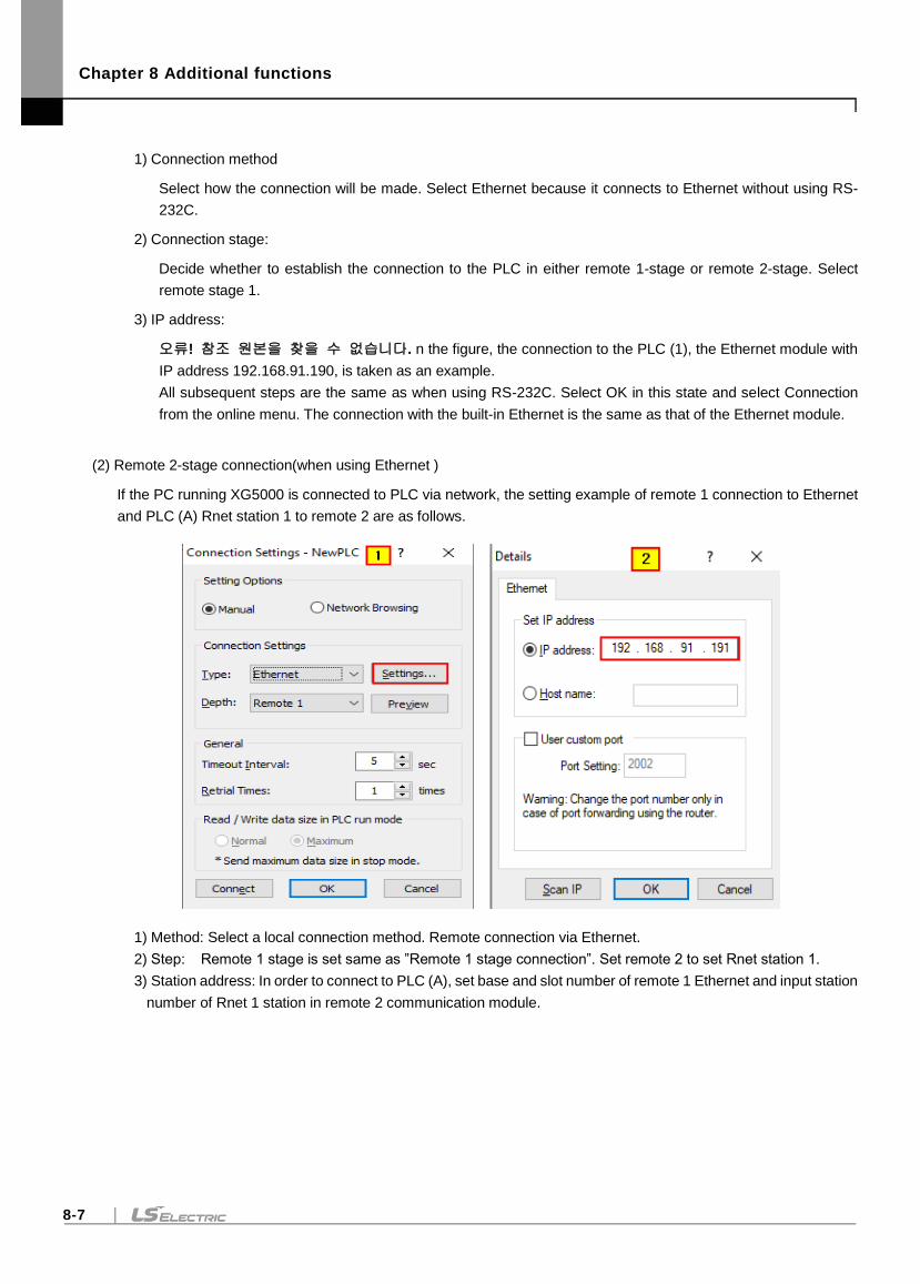
Chapter 8 Additional functions
8-7
1) Connection method
Select how the connection will be made. Select Ethernet because it connects to Ethernet without using RS-
232C.
2) Connection stage:
Decide whether to establish the connection to the PLC in either remote 1-stage or remote 2-stage. Select
remote stage 1.
3) IP address:
오류! 참조 원본을 찾을 수 없습니다. n the figure, the connection to the PLC (1), the Ethernet module with
IP address 192.168.91.190, is taken as an example.
All subsequent steps are the same as when using RS-232C. Select OK in this state and select Connection
from the online menu. The connection with the built-in Ethernet is the same as that of the Ethernet module.
(2) Remote 2-stage connection(when using Ethernet )
If the PC running XG5000 is connected to PLC via network, the setting example of remote 1 connection to Ethernet
and PLC (A) Rnet station 1 to remote 2 are as follows.
1) Method: Select a local connection method. Remote connection via Ethernet.
2) Step: Remote 1 stage is set same as ”Remote 1 stage connection”. Set remote 2 to set Rnet station 1.
3) Station address: In order to connect to PLC (A), set base and slot number of remote 1 Ethernet and input station
number of Rnet 1 station in remote 2 communication module.

Chapter 8 Additional functions
8-8
Notes
(1) Cautions when working with remote stage 1/2
1)If the currently open project on XG5000 and CPU type connected in 1st and 2nd stage do not match, the
following menu items cannot be used.
a) Write the program and each parameter
b) Read the program and each parameter
c) Monitor
d) Flash memory
e) Set link permission
f) I/O information
g) Forced I/O information
h) I/O SKIP
2) When programming XG5000 by connecting remote 1 and 2, open the project of the station to be connected
and execute remote connection.
3) Remote connection is only supported up to 2 levels No further remote connection is possible.
(2) Remote connection via XGR redundancy
The same service is supported even when remotely connecting to a dual system. However, in case of
connecting by master or standby, the connection path must be connected to the master CPU to transmit and
receive data.
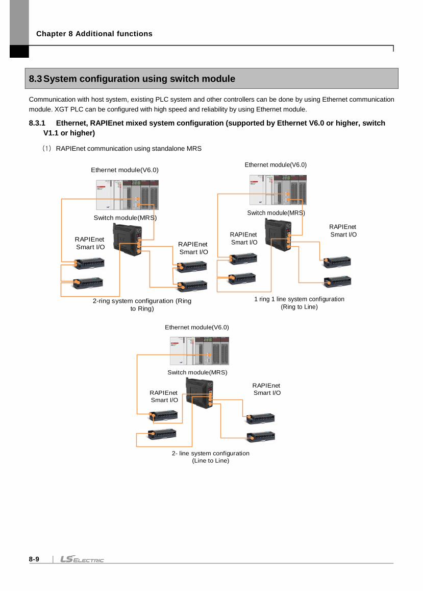
Chapter 8 Additional functions
8-9
8.3 System configuration using switch module
Communication with host system, existing PLC system and other controllers can be done by using Ethernet communication
module. XGT PLC can be configured with high speed and reliability by using Ethernet module.
8.3.1 Ethernet, RAPIEnet mixed system configuration (supported by Ethernet V6.0 or higher, switch
V1.1 or higher)
(1) RAPIEnet communication using standalone MRS
RAPIEnet
Smart I/O
Ethernet module(V6.0)
RAPIEnet
Smart I/O
Switch module(MRS)
2-ring system configuration (Ring
to Ring)
Ethernet module(V6.0)
RAPIEnet
Smart I/O
Switch module(MRS)
RAPIEnet
Smart I/O
1 ring 1 line system configuration
(Ring to Line)
Ethernet module(V6.0)
RAPIEnet
Smart I/O
Switch module(MRS)
RAPIEnet
Smart I/O
2- line system configuration
(Line to Line)
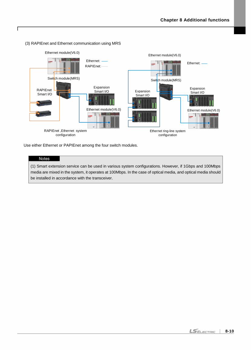
Chapter 8 Additional functions
8-10
(3) RAPIEnet and Ethernet communication using MRS
Ethernet module(V6.0)
RAPIEnet
Smart I/O
Switch module(MRS)
Expansion
Smart I/O
RAPIEnet ,Ethernet system
configuration
Ethernet module(V6.0)
Ethernet:
RAPIEnet:
Ethernet module(V6.0)
Switch module(MRS)
Expansion
Smart I/O
Ethernet ring-line system
configuration
Ethernet module(V6.0)
Ethernet:
Expansion
Smart I/O
Use either Ethernet or PAPIEnet among the four switch modules.
Notes
(1) Smart extension service can be used in various system configurations. However, if 1Gbps and 100Mbps
media are mixed in the system, it operates at 100Mbps. In the case of optical media, and optical media should
be installed in accordance with the transceiver.
Chapter 9 Troubleshooting
9-1
Chapter 9 Troubleshooting
An explanation of how to check the causes of a failure or an error that may occur during system operation and measures.
The following procedure can be used to check the status of the Ethernet module. Please follow the troubleshooting
procedures to determine the abnormal module status.
(1) Error checking method by LED on the front of module
Check whether there is a problem with the Ethernet module by lighting the LED on the front of the Ethernet module.
(2) Error checking method by XG5000 connection(Only Ethernet module)
1) Error / Warning check during PLC operation
2) Error / Warning check during communication module operation.
- Error / Warning check during communication module operation(P2P/dedicated service)
- Error / Warning check during communication module operation(Smart Extension Service)
- Diagnostic variables during communication module operation(Smart Extension Service)
3) View Communication Module Log
(3) XGT dedicated communication error code(Only Ethernet module)
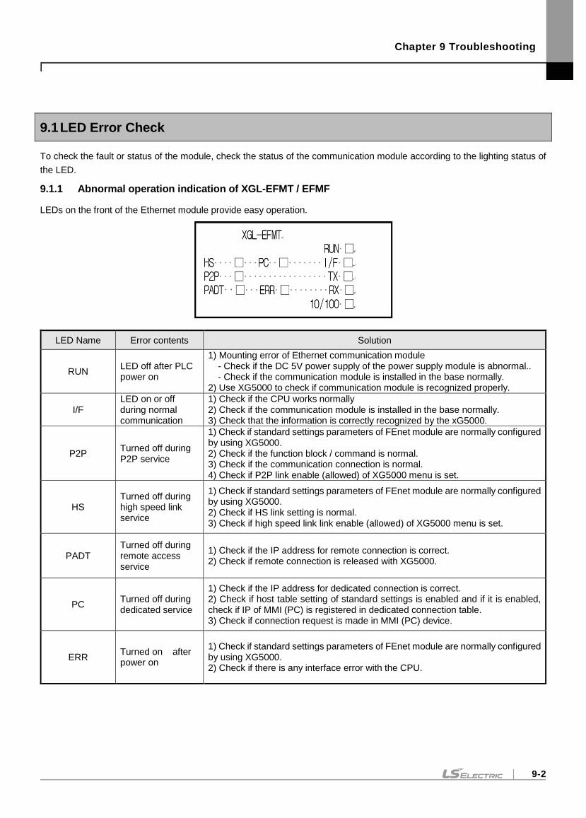
Chapter 9 Troubleshooting
9-2
9.1 LED Error Check
To check the fault or status of the module, check the status of the communication module according to the lighting status of
the LED.
9.1.1 Abnormal operation indication of XGL-EFMT / EFMF
LEDs on the front of the Ethernet module provide easy operation.
LED Name Error contents Solution
RUN LED off after PLC power on
1) Mounting error of Ethernet communication module - Check if the DC 5V power supply of the power supply module is abnormal.. - Check if the communication module is installed in the base normally.
2) Use XG5000 to check if communication module is recognized properly.
I/F LED on or off during normal communication
1) Check if the CPU works normally 2) Check if the communication module is installed in the base normally. 3) Check that the information is correctly recognized by the xG5000.
P2P Turned off during P2P service
1) Check if standard settings parameters of FEnet module are normally configured by using XG5000. 2) Check if the function block / command is normal. 3) Check if the communication connection is normal. 4) Check if P2P link enable (allowed) of XG5000 menu is set.
HS Turned off during high speed link service
1) Check if standard settings parameters of FEnet module are normally configured by using XG5000. 2) Check if HS link setting is normal. 3) Check if high speed link link enable (allowed) of XG5000 menu is set.
PADT Turned off during remote access service
1) Check if the IP address for remote connection is correct. 2) Check if remote connection is released with XG5000.
PC Turned off during dedicated service
1) Check if the IP address for dedicated connection is correct. 2) Check if host table setting of standard settings is enabled and if it is enabled, check if IP of MMI (PC) is registered in dedicated connection table. 3) Check if connection request is made in MMI (PC) device.
ERR Turned on after power on
1) Check if standard settings parameters of FEnet module are normally configured by using XG5000. 2) Check if there is any interface error with the CPU.
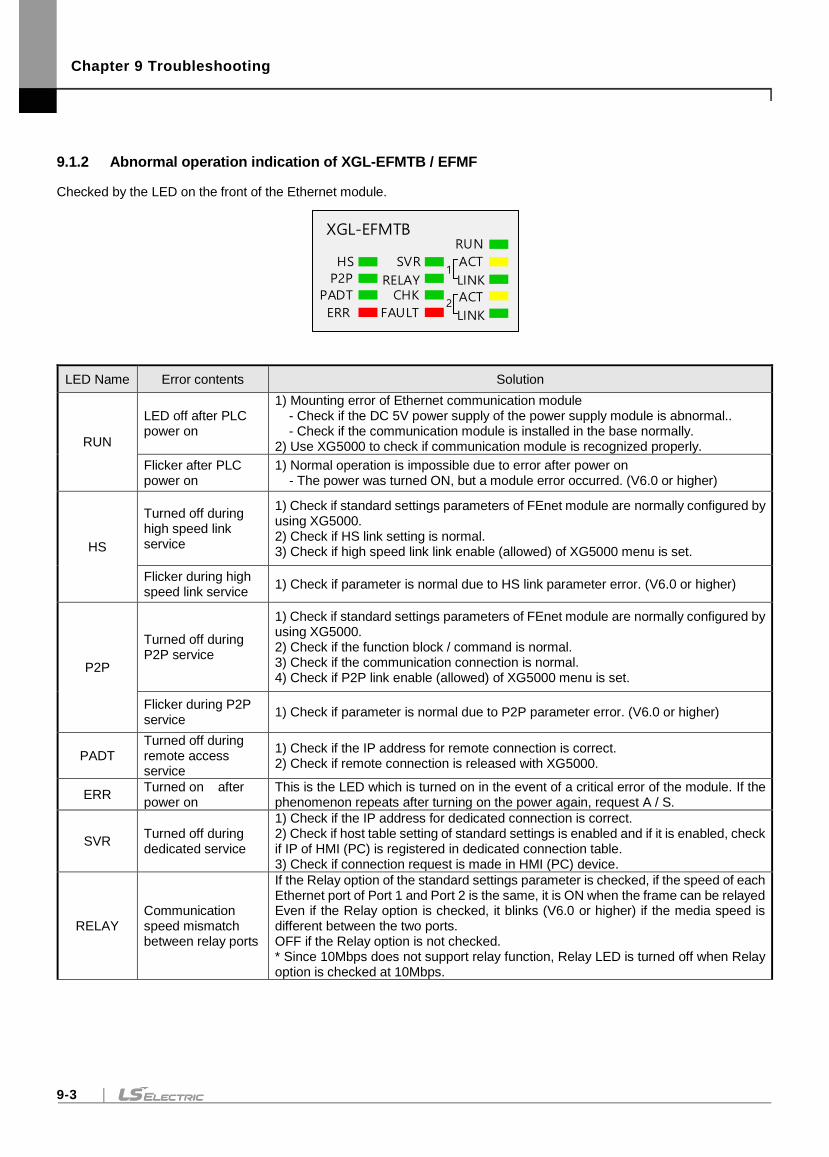
Chapter 9 Troubleshooting
9-3
9.1.2 Abnormal operation indication of XGL-EFMTB / EFMF
Checked by the LED on the front of the Ethernet module.
XGL-EFMTB
HS
P2P
PADT
ERR
SVR
RELAYCHK
FAULT
RUN
ACT
LINK
ACT
LINK
1
2
LED Name Error contents Solution
RUN
LED off after PLC power on
1) Mounting error of Ethernet communication module - Check if the DC 5V power supply of the power supply module is abnormal.. - Check if the communication module is installed in the base normally.
2) Use XG5000 to check if communication module is recognized properly.
Flicker after PLC power on
1) Normal operation is impossible due to error after power on - The power was turned ON, but a module error occurred. (V6.0 or higher)
HS
Turned off during high speed link service
1) Check if standard settings parameters of FEnet module are normally configured by using XG5000. 2) Check if HS link setting is normal. 3) Check if high speed link link enable (allowed) of XG5000 menu is set.
Flicker during high speed link service
1) Check if parameter is normal due to HS link parameter error. (V6.0 or higher)
P2P
Turned off during P2P service
1) Check if standard settings parameters of FEnet module are normally configured by using XG5000. 2) Check if the function block / command is normal. 3) Check if the communication connection is normal. 4) Check if P2P link enable (allowed) of XG5000 menu is set.
Flicker during P2P service
1) Check if parameter is normal due to P2P parameter error. (V6.0 or higher)
PADT Turned off during remote access service
1) Check if the IP address for remote connection is correct. 2) Check if remote connection is released with XG5000.
ERR Turned on after power on
This is the LED which is turned on in the event of a critical error of the module. If the phenomenon repeats after turning on the power again, request A / S.
SVR Turned off during dedicated service
1) Check if the IP address for dedicated connection is correct. 2) Check if host table setting of standard settings is enabled and if it is enabled, check if IP of HMI (PC) is registered in dedicated connection table. 3) Check if connection request is made in HMI (PC) device.
RELAY Communication speed mismatch between relay ports
If the Relay option of the standard settings parameter is checked, if the speed of each Ethernet port of Port 1 and Port 2 is the same, it is ON when the frame can be relayed Even if the Relay option is checked, it blinks (V6.0 or higher) if the media speed is different between the two ports. OFF if the Relay option is not checked. * Since 10Mbps does not support relay function, Relay LED is turned off when Relay option is checked at 10Mbps.
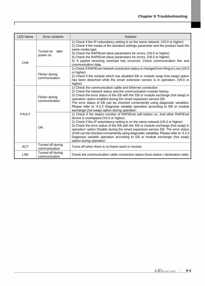
Chapter 9 Troubleshooting
9-4
LED Name Error contents Solution
CHK
Turned on after power on
1) Check if the IP redundancy setting is on the same network. (V5.0 or higher) 2) Check if the media of the standard settings parameter and the product have the same media type. 3) Check the RAPIEnet slave parameters for errors. (V6.0 or higher) 4) Check the RAPIEnet slave parameters for errors. (V6.0 or higher) 5) A packet receiving overload has occurred. Check communication line and communication data
Flicker during communication
1) Check if RAPIEnet network connection status is changed from Ring to Line.(V6.0 or higher) 2) Check if the module which has disabled EB or module swap (hot swap) option has been detached while the smart extension service is in operation. (V8.0 or higher)
FAULT
Flicker during communication
1) Check the communication cable and Ethernet connection. 2) Check the network status and the communication module history. 3) Check the error status of the EB with the 'EB or module exchange (hot swap) in operation' option enabled during the smart expansion service EB. The error status of EB can be checked conveniently using diagnostic variables. Please refer to ’4.3.3 Diagnosis variable operation according to EB or module exchange (hot swap) option during operation’.
ON
1) Check if the station number of RAPIEnet self-station no. And other RAPIEnet device is overlapped.(V6.0 or higher) 2) Check if the IP redundancy setting is on the same network.(V6.0 or higher) 3) Check the error status of the EB with the 'EB or module exchange (hot swap) in operation' option Disable during the smart expansion service EB. The error status of EB can be checked conveniently using diagnostic variables. Please refer to ’4.3.3 Diagnosis variable operation according to EB or module exchange (hot swap) option during operation’.
ACT Turned off during communication
Turns off when there is no frame send or receive.
LNK Turned off during communication
Check the communication cable connection status (host station / destination side).
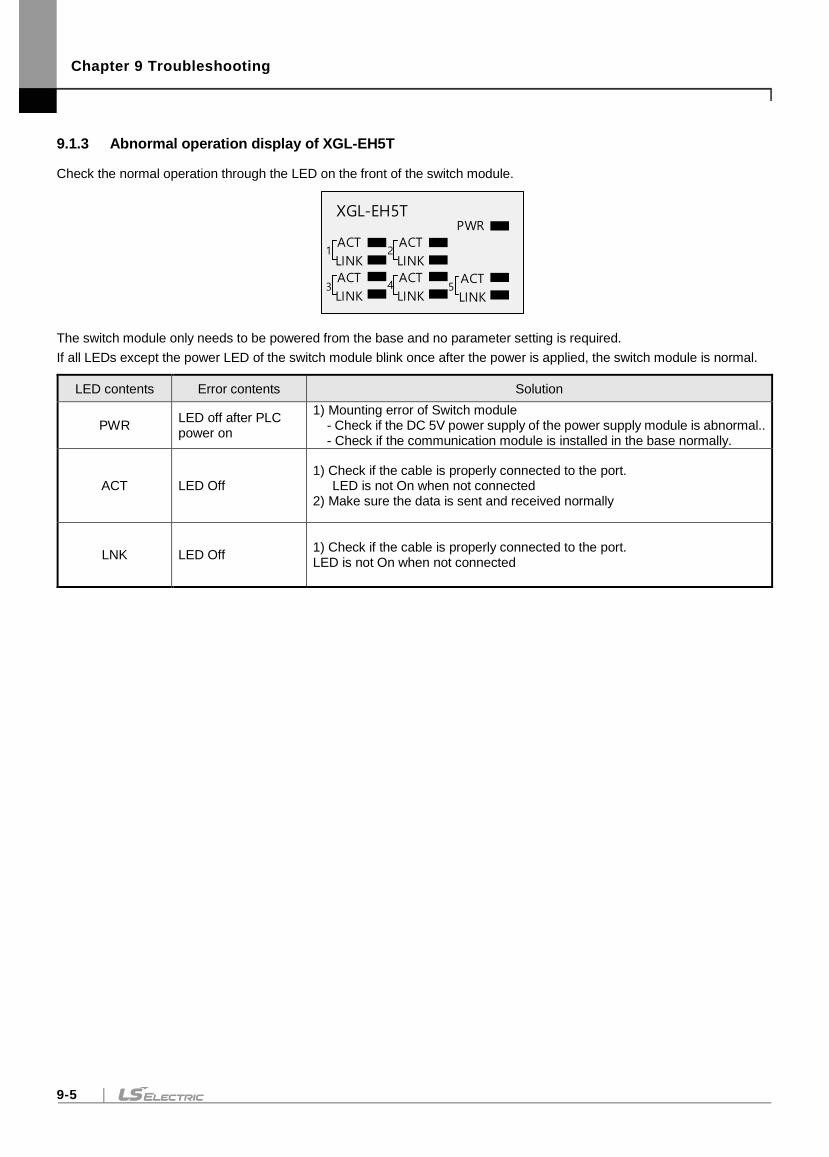
Chapter 9 Troubleshooting
9-5
9.1.3 Abnormal operation display of XGL-EH5T
Check the normal operation through the LED on the front of the switch module.
XGL-EH5TPWR
ACT
LINK
ACT
LINK
ACT
LINK
ACT
LINK
ACT
LINK
1
3
2
4 5
The switch module only needs to be powered from the base and no parameter setting is required.
If all LEDs except the power LED of the switch module blink once after the power is applied, the switch module is normal.
LED contents Error contents Solution
PWR LED off after PLC power on
1) Mounting error of Switch module - Check if the DC 5V power supply of the power supply module is abnormal.. - Check if the communication module is installed in the base normally.
ACT LED Off 1) Check if the cable is properly connected to the port.
LED is not On when not connected 2) Make sure the data is sent and received normally
LNK LED Off 1) Check if the cable is properly connected to the port. LED is not On when not connected
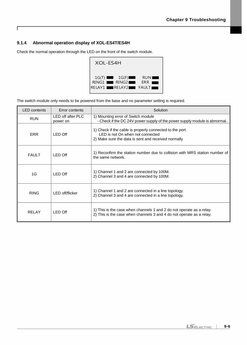
Chapter 9 Troubleshooting
9-6
9.1.4 Abnormal operation display of XOL-ES4T/ES4H
Check the normal operation through the LED on the front of the switch module.
XOL-ES4H
The switch module only needs to be powered from the base and no parameter setting is required.
LED contents Error contents Solution
RUN LED off after PLC power on
1) Mounting error of Switch module - Check if the DC 24V power supply of the power supply module is abnormal..
ERR LED Off 1) Check if the cable is properly connected to the port.
LED is not On when not connected 2) Make sure the data is sent and received normally
FAULT LED Off 1) Reconfirm the station number due to collision with MRS station number of the same network.
1G LED Off 1) Channel 1 and 2 are connected by 100M. 2) Channel 3 and 4 are connected by 100M.
RING LED off/flicker 1) Channel 1 and 2 are connected in a line topology. 2) Channel 3 and 4 are connected in a line topology.
RELAY LED Off 1) This is the case when channels 1 and 2 do not operate as a relay. 2) This is the case when channels 3 and 4 do not operate as a relay.
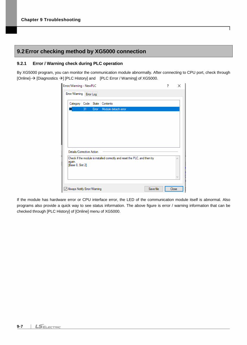
Chapter 9 Troubleshooting
9-7
9.2 Error checking method by XG5000 connection
9.2.1 Error / Warning check during PLC operation
By XG5000 program, you can monitor the communication module abnormally. After connecting to CPU port, check through
[Online]- [Diagnostics ] [PLC History] and [PLC Error / Warning] of XG5000.
If the module has hardware error or CPU interface error, the LED of the communication module itself is abnormal. Also
programs also provide a quick way to see status information. The above figure is error / warning information that can be
checked through [PLC History] of [Online] menu of XG5000.
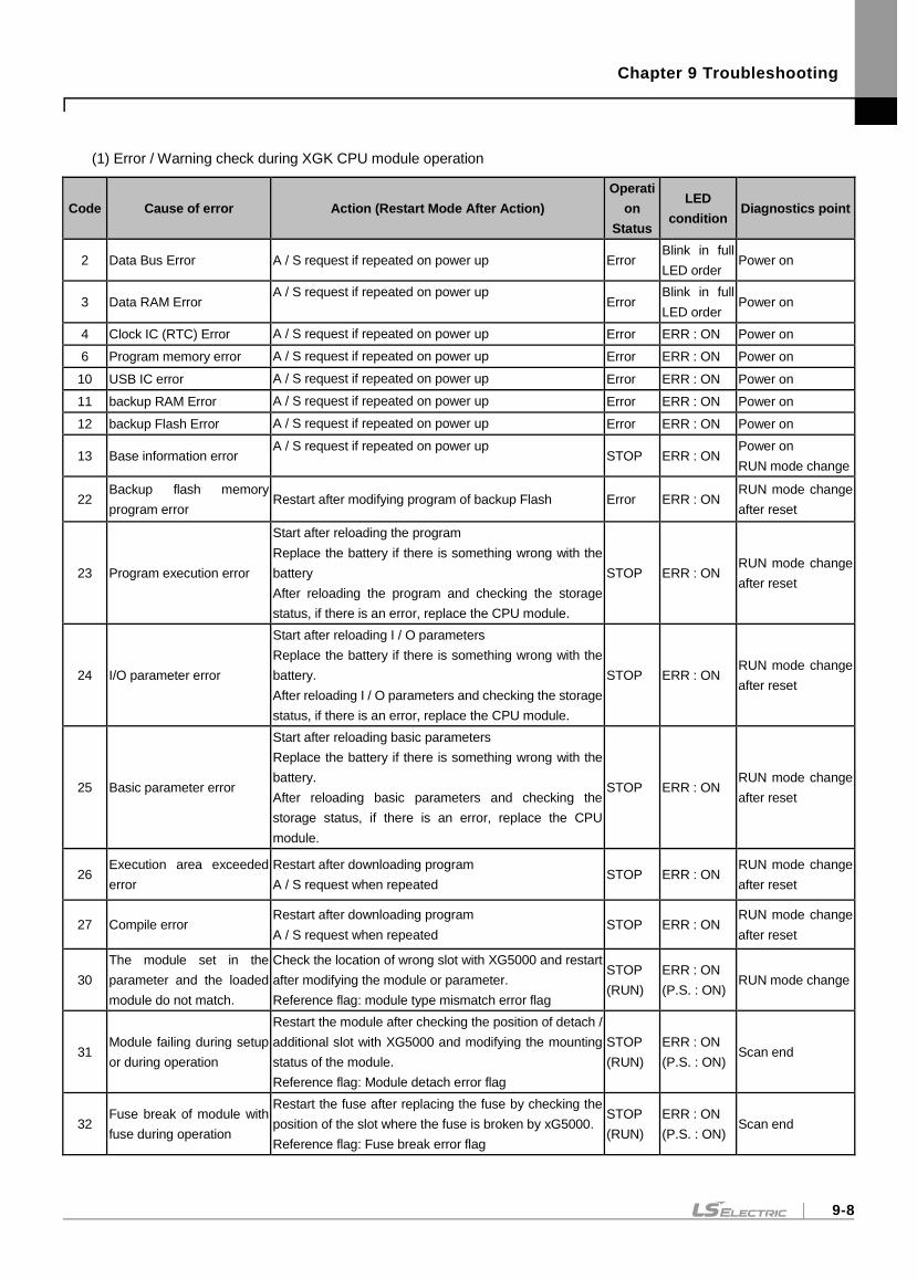
Chapter 9 Troubleshooting
9-8
(1) Error / Warning check during XGK CPU module operation
Code Cause of error Action (Restart Mode After Action)
Operati
on
Status
LED
condition Diagnostics point
2 Data Bus Error A / S request if repeated on power up Error Blink in full
LED order Power on
3 Data RAM Error A / S request if repeated on power up
Error Blink in full
LED order Power on
4 Clock IC (RTC) Error A / S request if repeated on power up Error ERR : ON Power on
6 Program memory error A / S request if repeated on power up Error ERR : ON Power on
10 USB IC error A / S request if repeated on power up Error ERR : ON Power on
11 backup RAM Error A / S request if repeated on power up Error ERR : ON Power on
12 backup Flash Error A / S request if repeated on power up Error ERR : ON Power on
13 Base information error A / S request if repeated on power up
STOP ERR : ON Power on
RUN mode change
22 Backup flash memory
program error Restart after modifying program of backup Flash Error ERR : ON
RUN mode change
after reset
23 Program execution error
Start after reloading the program
Replace the battery if there is something wrong with the
battery
After reloading the program and checking the storage
status, if there is an error, replace the CPU module.
STOP ERR : ON RUN mode change
after reset
24 I/O parameter error
Start after reloading I / O parameters
Replace the battery if there is something wrong with the
battery.
After reloading I / O parameters and checking the storage
status, if there is an error, replace the CPU module.
STOP ERR : ON RUN mode change
after reset
25 Basic parameter error
Start after reloading basic parameters
Replace the battery if there is something wrong with the
battery.
After reloading basic parameters and checking the
storage status, if there is an error, replace the CPU
module.
STOP ERR : ON RUN mode change
after reset
26 Execution area exceeded
error
Restart after downloading program
A / S request when repeated STOP ERR : ON
RUN mode change
after reset
27 Compile error Restart after downloading program
A / S request when repeated STOP ERR : ON
RUN mode change
after reset
30
The module set in the
parameter and the loaded
module do not match.
Check the location of wrong slot with XG5000 and restart
after modifying the module or parameter.
Reference flag: module type mismatch error flag
STOP
(RUN)
ERR : ON
(P.S. : ON) RUN mode change
31 Module failing during setup
or during operation
Restart the module after checking the position of detach /
additional slot with XG5000 and modifying the mounting
status of the module.
Reference flag: Module detach error flag
STOP
(RUN)
ERR : ON
(P.S. : ON) Scan end
32 Fuse break of module with
fuse during operation
Restart the fuse after replacing the fuse by checking the
position of the slot where the fuse is broken by xG5000.
Reference flag: Fuse break error flag
STOP
(RUN)
ERR : ON
(P.S. : ON) Scan end
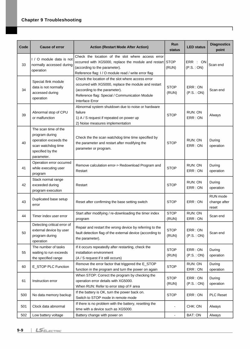
Chapter 9 Troubleshooting
9-9
Code Cause of error Action (Restart Mode After Action) Run
status LED status
Diagnostics
point
33
I / O module data is not
normally accessed during
operation
Check the location of the slot where access error
occurred with XG5000, replace the module and restart
(according to the parameter).
Reference flag: I / O module read / write error flag
STOP
(RUN)
ERR : ON
(P.S. : ON) Scan end
34
Special /link module
data is not normally
accessed during
operation
Check the location of the slot where access error
occurred with XG5000, replace the module and restart
(according to the parameter).
Reference flag: Special / Communication Module
Interface Error
STOP
(RUN)
ERR : ON
(P.S. : ON) Scan end
39 Abnormal stop of CPU
or malfunction
Abnormal system shutdown due to noise or hardware
failure
1) A / S request if repeated on power up
2) Noise measures implementation
STOP RUN: ON
ERR : ON Always
40
The scan time of the
program during
operation exceeds the
scan watchdog time
specified by the
parameter.
Check the the scan watchdog time time specified by
the parameter and restart after modifying the
parameter or program.
STOP RUN: ON
ERR : ON
During
operation
41
Operation error occurred
while executing user
program
Remove calculation error-> Redownload Program and
Restart STOP
RUN: ON
ERR : ON
During
operation
42
Stack normal range
exceeded during
program execution
Restart STOP RUN: ON
ERR : ON
During
operation
43 Duplicated base setup
error Reset after confirming the base setting switch STOP ERR : ON
RUN mode
change after
reset
44 Timer index user error Start after modifying / re-downloading the timer index
program
STOP
(RUN)
RUN: ON
ERR : ON Scan end
50
Detecting critical error of
external device by user
program during
operation
Repair and restart the wrong device by referring to the
fault detection flag of the external device (according to
the parameter).
STOP
(RUN)
ERR : ON
(P.S. : ON) Scan end
55
The number of tasks
waiting to run exceeds
the specified range
If it occurs repeatedly after restarting, check the
installation environment
(A / S request if it still occurs)
STOP
(RUN)
ERR : ON
(P.S. : ON)
During
operation
60 E_STOP PLC Function Remove the error factor that triggered the E_STOP
function in the program and turn the power on again STOP
RUN: ON
ERR : ON
During
operation
61 Instruction error
When STOP: Correct the program by checking the
operation error details with XG5000.
When RUN: Refer to error step of F area
STOP
(RUN)
ERR : ON
(P.S. : ON)
During
operation
500 No data memory backup If the battery is OK, turn the power back on.
Switch to STOP mode in remote mode STOP ERR : ON PLC Reset
501 Clock data abnormal If there is no problem with the battery, resetting the
time with a device such as XG5000. - CHK: ON Always
502 Low battery voltage Battery change with power on - BAT: ON Always
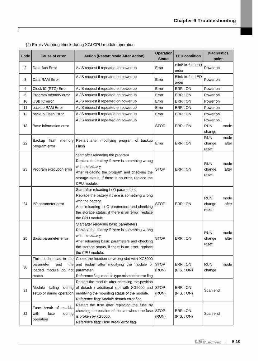
Chapter 9 Troubleshooting
9-10
(2) Error / Warning check during XGI CPU module operation
Code Cause of error Action (Restart Mode After Action) Operation
Status LED condition
Diagnostics
point
2 Data Bus Error A / S request if repeated on power up Error Blink in full LED
order Power on
3 Data RAM Error A / S request if repeated on power up
Error Blink in full LED
order Power on
4 Clock IC (RTC) Error A / S request if repeated on power up Error ERR : ON Power on
6 Program memory error A / S request if repeated on power up Error ERR : ON Power on
10 USB IC error A / S request if repeated on power up Error ERR : ON Power on
11 backup RAM Error A / S request if repeated on power up Error ERR : ON Power on
12 backup Flash Error A / S request if repeated on power up Error ERR : ON Power on
13 Base information error
A / S request if repeated on power up
STOP ERR : ON
Power on
RUN mode
change
22 Backup flash memory
program error
Restart after modifying program of backup
Flash Error ERR : ON
RUN mode
change after
reset
23 Program execution error
Start after reloading the program
Replace the battery if there is something wrong
with the battery
After reloading the program and checking the
storage status, if there is an error, replace the
CPU module.
STOP ERR : ON
RUN mode
change after
reset
24 I/O parameter error
Start after reloading I / O parameters
Replace the battery if there is something wrong
with the battery
After reloading I / O parameters and checking
the storage status, if there is an error, replace
the CPU module.
STOP ERR : ON
RUN mode
change after
reset
25 Basic parameter error
Start after reloading basic parameters
Replace the battery if there is something wrong
with the battery
After reloading basic parameters and checking
the storage status, if there is an error, replace
the CPU module.
STOP ERR : ON
RUN mode
change after
reset
30
The module set in the
parameter and the
loaded module do not
match.
Check the location of wrong slot with XG5000
and restart after modifying the module or
parameter.
Reference flag: module type mismatch error flag
STOP
(RUN)
ERR : ON
(P.S. : ON)
RUN mode
change
31 Module failing during
setup or during operation
Restart the module after checking the position
of detach / additional slot with XG5000 and
modifying the mounting status of the module.
Reference flag: Module detach error flag
STOP
(RUN)
ERR : ON
(P.S. : ON) Scan end
32
Fuse break of module
with fuse during
operation
Restart the fuse after replacing the fuse by
checking the position of the slot where the fuse
is broken by xG5000.
Reference flag: Fuse break error flag
STOP
(RUN)
ERR : ON
(P.S. : ON) Scan end
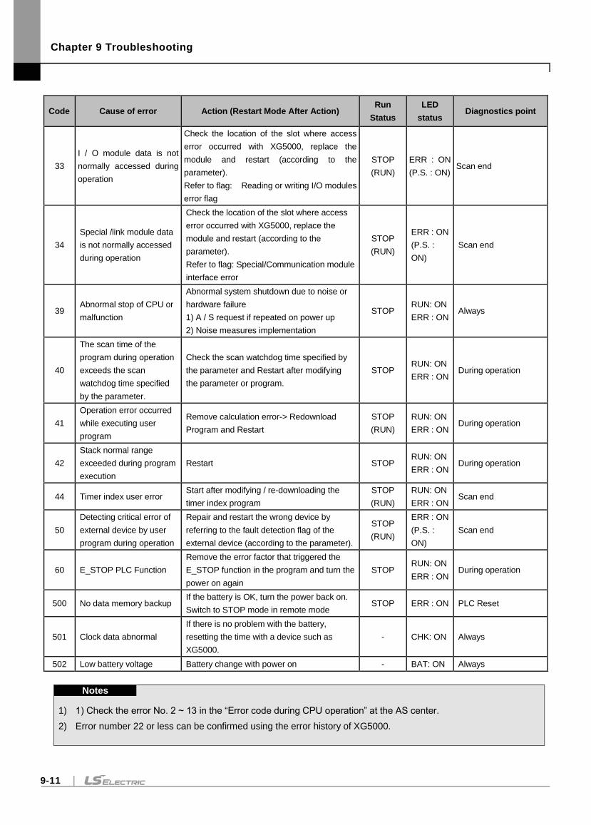
Chapter 9 Troubleshooting
9-11
Code Cause of error Action (Restart Mode After Action) Run
Status
LED
status Diagnostics point
33
I / O module data is not
normally accessed during
operation
Check the location of the slot where access
error occurred with XG5000, replace the
module and restart (according to the
parameter).
Refer to flag: Reading or writing I/O modules
error flag
STOP
(RUN)
ERR : ON
(P.S. : ON) Scan end
34
Special /link module data
is not normally accessed
during operation
Check the location of the slot where access
error occurred with XG5000, replace the
module and restart (according to the
parameter).
Refer to flag: Special/Communication module
interface error
STOP
(RUN)
ERR : ON
(P.S. :
ON)
Scan end
39 Abnormal stop of CPU or
malfunction
Abnormal system shutdown due to noise or
hardware failure
1) A / S request if repeated on power up
2) Noise measures implementation
STOP RUN: ON
ERR : ON Always
40
The scan time of the
program during operation
exceeds the scan
watchdog time specified
by the parameter.
Check the scan watchdog time specified by
the parameter and Restart after modifying
the parameter or program.
STOP RUN: ON
ERR : ON During operation
41
Operation error occurred
while executing user
program
Remove calculation error-> Redownload
Program and Restart
STOP
(RUN)
RUN: ON
ERR : ON During operation
42
Stack normal range
exceeded during program
execution
Restart STOP RUN: ON
ERR : ON During operation
44 Timer index user error Start after modifying / re-downloading the
timer index program
STOP
(RUN)
RUN: ON
ERR : ON Scan end
50
Detecting critical error of
external device by user
program during operation
Repair and restart the wrong device by
referring to the fault detection flag of the
external device (according to the parameter).
STOP
(RUN)
ERR : ON
(P.S. :
ON)
Scan end
60 E_STOP PLC Function
Remove the error factor that triggered the
E_STOP function in the program and turn the
power on again
STOP RUN: ON
ERR : ON During operation
500 No data memory backup If the battery is OK, turn the power back on.
Switch to STOP mode in remote mode STOP ERR : ON PLC Reset
501 Clock data abnormal
If there is no problem with the battery,
resetting the time with a device such as
XG5000.
- CHK: ON Always
502 Low battery voltage Battery change with power on - BAT: ON Always
Notes
1) 1) Check the error No. 2 ~ 13 in the “Error code during CPU operation” at the AS center.
2) Error number 22 or less can be confirmed using the error history of XG5000.
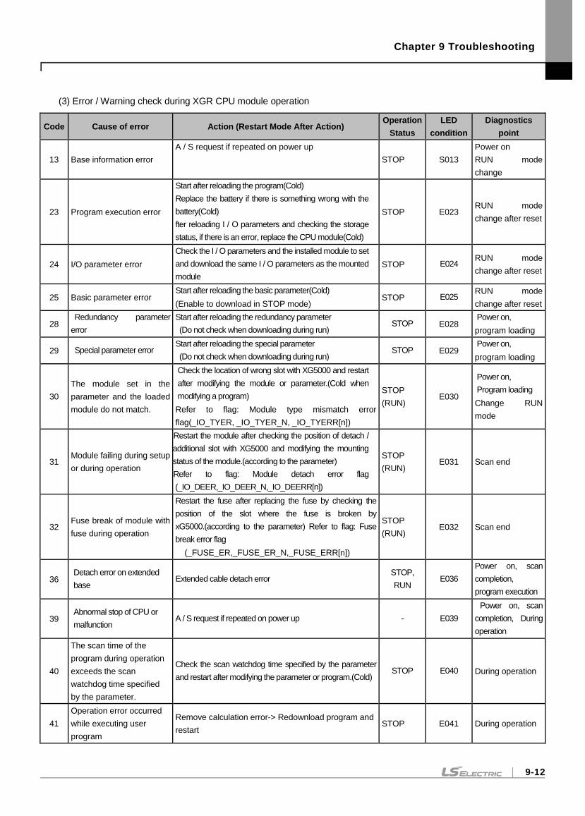
Chapter 9 Troubleshooting
9-12
(3) Error / Warning check during XGR CPU module operation
Code Cause of error Action (Restart Mode After Action) Operation
Status
LED
condition
Diagnostics
point
13 Base information error
A / S request if repeated on power up
STOP S013
Power on
RUN mode
change
23 Program execution error
Start after reloading the program(Cold)
Replace the battery if there is something wrong with the
battery(Cold)
fter reloading I / O parameters and checking the storage
status, if there is an error, replace the CPU module(Cold)
STOP E023 RUN mode
change after reset
24 I/O parameter error
Check the I / O parameters and the installed module to set
and download the same I / O parameters as the mounted
module
STOP E024 RUN mode
change after reset
25 Basic parameter error Start after reloading the basic parameter(Cold)
(Enable to download in STOP mode) STOP E025
RUN mode
change after reset
28 Redundancy parameter
error
Start after reloading the redundancy parameter
(Do not check when downloading during run) STOP E028
Power on,
program loading
29 Special parameter error Start after reloading the special parameter
(Do not check when downloading during run) STOP E029
Power on,
program loading
30
The module set in the
parameter and the loaded
module do not match.
Check the location of wrong slot with XG5000 and restart
after modifying the module or parameter.(Cold when
modifying a program)
Refer to flag: Module type mismatch error
flag(_IO_TYER, _IO_TYER_N, _IO_TYERR[n])
STOP
(RUN) E030
Power on,
Program loading
Change RUN
mode
31 Module failing during setup
or during operation
Restart the module after checking the position of detach /
additional slot with XG5000 and modifying the mounting
status of the module.(according to the parameter)
Refer to flag: Module detach error flag
(_IO_DEER,_IO_DEER_N,_IO_DEERR[n])
STOP
(RUN) E031 Scan end
32 Fuse break of module with
fuse during operation
Restart the fuse after replacing the fuse by checking the
position of the slot where the fuse is broken by
xG5000.(according to the parameter) Refer to flag: Fuse
break error flag
(_FUSE_ER,_FUSE_ER_N,_FUSE_ERR[n])
STOP
(RUN) E032 Scan end
36 Detach error on extended
base Extended cable detach error
STOP,
RUN E036
Power on, scan
completion,
program execution
39 Abnormal stop of CPU or
malfunction A / S request if repeated on power up - E039
Power on, scan
completion, During
operation
40
The scan time of the
program during operation
exceeds the scan
watchdog time specified
by the parameter.
Check the scan watchdog time specified by the parameter
and restart after modifying the parameter or program.(Cold) STOP E040 During operation
41
Operation error occurred
while executing user
program
Remove calculation error-> Redownload program and
restart STOP E041 During operation
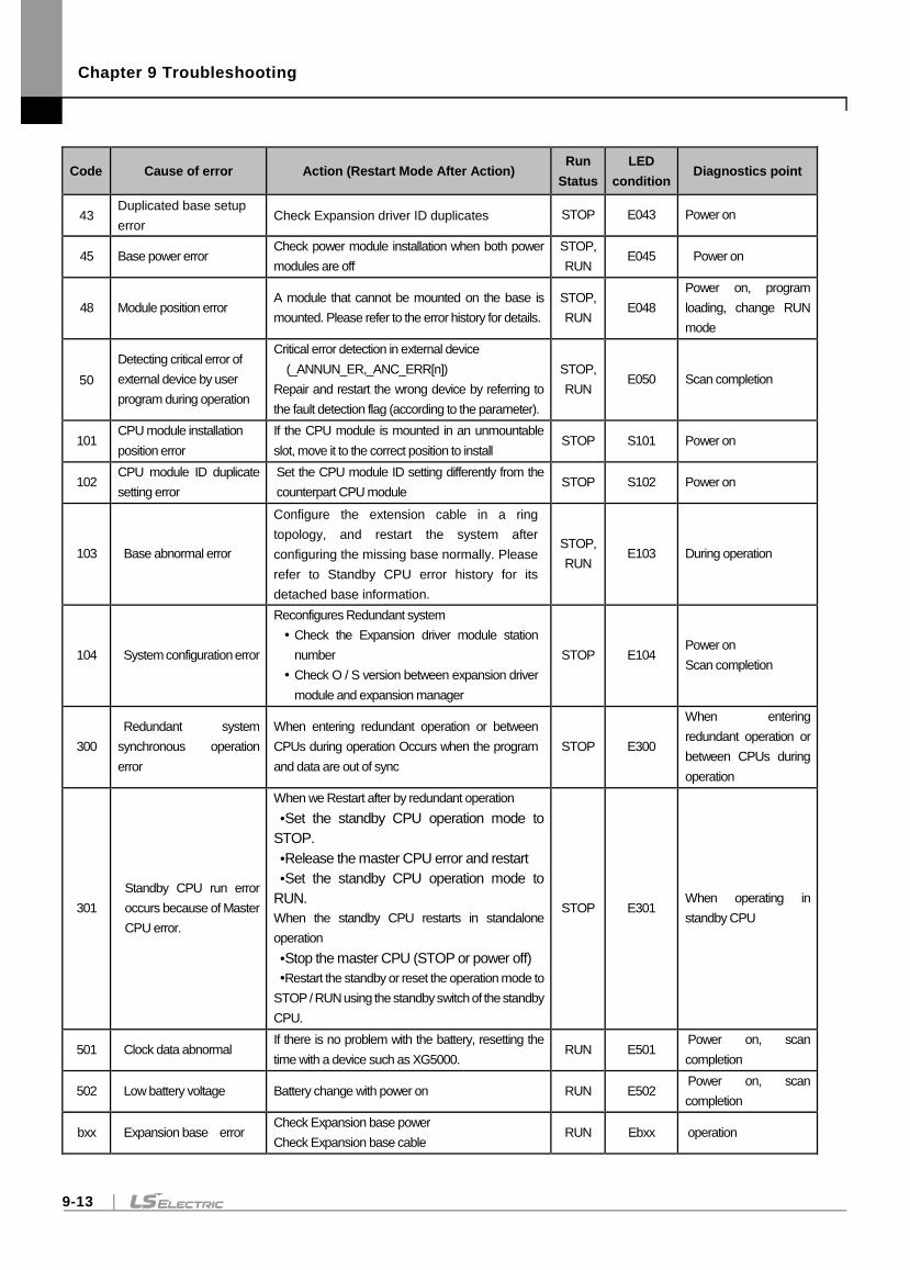
Chapter 9 Troubleshooting
9-13
Code Cause of error Action (Restart Mode After Action) Run
Status
LED
condition Diagnostics point
43 Duplicated base setup
error Check Expansion driver ID duplicates STOP E043 Power on
45 Base power error Check power module installation when both power
modules are off
STOP,
RUN E045 Power on
48 Module position error A module that cannot be mounted on the base is
mounted. Please refer to the error history for details.
STOP,
RUN E048
Power on, program
loading, change RUN
mode
50
Detecting critical error of
external device by user
program during operation
Critical error detection in external device
(_ANNUN_ER,_ANC_ERR[n])
Repair and restart the wrong device by referring to
the fault detection flag (according to the parameter).
STOP,
RUN E050 Scan completion
101 CPU module installation
position error
If the CPU module is mounted in an unmountable
slot, move it to the correct position to install STOP S101 Power on
102 CPU module ID duplicate
setting error
Set the CPU module ID setting differently from the
counterpart CPU module STOP S102 Power on
103 Base abnormal error
Configure the extension cable in a ring
topology, and restart the system after
configuring the missing base normally. Please
refer to Standby CPU error history for its
detached base information.
STOP,
RUN E103 During operation
104 System configuration error
Reconfigures Redundant system
Check the Expansion driver module station
number
Check O / S version between expansion driver
module and expansion manager
STOP E104 Power on
Scan completion
300
Redundant system
synchronous operation
error
When entering redundant operation or between
CPUs during operation Occurs when the program
and data are out of sync
STOP E300
When entering
redundant operation or
between CPUs during
operation
301
Standby CPU run error
occurs because of Master
CPU error.
When we Restart after by redundant operation
Set the standby CPU operation mode to
STOP.
Release the master CPU error and restart
Set the standby CPU operation mode to
RUN.
When the standby CPU restarts in standalone
operation
Stop the master CPU (STOP or power off)
Restart the standby or reset the operation mode to
STOP / RUN using the standby switch of the standby
CPU.
STOP E301 When operating in
standby CPU
501 Clock data abnormal If there is no problem with the battery, resetting the
time with a device such as XG5000. RUN E501
Power on, scan
completion
502 Low battery voltage Battery change with power on RUN E502 Power on, scan
completion
bxx Expansion base error Check Expansion base power
Check Expansion base cable RUN Ebxx operation
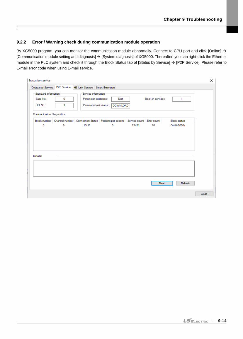
Chapter 9 Troubleshooting
9-14
9.2.2 Error / Warning check during communication module operation
By XG5000 program, you can monitor the communication module abnormally. Connect to CPU port and click [Online]
[Communication module setting and diagnosis] [System diagnosis] of XG5000. Thereafter, you can right-click the Ethernet
module in the PLC system and check it through the Block Status tab of [Status by Service] [P2P Service]. Please refer to
E-mail error code when using E-mail service.
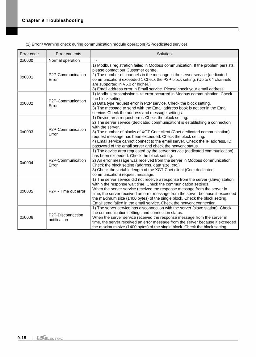
Chapter 9 Troubleshooting
9-15
(1) Error / Warning check during communication module operation(P2P/dedicated service)
Error code Error contents Solution
0x0000 Normal operation -
0x0001 P2P-Communication Error
1) Modbus registration failed in Modbus communication. If the problem persists, please contact our Customer centre. 2) The number of channels in the message in the server service (dedicated communication) exceeded 1 Check the P2P block setting. (Up to 64 channels are supported in V6.0 or higher.) 3) Email address error in Email service. Please check your email address
0x0002 P2P-Communication Error
1) Modbus transmission size error occurred in Modbus communication. Check the block setting. 2) Data type request error in P2P service. Check the block setting. 3) The message to send with the Email address book is not set in the Email service. Check the address and message settings.
0x0003 P2P-Communication Error
1) Device area request error. Check the block setting. 2) The server service (dedicated communication) is establishing a connection with the server. 3) The number of blocks of XGT Cnet client (Cnet dedicated communication) request message has been exceeded. Check the block setting. 4) Email service cannot connect to the email server. Check the IP address, ID, password of the email server and check the network status.
0x0004 P2P-Communication Error
1) The device area requested by the server service (dedicated communication) has been exceeded. Check the block setting. 2) An error message was received from the server in Modbus communication. Check the block setting (address, data size, etc.). 3) Check the variable length of the XGT Cnet client (Cnet dedicated communication) request message.
0x0005 P2P - Time out error
1) The server service did not receive a response from the server (slave) station within the response wait time. Check the communication settings. When the server service received the response message from the server in time, the server received an error message from the server because it exceeded the maximum size (1400 bytes) of the single block. Check the block setting. Email send failed in the email service. Check the network connection.
0x0006 P2P-Disconnection notification
1) The server service has disconnection with the server (slave station). Check the communication settings and connection status. When the server service received the response message from the server in time, the server received an error message from the server because it exceeded the maximum size (1400 bytes) of the single block. Check the block setting.
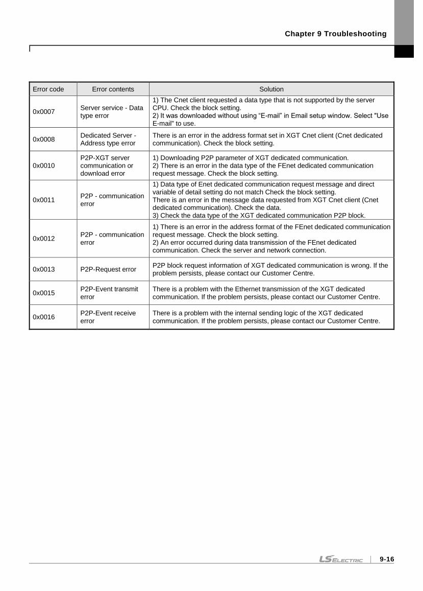
Chapter 9 Troubleshooting
9-16
Error code Error contents Solution
0x0007 Server service - Data type error
1) The Cnet client requested a data type that is not supported by the server CPU. Check the block setting. 2) It was downloaded without using “E-mail” in Email setup window. Select "Use E-mail" to use.
0x0008 Dedicated Server - Address type error
There is an error in the address format set in XGT Cnet client (Cnet dedicated communication). Check the block setting.
0x0010 P2P-XGT server communication or download error
1) Downloading P2P parameter of XGT dedicated communication. 2) There is an error in the data type of the FEnet dedicated communication request message. Check the block setting.
0x0011 P2P - communication error
1) Data type of Enet dedicated communication request message and direct variable of detail setting do not match Check the block setting. There is an error in the message data requested from XGT Cnet client (Cnet dedicated communication). Check the data. 3) Check the data type of the XGT dedicated communication P2P block.
0x0012 P2P - communication error
1) There is an error in the address format of the FEnet dedicated communication request message. Check the block setting. 2) An error occurred during data transmission of the FEnet dedicated communication. Check the server and network connection.
0x0013 P2P-Request error P2P block request information of XGT dedicated communication is wrong. If the problem persists, please contact our Customer Centre.
0x0015 P2P-Event transmit error
There is a problem with the Ethernet transmission of the XGT dedicated communication. If the problem persists, please contact our Customer Centre.
0x0016 P2P-Event receive error
There is a problem with the internal sending logic of the XGT dedicated communication. If the problem persists, please contact our Customer Centre.
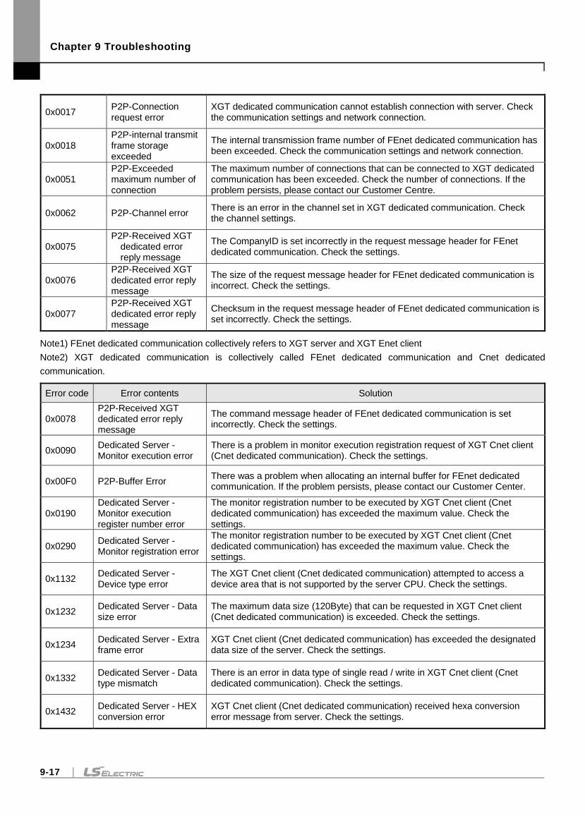
Chapter 9 Troubleshooting
9-17
0x0017 P2P-Connection request error
XGT dedicated communication cannot establish connection with server. Check the communication settings and network connection.
0x0018 P2P-internal transmit frame storage exceeded
The internal transmission frame number of FEnet dedicated communication has been exceeded. Check the communication settings and network connection.
0x0051 P2P-Exceeded maximum number of connection
The maximum number of connections that can be connected to XGT dedicated communication has been exceeded. Check the number of connections. If the problem persists, please contact our Customer Centre.
0x0062 P2P-Channel error There is an error in the channel set in XGT dedicated communication. Check the channel settings.
0x0075 P2P-Received XGT
dedicated error reply message
The CompanyID is set incorrectly in the request message header for FEnet dedicated communication. Check the settings.
0x0076 P2P-Received XGT dedicated error reply message
The size of the request message header for FEnet dedicated communication is incorrect. Check the settings.
0x0077 P2P-Received XGT dedicated error reply message
Checksum in the request message header of FEnet dedicated communication is set incorrectly. Check the settings.
Note1) FEnet dedicated communication collectively refers to XGT server and XGT Enet client
Note2) XGT dedicated communication is collectively called FEnet dedicated communication and Cnet dedicated
communication.
Error code Error contents Solution
0x0078 P2P-Received XGT dedicated error reply message
The command message header of FEnet dedicated communication is set incorrectly. Check the settings.
0x0090 Dedicated Server - Monitor execution error
There is a problem in monitor execution registration request of XGT Cnet client (Cnet dedicated communication). Check the settings.
0x00F0 P2P-Buffer Error There was a problem when allocating an internal buffer for FEnet dedicated communication. If the problem persists, please contact our Customer Center.
0x0190 Dedicated Server - Monitor execution register number error
The monitor registration number to be executed by XGT Cnet client (Cnet dedicated communication) has exceeded the maximum value. Check the settings.
0x0290 Dedicated Server - Monitor registration error
The monitor registration number to be executed by XGT Cnet client (Cnet dedicated communication) has exceeded the maximum value. Check the settings.
0x1132 Dedicated Server - Device type error
The XGT Cnet client (Cnet dedicated communication) attempted to access a device area that is not supported by the server CPU. Check the settings.
0x1232 Dedicated Server - Data size error
The maximum data size (120Byte) that can be requested in XGT Cnet client (Cnet dedicated communication) is exceeded. Check the settings.
0x1234 Dedicated Server - Extra frame error
XGT Cnet client (Cnet dedicated communication) has exceeded the designated data size of the server. Check the settings.
0x1332 Dedicated Server - Data type mismatch
There is an error in data type of single read / write in XGT Cnet client (Cnet dedicated communication). Check the settings.
0x1432 Dedicated Server - HEX conversion error
XGT Cnet client (Cnet dedicated communication) received hexa conversion error message from server. Check the settings.
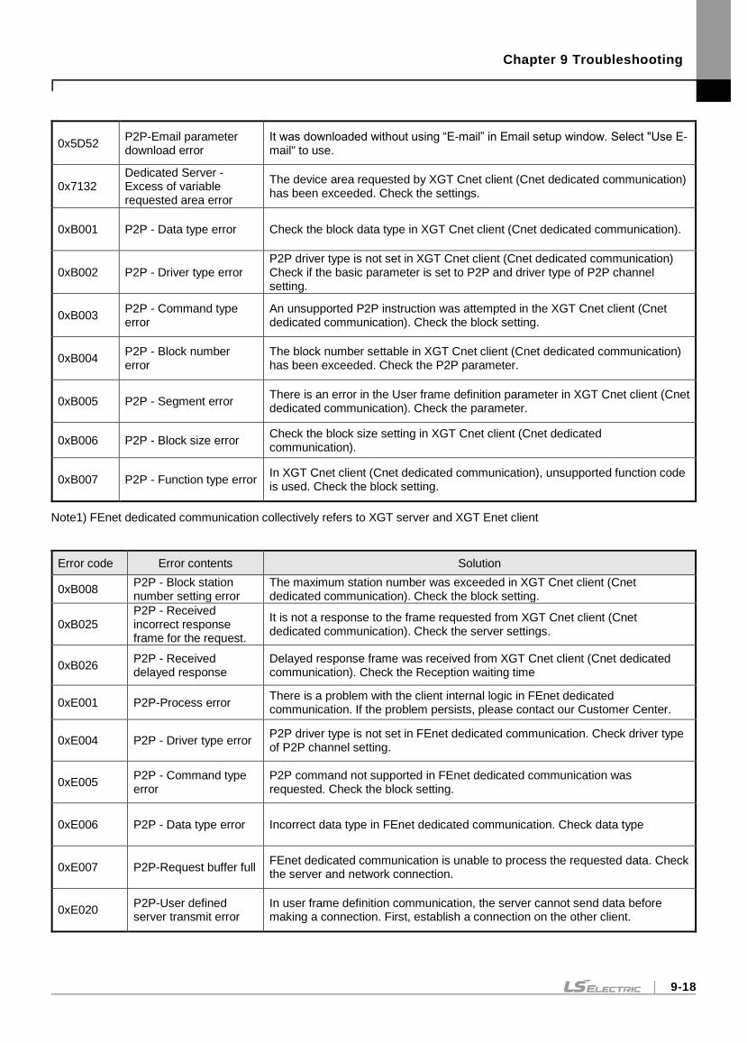
Chapter 9 Troubleshooting
9-18
0x5D52 P2P-Email parameter download error
It was downloaded without using “E-mail” in Email setup window. Select "Use E-mail" to use.
0x7132 Dedicated Server - Excess of variable requested area error
The device area requested by XGT Cnet client (Cnet dedicated communication) has been exceeded. Check the settings.
0xB001 P2P - Data type error Check the block data type in XGT Cnet client (Cnet dedicated communication).
0xB002 P2P - Driver type error P2P driver type is not set in XGT Cnet client (Cnet dedicated communication) Check if the basic parameter is set to P2P and driver type of P2P channel setting.
0xB003 P2P - Command type error
An unsupported P2P instruction was attempted in the XGT Cnet client (Cnet dedicated communication). Check the block setting.
0xB004 P2P - Block number error
The block number settable in XGT Cnet client (Cnet dedicated communication) has been exceeded. Check the P2P parameter.
0xB005 P2P - Segment error There is an error in the User frame definition parameter in XGT Cnet client (Cnet dedicated communication). Check the parameter.
0xB006 P2P - Block size error Check the block size setting in XGT Cnet client (Cnet dedicated communication).
0xB007 P2P - Function type error In XGT Cnet client (Cnet dedicated communication), unsupported function code is used. Check the block setting.
Note1) FEnet dedicated communication collectively refers to XGT server and XGT Enet client
Error code Error contents Solution
0xB008 P2P - Block station number setting error
The maximum station number was exceeded in XGT Cnet client (Cnet dedicated communication). Check the block setting.
0xB025 P2P - Received incorrect response frame for the request.
It is not a response to the frame requested from XGT Cnet client (Cnet dedicated communication). Check the server settings.
0xB026 P2P - Received delayed response
Delayed response frame was received from XGT Cnet client (Cnet dedicated communication). Check the Reception waiting time
0xE001 P2P-Process error There is a problem with the client internal logic in FEnet dedicated communication. If the problem persists, please contact our Customer Center.
0xE004 P2P - Driver type error P2P driver type is not set in FEnet dedicated communication. Check driver type of P2P channel setting.
0xE005 P2P - Command type error
P2P command not supported in FEnet dedicated communication was requested. Check the block setting.
0xE006 P2P - Data type error Incorrect data type in FEnet dedicated communication. Check data type
0xE007 P2P-Request buffer full FEnet dedicated communication is unable to process the requested data. Check the server and network connection.
0xE020 P2P-User defined server transmit error
In user frame definition communication, the server cannot send data before making a connection. First, establish a connection on the other client.
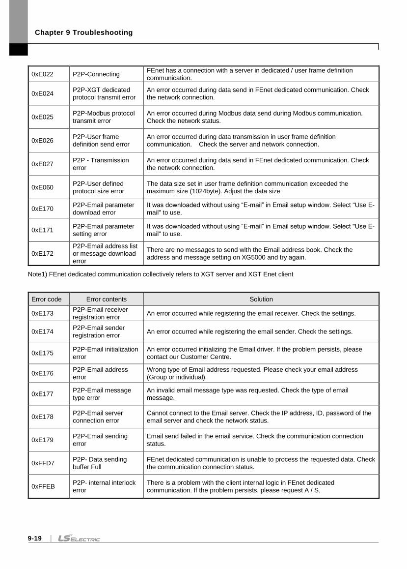
Chapter 9 Troubleshooting
9-19
0xE022 P2P-Connecting FEnet has a connection with a server in dedicated / user frame definition communication.
0xE024 P2P-XGT dedicated protocol transmit error
An error occurred during data send in FEnet dedicated communication. Check the network connection.
0xE025 P2P-Modbus protocol transmit error
An error occurred during Modbus data send during Modbus communication. Check the network status.
0xE026 P2P-User frame definition send error
An error occurred during data transmission in user frame definition communication. Check the server and network connection.
0xE027 P2P - Transmission error
An error occurred during data send in FEnet dedicated communication. Check the network connection.
0xE060 P2P-User defined protocol size error
The data size set in user frame definition communication exceeded the maximum size (1024byte). Adjust the data size
0xE170 P2P-Email parameter download error
It was downloaded without using “E-mail” in Email setup window. Select "Use E-mail" to use.
0xE171 P2P-Email parameter setting error
It was downloaded without using “E-mail” in Email setup window. Select "Use E-mail" to use.
0xE172 P2P-Email address list or message download error
There are no messages to send with the Email address book. Check the address and message setting on XG5000 and try again.
Note1) FEnet dedicated communication collectively refers to XGT server and XGT Enet client
Error code Error contents Solution
0xE173 P2P-Email receiver registration error
An error occurred while registering the email receiver. Check the settings.
0xE174 P2P-Email sender registration error
An error occurred while registering the email sender. Check the settings.
0xE175 P2P-Email initialization error
An error occurred initializing the Email driver. If the problem persists, please contact our Customer Centre.
0xE176 P2P-Email address error
Wrong type of Email address requested. Please check your email address (Group or individual).
0xE177 P2P-Email message type error
An invalid email message type was requested. Check the type of email message.
0xE178 P2P-Email server connection error
Cannot connect to the Email server. Check the IP address, ID, password of the email server and check the network status.
0xE179 P2P-Email sending error
Email send failed in the email service. Check the communication connection status.
0xFFD7 P2P- Data sending buffer Full
FEnet dedicated communication is unable to process the requested data. Check the communication connection status.
0xFFEB P2P- internal interlock error
There is a problem with the client internal logic in FEnet dedicated communication. If the problem persists, please request A / S.

Chapter 9 Troubleshooting
9-20
0xFFFF P2P-Error
1) In user frame definition communication, the server cannot send data before making a connection. First, establish a connection on the other client. 2) The data size set in user frame definition communication exceeded the maximum size (1024byte). Check the data size
Note1) FEnet dedicated communication collectively refers to XGT server and XGT Enet client
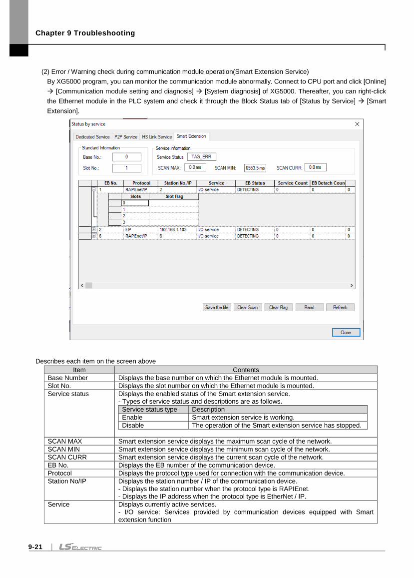
Chapter 9 Troubleshooting
9-21
(2) Error / Warning check during communication module operation(Smart Extension Service)
By XG5000 program, you can monitor the communication module abnormally. Connect to CPU port and click [Online]
[Communication module setting and diagnosis] [System diagnosis] of XG5000. Thereafter, you can right-click
the Ethernet module in the PLC system and check it through the Block Status tab of [Status by Service] [Smart
Extension].
Describes each item on the screen above
Item Contents
Base Number Displays the base number on which the Ethernet module is mounted.
Slot No. Displays the slot number on which the Ethernet module is mounted.
Service status Displays the enabled status of the Smart extension service. - Types of service status and descriptions are as follows.
Service status type Description
Enable Smart extension service is working.
Disable The operation of the Smart extension service has stopped.
SCAN MAX Smart extension service displays the maximum scan cycle of the network.
SCAN MIN Smart extension service displays the minimum scan cycle of the network.
SCAN CURR Smart extension service displays the current scan cycle of the network.
EB No. Displays the EB number of the communication device.
Protocol Displays the protocol type used for connection with the communication device.
Station No/IP Displays the station number / IP of the communication device. - Displays the station number when the protocol type is RAPIEnet. - Displays the IP address when the protocol type is EtherNet / IP.
Service Displays currently active services. - I/O service: Services provided by communication devices equipped with Smart extension function
Chapter 9 Troubleshooting
9-22
-Event service: EtherNet / IP Client Service
EB status Displays the current EB status.
Service status Description
IDLE The communication device (slave) to be controlled is not recognized in the network.
DETECTING Looking for communication device (slave).
STATE_CFM The communication device has been checked.
PRM_DONE Parameter download has been completed to the communication device.
IO_PRM_MISS_MATCH The I / O list of the reserved parameters and the I / O list installed in the communication device are different.
WORKING It is a state that normally performs Smart extension service.
DETACH The Communication device is detached during the control.
Service count Displays the service operation counts currently.
Error count Displays the count of errors that have occurred currently.
EB detachment count Displays the EB detachment counts that have occurred currently.
EB flag Flag is displayed according to the type of error occurred when an error occurs in EB.
Slot No. (slot) Displays the slot number (EB).
Type(slot) Displays the module type installed in the slot (EB). - For EtherNet / IP EIP) clients, displays the service type.
Status(slot) Displays the service status of the slot (EB).
Block Status(slot) Display the status of that service block. - This feature is only available for EIP clients.
Error code (Slot) The error code of the service is displayed. - This feature is only available for EIP clients.
Service count(slot) The service count of the service is displayed. - This feature is only available for EIP clients.
Error count(Slot) The error count of the service is displayed. - This feature is only available for EIP clients.
Slot flag (slot) Flag is displayed according to the type of error occurred when an error occurs in slot.
File save Saves the current status of Smart extension service as a file.
Clear Scan Initializes the scan information. Initializes the SCAN MAX and SCAN MIN values.
Clear flag Initialize the EB flag and slot flag (slot). - Error flag history is initialized.
Read continuously Smart extension service status is updated continuously.
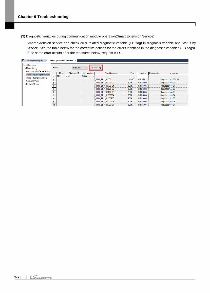
Chapter 9 Troubleshooting
9-23
(3) Diagnostic variables during communication module operation(Smart Extension Service)
Smart extension service can check error-related diagnostic variable (EB flag) in diagnosis variable and Status by
Service. See the table below for the corrective actions for the errors identified in the diagnostic variables (EB flags).
If the same error occurs after the measures below, request A / S.
Chapter 9 Troubleshooting
9-24
Diagnostic variables
Variable name Corrective Measure
System diagnosis
_BBSS_SYSTEM_ER
Check the network connection. 1) System check including smart extension network cable 2) Check the power status of devices in the network * Allocate diagnostic variables depend on the setting of the EB or module swap (hot swap) option during operation. For more information, refer to '4.4.3 Diagnosis Variable Action by EB or Module Change (Hot Swap) Option'.
_BBSS_SYSTEM_WAR
Check the network connection. 1) System check including smart extension network cable 2) Check the power status of devices in the network Allocate diagnostic variables depend on the setting of the EB or module swap(hot swap) option during operation. For more information, refer to '4.4.3 Diagnosis Variable Action by EB or Module Change (Hot Swap) Option'.
_BBSS_EB_DEER
Check the network connection. 1) System check including smart extension network cable 2) Check the power status of devices in the network Allocate diagnostic variables depend on the setting of the EB or module swap (hot swap) option during operation. For more information, refer to '4.4.3 Diagnosis Variable Action by EB or Module Change (Hot Swap) Option'.
_BBSS_EB_BASE_INFO_ER
Check the EB diagnostic variable and reapply the power to the EB where _BBSS_EBXX_BASE_INFO_ER occurred.
_BBSS_IO_TYER Check the EB diagnostic variable to see if the I / O parameter setting value of the communication device where _BBSS_EBXX_IO_TYER occurred matches the type of I / O module installed.
_BBSS_IO_DEER
Check I / O module status of the communication device for which _BBSS_EBXX_IO_DEER occurred by checking the EB diagnostic variable. 1) Check if I / O module is missing from communication device 2) Check if I / O module failure of communication device * Allocate diagnostic variables depend on the setting of the EB or module swap (hot swap) option during operation. For more information, refer to '4.4.3 Diagnosis Variable Action by EB or Module Change (Hot Swap) Option'.
_BBSS_FUSE_ER Replace I / O module where the FUSE error occurred among the I / O modules of the communication device.
_BBSS_REF_TIME_OUT
Check the EB diagnostic variable to check the communication device for which _BBSS_EBXX_REF_TIME_OUT has occurred. See Actions in EB Diagnostic Variables for action.
_BBSS_EB_CRC_ER
Check the network connection. 1) System check including smart extension network cable 2) Check the connection between the network cable and the module
_BBSS_TAG_ER Download EtherNet / IP tag (EIP tag) to XGL-EFMxB module for smart extension service operation.
_ B B S S _EB_CFG_ER
Check the status of EB set in the smart expansion service. 1) Check the EB network detachment 2) Check the Status of the EB error
_BBSS_EB_DETACH_WAR
During operation, check the network connection for EB that have EB or module swap (hot swap) settings enabled. 1) System check including smart extension network cable 2) Check the power status of devices in the network * This diagnostic variable reflects only the status of EB or EB with module exchange (hot swap) setting enabled during operation.
_BBSS_IO_DETACH_WAR
Check the I/O module status of the communication device where _BBSS_EBXX_IO_DEER occurred by checking the EB diagnostic variables of EB that have EB or module exchange (hot swap) setting enabled during operation. 1) Check if I / O module is missing from communication device
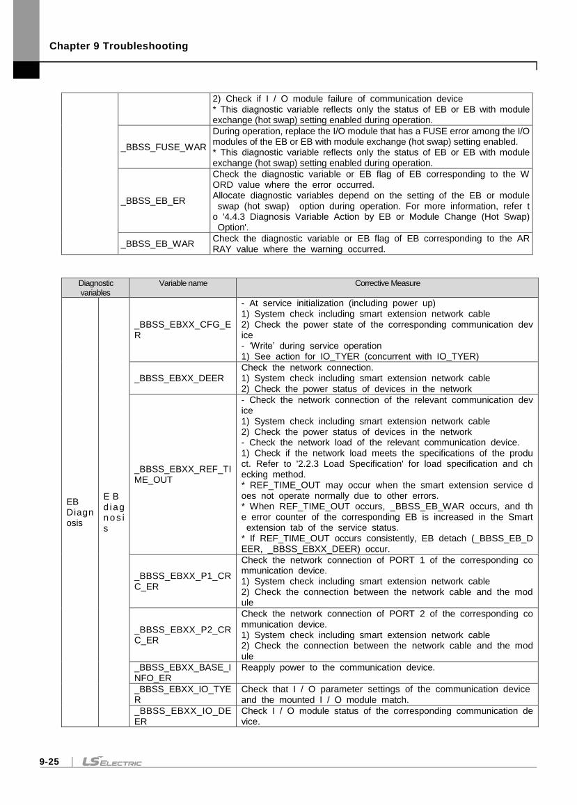
Chapter 9 Troubleshooting
9-25
2) Check if I / O module failure of communication device * This diagnostic variable reflects only the status of EB or EB with module exchange (hot swap) setting enabled during operation.
_BBSS_FUSE_WAR
During operation, replace the I/O module that has a FUSE error among the I/O modules of the EB or EB with module exchange (hot swap) setting enabled. * This diagnostic variable reflects only the status of EB or EB with module exchange (hot swap) setting enabled during operation.
_BBSS_EB_ER
Check the diagnostic variable or EB flag of EB corresponding to the WORD value where the error occurred. Allocate diagnostic variables depend on the setting of the EB or module swap (hot swap) option during operation. For more information, refer to '4.4.3 Diagnosis Variable Action by EB or Module Change (Hot Swap) Option'.
_BBSS_EB_WAR Check the diagnostic variable or EB flag of EB corresponding to the ARRAY value where the warning occurred.
Diagnostic variables
Variable name Corrective Measure
EB Diagnosis
E B d iagn o s is
_BBSS_EBXX_CFG_ER
- At service initialization (including power up) 1) System check including smart extension network cable 2) Check the power state of the corresponding communication device - ‘Write’ during service operation 1) See action for IO_TYER (concurrent with IO_TYER)
_BBSS_EBXX_DEER Check the network connection. 1) System check including smart extension network cable 2) Check the power status of devices in the network
_BBSS_EBXX_REF_TIME_OUT
- Check the network connection of the relevant communication device 1) System check including smart extension network cable 2) Check the power status of devices in the network - Check the network load of the relevant communication device. 1) Check if the network load meets the specifications of the product. Refer to '2.2.3 Load Specification' for load specification and checking method. * REF_TIME_OUT may occur when the smart extension service does not operate normally due to other errors. * When REF_TIME_OUT occurs, _BBSS_EB_WAR occurs, and the error counter of the corresponding EB is increased in the Smart extension tab of the service status. * If REF_TIME_OUT occurs consistently, EB detach (_BBSS_EB_DEER, _BBSS_EBXX_DEER) occur.
_BBSS_EBXX_P1_CRC_ER
Check the network connection of PORT 1 of the corresponding communication device. 1) System check including smart extension network cable 2) Check the connection between the network cable and the module
_BBSS_EBXX_P2_CRC_ER
Check the network connection of PORT 2 of the corresponding communication device. 1) System check including smart extension network cable 2) Check the connection between the network cable and the module
_BBSS_EBXX_BASE_INFO_ER
Reapply power to the communication device.
_BBSS_EBXX_IO_TYER
Check that I / O parameter settings of the communication device and the mounted I / O module match.
_BBSS_EBXX_IO_DEER
Check I / O module status of the corresponding communication device.
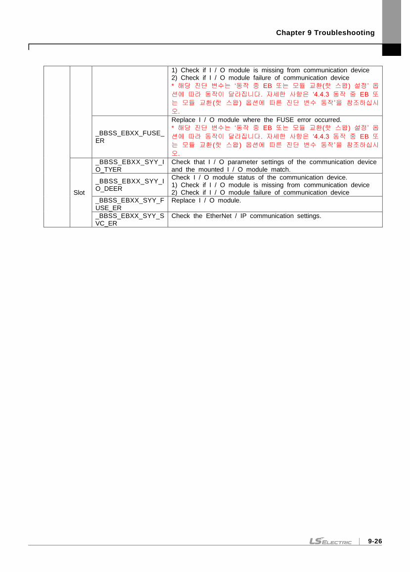
Chapter 9 Troubleshooting
9-26
1) Check if I / O module is missing from communication device 2) Check if I / O module failure of communication device
* 해당 진단 변수는 ‘동작 중 EB 또는 모듈 교환(핫 스왑) 설정’ 옵
션에 따라 동작이 달라집니다. 자세한 사항은 ‘4.4.3 동작 중 EB 또
는 모듈 교환(핫 스왑) 옵션에 따른 진단 변수 동작’을 참조하십시
오.
_BBSS_EBXX_FUSE_ER
Replace I / O module where the FUSE error occurred.
* 해당 진단 변수는 ‘동작 중 EB 또는 모듈 교환(핫 스왑) 설정’ 옵
션에 따라 동작이 달라집니다. 자세한 사항은 ‘4.4.3 동작 중 EB 또
는 모듈 교환(핫 스왑) 옵션에 따른 진단 변수 동작’을 참조하십시
오.
Slot
_BBSS_EBXX_SYY_IO_TYER
Check that I / O parameter settings of the communication device and the mounted I / O module match.
_BBSS_EBXX_SYY_IO_DEER
Check I / O module status of the communication device. 1) Check if I / O module is missing from communication device 2) Check if I / O module failure of communication device
_BBSS_EBXX_SYY_FUSE_ER
Replace I / O module.
_BBSS_EBXX_SYY_SVC_ER
Check the EtherNet / IP communication settings.

Chapter 9 Troubleshooting
9-27
9.2.3 View Communication Module Log
Communication module history view function of XG5000 program can check whether error occurred and measures. Select
[Online] [Communication module setting] [System Diagnosis] from XG5000. Right-click on the XGL-EFMxB module you
want to diagnose and select [View communication module log]. If you select the error occurrence history in the [Event History]
tab and the [Communication History] tab, you can check the details of the error and the corrective action in "Details and
Actions" below.
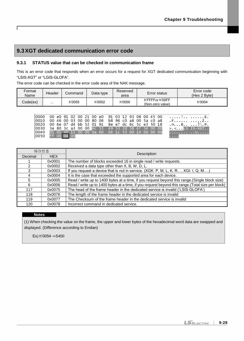
Chapter 9 Troubleshooting
9-28
9.3 XGT dedicated communication error code
9.3.1 STATUS value that can be checked in communication frame
This is an error code that responds when an error occurs for a request for XGT dedicated communication beginning with
“LSIS-XGT” or “LGIS-GLOFA”.
The error code can be checked in the error code area of the NAK message.
Format Name
Header Command Data type Reserved
area Error status
Error code (Hex 2 Byte)
Code(ex) ... h’0055 h’0002 h’0000 h’FFFFor h’00FF (Non-zero value)
h’0004
에러번호 Description
Decimal HEX
1 0x0001 The number of blocks exceeded 16 in single read / write requests.
2 0x0002 Received a data type other than X, B, W, D, L.
3 0x0003 If you request a device that is not in service. (XGK: P, M, L, K, R…, XGI: I, Q, M….)
4 0x0004 It is the case that exceeded the supported area for each device.
5 0x0005 Read / write up to 1400 bytes at a time, if you request beyond this range.(Single block size)
6 0x0006 Read / write up to 1400 bytes at a time, if you request beyond this range.(Total size per block)
117 0x0075 The head of the frame header in the dedicated service is invalid (‘LSIS-GLOFA’)
118 0x0076 The length of the frame header in the dedicated service is invalid
119 0x0077 The Checksum of the frame header in the dedicated service is invalid
120 0x0078 Incorrect command in dedicated service.
Notes
(1) When checking the value on the frame, the upper and lower bytes of the hexadecimal word data are swapped and
displayed. (Difference according to Endian)
Ex) h’0054 ⇒5400
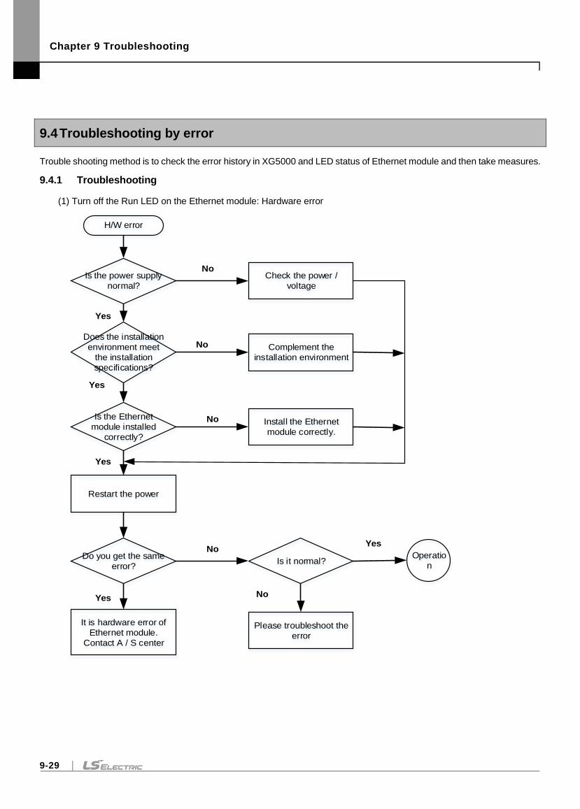
Chapter 9 Troubleshooting
9-29
9.4 Troubleshooting by error
Trouble shooting method is to check the error history in XG5000 and LED status of Ethernet module and then take measures.
9.4.1 Troubleshooting
(1) Turn off the Run LED on the Ethernet module: Hardware error
Is the power supply
normal?
H/W error
Does the installation
environment meet
the installation
specifications?
Is the Ethernet
module installed
correctly?
Restart the power
Do you get the same
error?
It is hardware error of
Ethernet module.
Contact A / S center
Check the power /
voltage
Complement the
installation environment
Install the Ethernet
module correctly.
No
No
No
Yes
Yes
Yes
Is it normal?Operatio
n
Please troubleshoot the
error
NoYes
NoYes
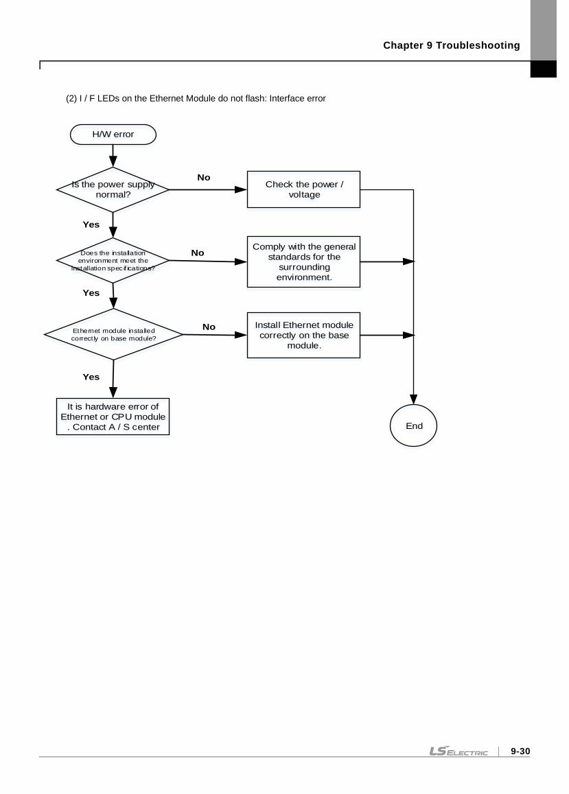
Chapter 9 Troubleshooting
9-30
(2) I / F LEDs on the Ethernet Module do not flash: Interface error
Is the power supply
normal?
H/W error
Does the installation
environment meet the
installation spec if ications?
Ethernet module installed
correct ly on base module?
It is hardware error of
Ethernet or CPU module
. Contact A / S center
Check the power /
voltage
Comply with the general
standards for the
surrounding
environment.
Install Ethernet module
correctly on the base
module.
No
No
No
Yes
Yes
Yes
End
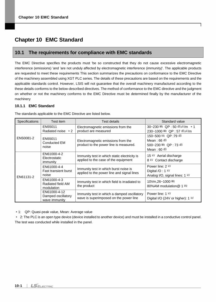
Chapter 10 EMC Standard
10-1
Chapter 10 EMC Standard
10.1 The requirements for compliance with EMC standards
The EMC Directive specifies the products must 'be so constructed that they do not cause excessive electromagnetic
interference (emissions) 'and 'are not unduly affected by electromagnetic interference (immunity)'. The applicable products
are requested to meet these requirements This section summarizes the precautions on conformance to the EMC Directive
of the machinery assembled using XGT PLC series. The details of these precautions are based on the requirements and the
applicable standards control. However, LSIS will not guarantee that the overall machinery manufactured according to the
these details conforms to the below-described directives. The method of conformance to the EMC directive and the judgment
on whether or not the machinery conforms to the EMC Directive must be determined finally by the manufacturer of the
machinery
10.1.1 EMC Standard
The standards applicable to the EMC Directive are listed below.
Specifications Test item Test details Standard value
EN50081-2
EN55011
Radiated noise *2 Electromagnetic emissions from the product are measured
30~230 QP : 50/m *1
230~1000 QP : 57/m
EN55011 Conducted EM noise
Electromagnetic emissions from the product to the power line is measured.
150~500 QP :79
Mean : 66
500~230 QP : 73
Mean : 60
EN61131-2
EN61000-4-2 Electrostatic immunity
Immunity test in which static electricity is applied to the case of the equipment
15 Aerial discharge
8 Contact discharge
EN61000-4-4 Fast transient burst noise
Immunity test in which burst noise is applied to the power line and signal lines
Power line: 2
Digital /O : 1
Analog I/O, signal lines: 1
EN61000-4-3 Radiated field AM modulation
Immunity test in which field is irradiated to the product
10Vm,26~1000
80%AM modulation@ 1
EN61000-4-12 Damped oscillatory wave immunity
Immunity test in which a damped oscillatory wave is superimposed on the power line
Power line: 1
Digital I/O (24V or higher): 1
*1: QP: Quasi-peak value, Mean: Average value
* 2: The PLC is an open type device (device installed to another device) and must be installed in a conductive control panel.
The test was conducted while installed in the panel.
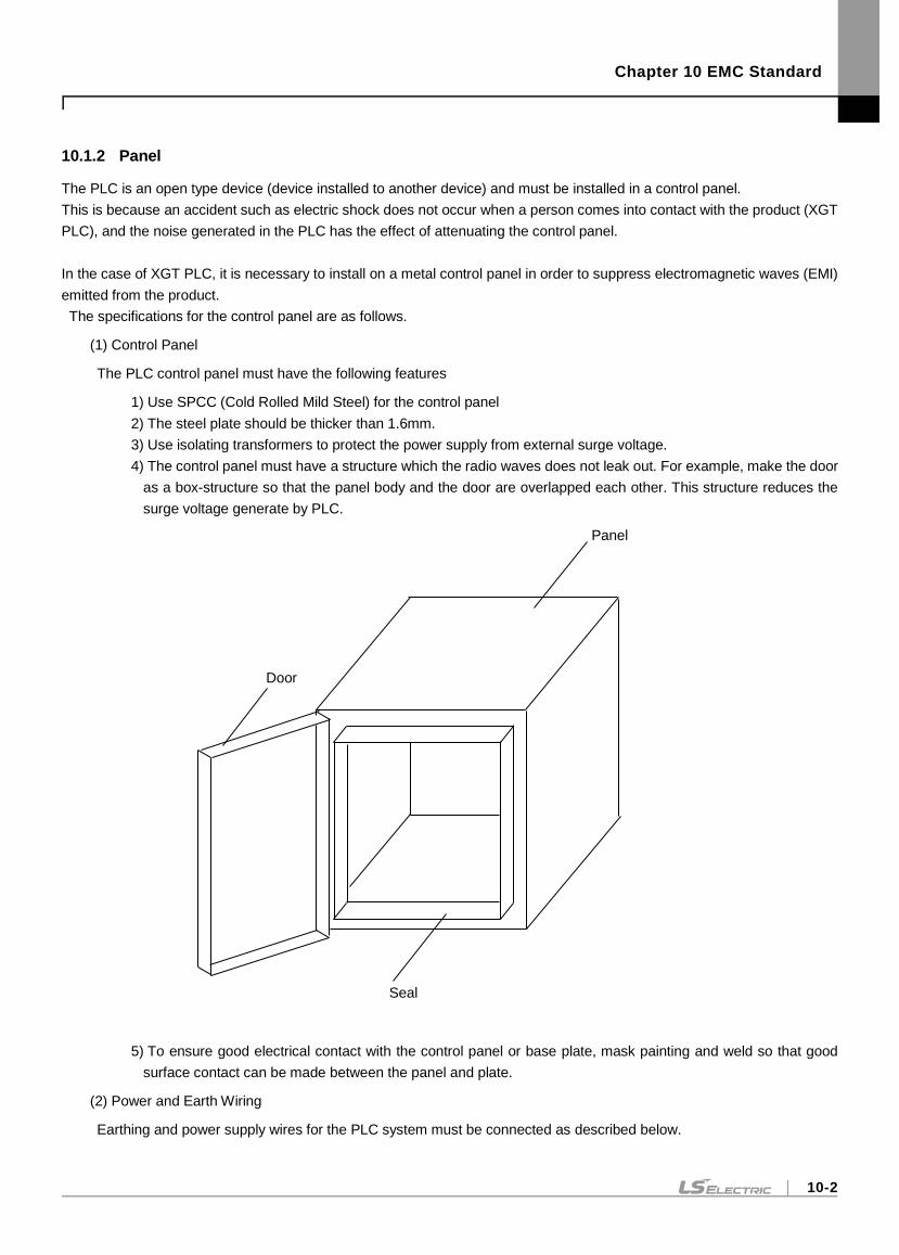
Chapter 10 EMC Standard
10-2
10.1.2 Panel
The PLC is an open type device (device installed to another device) and must be installed in a control panel.
This is because an accident such as electric shock does not occur when a person comes into contact with the product (XGT
PLC), and the noise generated in the PLC has the effect of attenuating the control panel.
In the case of XGT PLC, it is necessary to install on a metal control panel in order to suppress electromagnetic waves (EMI)
emitted from the product.
The specifications for the control panel are as follows.
(1) Control Panel
The PLC control panel must have the following features
1) Use SPCC (Cold Rolled Mild Steel) for the control panel
2) The steel plate should be thicker than 1.6mm.
3) Use isolating transformers to protect the power supply from external surge voltage.
4) The control panel must have a structure which the radio waves does not leak out. For example, make the door
as a box-structure so that the panel body and the door are overlapped each other. This structure reduces the
surge voltage generate by PLC.
5) To ensure good electrical contact with the control panel or base plate, mask painting and weld so that good
surface contact can be made between the panel and plate.
(2) Power and Earth Wiring
Earthing and power supply wires for the PLC system must be connected as described below.
Panel
Door
Seal
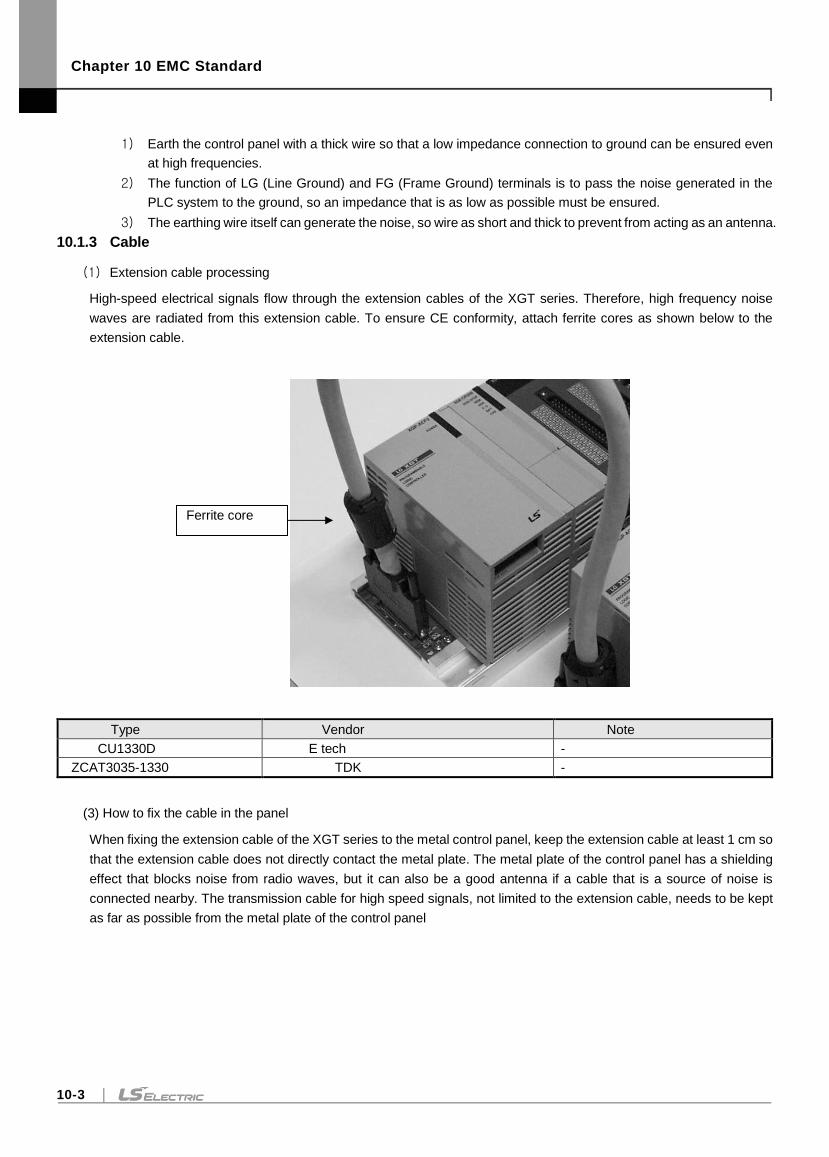
Chapter 10 EMC Standard
10-3
1) Earth the control panel with a thick wire so that a low impedance connection to ground can be ensured even
at high frequencies.
2) The function of LG (Line Ground) and FG (Frame Ground) terminals is to pass the noise generated in the
PLC system to the ground, so an impedance that is as low as possible must be ensured.
3) The earthing wire itself can generate the noise, so wire as short and thick to prevent from acting as an antenna.
10.1.3 Cable
(1) Extension cable processing
High-speed electrical signals flow through the extension cables of the XGT series. Therefore, high frequency noise
waves are radiated from this extension cable. To ensure CE conformity, attach ferrite cores as shown below to the
extension cable.
Type Vendor Note
CU1330D E tech -
ZCAT3035-1330 TDK -
(3) How to fix the cable in the panel
When fixing the extension cable of the XGT series to the metal control panel, keep the extension cable at least 1 cm so
that the extension cable does not directly contact the metal plate. The metal plate of the control panel has a shielding
effect that blocks noise from radio waves, but it can also be a good antenna if a cable that is a source of noise is
connected nearby. The transmission cable for high speed signals, not limited to the extension cable, needs to be kept
as far as possible from the metal plate of the control panel
Ferrite core
Chapter 10 EMC Standard
10-4
10.2 Requirement to conform to the Low-voltage Directive
The low-voltage directive requires each device that operates with the power supply ranging from 50V to 1000VAC and 75V
to 1500VDC to satisfy the safety requirements. Cautions and installation and wiring of the series PLC XGT series to conform
to the low-voltage directive are described in this section. However, LSIS will not guarantee that the overall machinery
manufactured according to the details conforms to the below-described directives. The method of conformance to the EMC
directive and compliance to the EMC Directive must be determined by the manufacturer of the machinery.
10.2.1 Standards applicable to XGT series
The XGT PLC complies with EN6100-1 (safety of equipment used in measurement and control laboratories. XGT series
PLCs have been developed in accordance with the above standards for modules operating at rated voltage of AC50V /
DC75V or higher.
10.2.2 Selection of XGT Series PLC
(1) Power supply module
There are dangerous voltages (higher than 42.4V peak) inside the power supply modules of the Rated input voltage
AC110/ 220Vtes. Therefore, the CE mark-compliant models feature enhanced insulation strong primary and secondary
windings.
(2) I/O Module
There are dangerous voltages (voltages higher than 42.4V peak) inside the I/O modules of the AC110/220V rated I/O
voltages. Therefore, the CE mark-compliant models are enhanced in insulation internally between the primary and
secondary.
The I/O modules of DC24V Rated input are out of the low-voltage directive application range.
(3) CPU module ,base
Since the above modules use DC5V and 3.3V circuits internally, they are not subject to the low voltage command.
(4) Special, Communication module
Special and communication modules are DC24V or less in rated voltage, therefore they are out of the low-voltage
directive application range.
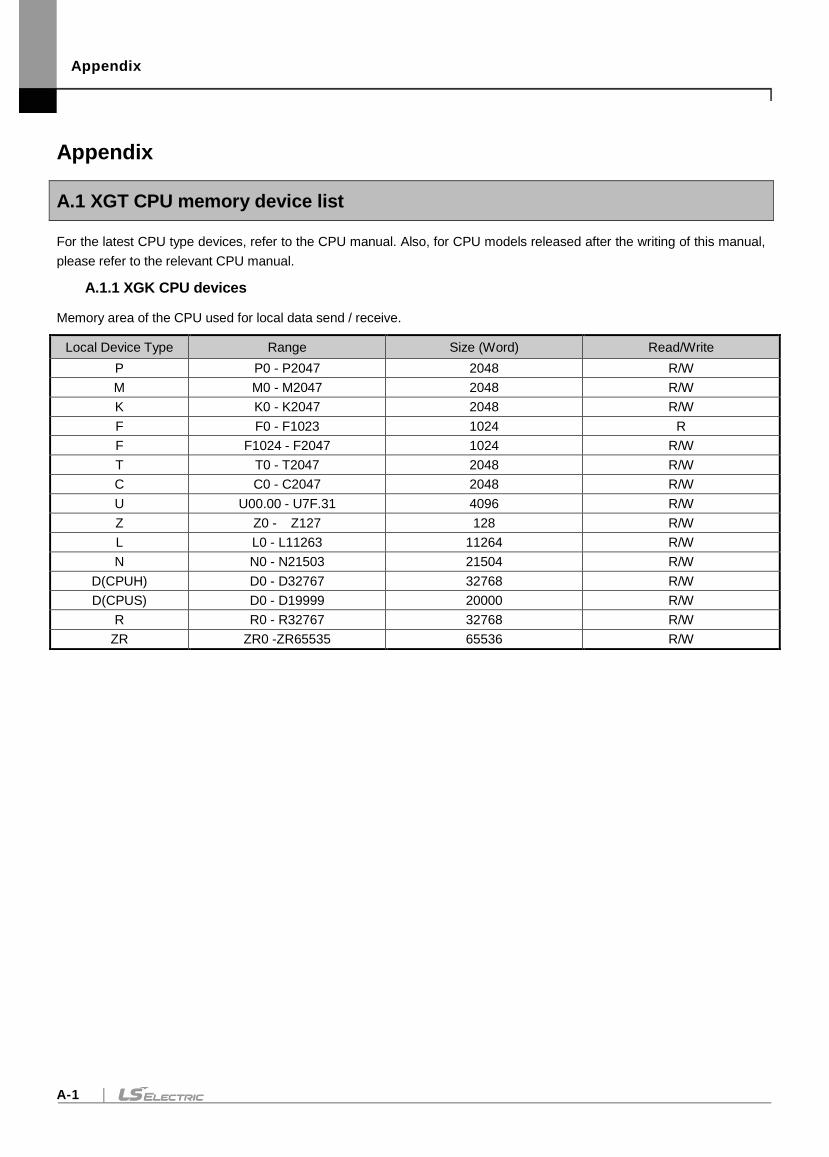
Appendix
A-1
Appendix
A.1 XGT CPU memory device list
For the latest CPU type devices, refer to the CPU manual. Also, for CPU models released after the writing of this manual,
please refer to the relevant CPU manual.
A.1.1 XGK CPU devices
Memory area of the CPU used for local data send / receive.
Local Device Type Range Size (Word) Read/Write
P P0 - P2047 2048 R/W
M M0 - M2047 2048 R/W
K K0 - K2047 2048 R/W
F F0 - F1023 1024 R
F F1024 - F2047 1024 R/W
T T0 - T2047 2048 R/W
C C0 - C2047 2048 R/W
U U00.00 - U7F.31 4096 R/W
Z Z0 - Z127 128 R/W
L L0 - L11263 11264 R/W
N N0 - N21503 21504 R/W
D(CPUH) D0 - D32767 32768 R/W
D(CPUS) D0 - D19999 20000 R/W
R R0 - R32767 32768 R/W
ZR ZR0 -ZR65535 65536 R/W
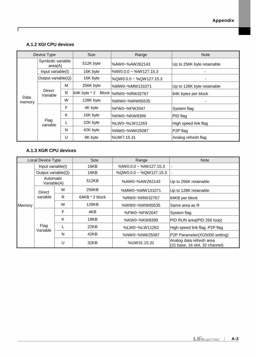
Appendix
A-2
A.1.2 XGI CPU devices
Device Type Size Range Note
Data memory
Symbolic variable area(A)
512K byte %AW0~%AW262143 Up to 256K byte retainable
Input variable(I) 16K byte %IW0.0.0 ~ %IW127.15.3 -
Output variable(Q) 16K byte %QW0.0.0 ~ %QW127.15.3 -
Direct Variable
M 256K byte %MW0~%MW131071 Up to 128K byte retainable
R 64K byte * 2 Block %RW0~%RW32767 64K bytes per block
W 128K byte %WW0~%WW65535 -
Flag variable
F 4K byte %FW0~%FW2047 System flag
K 16K byte %KW0~%KW8399 PID flag
L 22K byte %LW0~%LW11263 High speed link flag
N 42K byte %NW0~%NW25087 P2P flag
U 8K byte %UW7.15.31 Analog refresh flag
A.1.3 XGR CPU devices
Local Device Type Size Range Note
Memory
Input variable(I) 16KB %IW0.0.0 ~ %IW127.15.3 -
Output variable(Q) 16KB %QW0.0.0 ~ %QW127.15.3 -
Automatic Variable(A)
512KB %AW0~%AW262143 Up to 256K retainable
Direct variable
M 256KB %MW0~%MW131071 Up to 128K retainable
R 64KB * 2 block %RW0~%RW32767 64KB per block
W 128KB %WW0~%WW65535 Same area as R
Flag Variable
F 4KB %FW0~%FW2047 System flag
K 18KB %KW0~%KW8399 PID RUN area(PID 256 loop)
L 22KB %LW0~%LW11263 High speed link flag, P2P flag
N 42KB %NW0~%NW25087 P2P Parameter(XG5000 setting)
U 32KB %UW31.15.31 Analog data refresh area (31 base, 16 slot, 32 channel)
Appendix
A-3
A.2 Describes of terms
Before using this product, explain the general terms of Ethernet module. Please refer to the Ethernet technical book for
details.
Auto-MDIX(Automatic Medium Dependent Interface Crossover) The type of Ethernet cable is divided into Crossover
Cable (TX-RX, RX-TX) and Straight Cable (TX-TX, RX-RX), where the TX / RX is interchanged based on TX / RX.
Communication of each network device is possible through connection of TX (node A) -RX (node B) / RX (node A) -TX
(node B), so it is impossible to communicate with Straight Cable. However, if there is a function that can electrically
exchange TX and RX in the connected node, it is possible to communicate with each other using a straight cable, which is
called Auto-MDIX.
Auto-Negotiation Ethernet is the process by which Ethernet devices exchange information about performance, such as operation speed and duplex mode.
1) Find out why connection was denied
2) Determine the performance of your network equipment
3) Change connection speed
ARP(Address Resolution Protocol)
Protocol to search for MAC address by means of correspondent IP address on the Ethernet LAN
Bridge
A device used to connect two networks so to be operated as one network. Bridge is used not only to connect two different
types of networks but also to divide one big network into two small networks in order to increase the performance
Client
A user of the network service, or a computer or program (mainly the one requesting services) using other computer's
resource.
CSMA/CD(Carrier Sense Multiple Access with Collision Detection)
Each client checks if there is any sign prior to transmission of data to the network (Carrier Sense) and then sends its data
when the network is empty. At this time, all the clients have the equal right to send (Multiple Access). If two or more clients
send data, collision may occur. The client who detects the collision tries to send again in a specific time.
DHCP( Dynamic Host Configuration Protocol)
Communication protocol IP standard for automatically allocating and managing setting information necessary for
executing TCP / IP communication. Provides uniform management of IP addresses in telecommunication networks in TCP
/ IP environments.

Appendix
A-4
DNS(Domain Name System)
A method used to convert alphabetic Domain Name on the Internet to its identical Internet number (namely, IP address).
Dot Address
Shows IP address of ‘100.100.100.100’, where each figure is displayed in decimal with 1 byte occupied respectively for 4
bytes in total.
Duplex
It means duplex communication that can send / receive in both directions. Separate the send and receive paths so that
they can operate without being affected by each other.
EDS File
Abbreviation for Electronic Data Sheets, a file containing information about the device and its communication settings.
E-mail address
The address of the user with login account for the specific machine connected via the Internet. Usually user's ID @
domain name (machine name) is assigned. In other words, it will be like [email protected], where @ is called as 'at'
displayed with shift+2 pressed on the keyboard. The letters at the back of @ are for the domain name of specific company
(school, institute,..) connected with the Internet, and the letters in front of @ are for the user ID registered in the machine.
The last letters of the domain name are for the highest level. USA generally uses the following abbreviation as specified
below, and Korea uses .kr to stand for Korea. com : usually for companies) / .edu : usually for educational organizations
such as universities. / .ac(academy) is mostly used in Korea / .gov : for governmental organizations. For example,
nasa.gov is for NASA (government) / .mil : military related sites. For example, af.mil is for USA air force (military)/ .org :
private organizations / .au : Australia / .uk : the United Kingdom / .ca : Canada / .kr : Korea / .jp : Japan / .fr : France / .tw :
Taiwan, etc.
Ethernet
A representative LAN connection system (IEEE 802.3) developed by Xerox, Intel and DEC of America which can send
about 10Mbps and use the packet of 1.5kB. Since Ethernet can allow various types of computers to be connected as one
via the network, it has been called a pronoun of LAN as a universal standard with various products available, not limited to
some specific companies
Explicit Messaging
In addition to the explicit message and data, this message contains all the information that can be interpreted in the frame.
(XGT EtherNet / IP module provides non-cycle client communication)
FDDI(Fiber Distributed Data Interface)
Based on optical cable, provides 100Mbps, Shared Media Network as Dual Ring method, Token Passing is done in two-
way. Max 200Km distance for entire network, Max 2Km between Nodes, Max 500 nodes. Generally, this used as
Backbone Network.
Appendix
A-5
FTP(File Transfer Protocol)
An application program used to transfer files between computers among application programs providing TCP/IP protocol.
If an account is allowed to the computer to log in, fast log in the computer is available wherever the computer is so to copy
files.
Gateway
Software/Hardware used to translate for two different protocols to work together, which is equivalent to the gateway
necessary to exchange information with the different system.
Header
It indicates parts of packets, including its own station and the destination station's addresses, and a part for checking for
an error.
HTML
Hypertext Markup Language, standard language of WWW. In other words, it is a language system to prepare Hypertext
documents. The document made of HTML can be viewed through the web browser
HTTP
Hypertext Transfer Protocol, standard protocol of WWW. It is a protocol supporting the hypermedia system.
ICMP(Internet Control Message Protocol)
An extended protocol of IP address used to create error messages and test packets to control the Internet.
Implicit Messaging
Implicit messages and messages with minimal header information other than data.
(XGT EtherNet / IP module provides cycle client / cycle server communication)
IEEE 802.3
IEEE 802.3 specifies standards for CSMA/CD based Ethernet Exactly it is a LAN based on CSMA/CD (Carrier Sense
Multiple Access with Collision Detection) Ethernet designed by IEEE 802.3 group, which is classified into detailed projects
as specified below.
1) IEEE P802.3 - 10G Base T study Group
2) IEEE P802.3ah - Ethernet in the First Mile Task Force
IEEE P802.3ak - 10G Base-CX4 Task Force. Both IEEE 802.3 and Ethernet are broadband networks using
the CSMA / CD scheme and have a common feature that is implemented in the network interface card
hardware.
IP(Internet Protocol)
Protocol at the network layer for the Internet
Appendix
A-6
IP Address
Address of respective computers on the Internet made of figures binary of 32 bits (4 bytes) to distinguish the applicable
machine on the Internet. Classified into 2 sections, network distinguishing address and host distinguishing address. The
network address and the host address is respectively divided into class A, B and C based on the bits allotted. IP address
since it shall be unique all over the world, shall be decided not optionally but as assigned by NIC(Network Information
Center) of the applicable district when joining the Internet. In Korea, KRNIC(Korea Network Information Centre) is in
charge of this work. Ex.) 165.244.149.190
ISO(International Organization for Standardization)
A subsidiary organization of UN establishing and managing the international standards.
LAN(Local Area Network)
Called also as local area communication network or district information communication network, which allows lots of
computers to exchange data with each other as connected though communication cable within a limited area such as in
an office or a building.
MAC(Medium Access Control)
A method used to decide which device should use the network during given time on the broadcast network.
Node
Each computer connected with the network is called Node.
Packet
package of data which is the basic unit used to send through the network. Usually the package is made of several tens or
hundreds of bytes with the header attached in front to which its destination and other necessary information are added.
PORT number
Used to classify the applications on TCP/UDP.
Ex.) 21/tcp : Telet
PPP(Point-to-Point Protocol)
Phone communication protocol which allows packet transmission in connecting with the Internet. In other words, normal
phone cable and modem can be used for the computer to connect through TCP/IP with this most general Internet protocol.
Similar to SLIP, however with modern communication protocol factors such as error detection and data compression, it
demonstrates more excellent performance than SLIP.
Protocol
Contains regulations related with mutual information transmission method between computers connected with each other
through the network. The protocol may specify detailed interface between machines in Low level (for example, which
bit/byte should go out through the line) or high level of message exchange regulations as files are transferred through the
Internet.
Appendix
A-7
Reset
This is function used when you want to initialize the communication module to clear the error.
RPI
Abbreviation for Requested Packet Interval, which means to send packet.
(XGT EtherNet / IP module is provided in transmission cycle)
라우터(Router)
A device used to transfer the data packet between the networks. It sends the data packet to its final destination, waits if
the network is congested, or decides which LAN is good to connect to at the LAN junction. Namely, it is a special
computer/software used to control the two or more networks connected.
Server
The side which passively responds to the client's request and shares its resources.
Tag
Name tag, in other word named variable.
TCP (Transmission Control Protocol)
A transport layer protocol for the Internet
- Data Tx/Rx through connection
- Multiplexing
- Transmission reliable
- Emergent data transmission supported
TCP/IP (Transmission Control Protocol/Internet Protocol)
Transmission protocol used for communication among different kinds of computers, which makes the communication
available between general PC and medium host, IBM PC and MAC, and medium or large-sized different types of
computer. It is also used as a general term for information transmission protocol between computer networks including
FTP, Telnet, SMTP, etc. TCP divides data into packets to send through IP and the packets sent will be united back
together through TCP.
Telnet
It means remote login via Internet. To login to remote host via TELNET, account of that host is necessary. But for some
hosts providing public service, you can connect without account.
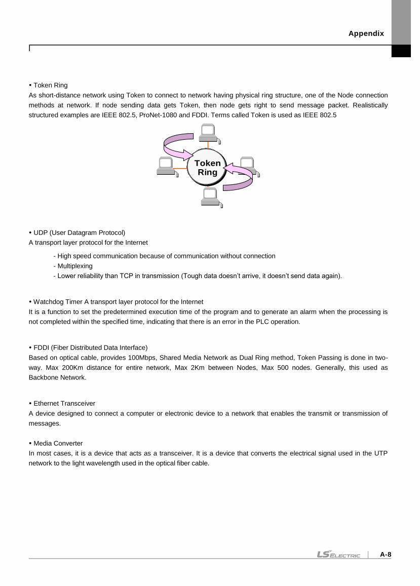
Appendix
A-8
Token Ring
As short-distance network using Token to connect to network having physical ring structure, one of the Node connection
methods at network. If node sending data gets Token, then node gets right to send message packet. Realistically
structured examples are IEEE 802.5, ProNet-1080 and FDDI. Terms called Token is used as IEEE 802.5
UDP (User Datagram Protocol)
A transport layer protocol for the Internet
- High speed communication because of communication without connection
- Multiplexing
- Lower reliability than TCP in transmission (Tough data doesn’t arrive, it doesn’t send data again).
Watchdog Timer A transport layer protocol for the Internet
It is a function to set the predetermined execution time of the program and to generate an alarm when the processing is
not completed within the specified time, indicating that there is an error in the PLC operation.
FDDI (Fiber Distributed Data Interface)
Based on optical cable, provides 100Mbps, Shared Media Network as Dual Ring method, Token Passing is done in two-
way. Max 200Km distance for entire network, Max 2Km between Nodes, Max 500 nodes. Generally, this used as
Backbone Network.
Ethernet Transceiver
A device designed to connect a computer or electronic device to a network that enables the transmit or transmission of
messages.
Media Converter
In most cases, it is a device that acts as a transceiver. It is a device that converts the electrical signal used in the UTP
network to the light wavelength used in the optical fiber cable.
TokenRing
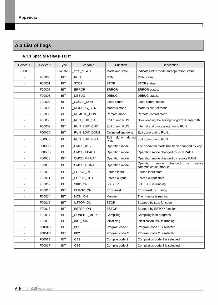
Appendix
A-9
A.3 List of flags
A.3.1 Special Relay (F) List
Device 1 Device 2 Type Variable Function Description
F0000 - DWORD _SYS_STATE Mode and state Indicates PLC mode and operation status
- F00000 BIT _RUN RUN RUN status.
- F00001 BIT _STOP STOP STOP status.
- F00002 BIT _ERROR ERROR ERROR status.
- F00003 BIT _DEBUG DEBUG DEBUG status.
- F00004 BIT _LOCAL_CON Local control Local control mode.
- F00005 BIT _MODBUS_CON Modbus mode Modbus control mode.
- F00006 BIT _REMOTE_CON Remote mode Remote control mode.
- F00008 BIT _RUN_EDIT_ST Edit during RUN Downloading the editing program during RUN.
- F00009 BIT _RUN_EDIT_CHK Edit during RUN Internal edit processing during RUN.
- F0000A BIT _RUN_EDIT_DONE Online editing done Edit done during RUN.
- F0000B BIT _RUN_EDIT_END Edit done during RUN
Edit done during RUN.
- F0000C BIT _CMOD_KEY Operation mode The operation mode has been changed by key.
- F0000D BIT _CMOD_LPADT Operation mode Operation mode changed by local PADT.
- F0000E BIT _CMOD_RPADT Operation mode Operation mode changed by remote PADT
- F0000F BIT _CMOD_RLINK Operation mode Operation mode changed by remote communication module.
- F00010 BIT _FORCE_IN Forced input Forced input state.
- F00011 BIT _FORCE_OUT Forced output Forced output state.
- F00012 BIT _SKIP_ON I/O SKIP I / O SKIP is running.
- F00013 BIT _EMASK_ON Error mask Error mask is running.
- F00014 BIT _MON_ON Monitor The monitor is running.
- F00015 BIT _USTOP_ON STOP Stopped by stop function.
- F00016 BIT _ESTOP_ON ESTOP Stopped by ESTOP function.
- F00017 BIT _CONPILE_MODE Compiling Compiling is in progress.
- F00018 BIT _INIT_RUN Initializing Initialization task is running.
- F0001C BIT _PB1 Program code 1 Program code 1 is selected.
- F0001D BIT _PB2 Program code 2 Program code 2 is selected.
- F0001E BIT _CB1 Compile code 1 Compilation code 1 is selected.
- F0001F BIT _CB2 Compile code 2 Compilation code 2 is selected.
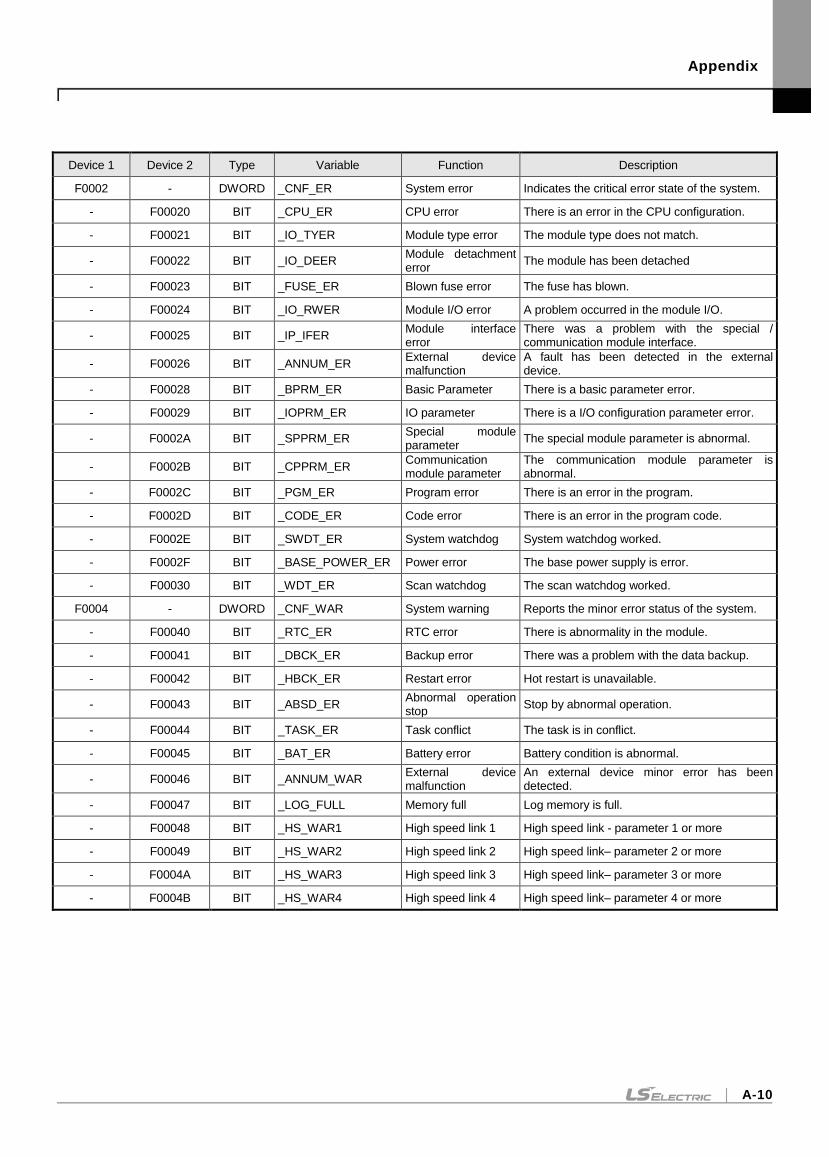
Appendix
A-10
Device 1 Device 2 Type Variable Function Description
F0002 - DWORD _CNF_ER System error Indicates the critical error state of the system.
- F00020 BIT _CPU_ER CPU error There is an error in the CPU configuration.
- F00021 BIT _IO_TYER Module type error The module type does not match.
- F00022 BIT _IO_DEER Module detachment error
The module has been detached
- F00023 BIT _FUSE_ER Blown fuse error The fuse has blown.
- F00024 BIT _IO_RWER Module I/O error A problem occurred in the module I/O.
- F00025 BIT _IP_IFER Module interface error
There was a problem with the special / communication module interface.
- F00026 BIT _ANNUM_ER External device malfunction
A fault has been detected in the external device.
- F00028 BIT _BPRM_ER Basic Parameter There is a basic parameter error.
- F00029 BIT _IOPRM_ER IO parameter There is a I/O configuration parameter error.
- F0002A BIT _SPPRM_ER Special module parameter
The special module parameter is abnormal.
- F0002B BIT _CPPRM_ER Communication module parameter
The communication module parameter is abnormal.
- F0002C BIT _PGM_ER Program error There is an error in the program.
- F0002D BIT _CODE_ER Code error There is an error in the program code.
- F0002E BIT _SWDT_ER System watchdog System watchdog worked.
- F0002F BIT _BASE_POWER_ER Power error The base power supply is error.
- F00030 BIT _WDT_ER Scan watchdog The scan watchdog worked.
F0004 - DWORD _CNF_WAR System warning Reports the minor error status of the system.
- F00040 BIT _RTC_ER RTC error There is abnormality in the module.
- F00041 BIT _DBCK_ER Backup error There was a problem with the data backup.
- F00042 BIT _HBCK_ER Restart error Hot restart is unavailable.
- F00043 BIT _ABSD_ER Abnormal operation stop
Stop by abnormal operation.
- F00044 BIT _TASK_ER Task conflict The task is in conflict.
- F00045 BIT _BAT_ER Battery error Battery condition is abnormal.
- F00046 BIT _ANNUM_WAR External device malfunction
An external device minor error has been detected.
- F00047 BIT _LOG_FULL Memory full Log memory is full.
- F00048 BIT _HS_WAR1 High speed link 1 High speed link - parameter 1 or more
- F00049 BIT _HS_WAR2 High speed link 2 High speed link– parameter 2 or more
- F0004A BIT _HS_WAR3 High speed link 3 High speed link– parameter 3 or more
- F0004B BIT _HS_WAR4 High speed link 4 High speed link– parameter 4 or more
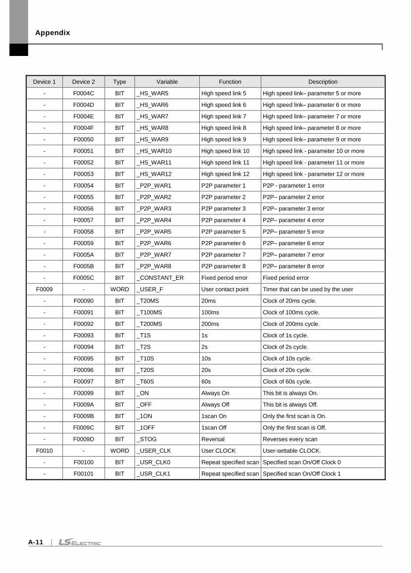
Appendix
A-11
Device 1 Device 2 Type Variable Function Description
- F0004C BIT _HS_WAR5 High speed link 5 High speed link– parameter 5 or more
- F0004D BIT _HS_WAR6 High speed link 6 High speed link– parameter 6 or more
- F0004E BIT _HS_WAR7 High speed link 7 High speed link– parameter 7 or more
- F0004F BIT _HS_WAR8 High speed link 8 High speed link– parameter 8 or more
- F00050 BIT _HS_WAR9 High speed link 9 High speed link– parameter 9 or more
- F00051 BIT _HS_WAR10 High speed link 10 High speed link - parameter 10 or more
- F00052 BIT _HS_WAR11 High speed link 11 High speed link - parameter 11 or more
- F00053 BIT _HS_WAR12 High speed link 12 High speed link - parameter 12 or more
- F00054 BIT _P2P_WAR1 P2P parameter 1 P2P - parameter 1 error
- F00055 BIT _P2P_WAR2 P2P parameter 2 P2P– parameter 2 error
- F00056 BIT _P2P_WAR3 P2P parameter 3 P2P– parameter 3 error
- F00057 BIT _P2P_WAR4 P2P parameter 4 P2P– parameter 4 error
- F00058 BIT _P2P_WAR5 P2P parameter 5 P2P– parameter 5 error
- F00059 BIT _P2P_WAR6 P2P parameter 6 P2P– parameter 6 error
- F0005A BIT _P2P_WAR7 P2P parameter 7 P2P– parameter 7 error
- F0005B BIT _P2P_WAR8 P2P parameter 8 P2P– parameter 8 error
- F0005C BIT _CONSTANT_ER Fixed period error Fixed period error
F0009 - WORD _USER_F User contact point Timer that can be used by the user
- F00090 BIT _T20MS 20ms Clock of 20ms cycle.
- F00091 BIT _T100MS 100ms Clock of 100ms cycle.
- F00092 BIT _T200MS 200ms Clock of 200ms cycle.
- F00093 BIT _T1S 1s Clock of 1s cycle.
- F00094 BIT _T2S 2s Clock of 2s cycle.
- F00095 BIT _T10S 10s Clock of 10s cycle.
- F00096 BIT _T20S 20s Clock of 20s cycle.
- F00097 BIT _T60S 60s Clock of 60s cycle.
- F00099 BIT _ON Always On This bit is always On.
- F0009A BIT _OFF Always Off This bit is always Off.
- F0009B BIT _1ON 1scan On Only the first scan is On.
- F0009C BIT _1OFF 1scan Off Only the first scan is Off.
- F0009D BIT _STOG Reversal Reverses every scan
F0010 - WORD _USER_CLK User CLOCK User-settable CLOCK.
- F00100 BIT _USR_CLK0 Repeat specified scan Specified scan On/Off Clock 0
- F00101 BIT _USR_CLK1 Repeat specified scan Specified scan On/Off Clock 1
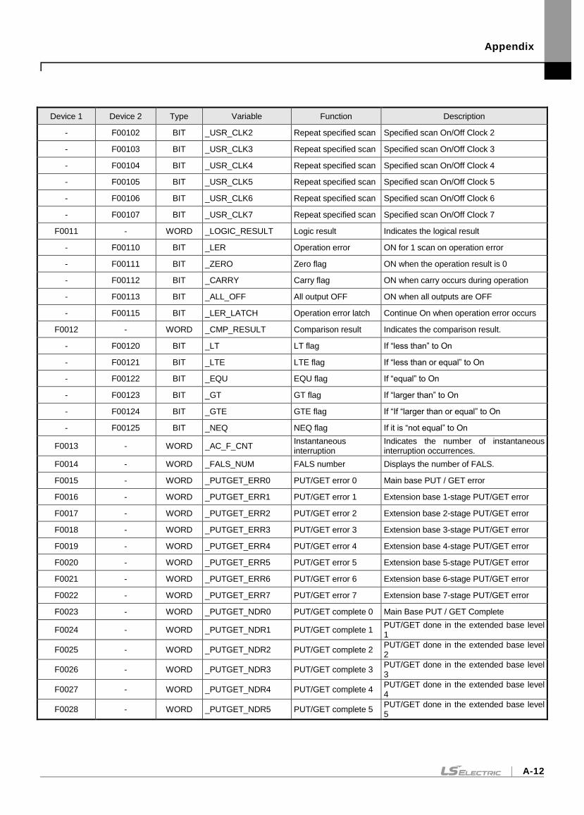
Appendix
A-12
Device 1 Device 2 Type Variable Function Description
- F00102 BIT _USR_CLK2 Repeat specified scan Specified scan On/Off Clock 2
- F00103 BIT _USR_CLK3 Repeat specified scan Specified scan On/Off Clock 3
- F00104 BIT _USR_CLK4 Repeat specified scan Specified scan On/Off Clock 4
- F00105 BIT _USR_CLK5 Repeat specified scan Specified scan On/Off Clock 5
- F00106 BIT _USR_CLK6 Repeat specified scan Specified scan On/Off Clock 6
- F00107 BIT _USR_CLK7 Repeat specified scan Specified scan On/Off Clock 7
F0011 - WORD _LOGIC_RESULT Logic result Indicates the logical result
- F00110 BIT _LER Operation error ON for 1 scan on operation error
- F00111 BIT _ZERO Zero flag ON when the operation result is 0
- F00112 BIT _CARRY Carry flag ON when carry occurs during operation
- F00113 BIT _ALL_OFF All output OFF ON when all outputs are OFF
- F00115 BIT _LER_LATCH Operation error latch Continue On when operation error occurs
F0012 - WORD _CMP_RESULT Comparison result Indicates the comparison result.
- F00120 BIT _LT LT flag If “less than” to On
- F00121 BIT _LTE LTE flag If “less than or equal” to On
- F00122 BIT _EQU EQU flag If “equal” to On
- F00123 BIT _GT GT flag If “larger than” to On
- F00124 BIT _GTE GTE flag If “If “larger than or equal” to On
- F00125 BIT _NEQ NEQ flag If it is “not equal” to On
F0013 - WORD _AC_F_CNT Instantaneous interruption
Indicates the number of instantaneous interruption occurrences.
F0014 - WORD _FALS_NUM FALS number Displays the number of FALS.
F0015 - WORD _PUTGET_ERR0 PUT/GET error 0 Main base PUT / GET error
F0016 - WORD _PUTGET_ERR1 PUT/GET error 1 Extension base 1-stage PUT/GET error
F0017 - WORD _PUTGET_ERR2 PUT/GET error 2 Extension base 2-stage PUT/GET error
F0018 - WORD _PUTGET_ERR3 PUT/GET error 3 Extension base 3-stage PUT/GET error
F0019 - WORD _PUTGET_ERR4 PUT/GET error 4 Extension base 4-stage PUT/GET error
F0020 - WORD _PUTGET_ERR5 PUT/GET error 5 Extension base 5-stage PUT/GET error
F0021 - WORD _PUTGET_ERR6 PUT/GET error 6 Extension base 6-stage PUT/GET error
F0022 - WORD _PUTGET_ERR7 PUT/GET error 7 Extension base 7-stage PUT/GET error
F0023 - WORD _PUTGET_NDR0 PUT/GET complete 0 Main Base PUT / GET Complete
F0024 - WORD _PUTGET_NDR1 PUT/GET complete 1 PUT/GET done in the extended base level 1
F0025 - WORD _PUTGET_NDR2 PUT/GET complete 2 PUT/GET done in the extended base level 2
F0026 - WORD _PUTGET_NDR3 PUT/GET complete 3 PUT/GET done in the extended base level 3
F0027 - WORD _PUTGET_NDR4 PUT/GET complete 4 PUT/GET done in the extended base level 4
F0028 - WORD _PUTGET_NDR5 PUT/GET complete 5 PUT/GET done in the extended base level 5
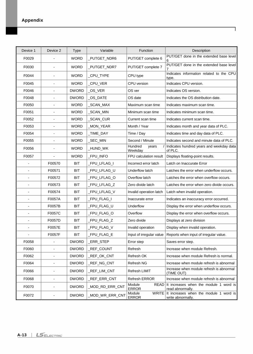
Appendix
A-13
Device 1 Device 2 Type Variable Function Description
F0029 - WORD _PUTGET_NDR6 PUT/GET complete 6 PUT/GET done in the extended base level 6
F0030 - WORD _PUTGET_NDR7 PUT/GET complete 7 PUT/GET done in the extended base level 7
F0044 - WORD _CPU_TYPE CPU type Indicates information related to the CPU type.
F0045 - WORD _CPU_VER CPU version Indicates CPU version.
F0046 - DWORD _OS_VER OS ver Indicates OS version.
F0048 - DWORD _OS_DATE OS date Indicates the OS distribution date.
F0050 - WORD _SCAN_MAX Maximum scan time Indicates maximum scan time.
F0051 - WORD _SCAN_MIN Minimum scan time Indicates minimum scan time.
F0052 - WORD _SCAN_CUR Current scan time Indicates current scan time.
F0053 - WORD _MON_YEAR Month / Year Indicates month and year data of PLC.
F0054 - WORD _TIME_DAY Time / Day Indicates time and day data of PLC.
F0055 - WORD _SEC_MIN Second / Minute Indicates second and minute data of PLC.
F0056 - WORD _HUND_WK Hundred years / Weekday
Indicates hundred years and weekday data of PLC.
F0057 - WORD _FPU_INFO FPU calculation result Displays floating-point results.
- F00570 BIT _FPU_LFLAG_I Incorrect error latch Latch on Inaccurate Error
- F00571 BIT _FPU_LFLAG_U Underflow latch Latches the error when underflow occurs.
- F00572 BIT _FPU_LFLAG_O Overflow latch Latches the error when overflow occurs.
- F00573 BIT _FPU_LFLAG_Z Zero divide latch Latches the error when zero divide occurs.
- F00574 BIT _FPU_LFLAG_V Invalid operation latch Latch when invalid operation.
- F0057A BIT _FPU_FLAG_I Inaccurate error Indicates an inaccuracy error occurred.
- F0057B BIT _FPU_FLAG_U Underflow Display the error when underflow occurs.
- F0057C BIT _FPU_FLAG_O Overflow Display the error when overflow occurs.
- F0057D BIT _FPU_FLAG_Z Zero divide Displays at zero division
- F0057E BIT _FPU_FLAG_V Invalid operation Display when invalid operation.
- F0057F BIT _FPU_FLAG_E Input of irregular value Reports when input of irregular value.
F0058 - DWORD _ERR_STEP Error step Saves error step.
F0060 - DWORD _REF_COUNT Refresh Increase when module Refresh.
F0062 - DWORD _REF_OK_CNT Refresh OK Increase when module Refresh is normal.
F0064 - DWORD _REF_NG_CNT Refresh NG Increase when module refresh is abnormal
F0066 - DWORD _REF_LIM_CNT Refresh LIMIT Increase when module refresh is abnormal (TIME OUT)
F0068 - DWORD _REF_ERR_CNT Refresh ERROR Increase when module refresh is abnormal
F0070 - DWORD _MOD_RD_ERR_CNT Module READ ERROR
It increases when the module 1 word is read abnormally.
F0072 - DWORD _MOD_WR_ERR_CNT Module WRITE ERROR
It increases when the module 1 word is write abnormally.
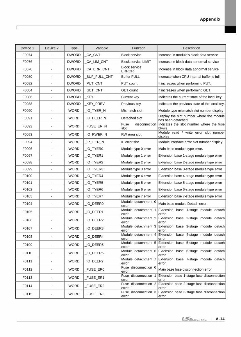
Appendix
A-14
Device 1 Device 2 Type Variable Function Description
F0074 - DWORD _CA_CNT Block service Increase in module's block data service
F0076 - DWORD _CA_LIM_CNT Block service LIMIT Increase in block data abnormal service
F0078 - DWORD _CA_ERR_CNT Block service ERROR
Increase in block data abnormal service
F0080 - DWORD _BUF_FULL_CNT Buffer FULL Increase when CPU internal buffer is full.
F0082 - DWORD _PUT_CNT PUT count It increases when performing PUT.
F0084 - DWORD _GET_CNT GET count It increases when performing GET.
F0086 - DWORD _KEY Current key Indicates the current state of the local key.
F0088 - DWORD _KEY_PREV Previous key Indicates the previous state of the local key.
F0090 - WORD _IO_TYER_N Mismatch slot Module type mismatch slot number display
F0091 - WORD _IO_DEER_N Detached slot Display the slot number where the module has been detached
F0092 - WORD _FUSE_ER_N Fuse disconnection slot
Indicates the slot number where the fuse blows
F0093 - WORD _IO_RWER_N RW error slot Module read / write error slot number display
F0094 - WORD _IP_IFER_N IF error slot Module interface error slot number display
F0096 - WORD _IO_TYER0 Module type 0 error Main base module type error.
F0097 - WORD _IO_TYER1 Module type 1 error Extension base 1-stage module type error
F0098 - WORD _IO_TYER2 Module type 2 error Extension base 2-stage module type error
F0099 - WORD _IO_TYER3 Module type 3 error Extension base 3-stage module type error
F0100 - WORD _IO_TYER4 Module type 4 error Extension base 4-stage module type error
F0101 - WORD _IO_TYER5 Module type 5 error Extension base 5-stage module type error
F0102 - WORD _IO_TYER6 Module type 6 error Extension base 6-stage module type error
F0103 - WORD _IO_TYER7 Module type 7 error Extension base 7-stage module type error
F0104 - WORD _IO_DEER0 Module detachment 0 error
Main base module Detach error.
F0105 - WORD _IO_DEER1 Module detachment 1 error
Extension base 1-stage module detach error.
F0106 - WORD _IO_DEER2 Module detachment 2 error
Extension base 2-stage module detach error.
F0107 - WORD _IO_DEER3 Module detachment 3 error
Extension base 3-stage module detach error.
F0108 - WORD _IO_DEER4 Module detachment 4 error
Extension base 4-stage module detach error.
F0109 - WORD _IO_DEER5 Module detachment 5 error
Extension base 5-stage module detach error.
F0110 - WORD _IO_DEER6 Module detachment 6 error
Extension base 6-stage module detach error.
F0111 - WORD _IO_DEER7 Module detachment 7 error
Extension base 7-stage module detach error.
F0112 - WORD _FUSE_ER0 Fuse disconnection 0 error
Main base fuse disconnection error
F0113 - WORD _FUSE_ER1 Fuse disconnection 1 error
Extension base 1-stage fuse disconnection error
F0114 - WORD _FUSE_ER2 Fuse disconnection 2 error
Extension base 2-stage fuse disconnection error
F0115 - WORD _FUSE_ER3 Fuse disconnection 3 error
Extension base 3-stage fuse disconnection error
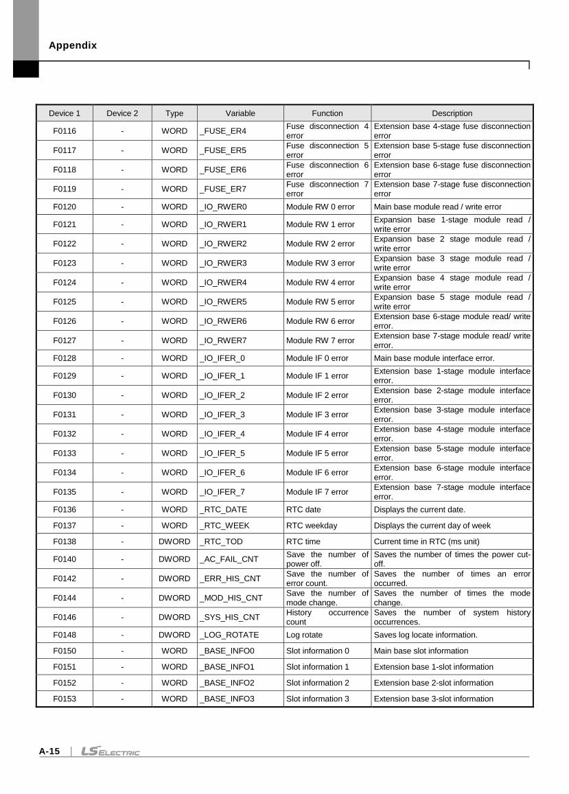
Appendix
A-15
Device 1 Device 2 Type Variable Function Description
F0116 - WORD _FUSE_ER4 Fuse disconnection 4 error
Extension base 4-stage fuse disconnection error
F0117 - WORD _FUSE_ER5 Fuse disconnection 5 error
Extension base 5-stage fuse disconnection error
F0118 - WORD _FUSE_ER6 Fuse disconnection 6 error
Extension base 6-stage fuse disconnection error
F0119 - WORD _FUSE_ER7 Fuse disconnection 7 error
Extension base 7-stage fuse disconnection error
F0120 - WORD _IO_RWER0 Module RW 0 error Main base module read / write error
F0121 - WORD _IO_RWER1 Module RW 1 error Expansion base 1-stage module read / write error
F0122 - WORD _IO_RWER2 Module RW 2 error Expansion base 2 stage module read / write error
F0123 - WORD _IO_RWER3 Module RW 3 error Expansion base 3 stage module read / write error
F0124 - WORD _IO_RWER4 Module RW 4 error Expansion base 4 stage module read / write error
F0125 - WORD _IO_RWER5 Module RW 5 error Expansion base 5 stage module read / write error
F0126 - WORD _IO_RWER6 Module RW 6 error Extension base 6-stage module read/ write error.
F0127 - WORD _IO_RWER7 Module RW 7 error Extension base 7-stage module read/ write error.
F0128 - WORD _IO_IFER_0 Module IF 0 error Main base module interface error.
F0129 - WORD _IO_IFER_1 Module IF 1 error Extension base 1-stage module interface error.
F0130 - WORD _IO_IFER_2 Module IF 2 error Extension base 2-stage module interface error.
F0131 - WORD _IO_IFER_3 Module IF 3 error Extension base 3-stage module interface error.
F0132 - WORD _IO_IFER_4 Module IF 4 error Extension base 4-stage module interface error.
F0133 - WORD _IO_IFER_5 Module IF 5 error Extension base 5-stage module interface error.
F0134 - WORD _IO_IFER_6 Module IF 6 error Extension base 6-stage module interface error.
F0135 - WORD _IO_IFER_7 Module IF 7 error Extension base 7-stage module interface error.
F0136 - WORD _RTC_DATE RTC date Displays the current date.
F0137 - WORD _RTC_WEEK RTC weekday Displays the current day of week
F0138 - DWORD _RTC_TOD RTC time Current time in RTC (ms unit)
F0140 - DWORD _AC_FAIL_CNT Save the number of power off.
Saves the number of times the power cut-off.
F0142 - DWORD _ERR_HIS_CNT Save the number of error count.
Saves the number of times an error occurred.
F0144 - DWORD _MOD_HIS_CNT Save the number of mode change.
Saves the number of times the mode change.
F0146 - DWORD _SYS_HIS_CNT History occurrence count
Saves the number of system history occurrences.
F0148 - DWORD _LOG_ROTATE Log rotate Saves log locate information.
F0150 - WORD _BASE_INFO0 Slot information 0 Main base slot information
F0151 - WORD _BASE_INFO1 Slot information 1 Extension base 1-slot information
F0152 - WORD _BASE_INFO2 Slot information 2 Extension base 2-slot information
F0153 - WORD _BASE_INFO3 Slot information 3 Extension base 3-slot information
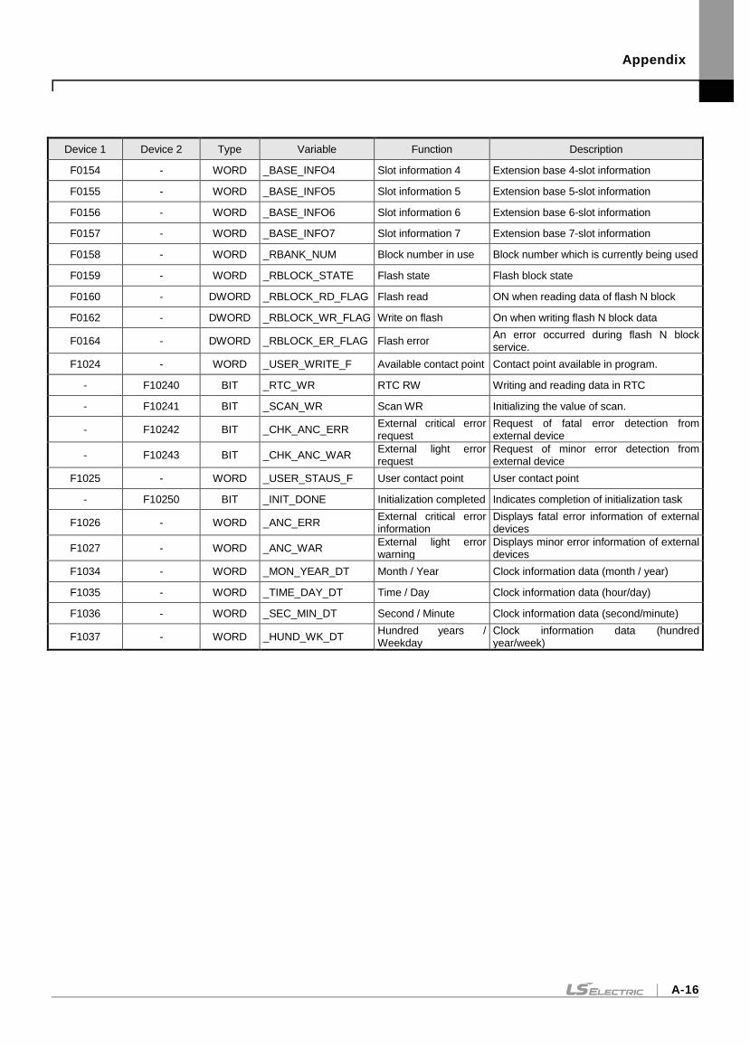
Appendix
A-16
Device 1 Device 2 Type Variable Function Description
F0154 - WORD _BASE_INFO4 Slot information 4 Extension base 4-slot information
F0155 - WORD _BASE_INFO5 Slot information 5 Extension base 5-slot information
F0156 - WORD _BASE_INFO6 Slot information 6 Extension base 6-slot information
F0157 - WORD _BASE_INFO7 Slot information 7 Extension base 7-slot information
F0158 - WORD _RBANK_NUM Block number in use Block number which is currently being used
F0159 - WORD _RBLOCK_STATE Flash state Flash block state
F0160 - DWORD _RBLOCK_RD_FLAG Flash read ON when reading data of flash N block
F0162 - DWORD _RBLOCK_WR_FLAG Write on flash On when writing flash N block data
F0164 - DWORD _RBLOCK_ER_FLAG Flash error An error occurred during flash N block service.
F1024 - WORD _USER_WRITE_F Available contact point Contact point available in program.
- F10240 BIT _RTC_WR RTC RW Writing and reading data in RTC
- F10241 BIT _SCAN_WR Scan WR Initializing the value of scan.
- F10242 BIT _CHK_ANC_ERR External critical error request
Request of fatal error detection from external device
- F10243 BIT _CHK_ANC_WAR External light error request
Request of minor error detection from external device
F1025 - WORD _USER_STAUS_F User contact point User contact point
- F10250 BIT _INIT_DONE Initialization completed Indicates completion of initialization task
F1026 - WORD _ANC_ERR External critical error information
Displays fatal error information of external devices
F1027 - WORD _ANC_WAR External light error warning
Displays minor error information of external devices
F1034 - WORD _MON_YEAR_DT Month / Year Clock information data (month / year)
F1035 - WORD _TIME_DAY_DT Time / Day Clock information data (hour/day)
F1036 - WORD _SEC_MIN_DT Second / Minute Clock information data (second/minute)
F1037 - WORD _HUND_WK_DT Hundred years / Weekday
Clock information data (hundred year/week)
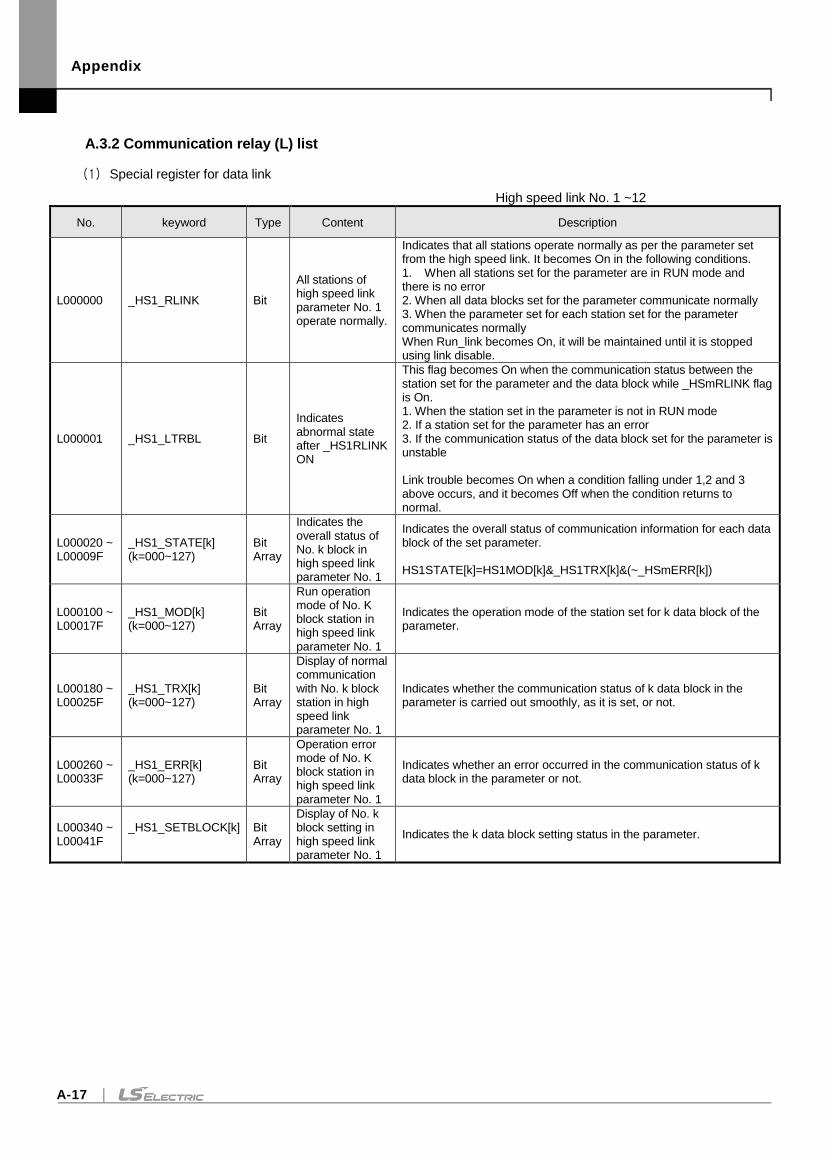
Appendix
A-17
A.3.2 Communication relay (L) list
(1) Special register for data link
High speed link No. 1 ~12
No. keyword Type Content Description
L000000 _HS1_RLINK Bit
All stations of high speed link parameter No. 1 operate normally.
Indicates that all stations operate normally as per the parameter set from the high speed link. It becomes On in the following conditions. 1. When all stations set for the parameter are in RUN mode and there is no error 2. When all data blocks set for the parameter communicate normally 3. When the parameter set for each station set for the parameter communicates normally When Run_link becomes On, it will be maintained until it is stopped using link disable.
L000001 _HS1_LTRBL Bit
Indicates abnormal state after _HS1RLINK ON
This flag becomes On when the communication status between the station set for the parameter and the data block while _HSmRLINK flag is On. 1. When the station set in the parameter is not in RUN mode 2. If a station set for the parameter has an error 3. If the communication status of the data block set for the parameter is unstable Link trouble becomes On when a condition falling under 1,2 and 3 above occurs, and it becomes Off when the condition returns to normal.
L000020 ~ L00009F
_HS1_STATE[k] (k=000~127)
Bit Array
Indicates the overall status of No. k block in high speed link parameter No. 1
Indicates the overall status of communication information for each data block of the set parameter. HS1STATE[k]=HS1MOD[k]&_HS1TRX[k]&(~_HSmERR[k])
L000100 ~ L00017F
_HS1_MOD[k] (k=000~127)
Bit Array
Run operation mode of No. K block station in high speed link parameter No. 1
Indicates the operation mode of the station set for k data block of the parameter.
L000180 ~ L00025F
_HS1_TRX[k] (k=000~127)
Bit Array
Display of normal communication with No. k block station in high speed link parameter No. 1
Indicates whether the communication status of k data block in the parameter is carried out smoothly, as it is set, or not.
L000260 ~ L00033F
_HS1_ERR[k] (k=000~127)
Bit Array
Operation error mode of No. K block station in high speed link parameter No. 1
Indicates whether an error occurred in the communication status of k data block in the parameter or not.
L000340 ~ L00041F
_HS1_SETBLOCK[k]
Bit Array
Display of No. k block setting in high speed link parameter No. 1
Indicates the k data block setting status in the parameter.
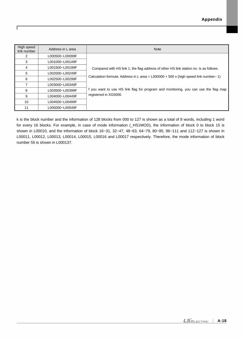
Appendix
A-18
High speed link number
Address in L area Note
2 L000500~L00099F
Compared with HS link 1, the flag address of other HS link station no. Is as follows. Calculation formula: Address in L area = L000000 + 500 x (high speed link number– 1)
f you want to use HS link flag for program and monitoring, you can use the flag map
registered in XG5000.
3 L001000~L00149F
4 L001500~L00199F
5 L002000~L00249F
6 L002500~L00299F
7 L003000~L00349F
8 L003500~L00399F
9 L004000~L00449F
10 L004500~L00499F
11 L005000~L00549F
k is the block number and the information of 128 blocks from 000 to 127 is shown as a total of 8 words, including 1 word
for every 16 blocks. For example, in case of mode information (_HS1MOD), the information of block 0 to block 15 is
shown in L00010, and the information of block 16~31, 32~47, 48~63, 64~79, 80~95, 96~111 and 112~127 is shown in
L00011, L00012, L00013, L00014, L00015, L00016 and L00017 respectively. Therefore, the mode information of block
number 55 is shown in L000137.
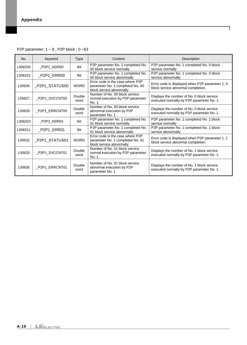
Appendix
A-19
P2P parameter: 1 ~ 8 , P2P block : 0 ~63
No. keyword Type Content Description
L006250 _P2P1_NDR00 Bit P2P parameter No. 1 completed No. 00 block service normally
P2P parameter No. 1 completed No. 0 block service normally
L006251 _P2P1_ERR00 Bit P2P parameter No. 1 completed No. 00 block service abnormally
P2P parameter No. 1 completed No. 0 block service abnormally
L00626 _P2P1_STATUS00 WORD Error code in the case where P2P parameter No. 1 completed No. 00 block service abnormally
Error code is displayed when P2P parameter 1, 0 block service abnormal completion.
L00627 _P2P1_SVCCNT00 Double word
Number of No. 00 block service normal execution by P2P parameter No. 1
Displays the number of No. 0 block service executed normally by P2P parameter No. 1.
L00629 _P2P1_ERRCNT00 Double word
Number of No. 00 block service abnormal execution by P2P parameter No. 1
Displays the number of No. 0 block service executed normally by P2P parameter No. 1.
L006310 _P2P1_NDR01 Bit P2P parameter No. 1 completed No. 01 block service normally
P2P parameter No. 1 completed No. 1 block service normally
L006311 _P2P1_ERR01 Bit P2P parameter No. 1 completed No. 01 block service abnormally
P2P parameter No. 1 completed No. 1 block service abnormally
L00632 _P2P1_STATUS01 WORD Error code in the case where P2P parameter No. 1 completed No. 01 block service abnormally
Error code is displayed when P2P parameter 1, 1 block service abnormal completion.
L00633 _P2P1_SVCCNT01 Double word
Number of No. 01 block service normal execution by P2P parameter No. 1
Displays the number of No. 1 block service executed normally by P2P parameter No. 1.
L00635 _P2P1_ERRCNT01 Double word
Number of No. 01 block service abnormal execution by P2P parameter No. 1
Displays the number of No. 1 block service executed normally by P2P parameter No. 1.
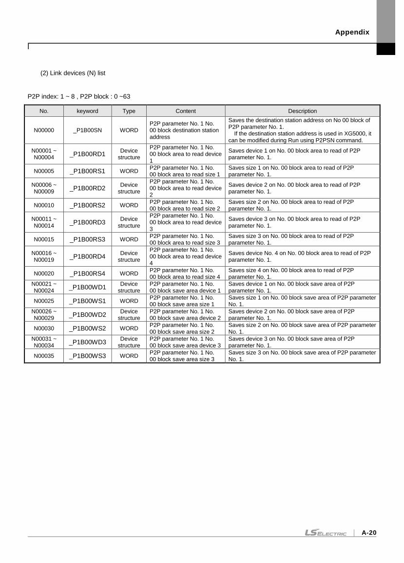
Appendix
A-20
(2) Link devices (N) list
P2P index: 1 ~ 8 , P2P block : 0 ~63
No. keyword Type Content Description
N00000 _P1B00SN WORD P2P parameter No. 1 No. 00 block destination station address
Saves the destination station address on No 00 block of P2P parameter No. 1.
If the destination station address is used in XG5000, it can be modified during Run using P2PSN command.
N00001 ~ N00004
_P1B00RD1 Device
structure
P2P parameter No. 1 No. 00 block area to read device 1
Saves device 1 on No. 00 block area to read of P2P parameter No. 1.
N00005 _P1B00RS1 WORD P2P parameter No. 1 No. 00 block area to read size 1
Saves size 1 on No. 00 block area to read of P2P parameter No. 1.
N00006 ~ N00009
_P1B00RD2 Device
structure
P2P parameter No. 1 No. 00 block area to read device 2
Saves device 2 on No. 00 block area to read of P2P parameter No. 1.
N00010 _P1B00RS2 WORD P2P parameter No. 1 No. 00 block area to read size 2
Saves size 2 on No. 00 block area to read of P2P parameter No. 1.
N00011 ~ N00014
_P1B00RD3 Device
structure
P2P parameter No. 1 No. 00 block area to read device 3
Saves device 3 on No. 00 block area to read of P2P parameter No. 1.
N00015 _P1B00RS3 WORD P2P parameter No. 1 No. 00 block area to read size 3
Saves size 3 on No. 00 block area to read of P2P parameter No. 1.
N00016 ~ N00019
_P1B00RD4 Device
structure
P2P parameter No. 1 No. 00 block area to read device 4
Saves device No. 4 on No. 00 block area to read of P2P parameter No. 1.
N00020 _P1B00RS4 WORD P2P parameter No. 1 No. 00 block area to read size 4
Saves size 4 on No. 00 block area to read of P2P parameter No. 1.
N00021 ~ N00024
_P1B00WD1 Device
structure P2P parameter No. 1 No. 00 block save area device 1
Saves device 1 on No. 00 block save area of P2P parameter No. 1.
N00025 _P1B00WS1 WORD P2P parameter No. 1 No. 00 block save area size 1
Saves size 1 on No. 00 block save area of P2P parameter No. 1.
N00026 ~ N00029
_P1B00WD2 Device
structure P2P parameter No. 1 No. 00 block save area device 2
Saves device 2 on No. 00 block save area of P2P parameter No. 1.
N00030 _P1B00WS2 WORD P2P parameter No. 1 No. 00 block save area size 2
Saves size 2 on No. 00 block save area of P2P parameter No. 1.
N00031 ~ N00034
_P1B00WD3 Device
structure P2P parameter No. 1 No. 00 block save area device 3
Saves device 3 on No. 00 block save area of P2P parameter No. 1.
N00035 _P1B00WS3 WORD P2P parameter No. 1 No. 00 block save area size 3
Saves size 3 on No. 00 block save area of P2P parameter No. 1.
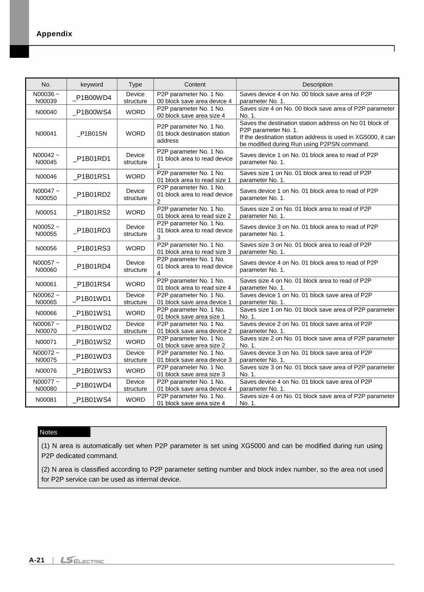
Appendix
A-21
No. keyword Type Content Description
N00036 ~ N00039
_P1B00WD4 Device
structure P2P parameter No. 1 No. 00 block save area device 4
Saves device 4 on No. 00 block save area of P2P parameter No. 1.
N00040 _P1B00WS4 WORD P2P parameter No. 1 No. 00 block save area size 4
Saves size 4 on No. 00 block save area of P2P parameter No. 1.
N00041 _P1B01SN WORD P2P parameter No. 1 No. 01 block destination station address
Saves the destination station address on No 01 block of P2P parameter No. 1. If the destination station address is used in XG5000, it can be modified during Run using P2PSN command.
N00042 ~ N00045
_P1B01RD1 Device
structure
P2P parameter No. 1 No. 01 block area to read device 1
Saves device 1 on No. 01 block area to read of P2P parameter No. 1.
N00046 _P1B01RS1 WORD P2P parameter No. 1 No. 01 block area to read size 1
Saves size 1 on No. 01 block area to read of P2P parameter No. 1.
N00047 ~ N00050
_P1B01RD2 Device
structure
P2P parameter No. 1 No. 01 block area to read device 2
Saves device 1 on No. 01 block area to read of P2P parameter No. 1.
N00051 _P1B01RS2 WORD P2P parameter No. 1 No. 01 block area to read size 2
Saves size 2 on No. 01 block area to read of P2P parameter No. 1.
N00052 ~ N00055
_P1B01RD3 Device
structure
P2P parameter No. 1 No. 01 block area to read device 3
Saves device 3 on No. 01 block area to read of P2P parameter No. 1.
N00056 _P1B01RS3 WORD P2P parameter No. 1 No. 01 block area to read size 3
Saves size 3 on No. 01 block area to read of P2P parameter No. 1.
N00057 ~ N00060
_P1B01RD4 Device
structure
P2P parameter No. 1 No. 01 block area to read device 4
Saves device 4 on No. 01 block area to read of P2P parameter No. 1.
N00061 _P1B01RS4 WORD P2P parameter No. 1 No. 01 block area to read size 4
Saves size 4 on No. 01 block area to read of P2P parameter No. 1.
N00062 ~ N00065
_P1B01WD1 Device
structure P2P parameter No. 1 No. 01 block save area device 1
Saves device 1 on No. 01 block save area of P2P parameter No. 1.
N00066 _P1B01WS1 WORD P2P parameter No. 1 No. 01 block save area size 1
Saves size 1 on No. 01 block save area of P2P parameter No. 1.
N00067 ~ N00070
_P1B01WD2 Device
structure P2P parameter No. 1 No. 01 block save area device 2
Saves device 2 on No. 01 block save area of P2P parameter No. 1.
N00071 _P1B01WS2 WORD P2P parameter No. 1 No. 01 block save area size 2
Saves size 2 on No. 01 block save area of P2P parameter No. 1.
N00072 ~ N00075
_P1B01WD3 Device
structure P2P parameter No. 1 No. 01 block save area device 3
Saves device 3 on No. 01 block save area of P2P parameter No. 1.
N00076 _P1B01WS3 WORD P2P parameter No. 1 No. 01 block save area size 3
Saves size 3 on No. 01 block save area of P2P parameter No. 1.
N00077 ~ N00080
_P1B01WD4 Device
structure P2P parameter No. 1 No. 01 block save area device 4
Saves device 4 on No. 01 block save area of P2P parameter No. 1.
N00081 _P1B01WS4 WORD P2P parameter No. 1 No. 01 block save area size 4
Saves size 4 on No. 01 block save area of P2P parameter No. 1.
Notes
(1) N area is automatically set when P2P parameter is set using XG5000 and can be modified during run using
P2P dedicated command.
(2) N area is classified according to P2P parameter setting number and block index number, so the area not used
for P2P service can be used as internal device.
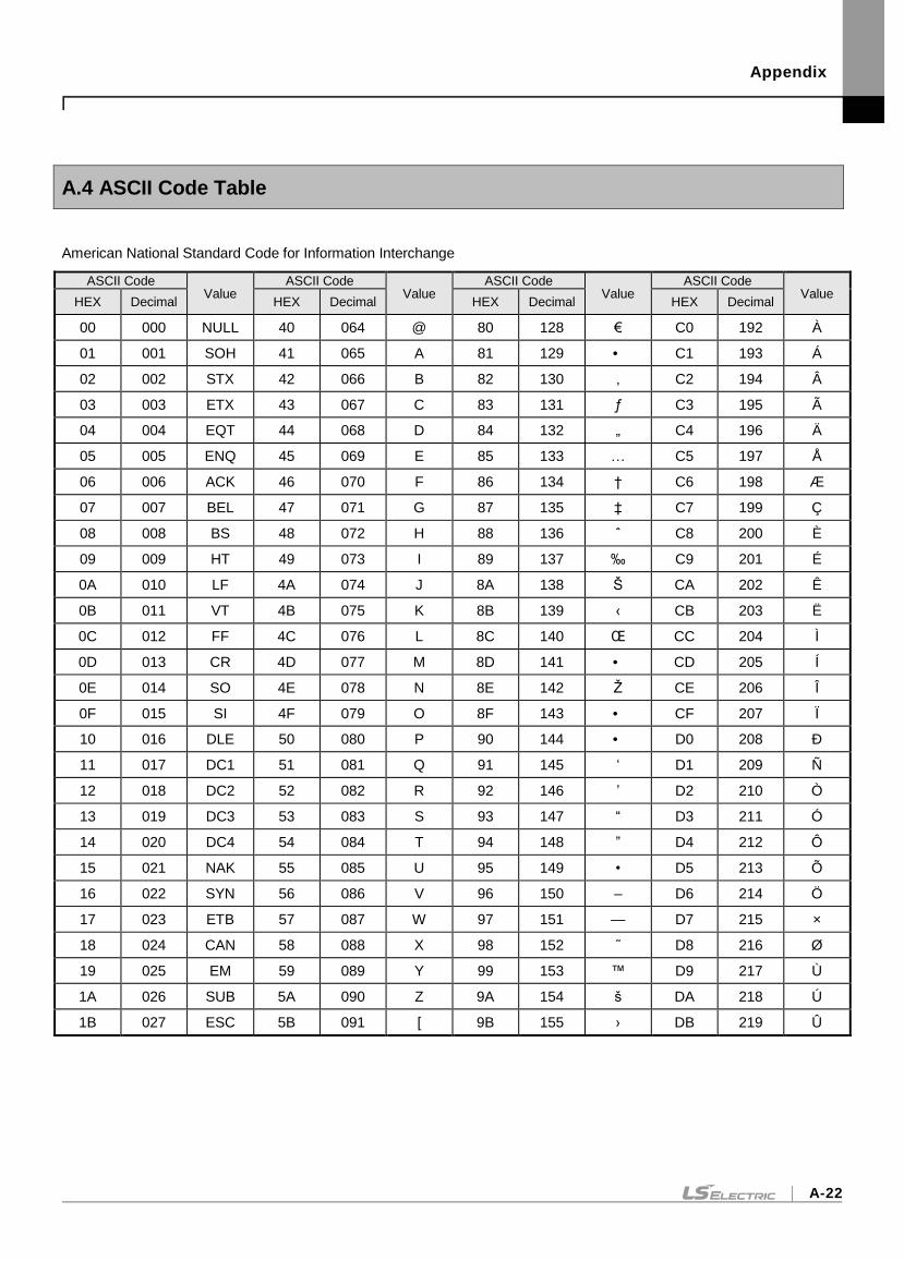
Appendix
A-22
A.4 ASCII Code Table
American National Standard Code for Information Interchange
ASCII Code Value
ASCII Code Value
ASCII Code Value
ASCII Code Value
HEX Decimal HEX Decimal HEX Decimal HEX Decimal
00 000 NULL 40 064 @ 80 128 € C0 192 À
01 001 SOH 41 065 A 81 129 • C1 193 Á
02 002 STX 42 066 B 82 130 ‚ C2 194 Â
03 003 ETX 43 067 C 83 131 ƒ C3 195 Ã
04 004 EQT 44 068 D 84 132 „ C4 196 Ä
05 005 ENQ 45 069 E 85 133 … C5 197 Å
06 006 ACK 46 070 F 86 134 † C6 198 Æ
07 007 BEL 47 071 G 87 135 ‡ C7 199 Ç
08 008 BS 48 072 H 88 136 ˆ C8 200 È
09 009 HT 49 073 I 89 137 ‰ C9 201 É
0A 010 LF 4A 074 J 8A 138 Š CA 202 Ê
0B 011 VT 4B 075 K 8B 139 ‹ CB 203 Ë
0C 012 FF 4C 076 L 8C 140 Œ CC 204 Ì
0D 013 CR 4D 077 M 8D 141 • CD 205 Í
0E 014 SO 4E 078 N 8E 142 Ž CE 206 Î
0F 015 SI 4F 079 O 8F 143 • CF 207 Ï
10 016 DLE 50 080 P 90 144 • D0 208 Ð
11 017 DC1 51 081 Q 91 145 ‘ D1 209 Ñ
12 018 DC2 52 082 R 92 146 ’ D2 210 Ò
13 019 DC3 53 083 S 93 147 “ D3 211 Ó
14 020 DC4 54 084 T 94 148 ” D4 212 Ô
15 021 NAK 55 085 U 95 149 • D5 213 Õ
16 022 SYN 56 086 V 96 150 – D6 214 Ö
17 023 ETB 57 087 W 97 151 — D7 215 ×
18 024 CAN 58 088 X 98 152 ˜ D8 216 Ø
19 025 EM 59 089 Y 99 153 ™ D9 217 Ù
1A 026 SUB 5A 090 Z 9A 154 š DA 218 Ú
1B 027 ESC 5B 091 [ 9B 155 › DB 219 Û
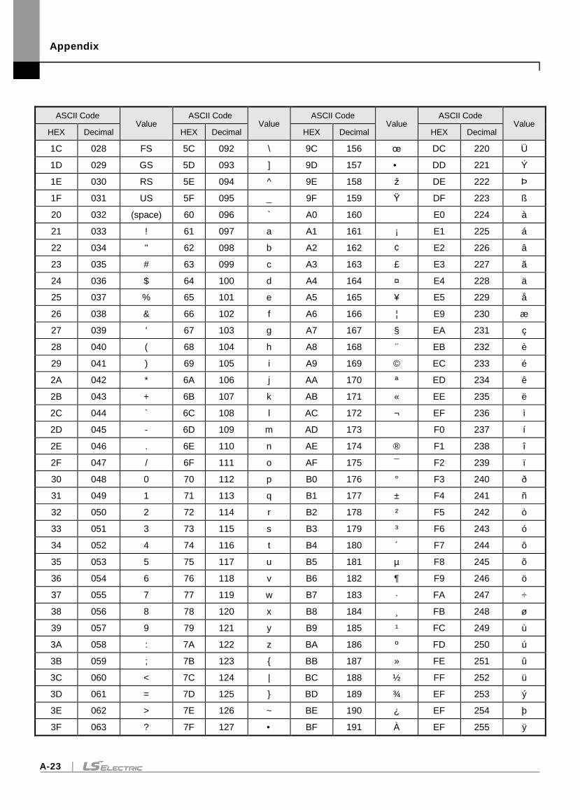
Appendix
A-23
ASCII Code Value
ASCII Code Value
ASCII Code Value
ASCII Code Value
HEX Decimal HEX Decimal HEX Decimal HEX Decimal
1C 028 FS 5C 092 \ 9C 156 œ DC 220 Ü
1D 029 GS 5D 093 ] 9D 157 • DD 221 Ý
1E 030 RS 5E 094 ^ 9E 158 ž DE 222 Þ
1F 031 US 5F 095 _ 9F 159 Ÿ DF 223 ß
20 032 (space) 60 096 ` A0 160 E0 224 à
21 033 ! 61 097 a A1 161 ¡ E1 225 á
22 034 " 62 098 b A2 162 ¢ E2 226 â
23 035 # 63 099 c A3 163 £ E3 227 ã
24 036 $ 64 100 d A4 164 ¤ E4 228 ä
25 037 % 65 101 e A5 165 ¥ E5 229 å
26 038 & 66 102 f A6 166 ¦ E9 230 æ
27 039 ' 67 103 g A7 167 § EA 231 ç
28 040 ( 68 104 h A8 168 EB 232 è
29 041 ) 69 105 i A9 169 © EC 233 é
2A 042 * 6A 106 j AA 170 ª ED 234 ê
2B 043 + 6B 107 k AB 171 « EE 235 ë
2C 044 ` 6C 108 l AC 172 ¬ EF 236 ì
2D 045 - 6D 109 m AD 173 F0 237 í
2E 046 . 6E 110 n AE 174 ® F1 238 î
2F 047 / 6F 111 o AF 175 ¯ F2 239 ï
30 048 0 70 112 p B0 176 ° F3 240 ð
31 049 1 71 113 q B1 177 ± F4 241 ñ
32 050 2 72 114 r B2 178 ² F5 242 ò
33 051 3 73 115 s B3 179 ³ F6 243 ó
34 052 4 74 116 t B4 180 F7 244 ô
35 053 5 75 117 u B5 181 µ F8 245 õ
36 054 6 76 118 v B6 182 ¶ F9 246 ö
37 055 7 77 119 w B7 183 · FA 247 ÷
38 056 8 78 120 x B8 184 FB 248 ø
39 057 9 79 121 y B9 185 ¹ FC 249 ù
3A 058 : 7A 122 z BA 186 º FD 250 ú
3B 059 ; 7B 123 BB 187 » FE 251 û
3C 060 < 7C 124 | BC 188 ½ FF 252 ü
3D 061 = 7D 125 BD 189 ¾ EF 253 ý
3E 062 > 7E 126 ~ BE 190 ¿ EF 254 þ
3F 063 ? 7F 127 • BF 191 À EF 255 ÿ

Appendix
A-24
A.5 Ethernet technology compare table
technology Speed (Mbps) Media Max. distance
Token Ring 4,16 UTP 100m
Ethernet
10BASE-T 10 UTP 100m
10BASE-F(Multi mode) 10 Optical cable Max. 2km
10BASE-F(Single mode) 10 Optical cable Max. 2.5km
10BASE-5 10 Coaxial cable 500m
10BASE-2 10 Coaxial cable 185m
Fast Ethernet
100BASE-T4 100 UTP 100m
100BASE-TX 100 UTP 100m
100BASE-FX(Multi mode) 100 Optical cable 412m(Half Duplex) 2km(Full Duplex)
100BASE-FX(Single mode) 100 Optical cable 20km
Gigabit Ethernet
1000BASE-T 1000 UTP 100m
100BASE-FX(Single mode) 1000 Optical cable 3km
100BASE-FX(Multi mode) 1000 Optical cable 500m
100BASE-T 1000 Coaxial cable 25m
100VG-AnyLAN 100 UTP -
ATM 155-622 UTP,Optical cable -
FDDI(Single mode) 100 Optical cable 40-60km
FDDI(Multi mode) 100 Optical cable 2km
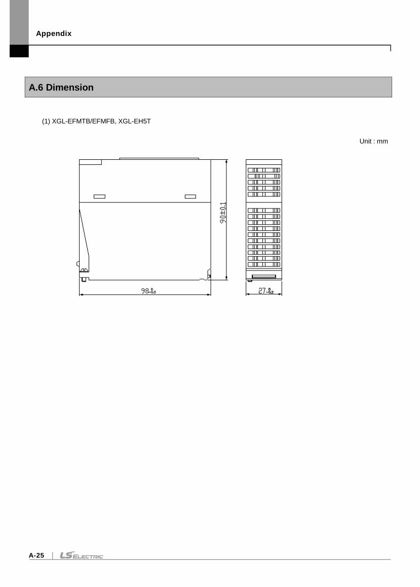
Appendix
A-25
A.6 Dimension
(1) XGL-EFMTB/EFMFB, XGL-EH5T
Unit : mm
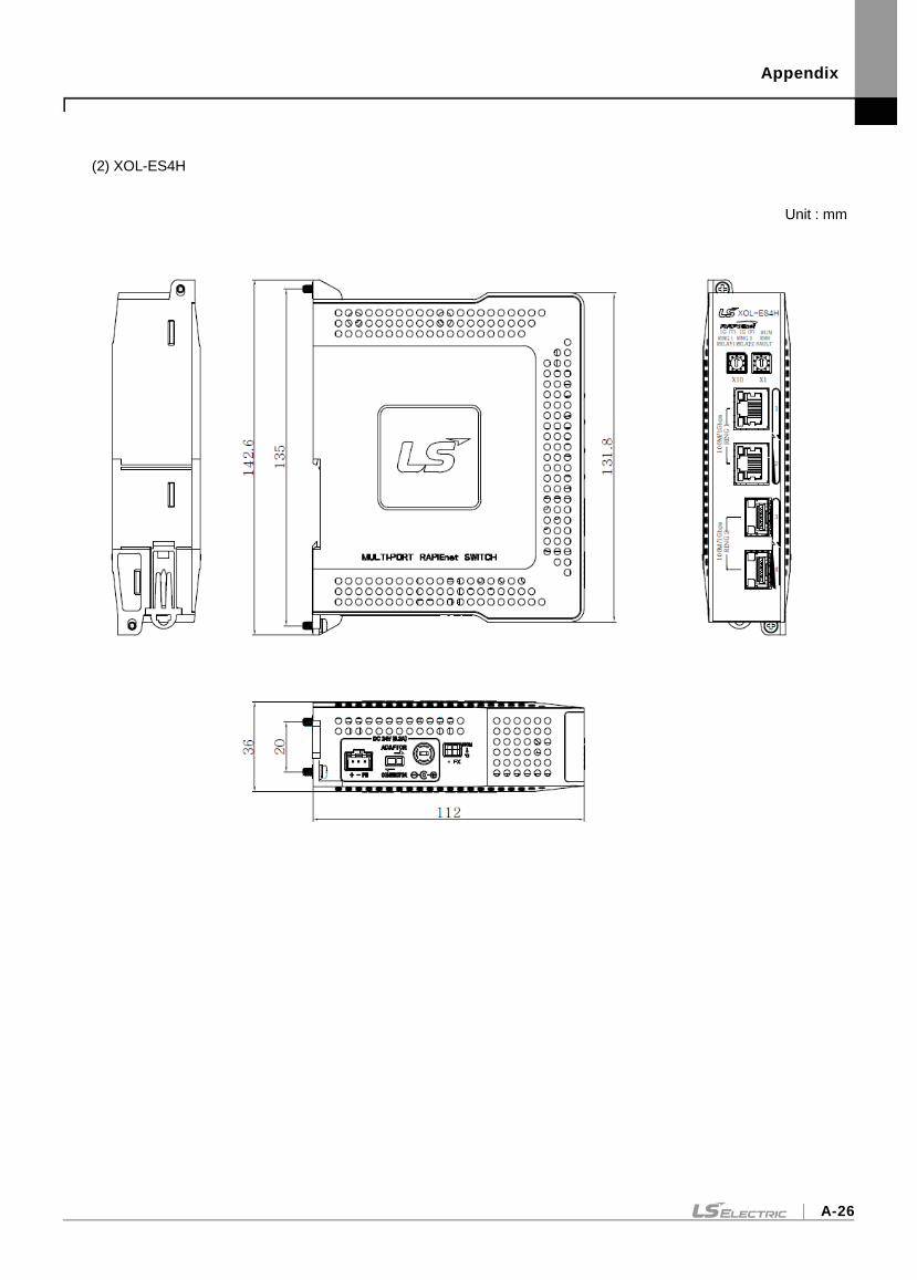
Appendix
A-26
(2) XOL-ES4H
Unit : mm
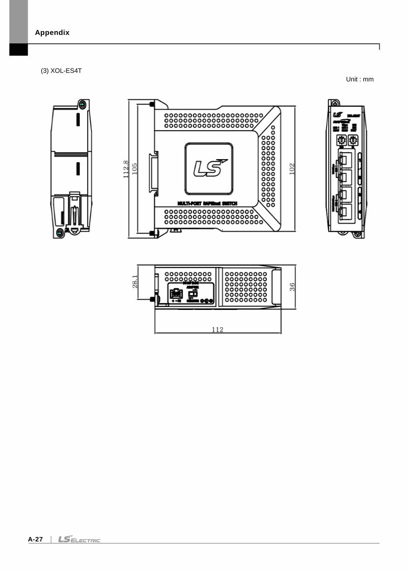
Appendix
A-27
(3) XOL-ES4T
Unit : mm

Appendix
A-28
Warranty and Environmental Policy
1
Warranty
1. Warranty Period
The product you purchased will be guaranteed for 18 months from the date of manufacturing.
2. Scope of Warranty
Any trouble or defect occurring for the above-mentioned period will be partially replaced or repaired. However, please note the following
cases will be excluded from the scope of warranty.
(1) Any trouble attributable to unreasonable condition, environment or handling otherwise specified in the manual,
(2) Any trouble attributable to others’ products,
(3) If the product is modified or repaired in any other place not designated by the company,
(4) Due to unintended purposes
(5) Owing to the reasons unexpected at the level of the contemporary science and technology when delivered.
(6) Not attributable to the company; for instance, natural disasters or fire
3. Since the above warranty is limited to PLC unit only, make sure to use the product considering the safety for system configuration or
applications.
Environmental Policy
LS ELECTRIC Co., Ltd supports and observes the environmental policy as below.
Environmental Management
LS ELECTRIC considers the environmental
preservation as the preferential management
subject and every staff of LS ELECTRIC use
the reasonable endeavors for the pleasurably
environmental preservation of the earth.
About Disposal
LS ELECTRIC’ PLC unit is designed to protect
the environment. For the disposal, separate
aluminum, iron and synthetic resin (cover) from
the product as they are reusable.

Warranty and Environment Policy
2

www.lselectric.co.kr
Overseas Subsidiaries
• LS ELECTRIC Japan Co., Ltd. (Tokyo, Japan)
Tel: 81-3-6268-8241 E-Mail: [email protected]
• LS ELECTRIC (Dalian) Co., Ltd. (Dalian, China)
Tel: 86-411-8730-6495 E-Mail: [email protected]
• LS ELECTRIC (Wuxi) Co., Ltd. (Wuxi, China)
Tel: 86-510-6851-6666 E-Mail: [email protected]
• LS ELECTRIC Shanghai Office (China)
Tel: 86-21-5237-9977 E-Mail: [email protected]
• LS ELECTRIC Vietnam Co., Ltd.
Tel: 84-93-631-4099 E-Mail: [email protected] (Hanoi)
Tel: 84-28-3823-7890 E-Mail: [email protected] (Hochiminh)
• LS ELECTRIC Middle East FZE (Dubai, U.A.E.)
Tel: 971-4-886-5360 E-Mail: [email protected]
• LS ELECTRIC Europe B.V. (Hoofddorf, Netherlands)
Tel: 31-20-654-1424 E-Mail: [email protected]
• LS ELECTRIC America Inc. (Chicago, USA)
Tel: 1-800-891-2941 E-Mail: [email protected]
Headquarter
LS-ro 127(Hogye-dong) Dongan-gu, Anyang-si, Gyeonggi-Do, 14119,
Korea
Seoul Office
LS Yongsan Tower, 92, Hangang-daero, Yongsan-gu, Seoul, 04386,
Korea
Tel: 82-2-2034-4033, 4888, 4703 Fax: 82-2-2034-4588
E-mail: [email protected]
Factory
56, Samseong 4-gil, Mokcheon-eup, Dongnam-gu, Cheonan-si,
Chungcheongnam-do, 31226, Korea
©2005. LS ELECTRIC Co., Ltd. All Rights Reserved.
2020.06
Related Documents