XGT Dedicated Enet I/F Module XGL-EDMT/EDMF ※ LS Industrial Systems constantly endeavors to improve its product so that information in this manual is subject to change without notice. ⓒ LS Industrial systems Co., Ltd 2006 All Rights Reserved. Right choice for ultimate yield LSIS strives to maximize customers' profit in gratitude of choosing us for your partner. User Manual LS values every single customer. Quality and service come first at LSIS. Always at your service, standing for our customers. Read this manual carefully before installing, wiring, operating, servicing or inspecting this equipment. Keep this manual within easy reach for quick reference. Programmable Logic Controller ■ HEAD OFFICE Yonsei Jaedan Severance Bldg. 84-11 5 ga, Namdaemun-ro, Jung-gu Seoul 100-753, Korea http://eng.lsis.biz Tel. (82-2)2034-4643~4649 Fax.(82-2)2034-4879, 2034-4885 ■ LS Industrial Systems Tokyo Office >> Japan Address: 16F, Higashi-Kan, Akasaka Twin Towers 17- 22, 2-chome, Akasaka, Minato-ku, Tokyo 107-8470, Japan Tel: 81-3-3582-9128 Fax: 81-3-3582-2667 e-mail: [email protected] ■ LS Industrial Systems Dubai Rep. Office >> UAE Address: P.O.BOX-114216, API World Tower, 303B, Sheikh Zayed road, Dubai, UAE. e-mail: [email protected] Tel: 971-4-3328289 Fax: 971-4-3329444 ■ LS-VINA Industrial Systems Co., Ltd. >> Vietnam Address: LSIS VINA Congty che tao may dien Viet-Hung Dong Anh Hanoi, Vietnam e-mail: [email protected] Tel: 84-4-882-0222 Fax: 84-4-882-0220 ■ LS Industrial Systems Hanoi Office >> Vietnam Address: Room C21, 5th Floor, Horison Hotel, 40 Cat Linh, Hanoi, Vietnam Tel: 84-4-736-6270/1 Fax: 84-4-736-6269 ■ Dalian LS Industrial Systems co., Ltd, >> China Address: No. 15 Liaohexi 3 Road, economic and technical development zone, Dalian, China e-mail: [email protected] Tel: 86-411-8273-7777 Fax: 86-411-8730-7560 ■ LS Industrial Systems (Shanghai) Co., Ltd. >> China Address: Room E-G, 12th Floor Huamin Empire Plaza, No. 726, West Yan’an Road, Shanghai, China Tel: 86-21-5237-9977 ■ LS Industrial Systems(Wuxi) Co., Ltd. >> China Address: 102-A National High & New Tech Industrial Development Area, Wuxi, Jiangsu, China e-mail: [email protected] Tel: 86-510-534-6666 Fax: 86-510-522-4078 ■ LS Industrial Systems Beijing Office >> China Address: B-tower 17th Floor, Beijing Global Trade Center building, No. 36, BeiSanHuanDong-Lu, DongCheng-District, Beijing, China Tel: 86-10-5825-6025 ■ LS Industrial Systems Guangzhou Office >> China Address: Room 1403, 14F, New Poly Tower, 2 Zhongshan Liu Rad, Guangzhou, China e-mail: [email protected] Tel: 86-20-8326-6754 Fax: 86-20-8326-6287 ■ LS Industrial Systems Chengdu Office >> China Address: Room 2907, Zhong Yin B/D, No. 35, Renminzhong(2)- Road, Chengdu, China e-mail: [email protected] Tel: 86-28-8612-9151 Fax: 86-28-8612-9236 ■ LS Industrial Systems Qingdao Office >> China Address: 12th Floor, Guodong building, No52 Jindun Road, Chengdu, China e-mail: [email protected] Tel: 86-532-580-2539 Fax: 86-532-583-3793 10310000629 XGT Series/2006,11

XGT Dedicated Enet I/F Module - AYPER OTOMASYON | … · 2015-09-18 · XGT Dedicated Enet I/F Module ... Chengdu, China e-mail: [email protected] Tel: 86-28-8612-9151 Fax: 86-28-8612
Jul 19, 2018
Welcome message from author
This document is posted to help you gain knowledge. Please leave a comment to let me know what you think about it! Share it to your friends and learn new things together.
Transcript

XGT Dedicated Enet I/F Module
XGL-EDMT/EDMF
※ LS Industrial Systems constantly endeavors to improve its product so that
information in this manual is subject to change without notice. LS Industrial systems Co., Ltd 2006 All Rights Reserved.
Right choice for ultimate yield LSIS strives to maximize customers' profit in gratitude of choosing us for your partner.
User Manual
LS values every single customer.
Quality and service come first at LSIS.
Always at your service, standing for our customers.
Read this manual carefully before installing, wiring, operating, servicing or inspecting this equipment.
Keep this manual within easy reach for quick reference.
Programmable Logic Controller
HEAD OFFICE
Yonsei Jaedan Severance Bldg. 84-11 5 ga, Namdaemun-ro,
Jung-gu Seoul 100-753, Korea http://eng.lsis.biz
Tel. (82-2)2034-4643~4649 Fax.(82-2)2034-4879, 2034-4885
LS Industrial Systems Tokyo Office >> Japan
Address: 16F, Higashi-Kan, Akasaka Twin Towers 17- 22,
2-chome, Akasaka, Minato-ku, Tokyo 107-8470, Japan
Tel: 81-3-3582-9128 Fax: 81-3-3582-2667
e-mail: [email protected]
LS Industrial Systems Dubai Rep. Office >> UAE
Address: P.O.BOX-114216, API World Tower, 303B, Sheikh
Zayed road, Dubai, UAE. e-mail: [email protected]
Tel: 971-4-3328289 Fax: 971-4-3329444
LS-VINA Industrial Systems Co., Ltd. >> Vietnam
Address: LSIS VINA Congty che tao may dien Viet-Hung
Dong Anh Hanoi, Vietnam e-mail: [email protected]
Tel: 84-4-882-0222 Fax: 84-4-882-0220
LS Industrial Systems Hanoi Office >> Vietnam
Address: Room C21, 5th Floor, Horison Hotel, 40 Cat Linh,
Hanoi, Vietnam
Tel: 84-4-736-6270/1 Fax: 84-4-736-6269
Dalian LS Industrial Systems co., Ltd, >> China
Address: No. 15 Liaohexi 3 Road, economic and technical
development zone, Dalian, China e-mail: [email protected]
Tel: 86-411-8273-7777 Fax: 86-411-8730-7560
LS Industrial Systems (Shanghai) Co., Ltd. >> China
Address: Room E-G, 12th Floor Huamin Empire Plaza,
No. 726, West Yan’an Road, Shanghai, China
Tel: 86-21-5237-9977
LS Industrial Systems(Wuxi) Co., Ltd. >> China
Address: 102-A National High & New Tech Industrial
Development Area, Wuxi, Jiangsu, China e-mail: [email protected]
Tel: 86-510-534-6666 Fax: 86-510-522-4078
LS Industrial Systems Beijing Office >> China
Address: B-tower 17th Floor, Beijing Global Trade Center building,
No. 36, BeiSanHuanDong-Lu, DongCheng-District, Beijing, China
Tel: 86-10-5825-6025
LS Industrial Systems Guangzhou Office >> China
Address: Room 1403, 14F, New Poly Tower, 2 Zhongshan Liu
Rad, Guangzhou, China e-mail: [email protected]
Tel: 86-20-8326-6754 Fax: 86-20-8326-6287
LS Industrial Systems Chengdu Office >> China
Address: Room 2907, Zhong Yin B/D, No. 35, Renminzhong(2)-
Road, Chengdu, China e-mail: [email protected]
Tel: 86-28-8612-9151 Fax: 86-28-8612-9236
LS Industrial Systems Qingdao Office >> China
Address: 12th Floor, Guodong building, No52 Jindun Road,
Chengdu, China e-mail: [email protected]
Tel: 86-532-580-2539 Fax: 86-532-583-3793
10310000629
XGT Series/2006,11

Safety Instructions
Safety Instructions should always be observed in order to prevent accident or risk with the safe and proper use the product.
Instructions are separated into “Danger”, “Warning” and “Caution”, and the meaning of the terms is as follows;
The marks displayed on the product and in the user’s manual have the following meanings.
This mark is to call a user's attention to actions and operations which may cause dangerous situation. Instructions with this mark shall be carefully read and observed to keep from dangerous situation.
This mark is to call a user's attention to possibility of electric shock under the special conditions.
This symbol indicates that serious injury or death may be caused in a moment if some applicable instructions are violated.
This symbol indicates the possibility of serious injury or death if some applicable instructions are violated.
This symbol indicates the possibility of slight injury or damage to products if some applicable instructions are violated.
Danger
Warning
Caution
Safety Instructions when designing
Safety Instructions when installing
Safety Instructions when wiring
Surely use the ground wire of Class 3 for FG terminals, which is exclusively used for PLC. If the terminals not grounded correctly, abnormal operation may be caused.
Prior to wiring and connection in PLC, check the rated voltage and terminal arrangement of the product. If other power than rated is connected or wiring is incorrect, it may cause fire or defect.
Secure the screws of terminals tightly with specified torque when wiring. If the screws of terminals get loose, short circuit or abnormal operation may be caused.
Don’t let any foreign materials such as wiring waste inside the module
Caution
Use PLC only in the environment specified in general standard. If not, electric shock, fire, abnormal operation of the product or flames may be caused.
Be sure that the module is correctly secured. If the module is not installed correctly, abnormal operation, error or dropping may be caused.
Caution
I/O signal or communication line shall be designed at least 100mm away from a high-voltage cable or power line to be kept from influence of noise or magnetic
field changing . If not, it may cause abnormal operation. Let the product installed free from direct vibration if lots of vibration is expected. Be sure to install the product free from metallic dust which may cause abnormal operation if lots metallic dust is expected.
Caution
Safety Instructions for test-operation or repair
Safety Instructions for waste disposal
Don’t remove PCB from the module case nor remodel the module. Defect, abnormal operation, product damage or fire may occur. Prior to installing or disassembling the module, let the power off. The battery shall be exchanged only when the power is On. If it is exchanged while the power is Off, the program may be lost.
Caution
Product waste shall be processed as industrial waste.
Caution
Don’t touch the terminal when powered. Abnormal operation or electric shock may occur. Prior to cleaning or tightening the terminal screws, let the power off.
Warning

Revision History
Date Manual number Description
’05.03 10310000503 First Edition.
‘05.5.19 10310000503 Description of function is added. (Page: A-5).
’06.6.30 10310000503 Terminologies are edited.

About User’s Manual
About User’s Manual
Congratulations on purchasing PLC of LS Industrial System Co.,Ltd.
Before use, make sure to carefully read and understand the User’s Manual about the functions,
performances, installation and programming of the product you purchased in order for correct use and
importantly, let the end user and maintenance administrator to be provided with the User’s Manual.
The Use’s Manual describes the product. If necessary, you may refer to the following description and order
accordingly. In addition, you may connect our website(http://www.lsis.biz/) and download the information as a
PDF file.
Relevant User’s Manuals
Title Description No. of User’s
Manual
XGK-CPUA/CPUE/CPUH/CPUS
It describes specifications, system structure and EMC
spec. correspondence of CPU module, power module,
base, I/O module and increase cable
10310000508
XG5000 User’s Manual
It describes how to use XG5000 software especially
about online functions such as programming, printing,
monitoring and debugging by using XGT series
products.
10310000512
XGK Series
Instructions & Programming
It is the user’s manual for programming to explain how
to use commands that are used PLC system with XGK
CPU.
10310000510
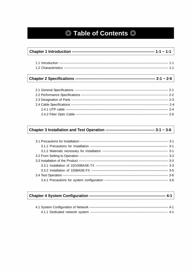
Table of Contents
Chapter 1 Introduction ---------------------------------------------------------------- 1-1 ~ 1-1 1.1 Introduction ----------------------------------------------------------------------------------------------------- 1-1
1.2 Characteristics ------------------------------------------------------------------------------------------------- 1-1
Chapter 2 Specifications -------------------------------------------------------------- 2-1 ~ 2-6
2.1 General Specifications --------------------------------------------------------------------------------------- 2-1 2.2 Performance Specifications --------------------------------------------------------------------------------- 2-2
2.3 Designation of Parts ------------------------------------------------------------------------------------------ 2-3 2.4 Cable Specifications ------------------------------------------------------------------------------------------- 2-4
2.4.1 UTP cable ----------------------------------------------------------------------------------------------- 2-4 2.4.2 Fiber Optic Cable -------------------------------------------------------------------------------------- 2-6
Chapter 3 Installation and Test Operation -------------------------------------- 3-1 ~ 3-6
3.1 Precautions for Installation ---------------------------------------------------------------------------------- 3-1 3.1.1 Precautions for Installation ------------------------------------------------------------------------ 3-1 3.1.2 Materials necessary for installation ------------------------------------------------------------- 3-1
3.2 From Setting to Operation ----------------------------------------------------------------------------------- 3-2 3.3 Installation of the Product ----------------------------------------------------------------------------------- 3-3
3.3.1 Installation of 10/100BASE-TX ------------------------------------------------------------------- 3-3 3.3.2 Installation of 100BASE-FX ----------------------------------------------------------------------- 3-5
3.4 Test Operation -------------------------------------------------------------------------------------------------- 3-6 3.4.1 Precautions for system configuration ----------------------------------------------------------- 3-6
Chapter 4 System Configuration ----------------------------------------------------------- 4-1
4.1 System Configuration of Network ------------------------------------------------------------------------- 4-1 4.1.1 Dedicated network system ------------------------------------------------------------------------ 4-1

Chapter 5 Communication Program --------------------------------------------- 5-1 ~ 5-10
5.1 Communication Program ------------------------------------------------------------------------------------ 5-1 5.1.1 Type of communication program ---------------------------------------------------------------- 5-1 5.1.2 Differences between HS link and P2P --------------------------------------------------------- 5-1
5.2 XG-PD ------------------------------------------------------------------------------------------------------------ 5-2 5.2.1 Introduction ------------------------------------------------------------------------------------------- 5-2 5.2.2 Basic setting ------------------------------------------------------------------------------------------ 5-3 5.2.3 Connect to communication module and download ----------------------------------------- 5-5
Chapter 6 High-speed Link -------------------------------------------------------- 6-1 ~ 6-19 6.1 Introduction ----------------------------------------------------------------------------------------------------- 6-1
6.2 HS link Tx/Rx Data Processing ---------------------------------------------------------------------------- 6-2 6.3 Operation Sequence through HS link -------------------------------------------------------------------- 6-3 6.4 HS link parameters setting ---------------------------------------------------------------------------------- 6-4
6.4.1 HS link parameters setting of XG-PD --------------------------------------------------------- 6-4 6.5 HS Link Information ----------------------------------------------------------------------------------------- 6-12
6.5.1 Monitor of HS link information ------------------------------------------------------------------ 6-14 6.6 Calculation of HS Link Speed ----------------------------------------------------------------------------- 6-16
6.6.1 Introduction ------------------------------------------------------------------------------------------ 6-16 6.6.2 Calculation of HS Link speed ------------------------------------------------------------------- 6-18
Chapter 7 P2P Service --------------------------------------------------------------- 7-1 ~ 7-10 7.1 Introduction ----------------------------------------------------------------------------------------------------- 7-1 7.2 P2P Instructions ----------------------------------------------------------------------------------------------- 7-2 7.3 P2P Application ------------------------------------------------------------------------------------------------ 7-2
7.3.1 Functions and setting of P2P --------------------------------------------------------------------- 7-4 7.4 Operation Sequence of P2P Service --------------------------------------------------------------------- 7-7 7.5 P2P Service Information ------------------------------------------------------------------------------------- 7-9
Chapter 8 Remote Communication Control ------------------------------------ 8-1 ~ 8-7 8.1 Introduction ----------------------------------------------------------------------------------------------------- 8-1 8.2 Remote connection example of XG5000/XG-PD ----------------------------------------------------- 8-2

Chapter 9 Program Example --------------------------------------------------------- 9-1 ~ 9-9 9.1 HS Link Program ---------------------------------------------------------------------------------------------- 9-1
9.1.1 HS link service between PLCs ------------------------------------------------------------------- 9-1 9.1.2 P2P service between PLCs of FDEnet ----------------------------------------------------------- 9-5
Chapter 10 Troubleshooting ------------------------------------------------------ 10-1 ~ 10-3 10.1 Diagnosis through communication module LED --------------------------------------------------- 10-1
10.1.1 Display of abnormal operation ---------------------------------------------------------------- 10-1 10.2 Diagnosis of Communication Module through XG5000 ------------------------------------------ 10-3
Appendix --------------------------------------------------------------------------------- A-1 ~ A-11 A.1 Terminology ---------------------------------------------------------------------------------------------------- A-1 A.2 List of Flags --------------------------------------------------------------------------------------------------- A-6
A.2.1 HS link flags -------------------------------------------------------------------------------------------- A-6 A.2.2 Link devices (N) --------------------------------------------------------------------------------------- A-9
A.3 External Dimensions ---------------------------------------------------------------------------------------- A-11

Chapter 1 Introduction
1-1
Chapter 1 Introduction
1.1 Introduction
This user’s manual is prepared to describe Dedicated Ethernet Interface Module of XGT series (Fast Dedicated Ethernet I/F module, hereinafter referred to as FDEnet I/F module). With the method of Ethernet-based Token Ring, communication can be controlled along with convenient network established in addition to the great amount of data collection available at high speed. FDEnet I/F module as an interface module uses 10/100BASE-TX and 100BASE-FX according to media type to transfer between PLCs.
Product configuration of XGT FDEnet I/F module is as follows;
Model Description Remarks
XGL-EDMT 10/100BASE-TX Category 5
XGL-EDMF 100BASE-FX Fiber Optic
1.2 Characteristics
XGT FDEnet I/F module has the following characteristics;
Conforms to IEEE 802.3 standard. HS link supported for HS data communication between LS modules:100Mbps Both 10/100BASE-TX and 100BASE-FX media supported. P2P service communication Network status monitored, information collected (LS communication module). Up to 12 units can be installed on 1 CPU module (up to 24 communication modules available)
Installed on the basic base and the added base Various system configurations available through basic parameters change
10/100 Base-TX
HUB
HUB HUB
Chapter 2 Specifications
2-1
Chapter 2 Specifications
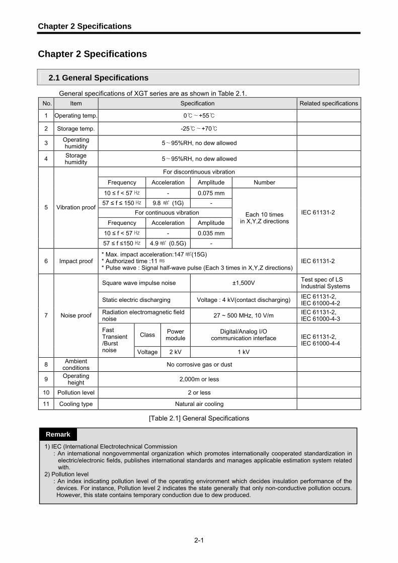
2.1 General Specifications
General specifications of XGT series are as shown in Table 2.1. No. Item Specification Related specifications
1 Operating temp. 0 +55∼
2 Storage temp. -25 +70∼
3 Operating humidity 5 95%RH, ∼ no dew allowed
4 Storage humidity 5 95%RH, no dew allowed∼
For discontinuous vibration
Frequency Acceleration Amplitude Number
10 ≤ f < 57 - 0.075 mm 57 ≤ f ≤ 150 9.8 (1G) -
For continuous vibration
Frequency Acceleration Amplitude
10 ≤ f < 57 - 0.035 mm
5 Vibration proof
57 ≤ f ≤150 4.9 (0.5G) -
Each 10 times in X,Y,Z directions
IEC 61131-2
6 Impact proof * Max. impact acceleration:147 (15G) * Authorized time :11 * Pulse wave : Signal half-wave pulse (Each 3 times in X,Y,Z directions)
IEC 61131-2
Square wave impulse noise ±1,500V Test spec of LS Industrial Systems
Static electric discharging Voltage : 4 kV(contact discharging) IEC 61131-2, IEC 61000-4-2
Radiation electromagnetic fieldnoise 27 ~ 500 MHz, 10 V/m IEC 61131-2,
IEC 61000-4-3
Class Power module
Digital/Analog I/O communication interface
7 Noise proof
Fast Transient /Burst noise Voltage 2 kV 1 kV
IEC 61131-2, IEC 61000-4-4
8 Ambient conditions No corrosive gas or dust
9 Operating height 2,000m or less
10 Pollution level 2 or less
11 Cooling type Natural air cooling
[Table 2.1] General Specifications
1) IEC (International Electrotechnical Commission : An international nongovernmental organization which promotes internationally cooperated standardization in
electric/electronic fields, publishes international standards and manages applicable estimation system related with.
2) Pollution level : An index indicating pollution level of the operating environment which decides insulation performance of the devices. For instance, Pollution level 2 indicates the state generally that only non-conductive pollution occurs. However, this state contains temporary conduction due to dew produced.
Remark
Chapter 2 Specifications
2-2
2.2 Performance Specifications
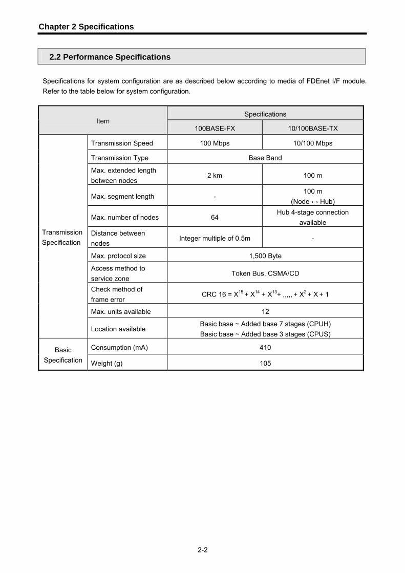
Specifications for system configuration are as described below according to media of FDEnet I/F module. Refer to the table below for system configuration.
Specifications Item
100BASE-FX 10/100BASE-TX
Transmission Speed 100 Mbps 10/100 Mbps
Transmission Type Base Band
Max. extended length between nodes
2 km 100 m
Max. segment length - 100 m
(Node ↔ Hub)
Max. number of nodes 64 Hub 4-stage connection
available Distance between nodes
Integer multiple of 0.5m -
Max. protocol size 1,500 Byte
Access method to service zone
Token Bus, CSMA/CD
Check method of frame error
CRC 16 = X15 + X14 + X13+ ,,,,, + X2 + X + 1
Max. units available 12
Transmission Specification
Location available Basic base ~ Added base 7 stages (CPUH) Basic base ~ Added base 3 stages (CPUS)
Consumption (mA) 410 Basic Specification Weight (g) 105
Chapter 2 Specifications
2-3
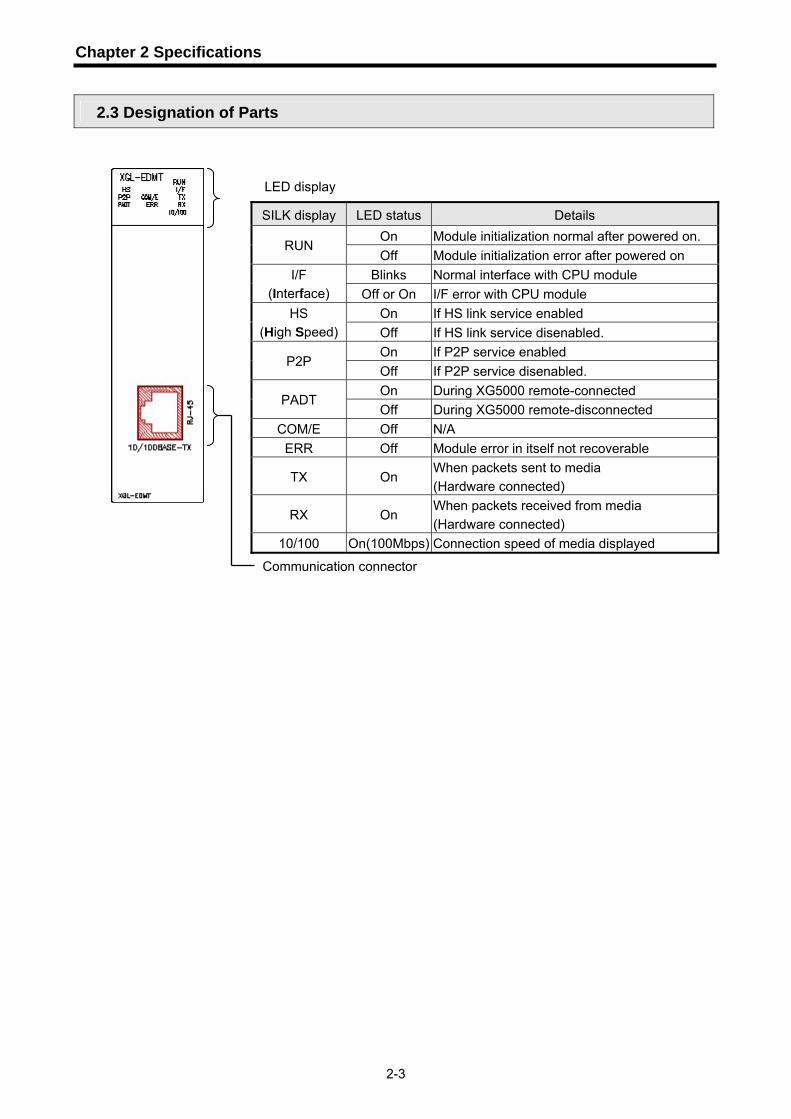
2.3 Designation of Parts
SILK display LED status Details On Module initialization normal after powered on.
RUN Off Module initialization error after powered on
Blinks Normal interface with CPU module I/F (Interface) Off or On I/F error with CPU module
On If HS link service enabled HS (High Speed) Off If HS link service disenabled.
On If P2P service enabled P2P
Off If P2P service disenabled. On During XG5000 remote-connected
PADT Off During XG5000 remote-disconnected
COM/E Off N/A ERR Off Module error in itself not recoverable
TX On When packets sent to media (Hardware connected)
RX On When packets received from media (Hardware connected)
10/100 On(100Mbps) Connection speed of media displayed
LED display
Communication connector

Chapter 2 Specifications
2-4
2.4 Cable Specifications
2.4.1 UTP cable UTP cable is classified into 3 types based on the following standards. ① Shield existence: classified into 3 (UTP, FTP, STP) ② Frequency band used: classified into 7 (Category 1 ~ 7) ③ Incombustibility grade : classified into 4 (CMX, CM, CMR, CMP)
1) Type of cables based on shield existence Classification Details Purpose
UTP(or U.UTP) So called unshielded cable used for HS signal
Max. 200MHz Phonetic + Data + Low grade of video signal
FTP(or S.UTP)
Cable with cable core only shielded solely *Shield material : AL/Plastic complex foil or Copper Braid
Max.100MHz Electronic impediment (EMI) and electric stability considered Phonetic + Data + Low grade of video signal
STP(or S.STP)
Double-shielded structure, pair shielded and core shielded cable *Pair shield material : AL/Plastic complex foil
* Core shield material : AL/Plastic complex foil or Copper Braid
Max. 500MHz Phonetic + Data + Video signal Substitute for 75Ω coaxial cable
Remark 1) UTP : Unshielded Twisted Paired Copper Cable
FTP : (Overall) Foiled Twisted Paired Copper Cable STP : (Overall) Shielded (and Shielded Individually Pair) Twisted Paired Copper Cable
2) Patch Cable(or Patch Cord) Stranded Conductor composed of stranded cable instead of solid conductor may be used to increase the flexibility of UTP 4-pair cable. Material and specification of stranded cable used are specified by UL444, and the representative specification and material are Un-coated AWG 24 (7/0203A). In other words, the diameter of a single cable is 0.203mm, and this cable is of 1+6 structure as standardized with annealed copper cable.
UTP STP FTP

Chapter 2 Specifications
2-5
2) Classification based on frequency used
Classification Frequency used
(MHz) Transmission Speed (Mbps)
Purpose
Category 1 Phonetic Frequency 1 Phone network (2-Pair)
Category 2 4 4 Multi-Pair communication cable
Category 3 16 16 Phone network + Computer network
Category 4 20 20 1) Computer network transmission
speed Up 2) Low-loss communication cable
Category 5 & Enhanced Category 5
100 100 1) Digital Phone network + Computer
network 2) Low-loss, broadband cable
Remark
1) Presently classified items are Category 3, 5, Enhanced Category 5 & Category 6 inside and
outside of the country, where Category 4 has been replaced by Category 5 and Category 7 is being under development all over the world as STP structure.
3) Classification based on incombustibility grade (based on UL criteria)
Classification Heat
applied Time
applied Combustion
length Smoke Remarks
CMP 88(kW) 20
minutes 73m/min or
less Controlled
• For ceiling with no duct • Plenum Cable • UL 910 (Plenum Test)
CMR 150(kW) 30
minutes 3.6m or
less Not
controlled
• For vertical application • Non-Plenum Cable • UL 1666(Riser Test)
CM 21(kW) 20
minutes 2.4m or
less Not
controlled
• General type • Non-Plenum Cable • UL 1581(VTFT Test)
CMX 1(kW) 1 minute0.5m or
less Not
controlled
• Limited application • Non-Plenum Cable • UL 1581 (VW-1 Test)
Remark
1) As a rule, CMG between CM and CMR grades is not applied to LAN cable such as UTP
cable. Ex) CMG: As CAS FT4 (VTFT Test), it is similar to CM of UL 1581.
→ Different between burner angle (horizontal→45°upward) and sample condition (arranged 1/2 distance →Bundle of 6 x 6).

Chapter 2 Specifications
2-6
4) Example of Category 5 Twisted Pair Cable (UTP)(CTP-LAN5) Item Unit Value
Conductor resistance (max.) Ω/km 93.5 Insulation resistance (min.) MΩ/km 2500 Voltage resistance V/min AC 500 Characteristic impedance Ω(1~100MHz) 100 ± 15
10MHz 6.5 16MHz 8.2 Decrement
dB/100m or less
20MHz 9.3 10MHz 47 16MHz 44 Near-end crosstalk decrement
dB/100m or less
20MHz 42
2.4.2 Fiber Optic Cable
Item Value Cable Type Twin strands of Multimode fiber(MMF) Connector SC Type Connector Diameter of optical fiber 62.5/125um (62.5um fiber optic core and 125um outer cladding) Wavelength used 1350 nm Decrement 2dB/1000m or less Near-end crosstalk decrement 11dB or less
Remark
1) Since the type of the connection cable used for communication module differs from each other based on the system configuration and its environment, applicable professional advice will be required prior to installation.
2) The optical cable may have communication errors due to natural decrement in its characteristics if any fingerprint or contamination is stuck on the sectional end of the cable during its treatment.

Chapter 3 Installation and Test Operation
3-1
Chapter 3 Installation and Test Operation
3.1 Precautions for Installation
3.1.1 Precautions for Installation For system configuration through FDEnet I/F module, carefully make sure of the following items prior to installation.
1) Check the basic factors necessary for system configuration so to select an appropriate
communication module. 2) Select the cable to be used for this communication module (only one is available between 10/100
BASE-TX and 100BASE-FX). 3) Before the communication module is installed, check for any foreign material on the base
connector the module will be installed on and any damage on the connector pin of the module. 4) All the communication modules can be installed on the basic base ~ added base 7 stages (XGK-
CPUH), the basic base ~ added base 3 stages (XGK-CPUS). 5) For installation of the module, exactly insert the protuberant part at the bottom of the module with
the communication cable disconnected into the base groove and then apply enough strength until its top is locked up with the locking device of the base. If the lock is not applied, it may cause an error on the interface with CPU.
6) The cable available for the communication module shall be installed with one type only between 10/100BASE-TX and 100BASE-FX.
7) Select standard products of switching hub and cable, which are necessary for communication with FDEnet I/F module
3.1.2 Materials necessary for installation
Materials necessary 10/100BASE-TX Coaxial cable (impedance 50Ω) Not available AUI cable Not available Twisted pair cable (impedance 100Ω) 4 twisted pairs (8-pole plug at both ends) Transceiver MAU necessary if AUI used Terminal resistance (50Ω) Not available T type connector Not available Hub Used
Optic cable 62.5/125um MMF(Multi Mode Fiber) Cable SC Type connector
Hub/Switch Optic switch necessary

Chapter 3 Installation and Test Operation
3-2
3.2 From Setting to Operation
The sequence of the product from installation to operation will be described below. After the product installation is complete, install and configure the system to be operated as specified in the following sequence.
Operation Sequence
6 Install FDEnet I/F module on the base.
Check the applicable base/slot position for correct installation on the basic base.
6 Connect FDEnet I/F module with other network.
Use a jig applicable to media to configure the system.
6 With power On, check the LED status of the communication module.
Check if the interface of the communication module is normal with CPU.
6 Specify “Basic Setting” in XG-PD and then reset it.
If PLC is not reset after “Basic Setting” complete, the communication module will not be available.
6 Specify and download HS link parameters.
Specify HS link in XG-PD and download the applicable HS link parameters.
6 Let HS link parameters enabled.
If HS link parameters enabled in XG-PD, HS link service will be available.
6 Start Run
Remark
1) After station No. is specified in XG-PD, surely reset the applicable module. The value read from the communication module will be kept on when the first station No. is initialized. Any changed details during communication will not be applied during Run.
Chapter 3 Installation and Test Operation
3-3
3.3 Installation of the Product 3.3.1 Installation of 10/100BASE-TX
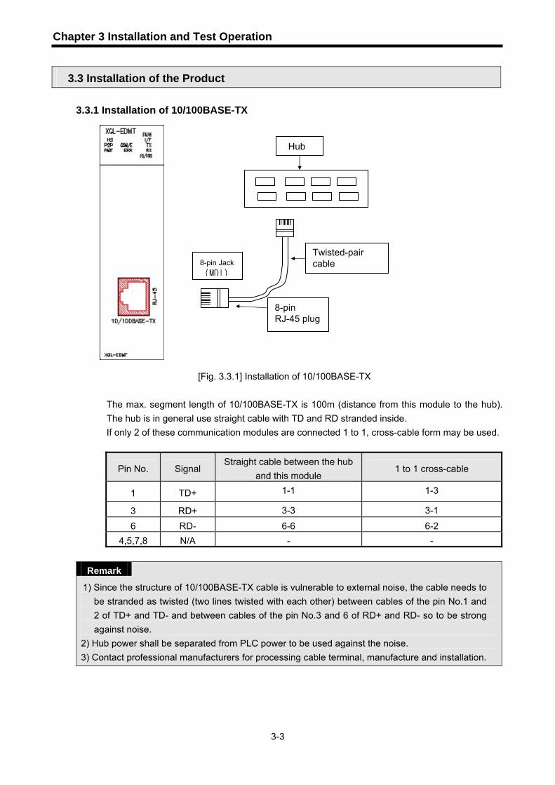
[Fig. 3.3.1] Installation of 10/100BASE-TX
The max. segment length of 10/100BASE-TX is 100m (distance from this module to the hub). The hub is in general use straight cable with TD and RD stranded inside. If only 2 of these communication modules are connected 1 to 1, cross-cable form may be used.
Pin No. Signal Straight cable between the hub
and this module 1 to 1 cross-cable
1 TD+ 1-1 1-3
3 RD+ 3-3 3-1
6 RD- 6-6 6-2 4,5,7,8 N/A - -
Remark
1) Since the structure of 10/100BASE-TX cable is vulnerable to external noise, the cable needs to be stranded as twisted (two lines twisted with each other) between cables of the pin No.1 and 2 of TD+ and TD- and between cables of the pin No.3 and 6 of RD+ and RD- so to be strong against noise.
2) Hub power shall be separated from PLC power to be used against the noise. 3) Contact professional manufacturers for processing cable terminal, manufacture and installation.
8-pin RJ-45 plug
8-pin Jack(MDI)
Twisted-pair cable
Hub

Chapter 3 Installation and Test Operation
3-4
1) UTP installation
(1) In order to transmit reliable 100Mbps sign with UTP cable, characteristics of patch cord, line cord, patch panel and DVO (Data Voice Outlet) shall conform to the Category 5 Spec. (EIA/TIA-568A).
(2) Be careful not to allow the length of patch cord to exceed 7m in cross-connect system. If 7m is exceeded, such subtraction as long as exceeded is required within the allowable value of 90m in Horizontal Distribution System.
(3) The length of line cord shall not exceed 3m in the workstation. If 3m is exceeded, such subtraction as long as exceeded is required within the allowable value of 90m in Horizontal Distribution System.
(4) When wiring between patch panel and DVO, the pair pitch of UTP cable shall not be loosened over the following measurements.
* Max. pair pitch loosened: Category 5: 13 mm Category 3: 26 mm (5) Use the jumper wire in IDC cross-connect system, and the pair pitch shall not be
loosened over the above-specified measurements either at this time. Especially, be careful not to bend the cable intensely, which may cause not only damage but also distance between pairs. * Max. radius of curvature: 4-pair cable : 4 times of external diameter
Cable with 25 or more pairs: 10 times of external diameter (6) Max. tension strength during wiring shall not exceed 110 N (11.3 Kgf), based on 4-pair cable. (7) Jumper wire and patch code shall be wired rather loosely. If wired too tight, the
characteristics of Category 5 may be deteriorated. If Tie-wrap is used, be careful not to apply stress on the cable.
(8) When UTP cable is installed, a suitable distance shall be maintained between EMI source and UTP cable.
The suitable distance for each case is as specified in the table below;
Min. separation distance
Condition 2.0 kVA or less 2.5 kVA 5.0 kVA or more
Power line unshielded, or electric facility open or near to nonmetallic pipe 127 mm 305 mm 610 mm
Power line unshielded, or electric facility near to metallic pipe buried 64 mm 152 mm 305 mm
Power line inside metallic pipe buried (or equivalently shielded) near to metallic pipe buried - 76 mm 152 mm
Remark
1) If voltage is 480 V, rated power is 5 kVA or more, separate calculation is needed.

Chapter 3 Installation and Test Operation
3-5
3.3.2 Installation of 100BASE-FX
[Fig. 3.3.2] Installation of 100BASE-FX
The max. segment length of 100BASE-FX is 2000 m (distance from this module to the optical
switch). Let the module’s Tx cross-connected with the optical switch’s Rx, and the module’s Rx
with the optical switch’s Tx.
Remark
1) Since the optical cable is vulnerable to impact, pressure, folding and pulling, pay good attention to its treatment. The optical contact between the connector and the end of the cable may have communication errors if contaminated, which may result in unavailable communication. If the cable is installed outdoors, additional countermeasures are required to protect the cable suitably for the installation environment.
Multi Mode SC
Optical switch

Chapter 3 Installation and Test Operation
3-6
3.4 Test Operation
3.4.1 Precautions for system configuration
1) HS link station No. of all stations shall be different from each other including this module in order
to use HS link service.
2) Use the communication cable as specified only. If not, serious error may occur to
communication.
3) Check communication cable if disconnected or shorted prior to installation.
4) Tighten up communication cable connector until connected firmly. If cable connection is unstable,
serious error may occur to communication.
5) If remote communication cable is connected, keep the cable far away from power line or
inductive noise.
6) Since the coaxial cable is not flexible, it is to be diverged min. 30cm away from the connector in
communication module. If the cable is bent at a right angle or transformed compulsorily, cable
disconnection or connector damage in communication module will be caused.
7) If LED operation is abnormal, refer to Chapter 10 Troubleshooting to check for causes and take
actions against. Contact Customer Service center if the error is as before.

Chapter 4 System Configuration
4-1
Chapter 4 System Configuration
4.1 System Configuration of Network
4.1.1 Dedicated network system
[Fig. 4.1.1] Dedicated Network System
10/100 Base T
PC
Monitor
(sniffer)
10/100 Switching
HUB
HUB
100 Base-FX (fiber optic)

Chapter 5 Communication Program
5-1
Chapter 5 Communication Program
There are two communication functions available in FDEnet I/F module as described below.
5.1 Communication Program
5.1.1 Type of communication program
1) HS link HS link as a communication method between XGT PLC communication modules is used to exchange data or information with correspondent station periodically for a specific time, through which the changed data of self station or the correspondent station can be referred to for each other periodically for efficient application to the operation system and execution of communication only with simple parameters setting. Parameters can be specified by setting Tx/Rx correspondent station area and self station area as well as data size, speed and station No. on XG-PD’s HS link parameters in order to execute communication. Data size is available from the min. 1 word (16 points) up to 200 words for the communication, communication cycle from the min. 20 ms up to 10 sec. based on the communication details. It is easy to use since communication with correspondent station is available only through simple parameters setting. And it is also useful for periodic process of lots of data at a time thanks to high processing speed of the internal data.
2) P2P HS link is of periodic communication, however, P2P communication is a service used for communication with the correspondent station only when a specific event happens. P2P can be used if any error occurs on the correspondent station and its details are to be sent to other correspondent station or specific contact is to be input for communication. Data size for HS link communication is of word unit (16 points). However, the data types of Bit, Byte, Word, etc. can be used respectively for communication with the correspondent station in P2P.

Chapter 5 Communication Program
5-2
5.1.2 Differences between HS link and P2P Differences between HS link and P2P service are as described in the table below; Differences are described as simply as below between specific data Tx/Rx periodically with the correspondent station (HS link) and transmission service of necessary data due to a specific event (P2P).
Description HS link P2P
Tx/Rx data basic unit 1 word (16 bits) Available for each data type
Ex) Bit, Byte, Word
Communication cycle
20ms, 50 ms, 100 ms, 200 ms, 500ms, 1s, 5s, 10s
Executed whenever P2P enable (REQ) condition is operated (timer)
Available communication
module
Between FDEnet I/F communicationmodules
Between FDEnet I/F communication modules
Station No. setting
Specify HS link station No. in XG-PD and download it onto FDEnet I/F module
Specify the station No. in XG-PD anddownload it onto FDEnet I/F module
[Table 5.1] Differences between HS link operation and P2P operation
5.2 XG-PD In order to use FDEnet I/F module, specify standard setting and parameters and then download the specified parameters onto FDEnet I/F module for application, which is available through the tool, so-called XG-PD.
5.2.1 Introduction
This is a tool used to specify basic system parameters and basic communication setting so to
control and manage the network in FDEnet I/F communication.
In XG-PD, there are HS link and P2P communication used to decide communication system
parameters for FDEnet I/F communication module.
Use-defined parameters can be written (downloaded) onto FDEnet I/F communication module
and can be also read (uploaded) from FDEnet I/F communication module.

Chapter 5 Communication Program
5-3
5.2.2 Standard setting
In order to operate FDEnet I/F module, the following standard setting shall be surely specified.
Click XG-PD icon of XG5000 or select ‘Tools’ ‘Network Manager’ to display the initial screen
of XG-PD as shown below in [Fig. 5.2.1].
1) Execution of XG-PD
If XG-PD is executed for the first time, the menu will be displayed as shown in the figure below;
[Fig. 5.2.1] If XG-PD is executed first
2) Standard setting Standard setting is to specify communication system parameters so to control and manage FDEnet I/F module where FDEnet I/F module’s station No. and media are to be set. Thus, for the dedicated network communication, after standard setting is specified on XG-PD’s ‘Module’ window, surely download and reset it. [Fig. 5.2.2] shows the specified basic parameters.

Chapter 5 Communication Program
5-4
[Fig. 5.2.2] XG-PD basic screen
[Fig. 5.2.3] Standard Settings (default)
Details of [Fig. 5.2.3] are as follows. Among those below, HS link station No. and Media need to be reset applicably to application environment.
Classification Description
HS link station No. Set station No. for HS link communication.
Media
Select media desired to use.
AUTO (electric): presently installed module is recognized and adjusted
automatically.
10M/FULL : 10MBps Full Duplex, electric
100M/FULL : 100MBps Full Duplex , electric
FX/100M/FULL : 100MBps Full Duplex, optic

Chapter 5 Communication Program
5-5
5.2.3 Connect to communication module and download
1) Standard setting download/upload XGT PLC’s communication module can read/write parameters and link enable by means of CPU module’s Loader Port.
(1) Write (download)
While CPU is running, stop CPU to write. Writing while CPU is running will make a serious effect on communication.
A) Use on-line connection to connect with CPU.
[Fig. 5.2.4] shows that connection is complete.
[Fig. 5.2.4] Connect screen
B) Standard setting screen after connected
(Double-click ‘Default’ of the slot installed on the base, select communication module
type of FDEnet, and then click [OK], and there double-click the left mouse button again to
open the standard setting screen.)
[Fig. 5.2.5] Standard Settings screen

Chapter 5 Communication Program
5-6
Classification Description
HS link station No. Set station No. of this module.
Media Set communication media of this module.
C) After standard setting is complete as specified in B), download the parameters.
(XG-PD [Online] -> [Write Parameter])
[Fig. 5.2.6] Check screen of standard setting
D) After standard setting is downloaded, surely let it powered back or reset. If not,
operation will continue with the old setting value.
2) HS link parameters setting
A) Select HS link parameters window (click HS link window of XG-PD)
[Fig. 5.2.7] HS link screen

Chapter 5 Communication Program
5-7
B) Communication module setting (Double-click HS link 01)
[Fig. 5.2.8] Setting of communication module and communication cycle
Classification Details
Module type Select FDEnet.
Base no. Select base no. the module is installed on. Communication
module setting Slot no. Select slot no. the module is installed on.
Communication
period setting Period type Set data Tx cycle.
C) Screen after communication module specified
[Fig. 5.2.9] Communication module setting

Chapter 5 Communication Program
5-8
D) HS link parameters setting (double-click the index No. on ‘HS link 5’ screen)
[Fig. 5.2.10] HS link block setting
Classification Details Master
Station type Slave
Set FDEnet to master or slave as applicable
Station No. Native station Set this module for Tx, correspondent module for RxAddress Memory area of this module. Read area
Size(Word) Specify the data size to transmit. Send Transmits data.
Block type Receive Receives data.
Block no. Block Specify Tx/Rx blocks.
Address Area to save the data received from correspondent station. Save area
Size(Word) Specify the data size to receive.

Chapter 5 Communication Program
5-9
E) HS link parameters download (XG-PD [Online] -> [Write Parameter])
[Fig. 5.2.11] HS link block setting
On the HS link parameters Write screen, check applicable HS link and click [OK].

Chapter 5 Communication Program
5-10
3) Read HS link parameters
A) Connect to CPU.
B) After connected, select On-line and Parameters Read to display the screen as shown in
[Fig. 5.2.11] and there, check the applicable parameters and click [OK] to read standard
setting and specified HS link parameters.
[Fig. 5.2.12] Read screen

Chapter 6 High-speed Link
6-1
Chapter 6 High-speed Link
6.1 Introduction
High-speed link (HS Link) is a communication method between XGT PLC communication modules to send and receive data with HS link parameters setting, which can also allow the user to use XG-PD to exchange data with parameters setting of Tx/Rx data size, Tx/Rx period, Tx/Rx area and area to save through its data transmission service function. However, since HS link service uses the subnet broad service, it may have an influence on other communication modules which use the identical network. Thus, setting as near to the max. Tx/Rx size (200 words) as available per HS link block is recommended for the user to obtain the greatest communication efficiency with the lowest influence on other modules so to reduce the sum of blocks. In order to make use of all functions, surely specify the basic communication parameters in the status of communication available. HS link functions are as specified below;
1) HS link block setting function (1) If there are many Tx/Rx areas, up to 96 blocks can be set (32 for Tx and 64 for Rx
respectively). (2) 200 words are available for a block. (3) Max. link points available are 19,200 words.
2) Tx/Rx period setting function Tx/Rx period can be set per block by user for the areas where especially fast Tx/Rx is required and not required respectively in a Tx/Rx period of 20ms to 10 sec.
3) Tx/Rx area setting function Tx/Rx area can be set per data block by user according to I/O address specified.
4) Providing function of HS link information Reliable communication system can be easily configured by providing HS link information for user via the user keyword.
[Table 6.1.1] shows communication HS link points whose basic unit is 1 word.
Classification Max. communication
points Max. Tx points Max. blocks
Max. points per block
XGK-CPUS 19,200 6,400 96 (0-63) 200
XGK-CPUH 19,200 6,400 96 (0-63) 200
[Table 6.1.1] Max. communication points

Chapter 6 High-speed Link
6-2
6.2 HS link Tx/Rx Data Processing
HS link application will be described below with the example where FDEnet I/F modules of the stations No.0 and No.1 are to send and receive the data between each other. Its setting sequence is as follows;
1) The station No.0 transmits M0000 data of 10 words to No.0 block. 2) The data received by the station No.1 is saved on M0010. 3) The station No.1 receives M0000 data of 10 words from the station No.0 to save on M0100. 4) M0110 data of 10 words is transmitted to No.1 block.
There are 32 blocks for Tx data and 64 blocks for Rx data in the HS link parameters. The block number can be set 0~31 for transmission or 0~63 for receiving. The Tx side needs only to decide which data to read and which block to send to without setting the correspondent station No. when transmitting the data
[Table 6.2.1] Diagram of HS link processing blocks
Station 0
•Station type: Local •Mode: Tx/Rx •Block No. : 0, 1 •Area to read: M0000 •Area to save: M0010 •Tx/Rx period: 200ms •Size: 10
Block 0
Block 1
Station 1
•Station type: Local •Mode: Tx/Rx •Block No.: 0, 1 •Area to read: M0110 •Area to save: M0100 •Tx/Rx period: 200ms •Size: 10
Block 0
Block 1

Chapter 6 High-speed Link
6-3
6.3 Operation Sequence through HS link
Set basic parameters 1 Use XG-PD
Select HS link 2 HS link setting window
Select HS link parameters 3 HS link1~12
Set HS link (link setting) 4 Network Type
FDEnet 5 Slot No.(0~11)
Set HS link (register list)
7 Station type
Local 8 Station No.(0~63)
9 Mode
Tx or Rx 10 Block No.(0~63) 11 Area to read/Area to save
12 Tx/Rx period (20ms~10sec)
13 Size (1~200 words)
On-line(after local-connected)
14 Write
HS link parameters
Set Enable Link 15 HS link1~12
Set the correspondent station as in 1~15 above
Set HS link parameters specified for HS link operation link-enabled in XG-PD
With XG-PD used, specify HS link station No. and media selection to download and then surely reset to apply those downloaded basic parameters.
Open HS link setting window of XG-PD
Set as applicable to the number of communication modules used (select HS link 1 if 1 communication module is used)
Input network type and self station’s slot No. wherecommunication module is installed
Self-station No. for Tx (set automatically) Correspondent station No. for Rx
Download HS link parameters from XG-PD onto CPU
Blocks available up to 32 for Tx and 64 for Rx. Tx/Rx data is sorted out by station No. and block No. of each other
Set self-station’s area to read for local Tx, and self-station’s area to save for Rx

Chapter 6 High-speed Link
6-4
6.4 HS link parameters setting
HS link parameters can be specified as selected on the XG-PD’s HS link screen for applicable items, whose setting sequence and respective functions are as follows.
6.4.1 HS link parameters setting of XG-PD
1) Execution of XG-PD
If XG-PD is executed for the first time, the screen will be displayed as shown in [Fig. 6.4.1]. Click XG5000’s ‘Tools’ ‘Network Manager’ or click XG-PD icon of XG5000.
[Fig. 6.4.1] Basic screen of XG-PD

Chapter 6 High-speed Link
6-5
2) Basic setting
(1) How to set the communication module
Double-click ‘Default’ of the slot where the communication module desired to operate is installed on the [Fig. 6.4.2] and XG-PD screen to select FDEnet on the Communication Module Setting window.
[Fig. 6.4.2] Communication Module Setting window
Item Description
Type Select a module desired to use
Base Inactive
Slot Inactive
[Table6.4.1] Communication module setting

Chapter 6 High-speed Link
6-6
(2) Standard Settings After FDEnet is selected on [Fig. 6.4.2], double-click the applicable FDEnet to set HS link station No. and media on the basic setting window.
[Fig. 6.4.3] Basic setting screen
(3) How to download basic setting
On [Fig. 6.4.1] XG-PD screen, select [Online] -> [Write Parameters] to open [Fig. 6.4.4]. Check applicable basic setting and click [OK] button. After basic setting is downloaded, surely let PLC power Off/On or reset. If the communication module is not reset, it will be not recognized as a communication module.
[Fig. 6.4.4] Write parameter screen

Chapter 6 High-speed Link
6-7
3) HS Link parameters setting
(1) Initial screen setting of HS link parameters
Select XG-PD’s HS link window as shown on [Fig. 6.4.5].
[Fig. 6.4.5] Initial setting screen of HS link
(2) Setting of communication module and communication period
Double-click one of the HS links 01~12 on the [Fig. 6.4.5] screen to open the setting screen of communication module and communication period where communication module and communication period can be specified.
[Fig. 6.4.6] Initial setting screen of HS link

Chapter 6 High-speed Link
6-8
Item Details
Module type Specify the communication module installed.
Base no. Specify the base position the module is installed on (max. 7 stages can be added). Setting range: 0 ~ 7
Communication module setting
Slot no. Specify the slot position the module is installed on (max. 12 units can be added). Setting range: 0 ~ 11
Communication period setting
Period type
- Set data Tx at periodic intervals. - Setting range; 20 , 50 , 100 , 200 , 500 , 1s, 5s, 10s
(default is 200 ) - However, Rx data will update the data whenever scanned regardless of
the communication period. - The communication period will be applied identically to the whole Tx/Rx
blocks. - Up to 4 blocks of data can be sent at a time. Even if this is exceeded,
the data will be divided into 4-block unit for transmission, with which the data size of a block has noting to do.
[Table 6.4.2] Setting of communication module and communication period

Chapter 6 High-speed Link
6-9
(3) HS link parameters setting
Click [OK] on [Fig.6.4.6] to display [Fig.6.4.7].
[Fig. 6.4.7] Initial setting screen of HS link
(4) Setting of HS link blocks
Double-click ‘Block’ on [Fig.6.4.7] to open [Fig.6.4.8].
[Fig. 6.4.8] Setting screen of HS link blocks

Chapter 6 High-speed Link
6-10
Classification Details
Master Station type
Slave Area to set the module application to master or slave
Station No. Self-station No.
Setting condition: 1) If station No. is for master with block type of Rx
2) If station No. is for slave Setting range: 0 ~ 63 If identical station No. is set, normal communication is not available.
Address
Area to set the start address of device used for Tx. Setting device : P, M, L, K, D, T, C (It shall not be duplicated with the device address being used in program) Read area
Size (Word) Set data size to transmit. Setting unit : Word Setting range :1 ~ 200
Tx Transmits data Block type
Rx Receives data.
Block No. Block No. Set Tx/Rx blocks Tx blocks: up to 32 (setting range: 0 ~ 31) Rx blocks: up to 64 (setting range: 0 ~ 31)
address
Area to set the start address of device used for Rx. Setting device : P, M, L, K, D, T, C (It shall not be duplicated with the device address being used in program) Save area
Size (Word) Set data size to receive. Setting unit : Word Setting range :1 ~ 200
[Table 6.4.3] HS link setting

Chapter 6 High-speed Link
6-11
(5) How to download HS link parameters
Click “Online” “Write Parameter” in XG-PD, check the applicable HS link and then click
[OK].
[Fig. 6.4.9] Parameters Write Screen
(6) HS link parameters enable
Click “Online” “Enable Link” in XG-PD, check the applicable HS link and then click
[Write]. If HS link is enabled, on the module’s LED display HS LED will be On, when HS
link starts.
[Fig. 6.4.10] Link Enable Screen

Chapter 6 High-speed Link
6-12
6.5 HS Link Information
With HS link service used to exchange data between communication modules of two or more stations, it provides a checking method of HS link service status for the user through HS link information so to confirm reliability of the data read from the correspondent station via the HS link. In other words, the communication module synthesizes the data received up to that time at intervals of a specific time and lets the user know if HS link operates as in parameters specified by the user through HS link information where the whole information of Run-link(_HSxRLINK) and Link-trouble(_HSxLTRBL) to provide the whole information of the communication network, and the individual information of _HSxSTATE, _HSxTRX, _HSxMOD and _HSxERR to provide communication status for 64 register items in the parameters are contained. The user can use the information in keyword format when programming, and also monitor the HS link status using the monitor function of the HS link information. Prior to its application, the user is requested to check the reliability of the Tx/Rx data through HS link information of Run-link and Link-trouble when operating several PLCs with HS link used. [Table 6.5.1] below shows functions and definition of the HS link information.
Classification Run-link Link-trouble Tx/Rx statusOperation
Mode Error
HS link status
Information type Whole
information
Whole
information
Individual
information
Individual
information
Individual
information
Individual
information
Keyword name (x=HS link No.)
_HSxRLINK _HSxLTRBL_HSxTRX[n]
(n=0..63) _HSxMOD[n]
(n=0..63) _HSxERR[n]
(n=0..63) _HSxSTATE[n](n=0..63)
Data type Bit Bit Bit-Array Bit-Array Bit-Array Bit-Array
Monitor Available Available Available Available Available Available
Program Available Available Available Available Available Available
[Table 6.5.1] HS link information function
Double-click [Variable/Comment] on the XG5000 project screen to display the flags view screen as
shown below on [Fig. 6.5.1]. From this screen drag the applicable device on to the variable monitor
window.
[Fig. 6.5.1] Variable Monitoring Window

Chapter 6 High-speed Link
6-13
A) Run-link (_HSxRLINK) As the whole information it shows whether HS link is normally executed through the user defined
parameters, whose contact will be kept ‘On’ if once ‘On’ until Link Enable is ‘Off’, and also will be
‘On’ under the conditions specified below.
If Link Enable is ‘On’.①
If all the register list settings of parameters are specified normally.②
If all the data applicable to the parameters register list is transmitted and received as ③
specified in the period.
④ If the status of all the correspondent stations specified in the parameters is Run and with no
error at the same time.
B) Link-trouble (_HSxLTRBL x=HS link No.(1~12)) As the whole information it shows whether HS link is normally executed through the user defined
parameters, which will be ‘On’ if Run-link ‘On’ condition is violated when Run-link is On, and will
be off if the condition is recovered.
C) Tx/Rx status (_HSxTRX[0..63] x=HS link No.(1~12)) As individual information it shows the operation status of HS link parameters on the register list
up to 64 registered items’Tx/Rx information. If the Tx/Rx operation of the registered items is
agreeable to the Tx/Rx period, the applicable bit will be On, and if not, it will be Off.
D) Operation mode(_HSxMODE[0..63] x=HS link No.(1~12)) As individual information it shows the operation status of HS link parameters on the register list
up to 64 registered items’ operation mode information just like the max. register number. If the
station specified in the register item is in Run mode, the applicable bit will be On, and if in
Stop/Pause/Debug mode, it will be Off.
E) Error (_HSxERR[0..63] x=HS link No.(1~12)) As individual information it shows the operation status of HS link parameters on the register list
up to 64 registered items’ error information just like the max. register number. The error displays
the general status of the PLC which fails to execute the user program. If the correspondent
station PLC is normal, it will be Off, and if abnormal, it will be On.
F) HS link status (_HSxSTATE[0..63] x=HS link No.(1~12)) As individual information it shows the operation status of HS link parameters on the register list
up to 64 registered items’ HS link status just like the max. register number, which synthesizes
the information of the individual items to display the general information of the registered items.
In other words, if the applicable list’s Tx/Rx status is normal with the operation mode of Run and
with no error, it will be On, and if the conditions above are violated, it will be Off.

Chapter 6 High-speed Link
6-14
6.5.1 Monitor of HS link information
HS link information can be checked through the variable monitor on the monitor menu after XG5000
is on-line connected, or through the XG-PD diagnosis service.
A) Variable monitor Variable monitor is a function used to select an item only necessary to monitor by means of
XG5000’s flag monitor function. Select [View] [Variable Monitor Window] to display the variable
register screen as shown on [Fig. 6.5.1] , and there select [Flag] directly to select and register HS
link information flag one by one on the screen of the variable flags list. At this time, since
_HSxSTATE[n], _HSxERR[n], _HSxMOD[n] and _HSxTRX[n] are the flags of array type, the user
needs directly to select the array numbers which stand for the register numbers inside the
parameters.
B) HS link monitor from the XG-PD diagnosis services
① Select XG-PD ‘Connect’ ‘Online’ ‘System Diagnosis’.
[Fig. 6.5.2] System Diagnosis

Chapter 6 High-speed Link
6-15
Item Details
Link type Displays communication module type
Option type Displays media type of communication module.
Hardware status Displays hardware status.
Hardware version Displays hardware version.
OS version Displays OS version.
OS date Displays OS released date.
Remote connection status Displays remote connection status.
② With the mouse cursor placed on XGL-EDMT, click the right mouse button and select ‘Status by
Service’ to open [Fig. 6.5.3] screen as shown below;
[Fig. 6.5.3] XG-PD diagnosis service

Chapter 6 High-speed Link
6-16
6.6 Calculation of HS Link Speed
6.6.1 Introduction Data Tx speed of HS link can be decided by various factors, which will be through the following route
as in [Fig. 6.6.1] until the data of a block is saved from one station onto the other station’s Rx area.
PLC - CPU(A) PLC - CPU(B)
Communication module (station 1) Communication module (station 2)
Requests Tx of CPU data Transmits data to PLC
to media after data received
Data Tx Data Rx
[Fig. 6.6.1] Data Tx path through communication module
The data shall be through mainly 3 paths to be sent to other station via the communication as shown
in [Fig. 6.6.1], and the time required for the respective paths will decide the Tx time.
Main paths to transmit data through and factors which have an influence on the time for the respective
paths are as described below in [Table 6.6.1]
Item Path Factor influencing time
1 PLC CPU(A) --> Communication module (station No.1) PLC-A Program scan time
2 Communication module (station No.1) --> Communication module (station No.2)
Communication scan time + Communication O/S scan time
3 Communication module (station No.2) --> PLC CPU(B) PLC-B Program scan time
[Table 6.6.1] Data Tx path and time factor
Receives data from communication module if
scan of PLC user program is complete.
Communication cable
Transmits data to communication module if
scan of PLC user program is complete.
Path 1 Path 3
Path 2

Chapter 6 High-speed Link
6-17
Since PLC CPU executes data Tx at the moment when PLC user program ends from or in the
communication module to PLC CPU, the scan time of PLC user program is a important factor of data
Tx. Select PLC information on XG5000 on-line menu to display the max./min./present program scan
time. In addition, the communication module needs to detect the empty time of the communication
cable to send its data, which will be decided by the standard of IEEE 802.3.
Tx point of time is as shown below in [Fig.6.6.2] based on PLC program scan time and communication
scan time.
PLC A station PLC B station PLC C station
T1
PLC-A TscanA TscanA TscanA
Scan time PLC scan time delayed (Tdelay_PLC1)
Communication scan Tx time delayed (Tdelay_Com)
T2 Communication Tcom_scan Tcom_scan Tcom_scan
Scan time
PLC scan time delayed (Tdelay_PLC2)
T3
PLC-B TscanB TscanB TscanB
Scan time
[Fig. 6.6.2] Relationship between PLC scan time and communication scan time
As shown in [Fig.6.6.2], PLC-A station sends Tx data from T1 to the communication module when
PLC-A station’s program ends. Thus, time as much as Tdelay_PLC1 will be delayed. The
communication module can send the data after waiting for the communication scan time delayed
(Tdelay_Com) after data received from PLC. The max. delayed time can be as much as
Tcom_Scan1.
In the case of PLC-B, the communication module also sends the received data to PLC after
waiting for the time as much as Tdelay_PLC2, thus the max. delayed time can be as much as
Tscan2. Accordingly, the communication time delayed is decided by various variables such as the
total number of communication stations, program size and communication module’s O/S scan time
as shown in [Fig.6.6.2]. Since these variables are difficult to calculate, here a convenient and
simple method is provided for user.

Chapter 6 High-speed Link
6-18
6.6.2 Calculation of HS Link speed HS link speed is defined as the max. time required to sent the data of a block from PLC-A to PLC-
B as shown above in [Fig.6.6.2]. And the calculation of HS link speed will be classified into the
complicated system with the data of 512 bytes or more to be sent to 10 or more communication
stations, and the simple system with the data less than to be sent to the communication stations
less than accordingly, as described below;
(A) Simple system
HS link speed can be calculated with the simple formula for the system with the data less than
512 bytes to be sent to the communication stations less than 10 as below;
St = P_ScanA + C_Scan + P_ScanB --------------------------------------------- [Formula 6.6.1(A)]
(St = Max. Tx time of HS link
P_ScanA = plc A’s max. program scan time
P_ScanB = plc B’s max. program scan time
C_Scan = Max. communication scan time )
In the [Formula 6.6.1(A)], C_Scan can be calculated as simple as below;
C_Scan = Th × Sn --------------------------------------------------------------------- [Formula 6.6.1(B)]
(Th = Data Tx time from media per station number (IEEE 802.3 standard)
Sn = Total Station Number : Total number of communication stations)
(B) Complicated system
HS link speed can be calculated as in [Formula 6.6.1(C)] for the system with the data of 512
bytes or more to be sent to 10 or more communication stations in total.
St = Et ×To ×Ntx + Mf ---------------------------------------------------------------- [Formula 6.6.1(C)]
Where, Et = Effective Tx Ratio (effective Tx rate)
To = Octet time (Tx time of 1 byte)
Ntx = Total Tx number
Mf = Margin Factor(marginal)
And the respective items will be decided as below;
Et = S① t × Nf ------------------------------------------------------------------------- [Formula 6.6.1(D)]
St = Total number of communication stations
Nf = Network Factor, constant based on characteristics of communication system, which
will be 1.5 in FDEnet system

Chapter 6 High-speed Link
6-19
② To = octet time, required to send a byte of data by serial data, which will be as follows;
- FDEnet : 0.8
③ Ntx = Total transmitted data, number of variable services included, which will be decided based
on the system as follows;
- FDEnet : Sum of HS link Tx bytes + function blocks + number of LS service data × 1,024
④ Mf = Marginal value for the factors unavailable to display in the formula above, such as O/S scan
time of communication module, which will be decided as follows;
- FDEnet : 25

Chapter 7 P2P Service
7-1
Chapter 7 P2P Service
7.1 Introduction
This service is used to write the self-station’s data on a specific area of the correspondent station, or
to read the data from a area of the correspondent station. Type and application of P2P provided for users will be described. Programming sequence with P2P used is as follows;
XG-PD
①
Connect to CPU. Register communication module
↓
Basic setting
② Station No., Media
↓
P2P parameters setting
③ Register up to 64 blocks
↓
Online
④ Download parameters
↓
Online
⑤ Start P2P
Not necessary if station No. and media type are already defined. If specified for the first time, surely let it reset to apply the specified network.
Chapter 7 P2P Service
7-2
7.2 P2P Instructions
1) P2P Instructions There are two P2P Instructions used for user to prepare programs.
Type Purpose
Read Reads the specified area of the correspondent station to save.
Write Saves the specified area data of the self-station on the specified area of the correspondent
station.
[Table 7.2.1] P2P type
7.3 P2P Application
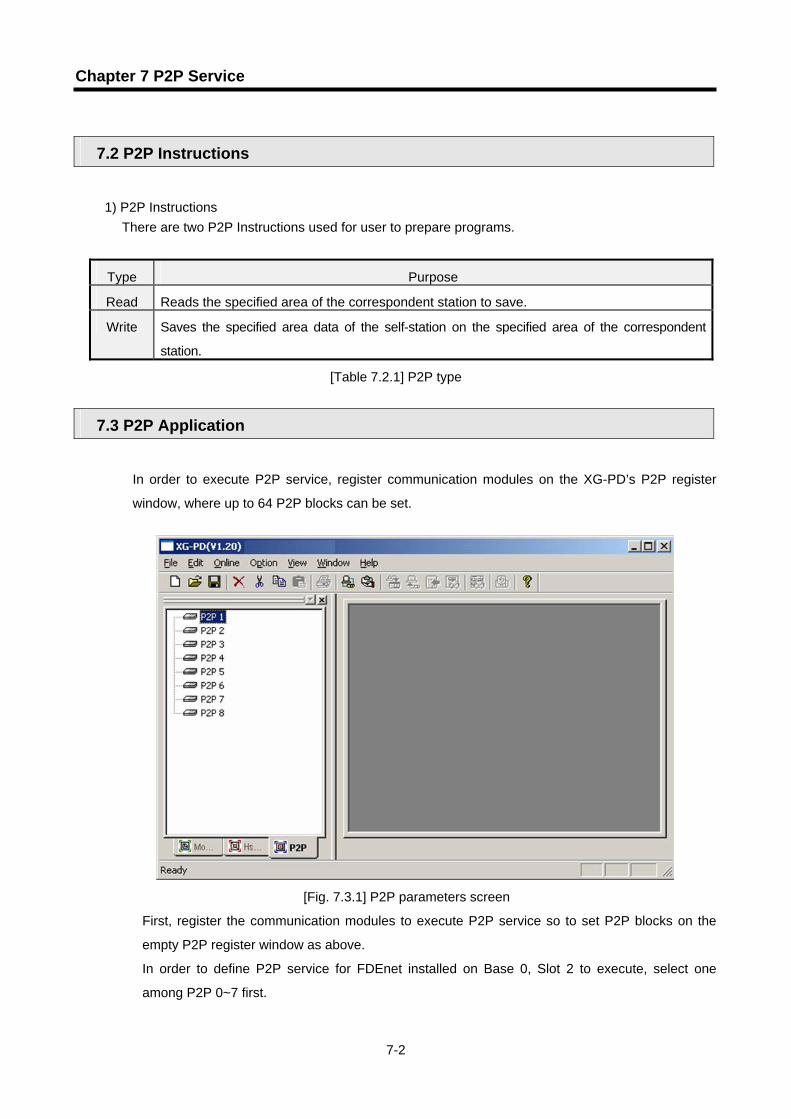
In order to execute P2P service, register communication modules on the XG-PD’s P2P register
window, where up to 64 P2P blocks can be set.
[Fig. 7.3.1] P2P parameters screen
First, register the communication modules to execute P2P service so to set P2P blocks on the
empty P2P register window as above.
In order to define P2P service for FDEnet installed on Base 0, Slot 2 to execute, select one
among P2P 0~7 first.

Chapter 7 P2P Service
7-3
[Fig. 7.3.2] Setting screen of communication module
Item Details
Type Select a module desired to use.
Base Inactive
Slot Inactive
Register type, base and slot positions in [Fig. 7.3.2] and click [OK] to display the screen as shown
in [Fig. 7.3.3].
[Fig. 7.3.3] P2P parameters screen
Double-click P2P block in [Fig. 7.3.3] to display the ‘P2P block setting’ screen as shown in [Fig.
7.3.4].

Chapter 7 P2P Service
7-4
[Fig. 7.3.4] P2P block setting
Item Details
Index P2P setting block where up to 0~63 can be set.
Command Specified Instruction displayed.
Detailed information Execution condition of Instruction displayed.
N address Reference address of P2P service.
7.3.1. Functions and setting of P2P
On the [Fig. 7.3.4] P2P block setting screen, double-click an optional index number among 0~63 to
display the P2P function screen as shown below in [Fig. 7.3.5].
[Fig. 7.3.5] P2P function screen

Chapter 7 P2P Service
7-5
1) READ
It is used to read the specified area of the correspondent station to save on the specified area of
the self-station when the defined event happens. If Bit No.1 of P0004 is set, data of
correspondent station No.2’s MW100 and MW110 will be read word by word to be saved on
P0020 and P0021 of the self-station with the following setting;
[Fig. 7.3.6] READ screen
Item Details
Condition flag 1) Decides the point of time READ function starts. 2) It will operate if P0004’s Bit No.1 is set for P00041.
Command type 1) Decides the type of Read operation. 2) Single/Continuous available. ① Single: reads individual areas.
② Continuous: reads data as specified from the defined start position to save.
Data type 1) If Read operation executed, define data type of the area used in P2P block.
2) Word and Bit available.
No. of variables
1) Available only for Single Read. 2) Number of areas used to execute Single Read.
Standard
Operating
Settings
Destination Station No. Correspondent station No. to read from.
Read area Area address of correspondent station to read from. Memory
settings Save area Area address of self-station to save the read data on

Chapter 7 P2P Service
7-6
1) WRITE
It is used to write the data of the self-station on an optional area of the correspondent station
when the defined event happens. If Bit No.0 of P0030 is set, 5 words from MW120 of the self-
station will be saved on MW200 of the correspondent station No.5 with the following setting.
Details of respective items are as follows;
Item Details
Condition flag 1) Decides the point of time WRITE function starts. 2) It will operate if P0030’s Bit No.0 is set for P00300.
Command type 1) Single/Continuous available. ① Single: reads individual areas.
② Continuous: reads data as specified from the defined start position to save.
Data type 1) If Write operation executed, define data type of the area used in P2P block.
2) Word and Bit available.
Number of variables
1) Available only for Single Write. 2) Number of areas used to execute Single Write.
Standard
Operation
Settings
Destination Station Number
Correspondent station No. to write to.
Read area Address of correspondent station to send the data of self-station to.
Memory
settings Save area Area address of correspondent station to save the data on.
P00300

Chapter 7 P2P Service
7-7
7.4 Operation Sequence of P2P Service
After P2P setting is complete, download the P2P parameters and start the P2P service to make the
service available.
1) P2P parameters download
In order to download the P2P parameters after registered, first connect XG-PD to CPU.
Select [Online] - [Write Parameter] to arrange and display the P2P parameters registered among P2P
parameters 0~7 as shown below;
[Fig. 7.4.1] Parameters setting screen
Select desired P2P parameters and click [OK] to start to download.
[Fig. 7.4.2] Write complete

Chapter 7 P2P Service
7-8
2) P2P service start
P2P parameters after downloaded shall be enabled by user to start P2P service. Select “Online –
Enable Link” to display the screen as shown below;
[Fig. 7.4.3] Parameters setting screen
Among P2P parameters 0~7, presently operation P2P parameters are checked, among which
check P2P parameters to be enabled and click [OK] to execute the service for the applicable P2P
parameters.
In order to stop P2P service, cancel the check mark of the applicable P2P parameters on the link
enable screen and then click [OK].

Chapter 7 P2P Service
7-9
7.5 P2P Service Information
P2P service information provides P2P related data through XG-PD.
1) P2P service from the XG-PD system diagnosis
① Select XG-PD ‘Connect’ ‘Online’ ‘System Diagnosis’.
[Fig. 7.5.1] System Diagnosis
Item
Details
Link type Displays communication module type
Option type Displays media type of communication module. Hardware status Displays hardware status. Hardware version Displays hardware version. OS version Displays OS version. OS date Displays OS released date. Remote connection status Displays remote connection status.

Chapter 7 P2P Service
7-10
② With the mouse cursor placed on XGL-EDMT, click the right mouse button and select ‘Status by
service’ to open [Fig. 7.5.2] as shown below, where P2P service information can be checked.
[Fig. 7.5.2] P2P status for respective services

Chapter 8 Remote Communication Control
8-1
Chapter 8 Remote Communication Control
8.1 Introduction
This function is for programming, download of user program, program debugging, monitoring, etc in
network system where PLCs are connected with each other via FDEnet by remote control without moving
the physical connection status of program tool (XG-5000/XG-PD). Especially it is convenient for easy
access to each device from a place without repositioning when network-connected devices are separated
far. Communication service function creates the following path to attain its purpose.
FDEnet
[Fig. 8.1.1] Example of remote connection network
A network is supposed where RS-232C cable is connected to CPU module of PLC A station, and PLC A,
PLC B and PLC C are connected with each other via FDEnet in the program tool (XG-5000/XG-PD) of
the computer. In order to access the contents of PLC C station in the figure above, select the station No.
of PLC C’s communication module (correspondent station No. to connect to) and the slot No. of PLC A
(slot No. where PLC A’s communication module presently connected is installed) to remote-connect with
RS-232C via FDEnet with remote 1/2 connection of the program tool.
This status as processed identically to connection with RS-232C cable as moved to PLC C station is
available to execute all functions of programming, download, debugging and monitoring as in PLC A.
With this remote communication service, easy access to PLC position in the distance is available without
moving thereto, which is useful for maintenance of PLC system.
Actual connection Virtual connection
PLC A PLC B PLC C

Chapter 8 Remote Communication Control
8-2
8.2 Remote connection example of XG5000/XG-PD
Remote connection between PLCs through FDEnet is available with remote 1 or 2 connection.
로컬 접속 리모트 1 단 접속
XG5000
FDEnet 모듈
리모트 2 단 접속
PLC A PLC B(1 국 )
PLC C
FDEnet FDEnet
PLC C FDEnet 국번 : 5
PLC B FDEnet 국번 : 1
[Fig. 8.2.1] Remote 1/2 connection
[Fig. 8.2.1] shows a connection example of remote 1 (PLC A, PLC B) and remote 2 (PLC C) in the
system composed of two networks.
1) Remote 1 connection
For remote 1 connection, XG-5000(or XG-PD) shall be in off-line status. In this status, select “Online
– Connection Settings” from the menu on the upper of the program.
Local connection Remote 1 connection
(Station 1)
FDEnet module
Station No. 1 of PLC B FDEnet Station No. 5 of PLC C FDEnet
Remote 2 connection

Chapter 8 Remote Communication Control
8-3
[Fig. 8.2.2] Communication setting screen
Item Details
Connection Type Select connection media (RS-232C or USB)
Communication option setting Connection Depth
1) Local : connection between computer and CPU2) Remote 1 : connection remote 1 through
communication module 3) Remote 2 : connection remote 2 through
communication module
Timeout interval Timeout time setting if CPU connected (1~9 sec.)General
Retrial times Retries setting if CPU connected (0~9)
On the communication setting menu, set “Connection Depth” to remote 1, and select “Setting button” to
specify each option on the “Details” screen.
[Fig. 8.2.3] Details screen
Channel

Chapter 8 Remote Communication Control
8-4
Item Details
Network type Select the type of network where remote 1 connection is performed.
Base number
Base No. of the communication module installed on self-station’s PLC to be connected with correspondent station by remote 1 connection
Local communication
module Slot number
Slot No. of the communication module installed on self-station’s PLC to be connected with correspondent station by remote 1 connection
Station number
Select the station No. of the communication module installed on correspondent station’s PLC to be connected by remote 1 (PLC B module’s station No.1 in [Fig. 8.2.1]). Remote 1
communication module IP
address
Select the IP address of the communication module installed on correspondent station’s PLC to be connected by remote 1 (PLC B module’s station No.1 in [Fig. 8.2.1]). (only for Fast Ethernet)
Click [View] on the communication setting window in order to confirm settings of remote 1
connection.
[Fig. 8.2.4] View screen of connection setting
After setting, click [OK] to escape from the option screen, and then execute the on-line
connection. If connection fails, the following message will appear.
[Fig. 8.2.6] Connection failed screen
(Displayed if connection setting or communication cable is abnormal.)

Chapter 8 Remote Communication Control
8-5
If the type is different between PLC with remote 1 connected and CPU of the project presently
open, the following message will appear, to which applicable CPU information needs to be
modified.
[Fig. 8.2.7] PLC type discordant screen
The status of remote 1 connection complete is identical to that of connection with RS-232C cable
repositioned, where all the on-line menus can be used.
2) Remote 2 connection
Pass through XG-5000 PLC A’s FDEnet PLC B’s FDEnet (slot 0) PLC B’s FDEnet (slot )
PLC C’s FDEnet module in order to execute the remote 2 connection, for which XG-5000 (or XG-
PD) shall be in off-line status. In this status, select “Online – Connection Settings” from the menu on
the upper of the program and “Remote 2” on the connection depth menu.
[Fig. 8.2.8] Communication setting screen
With the remote 2 selected, click [Settings].

Chapter 8 Remote Communication Control
8-6
Perform settings on the remote 1 screen first.
And then perform settings on the remote 2 screen.
Channel 1
Channel 1

Chapter 8 Remote Communication Control
8-7
Item Details
Network type Select the type of network where remote 1 or 2 connection is performed.
Base No. Base No. of the communication module installed on remote 1.
Remote 1 communication module Slot No. Slot No. of the communication module installed on remote 1.
Station No. Station No. the communication module installed on remote 2.Remote 2 communication module IP address Station No. the communication module installed on remote 2.
(only for Fast Ethernet)
In order to check if settings above are correct, select [Preview] on [Fig. 8.2.8]. If the remote 2
connection is selected, it will be as below;
Select the network type, station No. and slot No. as shown above and click [OK] on the dialog
box for online connection to perform the remote 2 connection.
At this time, the status of remote 2 connection complete is identical to that of connection with
RS-232C cable repositioned to PLC C, where all the online menus can be used.

Chapter 9 Program Examples
9-1
Chapter 9 Program Examples
9.1 HS Link Program 9.1.1 HS link service between PLCs
How to set HS link parameters in FDEnet system below will be described.
[Fig. 9.1.1] I/O configuration and Tx/Rx data
Tx/Rx structure I/O configuration
(identical to all stations)Tx area Rx area
XGT TX %PW8 (2 words) --
(station 1) RX:<--XGT station 2 -- %MW0(2 words)
XGT TX %PW8 (2 words) --
(station 2) RX:<--XGT station 3 -- %MW0(2 words)
XGT TX %PW8 (2 words) --
(station 3) RX:<--XGT station 1
Slot0: FDEnet Slot1: output 32-point Slot2: input 32 -point
-- %MW0(2 words)
[Table 9.1.1] I/O configuration and Tx/Rx data
In the example, all XGT CPUs transmit 2 words of input value of Slot No.2 and save the data received
from the correspondent station on %MW0.
Station 1 Station 3 Station 2
XGT
FDEnet dedicated network
I/O
POWERCPU I/OI/OI/OI/O
I/O
XG
L-ED
MT
I/O
I/O
POWERCPU I/O
I/OI/OI/O
I/O
XG
L-ED
MT
I/O
I/O
POWERCPU I/OI/OI/OI/O
I/O
XG
L-ED
MT
I/O
XGT XGT

Chapter 9 Program Examples
9-2
1) HS link parameters setting
In the system shown in [Fig. 9.1.1], user is to prepare data Tx/Rx map in order to let the stations 1,2
and 3 exchange data as in [Table 9.1.1]. And for data Tx/Rx as in [Table 9.1.1], HS link parameters
shall be prepared and downloaded onto PLC as in the sequence described below so to start HS link.
(1) Local-connect XG-PD with XGT CPU, and set basic communication parameters.
(2) Prepare data Tx/Rx map.
(3) On XG-PD’s HS link parameters setting option, set applicable parameters.
(4) Write parameters on the On-line menu.
(5) Select link enable setting on the On-line menu to set HS link enable applicable to setting No.
(6) Use XG-PD’s system diagnosis service to check HS link status.
(7) If any error occurs on HS link service of system diagnosis, execute again from A.
HS link parameters for example system shall be set as described below.
On the HS link setting screen as shown in [Fig.9.1.2], select one among 12 HS link parameters to
register modules.
[Fig. 9.1.2] Setting of communication module and communication cycle
Select the type of FDEnet and base/slot positions identical to communication module to be used.
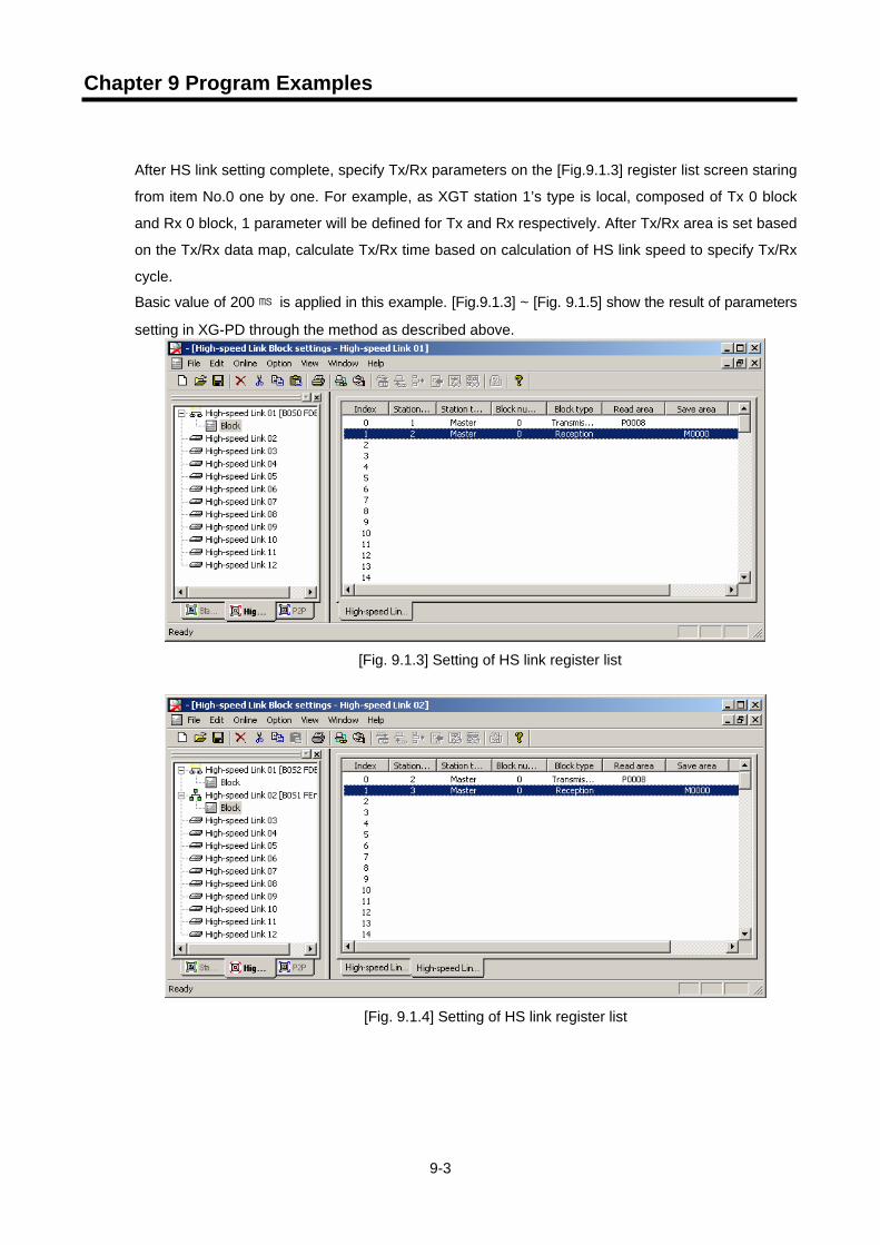
Chapter 9 Program Examples
9-3
After HS link setting complete, specify Tx/Rx parameters on the [Fig.9.1.3] register list screen staring
from item No.0 one by one. For example, as XGT station 1’s type is local, composed of Tx 0 block
and Rx 0 block, 1 parameter will be defined for Tx and Rx respectively. After Tx/Rx area is set based
on the Tx/Rx data map, calculate Tx/Rx time based on calculation of HS link speed to specify Tx/Rx
cycle.
Basic value of 200 is applied in this example. [Fig.9.1.3] ~ [Fig. 9.1.5] show the result of parameters
setting in XG-PD through the method as described above.
[Fig. 9.1.3] Setting of HS link register list
[Fig. 9.1.4] Setting of HS link register list

Chapter 9 Program Examples
9-4
[Fig. 9.1.5] Setting of HS link register list
If HS link parameters are downloaded during operation of HS link, Link enabled will be automatically
disenabled, and then enabled after downloading is complete.
2) How to decide HS link speed
The example shows a simple system where 4-word data is transmitted and received respectively by
communication modules of the 3 stations. Thus, Tx/Rx cycle of link parameters can be easily calculated
through the calculation method of speed in “6.4.2 Calculation of HS link speed” by means of the simple
calculation formula of system speed.
That is, formula St = P_ScanA + C_Scan + P_ScanB
(St = HS link max. Txtime
P_ScanA = PLC A’s max program scan time
P_ScanB = PLC B’s max program scan time
C_Scan = Max communication scan time)
Where, P_ScanA and P_ScanB is XGT PLC’s scan time, thus, in the program above if 5 is supposed
respectively (select XG-5000’s ‘On-line/PLC information/System information’ to check)
Formula CScan = Th × Sn
(Th = Data Tx time for 1 station in the media (IEEE 802.3 standard)
Sn = Total Station Number : Number of total communication stations)
Where, Sn = 3, Th is 2.3 in FDEnet, thus CScan = 6.9 and, St = P_ScanA(=5 ) + P_ScanB(=5) + CScan(6.9 ) = 16.9 , accordingly Tx/Rx cycle shall be set to 17 at least.

Chapter 9 Program Examples
9-5
9.1.2 P2P service between PLCs of FDEnet
In the XGT FDEnet system configured as below, P2P parameters setting shall be as described below for the master station 1 to perform data communication with the I/O structure shown below. However, it is supposed that setting of the basic communication parameters is complete and that all the stations operate normally.
1 국 2 국 3 국 4 국 5 국
Correspondent station No.
Operation point of time (Set) Operation Details
1 2 M0300’s Bit No.2 READ Reads %M0010, %M0020 and %M0030 to save on %M000, %M001 and %M002.
2 3 M0300’s Bit No.3 READ Reads 10 words from %M0100 to save on %M0010.
3 4 M5’s Bit No.0 WRITE Reads %M0000, %M0001 and %M0002 to save on correspondent station’s %M0010, %M0020 and %M0030.
4 5 M6’s Bit No.3 WRITE Reads 10 words from %M0010 to save on correspondent station’s %M0100.
1) Execute XG-PD to connect to XGT CPU the station 1 is installed on. 2) Use “Online – Read IO Information” to register the station 1’s FDEnet I/F communication module for
P2P service register. 3) Select P2P parameters window to register FDEnet on P2P 1.
[Fig. 9.1.6] P2P project setting window
Station 1 Station 2 Station 3 Station 4 Station 5
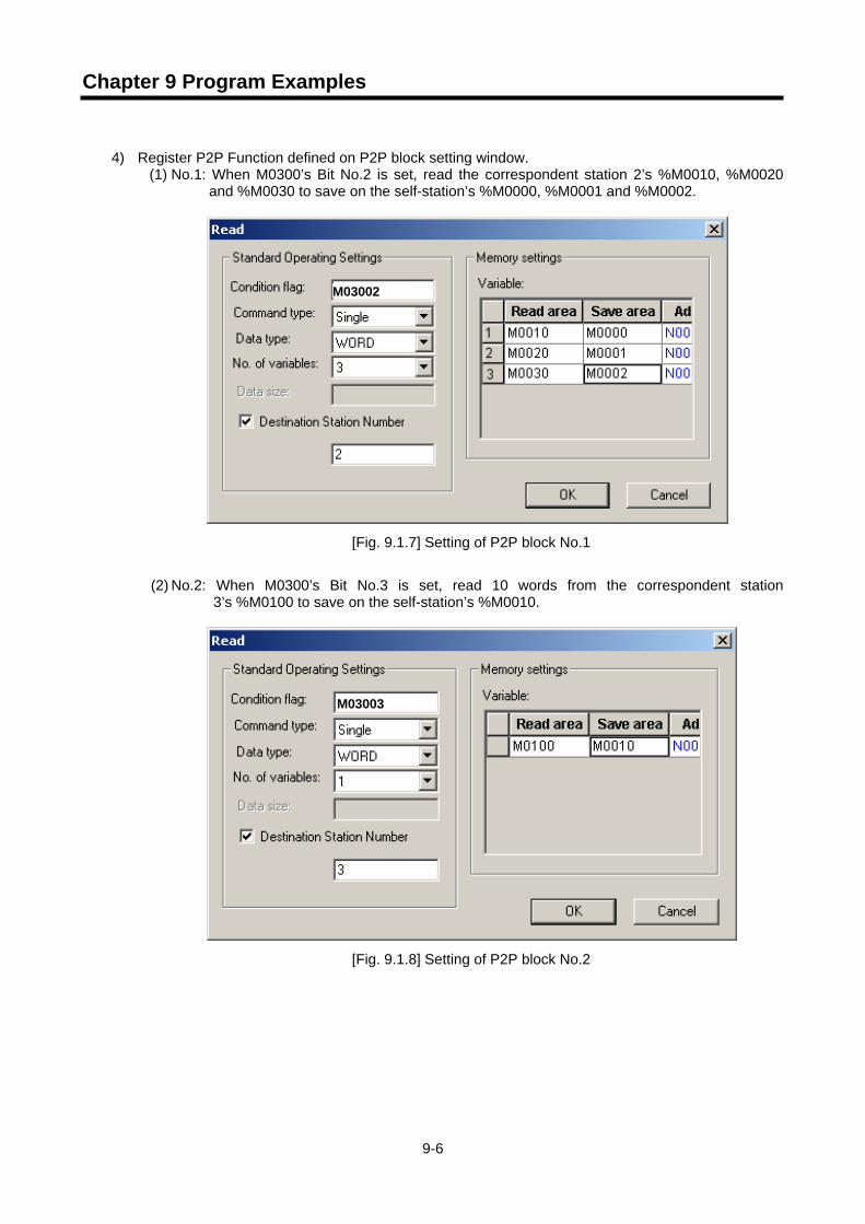
Chapter 9 Program Examples
9-6
4) Register P2P Function defined on P2P block setting window.
(1) No.1: When M0300’s Bit No.2 is set, read the correspondent station 2’s %M0010, %M0020 and %M0030 to save on the self-station’s %M0000, %M0001 and %M0002.
[Fig. 9.1.7] Setting of P2P block No.1
(2) No.2: When M0300’s Bit No.3 is set, read 10 words from the correspondent station
3’s %M0100 to save on the self-station’s %M0010.
[Fig. 9.1.8] Setting of P2P block No.2
M03002
M03003

Chapter 9 Program Examples
9-7
(3) No.3: When M0005’s Bit No.0 is set, read the self-station’s %M000, %M0001 and %M0002
to save on the correspondent station 4’s %M0010, %M0020 and %M0030.
[Fig. 9.1.9] Setting of P2P block No.3
(4) No.4: When M0006’s Bit No.3 is set, read 10 words from the self-station’s %M0010 to save
on the correspondent station 5’s %M0100.
[Fig. 9.1.10] Setting of P2P block No.4
The figure below shows the result of 4 functions registered as above.
[Fig. 9.1.11] P2P setting screen
M00050
M00063

Chapter 9 Program Examples
9-8
5) Prepare P2P parameters download
Select XG-PD’s “Online – Write Parameters” on the menu to download P2P parameters so to start
the service among P2P parameters registered.
[Fig. 9.1.12] Write screen of P2P parameters
The downloaded P2P parameters will be back up regardless of power On/Off.
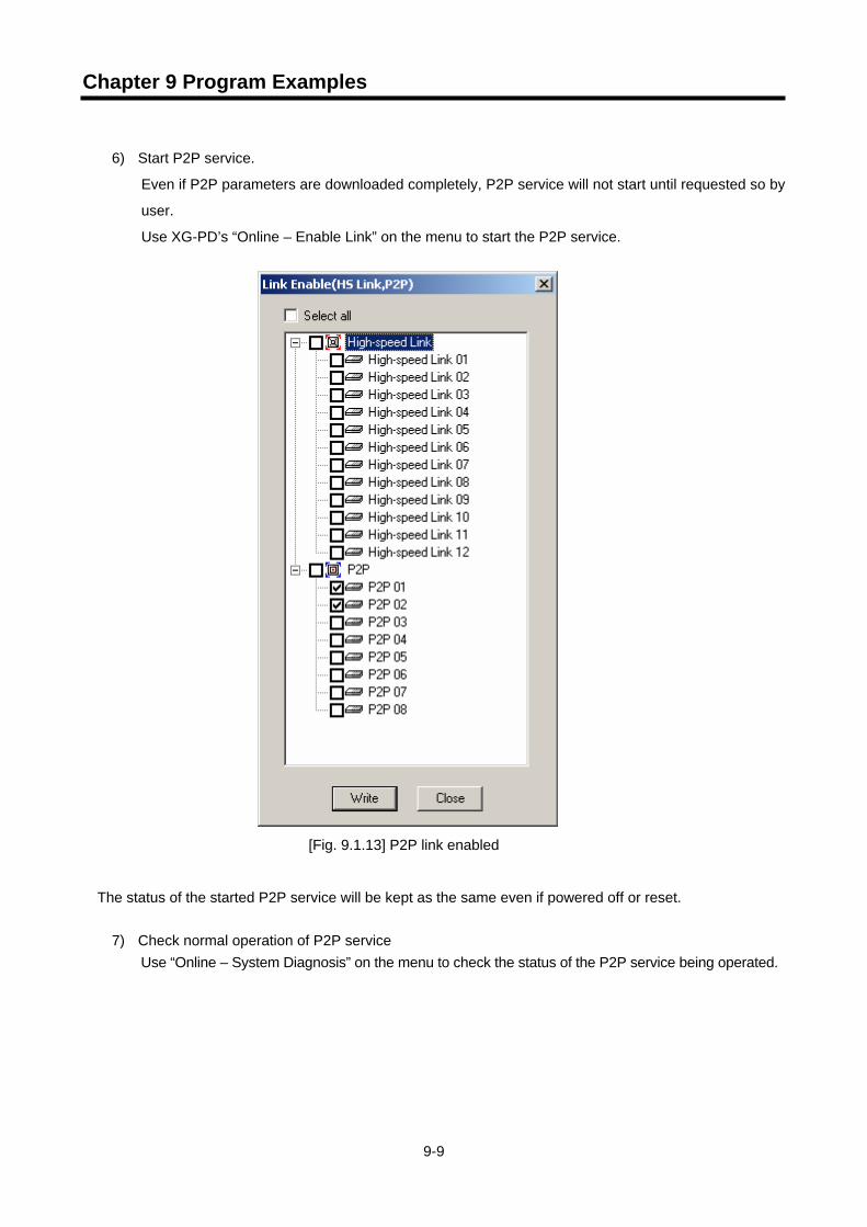
Chapter 9 Program Examples
9-9
6) Start P2P service.
Even if P2P parameters are downloaded completely, P2P service will not start until requested so by
user.
Use XG-PD’s “Online – Enable Link” on the menu to start the P2P service.
[Fig. 9.1.13] P2P link enabled
The status of the started P2P service will be kept as the same even if powered off or reset.
7) Check normal operation of P2P service
Use “Online – System Diagnosis” on the menu to check the status of the P2P service being operated.
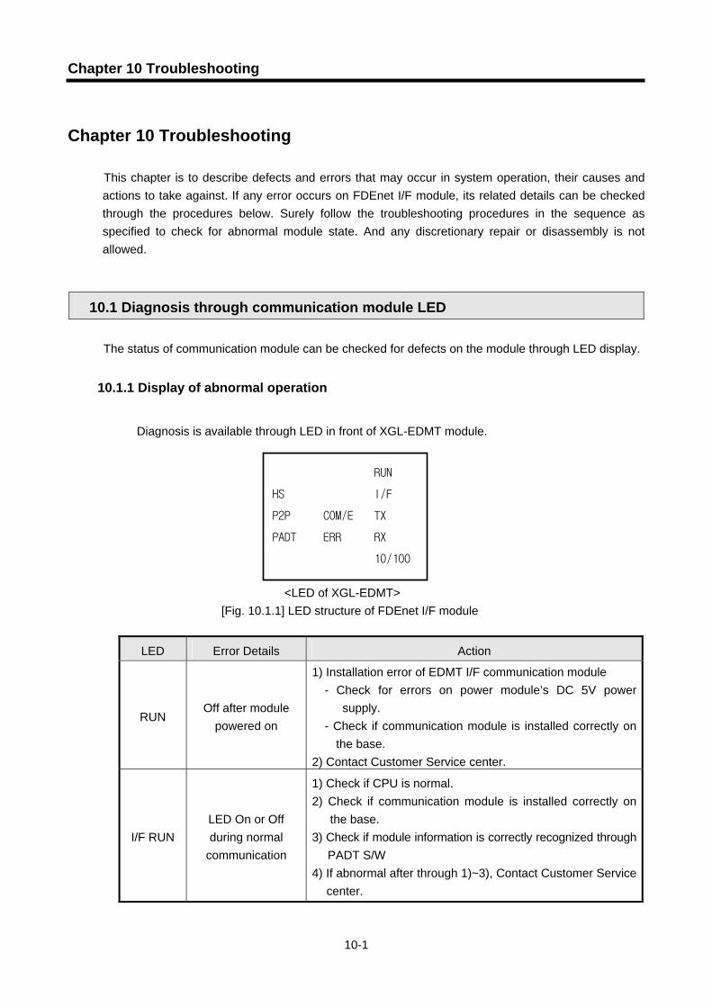
Chapter 10 Troubleshooting
10-1
Chapter 10 Troubleshooting
This chapter is to describe defects and errors that may occur in system operation, their causes and actions to take against. If any error occurs on FDEnet I/F module, its related details can be checked through the procedures below. Surely follow the troubleshooting procedures in the sequence as specified to check for abnormal module state. And any discretionary repair or disassembly is not allowed.
10.1 Diagnosis through communication module LED The status of communication module can be checked for defects on the module through LED display.
10.1.1 Display of abnormal operation
Diagnosis is available through LED in front of XGL-EDMT module.
<LED of XGL-EDMT> [Fig. 10.1.1] LED structure of FDEnet I/F module
LED Error Details Action
RUN Off after module
powered on
1) Installation error of EDMT I/F communication module - Check for errors on power module’s DC 5V power
supply. - Check if communication module is installed correctly on
the base. 2) Contact Customer Service center.
I/F RUN LED On or Off during normal
communication
1) Check if CPU is normal. 2) Check if communication module is installed correctly on
the base. 3) Check if module information is correctly recognized through
PADT S/W 4) If abnormal after through 1)~3), Contact Customer Service
center.
RUN
HS I/F
P2P COM/E TX
PADT ERR RX
10/100
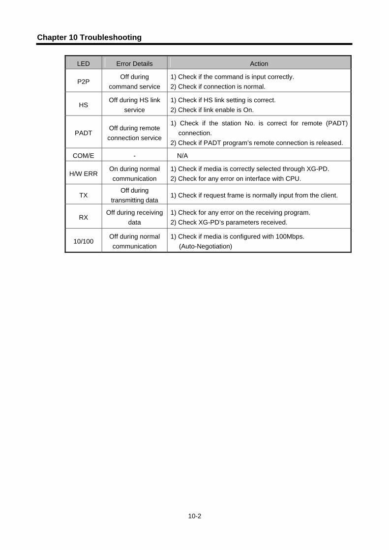
Chapter 10 Troubleshooting
10-2
LED Error Details Action
P2P Off during
command service 1) Check if the command is input correctly. 2) Check if connection is normal.
HS Off during HS link
service 1) Check if HS link setting is correct. 2) Check if link enable is On.
PADT Off during remote connection service
1) Check if the station No. is correct for remote (PADT) connection.
2) Check if PADT program’s remote connection is released.
COM/E - N/A
H/W ERR On during normal communication
1) Check if media is correctly selected through XG-PD. 2) Check for any error on interface with CPU.
TX Off during
transmitting data 1) Check if request frame is normally input from the client.
RX Off during receiving
data 1) Check for any error on the receiving program. 2) Check XG-PD’s parameters received.
10/100 Off during normal communication
1) Check if media is configured with 100Mbps. (Auto-Negotiation)

Chapter 10 Troubleshooting
10-3
10.2 Diagnosis of Communication Module through XG5000
XG5000 program can be used to monitor the communication module simply to check for any error thereon. Connect RS-232C connector with CPU port and then select [Online] [PLC History] -> [PLC Errors/Warnings] in XG5000.
[Fig. 10.2.1] PLC History
If a hardware error or a CPU interface error occurs on the module, LED of the communication module itself operates abnormally in general, whose status can be monitored simply through its dedicated program.
[Fig. 10.2.1] shows error/warning information through PLC History on the XG5000 [Online] menu,
which can be resolved by referring to “Details/Remedy”.

Appendix
A-1
Appendix
A.1 Terminology
General terms of FDEnet I/F module will be described below to help the user understand the product prior to its application. Refer to Ethernet-related technical books for more details.
1) IEEE 802.3 IEEE 802.3 specifies standards for CSMA/CD based Ethernet. Exactly it is a LAN based on CSMA/CD (Carrier Sense Multiple Access with Collision Detection) Ethernet designed by IEEE 802.3 group, which is classified into detailed projects as specified below; A) IEEE P802.3 - 10G Base T study Group B) IEEE P802.3ah - Ethernet in the First Mile Task Force C) IEEE P802.3ak - 10G Base-CX4 Task Force Both IEEE 802.3 and Ethernet are the broadband network using CSMA/CD method and both are also realized on the network interface card H/W in common.
2) ARP (Address Resolution Protocol) Protocol to search for MAC address by means of correspondent IP address on the Ethernet LAN
3) Bridge A device used to connect two networks so to be operated as one network. Bridge is used not only to connect two different types of networks but also to divide one big network into two small networks in order to increase the performance
4) Client A user of the network service, or a computer or program (mainly the one requesting services) using other computer’s resource.
5) CSMA/CD(Carrier Sense Multiple Access with Collision Detection) Each client checks if there is any sign prior to transmission of data to the network (Carrier Sense) and then sends its data when the network is empty. At this time, all the clients have the equal right to send (Multiple Access). If two or more clients send data, collision may occur. The client who detects the collision tries to send again in a specific time.
6) DNS (Domain Name System) A method used to convert alphabetic Domain Name on the Internet to its identical Internet number (namely, IP address)
Appendix
A-2
7) Dot Address
Shows IP address of ‘100.100.100.100’, where each figure is displayed in decimal with 1 byte occupied respectively for 4 bytes in total.
8) E-mail Address The address of the user with login account for the specific machine connected via the Internet. Usually user’s ID @ domain name (machine name) is assigned. In other words, it will be like [email protected], where @ is called as ‘at’ displayed with shift+2 pressed on the keyboard. The letters at the back of @ are for the domain name of specific company (school, institute,..) connected with the Internet, and the letters in front of @ are for the user ID registered in the machine. The last letters of the domain name are for the highest level. USA generally uses the following abbreviation as specified below, and Korea uses .kr to stand for Korea. .com : usually for companies) / .edu : usually for educational organizations such as universities. / .ac(academy) is mostly used in Korea / .gov : for governmental organizations. For example, nasa.gov is for NASA (government) / .mil : military related sites. For example, af.mil is for USA air force (military)/ .org : private organizations / .au : Australia / .uk : the United Kingdom / .ca : Canada / .kr : Korea / .jp : Japan / .fr : France / .tw : Taiwan, etc.
9) Ethernet A representative LAN connection system (IEEE 802.3) developed by Xerox, Intel and DEC of America which can send about 10Mbps and use the packet of 1.5kB. Since Ethernet can allow various types of computers to be connected as one via the network, it has been called a pronoun of LAN as a universal standard with various products available, not limited to some specific companies.
10) FTP (File Transfer Protocol) An application program used to transfer files between computers among application programs providing TCP/IP protocol. If an account is allowed to the computer to log in, fast log in the computer is available wherever the computer is so to copy files.
11) Gateway Software/Hardware used to translate for two different protocols to work together, which is equivalent to the gateway necessary to exchange information with the different system.
12) Header Part of the packet including self station No., correspondent station No. and error checking area.
13) HTML Hypertext Markup Language, standard language of WWW. In other words, it is a language system to prepare Hypertext documents. The document made of HTML can be viewed through the web browser

Appendix
A-3
14) HTTP
Hypertext Transfer Protocol, standard protocol of WWW. It is a protocol supporting the hypermedia system.
15) ICMP (Internet Control Message Protocol) An extended protocol of IP address used to create error messages and test packets to control the Internet.
16) IP (Internet Protocol) Protocol of network layers for the Internet
17) IP Address Address of respective computers on the Internet made of figures binary of 32 bits (4 bytes) to distinguish the applicable machine on the Internet. Classified into 2 sections, network distinguishing address and host distinguishing address. The network address and the host address is respectively divided into class A, B and C based on the bits allotted. IP address since it shall be unique all over the world, shall be decided not optionally but as assigned by NIC(Network Information Center) of the applicable district when joining the Internet. In Korea, KRNIC(Korea Network Information Center) is in charge of this work. Ex.) 165.244.149.190
18) ISO (International Organization for Standardization) A subsidiary organization of UN, establishing and managing the international standards.
19) LAN (Local Area Network) Called also as local area communication network or district information communication network, which allows lots of computers to exchange data with each other as connected though communication cable within a limited area such as in an office or a building
20) MAC (Medium Access Control) A method used to decide which device should use the network during given time on the broadcast network
21) Node Each computer connected with the network is called Node
22) Packet A package of data which is the basic unit used to send through the network. Usually the package is made of several tens or hundreds of bytes with the header attached in front to which its destination and other necessary information are added

Appendix
A-4
23) PORT number
Used to classify the applications on TCP/UDP. Ex.) 21/tcp : Telet
24) PPP (Point-to-Point Protocol) Phone communication protocol which allows packet transmission in connecting with the Internet. In other words, normal phone cable and modem can be used for the computer to connect through TCP/IP with this most general Internet protocol. Similar to SLIP, however with modern communication protocol factors such as error detection and data compression, it demonstrates more excellent performance than SLIP.
25) Protocol Contains regulations related with mutual information transmission method between computers connected with each other through the network. The protocol may specify detailed interface between machines in Low level (for example, which bit/byte should go out through the line) or high level of message exchange regulations as files are transferred through the Internet.
26) Router A device used to transfer the data packet between the networks. It sends the data packet to its final destination, waits if the network is congested, or decides which LAN is good to connect to at the LAN junction. Namely, it is a special computer/software used to control the two or more networks connected.
27) Server The side which passively responds to the client’s request and shares its resources.
28) TCP (Transmission Control Protocol) A transport layer protocol for the Internet - Data Tx/Rx through connection - Multiplexing - Transmission reliable - Emergent data transmission supported
29) TCP/IP (Transmission Control Protocol/Internet Protocol) Transmission protocol used for communication among different kinds of computers, which makes the communication available between general PC and medium host, IBM PC and MAC, and medium or large-sized different types of computer. It is also used as a general term for information transmission protocol between computer networks including FTP, Telnet, SMTP, etc. TCP divides data into packets to send through IP and the packets sent will be united back together through TCP.

Appendix
A-5
30) Telnet
Remote Login is allowed from one host to another host through the Internet. Although a login account shall be generally registered to log in the remote host through Telnet, some hosts providing several public services (white page directory provided) are available to connect to without personal account.
31) Token Ring As one of the node connection methods on the network, it is a local communication network using a token to access to communication network with physical ring structure. If the transmission node obtains a token and its control, it transfers the message packet. Actually realized examples are IEEE 802.5, ProNet-1080 and FDDI. The term of Token Ring is occasionally used in substitute for IEEE 802.5.
32) UDP (User Datagram Protocol) A transport layer protocol for the Internet - Since data Tx/Rx is allowed without connection, communication is available at high speed - Multiplexing - Unreliable transmission compared with TCP (resending unavailable even if the data does not
arrive at the correspondent station)
33) Auto-Negotiation Fast Ethernet process is used to allow Ethernet device to exchange performance information such as operation speed and duplex mode. 1. Detects the cause of denied connection 2. Decides performance of network equipment 3. Changes the connection speed
34) FDDI (Fiber Distributed Data Interface) Based on the optical cable, it provides a speed of 100Mbps with its Shared Media Network system applied to allow Token Passing in both directions through Dual Ring method. The maximum distance of the whole network is 200Km, the maximum distance between nodes is 2km, and the maximum number of nodes is 500(1000). Generally it is used as a Backbone Network.
TokenRing
Token passing
Dual Token passing
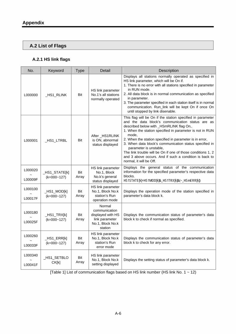
Appendix
A-6
A.2 List of Flags
A.2.1 HS link flags
No. Keyword Type Detail Description
L000000 _HS1_RLINK Bit HS link parameter No.1’s all stations normally operated
Displays all stations normally operated as specified in HS link parameter, which will be On if. 1. There is no error with all stations specified in parameter
in RUN mode. 2. All data block is in normal communication as specified
in parameter. 3. The parameter specified in each station itself is in normal
communication. Run_link will be kept On if once On until stopped by link disenable.
L000001 _HS1_LTRBL Bit After _HS1RLINK is ON, abnormal status displayed
This flag will be On if the station specified in parameter and the data block’s communication status are as described below with _HSmRLINK flag On,. 1. When the station specified in parameter is not in RUN
mode, 2. When the station specified in parameter is in error, 3. When data block’s communication status specified in
parameter is unstable, The link trouble will be On if one of those conditions 1, 2 and 3 above occurs. And if such a condition is back to normal, it will be Off.
L000020 ~
L00009F
_HS1_STATE[k] (k=000~127)
Bit Array
HS link parameter No.1, Block
No.k’s general status displayed
Displays the general status of the communication information for the specified parameter’s respective data blocks. HS1STATE[k]=HS1MOD[k]&_HS1TRX[k]&(~_HSmERR[k])
L000100 ~
L00017F
_HS1_MOD[k] (k=000~127)
Bit Array
HS link parameter No.1, Block No.k
station’s Run operation mode
Displays the operation mode of the station specified in parameter’s data block k.
L000180 ~
L00025F
_HS1_TRX[k] (k=000~127)
Bit Array
Normal communication
displayed with HS link parameter
No.1, Block No.k station
Displays the communication status of parameter’s data block k to check if normal as specified.
L000260 ~
L00033F
_HS1_ERR[k] (k=000~127)
Bit Array
HS link parameter No.1, Block No.k
station’s Run error mode
Displays the communication status of parameter’s data block k to check for any error.
L000340 ~
L00041F
_HS1_SETBLOCK[k]
Bit Array
HS link parameter No.1, Block No.k setting displayed
Displays the setting status of parameter’s data block k.
[Table 1] List of communication flags based on HS link number (HS link No. 1 ~ 12)

Appendix
A-7
Remark
HS link No. L area address Remarks
2 L000500~L00099F
3 L001000~L00149F
4 L001500~L00199F 5 L002000~L00249F
6 L002500~L00299F
7 L003000~L00349F
8 L003500~L00399F
9 L004000~L00449F
10 L004500~L00499F
11 L005000~L00549F
Compared with HS link of 1 in [Table 1], other HS link station number’s
flag address will be simply calculated as follows;
∗ Calculation formula:
L area address = L000000 + 500 x (HS link No. – 1) In order to use HS link flag for program and monitoring, use the flag map registered in XG5000 for convenient application.
Ex.) K as a block number is displayed through 8 words by 16 for 1 word for the information of 128 blocks from 000 to
127. For example, block information of 16~31, 32~47, 48~63, 64~79, 80~95, 96~111, 112~127 will be displayed in L00011, L00012, L00013, L00014, L00015, L00016, L00017 from block 0 to block 15 for mode information (_HS1MOD). Thus, the mode information of the block No. 55 will be displayed in L000137.

Appendix
A-8
No. Keyword Type Detail Description
L006250 _P2P1_NDR00 Bit P2P parameter No.1, block No.00 service complete normally
P2P parameter No.1, block No.0 service complete normally.
L006251 _P2P1_ERR00 Bit P2P parameter No.1, block No.00 service complete abnormally
P2P parameter No.1, block No.0 service complete abnormally.
L00626 _P2P1_STATUS00 Word
Error code if P2P parameter No.1,
block No.00 service complete abnormally
Error code displayed if P2P parameter No.1, block No.0 service complete abnormally.
L00627 _P2P1_SVCCNT00 DWord
P2P parameter No.1, block No.00 service
normal execution times
P2P parameter No.1, block No.0 service normal execution times displayed.
L00629 _P2P1_ERRCNT00 DWord
P2P parameter No.1, block No.00 service abnormal execution
times
P2P parameter No.1, block No.0 service abnormal execution times displayed.
L006310 _P2P1_NDR01 Bit P2P parameter No.1, block No.01 service complete normally
P2P parameter No.1, block No.1 service complete normally.
L006311 _P2P1_ERR01 Bit P2P parameter No.1, block No.01 service complete abnormally
P2P parameter No.1, block No.1 service complete abnormally.
L00632 _P2P1_STATUS01 Word
Error code if P2P parameter No.1,
block No.01 service complete abnormally
Error code displayed if P2P parameter No.1, block No.1 service complete abnormally.
L00633 _P2P1_SVCCNT01 DWord
P2P parameter No.1, block No.01 service
normal execution times
P2P parameter No.1, block No.1 service normal execution times displayed.
L00635 _P2P1_ERRCNT01 DWord
P2P parameter No.1, block No.01 service abnormal execution
times
P2P parameter No.1, block No.1 service abnormal execution times displayed.
[Table 2] List of communication flags based on P2P service setting (P2P parameter: 1~8, P2P block: 0~63)

Appendix
A-9
A.2.2 Link devices (N)
No. Keyword Type Detail Description
N00000 _P1B00SN Word
P2P parameter No.1, block No.00’s
correspondent station No.
P2P parameter No.1, block No.00’s correspondent station No. saved. Use P2PSN command to modify during Run if correspondent station number is used in XG-PD.
N00001 ~ N00004 _P1B00RD1 Device
structure
P2P parameter No.1, block No.00 area device 1 to read
P2P parameter No.1, block No.00 area device 1 to read saved.
N00005 _P1B00RS1 Word P2P parameter No.1,
block No.00 area size 1 to read
P2P parameter No.1, block No.00 area size 1 to read saved.
N00006 ~ N00009 _P1B00RD2 Device
structure
P2P parameter No.1, block No.00 area device 2 to read
P2P parameter No.1, block No.00 area device 2 to read saved.
N00010 _P1B00RS2 Word P2P parameter No.1,
block No.00 area size 2 to read
P2P parameter No.1, block No.00 area size 2 to read saved.
N00011 ~ N00014 _P1B00RD3 Device
structure
P2P parameter No.1, block No.00 area device 3 to read
P2P parameter No.1, block No.00 area device 3 to read saved.
N00015 _P1B00RS3 Word P2P parameter No.1,
block No.00 area size 3 to read
P2P parameter No.1, block No.00 area size 3 to read saved.
N00016 ~ N00019 _P1B00RD4 Device
structure
P2P parameter No.1, block No.00 area device 4 to read
P2P parameter No.1, block No.00 area device 4 to read saved.
N00020 _P1B00RS4 Word P2P parameter No.1,
block No.00 area size 4 to read
P2P parameter No.1, block No.00 area size 4 to read saved.
N00021 ~ N00024 _P1B00WD1 Device
structure
P2P parameter No.1, block No.00 saved
area device 1
P2P parameter No.1, block No.00 saved area device 1 saved.
N00025 _P1B00WS1 Word P2P parameter No.1,
block No.00 saved area size 1
P2P parameter No.1, block No.00 saved area size 1 saved.
N00026 ~ N00029 _P1B00WD2 Device
structure
P2P parameter No.1, block No.00 saved
area device 2
P2P parameter No.1, block No.00 saved area device 2 saved.
N00030 _P1B00WS2 Word P2P parameter No.1,
block No.00 saved area size 2
P2P parameter No.1, block No.00 saved area size 2 saved.
N00031 ~ N00034 _P1B00WD3 Device
structure
P2P parameter No.1, block No.00 saved
area device 3
P2P parameter No.1, block No.00 saved area device 3 saved.
N00035 _P1B00WS3 Word P2P parameter No.1,
block No.00 saved area size 3
P2P parameter No.1, block No.00 saved area size 3 saved.
N00036 ~ N00039 _P1B00WD4 Device
structure
P2P parameter No.1, block No.00 saved
area device 4
P2P parameter No.1, block No.00 saved area device 4 saved.
N00040 _P1B00WS4 Word P2P parameter No.1,
block No.00 saved area size 4
P2P parameter No.1, block No.00 saved area size 4 saved.
[Table 3] List of communication devices based on P2P number (P2P No. : 1~8, P2P block : 0~63)

Appendix
A-10
No. Keyword Type Detail Description
N00041 _P1B01SN Word
P2P parameter No.1, block No.01
correspondent station No.
P2P parameter No.1, block No.01’s correspondent station No. saved. Use P2PSN command to modify during Run if correspondent station number is used in XG-PD.
N00042 ~ N00045 _P1B01RD1 Device
structure
P2P parameter No.1, block No.01 area device
1 to read
P2P parameter No.1, block No.01 device area 1 to read saved.
N00046 _P1B01RS1 Word P2P parameter No.1,
block No.01 area size 1 to read
P2P parameter No.1, block No.01 area size 1 to read saved.
N00047 ~ N00050 _P1B01RD2 Device
structure
P2P parameter No.1, block No.01 area device
2 to read
P2P parameter No.1, block No.01 area device 1 to read saved.
N00051 _P1B01RS2 Word P2P parameter No.1,
block No.01 area size 2 to read
P2P parameter No.1, block No.01 area size 2 to read saved.
N00052 ~ N00055 _P1B01RD3 Device
structure
P2P parameter No.1, block No.01 area device
3 to read
P2P parameter No.1, block No.01 area device 3 to read saved.
N00056 _P1B01RS3 Word P2P parameter No.1,
block No.01 area size 3 to read
P2P parameter No.1, block No.01 area size 3 to read saved.
N00057 ~ N00060 _P1B01RD4 Device
structure
P2P parameter No.1, block No.01 area device
4 to read
P2P parameter No.1, block No.01 area device 4 to read saved.
N00061 _P1B01RS4 Word P2P parameter No.1,
block No.01 area size 4 to read
P2P parameter No.1, block No.01 area size 4 to read saved.
N00062 ~ N00065 _P1B01WD1 Device
structure
P2P parameter No.1, block No.01 saved area
device 1
P2P parameter No.1, block No.01 saved area device 1 saved.
N00066 _P1B01WS1 Word P2P parameter No.1,
block No.01 saved area size 1
P2P parameter No.1, block No.01 saved area size 1 saved.
N00067 ~ N00070 _P1B01WD2 Device
structure
P2P parameter No.1, block No.01 saved area
device 2
P2P parameter No.1, block No.01 saved area device 2 saved.
N00071 _P1B01WS2 Word P2P parameter No.1,
block No.01 saved area size 2
P2P parameter No.1, block No.01 saved area size 2 saved.
N00072 ~ N00075 _P1B01WD3 Device
structure
P2P parameter No.1, block No.01 saved area
device 3
P2P parameter No.1, block No.01 saved area device 3 saved.
N00076 _P1B01WS3 Word P2P parameter No.1,
block No.01 saved area size 3
P2P parameter No.1, block No.01 saved area size 3 saved.
N00077 ~ N00080 _P1B01WD4 Device
structure
P2P parameter No.1, block No.01 saved area
device 4
P2P parameter No.1, block No.01 saved area device 4 saved.
N00081 _P1B01WS4 Word P2P parameter No.1,
block No.01 saved area size4
P2P parameter No.1, block No.01 saved area size 4 saved
[Table 3] List of communication devices based on P2P number (P2P No. : 1~8, P2P block : 0~63)
Remark
1) If P2P parameters are to be specified with XG-PD used for N area, the setting will be performed automatically. And its modification during Run is also available by P2P dedicated command.
2) Since the addresses of N area available are classified according to P2P parameter setting No. and block index No., the area not used for P2P service can be used as an internal device.

Appendix
A-11
A.3 External Dimensions
Unit : mm

Warranty
1. Warranty Period
The product purchased will be guaranteed for a period of 18 months upon manufactured. 2. Warranty Coverage Against the defect found during the Warranty Period specified above, this product will be repaired or
exchanged partially. However, please understand that such cases as described below will be excluded from the Warranty Coverage.
(1) If the defect is caused by unsuitable condition, environment and treatment or other reason than
specified in the user’s manual. (2) If the defect is caused by other parts than LS product. (3) If the product is remodeled or repaired by others than LS or its designated service center (4) If the product is used with other procedures than originally intended. (5) If the defect is caused by a reason unexpected under the scientific and technical standard when
released from LS. (6) If the defect is caused by a natural calamity or fire which LS is not responsible for.
3. Since the warranty details above are to guarantee the PLC unit only, the customers are strongly recommended to use the product after due consideration of safety for system configuration or product application.
Warranty
Related Documents