XFP NETWORKABLE ANALOGUE ADDRESSABLE FIRE ALARM CONTROL PANEL 1 or 2 Loop 32 Zone Version engineering manual Approved Document No. DFU2200510 Rev 1

Welcome message from author
This document is posted to help you gain knowledge. Please leave a comment to let me know what you think about it! Share it to your friends and learn new things together.
Transcript

XFPNETWORKABLEANALOGUEADDRESSABLEFIRE ALARMCONTROL PANEL
1 or 2 Loop 32 Zone Version
engineeringmanualApproved Document No. DFU2200510 Rev 1

CONTENTS
Important Notes ..................................................................................................................................3
Key features..........................................................................................................................................4
Installation and wiring ........................................................................................................................5The fire panel enclosure ..................................................................................................................................5Removing the lid and base PCBs......................................................................................................................5Mounting the base to the wall ........................................................................................................................6Planning the cable layout in the panel ..........................................................................................................6Mains wiring......................................................................................................................................................6Connecting Mains to the Power Supply PCB ..................................................................................................7Analogue addressable loop wiring..................................................................................................................8Connecting the analogue loop to the Main Control PCB..............................................................................9Conventional sounder circuit wiring ..............................................................................................................9Auxiliary input wiring ....................................................................................................................................10Relay output wiring ........................................................................................................................................10Remote PC connection....................................................................................................................................11Printer connection ..........................................................................................................................................11Aux. 24V output..............................................................................................................................................11Installing the standby battery supply ............................................................................................................11Network/repeater wiring (optional) ..............................................................................................................12
Controls and indicators ......................................................................................................................14
Commissioning and programming ..................................................................................................16Recommended commissioning procedure ....................................................................................................16System operation / terms of reference..........................................................................................................16Access levels menu tree ..................................................................................................................................17How to enter access level three ....................................................................................................................18Fitting the panel’s NVM ‘memory unlock’ link ............................................................................................18A detailed description of the functions available at access level 3 ......................................................19-33
Maintenance ......................................................................................................................................34
Standby battery calculation guide....................................................................................................35
Technical specification ......................................................................................................................36
Disclaimer
© No responsibility can be accepted by the manufacturer or distributors of this range of fire panelsfor any misinterpretation of an instruction or guidance note or for the compliance of the system asa whole. The manufacturer’s policy is one of continuous improvement and we reserve the right tomake changes to product specifications at our discretion and without prior notice. E&OE.
XFP ENGINEERING MANUAL • Approved Document No. DFU2200510 Rev 1 • Page 2 of 36
XFP NETWORKABLE ANALOGUE ADDRESSABLE FIRE ALARM PANEL
This product has been manufactured in conformance with the requirements of allapplicable EU Council Directives.

IMPORTANT NOTES
This equipment must only be installed and maintained by a suitably skilled and technically competent person.
This equipment is a piece of Class 1 equipment and MUST BE EARTHED.
ALWAYS isolate the panel’s Mains and battery backup supplies before making connections to its PCBs.
Items supplied with this panel
• Engineering manual (this manual)
• User Manual / Log Book
• Hex key, for unfastening / securing the panel lid
• Electrical accessory pack, containing:2 x 6K8 0.25W conventional sounder circuit resistors1 x 20mm 1ATH 250V HRC ceramic fuse (spare primary fuse)1 x set of battery connection leads (red wire, black wire, jumper link and 2 x nylon cable ties)
System design
Fire alarm system design is beyond the scope of this document. A basic understanding of generalfire alarm system components and their use is assumed.
Contact the Fire Officer concerned with the property at an early stage in case he has any specialrequirements. We strongly recommend that a suitably qualified and competent person is consult-ed in connection with the design of the fire alarm system and that the system is commissionedand serviced in accordance with the laid down specification and national standards. If in doubtplease consult your supplier.
We recommend you read BS 5839 Part 1 "Fire Detection and Alarm Systems for Buildings (Codeof Practice for System Design, Installation, Commissioning and Maintenance)" available at yourlocal reference library or from the BSI. Other national standards of installation should be refer-enced where applicable.
Cable types and limitations
All system wiring should be installed to meet current national standards - in the United Kingdomthese are BS 5839 Part 1 and BS7671 (Wiring Regulations).
Fire resistant screened cable should be used throughout the installation. This not only shields thedata moving up and down the cables from outside interference but is essential to ensurecompliance with EMC regulations. Cables such as FP 200, Firetuff™, Firecel™ and MICC may beacceptable provided they are properly terminated at the fire panel and meet national standards /the system specification as applicable. Consult Clause 26 of BS 5839 Part 1 for more detailedinformation on cables, wiring and other interconnections.
Equipment guarantee
This equipment is not guaranteed unless the complete installation is installed and commissionedin accordance with the laid down national standards (in the UK BS 5839 Part 1) by an approvedand competent person or organisation.
Anti-static handling guidelinesAlways observe appropriate electro-static handling precautions prior to handling thepanel’s PCBs or any other static-sensitive components.
XFP ENGINEERING MANUAL • Approved Document No. DFU2200510 Rev 1 • Page 3 of 36
XFP NETWORKABLE ANALOGUE ADDRESSABLE FIRE ALARM PANEL

KEY FEATURES
This 1 or 2 loop (dependent on the model purchased) 32 zone analogue addressable fire alarm paneloffers the following features:
• Full compliance with EN54 parts 2 and 4, including EN54-2 Clauses 7.8 - Output to fire alarm devices, 8.3 - Fault Signals from points and 9.5 - Disablement of addressable points.
• Full compatibility with Hochiki’s ESP and Apollo’s XP95, Discovery and Xplorer protocols (dependent on the model purchased)
• Two independently programmable conventional sounder circuits
• Two programmable inputs
• A fault output relay and three programmable relay outputs with volt free changeover contacts
• A selection of zone dependency functions (EN54-2 Clause 7.12, type A, B or C) as detailed below:
Type A - If there is an alarm from a detector, the panel will look for a confirmatory alarm fromthe same or another detector in the same zone before a full alarm is established. If there is no confirmatory alarm, the first alarm will automatically reset.
Type B - As type A except the confirmatory signal must be from another detector in the same zone.
Type C - As type A except the confirmatory signal may also be from another zone, and the firstalarm will not automatically reset.
• A day/night (building occupied/unoccupied) function (engineer programmable day/night changes include detector sensitivity (high/low) and zone dependency settings
• An investigation delay period function (programmable for length of time, which zone(s) it applies to and whether or not it operates in day/night mode) which works as follows:When there is an alarm in a zone programmed to operate in ‘investigate’ mode, the full alarm condition will occur after a delay. It is possible to manually impose a further delay, to allow the source of the alarm to be investigated. If the second delay expires, or there is another alarm in the same zone, then a full alarm condition is established. During either delay period, the panel may be reset in the case of a false alarm
• Individual sensitivity settings for each device
• EN54-2 Clause 7.11 Delays to outputs, and a phased evacuation facility
• An EN54-2 Clause 7.13 alarm counter to record the number of times the panel has been in an alarm state
• Powerful short circuit protected loop drivers, each capable of supporting a total of 126 addressable devices, giving a total of 252 devices for a 2 loop panel
• An integral 3A EN54-4 switch mode PSU rated @ 185-260V a.c. 50/60Hz
• Earth fault monitoring
• Keypad access code to access levels 2 & 3. Keyswitch entry to access level 2.
• 40 characters of custom text per device
• 500 event monitoring
• Comprehensive EN54-2 Clause 10 test, with maintenance and commissioning functions
• An intuitive Windows based upload-download PC program (Part No. XFP507) that MUST be used to configure the system.
Networking
If required, the panel can be configured to sit on network of up to eight interconnected XFP masterpanels or it can have up to eight XFP repeaters connected to it. If you wish to utilise either of theseoptions, the panel will require a separately available Network Communication Card (Part No. AFP711).
XFP ENGINEERING MANUAL • Approved Document No. DFU2200510 Rev 1 • Page 4 of 36
XFP NETWORKABLE ANALOGUE ADDRESSABLE FIRE ALARM PANEL

INSTALLATION AND WIRING
The fire panel enclosureThe panel is supplied with a hinged metal lid, metal back box and four separate PCBs (a Main ControlPCB, a Power Supply PCB, a Switch & Indicator PCB and an LCD PCB. Space is available inside the panelfor the rated capacity of VRLA backup batteries and an optional Network Communication Card.
The panel must be sited internally in an area that is not subject to conditions that are likely to affect itsperformance, e.g. damp, salt-air, water ingress, extremes of temperature, physical abuse, near sources ofelectromagnetic interference, such as high current machines, welding equipment, radio transmitters, etc.See Page 36 for more details.
It should be sited at a height where it is easily accessible and in a prominent position within the building.Ideally, its front panel indicators should be at eye level.Typical locations for the panel are in the entrance foyer/hallway at ground floor level (the first andmost obvious point of contact for emergency services) or a permanently manned security office.
It is recommended that you remove the panel’s lid and base PCBs prior to first fix installation toprotect the electronics from damage.
Removing the lid and base PCBs
Fig. 1 : Location of the panel’s base PCBs and removal details
To remove the lid:
• Take the panel out of its box and undo the two lid screws using the hex key provided.• Hinge the lid 180° to the left (do not overbend the hinges) and remove the lid earth strap’s spade connector.
• Disconnect the telecoms-style lid/base connecting cable from PL5 on the Main Control PCB. Care should be taken when detaching the connector to depress the locking tab to prevent damage.
• Disconnect the two-way lid/base connecting cable from PL4 on the Main Control PCB.• Carefully remove the four M4 retaining nuts that secure the hinges and lift off the lid.
To remove the base PCBs:
• Ensure power has been removed from the panel and that the power supply PCB is safe to handle.• Disconnect the Power Supply PCB connecting cable from PL1 on the Main Control PCB.• Pull the Power Supply PCB’s earth strap off the spade connector at the main base earth point.• Carefully undo the PCB retaining screw located at the bottom left hand side of the relevant PCB using a crosshead screwdriver.
• Slide the PCBs up and over the mounting pillars taking care not to damage any of the components.• Store the PCBs in a clean, dry place which is free from vibration, dust and excessive heat. Retainingthe PCBs in a suitable cardboard box will also guard them against mechanical damage.
XFP ENGINEERING MANUAL • Approved Document No. DFU2200510 Rev 1 • Page 5 of 36
XFP NETWORKABLE ANALOGUE ADDRESSABLE FIRE ALARM PANEL
LCD PCB
SWITCH & INDICATOR PCB
MAINCONTROL
PCB
POWERSUPPLY
PCB
LID EARTH STRAP
TWO-WAY LID/BASECONNECTOR CABLE
TELECOMS-STYLE LID/BASECONNECTOR CABLE
PL5
PL4
PL1
POWER SUPPLY PCBEARTH STRAP
TEN-WAY PSUCONNECTOR CABLE
PCB RETAININGSCREW
PCB RETAININGSCREW
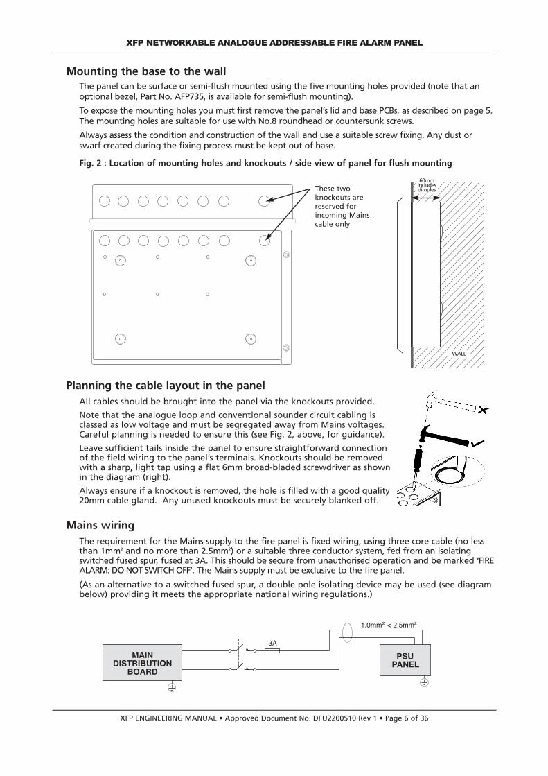
Mounting the base to the wallThe panel can be surface or semi-flush mounted using the five mounting holes provided (note that anoptional bezel, Part No. AFP735, is available for semi-flush mounting).
To expose the mounting holes you must first remove the panel’s lid and base PCBs, as described on page 5.The mounting holes are suitable for use with No.8 roundhead or countersunk screws.
Always assess the condition and construction of the wall and use a suitable screw fixing. Any dust orswarf created during the fixing process must be kept out of base.
Fig. 2 : Location of mounting holes and knockouts / side view of panel for flush mounting
These twoknockouts arereserved forincoming Mainscable only
Planning the cable layout in the panelAll cables should be brought into the panel via the knockouts provided.
Note that the analogue loop and conventional sounder circuit cabling isclassed as low voltage and must be segregated away from Mains voltages.Careful planning is needed to ensure this (see Fig. 2, above, for guidance).
Leave sufficient tails inside the panel to ensure straightforward connectionof the field wiring to the panel’s terminals. Knockouts should be removedwith a sharp, light tap using a flat 6mm broad-bladed screwdriver as shownin the diagram (right).
Always ensure if a knockout is removed, the hole is filled with a good quality20mm cable gland. Any unused knockouts must be securely blanked off.
Mains wiringThe requirement for the Mains supply to the fire panel is fixed wiring, using three core cable (no lessthan 1mm2 and no more than 2.5mm2) or a suitable three conductor system, fed from an isolatingswitched fused spur, fused at 3A. This should be secure from unauthorised operation and be marked ‘FIREALARM: DO NOT SWITCH OFF’. The Mains supply must be exclusive to the fire panel.
(As an alternative to a switched fused spur, a double pole isolating device may be used (see diagrambelow) providing it meets the appropriate national wiring regulations.)
XFP ENGINEERING MANUAL • Approved Document No. DFU2200510 Rev 1 • Page 6 of 36
XFP NETWORKABLE ANALOGUE ADDRESSABLE FIRE ALARM PANEL
60mm includes dimples
WALL
1.0mm < 2.5mm
PSUPANEL
MAINDISTRIBUTION
BOARD
3A
2 2

BA
TT
ER
Y F
US
E
3.1
5A
F
PRIMARY FUSE
+ –
Connecting Mains to the Power Supply PCB
The panel’s PSU is a 185-265Va.c. 50-60Hz off line switched mode power supply that combines thefunctions of a power supply unit, battery charging unit, battery monitoring unit and earth faultmonitoring unit. It should be positioned in the panel’s enclosure as shown in Fig. 3 below. DO NOToperate the panel without the Power Supply PCB correctly mounted in the enclosure with its threePCB retaining screws securely tightened.
DO NOT connect Mains to the Power Supply PCB until the installation is complete and ALL relevant PCBsare correctly attached within the panel.
Fig. 3 : Power Supply PCB layout and Mains connection details
Incoming Mains cable must besegregated from other cablesand should only enter thepanel through either of theseknockouts. Good quality cableglands must always be fitted.
The PSU earth strap MUSTbe connected to the spadeon the main base earth
post before operation. The spadeis compressed against a shoulder onthe post via the lowest nut. Theearth post may appear loose, this isintended by design.
WHEN CONNECTED, THE PCB STORES VOLTAGES AT UP TO 400Vd.c. ANDMAY BE LETHAL IF TOUCHED.
DO NOT TOUCH THE PCB WHILST THE RED‘HAZARDOUS VOLTAGES PRESENT’ LED IS LIT.
Ten-wayconnection loom(connects to PL1 on theMain Control PCB).
DO NOT REMOVEWHEN PANEL ISPOWERED
The incomingMains earthwire MUST beconnected tothe terminalmarked andNOT to the mainbase earth post.(The PSU earthstrap connects thePCB to the baseearth post).
XFP ENGINEERING MANUAL • Approved Document No. DFU2200510 Rev 1 • Page 7 of 36
XFP NETWORKABLE ANALOGUE ADDRESSABLE FIRE ALARM PANEL
Battery leads (note that abattery jumper lead issupplied in the panel’saccessory pack). See page11 for further details.
Primary fuse (F2)20mm 1ATH 250VHRC ceramic fuseto IEC 127(EN60127-2).
Battery fuse (F3)20mm x 3.15AFglass fuse to IEC 127(EN60127-2).

Analogue addressable loop wiring
Fig. 4 below shows a typical analogue addressable loop complete with loop isolators, detectors,loop-powered sounders, modules and monitors. The descriptions and availability of the devices shownmay not be applicable to all manufacturers’ protocols – check with your supplier for further details.Also this example arrangement of devices may not be permitted by design and installation regulationsin certain countries. The loop should be connected to the relevant 5mm connector block on thepanel’s Main Control PCB and its screens terminated at the panel’s base earth post as shown on page 9.
Fig. 4 : A typical analogue addressable loop
Design issues - reducing faults and their consequences
To ensure a reliable system, it should be designed and maintained to local design and installation regu-lations. The XFP has loop isolators included in the panel, and loop isolators should be included in theloop wiring. A single short circuit fault will now only disable devices in the section of wiring betweenisolators. Local design and installation regulations will dictate how many devices or zones may be lostin the case of this type of fault. In the case of a single open circuit no devices will lost, since communi-cation is from both ends of the loop, but a loop integrity fault will be shown.Note that a critical design issue with any analogue fire system is the combined effect of loop resistance,loop capacitance and the current demand of items connected to the loop. Factors that influence this include loop length, cable diameter, cable type, the number of isolators usedand the number and type of devices between isolators. There are no hard and fast rules regarding thesefactors as every situation is unique. However, if the following conservative advice is followed, the loopWILL almost certainly work. • Absolute maximum loop length = 1km, with either 1mm2 or 1.5mm2 cables.• No more than 20 addressable devices between loop isolators of which no more than 6 are loop sounders.• If loop sounders are used, use 1.5mm2 cable and do not fit more that 32 loop sounders per loop in total.• If more than 10 loop sounders are used per loop then the maximum loop length per loop should be no
greater than 750m. The above SHOULD NOT be considered the maximum operating conditions for the panel as many otherpermutations are possible. Any limitations are a consequence of device manufacturers’ protocol, coupledwith the cable’s characteristics. The panel’s loop driver is easily capable of driving lightly loaded loops upto 4 km long without a problem. However, devices connected at the end of 4 km may not be able to readthe data once corrupted by the cable.
XFP ENGINEERING MANUAL • Approved Document No. DFU2200510 Rev 1 • Page 8 of 36
XFP NETWORKABLE ANALOGUE ADDRESSABLE FIRE ALARM PANEL
XFPpanel
A+ A- B+ B- A+ A- B+ B-Fault
NC C NORelay 3
NC C NORelay 2
NC C NORelay 1
NC C NOSndr 1+ -
Sndr 2+ - C +24v 1/P1 1/P2 0v
BA
TT
ER
Y F
US
E
3.1
5A
F
PRIMARY FUSE
+ –
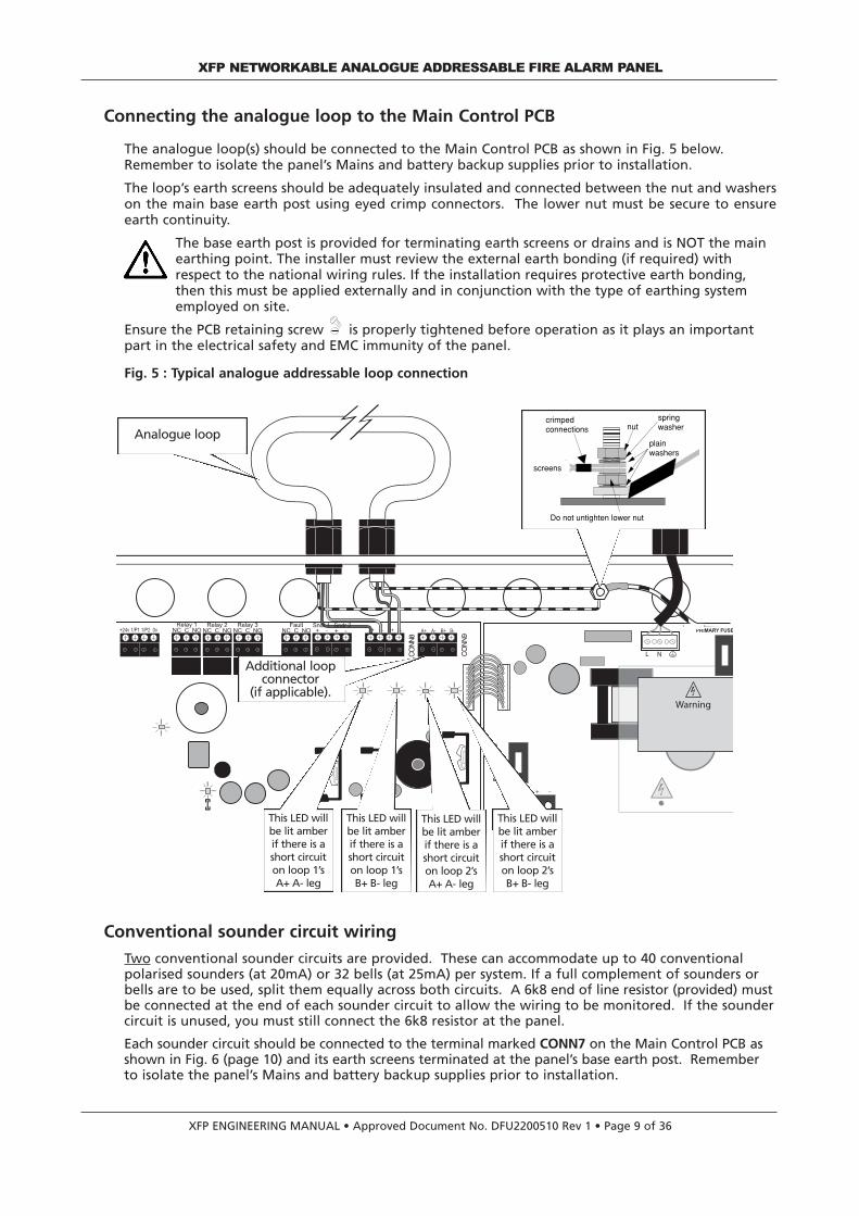
Connecting the analogue loop to the Main Control PCB
The analogue loop(s) should be connected to the Main Control PCB as shown in Fig. 5 below.Remember to isolate the panel’s Mains and battery backup supplies prior to installation.
The loop’s earth screens should be adequately insulated and connected between the nut and washerson the main base earth post using eyed crimp connectors. The lower nut must be secure to ensureearth continuity.
The base earth post is provided for terminating earth screens or drains and is NOT the mainearthing point. The installer must review the external earth bonding (if required) withrespect to the national wiring rules. If the installation requires protective earth bonding,then this must be applied externally and in conjunction with the type of earthing systememployed on site.
Ensure the PCB retaining screw is properly tightened before operation as it plays an importantpart in the electrical safety and EMC immunity of the panel.
Fig. 5 : Typical analogue addressable loop connection
PL2T PCB
L N
P
XFP ENGINEERING MANUAL • Approved Document No. DFU2200510 Rev 1 • Page 9 of 36
XFP NETWORKABLE ANALOGUE ADDRESSABLE FIRE ALARM PANEL
Analogue loopnut
plain washers
crimpedconnections
Do not untighten lower nut
springwasher
screens
Conventional sounder circuit wiring
Two conventional sounder circuits are provided. These can accommodate up to 40 conventionalpolarised sounders (at 20mA) or 32 bells (at 25mA) per system. If a full complement of sounders orbells are to be used, split them equally across both circuits. A 6k8 end of line resistor (provided) mustbe connected at the end of each sounder circuit to allow the wiring to be monitored. If the soundercircuit is unused, you must still connect the 6k8 resistor at the panel.
Each sounder circuit should be connected to the terminal marked CONN7 on the Main Control PCB asshown in Fig. 6 (page 10) and its earth screens terminated at the panel’s base earth post. Rememberto isolate the panel’s Mains and battery backup supplies prior to installation.
Additional loop connector
(if applicable).
CONN8
CONN9
This LED willbe lit amberif there is ashort circuiton loop 1’sA+ A- leg
This LED willbe lit amberif there is ashort circuiton loop 1’sB+ B- leg
This LED willbe lit amberif there is ashort circuiton loop 2’sA+ A- leg
This LED willbe lit amberif there is ashort circuiton loop 2’sB+ B- leg
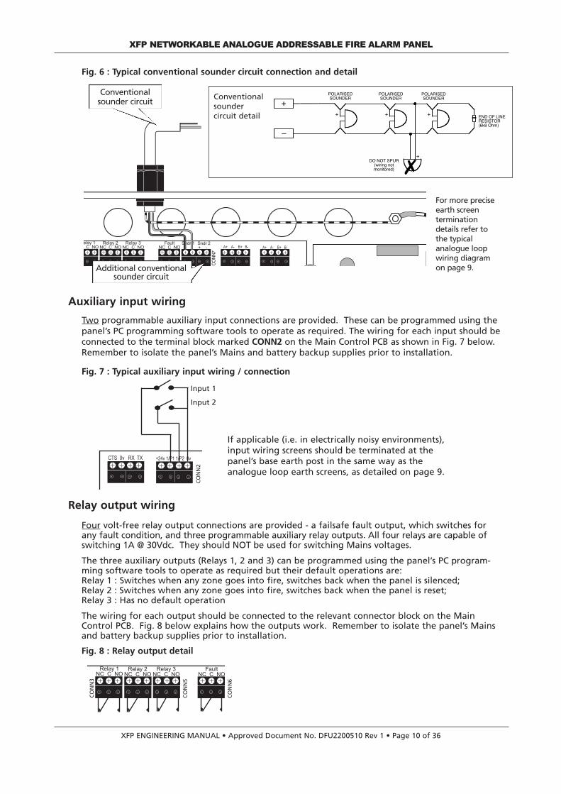
Fig. 6 : Typical conventional sounder circuit connection and detail
Auxiliary input wiring
Two programmable auxiliary input connections are provided. These can be programmed using thepanel’s PC programming software tools to operate as required. The wiring for each input should beconnected to the terminal block marked CONN2 on the Main Control PCB as shown in Fig. 7 below.Remember to isolate the panel’s Mains and battery backup supplies prior to installation.
Fig. 7 : Typical auxiliary input wiring / connection
Relay output wiring
Four volt-free relay output connections are provided - a failsafe fault output, which switches forany fault condition, and three programmable auxiliary relay outputs. All four relays are capable ofswitching 1A @ 30Vdc. They should NOT be used for switching Mains voltages.
The three auxiliary outputs (Relays 1, 2 and 3) can be programmed using the panel’s PC program-ming software tools to operate as required but their default operations are:Relay 1 : Switches when any zone goes into fire, switches back when the panel is silenced;Relay 2 : Switches when any zone goes into fire, switches back when the panel is reset;Relay 3 : Has no default operation
The wiring for each output should be connected to the relevant connector block on the MainControl PCB. Fig. 8 below explains how the outputs work. Remember to isolate the panel’s Mainsand battery backup supplies prior to installation.
Fig. 8 : Relay output detail
XFP ENGINEERING MANUAL • Approved Document No. DFU2200510 Rev 1 • Page 10 of 36
XFP NETWORKABLE ANALOGUE ADDRESSABLE FIRE ALARM PANEL
A- B+ B- A A- B+ B-F
CTS 0v RX TX +24v 1/P1 1/P2 0v
–
A- B+ B- A A- B+ B-Fault
NC C NORelay 3
NC C NORelay 2
NC C NORelay 1
NC C NO
–
Input 1
Input 2
4 3 4 3 4 3 4 3
If applicable (i.e. in electrically noisy environments),input wiring screens should be terminated at thepanel’s base earth post in the same way as theanalogue loop earth screens, as detailed on page 9.
CONN2
CONN5
CONN6
CONN3
END OF LINERESISTOR(6k8 Ohm)
POLARISEDSOUNDER
POLARISEDSOUNDER
+ + +
–
+
POLARISEDSOUNDER
+
�DO NOT SPUR
(wiring notmonitored)
P
A+ A- B+ B-Sndr 1+ -
Sndr 2+ - A+ A- B+ B-
FaultNC C NO
Relay 3NC C NO
Relay 2NC C NO
elay 1 C NO
For more preciseearth screenterminationdetails refer tothe typicalanalogue loopwiring diagramon page 9.
Conventionalsounder circuit
Conventionalsoundercircuit detail
Additional conventionalsounder circuit
CONN7

Remote PC connection
A four-way RS232 molexconnector (PL2) is providedon the Main Control PCB forthe connection of aWindows based PC for pro-gramming purposes. TheONLY way to program thisfire panel is using a PCloaded with the panel’ssophisticated programmingtools (Part No. XFP507).The lead supplied with thesoftware tools should beconnected to the panel andthe PC as shown in Fig. 9(right).
XFP ENGINEERING MANUAL • Approved Document No. DFU2200510 Rev 1 • Page 11 of 36
XFP NETWORKABLE ANALOGUE ADDRESSABLE FIRE ALARM PANEL
Plug the lead’s ‘D’-type connector into the appro-priate serial socket (com1, com2, etc) on the PC
NVM ‘memory unlock’ link,must be fitted whenuploading or downloadinginformation from/to the PC
RS232
Space for batteriesRed wire from panel
Shorting link (supplied in panel accessory pack)
Black wire from panel
12V battery12V battery
Fig. 9 : Connecting a PC to the panel’s RS232 connector
Printer connectionA second RS232 socket (CONN1) is provided on the Main Control PCB for the optional connection of aserial printer to allow optional printing of the panel’s 500 event log. We recommend the use of theAFP709 off-board printer kit which includes a printer, a 3m long connection lead and an isolation mod-ule/socket. The purpose of the isolation module/socket is to interface the panel to the printer and toprevent earth faults caused by the printers internal 0V to earth connection being generated at thepanel. For further information, please refer to the information supplied with the printer kit.
Aux. 24V outputOne fused 24V d.c. output, rated at 100mA, is provided and can be used for supplying power to ancil-lary fire alarm equipment. This input should not be used to power electromagnetic door retainers.
Installing the standby battery supplyTwo new, good quality and fully charged 12V valve regulated lead acid batteries are required as theemergency stand-by power supply for the panel. The batteries should be connected in series andlocated in the panel’s enclosure as shown in Fig. 10 below. The battery leads, link wire and nylon cableties are provided in the panel’s accessory pack. Run the battery leads through the slits in the panel’slower plastic ribs and secure the batteries into position using the nylon cable ties as shown.
The panel’s sophisticated battery monitoring unit protects the batteries against deep discharge byactivating a cut off circuit when the stand-by supply voltage reaches 21V approx. If batteries are notfitted, are discharged or in poor condition, a PSU fault will show at the panel.
The capacity of the batteries used will depend upon the required stand-by time. To calculate the bat-teries required for any given stand-by period, refer to the battery calculation guide on page 35.
Always dispose of used batteries according to the battery manufacturer’s instructions.
Fig. 10 : Battery location and connection details

• Disconnect the 10-way loom from PL1, the lid/base connecting cable from PL5 and all remaining connections from the top of the Main Control PCB as necessary.
• Unfasten the retaining screw at the bottom left of the Main Control PCB using a crosshead screwdriver and push the PCB up and over the panel’s mounting pillars.
• Insert the two hexagon spacers (supplied with the network communication card) through the holes on the Main ControlPCB and secure them using the nuts and washers provided, see right.
• Take the network communication card and carefully line its holes up with the two hexagon spacers, ensuring that it’s 6 way pin connectors are correctly inserted into PL3 on the Main Control PCB.
• Secure the card onto the hexagon spacers using the two 6mm slotted screws (supplied).
• Refit the Main Control PCB and all relevant connection cables previously removed. Ensure that the PCB retaining screw is firmly fastened down.
XFP ENGINEERING MANUAL • Approved Document No. DFU2200510 Rev 1 • Page 12 of 36
XFP NETWORKABLE ANALOGUE ADDRESSABLE FIRE ALARM PANEL
Network/repeater wiring (optional)
The XFP’s network protocol allows the interconnection of up to eight XFP main panels (any mix of singleloop 16 zone XFPs and/or 1 to 2 loop 32 zone XFPs) over a two-wire RS485 network. Alternatively, thenetwork can be used to connect up to eight XFP repeaters to one XFP main panel. It is not possible tomix XFP main panels and repeaters on the same network.
Key features of the XFP’s network protocol when used for interconnecting XFP main panels:
• Allows the interconnection of up to eight XFP main panels (any mix of single loop 16 zone XFPs and 1 and 2 loop 32 zone XFPs)
• Up to 1 km of cable may be fitted to an XFP main panel network.
• Each networked XFP main panel can be programmed to: Accept Fires from other main panels. Accept Faults from other main panels.Accept Control actions such as Silence Alarm Sounders and Control Panel Reset from other main panels.Accept Disablement commands for zones, sounders and output sets from other main panels. (Each of these four functions may be individually selected via the panel’s PC Programming Software Tools.
• All panels monitor all other panels for network wiring faults.
• Fires on remote panels are displayed on local panels including the point description of the alarm’s origin.
• Faults on remote panels are displayed on local panels including the point description in the case of a detector.
• Cause and effect can be programmed into local panels dependent on which remote panel is in alarm.
• The network supports the programming of site information into remote panels from a PC connected at a local panel.
• Time and date is common to all panels throughout the network.
Key features of the XFP’s network protocol when used for connecting XFP repeaters
• Allows the connection of up to eight XFP repeaters (any mix of single loop 16 zone repeaters and 1 and 2 loop 32 zone repeaters)
• Up to 500m of cable may be fitted to an XFP repeater network.
• Each XFP repeater offers all the functions and controls of an XFP main panel
Any XFP main panel connected to the RS485 network requires the installation of a NetworkCommunication Card (Part No. AFP711), as shown in Fig. 11 below (Repeaters come with a NetworkCommunication Card already fitted). Typical network wiring details are shown in Fig. 12.
Fig. 11: Installing the Network Communication Card
Important: Before installing the Network Communication Card, isolate the Mains supply anddisconnect the panel’s battery back-up supply. With reference to the diagram below:
See Fig. 12for typical networkwiringdetails
XFP ENGINEERING MANUAL • Approved Document No. DFU2200510 Rev 1 • Page 13 of 36
XFP NETWORKABLE ANALOGUE ADDRESSABLE FIRE ALARM PANEL
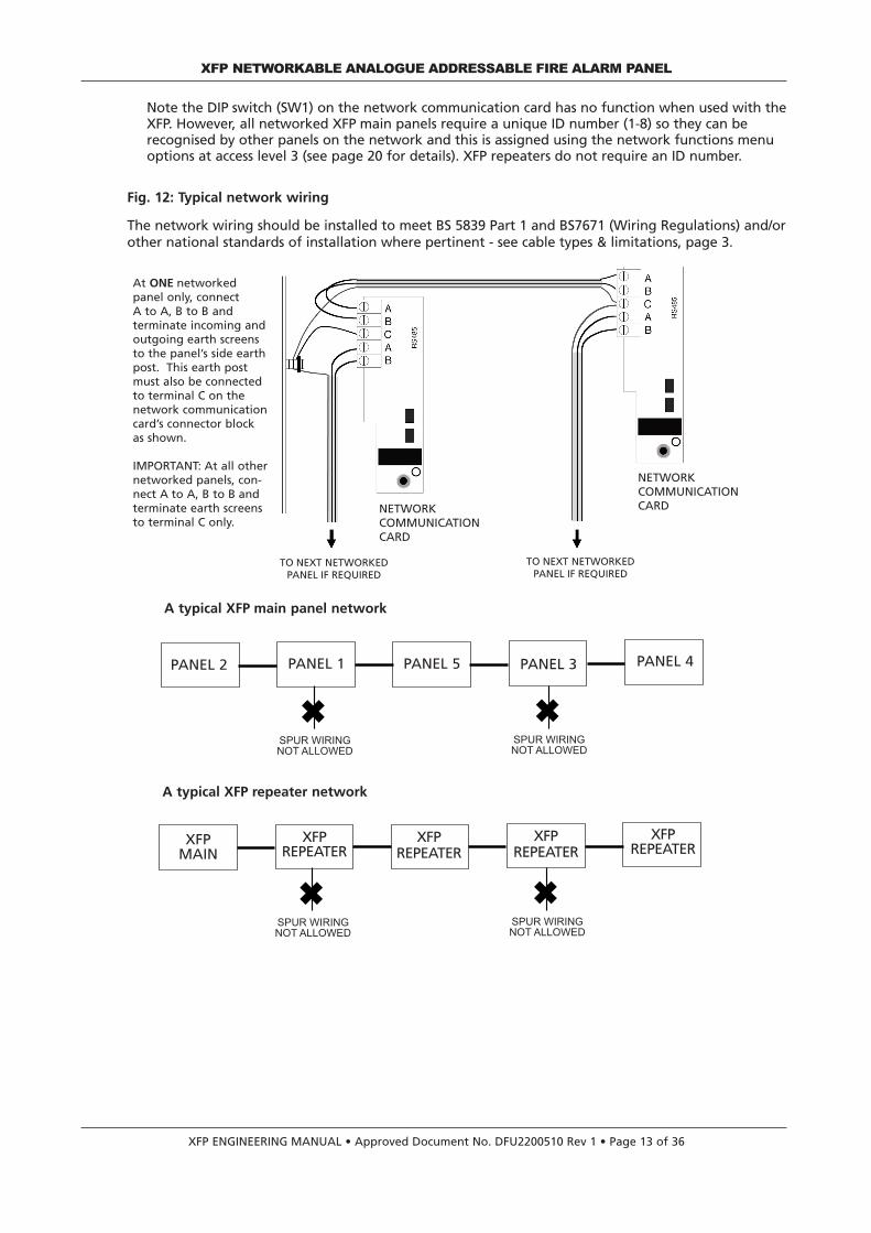
Fig. 12: Typical network wiring
The network wiring should be installed to meet BS 5839 Part 1 and BS7671 (Wiring Regulations) and/orother national standards of installation where pertinent - see cable types & limitations, page 3.
REPEATER 1 MASTER REPEATER 2 REPEATER 5 REPEATER 8
�SPUR WIRINGNOT ALLOWED
�SPUR WIRINGNOT ALLOWED
PANEL 2 PANEL 1 PANEL 5 PANEL 3 PANEL 4
At ONE networkedpanel only, connect A to A, B to B and terminate incoming andoutgoing earth screensto the panel’s side earthpost. This earth postmust also be connectedto terminal C on thenetwork communicationcard’s connector blockas shown.
IMPORTANT: At all othernetworked panels, con-nect A to A, B to B andterminate earth screensto terminal C only.
TO NEXT NETWORKEDPANEL IF REQUIRED
TO NEXT NETWORKEDPANEL IF REQUIRED
NETWORKCOMMUNICATIONCARD
NETWORKCOMMUNICATIONCARD
Note the DIP switch (SW1) on the network communication card has no function when used with theXFP. However, all networked XFP main panels require a unique ID number (1-8) so they can berecognised by other panels on the network and this is assigned using the network functions menuoptions at access level 3 (see page 20 for details). XFP repeaters do not require an ID number.
A typical XFP main panel network
REPEATER 1 MASTER REPEATER 2 REPEATER 5 REPEATER 8
�SPUR WIRINGNOT ALLOWED
�SPUR WIRINGNOT ALLOWED
XFPMAIN
XFPREPEATER
A typical XFP repeater network
XFPREPEATER
XFPREPEATER
XFPREPEATER
XFP ENGINEERING MANUAL • Approved Document No. DFU2200510 Rev 1 • Page 14 of 36
XFP NETWORKABLE ANALOGUE ADDRESSABLE FIRE ALARM PANEL
CONTROLS AND INDICATORS
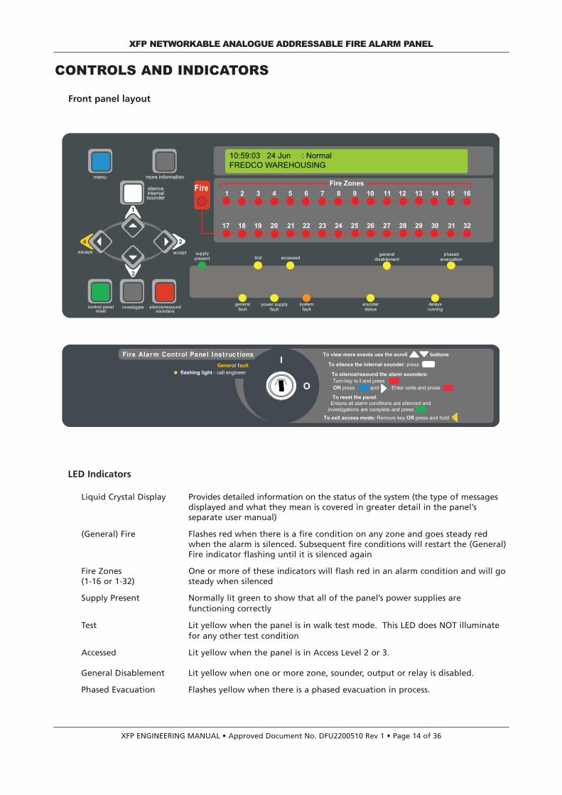
Front panel layout
LED Indicators
Liquid Crystal Display Provides detailed information on the status of the system (the type of messages displayed and what they mean is covered in greater detail in the panel’s separate user manual)
(General) Fire Flashes red when there is a fire condition on any zone and goes steady red when the alarm is silenced. Subsequent fire conditions will restart the (General)Fire indicator flashing until it is silenced again
Fire Zones One or more of these indicators will flash red in an alarm condition and will go (1-16 or 1-32) steady when silenced
Supply Present Normally lit green to show that all of the panel’s power supplies are functioning correctly
Test Lit yellow when the panel is in walk test mode. This LED does NOT illuminate for any other test condition
Accessed Lit yellow when the panel is in Access Level 2 or 3.
General Disablement Lit yellow when one or more zone, sounder, output or relay is disabled.
Phased Evacuation Flashes yellow when there is a phased evacuation in process.
Fire Zones
17 18 19 20 21 22 23 24 25 26 27 28 29 30 31 32
1 2 3 4 5 6 7 8 9 10 11 12 13 14 15 16Fire
generalfault
power supplyfault
systemfault
sounderstatus
delaysrunning
test accessedgeneral
disablementphased
evacuation
more informationmenu
silenceinternalsounder
silence/resoundsounders
control panelreset
investigate
escape accept supplypresent
General fault
Fire Alarm Control Panel Instruc t ions
flashing light - call engineer
O
ITo view more events use the scroll buttons
To silence the internal sounder: press
To silence/resound the alarm sounders:Turn key to and pressl
press and . Enter code and pressOR
To reset the panel:Ensure all alarm conditions are silenced and
investigations are complete and press
To exit access mode: ORRemove key press and hold
10:59:03 24 Jun : NormalFREDCO WAREHOUSING

XFP ENGINEERING MANUAL • Approved Document No. DFU2200510 Rev 1 • Page 15 of 36
XFP NETWORKABLE ANALOGUE ADDRESSABLE FIRE ALARM PANEL
LED Indicators (continued)
General Fault Flashes yellow when there is an fault condition on the panel. Will always be lit in conjunction with at least one other fault LED.
Power Supply Fault Lit yellow when the panel’s power supply or Mains has failed or the panel’s standby battery is in poor condition.
System Fault Lit amber when a system error, such as a microprocessor fault, occurs. Remains lit even if the panel automatically clears the fault.
Sounder Status Flashes yellow when a fault is detected on either of the panel’s two conventional sounder circuits or if there is a sounder disablement anywhere on the system.
Delays Running Lit yellow when one or more output delays have been programmed into the panel. Flashes yellow when one or more output delay is running.
Button controls
More Information Displays additional information on any fire, pre-alarm or fault conditionsthat appear on the panel’s display. Will also display additional context dependant information where appropriate.
(Scroll Up) 51 Dependent on the status of the panel, these two buttons:(Scroll Down) 63 • scroll vertically through any fire, pre-alarm or fault conditions that appear
on the panel’s display• scroll vertically through the panel’s user menus • manipulate date, time and disablement settings, etc• serve as code input buttons to access levels 2 or 3.
Accept 42 Dependent on the status of the panel, these two buttons:Escape 34 • scroll horizontally through the panel’s user menus
• escape or accept options available in the panel’s user menus • serve as code input buttons to access levels 2 or 3.
Menu Provides access to the panel’s menus
Silence Internal Sounder Silences the panel’s internal sounder
Control Panel Reset Resets the panel when the sounders are silenced (access levels 2 & 3 only)
Silence / Resound Sounders Silences or resounds the system’s sounders (access levels 2 & 3 only)
Investigate Starts the panel’s investigate timer function (access levels 2 & 3 only)
Keyswitch control
Turning the keyswitch to the armed position (I) gives the user instant access to access level 2 (authorised user level).
OO
II

COMMISSIONING AND PROGRAMMING
OverviewCommissioning is the setting to work of the equipment. The efficiency with which this is donedepends upon:• The accuracy of information received regarding the wiring and devices fitted. • The freedom of the installation from faults and errors.• The completeness of the information received from the client/specifier as regards the zoning, naming and functioning of the system.
The final quality of the installation ALWAYS depends upon the quality of these three factors.
Recommended commissioning procedure
Re-fit the panel’s PCBs and all connection leads by reversing the removal procedure detailed onpage 5. Ensure all PCB retaining screws are firmly fastened down and that the PSU earth strap isconnected to the base earth post. If a network communication card is required, this should be fit-ted as shown on page 12.
Check the continuity of the loop, the resistance of the conventional sounder circuits (if applicable)and all other field wiring as appropriate to ensure they are free from faults. DO NOT MEGGER!Remove all electronic devices if 500V testing is demanded).
If okay, connect all field wiring to the main control PCB as detailed on pages 8 to 11.
Connect the Mains supply to the L, N and terminals on the power supply PCB and the standby battery supply to its BAT1 terminals.
Upon powering up, the panel’s LCD will display a number of start up messages detailing the proto-col of the panel, etc.
Investigate any faults reported on the panel’s display and take the necessary steps to correct them.
When all faults have been corrected, carry out a loop learn as detailed on page 21. Rectify anyproblems resulting from loop learn (e.g. double addresses, missing devices, incomplete loops etc.Note that a wide range of test and fault-finding functions are available in access level 3.
When all faults have been cleared, proceed to program the panel as appropriate.
When you are satisfied the panel has been programmed and is working correctly, secure thepanel lid and instruct the client/customer in the operation of the system.
Complete and handover all necessary manuals and other documentation prior to leaving site.
XFP ENGINEERING MANUAL • Approved Document No. DFU2200510 Rev 1 • Page 16 of 36
XFP NETWORKABLE ANALOGUE ADDRESSABLE FIRE ALARM PANEL
System operation / terms of reference
Input devices such as detectors, manual call points and the input channels of I/O units areprogrammed to be members of a Zone.
Output devices such as loop powered sounders, sounder control units and the panel’sconventional sounder circuits are programmed to be members of a Group.
The output channels of I/O units and the panel’s relays are programmed to be members of a Set.
Zones are programmed via the panel’s software to activate Groups and/or Sets as appropriate.
The method of activation of Groups can be continuous or pulsed, with or without a delay, asrequired.
Note that the panel’s two auxiliary inputs can be programmed to function in a multitude of waysusing the special cause and effects options available in the XFP programming software.
XFP ENGINEERING MANUAL • Approved Document No. DFU2200510 Rev 1 • Page 17 of 36
ACCESS LEVELS MENU TREE
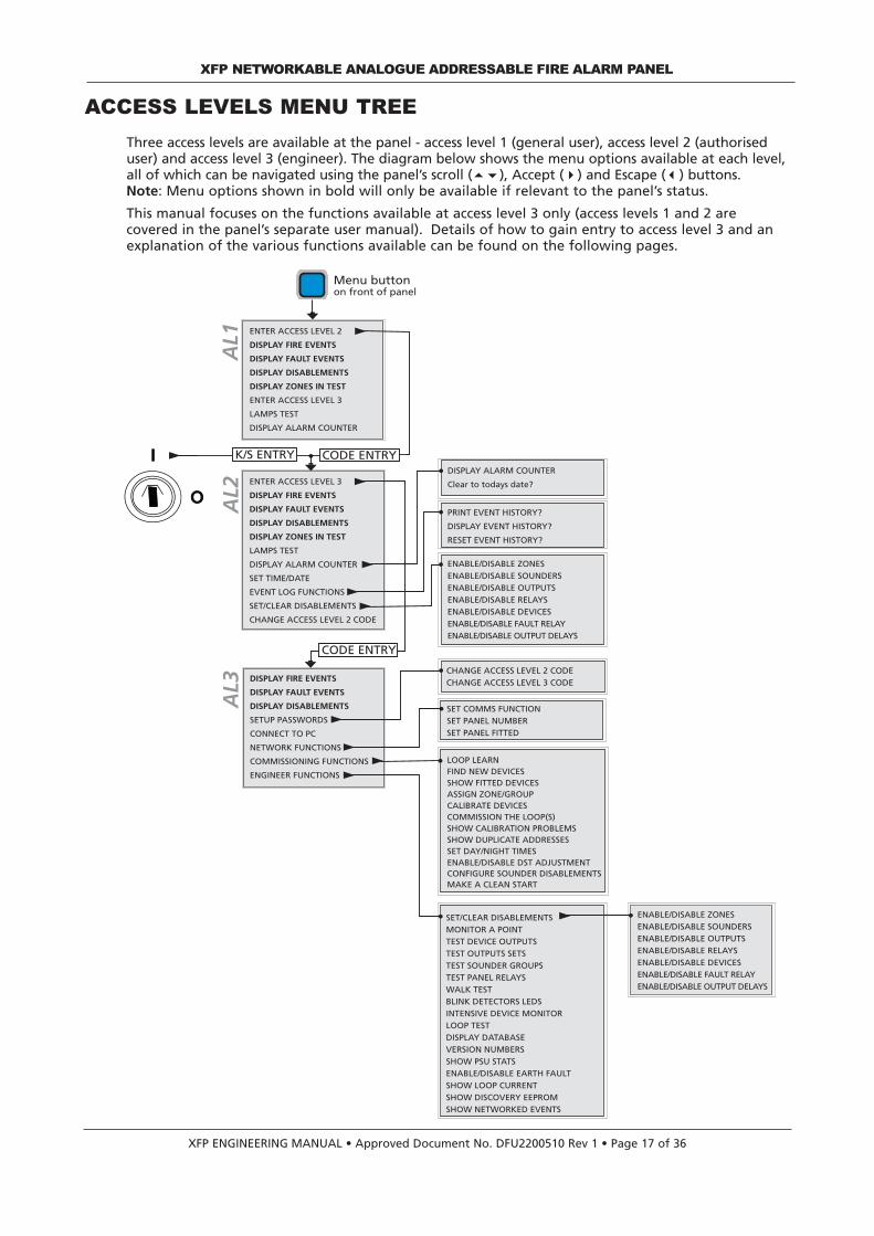
Three access levels are available at the panel - access level 1 (general user), access level 2 (authoriseduser) and access level 3 (engineer). The diagram below shows the menu options available at each level,all of which can be navigated using the panel’s scroll (56), Accept (4) and Escape (3) buttons.Note: Menu options shown in bold will only be available if relevant to the panel’s status.
This manual focuses on the functions available at access level 3 only (access levels 1 and 2 arecovered in the panel’s separate user manual). Details of how to gain entry to access level 3 and anexplanation of the various functions available can be found on the following pages.
XFP NETWORKABLE ANALOGUE ADDRESSABLE FIRE ALARM PANEL
ENTER ACCESS LEVEL 3
DISPLAY FIRE EVENTS
DISPLAY FAULT EVENTS
DISPLAY DISABLEMENTS
DISPLAY ZONES IN TEST
LAMPS TEST
DISPLAY ALARM COUNTER
SET TIME/DATE
EVENT LOG FUNCTIONS
SET/CLEAR DISABLEMENTS
CHANGE ACCESS LEVEL 2 CODE
DISPLAY ALARM COUNTER
Clear to todays date?
PRINT EVENT HISTORY?
DISPLAY EVENT HISTORY?
RESET EVENT HISTORY?
ENABLE/DISABLE ZONESENABLE/DISABLE SOUNDERSENABLE/DISABLE OUTPUTSENABLE/DISABLE RELAYSENABLE/DISABLE DEVICESENABLE/DISABLE FAULT RELAYENABLE/DISABLE OUTPUT DELAYS
ENTER ACCESS LEVEL 2
DISPLAY FIRE EVENTS
DISPLAY FAULT EVENTS
DISPLAY DISABLEMENTS
DISPLAY ZONES IN TEST
ENTER ACCESS LEVEL 3
LAMPS TEST
DISPLAY ALARM COUNTER
DISPLAY FIRE EVENTS
DISPLAY FAULT EVENTS
DISPLAY DISABLEMENTS
SETUP PASSWORDS
CONNECT TO PC
NETWORK FUNCTIONS
COMMISSIONING FUNCTIONS
ENGINEER FUNCTIONS
CHANGE ACCESS LEVEL 2 CODECHANGE ACCESS LEVEL 3 CODE
SET COMMS FUNCTION SET PANEL NUMBERSET PANEL FITTED
LOOP LEARNFIND NEW DEVICESSHOW FITTED DEVICESASSIGN ZONE/GROUPCALIBRATE DEVICESCOMMISSION THE LOOP(S)SHOW CALIBRATION PROBLEMSSHOW DUPLICATE ADDRESSESSET DAY/NIGHT TIMESENABLE/DISABLE DST ADJUSTMENTCONFIGURE SOUNDER DISABLEMENTSMAKE A CLEAN START
SET/CLEAR DISABLEMENTSMONITOR A POINTTEST DEVICE OUTPUTSTEST OUTPUTS SETSTEST SOUNDER GROUPSTEST PANEL RELAYSWALK TESTBLINK DETECTORS LEDSINTENSIVE DEVICE MONITORLOOP TESTDISPLAY DATABASEVERSION NUMBERSSHOW PSU STATSENABLE/DISABLE EARTH FAULTSHOW LOOP CURRENTSHOW DISCOVERY EEPROMSHOW NETWORKED EVENTS
ENABLE/DISABLE ZONESENABLE/DISABLE SOUNDERSENABLE/DISABLE OUTPUTSENABLE/DISABLE RELAYSENABLE/DISABLE DEVICESENABLE/DISABLE FAULT RELAYENABLE/DISABLE OUTPUT DELAYS
AL1
AL2
AL3
Menu buttonon front of panel
CODE ENTRY
CODE ENTRY
K/S ENTRY
OO
II

XFP ENGINEERING MANUAL • Approved Document No. DFU2200510 Rev 1 • Page 18 of 36
How to enter access level three
Access level 3 can be entered in one of two ways:
(1) By pressing the Menu button on the panel’s front, scrolling down to ENTER ACCESS LEVEL 3 and pressing the Accept4button. When you have done this, the following prompt will appear:
Enter the four-digit access level 3 code using the 5(1) 4(2) 6(3)3(4) buttons as appropriate.The default code is 4 4 4 4 (four presses of the3button). If this does not work, the code may have been changed. As soon as the code has been entered correctly, you will be taken into access level 3 (see pages 19 to 33).
(2) By entering access level 2 as detailed in the panel’s separate user manual, scrolling down to ENTER ACCESS LEVEL 3 and repeating the process described above.
In access level 3, the panel’s Silence / Resound Sounders, Control Panel Reset and Investigate buttonsbecome active and you can:
• Scroll through any fire, pre-alarm or fault conditions which are displayed on the panel’s LCD
• View any disablements or zones that are in test (if applicable)
• Change the entry codes to access levels 2 and 3 from their factory default settings
• Connect the panel to a compatible PC for system programming
• Set the panel up to belong to a network of up to eight XFP main panels or allow it to have up to eight XFP repeaters connected to it.
• Gain access to a wide range of commissioning functions including auto loop learn, device calibration and group/zone assignment
• Gain access to a wide range of engineering test and fault finding functions
• Ascertain software revision numbers, loop current and PSU statistics
• Enable/disable earth faults
• Set the time the panel enters and exits day (building occupied) and night (building unoccupied) mode
• Access all of the panel’s access level 2 menu options as described in the panel’s separate user manual.
This section of the engineering manual explains in detail the various functions available via theaccess level 3 menu options. (Note that information on how fire, pre-alarm and fault conditionsare reported, and how the panel’s control buttons operate, can be found in the separate usermanual/log book).
Fitting the panel’s NVM ‘memory unlock’ link
To allow site-specific changes to be made to the panel’snon-volatile memory, the NVM ‘memory unlock’ link (PLK2)must be fitted to the Main Control PCB, as shown right. Itis recommended that you fit this link as a matter of coursewhenever you are in access level 3.
Remember to re-lock the memory (remove the link) whenprogramming is complete to guard against data corrup-tion.
If you do not re-lock the memory, a reminder message will appear when you leave access level 3.
XFP NETWORKABLE ANALOGUE ADDRESSABLE FIRE ALARM PANEL
A- B+ B- A B+ B-F
C NO
R
- C 0v RX TX
–
PLK2LINK TO UNLOCK NVM
Enter Access Level 3 code:
NVM memory unlock link
A detailed description of the functions available at access level 3 can be found overleaf.

Display Fire Events
This function is only available if there are active fire conditions on the system. If available, press theAccept4button and a window similar to the one below will appear:
Pressing the 5and6buttons will scroll the display through all active fire conditions. More detailedinformation (if applicable) can be viewed by pressing the panel’s More Information button. To returnto the main access level 3 menu press the Escape3button.
Display Fault EventsThis function is only available if there are active faults on the system. If available, press theAccept4button and a window similar to the one below will appear:
Pressing the 5and6buttons will scroll the display through all active faults. More detailed informa-tion (if applicable) can be viewed by pressing the panel’s More Information button. To return to themain access level 3 menu press the Escape3button.
Display DisablementsThis function is only available when there are active disablements on the system. If available, pressthe Accept4button and a window similar to the one overleaf will appear:
Pressing the 5and6buttons will scroll the display through all active disablements. More detailedinformation (if applicable) can be viewed by pressing the panel’s More Information button. To returnto the main access level 3 menu press the Escape3button.
Display Zones In TestThis function is only available if one or more zones are being tested. If available, press theAccept4button and a window similar to the one below will appear:
Pressing the 5and6buttons will scroll the display through all zones currently in test. More detailedinformation (if applicable) can be viewed by pressing the panel’s More Information button. To returnto the main access level 3 menu press the Escape3button.
Setup PasswordsThis function allows you to change the four digit access codes required to activate the panel’s access level2 or 3 menu options. When selected, press the Accept4button and the following window will appear:
Use the 5and 6buttons to scroll to the desired option (the option in block capitals is the selectedoption) and press the Accept4button. The following message will appear if the CHANGE ACCESSLEVEL 2 CODE? prompt is accepted.
Using the 5(1) 4(2) 6(3)3(4) buttons, enter the new four digit access level 2 code. After the fourthdigit has been entered, the panel will request you confirm the new code by re-entering it:
XFP ENGINEERING MANUAL • Approved Document No. DFU2200510 Rev 1 • Page 19 of 36
XFP NETWORKABLE ANALOGUE ADDRESSABLE FIRE ALARM PANEL
Last Zone: 1:North Stairs :Fire!1 Zone
Zone 1: Ground FloorThere are faults on this zone
1st Zone: 1: Shop floorOn: This Panel: Is Disabled
Zone 1: North StairsIs On Test
CHANGE ACCESS LEVEL 2 CODE?Change Access Level 3 code
Enter NEW Access Level 2 code:
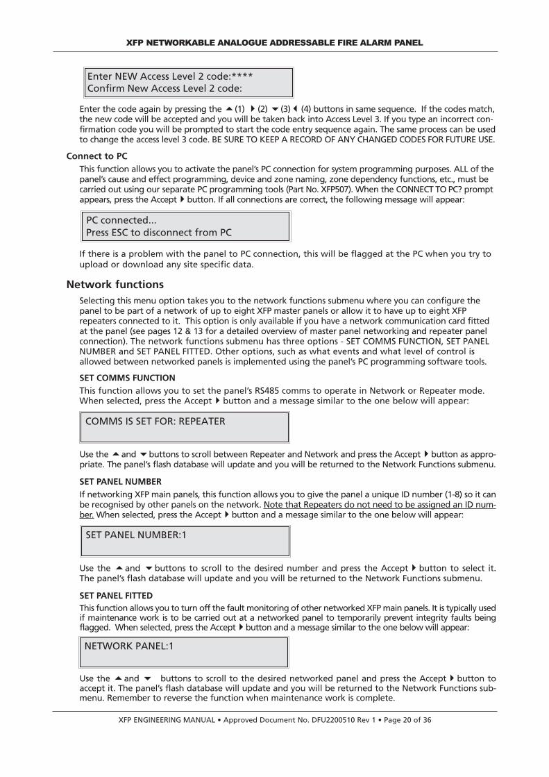
Enter the code again by pressing the 5(1) 4(2) 6(3)3(4) buttons in same sequence. If the codes match,the new code will be accepted and you will be taken back into Access Level 3. If you type an incorrect con-firmation code you will be prompted to start the code entry sequence again. The same process can be usedto change the access level 3 code. BE SURE TO KEEP A RECORD OF ANY CHANGED CODES FOR FUTURE USE.
Connect to PCThis function allows you to activate the panel’s PC connection for system programming purposes. ALL of thepanel’s cause and effect programming, device and zone naming, zone dependency functions, etc., must becarried out using our separate PC programming tools (Part No. XFP507). When the CONNECT TO PC? promptappears, press the Accept4button. If all connections are correct, the following message will appear:
If there is a problem with the panel to PC connection, this will be flagged at the PC when you try toupload or download any site specific data.
Network functionsSelecting this menu option takes you to the network functions submenu where you can configure thepanel to be part of a network of up to eight XFP master panels or allow it to have up to eight XFPrepeaters connected to it. This option is only available if you have a network communication card fittedat the panel (see pages 12 & 13 for a detailed overview of master panel networking and repeater panelconnection). The network functions submenu has three options - SET COMMS FUNCTION, SET PANELNUMBER and SET PANEL FITTED. Other options, such as what events and what level of control isallowed between networked panels is implemented using the panel’s PC programming software tools.
SET COMMS FUNCTION
This function allows you to set the panel’s RS485 comms to operate in Network or Repeater mode.When selected, press the Accept4button and a message similar to the one below will appear:
Use the 5and 6buttons to scroll between Repeater and Network and press the Accept4button as appro-priate. The panel’s flash database will update and you will be returned to the Network Functions submenu.
SET PANEL NUMBER
If networking XFP main panels, this function allows you to give the panel a unique ID number (1-8) so it canbe recognised by other panels on the network. Note that Repeaters do not need to be assigned an ID num-ber. When selected, press the Accept4button and a message similar to the one below will appear:
Use the 5and 6buttons to scroll to the desired number and press the Accept4button to select it.The panel’s flash database will update and you will be returned to the Network Functions submenu.
SET PANEL FITTEDThis function allows you to turn off the fault monitoring of other networked XFP main panels. It is typically usedif maintenance work is to be carried out at a networked panel to temporarily prevent integrity faults beingflagged. When selected, press the Accept4button and a message similar to the one below will appear:
Use the 5and 6 buttons to scroll to the desired networked panel and press the Accept4button toaccept it. The panel’s flash database will update and you will be returned to the Network Functions sub-menu. Remember to reverse the function when maintenance work is complete.
XFP ENGINEERING MANUAL • Approved Document No. DFU2200510 Rev 1 • Page 20 of 36
XFP NETWORKABLE ANALOGUE ADDRESSABLE FIRE ALARM PANEL
SET PANEL NUMBER:1
NETWORK PANEL:1
Enter NEW Access Level 2 code:****Confirm New Access Level 2 code:
PC connected...Press ESC to disconnect from PC
COMMS IS SET FOR: REPEATER

XFP ENGINEERING MANUAL • Approved Document No. DFU2200510 Rev 1 • Page 21 of 36
Commissioning functionsSelecting this menu option takes you to the commissioning functions submenu where you can carryout a loop learn; find new devices; view fitted devices; assign detectors/call points to zones andsounders/beacons to groups; manually calibrate devices; and/or return the panel to its default factorysettings. All of these functions are described in detail below. Note that the vast majority of systemcommissioning - cause and effect programming, device and zone naming, etc. - must be carried outusing our separately available PC programming software tools (Part No. XFP507).
LOOP LEARN
This function activates the panel’s automatic loop learn facility. During a loop learn, the panel inter-rogates every address location on the loop to see if an addressable unit is present and, if so, findsout what type of device it is. When the LOOP LEARN? prompt appears, press the Accept4buttonand you will be asked to confirm that you wish to continue:
Press the Accept4button again to continue and you will be asked to select which loop(s) you wantthe panel to learn (1, 2 or ALL, as applicable).
Use the 5and 6buttons to scroll to the desired loop(s) and press the Accept4button. As the panelmay already have loop device data stored in its memory from a previous loop learn or PC upload, youwill be asked if you want to erase this information before the loop learn begins.
You now have two options, as detailed below:
Option 1If the panel has not previously been programmed or if you want to program an existing system as ifit were a new system, press the Accept4button. The following message will appear:
Press the Accept4button again and the panel will erase its database, update its flash memory andstart to learn the loop(s) as appropriate.
Note that by default the loop learn will assign all detectors/manual call points to zone 1 and all sounders/ bea-cons to group 1. This is to ensure that all of the system’s sounders will activate in the event of a fire conditionanywhere in the building, i.e. one out, all out. These default settings can be modified as appropriate using thepanel’s PC programming software tools at a later date. Note that no default sets are assigned to the outputs ofI/O units - these must be assigned using the panel’s PC programming software tools.
Option 2If you DO NOT wish to erase the loop device data, press the Escape3button and the panel willimmediately start to learn the loop without overwriting data such as zone and group allocation,detector sensitivities, device names, etc., which will remain as it was before the Loop Learn. The onlydata that will be overwritten is device type and whether or not it is fitted. See note above aboutdefault loop learn settings.
Depending on the size of the installation, the loop learn process can take several minutes. Whenthe auto-learn process is complete, a brief summary window will appear, similar to the one below:
Press the Escape3button to return to the Commissioning Functions submenu.
XFP NETWORKABLE ANALOGUE ADDRESSABLE FIRE ALARM PANEL
Continue with Loop Learn?
Learn Loop:All
Erase ALL loop device data first?
Are you sure you want to erasethe Database?
0 changed; 0 removed; 112 total devicesAuto learn completed

XFP ENGINEERING MANUAL • Approved Document No. DFU2200510 Rev 1 • Page 22 of 36
FIND NEW DEVICES
This function allows you to check if any new devices have been connected to the panel since the lastloop learn. It works in a similar way to the loop learn function except whilst learning the loop, thepanel asks if you want to accept any of the new devices it has found and allows you to assign them toa detector zone or sounder group as appropriate. To start the search process, when the FIND NEWDEVICES? prompt appears press the Accept4button. The following window will appear:
Press the Accept4button again to confirm you wish to continue and you will be asked to selectwhich loop(s) you want the panel to search for new devices on (1, 2 or ALL, as applicable).
Use the 5and 6buttons to scroll to the desired loop(s) and press the Accept4button. The searchwill now begin. When a new device is found, the panel will tell you its type, its address (Dev) andthe loop it is fitted on, for example:
To accept the new device press the Accept4button. Alternatively, press the Escape3button toreject it. If the Escape3button is pressed, the panel will continue searching until the next newdevice is found. If the Accept4button is pressed, you will be given the opportunity to assign thedevice to a detector zone or a sounder group as appropriate. For example:
Use the 5and 6buttons to scroll to the desired zone or group and press the Accept4button. Thedevice search will now continue until the next new device is found. (Note that I/O units, etc. canonly be assigned to output sets via the panel’s programming tools. Therefore, when accepted, thepanel will continue its search for new devices straightaway. When the new device search is complete,a brief summary window will appear, similar to the one below:
Press the Escape3button to return to the Commissioning Functions submenu.
SHOW FITTED DEVICES
This function will list all of the addressable devices stored in the panel’s memory. It DOES NOT give alist of what is on the loop at the exact time the function is selected, i.e unlearnt devices will notshow but faulty / missing devices will. When the SHOW FITTED DEVICES prompt appears, press theAccept4button and you will be asked to select which loop’s devices you want to view:
Use the 5and 6buttons to scroll to the desired loop(s) and press the Accept4button. A windowsimilar to the one below will appear.
Devices are displayed in groups of 10. In the example above, the top line shows the type of devicesfitted at addresses 1 to 10 on loop 1 and the second line shows the type of devices fitted at addresses11 to 20. The letters displayed will be dependent on the type of device at that address location.
XFP NETWORKABLE ANALOGUE ADDRESSABLE FIRE ALARM PANEL
On loop: 1
Loop:2 Dev :48 :Optical det 0x88Accept device?
Shop floor: No name allocatedBelongs to Zone:- 1
0 changed; 0 removed; 112 total devicesAuto learn completed
On loop: 1
L:1D: 1 SMCCOOIC-I 10L:1D: 11 -C-TT--MMC 20
Continue to find new devices?

XFP ENGINEERING MANUAL • Approved Document No. DFU2200510 Rev 1 • Page 23 of 36
C = call point I = ionisation detector M = moduleO = optical detector S = sounder Z = zone monitorH = heat detector D = multisensor ? = unknown
To view the remaining devices on the loop, use the 5and 6buttons as appropriate. Press theEscape3button to return to the Commissioning Functions submenu.
ASSIGN ZONE/GROUP
This function allows you to assign devices to be members of detector zones or sounder groups asappropriate. This would normally be done using the panel’s PC programming software tools but isprovided at the panel in case you need to add a device at short notice, typically when a PC is not avail-able. It therefore allows you to get a new device working in a basic manner whilst it is waiting to beproperly configured at a later date. When selected, you will be prompted to enter the loop on which thedevice you want to assign is located followed by the device’s address (device) number:
Use the 5,6 and Accept4 buttons to select the desired loop and address (device). You will thenbe presented with the zone/group assignment window, for example:
Use the 5 and6 buttons to scroll to the desired zone or group and press the Accept4button. Theassignment will be made and you will be prompted to select another loop/device to assign using the sameprocedure. Alternatively, to return to the Commissioning Functions submenu press the Escape3button.Important, although I/O units, etc., can be assigned to be members of zones using this menu, this will onlyapply to their input functions. The panel’s PC programming software tools must be used to assign them tooutput sets.
CALIBRATE DEVICES
Daily calibration of the system’s smoke and heat detectors (to take into account environmental changes,drift compensation factors, etc.) takes place automatically at 0400 hours, or at an alternative time as pro-grammed by the engineer. The CALIBRATE DEVICES function allows you to carry out an additional manualcalibration of the system’s devices at any time. When selected, you will be asked if you wish to proceed:
Press the Accept4button and calibration will start. Depending on the size of the system, this may takesome time. When calibration is complete, the system will return to the Commissioning Functions submenu.
COMMISSION THE LOOP(S)
This function refreshes the characteristics (calibration levels, contamination values, etc) and checksthe type codes of all devices connected to the loop(s). When selected, you will be asked if you wishto proceed:
Press the Accept4button and the commissioning function will start. When completed, the system willreturn to the Commissioning Functions submenu.
SHOW CALIBRATION PROBLEMS
This function allows you to view any detector(s) with calibration issues. In addition to listing detectorsthat have definitely failed to calibrate correctly and will no longer function reliably, it also lists thosethat are in the process of being checked and MAY fail to operate correctly.
When the SHOW CALIBRATION PROBLEMS prompt is accepted, details of the first detector with a cal-ibration problem will appear. For example:
XFP NETWORKABLE ANALOGUE ADDRESSABLE FIRE ALARM PANEL
Loop:1 Device:-1
Shop floor: No name allocatedBelongs to Zone:- 1
Continue to Calibrate Devices?
This may take several minutesOK to proceed?

XFP ENGINEERING MANUAL • Approved Document No. DFU2200510 Rev 1 • Page 24 of 36
If there are multiple addresses with calibrationissues, press the 5 button to scroll to the nextaffected address.
Press the Accept4button and output channels 1 and 3 of the detector being viewed will be asserted.Once activated, you will be given the option to switch off output channels 1 and 3 by pressing theAccept4button again. Press the Escape3button as appropriate to return to the previous menus or toselect another device with calibration issues.
SHOW DUPLICATE ADDRESSESThis function helps you to locate devices with duplicate addresses by asserting their output channels 1&3.In the case of detectors and manual call points, activating these channels will turn their LEDs on.Caution: Note that channels 1 & 3 on an I/O unit may be programmed to trigger say, a water extin-guishant system, so this function must be used with care. Activating channels 1 and 3 on asounder/beacon will have no effect.
When the SHOW DUPLICATE DEVICES prompt is accepted, details of the first double address willappear. For example:
If there are multiple duplicate addresses, press the 5 button to scroll to the next affected address.
Press the Accept4button and output channels 1 and 3 of the duplicate address being viewed will beasserted. Once activated, you will be given the option to switch off output channels 1 and 3 by press-ing the Accept4button again.
Press the Escape3button as appropriate to return to the previous menus or to select another dupli-cate address to check.
SET DAY/NIGHT TIMES
This function allows the user to alter the time the panel enters day (building occupied) and night(building unoccupied) mode. WE RECOMMEND YOU DO NOT USE THIS FUNCTION UNLESS YOU AREINTIMATELY FAMILIAR WITH THE OPERATION OF THE FIRE ALARM SYSTEM. Changes that may take place when the panel is in day/night mode include detector sensitivities (howquick a detector reacts in the event of a fire), cause and effects (what happens in the event of a fire)and sounder volumes (if available). These changes can only be made by an authorised engineer usingthe panel’s sophisticated programming tools at access level 3. If in doubt, refer to page 20 where anyday/night changes will be recorded, provided it has been completed by the system engineer.When the SET/DAY NIGHT TIMES prompt appears, press the Accept4button and the following win-dow (or similar) will appear:
Use the 5and6 buttons to set the time in hours that you want the panel to enter day mode (thepanel has a 24 hour clock so hours 0 to 23 are available).When the correct hour is displayed, press the Accept4button to move to the minutes field.Use the 5and6 buttons to set the time in minutes you want the panel to enter day mode.When the desired time is displayed, press the Accept4button to access the night mode entry field.A window similar to the one below will appear:
Use the scroll 56and Accept4buttons to set the time in hours and minutes that you want thepanel to enter night mode. When the desired time is displayed, press the Accept4button again andyou will be returned to the commissioning functions submenu.
XFP NETWORKABLE ANALOGUE ADDRESSABLE FIRE ALARM PANEL
Loop: 1 Device: 23 :Calibration issueTurn ON output channels 1&3
Day (Occupied) mode begins:- 06:00
Day (Occupied) mode begins:- 06:00Night (Un-Occupied) mode begins:- 18:00
Loop: 1 Device: 23 :Duplicate Address
Loop: 1 Device: 23 :Duplicate AddressTurn ON output channels 1&3

XFP ENGINEERING MANUAL • Approved Document No. DFU2200510 Rev 1 • Page 25 of 36
XFP NETWORKABLE ANALOGUE ADDRESSABLE FIRE ALARM PANEL
ENABLE/DISABLE DST (DAYLIGHT SAVING TIME) ADJUSTMENTThis function (when enabled) allows you to programme the panel’s time so it automatically goes forwardone hour on the last Sunday in March and goes back one hour on the first Sunday in October:
Press the 5and6buttons to scroll between enabled and disabled and Accept4to select the desired option.CONFIGURE SOUNDER DISABLEMENTSThis function configures the Sounder Groups (1 to 16) to be ‘Globally’ or ‘Individually’ disabled / enabled.When accepted, two windows are available:
Press the 5and6buttons to scroll between Globally’ and ‘Individually’ andAccept4to select the desired option.
MAKE A CLEAN START
This function allows you to clear the panel’s memory back to its factory default settings. Whenselected you will be asked to input the five digit clean start confirmation code:
The button sequence for this is 5(1), 4(2), 6(3),3(4), Silence Internal Sounder button.
Engineer functionsSelecting this menu option takes you to the engineer functions submenu where you can set or cleardisablements, access the panel’s comprehensive test functions and display important system statusinformation. All of the panel’s engineering submenu functions are described in detail below.
SET/CLEAR DISABLEMENTS
Selecting this menu option takes you to the disablements sub-menu which allows you to enable or disable zones,sounders, outputs, relays, individual devices and/or the panel’s fault relay. Any disablement(s) will be indicated atall access levels via the DISPLAY DISABLEMENTS menu and the General Disablement LED on the front of thepanel. We strongly recommend all disablements are regularly reviewed and immediately enabled when nolonger necessary as they can have a major effect on how the system works. The following options are available:
ENABLE/DISABLE ZONES
This function allows you to disable zones from reporting faults, fires, pre-alarms, etc., and is normally used to tem-porarily disable a zone of detectors/call points in areas such as loading bays that are prone to nuisance triggeringfrom vehicle fumes. When selected, press the Accept4button and a window similar to below will appear:
Select the zone to be disabled/enabled using the5and6 buttons. Press the Accept4button andthe zone’s status (Enabled or Disabled) will flash.Next, use the 5and6 buttons to toggle between
enabled and disabled and press the Accept4button to select the desired option. The window willnow move to the next available zone allowing further enablements or disablements to be made.Alternatively, to return to the previous menu press the Escape3button.
Please note: if all the input devices on a zone have been individually disabled using the ENABLE/DISABLE DEVICESfunction described on page 26, the zone they belong to will also be disabled. If you try to re-enable a zone whichhas no enabled devices on it, a prompt appears saying this cannot be done. Instead you must first enable at leastone device on the zone using the ENABLE/DISABLE DEVICES function before re-enabling the zone itself.
ENABLE/DISABLE SOUNDERS
This function allows you to disable one or more sounder groups from sounding in a fire condition.When selected, press the Accept4button and a window similar to the one below will appear:
Select the sounder group (1 to 16 or ALL) to be dis-abled/enabled using the 5and6 buttons. Whenthe desired sounder group has been selected, pressthe Accept4button once and the sounder group’s
status (Enabled or Disabled) will flash. Next, use the 5and6 buttons to toggle between enabledand disabled and press the Accept4button to select the desired option. The window will now moveto the next sounder group allowing further enablements or disablements to be made. Alternatively,to return to the previous menu press the Escape3button.
Auto DST Time Adjustment is:Enabled
Enter confirmation code:
Zone: 1: Shop FloorEnabled
Sounder Group: All
Sounder Groups can be Disabled/Enabled‘Globally’
Sounder Groups can be Disabled/Enabled‘Individually’

XFP ENGINEERING MANUAL • Approved Document No. DFU2200510 Rev 1 • Page 26 of 36
ENABLE/DISABLE OUTPUTS
This function allows you to disable one or more output sets from sounding in a fire condition. It istypically used to disable, for example, auto-diallers from activating during routine maintenance.When selected, press the Accept4button and a window similar to the one below will appear:
Select the output set (1 to 16 or ALL) to be disabled/enabled using the 5and6 buttons.
When the desired output set has been selected, press the Accept4button and the output set’s sta-tus (Enabled or Disabled) will flash. Next, use the 5and6 buttons to toggle between enabled anddisabled and press the Accept4button to select the desired option. The window will now move tothe next output set allowing further enablements or disablements to be made. Alternatively, toreturn to the previous menu press the Escape3button.
ENABLE/DISABLE RELAYS
This function allows the disablement of one or more of the panel’s 3 auxiliary relays from activating as pro-grammed. When selected, press the Accept4button and a window similar to the one below will appear:
Select the relay (1, 2 or 3) to be disabled/enabled using the 5and 6 buttons.
When the desired relay has been selected, press the Accept4button and the relay’s status (Enabledor Disabled) will flash. Next, use the 5and6 buttons to toggle between enabled and disabled andpress the Accept4button to select the desired option. The window will now move to the next relayallowing further enablements or disablements to be made. Alternatively, to return to the previousmenu press the Escape3button.
ENABLE/DISABLE DEVICES
This function allows loop devices to be disabled from reporting faults, fires, pre-alarms, etc., and isnormally used to temporarily disable detectors/call points that are nuisance tripping. When selected,press the Accept4button and a window similar to the one below will appear:
Use the 5and6 buttons to select the zone where the device you wish to disable/enable is located.When selected, press the Accept4button and a list of all devices that can be disabled or enabled inthat zone will appear, for example:
Use the 5and6 buttons to scroll through the available devices. When the desired device appears,press the Accept4button and the device’s status (Enabled or Disabled) will flash. Next, use the5and6 buttons to toggle between enabled and disabled and press the Accept4button to selectthe desired option. The window will now move to the next device allowing further enablements ordisablements to be made. Alternatively, to return to the previous menu press the Escape3button.
Please note: if all the input devices on a zone are individually disabled, the zone they belong to willalso be disabled. If you try to re-enable a zone which has no enabled devices on it using theENABLE/DISABLE ZONES function described on page 25, a prompt appears saying this cannot be done.Instead you must first enable at least one device on the zone before re-enabling the zone itself.
XFP NETWORKABLE ANALOGUE ADDRESSABLE FIRE ALARM PANEL
Panel Relay:- 1
Shop Floor:- 1: Gent WCLoop 1, Device 3: Enabled
Select Zones:- 1: Shop Floor
Output Set: All

XFP ENGINEERING MANUAL • Approved Document No. DFU2200510 Rev 1 • Page 27 of 36
ENABLE/DISABLE FAULT RELAY
This function can be used to suppress the panel’s fault relay from activating in a fault condition.When selected, press the Accept4button and the following window will appear:
Use the 5and6 buttons to toggle between enabled and disabled and press the Accept4button toselect the desired option. Alternatively, to return to the previous menu press the Escape3button.
ENABLE/DISABLE OUTPUT DELAYS
This function can be used to globally disable or enable any delays to outputs that have been programmedinto the panel. When selected, press the Accept4button and the following window will appear:
Use the 5and6 buttons to toggle between enabled and disabled and press the Accept4button toselect the desired option. Alternatively, to return to the previous menu press the Escape3button.
MONITOR A POINT
This function allows you to view the current analogue status of any point (any addressable device onthe system). When selected, you will be prompted to enter the loop on which the device you wantto monitor is located and the device’s address :
Use the 5,6 and Accept4 buttons to select the desired loop and address. The panel will tem-porarily disable the point in question and return back its analogue values, for example:
To return to the Engineer Functions submenu press the Escape3button.
TEST DEVICE OUTPUTS
This function allows you to assert the output(s) of any addressable device to check it is working cor-rectly. It can be used, for example, to assert a detector’s internal or remote LED (if connected) or tocheck that an I/O unit is functioning correctly. Addressable devices typically have three output chan-nels (1, 2 and 3), the functions of which depend upon its type - please refer to the device manufac-turers technical data for further information. When selected, you will be prompted to enter the loopon which the device you want to test is located, the device’s address and the relevant output bitcode (0 to 7, as explained on the table overleaf):
Use the 5,6 and Accept4 buttons to select the desired loop, address (device) and output bit codewith reference to the table below.
XFP NETWORKABLE ANALOGUE ADDRESSABLE FIRE ALARM PANEL
L:-1 D:7 AV:63 ZP:62FP: 192 ATL: 148 F: 0 C: 0 T: 0x88
The loop the point being monitored is located on
The point'saddress
The point'scurrent analogue value
The point's normal analogue value
The maximum value the point will return when
in a fire condition
The point's alarm threshold level
(the level at which it will flag an alarm condition)
The codefor any fault
condition that point may be in
The points current stageof calibration
Thepoint's type
Loop:1 Device:-1
Fault relay is:- Enabled
Delays to Outputs are:- Enabled
Loop:-1 Device 1Output bits: 0

XFP ENGINEERING MANUAL • Approved Document No. DFU2200510 Rev 1 • Page 28 of 36
OUTPUT BIT CODES AND WHICH OUTPUT CHANNELS THEY ASSERT
When you have accepted the required output bit option, the panel will confirm your selection andthe device’s output channels will be asserted as programmed. If desired, you can now select alterna-tive sequences using the 5and 6 buttons (note that as the device is now ‘live’ you will not have topress the Accept4 button to make these changes).
When testing is complete, press the Escape3button to return to the Engineer Functions submenu.The device will no longer be ‘live’ and its output bits will return to their normal settings.
TEST OUTPUT SETS
This function allows you to test one or all of the system’s output sets (1 to 16) by altering its/theirstate from Normal to Triggered. When the TEST OUTPUT SETS? prompt appears, press theAccept4button and the output set selection window will appear:
Use the 5and6 buttons to select the output set you would like to test (all or 1 to 16). Press theAccept4button and the following window will appear:
Press the Accept4button and the output set you have selected will activate. To change the state backto normal press the Accept4button again. Should you wish to test additional output sets, use the5and6 buttons to change the output set’s number accordingly. To return to the main EngineerFunctions submenu, press the Escape3button.
TEST SOUNDER GROUPS
This function allows you to test one or all of the system’s sounder groups (1 to 16) by altering its/theirstate between Silenced, Intermittent and Continuous. When the TEST SOUNDER GROUP? promptappears, press the Accept4button and the sounder group selection window will appear:
Use the 5and6 buttons to select the sounder group you would like to test (all or 1 to 16). Pressthe Accept4button and the following window will appear:
Press the Accept4button to change the state of the selected sounder group between Silenced,Intermittent and Continuous. Should you wish to test additional sounder groups, use the 5and6buttons to change the sounder group’s number accordingly. To return to the main CommissioningFunctions submenu, press the Escape3button.
XFP NETWORKABLE ANALOGUE ADDRESSABLE FIRE ALARM PANEL
Output set:-1
Output set:-1 is NormalChange the state using the Accept button
Sounder group:-1
Output:-1 is SilencedChange the state using the Accept button
CODE OUTPUT CHANNELS ASSERTED0 No output channel asserted
1 Output channel 1 asserted
2 Output channel 2 asserted
3 Output channels 1 and 2 asserted
4 Output channel 3 asserted
5 Output channels 3 and 1 asserted
6 Output channels 2 and 3 asserted
7 All output channels asserted
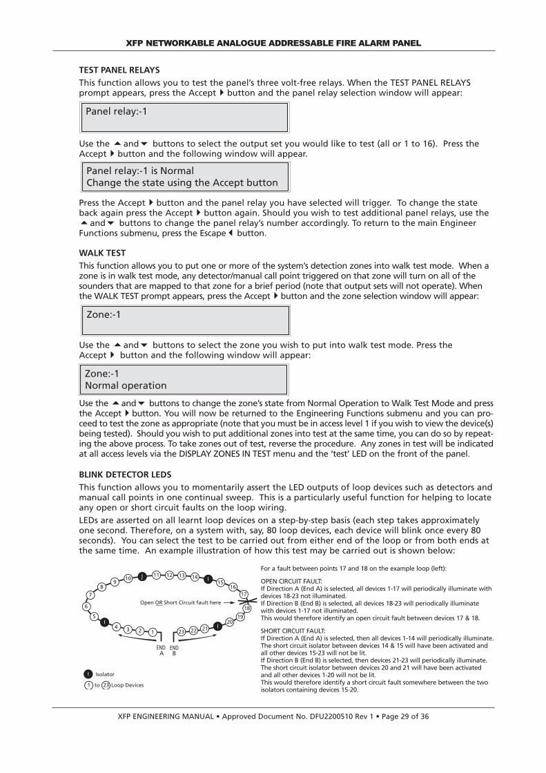
XFP ENGINEERING MANUAL • Approved Document No. DFU2200510 Rev 1 • Page 29 of 36
TEST PANEL RELAYS
This function allows you to test the panel’s three volt-free relays. When the TEST PANEL RELAYSprompt appears, press the Accept4button and the panel relay selection window will appear:
Use the 5and6 buttons to select the output set you would like to test (all or 1 to 16). Press theAccept4button and the following window will appear.
Press the Accept4button and the panel relay you have selected will trigger. To change the stateback again press the Accept4button again. Should you wish to test additional panel relays, use the5and6 buttons to change the panel relay’s number accordingly. To return to the main EngineerFunctions submenu, press the Escape3button.
WALK TEST
This function allows you to put one or more of the system’s detection zones into walk test mode. When azone is in walk test mode, any detector/manual call point triggered on that zone will turn on all of thesounders that are mapped to that zone for a brief period (note that output sets will not operate). Whenthe WALK TEST prompt appears, press the Accept4button and the zone selection window will appear:
Use the 5and6 buttons to select the zone you wish to put into walk test mode. Press theAccept4 button and the following window will appear:
Use the 5and6 buttons to change the zone’s state from Normal Operation to Walk Test Mode and pressthe Accept4button. You will now be returned to the Engineering Functions submenu and you can pro-ceed to test the zone as appropriate (note that you must be in access level 1 if you wish to view the device(s)being tested). Should you wish to put additional zones into test at the same time, you can do so by repeat-ing the above process. To take zones out of test, reverse the procedure. Any zones in test will be indicatedat all access levels via the DISPLAY ZONES IN TEST menu and the ‘test’ LED on the front of the panel.
BLINK DETECTOR LEDS
This function allows you to momentarily assert the LED outputs of loop devices such as detectors andmanual call points in one continual sweep. This is a particularly useful function for helping to locateany open or short circuit faults on the loop wiring.
LEDs are asserted on all learnt loop devices on a step-by-step basis (each step takes approximatelyone second. Therefore, on a system with, say, 80 loop devices, each device will blink once every 80seconds). You can select the test to be carried out from either end of the loop or from both ends atthe same time. An example illustration of how this test may be carried out is shown below:
XFP NETWORKABLE ANALOGUE ADDRESSABLE FIRE ALARM PANEL
Zone:-1
Zone:-1Normal operation
Panel relay:-1
Panel relay:-1 is NormalChange the state using the Accept button
ENDA
ENDB
7
11 1210
9
6
4
5
8
3 2 1
I
I 13 1415
1617
18
1920
I212223
Open OR Short Circuit fault here
I
1
Isolator
Loop Devices23to
I
For a fault between points 17 and 18 on the example loop (left):
OPEN CIRCUIT FAULT:If Direction A (End A) is selected, all devices 1-17 will periodically illuminate withdevices 18-23 not illuminated. If Direction B (End B) is selected, all devices 18-23 will periodically illuminatewith devices 1-17 not illuminated. This would therefore identify an open circuit fault between devices 17 & 18.
SHORT CIRCUIT FAULT:If Direction A (End A) is selected, then all devices 1-14 will periodically illuminate.The short circuit isolator between devices 14 & 15 will have been activated andall other devices 15-23 will not be lit.If Direction B (End B) is selected, then devices 21-23 will periodically illuminate.The short circuit isolator between devices 20 and 21 will have been activatedand all other devices 1-20 will not be lit.This would therefore identify a short circuit fault somewhere between the twoisolators containing devices 15-20.

When the BLINK DETECTOR LEDs? prompt appears, the following window will appear:
Select the loop you wish to carry out the test on using the 5and6 buttons and press the Accept4button. You will then be prompted to select from which end of the loop you wish to run the test:
Use the 5and6buttons to select End A, End B or Both Ends as appropriate and press the Accept4button.
The LEDs of all detectors on the loop will now start blinking accordingly. Note that addresses do nothave to be in sequential order for this facility to work. To end the test press the Escape3button atany time.
INTENSIVE DEVICE MONITOR
This function allows you to monitor a specific addressable point to see how it responds to intensive,repeated polls from the panel. In order to do this, the panel suspends all other system activity whenthis test is taking place - fires, etc, will not be flagged so please use this function with care. Byreporting back how many good and bad polls are made between the panel and the monitoreddevice, this function can help pinpoint loop wiring/communication faults and/or faulty devices.When selected, you will be prompted to enter the loop on which the device you want to monitor islocated, the device’s address and its output bit sequence:
Use the 5,6 and Accept4 buttons to select the desired loop, address (device) and output bit sequence.
The output bit option allows you to monitor a device whilst it is in a particular state, for example, ifan I/O unit is reporting back faults only when it has triggered, say, a rollershutter door (e.g when itsoutput channel 1 is asserted), you can set the device up so it is in this state whilst being monitored.See the table below for the output bit options available:
OUTPUT BIT CODES AND WHICH OUTPUT CHANNELS THEY ASSERT
Caution: Note that any channel on an I/O unit may be programmed to trigger say, a water extinguis-hant system, so this function must be used with care. When you have accepted the device’s outputbits sequence by pressing the Accept4 button, the test will begin and the panel will display thedevice’s current analogue values, for example:
XFP ENGINEERING MANUAL • Approved Document No. DFU2200510 Rev 1 • Page 30 of 36
XFP NETWORKABLE ANALOGUE ADDRESSABLE FIRE ALARM PANEL
L:-1 D:7 AV:63 ZP:62FP: 192 ATL: 148 F: 0 C: 0 T: 0x88
The loop the point being monitored is located on
The point'saddress
The point'scurrent analogue value
The point's normal analogue value
The maximum value the point will return when
in a fire condition
The point's alarm threshold level
(the level at which it will flag an alarm condition)
The codefor any fault
condition that point may be in
The points current stageof calibration
Thepoint's type
CODE OUTPUT CHANNELS ASSERTED
0 No output channel asserted 1 Output channel 1 asserted
2 Output channel 2 asserted
3 Output channels 1 and 2 asserted
4 Output channel 3 asserted
5 Output channels 3 and 1 asserted
6 Output channels 2 and 3 asserted
7 All output channels asserted
Loop:-1 Device 1Output bits: 0
Which loop:-1
Which loop:-1 End A Only
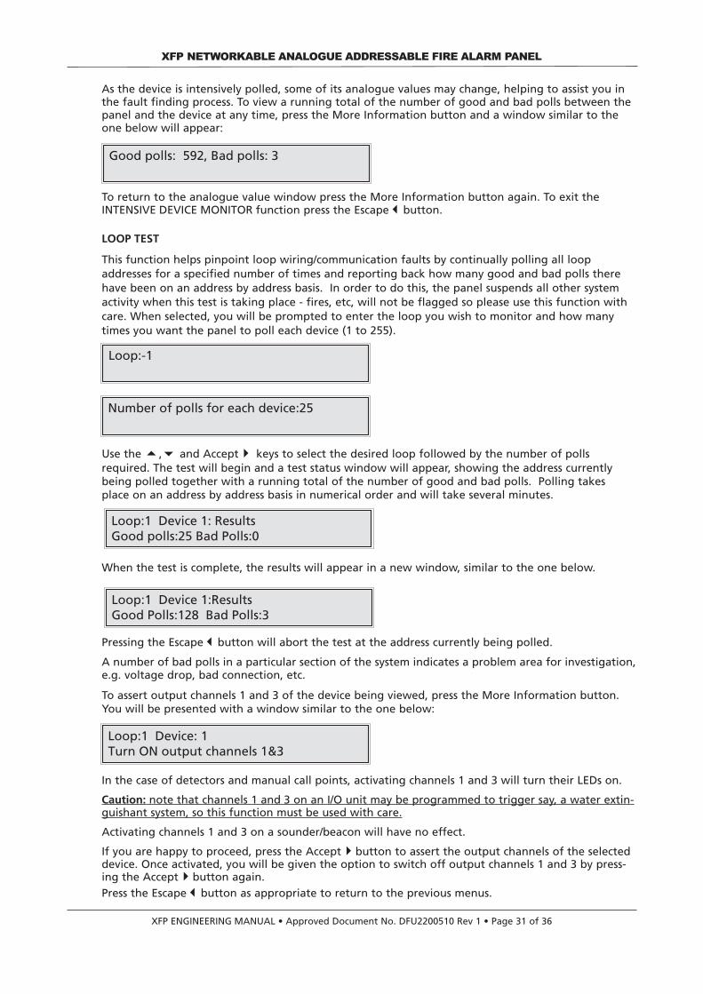
As the device is intensively polled, some of its analogue values may change, helping to assist you inthe fault finding process. To view a running total of the number of good and bad polls between thepanel and the device at any time, press the More Information button and a window similar to theone below will appear:
To return to the analogue value window press the More Information button again. To exit theINTENSIVE DEVICE MONITOR function press the Escape3button.
LOOP TEST
This function helps pinpoint loop wiring/communication faults by continually polling all loopaddresses for a specified number of times and reporting back how many good and bad polls therehave been on an address by address basis. In order to do this, the panel suspends all other systemactivity when this test is taking place - fires, etc, will not be flagged so please use this function withcare. When selected, you will be prompted to enter the loop you wish to monitor and how manytimes you want the panel to poll each device (1 to 255).
Use the 5,6 and Accept4 keys to select the desired loop followed by the number of pollsrequired. The test will begin and a test status window will appear, showing the address currentlybeing polled together with a running total of the number of good and bad polls. Polling takesplace on an address by address basis in numerical order and will take several minutes.
When the test is complete, the results will appear in a new window, similar to the one below.
Pressing the Escape3button will abort the test at the address currently being polled.
A number of bad polls in a particular section of the system indicates a problem area for investigation,e.g. voltage drop, bad connection, etc.
To assert output channels 1 and 3 of the device being viewed, press the More Information button.You will be presented with a window similar to the one below:
In the case of detectors and manual call points, activating channels 1 and 3 will turn their LEDs on.
Caution: note that channels 1 and 3 on an I/O unit may be programmed to trigger say, a water extin-guishant system, so this function must be used with care.
Activating channels 1 and 3 on a sounder/beacon will have no effect.
If you are happy to proceed, press the Accept4button to assert the output channels of the selecteddevice. Once activated, you will be given the option to switch off output channels 1 and 3 by press-ing the Accept4button again.Press the Escape3button as appropriate to return to the previous menus.
XFP ENGINEERING MANUAL • Approved Document No. DFU2200510 Rev 1 • Page 31 of 36
XFP NETWORKABLE ANALOGUE ADDRESSABLE FIRE ALARM PANEL
Loop:-1
Number of polls for each device:25
Loop:1 Device 1:ResultsGood Polls:128 Bad Polls:3
Loop:1 Device 1: Results Good polls:25 Bad Polls:0
Good polls: 592, Bad polls: 3
Loop:1 Device: 1Turn ON output channels 1&3

DISPLAY DATABASE
This function allows you to view the panel’s database of loop devices. Available on a loop by loop basis,the information displayed includes the device’s type, address and description (zone and device text).
When the DISPLAY DATABASE? prompt is accepted, you will be prompted to enter the loop youwish to view the database of:
Use the 5and6 buttons to select the desired loop and press the Accept4 button. You will thenbe prompted to enter the address of a particular device.
Use the 5and6 buttons to select the desired address number and press the Accept4 button. Theinformation that is stored on the database that relates to that address will now appear, for example:
You can now use the 5and6 buttons to scroll through the rest of the database for the selectedloop as required. To exit the database, press the Escape3 button at any time.
VERSION NUMBERS
This function allows you to view the current version number of the panel’s firmware and to ascertainwhen the site’s data was last changed. When accepted, the following two windows (with detailsspecific to the panel) will appear in quick succession.
Matching site data codes, i.e. 49191/49191 and program checksum codes, i.e. 16886/16886, show thatthe panel is functioning correctly. Mis-matched numbers, i.e. 49191/40286, indicate that the panel’smemory may be corrupt. After five seconds the panel will return to the Engineering Functions submenu.
XFP ENGINEERING MANUAL • Approved Document No. DFU2200510 Rev 1 • Page 32 of 36
XFP NETWORKABLE ANALOGUE ADDRESSABLE FIRE ALARM PANEL
Loop:-1 Device:22
Loop:-1 Device:22/0: Optical det 0x88Shop Floor Gents Toilet
XFP 8A22 28/06/20052 loops fitted Hochiki protocol
The version of the panel's firmware
The number of loops fitted
The date the panel'sfirmware was released
T
The protocol of thepanel's loops
Site data = 49191/49191 11/3/2005Program checksum = 16886/16886
The number of loops fitted
The identification numberof the site data
T
Program checksumcode
The date the site was last changed
Loop:-1
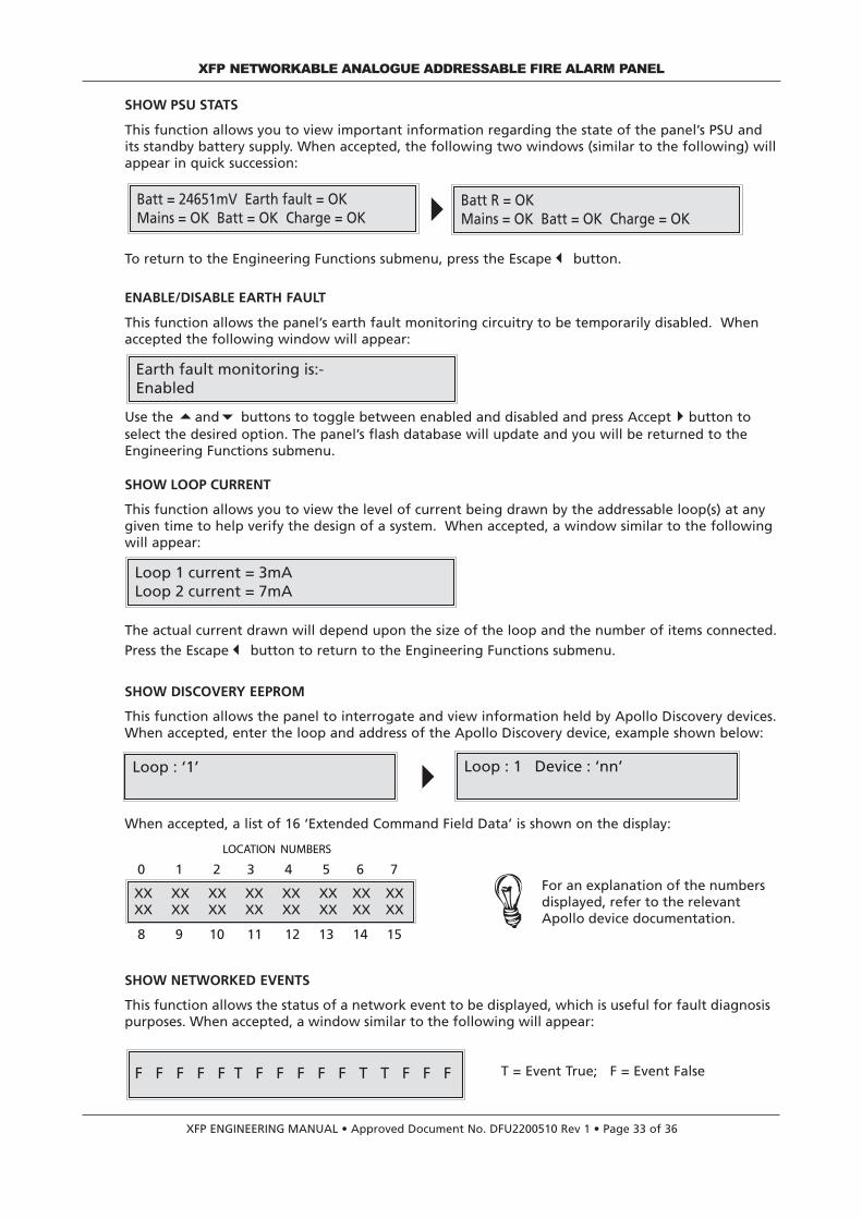
SHOW PSU STATS
This function allows you to view important information regarding the state of the panel’s PSU andits standby battery supply. When accepted, the following two windows (similar to the following) willappear in quick succession:
To return to the Engineering Functions submenu, press the Escape3 button.
ENABLE/DISABLE EARTH FAULT
This function allows the panel’s earth fault monitoring circuitry to be temporarily disabled. Whenaccepted the following window will appear:
Use the 5and6 buttons to toggle between enabled and disabled and press Accept4button toselect the desired option. The panel’s flash database will update and you will be returned to theEngineering Functions submenu.
SHOW LOOP CURRENT
This function allows you to view the level of current being drawn by the addressable loop(s) at anygiven time to help verify the design of a system. When accepted, a window similar to the followingwill appear:
The actual current drawn will depend upon the size of the loop and the number of items connected.
Press the Escape3 button to return to the Engineering Functions submenu.
SHOW DISCOVERY EEPROM
This function allows the panel to interrogate and view information held by Apollo Discovery devices.When accepted, enter the loop and address of the Apollo Discovery device, example shown below:
When accepted, a list of 16 ‘Extended Command Field Data’ is shown on the display:
SHOW NETWORKED EVENTS
This function allows the status of a network event to be displayed, which is useful for fault diagnosispurposes. When accepted, a window similar to the following will appear:
T = Event True; F = Event False
XFP NETWORKABLE ANALOGUE ADDRESSABLE FIRE ALARM PANEL
XFP ENGINEERING MANUAL • Approved Document No. DFU2200510 Rev 1 • Page 33 of 36
Earth fault monitoring is:-Enabled
Loop 1 current = 3mALoop 2 current = 7mA
Batt = 24651mV Earth fault = OKMains = OK Batt = OK Charge = OK
Batt R = OKMains = OK Batt = OK Charge = OK
Loop : ‘1’ Loop : 1 Device : ‘nn’
XX XX XX XX XX XX XX XX XX XX XX XX XX XX XX XX
LOCATION NUMBERS
0 1 2 3 4 5 6 7
8 9 10 11 12 13 14 15
F F F F F T F F F F F T T F F F
For an explanation of the numbersdisplayed, refer to the relevantApollo device documentation.

XFP NETWORKABLE ANALOGUE ADDRESSABLE FIRE ALARM PANEL
XFP ENGINEERING MANUAL • Approved Document No. DFU2200510 Rev 1 • Page 34 of 36
MAINTENANCE
Periodic system maintenance should be carried out on the system as prescribed in the localdesign, maintenance and installation regulations.
The Fire Alarm panel’s standby batteries should be checked for integrity of the connections,deposits indicating venting, and a periodic load test with the Mains supply disabled to ensureadequate battery capacity. Both batteries should be renewed if there is any doubt about theirintegrity.
The memory log should be checked for any faults that have automatically cleared, and thesedealt with accordingly.

XFP NETWORKABLE ANALOGUE ADDRESSABLE FIRE ALARM PANEL
XFP ENGINEERING MANUAL • Approved Document No. DFU2200510 Rev 1 • Page 35 of 36
STANDBY BATTERY CALCULATION GUIDE
The standby time of the fire alarm panel after the Mains has failed depends on the quiescentloading of the panel, the alarm load of the panel, and the capacity of the batteries.
To determine the capacity of batteries required for any given stand-by period, the followingformula should be used:
Battery Capacity in Ah = 1.25 x [(T x (A + L x 1.5) + H x (P + Z x 1.5)]
The multiplier 1.25 is present to account for lost capacity over the life of the batteries.
H = Number of hours standby required
P = The quiescent current of the panel = 0.065A
This value is with the Mains failed, beeper silenced and the Supply Present and General Faultindicators lit. If there are other quiescent drains on the panel then these must be added in.
Z = The total quiescent current of all loop devices
As a guideline, the average quiescent current addressable devices is typically 0.0003A (300µA).
To obtain accurate values consult the device manufacturers’ own specifications.
A = The total alarm current of panel sounders and activated relays [a panel relay consumes 20mA(0.02A) when activated].
L = The total alarm current of loop devices (sounders, beacons etc.)
T = The amount of time in hours required for the alarm (most commonly being half an hour).
Example:
The panel has 150 loop devices each consuming 300µA (0.0003A) each. In alarm, there will 40loop powered sounders at 8mA (0.008A) each, and 2 panel relays activated, and a conventionalsounder load of 0.25A. The required standby time is 24 hours, and the required alarm time is 0.5hours.
----------------------------------------------------------------------------------------------------------------------------------------
Calculate the alarm capacity: = T x (A + L x 1.5)
T = 0.5 Hrs; A = 0.25 + 2 x 0.02 = 0.29A; L = 40 x 0.008A
So the alarm capacity is: = 0.5 x (0.29 + 40 x 0.008 x 1.5)
= 0 .385Ah
----------------------------------------------------------------------------------------------------------------------------------------
Calculate the quiescent capacity: = H x (P + Z x 1.5)
H = 24 Hrs; P = 0.065A; Z = 150 x 0.0003A
So the standby capacity is: = 24 x (0.065 + 150 x 0.0003 x 1.5)
= 3.18Ah----------------------------------------------------------------------------------------------------------------------------------------
Total Capacity: = 1.25 x (0.385 + 3.18)
= 4.46Ah

XFP ENGINEERING MANUAL • Approved Document No. DFU2200510 Rev 1 • Page 36 of 36
XFP NETWORKABLE ANALOGUE ADDRESSABLE FIRE ALARM PANEL
TECHNICAL SPECIFICATION
POWER SUPPLY SPECIFICATIONMains supply 230V a.c 50/60Hz. Max. current 680mAInternal Power Supply 27 V d.c NominalTotal output current limited to 3A @ 230 V a.c.Power rating Imax. a = 250mA (1 loop), 270mA (2 loop); Imin = 70 mAMaximum internal battery resistance Ri max. = 1.1ΩSupply and battery charger monitored for failure YesBatteries monitored for disconnection and failure YesBatteries protected against deep discharge YesMax. battery size and type 7.0Ah VRLA. Use 2 x YUASA NP7-12 for LPCB approved systemsQuiescent current drain (1 loop unloaded) < 80mAQuiescent current drain (2 loop unloaded) < 100mAEarth fault monitoring Yes (any conductor)Temperature compensated charging Yes
LOOP DRIVER SPECIFICATIONNumber of loop drivers 1 or 2 (dependent on model purchased)Line monitored for open and short circuit faults YesOn-board loop isolators with LED indication when active YesAuto-polling from each loop end YesMax. output current per loop 500mA (Voltage: 25 V minimum; 34 V maximum)Max. number of addressable devices 126 per loop (giving a total of 126 for a 1 loop panel, 252 for a 2 loop panel)Max. number of loop powered sounders per loop @ 10mA 40Number of programmable sounder groups 16Number of programmable output sets 16
CONVENTIONAL SOUNDER CIRCUIT SPECIFICATIONNumber of programmable circuits 2End of line resistor value 6800 ohm 5% Tol. 0.25 WLine monitored for open and short circuit faults YesOutputs fused at 400mA. Protected by resettable overload circuitOutput voltage 19.5 V minimum; 28 V maximumMax. number of sounders @ 20mA 80
AUXILIARY OUTPUTSType Relay voltage free single pole changeoverMax. switching current 1AMax. switching voltage 30 V d.c.Relay 1 / Relay 2 / Relay 3 Programmed from cause and effectFault Active when no faults are present‘24V’ Aux. power output 19.5 V minimum, 28 V maximum. Max current 100mA. Protected by resettable overload circuit
AUXILIARY INPUTSInput 1 Connect to 0V to trigger, Max. input voltage 27V d.c (non-latching). Programmed from cause & effectInput 2 Connect to 0V to trigger, Max. input voltage 27V d.c (non-latching). Programmed from cause & effect
FUSES (to IEC - EN60127 Pt2)Mains fuse 1A HRC Ceramic 20mmBattery fuse 3.15A F 20mm. This limits the current drawn from the battery
PANEL INDICATORS AND CONTROLSControl buttons Menu, More Information, Silence Internal Sounder, Control Panel Reset, Investigate, ResoundEvent scrolling and menu access buttons Up5(1), Down6(3), Accept4(2), Escape3(4)Liquid crystal display Two lines x 40 characters, backlitNumber of zonal LED indicators 32Other LED indicators (General) Fire, Supply Present, Test, Accessed, General Disablement, Phased Evacuation, General
Fault, Power Supply Fault, System Fault, Sounder Status, Delays Running
PHYSICAL DIMENSIONSApprox. dimensions of back box (W x H x D) 410 x 250 x 80mm (metal)Approx. dimensions of lid (W x H x D) 439 x 274 x 7mm (metal)Approx. weight (without batteries) 4.5kg
CABLING REQUIREMENTSType of cable Fire resistant screened cable, minimum size 1mm2
Max. cable length per loop 1 KMConnector blocks Plug-on type, largest acceptable conductor size, 1.5mm2
Max. allowable loop impedance (each conductor) 20 OhmMax. cable capacitance .27µF
NETWORK SPECIFICATIONConnection Via AFP711 network driver fitted at main panelMax. no of main panels per network 8Max. no of repeaters per non-networked master panel 8Max. cable length per network 1 KM (main panel network); 500m (repeater network)
PC/PRINTER INTERFACEPC connection Via main panel RS232 molex connector (lead supplied in XFP507 upload/download software kit)Printer connection Via main panel RS232 connector block
OPERATING CONDITIONSThe components are selected to operate within their specification when the environmental conditions outside the enclosure comply with class 3k5 of IEC 721-3-3 : 1978.Temperature range: -5 to +40oC. Maximum relative humidity: 95%.
Related Documents