Revision 1.2 – Copyright A. Deperrois - October 2009 About performance and stability analysis using XFLR5 XF L R 5

XFLR5 and Stability Analysis
Oct 26, 2014
Welcome message from author
This document is posted to help you gain knowledge. Please leave a comment to let me know what you think about it! Share it to your friends and learn new things together.
Transcript
Revision 1.2 – Copyright A. Deperrois - October 2009
About performance and stability analysis using XFLR5
XFLR5
Revision 1.2 – Copyright A. Deperrois - October 2009
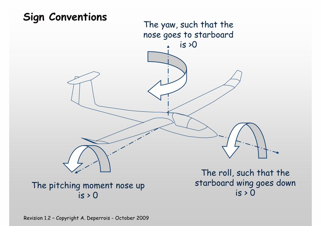
Sign ConventionsThe yaw, such that the nose goes to starboard
is >0
The pitching moment nose up is > 0
The roll, such that the starboard wing goes down
is > 0
Revision 1.2 – Copyright A. Deperrois - October 2009
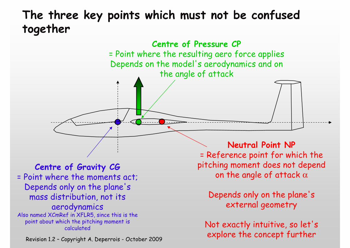
The three key points which must not be confused together
Centre of Gravity CG= Point where the moments act;Depends only on the plane's mass distribution, not its
aerodynamicsAlso named XCmRef in XFLR5, since this is the
point about which the pitching moment is calculated
Neutral Point NP= Reference point for which the pitching moment does not depend
on the angle of attack α
Depends only on the plane's external geometry
Not exactly intuitive, so let's explore the concept further
Centre of Pressure CP= Point where the resulting aero force appliesDepends on the model's aerodynamics and on
the angle of attack
Revision 1.2 – Copyright A. Deperrois - October 2009
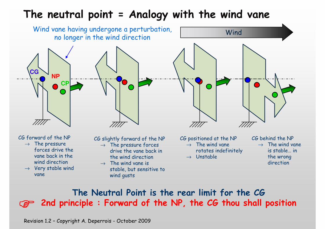
The neutral point = Analogy with the wind vane
NP
CP
Wind
CG
CG forward of the NP→ The pressure
forces drive the vane back in the wind direction
→ Very stable wind vane
CG positioned at the NP→ The wind vane
rotates indefinitely→ Unstable
CG behind the NP→ The wind vane
is stable… in the wrong direction
Wind vane having undergone a perturbation, no longer in the wind direction
The Neutral Point is the rear limit for the CG2nd principle : Forward of the NP, the CG thou shall position
CG slightly forward of the NP→ The pressure forces
drive the vane back in the wind direction
→ The wind vane is stable, but sensitive to wind gusts
����
Revision 1.2 – Copyright A. Deperrois - October 2009
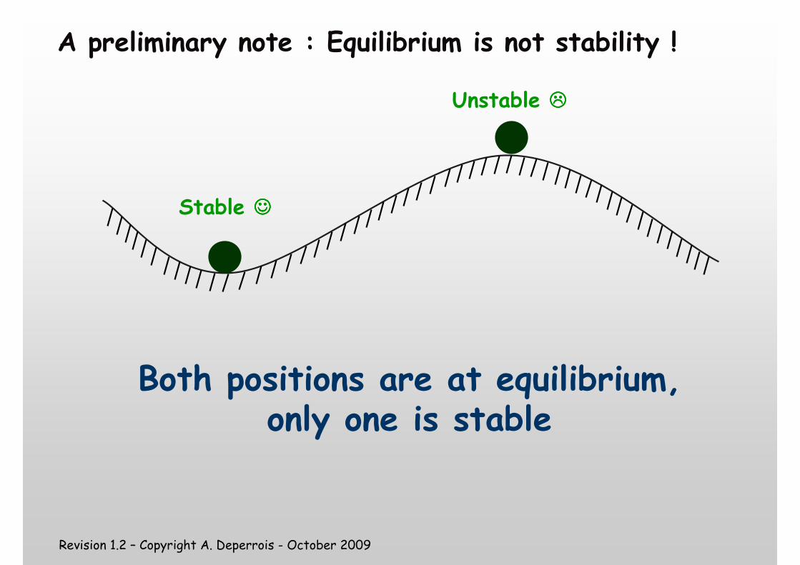
A preliminary note : Equilibrium is not stability !
Unstable ����
Both positions are at equilibrium, only one is stable
Stable ☺☺☺☺
Revision 1.2 – Copyright A. Deperrois - October 2009
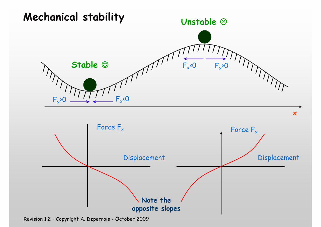
Mechanical stability
Force Fx
Displacement
x
Force Fx
Displacement
Fx<0
Fx<0 Fx>0
Fx>0
Unstable ����
Stable ☺☺☺☺
Note the opposite slopes
Revision 1.2 – Copyright A. Deperrois - October 2009
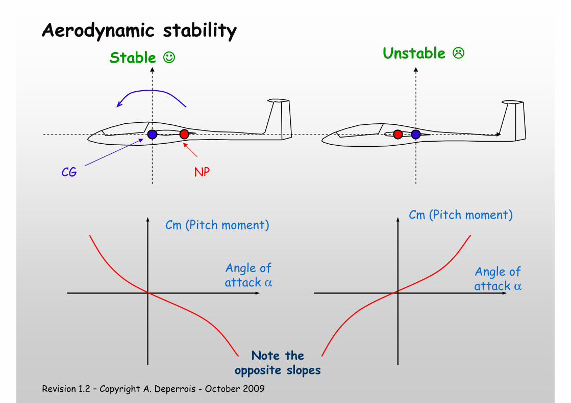
Aerodynamic stability
Angle of attack α
Cm (Pitch moment)
CG NP
Unstable ����Stable ☺☺☺☺
Angle of attack α
Cm (Pitch moment)
Note the opposite slopes
Revision 1.2 – Copyright A. Deperrois - October 2009
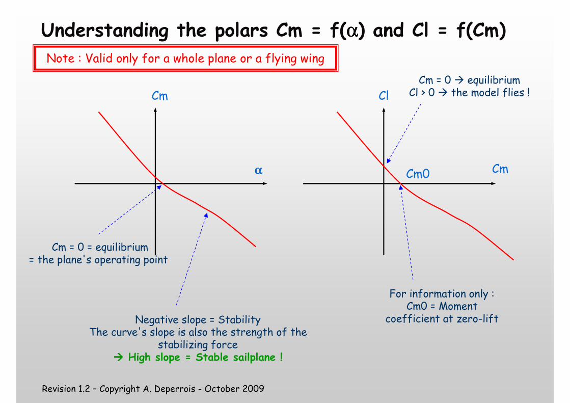
Understanding the polars Cm = f(αααα) and Cl = f(Cm)
αααα
Cm
Note : Valid only for a whole plane or a flying wing
Cm
Cl
Cm = 0 = equilibrium= the plane's operating point
Negative slope = StabilityThe curve's slope is also the strength of the
stabilizing force���� High slope = Stable sailplane !
For information only :Cm0 = Moment
coefficient at zero-lift
Cm = 0 � equilibriumCl > 0 � the model flies !
Cm0
Revision 1.2 – Copyright A. Deperrois - October 2009
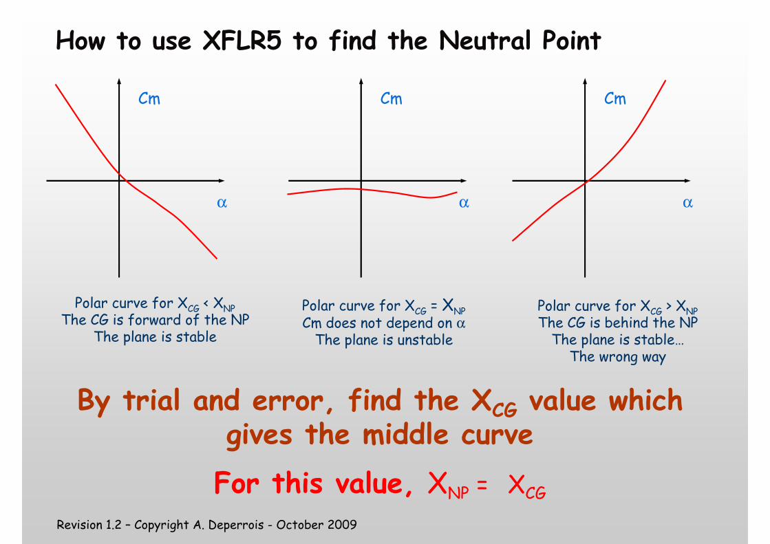
How to use XFLR5 to find the Neutral Point
α
Cm
Polar curve for XCG < XNPThe CG is forward of the NP
The plane is stable
α
Cm
α
Cm
Polar curve for XCG = XNP
Cm does not depend on αThe plane is unstable
Polar curve for XCG > XNPThe CG is behind the NP The plane is stable…The wrong way
By trial and error, find the XCG value which gives the middle curve
For this value, XNP = XCG
Revision 1.2 – Copyright A. Deperrois - October 2009
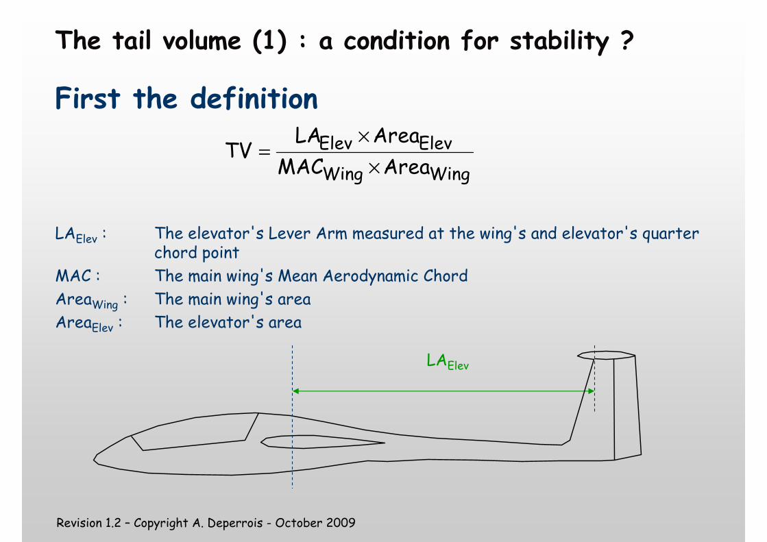
The tail volume (1) : a condition for stability ?
First the definition
LAElev : The elevator's Lever Arm measured at the wing's and elevator's quarter chord point
MAC : The main wing's Mean Aerodynamic Chord
AreaWing : The main wing's area
AreaElev : The elevator's area
WingWing
ElevElevAreaMAC
AreaLATV
×
×=
LAElev
Revision 1.2 – Copyright A. Deperrois - October 2009
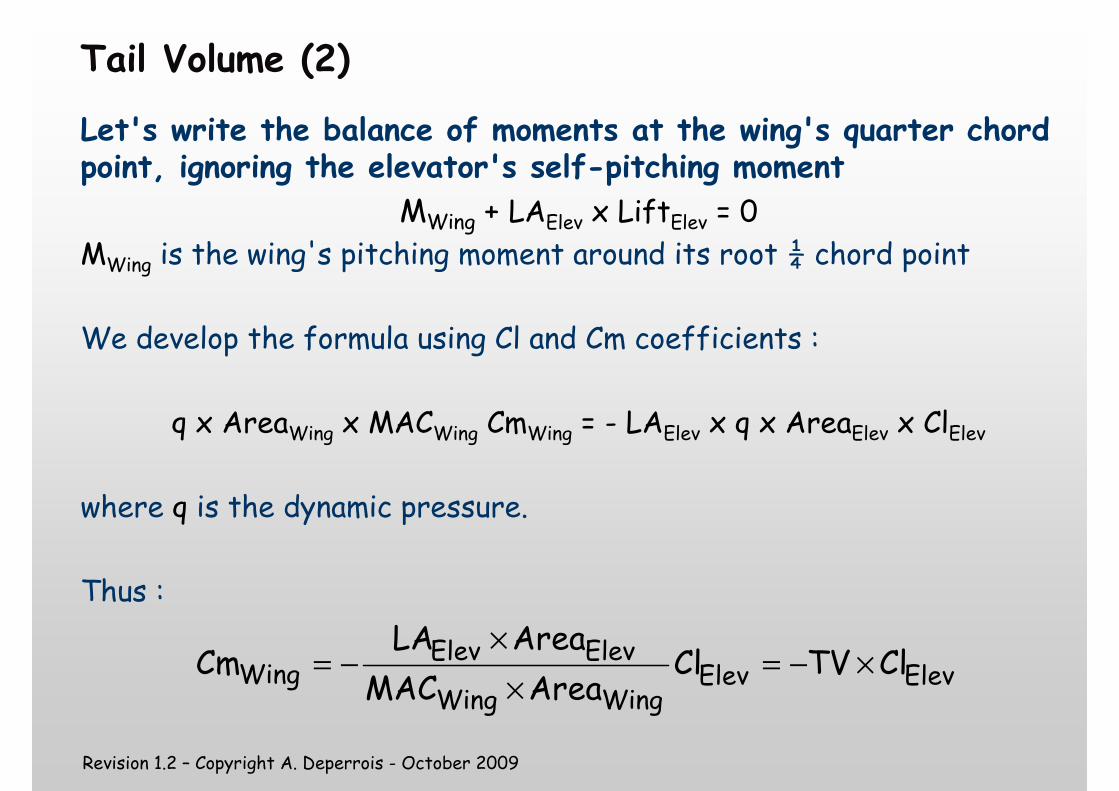
Tail Volume (2)
Let's write the balance of moments at the wing's quarter chord point, ignoring the elevator's self-pitching moment
MWing + LAElev x LiftElev = 0
MWing is the wing's pitching moment around its root ¼ chord point
We develop the formula using Cl and Cm coefficients :
q x AreaWing x MACWing CmWing = - LAElev x q x AreaElev x ClElev
where q is the dynamic pressure.
Thus :
ElevElevWingWing
ElevElevWing ClTVCl
AreaMAC
AreaLACm ×−=
×
×−=
Revision 1.2 – Copyright A. Deperrois - October 2009
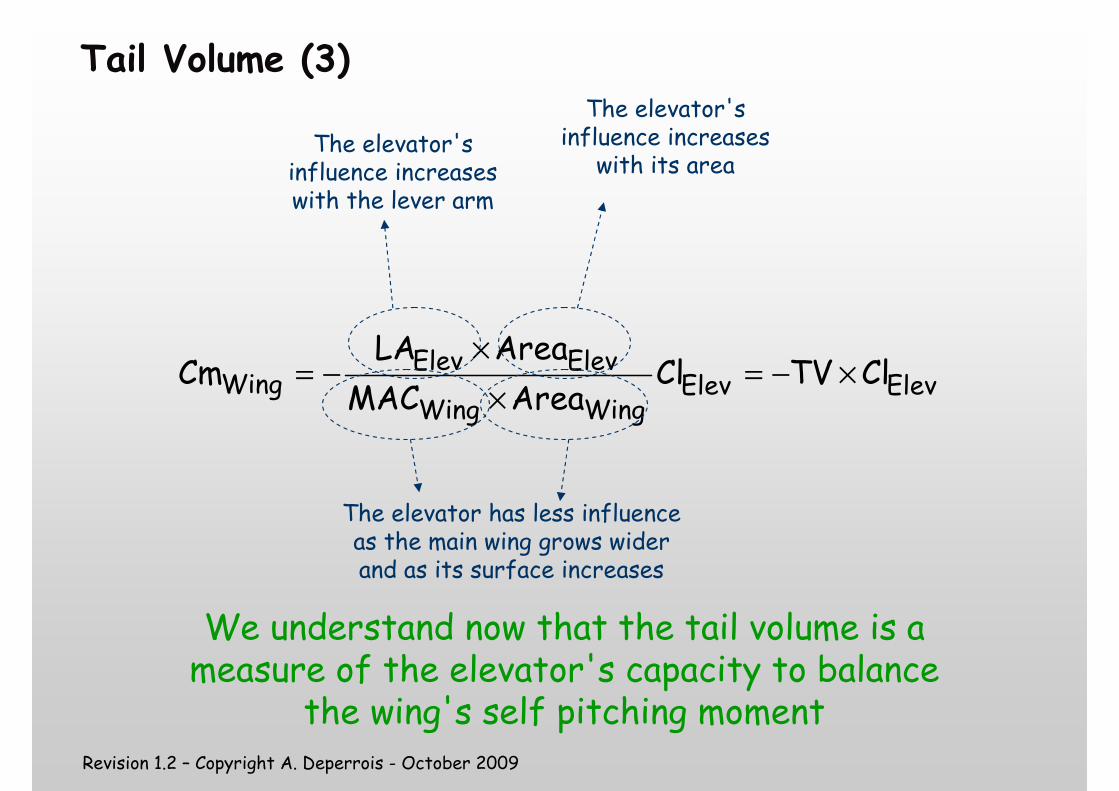
Tail Volume (3)
ElevElevWingWing
ElevElevWing ClTVCl
AreaMAC
AreaLACm ×−=
×
×−=
The elevator's influence increases with the lever arm
The elevator's influence increases
with its area
The elevator has less influence as the main wing grows wider and as its surface increases
We understand now that the tail volume is a measure of the elevator's capacity to balance
the wing's self pitching moment
Revision 1.2 – Copyright A. Deperrois - October 2009
Tail Volume (4)
ElevWing ClTVCm ×−=
� The formula above tells us only that the higher the TV, the greater the elevator's influence shall be
� It does not give us any clue about the plane's stability
� It tells us nothing on the values and on the signs of Cm and Cl
� Thus, an adequate value for the tail volume is not a condition sufficient for stability
Revision 1.2 – Copyright A. Deperrois - October 2009
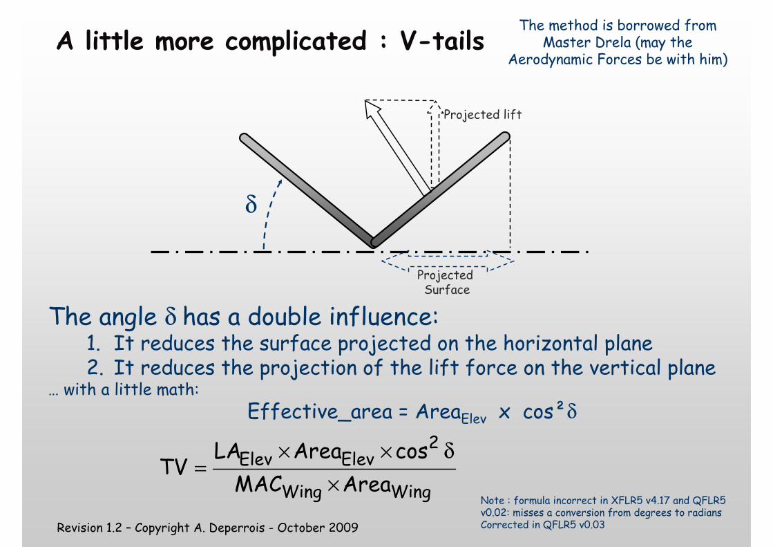
A little more complicated : V-tails
The angle δ has a double influence: 1. It reduces the surface projected on the horizontal plane2. It reduces the projection of the lift force on the vertical plane
… with a little math:
Effective_area = AreaElev x cos²δ
The method is borrowed from Master Drela (may the
Aerodynamic Forces be with him)
Note : formula incorrect in XFLR5 v4.17 and QFLR5 v0.02: misses a conversion from degrees to radiansCorrected in QFLR5 v0.03
WingWing
2ElevElev
AreaMAC
cosAreaLATV
×
δ××=
δ
Projected Surface
Projected lift
Revision 1.2 – Copyright A. Deperrois - October 2009
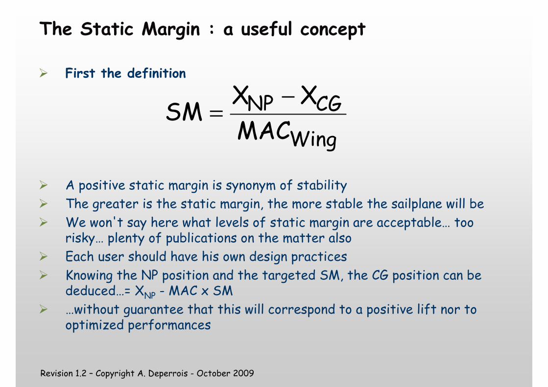
The Static Margin : a useful concept
� First the definition
� A positive static margin is synonym of stability
� The greater is the static margin, the more stable the sailplane will be
� We won't say here what levels of static margin are acceptable… too risky… plenty of publications on the matter also
� Each user should have his own design practices
� Knowing the NP position and the targeted SM, the CG position can be deduced…= XNP - MAC x SM
� …without guarantee that this will correspond to a positive lift nor to optimized performances
Wing
CGNPMAC
XXSM
−=
Revision 1.2 – Copyright A. Deperrois - October 2009
How to use XFLR5 to position the CG
� Idea N°1 : the most efficient
� Forget about XFLR5
� Position the CG at 30-35% of the Mean Aero Chord
� Try soft hand launches in an area with high grass
� Move progressively the CG backwards until the plane glides normally
� For a flying wing• Start at 15%• Set the ailerons up 5°-10°• Reduce progressively aileron angle and move the CG backwards
� Finish off with the dive test
���� Works every time !
Revision 1.2 – Copyright A. Deperrois - October 2009
How to use XFLR5 to position the CG
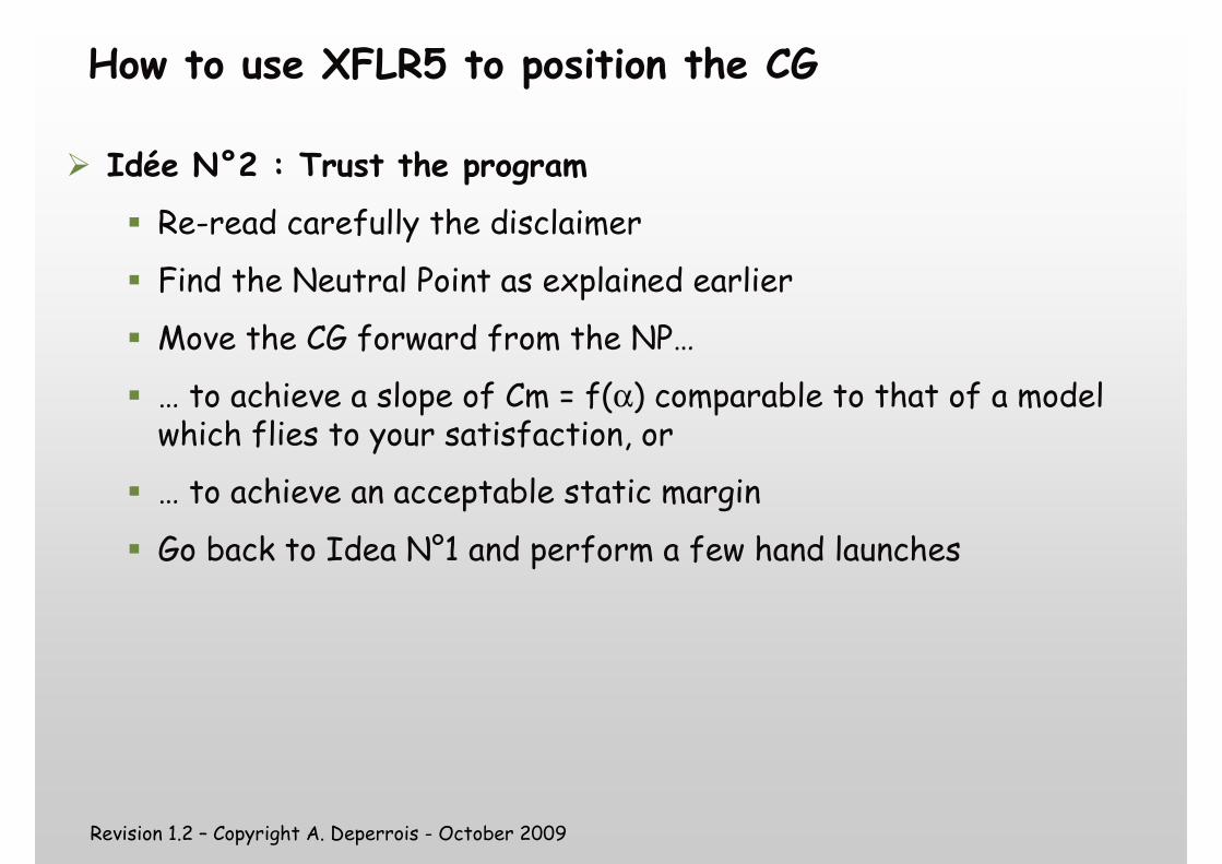
� Idée N°2 : Trust the program
� Re-read carefully the disclaimer
� Find the Neutral Point as explained earlier
� Move the CG forward from the NP…
� … to achieve a slope of Cm = f(α) comparable to that of a model which flies to your satisfaction, or
� … to achieve an acceptable static margin
� Go back to Idea N°1 and perform a few hand launches
Revision 1.2 – Copyright A. Deperrois - October 2009
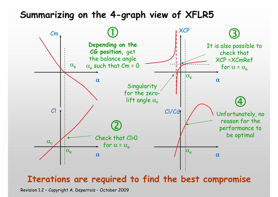
Summarizing on the 4-graph view of XFLR5
αααα
Cl
αααα
Cm ����Depending on the CG position, get the balance angle
αe such that Cm = 0
����Check that Cl>0 for α = αe
αααα
XCP
It is also possible to check that
XCP =XCmReffor α = αe
α0
Singularity for the zero-lift angle α0
αe
αe
αe
αααα
Cl/Cd
αe
Unfortunately, no reason for the performance to be optimal
Iterations are required to find the best compromise
Revision 1.2 – Copyright A. Deperrois - October 2009
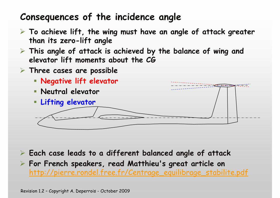
Consequences of the incidence angle
� To achieve lift, the wing must have an angle of attack greater than its zero-lift angle
� This angle of attack is achieved by the balance of wing and elevator lift moments about the CG
� Three cases are possible
� Negative lift elevator
� Neutral elevator
� Lifting elevator
� Each case leads to a different balanced angle of attack
� For French speakers, read Matthieu's great article on http://pierre.rondel.free.fr/Centrage_equilibrage_stabilite.pdf
Revision 1.2 – Copyright A. Deperrois - October 2009
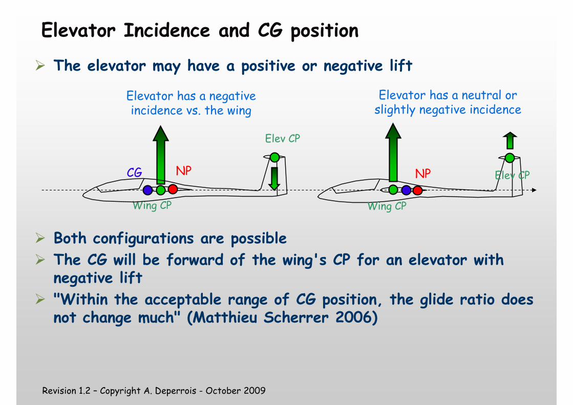
Elevator Incidence and CG position
� The elevator may have a positive or negative lift
� Both configurations are possible
� The CG will be forward of the wing's CP for an elevator with negative lift
� "Within the acceptable range of CG position, the glide ratio does not change much" (Matthieu Scherrer 2006)
Wing CP
CG
Elev CP
Wing CP
Elev CP
Elevator has a negative incidence vs. the wing
Elevator has a neutral or slightly negative incidence
NP NP
Revision 1.2 – Copyright A. Deperrois - October 2009
The case of Flying Wings
�No elevator
�The main wing must achieve its own stability
�Two options� Self stable foils
� Negative washout at the wing tip
Revision 1.2 – Copyright A. Deperrois - October 2009
Self-Stable Foils
� The notion is confusing : The concept covers those foils which make a wing self-stable, without the help of a stabilizer
� Theory and analysis tell us that a foil's Neutral Point is at distance from the leading edge = 25% x chord
� But then… all foils are self-stable ??? All that is required is to position the CG forward of the NP
�What's the difference between a so-called self-stable foil and all of the others ???
�Let's explore it with the help of XFLR5
Revision 1.2 – Copyright A. Deperrois - October 2009
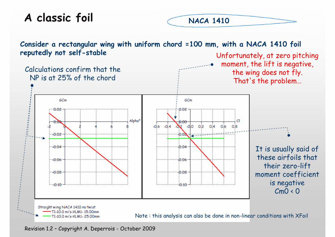
A classic foil
Consider a rectangular wing with uniform chord =100 mm, with a NACA 1410 foil reputedly not self-stable
Calculations confirm that the NP is at 25% of the chord
Unfortunately, at zero pitching moment, the lift is negative,
the wing does not fly.That's the problem…
NACA 1410
It is usually said of these airfoils that their zero-lift
moment coefficient is negativeCm0 < 0
Note : this analysis can also be done in non-linear conditions with XFoil
Revision 1.2 – Copyright A. Deperrois - October 2009
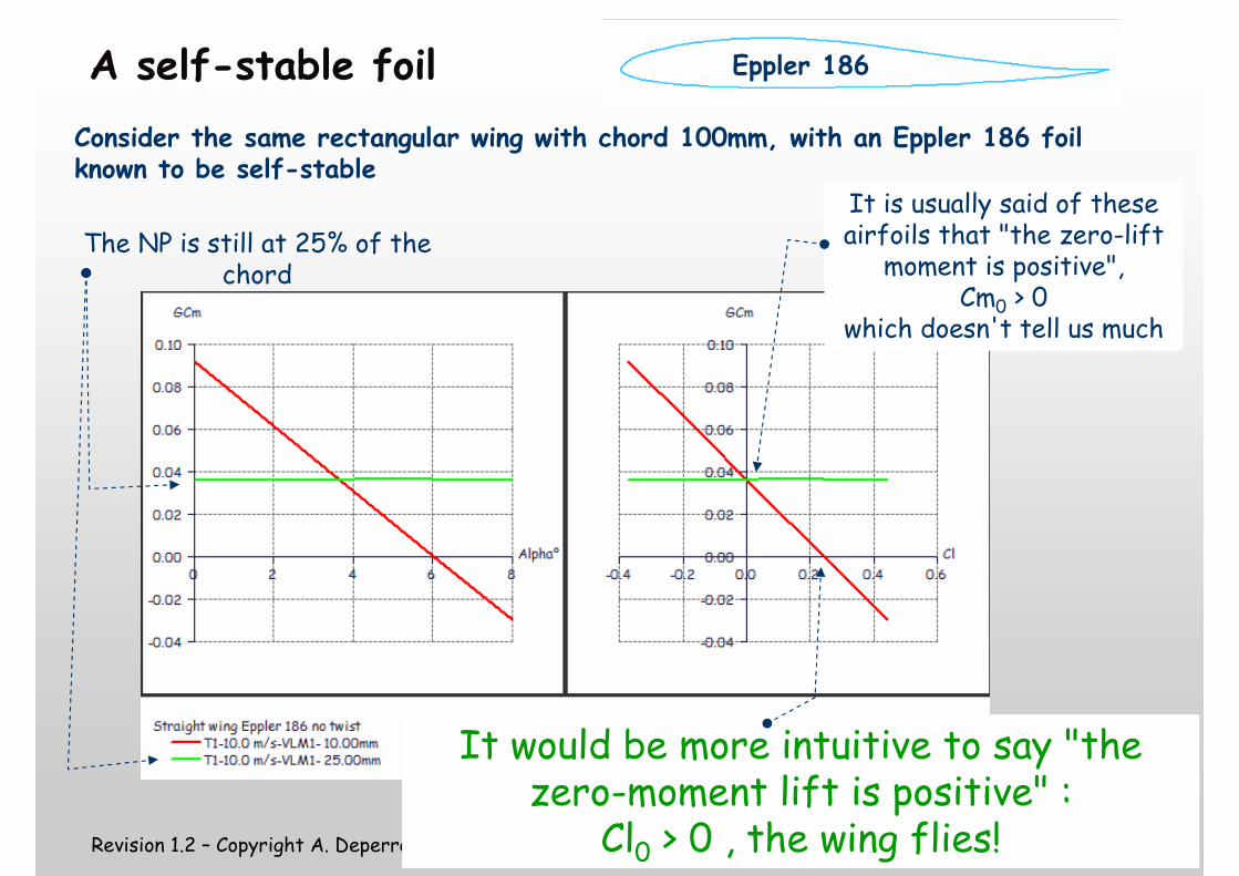
A self-stable foil
Consider the same rectangular wing with chord 100mm, with an Eppler 186 foil known to be self-stable
The NP is still at 25% of the chord
It would be more intuitive to say "the zero-moment lift is positive" :
Cl0 > 0 , the wing flies!
Eppler 186
It is usually said of these airfoils that "the zero-lift
moment is positive", Cm0 > 0
which doesn't tell us much
Revision 1.2 – Copyright A. Deperrois - October 2009
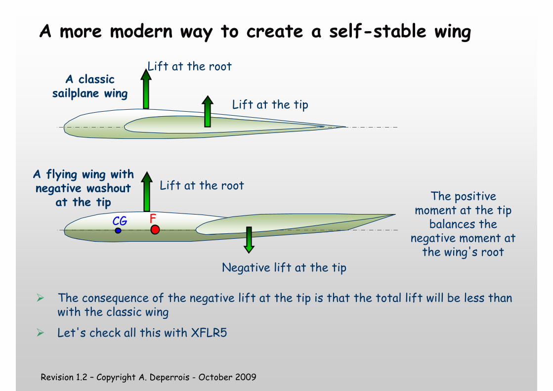
A more modern way to create a self-stable wing
CG
� The consequence of the negative lift at the tip is that the total lift will be less than with the classic wing
� Let's check all this with XFLR5
Lift at the root
Lift at the tip
A classic sailplane wing
A flying wing with negative washout
at the tip The positive moment at the tip balances the
negative moment at the wing's root
F
Lift at the root
Negative lift at the tip

Revision 1.2 – Copyright A. Deperrois - October 2009
Model data
Consider a simple wing� First without washout, � Then with -6° washout at tip
Revision 1.2 – Copyright A. Deperrois - October 2009
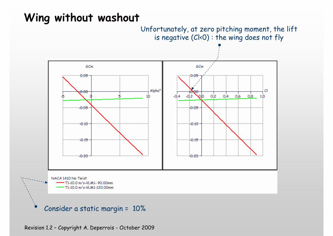
Wing without washout
Consider a static margin = 10%
Unfortunately, at zero pitching moment, the lift is negative (Cl<0) : the wing does not fly
Revision 1.2 – Copyright A. Deperrois - October 2009
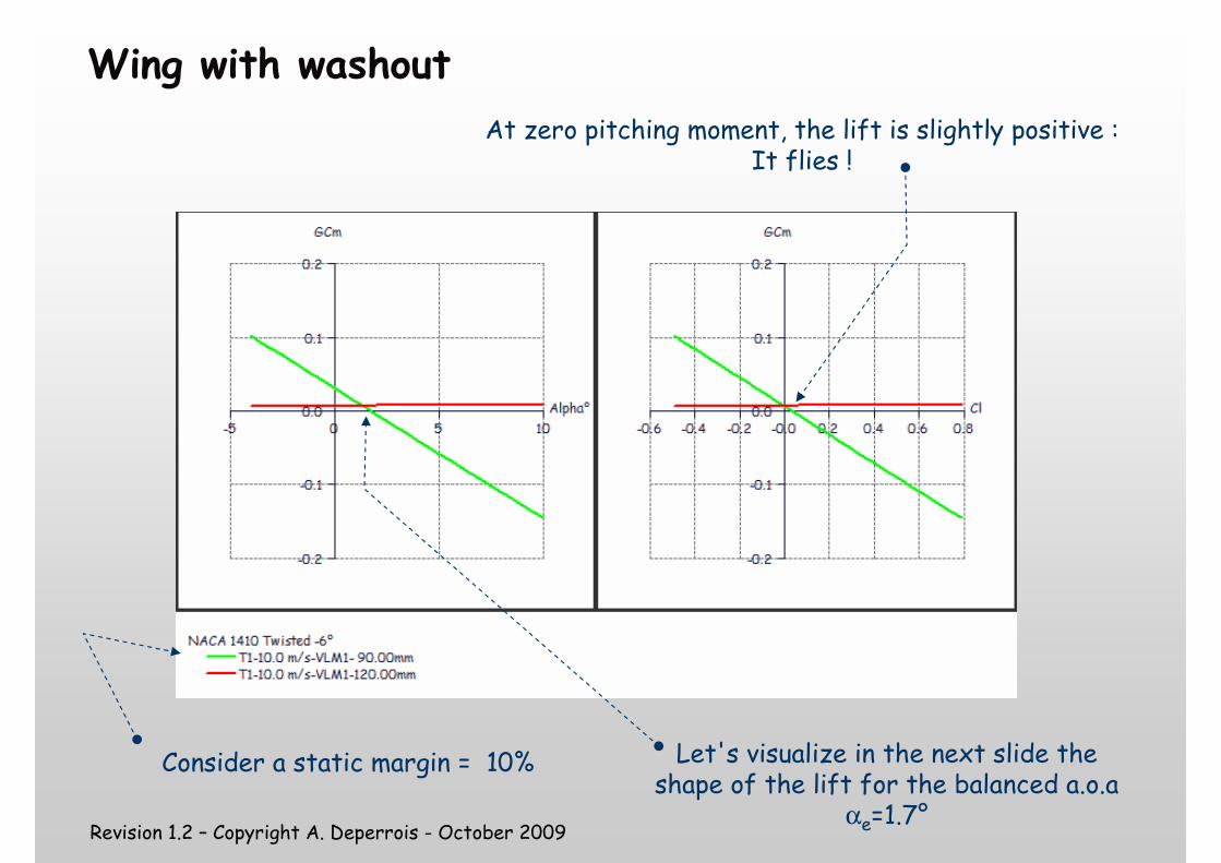
Wing with washout
At zero pitching moment, the lift is slightly positive :It flies !
Let's visualize in the next slide the shape of the lift for the balanced a.o.a
αe=1.7°
Consider a static margin = 10%
Revision 1.2 – Copyright A. Deperrois - October 2009
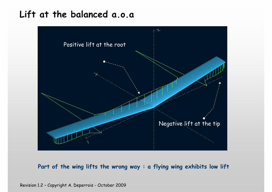
Lift at the balanced a.o.a
Positive lift at the root
Negative lift at the tip
Part of the wing lifts the wrong way : a flying wing exhibits low lift
Revision 1.2 – Copyright A. Deperrois - October 2009
About the Dive Test
Revision 1.2 – Copyright A. Deperrois - October 2009
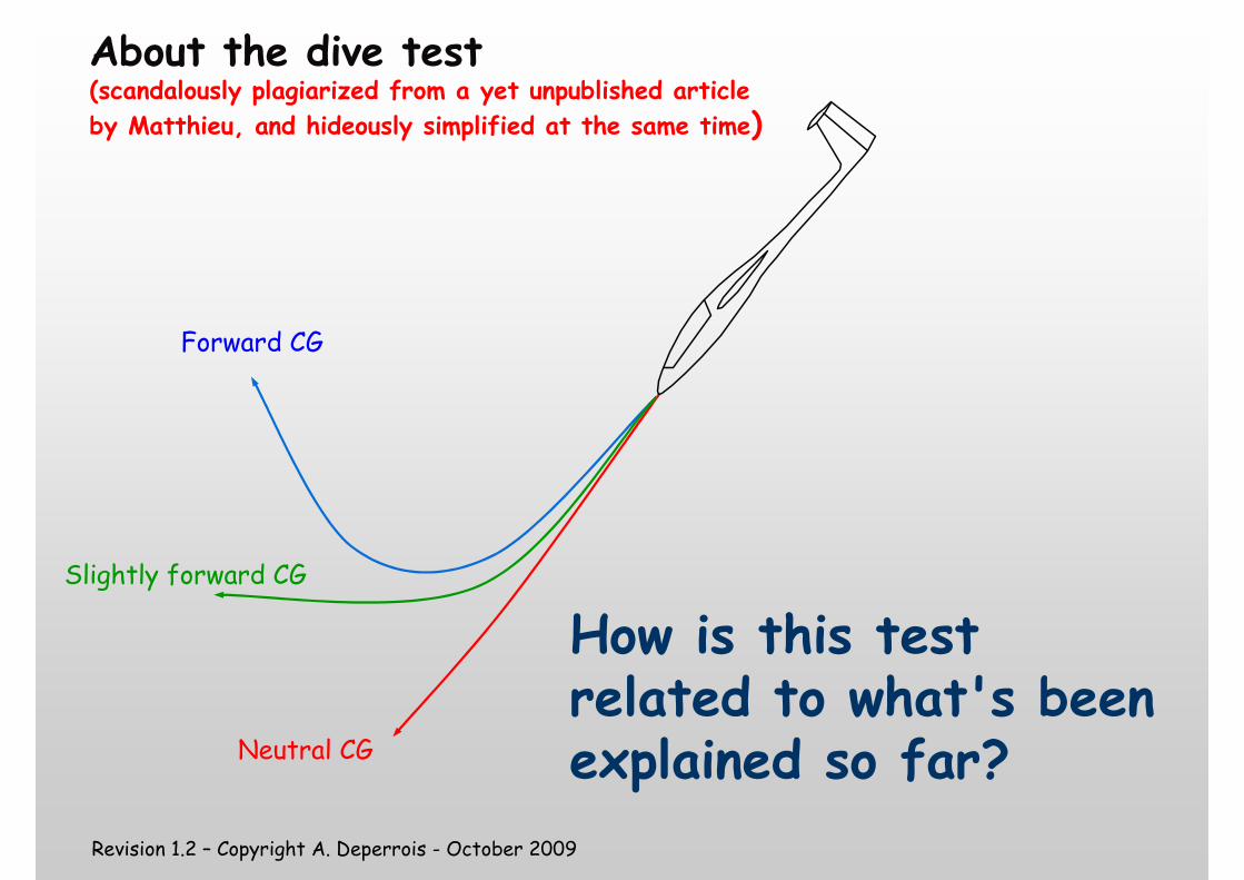
About the dive test (scandalously plagiarized from a yet unpublished article
by Matthieu, and hideously simplified at the same time)
How is this test related to what's been explained so far?
Forward CG
Slightly forward CG
Neutral CG
Revision 1.2 – Copyright A. Deperrois - October 2009
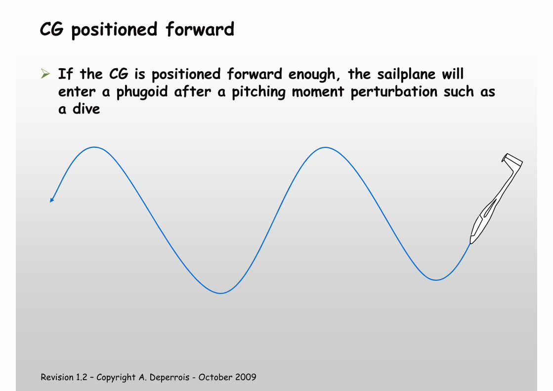
CG positioned forward
� If the CG is positioned forward enough, the sailplane will enter a phugoid after a pitching moment perturbation such as a dive
Revision 1.2 – Copyright A. Deperrois - October 2009
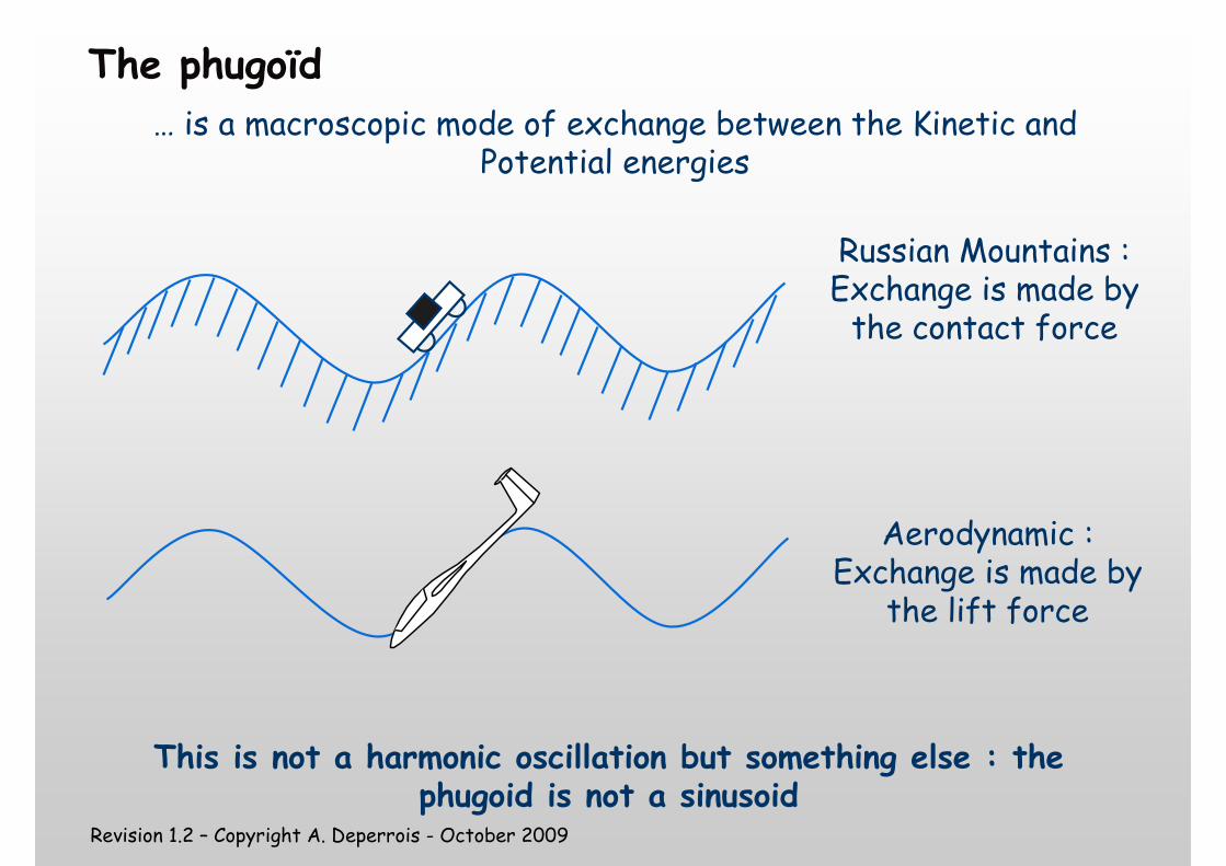
The phugoïd
… is a macroscopic mode of exchange between the Kinetic and Potential energies
Russian Mountains :Exchange is made by the contact force
Aerodynamic :Exchange is made by
the lift force
This is not a harmonic oscillation but something else : the phugoid is not a sinusoid
Revision 1.2 – Copyright A. Deperrois - October 2009
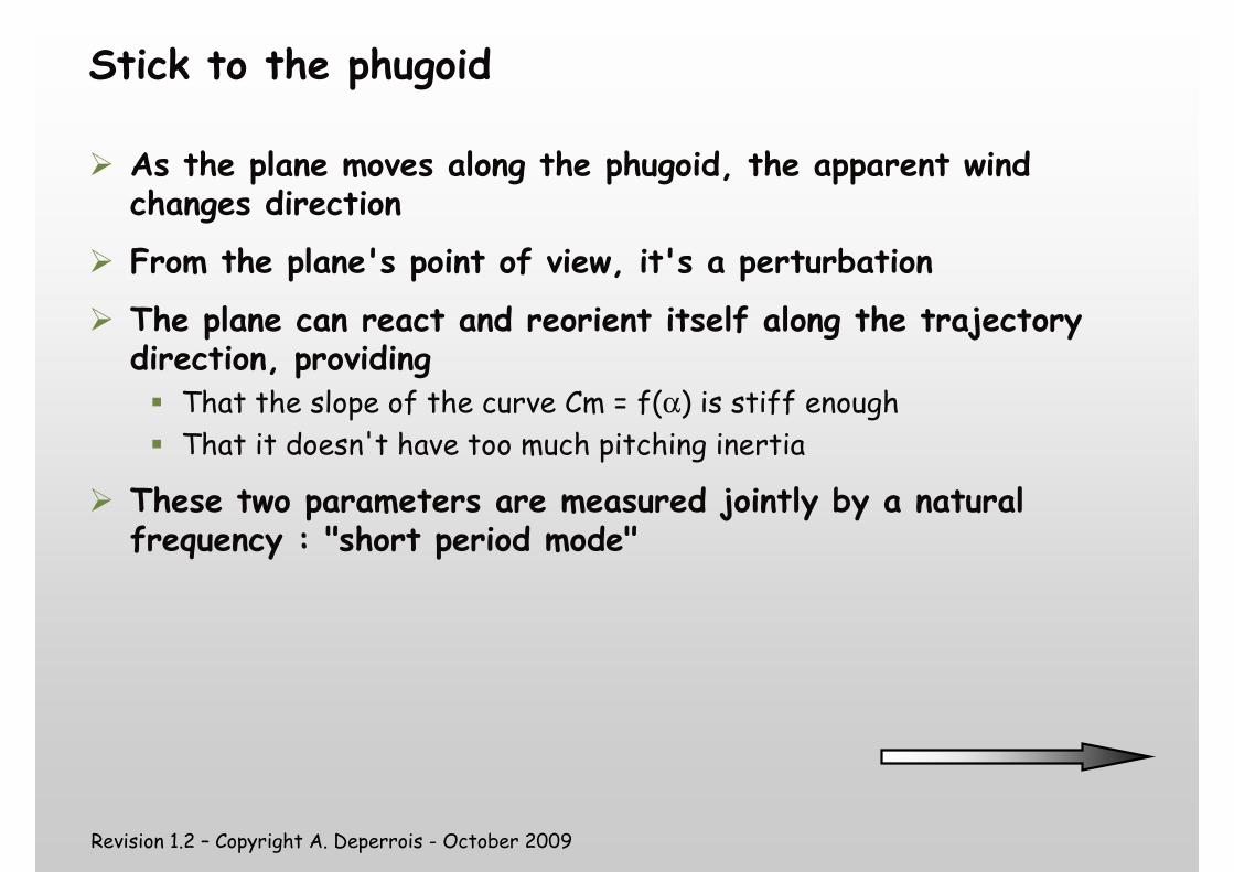
Stick to the phugoid
� As the plane moves along the phugoid, the apparent wind changes direction
� From the plane's point of view, it's a perturbation
� The plane can react and reorient itself along the trajectory direction, providing� That the slope of the curve Cm = f(α) is stiff enough
� That it doesn't have too much pitching inertia
� These two parameters are measured jointly by a natural frequency : "short period mode"
Revision 1.2 – Copyright A. Deperrois - October 2009
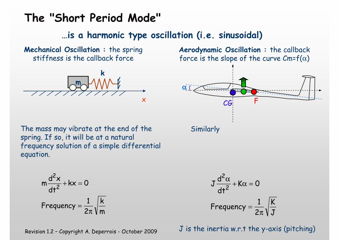
The "Short Period Mode"
x
mk
The mass may vibrate at the end of the spring. If so, it will be at a natural frequency solution of a simple differential equation.
mk
21
Frequency
0kxdt
xdm
2
2
π=
=+
Similarly
JK
21
Frequency
0Kdt
dJ
2
2
π=
=α+α
CG F
αααα
J is the inertia w.r.t the y-axis (pitching)
Mechanical Oscillation : the spring stiffness is the callback force
Aerodynamic Oscillation : the callback force is the slope of the curve Cm=f(α)
…is a harmonic type oscillation (i.e. sinusoidal)
Revision 1.2 – Copyright A. Deperrois - October 2009
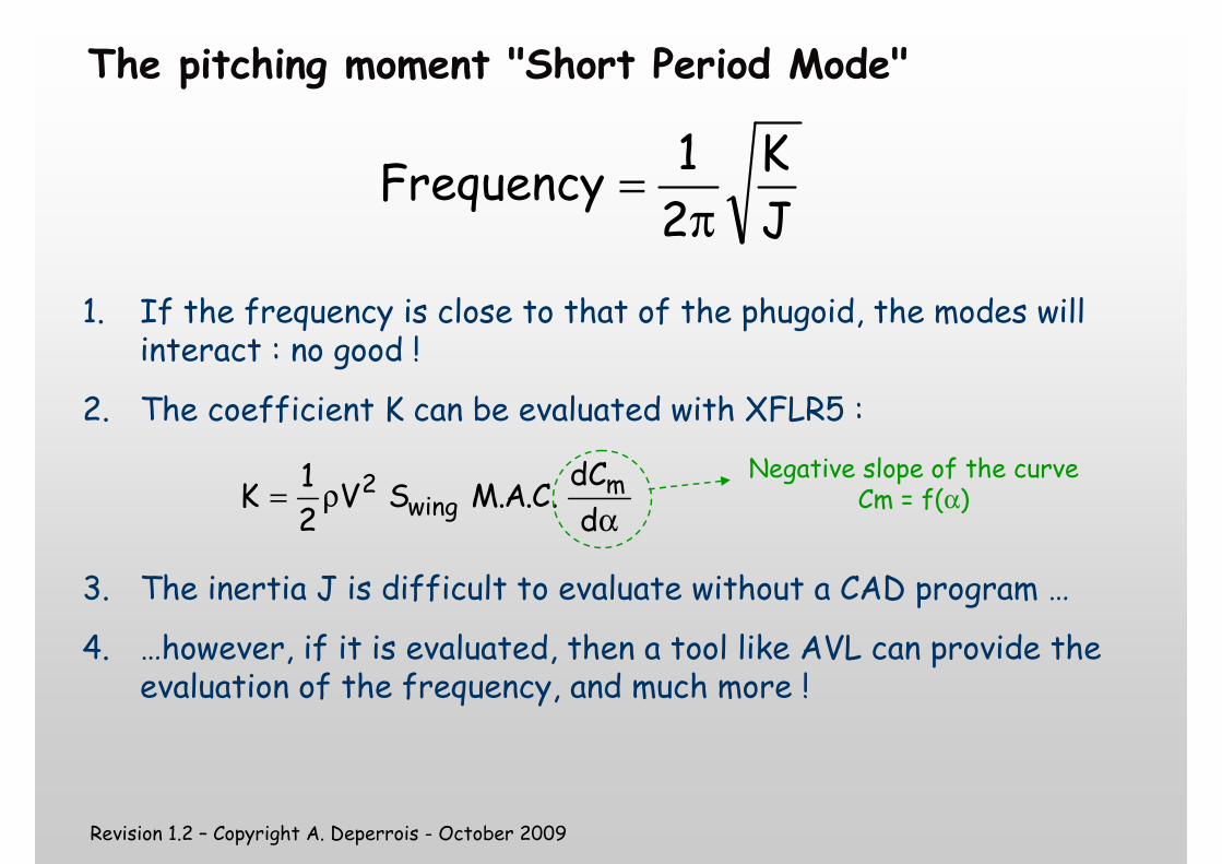
The pitching moment "Short Period Mode"
JK
21
Frequencyπ
=
1. If the frequency is close to that of the phugoid, the modes willinteract : no good !
2. The coefficient K can be evaluated with XFLR5 :
3. The inertia J is difficult to evaluate without a CAD program …
4. …however, if it is evaluated, then a tool like AVL can provide the evaluation of the frequency, and much more !
αρ=
d
dC.C.A.MSV
21
K mwing
2Negative slope of the curve
Cm = f(α)
Revision 1.2 – Copyright A. Deperrois - October 2009
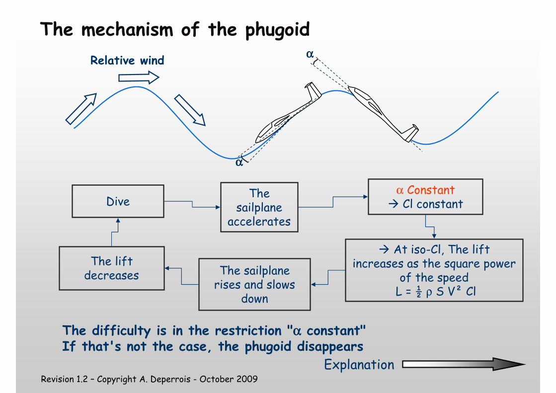
The mechanism of the phugoid
Dive
� At iso-Cl, The lift increases as the square power
of the speedL = ½ ρ S V² Cl
The sailplane
accelerates
α Constant� Cl constant
The sailplane rises and slows
down
The lift decreases
The difficulty is in the restriction "αααα constant"If that's not the case, the phugoid disappears
Relative wind
αααα
αααα
Explanation
Revision 1.2 – Copyright A. Deperrois - October 2009
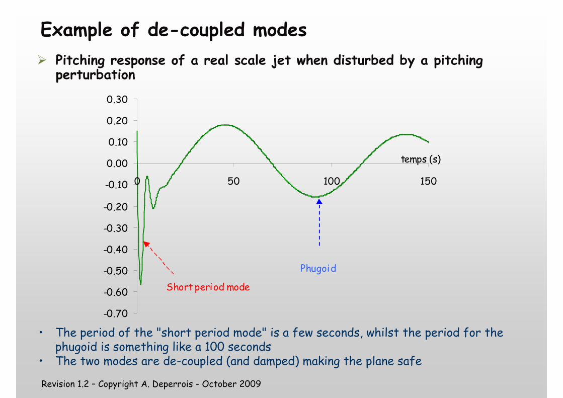
Example of de-coupled modes
� Pitching response of a real scale jet when disturbed by a pitching perturbation
-0.70
-0.60
-0.50
-0.40
-0.30
-0.20
-0.10
0.00
0.10
0.20
0.30
0 50 100 150
Short period mode
Phugoid
temps (s)
• The period of the "short period mode" is a few seconds, whilst the period for the phugoid is something like a 100 seconds
• The two modes are de-coupled (and damped) making the plane safe
Revision 1.2 – Copyright A. Deperrois - October 2009
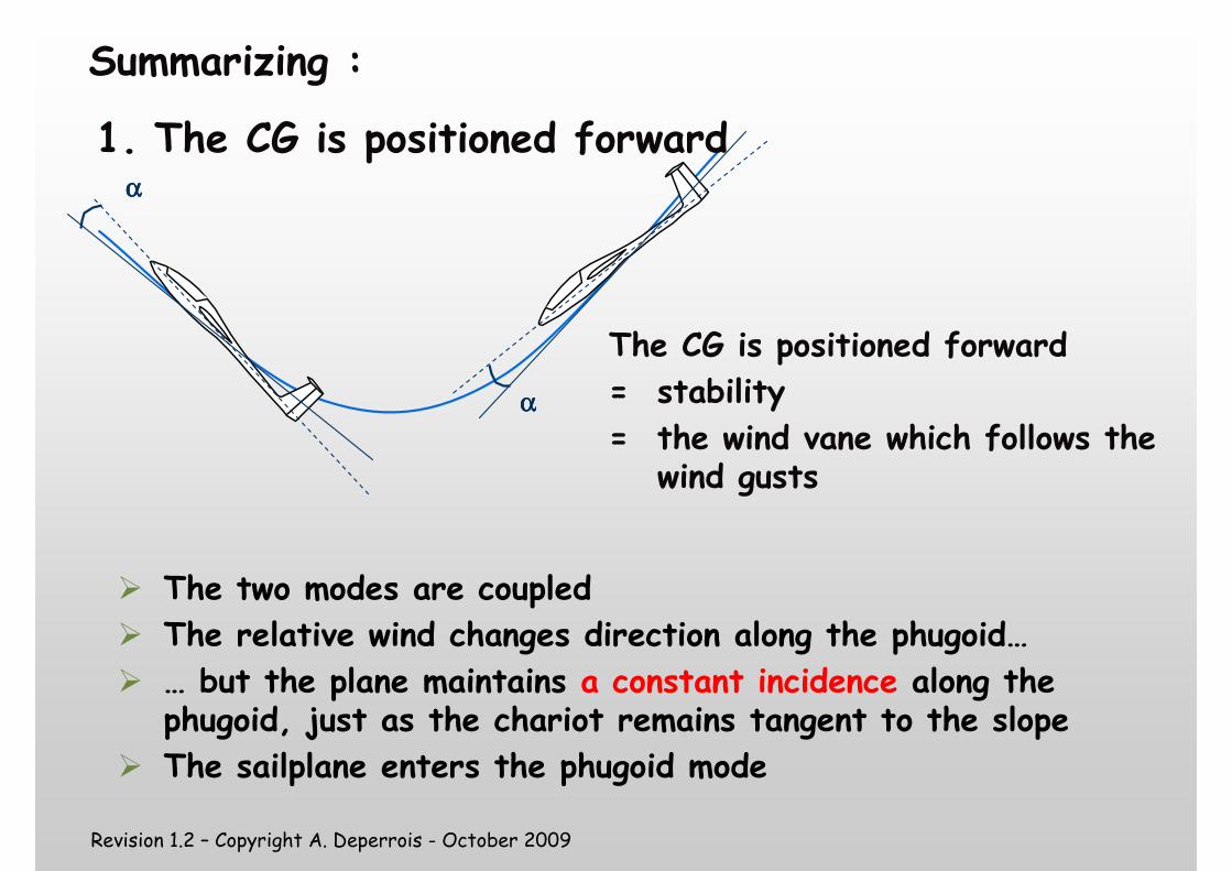
Summarizing :
αααα
αααα
The CG is positioned forward
= stability
= the wind vane which follows the wind gusts
� The two modes are coupled
� The relative wind changes direction along the phugoid…
� … but the plane maintains a constant incidence along the phugoid, just as the chariot remains tangent to the slope
� The sailplane enters the phugoid mode
1. The CG is positioned forward
Revision 1.2 – Copyright A. Deperrois - October 2009
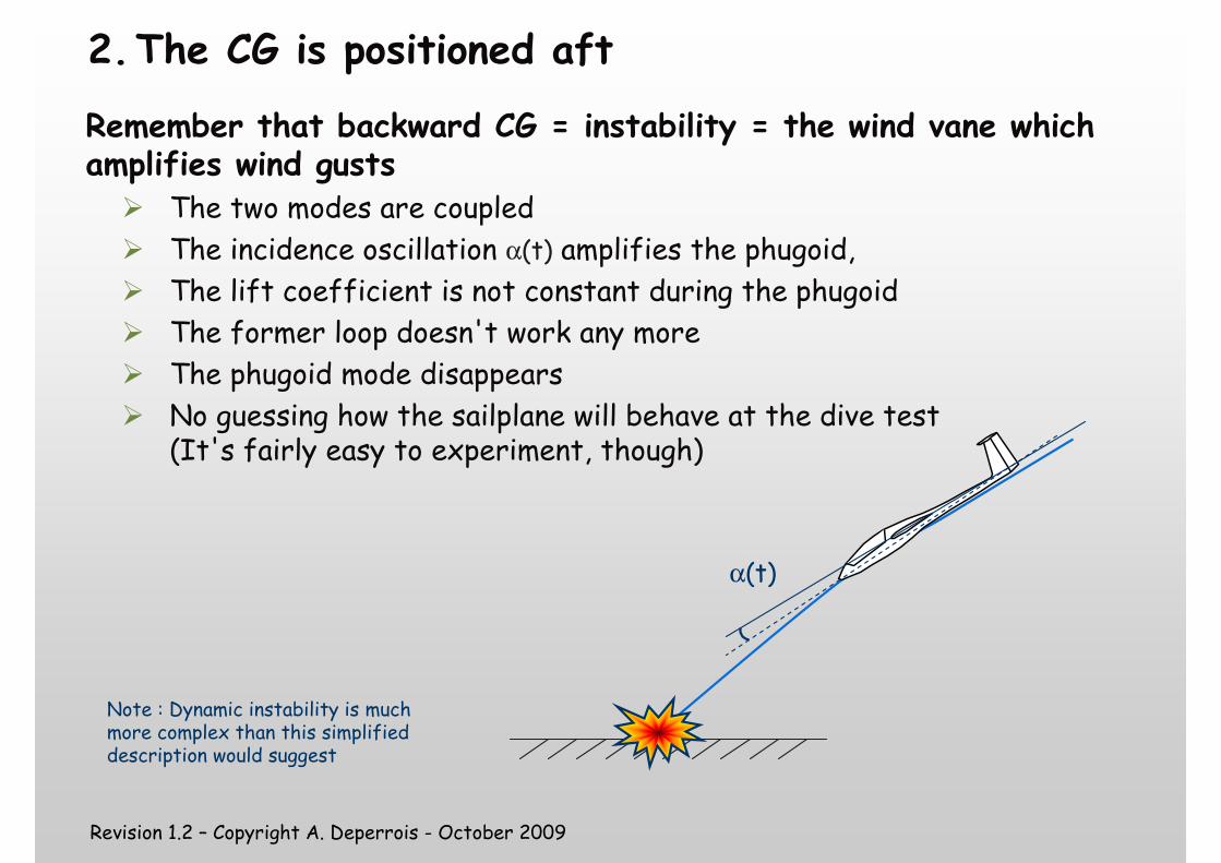
2.The CG is positioned aft
Remember that backward CG = instability = the wind vane which amplifies wind gusts
� The two modes are coupled
� The incidence oscillation α(t) amplifies the phugoid,
� The lift coefficient is not constant during the phugoid
� The former loop doesn't work any more
� The phugoid mode disappears
� No guessing how the sailplane will behave at the dive test(It's fairly easy to experiment, though)
Note : Dynamic instability is much more complex than this simplified description would suggest
α(t)

Revision 1.2 – Copyright A. Deperrois - October 2009
That's all for now
Good design and nice flights ☺☺☺☺
Needless to say, this presentation owes a lot to Matthieu Scherrer ; thanks Matt !
Related Documents


