Datasheet Please read the Important Notice and Warnings at the end of this document V 1.0 www.infineon.com page 1 of 22 2022-01-17 Datasheet of XENSIV™ PASCO2 XENSIV TM PAS CO2 Description Infineon has leveraged its knowledge in sensors and MEMS technologies to develop a disruptive gas sensor for CO2 sensing. The XENSIV TM PAS CO2 is a real CO2 sensor in an exceptionally small form factor based on the photoacoustic spectroscopy (PAS) principle. Infineon's MEMS microphone, which is optimized for low-frequency operation, detects the pressure change generated by CO2 molecules within the sensor cavity. CO2 concentration is then delivered in the form of a direct ppm readout thanks to the integrated microcontroller. Highly accurate CO2 readings are guaranteed. Features • Operating range: 0 ppm to 32000 ppm • Accuracy: ± (30 ppm +3%) of reading between 400 ppm and 5000 ppm • Lifetime: 10 years • Operating temperature: 0-50°C • Operating relative humidity: 0% to 85% (Non-condensing) • Interface: I2C, UART, and PWM • Supply voltage: 12.0 V for the emitter and 3.3 V for other components • Average power consumption: Typically, 30 mW at 1 measurement/minute • Package dimension: 13.8 x 14 x 7.5 mm 3 Potential applications High accuracy, compact size, and SMD capability make the XENSIV TM PAS CO2 ideal for indoor air quality monitoring solutions in the market with numerous potential applications. • Building automation: Demand Controlled Ventilation, Air Handler Units, Air Exchanger • Home appliances: Air purifiers, Air Conditioner • Smart home IoT devices: Thermostat, Speaker, Baby monitors, Personal assistants, Indoor Air Quality Monitor, Smart lighting. • City management/ CO2 emissions control: Outdoor lighting, Bus stop stations, Advertising billboards. • In-cabin air quality monitoring unit

Welcome message from author
This document is posted to help you gain knowledge. Please leave a comment to let me know what you think about it! Share it to your friends and learn new things together.
Transcript

Datasheet Please read the Important Notice and Warnings at the end of this document V 1.0
www.infineon.com page 1 of 22 2022-01-17
Datasheet of XENSIV™ PASCO2
XENSIVTM PAS CO2
Description
Infineon has leveraged its knowledge in sensors and MEMS technologies to develop a disruptive gas sensor for CO2 sensing. The XENSIVTM PAS CO2 is a real CO2 sensor in an exceptionally small form factor based on the photoacoustic spectroscopy (PAS) principle.
Infineon's MEMS microphone, which is optimized for low-frequency operation, detects the pressure change generated by CO2 molecules within the sensor
cavity. CO2 concentration is then delivered in the form of a direct ppm readout thanks to the integrated microcontroller. Highly accurate CO2 readings are guaranteed.
Features
• Operating range: 0 ppm to 32000 ppm
• Accuracy: ± (30 ppm +3%) of reading between 400 ppm and 5000 ppm
• Lifetime: 10 years
• Operating temperature: 0-50°C
• Operating relative humidity: 0% to 85% (Non-condensing)
• Interface: I2C, UART, and PWM
• Supply voltage: 12.0 V for the emitter and 3.3 V for other components
• Average power consumption: Typically, 30 mW at 1 measurement/minute
• Package dimension: 13.8 x 14 x 7.5 mm3
Potential applications
High accuracy, compact size, and SMD capability make the XENSIVTM PAS CO2 ideal for indoor air quality
monitoring solutions in the market with numerous potential applications.
• Building automation: Demand Controlled Ventilation, Air Handler Units, Air Exchanger
• Home appliances: Air purifiers, Air Conditioner
• Smart home IoT devices: Thermostat, Speaker, Baby monitors, Personal assistants, Indoor Air Quality Monitor, Smart lighting.
• City management/ CO2 emissions control: Outdoor lighting, Bus stop stations, Advertising billboards.
• In-cabin air quality monitoring unit

Datasheet Please read the Important Notice and Warnings at the end of this document V 1.0
www.infineon.com page 2 of 22 2022-01-17
Datasheet of XENSIV™ PASCO2
Table of contents
Description .................................................................................................................................... 1
Features ........................................................................................................................................ 1
Potential applications ..................................................................................................................... 1
Table of contents ............................................................................................................................ 2
1 Block diagram ........................................................................................................................ 3
2 Pin-out diagram ..................................................................................................................... 4
3 The typical sensor response to the CO2 concentration change ..................................................... 5
4 Characteristics and parameters ............................................................................................... 6
4.1 Specification ............................................................................................................................................ 6 4.1.1 Operating range ................................................................................................................................. 6
4.1.2 Timing characteristics ........................................................................................................................ 6
4.1.3 Absolute maximum ratings ................................................................................................................ 8 4.1.4 The current rating and power consumption ..................................................................................... 8 4.1.5 CO2 Transfer Function ....................................................................................................................... 9
4.1.6 Peripheral timing ............................................................................................................................. 10 4.1.6.1 I2C Timing .................................................................................................................................... 10
4.1.6.2 UART characteristics ................................................................................................................... 11 4.2 Application Circuit Example .................................................................................................................. 11 4.3 Functional description .......................................................................................................................... 12
4.3.1 Operating Modes .............................................................................................................................. 12 4.3.2 Data post-processing ....................................................................................................................... 13
4.3.3 Alarm Threshold ............................................................................................................................... 14 4.4 Advanced functionality ......................................................................................................................... 14
4.5 Digital interface ..................................................................................................................................... 15 4.5.1 I2C interface ..................................................................................................................................... 15
4.5.2 I2C transaction format ..................................................................................................................... 15
4.5.3 UART Interface .................................................................................................................................. 16 4.6 Register map .......................................................................................................................................... 16
5 Assembly instruction ............................................................................................................. 17
6 Package information ............................................................................................................. 18
7 Footprint and stencil recommendation .................................................................................... 19
8 Packing for shipment ............................................................................................................. 20
9 Revision history .................................................................................................................... 21

Datasheet Please read the Important Notice and Warnings at the end of this document V 1.0
www.infineon.com page 3 of 22 2022-01-17
Datasheet of XENSIV™ PASCO2 CO2 sensor based on Photo Acoustic Spectroscopy principle
1 Block diagram
Figure 1 Block diagram of XENSIVTM PAS CO2

Datasheet Please read the Important Notice and Warnings at the end of this document V 1.0
www.infineon.com page 4 of 22 2022-01-17
Datasheet of XENSIV™ PASCO2 CO2 sensor based on Photo Acoustic Spectroscopy principle
2 Pin-out diagram
Figure 2 Pin-out diagram (Bottom view)
Table 1
PIN Symbol Type Description
1 VDD3.3 Power supply (3.3V) 3.3V digital power supply
2 Rx Input/ Output UART receiver pin (3.3V domain)
3 SCL Input/ Output I2C clock pin (3.3V domain)
4 TX/ SDA Output UART transmitter pin (3.3V domain) / I2C data pin (3.3V
domain)
5 PWM_DIS Input PWM disable input pin (3.3V domain)
6 GND Ground Ground
7 INT Output Interrupt output pin (3.3V domain)
8 PSEL Input Communication interface select input pin (3.3V domain)
9 PWM Output PWM output pin (3.3V domain)
10 VDD12 Power supply (12V) 12V power supply for the IR emitter

Datasheet Please read the Important Notice and Warnings at the end of this document V 1.0
www.infineon.com page 5 of 22 2022-01-17
Datasheet of XENSIV™ PASCO2 CO2 sensor based on Photo Acoustic Spectroscopy principle
3 The typical sensor response to the CO2 concentration change
Measurement condition: VDD12 = 12V, VDD3.3=3.3V, Tamb = 25°C, P = 1013 hPa and rH = 30%
Figure 3 The typical sensor response to the CO2 concentration change.

Datasheet Please read the Important Notice and Warnings at the end of this document V 1.0
www.infineon.com page 6 of 22 2022-01-17
Datasheet of XENSIV™ PASCO2 CO2 sensor based on Photo Acoustic Spectroscopy principle
4 Characteristics and parameters
4.1 Specification
4.1.1 Operating range
All parameters specified in the following sections refer to these operating conditions unless otherwise specified.
Table 2 Operating range
Parameter Symbol Values Unit Note or Test Condition
Min. Typ. Max.
CO2 measurement range1) CCO2 0 32000 ppm Functional measurement range
Ambient temperature1) Tamb 0 50 °C
Relative humidity1) rH 0 85 % Non-condensing
Pressure1) p 750 1013 1150 hPa
Supply voltage1) VDD3.3 3 3.3 3.6 V
VDD12 10.8 12 13.2 V
Lifetime1) Tlife 10 Year Depends on the mission profile
Note: 1) Not subject to production test. This parameter is verified by design/ characterization.
4.1.2 Timing characteristics
Table 3 Timing characteristics
Parameter Symbol Values Unit Note or Test Condition
Min. Typ. Max.
Sampling time1) Tsampling 5 4095 s
Time to sensor ready1) Tsensor_rdy 1 s
Time to early notification1), 2) Tearly_noti 2 s
I2C Clock frequency1) fI2C 100
kHz
400
PWM frequency1) fpwm 80 Hz
UART baud rate1) fbaud 9.6 kBps
Note: 1) Not subject to production test. This parameter is verified by design/ characterization. 2) Relevant for continuous mode of operation.

Datasheet Please read the Important Notice and Warnings at the end of this document V 1.0
www.infineon.com page 7 of 22 2022-01-17
Datasheet of XENSIV™ PASCO2 CO2 sensor based on Photo Acoustic Spectroscopy principle
Typical measurement timing sequence has been illustrated in figure 4.
Figure 4 Illustration of the timing characteristic parameters

Datasheet Please read the Important Notice and Warnings at the end of this document V 1.0
www.infineon.com page 8 of 22 2022-01-17
Datasheet of XENSIV™ PASCO2 CO2 sensor based on Photo Acoustic Spectroscopy principle
4.1.3 Absolute maximum ratings
Absolute maximum ratings are verified by design/ characterization, and not tested during production.
Table 4 Absolute Maximum Ratings1)
Parameter Symbol Values Unit Note or Test Condition
Min. Typ. Max.
MSL Level MSL
3
Maximum ambient temperature Tamb_max -10 60 °C
Maximum relative humidity rHmax 0 95 %
12V Supply voltage VVDD12 9.6 14.4 V
3.3V Supply voltage VVDD3.3 3.0 3.6 V
Storage temperature Ts -30 85 °C
Reflow temperature Tr 245 °C JEDEC J-STD-020E
ESD Human Body Model VESD_HBM -2 2 kV HBM (JS001)
ESD Charge Discharge Model VESD_CDM 500 V CDM (JS002)
Note: 1) Stresses above the values listed as "Absolute Maximum Ratings" may cause permanent damage
to the devices. Exposure to absolute maximum rating conditions for extended period of time may
affect device reliability.
4.1.4 The current rating and power consumption
The current rating refers to 1 measurement/ minute as a typical sampling frequency. All parameters specified in table 5 refer to the following operating conditions unless otherwise specified:
VDD3.3 = 3.3V, VDD12 = 12V, Tamb = 25°C, % rH = 30 %, p = 1013 hPa.
Table 5 Current rating
Parameter Symbol Pin Values Unit Note or Test Condition
Min. Typ. Max.
Peak current1) Ipeak 12 VDD12
130 150 mA
Peak current1) Ipeak 3.3 VDD3.3
10 mA
Average current1) Iavg 12 VDD12 0.8 mA
Average current1) Iavg 3.3 VDD3.3 6.1 mA
Average power1) Pavg 30 mW
Note: 1) Not subject to production test. This parameter is verified by design/ characterization.
Power consumption can be optimized further. For more details please refer to our application note section at the product web page.
Datasheet Please read the Important Notice and Warnings at the end of this document V 1.0
www.infineon.com page 9 of 22 2022-01-17
Datasheet of XENSIV™ PASCO2 CO2 sensor based on Photo Acoustic Spectroscopy principle
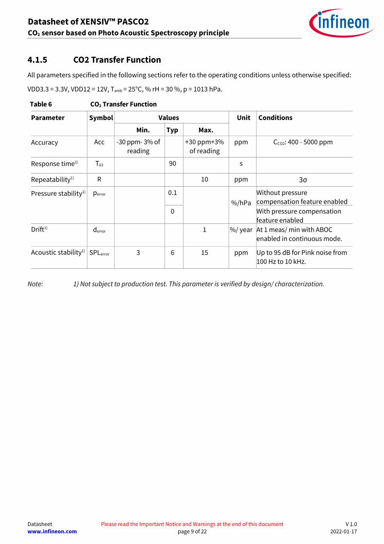
4.1.5 CO2 Transfer Function
All parameters specified in the following sections refer to the operating conditions unless otherwise specified:
VDD3.3 = 3.3V, VDD12 = 12V, Tamb = 25°C, % rH = 30 %, p = 1013 hPa.
Table 6 CO2 Transfer Function
Parameter Symbol Values Unit Conditions
Min. Typ.
Max.
Accuracy Acc -30 ppm- 3% of
reading +30 ppm+3%
of reading ppm CCO2: 400 - 5000 ppm
Response time1) T63 90 s
Repeatability1) R 10 ppm 3σ
Pressure stability1) perror 0.1
%/hPa
Without pressure
compensation feature enabled
0 With pressure compensation
feature enabled
Drift1) derror 1 %/ year At 1 meas/ min with ABOC
enabled in continuous mode.
Acoustic stability1) SPLerror 3 6 15 ppm Up to 95 dB for Pink noise from
100 Hz to 10 kHz.
Note: 1) Not subject to production test. This parameter is verified by design/ characterization.

Datasheet Please read the Important Notice and Warnings at the end of this document V 1.0
www.infineon.com page 10 of 22 2022-01-17
Datasheet of XENSIV™ PASCO2 CO2 sensor based on Photo Acoustic Spectroscopy principle
4.1.6 Peripheral timing
4.1.6.1 I2C Timing
Table 7 I2C Standard mode timing
Parameter Symbol Values Unit Note or Test Condition
Min. Typ. Max.
Fall time of both SDA and SCL t1 300 ns
The rise time of both SDA and SCL t2 1000 ns
Data hold time t3 0 μs
Data set-up time t4 250 ns
LOW period of SCL clock t5 4.7 μs
HIGH period of SCL clock t6 4.0 μs
Hold time for a (repeated) START condition
t7 4.0 μs
Set-up time for (repeated) START condition
t8 4.7 μs
Set-up time for STOP condition t9 4.0 μs
Bus free time between a STOP and START condition
t10 4.7
μs
Capacitive load for each bus line Cb 400 pF
Figure 5 Standard I2C mode timing.

Datasheet Please read the Important Notice and Warnings at the end of this document V 1.0
www.infineon.com page 11 of 22 2022-01-17
Datasheet of XENSIV™ PASCO2 CO2 sensor based on Photo Acoustic Spectroscopy principle
4.1.6.2 UART characteristics
The main characteristics of the UART interface are described below:
• Point to point operation – no bus support.
• Slave operation only.
• fbaud = 9.6kBps
• Format: 1 start bit, 8 Data bits, no parity bit, 1 stop bit.
• Supports direct connection with terminal program.
For further details on UART and I2C communication protocol, please refer to our application note section in the
product webpage.
4.2 Application Circuit Example
Typical application circuits for I2C and UART has been presented in the figure 6 and figure 7 respectively.
Figure 6 Application circuit example for I2C
Datasheet Please read the Important Notice and Warnings at the end of this document V 1.0
www.infineon.com page 12 of 22 2022-01-17
Datasheet of XENSIV™ PASCO2 CO2 sensor based on Photo Acoustic Spectroscopy principle
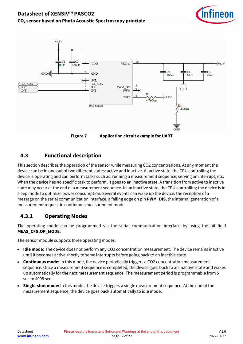
Figure 7 Application circuit example for UART
4.3 Functional description
This section describes the operation of the sensor while measuring CO2 concentrations. At any moment the device can be in one out of two different states: active and inactive. At active state, the CPU controlling the
device is operating and can perform tasks such as: running a measurement sequence, serving an interrupt, etc.
When the device has no specific task to perform, it goes to an inactive state. A transition from active to inactive
state may occur at the end of a measurement sequence. In an inactive state, the CPU controlling the device is in sleep mode to optimize power consumption. Several events can wake up the device: the reception of a
message on the serial communication interface, a falling edge on pin PWM_DIS, the internal generation of a measurement request in continuous measurement mode.
4.3.1 Operating Modes
The operating mode can be programmed via the serial communication interface by using the bit field
MEAS_CFG.OP_MODE.
The sensor module supports three operating modes:
• Idle mode: The device does not perform any CO2 concentration measurement. The device remains inactive
until it becomes active shortly to serve interrupts before going back to an inactive state.
• Continuous mode: In this mode, the device periodically triggers a CO2 concentration measurement
sequence. Once a measurement sequence is completed, the device goes back to an inactive state and wakes up automatically for the next measurement sequence. The measurement period is programmable from 5 sec to 4095 sec.
• Single-shot mode: In this mode, the device triggers a single measurement sequence. At the end of the
measurement sequence, the device goes back automatically to idle mode.

Datasheet Please read the Important Notice and Warnings at the end of this document V 1.0
www.infineon.com page 13 of 22 2022-01-17
Datasheet of XENSIV™ PASCO2 CO2 sensor based on Photo Acoustic Spectroscopy principle
Figure 8 Operating mode transition
4.3.2 Data post-processing
Once the CO2 concentration data has been acquired, several post-processing schemes can be applied to improve
the sensor performance.
• Pressure compensation
The CO2 concentration value acquired by the sensor is dependent on the external atmospheric pressure. To compensate for this effect, the application system can provide the value of the atmospheric pressure by writing
into the specific registers, i.e. PRESSREF_H and PRESSREF_L. At the end of a measurement sequence, the device reads the pressure value and applies for compensation on the CO2 concentration value before storing it into the
result registers.
• Automatic Baseline Offset Correction
To correct slow drifts caused by aging during operation, the device supports Automatic Baseline Offset
Compensation. Every week of operation, the device computes an offset to correct the baseline of the device. The device must be in contact with the reference concentration (e.g. fresh air at. 400 ppm of CO2 concentration) at
least 30 minutes per operating week to make sure proposer baseline compensation. The device supports different configurations for compensation. The ABOC setpoint may only be set between 350 and 1500 ppm.
• Forced compensation
Forced compensation provides a means to speed up the offset compensation process. Before forced
compensation is enabled, the device shall be physically exposed to the reference CO2 concentration. The device will use the 3 next measurements to calculate the compensation offset. The user shall ensure constant exposure to the reference CO2 concentration during that time. It is recommended to operate at 1 measurement per 10
seconds while implementing the forced compensation scheme. When the 3 measurement sequences are
completed, the device automatically reconfigures itself with the newly computed offset applied to the subsequent CO2 concentration measurement results.

Datasheet Please read the Important Notice and Warnings at the end of this document V 1.0
www.infineon.com page 14 of 22 2022-01-17
Datasheet of XENSIV™ PASCO2 CO2 sensor based on Photo Acoustic Spectroscopy principle
4.3.3 Alarm Threshold
The device can be configured to perform an alarm threshold check each time a new CO2 concentration data is
acquired. At the end of each measurement sequence, the computed CO2 value (after all applicable offset compensations) is compared to the concatenated value in ALARM_TH_H and ALARM_TH_L. In case of a threshold violation, the sticky bit MEAS_STS.ALARM is set. This also sets pin INT to active level if configured as
Alarm. Bit MEAS_STS.ALARM is cleared by reading register MEAS_STS.ALARM_CLR.
4.4 Advanced functionality
Monitoring mechanism
The device supports several mechanisms to monitor the correct operation of the sensor.
Table 7
Mechanism Description
Sensor Ready status After each power-on reset, bit SENS_STS.SEN_RDY is set to confirm that the sensor
has initialized correctly.
Scratchpad register To check the integrity of the communication layer of the serial communication interface, register SCRATCH_PAD can be used. This register can use this memory field to write any value and verify that the data received by the device is correct.
It can also be used to verify that a soft reset has been executed, using the following sequence:
1. The user writes a non-default value to register SCRATCH_PAD.
2. The user reads back register SCRATCH_PAD to verify the writ commend has been correctly executed.
3. The user writes register SENS_RST to trigger a soft reset.
4. The user reads register SCRATCH_PAD to verify that it has been reset to its
default value.
VDD12V verification At power-up and the beginning of each measurement sequence, the device
measures automatically the voltage at VDD12. If the measured voltage exceeds the specified operating range of the device, bit SENS_STS.ORVS is set. The
measurement sequence is however completed normally. Bit SENS_STS.ORVS can
be cleared by setting bit SENS_STS.ORVS_CLR
Internal temperature verification
At the beginning of each measurement sequence, the device measures automatically its internal temperature. If the measured temperature exceeds the specified operating ranged of the device, sticky bit SENS_STS.ORTMP is set. The
measurement sequence is however completed normally. Bit SENS_STS.ORTMP
can be cleared by setting bit SENS_STS.ORTMP_CLR.

Datasheet Please read the Important Notice and Warnings at the end of this document V 1.0
www.infineon.com page 15 of 22 2022-01-17
Datasheet of XENSIV™ PASCO2 CO2 sensor based on Photo Acoustic Spectroscopy principle
4.5 Digital interface
The XENSIVTM PAS CO2 supports I2C, UART, and PWM. The communication protocols have been covered in
separate application notes.
4.5.1 I2C interface
The device complies with the I2C protocol. When I2C is selected as a serial communication interface, the device acts as an I2C slave. The main characteristics of the interface are described below:
• Slave mode only.
• I2C Clock frequency: 100 kHz and 400 kHz
• 7-bit slave address: 0x28
• No CRC.
• The device supports clock stretching.
• 8bit addressing mode supported (7bit address + RW)
• Bulk read and write supported (device auto-increments automatically the address).
• Address 0x00 not supported.
Further details of the protocol are covered in the separate application note.
4.5.2 I2C transaction format
The I2C transaction has the following structure: a start condition followed by four bytes followed a stop condition.
Figure 9 I2C write and read transaction
Table 8
Byte Description Value Comments
Start condition
1 Header (Slave Address << 1) | R/W
2 First data-byte As per user request/register value
Read: data provided by the slave
Write: data provided by the user
N+2 Data byte N As per user request/register value
Read: data provided by the slave
Write: data provided by the user
End condition

Datasheet Please read the Important Notice and Warnings at the end of this document V 1.0
www.infineon.com page 16 of 22 2022-01-17
Datasheet of XENSIV™ PASCO2 CO2 sensor based on Photo Acoustic Spectroscopy principle
4.5.3 UART Interface
When UART is selected as a serial communication interface, the device acts as a UART slave. The device
operates via UART for point-to-point communication. Bus operation is not supported. As a result, it is recommended that the master uses a time-out mechanism. The basic format of a valid UART frame is 1 start bit, 8 data bits, no parity bit, and 1 stop bit. The master combines several UART frames into a message (read or
write). The combination of master request and salve answer defines a transaction. The main characteristics of
the interface are described below:
• Point to point operation – no bus support.
• Slave operation only.
• UART clock frequency = 9.6 kHz
• Format: 1 start bit, 8 Data bits, no parity bit, 1 stop bit. Supports direct connection with a terminal program.
For further details on UART communication, please have a look at the application note section on the product website ‘www.infineon.com/CO2’.
4.6 Register map
Complete 'Register map description' has been covered in a separate application note in the product webpage.

Datasheet Please read the Important Notice and Warnings at the end of this document V 1.0
www.infineon.com page 17 of 22 2022-01-17
Datasheet of XENSIV™ PASCO2 CO2 sensor based on Photo Acoustic Spectroscopy principle
5 Assembly instruction
XENSIVTM PAS CO2 modules are classified to be Moisture-Sensitivity Level 3 (MSL 3). The maximum reflow temperatures during board assembly must not exceed the classification profile as stated in IPC/JEDEC J-STD-
020E with a peak temperature of below 245°C with one possible reflow cycle. Please also refer to the product barcode label that can be found on the packing material.
Datasheet Please read the Important Notice and Warnings at the end of this document V 1.0
www.infineon.com page 18 of 22 2022-01-17
Datasheet of XENSIV™ PASCO2 CO2 sensor based on Photo Acoustic Spectroscopy principle
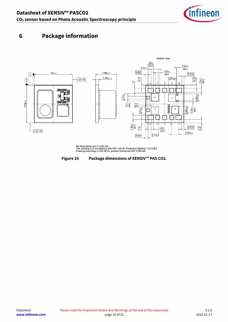
6 Package information
Figure 10 Package dimensions of XENSIVTM PAS CO2.

Datasheet Please read the Important Notice and Warnings at the end of this document V 1.0
www.infineon.com page 19 of 22 2022-01-17
Datasheet of XENSIV™ PASCO2 CO2 sensor based on Photo Acoustic Spectroscopy principle
7 Footprint and stencil recommendation
The board pad and stencil aperture recommendations can be found in the package data base that is available on the Infineon package web page (https://www.infineon.com/packages). The package type of XENSIVTM PAS
CO2 is LG-MLGA-14-1. Please search for the specific package name within the data base, which will then show an example of the footprint layout, stencil recommendation and board assembly recommendation within the download section.

Datasheet Please read the Important Notice and Warnings at the end of this document V 1.0
www.infineon.com page 20 of 22 2022-01-17
Datasheet of XENSIV™ PASCO2 CO2 sensor based on Photo Acoustic Spectroscopy principle
8 Packing for shipment
The device will be shipped in tape and reel. Each tape and reel consist of 300 parts.
Figure 11 Tape and reel packing of XENSIVTM PAS CO2

Datasheet Please read the Important Notice and Warnings at the end of this document V 1.0
www.infineon.com page 21 of 22 2022-01-17
Datasheet of XENSIV™ PASCO2 CO2 sensor based on Photo Acoustic Spectroscopy principle
9 Revision history
Table 9 Datasheet versions tracking
Reference Description Date
0.1 First copy of the preliminary datasheet 13.10.2020
0.2 Second copy of the preliminary datasheet 25.06.2021
1.0 First release of the datasheet 17.01.2022

Published by
Infineon Technologies AG
81726 München, Germany
© 2022 Infineon Technologies AG.
All Rights Reserved.
Do you have a question about this
document?
Email: [email protected]
Document reference
IMPORTANT NOTICE The information given in this document shall in no event be regarded as a guarantee of conditions or characteristics (“Beschaffenheitsgarantie”) . With respect to any examples, hints or any typical values stated herein and/or any information regarding the application of the product, Infineon Technologies hereby disclaims any and all warranties and liabilities of any kind, including without limitation warranties of non-infringement of intellectual property rights of any third party. In addition, any information given in this document is subject to customer’s compliance with its obligations stated in this document and any applicable legal requirements, norms and standards concerning customer’s products and any use of the product of Infineon Technologies in customer’s applications. The data contained in this document is exclusively intended for technically trained staff. It is the responsibility of customer’s technical departments to evaluate the suitability of the product for the intended application and the completeness of the product information given in this document with respect to such application.
For further information on the product, technology, delivery terms and conditions and prices please contact your nearest Infineon Technologies office (www.infineon.com).
WARNINGS Due to technical requirements products may contain dangerous substances. For information on the types in question please contact your nearest Infineon Technologies office. Except as otherwise explicitly approved by Infineon Technologies in a written document signed by authorized representatives of Infineon Technologies, Infineon Technologies’ products may not be used in any applications where a failure of the product or any consequences of the use thereof can reasonably be expected to result in personal injury.
Edition 2022-01-17
ifx1
Trademarks All referenced product or service names and trademarks are the property of their respective owners.
Related Documents