4. ELECTRICAL 412 : Climate Control System 412-00 : Climate Control System – General Information Specifications Specifications Lubricants, Fluids, Sealers and Adhesives Description Specification Air conditioning refrigerant HFC 134a Air conditioning compressor oil ND8 oil Capacities Description Grammes Air conditioning refrigerant - vehicles fitted with 2 zone 650g Air conditioning refrigerant - vehicles fitted with 4 zone 800g Refrigerant Oil Adding Capacities Item Cubic Centimeters (cc) Desiccant bag Add 30 cc Condenser core Add 40 cc Evaporator - Front Add 40 cc Evaporator - Rear Add 40 cc Air conditioning (A/C) compressor - If the quantity of oil taken from the old compressor is less than 30 cc Add 30 cc

Welcome message from author
This document is posted to help you gain knowledge. Please leave a comment to let me know what you think about it! Share it to your friends and learn new things together.
Transcript

4. ELECTRICAL
412 : Climate Control System
412-00 : Climate Control System – General Information
Specifications
Specifications Lubricants, Fluids, Sealers and Adhesives
Description Specification
Air conditioning refrigerant HFC 134a
Air conditioning compressor oil ND8 oil
Capacities
Description Grammes
Air conditioning refrigerant - vehicles fitted with 2 zone 650g
Air conditioning refrigerant - vehicles fitted with 4 zone 800g
Refrigerant Oil Adding Capacities
Item Cubic Centimeters (cc)
Desiccant bag Add 30 cc
Condenser core Add 40 cc
Evaporator - Front Add 40 cc
Evaporator - Rear Add 40 cc
Air conditioning (A/C) compressor - If the quantity of oil taken from the old compressor is less than 30 cc
Add 30 cc

Air conditioning (A/C) compressor - If the quantity of oil taken from the old compressor is greater than 30 cc
Add the same amount of oil as drained from the old compressor.
Air conditioning lines - If air conditioning has been operational
Add 10 cc per line

General Procedures
Air Conditioning (A/C) System Flushing 1.
WARNING: Use extreme care and observe all safety precautions related to the use of refrigerants. Due to refrigerant hazards, always wear safety goggles and non-penetrable gloves when working on or flushing air conditioning (A/C) systems. Failure to follow this instruction may result in personal injury.
WARNING: When flushing the A/C system, refer to the manufacturers equipment instructions for additional information. Failure to do so may result in system damage or personal injury.
WARNING: The A/C refrigerant analyzer must be used before the recovery of any vehicle's A/C refrigerant. Failure to do so puts shop bulk refrigerant at risk of contamination. If the vehicle A/C refrigerant is contaminated, refer the customer to return to the repair faci lity that performed the last A/C repair. If the customer wishes to pay the additional cost, use the A/C recovery equipment that is designated for recovering contaminated A/C refrigerant. All contaminated A/C refrigerant must be disposed of as hazardous waste. For additional information, refer to the manufacturers equipment instructions. Failure to follow this instruction may result in personal injury.
WARNING: Prior to using the A/C flushing equipment for the first time, follow the operating instructions. Failure to follow this instruction may result in personal injury.
CAUTION: Prior to flushing, remove and discard the desiccant sack. Depending on the equipment used, other A/C components may have to be removed prior to flushing. For additional information, refer to the manufacturers equipment instructions before flushing the A/C system. Recover the refrigerant. 2. Remove the desiccant sack. <<412-03>>

3. Flush the system. For additional information, refer to the manufacturers equipment instructions. 4. Install new refrigerant lines if blocked with debris. 5. Install a new desiccant sack. <<412-03>> 6. Add the required amount of oil to the A/C system depending on the repair procedure. 7. Evacuate and charge the A/C system. 8. Carry out fluorescent dye leak detection test. Fluorescent Dye Leak Detection 9. Check the A/C system for correct operation.

Air Conditioning (A/C) System Recovery, Evacuation and Charging (82.30.30) 1.
WARNING: The air conditioning (A/C) refrigerant an alyzer must be used before the recovery of any vehicles A/C refrigerant. Failure to do so puts shop bulk refrigerant at risk of contamination. If the vehicle A/C refrigerant is contaminated, refer the customer to return to the repair facility that carr ied out the last A/C repair. If the customer wishes to pay the additional cost, use the A/C recovery equipment that is designated for recovering contaminated A/C refrigerant. All contaminated A/C refrigerant must be disposed of as hazardous waste. For all equipment, follow the manufacturers equipment procedures and instructions. Failure to follow this instruction may result in personal injury.
WARNING: Jaguar Cars Limited recommend the use of a charging station to carry out the recovery, evacuation and charging of the refrigerant system. Follow the manufacturers equipment procedures and instructions. Failure to follow this instruction may result in personal injury.
CAUTION: Do not add R-12 refrigerant to an A/C system that requires the use of R-134a refrigerant. These two types of refrigerant should never be mixed. Doing so may cause damage to the A/C system. Connect the charging station. For additional information, refer to the manufacturers equipment instructions. 2. Recover the refrigerant. For additional information, refer to the manufacturers equipment instructions. 3. Carry out the required repair procedure. 4. Add the required amount of oil to the A/C system depending on the repair procedure. Specifications 5. Evacuate the A/C system. For additional information, refer to the manufacturers equipment instructions.
6. Check the A/C system for sufficient vacuum. For additional information, refer to the manufacturers equipment instructions. 7. Charge the A/C system. Specifications 8. Check the A/C system for correct operation. 9. Carry out fluorescent dye leak detection test. Fluorescent Dye Leak Detection

Contaminated Refrigerant Handling 1. If contaminated refrigerant is detected DO NOT recover the refrigerant into your R-134a OR R-12 recovery/recycling equipment. Take the follow actions: 1. Repeat the test to verify contaminated refrigerant is present.
2. Advise the customer of the contaminated A/C system and any additional cost to repair the system. The customer may wish to return to the repair facility performing the last A/C repair.
3. Recover the contaminated refrigerant using suitable recovery only equipment designed for capturing and storing contaminated refrigerant. This equipment must only be used to recover contaminated refrigerant to prevent the spread to other vehicles. As an alternative, contact an A/C repair facility in your area with the proper equipment to perform the repair.
• On completion of the recovery of the contaminated refrigerant, it will be necessary to carry out the A/C system flushing procedure. Air Conditioning (A/C) System Flushing
Electronic Leak Detection 1.
WARNING: Good ventilation is necessary in the area where A/C leak testing is to be carried out. If the surrounding air is contaminated with refrigerant gas, the leak detector will indicate this gas all the time. Odors from other chemicals such as antifreeze, diesel fuel, disc brake cleaner, or other cleaning solvents can cause the same problem. A fan, even in a well ventilated area, is very helpful in removing small traces of contamination from the air that might affect the leak detector. Failure to follow this instruction may result in personal injury. Attach an R-134a manifold gauge set or use a UL-approved recovery/recycling device such as an R-134a A/C refrigerant center (which meets SAE Standard J 1991). For additional information, refer to the manufacturers equipment instructions.
• Both gauges should indicate 413-551 kPa (60-80 psi) at 24°C (75°F) with the engine off.
• If little or no pressure is indicated, carry out the air conditioning (A/C) system recovery, evacuation and charging procedure.
2. Use an R134-a Automatic calibration halogen leak detector to leak test the refrigerant system. For additional information, refer to the manufacturers equipment instructions. 3. If a leak is found, carry out the air conditioning (A/C) system recovery procedure.
Fluorescent Dye Leak Detection 1.
WARNING: Eye protection glasses supplied with the ultraviolet (UV) lamp should be used to protect eyesight from harm. NOTE:
The air conditioning (A/C) system has an R-134a leak trace dye wafer incorporated into the desiccant bag. The exact location of leaks can be pinpointed by the bright yellow/green glow of the tracer dye. Since more than one leak may exist, always inspect each component. If it is necessary to add dye (due to a severe leakage for example) use proprietary tracer dye injection equipment.
Check for leaks using ultraviolet (UV) lamp. 2. Check all components, fittings and lines of the A/C system. 3. Carry out the repair. For additional information, refer to <<412-03>>. 4. After the leak is repaired, remove any traces of leak trace dye with a general purpose oil solvent. 5. Check the A/C system for correct operation. 6. Verify the repair by operating the system for a short time and inspecting with the (UV) lamp.

Inspection and Assembly Requirements 1. Check for leaks using ultraviolet (UV) Lamp. Fluorescent Dye Leak Detection 2. NOTE:
Any time a hose or component connection leak is observed, the component and fitting must be separated, cleaned and a new O-ring fitted and lubricated with air conditioning compressor oil.
NOTE:
When separating A/C joints, cap the open connections immediately. Do not leave open to atmosphere.
O-ring seal surfaces must be free of dirt, lint, burrs and scratches. The O-ring and connector should be lubricated with air conditioning compressor oil.
Manifold Gauge Set Connection 1.
WARNING: Use extreme care and observe all safety precautions related to the use of refrigerants. Failure to follow this instruction may result in personal injury.
WARNING: For additional information, refer to the manufacturers equipment instructions. Failure to follow this instruction may result in personal injury and system damage. Install the manifold gauge set. For additional information, refer to the manufacturers equipment instructions. 2. Carry out the repair. 3. Remove the manifold gauge set. For additional information, refer to the manufacturers equipment instructions. 4. Carry out flourescent dye leak detection test. Fluorescent Dye Leak Detection 5. Check air conditioning (A/C) system for correct operation.

Refrigerant Oil Adding
CAUTION: Make sure when disconnecting air conditioning (A/C) connections, that the exposed ports are capped immediately. Make sure you do not leave the A/C system open to the atmosphere. Failure to follow this instruction may result damage to the vehicle. NOTE: A new replacement A/C compressor is pre-filled with ND8 oil. 1. Drain the oil from the old compressor and measure the quantity of oil drained. 2. Drain the oil from the new compressor into a clean container. 3.
CAUTION: If less than 30 cc of oil was drained from the old compressor, then 30 cc of oil must be refilled into the new compressor. Failure to follow this instruction may result in damage to the vehicle. NOTE: Use the new compressor oil to refill to the required quantity. Refill the new compressor with the same amount of oil which was measured from the old compressor. Specifications

Refrigerant System Tests 1.
WARNING: Use extreme care and observe all safety precautions related to the use of refrigerants. Failure to follow this instruction may result in personal injury.
WARNING: The A/C refrigerant analyzer must be used before the recovery of any vehicle's A/C refrigerant. Failure to do so puts shop bulk refrigerant at risk of contamination. If the vehicle A/C refrigerant is contaminated, refer the customer to return to the repair facility that carried out the last A/C repair. If the customer wishes to pay the additional cost, use the A/C recovery equipment that is designated for recovering contaminated A/C refrigerant. All contaminated A/C refrigerant must be disposed of as hazardous waste. For all equipment, follow the equipment manufacturers procedures and instructions. Failure to follow this instruction may result in personal injury. NOTE:
Jaguar Cars Ltd. supports the efficient usage, recovery and recycling of the refrigerant used in passenger car air conditioners. Jaguar Cars Ltd. recommends the use of UL-approved recovery/recycling device such as R-134a A/C refrigerant center (which meets SAE Standard J 1991) during any A/C system repair and recharge procedure which requires that the system be evacuated.
Use R-134a A/C Refrigerant Centre to evacuate and recover the A/C system. • Follow the equipment manufactures procedures and instructions for use of equipment.

Description and operations
Climate Control System The purpose of the air distribution system is to route air to the designated registers. This is
accomplished when air enters the heater core and evaporator core housing and is directed to the
desired ducts by the use of air distribution doors.
The air distribution system contains the heater core and evaporator core, blower motor and
distribution doors. All of the air is mixed and distributed from the heater core and evaporator core
housing assembly depending on the distribution door positions.
For additional information, refer to Air Distribution and Filtering (412-01)
Heating/Defrosting
The heating system is an air blend controlled system. The ambient air is passed through the cabin air
filter, directed through the evaporator core, through and/or around the heater core, mixed and
distributed from the heater core and evaporator housing to the floor, panel and/or the defrost ducts
as desired. For additional information, refer to Heating and Ventilation (412-02A)
Auxiliary Heater - Vehicles with Diesel engine
The system consists of a fuel operated heater unit and a fuel dosing pump.
Fuel for the heater system is taken from the vehicle fuel tank, through a line attached to the fuel
pump module. Fuel is drawn from the fuel tank by a lift pump and supplied via the dosing pump to
the heater unit. In the heater unit, the fuel delivered by the fuel pump is burned and the resultant
heat output is used to heat the engine coolant.
An electronic control unit (ECU) integrated into the heater unit controls the operation of the heater
unit and the dosing pump. The climate control unit controls the operation of the re-circulation flaps
on initial start up. For additional information, refer to Fuel Fired Booster Heater (412-02B)
Heater Core and Evaporator core
The heater core consists of a number of fins and tubes in an arrangement to extract heat from the
engine coolant and transfer the heat to the air that passes through the heater core. The evaporator
core is a plate/fin type arrangement. For additional information, refer to Air Conditioning (412-03A)

Air Conditioning Line Peanut Fitting
Peanut Fitting Assembly
Item Part Number Description
1 — Female air conditioning line
2 — Stud
3 — Male air conditioning line
4 — Retaining nut
5 — O-ring seal
The connections between the air conditioning (A/C) condenser core/receiver drier and the
connections between the lines use peanut fittings.
• The male and female line of the peanut fitting are retained with a nut.
• An O-ring seal is installed around the tube on the male line.
• The female line is welded to the tube and is not adjustable.
• Support the female line with a wrench to prevent the twisting of the tubes.
• The male line will pivot around the tube to allow for alignment with the female line during
assembly.
• When correctly assembled, the mating surfaces of the male and female fittings should be
flush.
Blower motor
The blower motor pulls air from the air inlet and forces it into the heater core and evaporator core
housing where it is mixed and distributed. The blower motor has eleven speeds (vehicles with
telematics have seven speeds) and is controlled by the remote climate control module (RCCM).
Air conditioning refrigerant
The R-134a air conditioning system uses a hydrofluorocarbon (HFC) non-CFC based refrigerant. R-
134a requires the use of Jaguar compressor oil or equivalent meeting Jaguar specification. Do not use
R-12 tools and equipment when repairing an R-134a system unless specified in the workshop
manual. Never mix R-12 and R-134a refrigerants and oils. They are not compatible.

Air Conditioning (A/C) System
The air conditioning (A/C) system is a multi-piece, single case design, with an integral blower motor.
The system allows the operator to control the temperature by delivering heated or cooled air to
maintain a constant temperature. In addition, during A/C operation, it reduces the relative humidity
of air inside the vehicle. Controls are provided to adjust the temperature and system functions,
including blower motor speeds for desired airflow. Ambient air is passed through during all system
operations, except for when the auto system switches to recirculation for maximum A/C
performance, or when the air quality sensor (Japanese market only) requires the system to be in
recirculation, or when recirculation is manually selected, or when the system is switched off. For
additional information, refer to Air Conditioning (412-03A)
Control System Inputs
The climate control system inputs can be selected from the climate control assembly which offers
either AUTO or manual control (MODE).
Control System Outputs
The air inlet, air distribution and air temperature blend doors are all controlled by electronic
actuators. For additional information, refer to Control Components (412-04)

Diagnosis and testing
Climate Control System Principles of Operation
For a detailed description of the Climate Control system, refer to the relevant Description and
Operation sections in the workshop manual.
Climate Control System
Inspection and Verification
1 . Verify the customer concern by operating the system.
2 . Visually inspect for obvious signs of damage and system integrity.
Visual Inspection Chart
Mechanical Electrical
• Coolant Level
• Fuses/Relays
• Damaged, Loose or Corroded Connector(s)
• Damage to Wiring Loom/Incorrect Location, Stretched or Taught
1 . If an obvious cause for an observed or reported concern is found, correct the cause (if possible)
before proceeding to the next step.
2 . If the cause is not visually evident, check for Diagnostic Trouble Codes (DTCs) and refer to the DTC
Index.
DTC Index
Climate Control Module
CAUTION: When probing connectors to take measurements in the course of the pinpoint
tests, use the adaptor kit, part number 3548-1358-00
NOTE:
If the control module/component is suspect and the vehicle remains under manufacturer
warranty, refer to the Warranty Policy and Procedures manual (section B1.2), or determine if
any prior approval program is in operation, prior to the installation of a new
module/component.
NOTE:
When performing voltage or resistance tests, always use a digital multimeter (DMM) accurate to
three decimal places and with a current calibration certificate. When testing resistance, always
take the resistance of the DMM leads into account.
NOTE:
Check and rectify basic faults before beginning diagnostic routines that involve pinpoint tests.
NOTE:
Inspect connectors for signs of water ingress, and pins for damage and/or corrosion.
NOTE:
If DTCs are recorded and, after performing the pinpoint tests, a fault is not present, an
intermittent concern may be the cause. Always check for loose connections and corroded
terminals.
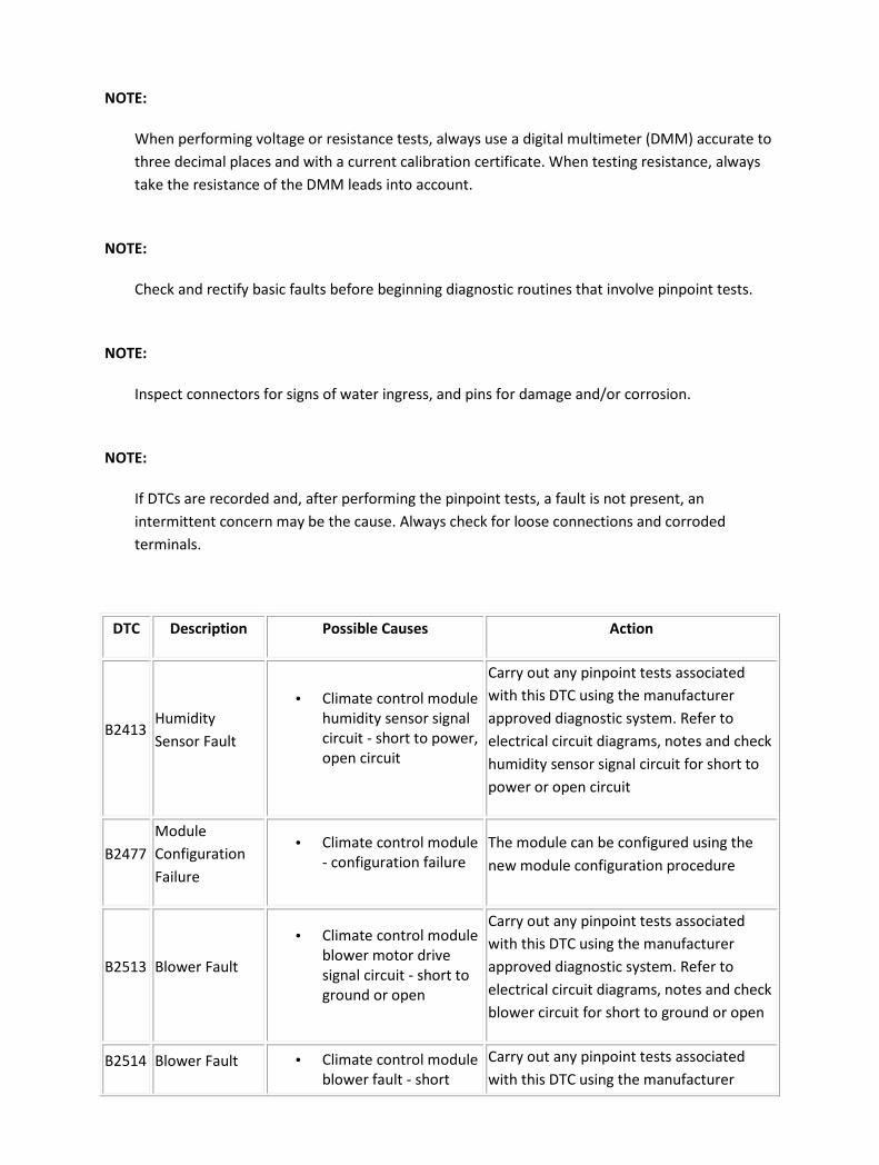
DTC Description Possible Causes Action
B2413 Humidity
Sensor Fault
• Climate control module
humidity sensor signal
circuit - short to power,
open circuit
Carry out any pinpoint tests associated
with this DTC using the manufacturer
approved diagnostic system. Refer to
electrical circuit diagrams, notes and check
humidity sensor signal circuit for short to
power or open circuit
B2477
Module
Configuration
Failure
• Climate control module
- configuration failure
The module can be configured using the
new module configuration procedure
B2513 Blower Fault
• Climate control module
blower motor drive
signal circuit - short to
ground or open
Carry out any pinpoint tests associated
with this DTC using the manufacturer
approved diagnostic system. Refer to
electrical circuit diagrams, notes and check
blower circuit for short to ground or open
B2514 Blower Fault • Climate control module
blower fault - short
Carry out any pinpoint tests associated
with this DTC using the manufacturer

circuit to power approved diagnostic system. Refer to
electrical circuit diagrams, notes and check
blower power circuit for short to power
B2585 Smog Sensor
Fault
• Climate control
module, smog sensor -
hydrocarbon signal
circuit short to ground
Carry out any pinpoint tests associated
with this DTC using the manufacturer
approved diagnostic system. Refer to
electrical circuit diagrams, notes and check
smog sensor circuit for short to ground
B2826
Evaporator
Temperature
Sensor Fault
• Climate control
module, evaporator
temperature sensor
circuit - short to power
or open
Carry out any pinpoint tests associated
with this DTC using the manufacturer
approved diagnostic system. Refer to
electrical circuit diagrams, notes and check
evaporator temperature sensor circuit for
short to power or open
B2827
Evaporator
Temperature
Sensor Fault
• Climate control
module, evaporator
temperature sensor
circuit - short to ground
Carry out any pinpoint tests associated
with this DTC using the manufacturer
approved diagnostic system. Refer to
electrical circuit diagrams, notes and check
evaporator temperature sensor circuit for
short to ground
B2832 Mode Servo
Fault
• Climate control
module, mode servo
circuit - short to
ground, power or open
Carry out any pinpoint tests associated
with this DTC using the manufacturer
approved diagnostic system. Refer to
electrical circuit diagrams, notes and check
mode servo's and circuit for short to
ground, power or open
B2833 Sensor Supply
Fault
• Climate control
module, servo circuit
sensor supply - short to
ground, power or open
Carry out any pinpoint tests associated
with this DTC using the manufacturer
approved diagnostic system. Refer to
electrical circuit diagrams, notes and check
sensor supply circuit for short to ground,
power or open
B2834 RH or LH Air
Mix Servo Fault
• Climate control
module, air mix servo
circuit - short to
ground, power or open
Carry out any pinpoint tests associated
with this DTC using the manufacturer
approved diagnostic system. Refer to
electrical circuit diagrams, notes and check
air mix servo's and circuit for short to
ground, power or open

B2835
RH /LH Outlet
Air Temp
Sensor Fault
• Climate control
module, outlet air temp
sensor circuit - short to
ground, power or open
Carry out any pinpoint tests associated
with this DTC using the manufacturer
approved diagnostic system. Refer to
electrical circuit diagrams, notes and check
outlet air temp sensor circuit for short to
ground, power or open
B2836
In car
Temperature
Sensor Fault
• Climate control
module, in car
temperature sensor
circuit - short to power
or open
Carry out any pinpoint tests associated
with this DTC using the manufacturer
approved diagnostic system. Refer to
electrical circuit diagrams, notes and check
in car temperature sensor for short to
power or open circuit
B2837
In car
Temperature
Sensor Fault
• Climate control
module, in car
temperature sensor
circuit - short to ground
Carry out any pinpoint tests associated
with this DTC using the manufacturer
approved diagnostic system. Refer to
electrical circuit diagrams, notes and check
in car temperature sensor circuit for short
to ground
B2840
Ambient Air
Temperature
Sensor Fault
• Climate control
module, ambient air
temperature sensor
circuit - short to power
or open
Carry out any pinpoint tests associated
with this DTC using the manufacturer
approved diagnostic system. Refer to
electrical circuit diagrams, notes and check
ambient air temperature sensor circuit for
short to power or open
B2841
Ambient Air
Temperature
Sensor Fault
• Climate control
module, ambient air
temperature sensor
circuit - short to ground
Carry out any pinpoint tests associated
with this DTC using the manufacturer
approved diagnostic system. Refer to
electrical circuit diagrams, notes and check
ambient air temperature sensor circuit for
short to ground
B2842
LH or RH Cool
Air Bypass
Servo Fault
• Climate control
module, cool air bypass
servo circuit - short to
ground, power or open
Carry out any pinpoint tests associated
with this DTC using the manufacturer
approved diagnostic system. Refer to
electrical circuit diagrams, notes and check
cool air bypass servo circuit for short to
ground, power or open
B2843 Air Intake Servo
Fault
• Climate control
module, air intake
servo circuit - short to
Carry out any pinpoint tests associated
with this DTC using the manufacturer
approved diagnostic system. Refer to

ground, power or open electrical circuit diagrams, notes and check
air intake servo and circuit for short to
ground, power or open
B2844 Ignition Fault
• Climate control
module, ignition signal
circuit - short to ground
or open
Refer to electrical circuit diagrams, notes
and check ignition signal circuit for short to
ground or open
B2846 Dual Solar
Sensor Fault
• Climate control
module, dual solar
sensor circuit - short to
ground, power or open
Carry out any pinpoint tests associated
with this DTC using the manufacturer
approved diagnostic system. Refer to
electrical circuit diagrams, notes and check
dual solar sensor circuit for short to
ground, power or open
C2781
Air Conditioning
Compressor
Solenoid
• Climate control
module, air
conditioning
compressor solenoid
circuit - short to
ground, power or open
Carry out any pinpoint tests associated
with this DTC using the manufacturer
approved diagnostic system. Refer to
electrical circuit diagrams, notes and check
air conditioning compressor solenoid
circuit for short to ground, power or open
U2022 Climate Control
Panel
• Climate control module
to climate control panel
- communication error
(non nav only)
Refer to electrical circuit diagrams, notes
and check climate control module
communication circuit for fault
U2516 CAN Bus Off
• Climate control
module, CAN Bus -
circuit fault No CAN
messages received
during ignition
on/missing messages
from other ecus
Carry out any pinpoint tests associated
with this DTC using the manufacturer
approved diagnostic system. Refer to
electrical circuit diagrams, notes and check
CAN Bus circuit for short to ground, power
or open
U2520 CAN Node
Missing
• Climate control module
- CAN Node missing
Check other modules for stored DTCs.
Carry out any pinpoint tests associated
with this DTC using the manufacturer
approved diagnostic system. Refer to
electrical circuit diagrams, notes and check
CAN Bus circuit to instrument cluster for
short to ground, power or open
U2521 CAN Node • Climate control module Check other modules for stored DTCs.
Carry out any pinpoint tests associated

Missing - CAN Node missing with this DTC using the manufacturer
approved diagnostic system. Refer to
electrical circuit diagrams, notes and check
CAN Bus circuit to dynamic stability control
module for short to ground, power or open
U2523 CAN Node
Missing
• Climate control module
- CAN Node missing
Check other modules for stored DTCs.
Carry out any pinpoint tests associated
with this DTC using the manufacturer
approved diagnostic system. Refer to
electrical circuit diagrams, notes and check
CAN Bus circuit to engine control module
for short to ground, power or open
U2525 CAN Node
Missing
• Rear climate control
module - CAN Node
missing 4 zone
configurations only
Check other modules for stored DTCs.
Carry out any pinpoint tests associated
with this DTC using the manufacturer
approved diagnostic system. Refer to
electrical circuit diagrams and check CAN
bus circuit to rear climate control module
for short to ground, power or open
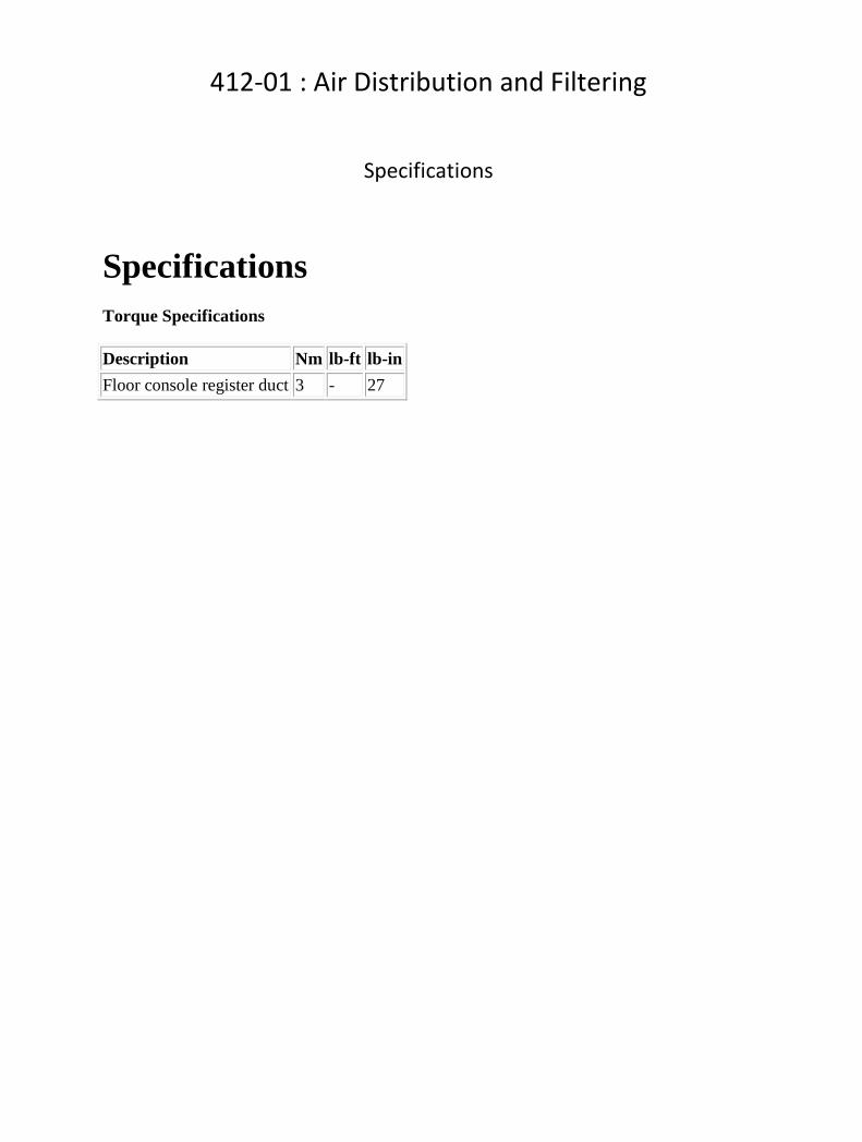
412-01 : Air Distribution and Filtering
Specifications
Specifications Torque Specifications
Description Nm lb-ft lb-in
Floor console register duct 3 - 27

Description and operation
Air Distribution and Filtering
Item Part Number Description
1 — Driver side register
2 — Driver side demister
3 — Air distribution box (part of instrument panel)
4 — Defroster duct
5 — Cowl vent
6 — Cabin air filter
7 — Passenger side demister
8 — Passenger side register
9 — Passenger side register duct (part of instrument panel)

10 — Front footwell duct RH
11 — Heater core and evaporator core housing
12 — Passenger side rear footwell duct
13 — Floor console register adaptor duct
14 — Floor console register duct
15 — Floor console register
16 — Driver side rear footwell duct
17 — Front footwell duct LH
18 — Driver side register duct (part of instrument panel)
19 — Center registers
The purpose of the air distribution system is to route air to the designated registers. This is accomplished when ambient air (fresh mode) enters through the cabin air filter and blower motor (in recirculation mode cabin air is drawn into the blower motor). <<412-02>> The air is then mixed and distributed to the desired outlets via the air distribution box and ducting, depending on the distribution door positions. The cabin air filter is a combination particulate and odour filter. Air ducts channel air to the registers depending on the specific request from the climate control assembly. For additional information, refer to <<412-04.>>

Diagnosis and testing
Air Distribution and Filtering For additional information, refer to <<412-00.>>

Removal and installation
Cabin Air Filter (76.10.09) Removal
1 . Remove the cabin air filter housing cover.
Detach the retaining tangs
2 . Detach the cabin filter retaining plate.
1) Depress the cabin filter retaining plate tangs.
2) Swing the cabin filter retaining plate down.
3 . Remove the cabin air filter.

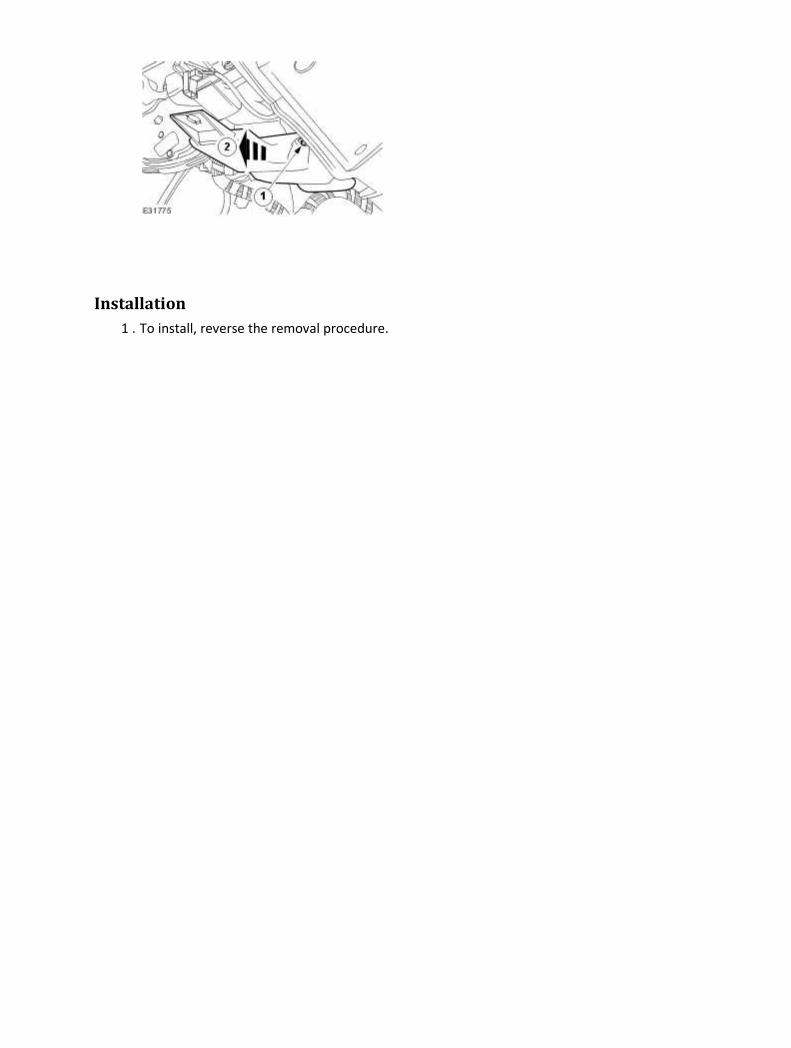
Installation
1
.
NOTE:
Make sure the new cabin air filter is fitted correctly, with the air flow markings on the
cabin air filter showing the direction of air flow.
To install, reverse the removal procedure.

Center Registers (82.20.38) Removal
1 . Remove the floor console. <<501-12>>
2 .
CAUTION: Make sure damage does not occur to the instrument panel finish panel.
Remove the instrument panel finish panel.
3 .
CAUTION: Make sure damage does not occur to the air bag module finish panel.
Remove the passenger air bag module finish panel.
4 . Remove the instrument cluster finish panel.

5 . Detach the center registers.
1) Remove the center registers retaining screws.
2) Detach the center registers.
6 . Disconnect the center register electrical connector.
7 . Disconnect the clock electrical connector.

8 . Remove the center registers.
1) Depress the clock retaining tangs.
2) Remove the clock.
3) Remove the center registers.
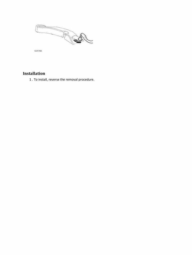
Installation
1 . To install, reverse the removal procedure.

Driver Side Register (82.20.39) Removal
1 . Remove the floor console assembly. <<501-12>>
2 .
CAUTION: Make sure damage does not occur to the instrument panel finish panel.
Remove the instrument panel finish panel.
3 . Remove the instrument cluster finish panel.
4 . Detach the driver side register.
1) Remove the driver side register retaining screw.
2) Detach the driver side register.

5 . Remove the driver side register.
Disconnect the driver side register electrical connector.
Installation
1 . To install, reverse the removal procedure.

Floor Console Register Duct (82.20.37) Removal
1 . Remove the floor console. <<501-12>>
2 . Remove the floor console register duct.
1) Remove the retaining nut.
2) Remove the floor console register duct.
Installation
1 . To install, reverse the removal procedure.
Tighten to 3 Nm.
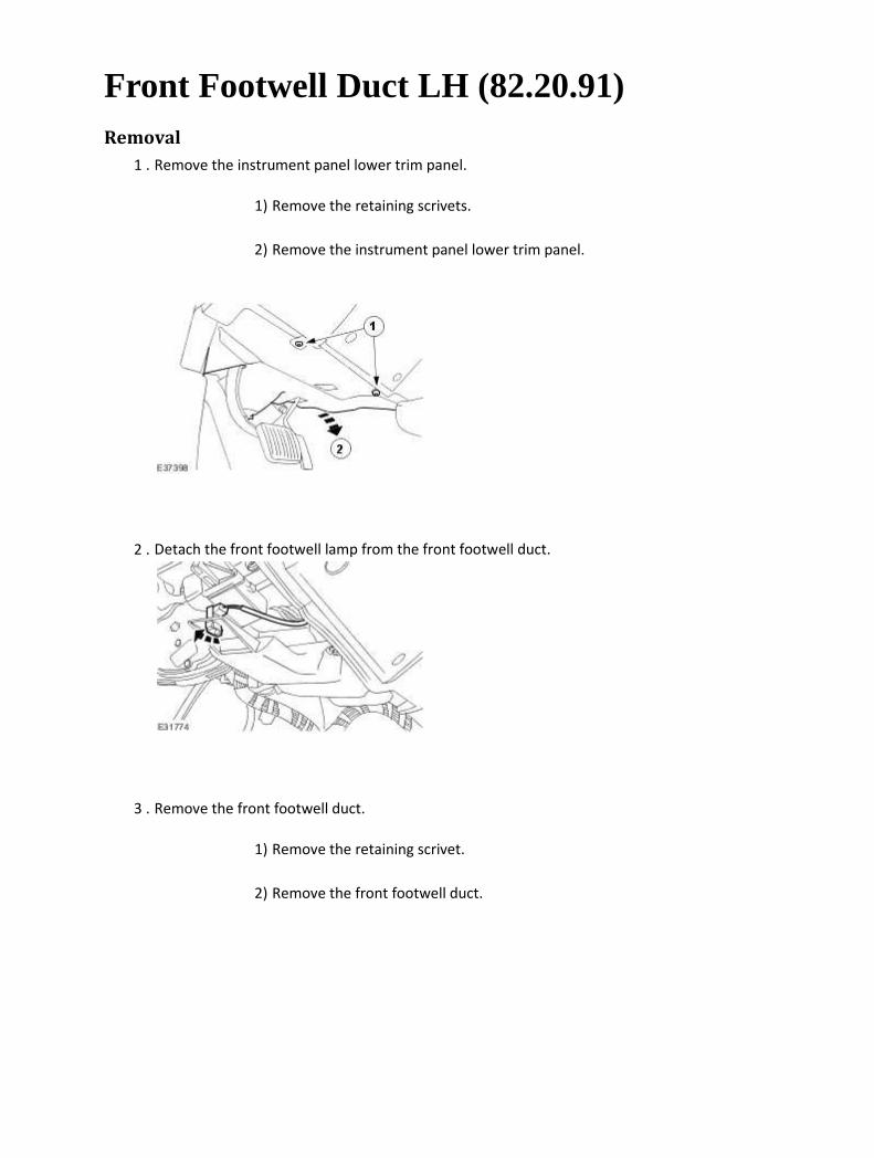
Front Footwell Duct LH (82.20.91) Removal
1 . Remove the instrument panel lower trim panel.
1) Remove the retaining scrivets.
2) Remove the instrument panel lower trim panel.
2 . Detach the front footwell lamp from the front footwell duct.
3 . Remove the front footwell duct.
1) Remove the retaining scrivet.
2) Remove the front footwell duct.
Installation
1 . To install, reverse the removal procedure.

Front Footwell Duct RH (82.20.92) Removal
1 . Remove the instrument panel lower trim panel.
1) Remove the retaining scrivets.
2) Remove the instrument panel lower trim panel.
2 . Detach the front footwell duct.
1) Remove the retaining scrivet.
2) Detach the front footwell duct.
3 . Remove the front footwell duct.
Detach the footwell lamp from the front footwell duct.
Installation
1 . To install, reverse the removal procedure.

Passenger Side Register (82.20.40) Removal
1 .
CAUTION: Make sure damage does not occur to the air bag module finish panel.
Remove the passenger air bag module finish panel.
2 . Detach the passenger side register.
1) Remove the passenger side register retaining screws
2) Detach the passenger side register.
3 . Remove the passenger side register.
Disconnect the passenger side register electrical connector.

Installation
1 . To install, reverse the removal procedure.

Rear Footwell Duct (82.20.96) Removal
1 . Remove the front seat. <<501-10>>
2 . Remove the floor console assembly. <<501-12>>
3 . Remove the B-pillar lower trim panel. <<501-05>>
4 .
CAUTION: Make sure damage does not occur to the floor covering.
NOTE:
Right-hand shown, left-hand similar.
Reposition the floor covering to access the rear floor duct.
1) Raise the floor covering at the front.
2) Raise the floor covering to access the rear floor duct.
5 . Remove the rear footwell duct.
1) Remove the rear footwell duct retaining screw.

2) Remove the rear footwell duct retaining clip.
3) Remove the rear footwell duct.
Installation
1 . To install, reverse the removal procedure.

412-02A : Heating and Ventilation
Specifications
Specifications Torque Specifications
Description Nm lb-ft lb-in
Heater hose bracket retaining bolt. 7 – 62
Heater core and evaporator core housing retaining nut. 7 – 62
Heater core and evaporator core housing retaining bolt. 7 – 62
Blower motor housing lower retaining nut. 7 – 62
Expansion valve manifold and tube assembly retaining bolt. 8 – 71
Auxillary coolant flow pump retaining bolt. 10 – 89
Engine compartment support retaining bolt. 25 18 –
Cabin filter housing retaining bolt. 6 – 53
Description and operation
Heating and Ventilation The heating and defrosting system:
• controls the vehicle air temperature, and during air conditioning (A/C) operation reduces the
relative humidity of the air inside the vehicle.
• delivers heated or cooled air to maintain the vehicle interior temperature and comfort level.
• controls the blower motor speed.
• allows temperature to be adjusted individually by the driver and the passenger to maintain
comfort.
• uses a reheat method to provide conditioned air to the passenger compartment. All airflow
from the blower motor passes through the A/C evaporator core. Temperature is regulated by
reheating a portion of the air and blending it with the remaining cool air to achieve the
desired temperature.
• blends the air temperature by regulating the flow of air through or around the heater core.
The blower motor draws ambient air through the cabin air filter during all system operations except
for when the auto system switches to recirculation for maximum A/C performance, or when the
ambient air temperatue sensor requires the system to be in recirculation mode or when recirculation
is manually selected.
For additional information, refer to <<412-03>>.
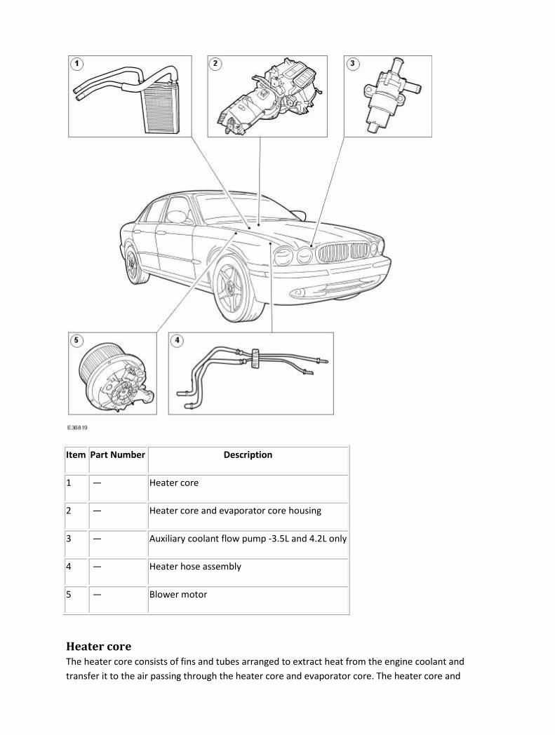
Item Part Number Description
1 — Heater core
2 — Heater core and evaporator core housing
3 — Auxiliary coolant flow pump -3.5L and 4.2L only
4 — Heater hose assembly
5 — Blower motor
Heater core
The heater core consists of fins and tubes arranged to extract heat from the engine coolant and
transfer it to the air passing through the heater core and evaporator core. The heater core and
evaporator core is separated into two sections. Air passing through one section is directed to the
driver side of the vehicle, while air passing through the other section is directed to the passenger side
of the vehicle.
Auxiliary coolant flow pump vehicles fitted with 3.5L or 4.2L engine
The auxiliary coolant flow pump is electrically driven and provides increased coolant flow during low
engine speed operation. The pump is also used to circulate coolant after the engine is turned off
under certain conditions.
Blower motor
The blower motor pulls air from the air inlet and forces it into the heater core and evaporator core
assembly where it is mixed and distributed. The blower motor has eleven speeds (vehicles with
telematics have seven speeds) and is controlled by the climate control assembly.

Removal and installation
Auxiliary Coolant Flow Pump - 4.2L NA V8 - AJV8/4.2L SC V8 - AJV8/3.5L NA V8 - AJV8 (82.25.59) Removal
1 . Carry out the cooling system drain procedure. <<303-03>>
2 . Remove the radiator upper hose.
3 . Detach the thermostat housing lower hose.
4 . Disconnect the coolant expansion tank lower hose.
1) Remove the coolant expansion tank lower hose retaining clip.
2) Disconnect the coolant expansion tank lower hose.
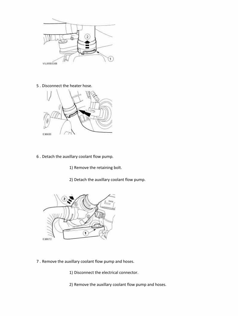
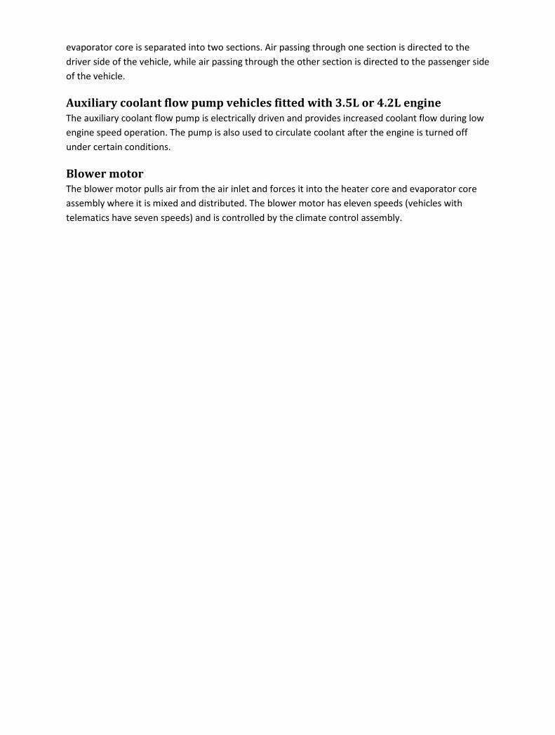
5 . Disconnect the heater hose.
6 . Detach the auxillary coolant flow pump.
1) Remove the retaining bolt.
2) Detach the auxillary coolant flow pump.
7 . Remove the auxillary coolant flow pump and hoses.
1) Disconnect the electrical connector.
2) Remove the auxillary coolant flow pump and hoses.

8 . Remove the auxillary coolant flow pump hoses.
Installation
1 . To install, reverse the removal procedure.
Tighten to 10 Nm.
2 . Carry out the cooling system filling and bleeding procedure. <<303-03>>

Auxiliary Coolant Flow Pump - 2.7L V6 - TdV6 (82.25.59) Removal
1 . Remove the air deflector.
For additional information, refer to Air Deflector (76.11.41)
2 . Disconnect the auxiliary coolant flow pump electrical connector.
3 . NOTE:
Using a suitable tool, clamp the hose to minimize coolant loss.
Detach the lower coolant hose.
4 . NOTE:
Using a suitable tool, clamp the hose to minimize coolant loss.
Detach the upper coolant hose.
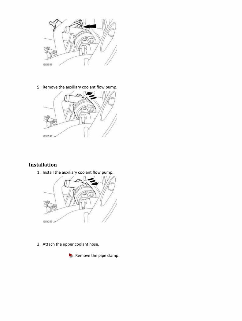
5 . Remove the auxiliary coolant flow pump.
Installation
1 . Install the auxiliary coolant flow pump.
2 . Attach the upper coolant hose.
Remove the pipe clamp.

3 . Attach the lower coolant hose.
Remove the pipe clamp.
4 . Connect the auxiliary coolant flow pump electrical connector.
5 . Remove the coolant expansion tank pressure cap.
6
.
Fill the cooling system up to the MAX mark on the coolant expansion tank using a fifty percent
mixture of Jaguar premium cooling system fluid or equivalent, meeting Jaguar specification
WSS M97B44-D and fifty percent water.
7 . Install the coolant expansion tank pressure cap.
8 . START and RUN the engine.
9
.
Set the heating system to MAX heat, the blower motor to MAX speed and the air distribution
to instrument panel registers.
10
. CAUTION: Observe the engine temperature gauge. If the engine starts to over-heat
switch off immediately and allow to cool. Failure to follow this instruction may result in
damage to the vehicle.
Allow the engine to RUN until hot air is emitted from the instrument panel registers, while
observing the engine temperature gauge.
11 . Switch off the engine.
12 . Allow the engine to cool.
13
. WARNING: Never remove the coolant pressure cap under any circumstances while
the engine is operating. Failure to follow this instruction may result in personal injury. To
avoid having scalding hot coolant or steam blow out of the cooling system, use extreme
care when removing the coolant pressure cap from a hot cooling system. Wait until the
engine has cooled, then wrap a thick cloth around the coolant pressure cap and turn it
slowly until the pressure begins to release. Step back while the pressure is released from
the system. When certain all the pressure has been released (still with a cloth) turn and
remove the coolant pressure cap from the coolant expansion tank. Failure to follow these
instructions may result in personal injury.
Release the cooling system pressure.
Remove the coolant expansion tank pressure cap.

14
.
Fill the cooling system up to the MAX mark on the coolant expansion tank using a fifty
percent mixture of Jaguar premium cooling system fluid or equivalent, meeting Jaguar
specification WSS M97B44-D and fifty percent water.
15 . Install the coolant expansion tank pressure cap.
16 . Raise the vehicle.
17 . Check for water leaks.
18 . Install the air deflector.
For additional information, refer to Air Deflector (76.11.41)

Blower Motor (82.25.66) Removal
1 . Disconnect the battery ground cable. <<414-01>>
2 . Remove the passenger side instrument panel closing panel.
3 . Remove the blower motor.
1) Disconnect the electrical connector.
2) Remove the blower motor.
Installation
1 . To install, reverse the removal procedure.
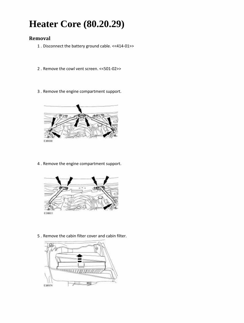
Heater Core (80.20.29) Removal
1 . Disconnect the battery ground cable. <<414-01>>
2 . Remove the cowl vent screen. <<501-02>>
3 . Remove the engine compartment support.
4 . Remove the engine compartment support.
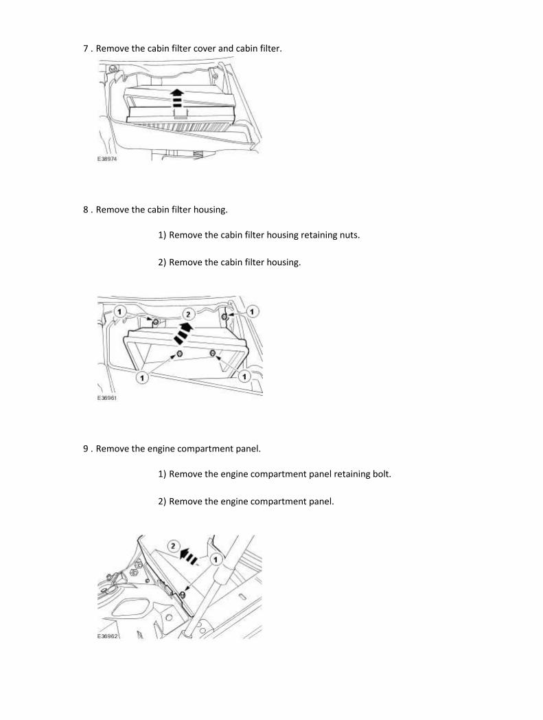
5 . Remove the cabin filter cover and cabin filter.
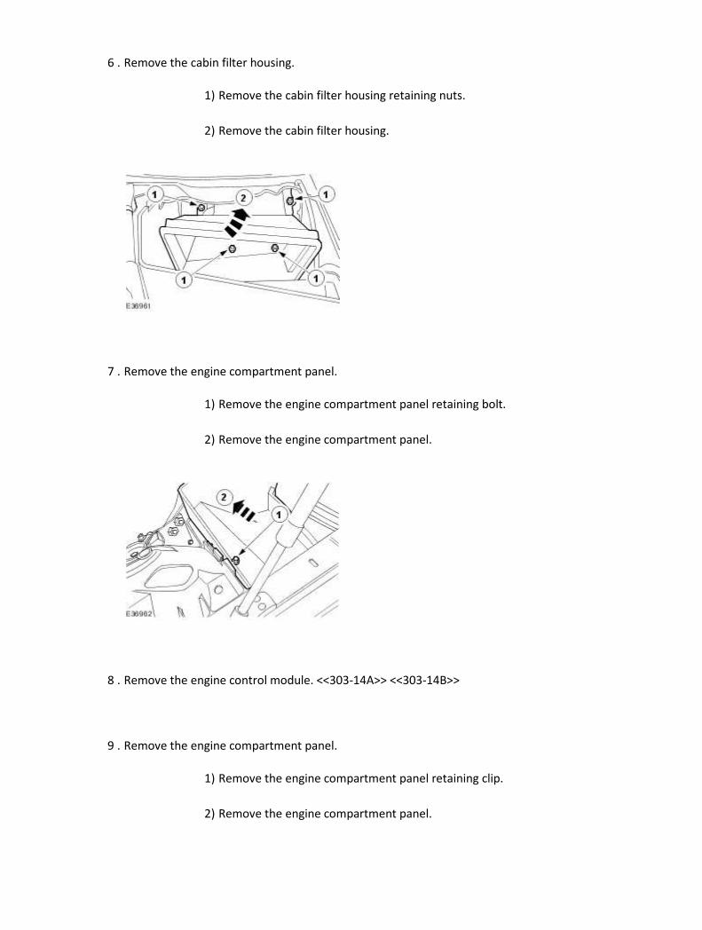
6 . Remove the cabin filter housing.
1) Remove the cabin filter housing retaining nuts.
2) Remove the cabin filter housing.
7 . Remove the engine compartment panel.
1) Remove the engine compartment panel retaining bolt.
2) Remove the engine compartment panel.
8 . Remove the engine control module. <<303-14A>> <<303-14B>>
9 . Remove the engine compartment panel.
1) Remove the engine compartment panel retaining clip.
2) Remove the engine compartment panel.
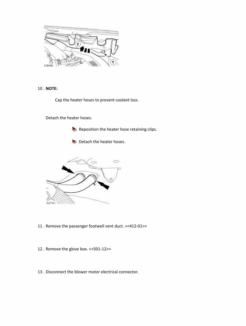
10 . NOTE:
Cap the heater hoses to prevent coolant loss.
Detach the heater hoses.
Reposition the heater hose retaining clips.
Detach the heater hoses.
11 . Remove the passenger footwell vent duct. <<412-01>>
12 . Remove the glove box. <<501-12>>
13 . Disconnect the blower motor electrical connector.

14 . Remove the blower motor housing securing bolts.
15 . Remove the blower motor housing securing bolts.
16 . Remove the blower motor housing.
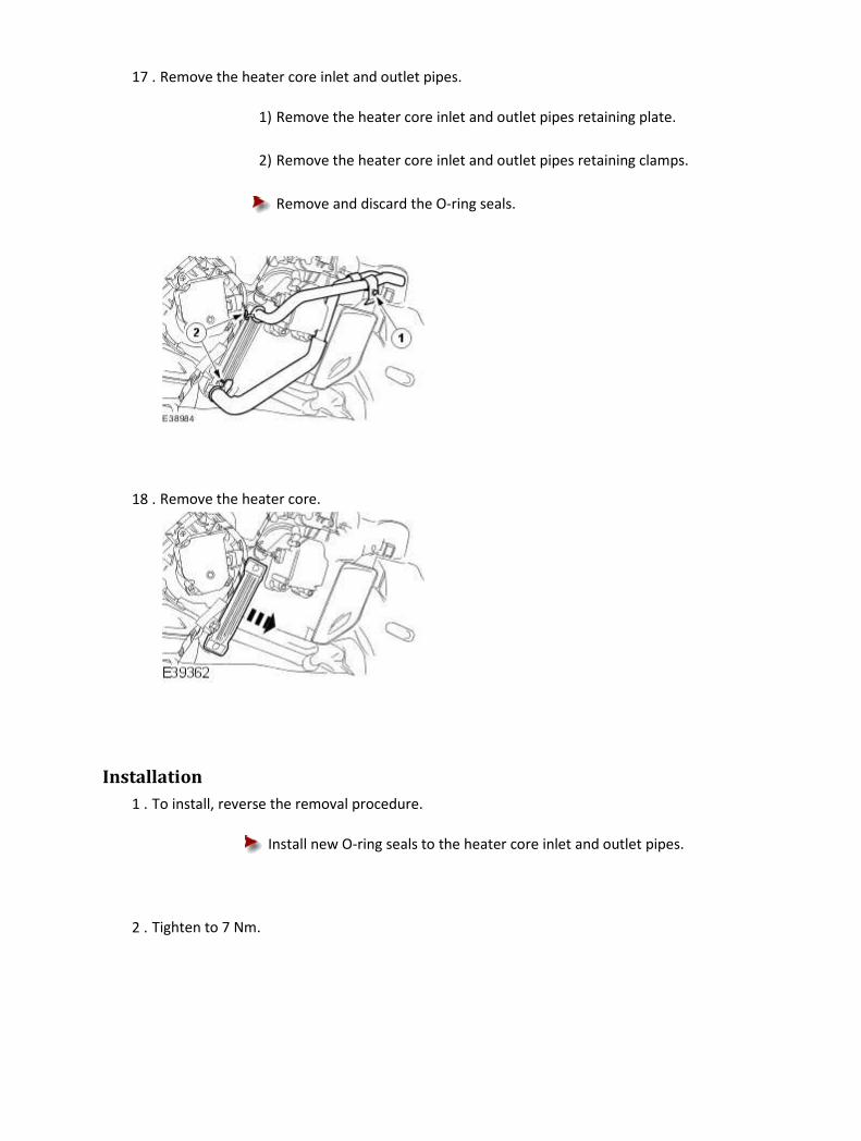
17 . Remove the heater core inlet and outlet pipes.
1) Remove the heater core inlet and outlet pipes retaining plate.
2) Remove the heater core inlet and outlet pipes retaining clamps.
Remove and discard the O-ring seals.
18 . Remove the heater core.
Installation
1 . To install, reverse the removal procedure.
Install new O-ring seals to the heater core inlet and outlet pipes.
2 . Tighten to 7 Nm.
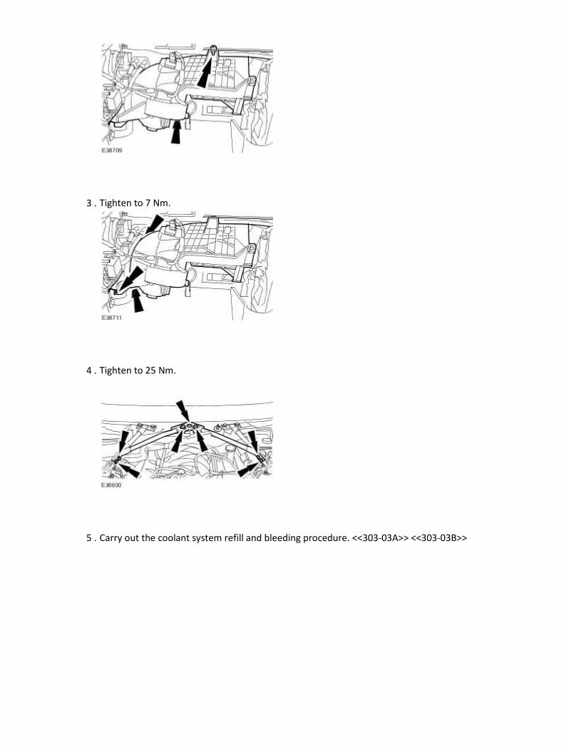
3 . Tighten to 7 Nm.
4 . Tighten to 25 Nm.
5 . Carry out the coolant system refill and bleeding procedure. <<303-03A>> <<303-03B>>

Heater Core and Evaporator Core Housing (82.25.21) Removal
All vehicles
1 . Disconnect the battery ground cable. <<414-01>>
2 . Carry out the air conditioning recovery procedure. <<412-00>>
3
. WARNING: Never remove the coolant pressure cap under any circumstances while
the engine is operating. Failure to follow this instruction may result in personal injury.
WARNING: To avoid having scalding hot coolant or steam blow out of the cooling
system, use extreme care when removing the coolant pressure cap from a hot cooling
system. Wait until the engine has cooled, then wrap a thick cloth around the coolant
pressure cap and turn it slowly until the pressure begins to release. Step back while the
pressure is released from the system. When certain all the pressure has been released (still
with a cloth) turn and remove the coolant pressure cap from the coolant expansion tank.
Failure to follow these instructions may result in personal injury.
WARNING: To avoid the possibility of personal injury, do not operate the engine
with the hood open until the fan blades have been examined for cracks and separation.
Failure to follow this instruction may result in personal injury.
WARNING: Remove fuse 14 from the engine compartment fuse box prior to
performing any under hood service in the area of the cooling fan when the engine is hot,
since the cooling fan motor could operate if the engine has been switched OFF. Failure to
follow this instruction may result in personal injury.

CAUTION: The engine cooling system must be maintained with the correct
concentration and type of anti-freeze solution to prevent corrosion and frost damage.
Failure to follow this instruction may result in damage to the engine.
CAUTION: Never remove the coolant pressure cap under any circumstances while
the engine is operating. Failure to follow this instruction may result in damage to the
engine.
Release the cooling system pressure.
Remove the coolant expansion tank pressure cap.
4 . Remove the cowl vent screen. <<501-02>>
5 . Remove the engine compartment support.
6 . Remove the engine compartment support.
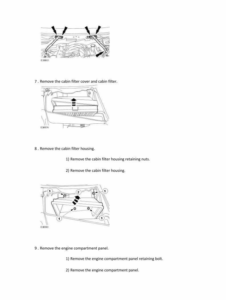
7 . Remove the cabin filter cover and cabin filter.
8 . Remove the cabin filter housing.
1) Remove the cabin filter housing retaining nuts.
2) Remove the cabin filter housing.
9 . Remove the engine compartment panel.
1) Remove the engine compartment panel retaining bolt.
2) Remove the engine compartment panel.
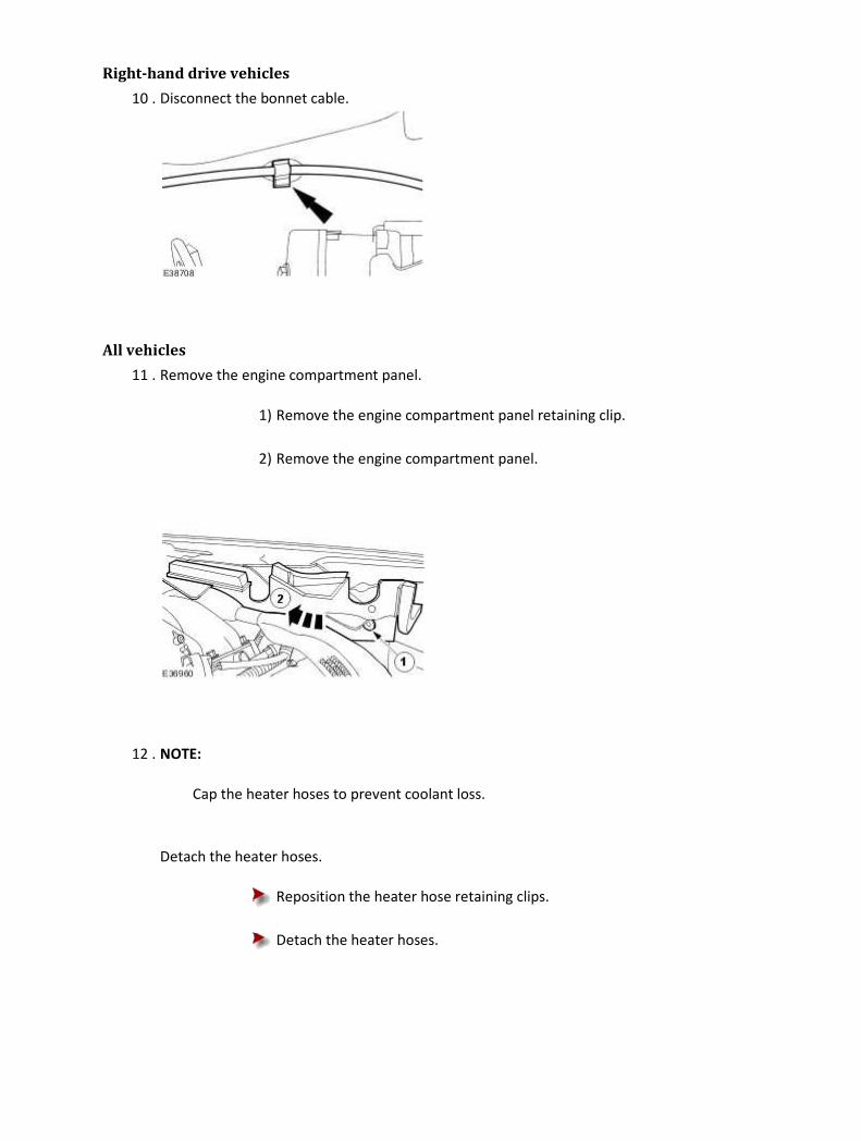
Right-hand drive vehicles
10 . Disconnect the bonnet cable.
All vehicles
11 . Remove the engine compartment panel.
1) Remove the engine compartment panel retaining clip.
2) Remove the engine compartment panel.
12 . NOTE:
Cap the heater hoses to prevent coolant loss.
Detach the heater hoses.
Reposition the heater hose retaining clips.
Detach the heater hoses.
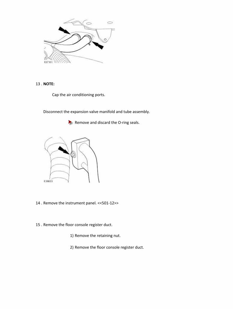
13 . NOTE:
Cap the air conditioning ports.
Disconnect the expansion valve manifold and tube assembly.
Remove and discard the O-ring seals.
14 . Remove the instrument panel. <<501-12>>
15 . Remove the floor console register duct.
1) Remove the retaining nut.
2) Remove the floor console register duct.

16 . Remove the floor console adaptor duct.
1) Detach the floor console adaptor duct retaining tang.
2) Remove the floor console adaptor duct.
17 . Disconnect the AC module electrical connector.
18 . Disconnect the heater motor electrical connector.
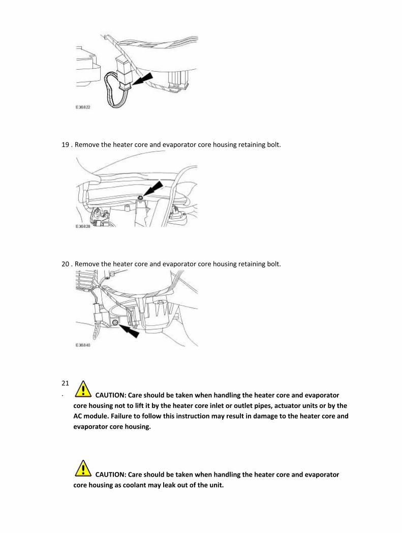
19 . Remove the heater core and evaporator core housing retaining bolt.
20 . Remove the heater core and evaporator core housing retaining bolt.
21
. CAUTION: Care should be taken when handling the heater core and evaporator
core housing not to lift it by the heater core inlet or outlet pipes, actuator units or by the
AC module. Failure to follow this instruction may result in damage to the heater core and
evaporator core housing.
CAUTION: Care should be taken when handling the heater core and evaporator
core housing as coolant may leak out of the unit.

Remove the heater core and evaporator core housing.
1) Detach the rear footwell vent ducts.
2) Remove the heater core and evaporator core housing retaining bolts.
3) Remove the heater core and evaporator core housing.
Installation
1 . To install, reverse the removal procedure.
Tighten to 7 Nm.
2 . Tighten to 7 Nm.

3 . Tighten to 7 Nm.
4 . NOTE:
Fit new O-ring seals to expansion valve manifold and tube assembly.
Tighten to 8 Nm.
5 . Tighten to 25 Nm.

6 . Tighten to 25 Nm.
7 . Reconnect the battery ground cable. <<414-01>>
8 . Carry out coolant system filling and bleeding procedure. <<303-03>>
9 . Carry out the air conditioning system evacuation and charging procedure. <<412-00>>
Heater Hose (80.25.01) Removal
All vehicles
1
. WARNING: Never remove the coolant pressure cap under any circumstances while
the engine is operating. Failure to follow this instruction may result in personal injury.
WARNING: To avoid having scalding hot coolant or steam blow out of the cooling
system, use extreme care when removing the coolant pressure cap from a hot cooling
system. Wait until the engine has cooled, then wrap a thick cloth around the coolant
pressure cap and turn it slowly until the pressure begins to release. Step back while the
pressure is released from the system. When certain all the pressure has been released (still
with a cloth) turn and remove the coolant pressure cap from the coolant expansion tank.
Failure to follow these instructions may result in personal injury.
WARNING: To avoid the possibility of personal injury, do not operate the engine
with the hood open until the fan blades have been examined for cracks and separation.
Failure to follow this instruction may result in personal injury.
WARNING: Remove fuse 14 from the engine compartment fuse box prior to
performing any under hood service in the area of the cooling fan when the engine is hot,
since the cooling fan motor could operate if the engine has been switched OFF. Failure to
follow this instruction may result in personal injury.
CAUTION: The engine cooling system must be maintained with the correct
concentration and type of anti-freeze solution to prevent corrosion and frost damage.
Failure to follow this instruction may result in damage to the engine.
CAUTION: Never remove the coolant pressure cap under any circumstances while

the engine is operating. Failure to follow this instruction may result in damage to the
engine.
Release the cooling system pressure.
Remove the coolant expansion tank pressure cap.
2 . Remove the air deflector. <<501-02>>
3 . Remove the heater hose retaining bolt.
4 . Remove the cowl vent screen. <<501-02>>
5 . Remove the engine compartment support.
6 . Remove the engine compartment support.
7 . Remove the cabin filter cover and cabin filter.
8 . Remove the cabin filter housing.
1) Remove the cabin filter housing retaining nuts.
2) Remove the cabin filter housing.
9 . Remove the engine compartment panel.
1) Remove the engine compartment panel retaining bolt.
2) Remove the engine compartment panel.

Right-hand drive vehicles
10 . Disconnect the bonnet cable.
All vehicles
11 . Remove the engine compartment panel.
1) Remove the engine compartment panel retaining clip.
2) Remove the engine compartment panel.
12 . NOTE:

Cap the heater hoses to prevent coolant loss.
Detach the heater hoses.
1) Remove the heater hose retaining clips.
2) Detach the heater hoses.
13 . Remove the heater hose retaining nut.
14 . NOTE:
Cap the heater hoses to prevent coolant loss.
Remove the heater hoses.
Reposition the heater hose retaining clips.

Installation
1 . To install, reverse the removal procedure.
Tighten to 7 Nm.
2 . Tighten to 7 Nm.
3 . Tighten to 6 Nm.

4 . Tighten to 25 Nm.
5 . Tighten to 25 Nm.
6 . Tighten to 7 Nm.

7 . Carry out the cooling system filling and bleeding procedure. <<303-03>>
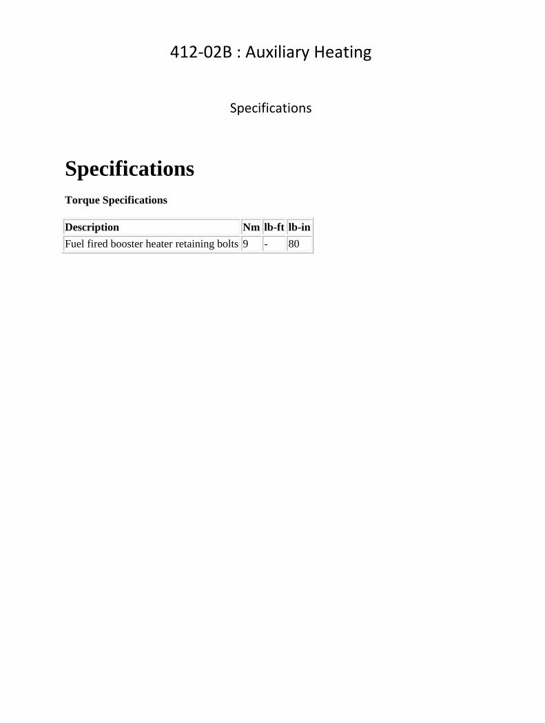
412-02B : Auxiliary Heating
Specifications
Specifications Torque Specifications
Description Nm lb-ft lb-in
Fuel fired booster heater retaining bolts 9 - 80

Description and operation
Fuel Fired Booster Heater The system consists of a fuel operated heater unit and a fuel dosing pump. Fuel for the heater system is taken from the vehicle fuel tank, through a fuel line attached to the fuel pump module. Fuel is drawn from the fuel tank by the dosing pump to the heater unit. In the heater unit, the fuel delivered by the fuel pump is burned and the resultant heat output is used to heat the engine coolant. An electronic control module integrated into the heater unit controls the operation of the heater unit and the dosing pump. The climate control unit controls the operation of the re-circulation flaps on initial start up.
Item Part Number Description
1 Air intake silencer
2 Air intake hose
3 Coolant outlet hose
4 Fuel fired booster heater assembly
5 Coolant inlet hose
6 Fuel fired booster heater bracket
7 Exhaust silencer assembly
The fuel fired booster heater is located behind the right-hand side of the front bumper and is
accessed through the right-hand fender splash shield and the radiator splash shield. The fuel fired booster heater operates at two levels. The system will only ever operate if the engine is running. When the ambient temperature is below 8° C (46° F) and the coolant temperature is lower than 76° C (169° F) the fuel fired booster heater operates at full power. This stage will operate until the coolant temperature reaches 87° C (189° F), and it will then switch to the second level and run at half power until the coolant temperature reaches 90° C (194° F). At this point the system will switch off. It will switch on again at half power if the coolant temperature drops below 79° C (174° F). If the coolant temperature drops to below 76° C (169° F), the system will operate at full power. The fuel fired booster heater will not operate if:
• the supply voltage is below 10.25V • it is in 'fault lockout'

Diagnosis and testing
Fuel Fired Booster Heater Principles of Operation
For a detailed description of the fuel fired booster heater, refer to the relevant Description and
Operation sections in the workshop manual.
Fuel Fired Booster Heater
Inspection and Verification
1 . Verify the customer concern.
2 . Visually inspect for obvious signs of mechanical or electrical damage.
Mechanical Electrical
• Coolant Level
• Fuel Level
• Fuses/Relays
• Damaged, Loose or Corroded Connector(s)
• Damage to Wiring Loom/Incorrect Location, Stretched or Taught
3 . If an obvious cause for an observed or reported concern is found, correct the cause (if possible)
before proceeding to the next step.
4 . If the cause is not visually evident, verify the symptom and refer to the Jaguar Approved
Diagnostic System.
DTC Index
CAUTION: When probing connectors to take measurements in the course of the pinpoint
tests, use the adaptor kit, part number 3548-1358-00
NOTE:
If the control module/component is suspect and the vehicle remains under manufacturer
warranty, refer to the Warranty Policy and Procedures manual (section B1.2), or determine if
any prior approval program is in operation, prior to the installation of a new module.
NOTE:

Generic scan tools may not read the codes listed, or may read only 5 digit codes. Match the five
digits from the scan tool to the first five digits of the seven digit code listed to identify the fault
(the last two digits give additional information read by the manufacturer approved diagnostic
system).
NOTE:
When performing voltage or resistance tests, always use a digital multimeter (DMM) accurate to
three decimal places and with a current calibration certificate. When testing resistance, always
take the resistance of the DMM leads into account.
NOTE:
Check and rectify basic faults before beginning diagnostic routines that involve pinpoint tests.
NOTE:
Inspect connectors for signs of water ingress, and pins for damage and/or corrosion.
NOTE:
If DTCs are recorded and, after performing the pinpoint tests, a fault is not present, an
intermittent concern may be the cause. Always check for loose connections and corroded
terminals.
DTC Description Possible Causes Action
B1A0016 Control Module
• Fuel fired booster heater
module - low supply
voltage
• Generator voltage is
regulated by the engine
control module
Refer to electrical circuit
diagrams, notes and check fuel
fired booster heater module for
circuit voltage below threshold
(check power and ground circuit)
B1A0017 Control Module
• Fuel fired booster heater
module - high supply
voltage
• Generator voltage is
regulated by the engine
control module
Refer to electrical circuit
diagrams, notes and check fuel
fired booster heater module for
circuit voltage above threshold
(check power and ground circuit)

B1A0043 Control Module • Fuel fired booster heater
module - deactivated
Suspect the fuel fired heater
assembly, check and install a new
heater assembly as required,
refer to the new module
installation note at the top of the
DTC Index
B1A0049 Control Module
• Fuel fired booster heater
module - internal circuit
electronic failure
Suspect the fuel fired heater
assembly, check and install a new
heater assembly as required,
refer to the new module
installation note at the top of the
DTC Index
B1D2211 Coolant
Temperature Sensor
• Fuel fired booster heater
module - internal circuit
fault short to ground
Suspect the fuel fired heater
assembly, check and install a new
heater assembly as required,
refer to the new module
installation note at the top of the
DTC Index
B1D2215 Coolant
Temperature Sensor
• Fuel fired booster heater
module, coolant
temperature sensor
circuit fault - short to
power or open circuit
Suspect the fuel fired heater
assembly, check and install a new
heater assembly as required,
refer to the new module
installation note at the top of the
DTC Index
B1D2313 Overheat Sensor
• Fuel fired booster heater
module, overheat sensor
circuit - open circuit
Suspect the fuel fired heater
assembly, check and install a new
heater assembly as required,
refer to the new module
installation note at the top of the
DTC Index
B1D2411 Glow Plug
• Fuel fired booster heater
module, glow plug circuit
- short to ground
Suspect the fuel fired heater
assembly, check and install a new
heater assembly as required,
refer to the new module
installation note at the top of the
DTC Index
B1D2415 Glow Plug • Fuel fired booster heater
module, glowplug circuit -
Suspect the fuel fired heater
assembly, check and install a new
heater assembly as required,

short to power or open refer to the new module
installation note at the top of the
DTC Index
B1D2511 Heater Fuel Pump
• Fuel fired booster heater
module, heater fuel pump
circuit - short to ground
Refer to electrical circuit
diagrams, notes and check fuel
fired booster heater fuel pump
circuit for short to ground
B1D2515 Heater Fuel Pump
• Fuel fired booster heater
module, fuel pump circuit
- short to power or open
Refer to electrical circuit
diagrams, notes and check fuel
fired booster heater fuel pump
circuit for short to power or open
B1D2611 Combustion Air
Blower
• Fuel fired booster heater
module, combustion air
fan circuit - short to
ground
Suspect the fuel fired heater
assembly, check and install a new
heater assembly as required,
refer to the new module
installation note at the top of the
DTC Index
B1D2615 Combustion Air
Blower
• Fuel fired booster heater
module, combustion air
fan circuit - short circuit
to power or open
Suspect the fuel fired heater
assembly, check and install a new
heater assembly as required,
refer to the new module
installation note at the top of the
DTC Index
B1D2692 Combustion Air
Blower
• Fuel fired booster heater
module, combustion air
fan circuit - performance
or incorrect operation
(fan speed low)
Suspect the fuel fired heater
assembly, check and install a new
heater assembly as required,
refer to the new module
installation note at the top of the
DTC Index
B1D2693 Combustion Air
Blower
• Fuel fired booster heater
module, combustion air
blower circuit - no
operation
Suspect the fuel fired heater
assembly, check and install a new
heater assembly as required,
refer to the new module
installation note at the top of the
DTC Index
B1D2711 Heater Coolant
Pump • Fuel fired booster heater
module, coolant pump
Pin not connected on Jaguar, DTC
will not log on Jaguar

circuit - short to ground applications
B1D2715 Heater Coolant
Pump
• Fuel fired booster heater
module, coolant pump
circuit - short to power or
open
Pin not connected on Jaguar, DTC
will not log on Jaguar
applications
B1D2993 No Start, even after
restart attempt
• Fuel fired booster heater
module - no operation
Suspect the fuel fired heater fuel
supply, check fuel supply pipe's
and joints for security Check fuel
pump for correct operation
B1D3093
No Start In Test
Mode, No
generation of flame
detected in test
mode
• Fuel fired booster heater
module - no generation of
flame detected in test
mode
Suspect the fuel fired heater fuel
supply, check fuel supply pipe's
and joints for security Check fuel
pump for correct operation
B1D3194
Flame Detected
Prior to Normal
Operation
• Fuel fired booster heater
module - unexpected
operation
Suspect the fuel fired heater
assembly, check and install a new
heater assembly as required,
refer to the new module
installation note at the top of the
DTC Index
B1D3292
Multiple Flame
Interruption During
Heating Cycle
• Fuel fired booster heater
module - performance or
incorrect operation
Suspect the fuel fired heater fuel
supply, check fuel supply pipe's
and joints for security Check fuel
pump for correct operation
B1D3392
Flame Interruption
During Normal
Operation
• Fuel fired booster heater
module - performance or
incorrect operation
Suspect the fuel fired heater fuel
supply, check fuel supply pipe's
and joints for security Check fuel
pump for correct operation
B1D3468 Heater In Lock Out
Mode
• Fuel fired booster heater
module - event
information
Suspect the fuel fired heater fuel
supply, check fuel supply pipe's
and joints for security Check fuel
pump for correct operation
U007308
Control Module
Communication Bus
"A" Off
• Fuel fired booster heater
module - CAN bus
signal/message failure
Refer to electrical circuit
diagrams and check fuel fired
booster heater module circuit for
CAN bus circuit fault
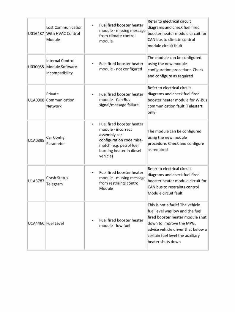
U016487
Lost Communication
With HVAC Control
Module
• Fuel fired booster heater
module - missing message
from climate control
module
Refer to electrical circuit
diagrams and check fuel fired
booster heater module circuit for
CAN bus to climate control
module circuit fault
U030055
Internal Control
Module Software
Incompatibility
• Fuel fired booster heater
module - not configured
The module can be configured
using the new module
configuration procedure. Check
and configure as required
U1A0008
Private
Communication
Network
• Fuel fired booster heater
module - Can Bus
signal/message failure
Refer to electrical circuit
diagrams and check fuel fired
booster heater module for W-Bus
communication fault (Telestart
only)
U1A0395 Car Config
Parameter
• Fuel fired booster heater
module - incorrect
assembly car
configuration code miss-
match (e.g. petrol fuel
burning heater in diesel
vehicle)
The module can be configured
using the new module
procedure. Check and configure
as required
U1A3787 Crash Status
Telegram
• Fuel fired booster heater
module - missing message
from restraints control
Module
Refer to electrical circuit
diagrams and check fuel fired
booster heater module circuit for
CAN bus to restraints control
Module circuit fault
U1A446C Fuel Level • Fuel fired booster heater
module - low fuel
This is not a fault! The vehicle
fuel level was low and the fuel
fired booster heater module shut
down to improve the MPG,
advise vehicle driver that below a
certain fuel level the auxiliary
heater shuts down

Removal and installation
Fuel Fired Booster Heater Removal
1 . Remove the fender splash shield.
For additional information, refer to Fender Splash Shield (76.10.90)
2 . Disconnect the fuel fired booster heater fuel line.
3 . Remove the fuel fired booster heater retaining bolt.
4 . Raise the vehicle.
5 . Remove the radiator splash shield.

6 . Disconnect the fuel fired booster heater electrical connector.
7 . Detach the cooling module wiring harness.
8 . NOTE:
Clamp the coolant hose to minimize coolant loss.
Disconnect the fuel fired booster heater coolant outlet hose.
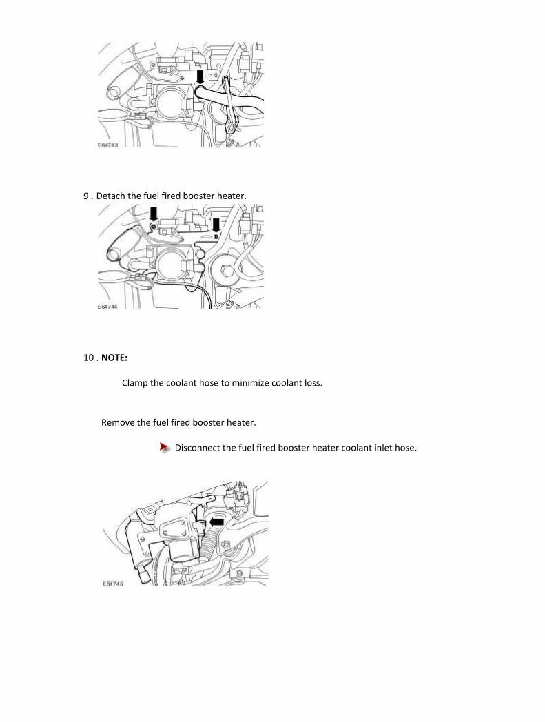
9 . Detach the fuel fired booster heater.
10 . NOTE:
Clamp the coolant hose to minimize coolant loss.
Remove the fuel fired booster heater.
Disconnect the fuel fired booster heater coolant inlet hose.

Installation
1 . To install, reverse the removal procedure.
Tighten to 9 Nm.
2 . Tighten to 9 Nm.
3 . Check and top-up the engine coolant as necessary.

412-03A : Air Conditionning
Specifications
Specifications Torque Specifications
Description Nm lb-ft lb-in
Air conditioning (A/C) compressor mounting retaining bolts 25 18 —
Air conditioning (A/C) compressor manifold and tube retaining bolt 20 15 —
Air conditioning (A/C) condenser core retaining studs 7 — 62
Air conditioning (A/C) condenser core supply and return lines retaining nuts 8 — 71
Power steering oil cooler retaining nuts 7 — 62
Air conditioning (A/C) desiccant bag retaining screw 22 16 —
Air conditioning (A/C) pressure cutoff switch 8 — 71
Air conditioning (A/C) compressor supply and return lines 20 15 —
Engine mounting and bracket assembly retaining bolts 25 18 —
Engine mounting bracket lower retaining bolt 63 46 —
Steering gear mounting bolts 100 74 —
Steering gear shaft pinch bolt 35 26 —
Cooling module retaining bolts 8 — 71
Radiator support bracket retaining bolts 9 — 80
Description and operation
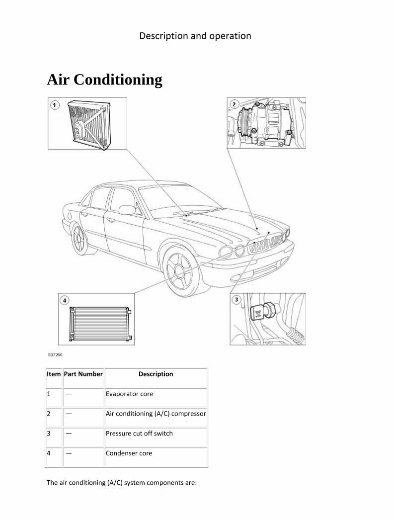
Air Conditioning
Item Part Number Description
1 — Evaporator core
2 — Air conditioning (A/C) compressor
3 — Pressure cut off switch
4 — Condenser core
The air conditioning (A/C) system components are:

• A/C Compressor
• Condenser core
• Evaporator core
• Thermostatic expansion valve
• Desiccant bag
• Connecting refrigerant lines
The refrigeration system operation is controlled by the:
• thermostatic expansion valve.
• evaporator discharge temperature sensor.
• pressure cut off switch.
• engine control module (ECM).
• remote climate control module (RCCM).
The refrigerant system incorporates a variable capacity A/C compressor.
The RCCM monitors the evaporator discharge temperature sensor and communicates with the ECM
to control A/C compressor operation. The RCCM also monitors the ambient air temperature and
disables A/C operation when the ambient air temperature is below 0°C (30°F).
The pressure switch is located in the A/C compressor discharge line and communicates with the ECM.
If high or low refrigerant pressures are experienced, the ECM will interrupt A/C compressor
operation.
The pressure relief valve is installed in the A/C compressor and protects the system from excessively
high refrigerant pressure.
The thermostatic expansion valve, which is mounted to the evaporator core supply and return lines,
contains an adjustable orifice which provides the restriction that separates the high and low pressure
liquid phases in the refrigerant system.
A/C Compressor
NOTE:
The A/C compressor internal components are not serviced separately. The A/C compressor is
serviced only as an assembly.
The A/C compressor has the following characteristics:
• A variable capacity function controlled by an external solenoid.
• A displacement capacity of 160cc on the petrol variants and 170cc on the diesel variant.
• The compressor is clutchless.
• The compressor operates all the time (from 2% to 100% while the engine is running).
A/C Compressor Pressure Relief Valve
An A/C compressor pressure relief valve is incorporated in the compressor to:

• relieve unusually high refrigerant system discharge pressure buildups.
• prevent damage to the A/C compressor and other system components.
• avoid total refrigerant loss by closing after the excessive pressure has been relieved.
Condenser Core
The A/C condenser core has the following characteristics:
• It is an aluminum fin and tube design heat exchanger located in front of the vehicle radiator.
• It cools compressed refrigerant gas by allowing air to pass over fins and tubes to extract heat
and by condensing gas to liquid refrigerant as it is cooled.
• The tube assembly mounted on the side of the condenser core contains the desiccant bag.
Desiccant Bag
The desiccant bag removes any retained moisture in the A/C system. The A/C system has an R-134a
leak trace dye wafer incorporated into the desiccant bag.
Refrigerant Lines
The manifold and tube assembly - thermostatic expansion valve carries high pressure liquid to the
thermostatic expansion valve and low pressure gas from the thermostatic expansion valve to the
manifold and tube assembly-compressor.
The tube assembly - A/C compressor to condenser carries the high pressure gas from the A/C
compressor to the condenser core. It also houses the high pressure service port and has a serviceable
high pressure relief valve.
The tube assembly - thermostatic expansion valve to the A/C compressor carries the low pressure gas
received from the thermostatic expansion valve to the compressor, houses the low pressure service
port and has a serviceable low pressure relief valve.
• The manifold and tube assembly - A/C compressor vehicles fitted with 3.5 or 4.2L petrol
engines are are not interchangeable with vehicles fitted with a 3.0L petrol or 2.7L diesel
engines.
The tube assembly - condenser to thermostatic expansion valve carries high pressure liquid to the
manifold and tube assembly-thermostatic expansion valve and houses the high pressure service port.
Evaporator Core
The A/C evaporator core is the plate/fin type with a unique refrigerant flow path.

• A mixture of refrigerant and oil exits the thermostatic expansion valve (TXV) and enters the
evaporator tank area through the 12.7 mm (0.5 in) tube.
• The tank area is divided into three sections: front inlet, front outlet and rear tank.
• The refrigerant enters the evaporator core tank area at the front inlet, flows down through
the core and up the back side in a "U-flow" pattern.
• The refrigerant moves into the rear tank area and across to the other half of the core. The
refrigerant moves down through the core and back up the front side of the core to the front
outlet tank area.
• The refrigerant at this point is in a gaseous state. It exits the evaporator through the 16 mm
(0.64 in) tube then passes through the TXV.
Item Part Number Description
1 — Sensing bulb
2 — Insulator
3 — Hollow core pin-type retainer
4 — Outlet port—low pressure liquid
5 — Metering orifice
6 — Inlet port—high pressure liquid
7 — Spring
8 — Evaporator inlet port—low pressure liquid

9 — Pin
10 — Evaporator outlet port—low pressure gas
11 — Housing
The thermostatic expansion valve has the following characteristics:
• It is mounted on the evaporator core supply and return lines.
• It is a block-type valve.
• It contains an internal sensing bulb to increase the effectiveness of temperature sensing.
• It is not serviceable. A new thermostatic expansion valve must be installed as a unit.
Pressure Cut Off Switch
The pressure cut off switch monitors the A/C compressor discharge pressure and communicates with
the engine control module (ECM). The ECM will interrupt A/C compressor operation in the event that
the pressure cut off switch indicates high system discharge pressures. It is also used to sense no or
low charge conditions. If the pressure is below a predetermined value for a given ambient
temperature, the ECM will interrupt A/C compressor operation.
• The pressure cut off switch is mounted on a Schrader-type valve fitting on the compressor to
condenser discharge line.
• A valve depressor, located inside the threaded end of the pressure cut off switch, presses on
the Schrader valve stem and allows the pressure cut off switch to monitor the compressor
discharge pressure.
• When the compressor discharge pressure rises to approximately 2,896 kPa (420 psi), the
ECM will interrupt the compressor operation and disable the compressor.
• When the pressure drops to approximately 1,724 kPa (250 psi) the ECM will enable the A/C
compressor circuit.
Service Gauge Port Valves
WARNING: Wear eye protection when opening/servicing the service gauge port valves.
The high-pressure service gauge port valve is located on the tube assembly - condenser to
thermostatic expansion valve.
The low pressure service gauge port valve is located on the manifold and tube assembly - A/C
compressor.

Item Part Number Description
1 — A/C charging valve cap
2 — Low pressure service gauge port valve
3 — Schrader-type valve
4 — O-ring seal
5 — High pressure service gauge port valve
6 — A/C charging valve cap
The fitting is an integral part of the refrigerant line or component.
• Special couplings are necessary for both the high side and low side service gauge ports.
• A new Schrader-type valve can be installed if the seal leaks.
• Always install the A/C charging valve cap on the service gauge port valves after repairing the
refrigerant system.

Diagnosis and testing
Air Conditioning For additional information refer to<<412-00>>
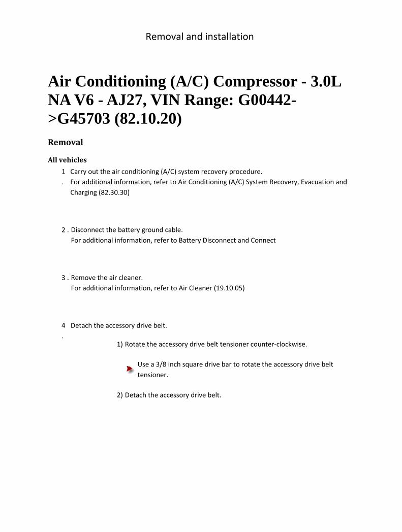
Removal and installation
Air Conditioning (A/C) Compressor - 3.0L NA V6 - AJ27, VIN Range: G00442->G45703 (82.10.20) Removal
All vehicles
1
.
Carry out the air conditioning (A/C) system recovery procedure.
For additional information, refer to Air Conditioning (A/C) System Recovery, Evacuation and
Charging (82.30.30)
2 . Disconnect the battery ground cable.
For additional information, refer to Battery Disconnect and Connect
3 . Remove the air cleaner.
For additional information, refer to Air Cleaner (19.10.05)
4
.
Detach the accessory drive belt.
1) Rotate the accessory drive belt tensioner counter-clockwise.
Use a 3/8 inch square drive bar to rotate the accessory drive belt
tensioner.
2) Detach the accessory drive belt.
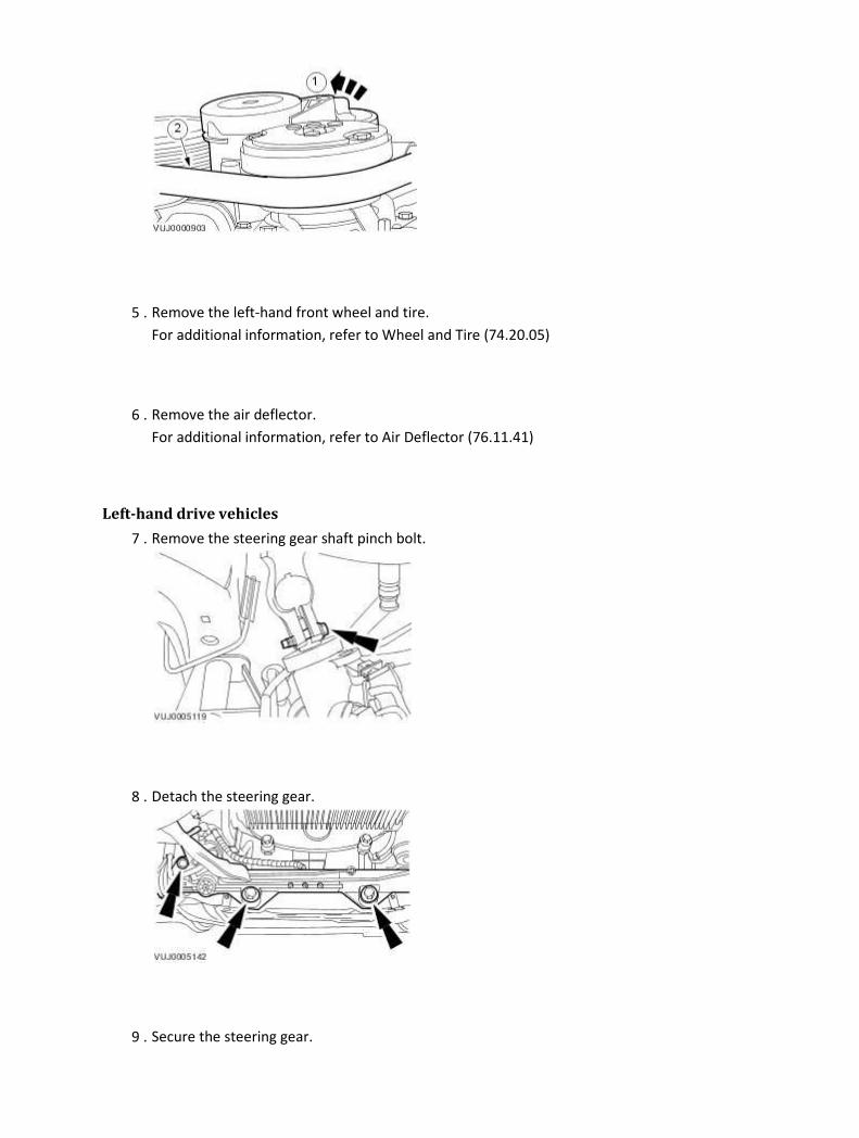
5 . Remove the left-hand front wheel and tire.
For additional information, refer to Wheel and Tire (74.20.05)
6 . Remove the air deflector.
For additional information, refer to Air Deflector (76.11.41)
Left-hand drive vehicles
7 . Remove the steering gear shaft pinch bolt.
8 . Detach the steering gear.
9 . Secure the steering gear.
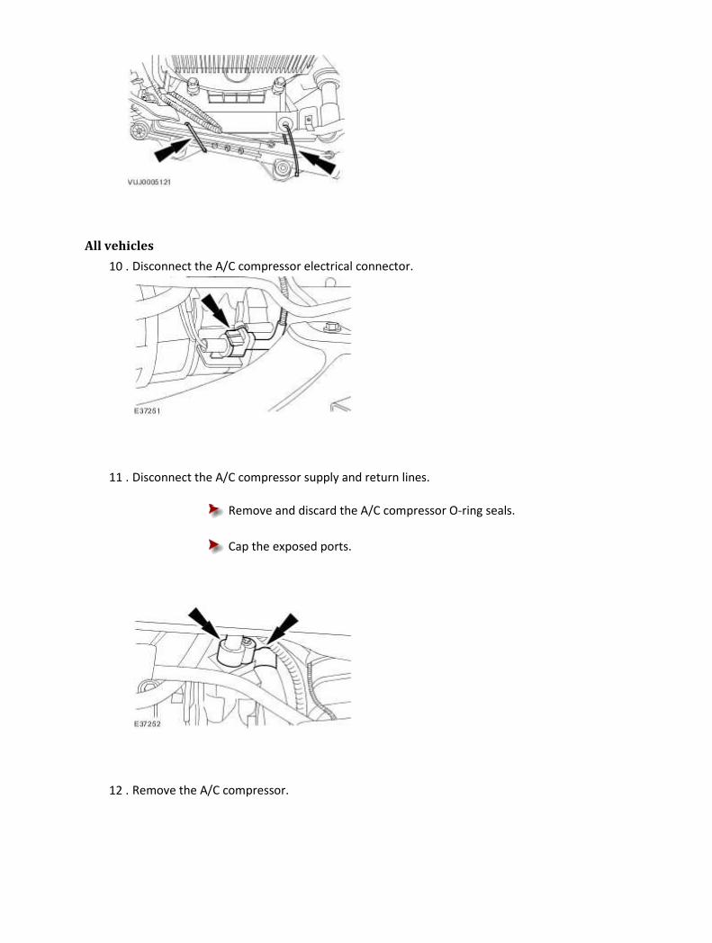
All vehicles
10 . Disconnect the A/C compressor electrical connector.
11 . Disconnect the A/C compressor supply and return lines.
Remove and discard the A/C compressor O-ring seals.
Cap the exposed ports.
12 . Remove the A/C compressor.

Installation
All vehicles
1 . Install the A/C compressor.
Tighten to 25 Nm.
2 . NOTE:
Un-cap the exposed ports.
Install new A/C compressor O-ring seals.
Lubricate the new O-rings with A/C refrigerant oil.
3 . Clean off any oil residue that may contain A/C system flourescent dye.
4 . Connect the A/C compressor supply and return lines.

Tighten to 20 Nm.
5 . Connect the A/C compressor electrical connector.
Left-hand drive vehicles
6 . Detach the steering gear.
7 . Attach the steering gear.
Tighten to 100 Nm.
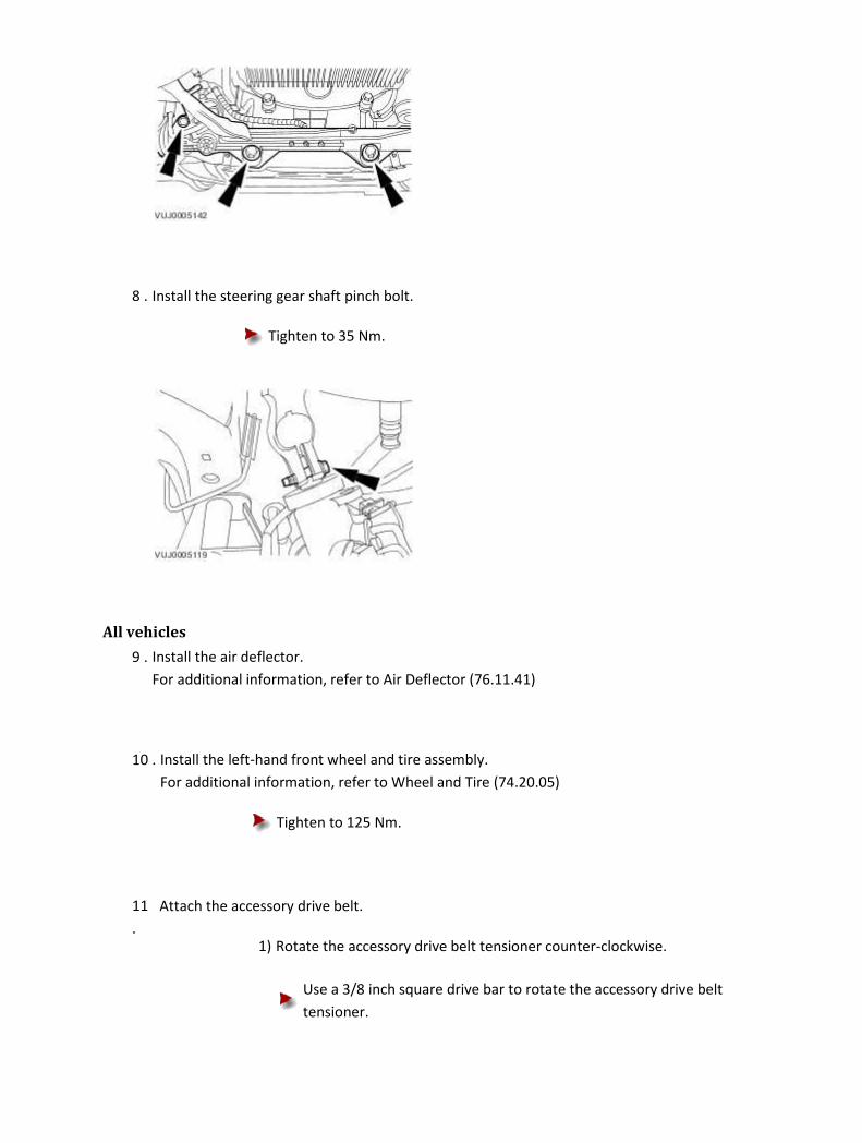
8 . Install the steering gear shaft pinch bolt.
Tighten to 35 Nm.
All vehicles
9 . Install the air deflector.
For additional information, refer to Air Deflector (76.11.41)
10 . Install the left-hand front wheel and tire assembly.
For additional information, refer to Wheel and Tire (74.20.05)
Tighten to 125 Nm.
11
.
Attach the accessory drive belt.
1) Rotate the accessory drive belt tensioner counter-clockwise.
Use a 3/8 inch square drive bar to rotate the accessory drive belt
tensioner.
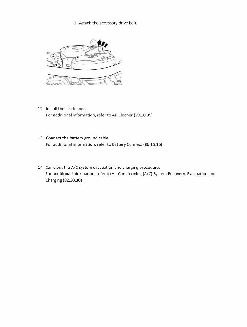
2) Attach the accessory drive belt.
12 . Install the air cleaner.
For additional information, refer to Air Cleaner (19.10.05)
13 . Connect the battery ground cable.
For additional information, refer to Battery Connect (86.15.15)
14
.
Carry out the A/C system evacuation and charging procedure.
For additional information, refer to Air Conditioning (A/C) System Recovery, Evacuation and
Charging (82.30.30)

Air Conditioning (A/C) Compressor - 3.0L NA V6 - AJ27, VIN Range: G45704->G99999 (82.10.20) Removal
All vehicles
1
.
Carry out the air conditioning (A/C) system recovery procedure.
For additional information, refer to Air Conditioning (A/C) System Recovery, Evacuation and
Charging (82.30.30)
2 . Disconnect the battery ground cable.
For additional information, refer to Battery Disconnect and Connect
3 . Remove the air cleaner.
For additional information, refer to Air Cleaner (19.10.05)
4
.
Detach the accessory drive belt.
1) Rotate the accessory drive belt tensioner counter-clockwise.
Use a 3/8 inch square drive bar to rotate the accessory drive belt
tensioner.
2) Detach the accessory drive belt.

5 . Remove the left-hand front wheel and tire.
For additional information, refer to Wheel and Tire (74.20.05)
6 . Remove the air deflector.
For additional information, refer to Air Deflector (76.11.41)
Left-hand drive vehicles
7 . Remove the steering gear shaft pinch bolt.
8 .
CAUTION: The steering gear must be supported at all times.
Detach the steering gear.
9 .
CAUTION: The steering gear must be supported at all times.
Using suitable tie straps, secure the steering gear.

All vehicles
10 . Disconnect the A/C compressor electrical connector.
11 . Disconnect the A/C compressor return line.
Remove and discard the A/C compressor O-ring seal.
Cap the exposed ports.
12 . Detach the A/C compressor.
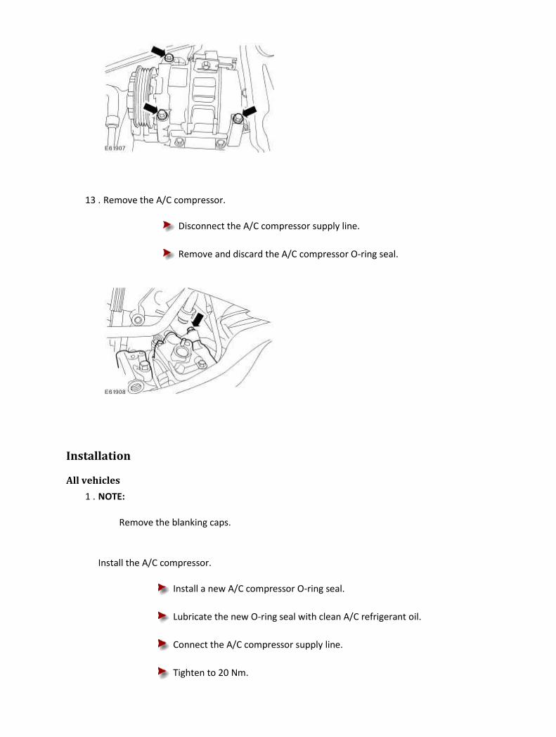
13 . Remove the A/C compressor.
Disconnect the A/C compressor supply line.
Remove and discard the A/C compressor O-ring seal.
Installation
All vehicles
1 . NOTE:
Remove the blanking caps.
Install the A/C compressor.
Install a new A/C compressor O-ring seal.
Lubricate the new O-ring seal with clean A/C refrigerant oil.
Connect the A/C compressor supply line.
Tighten to 20 Nm.

2 . Attach the A/C compressor.
Tighten to 25 Nm.
3 . Connect the A/C compressor return line.
Install a new A/C compressor O-ring seal.
Lubricate the new O-ring seal with clean A/C refrigerant oil.
Tighten to 20 Nm.

4 . Connect the A/C compressor electrical connector.
Left-hand drive vehicles
5 .
CAUTION: The steering gear must be supported at all times.
Detach the steering gear.
Remove and discard the tie straps.
6 .
CAUTION: The steering gear must be supported at all times.
Attach the steering gear.
Tighten to 100 Nm.

7 . Install the steering gear shaft pinch bolt.
Tighten to 35 Nm.
All vehicles
8 . Install the air deflector.
For additional information, refer to Air Deflector (76.11.41)
9 . Install the left-hand front wheel and tire assembly.
For additional information, refer to Wheel and Tire (74.20.05)
10
.
Attach the accessory drive belt.
1) Rotate the accessory drive belt tensioner counter-clockwise.
Use a 3/8 inch square drive bar to rotate the accessory drive belt
tensioner.
2) Attach the accessory drive belt.

11 . Install the air cleaner.
For additional information, refer to Air Cleaner (19.10.05)
12 . Connect the battery ground cable.
For additional information, refer to Battery Connect (86.15.15)
13
.
Carry out the A/C system evacuation and charging procedure.
For additional information, refer to Air Conditioning (A/C) System Recovery, Evacuation and
Charging (82.30.30)
Air Conditioning (A/C) Compressor - 4.2L NA V8 - AJV8/4.2L SC V8 - AJV8/3.5L NA V8 - AJV8, VIN Range: G00442->G45703 (82.10.20) Special Service Tools
Engine support beam
303-021
Engine lifting brackets
303-749
Removal
All vehicles
1
.
Carry out the air conditioning (A/C) system recovery procedure.
For additional information, refer to Air Conditioning (A/C) System Recovery, Evacuation and
Charging (82.30.30)
2 . Disconnect the battery ground cable.
For additional information, refer to Battery Disconnect and Connect
3 . Remove the air cleaner outlet pipe.
For additional information, refer to Air Cleaner Outlet Pipe (19.10.31)
4
.
Detach the accessory drive belt.

1) Rotate the accessory drive belt tensioner counter-clockwise.
Use a 3/8 inch square drive bar to rotate the accessory drive belt
tensioner.
2) Detach the accessory drive belt.
Vehicles without supercharger
5
.
Remove the throttle body.
For additional information, refer to Throttle Body - 4.2L NA V8 - AJV8/3.5L NA V8 - AJV8, VIN
Range: G00442->G45703 (19.70.04)
All vehicles
6 . NOTE:
Vehicles without supercharger shown, vehicles with supercharger similar.
Install the special tools.
7 . NOTE:

Vehicles without supercharger shown, vehicles with supercharger similar.
Install the special tool.
8 . NOTE:
Vehicles with supercharger shown, vehicles without supercharger similar.
Raise the engine to a suitable height.
1) Adjust the engine support beam (clockwise).
2) Raise the engine to a suitable height.

9 . Remove the left-hand front wheel and tire assembly.
For additional information, refer to Wheel and Tire (74.20.05)
10 . Remove the air deflector.
For additional information, refer to Air Deflector (76.11.41)
Left-hand drive vehicles
11 . Remove the steering gear shaft pinch bolt.
12 . Detach the steering gear.
13 . Secure the steering gear.

All vehicles
14 . Remove the left-hand engine mounting lower retaining nut.
15 . Lower the vehicle.
16
.
NOTE:
Vehicles with supercharger shown, vehicles without supercharger similar.
Lift the engine to a suitable height to access the A/C compressor retaining bolts.
1) Adjust the engine support beam.
2) Lift the engine to a suitable height to access the A/C compressor retaining
bolts.

17 . Raise the vehicle.
18 . Remove the engine mounting and bracket assembly.
19 . Disconnect the A/C compressor electrical connector.

20 . Detach the A/C compressor return line.
Remove and discard the A/C compressor O-ring seal.
Cap the exposed port.
21 . Detach the A/C compressor supply line.
Remove and discard the A/C compressor O-ring seal.
Cap the exposed port.
22 . Remove the A/C compressor.
Installation
All vehicles
1 . Install the A/C compressor.
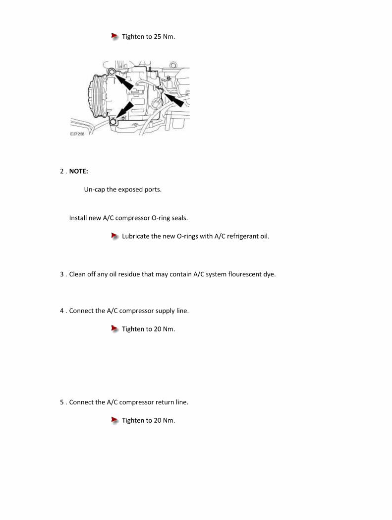
Tighten to 25 Nm.
2 . NOTE:
Un-cap the exposed ports.
Install new A/C compressor O-ring seals.
Lubricate the new O-rings with A/C refrigerant oil.
3 . Clean off any oil residue that may contain A/C system flourescent dye.
4 . Connect the A/C compressor supply line.
Tighten to 20 Nm.
5 . Connect the A/C compressor return line.
Tighten to 20 Nm.
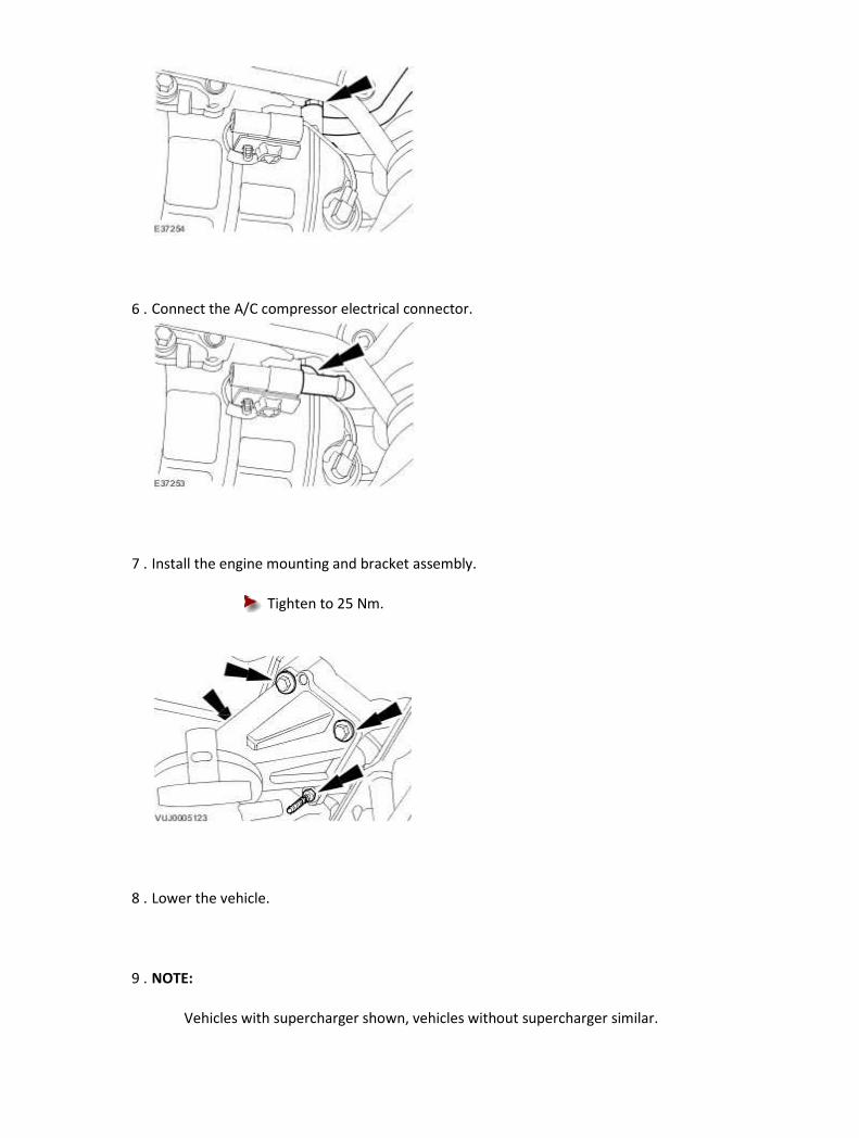
6 . Connect the A/C compressor electrical connector.
7 . Install the engine mounting and bracket assembly.
Tighten to 25 Nm.
8 . Lower the vehicle.
9 . NOTE:
Vehicles with supercharger shown, vehicles without supercharger similar.

Lower the engine.
1) Adjust the engine support beam.
2) Lower the engine.
10 . Raise the vehicle.
11 . Install the left-hand engine mounting lower retaining nut.
Tighten to 63 Nm.

Left-hand drive vehicles
12 . Detach the steering gear.
13 . Attach the steering gear.
Tighten to 100 Nm.
14 . Install the steering gear shaft pinch bolt.
Tighten to 35 Nm.
All vehicles
15 . Install the left-hand front wheel and tire assembly.
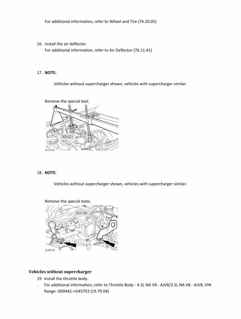
For additional information, refer to Wheel and Tire (74.20.05)
16 . Install the air deflector.
For additional information, refer to Air Deflector (76.11.41)
17 . NOTE:
Vehicles without supercharger shown, vehicles with supercharger similar.
Remove the special tool.
18 . NOTE:
Vehicles without supercharger shown, vehicles with supercharger similar.
Remove the special tools.
Vehicles without supercharger
19
.
Install the throttle body.
For additional information, refer to Throttle Body - 4.2L NA V8 - AJV8/3.5L NA V8 - AJV8, VIN
Range: G00442->G45703 (19.70.04)

All vehicles
20
.
Attach the accessory drive belt.
1) Rotate the accessory drive belt tensioner counter-clockwise.
Use a 3/8 inch square drive bar to rotate the accessory drive belt
tensioner.
2) Attach the accessory drive belt.
21 . Install the air cleaner outlet pipe.
For additional information, refer to Air Cleaner Outlet Pipe (19.10.31)
22 . Connect the battery ground cable.
For additional information, refer to Battery Connect (86.15.15)
23
.
Carry out the A/C system evacuation and charging procedure.
For additional information, refer to Air Conditioning (A/C) System Recovery, Evacuation and
Charging (82.30.30)

Air Conditioning (A/C) Compressor - 4.2L NA V8 - AJV8/4.2L SC V8 - AJV8/3.5L NA V8 - AJV8, VIN Range: G45704->G99999 (82.10.20) Special Service Tools
Engine support beam
303-021
Engine lifting brackets
303-749
Removal
All vehicles
1
.
Carry out the air conditioning (A/C) system recovery procedure.
For additional information, refer to Air Conditioning (A/C) System Recovery, Evacuation and
Charging (82.30.30)
2 . Disconnect the battery ground cable.
For additional information, refer to Battery Disconnect and Connect
3 . Remove the air cleaner.
For additional information, refer to Air Cleaner (19.10.05)
4
.
Detach the accessory drive belt.
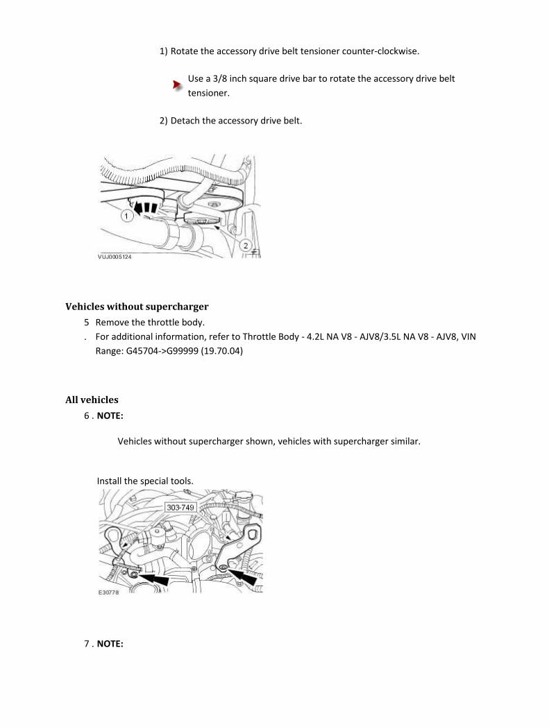
1) Rotate the accessory drive belt tensioner counter-clockwise.
Use a 3/8 inch square drive bar to rotate the accessory drive belt
tensioner.
2) Detach the accessory drive belt.
Vehicles without supercharger
5
.
Remove the throttle body.
For additional information, refer to Throttle Body - 4.2L NA V8 - AJV8/3.5L NA V8 - AJV8, VIN
Range: G45704->G99999 (19.70.04)
All vehicles
6 . NOTE:
Vehicles without supercharger shown, vehicles with supercharger similar.
Install the special tools.
7 . NOTE:
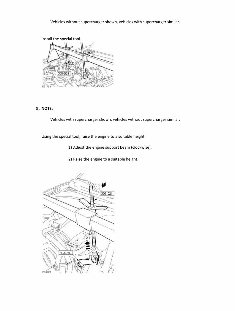
Vehicles without supercharger shown, vehicles with supercharger similar.
Install the special tool.
8 . NOTE:
Vehicles with supercharger shown, vehicles without supercharger similar.
Using the special tool, raise the engine to a suitable height.
1) Adjust the engine support beam (clockwise).
2) Raise the engine to a suitable height.

9 . Remove the left-hand front wheel and tire assembly.
For additional information, refer to Wheel and Tire (74.20.05)
10 . Remove the air deflector.
For additional information, refer to Air Deflector (76.11.41)
Left-hand drive vehicles
11 . Remove the steering gear shaft pinch bolt.
12 .
CAUTION: The steering gear must be supported at all times.
Detach the steering gear.
13 .
CAUTION: The steering gear must be supported at all times.
Using suitable tie straps, secure the steering gear.
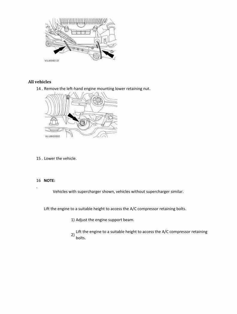
All vehicles
14 . Remove the left-hand engine mounting lower retaining nut.
15 . Lower the vehicle.
16
.
NOTE:
Vehicles with supercharger shown, vehicles without supercharger similar.
Lift the engine to a suitable height to access the A/C compressor retaining bolts.
1) Adjust the engine support beam.
2) Lift the engine to a suitable height to access the A/C compressor retaining
bolts.

17 . Raise the vehicle.
18 . Remove the engine mounting and bracket assembly.
19 . Disconnect the A/C compressor electrical connector.
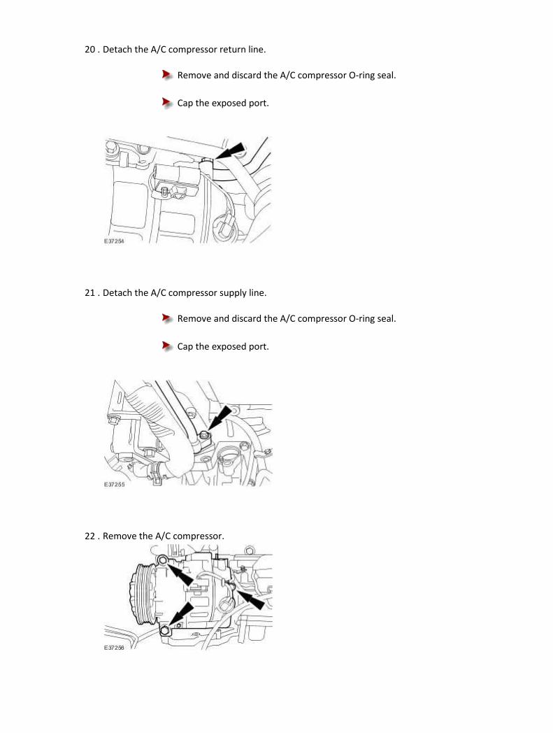
20 . Detach the A/C compressor return line.
Remove and discard the A/C compressor O-ring seal.
Cap the exposed port.
21 . Detach the A/C compressor supply line.
Remove and discard the A/C compressor O-ring seal.
Cap the exposed port.
22 . Remove the A/C compressor.

Installation
All vehicles
1 . Install the A/C compressor.
Tighten to 25 Nm.
2 . NOTE:
Un-cap the exposed ports.
Install new A/C compressor O-ring seals.
Lubricate the new O-rings with A/C refrigerant oil.
3 . Clean off any oil residue that may contain A/C system flourescent dye.
4 . Connect the A/C compressor supply line.
Tighten to 20 Nm.
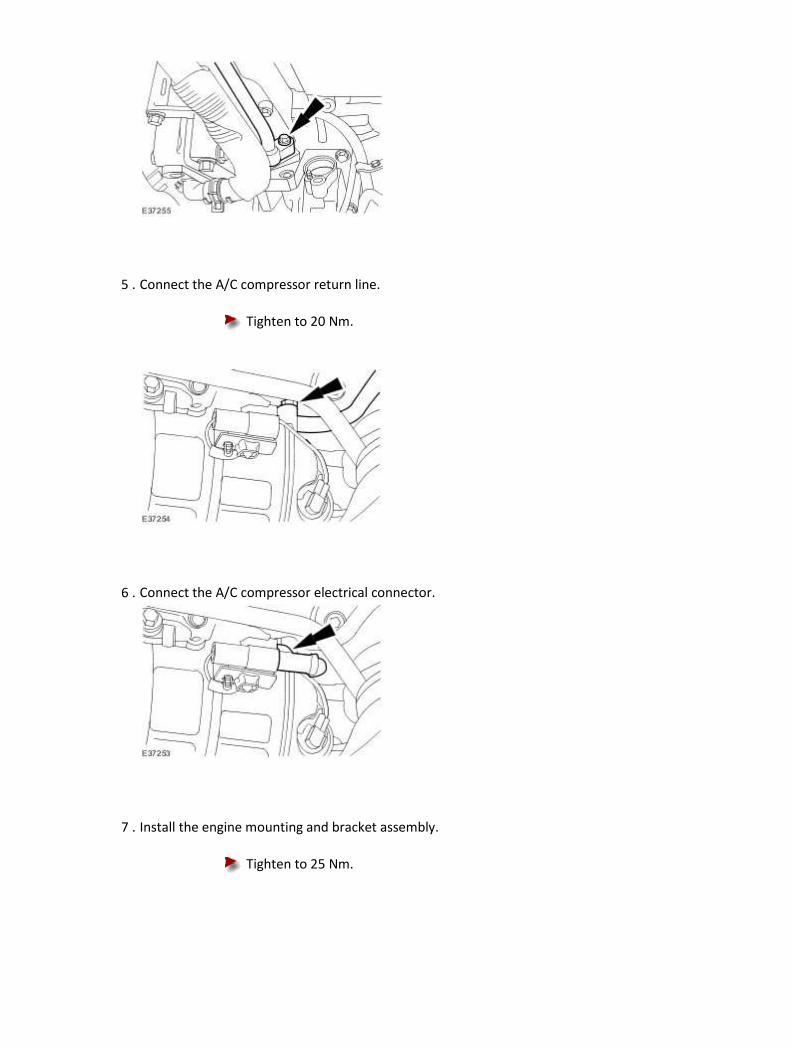
5 . Connect the A/C compressor return line.
Tighten to 20 Nm.
6 . Connect the A/C compressor electrical connector.
7 . Install the engine mounting and bracket assembly.
Tighten to 25 Nm.

8 . Lower the vehicle.
9 . NOTE:
Vehicles with supercharger shown, vehicles without supercharger similar.
Using the special tool, lower the engine.
1) Adjust the engine support beam.
2) Lower the engine.
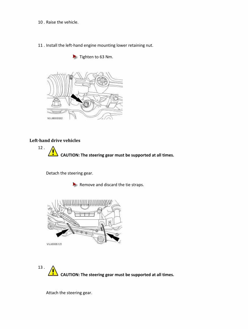
10 . Raise the vehicle.
11 . Install the left-hand engine mounting lower retaining nut.
Tighten to 63 Nm.
Left-hand drive vehicles
12 .
CAUTION: The steering gear must be supported at all times.
Detach the steering gear.
Remove and discard the tie straps.
13 .
CAUTION: The steering gear must be supported at all times.
Attach the steering gear.

Tighten to 100 Nm.
14 . Install the steering gear shaft pinch bolt.
Tighten to 35 Nm.
All vehicles
15 . Install the left-hand front wheel and tire assembly.
For additional information, refer to Wheel and Tire (74.20.05)
16 . Install the air deflector.
For additional information, refer to Air Deflector (76.11.41)
17 . NOTE:
Vehicles without supercharger shown, vehicles with supercharger similar.
Remove the special tool.

18 . NOTE:
Vehicles without supercharger shown, vehicles with supercharger similar.
Remove the special tools.
Vehicles without supercharger
19
.
Install the throttle body.
For additional information, refer to Throttle Body - 4.2L NA V8 - AJV8/3.5L NA V8 - AJV8, VIN
Range: G45704->G99999 (19.70.04)
All vehicles
20
.
Attach the accessory drive belt.
1) Rotate the accessory drive belt tensioner counter-clockwise.
Use a 3/8 inch square drive bar to rotate the accessory drive belt
tensioner.
2) Attach the accessory drive belt.
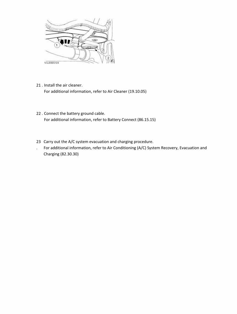
21 . Install the air cleaner.
For additional information, refer to Air Cleaner (19.10.05)
22 . Connect the battery ground cable.
For additional information, refer to Battery Connect (86.15.15)
23
.
Carry out the A/C system evacuation and charging procedure.
For additional information, refer to Air Conditioning (A/C) System Recovery, Evacuation and
Charging (82.30.30)
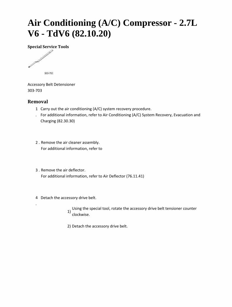
Air Conditioning (A/C) Compressor - 2.7L V6 - TdV6 (82.10.20) Special Service Tools
Accessory Belt Detensioner
303-703
Removal
1
.
Carry out the air conditioning (A/C) system recovery procedure.
For additional information, refer to Air Conditioning (A/C) System Recovery, Evacuation and
Charging (82.30.30)
2 . Remove the air cleaner assembly.
For additional information, refer to
3 . Remove the air deflector.
For additional information, refer to Air Deflector (76.11.41)
4
.
Detach the accessory drive belt.
1) Using the special tool, rotate the accessory drive belt tensioner counter
clockwise.
2) Detach the accessory drive belt.

5 . Lower the vehicle.
6
.
Detach the accessory drive belt from the power steering pump pulley and the A/C
compressor pulley.
7 . Remove the power steering pump retaining bolts.
8 . Reposition the power steering pump forwards.

9 . Detach the A/C compressor return line.
Remove and discard the A/C compressor O-ring seal.
Cap the exposed ports.
10 . Detach the A/C compressor supply line.
Remove and discard the A/C compressor O-ring seal.
Cap the exposed ports.

11 . Remove the power steering pump retaining bracket.
12 . Disconnect the A/C compressor electrical connector.
13 . Detach the A/C compressor electrical connector retaining bracket.
14
. CAUTION: Carefully remove the A/C compressor past the coolant pipes. Failure to
follow this instruction, may result in damage to the coolant pipes.
Remove the A/C compressor.
Remove the A/C compressor retaining bolts.

Installation
1 . To install, reverse the removal procedure.
Add the correct amount of A/C refrigerant oil to the A/C compressor.
For additional information, refer to Refrigerant Oil Adding
2
. CAUTION: Carefully install the A/C compressor past the coolant pipes. Failure to
follow this instruction, may result in damage to the coolant pipes.
Tighten to 25 Nm.
3 . Tighten to 4 Nm.
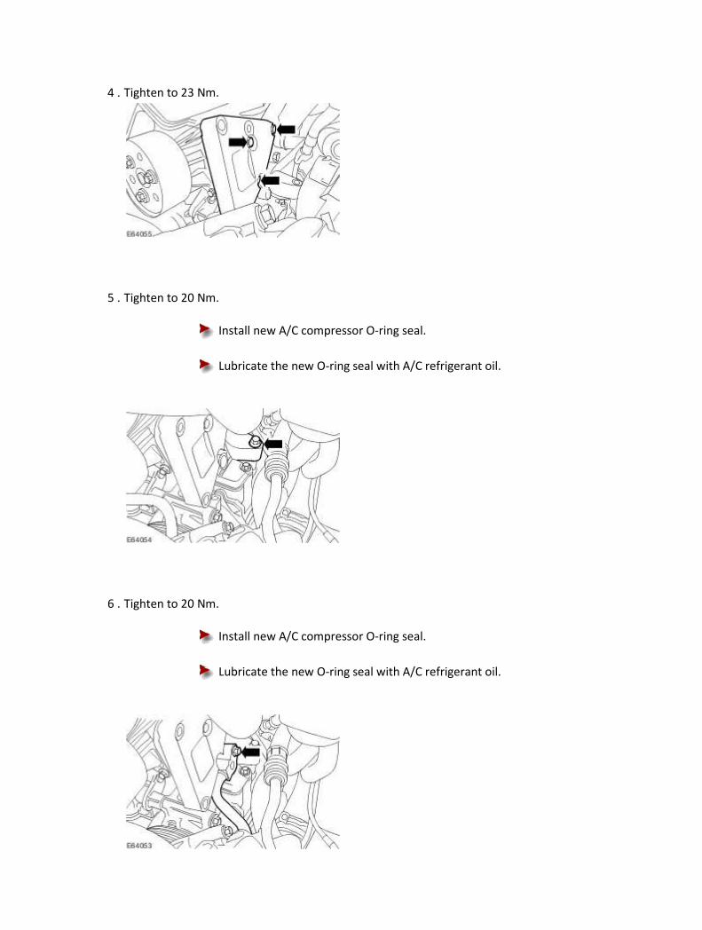
4 . Tighten to 23 Nm.
5 . Tighten to 20 Nm.
Install new A/C compressor O-ring seal.
Lubricate the new O-ring seal with A/C refrigerant oil.
6 . Tighten to 20 Nm.
Install new A/C compressor O-ring seal.
Lubricate the new O-ring seal with A/C refrigerant oil.

7 . Tighten to 22 Nm.
8
.
Carry out the A/C system evacuation and charging procedure.
For additional information, refer to Air Conditioning (A/C) System Recovery, Evacuation and
Charging (82.30.30)

Condenser Core - 4.2L NA V8 - AJV8/4.2L SC V8 - AJV8/3.0L NA V6 - AJ27/3.5L NA V8 - AJV8 (82.15.07) Installation
All vehicles
1 . Add the correct amount of A/C refrigerant oil to the A/C Condenser. <<412-00>>
2 .
CAUTION: Make sure damage does not occur to the cooling components.
Install the condensor core.
3 . NOTE:
Right-hand shown, left-hand similar
Locate the condenser in the upper fixing.
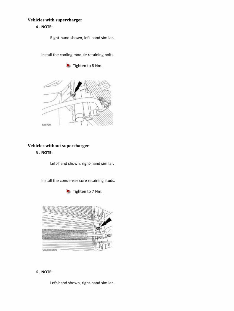
Vehicles with supercharger
4 . NOTE:
Right-hand shown, left-hand similar.
Install the cooling module retaining bolts.
Tighten to 8 Nm.
Vehicles without supercharger
5 . NOTE:
Left-hand shown, right-hand similar.
Install the condenser core retaining studs.
Tighten to 7 Nm.
6 . NOTE:
Left-hand shown, right-hand similar.
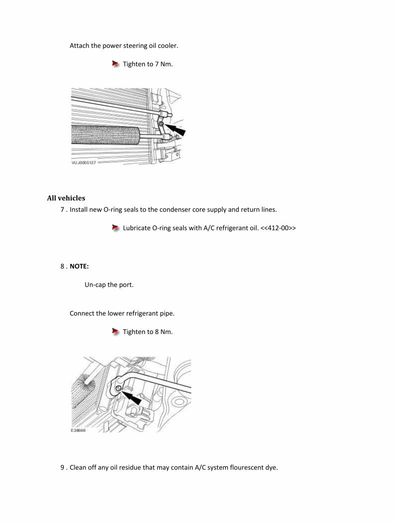
Attach the power steering oil cooler.
Tighten to 7 Nm.
All vehicles
7 . Install new O-ring seals to the condenser core supply and return lines.
Lubricate O-ring seals with A/C refrigerant oil. <<412-00>>
8 . NOTE:
Un-cap the port.
Connect the lower refrigerant pipe.
Tighten to 8 Nm.
9 . Clean off any oil residue that may contain A/C system flourescent dye.

10 . Install the radiator lower cowl.
11 . Install the radiator splash shield. <<501-02>>
12 . Lower the vehicle. <<100-02>>
13 . NOTE:
Un-cap the port.
Connect the upper refrigerant pipe.
Tighten to 8 Nm.
14 . Clean off any oil residue that may contain A/C system flourescent dye.
15 . Install the radiator support bracket.

Tighten to 9 Nm.
16 . Carry out the air conditioning (A/C) system evacuation and charging procedure. <<412-00>>
17 . Carry out the A/C system flourescent dye leak detection procedure. <<412-00>>
18 . Refit the radiator grille opening panel. <<501-02>>
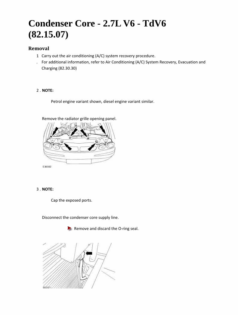
Condenser Core - 2.7L V6 - TdV6 (82.15.07) Removal
1
.
Carry out the air conditioning (A/C) system recovery procedure.
For additional information, refer to Air Conditioning (A/C) System Recovery, Evacuation and
Charging (82.30.30)
2 . NOTE:
Petrol engine variant shown, diesel engine variant similar.
Remove the radiator grille opening panel.
3 . NOTE:
Cap the exposed ports.
Disconnect the condenser core supply line.
Remove and discard the O-ring seal.

4 . Remove the radiator splash shield.
For additional information, refer to Radiator Splash Shield (76.22.90)
5 . Remove the radiator lower cowl.
6 . NOTE:
Cap the exposed ports.
Disconnect the condenser core return line.
Remove and discard the O-ring seal.
7 . Detach the condenser core.
Remove the retaining bolts.

8 . Remove the condenser core.
Installation
1 . To install, reverse the removal procedure.
Tighten to 7 Nm.
2 . NOTE:
Install a new O-ring seal.
NOTE:

Lubricate the new O-ring seal with A/C refrigerant oil.
Tighten to 5 Nm.
3 . NOTE:
Install a new O-ring seal.
NOTE:
Lubricate the new O-ring seal with A/C refrigerant oil.
Tighten to 5 Nm.
4
.
Carry out the A/C system evacuation and charging procedure.
For additional information, refer to Air Conditioning (A/C) System Recovery, Evacuation and
Charging (82.30.30)

Desiccant Bag - 4.2L NA V8 - AJV8/4.2L SC V8 - AJV8/3.0L NA V6 - AJ27/3.5L NA V8 - AJV8 (82.17.03) Installation
1 . Install new desiccant bag retaining screw O-ring seals.
Lubricate the new O-ring seals with A/C refrigerant oil.
2
. CAUTION: Do not leave the desiccant bag exposed to atmosphere for longer than
five minutes.
Install the desiccant bag.
3 . NOTE:
Un-cap the exposed port.
Install the retaining screw.
Tighten to 22 Nm.
4 . Clean off any oil residue that may contain A/C system flourescent dye.
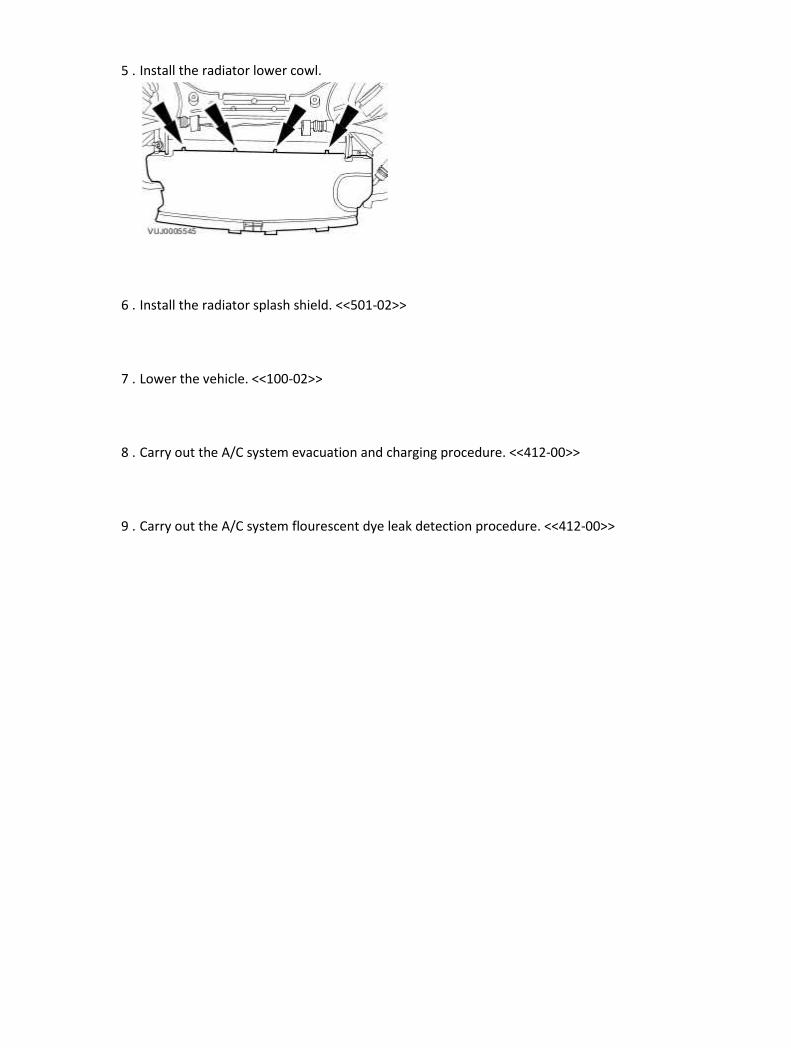
5 . Install the radiator lower cowl.
6 . Install the radiator splash shield. <<501-02>>
7 . Lower the vehicle. <<100-02>>
8 . Carry out the A/C system evacuation and charging procedure. <<412-00>>
9 . Carry out the A/C system flourescent dye leak detection procedure. <<412-00>>

Desiccant Bag - 2.7L V6 - TdV6 (82.17.03) Removal
1
.
Carry out the air conditioning (A/C) system recovery procedure.
For additional information, refer to Air Conditioning (A/C) System Recovery, Evacuation and
Charging (82.30.30)
2 . Raise the vehicle.
For additional information, refer to Lifting
3 . Remove the radiator splash shield.
For additional information, refer to Radiator Splash Shield (76.22.90)
4 . Remove the radiator lower cowl.
5 . NOTE:
Discard the desiccant bag retaining screw O-ring seal.
Remove the desiccant bag retaining screw.

6
. CAUTION: Do not leave the desiccant bag exposed to atmosphere for longer than
five minutes.
NOTE:
Catch the escaping oil into a suitable container.
NOTE:
On removal of the desiccant bag cap the exposed port immediately.
Remove the desiccant bag.
Installation
1
. CAUTION: Do not leave the desiccant bag exposed to atmosphere for longer than
five minutes.
NOTE:
Uncap the exposed port.
Install the desiccant bag.

2 . NOTE:
Install a new desiccant bag retaining screw O-ring seal.
NOTE:
Lubricate the new O-ring seal with A/C refrigerant oil.
Install the retaining screw.
Tighten to 3 Nm.
3 . Clean off any oil residue that may contain A/C system fluorescent dye.
4 . Install the radiator lower cowl.
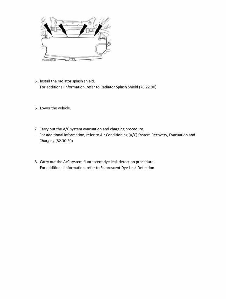
5 . Install the radiator splash shield.
For additional information, refer to Radiator Splash Shield (76.22.90)
6 . Lower the vehicle.
7
.
Carry out the A/C system evacuation and charging procedure.
For additional information, refer to Air Conditioning (A/C) System Recovery, Evacuation and
Charging (82.30.30)
8 . Carry out the A/C system fluorescent dye leak detection procedure.
For additional information, refer to Fluorescent Dye Leak Detection

Pressure Cutoff Switch - 4.2L NA V8 - AJV8/4.2L SC V8 - AJV8/3.0L NA V6 - AJ27/3.5L NA V8 - AJV8 (82.10.32) Removal
1 . Remove the air cleaner.
For additional information, refer to Air Cleaner (19.10.05)
For additional information, refer to Air Cleaner (19.10.05)
2 . Disconnect the pressure cutoff switch electrical connector.
3 . Remove the pressure cutoff switch.
Remove and discard the pressure cutoff switch O-ring seal.
Installation
1 . Install a new pressure cutoff switch O-ring seal.

Lubricate the new 0-ring seal with A/C refrigerant oil.
2 . Install the pressure cutoff switch.
1) Tighten to 8 Nm.
3 . Connect the pressure cutoff switch electrical connector.
4 . Clean off any oil residue that may contain A/C system fluorescent dye.
5 . Install the air cleaner.
For additional information, refer to Air Cleaner (19.10.05)
For additional information, refer to Air Cleaner (19.10.05)
6 . Carry out the A/C system fluorescent dye leak detection procedure.
For additional information, refer to Fluorescent Dye Leak Detection

Pressure Cutoff Switch - 2.7L V6 - TdV6 (82.10.32) Removal
1
.
Carry out the air conditioning (A/C) system recovery procedure.
For additional information, refer to Air Conditioning (A/C) System Recovery, Evacuation and
Charging (82.30.30)
2 . Remove the radiator splash shield.
For additional information, refer to Radiator Splash Shield (76.22.90)
3 . Disconnect the pressure cutoff switch electrical connector.
4 . Remove the pressure cutoff switch.
Remove and discard the pressure cutoff switch O-ring seal.

Installation
1 . NOTE:
Install a new pressure cutoff switch O-ring seal.
NOTE:
Lubricate the new O-ring seal with A/C refrigerant oil.
Install the pressure cutoff switch.
Tighten to 8 Nm.
2 . Connect the pressure cutoff switch electrical connector.
3 . Clean off any oil residue that may contain A/C system fluorescent dye.
4 . Install the radiator splash shield.
For additional information, refer to Radiator Splash Shield (76.22.90)

5
.
Carry out the A/C system evacuation and charging procedure.
For additional information, refer to Air Conditioning (A/C) System Recovery, Evacuation and
Charging (82.30.30)
6 . Carry out the A/C system fluorescent dye leak detection procedure.
For additional information, refer to Fluorescent Dye Leak Detection

412-03B : Auxiliary Climate Control
Specifications
Specifications Description Nm lb-ft lb-in
Auxiliary evaporator outlet and inlet lines retaining nut 2 – 18
Auxiliary evaporator outlet and inlet lines retaining bolts 2 – 18
Auxiliary heater core and evaporator core housing retaining nuts 4 – 35
Heater core inlet and outlet pipes retaining clamps 2 – 18
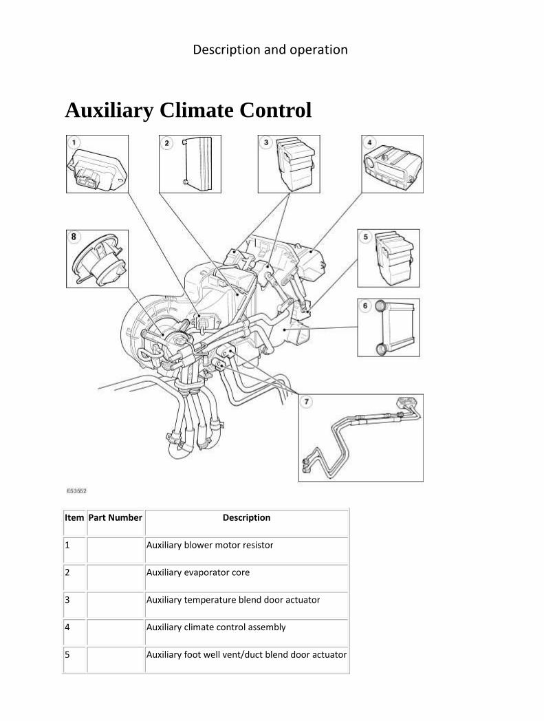
Description and operation
Auxiliary Climate Control
Item Part Number Description
1 Auxiliary blower motor resistor
2 Auxiliary evaporator core
3 Auxiliary temperature blend door actuator
4 Auxiliary climate control assembly
5 Auxiliary foot well vent/duct blend door actuator

6 Auxiliary heater core
7 Auxiliary evaporator outlet and inlet line
8 Auxiliary blower motor
The auxiliary climate control system will only function when the climate control system has been
activated. Any deactivation of the climate control system, will automatically deactivate the auxiliary
climate control system. Reactivation of the climate control system will not automatically reactivate
the auxiliary climate control system, manual intervention is required.
Item Part Number Description
1 Rear face registers
2 Auxiliary climate control assembly
3 Rear floor register
4 Input register
Auxiliary climate control assembly
The auxiliary climate control assembly has its own intergrated control module that, where
appropriate, can be overridden by signals from the climate control module.

If the climate control assembly is activated the auxiliary climate control assembly can be controlled
by the:
• rear seat passengers using the auxiliary climate control assembly.
• front seat passengers using the instrument panel console touch-screen.
The auxiliary climate control assembly is not configurable but may be reprogrammed using the
Jaguar approved diagnostic system.

Diagnosis and testing
Auxiliary Climate Control Principles of Operation
For a detailed description of the Climate Control system, refer to the relevant Description and
Operation sections in the workshop manual.
Auxiliary Climate Control
Inspection and Verification
1 . Verify the customer concern by operating the system.
2 . Visually inspect for obvious signs of damage and system integrity.
Visual Inspection Chart
Mechanical Electrical
• Coolant Level
• Fuses/Relays
• Damaged, Loose or Corroded Connector(s)
• Damage to Wiring Loom/Incorrect Location, Stretched or Taught
1 . If an obvious cause for an observed or reported concern is found, correct the cause (if possible)
before proceeding to the next step.
2 . If the cause is not visually evident, check for Diagnostic Trouble Codes (DTCs) and refer to the DTC
Index.
Symptom Chart
Symptom Possible source Action
Rear blower motor is
inoperative / does not
operate correctly
• Rear blower motor
circuits
• Rear blower motor
• Rear blower motor
control module
• Auxiliary climate
control module
For rear blower motor and control
module tests, GO to Pinpoint Test
G426404p9.
Auxiliary climate control is
inoperative / does not
operate correctly
• Auxiliary climate
control module circuits
• Auxiliary climate
For auxiliary climate control circuit
checks, GO to Pinpoint Test
G426404p10.
control module
DTC Index
Auxiliary Control Module
CAUTION: When probing connectors to take measurements in the course of the pinpoint
tests, use the adaptor kit, part number 3548-1358-00
NOTE:
If the control module/component is suspect and the vehicle remains under manufacturer
warranty, refer to the Warranty Policy and Procedures manual (section B1.2), or determine if
any prior approval program is in operation, prior to the installation of a new
module/component.
NOTE:
When performing voltage or resistance tests, always use a digital multimeter (DMM) accurate to
three decimal places and with a current calibration certificate. When testing resistance, always
take the resistance of the DMM leads into account.
NOTE:
Check and rectify basic faults before beginning diagnostic routines that involve pinpoint tests.
NOTE:
Inspect connectors for signs of water ingress, and pins for damage and/or corrosion.
NOTE:
If DTCs are recorded and, after performing the pinpoint tests, a fault is not present, an
intermittent concern may be the cause. Always check for loose connections and corroded
terminals.
DTC Description Possible Source Action
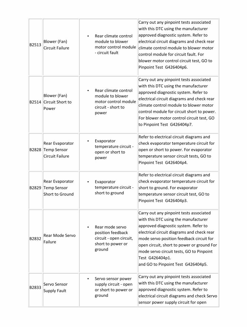
B2513 Blower (Fan)
Circuit Failure
• Rear climate control
module to blower
motor control module
- circuit fault
Carry out any pinpoint tests associated
with this DTC using the manufacturer
approved diagnostic system. Refer to
electrical circuit diagrams and check rear
climate control module to blower motor
control module for circuit fault. For
blower motor control circuit test, GO to
Pinpoint Test G426404p6.
B2514
Blower (Fan)
Circuit Short to
Power
• Rear climate control
module to blower
motor control module
circuit - short to
power
Carry out any pinpoint tests associated
with this DTC using the manufacturer
approved diagnostic system. Refer to
electrical circuit diagrams and check rear
climate control module to blower motor
control module for circuit short to power.
For blower motor control circuit test, GO
to Pinpoint Test G426404p7.
B2828
Rear Evaporator
Temp Sensor
Circuit Failure
• Evaporator
temperature circuit -
open or short to
power
Refer to electrical circuit diagrams and
check evaporator temperature circuit for
open or short to power. For evaporator
temperature sensor circuit tests, GO to
Pinpoint Test G426404p4.
B2829
Rear Evaporator
Temp Sensor
Short to Ground
• Evaporator
temperature circuit -
short to ground
Refer to electrical circuit diagrams and
check evaporator temperature circuit for
short to ground. For evaporator
temperature sensor circuit test, GO to
Pinpoint Test G426404p3.
B2832 Rear Mode Servo
Failure
• Rear mode servo
position feedback
circuit - open circuit,
short to power or
ground
Carry out any pinpoint tests associated
with this DTC using the manufacturer
approved diagnostic system. Refer to
electrical circuit diagrams and check rear
mode servo position feedback circuit for
open circuit, short to power or ground For
mode servo circuit tests, GO to Pinpoint
Test G426404p1.
and GO to Pinpoint Test G426404p5.
B2833 Servo Sensor
Supply Fault
• Servo sensor power
supply circuit - open
or short to power or
ground
Carry out any pinpoint tests associated
with this DTC using the manufacturer
approved diagnostic system. Refer to
electrical circuit diagrams and check Servo
sensor power supply circuit for open
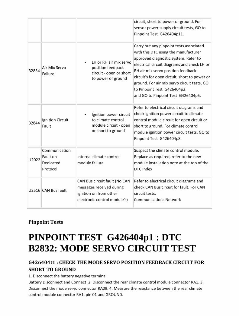
circuit, short to power or ground. For
sensor power supply circuit tests, GO to
Pinpoint Test G426404p11.
B2834 Air Mix Servo
Failure
• LH or RH air mix servo
position feedback
circuit - open or short
to power or ground
Carry out any pinpoint tests associated
with this DTC using the manufacturer
approved diagnostic system. Refer to
electrical circuit diagrams and check LH or
RH air mix servo position feedback
circuit's for open circuit, short to power or
ground. For air mix servo circuit tests, GO
to Pinpoint Test G426404p2.
and GO to Pinpoint Test G426404p5.
B2844 Ignition Circuit
Fault
• Ignition power circuit
to climate control
module circuit - open
or short to ground
Refer to electrical circuit diagrams and
check ignition power circuit to climate
control module circuit for open circuit or
short to ground. For climate control
module ignition power circuit tests, GO to
Pinpoint Test G426404p8.
U2022
Communication
Fault on
Dedicated
Protocol
Internal climate control
module failure
Suspect the climate control module.
Replace as required, refer to the new
module installation note at the top of the
DTC Index
U2516 CAN Bus fault
CAN Bus circuit fault (No CAN
messages received during
ignition on from other
electronic control module's)
Refer to electrical circuit diagrams and
check CAN Bus circuit for fault. For CAN
circuit tests,
Communications Network
Pinpoint Tests
PINPOINT TEST G426404p1 : DTC B2832: MODE SERVO CIRCUIT TEST G426404t1 : CHECK THE MODE SERVO POSITION FEEDBACK CIRCUIT FOR
SHORT TO GROUND
1. Disconnect the battery negative terminal.
Battery Disconnect and Connect 2. Disconnect the rear climate control module connector RA1. 3.
Disconnect the mode servo connector RA09. 4. Measure the resistance between the rear climate
control module connector RA1, pin 01 and GROUND.

• Is the resistance less than 10,000 ohms?
-> Yes
REPAIR the short circuit. For additional information, refer to the wiring diagrams. CLEAR the DTC.
TEST the system for normal operation.
-> No
GO to Pinpoint Test G426404t2.
G426404t2 : CHECK THE MODE SERVO POSITION FEEDBACK CIRCUIT FOR
OPEN CIRCUIT
1. Measure the resistance between the rear climate control module connector RA1, pin 01 and mode
servo connector RA09, pin 02.
• Is the resistance greater than 5 ohms?
-> Yes
REPAIR the high resistance circuit. For additional information, refer to the wiring diagrams. CLEAR the
DTC. TEST the system for normal operation.
-> No
GO to Pinpoint Test G426404t3.
G426404t34 : CHECK THE MODE SERVO MOTOR FEED CIRCUIT FOR OPEN
CIRCUIT
1. Measure the resistance between the rear climate control module connector RA2, pin 04 and mode
servo connector RA09, pin 04.
• Is the resistance greater than 5 ohms?
-> Yes
REPAIR the high resistance circuit. For additional information, refer to the wiring diagrams. CLEAR the
DTC. TEST the system for normal operation.
-> No
GO to Pinpoint Test G426404t35.
G426404t35 : CHECK THE MODE SERVO MOTOR FEED CIRCUIT FOR SHORT
TO GROUND
1. Measure the resistance between the rear climate control module connector RA2, pin 04 and
GROUND.
• Is the resistance less than 10,000 ohms?
-> Yes
REPAIR the short circuit. For additional information, refer to the wiring diagrams. CLEAR the DTC.
TEST the system for normal operation.
-> No
GO to Pinpoint Test G426404t36.
G426404t36 : CHECK THE MODE SERVO MOTOR RETURN CIRCUIT FOR
OPEN CIRCUIT
1. Measure the resistance between the rear climate control module connector RA2, pin 05 and mode
servo connector RA09, pin 05.
• Is the resistance greater than 5 ohms?
-> Yes
REPAIR the high resistance circuit. For additional information, refer to the wiring diagrams. CLEAR the
DTC. TEST the system for normal operation.
-> No
GO to Pinpoint Test G426404t37.
G426404t37 : CHECK THE MODE SERVO MOTOR RETURN CIRCUIT FOR
SHORT TO GROUND
1. Measure the resistance between the rear climate control module connector RA2, pin 05 and
GROUND.
• Is the resistance less than 10,000 ohms?
-> Yes
REPAIR the short circuit. For additional information, refer to the wiring diagrams. CLEAR the DTC.
TEST the system for normal operation.
-> No
GO to Pinpoint Test G426404t3.
G426404t3 : CHECK THE MODE SERVO POSITION FEEDBACK CIRCUIT FOR
SHORT TO B+
1. Reconnect the battery negative terminal.
Battery Connect (86.15.15) 2. Turn the ignition switch to the ON position. 3. Measure the voltage
between the rear climate control module connector RA1, pin 01 and GROUND.
• Is the voltage greater than 3 volts?
-> Yes
REPAIR the short circuit. For additional information, refer to the wiring diagrams. CLEAR the DTC.
TEST the system for normal operation.
-> No
INSTALL a new mode servo. CLEAR the DTC. TEST the system for normal operation. If the DTC is
repeated, INSTALL a new rear climate control module.
PINPOINT TEST G426404p2 : DTC 2834: AIR MIX SERVO LH AND RH CIRCUIT TESTS G426404t4 : CHECK THE LH AIR MIX SERVO POSITION FEEDBACK CIRCUIT
FOR OPEN CIRCUIT
1. Disconnect the battery negative terminal.
Battery Disconnect and Connect 2. Disconnect the rear climate control module connector RA1. 3.
Disconnect the LH air mix servo connector RA7. 4. Measure the resistance between the rear climate
control module connector RA1, pin 02 and LH air mix servo connector RA7, pin 02.
• Is the resistance greater than 5 ohms?
-> Yes
REPAIR the high resistance circuit. For additional information, refer to the wiring diagrams. CLEAR the
DTC. TEST the system for normal operation.
-> No
GO to Pinpoint Test G426404t5.
G426404t5 : CHECK THE LH AIR MIX SERVO POSITION FEEDBACK CIRCUIT
FOR SHORT TO GROUND
1. Measure the resistance between the rear climate control module connector RA1, pin 02 and
GROUND.
• Is the resistance less than 10,000 ohms?
-> Yes
REPAIR the short circuit. For additional information, refer to the wiring diagrams. CLEAR the DTC.
TEST the system for normal operation.
-> No
GO to Pinpoint Test G426404t7.

G426404t38 : CHECK THE LH AIR MIX SERVO MOTOR FEED CIRCUIT FOR
OPEN CIRCUIT
1. Measure the resistance between the rear climate control module connector RA2, pin 06 and LH air
mix servo connector RA7, pin 05.
• Is the resistance greater than 5 ohms?
-> Yes
REPAIR the high resistance circuit. For additional information, refer to the wiring diagrams. CLEAR the
DTC. TEST the system for normal operation.
-> No
GO to Pinpoint Test G426404t39.
G426404t39 : CHECK THE LH AIR MIX SERVO MOTOR FEED CIRCUIT FOR
SHORT TO GROUND
1. Measure the resistance between the rear climate control module connector RA2, pin 06 and
GROUND.
• Is the resistance less than 10,000 ohms?
-> Yes
REPAIR the short circuit. For additional information, refer to the wiring diagrams. CLEAR the DTC.
TEST the system for normal operation.
-> No
GO to Pinpoint Test G426404t40.
G426404t40 : CHECK THE LH AIR MIX SERVO MOTOR RETURN CIRCUIT FOR
OPEN CIRCUIT
1. Measure the resistance between the rear climate control module connector RA2, pin 12 and LH air
mix servo connector RA7, pin 04.
• Is the resistance greater than 5 ohms?
-> Yes
REPAIR the high resistance circuit. For additional information, refer to the wiring diagrams. CLEAR the
DTC. TEST the system for normal operation.
-> No
GO to Pinpoint Test G426404t41.
G426404t41 : CHECK THE LH AIR MIX SERVO MOTOR RETURN CIRCUIT FOR
SHORT TO GROUND
1. Measure the resistance between the rear climate control module connector RA2, pin 12 and
GROUND.
• Is the resistance less than 10,000 ohms?
-> Yes
REPAIR the short circuit. For additional information, refer to the wiring diagrams. CLEAR the DTC.
TEST the system for normal operation.
-> No
GO to Pinpoint Test G426404t7.
G426404t7 : CHECK THE RH AIR MIX SERVO POSITION FEEDBACK CIRCUIT
FOR OPEN CIRCUIT
1. Disconnect the RH air mix servo connector RA8. 2. Measure the resistance between the rear
climate control module connector RA1, pin 03 and RH air mix servo connector RA8, pin 02.
• Is the resistance greater than 5 ohms?
-> Yes
REPAIR the high resistance circuit. For additional information, refer to the wiring diagrams. CLEAR the
DTC. TEST the system for normal operation.
-> No
GO to Pinpoint Test G426404t8.
G426404t42 : CHECK THE RH AIR MIX SERVO MOTOR FEED CIRCUIT FOR
OPEN CIRCUIT
1. Measure the resistance between the rear climate control module connector RA2, pin 11 and RH air
mix servo connector RA8, pin 04.
• Is the resistance greater than 5 ohms?
-> Yes
REPAIR the high resistance circuit. For additional information, refer to the wiring diagrams. CLEAR the
DTC. TEST the system for normal operation.
-> No
GO to Pinpoint Test G426404t43.

G426404t43 : CHECK THE RH AIR MIX SERVO MOTOR FEED CIRCUIT FOR
SHORT TO GROUND
1. Measure the resistance between the rear climate control module connector RA2, pin 11 and
GROUND.
• Is the resistance less than 10,000 ohms?
-> Yes
REPAIR the short circuit. For additional information, refer to the wiring diagrams. CLEAR the DTC.
TEST the system for normal operation.
-> No
GO to Pinpoint Test G426404t44.
G426404t44 : CHECK THE RH AIR MIX SERVO MOTOR RETURN CIRCUIT FOR
OPEN CIRCUIT
1. Measure the resistance between the rear climate control module connector RA2, pin 10 and RH air
mix servo connector RA8, pin 05.
• Is the resistance greater than 5 ohms?
-> Yes
REPAIR the high resistance circuit. For additional information, refer to the wiring diagrams. CLEAR the
DTC. TEST the system for normal operation.
-> No
GO to Pinpoint Test G426404t45.
G426404t45 : CHECK THE RH AIR MIX SERVO MOTOR RETURN CIRCUIT FOR
SHORT TO GROUND
1. Measure the resistance between the rear climate control module connector RA2, pin 10 and
GROUND.
• Is the resistance less than 10,000 ohms?
-> Yes
REPAIR the short circuit. For additional information, refer to the wiring diagrams. CLEAR the DTC.
TEST the system for normal operation.
-> No
GO to Pinpoint Test G426404t8.
G426404t8 : CHECK THE RH AIR MIX SERVO POSITION FEEDBACK CIRCUIT
FOR SHORT TO GROUND
1. Measure the resistance between the rear climate control module connector RA1, pin 03 and
GROUND.
• Is the resistance less than 10,000 ohms?
-> Yes
REPAIR the short circuit. For additional information, refer to the wiring diagrams. CLEAR the DTC.
TEST the system for normal operation.
-> No
GO to Pinpoint Test G426404t6.
G426404t6 : CHECK THE RH AIR MIX SERVO POSITION FEEDBACK CIRCUIT
FOR SHORT TO B+
1. Reconnect the battery negative terminal.
Battery Connect (86.15.15) 2. Turn the ignition switch to the ON position. 3. Measure the voltage
between the rear climate control module connector RA1, pin 03 and GROUND.
• Is the voltage greater than 3 volts?
-> Yes
REPAIR the short circuit. For additional information, refer to the wiring diagrams. CLEAR the DTC.
TEST the system for normal operation.
-> No
GO to Pinpoint Test G426404t9.
G426404t9 : CHECK THE LH AIR MIX SERVO POSITION FEEDBACK CIRCUIT
FOR SHORT TO B+
1. Measure the voltage between the rear climate control module connector RA1, pin 02 and
GROUND.
• Is the voltage greater than 3 volts?
-> Yes
REPAIR the short circuit. For additional information, refer to the wiring diagrams. CLEAR the DTC.
TEST the system for normal operation.
-> No
INSTALL a new air mix servo. CLEAR the DTC. TEST the system for normal operation. If the DTC is
repeated, INSTALL a new rear climate control module.

PINPOINT TEST G426404p3 : DTC B2829: EVAPORATOR TEMPERATURE SENSOR CIRCUIT TEST G426404t10 : CHECK THE EVAPORATOR TEMPERATURE SENSOR CIRCUIT
FOR SHORT TO GROUND
1. Disconnect the battery negative terminal.
Battery Disconnect and Connect 2. Disconnect the rear climate control module connector RA1. 3.
Disconnect the evaporator temperature sensor connector RA10. 4. Measure the resistance between
the rear climate control module connector RA1, pin 09 and GROUND.
• Is the resistance less than 10,000 ohms?
-> Yes
REPAIR the short circuit. For additional information, refer to the wiring diagrams. CLEAR the DTC.
TEST the system for normal operation.
-> No
INSTALL a new evaporator temperature sensor. CLEAR the DTC. TEST the system for normal
operation. If the DTC is repeated, INSTALL a new rear climate control module.
PINPOINT TEST G426404p4 : DTC B2828: EVAPORATOR TEMPERATURE SENSOR CIRCUIT TEST G426404t11 : CHECK THE EVAPORATOR TEMPERATURE SENSOR CIRCUIT
FOR OPEN CIRCUIT
1. Disconnect the battery negative terminal.
Battery Disconnect and Connect 2. Disconnect the rear climate control module connector RA1. 3.
Disconnect the evaporator temperature sensor connector RA10. 4. Measure the resistance between
the rear climate control module connector RA1, pin 09 and evaporator temperature sensor
connector RA10, pin 01.
• Is the resistance greater than 5 ohms?
-> Yes
REPAIR the high resistance circuit. For additional information, refer to the wiring diagrams. CLEAR the
DTC. TEST the system for normal operation.
-> No
GO to Pinpoint Test G426404t13.
G426404t13 : CHECK THE EVAPORATOR TEMPERATURE SENSOR CIRCUIT
FOR SHORT TO B+
1. Reconnect the battery negative terminal.
Battery Connect (86.15.15) 2. Turn the ignition switch to the ON position. 3. Measure the voltage
between the rear climate control module connector RA1, pin 09 and GROUND.
• Is the voltage greater than 3 volts?
-> Yes
REPAIR the short circuit. For additional information, refer to the wiring diagrams. CLEAR the DTC.
TEST the system for normal operation.
-> No
INSTALL a new evaporator temperature sensor. CLEAR the DTC. TEST the system for normal
operation. If the DTC is repeated, INSTALL a new rear climate control module.
PINPOINT TEST G426404p5 : SERVO POWER SUPPLY CIRCUIT TESTS G426404t12 : CHECK THE SERVO POWER SUPPLY CIRCUIT FOR OPEN
CIRCUIT
1. Disconnect the battery negative terminal.
Battery Disconnect and Connect 2. Disconnect the rear climate control module connector RA1. 3.
Disconnect the mode servo connector RA09. 4. Measure the resistance between the rear climate
control module connector RA1, pin 11 and mode servo connector RA09, pin 03.
• Is the resistance greater than 5 ohms?
-> Yes
REPAIR the high resistance circuit between the rear climate control module connector RA1, pin 11
and splice RAS10. For additional information, refer to the wiring diagrams. CLEAR the DTC. TEST the
system for normal operation.
-> No
GO to Pinpoint Test G426404t14.

G426404t14 : CHECK THE SERVO POWER SUPPLY CIRCUIT FOR SHORT TO
GROUND
1. Disconnect the LH air mix servo connector RA7. 2. Disconnect the RH air mix servo connector RA8.
3. Measure the resistance between the rear climate control module connector RA1, pin 11 and
GROUND.
• Is the resistance less than 10,000 ohms?
-> Yes
REPAIR the short circuit between the rear climate control connector RA1, pin 11, mode servo
connector RA09, pin 03, LH air mix servo connector RA7, pin 03 and RH air mix servo connector RA8,
pin 03. For additional information, refer to the wiring diagrams. CLEAR the DTC. TEST the system for
normal operation.
-> No
GO to Pinpoint Test G426404t15.
G426404t15 : CHECK THE SERVO POWER SUPPLY CIRCUIT FOR SHORT TO
B+
1. Reconnect the battery negative terminal.
Battery Connect (86.15.15) 2. Turn the ignition switch to the ON position. 3. Measure the voltage
between the rear climate control module connector RA1, pin 11 and GROUND.
• Is the voltage greater than 3 volts?
-> Yes
REPAIR the short circuit between the rear climate control connector RA1, pin 11, mode servo
connector RA09, pin 03, LH air mix servo connector RA7, pin 03 and RH air mix servo connector RA8,
pin 03. For additional information, refer to the wiring diagrams. CLEAR the DTC. TEST the system for
normal operation.
-> No
GO to Pinpoint Test G426404t16.
G426404t16 : CHECK THE MODE SERVO FOR SHORT TO B+
1. Reconnect the mode servo connector RA09. 2. Measure the voltage between the rear climate
control module connector RA1, pin 11 and GROUND.
• Is the voltage greater than 3 volts?
-> Yes
INSTALL a new mode servo. CLEAR the DTC. TEST the system for normal operation.
-> No

GO to Pinpoint Test G426404t17.
G426404t17 : CHECK THE LH AIR MIX SERVO FOR SHORT TO B+
1. Reconnect the LH air mix servo connector RA7. 2. Measure the voltage between the rear climate
control module connector RA1, pin 11 and GROUND.
• Is the voltage greater than 3 volts?
-> Yes
INSTALL a new LH air mix servo. CLEAR the DTC. TEST the system for normal operation.
-> No
GO to Pinpoint Test G426404t18.
G426404t18 : CHECK THE RH AIR MIX SERVO FOR SHORT TO B+
1. Reconnect the RH air mix servo connector RA8. 2. Measure the voltage between the rear climate
control module connector RA1, pin 11 and GROUND.
• Is the voltage greater than 3 volts?
-> Yes
INSTALL a new RH air mix servo. CLEAR the DTC. TEST the system for normal operation.
-> No
GO to Pinpoint Test G426404t19.
G426404t19 : CHECK THE SERVO'S FOR SHORT TO GROUND
1. Disconnect the battery negative terminal.
Battery Disconnect and Connect 2. Measure the resistance between the rear climate control module
connector RA1, pin 11 and GROUND.
• Is the resistance less than 10,000 ohms?
-> Yes
GO to Pinpoint Test G426404t20.
-> No
INSTALL a new rear climate control module. CLEAR the DTC. TEST the system for normal operation.
G426404t20 : CHECK THE MODE SERVO FOR SHORT TO GROUND
1. Disconnect the mode servo connector RA09. 2. Measure the resistance between the rear climate
control module connector RA1, pin 11 and GROUND.
• Is the resistance less than 10,000 ohms?
-> Yes
GO to Pinpoint Test G426404t21.
-> No
INSTALL a new mode servo. CLEAR the DTC. TEST the system for normal operation.
G426404t21 : CHECK THE LH AIR MIX SERVO FOR SHORT TO GROUND
1. Disconnect the LH air mix connector RA7. 2. Measure the resistance between the rear climate
control module connector RA1, pin 11 and GROUND.
• Is the resistance less than 10,000 ohms?
-> Yes
INSTALL a new LH air mix servo. CLEAR the DTC. TEST the system for normal operation.
-> No
INSTALL a new RH air mix servo. CLEAR the DTC. TEST the system for normal operation.
PINPOINT TEST G426404p6 : DTC B2513: BLOWER MOTOR CONTROL MODULE CIRCUIT TEST G426404t22 : CHECK THE REAR BLOWER MOTOR CONTROL MODULE
CIRCUIT FOR OPEN CIRCUIT
1. Disconnect the battery negative terminal.
Battery Disconnect and Connect 2. Disconnect the rear climate control module connector RA1. 3.
Disconnect the rear blower motor control module connector RA3. 4. Measure the resistance
between the rear climate control module connector RA1, pin 14 and the rear blower motor control
module connector RA3, pin 02.
• Is the resistance greater than 5 ohms?
-> Yes
REPAIR the high resistance circuit. For additional information, refer to the wiring diagrams. CLEAR the
DTC. TEST the system for normal operation.
-> No
INSTALL a new rear blower motor control module. CLEAR the DTC. TEST the system for normal
operation. If the DTC is repeated, INSTALL a new rear climate control module.

PINPOINT TEST G426404p7 : DTC B2514: BLOWER MOTOR CONTROL MODULE CIRCUIT TEST G426404t23 : CHECK THE REAR BLOWER MOTOR CONTROL MODULE
CIRCUIT FOR SHORT TO B+
1. Disconnect the battery negative terminal.
Battery Disconnect and Connect 2. Disconnect the rear climate control module connector RA1. 3.
Disconnect the rear blower motor control module connector RA3. 4. Reconnect the battery negative
terminal.
Battery Connect (86.15.15) 5. Turn the ignition switch to the ON position. 6. Measure the voltage
between the rear climate control module connector RA1, pin 14 and GROUND.
• Is the voltage greater than 3 volts?
-> Yes
REPAIR the short circuit. For additional information, refer to the wiring diagrams. CLEAR the DTC.
TEST the system for normal operation.
-> No
INSTALL a new rear blower motor control module. CLEAR the DTC. TEST the system for normal
operation. If the DTC is repeated, INSTALL a new rear climate control module.
PINPOINT TEST G426404p8 : DTC B2844: REAR CLIMATE CONTROL MODULE IGNITION FEED CIRCUIT TESTS G426404t25 : CHECK THE REAR CLIMATE CONTROL MODULE IGNITION
FEED CIRCUIT FOR VOLTAGE
1. Disconnect the battery negative terminal.
Battery Disconnect and Connect 2. Disconnect the rear climate control module connector RA2. 3.
Reconnect the battery negative terminal.
Battery Connect (86.15.15) 4. Turn the ignition switch to the ON position. 5. Measure the voltage
between the rear climate control module connector RA2, pin 07 and GROUND.
• Is the voltage less than 10 volts?
-> Yes
GO to Pinpoint Test G426404t24.
-> No
CHECK the ground to the rear climate control module. If a ground is present, INSTALL a new rear
climate control module. CLEAR the DTC. TEST the system for normal operation.
G426404t24 : CHECK REAR PASSENGER DISTRIBUTION BOX FUSE F53
1. Turn the ignition switch to the OFF position. 2. Remove the rear passenger distribution box fuse
F53. 3. Inspect fuse F53 for open circuit.
• Is the fuse OK?
-> Yes
GO to Pinpoint Test G426404t26.
-> No
GO to Pinpoint Test G426404t27.
G426404t26 : CHECK THE REAR CLIMATE CONTROL MODULE IGNITION
FEED CIRCUIT FOR OPEN CIRCUIT
1. Disconnect the battery negative terminal.
Battery Disconnect and Connect 2. Measure the resistance between the rear climate control module
connector RA2, pin 07 and rear passenger distribution box fuse F53.
• Is the resistance greater than 5 ohms?
-> Yes
REPAIR the high resistance circuit. For additional information, refer to the wiring diagrams. CLEAR the
DTC. TEST the system for normal operation.
-> No
REPAIR the high resistance circuit between the rear passenger distribution box fuse F53 and battery
positive. This circuit includes the rear ignition relay R2. For additional information, refer to the wiring
diagrams. CLEAR the DTC. TEST the system for normal operation.
G426404t27 : CHECK THE REAR CLIMATE CONTROL MODULE IGNITION
FEED CIRCUIT FOR SHORT TO GROUND
1. Disconnect the battery negative terminal.
Battery Disconnect and Connect 2. Measure the resistance between the rear climate control module
connector RA2, pin 07 and GROUND.
• Is the resistance less than 10,000 ohms?

-> Yes
GO to Pinpoint Test G426404t28.
-> No
INSTALL a new rear climate control module. CLEAR the DTC. TEST the system for normal operation.
G426404t28 : CHECK THE REAR BLOWER MOTOR FOR SHORT TO GROUND
1. Disconnect the rear blower motor connector RA4. 2. Measure the resistance between the rear
climate control module connector RA2, pin 07 and GROUND.
• Is the resistance less than 10,000 ohms?
-> Yes
REPAIR the short circuit. For additional information, refer to the wiring diagrams. CLEAR the DTC.
TEST the system for normal operation.
-> No
INSTALL a new rear blower motor. CLEAR the DTC. TEST the system for normal operation.
PINPOINT TEST G426404p9 : REAR BLOWER MOTOR AND CONTROL MODULE TESTS G426404t29 : CHECK THE REAR BLOWER MOTOR FOR BATTERY VOLTAGE
1. Disconnect the battery negative terminal.
Battery Disconnect and Connect 2. Disconnect the rear blower motor connector RA4. 3. Reconnect
the battery negative terminal.
Battery Connect (86.15.15) 4. Turn the ignition switch to the ON position. 5. Measure the voltage
between the rear blower motor connector RA4, pin 01 and GROUND.
• Is the voltage less than 10 volts?
-> Yes
REPAIR the circuit between the rear blower motor connector RA4, pin 01 and battery positive. This
circuit includes the rear passenger distribution box (fuse 53) and rear ignition relay R2. Test the
system for normal operation.
-> No
GO to Pinpoint Test G426404t30.

G426404t30 : CHECK THE REAR BLOWER MOTOR CONTROL MODULE
GROUND CIRCUIT
1. Turn the ignition switch to the OFF position. 2. Disconnect the battery negative terminal.
Battery Disconnect and Connect 3. Disconnect the rear blower motor control module connector
RA3. 4. Measure the resistance between the rear blower motor module connector RA3, pin 01 and
ground.
• Is the resistance greater than 5 ohms?
-> Yes
REPAIR the high resistance circuit between the rear blower motor module connector RA3, pin 01 and
ground connection G32BS. Check the ground connection for contamination and security. For
additional information, refer to the wiring diagrams. TEST the system for normal operation.
-> No
GO to Pinpoint Test G426404t31.
G426404t31 : CHECK THE REAR BLOWER MOTOR GROUND CIRCUIT FOR
OPEN CIRCUIT
1. Measure the resistance between the rear blower motor connector RA4, pin 02 and rear blower
motor module connector RA3, pin 04.
• Is the resistance greater than 5 ohms?
-> Yes
REPAIR the high resistance circuit. For additional information, refer to the wiring diagrams. TEST the
system for normal operation.
-> No
GO to Pinpoint Test G426404t32.
G426404t32 : CHECK THE REAR BLOWER MOTOR CONTROL MODULE
FEEDBACK CIRCUIT FOR OPEN CIRCUIT
1. Disconnect the rear climate control module connector RA1. 2. Measure the resistance between
the rear blower motor module connector RA3, pin 03 and rear climate control module RA1, pin 13.
• Is the resistance greater than 5 ohms?
-> Yes
REPAIR the high resistance circuit. For additional information, refer to the wiring diagrams. TEST the
system for normal operation.
-> No
TEST the rear blower motor. If the rear blower motor is OK, INSTALL a new rear blower motor control

module. TEST the system for normal operation. If the concern persists, INSTALL a new rear climate
control module.
PINPOINT TEST G426404p10 : AUXILIARY CLIMATE CONTROL MODULE CIRCUIT TESTS G426404t33 : CHECK THE AUXILIARY CLIMATE CONTROL MODULE
BATTERY SUPPLY CIRCUIT FOR OPEN CIRCUIT
1. Disconnect the battery negative terminal.
Battery Disconnect and Connect 2. Disconnect the rear climate control module connector RA2. 3.
Reconnect the battery negative terminal.
Battery Connect (86.15.15) 4. Turn the ignition switch to the ON position. 5. Measure the voltage
between the rear climate control module connector RA2, pin 08 and GROUND.
• Is the voltage less than 10 volts?
-> Yes
REPAIR the high resistance circuit between the rear climate control module connector RA2, pin 08
and battery. This circuit includes the passenger junction fuse box (fuse 28) and the switched system
power relay. For additional information, refer to the wiring diagrams. TEST the system for normal
operation.
-> No
GO to Pinpoint Test G426404t46.
G426404t46 : CHECK THE AUXILIARY CLIMATE CONTROL MODULE GROUND
CIRCUIT FOR OPEN CIRCUIT
1. Turn the ignition switch to the OFF position. 2. Disconnect the battery negative terminal.
Battery Disconnect and Connect 3. Measure the resistance between the rear climate control module
connector RA2, pin 01 and GROUND.
• Is the resistance greater than 5 ohms?
-> Yes
REPAIR the high resistance circuit between the rear climate control module connector RA2, pin 01
and ground connection G32BS. Check the ground connection for contamination and security. For
additional information, refer to the wiring diagrams. TEST the system for normal operation.
-> No
INSTALL a new rear climate control module. TEST the system for normal operation.

PINPOINT TEST G426404p11 : DTC B2833: SENSOR POWER SUPPLY CIRCUIT TESTS G426404t47 : CHECK THE SENSOR POWER SUPPLY CIRCUIT FOR OPEN
CIRCUIT
1. Disconnect the battery negative terminal.
Battery Disconnect and Connect 2. Disconnect the evaporator sensor connector, RA10. 3. Disconnect
the rear climate control module connector, RA1. 4. Measure the resistance between RA1, pin 09 and
RA10, pin 01.
• Is the resistance greater than 5 ohms?
-> Yes
REPAIR the high resistance circuit. For additional information, refer to the wiring diagrams. TEST the
system for normal operation.
-> No
GO to Pinpoint Test G426404t48.
G426404t48 : CHECK THE SENSOR POWER SUPPLY CIRCUIT FOR SHORT
CIRCUIT TO GROUND
1. Measure the resistance between RA10, pin 01 and GROUND.
• Is the resistance less than 10,000 ohms?
-> Yes
REPAIR the short circuit. For additional information, refer to the wiring diagrams. TEST the system for
normal operation.
-> No
GO to Pinpoint Test G426404t49.
G426404t49 : CHECK THE SENSOR POWER SUPPLY CIRCUIT FOR SHORT
CIRCUIT TO B+
1. Reconnect the battery negative terminal.
Battery Connect (86.15.15) 2. Turn the ignition switch to the ON position. 3. Measure the voltage
between RA10, pin 01 and GROUND.
• Is the voltage greater than 3 volts?

-> Yes
REPAIR the short circuit. For additional information, refer to the wiring diagrams. TEST the system for
normal operation.
-> No
INSTALL a new evaporator sensor. TEST the system for normal operation.

Removal and installation
Auxiliary Climate Control Assembly Removal
1
. CAUTION: Make sure damage does not occur to the auxiliary climate control
assembly finish panel.
Remove the auxiliary climate control assembly finish panel.
2 . Detach the auxiliary climate control assembly.
Remove the auxiliary climate control assembly retaining screws.
3 . Remove the auxiliary climate control assembly.
Disconnect the auxiliary climate control assembly electrical connectors.
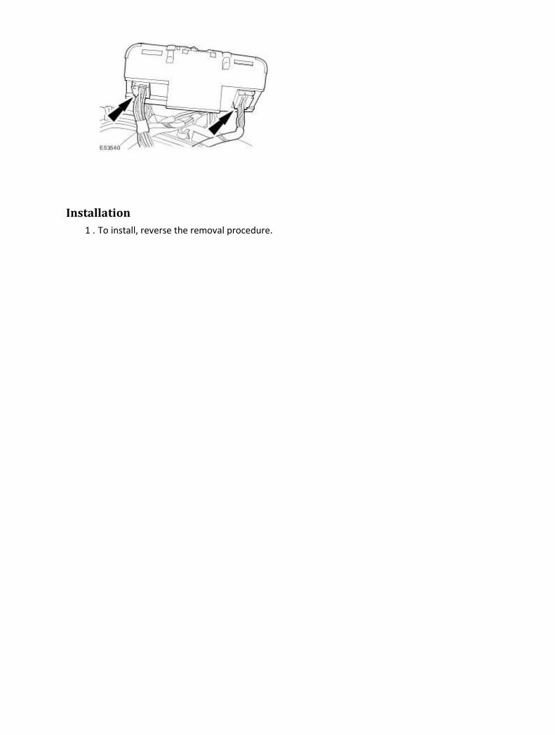
Installation
1 . To install, reverse the removal procedure.

Auxiliary Evaporator Outlet and Inlet Line Removal
1
.
Carry out the air conditioning (A/C) system recovery procedure.
For additional information, refer to Air Conditioning (A/C) System Recovery, Evacuation and
Charging (82.30.30)
2 . Raise and support the vehicle.
For additional information, refer to Lifting
3 . Remove the air deflector.
For additional information, refer to Air Deflector (76.11.41)
4 . Remove the left-hand splash shield.
5 . NOTE:
Remove and discard the auxiliary evaporator outlet and inlet line O-ring seals.

Detach the auxiliary evaporator outlet and inlet lines.
Remove the auxiliary evaporator outlet and inlet line retaining bolts.
6 . Lower the vehicle.
7 . Remove the front seat.
For additional information, refer to Front Seat (76.70.01)
8
.
Remove the floor console.
For additional information, refer to Floor Console - Vehicles With: Auxiliary Climate Control
(76.25.01)
9 . NOTE:
Remove and discard the auxiliary evaporator outlet and inlet line O-ring seals.
Detach the auxiliary evaporator outlet and inlet lines.
Remove the auxiliary evaporator outlet and inlet line retaining bolts.
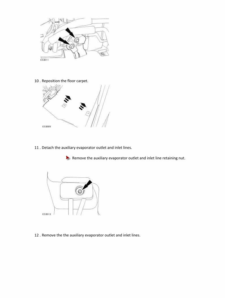
10 . Reposition the floor carpet.
11 . Detach the auxiliary evaporator outlet and inlet lines.
Remove the auxiliary evaporator outlet and inlet line retaining nut.
12 . Remove the the auxiliary evaporator outlet and inlet lines.

Installation
1 . To install, reverse the removal procedure.
Tighten to 2 Nm.
2 . NOTE:
Install new auxiliary evaporator outlet and inlet line O-ring seals.
Tighten to 2 Nm.
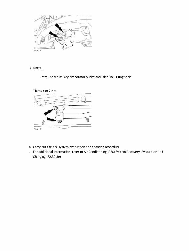
3 . NOTE:
Install new auxiliary evaporator outlet and inlet line O-ring seals.
Tighten to 2 Nm.
4
.
Carry out the A/C system evacuation and charging procedure.
For additional information, refer to Air Conditioning (A/C) System Recovery, Evacuation and
Charging (82.30.30)

Auxiliary Footwell Vent/Duct Blend Door Actuator Removal
1
.
Remove the floor console.
For additional information, refer to Floor Console - Vehicles With: Auxiliary Climate Control
(76.25.01)
2
. CAUTION: Make sure no damage occurs to the auxiliary temperature blend door
actuator link rod.
Detach the footwell vent/duct blend door actuator link rod.
3 . Disconnect the footwell vent/duct blend door actuator electrical connector.
4 . Remove the footwell vent/duct blend door actuator.
Remove the footwell vent/duct blend door actuator retaining screws.
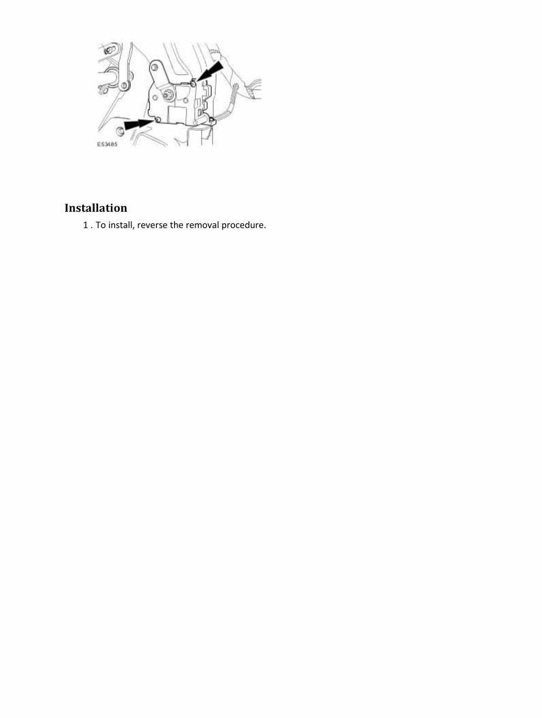
Installation
1 . To install, reverse the removal procedure.

Auxiliary Heater Core and Evaporator Core Housing Removal
1
.
Carry out the air conditioning (A/C) system recovery procedure.
For additional information, refer to Air Conditioning (A/C) System Recovery, Evacuation and
Charging (82.30.30)
2 . Remove the heater core.
For additional information, refer to Heater Core
3 . Disconnect the auxiliary heater core and evaporator core housing electrical connector.
4 . NOTE:
Remove and discard the auxiliary evaporator outlet and inlet line O-ring seals.
Detach the auxiliary evaporator outlet and inlet lines.
Remove the auxiliary evaporator outlet and inlet line retaining bolts.
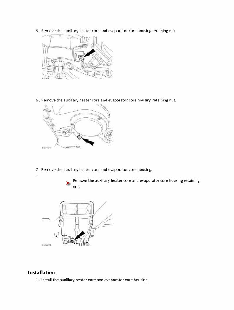
5 . Remove the auxiliary heater core and evaporator core housing retaining nut.
6 . Remove the auxiliary heater core and evaporator core housing retaining nut.
7
.
Remove the auxiliary heater core and evaporator core housing.
Remove the auxiliary heater core and evaporator core housing retaining
nut.
Installation
1 . Install the auxiliary heater core and evaporator core housing.

Install the auxiliary heater core and evaporator core housing retaining nut.
Tighten to 4 Nm.
2 . Install the auxiliary heater core and evaporator core housing retaining nut.
Tighten to 4 Nm.
3 . Install the auxiliary heater core and evaporator core housing retaining nut.
Tighten to 4 Nm.

4 . NOTE:
Install new auxiliary evaporator outlet and inlet line O-ring seals.
Attach the auxiliary evaporator outlet and inlet lines.
Install the auxiliary evaporator outlet and inlet line retaining bolts.
Tighten to 2 Nm.
5 . Connect the auxiliary heater core and evaporator core housing electrical connector.
6 . Install the heater core.
For additional information, refer to Heater Core
7
.
Carry out the A/C system evacuation and charging procedure.
For additional information, refer to Air Conditioning (A/C) System Recovery, Evacuation and
Charging (82.30.30)
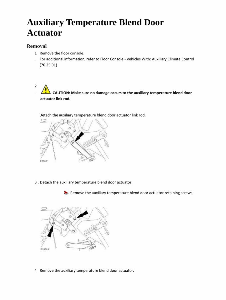
Auxiliary Temperature Blend Door Actuator Removal
1
.
Remove the floor console.
For additional information, refer to Floor Console - Vehicles With: Auxiliary Climate Control
(76.25.01)
2
. CAUTION: Make sure no damage occurs to the auxiliary temperature blend door
actuator link rod.
Detach the auxiliary temperature blend door actuator link rod.
3 . Detach the auxiliary temperature blend door actuator.
Remove the auxiliary temperature blend door actuator retaining screws.
4 Remove the auxiliary temperature blend door actuator.

.
Disconnect the auxiliary temperature blend door actuator electrical
connector.
Installation
1 . To install, reverse the removal procedure.

Auxiliary Blower Motor Removal
1 . Disconnect the battery ground cable.
For additional information, refer to Battery Disconnect and Connect
2
.
Remove the floor console.
For additional information, refer to Floor Console - Vehicles With: Auxiliary Climate Control
(76.25.01)
3 . Disconnect the blower motor electrical connector.
4 . Detach the heater core and evaporator core housing wiring harness.
5 . Detach the heater core and evaporator core housing electrical connector.
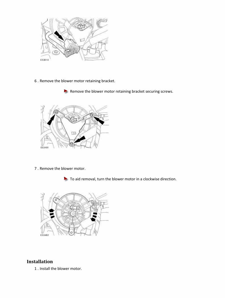
6 . Remove the blower motor retaining bracket.
Remove the blower motor retaining bracket securing screws.
7 . Remove the blower motor.
To aid removal, turn the blower motor in a clockwise direction.
Installation
1 . Install the blower motor.

To aid installation turn the blower motor in a counter-clockwise direction.
2 . Install the blower motor retaining bracket.
Install the blower motor retaining bracket securing screws.
3 . Attach the heater core and evaporator core housing electrical connector.
4 . Attach the heater core and evaporator core housing wiring harness.

5 . Connect the blower motor electrical connector.
6
.
Install the floor console.
For additional information, refer to Floor Console - Vehicles With: Auxiliary Climate Control
(76.25.01)
7 . Connect the battery ground cable.
For additional information, refer to Battery Connect (86.15.15)
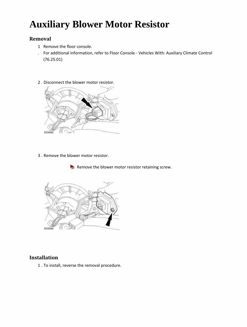
Auxiliary Blower Motor Resistor Removal
1
.
Remove the floor console.
For additional information, refer to Floor Console - Vehicles With: Auxiliary Climate Control
(76.25.01)
2 . Disconnect the blower motor resistor.
3 . Remove the blower motor resistor.
Remove the blower motor resistor retaining screw.
Installation
1 . To install, reverse the removal procedure.
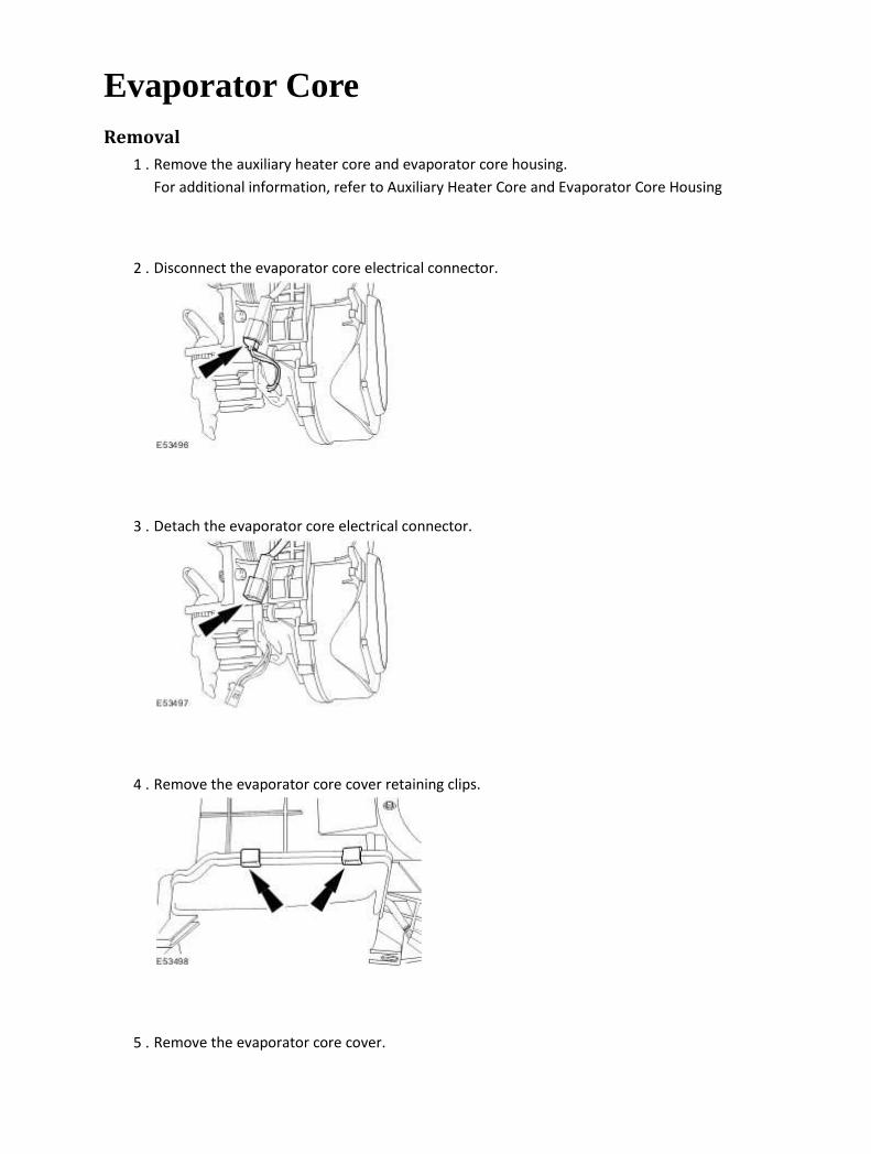
Evaporator Core Removal
1 . Remove the auxiliary heater core and evaporator core housing.
For additional information, refer to Auxiliary Heater Core and Evaporator Core Housing
2 . Disconnect the evaporator core electrical connector.
3 . Detach the evaporator core electrical connector.
4 . Remove the evaporator core cover retaining clips.
5 . Remove the evaporator core cover.
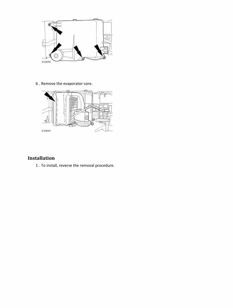
6 . Remove the evaporator core.
Installation
1 . To install, reverse the removal procedure.
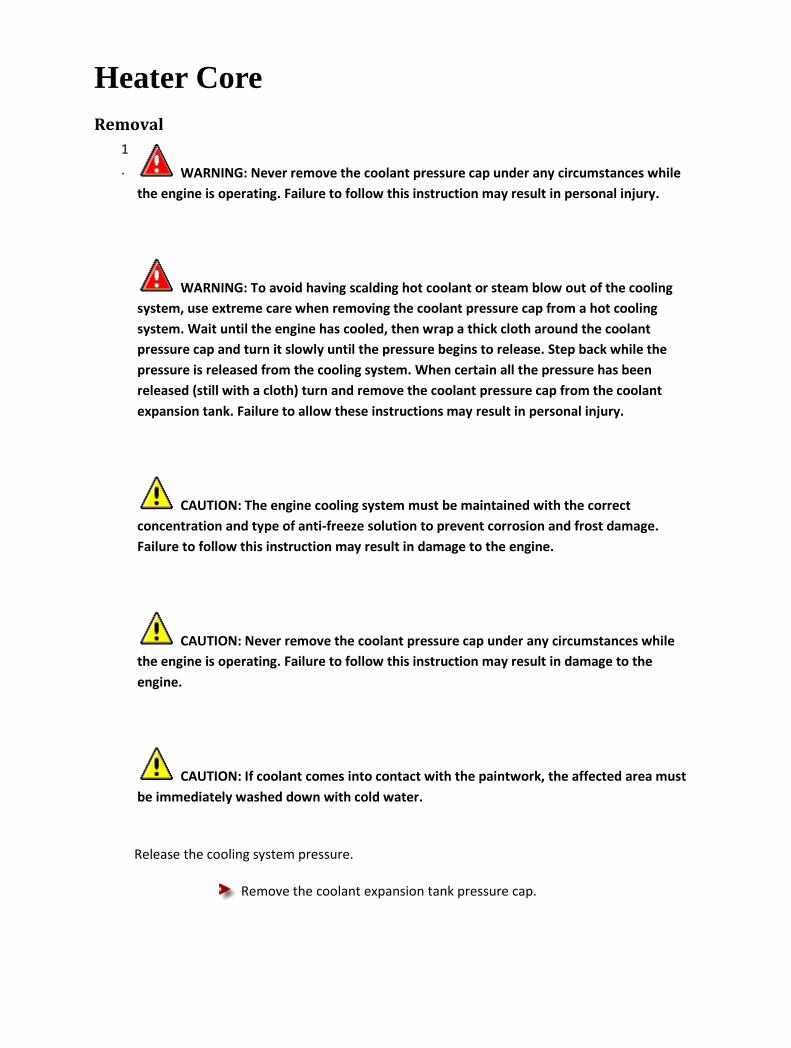
Heater Core Removal
1
. WARNING: Never remove the coolant pressure cap under any circumstances while
the engine is operating. Failure to follow this instruction may result in personal injury.
WARNING: To avoid having scalding hot coolant or steam blow out of the cooling
system, use extreme care when removing the coolant pressure cap from a hot cooling
system. Wait until the engine has cooled, then wrap a thick cloth around the coolant
pressure cap and turn it slowly until the pressure begins to release. Step back while the
pressure is released from the cooling system. When certain all the pressure has been
released (still with a cloth) turn and remove the coolant pressure cap from the coolant
expansion tank. Failure to allow these instructions may result in personal injury.
CAUTION: The engine cooling system must be maintained with the correct
concentration and type of anti-freeze solution to prevent corrosion and frost damage.
Failure to follow this instruction may result in damage to the engine.
CAUTION: Never remove the coolant pressure cap under any circumstances while
the engine is operating. Failure to follow this instruction may result in damage to the
engine.
CAUTION: If coolant comes into contact with the paintwork, the affected area must
be immediately washed down with cold water.
Release the cooling system pressure.
Remove the coolant expansion tank pressure cap.

2 . Remove the front seat.
For additional information, refer to Front Seat (76.70.01)
3
.
Remove the floor console.
For additional information, refer to Floor Console - Vehicles With: Auxiliary Climate Control
(76.25.01)
4 . Remove the heater core inlet and outlet pipes retaining plates.
5 . Detach the heater core.
6
. CAUTION: Drain the coolant in the heater core and inlet and outlet pipes into a
suitable container. Failure to follow this instruction may result in damage to the floor
carpet.
Remove the heater core.
Remove the heater core inlet and outlet pipes retaining clamps.

Installation
1
. WARNING: Never remove the coolant pressure cap under any circumstances while
the engine is operating. Failure to follow this instruction may result in personal injury.
WARNING: To avoid having scalding hot coolant or steam blow out of the cooling
system, use extreme care when removing the coolant pressure cap from a hot cooling
system. Wait until the engine has cooled, then wrap a thick cloth around the coolant
pressure cap and turn it slowly until the pressure begins to release. Step back while the
pressure is released from the cooling system. When certain all the pressure has been
released (still with a cloth) turn and remove the coolant pressure cap from the coolant
expansion tank. Failure to allow these instructions may result in personal injury.
CAUTION: The engine cooling system must be maintained with the correct
concentration and type of anti-freeze solution to prevent corrosion and frost damage.
Failure to follow this instruction may result in damage to the engine.
CAUTION: Never remove the coolant pressure cap under any circumstances while
the engine is operating. Failure to follow this instruction may result in damage to the
engine.
CAUTION: If coolant comes into contact with the paintwork, the affected area must

be immediately washed down with cold water.
Install the heater core.
Install the heater core inlet and outlet pipes retaining clamps.
Tighten to 2 Nm.
2 . Attach the heater core.
3 . Install the heater core inlet and outlet pipes retaining plates.
4 Install the floor console.
For additional information, refer to Floor Console - Vehicles With: Auxiliary Climate Control
. (76.25.01)
5 . Install the front seat.
For additional information, refer to Front Seat (76.70.01)
6 . Check and top up the cooling system as required.
7 . Install the coolant expansion tank pressure cap.
8
. CAUTION: Do not RUN the engine with the coolant expansion tank pressure cap
removed. Failure to follow this instruction may result in damage to the vehicle.
START and RUN the engine.
9
.
SET the heating system to MAX heat, the blower motor to MAX speed and the air distribution
to instrument panel and console assembly registers.
10
. CAUTION: Observe the engine temperature gauge. If the engine starts to over-heat
switch off immediately and allow to cool. Failure to follow this instruction may result in
damage to the vehicle.
Allow the engine to RUN until hot air is emitted from the instrument panel and console
assembly registers, while observing the engine temperature gauge.
11 . Switch off the engine.
12 . Allow the engine to cool.

13 . Release the cooling system pressure.
Remove the coolant expansion tank pressure cap.
14
.
Fill the cooling system up to the MAX mark on the coolant expansion tank using a fifty
percent mixture of Jaguar Premium Cooling System Fluid or equivalent, meeting Jaguar
specification WSS M97B44-D and fifty percent water.
15 . Install the coolant expansion tank pressure cap.

Register Removal
1 . Remove the auxiliary climate control assembly.
For additional information, refer to Auxiliary Climate Control Assembly
2 . Remove the rear heated seat switch and cigar lighter assembly.
Disconnect the electrical connectors.
3 . Detach the register.
4 . Detach the register electrical connector.

5 . Remove the register.
Disconnect the electrical connector.
Installation
1 . To install, reverse the removal procedure.

412-04 : Control Components
Specifications
Specifications Torque Specifications
Description Nm lb-ft lb-in
Blower motor housing retaining bolt. 7 – 62

Description and operation
Control Components
Item Part
Number Description
1 — Instrument Cluster (IC)
2 — Climate control assembly
3 — Climate control assembly (vehicles with navigation)
4 — Cold air bypass blend door actuator
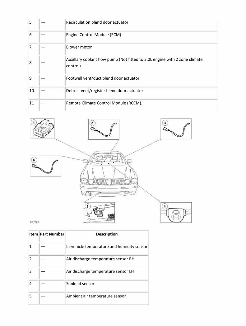
5 — Recirculation blend door actuator
6 — Engine Control Module (ECM)
7 — Blower motor
8 — Auxillary coolant flow pump (Not fitted to 3.0L engine with 2 zone climate
control)
9 — Footwell vent/duct blend door actuator
10 — Defrost vent/register blend door actuator
11 — Remote Climate Control Module (RCCM).
Item Part Number Description
1 — In-vehicle temperature and humidity sensor
2 — Air discharge temperature sensor RH
3 — Air discharge temperature sensor LH
4 — Sunload sensor
5 — Ambient air temperature sensor

6 — Evaporator temperature sensor
The climate control assembly is a single module packaged in the instrument panel consol of the
vehicle. It is a microprocessor-based control consisting of a bezel assembly (including all buttons and
switches), a main control board and a housing for the unit.
The climate control assembly provides the following driver interface controls:
• Climate control assembly ON/OFF switch/fan speed switch
• Manual temperature adjustment switches (drivers/passengers)
• DUAL temperature selection switch
• DEFROST switch
• Heated front screen ON/OFF switch
• Heated rear screen ON/OFF switch
• Manual air distribution MODE switch
• Fahrenheit/Centigrade option switch
• AUTO mode switch
• A/C selection switch
• Recirculate air switch
Operating any of the climate control assembly controls activates a chime (emitted from the
instrument cluster).
The climate control assembly automatically maintains a selected temperature for the interior of the
vehicle. The system regulates the volume of airflow between the instrument panel registers, floor
console registers, front and rear floor ducts, windshield defroster and side window registers. The
system can automatically select between fresh and recirculated air with an optional manual override.
The climate control assembly will try to provide both driver and passenger with their selected
temperature for comfort. The fan controls and air distribution are not controlled individually.
Blower Motor Control
The climate control system has a variable blower speed control. The operator has the option of
manually selecting one of eleven preset blower speeds from the control panel (seven preset blower
speeds with telematics fitted) or selecting to operate the climate control assembly in automatic
mode.
In automatic mode, the blower speed is determined as a function of many input variables. Based on
the desired in-vehicle temperature, the system constantly monitors the ambient temperature,
discharge air temperatures, in-vehicle temperature and sunload levels then calculates the desired
blower setting.
There are special conditions that affect the blower speed while in the automatic mode of operation.
In a cold ambient temperature condition, the climate control assembly implements a Cold Engine
Lock Out (CELO) feature with the blower motor. For a cold vehicle interior, the climate control
assembly will operate in low blower/defrost mode until the engine coolant temperature reaches a

required value. Once the engine coolant has warmed up the blower motor will continue in the
automatic mode.
At increasing vehicle speeds, monitored via the Standard Corporate Protocol (SCP) vehicle speed
status message, the climate control assembly system may adjust the blower motor speed to maintain
constant air flow. This may be necessary in situations where the ram air effect at high speed alters
the air flow into the vehicle interior.
For vehicles fitted with a cellular phone, the climate control assembly may lower the blower motor
speed to reduce the level of ambient noise in the vehicle interior when the phone is in use. The
status of the cellular phone is monitored via the SCP cellular phone ON/OFF message.
Air Distribution Control
The climate control system has variable position control provided by the electrical actuators. The
system gives the option of manually selecting one of five preset air distribution modes or operating
the climate control assembly in automatic mode.
Climate Control - Battery Disconnection
The climate control assembly will store the panel settings in volatile memory. Therefore, in the event
of battery disconnection, or interruption of the supply, the information is lost. After reconnection,
historical fault codes are available, and the panel will be set to OFF. An average automatic setting will
be recovered when the climate control assembly is next switched ON.
If the battery is disconnected, the panel settings will be lost. The customers personal settings should
be recorded and re-set before the vehicle is returned to the customer.

Diagnosis and testing
Control Components 1 . Verify the customer concern.
2 . Visually inspect for obvious signs of mechanical or electrical damage.
Visual Inspection Chart
Mechanical Electrical
• Refrigerant
• Heater control flaps
• Ducting
• Fuse(s)
• Harness
• Electrical connectors
• Switch(es)
1 . If an obvious cause for an observed or reported concern is found, correct the cause (if possible)
before proceeding to the next step.
2 . If the cause is not visually evident, verify the symptom and refer to the Jaguar Approved
Diagnostic System.
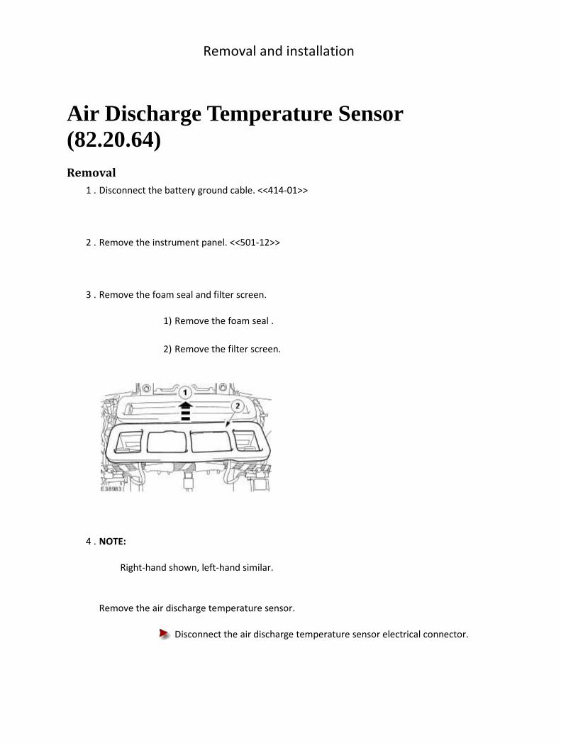
Removal and installation
Air Discharge Temperature Sensor (82.20.64) Removal
1 . Disconnect the battery ground cable. <<414-01>>
2 . Remove the instrument panel. <<501-12>>
3 . Remove the foam seal and filter screen.
1) Remove the foam seal .
2) Remove the filter screen.
4 . NOTE:
Right-hand shown, left-hand similar.
Remove the air discharge temperature sensor.
Disconnect the air discharge temperature sensor electrical connector.

Installation
1 . To install, reverse the removal procedure.

Ambient Air Temperature Sensor (82.20.02) Removal
1 . Disconnect the ambient air temperature electrical connector
2 . Remove the ambient air temperature sensor.
1) Displace the ambient air temperature sensor retaining tang.
2) Remove the ambient air temperature sensor.
Installation
1 . To install, reverse the removal procedure.

Climate Control Assembly (82.20.07) Removal
1
.
NOTE:
When the battery is disconnected and reconnected all previous panel settings and fault
codes will be lost. It is necessary to record any non-standard settings or fault codes
before battery disconnection to prevent customer complaint and carry out correct
diagnosis.
Disconnect the battery ground cable. <<414-01>>
2 . Remove the instrument panel console. <<501-12>>
3 . Remove the center console switch assembly.
4 . Remove the climate control assembly.
Installation
1 . To install, reverse the removal procedure.

2 . Make sure the climate control assembly is correctly located to the audio unit.
3
.
Make sure the center console switch assembly is correctly located to the climate control
assembly.

Cold Air Bypass Blend Door Actuator LH Removal
All vehicles
1 . Disconnect the battery ground cable. <<414-01>>
Right-hand drive vehicles
2
. WARNING: Never remove the coolant pressure cap under any circumstances while
the engine is operating. Failure to follow this instruction may result in personal injury.
WARNING: To avoid having scalding hot coolant or steam blow out of the cooling
system, use extreme care when removing the coolant pressure cap from a hot cooling
system. Wait until the engine has cooled, then wrap a thick cloth around the coolant
pressure cap and turn it slowly until the pressure begins to release. Step back while the
pressure is released from the system. When certain all the pressure has been released (still
with a cloth) turn and remove the coolant pressure cap from the coolant expansion tank.
Failure to follow these instructions may result in personal injury.
WARNING: To avoid the possibility of personal injury, do not operate the engine
with the hood open until the fan blades have been examined for cracks and separation.
Failure to follow this instruction may result in personal injury.
WARNING: Remove fuse 14 from the engine compartment fuse box prior to
performing any under hood service in the area of the cooling fan when the engine is hot,
since the cooling fan motor could operate even if the engine has been switched OFF. Failure
to follow this instruction may result in personal injury.
CAUTION: The engine cooling system must be maintained with the correct
concentration and type of anti-freeze solution to prevent corrosion and frost damage.

Failure to follow this instruction may result in damage to the engine.
CAUTION: Never remove the coolant pressure cap under any circumstances while
the engine is operating. Failure to follow this instruction may result in damage to the
engine.
Release the cooling system pressure.
Remove the coolant expansion tank pressure cap.
3 . Remove the front footwell vent duct. <<412-01>>
4 . Remove the glove box. <<501-12>>
5 . Remove the engine control module. <<303-14A>> <<303-14B>>
6 . Disconnect the blower motor electrical connector.
7 . Remove the blower motor housing securing bolts.

8 . Remove the blower motor housing securing bolts.
9 . Remove the blower motor housing.
10
. CAUTION: Care should be taken when removing the heater core inlet and outlet
pipes as coolant may leak out of the heater core.
NOTE:
Cap the heater core inlet and outlet pipes to prevent coolant loss.
Remove the heater core inlet and outlet pipes.
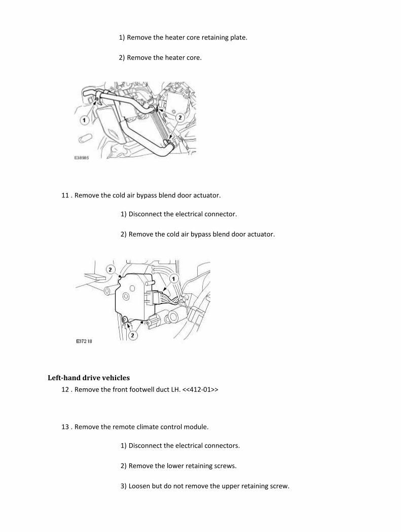
1) Remove the heater core retaining plate.
2) Remove the heater core.
11 . Remove the cold air bypass blend door actuator.
1) Disconnect the electrical connector.
2) Remove the cold air bypass blend door actuator.
Left-hand drive vehicles
12 . Remove the front footwell duct LH. <<412-01>>
13 . Remove the remote climate control module.
1) Disconnect the electrical connectors.
2) Remove the lower retaining screws.
3) Loosen but do not remove the upper retaining screw.

4) Remove the remote climate control module.
14 . Remove the cold air bypass blend door actuator.
1) Disconnect the electrical connector.
2) Remove the cold air bypass blend door actuator.
Installation
Right-hand drive vehicles
1 . NOTE:
Care should be taken to ensure the actuator linkages are correctly engaged.
To install, reverse the removal procedure.
Tighten to 7 Nm.
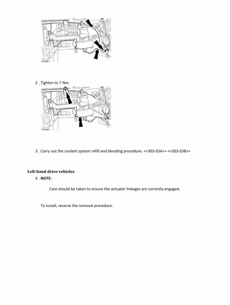
2 . Tighten to 7 Nm.
3 . Carry out the coolant system refill and bleeding procedure. <<303-03A>> <<303-03B>>
Left-hand drive vehicles
4 . NOTE:
Care should be taken to ensure the actuator linkages are correctly engaged.
To install, reverse the removal procedure.
Cold Air Bypass Blend Door Actuator RH Removal
All vehicles
1 . Disconnect the battery ground cable. <<414-01>>
Left-hand drive vehicles
2
. WARNING: Never remove the coolant pressure cap under any circumstances while
the engine is operating. Failure to follow this instruction may result in personal injury.
WARNING: To avoid having scalding hot coolant or steam blow out of the cooling
system, use extreme care when removing the coolant pressure cap from a hot cooling
system. Wait until the engine has cooled, then wrap a thick cloth around the coolant
pressure cap and turn it slowly until the pressure begins to release. Step back while the
pressure is released from the system. When certain all the pressure has been released (still
with a cloth) turn and remove the coolant pressure cap from the coolant expansion tank.
Failure to follow these instructions may result in personal injury.
WARNING: To avoid the possibility of personal injury, do not operate the engine
with the hood open until the fan blades have been examined for cracks and separation.
Failure to follow this instruction may result in personal injury.
WARNING: Remove fuse 14 from the engine compartment fuse box prior to
performing any under hood service in the area of the cooling fan when the engine is hot,
since the cooling fan motor could operate even if the engine has been switched OFF. Failure
to follow this instruction may result in personal injury.
CAUTION: The engine cooling system must be maintained with the correct
concentration and type of anti-freeze solution to prevent corrosion and frost damage.

Failure to follow this instruction may result in damage to the engine.
CAUTION: Never remove the coolant pressure cap under any circumstances while
the engine is operating. Failure to follow this instruction may result in damage to the
engine.
Release the cooling system pressure.
Remove the coolant expansion tank pressure cap.
3 . Remove the passenger footwell vent duct. <<412-01>>
4 . Remove the glove box. <<501-12>>
5 . Remove the engine control module. <<303-14A>> <<303-14B>>
6 . Disconnect the blower motor electrical connector.
7 . Remove the blower motor housing securing bolts.

8 . Remove the blower motor housing securing bolts.
9 . Remove the blower motor housing.
10
. CAUTION: Care should be taken when removing the heater core inlet and outlet
pipes as coolant may leak out of the heater core.
NOTE:
Cap the heater core inlet and outlet pipes to prevent coolant loss.
Remove the heater core inlet and outlet pipes.
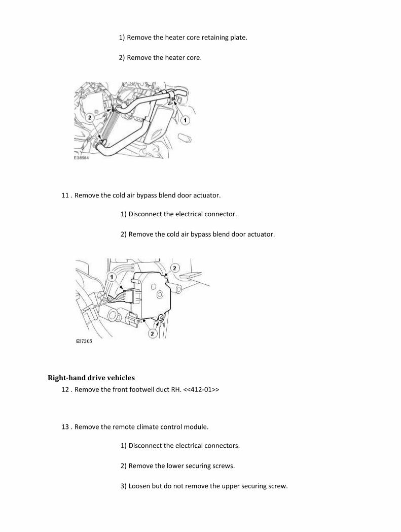
1) Remove the heater core retaining plate.
2) Remove the heater core.
11 . Remove the cold air bypass blend door actuator.
1) Disconnect the electrical connector.
2) Remove the cold air bypass blend door actuator.
Right-hand drive vehicles
12 . Remove the front footwell duct RH. <<412-01>>
13 . Remove the remote climate control module.
1) Disconnect the electrical connectors.
2) Remove the lower securing screws.
3) Loosen but do not remove the upper securing screw.

4) Remove the remote climate control module.
14 . Remove the cold air bypass blend door actuator.
1) Disconnect the electrical connector.
2) Remove the cold air bypass blend door actuator securing screws.
Installation
Right-hand drive vehicles
1 . NOTE:
Care should be taken to make sure the actuator linkages are correctly engaged.
To install, reverse the removal procedure.
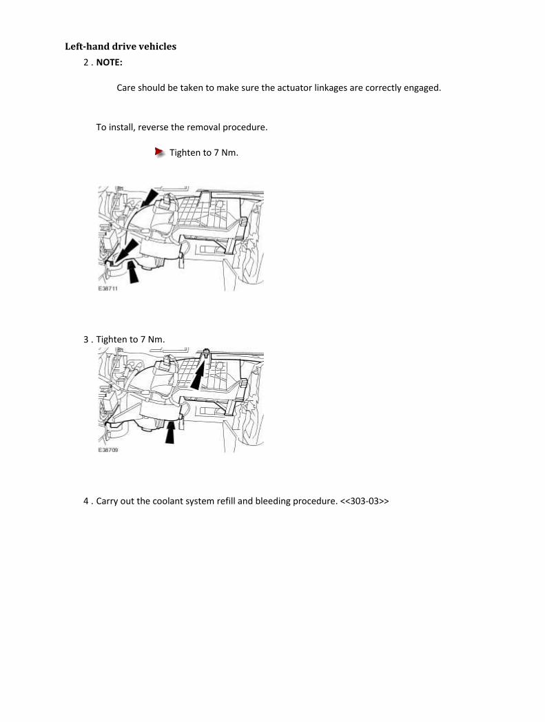
Left-hand drive vehicles
2 . NOTE:
Care should be taken to make sure the actuator linkages are correctly engaged.
To install, reverse the removal procedure.
Tighten to 7 Nm.
3 . Tighten to 7 Nm.
4 . Carry out the coolant system refill and bleeding procedure. <<303-03>>

Defrost Vent/Register Blend Door Actuator LH Removal
All vehicles
1 . Disconnect the battery ground cable. <<414-01>>
Left-hand drive vehicles
2 . Remove the remote climate control module.
1) Disconnect the electrical connectors.
2) Remove the lower retaining screws.
3) Loosen but do not remove the upper retaining screw.
4) Remove the remote climate control module.
3 . Remove the defrost vent/register blend door actuator.
1) Disconnect the electrical connector.
2) Remove the defrost vent/register blend door actuator.

Right-hand drive vehicles
4 . Remove the glove compartment. <<501-12>>
5 . Remove the defrost vent/register blend door actuator.
1) Disconnect the electrical connector.
2) Remove the defrost vent/register blend door actuator.
Installation
1 . NOTE:
Care should be taken to make sure the actuator linkages are correctly engaged.
To install, reverse the removal procedure.

Defrost Vent/Register Blend Door Actuator RH Removal
All vehicles
1 . Disconnect the battery ground cable. <<414-01>>
Left-hand drive vehicles
2 . Remove the glove compartment. <<501-12>>
3 . Remove the defrost vent/register blend door actuator.
1) Disconnect the electrical connector.
2) Remove the defrost vent/register blend door actuator.
Right-hand drive vehicles
4 . Remove the front footwell duct RH. <<412-01>>
5 . Remove the remote climate control module.
1) Disconnect the electrical connectors.
2) Remove the lower retaining screws.
3) Loosen but do not remove the upper retaining screw.
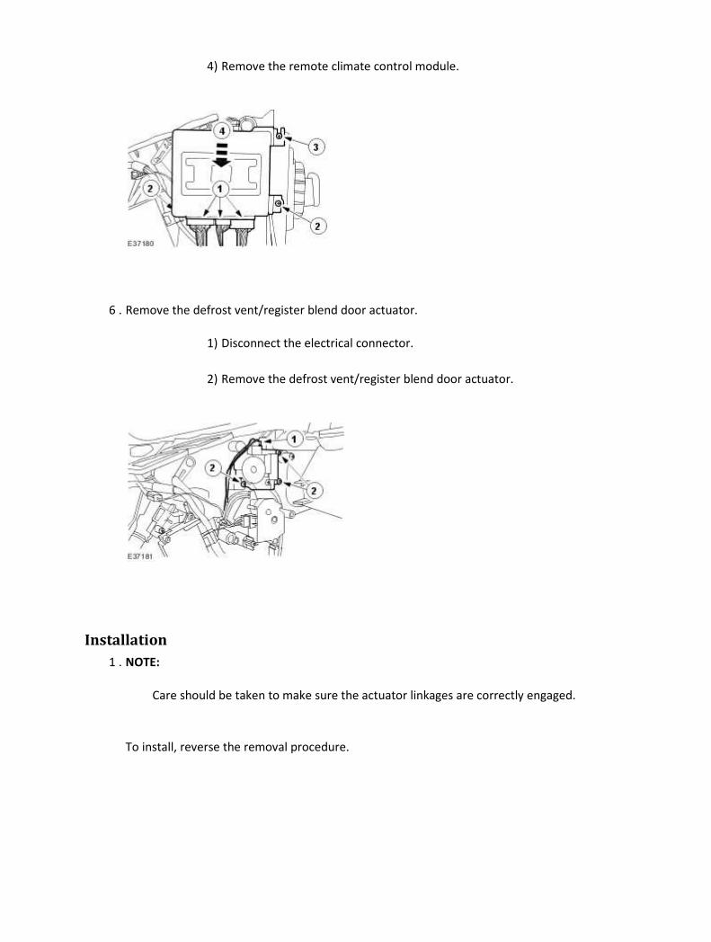
4) Remove the remote climate control module.
6 . Remove the defrost vent/register blend door actuator.
1) Disconnect the electrical connector.
2) Remove the defrost vent/register blend door actuator.
Installation
1 . NOTE:
Care should be taken to make sure the actuator linkages are correctly engaged.
To install, reverse the removal procedure.
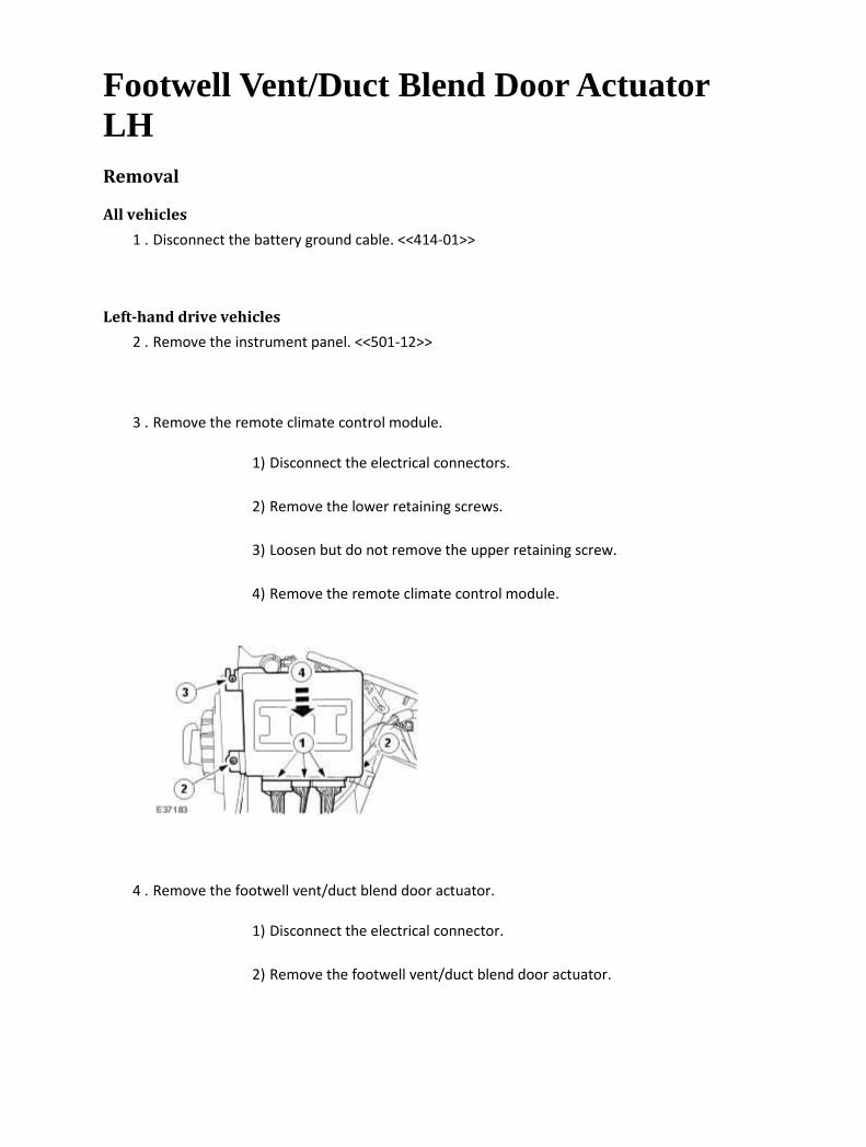
Footwell Vent/Duct Blend Door Actuator LH Removal
All vehicles
1 . Disconnect the battery ground cable. <<414-01>>
Left-hand drive vehicles
2 . Remove the instrument panel. <<501-12>>
3 . Remove the remote climate control module.
1) Disconnect the electrical connectors.
2) Remove the lower retaining screws.
3) Loosen but do not remove the upper retaining screw.
4) Remove the remote climate control module.
4 . Remove the footwell vent/duct blend door actuator.
1) Disconnect the electrical connector.
2) Remove the footwell vent/duct blend door actuator.
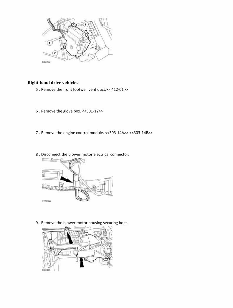
Right-hand drive vehicles
5 . Remove the front footwell vent duct. <<412-01>>
6 . Remove the glove box. <<501-12>>
7 . Remove the engine control module. <<303-14A>> <<303-14B>>
8 . Disconnect the blower motor electrical connector.
9 . Remove the blower motor housing securing bolts.

10 . Remove the blower motor housing securing bolts.
11 . Remove the blower motor housing.
12 . Remove the footwell vent/duct blend door actuator.
1) Disconnect the electrical connector.
2) Remove the footwell vent/duct blend door actuator.

Installation
Left-hand drive vehicles
1 . NOTE:
Care should be taken to ensure the actuator linkages are correctly engaged.
To install, reverse the removal procedure.
Right-hand drive vehicles
2 . NOTE:
Care should be taken to ensure the actuator linkages are correctly engaged.
To install, reverse the removal procedure.
Tighten to 7 Nm.
3 . Tighten to 7 Nm.

Footwell Vent/Duct Blend Door Actuator RH Removal
All vehicles
1 . Disconnect the battery ground cable. <<414-01>>
Right-hand drive vehicles
2 . Remove the instrument panel. <<501-12>>
3 . Remove the remote climate control module.
1) Disconnect the electrical connectors.
2) Remove the lower securing screws.
3) Loosen but do not remove the upper securing screw.
4) Remove the remote climate control module.
4 . Remove the footwell vent/duct blend door actuator.
1) Disconnect the electrical connector.
2) Remove the footwell vent/duct blend door actuator.

Left-hand drive vehicles
5 . Remove the passenger footwell vent duct. <<412-01>>
6 . Remove the glove box. <<501-12>>
7 . Remove the engine control module. <<303-14A>> <<303-14B>>
8 . Disconnect the blower motor electrical connector.
9 . Remove the blower motor housing securing bolts.
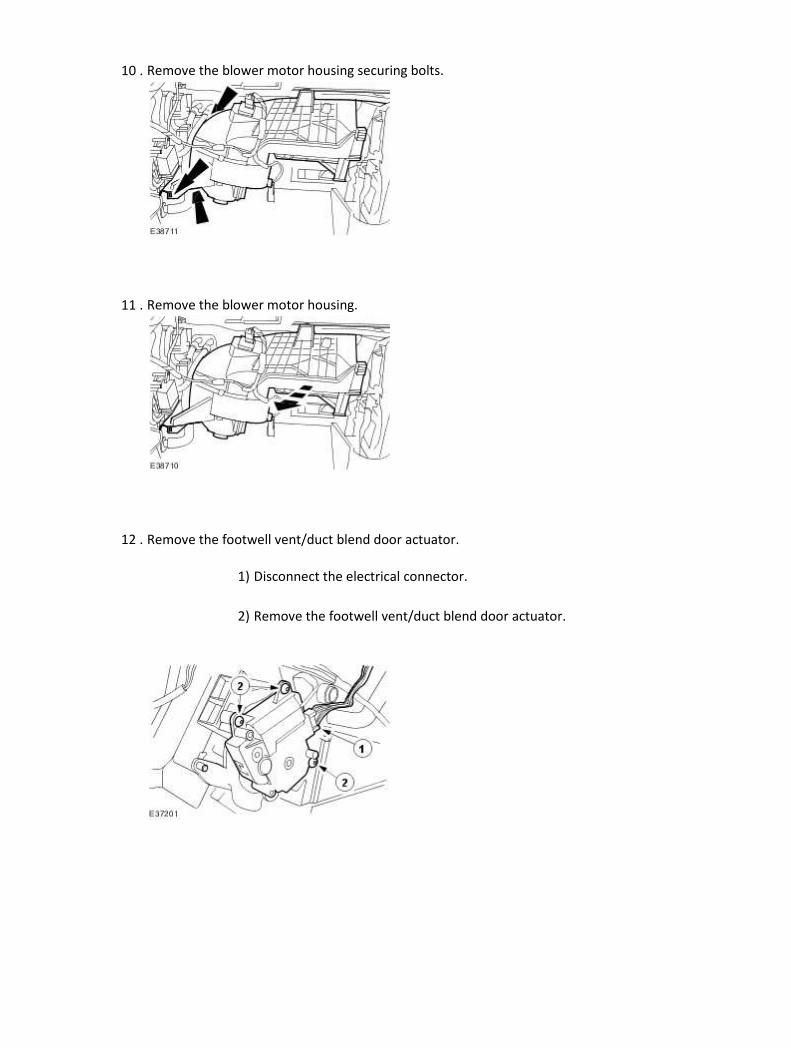
10 . Remove the blower motor housing securing bolts.
11 . Remove the blower motor housing.
12 . Remove the footwell vent/duct blend door actuator.
1) Disconnect the electrical connector.
2) Remove the footwell vent/duct blend door actuator.
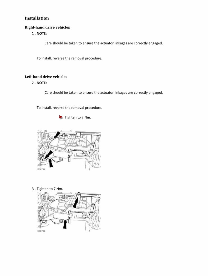
Installation
Right-hand drive vehicles
1 . NOTE:
Care should be taken to ensure the actuator linkages are correctly engaged.
To install, reverse the removal procedure.
Left-hand drive vehicles
2 . NOTE:
Care should be taken to ensure the actuator linkages are correctly engaged.
To install, reverse the removal procedure.
Tighten to 7 Nm.
3 . Tighten to 7 Nm.

In-Vehicle Temperature Sensor (82.20.03) Removal
1 . Reposition the steering column to its highest position.
2 . Disconnect the battery ground cable. <<414-01>>
3 . Remove the instrument panel lower trim panel.
4 . Detach the steering column lower shroud.
5 . Remove the lower steering column lower shroud.
Disconnect the electrical connector.

6 . Disconnect the in-vehicle temperature sensor hose.
1) Detach the hose from the bracket.
2) Remove the hose from the retaining clip.
7 . Disconnect the in-vehicle temperature sensor electrical connector.
8 . Remove the in-vehicle temperature sensor.
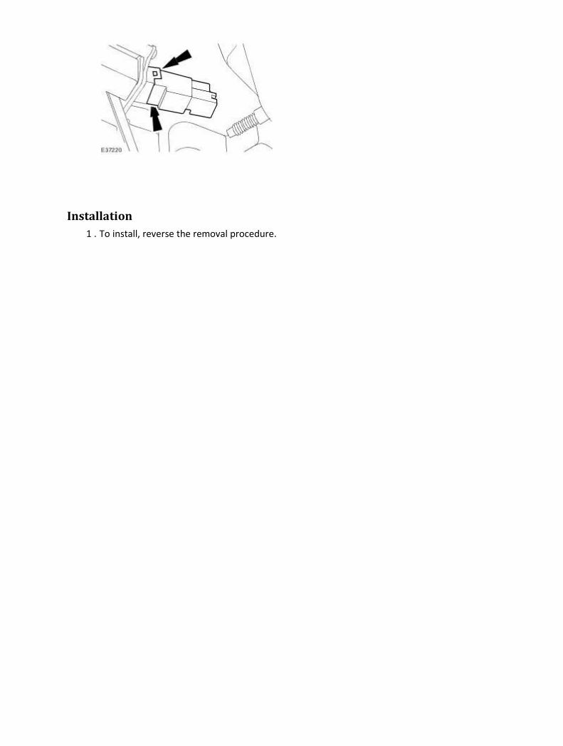
Installation
1 . To install, reverse the removal procedure.

Recirculation Blend Door Actuator (82.20.67) Removal
1 . Remove the passenger footwell vent duct. <<412-01>>
2 . Remove the glove box. <<501-12>>
3 . Remove the Engine control module. <<303-14A>> <<303-14B>>
4 . Disconnect the blower motor electrical connector.
5 . Remove the blower motor housing securing bolts.
6 . Remove the blower motor housing securing bolts.
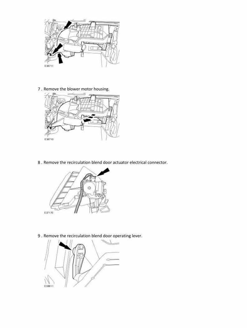
7 . Remove the blower motor housing.
8 . Remove the recirculation blend door actuator electrical connector.
9 . Remove the recirculation blend door operating lever.
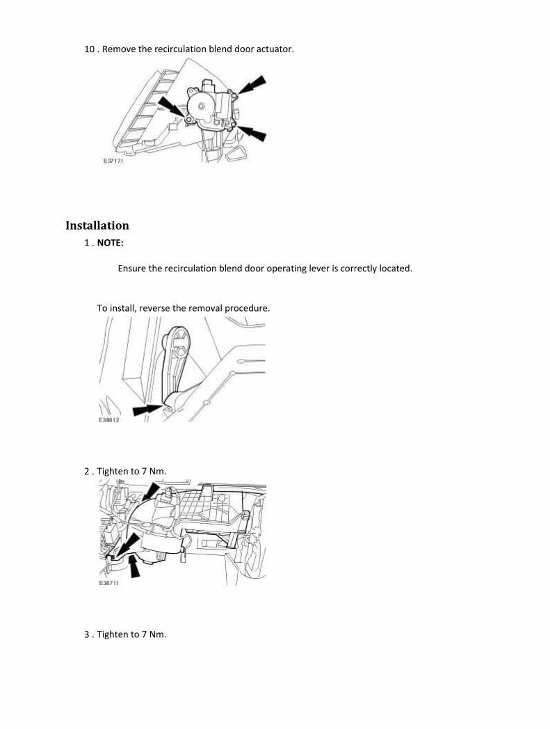
10 . Remove the recirculation blend door actuator.
Installation
1 . NOTE:
Ensure the recirculation blend door operating lever is correctly located.
To install, reverse the removal procedure.
2 . Tighten to 7 Nm.
3 . Tighten to 7 Nm.

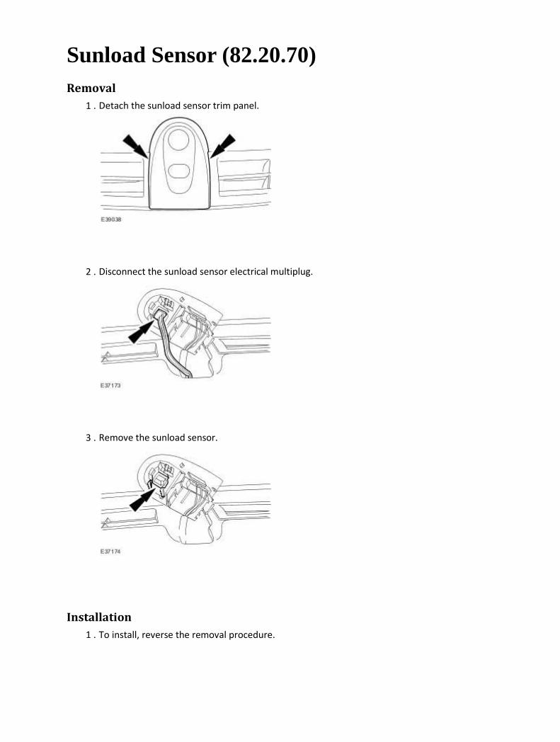
Sunload Sensor (82.20.70) Removal
1 . Detach the sunload sensor trim panel.
2 . Disconnect the sunload sensor electrical multiplug.
3 . Remove the sunload sensor.
Installation
1 . To install, reverse the removal procedure.
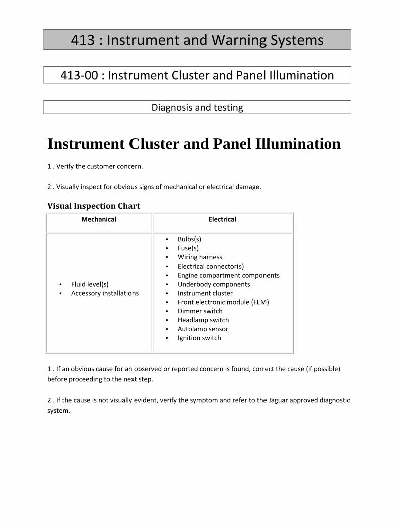
413 : Instrument and Warning Systems
413-00 : Instrument Cluster and Panel Illumination
Diagnosis and testing
Instrument Cluster and Panel Illumination 1 . Verify the customer concern.
2 . Visually inspect for obvious signs of mechanical or electrical damage.
Visual Inspection Chart
Mechanical Electrical
• Fluid level(s)
• Accessory installations
• Bulbs(s)
• Fuse(s)
• Wiring harness
• Electrical connector(s)
• Engine compartment components
• Underbody components
• Instrument cluster
• Front electronic module (FEM)
• Dimmer switch
• Headlamp switch
• Autolamp sensor
• Ignition switch
1 . If an obvious cause for an observed or reported concern is found, correct the cause (if possible)
before proceeding to the next step.
2 . If the cause is not visually evident, verify the symptom and refer to the Jaguar approved diagnostic
system.

413-01 : Instrument Cluster
Specifications
Specifications General specifications
Item Specification
Illumination bulb. 3.0 Watt

Description and operation
Instrument Cluster
Item Part Number Description
1 — Tachometer
2 — Left-hand direction indicator
3 — Speedometer
4 — Right-hand direction indicator
5 — Fuel gauge
6 — High engine temperature indicator
7 — Engine temperature gauge
8 — Side lamps indicator
9 — Rear fog lamps indicator
10 — High beam indicator
11 — Front fog lamps indicator
12 — Low fuel level indicator
13 — Adaptive speed control indicator
14 — Message center red warning indicator-primary warning
15 — Message center display
16 — Message center amber warning indicator-secondary warning
17 — Low tire pressure warning indicator
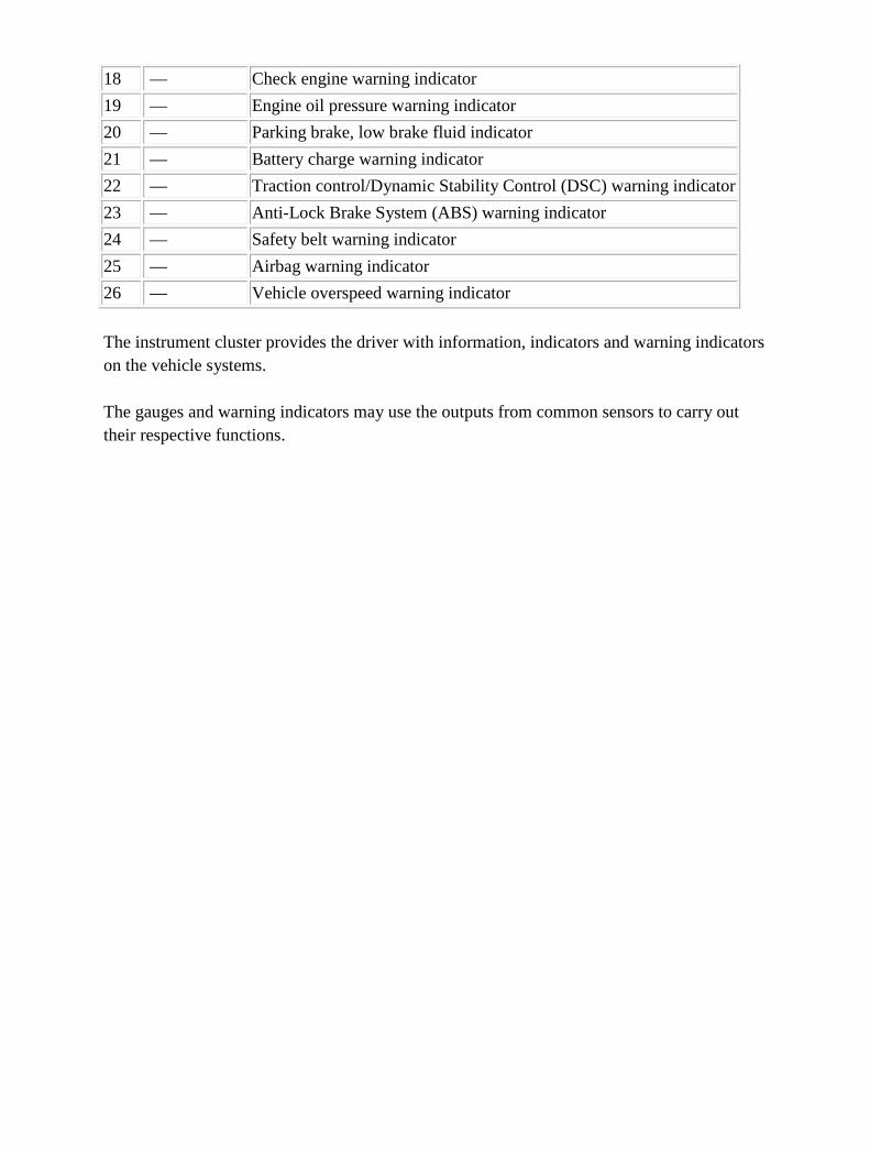
18 — Check engine warning indicator
19 — Engine oil pressure warning indicator
20 — Parking brake, low brake fluid indicator
21 — Battery charge warning indicator
22 — Traction control/Dynamic Stability Control (DSC) warning indicator
23 — Anti-Lock Brake System (ABS) warning indicator
24 — Safety belt warning indicator
25 — Airbag warning indicator
26 — Vehicle overspeed warning indicator
The instrument cluster provides the driver with information, indicators and warning indicators on the vehicle systems. The gauges and warning indicators may use the outputs from common sensors to carry out their respective functions.
Diagnosis and testing
Instrument Cluster Principles of Operation
For a detailed description of the Instrument Cluster, refer to the relevant Description and Operation
sections in the workshop manual.
Instrument Cluster
Inspection and Verification
1 . Verify the customer concern.
2 . Visually inspect for obvious signs of mechanical or electrical damage.
Visual Inspection Chart
Electrical
• Fuses/Relays
• Damaged, Loose or Corroded Connector(s)
• Damage to Wiring Loom/Incorrect Location, Stretched or Taught
1 . If an obvious cause for an observed or reported concern is found, correct the cause (if possible)
before proceeding to the next step.
2 . If the cause is not visually evident, verify the symptom and refer to the Jaguar approved diagnostic
system.
3 . If an instrument cluster warning lamp is illuminated, this normally indicates a non instrument
cluster fault. Interrogate the relevant module for stored DTCs and act on this information. When the
repair has been carried out, the fault codes cleared and after cycling the ignition the instrument
cluster warning lamp should extinguish.
DTC Index
Instrument Cluster
CAUTION: When probing connectors to take measurements in the course of the pinpoint
tests, use the adaptor kit, part number 3548-1358-00
NOTE:

If the control module/component is suspect and the vehicle remains under manufacturer
warranty, refer to the Warranty Policy and Procedures manual (section B1.2), or determine if
any prior approval program is in operation, prior to the installation of a new
module/component.
NOTE:
When performing voltage or resistance tests, always use a digital multimeter (DMM) accurate to
three decimal places and with a current calibration certificate. When testing resistance, always
take the resistance of the DMM leads into account.
NOTE:
Check and rectify basic faults before beginning diagnostic routines that involve pinpoint tests.
NOTE:
Inspect connectors for signs of water ingress, and pins for damage and/or corrosion.
NOTE:
If DTCs are recorded and, after performing the pinpoint tests, a fault is not present, an
intermittent concern may be the cause. Always check for loose connections and corroded
terminals.
DTC Description Possible Causes Action
B1202 Fuel Sender Circuit
Open
• Instrument cluster, fuel
sender - circuit open
Carry out any pinpoint tests
associated with this DTC using the
manufacturer approved diagnostic
system. Refer to electrical circuit
diagrams, notes and check rear
electronic module, fuel sender
circuit for open circuit
B1204 Fuel Sender Circuit
Short To Ground
• Instrument cluster, fuel
sender - short to
ground
Carry out any pinpoint tests
associated with this DTC using the
manufacturer approved diagnostic
system. Refer to electrical circuit
diagrams, notes and check rear
electronic module, fuel sender
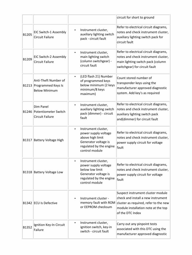
circuit for short to ground
B1205 EIC Switch-1 Assembly
Circuit Failure
• Instrument cluster,
auxiliary lighting switch
pack - circuit fault
Refer to electrical circuit diagrams,
notes and check instrument cluster,
auxiliary lighting switch pack for
circuit fault
B1209 EIC Switch-2 Assembly
Circuit Failure
• Instrument cluster,
main lighting switch
(column switchgear) -
circuit fault
Refer to electrical circuit diagrams,
notes and check instrument cluster,
main lighting switch pack (column
switchgear) for circuit fault
B1213
Anti-Theft Number of
Programmed Keys Is
Below Minimum
• (LED flash 21) Number
of programmed keys
below minimum (2 keys
minimum/8 keys
maximum)
Count stored number of
transponder keys using the
manufacturer approved diagnostic
system. Add key's as required
B1246
Dim Panel
Potentiometer Switch
Circuit Failure
• Instrument cluster,
auxiliary lighting switch
pack (dimmer) - circuit
fault
Refer to electrical circuit diagrams,
notes and check instrument cluster,
auxiliary lighting switch pack
and(dimmer) for circuit fault
B1317 Battery Voltage High
• Instrument cluster,
power supply voltage
above high limit
Generator voltage is
regulated by the engine
control module
Refer to electrical circuit diagrams,
notes and check instrument cluster,
power supply circuit for voltage
fault
B1318 Battery Voltage Low
• Instrument cluster,
power supply voltage
below low limit
Generator voltage is
regulated by the engine
control module
Refer to electrical circuit diagrams,
notes and check instrument cluster,
power supply circuit for voltage
fault
B1342 ECU Is Defective
• Instrument cluster -
memory fault with ROM
or EEPROM checksum
Suspect instrument cluster module
check and install a new instrument
cluster as required, refer to the new
module installation note at the top
of the DTC Index
B1352 Ignition Key-In Circuit
Failure
• Instrument cluster,
ignition switch, key-in
switch - circuit fault
Carry out any pinpoint tests
associated with this DTC using the
manufacturer approved diagnostic

system. Refer to electrical circuit
diagrams, notes and check
instrument cluster, ignition switch,
key-in switch for circuit fault
B1359 Ignition Run/Acc
Circuit Failure
• Instrument cluster -
ignition power input
voltage low (more than
15 seconds, starter
crank timeout)
Refer to electrical circuit diagrams,
notes and check instrument cluster,
ignition power and ground for
circuit fault
B1470 Lamp Headlamp Input
Circuit Failure
• Instrument cluster -
main lighting switch
(column switchgear)
headlamp - circuit fault
Carry out any pinpoint tests
associated with this DTC using the
manufacturer approved diagnostic
system. Refer to electrical circuit
diagrams, notes and check
instrument cluster, main lighting
switch (column switchgear)
headlamp switch and circuit for
fault
B1567
Lamp Headlamp
Highbeam Circuit
Failure
• Instrument cluster -
main lighting switch
(column switchgear)
highbeam - circuit fault
Carry out any pinpoint tests
associated with this DTC using the
manufacturer approved diagnostic
system. Refer to electrical circuit
diagrams, notes and check
instrument cluster, main lighting
switch (column switchgear)
highbeam switch and circuit for
fault
B1600
PATS Ignition Key
Transponder Signal Is
Not Received
• (LED flash 13)
Instrument cluster - no
PATS code received
from (passive anti-theft
system) key
transponder (key fault)
Carry out any pinpoint tests
associated with this DTC using the
manufacturer approved diagnostic
system. Check for transponder key
fault
B1601
PATS Received
Incorrect Key-Code
From Ignition Key
Transponder
• (LED flash 15)
Instrument cluster - not
programmed (passive
anti-theft system)
transponder key in
ignition switch
Carry out any pinpoint tests
associated with this DTC using the
manufacturer approved diagnostic
system. Refer to electrical circuit
diagrams, notes and check
transponder key is programmed to
vehicle
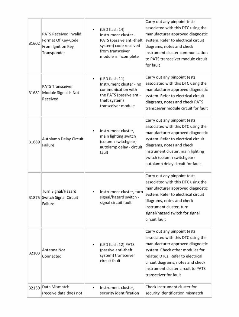
B1602
PATS Received Invalid
Format Of Key-Code
From Ignition Key
Transponder
• (LED flash 14)
Instrument cluster -
PATS (passive anti-theft
system) code received
from transceiver
module is incomplete
Carry out any pinpoint tests
associated with this DTC using the
manufacturer approved diagnostic
system. Refer to electrical circuit
diagrams, notes and check
instrument cluster communication
to PATS transceiver module circuit
for fault
B1681
PATS Transceiver
Module Signal Is Not
Received
• (LED flash 11)
Instrument cluster - no
communication with
the PATS (passive anti-
theft system)
transceiver module
Carry out any pinpoint tests
associated with this DTC using the
manufacturer approved diagnostic
system. Refer to electrical circuit
diagrams, notes and check PATS
transceiver module circuit for fault
B1689 Autolamp Delay Circuit
Failure
• Instrument cluster,
main lighting switch
(column switchgear)
autolamp delay - circuit
fault
Carry out any pinpoint tests
associated with this DTC using the
manufacturer approved diagnostic
system. Refer to electrical circuit
diagrams, notes and check
instrument cluster, main lighting
switch (column switchgear)
autolamp delay circuit for fault
B1875
Turn Signal/Hazard
Switch Signal Circuit
Failure
• Instrument cluster, turn
signal/hazard switch -
signal circuit fault
Carry out any pinpoint tests
associated with this DTC using the
manufacturer approved diagnostic
system. Refer to electrical circuit
diagrams, notes and check
instrument cluster, turn
signal/hazard switch for signal
circuit fault
B2103 Antenna Not
Connected
• (LED flash 12) PATS
(passive anti-theft
system) transceiver
circuit fault
Carry out any pinpoint tests
associated with this DTC using the
manufacturer approved diagnostic
system. Check other modules for
related DTCs. Refer to electrical
circuit diagrams, notes and check
instrument cluster circuit to PATS
transceiver for fault
B2139 Data Mismatch
(receive data does not
• Instrument cluster,
security identification
Check Instrument cluster for
security identification mismatch

match what was
expected)
mismatch with the rear
electronic module REM
(challenge-response
error)
with the rear electronic module
REM
B2141 NVM Configuration
Failure
• (LED flash 22)
Instrument cluster,
vehicle ID is not stored
in cluster
Carry out any pinpoint tests
associated with this DTC using the
manufacturer approved diagnostic
system. Enter vehicle id into
instrument cluster (Enable PCM ID
transfer) using the manufacturer
approved diagnostic system.
B2143 NVM Memory Failure • Instrument cluster,
Internal EEPROM error
Carry out any pinpoint tests
associated with this DTC using the
manufacturer approved diagnostic
system. Suspect instrument cluster
internal failure. Clear DTC carry out
battery reset, if DTC returns suspect
instrument cluster internal failure,
check and replace as required, refer
to the new module installation note
at the top of the DTC Index
B2162
Data Mismatch #2
(receive data does not
match what was
expected)
• Electronic steering
column lock ID
mismatch with
instrument cluster
stored ID
Enable Electronic steering column
lock ID transfer using the
manufacturer approved diagnostic
system.
B2329
Column Reach
Feedback
Potentiometer Circuit
Open
• Instrument cluster,
steering column
movement assembly,
telescope position
signal circuit fault -
open circuit or short to
ground
Carry out any pinpoint tests
associated with this DTC using the
manufacturer approved diagnostic
system. Refer to electrical circuit
diagrams, notes and check
instrument cluster, steering column
movement assembly, telescope
position feedback circuit for open
circuit or short to ground
B2330
Column Reach
Feedback
Potentiometer Circuit
Short to Power
• Instrument cluster,
steering column
movement assembly,
telescope position
signal circuit fault -
Carry out any pinpoint tests
associated with this DTC using the
manufacturer approved diagnostic
system. Refer to electrical circuit
diagrams, notes and check

short to power instrument cluster, steering column
movement assembly, telescope
position feedback circuit for short
to power
B2333
Column Tilt Feedback
Potentiometer Circuit
Open
• Instrument cluster,
steering column
movement assembly,
tilt position signal
circuit fault - open
circuit or short to
ground
Carry out any pinpoint tests
associated with this DTC using the
manufacturer approved diagnostic
system. Refer to electrical circuit
diagrams, notes and check
instrument cluster, steering column
movement assembly, tilt position
feedback circuit for open circuit or
short to ground
B2334
Column Tilt Feedback
Potentiometer Circuit
Short to Power
• Instrument cluster,
steering column
movement assembly,
tilt position signal
circuit fault - short to
power
Carry out any pinpoint tests
associated with this DTC using the
manufacturer approved diagnostic
system. Refer to electrical circuit
diagrams, notes and check
instrument cluster, steering column
movement assembly, tilt position
feedback circuit for short to power
B2351 Steering Column
Switch Circuit Failure
• Instrument cluster,
column and pedal
adjust switches - input
voltage out of range
Carry out any pinpoint tests
associated with this DTC using the
manufacturer approved diagnostic
system. Refer to electrical circuit
diagrams, notes and check
instrument cluster, column and
pedal adjust switchpack and input
circuit for fault
B2431 Transponder
Programming Failure
• Instrument cluster,
transponder keyfob
PATS code transmit
fault
Suspect transponder keyfob PATS
code transmit fault. Check and
replace keyfob as require
B2472 Fog Lamp Switch
Failure
• Instrument cluster,
auxiliary lighting
switchpack, foglamp
switch's - input voltage
out of range
Carry out any pinpoint tests
associated with this DTC using the
manufacturer approved diagnostic
system. Refer to electrical circuit
diagrams, notes and check
instrument cluster, auxiliary lighting
switchpack (foglamp's input) circuit

for voltage fault
B2477 Module Configuration
Failure
• Instrument cluster,
vehicle configuration
not programmed or
configuration write
failure
Enter vehicle configuration into
instrument cluster using the
manufacturer approved diagnostic
system
B2627 Fuel Sender Circuit
Open #2
• Fuel tank level sender
circuit to rear electronic
module - circuit open
Carry out any pinpoint tests
associated with this DTC using the
manufacturer approved diagnostic
system. Refer to electrical circuit
diagrams, notes and check fuel tank
level sender circuit to rear
electronic module for open circuit
B2628 Fuel Sender Circuit
Short To Ground #2
• Fuel tank level sender
circuit to rear electronic
module - short to
ground
Carry out any pinpoint tests
associated with this DTC using the
manufacturer approved diagnostic
system. Refer to electrical circuit
diagrams, notes and check fuel tank
level sender circuit to rear
electronic module for short to
ground
B2879 Fuel Tank Jet Pump
Fault
• Fuel pump module, fuel
tank jet pump fault
• Fuel level (check both
sides of the saddle tank)
Refer to electrical circuit diagrams,
notes and check fuel level sender's
and fuel tank jet pump circuit's for
fault
B2881
Column Reach
Movement Fault -
Primary Axis
• Instrument cluster,
steering column
movement assembly,
telescope primary axis
position sensor fault
Carry out any pinpoint tests
associated with this DTC using the
manufacturer approved diagnostic
system. Check steering column
movement (telescope primary axis
position sensor) assembly for fault
B2882
Column Reach
Movement Fault -
Secondary Axis
• Instrument cluster,
steering column
movement assembly,
telescope secondary
axis position sensor
fault
Carry out any pinpoint tests
associated with this DTC using the
manufacturer approved diagnostic
system. Check steering column
movement (telescope secondary
axis position sensor) assembly for
fault

B2883 Column Tilt Movement
Fault - Primary Axis
• Instrument cluster,
steering column
movement assembly,
tilt primary axis position
sensor fault
Carry out any pinpoint tests
associated with this DTC using the
manufacturer approved diagnostic
system. Check steering column
movement (tilt primary axis
position sensor) assembly for fault
B2884 Column Tilt Movement
Fault - Secondary Axis
• Instrument cluster,
steering column
movement assembly,
tilt secondary axis
position sensor fault
Carry out any pinpoint tests
associated with this DTC using the
manufacturer approved diagnostic
system. Check steering column
movement (tilt secondary axis
position sensor) assembly for fault
C1778 Power Steering Failure
• Instrument cluster,
incorrect reply from
variable assist steering
actuator output
transistor or NVM
checksum error
Suspect instrument cluster
electronic failure. Check and install
a new instrument cluster as
required, refer to the new module
installation note at the top of the
DTC Index
C1922
VAPS Solenoid
Actuator Output
Circuit Open
• Instrument cluster,
variable assist steering
actuator output - open
circuit
Refer to electrical circuit diagrams,
notes and check instrument cluster,
variable assist steering actuator
circuit for open circuit
C1923
VAPS Solenoid
Actuator Output
Circuit Short To Power
• Instrument cluster,
variable assist steering
actuator output - short
to power
Refer to electrical circuit diagrams,
notes and check instrument cluster,
variable assist steering actuator
circuit for short to power
C1924
VAPS Solenoid
Actuator Output
Circuit Short To
Ground
• Instrument cluster,
variable assist steering
actuator output - short
to ground
Refer to electrical circuit diagrams,
notes and check instrument cluster,
variable assist steering actuator
circuit for short to ground
C1986 VAPS Initial Speed
Above threshold
• Instrument cluster,
variable assist steering
actuator output - circuit
fault
Refer to electrical circuit diagrams,
notes and check instrument cluster
power circuit and variable assist
steering actuator circuit for loose
power connection's or short circuit
U0128 Lost Communication
With Park Brake
Control Module (EPB
• Instrument cluster -
electronic parking brake
message missing even
Check electronic parking brake for
stored DTCs. Refer to electrical
circuit diagrams, notes and check

message missing even
though CAN keep
awake message was
received)
though (CAN Bus) keep
awake message was
received
CAN Bus circuit between instrument
cluster and electronic parking brake
U1147
SCP (J1850) Invalid or
Missing Data for
Vehicle Security
• Instrument cluster,
invalid response from
rear electronic module
during
challenge/response
Check rear electronic module for
stored DTCs
U1262
SCP (J1850)
Communication Bus
Fault
• Instrument cluster - No
response from rear
electronic module
during
challenge/response
Check rear electronic module for
stored DTCs
U1751
Steering Column Lock
System Status
Message Missing from
REM
• Instrument cluster -
missing (electronic
steering column lock)
enable status - OFF
message from rear
electronic module
(logged after 2 retries)
Check rear electronic module for
stored DTCs
U1752
Steering Column Lock
System Status
Message Missing from
FEM
• Instrument cluster -
(electronic steering
column lock) missing
enable status - OFF
message from front
electronic module
(logged after 2 retries)
Check front electronic module for
stored DTCs
U1900
CAN Communication
Bus Fault (PATS use
only - Receive Error)
• Instrument cluster -
missing messages on
CAN bus
Refer to electrical circuit diagrams,
notes and check instrument cluster
CAN Bus circuit for fault
U2150 SCP (J1850) Invalid
Data from REM
• Instrument cluster -
(electronic steering
column lock) missing or
incorrect (electronic
steering column lock)
enable status from rear
electronic module
Check rear electronic module for
stored DTCs
U2152 SCP (J1850) Invalid
Data from FEM
• Instrument cluster -
(electronic steering
column lock) missing or
Check front electronic module for
stored DTCs

incorrect enable status
from front electronic
module
U2195 SCP (J1850) Invalid
Data from SCLM
• Instrument cluster -
(electronic steering
column lock) missing or
incorrect enable status
from electronic steering
column lock module
Check electronic steering column
lock module for stored DTCs
U2196 Invalid Data for Engine
RPM
• Instrument cluster
receive CAN Bus
message with default
data for >1 Sec
Check dynamic stability control
module for stored DTCs
U2197 Invalid data for Vehicle
Speed
• Instrument cluster
receive CAN Bus
message with default
data for >1 Sec
Check dynamic stability control
module for stored DTCs
U2199 Invalid data for Engine
Coolant
• Instrument cluster
received CAN Bus
message with default
data for >1 Sec
Check engine control module for
stored DTCs
U2200 Invalid 'ODO Count'
data
• Instrument cluster
received CAN Bus
message with default
data for >1 Sec
Check dynamic stability control
module for stored DTCs
U2510 CAN - Invalid data for
Vehicle Security
• (LED flash 23)
Instrument cluster,
engine control module
PATS identification
wrong/mismatch with
cluster
Enable engine control module PATS
identification transfer to instrument
cluster using the manufacturer
approved diagnostic system
U2511
CAN - Data Mis-Match
(Receive data does not
match expected)
• Instrument cluster -
CAN Bus
communication failure
with engine
management control
module
Refer to electrical circuit diagrams,
notes and check instrument cluster
to engine management control
module CAN Bus circuit for fault
U2515 Data Missing for
Adaptive Cruise
• Instrument cluster -
CAN message missing
from adaptive cruise
Check adaptive cruise control
module for stored DTCs

Control control (only logged
when cruise control is
enabled)
U2516 CAN bus Off
• Instrument cluster -
CAN Bus
communication failure
Refer to electrical circuit diagrams,
notes and check Instrument cluster
CAN Bus circuit for fault
U2519 Data Missing for EPB
• Instrument cluster -
CAN message missing
from electronic parking
brake
Check electronic parking brake
module for stored DTCs
U2521 Data Missing for
Vehicle Speed
• Instrument cluster -
CAN message missing
from dynamic stability
control module
Check dynamic stability control
module for stored DTCs
U2522
Data Missing for
Transmission Gear
Selected
• Instrument cluster -
CAN message missing
from transmission
control module
Check transmission control module
for stored DTCs
U2523 Data Missing for
Engine Speed
• Instrument cluster -
CAN message missing
from engine control
module
Check engine control module for
stored DTCs
U2524 Data Missing for Air
Suspension
• Instrument cluster -
CAN message missing
from air suspension
control module
Check air suspension control
module for stored DTCs

Removal and installation
Indicator Bulb (86.45.61) Removal
1 . Remove the instrument cluster.
For additional information, refer to
2
. CAUTION: Disassembly and assembly of the instrument cluster must only be carried
out in an electrostatically protected area.
Remove the instrument cluster housing.
3 . Remove the indicator bulb.
Installation
1 . To install, reverse the removal procedure.

Instrument Cluster (88.20.01) Removal
1 . Lower and extend the steering column to its maximum rearward position.
2 . Disconnect the battery ground cable. <<414-01>>
3 . Remove the centre console. <<501-12>>
4 .
CAUTION: Make sure damage does not occur to the instrument panel finish panel.
Remove the instrument panel finish panel.
5 . Remove the instrument cluster finish panel.
6 . Detach the instrument cluster.
Remove the instrument cluster retaining nuts.

7 . Remove the instrument cluster.
Disconnect the electrical connectors.
Installation
1
.
NOTE:
A new instrument cluster must be configured using the Jaguar approved diagnostic
equipment.
To install, reverse the removal procedure.
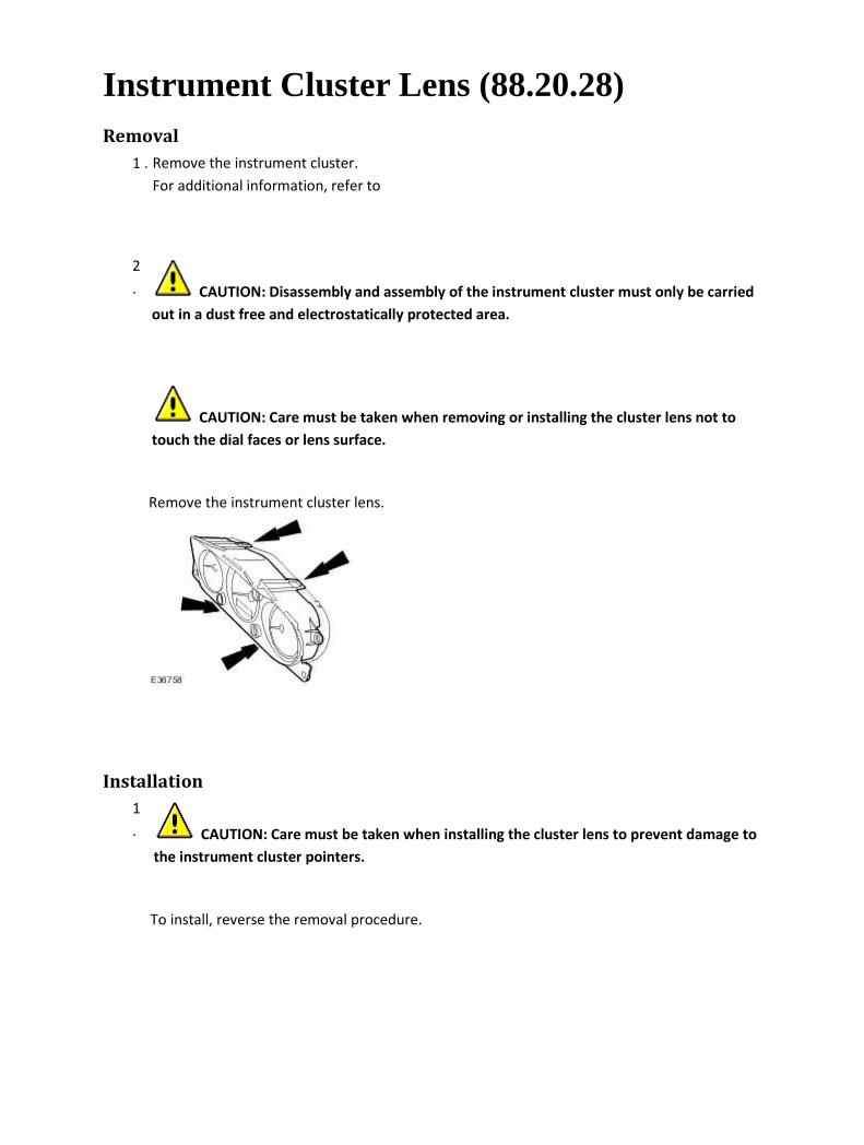
Instrument Cluster Lens (88.20.28) Removal
1 . Remove the instrument cluster.
For additional information, refer to
2
. CAUTION: Disassembly and assembly of the instrument cluster must only be carried
out in a dust free and electrostatically protected area.
CAUTION: Care must be taken when removing or installing the cluster lens not to
touch the dial faces or lens surface.
Remove the instrument cluster lens.
Installation
1
. CAUTION: Care must be taken when installing the cluster lens to prevent damage to
the instrument cluster pointers.
To install, reverse the removal procedure.
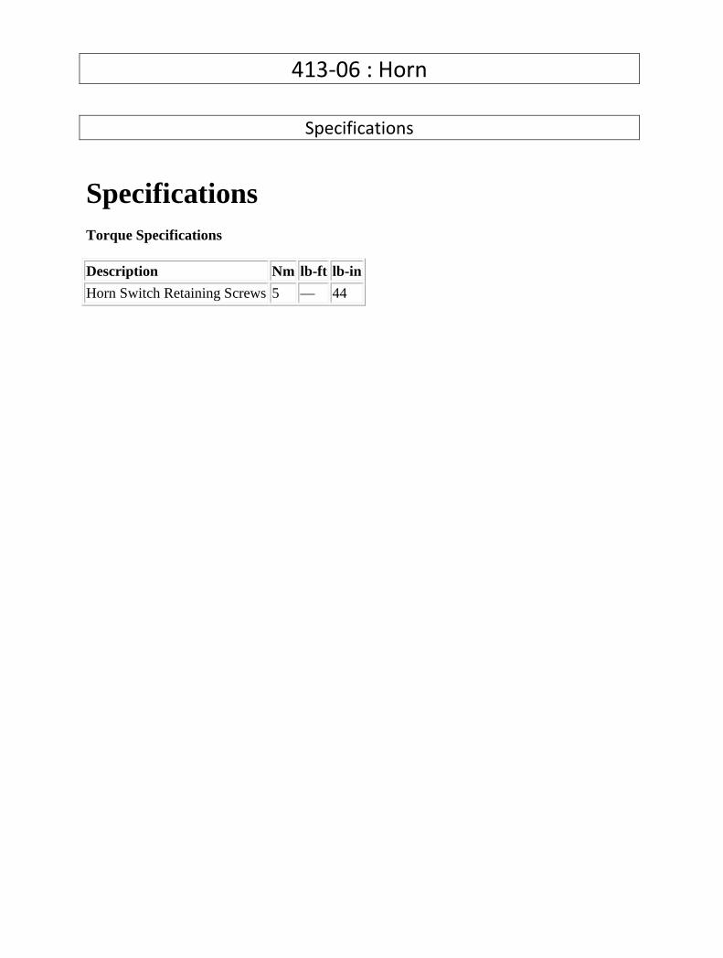
413-06 : Horn
Specifications
Specifications Torque Specifications
Description Nm lb-ft lb-in
Horn Switch Retaining Screws 5 — 44
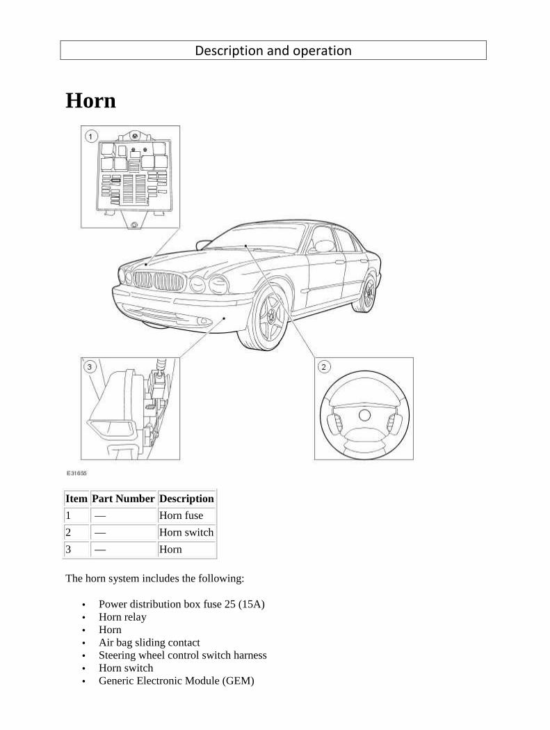
Description and operation
Horn
Item Part Number Description
1 — Horn fuse
2 — Horn switch
3 — Horn
The horn system includes the following:
• Power distribution box fuse 25 (15A) • Horn relay • Horn • Air bag sliding contact • Steering wheel control switch harness • Horn switch • Generic Electronic Module (GEM)

The horn system is designed to sound the horn when the horn switch is operated. The horn relay is supplied voltage at all times through the power distribution box fuse 25 (15A). Operating the horn switch provides a ground circuit to the coil side of the horn relay. In turn, the switch side of the horn relay is closed, allowing voltage to be applied to the horn.
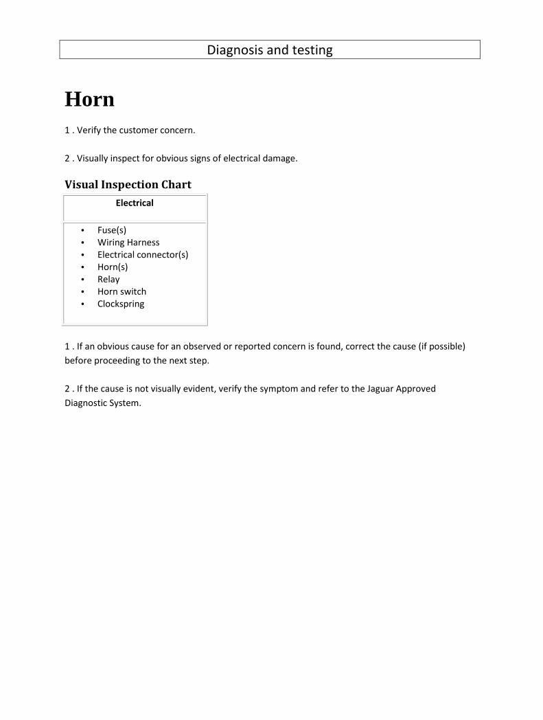
Diagnosis and testing
Horn 1 . Verify the customer concern.
2 . Visually inspect for obvious signs of electrical damage.
Visual Inspection Chart
Electrical
• Fuse(s)
• Wiring Harness
• Electrical connector(s)
• Horn(s)
• Relay
• Horn switch
• Clockspring
1 . If an obvious cause for an observed or reported concern is found, correct the cause (if possible)
before proceeding to the next step.
2 . If the cause is not visually evident, verify the symptom and refer to the Jaguar Approved
Diagnostic System.

Removal and installation
Horn (86.30.02) Removal
1 . Remove the radiator splash shield. <<501-02>>
2 . Disconnect the electrical connector.
3 . Remove the horn.
Installation
1 . To install, reverse the removal procedure.

Horn Switch (86.30.01) Removal
1 . Remove the driver air bag module. <<501-20B>>
2 . Disconnect the electrical connectors.
3 . Remove the horn switch.
Installation
1 . To install, reverse the removal procedure.
Tighten to 5 Nm.

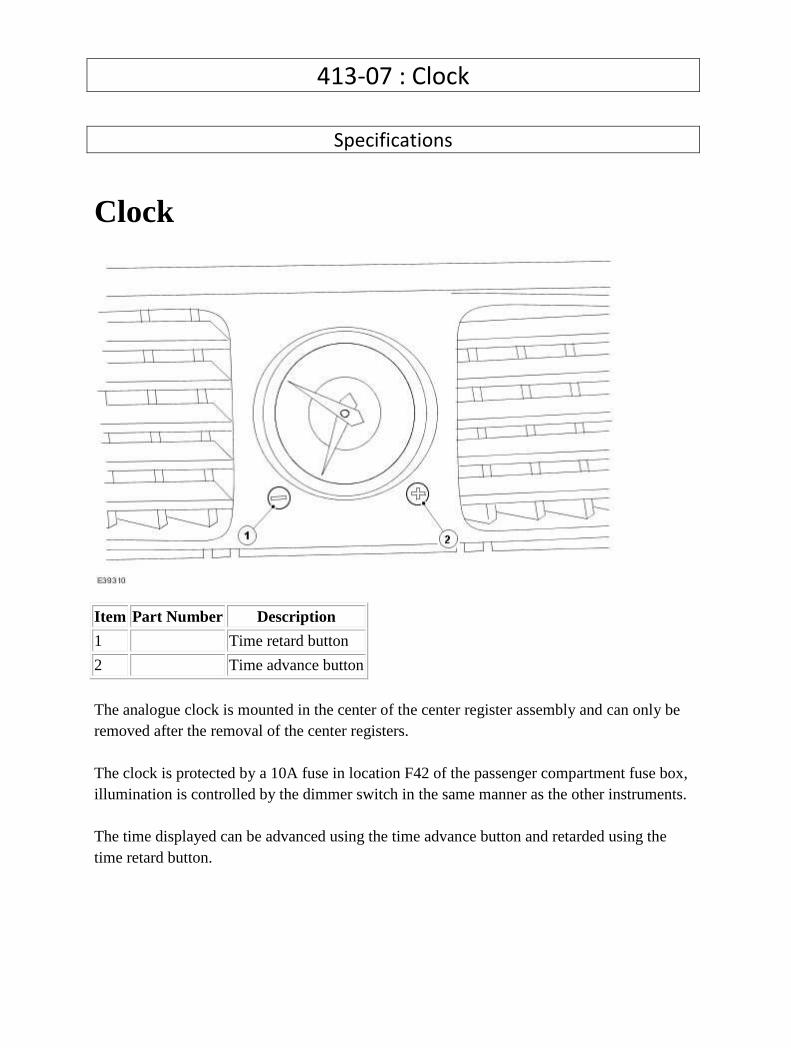
413-07 : Clock
Specifications
Clock
Item Part Number Description
1 Time retard button
2 Time advance button
The analogue clock is mounted in the center of the center register assembly and can only be removed after the removal of the center registers. The clock is protected by a 10A fuse in location F42 of the passenger compartment fuse box, illumination is controlled by the dimmer switch in the same manner as the other instruments. The time displayed can be advanced using the time advance button and retarded using the time retard button.

Description and operation
Clock Inspection and Verification
1 . Verify the customer concern.
2 . Visually inspect for obvious signs of mechanical or electrical damage.
Visual Inspection Chart
Mechanical Electrical
• Clock
• Advance/Retard button(s)
• Bulbs(s)
• Fuse(s)
• Wiring harness
• Loose or corroded connector(s)
• Switch(es)
1 . If an obvious cause for an observed or reported concern is found, correct the cause (if possible)
before proceeding to the next step.
2 . If the cause is not visually evident, verify the symptom and refer to the Jaguar approved diagnostic
system.
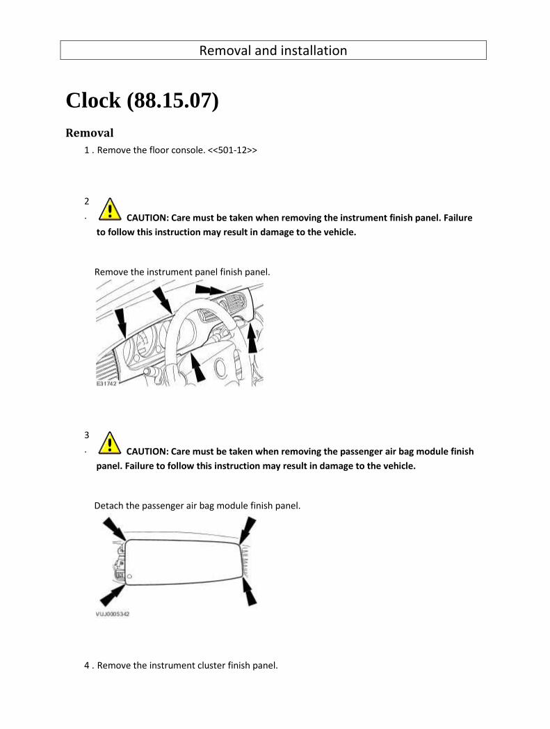
Removal and installation
Clock (88.15.07) Removal
1 . Remove the floor console. <<501-12>>
2
. CAUTION: Care must be taken when removing the instrument finish panel. Failure
to follow this instruction may result in damage to the vehicle.
Remove the instrument panel finish panel.
3
. CAUTION: Care must be taken when removing the passenger air bag module finish
panel. Failure to follow this instruction may result in damage to the vehicle.
Detach the passenger air bag module finish panel.
4 . Remove the instrument cluster finish panel.
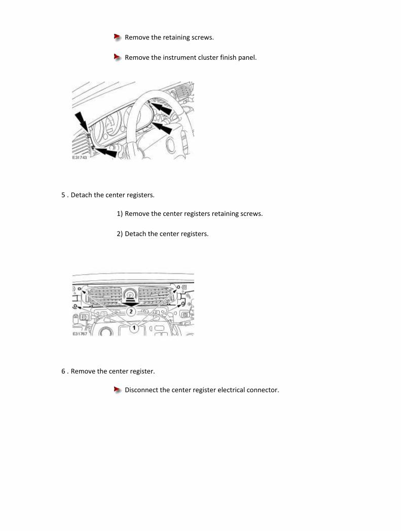
Remove the retaining screws.
Remove the instrument cluster finish panel.
5 . Detach the center registers.
1) Remove the center registers retaining screws.
2) Detach the center registers.
6 . Remove the center register.
Disconnect the center register electrical connector.

7 . Disconnect the clock electrical connector.
8 . Remove the clock.
1) Depress the clock retaining tangs.
2) Remove the clock.
Installation
1 . To install, reverse the removal procedure.

413-08 : Information and Message Center
Description and operation
Information and Message Center
Item Part Number Description
1 — Instrument Cluster
2 — Red Warning Lamp
3 — Drivers Information/Message Center
4 — Amber Warning Lamp
The drivers information and message center has a liquid crystal display (LCD) and is located in the
lower area of the speedometer.
The message center displays messages in text form for the driver, including odometer readings and
trip computer data. It can also provide information normally covered by conventional warning lamps
or indicate that a feature such as the cruise control is operating.
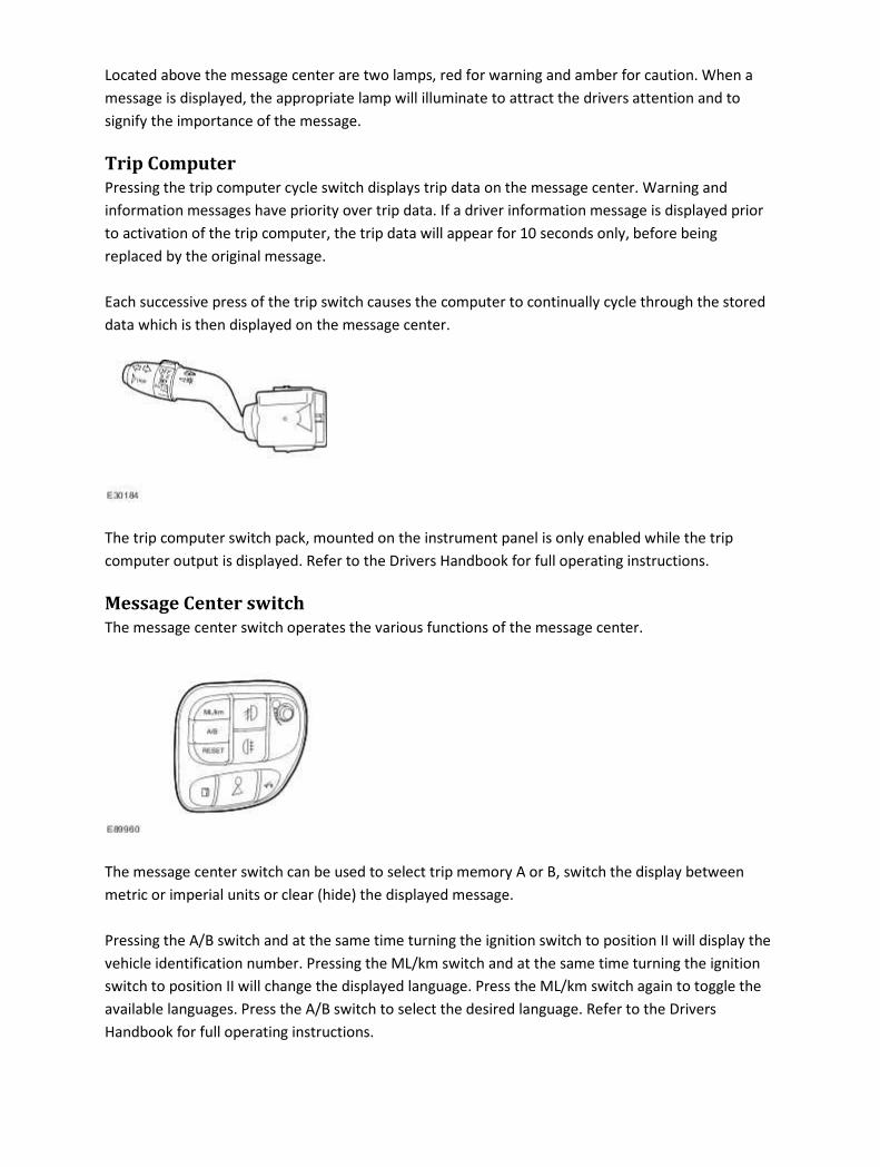
Located above the message center are two lamps, red for warning and amber for caution. When a
message is displayed, the appropriate lamp will illuminate to attract the drivers attention and to
signify the importance of the message.
Trip Computer
Pressing the trip computer cycle switch displays trip data on the message center. Warning and
information messages have priority over trip data. If a driver information message is displayed prior
to activation of the trip computer, the trip data will appear for 10 seconds only, before being
replaced by the original message.
Each successive press of the trip switch causes the computer to continually cycle through the stored
data which is then displayed on the message center.
The trip computer switch pack, mounted on the instrument panel is only enabled while the trip
computer output is displayed. Refer to the Drivers Handbook for full operating instructions.
Message Center switch
The message center switch operates the various functions of the message center.
The message center switch can be used to select trip memory A or B, switch the display between
metric or imperial units or clear (hide) the displayed message.
Pressing the A/B switch and at the same time turning the ignition switch to position II will display the
vehicle identification number. Pressing the ML/km switch and at the same time turning the ignition
switch to position II will change the displayed language. Press the ML/km switch again to toggle the
available languages. Press the A/B switch to select the desired language. Refer to the Drivers
Handbook for full operating instructions.

Oil Change Reminder Indicator - Vehicles with Diesel Particulate Filter
(DPF)
The service required reminder indicator informs the driver that the engine requires an engine oil
change due to excessive build-up of fuel within the engine oil. This is due to the diesel particulate
filter (DPF) regeneration process where additional fuel quantities are added to increase exhaust gas
temperatures. As a result small quantities of unburnt fuel remain in the combustion chamber and
bypass the piston rings into the engine oil.
The amount of excessive fuel is calculated by the powertrain control module (ECM). The ECM
monitors the engine operating conditions and the values from the exhaust gas temperature sensor
during the DPF regeneration process and calculates the amount of fuel in the oil. If the fuel content
exceeds the permitted level, the ECM will illuminate the service required reminder indicator in the
instrument cluster.
After the engine oil has been changed, a service indicator reset procedure must be carried out. For
additional information, refer to Oil Change Reminder Indicator Reset (413-09)
Diagnosis and testing
Information and Message Center 1 . Verify the customer concern.
2 . Visually inspect for obvious signs of mechanical or electrical damage.
Visual Inspection Chart
Mechanical Electrical
• Fluid level(s)
• Accessory installations
• Fuse(s)
• Wiring harness
• Electrical connector(s)
• Engine compartment components
• Underbody components
• Instrument cluster
• Door switches
• Electronic modules
• Boot/bonnet switch
1 . If an obvious cause for an observed or reported concern is found, correct the cause (if possible)
before proceeding to the next step.
2 . If the cause is not visually evident, verify the symptom and refer to the Jaguar approved diagnostic
system.

Removal and installation
Message Center Switch (86.66.11) Removal
1 . Remove the coin holder.
Remove the retaining screw.
2 . Detach the message center switch.
3 . Disconnect the message center switch electrical connector.
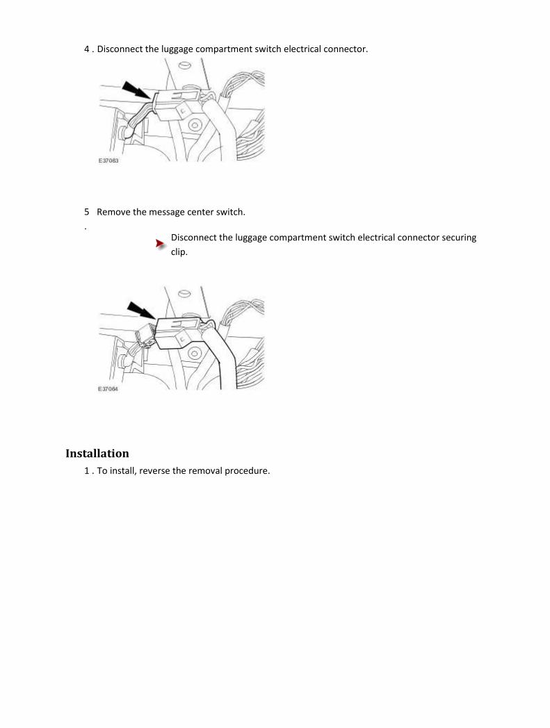
4 . Disconnect the luggage compartment switch electrical connector.
5
.
Remove the message center switch.
Disconnect the luggage compartment switch electrical connector securing
clip.
Installation
1 . To install, reverse the removal procedure.
413-09A : Warning Devices
General Procedures
Oil Change Indicator Reset 1. NOTE: Steps 2 to 5 must be completed within 3 seconds for successful service mode resetting. NOTE: Ignition key in the OFF position. Press and hold down the trip computer CLEAR/RESET button. 2. Continue to hold down the trip computer CLEAR/RESET button and turn the ignition switch to the ON position. 3. Release the trip computer CLEAR/RESET button. 4. Press and hold down the trip computer TRIP button located on the left-hand steering column multifunction switch. 5. Continue to hold down the trip computer TRIP button and press and hold down the trip computer CLEAR/RESET button. 6. Continue to hold down the trip computer TRIP and CLEAR/RESET buttons, RESETTING SERVICE MODE will display in the information and message center if steps 2 to 5 are completed successfully. 7. After 10 seconds the information and message center will then display SERVICE MODE RESET once the process is complete. 8. NOTE:
If the information and message center does NOT display SERVICE MODE RESET, steps 1 to 8 must be repeated.
Release the trip computer TRIP and CLEAR/RESET buttons and turn the ignition switch to

the OFF position.
Description and operation
Warning Devices Driver Audible Warning
The audible warning system provides the driver with an audible warning when the key is in the
ignition lock cylinder, a door is open, headlamps are on or the safety belt is not engaged. The driver
will also be provided with a visual warning message displayed in the message center when the
ignition lock cylinder is in the ON position. The system uses a number of inputs to provide the driver
with audible and visual warnings.
Instrument Cluster
CAUTION: If a red warning light is displayed in the instrument cluster the vehicle must be
stopped as soon as possible, but only when it is safe to do so. A red warning light indicates a
primary warning. Primary warnings must be reported to a Jaguar Dealer and investigated
immediately. Failure to follow these instructions may result in damage to the vehicle.
CAUTION: If an amber warning light is displayed in the instrument cluster the driver must
take the appropriate action, but only when it is safe to do so. An amber warning light indicates a
secondary warning. Secondary warnings must be reported to a Jaguar Dealer and investigated at
the drivers earliest opportunity. Failure to follow these instructions may result in damage to the
vehicle.
The instrument cluster acts as a system monitor for the audible and visual warnings. It receives
inputs from switches and sensors directly or through the multiplex link from another module and
triggers the necessary audible or visual warnings.
Message Center
CAUTION: If a red warning light is displayed in the instrument cluster the vehicle must be
stopped as soon as possible, but only when it is safe to do so. A red warning light indicates a
primary warning. Primary warnings must be reported to a Jaguar Dealer and investigated
immediately. Failure to follow these instructions may result in damage to the vehicle.
CAUTION: If an amber warning light is displayed in the instrument cluster the driver must
take the appropriate action, but only when it is safe to do so. An amber warning light indicates a
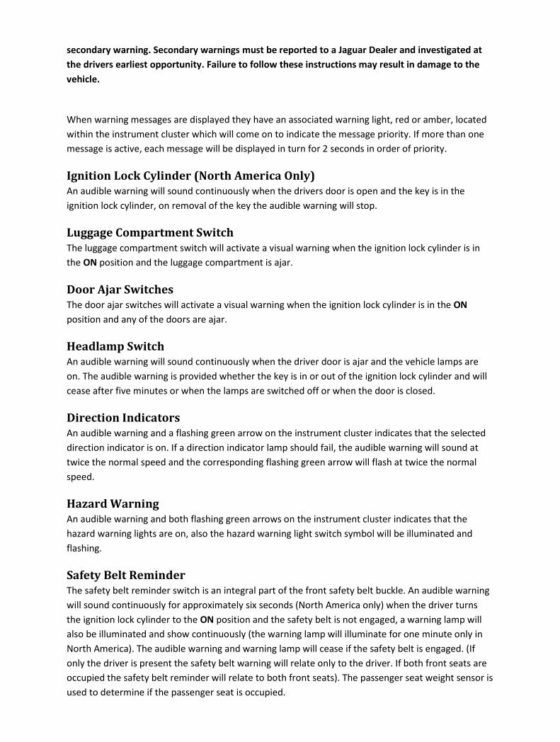
secondary warning. Secondary warnings must be reported to a Jaguar Dealer and investigated at
the drivers earliest opportunity. Failure to follow these instructions may result in damage to the
vehicle.
When warning messages are displayed they have an associated warning light, red or amber, located
within the instrument cluster which will come on to indicate the message priority. If more than one
message is active, each message will be displayed in turn for 2 seconds in order of priority.
Ignition Lock Cylinder (North America Only)
An audible warning will sound continuously when the drivers door is open and the key is in the
ignition lock cylinder, on removal of the key the audible warning will stop.
Luggage Compartment Switch
The luggage compartment switch will activate a visual warning when the ignition lock cylinder is in
the ON position and the luggage compartment is ajar.
Door Ajar Switches
The door ajar switches will activate a visual warning when the ignition lock cylinder is in the ON
position and any of the doors are ajar.
Headlamp Switch
An audible warning will sound continuously when the driver door is ajar and the vehicle lamps are
on. The audible warning is provided whether the key is in or out of the ignition lock cylinder and will
cease after five minutes or when the lamps are switched off or when the door is closed.
Direction Indicators
An audible warning and a flashing green arrow on the instrument cluster indicates that the selected
direction indicator is on. If a direction indicator lamp should fail, the audible warning will sound at
twice the normal speed and the corresponding flashing green arrow will flash at twice the normal
speed.
Hazard Warning
An audible warning and both flashing green arrows on the instrument cluster indicates that the
hazard warning lights are on, also the hazard warning light switch symbol will be illuminated and
flashing.
Safety Belt Reminder
The safety belt reminder switch is an integral part of the front safety belt buckle. An audible warning
will sound continuously for approximately six seconds (North America only) when the driver turns
the ignition lock cylinder to the ON position and the safety belt is not engaged, a warning lamp will
also be illuminated and show continuously (the warning lamp will illuminate for one minute only in
North America). The audible warning and warning lamp will cease if the safety belt is engaged. (If
only the driver is present the safety belt warning will relate only to the driver. If both front seats are
occupied the safety belt reminder will relate to both front seats). The passenger seat weight sensor is
used to determine if the passenger seat is occupied.
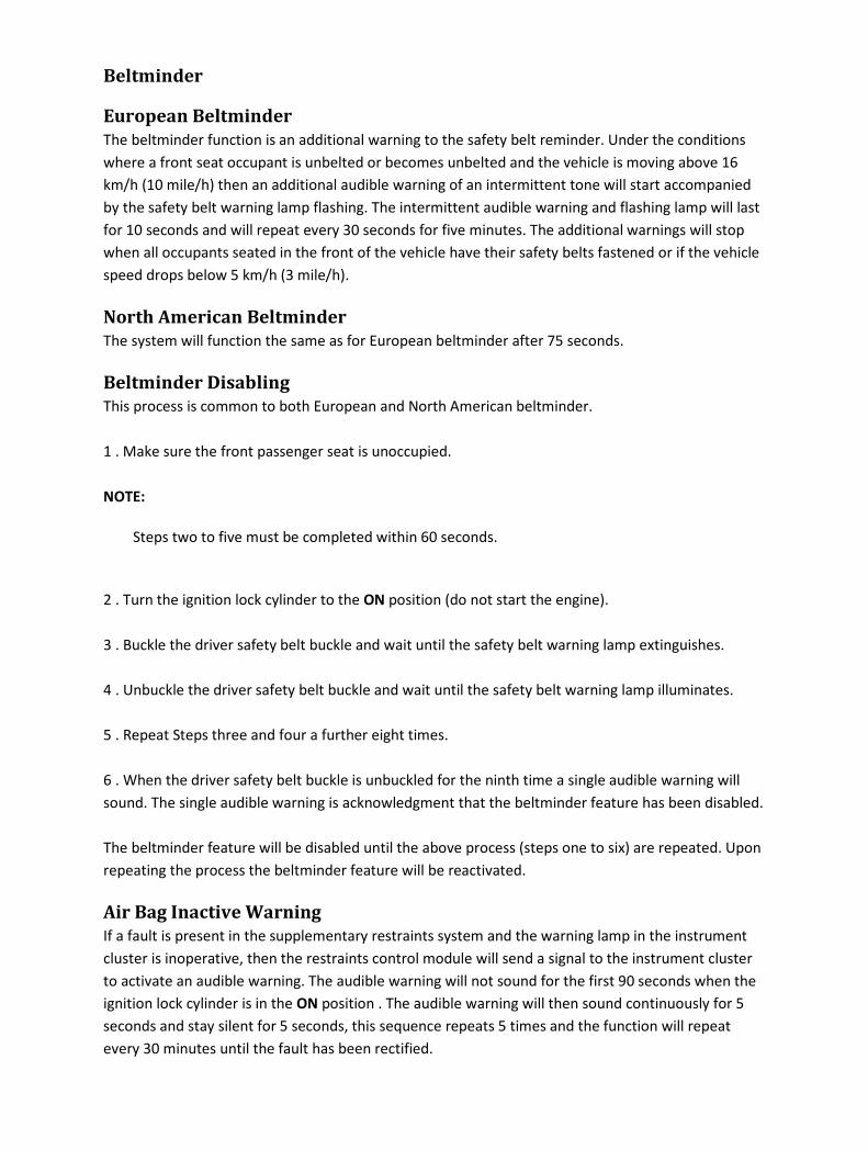
Beltminder
European Beltminder
The beltminder function is an additional warning to the safety belt reminder. Under the conditions
where a front seat occupant is unbelted or becomes unbelted and the vehicle is moving above 16
km/h (10 mile/h) then an additional audible warning of an intermittent tone will start accompanied
by the safety belt warning lamp flashing. The intermittent audible warning and flashing lamp will last
for 10 seconds and will repeat every 30 seconds for five minutes. The additional warnings will stop
when all occupants seated in the front of the vehicle have their safety belts fastened or if the vehicle
speed drops below 5 km/h (3 mile/h).
North American Beltminder
The system will function the same as for European beltminder after 75 seconds.
Beltminder Disabling
This process is common to both European and North American beltminder.
1 . Make sure the front passenger seat is unoccupied.
NOTE:
Steps two to five must be completed within 60 seconds.
2 . Turn the ignition lock cylinder to the ON position (do not start the engine).
3 . Buckle the driver safety belt buckle and wait until the safety belt warning lamp extinguishes.
4 . Unbuckle the driver safety belt buckle and wait until the safety belt warning lamp illuminates.
5 . Repeat Steps three and four a further eight times.
6 . When the driver safety belt buckle is unbuckled for the ninth time a single audible warning will
sound. The single audible warning is acknowledgment that the beltminder feature has been disabled.
The beltminder feature will be disabled until the above process (steps one to six) are repeated. Upon
repeating the process the beltminder feature will be reactivated.
Air Bag Inactive Warning
If a fault is present in the supplementary restraints system and the warning lamp in the instrument
cluster is inoperative, then the restraints control module will send a signal to the instrument cluster
to activate an audible warning. The audible warning will not sound for the first 90 seconds when the
ignition lock cylinder is in the ON position . The audible warning will then sound continuously for 5
seconds and stay silent for 5 seconds, this sequence repeats 5 times and the function will repeat
every 30 minutes until the fault has been rectified.
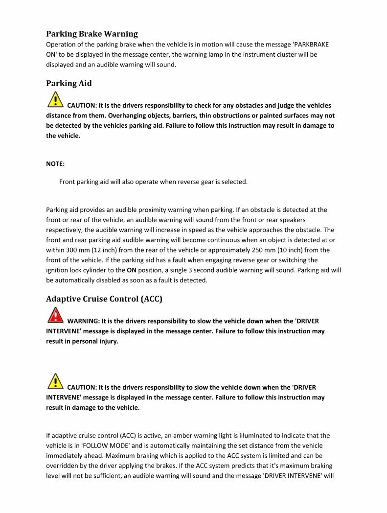
Parking Brake Warning
Operation of the parking brake when the vehicle is in motion will cause the message 'PARKBRAKE
ON' to be displayed in the message center, the warning lamp in the instrument cluster will be
displayed and an audible warning will sound.
Parking Aid
CAUTION: It is the drivers responsibility to check for any obstacles and judge the vehicles
distance from them. Overhanging objects, barriers, thin obstructions or painted surfaces may not
be detected by the vehicles parking aid. Failure to follow this instruction may result in damage to
the vehicle.
NOTE:
Front parking aid will also operate when reverse gear is selected.
Parking aid provides an audible proximity warning when parking. If an obstacle is detected at the
front or rear of the vehicle, an audible warning will sound from the front or rear speakers
respectively, the audible warning will increase in speed as the vehicle approaches the obstacle. The
front and rear parking aid audible warning will become continuous when an object is detected at or
within 300 mm (12 inch) from the rear of the vehicle or approximately 250 mm (10 inch) from the
front of the vehicle. If the parking aid has a fault when engaging reverse gear or switching the
ignition lock cylinder to the ON position, a single 3 second audible warning will sound. Parking aid will
be automatically disabled as soon as a fault is detected.
Adaptive Cruise Control (ACC)
WARNING: It is the drivers responsibility to slow the vehicle down when the 'DRIVER
INTERVENE' message is displayed in the message center. Failure to follow this instruction may
result in personal injury.
CAUTION: It is the drivers responsibility to slow the vehicle down when the 'DRIVER
INTERVENE' message is displayed in the message center. Failure to follow this instruction may
result in damage to the vehicle.
If adaptive cruise control (ACC) is active, an amber warning light is illuminated to indicate that the
vehicle is in 'FOLLOW MODE' and is automatically maintaining the set distance from the vehicle
immediately ahead. Maximum braking which is applied to the ACC system is limited and can be
overridden by the driver applying the brakes. If the ACC system predicts that it's maximum braking
level will not be sufficient, an audible warning will sound and the message 'DRIVER INTERVENE' will
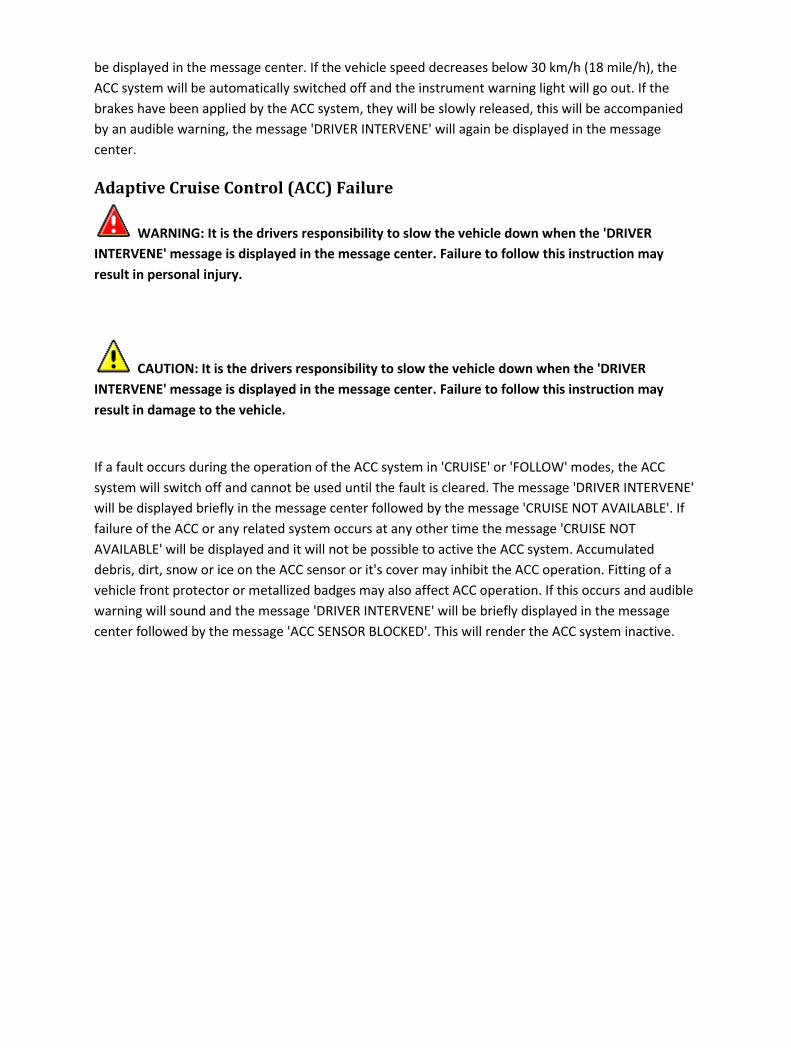
be displayed in the message center. If the vehicle speed decreases below 30 km/h (18 mile/h), the
ACC system will be automatically switched off and the instrument warning light will go out. If the
brakes have been applied by the ACC system, they will be slowly released, this will be accompanied
by an audible warning, the message 'DRIVER INTERVENE' will again be displayed in the message
center.
Adaptive Cruise Control (ACC) Failure
WARNING: It is the drivers responsibility to slow the vehicle down when the 'DRIVER
INTERVENE' message is displayed in the message center. Failure to follow this instruction may
result in personal injury.
CAUTION: It is the drivers responsibility to slow the vehicle down when the 'DRIVER
INTERVENE' message is displayed in the message center. Failure to follow this instruction may
result in damage to the vehicle.
If a fault occurs during the operation of the ACC system in 'CRUISE' or 'FOLLOW' modes, the ACC
system will switch off and cannot be used until the fault is cleared. The message 'DRIVER INTERVENE'
will be displayed briefly in the message center followed by the message 'CRUISE NOT AVAILABLE'. If
failure of the ACC or any related system occurs at any other time the message 'CRUISE NOT
AVAILABLE' will be displayed and it will not be possible to active the ACC system. Accumulated
debris, dirt, snow or ice on the ACC sensor or it's cover may inhibit the ACC operation. Fitting of a
vehicle front protector or metallized badges may also affect ACC operation. If this occurs and audible
warning will sound and the message 'DRIVER INTERVENE' will be briefly displayed in the message
center followed by the message 'ACC SENSOR BLOCKED'. This will render the ACC system inactive.

Diagnosis and testing
Warning Devices Inspection and Verification
1 . Verify the customer concern.
2 . Visually inspect for obvious signs of mechanical or electrical damage.
Visual Inspection Chart
Mechanical Electrical
• Door ajar switch(es)
• Safety belt buckle and pretensioner
• Headlamp switch
• Fuel gauge
• Inertia switch
• Fuse(s)
• Wiring harness
• Electrical connector(s)
• Switch(es)
• Sensor(s)
1 . If an obvious cause for an observed or reported concern is found, correct the cause (if possible)
before proceeding to the next step.
2 . If the cause is not visually evident, verify the symptom and refer to the Jaguar approved diagnostic
system.
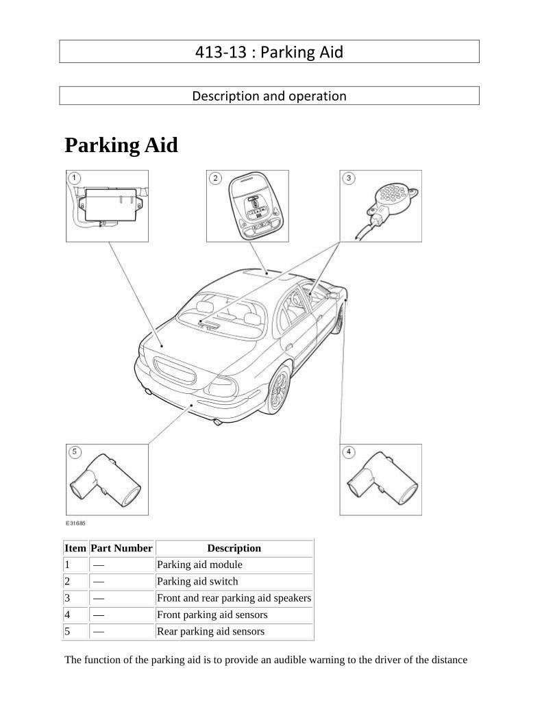
413-13 : Parking Aid
Description and operation
Parking Aid
Item Part Number Description
1 — Parking aid module
2 — Parking aid switch
3 — Front and rear parking aid speakers
4 — Front parking aid sensors
5 — Rear parking aid sensors
The function of the parking aid is to provide an audible warning to the driver of the distance
to obstacles near the front or rear bumper of the vehicle when parking or travelling at a slow speed. The system provides an assistance to the driver when parking in order to help avoid collision with obstacles. The sensor range at the front of the vehicle should be 0.8 meters and the sensor range at the rear of the vehicle should be 1.8 meters. This should extend the full width of the rear bumper and reduce to 50 cm at the vehicle corners. The vertical range is adequate to protect the highest and lowest points of the front and rear of the vehicle. The system will detect curbs with heights of at least 18 cm. Obstacles, such as curbs, that are low enough to pass under the vehicle until they make contact with the tires will not be detected. The system activates a specific speaker with a tone signifying the distance to the obstacle. The tone consists of a beep and defined space ratio which varies depending on the calculated distance. When the distance to the obstacle is less than 20 cm the speaker tone is continuous. The parking aid is continuously in operation, unless towing when the system automatically switches off. If the reverse aid develops a fault the tone will sound continuously for three seconds when the ignition is switched on or the reverse gear is selected. The parking aid system comprises of:
• a module mounted in the spare wheel well just rearward of the spare tyre. • four rear bumper mounted sensors which have a straight electrical connector plug. • four front bumper mounted sensors of which the two inner sensors have a 90° angled
electrical connector in order to give clearance to the bumper reinforcing frame. • two audible speakers, one mounted on the rear parcel shelf and the other mounted
behind the speedo binnacle. • a cancellation switch that is mounted into the roof console. This is fitted for the driver
to disable the system when in slow moving traffic. This stops the front parking aid continuously monitoring the vehicle in front, however, the system will only stay inoperative whilst the vehicle is moving or when the ignition switch is reset OFF or ON.

Diagnosis and testing
Parking Aid Principles of Operation
For a detailed description of the Parking Aid, refer to the relevant Description and Operation sections
in the workshop manual.
Parking Aid
Inspection and Verification
1 . Verify the customer concern.
2 . Visually inspect for obvious signs of electrical damage.
Mechanical Electrical
• Obstructions or Damage to Parking
Sensors
• Parking Sensor Face Obstructed (e.g.
snow, ice, dirt, flies etc)
• Fuses/Relays
• Damaged, Loose or Corroded Connector(s)
• Damage to Wiring Loom/Incorrect
Location, Stretched or Taught
3 . If an obvious cause for an observed or reported concern is found, correct the cause (if possible)
before proceeding to the next step.
4 . If the cause is not visually evident, verify the symptom and refer to the Jaguar approved diagnostic
system.
DTC Index
Parking Aid Module
CAUTION: When probing connectors to take measurements in the course of the pinpoint
tests, use the adaptor kit, part number 3548-1358-00.
NOTE:
If the control module/component is suspect and the vehicle remains under manufacturer
warranty, refer to the Warranty Policy and Procedures manual (section B1.2), or determine if
any prior approval program is in operation, prior to the installation of a new
module/component.

NOTE:
When performing voltage or resistance tests, always use a digital multimeter (DMM) accurate to
three decimal places and with a current calibration certificate. When testing resistance, always
take the resistance of the DMM leads into account.
NOTE:
Check and rectify basic faults before beginning diagnostic routines that involve pinpoint tests.
NOTE:
Inspect connectors for signs of water ingress, and pins for damage and/or corrosion.
NOTE:
If DTCs are recorded and, after performing the pinpoint tests, a fault is not present, an
intermittent concern may be the cause. Always check for loose connections and corroded
terminals.
DTC Description Possible Causes Action
B1299
Power Supply
Sensor Circuit
Short To Ground
• Parking aid module,
parking distance sensor
(rear)power circuit - short
to ground
Refer to electrical circuit diagrams,
notes and check parking aid module,
parking distance sensor (rear) power
circuit for short to ground
B1342 ECU is Defective • Parking aid module -
memory failure (RAM)
Suspect faulty module, check and install
as required, refer to the new module
installation note at the top of the DTC
Index
B2207 ECU ROM
Checksum Error
• Parking aid module -
memory failure (ROM)
Suspect faulty module, check and install
as required, refer to the new module
installation note at the top of the DTC
Index
B2373 LED #1 Circuit
Short to Power
• Parking aid module,
parking aid status (roof
console LED) circuit -
short to power or open
Refer to electrical circuit diagrams,
notes and check parking aid module,
parking aid status (roof console LED)
circuit for short to power or open

circuit circuit
B2477
Module
Configuration
Failure
• Parking aid module -
configuration failure
(EEPROM error during
power up)
Reconfigure. If this fails suspect faulty
module, check and install as required,
refer to the new module installation
note at the top of the DTC Index
C1699
Left Rear Sensor
Circuit Short to
Power
• Parking aid module, rear
outer left sensor data
circuit - short to power
Carry out any pinpoint tests associated
with this DTC using the manufacturer
approved diagnostic system. Refer to
electrical circuit diagrams, notes and
check parking aid module, rear outer
left sensor data circuit for short to
power
C1700
Left Rear Sensor
Circuit Failure Or
Blockage
• Parking aid module, rear
outer left sensor data
circuit - open or short to
ground
Carry out any pinpoint tests associated
with this DTC using the manufacturer
approved diagnostic system. Refer to
electrical circuit diagrams, notes and
check parking aid module, rear outer
left sensor data circuit for open circuit
or short to ground
C1701 Left Rear Sensor
Circuit Fault
• Parking aid module - rear
outer left sensor fault
Carry out any pinpoint tests associated
with this DTC using the manufacturer
approved diagnostic system. Suspect
rear outer left sensor fault
C1702
Right Rear
Sensor Circuit
Short to Power
• Parking aid module, rear
outer right sensor data
circuit - short to power
Carry out any pinpoint tests associated
with this DTC using the manufacturer
approved diagnostic system. Refer to
electrical circuit diagrams, notes and
check parking aid module, rear outer
right sensor data circuit for short to
power
C1703
Right Rear
Sensor Circuit
Failure Or
Blockage
• Parking aid module, rear
outer right sensor data
circuit - open or short to
ground
Carry out any pinpoint tests associated
with this DTC using the manufacturer
approved diagnostic system. Refer to
electrical circuit diagrams, notes and
check parking aid module, rear outer
right sensor data circuit for open circuit
or short to ground
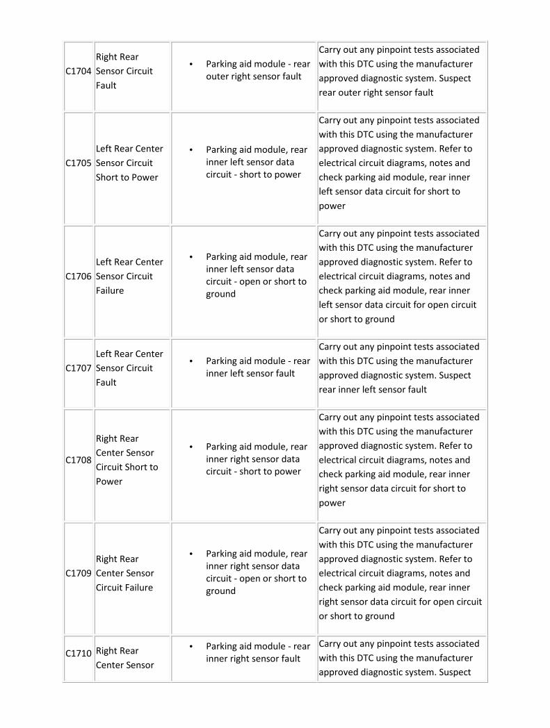
C1704
Right Rear
Sensor Circuit
Fault
• Parking aid module - rear
outer right sensor fault
Carry out any pinpoint tests associated
with this DTC using the manufacturer
approved diagnostic system. Suspect
rear outer right sensor fault
C1705
Left Rear Center
Sensor Circuit
Short to Power
• Parking aid module, rear
inner left sensor data
circuit - short to power
Carry out any pinpoint tests associated
with this DTC using the manufacturer
approved diagnostic system. Refer to
electrical circuit diagrams, notes and
check parking aid module, rear inner
left sensor data circuit for short to
power
C1706
Left Rear Center
Sensor Circuit
Failure
• Parking aid module, rear
inner left sensor data
circuit - open or short to
ground
Carry out any pinpoint tests associated
with this DTC using the manufacturer
approved diagnostic system. Refer to
electrical circuit diagrams, notes and
check parking aid module, rear inner
left sensor data circuit for open circuit
or short to ground
C1707
Left Rear Center
Sensor Circuit
Fault
• Parking aid module - rear
inner left sensor fault
Carry out any pinpoint tests associated
with this DTC using the manufacturer
approved diagnostic system. Suspect
rear inner left sensor fault
C1708
Right Rear
Center Sensor
Circuit Short to
Power
• Parking aid module, rear
inner right sensor data
circuit - short to power
Carry out any pinpoint tests associated
with this DTC using the manufacturer
approved diagnostic system. Refer to
electrical circuit diagrams, notes and
check parking aid module, rear inner
right sensor data circuit for short to
power
C1709
Right Rear
Center Sensor
Circuit Failure
• Parking aid module, rear
inner right sensor data
circuit - open or short to
ground
Carry out any pinpoint tests associated
with this DTC using the manufacturer
approved diagnostic system. Refer to
electrical circuit diagrams, notes and
check parking aid module, rear inner
right sensor data circuit for open circuit
or short to ground
C1710 Right Rear
Center Sensor
• Parking aid module - rear
inner right sensor fault
Carry out any pinpoint tests associated
with this DTC using the manufacturer
approved diagnostic system. Suspect
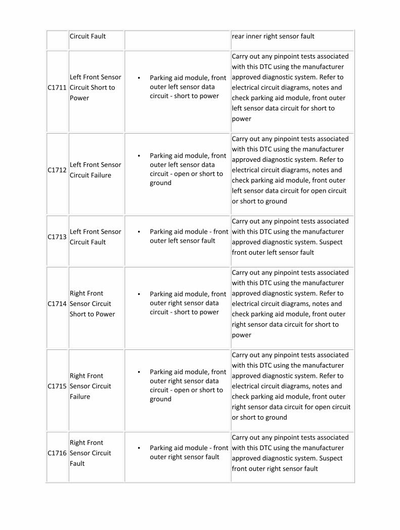
Circuit Fault rear inner right sensor fault
C1711
Left Front Sensor
Circuit Short to
Power
• Parking aid module, front
outer left sensor data
circuit - short to power
Carry out any pinpoint tests associated
with this DTC using the manufacturer
approved diagnostic system. Refer to
electrical circuit diagrams, notes and
check parking aid module, front outer
left sensor data circuit for short to
power
C1712 Left Front Sensor
Circuit Failure
• Parking aid module, front
outer left sensor data
circuit - open or short to
ground
Carry out any pinpoint tests associated
with this DTC using the manufacturer
approved diagnostic system. Refer to
electrical circuit diagrams, notes and
check parking aid module, front outer
left sensor data circuit for open circuit
or short to ground
C1713 Left Front Sensor
Circuit Fault
• Parking aid module - front
outer left sensor fault
Carry out any pinpoint tests associated
with this DTC using the manufacturer
approved diagnostic system. Suspect
front outer left sensor fault
C1714
Right Front
Sensor Circuit
Short to Power
• Parking aid module, front
outer right sensor data
circuit - short to power
Carry out any pinpoint tests associated
with this DTC using the manufacturer
approved diagnostic system. Refer to
electrical circuit diagrams, notes and
check parking aid module, front outer
right sensor data circuit for short to
power
C1715
Right Front
Sensor Circuit
Failure
• Parking aid module, front
outer right sensor data
circuit - open or short to
ground
Carry out any pinpoint tests associated
with this DTC using the manufacturer
approved diagnostic system. Refer to
electrical circuit diagrams, notes and
check parking aid module, front outer
right sensor data circuit for open circuit
or short to ground
C1716
Right Front
Sensor Circuit
Fault
• Parking aid module - front
outer right sensor fault
Carry out any pinpoint tests associated
with this DTC using the manufacturer
approved diagnostic system. Suspect
front outer right sensor fault
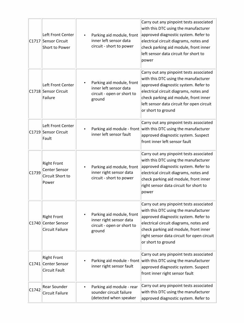
C1717
Left Front Center
Sensor Circuit
Short to Power
• Parking aid module, front
inner left sensor data
circuit - short to power
Carry out any pinpoint tests associated
with this DTC using the manufacturer
approved diagnostic system. Refer to
electrical circuit diagrams, notes and
check parking aid module, front inner
left sensor data circuit for short to
power
C1718
Left Front Center
Sensor Circuit
Failure
• Parking aid module, front
inner left sensor data
circuit - open or short to
ground
Carry out any pinpoint tests associated
with this DTC using the manufacturer
approved diagnostic system. Refer to
electrical circuit diagrams, notes and
check parking aid module, front inner
left sensor data circuit for open circuit
or short to ground
C1719
Left Front Center
Sensor Circuit
Fault
• Parking aid module - front
inner left sensor fault
Carry out any pinpoint tests associated
with this DTC using the manufacturer
approved diagnostic system. Suspect
front inner left sensor fault
C1739
Right Front
Center Sensor
Circuit Short to
Power
• Parking aid module, front
inner right sensor data
circuit - short to power
Carry out any pinpoint tests associated
with this DTC using the manufacturer
approved diagnostic system. Refer to
electrical circuit diagrams, notes and
check parking aid module, front inner
right sensor data circuit for short to
power
C1740
Right Front
Center Sensor
Circuit Failure
• Parking aid module, front
inner right sensor data
circuit - open or short to
ground
Carry out any pinpoint tests associated
with this DTC using the manufacturer
approved diagnostic system. Refer to
electrical circuit diagrams, notes and
check parking aid module, front inner
right sensor data circuit for open circuit
or short to ground
C1741
Right Front
Center Sensor
Circuit Fault
• Parking aid module - front
inner right sensor fault
Carry out any pinpoint tests associated
with this DTC using the manufacturer
approved diagnostic system. Suspect
front inner right sensor fault
C1742 Rear Sounder
Circuit Failure
• Parking aid module - rear
sounder circuit failure
(detected when speaker
Carry out any pinpoint tests associated
with this DTC using the manufacturer
approved diagnostic system. Refer to

is off) electrical circuit diagrams, notes and
check parking aid module, rear sounder
circuit for fault
C1743
Rear Sounder
Circuit Short to
Power
• Parking aid module - rear
sounder circuit short to
power (detected when
speaker is on)
Carry out any pinpoint tests associated
with this DTC using the manufacturer
approved diagnostic system. Refer to
electrical circuit diagrams, notes and
check parking aid module, rear sounder
circuit for short to power
C1744 Front Sounder
Circuit Failure
• Parking aid module - front
sounder circuit failure
(detected when speaker
is off)
Carry out any pinpoint tests associated
with this DTC using the manufacturer
approved diagnostic system. Refer to
electrical circuit diagrams, notes and
check parking aid module, front
sounder circuit for fault
C1745
Front Sounder
Circuit Short to
Power
• Parking aid module - front
sounder circuit short to
power (detected when
speaker is on)
Carry out any pinpoint tests associated
with this DTC using the manufacturer
approved diagnostic system. Refer to
electrical circuit diagrams, notes and
check parking aid module, front
sounder circuit for short to power
C1748
Switch Input
Circuit Short to
Ground
• Parking aid module, roof
console, parking aid
switch, momentary
disable switch circuit -
short to ground (set if
switch pushed > 10
seconds)
Refer to electrical circuit diagrams,
notes and check parking aid module,
momentary disable switch circuit for
short to ground
C1920 LED #1 Circuit
Failure
• Parking aid module, roof
console, parking aid
status LED circuit short to
ground
Refer to electrical circuit diagrams,
notes and check parking aid module,
parking aid status LED circuit for short
to ground

Removal and installation
Front Parking Aid Speaker (86.54.18) Removal
1 . Remove the instrument cluster. <<413-01>>
2 . Disconnect the electrical connector.
3 . Remove the parking aid speaker.
Installation
1 . To install, reverse the removal procedure.

Parking Aid Module - VIN Range: G00442->G45703 (86.80.39) Removal
1 . Disconnect the battery ground cable.
For additional information, refer to
2 . Remove the spare wheel.
3 . Disconnect the electrical connector.
4 . Remove the parking aid module.
Installation
1 . To install, reverse the removal procedure.

Parking Aid Module - VIN Range: G45704->G99999 (86.80.39) Removal
1 . Disconnect the battery ground cable.
For additional information, refer to Battery Ground Cable (86.15.19)
2 . Reposition the luggage compartment floor covering.
3 . Detach the parking aid module and bracket assembly.
4 . Remove the parking aid module.
Disconnect the parking aid module electrical connector.

Installation
1 . To install, reverse the removal procedure.
Tighten to 10 Nm.

Parking Aid Sensor (86.62.01) Removal
1 . Remove the bumper cover. <<501-19>>
2 . NOTE:
Rear parking aid sensor shown, front parking aid sensor similar.
Disconnect the electrical connector.
3
. CAUTION: Make sure excessive pressure or tools are not used when removing the
parking aid sensor from the housing.
NOTE:
Rear parking aid sensor shown, front parking aid sensor similar.
Remove the parking aid sensor.

Installation
1 . To install, reverse the removal procedure.

Rear Parking Aid Speaker (86.54.19) Removal
1 . Remove the parcel shelf. <<501-05>>
2 . Disconnect the electrical connector.
3 . Remove the parking aid speaker.
Installation
1 . To install, reverse the removal procedure.

414 : Battery and Charging System
414-00 : Charging System – General Information
General Procedures
Battery Charging 1. Before charging a discharged battery inspect and repair the following conditions, if necessary: • Loose accessory drive belt.
• Pinched or grounded wiring harness to the generator or voltage regulator.
• Loose wiring harness connections at the generator or voltage regulator.
• Loose or corroded connections at battery, headlamp panel junction wire or engine ground.
• Carry out generator charging checks.
• Excessive battery quiescent drain due to: engine compartment, load space, glove compartment and courtesy lamps remaining on (switch damaged or out of adjustment, glove compartment left open).
Battery Charging - Maintenance-Free Batteries
WARNING: KEEP BATTERIES OUT OF REACH OF CHILDREN. BATTERIES CONTAIN SULPHURIC ACID, AVOID CONTACT WIT H SKIN, EYES OR CLOTHING. SHIELD YOUR EYES WHEN WORKING NEAR THE BATTERY TO PROTECT AGAINST POSSIBLE SPLASHING OF THE ACID S OLUTION. IN CASE OF ACID CONTACT WITH SKIN OR EYES, FLUSH IMMED IATELY WITH WATER FOR A MINIMUM OF 15 MINUTES AND SEEK PROMPT M EDICAL ATTENTION. IF ACID IS SWALLOWED, CALL A PHYSICIAN I MMEDIATELY. FAILURE TO FOLLOW THESE INSTRUCTIONS MAY RESULT IN PERSONAL INJURY.
WARNING: BATTERIES NORMALLY PRODUCE EXPLOSIVE GASE S WHICH CAN CAUSE PERSONAL INJURY, THEREFORE DO NOT A LLOW FLAMES, SPARKS, OR LIGHTED SUBSTANCES TO COME NEAR THE

BATTERY. WHEN CHARGING OR WORKING NEAR A BATTERY AL WAYS SHIELD YOUR FACE AND PROTECT YOUR EYES . ALWAYS PRO VIDE ADEQUATE VENTILATION. FAILURE TO FOLLOW THESE INSTR UCTIONS MAY RESULT IN PERSONAL INJURY. 1. Cold batteries will not readily accept a charge. Therefore, batteries should be allowed to warm up approximately to 15 degrees centigrade (59 degrees Fahrenheit) before charging. This may require 12 hours at room temperature depending on the initial temperature and battery size. 2. A battery which has been completely discharged may be slow to accept a charge initially, and in some cases may not accept a charge at the normal charger setting. When batteries are in this condition, charging can be started by use of the 'dead battery' switch which is fitted to certain types of battery chargers. Follow the manufacturer's instructions when carrying out this procedure. 3. To determine whether a battery is accepting a charge, follow the manufacturer's instructions for the charger. 4. After releasing dead battery switch and with the charger still operating, measure battery voltage. If the voltage is 12 volts or higher, the battery may be accepting a charge and may be capable of being recharged. If the temperature of the battery is below 15 degrees centigrade (59 degrees Fahrenheit) the battery may require charging for up to two hours before the charge rate is high enough to show on the charger ammeter. It has been found that all un-damaged batteries can be charged by this procedure. If a battery cannot be charged by this procedure, it should be replaced. 5. A rapid recharge procedure has been developed for recharging batteries that have passed the 'No-Load Test' and only need a recharge. This can be due to non start battery failures or battery discharged in vehicle due to key-off loads. 6. The battery can be rapidly recharged by using either of the following methods:
• Perform a two hour charge using a constant current of 20 amps (manual setting on the charger).
• Perform a two hour charge using a constant voltage (automatic setting on the charger).
Quiescent Current Measurement 1. NOTE:
The following quiescent current measurement does not apply to vehicles fitted with the Tracker system. If the vehicle is fitted with the tracker system the quiescent current may be up to 14 milliamps higher. If non-jaguar approved accessories are installed the

following measurements may not apply. Disconnect the battery ground cable. <<414-01>> 2. Check the vehicle off-load battery voltage. If below 12.5 volts, install a fully charged slave battery for the tests and recharge the vehicle battery. 3. Connect a suitable ammeter to the battery with the negative test lead clip to the negative battery terminal, and the positive test lead clip to the battery negative lead. 4. NOTE: Make sure that all electrical accessories are switched off. Operate the key fob unlock button to disarm the vehicle security system. • Switch the ignition to the RUN position for a 10 second duration.
• Switch the ignition to the OFF position. Remove the key.
• Close the vehicle doors and luggage compartment lid. 5. Monitor the ammeter reading for 30 minutes. 6. After 30 minutes the quiescent current reading should be no greater than 30 milliamps. 7. Disconnect the ammeter. Reconnect the battery ground cable. <<414-01>>

Description and operation
Charging System The charging system for vehicles fitted with a 3.0L engine consist of a 120 amp L3B generator.
Vehicles fitted with a 3.5L or 4.2L engine consist of a 130 amp SC1 generator. Vehicles fitted with a
2.7L Diesel engine consist of a 150 amp SC2 generator. The generator and regulator assembly
generates current to supply the vehicle electrical system with electricity when the engine is running
and maintain the battery in a charged state.
The generator is belt driven by the accessory drive belt. For additional information, refer to
Accessory Drive (303-05)
When the engine is started, the generator begins to generate alternating current (AC) which is
converted to direct current (DC) internally. The DC current and voltage is controlled by the voltage
regulator, (located inside the generator) and then supplied to the battery through the main battery
positive cable.
The 3.0L generator is solidly mounted to the engine, while the 3.5L and 4.2L generator is pivot
mounted. The 2.7L Diesel generator is also solidly mounted to the engine. The generators are driven
at approximately three times engine speed.
Vehicles fitted with 3.0L engine (L3B generator)
The engine control module (ECM) can switch the voltage regulator between two voltages to optimize
the charging of the battery.
The low voltage regulator setting is 13.6 volts and the high voltage regulator setting 15.3 volts,
measured with the generator at 25°C (77°F) and charging at a rate of 5 amps. These values decrease
with a rise in temperature or current flow.
The ECM determines the output voltage setting of the generator. The high voltage setting is always
selected by the ECM once the vehicle has started. The ECM determines the period of time that the
high voltage setting is selected for.
There are three different time periods selected by the ECM which is dependent upon the vehicle
conditions when the vehicle is started:
• The longest period of time is selected if the ECM determines that the vehicle has been
'soaking' for sufficient time to allow the engine coolant temperature (ECT) and the air intake
temperature (IAT) to fall within 6°C (43°F) of each other.
• The intermediate time period is selected when the ECT and the IAT are below 15°C (59°F).
• The shortest time period is the default time and is used to provide a short period of boost
charge.

At the end of these time periods the voltage is always set to the low voltage setting to prevent the
battery from being over charged.
The time periods are variable depending upon the temperature and battery voltage. The target
voltage of the battery varies between 14 volts and 15 volts depending upon the ambient
temperature and the vehicle operating conditions. Once this target voltage has been achieved,
providing the vehicle has been operating for at least the shortest time period, the ECM will reduce
the voltage regulator to the minimum setting of 13.6 volts.
Vehicles fitted with 3.5L or 4.2L engine (SC1 generator)
The battery charging voltage is determined by the temperature of the generator. In cold conditions,
starting the vehicle from cold the battery voltage will be between 14.2 volts and 15.1 volts and will
reduce as the engine warms up. In hot conditions starting the vehicle when the engine is already
warm the battery voltage will be between 13.5 volts and 14.3 volts.
A fault in the wiring or the connections from the generator to the ECM, will cause a fault code to be
generated and stored in the ECM and the charge warning indicator lamp to be displayed in the
instrument cluster after a short time.
With the ignition switch in the RUN position the charge warning lamp will be displayed in the
instrument cluster when the generator is not generating power.
If a fault is detected with the generator a fault code will be generated and stored by the ECM. The
charge warning indicator lamp will also be displayed in the instrument cluster. Units should be
repaired as an assembly and not dismantled for repair. For additional information, refer to
Generator (414-02)
Vehicles fitted with 2.7L Diesel engine (SC2 generator)
All vehicles use a PCM (Pulse Control Modulated) generator. This allows the output voltage to be
controlled between 12.5 volts and 16 volts via a signal from the ECM.
This voltage is controlled between 13.5 volts & 15.5 volts. The system voltage is tailored more closely
to the demands of the battery. At low ambient temperatures (as measured by the air conditioning
ambient air sensor), the charging voltage is higher to improve charge acceptance. At high ambient
temperatures the voltage is lower to reduce electrolyte loss and unnecessary battery self-heating.
Also built into the strategy, is the ability to measure the battery voltage with the ignition switch in
the ON position. A battery with low voltage, with the ignition switch in the ON position, is boost
charged at a higher voltage for a calculated time before returning to its 'Base Characteristic' (defined
by the prevailing ambient temperatures). The time and boost voltage depends upon the temperature
and battery voltage with the ignition switch in the ON position.
All vehicles have a one way clutch fitted to the drive pulley, which reduces belt slip.
A fault in the wiring or the connections from the generator to the ECM, will cause a fault code to be

generated and stored in the ECM and the charge warning indicator lamp to be displayed in the
instrument cluster after a short time.
With the ignition switch in the RUN position the charge warning lamp will be displayed in the
instrument cluster when the generator is not generating power.
If a fault is detected with the generator a fault code will be generated and stored by the ECM. The
charge warning indicator lamp will also be displayed in the instrument cluster. Units should be
repaired as an assembly and not dismantled for repair. For additional information, refer to
Generator (414-02)

Diagnosis and testing
Charging System Principle of operation
For a detailed principle of operation,
Charging System
Inspection and Verification
1 . Verify the customer concern.
2 . Visually inspect for obvious signs of mechanical or electrical damage.
3 . Check the vehicle battery condition and state of charge before condemning any of the charging
system components. For additional information, refer to the battery care manual.
Visual Inspection Chart
Mechanical Electrical
• Generator
• Drive belt
• Drive belt tensioner
• Generator pulley
• Check the security of the
generator fittings
• Generator
• Battery
• Charging system warning light function (ignition ON,
engine OFF)
• Fuse 33 (5A) (passenger junction fuse box)
• Fuse 30 (10A) (Rear power distribution box) Vehicles
with 3.5L or 4.2L engine
• Engine/generator ground connection
• Circuit(s)
• Electrical connector(s)
• Engine control module (ECM)
1 . If an obvious cause for an observed or reported concern is found, correct the cause (if possible)
before proceeding to the next step.
2 . If the cause is not visually evident and the Jaguar approved diagnostic system is not available, use
a scan tool to retrieve the fault codes before proceeding to the Symptom Chart.
CAUTION: When probing connectors to take measurements in the course of the pinpoint
tests, use the adaptor kit, part number 3548-1358-00.
NOTE:
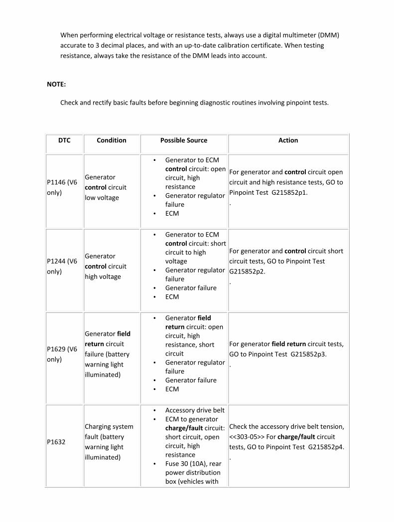
When performing electrical voltage or resistance tests, always use a digital multimeter (DMM)
accurate to 3 decimal places, and with an up-to-date calibration certificate. When testing
resistance, always take the resistance of the DMM leads into account.
NOTE:
Check and rectify basic faults before beginning diagnostic routines involving pinpoint tests.
DTC Condition Possible Source Action
P1146 (V6
only)
Generator
control circuit
low voltage
• Generator to ECM
control circuit: open
circuit, high
resistance
• Generator regulator
failure
• ECM
For generator and control circuit open
circuit and high resistance tests, GO to
Pinpoint Test G215852p1.
.
P1244 (V6
only)
Generator
control circuit
high voltage
• Generator to ECM
control circuit: short
circuit to high
voltage
• Generator regulator
failure
• Generator failure
• ECM
For generator and control circuit short
circuit tests, GO to Pinpoint Test
G215852p2.
.
P1629 (V6
only)
Generator field
return circuit
failure (battery
warning light
illuminated)
• Generator field
return circuit: open
circuit, high
resistance, short
circuit
• Generator regulator
failure
• Generator failure
• ECM
For generator field return circuit tests,
GO to Pinpoint Test G215852p3.
.
P1632
Charging system
fault (battery
warning light
illuminated)
• Accessory drive belt
• ECM to generator
charge/fault circuit:
short circuit, open
circuit, high
resistance
• Fuse 30 (10A), rear
power distribution
box (vehicles with
Check the accessory drive belt tension,
<<303-05>> For charge/fault circuit
tests, GO to Pinpoint Test G215852p4.
.
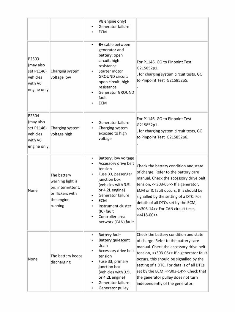
V8 engine only)
• Generator failure
• ECM
P2503
(may also
set P1146)
vehicles
with V6
engine only
Charging system
voltage low
• B+ cable between
generator and
battery: open
circuit, high
resistance
• Starter motor
GROUND circuit:
open circuit, high
resistance
• Generator GROUND
fault
• ECM
For P1146, GO to Pinpoint Test
G215852p1.
, for charging system circuit tests, GO
to Pinpoint Test G215852p5.
.
P2504
(may also
set P1146)
vehicles
with V6
engine only
Charging system
voltage high
• Generator failure
• Charging system
exposed to high
voltage
For P1146, GO to Pinpoint Test
G215852p1.
, for charging system circuit tests, GO
to Pinpoint Test G215852p6.
.
None
The battery
warning light is
on, intermittent,
or flickers with
the engine
running
• Battery, low voltage
• Accessory drive belt
tension
• Fuse 33, passenger
junction box
(vehicles with 3.5L
or 4.2L engine)
• Generator failure
• ECM
• Instrument cluster
(IC) fault
• Controller area
network (CAN) fault
Check the battery condition and state
of charge. Refer to the battery care
manual. Check the accessory drive belt
tension, <<303-05>> If a generator,
ECM or IC fault occurs, this should be
signalled by the setting of a DTC. For
details of all DTCs set by the ECM,
<<303-14>> For CAN circuit tests,
<<418-00>>
None The battery keeps
discharging
• Battery fault
• Battery quiescent
drain
• Accessory drive belt
tension
• Fuse 33, primary
junction box
(vehicles with 3.5L
or 4.2L engine)
• Generator failure
• Generator pulley
Check the battery condition and state
of charge. Refer to the battery care
manual. Check the accessory drive belt
tension, <<303-05>> If a generator fault
occurs, this should be signalled by the
setting of a DTC. For details of all DTCs
set by the ECM, <<303-14>> Check that
the generator pulley does not turn
independently of the generator.
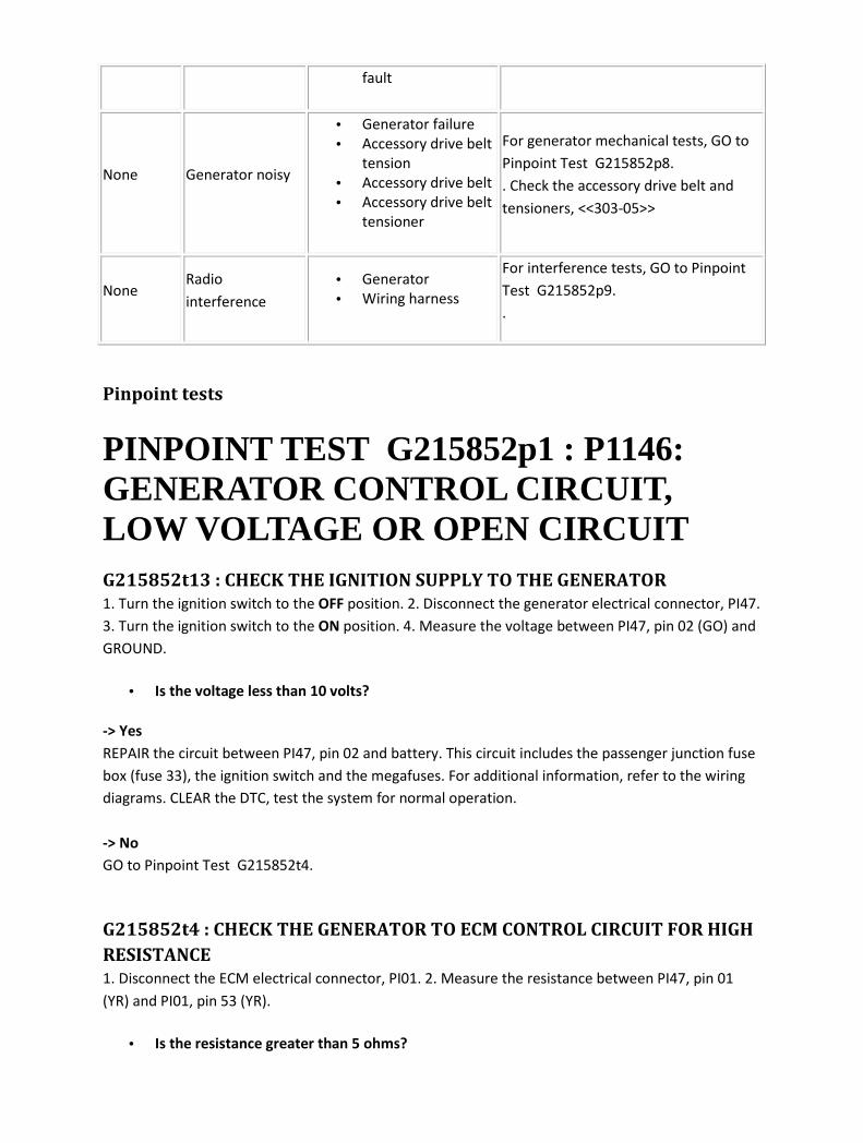
fault
None Generator noisy
• Generator failure
• Accessory drive belt
tension
• Accessory drive belt
• Accessory drive belt
tensioner
For generator mechanical tests, GO to
Pinpoint Test G215852p8.
. Check the accessory drive belt and
tensioners, <<303-05>>
None Radio
interference
• Generator
• Wiring harness
For interference tests, GO to Pinpoint
Test G215852p9.
.
Pinpoint tests
PINPOINT TEST G215852p1 : P1146: GENERATOR CONTROL CIRCUIT, LOW VOLTAGE OR OPEN CIRCUIT G215852t13 : CHECK THE IGNITION SUPPLY TO THE GENERATOR
1. Turn the ignition switch to the OFF position. 2. Disconnect the generator electrical connector, PI47.
3. Turn the ignition switch to the ON position. 4. Measure the voltage between PI47, pin 02 (GO) and
GROUND.
• Is the voltage less than 10 volts?
-> Yes
REPAIR the circuit between PI47, pin 02 and battery. This circuit includes the passenger junction fuse
box (fuse 33), the ignition switch and the megafuses. For additional information, refer to the wiring
diagrams. CLEAR the DTC, test the system for normal operation.
-> No
GO to Pinpoint Test G215852t4.
G215852t4 : CHECK THE GENERATOR TO ECM CONTROL CIRCUIT FOR HIGH
RESISTANCE
1. Disconnect the ECM electrical connector, PI01. 2. Measure the resistance between PI47, pin 01
(YR) and PI01, pin 53 (YR).
• Is the resistance greater than 5 ohms?
-> Yes
REPAIR the high resistance circuit. For additional information, refer to the wiring diagrams. CLEAR the
DTC, test the system for normal operation.
-> No
INSTALL a new generator. CLEAR the DTC, test the system for normal operation. If the DTC is
repeated, contact dealer technical support for advice on possible ECM failure.
PINPOINT TEST G215852p2 : P1244: GENERATOR CONTROL CIRCUIT, HIGH VOLTAGE G215852t11 : CHECK THE GENERATOR TO ECM CONTROL CIRCUIT FOR
SHORT CIRCUIT TO HIGH VOLTAGE
1. Disconnect the battery negative terminal. 2. Disconnect the generator electrical connector, PI47. 3.
Measure the resistance between PI47, pin 01 (YR) and the battery positive terminal.
• Is the resistance less than 10,000 ohms?
-> Yes
REPAIR the short circuit. For additional information, refer to the wiring diagrams. CLEAR the DTC, test
the system for normal operation.
-> No
INSTALL a new generator. CLEAR the DTC, test the system for normal operation. If the DTC is
repeated, contact dealer technical support for advice on possible ECM failure.
PINPOINT TEST G215852p3 : P1629: GENERATOR FIELD RETURN CIRCUIT FAILURE G215852t1 : CHECK THE GENERATOR ELECTRICAL CONNECTOR FOR
DAMAGE
1. Carefully inspect the generator connector, PI47 for damage/correct installation.
• Is the connector damaged or incorrectly installed?
-> Yes
INSTALL/REPAIR the connector as necessary. Test the system for normal operation.
-> No

GO to Pinpoint Test G215852t2.
G215852t2 : CHECK THE IGNITION SUPPLY TO THE GENERATOR
1. Disconnect the generator connector, PI47. 2. Turn the ignition switch to the ON position. 3.
Measure the voltage between PI47, pin 02 (GO) and GROUND.
• Is the voltage more than 9 volts?
-> Yes
GO to Pinpoint Test G215852t3.
-> No
REPAIR the circuit between the generator and the ignition switch. This circuit includes fuse 40 of the
rear power distribution box. For additional information, refer to the wiring diagrams. CLEAR the DTC.
TEST the system for normal operation.
G215852t3 : CHECK THE VOLTAGE AT THE FIELD RETURN TERMINAL
1. Turn the ignition switch to the ON position. 2. Measure the voltage between PI47, pin 03 (WR) and
GROUND.
• Is the voltage more than 9 volts?
-> Yes
GO to Pinpoint Test G215852t5.
-> No
GO to Pinpoint Test G215852t12.
G215852t5 : CHECK THE FIELD RETURN CIRCUIT FOR A SHORT TO
BATTERY
1. Turn the ignition switch to the OFF position. 2. Measure the voltage between PI47, pin 03 (WR)
and GROUND.
• Is the voltage less than 1 volt?
-> Yes
INSTALL a new generator. CLEAR the DTC. TEST the system for normal operation.
-> No
REPAIR the short circuit. For additional information, refer to the wiring diagrams. CLEAR the DTC.
TEST the system for normal operation.

G215852t12 : CHECK THE GENERATOR FIELD RETURN CIRCUIT FOR HIGH
RESISTANCE
1. Disconnect the battery negative terminal. 2. Disconnect the generator electrical connector, PI47. 3.
Disconnect the ECM electrical connector, PI01. 4. Measure the resistance between PI47, pin 03 (WR)
and PI01, pin 65 (WR).
• Is the resistance greater than 5 ohms?
-> Yes
REPAIR the high resistance circuit. For additional information, refer to the wiring diagrams. CLEAR the
DTC, test the system for normal operation.
-> No
INSTALL a new generator. Clear the DTC, test the system for normal operation. If the fault is
repeated, contact dealer technical support for advice on possible ECM failure.
PINPOINT TEST G215852p4 : P1632: CHARGING SYSTEM FAULT G215852t6 : CHECK THE BATTERY VOLTAGE WITH THE ENGINE RUNNING
1. Connect a suitable voltmeter across the battery terminals. 2. Start the engine and allow to idle
with no electrical loads applied. 3. Measure the maximum voltage achieved at the battery after start.
• Is the voltage less than 10.5 volts?
-> Yes
GO to Pinpoint Test G215852t8.
-> No
For vehicles with V6 engine; GO to Pinpoint Test G215852t8.
For vehicles with V8 engine; GO to Pinpoint Test G215852t7.
G215852t8 : CARRY OUT BATTERY CONDITION TEST (SEE BATTERY CARE
MANUAL)
1. Carry out the procedure in the battery care manual.
• Is the battery OK?
-> Yes
GO to Pinpoint Test G215852t18.
-> No
INSTALL a fully-charged battery.
G215852t18 : CHECK THE GROUND TO THE GENERATOR
1. Turn the ignition switch to the OFF position. 2. Measure the resistance between the generator
body and GROUND.
• Is the resistance greater than 5 ohms?
-> Yes
CHECK the security and condition of the GROUND lead to the transmission. CHECK that there is a
good electrical contact between the generator and it's mounting. CLEAR the DTC, test the system for
normal operation.
-> No
GO to Pinpoint Test G215852t19.
G215852t19 : CHECK THE BATTERY TO GENERATOR CABLES FOR HIGH
RESISTANCE
1. Disconnect the battery negative terminal. 2. Disconnect the battery positive terminal. 3.
Disconnect the B+ terminal from the starter motor. 4. Disconnect the B+ terminal from the
generator. 5. Measure the resistance of both leads.
• Is either resistance greater than 5 ohms?
-> Yes
INSTALL a new lead. CLEAR the DTC, test the system for normal operation.
-> No
GO to Pinpoint Test G215852t20.
G215852t20 : CHECK THE "L" LINE TO THE ECM
1. Reconnect both battery terminals. 2. Disconnect the alternator connector, PI47. 3. Turn the
ignition switch to the ON position. For vehicles with V6 engine
• Measure the voltage between PI47, pin 04 (YR) and GROUND.
For vehicles with V8 engine
• Measure the voltage between PI47, pin 01 (YR) and GROUND.
• Is the voltage greater than 10 volts?

-> Yes
GO to Pinpoint Test G215852t9.
-> No
CHECK the circuit between the ECM and the generator for open circuit/high resistance. REPAIR as
necessary. CLEAR the DTC, test the system for normal operation. If the fault persists, contact dealer
technical support for advice on possible ECM failure.
G215852t9 : CHECK THE "L" LINE FOR SHORT TO BATTERY
1. Turn the ignition switch to the OFF position. For vehicles with V6 engine
• Measure the voltage between PI47, pin 04 (YR) and GROUND.
For vehicles with V8 engine
• Measure the voltage between PI47, pin 01 (YR) and GROUND.
• Is the voltage less than 1 volt?
-> Yes
GO to Pinpoint Test G215852t21.
-> No
REPAIR the short circuit. For additional information, refer to the wiring diagrams. CLEAR the DTC, test
the system for normal operation.
G215852t21 : CHECK THE GENERATOR DRIVE PULLEY
1. Remove the accessory drive belt, <<303-05>> 2. Rotate the generator pulley by hand.
• Does the generator rotor shaft rotate with the pulley?
-> Yes
INSTALL a new generator. CLEAR the DTC, test the system for normal operation. If the fault is
repeated, contact dealer technical support for advice on possible ECM failure.
-> No
INSTALL a new generator. CLEAR the DTC, test the system for normal operation.
G215852t7 : CHECK THE VOLTAGE AT THE GENERATOR SENSE TERMINAL
(VEHICLES WITH V8 ENGINE ONLY)
1. Disconnect the generator electrical connector, PI48. 2. Measure the voltage between PI48, pin 03
(NG) and GROUND.
• Is the voltage less than 10 volts?
-> Yes
REPAIR the high resistance circuit. For additional information, refer to the wiring diagrams. CLEAR the
DTC, test the system for normal operation.
-> No
GO to Pinpoint Test G215852t10.
G215852t10 : CHECK FUSE 30 IN THE REAR DISTRIBUTION BOX (VEHICLES
WITH V8 ENGINE ONLY)
1. Check the fuse condition.
• Is the fuse blown?
-> Yes
GO to Pinpoint Test G215852t22.
-> No
REPAIR the circuit between the rear power distribution box and the generator, test the system for
normal operation.
G215852t22 : CHECK FUSE 30 IN THE REAR DISTRIBUTION BOX FOR A
SHORT TO GROUND (VEHICLES WITH V8 ENGINE ONLY)
1. Measure the resistance between the fuse box, terminal 01 and GROUND.
• Is the resistance less than 10,000 ohms?
-> Yes
REPAIR the short circuit. For additional information, refer to the wiring diagrams. INSTALL a new fuse,
test the system for normal operation.
-> No
INSTALL a new fuse, test the system for normal operation.
PINPOINT TEST G215852p5 : P2503: CHARGING SYSTEM VOLTAGE LOW G215852t14 : CHECK FOR DTC AFTER FULL LOAD TEST
1. Clear all DTCs. 2. Start the engine and run at 1500 rpm with all electrical loads switched ON, except
the heated front screen.
• Does P2503 reflag within five minutes?

-> Yes
GO to Pinpoint Test G215852t15.
-> No
No charging system fault found.
G215852t15 : CHECK THE BATTERY TO GENERATOR CABLES FOR HIGH
RESISTANCE
1. Turn the ignition switch to the OFF position. 2. Disconnect the battery negative terminal. 3.
Disconnect the battery positive terminal. 4. Disconnect the B+ terminal from the starter motor. 5.
Disconnect the B+ terminal from the generator. 6. Measure the resistance of both leads.
• Is either resistance greater than 5 ohms?
-> Yes
INSTALL a new lead. CLEAR the DTC, test the system for normal operation.
-> No
GO to Pinpoint Test G215852t16.
G215852t16 : CHECK FOR DTC AFTER CLEANING CONNECTIONS
1. Clean all connections in the supply and GROUND circuits. 2. Clear all DTCs. 3. Start the engine and
run at 1500 rpm with all electrical loads switched ON, except the heated front screen.
• Does P2503 reflag within five minutes?
-> Yes
INSTALL a new generator. CLEAR the DTC, test the system for normal operation. If the DTC is
repeated, contact dealer technical support for advice on possible ECM and/or power feeds failure.
-> No
Fault rectified.
PINPOINT TEST G215852p6 : P2504: CHARGING SYSTEM VOLTAGE HIGH G215852t17 : CHECK FOR DTC AFTER MINIMUM LOAD TEST
1. Clear all DTCs. 2. Start the engine and allow to idle with no additional electrical load. 3. Allow the
engine to idle for at least five minutes while checking for DTCs.
• Does P2504 reflag within five minutes?

-> Yes
INSTALL a new generator. CLEAR the DTC, test the system for normal operation.
-> No
CHECK with owner/driver for any history of boost charging.
PINPOINT TEST G215852p8 : GENERATOR NOISY G215852t74 : CHECK THE GENERATOR FOR SECURITY
1. Inspect the generator fixings.
• Is the generator secure?
-> Yes
GO to Pinpoint Test G215852t75.
-> No
SECURE the generator. TEST the system for normal operation.
G215852t75 : CHECK THE ACCESSORY DRIVE BELT
1. Remove and inspect the accessory drive belt. For additional information <<303-05>>
• Is the accessory drive belt in good condition?
-> Yes
GO to Pinpoint Test G215852t76.
-> No
INSTALL a new accessory drive belt. TEST the system for normal operation.
G215852t76 : CHECK THE ACCESSORY DRIVE BELT TENSIONER
1. Remove and inspect the accessory drive belt tensioner. <<303-05>>
• Is the accessory drive belt tensioner in good condition?
-> Yes
GO to Pinpoint Test G215852t77.
-> No
INSTALL a new accessory drive belt tensioner. TEST the system for normal operation.

G215852t77 : CHECK THE GENERATOR FOR MECHANICAL NOISE
1. Rotate the generator pulley by hand.
• Does the generator rotor shaft rotate smoothly and quietly?
-> Yes
GO to Pinpoint Test G215852t79.
-> No
INSTALL a new generator. TEST the system for normal operation.
G215852t79 : CHECK THE ACCESSORY DRIVE BELT IDLER PULLEYS
1. Rotate the accessory drive belt idler pulleys by hand.
• Do the accessory drive belt idler pulleys rotate smoothly and quietly?
-> Yes
GO to Pinpoint Test G215852t80.
-> No
INSTALL new accessory drive belt pulleys as necessary. TEST the system for normal operation.
G215852t80 : CHECK THE GENERATOR FOR ELECTRICAL NOISE
1. Install the accessory drive belt. 2. Start and run the engine at 1500 rpm. Apply a high electrical load
to the battery.
• Is the noise only heard with the high electrical load applied?
-> Yes
GO to Pinpoint Test G215852t81.
-> No
CHECK the air conditioning compressor. For additional information <<412-03>> CHECK the power
steering pump. For additional information <<211-02>> TEST the system for normal operation.
G215852t81 : ELIMINATE THE GENERATOR AS THE CAUSE OF ELECTRICAL
NOISE
1. Remove fuse 15 from the primary junction fuse box. 2. Start and run the engine at 1500 rpm.
• Is the noise still present?
-> Yes
CHECK the air conditioning compressor. For additional information <<412-03>> CHECK the power

steering pump. For additional information <<211-02>> TEST the system for normal operation.
-> No
INSTALL a new generator. TEST the system for normal operation.
PINPOINT TEST G215852p9 : RADIO INTERFERENCE G215852t82 : CHECK IF THE GENERATOR IS THE CAUSE OF THE RADIO
INTERFERENCE
1. Start and run the engine at 1500 rpm. 2. Turn the radio to the ON position, and select the affected
station.
• Is the radio interference present?
-> Yes
GO to Pinpoint Test G215852t84.
-> No
GO to Pinpoint Test G215852t83.
G215852t83 : CHECK IF THE GENERATOR IS THE CAUSE OF THE RADIO
INTERFERENCE WITH A HIGH ELECTRICAL LOAD APPLIED TO THE
BATTERY
1. Start and run the engine at 1500 rpm. 2. Apply a high electrical load to the battery. 3. Turn the
radio to the ON position, and select the affected station.
• Is the radio interference present?
-> Yes
GO to Pinpoint Test G215852t84.
-> No
DIAGNOSE the entertainment system. For additional information <<415-00>>
G215852t84 : ELIMINATE THE GENERATOR AS THE CAUSE OF RADIO
INTERFERENCE
1. Remove fuse 33 from the primary junction fuse box. 2. Start and run the engine at 1500 rpm. 3.
Turn the radio to the ON position, and select the affected station.
• Is the radio interference present?

-> Yes
DIAGNOSE the entertainment system. For additional information <<415-00>>
-> No
CLEAN and tighten all mounting points, positive and negative cable connections (including the
bonnet, boot and engine GROUND straps). INSTALL fuse 15 from the primary junction fuse box. TEST
the system for normal operation. If interference is still present, INSTALL a new generator.

Charging System - 2.7L V6 - TdV6 Overview
There are changes to diagnostics for 2006 my, the most obvious of which will be the change to 7-digit
diagnostic trouble codes (DTCs) from the familiar 5-digit.
Refer to the DTC index in this section for guidance on how to use these codes with the Jaguar
approved diagnostic system or a scan tool.
For information on the operation of the system,
Charging System
Inspection and Verification
1 . Verify the customer concern.
2 . Visually inspect for obvious signs of mechanical and electrical damage.
Mechanical Electrical
• Generator
• Front end accessory drive (FEAD) belt condition
and tension
• Accessory drive belt tensioner
• Generator pulley
• Generator fittings/connections
• Generator
• Battery
• Starter motor
• Harnesses and connectors
• Fuse 30, rear power distribution
box
• Starter motor megafuse
• Charge warning light function
• Controller area network (CAN)
circuit fault
• Engine control module (ECM)
3 . Check the vehicle battery condition and state of charge before condemning any charging system
components. For additional information, refer to the battery care manual.
4 . If an obvious cause for an observed or reported concern is found, correct the cause (if possible)
before proceeding to the next step.
5 . If the cause is not visually evident use the Jaguar approved diagnostic system or a scan tool to
retrieve the fault codes before proceeding to the DTC index, or the symptom chart if no DTCs are set.
Symptom chart
Symptom Possible cause Action
Charge warning • Bulb/circuit fault Check the warning light function with the ignition on
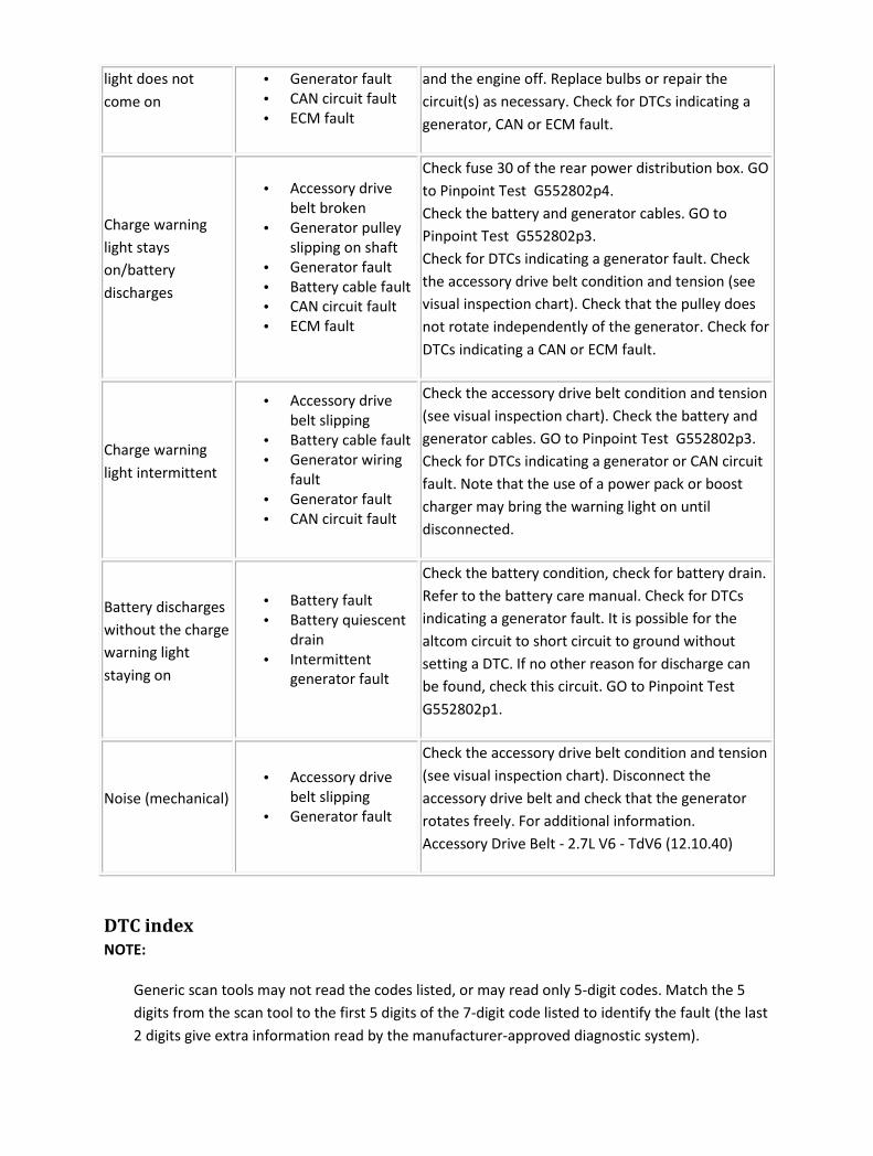
light does not
come on
• Generator fault
• CAN circuit fault
• ECM fault
and the engine off. Replace bulbs or repair the
circuit(s) as necessary. Check for DTCs indicating a
generator, CAN or ECM fault.
Charge warning
light stays
on/battery
discharges
• Accessory drive
belt broken
• Generator pulley
slipping on shaft
• Generator fault
• Battery cable fault
• CAN circuit fault
• ECM fault
Check fuse 30 of the rear power distribution box. GO
to Pinpoint Test G552802p4.
Check the battery and generator cables. GO to
Pinpoint Test G552802p3.
Check for DTCs indicating a generator fault. Check
the accessory drive belt condition and tension (see
visual inspection chart). Check that the pulley does
not rotate independently of the generator. Check for
DTCs indicating a CAN or ECM fault.
Charge warning
light intermittent
• Accessory drive
belt slipping
• Battery cable fault
• Generator wiring
fault
• Generator fault
• CAN circuit fault
Check the accessory drive belt condition and tension
(see visual inspection chart). Check the battery and
generator cables. GO to Pinpoint Test G552802p3.
Check for DTCs indicating a generator or CAN circuit
fault. Note that the use of a power pack or boost
charger may bring the warning light on until
disconnected.
Battery discharges
without the charge
warning light
staying on
• Battery fault
• Battery quiescent
drain
• Intermittent
generator fault
Check the battery condition, check for battery drain.
Refer to the battery care manual. Check for DTCs
indicating a generator fault. It is possible for the
altcom circuit to short circuit to ground without
setting a DTC. If no other reason for discharge can
be found, check this circuit. GO to Pinpoint Test
G552802p1.
Noise (mechanical)
• Accessory drive
belt slipping
• Generator fault
Check the accessory drive belt condition and tension
(see visual inspection chart). Disconnect the
accessory drive belt and check that the generator
rotates freely. For additional information.
Accessory Drive Belt - 2.7L V6 - TdV6 (12.10.40)
DTC index
NOTE:
Generic scan tools may not read the codes listed, or may read only 5-digit codes. Match the 5
digits from the scan tool to the first 5 digits of the 7-digit code listed to identify the fault (the last
2 digits give extra information read by the manufacturer-approved diagnostic system).

NOTE:
For a full list of powertrain DTCs,
Electronic Engine Controls
DTC Description Possible causes Action
P062200 Generator monitor
circuit plausibility • PWM signal incorrect
For generator monitor circuit
tests, GO to Pinpoint Test
G552802p1.
P062500 Generator monitor
circuit fault
• Voltage sense circuit: high
resistance
• Generator B+ circuit: high
resistance/intermittent
• Generator monitor circuit:
short circuit to ground
Check fuse 30 of the rear power
distribution box. GO to Pinpoint
Test G552802p4.
Carry out the battery cable volt
drop tests. GO to Pinpoint Test
G552802p3.
For generator monitor circuit
tests. GO to Pinpoint Test
G552802p1.
P062600 Generator monitor
circuit fault
• Generator connector:
loose/not connected
• Generator monitor circuit:
short circuit to power
• Generator monitor circuit:
high resistance
Carry out the battery cable volt
drop tests. GO to Pinpoint Test
G552802p3.
For generator monitor circuit
tests. GO to Pinpoint Test
G552802p1.
P065B00
Generator
command circuit
fault
• Generator command circuit:
short circuit to ground
• Generator command circuit:
short circuit to power
• Generator command circuit:
high resistance
For generator command circuit
tests. GO to Pinpoint Test
G552802p2.
Pinpoint tests
CAUTION: When probing connectors to take measurements in the course of the pinpoint
tests, use the adaptor kit, part number 3548-1358-00. Failure to follow this instruction may result
in damage to the vehicle.

NOTE:
When performing voltage or resistance tests, always use a digital multimeter (DMM) accurate to
3 decimal places, and with an up-to-date calibration certificate. When testing resistance, always
take the resistance of the DMM leads into account.
NOTE:
Check and rectify basic faults before beginning diagnostic routines involving pinpoint tests.
NOTE:
If DTCs are recorded and a fault is not present when performing the pinpoint tests, an
intermittent concern may be the cause. Always check for loose connections and corroded
terminals.
PINPOINT TEST G552802p1 : GENERATOR MONITOR CIRCUIT G552802t1 : CHECK THE MONITOR CIRCUIT FOR SHORT CIRCUIT TO
GROUND
1.
Circuit Pin
Voltage sense circuit 01
Altcom 02
Altmon 03
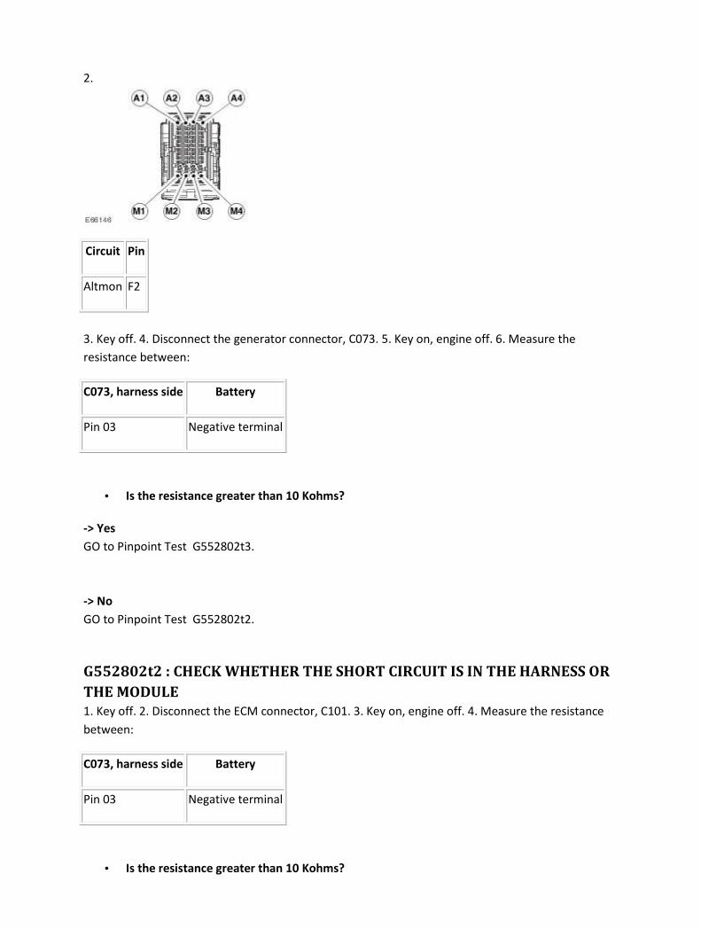
2.
Circuit Pin
Altmon F2
3. Key off. 4. Disconnect the generator connector, C073. 5. Key on, engine off. 6. Measure the
resistance between:
C073, harness side Battery
Pin 03 Negative terminal
• Is the resistance greater than 10 Kohms?
-> Yes
GO to Pinpoint Test G552802t3.
-> No
GO to Pinpoint Test G552802t2.
G552802t2 : CHECK WHETHER THE SHORT CIRCUIT IS IN THE HARNESS OR
THE MODULE
1. Key off. 2. Disconnect the ECM connector, C101. 3. Key on, engine off. 4. Measure the resistance
between:
C073, harness side Battery
Pin 03 Negative terminal
• Is the resistance greater than 10 Kohms?

-> Yes
An intermittent fault may be present in the wiring harness. Visually check for chaffed wires or other
physical damage to the harness. Refer to the warranty policy and procedures manual if a module is
suspect.
-> No
REPAIR the short circuit. For additional information, refer to the wiring diagrams. Clear the DTC, test
the system for normal operation.
G552802t3 : CHECK THE MONITOR CIRCUIT FOR SHORT CIRCUIT TO
POWER
1. Measure the resistance between:
C073, harness side Battery
Pin 03 Positive terminal
• Is the resistance greater than 10 Kohms?
-> Yes
GO to Pinpoint Test G552802t5.
-> No
GO to Pinpoint Test G552802t4.
G552802t4 : CHECK WHETHER THE SHORT CIRCUIT IS IN THE HARNESS OR
THE MODULE
1. Key off. 2. Disconnect the ECM connector, C101 3. Key on, engine off. 4. Measure the resistance
between:
C073, harness side Battery
Pin 03 Negative terminal
• Is the resistance greater than 10 Kohms?
-> Yes
An intermittent fault may be present in the wiring harness. Visually check for chaffed wires or other
physical damage to the harness. Refer to the warranty policy and procedures manual if a module is
suspect.
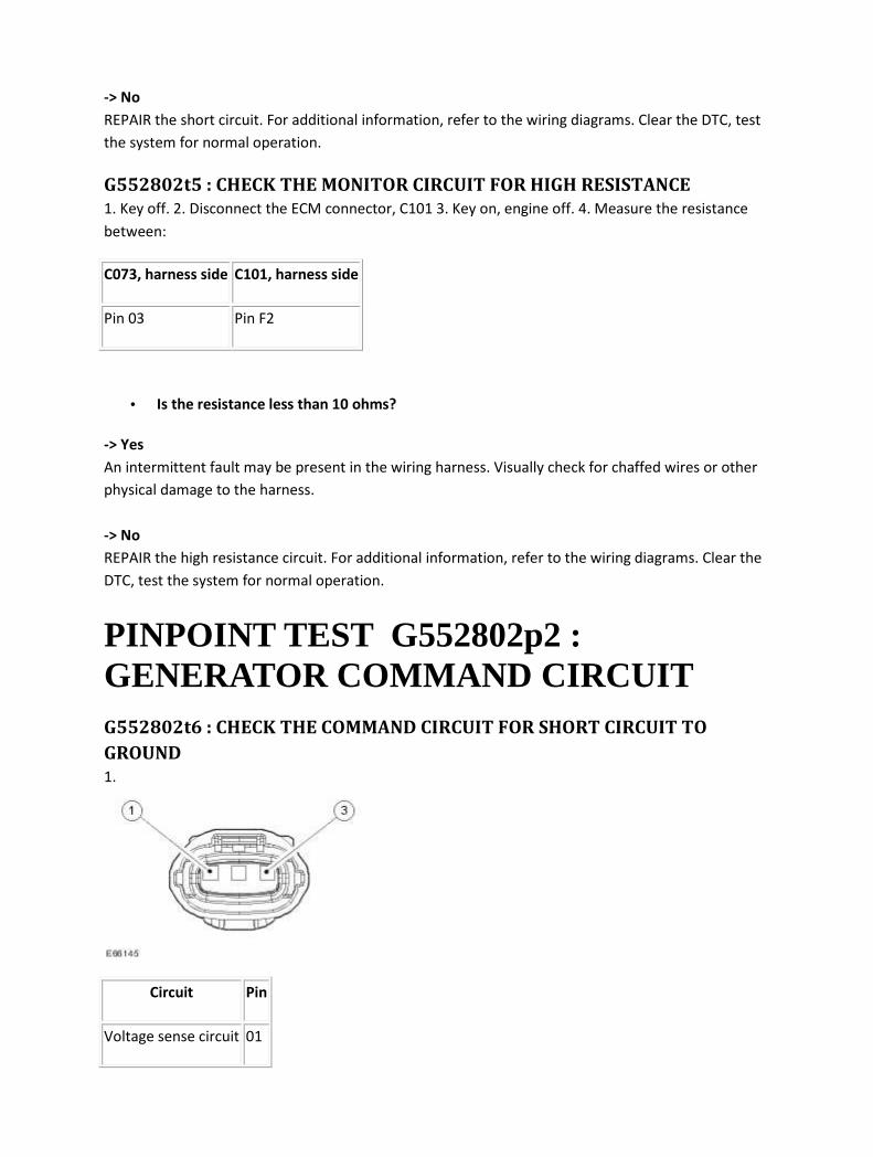
-> No
REPAIR the short circuit. For additional information, refer to the wiring diagrams. Clear the DTC, test
the system for normal operation.
G552802t5 : CHECK THE MONITOR CIRCUIT FOR HIGH RESISTANCE
1. Key off. 2. Disconnect the ECM connector, C101 3. Key on, engine off. 4. Measure the resistance
between:
C073, harness side C101, harness side
Pin 03 Pin F2
• Is the resistance less than 10 ohms?
-> Yes
An intermittent fault may be present in the wiring harness. Visually check for chaffed wires or other
physical damage to the harness.
-> No
REPAIR the high resistance circuit. For additional information, refer to the wiring diagrams. Clear the
DTC, test the system for normal operation.
PINPOINT TEST G552802p2 : GENERATOR COMMAND CIRCUIT G552802t6 : CHECK THE COMMAND CIRCUIT FOR SHORT CIRCUIT TO
GROUND
1.
Circuit Pin
Voltage sense circuit 01

Altcom 02
Altmon 03
2.
Circuit Pin
Altcom H1
3. Key off. 4. Disconnect the generator connector, C073. 5. Key on, engine off. 6. Measure the
resistance between:
C073, harness side Battery
Pin 02 Negative terminal
• Is the resistance greater than 10 Kohms?
-> Yes
GO to Pinpoint Test G552802t8.
-> No
GO to Pinpoint Test G552802t7.
G552802t7 : CHECK WHETHER THE SHORT CIRCUIT IS IN THE HARNESS OR
THE MODULE
1. Key off. 2. Disconnect the ECM connector, C101. 3. Key on, engine off. 4. Measure the resistance
between:
C073, harness side Battery
Pin 02 Negative terminal
• Is the resistance greater than 10 Kohms?
-> Yes
An intermittent fault may be present in the wiring harness. Visually check for chaffed wires or other
physical damage to the harness. Refer to the warranty policy and procedures manual if a module is
suspect.
-> No
REPAIR the short circuit. For additional information, refer to the wiring diagrams. Clear the DTC, test
the system for normal operation.
G552802t8 : CHECK THE COMMAND CIRCUIT FOR SHORT CIRCUIT TO
POWER
1. Measure the resistance between:
C073, harness side Battery
Pin 02 Positive terminal
• Is the resistance greater than 10 Kohms?
-> Yes
GO to Pinpoint Test G552802t10.
-> No
GO to Pinpoint Test G552802t9.
G552802t9 : CHECK WHETHER THE SHORT CIRCUIT IS IN THE HARNESS OR
THE MODULE
1. Key off. 2. Disconnect the ECM connector, C101 3. Key on, engine off. 4. Measure the resistance
between:
C073, harness side Battery
Pin 02 Positive terminal
• Is the resistance greater than 10 Kohms?
-> Yes
An intermittent fault may be present in the wiring harness. Visually check for chaffed wires or other
physical damage to the harness. Refer to the warranty policy and procedures manual if a module is
suspect.
-> No
REPAIR the short circuit. For additional information, refer to the wiring diagrams. Clear the DTC, test
the system for normal operation.
G552802t10 : CHECK THE COMMAND CIRCUIT FOR HIGH RESISTANCE
1. Key off. 2. Disconnect the ECM connector, C101 3. Key on, engine off. 4. Measure the resistance
between:
C073, harness side C101, harness side
Pin 02 Pin H1
• Is the resistance less than 10 ohms?
-> Yes
An intermittent fault may be present in the wiring harness. Visually check for chaffed wires or other
physical damage to the harness.
-> No
REPAIR the high resistance circuit. For additional information, refer to the wiring diagrams. Clear the
DTC, test the system for normal operation.
PINPOINT TEST G552802p3 : BATTERY CABLE VOLT DROP G552802t11 : CHECK FOR GENERATOR OUTPUT
1. Key off. 2. Measure and record the voltage between:
Battery Battery
Positive terminal Negative terminal
3. Key on, engine running.
Allow to idle 4. Switch off all electrical loads, including heater blowers. 5. Measure and record the
voltage between:
Battery Battery
Positive terminal Negative terminal
• Is the voltage greater than in step 2?
-> Yes
GO to Pinpoint Test G552802t12.
-> No
CHECK the connections at either end of the circuit for cleanliness and security. Check for high
resistance in the circuit. Clean or replace as necessary. Check that the generator is charging. Test the
system for normal operation.
G552802t12 : CHECK FOR VOLT DROP BETWEEN THE BATTERY AND THE
GENERATOR
1. Switch on all lights, select maximum heater blower speed, and turn on the rear heated screen. 2.
Measure the voltage between:
Generator Battery
Connector, ST07 Positive terminal
• Is the voltage less than 0.5 volts?
-> Yes
An intermittent fault may be present in the wiring harness. Visually check for chaffed wires or other
physical damage to the harness. Check for DTCs indicating another cause of the concern.
-> No
CHECK the connections at either end of the circuit for cleanliness and security. Check for high
resistance in the circuit. Clean or replace as necessary. Test the system for normal operation.
PINPOINT TEST G552802p4 : GENERATOR VOLTAGE SENSE CIRCUIT

G552802t14 : CHECK THE VOLTAGE AT THE GENERATOR SENSE CIRCUIT
1.
Circuit Pin
Voltage sense circuit 01
Altcom 02
Altmon 03
2. Key off. 3. Disconnect the generator connector, C073. 4. Measure the voltage between:
C073, harness side Battery
Pin 01 Negative terminal
• Is the voltage greater than 10 volts?
-> Yes
Voltage sense circuit is correct. GO to Pinpoint Test G552802p3.
-> No
GO to Pinpoint Test G552802t15.
G552802t15 : CHECK THE VOLTAGE AT THE REAR POWER DISTRIBUTION
BOX
1. Key off. 2. Remove fuse 30 of the rear power distribution box. 3. Measure the voltage between:
Rear power distribution box Battery
Fuse 30, input pin Negative terminal

• Is the voltage greater than 10 volts?
-> Yes
GO to Pinpoint Test G552802t16.
-> No
REPAIR the power supply circuit to the rear power distribution box. For additional information, refer
to the wiring diagrams. Clear the DTC, test the system for normal operation.
G552802t16 : CHECK THE VOLTAGE SENSE CIRCUIT FOR HIGH RESISTANCE
1. Measure the resistance between:
C073, harness side Rear power distribution box
Pin 01 Fuse 30, output pin
• Is the resistance less than 10 ohms?
-> Yes
RECHECK the fuse. An intermittent fault may be present in the wiring harness. Visually check for
chaffed wires or other physical damage to the harness.
-> No
REPAIR the high resistance circuit. For additional information, refer to the wiring diagrams. Clear the
DTC, test the system for normal operation.

414-01 : Battery, Mounting and Cables
Specifications
Specifications Battery Specification
Engine Specification
Vehicle Specification
Europe Rest of World Vehicles fitted without
electrical optional extras.
Vehicles fitted with electrical optional extras.
Vehicles fitted with 3.0L, 3.5L or 4.2L engine
90 Ah 90 Ah 90 Ah
Vehicles fitted with 2.7L Diesel engine
95Ah 95Ah 95Ah
Battery Cold Cranking Specification
Item Specification
90 Ah Battery Cold Cranking 680 Amps
95 Ah Battery Cold Cranking 800 Amps
Torque Specifications
Description Nm lb-ft lb-in
Battery positive cable to rear junction box retaining nut 12 9 -
Battery positive cable terminal retaining nut 4 - 35
Battery negative cable terminal retaining nut 4 - 35
Battery ground cable to body retaining bolt 12 9 -
Battery tray 13 10 -
Battery hold down clamp 13 10 -

General Procedures
Battery Connect (86.15.15)
WARNING: Batteries produce explosive gases which may cause personal injury. Do not expose the battery to a naked flame. When charging or working near a battery wear protective clothing and eye protectors. Always provide adequate ventilation. Failure to follow these instructions may result in personal injury.
WARNING: Batteries contain sulphuric acid, avoid contact with skin, eyes and clothing. Shield your eyes when working near the battery to protect against possible contact of the acid solution. In case of contact with the skin or eyes, flush immediately for a minimum of 15 minutes and seek prompt medical attention. If swallowed call a physician immediately. Failure to follow these instructions may result in personal injury.
CAUTION: Make sure all electrical systems are off before connecting the battery negative cable. Failure to follow these instructions may result in damage to the electrical system. NOTE:
Following reconnection of the battery, the engine should be allowed to idle as the stored idle and drive values contained within the engine control module (ECM) have been lost. This may cause driveablity concern if the following procedure is not carried out.
1. Connect the battery negative cable. • Tighten to 4 Nm.
2. Fit the spare wheel cover. • Fit and tighten the spare wheel cover retaining clamp.
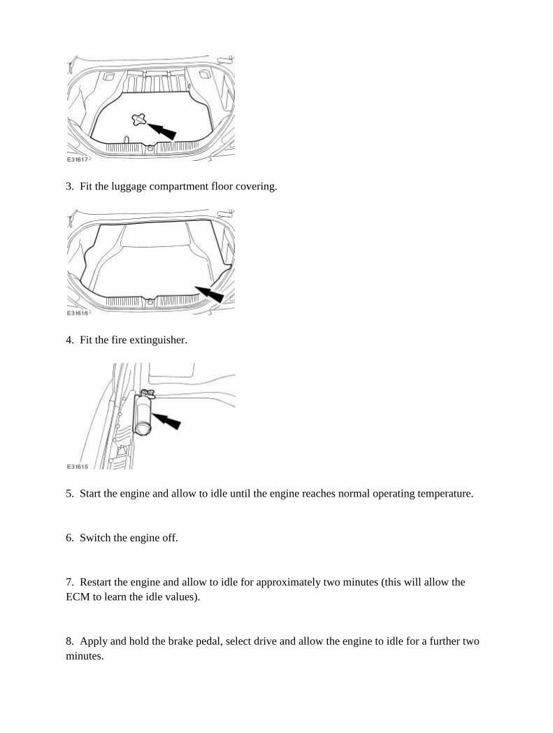
3. Fit the luggage compartment floor covering.
4. Fit the fire extinguisher.
5. Start the engine and allow to idle until the engine reaches normal operating temperature. 6. Switch the engine off. 7. Restart the engine and allow to idle for approximately two minutes (this will allow the ECM to learn the idle values). 8. Apply and hold the brake pedal, select drive and allow the engine to idle for a further two minutes.

9. Drive the vehicle for approximately five miles/eight kilometers of varied driving to enable the ECM to complete it's learning strategy. 10. Reset the audio unit and climate control assembly to original settings to avoid customer complaint. 11. Reset the door window motors. <<501-11>>

Battery Disconnect and Connect
WARNING: Batteries produce explosive gases which may cause personal injury. Do not expose the battery to a naked flame. When charging or working near a battery wear protective clothing and eye protectors. Always provide adequate ventilation. Failure to follow these instructions may result in personal injury.
WARNING: Batteries contain sulphuric acid, avoid contact with skin, eyes and clothing. Shield your eyes when working near the battery to protect against possible contact of the acid solution. In case of contact with the skin or eyes, flush immediately for a minimum of fifteen minutes and seek prompt medical attention. if swallowed call a physician immediately. Failure to follow these instructions may result in personal injury.
WARNING: Audio unit key code saving devices must not be used when working on supplementary restraint systems or fuel systems. When using these devices the vehicle electrical system is still live but with a reduced current flow. Failure to follow this instruction may result in personal injury.
WARNING: The backup power supply energy must be depleted before any supplementary restraint system repairs are carried out. To deplete the backup supply energy, first disconnect the battery negative cable, then disconnect the battery positive cable and wait one minute to avoid accidental deployment and personal injury. Failure to follow this instruction may result in personal injury.
CAUTION: Make sure the engine is not running before disconnecting the battery negative cable to avoid damage to the electrical system. NOTE:
Before disconnecting the battery make sure that no data is required from the engine control module (ECM), as battery cable disconnection will erase any fault codes and idle/drive values held in the keep alive memory (KAM). It is not necessary to disconnect or remove electronic control modules.
NOTE:
When the battery is disconnected all previous climate control assembly settings and fault codes will be lost. It is necessary to record any settings or fault codes before battery disconnection to prevent customer complaint.
NOTE: This procedure should be used to disconnect the battery while carrying out repairs that

refer to the battery being disconnected. 1. Obtain and record the audio unit keycode and preset radio frequencies. 2. Remove the fire extinguisher.
3. Remove the luggage compartment floor covering.
4. Remove the spare wheel cover. • Remove the spare wheel cover retaining clamp.
5. Disconnect the battery ground cable.

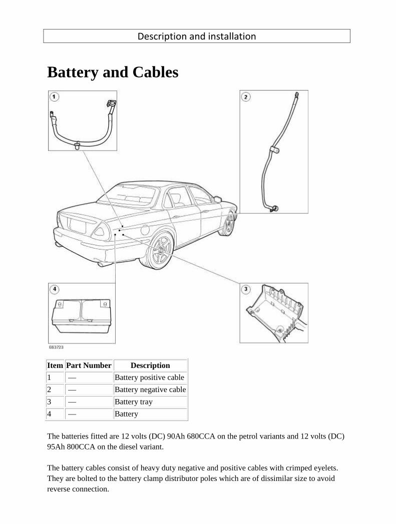
Description and installation
Battery and Cables
Item Part Number Description
1 — Battery positive cable
2 — Battery negative cable
3 — Battery tray
4 — Battery
The batteries fitted are 12 volts (DC) 90Ah 680CCA on the petrol variants and 12 volts (DC) 95Ah 800CCA on the diesel variant. The battery cables consist of heavy duty negative and positive cables with crimped eyelets. They are bolted to the battery clamp distributor poles which are of dissimilar size to avoid reverse connection.

Diagnosis and testing
Battery For additional information, <<414-00>>
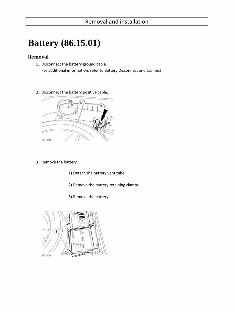
Removal and installation
Battery (86.15.01) Removal
1 . Disconnect the battery ground cable.
For additional information, refer to Battery Disconnect and Connect
2 . Disconnect the battery positive cable.
3 . Remove the battery.
1) Detach the battery vent tube.
2) Remove the battery retaining clamps.
3) Remove the battery.
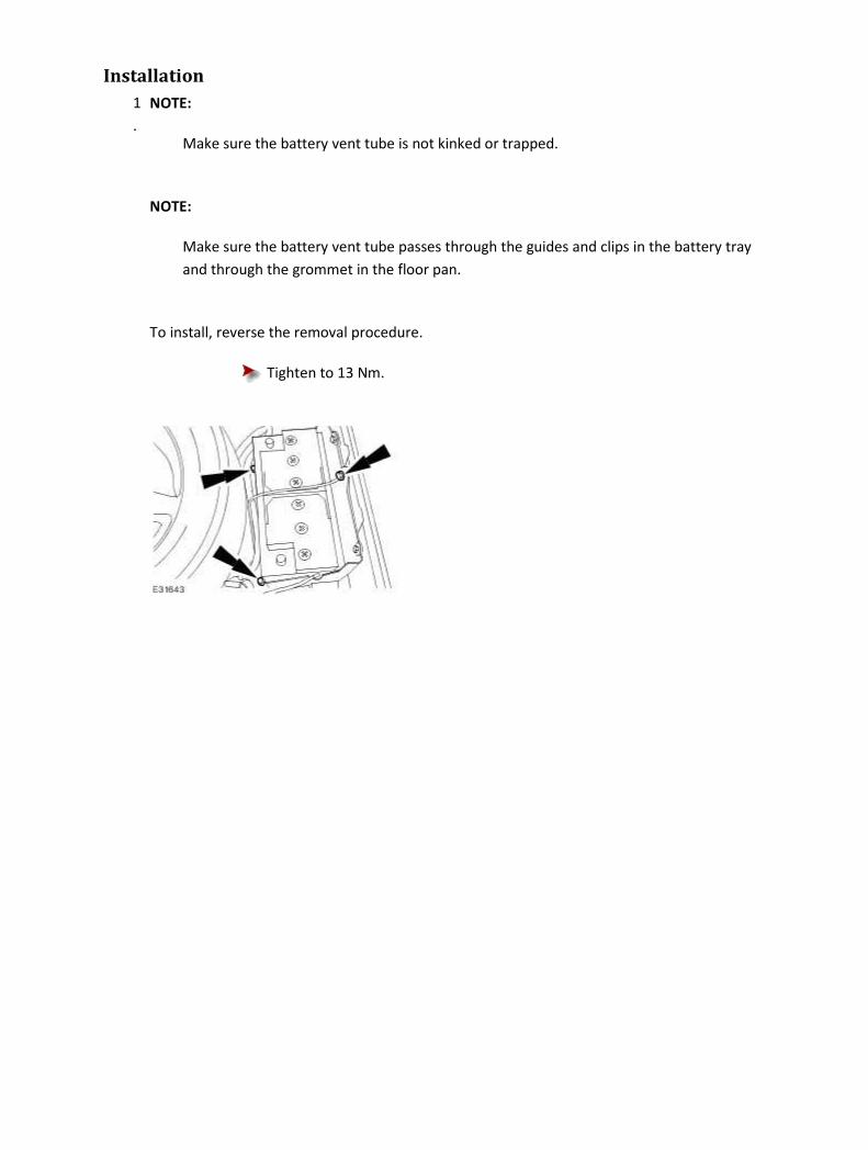
Installation
1
.
NOTE:
Make sure the battery vent tube is not kinked or trapped.
NOTE:
Make sure the battery vent tube passes through the guides and clips in the battery tray
and through the grommet in the floor pan.
To install, reverse the removal procedure.
Tighten to 13 Nm.

Battery Ground Cable (86.15.19) Installation
1 . Install the battery ground cable.
Tighten to 9 Nm.
2 . Connect the battery ground cable.
For additional information, refer to Battery Connect (86.15.15)

Battery Tray (86.15.11) Removal
1 . Remove the battery.
For additional information, refer to Battery (86.15.01)
2 . Remove the spare wheel and tire.
3 . Detach the rear power distribution box.
4 . Remove the battery tray.
Installation
1 . To install, reverse the removal procedure.
1) Tighten to 13 Nm.

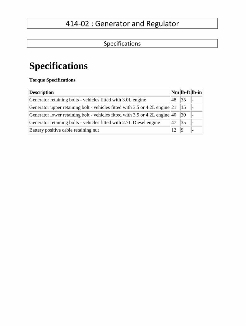
414-02 : Generator and Regulator
Specifications
Specifications Torque Specifications
Description Nm lb-ft lb-in
Generator retaining bolts - vehicles fitted with 3.0L engine 48 35 -
Generator upper retaining bolt - vehicles fitted with 3.5 or 4.2L engine 21 15 -
Generator lower retaining bolt - vehicles fitted with 3.5 or 4.2L engine 40 30 -
Generator retaining bolts - vehicles fitted with 2.7L Diesel engine 47 35 -
Battery positive cable retaining nut 12 9 -

Description and operation
Generator The generator is belt driven by the accessory drive belt. For additional information, refer to
Accessory Drive (303-05)
When the engine is started, the generator begins to generate alternating current (AC) which is
converted to direct current (DC) internally. The DC current and voltage is controlled by the voltage
regulator, (located inside the generator) and then supplied to the battery through the main battery
positive cable.
The 3.0L generator is solidly mounted to the engine, while the 3.5L and 4.2L generator is pivot
mounted. The 2.7L Diesel generator is also solidly mounted to the engine. The generators are driven
at approximately three times engine speed.
Vehicles fitted with 3.0L engine (L3B generator)
The engine control module (ECM) can switch the voltage regulator between two voltages to optimize
the charging of the battery.
The low voltage regulator setting is 13.6 volts and the high voltage regulator setting 15.3 volts,
measured with the generator at 25°C (77°F) and charging at a rate of 5 amps. These values decrease
with a rise in temperature or current flow.
The ECM determines the output voltage setting of the generator. The high voltage setting is always
selected by the ECM once the vehicle has started. The ECM determines the period of time that the
high voltage setting is selected for.
There are three different time periods selected by the ECM which is dependent upon the vehicle
conditions when the vehicle is started:
• The longest period of time is selected if the ECM determines that the vehicle has been
'soaking' for sufficient time to allow the engine coolant temperature (ECT) and the air intake
temperature (IAT) to fall within 6°C (43°F) of each other.
• The intermediate time period is selected when the ECT and the IAT are below 15°C (59°F).
• The shortest time period is the default time and is used to provide a short period of boost
charge.
At the end of these time periods the voltage is always set to the low voltage setting to prevent the
battery from being over charged.
The time periods are variable depending upon the temperature and battery voltage. The target
voltage of the battery varies between 14 volts and 15 volts depending upon the ambient
temperature and the vehicle operating conditions. Once this target voltage has been achieved,

providing the vehicle has been operating for at least the shortest time period, the ECM will reduce
the voltage regulator to the minimum setting of 13.6 volts.
Vehicles fitted with 3.5L or 4.2L engine (SC1 generator)
The battery charging voltage is determined by the temperature of the generator. In cold conditions,
starting the vehicle from cold the battery voltage will be between 14.2 volts and 15.1 volts and will
reduce as the engine warms up. In hot conditions starting the vehicle when the engine is already
warm the battery voltage will be between 13.5 volts and 14.3 volts.
A fault in the wiring or the connections from the generator to the ECM, will cause a fault code to be
generated and stored in the ECM and the charge warning indicator lamp to be displayed in the
instrument cluster after a short time.
With the ignition switch in the RUN position the charge warning lamp will be displayed in the
instrument cluster when the generator is not generating power.
If a fault is detected with the generator a fault code will be generated and stored by the ECM. The
charge warning indicator lamp will also be displayed in the instrument cluster. Units should be
repaired as an assembly and not dismantled for repair. For additional information, refer to
Generator (414-02)
Vehicles fitted with 2.7L Diesel engine (SC2 generator)
All vehicles use a PCM (Pulse Control Modulated) generator. This allows the output voltage to be
controlled between 12.5 volts and 16 volts via a signal from the ECM.
This voltage is controlled between 13.5 volts & 15.5 volts. The system voltage is tailored more closely
to the demands of the battery. At low ambient temperatures (as measured by the air conditioning
ambient air sensor), the charging voltage is higher to improve charge acceptance. At high ambient
temperatures the voltage is lower to reduce electrolyte loss and unnecessary battery self-heating.
Also built into the strategy, is the ability to measure the battery voltage with the ignition switch in
the ON position. A battery with low voltage, with the ignition switch in the ON position, is boost
charged at a higher voltage for a calculated time before returning to its 'Base Characteristic' (defined
by the prevailing ambient temperatures). The time and boost voltage depends upon the temperature
and battery voltage with the ignition switch in the ON position.
All vehicles have a one way clutch fitted to the drive pulley, which reduces belt slip.
A fault in the wiring or the connections from the generator to the ECM, will cause a fault code to be
generated and stored in the ECM and the charge warning indicator lamp to be displayed in the
instrument cluster after a short time.
With the ignition switch in the RUN position the charge warning lamp will be displayed in the
instrument cluster when the generator is not generating power.

If a fault is detected with the generator a fault code will be generated and stored by the ECM. The
charge warning indicator lamp will also be displayed in the instrument cluster. Units should be
repaired as an assembly and not dismantled for repair. For additional information, refer to
Generator (414-02)

Diagnosis and testing
Generator For additional information, refer to section<<414-00>>
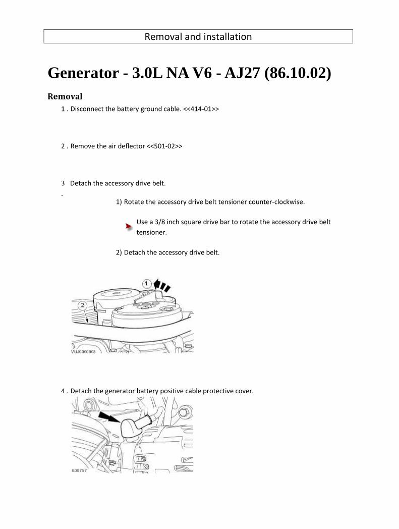
Removal and installation
Generator - 3.0L NA V6 - AJ27 (86.10.02) Removal
1 . Disconnect the battery ground cable. <<414-01>>
2 . Remove the air deflector <<501-02>>
3
.
Detach the accessory drive belt.
1) Rotate the accessory drive belt tensioner counter-clockwise.
Use a 3/8 inch square drive bar to rotate the accessory drive belt
tensioner.
2) Detach the accessory drive belt.
4 . Detach the generator battery positive cable protective cover.

5 . Remove the battery positive cable retaining nut.
6 . Disconnect the generator electrical connector.
7 . Remove the generator.
Installation
1 . To install, reverse the removal procedure.
Tighten to 48 Nm.

2 . Tighten to 12 Nm.
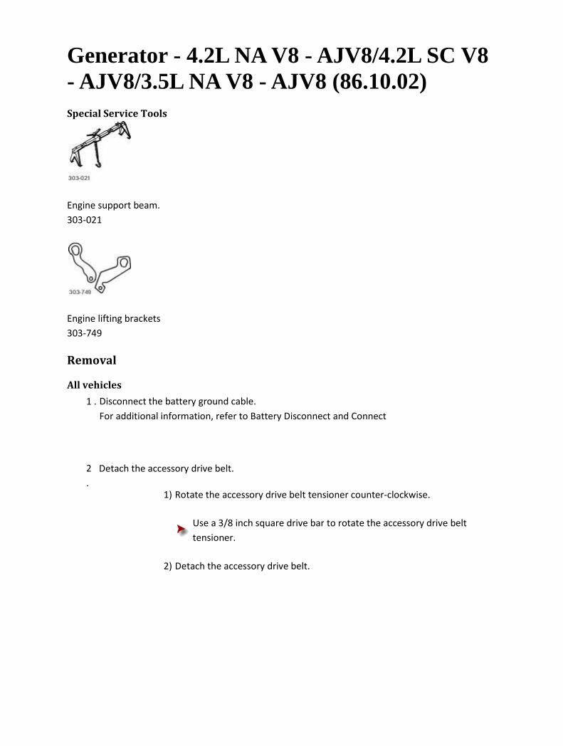
Generator - 4.2L NA V8 - AJV8/4.2L SC V8 - AJV8/3.5L NA V8 - AJV8 (86.10.02) Special Service Tools
Engine support beam.
303-021
Engine lifting brackets
303-749
Removal
All vehicles
1 . Disconnect the battery ground cable.
For additional information, refer to Battery Disconnect and Connect
2
.
Detach the accessory drive belt.
1) Rotate the accessory drive belt tensioner counter-clockwise.
Use a 3/8 inch square drive bar to rotate the accessory drive belt
tensioner.
2) Detach the accessory drive belt.
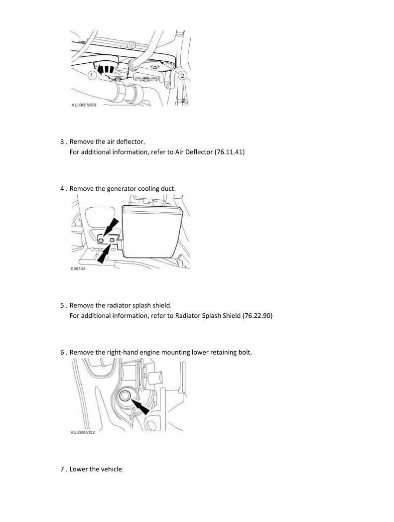
3 . Remove the air deflector.
For additional information, refer to Air Deflector (76.11.41)
4 . Remove the generator cooling duct.
5 . Remove the radiator splash shield.
For additional information, refer to Radiator Splash Shield (76.22.90)
6 . Remove the right-hand engine mounting lower retaining bolt.
7 . Lower the vehicle.

8 . NOTE:
Left-hand side shown, right-hand similar.
Install the left hand engine lifting eye.
9 . Using the special tools, raise the engine to a suitable height.
10 . Raise the vehicle.
Right-hand drive vehicles
11 . Remove the steering gear shaft pinch bolt.

12 . Detach the steering gear.
13 . Secure the steering gear.
All vehicles
14 . Remove the engine mounting and bracket assembly.
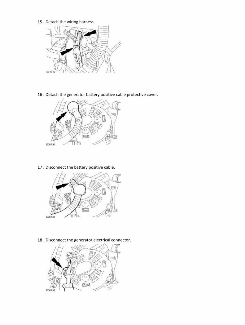
15 . Detach the wiring harness.
16 . Detach the generator battery positive cable protective cover.
17 . Disconnect the battery positive cable.
18 . Disconnect the generator electrical connector.

19 . Remove the generator.
Installation
1 . To install reverse the removal procedure.
Tighten the generator upper retaining bolt to 21 Nm.
Tighten the generator lower retaining bolt to 40 Nm.
2 . Tighten to 12 Nm.
3 . Tighten to 25 Nm.

4 . Tighten to 100 Nm.
5 . Tighten to 35 Nm.
6 . Tighten to 63 Nm.

Generator - 2.7L V6 - TdV6 (86.10.02) Special Service Tools
Accessory belt detensioner
303-703
Removal
1 . Disconnect the battery ground cable.
For additional information, refer to Battery Disconnect and Connect
2 . Remove the generator cooling duct (if equipped).
3
.
Detach the accessory drive belt.
1) Using the special tool, rotate the accessory drive belt tensioner counter
clockwise.
2) Detach the accessory drive belt.

4 . Undo the right-hand turbocharger outlet tube securing clips.
5 . Remove the right-hand turbocharger outlet tube.
Remove the retaining bolt.
6 . Rotate the generator.
Remove the generator retaining bolts.
7 . Detach the generator battery positive cable protective cover.

8 . Disconnect the battery positive cable.
Remove the retaining nut.
9 . Disconnect the generator electrical connector.
10 . Remove the right-hand engine mounting retaining nut.
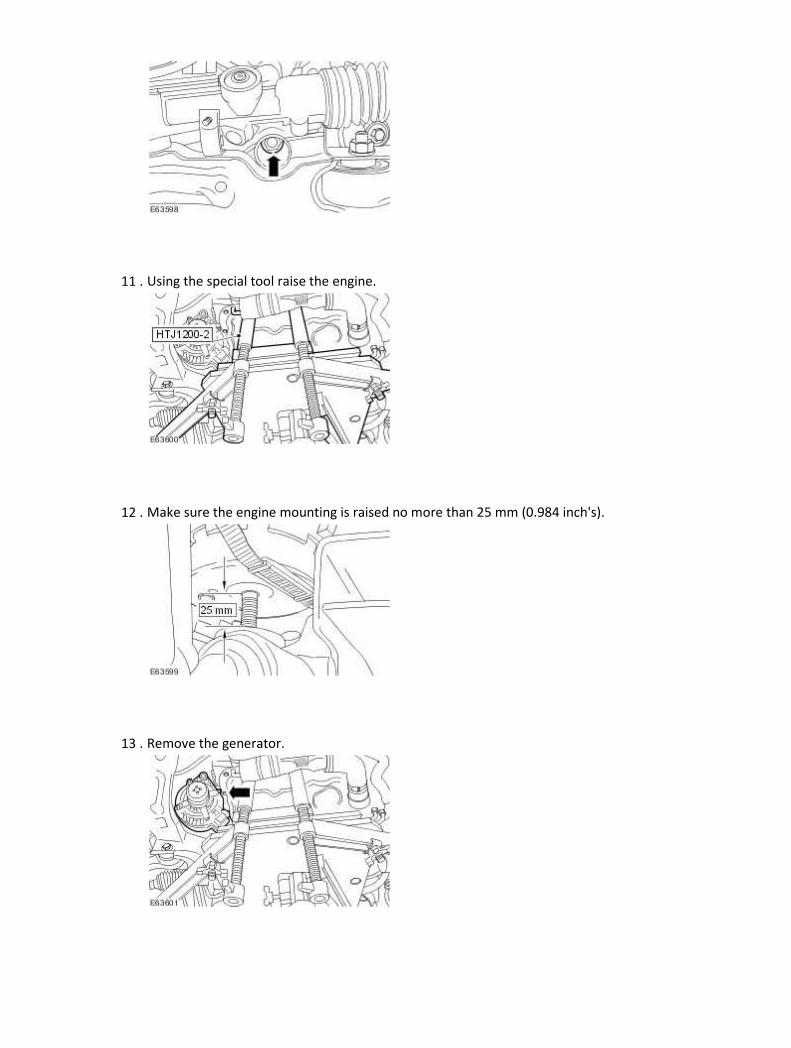
11 . Using the special tool raise the engine.
12 . Make sure the engine mounting is raised no more than 25 mm (0.984 inch's).
13 . Remove the generator.

Installation
1 . To install, reverse the removal procedure.
Tighten to 63 Nm.
2 . Tighten to 12 Nm.
3 . Tighten to 47 Nm.
4 . Tighten to 10 Nm.

5 . Connect the battery ground cable.
For additional information, refer to Battery Connect (86.15.15)

415 : Information and Entertainement
Systems
415-00 : Information and Entertainement System –
General Information
General procedures
Cassette Player Cleaning 1. NOTE:
Advise the customer of the need for regular tape head cleaning. It is recommended that the tape heads are cleaned after every 15 hours of play.
NOTE:
The audio unit incorporates a reminder facility to indicate when 15 hours of tape play has occurred. For more detail please refer to the audio handbook.
NOTE:
Question the customer on the type of tapes that are normally used. Low quality tapes can not only damage the cassette player heads, the plastic shells may twist and jam in the deck. Loose cassette labels may also become detached in the deck and jam the decks operation. Jaguar Audio units use high quality cassette decks which have precision moving parts, and need to be operated with care.
NOTE: Jaguar cars only recommends the use of wet type cleaning tapes. NOTE: Make sure that the cleaning cassette is used prior to any assessment of tape audio quality. Apply isopropyl alcohol to the cleaning cassette and insert it into the cassette player and run it for approximately 30 seconds.

Diagnosis and testing
Audio System Principles of Operation
For a detailed description of the Audio system, refer to the relevant Description and Operation
sections in the workshop manual.
Audio System
Audio System - VIN Range: H18680->H99999
Audio System
Antenna
Speakers
Speakers
Inspection and Verification
1 . Verify the customer concern.
2 . Visually inspect for obvious signs of mechanical or electrical damage.
Visual Inspection Chart
Electrical
• Fuses/Relays
• Damaged, Loose or Corroded Connector(s)
• Damage to Wiring Loom/Incorrect Location, Stretched or Taught
1 . If an obvious cause for an observed or reported concern is found, correct the cause (if possible)
before proceeding to the next step.
2 . If the cause is not visually evident, check for Diagnostic Trouble Codes (DTCs) and refer to the DTC
Index.
DTC Index
Gateway module
CAUTION: When probing connectors to take measurements in the course of the pinpoint
tests, use the adaptor kit, part number 3548-1358-00
NOTE:
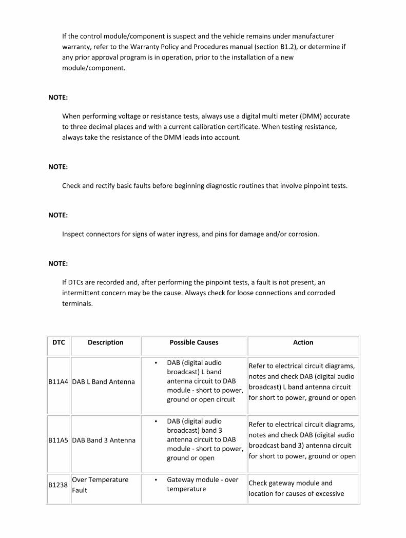
If the control module/component is suspect and the vehicle remains under manufacturer
warranty, refer to the Warranty Policy and Procedures manual (section B1.2), or determine if
any prior approval program is in operation, prior to the installation of a new
module/component.
NOTE:
When performing voltage or resistance tests, always use a digital multi meter (DMM) accurate
to three decimal places and with a current calibration certificate. When testing resistance,
always take the resistance of the DMM leads into account.
NOTE:
Check and rectify basic faults before beginning diagnostic routines that involve pinpoint tests.
NOTE:
Inspect connectors for signs of water ingress, and pins for damage and/or corrosion.
NOTE:
If DTCs are recorded and, after performing the pinpoint tests, a fault is not present, an
intermittent concern may be the cause. Always check for loose connections and corroded
terminals.
DTC Description Possible Causes Action
B11A4 DAB L Band Antenna
• DAB (digital audio
broadcast) L band
antenna circuit to DAB
module - short to power,
ground or open circuit
Refer to electrical circuit diagrams,
notes and check DAB (digital audio
broadcast) L band antenna circuit
for short to power, ground or open
B11A5 DAB Band 3 Antenna
• DAB (digital audio
broadcast) band 3
antenna circuit to DAB
module - short to power,
ground or open
Refer to electrical circuit diagrams,
notes and check DAB (digital audio
broadcast band 3) antenna circuit
for short to power, ground or open
B1238 Over Temperature
Fault
• Gateway module - over
temperature Check gateway module and
location for causes of excessive

temperature, install a new gateway
module as required, refer to the
new module installation note at the
top of the DTC Index
B1342 ECU Internal failure • Gateway module -
internal failure
Internal failure, install a new
gateway module as required, refer
to the new module installation
note at the top of the DTC Index
B1A89 Satellite Antenna
• Satellite radio module or
digital tuner antenna
circuit - short to power,
ground or open
Refer to electrical circuit diagrams,
notes and check satellite radio
module or digital tuner antenna
circuit for short to power, ground
or open
B2477 Module Configuration
Failure
• Gateway module -
configuration failure
The module can be configured
using the new module procedure.
Check and configure as required
U0193
Lost Communication
with Digital Audio
Control
Module(SDARS)
• Gateway module - lost
communication with
satellite radio module
Refer to electrical circuit diagrams,
notes and check gateway module
to satellite radio module power
and bus circuit to gateway module
on MOST ring
U0194
Lost Communication
with Digital Audio
Control Module
• Gateway module - lost
communication with
digital audio broadcast
module
Refer to electrical circuit diagrams,
notes and check gateway module
to digital audio broadcast module
power and bus circuit to gateway
module on MOST ring
U0237
Lost Communication
with Digital Audio
Control Module
• Gateway module - lost
communication with
(DACMC) Digital Audio
Control Module C
Refer to electrical circuit diagrams,
notes and check gateway module
to Digital Audio Control Module C
power and bus circuit to gateway
module on MOST ring
U1A15
Incomplete MOST
Ring Reported By
Gateway Module
• Gateway module -
(MOST) ring break
Refer to electrical circuit diagrams,
notes and check (MOST) circuit for
ring break
U2601 (D2B)Wake-up Line
Short To Ground • Gateway module, wake-
up line circuit - short to
Refer to electrical circuit diagrams,
notes and check gateway module
(D2B) wake-up line circuit for short

ground to ground
U2609
(D2B)Wake-up
Pulsewidth Out Of
Specification
• Gateway module - wake-
up line circuit fault
(pulse< 50mS, pulse >
110mS)
Refer to electrical circuit diagrams,
notes and check gateway module
(D2B) wake-up line circuit for fault
U2610
(D2B) Slave ECU Fails
To Receive A Report
Position
• Gateway module - during
initialization no position
status report is received
from one or more slave
modules
Refer to electrical circuit diagrams,
notes and check (D2B) slave
modules and circuit for fault,
replace as required, refer to the
new module installation note at the
top of the DTC Index
U2611
(D2B) Slave ECU fails
to receive an alarm
clear command
• Gateway module - on
entering alarm state,
slave ECU has failed to
receive alarm clear
command
Refer to electrical circuit diagrams,
notes and check (D2B) slave
modules and circuit for fault,
replace as required, refer to the
new module installation note at the
top of the DTC Index
U3004 Digital Tuner State
• Gateway module, digital
tuner MOST slave -
module is inoperative
Suspect digital tuner module
replace as required, refer to the
new module installation note at the
top of the DTC Index
U3098 Over Temperature
• Gateway module, digital
tuner (Most slave) -
above temperature
threshold
Check digital tuner module and
location for causes of excessive
temperature, install a new module
as required, refer to the new
module installation note at the top
of the DTC Index
Audio Amplifier Module
CAUTION: When probing connectors to take measurements in the course of the pinpoint
tests, use the adaptor kit, part number 3548-1358-00
NOTE:
If the control module/component is suspect and the vehicle remains under manufacturer
warranty, refer to the Warranty Policy and Procedures manual (section B1.2), or determine if
any prior approval program is in operation, prior to the installation of a new
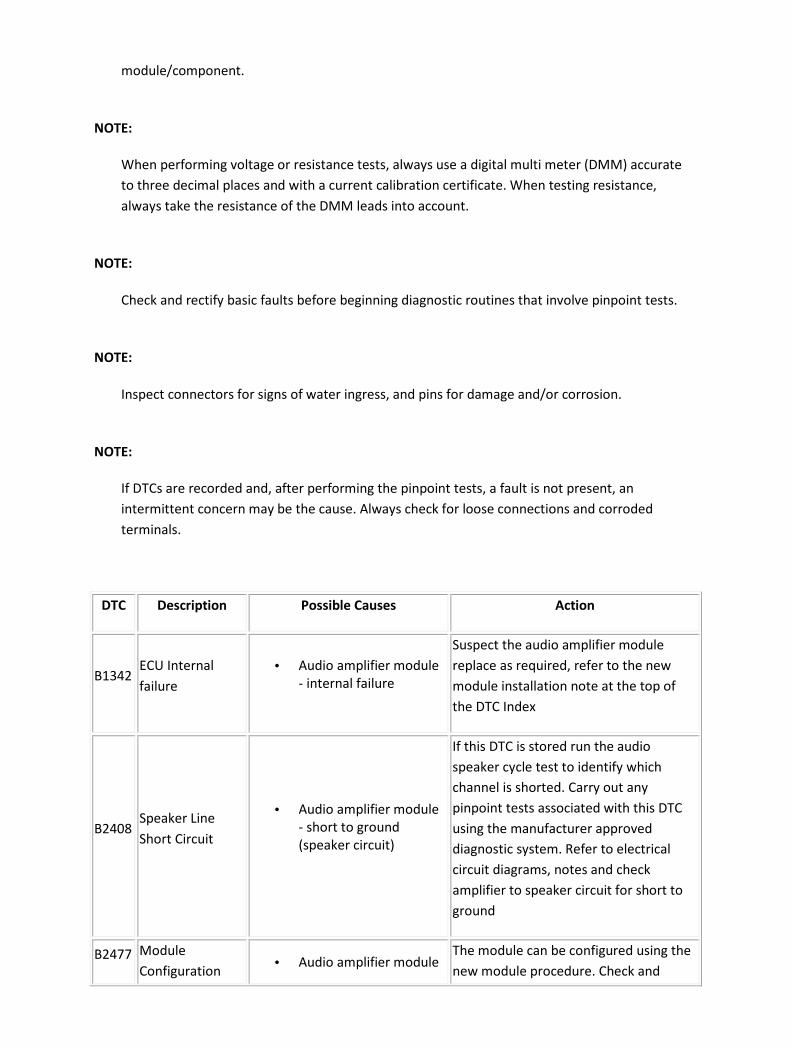
module/component.
NOTE:
When performing voltage or resistance tests, always use a digital multi meter (DMM) accurate
to three decimal places and with a current calibration certificate. When testing resistance,
always take the resistance of the DMM leads into account.
NOTE:
Check and rectify basic faults before beginning diagnostic routines that involve pinpoint tests.
NOTE:
Inspect connectors for signs of water ingress, and pins for damage and/or corrosion.
NOTE:
If DTCs are recorded and, after performing the pinpoint tests, a fault is not present, an
intermittent concern may be the cause. Always check for loose connections and corroded
terminals.
DTC Description Possible Causes Action
B1342 ECU Internal
failure
• Audio amplifier module
- internal failure
Suspect the audio amplifier module
replace as required, refer to the new
module installation note at the top of
the DTC Index
B2408 Speaker Line
Short Circuit
• Audio amplifier module
- short to ground
(speaker circuit)
If this DTC is stored run the audio
speaker cycle test to identify which
channel is shorted. Carry out any
pinpoint tests associated with this DTC
using the manufacturer approved
diagnostic system. Refer to electrical
circuit diagrams, notes and check
amplifier to speaker circuit for short to
ground
B2477 Module
Configuration • Audio amplifier module
The module can be configured using the
new module procedure. Check and
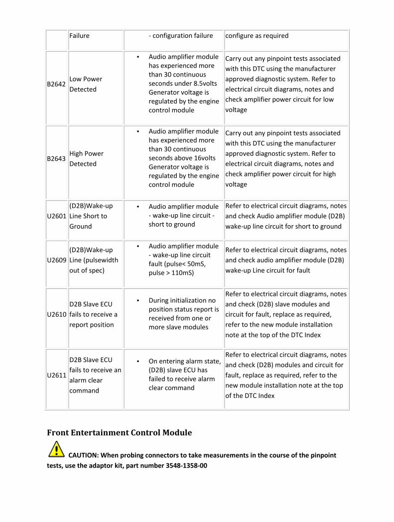
Failure - configuration failure configure as required
B2642 Low Power
Detected
• Audio amplifier module
has experienced more
than 30 continuous
seconds under 8.5volts
Generator voltage is
regulated by the engine
control module
Carry out any pinpoint tests associated
with this DTC using the manufacturer
approved diagnostic system. Refer to
electrical circuit diagrams, notes and
check amplifier power circuit for low
voltage
B2643 High Power
Detected
• Audio amplifier module
has experienced more
than 30 continuous
seconds above 16volts
Generator voltage is
regulated by the engine
control module
Carry out any pinpoint tests associated
with this DTC using the manufacturer
approved diagnostic system. Refer to
electrical circuit diagrams, notes and
check amplifier power circuit for high
voltage
U2601
(D2B)Wake-up
Line Short to
Ground
• Audio amplifier module
- wake-up line circuit -
short to ground
Refer to electrical circuit diagrams, notes
and check Audio amplifier module (D2B)
wake-up line circuit for short to ground
U2609
(D2B)Wake-up
Line (pulsewidth
out of spec)
• Audio amplifier module
- wake-up line circuit
fault (pulse< 50mS,
pulse > 110mS)
Refer to electrical circuit diagrams, notes
and check audio amplifier module (D2B)
wake-up Line circuit for fault
U2610
D2B Slave ECU
fails to receive a
report position
• During initialization no
position status report is
received from one or
more slave modules
Refer to electrical circuit diagrams, notes
and check (D2B) slave modules and
circuit for fault, replace as required,
refer to the new module installation
note at the top of the DTC Index
U2611
D2B Slave ECU
fails to receive an
alarm clear
command
• On entering alarm state,
(D2B) slave ECU has
failed to receive alarm
clear command
Refer to electrical circuit diagrams, notes
and check (D2B) modules and circuit for
fault, replace as required, refer to the
new module installation note at the top
of the DTC Index
Front Entertainment Control Module
CAUTION: When probing connectors to take measurements in the course of the pinpoint
tests, use the adaptor kit, part number 3548-1358-00

NOTE:
If the control module/component is suspect and the vehicle remains under manufacturer
warranty, refer to the Warranty Policy and Procedures manual (section B1.2), or determine if
any prior approval program is in operation, prior to the installation of a new
module/component.
NOTE:
When performing voltage or resistance tests, always use a digital multimeter (DMM) accurate to
three decimal places and with a current calibration certificate. When testing resistance, always
take the resistance of the DMM leads into account.
NOTE:
Check and rectify basic faults before beginning diagnostic routines that involve pinpoint tests.
NOTE:
Inspect connectors for signs of water ingress, and pins for damage and/or corrosion.
NOTE:
If DTCs are recorded and, after performing the pinpoint tests, a fault is not present, an
intermittent concern may be the cause. Always check for loose connections and corroded
terminals.
DTC Description Possible Causes Action
B1238 Over Temperature
Fault
• Front
entertainment
control module, CD
multichanger -
overheated (+80
degrees Celsius)
Check cd multichanger module and location
for causes of excessive temperature, install a
new module as required, refer to the new
module installation note at the top of the
DTC Index
B1342 ECU Internal
Failure
• Front
entertainment
control module -
no radio function
Refer to electrical circuit diagrams, notes
and check front entertainment control
module radio functions for fault, replace as
required, refer to the new module

installation note at the top of the DTC Index
B2004
Internal Media
Over Temperature
Fault
• Front
entertainment
control module -
internal cd/md has
overheated
Check front entertainment control module
and location for causes of excessive
temperature, install a new module as
required, refer to the new module
installation note at the top of the DTC Index
B2401 Audio Tape Deck
Mechanism Fault
• Front
entertainment
control module -
tape loading, tape
eject, tape stuck,
tape cut and seek
stop error
Refer to electrical circuit diagrams, check
front entertainment control module install a
new module as required, refer to the new
module installation note at the top of the
DTC Index
B2403 Audio CD/DJ
Internal Fault
• Front
entertainment
control module, CD
multichanger
module - cd eject
error, cd loading
error
Refer to electrical circuit diagrams, notes
and check cd multichanger module install a
new module as required, refer to the new
module installation note at the top of the
DTC Index
B2477
Module
Configuration
Failure
• Front
entertainment
control module -
configuration
failure
The module can be configured using the
new module procedure. Check and
configure as required
B2888 Audio Headunit
Media Fault
• Front
entertainment
control module -
tape loading, tape
eject, tape stuck,
tape cut and seek
stop error
Check front entertainment control module
install a new module as required, refer to
the new module installation note at the top
of the DTC Index
C1977
Audio Steering
Wheel Switch
Circuit Short To
Ground
• Front
entertainment
control module,
audio steering
wheel switch
circuit - short to
ground
Refer to electrical circuit diagrams, notes
suspect the audio steering wheel switch
check for circuit short to ground
U0147 Lost
Communication
• Front
entertainment
Refer to electrical circuit diagrams, notes
and check front entertainment control

With Gateway "B" control module,
gateway module -
no response
(D2B/MOST)
module to gateway module control and
power circuit`s, install a new module as
required, refer to the new module
installation note at the top of the DTC Index
U1262
SCP (J1850)
Communication
Bus Fault
• Front
entertainment
control module,
ECU not
responding -
internal standard
corporate protocol
(SCP) chip failure
Refer to electrical circuit diagrams, notes
and check Front entertainment control
module SCP circuit for fault, suspect the
front entertainment control module, install
a new module as required, refer to the new
module installation note at the top of the
DTC Index
U2003
Audio Compact
Disk / Disk Jockey
Unit is Not
Responding
• Front
entertainment
control module, CD
multichanger - no
response (D2B)
Carry out any pinpoint tests associated with
this DTC using the manufacturer approved
diagnostic system. Refer to electrical circuit
diagrams, notes and check cd multichanger
module and D2B circuit for fault, install a
new module as required, refer to the new
module installation note at the top of the
DTC Index
U2008 Audio Phone Not
Responding
• Front
entertainment
control module,
telephone control
module - no
response(D2B)
Carry out any pinpoint tests associated with
this DTC using the manufacturer approved
diagnostic system. Refer to electrical circuit
diagrams, notes and check telephone
control module and D2B circuit for fault,
install a new module as required, refer to
the new module installation note at the top
of the DTC Index
U2019
Audio Voice
Module Not
Responding
• Front
entertainment
control module,
audio voice
module - no
response(D2B)
Carry out any pinpoint tests associated with
this DTC using the manufacturer approved
diagnostic system. Refer to electrical circuit
diagrams, notes and check audio voice
module and D2B circuit for fault, install a
new module as required, refer to the new
module/component installation note at the
top of the DTC Index
U2601 (D2B)Wake-up Line
Short To Ground
• Front
entertainment
control module,
gateway module -
wake-up line, short
Carry out any pinpoint tests associated with
this DTC using the manufacturer approved
diagnostic system. Refer to electrical circuit
diagrams, notes and check gateway module

to ground (D2B) wake-up line for short to ground
U2602
Incomplete MOST
Ring (fault report
received)
• Front
entertainment
control module -
(MOST) ring circuit
fault
Carry out any pinpoint tests associated with
this DTC using the manufacturer approved
diagnostic system. Check front
entertainment control module for most ring
circuit fault
U2603
Incomplete MOST
Ring (No Fault
Report Received)
• Front
entertainment
control module -
(MOST) ring circuit
fault
Carry out any pinpoint tests associated with
this DTC using the manufacturer approved
diagnostic system. Check (MOST) ring for
circuit fault
U2604
Incomplete MOST
Ring (Corrupted
Fault Report
Received)
• Front
entertainment
control module -
(MOST) ring circuit
fault
Refer to electrical circuit diagrams, notes
and check (MOST) ring for circuit fault
U2605
Master ECU
Unable To Initialize
It's Address
• Front
entertainment
control module -
(MOST) ring circuit
fault (more than
one master on the
MOST ring)
Refer to electrical circuit diagrams, notes
and check for configuration fault on (MOST)
ring modules. Install a new module as
required, refer to the new module
installation note at the top of the DTC Index
U2606
Slave ECU Unable
To Initialize It's
Address
• Front
entertainment
control module -
(MOST) ring circuit
fault slave ecu
configuration fault
Refer to electrical circuit diagrams, notes
and check for configuration fault on (MOST)
ring modules. Install a new module as
required, refer to the new module
installation note at the top of the DTC Index
U2607
Slave ECU (
switched into
bypass mode)
• Front
entertainment
control module -
(MOST) ring circuit
fault (slave ecu
configuration fault)
The module can be configured using the
new module procedure. Check and
configure as required
U2609
(D2B)Circuit Wake-
up Line (pulse
width out of spec)
• Front
entertainment
control module -
wake up line circuit
fault (pulse< 50mS,
Refer to electrical circuit diagrams, notes
and check front entertainment control
module(D2B) wake up line circuit for fault
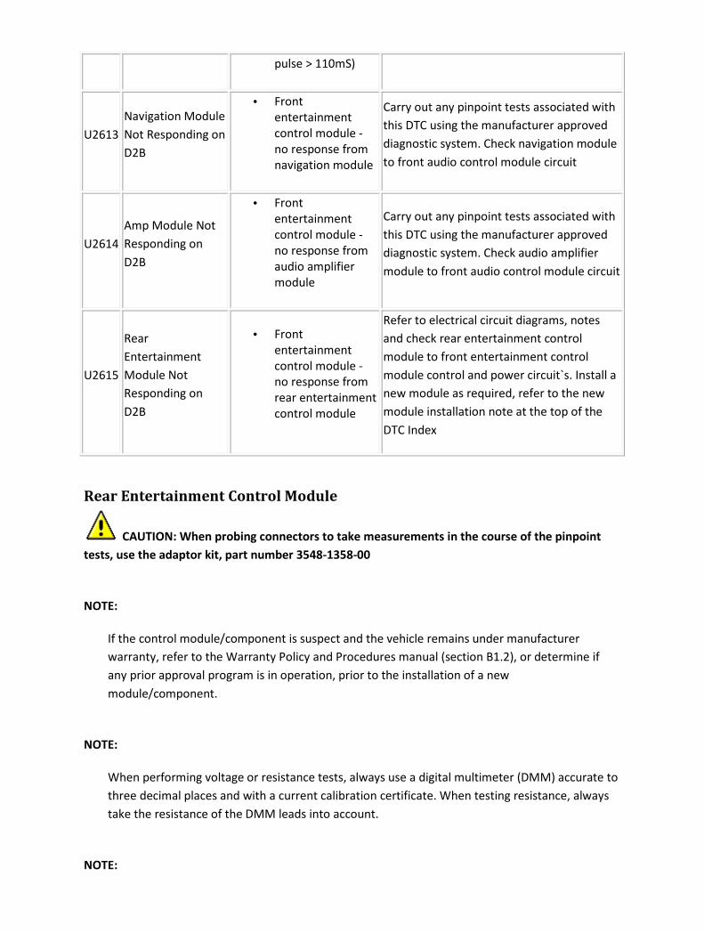
pulse > 110mS)
U2613
Navigation Module
Not Responding on
D2B
• Front
entertainment
control module -
no response from
navigation module
Carry out any pinpoint tests associated with
this DTC using the manufacturer approved
diagnostic system. Check navigation module
to front audio control module circuit
U2614
Amp Module Not
Responding on
D2B
• Front
entertainment
control module -
no response from
audio amplifier
module
Carry out any pinpoint tests associated with
this DTC using the manufacturer approved
diagnostic system. Check audio amplifier
module to front audio control module circuit
U2615
Rear
Entertainment
Module Not
Responding on
D2B
• Front
entertainment
control module -
no response from
rear entertainment
control module
Refer to electrical circuit diagrams, notes
and check rear entertainment control
module to front entertainment control
module control and power circuit`s. Install a
new module as required, refer to the new
module installation note at the top of the
DTC Index
Rear Entertainment Control Module
CAUTION: When probing connectors to take measurements in the course of the pinpoint
tests, use the adaptor kit, part number 3548-1358-00
NOTE:
If the control module/component is suspect and the vehicle remains under manufacturer
warranty, refer to the Warranty Policy and Procedures manual (section B1.2), or determine if
any prior approval program is in operation, prior to the installation of a new
module/component.
NOTE:
When performing voltage or resistance tests, always use a digital multimeter (DMM) accurate to
three decimal places and with a current calibration certificate. When testing resistance, always
take the resistance of the DMM leads into account.
NOTE:

Check and rectify basic faults before beginning diagnostic routines that involve pinpoint tests.
NOTE:
Inspect connectors for signs of water ingress, and pins for damage and/or corrosion.
NOTE:
If DTCs are recorded and, after performing the pinpoint tests, a fault is not present, an
intermittent concern may be the cause. Always check for loose connections and corroded
terminals.
DTC Description Possible Causes Action
B1238
Over
Temperature
Fault
• Rear entertainment control
module - DVD player has
overheated (+80 Degrees
Celsius)
Check DVD player module and
location for causes of excessive
temperature, install a new module as
required, refer to the new module
installation note at the top of the
DTC Index
B1342 ECU Internal
Failure
• Rear entertainment control
module - defective
Refer to electrical circuit diagrams,
notes and check rear entertainment
control module for fault. Install a
new module as required, refer to the
new module installation note at the
top of the DTC Index
B2642 Low Power
Detected
• Rear entertainment control
module - has experienced
more than 30 continuous
seconds under 8.5volts
Generator voltage is
regulated by the engine
control module
Refer to electrical circuit diagrams,
notes and check rear entertainment
control module power and ground
circuit's
B2656
DVD (Digital
Versatile Disk)
Error
• Rear entertainment control
module -DVD not detected
Refer to electrical circuit diagrams,
notes and check rear entertainment
control module to DVD control and
power circuit
U2601 (D2B)Wake-up
line short to
• Rear entertainment control
module - wake up line
Carry out any pinpoint tests
associated with this DTC using the

ground circuit short to ground manufacturer approved diagnostic
system. Refer to electrical circuit
diagrams, notes and check gateway
module (D2B) wake up line circuit for
short to ground
U2609
(D2B)Wake-up
line pulse width
out of spec
• Rear entertainment control
module wake up line fault
(pulse< 50mS, pulse >
110mS)
Refer to electrical circuit diagrams,
notes and check rear entertainment
control module (D2B) wake up line
circuit for fault
U2610
D2B Slave ECU
(fails to receive a
report position)
• During initialization no
position status report is
received from one or more
slave modules
Refer to electrical circuit diagrams,
notes and check (D2B) slave modules
for circuit fault, replace as required,
refer to the new module installation
note at the top of the DTC Index
U2611
D2B Slave ECU
(fails to receive
an alarm clear
command)
• Rear entertainment control
module - on entering alarm
state, slave ECU has failed
to receive alarm clear
command
Refer to electrical circuit diagrams,
notes and check (D2B) slave modules
and circuit for fault, replace as
required, refer to the new module
installation note at the top of the
DTC Index
Satellite Radio Module
CAUTION: When probing connectors to take measurements in the course of the pinpoint
tests, use the adaptor kit, part number 3548-1358-00
NOTE:
If the control module/component is suspect and the vehicle remains under manufacturer
warranty, refer to the Warranty Policy and Procedures manual (section B1.2), or determine if
any prior approval program is in operation, prior to the installation of a new
module/component.
NOTE:
Generic scan tools may not read the codes listed, or may read only 5 digit codes. Match the five
digits from the scan tool to the first five digits of the seven digit code listed to identify the fault
(the last two digits give additional information read by the manufacturer approved diagnostic
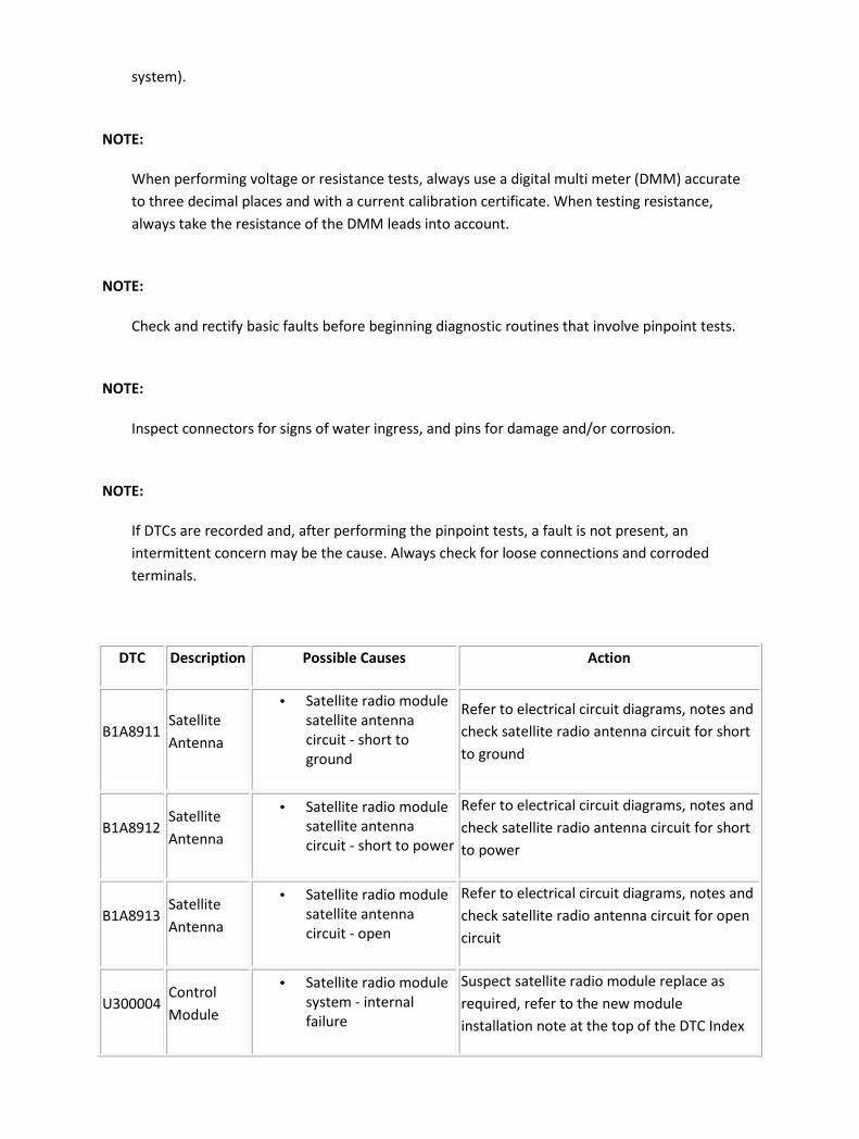
system).
NOTE:
When performing voltage or resistance tests, always use a digital multi meter (DMM) accurate
to three decimal places and with a current calibration certificate. When testing resistance,
always take the resistance of the DMM leads into account.
NOTE:
Check and rectify basic faults before beginning diagnostic routines that involve pinpoint tests.
NOTE:
Inspect connectors for signs of water ingress, and pins for damage and/or corrosion.
NOTE:
If DTCs are recorded and, after performing the pinpoint tests, a fault is not present, an
intermittent concern may be the cause. Always check for loose connections and corroded
terminals.
DTC Description Possible Causes Action
B1A8911 Satellite
Antenna
• Satellite radio module
satellite antenna
circuit - short to
ground
Refer to electrical circuit diagrams, notes and
check satellite radio antenna circuit for short
to ground
B1A8912 Satellite
Antenna
• Satellite radio module
satellite antenna
circuit - short to power
Refer to electrical circuit diagrams, notes and
check satellite radio antenna circuit for short
to power
B1A8913 Satellite
Antenna
• Satellite radio module
satellite antenna
circuit - open
Refer to electrical circuit diagrams, notes and
check satellite radio antenna circuit for open
circuit
U300004 Control
Module
• Satellite radio module
system - internal
failure
Suspect satellite radio module replace as
required, refer to the new module
installation note at the top of the DTC Index

U30004A Control
Module
• Satellite radio module
incorrect component
installed (car
configuration file
mismatch)
Car configuration/installed-part mismatch
Check and configure as required
U300055 Control
Module
• Satellite radio module
vehicle not configured
for satellite radio
The vehicle can be configured using the
vehicle configuration procedure. Check and
configure as required
U300087 Control
Module
• Satellite radio module
- missing message
(The configuration file
wasn't received)
Refer to electrical circuit diagrams, notes and
check Refer to electrical circuit diagrams,
notes and check satellite radio module
communication circuit for fault. The vehicle
can be configured using the vehicle
configuration procedure. Check and configure
as required
U300098 Control
Module
• Satellite radio module
- over temperature
Check satellite radio module and location for
causes of excessive temperature, install a
new module as required, refer to the new
module/component installation note at the
top of the DTC Index
U300362 Battery
Voltage
• Satellite radio module
power circuit - over or
under voltage Note
generator voltage is
regulated by the
engine control module
Refer to electrical circuit diagrams, notes and
check satellite radio module power circuit for
fault
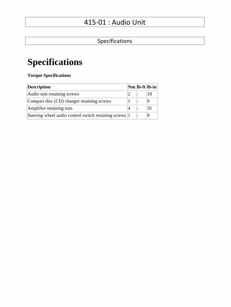
415-01 : Audio Unit
Specifications
Specifications Torque Specifications
Description Nm lb-ft lb-in
Audio unit retaining screws 2 - 18
Compact disc (CD) changer retaining screws 1 - 9
Amplifier retaining nuts 4 - 35
Steering wheel audio control switch retaining screws 1 - 9
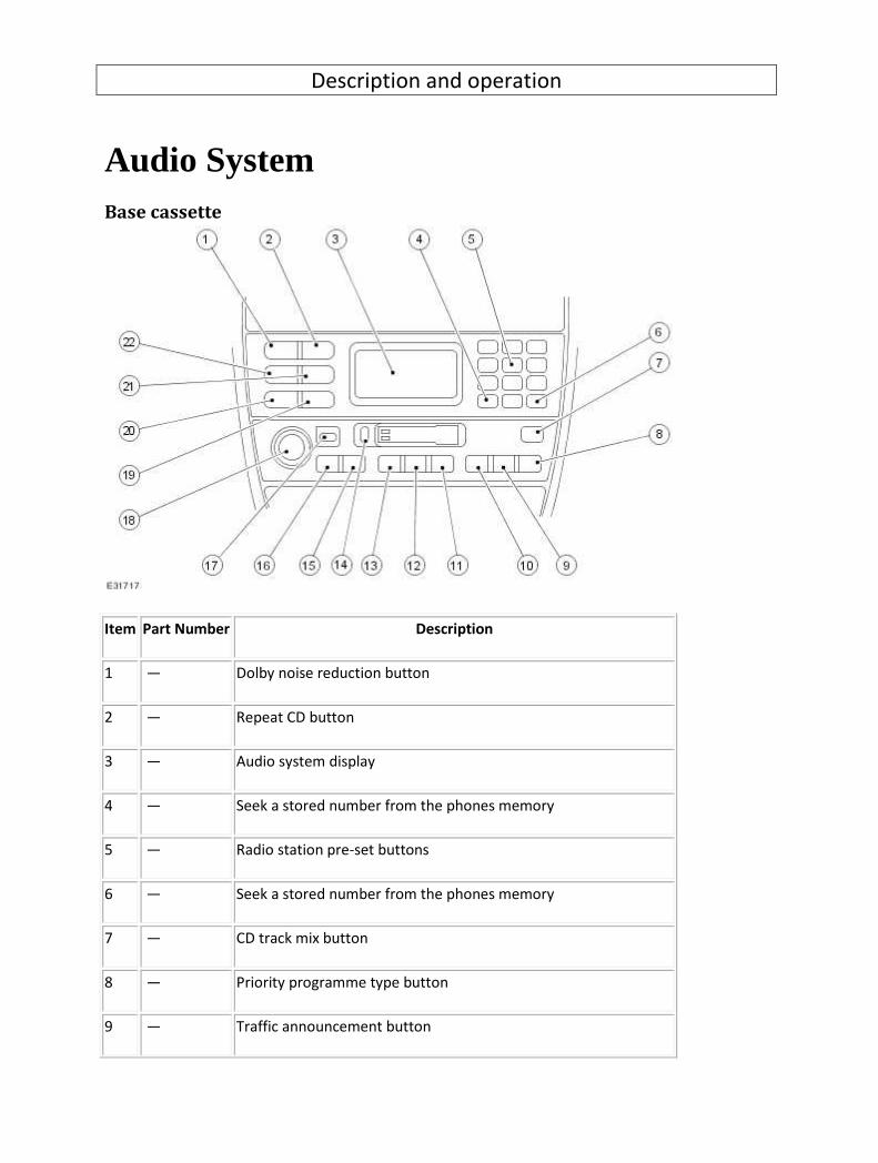
Description and operation
Audio System Base cassette
Item Part Number Description
1 — Dolby noise reduction button
2 — Repeat CD button
3 — Audio system display
4 — Seek a stored number from the phones memory
5 — Radio station pre-set buttons
6 — Seek a stored number from the phones memory
7 — CD track mix button
8 — Priority programme type button
9 — Traffic announcement button

10 — Auto memory button
11 — Select CD changer
12 — Cassette play and side change button
13 — Audio Source - AM/FM radio
14 — Cassette eject button
15 — CD seek forward, cassette fast forward, radio seek forward button
16 — CD seek back, cassette fast rewind, radio seek back button
17 — Mode button (volume/bass/treble/balance/fade)
18 — ON/OFF push (rotary volume/bass/treble/balance/fade) knob
19 — Phone mode - send/end button
20 — Phone mode select button
21 — Memory recall button
22 — Clear button
Base CD/MD

Item Part Number Description
1 — Mutes audio
2 — Repeat CD button
3 — Audio system display
4 — Seek a stored number from the phones memory
5 — Radio station pre-set buttons
6 — Seek a stored number from the phones memory
7 — Mix CDs or CD/MD tracks button
8 — Eject CD or MD
9 — Priority programme type button
10 — Traffic announcement button
11 — Auto memory button
12 — Select CD changer
13 — Select compact disc when in other audio mode, or CD pause
14 — Audio Source - AM/FM radio
15 — CD seek forward, cassette fast forward, radio seek forward button
16 — CD seek back, cassette fast rewind, radio seek back button
17 — Mode button (volume/bass/treble/balance/fade)
18 — ON/OFF push (rotary volume/bass/treble/balance/fade) knob
19 — Phone mode - send/end button
20 — Phone mode select button
21 — Memory recall button
22 — Clear button

23 — Select CD changer
24 — Select mini disc play when in other audio mode or MD pause
Touch screen cassette
Item Part Number Description
1 — On/Off push for touch-screen controls
2 — Touch-screen display
3 — Press to access touch-screen options
4 — CD track mix button
5 — Priority programme type button
6 — Traffic announcement button
7 — Auto memory button
8 — Select CD changer
9 — Cassette play and side change button
10 — Audio Source - AM/FM radio
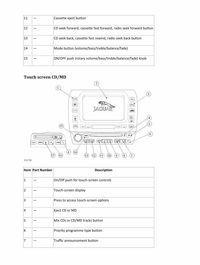
11 — Cassette eject button
12 — CD seek forward, cassette fast forward, radio seek forward button
13 — CD seek back, cassette fast rewind, radio seek back button
14 — Mode button (volume/bass/treble/balance/fade)
15 — ON/OFF push (rotary volume/bass/treble/balance/fade) knob
Touch screen CD/MD
Item Part Number Description
1 — On/Off push for touch-screen controls
2 — Touch-screen display
3 — Press to access touch-screen options
4 — Eject CD or MD
5 — Mix CDs or CD/MD tracks button
6 — Priority programme type button
7 — Traffic announcement button
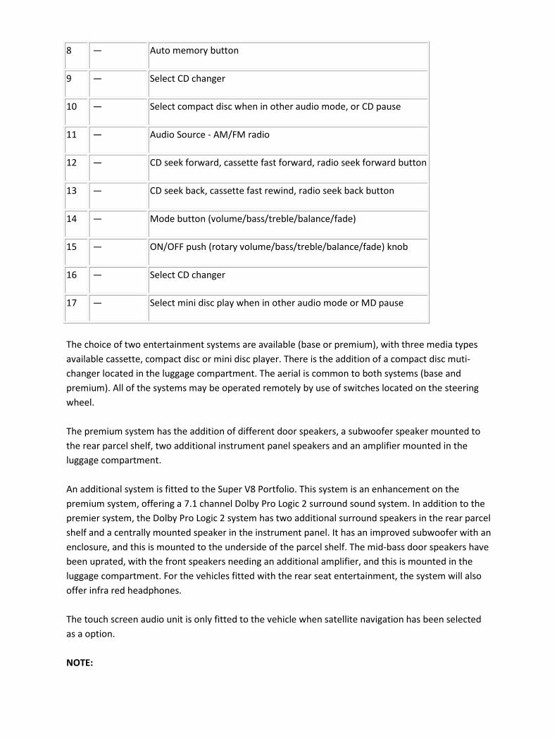
8 — Auto memory button
9 — Select CD changer
10 — Select compact disc when in other audio mode, or CD pause
11 — Audio Source - AM/FM radio
12 — CD seek forward, cassette fast forward, radio seek forward button
13 — CD seek back, cassette fast rewind, radio seek back button
14 — Mode button (volume/bass/treble/balance/fade)
15 — ON/OFF push (rotary volume/bass/treble/balance/fade) knob
16 — Select CD changer
17 — Select mini disc play when in other audio mode or MD pause
The choice of two entertainment systems are available (base or premium), with three media types
available cassette, compact disc or mini disc player. There is the addition of a compact disc muti-
changer located in the luggage compartment. The aerial is common to both systems (base and
premium). All of the systems may be operated remotely by use of switches located on the steering
wheel.
The premium system has the addition of different door speakers, a subwoofer speaker mounted to
the rear parcel shelf, two additional instrument panel speakers and an amplifier mounted in the
luggage compartment.
An additional system is fitted to the Super V8 Portfolio. This system is an enhancement on the
premium system, offering a 7.1 channel Dolby Pro Logic 2 surround sound system. In addition to the
premier system, the Dolby Pro Logic 2 system has two additional surround speakers in the rear parcel
shelf and a centrally mounted speaker in the instrument panel. It has an improved subwoofer with an
enclosure, and this is mounted to the underside of the parcel shelf. The mid-bass door speakers have
been uprated, with the front speakers needing an additional amplifier, and this is mounted in the
luggage compartment. For the vehicles fitted with the rear seat entertainment, the system will also
offer infra red headphones.
The touch screen audio unit is only fitted to the vehicle when satellite navigation has been selected
as a option.
NOTE:

When working on any part of the audio unit the audio unit security code must be obtained first.
NOTE:
The use of any cleaning liquid to clean the high gloss facia of the audio unit is prohibited, to
clean the high gloss facia the use of a lint free dry cloth is recommended.
NOTE:
Compact discs and mini discs should be checked for scratches and marks before condemning an
audio unit, if the surface of a compact disc or mini disc is dirty, use an appropriate compact disc
or mini disc cleaner.
Refer to the Sound System Handbook for setting-up procedures and use, after diagnostic or repair
operations.

Audio System - VIN Range: H18680->H99999 COMPONENT LOCATION
Item Part Number Description
1 Premium IHU
2 Low line IHU
3 DAB/SDARS/ IBOC radio module
4 Rear screen antenna
5 Audio amplifier

6 CD (compact disc) multichanger
7 Gateway module
8 Antenna amplifiers
9 Speakers
OVERVIEW
Three entertainment systems are available Base, Premium or Portfolio For additional information,
refer to Audio System (415-01 )
. All systems have FM (frequency modulation) radio and single disc CD (compact disc) player. There is
also the option of a CD (compact disc) multi-changer located in the LH (left-hand) side of the luggage
compartment. The antenna systems are common to all systems. All of the systems may be operated
remotely by use of switches located on the steering wheel.
The premium system has the addition of different door speakers, a subwoofer speaker mounted to
the rear parcel shelf, two additional instrument panel speakers and an amplifier mounted in the
luggage compartment.
Three variants of digital radio are available as well as the normal RF radio signal. These are
dependant upon which market the vehicle is built for:
• SDARS (Satellite Digital Audio Radio Service) NAS only
• IBOC (In Band On Channel) Nas only
• DAB (Digital Audio Broadcasting) Europe and Australia only
NOTE:
SDARS and IBOC cannot be specified together.
The audio system communicates on th D2B bus. DAB and SDARS/IBOC radio modules communicate
on the MOST bus. The D2B and Most systems communicate with each other via a gateway module
located in the LH (left-hand) side of the luggage compartment.
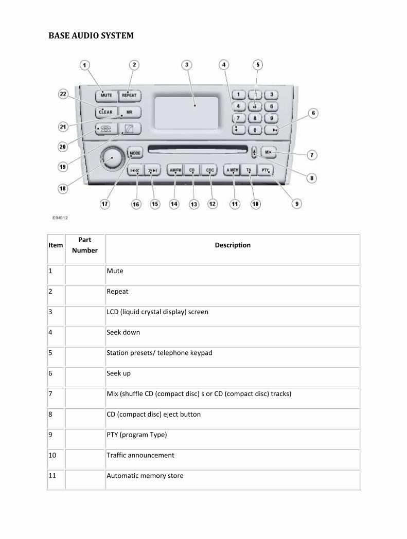
BASE AUDIO SYSTEM
Item Part
Number Description
1 Mute
2 Repeat
3 LCD (liquid crystal display) screen
4 Seek down
5 Station presets/ telephone keypad
6 Seek up
7 Mix (shuffle CD (compact disc) s or CD (compact disc) tracks)
8 CD (compact disc) eject button
9 PTY (program Type)
10 Traffic announcement
11 Automatic memory store
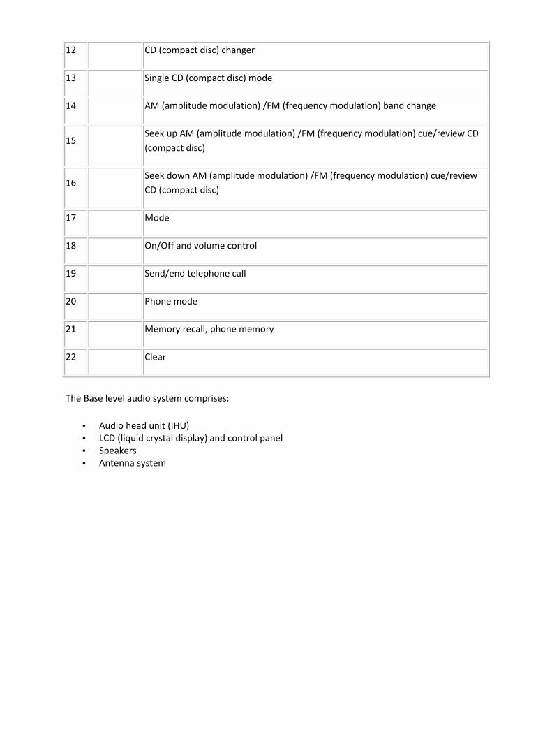
12 CD (compact disc) changer
13 Single CD (compact disc) mode
14 AM (amplitude modulation) /FM (frequency modulation) band change
15 Seek up AM (amplitude modulation) /FM (frequency modulation) cue/review CD
(compact disc)
16 Seek down AM (amplitude modulation) /FM (frequency modulation) cue/review
CD (compact disc)
17 Mode
18 On/Off and volume control
19 Send/end telephone call
20 Phone mode
21 Memory recall, phone memory
22 Clear
The Base level audio system comprises:
• Audio head unit (IHU)
• LCD (liquid crystal display) and control panel
• Speakers
• Antenna system

PREMIUM AUDIO SYSTEM
Item Part
Number Description
1 Audio system access button
2 Touch Screen Display (TSD)
3 Menu access button
4 CD (compact disc) eject button
5 Mix (shuffle CD (compact disc) s or CD (compact disc) tracks)
6 PTY (program Type)
7 Traffic announcement
8 Automatic memory store
9 CD (compact disc) changer
10 Single CD (compact disc) mode
11 AM (amplitude modulation) /FM (frequency modulation) band change

12 Seek up AM (amplitude modulation) /FM (frequency modulation) cue/review CD
(compact disc)
13 Seek down AM (amplitude modulation) /FM (frequency modulation) cue/review
CD (compact disc)
14 Mode
15 On/Off and volume control
The Premium audio system comprises:
• Audio head unit
• Touch screen display
• Amplifier
• Speakers
• Antenna system
The IHU incorporates a single CD (compact disc) player and audio controls. The unit is connected to
other audio units on the D2B bus. Above the IHU is the TSD. The TSD displays audio and navigation
system information as well as other vehicle systems.
TUNER
The IHU incorporates a AM/FM tuner which allows for 30 FM pre-sets (FM1 FM2 FM a) and 20 AM
(10 AM & 10 AM a, for Europe the 10 strongest LW & MW will be stored in frequency order). Pre-set
stations are stored in the IHU memory. The radio tuner also incorporates the following radio
functions:
• Auto tune
• Traffic announcements (TA) – Europe only
• Radio Data System (RDS) EON function (Radio Broadcast Data System RBDS in NAS markets)
• Seek station
• Tune up/down
• Scan PTY
For DAB/SDARS/IBOC radio functions a separate tuner module is required.

SDARS
The SDARS systems operate in the S-Band frequency range (2.3 GHz) and, as a result of the use of
satellite transmission have the ability to provide CD quality audio broadcasts over very large areas
(typically continents). SDARS service providers transmit a signal from their up-link facility (which is
the original point of transmission of data, voice or other information through an antenna system) to
a satellite where the signal is then down linked to both the terrestrial repeater network and the
individual SDARS car radios. The radio switches between the satellite signal and the repeater signal
depending on the strength of the signal at any given time.
The service is provided by a company called Sirius. The service comprises over 100 channels of digital
entertainment which is provided by subscription requiring a monthly payment.
Operation of the SDARS system is the same as the radio operation with selections made using the
TSD icons or the TSD buttons and rotary controller.
The SDARS system requires additional components to be added to the audio system. An SDARS
antenna and a receiver are fitted to allow reception of the service.
The customer must subscribe to receive the SDARS service. If the user selects a channel to which
subscription is not authorised, the TSD will display the telephone number of the SDARS providers
subscription service. The telephone number is stored in the IHU and can be changed or amended
using Jaguar recommended diagnostic equipment.
The SDARS systems comprises:
• Satellites
• Ground repeaters
• Up-link ground stations
• Radio receiver systems
The SDARS system uses three satellites on an inclined elliptical orbit. This ensures that each satellite
spends approximately 16 hours a day over the continent of the USA, with at least one satellite over
the country at any one time.
The satellites beam their signals down to the ground where the signal is picked up by receivers or is
transmitted to repeater stations to cover built up areas where the signal is obscured.
SDARS is a subscription based service which requires the user to contact Sirius to obtain a
subscription. In order to obtain a subscription the SDARS unit ID number will need to be retrieved
from the unit. This is achieved as follows:
• Press the MENU button and then rotate the menu control to scroll to advanced settings.
• Rotate the menu control to scroll to SIRIUS ID and press the menu control to select it.
• The Sirius ID is shown on the display screen.
If no subscription has been taken the ICM will display the Sirius telephone number. To subscribe to
Sirius use the displayed phone number. The user will need payment details, the Sirius ID number and
details of the required package.
The SDARS function is accessed by pressing the FM button and then pressing again to toggle through
the SAT1 and SAT2 sources. SAT1 and SAT2 operate in the same manner as FM1 and FM2.
The SDARS module is located in the rear LH side of the luggage compartment. The SDARS module is
connected to the rest of the audio system on the MOST ring. This allows control signals and received
audio to be routed around the system to the relevant module.
The SDARS antenna is located in the roof pod and is shared with the telephone system and
navigation system where fitted. The roof pod is located externally in a central position towards the
rear of the roof.
The roof pod contains two antennas for the SDARS system. One receives the digital transmissions
from the SDARS satellites and the second receives transmissions from the ground based repeater
stations.
The SDARS antennas are connected to the SDARS receiver using co-axial cables.
DAB/IBOC
Digital Audio Broadcast (DAB) is a digital radio network designed to provide reliable, multi-service
broadcasting for reception by mobile, portable and fixed receivers.
DAB is broadcast across Europe, Canada and most of Asia. In NAS markets DAB is replaced with the
IBOC system. Both systems are transmitted via terrestrial networks, on band III and L-band.
When the IHU is in any tuner mode, a short press of the "BAND" button cycles between the tuners
available to the user on the vehicle infotainment system. With DAB installed, these sources cycle as
follows: FM -> MW -> LW -> DAB1 -> DAB2 -> FM. The cycle list can only be navigated in one
direction.
The lowline IHU has an LCD (liquid crystal display) which is only capable of displaying upper-case
letters and some symbols.

CD PLAYER
The IHU incorporates a single disc CD player. There is also the option of a CD multi changer located in
the rear LH (left-hand) side of the luggage compartment. Both systems are capable of playing
commercial CDs, CDRs, CDRWs and MP3 discs. TheCD (compact disc) multi changer communicates on
the D2B bus with the rest of the audio system.
STEERING WHEEL SWITCHES
Item Part Number Description
1 Voice control/telephone
2 Volume up/down
3 Mode select
4 Cycle up/down
The audio and phone system steering wheel control switches are mounted on the LH (left-hand) side
of the steering wheel. The switches comprise:
• Jaguar voice/telephone send/end receive switch
• Volume increase/decrease
• Mode select switch
• Up/down cycle button
The switches operate on a resistive ladder principle. A reference voltage is supplied to the switches
and dependant upon which switch is operated a reduced voltage is returned to the head unit.

AMPLIFIER
The base audio system amplifier is integral to the IHU. The premium audio system is a separate unit
located towards the front of the loadspace on the LH (left-hand) side. The amplifier
GATEWAY MODULE
The gateway module is located in the LH (left-hand) side of the luggage compartment.
The gateway module translates MOST signals from the digital radio module (SDARS, DAB or IBOC/HD)
to D2B signals for the IHU. The gateway module also steams audio from the digital radio module to
the IHU.
The gateway module appears as a slave module on the D2B bus and a master on the MOST bus. The
gateway module incorporates basic ring break diagnostics and stores fault codes from the digital
radio module. The fault codes can be retrieved by the recommended Jaguar diagnostic tool.
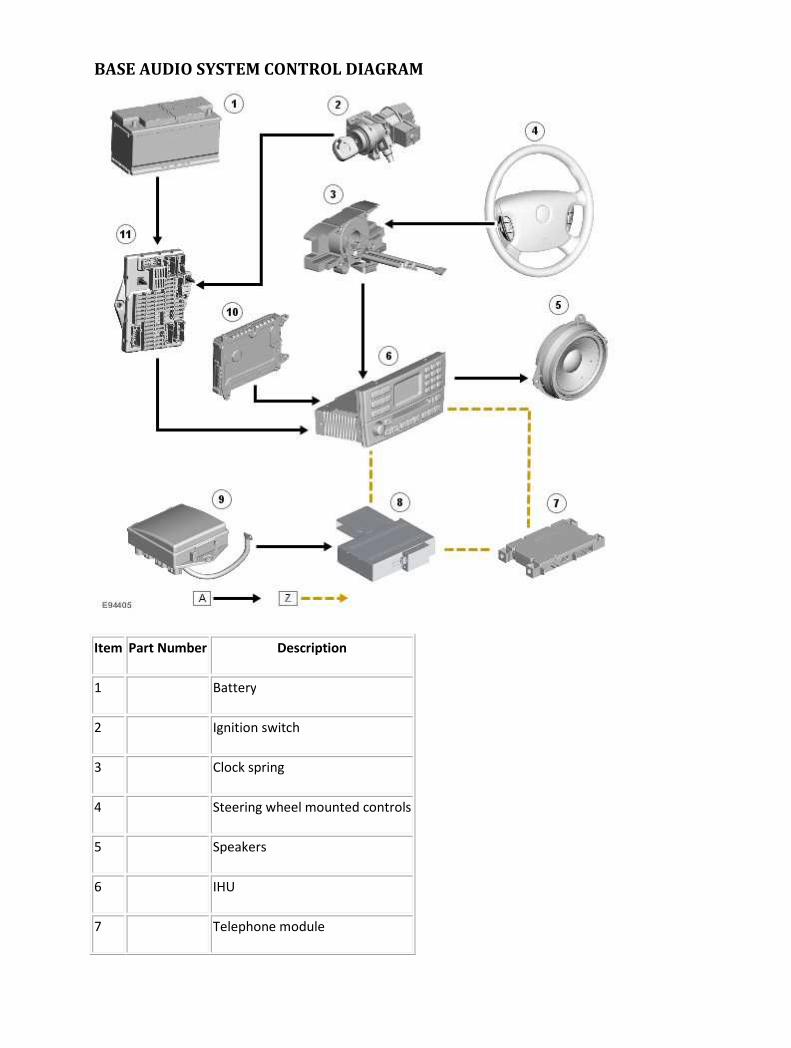
BASE AUDIO SYSTEM CONTROL DIAGRAM
Item Part Number Description
1 Battery
2 Ignition switch
3 Clock spring
4 Steering wheel mounted controls
5 Speakers
6 IHU
7 Telephone module

8 CD (compact disc) changer
9 RJB (rear junction box)
10 FEM (front electronic module)
11 CJB (central junction box)
PREMIUM AUDIO SYSTEM CONTROL DIAGRAM
Item Part Number Description
1 Battery
2 Ignition switch

3 Clock spring
4 Voice control module
5 Navigation computer
6 Clock spring
7 Rear seat entertainment system control module
8 TSD
9 Gateway module
10 DAB/SDARS/IBOC radio module
11 Telephone control module
12 Amplifier
13 CD (compact disc) changer
14 Speakers
15 RJB (rear junction box)
16 IHU
17 FEM (front electronic module)
18 CJB (central junction box)

Audio System OVERVIEW
The Portfolio audio system is an enhancement on the premium system, offering a 7.1 channel Dolby
Pro Logic 2 surround sound system. In addition to the premier system, the Dolby Pro Logic 2 system
has two additional surround speakers in the rear parcel shelf and a centrally mounted speaker

Diagnosis and testing
Audio System For additional information, refer to<<415-00>>

Removal and installation
Amplifier (86.50.10) Removal
1 . Disconnect the battery ground cable. <<414-01>>
2 . Remove the luggage compartment floor covering.
1) Remove the luggage compartment floor covering securing screws.
2) Remove the luggage compartment floor covering.
3 . Remove the luggage compartment side trim panel.
Remove the luggage compartment side trim retaining clip.
4 . Disconnect the audio unit amplifier electrical connectors.

5 . Remove the audio unit amplifier rear retaining bolts.
6 . Remove the audio unit amplifier.
Installation
1 . To install, reverse the removal procedure.
Tighten to 4 Nm.
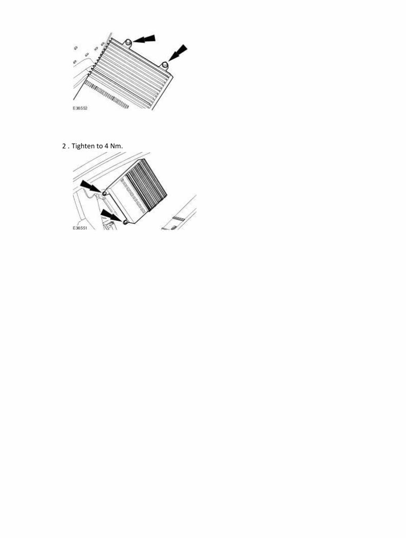
2 . Tighten to 4 Nm.

Audio Unit (86.50.03) Removal
1 . Remove the instrument panel console. <<501-12>>
2
. CAUTION: Extreme care must be observed not to damage the high gloss finish on
the surface of the audio unit.
CAUTION: Cleaning of the high gloss finish should only be carried out with a soft dry
cloth. Failure to follow this procedure will cause damage to the audio unit facia.
NOTE:
Left-hand shown, right-hand similar.
Remove the audio unit.
Installation
1 . To install, reverse the removal procedure.
Tighten to 2 Nm.

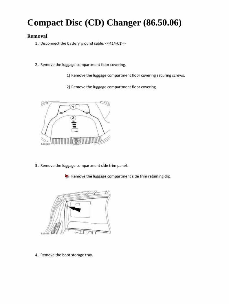
Compact Disc (CD) Changer (86.50.06) Removal
1 . Disconnect the battery ground cable. <<414-01>>
2 . Remove the luggage compartment floor covering.
1) Remove the luggage compartment floor covering securing screws.
2) Remove the luggage compartment floor covering.
3 . Remove the luggage compartment side trim panel.
Remove the luggage compartment side trim retaining clip.
4 . Remove the boot storage tray.
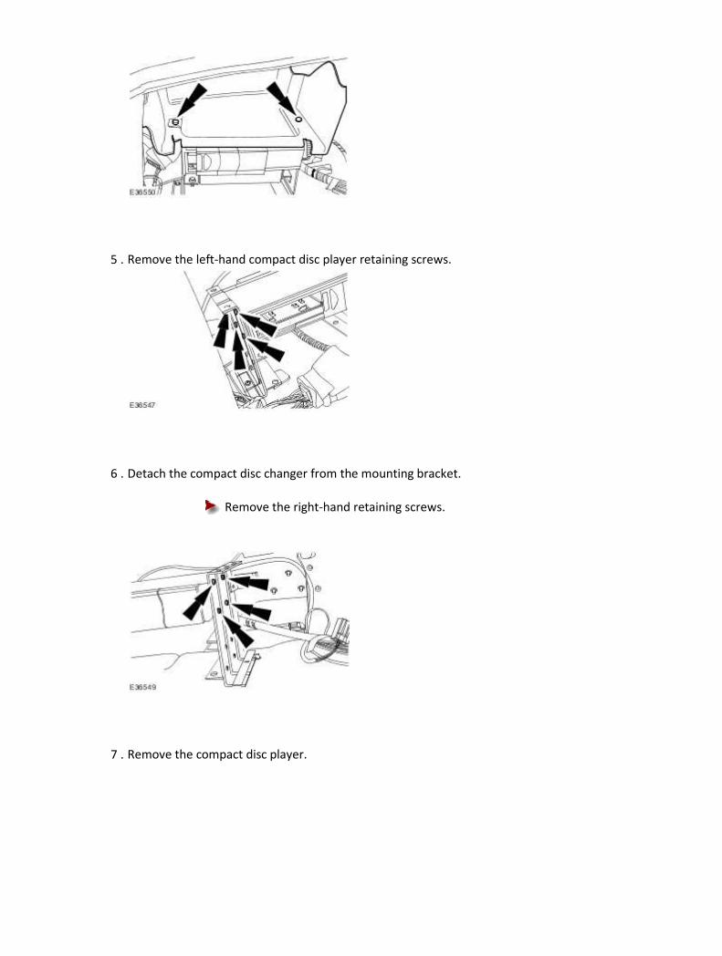
5 . Remove the left-hand compact disc player retaining screws.
6 . Detach the compact disc changer from the mounting bracket.
Remove the right-hand retaining screws.
7 . Remove the compact disc player.
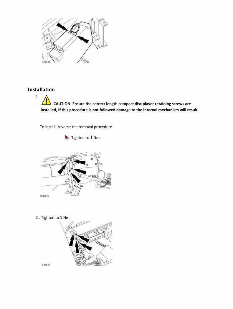
Installation
1
. CAUTION: Ensure the correct length compact disc player retaining screws are
installed, If this procedure is not followed damage to the internal mechanism will result.
To install, reverse the removal procedure.
Tighten to 1 Nm.
2 . Tighten to 1 Nm.

Steering Wheel Audio Controls (86.50.42) Installation
1 . To install, reverse the removal procedure.
Tighten to 2 Nm.
415-02 : Antenna
Description and operation
Antenna
Item Part Number Description
1 — Antenna FM
2 — Antenna AM
3 — Antenna filter VICS (Japan only)
4 — Amplifier(s) TV
5 — Ground wave trap
6 — Antenna isolator module
7 — Positive wave trap
8 — Antenna VICS beacon (Japan only)
The antenna cable is split into two sections:
• Audio unit to floor console connector. • Floor console connector to antenna isolator module.
The audio unit to antenna isolator module cable is located in the body wiring harness. There are two audio antennas fitted to the vehicle, an AM antenna and an FM antenna, both are located in the rear windshield glass. The AM antenna is above the heated rear windshield element to the left-hand side. The FM antenna utilizes the heated rear windshield demist element but does not carry the demist current. The power connector to the demist screen has a filter in line called a positive wavetrap and the ground connector to the demist screen has a filter called a negative wavetrap. The diversity FM antenna is similar to the AM/FM antenna, except that two FM antennas are derived from the demist pattern. As the demist screen is split to create the extra antennas, a double wavetrap is fitted which has two positive connectors. The antenna isolator switches between the two FM inputs and sends the strongest to the radio. The antenna isolator module controls both antennas. The TV antenna system is split into four and works the same as the diversity system for the

FM antenna. The TV antenna system consists of four amplifiers colour coded black, two mounted onto the rear parcel tray and two mounted onto the right hand rear 'C' pillar. These are connected to the rear backlite and use the same antenna as the FM audio antenna. In order for a vehicle to have TV it must have the navigation option fitted. The VICS (vehicle information and communication system, Japan only) has two antenna's, one located in the rear backlite and the other located on the facia panel in the left hand corner. The rear antenna has a filter which is located on the right hand rear 'C' pillar colour coded green.

Diagnosis and testing
Antenna Inspection and Verification
1 . Verify the customer concern.
2 . Visually inspect for obvious signs of electrical damage.
Visual Inspection Chart
Electrical
• Antenna isolator module
• Antenna AM
• Antenna FM
• Antenna beacon sensor VICS (Japan only)
• Antenna filter VICS (Japan only)
• Antenna(s) TV
• Amplifier(s) TV
• Positive wavetrap
• Negative wavetrap
• Harness/electrical connectors
• Audio unit
• Navigation unit
1 . If an obvious cause for an observed or reported concern is found, correct the cause (if possible)
before proceeding to the next step.
2 . If the cause is not visually evident, verify the symptom and refer to the Jaguar Approved
Diagnostic System.
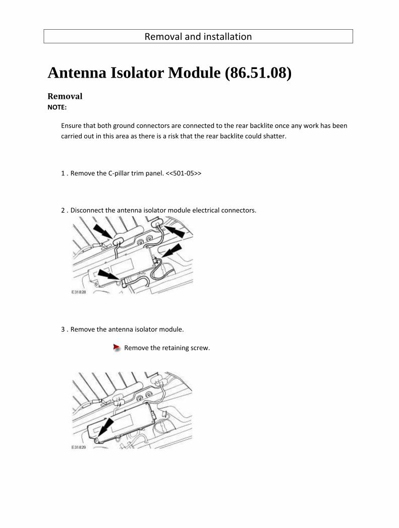
Removal and installation
Antenna Isolator Module (86.51.08) Removal
NOTE:
Ensure that both ground connectors are connected to the rear backlite once any work has been
carried out in this area as there is a risk that the rear backlite could shatter.
1 . Remove the C-pillar trim panel. <<501-05>>
2 . Disconnect the antenna isolator module electrical connectors.
3 . Remove the antenna isolator module.
Remove the retaining screw.

Installation
1 . To install, reverse the removal procedure.

415-03 : Speakers
Description and operation
Speakers There are three speaker systems available, a standard system which has 8 speakers and a premium system which has 12 speakers. The Dolby Pro Logic 2 system, which is fitted to the Super V8 Portfolio, has a 14 speaker configuration. On the standard system there are:
• door speakers mounted at the base of each door. • door tweeters mounted together with each door release handle.
On the premium sound system there are:
• high power and high quality door speakers mounted at the base of each door. • door tweeters mounted together with each door handle. • mid range speakers mounted to the top left and right of the instrument panel next to
the windshield. • two subwoofers mounted onto the rear parcel shelf.
On the Pro Logic 2 surround sound system there are:
• high power and high quality door speakers mounted at the base of each door. • door tweeters mounted together with each door release handle. • mid range speakers mounted to the top left and right of the instrument panel next to
the windshield. • one center fill speaker in the center of the instrument panel. • two surround speakers mounted in the rear parcel shelf. • one subwoofer speaker mounted centrally under the rear parcel shelf.
Diagnosis and testing
Speakers Inspection and Verification
1 . Verify the customer concern.
2 . Visually inspect for obvious signs of electrical damage.
Visual Inspection Chart
Electrical
• Speaker(s)
• Harness/electrical connectors
• Audio unit
• Amplifier
1 . If an obvious cause for an observed or reported concern is found, correct the cause (if possible)
before proceeding to the next step.
2 . If the cause is not visually evident, verify the symptom and refer to the Jaguar Approved
Diagnostic System.

Removal and installation
Front Door Speaker (86.50.13) Removal
1 . Remove the front door trim panel. For additional information, refer to <<501-05>>.
2 . Disconnect the front door speaker electrical connector.
3 . Remove the front door speaker.
Installation
1 . To install, reverse the removal procedure.

Front Door Tweeter Speaker (86.50.63) Removal
1 . Remove the front door trim panel. <<501-05>>
2 . Disconnect the electrical connector.
3 . Remove the tweeter speaker.
Installation
1 . Install the tweeter speaker.
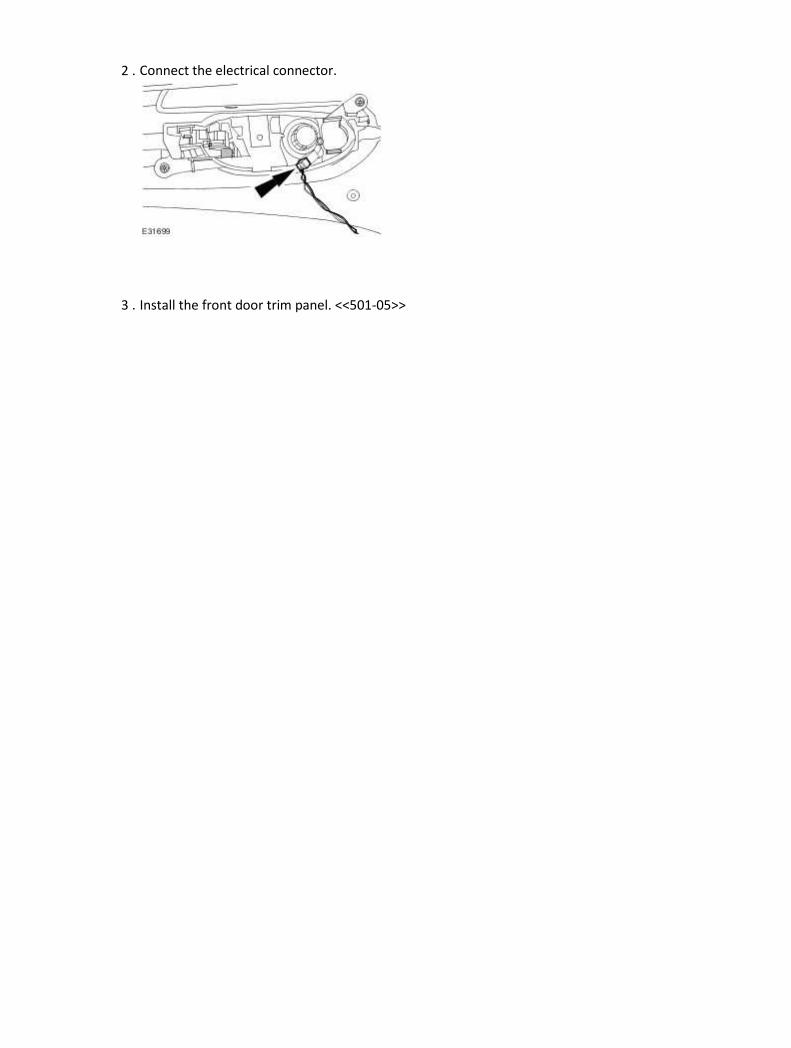
2 . Connect the electrical connector.
3 . Install the front door trim panel. <<501-05>>
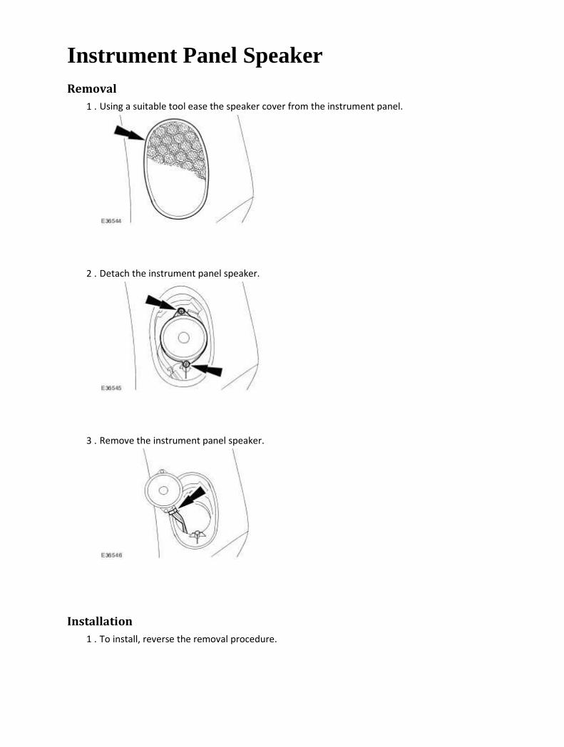
Instrument Panel Speaker Removal
1 . Using a suitable tool ease the speaker cover from the instrument panel.
2 . Detach the instrument panel speaker.
3 . Remove the instrument panel speaker.
Installation
1 . To install, reverse the removal procedure.

Rear Door Speaker (86.50.14) Removal
1 . Remove the rear door trim panel. For additional information, refer to <<501-05>>.
2 . Disconnect the rear door speaker electrical connector.
3 . Remove the rear door speaker.
Installation
1 . To install, reverse the removal procedure.

Rear Door Tweeter Speaker (86.50.62) Removal
1 . Remove the rear door trim panel. <<501-05>>
2 . Disconnect the electrical connector.
3 . Remove the tweeter speaker.
Installation
1 . Install the tweeter speaker.

2 . Connect the electrical connector.
3 . Install the rear door trim panel. <<501-05>>

Subwoofer Speaker (86.51.05) Removal
1 . Remove the parcel shelf. <<501-05>>
2 . NOTE:
Right-hand shown, left-hand similar.
Disconnect the subwoofer speaker electrical connector.
3 . NOTE:
Right-hand shown, left-hand similar.
Remove the subwoofer speaker.
Installation
1 . To install, reverse the removal procedure.

415-07 : Video System
Specifications
Specifications Torque Specifications
Description Nm lb-ft lb-in
Video system module 6 — 53
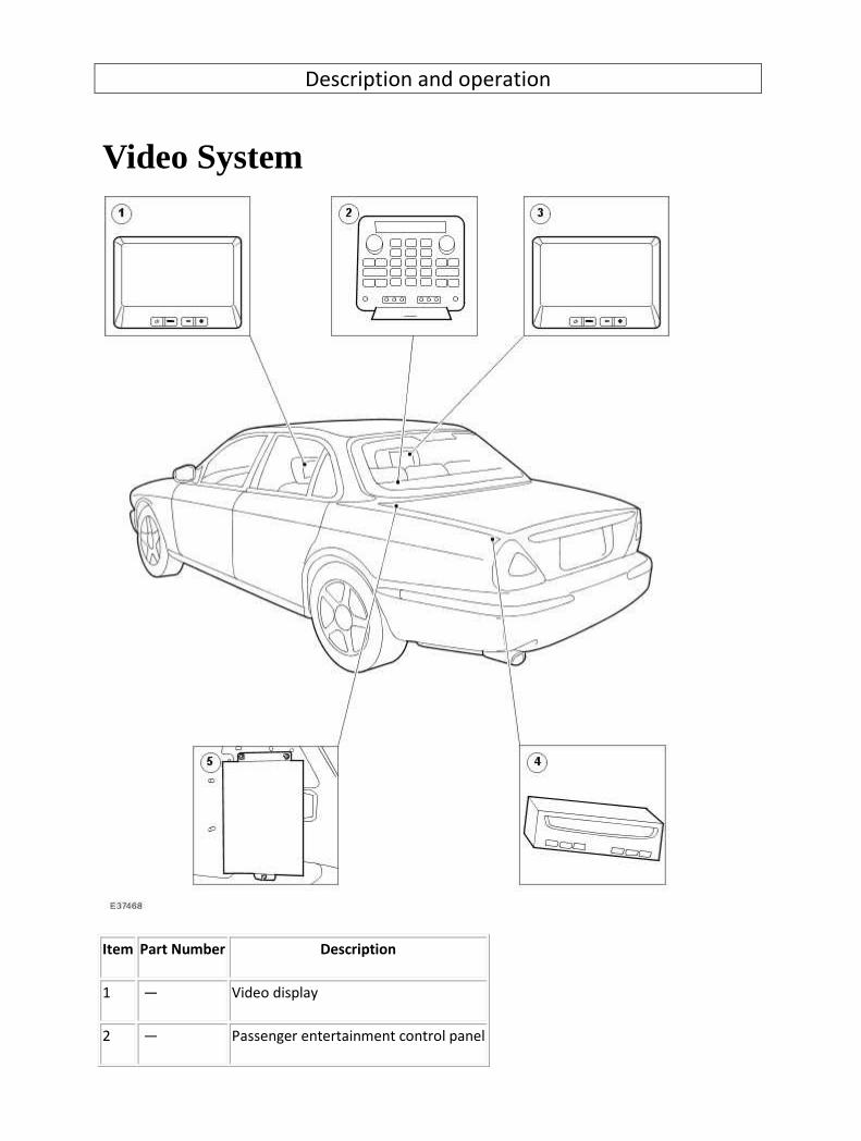
Description and operation
Video System
Item Part Number Description
1 — Video display
2 — Passenger entertainment control panel

3 — Video display
4 — Digital versatile disc (DVD) player
5 — Video system module
The function of the rear seat multimedia system is to provide audio and video entertainment for the
rear seat passengers.
It will provide control of a number of audio and video sources and channel the output independently
to the rear left and rear right seat passengers via personal headphones and video screens, or allow
output over the main vehicle audio speaker system.
The multimedia system includes the following components:
1. A passenger entertainment control panel (mounted in the rear seat center armrest/console).
2. Two 6.5'' video display screens (mounted in the back of the front headrests).
3. A DVD video player (mounted in the luggage compartment).
NOTE:
The DVD player is region specific and will only play DVD's of the correct region for the DVD
player.
4. A video system module (mounted behind the rear seat backrest).
5. A microswitch is fitted to the rear armrest/console lid which will switch off the illumination to the
passenger entertainment control panel when the lid is closed.
6. Two headphone sets (Jaguar accessory).
The system features available on a vehicle will depend on the particular vehicle specification.
There are 3 basic system levels:
a) Audio only.
b) Audio and video display screens.
c) Audio, video display screens and DVD video player.
System level a) provides rear seat audio entertainment only.

System level b) has audio/video capability.
System level c) has audio/video capability and includes a dedicated DVD movie player located in the
luggage compartment.
The system will allow the rear passengers to control the main vehicle audio system functions and
have the facility to connect 2 sets of headphones for private listening. The headphone sockets are
incorporated into the passenger entertainment control panel.
The 6.5'' video display screens mounted in the front seat headrests can display video pictures from a
number of sources, which can be selected using the passenger entertainment control panel. Signal
sources available include the vehicle TV tuner (if specified), navigation screen display (duplication of
the front screen), and a DVD video player (if specified). In addition to this the system is equipped
with 2 sets of audio/video (auxiliary) inputs that will provide the facility to connect external
audio/video media e.g. camcorder, or home video games console.
Each of the audio/video sources described above are independently switchable to either one or both
of the headphones and video display screens.
Controllable Units
The rear passengers will be able to control the following units:
Head unit (Cassette/CD/MD and Tuner)
CD changer
Phone (if fitted)
Multizone Voice (if fitted)
DVD Player (if fitted)
AUX 1 and 2
TV (if fitted)
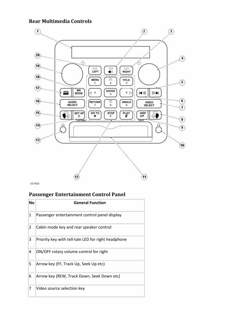
Rear Multimedia Controls
Passenger Entertainment Control Panel
No General Function
1 Passenger entertainment control panel display
2 Cabin mode key and rear speaker control
3 Priority key with tell-tale LED for right headphone
4 ON/OFF rotary volume control for right
5 Arrow key (FF, Track Up, Seek Up etc)
6 Arrow key (REW, Track Down, Seek Down etc)
7 Video source selection key

8 PTT and send/end with tell-tale for right
9 DVD display, cassette direction and Teletext key
10 Head phone socket for right-hand side passenger
11 AUX jack socket panel
12 12 digit keypad
13 Head phone for left-hand side passenger
14 Telephone cancel, DVD set-up menu and TV auto store key
15 PTT and send/end with tell-tale for left
16 Audio source selection key
17 Phone key
18 Audio mode and telephone memory recall key
19 ON/OFF rotary volume control for left
20 Priority key with tell-tale LED for left headphone
12 Digit Keypad (12)
No General Function
1 DVD mode: MENU key
2 DVD mode: CURSOR (UP) key
3 DVD mode: TITLE key
4 DVD mode: CURSOR (LEFT) key
5 DVD mode: ENTER key
6 DVD mode: CURSOR (RIGHT) key
7 DVD mode: RETURN key

8 DVD mode: CURSOR (DOWN) Key
9 DVD mode: ANGLE key
0 DVD mode: STOP key
# DVD mode: PLAY key
* DVD mode: GO TO key
Passenger Entertainment Control Panel Display (1)
The passenger entertainment control panel includes a single line 17 character LCD display. It will
display text messages, information and icons relating to the system function selected. When a
function has been selected e.g. voice command or phone call initiated, the LCD display will provide
text feedback to the rear passengers indicating their selection. It will also display information relating
to the audio and video mode selected or adjusted.
ON/OFF Rotary Volume Control (4 & 19)
Two ON/OFF master rotary controls are included in the system (one for left and one for right). Press
the rotary control to turn the system ON/OFF. The volume level of the source selected can be
adjusted by rotating the control knob clockwise for increase, and anti-clockwise for decrease, across
a range of settings (0-35). The volume level will be indicated on the passenger entertainment control
panel display during adjustment and momentarily afterwards. The system will memorise the volume
setting for each audio source.
Priority Key with Tell-tale LEDs (3 & 20)
Pressing the LEFT key will make all subsequent key presses affect the rear left passenger zone.
Pressing the RIGHT key will make all subsequent key presses affect the rear right passenger zone. To
indicate which zone is currently in control of the control panel an LED in the relevant zone key will be
illuminated. It will remain on until the priority zone is changed (e.g. right or cabin mode). Note: It is
not necessary to press the LEFT/RIGHT key when entering phone or voice command mode.
Rear Speaker Control and Cabin Mode Key (2)
This is a dual function key (cabin mode select key and a rear speaker mute/demute key).
A short press on this button will switch the system to cabin mode. This will allow the rear passengers
to control the main vehicle audio speaker system. When cabin mode is selected a tell-tale LED in the
button will be illuminated.
A long press on this switch will mute the rear speakers and the sub-woofer. If they are already
muted, speaker muting will be cancelled.
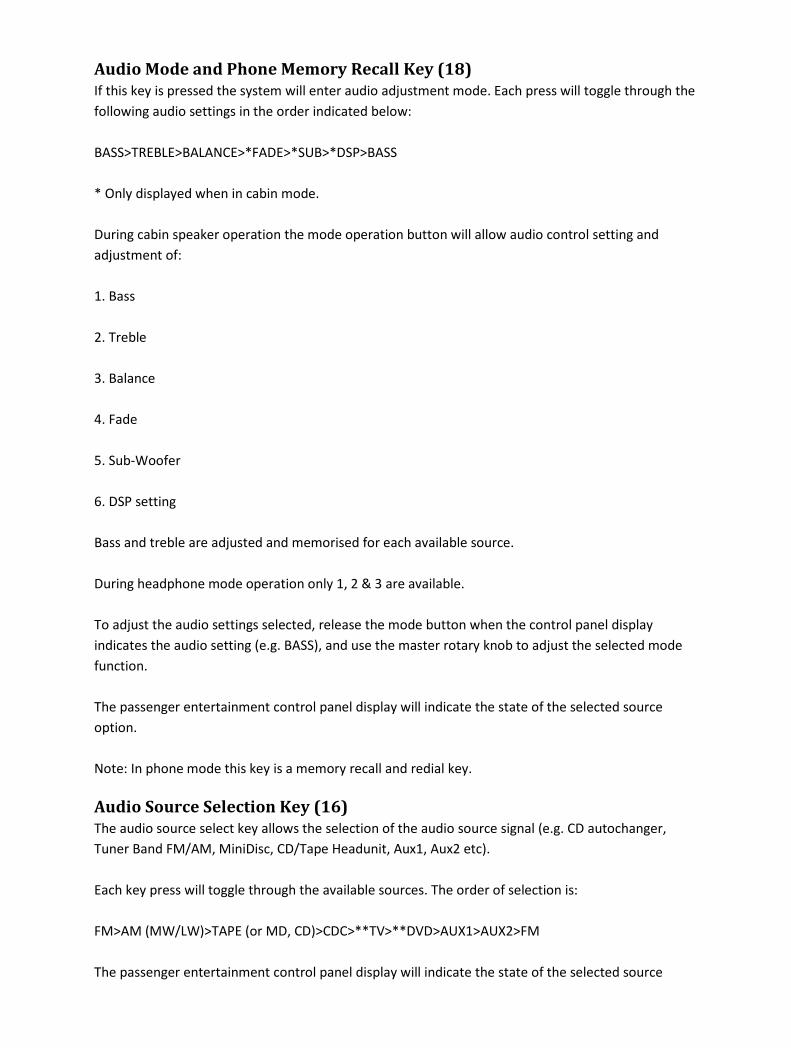
Audio Mode and Phone Memory Recall Key (18)
If this key is pressed the system will enter audio adjustment mode. Each press will toggle through the
following audio settings in the order indicated below:
BASS>TREBLE>BALANCE>*FADE>*SUB>*DSP>BASS
* Only displayed when in cabin mode.
During cabin speaker operation the mode operation button will allow audio control setting and
adjustment of:
1. Bass
2. Treble
3. Balance
4. Fade
5. Sub-Woofer
6. DSP setting
Bass and treble are adjusted and memorised for each available source.
During headphone mode operation only 1, 2 & 3 are available.
To adjust the audio settings selected, release the mode button when the control panel display
indicates the audio setting (e.g. BASS), and use the master rotary knob to adjust the selected mode
function.
The passenger entertainment control panel display will indicate the state of the selected source
option.
Note: In phone mode this key is a memory recall and redial key.
Audio Source Selection Key (16)
The audio source select key allows the selection of the audio source signal (e.g. CD autochanger,
Tuner Band FM/AM, MiniDisc, CD/Tape Headunit, Aux1, Aux2 etc).
Each key press will toggle through the available sources. The order of selection is:
FM>AM (MW/LW)>TAPE (or MD, CD)>CDC>**TV>**DVD>AUX1>AUX2>FM
The passenger entertainment control panel display will indicate the state of the selected source

option.
**If specified on vehicle.
Video Source Selection Key (7)
The video select key allows selection of a video source signal (e.g. DVD, TV, FRONT, AUX 1, AUX 2
etc).
Each key press will toggle through the available sources. The order of selection is:
**FRONT>**TV>**DVD>AUX 1>AUX 2>**FRONT
The audio will be changed automatically to the selected visual source except when FRONT is
selected.
The passenger entertainment control panel display will indicate the state of the selected source
option.
**If specified on vehicle.
Arrow Keys (5 & 6)
The arrow keys are multifunction buttons which have a different function depending on the specific
audio/video mode selected at the time of use:
Tuner frequency adjust (up/down) - In tuner mode, momentarily pressing this button allows tuning
(up or down) of the radio frequency band to the next available station. Pressing and holding the
button allows manual tuning of the radio frequency. During either operation the passenger
entertainment control panel display will show the frequency as it seeks up or down.
TV channel adjust (up/down) - In TV mode, momentarily pressing this button allows tuning (up or
down) of the available TV frequency band to the next available preset. Long press of this button
seeks the next station.
CD disc skip up/down - In CD mode, momentarily pressing this button allows selection of the next
(Skip Up) or previous (Skip Down) CD track of the current disc selected. Long press of this button
allows fast forward or fast reverse (Scan Up/Scan Down).
MiniDisc skip up/down - In MiniDisc (MD) mode, momentarily pressing this button allows selection of
the next (Skip Up) or previous (Skip Down) MD track of the current disc selected. A long press of this
button allows fast forward or fast reverse (Scan up/Scan down).
Tape forward (>>)/Rewind (<<) - In Tape mode, momentarily pressing the (>>) button allows
selection of the next (Seek Up) or pressing the (<<) button allows selection of the previous (Seek
Down) track. Multiple presses (up to a maximum of 9) will seek the chosen track. Pressing and
holding the button for 2 seconds will select fast forward or rewind.
Talk Keys (8 & 15)
The function of these keys depends on the mode selected at the time and the vehicle specification.
Headphone audio mute keys - In a vehicle without a phone and multizone voice system, these keys
are audio mute keys for the headphones. Pressing the left TALK or right TALK key will mute the
respective headphone set. When the LEFT/RIGHT mute function button is active a tell-tale LED in the
button will be illuminated.
Multizone voice if fitted (PTT keys) - Vehicles specified with a Multizone Voice command system will
allow the rear passengers to execute a number of voice commands from the rear seat position. Press
the left or right PTT key to inform the vehicle voice command system that a voice command is about
to be issued.
The following are examples of voice commands functions which are supported:
TV COMMANDS -
TV channel select
Preset up/down
PHONE COMMANDS -
Phone on/off
Phone redial
Phone directory
AUDIO CONTROL -
Radio/Audio on/off
Seek tune up/down
Tape on
Track select
CDC disc select
A complete list of all the voice commands which are available can be found in the owner's handbook.
An associated text message for each rear voice command will appear in the passenger entertainment
control panel display as confirmation of the issued voice command. In this mode, the passenger

entertainment control panel display will behave as a single 17-character display (not divided).
Handsfree phone mode (Send/End Keys) - vehicles equipped with a phone, and a multizone voice
command system allow the rear passengers to carry out a handsfree phone call.
Press the PHONE button to select phone mode. Dial the telephone number required using keys 0-9
and press LEFT/RIGHT Talk button to initiate a hands- free phone call.
Phone Key (17)
If this key is pressed, the system will enter phone mode. In this mode, the passenger entertainment
control panel display will behave as a single 17-character display (not divided). In this mode the user
will be able to the use passenger entertainment control panel as telephone keypad.
NOTE:
Phone and multizone voice must be specified on the vehicle.
12 Digit Keypad (12)
The 12-digt keypad is a multifunction keypad. It has a different function depending on the
audio/video mode at the time of use:
Tuner presets (1-9) - press and release the preset buttons (1-9) to select a preset radio station while
in audio tuner mode. In each waveband (FM/MW) nine stations can be recalled using the bank of
buttons marked 1-9. The passenger entertainment control panel display will indicate the selected
waveband and frequency selected (e.g. 102.6 FM).
TV channel select (0-9) - Press and release one of the preset buttons (1-9) to select a preset TV
station while in TV mode.
CD autochanger disc select (1-6) - Press and release one of the preset buttons (1-6) to select a CD disc
while in CD mode.
DVD functions - The following functions are available in DVD mode when pressing the control panel
keys, dependant on the functions being supported by the DVD disc. A short press of the relevant key
in DVD mode will select the following function:
[1] MENU Key
[2] CURSOR (UP) Key
[3] TITLE Key
[4] CURSOR (LEFT) Key
[5] ENTER Key
[6] CURSOR (RIGHT) Key
[7] RETURN Key
[8] CURSOR (DOWN) Key
[9] ANGLE Key
[0] STOP Key
[#] PLAY Key
[*] Go To Key
[Disp] Display
[C] Set up
A long press of the keys 0-9 in DVD mode will select the respective digit (0-9).
Tape Reverse, Display and Teletext key (9)
This key has 3 functions:
TAPE REVERSE KEY - Pressing this key in tape mode will change the side/direction of the tape
currently playing.
DVD DISPLAY KEY - In DVD mode the DVD display status information will be displayed on the 6.5"
video display screen (e.g. current chapter number, current playing time etc). If the disc information is
already displayed, it will be cancelled on pressing this button. A long press of this button will change
from NTSC to PAL format.
TV/TELETEXT KEY - In TV mode pressing this key will display teletext on the 6.5" video display screen.
If teletext is already displayed it will be cancelled on pressing this button and the picture will be
displayed.
Note: TV/Teletext picture quality is dependant on the TV reception signal available.
Cancel, Set-Up Menu and TV Auto Store Key (14)
This key has three functions.
PHONE CANCEL KEY - The CANCEL key is used for deleting entered number(s). A short press will
delete all entered digits. This function will be valid during phone mode only.
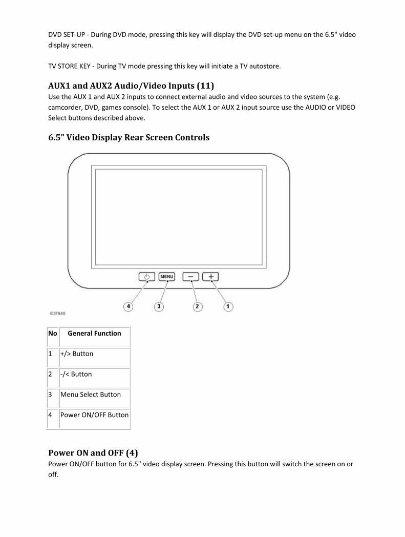
DVD SET-UP - During DVD mode, pressing this key will display the DVD set-up menu on the 6.5" video
display screen.
TV STORE KEY - During TV mode pressing this key will initiate a TV autostore.
AUX1 and AUX2 Audio/Video Inputs (11)
Use the AUX 1 and AUX 2 inputs to connect external audio and video sources to the system (e.g.
camcorder, DVD, games console). To select the AUX 1 or AUX 2 input source use the AUDIO or VIDEO
Select buttons described above.
6.5" Video Display Rear Screen Controls
No General Function
1 +/> Button
2 -/< Button
3 Menu Select Button
4 Power ON/OFF Button
Power ON and OFF (4)
Power ON/OFF button for 6.5" video display screen. Pressing this button will switch the screen on or
off.
Menu Select Button (3)
This button will select the on-screen display (O.S.D.) menu for the video display screen. A menu will
appear on the screen. The following screen settings will be available for adjustment:
Brightness: Adjust the brightness level of the screen.
Color: Adjust the color level of the screen (composite signal only).
Tint: Adjust the tint level of screen (composite NTSC signal only).
Dimmer: Select AUTO or MANUAL.
Dimmer level: Adjust dimmer level if set to MANUAL.
Screen mode: Select aspect ratio for screen.
Input: Select NTSC/PAL/AUTO.
Left (-/<) and Right (+/>) Cursor Control Keys (1 and 2)
These keys are used with the O.S.D. Menu key (3) to select and deselect the O.S.D. options available
on the video display screen.

Diagnosis and testing
Video System Principles of operation
The rear seat multimedia system can provide audio or audio/visual entertainment independently to
the rear left-hand and right-hand passengers via personal headphones and display screens, or allow
output over the main vehicle audio system speakers, and allows the rear seat passengers to control
certain voice-activated functions, provided the multi-zone voice option is fitted.
There are three system levels:
Level One
Level one provides rear seat audio only, controlled independently of the main ICE control unit.
Level Two
Level two provides audio/visual capability, and allows the use of video inputs from a number of
sources, selected from the rear entertainment control panel:
• TV tuner (where fitted)
• camcorder (via auxiliary connectors in the rear entertainment control panel)
• video games (via auxiliary connectors in the rear entertainment control panel)
• any other external audio or video source compatible with the auxiliary connectors
Level Three
Level three provides all the functions of level two, plus DVD (located in the luggage compartment).
Each of the audio/visual sources above are switchable to allow the headphones/display screens to
operate independently of each other.
The rear seat passengers will be able to control the following units:
• ICE head unit (tuner, MC, CD, and MD)
• phone (where fitted)
• multizone voice control (where fitted)
• TV tuner (where fitted)
• DVD player (where fitted)
• auxiliary sources, 1 and 2
For further information on the operation of the system,
Video System

Inspection and verification
1 . Verify the customer concern.
2 . Visually inspect for obvious signs of mechanical or electrical damage.
Visual inspection chart
WARNING: Removal of the front seats will involve the disconnection of "hot" connectors
(connectors in the SRS system to the air bag modules). <<501-20>> For safety information on
disconnection of air bag connections.
NOTE:
The display screens for each side are not handed, and may be used to prove a fault by
substituting one side for the other. Control modules should NOT be substituted from another
vehicle.
Electrical
Fuse(s) REFER to fuse identification table
Wiring harness(es) REFER to symptom charts
Electrical connector(s)
Rear entertainment control unit (control panel)
ICE head unit
DVD player
Right-hand rear display screen
Left-hand rear display screen
Video system module
Fuse
number Rating Circuit Fuse box location

41 20
Amp Ignition switch
Front power
distribution box
20 5 Amp Rear entertainment control panel (accessory supply) Front power
distribution box
30 10
Amp
Rear entertainment control panel/AV selector/DVD
player (battery supply)
Front power
distribution box
1 . If an obvious cause for an observed or reported concern is found, correct the cause (if possible)
before proceeding to the next step.
Symptom chart
Symptom Action
No display on either rear screen
To test the screens and circuits, GO to Pinpoint Test G240121p1.
. For screen power and ground circuit tests, GO to Pinpoint Test
G240121p11.
and GO to Pinpoint Test G240121p12.
.
No display on right-hand rear
screen
To test the screen and circuit, GO to Pinpoint Test G240121p2.
. For screen power and ground circuit tests, GO to Pinpoint Test
G240121p11.
and GO to Pinpoint Test G240121p12.
.
No display on left-hand rear
screen
To test the screen and circuit, GO to Pinpoint Test G240121p3.
. For screen power and ground circuit tests, GO to Pinpoint Test
G240121p11.
and GO to Pinpoint Test G240121p12.
.
PAL/NTSC malfunction
To test the screens and circuits, GO to Pinpoint Test G240121p1.
, GO to Pinpoint Test G240121p2.
, and GO to Pinpoint Test G240121p3.
.
No sound from the auxiliary
input
For AUX1 tests, GO to Pinpoint Test G240121p8.
. For AUX2 tests, GO to Pinpoint Test G240121p10.
No display on AUX1 For AUX1 tests, GO to Pinpoint Test G240121p1.
, GO to Pinpoint Test G240121p2.
, and GO to Pinpoint Test G240121p3.

.
No display on AUX2
For AUX2 tests, GO to Pinpoint Test G240121p9.
, and GO to Pinpoint Test G240121p10.
.
No display in ACC position For power and ground tests, GO to Pinpoint Test G240121p5.
.
Rear entertainment symptom chart
Symptom Possible Source Action
No rear entertainment
function
• Rear entertainment control
unit (control panel)
• Control module failure
• RCU control module
harness
• RCU control module power
harness
• RCU control module ground
harness
Check the D2B wake-up signal,
<<418-00>> For control panel circuit
tests, GO to Pinpoint Test
G240121p5.
, GO to Pinpoint Test G240121p6.
and GO to Pinpoint Test G240121p7.
. For screen power and ground circuit
tests, GO to Pinpoint Test
G240121p11.
and GO to Pinpoint Test
G240121p12.
.
Rear entertainment
system not functioning
correctly
• Rear entertainment control
unit (control panel)
• Control module failure
(control module for
incorrectly functioning
system)
For control module circuit tests, GO
to Pinpoint Test G240121p5.
, GO to Pinpoint Test G240121p6.
and GO to Pinpoint Test G240121p7.
<<418-00>> For screen power and
ground circuit tests, GO to Pinpoint
Test G240121p11.
and GO to Pinpoint Test
G240121p12.
.
Total or partial non-
function of rear
entertainment system
• Rear entertainment control
unit (control panel)
• AV selector unit
For rear entertainment control unit
(control panel) tests, GO to Pinpoint
Test G240121p5.
, GO to Pinpoint Test G240121p6.
and. GO to Pinpoint Test
G240121p7.
. For screen power and ground circuit

tests, GO to Pinpoint Test
G240121p11.
and GO to Pinpoint Test
G240121p12.
.
TV symptom chart
Symptom Possible Source Action
Impaired
screen image
• TV G signal
harness
• TV B signal
harness
• TV R signal
harness
• TV RGB ground
harness
• TV sync signal
harness
• TV sync ground
Check screen function from a different video source
(DVD/Video game). For circuit tests, GO to Pinpoint Test
G240121p13.
.
DVD symptom chart
Symptom Possible Source Action
No DVD signal • DVD player Check disc. For DVD supply, ground and
D2B circuit tests, <<418-00>>
Corrupted or unreadable
DVD signal • DVD player
Check disc. For DVD supply, ground and
D2B circuit tests, <<418-00>>
No DVD signal, no DVD
image available • DVD harness
For DVD supply, ground and D2B circuit
tests, <<418-00>>
No DVD player function
• DVD player power
harness
• DVD player ground
harness
For DVD supply, ground and D2B circuit
tests, <<418-00>>
Diagnostic trouble code (DTC) index
DTC Description Possible Action
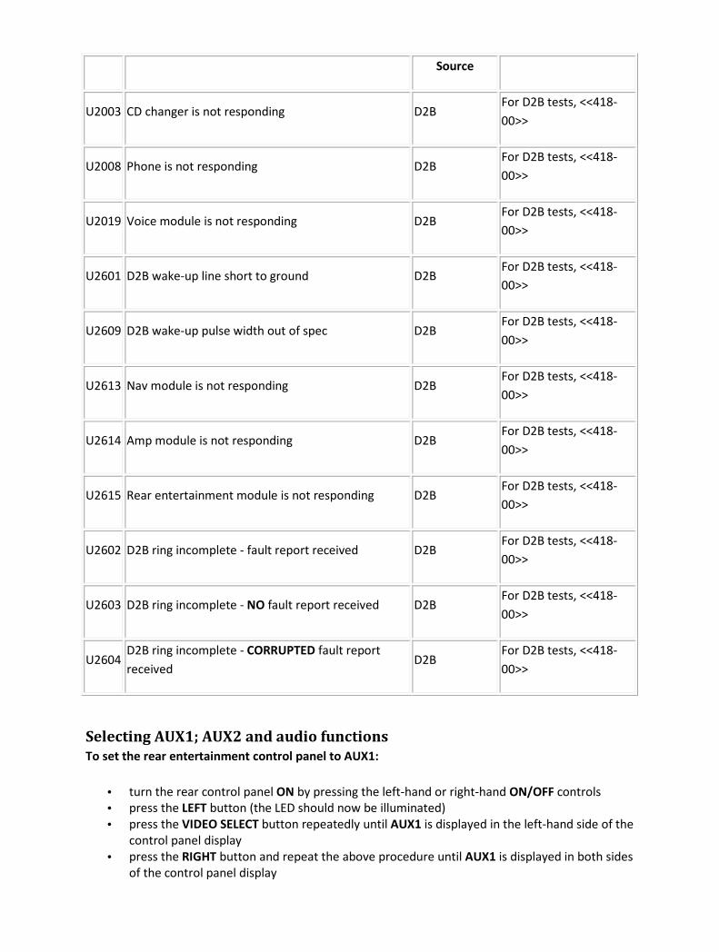
Source
U2003 CD changer is not responding D2B For D2B tests, <<418-
00>>
U2008 Phone is not responding D2B For D2B tests, <<418-
00>>
U2019 Voice module is not responding D2B For D2B tests, <<418-
00>>
U2601 D2B wake-up line short to ground D2B For D2B tests, <<418-
00>>
U2609 D2B wake-up pulse width out of spec D2B For D2B tests, <<418-
00>>
U2613 Nav module is not responding D2B For D2B tests, <<418-
00>>
U2614 Amp module is not responding D2B For D2B tests, <<418-
00>>
U2615 Rear entertainment module is not responding D2B For D2B tests, <<418-
00>>
U2602 D2B ring incomplete - fault report received D2B For D2B tests, <<418-
00>>
U2603 D2B ring incomplete - NO fault report received D2B For D2B tests, <<418-
00>>
U2604 D2B ring incomplete - CORRUPTED fault report
received D2B
For D2B tests, <<418-
00>>
Selecting AUX1; AUX2 and audio functions
To set the rear entertainment control panel to AUX1:
• turn the rear control panel ON by pressing the left-hand or right-hand ON/OFF controls
• press the LEFT button (the LED should now be illuminated)
• press the VIDEO SELECT button repeatedly until AUX1 is displayed in the left-hand side of the
control panel display
• press the RIGHT button and repeat the above procedure until AUX1 is displayed in both sides
of the control panel display

To set the rear entertainment control panel to AUX2:
• repeat the procedure above, until AUX2 is displayed in both sides of the control panel display
To set the cabin speakers to the AUX1 setting
• turn the rear control panel ON by pressing the left-hand and right-hand ON/OFF controls
• press the button between the LEFT and RIGHT buttons, marked with a speaker icon (the
current setting will be displayed in the middle of the control panel display)
• press the AUDIO SOURCE button repeatedly until AUX1 is displayed
To set the cabin speakers to the AUX2 setting
• repeat the procedure above, until AUX2 is displayed
Selecting AUTO/PAL/NTSC
To set the display screen module to the selected mode:
• turn the selected display screen on, so that the background is illuminated
• press and hold the MENU button until two choices are displayed, brightness and color
• press the MENU button twice to display the next screen. This will show four choices, dimmer
mode, dimmer level, display mode, and NTSC/PAL
• press the MENU button to select NTSC/PAL. This will show three setting choices
• press the + or - button to select the desired setting (testing requires the screens to be set to
AUTO)
Oscilloscope set-up procedure
The following set-up instructions refer to the Jaguar approved diagnostic system, but uses
terminology which can be adapted to suit other makes of oscilloscope.
Channel (first icon)
Select SENSE (listed under channel 1) in the left-hand side of the screen.
Select RED PROBE (C-248) in the right-hand side of the screen.
Select the second icon at the bottom of the screen.
Trigger (second icon)
Select TRIGGER EDGE in the left-hand side of the screen.
Select FALLING on the right-hand side of the screen.
Select the third icon at the bottom of the screen.
Signal (third icon)
Select CHANNEL 1 in the left-hand side of the screen.
Select FREQUENCY in the right-hand side of the screen.
Select the fourth icon at the bottom of the screen.
Display (fourth icon)
Select the Y axis.
From the list of frequencies, select 500 mV/div. This range should be available in most oscilloscopes.
Select the X axis.
From the list of frequencies, select 50 us/div. This range should be available in most oscilloscopes.
Start
Depending on the type of oscilloscope being used, this may vary, but will usually be the triangular
button.
With the oscilloscope capturing data, observe the waveforms. Examples of expected waveforms can
be seen in "Waveforms" in this section.
Waveforms
The waveform below will be displayed when a test signal is being transmitted.

Connector access
Connector
number Function Location
VL01 Screen connector At left-hand screen,
Video Display
VR01 Screen connector At right-hand screen,
Video Display
VL02 Intermediate connector In the front seat back, <<501-10>>
VR02 Intermediate connector In the front seat back, <<501-10>>
TL91 Intermediate connector Beneath the right-hand front seat (move the seat fully
forward and to the fully raised position).
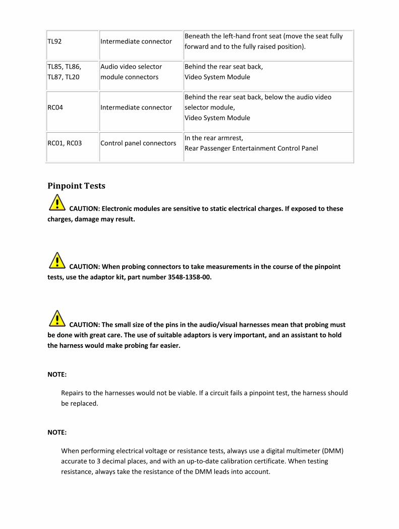
TL92 Intermediate connector Beneath the left-hand front seat (move the seat fully
forward and to the fully raised position).
TL85, TL86,
TL87, TL20
Audio video selector
module connectors
Behind the rear seat back,
Video System Module
RC04 Intermediate connector
Behind the rear seat back, below the audio video
selector module,
Video System Module
RC01, RC03 Control panel connectors In the rear armrest,
Rear Passenger Entertainment Control Panel
Pinpoint Tests
CAUTION: Electronic modules are sensitive to static electrical charges. If exposed to these
charges, damage may result.
CAUTION: When probing connectors to take measurements in the course of the pinpoint
tests, use the adaptor kit, part number 3548-1358-00.
CAUTION: The small size of the pins in the audio/visual harnesses mean that probing must
be done with great care. The use of suitable adaptors is very important, and an assistant to hold
the harness would make probing far easier.
NOTE:
Repairs to the harnesses would not be viable. If a circuit fails a pinpoint test, the harness should
be replaced.
NOTE:
When performing electrical voltage or resistance tests, always use a digital multimeter (DMM)
accurate to 3 decimal places, and with an up-to-date calibration certificate. When testing
resistance, always take the resistance of the DMM leads into account.

NOTE:
Check and rectify basic faults before beginning diagnostic routines involving pinpoint tests.
PINPOINT TEST G240121p1 : CHECK THE NTSC SIGNAL AT THE REAR SCREENS G240121t1 : CHECK THE SCREENS AND CIRCUITS USING THE VIDEO/AUDIO
TESTER (NTSC)
1. Turn the ignition switch to the ACC position. 2. Set the rear entertainment control panel to AUX1
for both screens (refer to Selecting AUX1; AUX2 and audio functions in this section). 3. Set the rear
screens to AUTO (refer to Selecting AUTO/PAL/NTSC in this section). 4. Connect the video/audio
tester to AUX1, video (yellow). 5. Select NTSC on the video/audio tester, make sure the blue LED is
illuminated.
• Is the NTSC test image displayed on both screens?
-> Yes
For PAL signal tests, GO to Pinpoint Test G240121p4.
.
-> No
If the test image is displayed on the left-hand screen only, GO to Pinpoint Test G240121p2.
.
If the test image is displayed on the right-hand screen only, GO to Pinpoint Test G240121p3.
.
If the test image is displayed on neither screen, GO to Pinpoint Test G240121p4.
.
PINPOINT TEST G240121p2 : CHECK THE PAL SIGNAL AT THE THE RIGHT-HAND SCREEN
G240121t2 : CHECK THE PAL SIGNAL AT THE RIGHT-HAND SCREEN
1. Turn the ignition switch to the ACC position. 2. Set the rear entertainment control panel to AUX1
for both screens (refer to Selecting AUX1; AUX2 and Audio functions in this section). 3. Set the rear
screens to AUTO (refer to Selecting AUTO/PAL/NTSC in this section). 4. Connect the video/audio
tester to AUX1, video (yellow). 5. Select PAL on the video/audio tester, make sure the blue LED is
illuminated. 6. Observe the rear screen image.
• Is the PAL test image displayed on the right-hand screen?
-> Yes
INSTALL a new right-hand screen,
Rear Passenger Entertainment Control Panel (The screen cannot decode a NTSC signal).
-> No
GO to Pinpoint Test G240121t3.
G240121t3 : CHECK THE SIGNAL TO THE RIGHT-HAND REAR SCREEN
INTERMEDIATE CONNECTOR TL91
1. Reposition the right-hand front seat fully forward and to the fully raised position. 2. Turn the
ignition switch to the OFF position. 3. Make sure the video/audio tester is switched OFF. 4.
Disconnect the intermediate connector, TL91. 5. Connect the oscilloscope. Refer to Oscilloscope set-
up procedure in this section. 6. Turn the video/audio tester ON, and to the TEST position by holding
in the TEST button while selecting PAL or NTSC. The blue and red LEDs will illuminate. 7. Turn the
ignition switch to the ON position. 8. Using suitable adaptors, and an assistant if necessary, connect
the red oscilloscope probe to TL91, pin 15 (RW). 9. Using suitable adaptors, and an assistant if
necessary, connect the black oscilloscope probe to TL91, pin 09 (B).
• Is the waveform similar to the example in Waveforms in this section?
-> Yes
GO to Pinpoint Test G240121t5.
-> No
GO to Pinpoint Test G240121t4.
G240121t4 : CHECK THE CIRCUIT FROM THE AUDIO VIDEO SELECTOR
MODULE TO THE INTERMEDIATE CONNECTOR TL91 FOR CONTINUITY
1. Turn the ignition switch to the OFF position. 2. Make sure the video/audio tester is switched OFF.
3. Disconnect the audio video module electrical connector, TL87. 4. Using suitable adaptors, measure
the resistance between TL91, pin 15 (RW) and TL87, pin 15 (RW). 5. Using suitable adaptors, measure
the resistance between TL91, pin 09 (B) and TL87, pin 09 (B).

• Is either resistance greater than 5 ohms?
-> Yes
INSTALL a new harness. For additional information, refer to the wiring diagrams.
-> No
For signal output from the control panel tests, GO to Pinpoint Test G240121p6.
.
G240121t5 : CHECK THE SIGNAL TO THE RIGHT-HAND REAR SCREEN
CONNECTOR VR01
1. Turn the ignition switch to the OFF position. 2. Make sure the video/audio tester is switched OFF.
3. Reconnect the intermediate connector, TL91. 4. Reconnect the audio video module electrical
connector, TL87. 5. Disconnect the screen connector, VR01. 6. Turn the video/audio tester ON, and
to the TEST position by holding in the TEST button while selecting PAL or NTSC. The blue and red
LEDs will illuminate. 7. Turn the ignition switch to the ON position. 8. Using suitable adaptors, and an
assistant if necessary, connect the red oscilloscope probe to VR01, pin 15 (RW). 9. Using suitable
adaptors, and an assistant if necessary, connect the black oscilloscope probe to VR01, pin 09 (B).
• Is the waveform similar to the example in Waveforms in this section?
-> Yes
INSTALL a new rear screen,
Video Display
-> No
GO to Pinpoint Test G240121t6.
G240121t6 : CHECK THE SIGNAL TO THE RIGHT-HAND REAR SCREEN
INTERMEDIATE CONNECTOR VR02
1. Turn the ignition switch to the OFF position. 2. Make sure the video/audio tester is switched OFF.
3. Remove the seat back and disconnect the rear screen intermediate connector, VR02. 4. Turn the
video/audio tester ON, and to the TEST position by holding in the TEST button while selecting PAL or
NTSC. The blue and red LEDs will illuminate. 5. Turn the ignition switch to the ON position. 6. Using
suitable adaptors, and an assistant if necessary, connect the red oscilloscope probe to VR02, pin 15
(RW). 7. Using suitable adaptors, and an assistant if necessary, connect the black oscilloscope probe
to VR02, pin 09 (B).
• Is the waveform similar to the example in Waveforms in this section?
-> Yes
INSTALL a new harness between VR02 and VR01. Test the system for normal operation.
-> No

GO to Pinpoint Test G240121t7.
G240121t7 : CHECK THE CIRCUIT BETWEEN INTERMEDIATE CONNECTORS,
VR02 AND TL91 FOR CONTINUITY
1. Turn the ignition switch to the OFF position. 2. Make sure the video/audio tester is switched OFF.
3. Disconnect the intermediate connector, TL91. 4. Using suitable adaptors, measure the resistance
between TL91, pin 15 (RW) and VR02, pin 15 (RW). 5. Using suitable adaptors, measure the
resistance between TL91, pin 09 (B) and VR02, pin 09 (09).
• Is either resistance greater than 5 ohms?
-> Yes
INSTALL a new harness between VR02 and TL91. Test the system for normal operation.
-> No
The harness from the audio/video selector module checks out, GO to Pinpoint Test G240121p5.
and GO to Pinpoint Test G240121p7.
.
PINPOINT TEST G240121p3 : CHECK THE PAL SIGNAL AT THE THE LEFT-HAND SCREEN G240121t8 : CHECK THE PAL SIGNAL AT THE LEFT-HAND SCREEN
1. Turn the ignition switch to the ACC position. 2. Set the rear entertainment control panel to AUX1
for both screens (refer to Selecting AUX1; AUX2 and Audio functions in this section). 3. Set the rear
screens to AUTO (refer to Selecting AUTO/PAL/NTSC in this section). 4. Connect the video/audio
tester to AUX1, video (yellow). 5. Select PAL on the video/audio tester, make sure the blue LED is
illuminated. 6. Observe the rear screen image.
• Is the PAL test image displayed on the left-hand screen?
-> Yes
INSTALL a new left-hand screen,
Rear Passenger Entertainment Control Panel (The screen cannot decode a NTSC signal).
-> No
GO to Pinpoint Test G240121t9.

G240121t9 : CHECK THE SIGNAL TO THE LEFT-HAND REAR SCREEN
INTERMEDIATE CONNECTOR TL91
1. Reposition the left-hand front seat fully forward and to the fully raised position. 2. Turn the
ignition switch to the OFF position. 3. Make sure the video/audio tester is switched OFF. 4.
Disconnect the intermediate connector, TL92. 5. Connect the oscilloscope. Refer to Oscilloscope set-
up procedure in this section. 6. Turn the video/audio tester ON, and to the TEST position by holding
in the TEST button while selecting PAL or NTSC. The blue and red LEDs will illuminate. 7. Turn the
ignition switch to the ON position. 8. Using suitable adaptors, and an assistant if necessary, connect
the red oscilloscope probe to TL92, pin 15 (RW). 9. Using suitable adaptors, and an assistant if
necessary, connect the black oscilloscope probe to TL92, pin 09 (B).
• Is the waveform similar to the example in Waveforms in this section?
-> Yes
GO to Pinpoint Test G240121t11.
-> No
GO to Pinpoint Test G240121t10.
G240121t10 : CHECK THE CIRCUIT FROM THE AUDIO VIDEO SELECTOR
MODULE FOR CONTINUITY
1. Turn the ignition switch to the OFF position. 2. Make sure the video/audio tester is switched OFF.
3. Disconnect the audio video module electrical connector, TL85. 4. Using suitable adaptors, measure
the resistance between TL92, pin 15 (RW) and TL85, pin 15 (RW). 5. Using suitable adaptors, measure
the resistance between TL92, pin 09 (B) and TL85, pin 09 (B).
• Is either resistance greater than 5 ohms?
-> Yes
INSTALL a new harness. For additional information, refer to the wiring diagrams.
-> No
For signal output from the control panel tests, GO to Pinpoint Test G240121p6.
.
G240121t11 : CHECK THE SIGNAL TO THE LEFT-HAND REAR SCREEN
CONNECTOR VL01
1. Turn the ignition switch to the OFF position. 2. Make sure the video/audio tester is switched OFF.
3. Reconnect the intermediate connector, TL92. 4. Reconnect the audio video module electrical
connector, TL85. 5. Disconnect the screen connector, VL01. 6. Turn the video/audio tester ON, and to
the TEST position by holding in the TEST button while selecting PAL or NTSC. The blue and red LEDs
will illuminate. 7. Turn the ignition switch to the ON position. 8. Using suitable adaptors, and an

assistant if necessary, connect the red oscilloscope probe to VL01, pin 15 (RW). 9. Using suitable
adaptors, and an assistant if necessary, connect the black oscilloscope probe to VL01, pin 09 (B).
• Is the waveform similar to the example in Waveforms in this section?
-> Yes
INSTALL a new rear screen,
Video Display
-> No
GO to Pinpoint Test G240121t12.
G240121t12 : CHECK THE SIGNAL TO THE LEFT-HAND REAR SCREEN
INTERMEDIATE CONNECTOR VR02
1. Turn the ignition switch to the OFF position. 2. Make sure the video/audio tester is switched OFF.
3. Remove the seat back and disconnect the rear screen intermediate connector, VR02. 4. Turn the
video/audio tester ON, and to the TEST position by holding in the TEST button while selecting PAL or
NTSC. The blue and red LEDs will illuminate. 5. Turn the ignition switch to the ON position. 6. Using
suitable adaptors, and an assistant if necessary, connect the red oscilloscope probe to VL02, pin 15
(RW). 7. Using suitable adaptors, and an assistant if necessary, connect the black oscilloscope probe
to VL02, pin 09 (B).
• Is the waveform similar to the example in Waveforms in this section?
-> Yes
INSTALL a new harness between VL02 and VL01. Test the system for normal operation.
-> No
GO to Pinpoint Test G240121t13.
G240121t13 : CHECK THE CIRCUIT BETWEEN INTERMEDIATE
CONNECTORS, VL02 AND TL92 FOR CONTINUITY
1. Turn the ignition switch to the OFF position. 2. Make sure the video/audio tester is switched OFF.
3. Disconnect the intermediate connector, TL92. 4. Using suitable adaptors, measure the resistance
between TL92, pin 15 (RW) and VL02, pin 15 (RW). 5. Using suitable adaptors, measure the resistance
between TL92, pin 09 (B) and VL02, pin 09 (09).
• Is the resistance greater than 5 ohms?
-> Yes
INSTALL a new harness between VL02 and TL92. Test the system for normal operation.
-> No
The harness from the audio/video selector module checks out, GO to Pinpoint Test G240121p5.

and GO to Pinpoint Test G240121p6.
.
PINPOINT TEST G240121p4 : CHECK THE PAL SIGNAL AT BOTH REAR SCREENS G240121t14 : CHECK THE SCREENS AND CIRCUITS USING THE
VIDEO/AUDIO TESTER (PAL)
1. Turn the ignition switch to the ACC position. 2. Set the rear entertainment control panel to AUX1
for both screens (refer to Selecting AUX1; AUX2 and audio functions in this section). 3. Set the rear
screens to AUTO. (Refer to Selecting AUTO/PAL/NTSC in this section). 4. Connect the video/audio
tester to AUX1, video (yellow). 5. Select PAL on the video/audio tester, make sure the blue LED is
illuminated. 6. Observe the rear screen images.
• Is the PAL test image displayed on both screens?
-> Yes
The signal from the AUX1 system has passed.
-> No
If the test image is only on the left-hand screen, INSTALL a new right-hand screen,
Rear Passenger Entertainment Control Panel (The screen cannot decode a NTSC signal).
If the test image is only on the right-hand screen, INSTALL a new left-hand screen,
Rear Passenger Entertainment Control Panel (The screen cannot decode a NTSC signal).
If the test image is on neither screen, INSTALL two new screens,
Rear Passenger Entertainment Control Panel (The screens cannot decode a NTSC signal).
PINPOINT TEST G240121p5 : CHECK THE SIGNAL/CIRCUIT THROUGH THE REAR ENTERTAINMENT CONTROL PANEL G240121t15 : CHECK THE SIGNAL THROUGH THE CONTROL PANEL
1. Turn the ignition switch to the OFF position. 2. Make sure the video/audio tester is switched OFF.
3. Disconnect the control panel electrical connector, RC03. 4. Turn the video/audio tester ON, and to
the TEST position by holding in the TEST button while selecting PAL or NTSC. The blue and red LEDs
will illuminate. 5. Connect the oscilloscope. Refer to Oscilloscope set-up procedure in this section. 6.

Turn the ignition switch to the ON position. 7. Using suitable adaptors, and an assistant if necessary,
connect the red oscilloscope probe to RC03, pin 18 (probing INTO the control panel). 8. Using
suitable adaptors, and an assistant if necessary, connect the red oscilloscope probe to RC03, pin 20
(probing INTO the control panel).
• Is the waveform similar to the example in Waveforms in this section?
-> Yes
GO to Pinpoint Test G240121t16.
-> No
For further control panel tests, GO to Pinpoint Test G240121p5.
, GO to Pinpoint Test G240121p6.
and GO to Pinpoint Test G240121p7.
.
G240121t16 : CHECK THE SIGNAL THROUGH THE REAR ENTERTAINMENT
CONTROL PANEL TO INTERMEDIATE CONNECTOR, RC04
1. Turn the ignition switch to the OFF position. 2. Make sure the video/audio tester is switched OFF.
3. Reconnect the control panel electrical connector, RC03. 4. Disconnect intermediate connector,
RC04. 5. Turn the video/audio tester ON, and to the TEST position by holding in the TEST button
while selecting PAL or NTSC. The blue and red LEDs will illuminate. 6. Connect the oscilloscope. Refer
to Oscilloscope set-up procedure in this section. 7. Turn the ignition switch to the ON position. 8.
Using suitable adaptors, and an assistant if necessary, connect the red oscilloscope probe to RC04,
pin 18 (YB). 9. Using suitable adaptors, and an assistant if necessary, connect the red oscilloscope
probe to RC04, pin 20 (B).
• Is the waveform similar to the example in Waveforms in this section?
-> Yes
GO to Pinpoint Test G240121t18.
-> No
GO to Pinpoint Test G240121t17.
G240121t17 : CHECK THE HARNESS BETWEEN RC03 AND RC04 FOR
CONTINUITY
1. Turn the ignition switch to the OFF position. 2. Make sure the video/audio tester is switched OFF.
3. Disconnect the control panel electrical connector, RC03. 4. Measure the resistance between RC03,
pin 18 (YB) and RC04, pin 18 (YB). 5. Measure the resistance between RC03, pin 20 (B) and RC04, pin
20 (B).
• Is either resistance greater than 5 ohms?
-> Yes
INSTALL a new harness between RC03 and RC04. TEST the system for normal operation.
-> No
RECHECK all connections and harnesses, as no fault has been confirmed. TEST the system for normal
operation.
G240121t18 : CHECK THE HARNESS BETWEEN TL86 AND RC04 FOR
CONTINUITY
1. Turn the ignition switch to the OFF position. 2. Make sure the video/audio tester is switched OFF.
3. Disconnect the audio video selector electrical connector, TL86. 4. Measure the resistance between
RC04, pin 18 (YB) and TL86, pin 18 (YB). 5. Measure the resistance between RC04, pin 20 (B) and
TL86, pin 20 (B).
• Is either resistance greater than 5 ohms?
-> Yes
INSTALL a new harness between TL86 and RC04. TEST the system for normal operation.
-> No
GO to Pinpoint Test G240121t19.
G240121t19 : CHECK THE AC ON/OFF CONTROL TO THE AUDIO VIDEO
SELECTOR MODULE AT CONNECTOR TL86
1. Make sure the ignition switch is in the OFF position. 2. Reconnect the control panel electrical
connector, RC04. 3. Measure the resistance between TL86, pin 06 (RG) and GROUND.
• Is the resistance greater than 5 ohms?
-> Yes
GO to Pinpoint Test G240121t20.
-> No
GO to Pinpoint Test G240121t25.
G240121t20 : CHECK THE AC ON/OFF CONTROL TO THE AUDIO VIDEO
SELECTOR MODULE AT CONNECTOR RC04
1. Make sure the ignition switch is in the OFF position. 2. Disconnect the intermediate connector,
RC04. 3. Measure the resistance between RC04, pin 06 (RG) and GROUND.
• Is the resistance greater than 5 ohms?

-> Yes
GO to Pinpoint Test G240121t21.
-> No
INSTALL a new harness between TL86 and RC04. TEST the system for normal operation.
G240121t21 : CHECK THE AC ON/OFF CONTROL TO THE AUDIO VIDEO
SELECTOR MODULE AT THE CONTROL PANEL
1. Make sure the ignition switch is in the OFF position. 2. Disconnect the control panel electrical
connector, RC03. 3. Measure the resistance between RC03, pin 06 (probing into the control panel)
and GROUND.
• Is the resistance greater than 5 ohms?
-> Yes
GO to Pinpoint Test G240121t22.
-> No
INSTALL a new harness between RC03 and RC04. TEST the system for normal operation.
G240121t22 : CHECK THE ACCESSORY POWER SUPPLY TO THE CONTROL
PANEL
1. Make sure the ignition switch is in the OFF position. 2. Disconnect the control panel electrical
connector, RC01. 3. Turn the ignition switch to the ACC position. 4. Measure the voltage between
RC01, pin 07 (YU) and GROUND.
• Is the voltage less than 10 volts?
-> Yes
REPAIR the circuit between RC01, pin 07 and battery. This circuit includes the primary junction box
(fuse 20). For additional information, refer to the wiring diagrams.
-> No
GO to Pinpoint Test G240121t23.
G240121t23 : CHECK THE PERMANENT POWER SUPPLY TO THE CONTROL
PANEL
1. Turn the ignition switch to the OFF position. 2. Measure the voltage between RC01, pin 04 (RW)
and GROUND.
• Is the voltage less than 10 volts?
-> Yes
REPAIR the circuit between RC01, pin 04 and battery. This circuit includes the primary junction box
(fuse 30). For additional information, refer to the wiring diagrams. TEST the system for normal
operation.
-> No
GO to Pinpoint Test G240121t24.
G240121t24 : CHECK THE GROUND TO THE CONTROL PANEL
1. Measure the resistance between RC01, pin 08 (B) and GROUND.
• Is the resistance greater than 5 ohms?
-> Yes
REPAIR the high resistance circuit, for additional information, refer to the wiring diagrams. TEST the
system for normal operation.
-> No
INSTALL a new control panel,
Rear Passenger Entertainment Control Panel TEST the system for normal operation.
G240121t25 : CHECK THE AC ON/OFF CONTROL TO THE AUDIO VIDEO
SELECTOR MODULE AT CONNECTOR TL86, IGNITION ON
1. Turn the ignition switch to the ON position. 2. Measure the voltage between TL86, pin 06 (RG) and
GROUND.
• Is the voltage less than 10 volts?
-> Yes
GO to Pinpoint Test G240121t26.
-> No
For further control panel tests, GO to Pinpoint Test G240121p5.
, GO to Pinpoint Test G240121p6.
and GO to Pinpoint Test G240121p7.
.
G240121t26 : CHECK THE AC ON/OFF CONTROL TO THE AUDIO VIDEO
SELECTOR MODULE FOR SHORT TO GROUND (TL86)
1. Disconnect the control panel electrical connector, RC03. 2. Measure the resistance between TL86,
pin 06 (RG) and GROUND.
• Is the resistance less than 10,000 ohms?

-> Yes
GO to Pinpoint Test G240121t27.
-> No
INSTALL a new control panel,
Rear Passenger Entertainment Control Panel TEST the system for normal operation.
G240121t27 : CHECK THE AC ON/OFF CONTROL TO THE AUDIO VIDEO
SELECTOR MODULE FOR SHORT TO GROUND (RC04)
1. Disconnect the intermediate connector, RC04. 2. Measure the resistance between TL86, pin 06
(RG) and GROUND.
• Is the resistance less than 10,000 ohms?
-> Yes
INSTALL a new harness between TL86 and RC04. TEST the system for normal operation.
-> No
INSTALL a new harness between RC03 and RC04. TEST the system for normal operation.
PINPOINT TEST G240121p6 : CHECK THE REAR ENTERTAINMENT CONTROL PANEL LEFT-HAND OUTPUTS G240121t28 : CHECK THE CONT L1 OUTPUT FROM THE CONTROL PANEL
1. Disconnect the control panel electrical connector, RC03. 2. Turn the video/audio tester ON, and to
the TEST position by holding in the TEST button while selecting PAL or NTSC. The blue and red LEDs
will illuminate. 3. Make sure both screens are selected on the control panel. 4. Turn the ignition
switch to the ON position. 5. Measure the voltage between RC03, pin 15 (probing INTO the control
panel) and GROUND.
• Is the voltage 5 volts?
-> Yes
GO to Pinpoint Test G240121t29.
-> No
INSTALL a new control panel,
Rear Passenger Entertainment Control Panel TEST the system for normal operation.
G240121t29 : CHECK THE CONT L2 OUTPUT FROM THE CONTROL PANEL
1. Measure the voltage between RC03, pin 14 (probing INTO the control panel) and GROUND.
• Is the voltage 0 volts?
-> Yes
GO to Pinpoint Test G240121t30.
-> No
INSTALL a new control panel,
Rear Passenger Entertainment Control Panel TEST the system for normal operation.
G240121t30 : CHECK THE CONT L3 OUTPUT FROM THE CONTROL PANEL
1. Measure the voltage between RC03, pin 19 (probing INTO the control panel) and GROUND.
• Is the voltage 5 volts?
-> Yes
GO to Pinpoint Test G240121t31.
-> No
INSTALL a new control panel,
Rear Passenger Entertainment Control Panel TEST the system for normal operation.
G240121t31 : CHECK THE L1 CIRCUIT FROM RC03 TO TL86 FOR
CONTINUITY
1. Disconnect the audio video selector electrical connector, TL86. 2. Measure the resistance between
RC03, pin 15 (WR) and TL86, pin 15 (WR).
• Is the resistance greater than 5 ohms?
-> Yes
GO to Pinpoint Test G240121t32.
-> No
GO to Pinpoint Test G240121t33.
G240121t32 : CHECK THE L1 CIRCUIT FROM RC03 TO RC04 FOR
CONTINUITY
1. Disconnect intermediate connector, RC04. 2. Measure the resistance between RC03, pin 15 (WR)
and RC04, pin 15 (WR).

• Is the resistance greater than 5 ohms?
-> Yes
INSTALL a new harness between RC03 and RC04. TEST the system for normal operation.
-> No
INSTALL a new harness between RC03 and TL86. TEST the system for normal operation.
G240121t33 : CHECK THE L2 CIRCUIT FROM RC03 TO TL86 FOR
CONTINUITY
1. Reconnect intermediate connector, RC04. 2. Measure the resistance between RC03, pin 14 (B) and
TL86, pin 14 (B).
• Is the resistance greater than 5 ohms?
-> Yes
GO to Pinpoint Test G240121t34.
-> No
GO to Pinpoint Test G240121t35.
G240121t34 : CHECK THE L2 CIRCUIT FROM RC03 TO RC04 FOR
CONTINUITY
1. Disconnect intermediate connector, RC04. 2. Measure the resistance between RC03, pin 14 (B) and
RC04, pin 14 (B).
• Is the resistance greater than 5 ohms?
-> Yes
INSTALL a new harness between RC03 and RC04. TEST the system for normal operation.
-> No
INSTALL a new harness between RC03 and TL86. TEST the system for normal operation.
G240121t35 : CHECK THE L3 CIRCUIT FROM RC03 TO TL86 FOR
CONTINUITY
1. Reconnect intermediate connector, RC04. 2. Measure the resistance between RC03, pin 19 (YG)
and TL86, pin 19 (YG).
• Is the resistance greater than 5 ohms?
-> Yes
GO to Pinpoint Test G240121t36.
-> No
The AUX1 circuit checks out.
G240121t36 : CHECK THE L3 CIRCUIT FROM RC03 TO RC04 FOR
CONTINUITY
1. Disconnect intermediate connector, RC04. 2. Measure the resistance between RC03, pin 19 (YG)
and RC04, pin 19 (YG).
• Is the resistance greater than 5 ohms?
-> Yes
INSTALL a new harness between RC03 and RC04. TEST the system for normal operation.
-> No
INSTALL a new harness between RC03 and TL86. TEST the system for normal operation.
PINPOINT TEST G240121p7 : CHECK THE REAR ENTERTAINMENT CONTROL PANEL RIGHT-HAND OUTPUTS G240121t37 : CHECK THE CONT R1 OUTPUT FROM THE CONTROL PANEL
1. Disconnect the control panel electrical connector, RC03. 2. Turn the video/audio tester ON, and to
the TEST position by holding in the TEST button while selecting PAL or NTSC. The blue and red LEDs
will illuminate. 3. Make sure both screens are selected on the control panel. 4. Turn the ignition
switch to the ON position. 5. Measure the voltage between RC03, pin 11 (probing INTO the control
panel) and GROUND.
• Is the voltage 5 volts?
-> Yes
GO to Pinpoint Test G240121t38.
-> No
INSTALL a new control panel,
Rear Passenger Entertainment Control Panel TEST the system for normal operation.
G240121t38 : CHECK THE CONT R2 OUTPUT FROM THE CONTROL PANEL
1. Measure the voltage between RC03, pin 10 (probing INTO the control panel) and GROUND.
• Is the voltage 0 volts?
-> Yes
GO to Pinpoint Test G240121t39.
-> No
INSTALL a new control panel,
Rear Passenger Entertainment Control Panel TEST the system for normal operation.
G240121t39 : CHECK THE CONT R3 OUTPUT FROM THE CONTROL PANEL
1. Measure the voltage between RC03, pin 09 (probing INTO the control panel) and GROUND.
• Is the voltage 5 volts?
-> Yes
GO to Pinpoint Test G240121t40.
-> No
INSTALL a new control panel,
Rear Passenger Entertainment Control Panel TEST the system for normal operation.
G240121t40 : CHECK THE R1 CIRCUIT FROM RC03 TO TL86 FOR
CONTINUITY
1. Disconnect the audio video selector electrical connector, TL86. 2. Measure the resistance between
RC03, pin 11 (WU) and TL86, pin 11 (WU).
• Is the resistance greater than 5 ohms?
-> Yes
GO to Pinpoint Test G240121t41.
-> No
GO to Pinpoint Test G240121t42.
G240121t41 : CHECK THE R1 CIRCUIT FROM RC03 TO RC04 FOR
CONTINUITY
1. Disconnect intermediate connector, RC04. 2. Measure the resistance between RC03, pin 11 (WU)
and RC04, pin 11 (WU).
• Is the resistance greater than 5 ohms?
-> Yes
INSTALL a new harness between RC03 and RC04. TEST the system for normal operation.
-> No
INSTALL a new harness between RC03 and TL86. TEST the system for normal operation.
G240121t42 : CHECK THE R2 CIRCUIT FROM RC03 TO TL86 FOR
CONTINUITY
1. Reconnect intermediate connector, RC04. 2. Measure the resistance between RC03, pin 10 (B) and
TL86, pin 10 (B).
• Is the resistance greater than 5 ohms?
-> Yes
GO to Pinpoint Test G240121t43.
-> No
GO to Pinpoint Test G240121t44.
G240121t43 : CHECK THE R2 CIRCUIT FROM RC03 TO RC04 FOR
CONTINUITY
1. Disconnect intermediate connector, RC04. 2. Measure the resistance between RC03, pin 10 (B) and
RC04, pin 10 (B).
• Is the resistance greater than 5 ohms?
-> Yes
INSTALL a new harness between RC03 and RC04. TEST the system for normal operation.
-> No
INSTALL a new harness between RC03 and TL86. TEST the system for normal operation.
G240121t44 : CHECK THE R3 CIRCUIT FROM RC03 TO TL86 FOR
CONTINUITY
1. Reconnect intermediate connector, RC04. 2. Measure the resistance between RC03, pin 09 (WB)
and TL86, pin 09 (WB).
• Is the resistance greater than 5 ohms?
-> Yes
GO to Pinpoint Test G240121t36.
-> No
The AUX1 circuit checks out.

G240121t45 : CHECK THE R3 CIRCUIT FROM RC03 TO RC04 FOR
CONTINUITY
1. Disconnect intermediate connector, RC04. 2. Measure the resistance between RC03, pin 09 (WB)
and RC04, pin 09 (WB).
• Is the resistance greater than 5 ohms?
-> Yes
INSTALL a new harness between RC03 and RC04. TEST the system for normal operation.
-> No
INSTALL a new harness between RC03 and TL86. TEST the system for normal operation.
PINPOINT TEST G240121p8 : CHECK THE REAR ENTERTAINMENT AUDIO G240121t46 : CHECK THE CABIN SPEAKER OUTPUT FROM THE REAR
ENTERTAINMENT CONTROL PANEL (RED CONNECTOR)
1. Set the rear entertainment control panel to AUX1, cabin speakers (refer to Selecting AUX1; AUX2
and audio functions in this section). 2. Connect the video/audio tester to the AUX1 audio socket
(RED), and to the corresponding socket on the video/audio tester. 3. Turn the video/audio tester ON,
and to the TEST position by holding in the TEST button while selecting PAL or NTSC. The blue and red
LEDs will illuminate. 4. Turn the ignition switch to the ON position. 5. Adjust the volume on the
control panel to the desired level (eg 12).
• Could a continuous "buzzing" noise be heard from the cabin speakers?
-> Yes
GO to Pinpoint Test G240121t47.
-> No
CHECK for D2B related codes before installing a new control panel.
Rear Passenger Entertainment Control Panel TEST the system for normal operation.
G240121t47 : CHECK THE CABIN SPEAKER OUTPUT FROM THE REAR
ENTERTAINMENT CONTROL PANEL (WHITE CONNECTOR)
1. Turn the ignition switch to the OFF position. 2. Make sure the video/audio tester is switched OFF.
3. Disconnect the test lead from the RED AUX1 socket, and connect it into the WHITE AUX1 socket.
4. Make sure the cabin speakers are still set to the desired level.
• Could a continuous "buzzing" noise be heard from the cabin speakers?
-> Yes
The AUX1 audio test has passed.
-> No
INSTALL a new control panel,
Rear Passenger Entertainment Control Panel TEST the system for normal operation.
PINPOINT TEST G240121p9 : CHECK THE NTSC SIGNAL AT THE REAR SCREENS (AUX2) G240121t48 : CHECK THE SCREENS AND CIRCUITS USING THE
VIDEO/AUDIO TESTER (NTSC)
1. Turn the ignition switch to the ACC position. 2. Set the rear entertainment control panel to AUX2
for both screens (refer to Selecting AUX1; AUX2 and audio functions in this section). 3. Set the rear
screens to AUTO (refer to Selecting AUTO/PAL/NTSC in this section). 4. Connect the video/audio
tester to AUX2, video (yellow). 5. Select NTSC on the video/audio tester, make sure the blue LED is
illuminated.
• Is the NTSC test image displayed on both screens?
-> Yes
The AUX2 signal test has passed.
-> No
If the test image is displayed on the left-hand screen only, GO to Pinpoint Test G240121p2.
.
If the test image is displayed on the right-hand screen only, GO to Pinpoint Test G240121p3.
.
If the test image is displayed on neither screen, GO to Pinpoint Test G240121t49.
.
G240121t49 : CHECK THE SCREENS AND CIRCUITS USING THE
VIDEO/AUDIO TESTER (PAL)
1. Select PAL on the video/audio tester, make sure the blue LED is illuminated.
• Is the PAL test image displayed on both screens?
-> Yes
Neither screen can decode a NTSC signal. INSTALL two new screens,
Video Display
-> No
If the test image is displayed on the left-hand screen only, install a new left-hand screen, as it cannot
decode a NTSC signal,
Video Display TEST the system for normal operation.
If the test image is displayed on the right-hand screen only, install a new right-hand screen, as it
cannot decode a NTSC signal,
Video Display TEST the system for normal operation.
If the test image is displayed on neither screen, GO to Pinpoint Test G240121t50.
.
G240121t50 : CHECK THE TEST SIGNAL OUTPUT FROM THE CONTROL
PANEL
1. Turn the ignition switch to the OFF position. 2. Make sure the video/audio tester is switched OFF.
3. Disconnect the control panel electrical connector, RC03. 4. Turn the ignition switch to the ACC
position. 5. Set the rear entertainment control panel to AUX2 for both screens (refer to Selecting
AUX1; AUX2 and audio functions in this section). 6. Connect the oscilloscope. Refer to Oscilloscope
set-up procedure in this section. 7. Using suitable adaptors, and an assistant if necessary, connect
the red oscilloscope probe to RC03, pin 16 (probing INTO the control panel). 8. Using suitable
adaptors, and an assistant if necessary, connect the black oscilloscope probe to RC03, pin 17 (probing
INTO the control panel). 9. Turn the video/audio tester ON, and to the TEST position by holding in
the TEST button while selecting PAL or NTSC. The blue and red LEDs will illuminate.
• Is the waveform similar to the example in Waveforms in this section?
-> Yes
GO to Pinpoint Test G240121t51.
-> No
For further control panel tests, GO to Pinpoint Test G240121p5.
, GO to Pinpoint Test G240121p6.
, and GO to Pinpoint Test G240121p7.
.
G240121t51 : CHECK THE TEST SIGNAL AT INTERMEDIATE CONNECTOR,
RC04
1. Turn the ignition switch to the OFF position. 2. Make sure the video/audio tester is switched OFF.
3. Reconnect the control panel electrical connector, RC03. 4. Disconnect intermediate connector,
RC04. 5. Turn the ignition switch to the ACC position. 6. Connect the oscilloscope. Refer to
Oscilloscope set-up procedure in this section. 7. Using suitable adaptors, and an assistant if
necessary, connect the red oscilloscope probe to RC04, pin 16 (Y). 8. Using suitable adaptors, and an
assistant if necessary, connect the black oscilloscope probe to RC04, pin 17 (B). 9. Turn the

video/audio tester ON, and to the TEST position by holding in the TEST button while selecting PAL or
NTSC. The blue and red LEDs will illuminate.
• Is the waveform similar to the example in Waveforms in this section?
-> Yes
GO to Pinpoint Test G240121t53.
-> No
GO to Pinpoint Test G240121t52.
G240121t52 : CHECK THE CIRCUIT BETWEEN RC03 AND RC04 FOR
CONTINUITY
1. Turn the ignition switch to the OFF position. 2. Make sure the video/audio tester is switched OFF.
3. Measure the resistance between RC03, pin 16 (Y) and RC04, pin 16 (Y). 4. Measure the resistance
between RC03, pin 17 (B) and RC04, pin 17 (B).
• Is either resistance greater than 5 ohms?
-> Yes
INSTALL a new harness between RC03 and RC04, TEST the system for normal operation.
-> No
RECHECK all connections and harness, as no fault has been confirmed.
G240121t53 : CHECK THE CIRCUIT BETWEEN RC04 AND TL86 FOR
CONTINUITY
1. Disconnect the audio/video selector module electrical connector, TL86. 2. Measure the resistance
between TL86, pin 16 (Y) and RC04, pin 16 (Y). 3. Measure the resistance between TL86, pin 17 (B)
and RC04, pin 17 (B).
• Is either resistance greater than 5 ohms?
-> Yes
INSTALL a new harness between TL86 and RC04, TEST the system for normal operation.
-> No
GO to Pinpoint Test G240121t54.
G240121t54 : CHECK THE AC ON/OFF CONTROL TO THE AUDIO VIDEO
SELECTOR MODULE AT CONNECTOR TL86
1. Make sure the ignition switch is in the OFF position. 2. Reconnect intermediate connector, RC04. 3.
Measure the resistance between TL86, pin 06 (RG) and GROUND.

• Is the resistance greater than 5 ohms?
-> Yes
GO to Pinpoint Test G240121t56.
-> No
GO to Pinpoint Test G240121t55.
G240121t55 : CHECK THE AC ON/OFF CONTROL TO THE AUDIO VIDEO
SELECTOR MODULE AT CONNECTOR TL86 IGNITION ON
1. Turn the ignition switch to the ON position. 2. Measure the voltage between TL86, pin 06 (RG) and
GROUND.
• Is the voltage battery voltage?
-> Yes
For further control panel tests, GO to Pinpoint Test G240121p5.
, GO to Pinpoint Test G240121p6.
and GO to Pinpoint Test G240121p7.
.
-> No
GO to Pinpoint Test G240121t58.
G240121t56 : CHECK THE AC ON/OFF CONTROL TO THE AUDIO VIDEO
SELECTOR MODULE AT CONNECTOR RC04
1. Make sure the ignition switch is in the OFF position. 2. Disconnect intermediate connector, RC04.
3. Measure the resistance between RC04, pin 06 (RG) and GROUND.
• Is the resistance greater than 5 ohms?
-> Yes
GO to Pinpoint Test G240121t57.
-> No
INSTALL a new harness between TL86 and RC04. TEST the system for normal operation.
G240121t57 : CHECK THE AC ON/OFF CONTROL TO THE AUDIO VIDEO
SELECTOR MODULE AT CONNECTOR RC03
1. Make sure the ignition switch is in the OFF position. 2. Disconnect the control panel electrical
connector, RC03. 3. Measure the resistance between RC03, pin 06 (probing INTO the control panel)
and GROUND.

• Is the resistance greater than 5 ohms?
-> Yes
For further control panel tests, GO to Pinpoint Test G240121p5.
, GO to Pinpoint Test G240121p6.
and GO to Pinpoint Test G240121p7.
.
-> No
INSTALL a new harness between RC03 and RC04. TEST the system for normal operation.
G240121t58 : CHECK THE AC ON/OFF CONTROL TO THE AUDIO VIDEO
SELECTOR MODULE FOR SHORT TO GROUND AT CONNECTOR TL86
1. Make sure the ignition switch is in the OFF position. 2. Disconnect the control panel electrical
connector, RC03. 3. Measure the resistance between TL86, pin 06 (RG) and GROUND.
• Is the resistance less than 10,000 ohms?
-> Yes
INSTALL a new harness between TL86 and RC04. TEST the system for normal operation.
-> No
GO to Pinpoint Test G240121t59.
G240121t59 : CHECK THE AC ON/OFF CONTROL TO THE AUDIO VIDEO
SELECTOR MODULE FOR SHORT TO GROUND AT CONNECTOR RC03
1. Measure the resistance between RC03, pin 06 (RG) and GROUND.
• Is the resistance less than 10,000 ohms?
-> Yes
INSTALL a new harness between RC03 and RC04. TEST the system for normal operation.
-> No
INSTALL a new control panel,
Rear Passenger Entertainment Control Panel TEST the system for normal operation.
PINPOINT TEST G240121p10 : CHECK THE REAR ENTERTAINMENT AUDIO (AUX2)

G240121t60 : CHECK THE CABIN SPEAKER OUTPUT FROM THE REAR
ENTERTAINMENT CONTROL PANEL (RED CONNECTOR)
1. Set the rear entertainment control panel to AUX2, cabin speakers (refer to Selecting AUX1; AUX2
and audio functions in this section). 2. Connect the video/audio tester to the AUX2 audio socket
(RED), and to the corresponding socket on the video/audio tester. 3. Turn the video/audio tester ON,
and to the TEST position by holding in the TEST button while selecting PAL or NTSC. The blue and red
LEDs will illuminate. 4. Turn the ignition switch to the ON position. 5. Adjust the volume on the
control panel to the desired level (eg 12).
• Could a continuous "buzzing" noise be heard from the cabin speakers?
-> Yes
GO to Pinpoint Test G240121t61.
-> No
CHECK for D2B related codes before installing a new control panel.
Rear Passenger Entertainment Control Panel TEST the system for normal operation.
G240121t61 : CHECK THE CABIN SPEAKER OUTPUT FROM THE REAR
ENTERTAINMENT CONTROL PANEL (WHITE CONNECTOR)
1. Turn the ignition switch to the OFF position. 2. Make sure the video/audio tester is switched OFF.
3. Disconnect the test lead from the RED AUX2 socket, and connect it into the WHITE AUX2 socket.
4. Make sure the cabin speakers are still set to the desired level.
• Could a continuous "buzzing" noise be heard from the cabin speakers?
-> Yes
The AUX2 audio test has passed.
-> No
INSTALL a new control panel,
Rear Passenger Entertainment Control Panel TEST the system for normal operation.
PINPOINT TEST G240121p11 : CHECK THE POWER AND GROUND SUPPLIES TO THE RIGHT-HAND SCREEN G240121t62 : CHECK FOR BATTERY VOLTAGE AT THE SCREEN CONNECTOR,
VR01
1. Disconnect the right-hand screen electrical connector, VR01. 2. Turn the ignition switch to the ON
position. 3. Measure the voltage between VR01, pin 18 (OY) and GROUND.
• Is the voltage greater than 10 volts?
-> Yes
GO to Pinpoint Test G240121t67.
-> No
GO to Pinpoint Test G240121t63.
G240121t63 : CHECK THE CIRCUIT BETWEEN VR01 AND TL87 FOR
CONTINUITY
1. Disconnect the audio video selector module electrical connector, TL87. 2. Measure the resistance
between VR01, pin 18 (OY) and TL87, pin 18 (OY).
• Is the resistance greater than 5 ohms?
-> Yes
GO to Pinpoint Test G240121t64.
-> No
INSTALL a new audio video selector module,
Video System Module TEST the system for normal operation.
G240121t64 : CHECK THE CIRCUIT BETWEEN VR01 AND VR02 FOR
CONTINUITY
1. Disconnect intermediate connector, VR02. 2. Measure the resistance between VR01, pin 18 (OY)
and VR02, pin 18 (OY).
• Is the resistance greater than 5 ohms?
-> Yes
INSTALL a new harness between VR01 and VR02. TEST the system for normal operation.
-> No
GO to Pinpoint Test G240121t65.
G240121t65 : CHECK THE CIRCUIT BETWEEN VR02 AND TL91 FOR
CONTINUITY
1. Disconnect intermediate connector, TL91. 2. Measure the resistance between VR02, pin 18 (OY)
and TL91, pin 18 (OY).
• Is the resistance greater than 5 ohms?

-> Yes
INSTALL a new harness between VR02 and TL91. TEST the system for normal operation.
-> No
GO to Pinpoint Test G240121t66.
G240121t66 : CHECK THE CIRCUIT BETWEEN TL91 AND TL87 FOR
CONTINUITY
1. Measure the resistance between TL91, pin 18 (OY) and TL87, pin 18 (OY).
• Is the resistance greater than 5 ohms?
-> Yes
INSTALL a new harness between TL91 and TL87. TEST the system for normal operation.
-> No
INSTALL a new audio video selector module,
Video System Module TEST the system for normal operation.
G240121t67 : CHECK FOR VOLTAGE AT VR01, PIN 08
1. Reconnect the audio video selector module electrical connector, TL87. 2. Turn the ignition switch
to the ON position. 3. Measure the voltage between VR01, pin 08 (N) and GROUND.
• Is the voltage -14 to -18 volts?
-> Yes
GO to Pinpoint Test G240121t72.
-> No
GO to Pinpoint Test G240121t68.
G240121t68 : CHECK THE CIRCUIT BETWEEN VR01 AND TL87 FOR
CONTINUITY
1. Turn the igntition switch to the OFF position. 2. Disconnect audio video selector module electrical
connector, TL87. 3. Measure the resistance between VR01, pin 08 (N) and TL87, pin 08 (N).
• Is the resistance greater than 5 ohms?
-> Yes
GO to Pinpoint Test G240121t69.
-> No

INSTALL a new audio video selector module,
Video System Module TEST the system for normal operation.
G240121t69 : CHECK THE CIRCUIT BETWEEN VR01 AND VR02 FOR
CONTINUITY
1. Disconnect intermediate connector, VR02. 2. Measure the resistance between VR01, pin 08 (N)
and VR02, pin 08 (N).
• Is the resistance greater than 5 ohms?
-> Yes
INSTALL a new harness between VR01 and VR02. TEST the system for normal operation.
-> No
GO to Pinpoint Test G240121t70.
G240121t70 : CHECK THE CIRCUIT BETWEEN VR02 AND TL91 FOR
CONTINUITY
1. Disconnect intermediate connector, TL91. 2. Measure the resistance between VR02, pin 08 (N) and
TL91, pin 08 (N).
• Is the resistance greater than 5 ohms?
-> Yes
INSTALL a new harness between VR02 and TL91. TEST the system for normal operation.
-> No
GO to Pinpoint Test G240121t71.
G240121t71 : CHECK THE CIRCUIT BETWEEN TL91 AND TL87 FOR
CONTINUITY
1. Measure the resistance between TL91, pin 08 (N) and TL87, pin 08 (N).
• Is the resistance greater than 5 ohms?
-> Yes
INSTALL a new harness between TL91 and TL87. TEST the system for normal operation.
-> No
INSTALL a new audio video selector module,
Video System Module TEST the system for normal operation.
G240121t72 : CHECK FOR VOLTAGE AT VR01, PIN 06
1. Reconnect audio video selector module electrical connector, TL87. 2. Make sure the ignition switch
is in the ON position. 3. Measure the voltage between VR01, pin 06 (U) and GROUND.
• Is the voltage 6 volts?
-> Yes
GO to Pinpoint Test G240121t77.
-> No
GO to Pinpoint Test G240121t73.
G240121t73 : CHECK THE CIRCUIT BETWEEN VR01 AND TL87 FOR
CONTINUITY
1. Turn the ignition switch to the OFF position. 2. Disconnect audio video selector module electrical
connector, TL87. 3. Measure the resistance between VR01, pin 06 (U) and TL87, pin 06 (U).
• Is the resistance greater than 5 ohms?
-> Yes
GO to Pinpoint Test G240121t74.
-> No
INSTALL a new audio video selector module,
Video System Module TEST the system for normal operation.
G240121t74 : CHECK THE CIRCUIT BETWEEN VR01 AND VR02 FOR
CONTINUITY
1. Disconnect intermediate connector, VR02. 2. Measure the resistance between VR01, pin 06 (U)
and VR02, pin 06 (U).
• Is the resistance greater than 5 ohms?
-> Yes
INSTALL a new harness between VR01 and VR02. TEST the system for normal operation.
-> No
GO to Pinpoint Test G240121t75.

G240121t75 : CHECK THE CIRCUIT BETWEEN VR02 AND TL91 FOR
CONTINUITY
1. Disconnect intermediate connector, TL91. 2. Measure the resistance between VR02, pin 06 (U) and
TL91, pin 06 (U).
• Is the resistance greater than 5 ohms?
-> Yes
INSTALL a new harness between VR02 and TL91. TEST the system for normal operation.
-> No
GO to Pinpoint Test G240121t76.
G240121t76 : CHECK THE CIRCUIT BETWEEN TL91 AND TL87 FOR
CONTINUITY
1. Measure the resistance between TL91, pin 06 (U) and TL87, pin 06 (U).
• Is the resistance greater than 5 ohms?
-> Yes
INSTALL a new harness between TL91 and TL87. TEST the system for normal operation.
-> No
INSTALL a new audio video selector module,
Video System Module TEST the system for normal operation.
G240121t77 : CHECK FOR VOLTAGE AT VR01, PIN 04
1. Reconnect the audio video selector module electrical connector, TL87. 2. Make sure the ignition
switch is in the ON position. 3. Measure the voltage between VR01, pin 04 (BK) and GROUND.
• Is the voltage battery voltage?
-> Yes
GO to Pinpoint Test G240121t82.
-> No
GO to Pinpoint Test G240121t78.
G240121t78 : CHECK THE CIRCUIT BETWEEN VR01 AND TL87 FOR
CONTINUITY
1. Make sure the ignition switch is in the OFF position. 2. Disconnect audio video selector module
electrical connector, TL87. 3. Measure the resistance between VR01, pin 04 (BK) and TL87, pin 04
(BK).

• Is the resistance greater than 5 ohms?
-> Yes
GO to Pinpoint Test G240121t79.
-> No
INSTALL a new audio video selector module,
Video System Module TEST the system for normal operation.
G240121t79 : CHECK THE CIRCUIT BETWEEN VR01 AND VR02 FOR
CONTINUITY
1. Disconnect intermediate connector, VR02. 2. Measure the resistance between VR01, pin 04 (BK)
and VR02, pin 04 (BK).
• Is the resistance greater than 5 ohms?
-> Yes
INSTALL a new harness between VR01 and VR02. TEST the system for normal operation.
-> No
GO to Pinpoint Test G240121t80.
G240121t80 : CHECK THE CIRCUIT BETWEEN VR02 AND TL91 FOR
CONTINUITY
1. Disconnect intermediate connector, TL91. 2. Measure the resistance between VR02, pin 04 (BK)
and TL91, pin 04 (BK).
• Is the resistance greater than 5 ohms?
-> Yes
INSTALL a new harness between VR02 and TL91. TEST the system for normal operation.
-> No
GO to Pinpoint Test G240121t81.
G240121t81 : CHECK THE CIRCUIT BETWEEN TL91 AND TL87 FOR
CONTINUITY
1. Measure the resistance between TL91, pin 04 (BK) and TL87, pin 04 (BK).
• Is the resistance greater than 5 ohms?
-> Yes
INSTALL a new harness between TL91 and TL87. TEST the system for normal operation.
-> No
INSTALL a new audio video selector module,
Video System Module TEST the system for normal operation.
G240121t82 : CHECK FOR VOLTAGE AT VR01, PIN 02
1. Reconnect the audio video selector module electrical connector, TL87. 2. Measure the voltage
between VR01, pin 02 (YB) and GROUND.
• Is the voltage battery voltage?
-> Yes
GO to Pinpoint Test G240121t87.
-> No
GO to Pinpoint Test G240121t83.
G240121t83 : CHECK THE CIRCUIT BETWEEN VR01 AND TL87 FOR
CONTINUITY
1. Disconnect audio video selector module electrical connector, TL87. 2. Measure the resistance
between VR01, pin 02 (YB) and TL87, pin 02 (YB).
• Is the resistance greater than 5 ohms?
-> Yes
GO to Pinpoint Test G240121t84.
-> No
INSTALL a new audio video selector module,
Video System Module TEST the system for normal operation.
G240121t84 : CHECK THE CIRCUIT BETWEEN VR01 AND VR02 FOR
CONTINUITY
1. Disconnect intermediate connector, VR02. 2. Measure the resistance between VR01, pin 02 (YB)
and VR02, pin 02 (YB).
• Is the resistance greater than 5 ohms?
-> Yes
INSTALL a new harness between VR01 and VR02. TEST the system for normal operation.
-> No

GO to Pinpoint Test G240121t85.
G240121t85 : CHECK THE CIRCUIT BETWEEN VR02 AND TL91 FOR
CONTINUITY
1. Disconnect intermediate connector, TL91. 2. Measure the resistance between VR02, pin 02 (YB)
and TL91, pin 02 (YB).
• Is the resistance greater than 5 ohms?
-> Yes
INSTALL a new harness between VR02 and TL91. TEST the system for normal operation.
-> No
GO to Pinpoint Test G240121t86.
G240121t86 : CHECK THE CIRCUIT BETWEEN TL91 AND TL87 FOR
CONTINUITY
1. Measure the resistance between TL91, pin 02 (YB) and TL87, pin 02 (YB).
• Is the resistance greater than 5 ohms?
-> Yes
INSTALL a new harness between TL91 and TL87. TEST the system for normal operation.
-> No
INSTALL a new audio video selector module,
Video System Module TEST the system for normal operation.
G240121t87 : CHECK FOR GROUND AT VR01, PIN 01
1. Reconnect the audio video selector module electrical connector, TL87. 2. Measure the resistance
between VR01, pin 01 (YG) and GROUND.
• Is the resistance greater than 5 ohms?
-> Yes
GO to Pinpoint Test G240121t88.
-> No
GO to Pinpoint Test G240121t92.

G240121t88 : CHECK THE CIRCUIT BETWEEN VR01 AND TL87 FOR
CONTINUITY
1. Disconnect the audio video selector module electrical connector, TL87. 2. Measure the resistance
between VR01, pin 01 (YG) and TL87, pin 01 (YG).
• Is the resistance greater than 5 ohms?
-> Yes
GO to Pinpoint Test G240121t89.
-> No
INSTALL a new audio video selector module,
Video System Module TEST the system for normal operation.
G240121t89 : CHECK THE CIRCUIT BETWEEN VR01 AND VR02 FOR
CONTINUITY
1. Disconnect intermediate connector, VR02. 2. Measure the resistance between VR01, pin 01 (YG)
and VR02, pin 01 (YG).
• Is the resistance greater than 5 ohms?
-> Yes
INSTALL a new harness between VR01 and VR02. TEST the system for normal operation.
-> No
GO to Pinpoint Test G240121t90.
G240121t90 : CHECK THE CIRCUIT BETWEEN VR02 AND TL91 FOR
CONTINUITY
1. Disconnect intermediate connector, TL91. 2. Measure the resistance between VR02, pin 01 (YG)
and TL91, pin 01 (YG).
• Is the resistance greater than 5 ohms?
-> Yes
INSTALL a new harness between VR02 and TL91. TEST the system for normal operation.
-> No
GO to Pinpoint Test G240121t91.
G240121t91 : CHECK THE CIRCUIT BETWEEN TL91 AND TL87 FOR
CONTINUITY
1. Measure the resistance between TL91, pin 01 (YG) and TL87, pin 01 (YG).

• Is the resistance greater than 5 ohms?
-> Yes
INSTALL a new harness between TL91 and TL87. TEST the system for normal operation.
-> No
INSTALL a new audio video selector module,
Video System Module TEST the system for normal operation.
G240121t92 : CHECK FOR IGNITION VOLTAGE AT VR01, PIN 16
1. Turn the ignition switch to the ON position. 2. Measure the voltage between VR01, pin 16 (RG) and
GROUND.
• Is the voltage 5 volts?
-> Yes
INSTALL a new right-hand screen,
Video Display TEST the system for normal operation.
-> No
GO to Pinpoint Test G240121t93.
G240121t93 : CHECK FOR SHORT TO GROUND AT VR01, PIN 16
1. Reconnect the intermediate connectors. 2. Measure the resistance between VR01, pin 16 (RG) and
GROUND.
• Is the resistance less than 10,000 ohms?
-> Yes
GO to Pinpoint Test G240121t94.
-> No
GO to Pinpoint Test G240121t101.
G240121t97 : CHECK THE CIRCUIT BETWEEN VR01 AND TL87 FOR
CONTINUITY
1. Measure the resistance between VR01, pin 16 (RG) and TL87, pin 16 (RG).
• Is the resistance greater than 5 ohms?
-> Yes
GO to Pinpoint Test G240121t98.
-> No
GO to Pinpoint Test G240121t101.
G240121t94 : CHECK FOR SHORT TO GROUND AT VR02, PIN 16
1. Disconnect intermediate connector, VR02. 2. Measure the resistance between VR02, pin 16 (RG)
and GROUND.
• Is the resistance less than 10,000 ohms?
-> Yes
INSTALL a new harness between VR01 and VR02. TEST the system for normal operation.
-> No
GO to Pinpoint Test G240121t95.
G240121t98 : CHECK THE CIRCUIT BETWEEN VR01 AND VR02 FOR
CONTINUITY
1. Measure the resistance between VR01, pin 16 (RG) and VR02, pin 16 (RG).
• Is the resistance greater than 5 ohms?
-> Yes
INSTALL a new harness between VR01 and VR02. TEST the system for normal operation.
-> No
GO to Pinpoint Test G240121t99.
G240121t95 : CHECK FOR SHORT TO GROUND AT TL91, PIN 16
1. Disconnect intermediate connector, TL91. 2. Measure the resistance between TL91, pin 16 (RG)
and GROUND.
• Is the resistance less than 10,000 ohms?
-> Yes
INSTALL a new harness between VR02 and TL91. TEST the system for normal operation.
-> No
GO to Pinpoint Test G240121t96.

G240121t99 : CHECK THE CIRCUIT BETWEEN VR02 AND TL91 FOR
CONTINUITY
1. Measure the resistance between VR02, pin 16 (RG) and TL91, pin 16 (RG).
• Is the resistance greater than 5 ohms?
-> Yes
INSTALL a new harness between VR02 and TL91. TEST the system for normal operation.
-> No
GO to Pinpoint Test G240121t100.
G240121t96 : CHECK FOR SHORT TO GROUND AT TL87, PIN 16
1. Measure the resistance between TL87, pin 16 (RG) and GROUND.
• Is the resistance less than 10,000 ohms?
-> Yes
INSTALL a new harness between TL91 and TL87. TEST the system for normal operation.
-> No
GO to Pinpoint Test G240121t101.
G240121t100 : CHECK THE CIRCUIT BETWEEN TL91 AND TL87 FOR
CONTINUITY
1. Measure the resistance between TL91, pin 16 (RG) and TL87, pin 16 (RG).
• Is the resistance greater than 5 ohms?
-> Yes
INSTALL a new harness between TL91 and TL87. TEST the system for normal operation.
-> No
GO to Pinpoint Test G240121t101.
G240121t101 : CHECK FOR VOLTAGE AT AUDIO VIDEO SELECTOR MODULE
CONNECTOR TL86
1. Disconnect the audio video selector module electrical connector, TL86. 2. Turn the ignition switch
to the ON position. 3. Measure the voltage between TL86, pin 05 (RU) and GROUND.
• Is the voltage 5 volts?

-> Yes
INSTALL a new audio video selector module,
Video System Module TEST the system for normal operation.
-> No
GO to Pinpoint Test G240121t102.
G240121t102 : CHECK FOR SHORT TO GROUND AT CONTROL PANEL
CONNECTOR RC03
1. Disconnect the control panel electrical connector, RC03. 2. Measure the resistance between RC03,
pin 05 (RU) and GROUND.
• Is the resistance less than 10,000 ohms?
-> Yes
GO to Pinpoint Test G240121t104.
-> No
GO to Pinpoint Test G240121t103.
G240121t103 : CHECK THE CIRCUIT BETWEEN RC03 AND TL86 FOR
CONTINUITY
1. Measure the resistance between RC03, pin 05 (RU) and TL86, pin 05 (RU).
• Is the resistance greater than 5 ohms?
-> Yes
GO to Pinpoint Test G240121t105.
-> No
INSTALL a new control panel,
Rear Passenger Entertainment Control Panel TEST the system for normal operation.
G240121t104 : CHECK FOR SHORT TO GROUND AT INTERMEDIATE
CONNECTOR RC04
1. Disconnect intermediate connector, RC04. 2. Measure the resistance between RC04, pin 05 (RU)
working towards the control panel, and GROUND.
• Is the resistance less than 10,000 ohms?
-> Yes
INSTALL a new harness between RC03 and RC04. TEST the system for normal operation.

-> No
GO to Pinpoint Test G240121t105.
G240121t105 : CHECK THE CIRCUIT BETWEEN RC03 AND RC04 FOR
CONTINUITY
1. Measure the resistance between RC03, pin 05 (RU) and RC04, pin 05 (RU).
• Is the resistance greater than 5 ohms?
-> Yes
INSTALL a new harness between RC03 and RC04. TEST the system for normal operation.
-> No
GO to Pinpoint Test G240121t106.
G240121t106 : CHECK FOR SHORT TO GROUND AT AUDIO VIDEO SELECTOR
MODULE CONNECTOR TL86
1. Measure the resistance between TL86, pin 05 (RU) and GROUND.
• Is the resistance less than 10,000 ohms?
-> Yes
INSTALL a new harness between RC04 and TL86. TEST the system for normal operation.
-> No
GO to Pinpoint Test G240121t107.
G240121t107 : CHECK THE CIRCUIT BETWEEN RC04 AND TL86 FOR
CONTINUITY
1. Measure the resistance between RC04, pin 05 (RU) and TL86, pin 05 (RU).
• Is the resistance greater than 5 ohms?
-> Yes
INSTALL a new harness between RC04 and TL86. TEST the system for normal operation.
-> No
INSTALL a new control panel,
Rear Passenger Entertainment Control Panel TEST the system for normal operation.

PINPOINT TEST G240121p12 : CHECK THE POWER AND GROUND SUPPLIES TO THE LEFT-HAND SCREEN G240121t108 : CHECK FOR BATTERY VOLTAGE AT THE SCREEN
CONNECTOR, VL01
1. Disconnect the left-hand screen electrical connector, VL01. 2. Turn the ignition switch to the ON
position. 3. Measure the voltage between VL01, pin 18 (OY) and GROUND.
• Is the voltage greater than 10 volts?
-> Yes
GO to Pinpoint Test G240121t113.
-> No
GO to Pinpoint Test G240121t109.
G240121t109 : CHECK THE CIRCUIT BETWEEN VL01 AND TL85 FOR
CONTINUITY
1. Disconnect the audio video selector module electrical connector, TL85. 2. Measure the resistance
between VL01, pin 18 (OY) and TL85, pin 18 (OY).
• Is the resistance greater than 5 ohms?
-> Yes
GO to Pinpoint Test G240121t110.
-> No
INSTALL a new audio video selector module,
Video System Module TEST the system for normal operation.
G240121t110 : CHECK THE CIRCUIT BETWEEN VL01 AND VL02 FOR
CONTINUITY
1. Disconnect intermediate connector, VL02. 2. Measure the resistance between VL01, pin 18 (OY)
and VL02, pin 18 (OY).
• Is the resistance greater than 5 ohms?
-> Yes
INSTALL a new harness between VL01 and VL02. TEST the system for normal operation.
-> No
GO to Pinpoint Test G240121t111.
G240121t111 : CHECK THE CIRCUIT BETWEEN VL02 AND TL92 FOR
CONTINUITY
1. Disconnect intermediate connector, TL92. 2. Measure the resistance between VL02, pin 18 (OY)
and TL92, pin 18 (OY).
• Is the resistance greater than 5 ohms?
-> Yes
INSTALL a new harness between VL02 and TL92. TEST the system for normal operation.
-> No
GO to Pinpoint Test G240121t112.
G240121t112 : CHECK THE CIRCUIT BETWEEN TL92 AND TL85 FOR
CONTINUITY
1. Measure the resistance between TL92, pin 18 (OY) and TL85, pin 18 (OY).
• Is the resistance greater than 5 ohms?
-> Yes
INSTALL a new harness between TL92 and TL85. TEST the system for normal operation.
-> No
INSTALL a new audio video selector module,
Video System Module TEST the system for normal operation.
G240121t113 : CHECK FOR VOLTAGE AT VL01, PIN 08
1. Reconnect the audio video selector module electrical connector, TL85. 2. Turn the igntition switch
to the ON position. 3. Measure the voltage between VL01, pin 08 (N) and GROUND.
• Is the voltage -14 to -18 volts?
-> Yes
GO to Pinpoint Test G240121t118.
-> No
GO to Pinpoint Test G240121t114.

G240121t114 : CHECK THE CIRCUIT BETWEEN VL01 AND TL85 FOR
CONTINUITY
1. Turn the igntition switch to the OFF position. 2. Disconnect audio video selector module electrical
connector, TL85. 3. Measure the resistance between VL01, pin 08 (N) and TL85, pin 08 (N).
• Is the resistance greater than 5 ohms?
-> Yes
GO to Pinpoint Test G240121t115.
-> No
INSTALL a new audio video selector module,
Video System Module TEST the system for normal operation.
G240121t115 : CHECK THE CIRCUIT BETWEEN VL01 AND VL02 FOR
CONTINUITY
1. Disconnect intermediate connector, VL02. 2. Measure the resistance between VL01, pin 08 (N) and
VL02, pin 08 (N).
• Is the resistance greater than 5 ohms?
-> Yes
INSTALL a new harness between VL01 and VL02. TEST the system for normal operation.
-> No
GO to Pinpoint Test G240121t116.
G240121t116 : CHECK THE CIRCUIT BETWEEN VL02 AND TL92 FOR
CONTINUITY
1. Disconnect intermediate connector, TL92. 2. Measure the resistance between VL02, pin 08 (N) and
TL92, pin 08 (N).
• Is the resistance greater than 5 ohms?
-> Yes
INSTALL a new harness between VL02 and TL92. TEST the system for normal operation.
-> No
GO to Pinpoint Test G240121t117.
G240121t117 : CHECK THE CIRCUIT BETWEEN TL92 AND TL85 FOR
CONTINUITY
1. Measure the resistance between TL92, pin 08 (N) and TL85, pin 08 (N).

• Is the resistance greater than 5 ohms?
-> Yes
INSTALL a new harness between TL92 and TL85. TEST the system for normal operation.
-> No
INSTALL a new audio video selector module,
Video System Module TEST the system for normal operation.
G240121t118 : CHECK FOR VOLTAGE AT VL01, PIN 06
1. Reconnect audio video selector module electrical connector, TL85. 2. Make sure the ignition switch
is in the ON position. 3. Measure the voltage between VL01, pin 06 (B) and GROUND.
• Is the voltage 6 volts?
-> Yes
GO to Pinpoint Test G240121t123.
-> No
GO to Pinpoint Test G240121t119.
G240121t119 : CHECK THE CIRCUIT BETWEEN VL01 AND TL85 FOR
CONTINUITY
1. Turn the ignition switch to the OFF position. 2. Disconnect audio video selector module electrical
connector, TL85. 3. Measure the resistance between VL01, pin 06 (B) and TL85, pin 06 (B).
• Is the resistance greater than 5 ohms?
-> Yes
GO to Pinpoint Test G240121t120.
-> No
INSTALL a new audio video selector module,
Video System Module TEST the system for normal operation.
G240121t120 : CHECK THE CIRCUIT BETWEEN VL01 AND VL02 FOR
CONTINUITY
1. Disconnect intermediate connector, VL02. 2. Measure the resistance between VL01, pin 06 (B) and
VL02, pin 06 (B).
• Is the resistance greater than 5 ohms?

-> Yes
INSTALL a new harness between VL01 and VL02. TEST the system for normal operation.
-> No
GO to Pinpoint Test G240121t121.
G240121t121 : CHECK THE CIRCUIT BETWEEN VL02 AND TL92 FOR
CONTINUITY
1. Disconnect intermediate connector, TL92. 2. Measure the resistance between VL02, pin 06 (B) and
TL92, pin 06 (B).
• Is the resistance greater than 5 ohms?
-> Yes
INSTALL a new harness between VL02 and TL92. TEST the system for normal operation.
-> No
GO to Pinpoint Test G240121t122.
G240121t122 : CHECK THE CIRCUIT BETWEEN TL92 AND TL85 FOR
CONTINUITY
1. Measure the resistance between TL92, pin 06 (B) and TL85, pin 06 (B).
• Is the resistance greater than 5 ohms?
-> Yes
INSTALL a new harness between TL92 and TL85. TEST the system for normal operation.
-> No
INSTALL a new audio video selector module,
Video System Module TEST the system for normal operation.
G240121t123 : CHECK FOR VOLTAGE AT VL01, PIN 04
1. Reconnect the audio video selector module electrical connector, TL85. 2. Make sure the ignition
switch is in the ON position. 3. Measure the voltage between VL01, pin 04 (BK) and GROUND.
• Is the voltage battery voltage?
-> Yes
GO to Pinpoint Test G240121t128.
-> No

GO to Pinpoint Test G240121t124.
G240121t124 : CHECK THE CIRCUIT BETWEEN VL01 AND TL85 FOR
CONTINUITY
1. Make sure the ignition switch is in the OFF position. 2. Disconnect audio video selector module
electrical connector, TL85. 3. Measure the resistance between VL01, pin 04 (BK) and TL85, pin 04
(BK).
• Is the resistance greater than 5 ohms?
-> Yes
GO to Pinpoint Test G240121t125.
-> No
INSTALL a new audio video selector module,
Video System Module TEST the system for normal operation.
G240121t125 : CHECK THE CIRCUIT BETWEEN VL01 AND VL02 FOR
CONTINUITY
1. Disconnect intermediate connector, VL02. 2. Measure the resistance between VL01, pin 04 (BK)
and VL02, pin 04 (BK).
• Is the resistance greater than 5 ohms?
-> Yes
INSTALL a new harness between VL01 and VL02. TEST the system for normal operation.
-> No
GO to Pinpoint Test G240121t126.
G240121t126 : CHECK THE CIRCUIT BETWEEN VL02 AND TL92 FOR
CONTINUITY
1. Disconnect intermediate connector, TL92. 2. Measure the resistance between VL02, pin 04 (BK)
and TL92, pin 04 (BK).
• Is the resistance greater than 5 ohms?
-> Yes
INSTALL a new harness between VL02 and TL92. TEST the system for normal operation.
-> No
GO to Pinpoint Test G240121t127.
G240121t127 : CHECK THE CIRCUIT BETWEEN TL92 AND TL85 FOR
CONTINUITY
1. Measure the resistance between TL92, pin 04 (BK) and TL85, pin 04 (BK).
• Is the resistance greater than 5 ohms?
-> Yes
INSTALL a new harness between TL92 and TL85. TEST the system for normal operation.
-> No
INSTALL a new audio video selector module,
Video System Module TEST the system for normal operation.
G240121t128 : CHECK FOR VOLTAGE AT VL01, PIN 02
1. Reconnect the audio video selector module electrical connector, TL85. 2. Measure the voltage
between VL01, pin 02 (YU) and GROUND.
• Is the voltage battery voltage?
-> Yes
GO to Pinpoint Test G240121t133.
-> No
GO to Pinpoint Test G240121t129.
G240121t129 : CHECK THE CIRCUIT BETWEEN VL01 AND TL85 FOR
CONTINUITY
1. Disconnect audio video selector module electrical connector, TL85. 2. Measure the resistance
between VL01, pin 02 (YU) and TL85, pin 02 (YU).
• Is the resistance greater than 5 ohms?
-> Yes
GO to Pinpoint Test G240121t130.
-> No
INSTALL a new audio video selector module,
Video System Module TEST the system for normal operation.
G240121t130 : CHECK THE CIRCUIT BETWEEN VL01 AND VL02 FOR
CONTINUITY
1. Disconnect intermediate connector, VL02. 2. Measure the resistance between VL01, pin 02 (YU)
and VL02, pin 02 (YU).
• Is the resistance greater than 5 ohms?
-> Yes
INSTALL a new harness between VL01 and VL02. TEST the system for normal operation.
-> No
GO to Pinpoint Test G240121t131.
G240121t131 : CHECK THE CIRCUIT BETWEEN VL02 AND TL92 FOR
CONTINUITY
1. Disconnect intermediate connector, TL92. 2. Measure the resistance between VL02, pin 02 (YU)
and TL92, pin 02 (YU).
• Is the resistance greater than 5 ohms?
-> Yes
INSTALL a new harness between VL02 and TL92. TEST the system for normal operation.
-> No
GO to Pinpoint Test G240121t132.
G240121t132 : CHECK THE CIRCUIT BETWEEN TL92 AND TL85 FOR
CONTINUITY
1. Measure the resistance between TL92, pin 02 (YU) and TL85, pin 02 (YU).
• Is the resistance greater than 5 ohms?
-> Yes
INSTALL a new harness between TL92 and TL85. TEST the system for normal operation.
-> No
INSTALL a new audio video selector module,
Video System Module TEST the system for normal operation.
G240121t133 : CHECK FOR GROUND AT VL01, PIN 01
1. Reconnect the audio video selector module electrical connector, TL85. 2. Measure the resistance
between VL01, pin 01 (YR) and GROUND.
• Is the resistance greater than 5 ohms?
-> Yes
GO to Pinpoint Test G240121t134.

-> No
GO to Pinpoint Test G240121t138.
G240121t134 : CHECK THE CIRCUIT BETWEEN VL01 AND TL85 FOR
CONTINUITY
1. Disconnect the audio video selector module electrical connector, TL85. 2. Measure the resistance
between VL01, pin 01 (YR) and TL85, pin 01 (YR).
• Is the resistance greater than 5 ohms?
-> Yes
GO to Pinpoint Test G240121t135.
-> No
INSTALL a new audio video selector module,
Video System Module TEST the system for normal operation.
G240121t135 : CHECK THE CIRCUIT BETWEEN VL01 AND VL02 FOR
CONTINUITY
1. Disconnect intermediate connector, VL02. 2. Measure the resistance between VL01, pin 01 (YR)
and VL02, pin 01 (YR).
• Is the resistance greater than 5 ohms?
-> Yes
INSTALL a new harness between VL01 and VL02. TEST the system for normal operation.
-> No
GO to Pinpoint Test G240121t136.
G240121t136 : CHECK THE CIRCUIT BETWEEN VL02 AND TL92 FOR
CONTINUITY
1. Disconnect intermediate connector, TL92. 2. Measure the resistance between VL02, pin 01 (YR)
and TL92, pin 01 (YR).
• Is the resistance greater than 5 ohms?
-> Yes
INSTALL a new harness between VL02 and TL92. TEST the system for normal operation.
-> No
GO to Pinpoint Test G240121t137.

G240121t137 : CHECK THE CIRCUIT BETWEEN TL92 AND TL85 FOR
CONTINUITY
1. Measure the resistance between TL92, pin 01 (YR) and TL85, pin 01 (YR).
• Is the resistance greater than 5 ohms?
-> Yes
INSTALL a new harness between TL92 and TL85. TEST the system for normal operation.
-> No
INSTALL a new audio video selector module,
Video System Module TEST the system for normal operation.
G240121t138 : CHECK FOR IGNITION VOLTAGE AT VL01, PIN 16
1. Turn the ignition switch to the ON position. 2. Measure the voltage between VL01, pin 16 (RG) and
GROUND.
• Is the voltage 5 volts?
-> Yes
INSTALL a new right-hand screen,
Video Display TEST the system for normal operation.
-> No
GO to Pinpoint Test G240121t139.
G240121t139 : CHECK FOR SHORT TO GROUND AT VL01, PIN 16
1. Reconnect the intermediate connectors. 2. Measure the resistance between VL01, pin 16 (RG) and
GROUND.
• Is the resistance less than 10,000 ohms?
-> Yes
GO to Pinpoint Test G240121t141.
-> No
GO to Pinpoint Test G240121t140.
G240121t140 : CHECK THE CIRCUIT BETWEEN VR01 AND TL85 FOR
CONTINUITY
1. Measure the resistance between VL01, pin 16 (RG) and TL85, pin 16 (RG).
• Is the resistance greater than 5 ohms?
-> Yes
GO to Pinpoint Test G240121t142.
-> No
GO to Pinpoint Test G240121t101.
G240121t141 : CHECK FOR SHORT TO GROUND AT VL02, PIN 16
1. Disconnect intermediate connector, VL02. 2. Measure the resistance between VL02, pin 16 (RG)
and GROUND.
• Is the resistance less than 10,000 ohms?
-> Yes
INSTALL a new harness between VL01 and VL02. TEST the system for normal operation.
-> No
GO to Pinpoint Test G240121t143.
G240121t142 : CHECK THE CIRCUIT BETWEEN VL01 AND VL02 FOR
CONTINUITY
1. Measure the resistance between VL01, pin 16 (RG) and VL02, pin 16 (RG).
• Is the resistance greater than 5 ohms?
-> Yes
INSTALL a new harness between VL01 and VL02. TEST the system for normal operation.
-> No
GO to Pinpoint Test G240121t144.
G240121t143 : CHECK FOR SHORT TO GROUND AT TL92, PIN 16
1. Disconnect intermediate connector, TL92. 2. Measure the resistance between TL92, pin 16 (RG)
and GROUND.
• Is the resistance less than 10,000 ohms?
-> Yes
INSTALL a new harness between VL02 and TL92. TEST the system for normal operation.
-> No
GO to Pinpoint Test G240121t145.

G240121t144 : CHECK THE CIRCUIT BETWEEN VL02 AND TL92 FOR
CONTINUITY
1. Measure the resistance between VL02, pin 16 (RG) and TL92, pin 16 (RG).
• Is the resistance greater than 5 ohms?
-> Yes
INSTALL a new harness between VL02 and TL92. TEST the system for normal operation.
-> No
GO to Pinpoint Test G240121t146.
G240121t145 : CHECK FOR SHORT TO GROUND AT TL85, PIN 16
1. Measure the resistance between TL85, pin 16 (RG) and GROUND.
• Is the resistance less than 10,000 ohms?
-> Yes
INSTALL a new harness between TL92 and TL85. TEST the system for normal operation.
-> No
GO to Pinpoint Test G240121t147.
G240121t146 : CHECK THE CIRCUIT BETWEEN TL92 AND TL85 FOR
CONTINUITY
1. Measure the resistance between TL92, pin 16 (RG) and TL85, pin 16 (RG).
• Is the resistance greater than 5 ohms?
-> Yes
INSTALL a new harness between TL92 and TL85. TEST the system for normal operation.
-> No
GO to Pinpoint Test G240121t147.
G240121t147 : CHECK FOR VOLTAGE AT AUDIO VIDEO SELECTOR MODULE
CONNECTOR TL86
1. Disconnect the audio video selector module electrical connector, TL86. 2. Turn the ignition switch
to the ON position. 3. Measure the voltage between TL86, pin 05 (RU) and GROUND.
• Is the voltage 5 volts?

-> Yes
INSTALL a new audio video selector module,
Video System Module TEST the system for normal operation.
-> No
GO to Pinpoint Test G240121t148.
G240121t148 : CHECK FOR SHORT TO GROUND AT CONTROL PANEL
CONNECTOR RC03
1. Disconnect the control panel electrical connector, RC03. 2. Measure the resistance between RC03,
pin 05 (RU) and GROUND.
• Is the resistance less than 10,000 ohms?
-> Yes
GO to Pinpoint Test G240121t150.
-> No
GO to Pinpoint Test G240121t149.
G240121t149 : CHECK THE CIRCUIT BETWEEN RC03 AND TL86 FOR
CONTINUITY
1. Measure the resistance between RC03, pin 05 (RU) and TL86, pin 05 (RU).
• Is the resistance greater than 5 ohms?
-> Yes
GO to Pinpoint Test G240121t151.
-> No
INSTALL a new control panel,
Rear Passenger Entertainment Control Panel TEST the system for normal operation.
G240121t150 : CHECK FOR SHORT TO GROUND AT INTERMEDIATE
CONNECTOR RC04
1. Disconnect intermediate connector, RC04. 2. Measure the resistance between RC04, pin 05 (RU)
working towards the control panel, and GROUND.
• Is the resistance less than 10,000 ohms?
-> Yes
INSTALL a new harness between RC03 and RC04. TEST the system for normal operation.
-> No
GO to Pinpoint Test G240121t151.
G240121t151 : CHECK THE CIRCUIT BETWEEN RC03 AND RC04 FOR
CONTINUITY
1. Measure the resistance between RC03, pin 05 (RU) and RC04, pin 05 (RU).
• Is the resistance greater than 5 ohms?
-> Yes
INSTALL a new harness between RC03 and RC04. TEST the system for normal operation.
-> No
GO to Pinpoint Test G240121t152.
G240121t152 : CHECK FOR SHORT TO GROUND AT AUDIO VIDEO SELECTOR
MODULE CONNECTOR TL86
1. Measure the resistance between TL86, pin 05 (RU) and GROUND.
• Is the resistance less than 10,000 ohms?
-> Yes
INSTALL a new harness between RC04 and TL86. TEST the system for normal operation.
-> No
GO to Pinpoint Test G240121t153.
G240121t153 : CHECK THE CIRCUIT BETWEEN RC04 AND TL86 FOR
CONTINUITY
1. Measure the resistance between RC04, pin 05 (RU) and TL86, pin 05 (RU).
• Is the resistance greater than 5 ohms?
-> Yes
INSTALL a new harness between RC04 and TL86. TEST the system for normal operation.
-> No
INSTALL a new control panel,
Rear Passenger Entertainment Control Panel TEST the system for normal operation.

PINPOINT TEST G240121p13 : TV IMPAIRED SCREEN IMAGE G240121t154 : CHECK THE TV GREEN SIGNAL HARNESS FOR HIGH
RESISTANCE
1. Disconnect the battery negative terminal. 2. Disconnect the audio video selector module electrical
connector, TL20. 3. Disconnect the TV electrical connector, CC11. 4. Measure the resistance between
TL20, pin 13 (K) and CC11, pin 03 (K).
• Is the resistance greater than 5 ohms?
-> Yes
GO to Pinpoint Test G240121t155.
-> No
GO to Pinpoint Test G240121t157.
G240121t157 : CHECK THE TV GREEN SIGNAL HARNESS FOR SHORT TO
GROUND
1. Reconnect the battery negative terminal. 2. Measure the resistance between TL20, pin 13 (K) and
GROUND.
• Is the resistance less than 10,000 ohms?
-> Yes
GO to Pinpoint Test G240121t156.
-> No
GO to Pinpoint Test G240121t158.
G240121t158 : CHECK THE TV GREEN SIGNAL HARNESS FOR SHORT TO B+
1. Measure the voltage between TL20, pin 13 (K) and GROUND.
• Is the voltage greater than 3 volts?
-> Yes
GO to Pinpoint Test G240121t159.
-> No

GO to Pinpoint Test G240121t160.
G240121t155 : CHECK THE CIRCUIT BETWEEN CC11 AND INTERMEDIATE
CONNECTOR CC02 FOR HIGH RESISTANCE
1. Disconnect intermediate connector, CC02. 2. Measure the resistance between CC11, pin 03 (K) and
CC02, pin 13 (K).
• Is the resistance greater than 5 ohms?
-> Yes
INSTALL a new harness between CC02 and CC11. TEST the system for normal operation.
-> No
INSTALL a new harness between CC02 and TL20. TEST the system for normal operation.
G240121t156 : CHECK THE CIRCUIT BETWEEN CC11 AND INTERMEDIATE
CONNECTOR CC02 FOR SHORT TO GROUND
1. Disconnect intermediate connector, CC02. 2. Measure the resistance between CC11, pin 03 (K) and
GROUND.
• Is the resistance less than 10,000 ohms?
-> Yes
INSTALL a new harness between CC02 and CC11. TEST the system for normal operation.
-> No
INSTALL a new harness between CC02 and TL20. TEST the system for normal operation.
G240121t159 : CHECK THE CIRCUIT BETWEEN CC11 AND INTERMEDIATE
CONNECTOR CC02 FOR SHORT TO B+
1. Measure the voltage between CC11, pin 03 (K) and GROUND.
• Is the voltage greater than 3 volts?
-> Yes
INSTALL a new harness between CC02 and CC11. TEST the system for normal operation.
-> No
INSTALL a new harness between CC02 and TL20. TEST the system for normal operation.
G240121t160 : CHECK THE TV BLUE SIGNAL HARNESS FOR HIGH
RESISTANCE
1. Measure the resistance between TL20, pin 14 (W) and CC11, pin 08 (W).
• Is the resistance greater than 5 ohms?

-> Yes
GO to Pinpoint Test G240121t163.
-> No
GO to Pinpoint Test G240121t161.
G240121t161 : CHECK THE TV BLUE SIGNAL HARNESS FOR SHORT TO
GROUND
1. Measure the resistance between TL20, pin 14 (W) and GROUND.
• Is the resistance less than 10,000 ohms?
-> Yes
GO to Pinpoint Test G240121t164.
-> No
GO to Pinpoint Test G240121t162.
G240121t162 : CHECK THE TV BLUE SIGNAL HARNESS FOR SHORT TO B+
1. Measure the voltage between TL20, pin 14 (W) and GROUND.
• Is the voltage greater than 3 volts?
-> Yes
GO to Pinpoint Test G240121t165.
-> No
GO to Pinpoint Test G240121t166.
G240121t163 : CHECK THE CIRCUIT BETWEEN CC11 AND INTERMEDIATE
CONNECTOR CC02 FOR HIGH RESISTANCE
1. Disconnect intermediate connector, CC02. 2. Measure the resistance between CC11, pin 08 (W)
and CC02, pin 14 (W).
• Is the resistance greater than 5 ohms?
-> Yes
INSTALL a new harness between CC02 and CC11. TEST the system for normal operation.

-> No
INSTALL a new harness between CC02 and TL20. TEST the system for normal operation.
G240121t164 : CHECK THE CIRCUIT BETWEEN CC11 AND INTERMEDIATE
CONNECTOR CC02 FOR SHORT TO GROUND
1. Disconnect intermediate connector, CC02. 2. Measure the resistance between CC11, pin 08 (W)
and GROUND.
• Is the resistance less than 10,000 ohms?
-> Yes
INSTALL a new harness between CC02 and CC11. TEST the system for normal operation.
-> No
INSTALL a new harness between CC02 and TL20. TEST the system for normal operation.
G240121t165 : CHECK THE CIRCUIT BETWEEN CC11 AND INTERMEDIATE
CONNECTOR CC02 FOR SHORT TO B+
1. Measure the voltage between CC11, pin 08 (W) and GROUND.
• Is the voltage greater than 3 volts?
-> Yes
INSTALL a new harness between CC02 and CC11. TEST the system for normal operation.
-> No
INSTALL a new harness between CC02 and TL20. TEST the system for normal operation.
G240121t166 : CHECK THE TV RED SIGNAL HARNESS FOR HIGH
RESISTANCE
1. Disconnect the battery negative terminal. 2. Disconnect the audio video selector module electrical
connector, TL20. 3. Disconnect the TV electrical connector, CC11. 4. Measure the resistance between
TL20, pin 12 (R) and CC11, pin 02 (R).
• Is the resistance greater than 5 ohms?
-> Yes
GO to Pinpoint Test G240121t169.
-> No
GO to Pinpoint Test G240121t167.

G240121t167 : CHECK THE TV RED SIGNAL HARNESS FOR SHORT TO
GROUND
1. Reconnect the battery negative terminal. 2. Measure the resistance between TL20, pin 12 (R) and
GROUND.
• Is the resistance less than 10,000 ohms?
-> Yes
GO to Pinpoint Test G240121t170.
-> No
GO to Pinpoint Test G240121t168.
G240121t168 : CHECK THE TV RED SIGNAL HARNESS FOR SHORT TO B+
1. Measure the voltage between TL20, pin 12 (R) and GROUND.
• Is the voltage greater than 3 volts?
-> Yes
GO to Pinpoint Test G240121t171.
-> No
GO to Pinpoint Test G240121t172.
G240121t169 : CHECK THE CIRCUIT BETWEEN CC11 AND INTERMEDIATE
CONNECTOR CC02 FOR HIGH RESISTANCE
1. Disconnect intermediate connector, CC02. 2. Measure the resistance between CC11, pin 02 (R) and
CC02, pin 15 (R).
• Is the resistance greater than 5 ohms?
-> Yes
INSTALL a new harness between CC02 and CC11. TEST the system for normal operation.
-> No
INSTALL a new harness between CC02 and TL20. TEST the system for normal operation.
G240121t170 : CHECK THE CIRCUIT BETWEEN CC11 AND INTERMEDIATE
CONNECTOR CC02 FOR SHORT TO GROUND
1. Disconnect intermediate connector, CC02. 2. Measure the resistance between CC11, pin 02 (R) and
GROUND.
• Is the resistance less than 10,000 ohms?
-> Yes
INSTALL a new harness between CC02 and CC11. TEST the system for normal operation.
-> No
INSTALL a new harness between CC02 and TL20. TEST the system for normal operation.
G240121t171 : CHECK THE CIRCUIT BETWEEN CC11 AND INTERMEDIATE
CONNECTOR CC02 FOR SHORT TO B+
1. Measure the voltage between CC11, pin 02 (R) and GROUND.
• Is the voltage greater than 3 volts?
-> Yes
INSTALL a new harness between CC02 and CC11. TEST the system for normal operation.
-> No
INSTALL a new harness between CC02 and TL20. TEST the system for normal operation.
G240121t172 : CHECK THE TV RGB SIGNAL GROUND HARNESS FOR HIGH
RESISTANCE
1. Disconnect the battery negative terminal. 2. Disconnect the audio video selector module electrical
connector, TL20. 3. Disconnect the TV electrical connector, CC11. 4. Measure the resistance between
TL20, pin 11 (W) and CC11, pin 01 (W).
• Is the resistance greater than 5 ohms?
-> Yes
GO to Pinpoint Test G240121t175.
-> No
GO to Pinpoint Test G240121t173.
G240121t173 : CHECK THE TV RGB SIGNAL GROUND HARNESS FOR SHORT
TO GROUND
1. Reconnect the battery negative terminal. 2. Measure the resistance between TL20, pin 11 (W) and
GROUND.
• Is the resistance less than 10,000 ohms?
-> Yes
GO to Pinpoint Test G240121t176.
-> No
GO to Pinpoint Test G240121t174.
G240121t174 : CHECK THE TV RGB SIGNAL GROUND HARNESS FOR SHORT
TO B+
1. Measure the voltage between TL20, pin 11 (W) and GROUND.
• Is the voltage greater than 3 volts?
-> Yes
GO to Pinpoint Test G240121t177.
-> No
GO to Pinpoint Test G240121t178.
G240121t175 : CHECK THE CIRCUIT BETWEEN CC11 AND INTERMEDIATE
CONNECTOR CC02 FOR HIGH RESISTANCE
1. Disconnect intermediate connector, CC02. 2. Measure the resistance between CC11, pin 01 (W)
and CC02, pin 16 (W).
• Is the resistance greater than 5 ohms?
-> Yes
INSTALL a new harness between CC02 and CC11. TEST the system for normal operation.
-> No
INSTALL a new harness between CC02 and TL20. TEST the system for normal operation.
G240121t176 : CHECK THE CIRCUIT BETWEEN CC11 AND INTERMEDIATE
CONNECTOR CC02 FOR SHORT TO GROUND
1. Disconnect intermediate connector, CC02. 2. Measure the resistance between CC11, pin 01 (W)
and GROUND.
• Is the resistance less than 10,000 ohms?
-> Yes
INSTALL a new harness between CC02 and CC11. TEST the system for normal operation.
-> No
INSTALL a new harness between CC02 and TL20. TEST the system for normal operation.

G240121t177 : CHECK THE CIRCUIT BETWEEN CC11 AND INTERMEDIATE
CONNECTOR CC02 FOR SHORT TO B+
1. Measure the voltage between CC11, pin 01 (W) and GROUND.
• Is the voltage greater than 3 volts?
-> Yes
INSTALL a new harness between CC02 and CC11. TEST the system for normal operation.
-> No
INSTALL a new harness between CC02 and TL20. TEST the system for normal operation.
G240121t178 : CHECK THE TV SYNC SIGNAL HARNESS FOR HIGH
RESISTANCE
1. Disconnect the battery negative terminal. 2. Disconnect the audio video selector module electrical
connector, TL20. 3. Disconnect the TV electrical connector, CC11. 4. Measure the resistance between
TL20, pin 16 (N) and CC11, pin 09 (N).
• Is the resistance greater than 5 ohms?
-> Yes
GO to Pinpoint Test G240121t181.
-> No
GO to Pinpoint Test G240121t179.
G240121t179 : CHECK THE TV SYNC SIGNAL HARNESS FOR SHORT TO
GROUND
1. Reconnect the battery negative terminal. 2. Measure the resistance between TL20, pin 16 (N) and
GROUND.
• Is the resistance less than 10,000 ohms?
-> Yes
GO to Pinpoint Test G240121t182.
-> No
GO to Pinpoint Test G240121t180.
G240121t180 : CHECK THE TV SYNC SIGNAL HARNESS FOR SHORT TO B+
1. Measure the voltage between TL20, pin 16 (N) and GROUND.
• Is the voltage greater than 3 volts?
-> Yes
GO to Pinpoint Test G240121t183.
-> No
GO to Pinpoint Test G240121t184.
G240121t181 : CHECK THE CIRCUIT BETWEEN CC11 AND INTERMEDIATE
CONNECTOR CC02 FOR HIGH RESISTANCE
1. Disconnect intermediate connector, CC02. 2. Measure the resistance between CC11, pin 09 (N)
and CC02, pin 17 (N).
• Is the resistance greater than 5 ohms?
-> Yes
INSTALL a new harness between CC02 and CC11. TEST the system for normal operation.
-> No
INSTALL a new harness between CC02 and TL20. TEST the system for normal operation.
G240121t182 : CHECK THE CIRCUIT BETWEEN CC11 AND INTERMEDIATE
CONNECTOR CC02 FOR SHORT TO GROUND
1. Disconnect intermediate connector, CC02. 2. Measure the resistance between CC11, pin 09 (N)
and GROUND.
• Is the resistance less than 10,000 ohms?
-> Yes
INSTALL a new harness between CC02 and CC11. TEST the system for normal operation.
-> No
INSTALL a new harness between CC02 and TL20. TEST the system for normal operation.
G240121t183 : CHECK THE CIRCUIT BETWEEN CC11 AND INTERMEDIATE
CONNECTOR CC02 FOR SHORT TO B+
1. Measure the voltage between CC11, pin 09 (N) and GROUND.
• Is the voltage greater than 3 volts?
-> Yes
INSTALL a new harness between CC02 and CC11. TEST the system for normal operation.
-> No
INSTALL a new harness between CC02 and TL20. TEST the system for normal operation.
G240121t184 : CHECK THE TV SYNC GROUND HARNESS FOR HIGH
RESISTANCE
1. Disconnect the battery negative terminal. 2. Disconnect the audio video selector module electrical
connector, TL20. 3. Disconnect the TV electrical connector, CC11. 4. Measure the resistance between
TL20, pin 15 (W) and CC11, pin 07 (W).
• Is the resistance greater than 5 ohms?
-> Yes
GO to Pinpoint Test G240121t187.
-> No
GO to Pinpoint Test G240121t185.
G240121t185 : CHECK THE TV SYNC GROUND HARNESS FOR SHORT TO
GROUND
1. Reconnect the battery negative terminal. 2. Measure the resistance between TL20, pin 15 (W) and
GROUND.
• Is the resistance less than 10,000 ohms?
-> Yes
GO to Pinpoint Test G240121t188.
-> No
GO to Pinpoint Test G240121t186.
G240121t186 : CHECK THE TV SYNC GROUND HARNESS FOR SHORT TO B+
1. Measure the voltage between TL20, pin 15 (W) and GROUND.
• Is the voltage greater than 3 volts?
-> Yes
GO to Pinpoint Test G240121t189.
-> No
No circuit fault found. Contact dealer technical support for advice on possible TV or audio video
selector module failure.

G240121t187 : CHECK THE CIRCUIT BETWEEN CC11 AND INTERMEDIATE
CONNECTOR CC02 FOR HIGH RESISTANCE
1. Disconnect intermediate connector, CC02. 2. Measure the resistance between CC11, pin 07 (W)
and CC02, pin 18 (W).
• Is the resistance greater than 5 ohms?
-> Yes
INSTALL a new harness between CC02 and CC11. TEST the system for normal operation.
-> No
INSTALL a new harness between CC02 and TL20. TEST the system for normal operation.
G240121t188 : CHECK THE CIRCUIT BETWEEN CC11 AND INTERMEDIATE
CONNECTOR CC02 FOR SHORT TO GROUND
1. Disconnect intermediate connector, CC02. 2. Measure the resistance between CC11, pin 07 (W)
and GROUND.
• Is the resistance less than 10,000 ohms?
-> Yes
INSTALL a new harness between CC02 and CC11. TEST the system for normal operation.
-> No
INSTALL a new harness between CC02 and TL20. TEST the system for normal operation.
G240121t189 : CHECK THE CIRCUIT BETWEEN CC11 AND INTERMEDIATE
CONNECTOR CC02 FOR SHORT TO B+
1. Measure the voltage between CC11, pin 07 (W) and GROUND.
• Is the voltage greater than 3 volts?
-> Yes
INSTALL a new harness between CC02 and CC11. TEST the system for
normal operation.
-> No
INSTALL a new harness between CC02 and TL20. TEST the system for
normal operation.

Removal and installation
Digital Versatile Disc (DVD) Player Removal
1 . Disconnect the battery ground cable. <<414-01>>
2 . Remove the luggage compartment floor covering.
1) Remove the luggage compartment floor covering securing screws.
2) Remove the luggage compartment floor covering.
3 . Remove the luggage compartment side trim panel.
Remove the luggage compartment side trim retaining clip.
4 . Detach the rear module stack

5
. CAUTION: Care should be taken when removing the fir tree clip as damage could be
caused to the DVD player.
Detach the DVD player electrical connector.
6 . Disconnect the DVD player electrical connectors.
7 . Remove the DVD player.
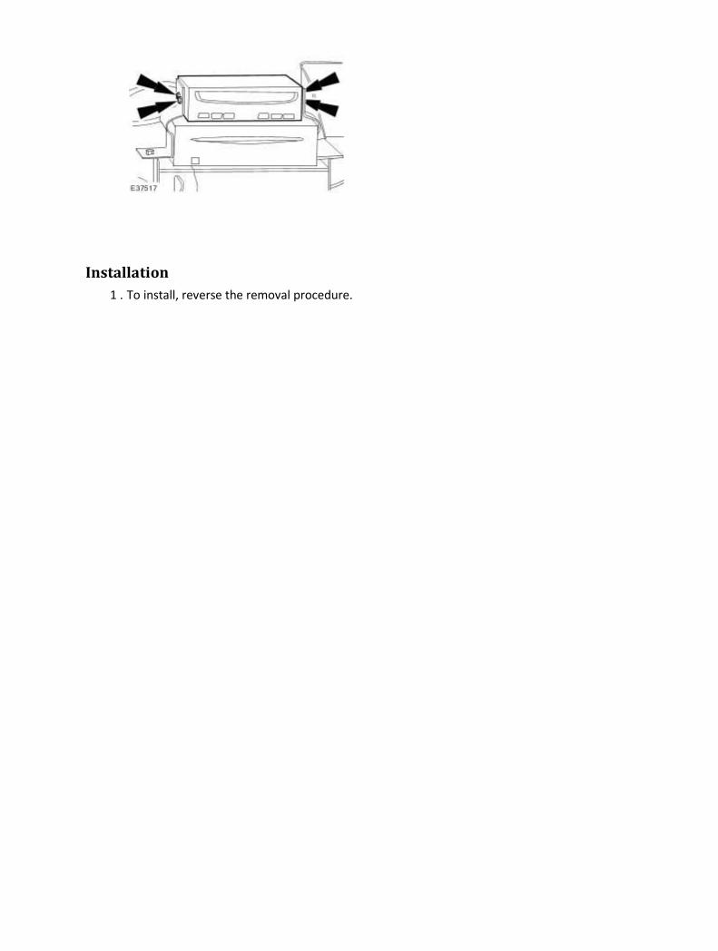
Installation
1 . To install, reverse the removal procedure.
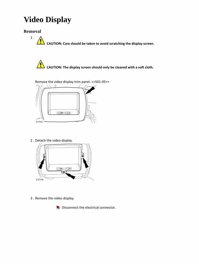
Video Display Removal
1 .
CAUTION: Care should be taken to avoid scratching the display screen.
CAUTION: The display screen should only be cleaned with a soft cloth.
Remove the video display trim panel. <<501-05>>
2 . Detach the video display.
3 . Remove the video display.
Disconnect the electrical connector.

Installation
1 . NOTE:
Ensure the cable is not trapped.
To install, reverse the removal procedure.

Video System Module Removal
1 . Remove the rear seat backrest. <<501-10>>
2 . Disconnect the video system module electrical connectors.
3 . Remove the video system module.
Installation
1 . To install, reverse the removal procedure.
Tighten to 6 Nm.


417 : Lighting
417-01 : Exterior Lighting
Specifications
Specifications General Specifications
Item Specification
Low beam headlamp bulb - Vehicles with conventional headlamps H7
Low beam headlamp bulb - Vehicles with High Intensity Discharge (HID) headlamps
D2s35W
High beam headlamp bulb H7
Side repeater lamp bulb W5W
Side marker lamp bulb W5W
Front turn signal lamp bulb PY21W
Rear turn signal lamp bulb PY21W
Front fog lamp bulb H3
Rear fog lamp bulb P21W
Front side/parking lamp bulb W5W
Rear side/stoplamp bulb Light emitting diode (LED)
Number plate lamp bulb W5W
Reversing lamp bulb P21W
Description Nm lb-ft lb-in
Headlamp leveling sensor retaining bolts 20 15 -
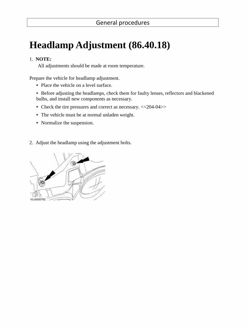
General procedures
Headlamp Adjustment (86.40.18) 1. NOTE: All adjustments should be made at room temperature. Prepare the vehicle for headlamp adjustment. • Place the vehicle on a level surface.
• Before adjusting the headlamps, check them for faulty lenses, reflectors and blackened bulbs, and install new components as necessary.
• Check the tire pressures and correct as necessary. <<204-04>>
• The vehicle must be at normal unladen weight.
• Normalize the suspension. 2. Adjust the headlamp using the adjustment bolts.
Description and operation
Exterior Lighting The headlamp switch is located on the multifunction switch. The switch operates the sidelights, the dipped and main beam lamps, the switch also features an auto lamps function (operates the headlamps when the sunload sensor detects low light levels) and the exit delay variable timer switch (allows the headlamps to stay on for a period of time from ten seconds to two minutes). Each headlamp assembly consists of two headlamp units. The main beam lamp unit and the front parking (side) lamp are in the inner unit and the dipped beam and the turn signal lamp unit are in the outer. Access for bulb replacement is from the engine compartment.
WARNING: VOLTAGES OF UP TO 25 KV ARE POSSIBLE WITH HIGH INTENSITY DISCHARGE HEADLAMPS (HID). The HID headlamps, if fitted, consists of a headlamp bulb and a combined ballast and headlamp leveling module fitted to the headlamp. Burner wear for HID lamps is so low that the burner lasts the lifetime of the vehicle under normal use. Headlamp automatic leveling is controlled by the air suspension module receiving information from the controlled area network (CAN) data. The fog lamps are located in recesses in the front bumper. The two retaining screws are located behind the anti-theft cover. The license plate lamps are fitted in the license plate housing. Each bulb is accessible after removing the relevant lens. Each rear lamp assembly incorporates a light emitting diode (LED) stop and tail lamp, a fog lamp, a reversing lamp and a direction indicator lamp. Access for bulb replacement is from the luggage compartment. The high mounted stoplamp is only replaceable as a unit. The side repeater lamps are located within the front fender. The sidemarker lamps are located within the rear bumper and front bumper and are supplied as part of a high level bumper assembly, (the side markers are located in the bumper by tangs on one side of the unit and held in position by a spring clip on the other side). The exterior mirrors incorporate ground illumination, which is activated when the vehicle is locked and unlocked under low ambient light conditions. The ground illumination is timed to stay on for the same amount of time as the interior light.

Exterior Lighting - VIN Range: H18680->H99999 COMPONENT LOCATION
Item Part Number Description
1 Direction indicator repeaters
OVERVIEW
Vehicles built from June 2007 feature direction indicator repeaters located in the exterior rear view
mirrors. The functionality and operation of the direction indicator repeaters remains the same as the
previous fender mounted items. For additional information, refer to Exterior Lighting (417-01 )
In the event of a direction indicator repeater bulb failure, the mirror glass will need to be removed.
For additional information, refer to the Owners Handbook.
Vehicles built from June 2007 also feature revised side marker lamps. The revised side marker lamps
also incorporate a reflector.
CONTROL DIAGRAM
NOTE:
A = Hardwired; Y = SCP (standard corporate protocol) network.

Item Part Number Description
1 Battery
2 Battery junction box
3 Rear power distribution box
4 LH (left-hand) rear direction indicator

5 RH (right-hand) rear direction indicator
6 REM (rear electronic module)
7 FEM (front electronic module)
8 Lighting switch
9 Hazard warning switch
10 Ignition switch
11 Instrument cluster
12 RH (right-hand) front direction indicator
13 RH (right-hand) direction indicator repeater
14 LH (left-hand) front direction indicator
15 LH (left-hand) direction indicator repeater
16 Passenger junction box
PRINCIPLES OF OPERATION
The direction indicator lamps will only operate when the ignition switch is in position II. An ignition
switch status signal is transmitted to the FEM (front electronic module) from the instrument cluster
on the SCP (standard corporate protocol) network. The hazard warning lamps will operate with the
ignition switch in any position, including off.
Direction Indicators - Front
A battery feed is provided to passenger junction box relays R1A and R1B from a 100 Amp megafuse
located in the BJB (battery junction box) . Relay R1A controls operation of the RH (right-hand)
direction indicators; relay R1B controls operation of the LH (left-hand) direction indicators.
The ground path for both relays coils is controlled by the FEM (front electronic module) . The FEM
(front electronic module) switches the ground path on and off when a request for direction indicator
operation is received from the column switch or the hazard warning switch. The FEM (front
electronic module) receives this request from the instrument cluster over the SCP (standard
corporate protocol) network. When the request for direction indicator operation is withdrawn, the
FEM (front electronic module) removes the ground path from both relay coils.

Direction Indicators - Rear
A battery feed is provided to rear power distribution box relays R8B and R7A. Relay R8B controls
operation of the RH (right-hand) direction indicators; relay R7A controls operation of the LH (left-
hand) direction indicators.
The ground path for both relay coils is controlled by the REM (rear electronic module) . The REM
(rear electronic module) switches the ground path on and off when a request for direction indicator
operation is received from the column switch or the hazard warning switch. The REM (rear electronic
module) receives this request from the instrument cluster over the SCP (standard corporate
protocol) network. When the request for direction indicator operation is withdrawn, the FEM (front
electronic module) removes the ground path from both relay coils.

Diagnosis and testing
Headlamps Inspection and Verification
1 . Verify the customer concern.
2 . Visually inspect for obvious signs of electrical damage.
Visual Inspection Chart
Electrical
• Bulb(s)
• Photocell(s)
• Ballast
• Wiring harness/electrical connectors
• Fuse(s)
1 . If an obvious cause for an observed or reported concern is found, correct the cause (if possible)
before proceeding to the next step.
2 . If the cause is not visually evident, verify the symptom and refer to the Jaguar Approved
Diagnostic System.
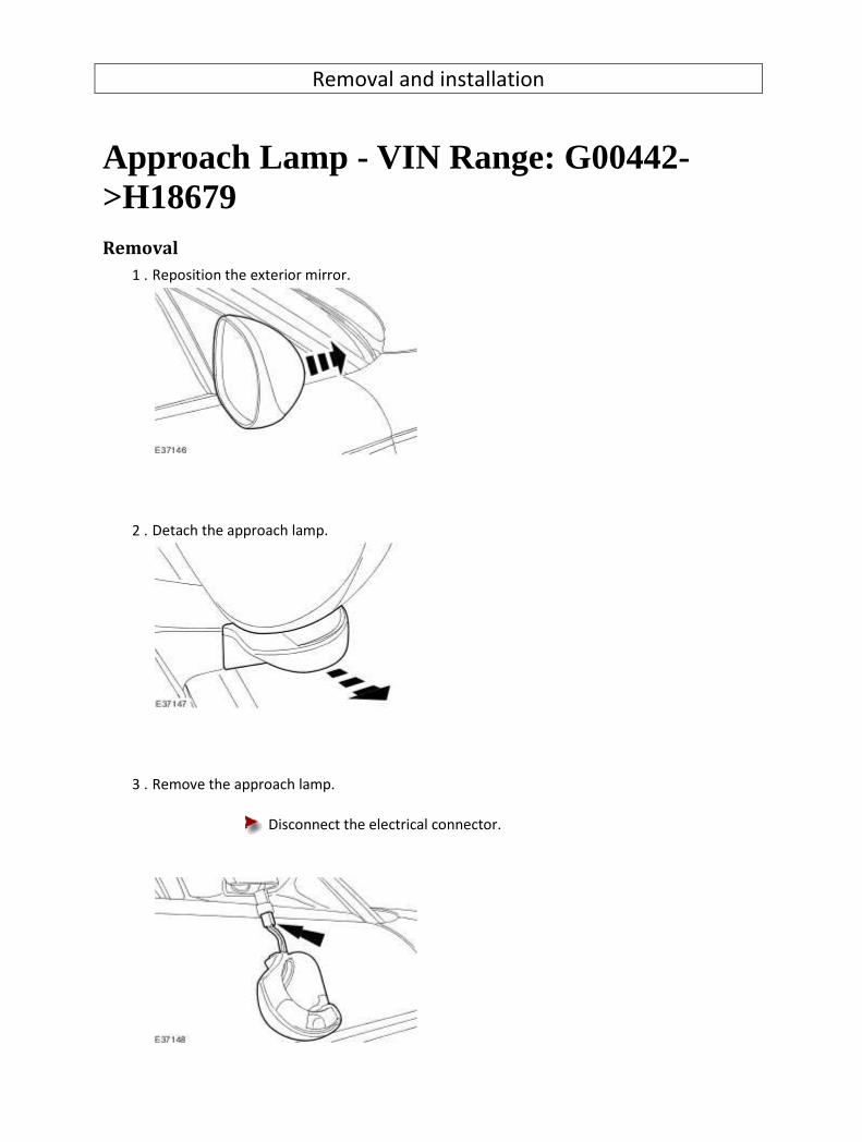
Removal and installation
Approach Lamp - VIN Range: G00442->H18679 Removal
1 . Reposition the exterior mirror.
2 . Detach the approach lamp.
3 . Remove the approach lamp.
Disconnect the electrical connector.

Installation
1 . To install, reverse the removal procedure.

Approach Lamp - VIN Range: H18680->H99999 Removal
1 . Remove the exterior mirror glass.
For additional information, refer to Exterior Mirror Glass (76.10.53)
2 . Release and reposition the approach lamp.
Release retaining clip.
3 . Remove the approach lamp.
Disconnect the electrical connector.
Installation
1 . To install, reverse the removal procedure.

Ballast - Vehicles With: High Intensity Discharge Headlamps (86.41.52) Removal
1 . Disconnect the battery ground cable. <<414-01>>
2 . Remove the headlamp assembly.
For additional information, refer to
3 . Detach the ballast module.
Remove the ballast module retaining screws.
4 . Remove the ballast module.
Disconnect the ballast module electrical connectors.

Installation
1 . To install, reverse the removal procedure.

Front Fog Lamp - VIN Range: G00442->H18679 (86.40.96) Removal
1 . Remove the front fog lamp anti-theft cover.
2 . Detach the front fog lamp.
3 . Remove the front fog lamp.
Disconnect the fog lamp electrical connector.

Installation
1 . To install, reverse the removal procedure.
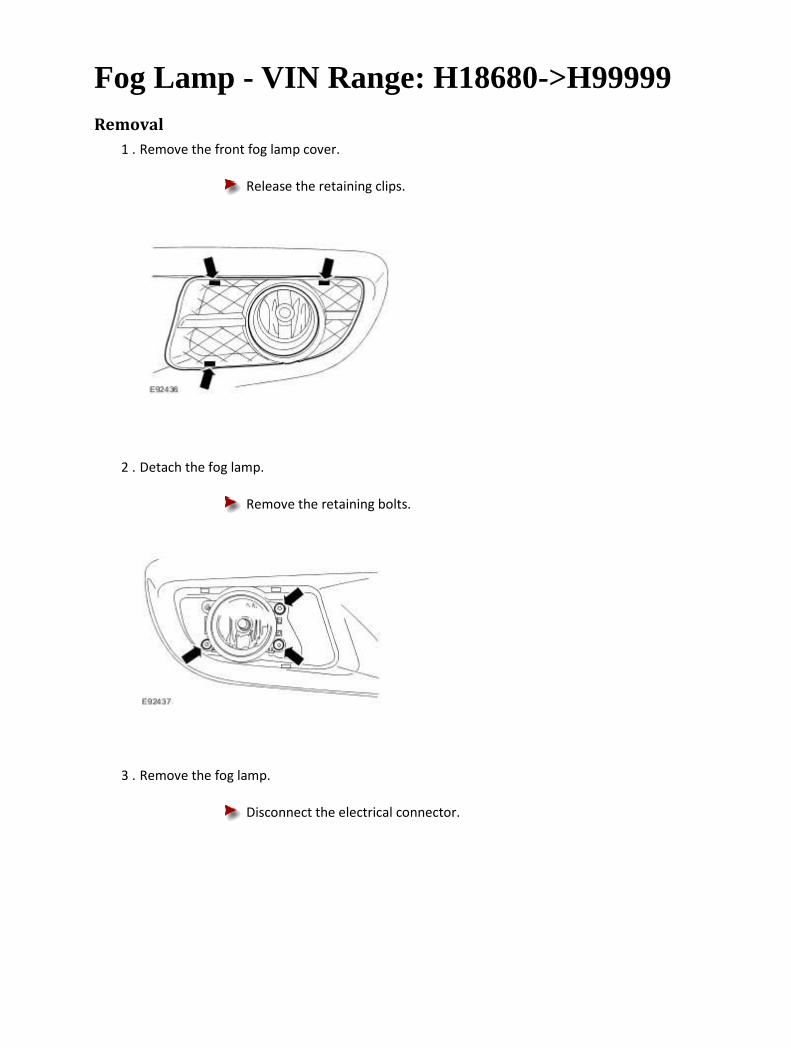
Fog Lamp - VIN Range: H18680->H99999 Removal
1 . Remove the front fog lamp cover.
Release the retaining clips.
2 . Detach the fog lamp.
Remove the retaining bolts.
3 . Remove the fog lamp.
Disconnect the electrical connector.
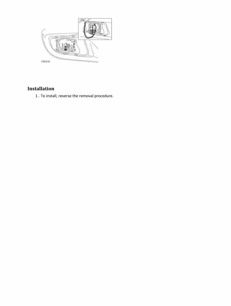
Installation
1 . To install, reverse the removal procedure.

Headlamp Assembly (86.41.33) Removal
1 . Remove the front bumper cover. <<501-19>>
2 . Detach the headlamp assembly.
Remove the headlamp retaining bolts.
3 . Remove the headlamp assembly.
Disconnect the headlamp electrical connector.
Installation
1 . To install, reverse the removal procedure.
2 . Check the headlamp adjustment.

For additional information, refer to
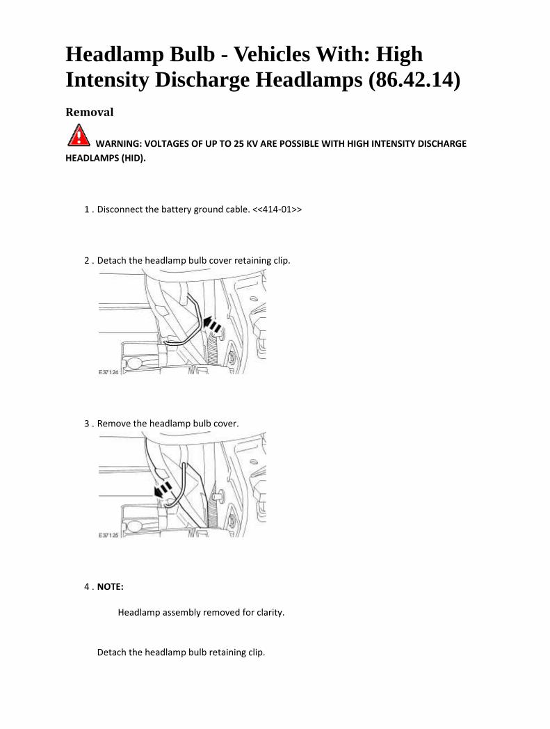
Headlamp Bulb - Vehicles With: High Intensity Discharge Headlamps (86.42.14) Removal
WARNING: VOLTAGES OF UP TO 25 KV ARE POSSIBLE WITH HIGH INTENSITY DISCHARGE
HEADLAMPS (HID).
1 . Disconnect the battery ground cable. <<414-01>>
2 . Detach the headlamp bulb cover retaining clip.
3 . Remove the headlamp bulb cover.
4 . NOTE:
Headlamp assembly removed for clarity.
Detach the headlamp bulb retaining clip.

Detach the headlamp bulb.
5 . NOTE:
Headlamp assembly removed for clarity.
Remove the headlamp bulb.
Detach the headlamp bulb electrical connector.
Installation
1 . To install, reverse the removal procedure.
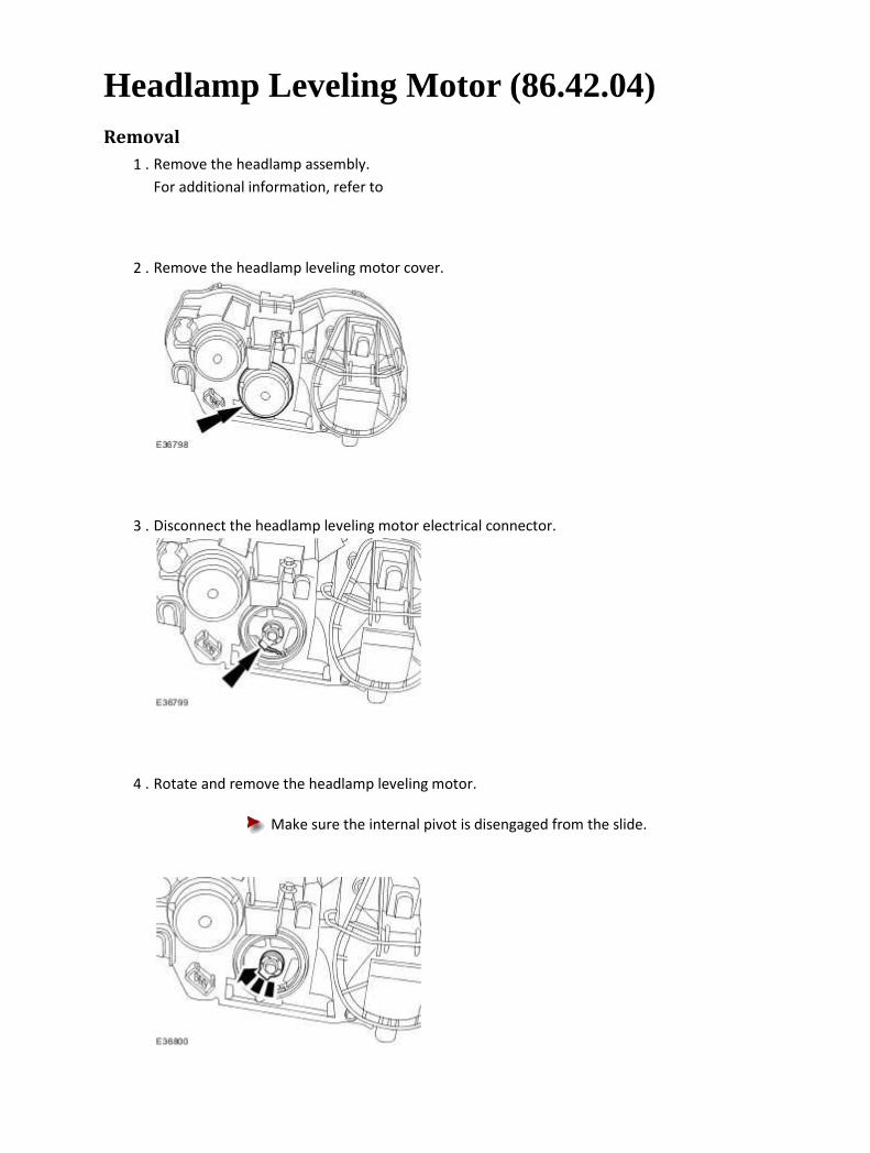
Headlamp Leveling Motor (86.42.04) Removal
1 . Remove the headlamp assembly.
For additional information, refer to
2 . Remove the headlamp leveling motor cover.
3 . Disconnect the headlamp leveling motor electrical connector.
4 . Rotate and remove the headlamp leveling motor.
Make sure the internal pivot is disengaged from the slide.

Installation
1 . To install, reverse the removal procedure.
Make sure the internal pivot is located in the slide.
2 . Check the headlamp adjustment.
For additional information, refer to

Headlamp Leveling Sensor (86.42.15) Removal
1 . Remove the wheel and tire assembly. <<204-04>>
2 . Disconnect the headlamp leveling sensor electrical connector.
3 . Detach the wheel speed sensor harness.
4 . Detach the headlamp leveling sensor link rod.
5 . Remove the headlamp leveling sensor.
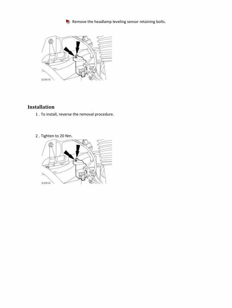
Remove the headlamp leveling sensor retaining bolts.
Installation
1 . To install, reverse the removal procedure.
2 . Tighten to 20 Nm.
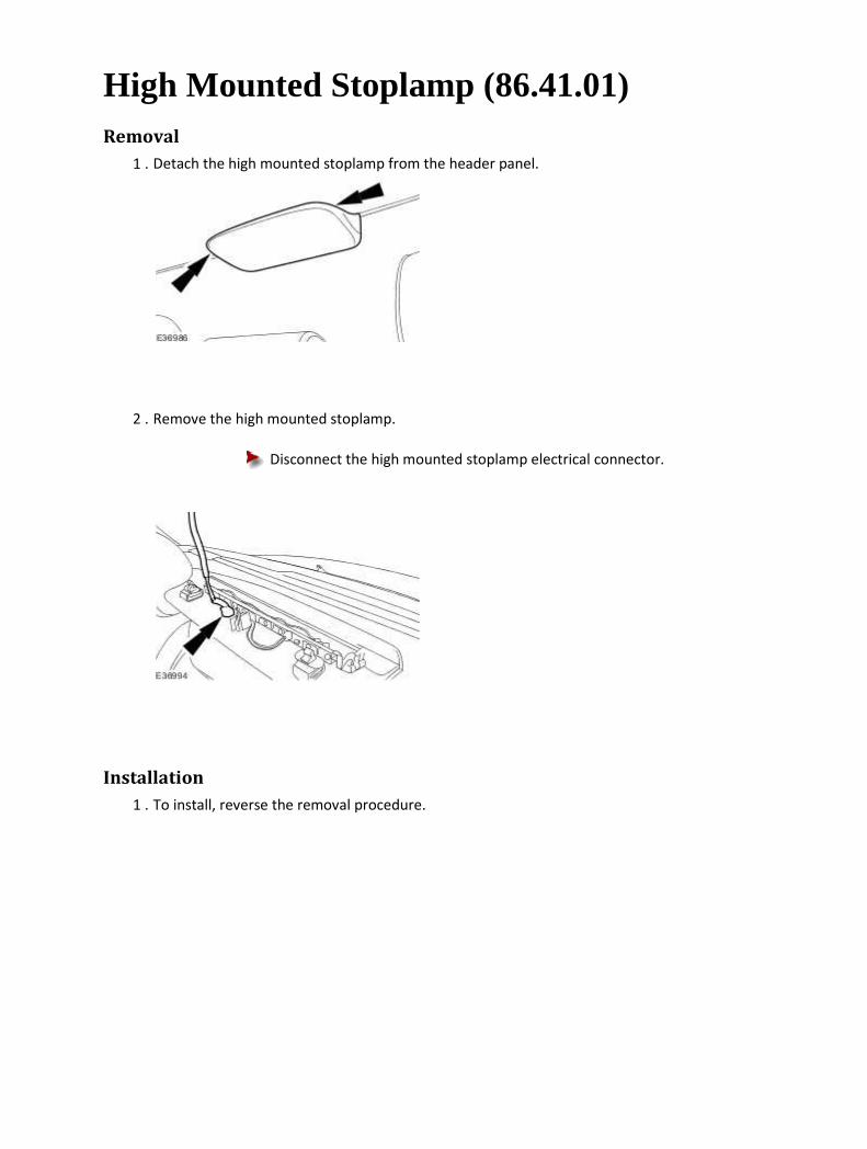
High Mounted Stoplamp (86.41.01) Removal
1 . Detach the high mounted stoplamp from the header panel.
2 . Remove the high mounted stoplamp.
Disconnect the high mounted stoplamp electrical connector.
Installation
1 . To install, reverse the removal procedure.

Stoplamp Switch Removal
1 . Remove the brake pedal position (BPP) switch.
For additional information, refer to Brake Pedal Position (BPP) Switch
2 . Release the stoplamp switch.
Rotate the stoplamp switch 45 degrees clockwise.
3 . Remove the stoplamp switch.
Disconnect the electrical connector.

Installation
1
. CAUTION: Make sure that the brake pedal remains in the rest position during this
procedure.
CAUTION: The bracket is keyed to avoid incorrect orientation. Failure to correctly
align the switch may result in damage to the vehicle.
Install the stoplamp switch.
Locate the stoplamp switch in the bracket.
Rotate the stoplamp switch 45 degrees counter-clockwise.
2 . Connect the electrical connector.
3 . Install the BPP switch.
For additional information, refer to Brake Pedal Position (BPP) Switch

Rear Lamp Assembly (86.40.70) Removal
1 . Reposition the luggage compartment floor covering.
2 . NOTE:
Left-hand shown, right-hand similar
Detach and reposition the luggage compartment side trim panel.
3 . Disconnect the rear lamp assembly electrical connector.
4 . Remove the rear lamp assembly.
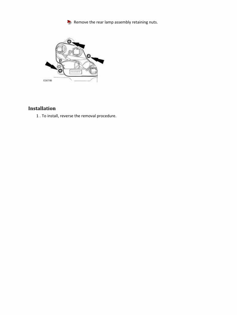
Remove the rear lamp assembly retaining nuts.
Installation
1 . To install, reverse the removal procedure.

417-02 : Interior Lighting
Description and operation
Interior Lighting The interior lighting system consists of the following components:
• One front interior lamp and two map reading lamps. • Soft mood lighting. • Front footwell lamps. • Two rear interior lamps with integral reading lamps. • Front/rear door puddle lamps. • Glove compartment lamp. • Vanity mirror lamps. • Two luggage compartment lamps..
The automatic operation of the interior lights is controlled by the front electronics module (FEM). Pressing the interior light switch in the overhead console switches the interior lighting control from automatic to the ON position. When the switch is in the ON position if any of the doors are open, none of the individual interior lamps can be turned off. In the AUTOMATIC position, when the interior lights have faded out , each lamp can be switched on or off by pressing the associated switch. Also in this position, if a door is open when the vehicle is driven the interior lighting will fade off and then fade back on again when the vehicle slows down. With the switch in the AUTOMATIC position the following times apply to the interior lights fading out assuming lights on. Soft mood lighting is fitted in the roof console and to the top of the two rear interior lamps. This lighting scatters subtle illumination onto the floor console and the headlining with the headlamps on. The interior lamp is incorporated in the roof console. <<501-12>>
Condition Fade out time
Open any door with key not in ignition, close door Lamps will fade out after 20
seconds
Any door ajar with the vehicle acclerating between 0-10 kph
Lamps will fade out above 5 kph
With engine in RUN position and open any door, close door
Lamps will fade out immediately
Open any door, switch ignition to the RUN position, close Lamps will fade out immediately

door

Diagnosis and testing
Interior Lighting 1 . Verify the customer concern.
2 . Visually inspect for obvious signs of electrical damage.
Visual Inspection Chart
Electrical
• Fuse(s)
• Bulb(s)
• Wiring harness
• Loose or corroded connector(s)
• Accessories
• Switch(es)
1 . If an obvious cause for an observed or reported concern is found, correct the cause (if possible)
before proceeding to the next step.
2 . If the cause is not visually evident, verify the symptom and refer to the Jaguar Approved
Diagnostic System.

417-04 : Daytime Running Lamps
Description and operation
Daytime Running Lamps (DRL) DRL use the full intensity low beam headlamps which are permanently illuminated when the vehicle
is being driven. DRL are used in a number of markets and there are two systems to cover these
markets.
DRL CANADIAN MARKET
DRL for this market use full intensity low beam headlamps. The side marker lamps and license plate
lamps will be on, but instrument cluster illumination will be off. DRL are active when the following
parameters are met:
• Parking brake is off on vehicles with manual transmission or PARK is not selected on vehicles
with automatic transmission
• Ignition switch is in the ignition position (II)
• The central junction box receives an engine running signal
• The lighting control switch is in the off or side lamps position. If the switch is in the 'AUTO'
position the DRL will be active when the light sensor is not operating the headlamps using
the auto lamps function.
If the above conditions are met, the low beam headlamps are illuminated by a Pulse Width
Modulated signal (PWM) for the vehicles fitted with halogen headlamps (when the average voltage
exceeds 14V). Vehicles with High Intensity Discharge (HID) headlamps operate the dip beam at
normal supply voltage.
The front park lamps (including front side markers) and low beam lamps are illuminated from the
Front Electronic Module (FEM), the rear park lamps (including the rear side markers and the license
plate lamps) are illuminated by the Rear Electronic Module (REM).
If the lighting control switch is moved to the side lamp or headlamp positions or the auto lamps
feature has activated the headlamps, DRL are deactivated and normal side lamp and headlamp
functionality is operational.
NOTE:
When DRL are active, the headlamp flash function using the left hand steering column
multifunction switch will operate normally. The high beam headlamp function using the left
hand steering column stalk switch will be deactivated.
When the parking brake is applied on manual transmission vehicles or the selector lever is in the

PARK position on automatic transmission vehicles, DRL are turned off. This is to reduce battery
discharge during long periods of engine idling in cold climate conditions. When the parking brake is
released or the selector lever is moved from the PARK position, normal DRL functionality is restored.
DRL DENMARK, HOLLAND, NORWAY, SWEDEN, FINLAND AND POLAND
NOTE:
DRL for Poland is on vehicles from 2008MY.
DRL for these markets use full intensity low beam headlamps. Side lamps and license plate lamps will
be on, but instrument cluster illumination will be off. DRL are active when the following parameters
are met:
• Ignition switch is in the ignition position (II)
• The central junction box receives an engine running signal
• The lighting control switch is in the off position. If the switch is in the 'AUTO' position the DRL
will be active when the light sensor is not operating headlamps using the auto lamps
function.
If the above conditions are met, the low beam headlamps are illuminated by a Pulse Width
Modulated signal (PWM) for the vehicles fitted with halogen headlamps (when the average voltage
exceeds 14V). Vehicles with High Intensity Discharge (HID) headlamps operate the dip beam at
normal supply voltage.
The front park lamps (including front side markers) and low beam lamps are illuminated from the
Front Electronic Module (FEM), the rear park lamps (including the rear side markers and the license
plate lamps) are illuminated by the Rear Electronic Module (REM).
If the lighting control switch is moved to the side lamp or headlamp positions or the auto lamps
feature has activated the headlamps, DRL are deactivated and normal side lamp and headlamp
functionality is operational.
NOTE:
When DRL are active, the headlamp flash function using the left hand steering column
multifunction switch will operate normally. The high beam headlamp function using the left
hand steering column stalk switch will be deactivated.

Diagnosis and testing
Daytime Running Lamps (DRL) 1 . Verify the customer concern.
2 . Visually inspect for obvious signs of electrical damage.
Visual Inspection Chart
Electrical
• Fuse(s)
• Bulb(s)
• Switch(es)
• Electrical connector(s)
• Wiring Harness
1 . If an obvious cause for an observed or reported concern is found, correct the cause (if possible)
before proceeding to the next step.
2 . If the cause is not visually evident, verify the symptom and refer to the Jaguar Approved
Diagnostic System.
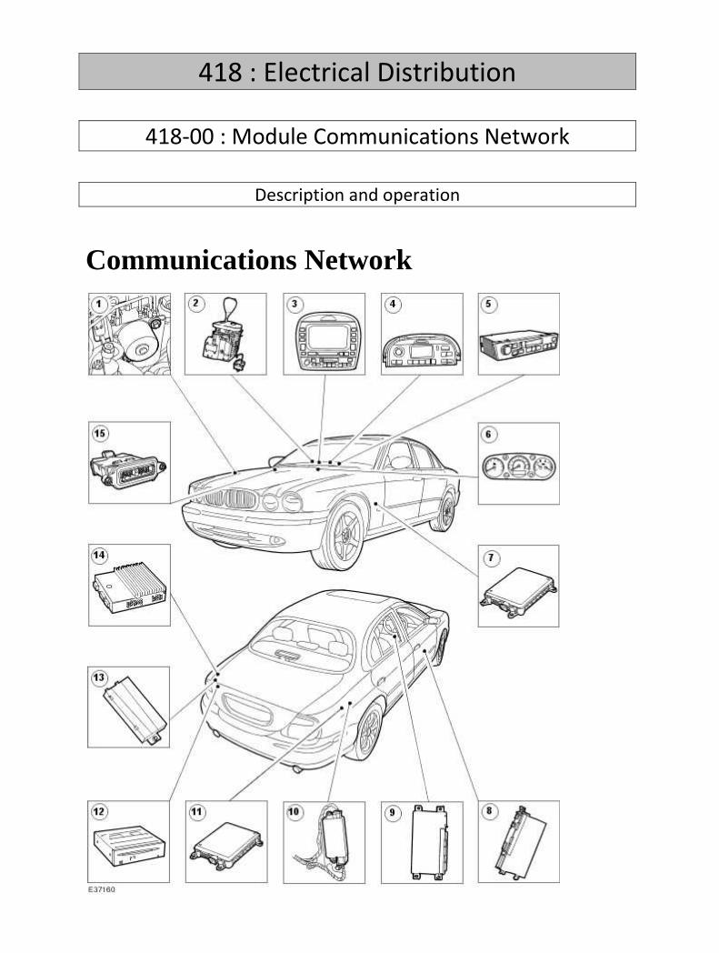
418 : Electrical Distribution
418-00 : Module Communications Network
Description and operation
Communications Network

Item Part Number Description
1 — Anti-Lock Brake System (ABS) Module
2 — Transmission selector lever
3 — Climate control module (vehicles fitted with telematics)
4 — Climate control assembly
5 — Audio control module (ACM)
6 — Instrument Pack (IP)
7 — Front electronic module (FEM)
8 — Drivers door module (DDM)
9 — Driver seat module (DSM)
10 — Electronic parking brake module (EPB)
11 — Rear electronic module (REM)
12 — Navigation control module (NAV)
13 — Voice activated control module (VACM)
14 — Amplifier
15 — Engine control module (ECM)

Item Part Number Description
1 — Remote climate control module (RCCM)
2 — Intrusion sensor module
3 — High intensity discharge headlamp module (HID)
4 — Restraints control module (RCM)
5 — Rear climate control panel (RCCP)
6 — Air suspension unit (ASU)
7 — Parking aid module
8 — Rear memory module (RMM)

9 — Compact disc changer
10 — High intensity discharge headlamp module (HID)

Diagnosis and testing
Communications Network Principles of Operation
There are three module communication networks connected to the data link connector (DLC),
controller area network, (CAN), standard corporate protocol (SCP), and international standards
organisation (ISO). CAN and SCP are unshielded twisted pair cable; data bus + and data bus -, while
ISO is a single wire system. The networks can be connected to the Jaguar approved diagnostic system
or scan tool by the DLC.
The SCP communication network remains operational even with the severing of one of the bus wires.
Communications will also continue if one of the bus wires is shorted to ground or battery positive
voltage (B+), or if some, but not all, termination resistors are lost.
The ISO network, however, will not function if the circuit is damaged.
The fourth module communication network is domestic data bus (D2B), which is a fibre optic
system.
The D2B network is diagnosed from the ICE head unit via the SCP network for DTCs, and by the use of
the optical bus tester for diagnosis of the optical ring.
Modules may log DTCs if power supply or ground is interrupted. Supply and ground tests are in this
section under the DTC number flagged, or by module name in the power supply and ground table.
The instrument cluster (also known as an instrument cluster module or ICM) is connected to the CAN
and SCP communication networks, and forms a "gateway" between the networks. The networks
share information, allowing sensors to serve more than one network.
Inspection and Verification
1 . Verify the customer concern.
2 . Confirm which, if any, warning lights and/or messages were displayed on the instrument cluster.
NOTE:
If any warning lights and/or messages were displayed when the fault occurred, refer to the
driver information table for DTCs associated with the display, then to the DTC index table for
possible sources and actions. Some warnings will appear to clear when the ignition is cycled. This
is often because the warning has flagged as a result of one of the vehicle's on-board diagnostic
routines having run to detect the fault. If the same routine is not run when the ignition is
switched ON, the warning will not reflag until the routine does run. See the DTC summaries for

drive cycle routines.
3 . Visually inspect for obvious signs of mechanical or electrical damage.
Electrical
General
• Fuses (see table)
• Wiring harness
• Correct engagement of electrical connectors
• Loose or corroded connections
Controller area network (CAN)
• Instrument cluster (IC)
• J-Gate module (JGM)
• Air conditioning control module (A/CCM)
• Dynamic stability control control module (DSCCM)
• Engine control module (ECM)
• Transmission control module (TCM)
• Adaptive speed control control module (ASCCM)
• Yaw rate sensor
• Rear climate control panel (RCCP)
• Air suspension control module (ASU)
Standard corporate protocol (SCP)
• Instrument cluster (IC)
• ICE head unit (HU)
• Rear electronic module (REM)
• Front electronic module (FEM)
• Rear memory module (RMM)
• Navigation module (NAV)
• Steering column lock module (SCLM)
• Electronic park brake module (EPB)
• Driver door control module (DDCM)
• Driver seat control module (DSCM)
International standards organisation (ISO)
• Engine control module (ECM)
• Parking aid control module (PACM)
• Intrusion sensor
• Restraints control module (RCM)
• Left-hand high intensity discharge headlamp assembly (HID)
• Right-hand high intensity discharge headlamp assembly (HID)

Domestic data bus (D2B)
• Routing of fibre optic harnesses
• Correct engagement of optical connectors
• Correct placement of optical connectors (ring order)
• Correct assembly of optical connectors (backout, etc)
• Damage to fibre (chafing, abrasion, kinking, cuts, etc)
• ICE head unit (HU)
• Compact disc changer (CD)
• Cellular phone module (CPM)
• Voice module (VACM)
• Rear entertainment system
• Navigation system module (NSM)
• Amplifier (AMP)
Fuse Rating Circuit Location
43 5 Amp Diagnostic connector (battery) Primary junction
box
16 5 Amp Diagnostic connector (ignition) Primary junction
box
11 5 Amp ICE head unit Primary junction
box
34 5 Amp Navigation Primary junction
box
08 5 Amp Instrument cluster Primary junction
box
20 5 Amp Cellular phone module, voice, VICS (Japan), rear entertainment
system
Primary junction
box
15 5 Amp Front electronic module, engine control module, instrument
cluster
Primary junction
box
29 10
Amp Restraints control module
Primary junction
box
02 5 Amp Adaptive speed control control module Primary junction
box
08 10 Air conditioning control module Primary junction
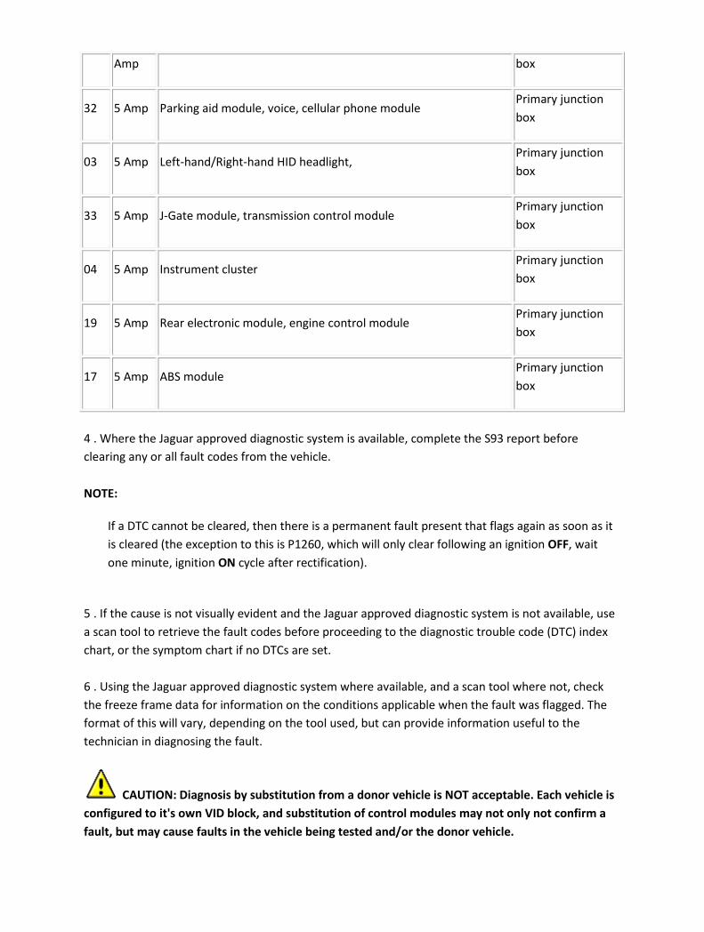
Amp box
32 5 Amp Parking aid module, voice, cellular phone module Primary junction
box
03 5 Amp Left-hand/Right-hand HID headlight, Primary junction
box
33 5 Amp J-Gate module, transmission control module Primary junction
box
04 5 Amp Instrument cluster Primary junction
box
19 5 Amp Rear electronic module, engine control module Primary junction
box
17 5 Amp ABS module Primary junction
box
4 . Where the Jaguar approved diagnostic system is available, complete the S93 report before
clearing any or all fault codes from the vehicle.
NOTE:
If a DTC cannot be cleared, then there is a permanent fault present that flags again as soon as it
is cleared (the exception to this is P1260, which will only clear following an ignition OFF, wait
one minute, ignition ON cycle after rectification).
5 . If the cause is not visually evident and the Jaguar approved diagnostic system is not available, use
a scan tool to retrieve the fault codes before proceeding to the diagnostic trouble code (DTC) index
chart, or the symptom chart if no DTCs are set.
6 . Using the Jaguar approved diagnostic system where available, and a scan tool where not, check
the freeze frame data for information on the conditions applicable when the fault was flagged. The
format of this will vary, depending on the tool used, but can provide information useful to the
technician in diagnosing the fault.
CAUTION: Diagnosis by substitution from a donor vehicle is NOT acceptable. Each vehicle is
configured to it's own VID block, and substitution of control modules may not only not confirm a
fault, but may cause faults in the vehicle being tested and/or the donor vehicle.
CAUTION: Electronic modules are sensitive to static electrical charges. If exposed to these
charges, damage may result.
CAUTION: When probing connectors to take measurements in the course of the pinpoint
tests, use the adaptor kit, part number 3548-1358-00.
NOTE:
When performing electrical voltage or resistance tests, always use a digital multimeter (DMM)
accurate to 3 decimal places, and with an up-to-date calibration certificate. When testing
resistance, always take the resistance of the DMM leads into account.
NOTE:
Where indicated in the tests, use a suitable oscilloscope. The Jaguar approved diagnostic tester
has an oscilloscope function in the "toolbox" menu.
NOTE:
Check and rectify basic faults before beginning diagnostic routines involving pinpoint tests.
7 . If an obvious cause for an observed or reported concern is found, correct the cause (if possible)
before proceeding to the next step.
8 . If the cause is not visually evident, verify the symptom and refer to the diagnostic trouble code
(DTC) index.
Power Supply and Ground table
Module Action
Instrument cluster (IC) GO to Pinpoint Test G239843p23.
.
J-Gate module (JGM) GO to Pinpoint Test G239843p31.
.
Air conditioning control module (A/CCM) GO to Pinpoint Test G239843p32.
.
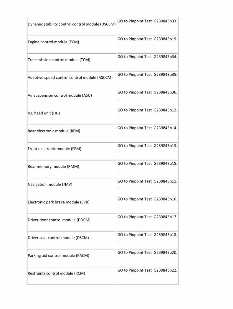
Dynamic stability control control module (DSCCM) GO to Pinpoint Test G239843p33.
.
Engine control module (ECM) GO to Pinpoint Test G239843p19.
.
Transmission control module (TCM) GO to Pinpoint Test G239843p34.
.
Adaptive speed control control module (ASCCM) GO to Pinpoint Test G239843p35.
.
Air suspension control module (ASU) GO to Pinpoint Test G239843p36.
.
ICE head unit (HU) GO to Pinpoint Test G239843p12.
.
Rear electronic module (REM) GO to Pinpoint Test G239843p14.
.
Front electronic module (FEM) GO to Pinpoint Test G239843p13.
.
Rear memory module (RMM) GO to Pinpoint Test G239843p15.
.
Navigation module (NAV) GO to Pinpoint Test G239843p11.
.
Electronic park brake module (EPB) GO to Pinpoint Test G239843p16.
.
Driver door control module (DDCM) GO to Pinpoint Test G239843p17.
.
Driver seat control module (DSCM) GO to Pinpoint Test G239843p18.
.
Parking aid control module (PACM) GO to Pinpoint Test G239843p20.
.
Restraints control module (RCM) GO to Pinpoint Test G239843p22.
.

Compact disc changer (CD) GO to Pinpoint Test G239843p6.
.
Cellular phone module (CPM) GO to Pinpoint Test G239843p8.
.
Voice module (VACM) GO to Pinpoint Test G239843p9.
.
Rear entertainment system GO to Pinpoint Test G239843p10.
.
Amplifier (AMP) GO to Pinpoint Test G239843p7.
.
Driver Information Chart
NOTE:
Use this table to identify DTCs associated with the message center display, then refer to the DTC
index for possible sources and actions.
NOTE:
For definitions of default modes, see the foot of this table.
Warning
light Message Default Mode DTC
Amber Restricted performance, DSC fault, DSC
system fault
Engine speed limited, reverse throttle
progression enabled P1637
Amber Restricted performance Engine speed limited, reverse throttle
progression enabled P1638
Amber Restricted performance Engine speed limited, reverse throttle
progression enabled P1642
Amber Restricted performance Engine speed limited, reverse throttle
progression enabled P1643
Amber Cruise not available Cruise control inhibited P1696
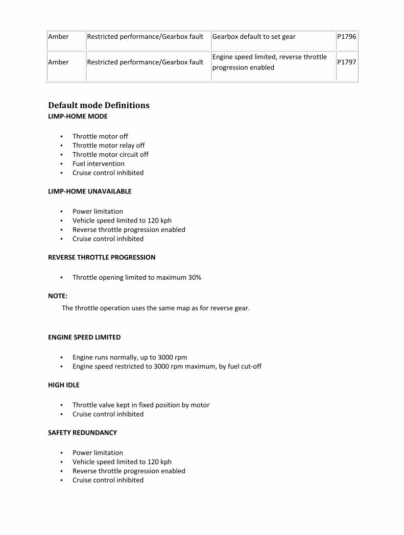
Amber Restricted performance/Gearbox fault Gearbox default to set gear P1796
Amber Restricted performance/Gearbox fault Engine speed limited, reverse throttle
progression enabled P1797
Default mode Definitions
LIMP-HOME MODE
• Throttle motor off
• Throttle motor relay off
• Throttle motor circuit off
• Fuel intervention
• Cruise control inhibited
LIMP-HOME UNAVAILABLE
• Power limitation
• Vehicle speed limited to 120 kph
• Reverse throttle progression enabled
• Cruise control inhibited
REVERSE THROTTLE PROGRESSION
• Throttle opening limited to maximum 30%
NOTE:
The throttle operation uses the same map as for reverse gear.
ENGINE SPEED LIMITED
• Engine runs normally, up to 3000 rpm
• Engine speed restricted to 3000 rpm maximum, by fuel cut-off
HIGH IDLE
• Throttle valve kept in fixed position by motor
• Cruise control inhibited
SAFETY REDUNDANCY
• Power limitation
• Vehicle speed limited to 120 kph
• Reverse throttle progression enabled
• Cruise control inhibited

Diagnostic Trouble Code (DTC) index
DTC Control Module Description Possible Source Action
U2601 AMP D2B "wake-up" circuit
fault
• D2B "wake-up"
circuit; short circuit to
ground
For D2B "wake-up"
circuit tests, GO to
Pinpoint Test
G239843p5.
.
U2609 AMP D2B "wake-up" signal
out of specification
• D2B "wake-up"
circuit; high
resistance
• D2B network slave
module failure
• Power amplifier
failure
For D2B "wake-up"
circuit tests, GO to
Pinpoint Test
G239843p5.
.
U2610 AMP
D2B network "position
status report" not
received
• D2B network error
Check the D2B
"wake-up" circuit,
and the optical ring,
GO to Pinpoint Test
G239843p5.
, GO to Pinpoint
Test G239843p29.
, and GO to Pinpoint
Test G239843p30.
.
U2611 AMP
D2B network "alarm
clear command" not
received
• D2B network error
Check the D2B
"wake-up" circuit,
and the optical ring,
GO to Pinpoint Test
G239843p5.
, GO to Pinpoint
Test G239843p29.
, and GO to Pinpoint
Test G239843p30.
. GO to Pinpoint
Test G239843p1.
U2023 ASCM
CAN fault message
received from other
network modules
• CAN/ASCM related
fault; ECM, TCM,
DSCM, IC
• ASCM internal CAN
fault
For CAN open circuit
tests, GO to Pinpoint
Test G239843p1.
. For CAN short
circuit tests, GO to

• CAN network fault Pinpoint Test
G239843p2.
.
U2501 ASCM CAN ECM token
missing
• CAN ECM token
missing on network
(other CAN modules
also flag ECM token
missing fault)
• ECM/CAN fault
• CAN network fault
For CAN open circuit
tests, GO to Pinpoint
Test G239843p1.
. For CAN short
circuit tests, GO to
Pinpoint Test
G239843p2.
.
U2502 ASCM CAN TCM token
missing
• CAN TCM token
missing on network
(other CAN modules
also flag TCM token
missing fault)
• TCM/CAN fault
• CAN network fault
For CAN open circuit
tests, GO to Pinpoint
Test G239843p1.
. For CAN short
circuit tests, GO to
Pinpoint Test
G239843p2.
.
U2503 ASCM CAN IC token missing
• CAN IC token missing
on network (other
CAN modules also
flag IC token missing
fault)
• IC/CAN fault
• CAN network fault
For CAN open circuit
tests, GO to Pinpoint
Test G239843p1.
. For CAN short
circuit tests, GO to
Pinpoint Test
G239843p2.
.
U2504 ASCM CAN DSCM token
missing
• CAN DSCM token
missing on network
(other CAN modules
also flag DSCM token
missing fault)
• DSCM/CAN fault
• CAN network fault
For CAN open circuit
tests, GO to Pinpoint
Test G239843p1.
. For CAN short
circuit tests, GO to
Pinpoint Test
G239843p2.
.
U2505 ASCM CAN TCM message
missing • TCM CAN DTC flagged
For CAN open circuit
tests, GO to Pinpoint
Test G239843p1.
. For CAN short
circuit tests, GO to

Pinpoint Test
G239843p2.
.
U2520 ASCM CAN IC module missing
• IC CAN circuit; open
circuit, short circuit to
B+, short circuit to
ground
• IC CAN fault
• CAN network fault
For CAN open circuit
tests, GO to Pinpoint
Test G239843p1.
. For CAN short
circuit tests, GO to
Pinpoint Test
G239843p2.
.
U2521 ASCM CAN DSCM module
missing
• DSCM CAN circuit;
open circuit, short
circuit to B+, short
circuit to ground
• DSCM CAN fault
• CAN network fault
For CAN open circuit
tests, GO to Pinpoint
Test G239843p1.
. For CAN short
circuit tests, GO to
Pinpoint Test
G239843p2.
.
U2522 ASCM CAN TCM module
missing
• TCM CAN circuit;
open circuit, short
circuit to B+, short
circuit to ground
• TCM CAN fault
• CAN network fault
For CAN open circuit
tests, GO to Pinpoint
Test G239843p1.
. For CAN short
circuit tests, GO to
Pinpoint Test
G239843p2.
.
U2523 ASCM CAN ECM module
missing
• ECM CAN circuit;
open circuit, short
circuit to B+, short
circuit to ground
• ECM CAN fault
• CAN network fault
For CAN open circuit
tests, GO to Pinpoint
Test G239843p1.
. For CAN short
circuit tests, GO to
Pinpoint Test
G239843p2.
.
U1900 ASM CAN communication
fault
• CAN circuit; open
circuit, short circuit to
B+, short circuit to
ground
• ASM internal CAN
fault
For CAN open circuit
tests, GO to Pinpoint
Test G239843p1.
. For CAN short
circuit tests, GO to

• CAN network fault Pinpoint Test
G239843p2.
.
U2516 ASM CAN not responding
• Multiple CAN
modules with CAN
DTCs flagged
• CAN circuit; open
circuit, short circuit to
B+, short circuit to
ground
• ASM internal CAN
fault
• CAN network fault
For CAN open circuit
tests, GO to Pinpoint
Test G239843p1.
. For CAN short
circuit tests, GO to
Pinpoint Test
G239843p2.
.
U2518 ASM CAN CCM message
missing
• CCM CAN DTC
flagged
For CAN open circuit
tests, GO to Pinpoint
Test G239843p1.
. For CAN short
circuit tests, GO to
Pinpoint Test
G239843p2.
.
U2521 ASM CAN DSCM message
missing
• DSCM CAN DTC
flagged
For CAN open circuit
tests, GO to Pinpoint
Test G239843p1.
. For CAN short
circuit tests, GO to
Pinpoint Test
G239843p2.
.
U2523 ASM CAN ECM message
missing • ECM CAN DTC flagged
For CAN open circuit
tests, GO to Pinpoint
Test G239843p1.
. For CAN short
circuit tests, GO to
Pinpoint Test
G239843p2.
.
U1262 Audio SCP network fault • SCP network circuit;
open circuit, short
circuit to B+, short
For SCP network
tests, GO to Pinpoint
Test G239843p3.

circuit to ground .
U2003 Audio
CD changer not
responding on D2B
network
• D2B "wake-up"
circuit; open circuit,
short circuit to B+
• CD changer D2B fault
• D2B network fault
For D2B "wake-up"
circuit tests, GO to
Pinpoint Test
G239843p5.
. For optical ring
tests, GO to Pinpoint
Test G239843p24.
.
U2008 Audio CPM not responding on
D2B network
• D2B "wake-up"
circuit; open circuit,
short circuit to B+
• D2B network fault
For D2B "wake-up"
circuit tests, GO to
Pinpoint Test
G239843p5.
. For optical ring
tests, GO to Pinpoint
Test G239843p25.
.
U2019 Audio VACM not responding
on D2B network
• D2B "wake-up"
circuit; open circuit,
short circuit to B+
• VACM D2B fault
• D2B network fault
For D2B "wake-up"
circuit tests, GO to
Pinpoint Test
G239843p5.
. For optical ring
tests, GO to Pinpoint
Test G239843p26.
.
U2601 Audio D2B "wake-up" circuit
fault
• D2B "wake-up"
circuit; short circuit to
ground
For D2B "wake-up"
circuit tests, GO to
Pinpoint Test
G239843p5.
.
U2602 Audio
D2B network ring
incomplete (fault
reported)
• D2B network module
disconnected
• D2B network circuit;
open circuit
Check the D2B
"wake-up" circuit,
and the optical ring,
GO to Pinpoint Test
G239843p5.
, GO to Pinpoint
Test G239843p29.
, and GO to Pinpoint
Test G239843p30.

.
U2603 Audio
D2B network ring
incomplete (fault not
reported)
• D2B network module
disconnected
• D2B network circuit;
open circuit
Check the D2B
"wake-up" circuit,
and the optical ring,
GO to Pinpoint Test
G239843p5.
, GO to Pinpoint
Test G239843p29.
, and GO to Pinpoint
Test G239843p30.
.
U2604 Audio
D2B network ring
incomplete (corrupted
fault report)
• D2B network module
disconnected
• D2B network circuit;
open circuit
Check the D2B
"wake-up" circuit,
and the optical ring,
GO to Pinpoint Test
G239843p5.
, GO to Pinpoint
Test G239843p29.
, and GO to Pinpoint
Test G239843p30.
.
U2605 Audio Audio unit unable to
initialize it's address
• More than one
master module
(audio unit) on the
D2B network ring
Check for correct
configuration of the
optical ring. REFER
to the electrical
guides.
U2506 Audio
D2B slave module
unable to initialize it's
address
• One or more slave
modules duplicated
on the D2B network
ring
Check for corrrect
configuration of the
optical ring. REFER
to the electrical
guides.
U2607 Audio
D2B slave module
switched into bypass
mode
• One or more slave
modules on the D2B
network ring
switched into bypass
mode
Check the D2B
"wake-up" circuit,
and the optical ring,
GO to Pinpoint Test
G239843p5.
, GO to Pinpoint
Test G239843p29.
, and GO to Pinpoint
Test G239843p30.
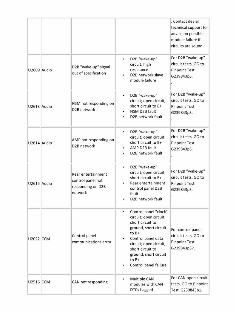
. Contact dealer
technical support for
advice on possible
module failure if
circuits are sound.
U2609 Audio D2B "wake-up" signal
out of specification
• D2B "wake-up"
circuit; high
resistance
• D2B network slave
module failure
For D2B "wake-up"
circuit tests, GO to
Pinpoint Test
G239843p5.
.
U2613 Audio NSM not responding on
D2B network
• D2B "wake-up"
circuit; open circuit,
short circuit to B+
• NSM D2B fault
• D2B network fault
For D2B "wake-up"
circuit tests, GO to
Pinpoint Test
G239843p5.
.
U2614 Audio AMP not responding on
D2B network
• D2B "wake-up"
circuit; open circuit,
short circuit to B+
• AMP D2B fault
• D2B network fault
For D2B "wake-up"
circuit tests, GO to
Pinpoint Test
G239843p5.
.
U2615 Audio
Rear entertainment
control panel not
responding on D2B
network
• D2B "wake-up"
circuit; open circuit,
short circuit to B+
• Rear entertainment
control panel D2B
fault
• D2B network fault
For D2B "wake-up"
circuit tests, GO to
Pinpoint Test
G239843p5.
.
U2022 CCM Control panel
communications error
• Control panel "clock"
circuit; open circuit,
short circuit to
ground, short circuit
to B+
• Control panel data
circuit; open circuit,
short circuit to
ground, short circuit
to B+
• Control panel failure
For control panel
circuit tests, GO to
Pinpoint Test
G239843p37.
U2516 CCM CAN not responding • Multiple CAN
modules with CAN
DTCs flagged
For CAN open circuit
tests, GO to Pinpoint
Test G239843p1.

• CAN circuit; open
circuit, short circuit to
B+, short circuit to
ground
• CCM internal CAN
fault
• CAN network fault
. For CAN short
circuit tests, GO to
Pinpoint Test
G239843p2.
.
U2520 CCM CAN IC module missing
• IC CAN circuit; open
circuit, short circuit to
B+, short circuit to
ground
• IC CAN fault
• CAN network fault
For CAN open circuit
tests, GO to Pinpoint
Test G239843p1.
. For CAN short
circuit tests, GO to
Pinpoint Test
G239843p2.
.
U2521 CCM CAN DSCM module
missing
• DSCM CAN circuit;
open circuit, short
circuit to B+, short
circuit to ground
• DSCM CAN fault
• CAN network fault
For CAN open circuit
tests, GO to Pinpoint
Test G239843p1.
. For CAN short
circuit tests, GO to
Pinpoint Test
G239843p2.
.
U2523 CCM CAN ECM module
missing
• ECM CAN circuit;
open circuit, short
circuit to B+, short
circuit to ground
• ECM CAN fault
• CAN network fault
For CAN open circuit
tests, GO to Pinpoint
Test G239843p1.
. For CAN short
circuit tests, GO to
Pinpoint Test
G239843p2.
.
U2525 CCM CAN RCCM module
missing
• RCCM CAN circuit;
open circuit, short
circuit to B+, short
circuit to ground
• RCCM CAN fault
• CAN network fault
For CAN open circuit
tests, GO to Pinpoint
Test G239843p1.
. For CAN short
circuit tests, GO to
Pinpoint Test
G239843p2.
.
U2601 CPM D2B "wake-up" circuit • D2B "wake-up"
circuit, short circuit to For D2B "wake-up"

fault ground circuit tests, GO to
Pinpoint Test
G239843p5.
.
U2609 CPM D2B "wake-up" signal
out of specification
• D2B "wake-up"
circuit; high
resistance
• D2B network slave
module failure
For D2B "wake-up"
circuit tests, GO to
Pinpoint Test
G239843p5.
.
U2610 CPM
D2B network "position
status report" not
received
• D2B network error
Check the D2B
"wake-up" circuit,
and the optical ring,
GO to Pinpoint Test
G239843p5.
, GO to Pinpoint
Test G239843p29.
, and GO to Pinpoint
Test G239843p30.
. Contact dealer
technical support for
advice on possible
module failure if
circuits are sound.
U2611 CPM
D2B "alarm clear
command" not
received
• D2B network error
Check the D2B
"wake-up" circuit,
and the optical ring,
GO to Pinpoint Test
G239843p5.
, GO to Pinpoint
Test G239843p29.
, and GO to Pinpoint
Test G239843p30.
. Contact dealer
technical support for
advice on possible
module failure if
circuits are sound.
U1260 DDM SCP positive circuit
fault
• SCP positive circuit;
open circuit, short
circuit to ground,
For SCP network
tests, GO to Pinpoint
Test G239843p3.
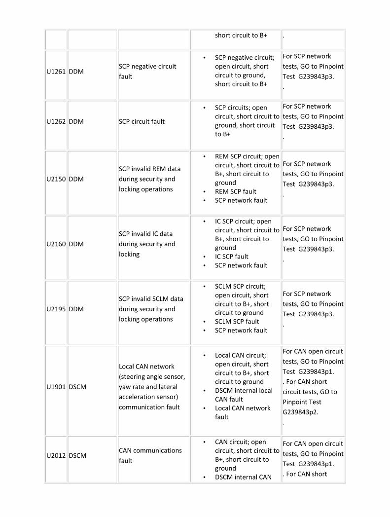
short circuit to B+ .
U1261 DDM SCP negative circuit
fault
• SCP negative circuit;
open circuit, short
circuit to ground,
short circuit to B+
For SCP network
tests, GO to Pinpoint
Test G239843p3.
.
U1262 DDM SCP circuit fault
• SCP circuits; open
circuit, short circuit to
ground, short circuit
to B+
For SCP network
tests, GO to Pinpoint
Test G239843p3.
.
U2150 DDM
SCP invalid REM data
during security and
locking operations
• REM SCP circuit; open
circuit, short circuit to
B+, short circuit to
ground
• REM SCP fault
• SCP network fault
For SCP network
tests, GO to Pinpoint
Test G239843p3.
.
U2160 DDM
SCP invalid IC data
during security and
locking
• IC SCP circuit; open
circuit, short circuit to
B+, short circuit to
ground
• IC SCP fault
• SCP network fault
For SCP network
tests, GO to Pinpoint
Test G239843p3.
.
U2195 DDM
SCP invalid SCLM data
during security and
locking operations
• SCLM SCP circuit;
open circuit, short
circuit to B+, short
circuit to ground
• SCLM SCP fault
• SCP network fault
For SCP network
tests, GO to Pinpoint
Test G239843p3.
.
U1901 DSCM
Local CAN network
(steering angle sensor,
yaw rate and lateral
acceleration sensor)
communication fault
• Local CAN circuit;
open circuit, short
circuit to B+, short
circuit to ground
• DSCM internal local
CAN fault
• Local CAN network
fault
For CAN open circuit
tests, GO to Pinpoint
Test G239843p1.
. For CAN short
circuit tests, GO to
Pinpoint Test
G239843p2.
.
U2012 DSCM CAN communications
fault
• CAN circuit; open
circuit, short circuit to
B+, short circuit to
ground
• DSCM internal CAN
For CAN open circuit
tests, GO to Pinpoint
Test G239843p1.
. For CAN short

fault
• CAN network fault
circuit tests, GO to
Pinpoint Test
G239843p2.
.
U2202 DSCM
CAN invalid
configuration data
received
• ECM, TCM or ASCM
incorrectly configured
Reconfigure
modules.
U2515 DSCM
CAN adaptive speed
control message
missing
• TCM CAN DTC flagged
For CAN open circuit
tests, GO to Pinpoint
Test G239843p1.
. For CAN short
circuit tests, GO to
Pinpoint Test
G239843p2.
.
U2522 DSCM CAN TCM module
missing
• TCM CAN circuit;
open circuit, short
circuit to B+, short
circuit to ground
• TCM CAN fault
• CAN network fault
For CAN open circuit
tests, GO to Pinpoint
Test G239843p1.
. For CAN short
circuit tests, GO to
Pinpoint Test
G239843p2.
.
U2523 DSCM CAN ECM module
missing
• ECM CAN circuit;
open circuit, short
circuit to B+, short
circuit to ground
• ECM CAN fault
• CAN network fault
For CAN open circuit
tests, GO to Pinpoint
Test G239843p1.
. For CAN short
circuit tests, GO to
Pinpoint Test
G239843p2.
.
U2527 DSCM
Local CAN network
(steering angle sensor,
yaw rate and lateral
acceleration sensor)
transmit fault
• Local CAN circuit;
open circuit, short
circuit to B+, short
circuit to ground
• DSCM internal local
CAN fault
• Local CAN network
fault
For CAN open circuit
tests, GO to Pinpoint
Test G239843p1.
. For CAN short
circuit tests, GO to
Pinpoint Test
G239843p2.
.
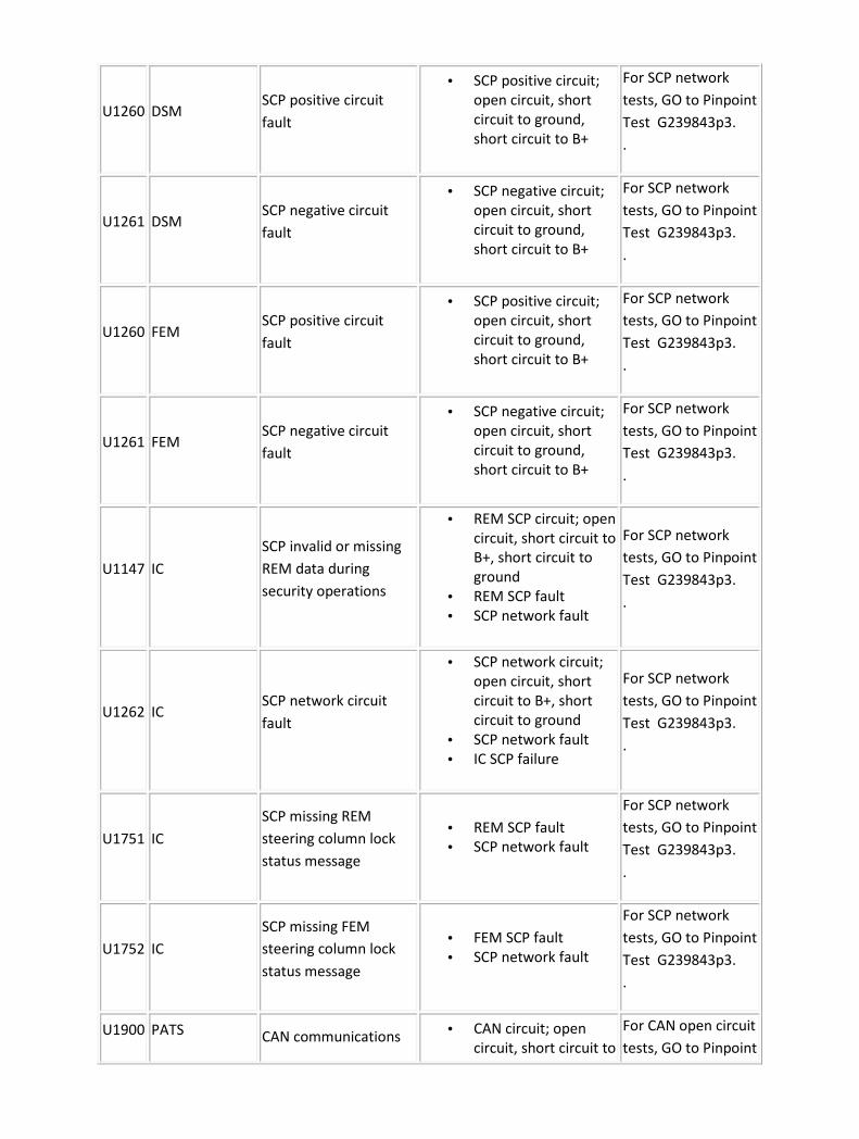
U1260 DSM SCP positive circuit
fault
• SCP positive circuit;
open circuit, short
circuit to ground,
short circuit to B+
For SCP network
tests, GO to Pinpoint
Test G239843p3.
.
U1261 DSM SCP negative circuit
fault
• SCP negative circuit;
open circuit, short
circuit to ground,
short circuit to B+
For SCP network
tests, GO to Pinpoint
Test G239843p3.
.
U1260 FEM SCP positive circuit
fault
• SCP positive circuit;
open circuit, short
circuit to ground,
short circuit to B+
For SCP network
tests, GO to Pinpoint
Test G239843p3.
.
U1261 FEM SCP negative circuit
fault
• SCP negative circuit;
open circuit, short
circuit to ground,
short circuit to B+
For SCP network
tests, GO to Pinpoint
Test G239843p3.
.
U1147 IC
SCP invalid or missing
REM data during
security operations
• REM SCP circuit; open
circuit, short circuit to
B+, short circuit to
ground
• REM SCP fault
• SCP network fault
For SCP network
tests, GO to Pinpoint
Test G239843p3.
.
U1262 IC SCP network circuit
fault
• SCP network circuit;
open circuit, short
circuit to B+, short
circuit to ground
• SCP network fault
• IC SCP failure
For SCP network
tests, GO to Pinpoint
Test G239843p3.
.
U1751 IC
SCP missing REM
steering column lock
status message
• REM SCP fault
• SCP network fault
For SCP network
tests, GO to Pinpoint
Test G239843p3.
.
U1752 IC
SCP missing FEM
steering column lock
status message
• FEM SCP fault
• SCP network fault
For SCP network
tests, GO to Pinpoint
Test G239843p3.
.
U1900 PATS CAN communications • CAN circuit; open
circuit, short circuit to
For CAN open circuit
tests, GO to Pinpoint

fault B+, short circuit to
ground
• IC internal CAN fault
• CAN network fault
Test G239843p1.
. For CAN short
circuit tests, GO to
Pinpoint Test
G239843p2.
.
U2150 IC
SCP missing or invalid
REM steering column
lock enable status
message
• REM SCP fault
• SCP network fault
For SCP network
tests, GO to Pinpoint
Test G239843p3.
.
U2152 IC
SCP missing or invalid
FEM steering column
lock enable status
message
• FEM SCP fault
• SCP network fault
For SCP network
tests, GO to Pinpoint
Test G239843p3.
.
U2195 IC
SCP missing or invalid
SCLM steering column
lock enable status
message
• SCLM SCP fault
• SCP network fault
For SCP network
tests, GO to Pinpoint
Test G239843p3.
.
U2196 IC CAN invalid ECM
engine speed data
• ECM CAN fault
• CAN network fault
For CAN open circuit
tests, GO to Pinpoint
Test G239843p1.
. For CAN short
circuit tests, GO to
Pinpoint Test
G239843p2.
.
U2197 IC CAN invalid DSCM
vehicle speed data
• DSCM CAN fault
• CAN network fault
For CAN open circuit
tests, GO to Pinpoint
Test G239843p1.
. For CAN short
circuit tests, GO to
Pinpoint Test
G239843p2.
.
U2199 IC
CAN invalid ECM
engine coolant
temperature data
• ECM CAN fault
• CAN network fault
For CAN open circuit
tests, GO to Pinpoint
Test G239843p1.
. For CAN short
circuit tests, GO to

Pinpoint Test
G239843p2.
.
U2200 IC
CAN invalid DSCM
odometer count "ODO
count" data
• DSCM CAN fault
• CAN network fault
For CAN open circuit
tests, GO to Pinpoint
Test G239843p1.
. For CAN short
circuit tests, GO to
Pinpoint Test
G239843p2.
.
U2510 IC
CAN invalid ECM data
for vehicle security
(incorrect PATS
identification -IC/ECM)
• IC/ECM configuration
fault
Reconfigure IC/ECM.
Contact dealer
technical support for
information on PATS
system.
U2511 IC CAN communication
failure - IC to ECM
• CAN network circuit;
open circuit, short
circuit to B+, short
circuit to ground
• CAN network fault
• ECM CAN failure
For CAN open circuit
tests, GO to Pinpoint
Test G239843p1.
. For CAN short
circuit tests, GO to
Pinpoint Test
G239843p2.
.
U2515 IC CAN ASCM data
missing
• ASCM CAN DTC
flagged
For CAN open circuit
tests, GO to Pinpoint
Test G239843p1.
. For CAN short
circuit tests, GO to
Pinpoint Test
G239843p2.
.
U2516 IC CAN network circuit
fault
• CAN network circuit;
open circuit, short
circuit to B+, short
circuit to ground
• CAN network fault
For CAN open circuit
tests, GO to Pinpoint
Test G239843p1.
. For CAN short
circuit tests, GO to
Pinpoint Test
G239843p2.

.
U2521 IC CAN DSCM vehicle
speed data missing
• DSCM CAN DTC
flagged
For CAN open circuit
tests, GO to Pinpoint
Test G239843p1.
. For CAN short
circuit tests, GO to
Pinpoint Test
G239843p2.
.
U2522 IC CAN TCM gear selected
data missing • TCM CAN DTC flagged
For CAN open circuit
tests, GO to Pinpoint
Test G239843p1.
. For CAN short
circuit tests, GO to
Pinpoint Test
G239843p2.
.
U2523 IC CAN ECM engine speed
data missing • ECM CAN DTC flagged
For CAN open circuit
tests, GO to Pinpoint
Test G239843p1.
. For CAN short
circuit tests, GO to
Pinpoint Test
G239843p2.
.
U2524 IC CAN ASM data missing • ASM CAN DTC flagged
For CAN open circuit
tests, GO to Pinpoint
Test G239843p1.
. For CAN short
circuit tests, GO to
Pinpoint Test
G239843p2.
.
U2601
Rear
entertainment
control panel
D2B "wake-up" circuit
fault
• D2B "wake-up"
circuit; short circuit to
ground
For D2B "wake-up"
circuit tests, GO to
Pinpoint Test
G239843p5.
.
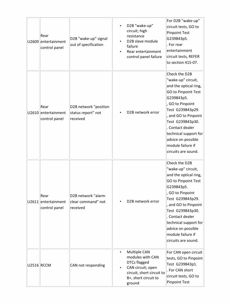
U2609
Rear
entertainment
control panel
D2B "wake-up" signal
out of specification
• D2B "wake-up"
circuit; high
resistance
• D2B slave module
failure
• Rear entertainment
control panel failure
For D2B "wake-up"
circuit tests, GO to
Pinpoint Test
G239843p5.
. For rear
entertainment
circuit tests, REFER
to section 415-07.
U2610
Rear
entertainment
control panel
D2B network "position
status report" not
received
• D2B network error
Check the D2B
"wake-up" circuit,
and the optical ring,
GO to Pinpoint Test
G239843p5.
, GO to Pinpoint
Test G239843p29.
, and GO to Pinpoint
Test G239843p30.
. Contact dealer
technical support for
advice on possible
module failure if
circuits are sound.
U2611
Rear
entertainment
control panel
D2B network "alarm
clear command" not
received
• D2B network error
Check the D2B
"wake-up" circuit,
and the optical ring,
GO to Pinpoint Test
G239843p5.
, GO to Pinpoint
Test G239843p29.
, and GO to Pinpoint
Test G239843p30.
. Contact dealer
technical support for
advice on possible
module failure if
circuits are sound.
U2516 RCCM CAN not responding
• Multiple CAN
modules with CAN
DTCs flagged
• CAN circuit; open
circuit, short circuit to
B+, short circuit to
ground
For CAN open circuit
tests, GO to Pinpoint
Test G239843p1.
. For CAN short
circuit tests, GO to
Pinpoint Test

• CCM internal CAN
fault
• CAN network fault
G239843p2.
.
U1260 REM SCP positive circuit
fault
• SCP positive circuit;
open circuit, short
circuit to ground,
short circuit to B+
For SCP network
tests, GO to Pinpoint
Test G239843p3.
.
U1261 REM SCP negative circuit
fault
• SCP negative circuit;
open circuit, short
circuit to ground,
short circuit to B+
For SCP network
tests, GO to Pinpoint
Test G239843p3.
.
U1260 RMM SCP positive circuit
fault
• SCP positive circuit;
open circuit, short
circuit to ground,
short circuit to B+
For SCP network
tests, GO to Pinpoint
Test G239843p3.
.
U1261 RMM SCP negative circuit
fault
• SCP negative circuit;
open circuit, short
circuit to ground,
short circuit to B+
For SCP network
tests, GO to Pinpoint
Test G239843p3.
.
U2601 VACM D2B "wake-up" circuit
fault
• D2B "wake-up"
circuit; short circuit to
ground
For D2B "wake-up"
circuit tests, GO to
Pinpoint Test
G239843p5.
.
U2609 VACM D2B "wake-up" signal
out of specification
• D2B "wake-up"
circuit; high
resistance
• D2B slave module
failure
• VACM failure
For D2B "wake-up"
circuit tests, GO to
Pinpoint Test
G239843p5.
.
U2610 VACM
D2B network "position
status report" not
received
• D2B network error
Check the D2B
"wake-up" circuit,
and the optical ring,
GO to Pinpoint Test
G239843p5.
, GO to Pinpoint
Test G239843p29.
, and GO to Pinpoint
Test G239843p30.
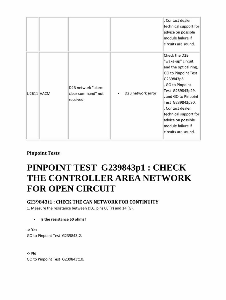
. Contact dealer
technical support for
advice on possible
module failure if
circuits are sound.
U2611 VACM
D2B network "alarm
clear command" not
received
• D2B network error
Check the D2B
"wake-up" circuit,
and the optical ring,
GO to Pinpoint Test
G239843p5.
, GO to Pinpoint
Test G239843p29.
, and GO to Pinpoint
Test G239843p30.
. Contact dealer
technical support for
advice on possible
module failure if
circuits are sound.
Pinpoint Tests
PINPOINT TEST G239843p1 : CHECK THE CONTROLLER AREA NETWORK FOR OPEN CIRCUIT G239843t1 : CHECK THE CAN NETWORK FOR CONTINUITY
1. Measure the resistance between DLC, pins 06 (Y) and 14 (G).
• Is the resistance 60 ohms?
-> Yes
GO to Pinpoint Test G239843t2.
-> No
GO to Pinpoint Test G239843t10.

G239843t2 : CHECK THE REAR CLIMATE CONTROL CONTROL MODULE
(RCCM) CAN + CIRCUIT FOR CONTINUITY
1. Disconnect the RCCM electrical connector, RA01. 2. Measure the resistance between DLC, pin 06
(Y) and RA01, pin 08 (Y).
• Is the resistance greater than 5 ohms?
-> Yes
REPAIR the high resistance circuit. For additional information, refer to the wiring diagrams. CLEAR the
DTC. TEST the system for normal operation.
-> No
GO to Pinpoint Test G239843t3.
G239843t3 : CHECK THE REAR CLIMATE CONTROL CONTROL MODULE
(RCCM) CAN - CIRCUIT FOR CONTINUITY
1. Measure the resistance between DLC, pin 14 (G) and RA01, pin 16 (G).
• Is the resistance greater than 5 ohms?
-> Yes
REPAIR the high resistance circuit. For additional information, refer to the wiring diagrams. CLEAR the
DTC. TEST the system for normal operation.
-> No
GO to Pinpoint Test G239843t4.
G239843t4 : CHECK THE YAW RATE SENSOR CAN + CIRCUIT FOR
CONTINUITY
1. Disconnect the Yaw rate sensor electrical connector, IP23. 2. Measure the resistance between DLC,
pin 06 (Y) and IP23, pin 02 (Y).
• Is the resistance greater than 5 ohms?
-> Yes
REPAIR the high resistance circuit. For additional information, refer to the wiring diagrams. CLEAR the
DTC. TEST the system for normal operation.
-> No
GO to Pinpoint Test G239843t5.

G239843t5 : CHECK THE YAW RATE SENSOR CAN - CIRCUIT FOR
CONTINUITY
1. Measure the resistance between DLC, pin 14 (G) and IP23, pin 01 (U).
• Is the resistance greater than 5 ohms?
-> Yes
REPAIR the high resistance circuit. For additional information, refer to the wiring diagrams. CLEAR the
DTC. TEST the system for normal operation.
-> No
GO to Pinpoint Test G239843t6.
G239843t6 : CHECK THE ASCCM CAN + CIRCUIT FOR CONTINUITY
1. Disconnect the ASCCM electrical connector, EC23. 2. Measure the resistance between DLC, pin 06
(Y) and EC23, pin 10 (Y).
• Is the resistance greater than 5 ohms?
-> Yes
REPAIR the high resistance circuit. For additional information, refer to the wiring diagrams. CLEAR the
DTC. TEST the system for normal operation.
-> No
GO to Pinpoint Test G239843t7.
G239843t7 : CHECK THE ASCCM CAN - CIRCUIT FOR CONTINUITY
1. Measure the resistance between DLC, pin 14 (G) and EC23, pin 04 (G).
• Is the resistance greater than 5 ohms?
-> Yes
REPAIR the high resistance circuit. For additional information, refer to the wiring diagrams. CLEAR the
DTC. TEST the system for normal operation.
-> No
GO to Pinpoint Test G239843t8.
G239843t8 : CHECK THE TCM CAN + CIRCUIT FOR CONTINUITY
1. Disconnect the TCM electrical connector, GB02. 2. Measure the resistance between DLC, pin 06 (Y)
and GB02, pin 06 (Y).
• Is the resistance greater than 5 ohms?

-> Yes
REPAIR the high resistance circuit. For additional information, refer to the wiring diagrams. CLEAR the
DTC. TEST the system for normal operation.
-> No
GO to Pinpoint Test G239843t9.
G239843t9 : CHECK THE TCM CAN - CIRCUIT FOR CONTINUITY
1. Measure the resistance between DLC, pin 14 (G) and GB02, pin 02 (G).
• Is the resistance greater than 5 ohms?
-> Yes
REPAIR the high resistance circuit. For additional information, refer to the wiring diagrams. CLEAR the
DTC. TEST the system for normal operation.
-> No
The CAN resistances are all correct. Check for DTCs indicating a faulty module, carry out pinpoint
tests for module indicated.
G239843t10 : CHECK THE CAN + CIRCUIT BETWEEN THE DLC AND THE
INSTRUMENT CLUSTER (IC) FOR CONTINUITY
1. Disconnect the IC electrical connector, IP06. 2. Measure the resistance between DLC, pin 06 (Y)
and IP06, pin 08 (Y).
• Is the resistance greater than 5 ohms?
-> Yes
REPAIR the high resistance circuit. For additional information, refer to the wiring diagrams. CLEAR the
DTC. TEST the system for normal operation.
-> No
GO to Pinpoint Test G239843t11.
G239843t11 : CHECK THE CAN - CIRCUIT BETWEEN THE DLC AND THE
INSTRUMENT CLUSTER (IC) FOR CONTINUITY
1. Measure the resistance between DLC, pin 14 (G) and IP06, pin 09 (G).
• Is the resistance greater than 5 ohms?
-> Yes
REPAIR the high resistance circuit. For additional information, refer to the wiring diagrams. CLEAR the
DTC. TEST the system for normal operation.
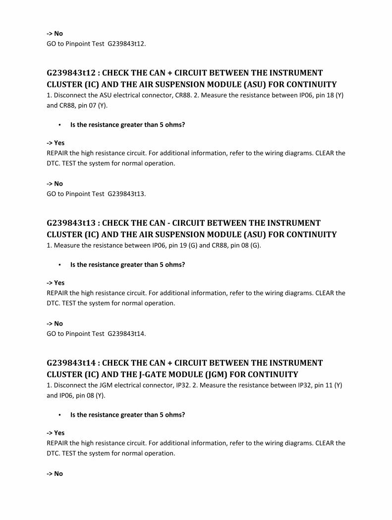
-> No
GO to Pinpoint Test G239843t12.
G239843t12 : CHECK THE CAN + CIRCUIT BETWEEN THE INSTRUMENT
CLUSTER (IC) AND THE AIR SUSPENSION MODULE (ASU) FOR CONTINUITY
1. Disconnect the ASU electrical connector, CR88. 2. Measure the resistance between IP06, pin 18 (Y)
and CR88, pin 07 (Y).
• Is the resistance greater than 5 ohms?
-> Yes
REPAIR the high resistance circuit. For additional information, refer to the wiring diagrams. CLEAR the
DTC. TEST the system for normal operation.
-> No
GO to Pinpoint Test G239843t13.
G239843t13 : CHECK THE CAN - CIRCUIT BETWEEN THE INSTRUMENT
CLUSTER (IC) AND THE AIR SUSPENSION MODULE (ASU) FOR CONTINUITY
1. Measure the resistance between IP06, pin 19 (G) and CR88, pin 08 (G).
• Is the resistance greater than 5 ohms?
-> Yes
REPAIR the high resistance circuit. For additional information, refer to the wiring diagrams. CLEAR the
DTC. TEST the system for normal operation.
-> No
GO to Pinpoint Test G239843t14.
G239843t14 : CHECK THE CAN + CIRCUIT BETWEEN THE INSTRUMENT
CLUSTER (IC) AND THE J-GATE MODULE (JGM) FOR CONTINUITY
1. Disconnect the JGM electrical connector, IP32. 2. Measure the resistance between IP32, pin 11 (Y)
and IP06, pin 08 (Y).
• Is the resistance greater than 5 ohms?
-> Yes
REPAIR the high resistance circuit. For additional information, refer to the wiring diagrams. CLEAR the
DTC. TEST the system for normal operation.
-> No

GO to Pinpoint Test G239843t15.
G239843t15 : CHECK THE CAN - CIRCUIT BETWEEN THE INSTRUMENT
CLUSTER (IC) AND THE J-GATE MODULE (JGM) FOR CONTINUITY
1. Measure the resistance between IP32, pin 12 (G) and IP06, pin 09 (G).
• Is the resistance greater than 5 ohms?
-> Yes
REPAIR the high resistance circuit. For additional information, refer to the wiring diagrams. CLEAR the
DTC. TEST the system for normal operation.
-> No
GO to Pinpoint Test G239843t16.
G239843t16 : CHECK THE CAN + CIRCUIT BETWEEN THE J-GATE MODULE
(JGM) AND THE AIR CONDITIONING MODULE (A/CCM) FOR CONTINUITY
1. Disconnect the A/CCM electrical connector, CR119. 2. Measure the resistance between IP32, pin
09 (Y) and CR119, pin 16 (Y).
• Is the resistance greater than 5 ohms?
-> Yes
REPAIR the high resistance circuit. For additional information, refer to the wiring diagrams. CLEAR the
DTC. TEST the system for normal operation.
-> No
GO to Pinpoint Test G239843t17.
G239843t17 : CHECK THE CAN - CIRCUIT BETWEEN THE J-GATE MODULE
(JGM) AND THE AIR CONDITIONING MODULE (A/CCM) FOR CONTINUITY
1. Measure the resistance between IP32, pin 10 (G) and CR119, pin 17 (G).
• Is the resistance greater than 5 ohms?
-> Yes
REPAIR the high resistance circuit. For additional information, refer to the wiring diagrams. CLEAR the
DTC. TEST the system for normal operation.
-> No
GO to Pinpoint Test G239843t18.
G239843t18 : CHECK THE CAN + CIRCUIT BETWEEN THE AIR
CONDITIONING MODULE (A/CCM) AND THE ABS CONTROL MODULE
(ABSCM) FOR CONTINUITY
1. Disconnect the ABSCM electrical connector, EC30. 2. Measure the resistance between CR119, pin
06 (Y) and EC30, pin 11 (Y).
• Is the resistance greater than 5 ohms?
-> Yes
REPAIR the high resistance circuit. For additional information, refer to the wiring diagrams. CLEAR the
DTC. TEST the system for normal operation.
-> No
GO to Pinpoint Test G239843t19.
G239843t19 : CHECK THE CAN - CIRCUIT BETWEEN THE AIR CONDITIONING
MODULE (A/CCM) AND THE ABS CONTROL MODULE (ABSCM) FOR
CONTINUITY
1. Measure the resistance between CR119, pin 07 (G) and EC30, pin 15 (G).
• Is the resistance greater than 5 ohms?
-> Yes
REPAIR the high resistance circuit. For additional information, refer to the wiring diagrams. CLEAR the
DTC. TEST the system for normal operation.
-> No
GO to Pinpoint Test G239843t20.
G239843t20 : CHECK THE CAN + CIRCUIT BETWEEN THE ABS CONTROL
MODULE (ABSCM) AND THE ENGINE CONTROL MODULE (ECM) FOR
CONTINUITY
1. Disconnect the ECM electrical connector, PI01. 2. Measure the resistance between EC30, pin 12 (Y)
and PI01, pin 124 (Y).
• Is the resistance greater than 5 ohms?
-> Yes
REPAIR the high resistance circuit. For additional information, refer to the wiring diagrams. CLEAR the
DTC. TEST the system for normal operation.
-> No
GO to Pinpoint Test G239843t21.
G239843t21 : CHECK THE CAN - CIRCUIT BETWEEN THE ABS CONTROL
MODULE (ABSCM) AND THE ENGINE CONTROL MODULE (ECM) FOR
CONTINUITY
1. Measure the resistance between EC30, pin 14 (G) and PI01, pin 123 (G).
• Is the resistance greater than 5 ohms?
-> Yes
REPAIR the high resistance circuit. For additional information, refer to the wiring diagrams. CLEAR the
DTC. TEST the system for normal operation.
-> No
Recheck the resistance in test A1. Check for DTCs indicating a module fault. Carry out the pinpoint
test for the module indicated.
PINPOINT TEST G239843p2 : CHECK THE CONTROLLER AREA NETWORK FOR SHORT CIRCUIT G239843t22 : CHECK THE CAN + FOR SHORT CIRCUIT TO B +
1. Measure the resistance between pins 06 (Y) and 16 (NW) of the DLC.
• Is the resistance less than 10,000 ohms?
-> Yes
REPAIR the short circuit. For additional information, refer to the wiring diagrams. CLEAR the DTC.
TEST the system for normal operation.
-> No
GO to Pinpoint Test G239843t23.
G239843t23 : CHECK THE CAN + FOR SHORT CIRCUIT TO IGNITION
SWITCHED +
1. Turn the ignition switch to the ON position. 2. Measure the resistance between pins 06 (Y) and 09
(GO) of the DLC.
• Is the resistance less than 10,000 ohms?
-> Yes
REPAIR the short circuit. For additional information, refer to the wiring diagrams. CLEAR the DTC.
TEST the system for normal operation.
-> No
GO to Pinpoint Test G239843t24.
G239843t24 : CHECK THE CAN + FOR SHORT CIRCUIT TO GROUND
1. Turn the ignition switch to the OFF position. 2. Measure the resistance between pins 06 (Y) and 04
(B) of the DLC. 3. Measure the resistance between pins 06 (Y) and 05 (BK) of the DLC.
• Is either resistance less than 10,000 ohms?
-> Yes
REPAIR the short circuit. For additional information, refer to the wiring diagrams. CLEAR the DTC.
TEST the system for normal operation.
-> No
GO to Pinpoint Test G239843t25.
G239843t25 : CHECK THE CAN - FOR SHORT CIRCUIT TO B +
1. Measure the resistance between pins 14 (G) and 16 (NW) of the DLC.
• Is the resistance less than 10,000 ohms?
-> Yes
REPAIR the short circuit. For additional information, refer to the wiring diagrams. CLEAR the DTC.
TEST the system for normal operation.
-> No
GO to Pinpoint Test G239843t26.
G239843t26 : CHECK THE CAN - FOR SHORT CIRCUIT TO IGNITION
SWITCHED +
1. Turn the ignition switch to the ON position. 2. Measure the resistance between pins 14 (G) and 09
(GO) of the DLC.
• Is the resistance less than 10,000 ohms?
-> Yes
REPAIR the short circuit. For additional information, refer to the wiring diagrams. CLEAR the DTC.
TEST the system for normal operation.
-> No
GO to Pinpoint Test G239843t27.
G239843t27 : CHECK THE CAN - FOR SHORT CIRCUIT TO GROUND
1. Turn the ignition switch to the OFF position. 2. Measure the resistance between pins 14 (G) and 04
(B) of the DLC. 3. Measure the resistance between pins 14 (G) and 05 (BK) of the DLC.
• Is either resistance less than 10,000 ohms?
-> Yes
REPAIR the short circuit. For additional information, refer to the wiring diagrams. CLEAR the DTC.
TEST the system for normal operation.
-> No
No short circuit fault found in controller area network. Check for DTCs indicating a module fault.
Carry out the pinpoint test for the module indicated.
PINPOINT TEST G239843p3 : CHECK THE SCP NETWORK G239843t28 : CHECK FOR CORRECT BUS TERMINATION IN THE SCP +
NETWORK
1. Measure the resistance between pins 02 (Y) and 05 (BK) of the DLC.
• Is the resistance 120 ohms?
-> Yes
Network resistance is correct. Check for DTCs indicating a module or circuit fault. REFER to the DTC
index.
-> No
GO to Pinpoint Test G239843t29.
G239843t29 : CHECK THE SCP + FOR SHORT CIRCUIT TO BATTERY
1. Measure the voltage across pins 02 (Y) and 16 (NW) of the DLC.
• Is the voltage greater than 3 volts?
-> Yes
REPAIR the short circuit. For additional information, refer to the wiring diagrams. Test the system for
normal operation.

-> No
GO to Pinpoint Test G239843t30.
G239843t30 : CHECK THE SCP + FOR SHORT CIRCUIT TO IGNITION +
1. Turn the ignition switch to the ON position. 2. Measure the voltage across pins 02 (Y) and 09 (GO)
of the DLC.
• Is the voltage greater than 3 volts?
-> Yes
REPAIR the short circuit. For additional information, refer to the wiring diagrams. Test the system for
normal operation.
-> No
GO to Pinpoint Test G239843t31.
G239843t31 : CHECK THE SCP + FOR SHORT CIRCUIT TO GROUND
1. Measure the resistance between pins 02 (Y) and 05 (BK) of the DLC.
• Is the resistance less than 90 ohms?
-> Yes
REPAIR the short circuit. For additional information, refer to the wiring diagrams. Test the system for
normal operation.
-> No
GO to Pinpoint Test G239843t32.
G239843t32 : CHECK THE SCP - FOR SHORT CIRCUIT TO BATTERY
1. Measure the voltage across pins 10 (U) and 16 (NW) of the DLC.
• Is the voltage greater than 3 volts?
-> Yes
REPAIR the short circuit. For additional information, refer to the wiring diagrams. Test the system for
normal operation.
-> No
GO to Pinpoint Test G239843t33.
G239843t33 : CHECK THE SCP - FOR SHORT CIRCUIT TO IGNITION +
1. Turn the ignition switch to the ON position. 2. Measure the voltage across pins 10 (U) and 09 (GO)
of the DLC.
• Is the voltage greater than 3 volts?
-> Yes
REPAIR the short circuit. For additional information, refer to the wiring diagrams. Test the system for
normal operation.
-> No
GO to Pinpoint Test G239843t34.
G239843t34 : CHECK THE SCP - FOR SHORT CIRCUIT TO GROUND
1. Measure the resistance between pins 10 (U) and 05 (BK) of the DLC.
• Is the resistance less than 10,000 ohms?
-> Yes
REPAIR the short circuit. For additional information, refer to the wiring diagrams. Test the system for
normal operation.
-> No
GO to Pinpoint Test G239843t35.
G239843t35 : CHECK FOR SHORT CIRCUIT BETWEEN SCP + AND SCP -
1. Measure the resistance between pins 10 (U) and 02 (BK) of the DLC.
• Is the resistance less than 10,000 ohms?
-> Yes
REPAIR the short circuit. For additional information, refer to the wiring diagrams. Test the system for
normal operation.
-> No
Check for DTCs indicating a faulty module or circuit. Refer to the DTC index.
PINPOINT TEST G239843p4 : CHECK THE ISO NETWORK CIRCUIT G239843t36 : CHECK THE TCM ISO CIRCUIT FOR SHORT TO BATTERY +
1. Measure the voltage between pin 11 of the DLC (O) and GROUND.

• Is the voltage greater than 3 volts?
-> Yes
REPAIR the short circuit. For additional information, refer to the wiring diagrams. Test the system for
normal operation.
-> No
GO to Pinpoint Test G239843t37.
G239843t37 : CHECK THE TCM ISO CIRCUIT FOR SHORT TO IGNITION +
1. Turn the ignition switch to the ON position. 2. Measure the voltage between pin 11 of the DLC (O)
and GROUND.
• Is the voltage greater than 3 volts?
-> Yes
REPAIR the short circuit. For additional information, refer to the wiring diagrams. Test the system for
normal operation.
-> No
GO to Pinpoint Test G239843t38.
G239843t38 : CHECK THE TCM ISO CIRCUIT FOR SHORT TO GROUND
1. Measure the resistance between pin 11 of the DLC (O) and GROUND.
• Is the resistance less than 10,000 ohms?
-> Yes
REPAIR the short circuit. For additional information, refer to the wiring diagrams. Test the system for
normal operation.
-> No
GO to Pinpoint Test G239843t39.
G239843t39 : CHECK THE TCM ISO CIRCUIT FOR HIGH RESISTANCE
1. Disconnect the battery negative terminal. 2. Disconnect the TCM electrical connector, GB02. 3.
Measure the resistance between GB02, pin 03 (O) and pin 11 of the DLC (O).
• Is the resistance greater than 5 ohms?
-> Yes
REPAIR the high resistance circuit. For additional information, refer to the wiring diagrams. Test the
system for normal operation.

-> No
GO to Pinpoint Test G239843t40.
G239843t40 : CHECK THE ISO CIRCUIT FOR SHORT TO BATTERY +
1. Reconnect the TCM electrical connector, GB02. 2. Reconnect the battery negative terminal. 3.
Measure the voltage between pin 07 of the DLC (W) and GROUND.
• Is the voltage greater than 3 volts?
-> Yes
REPAIR the short circuit. For additional information, refer to the wiring diagrams. Test the system for
normal operation.
-> No
GO to Pinpoint Test G239843t41.
G239843t41 : CHECK THE ISO CIRCUIT FOR SHORT TO IGNITION +
1. Turn the ignition switch to the ON position. 2. Measure the voltage between pin 07 of the DLC (W)
and GROUND.
• Is the voltage greater than 3 volts?
-> Yes
REPAIR the short circuit. For additional information, refer to the wiring diagrams. Test the system for
normal operation.
-> No
GO to Pinpoint Test G239843t42.
G239843t42 : CHECK THE ISO CIRCUIT FOR SHORT TO GROUND
1. Measure the resistance between pin 07 of the DLC (W) and GROUND.
• Is the resistance less than 10,000 ohms?
-> Yes
REPAIR the short circuit. For additional information, refer to the wiring diagrams. Test the system for
normal operation.
-> No
GO to Pinpoint Test G239843t43.

G239843t43 : CHECK THE ISO CIRCUIT BETWEEN THE RIGHT-HAND HID
AND THE DLC FOR HIGH RESISTANCE
1. Disconnect the battery negative terminal. 2. Disconnect the HID electrical connector, EC06. 3.
Measure the resistance between EC06, pin 05 (W) and pin 07 of the DLC (W).
• Is the resistance greater than 5 ohms?
-> Yes
REPAIR the high resistance circuit. For additional information, refer to the wiring diagrams. Test the
system for normal operation.
-> No
GO to Pinpoint Test G239843t44.
G239843t44 : CHECK THE ISO CIRCUIT BETWEEN THE LEFT-HAND HID AND
THE DLC FOR HIGH RESISTANCE
1. Reconnect the HID electrical connector, EC06. 2. Disconnect the HID electrical connector, EC57. 3.
Measure the resistance between EC57, pin 05 (W) and pin 07 of the DLC (W).
• Is the resistance greater than 5 ohms?
-> Yes
REPAIR the high resistance circuit. For additional information, refer to the wiring diagrams. Test the
system for normal operation.
-> No
GO to Pinpoint Test G239843t45.
G239843t45 : CHECK THE ISO CIRCUIT BETWEEN THE ECM AND THE DLC
FOR HIGH RESISTANCE
1. Reconnect the HID electrical connector, EC57. 2. Disconnect the ECM electrical connector, PI01. 3.
Measure the resistance between PI01, pin 105 (W) and pin 07 of the DLC (W).
• Is the resistance greater than 5 ohms?
-> Yes
REPAIR the high resistance circuit. For additional information, refer to the wiring diagrams. Test the
system for normal operation.
-> No
GO to Pinpoint Test G239843t46.
G239843t46 : CHECK THE ISO CIRCUIT BETWEEN THE PARKING AID
MODULE AND THE DLC FOR HIGH RESISTANCE
1. Reconnect the ECM electrical connector, PI01. 2. Disconnect the parking aid control module
electrical connector, CR52. 3. Measure the resistance between CR52, pin 05 (W) and pin 07 of the
DLC (W).
• Is the resistance greater than 5 ohms?
-> Yes
REPAIR the high resistance circuit. For additional information, refer to the wiring diagrams. Test the
system for normal operation.
-> No
GO to Pinpoint Test G239843t47.
G239843t47 : CHECK THE ISO CIRCUIT BETWEEN THE INTRUSION SENSOR
AND THE DLC FOR HIGH RESISTANCE
1. Reconnect the parking aid control module electrical connector, CR52. 2. Disconnect the intrusion
sensor electrical connector, RF03. 3. Measure the resistance between RF03, pin 08 (W) and pin 07 of
the DLC (W).
• Is the resistance greater than 5 ohms?
-> Yes
REPAIR the high resistance circuit. For additional information, refer to the wiring diagrams. Test the
system for normal operation.
-> No
GO to Pinpoint Test G239843t48.
G239843t48 : CHECK THE ISO CIRCUIT BETWEEN THE AIRBAG MODULE
AND THE DLC FOR HIGH RESISTANCE
1. Reconnect the intrusion sensor electrical connector, RF03. 2. Disconnect the airbag module
electrical connector, CR86. 3. Measure the resistance between CR86, pin 11 (W) and pin 07 of the
DLC (W).
• Is the resistance greater than 5 ohms?
-> Yes
REPAIR the high resistance circuit. For additional information, refer to the wiring diagrams. Test the
system for normal operation.
-> No
Reconnect the airbag module electrical connector, CR86. If a module fault is still suspected, check the
module power supplies and GROUNDS.
PINPOINT TEST G239843p5 : ONE OR MORE D2B MODULES NOT RESPONDING. WAKE-UP SIGNAL FAULT G239843t255 : CHECK THE WAKE-UP SIGNAL TO THE CD CHANGER
1. Disconnect the CD changer electrical connector TLO5. 2. Turn the ignition switch to the ACC
position. 3. Measure the voltage between TLO5 pin 03 (OG) and GROUND, using an oscilloscope (see
note above).
• Does the oscilloscope show a wake-up signal as described?
-> Yes
GO to Pinpoint Test G239843t256.
-> No
REPAIR the circuit between TLO5 pin 03 and ACU electrical connector CC08 pin 19. For additional
information, refer to the wiring diagrams. CLEAR the DTC. TEST the system for normal operation.
G239843t256 : CHECK THE WAKE-UP SIGNAL TO THE PHONE MODULE
1. Disconnect the phone module electrical connector TLO7. 2. Turn the ignition switch to the ACC
position. 3. Measure the voltage between TLO7 pin 23 (OG) and GROUND, using an oscilloscope (see
note above).
• Does the oscilloscope show a wake-up signal as described?
-> Yes
GO to Pinpoint Test G239843t257.
-> No
REPAIR the circuit between TLO7 pin 23 and audio control module electrical connector CC08 pin 19.
For additional information, refer to the wiring diagrams. CLEAR the DTC. TEST the system for normal
operation.

G239843t257 : CHECK THE WAKE-UP SIGNAL TO THE VOICE ACTIVATED
CONTROL MODULE
1. Disconnect the voice activated control module electrical connector TL68. 2. Turn the ignition
switch to the ACC position. 3. Measure the voltage between TL68 pin 14 (OG) and GROUND, using an
oscilloscope (see note above).
• Does the oscilloscope show a wake-up signal as described?
-> Yes
GO to Pinpoint Test G239843t258.
-> No
REPAIR the circuit between TL68 pin 14 and audio control module electrical connector CC08 pin 19.
For additional information, refer to the wiring diagrams. CLEAR the DTC. TEST the system for normal
operation.
G239843t258 : CHECK THE WAKE-UP SIGNAL TO THE NAVIGATION
COMPUTER
1. Disconnect the navigation module electrical connector TLOO2. 2. Turn the ignition switch to the
ACC position. 3. Measure the voltage between TLO2 pin 03 (OG) and GROUND, using an oscilloscope
(see note above).
• Does the oscilloscope show a wake-up signal as described?
-> Yes
GO to Pinpoint Test G239843t259.
-> No
REPAIR the circuit between TLO2 pin 03 and audio control module electrical connector CC08 pin 19.
For additional information, refer to the wiring diagrams. CLEAR the DTC. TEST the system for normal
operation.
G239843t259 : CHECK THE WAKE-UP SIGNAL TO THE AMP
1. Disconnect the amplifier electrical connector TLO9. 2. Turn the ignition switch to the ACC position.
3. Measure the voltage between TLO9 pin 05 (OG) and GROUND, using an oscilloscope (see note
above).
• Does the oscilloscope show a wake-up signal as described?
-> Yes
GO to Pinpoint Test G239843t351.
-> No

REPAIR the circuit between TLO9 pin 05 and audio control module electrical connector CC08 pin 19.
For additional information, refer to the wiring diagrams. CLEAR the DTC. TEST the system for normal
operation.
G239843t351 : CHECK THE WAKE-UP SIGNAL TO THE REAR
ENTERTAINMENT MODULE
1. Disconnect the rear entertainment module electrical connector RC001. 2. Turn the ignition switch
to the ACC position. 3. Measure the voltage between RC01 pin 06 (OG) and GROUND, using an
oscilloscope (see note above).
• Does the oscilloscope show a wake-up signal as described?
-> Yes
Check for DTCs indicating a module fault.
-> No
REPAIR the circuit between RC01 pin 06 and audio control module electrical connector CC08 pin 19.
For additional information, refer to the wiring diagrams. CLEAR the DTC. TEST the system for normal
operation.
PINPOINT TEST G239843p24 : U2003; COMPACT DISC CHANGER NOT RESPONDING G239843t233 : CHECK THE CD CHANGER MODULE, USING THE OPTICAL BUS
TESTER
1. Connect the optical bus tester to the fibre optic lead connector DB02. 2. Set the optical bus tester
to BY-PASS. 3. CLEAR the DTC. 4. Turn the ignition switch to the ACC position. 5. Wait for 10 seconds.
6. Check for "not responding" DTCs.
• Is U2003 set?
-> Yes
For "wake-up" signal circuit tests, GO to Pinpoint Test G239843p5.
. GO to Pinpoint Test G239843t255.
-> No
GO to Pinpoint Test G239843t234.
G239843t234 : CHECK FOR DTC U2602 OR U2603
1. Check DTCs.

• Are codes U2602 or U2603 logged?
-> Yes
For optical ring tests, GO to Pinpoint Test G239843p29.
, and GO to Pinpoint Test G239843p30.
.
-> No
Recheck DTCs. No break in optical harness.
PINPOINT TEST G239843p25 : U2008; PHONE MODULE NOT RESPONDING G239843t235 : CHECK PHONE MODULE, USING OPTICAL BUS TESTER
1. Connect the optical bus tester to the fibre optic lead connector DB03. 2. Set the optical bus tester
to BY-PASS. 3. CLEAR the DTC. 4. Turn the ignition switch to the ACC position. 5. Wait for 10 seconds.
6. Check for "not responding" DTCs.
• Is U2008 set?
-> Yes
For "wake-up" signal circuit tests, GO to Pinpoint Test G239843p5.
.
-> No
GO to Pinpoint Test G239843t236.
G239843t236 : CHECK FOR DTC U2602 OR U2603
1. Check DTCs.
• Are codes U2602 or U2603 logged?
-> Yes
For optical ring tests, GO to Pinpoint Test G239843p29.
, and GO to Pinpoint Test G239843p30.
.
-> No
Recheck DTCs. No break in optical harness.
PINPOINT TEST G239843p26 : U2019; VOICE ACTIVATED CONTROL MODULE (VACM) NOT RESPONDING G239843t237 : CHECK VOICE CONTROL MODULE USING OPTICAL BUS
TESTER
1. Connect the optical bus tester to the fibre optic lead connector DB04. 2. Set the optical bus tester
to BY-PASS. 3. CLEAR the DTC. 4. Turn the ignition switch to the ACC position. 5. Wait for 10 seconds.
6. Check for "not responding" DTCs.
• Is U2019 set?
-> Yes
For "wake-up" signal circuit tests, GO to Pinpoint Test G239843p5.
.
-> No
GO to Pinpoint Test G239843t238.
G239843t238 : CHECK FOR DTC U2602 OR U2603
1. Check DTCs.
• Are codes U2602 or U2603 logged?
-> Yes
For optical ring tests, GO to Pinpoint Test G239843p29.
, and GO to Pinpoint Test G239843p30.
.
-> No
Recheck DTCs. No break in optical harness.
PINPOINT TEST G239843p27 : U2613; NAVIGATION CONTROL MODULE NOT RESPONDING

G239843t239 : CHECK NAVIGATION CONTROL MODULE, USING OPTICAL
BUS TESTER
1. Connect the optical bus tester to the fibre optic lead connector DB06. 2. Set the optical bus tester
to BY-PASS. 3. CLEAR the DTC. 4. Turn the ignition switch to the ACC position. 5. Wait for 10 seconds.
6. Check for DTCs.
• Is U2613 set?
-> Yes
For "wake-up" signal circuit tests, GO to Pinpoint Test G239843p5.
. GO to Pinpoint Test G239843t258.
-> No
GO to Pinpoint Test G239843t240.
G239843t240 : CHECK FOR DTC U2602 OR U2603
1. Check DTCs.
• Are codes U2602 or U2603 logged?
-> Yes
For optical ring tests, GO to Pinpoint Test G239843p29.
, and GO to Pinpoint Test G239843p30.
.
-> No
Recheck DTCs. No break in optical harness.
PINPOINT TEST G239843p28 : U2614; AMPLIFIER NOT RESPONDING G239843t241 : CHECK AMPLIFIER USING OPTICAL BUS TESTER
1. Connect the optical bus tester to the fibre optic lead connector DB07. 2. Set the optical bus tester
to BY-PASS. 3. CLEAR the DTC. 4. Turn the ignition switch to the ACC position. 5. Wait for 10 seconds.
6. Check for DTCs.
• Is U2614 set?
-> Yes
For "wake-up" signal circuit tests, GO to Pinpoint Test G239843p5.
.

-> No
GO to Pinpoint Test G239843t242.
G239843t242 : CHECK FOR DTC U2602 OR U2603
1. Check DTCs.
• Are codes U2602 or U2603 logged?
-> Yes
For optical ring tests, GO to Pinpoint Test G239843p29.
, and GO to Pinpoint Test G239843p30.
.
-> No
Recheck DTCs. No break in optical harness.
PINPOINT TEST G239843p43 : U2615; REAR ENTERTAINMENT MODULE NOT RESPONDING G239843t349 : CHECK REAR ENTERTAINMENT MODULE USING OPTICAL
BUS TESTER
1. Connect the optical bus tester to the fibre optic lead connector RC05. 2. Set the optical bus tester
to BY-PASS. 3. CLEAR the DTC. 4. Turn the ignition switch to the ACC position. 5. Wait for 10 seconds.
6. Check for DTCs.
• Is U2615 set?
-> Yes
For "wake-up" signal circuit tests, GO to Pinpoint Test G239843p5.
.
-> No
GO to Pinpoint Test G239843t350.
G239843t350 : CHECK FOR DTC U2602 OR U2603
1. Check DTCs.
• Are codes U2602 or U2603 logged?
-> Yes
For optical ring tests, GO to Pinpoint Test G239843p29.
, and GO to Pinpoint Test G239843p30.
.
-> No
Recheck DTCs. No break in optical harness.
PINPOINT TEST G239843p29 : U2602: BREAK IN OPTICAL HARNESS FROM AUDIO CONTROL MODULE. (TRANSMITTER) G239843t243 : CHECK FIBRE OPTIC LEAD BETWEEN LUGGAGE
COMPARTMENT JOINT AND CD CHANGER
1. Disconnect fibre optic connector DB02. 2. Disconnect fibre optic connector DB01. 3. Connect the
optical bus tester to the fibre optic lead connector DB01. 4. Set the optical bus tester to TX. 5. Set the
optical bus tester to ON. 6. Check for light pulses at the receiver pin of disconnected D2B connector
DB02.
• Are light pulses visible?
-> Yes
GO to Pinpoint Test G239843t244.
-> No
INSTALL a new telematic harness between DB03 and DB02. For additional information, refer to the
electrical guide. CLEAR the DTC. TEST the system for normal operation.
G239843t244 : CHECK CABIN FIBRE OPTIC HARNESS
1. Disconnect the fibre optic connector FC107. 2. Disconnect the fibre optic connector DB01. 3.
Connect the optical bus tester to TL95 using adaptor lead. 4. Set the optical bus tester to TX. 5. Set
the optical bus tester to ON. 6. Check for light pulses at the receiver pin of disconnected D2B
connector DB01.
• Are light pulses visible?
-> Yes
GO to Pinpoint Test G239843t245.
-> No

INSTALL a new cabin optical harness between DB01 and TL95. For additional information, refer to the
electrical guide. CLEAR the DTC. TEST the system for normal operation.
G239843t245 : CHECK FIBRE OPTIC LEAD BETWEEN ASHTRAY AND AUDIO
CONTROL MODULE
1. Connect the optical bus tester to CC21 using the adaptor lead. 2. Set the optical bus tester to TX. 3.
Set the optical bus tester to ON. 4. Check for light pulses at the receiver pin of disconnected D2B
connector TL95.
• Are light pulses visible?
-> Yes
GO to Pinpoint Test G239843t246.
-> No
INSTALL a new instrument optical harness between CC21 and TL95. For additional information, refer
to the electrical guide. CLEAR the DTC. TEST the system for normal operation.
G239843t246 : CHECK THE AUDIO CONTROL MODULE
1. Turn the ignition switch to the ACC position. 2. Wait for 10 seconds. 3. Check for light pulses at the
transmitter pin of disconnected D2B connector CC21 (rear of audio control module).
• Are light pulses visible?
-> Yes
GO to Pinpoint Test G239843t247.
-> No
INSTALL a new ACU. <<415-01>> CLEAR the DTC. TEST the system for normal operation.
G239843t247 : CHECK THE FIBRE OPTIC LEAD FROM THE CD CHANGER TO
THE PHONE MODULE
1. Disconnect optical connector DB02. 2. Disconnect optical connector DB03. 3. Connect the optical
bus tester to DB02. 4. Check for light pulses at the transmitter pin of disconnected D2B connector
DB03.
• Are light pulses visible?
-> Yes
GO to Pinpoint Test G239843t248.
-> No

INSTALL a new telematic harness between DB03 and DB02. For additional information, refer to the
electrical guide. CLEAR the DTC. TEST the system for normal operation.
G239843t248 : CHECK THE FIBRE OPTIC LEAD FROM THE PHONE MODULE
TO THE VOICE MODULE
1. Disconnect optical connector DB03. 2. Disconnect optical connector DB04. 3. Connect the optical
bus tester to DB03. 4. Check for light pulses at the transmitter pin of disconnected D2B connector
DB04.
• Are light pulses visible?
-> Yes
GO to Pinpoint Test G239843t249.
-> No
INSTALL a new telematic harness between DB03 and DB04. For additional information, refer to the
electrical guide. CLEAR the DTC. TEST the system for normal operation.
G239843t354 : CHECK THE FIBRE OPTIC LEAD FROM THE VOICE MODULE
TO THE REAR ENTERTAINMENT MODULE
1. Disconnect optical connector DB04. 2. Disconnect optical connector RC05. 3. Connect the optical
bus tester to DB04. 4. Check for light pulses at the transmitter pin of disconnected D2B connector
RC05.
• Are light pulses visible?
-> Yes
GO to Pinpoint Test G239843t355.
-> No
INSTALL a new telematic harness between DB04 and RC05. For additional information, refer to the
electrical guide. CLEAR the DTC. TEST the system for normal operation.
G239843t355 : CHECK THE FIBRE OPTIC LEAD FROM THE REAR
ENTERTAINMENT MODULE TO THE NAVIGATION COMPUTER
1. Disconnect optical connector RC05. 2. Disconnect optical connector DB06. 3. Connect the optical
bus tester to RC05.
• Are light pulses visible?
-> Yes
GO to Pinpoint Test G239843t249.

-> No
INSTALL a new telematic harness between RC05 and DB06. For additional information, refer to the
electrical guide. CLEAR the DTC. TEST the system for normal operation.
G239843t249 : CHECK THE FIBRE OPTIC LEAD FROM THE VOICE MODULE
TO THE NAVIGATION COMPUTER
1. Disconnect optical connector DB04. 2. Disconnect optical connector DB06. 3. Connect the optical
bus tester to DB04. 4. Check for light pulses at the transmitter pin of disconnected D2B connector
DB06.
• Are light pulses visible?
-> Yes
GO to Pinpoint Test G239843t250.
-> No
INSTALL a new telematic harness between DB04 and DB06. For additional information, refer to the
electrical guide. CLEAR the DTC. TEST the system for normal operation.
G239843t250 : CHECK THE FIBRE OPTIC LEAD FROM THE NAVIGATION
COMPUTER TO THE AMP
1. Disconnect optical connector DB06. 2. Disconnect optical connector DB07. 3. Connect the optical
bus tester to DB06. 4. Check for light pulses at the transmitter pin of disconnected D2B connector
DB07.
• Are light pulses visible?
-> Yes
Recheck DTCs. No fault found in D2B system.
-> No
INSTALL a new telematic harness between DB06 and DB07. For additional information, refer to the
electrical guide. CLEAR the DTC. TEST the system for normal operation.
PINPOINT TEST G239843p30 : U2603: BREAK IN OPTICAL HARNESS TO AUDIO CONTROL MODULE. (RECEIVER)

G239843t251 : CHECK FIBRE OPTIC LEAD BETWEEN LUGGAGE
COMPARTMENT JOINT AND AMPLIFIER
1. Disconnect the fibre optic connector DB07. 2. Disconnect the fibre optic connector DB01. 3.
Connect the optical bus tester to DB07. 4. Set the optical bus tester to TX. 5. Set the optical bus
tester to ON. 6. Check for light pulses at the receiver pin of disconnected D2B connector DB01.
• Are light pulses visible?
-> Yes
GO to Pinpoint Test G239843t252.
-> No
INSTALL a new telematic harness between DB01 and DB07. For additional information, refer to the
electrical guide. CLEAR the DTC. TEST the system for normal operation.
G239843t252 : CHECK CABIN FIBRE OPTIC HARNESS
1. Disconnect the fibre optic connector TL95. 2. Disconnect the fibre optic connector DB01. 3.
Connect the optical bus tester to DB01 using the adaptor lead, if required. 4. Set the optical bus
tester to TX. 5. Set the optical bus tester to ON. 6. Check for light pulses at the receiver pin of
disconnected D2B connector TL95.
• Are light pulses visible?
-> Yes
GO to Pinpoint Test G239843t253.
-> No
INSTALL a new cabin optical harness between RA01 and FC107. For additional information, refer to
the electrical guide. CLEAR the DTC. TEST the system for normal operation.
G239843t253 : CHECK FIBRE OPTIC LEAD BETWEEN ASHTRAY AND AUDIO
CONTROL MODULE
1. Disconnect the fibre optic connector CC21. 2. Disconnect the fibre optic connector TL95. 3.
Connect the optical bus tester to CC21. 4. Set the optical bus tester to TX. 5. Set the optical bus tester
to ON. 6. Check for light pulses at the receiver pin of disconnected D2B connector TL95.
• Are light pulses visible?
-> Yes
GO to Pinpoint Test G239843t254.
-> No

INSTALL a new instrument optical harness between CC21 and TL95. For additional information, refer
to the electrical guide. CLEAR the DTC. TEST the system for normal operation.
G239843t254 : CHECK THE AUDIO CONTROL MODULE
1. Connect the optical short link between the receiver and transmitter of the audio control module.
2. Turn the ignition switch to the ACC position. 3. Wait for 10 seconds. 4. Check for DTC.
• Is U2603 logged?
-> Yes
INSTALL a new audio control module, <<415-01>> CLEAR the DTC. TEST the system for normal
operation.
-> No
Recheck DTCs. No fault found in D2B system.
PINPOINT TEST G239843p6 : CHECK THE SUPPLIES AND GROUNDS TO THE CD CHANGER G239843t49 : CHECK THE PERMANENT SUPPLY TO THE CD CHANGER
1. Disconnect the CD changer electrical connector, TL05. 2. Measure the voltage between TL05, pin
02 (NW) and GROUND.
• Is the voltage less than 10 volts?
-> Yes
REPAIR the circuit between the CD changer and battery. This circuit includes the rear power
distribution box (fuse 27). For additional information, refer to the wiring diagrams. TEST the system
for normal operation.
-> No
GO to Pinpoint Test G239843t50.
G239843t50 : CHECK THE GROUND TO THE CD CHANGER
1. Measure the resistance between TL05, pin 01 (BK) and GROUND.
• Is the resistance greater than 5 ohms?
-> Yes
REPAIR the high resistance circuit. For additional information, refer to the wiring diagrams. TEST the
system for normal operation.
-> No
CHECK for DTCs indicating a wake-up circuit or optical ring fault. REFER to the DTC index.
PINPOINT TEST G239843p7 : CHECK THE SUPPLIES AND GROUNDS TO THE AMPLIFIER G239843t51 : CHECK THE PERMANENT SUPPLY TO THE AMPLIFIER
1. Disconnect the amplifier electrical connector, TL09. 2. Measure the voltage between TL09, pins 03
and 09 (NR) and GROUND.
• Is the voltage less than 10 volts?
-> Yes
REPAIR the circuit between the amplifier and battery. This circuit includes the rear power distribution
box (fuse 34). For additional information, refer to the wiring diagrams. TEST the system for normal
operation.
-> No
GO to Pinpoint Test G239843t52.
G239843t52 : CHECK THE GROUND TO THE AMPLIFIER
1. Measure the resistance between TL09, pins 02 and 08 (B) and GROUND.
• Is the resistance greater than 5 ohms?
-> Yes
REPAIR the high resistance circuit. For additional information, refer to the wiring diagrams. TEST the
system for normal operation.
-> No
CHECK for DTCs indicating a wake-up circuit or optical ring fault. REFER to the DTC index.
PINPOINT TEST G239843p8 : CHECK THE SUPPLIES AND GROUNDS TO THE CELLULAR PHONE MODULE G239843t53 : CHECK THE PERMANENT SUPPLY TO THE PHONE MODULE
1. Disconnect the phone module electrical connector, TL07. 2. Measure the voltage between TL07,
pins 12 and 13 (RW) and GROUND.
• Is the voltage less than 10 volts?
-> Yes
REPAIR the circuit between the phone module and battery. This circuit includes the primary junction
box (fuse 30). For additional information, refer to the wiring diagrams. TEST the system for normal
operation.
-> No
GO to Pinpoint Test G239843t54.
G239843t54 : CHECK THE ACCESSORY SUPPLY TO THE PHONE MODULE
1. Turn the ignition switch to the ACC position. 2. Measure the voltage between TL07, pin 14 (YU) and
GROUND.
• Is the voltage less than 10 volts?
-> Yes
REPAIR the circuit between the phone module and battery. This circuit includes the primary junction
box (fuse 20) and the ignition switch. For additional information, refer to the wiring diagrams. TEST
the system for normal operation.
-> No
GO to Pinpoint Test G239843t55.
G239843t55 : CHECK THE IGNITION SUPPLY TO THE PHONE MODULE
1. Turn the ignition switch to the ON position. 2. Measure the voltage between TL07, pin 29 (WR) and
GROUND.
• Is the voltage less than 10 volts?
-> Yes
REPAIR the circuit between the phone module and battery. This circuit includes the primary junction
box (fuse 32) and the ignition switch. For additional information, refer to the wiring diagrams. TEST
the system for normal operation.
-> No
GO to Pinpoint Test G239843t56.
G239843t56 : CHECK THE GROUND TO THE PHONE MODULE
1. Measure the resistance between TL07, pins 09 and 25 (BK) and GROUND.
• Is the resistance greater than 5 ohms?
-> Yes
REPAIR the high resistance circuit. For additional information, refer to the wiring diagrams. TEST the
system for normal operation.
-> No
CHECK for DTCs indicating a wake-up circuit or optical ring fault. REFER to the DTC index.
PINPOINT TEST G239843p9 : CHECK THE SUPPLIES AND GROUNDS TO THE VOICE CONTROL MODULE G239843t57 : CHECK THE PERMANENT SUPPLY TO THE VACM
1. Disconnect the voice module electrical connector, TL68. 2. Measure the voltage between TL68, pin
22 (RW) and GROUND.
• Is the voltage less than 10 volts?
-> Yes
REPAIR the circuit between the voice module and battery. This circuit includes the primary junction
box (fuse 30). For additional information, refer to the wiring diagrams. TEST the system for normal
operation.
-> No
GO to Pinpoint Test G239843t58.
G239843t58 : CHECK THE ACCESSORY SUPPLY TO THE VACM
1. Turn the ignition switch to the ACC position. 2. Measure the voltage between TL68, pin 08 (YU) and
GROUND.
• Is the voltage less than 10 volts?
-> Yes
REPAIR the circuit between the phone module and battery. This circuit includes the primary junction
box (fuse 20) and the ignition switch. For additional information, refer to the wiring diagrams. TEST
the system for normal operation.
-> No
GO to Pinpoint Test G239843t59.

G239843t59 : CHECK THE IGNITION SUPPLY TO THE VACM
1. Turn the ignition switch to the ON position. 2. Measure the voltage between TL68, pin 06 (WR) and
GROUND.
• Is the voltage less than 10 volts?
-> Yes
REPAIR the circuit between the phone module and battery. This circuit includes the primary junction
box (fuse 32) and the ignition switch. For additional information, refer to the wiring diagrams. TEST
the system for normal operation.
-> No
GO to Pinpoint Test G239843t60.
G239843t60 : CHECK THE GROUND TO THE VACM
1. Measure the resistance between TL68, pin 11 (BK) and GROUND.
• Is the resistance greater than 5 ohms?
-> Yes
REPAIR the high resistance circuit. For additional information, refer to the wiring diagrams. TEST the
system for normal operation.
-> No
CHECK for DTCs indicating a wake-up circuit or optical ring fault. REFER to the DTC index.
PINPOINT TEST G239843p10 : CHECK THE SUPPLIES AND GROUNDS TO THE REAR ENTERTAINMENT CONTROL PANEL G239843t61 : CHECK THE PERMANENT SUPPLY TO THE REAR
ENTERTAINMENT CONTROL PANEL
1. Disconnect the rear entertainment control panel electrical connector, TL20. 2. Measure the
voltage between TL20, pin 08 (RW) and GROUND.
• Is the voltage less than 10 volts?
-> Yes
REPAIR the circuit between the rear entertainment control panel and battery. This circuit includes
the primary junction box (fuse 30). For additional information, refer to the wiring diagrams. TEST the
system for normal operation.
-> No
GO to Pinpoint Test G239843t62.
G239843t62 : CHECK THE GROUND TO THE REAR ENTERTAINMENT
CONTROL PANEL
1. Measure the resistance between TL20, pin 10 (B) and GROUND.
• Is the resistance greater than 5 ohms?
-> Yes
REPAIR the high resistance circuit. For additional information, refer to the wiring diagrams. TEST the
system for normal operation.
-> No
CHECK for DTCs indicating a wake-up circuit or optical ring fault. REFER to the DTC index.
PINPOINT TEST G239843p11 : CHECK THE SUPPLIES AND GROUNDS TO THE NAVIGATION SYSTEM MODULE G239843t63 : CHECK THE PERMANENT SUPPLY TO THE NSM
1. Disconnect the NSM electrical connector, TL02. 2. Measure the voltage between TL02, pin 01 (R)
and GROUND.
• Is the voltage less than 10 volts?
-> Yes
REPAIR the circuit between the NSM and battery. This circuit includes the primary junction box (fuse
51). For additional information, refer to the wiring diagrams. TEST the system for normal operation.
-> No
GO to Pinpoint Test G239843t64.
G239843t64 : CHECK THE ACCESSORY SUPPLY TO THE NSM
1. Turn the ignition switch to the ACC position. 2. Measure the voltage between TL02, pin 1 (R) and
GROUND.
• Is the voltage less than 10 volts?
-> Yes
REPAIR the circuit between the phone module and battery. This circuit includes the primary junction

box (fuse 34) and the ignition switch. For additional information, refer to the wiring diagrams. TEST
the system for normal operation.
-> No
GO to Pinpoint Test G239843t65.
G239843t65 : CHECK THE GROUND TO THE NSM
1. Measure the resistance between TL02, pin 02 (BK) and GROUND.
• Is the resistance greater than 5 ohms?
-> Yes
REPAIR the high resistance circuit. For additional information, refer to the wiring diagrams. TEST the
system for normal operation.
-> No
CHECK for DTCs indicating a wake-up circuit or optical ring fault. REFER to the DTC index.
PINPOINT TEST G239843p12 : CHECK THE SUPPLIES AND GROUNDS TO THE ICE HEAD UNIT G239843t66 : CHECK THE PERMANENT SUPPLY TO THE HU
1. Disconnect the HU electrical connector, CC08. 2. Measure the voltage between CC08, pin 11 (NW)
and GROUND.
• Is the voltage less than 10 volts?
-> Yes
REPAIR the circuit between the NU and battery. This circuit includes the primary junction box (fuse
38). For additional information, refer to the wiring diagrams. TEST the system for normal operation.
-> No
GO to Pinpoint Test G239843t67.
G239843t67 : CHECK THE ACCESSORY SUPPLY TO THE HU
1. Turn the ignition switch to the ACC position. 2. Measure the voltage between CC08, pin 02 (YR)
and GROUND.
• Is the voltage less than 10 volts?
-> Yes
REPAIR the circuit between the HU and battery. This circuit includes the primary junction box (fuse
11) and the ignition switch. For additional information, refer to the wiring diagrams. TEST the system
for normal operation.
-> No
GO to Pinpoint Test G239843t68.
G239843t68 : CHECK THE GROUND TO THE HU
1. Measure the resistance between CC08, pin 01 (B) and GROUND.
• Is the resistance greater than 5 ohms?
-> Yes
REPAIR the high resistance circuit. For additional information, refer to the wiring diagrams. TEST the
system for normal operation.
-> No
CHECK for DTCs indicating a network or module fault. REFER to the DTC index.
PINPOINT TEST G239843p13 : CHECK THE SUPPLIES AND GROUNDS TO THE FRONT ELECTRONIC MODULE G239843t69 : CHECK THE PERMANENT SUPPLY TO THE FEM
1. Disconnect the FEM electrical connector, CR09. 2. Measure the voltage between CR09, pin 06
(NW) and GROUND.
• Is the voltage less than 10 volts?
-> Yes
REPAIR the circuit between the FEM and battery. This circuit includes the primary junction box (fuse
42). For additional information, refer to the wiring diagrams. TEST the system for normal operation.
-> No
GO to Pinpoint Test G239843t70.

G239843t70 : CHECK THE SWITCHED SYSTEM POWER (SSP) SUPPLY TO THE
FEM
1. Reconnect the FEM electrical connector, CR09. 2. Disconnect the FEM electrical connector, CR01.
3. Make sure the SSP relay is energized. 4. Measure the voltage between CR01, pins 07 and 08 (NW)
and GROUND.
• Is the voltage less than 10 volts?
-> Yes
REPAIR the circuit between the FEM and battery. This circuit includes the primary junction box (fuse
47) and the SSP relay. For additional information, refer to the wiring diagrams. TEST the system for
normal operation.
-> No
GO to Pinpoint Test G239843t71.
G239843t71 : CHECK THE GROUND TO THE FEM
1. Reconnect the FEM electrical connector, CR01. 2. Disconnect the FEM electrical connector, CR10.
3. Measure the resistance between CR10, pins 11 and 13 (B) and GROUND.
• Is the resistance greater than 5 ohms?
-> Yes
REPAIR the high resistance circuit. For additional information, refer to the wiring diagrams. TEST the
system for normal operation.
-> No
CHECK for DTCs indicating a network or module fault. REFER to the DTC index.
PINPOINT TEST G239843p14 : CHECK THE SUPPLIES AND GROUNDS TO THE REAR ELECTRONIC MODULE G239843t72 : CHECK THE PERMANENT SUPPLY TO THE REM
1. Disconnect the REM electrical connector, CR04. 2. Measure the voltage between CR04, pin 03
(NW) and GROUND.
• Is the voltage less than 10 volts?
-> Yes
REPAIR the circuit between the REM and battery. This circuit includes the primary junction box (fuse
42). For additional information, refer to the wiring diagrams. TEST the system for normal operation.

-> No
GO to Pinpoint Test G239843t73.
G239843t73 : CHECK THE SWITCHED SYSTEM POWER (SSP) SUPPLY TO THE
REM
1. Reconnect the REM electrical connector, CR04. 2. Disconnect the REM electrical connector, CR13.
3. Make sure the SSP relay is energized. 4. Measure the voltage between CR13, pin 06 (N) and
GROUND.
• Is the voltage less than 10 volts?
-> Yes
REPAIR the circuit between the REM and battery. This circuit includes the primary junction box (fuse
13) and the SSP relay. For additional information, refer to the wiring diagrams. TEST the system for
normal operation.
-> No
GO to Pinpoint Test G239843t74.
G239843t74 : CHECK THE GROUND TO THE REM
1. Reconnect the REM electrical connector, CR13. 2. Disconnect the REM electrical connector, CR11.
3. Measure the resistance between CR11, pins 11 and 25 (B) and GROUND.
• Is the resistance greater than 5 ohms?
-> Yes
REPAIR the high resistance circuit. For additional information, refer to the wiring diagrams. TEST the
system for normal operation.
-> No
CHECK for DTCs indicating a network or module fault. REFER to the DTC index.
PINPOINT TEST G239843p15 : CHECK THE SUPPLIES AND GROUNDS TO THE REAR MEMORY MODULE (RMM) G239843t75 : CHECK THE PERMANENT SUPPLY (1) TO THE REM
1. Disconnect the RMM electrical connector, CR41. 2. Measure the voltage between CR41, pin 06
(NR) and GROUND.
• Is the voltage less than 10 volts?
-> Yes
REPAIR the circuit between the RMM and battery. This circuit includes the rear power distribution
box (fuse 21). For additional information, refer to the wiring diagrams. TEST the system for normal
operation.
-> No
GO to Pinpoint Test G239843t76.
G239843t76 : CHECK THE PERMANENT SUPPLY (2) TO THE REM
1. Reconnect the RMM electrical connector, CR41. 2. Disconnect the RMM electrical connector,
CR59. 3. Measure the voltage between CR59, pin 02 (NG) and GROUND.
• Is the voltage less than 10 volts?
-> Yes
REPAIR the circuit between the RMM and battery. This circuit includes the rear power distribution
box (fuse 09). For additional information, refer to the wiring diagrams. TEST the system for normal
operation.
-> No
GO to Pinpoint Test G239843t77.
G239843t77 : CHECK THE SWITCHED SYSTEM POWER (SSP) SUPPLY TO THE
RMM
1. Reconnect the RMM electrical connector, CR59. 2. Disconnect the RMM electrical connector,
CR37. 3. Make sure the SSP relay is energized. 4. Measure the voltage between CR37, pin 13 (NG) and
GROUND.
• Is the voltage less than 10 volts?
-> Yes
REPAIR the circuit between the RMM and battery. This circuit includes the primary junction box (fuse
21) and the SSP relay. For additional information, refer to the wiring diagrams. TEST the system for
normal operation.
-> No
GO to Pinpoint Test G239843t78.
G239843t78 : CHECK THE LOGIC GROUND TO THE RMM
1. Measure the resistance between CR37, pin 26 (BK) and GROUND.

• Is the resistance greater than 5 ohms?
-> Yes
REPAIR the high resistance circuit. For additional information, refer to the wiring diagrams. TEST the
system for normal operation.
-> No
GO to Pinpoint Test G239843t79.
G239843t79 : CHECK THE MOTOR GROUNDS TO THE RMM
1. Reconnect the RMM electrical connector, CR37. 2. Disconnect the RMM electrical connector,
CR59. 3. Disconnect the RMM electrical connector, CR41. 4. Measure the resistance between CR59,
pin 01 (B) and GROUND. 5. Measure the resistance between CR41, pin 05 (B) and GROUND.
• Is either resistance greater than 5 ohms?
-> Yes
REPAIR the high resistance circuit. For additional information, refer to the wiring diagrams. TEST the
system for normal operation.
-> No
CHECK for DTCs indicating a network or module fault. REFER to the DTC index.
PINPOINT TEST G239843p16 : CHECK THE SUPPLIES AND GROUNDS TO THE ELECTRONIC PARK BRAKE MODULE (EPB) G239843t80 : CHECK THE PERMANENT SUPPLY TO THE EPB
1. Disconnect the EPB electrical connector, CR50. 2. Measure the voltage between CR50, pin 01 (NW)
and GROUND.
• Is the voltage less than 10 volts?
-> Yes
REPAIR the circuit between the EPB and battery. This circuit includes the rear power distribution box
(fuse 32). For additional information, refer to the wiring diagrams. TEST the system for normal
operation.
-> No
GO to Pinpoint Test G239843t81.
G239843t81 : CHECK THE GROUND TO THE EPB
1. Measure the resistance between CR50, pin 04 (B) and GROUND.
• Is the resistance greater than 5 ohms?
-> Yes
REPAIR the high resistance circuit. For additional information, refer to the wiring diagrams. TEST the
system for normal operation.
-> No
CHECK for DTCs indicating a network or module fault. REFER to the DTC index.
PINPOINT TEST G239843p17 : CHECK THE SUPPLIES AND GROUNDS TO THE DRIVER DOOR CONTROL MODULE (DDCM) G239843t82 : CHECK THE PERMANENT SUPPLY TO THE DDCM
1. Disconnect the DDCM electrical connector, DD13. 2. Measure the voltage between DD13, pin 11
(NW) and GROUND.
• Is the voltage less than 10 volts?
-> Yes
REPAIR the circuit between the DDCM and battery. This circuit includes the primary junction box
(fuse 42). For additional information, refer to the wiring diagrams. TEST the system for normal
operation.
-> No
GO to Pinpoint Test G239843t83.
G239843t83 : CHECK THE SWITCHED SYSTEM POWER (SSP) SUPPLY TO THE
DDCM
1. Make sure the SSP relay is energized. 2. Measure the voltage between DD13, pin 12 (N) and
GROUND.
• Is the voltage less than 10 volts?
-> Yes
REPAIR the circuit between the RMM and battery. This circuit includes the primary junction box (fuse
28) and the SSP relay. For additional information, refer to the wiring diagrams. TEST the system for
normal operation.
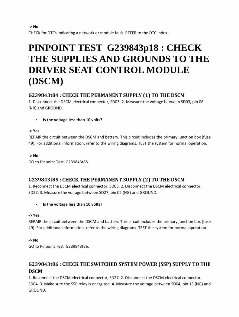
-> No
CHECK for DTCs indicating a network or module fault. REFER to the DTC index.
PINPOINT TEST G239843p18 : CHECK THE SUPPLIES AND GROUNDS TO THE DRIVER SEAT CONTROL MODULE (DSCM) G239843t84 : CHECK THE PERMANENT SUPPLY (1) TO THE DSCM
1. Disconnect the DSCM electrical connector, SD03. 2. Measure the voltage between SD03, pin 06
(NR) and GROUND.
• Is the voltage less than 10 volts?
-> Yes
REPAIR the circuit between the DSCM and battery. This circuit includes the primary junction box (fuse
49). For additional information, refer to the wiring diagrams. TEST the system for normal operation.
-> No
GO to Pinpoint Test G239843t85.
G239843t85 : CHECK THE PERMANENT SUPPLY (2) TO THE DSCM
1. Reconnect the DSCM electrical connector, SD03. 2. Disconnect the DSCM electrical connector,
SD27. 3. Measure the voltage between SD27, pin 02 (NG) and GROUND.
• Is the voltage less than 10 volts?
-> Yes
REPAIR the circuit between the DSCM and battery. This circuit includes the primary junction box (fuse
49). For additional information, refer to the wiring diagrams. TEST the system for normal operation.
-> No
GO to Pinpoint Test G239843t86.
G239843t86 : CHECK THE SWITCHED SYSTEM POWER (SSP) SUPPLY TO THE
DSCM
1. Reconnect the DSCM electrical connector, SD27. 2. Disconnect the DSCM electrical connector,
SD04. 3. Make sure the SSP relay is energized. 4. Measure the voltage between SD04, pin 13 (NG) and
GROUND.

• Is the voltage less than 10 volts?
-> Yes
REPAIR the circuit between the RMM and battery. This circuit includes the primary junction box (fuse
28) and the SSP relay. For additional information, refer to the wiring diagrams. TEST the system for
normal operation.
-> No
CHECK for DTCs indicating a network or module fault. REFER to the DTC index.
PINPOINT TEST G239843p19 : CHECK THE SUPPLIES AND GROUNDS TO THE ENGINE CONTROL MODULE (ECM) G239843t87 : CHECK THE PERMANENT SUPPLY TO THE ECM
1. Disconnect the ECM electrical connector, PI01. 2. Measure the voltage between PI01, pin 22 (NR)
and GROUND.
• Is either voltage less than 10 volts?
-> Yes
REPAIR the circuit between the ECM and battery. This circuit includes the front power distribution
box (fuse 17). For additional information, refer to the wiring diagrams. TEST the system for normal
operation.
-> No
GO to Pinpoint Test G239843t88.
G239843t88 : CHECK THE EMS SUPPLY TO THE ECM
1. Turn the ignition switch to the ON position. 2. Make sure the EMS relay is energized. 3. Measure
the voltage between PI01, pins 23 and 24 (WG) and GROUND.
• Is the voltage less than 10 volts?
-> Yes
REPAIR the circuit between the ECM and battery. This circuit includes the front power distribution
box (fuse 12) and the EMS relay. For additional information, refer to the wiring diagrams. TEST the
system for normal operation.
-> No
GO to Pinpoint Test G239843t89.

G239843t89 : CHECK THE POWER GROUND TO THE ECM
1. Measure the resistance between PI01, pin 04 (B) and GROUND.
• Is the resistance greater than 5 ohms?
-> Yes
REPAIR the high resistance circuit. For additional information, refer to the wiring diagrams. TEST the
system for normal operation.
-> No
CHECK for DTCs indicating a network or module fault. REFER to the DTC index.
PINPOINT TEST G239843p20 : CHECK THE SUPPLIES AND GROUNDS TO THE PARKING AID CONTROL MODULE (PACM) G239843t90 : CHECK THE IGNITION SUPPLY TO THE PACM
1. Disconnect the PACM electrical connector, CR52. 2. Turn the ignition switch to the ON position. 3.
Measure the voltage between CR52, pin 01 (WR) and GROUND.
• Is the voltage less than 10 volts?
-> Yes
REPAIR the circuit between the PACM and battery. This circuit includes the primary junction box
(fuse 32) and the ignition relay. For additional information, refer to the wiring diagrams. TEST the
system for normal operation.
-> No
GO to Pinpoint Test G239843t91.
G239843t91 : CHECK THE GROUND TO THE PACM
1. Measure the resistance between CR52, pin 03 (B) and GROUND.
• Is the resistance greater than 5 ohms?
-> Yes
REPAIR the high resistance circuit. For additional information, refer to the wiring diagrams. TEST the
system for normal operation.
-> No
CHECK for DTCs indicating a network or module fault. REFER to the DTC index.

PINPOINT TEST G239843p21 : CHECK THE SUPPLIES AND GROUNDS TO THE INTRUSION SENSOR G239843t92 : CHECK THE POWER SUPPLY TO THE INTRUSION SENSOR
1. Disconnect the intrusion sensor electrical connector, RF03. 2. ARM the security system. 3.
Measure the voltage between RF03, pin 06, (YU) and GROUND.
• Is the voltage less than 5 volts?
-> Yes
REPAIR the circuit between the intrusion sensor and battery. This circuit includes the REM. For
additional information, refer to the wiring diagrams. TEST the system for normal operation.
-> No
GO to Pinpoint Test G239843t93.
G239843t93 : CHECK THE GROUND TO THE INTRUSION SENSOR
1. Measure the resistance between RF03, pin 01 (B) and GROUND.
• Is the resistance greater than 5 ohms?
-> Yes
REPAIR the high resistance circuit. For additional information, refer to the wiring diagrams. TEST the
system for normal operation.
-> No
CHECK for DTCs indicating a network or module fault. REFER to the DTC index.
PINPOINT TEST G239843p22 : CHECK THE SUPPLIES AND GROUNDS TO THE RESTRAINTS CONTROL MODULE (RCM) G239843t94 : CHECK THE PERMANENT SUPPLY TO THE RCM
1. Disconnect the RCM electrical connector, CR86. 2. Measure the voltage between CR86, pin 12,
(WU) and GROUND.
• Is the voltage less than 10 volts?

-> Yes
REPAIR the circuit between the RCM and battery. This circuit includes the primary junction box (fuse
29). For additional information, refer to the wiring diagrams. TEST the system for normal operation.
-> No
GO to Pinpoint Test G239843t95.
G239843t95 : CHECK THE GROUND TO THE RCM
1. Measure the resistance between CR86, pin 16 (B) and GROUND.
• Is the resistance greater than 5 ohms?
-> Yes
REPAIR the high resistance circuit. For additional information, refer to the wiring diagrams. TEST the
system for normal operation.
-> No
CHECK for DTCs indicating a network or module fault. REFER to the DTC index.
PINPOINT TEST G239843p23 : CHECK THE SUPPLIES AND GROUNDS TO THE INSTRUMENT CLUSTER (IC) G239843t96 : CHECK THE PERMANENT SUPPLY TO THE IC
1. Disconnect the IC electrical connector, IP06. 2. Measure the voltage between IP06, pin 03, (O) and
GROUND.
• Is the voltage less than 10 volts?
-> Yes
REPAIR the circuit between the IC and battery. This circuit includes the primary junction box (fuse
47). For additional information, refer to the wiring diagrams. TEST the system for normal operation.
-> No
GO to Pinpoint Test G239843t97.
G239843t97 : CHECK THE ACCESSORY SUPPLY TO THE IC
1. Reconnect the IC electrical connector, IP06. 2. Disconnect the IC electrical connector, IP05. 3. Turn
the ignition switch to the ACC position. 4. Measure the voltage between IP05, pin 04, (YG) and
GROUND.
• Is the voltage less than 10 volts?

-> Yes
REPAIR the circuit between the IC and battery. This circuit includes the primary junction box (fuse 08)
and the ignition switch. For additional information, refer to the wiring diagrams. TEST the system for
normal operation.
-> No
GO to Pinpoint Test G239843t98.
G239843t98 : CHECK THE IGNITION SUPPLY (1) TO THE IC
1. Turn the ignition switch to the ON position. 2. Measure the voltage between IP05, pin 03, (GR) and
GROUND.
• Is the voltage less than 10 volts?
-> Yes
REPAIR the circuit between the IC and battery. This circuit includes the primary junction box (fuse 06)
and the ignition switch. For additional information, refer to the wiring diagrams. TEST the system for
normal operation.
-> No
GO to Pinpoint Test G239843t99.
G239843t99 : CHECK THE IGNITION SUPPLY (2) TO THE IC
1. Turn the ignition switch to the OFF position. 2. Reconnect the IC electrical connector, IP05. 3.
Disconnect the IC electrical connector, IP06. 4. Turn the ignition switch to the ON position. 5.
Measure the voltage between IP06, pin 17, (WB) and GROUND.
• Is the voltage less than 10 volts?
-> Yes
REPAIR the circuit between the IC and battery. This circuit includes the primary junction box (fuse 06)
and the ignition switch. For additional information, refer to the wiring diagrams. TEST the system for
normal operation.
-> No
GO to Pinpoint Test G239843t100.
G239843t100 : CHECK THE GROUND TO THE IC
1. Turn the ignition switch to the OFF position. 2. Reconnect the IC electrical connector, IP06. 3.
Disconnect the IC electrical connector, IP05. 4. Measure the resistance between IP05, pin 14 (B) and
GROUND.
• Is the resistance greater than 5 ohms?
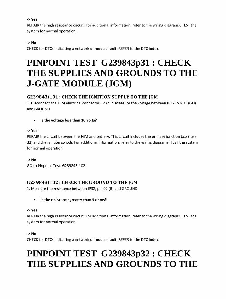
-> Yes
REPAIR the high resistance circuit. For additional information, refer to the wiring diagrams. TEST the
system for normal operation.
-> No
CHECK for DTCs indicating a network or module fault. REFER to the DTC index.
PINPOINT TEST G239843p31 : CHECK THE SUPPLIES AND GROUNDS TO THE J-GATE MODULE (JGM) G239843t101 : CHECK THE IGNITION SUPPLY TO THE JGM
1. Disconnect the JGM electrical connector, IP32. 2. Measure the voltage between IP32, pin 01 (GO)
and GROUND.
• Is the voltage less than 10 volts?
-> Yes
REPAIR the circuit between the JGM and battery. This circuit includes the primary junction box (fuse
33) and the ignition switch. For additional information, refer to the wiring diagrams. TEST the system
for normal operation.
-> No
GO to Pinpoint Test G239843t102.
G239843t102 : CHECK THE GROUND TO THE JGM
1. Measure the resistance between IP32, pin 02 (B) and GROUND.
• Is the resistance greater than 5 ohms?
-> Yes
REPAIR the high resistance circuit. For additional information, refer to the wiring diagrams. TEST the
system for normal operation.
-> No
CHECK for DTCs indicating a network or module fault. REFER to the DTC index.
PINPOINT TEST G239843p32 : CHECK THE SUPPLIES AND GROUNDS TO THE
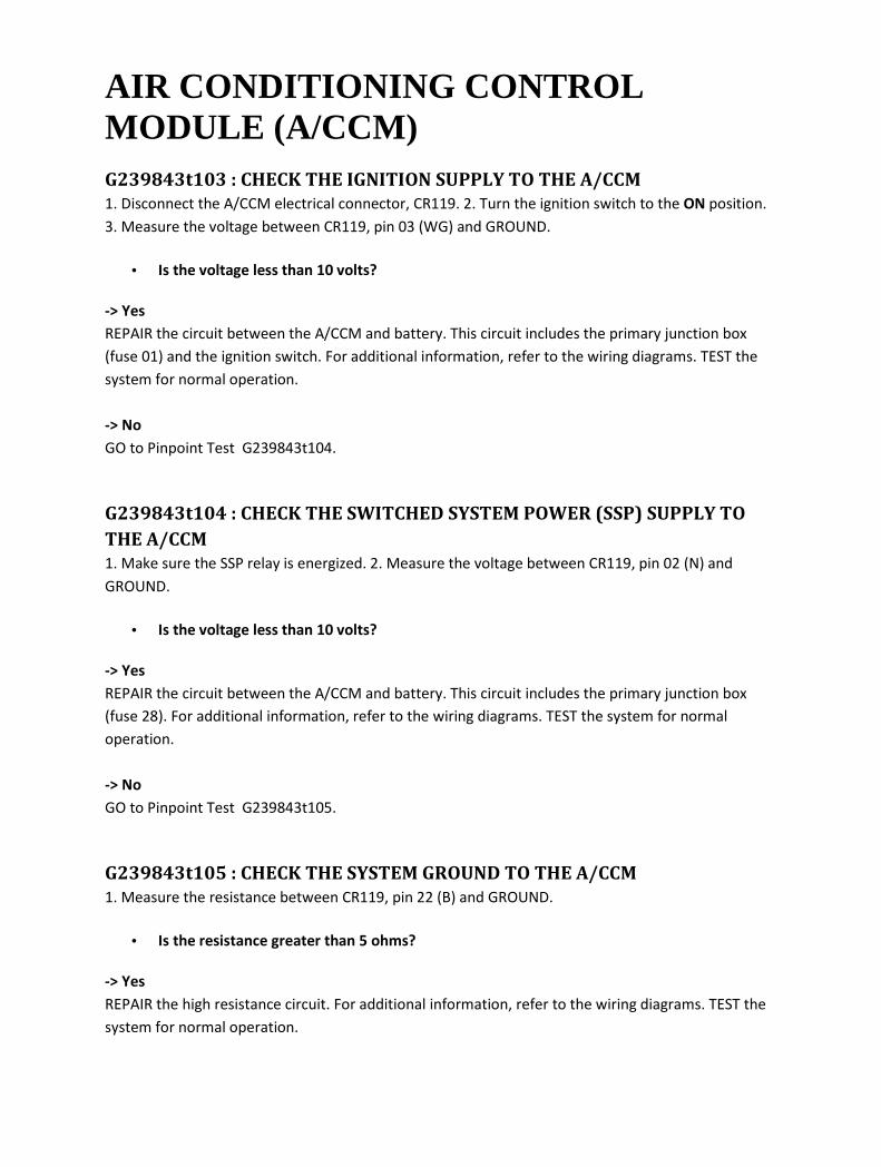
AIR CONDITIONING CONTROL MODULE (A/CCM) G239843t103 : CHECK THE IGNITION SUPPLY TO THE A/CCM
1. Disconnect the A/CCM electrical connector, CR119. 2. Turn the ignition switch to the ON position.
3. Measure the voltage between CR119, pin 03 (WG) and GROUND.
• Is the voltage less than 10 volts?
-> Yes
REPAIR the circuit between the A/CCM and battery. This circuit includes the primary junction box
(fuse 01) and the ignition switch. For additional information, refer to the wiring diagrams. TEST the
system for normal operation.
-> No
GO to Pinpoint Test G239843t104.
G239843t104 : CHECK THE SWITCHED SYSTEM POWER (SSP) SUPPLY TO
THE A/CCM
1. Make sure the SSP relay is energized. 2. Measure the voltage between CR119, pin 02 (N) and
GROUND.
• Is the voltage less than 10 volts?
-> Yes
REPAIR the circuit between the A/CCM and battery. This circuit includes the primary junction box
(fuse 28). For additional information, refer to the wiring diagrams. TEST the system for normal
operation.
-> No
GO to Pinpoint Test G239843t105.
G239843t105 : CHECK THE SYSTEM GROUND TO THE A/CCM
1. Measure the resistance between CR119, pin 22 (B) and GROUND.
• Is the resistance greater than 5 ohms?
-> Yes
REPAIR the high resistance circuit. For additional information, refer to the wiring diagrams. TEST the
system for normal operation.

-> No
CHECK for DTCs indicating a network or module fault. REFER to the DTC index.
PINPOINT TEST G239843p33 : CHECK THE SUPPLIES AND GROUNDS TO THE DYNAMIC STABILITY CONTROL MODULE (DSCCM) G239843t106 : CHECK THE PERMANENT SUPPLIES TO THE DSCCM
1. Disconnect the DSCCM electrical connector, EC30. 2. Measure the voltage between EC30, pins 01
(NR) and 32 (NW) and GROUND.
• Is the voltage less than 10 volts?
-> Yes
REPAIR the circuit between the DSCCM and battery. This circuit includes the front power distribution
box (fuses 20 and 22). For additional information, refer to the wiring diagrams. TEST the system for
normal operation.
-> No
GO to Pinpoint Test G239843t107.
G239843t107 : CHECK THE IGNITION SUPPLY TO THE DSCCM
1. Turn the ignition switch to the ON position. 2. Measure the voltage between EC30, pins 04 (W) and
GROUND.
• Is the voltage less than 10 volts?
-> Yes
REPAIR the circuit between the DSCCM and battery. This circuit includes the primary junction box
(fuse 17) and the ignition switch. For additional information, refer to the wiring diagrams. TEST the
system for normal operation.
-> No
CHECK for DTCs indicating a network or module fault. REFER to the DTC index.
PINPOINT TEST G239843p34 : CHECK THE SUPPLIES AND GROUNDS TO THE

TRANSMISSION CONTROL MODULE (TCM) G239843t108 : CHECK THE PERMANENT SUPPLY TO THE TCM
1. Disconnect the TCM electrical connector, GB02. 2. Measure the voltage between GB02, pin 14 (NR)
and GROUND.
• Is the voltage less than 10 volts?
-> Yes
REPAIR the circuit between the TCM and battery. This circuit includes the front power distribution
box (fuse 17). For additional information, refer to the wiring diagrams. TEST the system for normal
operation.
-> No
GO to Pinpoint Test G239843t109.
G239843t109 : CHECK THE IGNITION SUPPLY TO THE TCM
1. Turn the ignition switch to the ON position. 2. Measure the voltage between GB02, pin 09 (GO)
and GROUND.
• Is the voltage less than 10 volts?
-> Yes
REPAIR the circuit between the TCM and battery. This circuit includes the primary junction box (fuse
33) and the ignition switch. For additional information, refer to the wiring diagrams. TEST the system
for normal operation.
-> No
GO to Pinpoint Test G239843t110.
G239843t110 : CHECK THE GROUND TO THE TCM
1. Measure the resistance between GB02, pins 13 and 16 (B) and GROUND.
• Is the resistance greater than 5 ohms?
-> Yes
REPAIR the high resistance circuit. For additional information, refer to the wiring diagrams. TEST the
system for normal operation.
-> No
CHECK for DTCs indicating a network or module fault. REFER to the DTC index.

PINPOINT TEST G239843p35 : CHECK THE SUPPLIES AND GROUNDS TO THE ADAPTIVE SPEED CONTROL MODULE (ASCCM) G239843t111 : CHECK THE IGNITION SUPPLY TO THE ASCCM
1. Disconnect the ASCCM electrical connector, EC23. 2. Turn the ignition switch to the ON position. 3.
Measure the voltage between EC23, pin 07 (WU) and GROUND.
• Is the voltage less than 10 volts?
-> Yes
REPAIR the circuit between the ASCCM and battery. This circuit includes the primary junction box
(fuse 02) and the ignition switch. For additional information, refer to the wiring diagrams. TEST the
system for normal operation.
-> No
GO to Pinpoint Test G239843t112.
G239843t112 : CHECK THE SWITCHED SYSTEM POWER (SSP) SUPPLY TO
THE ASCCM
1. Make sure the SSP relay is energized. 2. Measure the voltage between EC23, pin 01 (NW) and
GROUND.
• Is the voltage less than 10 volts?
-> Yes
REPAIR the circuit between the ASCCM and battery. This circuit includes the primary junction box
(fuse 27) and the SSP relay. For additional information, refer to the wiring diagrams. TEST the system
for normal operation.
-> No
GO to Pinpoint Test G239843t113.
G239843t113 : CHECK THE GROUND TO THE ASCCM
1. Measure the resistance between EC23, pin 02 (B) and GROUND.
• Is the resistance greater than 5 ohms?
-> Yes
REPAIR the high resistance circuit. For additional information, refer to the wiring diagrams. TEST the

system for normal operation.
-> No
CHECK for DTCs indicating a network or module fault. REFER to the DTC index.
PINPOINT TEST G239843p36 : CHECK THE SUPPLIES AND GROUNDS TO THE AIR SUSPENSION CONTROL MODULE (ASU) G239843t114 : CHECK THE PERMANENT SUPPLY TO THE ASU
1. Disconnect the ASU electrical connector, CR88. 2. Measure the voltage between CR88, pin 01 (NW)
and GROUND.
• Is the voltage less than 10 volts?
-> Yes
REPAIR the circuit between the ASU and battery. This circuit includes the rear power distribution box
(fuse 52). For additional information, refer to the wiring diagrams. TEST the system for normal
operation.
-> No
GO to Pinpoint Test G239843t115.
G239843t115 : CHECK THE SWITCHED SYSTEM POWER (SSP) SUPPLY TO
THE ASU
1. Make sure the SSP relay is energized. 2. Measure the voltage between CR88, pin 02 (N) and
GROUND.
• Is the voltage less than 10 volts?
-> Yes
REPAIR the circuit between the ASU and battery. This circuit includes the rear power distribution box
(fuse 12) and the SSP relay. For additional information, refer to the wiring diagrams. TEST the system
for normal operation.
-> No
GO to Pinpoint Test G239843t116.
G239843t116 : CHECK THE GROUND TO THE ASU
1. Measure the resistance between CR88, pin 03 (B) and GROUND.
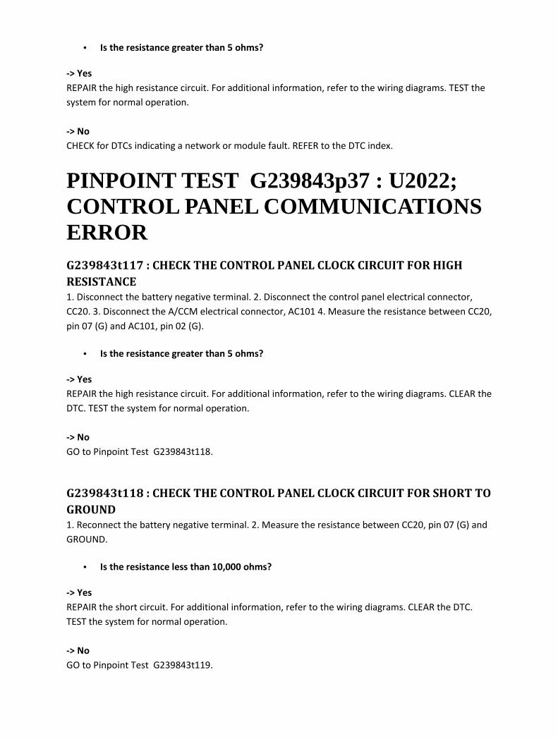
• Is the resistance greater than 5 ohms?
-> Yes
REPAIR the high resistance circuit. For additional information, refer to the wiring diagrams. TEST the
system for normal operation.
-> No
CHECK for DTCs indicating a network or module fault. REFER to the DTC index.
PINPOINT TEST G239843p37 : U2022; CONTROL PANEL COMMUNICATIONS ERROR G239843t117 : CHECK THE CONTROL PANEL CLOCK CIRCUIT FOR HIGH
RESISTANCE
1. Disconnect the battery negative terminal. 2. Disconnect the control panel electrical connector,
CC20. 3. Disconnect the A/CCM electrical connector, AC101 4. Measure the resistance between CC20,
pin 07 (G) and AC101, pin 02 (G).
• Is the resistance greater than 5 ohms?
-> Yes
REPAIR the high resistance circuit. For additional information, refer to the wiring diagrams. CLEAR the
DTC. TEST the system for normal operation.
-> No
GO to Pinpoint Test G239843t118.
G239843t118 : CHECK THE CONTROL PANEL CLOCK CIRCUIT FOR SHORT TO
GROUND
1. Reconnect the battery negative terminal. 2. Measure the resistance between CC20, pin 07 (G) and
GROUND.
• Is the resistance less than 10,000 ohms?
-> Yes
REPAIR the short circuit. For additional information, refer to the wiring diagrams. CLEAR the DTC.
TEST the system for normal operation.
-> No
GO to Pinpoint Test G239843t119.

G239843t119 : CHECK THE CONTROL PANEL CLOCK CIRCUIT FOR SHORT TO
B+
1. Measure the voltage between CC20, pin 07 (G) and GROUND.
• Is the voltage greater than 3 volts?
-> Yes
REPAIR the short circuit. For additional information, refer to the wiring diagrams. CLEAR the DTC.
TEST the system for normal operation.
-> No
GO to Pinpoint Test G239843t120.
G239843t120 : CHECK THE CONTROL PANEL DATA CIRCUIT FOR HIGH
RESISTANCE
1. Measure the resistance between CC20, pin 02 (RU) and AC101, pin 16 (RU).
• Is the resistance greater than 5 ohms?
-> Yes
REPAIR the high resistance circuit. For additional information, refer to the wiring diagrams. CLEAR the
DTC. TEST the system for normal operation.
-> No
GO to Pinpoint Test G239843t121.
G239843t121 : CHECK THE CONTROL PANEL DATA CIRCUIT FOR SHORT TO
GROUND
1. Measure the resistance between CC20, pin 02 (RU) and GROUND.
• Is the resistance less than 10,000 ohms?
-> Yes
REPAIR the short circuit. For additional information, refer to the wiring diagrams. CLEAR the DTC.
TEST the system for normal operation.
-> No
GO to Pinpoint Test G239843t122.
G239843t122 : CHECK THE CONTROL PANEL DATA CIRCUIT FOR SHORT TO
B+
1. Measure the voltage between CC20, pin 02 (RU) and GROUND.

• Is the voltage greater than 3 volts?
-> Yes
REPAIR the short circuit. For additional information, refer to the wiring diagrams. CLEAR the DTC.
TEST the system for normal operation.
-> No
INSTALL a new control panel. <<412-02>> CLEAR the DTC. TEST the system for normal operation. If
the DTC is repeated, contact dealer technical support for advice on possible control module failure.

418-01 : Module Configuration
Diagnosis and testing
Module Configuration Principles of Operation
Module Configuration
There are two modes of configuration data. The first type requires configuration information so that
the module can interact with the vehicle correctly. This information will be transferred to the new
module using the Jaguar Approved Diagnostic System, so that it will contain the same settings as the
old module.
Modules which require configuration when installing a replacement module are:
• Engine control module (ECM)
• Transmission control module (TCM)
• Audio unit
• Drivers door module (DDM)
• Rear electronic module (REM)
• Front electronic module (FEM)
• Amplifier
• Intrusion sensor module
• Multifunction voice activated control module
• Headlamp levelling module (ADHLS)
• Electronic park brake (EPB) module
• Instrument cluster and message centre
• Climate control module
Customer Driven Preferences
The second type of configuration data is customer preference driven. These are items that the
customer may or may not want to have enabled. Typically, customer preference items can be toggled
on or off by the use of a compatible scan tool. You may need to ask the customer which preferences
they had enabled prior to installation of the new module, although after installation they will
automatically learn the settings by receiving information from existing modules.
To carry out the customer configuration process, use the Jaguar Approved Diagnostic System. Refer
to the Dealer Options Index for modules on the vehicle that have customer preference items.
Configure the items as needed.
Modules which can be configured with dealer options are:
• The FEM.

• The instrument cluster and message centre.
• TCM (market configuration).
• ECM (market configuration).
• Intrusion sensor module.
• Multifunction voice activated control module (market configuration).
• Audio unit (market configuration
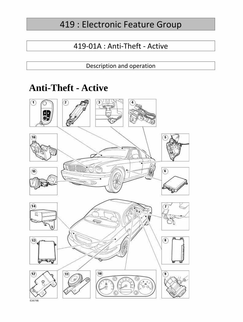
419 : Electronic Feature Group
419-01A : Anti-Theft - Active
Description and operation
Anti-Theft - Active

Item Part Number Description
1 — Four button transmitter
2 — Ultrasonic sensor
3 — Luggage compartment key-in sensor
4 — Luggage compartment actuator
5 — Door actuator
6 — Front electronic module (FEM)
7 — Diagnostic connector
8 — Driver door module (DDM)
9 — Transceiver module
10 — Instrument cluster
11 — Anti theft alarm horn
12 — Anti theft alarm horn (battery back-up)
13 — Rear electronics module (REM)
14 — Inclination sensor
15 — Vehicle horn
16 — Hood switch
The anti-theft system provides protection from unauthorized entry into the vehicle. The security
system functions are controlled by the rear electronic module (REM), driver door module (DDM),
front electronic module (FEM), and the instrument cluster (IC). When the alarm is triggered the
system flashes the directional indicators, or turns on the front and rear lamps or flashes the front and
rear lamps or a combination of front and rear lamps with directional indicators and can also sound
the alarm system horns, siren or a combination of both, all are Market dependant.
The base perimeter alarm consists of four doors, hood and luggage compartment ajar switches, radio
sense, key sense, vehicle horn and separate anti-theft alarm horn (rest of the world (ROW)) or anti-
theft alarm horn (battery backed - UK, Holland, France, Belgium, Luxemburg, Israel, Ireland and
Malta), visual feedback from direction indicators on arm, disarm, alarm and error states (note visual

feedback for error states is only a dealer programmable feature - standard configuration is an audible
error state indicator enabled, and full alarm activation can also be from front and rear lamps),
security light emitting diode (LED) located in the instrument panel. Audible feedback is provided for
error state, full alarm, arming, disarming and double locking - all of these above feedbacks are
market dependant. Higher levels of alarm can be added for specific market requirements - ultrasonic
scanning sensors located in the overhead console, inclination sensor (Dealer fit option only) located
in the luggage compartment, anti-theft alarm horn (battery backed) located in the right hand side
rear wheel arch near to the fuel filler neck.
Security System Arming
The system will be activated by the keyless entry remote transmitter when
the following input sequence is followed:
1 . Turn the ignition off and remove the key.
2 . Close all the doors (unlocked).
3 . Press the LOCK button on the transmitter to lock the doors. The directional indicators will flash
once plus in some markets an audible warning will also be emitted.
4 . Press the LOCK button twice the vehicle will double lock (if enabled). The directional indicators
will provide a longer flash plus an audible warning is emitted to indicate double locking action has
occurred. In USA, Canada, Mexico and Dominican Republic a second press audible warning can be
enabled, therefore if you press the four button transmitter lock button twice, then an audible
warning will be emitted.
5 . If the directional indicators do not flash, the system is not activated. (If a door is open, luggage
compartment and hood is ajar or a key is in the ignition, the remote lock function will be inhibited
and two audible error sounds will be emitted, however the dealer has the option to enable the
direction indicators, which will flash five times).
The system will also be activated when the following input sequence is
followed:
6 . Turn the ignition off and remove the ignition key.
7 . Close all the doors (unlocked).
8 . Lock all the doors via the driver door key barrel with the ignition key, direction indicators will flash
once. To double lock, activate the drivers door key barrel to the unlock then lock position within
three seconds with the ignition key. The vehicle will double lock (if enabled). The directional
indicators will provide a longer flash plus an audible warning is emitted to indicate that double
locking action has occurred.
9 . If the directional indicators do not flash, the system is not activated.

10 . If two consecutive audible sounds with a 200ms pause period between them is emitted, then
either a door, luggage compartment or hood is open or the ignition key is in the ignition barrel.
Dealer option is, if the directional indicators flash five times either the door, hood or luggage
compartment lid is open or the ignition key is in the ignition barrel.
Opening any of the doors, luggage compartment or hood will activate full alarm immediately in
Europe and in North America there will be a seven second audible warning followed by activating full
alarm immediately, providing the alarm has been activated.
Disarming an Untriggered Alarm System
Carrying out either of the following steps will deactivate an untriggered alarm system.
11 . Unlock the drivers door with a key (USA, Canada, Mexico, Dominican republic, ROW). The
directional indicators will flash twice and two audible disarm warnings will be emitted (warnings are
market dependant). If however a fault exists on the intrusion sensor or inclination sensor, then the
system will disarm in one of a number of ways, depending upon the market configuration:
• USA, Canada, Mexico, Dominican republic, ROW only, the disarm warnings are: three
direction indicator flashes with two audible tones on the first two flashes followed by the
third direction indicator flash with two error tones. three direction indicator flashes with two
audible error tones on the third direction indicator flash. seven direction indicator flashes.
seven direction indicator flashes with two audible error tones. seven direction indicator
flashes with two audible tones followed by two audible error tones.
o three direction indicator flashes with two audible tones on the first two flashes
followed by the third direction indicator flash with two error tones.
o three direction indicator flashes with two audible error tones on the third direction
indicator flash.
o seven direction indicator flashes.
o seven direction indicator flashes with two audible error tones.
o seven direction indicator flashes with two audible tones followed by two audible
error tones.
• EURO with error options are: three direction indicator flashes with two audible error tones
on the third direction indicator flash. seven direction indicator flashes. seven direction
indicator flashes with two audible error tones.
o three direction indicator flashes with two audible error tones on the third direction
indicator flash.
o seven direction indicator flashes.
o seven direction indicator flashes with two audible error tones.
12 . Press the UNLOCK button on the keyless entry remote transmitter. The directional indicators will
flash twice and two audible disarm warnings will be emitted (warnings are market dependant). If
however a fault exists on the intrusion sensor or inclination sensor, then the system will disarm in
one of a number of ways, depending upon the market configuration:
• USA, Canada, Mexico, Dominican republic, ROW only, the disarm warnings are: three
direction indicator flashes with two audible tones on the first two flashes followed by the
third direction indicator flash with two error tones. three direction indicator flashes with two
audible error tones on the third direction indicator flash. seven direction indicator flashes.

seven direction indicator flashes with two audible error tones. seven direction indicator
flashes with two audible tones followed by two audible error tones.
o three direction indicator flashes with two audible tones on the first two flashes
followed by the third direction indicator flash with two error tones.
o three direction indicator flashes with two audible error tones on the third direction
indicator flash.
o seven direction indicator flashes.
o seven direction indicator flashes with two audible error tones.
o seven direction indicator flashes with two audible tones followed by two audible
error tones.
• EURO with error options are: three direction indicator flashes with two audible error tones
on the third direction indicator flash. seven direction indicator flashes. seven direction
indicator flashes with two audible error tones.
o three direction indicator flashes with two audible error tones on the third direction
indicator flash.
o seven direction indicator flashes.
o seven direction indicator flashes with two audible error tones.
13 . If unlocked from the drivers door when the key barrel disarm is disabled (EURO) and the key is
fitted in the ignition switch within 7 seconds from the door being opened, if the vehicle has been
actively armed. The directional indicators will flash twice and two audible disarm warnings will be
emitted (warnings are market dependant). If however a fault exists on the intrusion sensor or
inclination sensor, then the system will disarm in one of a number of ways, depending upon the
market configuration:
• USA, Canada, Mexico, Dominican republic, ROW only, the disarm warnings are: three
direction indicator flashes with two audible tones on the first two flashes followed by the
third direction indicator flash with two error tones. three direction indicator flashes with two
audible error tones on the third direction indicator flash. seven direction indicator flashes.
seven direction indicator flashes with two audible error tones. seven direction indicator
flashes with two audible tones followed by two audible error tones.
o three direction indicator flashes with two audible tones on the first two flashes
followed by the third direction indicator flash with two error tones.
o three direction indicator flashes with two audible error tones on the third direction
indicator flash.
o seven direction indicator flashes.
o seven direction indicator flashes with two audible error tones.
o seven direction indicator flashes with two audible tones followed by two audible
error tones.
• EURO with error options are: three direction indicator flashes with two audible error tones
on the third direction indicator flash. seven direction indicator flashes. seven direction
indicator flashes with two audible error tones.
o three direction indicator flashes with two audible error tones on the third direction
indicator flash.
o seven direction indicator flashes.
o seven direction indicator flashes with two audible error tones.

14 . If unlocked from the drivers door when the key barrel disarm is disabled (EURO) and the key is
fitted in the ignition switch within 7 seconds from the door being opened, if the vehicle has been
passively armed. The directional indicators will flash twice and two audible disarm warnings will be
emitted (warnings are market dependant). If however a fault exists on the intrusion sensor or
inclination sensor, then the system will disarm in one of a number of ways, depending upon the
market configuration:
• USA, Canada, Mexico, Dominican republic, ROW only, the disarm warnings are: three
direction indicator flashes with two audible tones on the first two flashes followed by the
third direction indicator flash with two error tones. three direction indicator flashes with two
audible error tones on the third direction indicator flash. seven direction indicator flashes.
seven direction indicator flashes with two audible error tones. seven direction indicator
flashes with two audible tones followed by two audible error tones.
o three direction indicator flashes with two audible tones on the first two flashes
followed by the third direction indicator flash with two error tones.
o three direction indicator flashes with two audible error tones on the third direction
indicator flash.
o seven direction indicator flashes.
o seven direction indicator flashes with two audible error tones.
o seven direction indicator flashes with two audible tones followed by two audible
error tones.
• EURO with error options are: three direction indicator flashes with two audible error tones
on the third direction indicator flash. seven direction indicator flashes. seven direction
indicator flashes with two audible error tones.
o three direction indicator flashes with two audible error tones on the third direction
indicator flash.
o seven direction indicator flashes.
o seven direction indicator flashes with two audible error tones.
15 . If 2-stage unlocking is enabled, then when you press the remote key head unlock button once,
this will unlock the drivers door only. The directional indicators will flash twice and two audible
disarm warnings will be emitted (warnings are market dependant). By pressing the remote key head
unlock button again the remainder of the doors will be unlocked and no additional warnings will be
given. If however a fault exists on the intrusion sensor or inclination sensor, then the system will
disarm in one of a number of ways, depending upon the market configuration:
• USA, Canada, Mexico, Dominican republic, ROW only, the disarm warnings are: three
direction indicator flashes with two audible tones on the first two flashes followed by the
third direction indicator flash with two error tones. three direction indicator flashes with two
audible error tones on the third direction indicator flash. seven direction indicator flashes.
seven direction indicator flashes with two audible error tones. seven direction indicator
flashes with two audible tones followed by two audible error tones.
o three direction indicator flashes with two audible tones on the first two flashes
followed by the third direction indicator flash with two error tones.
o three direction indicator flashes with two audible error tones on the third direction
indicator flash.
o seven direction indicator flashes.
o seven direction indicator flashes with two audible error tones.

o seven direction indicator flashes with two audible tones followed by two audible
error tones.
• EURO with error options are: three direction indicator flashes with two audible error tones
on the third direction indicator flash. seven direction indicator flashes. seven direction
indicator flashes with two audible error tones.
o three direction indicator flashes with two audible error tones on the third direction
indicator flash.
o seven direction indicator flashes.
o seven direction indicator flashes with two audible error tones.
16 . If 2-stage unlocking is enabled then when you turn the key in the drivers door key barrel to the
unlock position, this will unlock the drivers door only (USA, Canada, Mexico, Dominican republic,
ROW). The directional indicators will flash twice and two audible disarm warnings will be emitted
(warnings are market dependant). If however, a fault exists on the intrusion sensor or inclination
sensor, then the system will disarm in one of a number of ways, depending upon the market
configuration:
• USA, Canada, Mexico, Dominican republic, ROW only, the disarm warnings are: three
direction indicator flashes with two audible tones on the first two flashes followed by the
third direction indicator flash with two error tones. three direction indicator flashes with two
audible error tones on the third direction indicator flash. seven direction indicator flashes.
seven direction indicator flashes with two audible error tones. seven direction indicator
flashes with two audible tones followed by two audible error tones.
o three direction indicator flashes with two audible tones on the first two flashes
followed by the third direction indicator flash with two error tones.
o three direction indicator flashes with two audible error tones on the third direction
indicator flash.
o seven direction indicator flashes.
o seven direction indicator flashes with two audible error tones.
o seven direction indicator flashes with two audible tones followed by two audible
error tones.
• EURO with error options are: three direction indicator flashes with two audible error tones
on the third direction indicator flash. seven direction indicator flashes. seven direction
indicator flashes with two audible error tones. Turning the drivers door key barrel to the
unlock position again will unlock the remainder of the doors. No additional warnings will be
given.
o three direction indicator flashes with two audible error tones on the third direction
indicator flash.
o seven direction indicator flashes.
o seven direction indicator flashes with two audible error tones.
o Turning the drivers door key barrel to the unlock position again will unlock the
remainder of the doors. No additional warnings will be given.
Disarming a Triggered System
Carrying out either of the following steps will deactivate a triggered alarm system.
17 . Driver door is unlocked with the ignition key (USA, Canada, Mexico, Dominican republic, ROW
only). The directional indicators will flash twice and two audible disarm warnings will be emitted
(warnings are market dependant). If however a fault exists on the intrusion sensor or inclination
sensor, then the system will disarm in one of a number of ways, depending upon the market
configuration:
• USA, Canada, Mexico, Dominican republic, ROW only, the disarm warnings are: three
direction indicator flashes with two audible tones on the first two flashes followed by the
third direction indicator flash with two error tones. three direction indicator flashes with two
audible error tones on the third direction indicator flash. seven direction indicator flashes.
seven direction indicator flashes with two audible error tones. seven direction indicator
flashes with two audible tones followed by two audible error tones.
o three direction indicator flashes with two audible tones on the first two flashes
followed by the third direction indicator flash with two error tones.
o three direction indicator flashes with two audible error tones on the third direction
indicator flash.
o seven direction indicator flashes.
o seven direction indicator flashes with two audible error tones.
o seven direction indicator flashes with two audible tones followed by two audible
error tones.
• EURO with error options are: three direction indicator flashes with two audible error tones
on the third direction indicator flash. seven direction indicator flashes. seven direction
indicator flashes with two audible error tones.
o three direction indicator flashes with two audible error tones on the third direction
indicator flash.
o seven direction indicator flashes.
o seven direction indicator flashes with two audible error tones.
18 . Driver door is unlocked by pressing the UNLOCK button on the remote entry transmitter. The
directional indicators will flash twice and two audible disarm warnings will be emitted (warnings are
market dependant). If however, a fault exists on the intrusion sensor or inclination sensor, then the
system will disarm in one of a number of ways, depending upon the market configuration:
• USA, Canada, Mexico, Dominican republic, ROW only, the disarm warnings are: three
direction indicator flashes with two audible tones on the first two flashes followed by the
third direction indicator flash with two error tones. three direction indicator flashes with two
audible error tones on the third direction indicator flash. seven direction indicator flashes.
seven direction indicator flashes with two audible error tones. seven direction indicator
flashes with two audible tones followed by two audible error tones.
o three direction indicator flashes with two audible tones on the first two flashes
followed by the third direction indicator flash with two error tones.
o three direction indicator flashes with two audible error tones on the third direction
indicator flash.
o seven direction indicator flashes.
o seven direction indicator flashes with two audible error tones.
o seven direction indicator flashes with two audible tones followed by two audible
error tones.
• EURO with error options are: three direction indicator flashes with two audible error tones
on the third direction indicator flash. seven direction indicator flashes. seven direction
indicator flashes with two audible error tones.

o three direction indicator flashes with two audible error tones on the third direction
indicator flash.
o seven direction indicator flashes.
o seven direction indicator flashes with two audible error tones.
19 . If a valid key is fitted in the ignition switch. The directional indicators will flash twice and two
audible disarm warnings will be emitted (warnings are market dependant). If however a fault exists
on the intrusion sensor or inclination sensor, then the system will disarm in one of a number of ways,
depending upon the market configuration:
• USA, Canada, Mexico, Dominican republic, ROW only, the disarm warnings are: three
direction indicator flashes with two audible tones on the first two flashes followed by the
third direction indicator flash with two error tones. three direction indicator flashes with two
audible error tones on the third direction indicator flash. seven direction indicator flashes.
seven direction indicator flashes with two audible error tones. seven direction indicator
flashes with two audible tones followed by two audible error tones.
o three direction indicator flashes with two audible tones on the first two flashes
followed by the third direction indicator flash with two error tones.
o three direction indicator flashes with two audible error tones on the third direction
indicator flash.
o seven direction indicator flashes.
o seven direction indicator flashes with two audible error tones.
o seven direction indicator flashes with two audible tones followed by two audible
error tones.
• EURO with error options are: three direction indicator flashes with two audible error tones
on the third direction indicator flash. seven direction indicator flashes. seven direction
indicator flashes with two audible error tones.
o three direction indicator flashes with two audible error tones on the third direction
indicator flash.
o seven direction indicator flashes.
o seven direction indicator flashes with two audible error tones.
20 . If 2-stage unlocking is enabled then when you press the remote key head unlock button once,
this will unlock the drivers door only. The directional indicators will flash twice and two audible
disarm warnings will be emitted (warnings are market dependant). If however a fault exists on the
intrusion sensor or inclination sensor, then the system will disarm in one of a number of ways,
depending upon the market configuration:
• USA, Canada, Mexico, Dominican republic, ROW only, the disarm warnings are: three
direction indicator flashes with two audible tones on the first two flashes followed by the
third direction indicator flash with two error tones. three direction indicator flashes with two
audible error tones on the third direction indicator flash. seven direction indicator flashes.
seven direction indicator flashes with two audible error tones. seven direction indicator
flashes with two audible tones followed by two audible error tones.
o three direction indicator flashes with two audible tones on the first two flashes
followed by the third direction indicator flash with two error tones.
o three direction indicator flashes with two audible error tones on the third direction
indicator flash.
o seven direction indicator flashes.

o seven direction indicator flashes with two audible error tones.
o seven direction indicator flashes with two audible tones followed by two audible
error tones.
• EURO with error options are: three direction indicator flashes with two audible error tones
on the third direction indicator flash. seven direction indicator flashes. seven direction
indicator flashes with two audible error tones. Pressing the remote key head unlock button
again will unlock the remainder of the doors. No additional warnings will be given.
o three direction indicator flashes with two audible error tones on the third direction
indicator flash.
o seven direction indicator flashes.
o seven direction indicator flashes with two audible error tones.
o Pressing the remote key head unlock button again will unlock the remainder of the
doors. No additional warnings will be given.
21 . If 2-stage unlocking is enabled when you turn the key in the drivers door key barrel to the unlock
position, this will unlock the drivers door only (USA, Canada, Mexico, Dominican republic, ROW only).
The directional indicators will flash twice and two audible disarm warnings will be emitted (warnings
are market dependant). If however a fault exists on the intrusion sensor or inclination sensor, then
the system will disarm in one of a number of ways, depending upon the market configuration:
• USA, Canada, Mexico, Dominican republic, ROW only, the disarm warnings are: three
direction indicator flashes with two audible tones on the first two flashes followed by the
third direction indicator flash with two error tones. three direction indicator flashes with two
audible error tones on the third direction indicator flash. seven direction indicator flashes.
seven direction indicator flashes with two audible error tones. seven direction indicator
flashes with two audible tones followed by two audible error tones.
o three direction indicator flashes with two audible tones on the first two flashes
followed by the third direction indicator flash with two error tones.
o three direction indicator flashes with two audible error tones on the third direction
indicator flash.
o seven direction indicator flashes.
o seven direction indicator flashes with two audible error tones.
o seven direction indicator flashes with two audible tones followed by two audible
error tones.
• EURO with error options are: three direction indicator flashes with two audible error tones
on the third direction indicator flash. seven direction indicator flashes. seven direction
indicator flashes with two audible error tones. Turning the drivers door key barrel to the
unlock position again will unlock the remainder of the doors. No additional warnings will be
given.
o three direction indicator flashes with two audible error tones on the third direction
indicator flash.
o seven direction indicator flashes.
o seven direction indicator flashes with two audible error tones.
o Turning the drivers door key barrel to the unlock position again will unlock the
remainder of the doors. No additional warnings will be given.
Once the system has been triggered, the horns, siren or a combination of both (market dependant)
and directional indicators (or turn on the front and rear lamps or flash the front and rear lamps or a

combination of front and rear lamp with directional indicators, these are market dependant) will shut
off automatically after 30 seconds (60 seconds USA, Canada, Mexico, Dominican republic, Korean).
The system will then reset to an armed state and will trigger again if another trigger occurs and in
some markets the repeat triggers will be activated.
PANIC Alarm Activation (USA, Canada, Mexico, Dominican Republic and
ROW)
Press the Headlamp convenience button on the keyless entry remote transmitter three times within
three seconds. The directional indicators flash or turn on the front and rear lamps or flash the front
and rear lamps or a combination of front and rear lamps with directional indicators, these are market
dependant and the horns, siren or a combination of both (market dependant) sounds for
approximately 30 or 60 seconds (USA, Canada, Mexico, Dominican republic, Korean) or until:
• The ignition switch lock cylinder is switched to position II with a valid key.
The panic feature is controlled by security system control modules and can be activated independent
of the current security system state (e.g. armed, disarmed, pre-armed, locked, unlocked). Panic alarm
will only activate if the key is in the ignition or if the security system is disabled.

Diagnosis and testing
Anti-Theft - Active The complexity of the electronics involved with the anti-theft, of which the front electronic module (FEM), driver door module (DDM), rear electronic module (REM), and the instrument cluster are a part, and the multiplexed communication network which are connected to it preclude the use of workshop general electrical test equipment. Therefore, reference should be made to the Jaguar approved diagnostic system, for detailed instructions on testing the anti-theft. The Jaguar approved diagnostic system systematically tests and analyses all functions and the various systems affected by it. Where a fault is indicated, some basic diagnostic methods may be necessary to confirm that connections are good and that wiring is not damaged before installing a new component.

Removal and installation
Anti-Theft Alarm Horn (86.52.03) Removal
1 . Remove the wheel and tire assembly. <<204-04>>
2 . Remove the rear fender splash shield retaining screws.
3 . Remove the rear fender splash shield.
4 . Disconnect the electrical connector.

5 . Remove the anti-theft alarm horn.
Installation
1 . To install, reverse the removal procedure.

419-01B : Anti-Theft - Passive
General procedures
Anti-Theft Security Access 1. The complexity of the electronics involved with the passive anti-theft system of which the security access is a part, and the multiplexed communication network which are connected to it preclude the use of workshop general electrical test equipment. Therefore, reference should be made to the Jaguar approved diagnostic system for detailed instructions on security access . The Jaguar approved diagnostic system systematically tests and analyses all functions and the various systems affected by it.

Key Programming Using Diagnostic Equipment 1. The complexity of the electronics involved with the anti-theft, of which the key programming is a part, and the multiplexed communication network which are connected to it preclude the use of workshop general electrical test equipment. Therefore, reference should be made to the Jaguar Approved Diagnostic System for detailed instructions on key programming . The Jaguar approved diagnostic system systematically tests and analyses all functions and the various systems affected by it.

Key Programming Using Two Programmed Keys 1. To program additional PATS keys, a minimum of two valid keys must be available(if only one key is available, it will be erased and reprogrammed with the new key). 2. Key programming using two programmed keys.
• Insert the first valid key and turn to the run position for a maximum of five seconds, then turn to off and remove the key.
• Within ten seconds of removing the first key, insert the second valid key and turn to the run position for a maximum of five seconds, then turn to off and remove the key.
• To program the third (additional) key, insert the key and turn to the run position within twenty seconds of removing the second key, allow the PATS LED to prove out for three seconds to confirm storage of the additional key, then turn to off and remove the key.
• This method can be used to store up to a maximum of 8 ignition keys.
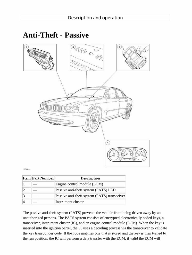
Description and operation
Anti-Theft - Passive
Item Part Number Description
1 — Engine control module (ECM)
2 — Passive anti-theft system (PATS) LED
3 — Passive anti-theft system (PATS) transceiver
4 — Instrument cluster
The passive anti-theft system (PATS) prevents the vehicle from being driven away by an unauthorized persons. The PATS system consists of encrypted electronically coded keys, a transceiver, instrument cluster (IC), and an engine control module (ECM). When the key is inserted into the ignition barrel, the IC uses a decoding process via the transceiver to validate the key transponder code. If the code matches one that is stored and the key is then turned to the run position, the IC will perform a data transfer with the ECM, if valid the ECM will
enable the fuel injectors, ignition coils, fuel pump drive and starter. If the key is invalid the control function will send a theft status message to the ECM, which in turn, will disable the vehicle from starting. If the correct key is used without a transponder or used with a transponder with an incorrect code, the vehicle will be inhibited from starting. This will prevent vehicle theft even if a duplicate key is cut. A PATS indicator LED (located on the instrument panel) provides the driver with the status of the PATS system. When the ignition is switched to the run position, the PATS indicator LED will illuminate for three seconds and extinguish. If there is a fault with the PATS system after 60 seconds of continuous flashing, the PATS indicator LED will flash an error code.

Diagnosis and testing
Anti-Theft - Passive The best method to confirm the correct operation of PATS is to check the LED (located in the center
of the instrument panel). The LED should illuminate solid for 3 seconds when the key is turned to the
run position and then extinguish. This validates the PATS functions (the key transponder matches the
key code stored, the challenge/response sequence between the instrument cluster (IC) and the
engine control module (ECM) was successful resulting in the ECM being enabled).
The ECM will disable the fuel injectors, ignition coils, fuel pump drive and starter if any of the
following conditions apply, a theft signal has been received from the IC (the key has not been
authenticated), a challenge code has been transmitted to the IC but no response code has been
received, a challenge code has been transmitted to the IC and an incorrect response received.
If any of the above cases apply, the ECM will log DTC P1260. This DTC is further defined by sub-codes.
The sub-codes are accessed through mode 12 (freeze frame data). Additionally the IC will log DTC's if
the failure was a result of the key read.
Engine fails to crank
If a PATS fault is detected, the LED will flash for 60 seconds at 4Hz with a 50% duty cycle. At the end
of this period, the LED will flash a 2 digit code, this code is repeated 10 times. The meaning of this
code along with the frequency of flashing is given in the accompanying table (as a general rule a fault
code of 16 or less will cause the vehicle not to crank. Additionally, the Jaguar Approved Diagnostic
System should be used to check the DTC stored in the IC.
The most regular occurrence for failing to crank is due to the park and neutral switches (gearshift not
in park or neutral). The start circuit is as follows, low side of relay coil (Switched directly from the
instrument cluster, if conditions correct), high side of relay of coil (from ignition start position
through gearbox rotary start switches to relay).
Another likely cause maybe the CAN network is malfunctioning, (the CAN circuit is open/short). This
means that the IC and ECM would be unable to communicate resulting in no challenge being
performed to enable the ECM.
On US manual vehicles the addition of a clutch switch has been included in the starting circuit, this
switch takes place of the park/neutral switch (auto transmission). The switch activates at end of
travel (clutch fully depressed).
Engine cranks but will not start
If the engine is cranking it means that the ECM is enabled with respect to the PATS. If PATS was
disabled the ECM would not engage the starter. This could be confirmed by verifying the PATS LED
prove out (illuminated solid for 3 seconds) or by reading DTC's from the IC and ECM. In this case, the

fuel pump circuit should be verified. A fuel pump module, which is controlled by the ECM supplies
the fuel pump. In all cases of suspected PATS non-start issues, the most logical failure modes should
be eliminated first. Check all relevant supplies and grounds to the IC and ECM, check that the starter
relay has a permanent 12v supply, check that the relay has a 12v supply and ground across the coil
whilst the ignition is in the crank position.
PATS Fault Codes
For the various PATS modes/faults listed in the table , the IC will store a DTC and indicate this to the
customer during the detection peroid defined in the 'when logged' column, by illuminating the
indicator as described for 60 seconds and then flashing the LED 10 times as appropriate. The
indication will stop immediately the ignition is turned to off any time during the fault indication
sequence. Up to 4 DTC's could be stored per key read (1-!0 read attempts). No DTC's will be stored
until all retry attempts are complete. Only the highest priority fault code will be flashed.
The PATS LED will be commanded on as shown under 'indication'. Normal PATS operations are
complete within 400ms of the ignition switch transition from off to run or start, worst case for ECM
communication problems will be less than 2 seconds. If PATS is not complete during the 2 seconds
the ECM will terminate PATS and await the next ignition run/start event. PATS faults will be indicated
via the LED as soon as possible and will terminate the LED prove out. At key off all previous flashing
will cease and the perimeter anti theft system will control the LED when the vehicle is locked and
armed.
Mode of Operation/Fault When Logged
Ignition
Switch
Position
DTC
LED
Fault
Code
Indication
Prove out N/A Off to
Run/Start N/A N/A
3 Seconds of steady
illumination
Perimeter Anti theft Control N/A Off N/A N/A Off or 0.5Hz, 5% duty
cycle until off
Transceiver not connected Key Read Run/Start B1681 11
60 seconds off 4Hz
flashing at 50% duty
cyle followed by fault
code flashing 10 times
Key problem. No code
received from Key Key Read Run/Start B1600 13
60 seconds off 4Hz
flashing at 50% duty
cyle followed by fault
code flashing 10 times
Key/Transceiver problem,
partial code received,
Key Read Run/Start B1602 14 60 seconds off 4Hz
flashing at 50% duty
cyle followed by fault

checksum error code flashing 10 times
Key code not stored in
memory(also due to having 8
key codes already stored in
memory)/ signature
mismatch
Ke
Read/Diagnostic
Test
Run/Start B1601 15
60 seconds off 4Hz
flashing at 50% duty
cyle followed by fault
code flashing 10 times
Problem with CAN link - ECM
disabled. ECM system status
CAN message missing
ECM CAN
Comm's Run/Start
U2511
U1900 16
60 seconds off 4Hz
flashing at 50% duty
cyle followed by fault
code flashing 10 times
Following part replacement the following codes maybe applicable, these are not normal customer
mode fault codes.
Mode of Operation/Fault When Logged
Ignition
Switch
Position
DTC
LED
Fault
Code
Indication
Following new key
programming Jaguar Approved
Diagnostic System application,
2 keys have not been cycled in
the ignition
B and A/Dealer Run/Start B1213 21
60 seconds of
steady indication
followed by fault
code flashing 10
times
PATS reset application not
performed after part IPK
replacement
B and A/Dealer Run/Start B2141 22
60 seconds of
steady indication
followed by fault
code flashing 10
times
PATS reset application not
performed after part ECM
replacement
Challenge/Response Run/Start U2510 23
60 seconds of
steady indication
followed by fault
code flashing 10
times
1 . If an obvious cause for an observed or reported concern is found, correct the cause (if possible)
before proceeding to the next step.
2 . If the cause is not visually evident, verify the symptom and refer to the Jaguar Approved
Diagnostic System.

Removal and installation
Passive Anti-Theft System (PATS) Transceiver (86.52.30) Removal
1 . Remove the ignition switch lock cylinder. <<211-04>>
2 . Remove the PATS transceiver.
1) Detach the PATS transceiver retaining tang.
2) Remove the PATS transceiver.
Installation
1 . To install, reverse the removal procedure.

419-02 : Remote Convenience
General procedures
Universal Transmitter Programming
WARNING: A garage door opening system that cannot stop or reverse itself after detecting an object in its path does not meet current federal safety standards. To decrease the risk of serious injury or death, do not use this HomeLink�transmitter with a door opening system that lacks stop and reverse features as required by federal standards. This includes any garage door opening system manufactured before April 1, 1982. For more information, call HomeLink�customer assistance at 1-800-355-3515. 1.
CAUTION: During this procedure, the system that you are programming will be made to operate. Make sure that people or objects are clear of the garage door or gate being programmed. Verify the hand-held transmitter is operative. 2. Prepare for programming the universal transmitter by erasing all three channels by holding down the two outside buttons until the red light begins to flash (20-30 seconds). Release both buttons.
3. Select one of the three universal transmitter channels to be programmed by pressing the desired button. 4. Hold the end of the hand-held transmitter 50-150mm (2-6 in) from the front surface of the universal transmitter so that the red light can still be seen. 5. NOTE:
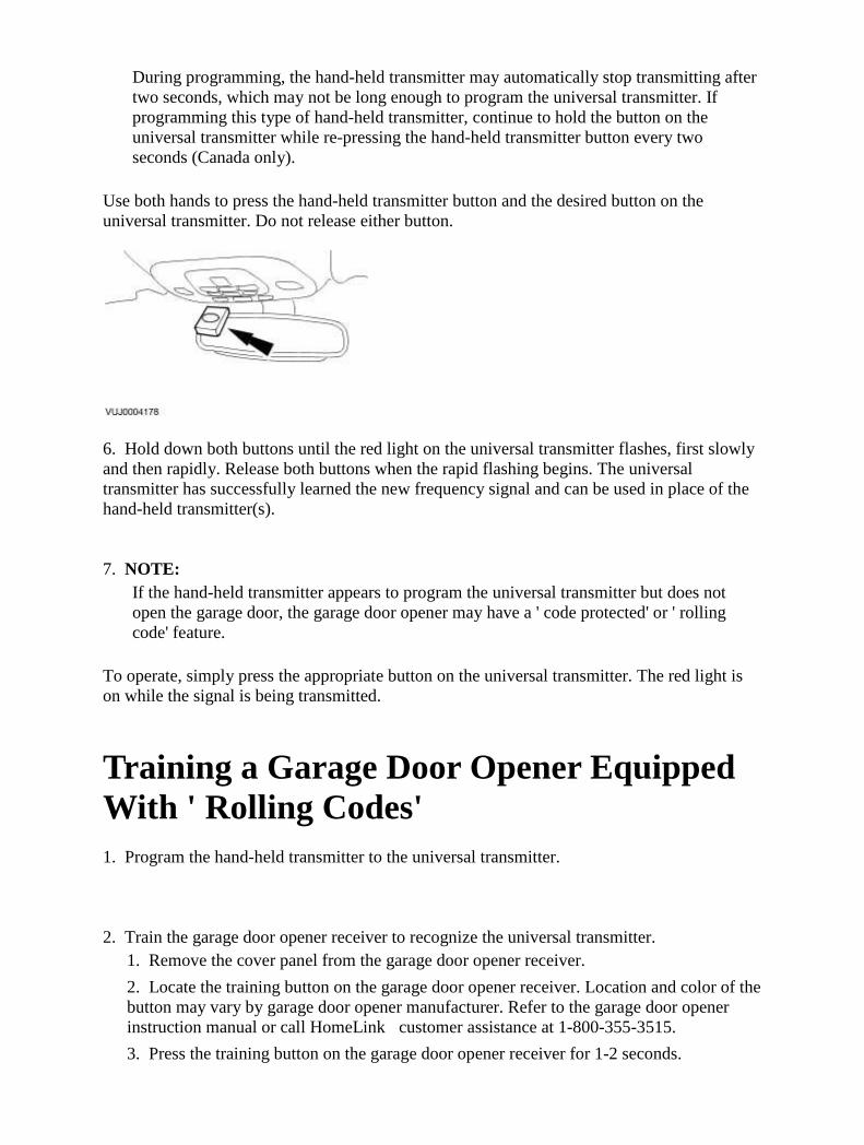
During programming, the hand-held transmitter may automatically stop transmitting after two seconds, which may not be long enough to program the universal transmitter. If programming this type of hand-held transmitter, continue to hold the button on the universal transmitter while re-pressing the hand-held transmitter button every two seconds (Canada only).
Use both hands to press the hand-held transmitter button and the desired button on the universal transmitter. Do not release either button.
6. Hold down both buttons until the red light on the universal transmitter flashes, first slowly and then rapidly. Release both buttons when the rapid flashing begins. The universal transmitter has successfully learned the new frequency signal and can be used in place of the hand-held transmitter(s). 7. NOTE:
If the hand-held transmitter appears to program the universal transmitter but does not open the garage door, the garage door opener may have a ' code protected' or ' rolling code' feature.
To operate, simply press the appropriate button on the universal transmitter. The red light is on while the signal is being transmitted.
Training a Garage Door Opener Equipped With ' Rolling Codes' 1. Program the hand-held transmitter to the universal transmitter. 2. Train the garage door opener receiver to recognize the universal transmitter. 1. Remove the cover panel from the garage door opener receiver.
2. Locate the training button on the garage door opener receiver. Location and color of the button may vary by garage door opener manufacturer. Refer to the garage door opener instruction manual or call HomeLink�customer assistance at 1-800-355-3515.
3. Press the training button on the garage door opener receiver for 1-2 seconds.

4. Press the programmed universal transmitter button for as long as the universal transmitter red light flashes (1-2 seconds). Release the button and re-press the button to confirm that the universal transmitter is trained to the receiver.
5. The garage door opener should recognize the universal transmitter.
Erasing Channels 1. NOTE:
Individual channels cannot be erased, but can be reprogrammed using the procedures for programming.
To erase all three programmed channels, hold down the two outside buttons until the red light begins to flash (20-30 seconds). Release both buttons.
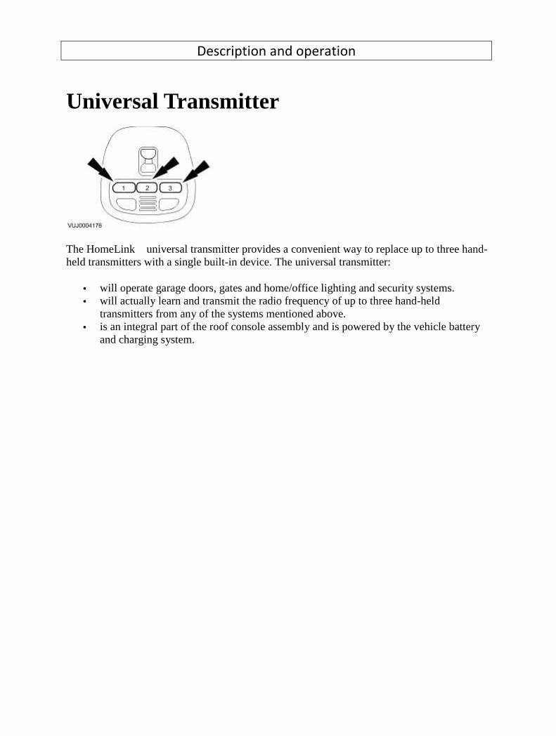
Description and operation
Universal Transmitter
The HomeLink� universal transmitter provides a convenient way to replace up to three hand-held transmitters with a single built-in device. The universal transmitter:
• will operate garage doors, gates and home/office lighting and security systems. • will actually learn and transmit the radio frequency of up to three hand-held
transmitters from any of the systems mentioned above. • is an integral part of the roof console assembly and is powered by the vehicle battery
and charging system.

Diagnosis and testing
Universal Transmitter Inspection and Verification
1 . Verify the customer concern by operating the system.
2 . Visually inspect for obvious signs of mechanical damage.
Mechanical
• Damaged universal transmitter
• Damaged receiver
3 . If an obvious cause for an observed or reported concern is found, correct the cause (if possible)
before proceeding to the next step.
4 . If the concern is not visually evident, verify the concern and refer to the Symptom Chart. Refer to
the electrical circuit diagrams for schematic and connector information.
Symptom Chart
Symptom Possible Cause Action
The universal transmitter is
inoperative
• Universal transmitter
• Receiver unit
GO to Pinpoint Test
G92661p1.
Pinpoint Tests
PINPOINT TEST G92661p1 : THE UNIVERSAL TRANSMITTER IS INOPERATIVE G92661t1 : CHECK THE ROOF CONSOLE ASSEMBLY OPERATION
1. Check the illumination of the interior lamp.
• Does the interior lamp illuminate?

-> Yes
GO to Pinpoint Test G92661t2.
.
-> No
Check and rectify fault with interior lamp circuit. TEST the system for normal operation.
G92661t2 : PROGRAM HAND-HELD TRANSMITTER INTO UNIVERSAL
TRANSMITTER
1. NOTE:
If the garage door is equipped with rolling codes, refer to Training a Garage Door Opener
Equipped With "Rolling Codes."
Program the universal transmitter.
Universal Transmitter Programming
• Did the universal transmitter program successfully?
-> Yes
The universal transmitter is OK. VERIFY receiver operation.
-> No
REPLACE the roof console assembly. TEST the system for normal operation.

419-07 : Navigation System
Description and operation
Navigation System
Item Part Number Description
1 — Navigation system display module
2 — Navigation system antenna
3 — Navigation system module
The navigation system utilizes the following functions:
• Voice guidance volume controlled via audio head unit. • Screen brightness controlled via on screen menus.

• Key illumination controlled via vehicle dimmer switch. • Any key turns system "ON". • Language choice controlled via on screen menus.
The navigation head unit comprises of a 7" full color screen which also provides control of the phone, audio system, climate control, vehicle emergency messaging system (VEMS), voice control, and TV. The navigation module is situated in the luggage compartment on the left-hand side and is covered by a protective trim panel. The Global Positioning System (GPS) antenna is located beneath the parcel shelf trim. The system utilizes signals from the GPS antenna, the ABS unit and the GYRO sensor signals to enable the navigation module to calculate, with the aid of DVD map data, the position of the vehicle. After entering the required destination, the driver is guided along by both visual guidance and voice instructions. Even if the driver strays off the route, the system calculates a new route showing the easiest way back to the original destination. On route it can also point out useful landmarks such as petrol stations, restaurants, hotels, Jaguar dealers, and car parks. The system also provides system interfaces such as TV and VEMS. Japanese market vehicles only have a navigation module with integrated voice recognition for control of the navigation system. The Japanese system also has the addition of VICS which provides real time traffic information.

Diagnosis and testing
Navigation System Principles of Operation
For a detailed description of the Navigation System refer to the relevant Description and Operation
sections in the workshop manual.
Navigation System
Inspection and Verification
1 . Verify the customer concern.
2 . Visually inspect for obvious signs of mechanical or electrical damage.
Visual Inspection Chart
Electrical
• Fuses/relays
• Damaged, Loose or Corroded Connector(s)
• Damage to Wiring Loom/Incorrect Location, Stretched or Taught
1 . If an obvious cause for an observed or reported concern is found, correct the cause (if possible)
before proceeding to the next step.
2 . If the cause is not visually evident, verify the symptom and refer to the Jaguar Approved
Diagnostic System.
Navigation System Module
CAUTION: When probing connectors to take measurements in the course of the pinpoint
tests, use the adaptor kit, part number 3548-1358-00
NOTE:
If the control module/component is suspect and the vehicle remains under manufacturer
warranty, refer to the Warranty Policy and Procedures manual (section B1.2), or determine if
any prior approval program is in operation, prior to the installation of a new
module/component.
NOTE:
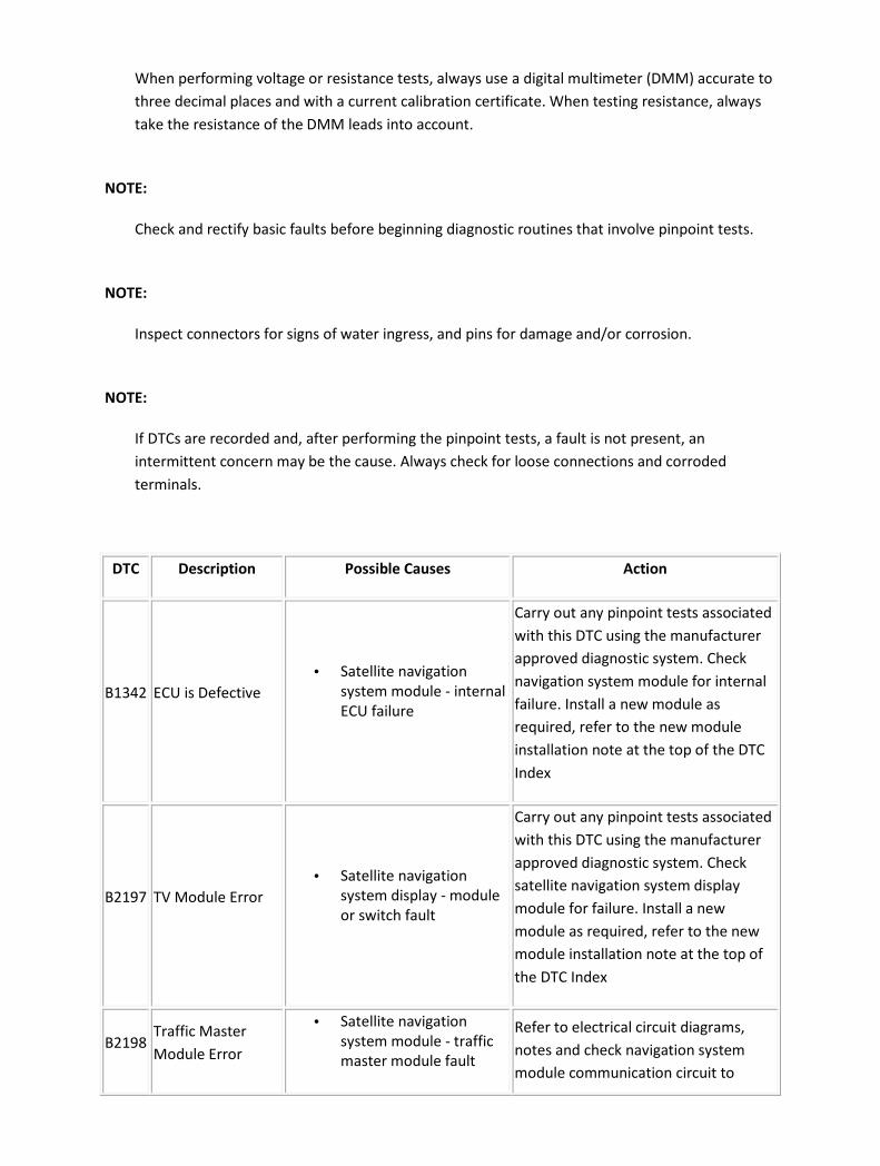
When performing voltage or resistance tests, always use a digital multimeter (DMM) accurate to
three decimal places and with a current calibration certificate. When testing resistance, always
take the resistance of the DMM leads into account.
NOTE:
Check and rectify basic faults before beginning diagnostic routines that involve pinpoint tests.
NOTE:
Inspect connectors for signs of water ingress, and pins for damage and/or corrosion.
NOTE:
If DTCs are recorded and, after performing the pinpoint tests, a fault is not present, an
intermittent concern may be the cause. Always check for loose connections and corroded
terminals.
DTC Description Possible Causes Action
B1342 ECU is Defective
• Satellite navigation
system module - internal
ECU failure
Carry out any pinpoint tests associated
with this DTC using the manufacturer
approved diagnostic system. Check
navigation system module for internal
failure. Install a new module as
required, refer to the new module
installation note at the top of the DTC
Index
B2197 TV Module Error
• Satellite navigation
system display - module
or switch fault
Carry out any pinpoint tests associated
with this DTC using the manufacturer
approved diagnostic system. Check
satellite navigation system display
module for failure. Install a new
module as required, refer to the new
module installation note at the top of
the DTC Index
B2198 Traffic Master
Module Error
• Satellite navigation
system module - traffic
master module fault
Refer to electrical circuit diagrams,
notes and check navigation system
module communication circuit to
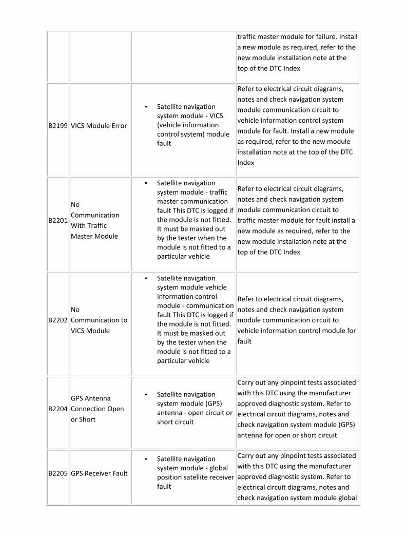
traffic master module for failure. Install
a new module as required, refer to the
new module installation note at the
top of the DTC Index
B2199 VICS Module Error
• Satellite navigation
system module - VICS
(vehicle information
control system) module
fault
Refer to electrical circuit diagrams,
notes and check navigation system
module communication circuit to
vehicle information control system
module for fault. Install a new module
as required, refer to the new module
installation note at the top of the DTC
Index
B2201
No
Communication
With Traffic
Master Module
• Satellite navigation
system module - traffic
master communication
fault This DTC is logged if
the module is not fitted.
It must be masked out
by the tester when the
module is not fitted to a
particular vehicle
Refer to electrical circuit diagrams,
notes and check navigation system
module communication circuit to
traffic master module for fault install a
new module as required, refer to the
new module installation note at the
top of the DTC Index
B2202
No
Communication to
VICS Module
• Satellite navigation
system module vehicle
information control
module - communication
fault This DTC is logged if
the module is not fitted.
It must be masked out
by the tester when the
module is not fitted to a
particular vehicle
Refer to electrical circuit diagrams,
notes and check navigation system
module communication circuit to
vehicle information control module for
fault
B2204
GPS Antenna
Connection Open
or Short
• Satellite navigation
system module (GPS)
antenna - open circuit or
short circuit
Carry out any pinpoint tests associated
with this DTC using the manufacturer
approved diagnostic system. Refer to
electrical circuit diagrams, notes and
check navigation system module (GPS)
antenna for open or short circuit
B2205 GPS Receiver Fault
• Satellite navigation
system module - global
position satellite receiver
fault
Carry out any pinpoint tests associated
with this DTC using the manufacturer
approved diagnostic system. Refer to
electrical circuit diagrams, notes and
check navigation system module global
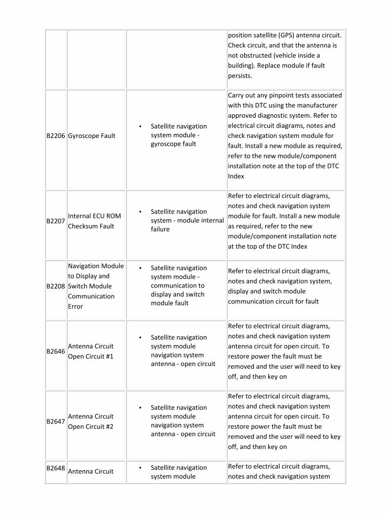
position satellite (GPS) antenna circuit.
Check circuit, and that the antenna is
not obstructed (vehicle inside a
building). Replace module if fault
persists.
B2206 Gyroscope Fault
• Satellite navigation
system module -
gyroscope fault
Carry out any pinpoint tests associated
with this DTC using the manufacturer
approved diagnostic system. Refer to
electrical circuit diagrams, notes and
check navigation system module for
fault. Install a new module as required,
refer to the new module/component
installation note at the top of the DTC
Index
B2207 Internal ECU ROM
Checksum Fault
• Satellite navigation
system - module internal
failure
Refer to electrical circuit diagrams,
notes and check navigation system
module for fault. Install a new module
as required, refer to the new
module/component installation note
at the top of the DTC Index
B2208
Navigation Module
to Display and
Switch Module
Communication
Error
• Satellite navigation
system module -
communication to
display and switch
module fault
Refer to electrical circuit diagrams,
notes and check navigation system,
display and switch module
communication circuit for fault
B2646 Antenna Circuit
Open Circuit #1
• Satellite navigation
system module
navigation system
antenna - open circuit
Refer to electrical circuit diagrams,
notes and check navigation system
antenna circuit for open circuit. To
restore power the fault must be
removed and the user will need to key
off, and then key on
B2647 Antenna Circuit
Open Circuit #2
• Satellite navigation
system module
navigation system
antenna - open circuit
Refer to electrical circuit diagrams,
notes and check navigation system
antenna circuit for open circuit. To
restore power the fault must be
removed and the user will need to key
off, and then key on
B2648 Antenna Circuit • Satellite navigation
system module
Refer to electrical circuit diagrams,
notes and check navigation system

Open Circuit #3 navigation system
antenna - open circuit
antenna circuit for open circuit. To
restore power the fault must be
removed and the user will need to key
off, and then key on
B2649 Antenna Circuit
Open Circuit #4
• Satellite navigation
system module
navigation system
antenna - open circuit
Refer to electrical circuit diagrams,
notes and check navigation system
antenna circuit for open circuit. To
restore power the fault must be
removed and the user will need to key
off, and then key on
B2650 Antenna Circuit
Short Circuit #1
• Satellite navigation
system module
navigation system
antenna circuit - short to
power or ground
Refer to electrical circuit diagrams,
notes and check navigation system
antenna circuit for short to power or
ground. To restore power the fault
must be removed and the user will
need to key off, and then key on
B2651 Antenna Circuit
Short Circuit #2
• Satellite navigation
system module
navigation system
antenna circuit - short to
power or ground
Refer to electrical circuit diagrams,
notes and check navigation system
antenna circuit for short to power or
ground. To restore power the fault
must be removed and the user will
need to key off, and then key on
B2652 Antenna Circuit
Short Circuit #3
• Satellite navigation
system module
navigation system
antenna circuit - short to
power or ground
Refer to electrical circuit diagrams,
notes and check navigation system
antenna circuit for short to power or
ground. To restore power the fault
must be removed and the user will
need to key off, and then key on
B2653 Antenna Circuit
Short Circuit #4
• Satellite navigation
system module
navigation system
antenna circuit - short to
power or ground
Refer to electrical circuit diagrams,
notes and check navigation system
antenna circuit for short to power or
ground. To restore power the fault
must be removed and the user will
need to key off, and then key on
B2655
Switch and Display
module is
defective
• Satellite navigation
system module - display
faulty
Refer to electrical circuit diagrams,
notes and check navigation system
display and switch module for failure.
Install a new display module as
required, refer to the new

module/component installation note
at the top of the DTC Index
B2656
DVD (Digital
Versatile Disk)
Error
• Satellite navigation
system module - DVD
error (DVD is integral to
navigation system
module ECU)
Refer to electrical circuit diagrams,
notes and check navigation system
module for fault. Install a new module
as required, refer to the new
module/component installation note
at the top of the DTC Index
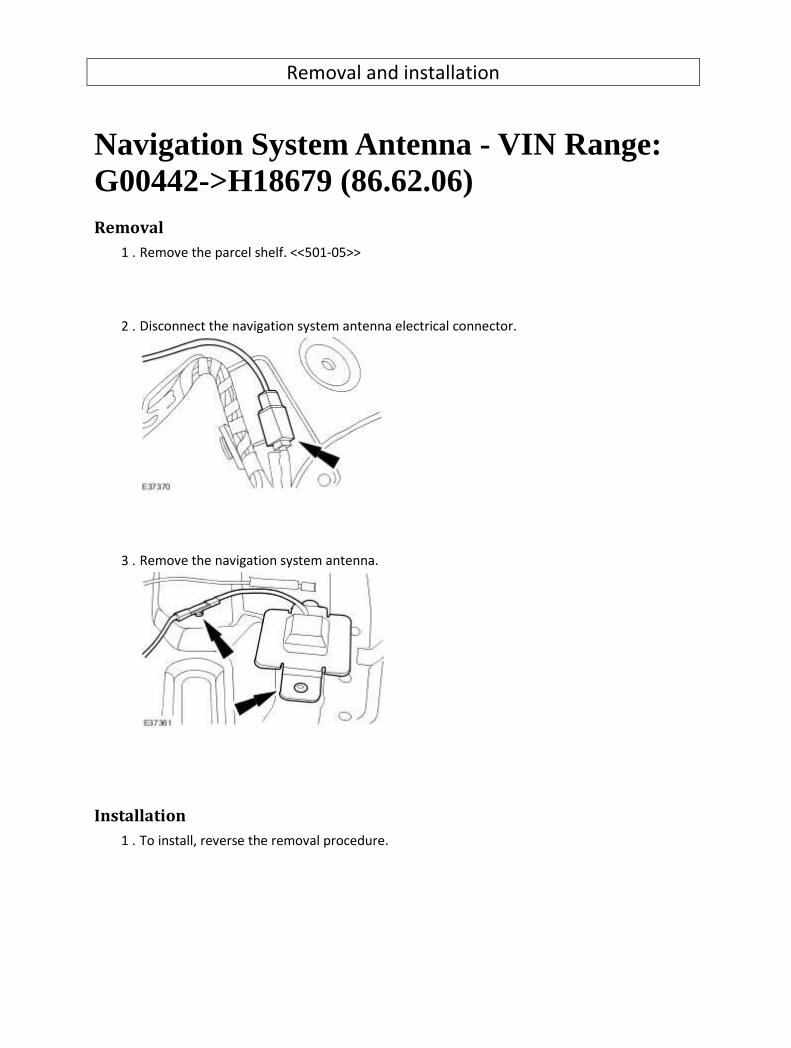
Removal and installation
Navigation System Antenna - VIN Range: G00442->H18679 (86.62.06) Removal
1 . Remove the parcel shelf. <<501-05>>
2 . Disconnect the navigation system antenna electrical connector.
3 . Remove the navigation system antenna.
Installation
1 . To install, reverse the removal procedure.
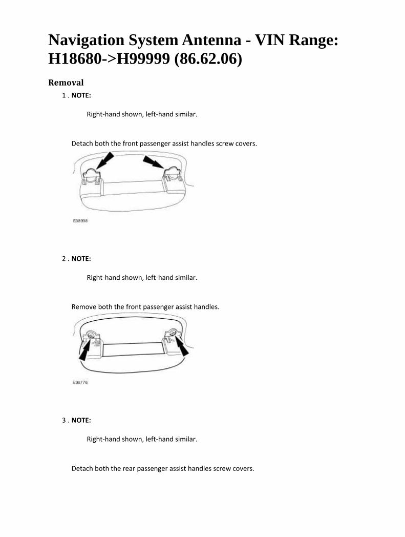
Navigation System Antenna - VIN Range: H18680->H99999 (86.62.06) Removal
1 . NOTE:
Right-hand shown, left-hand similar.
Detach both the front passenger assist handles screw covers.
2 . NOTE:
Right-hand shown, left-hand similar.
Remove both the front passenger assist handles.
3 . NOTE:
Right-hand shown, left-hand similar.
Detach both the rear passenger assist handles screw covers.

4 . NOTE:
Right-hand shown, left-hand similar.
Remove both the rear passenger assist handles.
Disconnect the electrical connectors.
5 . Locally detach the top of all the door aperture weatherstrips.
6 . NOTE:
Right-hand shown, left-hand similar.
Remove both the rear safety belt trim covers.

7 . NOTE:
Right-hand shown, left-hand similar.
Detach both the c-pillar upper trim panels.
8 . NOTE:
Right-hand shown, left-hand similar.
Detach both the c-pillar upper trim panel retaining straps.

9 . Remove the high mounted stoplamp.
For additional information, refer to High Mounted Stoplamp (86.41.01)
10 . Detach the rear of the headliner.
11 . Disconnect the navigation system antenna electrical connector.
12 . Remove the navigation system antenna securing nuts.
13 . Remove the navigation system antenna.
Detach the retaining clip.
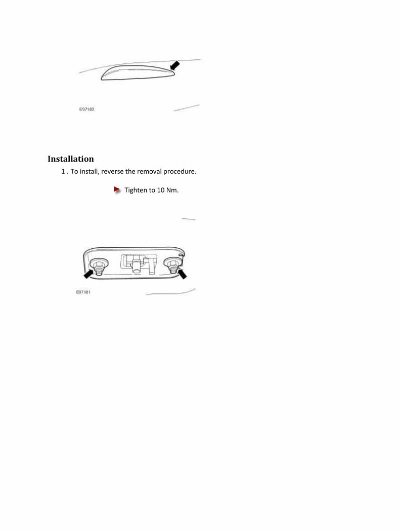
Installation
1 . To install, reverse the removal procedure.
Tighten to 10 Nm.

Navigation System Display Module (86.62.07) Removal
1 . Remove the instrument panel console. <<501-12>>
2 . Remove the navigation system display module.
1) Remove the navigation system display module retaining bolts.
2) Remove the navigation system display module.
Installation
1 . To install, reverse the removal procedure.

Navigation System Module (86.62.05) Removal
1
.
NOTE:
Make sure the mep DVD has been removed before disconnecting the battery ground
cable.
Disconnect the battery ground cable. <<414-01>>
2 . Remove the luggage compartment trim panel lower retaining clips.
3 . Remove the luggage compartment trim panel.
4 . Detach the luggage compartment side trim panel.
1) Remove the luggage compartment side trim panel retaining clip.
2) Detach the luggage compartment side trim panel.

5 . Detach the air suspension pipe.
6 . Detach the module retaining bracket.
7 . Disconnect the navigation system module electrical connectors and fibre optic connector.

8 . NOTE:
Right-hand shown, left-hand similar.
Remove the navigation system module.
Installation
1 . To install, reverse the removal procedure.
419-08 : Cellurar Phone
Description and operation
Cellular Phone - VIN Range: G00442->G45703 The portable cellular phone system consists of:
• cellular phone handset (GSM). • cradle (GSM). • cellular portable (US only). • handset battery (US only). • hang up cup (US only). • roof console mounted microphone. • steering wheel switch controls. • portable support electronics (PSE) module (US only). • transceiver (GSM). • in-bumper cellular phone antenna. • parcel shelf antenna (US only). • antenna cable. • audio unit controls.
The cellular phone handset is located within the center console armrest. The audio control unit and the steering wheel controls are utilized to operate the system. The vehicle utilizes two unique cellular phones systems:
• GSM • US CDMA/TDMA digital and AMPS analogue systems
The voice activation control module provides the handsfree operation for cellular phone. To activate the handsfree function: 1 . Switch the ignition to the RUN position. After 4-6 seconds the system will be initialized and "VOICE READY" will be displayed in the message center. 2 . Operate the VOICE/PHONE switch on the steering wheel. 3 . Clearly state the command when "LISTENING" is displayed in the message center. 4 . Operate the VOICE/PHONE switch on the steering wheel or remain silent for 1 second. If

speech is detected "PROCESSING" will be displayed in the message center. Operating the VOICE/PHONE switch again will cancel the voice session. Refer to the Cellular Phone user guide for complete operating instructions. For additional information on the voice activation control module, refer to <<419-10>>.

Cellular Phone - VIN Range: G45704->H18679 Component Location
Item Description
1 Voice activated control module
2 Microphone
3 Steering wheel telematics control switches
4 Bluetooth upgrade module
5 Portable Support Electronics (PSE)
Bluetooth
2006 model year (MY) sees the introduction of a Bluetooth® communications network system.
Note: In common with previous cellular phones it is the drivers responsibility to comply with local
legislation regarding cellular phone use.
Bluetooth is a way of communicating with various electronic devices that are equipped with
specialized chips using a short-range radio link. It allows most devices to communicate with one

another by creating a universal language. The devices then form a private network known as a
'personal area network'.
Interaction between Bluetooth devices can take place without direct human intervention whenever
two or more Bluetooth devices are within each other's range. This enables the Bluetooth transceiver
chip to trigger an automatic connection to deliver and accept a flow of data.
Bluetooth devices operate on a radio frequency band knows as the Industrial, Scientific, and Medical
frequency. The Industrial, Scientific, and Medical radio frequency band is 2.40 GigaHertz (GHz) to
2.48 GHz which is divided into 79 channels, each carrying a bandwidth of 1 MegaHertz (MHz).
The devices use the 79 individual randomly chosen channels within the frequency band, changing
from one to another on a regular basis. The Bluetooth transmitters change frequencies
approximately 1,600 times every second, meaning that more devices can utilize the limited slice of
the radio frequency.
Since every Bluetooth transmitter uses this technique automatically, it's most unlikely that two
transmitters will be on the same frequency at the same time. This technique minimizes the risk of
disruption to Bluetooth devices, as any interference on a particular frequency will last only a fraction
of a second.
The Bluetooth system consists of:
• A Bluetooth upgrade module
• A Portable Support Electronics (PSE) module
• A voice activated control module
• A microphone
• Steering wheel telematics control switches
• An audio unit
The Bluetooth upgrade module allows the driver to integrate their personal cellular phone to the
vehicle. When a cellular phone is paired to the vehicle, it allows the storage of up to 500 individual
phone numbers and 40 related voice tags to the voice activated control module. These stored phone
numbers can then be accessed using the audio unit control buttons, the audio unit touch screen (if
equipped) or steering wheel telematics control switches. The voice tags can be accessed by using the
steering wheel telematics control switches when utilizing the voice activation facility.
If a cellular phone has been matched/programmed to the vehicle and a second cellular phone is
added, the stored phone numbers and voice tags from the second cellular phone will overwrite the
original phones' stored data.
Phone numbers stored to the PSE and voice tags stored to the voice activated control module need
to be manually updated should alterations be required. If a new phone number has been added to
the cellular phone memory, it will need to be added manually to the vehicle memory.
Once stored to the vehicle, the phone numbers can be viewed on the audio unit screen. The audio
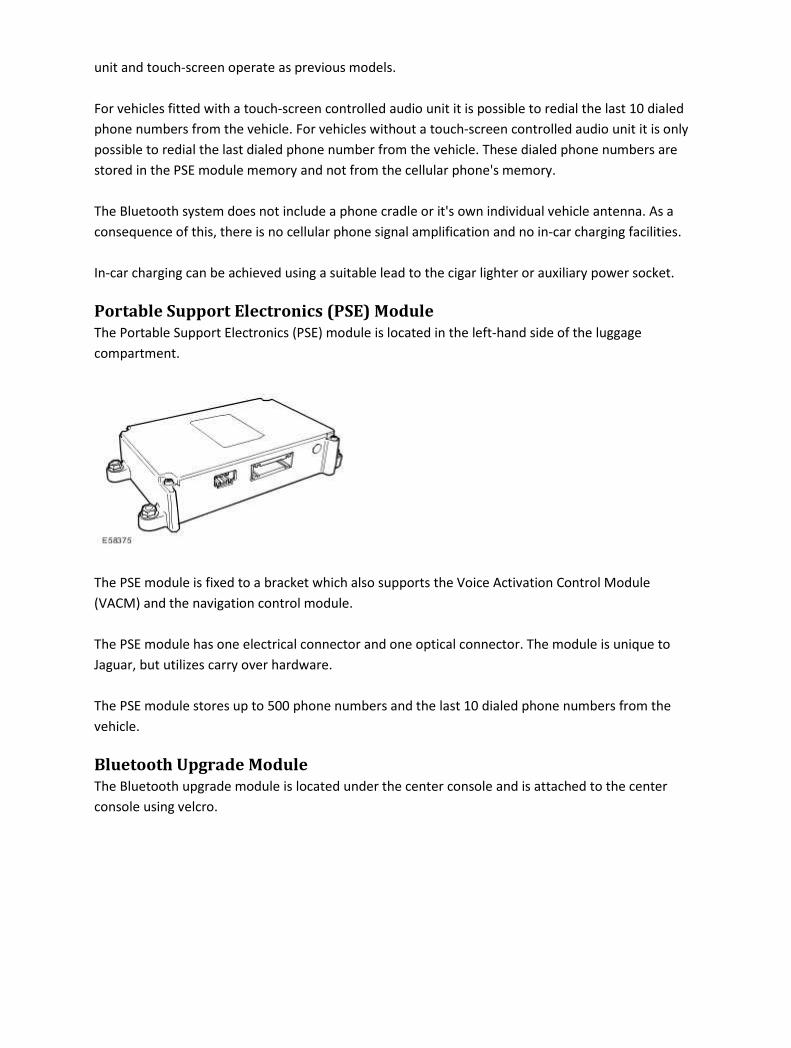
unit and touch-screen operate as previous models.
For vehicles fitted with a touch-screen controlled audio unit it is possible to redial the last 10 dialed
phone numbers from the vehicle. For vehicles without a touch-screen controlled audio unit it is only
possible to redial the last dialed phone number from the vehicle. These dialed phone numbers are
stored in the PSE module memory and not from the cellular phone's memory.
The Bluetooth system does not include a phone cradle or it's own individual vehicle antenna. As a
consequence of this, there is no cellular phone signal amplification and no in-car charging facilities.
In-car charging can be achieved using a suitable lead to the cigar lighter or auxiliary power socket.
Portable Support Electronics (PSE) Module
The Portable Support Electronics (PSE) module is located in the left-hand side of the luggage
compartment.
The PSE module is fixed to a bracket which also supports the Voice Activation Control Module
(VACM) and the navigation control module.
The PSE module has one electrical connector and one optical connector. The module is unique to
Jaguar, but utilizes carry over hardware.
The PSE module stores up to 500 phone numbers and the last 10 dialed phone numbers from the
vehicle.
Bluetooth Upgrade Module
The Bluetooth upgrade module is located under the center console and is attached to the center
console using velcro.
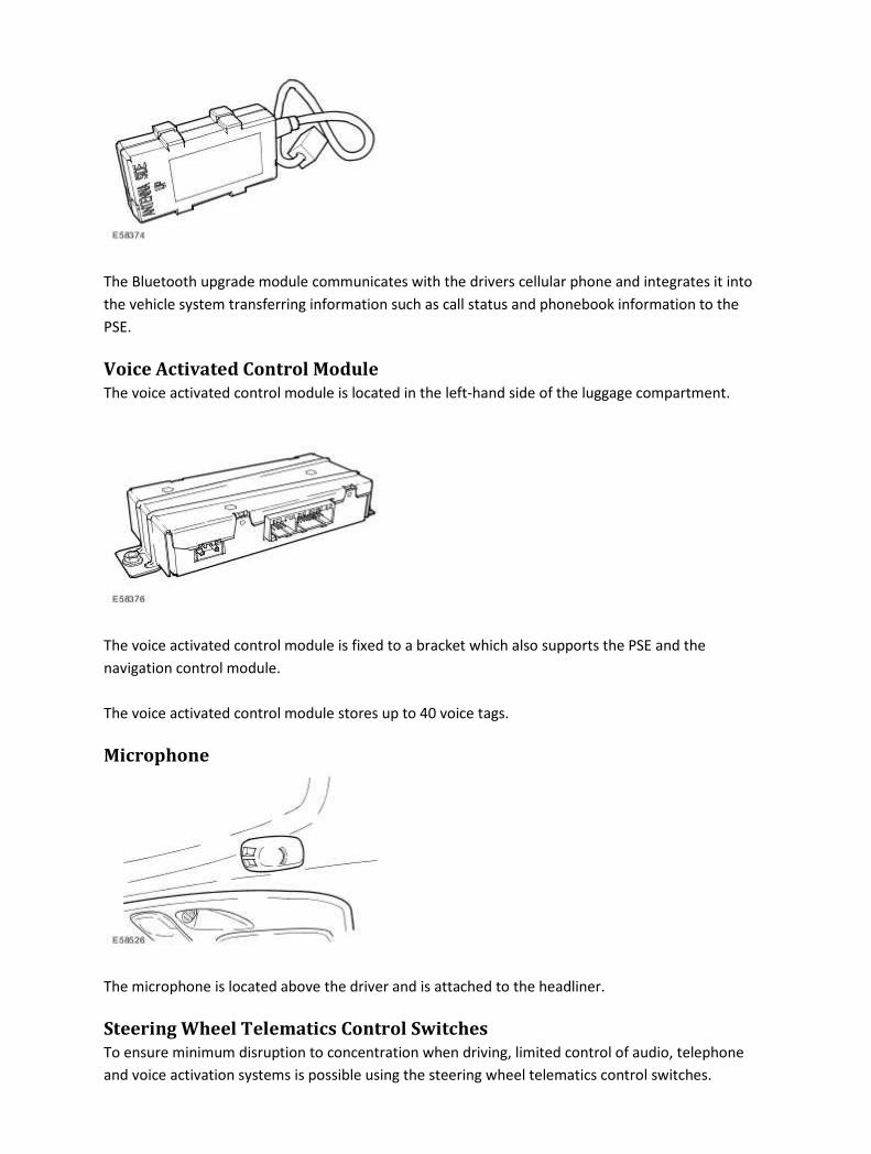
The Bluetooth upgrade module communicates with the drivers cellular phone and integrates it into
the vehicle system transferring information such as call status and phonebook information to the
PSE.
Voice Activated Control Module
The voice activated control module is located in the left-hand side of the luggage compartment.
The voice activated control module is fixed to a bracket which also supports the PSE and the
navigation control module.
The voice activated control module stores up to 40 voice tags.
Microphone
The microphone is located above the driver and is attached to the headliner.
Steering Wheel Telematics Control Switches
To ensure minimum disruption to concentration when driving, limited control of audio, telephone
and voice activation systems is possible using the steering wheel telematics control switches.
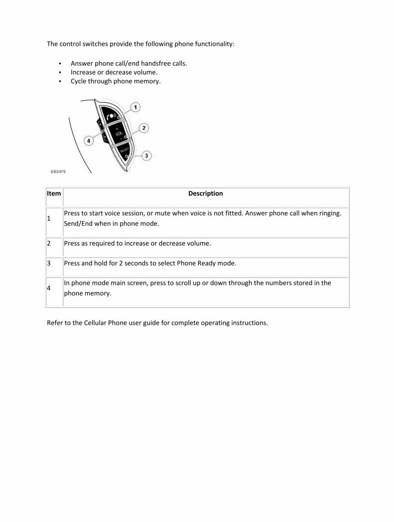
The control switches provide the following phone functionality:
• Answer phone call/end handsfree calls.
• Increase or decrease volume.
• Cycle through phone memory.
Item Description
1 Press to start voice session, or mute when voice is not fitted. Answer phone call when ringing.
Send/End when in phone mode.
2 Press as required to increase or decrease volume.
3 Press and hold for 2 seconds to select Phone Ready mode.
4 In phone mode main screen, press to scroll up or down through the numbers stored in the
phone memory.
Refer to the Cellular Phone user guide for complete operating instructions.

Cellular Phone - VIN Range: H18680->H99999 COMPONENT LOCATION
Item Part Number Description
1 Microphone
2 Bluetoth antenna
3 Audio amplifier
4 Telephone control module
5 Speakers

OVERVIEW
The system allows the driver to use a Bluetooth equipped cellular phone handset through the
vehicles Information and Entertainment system.
NOTE:
There is no physical connection (cradle) between the phone handset and the telephone control
module. Communications between the 2 components are purely Bluetooth. This can limit the
available functions dependant on the handset used.
The cellular phone system comprises the following components:
• Telephone control module
• Microphone
• Bluetooth antenna
Phone dialing is achieved using one of the following methods:
• Dialing a number using the ICP keypad
• Selecting a number from the handsets phonebook via the ICM
• Selecting from the handsets call register via the ICM
The Telephone control module is connected to the Information and Entertainment system on the
D2B bus. This allows audio and control signals to be routed to and from the telephone control
module. The telephone control module has a saperate integral Bluetooth antenna located on the LH
(left-hand) side of the rear parcel shelf.
Telephone handsets must be paired with the telephone control module before they can be used with
the vehicle system. Up to five telephone handsets can be paired with the vehicle, but only one
telephone can used at a time.
PHONE MODULE
The telephone control module is located in the rear LH (left-hand) side of the luggage compartment.
The phone module is connected on the D2B ring to the rest of the entertainment system. The D2B
ring allows control instructions and audio to be transfered to the relevant modules.

MICROPHONE
The microphone is located in the overhead console which surrounds the front interior lamp. The
microphone is hardwired to the IAM.
CONTROL SWITCHES
Item Part Number Description
1 Answer call or dial switch
2 Volume up/down
3 Mode select button
4 Menu previous/next button
The steering wheel mounted telephone control switches are located on the RH side of the steering
wheel. The switches are a resistive ladder type which return a different voltage to the ICM in
response to different switches being pressed.

BLUETOOTH ANTENNA
The bluetooth antenna is located on the LH (left-hand) side of the rear parcel shelf. The antenna is
used to connect the telephone control module to a Bluetooth compatible phone.
TELEPHONE VOICE CONTROL
The vehicle system is able to use any voice tags which are stored in the mobile telephone. There is no
voice dialing feature of the cellular telephone system.
Voice dialing is accessed via a long press of the RH rotary ENTER button. The ICM displays that Voice
tag dialing is in progress and an audible prompt is generated from th e telephone control module.
After the prompt the handset waits several seconds for the voice command.
PRINCIPLES OF OPERATION
The phone system is controlled from the ICM and/or the steering wheel mounted switches. Control
signals from the steering wheel switches are sent via the clock spring and the steering wheel module
to the ICM. The ICM sends control signals on the D2B ring to the telephone control module. Audio is
sent on the D2B ring to the audio amplifier and is output on the vehicle speaker system.
CONTROL DIAGRAM
NOTE:
A = Hardwired; Z = D2B

Item Part Number Description
1 Steering wheel mounted control switches
2 CJB (central junction box)
3 Ignition switch
4 BJB (battery junction box)
5 Speakers
6 Audio amplifier
7 Voice recognition control module

8 Microphone
9 Bluetooth antenna
10 Integrated audio module (IAM)
11 Clockspring
12 Telephone control module
Diagnosis and testing
Cellular Phone Principles of Operation
For a detailed description of the Cellular Phone, refer to the relevant Description and Operation
sections in the workshop manual.
Cellular Phone - VIN Range: G00442->G45703
Inspection and Verification
1 . Verify the customer concern.
2 . Visually inspect for obvious signs of mechanical or electrical damage.
Visual Inspection Chart
Electrical
• Fuses/relays
• Wiring Harness For Damage And Corrosion
• Electrical Connector(s) Loose, Damaged Or Corrosion
1 . If an obvious cause for an observed or reported concern is found, correct the cause (if possible)
before proceeding to the next step.
2 . If the cause is not visually evident, check for Diagnostic Trouble Codes (DTCs) and refer to the DTC
Index.
DTC Index
Telephone Control Module
CAUTION: When probing connectors to take measurements in the course of the pinpoint
tests, use the adaptor kit, part number 3548-1358-00
NOTE:
If the control module/component is suspect and the vehicle remains under manufacturer
warranty, refer to the Warranty Policy and Procedures manual (section B1.2), or determine if
any prior approval program is in operation, prior to the installation of a new
module/component.
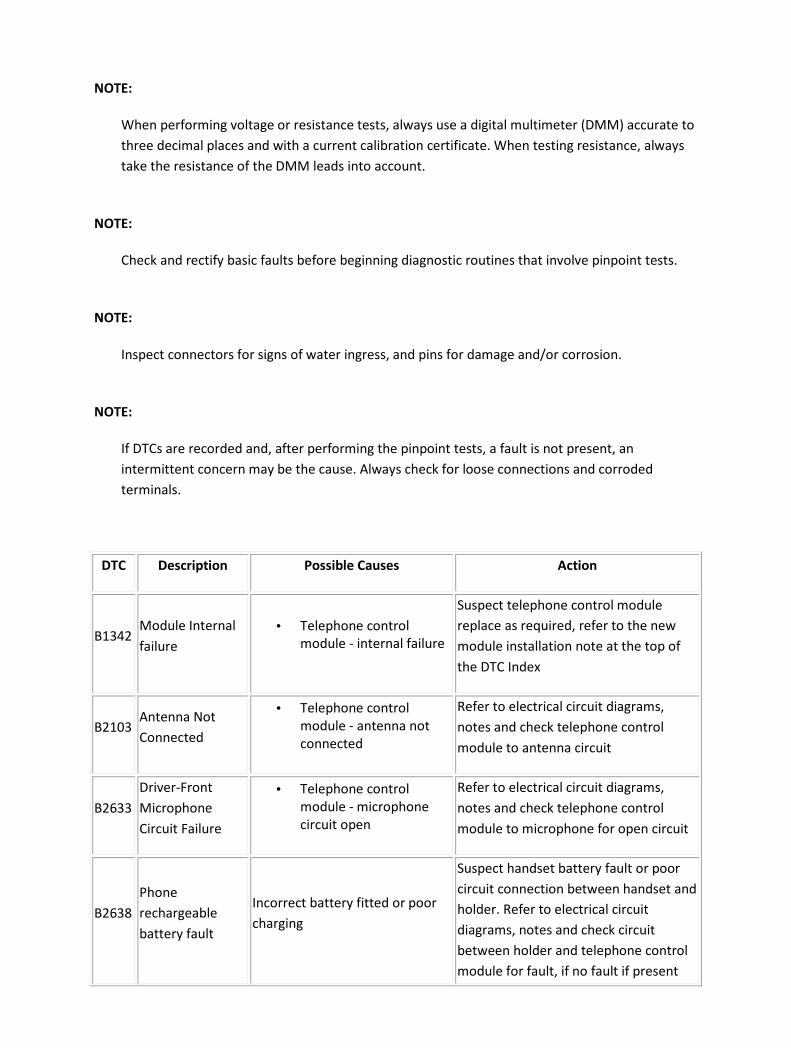
NOTE:
When performing voltage or resistance tests, always use a digital multimeter (DMM) accurate to
three decimal places and with a current calibration certificate. When testing resistance, always
take the resistance of the DMM leads into account.
NOTE:
Check and rectify basic faults before beginning diagnostic routines that involve pinpoint tests.
NOTE:
Inspect connectors for signs of water ingress, and pins for damage and/or corrosion.
NOTE:
If DTCs are recorded and, after performing the pinpoint tests, a fault is not present, an
intermittent concern may be the cause. Always check for loose connections and corroded
terminals.
DTC Description Possible Causes Action
B1342 Module Internal
failure
• Telephone control
module - internal failure
Suspect telephone control module
replace as required, refer to the new
module installation note at the top of
the DTC Index
B2103 Antenna Not
Connected
• Telephone control
module - antenna not
connected
Refer to electrical circuit diagrams,
notes and check telephone control
module to antenna circuit
B2633
Driver-Front
Microphone
Circuit Failure
• Telephone control
module - microphone
circuit open
Refer to electrical circuit diagrams,
notes and check telephone control
module to microphone for open circuit
B2638
Phone
rechargeable
battery fault
Incorrect battery fitted or poor
charging
Suspect handset battery fault or poor
circuit connection between handset and
holder. Refer to electrical circuit
diagrams, notes and check circuit
between holder and telephone control
module for fault, if no fault if present

advise a new phone battery is required.
U2601
D2B (wake up
line short to
ground)
• Telephone control
module - wake-up line
short to ground
Refer to electrical circuit diagrams,
notes and check telephone control
module (D2B) wake-up Line for short to
ground
U2609
D2B (wake-up
line pulse width
out of spec)
• Telephone control
module - wake-up line
fault (pulse< 50mS, pulse
> 110mS)
Refer to electrical circuit diagrams,
notes and check telephone control
module - (D2B) wake-up Line circuit for
fault
U2610
D2B (Slave ECU
fails to receive a
report position)
• During initialization no
position status report is
received from one or
more slave modules
Refer to electrical circuit diagrams,
notes and check (D2B) slave modules
and circuit for fault, replace as required,
refer to the new module installation
note at the top of the DTC Index
U2611
D2B (Slave ECU
fails to receive an
alarm clear
command)
• Telephone control
module - on entering
alarm state, slave ECU
has failed to receive
alarm clear command
Refer to electrical circuit diagrams,
notes and check (D2B) slave modules
and circuit for fault, replace as required,
refer to the new module installation
note at the top of the DTC Index
Cellular Phone - Vehicles With: Bluetooth Overview
This section covers the components of the Bluetooth cellular phone system.
For information on the description and operation of the Bluetooth cellular phone system :
Cellular Phone - VIN Range: G45704->H18679
For additional information on the Bluetooth cellular phone system : REFER to owner information -
Bluetooth telephone system handbook.
Inspection and Verification
NOTE:
Only cellular phones and software versions featured in the Jaguar Bluetooth approved phones
and software list can be guaranteed to operate correctly. Check the D2B ring order and circuit
integrity. Before pairing a handset to the Bluetooth phone system make sure that the
handbook for the specific handset is available.
1 . Verify the customer concern by operating the system using the customers cellular phone.
2 . Visually inspect for obvious signs of electrical damage.
Visual Inspection Chart
Electrical
• Fuse(s)
• Wiring harness
• Electrical connector(s)
• Bluetooth cellular phone
• Microphone
• Steering wheel control
• Bluetooth upgrade module
• Portable support electronics (PSE) module
• Voice module
1 . If an obvious cause for an observed or reported concern is found, correct the cause (if possible)
before proceeding to the next step.
2 . Use the approved diagnostic system or a scan tool to retrieve any DTCs before moving onto the
symptom chart.
Make sure that all DTCs are cleared following rectification.

Symptom Chart
Symptom Action
"NO PHONE FITTED" (touch-screen) message displayed continuously or "NO
PHONE" message displayed every time the phone mode button is pressed
GO to Pinpoint Test
G970218p1.
"HANDSET IN USE" (touch-screen) message displayed for more than 2 minutes,
or "HANDSET" message displayed every time the phone mode button is
pressed and never changes to "SIG*"
GO to Pinpoint Test
G970218p2.
Unable to pair the handset to telephone system GO to Pinpoint Test
G970218p3.
"PHONE OFF" message displayed (touch-screen only) GO to Pinpoint Test
G970218p4.
Cannot answer/reject/end call from the audio head unit/touch screen/steering
wheel control
GO to Pinpoint Test
G970218p5.
Unable to connect the handset to telephone system GO to Pinpoint Test
G970218p6.
Bluetooth connection is dropped GO to Pinpoint Test
G970218p7.
Incorrect or no phonebook entries GO to Pinpoint Test
G970218p8.
No third party audio GO to Pinpoint Test
G970218p9.
No in-vehicle audio GO to Pinpoint Test
G970218p10.
No ringing heard through the vehicle speakers GO to Pinpoint Test
G970218p11.
Low audio volume GO to Pinpoint Test
G970218p12.
Cannot dial out from audio head unit/touch-screen/steering wheel control GO to Pinpoint Test
G970218p13.

Voice activated phone functions inoperative GO to Pinpoint Test
G970218p14.
Call is dropped GO to Pinpoint Test
G970218p15.
Interference and distortion GO to Pinpoint Test
G970218p16.
Unable to transfer call between hands free and handset GO to Pinpoint Test
G970218p17.
Pinpoint Tests
NOTE:
When performing voltage or resistance tests, always use a digital multimeter (DMM) accurate to
three decimal places, and with an up-to-date calibration certificate. When testing resistance
always take the resistance of the DMM leads into account.
NOTE:
Inspect connectors for signs of water ingress, and pins for damage and/or corrosion.
NOTE:
If a control module or component is suspect and the vehicle remains under manufacturer
warranty, refer to the Warranty Policy and Procedures manual (section B1.2), or determine if
any prior approval program is in operation, before the replacement of a component.
PINPOINT TEST G970218p1 : "NO PHONE FITTED" (touch-screen) message displayed continuously or "NO PHONE" message displayed every time the phone mode button is pressed G970218t1 :
1.

• Is the car a USA/Mexico/Canada car?
-> Yes
GO to Pinpoint Test G970218t3.
-> No
GO to Pinpoint Test G970218t2.
G970218t2 :
1.
• Is the VIN of the car post VIN break for Bluetooth? (Refer to Technical Helpline for VIN
break information).
-> Yes
GO to Pinpoint Test G970218t3.
-> No
The Bluetooth system cannot be retrofitted to rest of world cars pre-VIN break or to those cars not
fitted with the Bluetooth pre-wire due to a harness architecture change.
G970218t3 :
1.
• Has the correct harness been fitted to the car?
-> Yes
GO to Pinpoint Test G970218t4.
-> No
The Bluetooth system cannot be retrofitted to rest of world cars pre-VIN break or to those cars not
fitted with the Bluetooth pre-wire due to a harness architecture change. (Refer to Technical Helpline
for VIN break and pre-wire information).
G970218t4 :
1.
• Does the display ever return to the main phone screen or ever display "PHONE"?
-> Yes
GO to Pinpoint Test G970218t22.

-> No
GO to Pinpoint Test G970218t5.
G970218t5 :
1.
• Check the part number of the portable support electronics (PSE) module. Has the correct
part been fitted?
-> Yes
Check power, ignition and ground circuits/connections at the PSE module. GO to Pinpoint Test
G970218t7.
-> No
Refer to the warranty policy and procedures manual if the PSE module is suspect.
G970218t22 :
1.
• Are any of the D2B connections loose or damaged?
-> Yes
Reconnect/change/repair the D2B leads and check for normal operation.
-> No
GO to Pinpoint Test G970218t7.
G970218t7 :
1.
• Are power, ignition and ground being supplied to the portable support electronics (PSE)
module?
-> Yes
Refer to the warranty policy and procedures manual if the PSE module is suspect.
-> No
Rectify as necessary. Refer to the electrical guides.
PINPOINT TEST G970218p2 : "HANDSET IN USE" (touch-screen)
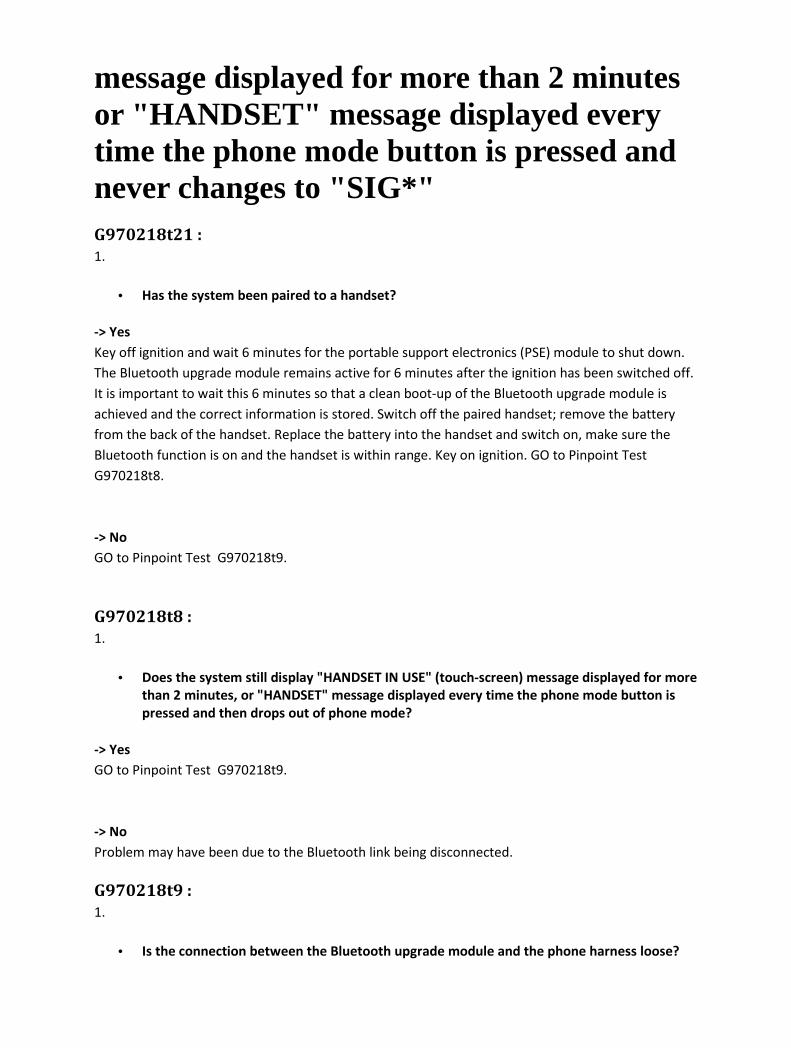
message displayed for more than 2 minutes or "HANDSET" message displayed every time the phone mode button is pressed and never changes to "SIG*" G970218t21 :
1.
• Has the system been paired to a handset?
-> Yes
Key off ignition and wait 6 minutes for the portable support electronics (PSE) module to shut down.
The Bluetooth upgrade module remains active for 6 minutes after the ignition has been switched off.
It is important to wait this 6 minutes so that a clean boot-up of the Bluetooth upgrade module is
achieved and the correct information is stored. Switch off the paired handset; remove the battery
from the back of the handset. Replace the battery into the handset and switch on, make sure the
Bluetooth function is on and the handset is within range. Key on ignition. GO to Pinpoint Test
G970218t8.
-> No
GO to Pinpoint Test G970218t9.
G970218t8 :
1.
• Does the system still display "HANDSET IN USE" (touch-screen) message displayed for more
than 2 minutes, or "HANDSET" message displayed every time the phone mode button is
pressed and then drops out of phone mode?
-> Yes
GO to Pinpoint Test G970218t9.
-> No
Problem may have been due to the Bluetooth link being disconnected.
G970218t9 :
1.
• Is the connection between the Bluetooth upgrade module and the phone harness loose?

-> Yes
Reconnect the Bluetooth upgrade module and check for normal operation.
-> No
GO to Pinpoint Test G970218t10.
G970218t6 :
1.
• Are any of the Bluetooth upgrade module pins damaged?
-> Yes
Refer to the warranty policy and procedures manual if the Bluetooth upgrade module is suspect.
-> No
Check harness to/from the Bluetooth upgrade module and the portable support electronics (PSE)
module. GO to Pinpoint Test G970218t10.
G970218t10 :
1.
• Is power being supplied to the Bluetooth upgrade module?
-> Yes
Refer to the warranty policy and procedures manual if the Bluetooth upgrade module is suspect.
-> No
GO to Pinpoint Test G970218t11.
G970218t11 :
1.
• Are power, ignition, and ground being supplied to the portable support electronics (PSE)
module?
-> Yes
Refer to the warranty policy and procedures manual if the PSE module is suspect.
-> No
Rectify as necessary. Refer to the electrical guides.

PINPOINT TEST G970218p3 : - Unable to pair the handset to telephone system G970218t14 :
1.
• Has another handset previously been paired to the system?
-> Yes
GO to Pinpoint Test G970218t15.
-> No
GO to Pinpoint Test G970218t16.
G970218t15 :
1.
• Is the "HANDSET IN USE" (touch-screen) or "HANDSET" message displayed, or does the
system drop out of phone mode?
-> Yes
Go to'"HANDSET IN USE" or "HANDSET"' message displayed - GO to Pinpoint Test G970218p2.
-> No
GO to Pinpoint Test G970218t16.
G970218t16 :
1.
• Does the touch-screen display "Discover Me" with 4 or 5 bars (The 5th bar will flash slowly)
or does the audio head unit display "SIG****" or "SIG*****" (The 5th '*' will flash slowly)?
-> Yes
Retry the pairing process following the 'quick guide information' for the specific handset. GO to
Pinpoint Test G970218t17.
-> No
Enter the ##3#*# pairing key sequence. GO to Pinpoint Test G970218t18.

G970218t17 :
1.
• Has the handset paired with the system successfully? ("Phone connected" displayed (touch
screen) or "SIG*" displayed (audio head unit display))?
-> Yes
Problem may have been due to a faulty Bluetooth connection.
-> No
Key off ignition and wait 6 minutes for the portable support electronics (PSE) module to shut down.
The Bluetooth upgrade module remains active for 6 minutes after the ignition has been switched off.
It is important to wait this 6 minutes so that a clean boot-up of the Bluetooth upgrade module is
achieved and the correct information is stored. Switch off the paired handset; remove the battery
from the back of the handset. Replace the battery into the handset and switch on, make sure the
Bluetooth function is on and the handset is within range. Key on ignition. GO to Pinpoint Test
G970218t20.
G970218t18 :
1.
• Does the touch-screen display "Discover Me" with 4 or 5 bars (The 5th bar will flash slowly)
or does the audio head unit display "SIG****" or "SIG*****" (The 5th '*' will flash slowly)?
-> Yes
Retry the pairing process following the 'quick guide information' for the specific handset.
-> No
Key off ignition and wait 6 minutes for the portable support electronics (PSE) module to shut down.
Key on ignition. GO to Pinpoint Test G970218t19.
G970218t19 :
1.
• Does the touch-screen display "Discover Me" with 4 or 5 bars (The 5th bar will flash slowly)
or does the audio head unit display "SIG****" or "SIG*****" (The 5th '*' will flash slowly)?
-> Yes
Retry the pairing process following the 'quick guide information' for the specific handset.
-> No
GO to Pinpoint Test G970218t196.
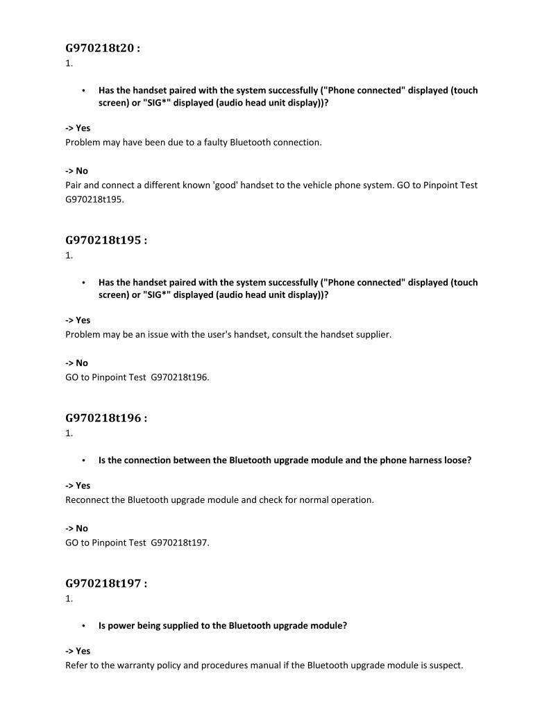
G970218t20 :
1.
• Has the handset paired with the system successfully ("Phone connected" displayed (touch
screen) or "SIG*" displayed (audio head unit display))?
-> Yes
Problem may have been due to a faulty Bluetooth connection.
-> No
Pair and connect a different known 'good' handset to the vehicle phone system. GO to Pinpoint Test
G970218t195.
G970218t195 :
1.
• Has the handset paired with the system successfully ("Phone connected" displayed (touch
screen) or "SIG*" displayed (audio head unit display))?
-> Yes
Problem may be an issue with the user's handset, consult the handset supplier.
-> No
GO to Pinpoint Test G970218t196.
G970218t196 :
1.
• Is the connection between the Bluetooth upgrade module and the phone harness loose?
-> Yes
Reconnect the Bluetooth upgrade module and check for normal operation.
-> No
GO to Pinpoint Test G970218t197.
G970218t197 :
1.
• Is power being supplied to the Bluetooth upgrade module?
-> Yes
Refer to the warranty policy and procedures manual if the Bluetooth upgrade module is suspect.
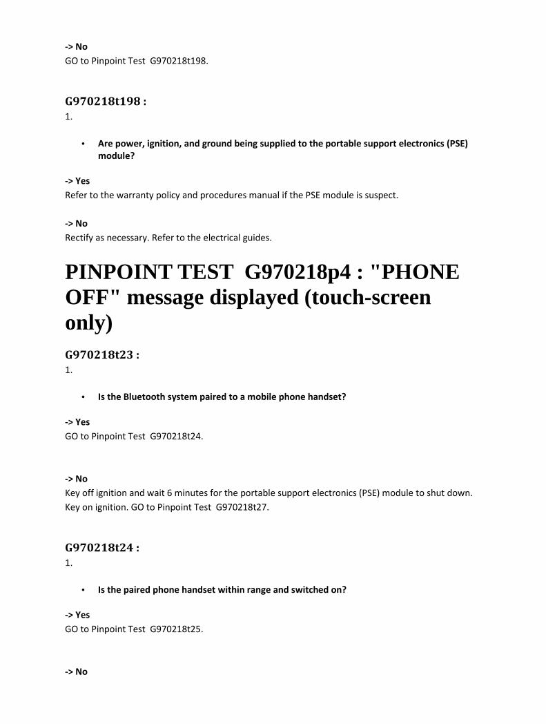
-> No
GO to Pinpoint Test G970218t198.
G970218t198 :
1.
• Are power, ignition, and ground being supplied to the portable support electronics (PSE)
module?
-> Yes
Refer to the warranty policy and procedures manual if the PSE module is suspect.
-> No
Rectify as necessary. Refer to the electrical guides.
PINPOINT TEST G970218p4 : "PHONE OFF" message displayed (touch-screen only) G970218t23 :
1.
• Is the Bluetooth system paired to a mobile phone handset?
-> Yes
GO to Pinpoint Test G970218t24.
-> No
Key off ignition and wait 6 minutes for the portable support electronics (PSE) module to shut down.
Key on ignition. GO to Pinpoint Test G970218t27.
G970218t24 :
1.
• Is the paired phone handset within range and switched on?
-> Yes
GO to Pinpoint Test G970218t25.
-> No

GO to Pinpoint Test G970218t26.
G970218t25 :
1.
• Is the paired phone handset 'connected' to the vehicle phone system?
-> Yes
GO to Pinpoint Test G970218t26.
-> No
Follow instructions to 'connect' specific handset with the vehicle phone system. GO to Pinpoint Test
G970218t26.
G970218t26 :
1.
• Has the user switched out of phone mode e.g. audio, and then back to phone mode?
-> Yes
This is a system issue carried over from the previous phone system. Make sure that the last paired
phone is on and within range, and test for normal operation.
-> No
Call Technical Helpline.
G970218t27 :
1.
• Does the display still show the "PHONE OFF" message?
-> Yes
GO to Pinpoint Test G970218t28.
-> No
Check for normal operation.
G970218t28 :
1.
• Are the D2B connections loose or damaged?
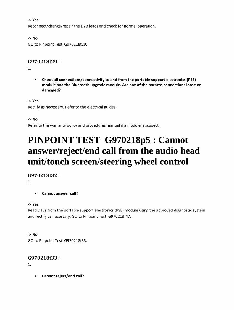
-> Yes
Reconnect/change/repair the D2B leads and check for normal operation.
-> No
GO to Pinpoint Test G970218t29.
G970218t29 :
1.
• Check all connections/connectivity to and from the portable support electronics (PSE)
module and the Bluetooth upgrade module. Are any of the harness connections loose or
damaged?
-> Yes
Rectify as necessary. Refer to the electrical guides.
-> No
Refer to the warranty policy and procedures manual if a module is suspect.
PINPOINT TEST G970218p5 : Cannot answer/reject/end call from the audio head unit/touch screen/steering wheel control G970218t32 :
1.
• Cannot answer call?
-> Yes
Read DTCs from the portable support electronics (PSE) module using the approved diagnostic system
and rectify as necessary. GO to Pinpoint Test G970218t47.
-> No
GO to Pinpoint Test G970218t33.
G970218t33 :
1.
• Cannot reject/end call?
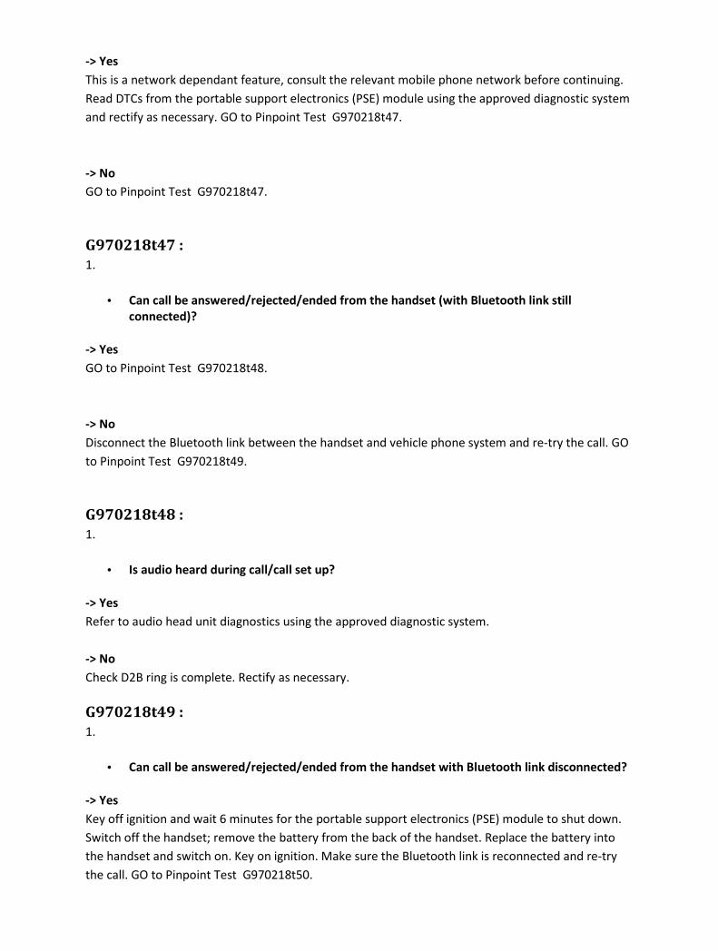
-> Yes
This is a network dependant feature, consult the relevant mobile phone network before continuing.
Read DTCs from the portable support electronics (PSE) module using the approved diagnostic system
and rectify as necessary. GO to Pinpoint Test G970218t47.
-> No
GO to Pinpoint Test G970218t47.
G970218t47 :
1.
• Can call be answered/rejected/ended from the handset (with Bluetooth link still
connected)?
-> Yes
GO to Pinpoint Test G970218t48.
-> No
Disconnect the Bluetooth link between the handset and vehicle phone system and re-try the call. GO
to Pinpoint Test G970218t49.
G970218t48 :
1.
• Is audio heard during call/call set up?
-> Yes
Refer to audio head unit diagnostics using the approved diagnostic system.
-> No
Check D2B ring is complete. Rectify as necessary.
G970218t49 :
1.
• Can call be answered/rejected/ended from the handset with Bluetooth link disconnected?
-> Yes
Key off ignition and wait 6 minutes for the portable support electronics (PSE) module to shut down.
Switch off the handset; remove the battery from the back of the handset. Replace the battery into
the handset and switch on. Key on ignition. Make sure the Bluetooth link is reconnected and re-try
the call. GO to Pinpoint Test G970218t50.

-> No
This may be a handset issue, consult the handset supplier.
G970218t50 :
1.
• Can the call be answered/rejected/ended from the handset (with Bluetooth link
connected)?
-> Yes
Problem may have been due to the Bluetooth link being inoperative.
-> No
Pair and connect a different known 'good' handset to the vehicle phone system and make an
incoming call. GO to Pinpoint Test G970218t51.
G970218t51 :
1.
• Can the call be answered/rejected/ended from the handset (with Bluetooth link
connected)?
-> Yes
This may be a handset issue, consult the handset supplier.
-> No
GO to Pinpoint Test G970218t52.
G970218t52 :
1.
• Check all connections/connectivity to and from the portable support electronics (PSE)
module and the Bluetooth upgrade module. Are any of the harness connections loose or
damaged?
-> Yes
Rectify as necessary. Refer to the electrical guides.
-> No
Refer to the warranty policy and procedures manual if a module is suspect.

PINPOINT TEST G970218p6 : Unable to connect the handset to telephone system G970218t34 :
1.
• Was the handset the last device to be connected to the vehicle?
-> Yes
GO to Pinpoint Test G970218t57.
-> No
In the handset Bluetooth menu, delete any existing "Jaguar" devices from the list. Enter the ##3#*#
key sequence to initiate the pairing process. Follow pairing process for the specific handset. GO to
Pinpoint Test G970218t61.
G970218t57 :
1.
• In the handset Bluetooth menu, is "Jaguar" listed as a paired device?
-> Yes
GO to Pinpoint Test G970218t58.
-> No
Follow pairing process for the specific handset. GO to Pinpoint Test G970218t61.
G970218t58 :
1.
• Is the handset 'connected' to another Bluetooth device (i.e. not "Jaguar")?
-> Yes
Check "Active Devices" in the handset's Bluetooth menu and disconnect the handset from the other
Bluetooth device. Follow the instructions for the specific handset to allow the handset to 'connect' to
the vehicle. GO to Pinpoint Test G970218t63.
-> No

GO to Pinpoint Test G970218t59.
G970218t59 :
1.
• What message does the vehicle display show, "Connected" or "No BT Phone"?
-> Yes
Follow the vehicle un-pairing process, delete "Jaguar" from the handset device list and key off
ignition for 6 minutes. Key on ignition. Follow the pairing process for the specific handset. GO to
Pinpoint Test G970218t61.
-> No
GO to Pinpoint Test G970218t60.
G970218t60 :
1.
• Is the vehicle in "Discover Me" mode?
-> Yes
Follow pairing process for the specific handset. GO to Pinpoint Test G970218t61.
-> No
Go to'"HANDSET IN USE" or "HANDSET"' message displayed - GO to Pinpoint Test G970218p2.
G970218t61 :
1.
• Has the handset paired successfully with the vehicle?
-> Yes
GO to Pinpoint Test G970218t62.
-> No
Go to 'Unable to pair' - GO to Pinpoint Test G970218p3.
G970218t62 :
1.
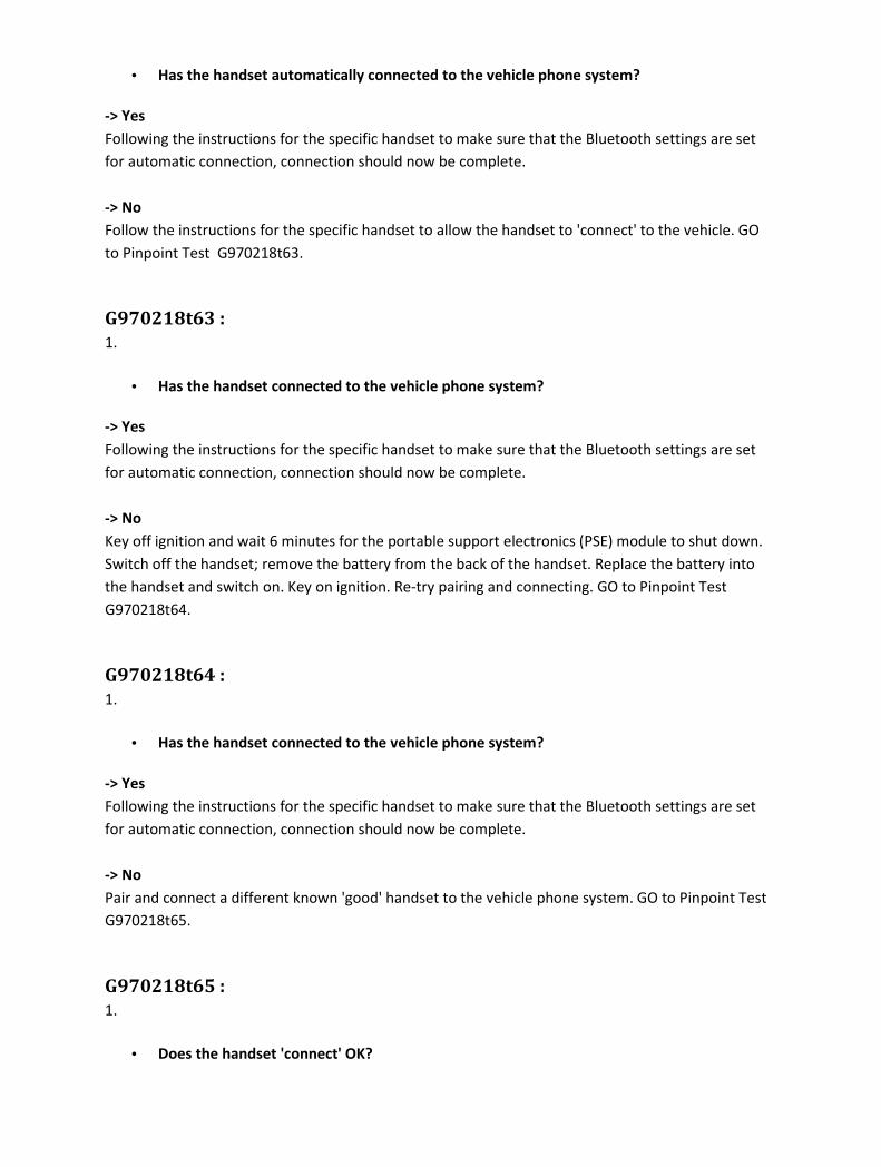
• Has the handset automatically connected to the vehicle phone system?
-> Yes
Following the instructions for the specific handset to make sure that the Bluetooth settings are set
for automatic connection, connection should now be complete.
-> No
Follow the instructions for the specific handset to allow the handset to 'connect' to the vehicle. GO
to Pinpoint Test G970218t63.
G970218t63 :
1.
• Has the handset connected to the vehicle phone system?
-> Yes
Following the instructions for the specific handset to make sure that the Bluetooth settings are set
for automatic connection, connection should now be complete.
-> No
Key off ignition and wait 6 minutes for the portable support electronics (PSE) module to shut down.
Switch off the handset; remove the battery from the back of the handset. Replace the battery into
the handset and switch on. Key on ignition. Re-try pairing and connecting. GO to Pinpoint Test
G970218t64.
G970218t64 :
1.
• Has the handset connected to the vehicle phone system?
-> Yes
Following the instructions for the specific handset to make sure that the Bluetooth settings are set
for automatic connection, connection should now be complete.
-> No
Pair and connect a different known 'good' handset to the vehicle phone system. GO to Pinpoint Test
G970218t65.
G970218t65 :
1.
• Does the handset 'connect' OK?
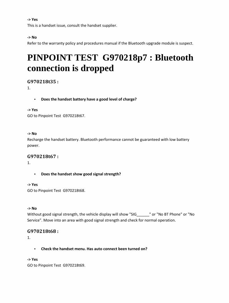
-> Yes
This is a handset issue, consult the handset supplier.
-> No
Refer to the warranty policy and procedures manual if the Bluetooth upgrade module is suspect.
PINPOINT TEST G970218p7 : Bluetooth connection is dropped G970218t35 :
1.
• Does the handset battery have a good level of charge?
-> Yes
GO to Pinpoint Test G970218t67.
-> No
Recharge the handset battery. Bluetooth performance cannot be guaranteed with low battery
power.
G970218t67 :
1.
• Does the handset show good signal strength?
-> Yes
GO to Pinpoint Test G970218t68.
-> No
Without good signal strength, the vehicle display will show "SIG______" or "No BT Phone" or "No
Service". Move into an area with good signal strength and check for normal operation.
G970218t68 :
1.
• Check the handset menu. Has auto connect been turned on?
-> Yes
GO to Pinpoint Test G970218t69.
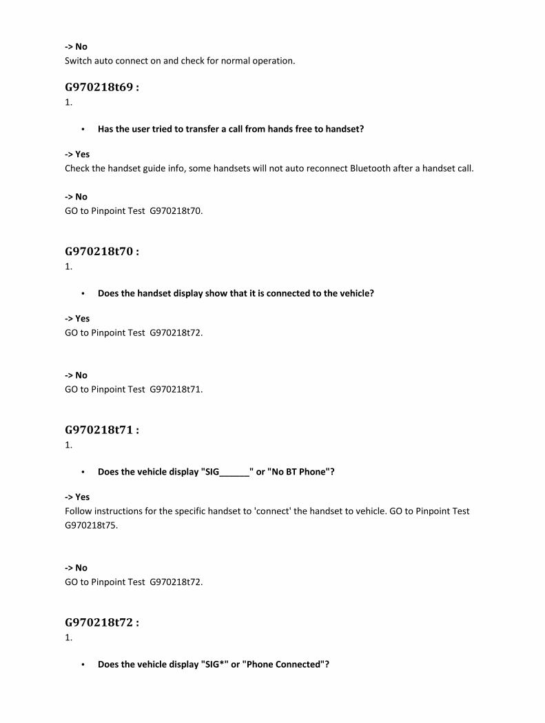
-> No
Switch auto connect on and check for normal operation.
G970218t69 :
1.
• Has the user tried to transfer a call from hands free to handset?
-> Yes
Check the handset guide info, some handsets will not auto reconnect Bluetooth after a handset call.
-> No
GO to Pinpoint Test G970218t70.
G970218t70 :
1.
• Does the handset display show that it is connected to the vehicle?
-> Yes
GO to Pinpoint Test G970218t72.
-> No
GO to Pinpoint Test G970218t71.
G970218t71 :
1.
• Does the vehicle display "SIG______" or "No BT Phone"?
-> Yes
Follow instructions for the specific handset to 'connect' the handset to vehicle. GO to Pinpoint Test
G970218t75.
-> No
GO to Pinpoint Test G970218t72.
G970218t72 :
1.
• Does the vehicle display "SIG*" or "Phone Connected"?

-> Yes
Bluetooth connection has not been dropped, check for normal operation.
-> No
Key off ignition and wait 6 minutes for the portable support electronics (PSE) module to shut down.
Switch off the handset; remove the battery from the back of the handset. Replace the battery into
the handset and switch on. Key on ignition. GO to Pinpoint Test G970218t73.
G970218t73 :
1.
• Does the vehicle display "SIG*" or "Phone Connected"?
-> Yes
Check for normal operation.
-> No
Follow the vehicle un-pairing process, delete "Jaguar" from the handset device list and key off
ignition for 6 minutes. Key on ignition. Follow pairing process for the specific handset. GO to Pinpoint
Test G970218t74.
G970218t74 :
1.
• Has the handset paired successfully with the vehicle?
-> Yes
Follow instructions for the specific handset to 'connect' the handset to vehicle. GO to Pinpoint Test
G970218t75.
-> No
Go to 'Unable to pair' - GO to Pinpoint Test G970218p3.
G970218t75 :
1.
• Does the handset 'connect'?
-> Yes
GO to Pinpoint Test G970218t13.
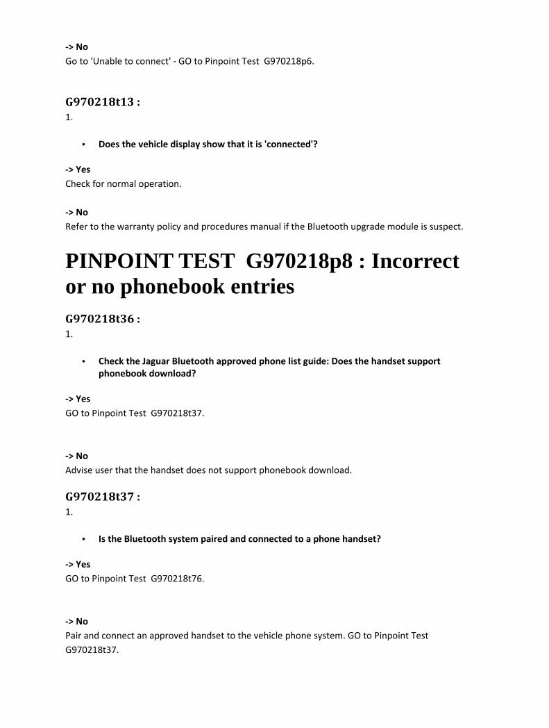
-> No
Go to 'Unable to connect' - GO to Pinpoint Test G970218p6.
G970218t13 :
1.
• Does the vehicle display show that it is 'connected'?
-> Yes
Check for normal operation.
-> No
Refer to the warranty policy and procedures manual if the Bluetooth upgrade module is suspect.
PINPOINT TEST G970218p8 : Incorrect or no phonebook entries G970218t36 :
1.
• Check the Jaguar Bluetooth approved phone list guide: Does the handset support
phonebook download?
-> Yes
GO to Pinpoint Test G970218t37.
-> No
Advise user that the handset does not support phonebook download.
G970218t37 :
1.
• Is the Bluetooth system paired and connected to a phone handset?
-> Yes
GO to Pinpoint Test G970218t76.
-> No
Pair and connect an approved handset to the vehicle phone system. GO to Pinpoint Test
G970218t37.

G970218t76 :
1.
• Has the user followed vehicle and handset instructions for downloading phonebook?
-> Yes
GO to Pinpoint Test G970218t77.
-> No
Refer to the vehicle handbooks/handset 'quick guide information' regarding phonebook download.
Check for normal operation.
G970218t77 :
1.
• After "Downloading the phonebook" has the ignition been switched off for 6 minutes?
-> Yes
GO to Pinpoint Test G970218t80.
-> No
Make sure that the ignition has been switched off for 6 minutes after following process for
downloading phonebook. The Bluetooth upgrade module remains active for 6 minutes after the
ignition has been switched off. It is important to wait this 6 minutes so that a clean boot-up of the
Bluetooth upgrade module is achieved and the correct information is stored. Switch ignition on to
prompt the portable support electronics (PSE) module to pull phonebook entries from the Bluetooth
upgrade module. GO to Pinpoint Test G970218t78.
G970218t78 :
1.
• Can the user view the phonebook entries on the vehicle display?
-> Yes
End.
-> No
GO to Pinpoint Test G970218t79.
G970218t79 :
1.

• Have two or more handsets been tried?
-> Yes
GO to Pinpoint Test G970218t82.
-> No
Pair and connect a different known 'good' handset which will automatically download the
phonebook to the vehicle phone system. GO to Pinpoint Test G970218t82.
G970218t80 :
1.
• After switching the ignition back on, does the handset connect to the vehicle phone
system?
-> Yes
GO to Pinpoint Test G970218t81.
-> No
Reconnect the handset and make sure auto-reconnect is set to on. GO to Pinpoint Test G970218t80.
G970218t81 :
1.
• Is the phonebook available on the vehicle display?
-> Yes
End
-> No
Pair and connect a different known 'good' handset which will automatically download the
phonebook to the vehicle phone system. GO to Pinpoint Test G970218t82.
G970218t82 :
1.
• Is the phonebook available on the vehicle display?
-> Yes
This is an issue with the user's handset, consult the handset supplier.

-> No
Refer to the warranty policy and procedures manual if a module is suspect.
PINPOINT TEST G970218p9 : No third party audio G970218t38 :
1. Check the handset manual and the handset settings to make sure user's speech is routed through
the vehicle microphone and not the handset microphone.
• Does 3rd party call audio work with the call in 'handset' mode?
-> Yes
Check for telephone related DTCs using the approved diagnostic system. Rectify as necessary. GO to
Pinpoint Test G970218t88.
-> No
GO to Pinpoint Test G970218t85.
G970218t85 :
1.
• Is there any 3rd party call audio with the handset disconnected from the Bluetooth
system?
-> Yes
Pair and connect a different known 'good' handset to the vehicle phone system and make a call to
the 3rd party. GO to Pinpoint Test G970218t87.
-> No
Try calling another 3rd party from the handset. GO to Pinpoint Test G970218t86.
G970218t86 :
1.
• Is there any 3rd party audio?
-> Yes
Initial audio problem may be due to a fault at 3rd party end. Check by calling them on another
number.

-> No
This may be a handset issue, consult the handset supplier.
G970218t87 :
1.
• Does the 3rd party call audio work with the Bluetooth system?
-> Yes
This may be a handset issue, consult the handset supplier.
-> No
Check for telephone related DTCs using the approved diagnostic system. Rectify as necessary. GO to
Pinpoint Test G970218t88.
G970218t88 :
1.
• Is there any 3rd party audio?
-> Yes
End.
-> No
Disconnect the Bluetooth link between the handset and vehicle phone system and re-try the call. GO
to Pinpoint Test G970218t90.
G970218t90 :
1.
• Does the 3rd party call audio work with the mobile phone disconnected from the vehicle?
-> Yes
Re-connect the Bluetooth link between the handset and the vehicle phone system and re-try the call.
GO to Pinpoint Test G970218t92.
-> No
Switch off the handset, remove the battery from the back of the handset. Replace the battery into
the handset and switch on. Make sure the Bluetooth link is disconnected and re-try the call. GO to
Pinpoint Test G970218t91.
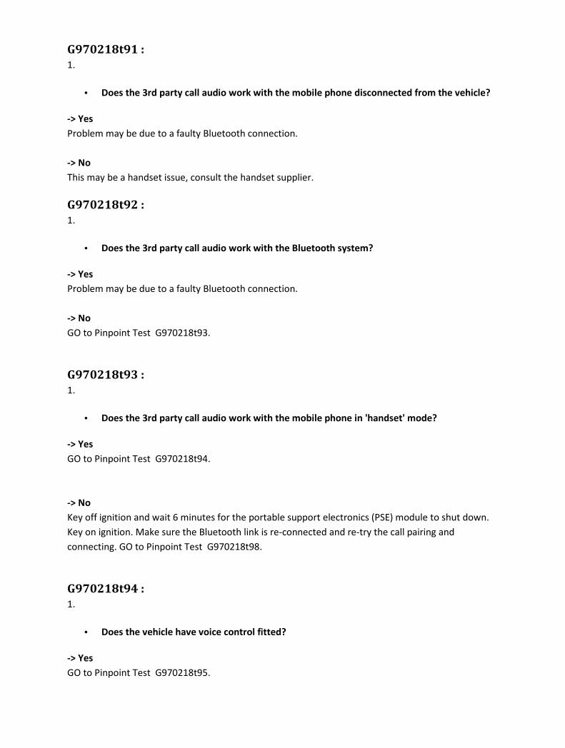
G970218t91 :
1.
• Does the 3rd party call audio work with the mobile phone disconnected from the vehicle?
-> Yes
Problem may be due to a faulty Bluetooth connection.
-> No
This may be a handset issue, consult the handset supplier.
G970218t92 :
1.
• Does the 3rd party call audio work with the Bluetooth system?
-> Yes
Problem may be due to a faulty Bluetooth connection.
-> No
GO to Pinpoint Test G970218t93.
G970218t93 :
1.
• Does the 3rd party call audio work with the mobile phone in 'handset' mode?
-> Yes
GO to Pinpoint Test G970218t94.
-> No
Key off ignition and wait 6 minutes for the portable support electronics (PSE) module to shut down.
Key on ignition. Make sure the Bluetooth link is re-connected and re-try the call pairing and
connecting. GO to Pinpoint Test G970218t98.
G970218t94 :
1.
• Does the vehicle have voice control fitted?
-> Yes
GO to Pinpoint Test G970218t95.
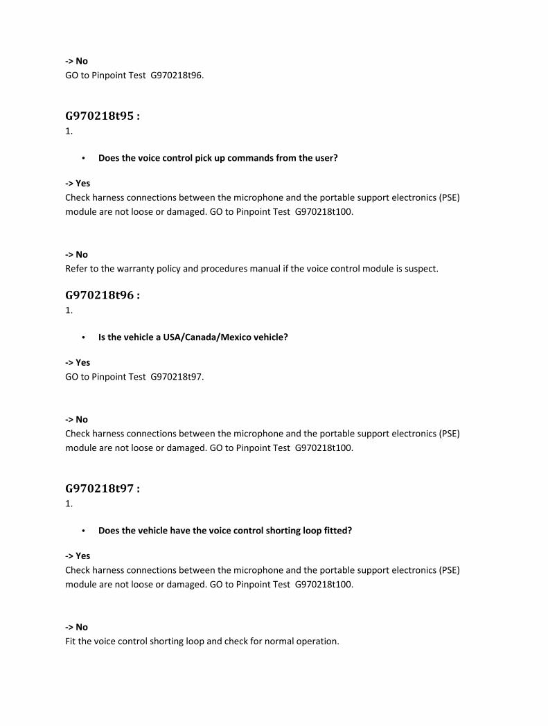
-> No
GO to Pinpoint Test G970218t96.
G970218t95 :
1.
• Does the voice control pick up commands from the user?
-> Yes
Check harness connections between the microphone and the portable support electronics (PSE)
module are not loose or damaged. GO to Pinpoint Test G970218t100.
-> No
Refer to the warranty policy and procedures manual if the voice control module is suspect.
G970218t96 :
1.
• Is the vehicle a USA/Canada/Mexico vehicle?
-> Yes
GO to Pinpoint Test G970218t97.
-> No
Check harness connections between the microphone and the portable support electronics (PSE)
module are not loose or damaged. GO to Pinpoint Test G970218t100.
G970218t97 :
1.
• Does the vehicle have the voice control shorting loop fitted?
-> Yes
Check harness connections between the microphone and the portable support electronics (PSE)
module are not loose or damaged. GO to Pinpoint Test G970218t100.
-> No
Fit the voice control shorting loop and check for normal operation.

G970218t98 :
1.
• Does the 3rd party call audio work with the Bluetooth system?
-> Yes
Problem may be due to a faulty Bluetooth connection.
-> No
Pair and connect a different known 'good' handset to the vehicle phone system and make an
incoming call. GO to Pinpoint Test G970218t99.
G970218t99 :
1.
• Does the 3rd party call audio work with the Bluetooth system?
-> Yes
This may be a handset issue, consult the handset supplier.
-> No
Check harness connections between the microphone and the portable support electronics (PSE)
module are not loose or damaged. GO to Pinpoint Test G970218t100.
G970218t100 :
1.
• Are the microphone harness connections damaged?
-> Yes
Rectify as necessary. Refer to the electrical guides.
-> No
Replace the microphone and re-try the call. GO to Pinpoint Test G970218t101.
G970218t101 :
1.
• Does the 3rd party call audio work with the Bluetooth system?
-> Yes
Problem may have been due to a faulty microphone.
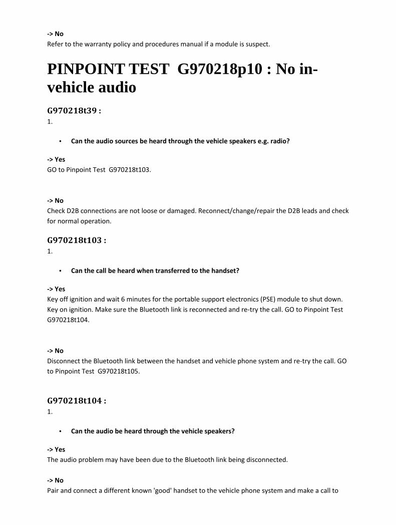
-> No
Refer to the warranty policy and procedures manual if a module is suspect.
PINPOINT TEST G970218p10 : No in-vehicle audio G970218t39 :
1.
• Can the audio sources be heard through the vehicle speakers e.g. radio?
-> Yes
GO to Pinpoint Test G970218t103.
-> No
Check D2B connections are not loose or damaged. Reconnect/change/repair the D2B leads and check
for normal operation.
G970218t103 :
1.
• Can the call be heard when transferred to the handset?
-> Yes
Key off ignition and wait 6 minutes for the portable support electronics (PSE) module to shut down.
Key on ignition. Make sure the Bluetooth link is reconnected and re-try the call. GO to Pinpoint Test
G970218t104.
-> No
Disconnect the Bluetooth link between the handset and vehicle phone system and re-try the call. GO
to Pinpoint Test G970218t105.
G970218t104 :
1.
• Can the audio be heard through the vehicle speakers?
-> Yes
The audio problem may have been due to the Bluetooth link being disconnected.
-> No
Pair and connect a different known 'good' handset to the vehicle phone system and make a call to

the 3rd party. GO to Pinpoint Test G970218t108.
G970218t105 :
1.
• Does the handset audio work with mobile phone disconnected from the vehicle?
-> Yes
Key off ignition and wait 6 minutes for the portable support electronics (PSE) module to shut down.
Key on ignition. Switch off the handset; remove the battery from the back of the handset. Replace
the battery into the handset and switch on. Key on ignition. Make sure the Bluetooth link is
reconnected and re-try the call. GO to Pinpoint Test G970218t107.
-> No
Try calling another 3rd party from the handset. GO to Pinpoint Test G970218t106.
G970218t106 :
1.
• Is there any call audio on the handset?
-> Yes
Initial audio problem may be due to a fault at the 3rd party end, check by calling them on another
number.
-> No
This may be a handset issue, consult the handset supplier.
G970218t107 :
1.
• Can the audio be heard through the vehicle speakers?
-> Yes
The audio problem may have been due to the Bluetooth link being disconnected.
-> No
Pair and connect a different known 'good' handset to the vehicle phone system and make a call to
the 3rd party. GO to Pinpoint Test G970218t108.
G970218t108 :
1.

• Can the audio be heard through the vehicle speakers?
-> Yes
This may be a handset issue, consult the handset supplier.
-> No
Check harness connections between the Bluetooth upgrade module and the portable support
electronics (PSE) module. GO to Pinpoint Test G970218t109.
G970218t109 :
1.
• Are any of the harness connections damaged?
-> Yes
Rectify as necessary. Refer to the electrical guides.
-> No
Refer to the warranty policy and procedures manual if a module is suspect.
PINPOINT TEST G970218p11 : No ringing heard through the vehicle speakers G970218t40 :
1.
• When there is no call in progress, and the audio source is changed, is any audio heard e.g.
from radio?
-> Yes
GO to Pinpoint Test G970218t113.
-> No
Check D2B connections are not loose and that all nodes are connected on the D2B ring. Rectify as
necessary. GO to Pinpoint Test G970218t112.
G970218t112 :
1.
• Are any of the D2B connections damaged?

-> Yes
Change/repair the D2B leads and check for normal operation.
-> No
Call Technical Helpline.
G970218t113 :
1.
• Is the vehicle phone system volume set to more than 15?
-> Yes
GO to Pinpoint Test G970218t114.
-> No
Make sure that the vehicle phone system is set to more than 15 and retry the call.
G970218t114 :
1.
• Is the message "incoming call" displayed?
-> Yes
GO to Pinpoint Test G970218t115.
-> No
GO to Pinpoint Test G970218t116.
G970218t115 :
1.
• On answering the incoming call using the vehicle controls, can the 3rd party be heard
through the vehicle speakers?
-> Yes
GO to Pinpoint Test G970218t116.
-> No
Go to 'No in-vehicle audio' - GO to Pinpoint Test G970218p10.

G970218t116 :
1.
• Is there any ringing heard on the handset with the Bluetooth link connected?
-> Yes
GO to Pinpoint Test G970218t117.
-> No
GO to Pinpoint Test G970218t120.
G970218t117 :
1.
• Does the handset support in-band ringing or send its ringing status to the Bluetooth
upgrade module?
-> Yes
Key off ignition and wait 6 minutes for the portable support electronics (PSE) module to shut down.
Key on ignition. Make sure the Bluetooth link is re-connected and re-try the call. GO to Pinpoint Test
G970218t118.
-> No
This is a handset issue, contact the handset supplier or replace with another handset from the
approved list.
G970218t118 :
1.
• Can any ringing be heard through the vehicle speakers?
-> Yes
The audio problem may have been due to the Bluetooth link being disconnected.
-> No
Un-pair the current handset and pair/connect a known good handset with the vehicle. Make an
incoming call. GO to Pinpoint Test G970218t119.
G970218t119 :
1.
• Can any ringing be heard through the vehicle speakers?
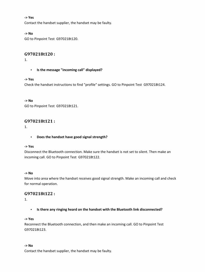
-> Yes
Contact the handset supplier, the handset may be faulty.
-> No
GO to Pinpoint Test G970218t120.
G970218t120 :
1.
• Is the message "incoming call" displayed?
-> Yes
Check the handset instructions to find "profile" settings. GO to Pinpoint Test G970218t124.
-> No
GO to Pinpoint Test G970218t121.
G970218t121 :
1.
• Does the handset have good signal strength?
-> Yes
Disconnect the Bluetooth connection. Make sure the handset is not set to silent. Then make an
incoming call. GO to Pinpoint Test G970218t122.
-> No
Move into area where the handset receives good signal strength. Make an incoming call and check
for normal operation.
G970218t122 :
1.
• Is there any ringing heard on the handset with the Bluetooth link disconnected?
-> Yes
Reconnect the Bluetooth connection, and then make an incoming call. GO to Pinpoint Test
G970218t123.
-> No
Contact the handset supplier, the handset may be faulty.
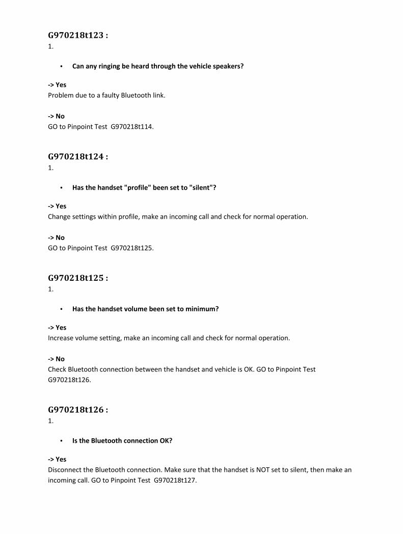
G970218t123 :
1.
• Can any ringing be heard through the vehicle speakers?
-> Yes
Problem due to a faulty Bluetooth link.
-> No
GO to Pinpoint Test G970218t114.
G970218t124 :
1.
• Has the handset "profile" been set to "silent"?
-> Yes
Change settings within profile, make an incoming call and check for normal operation.
-> No
GO to Pinpoint Test G970218t125.
G970218t125 :
1.
• Has the handset volume been set to minimum?
-> Yes
Increase volume setting, make an incoming call and check for normal operation.
-> No
Check Bluetooth connection between the handset and vehicle is OK. GO to Pinpoint Test
G970218t126.
G970218t126 :
1.
• Is the Bluetooth connection OK?
-> Yes
Disconnect the Bluetooth connection. Make sure that the handset is NOT set to silent, then make an
incoming call. GO to Pinpoint Test G970218t127.

-> No
Follow the handset instructions for 'connecting' the Bluetooth link, then make an incoming call and
check for normal operation.
G970218t127 :
1.
• Is there any ringing heard on the handset?
-> Yes
Reconnect Bluetooth link between the handset and vehicle. GO to Pinpoint Test G970218t128.
-> No
Un-pair the current handset and pair/connect a known good handset with the vehicle. Make an
incoming call. GO to Pinpoint Test G970218t119.
G970218t128 :
1.
• Can any ringing be heard through the vehicle speakers?
-> Yes
Change settings within profile, make an incoming call and check for normal operation.
-> No
Check harness connections between the Bluetooth upgrade module and the portable support
electronics (PSE) module. GO to Pinpoint Test G970218t129.
G970218t129 :
1.
• Are any of the harness connections damaged?
-> Yes
Rectify as necessary. Refer to the electrical guides.
-> No
Refer to the warranty policy and procedures manual if a module is suspect.
PINPOINT TEST G970218p12 : Low audio volume
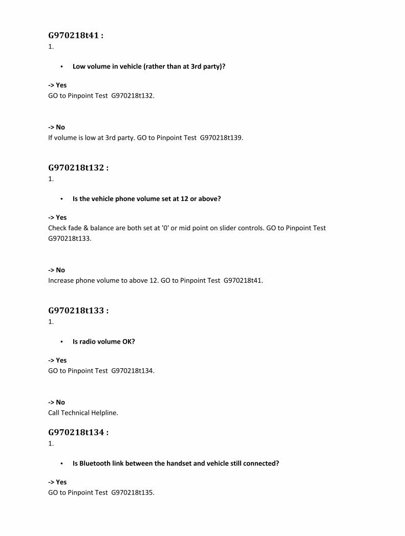
G970218t41 :
1.
• Low volume in vehicle (rather than at 3rd party)?
-> Yes
GO to Pinpoint Test G970218t132.
-> No
If volume is low at 3rd party. GO to Pinpoint Test G970218t139.
G970218t132 :
1.
• Is the vehicle phone volume set at 12 or above?
-> Yes
Check fade & balance are both set at '0' or mid point on slider controls. GO to Pinpoint Test
G970218t133.
-> No
Increase phone volume to above 12. GO to Pinpoint Test G970218t41.
G970218t133 :
1.
• Is radio volume OK?
-> Yes
GO to Pinpoint Test G970218t134.
-> No
Call Technical Helpline.
G970218t134 :
1.
• Is Bluetooth link between the handset and vehicle still connected?
-> Yes
GO to Pinpoint Test G970218t135.
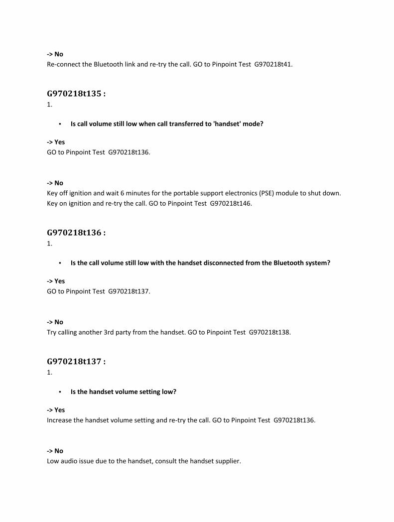
-> No
Re-connect the Bluetooth link and re-try the call. GO to Pinpoint Test G970218t41.
G970218t135 :
1.
• Is call volume still low when call transferred to 'handset' mode?
-> Yes
GO to Pinpoint Test G970218t136.
-> No
Key off ignition and wait 6 minutes for the portable support electronics (PSE) module to shut down.
Key on ignition and re-try the call. GO to Pinpoint Test G970218t146.
G970218t136 :
1.
• Is the call volume still low with the handset disconnected from the Bluetooth system?
-> Yes
GO to Pinpoint Test G970218t137.
-> No
Try calling another 3rd party from the handset. GO to Pinpoint Test G970218t138.
G970218t137 :
1.
• Is the handset volume setting low?
-> Yes
Increase the handset volume setting and re-try the call. GO to Pinpoint Test G970218t136.
-> No
Low audio issue due to the handset, consult the handset supplier.

G970218t138 :
1.
• Is the call volume still low with the handset disconnected from the Bluetooth system?
-> Yes
Low audio issue due to the handset, consult the handset supplier.
-> No
Initial audio problem may be due to a fault at the 3rd party end. Check by calling them on another
number.
G970218t139 :
1.
• Check that handset volume setting and signal strength are not low. Is call volume still low
when call transferred to 'handset' mode?
-> Yes
GO to Pinpoint Test G970218t144.
-> No
GO to Pinpoint Test G970218t140.
G970218t140 :
1.
• Is the microphone fitted OK? Check DTCs using the approved diagnostic system.
-> Yes
GO to Pinpoint Test G970218t142.
-> No
Rectify as necessary. GO to Pinpoint Test G970218t141.
G970218t141 :
1.
• Is volume still low?
-> Yes
GO to Pinpoint Test G970218t142.

-> No
Issue caused by faulty microphone or microphone circuit.
G970218t142 :
1.
• Is voice control fitted to vehicle?
-> Yes
Disconnect the voice control module and fit the voice control shorting loop to the wiring harness. GO
to Pinpoint Test G970218t143.
-> No
GO to Pinpoint Test G970218t144.
G970218t143 :
1.
• Is volume still low?
-> Yes
GO to Pinpoint Test G970218t144.
-> No
Refer to voice control diagnostics.
G970218t144 :
1.
• Is the 3rd party call audio still low with the handset disconnected from the Bluetooth
system?
-> Yes
Pair and connect a different known 'good' handset to the vehicle phone system and make a call to a
3rd party. GO to Pinpoint Test G970218t147.
-> No
Re-connect Bluetooth link and re-try the call. GO to Pinpoint Test G970218t145.

G970218t145 :
1.
• Is volume still low?
-> Yes
Key off ignition and wait 6 minutes for the portable support electronics (PSE) module to shut down.
Key on ignition and re-try the call. GO to Pinpoint Test G970218t146.
-> No
Issue caused by a faulty Bluetooth connection.
G970218t146 :
1.
• Is volume still low?
-> Yes
Refer to the warranty policy and procedures manual if a module is suspect.
-> No
Issue caused by a faulty Bluetooth connection.
G970218t147 :
1.
• Is volume still low?
-> Yes
Refer to the warranty policy and procedures manual if a module is suspect.
-> No
Low audio issue caused by the handset, consult the handset supplier.
PINPOINT TEST G970218p13 : Cannot dial out from audio head unit/touch-screen/steering wheel control G970218t42 :
1.
• Is D2B ring complete?

-> Yes
GO to Pinpoint Test G970218t149.
-> No
Reconnect/change/repair the D2B leads and check for normal operation.
G970218t149 :
1.
• Does display show "NO SERVICE" or drop out of phone mode?
-> Yes
GO to Pinpoint Test G970218t150.
-> No
GO to Pinpoint Test G970218t151.
G970218t150 :
1.
• Signal strength on the handset greater than 1?
-> Yes
GO to Pinpoint Test G970218t151.
-> No
Re-try call in a stronger signal strength area, low signal strength can cause interference and distortion
in car and at 3rd party.
G970218t151 :
1.
• Can user dial out from the handset?
-> Yes
Key off ignition and wait 6 minutes for the portable support electronics (PSE) module to shut down.
Key on ignition. Make sure the Bluetooth link is reconnected and re-try the call. GO to Pinpoint Test
G970218t152.
-> No
Switch off the handset, remove the battery from the back of the handset. Replace the battery into
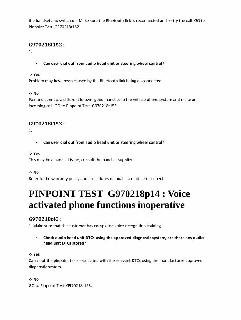
the handset and switch on. Make sure the Bluetooth link is reconnected and re-try the call. GO to
Pinpoint Test G970218t152.
G970218t152 :
1.
• Can user dial out from audio head unit or steering wheel control?
-> Yes
Problem may have been caused by the Bluetooth link being disconnected.
-> No
Pair and connect a different known 'good' handset to the vehicle phone system and make an
incoming call. GO to Pinpoint Test G970218t153.
G970218t153 :
1.
• Can user dial out from audio head unit or steering wheel control?
-> Yes
This may be a handset issue, consult the handset supplier.
-> No
Refer to the warranty policy and procedures manual if a module is suspect.
PINPOINT TEST G970218p14 : Voice activated phone functions inoperative G970218t43 :
1. Make sure that the customer has completed voice recognition training.
• Check audio head unit DTCs using the approved diagnostic system, are there any audio
head unit DTCs stored?
-> Yes
Carry out the pinpoint tests associated with the relevant DTCs using the manufacturer approved
diagnostic system.
-> No
GO to Pinpoint Test G970218t158.
G970218t158 :
1.
• Is there a dial problem?
-> Yes
GO to Pinpoint Test G970218t159.
-> No
GO to Pinpoint Test G970218t161.
G970218t159 :
1.
• Dials wrong number?
-> Yes
GO to Pinpoint Test G970218t163.
-> No
GO to Pinpoint Test G970218t160.
G970218t160 :
1.
• Will not dial?
-> Yes
GO to Pinpoint Test G970218t165.
-> No
GO to Pinpoint Test G970218t161.
G970218t161 :
1.
• Cannot dial using voice control?
-> Yes
GO to Pinpoint Test G970218t164.

-> No
GO to Pinpoint Test G970218t162.
G970218t162 :
1.
• Cannot turn phone on/off?
-> Yes
GO to Pinpoint Test G970218t164.
-> No
GO to Pinpoint Test G970218t166.
G970218t163 :
1.
• Is the handset on the approved phone list?
-> Yes
Call Technical Helpline.
-> No
Only handsets specified in the approved list with the correct level of software can be guaranteed to
work.
G970218t164 :
1.
• Is voice control on the D2B ring?
-> Yes
GO to Pinpoint Test G970218t165.
-> No
Not a phone issue.
G970218t165 :
1.

• Does verbal communication confirm correct number?
-> Yes
GO to Pinpoint Test G970218t166.
-> No
Not a phone issue.
G970218t166 :
1.
• Does the audio head unit/touch-screen show "NO PHONE" or "PHONE NOT FITTED" (i.e. is
phone off the D2B ring)?
-> Yes
GO to Pinpoint Test G970218t12.
-> No
GO to Pinpoint Test G970218t167.
G970218t12 :
1. Are any of the D2B connections loose or damaged?
•
-> Yes
Reconnect/change/repair the D2B leads and check for normal operation.
-> No
Refer to the warranty policy and procedures manual if a module is suspect.
G970218t167 :
1.
• Check all connections/connectivity to and from the portable support electronics (PSE)
module and the Bluetooth upgrade module. Are any of the harness connections loose or
damaged?
-> Yes
Rectify as necessary. Refer to the electrical guides.
-> No
Refer to the warranty policy and procedures manual if a module is suspect.

PINPOINT TEST G970218p15 : Call is dropped G970218t44 :
1.
• Is the 3rd party call to another cellular phone?
-> Yes
GO to Pinpoint Test G970218t173.
-> No
GO to Pinpoint Test G970218t172.
G970218t172 :
1.
• Is the 3rd party call to a landline?
-> Yes
Disconnect the Bluetooth link between the handset and vehicle phone system. Re-try the call in the
vehicle, preferably with the handset in the same position as when connected via the Bluetooth link.
GO to Pinpoint Test G970218t174.
-> No
GO to Pinpoint Test G970218t175.
G970218t173 :
1.
• Is the signal strength on the 3rd party handset greater than 1?
-> Yes
Disconnect the Bluetooth link between the handset and vehicle phone system. Re-try the call in the
vehicle, preferably with the handset in the same position as when connected via the Bluetooth link.
GO to Pinpoint Test G970218t174.
-> No
Re-try call in stronger signal strength area. Low signal strength can lead to calls being dropped.

G970218t174 :
1.
• Is the call dropped again?
-> Yes
Pair and connect a different known 'good' handset to the vehicle phone system and make an
incoming call. GO to Pinpoint Test G970218t177.
-> No
Switch off the handset, remove the battery from the back of the handset. Replace the battery into
the handset and switch on. Make sure the Bluetooth link is reconnected and re-try the call. GO to
Pinpoint Test G970218t175.
G970218t175 :
1.
• Is the call dropped again?
-> Yes
Key off ignition and wait 6 minutes for the portable support electronics (PSE) module to shut down.
Key on ignition. Make sure the Bluetooth link is reconnected and re-try the call. GO to Pinpoint Test
G970218t176.
-> No
Problem may have been caused by the Bluetooth link being disconnected.
G970218t176 :
1.
• Is the call dropped again?
-> Yes
Pair and connect a different known 'good' handset to the vehicle phone system and make an
incoming call. GO to Pinpoint Test G970218t177.
-> No
Problem may have been caused by the Bluetooth link being disconnected.
G970218t177 :
1.

• Is the call dropped again?
-> Yes
Refer to the warranty policy and procedures manual if a module is suspect.
-> No
This may be a handset issue, consult the handset supplier.
PINPOINT TEST G970218p16 : Interference and distortion G970218t45 :
1.
• Is interference present with Bluetooth link disconnected?
-> Yes
GO to Pinpoint Test G970218t181.
-> No
Check for external sources of interference. Drive to where the customer has problems to identify if
location dependant. Test in an area of known high signal strength. GO to Pinpoint Test
G970218t183.
G970218t181 :
1.
• Is it present with a different known 'good' handset paired/connected?
-> Yes
GO to Pinpoint Test G970218t182.
-> No
This may be a handset issue, consult the handset supplier.
G970218t182 :
1.
• Is it present with other network carriers?
-> Yes
Check for external sources of interference. Drive to where the customer has problems to identify if

location dependant. Test in an area of known high signal strength. GO to Pinpoint Test
G970218t183.
-> No
This may be a network or handset issue, consult the handset supplier/network provider.
G970218t183 :
1.
• Are there any powered items/aftermarket accessories in the car?
-> Yes
Switch off any powered items/aftermarket accessories in the car. GO to Pinpoint Test G970218t184.
-> No
Refer to the warranty policy and procedures manual if a module is suspect.
G970218t184 :
1.
• Is interference still present?
-> Yes
Refer to the warranty policy and procedures manual if a module is suspect.
-> No
User to be advised of interference from aftermarket accessories.
PINPOINT TEST G970218p17 : Unable to transfer call between hands free and handset G970218t46 :
1.
• Does the specific handset guide state that the handset does not support call transfer?
-> Yes
Advise user that some software levels are not guaranteed to function correctly. Software to be
changed to approved level or the handset to be changed.
-> No

Switch off the handset, remove the battery from the back of the handset. Replace the battery into
the handset and switch on. Make sure the Bluetooth link is reconnected and re-try the call. GO to
Pinpoint Test G970218t190.
G970218t190 :
1.
• Can the call be transferred between hands free and handset?
-> Yes
Problem may have been caused by the Bluetooth link being disconnected.
-> No
Key off ignition for 6 minutes for the portable support electronics (PSE) module to shut down. Key on
ignition and re-try the call. GO to Pinpoint Test G970218t191.
G970218t191 :
1.
• Can the call be transferred between hands free and handset?
-> Yes
Problem may have been caused by the Bluetooth link being disconnected.
-> No
Pair and connect a different known 'good' handset to the vehicle phone system and make an
incoming call. GO to Pinpoint Test G970218t192.
G970218t192 :
1.
• Can the call be transferred between hands free and handset?
-> Yes
This is a handset issue, consult the handset supplier.
-> No
Refer to the warranty policy and procedures manual if a module is suspect.

Removal and installation
Bluetooth Module Removal
1
.
Remove the floor console.
For additional information, refer to Floor Console - Vehicles With: Auxiliary Climate Control
(76.25.01)
For additional information, refer to Floor Console - Vehicles Without: Auxiliary Climate
Control (76.25.01)
2 . Remove the Bluetooth module.
Installation
1 . To install, reverse the removal procedure.

Cellular Phone Antenna - Vehicles With: Corded Cellular Phone, VIN Range: G00442->H18679 (86.51.17) Removal
1
. CAUTION: Electronic modules are sensitive to electrical charges. If exposed to these
electrical charges, damage may result.
Disconnect the battery ground cable. <<414-01>>
2 . Remove the luggage compartment floor covering.
1) Remove the luggage compartment floor covering screws.
2) Remove the luggage compartment floor covering.
3 . Remove the luggage compartment side trim panel.

4 . Detach the air pipe.
5 . Detach the module retaining bracket.
6 . Disconnect the cellular phone antenna electrical connector.
7 . Detach the grommet.
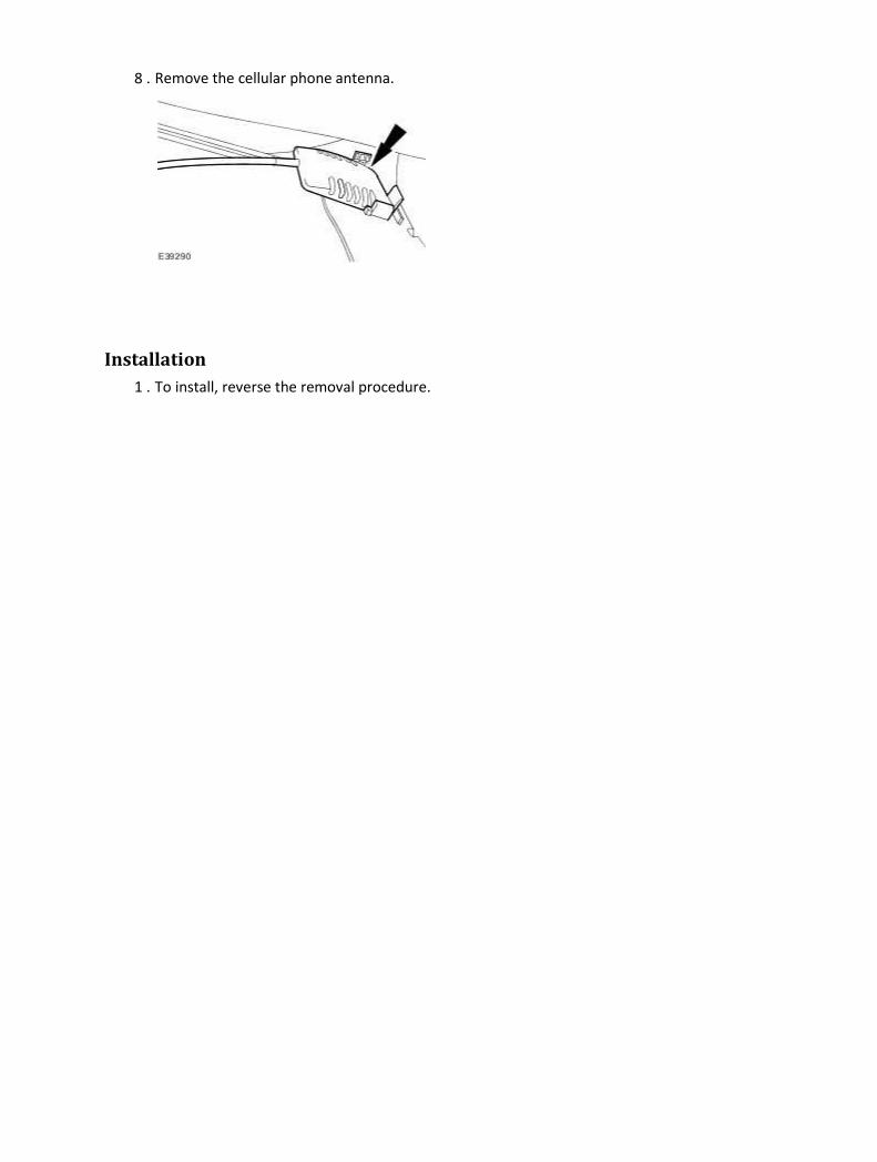
8 . Remove the cellular phone antenna.
Installation
1 . To install, reverse the removal procedure.

Cellular Phone Antenna - Vehicles With: Cordless Cellular Phone, VIN Range: G00442->H18679 (86.51.17) Removal
1 . Remove the parcel shelf. <<501-05>>
2
.
Locally remove the insulation on the back of the parcel shelf to gain access to the cellular
phone antenna.
3 . Detach the cellular phone antenna harness.
4 . Remove the cellular phone antenna.

Installation
1 . To install, reverse the removal procedure.

Cellular Phone Antenna - VIN Range: H18680->H99999 (86.51.17) Removal
1 . NOTE:
Right-hand shown, left-hand similar.
Detach both the front passenger assist handles screw covers.
2 . NOTE:
Right-hand shown, left-hand similar.
Remove both the front passenger assist handles.
3 . NOTE:
Right-hand shown, left-hand similar.
Detach both the rear passenger assist handles screw covers.

4 . NOTE:
Right-hand shown, left-hand similar.
Remove both the rear passenger assist handles.
Disconnect the electrical connectors.
5 . Locally detach the top of all the door aperture weatherstrips.
6 . NOTE:
Right-hand shown, left-hand similar.
Remove both the rear safety belt trim covers.

7 . NOTE:
Right-hand shown, left-hand similar.
Detach both the c-pillar upper trim panels.
8 . NOTE:
Right-hand shown, left-hand similar.
Detach both the c-pillar upper trim panel retaining straps.
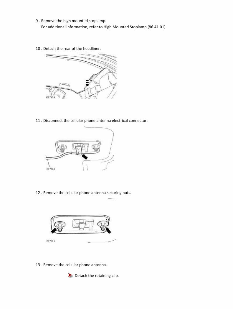
9 . Remove the high mounted stoplamp.
For additional information, refer to High Mounted Stoplamp (86.41.01)
10 . Detach the rear of the headliner.
11 . Disconnect the cellular phone antenna electrical connector.
12 . Remove the cellular phone antenna securing nuts.
13 . Remove the cellular phone antenna.
Detach the retaining clip.

Installation
1 . To install, reverse the removal procedure.
Tighten to 10 Nm.

Front Handset Holder Removal
1 . Detach the cellular phone.
2 . Remove the front handset retaining screw finisher trim.
3 . Remove the front handset holder.
Installation
1 . To install, reverse the removal procedure.

Transceiver Module Removal
1
. CAUTION: Electronic modules are sensitive to electrical charges. If exposed to these
electrical charges, damage may result.
Disconnect the battery ground cable. <<414-01>>
2 . Remove the luggage compartment floor covering.
1) Remove the luggage compartment floor covering screws.
2) Remove the luggage compartment floor covering.
3 . Remove the luggage compartment side trim panel.
4 . Detach the air pipe.

5 . Detach the module retaining bracket.
6 . Disconnect the digital versatile disc (DVD) electrical connectors.
7 . Disconnect the navigation system module electrical connectors and fibre optic connector.
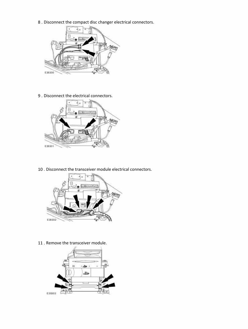
8 . Disconnect the compact disc changer electrical connectors.
9 . Disconnect the electrical connectors.
10 . Disconnect the transceiver module electrical connectors.
11 . Remove the transceiver module.

Installation
1 . To install, reverse the removal procedure.

419-10 : Multifonction Electronic Modules
Specifications
Specifications Torque Specifications
Description Nm lb-ft lb-in
Rear electronic module (REM) retaining bolts 6 – 53
Multifunction voice activated module retaining bolts 8 – 71
Front electronic module (FEM) retaining bolts 6 – 53
Rear seat module retaining bolts 6 – 53
CD changer 6 – 53
Module mounting bracket 10 7 –
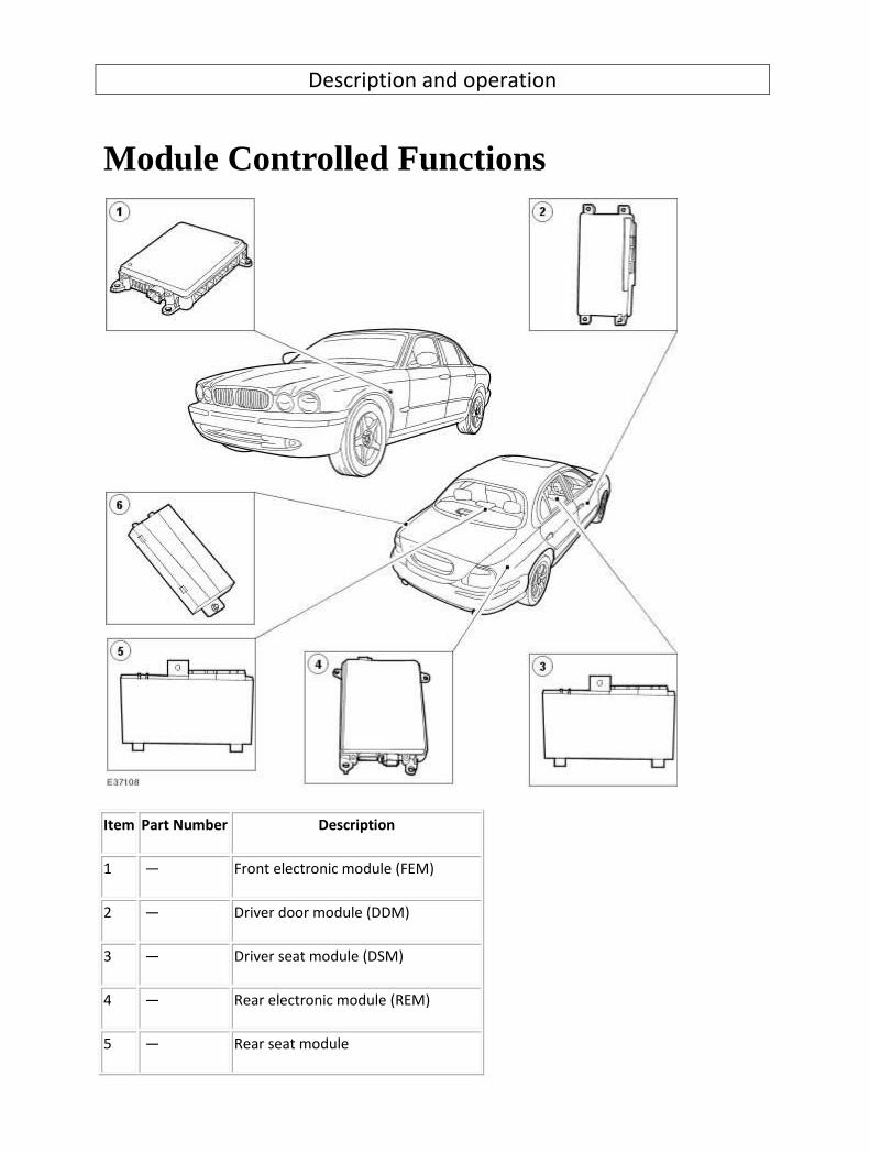
Description and operation
Module Controlled Functions
Item Part Number Description
1 — Front electronic module (FEM)
2 — Driver door module (DDM)
3 — Driver seat module (DSM)
4 — Rear electronic module (REM)
5 — Rear seat module

6 — Multifunction voice activated module
Driver Seat Module (DSM)
The DSM is located under the driver seat.
The DSM controls the seat memory recall positions and seat functionality. <<501-10>>
Driver Door Module (DDM)
The DDM is located in the driver door behind the trim panel.
The DDM is involved with the following operations:
• door window motor and regulator
• exterior rear view mirror movement
• keyless entry
• global closing
• drivers door locking/unlocking
Front Electronic Module (FEM)
The FEM is located behind the left-hand cowl side trim panel.
The FEM is involved with the following operations:
• front exterior lighting
• direction indicators
• adjustable pedals
• daytime running lamps
• courtesy lighting
• low brake fluid reservoir level
• low windshield washer reservoir fluid level
• low oil pressure
• windshield wipers
• rear view mirror electro-cromic function
Rear Electronic Module (REM)
The REM is located in the luggage compartment behind the right-hand luggage compartment side
trim panel.
The REM is involved with the following operations:
• fuel pump
• heated rear windshield
• rear exterior lighting
• luggage compartment lid release
• inertia fuel cut off switch
• passenger door locks

Rear Seat Module
The rear seat module is fitted behind the rear seat, or on the ski hatch blanking plate when the rear
entertainment module is fitted.
The rear seat module is involved with the following operation:
• manual and memory movement of electric rear seats
Multifunction Voice Activated Module
The multifunction voice activated module is located in the luggage compartment behind the left-
hand luggage compartment side trim panel. The multifunction voice activated module controls and
processes all the voice commands given by the driver, then delivers this information to the audio
unit, cellular phone, navigation and the climate control modules which then carry out these
commands.
Microphone
The microphone is used for the cellular phone and to receive voice commands for the audio unit and
climate control functions. The microphone supplies the information to the multifunction voice
control module which processes the commands and supplies the necessary information to the
correct modules.
Visual Feedback Message Center Display
This display keeps the driver informed of the function which is being selected or processed.
Audible Feedback Instrument Cluster
This audible tone informs the driver when the system is able to receive commands for processing.
Verbal Feedback Speakers
These speakers are utilized to confirm to the driver that his verbal command has been accepted and
is being processed.
Steering Wheel Control VOICE/PHONE Button
This button is automatically configured by the audio unit depending on which systems are equipped
on the vehicle. For additional information, refer to the Owner Guide.

Diagnosis and testing
Multifunction Electronic Module Principles of Operation
For a detailed description of the Multifunction Electronic Module's, refer to the relevant Description
and Operation sections in the workshop manual.
Module Controlled Functions
Inspection and Verification
1 . Verify the customer concern.
2 . Visually inspect for obvious signs of electrical damage.
Visual Inspection Chart
Electrical
• Fuses/Relays
• Damaged, Loose or Corroded Connector(s)
• Damage to Wiring Loom/Incorrect Location, Stretched or Taught
1 . If an obvious cause for an observed or reported concern is found, correct the cause (if possible)
before proceeding to the next step.
2 . If the cause is not visually evident, verify the symptom and refer to the Jaguar Approved
Diagnostic System.
DTC Index
Voice Activated Control Module
CAUTION: When probing connectors to take measurements in the course of the pinpoint
tests, use the adaptor kit, part number 3548-1358-00
NOTE:
If the control module/component is suspect and the vehicle remains under manufacturer
warranty, refer to the Warranty Policy and Procedures manual (section B1.2), or determine if
any prior approval program is in operation, prior to the installation of a new
module/component.
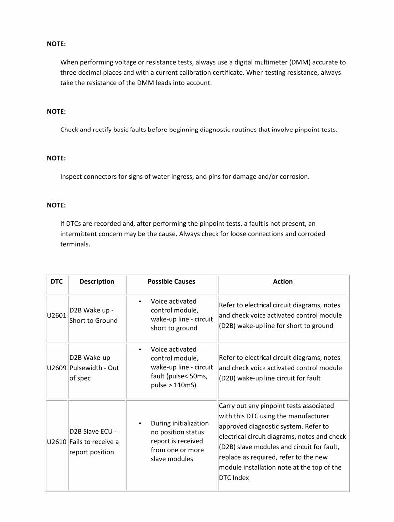
NOTE:
When performing voltage or resistance tests, always use a digital multimeter (DMM) accurate to
three decimal places and with a current calibration certificate. When testing resistance, always
take the resistance of the DMM leads into account.
NOTE:
Check and rectify basic faults before beginning diagnostic routines that involve pinpoint tests.
NOTE:
Inspect connectors for signs of water ingress, and pins for damage and/or corrosion.
NOTE:
If DTCs are recorded and, after performing the pinpoint tests, a fault is not present, an
intermittent concern may be the cause. Always check for loose connections and corroded
terminals.
DTC Description Possible Causes Action
U2601 D2B Wake up -
Short to Ground
• Voice activated
control module,
wake-up line - circuit
short to ground
Refer to electrical circuit diagrams, notes
and check voice activated control module
(D2B) wake-up line for short to ground
U2609
D2B Wake-up
Pulsewidth - Out
of spec
• Voice activated
control module,
wake-up line - circuit
fault (pulse< 50ms,
pulse > 110mS)
Refer to electrical circuit diagrams, notes
and check voice activated control module
(D2B) wake-up line circuit for fault
U2610
D2B Slave ECU -
Fails to receive a
report position
• During initialization
no position status
report is received
from one or more
slave modules
Carry out any pinpoint tests associated
with this DTC using the manufacturer
approved diagnostic system. Refer to
electrical circuit diagrams, notes and check
(D2B) slave modules and circuit for fault,
replace as required, refer to the new
module installation note at the top of the
DTC Index

U2611
D2B Slave ECU -
Fails to a receive
an alarm clear
command
• Voice activated
control module - on
entering alarm state,
slave ECU has failed
to receive alarm clear
command
Refer to electrical circuit diagrams, notes
and check (D2B) slave modules and circuit
for fault, replace as required, refer to the
new module installation note at the top of
the DTC Index
B2477
Module
Configuration
Failure
• Voice activated
control module -
module configuration
failure
The module can be configured using the
new module procedure. Check and
configure as required
Drivers Door Module
CAUTION: When probing connectors to take measurements in the course of the pinpoint
tests, use the adaptor kit, part number 3548-1358-00
NOTE:
If the control module/component is suspect and the vehicle remains under manufacturer
warranty, refer to the Warranty Policy and Procedures manual (section B1.2), or determine if
any prior approval program is in operation, prior to the installation of a new
module/component.
NOTE:
When performing voltage or resistance tests, always use a digital multimeter (DMM) accurate to
three decimal places and with a current calibration certificate. When testing resistance, always
take the resistance of the DMM leads into account.
NOTE:
Check and rectify basic faults before beginning diagnostic routines that involve pinpoint tests.
NOTE:
Inspect connectors for signs of water ingress, and pins for damage and/or corrosion.
NOTE:

If DTCs are recorded and, after performing the pinpoint tests, a fault is not present, an
intermittent concern may be the cause. Always check for loose connections and corroded
terminals.
DTC Description Possible Causes Action
B1234 Mirror Switch Invalid
• Drivers door module,
drivers door switch pack -
mirror joystick circuit
fault
Suspect switchpack. Refer to
electrical circuit diagrams, notes
and check driver door switch
pack circuit for fault
B1529 Memory Set Switch
Circuit - Short To Power
• Drivers door module,
drivers memory switch
pack circuit - short to
power
Carry out any pinpoint tests
associated with this DTC using
the manufacturer approved
diagnostic system. Refer to
electrical circuit diagrams, notes
and check driver memory switch
pack circuit for short to power
B1530
Memory Set Switch
Circuit - Short To
Ground
• Drivers door module,
drivers memory switch
pack circuit - short to
ground
Carry out any pinpoint tests
associated with this DTC using
the manufacturer approved
diagnostic system. Refer to
electrical circuit diagrams, notes
and check driver memory switch
pack circuit for short to ground
B1676 Battery Voltage Out Of
Range
• Driver door module -
Supply voltage above or
below preset level
Refer to electrical circuit
diagrams, notes and check driver
door module power circuit
B1683
Mirror
Driver/Passenger
Switch Circuit Failure
• Drivers door module,
driver door switch pack -
right mirror select
remained active when
left mirror select became
active
Carry out any pinpoint tests
associated with this DTC using
the manufacturer approved
diagnostic system. Refer to
electrical circuit diagrams, notes
and check driver door switch
pack circuit for fault
B1895
Driver's/Passenger's
Door Ajar Output
Circuit Failure
• Drivers door module,
driver door puddle lamp
circuit - short to power or
ground
Refer to electrical circuit
diagrams, notes and check driver
door puddle lamp circuit for short
to power or ground

B2082 Mirror Vertical Output
Fault
• Drivers door module,
door mirror circuit -
output fault
Suspect mirror motor fault. Carry
out any pinpoint tests associated
with this DTC using the
manufacturer approved
diagnostic system. Refer to
electrical circuit diagrams, notes
and check driver door mirror
motor circuit
B2083 Mirror Horizontal
Output Fault
• Drivers door module,
door mirror circuit -
output fault
Suspect mirror motor fault. Carry
out any pinpoint tests associated
with this DTC using the
manufacturer approved
diagnostic system. Refer to
electrical circuit diagrams, notes
and check driver door mirror
motor circuit
B2084 Memory Set Indicator
Short To Ground
• Drivers door module,
memory set LED circuit -
short to ground
Carry out any pinpoint tests
associated with this DTC using
the manufacturer approved
diagnostic system. Refer to
electrical circuit diagrams, notes
and check memory-set LED short
to ground
B2085
Rear Window Lockout
Indicator Short To
Ground
• Drivers door module,
window lockout LED
circuit - short to ground
Carry out any pinpoint tests
associated with this DTC using
the manufacturer approved
diagnostic system. Refer to
electrical circuit diagrams, notes
and check window lockout LED
circuit for short to ground
B2086
Rear Window Lockout
Indicator Short To
Power
• Drivers door module,
window lockout LED
circuit - short to power
Carry out any pinpoint tests
associated with this DTC using
the manufacturer approved
diagnostic system. Refer to
electrical circuit diagrams, notes
and check window lockout LED
circuit for short to power
B2087 Security Line Short To
Ground
• Security line from driver
door module to (REM)
rear electronic module
Refer to electrical circuit
diagrams, notes and check driver
door module to rear electronic
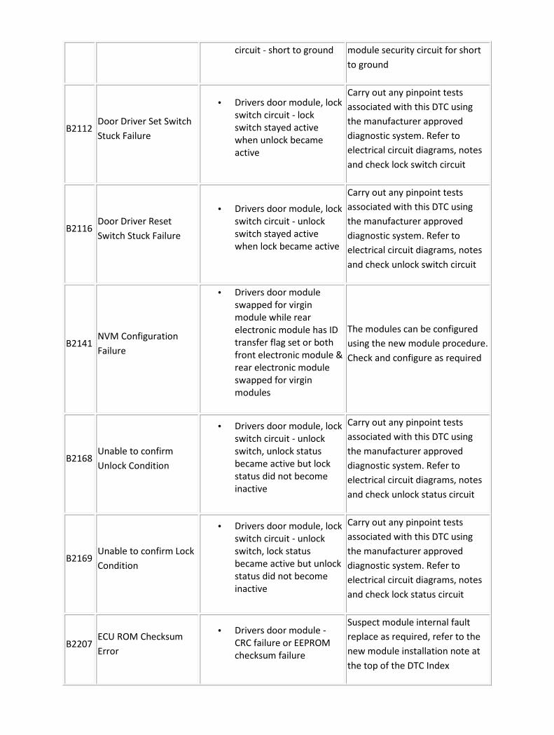
circuit - short to ground module security circuit for short
to ground
B2112 Door Driver Set Switch
Stuck Failure
• Drivers door module, lock
switch circuit - lock
switch stayed active
when unlock became
active
Carry out any pinpoint tests
associated with this DTC using
the manufacturer approved
diagnostic system. Refer to
electrical circuit diagrams, notes
and check lock switch circuit
B2116 Door Driver Reset
Switch Stuck Failure
• Drivers door module, lock
switch circuit - unlock
switch stayed active
when lock became active
Carry out any pinpoint tests
associated with this DTC using
the manufacturer approved
diagnostic system. Refer to
electrical circuit diagrams, notes
and check unlock switch circuit
B2141 NVM Configuration
Failure
• Drivers door module
swapped for virgin
module while rear
electronic module has ID
transfer flag set or both
front electronic module &
rear electronic module
swapped for virgin
modules
The modules can be configured
using the new module procedure.
Check and configure as required
B2168 Unable to confirm
Unlock Condition
• Drivers door module, lock
switch circuit - unlock
switch, unlock status
became active but lock
status did not become
inactive
Carry out any pinpoint tests
associated with this DTC using
the manufacturer approved
diagnostic system. Refer to
electrical circuit diagrams, notes
and check unlock status circuit
B2169 Unable to confirm Lock
Condition
• Drivers door module, lock
switch circuit - unlock
switch, lock status
became active but unlock
status did not become
inactive
Carry out any pinpoint tests
associated with this DTC using
the manufacturer approved
diagnostic system. Refer to
electrical circuit diagrams, notes
and check lock status circuit
B2207 ECU ROM Checksum
Error
• Drivers door module -
CRC failure or EEPROM
checksum failure
Suspect module internal fault
replace as required, refer to the
new module installation note at
the top of the DTC Index

B2322
Mirror Driver
Horizontal Feedback
Potentiometer Circuit
Short To Power
• Drivers door module,
door mirror
potentiometer - circuit
voltage high this DTC will
only log when operation
of memory position recall
Carry out any pinpoint tests
associated with this DTC using
the manufacturer approved
diagnostic system. Refer to
electrical circuit diagrams, notes
and check door mirror circuit for
fault
B2323
Mirror Driver
Horizontal Feedback
Potentiometer Circuit
Short to Ground
• Drivers door module,
door mirror
potentiometer - circuit
voltage low this DTC will
only log when operation
of memory position recall
Carry out any pinpoint tests
associated with this DTC using
the manufacturer approved
diagnostic system. Refer to
electrical circuit diagrams, notes
and check door mirror circuit for
fault
B2326
Mirror Driver Vertical
Feedback
Potentiometer Circuit
Short to Power
• Drivers door module,
door mirror
potentiometer - circuit
short to power this DTC
will only log when
operation of memory
position recall
Carry out any pinpoint tests
associated with this DTC using
the manufacturer approved
diagnostic system. Refer to
electrical circuit diagrams, notes
and check door mirror circuit for
short to power
B2327
Mirror Driver Vertical
Feedback
Potentiometer Circuit
Short to Ground
• Drivers door module,
door mirror
potentiometer - circuit
short to ground this DTC
will only log when
operation of memory
position recall
Carry out any pinpoint tests
associated with this DTC using
the manufacturer approved
diagnostic system. Refer to
electrical circuit diagrams, notes
and check door mirror circuit for
short to ground
B2336 Mirror Switch Assembly
Circuit Failure
• Drivers door module,
door mirror switch - left
mirror select remained
active when right mirror
select became active
Carry out any pinpoint tests
associated with this DTC using
the manufacturer approved
diagnostic system. Refer to
electrical circuit diagrams, notes
and check door left/right mirror
switch and circuit for fault
B2373 LED #1 Circuit Short to
Battery
• Drivers door module,
memory set LED circuit -
short to power
Carry out any pinpoint tests
associated with this DTC using
the manufacturer approved
diagnostic system. Refer to
electrical circuit diagrams, notes

and check memory-set LED circuit
for short to power
B2477 Module Configuration
Failure
• Drivers door module -
configuration failure
Default: Always present
in new module.
The module can be configured
using the new module procedure.
Check and configure as required
B2499 Courtesy Lamp Output
Failure
• Drivers door module,
driver puddle lamp circuit
- short to power or
ground
Carry out any pinpoint tests
associated with this DTC using
the manufacturer approved
diagnostic system. Refer to
electrical circuit diagrams, notes
and check puddle lamp circuit for
short to power or ground
B2945 RF Receiver Enable
Short to Ground
• Drivers door module,
remote keyless entry
module circuit - short to
ground
• Hardware detection only
implemented on LP Japan
drivers door module with
external receiver
Carry out any pinpoint tests
associated with this DTC using
the manufacturer approved
diagnostic system. Refer to
electrical circuit diagrams, notes
and check remote keyless entry
module circuit for short to
ground
B2946 RF Receiver Power
Short To Ground
• Drivers door module,
remote keyless entry
module circuit - short to
ground
• Hardware detection only
implemented on LP Japan
drivers door module with
external receiver
Carry out any pinpoint tests
associated with this DTC using
the manufacturer approved
diagnostic system. Refer to
electrical circuit diagrams, notes
and check remote keyless entry
module circuit for short to
ground
U1147
SCP (J1850) Invalid or
Missing Data for
Vehicle Security
• Drivers door module -
missing message Set
when driver door module
to rear electronic module
challenge fails and
security is not disarmed
Common DTC, only investigate if
this is the only DTC stored or if
dtc reoccurs after clearing. Refer
to electrical circuit diagrams,
notes and check driver door
module to rear electronic module
SCP circuit for fault
U1262 SCP (J1850)
Communication Bus
• Drivers door module -
SCP circuit fault Set when
rear electronic module
doesn't send a challenge
Common DTC, only investigate if
this is the only DTC stored or if
dtc reoccurs after clearing. Carry

Fault query out any pinpoint tests associated
with this DTC using the
manufacturer approved
diagnostic system. Refer to
electrical circuit diagrams, notes
and check driver door to rear
electronic module SCP circuit for
fault
Front Electronic Module
CAUTION: When probing connectors to take measurements in the course of the pinpoint
tests, use the adaptor kit, part number 3548-1358-00
NOTE:
If the control module/component is suspect and the vehicle remains under manufacturer
warranty, refer to the Warranty Policy and Procedures manual (section B1.2), or determine if
any prior approval program is in operation, prior to the installation of a new
module/component.
NOTE:
When performing voltage or resistance tests, always use a digital multimeter (DMM) accurate to
three decimal places and with a current calibration certificate. When testing resistance, always
take the resistance of the DMM leads into account.
NOTE:
Check and rectify basic faults before beginning diagnostic routines that involve pinpoint tests.
NOTE:
Inspect connectors for signs of water ingress, and pins for damage and/or corrosion.
NOTE:
If DTCs are recorded and, after performing the pinpoint tests, a fault is not present, an
intermittent concern may be the cause. Always check for loose connections and corroded

terminals.
DTC Description Possible Causes Action
B1221 Driver Seat Heater
Output Fault
• Front electronic
module, seat heater -
power circuit fault
Refer to electrical circuit diagrams, notes
and check front electronic module seat
heater output for circuit fault
B1222 Passenger Seat
Heater Output Fault
• Front electronic
module, right seat
heater - power
circuit fault
Refer to electrical circuit diagrams, notes
and check front electronic module seat
heater power for circuit fault
B1313 Battery Saver Relay
Coil Circuit Failure
• Front electronic
module - self
protected due to
high circuit load
Refer to electrical circuit diagrams, notes
and check front electronic module
switched system power distribution
circuit for non standard output loads
B1315
Battery Saver Relay
Coil Circuit Short To
Power
• Front electronic
module, switched
system power fault -
circuit short to
power
Refer to electrical circuit diagrams, notes
and check front electronic module
switched system power distribution
circuit for short to power
B1432
Wiper Brake/Run
Relay Circuit Short
To Power
• Front electronic
module ,wiper relay
output circuit - short
to power
Refer to electrical circuit diagrams, notes
and check front electronic module to
wiper relay circuit for short to power
B1433
Wiper Brake/Run
Relay Circuit Short
To Ground
• Front electronic
module, wiper relay
output circuit - short
to ground
Refer to electrical circuit diagrams, notes
and check front electronic module to
wiper relay circuit for short to ground
B1436
Wiper Hi/Low Speed
Relay Coil Circuit
Short To Power
• Front electronic
module, wiper relay
output circuit - short
to power
Refer to electrical circuit diagrams, notes
and check front electronic module to
wiper relay circuit for short to power
B1437
Wiper Hi/Low Speed
Relay Coil Circuit
Short To Ground
• Front electronic
module, wiper relay
output circuit - short
to ground
Refer to electrical circuit diagrams, notes
and check front electronic module to
wiper relay circuit for short to ground

B1438 Wiper Mode Select
Switch Circuit Failure
• Front electronic
module, master
wiper switch circuit -
short to ground
Refer to electrical circuit diagrams, notes
and check front electronic module wiper
switch circuit for short to ground
B1439 Wiper Mode Select
Switch Circuit Open
• Front electronic
module, master
wiper switch circuit -
open or short to
power
Refer to electrical circuit diagrams, notes
and check front electronic module wiper
switch line for short to power or open
circuit
B1440
Wiper Mode Select
Switch Circuit Short
To Power
• Front electronic
module, momentary
wipe switch circuit -
short to power or
open
Refer to electrical circuit diagrams, notes
and check front electronic module
momentary wipe switch circuit for short
to power or open
B1441
Wiper Mode Select
Switch Circuit Short
To Ground
• Front electronic
module ,momentary
wipe switch circuit -
short to ground
Refer to electrical circuit diagrams, notes
and check front electronic module
momentary wipe switch circuit for short
to ground
B1450 Wiper Wash/Delay
Switch Circuit Failure
• Front electronic
module, wash/wipe
switch circuit - short
to ground
Carry out any pinpoint tests associated
with this DTC using the manufacturer
approved diagnostic system. Refer to
electrical circuit diagrams, notes and
check front electronic module
wash/wipe switch circuit for short to
ground
B1451 Wiper Wash/Delay
Switch Circuit Open
• Front electronic
module, wash/wipe
delay switch - circuit
open
Refer to electrical circuit diagrams, notes
and check front electronic module
wash/wipe delay switch line for open
circuit
B1452
Wiper Wash/Delay
Switch Circuit Short
To Power
• Front electronic
module, wash/wipe
delay switch circuit -
short to power
Refer to electrical circuit diagrams, notes
and check front electronic module
wash/wipe delay switch circuit - short to
power
B1453
Wiper Wash/Delay
Switch Circuit Short
To Ground
• Front electronic
module, wash/wipe
delay switch circuit -
short to ground
Refer to electrical circuit diagrams, notes
and check front electronic module
wash/wipe delay switch circuit short to
ground

B1458
Wiper Washer Pump
Motor Relay Circuit
Failure
• Front electronic
module, screen-wash
pump power circuit -
self protection (high
circuit load)
Carry out any pinpoint tests associated
with this DTC using the manufacturer
approved diagnostic system. Refer to
electrical circuit diagrams, notes and
check front electronic module screen-
wash pump power circuit for fault
B1459
Wiper Washer Pump
Motor Relay Coil
Circuit Open
• Front electronic
module, screen-wash
pump power - circuit
open
Refer to electrical circuit diagrams, notes
and check front electronic module
screen-wash pump power line for open
circuit
B1460
Wiper Washer Pump
Motor Relay Coil
Circuit Short To
Power
• Front electronic
module, screen-wash
pump power circuit -
short to ground
Refer to electrical circuit diagrams, notes
and check front electronic module
screen-wash pump power circuit for
short to ground
B1474
Battery Saver Power
Relay Circuit Short
To Power
• Front electronic
module switched
system power
distribution circuit -
short to power
Refer to electrical circuit diagrams, notes
and check front electronic module
switched system power distribution
circuit for short to power
B1500 Lamp Turn Signal
Left Circuit Open
• Front electronic
module, left front
direction indicator -
circuit open
Refer to electrical circuit diagrams, notes
and check front electronic module left
front direction indicator line for open
circuit
B1501
Lamp Turn Signal
Left Circuit Short To
Power
• Front electronic
module, left front
direction indicator
circuit - short to
power
Refer to electrical circuit diagrams, notes
and check front electronic module left
front direction indicator circuit for short
to power
B1504 Lamp Turn Signal
Right Circuit Open
• Front electronic
module, right front
direction indicator -
circuit open
Refer to electrical circuit diagrams, notes
and check front electronic module right
front direction indicator for open circuit
B1505
Lamp Turn Signal
Right Circuit Short To
Power
• Front electronic
module, right front
direction indicator
circuit - short to
power
Refer to electrical circuit diagrams, notes
and check front electronic module right
front direction indicator circuit for short
to power
B1569 Lamp Headlamp • Front electronic
module, main beam Refer to electrical circuit diagrams, notes

High-Beam Circuit
Short To Power
relay circuit - short to
power
and check front electronic module main
beam relay circuit for short to power
B1570
Lamp Headlamp
High-Beam Circuit
Short To Ground
• Front electronic
module, main beam
relay circuit - short to
ground
Refer to electrical circuit diagrams, notes
and check front electronic module main
beam relay circuit for short to ground
B1676 Battery Pack Voltage
Out Of Range
• Front electronic
module - Supply
voltage above or
below preset level
Carry out any pinpoint tests associated
with this DTC using the manufacturer
approved diagnostic system. Refer to
electrical circuit diagrams, notes and
check front electronic module power
and ground circuit for fault
B1838 Battery Saver Power
Relay Circuit Failure
• Front electronic
module, switched
system power
distribution circuit -
short to ground
Carry out any pinpoint tests associated
with this DTC using the manufacturer
approved diagnostic system. Refer to
electrical circuit diagrams, notes and
check front electronic module switched
system power distribution circuit for
short to ground
B1987
Pedal Forward /
Rearward Motor
Stalled
• Front electronic
module, adjustable
pedal motor output
circuit - motor stall
detected
Refer to electrical circuit diagrams, notes
and check front electronic module,
adjustable pedal motor and circuit for
fault
B1990
Pedal Forward /
Rearward
Potentiometer
Feedback Circuit
Failure
• Front electronic
module, adjustable
pedal feedback
potentiometer circuit
- short to ground or
open
Carry out any pinpoint tests associated
with this DTC using the manufacturer
approved diagnostic system. Refer to
electrical circuit diagrams, notes and
check front electronic module
(adjustable pedal) feedback
potentiometer circuit for short to ground
or open
B1991
Pedal Forward /
Rearward
Potentiometer
Feedback Circuit
Short to power
• Front electronic
module ,adjustable
pedal feedback
potentiometer circuit
- short to power
Refer to electrical circuit diagrams, notes
and check front electronic module
(adjustable pedal)feedback
potentiometer circuit for short to power
B2022 Rear Courtesy Lamp
Output Circuit
• Front electronic
module, front
Carry out any pinpoint tests associated
with this DTC using the manufacturer

Failure courtesy lamp circuit
- short to power
approved diagnostic system. Refer to
electrical circuit diagrams, notes and
check front electronic module (front
courtesy lamp) circuit for short to power
B2023
Courtesy Lamp
Output Circuit Short
to Ground
• Front electronic
module, front
courtesy lamp circuit
- short to ground
Refer to electrical circuit diagrams, notes
and check front electronic module (front
courtesy lamp) circuit for short to
ground
B2026
Incandescent
Backlighting Output
Circuit Failure
• Front electronic
module, (bulb/LED)
back light circuit -
short (self
protection)
Carry out any pinpoint tests associated
with this DTC using the manufacturer
approved diagnostic system. Refer to
electrical circuit diagrams, notes and
check front electronic module (bulb/LED
back light) line for short or abnormal
output loads
B2030 Front Fog Lamp
Relay Circuit Failure
• Front electronic
module, front fog
lamp relay circuit -
short to ground
Carry out any pinpoint tests associated
with this DTC using the manufacturer
approved diagnostic system. Refer to
electrical circuit diagrams, notes and
check front electronic module front fog
lamp relay output for short to ground
B2035
LF Side Repeater
Lamp Output Circuit
Failure
• Front electronic
module, left
direction indicator
repeater circuit -
open
Carry out any pinpoint tests associated
with this DTC using the manufacturer
approved diagnostic system. Refer to
electrical circuit diagrams, notes and
check front electronic module left
direction indicator repeater for open
circuit
B2037
RF Side Repeater
Lamp Output Circuit
Failure
• Front electronic
module, right
direction indicator
repeater circuit -
open
Carry out any pinpoint tests associated
with this DTC using the manufacturer
approved diagnostic system. Refer to
electrical circuit diagrams, notes and
check front electronic module right
direction indicator repeater for open
circuit
B2087 Security Line Short
to Ground
• Front electronic
module, security
output circuit - short
Refer to electrical circuit diagrams, notes
and check front electronic module front
electronic module security line circuit for

to ground short to ground
B2170
Steering Column
Lock Switch Circuit
Failure
• Front electronic
module, electronic
steering column lock
circuit - failure (high
circuit load detected)
Carry out any pinpoint tests associated
with this DTC using the manufacturer
approved diagnostic system. Refer to
electrical circuit diagrams, notes and
check front electronic module electronic
steering column lock circuit fault
B2196
Passenger Window
Up / Down Power
Circuit Short to
Ground
• Front electronic
module, front
window enable
circuit - short to
ground
Refer to electrical circuit diagrams, notes
and check front electronic module front
window enable circuit for short to
ground
B2207 ECU ROM Checksum
Error
• Front electronic
module - CRC failure
or EEPROM
checksum failure
Suspect module internal fault replace as
required, refer to the new module
installation note at the top of the DTC
Index
B2249 Head Lamp Relay
Coil Short to Power
• Front electronic
module, dip beam
relay circuit - short to
power
Refer to electrical circuit diagrams, notes
and check front electronic module dip
beam relay circuit for short to power
B2258
Headlamp Washer
Relay Circuit Short to
Power
• Front electronic
module, power wash
relay circuit - short to
power
Refer to electrical circuit diagrams, notes
and check front electronic module
power wash relay circuit for short to
power
B2262 Wiper Park to Park
Timeout
• Front electronic
module, wiper motor
park - circuit fault
Refer to electrical circuit diagrams, notes
and check front electronic module wiper
motor park circuit for fault
B2314
Mirror Passenger
Horizontal Feedback
Potentiometer
Circuit Short to
Power
• Front electronic
module, passenger
mirror horizontal
feedback
potentiometer circuit
- short to power
Refer to electrical circuit diagrams, notes
and check front electronic module
passenger mirror horizontal feedback
potentiometer circuit for short to power
B2315
Mirror Passenger
Horizontal Feedback
Potentiometer
Circuit Short to
• Front electronic
module, passenger
mirror horizontal
feedback
potentiometer circuit
- short to ground or
Refer to electrical circuit diagrams, notes
and check front electronic module
passenger mirror horizontal feedback
potentiometer circuit for short to ground

Ground open or open circuit
B2318
Mirror Passenger
Vertical Feedback
Potentiometer
Circuit Short to
Battery
• Front electronic
module, passenger
mirror vertical
feedback
potentiometer circuit
- short to power
Refer to electrical circuit diagrams, notes
and check front electronic module
passenger mirror vertical feedback
potentiometer circuit for short to power
B2319
Mirror Passenger
Vertical Feedback
Potentiometer
Circuit Short to
Ground
• Front electronic
module, passenger
mirror vertical
feedback
potentiometer circuit
- short to ground or
open
Refer to electrical circuit diagrams, notes
and check front electronic module
passenger mirror vertical feedback
potentiometer circuit for short to ground
or open
B2356 Driver Seat Heater
Output Fault
• Front electronic
module, left seat
heater output circuit
- over current
Carry out any pinpoint tests associated
with this DTC using the manufacturer
approved diagnostic system. Refer to
electrical circuit diagrams, notes and
check front electronic module seat
heater power circuit for non standard
output loads
B2360
Window Motor
Control Output
Circuit Failure
• Front electronic
module, window
global circuit - short
to power
Carry out any pinpoint tests associated
with this DTC using the manufacturer
approved diagnostic system. Refer to
electrical circuit diagrams, notes and
check front electronic module window
global circuit for short to power
B2361 Passenger Seat
Heater Output Fault
• Front electronic
module, right seat
heater circuit - high
circuit load
Refer to electrical circuit diagrams, notes
and check front electronic module seat
heater power circuit for fault
B2363 Optical Sensor
System Failure
• Front electronic
module, rain sensing
module circuit -
signal fault
Refer to electrical circuit diagrams, notes
and check front electronic module rain
sensing module circuit for signal fault
B2370 Seat Heater Power
Shutdown
• Front electronic
module, left seat
heater - circuit fault
(shutdown by power
This DTC has been stored for information
only, advise customer that the demand
for power has exceeded the vehicles
capability at the time this DTC was
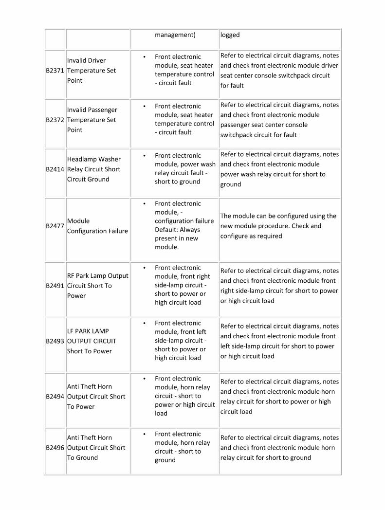
management) logged
B2371
Invalid Driver
Temperature Set
Point
• Front electronic
module, seat heater
temperature control
- circuit fault
Refer to electrical circuit diagrams, notes
and check front electronic module driver
seat center console switchpack circuit
for fault
B2372
Invalid Passenger
Temperature Set
Point
• Front electronic
module, seat heater
temperature control
- circuit fault
Refer to electrical circuit diagrams, notes
and check front electronic module
passenger seat center console
switchpack circuit for fault
B2414
Headlamp Washer
Relay Circuit Short
Circuit Ground
• Front electronic
module, power wash
relay circuit fault -
short to ground
Refer to electrical circuit diagrams, notes
and check front electronic module
power wash relay circuit for short to
ground
B2477 Module
Configuration Failure
• Front electronic
module, -
configuration failure
Default: Always
present in new
module.
The module can be configured using the
new module procedure. Check and
configure as required
B2491
RF Park Lamp Output
Circuit Short To
Power
• Front electronic
module, front right
side-lamp circuit -
short to power or
high circuit load
Refer to electrical circuit diagrams, notes
and check front electronic module front
right side-lamp circuit for short to power
or high circuit load
B2493
LF PARK LAMP
OUTPUT CIRCUIT
Short To Power
• Front electronic
module, front left
side-lamp circuit -
short to power or
high circuit load
Refer to electrical circuit diagrams, notes
and check front electronic module front
left side-lamp circuit for short to power
or high circuit load
B2494
Anti Theft Horn
Output Circuit Short
To Power
• Front electronic
module, horn relay
circuit - short to
power or high circuit
load
Refer to electrical circuit diagrams, notes
and check front electronic module horn
relay circuit for short to power or high
circuit load
B2496
Anti Theft Horn
Output Circuit Short
To Ground
• Front electronic
module, horn relay
circuit - short to
ground
Refer to electrical circuit diagrams, notes
and check front electronic module horn
relay circuit for short to ground

B2512
Front Fog Lamp
Relay Circuit Short to
Power
• Front electronic
module, front fog
lamp relay circuit -
short to power
Refer to electrical circuit diagrams, notes
and check front electronic module front
fog lamp relay circuit for short to power
B2585
Anti Theft Input
Signal Circuit Short
To power
• Front electronic
module, security line
circuit - short to
power
Refer to electrical circuit diagrams, notes
and check front electronic module
security line circuit for short to power
B2598 Headlamp Relay
Circuit Failure
• Front electronic
module, dip beam
relay circuit - short to
ground
Carry out any pinpoint tests associated
with this DTC using the manufacturer
approved diagnostic system. Refer to
electrical circuit diagrams, notes and
check front electronic module dip beam
relay circuit for short to ground
B2704
Optical Sensor
Power Short to
Ground
• Front electronic
module, rain sensing
module power circuit
- short to ground
Refer to electrical circuit diagrams, notes
and check front electronic module rain
sensing module power circuit for short
to ground
B2789 Left or right latch
release circuit failure
• Front electronic
module, glove box
motor circuit fault -
short to power or
high circuit load
Carry out any pinpoint tests associated
with this DTC using the manufacturer
approved diagnostic system. Refer to
electrical circuit diagrams, notes and
check front electronic module glove box
motor circuit fault - short to power or
high circuit load
C1712 Left Front Sensor
Circuit Failure
• Front electronic
module, left seat
heater sensor circuit
- short to power or
open
Carry out any pinpoint tests associated
with this DTC using the manufacturer
approved diagnostic system. Refer to
electrical circuit diagrams, notes and
check front electronic module left seat
heater sensor circuit for short to power
or open
C1713 Left Front Sensor
Circuit Fault
• Front electronic
module, left seat
heater sensor circuit
- short to ground
Carry out any pinpoint tests associated
with this DTC using the manufacturer
approved diagnostic system. Refer to
electrical circuit diagrams, notes and
check front electronic module left seat
heater sensor circuit for short to ground

C1715 Right Front Sensor
Circuit Failure
• Front electronic
module, right seat
heater sensor circuit
- short to power or
open
Carry out any pinpoint tests associated
with this DTC using the manufacturer
approved diagnostic system. Refer to
electrical circuit diagrams, notes and
check front electronic module right seat
heater sensor circuit for short to power
or open
C1716 Right Front Sensor
Circuit Fault
• Front electronic
module, right seat
heater sensor circuit
- short to ground
Carry out any pinpoint tests associated
with this DTC using the manufacturer
approved diagnostic system. Refer to
electrical circuit diagrams, notes and
check front electronic module right seat
heater sensor circuit for short to ground
C1755 Power Limit
Shutdown Fault
• Front electronic
module right seat
heater - shutdown by
power management
This DTC has been stored for information
only, advise customer that the demand
for power has exceeded the vehicles
capability at the time this DTC was
logged
Rear Electronic Module
CAUTION: When probing connectors to take measurements in the course of the pinpoint
tests, use the adaptor kit, part number 3548-1358-00
NOTE:
If the control module/component is suspect and the vehicle remains under manufacturer
warranty, refer to the Warranty Policy and Procedures manual (section B1.2), or determine if
any prior approval program is in operation, prior to the installation of a new
module/component.
NOTE:
When performing voltage or resistance tests, always use a digital multimeter (DMM) accurate to
three decimal places and with a current calibration certificate. When testing resistance, always
take the resistance of the DMM leads into account.
NOTE:
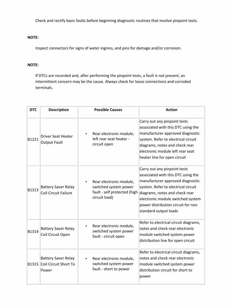
Check and rectify basic faults before beginning diagnostic routines that involve pinpoint tests.
NOTE:
Inspect connectors for signs of water ingress, and pins for damage and/or corrosion.
NOTE:
If DTCs are recorded and, after performing the pinpoint tests, a fault is not present, an
intermittent concern may be the cause. Always check for loose connections and corroded
terminals.
DTC Description Possible Causes Action
B1221 Driver Seat Heater
Output Fault
• Rear electronic module,
left rear seat heater -
circuit open
Carry out any pinpoint tests
associated with this DTC using the
manufacturer approved diagnostic
system. Refer to electrical circuit
diagrams, notes and check rear
electronic module left rear seat
heater line for open circuit
B1313 Battery Saver Relay
Coil Circuit Failure
• Rear electronic module,
switched system power
fault - self protected (high
circuit load)
Carry out any pinpoint tests
associated with this DTC using the
manufacturer approved diagnostic
system. Refer to electrical circuit
diagrams, notes and check rear
electronic module switched system
power distribution circuit for non
standard output loads
B1314 Battery Saver Relay
Coil Circuit Open
• Rear electronic module,
switched system power
fault - circuit open
Refer to electrical circuit diagrams,
notes and check rear electronic
module switched system power
distribution line for open circuit
B1315
Battery Saver Relay
Coil Circuit Short To
Power
• Rear electronic module,
switched system power
fault - short to power
Refer to electrical circuit diagrams,
notes and check rear electronic
module switched system power
distribution circuit for short to
power

B1499 Lamp Turn Signal
Left Circuit Failure
• Rear electronic module,
left rear direction
indicator circuit - high
circuit load (self
protected)
Carry out any pinpoint tests
associated with this DTC using the
manufacturer approved diagnostic
system. Refer to electrical circuit
diagrams, notes and check left rear
direction indicator circuit for non
standard output loads
B1500 Lamp Turn Signal
Left Circuit Open
• Rear electronic module,
left rear direction
indicator - circuit open
Refer to electrical circuit diagrams,
notes and check left rear direction
indicator line for open circuit
B1501
Lamp Turn Signal
Left Circuit Short To
Power
• Rear electronic module,
left rear direction
indicator circuit - short to
power
Refer to electrical circuit diagrams,
notes and check left rear direction
indicator circuit for short to power
B1503 Lamp Turn Signal
Right Circuit Failure
• Rear electronic module,
right rear direction
indicator circuit - high
circuit load (self
protected)
Carry out any pinpoint tests
associated with this DTC using the
manufacturer approved diagnostic
system. Refer to electrical circuit
diagrams, notes and check right rear
direction indicator circuit for non
standard output loads
B1504 Lamp Turn Signal
Right Circuit Open
• Rear electronic module,
right rear direction
indicator - circuit open
Refer to electrical circuit diagrams,
notes and check right rear direction
indicator for open circuit
B1505
Lamp Turn Signal
Right Circuit Short
To Battery
• Rear electronic module,
right rear direction
indicator circuit - short to
power
Refer to electrical circuit diagrams,
notes and check right rear direction
indicator circuit for short to power
B1676 Battery Pack Voltage
Out Of Range
• Rear electronic module -
Supply voltage above or
below preset level
Carry out any pinpoint tests
associated with this DTC using the
manufacturer approved diagnostic
system. Refer to electrical circuit
diagrams, notes and check rear
electronic module power and
ground circuit for fault
B2089 Puddle / Approach
Lamp Fault
• Rear electronic module,
puddle or approach lamp
circuit - fault Set for any
fault detected by rear
Carry out any pinpoint tests
associated with this DTC using the
manufacturer approved diagnostic

puddle lamp output
circuits
system. Refer to electrical circuit
diagrams, notes and check rear
puddle lamp circuit for fault
B2139
Data Mismatch
(receive data does
not match what was
expected)
• Rear electronic module -
challenge/response from
drivers door module error
on Unlock process
Rear electronic module data
mismatch with drivers door module.
The modules can be configured
using the new module procedure.
Check and configure as required,
using the manufacturer approved
diagnostic system
B2141 NVM Configuration
Failure
• Rear electronic module,
vehicle configuration not
programmed or
configuration write
failure
The modules can be configured
using the new module procedure.
Check and configure as required,
using the manufacturer approved
diagnostic system
B2162
Data Mismatch #2
(receive data does
not match what was
expected)
• Rear electronic module -
challenge/response with
instrument cluster fails
Rear electronic module data
mismatch with instrument cluster
The modules can be configured
using the new module procedure.
Check and configure as required,
using the manufacturer approved
diagnostic system
B2168 Unable to confirm
Unlock Condition
• Rear electronic module
lock switch - lock status
remained active when
unlock status became
active
Refer to electrical circuit diagrams,
notes and check rear electronic
module lock status circuit
B2169 Unable to confirm
Lock Condition
• Rear electronic module,
lock switch - unlock
status remained active
when lock status became
active
Refer to electrical circuit diagrams,
notes and check rear electronic
module unlock status circuit
B2170
Steering Column
Lock Switch Circuit
Failure
• Rear electronic module,
electronic steering
column lock switch -
circuit failure
Carry out any pinpoint tests
associated with this DTC using the
manufacturer approved diagnostic
system. Refer to electrical circuit
diagrams, notes and check rear
electronic module electronic
steering column lock switch circuit

fault
B2177
Interior Scanning
Sensor Circuit
Failure
• Rear electronic module
intrusion sensor power
output - circuit failure No
communication with
intrusion sensors
Carry out any pinpoint tests
associated with this DTC using the
manufacturer approved diagnostic
system. Refer to electrical circuit
diagrams, notes and check rear
electronic module intrusion sensor
and power circuit for failure
B2207 ECU ROM Checksum
Error
• Rear electronic module,
CRC Failure or EEPROM
checksum failure
Suspect module internal fault
replace as required, refer to the new
module installation note at the top
of the DTC Index
B2287 Inclination Sensor
Circuit Failure
• Rear electronic module,
inclination sensor power
output - circuit failure No
communication with
inclination sensors
Carry out any pinpoint tests
associated with this DTC using the
manufacturer approved diagnostic
system. Refer to electrical circuit
diagrams, notes and check rear
electronic module inclination sensor
and power output circuit for failure
B2356 Driver Seat Heater
Output Fault
• Rear electronic module,
rear seat heater circuit -
short to ground or high
circuit load protection
activated
Carry out any pinpoint tests
associated with this DTC using the
manufacturer approved diagnostic
system. Refer to electrical circuit
diagrams, notes and check rear
electronic module rear seat heater
circuit for short to ground or non
standard output loads
B2361 Passenger Seat
Heater Output Fault
• Rear electronic module,
rear seat heater circuit -
short to ground or high
circuit load protection
activated
Carry out any pinpoint tests
associated with this DTC using the
manufacturer approved diagnostic
system. Refer to electrical circuit
diagrams, notes and check rear
electronic module rear seat heater
circuit for short to ground or non
standard output loads
B2370 Seat Heater Power
Shutdown
• Rear electronic module,
left rear seat heater -
shutdown by power
Refer to electrical circuit diagrams,
notes and check rear electronic
module left rear seat heater circuit

management for fault
B2371
Invalid Left
Temperature Set
Point
• Rear electronic module,
left seat heater -
temperature control
input is invalid
Refer to electrical circuit diagrams,
notes and check rear electronic
module left rear center console
switch pack circuit for fault
B2372
Invalid Right
Temperature Set
Point
• Rear electronic module,
right seat heater -
temperature control
input is invalid
Refer to electrical circuit diagrams,
notes and check rear electronic
module right rear center console
switch pack circuit for fault
B2477
Module
Configuration
Failure
• Rear electronic module -
configuration failure
Default: Always present
in new module.
The module can be configured using
the new module procedure. Check
and configure as required
B2495
Anti Theft Horn
Output Circuit
Failure
• Rear electronic module,
passive security sounder
output - circuit fault
Carry out any pinpoint tests
associated with this DTC using the
manufacturer approved diagnostic
system. Refer to electrical circuit
diagrams, notes and check rear
electronic module passive security
sounder circuit for fault
B2525 Rear Backup Lamp
Circuit Failure
• Rear electronic module,
reverse lamp - circuit
fault
Carry out any pinpoint tests
associated with this DTC using the
manufacturer approved diagnostic
system. Refer to electrical circuit
diagrams, notes and check rear
electronic module, reverse lamp for
circuit fault
B2526
Rear Backup Lamp
Circuit Short To
Power
• Rear electronic module,
reverse lamp circuit -
short to power
Refer to electrical circuit diagrams,
notes and check rear electronic
module reverse lamp circuit for
short to power
B2533 Right Stop Lamp
Circuit Failure
• Rear electronic module,
right stop lamp - circuit
open
Carry out any pinpoint tests
associated with this DTC using the
manufacturer approved diagnostic
system. Refer to electrical circuit
diagrams, notes and check rear
electronic module right stop lamp

for open circuit
B2534
Right Stop Lamp
Circuit Short to
power
• Rear electronic module,
right stop lamp circuit -
short to power or high
circuit load
Refer to electrical circuit diagrams,
notes and check rear electronic
module right stop lamp circuit for
short to power or non standard
output loads
B2565 Right Tail Lamp
Circuit Failure
• Rear electronic module,
right tail lamp circuit fault
Carry out any pinpoint tests
associated with this DTC using the
manufacturer approved diagnostic
system. Refer to electrical circuit
diagrams, notes and check rear
electronic module right tail lamp
circuit for fault
B2577 Left Tail Lamp
Circuit Failure
• Rear electronic module,
left stop lamp circuit -
short to power
Carry out any pinpoint tests
associated with this DTC using the
manufacturer approved diagnostic
system. Refer to electrical circuit
diagrams, notes and check rear
electronic module left stop lamp
circuit for short to power
B2915 Fuel Sender Circuit
Failure #2
• Rear electronic module,
critical fuel level switch -
circuit fault
Refer to electrical circuit diagrams,
notes and check rear electronic
module critical fuel level switch
circuit for fault
C1712 Left Front Sensor
Circuit Failure
• Rear electronic module,
left rear seat heater
sensor circuit - short to
power or open
Carry out any pinpoint tests
associated with this DTC using the
manufacturer approved diagnostic
system. Refer to electrical circuit
diagrams, notes and check rear
electronic module left rear seat
heater sensor for circuit short to
power or open
C1713 Left Front Sensor
Circuit Fault
• Rear electronic module,
left seat heater sensor
circuit - short to ground
Carry out any pinpoint tests
associated with this DTC using the
manufacturer approved diagnostic
system. Refer to electrical circuit
diagrams, notes and check rear
electronic module left seat heater
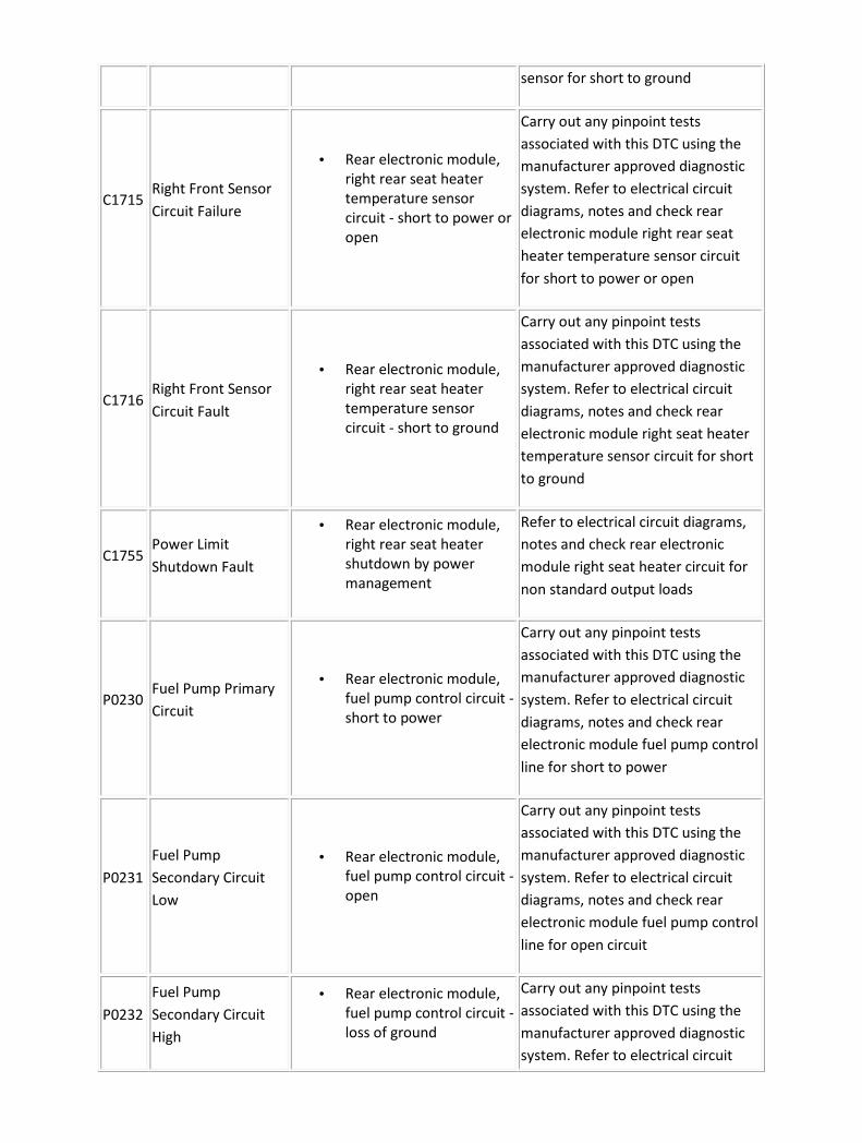
sensor for short to ground
C1715 Right Front Sensor
Circuit Failure
• Rear electronic module,
right rear seat heater
temperature sensor
circuit - short to power or
open
Carry out any pinpoint tests
associated with this DTC using the
manufacturer approved diagnostic
system. Refer to electrical circuit
diagrams, notes and check rear
electronic module right rear seat
heater temperature sensor circuit
for short to power or open
C1716 Right Front Sensor
Circuit Fault
• Rear electronic module,
right rear seat heater
temperature sensor
circuit - short to ground
Carry out any pinpoint tests
associated with this DTC using the
manufacturer approved diagnostic
system. Refer to electrical circuit
diagrams, notes and check rear
electronic module right seat heater
temperature sensor circuit for short
to ground
C1755 Power Limit
Shutdown Fault
• Rear electronic module,
right rear seat heater
shutdown by power
management
Refer to electrical circuit diagrams,
notes and check rear electronic
module right seat heater circuit for
non standard output loads
P0230 Fuel Pump Primary
Circuit
• Rear electronic module,
fuel pump control circuit -
short to power
Carry out any pinpoint tests
associated with this DTC using the
manufacturer approved diagnostic
system. Refer to electrical circuit
diagrams, notes and check rear
electronic module fuel pump control
line for short to power
P0231
Fuel Pump
Secondary Circuit
Low
• Rear electronic module,
fuel pump control circuit -
open
Carry out any pinpoint tests
associated with this DTC using the
manufacturer approved diagnostic
system. Refer to electrical circuit
diagrams, notes and check rear
electronic module fuel pump control
line for open circuit
P0232
Fuel Pump
Secondary Circuit
High
• Rear electronic module,
fuel pump control circuit -
loss of ground
Carry out any pinpoint tests
associated with this DTC using the
manufacturer approved diagnostic
system. Refer to electrical circuit

diagrams, notes and check rear
electronic module fuel pump control
line for loss of ground
P1235 Fuel Pump Control
Out Of Range
• Rear electronic module,
fuel input (modulated
pulsewidth) - out of range
(low)
Carry out any pinpoint tests
associated with this DTC using the
manufacturer approved diagnostic
system. Refer to electrical circuit
diagrams, notes and check engine
control module to rear electronic
module fuel input (modulated
pulsewidth) is out of range (low)
P1236 Fuel Pump Control
Out Of Range
• Rear electronic module,
fuel input (modulated
pulsewidth) - out of range
(high)
Carry out any pinpoint tests
associated with this DTC using the
manufacturer approved diagnostic
system. Refer to electrical circuit
diagrams, notes and check engine
control module to rear electronic
module fuel input (modulated
pulsewidth) is out of range (high)
U1262 SCP Communication
Bus Fault
• Rear electronic module
(SCP) - communication
circuit fault
Refer to electrical circuit diagrams,
notes and check rear electronic
module SCP circuit for fault
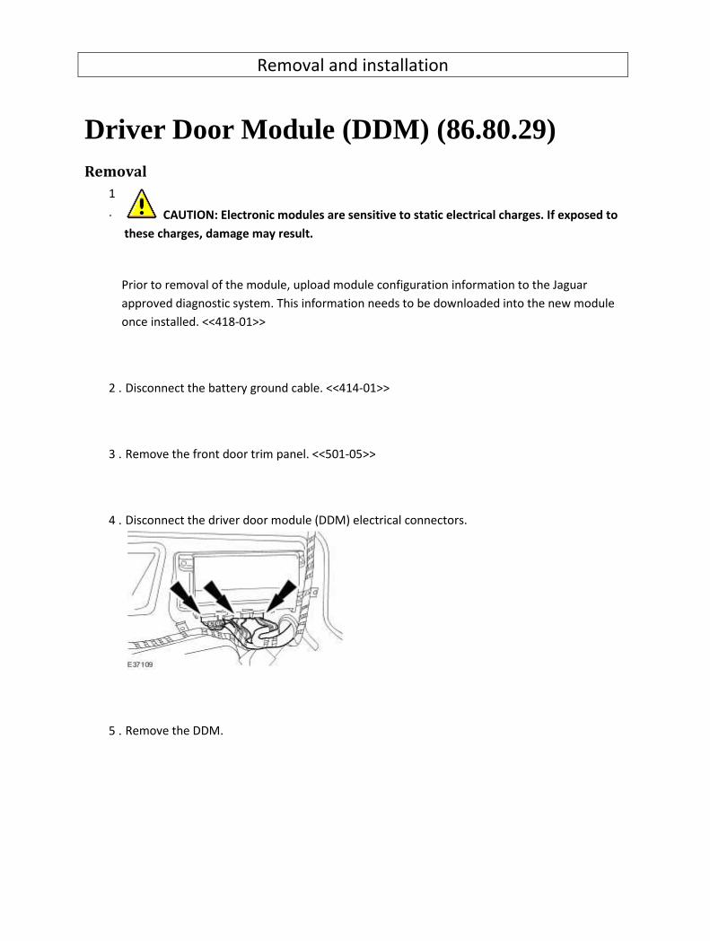
Removal and installation
Driver Door Module (DDM) (86.80.29) Removal
1
. CAUTION: Electronic modules are sensitive to static electrical charges. If exposed to
these charges, damage may result.
Prior to removal of the module, upload module configuration information to the Jaguar
approved diagnostic system. This information needs to be downloaded into the new module
once installed. <<418-01>>
2 . Disconnect the battery ground cable. <<414-01>>
3 . Remove the front door trim panel. <<501-05>>
4 . Disconnect the driver door module (DDM) electrical connectors.
5 . Remove the DDM.

Installation
1 . To install, reverse the removal procedure.
2
.
After installation of the module, download module configuration information to the new
module. <<418-01>>

Driver Seat Module (DSM) (86.75.28) Removal
CAUTION: Electronic modules are sensitive to static electrical charges. If exposed to these
charges, damage may result.
1 . Remove the front seat. <<501-10>>
2 . Disconnect the electrical connectors.
3 . Remove the driver seat module (DSM).
Release the retaining tang
Installation
1 . To install, reverse the removal procedure.

Front Electronic Module (FEM) (86.80.41) Removal
1
. CAUTION: Electronic modules are sensitive to static electrical charges. If exposed to
these charges, damage may result.
Prior to removal of the module, upload module configuration information to the Jaguar
approved diagnostic system. This information needs to be downloaded into the new module
once installed. <<418-01>>
2 . Disconnect the battery ground cable. <<414-01>>
3 . Remove the left-hand cowl side trim panel. <<501-05>>
4 . Reposition the floor covering.
5 . Disconnect the electrical connectors.
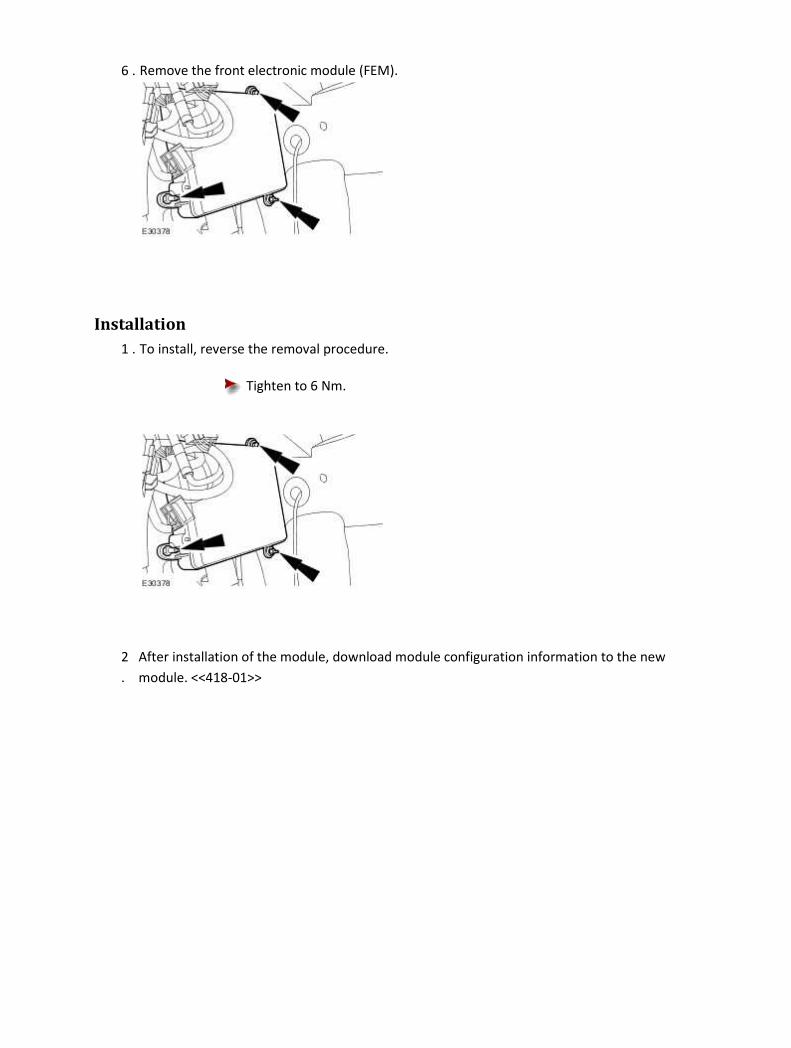
6 . Remove the front electronic module (FEM).
Installation
1 . To install, reverse the removal procedure.
Tighten to 6 Nm.
2
.
After installation of the module, download module configuration information to the new
module. <<418-01>>

Multifunction Voice Activated Module (86.53.13) Removal
1
. CAUTION: Electronic modules are sensitive to static electrical charges. If exposed to
these charges, damage may result.
Prior to removal of the module, upload module configuration information to the Jaguar
approved diagnostic system. This information needs to be downloaded into the new module
once installed. <<418-01>>
2 . Disconnect the battery ground cable. <<414-01>>
3 . Remove the left-hand luggage compartment side trim panel.
1) Remove the luggage compartment side trim retaining clip.
2) Remove the luggage compartment side trim panel.
4 . Detach the module mounting bracket.

5 . Disconnect the CD changer electrical connectors.
6 . Disconnect the multifunction voice activated module electrical connectors.
7 . NOTE:
Left-hand shown, right-hand similar.
Remove the CD changer.
Remove the CD changer retaining bolts.

8 .
CAUTION:
Remove the multifunction voice activated module.
Installation
1 . To install, reverse the removal procedure.
Tighten to 8 Nm.
2 After installation of the module, download module configuration information to the new
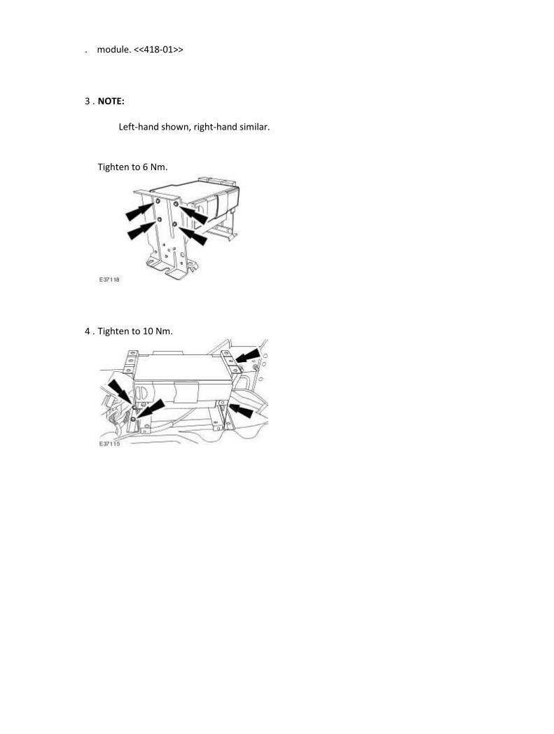
. module. <<418-01>>
3 . NOTE:
Left-hand shown, right-hand similar.
Tighten to 6 Nm.
4 . Tighten to 10 Nm.
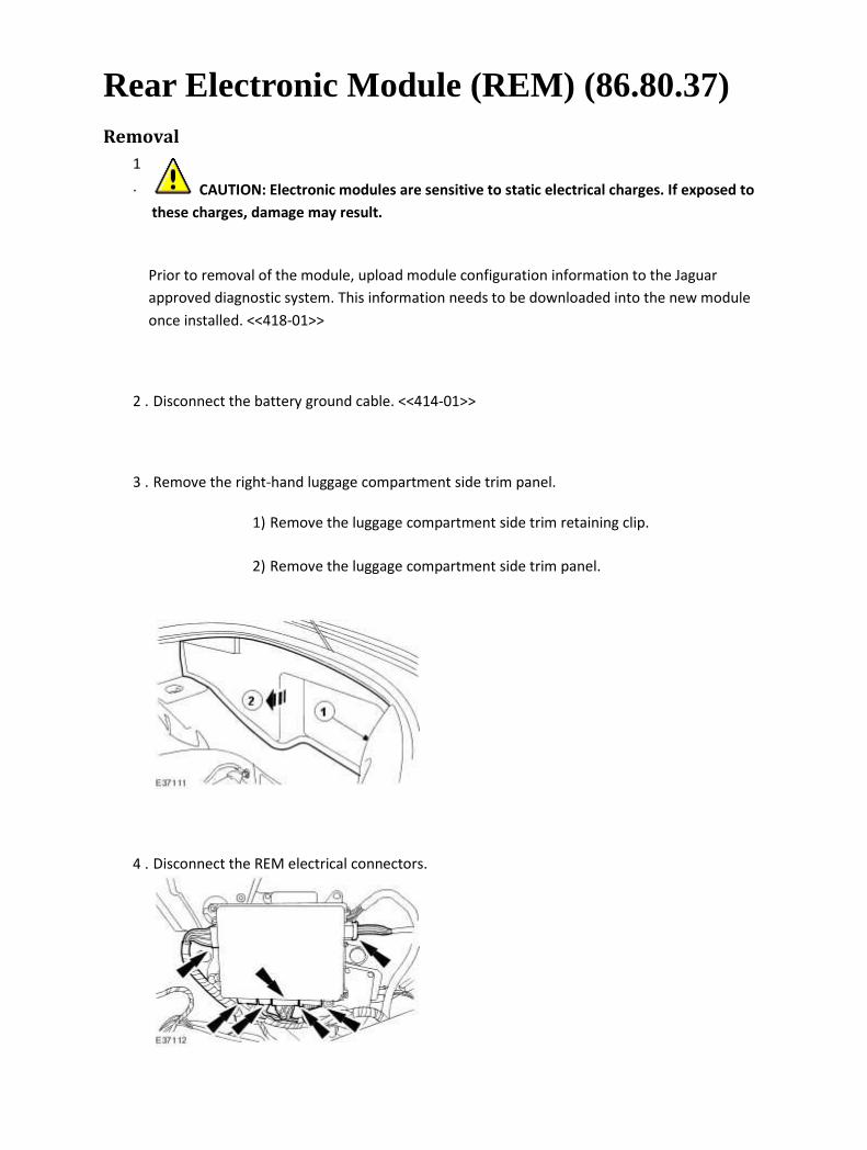
Rear Electronic Module (REM) (86.80.37) Removal
1
. CAUTION: Electronic modules are sensitive to static electrical charges. If exposed to
these charges, damage may result.
Prior to removal of the module, upload module configuration information to the Jaguar
approved diagnostic system. This information needs to be downloaded into the new module
once installed. <<418-01>>
2 . Disconnect the battery ground cable. <<414-01>>
3 . Remove the right-hand luggage compartment side trim panel.
1) Remove the luggage compartment side trim retaining clip.
2) Remove the luggage compartment side trim panel.
4 . Disconnect the REM electrical connectors.

5 . Remove the REM.
Installation
1 . To install, reverse the removal procedure.
Tighten to 6 Nm.
2
.
After installation of the module, download module configuration information to the new
module. <<418-01>>

Rear Seat Module (RSM) (86.75.40) Removal
1
. CAUTION: Electronic modules are sensitive to static electrical charges. If exposed to
these charges, damage may result.
Prior to removal of the module, upload module configuration information to the Jaguar
approved diagnostic system. This information needs to be downloaded into the new module
once installed.
2 . Disconnect the battery ground cable. <<414-01>>
3 . Remove the rear seat. <<501-10>>
4 . Reposition the rear seat backrest insulator.
Remove the retaining clips.
5 . Disconnect the RSM electrical connectors.

6 . Remove the RSM.
Remove the securing nuts.
Installation
1 . To install, reverse the removal procedure.
Tighten to 6 Nm.
Related Documents