Form X30597A Supplement I © 1997 jTeledyne Industries, Inc. JANUARY 1997

Welcome message from author
This document is posted to help you gain knowledge. Please leave a comment to let me know what you think about it! Share it to your friends and learn new things together.
Transcript
Form X30597A Supplement I© 1997 jTeledyne Industries, Inc. JANUARY 1997

DEFINITIONS OF NOTES, CAUTIONS and WARNINGS
NOTES, CA UTIONS and WARNINGS are defined for use in this manual as follows:
NOTE ... Special interest information which may facilitate performance of a procedure or operation ofequipment.
CA UTION... .Used to emphasize certain information or instructions which if disregarded may result indamage to engine or accessories.
WARNING
Used to provide warning with respect to information and/or instructions which if disregarded willendanger personnel and/or severely damage the engine resulting in subsequent engine malfunction orfailure.
Notes, cautions and warnings do not impose undue restrictions. They are inserted to obtain maximumsafety, efficiency and performance. Abuse, misuse or neglect of equipment can cause eventual enginemalfunction or failure. Compliance with instructions and provisions in this manual is mandatory.
Hi
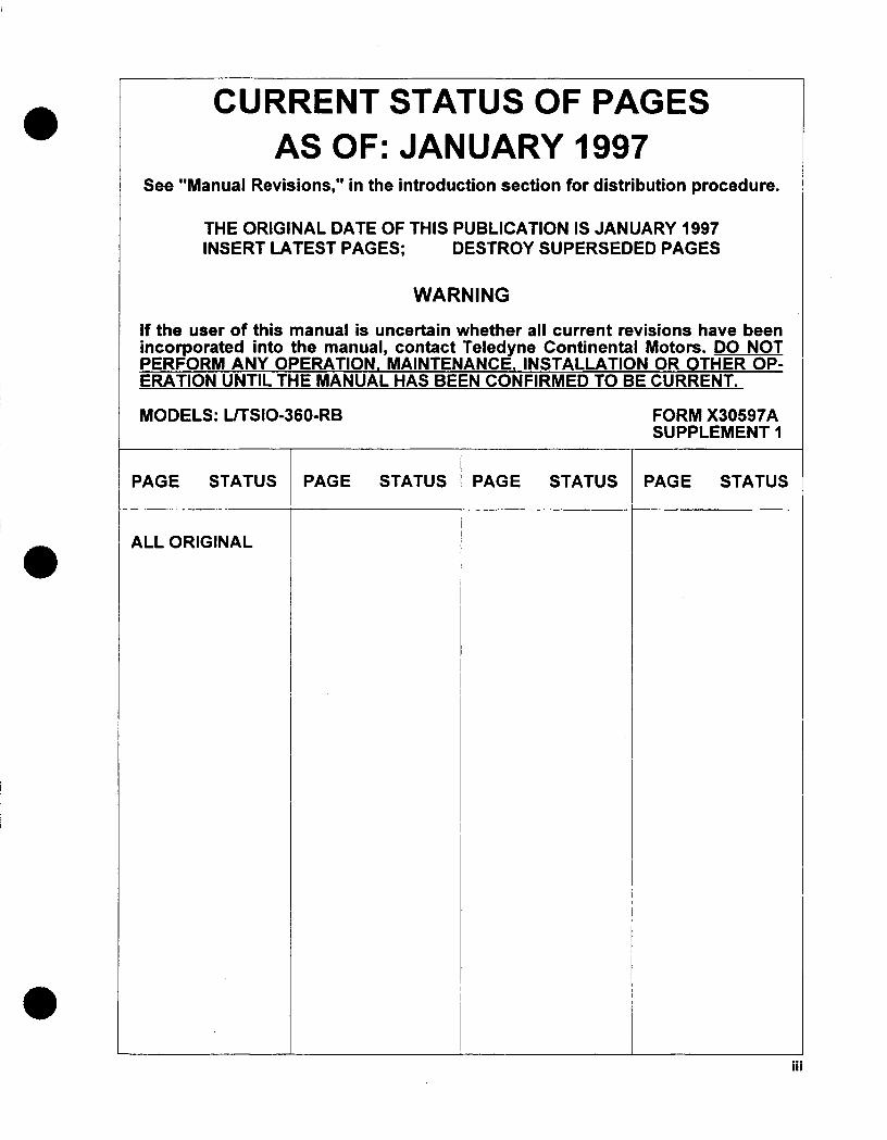
CURRENT STATUS OF PAGESAS OF: JANUARY 1997
See "Manual Revisions," in the introduction section for distribution procedure.
THE ORIGINAL DATE OF THIS PUBLICATION IS JANUARY 1997INSERT LATEST PAGES; DESTROY SUPERSEDED PAGES
WARNING
If the user of this manual is uncertain whether all current revisions have beenincorporated into the manual, contact Teledyne Continental Motors. DO NOTPERFORM ANY OPERATION. MAINTENANCE. INSTALLATION OR OTHER OP-ERATION UNTIL THE MANUAL HAS BEEN CONFIRMED TO BE CURRENT._
MODELS: LITSIO-360-RB FORM X30597ASUPPLEMENT I
PAGE STATUS PAGE STATUS PAGE STATUS PAGE STATUS
ALL ORIGINAL
iii

WARNING
BACKGROUND. Replacement parts, materials, appliances, and instruments may be sold as being ofaircraft quality when actually the quality and origin of these units are unknown. Users of such units areusually unaware of potential hazards involved with replacement parts not eligible for use on certificatedaircraft. Units may be deceptively advertised as "unused," "like new" or* "remanufactured." This impliesthe quality of such units is equal to an original, repaired or overhauled unit.
Federal Aviation Regulations (FAR) 43.13 and FAR 145.57 specify performance rules for replacement ofparts and materials used in maintenance and alteration of United States (US) certificated aircraft. Asoutlined in FAR 91.403, FAR 121.363, FAR 123.45, and FAR 135.143 (a), the ownerloperator isresponsible for continued airworthiness of the aircraft which includes parts replacement.
IDENTIFICATION OF THE APPROVED PARTS. Approved, serviceable replacement parts are
identified by:
a. A Federal Aviation Administration (FAA) Form 81 30-3 Airworthiness Approval Tag. An AirworthinessApproval Tag identifies a part or group of parts approved by authorized FAA representatives.
b. An FAA Technical Standard Order (TSO) number and identification mark that indicates the part orappliance has been manufactured under the requirements of FAR 21 Subpart 0.
C. An FAA Parts Manufacturer Approval (PMA) symbol, together with the manufacturer's name, partnumber and make and model of the type certified product on which the part might be installed,stamped on the part. An FAA I PMA is issued under FAR 21.305. The make and model informationmay be on a tag attached to the part.
d. Shipping ticket, invoice or other document which verifies the part was manufactured by a facilityholding an FAA Approved Production Inspection System issued under FAR 21 Subpart F or by amanufacturer holding an FAA Production Certificate issued under FAR 21 Subpart G.
e. Certificate of airworthiness for export issued by a foreign govemnment under the provisions of FAR21 Subpart N.
KNOW YOUR SUPPLIER. Many reproduced parts and components are available for purchase andinstallation on US certified aircraft. Often, an original part is used as a sample to produce duplicates. Thereproduced parts appear to be as good as the original part; however, many unknown factors are not readilyapparent to the purchaser such as degree of heat treating, plating, inspections, tests and calibrations.Often the faulty part is not discovered until a malfunction or an accident occurs.
SUMMARY. In accordance with FAR certification of materials, parts and appliances for return toservice for use on aircraft is the responsibility of the person~iagency who signs the approval. Theowner/operator is responsible for the continued airworthiness of the aircraft. To assure continued safetyin aircraft operation, great care must be used when inspecting, testing and determining the acceptabilityof all parts and materials. Exercise extreme discretion to identify and establish the origin of materials,parts, and appliances.
iv

NOTICE TO ALL USERS
The following publication contains parts listings introduced by general information. It is important all personnelinvolved with part procurement and installation thoroughly read and understand the information provided. Theseinstructions contain the information required to obtain replacement parts for the aircraft engine and must be followedcarefully.
Publication Format
This publication is formatted for practical use and ease of reference. Chapter and page numbering are independentwithin each section so that revisions can be made by section without affecting the entire publication. A list ofchapters is located at the begining of the manual and a chapter index is located at the begining of each chapter.
This manual contains no warranties, either expressed or implied.
Pnior to performing parts replacement, the mechanic must meet requirements of FAR 65 and must follow FARParts 43, 91 and 145 as applicable. Use this manual in conjunction with Teledyne Continental Motors (TCM) servicedocuments, related publications, accessory manufacturer's instructions, FAR and FAA Advisory Circulars.
WARNING
This manual, the Service Documents, the Overhaul Manual and Maintenance Manualconstitute the Instructions for Continued Airworthiness prepared by TCM as approvedby the FAA, pursuant to FAR Part 33. As required by FAR § 43.13, each personperforming maintenance, alteration or preventive maintenance on the engine or acces-sories must use the methods, techniques and practices prescribed in the Instructionsfor Continued Airworthiness. Failure to comply with the Instructions for ContinuedAirworthiness may result in engine malfunction, engine failure, injury or death.
V

INTENTIONALLY
LEFT
BLANK
VI

Publication Table of Contents
COVER PAGES
Definition of Notes, Cautions and Warnings.....
CFC Warning Statement.. ..........
Status Page .................
Replacement Parts Warning...........
Notice to all users . . . . . . . . . . . . . .
PAGE
*... ii
... ii
.. iii
..iv
Chapter Index
CHAPTER F
1 Introduction.......................
2 Exhaust System.....................
Ignition System ......
Fuel Injection System ...
Induction System.....
Air Conditioning .....
Electrical Charging System
Starting System......
Accessory Case .....
Lubnication System ....
Cylinders And Pistons ...
Prankcase........
13 Engine Drive Train
2AGE
1-1
2-1
3-1
4-1
5-1
6-1
7-1
8-1
9-1
10-1
11-1
12-1
13-1
3
4
5
6
7
8
9
10
1 1
12
vii
................
................
................
................
................
.....
.....
.....
.....
.....
.....
.....
.....
.....
.....
.....
.....
.....
.....
.....
.....
.....
.....
INTENTIONALLY
LEFT
BLANK
viii

CHAPTERI1INTRODUCTION
PAGE
Introduction ....................... 1-2
Scope ......................... 1-2
Manual Revisions.....................1-2
List Of Abbreviations And Symbols . ............ 1-3
Related Publications....................1-3
Repair Parts Sets and Materials .. . . ... ... . . ... 14
SECTION
1-1
1-2
1-3
1-4
1-5
1-6
1-1

1-1 INTRODUCTION
For a list of chapters contained in this manual refer to the Chapter Index on page vi. For a list ofparts and figures contained in each chapter, see the first page of each chapter. The chapters, pagesand figures contained in this publication are numbered consecutively.
In this edition, currently available parts are listed for LITSIO-360-RB engines. If accessories or partsattached to any engine installed in an aircraft manufactured in the United States under a productionmodel number do not appear in this catalog, determine whether they are available from the airframemanufacturer before placing an order with a Teledyne Continental Authorized Distributor.
The system figure is followed by figures for assemblies that compose the particular system. Thefigures are illustrated in exploded form. Each figure has a figure index and parts listing of thecomponents contained appearing on the same or adjacent page.
WARNING
The figures depicted in this publication are for illustration purposes only.They are not intended to be accurate detailed illustrations of any specificengine model, part or equipment.Index numbers that correspond with the numbers contained in the related figure are assigned toeach part number.In the parts listings, the first column of each system or component identifies the figure number in thetop left corner and the index number (following a dash) which identifies each part in numerical order.DO NOT ORDER PARTS BY INDEX NUMBERS. Use the part number which appears in the secondcolumn, and use the part name which appears in the third column under DESCRIPTION. Do notorder a part that has "No Number' shown with the description, or that has "NS" (not sold) shown inthe QUANTITY column. To replace a part "not sold," order the next higher level assembly. Payparticular attention to the quantity of parts required per engine or per assembly. Example: 6 cylindersper engine, 12 pushrods per engine, 2 pushrods per cylinder.
Some customer specification model engines have certain part differences from the basic engine.Check the engine data plate model designation and specification number before ordering parts forthe engine.When ordering parts use the description and model designation shown with the part number. Thisinformation is necessary to ensure correct part to assembly or assembly to engine application.
Oversize parts must be ordered by the numbers listed herein with correct descriptions to avoid errors.Authorized Oversize parts are indicated by a suffix such as P003. Authorized Undersize parts areindicated by a suffix such as M005 after the part number.
Repair Parts Sets are usually requested for overhaul work and should be ordered by set part
numbers. See "Repair Parts Sets and Materials," Section 1-6.
1-2 SCOPE
This publication contains information necessary to order factory replacement parts for the LITS10-360-RB model engines.
1-3 MANUAL REVISIONS
Teledyne Continental Motors Parts Catalogs are revised as necessary. Revisions to this catalog willbe furnished to purchasers who fill out and return the registration post card located in the front ofthis catalog.The "Current Status of Pages" on Page iii contains a record of revisions to this catalog. Each issuedchange to this catalog includes an updated "Current Status of Pages." Upon receipt of a revision,remove the old "Current Status of Pages" and insert the new one.
Each individual revised page contains the date of the change to that page. Accordingly, if the "CurrentStatus of Pages" indicates that a page has been changed, that page in the catalog must be datedin agreement with the status page. Original pages in this catalog are not individually dated.
1-2

1-4 LIST OF ABBREVIATIONS AND SYMBOLS
SYMBOL DEFINITION SYMBOL DEFINITIONAR (ar) As Required NS Not Solddia. Diameter $ Parts included in a sethd Head PD Pitch diameter (thread)hex Hexagon(al) RF (rf) ReferenceID Inside Diameter NPT National Pipe Tap (or
thread)in. Inches us Undersize1g. Long No. Numbermm Millimeters t Oversize parts availableOD Outside diameter t Undersize parts availableOP Optional ... End of group of attaching
partsOs Oversize
1-5 RELATED PUBLICATIONS
The following is a list of related manuals:
1. Overhaul Manual for L/TSIO-360-RB Series Aircraft engine, Form X30596A SupplementNo. 1
2. Maintenance Manual for L/TS10-360-RB Series Aircraft engine, Form X30645A.
3. Operators and Installation Manual for LJTS10-360-RB Series Aircraft Engine, Form X30644.
4. Teledyne Continental Motors Aircraft Engine Service Documents (including servicebulletins.)
5. Fuel Injection Manual, Form X30593A.
6. Starter Service Instructions, Form X30643-2.
7. TCM Ignition Systems Master Service Manual, Form X40000.
8. Alternator Service Instructions, Form X30531-3.
The above publications may be ordered through your Teledyne Continental Motors Distributor orordered directly, if prepaid, from:
Teledyne Continental MotorsP. 0. Box 90Mobile, AL 36601ATTN: Publications Sales DepartmentTelephone: (334) 438-341 1.
For price information on the above publications see TCM Publications Index Form X-2-94, CurrentPublications and Form X-3-94, Optional Publications.
9. Slick Ignition Systems Master Service ManuallIndex and Order Form Number F-i1100order through:
Slick Aircraft ProductsUnison Industries.530 Blackhawk Park AvenueRockford, Illinois 61104ATTN: Subscription DepartmentTelephone:(81 5) 965-4700.
(continued on next page)1- 1-3
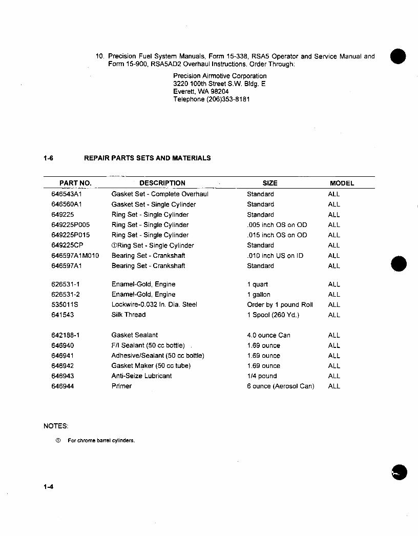
10. Precision Fuel System Manuals, Farm 15-338, RSA5 Operator and Service Manual andForm 15-900, RSA5AD2 Overhaul Instructions. Order Through:.
Precision Airmotive Corporation3220 100th Street S.W. Bldg. EEverett, WA 98204Telephone (206)353-8181
REPAIR PARTS SETS AND MATERIALS1-6
PART NO.
646543A1646560A1649225
649225 P005649225P01 5
64 922SC P
646597A1 M010
646597A1
DESCRIPTION
Gasket Set - Complete OverhaulGasket Set - Single CylinderRing Set - Single CylinderRing Set - Single CylinderRing Set - Single Cylinder(DRing Set - Single CylinderBearing Set - CrankshaftBearing Set - Crankshaft
SIZE
StandardStandardStandard.005 inch OS on OD.015 inch OS on ODStandard.010 inch US on IDStandard
Enamel-Gold, EngineEnamel-Gold, EngineLockwire-0.032 In. Dia. SteelSilk Thread
Gasket SealantF/I Sealant (50 cc bottle)Adhesive/Sealant (50 cc bottle)Gasket Maker (50 cc tube)Anti-Seize LubricantPrimer
1 quart1 gallonOrder by 1 pound Roll1 Spool (260 Yd.)
4.0 ounce Can1.69 ounce1.69 ounce1.69 ounce1/4 pound6 ounce (Aerosol Can)
NOTES:
0 For chrome barrel cylinders.
1-4
MODEL
ALLALLALLALLALLALLALLALL
626531-1626531-253501 uS641543
642188-1646940
646941
646942
646943
646944
ALLALLALL
ALL
ALLALLALLALLALL
ALL

CHAPTER 2EXHAUST SYSTEM
FIGURE PAGE
2-1 Exhaust System ........................ 2-2
2-1

S
FIGU
RE 2.1. EXH
AUST SYSTEM
a
2-2

FIG. & PART 23DECITOINDEX NUMBER123DECITO
654265654264654263654262654261654ii260654400654401654402654403654404654407634305654309AN3-4AMS2 1043-36543066303652202263646564915 1-2654361654362AN5C4A532393NAS1 006-12ANAS1 587-6NAS1O21C6652100642659MS35338-45537750652101641945MS35338-46629275652457649006-8MS20034-4MS20034-5NAS1 587-4MS20500-428653337649197654286654299654285AN5-7A
-49 401506
Tee, Riser .. ..Tee, Riser .......Tee, Riser .......Tee, Riser .......Tee, Riser .......Tee, Riser .......Elbow . .........Elbow ..........Manifold ........Tailpipe .........Tube, Wastegate ....
Clamp .........Tie Rod .........Spacer .........Bolt . . . . . . . . . . .Nut ...........Tie Rod .........Gasket, Exhaust FlangeNut, Exhaust FlangeGasket, TurbochargerTurbocharger ......Braket, Tailpipe .....Clamp, Tailpipe .....Bolt ...........Nut ...........Bolt . . . . . . . . . . .Washer .........Nut ...........Gasket .........Adapter .........Washer, Lock ......Bolt ...........Gasket .........Adapter .........Washer, Lock ......Bolt ...........Gasket, Wastegate ...Wastegate .......Bolt ...........Bolt ...........Washer .........Nut ...........Clamp, Tail Pipe . ...
Bolt, Turbo bracket ...
Bracket, Turbo .....Bracket. Intercooler .Bracket, Turbocharger .Bolt ...........Washer .........
QUANTITY
TSIO-360-RB
6
LTSIO-360-RB
A
2-3
2-1 -1-2-3-4-5-6-7-8-9
-10-11-12-13-14-15-16-17-18-19-20-21-22-23-24-25-26-27-28-29-30-31-32-33-34-35-36-37-38-39-40-41-42-43-44-45-46-47-48
. . . . . . .
QUANTITYFIG. & PARTINDEX NUMBER 1 2 3 DESCRIPTION TSIO-360-RB LTSIO-360-RB
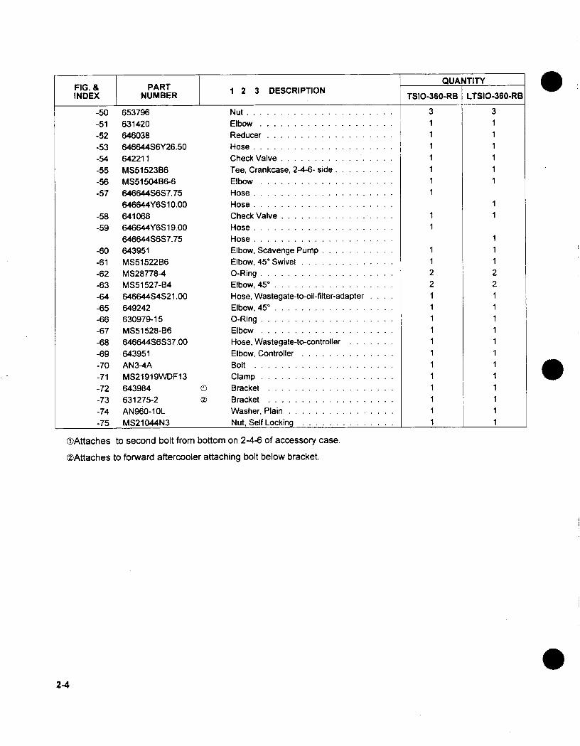
-50 653796 Nut .. . . . . . . . . . .3 3-51 631420 Elbow........... . 1 1-52 646038 Reducer .......... . 1 1-53 646644S6Y26.50 Hose ........... . 1 1-54 642211 Check Valve.......... . 1 1-55 MS51523B36 Tee, Crankcase, 2-4-6- side ...... 1 1-56 MS51504B36-6 Elbow........... . 1 1-57 646644S6S7.75 Hose ........... . 1
646644Y6S10.00 Hose........... . . 1-58 641068 Check Valve ......... .1I 1-59 64.6644Y6S19.00 Hose ........... . 1
646644S6S7.75 Hose........... . . 1-60 643951 Elbow, Scavenge Pump...... .. ... 1 1-61 MS51522B6 Elbow, 450 Swivel........ . ..... 1 1-62 MS28778-4 0-Ring............... ...... 2 2-63 MS51527-B34 Elbow, 450............... ..... 2 2-64 646644S4S21.00 Hose, Wastegate-to-oil-filter-adapter .... 1 1-65 649242 Elbow, 450.............. ...... 1 1-66 630979-15 0-Ring............... ...... 1 1-67 MS51528-B6 Elbow............... ...... 1 1-68 646644S6S37.00 Hose, Wastegate-to-controller ....... 1 1-69 643951 Elbow, Controller........ . ..... 1 1-70 AN3-4A Bolt................ ...... 1 1-71 MS21919WDF13 Clamp............... ...... 1 1-72 643984 0) Bracket............... ..... 1 1-73 631275-2 0Z Bracket............... ..... 1 1-74 AN960-1 OL Washer, Plain............. .... 1 1-75 MS21044N3 Nut, Self Locking ........ . .1... 1
(DAttaches to second bolt from bottom on 2-4-6 of accessory case.
.ZAttaches to forward aftercooler attaching bolt below bracket.
2-4
CHAPTER 3IGNITION SYSTEM
FIGURE PAGE
3-1 Ignition System ... .... .. .. .. 3-2
Note: For further parts information on Slick magnetos and harnesses refer to Section 1 -5, "RelatedPublications," of this manual.
3-1

FIGURE 3-1. IGNITION SYSTEM
FIG. & PART 1 2 3 DESCRIPTION ~~~~QUANTITY
3-1 - 1 649954 Gasket, Magneto.............. 2-2 653292 Magneto, Slick, TSIO-360-RB Only......... 2
653280 Magneto, Slick, LTS10-36G-RB Only......... 2ATTACHING PARTS
-3 630535 Washer, Mag Holding ............ 4-4 MS35338-45 Washer, Lock.............. 4-5 AN315-5R Nut, Plain ................ 4
3-2

FIG. & PART 123DSRPINQATTINDEX NUMBER 123DSRPINQATT
3-1 -6 638172 Bushing, Mag. Drive Coupling.......... 4-7 531178 Retainer, Mag. Coupling ........... 2-8 630525 Gear Assembly, Mag. Drive .......... 2-9 630523 Washer, Thrust.............. 2
-10 633609-18 Bearing, Needle. ........................ 2-11 531177 Sleeve, Magneto Coupling. .................. 2-12 628555-14 Hose, 9.50 Inches Long.................... 1-13 646258 Tee, Mag., Air Reference.................... 1-14 653386 Filter Assembly, Magneto.................... 1-15 628555-22 Hose, 11.50 Inches Long.................... 1-16 628555-26 Hose, Tee To Right Mag..................... 1-17 628555-29 Hose, Tee To Left Mag...................... 1-18 640187 Clamp, Hose.......................... 8-19 649596 Elbow, 900............................. 2-20. 646566 Bushing. ............................ 2-21 654462 Harness, Ignition, Slick ....... .............. 1-22 630049 Sparkplug, Champion RHM38E ................ 12-23 M1553 T Screw, Harness Cap . . . ................... 6-24 M2754 0D Clamp, Single Lead. ...................... 12-25 M2758 0D Clamp, Six Lead. ....................... 2-26 M3169 0 Tie, Cable. ........................... AR-27 No Number Screw. ............................. AR-28 No Number Nut, Self Locking ........................ AR
OJThese part numbers are available from Unison Industries.
3-3

INTENTIONALLY
LEFT
BLANK
3-4

CHAPTER 4
FUEL INJECTION SYSTEM
FIGURE PAGE
4-1 Fuel Injection System ........... 4-2
4-2 Adapter, Fuel Servo, Controller & Overboost Valve ...... 4-5
4-3 Fuel Manifold Valve.......... . ........... 4-7
4-4 Fuel Manifold Valve Fitting Locations.... . ........ 4-8
4-5 Fuel Pump Fitting Locations........ . ......... 4-9
4-1

27
-65
I N1
I'
\\ I
S
FIGURE 4-1. FUEL INJECTION ASSEMBLY
4-2
I
11 ll�\\�
I

FIG. & PART 23DECITOINDEX NUMBER123DECITO
- 649051 A9-3- 649051 A9-2
-1 654475A1-2 649362-3-3 632555-51-4 632554-2-5 626813-6 625327-2-7 537690-8 2500-9 MS21044N3
-10 626634-11 632557-12 633381-8
-13 AN500A10-12-14 MS35338-43-15 AN960-1 0
-16 653333-17 654356-18 2024-19 649493-20 654367
-21 AN960-516-22 MS35338-45-23 537750
-24 654366
-25 AN960-41622139
-26 MS35338-44-27 24835
MS35295-6
-28 654368-29 X12935-30 654378-31 642070-1-32 643511-34-33 MS29513-138
-34 AN500A10-12-35 MS35338-43
-36 640187
Fuel Injection System, TSIO-360-RB Only ............Fuel Injection System, LTSIO-360-RB Only ...........Servo Assembly, Fuel ......................Controller & Lever Assembly ...................Lever ...............................Bushing ..............................Pin, Lever .............................Washer, Wave ..........................Washer ..............................Pin, Cotter ............................Nut, Self-locking .........................Spring ...............................Rod End .............................Rod & Link Assembly ......................
ATTACHING PARTSScrew , Fillister . . . . . . . . . . . . . . . . . . . . . . . . . .Washer, Lock ...........................Washer. Plain .....................
Gasket, Controller ......................Manifold Assembly ......................Plug, .125 ...........................Elbow .............................G asket . ... . . . . . . . . . . . . . . . . . . . . . . . .
ATTACHING PARTSW asher, Plain . .. . . . . . . . . . . . . . . . . . . . . .Washer, Lock .........................Screw, .31-18 .........................
Gasket ............................
ATTACHING PARTSW asher, Plain, Upper.....................Washer, Plain, Lower .....................Washer, Lock .........................Screw, Cap, Upper ......................Screw, Cap, Lower ......................
Adapter Assembly, Air Throttle ................Connector, Flex .......................Fitting, Mag. Pressure ....................Fitting, Straight ........................Valve, Overboost .......................Seal, "O"Ring .. . . . . . . .. . . . . . . . . . . .. . . .
ATTACHING PARTSScrew, Fillister, 10-24 ....................Washer, Lock .........................
Clamp, Hose .........................
4-1
QUANTITY
1
1RF
RE
RERE
1
22422
12111
4
4
3
4-3

FIG. & PART 23DECITOINDEX NUMBER123DECITO
-37-38-39-40-41-42-43-44-45-46-47-48-49-50-51-52-53-54-55-56-57-58
-59-60-61
628555-30628555-3965437065-4369633485646644S4S6.50MS51 501 B34646644S4S32.00MS51 527B3464644S4Y1 5.75628437652432-4Al654451654452654453654454654455654456628556640612630979-9633608-1 3B
AN960-51 6MS35338-45AN31 5-5R
-62 653747-63 630265-64 654351-2Al
654351-1lAl-65 MS21919WF27-66 MS21919WF5-67 AN960-1lOL-68 MS21044N3-69 AN3-4A-70 640501-71 MS3367-2-72 646644S6S37.00-73 646644S651 3.50
Hose, Fuel Pump Deck Pressure ............Hose, Filter To Fitting ..................Tube Assembly, Air Reference, 2-4-6 Side .......Tube Assembly, Air Reference, 1-3-5 Side .......Tube Assembly, Air Manifold ..............Hose, Nipple To F/I Servo ................Nipple-Tube, F uel Pump To Metering Unit .......Hose, Fuel Pump To Nipple ...............Elbow, 9Q0 Degree ....................Hose, F/I Servo To Manifold Valve ...........Elbow, Fitting 90' Degree ................Manifold Valve Assembly, Fuel .............Tube Bend Assembly, lnj. Line, Cyl. #1 .........Tube Bend Assembly, Inj. Line. Cyl. #2 .........Tube Bend Assembly, Inj. Line, Cyl. #3 .........Tube Bend Assembly, lnj. Line, Cyl. #4 .........Tube Bend Assembly, Inj. Line, Cyl. #5 .........Tube Bend Assembly, Inj. Line, Cyl. #6 .........Washer,-31 L.D......................Washer, .50 O.D. x .31 l. D................'O"Ring .........................
g) Nozzle, Fuel . . . . . . . . . . . . . . . . . . . . . . .
ATTACHING PARTSW asher, Plain ... . . . . . . . . . . . . . . . . . . .Washer, Lock ......................Nut, Plain ........................
Gasket, Fuel Pump ...................Shaft, Fuel Pump Drive .................Pump Assembly With Fittings, Fuel, TSIO-36G-RB OnlyPump Assembly With Fittings, Fuel, LTSIO-360-RB OnlyClamp, Loop, Cushioned ................Clamp, Loop, Cushioned ................Washer, Flat .......................Nut, Self Locking 10.32 .................Bolt ............................S leeve . . . . . . . . . . . . . . . . . . . . . . . . . .
Strap, Tie Down .. . .. . . .. . . . . . . . . . . . .Hose, Controller to Wastegate .............Hose, Controller to Accessory Case ..........
TOrder nozzle by number/letter stamped on hex of nozzle.
4-4
QUANTITY
1112
1
111
111
6612
6
444
111
666666
2
1

11
1314
15
16
VIEW A-A
FIGURE 4-2. ADAPTER, FUEL SERVO, CONTROLLER & OVERBOOST VALVE
FIG. & PART 123DSRPINQATTINDEX NUMBER 123DSRPINQATT
4-2 -1 654368 Adapter Assembly, Air Throttle ......... RF-2 654475A1 Servo Assembly, Fuel............ RF-3 654366 Gasket................ RF
ATTACHING PARTS RF-4 22139 Washer, Plain, Upper............ RF
AN960-416 Washer, Plain, Lower............ RF-5 MS35338-44 Washer, Lock.............. RF-6 MS35295-6 Screw, Cap, Upper............. RF
24835 Screw, Cap, Lower............. RF
(continued on next page)4-5
4, 5,
AIRFLOW

4-6
FIG. & PARTINDEX NUMBER 1 2 3 DESCRIPTION QUANTITY
4-2 (cont'd)-7 640655-28 Controller & Lever Assembly......... RF-8 643951 Fitting, Bottom, Controller To Acc. Case, Return . . .. 1-9 643951 Fitting, Top, Controller To Wastegate............. 1
-10 537690 Washer .............. .............. RF-11 625327-2 Washer, Wave ............ ............ RF-12 2500 Pin, Coffer .............. ............. RF-13 633381-8 Rod & Link Assembly ........... .......... RF-14 626634 Spring ............... .............. RF-15 632557 Rod End .............. .............. RF-16 MS21044N3 Nut, Self-locking ............ ............ RF-17 653333 Gasket, Controller ....................... RF
ATTACHING PARTS RF-18 AN500A10-12 Screw, Fillister ......................... .RE-19 MS35338-43 Washer, Lock ............. ............ RF-20 AN960-1 0 Washer, Plain ............. ............ RF-21 535011 Lockwire .............. .............. AR
.... ~~~~~~~RF-22 64351 1-34 Valve, Overboost ....................... .RE-23 MS29513-138 Seal, "O"Ring ......................... RE
ATTACHING PARTS RE-24 AN960-1 0 Washer, Plain ......................... RF-25 MS35338-43 Washer, Lock ......................... .RE-26 AN500A10-12 Screw, Fillister, 10-24 ...................... RE-27 535011 Lockwire ................ . .......... AR

FIGURE 4-3. FUEL MANIFOLD VALVE
FIG. & PART 1 ECITINQATTINDEX NUMBER 1 ECITINQATT
4-3 652432-4A1 T cZ' Fuel Manifold Valve Assembly......... . RF
-1 652431 (I Body, Fuel Manifold Valve........... 1
-2 627123 Plate ... . . . . . . .. . . . . . .1
-3 626536A2 Diaphragm............... 1
-4 626556 Plate ... . . . . . . .. . . . . . .1
-5 AN315-4R Nut................. 1
-6 627378 Spring................ 1
-7 634325 Cover ................ 1
-8 654498 Bracket ................ 1ATTACHING PARTS
-9 AN503-8-12 Screw .... ... . . . . . . . . ... 4
-10 MS35338-42 Washer, Lock.............. 4
-11 AN960-8 Washer................ 4
-12 535011 Wire, Lock . I......AR
©NOTES:For complete parts breakdown of manifold valve assemblies see TCM Form X30593A.
Bracket and fittings included.652431 Plunger and body are matched set.
3
4
4-7
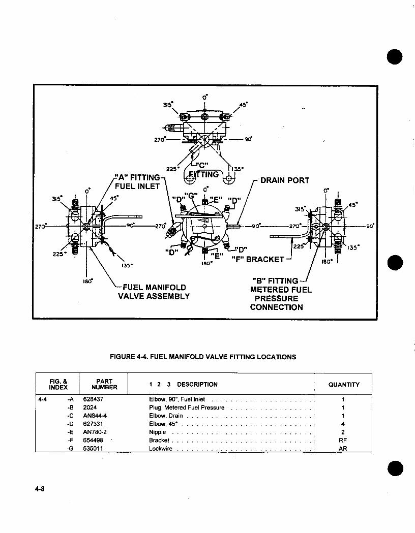
FIGURE 4-4. FUEL MANIFOLD VALVE FITTING LOCATIONS
4-8
FIG. & PART 123DSRPINQATTINDEX NUMBER 123DSRPINQATT
4-4 -A 628437 Elbow, 900, Fuel Inlet........... 1-B 2024 Plug, Metered Fuel Pressure......... 1-C AN844-4 Elbow, Drain.............. 1-D 627331 Elbow, 45 ............... 4-E AN780-2 Nipple................ 2-F 654.498 Bracket. ............................ RF-G 535011 Lockwire ............................ AR
OS A E
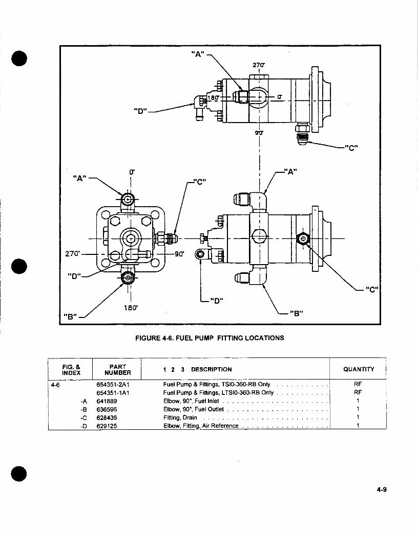
FIGURE 4-6. FUEL PUMP FITTING LOCATIONS
4-9
277
270'
goat
goenie
FIG. & PART 123DSRPINQATTINDEX NUMBER 123DSRPINQATT
4-6 654351 -2A1 Fuel Pump & Fittings, TS10-36G-RB Only . ..... RF654351-lAl Fuel Pump & Fillings, LTSIO-360-RB Only...... . RE
-A 641889 Elbow, 90', Fuel Inlet ............ 1-B 636596 Elbow, 900, Fuel Outlet............ 1-C 628436 Fitting, Drain ............... 1-D 629125 Elbow, Fitting, Air Reference .. . . . . . . . .1
16W
i

INTENTIONALLY
LEFT
BLANK
4-10

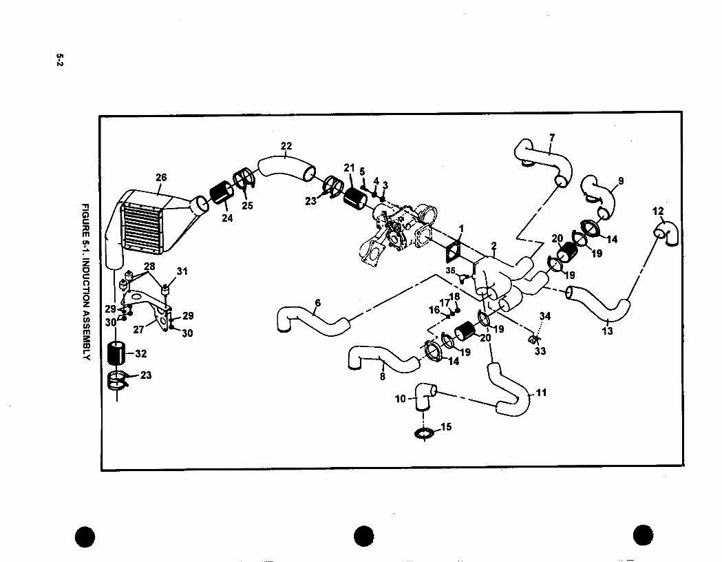
CHAPTER 5INDUCTION SYSTEM
FIGURE PAGE
5-1 Induction System (TSIO-360-RB) .. ....... 5-2
5-1
LO
0
V)
c--
D00
04co
toN4
FIGU
RE 5-1. IN
DU
CTIO
N A
SS
EM
BLY
5-2

O I -1I bb43j (-2 649256.4
-3 AN960-516-4 MS35338-45-5 537750
-6 649261-7 6.49262-8 649263-9 649264
-10 654289-1-11 654289-2-12 649266-1-13 649266-2-14 6.46933-15 654227
-16 AN960-516L-17 MS35338-45-18 AN315-5R
-19 AN737TW74-20 642917-16-21 642917-15-22 654298-23 629163-5-24 642917-6-25 629163-7-26 654295-27 654299-28 654363-29 MS35338-44-30 23890-31 646941-32 64291 7-2-33 646416-34 648439-35 649493
$ Gasket, Intake ManifoldManifold And Fitting Assembly ..........
ATTACHING PARTSWasher, Plain ... .......Washer, Lock .... ......Screw, .31-18...........
Tube, Induction, Cyl. #1 .............Tube, Induction, Cyl. #2 .............Tube, Induction, Cyl. #3 .............Tube, Induction, Cyl. #4 .............Tube, Induction, Cyl. #5 .............Tube, Induction, Cyl. #5 .............Tube, Induction, Cyl. #6 .............Tube, Induction, Cyl. #6 .............Flange, Induction Tube ..............Gasket, Intake Manifold ..............
ATTACHING PARTSW asher, Plain . . .. . . .. . . .. . . .. . . .Washer, Lock ...................Nut, Plain, .31-24 .................
Clamp, 1.75 I.D., Hose ..............Hose, Intake ...................Hose, Intake, 2.25 L.D...............Tube, Induction, Aftercooler ...........Clamp. Assembly .................Hose, Intake, 2.25 L.D...............Clamp, Assembly .................Aftercooler ....................Bracket, Aftercooler ................Mount, Vibration Damper .............Washer, Lock ...................Nut, Plain, .25-20 .................Sealant, Adhesive ................Hose, Aftercooler To Turbo ............Bumper, Rubber .................Adhesive .....................Elbow .......................
FIG. & PARTINDEX NUMBER QUANTITY
1
4
44
1
1
1
66
121212
168
2
12
1
1
Ref.
5.3
-- - - -1
. . . . . .

INTENTIONALLY
LEFT
BLAN K
5-4
CHAPTER 6
AIR CONDITIONING SYSTEM
FIGURE PAGE
6-1 Compressor Brackets, Starter And Starter AdapterAssembly (TSIO-360-RB) . 6-2
6-1

FIGURE 6.1. FREON COMPRESSOR, STARTER AND STARTER
ADAPTER ASSEMBLY (TSIO-360-RB)
6-2
FIG. & PART 23DECITOINDEX NUMBER 123DECITO
-1 649988653074A23
EQ6939
-2 653074
-3 402127
-4 401861
-5 401834
-6 627882
-7 641368
-8 643303-9 X13041
-10 MS16626-3078-11 502287-3-12 630680-13 653696-14 643109-15 501867-16 633845-17 653709-18 AN123902
-19 633630
-20 633632
-21 633629
-22 65-4814
-23 633609-7
-24 20522
-25 22537
-26 535011
-27 633342-6
-28 MS9021-038-29 646275-1-30 539058-31 2441-32 633687
640756A7-33 640756
-34 402941
-35-36
-37-38
-39
-40
-41-42
-43
-44-45
64291025102
632409
642912
630773401843
401870643951
MS511522B36642930
MS20066-98-46 640684
Gasket, Adapter-To-Accessory Case .....Adapter Assembly, Starter ...........Compressor Mounting Kit ............Housing Adapter ................Stud. 3/8 x 1 17/32 inch long, 1.00 extensionStud, 3/8 x 1 3/4 inch long, 1.22 extension...Stud, 5/16 x 18, 1.30 extension .........Dowel, .51 inch long, .17 extension ......Bearing, Needle .................Shaft, Starter Worm ...............Bearing, Ball . . . . . . . . . . . . . . . . . .Ring, Retaining .................Ring, Retaining .................Bearing, Roller .................Gear, Worm Wheel ...............Spring, Clutch ..................Washer, Tab ..................Screw ......................Shaftgear, Starter ................0-Ring .....................Gear, Scavenge Pump .............Bushing, Gear .................Gear, Scavenge Pump .............Cover Scavenge Pump .............Bearing Needle .................Washer .....................Screw ......................Lockwire ....................Key, Woodruff ..................0-Ring .....................Motor Starter ..................Washer .....................Nut .......................Bushing .....................Adapter, Scavenge pump and Accessory DriveAdapter Housing Assembly ...........Plug .......................S eal, O il . .. . . . . . . . . . . . . . . . . . .Seal, Oil .....................Bushing .....................Bushing .....................Dowel ......................Stud .......................Stud . . . . . . . . . . . . . . . . . . . . . . .
Elbow, 900.
Elbow, 450..
Shaft, Gear ...................Key, Square ...................Gear. Bevel.----------
6-1
QUANTITYTSIO-360-RB
11
AR1
111111111
1111166AR1
1
1112
1R1112
4
811111
6-3
---------------

06-4
FIG. & PART QATTINDEX NME 1 2 3 DESCRIPTION QUANTITY-R
6-1 -47 522247-3 Ring, Retaining.............. 1-48 640802 Gear, Bevel.............. 1-49 640809 Gear, Bevel.............. 1-50 653487 Gasket, Cover .............. 2-51. 640380 Cover, Accessory. ....................... 2-52 20522 Washer, Plain.......................... 8-53 MS35338-44 Washer, Lock.......................... 8-54 AN315-4R Nut, Plain............................. 8-55 633609-9 Bearing. ............................. 2-56 534938 Seal, Oil............................. 1-57 640815 Housing, gearshaft, accessory drive............... 1-58 641893 Sheave, accessory drive..................... 1-59 20202 Washer, Sheave......................... 1-60 640816 Bolt................................ 1-61 641543 Thread, Silk. .......................... AR-62 642290 Bracket, Freon Compressor................... 1-63 653328 Bracket, Freon Compressor................... 1-64 654374 Eye, Engine Lifting, Rear.................... 1-65 AN960PD416L Washer.............................. 8-66 AN315-4R Nut. ............................... 4-67 MS9882-10 Nut. ............................... 4-68 AN960-516 Washer, Plain. ......................... 10-69 MS35338-45 Washer, Lock. ......................... 7-70 MS20074-05-37 Bolt................................ 1-71 630966-5.75 Bolt................................ 1-72 AN315-5R Nut. ............................... 2-73 627433 Bolt................................ 1-74 628056 Bolt . . . . . . . . . . . . . . . . . . . . . . . . . . . . . . . . .1

CHAPTER 7
.ELECTRICAL CHARGING SYSTEM
FIGURE PAGE
7-1 Alternator Assembly .. .......... 7-2
7-1

FIGURE 7-1. ALTERNATOR ASSEMBLY
7-2

7-3
FIG. & PART QATTINDEX NUMBER 1 2 3 DESCRIPTION
7-1 - 1 654200 Alternator . .. . . . . . . . . . . . .
-2 654517-1 Belt, Alternator Dnive- 38.00.................. 1-3 65-4358 Bracket, Alternator Mount.................... 1-4 AN7-46A Bolt............................... 1-5 AN960-716 Washer. ............................ 2-6 AN960-716L Shim. ............................. 2-7 MS21045-7 Nut............................... 1-8 654288 Bracket, Alternator Adjusting.................. 1-9 MS35338-46 Washer, Lock.......................... 1
-10 649288 Washer............................. 1-11 MS20074-06-07 Bolt............................... 1
-12 AN960-616 Washer............................. 1-13 MS21044N6 Nut............................... 1-14 MS90726-61 Bolt............................... 1

INTENTIONALLY
LEFT
BLAN K
7-4

CHAPTER 8
STARTING SYSTEM
FIGURE PAGE
8-1 Optional Starter Adapter Assembly (TSIO-360-RB). ..... 8-2
8-2 Starter Adapter Assembly (LTSIO-360-RB) .......... 8-4
8-1

45.
7.
21i
13 1 19
23-
355,
I
FIGURE 8-1. OPTIONAL STARTER ADAPTER ASSEMBLY (TSIO-360-RB)
FIG. & PART 123DSRPINQUANTITYINDEX NUMBER 123DSRPINTSIO-360-RB
8-1 -1 649988 Gasket, Adapter-To-Accessory Case....... 1653074A13 Adapter Assembly, Starter.......... 1
-2 653074 Housing Adapter . ... . . . . . . . ... .1
-3 402127 Stud, 318 x 1 17/32 inch long, 1'.00 extension..... 1-4 401861 Stud, 3/8 x 1 3/4 inch long, 1.22......... 1
8-2NOTE... .See Figure 6-1. For TSIO-360-RB standard equipment starter adapter.
-ru
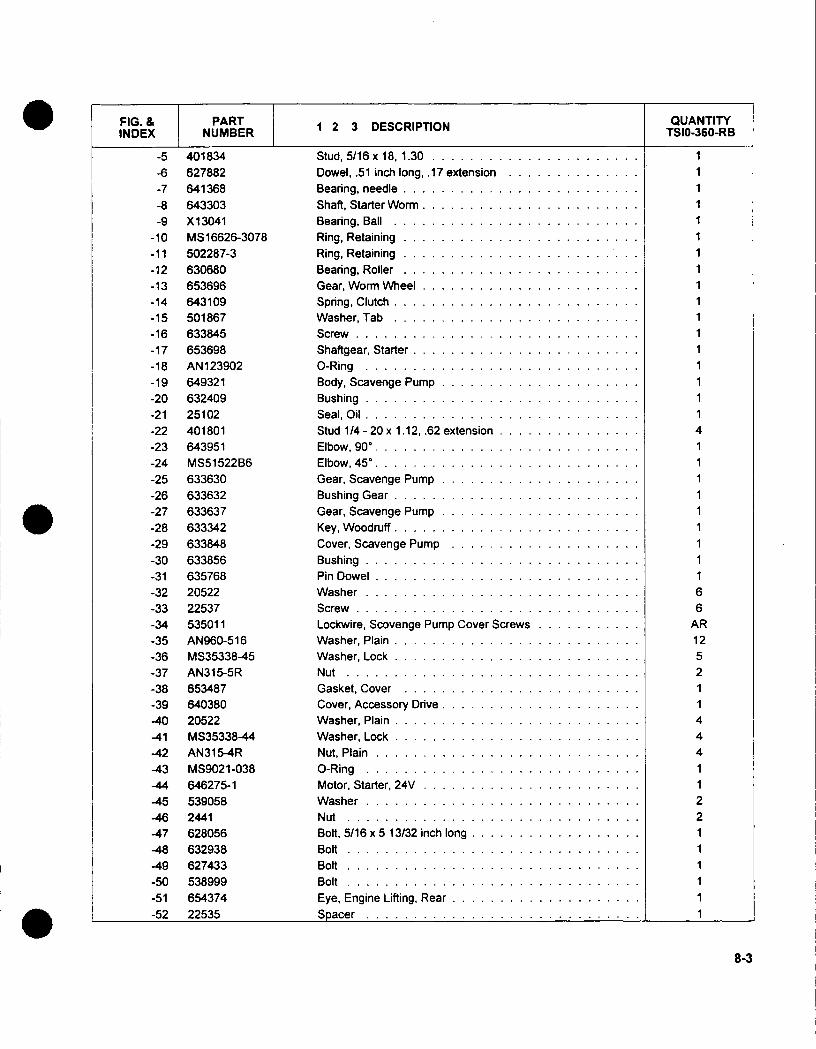
FIG. & PART 23DECITOINDEX NUMBER123DECITO
-5-6
401834
627882
-7 6.41368-8 643303-9 X 13041
-10 MS16626-3078-11 502287-3-12 630680-13 653696-14 643109-15 501867-16 633845-17 653698
-18 AN123902-19 649321
-20 632409-21 25102-22 401801
-23 643951
-24 MS51522B36
-25 633630
-26 633632
-27 633637
-28 633342
-29 633848
-30 633856-31 635768
-32 20522
-33 22537
-34 535011
-35 AN960-516-36 MS35338-45-37 AN315-5R-38 653487-39 640380
-40 20522
-41 MS35338-44-42 AN315-4R-43 MS9021-038
-44 646275-1
-45 539058
-46 2441-47 628056
-48 632938
-49 627433
-50 538999-51 654374
-52 22535
Stud, 5/16 x 18, 1.30 ......................Dowel, .51 inch long, .1 7 extension ..............Bearing, needle . . . . . . . . . . . . . . . . . . . . . .. . .Shaft, Starter W orm .......................Bearing, Ball . . . . . . . . . . . . . . . . . . . . . . . . . .Ring, Retaining .........................Ring, Retaining ................Bearing, Roller .........................Gear, Worm Wheel .......................Spring, Clutch ..........................Washer, Tab ..........................Screw ..............................Shaftgear, Starter ........................0 -R ing . . . . . . . . . . . . . . . . . . . . . . . . . . . . .Body, Scavenge Pump .....................B ushing . . . . . . . . . . . . . . . . . . . . . . . . . . . . .Seal, Oil .............................Stud 114 -20 x 1.12, .62 extension ...............Elbow, 900..Elbow, 450.
Gear, Scavenge Pump .....................Bushing G ear . . . . ... . . . . . . . . . . . . . . . . . . .
Gear, Scavenge Pump .....................Key, W oodruff .... .... ...... .. ... . . .... .Cover, Scavenge Pump ....................Bushing .............................Pin Dowel ............................Washer .............................Screw ..............................Lockwire, Scovenge Pump Cover Screws...........Washer, Plain ..........................Washer, Lock ..........................Nut ...............................Gasket, Cover .........................Cover, Accessory Drive .....................Washer, Plain ..........................Washer, Lock ..........................Nut, Plain ............................0-Ring .............................Motor, Starter, 24V .......................Washer .............................Nut ...............................Bolt, 5/16 x 5 13/32 inch long ..................Bolt ...............................Bolt ...............................Bolt ...............................Eye, Engine Lifting, Rear ....................S oacer . . . . . . . . . . . . . . . . . . . . . . . . . . . . .
QUANTITYTSIO-360-RB
1
1
1
1111
1111
1
1
11114
111
1
1
1
1116
6AR1252
114
4
4
1122111111
8-3

45-,
46
49
115
31'
54
FIGURE 8-2. STARTER ADAPTER ASSEMBLY (LTSIO-360-RB)
FIG. & PART 123DSRPINQUANTITYINDEX NUMBER 123DSRPINLTS10360
8-2 - 1 649988 Gasket Adapter-To-Accessory Case....... 1646220A1 5 Adapter Assembly, Starter.......... 1
-2 646220 Housing, Adapter............ 1-3 402127 Stud, 3/8 x 1 17/32 inch long, 1.00 extension..... 1-4 401861 Stud, 3/8 x 1 3/4 inch long, 1.22 extension...... 1-5 402151 Stud, 5/16 x18............. 1-6 627826 Dowel, .51 inch long, .1 7 extension.............. 1-7 641368 Bearing, Needle........................ 1-8 631253 Shaft, Starter Worm...................... 1-9 MS35756-8 Key, Woodruff . ........................ 1
8-4

FIG. & PART 23DECITOINDEX NUMBER123DECITO
Gear, Starter Worm ........Bushing, Gear ..........Pin ................Bearing, Ball ...........Ring, Retaining ..........Bearing, Roller ..........Gear, Worm Wheel ........Spring, Clutch ...........Washer, Tab ...........Screw ...............Shaftgear, Starter .........0-Ring . . . . . . . . . . . . . .Body, Scavenge Pump......Bushing ..............Seal, Oil ..............Stud, 1/4 20 x 1.12,-62 extensionElbow ...............Gear, Scavenge Pump ......Bushing, Gear ..........Gear, Scavenge Pump ......Key, Woodruff ...........Cover, Scavenge Pump .....Bushing Cover ..........Pin, Dowel ............Washer ..............Screw ...............Lockwire .............Washer, Plain ...........Washer, Lock ...........Nut ................Gasket, Accessory Drive.....Cover ...............Washer, Plain ...........Washer, Lock ...........Nut, Plain .............0-Ring ..............Motor, Starter, 24 Volt ......Washer ..............Nut ................Bolt, 5/16 x 5 13/32 inch long .Washer, Plain ...........Washer, Lock ...........Bolt ................Bolt ................Bolt ................Eye, Engine Lifting, Rear .....Snacrr
8-2 -10-11-12-13-14-15-16-17-18-19-20-21-22-23-24-25-26-27-28-29-30-31-32-33-34-35-36-37-38-39-40-41-42-43-44-45-46-47-48-49-50-51-5253
-54-55-56
539793628149528155-1Xl1 3041502287-3630680653708643110501867633845653698AN1 23902641103632409251024018706439516336306336326336376333426410786338566357682052222537535011AN960-51 6MS35338-45AN31 5-5R65348764038020522MS35338-44AN315-4RMS902 1-038646275-15390582441628056AN960-516MS35338-45630966-5.7562743353899964693822535
QUANTITYLTS10360
11111111111111141111111166
AR1111
4441122111
411111
8-5
........................

INTENTIONALLY
LEFT
BLANK
8-6

CHAPTER 9
ACCESSORY CASE
FIGURE PAGE
9-1 Accessory Case Studding Assembly. . ........... 9-2
9-2 Accessory Case Attaching Parts (TSIO-360-RB) . . 9-4
9-3 Accessory Case Attaching Parts (LTSIO-360-RB) ....... 9-6
9-1

FIGURE 9-1. ACCESSORY CASE STUDDING ASSEMBLY
9-2

9-3
FIG. & PART QUANTITYINDEX NUMBER ~~~~~~~~~~~~TSIO-360-RB LTSI0-360-RB
9-1 6-42634-2A1 Accessory Case, Stud Assembly .1....643829A24 Accessory Case, Stud Assembly ...... 1
-1 642625 Neck Assembly, Oil Filter. ............. 1 1-2 MS122162 Helical Coil, .3152-18. ............... 2 2-3 MS122122 Helical Coil, .3125-18 .04,.08 Below Flange . . .. 1 1-4 402044 Stud, .3125-24, .81 extension. ........... 3 3-5 401971 Stud, .3125-24, 1.00 extension. .......... 3 3-6 401885 Stud, .3125-24. .70 extension. ........... 4 4-7 629518-3 Plug .1............. 1-8 AN 125970 Stud, .250-28, .59 extension. ............ 3 3-9 532432 Plug. ........................ 2 2
-10 MS35769-11 Gasket, Plug. .................... 2 2-11 535011 Lockwire. ...................... AR AR

36
7
I w
FIGURE 9-2. ACCESSORY CASE ATTACHING PARTS (TSIO-360-RB)
0s9-4
I
- � -Ah&�

FIG. & PART 23DECITOINDEX NUMBER123DECITO
-1 B5,3418
-2 642634-2A2-3 642635
MS35769-1 1532432535011MS51 500136-6631687627458MS35769-1 8641074649215Xl1473632762AN315C6R649980632475AN960-416LMS35338-44AN315-4RMS35769-21653658653748MS9021-028653539-1653489649242649922AN960-51 6MS35338-45AN31 5-5RAN 960-516MS35338-45AN31 5-SR537961AN5-32A642892654715
-39 646644S6S13.50
Gasket, Crankcase Cover .............Accessory Case Assembly .Tube, Oil Filler Neck ................Gasket, Plug ....................Plug ........................Lockwire ......................Fitting, Straight ...................Plunger, Oil Pressure Relief Valve.Spring ........................Gasket ........................Cap ..........................Screw, Adjusting ...................Washer ........................N ut . .. . . . . . . . . . . . . . . . . . . . . . . .
Nut (RIH) .......................Gasket, Cover ....................Cover .........................Washer ........................Washer, Lock ....................Nut ..........................Gasket, Screen ...................Screen, Scavenge Oil ................Gasket, Oil Filter Adapter ..............0-Ring ........................Adapter, Oil Filter ..................Stud .........................Fitting, Orifice ....................Filter Assembly, Oil .................Washer, Plain ....................Washer, Lock ....................Nut ..........................Washer, Plain ....................Washer, Lock ....................Nut . .........................Screw . .......................B o lt . . . . . . . . . . . . . . . . . . . . . . . . . .Gasket, Oil Filler Cap ................Cap, Oil Filler . . . . . . . . . . . . . . . . . . . .Hose, Controller to Accessory Case.
QUANTITYTSIO-360-RB
-4-5-6-7-8-9
-10-11-12-13-14-15-16-17-18-19-20-21-22-23-24-25-26-27-28-29-30-31-32-33-34-35-36-37-38
111
22
AR1
1
11
1
333
333121274
1
RF
9-5
. . .
V-Z

FIGURE 9-3. ACCESSORY CASE ATTACHING PARTS (LTSIO-360-RB)
9-6
I

FIG. & PARTINDEX NUMBER 1 2 3 DESCRIPTION QUANTITY
LTSIO-360-RB9-3 -1 653418
-2 643829A25
-3 642635
-4 MS35769-11-5 532432-8 535011-7 MS51500B6-6-8 631687
-9 627458-10 MS35769-18-11 641074
-12 649215
-13 X1473-14 632762-15 AN315C6L
-16 649980
-17 632475
-18 AN960-416L
-19 MS35338-44
-20 AN315-4R-21 MS35769-21-22 653658
-23 653748-24 MS9021-028
-25 653539-1
-26 653489-27 649242
-28 649922-29 AN960-516-30 MS35338-45-31 AN31 5-5R-32 AN960-516-33 MS35338-45-34 AN315-5R
-35 537961
-36 AN5-32A-37 642892
-38 654715
-39 646644S6S13.50
Gasket, Crankcase Cover .............Accessory Case Assembly ............Tube, Oil Filler Neck ................Gasket, Plug ....................Plug .........................Lockwire ......................Fitting, Straight ....................Plunger, Oil Pressure Relief Valve.Spring ........................Gasket ........................Cap ..........................Screw, Adjusting ...................Washer ........................Nut ..........................Nut (R/H) .......................Gasket, Cover ....................Cover .........................Washer ........................Washer, Lock ....................Nut ..........................Gasket, Screen ...................Screen, Scavenge Oil ................Gasket, Oil Filter Adapter ..............0-Ring ........................Adapter, Oil Filter ..................Stud .........................Fitting, Orifice ....................Filter Assembly, Oil .................Washer, Plain ....................Washer, Lock ....................Nut ..........................Washer, Plain ....................Washer, Lock ....................Nut . .........................Screw . . . . . . . . . . . . . . . . . . . . . . . .B olt . . . . . . . . . . . . . . . . . . . . . . . . . .Gasket, Oil Filler Cap ................Cap, Oil Filler ....................Hose. Controller to Accessorv Case.
111
2
2AR
1
1
1
1
1
1
I
1
11
1
3
3
3
111
111
1
13
3
312
12
74
1
11
PP
9-7

INTENTIONALLY
.LEFT
BLANK
9-8

CHAPTERI10
LUBRICATION SYSTEM
FIGURE PAGE
10-1 Oil Pump Assembly ............ 10-2
10-2 Oil Cooler Assembly ............ 10-3
10-3 Oil Sump Assembly ............ 10-4
10-1

I
2
7
4
FIGURE 10-1. OIL PUMP ASSEMBLY
(D Trim bent end to insure running clearance.
10-2
QUANTITYINDEX. NUMBER 123DSRPINTSIO-360-RB LTSIO-360-RB
10-1 -1 627762 Bushing, Split .72 ILD . . . . . .. 1 1-2 653814 Gear, Oil Pump. . . . . . ... 1 1-3 633611 Bushing............ 1 1-4 633610 Gear, Oil Pump Driven .. . . . . .1 1-5 633612 Cover, Oil Pump ...... .. .. 1 1-6 36025 ®D Washer, Tab Lock .. . . . . . .4 4-7 626487 Bolt, Oil Pump Cover . . . . . .. 4 4-8 654210 Gear, Oil Pump Drive (R/H)..... 1-8 654210-1 Gear, Oil Pump Drive (UH) 1.. . .
12 -
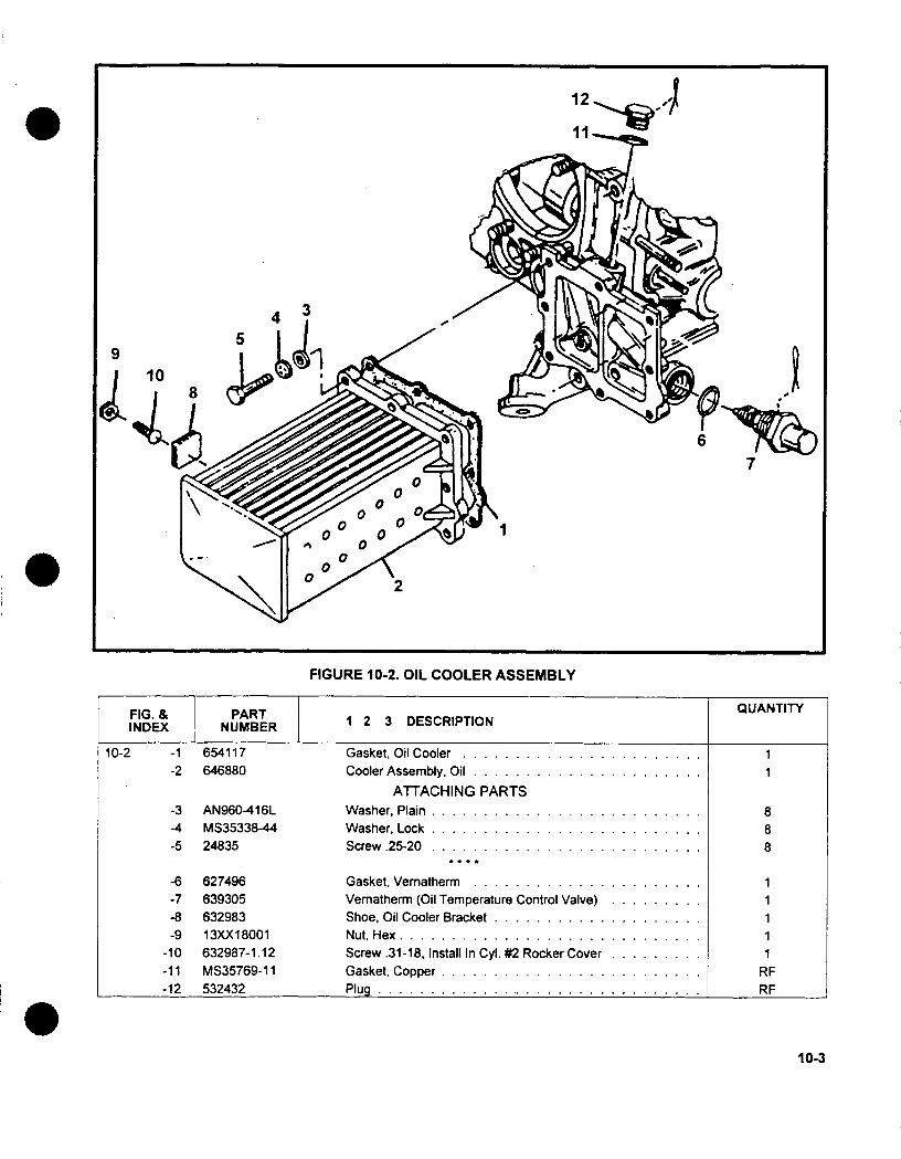
FIGURE 10-2. OIL COOLER ASSEMBLY
FIG. & PART QUANTITYINDEX NUMBER 1 2 3 DESCRIPTION
10-2 -1 654117 Gasket, Oil Cooler............ 1-2 646880 Cooler Assembly, Oil............ 1
ATTACHING PARTS-3 AN960-416L Washer, Plain .. . . . . . . . . . . . .8-4 MS35338-44 Washer, Lock.............. 8-5 24835 Screw .25-20.............. 8
-6 627496 Gasket, Vemnatherm............ 1-7 639305 Vemnatherm (Oil Temperature Control Valve) . . . .. 1-8 632983 Shoe, Oil Cooler Bracket........... 1-9 13XX18001 Nut, Hex............................. 1
-10 632987-1.12 Screw .31-18, InstallIn Cyl. #2 Rocker Cover .1.....-11 MS35769-1 1 Gasket, Copper......................... RE-12 532432 Plug............................... RE
10-3
7
I
9

FIGURE 10-3. OIL SUMP ASSEMBLY
10-4
FIG. & PART QATTINDEX NUMBER 1 2 3 DESCRIPTION
10-3 -1 649972 Gasket, Oil Sump............ 1-2 629571 Al Sump, Oil . . . . . . . . . . . . .. 1-3 MS 122122 Helical Coil.5-4 20522 Washer ............... 14-5 MS35338-44 Washer, Lock ............. 14-6 AN315-5R Nut, Plain............... 14-7 636376 Plug, Magnetic, Drain........... 1-8 MS35769-1 1 Gasket, Plug............. 1-9 626264 Tube, Oil Suction............. 1

CHAPTER 11
CYLINDERS AND PISTONS
FIGURE PAGE
11-1 Baffle Assembly..............11-2
11-2 Cylinder Assembly ....................... 11-4
11-3 Piston And Rings ........................ 11-7
11-1

1
FIGURE 11-1. BAFFLE ASSEMBLY
11-2
I

11-3
FIG. & PART 123DSRPINQATTINDEX NUMBER 123DSRPINQATT
111 -1 646812 Spacer ................ 4-2 641166 Support, Baffle, Outer ............ 4-3 MS35207-263 Screw................. 4-4 641341 Support, Baffle Inner............. 4-5 AN3-75A Bolt, No. 10-32 x 7-13/16 Lg. .......... 4-6 649037 Baffle Assy., No. 2 Cyl....................... 1-7 649035 Baffle Assy., No. 1 & 6 Cyl. .................... 2-8 641346 Baffle Fastener. ......................... 4-9 641347 Spring, Compression. ...................... 4
-10 649036 Baffle Assy., No. 5 Cyl....................... 1-11 649034 Baffle Assy., No. 3 & 5 Cyl. .................... 2-12 641330 Baffle Assy., Intercyl. ...................... 2-13 641322 Baffle Assy., Intercyl. ...................... 2-14 AN960-1 OL Washer, Plain. .......................... 4

47 e46 1
45% 44/-~-
2.q
14
7
28
38
SEE FIGURE 10-2.- j.:
FIGURE 11-2. CYLINDER ASSEMBLY
FIG. & PART 123DSRPINQATTINDEX NUMBER 123DSRPINQATT
11-2 -1 21477 Packing, Cylinder Base............ 6-2 654702A1 Cylinder & Valve Assembly........... 6
653451TC-A4 Cylinder & Valve Assembly, Chrome ........ Opt.654702A3 Cylinder Kit, Loaded............. Opt.
653451TC-A5 Cylinder Kit, Loaded, Chrome .......... Opt.654702A1BP Cylinder Kit, Loaded, Balanced Piston ........ Opt.653451TC-A5BP Cylinder Kit, Loaded, Balanced Piston, Chrome. ........ Opt.
-3 530112 Insert, Spark Plug Thread. ................... 12-4 646681 Guide, Valve, Intake. ...................... 6-5 646678 Seal, Intake Valve Guide. .................... 6-6 653214 Guide, Valve, Exhaust. ..................... 6
11-4
O�

FIG. & PART 23DECITOINDEX NUMBER123DECITO
-7 402044402044P003402044P007402044P01 2
-8 401852401 852P003401 852P007401 852P01 2
-9 635959635959P005635959P01 0635959P01 5
635959P020
635959P030
-10 646929
646929P005646929P01 0
646929P01 5
646929P020
646929P030
-11 654067
-12 646459
-13 625957
-14 625958
-15 24026
-16 631654-17 627731
-18 632068
-19 639648
-20 627693
-21 21007
-22 653189
-23 653825
-24 631996
-25 501867
-26 646605
-27-28-29-30
-31
-32-33-34-35-36-37
653195627593633019AN960-416
MS35338-44
649353-.62AN500D416-20
630365
22022
632141630286
1-3A 632317
Stud, 5/16 x 1-/ inch longStud, 5/16 x 1-3/a inch longStud, 5/16 x 1-3/ inch longStud, 5/1 6 x 1-3/ inch longStud, 1/4 X 1-13/32 inch longStud, 1/4 X 1-13/t2 inch longStud, 1¼ X 1-13/~2 inch longStud, 1/4 X 1-13/t2 inch longInsert, Exhaust Valve SeatInsert, Exhaust Valve SeatInsert, Exhaust Valve SeatInsert, Exhaust Valve SeatInsert, Exhaust Valve SeatInsert, Exhaust Valve SeatInsert, Intake Valve Seat...Insert, Intake Valve Seat...Insert, Intake Valve Seat...Insert, Intake Valve Seat...Insert, Intake Valve Seat...Insert, Intake Valve Seat .Valve, Exhaust ........Valve, Intake .........Spring, Valve, Inner ......Spring, Valve, Outer .....Retainer, Valve Spring ....
Roto Coil Assembly ......Key, Valve Spring RetainerSleeve, Drain Connector...Rocker Arm Assembly....Bushing Rocker Arm.....Screw, Drive #2........Washer, Thrust ........Shaft, Valve Rocker ......Retainer, Valve Rocker ....
Washer, Tab .........Nut, Plain ...........
Gasket, Rocker Cover ....
Cover, Rocker ........Cover, Rocker ........Washer, Plain .........Washer, Lock .........Screw .............Screw .............Gasket, Exhaust Flange ...
Nut, Exhaust, Brass ......Housing, Push Rod ......Seal, 0-Ring .........Sorina. Push Rod Housina
11-2
QUANTITY
24Opt.Opt.Opt.24
Opt.Opt.
Opt.6
Opt.Opt.Opt.Opt.Opt.
6Opt.
Opt.
Opt.
Opt.
Opt.
66121212122461212122412242424
121 11
4848444612121212
11-5
-- ------

11-6
FIG. & PART 123DSRPINQATTINDEX NUMBER 123DSRPINQATT
11-2 -39 629711 Washer ................ 24.-40 641607 Seal, Push Rod Housing............ 12-41 630393 Push Rod Assembly............. 12-42 642580 Tube Assembly, Cylinder Drain.......... 2-43 632248 Sleeve................ 3-44 630057 Baffle, Cylinder Head ............ 6-45 532377 Spring, Cylinder Baffle ............ 6-46 652422 Nut, Flanged, 7/16 ........................ 12-47 652421 Nut, Flanged, / .............. 36

FIGURE 11-3. PISTON AND RINGS
11-7
1~~
4
3
FINDE NUMBRT 1 2 3 DESCRIPTION QUANTITY
11-3 -1 654727 Piston 7.5:1 Compression Ratio...... 1654727P015 Piston. ........................ opt.654727BP Piston, Balanced. .................. Opt.654727P015BP Pistion, Balanced. .................. Opt.
-2 648039 Ring Compression, Top Groove ...........648039CP 0 Ring Compression, Top Groove ........... Opt.648039 P005 Ring Compression, Top Groove ........... Opt.648039P015 0D Ring Compression, Top Groove ..... ...... Opt.
-3 648040 Ring Compression, Second Groove ......... 1648040CP 0 Ring Compression, Second Groove .... ..... Opt.648040P005 Ring Compression, Second Groove ......... Opt.648040P015 0 Ring Compression. Second Groove .... ..... Opt.
-4 648041 Ring Oil Control, Third Groove ............ 1648041CP Ring Oil Control. Third Groove ..... ....... Opt.648041 P005 Ring Oil Control, Third Groove ..... ....... Opt.648G41P015 Ring Oil Control, Third Groove ............ Opt.
-5 648042 Ring, Fourth Groove ................. 1648042P005 Ring, Fourth Groove ........ ......... Opt.648042P015 Ring, Fourth Groove ........ ......... Opt.
-6 629690 Pin and Plug Assembly ................. 1
INTENTIONALLY
LEFT
BLANK
11-8

CHAPTER 12
CRANKCASE
FIGURE PAGE
12-1 Crankcase Associated Parts . . ................ 12-2
12-2 Crankcase Attaching Parts ................... 12-4
12-4 Crankcase Studding Assembly. ............... 12-6
12-1

-17
FIGURE 12-1. CRANKCASE ASSOCIATED PARTS
12-2

FIG. I PAR
FINDE NUMBRT 1 2 3 DESCRIPTION
12-1 - 1 653415 Gasket. Cam Cover. . . . . . . . . . . .
642914MS35338-4462648764136162832 1-38640187631928654461537299MS21 91 9WCJ8AN960-8MS21 044N3
Cover, Camshaft ....
Washer, Lock ......Screw, Cam Cover ..Plate, Oil Seal RetainerScrew, Retainer .....Clamp, Hose ......Hose, Oil Gage HousingHousing, Oil Gage ...
Ring, Oil Gage LockClamp, Oil Gage HousingWasher, Plain ......Nut, Self-Locking . ...
-14 AN3-4A Screw................-15 654499 Clamp. Filler Neck-to-O/G Housing ...............
-16 MS9021-011 0-Ring, Oil Gage ........................
-17 632062-36 Gage, Oil, TSIO-360-RB ....................-17 A'A~flf2-37 Gacae, Oil, LTSIO-360-RB ....................
QUANTITY
2224211
111111
-2-3-4-5
-6-7-8-9
-10-11-12-13
12-3
. . ------ --
I1 1

FIGURE 12-2. CRANKCASE ATTACHING PARTS
FIG. & PART 123DSRPINQATTINDEX NUMBER 123DSRPINQATT
12-2 - 1 AN4-13A Bolt, 25-28X1-13/32............6-2 AN4-14A Bolt, .25-28X1-17/32............4-3 AN4-13A Bolt, 25-28X 1- 13/32........... 1-4 20522 Washer, Plain ............. 28-5 AN315-4R Nut, Plain...............14-6 AN960-416 Washer, Plain........................ 1-7 629728 Bolt, Through. ........................ 2-8 654364 Brace, Shock Mount. .................... 2-9 654363 Mount. Shock........................ 1
-10 22139 Washer. ........................... 2-11 MS35338-44 Washer, Lock. ....................... 2-12 23890 Nut. ............................. 2-13 631823-5.19 Bolt, Through......................... 1-14 537466-5 Bolt, Through......................... 1-15 630693-10.60 Bolt, Through......................... 1
1 2-4
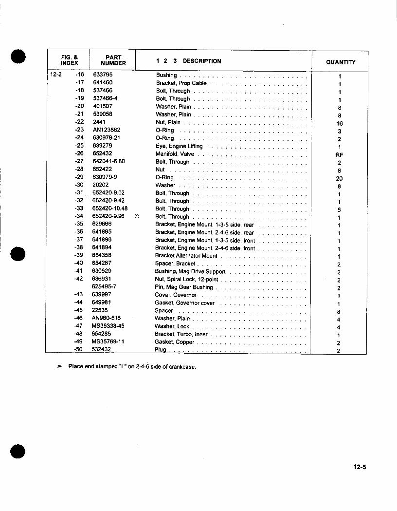
FIG. & PART 23DECITOINDEX NUMBER 123DECITO
I Z-Z -lb
-17-18-19-20-21-22-23-24-25-26-27-28-29-30-31-32-33-34
bJ319S
641460537466537466-44015075390582441ANi123862630979-21639279652432642041-6.80652422630979-920202652420-9.02652420-9.42652420-10.48652420-9.96
-35 629666-36 641895-37 641896-38 641894-39 654358-40 654287-41 630529-42 636931
625495-7-43 639997-4.4 649981-45 22535-46 AN960-516-47 MS35338-45-48 65-4285-49 MS35769-11-50 532432
Bushing .......Bracket, Prop CableBolt, Thmough ....
Bolt, Through ....
Washer, Plain ....
Washer, Plain ....
Nut, Plain ......0-Ring .......0-Ring .......Eye, Engine LiftingManifold, Valve...Bolt, Through ....
Nut .........0-Ring .......Washer .......Bolt, Through ....
Bolt, Through ....
Bolt, Through ....
Bolt, Through ....
Bracket, Engine Mount, 1-3-5 side, rearBracket, Engine Mount, 2-4-6 side, rearBracket, Engine Mount, 1-3-5 side, frontBracket, Engine Mount, 2-4-6 side, frontBracket Alternator Mount ........Spacer, Bracket .............Bushing, Mag Drive Support ......Nut, Spiral Lock, 12-point ........Pin, Mag Gear Bushing .........Cover, Governor ............Gasket, Governor cover ........Spacer .................Washer, Plain ..............Washer, Lock ..............Bracket, Turbo, Inner ..........Gasket, Copper .............Pluo ............
>- Place end stamped 'L" on 2-4-6 side of crankcase.
12-5
QUANTITY
11I18816321
RF28
208115
11
12
22211
844129
------ ..............
24 24SEC1rC A-
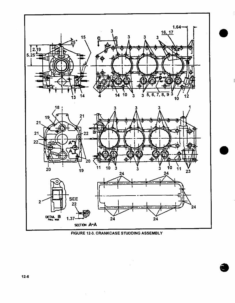
FIGURE 12-3. CRANKCASE STUDDING ASSEMBLY
12-6

FIG. & IINDEX
-1-2
PARTNUMBERI
113-13 CC-2coo4&UaV0 I v
537505629718
-3 643651-1-4-5-6-7-8-9
-10-11-12-13-14-15-16-17-18-19-20-21-22-23-24
401814646038MS20822-6MS51523B6649247MS51531 B364020664019444018622024AN932-C.4632067MS35769-1 153243262972021080401809402439401814402151401801
1 2 3 DESCRIPTION
Studding Assembly. CrankcaseBreather Assembly .......Bushing, Starter Shaftgear...Stud ...............Stud ...............Bushing, Reducer ........Elbow ..............Swivel Tee ...........Reducer Orifice .........Nut ...............Stud ...............Stud ...............Stud ...............Plug ...............Plug ...............Housing, Oil Gage .......Gasket .............Plug ...............Dowel ..............Dowel ..............Stud ...............Stud ...............Stud ...............Stud ...............Stud ...............
QUANTITY
11I
3641111143112111123324
14
12-7
. . . . . . . . . . . . . . . .
I �-�

INTENTIONALLY
LEFT
BLANK
1248
CHAPTER 13
ENGINE DRIVE TRAIN
FIGURE PAGE
13-1 Crankshaft Group.............13-2
13-2 Camshaft Group........................1 3-4
13-1

FIGURE 13-1. CRANKSHAFT GROUP
13-2

FIG. & PARTINDEX NUMBER
13-1 653129A1 Crankshaft and C/W Assembly........-1 629935 Plug, Crankshaft .. ......-2 639580 Bushing, Crankshaft C/W .................-3 639199 Counterweight ......................-4 639198 Bushing ..........................-5 643626-110 Pin, Counterweight 4-1/2 order .............-6 643626-111 Pin, Counterweight 6th order ..............-7 653143 Plate, Retaining ......................-8 629004 Ring, Retaining ......................-9 630651 Dowel ...........................
-10 642337 t Bearing, Main, Rear & Intermediate ...........-11 641992 t Bearing, Main, Front ...................-12 632879 Packing ..........................-13 646288 Washer, Thrust ......................-14 630690 Gear, Crankshaft Cluster .................-15 630692 Screw ...........................-16 530917 Seal Assembly, Crankshaft ................-17 530974 Spring ...........................-18 646320A1 Connecting Rod Assembly ................-19 538684 .Bushing, Piston Pin ..................-20 530213 .Bolt, Connecting Rod .................-21 626140 .Nut, Slotted, Special, 3/8-24 ..............-22 642338 t Bearing, Connecting Rod .................-23 639292 Pin, Cotter .
QUANTITY
1
424228816244
4
1
12
21212
13-3

FIGURE 13-2. CAMSHAFT GROUP
1 3-4
6 'I
A1ItI
FIG. & PART QUANTITYINDEX NUMBER 13 3 DESCRIPTION TSIO-360-RB LTSIO-360-RB
13-2 -1 653061 Camshaft .. . . . . . . . . . .1-1 643069 Camshaft ......... 1...-2 632477 Gear, Camshaft .. ........ 1 1-3 630742 Screw, 5/16-24 x 3/8 .. ....... 4 4-4 MS35756-8 Key, Woodruff........... 1 1-5 629588 Gear, Governor Dnive......... 1 1-6 629602 Gear, Governor Driven......... 1 1-7 630265 Shaft, Fuel Pump Drive .. ...... 1 1-8 653906 Tappet, Hydraulic.......... 12 12-9 628491 Ring, Snap............ 12 12
15
Related Documents