
Welcome message from author
This document is posted to help you gain knowledge. Please leave a comment to let me know what you think about it! Share it to your friends and learn new things together.
Transcript

7. Temperature probe setup:
6.1 Daisy chain the fans to be regulated using the fan speed controller. Con- nect male to female ends and plug the last male end into the fan controller connector labeled ‘OUT- PUT’. The male end of the connector with 7 wires(2 yellow, 2 red, 3 black) is then routed to the power supply.
6.2 Use the fan controller knob on the front panel to regulate the airflow and fan noise.
6. Case fan setup:
7.3 Should you opt to monitor your hard-drive’s operating temperature, place the probe on the hard-drive’s surface. Thermal tape should be used for best results.
Note: You may also leave a sensor loose in the chassis in order to monitor the ambient system temperature. DO NOT place the sensor directly on the CPU as it will damage the sensor.
6
7.2 Place the probe on any ‘fin’ of the CPU’s heatsink and tape in place. Thermal tape should be used for best results.
7.1 Locate device temperature probe.
8
5. Connect case leads to motherboard:
5.1 Locate the top panel leads. Your motherboard user’s manual will provide schematics. The triang- ular markings on the leads indicate positive wires.
5.2 Locate front panel leads. LED leads are located near the right-side panel. The Power/Reset/Speaker leads can be accessed by removing the left panel. Refer to your motherboard user’s manual for placement schem- atics.
(Remove right-side panel to better access wiring.)
7.4 Monitor system temperatures from the front panel LCD.
10
10. USB/1394/Audio cable pin assignments:9. Complete the installation:
9.3 With all components properly installed, gently return side panels to their original positions and replace all screws. Congratulations! You have completed assembly of the X-Telstar Jr.
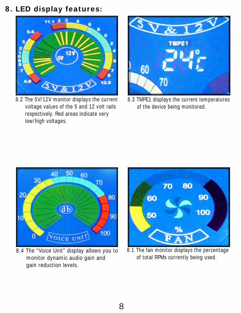
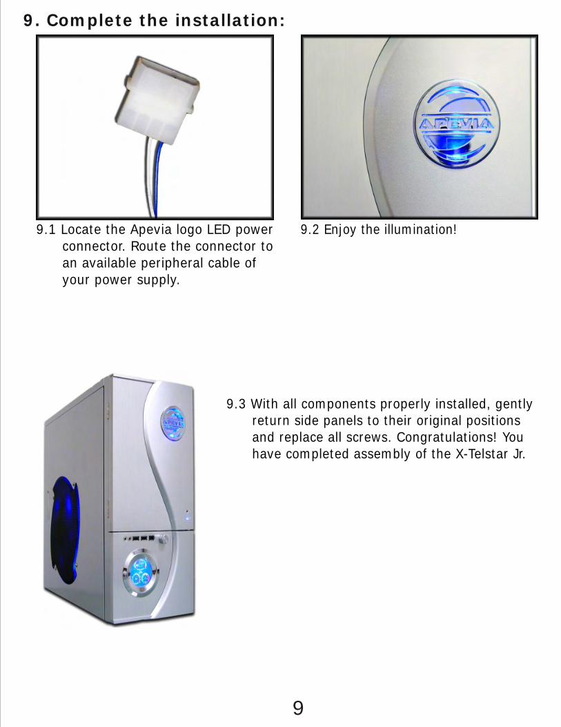
8. LED display features:
8.2 The 5V/12V monitor displays the current voltage values of the 5 and 12 volt rails respectively. Red areas indicate very low/high voltages.
8.1 The fan monitor displays the percentage of total RPMs currently being used.
8.4 The “Voice Unit” display allows you to monitor dynamic audio gain and gain reduction levels.
8.3 TMPE1 displays the current temperatures of the device being monitored.
9.1 Connect the two Power LEDs. The Apevia logo LED is powered by a 2-pin connector. (blue/white wire.)
9.2 Plug in the LED, which is powered by a 2-pin Molex consisting of a black/red wire pair.
7 9
2. Motherboard installation:
4
4.2 From the outside rear of the case, push PCI slot cover(s) toward the inside of the chassis.
4.1 First, remove the PCI slot covers. Firmly press point A with thumb, while pulling point B with index finger to open the latch.
3.5 Align rails with hard-drive bay and insert.
4. Install PCI components:
3
3.1 To install an optical or floppy drive, first remove the metal shield that sits behind each drive bay cover. This must be done from the inside of the case. Next remove the drive bay covers by using a screwdriver, and forcing them out from behind.
3.4 Attach 1 mounting rail to each side of each hard-disk drive.
3.2 For 5 1/4” drives, align the device with the drive bay and insert. Do the same for 3 1/2” drives using the two lower drive bays (one bay is accessible from the front of the case, the other must be accessed from inside the case.
3.3 Slide the blue drive-rail forward and push the clamp downwards to engage locking mechanism. No screws are necessary, but can be used optionally on opti- cal and floppy drive bays.
5
4.3 Read your PCI expansion card’s documentation. Install PCI card into correct slot for your card type (x1, x16, etc.).
3. Install 3½” and 5¼” drives:
4.4 Once the card is seated firmly, return latch to the initial position. A ‘click’ will be heard when fully engaged.
2.2 If your motherboard included an IO shield, you must remove the X-Telstar Jr.’s IO shield. Use thumbs or other object to push shield inward (cover area with a cloth to avoid injury from metal edges!).
2.1 Refer to the motherboard holes index for standoff placement for your motherboard type. A full ATX (12”x9.6”) board will use notches A1-A9. Some mother- boards may not use all notches. Use any notches that line up with your motherboard.
2.3 Put standoff screws in place. Align motherboard with standoffs and mount to case. This ATX mother- board (12”x8.3”) only used notches A1-A6. M8 was also used since it lined up.
2
1.4 Install power supply on top of mounting ledges.
1.6 Fasten screws.1.5 Make sure that the power supply is correctly installed, and that screw mount points are aligned.
NOTE: Touch an unpainted metal section of the chassis to discharge static electricity before handling PC components. An anti-static wrist strap should also be worn to further minimize the possibility of damage.
1.3 Likewise for the window version; grab the notch on the left panel and pull to release.
1
1. Power Supply installation:
1.1 Remove thumbscrews from the rear of the X-Telstar Jr.
NOTE: CPU and memory installation is not covered in this manual. Please refer to each components’ documentation for instructions.
25cm Fan versionWindow version
1. Motherboard installation................................1
3. Install 3½” and 5¼” drives..........................3
4. Install PCI components................................5
6. Case fan setup...........................................6
7. ..........................7 Temperature probe setup
8. LED display features...............................................8
9. Complete the installation.........................................9
5. Connect case leads to motherboard...............6
10. USB/1394/Audio cable pin assignments.......................10
X-Telstar Jr. Finished Appearance.
1.2 Grab the notch on the left panel. Pull to release.
CONTENTS:
2. Power Supply installation..............................3

7. Temperature probe setup:
6.1 Daisy chain the fans to be regulated using the fan speed controller. Con- nect male to female ends and plug the last male end into the fan controller connector labeled ‘OUT- PUT’. The male end of the connector with 7 wires(2 yellow, 2 red, 3 black) is then routed to the power supply.
6.2 Use the fan controller knob on the front panel to regulate the airflow and fan noise.
6. Case fan setup:
7.3 Should you opt to monitor your hard-drive’s operating temperature, place the probe on the hard-drive’s surface. Thermal tape should be used for best results.
Note: You may also leave a sensor loose in the chassis in order to monitor the ambient system temperature. DO NOT place the sensor directly on the CPU as it will damage the sensor.
6
7.2 Place the probe on any ‘fin’ of the CPU’s heatsink and tape in place. Thermal tape should be used for best results.
7.1 Locate the device temperature probe.
8
5. Connect case leads to motherboard:
5.1 Locate the top panel leads. Your motherboard user’s manual will provide schematics. The triang- ular markings on the leads indicate positive wires.
5.2 Locate front panel leads. LED leads are located near the right-side panel. The Power/Reset/Speaker leads can be accessed by removing the left panel. Refer to your motherboard user’s manual for placement schem- atics.
(Remove right-side panel to better access wiring.)
7.4 Monitor the device temperature from the front panel LCD.
10
10. USB/1394/Audio cable pin assignments:9. Complete the installation:
9.3 With all components properly installed, gently return side panels to their original positions and replace all screws. Congratulations! You have completed assembly of the X-Telstar Jr.
8. LED display features:
8.2 The 5V/12V monitor displays the current voltage values of the 5 and 12 volt rails respectively. Red areas indicate very low/high voltages.
8.1 The fan monitor displays the percentage of total RPMs currently being used.
8.4 The “Voice Unit” display allows you to monitor dynamic audio gain and gain reduction levels.
8.3 TMPE1 displays the current temperatures of the device being monitored.
9.1 Connect the two Power LEDs to the power supply. The Apevia logo LED is powered by a 2-pin connector. (blue/white wire pair.)
9.2 Plug in the LED, also powered by a 2-pin connector. (black/red wire pair.)
7 9
2. Install Motherboard:
4
4.2 From the outside rear of the case, push PCI slot cover(s) toward the inside of the chassis.
4.1 First, remove the PCI slot covers. Firmly press point A with thumb, while pulling point B with index finger to open the latch.
3.5 Align rails with hard-drive bay and insert.
4. Install PCI components:
3
3.1 To install an optical or floppy drive, first remove the metal shield that sits behind each drive bay cover. This must be done from the inside of the case. Next remove the drive bay covers by using a screwdriver, and forcing them out from behind.
3.4 Attach 1 mounting rail to each side of each hard-disk drive.
3.2 For 5 1/4” drives, align the device with the drive bay and insert. Do the same for 3 1/2” drives using the two lower drive bays (one bay is accessible from the front of the case, the other must be accessed from inside the case.
3.3 Slide the blue drive-rail forward and push the clamp downwards to engage locking mechanism. No screws are necessary, but can be used optionally on opti- cal and floppy drive bays.
5
4.3 Read your PCI expansion card’s documentation. Install PCI card into correct slot for your card type (x1, x16, etc.).
3. Install 3½” and 5¼” drives:
4.4 Once the card is seated firmly, return latch to the initial position. A ‘click’ will be heard when fully engaged.
2.2 If your motherboard included an IO shield, you must remove the X-Telstar Jr.’s IO shield. Use thumbs or other object to push shield inward (cover area with a cloth to avoid injury from metal edges!).
2.1 Refer to the motherboard holes index for standoff placement for your motherboard type. A full ATX (12”x9.6”) board will use notches A1-A9. Some mother- boards may not use all notches. Use any notches that line up with your motherboard.
2.3 Put standoff screws in place. Align motherboard with standoffs and mount to case. This ATX mother- board (12”x8.3”) only used notches A1-A6. M8 was also used since it lined up.
2
1.4 Install power supply on top of mounting ledges.
1.6 Fasten screws.1.5 Make sure that the power supply is correctly installed, and that screw mount points are aligned.
NOTE: Touch an unpainted metal section of the chassis to discharge static electricity before handling PC components. An anti-static wrist strap should also be worn to further minimize the possibility of damage.
1.3 Likewise for the window version; grab the notch on the left panel and pull to release.
1
1. Install Power Supply:
1.1 Remove thumbscrews from the rear of the X-Telstar Jr.
NOTE: CPU and memory installation is not covered in this manual. Please refer to each components’ documentation for instructions.
S-TypeG-Type
1. Install Power Supply...................................1
3. Install 3½” and 5¼” drives..........................3
4. Install PCI components................................5
6. Case fan setup...........................................6
7. ..........................7 Temperature probe setup
8. LED display features...............................................8
9. Complete the installation.........................................9
5. Connect case leads to motherboard...............6
10. USB/1394/Audio cable pin assignments.......................10
X-Telstar Jr. Finished Appearance.
1.2 Grab the notch on the left panel. Pull to release.
CONTENTS:
2. Install Motherboard......................................3

7. Temperature probe setup:
6.1 Daisy chain the fans to be regulated using the fan speed controller. Con- nect male to female ends and plug the last male end into the fan controller connector labeled ‘OUT- PUT’. The male end of the connector with 7 wires(2 yellow, 2 red, 3 black) is then routed to the power supply.
6.2 Use the fan controller knob on the front panel to regulate the airflow and fan noise.
6. Case fan setup:
7.3 Should you opt to monitor your hard-drive’s operating temperature, place the probe on the hard-drive’s surface. Thermal tape should be used for best results.
Note: You may also leave a sensor loose in the chassis in order to monitor the ambient system temperature. DO NOT place the sensor directly on the CPU as it will damage the sensor.
6
7.2 Place the probe on any ‘fin’ of the CPU’s heatsink and tape in place. Thermal tape should be used for best results.
7.1 Locate the device temperature probe.
8
5. Connect case leads to motherboard:
5.1 Locate the top panel leads. Your motherboard user’s manual will provide schematics. The triang- ular markings on the leads indicate positive wires.
5.2 Locate front panel leads. LED leads are located near the right-side panel. The Power/Reset/Speaker leads can be accessed by removing the left panel. Refer to your motherboard user’s manual for placement schem- atics.
(Remove right-side panel to better access wiring.)
7.4 Monitor the device temperature from the front panel LCD.
10
10. USB/1394/Audio cable pin assignments:9. Complete the installation:
9.3 With all components properly installed, gently return side panels to their original positions and replace all screws. Congratulations! You have completed assembly of the X-Telstar Jr.
8. LED display features:
8.2 The 5V/12V monitor displays the current voltage values of the 5 and 12 volt rails respectively. Red areas indicate very low/high voltages.
8.1 The fan monitor displays the percentage of total RPMs currently being used.
8.4 The “Voice Unit” display allows you to monitor dynamic audio gain and gain reduction levels.
8.3 TMPE1 displays the current temperatures of the device being monitored.
9.1 Connect the two Power LEDs to the power supply. The Apevia logo LED is powered by a 2-pin connector. (blue/white wire pair.)
9.2 Plug in the LED, also powered by a 2-pin connector. (black/red wire pair.)
7 9
2. Install Motherboard:
4
4.2 From the outside rear of the case, push PCI slot cover(s) toward the inside of the chassis.
4.1 First, remove the PCI slot covers. Firmly press point A with thumb, while pulling point B with index finger to open the latch.
3.5 Align rails with hard-drive bay and insert.
4. Install PCI components:
3
3.1 To install an optical or floppy drive, first remove the metal shield that sits behind each drive bay cover. This must be done from the inside of the case. Next remove the drive bay covers by using a screwdriver, and forcing them out from behind.
3.4 Attach 1 mounting rail to each side of each hard-disk drive.
3.2 For 5 1/4” drives, align the device with the drive bay and insert. Do the same for 3 1/2” drives using the two lower drive bays (one bay is accessible from the front of the case, the other must be accessed from inside the case).
3.3 Slide the blue drive-rail forward and push the clamp downwards to engage locking mechanism. No screws are necessary, but can be used optionally on opti- cal and floppy drive bays.
5
4.3 Read your PCI expansion card’s documentation. Install PCI card into correct slot for your card type (x1, x16, etc.).
3. Install 3½” and 5¼” drives:
4.4 Once the card is seated firmly, return latch to the initial position. A ‘click’ will be heard when fully engaged.
2.2 If your motherboard included an IO shield, you must remove the X-Telstar Jr.’s IO shield. Use thumbs or other object to push shield inward (cover area with a cloth to avoid injury from metal edges!).
2.1 Refer to the motherboard holes index for standoff placement for your motherboard type. A full ATX (12”x9.6”) board will use notches A1-A9. Some mother- boards may not use all notches. Use any notches that line up with your motherboard.
2.3 Put standoff screws in place. Align motherboard with standoffs and mount to case. This ATX mother- board (12”x8.3”) only used notches A1-A6. M8 was also used since it lined up.
2
1.4 Install power supply on top of mounting ledges.
1.6 Fasten screws.1.5 Make sure that the power supply is correctly installed, and that screw mount points are aligned.
NOTE: Touch an unpainted metal section of the chassis to discharge static electricity before handling PC components. An anti-static wrist strap should also be worn to further minimize the possibility of damage.
1.3 Likewise for the G-Type; grab the notch on the left panel and pull to release.
1
1. Install Power Supply:
1.1 Remove thumbscrews from the rear of the X-Telstar Jr.
NOTE: CPU and memory installation is not covered in this manual. Please refer to each components’ documentation for instructions.
S-TypeG-Type
1. Install Power Supply...................................1
3. Install 3½” and 5¼” drives..........................3
4. Install PCI components................................5
6. Case fan setup...........................................6
7. ..........................7 Temperature probe setup
8. LED display features...............................................8
9. Complete the installation.........................................9
5. Connect case leads to motherboard...............6
10. USB/1394/Audio cable pin assignments.......................10
X-Telstar Jr. Finished Appearance.
1.2 Grab the notch on the left panel. Pull to release.
CONTENTS:
2. Install Motherboard......................................3

7. Temperature probe setup:
6.1 Daisy chain the fans to be regulated using the fan speed controller. Con- nect male to female ends and plug the last male end into the fan controller connector labeled ‘OUT- PUT’. The male end of the connector with 7 wires(2 yellow, 2 red, 3 black) is then routed to the power supply.
6.2 Use the fan controller knob on the front panel to regulate the airflow and fan noise.
6. Case fan setup:
7.3 Should you opt to monitor your hard-drive’s operating temperature, place the probe on the hard-drive’s surface. Thermal tape should be used for best results.
Note: You may also leave a sensor loose in the chassis in order to monitor the ambient system temperature. DO NOT place the sensor directly on the CPU as it will damage the sensor.
6
7.2 Place the probe on any ‘fin’ of the CPU’s heatsink and tape in place. Thermal tape should be used for best results.
7.1 Locate the device temperature probe.
8
5. Connect case leads to motherboard:
5.1 Locate the top panel leads. Your motherboard user’s manual will provide schematics. The triang- ular markings on the leads indicate positive wires.
5.2 Locate front panel leads. LED leads are located near the right-side panel. The Power/Reset/Speaker leads can be accessed by removing the left panel. Refer to your motherboard user’s manual for placement schem- atics.
(Remove right-side panel to better access wiring.)
7.4 Monitor the device temperature from the front panel LCD.
10
10. USB/1394/Audio cable pin assignments:9. Complete the installation:
9.3 With all components properly installed, gently return side panels to their original positions and replace all screws. Congratulations! You have completed assembly of the X-Telstar Jr.
8. LED display features:
8.2 The 5V/12V monitor displays the current voltage values of the 5 and 12 volt rails respectively. Red areas indicate very low/high voltages.
8.1 The fan monitor displays the percentage of total RPMs currently being used.
8.4 The “Voice Unit” display allows you to monitor dynamic audio gain and gain reduction levels.
8.3 TMPE1 displays the current temperatures of the device being monitored.
9.1 Connect the two Power LEDs to the power supply. The Apevia logo LED is powered by a 2-pin connector. (blue/white wire pair.)
9.2 Plug in the LED, also powered by a 2-pin connector. (black/red wire pair.)
7 9
2. Install Motherboard:
4
4.2 From the outside rear of the case, push PCI slot cover(s) toward the inside of the chassis.
4.1 First, remove the PCI slot covers. Firmly press point A with thumb, while pulling point B with index finger to open the latch.
3.5 Align rails with hard-drive bay and insert.
4. Install PCI components:
3
3.1 To install an optical or floppy drive, first remove the metal shield that sits behind each drive bay cover. This must be done from the inside of the case. Next remove the drive bay covers by using a screwdriver, and forcing them out from behind.
3.4 Attach 1 mounting rail to each side of each hard-disk drive.
3.2 For 5 1/4” drives, align the device with the drive bay and insert. Do the same for 3 1/2” drives using the two lower drive bays (one bay is accessible from the front of the case, the other must be accessed from inside the case.
3.3 Slide the blue drive-rail forward and push the clamp downwards to engage locking mechanism. No screws are necessary, but can be used optionally on opti- cal and floppy drive bays.
5
4.3 Read your PCI expansion card’s documentation. Install PCI card into correct slot for your card type (x1, x16, etc.).
3. Install 3½” and 5¼” drives:
4.4 Once the card is seated firmly, return latch to the initial position. A ‘click’ will be heard when fully engaged.
2.2 If your motherboard included an IO shield, you must remove the X-Telstar Jr.’s IO shield. Use thumbs or other object to push shield inward (cover area with a cloth to avoid injury from metal edges!).
2.1 Refer to the motherboard holes index for standoff placement for your motherboard type. A full ATX (12”x9.6”) board will use notches A1-A9. Some mother- boards may not use all notches. Use any notches that line up with your motherboard.
2.3 Put standoff screws in place. Align motherboard with standoffs and mount to case. This ATX mother- board (12”x8.3”) only used notches A1-A6. M8 was also used since it lined up.
2
1.4 Install power supply on top of mounting ledges.
1.6 Fasten screws.1.5 Make sure that the power supply is correctly installed, and that screw mount points are aligned.
NOTE: Touch an unpainted metal section of the chassis to discharge static electricity before handling PC components. An anti-static wrist strap should also be worn to further minimize the possibility of damage.
1.3 Likewise for the window version; grab the notch on the left panel and pull to release.
1
1. Install Power Supply:
1.1 Remove thumbscrews from the rear of the X-Telstar Jr.
NOTE: CPU and memory installation is not covered in this manual. Please refer to each components’ documentation for instructions.
S-TypeG-Type
1. Install Power Supply...................................1
3. Install 3½” and 5¼” drives..........................3
4. Install PCI components................................5
6. Case fan setup...........................................6
7. ..........................7 Temperature probe setup
8. LED display features...............................................8
9. Complete the installation.........................................9
5. Connect case leads to motherboard...............6
10. USB/1394/Audio cable pin assignments.......................10
X-Telstar Jr. Finished Appearance.
1.2 Grab the notch on the left panel. Pull to release.
CONTENTS:
2. Install Motherboard......................................3

7. Temperature probe setup:
6.1 Daisy chain the fans to be regulated using the fan speed controller. Con- nect male to female ends and plug the last male end into the fan controller connector labeled ‘OUT- PUT’. The male end of the connector with 7 wires(2 yellow, 2 red, 3 black) is then routed to the power supply.
6.2 Use the fan controller knob on the front panel to regulate the airflow and fan noise.
6. Case fan setup:
7.3 Should you opt to monitor your hard-drive’s operating temperature, place the probe on the hard-drive’s surface. Thermal tape should be used for best results.
Note: You may also leave a sensor loose in the chassis in order to monitor the ambient system temperature. DO NOT place the sensor directly on the CPU as it will damage the sensor.
6
7.2 Place the probe on any ‘fin’ of the CPU’s heatsink and tape in place. Thermal tape should be used for best results.
7.1 Locate the device temperature probe.
8
5. Connect case leads to motherboard:
5.1 Locate the top panel leads. Your motherboard user’s manual will provide schematics. The triang- ular markings on the leads indicate positive wires.
5.2 Locate front panel leads. LED leads are located near the right-side panel. The Power/Reset/Speaker leads can be accessed by removing the left panel. Refer to your motherboard user’s manual for placement schem- atics.
(Remove right-side panel to better access wiring.)
7.4 Monitor the device temperature from the front panel LCD.
10
10. USB/1394/Audio cable pin assignments:9. Complete the installation:
9.3 With all components properly installed, gently return side panels to their original positions and replace all screws. Congratulations! You have completed assembly of the X-Telstar Jr.
8. LED display features:
8.2 The 5V/12V monitor displays the current voltage values of the 5 and 12 volt rails respectively. Red areas indicate very low/high voltages.
8.1 The fan monitor displays the percentage of total RPMs currently being used.
8.4 The “Voice Unit” display allows you to monitor dynamic audio gain and gain reduction levels.
8.3 TMPE1 displays the current temperatures of the device being monitored.
9.1 Connect the two Power LEDs to the power supply. The Apevia logo LED is powered by a 2-pin connector. (blue/white wire pair.)
9.2 Plug in the LED, also powered by a 2-pin connector. (black/red wire pair.)
7 9
2. Install Motherboard:
4
4.2 From the outside rear of the case, push PCI slot cover(s) toward the inside of the chassis.
4.1 First, remove the PCI slot covers. Firmly press point A with thumb, while pulling point B with index finger to open the latch.
3.5 Align rails with hard-drive bay and insert.
4. Install PCI components:
3
3.1 To install an optical or floppy drive, first remove the metal shield that sits behind each drive bay cover. This must be done from the inside of the case. Next remove the drive bay covers by using a screwdriver, and forcing them out from behind.
3.4 Attach 1 mounting rail to each side of each hard-disk drive.
3.2 For 5 1/4” drives, align the device with the drive bay and insert. Do the same for 3 1/2” drives using the two lower drive bays (one bay is accessible from the front of the case, the other must be accessed from inside the case).
3.3 Slide the blue drive-rail forward and push the clamp downwards to engage locking mechanism. No screws are necessary, but can be used optionally on opti- cal and floppy drive bays.
5
4.3 Read your PCI expansion card’s documentation. Install PCI card into correct slot for your card type (x1, x16, etc.).
3. Install 3½” and 5¼” drives:
4.4 Once the card is seated firmly, return latch to the initial position. A ‘click’ will be heard when fully engaged.
2.2 If your motherboard included an IO shield, you must remove the X-Telstar Jr.’s IO shield. Use thumbs or other object to push shield inward (cover area with a cloth to avoid injury from metal edges!).
2.1 Refer to the motherboard holes index for standoff placement for your motherboard type. A full ATX (12”x9.6”) board will use notches A1-A9. Some mother- boards may not use all notches. Use any notches that line up with your motherboard.
2.3 Put standoff screws in place. Align motherboard with standoffs and mount to case. This ATX mother- board (12”x8.3”) only used notches A1-A6. M8 was also used since it lined up.
2
1.4 Install power supply on top of mounting ledges.
1.6 Fasten screws.1.5 Make sure that the power supply is correctly installed, and that screw mount points are aligned.
NOTE: Touch an unpainted metal section of the chassis to discharge static electricity before handling PC components. An anti-static wrist strap should also be worn to further minimize the possibility of damage.
1.3 Likewise for the G-Type; grab the notch on the left panel and pull to release.
1
1. Install Power Supply:
1.1 Remove thumbscrews from the rear of the X-Telstar Jr.
NOTE: CPU and memory installation is not covered in this manual. Please refer to each components’ documentation for instructions.
S-TypeG-Type
1. Install Power Supply...................................1
3. Install 3½” and 5¼” drives..........................3
4. Install PCI components................................5
6. Case fan setup...........................................6
7. ..........................7 Temperature probe setup
8. LED display features...............................................8
9. Complete the installation.........................................9
5. Connect case leads to motherboard...............6
10. USB/1394/Audio cable pin assignments.......................10
X-Telstar Jr. Finished Appearance.
1.2 Grab the notch on the left panel. Pull to release.
CONTENTS:
2. Install Motherboard......................................3

7. Temperature probe setup:
4.2 From the outside rear of the case, push PCI slot cover(s) toward the inside of the chassis.
4.1 First, remove the PCI slot covers. Firmly press point A with thumb, while pulling point B with index finger to open the latch.
4. Install PCI components:
5
4.3 Read your PCI expansion card’s documentation. Install PCI card into correct slot for your card type (x1, x16, etc.).
6.1 Daisy chain the fans to be regulated using the fan speed controller. Con- nect male to female ends and plug the last male end into the fan controller connector labeled ‘OUT- PUT’. The connector labeled ‘INPUT’ is then plugged into the power supply.
6.2 Use the fan controller knob on the front panel to regulate the airflow and fan noise.
6. Case fan setup:
4.4 Once the card is seated firmly, return latch to the initial position. A ‘click’ will be heard when fully engaged.
7.3 Place the other probe labeled ‘HDD’ on the hard-drive’s surface. Thermal tape should be used for best results.
Note: You may also leave a sensor loose in the chassis in order to monitor the ambient system temperature. DO NOT place the sensor directly on the CPU as it will damage the sensor.
6
7.2 Place one of the probes on any ‘fin’ on the CPU’s heatsink and tape in place. Thermal tape should be used for best results.
7.1 Locate the device temperature probes.
7
5. Connect case leads to motherboard:
5.1 Locate the top panel leads. Your motherboard user’s manual will provide schematics. The triang- ular markings on the leads indicate positive wires.
5.2 Locate front panel leads. LED leads are located near the right-side panel. The Power/Reset/Speaker leads can be accessed by removing the left panel. Refer to your motherboard user’s manual for placement schem- atics.
(Remove right-side panel to better access wiring.)
7.4 Monitor system temperatures from the front panel LCD.
9
10. USB/1394/Audio cable pin assignments:9. Complete the installation:
9.3 With all components properly installed, gently return side panels to their original positions and replace all screws. Congratulations! You have completed assembly of the X-Telstar Jr.
8. LED display features:
8.2 The 5V/12V monitor displays the current voltage values of the 5 and 12 volt rails respectively. Red areas indicate very low/high voltages.
8.1 The fan monitor displays the percentage of total RPMs currently being used.
8.4 The “Voice Unit” display allows you to monitor dynamic audio gain and gain reduction levels.
8.3 TMPE1 and TMPE2 display the current temperatures of components that have temp. sensors attached. The H.D.D indicator displays hard drive activity.
9.1 Connect the two Power LEDs. The LED behind the Apevia logo is powered by a 2-pin connector consisting of a blue/white wire pair.
9.2 Plug in the LED, which is powered by a 2-pin lead consisting of a black/red wire pair.
4
3.5 Align rails with hard-drive bay and insert.
3.4 Attach 1 mounting rail to each side of each hard-disk drive.
3.2 For 5 1/4” drives, align the device with the drive bay and insert. Do the same for 3 1/2” drives using the two lower drive bays.
3.3 Slide the blue drive-rail forward and push the clamp downwards to engage locking mechanism. No screws are necessary, but can be used optionally on opti- cal and floppy drive bays.
1.4 Install power supply on top of mounting ledges.
NOTE: Touch an unpainted metal section of the chassis to discharge static electricity before handling PC components. An anti-static wrist strap should also be worn to further minimize the possibility of damage.
3
3.1 To install an optical or floppy drive, first remove the metal shield that sits behind each drive bay cover. This must be done from the inside of the case. Next remove the drive bay covers by using a screwdriver, and forcing them out from behind.
3. Install 3½” and 5¼” drives:
2.2 If your motherboard included an IO shield, you must remove the X-Jupiter Jr.’s IO shield. Use thumbs or other object to push shield inward (cover area with a cloth to avoid injury from metal edges!).
2.1 Refer to the motherboard holes index for standoff placement for your motherboard type. A full ATX (12”x9.6”) board will use notches A1-A9. Some mother- boards may not use all notches. Use any notches that line up with your motherboard.
2.3 Put brass standoffs in place. Align motherboard with standoffs and mount to case. This ATX mother- board (12”x8.3”) only used notches A1-A6. M8 was also used since it lined up.
2. Motherboard installation:
2
1.6 Fasten screws.1.5 Make sure that the power supply is correctly installed, and that screw mount points are aligned.
1
1. Power Supply installation:
1.1 Remove thumbscrews from the rear of the X-Telstar Jr.
1.3 Likewise for the window version; grab the notch on the left panel and pull to release.
NOTE: CPU and memory installation is not covered in this manual. Please refer to each components’ documentation for instructions.
25cm Fan versionWindow version
1. Motherboard installation..................................1
3. Install 3½” and 5¼” drives..............................3
4. Install PCI components.................................5
6. Case fan setup.......................................6
7. .........................7 Temperature probe setup
8. LED display features.....................................8
8. Complete the installation............................9
5. Connect case leads to motherboard...............6
9. USB/1394/Audio cable pin assignments........9
X-Telstar Jr. Finished Appearance.
1.2 Grab the notch on the left panel. Pull to release.
CONTENTS:
2. Power Supply installation..................................3

7. Temperature probe setup:
6.1 Daisy chain the fans to be regulated using the fan speed controller. Con- nect male to female ends and plug the last male end into the connector labeled ‘OUTPUT’. The male end of the connector with 7 wires(2 yellow, 2 red, 3 black) is then routed to the power supply.
6.2 Use the fan controller knob on the front panel to regulate the airflow and fan noise.
6. Case fan setup:
7.3 Should you opt to monitor your hard-drive’s operating temperature, place the probe on the hard-drive’s surface. Thermal tape should be used for best results.
Note: You may also leave a sensor loose in the chassis in order to monitor the ambient system temperature. DO NOT place the sensor directly on the CPU as it will damage the sensor.
6
7.2 Place the probe on any ‘fin’ of the CPU’s heatsink and tape in place. Thermal tape should be used for best results.
7.1 Locate the device temperature probe.
8
5. Connect case leads to motherboard:
5.1 Locate the top panel leads. Your motherboard user’s manual will provide schematics. The triang- ular markings on the leads indicate positive wires.
5.2 Locate front panel leads. LED leads are located near the right-side panel. The Power/Reset/Speaker leads can be accessed by removing the left panel. Refer to your motherboard user’s manual for placement schem- atics.
(Remove right-side panel to better access wiring.)
7.4 Monitor the device temperature from the front panel LCD.
10
10. USB/1394/Audio cable pin assignments:9. Complete the installation:
9.3 With all components properly installed, gently return side panels to their original positions and replace all screws. Congratulations! You have completed assembly of the X-Telstar Jr.
8. LED display features:
8.2 The 5V/12V monitor displays the current voltage values of the 5 and 12 volt rails respectively. Red areas indicate very low/high voltages.
8.1 The fan monitor displays the percentage of total RPMs currently being used.
8.4 The “Voice Unit” display allows you to monitor dynamic audio gain and gain reduction levels.
8.3 TMPE1 displays the current temperatures of the device being monitored.
9.1 Locate the Apevia logo LED power connector. Route the connector to an available peripheral cable of your power supply.
7 9
2. Install Motherboard:
4
4.2 From the outside rear of the case, push PCI slot cover(s) toward the inside of the chassis.
4.1 First, remove the PCI slot covers. Firmly press point A with thumb, while pulling point B with index finger to open the latch.
3.5 Align rails with hard-drive bay and insert.
4. Install PCI components:
3
3.1 To install an optical or floppy drive, first remove the metal shield that sits behind each drive bay cover. This must be done from the inside of the case. Next remove the drive bay covers by using a screwdriver, and forcing them out from behind.
3.4 Attach 1 mounting rail to each side of each hard-disk drive.
3.2 For 5 1/4” drives, align the device with the drive bay and insert. Do the same for 3 1/2” drives using the two lower drive bays (one bay is accessible from the front of the case, the other must be accessed from inside the case).
3.3 Slide the blue drive-rail forward and push the clamp downwards to engage locking mechanism. No screws are necessary, but can be used optionally on opti- cal and floppy drive bays.
5
4.3 Read your PCI expansion card’s documentation. Install PCI card into correct slot for your card type (x1, x16, etc.).
3. Install 3½” and 5¼” drives:
4.4 Once the card is seated firmly, return latch to the initial position. A ‘click’ will be heard when fully engaged.
2.2 If your motherboard included an IO shield, you must remove the X-Telstar Jr.’s IO shield. Use thumbs or other object to push shield inward (cover area with a cloth to avoid injury from metal edges!).
2.1 Refer to the motherboard holes index for standoff placement for your motherboard type. A full ATX (12”x9.6”) board will use notches A1-A9. Some mother- boards may not use all notches. Use any notches that line up with your motherboard.
2.3 Put standoff screws in place. Align motherboard with standoffs and mount to case. This ATX mother- board (12”x8.3”) only used notches A1-A6. M8 was also used since it lined up.
2
1.4 Install power supply on top of mounting ledges.
1.6 Fasten screws.1.5 Make sure that the power supply is correctly installed, and that screw mount points are aligned.
NOTE: Touch an unpainted metal section of the chassis to discharge static electricity before handling PC components. An anti-static wrist strap should also be worn to further minimize the possibility of damage.
1.3 Likewise for the G-Type; grab the notch on the left panel and pull to release.
1
1. Install Power Supply:
1.1 Remove thumbscrews from the rear of the X-Telstar Jr.
NOTE: CPU and memory installation is not covered in this manual. Please refer to each components’ documentation for instructions.
S-TypeG-Type
1. Install Power Supply...................................1
3. Install 3½” and 5¼” drives..........................3
4. Install PCI components................................5
6. Case fan setup...........................................6
7. ..........................7 Temperature probe setup
8. LED display features...............................................8
9. Complete the installation.........................................9
5. Connect case leads to motherboard...............6
10. USB/1394/Audio cable pin assignments.......................10
X-Telstar Jr. Finished Appearance.
1.2 Grab the notch on the left panel. Pull to release.
CONTENTS:
2. Install Motherboard......................................3
9.2 Enjoy the illumination!

7. Temperature probe setup:
6.1 Daisy chain the fans to be regulated using the fan speed controller. Con- nect male to female ends and plug the last male end into the fan controller connector labeled ‘OUT- PUT’. The male end of the connector with 7 wires(2 yellow, 2 red, 3 black) is then routed to the power supply.
6.2 Use the fan controller knob on the front panel to regulate the airflow and fan noise.
6. Case fan setup:
7.3 Should you opt to monitor your hard-drive’s operating temperature, place the probe on the hard-drive’s surface. Thermal tape should be used for best results.
Note: You may also leave a sensor loose in the chassis in order to monitor the ambient system temperature. DO NOT place the sensor directly on the CPU as it will damage the sensor.
6
7.2 Place the probe on any ‘fin’ of the CPU’s heatsink and tape in place. Thermal tape should be used for best results.
7.1 Locate the device temperature probe.
8
5. Connect case leads to motherboard:
5.1 Locate the top panel leads. Your motherboard user’s manual will provide schematics. The triang- ular markings on the leads indicate positive wires.
5.2 Locate front panel leads. LED leads are located near the right-side panel. The Power/Reset/Speaker leads can be accessed by removing the left panel. Refer to your motherboard user’s manual for placement schem- atics.
(Remove right-side panel to better access wiring.)
7.4 Monitor the device temperature from the front panel LCD.
10
10. USB/1394/Audio cable pin assignments:9. Complete the installation:
9.3 With all components properly installed, gently return side panels to their original positions and replace all screws. Congratulations! You have completed assembly of the X-Telstar Jr.
8. LED display features:
8.2 The 5V/12V monitor displays the current voltage values of the 5 and 12 volt rails respectively. Red areas indicate very low/high voltages.
8.1 The fan monitor displays the percentage of total RPMs currently being used.
8.4 The “Voice Unit” display allows you to monitor dynamic audio gain and gain reduction levels.
8.3 TMPE1 displays the current temperatures of the device being monitored.
9.1 Connect the two Power LEDs. The Apevia logo LED is powered by a 2-pin connector. (blue/white wire.)
9.2 Plug in the LED, which is powered by a 2-pin Molex consisting of a black/red wire pair.
7 9
2. Motherboard installation:
4
4.2 From the outside rear of the case, push PCI slot cover(s) toward the inside of the chassis.
4.1 First, remove the PCI slot covers. Firmly press point A with thumb, while pulling point B with index finger to open the latch.
3.5 Align rails with hard-drive bay and insert.
4. Install PCI components:
3
3.1 To install an optical or floppy drive, first remove the metal shield that sits behind each drive bay cover. This must be done from the inside of the case. Next remove the drive bay covers by using a screwdriver, and forcing them out from behind.
3.4 Attach 1 mounting rail to each side of each hard-disk drive.
3.2 For 5 1/4” drives, align the device with the drive bay and insert. Do the same for 3 1/2” drives using the two lower drive bays (one bay is accessible from the front of the case, the other must be accessed from inside the case.
3.3 Slide the blue drive-rail forward and push the clamp downwards to engage locking mechanism. No screws are necessary, but can be used optionally on opti- cal and floppy drive bays.
5
4.3 Read your PCI expansion card’s documentation. Install PCI card into correct slot for your card type (x1, x16, etc.).
3. Install 3½” and 5¼” drives:
4.4 Once the card is seated firmly, return latch to the initial position. A ‘click’ will be heard when fully engaged.
2.2 If your motherboard included an IO shield, you must remove the X-Telstar Jr.’s IO shield. Use thumbs or other object to push shield inward (cover area with a cloth to avoid injury from metal edges!).
2.1 Refer to the motherboard holes index for standoff placement for your motherboard type. A full ATX (12”x9.6”) board will use notches A1-A9. Some mother- boards may not use all notches. Use any notches that line up with your motherboard.
2.3 Put standoff screws in place. Align motherboard with standoffs and mount to case. This ATX mother- board (12”x8.3”) only used notches A1-A6. M8 was also used since it lined up.
2
1.4 Install power supply on top of mounting ledges.
1.6 Fasten screws.1.5 Make sure that the power supply is correctly installed, and that screw mount points are aligned.
NOTE: Touch an unpainted metal section of the chassis to discharge static electricity before handling PC components. An anti-static wrist strap should also be worn to further minimize the possibility of damage.
1.3 Likewise for the window version; grab the notch on the left panel and pull to release.
1
1. Power Supply installation:
1.1 Remove thumbscrews from the rear of the X-Telstar Jr.
NOTE: CPU and memory installation is not covered in this manual. Please refer to each components’ documentation for instructions.
25cm Fan versionWindow version
1. Motherboard installation................................1
3. Install 3½” and 5¼” drives..........................3
4. Install PCI components................................5
6. Case fan setup...........................................6
7. ..........................7 Temperature probe setup
8. LED display features...............................................8
9. Complete the installation.........................................9
5. Connect case leads to motherboard...............6
10. USB/1394/Audio cable pin assignments.......................10
X-Telstar Jr. Finished Appearance.
1.2 Grab the notch on the left panel. Pull to release.
CONTENTS:
2. Power Supply installation..............................3
7. Temperature probe setup:
6.1 Daisy chain the fans to be regulated using the fan speed controller. Con- nect male to female ends and plug the last male end into the fan controller connector labeled ‘OUT- PUT’. The male end of the connector with 7 wires(2 yellow, 2 red, 3 black) is then routed to the power supply.
6.2 Use the fan controller knob on the front panel to regulate the airflow and fan noise.
6. Case fan setup:
7.3 Should you opt to monitor your hard-drive’s operating temperature, place the probe on the hard-drive’s surface. Thermal tape should be used for best results.
Note: You may also leave a sensor loose in the chassis in order to monitor the ambient system temperature. DO NOT place the sensor directly on the CPU as it will damage the sensor.
6
7.2 Place the probe on any ‘fin’ of the CPU’s heatsink and tape in place. Thermal tape should be used for best results.
7.1 Locate device temperature probe.
8
5. Connect case leads to motherboard:
5.1 Locate the top panel leads. Your motherboard user’s manual will provide schematics. The triang- ular markings on the leads indicate positive wires.
5.2 Locate front panel leads. LED leads are located near the right-side panel. The Power/Reset/Speaker leads can be accessed by removing the left panel. Refer to your motherboard user’s manual for placement schem- atics.
(Remove right-side panel to better access wiring.)
7.4 Monitor the device temperature from the front panel LCD.
10
10. USB/1394/Audio cable pin assignments:9. Complete the installation:
9.3 With all components properly installed, gently return side panels to their original positions and replace all screws. Congratulations! You have completed assembly of the X-Telstar Jr.
8. LED display features:
8.2 The 5V/12V monitor displays the current voltage values of the 5 and 12 volt rails respectively. Red areas indicate very low/high voltages.
8.1 The fan monitor displays the percentage of total RPMs currently being used.
8.4 The “Voice Unit” display allows you to monitor dynamic audio gain and gain reduction levels.
8.3 TMPE1 displays the current temperatures of the device being monitored.
9.1 Connect the two Power LEDs. The Apevia logo LED is powered by a 2-pin connector. (blue/white wire.)
9.2 Plug in the LED, which is powered by a 2-pin Molex consisting of a black/red wire pair.
7 9
2. Motherboard installation:
4
4.2 From the outside rear of the case, push PCI slot cover(s) toward the inside of the chassis.
4.1 First, remove the PCI slot covers. Firmly press point A with thumb, while pulling point B with index finger to open the latch.
3.5 Align rails with hard-drive bay and insert.
4. Install PCI components:
3
3.1 To install an optical or floppy drive, first remove the metal shield that sits behind each drive bay cover. This must be done from the inside of the case. Next remove the drive bay covers by using a screwdriver, and forcing them out from behind.
3.4 Attach 1 mounting rail to each side of each hard-disk drive.
3.2 For 5 1/4” drives, align the device with the drive bay and insert. Do the same for 3 1/2” drives using the two lower drive bays (one bay is accessible from the front of the case, the other must be accessed from inside the case.
3.3 Slide the blue drive-rail forward and push the clamp downwards to engage locking mechanism. No screws are necessary, but can be used optionally on opti- cal and floppy drive bays.
5
4.3 Read your PCI expansion card’s documentation. Install PCI card into correct slot for your card type (x1, x16, etc.).
3. Install 3½” and 5¼” drives:
4.4 Once the card is seated firmly, return latch to the initial position. A ‘click’ will be heard when fully engaged.
2.2 If your motherboard included an IO shield, you must remove the X-Telstar Jr.’s IO shield. Use thumbs or other object to push shield inward (cover area with a cloth to avoid injury from metal edges!).
2.1 Refer to the motherboard holes index for standoff placement for your motherboard type. A full ATX (12”x9.6”) board will use notches A1-A9. Some mother- boards may not use all notches. Use any notches that line up with your motherboard.
2.3 Put standoff screws in place. Align motherboard with standoffs and mount to case. This ATX mother- board (12”x8.3”) only used notches A1-A6. M8 was also used since it lined up.
2
1.4 Install power supply on top of mounting ledges.
1.6 Fasten screws.1.5 Make sure that the power supply is correctly installed, and that screw mount points are aligned.
NOTE: Touch an unpainted metal section of the chassis to discharge static electricity before handling PC components. An anti-static wrist strap should also be worn to further minimize the possibility of damage.
1.3 Likewise for the window version; grab the notch on the left panel and pull to release.
1
1. Power Supply installation:
1.1 Remove thumbscrews from the rear of the X-Telstar Jr.
NOTE: CPU and memory installation is not covered in this manual. Please refer to each components’ documentation for instructions.
25cm Fan versionWindow version
1. Motherboard installation................................1
3. Install 3½” and 5¼” drives..........................3
4. Install PCI components................................5
6. Case fan setup...........................................6
7. ..........................7 Temperature probe setup
8. LED display features...............................................8
9. Complete the installation.........................................9
5. Connect case leads to motherboard...............6
10. USB/1394/Audio cable pin assignments.......................10
X-Telstar Jr. Finished Appearance.
1.2 Grab the notch on the left panel. Pull to release.
CONTENTS:
2. Power Supply installation..............................3
7. Temperature probe setup:
6.1 Daisy chain the fans to be regulated using the fan speed controller. Con- nect male to female ends and plug the last male end into the fan controller connector labeled ‘OUT- PUT’. The male end of the connector with 7 wires(2 yellow, 2 red, 3 black) is then routed to the power supply.
6.2 Use the fan controller knob on the front panel to regulate the airflow and fan noise.
6. Case fan setup:
7.3 Should you opt to monitor your hard-drive’s operating temperature, place the probe on the hard-drive’s surface. Thermal tape should be used for best results.
Note: You may also leave a sensor loose in the chassis in order to monitor the ambient system temperature. DO NOT place the sensor directly on the CPU as it will damage the sensor.
6
7.2 Place the probe on any ‘fin’ of the CPU’s heatsink and tape in place. Thermal tape should be used for best results.
7.1 Locate the device temperature probe.
8
5. Connect case leads to motherboard:
5.1 Locate the top panel leads. Your motherboard user’s manual will provide schematics. The triang- ular markings on the leads indicate positive wires.
5.2 Locate front panel leads. LED leads are located near the right-side panel. The Power/Reset/Speaker leads can be accessed by removing the left panel. Refer to your motherboard user’s manual for placement schem- atics.
(Remove right-side panel to better access wiring.)
7.4 Monitor the device temperature from the front panel LCD.
10
10. USB/1394/Audio cable pin assignments:9. Complete the installation:
9.3 With all components properly installed, gently return side panels to their original positions and replace all screws. Congratulations! You have completed assembly of the X-Telstar Jr.
8. LED display features:
8.2 The 5V/12V monitor displays the current voltage values of the 5 and 12 volt rails respectively. Red areas indicate very low/high voltages.
8.1 The fan monitor displays the percentage of total RPMs currently being used.
8.4 The “Voice Unit” display allows you to monitor dynamic audio gain and gain reduction levels.
8.3 TMPE1 displays the current temperatures of the device being monitored.
9.1 Locate the Apevia logo LED power connector. Route the connector to an available peripheral cable of your power supply.
7 9
2. Install Motherboard:
4
4.2 From the outside rear of the case, push PCI slot cover(s) toward the inside of the chassis.
4.1 First, remove the PCI slot covers. Firmly press point A with thumb, while pulling point B with index finger to open the latch.
3.5 Align rails with hard-drive bay and insert.
4. Install PCI components:
3
3.1 To install an optical or floppy drive, first remove the metal shield that sits behind each drive bay cover. This must be done from the inside of the case. Next remove the drive bay covers by using a screwdriver, and forcing them out from behind.
3.4 Attach 1 mounting rail to each side of each hard-disk drive.
3.2 For 5 1/4” drives, align the device with the drive bay and insert. Do the same for 3 1/2” drives using the two lower drive bays (one bay is accessible from the front of the case, the other must be accessed from inside the case).
3.3 Slide the blue drive-rail forward and push the clamp downwards to engage locking mechanism. No screws are necessary, but can be used optionally on opti- cal and floppy drive bays.
5
4.3 Read your PCI expansion card’s documentation. Install PCI card into correct slot for your card type (x1, x16, etc.).
3. Install 3½” and 5¼” drives:
4.4 Once the card is seated firmly, return latch to the initial position. A ‘click’ will be heard when fully engaged.
2.2 If your motherboard included an IO shield, you must remove the X-Telstar Jr.’s IO shield. Use thumbs or other object to push shield inward (cover area with a cloth to avoid injury from metal edges!).
2.1 Refer to the motherboard holes index for standoff placement for your motherboard type. A full ATX (12”x9.6”) board will use notches A1-A9. Some mother- boards may not use all notches. Use any notches that line up with your motherboard.
2.3 Put standoff screws in place. Align motherboard with standoffs and mount to case. This ATX mother- board (12”x8.3”) only used notches A1-A6. M8 was also used since it lined up.
2
1.4 Install power supply on top of mounting ledges.
1.6 Fasten screws.1.5 Make sure that the power supply is correctly installed, and that screw mount points are aligned.
NOTE: Touch an unpainted metal section of the chassis to discharge static electricity before handling PC components. An anti-static wrist strap should also be worn to further minimize the possibility of damage.
1.3 Likewise for the G-Type; grab the notch on the left panel and pull to release.
1
1. Install Power Supply:
1.1 Remove thumbscrews from the rear of the X-Telstar Jr.
NOTE: CPU and memory installation is not covered in this manual. Please refer to each components’ documentation for instructions.
S-TypeG-Type
1. Install Power Supply...................................1
3. Install 3½” and 5¼” drives..........................3
4. Install PCI components................................5
6. Case fan setup...........................................6
7. ..........................7 Temperature probe setup
8. LED display features...............................................8
9. Complete the installation.........................................9
5. Connect case leads to motherboard...............6
10. USB/1394/Audio cable pin assignments.......................10
X-Telstar Jr. Finished Appearance.
1.2 Grab the notch on the left panel. Pull to release.
CONTENTS:
2. Install Motherboard......................................3
9.2 Enjoy the illumination!

7. Temperature probe setup:
6.1 Daisy chain the fans to be regulated using the fan speed controller. Con- nect male to female ends and plug the last male end into the fan controller connector labeled ‘OUT- PUT’. The male end of the connector with 7 wires(2 yellow, 2 red, 3 black) is then routed to the power supply.
6.2 Use the fan controller knob on the front panel to regulate the airflow and fan noise.
6. Case fan setup:
7.3 Should you opt to monitor your hard-drive’s operating temperature, place the probe on the hard-drive’s surface. Thermal tape should be used for best results.
Note: You may also leave a sensor loose in the chassis in order to monitor the ambient system temperature. DO NOT place the sensor directly on the CPU as it will damage the sensor.
6
7.2 Place the probe on any ‘fin’ of the CPU’s heatsink and tape in place. Thermal tape should be used for best results.
7.1 Locate the device temperature probe.
8
5. Connect case leads to motherboard:
5.1 Locate the top panel leads. Your motherboard user’s manual will provide schematics. The triang- ular markings on the leads indicate positive wires.
5.2 Locate front panel leads. LED leads are located near the right-side panel. The Power/Reset/Speaker leads can be accessed by removing the left panel. Refer to your motherboard user’s manual for placement schem- atics.
(Remove right-side panel to better access wiring.)
7.4 Monitor the device temperature from the front panel LCD.
10
10. USB/1394/Audio cable pin assignments:9. Complete the installation:
9.3 With all components properly installed, gently return side panels to their original positions and replace all screws. Congratulations! You have completed assembly of the X-Telstar Jr.
8. LED display features:
8.2 The 5V/12V monitor displays the current voltage values of the 5 and 12 volt rails respectively. Red areas indicate very low/high voltages.
8.1 The fan monitor displays the percentage of total RPMs currently being used.
8.4 The “Voice Unit” display allows you to monitor dynamic audio gain and gain reduction levels.
8.3 TMPE1 displays the current temperatures of the device being monitored.
9.1 Connect the two Power LEDs to the power supply. The Apevia logo LED is powered by a 2-pin connector. (blue/white wire pair.)
9.2 Plug in the LED, also powered by a 2-pin connector. (black/red wire pair.)
7 9
2. Motherboard installation:
4
4.2 From the outside rear of the case, push PCI slot cover(s) toward the inside of the chassis.
4.1 First, remove the PCI slot covers. Firmly press point A with thumb, while pulling point B with index finger to open the latch.
3.5 Align rails with hard-drive bay and insert.
4. Install PCI components:
3
3.1 To install an optical or floppy drive, first remove the metal shield that sits behind each drive bay cover. This must be done from the inside of the case. Next remove the drive bay covers by using a screwdriver, and forcing them out from behind.
3.4 Attach 1 mounting rail to each side of each hard-disk drive.
3.2 For 5 1/4” drives, align the device with the drive bay and insert. Do the same for 3 1/2” drives using the two lower drive bays (one bay is accessible from the front of the case, the other must be accessed from inside the case.
3.3 Slide the blue drive-rail forward and push the clamp downwards to engage locking mechanism. No screws are necessary, but can be used optionally on opti- cal and floppy drive bays.
5
4.3 Read your PCI expansion card’s documentation. Install PCI card into correct slot for your card type (x1, x16, etc.).
3. Install 3½” and 5¼” drives:
4.4 Once the card is seated firmly, return latch to the initial position. A ‘click’ will be heard when fully engaged.
2.2 If your motherboard included an IO shield, you must remove the X-Telstar Jr.’s IO shield. Use thumbs or other object to push shield inward (cover area with a cloth to avoid injury from metal edges!).
2.1 Refer to the motherboard holes index for standoff placement for your motherboard type. A full ATX (12”x9.6”) board will use notches A1-A9. Some mother- boards may not use all notches. Use any notches that line up with your motherboard.
2.3 Put standoff screws in place. Align motherboard with standoffs and mount to case. This ATX mother- board (12”x8.3”) only used notches A1-A6. M8 was also used since it lined up.
2
1.4 Install power supply on top of mounting ledges.
1.6 Fasten screws.1.5 Make sure that the power supply is correctly installed, and that screw mount points are aligned.
NOTE: Touch an unpainted metal section of the chassis to discharge static electricity before handling PC components. An anti-static wrist strap should also be worn to further minimize the possibility of damage.
1.3 Likewise for the window version; grab the notch on the left panel and pull to release.
1
1. Power Supply installation:
1.1 Remove thumbscrews from the rear of the X-Telstar Jr.
NOTE: CPU and memory installation is not covered in this manual. Please refer to each components’ documentation for instructions.
25cm Fan versionWindow version
1. Motherboard installation................................1
3. Install 3½” and 5¼” drives..........................3
4. Install PCI components................................5
6. Case fan setup...........................................6
7. ..........................7 Temperature probe setup
8. LED display features...............................................8
9. Complete the installation.........................................9
5. Connect case leads to motherboard...............6
10. USB/1394/Audio cable pin assignments.......................10
X-Telstar Jr. Finished Appearance.
1.2 Grab the notch on the left panel. Pull to release.
CONTENTS:
2. Power Supply installation..............................3

7. Temperature probe setup:
6.1 Daisy chain the fans to be regulated using the fan speed controller. Con- nect male to female ends and plug the last male end into the fan controller connector labeled ‘OUT- PUT’. The male end of the connector with 7 wires(2 yellow, 2 red, 3 black) is then routed to the power supply.
6.2 Use the fan controller knob on the front panel to regulate the airflow and fan noise.
6. Case fan setup:
7.3 Should you opt to monitor your hard-drive’s operating temperature, place the probe on the hard-drive’s surface. Thermal tape should be used for best results.
Note: You may also leave a sensor loose in the chassis in order to monitor the ambient system temperature. DO NOT place the sensor directly on the CPU as it will damage the sensor.
6
7.2 Place the probe on any ‘fin’ of the CPU’s heatsink and tape in place. Thermal tape should be used for best results.
7.1 Locate device temperature probe.
8
5. Connect case leads to motherboard:
5.1 Locate the top panel leads. Your motherboard user’s manual will provide schematics. The triang- ular markings on the leads indicate positive wires.
5.2 Locate front panel leads. LED leads are located near the right-side panel. The Power/Reset/Speaker leads can be accessed by removing the left panel. Refer to your motherboard user’s manual for placement schem- atics.
(Remove right-side panel to better access wiring.)
7.4 Monitor system temperatures from the front panel LCD.
10
10. USB/1394/Audio cable pin assignments:9. Complete the installation:
9.3 With all components properly installed, gently return side panels to their original positions and replace all screws. Congratulations! You have completed assembly of the X-Telstar Jr.
8. LED display features:
8.2 The 5V/12V monitor displays the current voltage values of the 5 and 12 volt rails respectively. Red areas indicate very low/high voltages.
8.1 The fan monitor displays the percentage of total RPMs currently being used.
8.4 The “Voice Unit” display allows you to monitor dynamic audio gain and gain reduction levels.
8.3 TMPE1 displays the current temperatures of the device being monitored.
9.1 Connect the two Power LEDs. The Apevia logo LED is powered by a 2-pin connector. (blue/white wire.)
9.2 Plug in the LED, which is powered by a 2-pin Molex consisting of a black/red wire pair.
7 9
2. Motherboard installation:
4
4.2 From the outside rear of the case, push PCI slot cover(s) toward the inside of the chassis.
4.1 First, remove the PCI slot covers. Firmly press point A with thumb, while pulling point B with index finger to open the latch.
3.5 Align rails with hard-drive bay and insert.
4. Install PCI components:
3
3.1 To install an optical or floppy drive, first remove the metal shield that sits behind each drive bay cover. This must be done from the inside of the case. Next remove the drive bay covers by using a screwdriver, and forcing them out from behind.
3.4 Attach 1 mounting rail to each side of each hard-disk drive.
3.2 For 5 1/4” drives, align the device with the drive bay and insert. Do the same for 3 1/2” drives using the two lower drive bays (one bay is accessible from the front of the case, the other must be accessed from inside the case.
3.3 Slide the blue drive-rail forward and push the clamp downwards to engage locking mechanism. No screws are necessary, but can be used optionally on opti- cal and floppy drive bays.
5
4.3 Read your PCI expansion card’s documentation. Install PCI card into correct slot for your card type (x1, x16, etc.).
3. Install 3½” and 5¼” drives:
4.4 Once the card is seated firmly, return latch to the initial position. A ‘click’ will be heard when fully engaged.
2.2 If your motherboard included an IO shield, you must remove the X-Telstar Jr.’s IO shield. Use thumbs or other object to push shield inward (cover area with a cloth to avoid injury from metal edges!).
2.1 Refer to the motherboard holes index for standoff placement for your motherboard type. A full ATX (12”x9.6”) board will use notches A1-A9. Some mother- boards may not use all notches. Use any notches that line up with your motherboard.
2.3 Put standoff screws in place. Align motherboard with standoffs and mount to case. This ATX mother- board (12”x8.3”) only used notches A1-A6. M8 was also used since it lined up.
2
1.4 Install power supply on top of mounting ledges.
1.6 Fasten screws.1.5 Make sure that the power supply is correctly installed, and that screw mount points are aligned.
NOTE: Touch an unpainted metal section of the chassis to discharge static electricity before handling PC components. An anti-static wrist strap should also be worn to further minimize the possibility of damage.
1.3 Likewise for the window version; grab the notch on the left panel and pull to release.
1
1. Power Supply installation:
1.1 Remove thumbscrews from the rear of the X-Telstar Jr.
NOTE: CPU and memory installation is not covered in this manual. Please refer to each components’ documentation for instructions.
25cm Fan versionWindow version
1. Motherboard installation................................1
3. Install 3½” and 5¼” drives..........................3
4. Install PCI components................................5
6. Case fan setup...........................................6
7. ..........................7 Temperature probe setup
8. LED display features...............................................8
9. Complete the installation.........................................9
5. Connect case leads to motherboard...............6
10. USB/1394/Audio cable pin assignments.......................10
X-Telstar Jr. Finished Appearance.
1.2 Grab the notch on the left panel. Pull to release.
CONTENTS:
2. Power Supply installation..............................3
Related Documents

![µ ] v - Casa Montessori · µ ] v 7lwoxo , x x x x x x x x x x x x x x x x x x x x x x x x x x x x x x x x x x x x x x x x x x x x x x x x x x x x x x x x x x x x x x x x x x x x](https://static.cupdf.com/doc/110x72/5e3041645d2be568cb68ec81/-v-casa-v-7lwoxo-x-x-x-x-x-x-x-x-x-x-x-x-x-x-x-x-x-x-x-x-x-x-x-x-x.jpg)


![78725,$/ 6$/$ '( $8/$ ,19(57,'$ $3/,&$'$ /(, '$ ,1e5&,$...ï ^ µ u ] } v } X X X X X X X X X X X X X X X X X X X X X X X X X X X X X X X X X X X X X X X X X X X X X X X X X X X X](https://static.cupdf.com/doc/110x72/60a919543e4cb72b06735cda/78725-6-8-1957-3-1e5-u.jpg)