Welcome message from author
This document is posted to help you gain knowledge. Please leave a comment to let me know what you think about it! Share it to your friends and learn new things together.
Transcript
X-ray Scatter Measurements from Thermally Slumped Thin
Glass Substrates for the HEFT Hard X-ray Telescopes
Ahsen M. Hussaina, Finn E. Christensena, Mario A. Jimenez-Garateb,
William W. Craigb, Charles J. Haileyb, Todd R. Deckerb, Marcela Sternb
David L. Windtc, Peter H. Maod, Fiona A. Harrisond,
Giovanni Pareschie, Manuel Sanchez del Riof, Alexei Souvorovf,
Andreas K. Freundf, Remi Tucoulouf, Anders Madseng & Christian Mammeng
aDanish Space Research Institute, Juliane Maries Vej 30,Copenhagen Dk-2100, Denmark.
bColumbia Astrophysics Laboratory, Columbia University, New York, USA.cBell Laboratories, Lucent Technologies, New Jersey, USA.
dSpace Radiation Laboratory, California Institute of Technology, Pasadena, California, USA.eOsservatorio Astronomico di Brera-Milano, Merate, Italy.
fEuropean Synchrotron Radiation Facility (ESRF), Grenoble, France.g�rsted Laboratory, University of Copenhagen, Copenhagen, Denmark.
ABSTRACT
We have performed X-ray specular re ectivity and scattering measurements of thermally slumped glass substrates
on X-ray di�ractometers utilizing a rotating anode X-ray source (8.048 keV) at the Danish Space Research Institute
(DSRI) and synchrotron radiation (18 & 28 keV) at the European Synchrotron Radiation Facility (ESRF) optics
Bending Magnet (BM05) beamline. In addition, we tested depth graded W/Si multilayer-coated slumped glass using
X-ray specular re ectivity measurements at 8.048 keV (DSRI) & 28 keV (ESRF) and energy-dispersive measurements
in the 20{50 keV range at a double-axis di�ractometer at the �rsted Laboratory, University of Copenhagen. The
thermally slumped glass substrates will be used to fabricate the hard X-ray grazing incidence optics for the High-
Energy Focusing Telescope (HEFT).7,8 We compared the measurements to the SODART-mirrors1 from the SRG17
telescope mission program. The surface scatter measurements of the thermally slumped glass substrates yields
Half Power Diameters (HPD's) of single-bounce mirrors of full-illuminated lengths of �40 arcseconds for typical
substrates and as low as �10 arcseconds for the best substrates, whereas the SODART mirrors yields HPD's of �80
arcseconds with very little variation. Both free-standing glass substrates and prototype mounted and multilayer-
coated optics were tested. The results demonstrate that the surface scatter contribution, plus any contribution from
the mounting procedure, to the Half Power Diameter (HPD) from a telescope using the slumped glass optics will be
in the subarcminute range. In addition we measured low surface microroughness, yielding high re ectivity, from the
glass substrates (�2 �A), as well as from the depth graded W/Si multilayer-coated glass (interfacial width �4.2 �A).
Keywords: X-ray Re ectivity, X-ray Scattering, Synchrotron Radiation, Hard X-ray Telescopes, X-ray Optics,
Segmented Optics, Wolter-I Optics, Thermal Slumping, Depth Graded Multilayers.
Correspondence: Ahsen M. Hussain:
E-mail: [email protected], Tel: (+45) 35 32 57 35, Fax: (+45) 35 36 24 75

1. INTRODUCTION
The HEFT7,8 telescope consists of an 1.25 m (diameter) array of 14 co-aligned conical approximation Wolter-I
mirror modules, each focusing hard X-rays/soft gamma-rays (20-100 keV) onto individual solid-state Cadmium
Zinc Telluride (CdZnTe) pixel detectors positioned at a focal length of 6 m. Each module consists of 72 nested
shells (consisting of a front and back section, approximating the hyperboloid and paraboloid sections of a Wolter-I
re ector), produced in quadrant segments. A total of 8064 quadrant segments is then required for the entire telescope
array. The shells are 20 cm long in the direction of the optical axis and vary in radius from 4 cm to 12 cm.
The large numbers of segments required for the telescope demands substrate structures that can be easily fabricated
at low cost. In addition the substrate must be of high strength and must be able to maintain its �gure.
Columbia University, the Danish Space Research Institute (DSRI) and California Institute of Technology have worked
in a joint e�ort on development and characterization of new candidate optics for future Hard X-ray telescopes, in
particular for the High-Energy Focusing Telescope (HEFT)7,8 and the Constellation-X5,6,18 NASA missions.
The optic chosen for the HEFT telescope is the thin (0.3 mm) DESAG AF45 (a Schott Group Product) glass sheet.
The DESAG (AF45) boro-silicate glass �repolished microsheets are originally developed for at panel displays (by
means of a process called \di�usion over ow", where any mechanical contact with the glass surface is avoided in the
critical glass production process13), and are thus inherently smooth and at.11 The glass is slumped under gravity
in an oven at temperatures around 700{750� (thus below the softening point of the glass and above the annealing
point) into the required shape, determined by a cylindrical quartz tube mandrel, cut in half along its length.
In order to achieve a broad-band energy response in the hard X-ray band up to 100 keV, all of the individual
segments in the HEFT telescope will be coated with depth graded multilayers.2 A study has been conducted to
optimize the coating of the mission.14 The present optimized design utilizes W/Si graded d-spacing multilayers on
the outer shells in the 20{69.5 keV energy band (W having its K-absorption edge at 69.5 keV). Several di�erent
graded multilayer coatings are currently being investigated, to be utilized on the inner shells for the E > 69:5 keV
energy range.
The thermally slumped glass substrates will be coated both at the new DC magnetron sputtering Multilayer De-
position System (MDS)10 at DSRI and at a DC magnetron sputter deposition system at Bell Laboratories (Lucent
Technologies).20 The multilayers tested in this presentation were coated at the latter facility.
The following sections present the experimental setups and the results, followed by the conclusions.
2. EXPERIMENTAL SETUPS
We performed X-ray characterization measurements at several di�erent experimental setups :
1. 8.048 keV Specular Re ectivity Measurements: The 8.048 keV specular re ectivity measurements
were made at a double-axis di�ractometer at DSRI.3 The system utilizes a 12 kW Rigaku rotating anode
X-ray source (working at Cu-K�1(8.048 keV)). The beam is con�ned by two slits (1.0 mm (width) �
2.0 mm (height)) in front of the asymmetric cut Ge(111) monochromator and beam compressor. An
additional guard slit (0.1 mm � 2.0 mm) is placed in front of the sampleholder. The resolution of
the setup is �1 arcminute FWHM. The setup utilizes a one-dimensional position sensitive detector for
simultaneous measurements of the specular re ectivity and scattering. This combined with subsequent
analysis software allows for detecting scattering from roughness on lengthscales up to 25 �m. The root-
mean-square (r.m.s) roughness derived from the specular re ectivity data is thus the r.m.s roughness
averaged over all lengthscales up to 25 �m.
2. 8.048 keV Scatter Measurements: For the 8.048 keV high-resolution (�5 arcsecond FWHM) scatter
measurements we changed the setup to a triple-axis di�ractometer con�guration, utilizing high-resolution
perfect channel-cut monochromator and analyzer crystals (both Si(220)) in a non-dispersive con�guration.
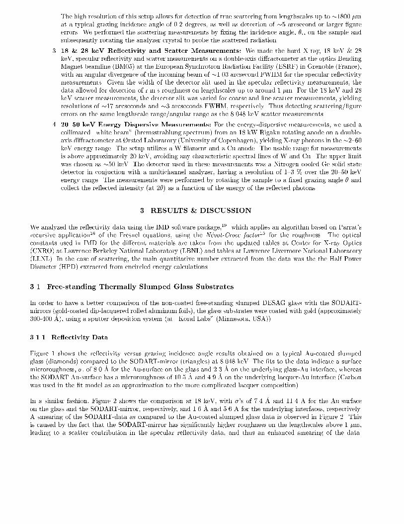
The high resolution of this setup allows for detection of true scattering from lengthscales up to �1800 �m
at a typical grazing incidence angle of 0.2 degrees, as well as detection of �5 arcsecond or larger �gure
errors. We performed the scattering measurements by �xing the incidence angle, �i, on the sample and
subsequently rotating the analyzer crystal to probe the scattered radiation.
3. 18 & 28 keV Re ectivity and Scatter Measurements: We made the hard X-ray, 18 keV & 28
keV, specular re ectivity and scatter measurements on a double-axis di�ractometer at the optics Bending
Magnet beamline (BM05) at the European Synchrotron Radiation Facility (ESRF) in Grenoble (France),
with an angular divergence of the incoming beam of �1.03 arcsecond FWHM for the specular re ectivity
measurements. Given the width of the detector slit used in the specular re ectivity measurements, the
data allowed for detection of r.m.s roughness on lengthscales up to around 1 �m. For the 18 keV and 28
keV scatter measurements, the detector slit was varied for coarse and �ne scatter measurements, yielding
resolutions of �17 arcseconds and �3 arcseconds FWHM, respectively. Thus detecting scattering/�gure
errors on the same lengthscale range/angular range as the 8.048 keV scatter measurements.
4. 20{50 keV Energy Dispersive Measurements: For the energy-dispersive measurements, we used a
collimated \white beam" (bremsstrahlung spectrum) from an 18 kW Rigaku rotating anode on a double-
axis di�ractometer at �rsted Laboratory (University of Copenhagen), yielding X-ray photons in the�2{60
keV energy range. The setup utilizes a W �lament and a Cu anode. The usable range for measurements
is above approximately 20 keV, avoiding any characteristic spectral lines of W and Cu. The upper limit
was chosen as �50 keV. The detector used in these measurements was a Nitrogen-cooled Ge solid state
detector in conjuction with a multichannel analyzer, having a resolution of 1{3 % over the 20{50 keV
energy range. The measurements were performed by rotating the sample to a �xed grazing angle � and
collect the re ected intensity (at 2�) as a function of the energy of the re ected photons.
3. RESULTS & DISCUSSION
We analyzed the re ectivity data using the IMD software package,19 which applies an algorithm based on Parrat's
recursive application16 of the Fresnel equations, using the N�evot-Croce factor15 for the roughness. The optical
constants used in IMD for the di�erent materials are taken from the updated tables at Center for X-ray Optics
(CXRO) at Lawrence Berkeley National Laboratory (LBNL) and tables at Lawrence Livermore National Laboratory
(LLNL). In the case of scattering, the main quantitative number extracted from the data was the the Half Power
Diameter (HPD) extracted from encircled energy calculations.
3.1. Free-standing Thermally Slumped Glass Substrates
In order to have a better comparison of the non-coated free-standing slumped DESAG glass with the SODART-
mirrors (gold-coated dip-lacquered rolled aluminum foils), the glass substrates were coated with gold (approximately
300-400 �A), using a sputter deposition system (at \Koral Labs" (Minnesota, USA)).
3.1.1. Re ectivity Data
Figure 1 shows the re ectivity versus grazing incidence angle results obtained on a typical Au-coated slumped
glass (diamonds) compared to the SODART-mirror (triangles) at 8.048 keV. The �ts to the data indicate a surface
microroughness, �, of 8.0 �A for the Au-surface on the glass and 2.3 �A on the underlying glass-Au interface, whereas
the SODART Au-surface has a microroughness of 10.5 �A and 4.9 �A on the underlying lacquer-Au interface (Carbon
was used in the �t model as an approximation to the more complicated lacquer composition).
In a similar fashion, Figure 2 shows the comparison at 18 keV, with �'s of 7.4 �A and 11.4 �A for the Au-surface
on the glass and the SODART-mirror, respectively, and 1.6 �A and 5.6 �A for the underlying interfaces, respectively.
A smearing of the SODART-data as compared to the Au-coated slumped glass data is observed in Figure 2. This
is caused by the fact that the SODART-mirror has signi�cantly higher roughness on the lengthscales above 1 �m,
leading to a scatter contribution in the specular re ectivity data, and thus an enhanced smearing of the data.
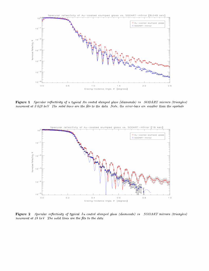
Figure 1. Specular re ectivity of a typical Au-coated slumped glass (diamonds) vs. SODART-mirrors (triangles)
measured at 8.048 keV. The solid lines are the �ts to the data. Note, the error-bars are smaller than the symbols.
Figure 2. Specular re ectivity of typical Au-coated slumped glass (diamonds) vs. SODART-mirrors (triangles)
measured at 18 keV. The solid lines are the �ts to the data.

Figure 3. Specular re ectivity of a typical Au-coated slumped glass (diamonds) at 28 keV. The solid line is the �t
to the data.
A detailed model of the correlation length of the roughness is required to separate the scatter from the specular
re ectivity in the data analysis. At present such a detailed model is not available. A detailed model will however
only change the quality of the �t, and not the derived roughness parameters.
We tested the Au-coated slumped glass at 28 keV (see Figure 3), and the surface roughness results obtained are
similar to the 18 keV case, i.e. 8.0 �A and 1.6 �A on the Au-surface and underlying interface, respectively.
The roughnesses obtained are quite consistent given the change of lengthscales probed at 8.048 keV and at the
harder X-ray energies. The fact that the gold coating on the SODART-mirror was done by thermal evaporation as
opposed to sputtering explains the higher Au-surface roughness on the SODART-mirror.
The lacquer surface on the SODART-mirror has substantially higher roughness than the glass-Au interface on the
slumped glass on the lengthscales probed in these measurements (up to 25 �m at the 8.048 keV measurements and
up to around 1 �m at 18 keV and 28 keV). We measure roughness as low as 1.6 �A on the glass-Au interface on
the slumped glass, consistent with the promising results obtained from coating multilayers directly on the glass (see
section 3.3).
3.1.2. Scattering Data
We performed the scattering measurements at grazing incidence angles of 0.1, 0.2, and 0.4 degrees at 8.048 keV, and
0.15 degrees at 18 keV and 28 keV. In addition, the guard-slit opening was varied in the di�erent setups as well,
thus changing the illuminated surface length during the experiments, ranging from a few millimeter to the full size
of the substrates (�20 cm).
The high resolution scatter data from the best-case free-standing Au-coated slumped glass measured at 8.048 keV,
with a grazing incidence angle, �i, of 0.2 degrees is shown in Figure 4, with the intensity (diamonds) shown as
a function of the analyzer o�set (in arcseconds). The direct beam (resolution function) of the setup (triangles)
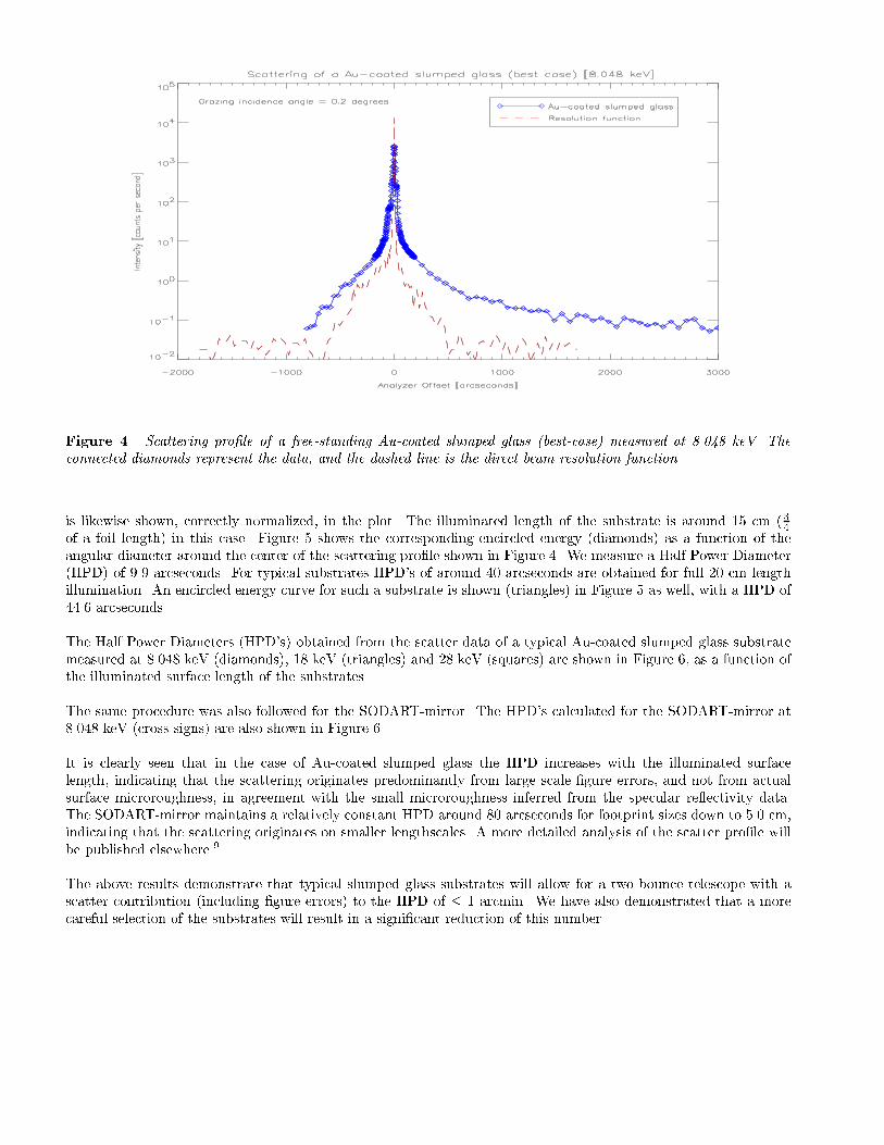
Figure 4. Scattering pro�le of a free-standing Au-coated slumped glass (best-case) measured at 8.048 keV. The
connected diamonds represent the data, and the dashed line is the direct beam resolution function.
is likewise shown, correctly normalized, in the plot. The illuminated length of the substrate is around 15 cm ( 34
of a foil length) in this case. Figure 5 shows the corresponding encircled energy (diamonds) as a function of the
angular diameter around the center of the scattering pro�le shown in Figure 4. We measure a Half Power Diameter
(HPD) of 9.9 arcseconds. For typical substrates HPD's of around 40 arcseconds are obtained for full 20 cm length
illumination. An encircled energy curve for such a substrate is shown (triangles) in Figure 5 as well, with a HPD of
44.6 arcseconds.
The Half Power Diameters (HPD's) obtained from the scatter data of a typical Au-coated slumped glass substrate
measured at 8.048 keV (diamonds), 18 keV (triangles) and 28 keV (squares) are shown in Figure 6, as a function of
the illuminated surface length of the substrates.
The same procedure was also followed for the SODART-mirror. The HPD's calculated for the SODART-mirror at
8.048 keV (cross-signs) are also shown in Figure 6.
It is clearly seen that in the case of Au-coated slumped glass the HPD increases with the illuminated surface
length, indicating that the scattering originates predominantly from large scale �gure errors, and not from actual
surface microroughness, in agreement with the small microroughness inferred from the specular re ectivity data.
The SODART-mirror maintains a relatively constant HPD around 80 arcseconds for footprint sizes down to 5.0 cm,
indicating that the scattering originates on smaller lengthscales. A more detailed analysis of the scatter pro�le will
be published elsewhere.9
The above results demonstrate that typical slumped glass substrates will allow for a two-bounce telescope with a
scatter contribution (including �gure errors) to the HPD of � 1 arcmin. We have also demonstrated that a more
careful selection of the substrates will result in a signi�cant reduction of this number.

Figure 5. Encircled energy as a function of angular diameter around the center of the scattering pro�le for a Au-
coated slumped glass measured at 8.048 keV. The connected diamonds represent the best case, whereas the connected
triangles represent typical substrates.
Figure 6. Half Power Diameter (HPD)'s as a function of the illuminated substrate surface length for the Au-coated
slumped glass vs. SODART-mirrors.

Figure 7. The HEFT 6-shell single bounce cylindrical prototype.
3.2. Prototype Mounted Thermally Slumped Glass Substrates
We built a prototype cylindrical �xture with 3 realistic W/Si multilayer-coated and 3 un-coated (no Au-layer)
thermally slumped glass substrates mounted, using the scheme developed for HEFT.4 The cylinder consists of solid
aluminum, with the foils carefully attached (see Figure 7). The di�erent foils are separated by precisely machined
graphite rods that position the substrates in the required cylindrical shape.
In order to compare the quality of a mounted optic with the free-standing optics, we performed a series of scattering
measurements on the un-coated and multilayer-coated mounted foils. A representative scattering measurement of
an un-coated mounted foil measured at 0.2 degree grazing incidence angle and the corresponding encircled energy
curve are shown in Figure 8 and Figure 9, respectively.
Figure 9 shows that a HPD of around 40 arcsecond (in the range of a typical free-standing slumped glass substrate)
is obtained from the prototype mounted slumped glass. In addition, no increase in HPD has been observed for
the multilayer-coated foils. This clearly demonstrates that no additional scatter is introduced due to the multilayer
coating or the mounting procedure developed for HEFT.
3.3. Multilayer Coated Thermally Slumped Glass Substrates
We coated free-standing slumped glass substrates with W/Si depth graded multilayers at a sputter deposition facility
at Bell Labs (Lucent Technologies)20 and subsequently tested the foils in X-ray specular re ectivity measurements
both at 8.048 keV and 28 keV. Figure 10 and 11 show the re ectivity results obtained on a n = 200 bilayer W/Si
depth graded multilayer. The grading of the bilayer thickness di for the i'th bilayer (with the bilayer index i ranging
from 1 to n, with i = n being the bilayer next to the substrate) follows a power law distribution given by12
di =a
(b+ i)c(1)
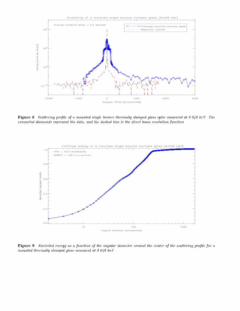
Figure 8. Scattering pro�le of a mounted single bounce thermally slumped glass optic measured at 8.048 keV. The
connected diamonds represent the data, and the dashed line is the direct beam resolution function.
Figure 9. Encircled energy as a function of the angular diameter around the center of the scattering pro�le for a
mounted thermally slumped glass measured at 8.048 keV.
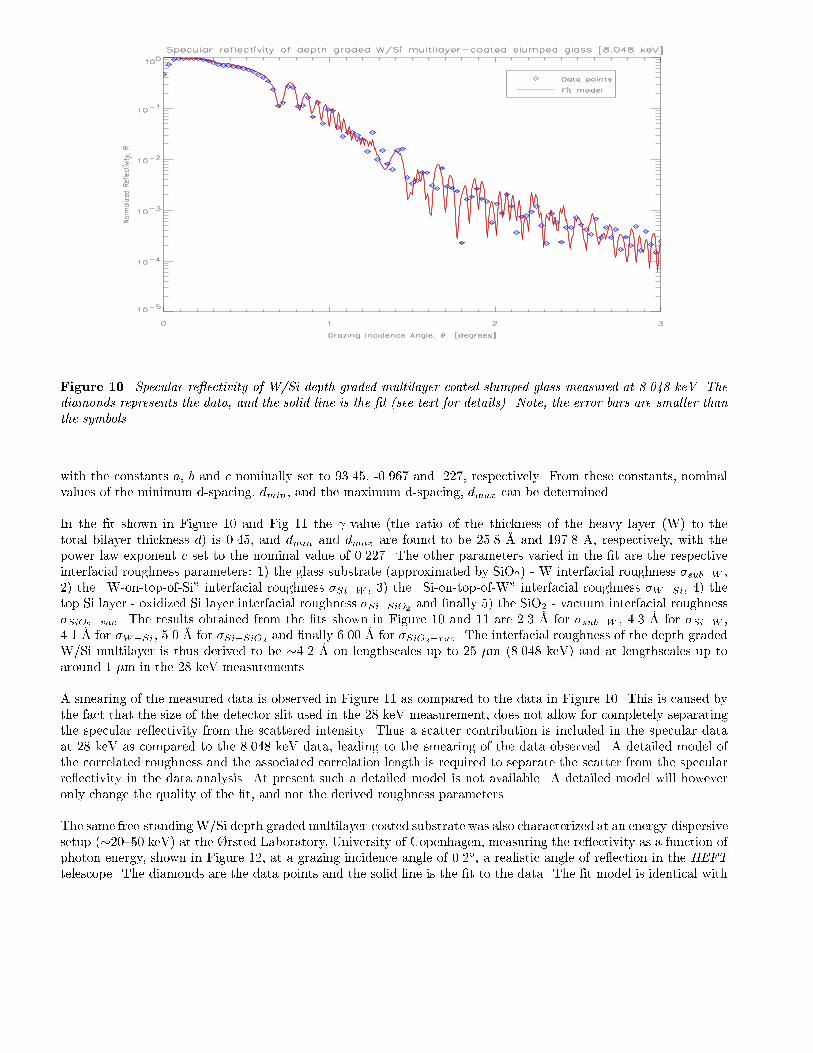
Figure 10. Specular re ectivity of W/Si depth graded multilayer-coated slumped glass measured at 8.048 keV. The
diamonds represents the data, and the solid line is the �t (see text for details). Note, the error bars are smaller than
the symbols.
with the constants a, b and c nominally set to 93.45, -0.967 and .227, respectively. From these constants, nominal
values of the minimum d-spacing, dmin, and the maximum d-spacing, dmax can be determined.
In the �t shown in Figure 10 and Fig 11 the -value (the ratio of the thickness of the heavy layer (W) to the
total bilayer thickness d) is 0.45, and dmin and dmax are found to be 25.8 �A and 197.8 �A, respectively, with the
power law exponent c set to the nominal value of 0.227. The other parameters varied in the �t are the respective
interfacial roughness parameters: 1) the glass substrate (approximated by SiO2) - W interfacial roughness �sub�W ,
2) the \W-on-top-of-Si" interfacial roughness �Si�W , 3) the \Si-on-top-of-W" interfacial roughness �W�Si, 4) the
top Si layer - oxidized Si layer interfacial roughness �Si�SiO2and �nally 5) the SiO2 - vacuum interfacial roughness
�SiO2�vac. The results obtained from the �ts shown in Figure 10 and 11 are 2.3 �A for �sub�W , 4.3 �A for �Si�W ,
4.1 �A for �W�Si, 5.0 �A for �Si�SiO2and �nally 6.00 �A for �SiO2�vac
. The interfacial roughness of the depth graded
W/Si multilayer is thus derived to be �4.2 �A on lengthscales up to 25 �m (8.048 keV) and at lengthscales up to
around 1 �m in the 28 keV measurements.
A smearing of the measured data is observed in Figure 11 as compared to the data in Figure 10. This is caused by
the fact that the size of the detector slit used in the 28 keV measurement, does not allow for completely separating
the specular re ectivity from the scattered intensity. Thus a scatter contribution is included in the specular data
at 28 keV as compared to the 8.048 keV data, leading to the smearing of the data observed. A detailed model of
the correlated roughness and the associated correlation length is required to separate the scatter from the specular
re ectivity in the data analysis. At present such a detailed model is not available. A detailed model will however
only change the quality of the �t, and not the derived roughness parameters.
The same free-standingW/Si depth graded multilayer-coated substrate was also characterized at an energy-dispersive
setup (�20{50 keV) at the �rsted Laboratory, University of Copenhagen, measuring the re ectivity as a function of
photon energy, shown in Figure 12, at a grazing incidence angle of 0.2�, a realistic angle of re ection in the HEFT
telescope. The diamonds are the data points and the solid line is the �t to the data. The �t model is identical with

Figure 11. Specular re ectivity of W/Si depth graded multilayer-coated thermally slumped glass measured at 28
keV. The diamonds represents the data, and the solid line is the �t (see text for details).
Energy dispersive scan of depth graded W/Si ml−coated slumped glass
(θ=0.2 deg )
20 25 30 35 40 45 50Energy, E [keV]
0.0
0.2
0.4
0.6
0.8
1.0
Refle
ctanc
e, R
Figure 12. Normalized re ectivity as a function of energy of W/Si depth graded multilayer-coated thermally slumped
glass at a grazing incidence angle of 0.2�. The diamonds represents the data, and the solid line is the �t (see text
for details).

the model used in the 8.048 keV and 28 keV specular re ectivity measurements (described in detail above). It is
seen from the plot that the energy dispersive result is consistent with the 8.048 keV and 28 keV results, yielding an
interfacial roughness of the depth graded W/Si multilayer of �4.2 �A.
4. CONCLUSIONS
We have characterized the thermally slumped glass substrates from the HEFT telescope mission using X-ray specular
re ectivity and scattering measurements at 8.048 keV, 18 keV and 28 keV. We compared these results to the
SODART-mirror from the SRG mission.
Substantially lower r.m.s surface roughness is measured for the slumped glass compared to the SODART-mirror
on the lengthscales probed in the specular re ectivity measurements. In addition, specular re ectivity and energy-
dispersive measurements of depth graded W/Si multilayer-coated slumped glass foils yields interfacial roughness as
low as �4.2 �A, thus demonstrating the capability of coating slumped glass substrates with high quality depth graded
multilayer structures.
Scatter measurements yield Half Power Diameters (HPD's) of around 10 arcseconds for the best slumped glass
substrates, and typically around 40 arcseconds for full illuminated pieces, whereas the SODART-mirror yields HPD's
around 80 arcseconds. In addition, it has been shown that the HPD of the slumped glass varies with the illuminated
length of the substrate, whereas the SODART-mirror maintains a constant HPD of around 80 arcseconds more or less
independent of the illuminated length, indicating that the scattering from the slumped glass originates predominantly
from large scale �gure errors.
We tested a prototype cylindrical slumped glass �xture as well. A representative result from an un-coated mounted
slumped glass showed an HPD of around 40 arcseconds, similar to the typical free-standing substrates. This shows
that no increase in scatter is introduced in the mounting procedure developed for HEFT. This was also veri�ed for
the multilayer coated substrates.
We have demonstrated that with a careful selection of the thermally slumped glass substrates, the surface scatter
contribution, plus any contribution from the mounting procedure, holds promise for producing a subarcminute Half
Power Diameter hard X-ray telescope.
ACKNOWLEDGMENTS
The authors wish to thank the European Synchrotron Radiation Facility (ESRF) for the allocated beamtime and
the technical support during the experiments, and the continuing support in this project.
REFERENCES
1. F. E. Christensen, A. Hornstrup, P. K. Frederiksen, S. Abdali, P. Grunds�e, et al., Proc. SPIE 2515 (1995),
p. 458{467.
2. F. E. Christensen, A. Hornstrup, N. J. Westergaard, H. W. Schnopper, J. Wood & K. Parker, Proc. SPIE
1546 (1991), p. 160{167.
3. F. E. Christensen, Z. Shou-Hua, A. Hornstrup, H. W. Schnopper, P. Plag & J. Wood, J. X-ray Sci. Tech. 3
(1991), p. 1.
4. W. W. Craig, F. E. Christensen, T. A. Decker, C. J. Hailey, F. A. Harrison, et al., Proc. SPIE 3445 (1999), p.
112{120.
5. P. Gorenstein, Hard X-ray Telescope (HXT) With Simultaneous Multiwavelength Observing From UV To 1
MeV, Proposal for New Mission Concepts in Astrophysics, NRA 94-OSS-15, (1994).
6. F. A. Harrison et al., A Comprehensive technology Development Program for the Constellation Mission Hard
X-ray Telescope, A Proposal to The National Aeronautics and Space Administration, (1997).

7. F. A. Harrison (PI), The High-Energy Focusing Telescope (HEFT): A Balloon-Borne Hard X-ray/Soft Gamma-
Ray Experiment, Proposal for High Energy Astrophysics Supporting Research and Technology Program, NRA
99-OSS-01 HEA - High Energy Astrophysics, (1999).
8. F. A. Harrison & T. A. Prince (PI's), The High-Energy Focusing Telescope (HEFT): A Balloon-Borne Hard
X-ray/Soft Gamma-Ray Experiment, Proposal for High Energy Astrophysics Supporting Research and Tech-
nology Program, NRA 95-OSS-17, (1996).
9. A. M. Hussain, Multilayer X-ray Telescopes, Ph.D.-thesis, University of Copenhagen (1999).
10. A. M. Hussain, F. E. Christensen, G. Pareschi & H. F. Poulsen, Proc. SPIE 3444 (1998), p. 443{450.
11. M. A. Jimenez-Garate, W. W. Craig & C. J. Hailey, Proc. SPIE 3444 (1998), p. 622{633.
12. K. D. Joensen, F. E. Christensen, H. W. Schnopper, P. Gorenstein, J. Susini, et al., Proc. SPIE 1736 (1992),
p. 239{248.
13. A. Kruse (Product Manager), Private meeting at Deutsche Spezialglas AG (DESAG) in Gr�unenplan, Germany
(February 28. 1996).
14. P. H. Mao, F. A. Harrison, D. W. Windt & F. E. Christensen, Appl. Optics 38(22) (1999).
15. L. N�evot & P. Croce, Rev. Phys. Appl. 15 (1980), p. 761{779.
16. L. G. Parrat, Phys. Rev. 95 (1954), p. 359-369.
17. H. W. Schnopper, Proc. SPIE 2279 (1994), p. 412.
18. H. Tananbaum, N. White & P. Sullivan, eds., Proceedings of The High Throughput X-ray Spectroscopy Work-
shop, Boston, MA, 29. september - 1 October (1996).
19. D. L. Windt, Computers in Physics 12 (1998), p. 360{370.
20. D. L. Windt & W. K. Waskiewicz, J. Vac. Sci. Technol. B 12 (1994), p. 3826{3832.
Related Documents