Norwegian Defense Research Establishment (FFI) PO Box 25 NO-2027 Kjeller NORWAY [email protected] ABSTRACT This paper presents analysis of sea-clutter measurements recorded using FFI’s PicoSAR radar operating at X-band mounted in a helicopter platform. A helicopter offers maneuvering in both horizontal and vertical direction at slow speed that gives additional flexibility when compared to a fixed wing platform. The rather small size of the helicopter platform causes challenges in recording sea-clutter in high wind conditions. Measurements of sea-clutter reflectivity and analysis of Doppler characteristics recorded during circular trajectory flights and vertical climbing flight profiles will be presented. Measurements covering a range of viewing angles of the sea surface both in grazing and azimuth will be discussed as well as the process of extracting high quality data sets from the long sequence of recorded sea-clutter data. The data sets represent samples from different sea conditions ranging from an almost flat sea surface at very low wind speed to a rough sea surface at high wind speed. 1.0 INTRODUCTION Radar sea-clutter has been studied for a long time and comprehensive material has been reported in the literature (e.g. [1]). These cover topics from a broad range including analysis of temporal and spatial behaviour of experimental data as well as theoretical studies. Even though the amount of knowledge is comprehensive, a full understanding of the phenomena involved in the scattering of a sea surface is not yet achieved. Characteristics of sea-clutter in open sea versus near coast conditions where land and islands interfere are important to better understand. The measurements of reflectivity and analysis of Doppler characteristics and amplitude distributions described in this paper will contribute to the common knowledge in covering some areas of this parameter space. As will be described in the experiment section the measurement conditions led to a short fetch and results therefore represent comparison of results in an immature sea towards modelled and reported sea-clutter in open sea conditions. FFI has an ultralight radar system made by SELEX named PicoSAR (Figure 1) that operates at X-band at VV polarisation. Its primary use with premade menus is directed towards Synthetic Aperture Radar (SAR) studies at FFI. The radar output has been further used for Inverse-SAR (ISAR) studies using FFI software. The radar has in addition to its premade modes a set of advanced menus where detailed control can be specified. Since it is equipped with a GPS and Inertial Measurement Unit (IMU) and access to data records per pulse at a de-ramped IQ-level the radar was viewed as applicable for sea-clutter analysis. Software for analysing sea-clutter data from PicoSAR has been developed for use in *the NATO SET-185 Task Group and extract of FFI’s work conducted in relation to SET-185 constitutes the background for writing up this paper. STO-MP-SET-239 1 - 1 PUBLIC RELEASE PUBLIC RELEASE X-Band Radar Sea-Clutter Measurements from Low-Medium Grazing Angles Recorded from a Helicopter Platform Terje Johnsen, Nina Ødegaard and Atle Onar Knapskog

Welcome message from author
This document is posted to help you gain knowledge. Please leave a comment to let me know what you think about it! Share it to your friends and learn new things together.
Transcript
Norwegian Defense Research Establishment (FFI) PO Box 25
NO-2027 Kjeller NORWAY
ABSTRACT
This paper presents analysis of sea-clutter measurements recorded using FFI’s PicoSAR radar operating at X-band mounted in a helicopter platform. A helicopter offers maneuvering in both horizontal and vertical direction at slow speed that gives additional flexibility when compared to a fixed wing platform. The rather small size of the helicopter platform causes challenges in recording sea-clutter in high wind conditions. Measurements of sea-clutter reflectivity and analysis of Doppler characteristics recorded during circular trajectory flights and vertical climbing flight profiles will be presented. Measurements covering a range of viewing angles of the sea surface both in grazing and azimuth will be discussed as well as the process of extracting high quality data sets from the long sequence of recorded sea-clutter data. The data sets represent samples from different sea conditions ranging from an almost flat sea surface at very low wind speed to a rough sea surface at high wind speed.
1.0 INTRODUCTION
Radar sea-clutter has been studied for a long time and comprehensive material has been reported in the literature (e.g. [1]). These cover topics from a broad range including analysis of temporal and spatial behaviour of experimental data as well as theoretical studies. Even though the amount of knowledge is comprehensive, a full understanding of the phenomena involved in the scattering of a sea surface is not yet achieved. Characteristics of sea-clutter in open sea versus near coast conditions where land and islands interfere are important to better understand. The measurements of reflectivity and analysis of Doppler characteristics and amplitude distributions described in this paper will contribute to the common knowledge in covering some areas of this parameter space. As will be described in the experiment section the measurement conditions led to a short fetch and results therefore represent comparison of results in an immature sea towards modelled and reported sea-clutter in open sea conditions.
FFI has an ultralight radar system made by SELEX named PicoSAR (Figure 1) that operates at X-band at VV polarisation. Its primary use with premade menus is directed towards Synthetic Aperture Radar (SAR) studies at FFI. The radar output has been further used for Inverse-SAR (ISAR) studies using FFI software. The radar has in addition to its premade modes a set of advanced menus where detailed control can be specified. Since it is equipped with a GPS and Inertial Measurement Unit (IMU) and access to data records per pulse at a de-ramped IQ-level the radar was viewed as applicable for sea-clutter analysis. Software for analysing sea-clutter data from PicoSAR has been developed for use in *the NATO SET-185 Task Group and extract of FFI’s work conducted in relation to SET-185 constitutes the background for writing up this paper.
STO-MP-SET-239 1 - 1
PUBLIC RELEASE
PUBLIC RELEASE
X-Band Radar Sea-Clutter Measurements from Low-Medium Grazing Angles Recorded from a Helicopter Platform
Terje Johnsen, Nina Ødegaard and Atle Onar Knapskog
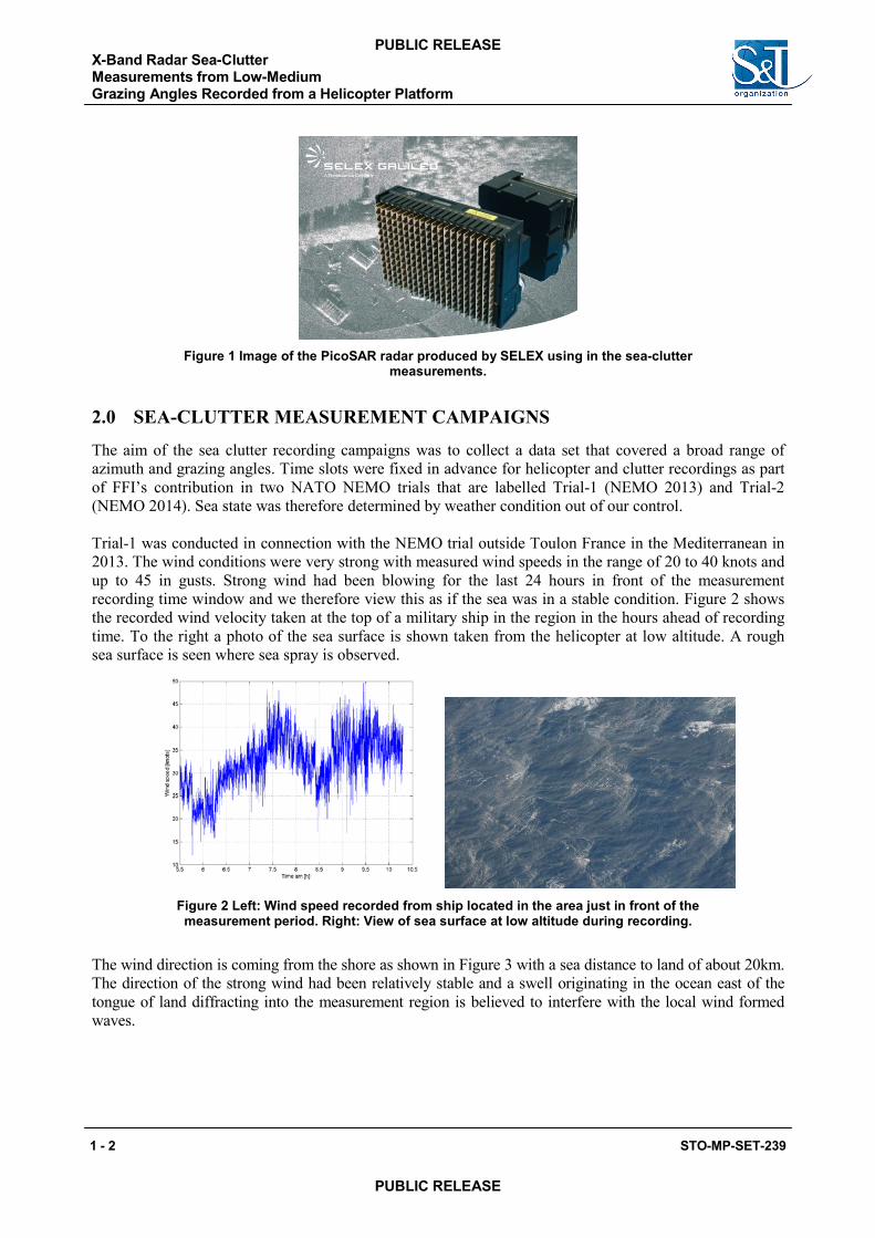
Figure 1 Image of the PicoSAR radar produced by SELEX using in the sea-clutter measurements.
2.0 SEA-CLUTTER MEASUREMENT CAMPAIGNS
The aim of the sea clutter recording campaigns was to collect a data set that covered a broad range of azimuth and grazing angles. Time slots were fixed in advance for helicopter and clutter recordings as part of FFI’s contribution in two NATO NEMO trials that are labelled Trial-1 (NEMO 2013) and Trial-2 (NEMO 2014). Sea state was therefore determined by weather condition out of our control.
Trial-1 was conducted in connection with the NEMO trial outside Toulon France in the Mediterranean in 2013. The wind conditions were very strong with measured wind speeds in the range of 20 to 40 knots and up to 45 in gusts. Strong wind had been blowing for the last 24 hours in front of the measurement recording time window and we therefore view this as if the sea was in a stable condition. Figure 2 shows the recorded wind velocity taken at the top of a military ship in the region in the hours ahead of recording time. To the right a photo of the sea surface is shown taken from the helicopter at low altitude. A rough sea surface is seen where sea spray is observed.
Figure 2 Left: Wind speed recorded from ship located in the area just in front of the measurement period. Right: View of sea surface at low altitude during recording.
The wind direction is coming from the shore as shown in Figure 3 with a sea distance to land of about 20km. The direction of the strong wind had been relatively stable and a swell originating in the ocean east of the tongue of land diffracting into the measurement region is believed to interfere with the local wind formed waves.
X-Band Radar Sea-Clutter Measurements from Low-Medium Grazing Angles Recorded from a Helicopter Platform
1 - 2 STO-MP-SET-239
PUBLIC RELEASE
PUBLIC RELEASE
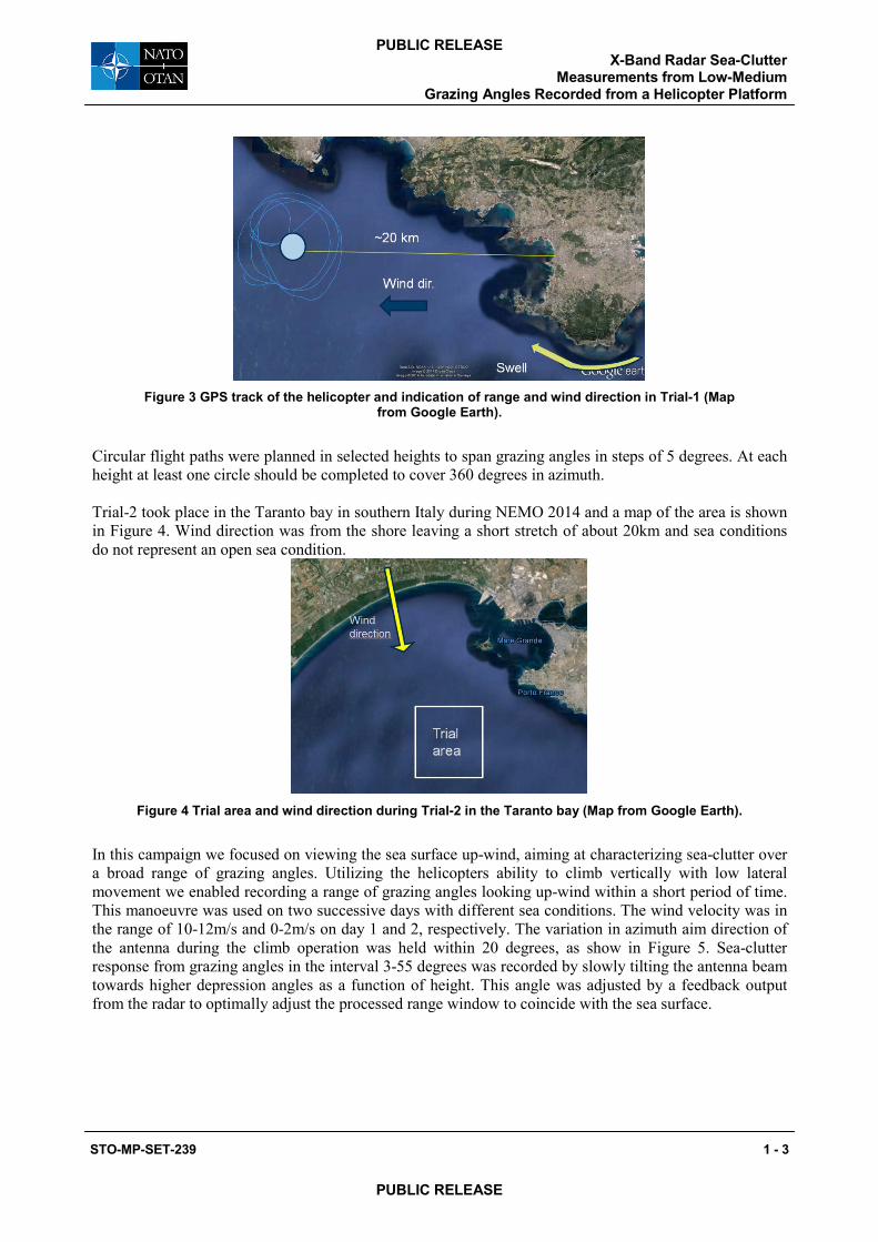
Figure 3 GPS track of the helicopter and indication of range and wind direction in Trial-1 (Map from Google Earth).
Circular flight paths were planned in selected heights to span grazing angles in steps of 5 degrees. At each height at least one circle should be completed to cover 360 degrees in azimuth.
Trial-2 took place in the Taranto bay in southern Italy during NEMO 2014 and a map of the area is shown in Figure 4. Wind direction was from the shore leaving a short stretch of about 20km and sea conditions do not represent an open sea condition.
Figure 4 Trial area and wind direction during Trial-2 in the Taranto bay (Map from Google Earth).
In this campaign we focused on viewing the sea surface up-wind, aiming at characterizing sea-clutter over a broad range of grazing angles. Utilizing the helicopters ability to climb vertically with low lateral movement we enabled recording a range of grazing angles looking up-wind within a short period of time. This manoeuvre was used on two successive days with different sea conditions. The wind velocity was in the range of 10-12m/s and 0-2m/s on day 1 and 2, respectively. The variation in azimuth aim direction of the antenna during the climb operation was held within 20 degrees, as show in Figure 5. Sea-clutter response from grazing angles in the interval 3-55 degrees was recorded by slowly tilting the antenna beam towards higher depression angles as a function of height. This angle was adjusted by a feedback output from the radar to optimally adjust the processed range window to coincide with the sea surface.
X-Band Radar Sea-Clutter Measurements from Low-Medium
Grazing Angles Recorded from a Helicopter Platform
STO-MP-SET-239 1 - 3
PUBLIC RELEASE
PUBLIC RELEASE
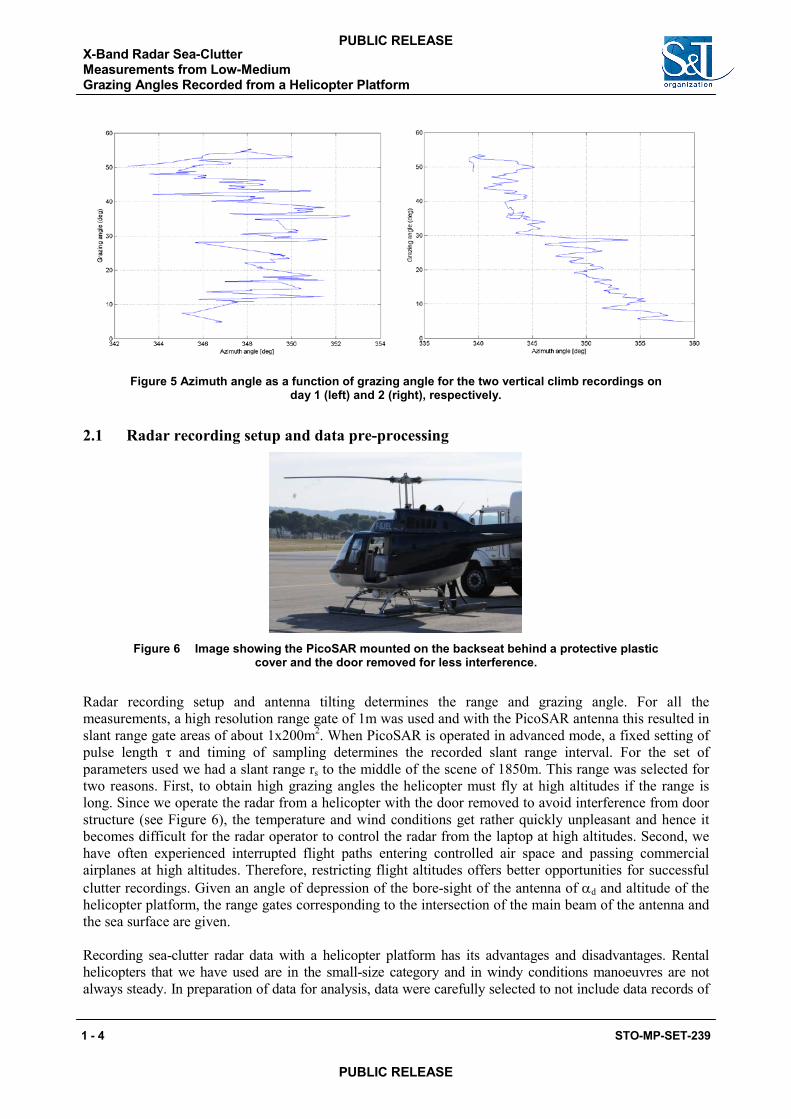
Figure 5 Azimuth angle as a function of grazing angle for the two vertical climb recordings on day 1 (left) and 2 (right), respectively.
2.1 Radar recording setup and data pre-processing
Figure 6 Image showing the PicoSAR mounted on the backseat behind a protective plastic cover and the door removed for less interference.
Radar recording setup and antenna tilting determines the range and grazing angle. For all the measurements, a high resolution range gate of 1m was used and with the PicoSAR antenna this resulted in slant range gate areas of about 1x200m2. When PicoSAR is operated in advanced mode, a fixed setting of pulse length τ and timing of sampling determines the recorded slant range interval. For the set of parameters used we had a slant range rs to the middle of the scene of 1850m. This range was selected for two reasons. First, to obtain high grazing angles the helicopter must fly at high altitudes if the range is long. Since we operate the radar from a helicopter with the door removed to avoid interference from door structure (see Figure 6), the temperature and wind conditions get rather quickly unpleasant and hence it becomes difficult for the radar operator to control the radar from the laptop at high altitudes. Second, we have often experienced interrupted flight paths entering controlled air space and passing commercial airplanes at high altitudes. Therefore, restricting flight altitudes offers better opportunities for successful clutter recordings. Given an angle of depression of the bore-sight of the antenna of αd and altitude of the helicopter platform, the range gates corresponding to the intersection of the main beam of the antenna and the sea surface are given.
Recording sea-clutter radar data with a helicopter platform has its advantages and disadvantages. Rental helicopters that we have used are in the small-size category and in windy conditions manoeuvres are not always steady. In preparation of data for analysis, data were carefully selected to not include data records of
X-Band Radar Sea-Clutter Measurements from Low-Medium Grazing Angles Recorded from a Helicopter Platform
1 - 4 STO-MP-SET-239
PUBLIC RELEASE
PUBLIC RELEASE
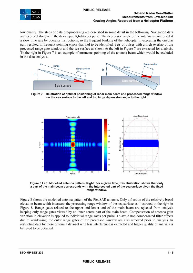
low quality. The steps of data pre-processing are described in some detail in the following. Navigation data are recorded along with the de-ramped IQ-data per pulse. The depression angle of the antenna is controlled at a slow time rate by operator instructions, so the frequent banking of the helicopter in executing the circular path resulted in frequent pointing errors that had to be identified. Sets of pulses with a high overlap of the processed range gate window and the sea surface as shown to the left in Figure 7 are extracted for analysis. To the right in Figure 7 is an example of erroneous pointing of the antenna beam which would be excluded in the data analysis.
Figure 7 Illustration of optimal positioning of radar main beam and processed range window on the sea surface to the left and too large depression angle to the right.
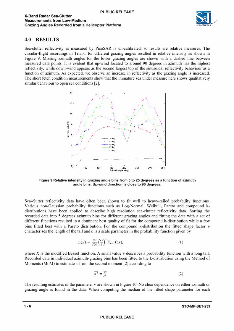
Figure 8 Left: Modelled antenna pattern. Right: For a given time, this illustration shows that only a part of the main beam corresponds with the intersected part of the sea surface given the fixed
range window.
Figure 8 shows the modelled antenna pattern of the PicoSAR antenna. Only a fraction of the relatively broad elevation beam-width intersects the processing range window of the sea surface as illustrated to the right in Figure 8. Range gates related to the upper and lower end of the main beam are rejected from analysis keeping only range gates viewed by an inner centre part of the main beam. Compensation of antenna gain variation in elevation is applied to individual range gates per pulse. To avoid non-compensated filter effects due to windowing, the outer range gates of the processed window are also removed prior to analysis. In restricting data by these criteria a data-set with less interference is extracted and higher quality of analysis is believed to be obtained.
X-Band Radar Sea-Clutter Measurements from Low-Medium
Grazing Angles Recorded from a Helicopter Platform
STO-MP-SET-239 1 - 5
PUBLIC RELEASE
PUBLIC RELEASE
4.0 RESULTS
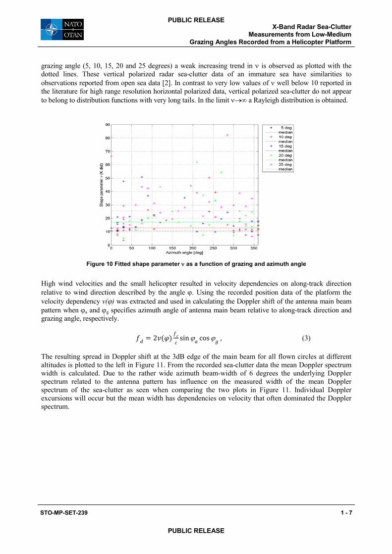
Sea-clutter reflectivity as measured by PicoSAR is un-calibrated, so results are relative measures. The circular-flight recordings in Trial-1 for different grazing angles resulted in relative intensity as shown in Figure 9. Missing azimuth angles for the lower grazing angles are shown with a dashed line between measured data points. It is evident that up-wind located to around 90 degrees in azimuth has the highest reflectivity, while down-wind appears as the second largest top of the sinusoidal reflectivity behaviour as a function of azimuth. As expected, we observe an increase in reflectivity as the grazing angle is increased. The short fetch condition measurements show that the immature sea under measure here shows qualitatively similar behaviour to open sea conditions [2].
Figure 9 Relative intensity in grazing angle bins from 5 to 25 degrees as a function of azimuth angle bins. Up-wind direction is close to 90 degrees.
Sea-clutter reflectivity data have often been shown to fit well to heavy-tailed probability functions. Various non-Gaussian probability functions such as Log-Normal, Weibull, Pareto and compound k-distributions have been applied to describe high resolution sea-clutter reflectivity data. Sorting the recorded data into 5 degrees azimuth bins for different grazing angles and fitting the data with a set of different functions resulted in a dominant best quality of fit for the compound k-distribution while a few bins fitted best with a Pareto distribution. For the compound k-distribution the fitted shape factor ν characterises the length of the tail and c is a scale parameter in the probability function given by
𝑝𝑝(𝑥𝑥) = 2𝑐𝑐Γ(ν)
�𝑐𝑐𝑐𝑐2�
ν𝐾𝐾ν−1(𝑐𝑐𝑥𝑥), (1)
where K is the modified Bessel function. A small value ν describes a probability function with a long tail. Recorded data in individual azimuth-grazing bins has been fitted to the k-distribution using the Method of Moments (MoM) to estimate ν from the second moment [2] according to
𝑥𝑥2��� = 4ν𝑐𝑐2
(2)
The resulting estimates of the parameter ν are shown in Figure 10. No clear dependence on either azimuth or grazing angle is found in the data. When computing the median of the fitted shape parameter for each
X-Band Radar Sea-Clutter Measurements from Low-Medium Grazing Angles Recorded from a Helicopter Platform
1 - 6 STO-MP-SET-239
PUBLIC RELEASE
PUBLIC RELEASE
grazing angle (5, 10, 15, 20 and 25 degrees) a weak increasing trend in ν is observed as plotted with the dotted lines. These vertical polarized radar sea-clutter data of an immature sea have similarities to observations reported from open sea data [2]. In contrast to very low values of ν well below 10 reported in the literature for high range resolution horizontal polarized data, vertical polarized sea-clutter do not appear to belong to distribution functions with very long tails. In the limit ν→∞ a Rayleigh distribution is obtained.
Figure 10 Fitted shape parameter ν as a function of grazing and azimuth angle
High wind velocities and the small helicopter resulted in velocity dependencies on along-track direction relative to wind direction described by the angle ϕ. Using the recorded position data of the platform the velocity dependency v(ϕ) was extracted and used in calculating the Doppler shift of the antenna main beam pattern when ϕa and ϕg specifies azimuth angle of antenna main beam relative to along-track direction and grazing angle, respectively.
𝑓𝑓𝑑𝑑 = 2𝑣𝑣(𝜑𝜑)𝑓𝑓𝑐𝑐𝑐𝑐
sin ϕ𝑎𝑎 cos ϕ𝑔𝑔 , (3)
The resulting spread in Doppler shift at the 3dB edge of the main beam for all flown circles at different altitudes is plotted to the left in Figure 11. From the recorded sea-clutter data the mean Doppler spectrum width is calculated. Due to the rather wide azimuth beam-width of 6 degrees the underlying Doppler spectrum related to the antenna pattern has influence on the measured width of the mean Doppler spectrum of the sea-clutter as seen when comparing the two plots in Figure 11. Individual Doppler excursions will occur but the mean width has dependencies on velocity that often dominated the Doppler spectrum.
X-Band Radar Sea-Clutter Measurements from Low-Medium
Grazing Angles Recorded from a Helicopter Platform
STO-MP-SET-239 1 - 7
PUBLIC RELEASE
PUBLIC RELEASE
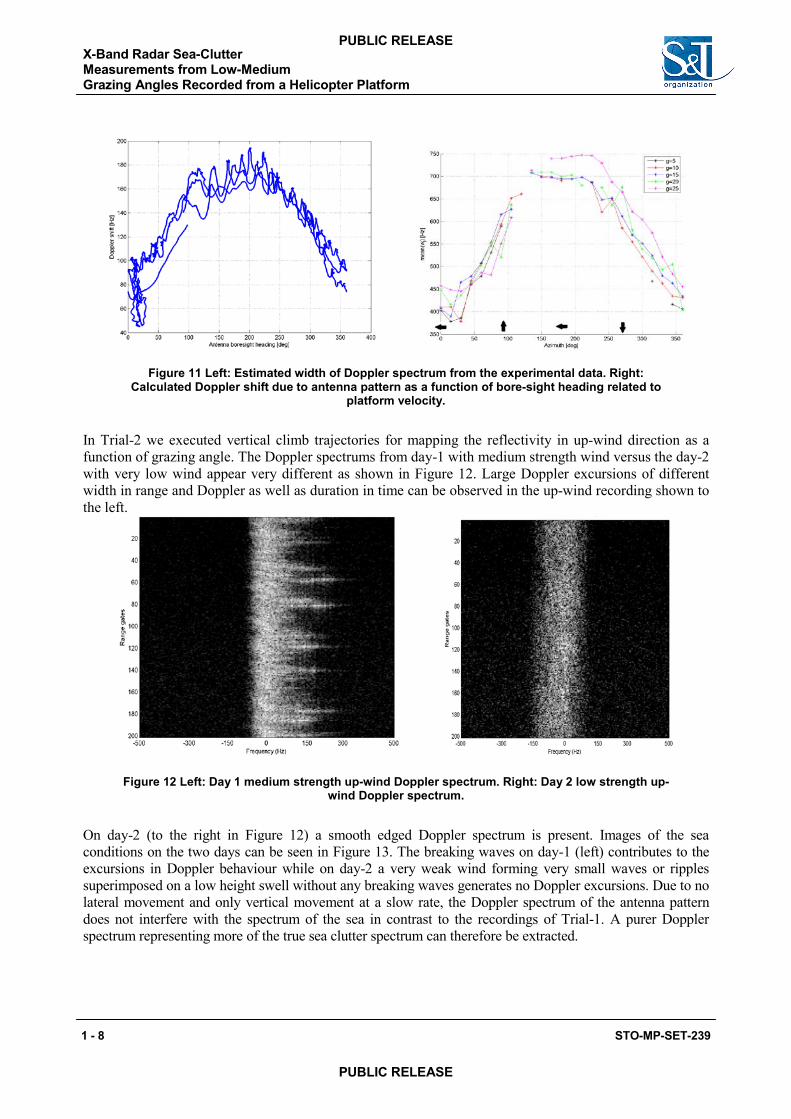
Figure 11 Left: Estimated width of Doppler spectrum from the experimental data. Right: Calculated Doppler shift due to antenna pattern as a function of bore-sight heading related to
platform velocity.
In Trial-2 we executed vertical climb trajectories for mapping the reflectivity in up-wind direction as a function of grazing angle. The Doppler spectrums from day-1 with medium strength wind versus the day-2 with very low wind appear very different as shown in Figure 12. Large Doppler excursions of different width in range and Doppler as well as duration in time can be observed in the up-wind recording shown to the left.
Figure 12 Left: Day 1 medium strength up-wind Doppler spectrum. Right: Day 2 low strength up-wind Doppler spectrum.
On day-2 (to the right in Figure 12) a smooth edged Doppler spectrum is present. Images of the sea conditions on the two days can be seen in Figure 13. The breaking waves on day-1 (left) contributes to the excursions in Doppler behaviour while on day-2 a very weak wind forming very small waves or ripples superimposed on a low height swell without any breaking waves generates no Doppler excursions. Due to no lateral movement and only vertical movement at a slow rate, the Doppler spectrum of the antenna pattern does not interfere with the spectrum of the sea in contrast to the recordings of Trial-1. A purer Doppler spectrum representing more of the true sea clutter spectrum can therefore be extracted.
X-Band Radar Sea-Clutter Measurements from Low-Medium Grazing Angles Recorded from a Helicopter Platform
1 - 8 STO-MP-SET-239
PUBLIC RELEASE
PUBLIC RELEASE
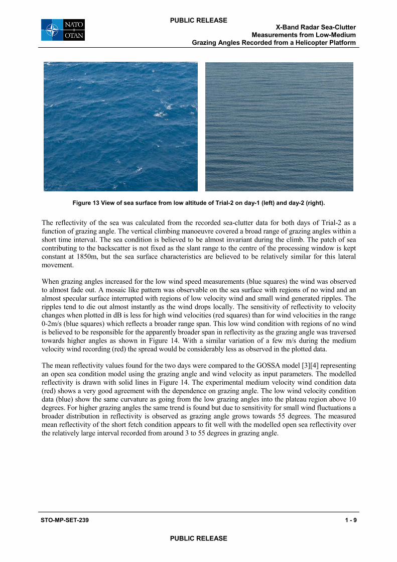
Figure 13 View of sea surface from low altitude of Trial-2 on day-1 (left) and day-2 (right).
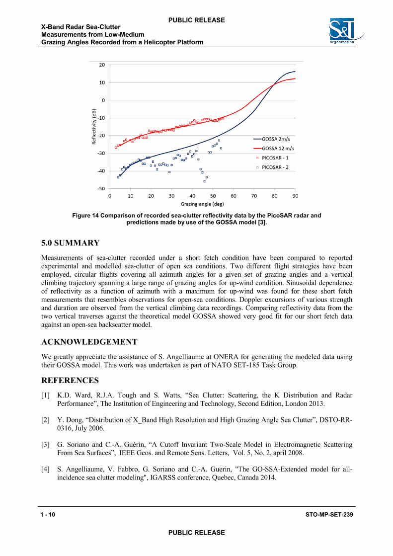
The reflectivity of the sea was calculated from the recorded sea-clutter data for both days of Trial-2 as a function of grazing angle. The vertical climbing manoeuvre covered a broad range of grazing angles within a short time interval. The sea condition is believed to be almost invariant during the climb. The patch of sea contributing to the backscatter is not fixed as the slant range to the centre of the processing window is kept constant at 1850m, but the sea surface characteristics are believed to be relatively similar for this lateral movement.
When grazing angles increased for the low wind speed measurements (blue squares) the wind was observed to almost fade out. A mosaic like pattern was observable on the sea surface with regions of no wind and an almost specular surface interrupted with regions of low velocity wind and small wind generated ripples. The ripples tend to die out almost instantly as the wind drops locally. The sensitivity of reflectivity to velocity changes when plotted in dB is less for high wind velocities (red squares) than for wind velocities in the range 0-2m/s (blue squares) which reflects a broader range span. This low wind condition with regions of no wind is believed to be responsible for the apparently broader span in reflectivity as the grazing angle was traversed towards higher angles as shown in Figure 14. With a similar variation of a few m/s during the medium velocity wind recording (red) the spread would be considerably less as observed in the plotted data.
The mean reflectivity values found for the two days were compared to the GOSSA model [3][4] representing an open sea condition model using the grazing angle and wind velocity as input parameters. The modelled reflectivity is drawn with solid lines in Figure 14. The experimental medium velocity wind condition data (red) shows a very good agreement with the dependence on grazing angle. The low wind velocity condition data (blue) show the same curvature as going from the low grazing angles into the plateau region above 10 degrees. For higher grazing angles the same trend is found but due to sensitivity for small wind fluctuations a broader distribution in reflectivity is observed as grazing angle grows towards 55 degrees. The measured mean reflectivity of the short fetch condition appears to fit well with the modelled open sea reflectivity over the relatively large interval recorded from around 3 to 55 degrees in grazing angle.
X-Band Radar Sea-Clutter Measurements from Low-Medium
Grazing Angles Recorded from a Helicopter Platform
STO-MP-SET-239 1 - 9
PUBLIC RELEASE
PUBLIC RELEASE
Related Documents