Civil Engineering | August 2011 August 2011 Vol 19 No 7 ENVIRONMENTAL ENGINEERING ENVIRONMENTAL ENGINEERING • The Fracking Debate • The Fracking Debate • Disaster Risk Management • Disaster Risk Management • Fisantekraal Wastewater Treatment Plant • Fisantekraal Wastewater Treatment Plant Western and Southern Cape Projects Western and Southern Cape Projects SAICE AND PROFESSIONAL NEWS SAICE AND PROFESSIONAL NEWS • CESMM3 for Southern Africa • CESMM3 for Southern Africa • Photo Competition Winners • Photo Competition Winners

Welcome message from author
This document is posted to help you gain knowledge. Please leave a comment to let me know what you think about it! Share it to your friends and learn new things together.
Transcript
Civil Engineering | August 2011 1
August 2011 Vol 19 No 7
ENVIRONMENTAL ENGINEERINGENVIRONMENTAL ENGINEERING• The Fracking Debate• The Fracking Debate• Disaster Risk Management• Disaster Risk Management• Fisantekraal Wastewater Treatment Plant• Fisantekraal Wastewater Treatment Plant
Western and Southern Cape ProjectsWestern and Southern Cape ProjectsSAICE AND PROFESSIONAL NEWSSAICE AND PROFESSIONAL NEWS• CESMM3 for Southern Africa• CESMM3 for Southern Africa• Photo Competition Winners• Photo Competition Winners

Maxx
Co
rpor
ate
Comm
unications
©
Telephone: +27 21 917 8840 Facsimile: +27 21 914 1174 www.afrimat.co.za
Black empowered, JSE-listed Afrimat is one of the largest suppliers of a broad range of construction and industrial materials.
INGREDIENTS
Vision
Values
Trust 100%
Integrity 100%
Respect 100%
Accountability 100%
Teamwork 100%
CustomerSatisfaction 100%
Mining & Aggregates, Industrial Minerals,
Readymix, Concrete Products,
Contracting International.
highly motivated, effective and reliable systems,
sustainable growth, transformation initiatives,

PUBLISHED BY SAICEBlock 19, Thornhill Offi ce Park, Bekker Street, Vorna Valley, MidrandPrivate Bag X200, Halfway House, 1685Tel 011 805 5947/48, Fax 011 805 5971http://[email protected]
CHIEF EXECUTIVE OFFICERManglin [email protected] 011 805 5947/8
EDITORVerelene de [email protected] 011 805 5947/8, Cell 083 378 3996
EDITORIAL PANELMarco van Dijk (chairman), Irvin Luker (vice-chairman), Seetella Makhetha (president), Manglin Pillay (CEO), Dawie Botha, Wally Burdzik, Johan de Koker, Gerhard Heymann, Jeffrey Mahachi, Jones Moloisane, Michelle Theron, Linda Erasmus (communications manager), Marie Ashpole, Zina Girald, Verelene de Koker (editor), Cathy van der Westhuizen (editor’s assistant), Barbara Spence (advertising)
ANNUAL SUBSCRIPTION RATESA R575.00 (VAT included), International US$ 122.00
ADVERTISINGBarbara Spence, Avenue [email protected] 011 463 7940, Fax 011 463 7939Cell 082 881 3454
DESIGN AND REPRODUCTIONMarketing Support Services, Menlo Park, Pretoria
PRINTINGUltra Litho, Johannesburg
The South African Institution of Civil Engineering accepts no responsibility for any statements made or opinions expressed in this publication. Consequently nobody connected with the publication of the magazine, in particular the proprietors, the publishers and the editors, will be liable for any loss or damage sustained by any reader as a result of his or her action upon any statement or opinion published in this magazine.
ISSN 1021-2000
F O R E X C E L L E N C E I N M A G A Z I N EP U B L I S H I N G A N D J O U R N A L I S M
AAP CA
R D SWW I N E R 2 0 0 7N W I N N E R 2 0 0 8
F O R E X C E L L E N C E I N M A G A Z I N EP U B L I S H I N G A N D J O U R N A L I S M
W I N N E R 2 0 0 9F O R E X C E L L E N C E I N M A G A Z I N E
P U B L I S H I N G A N D E D I T O R I A L
Winner of the 2009 Pica Awardin the Construction, Engineering and Related Industries category for the third year running
Civil Engineering | August 2011 1
August 2011 Vol 19 No 7
ON THE COVERThe AfriSam Slagment Operation in
Vanderbijlpark has provided ground
granulated blast furnace slag (GGBFS) over
the last 40 years for the construction of
major structures, including buildings, dams,
bridges, roads and water-retaining structures
Civil Engineering | August 2011 1
August 2011 Vol 19 No 7
ENVIRONMENTAL ENGINEERING
SAICE AND PROFESSIONAL NEWS
FROM THE CEO’S DESKRight down the middle 3
OPINIONIs it us, or is it climate change? 6
ENVIRONMENTAL ENGINEERINGOn fracking in the Karoo, open forums and the power of public opinion… 9
The importance of independent construction quality assurance (CQA) services for the installation of geosynthetic lining systems 12
Disaster Risk Management – planning for resilient and sustainable societies 16
S&P JV on track with Cape Town’s Fisantekraal Wastewater Treatment Plant 20
Quantitative Analysis of EIA for Environmental Engineers 25
Public transport and the environment – the way forward 30
WESTERN CAPEImplementation of school construction in the Western Cape 35
Upgrade of rental stock in the City of Cape Town 40
SOUTHERN CAPELight-gauge steel frame development in the Southern Cape 43
MARKET CONTRIBUTIONPost-tensioning: the right solution 47
OMB Waste Logistics takes waste underground 50
Amanzimtoti rehabilitation of dune slopes using Green Terramesh 52
Mezzanines in minutes 54
IN BRIEF 56 World’s fi rst commercial wave power plant
inaugurated Veolia to upgrade Bellville Wastewater Works Corobrik pavers beautify PE inner city
Sika stands up for sustainability and health & safety Mapei helps to reinforce concrete columns
Precast concrete standards and the CPA Lady civil engineer wins 2011 L’Oréal-UNESCO Fellowship
SAICE AND PROFESSIONAL NEWSA new standard system of measurement for civil engineering quantities in southern Africa (CESMM3) 62
Winners of the AfriSam-SAICE Electronic Photo Competition 2011 64
The United Nations Conference on Sustainable Development for 2012 – Regional Workshop for Africa 66
Strengthening ties with our Nigerian colleagues 67
SAICE UCT Student Chapter – visit to the Berg River Dam 68
Obituary – Professor Richard Loewenthal (or Richard the Lionheart!) 70
Diarise This 72
AfriSam wins M&G “Greening the Future” award 4 AfriSam had committed itself to reducing its burden on the environment long before it became fashionable to do so
ON THE COVER

MAPEI is
f o r t h e ENVIRONMENTG D
United States Italy Canada
* Our Commitment To The EnvironmentMore than 150 MAPEI products assist Project Designers and Contractors create innovative LEED
(The Leadership in Energy and Environmental Design) certified projects, in compliance with the U.S. Green Building Council
Four ways Mapei helps you contribute to LEED certification points:
• Recycled Product Content Mapei is heavily committed to utilizing post-industrial materials
• Low-VOC Products Green Label Plus-certified adhesives
• Indoor Air Quality Initiatives Mapei’s Low Dust Technology helps reduce dust up to 90% during pouring and mixing compared
with common Mapei’s cementitious adhesives
• Regional Production Facilities Reduces the environmental impact of transportation
Put MAPEI in your specifications for your next LEED*-certified project
70% of Research and Development goes toward formulating Eco-friendly solution
Visit us at the
Convention & Exhibition
Cape Town International Convention Centre
Green Building
26 -28 October 2011stand 56-57
ADHESIVES • SEALANTS • CHEMICAL PRODUCTS FOR BUILDING
www.mapei.co.za
Contact us: +27 11 552 8476 or [email protected]
D110602 Mapei Exhibition Green 2.ai 1 25/07/2011 09:42

Civil Engineering | August 2011 3
F R O M T H E C E O ’ S D E S K
Right down the middle I HAVE NEVER BEEN one to enjoy golf.
I think it is boring like London weather.
Th e one good thing about golf, though,
is that it is an excellent barometer for
the state of the economy – the more golf
players on the golf course, the more en-
couraging the state of economic activity
in the country. But our golf courses are
starting to appear dejected and forlorn
with the scarcity of visitors. A civil engi-
neering colleague from a well-established
engineering fi rm in South Africa jokes
that the company’s golf diary remains
largely unscheduled. Th eir principal
engineers are hardly on the golf course
these days; they are too busy scampering
around the local and international market
places sniffi ng for work. Th is is not a good
sign – not for improving handicap, and
most certainly not for the infrastructure
engineering economy.
Other senior engineers and heads of
departments that I have been commu-
nicating with, appear to share the same
sad sentiment. Some companies with
excellent management and administrative
skills had the foresight to plan for lean
times, and are able to sustain their people
despite the lack of work. How long these
organisations will be able to maintain
this situation is uncertain. Small and
medium-sized businesses, however, have
insuffi cient economic depth to apply the
same liberalities as their larger and more
established counterparts.
For lack of sustainable project work,
fi rms are forced to release engineers back
into the market. Some are exploring in-
ternational pastures and others are reluc-
tantly looking over the fence into alterna-
tive work. Th e heads of civil engineering
departments from four of the leading
universities of technology in the country
all chorus a consistent grumble – their
students are unable to secure sustainable
work for in-service training, as well as
post-graduation employment.
So it appears that South African engi-
neers are starting to experience unemploy-
ment. Despite living in South Africa where
“job creation” and “unemployment” appear
in everyday conversation, it is uncommon
to hear the words “engineer” and “unem-
ployment” in the same sentence. In fact,
it leaves a frustrating void akin to worry.
And the South African government has the
audacity to bring engineers (together with
other professionals) from Cuba en masse,
with full and comprehensive packages, to
work in South Africa on South African
government funded projects.
Healthcare, education, water, sanitation,
housing and electricity are priority features
in the development plan and poverty al-
leviation objectives for South Africa. Th e
result of not meeting these objectives, that
had been promised during election cam-
paigns over recent years, has boiled over
into the streets in the form of mad mobs
brandishing pangas, wielding knobkerries,
and toyi-toying through burning tyres in
public spaces. Th ese images terrify not only
our own people, but they also discourage
foreign investors who are vital for genera-
ting economic activity in South Africa.
What confuses me is why we have
unemployed engineers when it is very
evident that there is a genuine need for
engineering capacity to pursue the na-
tional demands of social and economic
development. And why is there inade-
quate project roll-out from the biggest
civil engineering client, when the develop-
ment goals have already been announced
from the highest points of administration
in the country, to the tune of some R800
billion over the next three years?
It appears the weakness is a lack of
knowledge on how to identify projects
and how to spend the allocated money.
Th is is evident in the lack of structures,
processes and systems in government to
manage infrastructure spend. Th en there
is the cauldron of unsuitably qualifi ed
individuals, ineff ectually occupying tech-
nical engineering posts, nervously man-
aging engineering projects, and second-
guessing the allocation of funds.
But I am a prisoner of optimism,
so allow me to enter in a ray of hope by
referring to our well accomplished 2010
FIFA World Cup. Despite the incapacities
and inabilities, our world-class stadiums
confi rmed that South Africans can dream
with deadlines. When fi rst-world sceptics
and cynics said we would fall fl at, we raised
magnifi cent stadiums. Not only did we rise
to the occasion and deliver on demand, but
much to our encouragement we proved to
ourselves, and to the rest of the world, that
the people of this nation and South African
civil engineering are not to be trifl ed with.
To overcome the current infrastruc-
ture development challenges, national
government needs to apply the same
approach we adopted for the World Cup.
Th e current challenges are certainly not
due to insuffi cient funding or defi cient
engineering resources. It is, I believe, a
matter of political will and the re-capaci-
tating of the technical echelons within the
government structures.
Let’s get our principal engineers back
onto the golf course – our economy needs
them there.

4 Civil Engineering | August 2011
O N T H E C O V E R
LEADING BLACKCONTROLLED
construction materials group AfriSam
recently won a prestigious Greening the
Future award.
For the past eight years, the Mail
& Guardian (M&G) newspaper’s an-
nual Greening the Future awards have
honoured innovation and action in
environmental sustainability. Th is year
the awards built on past successes and
refl ected the latest thinking, trends and
practices to combat climate change,
reduce impacts on water, preserve biodi-
versity and improve eco-effi ciency. Th e
winning entries were those that could
clearly demonstrate the link and benefi t to
the company's core business activity.
In an interview with the M&G, AfriSam
South Africa’s chief executive offi cer,
Stephan Olivier, said the company had
committed itself to reducing its burden
on the environment long before it became
fashionable to do so. Today, AfriSam is an
industry leader in emissions reduction and
energy management, with the distinction
of creating the world's fi rst carbon dioxide
(CO2) measurement rating for its products,
thereby setting new benchmarks in the con-
struction industry, since cement production
is a key source of carbon emissions.
"We realised that a delicate balance
must be maintained between our emissions
and the imperative to protect the planet,"
Olivier said. "Our focus on CO2 reduction
and energy reduction initiatives have put
us at the forefront in balancing economic
progress and due care for the environment."
Th e company began monitoring its
greenhouse gas emissions in 1990 and
published an Environmental Policy four
years later. In 2000 it implemented a fully-
fl edged CO2 reduction programme and set
ambitious targets to reduce emissions as-
sociated with its products. AfriSam took
its fi rst major step towards CO2 reduction
by launching Project Green Cement in
that same year.
AfriSam’s environmental manager,
Claudene Moorgas, also told the M&G
that, by using carefully selected by-
products from the steel, energy and other
industries to extend cement, AfriSam has
been able to reduce the amount of clinker
without compromising on quality.
Raw clinker – the main ingredient of
cement – is highly energy-intensive and
has a signifi cant CO2 footprint. Blending
raw clinker with other materials means a
reduced carbon footprint and a signifi cant
saving on energy consumption.
From 2002 to 2005 AfriSam be-
came the fi rst southern African ce-
ment producer to install sophisticated
emission-measuring equipment in all
its kiln stacks. Th is, coupled with the
installation of the fi rst bag-house fi lters
for the cement kiln stacks, enabled its
Dudfi eld factory to have the cleanest kiln
emissions, from a particulate emissions
perspective, in the region.
"Between 1990 and 2010, we reduced
our CO2 emissions per ton of cement by
more than 30%," Moorgas said. “In 2009
we introduced a world-fi rst CO2 rating
system on all our cement bags, which
AfriSam winsAfriSam wins M&G “Greening the Future” award
1
1 The AfriSam team at the Mail & Guardian
Greening the Future awards function. From left:
Mike McDonald (product manager: cement),
Winston Malinga (cement sales consultant),
Claudene Moorgas (environmental manager),
Stephan Oliver (chief executive officer), Ntaga
Mojapelo (external communications specialist),
Lebogang Baloyi (cement sales consultant) and
Sharon Maleka (corporate affairs executive)
2 Bags of AfriSam Eco Building Cement
being checked prior to dispatch
3 An AfriSam Readymix truck delivering
product – a daily occurrence on
construction sites across the country

Civil Engineering | August 2011 5
means that the carbon footprint of each
AfriSam product, relative to the world
average, is printed on every bag.
“As customers become increasingly
aware of climate change and other threats,
they look to make environmentally
responsible purchasing decisions. We want
them to be assured that we are making
environmentally responsible production
decisions," Moorgas said.
AfriSam launched its Eco Building
Cement in 2010, which uses more slag
instead of clinker to extend cement. Th is
product has a carbon footprint of 414 g per
kg – half the world average of 890 g per kg
for cement, as calculated by Cembureau,
the European Cement Association. Its latest
product, Eco Readymix Concrete, has an
even lower carbon footprint.
"We have achieved this reduction
without compromising on quality,"
Moorgas told the M&G. "Our Eco
Building products meet SABS standards
for their strength class and are competi-
tively priced."
Advanced fuel and energy effi cient
technologies play a major role in reducing
emissions. "We were the fi rst South
African company to install an energy ef-
fi cient vertical roller mill for raw material
preparation and grinding of cement.
"When we began Project Green
Cement, we installed state-of-the-art
blenders, which allowed us to blend ce-
ment with extenders. By using these
extenders we consume 60% less electrical
and thermal energy in the cement pro-
duction process," she said.
Th e company has also invested in
major energy effi cient upgrades of equip-
ment at its production plants and employ
a team of process engineers to get max-
imum energy effi ciency out of each plant
component. Th ese measures, alongside
behavioural, educational and staff advo-
cacy initiatives, have yielded signifi cant
energy savings.
Using 2000 as its base year, AfriSam
has reduced its electrical energy con-
sumption by 25% and its thermal energy
consumption by 40%. Moorgas told
the M&G that AfriSam prides itself on
“leading the pack” when it comes to CO2
emission reduction and energy manage-
ment in the industry.
INFO
Victor Bouguenon
AfriSam
011 670 5520
www.afrisam.com
2
3

6 Civil Engineering | August 2011
Dawie Botha
Retired SAICE Executive Director
O P I N I O N
Is it us, or is it climate change?OUR SUMMER RAINS here in Gauteng
earlier this year brought us more than our
fair share of fl ooding. Damage once more
occurred and, despite the disputes that
the insurance companies are known to
engage in not to pay out, agreements were
eventually concluded and we all went on
our merry ways again.
During this time newspaper photos
and video footage, along with Facebook,
Twitter and mobile phone images, con-
tributed to the annual fl ood anxiety and
anguish. But we live in an instant society
– so, as fast as we see, we forget again.
But come tonight when we watch pro-
grammes like 50/50 and Carte Blanche on
television, and hear about power supply
and related problems, then we suddenly
sit up straight again, nodding in agree-
ment that, yes, the storms and the fl oods
are most probably going to increase next
year if we do not switch off our geysers
RIGHT NOW. And many claim that
Global Warming and/or Climate Change
are the culprits, and that we better do
something or we will perish.
But if it does not rain, the roof does
not leak.
And counting the costs – well, that is
for the insurance companies to worry about.
However, is CO2 indeed the culprit
and solely responsible for what we per-
ceive as increased incidents of fl ooding
and natural disasters?
In the fi rst instance, the question re-
mains – how trustworthy is our database
of incidents in terms of the length of time
that we have been keeping real records.
I often wondered about the accuracy of
the fl ood lines I calculated, taking into
account that I had South African rainfall
fi gures of only 100 years or so at hand.
And if developments now start taking
place upstream from that town (for which
I had calculated the fl ood lines) in such a
way that my safety factors become inade-
quate, can I now withdraw my signature
and refuse responsibility for what I did
30 years ago? And what if the one-in-fi fty
year storm now starts occurring every fi ve
years or so – when do we rewrite or recal-
culate our norms for what a one-in-fi fty
year storm constitutes?
Time Magazine recently speculated
about the damage and loss of life due to
tornados in the USA. Th e media showed
us horrifi c pictures of devastated towns,
and reported on hundreds of deaths. So,
are the tornado numbers increasing?
According to some scientists this is not
necessarily the case. But what is actually
happening then?
Whole new towns and cities have
been built in the so-called tornado alley.
Maybe we are building where we should
in fact not be building – where in the past
one would have seen minimal damage
when a tornado passed over farm land or
virgin land. A couple of broken trees and
a fl attened corn fi eld might have been
the “only” damage, along with what Time
called the loss of an outhouse or two.
Could it be that reporting has become
so much more sophisticated and instant
that we perceive the incidents to be on
the rise? Maybe one should therefore not
only ask whether the damage is due to, or
the result of, climate change, but whether
it could not also be blamed on increased
human activity in places where humans
had not previously resided.
A sobering philosophy was put for-
ward by Prof Dr Ing Sybe Schaap in his
inaugural lecture at the Delft University
of Technology in the Netherlands in
December 2010. A free translation of
the title of this lecture (Klimaat en over-
stroming een verleidelijk verband) could
read something like “Climate and fl ooding
– a tempting link”, or in my own words:
“Are we being led by the nose by
some, claiming a direct relationship be-
tween climate (change) and fl oods?”
In his substantial and thought-pro-
voking work Prof Schaap warns against
these too obvious conclusions that we
make. He mentions that we are in many
cases building in fl ood plains that had
been there for ages. In addition we are
dewatering those areas in such a manner
that some areas are “sinking” at a rate of
200 mm per annum. And when the rains
come we then perceive the fl ooding as
induced by climate change. He mentions
that it seems easy and logical to steer the
discussion away from the catastrophes to
the climate theme, and poses the ques-
tion whether we are really engaging in a
responsible and fully defendable debate.
He goes on to say:
“Because of this strong association
between climate and fl ooding, and be-
cause it easily sparks our imagination,
I considered adding a subtitle to what I
called ‘a tempting link’, namely Climate
and Imagination. Th e word ‘climate’ is
nowadays thought to be directly related
to ‘climate change’, and by extension to
consequent disruptions. Th e suggested
force of the concept of climate is therefore
much larger than necessary and justifi ed.
Changes in climate are undeniable. Th is in
itself is nothing special – they have always
been, and will also occur in the future. Th e
climate is not a static state of aff airs. How
climate changes come about, how it works
and what our responses should be is an
extremely complicated matter. However,
these complexities are very often swept
away with simplistic solutions or answers.”
Some years ago, at a congress of the
American Society of Civil Engineers, I
was present when a Disney employee
addressed us about imagineering and
the way in which animation, as used for

Civil Engineering | August 2011 7
movies, became a fantastic tool in engi-
neering, in terms of designing complex
structures and then being able to ‘ani-
mate’ the construction in such a way that
the designer is able to resolve confl icts
and points of concern by manipulating
the drawings with the software.
So maybe we are wrongfully imagi-
neering things in terms of fl ooding, and
blaming it on that elusive concept of
climate change instead of on human set-
tlements and its consequences. Examples
are all around us for all to see, but maybe
our profession is also being blinded by the
foul criers, by the Green Peace activists
and by the herd-mentality of our times?
It is time to re-introduce thought-
provoking debates in an atmosphere of
trust, without competition or fear of being
ridiculed by peers for not being suffi ciently
“technically orientated”. In the early
1900s, debates at the Cape Society of Civil
Engineers (the forerunner of SAICE) in
Cape Town went on for hours, and some-
times continued a week later. According
to the proceedings of those meetings there
did not seem to be unhealthy rivalry or
holier-than-thou attitudes within those
walls at the time, no scoring points or
shouting louder. Hear ye! Th ose were the
times when an engineer reported on what
he had observed in the Cape Town harbour
– the below sea level concrete in the piers
was corroding, for example – but ……. he
refused to claim that he knew what the
cause was and what “was going on”.
So maybe the jury is out on what should
be attributed to climate change and what
not. Even a simple lack of maintenance,
such as cleaning out the stormwater catch
pit now and then, might be causing fl ooding
in my street. So, before I run about shouting
“beware, beware, doomsday is coming” if
I pump another kilogram or two of CO2
into the air while having another braai next
week, let us reconsider where our woes are
really coming from.
In closing, the CSIR studies for the
development of the Richards Bay harbour
are eye openers – a mere 20 000 years ago
the sea was 20 metres higher than today
and the Berea red dunes in Durban and
near Empangeni were where our ances-
tors went to the beach, and of course
Table Mountain must have been an island
at the time. But there is more – some time
before that the sea was 60 metres lower
than it is today, so one could possibly have
walked all the way from Robben Island to
Table Mountain!
I believe in climate change – it is the
one constant on Planet Earth, so it cannot
be ignored. But Prof Schaap has certainly
opened up a new debate for me – do we
worry about a few centimetres of rising
sea levels in isolation, or do we also think
about the deltas of the world that might
be hosting sinking cities at a rate of a
metre every fi ve years or so? Do we con-
centrate on CO2 only, or do we also look
at where we are going with development
of towns and cities and the downstream
consequences of that development?
1
1 Roodepoort, Gauteng: what was once
a small stream now eroding the banks and
destabilising pylons that had been standing
there for the last 30 years or more


Civil Engineering | August 2011 9
E N V I R O N M E N T A L E N G I N E E R I N G
On fracking in the Karoo,open forums and the power of public opinion...
SOUTH AFRICA IS [thought to be]
home to the world's fi fth-largest shale gas
reserves, a resource seen as a potential
"game changer" in the energy sector. Shale
gas could add much-needed primary
energy diversity to the country's power
generation industry, and create jobs in
gas-to-liquid plants, combined-cycle gas
turbine (CCGT) power stations, steel
works and a variety of other plants, facto-
ries and secondary commercial, business,
transport and hospitality activities.
Extracting the shale gas, however,
calls for the process of hydraulic frac-
turing (or "fracking") in the Karoo, an
issue considered highly controversial by
those who, like Umvoto technical director
and former UCT associate professor of
geological sciences Dr Chris Hartnady,
approach the matter with caution: Will
the full life-cycle "fugitive" emissions and
greenhouse-eff ects of shale gas extrac-
tion, they ask, indeed be lower than that
of coal? Does the economics make sense
when measured on the basis of energy
return on energy invested? Would drilling
in the Karoo aff ect the geological stability
of the region and increase the likelihood
of earthquakes? What of the integrity of
sub-surface water resources?
These and other concerns are widely
echoed, turning the "fracking debate"
into an issue of national and public
interest. Already this has resulted in a
government-announced moratorium on
the licensing of exploration for shale gas
in the Karoo. This affords government,
oil and gas companies, the media and
the public an opportunity to reflect,
engage and debate the issues in an open
and transparent way at a scientific, eco-
nomic, social, engineering and environ-
mental level, rather than at a knee-jerk,
emotional, environmental level, in order
to reach a rational decision in the public
and national interest as to whether
fracking in the Karoo should continue
or not.
Such a forum was provided recently
when EE Publishers and the Johannesburg
Press Club convened a public debate at
the Axiz Auditorium, Midrand, titled
"Fracking in the Karoo – for and against..."
Th is brought together diverse expert pre-
senters to express their views and argue
the case, thus raising media and public
awareness, improving the understanding
of the issues, and thereby resulting in
better informed opinions.
Th e motion that was debated was
framed in terms of the usual "green"
activist agenda, namely: "Th is house be-
lieves that the current moratorium on the
exploration and production of shale gas in
the Karoo through the technique known
as hydraulic fracturing, or 'fracking',
should be extended indefi nitely, and that
fracking in the Karoo in its current form
should be abandoned."
Speaking in favour of fracking were
Prof Philip Lloyd of the Energy Institute
at the Cape Peninsula University of
Technology (CPUT), and well-known
journalist and writer, Ivo Vegter. Th e
case against fracking was argued by
Dr Chris Hartnady and water resource
scientist Dr Anthony Turton, professor
at the University of the Free State's
Centre for Environmental Management.
Th e debate was moderated by Dr Rod
Crompton, the member of the board of
The debate around hydraulic fracturing in the Karoo is an issue of national
and public interest. Shale gas extraction has the potential, some say, to
change the face of the country's power industry and improve the lives
of millions of South Africans. Public opinion, however, is a powerful force
well known to have hampered the nuclear industry in the past
This article, written by Mark Botha and Chris Yelland, was published by EE Publishers
(www.eepublishers.co.za) in EE-News, Issue 142, June 2011, and is republished here with permission

10 Civil Engineering | August 2011
the National Energy Regulator of South
Africa (NERSA) responsible for regulating
petroleum pipelines. Also invited to par-
ticipate, but whose only contribution was
their telling absence, were Sasol and Shell,
two companies vying for shale gas explo-
ration licences in the Karoo.
Th e general consensus indicated by
a vote after the debate was that, although
the risks are signifi cant, the proper use of
regulation could transfer most of these
risks to the companies involved, while the
benefi ts to South Africa as a whole would
outweigh the dangers.
A case in point is the matter of
water use and contamination. Fracking
would require some 1 000 m3 of water
per gas well – a real concern in a water-
restrained country. Dr Turton pointed
out that South Africa had entered an era
of trade-off s, one such being between
energy and water. In his response, Mr
Vegter pointed out the "irrelevance" of
how or where the required water would
be sourced, as long as fracking did not
tap into the nation's 45-billion litre na-
tional fresh-water resource.
Prof Lloyd argued that there was
"minimal" evidence that water used in
fracking had ever contaminated under-
ground drinking water. He said the ad-
ditives used in the water during fracking
constituted only 0,5% by volume, and even
if the "contaminated" water were mixed
with drinking water, it would still be fi t
for human consumption.
Prof Lloyd also stressed that the deep
underground water in the Karoo was,
in any case, brackish and contaminated
with natural uranium radio-activity and
arsenic, and was already unfi t for human
consumption. In any event, it was stated
that, as with many other industrial pro-
cesses, waste water from the fracking
process could be treated properly, and
potential spillage could be easily miti-
gated. "Industrial waste," said Mr Vegter,
"is no new problem".
Dr Hartnady pointed out that pros-
pecting companies would have to absorb
the full project life-cycle costs, and that
obtaining licenses and sourcing water
would be costly. Rather than measuring
the upstream and downstream costs in
monetary terms, he said, they should be
measured in terms of energy. Th e energy
return on energy invested was poor, and
if the full life-cycle of fracking was taken
into account, the total greenhouse gas
emissions may be higher than those of
coal generation, and not lower as was held
by the pro-fracking camp.
Dr Turton proposed that water, en-
ergy, climate and agricultural scientists,
policy-makers and practitioners need to
forge a transparent policy on fracking and
on the "super nexus" of water, energy, food
and global climate change. Meanwhile,
he said, the "precautionary principle"
should apply. Prof Lloyd responded that
the so-called precautionary principle was
fundamentally philosophically fl awed in
such matters, and in practice could not be
applied in the context of fracking, whose
viability and worth could never be proven
one way or another without exploration
and pilot production to establish the
extent and sustainability of the shale gas
resource, and to confi rm its economics
and environmental impact.
Fracking had the potential, Prof Lloyd
said, to change South Africa's energy
economy and create "thousands" of jobs.
Th e potential gas resource was in the
order of 1 000-trillion cubic feet, making
this country's unconventional gas re-
source second only to those of Argentina,
China, Mexico and the USA. He said the
potential environmental impacts were
"manageable" and that the relatively small
footprint of fracking plants would make
them "nearly invisible" in the Karoo.
Dr Turton noted that South Africa
was entering a period that would be
defined by a new social contract based
on trust. Large companies, he said, were
realising that the business landscape
was changing, that society was de-
manding – and deserved – transparent
information, with respect for communi-
ties and environmental impact assess-
ments that are rigorous and truthful.
In Mr Vegter's words, "a developing
country [like South Africa] cannot af-
ford to have a pathological distrust of
capitalism or industrial development".
On this issue of trust, Sasol's and
Shell's absence and lack of engagement
with the media at the debate spoke vol-
umes. Initially they complain about the
level of the public discourse. Th en when
there are serious scientifi c, engineering
and environmental issues to answer, they
retreat behind classic corporate defensive
behaviour and decline to participate,
preferring instead to engage behind
closed doors with the powers that be, out
of public and media scrutiny. Or perhaps
the energy companies are simply too
complacent about the need to get their
Fracking had the potential, Prof Lloyd
said, to change South Africa's energy
economy and create "thousands"
of jobs. The potential gas resource
was in the order of 1 000-trillion
cubic feet, making this country's
unconventional gas resource
second only to those of Argentina,
China, Mexico and the USA. He
said the potential environmental
impacts were "manageable" and
that the relatively small footprint of
fracking plants would make them
"nearly invisible" in the Karoo

Civil Engineering | August 2011 11
acts together, engage openly and respond
honestly to justifi able public concerns.
Th e anti-nuclear sentiment of the past
two decades is a case in point. Th e nu-
clear industry, with its huge fi nancial,
scientifi c and engineering resources, let
a well-organised but amateur legion of
environmental and anti-nuclear activ-
ists run rings around them to delay the
peaceful application of nuclear power
for decades. In so doing, the nuclear in-
dustry let itself down badly.
Th e vast expanses of the Karoo are
dotted with picturesque towns with a
colonial heritage. However, those who
would like to retain the Karoo in its cur-
rent pristine state would do well to re-
member that the outskirts of these towns
are also home to a signifi cant majority of
shanty dwellers living in varying degrees
of abject poverty. Th ese voters are des-
perate for change and opportunity, aspire
to improved living conditions, jobs,
housing, clinics and schools, and look to
local and national government and the
private sector to improve their fate.
Th e motion debated was framed in
terms of the usual "green" activist agenda,
namely: "Th is house believes that the
current moratorium on the explora-
tion and production of shale gas in the
Karoo through the technique known as
hydraulic fracturing, or 'fracking', should
be extended indefi nitely, and that fracking
in the Karoo in its current form should be
abandoned." After hearing the arguments
both for and against, the motion was
overwhelming defeated in a vote with a
majority of more than 2 to 1.
Th e outcome suggests that the public
and the media in South Africa are
indeed open and receptive to rational
debate, and are not prepared to simply
go along with the green activist agenda
to STOP FRACKING NOW. Th is is not
to say that the defeat of the motion at
the debate should be seen as simply pro-
fracking or a green light to proceed with
fracking in the Karoo forthwith. Rather,
the defeat of the motion may be seen
as a pragmatic acknowledgement that
further studies and exploration of the
shale gas resource in South Africa needs
to proceed with due care to determine
its potential, size, depth, sustainability,
environmental impact, etc, so that the
resource can be properly evaluated, and
a rational, informed decision made in
due course on whether or not to proceed
with natural gas production in the na-
tional and public interest.
Th e debate was hosted on
24 May 2011, one day after a UK parlia-
mentary committee found no evidence to
support the need for the implementation
of a moratorium on drilling for uncon-
ventional gas, and a week after the French
parliament voted to ban fracking, a deci-
sion that must still be approved by the
senate in France before becoming law.
COMMENTWe approached Dr Chris Herold,
past chairman of the SAICE Water
Engineering Division, for his
comments on the EE Publishers
article in particular, and on the
fracking issue in general. These
are a few of his thoughts
Th is is an interesting article, but I am
no expert on this subject. I agree that
it would be good to air this issue in our
magazine. However, as a learned society
we should address it on its technical
merits, rather than as a debate such as the
one described. After all, truth is absolute
and is not decided by majority vote.
With regard to the amount of water
needed for the fracking, and whether
a water scarce country can aff ord this,
1 000 kl of water per borehole is pretty
small. It is also a once-off use of a renew-
able resource. Moreover, use can be made
of unpalatable water that would otherwise
remain unused (and unmissed).
As for cheaper alternatives, let that
fall where it may. After due exploration no
one would be crazy enough to spend lots
of money and many years drilling 5-km-
deep production wells and developing
distribution systems unless it is cheaper
than what they can get elsewhere. Th e oil
companies are generally sensitive to envi-
ronmental issues and are mindful of the
need to avoid unnecessary controversy –
perhaps that is precisely why they want to
use shale gas?
Regarding concerns about the possible
destruction of part of our national heritage
– the Karoo is a big place and the footprint
of the operations would be very small in
comparison. And even if there is a small
local impact, what is diff erent from the in-
evitable impact of any kind of worthwhile
development? Also, in terms of impact,
shale gas has a low carbon footprint.
We have always bemoaned our lack of
oil. Shale gas could potentially swing that
right around, with a potential as big as the
world’s original oil reserves. If it is true
that we could become the world’s fi fth
largest producer then we would be insane
not to investigate it.
Share your knowledgeWe invite members to share their technical
knowledge about fracking via our magazine.
Please send your comments to the editor
Members who are interested in the
results of the UK parliamentary enquiry held
earlier this year to discuss fracking issues are
welcome to drop the editor an e-mail and
she will then send you the link per return
e-mail (it is too long to publish here).

12 Civil Engineering | August 2011
Brendon Jewaskiewitz
Managing Director
Envitech Solutions (Pty) Ltd
The importance of independent Construction Quality Assurance (CQA) services
for the installation of geosynthetic lining systemsCONSTRUCTION QUALITY
ASSURANCE (CQA) would appear to
be a relatively misunderstood concept in
the South African civil engineering fra-
ternity, specifi cally with reference to the
construction of solid or liquid waste con-
tainment facilities incorporating geosyn-
thetic lining systems. Civil engineers are
comfortable with conventional construc-
tion monitoring activities, which may
be carried out on a part-time or resident
engineer basis, but is the true meaning
and value of independent Construction
Quality Assurance really understood?
Koerner (1993) describes
Construction Quality Assurance (CQA),
as opposed to Construction Quality
Control (CQC), Manufacturer Quality
Control (MQC) and Manufacturer
Quality Assurance (MQA), as: “A
planned system of activities that provides
the owner and permitting agency assur-
ance that the facility was constructed
as specifi ed in the design. CQA includes
inspections, verifi cations, audits, and
the evaluation of materials and work-
manship necessary to determine and
document the quality of the constructed
facility. CQA refers to measures taken
by the CQA organisation to assess if the
installer or contractor is in compliance
with the plans and specifi cations for a
project.” It must also be understood that
CQA and MQA are performed independ-
ently from Construction Quality Control
(CQC) and Manufacturer Quality
Control (MQC). Strictly speaking, for
CQA to be classifi ed as independent, it
should be carried out by a third party,
working alongside the installation con-
tractor and consulting/design engineers.
Although most CQA work is focused
on project documentation and recording
the facts and circumstances surrounding
the installation of a lining system, the
real essence of on-site independent CQA
services is to identify possible non-con-
formances before and during the installa-
tion phase and to immediately initiate and
monitor remedial work. Even though an
independent CQA engineer has little or
no authority over work progress on site, it
is his/her duty to provide suffi cient moti-
vation to the installation contractor and
consulting/design engineers to rectify any
non-conformances, the failure of which
could result in non-approval and failure of
the lining system as a whole.
Th e correct understanding and appli-
cation of CQA is now of vital importance
in the South African waste management
WASTE
200 mm TYPE B AGGREGATE Stage 5: SEPARATION/FILTRATION GEOTEXTILE 400 g/m2
300 mm SAND (k = 10-2 cm/sec) Stage 4: GEOCOMPOSITE DRAINAGE NET 220 (GEONET LAMINATED TO 300 g/m2 GEOTEXTILE) Stage 3: SOLMAX HDPE GEOMEMBRANE 2,0 mm THICK Stage 2: GCL BENTOMAT AS3500 COMPACTED GENERAL SELECTED FILL Stage 1: GEOGRID 3030
EARTH
1
1 Schematic cross section detail for
the geosynthetic lining system
2a and 2b Shell Pearl GTL Project: Hazardous
Industrial Waste Cell, Ras Laffan, State of Qatar

Civil Engineering | August 2011 13
industry, as the new waste disposal regu-
lations for landfi ll containment systems
specifi cally call for CQA to be performed
on all new liner installations.
CASE ILLUSTRATIONThe Shell Pearl GTL Industrial Waste Landfi ll,
Ras Laff an Industrial City, State of Qatar
(September 2010)
As part of the construction of the
Shell Pearl Gas-to-Liquids (GTL)
facility within Ras Laffan Industrial
City (RLC), the effective disposal and
containment of hazardous industrial
waste products to be generated by the
facility had to be considered. Since the
facility is in many respects a ‘world
first’, the chemical composition of the
industrial waste product could only be
predicted theoretically. A multi-layered
geosynthetic lining system was selected
for the containment facility to ensure
negligible ground water contamination.
The waste cell was divided into two
‘compartments’ separated by an internal
berm, the smaller of the compartments
designated for salt storage, and the
larger for bio-sludge containment.
The DAMAC Group was appointed
as Construction Project Managers for
the excavation and shaping earthworks,
leachate and rainwater management
system construction, as well as con-
struction of the access road into the
waste cell. The specialist geosynthetic
liner installation was performed by
Arabian Specialised Materials Co
(ASMA). Envitech Solutions (Pty) Ltd
assisted with part of the technical de-
sign and slope stability calculations and
was also responsible for the provision of
independent on-site CQA services.
DAMAC used their own construc-
tion labourers during the installation
of the liner system and only six trained
ASMA geosynthetic liner installation
staff members were on site for the dura-
tion of the project. Th is in itself created a
2a
2b

14 Civil Engineering | August 2011
problem, not only as the labourers had to
be trained from scratch, but as there was
also a signifi cant language barrier. Some
of the most important CQA tasks for the
project included:
■ Inspection of all lining mate-
rials delivered to the site.
■ Checking that the relevant MQC
documentation was supplied for the
delivered material to site, and checking
the MQC documentation for conform-
ance to the material specifi cations.
■ Inspection of the completed anchor
trenches and sub-grade preparation.
■ Providing advice to the contractor with
respect to the anchor trench construc-
tion and sub-grade preparation.
■ Observing the ongoing deploy-
ment of all lining materials.
■ Inspection of all deployed geosyn-
thetic clay liner (GCL), drainage
geocomposite, protection/drainage
geotextiles and geomembrane (HDPE)
panels for any defects, physical
damage and correct overlapping.
■ Observing seaming pre-weld
performance and checking
destructive test results.
■ Observing and inspecting fi eld seaming
of all geosynthetic membrane panels.
■ Observing and verifying non-destruc-
tive air pressure testing of seams,
vacuum box testing and high-voltage
spark testing of fi eld seams, extru-
sion welds, patches and repairs.
■ Removing destructive test sam-
ples from completed field seams
at regular pre-defined intervals,
on-site testing of destructive sam-
ples, recording results, and keeping
archive samples for the Employer.
■ Identifi cation and notifi cation of
non-conformances, as well as closely
monitoring all rectifi cation work.
■ Inspection of sand drainage ma-
terial and aggregate layers.
■ Checking and confi rming the in-
staller’s fi eld installation reports.
■ Updating sketches of as-built geo-
synthetic membrane panel layouts.
■ Keeping a detailed photographic record
of the GCL, drainage geocomposite,
protection/drainage geotextiles and
geomembrane (HDPE) liner installation.
3
4
3 Area cleared of sand backfi ll, damaged
geocomposite drainage net replaced,
geocomposite liner inspected and tested for leaks
4 Pinhead size leak detected on geomembrane
through high-voltage spark testing

Civil Engineering | August 2011 15
During the liner installation phase, a
number of problems were found, many
of which would have gone unnoticed
– buried beneath 300 mm of drainage
sand – had they not been identified
during the course of the installation
phase through continuous CQA scru-
tiny. Sand backfilling is known to be
responsible for up to 73% of overall liner
defects (survey data: Nosko et al 1996).
In this case, the use of a non-cohesive
beach sand (k=10-2cm/sec), perfect as
a drainage layer but very difficult to
place effectively, caused significant
damage to the geocomposite drainage
net below, and some minor damage
to the underlying geomembrane, par-
ticularly in areas heavily trafficked
during the sand placement. After the
sand placement had been completed,
spot checks were initiated by the CQA
engineer, revealing the damaged areas.
Areas marked out were cleared of
sand backfill, repaired and tested for
leaks (high voltage spark and vacuum
box testing), and the geocomposite
drainage net restored, before final ap-
proval was given and the sand backfill
replaced. Without effective independent
CQA, this entire exercise would not
have taken place, and the damage
would have remained undetected.
Some additional problems addressed
through effective CQA included preven-
tion of damage to geosynthetic liners
through puncturing by the removal of
large or sharp-edged stones in the sand
backfill by ordering on-site sieving;
stopping geomembrane welding during
unfavourable – too hot/windy – weather
conditions; re-compaction of certain
sub-grade areas to ensure uniform and
compacted subgrade, free from sharp
objects, prior to liner deployment; mini-
misation of wrinkle formation below the
sand backfill by ordering night work and
training earthmoving vehicle operators;
and assisting the contractor with plan-
ning the installation activities to ensure
minimal damage to the lining system as
a whole.
This particular project example
clearly illustrates that the extensive
time, money and other resources spent
on the design and development of a
complex geosynthetic lining system can
be easily wasted if the system’s integrity
is compromised during the installation
phase, not to mention the potential cost
of failure, de-commissioning and repair
of the completed facility. The use of in-
dependent CQA services should provide
the reassurance that every measure is
taken to ensure the installation of a geo-
synthetic lining system of the highest
quality and workmanship.
REFERENCESDaniel, D E & Koerner, R M 1993 (September).
EPAl600/R•93/182: Technical Guidance
Document: Quality Assurance and Quality
Control for Waste Containment Facilities.
Nosko, V, Andrezal, T, Gregor, T & Ganier, P
1996. SENSOR Damage Detection System
(DDS) – The Unique Geomembrane
Testing Method, Geosynthetics: applications,
design and construction. De Groot, M B, den
Hoedt, G & Termaat, R J – Editors, Balkema,
Proceedings of the First European
Geosynthetics Conference EuroGeo1,
Maastrict, Netherlands, pp 743-748.

16 Civil Engineering | August 2011
Dr Elretha Louw
Technical Director
Disaster Risk Management and GIS
Aurecon
Simon van Wyk
Senior Risk Consultant
Aurecon
Disaster Risk Management – planning for resilient and sustainable societiesINTRODUCTIONIt is generally accepted that disasters are having an increasing
impact on our lives, property, environment, infrastructure, and
economic and social activities. Globally, severe weather and
other natural phenomena, as well as human activities, are ex-
acting a heavy toll on us and the environment we depend on.
The results of disasters are human suffering, and damage
to the resources and infrastructure on which humans rely for
survival and quality of life. In the aftermath of a disaster, it is
critical to rapidly determine the exact nature of the impacts
and what will be required to restore the situation, or prefer-
ably to improve the situation by reducing vulnerability to
future impacts.
It is even more important to intervene pro-actively, before
disasters occur, to infl uence the process by which disaster and
operational risks develop, due to increasing vulnerability, re-
sulting in decreasing coping capacity.
DISASTER RISK MANAGEMENT – AN OVERVIEWAs defi ned by the South African Disaster Management Act
(Notice 654 of 2005), Disaster Risk is defi ned as the possibility, or
chance, of harmful consequence, or expected loss (of lives, people
injured, property, livelihoods, economic activity disrupted or en-
vironment damaged) resulting from interactions between natural
and human-induced hazards and vulnerable conditions. It is im-
portant to note that not all disasters happen with a sudden onset,
such as earthquakes or tsunamis. It is often the slow onset disas-
ters (e.g. environmental degradation, drought, changes in fl ood
prone areas / fl ood lines) that pose the higher risk if not identifi ed
and planned for in the Disaster Risk Management (DRM) process.
Although generally perceived as such, DRM is not only
reactive (the so-called response paradigm). Th e South African
Disaster Management Act (Act 57 of 2002) defi nes DRM as a
Prevention &
Mitigation strand
Preparedness
strand Relief & Response
strand
CRISIS
Recovery &
Rehabilitation strand
Prevention &
Mitigation strand
Time
1
1 The Disaster Risk Management continuum
2 The relationship between disasters (risk) and development

Civil Engineering | August 2011 17
“continuous and integrated multi-sectoral, multi-disciplinary
process of planning and implementation of measures aimed at:
(a) preventing or reducing the risk of disasters
(b) mitigating the severity or consequences of disasters
(c) emergency preparedness
(d) a rapid and eff ective response to disaster, and
(e) post-disaster recovery and rehabilitation.”
Figure 1 illustrates this life cycle of Disaster Risk Management –
the DRM continuum – illustrating a strong paradigm shift from
response towards risk reduction, shown as a continuous process
(the green strand), even during an event.
Internationally, governments have committed themselves to
taking action against disaster risk, and have adopted a guideline to
reduce vulnerabilities to hazards. Th is guideline is known as the
Hyogo Framework for Action, as defi ned by the United Nations
International Strategy for Disaster Reaction (UNISDR 2004).
Th e fi rst step for action is to make risk reduction a priority with
a strong institutional basis for implementation. In South Africa,
DRM is now regarded as ‘everybody’s business’, emphasising the
responsibilities of all role-players, and is especially not limited to
those historically associated with DRM. Th e Act (Act 57 of 2002)
also recognises that disasters know no boundaries and that plans
and strategies should be fi nalised in conjunction with neigh-
bouring municipalities and higher/lower spheres of government to
curb, where practical, the onslaught of disaster risk.
DISASTER RISK AND INTEGRATED PLANNINGTh e Act (Act 57 of 2002) requires that the disaster management
plan forms an integral part of the Integrated Development
Planning (IDP) process. Th is inter-relationship is also refl ected
in Section 26 of the Municipal Systems Act (Act 32 of 2002).
Th e National Spatial Development Perspective has broad-
ened the functionality of the IDP. It focuses on development
planning within a spatial extent, not a managerial entity, ir-
respective of the sphere of government responsible for certain
functions. Th is new approach gave rise to the so-called second
generation IDP, where integrated development planning is
performed through the implementation of a systematic process,
targeting distinct deliverables portrayed in the IDP to be ad-
dressed by councils for implementation (Louw 2007). It is
within this planning context that disaster risk must be identi-
fi ed, quantifi ed, planned for and implemented.
A FOCUS ON RISK REDUCTIONRisk reduction initiatives are essential as they form the fi rst
‘real’ barrier that, if nothing else, acts as a buff er by lowering the
vulnerability of the area impacted. Furthermore, reduction is
pre-emptive and is based on the perceived ‘anticipated’ risk sup-
plemented by historical data.
A disaster risk assessment is the fi rst step towards risk reduc-
tion. Disaster risk assessments, supported by eff ective moni-
toring, are essential for:
■ eff ective risk management planning
■ sustainable development planning
■ identifying potential threats that can undermine a develop-
ment’s success and sustainability, making it possible to incor-
porate risk reduction measures into project design prior to
implementation
■ identifying high risk periods and conditions, and
■ activating response and preparedness actions.
Relevant national organs of state must execute systematic dis-
aster risk assessments in the following instances:
■ prior to the implementation of any risk reduction, prepared-
ness or response programme
■ as an integral part of the planning phase for large-scale
housing, infrastructure or commercial/industrial develop-
ments of national signifi cance
■ as an integral component of the planning phase for nationally
signifi cant initiatives that aff ect the natural environment, and
2
Linking Disasters and Development: Some requirements are undefi ned
Positive developmental outcome
Negative developmental outcome
Disaster
ImpactDevelopment
Intervention
Disasterscreate
developmentopportunities
Disastersdestroy
development
Developmentreducesdisaster risk
Developmentincreasesdisaster risk

18 Civil Engineering | August 2011
■ when social, economic, infrastructural, environmental, cli-
matic or other indicators suggest changing patterns of risk.
Risk assessments must be undertaken to ensure that develop-
ment initiatives maximise their vulnerability reduction out-
comes. Th e relationship between development and Disaster
(Risk) is illustrated in Figure 2.
Th eoretically, the measures that can be considered for re-
ducing the risk of an area are fi ve-fold, taken from Botha and
Louw (2004) and summarised in Louw (2007):
1. Physical planning measures
Physical planning measures include the location of public
sector facilities that can reduce the vulnerability of an area,
such as schools, hospitals, major infrastructural elements
like wastewater treatment works and power transformers.
However, the consideration of disaster risks in spatial plan-
ning is extremely important. The development of residential
areas and the supporting infrastructure should always aim to
reduce risk.
2. Engineering/construction measures
Two types of engineering measures are possible. Th e fi rst option
results in stronger individual structures which are more resistant
to hazards, while the second option creates structures to protect
and alleviate against hazards, e.g. dykes, levees and dams.
3. Economic measures
Risk reduction measures that increase the capacity of a
community to cope with future losses create resilience in
dealing with losses and recovering from it. Examples include
incentive grants, tax rebates and economic diversification.
Economic development should be one of the main focuses of
regional planning.
4. Management and institutional measures
Institutional measures are very important and a longer term
initiative, requiring institutional buy-in. Education, training, pro-
fessional and technical competence, as well as budget allocations,
are crucial for success. It includes measures such as the regula-
tion of building below fl ood lines.
5. Societal measures
Public awareness is a key component of reducing risk. Th e crea-
tion of a safety culture is encouraged, where the community
reaches consensus that risk reduction measures are desirable,
feasible and aff ordable.
CONCLUSIONTh e risks involved in disasters are determined by our ‘everyday’
living conditions through the vulnerabilities created by such
conditions (Wisner et al 2004). Disasters are therefore a com-
plex mix of natural and other hazards and human action (and
vulnerabilities). Th ey consist of a combination of factors that
determine the potential for people to be exposed to particular
types of hazard. Th e impact of the disaster also depends fun-
damentally on how social and political systems interact in dif-
ferent societies. Th ese factors determine how groups of people
diff er in relation to income (economy), health, employment,
housing and social environment.
Resilience can also be impacted (positively or negatively)
by risk reduction initiatives and measures. DRM therefore
entails a holistic and considered approach which includes,
amongst others, risk management planning, advisory services
and engineering innovation. Assessing risk is the first step
towards planning for it. Risk reduction measures must be
inter-sectoral, inter-departmental and be part of a continuous
process. DRM is a coordinating function, recognising that
solutions towards risk reduction are a team effort – therefore,
‘everybody’s business’.
REFERENCESBotha, J J & Louw, E J M 2004. Step by step guidelines to prepare a
disaster management plan ~ Guideline 2: how to prepare disaster
risk reduction plans. Cape Town: Business and Information Solutions
Division, AFRICON. Unpublished guidelines.
Louw, E J M 2007. Climate Change in the Western Cape – a Disaster Risk
Assessment of the Impact on Human Health. Unpublished PhD
Dissertation. University of Stellenbosch.
South Africa (Republic of) 2003. Disaster Management Act No 57 of 2002.
Pretoria. Government Printer.
South Africa (Republic of) 2003. Municipal Systems Act No 32 of 2002.
Pretoria. Government Printer.
South Africa (Republic of) 2005. National Disaster Management Act: Policy
Framework. Notice 654 of 2005. Pretoria. Government Printer.
United Nations International Strategy for Disaster Reduction 2004.
Hyogo Framework for Action, 2005 - 2015. Available from
http://www.unisdr.org/hfa
Wisner, B, Blaikie, P, Cannon, T & Davis, I 2004. At Risk: Natural hazards,
people's vulnerability and disasters. London: Routledge.

WITH SAMSUNG’S NEW ML-3310 AND SCX-4833 PRINTER SERIESPAPER JAMS ARE A THING OF THE PAST. SCHWEET!
20 Civil Engineering | August 2011
Kevin Fawcett
Associate: Water & Wastewater Treatment
PD Naidoo & Associates
Boris Vassilev
Principal Specialist
SSI Engineers and Environmental Consultants
Kevin Pillay
COO and Water Sector Head
PD Naidoo & Associates
S&P JV on track with Cape Town’s Fisantekraal Wastewater Treatment Plant
S&P JV A JOINT VENTURE between
PD Naidoo & Associates, and SSI – is
nearing completion on a multi-million
rand contract awarded in 2007 by the
City of Cape Town to launch one of the
fi rst greenfi elds wastewater treatment
works to be constructed in Cape Town for
many years. Th e total cost of the project is
around R150 million.
Th e contract involves the detail de-
sign, tender adjudication and construction
monitoring of the civil, building, me-
chanical and electrical works for the new
24 Mℓ per day Fisantekraal Wastewater
Treatment Works (WWTW). Included
in the project are new access roads, inlet
works, biological reactors, clarifi ers,
maturation ponds, UV disinfection,
sludge thickening and dewatering, effl uent
reuse as well as odour control. Th e de-
sign makes allowance for upgrading to a
maximum design capacity of 50 Mℓ/d.
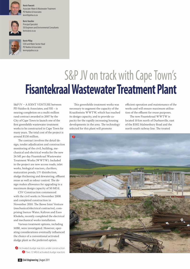
CSV Construction commenced
with the civil works in November 2008
and completed construction in
November 2010. Th e Ikewe Joint Venture
(mechanical/electrical contractor), com-
prising Inenzo Water, Kaltron and Exeo
Khokela, recently completed the electrical
and mechanical works installation.
Various treatment options, including
MBR, were investigated. However, oper-
ating considerations eventually infl uenced
the choice of a conventional activated
sludge plant as the preferred option.
Th is greenfi elds treatment works was
necessary to augment the capacity of the
Kraaifontein WWTW, which has reached
its design capacity, and to provide ca-
pacity for the rapidly increasing housing
developments in the area. Th e technology
selected for this plant will promote
effi cient operation and maintenance of the
works and will ensure maximum utilisa-
tion of the effl uent for reuse purposes.
Th e new Fisantekraal WWTW is
located 10 km north of Durbanville, east
of the R302 Malmesbury Road and the
north-south railway line. Th e treated
1
1 Activated sludge reactors under construction
2 Two 12 Mℓ/d activated sludge reactors

Civil Engineering | August 2011 21
effl uent is discharged to the Mosselbank
River, which lies approximately 300 m to
the west of the works.
Th e works rely entirely on a pumped
feed which is discharged in the inlet
works, where it is screened, degritted,
measured and divided between the reac-
tors. Two front raked screens are used
with the screenings being transported
to a washing and compaction facility.
All screenings are disposed of into skips
which are housed in an enclosed building
fi tted with an odour control air extraction
system. To cater for the proposed phases
of development, four Vortex de-gritters of
3,5 metres in diameter were constructed,
but only two were fi tted with the required
mechanical equipment. Th e grit is trans-
ported to grit classifi ers and conveyed to
collection skips which are located in a
separate enclosed building equipped with
an odour control extraction facility. Th e
grit and screenings skips are located on a
rail system which permits easy removal of
these units out of their respective build-
ings prior to removal from site.
Th e wastewater characteristics indi-
cated that treating the raw sewage in an
activated sludge reactor confi gured as a
University of Cape Town (UCT) process
will readily achieve suffi cient biological
N and P removal to meet the new effl uent
discharge standards specifi ed. A standby
chemical P removal facility is, however,
provided for use during periods of poor
biological P removal.
Th e screened and de-gritted raw
sewage gravitates directly to two 12 Mℓ/d
rectangular bioreactors. Th ey are each
divided into an anaerobic, anoxic and aer-
obic zone to conform to the UCT process
confi guration. Th e unaerated zones are
mixed by bridge-mounted vertical spindle
mixers, while the aerated zones are aer-
ated by six bridge-mounted, vertical
spindle mechanical aerators. Axial fl ow
mixed liquor pumps are provided to re-
circulate mixed liquor from the aerobic
to the anoxic zones (A-recycle), and also
from the anoxic to the anaerobic zones
(R-recycle).
Th e mixed liquor gravitates to four
30 metre diameter, fl at-bottomed, suction
lift secondary settling tanks (SSTs). Th e
SSTs are equipped with a peripheral-
driven half-bridge mechanism. Th e over-
fl ow gravitates to the maturation ponds
and the underfl ow gravitates to the return
activated sludge (RAS) pump station
where it is pumped to the anoxic zone in
the reactors.
Th e waste activate sludge (WAS) is
pumped directly out of each reactor to
the sludge dewatering building where it
is thickened and dewatered by means of
two linear screen/belt press trains. Th e
dewatered sludge is pumped via progres-
sive cavity pumps to a reinforced concrete
elevated hopper from which sludge will be
discharged to trucks for disposal. Th e fi l-
trate and wash water from the thickening/
dewatering trains gravitate back to the
RAS division box where it is mixed with
the RAS before entering the anoxic zones
of the bioreactors.
Th e effl uent stream passes through a
series of maturation ponds upstream of
the disinfection facility. Several disinfec-
tion options were investigated. However,
in view of safety, environmental and
logistical considerations, it was decided
that UV radiation be selected for dis-
infection of the fi nal effl uent. Th e fi rst
two maturation ponds out of a total of
thirteen were constructed with concrete
fl oors and a vehicle ramp to enable pe-
riodic removal of any settled sludge. A
2
22 Civil Engineering | August 2011
facility to bypass the maturation pond
system was also provided.
Th e design of the works took the reuse
of effl uent into consideration and provides
for a service water pump station which
distributes water to the plant for opera-
tional purposes. Other reuse considera-
tions included the distribution of effl uent
to adjacent farms and a proposed golf
course. Th e balance of the effl uent is dis-
charged into the Mosselbank River.
Th e initially low sewage fl ows and the
long retention period in the rising main
feeding the works are expected to result
in the raw sewage feed being septic and
hence creating the potential to generate
excessive odours. Th ese potentially ad-
verse conditions will be unacceptable,
particularly considering the close prox-
imity of the works to the proposed adja-
cent housing developments, and patrons
of the proposed golf course. Th e provision
of an adequate odour control system was
a critical component of the overall design.
Th e major source of odour will arise
from the inlet works, particularly at
the discharge point of the rising mains,
screens, grit removal, fl ow measurement
and division channels. Purpose-built and
designed covers have been installed to
cover all open channels between the inlet
rising main and the division channels to
the biological reactors. Th ese covers also
include the pista grit tanks.
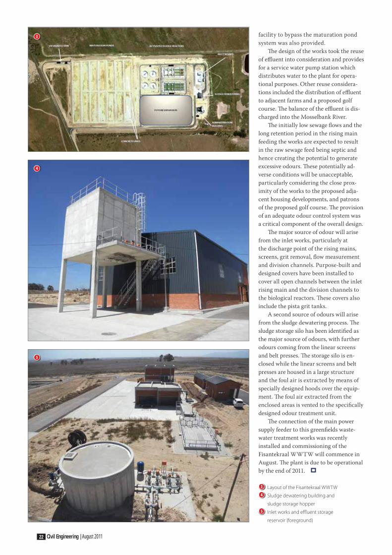
A second source of odours will arise
from the sludge dewatering process. Th e
sludge storage silo has been identifi ed as
the major source of odours, with further
odours coming from the linear screens
and belt presses. Th e storage silo is en-
closed while the linear screens and belt
presses are housed in a large structure
and the foul air is extracted by means of
specially designed hoods over the equip-
ment. Th e foul air extracted from the
enclosed areas is vented to the specifi cally
designed odour treatment unit.
Th e connection of the main power
supply feeder to this greenfi elds waste-
water treatment works was recently
installed and commissioning of the
Fisantekraal WWTW will commence in
August. Th e plant is due to be operational
by the end of 2011.
3
4
5
3 Layout of the Fisantekraal WWTW
4 Sludge dewatering building and
sludge storage hopper
5 Inlet works and effl uent storage
reservoir (foreground)
“This retaining wall provides a strong support, whilst being eco-friendly,
versatile and aesthetically pleasing.It’s smart concrete engineering!”
– Fatima Naidoo
DurabilityConsistency
ExpertiseValue for money
Time savingCompliance
GuaranteeRecourse
call: +27 11 805 6742 e-mail: [email protected]
QUALITY CAST IN CONCRETEDiscover how concrete retaining walls can transform your world
www.cma.org.za

People Planet
Progress
40 years of better solutions
Kaytech has provided revolutionary improvements in geosynthetic solutions in South Africa for 40 years. With continuous technological innovation and a specialist support team of 20 professionals, you can rely on Kaytech for the complete solution.
Ongoing technological innovation includes:
professional support and consultation job creation through local manufacture 100% recycled bidim geotextile environmentally protective construction and
waste management solutions
For more information, call us onJohannesburg 011 922 3300East London 043 727 1057Cape Town 021 531 8110Durban 031 717 2300Or contact us on-line at www.kaytech.co.za oc
tarin
e 33
82/A

Civil Engineering | August 2011 25
Khin Aung Han
Lecturer
Dept Civil Engineering and Surveying
Durban University of Technology
Quantitative Analysis of EIA for Environmental EngineersBACKGROUNDMany environmental impact assessment
(EIA) reports are lacking in science and
technology, in that they contain more de-
scription than scientifi c calculation. EIA
reports, which are vital tools for decision-
makers, involve specialised studies in spe-
cialised fi elds, many of which are based
on environmental engineering.
According to Brockman (2009), “Th e
main business of engineering is to apply
technology in concert with natural phe-
nomena to develop these things that we
need or want. Whereas the natural sci-
ences traditionally seek to discover how
things are, engineering focuses on the
question, ‘What form should we give to
this thing so that it will eff ectively serve
its purpose?’
“Most engineering problems are open-
ended, in that they don’t have a single
solution. Engineering approaches are
based on:
■ how to represent a design problem
■ how to make assumptions
■ how to generate possible ideas for designs
■ how to eff ectively conduct a search for
a solution
■ how to plan and schedule activities
■ how to make effi cient use of resources
■ how to organise the components and
activities of a team design project.”
Based on the above-mentioned approaches,
EIAs prepared by environmental engineers
are supported by calculations. Th is is the
main diff erence between EIAs written by
environmental engineers and EIAs written
by environmental scientists.
Nowadays most project owners/
managers are willing to cooperate with
EIA specialists from the planning stage to
avoid EIA-recommended alterations at a
later stage.
THE ENVIRONMENTAL IMPACT ASSESSMENTAn EIA report consists of:
■ Baseline data (existing environment
such as air, water, noise, community,
infrastructure)
■ Project data
■ Impact prediction, i.e. above-mentioned
two items combined
■ Mitigation measures, and
■ Monitoring programme.
Firstly, a project plan indicating the loca-
tion of the project site and surrounding
areas is given to the EIA specialist. It is
the responsibility of the EIA specialist to
then check the existing main drainage
system, and the drainage system of the
proposed project, as well as to estimate
the increased future stormwater runoff .
The Rational method is used to
estimate the quantity of runoff in the
project area:
Q = CIA
where
Q is the maximum fl ow
C is the coeffi cient of runoff areas
I is the average rainfall intensity, and
A is the drainage area.
Th en the sizes of the drains are
checked to determine whether they can ac-
commodate increased fl ow or not. For this
step: read the site map, and fi nd out the
size of the main drain and its direction.

26 Civil Engineering | August 2011
Water quality monitoring stations
Ambient air quality monitoring stations
Ambient noise level monitoring stations
Project Site
Project location and surrounding areas showing the following:
1

Civil Engineering | August 2011 27
Identification and permitting of landfill sites, Design of General and Hazardous Waste sites,Design of Solid Waste Transfer Stations, Design of Material Recovery Facilities,
Optimisation of Waste Collection Systems, Auditing of Waste Management Facilities,
Development of Operational Plans,Closure and Rehabilitation of Landfills, Quality Assurance on Synthetic Liners
Sustainable and appropriate engineering solutions with integrity and professionalism.
Specialist Waste Management Consultants
Jan Palm Consulting EngineersTel +27 21 982 6570 / Fax +27 21 981 0868 / E-mail [email protected] / www.jpce.co.za
Highlands Materials Recovery Facility
Pearly Beach Drop-Off Facility
Hermanus Materials Recovery Facility
The velocity of f low and the size of
the drains are checked by using conti-
nuity equation Q = Av and the Manning
formula v = (1/n) m2/3s½ where “v” is
the f low velocity, “n” is the Manning’s
roughness factor, “m” is the hydraulic
mean depth and “s” is the bed slope.
Using the project detail drawing
and P&ID diagram, determine the mass
balance of all inputs and all outputs.
All inputs are energy (power, steam,
fuel, compressed air), water and raw
materials. All outputs are solid waste,
liquid waste, gaseous waste, noise,
products and by-products. This entails
drawing material balance sheets based
on the chemical process diagrams.
Check the water demand for the project
(including processing and cooling
tower if necessary) and calculate the
percentage demand for the project
based on the existing usage of the sur-
rounding areas.
DEFINE INVENTORY
AND STORAGE CONDITIONS
OF HAZARDOUS MATERIALS
FLAMMABLE
GAS LIQUID
OR TWO-PHASE
BLEVE OTHER CASES
GAS LIQUID
OR TWO-PHASE
TOXIC
Flammable Gas
Event TreeFlammable
Liquid
Event Tree
BLEVE
Model
Toxic Gas
Event TreeToxic Liquid
Event Tree
Nature of Hazard
Phase in the
Process or
Storage vessel
Release Case
Event Tree
of Model
2
1 Project location and surrounding areas
2 Failure case defi nition tree

28 Civil Engineering | August 2011
CALCULATIONS AND PROBLEMS ENCOUNTEREDWater pollution impact
Th e quality of the receiving water course
can be aff ected by the treated wastewater
discharged from the project. One of the
main tasks of the EIA specialist is there-
fore to analyse the effl uent to check the
removal effi ciency.
Use the equation:
Removal
Effi ciency (%) =
Infl uent C-Effl uent C
Infl uent C x 100
and check the removal effi ciency of each
unit in the proposed wastewater treat-
ment plant for SS, COD, BOD, NO3
- and
Cl-, etc. Th en compare the quality of the
fi nal effl uent with the standard set by the
governing body.
It is necessary to estimate the impact of
effl uent on the receiving water course. First
locate the outlet pipe of the project at the
water course. Th en take water samplings at
the outlet location, 50 m before and 50 m
after the outlet. Next, calculate the impact
on the constituents (BOD, COD, phenol,
grease and oil, SS, NO3
-, etc) in the receiving
water by using the Mass Balance equation:
Cmix = Qwater Cwater+Qeff Ceff
Qwater+Qeff
Air pollution impact
To estimate gas emission from the project,
extract the gas emission from the mass
balance sheets of the project description.
Th e type of gas and concentration, emission
temperature, stack height, stack diameter
and emission velocity are determined from
the project data sheets. At the beginning of
the EIA project, the existing air quality is
measured (SO2, NO
3, CO
2, TSP, etc). Use the
above-mentioned gas emission data as input
data and run air modelling (e.g. ISCST/
LT) to predict the ground level concentra-
tion. Th e modelling results are shown by
isopleths. Also check the air quality at the
receptors (the most vulnerable places are
schools, hospitals, clinics and community
centres). Th en compare the results with the
ambient air criteria.
Noise pollution impact
High-level noise-producing areas should
be identifi ed and, using the compounding
eff ect of the noise level, its impact to the
nearest community should be calculated
by using the following equation:
Lp2 = Lp1 – 20 log (R2/R1)
VAPOUR CLOUD EXPLOSION
DELAYED IGNITION
LIQUID SPILL CLIMATIC
CONDITION FOR
DENSE GAS
FORMATION
NO
IMMEDIATE
IGNITION
Xa = 1 (Delayed ignition
source existed) = 0 (No delayed
ignition source)
PE
P3
P2
= 0,04
P1
= 0,5
3
4

Civil Engineering | August 2011 29
0860 CRANESHead Office Tel: +27 (011) 455 9222Head Office Fax: +27 (011) 455 9230Email: [email protected]
www.jch.co.za
TOTAL COSTEFFECTIVENESS
RELIABILITYAVAILABILITYMAINTENANCESAFETY
where Lp1 and Lp2 are noise levels at R1
and R2 distances.
Th en the composite noise level (ambient +
noise from project) is calculated by:
Lp total = 10 log (1/n) (S 10Li/10)
Fire and explosion impact
Th is concerns only catastrophic failure –
fatality and property damage. First, based
on the storage inventory, high pressure,
temperature and fi re /explosion index,
identify hazardous substances / process
areas. Th e analysis of the potential hazard
is recorded by using the HAZOP study
and fault tree diagram. Th en the prob-
ability of each hazard is calculated, and its
consequences (e.g. fi re and/or explosion)
analysed by using a hazard model such
as WHAZAN. Th e hazard impact is then
shown on the project area and its sur-
rounding by diff erent impact intensities.
Fire prevention and safety
Based on locations and the number of fi re
hydrants, the fi re prevention areas are
checked together with water pressure and
water storage demand.
CONCLUSIONEIAs for industrial projects are challenging
and require engineering science and tech-
nology – hydraulics and hydrology, water
and wastewater engineering, building
engineering, pipeline engineering, water
pollution analysis, drawing interpretation,
chemical process engineering, air model-
ling, and hazard modelling. All these ap-
plications prove that the EIA is pertinent
to environmental engineers.
REFERENCES1. Brochman, J B 2009. Introduction to
Engineering: Modelling and Problem Solving.
John Wiley & Sons Inc.
2. Final Report, Environmental Impact
Assessment of Olefi ns Plant (Expansion),
Map Ta Phut, Rayoung, Thailand, 1996.
3 Fault tree diagram for unconfi ned
vapour cloud explosion
4 Boundary of hazard consequences
from vapour cloud explosion
EIAs for industrial projects are
challenging and require engineering
science and technology – hydraulics
and hydrology, water and wastewater
engineering, building engineering,
pipeline engineering, water pollution
analysis, drawing interpretation,
chemical process engineering, air
modelling, and hazard modelling

30 Civil Engineering | August 2011
Andile Gqaji
Project Manager
SANRAL
Public transport and the environment –
the way forwardBACKGROUNDTh e vision for South African transport is of
a system which will:
"Provide safe, reliable, eff ective,
effi cient, and fully integrated trans-
port operations and infrastructure
which will best meet the needs of
freight and passenger customers
at improving levels of service and
cost in a fashion which supports
government strategies for economic
and social development whilst being
environmentally and economi-
cally sustainable." (White Paper on
National Transport Policy 1996)
Th ere is no denying that the state of public
transport in South Africa is in a terrible
state and defi nitely does not support the
above transport vision. Public transport in
South Africa is expensive, unreliable and
ineff ective. Th ese are some of the chal-
lenges faced by commuters, many of whom
are from the poorest of the poor.
Partly due to the current state of the
public transport system, there has been
a rapid increase in private vehicle owner-
ship in South Africa over the last few
years, resulting in our roads and transport
systems being overloaded at the same
time every day. Billions of rands are spent
by government on capacity improvements
to accommodate the ever increasing
private vehicle ownership. It is estimated
that there are about 9 970 381 registered
vehicles in South Africa, of which approx-
imately 57% are a combination of motor
cars and station wagons (eNaTIS 30 April
2011). According to eNaTIS there were
5 675 628 motor cars and station wagons
on our roads by 31 March 2011.
When the new government came into
power in 1994, it listed transport as one
of its fi ve top national priorities. From the
supply side, government is tasked with
the provision of roads, rail infrastructure,
rolling stock and ancillary items. It is also
tasked with supplying services such as
subsidised bus and train services, main-
tenance of transport infrastructure and
regulation of the use of these facilities.
Th e spatial structure of our country
can be divided into rural and urban areas,
with cities fragmented into zoned areas of
specialised land use. Th e need for avail-
able transport in this space is a given.
Th e cost of transport infl uences
wealth, as it reduces the resources that
could have been saved, invested or spent
on other needs. Th e cost of commuting to
work should not exceed 10% of a worker’s
remuneration (White Paper on National
Transport Policy 1996), but there are
many cases in our country where this
policy guideline cannot be achieved,
which is a pity, as reduced transport costs
could result in a higher standard of living
for workers. Th e cost of providing road
infrastructure, which encourages more
private travel and congestion, should be
redirected at promoting public transport.
Two of the strategic objectives, re-
garding public transport, listed in the
1996 White Paper on National Transport
Policy, are:
(i) “To promote the use of public transport
over private car travel, with the goal
of achieving a ratio of 80:20 between
public transport and private car
usage.” Th is objective was too ambi-
tious, and had been listed without
fully understanding the issues around
public transport and the challenges
faced by commuters.
(ii) “To ensure that public transport is af-
fordable, with commuters spending less
than about 10% of disposable income
on transport”. Th is objective is also not
realistic, as many people live very far
from employment centres as a result of
the previous apartheid policies.
ROLE OF PUBLIC TRANSPORT IN SOUTH AFRICAPublic transport has three objectives:
1. Strategic: to off er an alternative
equivalent in quality to private car
usage, and to support the modal split.
2. Social: to off er travel possibilities to
people who do not possess cars, and
support sustainable access.
3. Commercial: to make a profi t or
minimise the loss.
Public transport has a crucial role to play
in improving accessibility, in combating
congestion, and in supporting improved
road safety and air quality. Logically,
the basic requirements for a good public
transport system are:
■ Aff ordability
■ Reliability/Frequency
■ Accessibility
■ Comfort
■ Safety
■ Availability
Th e current public transport system does
not come close to meeting these require-
ments.
THE NATIONAL HOUSEHOLD TRAVEL SURVEY (NHTS) 2003From the NHTS we can understand the
current travel situation in South Africa.
According to the NHTS, the reasons
why commuters do not use trains and
buses on the one hand, or minibus-taxis
on the other hand, are their unavail-
ability and high fares respectively. These
reasons in fact constitute some of the
basic requirements of a good public
transport system.
Some facts as recorded in the NHTS 2003
Access to public transport services
Figure 1 shows that the majority (76%) of
households did not have access to train
services, while 38% of households did not
have access to bus services (stops).

Civil Engineering | August 2011 31
Th e signifi cance of the taxi mode
(minibus, sedan or bakkie) as a convenient
form of public transport is also illustrated
in the graph. Only 9% of households
indicated that there was no available taxi
service near their homes.
Customer perceptions about
the quality of public transport services
Respondents were given the opportunity
to report on the main transport problems
experienced by their households. Table 1
shows that many households, in all
areas, did not experience any transport
problems. Th is applies particularly to
the smaller urban areas where travel dis-
tances to services and amenities are rela-
tively short. On the other hand, only 18%
of rural households reported no serious
transport problems.
Travel choice factors
All race groups, and people in every pro-
vince, indicated that the most important
factor to consider when travelling is safety
from accidents (see Figure 2).
Of people 15 years and older, 83%
did not use buses. Th eir reasons were
that buses were too infrequent, did not
depart/arrive at appropriate times and
that travel times were too long. About
19 million people 15 years and older
(over 59%) had used a taxi in the previous
month. Th ose who did not use taxis were
deterred by cost, by crime and by the
number of taxi accidents.
Almost half (48%) of the minibus-taxi
passengers, 42% of train passengers and a
third of bus passengers were dissatisfi ed
with the overall quality of the service.
Th e main complaints about public
transport services were the following:
■ Trains
Overcrowding
(71% of users dissatisfi ed)
Security when walking to stations (64%
dissatisfi ed)
Security on trains (63% dissatisfi ed)
■ Buses
Lack of facilities at bus stops
(74% dissatisfi ed)
Overcrowding on buses
(54% dissatisfi ed)
Low frequency during off -peak times
(51% dissatisfi ed)
■ Minibus-taxis
Safety from taxi accidents (67%)
Lack of facilities at ranks (64%)
Lack of roadworthiness of vehicles (60%)
Travel to Work
Th ere are about 10 million people who
regularly travel to work. Th e modal share
for work trips is depicted in Figure 3. Th e
modes used vary, but about a third of
all commuters travelled to work by car.
Another signifi cant group of commuters
(almost a quarter) walked to work.
Figure 4 shows the modes used by the
commuters who travelled to work using
public transport. Th e vast majority of
taxi users travelled in minibus-taxis (over
98 percent) as distinct from sedan-taxis
or bakkie-taxis.
Th ere are approximately 3,9 mil-
lion public transport commuters. Th e
2,5 million taxi commuters account for
over 63% of public transport work trips.
Bus services account for another 22% of
public transport commuters and the bal-
ance are carried to work by train.
The cost of getting to work /
the aff ordability of transport
The most serious concerns about
transport costs related to the cost of
travelling to work, particularly for low-
income earners. Figure 5 shows the
monthly cost of commuting to work at
the time of the survey. Figure 6 shows
the relationship between monthly
household income and the households
that spent more than 20% of income on
public transport. For South Africa as a
whole 18% of households spent 20% or
more per month on transport.
Th e benchmark used in the White
Paper on National Transport Policy
(DoT 1996) to assess whether trans-
port costs were creating hardship for
households or individuals, was 10% of
disposable income. Th is may either be the
percentage of the household income or
the percentage of the personal income of
Table 1 Absence of
transport problems by type of area
Type of area % of household
Metropolitan 27
Urban 41
Rural 18
RSA 28
80
70
60
50
40
30
20
10
0
1 – 15 16 – 30 >30 No Meanmins mins mins service
Walking time
% o
f h
ou
seh
old
s
Train station
Bus stop
Taxi service
100
90
80
70
60
50
40
30
20
10
0African/Black Coloured Indian/Asian White
% o
f h
ou
seh
old
s
Accessibility of service
Driver’s attitude
Flexibility
Security from crime
Safety from accidents
Travel cost
Travel time
47 53 61 51
1310
15
1
2
1 Household access to public transport
2 Travel choice factors

32 Civil Engineering | August 2011
commuters. Th e percentage of personal
income spent by workers on public trans-
port to work is shown in Table 2.
Considering expenditure on travel
to work as a percentage of commuter
income, there is strong evidence that poor
people are using a large proportion of their
income to get to their jobs. As shown in
Figure 6, on average, commuters who earn
R500 or less are paying over a third of their
income for travel to work. Table 2 shows
that some 82% are spending more than
20% of their income on transport. Th is
means that the disposable income left for
basic necessities is relatively small.
In summary, the NHTS 2003 identifi ed
the following as commuters’ main problems:
1. Almost half of the households in South
Africa said that their main transport
problem was that public transport was
either not available or too far away.
2. One third of households reported
that safety from accidents and bad
driver behaviour was the most se-
rious transport problem.
3. For 20% of the households, the cost
of transport was a serious problem.
4. Crime.
PUBLIC TRANSPORTATION VERSUS PRIVATE CARTh e number of private cars on the road is
rising rapidly and will continue to do so,
but a good public transport system could
be more convenient, quicker and cheaper.
No Parking:
One of the most frustrating and time-
consuming things about driving a car is
hunting for parking, which is often scarce
and usually expensive. Th e bonus of get-
ting on public transport is being able to
alight and nothing else.
Cheaper:
Contrary to popular belief, nearly all forms
of public transport are cheaper than run-
ning a private car. In addition, regular com-
muters could make use of season tickets and
similar special off ers. Th e cost of running a
car entails much more than the mere cost
of petrol, which in itself is already expensive
enough. Car insurance, maintenance, etc,
all add up to substantial amounts.
Quicker:
Despite the occasional delay, a public
transport journey from A to B could be
quicker and often more direct, as in-
creasing investments are made into public
transport systems.
Convenient:
Th e great thing about reliable public trans-
port is that it gets you where you want to
be, particularly in cities and towns. Rather
than being able to drive to a certain point
only before getting stuck in a one-way
system, you can reach your central point
directly. Plus you have the bonus of sitting
back, relaxing with a newspaper and let-
ting someone else do the driving.
Granted, cars and motorbikes are
more fl exible at times, off ering an easier
and quicker form of travel, but the green
credentials of this mode of travel are
far less attractive to anyone wanting to
reduce his/her carbon footprint. When
there is a realistic public transport alter-
native to driving, the biggest challenge is
changing our preconceptions.
ENVIRONMENTAL BENEFITS OF USING PUBLIC TRANSPORT Catching public transport is a great way
for people to contribute to a cleaner
environment.
Given the proportion of South Africa’s
total carbon emissions that can be attributed
Public Transport modes
TrainBusTaxiCarWalkOther
6%
9%
25%
32%
23%
5%
Train
Bus
Taxi
RSA
15
22
63
250
200
150
100
50
0Train Bus Taxi
Mo
nth
ly c
ost
of
com
mu
tin
g
Main mode of travel to work
R172
R201
R222
3
4
5
3 Main mode of travel to work
4 Public transport modes used for work trips
5 Cost of commuting by public transport

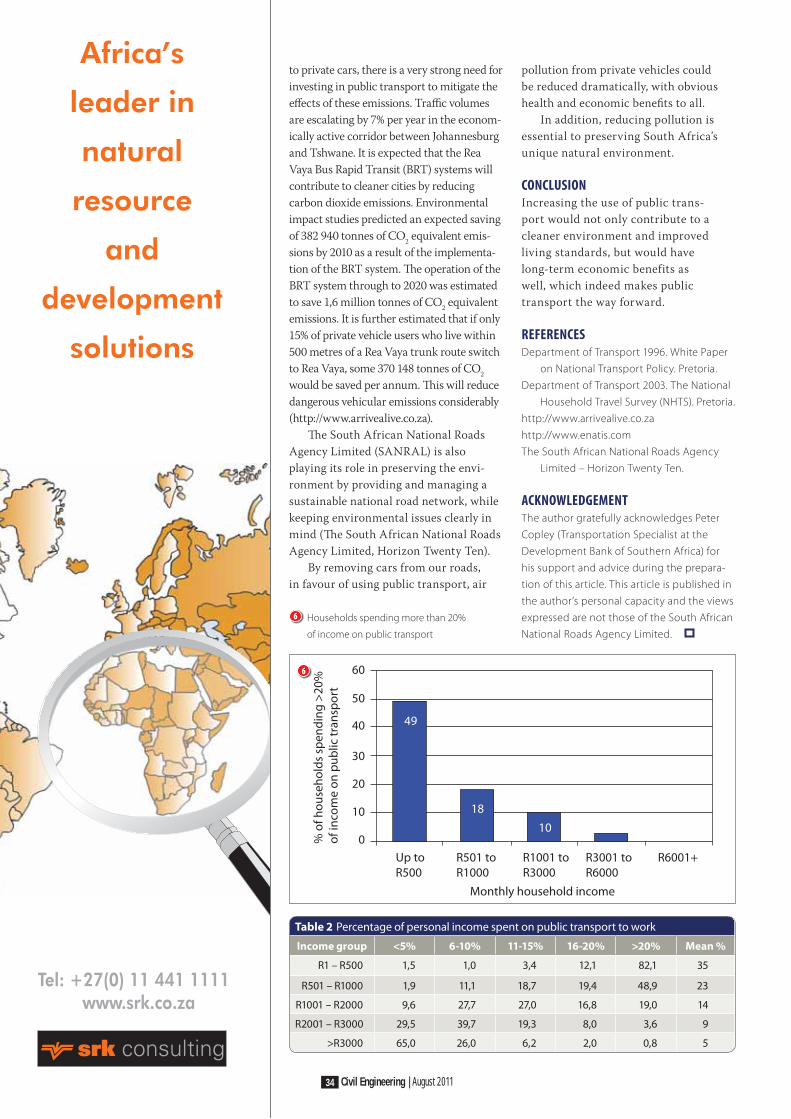
34 Civil Engineering | August 2011
Africa’s
leader in
natural
resource
and
development
solutions
Tel: +27(0) 11 441 1111 www.srk.co.za
Table 2 Percentage of personal income spent on public transport to work
Income group <5% 6-10% 11-15% 16-20% >20% Mean %
R1 – R500 1,5 1,0 3,4 12,1 82,1 35
R501 – R1000 1,9 11,1 18,7 19,4 48,9 23
R1001 – R2000 9,6 27,7 27,0 16,8 19,0 14
R2001 – R3000 29,5 39,7 19,3 8,0 3,6 9
>R3000 65,0 26,0 6,2 2,0 0,8 5
to private cars, there is a very strong need for
investing in public transport to mitigate the
eff ects of these emissions. Traffi c volumes
are escalating by 7% per year in the econom-
ically active corridor between Johannesburg
and Tshwane. It is expected that the Rea
Vaya Bus Rapid Transit (BRT) systems will
contribute to cleaner cities by reducing
carbon dioxide emissions. Environmental
impact studies predicted an expected saving
of 382 940 tonnes of CO2 equivalent emis-
sions by 2010 as a result of the implementa-
tion of the BRT system. Th e operation of the
BRT system through to 2020 was estimated
to save 1,6 million tonnes of CO2 equivalent
emissions. It is further estimated that if only
15% of private vehicle users who live within
500 metres of a Rea Vaya trunk route switch
to Rea Vaya, some 370 148 tonnes of CO2
would be saved per annum. Th is will reduce
dangerous vehicular emissions considerably
(http://www.arrivealive.co.za).
Th e South African National Roads
Agency Limited (SANRAL) is also
playing its role in preserving the envi-
ronment by providing and managing a
sustainable national road network, while
keeping environmental issues clearly in
mind (Th e South African National Roads
Agency Limited, Horizon Twenty Ten).
By removing cars from our roads,
in favour of using public transport, air
pollution from private vehicles could
be reduced dramatically, with obvious
health and economic benefi ts to all.
In addition, reducing pollution is
essential to preserving South Africa’s
unique natural environment.
CONCLUSIONIncreasing the use of public trans-
port would not only contribute to a
cleaner environment and improved
living standards, but would have
long-term economic benefits as
well, which indeed makes public
transport the way forward.
REFERENCESDepartment of Transport 1996. White Paper
on National Transport Policy. Pretoria.
Department of Transport 2003. The National
Household Travel Survey (NHTS). Pretoria.
http://www.arrivealive.co.za
http://www.enatis.com
The South African National Roads Agency
Limited – Horizon Twenty Ten.
ACKNOWLEDGEMENTThe author gratefully acknowledges Peter
Copley (Transportation Specialist at the
Development Bank of Southern Africa) for
his support and advice during the prepara-
tion of this article. This article is published in
the author’s personal capacity and the views
expressed are not those of the South African
National Roads Agency Limited.
% o
f h
ou
seh
old
s sp
en
din
g >
20
%
of
inco
me
on
pu
blic
tra
nsp
ort
60
50
40
30
20
10
0
Up to
R500
R501 to
R1000
R1001 to
R3000
R3001 to
R6000
R6001+
Monthly household income
49
18
10
6
6 Households spending more than 20%
of income on public transport

BACKGROUNDIn February 2010, Aurecon was
awarded a contract by the Provincial
Government of the Western Cape to
establish a Programme Implementation
Unit (PIU) within the Western Cape
Education Department (WCED) to as-
sist in the implementation of school
infrastructure projects.
Some of the main aims of the PIU are
to facilitate, implement and expedite in-
frastructure delivery for the WCED. Th is
is achieved by acting as a second parallel
delivery mechanism to the Department
of Transport and Public Works (DTPW)
which continues to implement the ma-
jority of the WCED’s projects as the pri-
mary delivery agent.
PROJECT DESCRIPTIONNow halfway through the three-year
contract period, the PIU has been in-
volved in the implementation of a wide
range of projects at over 200 schools,
totalling over R250 m, including:
■ construction of two new schools
■ construction of 120 classrooms at
64 overcrowded primary schools
■ construction of additional facilities at 14
top-performing schools to allow for the
enrolment of an additional class per grade
■ renovation of a disused teachers’
training centre into a new high school
■ additions of various facilities such as
halls, administration blocks, fi elds,
laboratories, etc, at numerous schools
■ planned maintenance at 39 schools
■ placement or relocation of over 200 mo-
bile (prefabricated) classrooms at over
100 schools, and the
■ development of workshops and special fa-
cilities at schools for Learners with Special
Educational Needs (LSEN schools).
1
1 Perspective of the new Claremont
High School after a R10 m facelift
2 The old Barkly House Teacher’s
Training College before its transformation
into the Claremont High School
3 Internal courtyard at the new
Claremont High School
Jonathan Webb
Associate:
Civil Engineering/Project Management
Aurecon SA (Pty) Ltd
W E S T E R N C A P E
Implementation of school construction in the Western Cape
2 3
Civil Engineering | August 2011 35

36 Civil Engineering | August 2011
In all this, Aurecon fulfi ls a programme
and project management role. As
such, a permanent programme offi ce
has been established within the
WCED to assist in the coordination,
communication, reporting, fi nan-
cial control and project information
management of the programme.
Th e PIU also includes a team of tech-
nical advisors or specialists to provide
technical oversight and input where
necessary. Th is team includes architec-
tural (EHH Architects) and quantity
surveying (De Leeuw Group) advisors.
Specialist input for engineering, contrac-
tual, legal, environmental and community
liaison matters is provided by Aurecon.
Each project is managed by one of
a team of ten project managers who
manage the day-to-day aspects of the
project and facilitate communication
between the WCED, the schools and the
project professional teams. Diff erent pro-
fessional teams are appointed per project
and contract directly through Aurecon
to manage the planning, design, tender
documentation and contract management
at each school. Tenders are advertised by
Aurecon, and CIDB prescripts are applied
in the tender process and documentation.
Once PGWC approval has been obtained
for a recommended tenderer, Aurecon
contracts directly with the tenderer for
the further roll-out of the project.
CHALLENGES, INNOVATIONS AND SUCCESSESFast-track delivery
One of the key aspects on this programme
has been meeting some extremely tight
delivery deadlines. It is not unusual for
project expenditure to be restricted to one
fi nancial year, which often results in very
tight project time lines. Compounding
this is the need to often deliver a project
in time for the start of a school year or
new school term, which results in limited
fl exibility or ability to extend or overrun
on a programme.
Two particularly successful fast-
track projects have been the Khayelitsha
COSAT and Claremont High Schools.
4
4 The new Khayelitsha COSAT school
which opened in January 2011 after
just fi ve months of construction
5 The front entrance of Wallacedene
Primary School, completed in late 2010
6 Additional classrooms at Mandalay Primary
School in Mitchells Plain were designed to
match the existing look of the school

Civil Engineering | August 2011 37
Both projects were allocated to the PIU to
manage in late May 2010 with stipulated
delivery for initial occupation by January
2011. Both high schools are STEM
schools (Science, Technology, Engineering
and Maths), which aim to attract top-end
maths and science learners.
Design, documentation and approvals
of the Khayelitsha COSAT school were
fast-tracked and tenders closed in early
August 2010, with a contractor on site
shortly thereafter. Luckily the site was
serviced and presented few constraints.
Delivery of Phase 1 (ten classrooms and
administration facilities) was achieved
on time for occupation in January 2011,
and practical completion for the full
school for 600 learners, including a
hall and sports fi eld was achieved four
months later. Several measures in design,
constructability, phasing, layout and
documentation were implemented by
the professional team to ensure this pro-
gramme could be achieved.
Th e R10 m renovation and exten-
sion of an old teachers’ training college
into the new Claremont High School
for 500 learners similarly followed an
accelerated design, documentation and
tender process. A contractor was on site
in August 2010 and delivery was achieved
for the school to take occupation by
January 2011, with fi nal works being com-
pleted by March. Renovation projects al-
ways present challenges, and numerous un-
expected hurdles were indeed encountered
along the way, ranging from the discovery
of a freshwater spring beneath the building’s
foundation to encountering asbestos insula-
tion which had to be removed by specialist
contractors. To deal with the myriad issues
typical of renovation projects, the Principal
Agent placed a resident architect on site to
manage daily queries. Th e success of this
project in terms of timeous delivery was
largely due to the excellent teamwork which
developed between the professional team
and the contractor.
Capitalising on economies of scale
School projects are frequently grouped by
the WCED into programmes, depending
on the nature of the project or the source
of the funding. One such example is the
“Relief Programme” which comprised
the construction of 120 classrooms at
64 overcrowded primary schools. Each
school was provided with between one
and four new classrooms. It was decided
to group school projects geographically
5
6

38 Civil Engineering | August 2011
into clusters whereby certain benefi ts
could be achieved, including:
■ reduction in the management eff ort of
numerous small contracts, both on a
programme level and in terms of site
management by the principal agents
■ increased contract values which
allowed for a higher grading of
contractor to be targeted, and
■ the benefit of economy of
scale both in construction
costs and professional fees.
A total of four sites per contract seemed
to be the optimum size in order to
increase the contract value, while not
exceeding the capacity or capability of the
target group of contractors to resource
multiple sites simultaneously.
Th is approach proved successful, al-
though a number of issues arose and had to
be dealt with along the way, for instance:
■ Although a Community Liaison Offi cer
(CLO) had been allowed on each con-
tract, several communities demanded a
dedicated CLO for each site, leading to
additional costs on the programme.
■ Contracts where sites were further
apart proved challenging to some of the
contractors.
Despite the above, the majority of the
64 schools had their classrooms delivered
on time and within budget, with a few
remaining problematic contracts fi nishing
slightly behind the rest.
A similar approach of clustering
projects was also adopted for the imple-
mentation of the planned maintenance pro-
gramme at 39 schools, with similar success.
Norms, standards and other requirements
Th e aim of the PIU has never been to
reinvent the wheel. Rather, it has been to
achieve any possible time, cost or effi ciency
benefi t on behalf of the Client without com-
prising the integrity of Government’s proc-
esses or the quality of the end product. As
such, projects are structured to match those
delivered through other conventional de-
livery mechanisms. For instance, the norms
and standards for schools are applied on all
projects to ensure quality end products and
Project 2Project 1
PROGRAMME OFFICE AT WCED
WCED: Infrastructure Development and Planning
Programme Manager
Project Management Technical Advisors Specialist Advisors
Architect
Quantity Surveyor
Civil, Structural, and Electrical Engineers
OHS
Legal
Environmental
Contract Documentation
Administrative Support
Professional Team Professional Team
Contractor Contractor
7
8
7 Impendulo Primary School – one of
64 schools for which additional classrooms
were added under the Relief Programme
8 The structure of the Programme
Implementation Unit (PIU)
Civil Engineering | August 2011 39
Construction
Data and Telecommunications
Defence
Energy
Government
International Development Assistance
Manufacturing
Property
Resources
Transport
Water
Aurecon provides engineering, management and specialist technical services to government and private sector clients globally. The group has successfully delivered world class technical expertise and innovative
the Middle East.
The key to our success lies in our business model which focuses on
Aurecon team across sectors, expertise and geographies to engineer that success.
We look forward to partnering with you to achieve your goals.
Your success is our success.
For more information contact us at tel: +27 12 427 2000 or email: [email protected]
Engineering your success
Industries:
uniformity, and standardisation between
schools. While layout design is approved
by the WCED at concept stage, drawings
and designs are submitted for approval to
DTPW as the ultimate custodian of the
facilities on behalf of the WCED. Local
authorities are also provided with courtesy
drawings for scrutiny and comment.
Along the way, some peculiarities
have been encountered relating to zoning,
sub-division or ownership of existing edu-
cational facilities. Th ese matters are dealt
with between the PIU, WCED and DTPW
property on a case-by-case basis.
All permanent construction to date
has been of a conventional nature (brick
and mortar), although the WCED has
expressed interest in investigating appro-
priate certifi ed/standardised alternative
construction technologies to expedite
delivery and/or reduce costs in future.
At a contractual level, the PIU imple-
ments similar contractual requirements in
terms of utilisation of local labour as are
required on other provincial projects. Th e
involvement of local communities is usually
facilitated through the School Governing
Bodies who identify appropriate CLOs for
the projects. As with most projects, those
projects which have the buy-in of the local
community from the beginning inevitably
have proven to be the most successful.
Financial Expenditure
Financial performance is always a critical
Key Performance Indicator. Th e PIU as-
sisted the WCED in achieving, for the fi rst
time, a 100% spend on their budget for the
2010/2011 fi nancial year. Moreover, only a
few months into the current fi nancial year,
and everything already appears on track
for the WCED to match their achievement
with an even larger budget this year.
CONCLUSIONTh e need within both the Western Cape,
and indeed the country as a whole, for
delivery of educational infrastructure is
immense. Th ere are tremendous pres-
sures on thinly stretched resources to
deliver, expand and maintain educational
infrastructure. Mechanisms such as the
WCED PIU off er a viable alternative or
additional delivery mechanism to assist in
expediting infrastructure delivery.
PROJECT TEAM
Client
Western Cape Education Department (WCED)
Programme Management Unit
Programme and Project Managers Aurecon SA (Pty) Ltd
Architectural Technical Advisor EHH Architects
Quantity Surveying Technical Advisor De Leeuw Group
Engineering Technical Advisor Aurecon SA (Pty) Ltd
Project Teams
Professional Teams (all disciplines) Numerous Professional Service Providers
Contractors Numerous Contractors

40 Civil Engineering | August 2011
AIMS AND OBJECTIVES OF THE PROJECTTh e project aims, fi rstly, to provide community upliftment and
act as a catalyst in presenting new development opportunities
for historically downtrodden communities. Secondly, the project
aims to ensure the upgrade of rental stock within budget and
on time. Th e project is a government-funded project, hence the
focus is on ensuring that the available budget is utilised in the
most advantageous manner for residents, as well as for the City,
who has to maintain these assets.
OVERVIEW OF THE UPGRADETh e upgrade includes general renovations to buildings, roofs,
electrical and plumbing systems, as well as the installation of
new ceilings, fl oor coverings, cupboards and geysers, fencing,
refuse management, area lighting, greening of areas and recrea-
tional facilities.
Th e process of rolling this out requires precision planning. A
temporary village has been established for the tenants to move
to whilst upgrading is in process. A block takes fi ve weeks to
complete, after which time the residents would be assisted to
move back to their upgraded units so that the next block could
be vacated for the builders to transform. Th e location of the tem-
porary accommodation is in close proximity to the rental units,
minimising disruption to the tenants’ daily lives. By arranging
new refuse collection points, cleaning of units between moves,
installing fi re hydrants, etc, Aurecon ensured that the village is
kept in a good, clean condition, without compromising the safety
of the residents, and ensuring a safe environment at all times.
Community participation is also a key element in the success
of the project. Comprehensive engagement of communities began
with the establishment of Project Steering Committees. Various
community representatives, including the local Ward Councillor,
serve on these committees and attend the monthly meetings.
PROBLEMS ENCOUNTERED AND INNOVATIONSProblem 1
Initially there was a notion that the tenants should stay in the
buildings during the renovations. However, it was acknow-
ledged that, due to the magnitude of work required to upgrade
these units, their staying in the units would not only slow down
progress to unacceptable levels, but tenants would be at great risk
of getting injured.
Innovation 1
All options for relocation were considered to ensure that costs
were kept within budget, and to ensure minimal disruption to
the residents’ daily lives. Tenants were fully consulted in order
to identify the most suitable solution. Aurecon designed a tem-
porary village which met the stringent standards set by the City
– converted containers for residents to stay in whilst their fl ats
are being refurbished.
Th e 12-metre converted containers have windows and doors,
insulation, partitions, a bathroom, free electricity, and free hot
and cold water. Aspects such as garbage collection and delivery
of mail were also considered to ensure a comfortable stay.
Communal dish antennas were even provided for those who have
decoders. Th is arrangement is cutting down by half the con-
struction time for each block.
Th e temporary village will be dismantled at the end of the
project to prevent the formation of an informal settlement.
Problem 2
Many buildings have families residing in informal structures at
the back of the buildings (back-yarders). Th ese are often attached
Johan Keuler
Associate:
Project Management
Aurecon SA (Pty) Ltd
Upgrade of rental stock in the City of Cape Town
The City of Cape Town realised that unsatisfactory
maintenance conditions prevailed in their housing
stock of 43 500 units. As a start 7 775 rental units
were identified in eleven areas across the Cape
Metropole in a pilot project programme for basic
upgrade refurbishment in terms of the Community
Residential Unit (CRU) Programme of the National
Government. In August 2008 Aurecon was
appointed as implementing agent for the upgrade
of 3 840 units (R506 million). The areas included
Hanover Park, Heideveld, Ottery (Marble Flats),
Kewtown (Athlone) and Elsies River (The Range)

Civil Engineering | August 2011 41
to the main building and are in the way of the scaff olding
that needs to go up next to the building for renovation work.
Furthermore, there are no funds to accommodate the back-
yarders in temporary villages as in the case of the main tenants.
Innovation 2
After consultation with the back-yarders it was agreed that
the scaff olding would be erected by going through roofs and
anchoring on open spaces between the shacks. Th e part of the
shack which is under the scaff olding is partitioned off and is not
accessible to anyone. Cantilevers are used to protect the parts of
the shacks next to the scaff olding. Th ese measures ensure that all
health and safety regulations are adequately adhered to.
Problem 3
Th e project continuously runs the risk of delays and political
interference.
Innovation 3
To this end, proper screening measures for contractors were put
in place and the community was involved in the planning of the
project from the outset.
Problem 4
Th e expectation of communities in relationship to job opportu-
nities proved diffi cult to manage.
Innovation 4
In an effort to address the huge need for job opportunities this
aspect was captured in the tender document and is strictly
monitored. Over the five contracts approximately 50% of the
labour bill is allocated to the local community. Training and
skills are transferred to participants. Following the hard-skills
(technical) training that is provided, the trainees are em-
ployed in the projects.
Before families move back into their refurbished units they
also undergo education relating to the maintenance of a rental
unit, payment of rent, management of electricity and water ac-
counts, management of refuse, and so forth.
Problem 5
All the project areas are gang-dominated and gang fi ghts occur
regularly. Th e tenants in the temporary villages are exposed in
this regard, since the villages are used by the gangs as places to
seek cover during shootouts.
Innovation 5
Aurecon approached the South African Police, the City of
Cape Town‘s Metro Police, and the City Law Enforcement and
Community Crime Prevention Bodies to coordinate their patrols
in order to obtain 24/7 surveillance, as well as occasional patrols
in the temporary villages. Th e refurbishment is scheduled spe-
cifi cally to ensure that no rival gang members are residing in the
temporary village at the same time.
1 2
3 4
1 Kewtown (Athlone) – before
2 Kewtown (Athlone) – after. Also shown in this picture is
part of the temporary village of containers (blue)
3 The Range (Elsies River) – before
4 The Range (Elsies River) – after

42 Civil Engineering | August 2011
Problem 6
Some of the blocks were built with precast concrete walls, which
resulted in serious damp and water ingress problems, especially
in winter.
Innovation 6
Th e precast concrete walls at the rental units were assessed and
a new brick skin was suggested. Th e newly built façade acts as a
cavity wall and gives the building a fresh look, reduces dampness
inside units and solves water ingress problems at window sills.
Problem 7
Th e policy of the funding regime (the Community Residential
Unit) provides for the refurbishment of the buildings, but not for
the external environment, i.e. the public open spaces between the
buildings. Without being able to upgrade the external environ-
ment, the upgraded areas would lack complete transformation
and would not achieve a sense of place to instill community
pride.
Innovation 7
Additional funding was sourced from the Social and Economic
Facilities Programme (SEFP) to develop these public open spaces.
PROJECT STATUSTo date 484 units out of a total of 3 840 units have been
completed. Th e project is scheduled for fi nal completion by
30 June 2015. Th e fi rst two parks are also currently under con-
struction.
CONCLUSIONTh is direct intervention ensures enhancement of the lives of
these tenants who have become accustomed to unsafe and not
always well maintained rental accommodation, thereby uplifting
their standard of living.
5
6
7
5 Hanover – scaff olding next to the building erected
over informal shacks in the backyards
6 Kewtown (Athlone) – model of developed public open space
7 Kewtown (Athlone) – public open space under construction;
note the temporary village of containers in the background
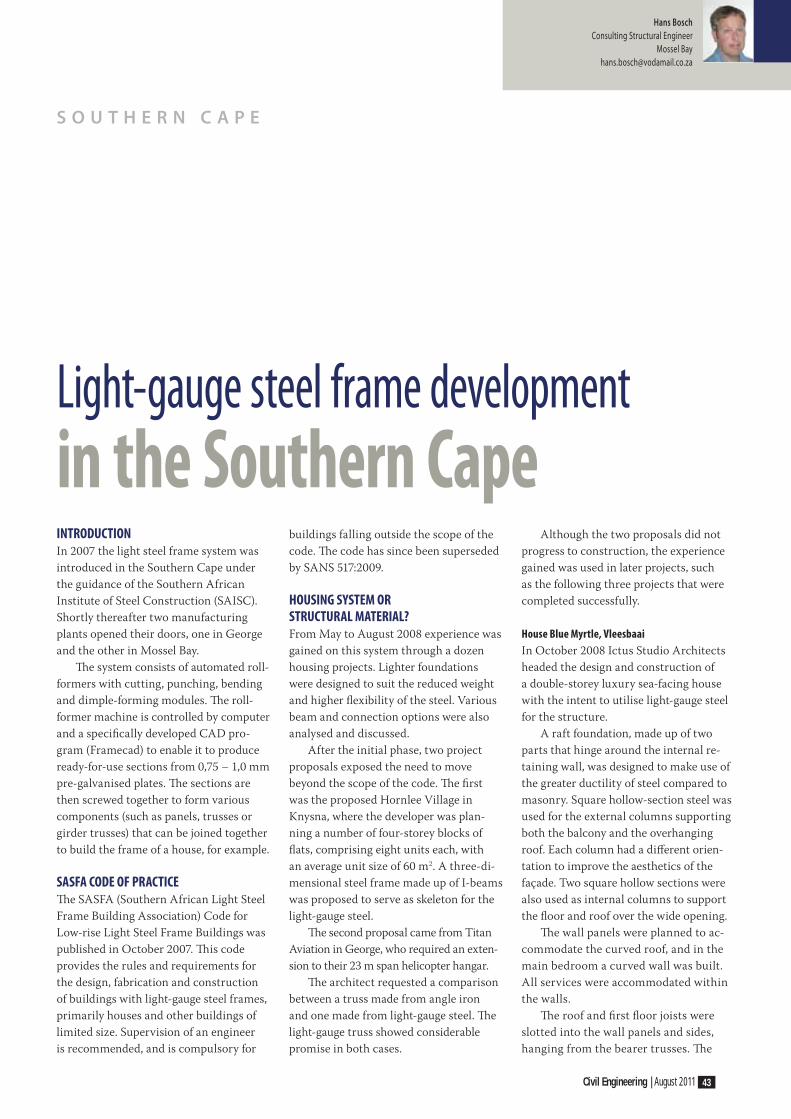
Civil Engineering | August 2011 43
Hans Bosch
Consulting Structural Engineer
Mossel Bay
S O U T H E R N C A P E
INTRODUCTIONIn 2007 the light steel frame system was
introduced in the Southern Cape under
the guidance of the Southern African
Institute of Steel Construction (SAISC).
Shortly thereafter two manufacturing
plants opened their doors, one in George
and the other in Mossel Bay.
Th e system consists of automated roll-
formers with cutting, punching, bending
and dimple-forming modules. Th e roll-
former machine is controlled by computer
and a specifi cally developed CAD pro-
gram (Framecad) to enable it to produce
ready-for-use sections from 0,75 – 1,0 mm
pre-galvanised plates. Th e sections are
then screwed together to form various
components (such as panels, trusses or
girder trusses) that can be joined together
to build the frame of a house, for example.
SASFA CODE OF PRACTICETh e SASFA (Southern African Light Steel
Frame Building Association) Code for
Low-rise Light Steel Frame Buildings was
published in October 2007. Th is code
provides the rules and requirements for
the design, fabrication and construction
of buildings with light-gauge steel frames,
primarily houses and other buildings of
limited size. Supervision of an engineer
is recommended, and is compulsory for
buildings falling outside the scope of the
code. Th e code has since been superseded
by SANS 517:2009.
HOUSING SYSTEM OR STRUCTURAL MATERIAL?From May to August 2008 experience was
gained on this system through a dozen
housing projects. Lighter foundations
were designed to suit the reduced weight
and higher fl exibility of the steel. Various
beam and connection options were also
analysed and discussed.
After the initial phase, two project
proposals exposed the need to move
beyond the scope of the code. Th e fi rst
was the proposed Hornlee Village in
Knysna, where the developer was plan-
ning a number of four-storey blocks of
fl ats, comprising eight units each, with
an average unit size of 60 m2. A three-di-
mensional steel frame made up of I-beams
was proposed to serve as skeleton for the
light-gauge steel.
Th e second proposal came from Titan
Aviation in George, who required an exten-
sion to their 23 m span helicopter hangar.
Th e architect requested a comparison
between a truss made from angle iron
and one made from light-gauge steel. Th e
light-gauge truss showed considerable
promise in both cases.
Although the two proposals did not
progress to construction, the experience
gained was used in later projects, such
as the following three projects that were
completed successfully.
House Blue Myrtle, Vleesbaai
In October 2008 Ictus Studio Architects
headed the design and construction of
a double-storey luxury sea-facing house
with the intent to utilise light-gauge steel
for the structure.
A raft foundation, made up of two
parts that hinge around the internal re-
taining wall, was designed to make use of
the greater ductility of steel compared to
masonry. Square hollow-section steel was
used for the external columns supporting
both the balcony and the overhanging
roof. Each column had a diff erent orien-
tation to improve the aesthetics of the
façade. Two square hollow sections were
also used as internal columns to support
the fl oor and roof over the wide opening.
Th e wall panels were planned to ac-
commodate the curved roof, and in the
main bedroom a curved wall was built.
All services were accommodated within
the walls.
Th e roof and fi rst fl oor joists were
slotted into the wall panels and sides,
hanging from the bearer trusses. Th e
Light-gauge steel frame development in the Southern Cape

44 Civil Engineering | August 2011
connectors were made from hand-
machined plates, while the ring beam on
the outer ring of the balcony consisted
of two standard C-sections forming an
enlarged box section.
Th e house was completed in 2009 and
valuable experience was gained in the use
of light-gauge steel together with standard
square hollow sections. Th is project proved
that it is possible to construct aesthetic
buildings with light-gauge steel. Th e project
was shortlisted for the 2010 SAISC awards.
Mezzanine fl oor for Bali Trading, Riversdale
Th e client required a mezzanine fl oor
as a furniture showroom. Design and
construction had to take place within two
months and with minimum disruption to
the existing store on the ground level. Th e
U-shaped fl oor area of 290 m2 was there-
fore constructed in two stages, allowing
the shop to continue doing business during
construction. A series of three parallel
trusses and one cross-bearer truss allowed
the use of 5 m light-girder trusses spaced
at 500 mm centres to be used on top of
the bearer trusses. Each bearer truss was
made up of two lattice girders side by side
and screwed together with plate stiff eners
at maximum hogging and sagging mo-
ments. Th e continuous-bearer trusses were
supported at 5 m centres, and at the end
by angle iron brackets to the steel portal
frame. Th e seven supporting columns
consisted of two 400 mm deep lattice
trusses each. No strengthening of the fl oor
was required as it had been designed for
110 mm masonry walls.
Th is simple arrangement made for
fast and easy construction. Th e total
structural weight was about 2 600 kg or
8,85 kg/m2 for a 2 kN/m2 load. Th e project
was completed within the four-week con-
struction period, illustrating that the ma-
terial can be used effi ciently in suspended
fl ooring applications.
1
4 5
1 House Blue Myrtle: frame
exposed during construction
2 House Blue Myrtle: front view
of house after completion
3 House Blue Myrtle: trusses
as feature in living room
4 Bali Trading mezzanine fl oor: lattice
girder truss on joist, and stiff eners exposed
5 Bali Trading mezzanine fl oor: the fl oor
two weeks later as part of the showroom
6 Steyns-Holzfaller shop and fl ats: hot-
rolled skeleton inner frame and a light-
gauge outer frame before cladding

Civil Engineering | August 2011 45
Steyns-Holzfaller shop and fl ats, Danabaai
In August 2010 planning and design
commenced for the construction of a
two-storey 760 m2 building comprising a
hardware store on the ground fl oor and
four apartments on the fi rst fl oor.
Th e use of the ‘solid wall’ system was
requested to improve wall insulation and
reduce noise. Th is system consists mainly
of vertical sections clad both sides with
fi bre cement boards. Horizontal steel sec-
tions are fi xed and holes are made at stra-
tegic positions. Hereafter a light-weight
concrete mix with polystyrene bubbles
is pumped into the cavity. Th e solid wall
system was also used upstairs as fi rewalls.
Th e typical wall will induce a load of only
1,2 kN/m onto the slab.
Th e core structure consisted of three
portal-type frames with square tubing
columns and horizontal I-beams. A com-
posite fl oor was developed, drawing on
factory trials and experience gained from
previous projects.
A concrete slab was chosen to re-
duce fire risk and noise transmission, as
well as to reduce the weight, and hence
the cost. The composite slab was made
up of light-gauge steel joists of 300 mm
deep, with a 58 mm concrete slab cast
on permanent plywood shutters. The
shear connectors consisted of two types
of bent plate sourced from machine
offcuts that would also act as spacers
for the steel mesh. Hogging reinforcing
steel was placed in the concrete in both
6
2 3

46 Civil Engineering | August 2011
directions to make the composite slab
continuous in both directions.
Th e project was completed nearly on
schedule. Delays were caused by subcon-
tractors not delivering components to speci-
fi cations. Although the hogging steel details
were changed, unwanted web sagging in the
joist trusses occurred during casting. Th is
was rectifi ed by propping the trusses until
the concrete had cured and composite ac-
tion developed suffi cient strength.
SUMMARYTh e use of light-gauge steel was initially
associated with the construction of
houses. Due to a combination of eco-
nomic need, constant requests and a
willing team, the scope of usage has been
broadened. Th e three projects discussed
above prove that light-gauge steel can be
used successfully outside the scope of the
design code and the suppliers’ CAD pro-
grams. Th e notion that light-gauge steel
is a housing system only has been chal-
lenged. Light-gauge steel should rather be
seen as a variation of cold-formed steel
design, using screws for the connections.
Continued development will improve
both the scope and the effi ciency of con-
struction with light-gauge steel. Some
possible improvements are:
■ In view of the limits of the CAD opera-
tors, the practice of making workshop
drawings should be enforced.
■ An erection code similar to SANS 10243
(timber) may assist the erectors to
prevent damaging panels, speed up con-
struction, and increase safety.
■ Th e support from the SAISC was
encouraging, but more focus could be
placed on project management and the
important role of the architect in areas
where formal contracts are not used.
■ Investors in machinery and building
equipment could be approached to de-
velop more productive methods.
Th e introduction of light-gauge steel to
the Southern Cape raised considerable
interest, with a number of entrepreneurs
becoming involved. Many lessons were
learnt, and mistakes were made. Th is is all
part of pushing the boundary.
7
8
9
7 Steyns-Holzfaller shop and fl ats:
composite slab made up of concrete
and light-gauge steel joists
8 Steyns-Holzfaller shop and fl ats: pumping
of light-weight concrete into wall panels
9 Steyns-Holzfaller shop and fl ats: front view
of building during construction of second fl oor

Civil Engineering | August 2011 47
THE 14-HOUR POUROn Monday 11 October 2010, possibly
the largest ever (area-based) single-pour
post-tensioned (PT) slab on ground pave-
ment was completed at Toll-Intermodal’s
container storage facility in Laverton,
Victoria, Australia. At 5 824 m2 it incor-
porated over 50 tonnes of post-tensioning
cable and required some 1 590 m3 45 MPa
concrete. Th e 260 mm thick slab is the
largest single pour area of post-tensioned
concrete ever constructed in Australia.
Commencing at 3:30, the pour took
approximately 14 hours to complete, using
three concrete boom pumps, two laser-con-
trolled screed machines, three twin-head
ride-on trowelling machines and coordi-
nating over 260 concrete truck deliveries
from two dedicated concrete batch plants.
Th is pour was the fi nal slab section
in a two-year pavement replacement pro-
gramme undertaken at the site to repair
approximately 20 000 m2 of failed and
badly cracked concrete pavement. For this
project, the structures team from Hyder
Consulting’s Melbourne offi ce prepared the
design and documentation and provided
construction planning, advice and super-
vision services to Toll-Intermodal while
Structural Systems were contracted for the
post-tensioning site installation works.
Th e pavements were designed to sup-
port 35 tonne container boxes stacked up
to three high, and they can accommodate
unlimited repetitions of 110 tonne axle
load ‘reachstacker’ forklift vehicles. A
260 mm thick post-tensioned concrete
pavement slab was adopted, using a range
of pour sizes to suit the site conditions
and areas of damaged slabs that needed to
be replaced.
Reconstruction work included demoli-
tion and removal of the existing damaged
and/or settled concrete, reworking of the
underlying subgrade (generally reactive
basaltic clays), provision of a 150 mm
thick cement-stabilised sub-base, the
addition of subsurface drainage, and pave-
ment reconstruction using high-capacity
post-tensioned concrete.
A feature of completed post-tensioned
slabs is the large joint-free areas produced.
Th is was a particular attraction for this
site, given the problems experienced with
maintaining and sealing the many closely
spaced joints in the original pavements.
THE PURPOSE OF POST-TENSIONING IN CONCRETE GROUND PAVEMENTSPost-tensioning in concrete pavements
has two functions – fi rstly, to counter-
act shrinkage cracking from about
18 – 24 hours onwards, and secondly, to
pre-compress the concrete to counteract
cracking due to ongoing shrinkage,
fl exural tensile stresses from service loads
and temperature gradient in concrete.
Th e post-tensioning system used is a
bonded fl at-slab system that follows the
following basic methodology:
1. Slabs are cast with high-tensile pre-
stressing strands running through the
slab from edge to edge, at regular spac-
ings, inside galvanised fl at oval ducts.
2. Tendons are unprofi led (fl at) in one
layer, with equal or close-to-equal
quantities in orthogonal directions.
3. Tendons are anchored at the slab edges
and stressed after concrete placement,
thereby placing a permanent two-way
compression force on the slab.
4. Th is force is then locked in by grouting
the ducts with a high-strength grout
which also acts as corrosion protection.
5. Post-tensioning couplers are available
for up to fi ve 12,7 mm strands, or fi ve
15,2 mm strands, and are valuable for
construction joints.
Post-tensioned slabs on grade are used
in industrial structures where the main
1
1 The crew from Structural Systems installing
bonded post-tensioning system for the
5 842 m2 post-tensioned ground slab at
the Toll-Intermodal container storage
facility in Laverton, Victoria, Australia
M A R K E T C O N T R I B U T I O N
Post-tensioning: the right solution

48 Civil Engineering | August 2011
objective is to eliminate joints that are
the major weakness in ground slabs.
The post-tensioning system allows a
significant reduction in the number
of joints, while keeping the structure
within allowable tensile stresses, re-
sulting in lower maintenance costs over
the design life of the slab.
Concrete has limited capacity to
resist tensile stresses. For conventional
reinforced concrete slabs, or slabs with
steel fi bre reinforcement, the thickness
and primary reinforcement are increased
so that the stresses do not exceed the
concrete tensile strength. Post-tensioning
allows balancing of the tensile stresses
in the concrete, leading to thinner slabs
without the need to signifi cantly increase
the amount of reinforcement.
Th e major advantages of using a
post-tensioned slab on grade solution
compared to other ground slab systems
are as follows:
■ Eff ective load support – it is a properly
engineered fl oor designed for any load
system.
■ Active crack control – post-tensioned
slabs reduce the risk of cracking far
more eff ectively than any other method,
due to the active compression force
exerted on the slab.
■ Fewer or no joints – the use of a post-
tensioned slab on grade solution greatly
reduces the joints required in a fl oor,
with resulting reduced maintenance.
2
3
4
2 Post-tensioned ground slab of 5 824 m2
ready for concreting at the Toll-Intermodal site
3 Construction of a heavy-duty external
post-tensioned ground slab at Molineaux
Point in Botany, Australia – PT slab design
and site PT works by Structural Systems
4 Completed post-tensioned 28 000 m2
ground slab for Coca Cola’s Amatil Distribution
Centre in Sydney, Australia – PT slab design
and site PT works by Structural Systems

Civil Engineering | August 2011 49
Structural Systems (Africa) is a specialist engineering company providing Design, Materials, Equipment,on-site services and expertise throughoutSouthern Africa in the following fields:
www.structuralsystemsafrica.com
T: +27 (0) 11 4096700e-mail: [email protected]: +27 (0) 79 512 6310F: +27 (0) 86 616 7482
i.e. silo’s, bridges etc.
un-bonded post tensioning
■ Th e risk of slab curling is substantially
reduced due to the fewer joints and
better joint spacing. Th is produces a
smoother ride for forklifts, and less
maintenance on these machines.
■ Greatly increased resistance to prob-
lematic soils.
■ Th e reduced sub-grade preparation,
and a thinner slab with few or no joints,
saves on construction time and cost.
Post-tensioning achieves the highest ef-
fi ciency, based on:
■ Th e external eff ects that apply to the
structure (including temperature, tem-
perature diff erential and loadings)
■ Th e internal eff ects such as concrete
shrinkage
■ Th e size of the structure
■ Th e quality of the supporting ground.
Th e design of a post-tensioned slab on
grade optimises the overall cost of the
structure, including cost of ground prepa-
ration and the cost of the slab itself. Th e
system uses an optimum combination
of post-tensioning, slab thickness and
concrete tensile strength to produce a cost-
eff ective slab on grade solution. Moreover,
the design provides a joint-free and crack-
free area with greatly improved durability.
THE RIGHT SOLUTIONCompared with conventional reinforce-
ment, post-tensioning provides a long
service life and high loading capacity,
requires almost no maintenance and
retains a high resale value. Post-tensioned
slabs on grade have been used successfully
worldwide in various types of logistics
and manufacturing facilities, workshops
and other structures.
Th e Structural Systems group has a
long-standing track record in the design
and site installation of post-tensioned
slabs on grade and has completed well in
excess of two million square metres of
post-tensioned slabs on grade in Australia
alone over the past 15 years.
INFO
Paul Heymanns
General Manager
Structural Systems Africa
011 409 6700
Concrete has limited capacity to
resist tensile stresses. For conventional
reinforced concrete slabs, or slabs
with steel fibre reinforcement, the
thickness and primary reinforcement
are increased so that the stresses
do not exceed the concrete tensile
strength. Post-tensioning allows
balancing of the tensile stresses in
the concrete, leading to thinner slabs
without the need to significantly
increase the amount of reinforcement

50 Civil Engineering | August 2011
IMAGINE A WORLD where dustbin over-
fl ow no longer exists, and where no waste is
being blown around the countryside. Th is
ideal can become a reality with Translift’s
underground waste collection and storage
systems, which are not only able to handle
increased amounts of waste, but can keep
waste out of sight by taking it underground.
A precast concrete shell, fi tted with
a platform which holds the refuse bin,
is buried in the ground, with a mounted
swing-away lid on top that carries the
entry tower. Th is lid is fi tted with a seal
which renders the system weather- and
tamper-proof. Th e entry tower is the only
visible indication that there is a waste
storage site underfoot. Th e entry tower
can be supplied to handle a variety of dis-
posal and access control methods.
Th e storage bin can be from 1,1 m3 to
4,5 m3, depending on the local municipal
collection system. Th e unit can be wired to
send a signal to the collection depot once it
has reached its capacity. A compactor can
also be installed below the surface to allow
for up to 20 m3 of waste to be stored out
of sight. Emptying takes only a few min-
utes. Th is system is ideal for townhouse
complexes or areas of dense population in
and around city centres. As the concrete
shell is precast, there is no need for in situ
concrete works, and installation therefore
takes only a few days to be operational.
Having the stored waste fully con-
tained underground will not only elimi-
nate any unpleasant odours, but will also
drastically reduce the scavenging through
refuse that currently takes place.
Th e system can be customised for
separation at source so that non-organic
waste, which does not decompose fast,
can be collected only once those bins are
full, thereby reducing the time collection
vehicles spend on the road. Th is arrange-
ment would be helpful particularly in
high-volume areas like security complexes
and shopping centres where it is not
practical to empty bins during peak times.
Of course, fewer trucks on the road also
contribute to a smaller carbon footprint.
A previous study undertaken showed that
this system, properly managed, has the
potential to reduce the operational refuse
collection costs by up to 50%.
An optional extra is the fi tting of a
‘smart card’, which would allow controlled
access to people who are charged only
for the amount of waste they deposit. Th e
card system could also be used to create
jobs – people could be paid according
to the amount of waste they collect and
discharge into the system; the system has
the potential to create one job per 100 kg
of generated waste.
A variety of options exist to power the
unit – solar energy, battery pack, main elec-
trical grid, or power via an umbilical from
the collection vehicle (in instances where no
alternative power supply is available).
To summarise, the system off ers the
following integrated waste management
features:
■ Colour-coded installation for separa-
tion at source
■ Access control for integrated management
■ Secure tamper-proof components
■ Underground bin status control
■ Tamper alarm
■ Auditing software
■ Accounting software
■ Container identifi cation
■ Collection management
■ Community participation
INFO
Les Penny
OMB Waste Logistics
A division of Translift (NLBV)
012 460 1973
M A R K E T C O N T R I B U T I O N
OMB Waste Logistics takes waste underground
1
2
1 Neat and tidy – the only visible indication
of waste being stored underground
2 Collecting waste while supplying
power to the unit via an umbilical chord

• • ••
•
•

52 Civil Engineering | August 2011
M A R K E T C O N T R I B U T I O N
Amanzimtoti rehabilitation of dune slopes using Green Terramesh
DURING THE STORMS of June 2008,
more than 100 mm of rain fell during a
15-minute period in the Amanzimtoti
area, causing a fl ash fl ood that sent water
through an old age home adjacent to the
N2 national route, across Kingsway Road
and down the 80 m high dunes, taking
with it some 60 000 m3 of material and
leaving a trail of damaged houses and
roads in its wake.
During the fl ood the dune was eroded
to a depth of approximately 30 m in
places, fortunately mainly seawards of
the front row of houses that had been
built on top of the dune. Th e foundations
of the nearest houses were undermined
and patios, outbuildings and swimming
pools were lost into the dongas, resulting
in many of the threatened houses having
to be evacuated until the damage could
be repaired and the area made safe again.
Repair would include backfi lling and rein-
stating the damaged dune slopes.
Th ese dunes have a history of similar,
but not as severe, slope failure, due to the
fact that the dunes in the Durban area con-
sist of fi ne-grained sand with an internal
angle of friction as low as 28 degrees. Th e
dunes had, over the years, been banked and
reinforced with vegetation to an unnatural
and unstable slope of approximately
37 degrees. Th e top of the dunes had been
cleared for development, and this made the
slopes vulnerable to wash-aways.
Th e only practical and environmen-
tally acceptable solution to fi lling the huge
dongas was to import sand and reinforce it
with geosynthetics placed in layers within
the compacted backfi ll material. A wrap-
around system could have been used to
provide a facing to the reinstated slope, but
it was very important to fast-track the back-
fi lling process and provide immediate pro-
tection to the front face to avoid any further
failures during the period of reinstating.
Th is was achieved by using Maccaferri’s
Green Terramesh system – a structural
unit manufactured from double-twist mesh
which incorporates a reinforced front face
lined with BioMac, a biosynthetic coconut
erosion control blanket. Th e mesh that
forms the backbone of the Green Terramesh
unit creates both the front face and a tail
1
2
1 Flash fl ood damage caused to the
80 m high dunes in Amanzimtoti
2 Repaired bank prior to vegetation
3 Close-up of Green Terramesh stepped
to match surrounding slopes
4 Completed vegetated slope
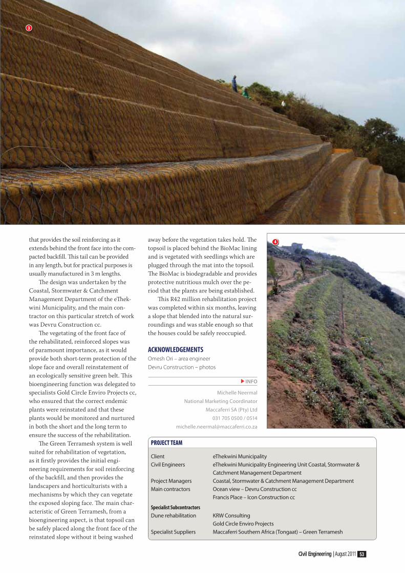
Civil Engineering | August 2011 53
that provides the soil reinforcing as it
extends behind the front face into the com-
pacted backfi ll. Th is tail can be provided
in any length, but for practical purposes is
usually manufactured in 3 m lengths.
Th e design was undertaken by the
Coastal, Stormwater & Catchment
Management Department of the eTh ek-
wini Municipality, and the main con-
tractor on this particular stretch of work
was Devru Construction cc.
Th e vegetating of the front face of
the rehabilitated, reinforced slopes was
of paramount importance, as it would
provide both short-term protection of the
slope face and overall reinstatement of
an ecologically sensitive green belt. Th is
bioengineering function was delegated to
specialists Gold Circle Enviro Projects cc,
who ensured that the correct endemic
plants were reinstated and that these
plants would be monitored and nurtured
in both the short and the long term to
ensure the success of the rehabilitation.
Th e Green Terramesh system is well
suited for rehabilitation of vegetation,
as it fi rstly provides the initial engi-
neering requirements for soil reinforcing
of the backfi ll, and then provides the
landscapers and horticulturists with a
mechanisms by which they can vegetate
the exposed sloping face. Th e main char-
acteristic of Green Terramesh, from a
bioengineering aspect, is that topsoil can
be safely placed along the front face of the
reinstated slope without it being washed
away before the vegetation takes hold. Th e
topsoil is placed behind the BioMac lining
and is vegetated with seedlings which are
plugged through the mat into the topsoil.
Th e BioMac is biodegradable and provides
protective nutritious mulch over the pe-
riod that the plants are being established.
Th is R42 million rehabilitation project
was completed within six months, leaving
a slope that blended into the natural sur-
roundings and was stable enough so that
the houses could be safely reoccupied.
ACKNOWLEDGEMENTSOmesh Ori – area engineer
Devru Construction – photos
INFO
Michelle Neermal
National Marketing Coordinator
Maccaferri SA (Pty) Ltd
031 705 0500 / 0514
PROJECT TEAM
Client eThekwini Municipality
Civil Engineers eThekwini Municipality Engineering Unit Coastal, Stormwater &
Catchment Management Department
Project Managers Coastal, Stormwater & Catchment Management Department
Main contractors Ocean view – Devru Construction cc
Francis Place – Icon Construction cc
Specialist Subcontractors
Dune rehabilitation KRW Consulting
Gold Circle Enviro Projects
Specialist Suppliers Maccaferri Southern Africa (Tongaat) – Green Terramesh
3
4

54 Civil Engineering | August 2011
M A R K E T C O N T R I B U T I O N
Mezzanines in minutesTHE LATEST RELEASE of MultiSUITE
Mezzanine, software for the messanine
fl oor industry, makes almost instant quotes
and layout generation possible for both
single and multiple-tier mezzanine fl oors.
It enables the user to move quickly from
survey data, loading requirements and basic
fl oor geometry, to producing member sizes
including base plates and bracing, to a full
quotation and preliminary sales drawing in
a matter of minutes. It is very easy to try a
number of alternative confi gurations to see
how they might aff ect the structural calcu-
lations, quantities and pricing.
Detailed designs and an accurate
3D Model of the fl oor can be created
instantly in AutoCAD using MultiSTEEL.
From this accurate arrangement and
fabrication, drawings can be generated for
all of the members, with full structural
calculations.
Th is new approach to mezzanine pro-
duction covers the full work stream from
initial survey to fi nal production draw-
ings – design (single and multi-tier fl oors),
estimating (full material quantities are
produced), quotations (produced instantly
in Excel), and drawings (sales and fi nal
design drawings). Th e following are the key
features:
■ Internal design codes
■ Rectangular and irregular shaped fl oors
■ Single and multi-tier fl oors (to fi ve tiers)
■ User-specifi ed beam and secondary
beam data
■ Suitable for braced and unbraced fl oor
design
■ SDNF output to AutoCAD and other
CAD systems
■ Complete video training course
MultiSUITE MezzanineMultiSUITE Mezzanine is the product
of international collaboration between
engineers, software developers and mez-
zanine industry professionals. Th e soft-
ware caters for all stages in the design
and pricing of mezzanine fl oors and fully
takes into account the primary objective
of all companies in this fi eld, which is
to produce competitive designs in the
shortest possible time.
To achieve this the software con-
stantly takes data from one stage in the
process to the next – from the design and
member sizing to the materials list, then
on to the pricing module where items
are automatically matched against price
data prepared by the user. Once a project
goes ahead, the design geometry is passed
into AutoCAD to create the intelligent
drawing model where the fabrication
drawings are produced.
Th e software also off ers the advantage
of treating the fl oor as a complete struc-
ture, and designing and checking all the
component elements right down to the
foundations, completely automatically.
Th is means, for example, that an alterna-
tive arrangement of bays, bracing, or
secondary beam spacing, can be tried, and
the eff ect on the material quantities, and
hence the price, can be seen immediately.
MultiSUITE Mezzanine is an indis-
pensible tool for all companies operating
in this very competitive industry.
MezzoQUOTEMezzoQUOTE is a standalone program
that allows the overall dimensions of the
fl oor to be entered from the survey infor-
mation. Once the number of bays required
in each direction and the loadings are en-
tered, the most economical sizes for all the
members are selected, taking into account
strength and defl ection criteria. Bays can
be added or removed simply by clicking
on the fl oor layout diagram. Bracing can
be added to the required bays in the same
way. Changes to the design data can be
carried out at any stage and a completely
new design can be arrived at in seconds.
Th e material required for each design is
calculated by length or tonnage as appro-
priate, and an average weight per square
metre of fl oor is displayed to enable a quick
comparison between design alternatives.
Full structural calculations are produced
based on the chosen design. A range of
international design codes are provided for.
Th e material list information is updated
continuously, and once a design is chosen,
is then transferred instantly to Excel for
pricing. Also the model of the fl oor struc-
ture can be transferred to AutoCAD for
preparation of a sales drawing if required.
An intelligent drawing is created for either
2D or 3D presentation. MultiSTEEL then
allows the addition of staircases, handrail-
ings, ladders, etc, from an extensive built-in
library. For multi-tier fl oors, MultiSTEEL
will generate 2D fl oor plans and elevations
from the 3D model.
Quotation BuilderOnce the design is fi nalised and the
material quantities identifi ed, this data is
transferred to an Excel template which
automatically matches the items against
price data maintained by the user in a
separate workbook. Th e structure of this
template can be customised easily within
Excel to suit a company’s preferred way
of costing individual items. Similarly the
fi nal quotation document in Microsoft
Word takes all of the fl oor parameters and
the fi nal total price information and lays it
3D sales drawing generated from MezzoQUOTE

Civil Engineering | August 2011 55
MultiSUITE CAD employs the latest AutoCAD OEM 2010 technology from Autodesk. This technology allows Developers like MultiSUITE Software to
box”.
DWG drawings.
MultiSTEEL CAD: Structural Steel CAD package.
MultiREBAR CAD: Reinforced Concrete detailing and scheduling CAD package.
Both products are embedded with AutoCAD OEM Component Technology
The cost-effective complete tailor made CAD solution
MultiSUITE CAD Leading Structural Steel and Concrete Solutions Incorporating AutoCAD (OEM)
A Unique Solution for Structural Drafting
based onAutoCAD OEM 2011 technology
AutoCAD OEM is a registered trade mark of Autodesk Inc.
EURO TECHNOLOGY (PTY) LTD
Tel: 021 762 [email protected]
Also Resellers of MultiSUITE Mezzanine, Strand7 & Rhino 3D.
ology from
Did you know...? MultiSUITEnow works with Strand7 FEA...!
Request your FREE Demo Licence
out in the user’s preferred style for presen-
tation to the client. Th is two-stage pricing
and quotation process is referred to as
Quotation Builder. Fully documented
calculations are produced ready for sub-
mission to Local Authorities for approval.
Calculations can be printed, saved to PDF,
or saved to Microsoft Word format.
MultiSTEEL: drafting and detailing in AutoCADFeature Summary:
■ Fast , accurate layout and detail
drawing production
■ Easy editing to keep up with design
changes
■ Full international section libraries for
all hot-rolled fl oor beams and cold-
formed fl ooring joists
■ Extensive connections library for
various joists types
■ Full plate details for top plates, base
plates and beam connections
■ Cutting lists, material summaries, steel
weights
■ Stair detailing and new bracing detailer
included
■ Inset and oversail designs
■ Multi-level column detailing
Th e MultiSUITE can generate a com-
prehensive material list at any stage.
Automatic item numbers are allocated
to each component and these provide
a direct link to the drawing schedule.
Total weights of steel, surface areas, cut-
ting lists and steel summaries can then
be displayed. A drawing created with
MultiSTEEL becomes a working database,
which can also be exported to other ap-
plications such as Excel if required.
MultiSTEEL also includes macros for
designing stairs, ladders, handrailing and
bracing. Each macro is confi gurable to the
client’s exact requirements.
AutoCAD platforms supported ■ MezzoQUOTE is a standalone pro-
gram that will run on any Windows
platform and PC configuration.
■ Quotation Builder operates in
Microsoft Excel and all current ver-
sions are supported.
■ MultiSTEEL can be used with all
current versions of full AutoCAD.
Hardware requirements are as speci-
fied by Autodesk for the client’s par-
ticular version of AutoCAD.
■ MultiSTEEL CAD consists of
the MultiSTEEL application with
AutoCAD OEM, which is supplied by
MultiSUITE Software under licence
from Autodesk Inc.
MultiSUITE mezzanine options ■ MezzoQUOTE:
Design and pricing module only
■ MezzoQUOTE with MultiSTEEL:
Design, pricing, detailing with
MultiSTEEL utilising existing
AutoCAD license
■ MezzoQUOTE with MultiSTEEL CAD:
(includes AutoCAD OEM licence)
Full design, pricing and detailing suite
with AutoCAD OEM. Suitable for com-
panies that do not currently have a full
AutoCAD licence.
INFO
ET Euro-Technology
021 762 3176

IN BRIEF
WORLD’S FIRST COMMERCIAL WAVE
POWER PLANT INAUGURATED
ON 13 JULY THE BASQUE seaport of Mutriku, located between Bilbao and San
Sebastian in Spain, witnessed a historical day in energy generation history.
Utility Ente Vasco de la Energía (EVE) offi cially inaugurated the Mutriku wave
power plant – the fi rst in commercial operation worldwide. Voith Hydro sup-
plied the equipment for Mutriku’s 16 power units that will provide an output
of 300 kilowatts in total – electricity suffi cient for around 250 homes.
“The rising global demand for green energy proves to be a strong
catalyst for the implementations of innovative forms of renewable energy.
The Mutriku project shows that our wave power technology is commercially
viable and ready for wide deployment on the global markets,” says Dr
Roland Muench, Chief Executive Offi cer of Voith Hydro Holding. “To further
this development, adequate feed-in-tariff s for wave power, as they already
exist for a number of renewables, can now set the right legal framework.”
Voith Hydro’s wave power technology can be deployed in new and
existing breakwaters, and in purpose-built structures. Building on its long-
term proven reliability, continual design improvements have developed the
technology to its leading-edge performance. The worldwide potential of
ocean energy is an estimated 1,8 terawatts and still remains largely untapped.
Voith Hydro’s OWC (oscillating water column) technology is the only one
that has been proven with regard to commercial utilisation, combining avail-
ability and effi ciency at the highest level. On the Scottish island of Islay, Voith
Hydro has been operating the wave power plant Limpet for over a decade
on a commercial scale, producing over 65 000 grid-connected hours.
INFO
Roy Webster
Marketing Manager
Voith Turbo
011 418 4036 / 4000
VEOLIA TO UPGRADE BELLVILLE
WASTEWATER WORKS
VEOLIA WATER SOLUTIONS & TECHNOLOGIES SOUTH AFRICA, a sub-
sidiary of Veolia Water Solutions & Technologies, has been awarded a
R187-million contract by the City of Cape Town’s Department of Water
& Sanitation, to upgrade and extend the treatment capacity at Bellville’s
wastewater treatment works (WWTW).
With this upgrade, the Bellville plant will feature the largest mem-
brane bio-reactor (MBR) in the country to date, and its capacity will
increase by 20 Mℓ/day, to 70 Mℓ/day (average dry weather fl ow – ADWF).
The 20 Mℓ /day MBR will be separate from the existing activated sludge
plant. Hence, during the construction period, the existing plant will not
be impacted upon.
In addition, the design and build contract, including all mechanical
and electrical works, will see Veolia Water Solutions & Technologies
South Africa supply a new inlet works for the MBR plant, new biological
reactors and six membrane trains. A new sludge dewatering facility will
also be supplied, as well as an upgrade of the existing electrical and
control systems infrastructure at the Bellville WWTW.
“The water produced has to meet strict quality requirements
with regard to organic matter, viruses and bacteria removal, am-
monia and suspended solids content. The submerged ultra-filtration
membrane technology will increase capacity, while producing excel-
lent quality, treated water, which will be reused as process water to
industrial and commercial clients in the area,” explains Abrie Wessels,
Regional General Manager, Veolia Water Solutions & Technologies
South Africa, Paarl.
The raw wastewater to the new plant will pass through coarse
screens for degritting, before passing through fi ne screens and un-
dergoing anaerobic, anoxic and aerobic treatment before undergoing
ultra-fi ltration and dewatering of sludge. OTV France, another subsidiary
of Veolia Water Solutions & Technologies, will be providing design and
commissioning support.
The client was looking for a design and build company with suitable
experience, local representation and commercial backbone to deliver on
their commitments. Veolia Water Solutions & Technologies South Africa
has clearly demonstrated technical competence and a track record with
turnkey project execution of this size during the tendering process, while
being commercially competitive.
With this capacity increase, the strain on the existing Bellville facility
will reduce signifi cantly and the effl uent quality will improve. An added
advantage will be the potential for the reuse of the effl uent, which will
save the use of potable water.
Currently, in the basic engineering design phase, the plant is due
for commissioning in 2013. Veolia Water Solutions & Technologies
South Africa will provide training and maintenance support for the
first year of operation.
INFO
Gunter Rencken
Managing Director
Veolia Water Solutions & Technologies South Africa (Pty) Ltd
011 663 3600
1 The world’s fi rst commercial wave power plant at Mutriku, Spain
1 An artist’s impression of the planned new membrane bio-reactor plant at the
Bellville WWTW
56 Civil Engineering | August 2011
1

Civil Engineering | August 2011 57
COROBRIK PAVERS
BEAUTIFY PE INNER CITY
INTERNATIONAL TRENDS CONFIRM the growing preference for clay paving
by urban design professionals abroad for providing functionality with char-
acter and charm to urban environments. Keeping pace with this trend lo-
cally it is no surprise then that more and more urban upgrades are opting to
use Corobrik clay pavers to bring life and vibrancy to our urban landscapes.
“It has been very rewarding to see our clay pavers being used in-
creasingly in large-scale metropolitan renovations around the country.
A recent, and certainly one of the largest, is currently under way in Port
Elizabeth (PE) where 90 000 m2 of Burgundy 50 mm clay pavers have
already been laid,” says Corobrik’s Peter Kidger.
He says that in KwaZulu-Natal 75 000 m2 of Corobrik’s clay pavers were
specifi cally sought for the upgrade of the Durban beachfront precinct,
Umhlanga Promenade and Amanzimtoti beachfront, with extensive use of
their clay pavers also having been made in Knysna, George, the Hillbrow pre-
cinct of Johannesburg, the Cape Town CBD and surrounding suburbs, and
other upmarket residential and commercial estates throughout South Africa.
The PE refurbishments, which began in September 2006, involved
Corobrik products from the start with Burgundy pavers being used for the
broadening of sidewalks from Whites Road to Russell Road. In Govan Mbeki
Avenue, the sidewalks were realigned and broadened using the same
50 mm pavers. To accommodate the loadings of vehicular traffi c, all the
vehicle ramps were paved with the thicker 65 mm paver in the same colour.
According to Kidger, the PE upgrade included the Donkin Reserve and
Govan Mbeki Avenue, both initiated by the Mandela Bay Development
Agency (MBDA) on behalf of the Nelson Mandela Bay Municipality (NMBM).
Hedwig Crooijmans-Allers of Matrix Urban Designers and Architects
says, “The unique colour and texture of Corobrik Burgundy pavers was
ideal. The rich shade blended perfectly into the design and gave the
area an upmarket, rustic feel. Environmentally, we required that the solu-
tion be sustainable and eco-friendly, with the surface being resistant to
staining and corrosion, the latter most important to counter the salt and
high humidity levels prevalent in this vicinity of the city. The Matrix, in
collaboration with Mandela Bay Development Agency (MBDA), opted for
the Burgundy paver as it fulfi lled the sustainability imperative well.”
“Looking at what has been achieved, our pavers have satisfi ed their
mandate to transform and uplift these urban environments, bringing a
richness of colour and texture that the eye relates to. The colour fastness
and enduring intrinsic qualities of fi red clay will provide a rewarding up-
market aesthetic appeal for decades to come”, adds Kidger.
Bryan Wintermeyer, of Workplace Architects, says, “Together
with the MBDA, we selected, for the Donkin Reserve, colours already
used in other projects to achieve coherence and consistency be-
tween the various projects in the city. The pavers in this instance
were laid in stack-bond pattern, forming long, continuous lines that
enhance the sense of directional movement. The product integrates
well with other materials and provides various opportunities for
layouts and patterns.”
250 000 metres of
TRENCHLESS PIPE
Successfully Installed Countrywide 08600 66 344
SPECIALIST IN DIRECTIONAL DRILLING
& PIPELINE REHABILITATION
1 and 2 The use of Corobrik Burgundy pavers has brought an authentic, rustic feel
to the Port Elizabeth city centre. Photo 1 shows the city centre with the City Hall in the
background, while photo 2 captures both the library (on the right) and the City Hall
1
2
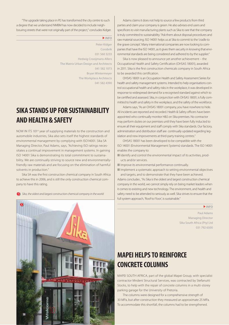
“The upgrade taking place in PE has transformed the city centre to such
a degree that we understand NMBM has now decided to include neigh-
bouring streets that were not originally part of the project,” concludes Kidger.
INFO
Peter Kidger
Corobrik
031 560 3233
Hedwig Crooijmans-Allers
The Matrix Urban Design and Architects
041 582 1073
Bryan Wintermeyer
The Workplace Architects
041 582 4390
SIKA STANDS UP FOR SUSTAINABILITY
AND HEALTH & SAFETY
NOW IN ITS 101st year of supplying materials to the construction and
automobile industries, Sika also sets itself the highest standards of
environmental management by complying with ISO14001. Sika SA
Managing Director, Paul Adams, says, “Achieving ISO ratings neces-
sitates a continual improvement in management systems. In gaining
ISO 14001 Sika is demonstrating its total commitment to sustaina-
bility. We are continually striving to source new and environmentally-
friendly raw materials and are focusing on the elimination of harmful
solvents in production.”
Sika SA was the fi rst construction chemical company in South Africa
to achieve this in 2006, and is still the only construction chemical com-
pany to have this rating.
Adams claims it does not help to source a few products from third
parties and claim your company is green. He also advises end users and
specifi cers to visit manufacturing plants such as Sika to see that the company
is truly committed to sustainability. “Ask them about disposal procedures and
raw material sourcing. ISO 14001 helps us at Sika to commit to the ‘cradle to
the grave concept’. Many international companies are now looking to com-
panies that have the ISO 14001, as it gives them security in knowing that envi-
ronmental standards are being considered and adhered to by the supplier.”
Sika is now pleased to announce yet another achievement – the
Occupational Health and Safety Certifi cation (OHSAS 18001), awarded
in 2011. Sika is the fi rst construction chemicals company in South Africa
to be awarded this certifi cation.
OHSAS 18001 is an Occupation Health and Safety Assessment Series for
health and safety management systems. Intended to help organisations con-
trol occupational health and safety risks in the workplace, it was developed in
response to widespread demand for a recognised standard against which to
be certifi ed and assessed. Sika, in conjunction with OHSAS 18001, is fully com-
mitted to health and safety in the workplace, and the safety of the workforce.
Adams says, “As an OHSAS 18001 company, you have nowhere to hide.
All incidents are reported and recorded. Health & Safety offi cers have been
appointed who continually monitor H&S on Sika premises. No contractor
may perform duties on our premises until they have been fully inducted to
ensure all their equipment and staff comply with Sika standards. Our factory,
administration and distribution staff are continually updated regarding leg-
islation and new improvements at third-party training centres.”
OHSAS 18001 has been developed to be compatible with the
ISO 14001 (Environmental Management Systems) standards. The ISO 14001
enables the company to:
■ Identify and control the environmental impact of its activities, prod-
ucts and/or services.
■ Improve its environmental performance continually.
■ Implement a systematic approach to setting environmental objectives
and targets, and to demonstrate that they have been achieved.
Adams concludes , “As Sika is the oldest and largest construction chemical
company in the world, we cannot simply rely on being market leaders when
it comes to existing and new technology. The environment, and health and
safety need to be attended to seriously as well. Sika strives to ensure that the
full system approach, ‘Roof to Floor’, is sustainable.”
INFO
Paul Adams
Managing Director
Sika South Africa (Pty) Ltd
031 792 6500
MAPEI HELPS TO REINFORCE
CONCRETE COLUMNS
MAPEI SOUTH AFRICA, part of the global Mapei Group, with specialist
contractor Mndeni Structural Services, was contracted by Stefanutti
Stocks, to help with the repair of concrete columns in a multi-storey
parking garage for the University of Pretoria.
The columns were designed for a comprehensive strength of
30 MPa, but after construction they measured an approximate 25 MPa.
To accommodate this shortfall, the columns had to be strengthened.
1
1 Sika, the oldest and largest construction chemical company in the world
58 Civil Engineering | August 2011

Sika
Roof
Completely seamlessCold appliedElastomeric and durableRoot resistant waterproofing membraneEasy to repair if puncturedCan be applied in damp conditionsQuick and easy to applyIncreases thermal performance
Advanced waterproofing technology for Africa – Sikalastic MTC®
Civil Engineering | August 2011 59
Carbon fi bre wrapping was the preferred option, as it is strong but light-
weight, and MapeWrap C UNI-AX 600/40 met the project requirements.
Before the wrapping could be applied, the columns had to be thoroughly
prepared. First, laitance was removed with grinding and sandblasting to pro-
vide an open texture surface. In the next step, MapeWrap Primer 1 – an epoxy
primer specifi c to the MapeWrap system – was applied to promote adhesion.
All blowholes were then fi lled with Adesilex PG2, a two-component
epoxy resin-based product containing special hardeners that off er extended
workability and are ideal for structural strengthening and sealing large cracks.
MapeWrap C UNI-AX 600/40, a high-strength, uni-directional, con-
tinuous carbon fi bre fabric with a very high modulus of elasticity and
high tensile strength, was then layered tightly around the columns in
segments, with overlaps. To impregnate the MapeWrap, MapeWrap 31, a
medium-viscosity epoxy resin, was applied to the concrete.
In the next step, the MapeWrap C UNI-AX 600/40 was rolled on with a
steel roller to remove any trapped air bubbles, and blinded with silica sand.
After the epoxy had hardened, excess sand was brushed off and a skim-
ming mortar was applied to the columns. Planitop 200, a single-component
cementitious mortar with high bonding strength, was applied in the fi nal
step to smooth the surface, protect the wrapping and fi nish off the columns.
INFO
Lollita Pitso
Marketing Consultant
Mapei SA (Pty) Ltd
011 552 8476
1 High-strength MapeWrap C UNI-AX 600/40 was layered tightly around
the columns in segments, with overlaps
1

SURVEYS, MAPPING, GIS
www.geoinfo.co.za Tel: +27 11 763 7173 Fax: +27 11 763 1263
♦ Project Management of large survey & mapping contracts ♦ 3 Dimensional Laser Scanning (Mobile & Terrestrial) ♦ Underground Services Detection ♦ GIS Data Capture ♦ Engineering ♦ Mining ♦ Bathymetric
60 Civil Engineering | August 2011
PRECAST CONCRETE
STANDARDS AND THE CPA
ALTHOUGH THE CONSUMER PROTECTION ACT (CPA) has been in force
for several months, the jury is still out as to the impact it will have on
the South African economy and, more specifi cally, on precast concrete
manufacturers.
However, Hamish Laing, Director of the Concrete Manufacturers
Association (CMA), observes that companies which adhere or manu-
facture to a certifi able standard are in a far better position to face any
purchase disputes which may arise from the Act.
“Standards, especially those which originate from the South
African Bureau of Standards, will play a far more meaningful role than
had previously been the case, not only for precast concrete prod-
ucts, but for any product or service. In fact, the CPA makes it almost
mandatory for any supplier of any product to carry a SABS or other
recognised quality certification, as those who do not, lay themselves
open to the full force of the law in the event of a dispute.
Laing says the CPA does not only apply to the manufacturing
process, because in addition to inherent product quality, the Act
also covers correct application. “The onus is on the manufacturer to
inform the customer about proper product application. In other words,
manufacturers must inform their customers about the capabilities and
limitations of their products.
“For example, if a concrete retaining block manufacturer sells to
a nursery, he must inform the nursery management that blocks can
only be used for walls up to 1,4 m high; for higher walls an engineer
must design the structure. And the nursery in turn must inform its
customers. The same applies to other precast concrete products such
as pipes, culverts, hollow-core slabs, concrete block pavers, concrete
masonry and concrete roof tiles – in each instance the buyer must be
informed about correct application.
“The CPA places considerable onus on the supplier to off er fair
value in an honest and even-handed manner, and it provides the con-
sumer with a powerful mechanism to challenge those suppliers who
do not comply.
“The CMA welcomes the Act, because it weaves the whole
process of standards into the country’s economic fabric and justifies
the expense of carrying the SABS mark. One thing is certain, stand-
ards are going to play an increasingly important role in the years
ahead and that can only be to the benefit of all consumers,” Laing
concludes.
INFO
Hamish Laing
Director: CMA
011 805 6742
LADY CIVIL ENGINEER WINS 2011
L’ORÉAL-UNESCO FELLOWSHIP
L’ORÉAL AND UNESCO RECENTLY announced the winners of the
2011 L’Oréal-UNESCO Regional Fellowships for Women in Science in
Sub-Saharan Africa. This year, ten inspiring women scientists from across
Sub-Saharan Africa have been awarded fellowships of US$20 000.
The winners are Olutayo K. Boyinbode (Nigeria), Dalene de Swardt
(SA), Jeanne de Waal (SA), Valencia Jacobs (SA), Ifeoma Obidike (Nigeria),
1 Hamish Laing, Director of the CMA
1

Civil Engineering | August 2011 61
Ruth Odhiambo (Kenya), Salome Muriuki (Kenya), Rachel Muigai (Kenya),
Kim Trollope (SA), and Madeleine Bihina Bella (Cameroon).
These Fellowships are awarded to young doctorate or post-
doctorate lady scientists. The scientific research areas being covered
by this year’s Fellows include studies in the fields of computer sci-
ence, microbiology, environmental science, medical virology, textile
science, chemistry, pharmacy, civil engineering and agriculture.
The L’Oréal Foundation doubled the number of Fellows from fi ve to
ten in 2011 based on the extraordinary success of the pilot programme
launched in 2010, which recognised and awarded fi ve lady scientists
with $20 000 towards the completion of their PhD research projects.
Philippe Raff ray, Managing Director for L’Oréal South Africa, says the
programme attracted an increased number of entries this year, proof of
the potential of these fellowships to make a real diff erence in the lives
and careers of Africa’s women scientists.
“The programme is open to all women scientists up to the age of 40
across Sub-Saharan Africa who are working towards their PhDs in all fi elds
of science. This year we received 175 applications from across the Sub-
Saharan region, a signifi cant increase from last year’s 104 applications.”
Rachel Muigai, who was born and raised in Nairobi, Kenya, but
who has been living in Cape Town for the past fi ve years, is one of
the ten new 2011 Fellows. She is currently completing her PhD at the
University of Cape Town, with research focusing on the sustainability of
concrete structures.
Rachel’s academic excellence in subjects such as physics, chem-
istry and biology in high school, as well as her intense curiosity to
understand how things work, coupled with encouragement from her
teachers, nurtured her love for science. Civil engineering interested
her, as it offers a whole range of science-related subjects that one
could specialise in.
She completed a BSc in Civil Engineering at the University of Nairobi
(2001-2006), a Masters in Civil Engineering at the University of Cape Town
(2007-2008), and carried out ongoing PhD research at the Technical
University of Münich, Germany, in 2010.
Despite her affi nity for structural engineering, the 30-year-old re-
searcher says she still fi nds herself having to prove her worth in the sector.
“Civil engineering is still a male-dominated fi eld and I fi nd that you have to
continuously prove yourself. Despite having a deep interest in the fi eld, as a
woman I’m constantly challenged as to why I want to work in construction.
However, being confi dent in myself, as well as persistent and hardworking,
always wins the case for me!”
For her PhD, Rachel researches design and construction solutions that
could lead to sustainable concrete infrastructure in South Africa. The study
output aims to ensure that future concrete structures have the lowest pos-
sible carbon footprint, emissions, energy use and impact on the environ-
ment and society.
She says the L’Oréal-UNESCO Fellowship provides her with an op-
portunity to further enrich the research undertaken by UCT’s Concrete
Materials and Structural Integrity Research Unit (CoMSIRU) and, to an
extent, the local cement and concrete industry.
In her downtime, Rachel enjoys hiking, mountain-biking, volleyball,
and participating in environmental awareness programmes, like tree-
planting initiatives.
INFO
Sara-Lea van Eeden,
Taryn Fritz Public Relations & Communications
083 446 6109
www.forwomeninscience.com
1
1 Rachel Muigai, civil engineering PhD candidate, who was awarded a
2011 L’Oréal-UNESCO Fellowship recently

62 Civil Engineering | August 2011
A new standard system of measurement for civil engineering quantities in southern AfricaA SOUTHERN AFRICAN edition of
Civil Engineering Standard Method of
Measurement (CESMM3) has recently
been published, following inputs from
local industry stakeholders. It is a regional
customisation of a well-established
standard for the preparation of bills of
quantities for civil engineering work,
developed by the Institution of Civil
Engineers (ICE) (London).
Th e current methodology for meas-
uring civil engineering quantities is
contained in Clause 8 of the SANS 1200
Standardised Specifi cations for Civil
Engineering Construction, read together
with the South African Institution of Civil
Engineering’s (SAICE) Civil Engineering
Quantities (1990). Th e SANS 1200 series
of standards, which were developed
and last updated during the 1980s, were
designed for use with SAICE’s General
Conditions of Contract. In line with
modern drafting requirements for docu-
ments embodied in the Construction
Industry Development Board’s
Standard for Uniformity in Construction
Procurement, SABS has published the
SANS 1921 series of standards for con-
struction and management requirements
for works contracts and most of the SANS
2001 series of technical standards for
construction works. Th e southern African
edition of CESMM3 is compatible with
these standards and is suitable for use
with international, national, organisa-
tional, industry and bespoke standards,
and most standard forms of contract.
Th e chairman of the SAICE Joint
Civils Division (a joint division of SAICE
and ICE), Dr Ron Watermeyer, says,
“CESMM3 became a logical choice as a
base document for the successor to the
current system of measurement em-
bedded in the SABS 1200 Standardised
Specifi cations, as it is a document founded
on the same thinking and philosophy
as the system that has evolved in South
Africa. It is widely used in Africa and
is well understood by the international
community. It is a well tried and tested
document that is adequately supported by
a range of comprehensive handbooks and
texts.”
Peter Becker, who was intimately in-
volved in the development of the current
system of measurement and under whose
guidance the new system was developed,
points out that in the southern African
edition of CESMM3:
■ No reference is made to any standard
form of contract, as the terms and text
are aligned with standard forms of con-
tract commonly used in the region.
■ Th e terminology is aligned with the
provisions of the CIDB’s Standard for
Uniformity in Construction Procurement,
and South African national standards or
international standards.
■ Adjustments have been made to items
and terminology to refl ect southern
African practices.
■ Th e fabrication of structural metalwork
items needs to be supported by separate
bills of quantities developed in ac-
cordance with the SAISC’s (Southern
African Institute of Steel Construction)
system of measurement.
■ Classes EA (Additional Earthworks)
and RA (Additional Roadworks), and
items within these classes, have been
introduced to provide fl exibility to ac-
commodate regional earthworks prac-
tices, i.e. to enable interim operations to
be measured.
The southern African edition of
CESMM3 costs R500, including VAT
but excluding postage, and may be
obtained from the South African
Institution of Civil Engineering
(+27 11 805 5947), the Association of
South African Quantity Surveyors
(+27 11 315 4140), Consulting Engineers
South Africa (+27 11 463 2022),
Engineering Contract Strategies
(+27 11 803 3008), and the South
African Federation of Civil Engineering
Contractors (+27 11 409 0900).
INFO
Dr Ron Watermeyer
Chairman: SAICE Joint Civils Division
S A I C E A N D P R O F E S S I O N A L N E W S

Free BIM software for project collaborationDownload Tekla BIMsight at www.teklabimsight.com
We love models. And we believe that once you download the new Tekla BIMsight, so will you. Combine models, check for clashes and enjoy seamless communication - Tekla BIMsight will change the way you manage your construction projects.
Cadex SA, Tekla’s Partner for Southern Africa [email protected] or www.CadexSA.com

64 Civil Engineering | August 2011
Winners of the AfriSam – SAICE
Electronic Photo Competition 2011
1
1 FIRST: Dawning of a new day
Photographer: K Marais
2 SECOND: Hospital Bend at night
Photographer: Bruce Sutherland
3 THIRD: Cape Town Stadium during the FIFA World Cup
Photographer: Bruce Sutherland

Civil Engineering | August 2011 65
For the first time in its history, SAICE’s ever popular photo
competition was presented in electronic format this year, drawing
126 high-resolution entries. The first round of voting was done
online by SAICE members (we received more than a thousand votes),
narrowing the entries down to a shortlist of finalists from which
the winning photographs were selected by a panel of judges. The
adjudication took place on Tuesday 21 June at the historic Liliesleaf
Farm in Rivonia, with AfriSam kindly sponsoring the event
2
3

66 Civil Engineering | August 2011
The United Nations Conference on Sustainable Development 2012 –
Regional Workshop for AfricaSAICE WAS INVITED by the
World Federation of Engineering
Organisations (WFEO) to attend the
Africa Regional Workshop, which
was held in Pretoria from 30 May –
1 June 2011. The event was organised
by the International Council for Science
(ICSU) (Regional Office for Africa)
and the United Nations Educational,
Scientific and Cultural Organisation
(UNESCO), Nairobi. Manglin Pillay,
CEO of SAICE, and Lorraine de Ronde,
SAICE International Liaison Officer,
attended the workshop.
Th e United Nations Conference on
Sustainable Development 2012, also
known as “Rio+20”, is scheduled for 4 –
6 June 2012 in Rio de Janeiro, Brazil, the
same city where the fi rst Earth Summit
was held in 1992. In preparation for the
event, fi ve regional workshops for Asia
Pacifi c, Latin America and the Caribbean,
Africa, the Arab Region and Europe
were organised to aff ord scientists and
engineers from the diff erent regions the
opportunity to prepare joint positions and
concerted input into the processes leading
to Rio+20. Delegates came from various
African countries and included natural
and social scientists, engineers, policy-
makers and government representatives,
major group representatives, research
organisations, educational institutions,
UNESCO and ICSU.
Th e objectives of Rio+20 include,
among others:
■ To secure renewed political commit-
ment for sustainable development.
■ To assess progress to date of the fi rst
summit (1992 Earth Summit).
■ To identify the remaining gaps that
inhibit progress.
■ To implement the outcomes of the major
summits on sustainable development.
■ To address new and emerging challenges.
Delegates at the recent Rio+20 Africa Regional
Workshop in Pretoria – from left:
Prof Alice Abreu (ICSU, Paris),
Manglin Pillay (CEO, SAICE),
Edith Madela-Mntla (ICSU Regional Offi ce for Africa),
Prof Joseph Massaquoi (UNESCO, Nairobi),
Prof Lidio Brito (UNESCO, Paris) and
Lorraine de Ronde (SAICE International Liaison Offi cer)

Civil Engineering | August 2011 67
During the regional workshop for Africa,
the following three main themes were
discussed:
■ Greening of the global economy for
poverty reduction
■ Building of institutional frameworks for
sustainable development
■ Identifi cation and confi guration of ap-
proaches to management of new and
emerging challenges for sustainable
development.
Discussions centred around four key
questions:
1) What are the priority issues for Rio+20
in 2012, as seen by the scientifi c and
technological community from the
region, taking into account the UN
General Assembly outline of Rio+20?
2) What are the needs of science and
technology in the region, in order to be
able to contribute best to sustainable
development in the region?
3) What are the major contributions from
the sciences and engineering towards
sustainable development at local, na-
tional, and regional levels?
4) What role can the diff erent stakeholders
and major groups play in enhancing
regional science and technology for sus-
tainable development, and what do they
need from science and technology?
Th e nine non-governmental stakeholder
groups, also referred to as major groups, are:
1) Women
2) Youth and Children
3) Indigenous Peoples
4) Non-Governmental Organisations
5) Local Authorities
6) Workers and Trade Unions
7) Business and Industry
8) Farmers
9) Scientifi c and Technological
Community
Th e important outcome of the Regional
Workshop was a document that expresses
the point of view of the African scientifi c
and technological community regarding
the three main themes of Rio+20.
Th e bottom-up approach that was
used in the preparatory process ensured
strengthening of regional and sub-re-
gional policy frameworks for sustainable
development. Africa will have an agreed-
upon position when going to Rio next year
to contribute to discussions around earth
systems, climate change and sustainable
development.
The Rio+20 Africa Regional
Workshop offered valuable opportuni-
ties to network with representatives of
UNESCO, WFEO and ICSU, who are
also involved in strengthening engi-
neering institutions globally.
Government offi cials from the
Departments of Environmental Aff airs,
Science and Technology, and Social
Development were also present during the
workshop. Relationships have also been
established with various engineers and
scientists from universities across Africa.
Th e workshop was a successful col-
laboration of the African SET (Science,
Engineering and Technology) opinion – to
be carried forward to the 2012 Rio+20 event.
Building international relationships,
not only in Africa, but with major stake-
holders across the world, is vital for the
sustainable future of institutions and
their members. Opportunities are created
for members to interact and work with
counterparts from other countries, and to
be exposed to international best practice.
INFO
Lorraine de Ronde
SAICE International Liaison Offi cer
A group of twenty transportation engineers from the Nigerian Institution of Civil Engineers visited
South Africa during the last week of June. SAICE, together with the BEPEC (Built Environment
Professions Export Council), arranged various interesting site visits for the delegation, including a
ride on the Gautrain. SAICE also entertained the group at National Offi ce, where President Seetella
Makhetha shared his “Credo of the African Engineer” with them. The picture shows members of
the delegation in the SAICE bookshop.
Strengthening ties with our Nigerian colleagues

68 Civil Engineering | August 2011
UCT Student ChapterUCT Student Chaptervisit to the Berg River Damvisit to the Berg River Dam
THE BERG RIVER DAM is the fi rst
dam in South Africa to be designed,
constructed and operated in accordance
with the guidelines of the United Nations
World Commission on Dams.
Earlier this year, the third and fourth
year civil engineering students from the
University of Cape Town had the amazing
opportunity to visit this concrete-faced,
rock-fi ll dam, located in the upper reaches
of the Berg River catchment area. Th e
students were taken on a tour of the pump
station, the intake tower and the dam
outlet. Th e visit into the intake tower
was interesting, especially for the more
adventurous students who got a chance to
trek all the way down to the bottom. Th e
only problem was, once you reached to
the bottom of the tower, you had to climb
160 m back up to the top again! To round
off the perfect fi eld trip, the students were
treated to a picnic of pizza and cold beers.
Th e SAICE Student Chapter at UCT
would like to thank Bruce (GOBA) and
Wallie (DWA) for taking the time to
share their extensive knowledge and ex-
perience. Th anks also to GOBA for spon-
soring the refreshments and Bertrand
van Zyl (DWA) for organising the permit
for the visit. And fi nally, a huge thank
you to Prof Kobus van Zyl of UCT, as it
would not have been possible to organise
this visit without his assistance.
INFO
Alice Chang
SAICE UCT Student Chapter
1
2
3

Civil Engineering | August 2011 69
1 The third and fourth year civil engineering
students from the University of Cape Town
visiting the Berg River Dam earlier this year
2 Examining the butterfl y valve
3 Admiring the magnifi cent Berg River Dam
4 The students at a model of the dam
5 Bruce (GOBA) addressing the students
4 5

70 Civil Engineering | August 2011
In celebration of the life of Professor Richard Loewenthal
(or Richard the Lionheart!)
RICHARD DICK LOEWENTHAL retired to his olive farm in
Vermaaklikheid a few years ago. Dick was born on 26 August 1941
in Johannesburg and died at the age of 69 on 6 January 2011.
Emeritus Associate Professor Loewenthal started working at the
University of Cape Town in September 1974 as a Senior Lecturer
and was promoted to Associate Professor on 1 January 1987. He
retired from UCT on 31 December 2006. Th is is a short tribute to
the man that Richard Loewenthal was, rather than a record of all
his academic achievements (of which there were many!).
Richard was a husband to one, a father to three, and a father
fi gure, friend and educator, magnifi cent entertainer and inspira-
tional stalwart to a multitude. In his few years of retirement on the
farm, he would often sit on the stoep, look out over the olive trees
and the dusty road leading into the hills and refl ect on his friends,
on family, on cooking, on the universe, on the human condition,
on philosophy, in short on all the richness and joys of life. What
struck his family most about these moments was how incredibly
grateful he was for everything he had. “You know, Doug,” he would
say to his son, “sometimes when I think back on when I was young
and growing up, I still can’t believe how lucky I’ve been.”
Lucky he may have been, but if ever there was someone who
made his own luck, it was surely him – with an enormity of will
and spirit, with a singleness of purpose and a sheer joy of living
that is seen in very few people. Perhaps a good part of his char-
acter was the result of a tough childhood and, sadly, a father who
told him that he would amount to nothing in life. On one occa-
sion he was told that he lacked the basic intelligence to go further
than matric. His old friend, who knew him well as a young man,
said that to Richard this was like a red rag to a bull. Some rag,
some bull!
He left home at the age of fi fteen, eventually working on the
gold mines to fund himself through university. While working
as a miner, he was already educating himself by going to evening
classes – no mean feat, as his work started every day at four in
the morning with a trip two kilometres underground. Already
it was clear that the seeds of a mightily stubborn will had been
Obituary

Civil Engineering | August 2011 71
������������� ��� �� ��������� ������������������������
� � �� � � � �� � � ���� ������ ��� ���� �����
��
� � � � � � � � � � � � � �� � � � � � �
� ��� � � � ���� � � � � � � � � ��� � � ��������� � ������������������ �!
sown – that a fi ne spirit was being smelted in the crucible of
adversity. At university, as a somewhat wayward and lost fourth
year civil engineering student, he faced his fi rst real research
problem – given to him by his mentor, Professor Marais, who
was highly regarded in his fi eld at the time. Richard, after a huge
party on the Wild Coast, returned with the prospect of having
to do his fi nal year project in a week. Well, he solved the problem
and just managed to write up his thesis in time. On the fi rst
reading, Prof Marais declared that it must be nonsense, but on
the second reading he realised that Richard was onto something
very special. By the third reading, he said later, he felt that he
was witnessing the workings of a great mind. Professor Marais
was big enough to later admit that he had been working on the
problem for two years without success!
It was truly in research that Richard found his niche in life
and, from his fourth year onwards, began to realise his enormous
potential. He was, as someone else said, a researcher from his
teeth to his toenails. He once told his son, Doug, that, “Doing
research is like no other work you can imagine.” For most people
work consists of learning a formula and applying that formula
in life with varying degrees of success – reliable, but boring. But
when you are doing truly creative research, as with any creative
endeavour, there is no formula to rely on – every great research
problem is unique. It is a terrifying, humbling and exhilarating
experience all in one. You open a dark room, you stumble around
as best you can and try to bring some order to things. Th en even-
tually you fi nd the light switch and you switch the light on and
everything becomes bright and clear. For a short moment you
walk with the Gods, and the universe suddenly seems a much
friendlier, much more beautiful place. Th en other people enter
the room, often ignorant, often arrogant, usually self-assured,
wondering what all the fuss was about – except they didn’t have
to turn the light on. Th en you go into the next dark room.......
Marais, Dick’s long-time mentor and colleague, said that he
was a researcher who leapt from peak to peak while others toiled
away in the valleys. Th is perhaps gave the impression that he did
not work hard, but all who knew him witnessed his incredible
drive when faced with a truly massive research problem. Th e
harder the problem, the more excited and more tenacious he be-
came, and the more determined he was to solve it.
Needless to say, his students loved him and his eccentrici-
ties. He always entered the lecture hall without a single lecture
note, believing that keeping notes would make his lectures stale
and repetitive. Some of the words and phrases students used to
describe him have been recorded for posterity in student year
books. Here are a few:
“.....understands the mind of a student through and
through…..”
“…..he made complex concepts so simple to understand…..
that you went away wondering what the problem was…..”
“…..has the weathered face of a Keith Richards and a devilish
sense of humour.....”
“.....he often landed up lighting two cigarettes and placed
one at each side of the lecture hall, so that he could pace
back and forth taking regular puff s at each end as the ideas
fl owed…..”
Despite his achievements in the academic world, it was his
family and friends that he valued most, recognising that “to
know and to love one’s fellow human being is truly at the root of
all wisdom”. Certainly, it was with friends and family around
him, a glass of red wine in hand and a curry simmering on the
stove that he was very often at his happiest and most animated.
On these occasions he loved to shock people into laughter,
delightfully mixing profound conversation with the absurd and
giving vent to his magnifi cent, wonderfully vulgar and often
outrageous sense of humour.
But behind the jokes, the banter, the laughter and mag-
nificent mockery, one always sensed that there resided a fine,
grand and generous spirit. A spirit that never ceased to bring
joy to all those whom he came into contact with. He had a
magnetism that drew people to him from all walks of life.
He had the rare gift of making all people feel somehow more
special, more alive in his presence. That indeed was his magic
and a huge part of his legacy.
In the end he faced death as he faced the trials of life:
squarely and bravely, with honesty and integrity, and with that
magnifi cent mix of fl ippancy and profundity that he made
uniquely his own. He wanted all who were dear to him not to
wallow in sadness, but to celebrate his life.
As his old friend Dave McPhail said, he was indeed Richard
the Lionheart!
Cheryl Wright and Marianne Vanderschuren
[email protected] / [email protected]
Adapted from Doug Loewenthal’s memorial address
72 Civil Engineering | August 2011
Date Event and CPD
validation numberPresenters
Contact details
8-9 September Durban
13-14 October Cape Town
17-18 November Gauteng
Business Finances for Built Environment
Professionals
SAICEfi n08/00405/11
Wolf WeidemannDawn Hermanus
5-6 September Durban
10-11 October Cape Town
Handling Projects in a Consulting Engineer's
Practice
SAICEproj08/00404/11
Wolf WeidemannDawn Hermanus
12 September Pietermaritzburg
21 November Johannesburg
Bridge Maintenance
SAICErail09/00495/12 Ed EltonDawn Hermanus
13-14 September Pietermaritzburg
22-23 November Johannesburg
Basics of Track Engineering
SAICErail09/00496/12Ed Elton
Dawn Hermanus
26-27 September MidrandGCC
SAICEcon10/00706/13Theuns Eloff
Cheryl-Lee Williams
20 September East LondonReinforced Concrete Design to SANS 10100-1
SAICEstr09/00432/11Greg Parrott
Cheryl-Lee Williams
21 September East LondonStructural Steel Design Code to SANS 10162:1-2005
SAICEstr09/00513/12Greg Parrott
Cheryl-Lee Williams
26-27 September Bloemfontein
17-18 October Durban
Network Analysis & Introduction to Surge Analysis
SAICEwat10/00804/13Prof Fanie van Vuuren
Cheryl-Lee Williams
1-2 November Port Elizabeth
8-9 November Durban
15-16 November Johannesburg
22-23 November Cape Town
Basic Coastal & Harbour Engineering
SAICEwat09/00611/12Keith Mackie
Cheryl-Lee Williams
15-16 September Pietermaritzburg
24-25 November Johannesburg
Rail Transport
SAICErail11/00887/14Ed Elton
Dawn Hermanus
For more information on courses, venues and course outlines please visit http://www.civils.org.za/courses.html
DIARISE THIS!DIARISE THIS!T !ISE TA THIST IS!IS
IAARISE TA THIST IS!ISDIAARISEAD
EltonDawn Hermanu
SAICEcon10/00706/13Theuns Eloff
ryl-Lee Willia
ember East Londoneinforced Concrete Design to SANS 1
AICEstr09/00432/11Greg Parrott
Ch
ber East LondonStructural Steel Design Cod
SAICEstr0


Related Documents


