WS7-1 ANSYS, Inc. Proprietary © 2009 ANSYS, Inc. All rights reserved. April 28, 2009 Inventory #002601 Introductory FLUENT Training Workshop 7 Tank Flushing

WS7-1 ANSYS, Inc. Proprietary © 2009 ANSYS, Inc. All rights reserved. April 28, 2009 Inventory #002601 Introductory FLUENT Training Workshop 7 Tank Flushing.
Dec 13, 2015
Welcome message from author
This document is posted to help you gain knowledge. Please leave a comment to let me know what you think about it! Share it to your friends and learn new things together.
Transcript
WS7-1ANSYS, Inc. Proprietary© 2009 ANSYS, Inc. All rights reserved.
April 28, 2009Inventory #002601
Introductory FLUENT Training
Workshop 7
Tank Flushing
WS7-2ANSYS, Inc. Proprietary© 2009 ANSYS, Inc. All rights reserved.
April 28, 2009Inventory #002601
Workshop Supplement
WS7 – Tank Flushing
Introduction
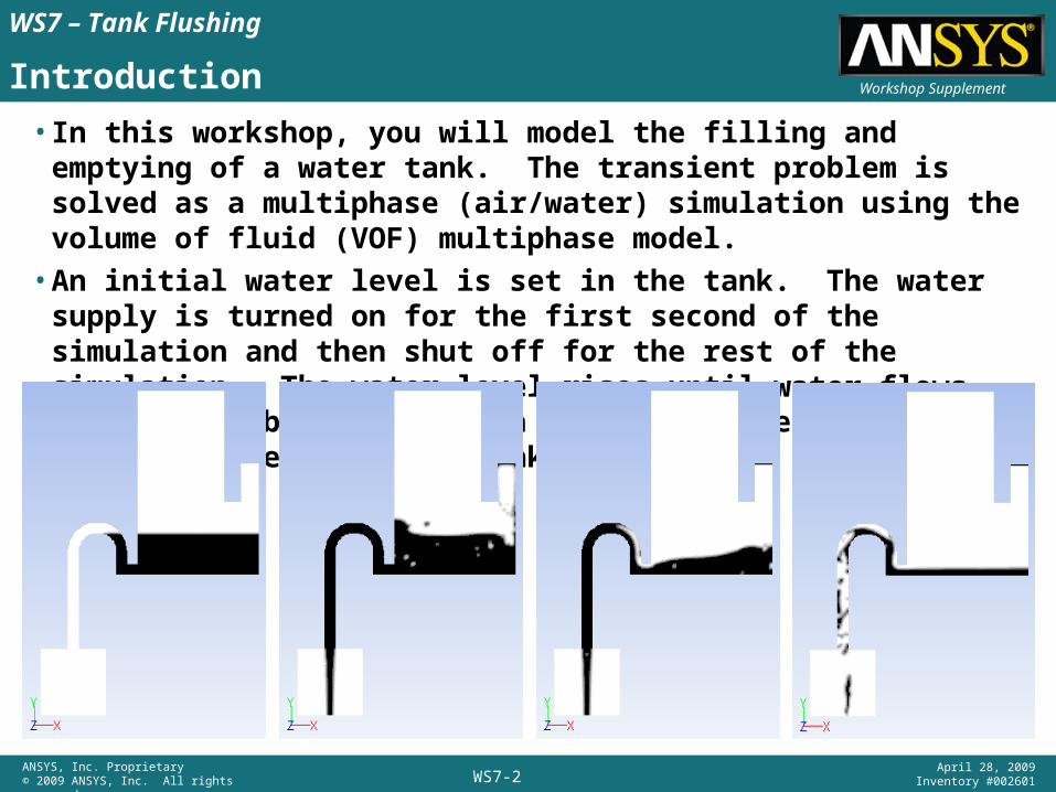
• In this workshop, you will model the filling and emptying of a water tank. The transient problem is solved as a multiphase (air/water) simulation using the volume of fluid (VOF) multiphase model.
• An initial water level is set in the tank. The water supply is turned on for the first second of the simulation and then shut off for the rest of the simulation. The water level rises until water flows out the U-tube generating a siphoning effect which effectively empties the tank.
WS7-3ANSYS, Inc. Proprietary© 2009 ANSYS, Inc. All rights reserved.
April 28, 2009Inventory #002601
Workshop Supplement
WS7 – Tank Flushing
Mesh Import
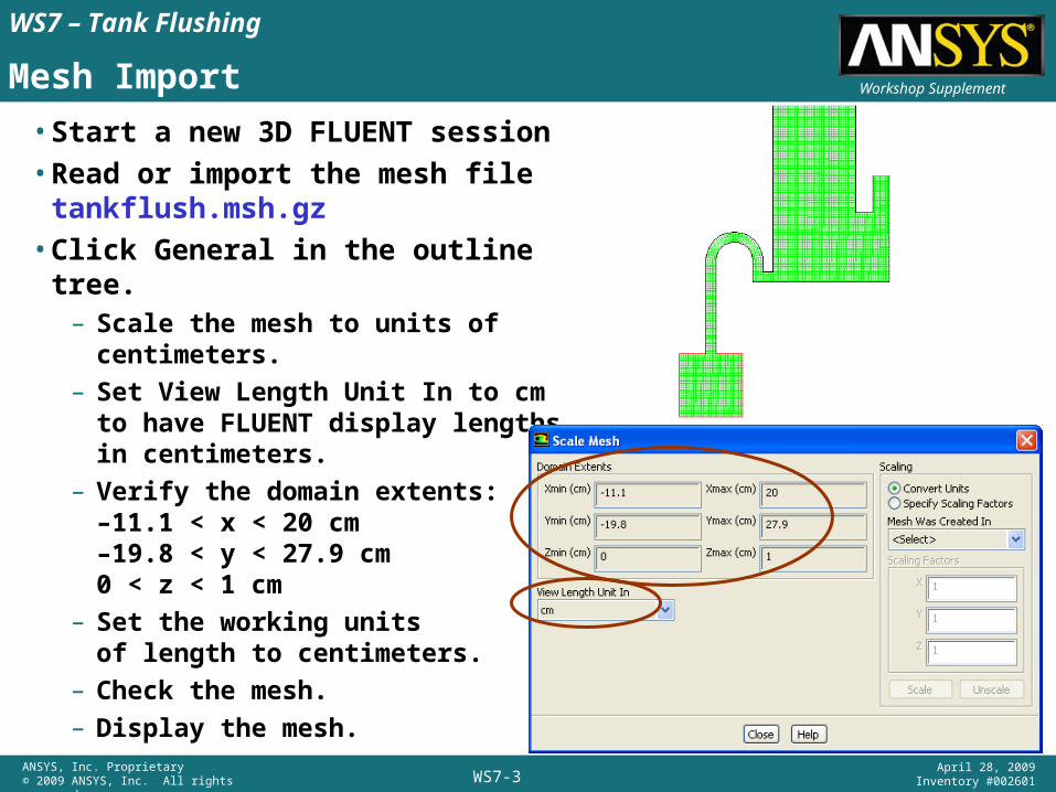
• Start a new 3D FLUENT session• Read or import the mesh file
tankflush.msh.gz• Click General in the outline tree.– Scale the mesh to units of
centimeters.– Set View Length Unit In to cm to
have FLUENT display lengths in centimeters.
– Verify the domain extents:–11.1 < x < 20 cm–19.8 < y < 27.9 cm 0 < z < 1 cm
– Set the working units of length to centimeters.
– Check the mesh.– Display the mesh.
WS7-4ANSYS, Inc. Proprietary© 2009 ANSYS, Inc. All rights reserved.
April 28, 2009Inventory #002601
Workshop Supplement
WS7 – Tank Flushing
Define Simulation Type
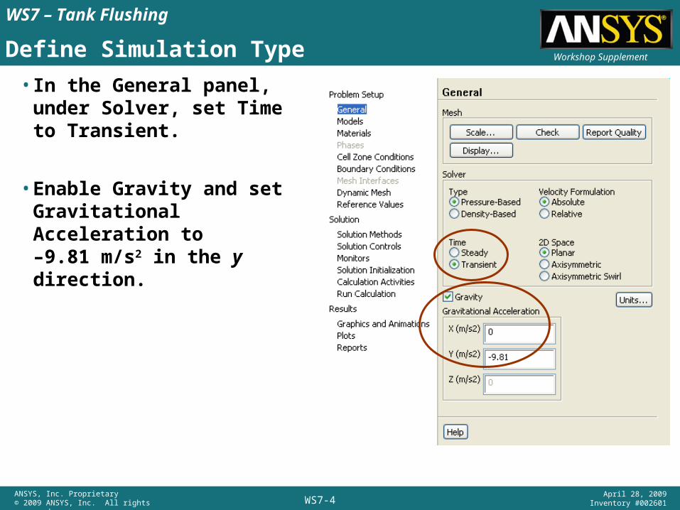
• In the General panel, under Solver, set Time to Transient.
• Enable Gravity and set Gravitational Acceleration to–9.81 m/s2 in the y direction.
WS7-5ANSYS, Inc. Proprietary© 2009 ANSYS, Inc. All rights reserved.
April 28, 2009Inventory #002601
Workshop Supplement
WS7 – Tank Flushing
Enable Turbulence Model
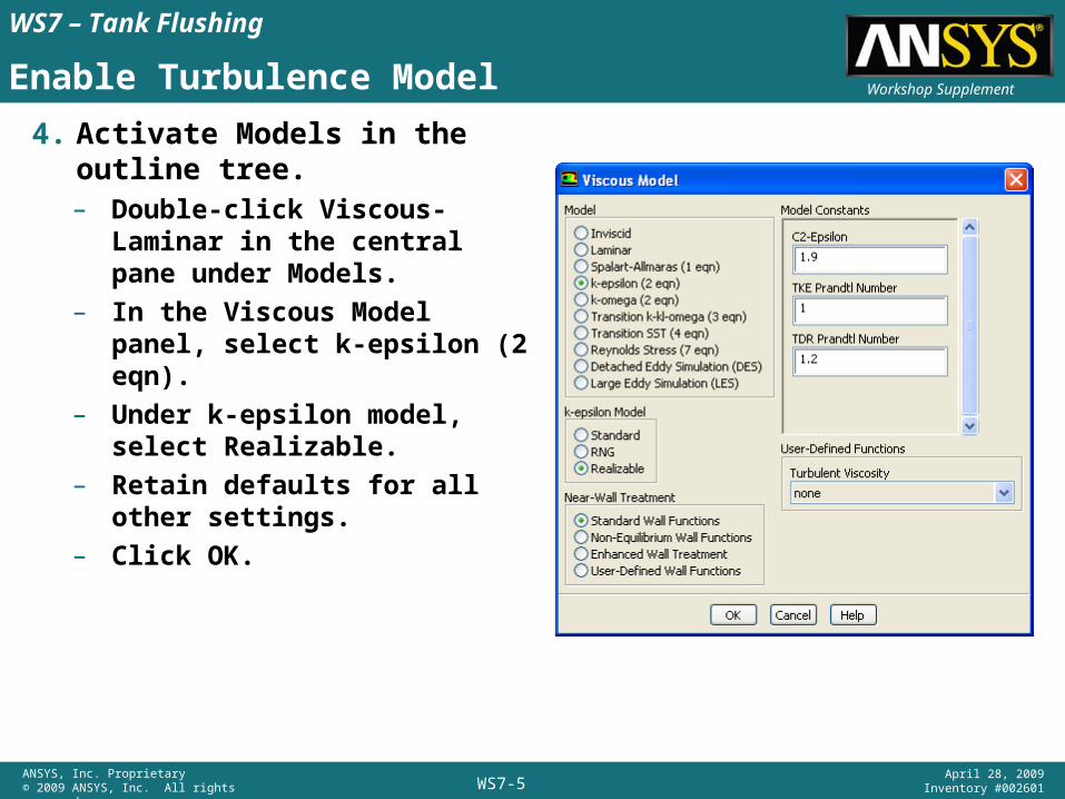
4. Activate Models in the outline tree.– Double-click Viscous-Laminar in
the central pane under Models.– In the Viscous Model panel,
select k-epsilon (2 eqn).– Under k-epsilon model, select
Realizable.– Retain defaults for all other
settings.– Click OK.
WS7-6ANSYS, Inc. Proprietary© 2009 ANSYS, Inc. All rights reserved.
April 28, 2009Inventory #002601
Workshop Supplement
WS7 – Tank Flushing
VOF Multiphase Model Setup
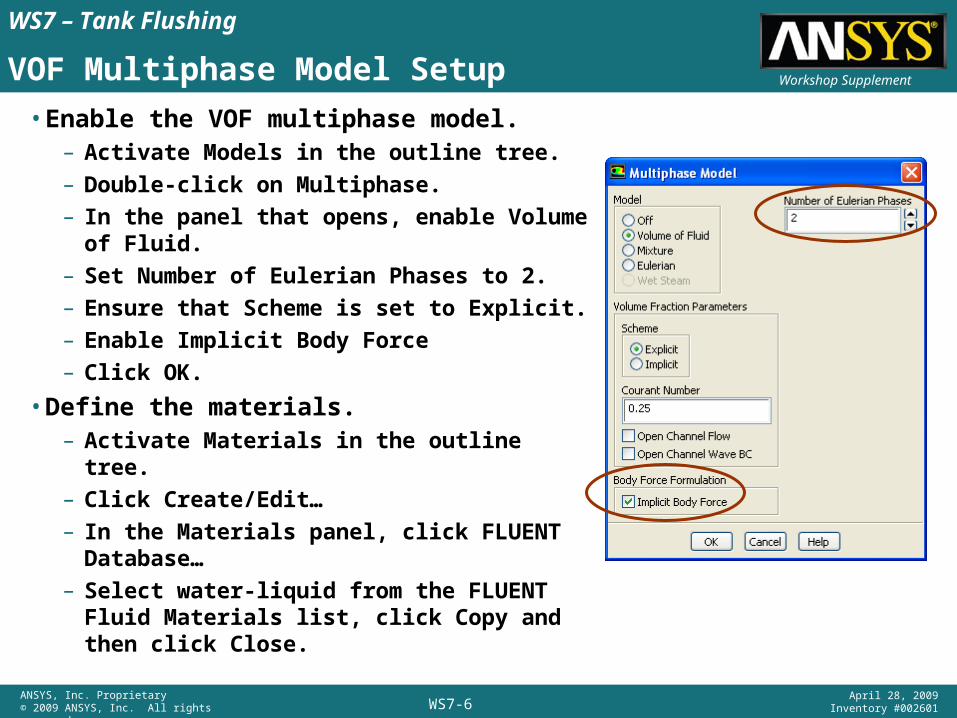
• Enable the VOF multiphase model.– Activate Models in the outline tree.– Double-click on Multiphase.– In the panel that opens, enable Volume of
Fluid.– Set Number of Eulerian Phases to 2.– Ensure that Scheme is set to Explicit.– Enable Implicit Body Force– Click OK.
• Define the materials.– Activate Materials in the outline tree.– Click Create/Edit…– In the Materials panel, click FLUENT
Database…– Select water-liquid from the FLUENT Fluid
Materials list, click Copy and then click Close.
WS7-7ANSYS, Inc. Proprietary© 2009 ANSYS, Inc. All rights reserved.
April 28, 2009Inventory #002601
Workshop Supplement
WS7 – Tank Flushing
Phases
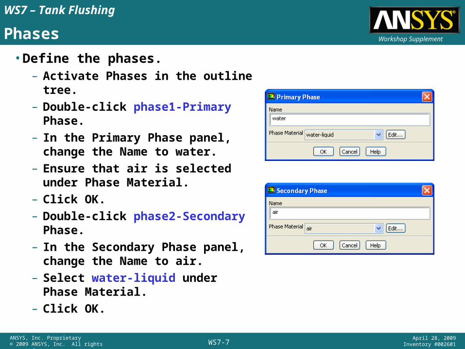
• Define the phases.– Activate Phases in the outline tree.– Double-click phase1-Primary Phase.– In the Primary Phase panel, change
the Name to water.– Ensure that air is selected under
Phase Material.– Click OK.– Double-click phase2-Secondary
Phase.– In the Secondary Phase panel, change
the Name to air.– Select water-liquid under Phase
Material.– Click OK.
WS7-8ANSYS, Inc. Proprietary© 2009 ANSYS, Inc. All rights reserved.
April 28, 2009Inventory #002601
Workshop Supplement
WS7 – Tank Flushing
Multiphase Model Setup
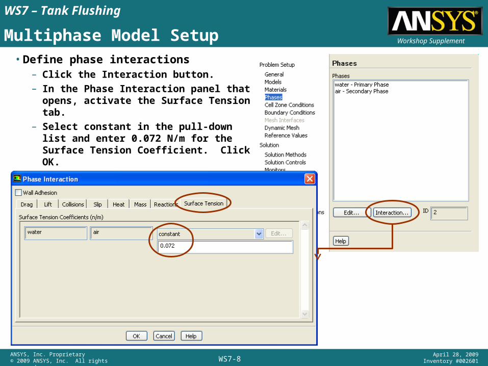
• Define phase interactions– Click the Interaction button.– In the Phase Interaction panel that
opens, activate the Surface Tensiontab.
– Select constant in the pull-down list and enter 0.072 N/m for the Surface Tension Coefficient. Click OK.
WS7-9ANSYS, Inc. Proprietary© 2009 ANSYS, Inc. All rights reserved.
April 28, 2009Inventory #002601
Workshop Supplement
WS7 – Tank Flushing
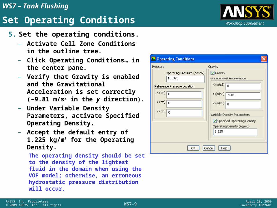
Set Operating Conditions
5. Set the operating conditions.– Activate Cell Zone Conditions in
the outline tree.– Click Operating Conditions… in the
center pane.– Verify that Gravity is enabled and
the Gravitational Acceleration is set correctly (–9.81 m/s2 in the y direction).
– Under Variable Density Parameters, activate Specified Operating Density.
– Accept the default entry of 1.225 kg/m3 for the Operating Density.The operating density should be set to the density of the lightest fluid in the domain when using the VOF model; otherwise, an erroneous hydrostatic pressure distribution will occur.
WS7-10ANSYS, Inc. Proprietary© 2009 ANSYS, Inc. All rights reserved.
April 28, 2009Inventory #002601
Workshop Supplement
WS7 – Tank Flushing
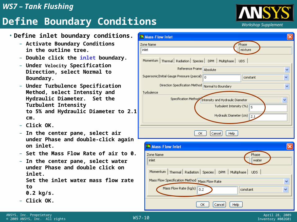
Define Boundary Conditions• Define inlet boundary conditions.
– Activate Boundary Conditionsin the outline tree.
– Double click the inlet boundary.– Under Velocity Specification Direction,
select Normal to Boundary.– Under Turbulence Specification
Method, select Intensity and Hydraulic Diameter. Set the Turbulent Intensity to 5% and Hydraulic Diameter to 2.1 cm.
– Click OK.– In the center pane, select air under
Phase and double-click again on inlet.– Set the Mass Flow Rate of air to 0.– In the center pane, select water under
Phase and double click on inlet.Set the inlet water mass flow rate to 0.2 kg/s.
– Click OK.
WS7-11ANSYS, Inc. Proprietary© 2009 ANSYS, Inc. All rights reserved.
April 28, 2009Inventory #002601
Workshop Supplement
WS7 – Tank Flushing
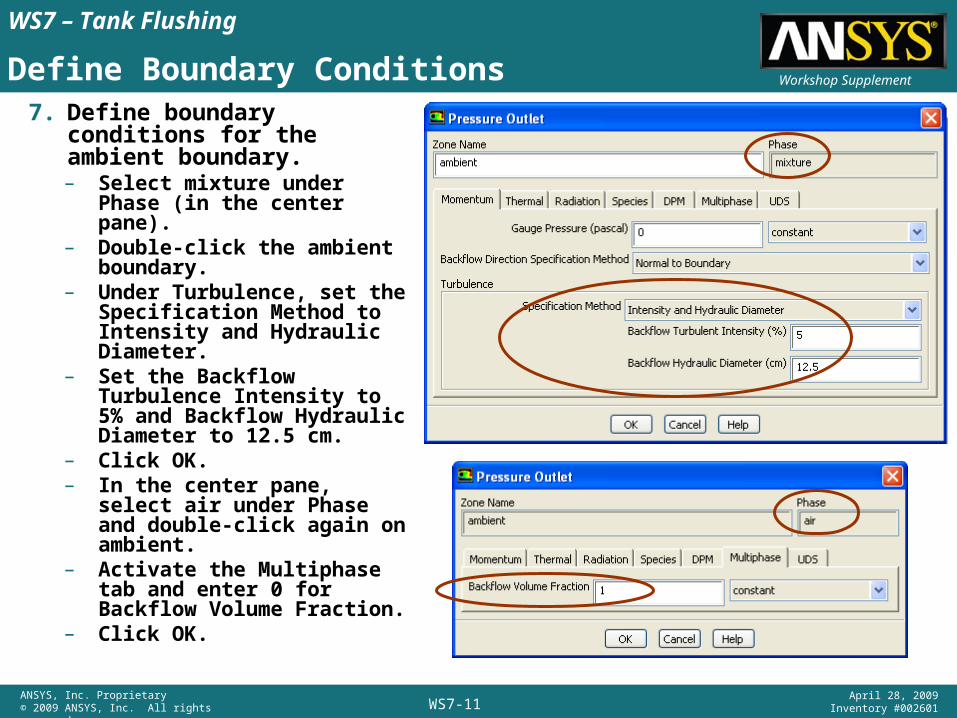
Define Boundary Conditions7. Define boundary conditions
for the ambient boundary.– Select mixture under Phase
(in the center pane).– Double-click the ambient
boundary.– Under Turbulence, set the
Specification Method to Intensity and Hydraulic Diameter.
– Set the Backflow Turbulence Intensity to 5% and Backflow Hydraulic Diameter to 12.5 cm.
– Click OK.– In the center pane, select air
under Phase and double-click again on ambient.
– Activate the Multiphase tab and enter 0 for Backflow Volume Fraction.
– Click OK.
WS7-12ANSYS, Inc. Proprietary© 2009 ANSYS, Inc. All rights reserved.
April 28, 2009Inventory #002601
Workshop Supplement
WS7 – Tank Flushing
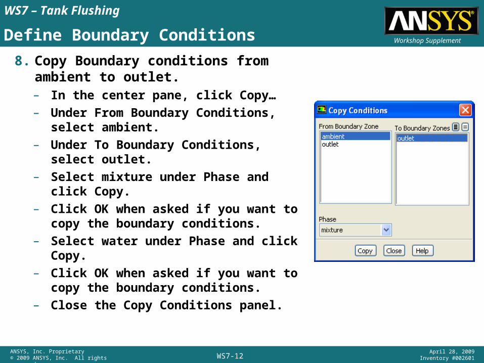
Define Boundary Conditions
8. Copy Boundary conditions from ambient to outlet.– In the center pane, click Copy…– Under From Boundary Conditions, select
ambient.– Under To Boundary Conditions, select
outlet.– Select mixture under Phase and click Copy.– Click OK when asked if you want to copy
the boundary conditions.– Select water under Phase and click Copy.– Click OK when asked if you want to copy
the boundary conditions.– Close the Copy Conditions panel.
WS7-13ANSYS, Inc. Proprietary© 2009 ANSYS, Inc. All rights reserved.
April 28, 2009Inventory #002601
Workshop Supplement
WS7 – Tank Flushing
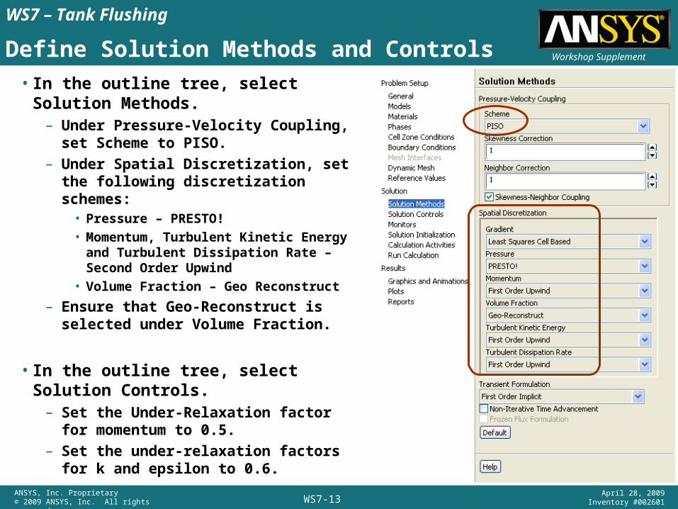
Define Solution Methods and Controls
• In the outline tree, select Solution Methods.– Under Pressure-Velocity Coupling, set
Scheme to PISO.– Under Spatial Discretization, set the
following discretization schemes:• Pressure – PRESTO!
• Momentum, Turbulent Kinetic Energy and Turbulent Dissipation Rate – Second Order Upwind
• Volume Fraction – Geo Reconstruct
– Ensure that Geo-Reconstruct is selected under Volume Fraction.
• In the outline tree, select Solution Controls.– Set the Under-Relaxation factor for
momentum to 0.5.– Set the under-relaxation factors for k and
epsilon to 0.6.
WS7-14ANSYS, Inc. Proprietary© 2009 ANSYS, Inc. All rights reserved.
April 28, 2009Inventory #002601
Workshop Supplement
WS7 – Tank Flushing
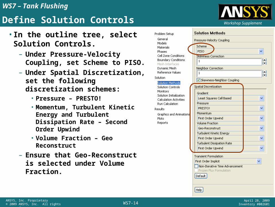
Define Solution Controls
• In the outline tree, select Solution Controls.– Under Pressure-Velocity Coupling,
set Scheme to PISO.– Under Spatial Discretization, set the
following discretization schemes:• Pressure – PRESTO!• Momentum, Turbulent Kinetic Energy
and Turbulent Dissipation Rate – Second Order Upwind
• Volume Fraction – Geo Reconstruct
– Ensure that Geo-Reconstruct is selected under Volume Fraction.
WS7-15ANSYS, Inc. Proprietary© 2009 ANSYS, Inc. All rights reserved.
April 28, 2009Inventory #002601
Workshop Supplement
WS7 – Tank Flushing
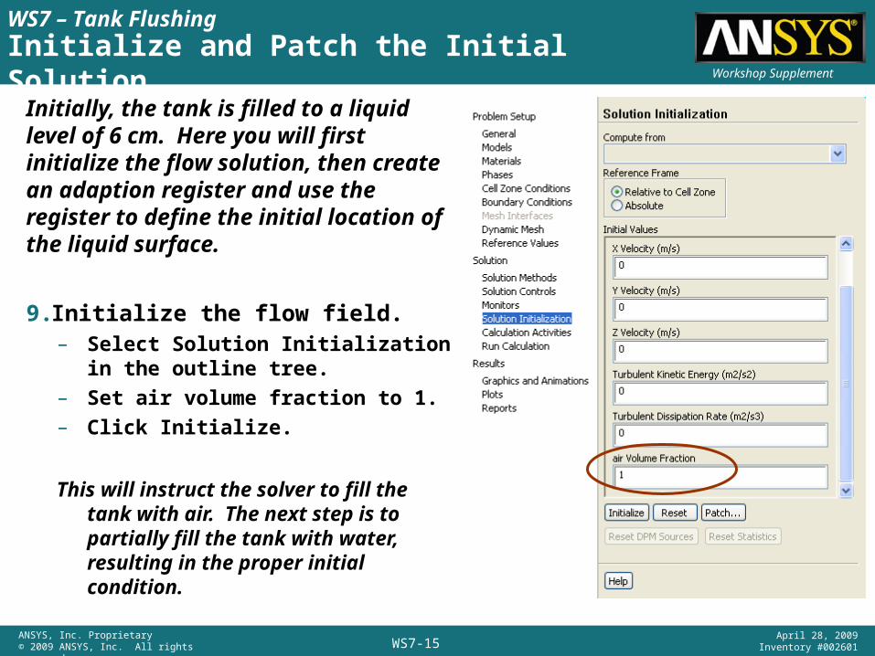
Initialize and Patch the Initial Solution
Initially, the tank is filled to a liquid level of 6 cm. Here you will first initialize the flow solution, then create an adaption register and use the register to define the initial location of the liquid surface.
9.Initialize the flow field.– Select Solution Initialization in the
outline tree.– Set air volume fraction to 1.– Click Initialize.
This will instruct the solver to fill the tank with air. The next step is to partially fill the tank with water, resulting in the proper initial condition.
WS7-16ANSYS, Inc. Proprietary© 2009 ANSYS, Inc. All rights reserved.
April 28, 2009Inventory #002601
Workshop Supplement
WS7 – Tank Flushing
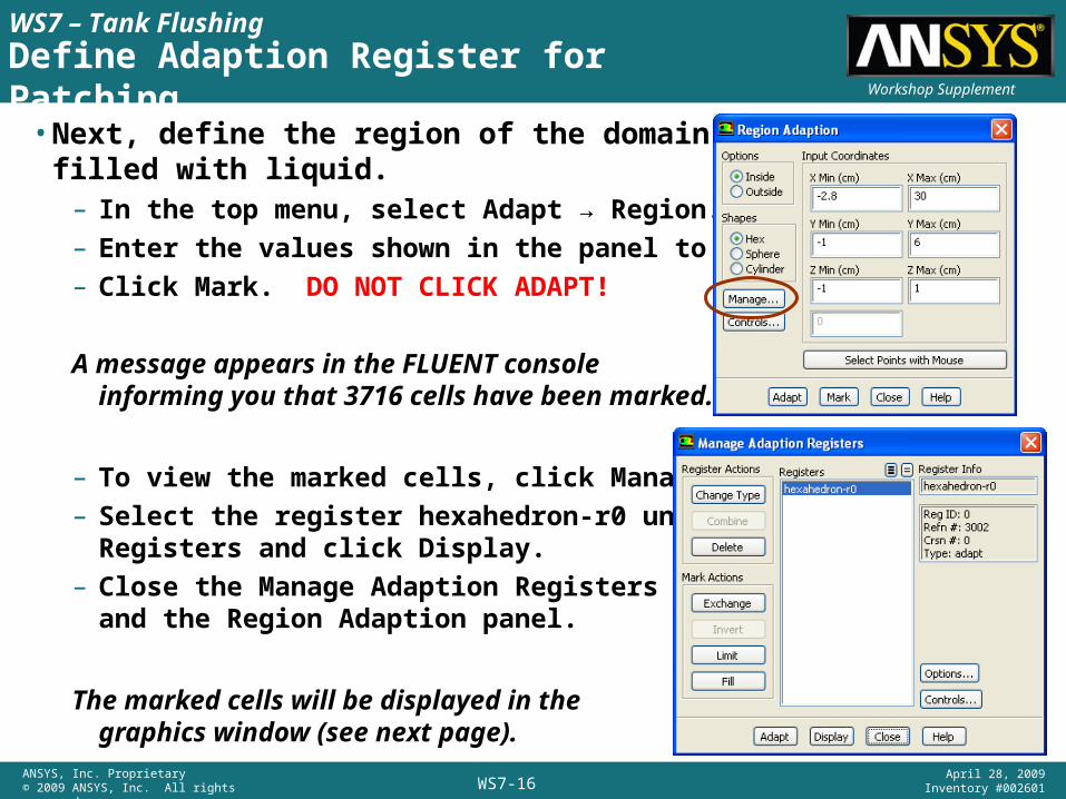
Define Adaption Register for Patching
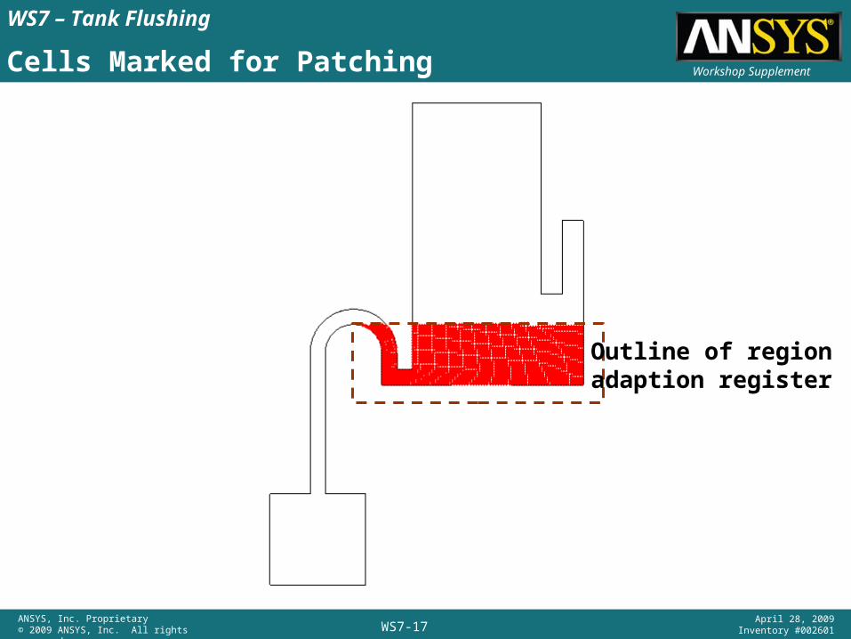
• Next, define the region of the domain to be filled with liquid.– In the top menu, select Adapt → Region.– Enter the values shown in the panel to the right.– Click Mark. DO NOT CLICK ADAPT!
A message appears in the FLUENT console informing you that 3716 cells have been marked.
– To view the marked cells, click Manage.– Select the register hexahedron-r0 under
Registers and click Display.– Close the Manage Adaption Registers panel
and the Region Adaption panel.
The marked cells will be displayed in thegraphics window (see next page).
WS7-17ANSYS, Inc. Proprietary© 2009 ANSYS, Inc. All rights reserved.
April 28, 2009Inventory #002601
Workshop Supplement
WS7 – Tank Flushing
Cells Marked for Patching
Outline of regionadaption register
WS7-18ANSYS, Inc. Proprietary© 2009 ANSYS, Inc. All rights reserved.
April 28, 2009Inventory #002601
Workshop Supplement
WS7 – Tank Flushing
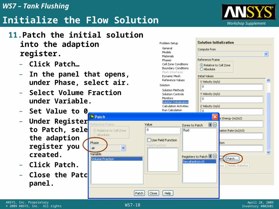
Initialize the Flow Solution
11. Patch the initial solution into the adaption register.– Click Patch…– In the panel that opens, under
Phase, select air.– Select Volume Fraction under
Variable.– Set Value to 0.– Under Registers
to Patch, select the adaption register you created.
– Click Patch.– Close the Patch
panel.
WS7-19ANSYS, Inc. Proprietary© 2009 ANSYS, Inc. All rights reserved.
April 28, 2009Inventory #002601
Workshop Supplement
WS7 – Tank Flushing
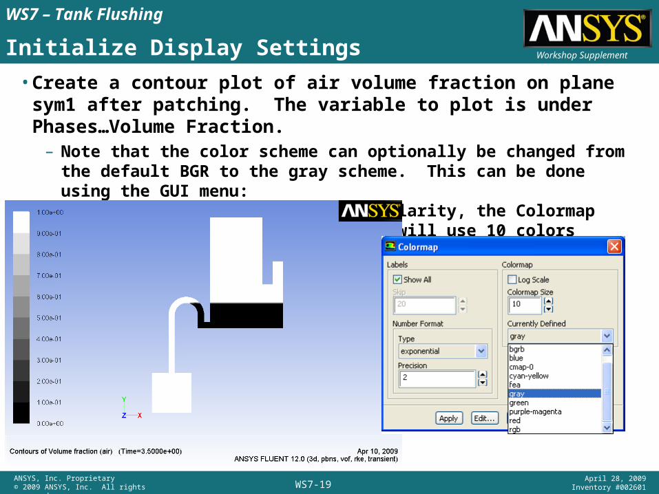
Initialize Display Settings
• Create a contour plot of air volume fraction on plane sym1 after patching. The variable to plot is under Phases…Volume Fraction.– Note that the color scheme can optionally be changed from the default
BGR to the gray scheme. This can be done using the GUI menu:Display → Colormap. Also, for clarity, the Colormap Size has been reduced to 10 which will use 10 colors instead of the default 20.
WS7-20ANSYS, Inc. Proprietary© 2009 ANSYS, Inc. All rights reserved.
April 28, 2009Inventory #002601
Workshop Supplement
WS7 – Tank Flushing
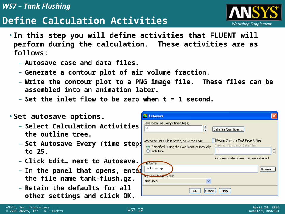
Define Calculation Activities
• In this step you will define activities that FLUENT will perform during the calculation. These activities are as follows:– Autosave case and data files.– Generate a contour plot of air volume fraction.– Write the contour plot to a PNG image file. These files can be assembled
into an animation later.– Set the inlet flow to be zero when t = 1 second.
• Set autosave options.– Select Calculation Activities in
the outline tree.– Set Autosave Every (time steps)
to 25.– Click Edit… next to Autosave.– In the panel that opens, enter
the file name tank-flush.gz.– Retain the defaults for all
other settings and click OK.
WS7-21ANSYS, Inc. Proprietary© 2009 ANSYS, Inc. All rights reserved.
April 28, 2009Inventory #002601
Workshop Supplement
WS7 – Tank Flushing
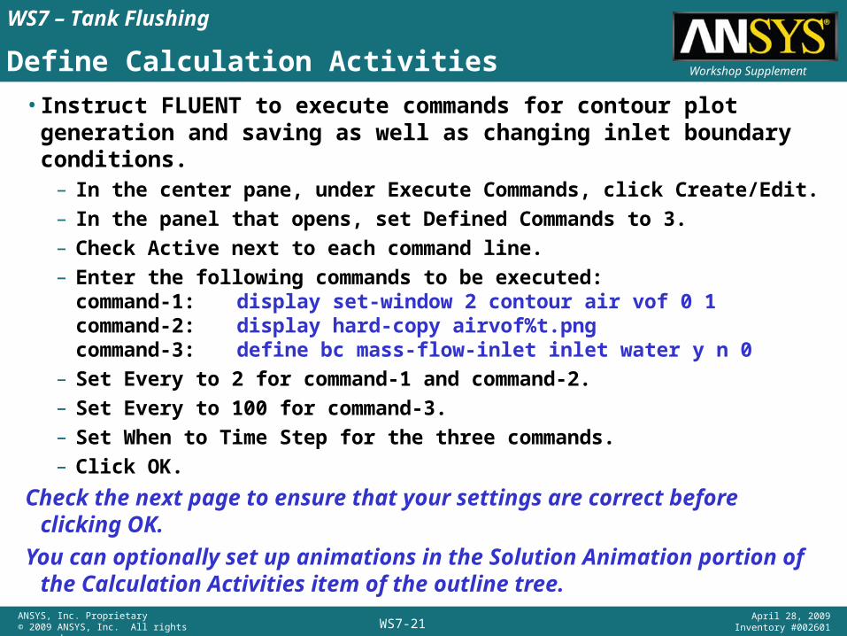
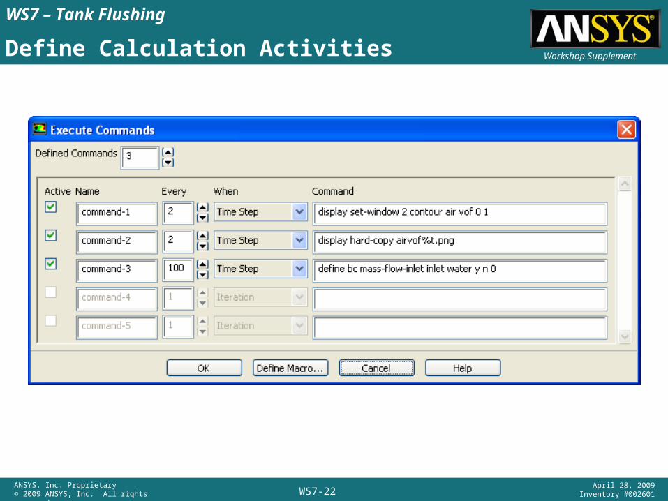
Define Calculation Activities
• Instruct FLUENT to execute commands for contour plot generation and saving as well as changing inlet boundary conditions.– In the center pane, under Execute Commands, click Create/Edit.– In the panel that opens, set Defined Commands to 3.– Check Active next to each command line.– Enter the following commands to be executed:
command-1: display set-window 2 contour air vof 0 1command-2: display hard-copy airvof%t.pngcommand-3: define bc mass-flow-inlet inlet water y n 0
– Set Every to 2 for command-1 and command-2.– Set Every to 100 for command-3.– Set When to Time Step for the three commands.– Click OK.
Check the next page to ensure that your settings are correct before clicking OK.
You can optionally set up animations in the Solution Animation portion of the Calculation Activities item of the outline tree.
WS7-22ANSYS, Inc. Proprietary© 2009 ANSYS, Inc. All rights reserved.
April 28, 2009Inventory #002601
Workshop Supplement
WS7 – Tank Flushing
Define Calculation Activities
WS7-23ANSYS, Inc. Proprietary© 2009 ANSYS, Inc. All rights reserved.
April 28, 2009Inventory #002601
Workshop Supplement
WS7 – Tank Flushing
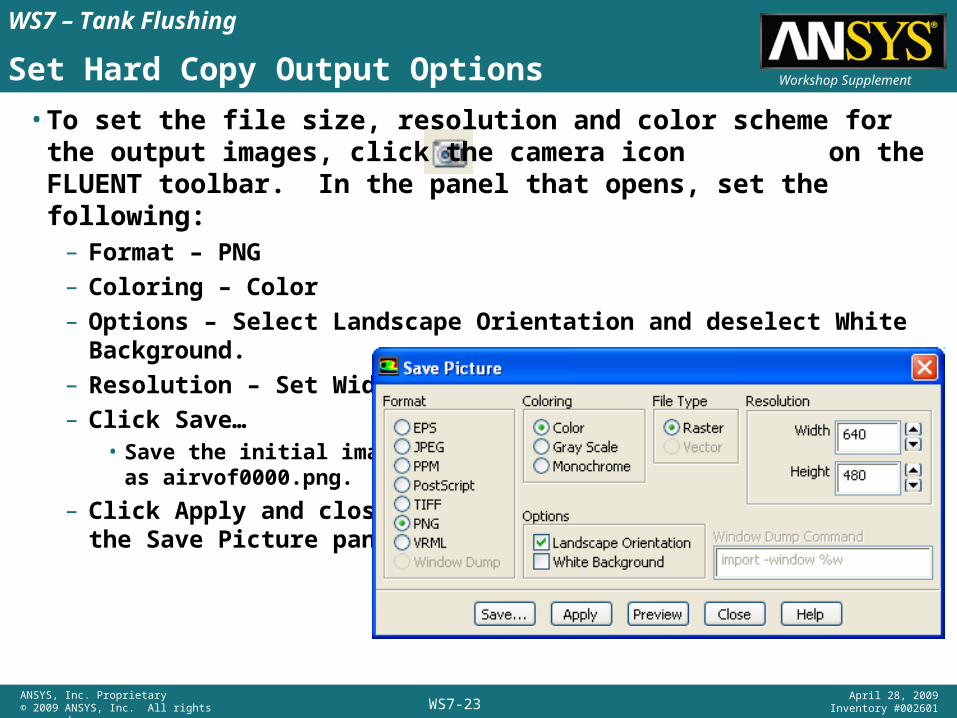
Set Hard Copy Output Options
• To set the file size, resolution and color scheme for the output images, click the camera icon on the FLUENT toolbar. In the panel that opens, set the following:– Format – PNG– Coloring – Color– Options – Select Landscape Orientation and deselect White Background.– Resolution – Set Width to 640 and Height to 480.– Click Save…
• Save the initial imageas airvof0000.png.
– Click Apply and close the Save Picture panel.
WS7-24ANSYS, Inc. Proprietary© 2009 ANSYS, Inc. All rights reserved.
April 28, 2009Inventory #002601
Workshop Supplement
WS7 – Tank Flushing
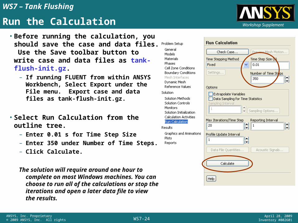
Run the Calculation
• Before running the calculation, you should save the case and data files. Use the Save toolbar button to write case and data files as tank-flush-init.gz.– If running FLUENT from within ANSYS
Workbench, Select Export under the File menu. Export case and data files as tank-flush-init.gz.
• Select Run Calculation from the outline tree.– Enter 0.01 s for Time Step Size– Enter 350 under Number of Time Steps.– Click Calculate.
The solution will require around one hour to complete on most Windows machines. You can choose to run all of the calculations or stop the iterations and open a later data file to view the results.
WS7-25ANSYS, Inc. Proprietary© 2009 ANSYS, Inc. All rights reserved.
April 28, 2009Inventory #002601
Workshop Supplement
WS7 – Tank Flushing
Post-Process Results
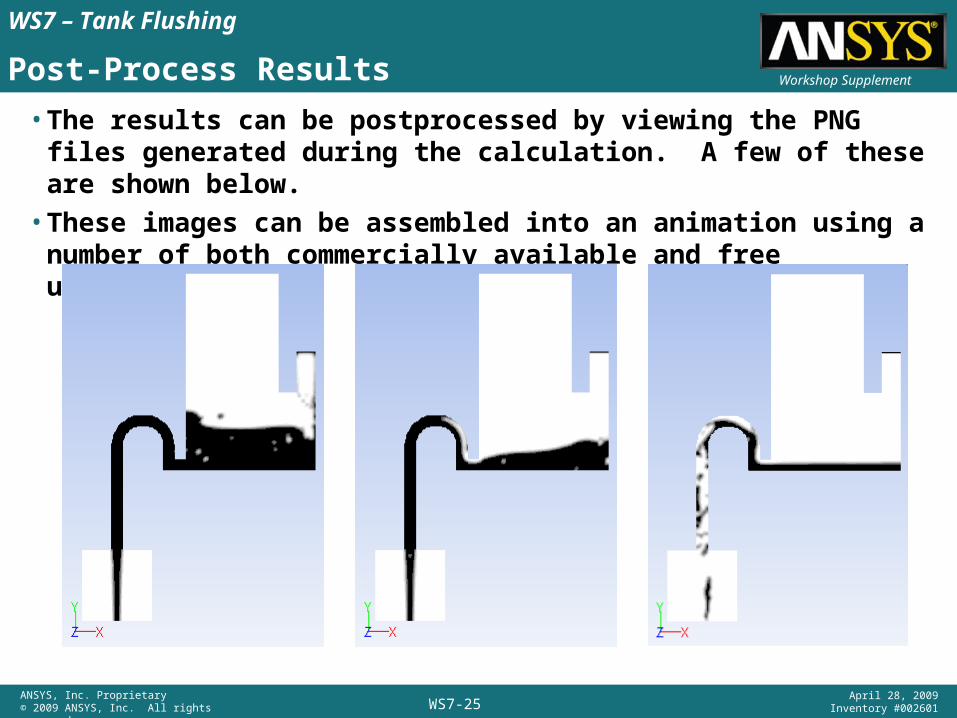
• The results can be postprocessed by viewing the PNG files generated during the calculation. A few of these are shown below.
• These images can be assembled into an animation using a number of both commercially available and free utilities.
Related Documents


![Ansys Kurulumu - bim.yildiz.edu.tr · Documentation Only' Install MPI for ANSYS ... ANSYS ANSYS F ANSYS ANSYS AIM (V] ANSYS AP-SYS CFO [V) ANSYS ore S . msys Realize Product Promise"](https://static.cupdf.com/doc/110x72/5b69d01e7f8b9a422e8b4fb9/ansys-kurulumu-bim-documentation-only-install-mpi-for-ansys-ansys-ansys.jpg)
