WS4-1 ADM704-705, Workshop 4, August 2005 Copyright 2005 MSC.Software Corporation WORKSHOP 4 PARAMETERIZING AN EXISTING MODEL

Welcome message from author
This document is posted to help you gain knowledge. Please leave a comment to let me know what you think about it! Share it to your friends and learn new things together.
Transcript

WS4-1ADM704-705, Workshop 4, August 2005Copyright 2005 MSC.Software Corporation
WORKSHOP 4
PARAMETERIZING AN EXISTING MODEL
WS4-2ADM704-705, Workshop 4, August 2005Copyright 2005 MSC.Software Corporation

WS4-3ADM704-705, Workshop 4, August 2005Copyright 2005 MSC.Software Corporation
Problem statement Parameterize the locations of points in the model, and then plot toe
angle for different configurations of the given suspension model.
WORKSHOP 4 - PARAMETERIZING AN EXISTING MODEL

WS4-4ADM704-705, Workshop 4, August 2005Copyright 2005 MSC.Software Corporation
WORKSHOP 4 - PARAMETERIZING AN EXISTING MODEL
Model description The model has five parts (not including ground).
All appropriate constraints are in the model.
There are markers attached to ground at each key location (see the figure on the next page).
There is a point motion driving the spindle up and down 100 mm.
There is one function measure that calculates toe angle, and one that calculates wheel height.

WS4-5ADM704-705, Workshop 4, August 2005Copyright 2005 MSC.Software Corporation
Getting started
To import the model:
1. Start ADAMS/View from the mod_04_sla directory.
2. Import the sla_start.cmd file.
3. From the Settings menu, select Names.
4. In the Default Names dialog box, select Full names.
5. Select OK.
WORKSHOP 4 - PARAMETERIZING AN EXISTING MODEL
WS4-6ADM704-705, Workshop 4, August 2005Copyright 2005 MSC.Software Corporation
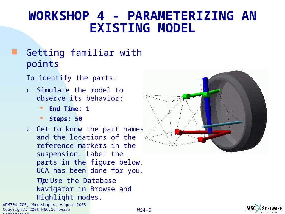
Getting familiar with points
To identify the parts:
1. Simulate the model to observe its behavior:
End Time: 1 Steps: 50
2. Get to know the part names and the locations of the reference markers in the suspension. Label the parts in the figure below. UCA has been done for you.
Tip: Use the Database Navigator in Browse and Highlight modes.
WORKSHOP 4 - PARAMETERIZING AN EXISTING MODEL

WS4-7ADM704-705, Workshop 4, August 2005Copyright 2005 MSC.Software Corporation
Parameterizing the tierod In this section, you parameterize the tierod objects (geometry and
joints) to markers pnt7_ref and pnt8_ref.
WORKSHOP 4 - PARAMETERIZING AN EXISTING MODEL

WS4-8ADM704-705, Workshop 4, August 2005Copyright 2005 MSC.Software Corporation
To parameterize the location of the tierod geometry:1. Find out the name of the marker that is the center marker for the
cylinder geometry that makes up the tierod. It is ______________.
2. Turn on the appearance of that marker: From the Tools menu, select Database Navigator. From the option menu at the top of the Database Navigator, select
Display Attribute. Expand sla and then expand tierod. Select the marker from Step 1. Set Visibility to On. Select Apply. Select Close.
WORKSHOP 4 - PARAMETERIZING AN EXISTING MODEL

WS4-9ADM704-705, Workshop 4, August 2005Copyright 2005 MSC.Software Corporation
3. Parameterize the location of that center marker to pnt7_ref using the location parameterization tool, f(x).
From the Main Toolbox, in the Move toolstack, select the f(x) tool. Set the menu to Collapse (distance). Follow the prompts that appear in the status bar:
Select the marker to have its location parameterized (tierod_geo_base). Select the marker to parameterize to (pnt7_ref).
4. Display the modify dialog box for the marker tierod_geo_base.
5. What is in the Location text box?__________________________
You should see a parametric expression that ADAMS/View just wrote for you.
WORKSHOP 4 - PARAMETERIZING AN EXISTING MODEL

WS4-10ADM704-705, Workshop 4, August 2005Copyright 2005 MSC.Software Corporation
To parameterize the orientation of the tierod geometry:1. Parameterize the z-axis of the center marker so it points from
pnt7_ref to pnt8_ref using the orientation parameterization tool, f().
From the Main Toolbox, in the Move toolstack, select on the f() tool.
Set the first menu to Along Axis.
Set the second menu to Z.
Following the prompts:
Select the object whose orientation you want to parameterize (tierod_geo_base).
Define the axis start location (pnt7_ref).
Define the axis end location (pnt8_ref).
2. Display the modify dialog box for the marker tierod_geo_base.
WORKSHOP 4 - PARAMETERIZING AN EXISTING MODEL
WS4-11ADM704-705, Workshop 4, August 2005Copyright 2005 MSC.Software Corporation
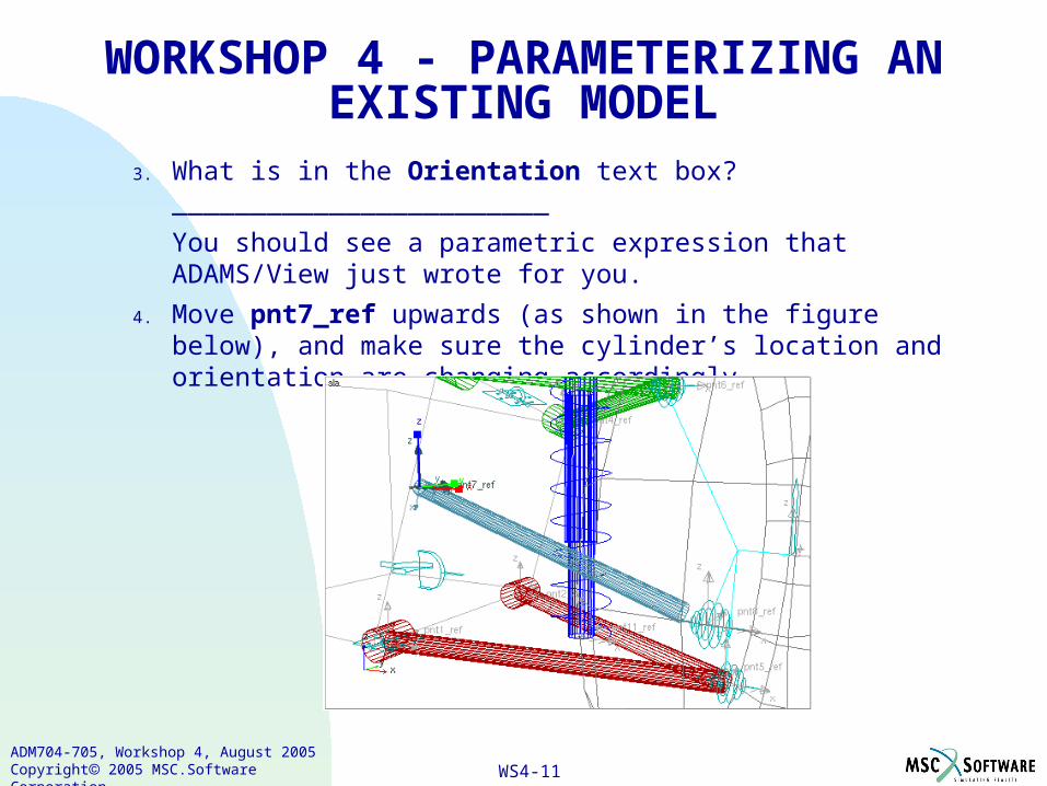
3. What is in the Orientation text box? ________________________
You should see a parametric expression that ADAMS/View just wrote for you.
4. Move pnt7_ref upwards (as shown in the figure below), and make sure the cylinder’s location and orientation are changing accordingly.
WORKSHOP 4 - PARAMETERIZING AN EXISTING MODEL

WS4-12ADM704-705, Workshop 4, August 2005Copyright 2005 MSC.Software Corporation
WORKSHOP 4 - PARAMETERIZING AN EXISTING MODEL
5. Does the length of the cylinder adjust parametrically? ____Yes ____ No
6. From the Edit menu, select Undo to move pnt_7_ref back to its original position (loc: 337,1311,471.734, ori: 0,0,0).

WS4-13ADM704-705, Workshop 4, August 2005Copyright 2005 MSC.Software Corporation
To parameterize the length of the tierod geometry: Parameterize the cylinder’s length to change based on the
locations of pnt7_ref and pnt8_ref.
Tip: Use the DM function just as you did in the previous workshop.
The following expression now describes the cylinder’s length:
DM (.sla.ground.pnt7_ref,.sla.ground.pnt8_ref)
WORKSHOP 4 - PARAMETERIZING AN EXISTING MODEL
WS4-14ADM704-705, Workshop 4, August 2005Copyright 2005 MSC.Software Corporation
To parameterize the universal joint:1. Use the f(x) tool to parameterize the location of the universal joint,
ground_tierod_uni, to pnt7_ref.
2. Obtain information about the I and J markers associated with that joint.
Hint: Select Verbose in the Information window.
3. Do you see a parametric expression written for the location of each marker? _____Yes _____ No
WORKSHOP 4 - PARAMETERIZING AN EXISTING MODEL
WS4-15ADM704-705, Workshop 4, August 2005Copyright 2005 MSC.Software Corporation
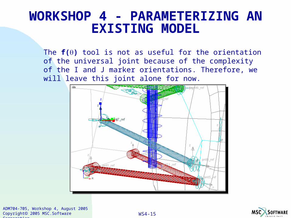
The f() tool is not as useful for the orientation of the universal joint because of the complexity of the I and J marker orientations. Therefore, we will leave this joint alone for now.
WORKSHOP 4 - PARAMETERIZING AN EXISTING MODEL
WS4-16ADM704-705, Workshop 4, August 2005Copyright 2005 MSC.Software Corporation
Parameterizing the upper control arm (uca) You will now parameterize the cylindrical geometry of the UCA part.
This time you will use design points as well as parametric expressions. The long and short cylinders will be treated differently in the ways they are parameterized.
A marker's icon must be visible on the screen if you want to parameterize using graphical methods. Therefore, you need to turn on some marker icons.
To display marker icons: Display the icons for the center_marker of each cylinder belonging to
the UCA part.
Tip: Turn the visibility of the center_marker on and off by using the command files ctr_mar_on.cmd and ctr_mar_off.cmd in the subdirectory utils (use the F2 shortcut key). This is a utility we've custom written for this workshop, and you can customize it for other models.
WORKSHOP 4 - PARAMETERIZING AN EXISTING MODEL

WS4-17ADM704-705, Workshop 4, August 2005Copyright 2005 MSC.Software Corporation
To parameterize the location of the long cylinders:1. Use the Point tool to create a design point:
Set its characteristics to: Add to Ground Attach Near
Select ground.pnt3_ref as the point location.
Rename the point to Point_1.
WORKSHOP 4 - PARAMETERIZING AN EXISTING MODEL
WS4-18ADM704-705, Workshop 4, August 2005Copyright 2005 MSC.Software Corporation
2. Use the Command Window (F3 shortcut key) to review the commands issued during the point creation.
3. How many markers were automatically parameterized?
Circle the best answer: 1 2 3
4. Create another design point, named Point_2, this time selecting ground.pnt4_ref as the point location.
WORKSHOP 4 - PARAMETERIZING AN EXISTING MODEL
WS4-19ADM704-705, Workshop 4, August 2005Copyright 2005 MSC.Software Corporation
To parameterize the orientation of the long cylinders:1. From the Main Toolbox, select the F() tool.
2. Set the characteristic to Along Axis and Axis to Z.
3. Right-click near the location of pnt3_ref shown in the figure on page .
4. Select the object whose orientation you want to parameterize (uca.uca_geo1_base).
5. Define the axis start location (pnt3_ref).
6. Define the axis end location (ground.pnt6_ref).
7. Use the Command Window to review what commands were issued during the F() parameterization.
WORKSHOP 4 - PARAMETERIZING AN EXISTING MODEL

WS4-20ADM704-705, Workshop 4, August 2005Copyright 2005 MSC.Software Corporation
8. Select F() again.
9. Set the characteristic to Along Axis and Axis to Z.
10. Right-click near the location of pnt4_ref shown in the figure on page .
11. Select the object whose orientation you want to parameterize (uca_geo3_base).
12. Define the axis start location (pnt4_ref).
13. Define the axis end location (pnt6_ref).
To parameterize the length of the long cylinders: Use an expression to define the cylinder length of both long
cylinders of the uca so that they update parametrically as their endpoints change.
Tip: Use the DM function (again).
WORKSHOP 4 - PARAMETERIZING AN EXISTING MODEL

WS4-21ADM704-705, Workshop 4, August 2005Copyright 2005 MSC.Software Corporation
To parameterize the orientation of the short cylinders:1. From the Main Toolbox, select the F(q) tool.
2. Set the characteristic to Along Axis and Axis to Z.
3. Right-click the location shown next:
WORKSHOP 4 - PARAMETERIZING AN EXISTING MODEL

WS4-22ADM704-705, Workshop 4, August 2005Copyright 2005 MSC.Software Corporation
4. Select uca_geo2_base.
5. Select pnt3_ref.
6. Select pnt4_ref.
7. Choose F() again.
8. Set the characteristic to Along Axis and Axis to Z.
9. Right-click the other short cylinder's end.
10. Select uca_geo4_base.
Tip: This is the center_marker of the other short cylinder on the uca.
11. Select pnt4_ref.
12. Select pnt3_ref.
WORKSHOP 4 - PARAMETERIZING AN EXISTING MODEL

WS4-23ADM704-705, Workshop 4, August 2005Copyright 2005 MSC.Software Corporation
To inspect the behavior of short cylinder parametrics: It's a good idea to test the parametrics as you build them. This follows
the crawl-walk-run process that we teach. You will move one of the design points and see what happens.
1. Select the design point at pnt3_ref (Point_1).
2. Set the view to the right.
WORKSHOP 4 - PARAMETERIZING AN EXISTING MODEL
WS4-24ADM704-705, Workshop 4, August 2005Copyright 2005 MSC.Software Corporation
3. Using the Move tool, translate (10 cm) upward in the global z direction.
4. Inspect the model from different viewpoints.
5. Do the centerlines of the short cylinders pass through pnt3_ref and pnt4_ref? ____ Yes ____ No
6. What do you think went wrong? ______________________________________________________________________________________________________________
WORKSHOP 4 - PARAMETERIZING AN EXISTING MODEL

WS4-25ADM704-705, Workshop 4, August 2005Copyright 2005 MSC.Software Corporation
To parameterize the locations of the short cylinders:1. Display the modify dialog box for marker uca.uca_geo2_base.
2. Clear the Location text box.Tip: To quickly clear a text box, left-click the start of the text box, and
then press Ctrl-k.
3. In the Location text box, point to Parameterize, and then select Expression Builder.
4. In the Expression Builder, set the function category to Location/Orientation.
5. From the Selection menu, highlight LOC_ALONG_LINE, and then select Assist.
WORKSHOP 4 - PARAMETERIZING AN EXISTING MODEL

WS4-26ADM704-705, Workshop 4, August 2005Copyright 2005 MSC.Software Corporation
6. In the assist dialog box, set the options to: Object for Start Point: pnt3_ref Object for Point on Line: pnt4_ref Distance: -0.5
7. Select OK.
The expression is now in the work area.
You want to change the distance from -0.5 to be half of the cylinder's length so you’ll multiply the -0.5 by the cylinder length.
8. Place your cursor after the -0.5, type the multiplier operator, for example, type asterisk, *.
9. Use the Getting Object Data section to obtain the length of the cylinder uca_geo2.
When you are done, your expression should look like:
LOC_ALONG_LINE( pnt3_ref , pnt4_ref , -0.5*uca_geo2.length )
10. Select Evaluate to verify syntax and see the location array values.
WORKSHOP 4 - PARAMETERIZING AN EXISTING MODEL
WS4-27ADM704-705, Workshop 4, August 2005Copyright 2005 MSC.Software Corporation
11. In the Expression Builder, select OK.
Notice that the expression is sent to the Marker Modify dialog box, and in the process, the Expression Builder automatically wrapped the expression in the required parentheses.
12. In the Marker Modify dialog box, select Apply.
The short cylinder adjusts its location.
13. Place your cursor at the start of the Location text box. Press Shift-End to select all of the text. Then, right-click in the Location text box, and select Copy to save the expression, which you will paste later.
14. In the Name text box, browse for uca_geo4_base.
15. Clear the entry in the Location text box.
16. Paste the text you saved in Step 13.
17. Hand-edit the expression to be as follows:
(LOC_ALONG_LINE(pnt4_ref, pnt3_ref, -0.5 * uca_geo4.length))
WORKSHOP 4 - PARAMETERIZING AN EXISTING MODEL

WS4-28ADM704-705, Workshop 4, August 2005Copyright 2005 MSC.Software Corporation
18. In the Marker Modify dialog box, select Ok. The short cylinder adjusts its location.
19. Using the Table Editor, move Point_1 back to its original position (384.0, 1330.0, 710.348).
WORKSHOP 4 - PARAMETERIZING AN EXISTING MODEL

WS4-29ADM704-705, Workshop 4, August 2005Copyright 2005 MSC.Software Corporation
Parameterizing constraints connected to UCA To display joint marker icons:
Again you will need the marker icons visible to use the parameterization tools. Therefore, you need to turn on some joint marker icons.
Display the marker icons for all the joints connected to the UCA part.
Tip: Turn joint marker visibility on and off by using jnt_mar_on.cmd and jnt_mar_toggle.cmd in the subdirectory utils (use the F2 shortcut key). This is another utility we've custom written, and you can customize it for use on other models. The I and J markers for the joints are displayed, colored maize and blue, respectively.
WORKSHOP 4 - PARAMETERIZING AN EXISTING MODEL
WS4-30ADM704-705, Workshop 4, August 2005Copyright 2005 MSC.Software Corporation
To parameterize the location of the UCA-spindle spherical joint:1. Create a design point:
Set its characteristics to: Add to Ground
Attach Near
Select ground.pnt6_ref as the point location.
Rename it to Point_3.
2. Use the Command Window (F3 shortcut key) to review what commands were issued during the point creation.
3. Were the joint markers parameterized to pnt6_ref or to the design point? ___________________________________________________
4. If you dragged pnt6_ref to a new location would the spherical joint move as well? ____ Yes _____ No
5. What do you think would happen? _____________________________
WORKSHOP 4 - PARAMETERIZING AN EXISTING MODEL
WS4-31ADM704-705, Workshop 4, August 2005Copyright 2005 MSC.Software Corporation
To parameterize the location of UCA_ground_rev revolute joint: Earlier in this workshop, you parameterized the tierod universal
joint using the f(x) tool. That simultaneously parameterized the underlying I and J markers of the joint using a LOC_RELATIVE_TO function. In this section, you need to use the LOC_ALONG_LINE function so you parameterize the joint markers one at a time.
1. Parameterize the location of the revolute joint's J marker uca.uca_ground_rev2 so it lies halfway between the ground markers, pnt3_ref and pnt4_ref.
Tip: Use the LOC_ALONG_LINE() function and + 0.5*DM() as your offset distances.
WORKSHOP 4 - PARAMETERIZING AN EXISTING MODEL

WS4-32ADM704-705, Workshop 4, August 2005Copyright 2005 MSC.Software Corporation
2. Use the f(x) tool to collapse the location of the I marker, ground.uca_ground_rev1, onto the J marker, uca.uca_ground_rev2.
WORKSHOP 4 - PARAMETERIZING AN EXISTING MODEL

WS4-33ADM704-705, Workshop 4, August 2005Copyright 2005 MSC.Software Corporation
Parameterizing the orientation of UCA_ground_rev revolute joint
In this section, you want the joint markers to be oriented such that the z-axis points from pnt3_ref to pnt4_ref and the x-axis lies in the plane of the three points: pnt3_ref, pnt4_ref, and pnt6_ref.
To parameterize the orientation of the J marker: Write an function expression for the orientation of
uca.uca_ground_rev2 as follows:
(ORI_IN_PLANE( pnt3_ref , pnt4_ref , pnt6_ref , "Z_ZX" ))
WORKSHOP 4 - PARAMETERIZING AN EXISTING MODEL

WS4-34ADM704-705, Workshop 4, August 2005Copyright 2005 MSC.Software Corporation
To parameterize the orientation of the I marker:1. Use the F() tool to collapse the orientation of I marker,
ground.uca_ground_rev1, onto the J marker, uca.uca_ground_rev2.
2. Inspect the commands issued to the Command Window.
3. Which of the following functions was used? Circle the best answer:
ORI_ALONG_AXIS ORI_LOCAL
ORI_FRAME_MIRROR ORI_RELATIVE_TO
WORKSHOP 4 - PARAMETERIZING AN EXISTING MODEL

WS4-35ADM704-705, Workshop 4, August 2005Copyright 2005 MSC.Software Corporation
Defining a marker location in terms of design variables The model is parameterized, but you need to take it one step
further. You should use design variables to define the x, y, and z locations of the marker pnt7_ref.
To define a location in terms of design variables:
1. Display the Table Editor and select Markers.
2. Set up a filter for the markers: Select Filters.
Set Scope to .sla.ground.
Set Name Filter to *pnt*.
Clear the selection of Adams ID.
Select Location and Location and Ori. Components in Individual Columns.
3. Select Ok.
WORKSHOP 4 - PARAMETERIZING AN EXISTING MODEL

WS4-36ADM704-705, Workshop 4, August 2005Copyright 2005 MSC.Software Corporation
4. Select the cell in the Loc_X column for pnt7_ref.
5. Right-click the input box at the top of the Table Editor, point to Parameterize, point to Create Design Variable, and then select Real.
6. Repeat for the Loc_Y and Loc_Z cells, creating new design variables for each.
7. Select Apply.
8. Close the Table Editor.
9. Adjust the value of DV_3 to see what effect it has on the SLA geometry:
From the Build menu, point to Design Variable, and then select Modify.
From the Database Navigator, select DV_3.
In the dialog box, set Standard Value to 500, and then select Apply.
Notice that pnt7_ref moved upwards, and the geometry and constraint adjusted parametrically.
WORKSHOP 4 - PARAMETERIZING AN EXISTING MODEL
WS4-37ADM704-705, Workshop 4, August 2005Copyright 2005 MSC.Software Corporation
Running simulations of different model configurations
To run different simulations:
1. Display the toe angle measure, if necessary.
2. Simulate the model: End time: 1.0 Steps: 50
3. Save the curve on the strip chart.
4. Change DV_3 to 480 and simulate again, and observe the effect on the toe angle measurement.
WORKSHOP 4 - PARAMETERIZING AN EXISTING MODEL

WS4-38ADM704-705, Workshop 4, August 2005Copyright 2005 MSC.Software Corporation
Optional tasks
1. Parameterize the outline geometry on ground so it adjusts as you move key points.
Use the f(x) tool to collapse ground geometry markers onto corresponding cylinder center markers.
2. Parameterize the lower control arm (lca).
You should parameterize the lca geometry similar to how you parameterized the rest of the model. In general, the steps are:
Create design points at pnt1_ref and pnt2_ref.
Use the F() tool to parameterize: Orientation of first long cylinder
Orientation of second long cylinder
WORKSHOP 4 - PARAMETERIZING AN EXISTING MODEL

WS4-39ADM704-705, Workshop 4, August 2005Copyright 2005 MSC.Software Corporation
WORKSHOP 4 - PARAMETERIZING AN EXISTING MODEL
Parameterize the following: Long cylinder lengths using DM.
Short cylinder orientations using F() tool.
Short cylinder locations using LOC_ALONG_LINE.
LCA-to-spindle spherical joint using design points.
LCA_ground_rev J marker orientation to lie in plane using F() tool with Same As/Collapse options.
WS4-40ADM704-705, Workshop 4, August 2005Copyright 2005 MSC.Software Corporation
WORKSHOP 4 - PARAMETERIZING AN EXISTING MODEL
3. Preview what can be achieved with optimization in ADAMS/View: Start a new database and change directories to the completed
subdirectory. Import the model mod_04_completed.cmd from the completed
subdirectory.
This will build the fully parameterized SLA model. Import the command file prep_model_for_opt.cmd.
This file puts the SLA model into a configuration that needs to have its toe angle optimized. It prepares the model for optimizing by defining design variables and an optimization objective.
Simulate using SIM_SCRIPT_1 to see the design performance of the SLA before optimization.

WS4-41ADM704-705, Workshop 4, August 2005Copyright 2005 MSC.Software Corporation
WORKSHOP 4 - PARAMETERIZING AN EXISTING MODEL
Plot Wheel Height versus Toe Angle as shown next:
Initiate the optimization by importing the command file run_opt.cmd.
You will have to wait a while as it will run several simulations. Use Reload Simulations tool in ADAMS/PostProcessor to update
the plot with the optimized design.

WS4-42ADM704-705, Workshop 4, August 2005Copyright 2005 MSC.Software Corporation
Related Documents